Craftsman 31522210 User Manual ROUTER KIT ACCESSORY Manuals And Guides L0308385
CRAFTSMAN Router Manual L0308385 CRAFTSMAN Router Owner's Manual, CRAFTSMAN Router installation guides
User Manual: Craftsman 31522210 31522210 CRAFTSMAN ROUTER KIT ACCESSORY - Manuals and Guides View the owners manual for your CRAFTSMAN ROUTER KIT ACCESSORY #31522210. Home:Tool Parts:Craftsman Parts:Craftsman ROUTER KIT ACCESSORY Manual
Open the PDF directly: View PDF ![]() .
.
Page Count: 8
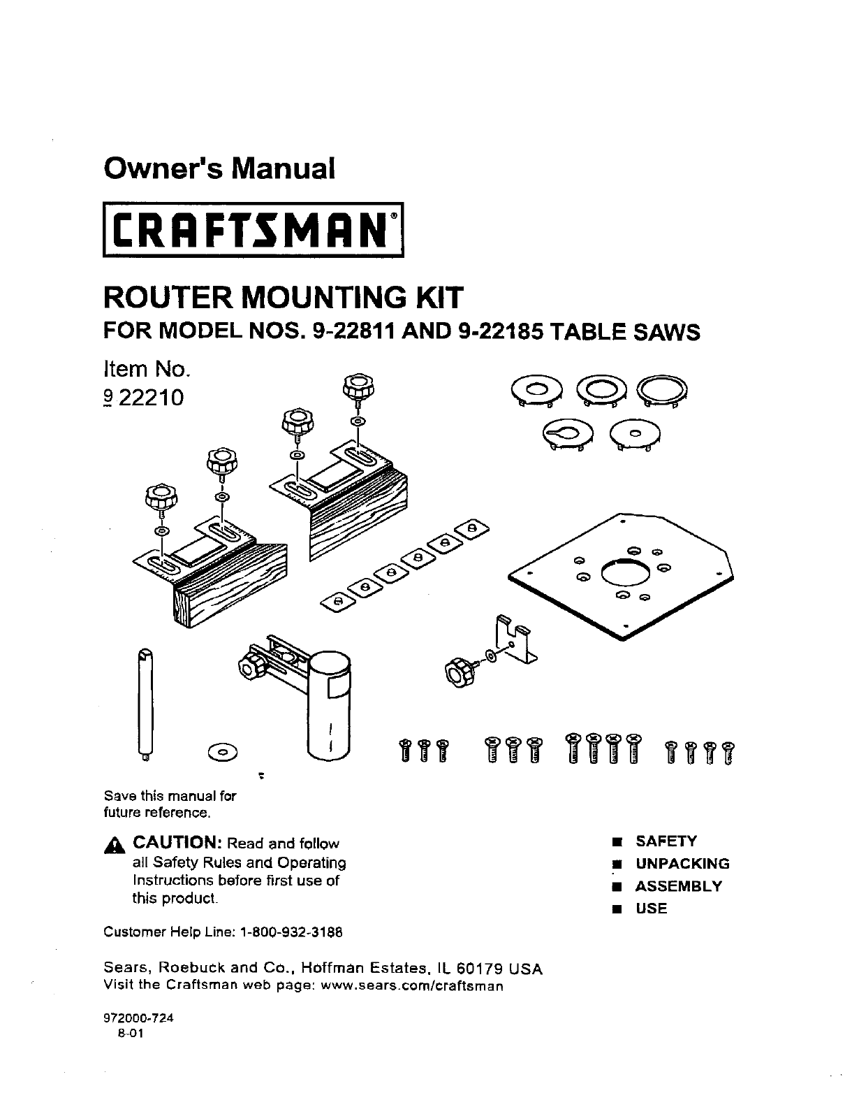
Owner's Manual
II:RRFTSMRN'I
ROUTER MOUNTING KIT
FOR MODEL NOS, 9-22811 AND 9-22185 TABLE SAWS
Item No.
_922210
I
Sava this manual for
future reference.
,A CAUTION: Read and follow
all Safety Rules and Operating
Instructions before first use of
this product.
Customer HeEpLine: 1-800-932-3188
• SAFETY
•UNPACKING
•ASSEMBLY
•USE
Sears, Roebuck and Co., Hoffman Estates, IL 60179 USA
Visit the Craftsman web page: www.sears.com/craftsman
972000-724
8-01
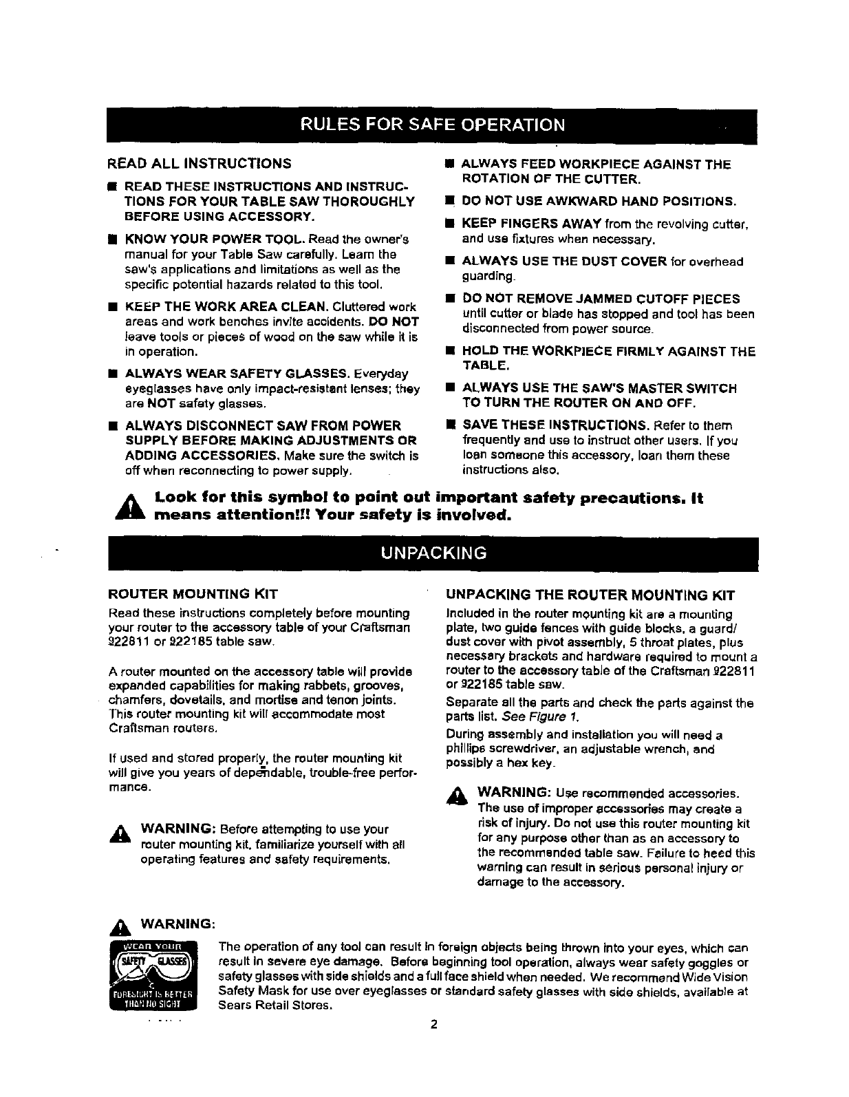
READ ALL INSTRUCTIONS
•READ THESE INSTRUCTIONS AND INSTRUC-
TIONS FOR YOUR TABLE SAW THOROUGHLY
BEFORE USING ACCESSORY.
i KNOW YOUR POWER TOOL. Read the owner's
manual for your Table Saw carefully. L.eam the
saw's applications and limitations as well as the
specific potential hazards related to this tool.
• KEEP THE WORK AREA CLEAN. Cluttered work
areas and work benches invite accidents. DO NOT
leave tools or pieces of wood on the saw while it is
in operation.
•ALWAYS WEAR SAFETY GLASSES. Everyday
eyeglasses have only impact-resistant lenses; they
are NOT safety glasses.
•ALWAYS DISCONNECT SAW FROM POWER
SUPPLY BEFORE MAKING ADJUSTMENTS OR
ADDING ACCESSORIES, Make sure the switch is
off when reconnecting to power supply.
i
M
ii
I
ALWAYS FEED WORKPIECE AGAINST THE
ROTATION OF THE CUTTER.
DO NOT USE AWKWARD HAND POSITIONS.
KEEP FINGERS AWAY from the revolving cutter,
and use fixtures when necessary.
ALWAYS USE THE DUST COVER for overhead
guarding.
DO NOT REMOVE JAMMED CUTOFF PIECES
until cutter or blade has Stopped and tool has bean
disconnected from power source.
HOLD THE WORKPIECE FIRMLY AGAINST THE
TABLE.
ALWAYS USE THE SAW'S MASTER SWITCH
TO TURN THE ROUTER ON AND OFF.
SAVE THESE INSTRUCTIONS. Refer to them
frequently and use to instruct other users. If you
loan someone this accessory, loan them these
instructions also.
_lk Look for this symbol to point out important safety precautions, it
means attention!I! Your safety is involved.
ROUTER MOUNTING KIT
Read these instructions completely before mounting
your router to the accessory table of your Craftsman
922811 or 922185 table sew.
Arouter mounted on the accessory table will provide
expanded capabilities for making rabbets, grooves,
chamfers, dovetails, and mortise and tenon joints.
This router mounting kit wi[[ accommodate most
Craftsman reuters.
If used and stored proper[y, the muter mounting kit
will give you years of dep_ndable, trouble-free perfor-
mance.
_1= WARNING: Before attempting to use your
muter mounting kit. familiarize yourself with all
operating features and safety requirements.
UNPACKING THE ROUTER MOUNTING KIT
Included in the router mounting kit are a mounting
plate, two guide fences with guide blocks, a guard/
dust cover with pivot assembly, 5 throat plates, plus
necessary brackets and hardware required to mount a
router to the accessory table of the Craftsman 922811
or 922185 table saw.
Separate ell the parts and check the parts against the
parts list. See Figure I.
During assembly and installation you will need a
phillips screwdriver, an adjustable wrench, end
possibly a hex key.
_k WARNING: Use recommended accessories.
The use of improper accessories may create a
risk of injury. Do not use this router mounting kit
for any purpose other than as an accessory to
the recommended table saw. Fsilur'e to heed this
warning can result in serious personal injury or
damage to the accessory.
WARNING:
The operation of any tool can result In foreign objects being thrown into your eyes. which can
result In severe eye damage. Before beginning tool operation, always wear safety goggles or
safety glasses with side shields and a fullface shield when needed. We recommend Wide Vision
Safety Mask for use over eyeglasses or standard safety glasses with side shields, available at
Sears Retail Stores.
2
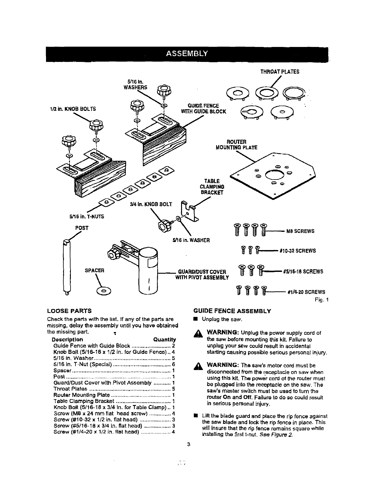
THROAT PLATES
5/16 In.
ROUTER
MOUNTING PLATE
Fig. 1
LOOSE PARTS
Check the parts with the list. If any of the parts are
missing, delay the assembly until you have obtained
the missing part.
Description Quantity
Guide Fence with Guide Block ......................... 2
Knob Bolt (5/16-18 x 1/2 in. for Guide Fence)., 4
5/16 in. Washer ................................................. 5
5/16 in. T-Nut (Special) ..................................... 6
Spacer ............................................................... 1
Post ................................................................ 1
Guard/Dust Cover with Pivot Assembly ........... I
Throat Plates .................................................... 5
Router Mounting Plate ...................................... 1
Table Clamping Bracket ................................... 1
Knob Bolt (5/16-18 x 3/4 in. for Table Clamp) .. 1
Screw (MS x 24 mm fiat head screw) .............. 4
Screw (#10-32 x 1/2 in, flat head) .................... 3
Screw (#5/16-18 x 3/4 in. fiat head) ................. 3
Screw (#1/4-20 x1/2 in. flat head) .................. 4
GUIDE FENCE ASSEMBLY
•Unplugthe saw,
A
WARNING: Unplugthe power supplycord of
the saw before mountingthis kit. Failure to
unplugyour sew couldresult in aooiclental
startingcausing possibleseriouspersonal injuw.
WARNING: The saw's motor cord must be
disconnected from the receptacJe on saw when
using this kit. The power cord of the muter must
be plugged into the receptacle on the saw. The
saw's master switch must be used to turn the
router On and Off, Failure to do so could result
in serious personal injury.
•Lift the blade guard end place the rip fence against
the sew blade and lock the rip fence in place. This
will insure that the rip fence remains square while
instetling the first t-nut. See Figure 2.
3
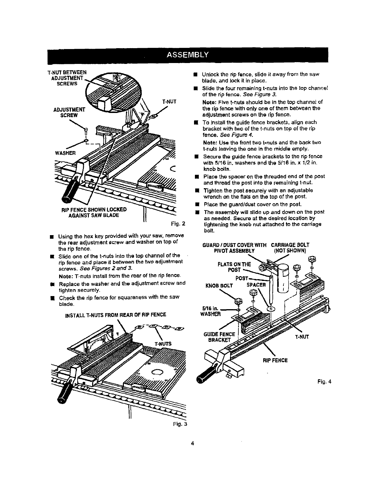
T-NUTBETWEEN
ADJUSTMENT
SCREWS
ADJUSTMENT
SCREW
L
T-NUT
WASHER
RIPFENCE SHOWN LOCKED
AGAINST SAW BLADE
Fig. 2
•Using the hex key provided with your saw, remove
the rear adjustment screw and washer on top of
the rip fence.
•Slide one of the t-nuts into the top channel of the
rip fence and place it between the two adjustment
screws. See Figures 2 and 3.
Note: T-nuts install from the rear of the rip fence.
•Replace the washer and the adjustment screw and
tighten securely.
[] Check the rip fence for squareness with the saw
blade.
INSTALL T-NUTS FROM REAR OF RIP FENCE
• Unlock the rip fence, slide it away from the saw
blade, and lock it in place.
•Slide the four remaining t-nuts into the top channel
of the rip fence. See Figure 3,
Note: Five t-nuts should be in the top channel of
the rip fence with only one of them between the
adjustment screws on the rip fence.
[] To install the guide fence brackets, align each
bracket with two of the t-nuts on top of the rip
fence. See Figure 4.
Mote: Use the front two t-nuts and the back two
t-nuts leaving the one in the middle empty.
•Secure the guide fence brackets to the rip fence
with 5116 in. washers and the 5/16 in, x 1/2 in.
knob bolts.
•Place the spacer on the threaded end of the post
and thread the post into the remaining t-nut,
[] Tighten the post securely with an adjustable
wrench on the flats on the top of the pest.
•Place the guard/dust cover on the post.
•The assembly will slide up and down on the post
as needed. Secure at the desired location by
tightening the knob nut attached to the carriage
bolt.
GUARD/DUSTCOVERWITH CARRIAGE [3OLT
PIVOTASSEMBLY (NOT SHOWN)
FLATSONTHE Y
POST
KNOB BOLT SPACER
,_16in.,
WASHER
T-HUTS
GUIDE FENCE T-NUT
BRACKET
RIPFENCE
Fig. 4
Fig. 3
4
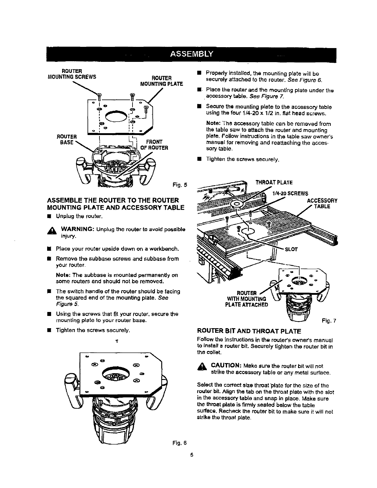
ROUTER
MOUN_NG SCREWS ROUTER
MOUN_NG PLATE
BOUTER _
BASE_ !FRONT
=ROUTER
•Properly installed, the mounting plate will be
secvrely attached to the router. See Figure 6.
J Place the router and the mounting plate under the
•accessory table. See Figure 7.
•Secure the mounting plate to the accessory table
using the four 114-20 x 112 in. fiat head screws.
Note: The accessory table can be removed from
the table saw to attach the router and mounting
plate, Follow instructions in the table saw owner's
manual for removing and reattaching the acces=
sory table.
•Tighten the screws securely.
Fig. 5
ASSEMBLE THE ROUTER TO THE ROUTER
MOUNTING PLATE AND ACCESSORY TABLE
•Unplugthe router.
,_ WARNING: Unplug the router tOavoid possible
LnJUry.
uPlace your router upside down on a workbench,
•Remove the subbase screws and subbase from
your router.
Nots: The subbase is mounted permanently on
some touters and should not be removed.
•The switch handle of the router should be facing
the squared end of the mounting plate. See
Figure 5,
•Using the screws that fit your router, secure the
mounting plate to your router base.
•Tighten the screws securely.
Fig. 6
IEWS
ACCESSORY
ROUTER
WITH MOUNTING
PLATEATrACHED
Fig, 7
ROUTER BIT AND THROAT PLATE
Follow the instructions in the router's owner's manual
to install a router bit. Securely tighten the router bit in
the collet.
_1= CAUTION: Make sure the router bit will not
sb-ikethe accessory table or any metal surface.
Setect the correct size throat _late for the size of the
router bit. Align the tab on the throat plate with the slot
in the accessory table and snap in place, Make sure
the throat plate is firmly seated below the table
surface. Recheck the router bit to make sure it will not
stdke the throat plate,
_1, WARNING; The router throat platesare
includedto assure no more than _/4 in.
clearance betweenthe cutterand the openingin
the throat plate. Use the correct throat plate. Do
not use a routerbit smaller than 1/4 in. orlarger
than 2 in.
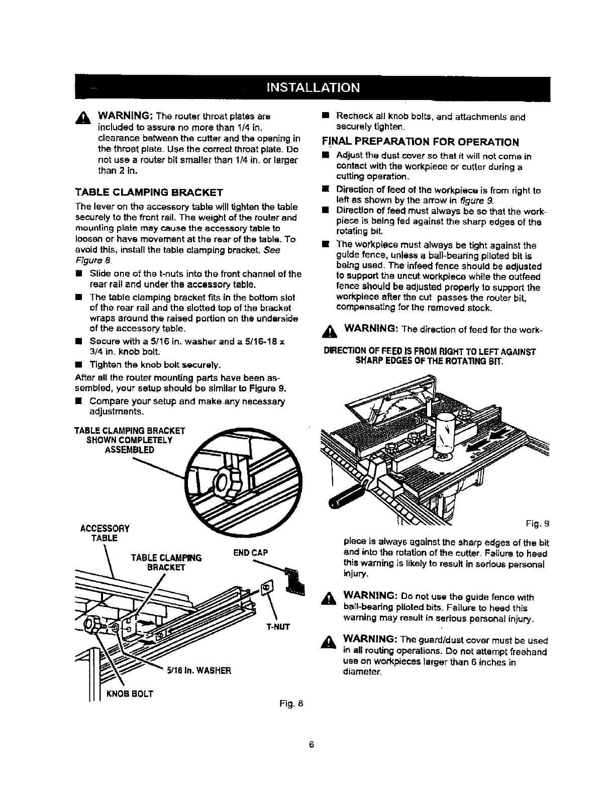
TABLE CLAMPING BRACKET
The lever on the accessory table will tighten the table
securely to the front rail, The weight of the router and
mounting plate may cause the accessory table to
loosen or have movement at the rear of the table. To
avoid this, instatl the tabte clamping bracket. See
Figure 8.
•Slideoneofthat-nutsintothefrontchannelofthe
rear rail and under the accessory table.
• The table clamping bracket fits in the bottom slot
of the rear rail and the slotted top of the bracket
wraps around the raised portion on the underside
of the accessory table.
•Secure with a 5116 in. washer and a 5/16-18
3/4 in. knob bolt.
• Tighten the knob bolt securely,
After all the router mounting parts have been as-
sembled, your setup should be similar to Figure 9,
•Compare your setup end makeany necessary
adjustments.
TABLECLAMPING BRACKET
SHOWN COMPLETELY
ASSEMBLED
ACCESSOR¥_
TABLE
ENDCAP
T-NUT
5/16 in. WASHER
KNOB BOLT Fig_ 8
•Recheck all knob bolts, and attachments and
seCureLy tighten.
FINAL PREPARATION FOR OPERATION
•Adjust the dust cover so that it will not come in
contact with the workpiece or cutter during a
cuffing operation.
•Direction of feed of the wofkpiece is from right to
left as shown by the arrow In figure 9.
•Direction of feed must always be so that the work-
piece is being fed against the sharp edges of the
rotating bit.
•The workplace must always be tight against the
guide fence, unless a bali-bearing piloted bit is
being used. The infeed fence should be adjusted
to support the uncut workplace while the outfeed
fence should be adjusted propedy to support the
workplace after the cut passes the router bit,
compensating for the removed stock.
WARNING: The direction of feed for the work-
DIRECTIONOF FEED ISFROM RIGHT TO LEFT AGAINST
SHARP EDGESOFTHE ROTATING BIT.
Fig. 9
piece is always against the sharp edges of the bit
and into the rotation of the cutter. FaUure to heed
this warning is likely to result in serious personal
injury.
_. WARNING: Do not use the guide fence with
bail-bearing piloted bits. Failure to head this
warning may result in serious personal injur3,.
WARNING: The guard/dustcover must be used
in all routingoperations.Do not attemptfreehand
usa on workpieces larger than 6 inches in
diameter.
6
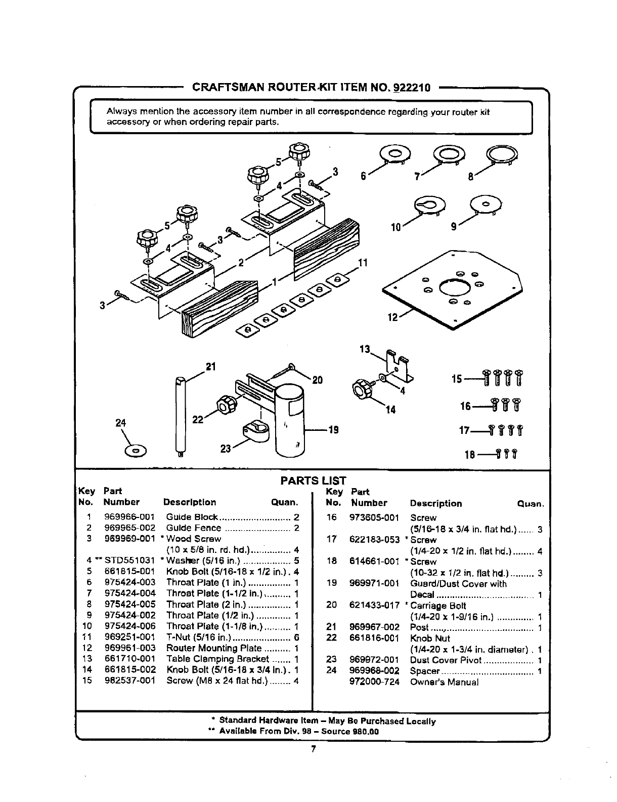
CRAFTSMAN ROUTER,KIT ITEM NO._922210
IAtways mention the accessory item number in all correspondenceregerdlngyour routerkit
accessory or when ordering repair parts. i
13
24 is 17 YYT
Key Part
No. Number
1969966-001
2 969965-002
3969969-001
4 *" STD551031
5661815-001
6 975424-003
7 975424-004
8 975424-005
9 975424-002
10 975424-006
11 969251-001
12 969961-003
13 661710-001
14 661815-002
15 982537-O01
PARTS LIST
Key
Description Quart. No.
Guide Block ........................... 2 16
Guide Fence ......................... 2
"Wood Screw 17
(10 x 5/8 in, rd. hd.)...,. .......... 4
*Washer (5/16 in) .................. 518
Knob Bolt (5/16-18 x 1/2 in.). 4
Throat Plate (1 in.) ................ 1 19
Throat Plate (1-1/2 in.) .......... 1
Throat Plate (2 in.) ................ 1 20
Throat Plate (1/2 in.) ............. 1
Throat Plate (1-1/8 in.) .......... 1 21
T-Nut (5/16 in.) ...................... 6 22
Router Mounting Plate .......... 1
Table Clamping Bracket ....... 1 23
Knob Bolt (5/16-18 x 3/4 in.). 1 24
Screw (MS x24 fiat hal,) ........ 4
Part
Number Description Quart,
973605-001 Screw
(5/16-18 x 3/4 in. fiat hd.) ...... 3
622183°053 * Screw
(1/4-20 x 1/2 in. fiat hd.) ........ 4
614661-001 "Screw
(10-32 x 1/2 in. fiat hd.) ......... 3
969971-001 Guard/Dust Cover with
Decal ..................................... 1
621433-017 *Carriage Bolt
(I/4=20 x1-9/16 in.) .............. 1
969967-O02
661816-001
969972-001
969968-002
972000-724
Post ,,..., ................................. 1
Knob Nut
(1/4-20 x1-3/4 in. diameter). 1
Dust Cover Pivot ................... 1
Spacer ............................ 1
Owner's Manual
* Standard Hardware Item - May Be Purchased Locally
** Available From Div. 9B - Source 980.00
7

For repair of major brand appliances in your own home...
no matter who made it, no matter who sold it!
1-800-4-MY-HOM EsMAnytime, day or night
(1-800-469-4663)
www.sears.corn
To bring in products such as vacuums, lawn equipment and electronics
for repair, call for the location of your nearest Sears Parts & Repair Center
1-800-488-1222 Anytime. day or night
www.sears.com
For the replacement parts, accessories and owner's manuals
that you need to do-it-yourself, call Sears PartsDirectSM!
1-800-366-PART 6a.m.-11p.m.CST,
(1-800-366-7278) 7 days aweek
www.sears.com/partsdirect
To purchase or inquire about a Sears Service Agreement:
1-800-827-6655
7a,m. - 5 p.m. CST, Mon. -Sat.
Para pedir servicio de reparacibn a domicilio,
ypara ordenar piezas con ontrega adornicilio:
1-888-SU-HOGAR _'
(1-888-784-6427)
Au Canada pour service en franq.ais:
1-877-LE-FOYER _
(1-877-533-69371
® RcgiSlctC'dTrademark [TM Trademark ofSeam, Roebuck _n_lCo,
(_ _ear_, Rood uc:_.3ridCo. •M_lrca Reg_tr_da /TM Matca _e F=_btlcadR Se_is. Raebuck and Co.
