Craftsman 315223400 User Manual STAND N STOW CABINET Manuals And Guides L0905113
CRAFTSMAN Workbench / Project Manual L0905113 CRAFTSMAN Workbench / Project Owner's Manual, CRAFTSMAN Workbench / Project installation guides
User Manual: Craftsman 315223400 315223400 CRAFTSMAN STAND-N-STOW CABINET - Manuals and Guides View the owners manual for your CRAFTSMAN STAND-N-STOW CABINET #315223400. Home:Tool Parts:Craftsman Parts:Craftsman STAND-N-STOW CABINET Manual
Open the PDF directly: View PDF ![]() .
.
Page Count: 6
PERATOR'S
T$
MAN AL
®
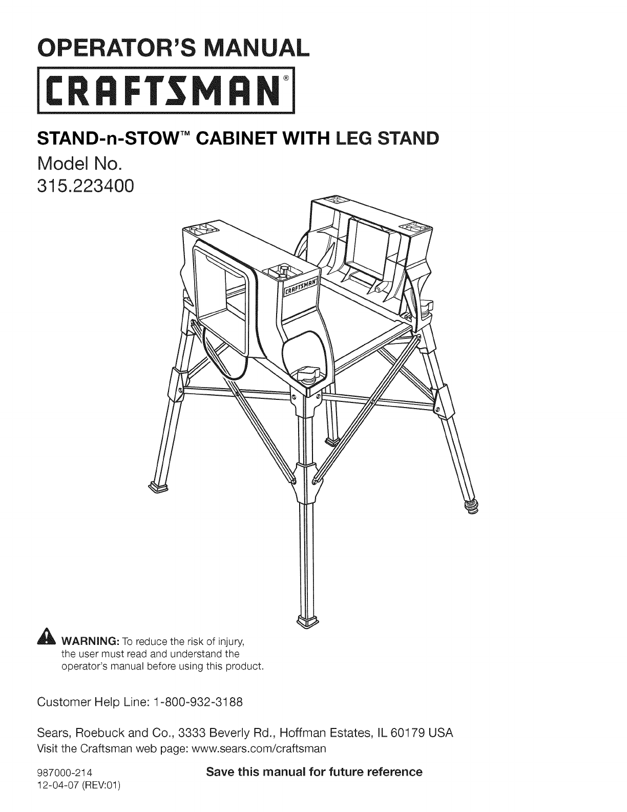
STAND-n-STOW" CABINET WITH LEG STAND
Model No.
315.223400
_ WARNING: To reduce the risk of injury,
the user must read and understand the
operator's manual before using this product.
Customer Help Line: 1-800-932-3188
Sears, Roebuck and Co., 3333 Beverly Rd., Hoffman Estates, IL 60179 USA
Visit the Craftsman web page: www.sears.com/craftsman
987000-214
12-04-07 (REV:01)
Save this manual for future reference

AWARNING: Read and understand all instructions.
Failure to follow all instructions listed below may
result in electric shock, fire, and/or serious personal
injury.
Safe operation of this accessory requires that you read
and understand this operator's manual, the operator's
manual for the miter saw, and all labels affixed to the tool.
SAVE THESE INSTRUCTIONS
READ ALL INSTRUCTIONS
•KNOW YOUR ACCESSORY. Read the operator's
manual carefully, Learn the applications and limitations
as well as the specific potential hazards related to this
tool.
ASSEMBLING THE STAND-n-STOW TM CABINET
See Figure 1.
This product requires assembly,
• Insert the supplied lock nut into the hex nut pocket,
• Align the reinforcement plate holes with the tab on the
bottom of the base and the screw hole in the base.
• Place supplied washer and lock washer onto the
supplied screw,
• Insert screw into the hole in the base.
• Turn clockwise to tighten screw,
• Repeat above steps until all four screws have
been inserted and tightened into base and both
reinforcement plates are installed.
HEXNUT BASE
POCKET
o Q
I
WASHER
REINFORCEMENT
PLATE LOCKWASHER
-_SCREW
Fig. 1
MOUNTING THE STAND-n-STOW TM CABINET
BASE TO THE LEG STAND
See Figures 2 -4.
When the leg stand and Stand-n-Stow TM cabinet are not in
use, the leg stand can be folded up and placed in the leg
stand storage area as indicated in figure 4.
• Place the leg stand on the floor then open the leg
stand by pushing opposite legs in opposite directions
as indicated by the arrows in figure 2.
Place the Stand-n-Stow TM cabinet on the leg stand.
Align the slots in the miter saw base with the slots on
the top of the leg stand,
• Insert the tab on the Stand-n-Stow TM cabinet locking
knob into the slot on the leg stand.
• Turn the locking knob clockwise to secure the Stand-n-
Stow TM cabinet to the leg stand,
• Repeat with the other three locking knobs.
1[
i
Fig. 2
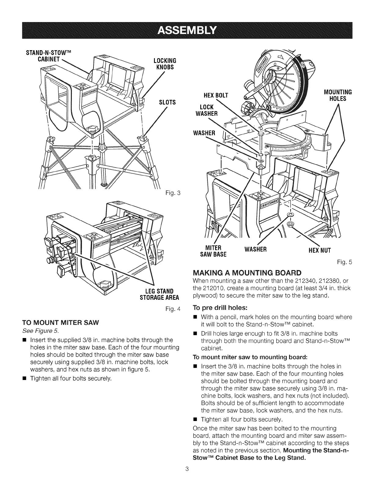
STAND-N-STOWTM
CABINET LOCKING
KNOBS
SLOTS
HEXBOLT MOUNTING
HOLES
LOCK
WASHER
WASHER
Fig. 3
LEGSTAND
STORAGEAREA
Fig. 4
TO MOUNT MITER SAW
See Figure 5.
•Insert the supplied 3/8 in. machine bolts through the
holes in the miter saw base. Each of the four mounting
holes should be bolted through the miter saw base
securely using supplied 3/8 in. machine bolts, lock
washers, and hex nuts as shown in figure 5.
• Tighten all four bolts securely.
MITER WASHER HEXNUT
SAWBASE
Fig. 5
MAKING A MOUNTING BOARD
When mounting a saw other than the 212340, 212380, or
the 212010, create a mounting board (at least 3/4 in. thick
plywood) to secure the miter saw to the leg stand.
To pre drill holes:
• With a pencil, mark holes on the mounting board where
it will bolt to the Stand-n-Stow TM cabinet.
• Drill holes large enough to fit 3/8 in. machine bolts
through both the mounting board and Stand-n-Stow TM
cabinet.
To mount miter saw to mounting board:
• Insert the 3/8 in. machine bolts through the holes in
the miter saw base. Each of the four mounting holes
should be bolted through the mounting board and
through the miter saw base securely using 3/8 in. ma-
chine bolts, lock washers, and hex nuts (not included).
Bolts should be of sufficient length to accommodate
the miter saw base, lock washers, and the hex nuts.
• Tighten all four bolts securely.
Once the miter saw has been bolted to the mounting
board, attach the mounting board and miter saw assem-
bly to the Stand-n-Stow TM cabinet according to the steps
as noted in the previous section, Mounting the Stand=n-
Stow TM Cabinet Base to the Leg Stand.
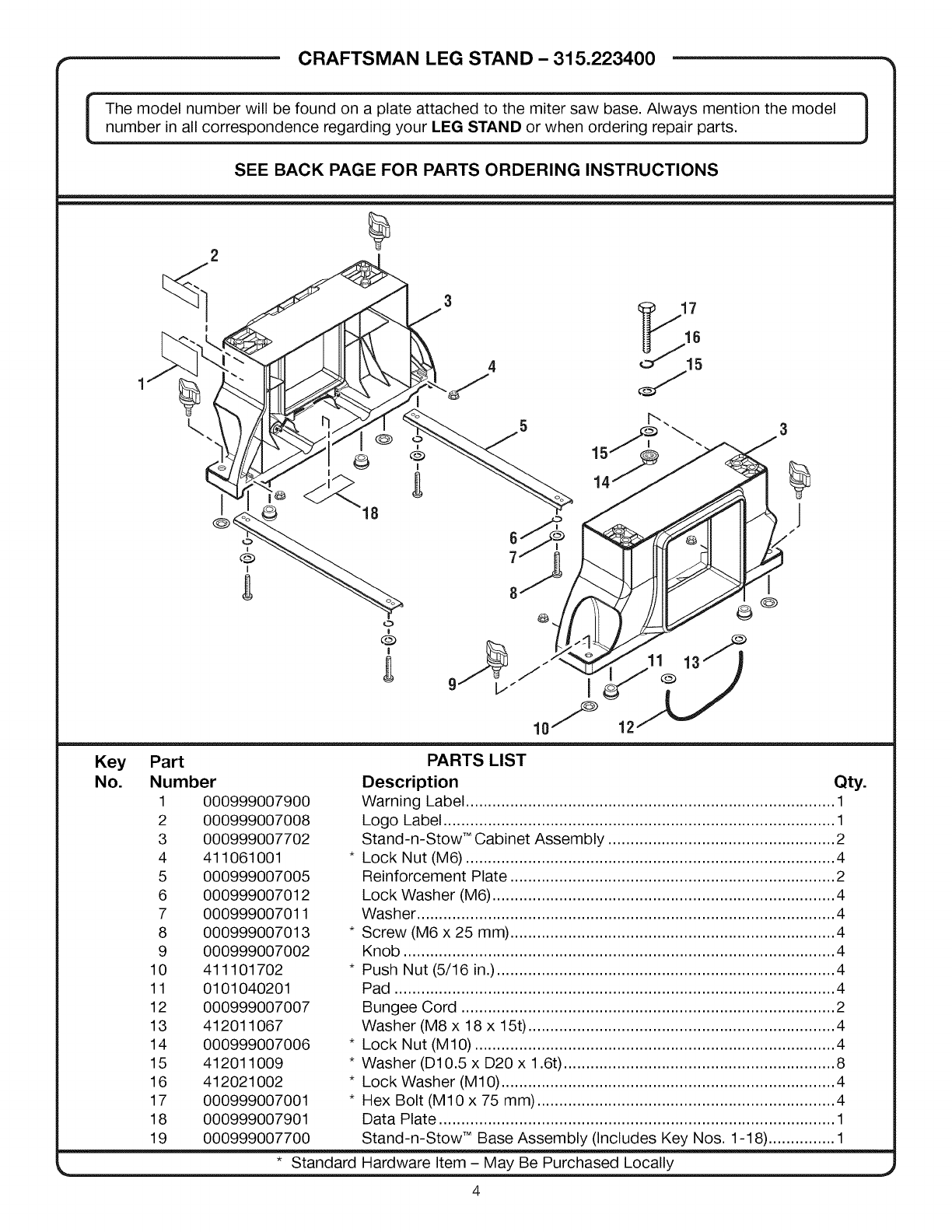
," CRAFTSMAN LEG STAND - 315.223400 -_
The model number will be found on a plate attached to the miter saw base. Always mention the model |number in all correspondence regarding your LEG STAND or when ordering repair parts. J
SEE BACK PAGE FOR PARTS ORDERING INSTRUCTIONS
¼
18
O
6
I
3
J
/
Key
No.
Part
Number
1 000999007900
2 000999007008
3 000999007702
4 411061001
5 000999007005
6 000999007012
7 000999007011
8 000999007013
9 000999007002
10 411101702
11 0101040201
12 000999007007
13 412011067
14 000999007006
15 412011009
16 412021002
17 000999007001
18 000999007901
19 000999007700
PARTS LIST
Description Qty.
Warning Label ................................................................................... 1
Logo Label ........................................................................................ 1
Stand-n-Stow TM Cabinet Assembly ................................................... 2
*Lock Nut (M6) ................................................................................... 4
Reinforcement Plate ......................................................................... 2
Lock Washer (M6) ............................................................................. 4
Washer .............................................................................................. 4
*Screw (M6 x 25 mm) ......................................................................... 4
Knob ................................................................................................. 4
*Push Nut (5/16 in.) ............................................................................ 4
Pad ................................................................................................... 4
Bungee Cord .................................................................................... 2
Washer (M8 x 18 x 15t) ..................................................................... 4
*Lock Nut (M10) ................................................................................. 4
*Washer (D10.5 x D20 x 1.6t) ............................................................. 8
*Lock Washer (M10) ........................................................................... 4
*Hex Bolt (M10 x 75 mm) ................................................................... 4
Data Plate ......................................................................................... 1
Stand-n-Stow TM Base Assembly (Includes Key Nos. 1-18) ............... 1
* Standard Hardware Item - May Be Purchased Locally

CRAFTSMAN LEG STAND - 315.223400
I The model number will be found on a plate attached to the miter saw base. Always mention the model |
number in all correspondence regarding your LEG STAND or when ordering repair parts. J
SEE BACK PAGE FOR PARTS ORDERING INSTRUCTIONS
2
12
1
0
5
* Standard Hardware Item - May Be Purchased Locally
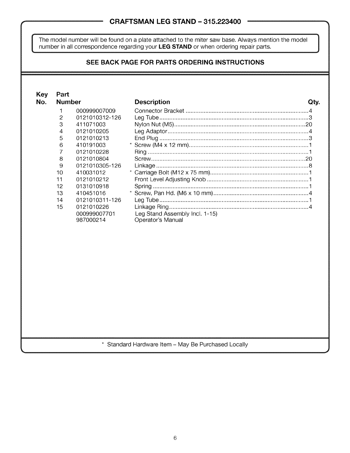
CRAFTSMAN LEG STAND - 315.223400 =*
l The model number will be found on a plate attached to the miter saw base. Always mention the model |
number in all correspondence regarding your LEG STAND or when ordering repair parts, iJ
SEE BACK PAGE FOR PARTS ORDERING INSTRUCTIONS
Key Part
No. Number
1 000999007009
2 0121010312-126
3 411071003
4 0121010205
5 0121010213
6 410191003
7 0121010228
8 0121010804
9 0121010305-126
10 410031012
11 0121010212
12 0131010918
13 410451016
14 0121010311-126
15 0121010226
000999007701
987000214
Description Qty.
Connector Bracket ........................................................................... 4
Leg Tube ........................................................................................... 3
Nylon Nut (M5) ................................................................................ 20
Leg Adaptor ...................................................................................... 4
End Plug ........................................................................................... 3
Screw (M4 x 12 mm) ......................................................................... 1
Ring .................................................................................................. 1
Screw .............................................................................................. 20
Linkage ............................................................................................. 8
Carriage Bolt (M12 x 75 mm) ............................................................ 1
Front Level Adjusting Knob .............................................................. 1
Spring ............................................................................................... 1
Screw, Pan Hd. (M6 x 10 mm) .......................................................... 4
Leg Tube ........................................................................................... 1
Linkage Ring ..................................................................................... 4
Leg Stand Assembly Incl. 1-15)
Operator's Manual
* Standard Hardware Item - May Be Purchased Locally
