Craftsman 315248200 User Manual TABLE SAW Manuals And Guides L0308254
CRAFTSMAN Saw Table Manual L0308254 CRAFTSMAN Saw Table Owner's Manual, CRAFTSMAN Saw Table installation guides
User Manual: Craftsman 315248200 315248200 CRAFTSMAN TABLE SAW - Manuals and Guides View the owners manual for your CRAFTSMAN TABLE SAW #315248200. Home:Tool Parts:Craftsman Parts:Craftsman TABLE SAW Manual
Open the PDF directly: View PDF ![]() .
.
Page Count: 47
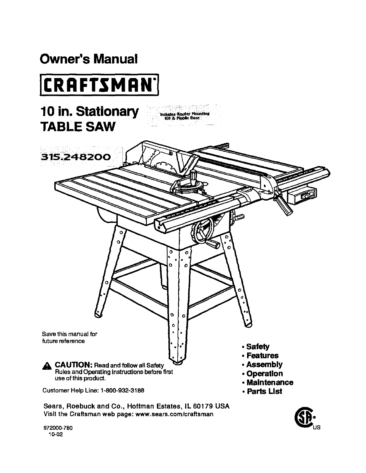
Owner's Manual
10 in. Stationary
TABLE SAW
Save this manual for
future reference
O
CAUTION: Read and follow all Safety
Rules and Operating Instructions before first
use of this product.
Customer Help Line: 1-800-932-3188
Sears, Roebuck and Co., Hoffman Estates, IL 60179 USA
Visit the Craftsman web page: www.sears.com/craftsman
972000-780
10-02
•Safety
•Features
•Assembly
•Operation
•Maintenance
•Parts List
FULL ONE YEAR WARRANTY ON CRAFTSMAN TABLE SAW
If this(RAFTSMAN Table Saw fails due to a defeat in matedal or workmanshipwithin one year from the date
of pumhase, Sears will repair it, free of charge.
Contact aSears Service Canter for repair.
if this product is used for commercial or rental purposes,this warranty applies only for 90 days from the date
ofpurchase.
Thiswarrantygivesyou specificlegalrights,and you may alsohave otherdghtswhichvaryfrom stateto
state.
Seare, Roebuck and Co., Dept. 8t7WA, Hoffman Estate,=,IL 60179
Your saw has many features for making cuttingoperations more pleasantend enjoyable. Safety, performance
and dependabilityhave been given top priorityinthe designof this saw making it easy to maintainand operate,
CAUTION: Carefully read throughthisentire owner'smanual before usingyour new saw. Pay close
attentionto the Rules For Safe Operation, and all Safety Alert Symbols,includingDanger, Warning and
Caution. If you use your saw propedyand onlyfor what it is intended,youwill enjoyyears of safe, reliable
service.
,_, Look for this symbol to point out important safetyprecautions,It means attention!!!Your safety is involved.
•k WARNING:
The operation of any powertool san result in foreign objects being thrown into your eyes,
which can result in severe eye damage, Before beginningpower tool operation, always
wear safety goggles or safetyglasseswith side shieldsand a fullface shieldwhen needed.
We recommend a Wide Vision Safety Mask for usa over eyeglasses or standardsafety
glasses with side shields, availableat Sears Retail Stores.
•Warranty and Introduction............................................................................................................................. 2
•Table Of Contents ...................................................................................................................................... 2-3
•Rules For Safe Operation........................................................................................................................... 4-6
•Electrical ....................................................................................................................................................... 7
•Glossary and ProductSpecifications............................................................................................................ 8
•Unpacking and Accassodes ......................................................................................................................... 9
•Loose Parts List.......................................................................................................................................... 10
•Small Parts List...................................................................................................................................... 11-12
•Tools Needed .............................................................................................................................................. 13
•Labels ..................................................................................................................................................... 14-15
•Features ................................................................................................................................................. 16-17
•Assembly ................................................................................................................................................ 16-29
InstallingHandwheals on Table Sew Base ................................................................................................. 18
AssemblingLeg Stand ........................................................................................................................... 16-19
CRAFTSMAN"TABLESAW315.228390 2

MountingtheLegStandontheTableSawBase........................................................................................ 19
AssemblingTable Extensions..................................................................................................................... 20
AligningTable Extensions ..................................................................................................... 20
Installingthe Rear Rail ................................................................................................................................ 21
Installingthe Front Rail ............................................................................................................................... 22
Aligning Rip Fence and Rails ...................................................................................................................... 23
Mountingthe Motor...................................................................................................................................... 23
Installing the Belt and Belt Guard ............................................................................................................... 24
Checking the Throat Plate ........................................................................................................................... 24
Installingthe Blade Guard ........................................................................................................................... 25
Aligning the Riving Knife withthe Blade ..................................................................................................... 26
Check Heeling (Paralleling) of the Saw Blade to the Miter Gage Groove .................................................. 27
Checking Rip Fence and Blade Alignment .................................................................................................. 28
Checking Squareness of ExtensionTables to Saw Table .......................................................................... 29
•Adjustments............................................................................................................................................ 30-34
Replacingthe Blade .................................................................................................................................... 30
Heeling (Paralleling) the Sawblade to Miter Gage Groove .................................................................... 31-32
Setting the Bevel Stopsand Indicator.................................................................................................... 32-33
Adjustingthe Miter Gage ............................................................................................................................. 33
Removing/Replacing the Throat Plate ...................................................................................................... 34
•BasicOperation of the Table Saw ......................................................................................................... 35-42
Causes of Kickback .................................................................................................................................... 35
Avoiding Kickback....................................................................................................................................... 35
Cutting Aids ................................................................................................................................................. 35
Types of Cuts .............................................................................................................................................. 36
Making a Cross Cut..................................................................................................................................... 37
Making a Rip Cut .................................................................................................................................... 37-38
Making a Miter Cut ...................................................................................................................................... 38
Making a Bevel Cross Cut ..................................................................................................................... 38-39
Making a Bevel Rip Cut ............................................................................................................................... 39
Making a Compound (Bevel) Miter Cut....................................................................................................... 40
Making a Large Panel Cut ........................................................................................................................... 41
Makinga Non-ThroughCUt ......................................................................................................................... 41
Makinga Dado Cut ...................................................................................................................................... 42
• Maintenance ................................................................................................................................................ 43
•Lubrication................................................................................................................................................... 43
•Troubleshooting...................................................................................................................................... 44.46
•ExplodedView and Repair Parts List..................................................................................................... 48-65
•Parts Ordering/Sen/ica ................................................................................................................ back page
3 cnn_lrxHnr TABLESAW31,5,228390
The purposeof safety symbolsisto attractyour attentionto possibledangers. The safety symbols,and the
explanationswiththem, deserve your careful attentionand understanding,The safety warnings do not by
themselves eliminateany danger. The instructionsorwarningsthey give are notsubstitutesfor proper accident
preventionmeasures.
SYMBOL MEANING
&
&
A
&
SAFETY ALERT SYMBOL
Indicates danger, warning,or caution. May be used in conjunctionwithother symbolsor
pictugraphs.
DANG ER: Failureto obey a safety warningwill result inseriousinjuryto yourselfor to others,
Always followthe safety precautionsto reduce the riskof fire, electdc shockand personalinjuP/,
WARNING: Failureto obey a safety warningcan resultin sadous Injury to yourselfor to others,
Always followthe safetyprecautionsto reduce the riskof fire, electdc shockand personal injuw.
CAUTION: Failureto obey asafety warning may resultin propertydamage or personal injulyto
yourselforto others.Alwaysfollow the safety precautionsto reduce the dsk of fire, electric shock
and personal injury,
Note: Advises you of informationor Instructions vital to the operationor maintenanceof the equipment,
IMPORTANT
Servicingrequiresextreme care and knowledgeof the
system and should be performed only by a qualified
servicetechnician, For servicewe suggestyou return
the toolto your nearest Sears store or repaircenter.
Alwaysuse odginalfactory replacement partswhen
servicing.
_, WARNING: Do not attemptto operate thistool
untilyou have read thoroughlyand understand
completelyall instructions,safety rules,etc.
contained inthis manual. Failure to complycan
result in accidentsinvolvingfire, electrical shock,
or serious personal injury.Save the owners
manual and reviewfrequently for continuingsafe
operation, and instructingotherswho rneyusa
this tool.
READ ALL INSTRUCTIONS
•KNOW YOUR POWER TOOL. Read the owner's
manual carefully, Leam the saw's applications
and limitationsas well as the specific potential
hazards related to this tool.
•DO NOT USE IN DANGEROUS ENVIRON-
MENT. Do not use power tools near gasoline or
other flammable liquids, in damp or wet loca-
tions, or expose them to rain. Keep the work
area well lit.
•MAKE WORKSHOP CHILD-PROOF with
padlocks and master switchesor by removing
starter keys.
•KEEP CHILDREN AND VISITORS AWAY. All
visitors sbou|dwear safety glasses and be kept
a safe distance from work area. Do not let
visitorscontact tool or extension cord while
operating.
•KEEP THE WORK AREA CLEAN. Cluttered
work areas and work benches inviteaccidents.
DO NOT leave tools or pieces of wood on the
saw while it is in operation,
•MAINTAIN TOOLS WITH CARE. Keep tools
sharp and clean for better and safer perfor-
mance. Follow instructionsfor lubricatingand
changing accessories,
•USE THE RIGHT TOOL FOR THE JOB. Do not
force the tool or attachmentto do a job it was
not designedfor. Usa it only the way it was
intended.
•DRESS PROPERLY. Do not wear loose cloth-
ing. gloves, neckties, rings, bracelets, or other
jewelry. They can get caught and draw you into
moving parts. Rubber gloves and nonslip
footwear are recommended.Also wear protec-
tive hair covedng to contain long hair.
• ALWAYS WEAR SAFETY GLASSES WITH
SIDE SHIELDS. Everyday eyeglasses have only
impact-rasistantlenses; they are NOT safety
glaseas.
•NEVER STAND ON TOOL, Serious injurycould
or.cur if the tool is tipped or if the blade is
unintentionallycontacted.
EIIRFTIMRIr TABLESAW315.228390 4
RULES FOR SAFE OPERATION (Continued)
•DO NOT OVERREACH. Keep properfootingand
balance at all times.
•SECURE WORK. Usa clamps or • vise to hold
work when practical. It's safer then usingyour
hand and frees both hands to operate tool.
•USE THE PROPER EXTENSION CORD. Make
sure your extension cord is in good condition,
Use only a cord heavy enough to carry the
currentyour product will drew, An undersized
cord will cause a drop in line voltage resultingin
loss of power and overheating. A wire gage size
(A.W,G.) of at least 14 is recommendedfor an
extension cord 25 feat or less in length. If in
doubt, use the next heavier gage. The smaller
the gage number, the heavier the cord.
•AVOID ACCIDENTAL STARTING. Be sure
switchis off when pluggingin,
•REMOVE WRENCHES AND ADJUSTING
KEYS, Get in the habit of checking-before
turning on tool -that hex keys and adjusting
wrenches are removed from tool.
CHECK DAMAGED PARTS. Before usingthe
tool again, check any damaged parts, including
guards,for proper operation and perfon_anca.
Check alignment of movingparts, bindingof
moving parts, breakage of parts, saw stability,
mountingand any other conditionsthat may
affect its operation. A damaged part muStbe
proparlyrepaired or replaced by a qualified
service technician at a Sears Store or repair
center to avoid risk of personal injury.
USE ONLY CORRECT BLADES. Use the dght
blade size, style and cuttingspeed for the
matedal and the type of cut. Blade teeth should
point down toward the front of the table.
•USE RECOMMENDED ACCESSORIES. Using
improper accessories may risk injury.
USE ONLY SEARS REPLACEMENT PARTS.
All repairs, whether electrical or mechanical,
should be made by a qualified sarvice technician
at a Sears Store or repair center.
•KEEP GUARDS IN PLACE and in goodworking
order, This includesthe blade guard, dying
knife, and anti-ldckback pawls.
•CHECK DIRECTION OF FEED. Feed work into
a blade or cutter against the direction of rotation
of the blade or cutter only.
DISCONNECT ALL TOOLS. When notin use,
before saP.'icing, or when changing attachments,
blades, bits, cutters, etc., all tools should be
disconnectedfrom power supply.
•DO NOT FORCE THE TOOL. It will dothe job
better and more safely at the rate for which it
was designed,
•NEVER LEAVE TOOL RUNNING UNAT-
TENDED. TURN THE POWER OFF. Do not
leave tool until it comes to a complete Stop.
•BEFORE MOUNTING, DISCONNECTING OR
REMOUNTING THE MOTOR; unplugthe saw
and removethe switchkey.
AWARNING: When servicing,use only identical
Creflsman replacement parts. Use of any other
parts may create a hazard or cause product
damage.
•NEVER USE THIS TOOL IN AN EXPLOSNE
ATMOSPHERE. Normal sparkingof the motor
could ignite fumes,
•MAKE SURE THE WORK AREA HAS AMPLE
LIGHTING to see the work and that no obStruc-
tions will interferewith safe operation BEFORE
performingany work usingthis tool.
•DO NOT USE TOOL IF SWITCH DOES NOT
TURN n" ON AND OFF. Have defective
switches replaced by a qualified servicetechni-
cian at a Sears Store or repair center.
•GUARD AGAINST ELECTRICAL SHOCK by
preventingbody contactwith grounded surfaces
such as pipes, radiators, ranges, refrigerator
enclosures.
•GROUND ALL TOOLS. See Electrical page.
•WEAR A DUST •ASK to keep from inhaling
fine particles.
•PROTECT YOUR HEARING. Wear hsaring
protectiondudngextended periodsof operation,
•DO NOT OPERATE THIS TOOL WHILE UN-
DER THE INFLUENCE OF DRUGS, ALCOHOL,
OR ANY MEDICATION.
•STAY ALERT AND EXERCISE CONTROL.
Watch what you ere doing and use common
sense. Do not operate tool when you are
tired. Do not rash.
•AVOID AWKWARD OPERATIONS AND HAND
PosmoNs where a sudden slip couldcause
your hand to move intothe blade. ALWAYS
make sure you have good balance.
•ALWAYS SUPPORT LARGE WORK PIECES
while cuttingto minimize risk of blade pinching
and kickback.Saw may slip. walk or slide while
cutting large or heavy boards.
•GUARD AGAINST KICKBACK, Kickbackcan
occur when the blade stalls, drivingthe work
piece beck toward the operator. It can pullyour
hand into the blade, resultingin sedous personal
injury.Stay out of the blade path and turn switch
off immediatelyif blade bindsor stalls.
5 I;IIIIFI'ZNRN" TABLESAW315.228390
RULES FOR SAFE OPERATION (Continued)
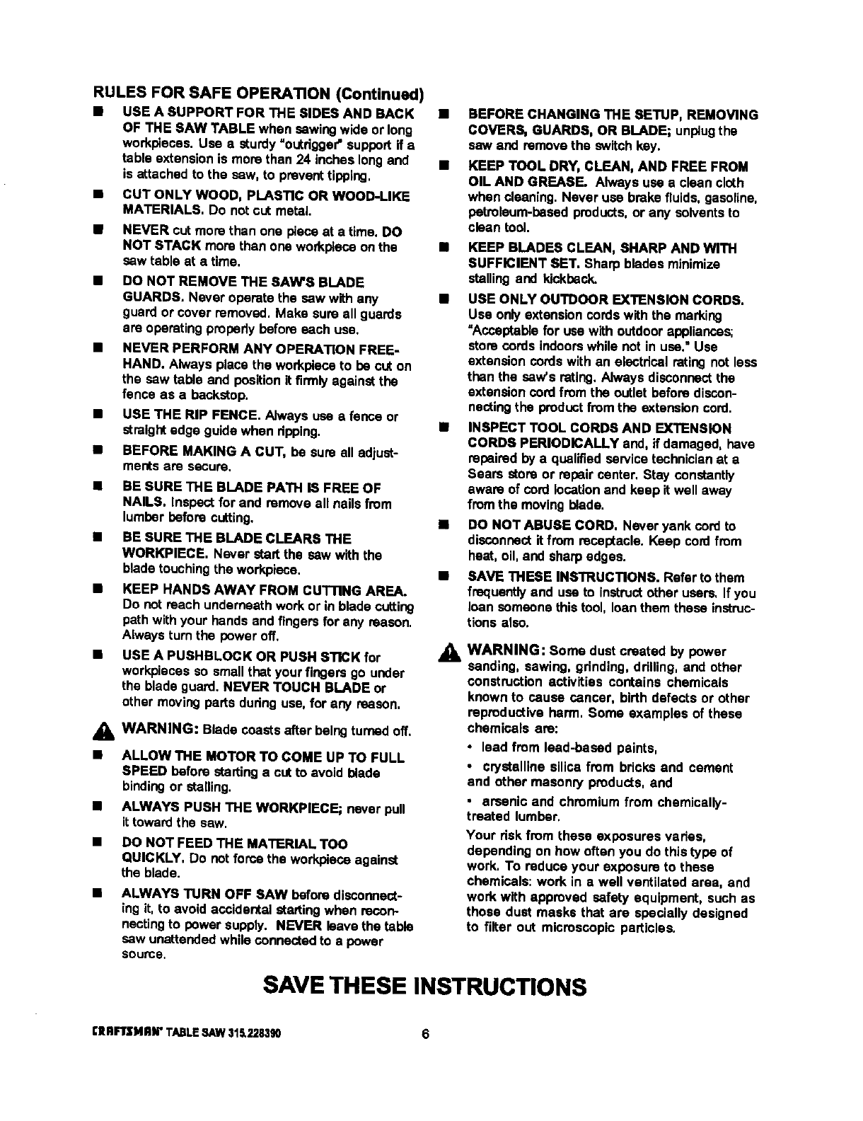
•USE A SUPPORT FOR THE SIDES AND BACK •
OF THE SAW TABLE when sawingwide or long
workpleoas. Usa e sturdy "outrigger"support if e
table extensionis more than 24 inches longand •
is attached to the saw, to prevent tipping,
CUT ONLY WOOD, PLASTIC OR WOOD-LIKE
MATERIALS. Do not cut metal.
NEVER cut more then one piece at a time. DO
NOT STACK more than one workpieceon the
saw table at a time,
DO NOT REMOVE THE SAW'S BLADE
GUARDS. Never operate the saw with any
guard or cover removed, Make sure all guards
are operating propedy before each use,
NEVER PERFORM ANY OPERATION FREE-
HAND. Always place the workplaceto be cut on
the saw table and positionit firmly against the
fence as a backstop.
USE THE RIP FENCE. Always usa a fence or
straight edge guide when ripping,
BEFORE MAKING A CUT, be sure all adjust-
ments are secure.
BE SURE THE BLADE PATH • FREE OF
NAILS. Inspect for and remove all nails from
lumber before cutting.
•BE SURE THE BLADE CLEARS THE
WORKPIECE, Never start the saw with the
blade touching the workplace,
•KEEP HANDS AWAY FRO• CUTTING AREA.
Do not reach underneath work or in blade cutting
path withyour hands and fingers for any reason.
Alwaysturn the power off,
USE A PUSHBLOCK OR PUSH STICK for
workpiecas so small that your fingers go under
the blade guard. NEVER TOUCH BLADE or
other moving parts dudng usa, for any reason,
_lb WARNING: Blade coasts after balngturned off.
•ALLOW THE MOTOR TO COME UP TO FULL
SPEED before startinga out to avoid blade
bindingor stalling.
•ALWAYS PUSH THE WORKPIEGE; never pull
it toward the saw.
•DO NOT FEED THE MATERIAL TOO
QUICKLY, Do not force the workplace against
the blade.
•ALWAYS TURN OFF SAW before disconnect-
ing it, to avoid accidental =talting when recon-
nectingto power supply. NEVER leave the table
saw unattended while connectedto a power
source.
BEFORE CHANGING THE SETUP, REMOVING
COVERS, GUARDS, OR BLADE; unplugthe
saw end remove the switchkey.
KEEP TOOL DRY, CLEAN, AND FREE FROM
OIL AND GREASE. Always use a clean cloth
when Cleaning.Never use brake fluids, gesaline,
petroleum-based products,or any solvents to
clean tool.
•KEEP BLADES CLEAN, SHARP AND WITH
SUFFICIENT SET. Sharp blades minimize
stalling and kickback,
•USE ONLY OUTDOOR EXTENSION CORDS,
Use only extensioncords with the marking
"Acceptablefor usa with outdoor appliances;
store cords indoors while not in usa." Use
extension cordswith an electrical rating not less
than the saw's rating, Always disconnect the
extension cord from the outlet before discon-
nectingthe product from the extension cord.
•INSPECT TOOL CORDS AND EXTENSION
CORDS PERIODICALLY and, if damaged, have
repaired by a qualifiedservice technicianat a
Sears store or repair center. Stay constantly
aware of cord locationand keep it well away
fromthe moving blade.
IS DO NOT ABUSE CORD, Never yank cordto
disconnect it from receptacle. Keep cord from
heat, oil, and sharp edges.
•SAVE THESE INSTRUCTIONS. Refer to them
frequently and use to instructother users, If you
loan someone this tool, loan them these instruc-
t_onsalso.
,&WARNING: Some dust created by power
sanding, sawing, grinding, ddlling, and other
construction activities contains chemicals
known to cause cancer, birth defects or other
reproductive harm, Some examples of these
chemicals are:
• lead from lead-based paints,
•crystalline silica from bricks and cement
end other masonry products, and
,arsenic and chromium from chemically-
treated lumbar,
Your dsk from these exposures vades,
depending on how often you do this type of
work. To reduce your exposure to these
chemicals: work in a well ventilated area, and
work with approved safety equipment, such as
those dust masks that are specially designed
to filter out microscopic particles.
SAVE THESE INSTRUCTIONS
[IIRFIrSI4RN" TABLESAW$I_228390 6
EXTENSION CORDS
Use only3-wirs extensioncords that have 3-prong
groundingplugsand 3-pole receptaclesthat accept
the tool'splug.When usinga powertool at a consid-
erable distancefrom the power source, use an
extensioncord heavy enough to carrythe currentthat
the tool willdraw. An undersized extensioncordwill
cause a dropin line voltage, resultingina lossof
power and causingthe motor to overheat, Use the
chart providedbelow to determinethe minimumwire
size requiredin an extensioncord. Only round jack-
eted cords listed by Underwriter'sLaboratories(UL)
should be used,
Length of Extension Cord Wire Size (A.W.G.)
Up to 25 feet 14
26-100 feet 12
When workingwiththe tool outdoors,use an exten-
sion cordthat is designed for outsideuse. This is
indicated by the lettersWA on the cord'sjacket.
Before usingan extensioncord, inspectitfor loose or
exposed wires and cut orwom insulation.
A_ CAUTION: Keep the cord away from the cutting
arsa and positionthe cord so that Itwill not be
caught on lumber, tools, or other objectsduring
cuttingoperations.
ELECTRICAL CONNECTION
Your Sears Craftsman Table Saw is powered by a
precisionbuiltelectric motor. It should be connected
to apower supply that is 120 volts, 60 Hz, AC only
(normal household cun'ent). Do notoperate this tool
on directcurrent (DC), A substantialvoltage dropwill
cause a loss of power and the motorwill overheat. If
the saw does not operate when pluggedinto an
outlet, double check the power supply.
SPEED AND WIRING
The no-load speed of yourtable saw is approximately
3,600 rpm. This speed is notconstant and decreases
undera load or withlower voltage. For voltage,the
wiring ina shop is as importantas the motor's horse-
power rating.A line intended only for lightscannot
probedy carry a power tool motor.Wire that is heavy
enough for a short distancewill be too lightfor a
greeter distance. A linethat can supportone power
tool may not be able to supporttwo orthrae tools.
GROUNDING INSTRUCTIONS
In the event of a malfunctionor breakdown,grounding
providese path of least resistancefor electriccurrent
to reduce the riskof electric shock.This tool is
equippedwithan electdccord having an equipment-
groundingconductorand a groundingplug. The plug
must be pluggedintoa matchingoutletthat is properly
installedand groundedin accordancewith all local
codes and ordinances.
Do not modifythe plugprovided. If it will not fit the
outlet,have the properoutlet installedby a qualified
electrician,improperconnectionofthe equiprnent-
groundingconductorcan result ina riskof electric
shook.The conductor with insulationhavingan outer
surfacethat is green withor withoutyellow stripesis
the equipment-groundingconductor. If repairor
replacementof the electriccord or plugis necessary,
do notconnectthe equipment-groundingconductor to
a live terminal.
Check with a qualifiedelectrician or service personnel
if the groundinginstructionsare net completely
understood,or if in doubtas to whether the tool is
properlygrounded.
Repairor replace a damaged orwom cord immedi-
ately.
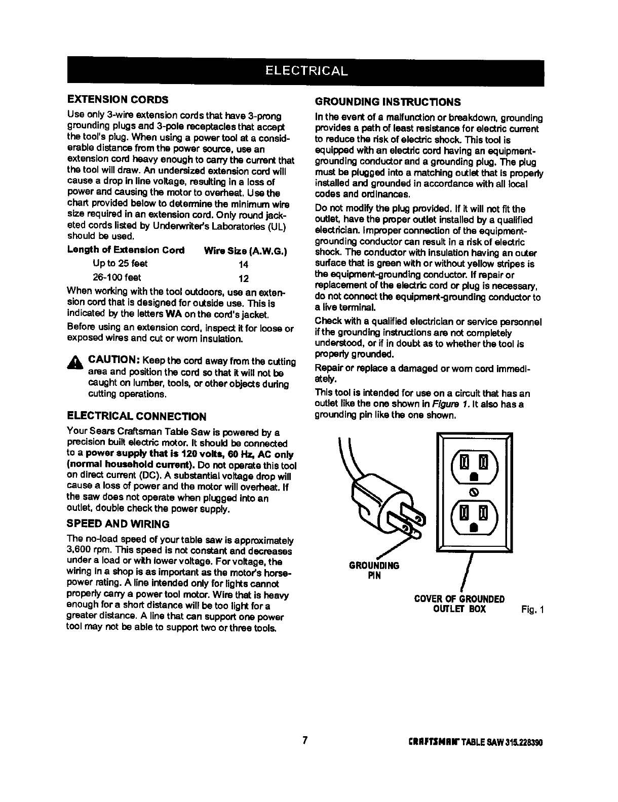
This tool is intendedfor use on a cimultthat has an
outlet likethe one shownin Figure 1. It also has •
groundingpin likethe one shown,
\
GROUNDING
RN /
COVEROF GROUNDED
OtRLEr BOX Fig, 1
7ClllF1'$Nlnr TABLESAW315,228390

Anti-Kickback Pawls
Toothed safety devices behind the blade designedto
stop a workpiece from being kickedback at the
operator duringa ripping operation.
Arbor
The shaft on which ablade or cuttingtool is mounted.
Bevel Cut
A cuttingoperation made with the blade at any angle
other than 90° to the saw table.
Compound Cut
Acut withboth a miterangle and a bevel angle.
Crosscut
A cuttingoperationmade acrossthe grainorthe width
of the workpiece,
Dado
A non-throughcut that gives a square notchor trough;
requiresa special blade.
Feat herboard
A deviceto help guide workpiecesduring ripcuts.
Freehand (for table saw)
Dangerouspractice of making a cut withoutusingrip
or miterfences. See Safety Rules.
Gum
A sticky,sap-based residuefrom wood products.
Heel
Alignmentof the blade.
Kerr
The matedal removed by the blade inathroughcut or
the slotproduced by the blade In a non-throughcut.
Kickback
A hazardthat can occur when blade binds or stalls,
throwingworkpleceback toward operator.
Leading End
The end of the workpiece pushed intothe cuttingtool
first.
Miter Cut
A cuttingoperation made with the miter gage at any
angle other than 0°.
Molding
Anon-through cut that gives a varied shape to the
workpieceand requires a special blade.
Push Stick
Adevice used to feed the workpiecethroughthe saw
blade dudng narrowcuttingoperations. It helps keep
the operator'shands well away from the blade,
Rabbet
Anotch in the edge of a workpiece.
Rw
A cutting operation to reduce the thickness of the
workpiece in order to make thinner pieces.
Resin
A sticky,sap-bssed substance.
RIp Cut
A cut made withthe the grain ofthe workpiece.
SawbladiePath
The area directlyin linewith the blade -- over, under,
behind,or in frontof it. Also, the workpiecearea
which will be or has been cut bythe blade.
Set
The distancethatthe tip of the saw blade tooth is bent
(or set) outwardfromthe face of the blade.
Throw-Back
Saw throwingback a workpiece;similarto kickback.
Through Sawing
Any cuttingoperation where the blade extends
completelythroughthe workpiece.
TratIIng End
The workpiece end last cutby the blade in a rip cut.
Workplace
The item on whichthe cuttingoperation is beingdone.
The surfacesof a workpiesaare commonlyreferredto
as faces, ends, and edges.
Worktable
The surface on whichthe workpiece restswhile
performinga cuttingoperation.
Blade Arbor 5/8 in,
BLadeDiameter 10 in.
Blade "13it O° -45 °
Table Size withouttable extensions 20 in. x 27 in.
Table Size with table extensions 44 in. x 27 in.
Rating 13 Amperes, 1,5 HP
(3 HP max. developed)
Input 120 V, 60 Hz -AC only
No Load Speed 3,600 RPM
Cutting Capacity with Miter at 0°/Bevel 0°3-3/8 in.
Cutting Capacity wIth Miter at 0°/Bevel 45°: 2-1/4 in.
£11RFTSMRN" TABLE ,SAW315.228390 8
Your new table saw has been designedto give you
many years of highquality performance.To insure
this goal, Woparcare andtreatment is important.
Careful treatment beginswith removingall partsfrom
the carton and checkingthem against the listof loose
parts. The longbox containsthe rails.The large box
holdsall other parts, which are detailed in the Loose
Parts List,
•Separate the saw and all partsfrom the packing
materialsand check each againstthe packinglist,
especiallythe smallparts that can be hidden inthe
packing material.
Note: Do not discardthe packing matadals untilyou
have carefullyinspected the sew, identifiedall
parts, and satisfactorilyoperated your new saw.
WARNING: Never use gasoline,naptha, or
other highlyvolatile solvents.Do not ever let
brakefluids, gasoline, petroioumJoased
products,or penetrating oils contact plasticparts.
Such chemicals can weaken or destroy plastic.
•Removethe wax paper covedngon the table. Use
any ordinaryhouseholdtype grease and spot
remover. Immediatelyapply a coat of pasta wax to
the table and table extensions.
WARNING: To prevent accidental startingthat
couldcause possible sadous personal injury,
assemble all parts to your sew before connecting
itto power supply.Saw should never be
connectedto power supplywhen you are
assemblingparts, makingadjustments,installing
or removingblades, or when notin use.
_1= WARNING: If any parts are missing,do not
operate this tool untilthe missingpartsare
replaced. Failure to do so could resultin possible
seriouspersonal injury.
The followingrecommendedaccassodesare currentlyavailable at Sears Retail Stores.
Fence Guide System
Guide Master
BoxJoint & Miter Guide
Universal Jig
Taper Jig
10 in. Sanding Disc
8 in. Sanding Disc
Elite Dado
Excalibur Dado
7 in. Adj. Dado 36 tip
7 in. Adj. Dado 24 tip
7 in. Stack Steel Dado
7 in. x 9/t6 in, Stack Dado
7 in. MoldingHead Set
2BitMolding Head Set
Saw Baskets
JointerClamps
SpecialtyThroat Plate
MiterGage Hold Down Clamp
Align.A-RipXRC Rip Fence
Dust Collection System
Accessory Table
A_. WARNING: The use of attachmentsor accassedes not listed mightbe hazardous.
9 ElUlIqrENIIN"TABLESAW31.5.2,?.8,_0
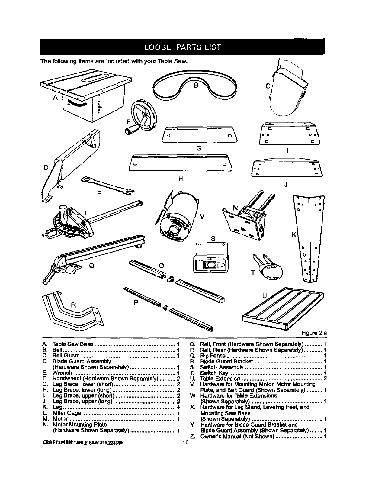
The following items are included with your Table Saw.
D
A
A. Table Saw Base ................................................... 1
B. Belt....................................................................... 1
C, BeltGuard ............................................................ 1
D, Blade Guard Assembly
(Hardware Shown Separately) ............................. 1
E, Wrench ................................................................ 1
F, Handwheel (Hardware Shown Separately) .......... 2
G, Leg Brace, lower (short)....................................... 2
H, Leg Brace, lower(long)........................................ 2
I, Leg Brace, upper (short) ...................................... 2
J. Leg Brace, upper (long) ....................................... 2
K. Leg ....................................................................... 4
L. Miter Gage ........................................................... 1
M. Motor.................................................................... 1
N. Motor MountingPlate
(Hardware Shown Separately) ............................. 1
CRnFTSMnN'TABLESAW315,228,390
O. Rail, Front (Hardware Shown Separately) ........... 1
R Rail, Rear (Hardware Shown Separately)............ 1
Q. Rip Fence............................................................. 1
R. Blade Guard Bracket........................................... 1
S. Switch Assembly ................................................. 1
T. Switch Key ........................................................... 1
U, Table Extension ................................................... 2
V, Hardware for MountingMotor,Motor Mounting
Plate, and BeltGuard (Shown Separately) .......... 1
W. Hardware for Table Extensions
(Shown Separately) ............................................. 1
X. Hardware for Leg Stand, Leveling Feet, and
MountingSaw Base
(Shown Separately) ............................................. 1
Y. Hardwarefor Blade Guard Bracketand
Blade Guard Assembly(Shown Separately) ........ 1
Z. Owner's Manual (Not Shown) .............................. 1
10
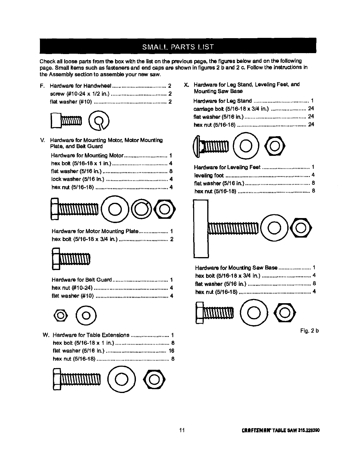
Checkallloosepartsfromtheboxwiththelistonthepreviouspage,thefiguresbelowandonthefollowing
page.Smallitems such as fasteners and end caps are shownin figures2 b and 2 c. Follow the instructionsin
the Assembly sectionto assemble your new sew.
F. Hardware for Handwheel ................................... 2
screw (#10-24 x 1/2 in.) .................................... 2
flat washer (#10) ............................................... 2
V. Hardware for MountingMotor, Motor Mounting
Plate, and BeltGuard
Hardwarefor Mounting Motor............................ 1
hex bolt (5116-18x 1 in.) .................................... 4
flat washer (5/16 in.) .......................................... 8
lockwasher (5/16 in.) ........................................ 4
hex nut (5116-18) ............................................... 4
X. Hardwarefor Leg Stand, LevelingFeet, and
MountingSaw Base
Hardwarefor LagStand .................................... 1
carriage bolt (5/16-t8 x 3/4 in.) ....................... 24
fiat washer (5/16 in.) ........................................ 24
hex nut (5116-18) ............................................. 24
Hardwarefor Leveling Feet ............................... 1
levelingfoot ....................................................... 4
flat washer (5/16 in.) .......................................... 8
hex nut (5116-18) ............................................... 8
Hardware for Motor Mounting Plate ................... 1
hex bolt (5/16-18 x 3/4 in.) ................................ 2
Hardware for Belt Guard .................................... 1
hex nut (#10-24) ................................................ 4
flat washer (#10) ............................................... 4
W, Hardware for Table Extensions ......................... 1
hex bolt (5/16-18 x 1 in.) ................................... 8
flat washer (5/16 in.) ....................................... 16
hex nut (5/16-18) ............................................... 8
i
m
Hardwarefor MountingSaw Base ..................... 1
hex bolt (5116-18 x 3/4 in.) ................................ 4
fiat washer (5/16 in.) ......................................... 6
hex nut (5/16-18) ............................................... 4
Fig. 2 b
11 rlUIFTSNRIrTABLESAW315,228,190
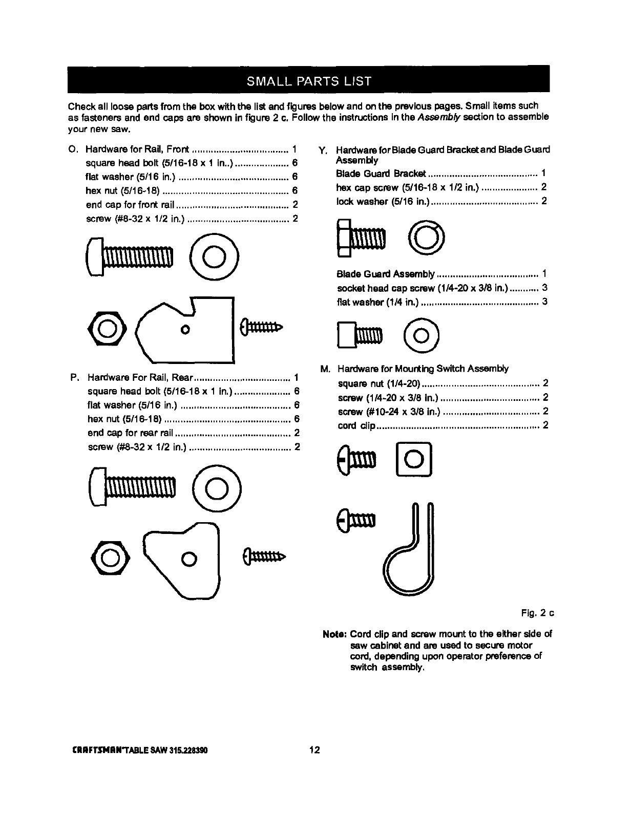
Checkalllooseparsfromtheboxwiththelistandfiguresbelowandonthepreviouspages.Smallitemssuch
asfasteners and end caps are shown in figure 2 c. Follow the instructionsin the Assembly section to assemble
your new sew.
O. Hardware for Rail, Front.................................... 1
square head holt (5/16-18 x 1 in..).................... 6
flat washer (5/16 in.) ......................................... 6
hex nut (5/16-18) ............................................... 6
end cap for front rail .......................................... 2
screw (#8-32 x 112in.) ...................................... 2
P, Hardware For Rail, Rear.................................... 1
square head bolt (5/16-18 x 1 in,)..................... 6
flat washer (5/16 in.) ......................................... 6
hex nut(5/16-18) ............................................... 6
end cap for rear rail ........................................... 2
screw (#8-32 x 1/2 in.) ...................................... 2
Y*
i_
Hardwarefor BladeGuard Bracketand BladeGuard
Assembly
Blade Guard Bracket......................................... 1
hex cap screw (5/16-18 x 112in.) ..................... 2
lock washer (5/16 in.) ........................................ 2
Blade Guard Assembly...................................... 1
sockethead cap screw (1/4-20 x 318in.)........... 3
fiat washer (1/4 in.) ............................................ 3
Hardwarefor MountingSwitchAssembly
squara nut (1/4-20) ............................................ 2
screw (1/4-20 x 3/8 in.) ..................................... 2
screw (#10-24 x 3/8 in.) .................................... 2
cord clip............................................................. 2
(
Fig. 2 c
Note: Cord clip and screw mountto the either side of
saw cabinet and are usedto secure motor
cord,depending uponoperator preferancaof
switch assembly,
I:ll nFTJflNII N"I'ABLE SAW 315.228390 12
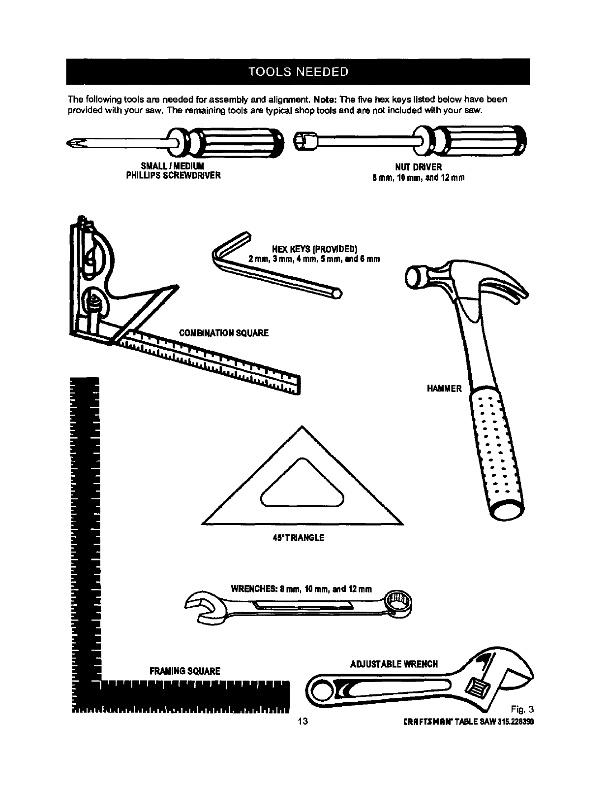
The following tools are needed for assembly and alignment, Note: The five hex keys listed below have been
provided with your saw. The remaining tools are typical shop tools and are not included with your saw.
SMALLIMEDIUM
PHILUPSSCREWDRIVER NUTDRIVER
8ram,t0 mm,and12mm
HEXI_EYS(PROVIDED)
and6mm
COMBINATIONSQUARE
45°TRIANGLE
HAMMER
_WRE_HES: 8.m, ,Omm,and_2mm _¢_
FRAMINGSQUARE ADJUSTABLEWRENCH
13 CRRFTSNIIW TABLESAW315.228390
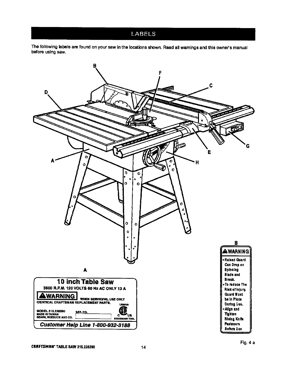
The following labels are found onyour saw inthe locationsshown.Read allwarningsand this owner'smanual
before usingsaw.
B
D
E
H
A
10 inch Table Saw
3600 R.P.M. 1;!0 VOLTS 60 HZ AC ONLY 13 A
JAWARNING J,,....._--.. u. o._,
IDENTICAL CRAFTBMAN REPLACEMENT PARTS.
MODEL 315.228390 ra,lR.NO. C_
MADE IN TAIWAN US
SF.ARS.ROEBUCI(ANDCO. I 1 S_I_.-lCaUUWI:=OI.
Customer Help Line 1-800.932.3188
B
AWARNING
Fig. 4 a
CRRFI"$NRN"TABLESAW315.228390 14
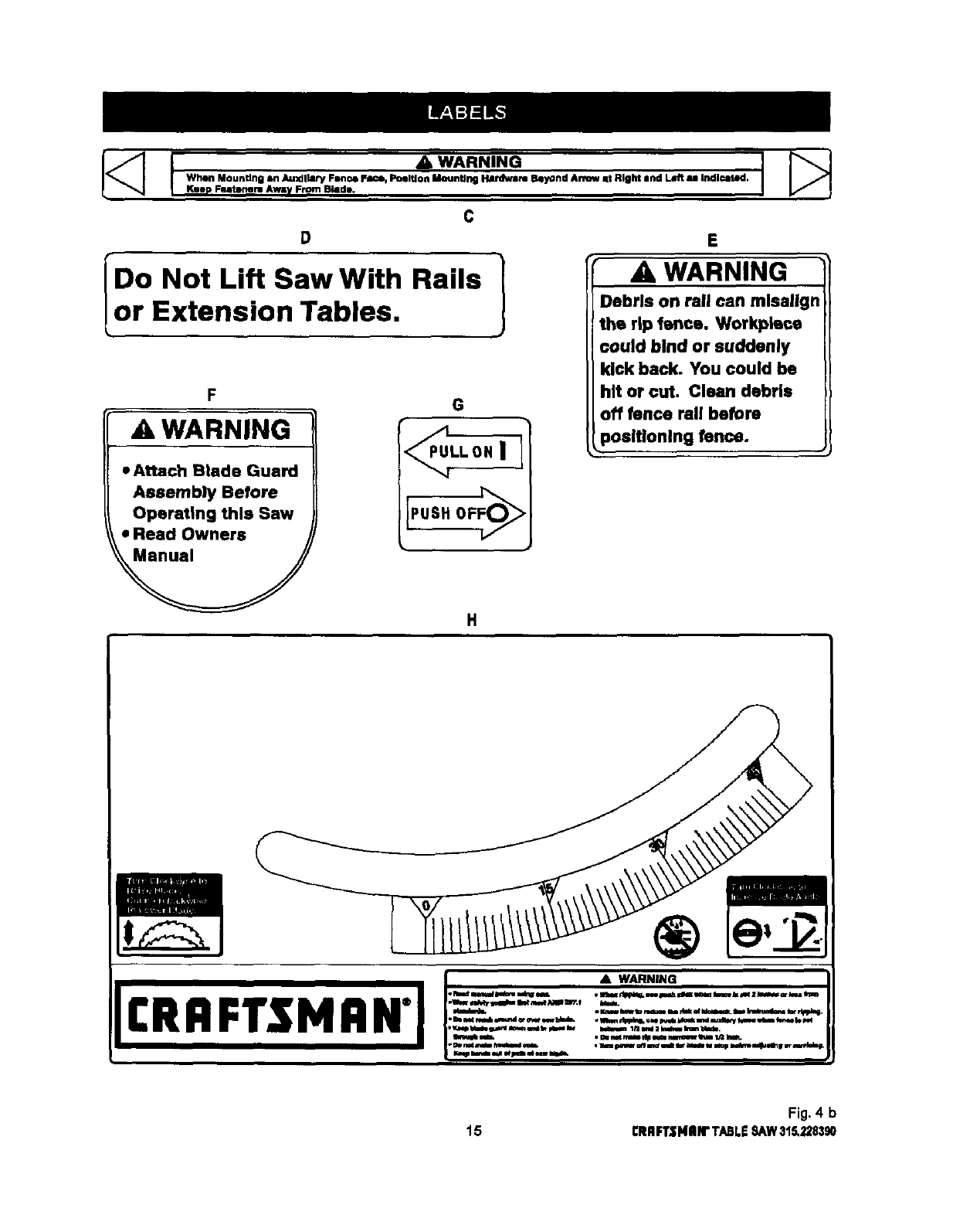
C
•D•
IDo Not Lift Saw With Rails 1
_or Extension Tables, J
F
AWARNING
•Attach Btade Guard
Assembly Before
Operating this Saw
•Read Owners
•G
E
WARNING
Debris on Pall can mlsallgn
the rip fence. Workplace
could bind or suddenly
kick back. You could be
hit or cut, Clean debris
off fence Pall before
3ositlonlng fence.
£RRFr$ H RN"FI:_-:z: .'i_-_-"____:_=.J
Fig. 4 b
15 CRRFTZNIIN"TABLE8/kW315.228,190
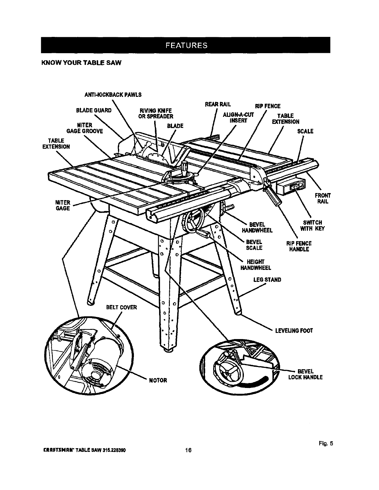
KNOW YOUR TABLE SAW
ANTI-KICKBACKPAWLS
MITER
GAGEGROOVE
TABLE
EXTENSION
RIVINGKNIFE
ORSPREADER
REARRAIL RiPFENCE
AUGH-A_UT TABLE
INSERT EXTENSION
BLADE SCALE
MITER
GAGE
BELTCOVER o
o
FRONT
RAIL
BEVEL SWITCH
HANDWHEEL WITH KEY
RIP FENCE
SCALE HANDLE
HEIGHT
HANDWHEEL
LEG STAND
LEVEUNGFOOT
MOTOR
BEVEL
_CK_NDLE
Fig, 5
CRRFTSNRN"TABLESAW3t5,228390 16
OVERVIEW
The upperportionof the blade projects upthroughthe
table, surroundedby an insert celled the throat plate.
The heightof the blade is set with a handwheai onthe
front of the cabinet. To accommodate wide panels,
the tabletop has extensionson each side. Detailed
instructionsare providedin the Operationsection of
this manual for the basic cuts:cross cuts, mitercuts,
bevel cuts, and compoundcuts,
For cuts withthe blade straight up and cuttingacross
the grain (crosscuts or miter cuts), use the mitergage
to set the angle and push the wood into the blade, To
cut withthe blade straight up, alongthe grainof the
wood (rip cuts), usa the rip fence to guide the wood.
Push srnailerpieces with a puchblockorpushstick.
To tiltthe blade for a bevelcut, use the bevel
handwheel onthe sideof the cabinet.A bevel scale
on the front ofthe cabinetshews the blade angle.
Insidethe ceblnet, adjustable positivestops control
the degree of tilt.
Usa the miter gage with abevel crosscut (compound
cut) and the rip fence with a bevel dp cut. Other cuts
requirespedal attachments, which have detailed
instructionsto reduce riskof injuryand ensurethe
bast performancefrom your new saw,
Before attempting to use your saw, familiarizeyourself
withall operatingfeatures and safety requirementsof
your Sears Craftsman table saw. The saw's features
are describedbelow,
ALIGN-A-CUT INSERT - A plastic inserton which
marks may be made to indicatethe location of the
sawcuton the workpieco,
ANTI-KICKBACK PAWLS -Kickbackis a hazard in
whichthe workpiece is thrownback toward the
pper_or. The toothed pawls are designed to snag the
workpieseto prevent or reduce injuryshould kickback
occur,
BEVEL HANDWHEEL -This handwheel, onthe right
side of the cabinet,tiltsthe blade for a bevel cut,
BEVEL SCALE -The easy-to-reed scale onthe front
of the workstandshows the exact blade angle.
BLADE -This saw is providedwith a Craftsman64
tooth, 10 in. steel blade. The blade is adjusted with
bevel and height handwheelson the cabinet.Bevel
angles are lockedwith a handle below the front rail.
_k WARNING: Be sure to use only blades rated for
at least 5,000 rpm and recommendedfor use on
this saw, Check with your nearestSears retail
store.
BLADE GUARD - Always keep the guard downover
the blade for through-sawingcuts.
BEVEL LOCK HANDLE - This handle, placed just
underthe worktable surfaceon the frontof the cebi-
net, locksthe angle setting of the blade. Be sure the
handleis hangingstraightdown before tiltingthe
blade. If it is notstraightdown, it may jam and bend
the lockingbolt,
HEIGHT HANDWHEEL -Use this handwheelto lower
and raise the blade for adjustmentsor replacement, it
is located on the frontof the cabinet.
MITER GAGE oThis gage alignsthe wood for a
crosscut.The easy-to-read indicatorshowsthe exact
angle for a miter cut, with positivestops at 90° and
45 ° .
MITER GAGE GROOVES -The miter gage rides in
these grooveson either side of the blade.
MITER GAGE KNOB - Located on the miter gage,
this knob locksinthe cutting angle after selection.
MOTOR (13 AMP) -The powerful inductionmotoris
1.SHP (3HP maximumdeveloped), with capacitor
start and V-belt drive, and is housed ina sturdysteel
base,
RAILS - Frontand rear rails provide supportfor large
workplecesand the dpfence.
RIP FENCE -A sturdymetal fence guidesthe
workpleceand is secured withthe ripfence handle,
Grooves run alongthe top and sides of the ripfence
for use withoptionaldamps and accessories,
RIP FENCE HANDLE -The handle onthe front of the
dp fence releasesthe rip fence or locksit in place.
RIVING KNIFE OR SPREADER -Located directly
behind the blade, it keeps cut edges from bindingand
supportsthe blade guard.
SCALE -Found on the front rail,the easy-to-read
scale providesprecise measurements in rip cuts.
SWITCH WITH KEY -Your table saw has an easy
access power switch locatedbelow the front rail, The
yellow switchkey must be removedfrom the hard-
ware bag and insertedinto the switch before saw can
be oper_ed. To lockthe switchinthe OFF position,
removethe switchkey fromthe switch.Place the key
ina locationthat is inaccessibleto children and others
not qualifiedto use the tool.
TABLE EXTENSIONS -Removable stamped steel
extensions, 12 in. by 27 in,, suppor_largerwork-
pieces.
17CRIIFTSNIIN"TABLESAW315.228390
Assembly is bast done inthe area where the saw will be used. When you remove the table saw base, loose
parts, and hardware from the peckingmatarials, check all items withthe loose parts listand drawing.If you are
unsura about the descdptionof any pert. refer to the drawing. If any partsare missing,delay assembling until
you have obtained the missingpert(s).
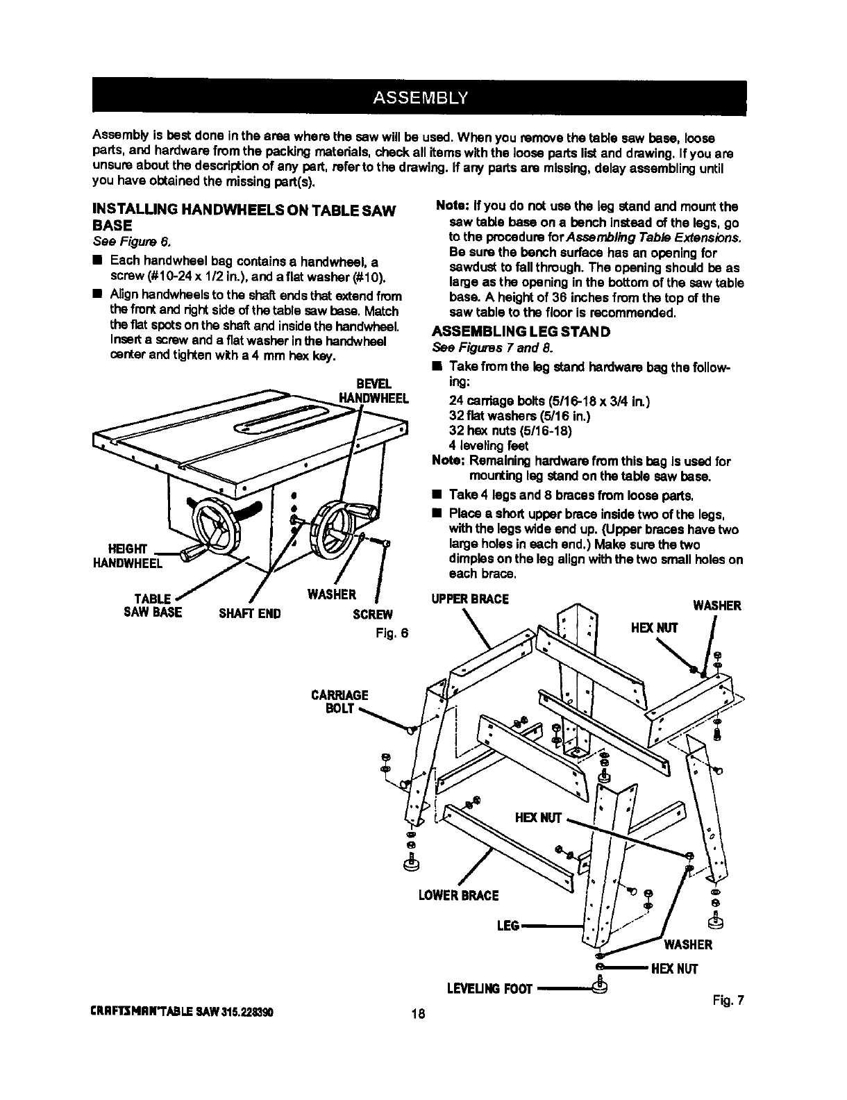
INSTALLING HANDWHEELS ON TABLE SAW
BASE
See Figure 6.
• Each handwheel bag containsa handwheel, a
screw (#10-24 x 1/2 in.), and aflat washer (#10).
•Alignhendwheels to the shaftendsthat extendfrom
thefrontand dght sideof the table sawbase, Match
theflat spotson the shaftand insidethe handwheal,
Inserta screwanda fiatwasher inthe handwheel
santer andtightenwith a 4 mm hex key.
BEVEL
HANDWHEEL
HBGHT
HANDWHEEL
TABLE WASHER
SAWBASE SHAFTEND SCREW
Fig.6
Note: If you do not use the leg standand mountthe
saw table base on a bench instead of the legs, go
to the procedureforAssambling Table Extensions.
Be surethe bench surface has an openingfor
sawdust to fallthrough. The opening should be as
large as the opening inthe bottom of the saw table
base. A height of 36 inches fromthe top of the
sawtable to the floor is recommended.
ASSEMBLING LEG STAND
See Figures 7 and 8.
• Take fromthe legstand hardwarebag the follow-
ing:
24 cardage bolts (5/16-18 x 3/4 in.)
32 flat washers(5/16 in,)
32 hex nuts(5/16-18)
4 levelingfeet
Note: Remaininghardwarefromthis bag is used for
mountingleg standon the table saw base.
•Take 4 legs and 8 bracesfrom looseperts.
•Place •shod upper brace insidetwo oftba legs,
withthe legswide end up. (Upper braces have two
largeholes in each end.) Make sure the two
dimpleson the lag alignwiththe two smallholeson
each brace,
UPPERBRACE WASHER
HEX NUT
CARRIAGE
LOWERBRACE
LEG
HEXNUT
LEVEUNGFOOT Fig. 7
£RRFlr];NRN"i'ABLESAW315,2211390 18
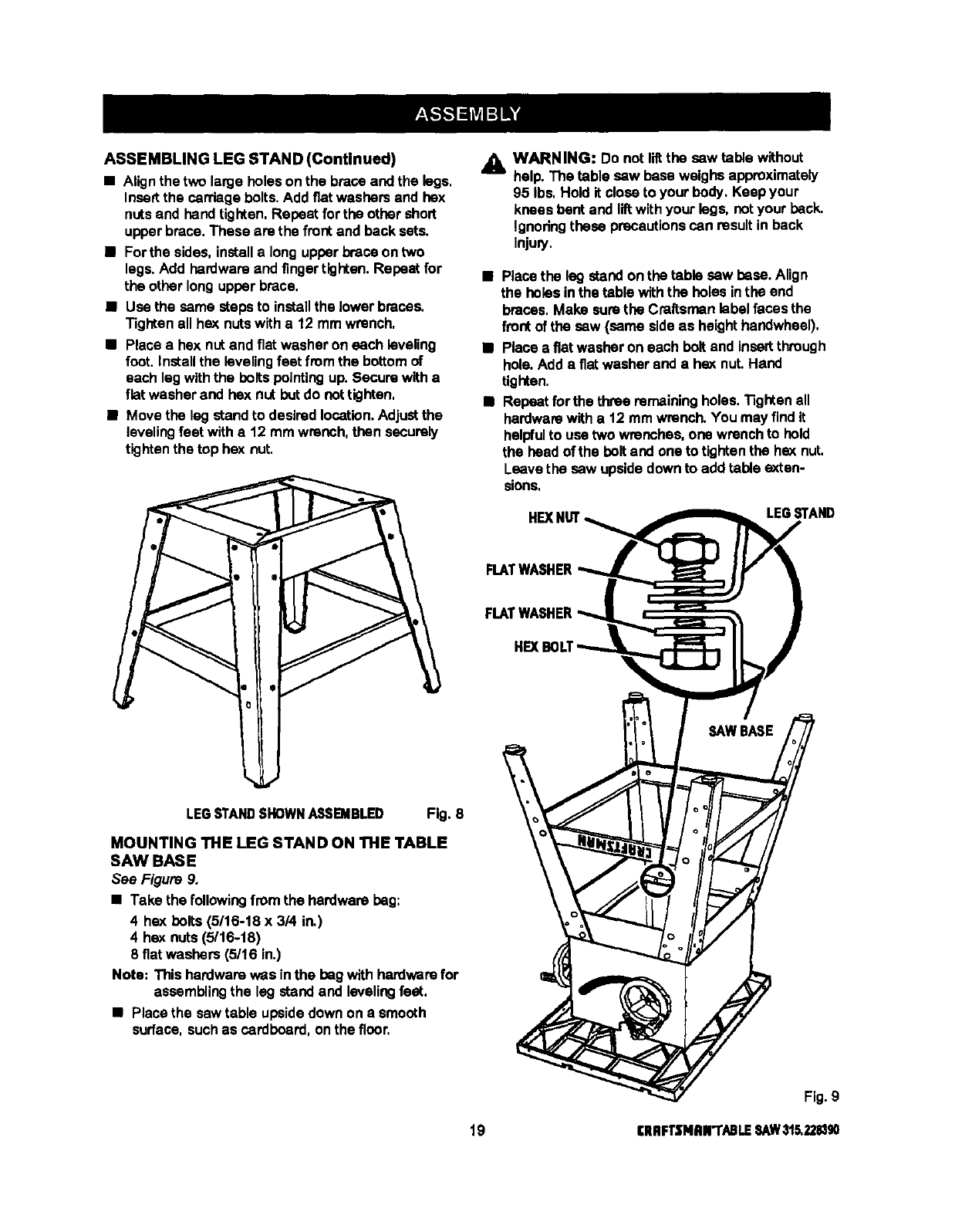
ASSEMBLINGLEGSTAND(Continued)
•Align the two large holeson the braceand the legs,
Insertthe carriagebolts,Add fiat washers and hex
nutsand hand tighten, Repeat for the other short
upperbrace, These are the frontand beck sets.
•Forthe sides, installa long upperbrace on two
legs.Add hardwareand fingertighten. Repeat for
the other long upper brace.
•Use the same stepsto installthe lower braces,
Tighten all hex nutswith a 12 mm wrench,
•Place a hex nutand flat washer on each leveling
foot, Installthe leveling feet fromthe bottomof
each leg withthe boltspointingup. Secure witha
flit washer and hex nut butdo nottighten,
•Move the leg standto desiredlocation.Adjustthe
levelingfeet witha 12 mmwrench, then securely
tightenthe top hex nut,
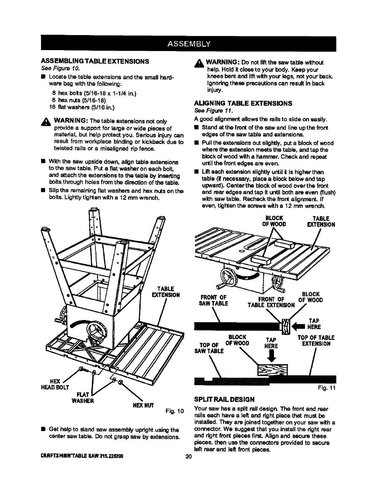
_. WARNING: Do not liltthe sew table without
help. The table saw base weighs approximately
95 Ibs. Hold it closeto your body. Keep your
knees bent and liftwith your legs, not your beck.
Ignoringthese precautionscan result in beck
Injury,
•Place the leg standon the table saw base. Align
the holes inthe table withthe holes inthe end
braces, Make surethe Craftsman libel faces the
frontof the saw (same sideas heighthandwheel),
•Place a fiat washer on each bolt and insertthrough
hole.Add a fiat washer and a hex nut. Hand
tighten.
•Repeatfor the three remainingholes. Tighten all
hardwarawith a t2 mm wrench.You may find it
helpfulto use two wrenches, one wrenchto hold
the head of the bolt and one to tightenthe hex nut.
Leave the sew upsidedownto add table exten-
sions,
LEG STAND
FLATWASHER
HEX
LEGSTANDSHOWNA,.%qBIBLED Fig. 8
MOUNTING THE LEG STAND ON THE TABLE
SAW BASE
See Figure 9.
•Take the followingfromthe hardware bag:
4 hex bolts(5/16-18 x 3/4 in.)
4 hex nuts(5'16-18)
8 fiat washers (5116in.)
Note: This herdwam was inthe beg with hardwarefor
assemblingthe leg standand levelingfeat.
•Place the sawtable upside down on a smooth
surface,suchas cardboard, onthe floor,
19
SAWBASE
Fig.9
CRRFTSNNFI'ABLESAW315.221B90
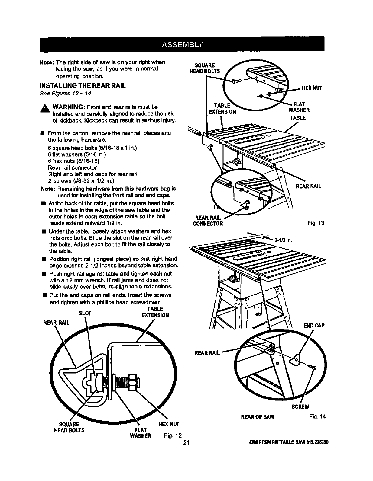
ASSEMBLINGTABLEEXTENSIONS
See Figure 10.
• Locate the table extensionsand the small herd-
ware bag withthe following:
8 hex bolts (5/16-18 x 1-1/4 in.)
8 hex nuts (5/16-18)
16 fiat washers (5/16 in.)
,_k WARNING: The table extensionsnot only
provideasupportfor kirge or wLdepieces of
material, but help protectyou. Serious injurycan
result from workpieca bindingor kickback due to
twisted roils or a misalignedrip fence.
•With the saw upside down, aligntable extensions
to the saw table. PUt a fiat washer on each bolt,
and attachthe extensionsto the table by inserting
boilsthrough holes from the directionof the table.
•Slip the remainingflat washers and hex nutson the
bolts.Lightlytightenwith a 12 mm wrench.
j_ WARNING: Do notliftthe saw table without
help. Hold it close to your body, Keep your
knees bent and liftwithyour lags, notyour back.
Ignodngthese precautionscan result in back
injury.
ALIGNING TABLE EXTENSIONS
See Figure 11.
A good alignment allowsthe roilsto slide on easily.
•Stand at the front of the saw and line upthe front
edges of the sew table and extensions.
•Pull the extensionsoutslightly,put a block of wood
wherethe extensionmeats the table, and tap the
blockof wood with a hemmer. Check and repeat
untilthe frontedges are even.
•Lifteach extensionslightlyuntilit is higherthan
table (if necessary,piaca a block belowand tap
upward). Center the blockof wood over the front
and rearedges and tap it until bothare even (flush)
with sew table. Recheck the front alignment,If
even, tightenthe screwswith a 12 mm wrench,
BLOCK TABLE
OFWOOD EXTENSION
TABLE
EXTENSION FRONT OF FRONT OF
SAW TABLE TABLE EXTENSION
\
BLOCK
OF WOOD
TAP
HERE
BLOCK TAP TOP OF TABLE
TOP OF OFWOOD HERE EXTENSION
SAW TABLE
HE)(
HEADBOLT
FLAT
WASHER HEXNUT Fig.10
•Get help to stand saw assembly uprightusingthe
centersaw tabte, Do notgrasp saw by extensions.
rRRFTSNRN*'rABLESAW315.22s_Igo
SPLIT RAIL DESIGN
Your saw has a split rail design. The front and rear
roilseach have aleft and rightpiece that must be
installed.They are joined together on your saw witha
connector.We suggestthat you installthe right roar
and rightfront piecesfirst. Align and secure these
pieces, then use the connectors providedto secure
left rear and left front pieces,
20
Note: The right side of saw is on your dght when
facing the saw, as if you were in normal
operating position,
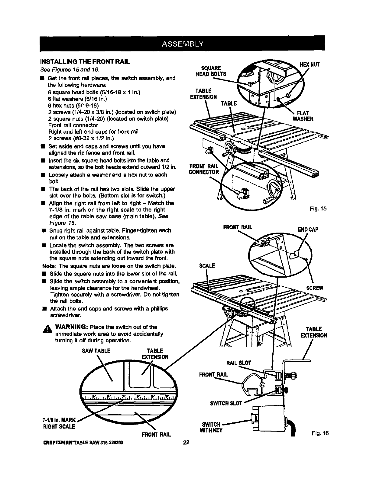
INSTALLING THE REAR RAIL
See Figures 12- 14.
_k WARNING: Frontand rear rails must be
installedand carefully aligned to reducethe risk
of kickback, Kickback can result in serious injury.
•From the carton, removethe mar rail pieces and
the followinghardware:
6 squarehead bolts(5/16-18 x I in,)
6 fiat washers(5/16 in,)
6 hex nuts (5/16-18)
Rear rail connector
Rightand left end caps for rear rail
2screws (#8-32 x 112in.)
Note: Remaininghardware from this hardware beg is
usedfor installingthe front rail and end caps.
•At the back of the table, putthe square head bolts
inthe holes inthe edge of the saw table and the
outer holes in each extensiontable so the bolt
heads extend outward112in.
•Under the table, looselyattach washers and hex
nutsonto bolts.Slide the sloton the rear rail over
the bolts.Adjusteach bolt to fit the rail closelyto
the table.
•Position rightrail (longestpiece) so that righthand
edge extends 2-1/2 inches beyondtable extension.
•Push right rail against table and tighteneach nut
with a 12 mm wrench. If rail jams and does not
slide easily over bolts, re-align table extensions.
•Put the end caps on rail ends. Insert the screws
and tighten witha phillipshead screwdriver.
TABLE
SLOT EXTENSION
REARRAIL
SQUARE
HEADBOLTS
REAR RAIL
CONNECTOR
WASHER
TABLE
REARRAIL
Fig. 13
ENDCAP
SQUARE HE)(NUT
HEADBOLTS FLAT
WASHER Fig, 12 21
SCREW
REAROFSAW Fig. 14
CRRFTSMRN'I"ABLESAW31_2283S0
INSTALLING THE FRONT RAIL
See Figures 15and 16.
•Get the front rail pieces, the switchassembly, and
the following hardware:
6 square head bolts(5/16-18 x 1 in.)
6flat washers (5/16 in.)
6 hex nuts(5/16-18)
2screws (1/4-20 x 3/8 in.) (located on switch plate)
2 square nuts (1/4-20) (located on switch plate)
Front rail connector
Rightand left end caps for front rail
2 screws (#8-32 x 112in.)
•Set aside end caps and screws untilyou have
alignedthe ripfence and front rail.
•Insertthe s_ squarehead boltsintothe tableand
extensions,so the boltheadsextend outward112in.
•Looselyattach a washer and a hex nutto each
bolt.
•The back of the rail has two slots. Slide the upper
slot over the bolts. (Bottom slot is for switch.)
•Align the dght rail from left to dght - Match the
7-1/8 in. mark on the right scale to the right
edge of the table saw base (main table). See
Figure 16.
•Snug rightrail against table. Finger-tighteneach
nuton the table and extensions.
• Locate the switchassembly. The two screws are
installedthroughthe back of the switch platewith
the square nutsextending out toward the front.
Note: The square nuts am loose on the switch plate.
•Slide the square nutsinto the lower slotof the rail.
•Slide the switchassembly to a convenient position,
leavingample clearance for the hendwheel.
Tighten securely with a screwdriver.Do nottighten
the rail bolts.
•Attachthe and caps and screws witha phillips
screwd dver.
WARNING: Place the switchout of the
immediate work area to avoid accidentally
turningit off dudng operation.
SAWTABLE TABLE
EXTENSION
SQUARE
HEADBOLTS
TABLE
EXTENSION
FRONT
CONNECTOR
FRONTRAIL
SCALE
RAILSLOT
FRONTRAIL
HEXNUT
FLAT
WASHER
Fig.15
ENDCAP
SCREW
TABLE
EXTEI_ON
SWITCHSLOT
RIGHTSCALE
ERRFTSMRN"i'ABLESAW315.22.8390
FRONTRAIL WITHKEY
22
Fig. 16
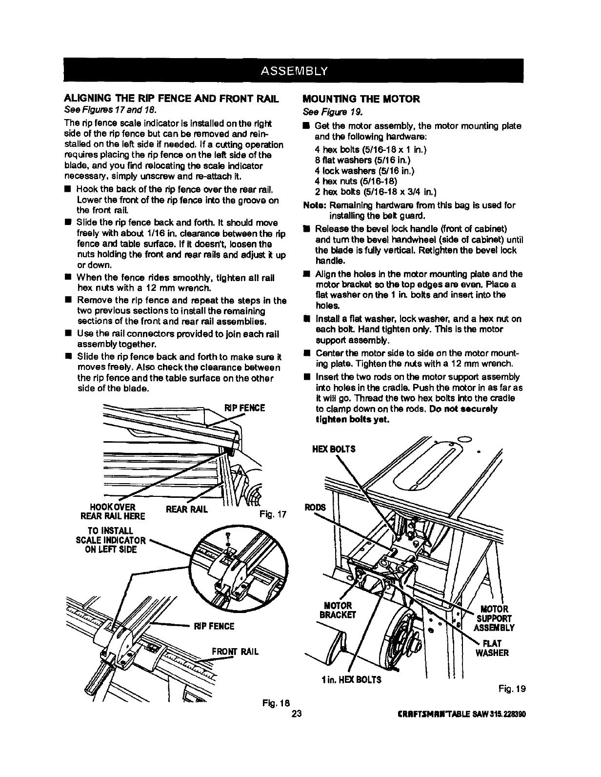
ALIGNINGTHERIPFENCEANDFRONTRAIL
See Figures 17and 18.
The ripfence scale indicatoris installedon the dght
side of the dp fence but can be removed and rein-
stalledon the leftside if needed. If a cuttingoperation
requiresplacing the dp fence on the left sideof the
blade, and you find relocatingthe scale indicator
necessary, simply unscrewand ra-attach it,
•Hook the back of the rip fence over the rear rail.
Lowerthe front ofthe ripfence intothe grooveon
the front rail.
•Slide the rip fence back and forth. It shouldmove
freely withabout t/16 in. clearance betweenthe rip
fence and table surface. If it doesn't, loosenthe
nuts holdingthe front and rear rails and adjust it up
or down.
•When the fence ddas smoothly, tighten all rail
hex nuts with a 12 mm wrench.
•Remove the rip fence and repeat the steps in the
two previous sections to install the remaining
sections of the front and rear rail assemblies.
•Use the rail connectors providedto join each rail
assembly togather.
•Slide the rip fence back and forth to make sure it
moves freely. Also check the clearance between
the rip fence and the table surface on the other
side of the blade.
HOOKOVER REARRAIL
REARRAILHERE
TO INSTALL
SCALEINDICATOR
ONLEFTSIDE
RIPFENCE
Fig. 17
MOUN_NGTHE MOTOR
See Figure 19.
•Get the motorassembly, the motor mountingplate
and the following hardware:
4hex bolts (5/16-18 x 1 in.)
8 fiat washers (5/16 in.)
4 lockwashers (5/16 in.)
4hex nuts (5/16-18)
2 hex bolts (5/16-t8 x3/4 in.)
Nota: Remaininghardwarefrom this bag is usedfor
installingthe belt guard.
•Release the bevel lockhandle (frontof cabinet)
and turn the bevel hendwheal (side of cabinet) until
the blade isfully vertical. Retightanthe bevel lock
handle.
•Align the holes in the motor mountingplateand the
motorbracket sothe top edges are even. Place a
fiat washer on the 1 in. belts and insertinto the
holes.
•Installa flat washer, Iockwasher, and a hex nut on
each bolt. Hand tighten only.This is the motor
supportassembly.
•Cantarthe motor sideto side on the motor mount-
ing plate. Tighten the nutswith a 12 mm wrench.
•Insertthe two rodson the motor supportassembly
into holes in the cradle. Push the motorinas far as
it will go. Thraad the two hex bolts intothe cradle
to clamp down onthe rods. Do not securely
tighten bolts yet.
HE](BOLTS
RODS
RIPFENCE
MOTOR MOTOR
BRACKET
ASSB_BLY
FRONTRAIL WASHER
I in. HE]( BOLTS Fig. 19
Fig. 18 23 CRRFT.t'NRR'I'ABLESAW315.228390
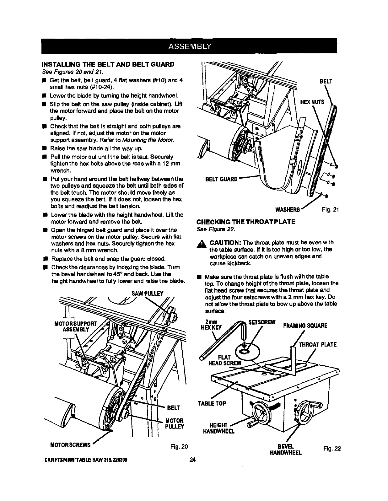
INSTALLING THE BELT AND BELT GUARD
See Figures 20 and 21.
•Get the bolt,bolt guard, 4 fiat washers (#10) and 4
small hex nuts (#10-24).
•Lower the blade byturningthe height handwheel,
•Slip the bolt on the sew pulley (insidecabinet). Lift
the motorforwardand placethe bolt on the motor
pulley.
•Checkthat the bolt is straightand both pulleysare
aligned,If not, adjustthe motoron the motor
supportassembly. Referto Mountingthe Motor.
•Raise the sew blade allthe way up.
•Pullthe motorout untilthe beltis taut. Securely
tightenthe hex boltsabove the rodswitha 12 mm
wrench.
•Putyour hand around the bolt halfwaybetweenthe
two pulleys and squeeze the bolt untilboth sidesof
the belttouch.The motor should move freelyas
you squeeze the bolt. If it does not, loosenthe hex
bolts and readjustthe belttension.
•Lower the blade withthe height handwheel.Lilt the
motorforwardand removethe bolt.
•Open the hinged bolt guardand place it overthe
motorscrewson the motor pulley. Secura withflat
washersand hex nuts. Securelytightenthe hex
nutswith a 8 mm wrench.
•Replace the beltand snapthe guardclosed,
•Checkthe clearances by indexingthe blade.Turn
the bevel handwheelto 45* and back.Use the
heighthandwheel to fully lower and raise the blade.
SAWPULLEY
BELT
BEL
WASHERS
CHECKING THE THROAT PLATE
See Figure 22.
Fig.21
_1_ CAUTION: The throat plata must be even with
the table surface. If it is too high ortoo low,the
workplacecan catch on uneven edges and
cause kickback.
•Make surethe throat plata isflush withthe table
top. To change height of the throat plata, loosenthe
flat heed screwthat securesthe throat plate and
adjustthe four setscrewswitha 2 mm hex key. Do
nat allowthe throat plateto bow up abovethe table
surface.
2mm SETSCREW
HEXKEY FRAMINGSQUARE
HROAT PLATE
TABLE TOP
MOTORSCRL_NS
CRRFTJ;NRN"rABLESAW315.2,?.1BS0
MOTOR
PULLEY
Fig. 20
24
HEIGHT
HANDWHEEL
BEVEL
HANDWHEEL Fig.22

INSTALLINGTHEBLADEGUARD
See Figures 23 - 25.
_L WARNING: If the blade is notfully lowered, turn
the heighthandwheelto lowerthe blade to prevent
injury.
• Get the blade guard, the blade guard bracket,and
the followinghardware:
2 hex bolts(5/16-18 x 1/2 in.)
2 lockwashers (5/16 in,)
3 socket head screws (1/4-20 x 3/8 in.)
3 fiat washers (1/4 in.)
•Align the lower end of the blade guard bracketand
the threaded boles of the cradle and insoltthe hex
boltsand lock washers. Securely tightenwitha 12
mmwrench.
•Remove the throat plate, See page34.
•Put the blade guard assembly inplace on the table
top, aligningthe screw holes inthe riving knifeto
the holes inthe bracket. Alignthe hole inthe front
of the rivingknife base withthe screw hole inthe
cradle.
Note: The screw hole is located underthe slotin
back of the throat plate.
•Insert two socket head screws and two flat wash-
ere in the two holes at the backof the rivingknife
base, Securely tighten with a5 mm hex key.
•Insmtthe third socket heed screw and fiat washer
into screw hole in cradle underthroat plate,
Securely tightenwith a 5 mm hex key.
•Raise the blade all the way up.
SOCI_ET
HEADSCREWS
FLAT
WASHER
SOCKET
HEADSCREW
FLAT RIVING
KNIFE
BLADE
O
Fig. 24
BLADE
BLADE
GUARD
BRACKET
_NTI-KICKBACK
PAWLS
LOCK
WASHER
HEX Fig. 25
Fig.23 25 CRAFTSNRr'I'ABLESAW315,2283g0
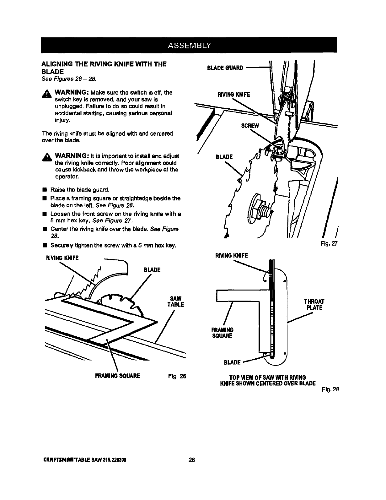
ALIGNING THE RIVING KNIFE WITH THE
BLADE
See Figures 26 - 28.
_1_ WARNING: Make sure the switchis off, the
switch key is removed, and your saw is
unplugged. Failure to do so couldresult in
accidentalstarting, causingsedous personal
injury,
The rivingknife must be alignedwith and centered
over the blade.
,_ WARNING: It is importantto installand adjust
the rivingknifecorrectly. Poor alignment could
cause kickbackand throw the workpieceat the
operator.
•Raise the blade guard,
•Place a framing square or straightedgebeside the
blade on the left. See Figure 26.
•Loosen the front screw on the riving knife with a
5 mm hex key. See Figure 27.
•Centarthe rivingknifeover the blade. See Figure
28.
•Securelytightenthe screw witha 5 mm bex key.
RIVINGKNIFE
BLADE
SAW
TABLE
FRAMINGSQUARE Fig, 26
BLADE GUARD
RIVINGKNIFE
BLADE
RIVINGKNIFE
I/
FRAMING
SQUARE
BLADEf
THROAT
PLATE
J
TOP MEW OF SAW WITH RIVING
KNIFESHOWNCENTEREDOVER BLADE
/
Fig,27
Fig.28
ICRRFTSNRR'TABLESAW315.228390 26
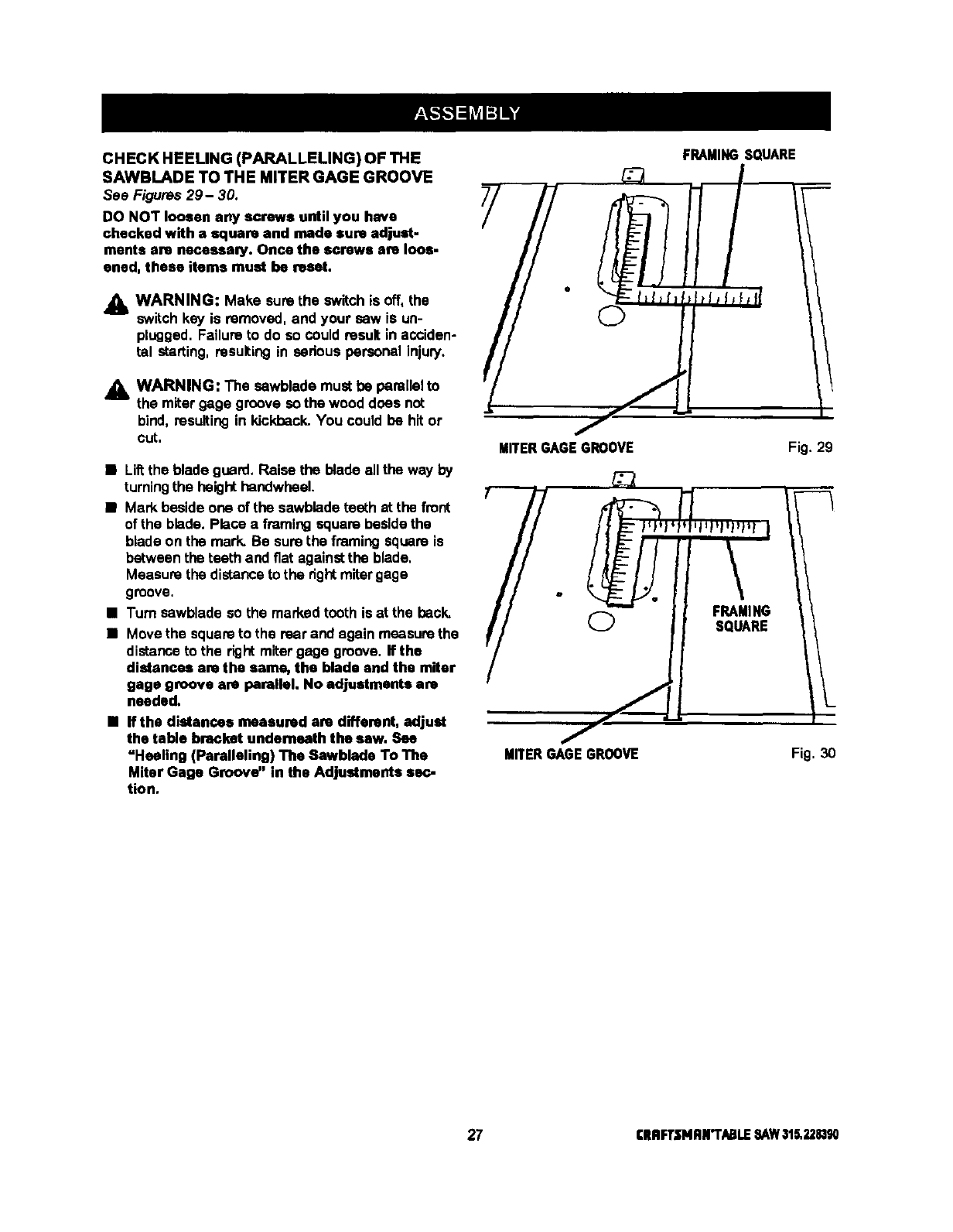
CHECK HEELING (PARALLELING) OF THE
SAWBLADE TO THE MITER GAGE GROOVE
See Figures 29- 30.
DO NOT loosen any screws until you have
checked with a square and rode sure adjust-
ments are neceeaa_y. Once the screws are loos-
ened, these items must be reset.
Jl_ WARNING: Make surethe switchis off, the
switch key is removed, and your saw is un-
plugged. Failure to do so couldresult in acciden-
tal starting, resulting in serious personal injury.
AWARNING: The sawblade must be parallelto
the miter gage groove so the wood does not
bind, resultingin kickback. You could be hit or
cut.
•Liftthe blade guard. Raise the blade all the way by
turningthe heighthandwbeel.
•Mark beside one of the sawblade teeth at the front
of the blade. Place a framing square beside the
blade on the mark. Be surethe framing square is
between the teeth and fiat againstthe blade,
Measure the distance to the dghtmitergage
groove,
•Turn sawblade so the marked tooth is at the back.
•Move the square to the rear and again measure the
distance to the right miter gage groove. If the
distances are the same, the blade and the miter
gage groove are parallel. No adjustments are
needed.
•If the distances measured are different, adjust
the table bracket underneath the saw. See
"Heeling (Paralleling) The Sawblade To The
Miter Gage Groove" in the Adjustments se_.-
tion,
FRAMINGSQUARE
MITERGAGEGROOVE Fig. 29
MITER GAGE GROOVE Fig. 30
27 CRRFT.IflP4AN"T/_LE SAWalS,2281_
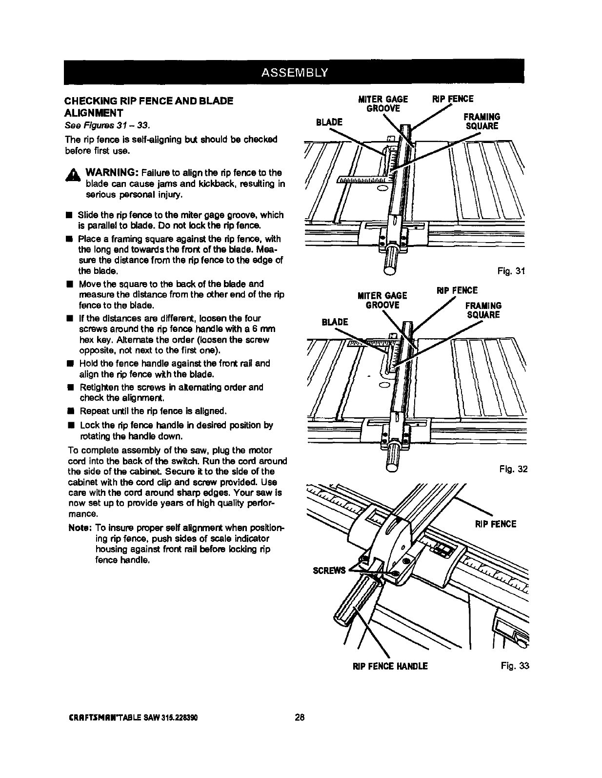
CHECKING RIP FENCE AND BLADE
ALIGNMENT
See Figures 31 -33.
The rip fence is self-aligningbut should be checked
before first use.
•L WARNING: Failure to alignthe dp fence to the
blade can cause jams and kickback, resulting in
sedous personal injury.
•Slide the dp fence to the miter gage groove, which
is parallelto blade. Do not lock the dp fenne.
•Place a framing square against the dpfence, with
the longand towards the front of the blade. Mea-
surethe distancefrom the dpfence to the edge of
the blade,
•Movethe square to the back of the blade and
measurethe distancefrom the otherend of the tip
fence to the blade,
•If the distancesare different, loosenthe four
screwsaround the dpfence handlewith a 6 mm
hex key, Alternatethe order (loosenthe screw
opposite,not next to the first one),
•Holdthe fence handleagainst the fmot rail and
alignthe rip fence withthe blade,
•Retightenthe screws inalternating order and
check the alignment,
•Repeat untilthe dp fence is aligned,
• Lock the rip fence handle in desired positionby
rotating the handle down.
To complete assembly of the saw, plugthe motor
cord into the beck of the switch. Run the cord around
the side of the cabinet. Secure it to the side of the
cabinet with the cord clip and screw provided, Use
care withthe cord around sharp edges, Your sew is
now set upto provide years of high quality perfor-
mance.
Note: To insure properserf alignmentwhen position-
ing dp fence, push skies of scale indicator
housingagainst front rail before lockingdp
fence handle.
BLADE
BLADE
MITERGAGE RIPFENCE
GROO_ _FRAMINGSQUARE
MITERGAGE
GROOVE
Fig. 31
RIPFENCE
FRAMING
SQUARE
Fig. 32
RIPFENCE
RIPFENCEHANDLE Fig. 33
CRIIFTSNRN'TABLESAW315,228390 28
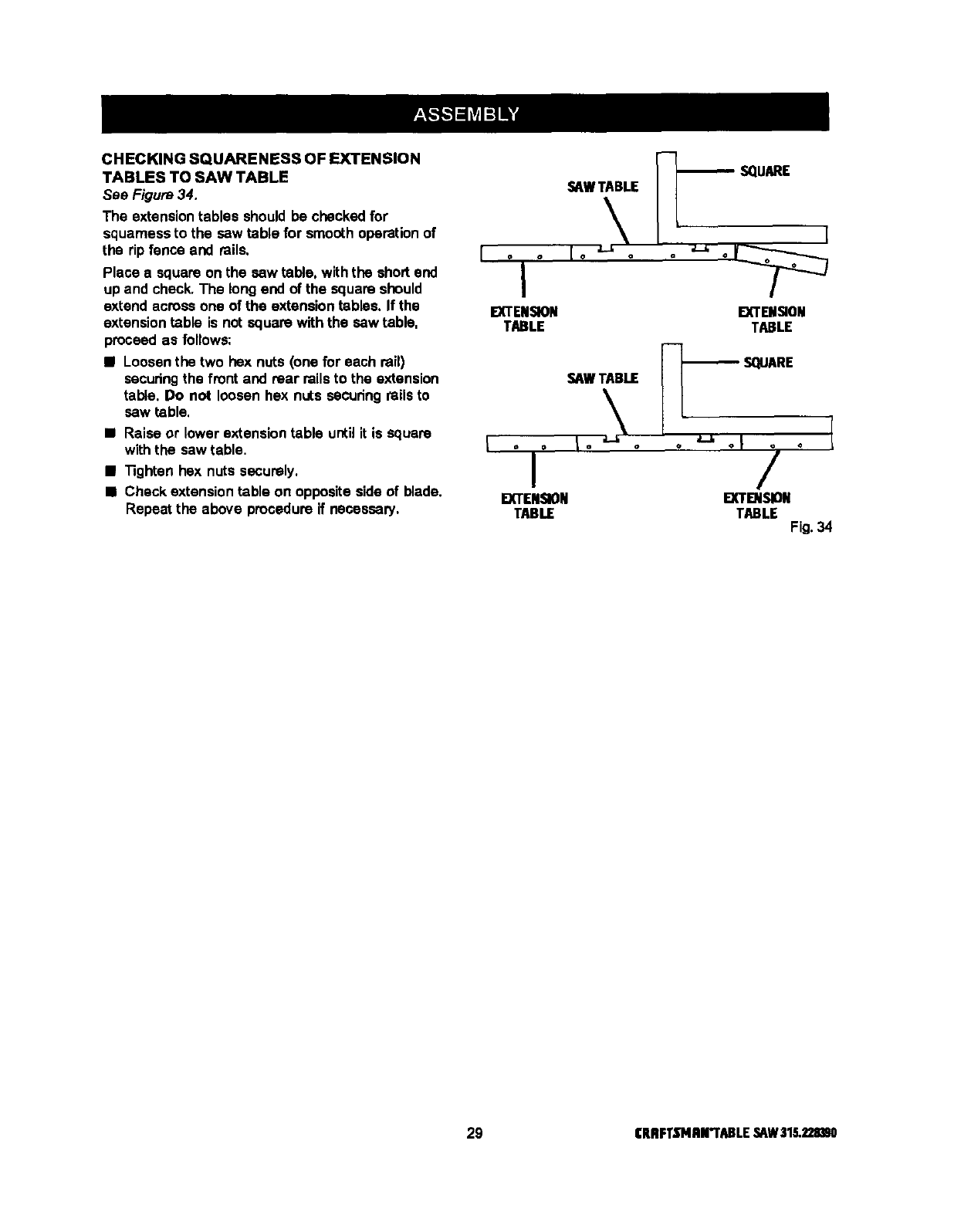
CHECKING SQUARENESS OF EXTENSION
TABLES TO SAW TABLE
See Figure 34.
The extensiontables should be checked for
squamess to the saw table for smooth operationof
the rip fence and rails.
Place a square on the saw table, withthe short end
up and check.The longend of the square should
extend across one of the extension tables. If the
extension table is not square with the saw table.
proceed as follows:
•Loosenthe two hex nuts (one for each rail)
securingthe front and rear rails to the extension
table. Do not loosen hex nuts secudng rails to
saw table,
•Raise or lower extension table until it is square
with the saw table.
•"13ghtenhex nuts securely.
•Check extension table on opposite side of blade.
Repeat the above procedureif necessary.
SAW TABLE
o o
I
EXTENSION
TABLE EXTENSION
TABLE
F-1
SAWTABLE [_'_- SQUARE
II ,-,., I
EXTENSION I_DI,_ON
TABLE TABLE Fig.34
29 CRBFT._'MBrI'ABLE,_W $18.2211_0
To avoid unnecessary setups and adjustments, a
good practice is to check your setupscarefully with a
framing square and make practice cuts in scrapwood
before making finish cuts in good workpieces, Do not
start any adjustments untilyou have checked with a
square and made test cuts to be sureadjustments
are needed,
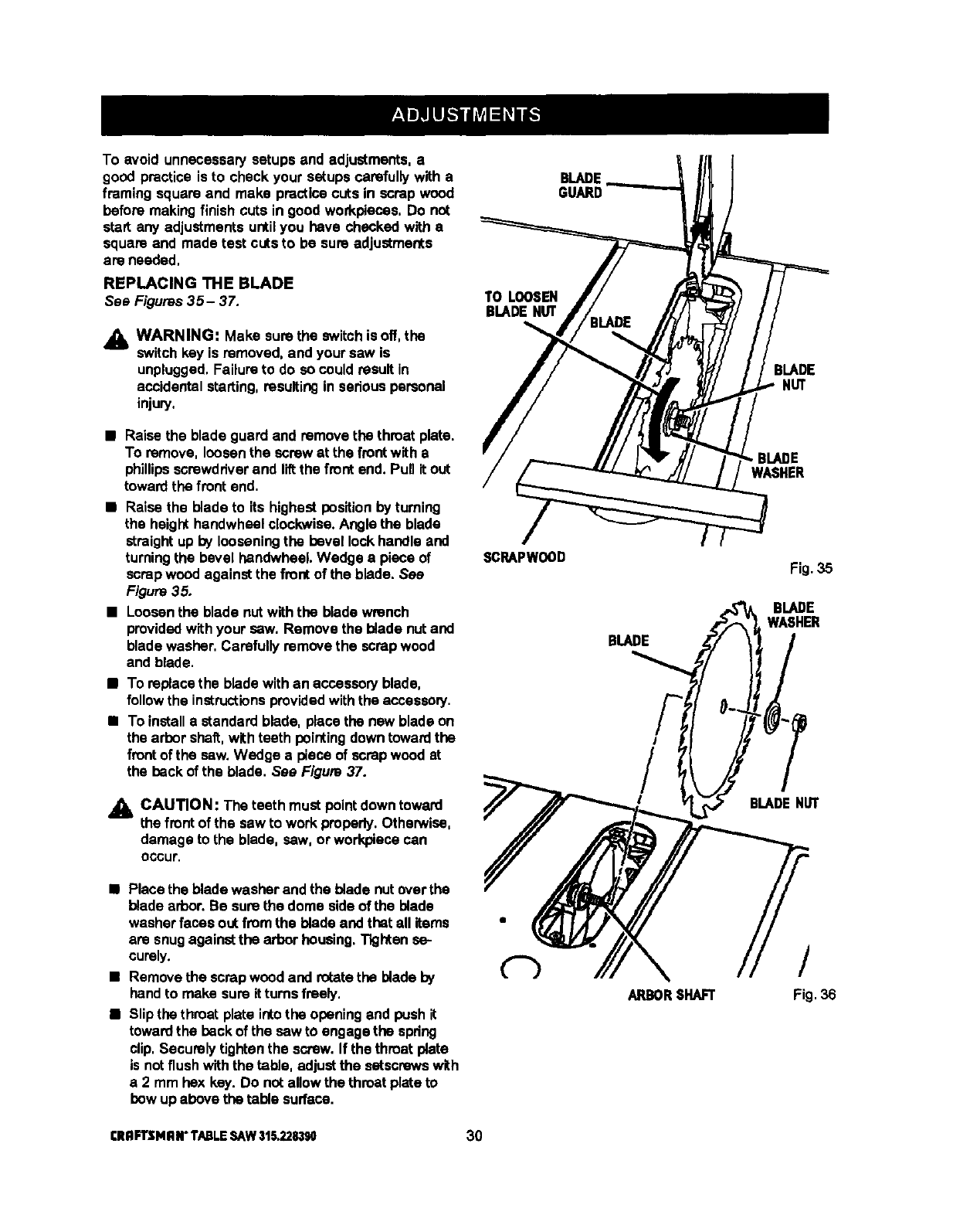
REPLACING THE BLADE
See Figures35- 37.
_lb WARNING: Make sure the switchisoff, the
switchkey is removed, and your saw is
unplugged,Failure to do so couldresult in
accidental starting, resultingin seriouspersonal
injury,
TO LOOSEN
BLADENUT
GUARD
BLADE
NUT
•Raise the blade guard and removethe throat plate.
To remove, loosen the screw at the frontwith a
phillipsscrewdriverand liftthe front end. Punit out
toward the front end.
•Raise the blade to its highest positionby turning
the heighthandwheel clockwise.Angle the blade
straight up by looseningthe bevel lockhandle and
turningthe bevel handwheel. Wedge a piece of
scrapwood against the front of the blade. See
Figure 35.
•Loosenthe blade nutwith the blade wrench
providedwith your saw, Remove the blade nutand
blade washer, Carefully remove the scrap wood
and blade.
•To replace the bladewith an accessoryblade,
followthe instructionsprovidedwith the acceseorj.
•To installa standard blade, place the new blade on
the arbor shaft,with teeth pointingdown towardthe
frontof the saw, Wedge a piece of scrap wood at
the back of the blade. See Figure 37.
•k CAUTION: The teeth must pointdown toward
the front of the saw to work properly.Otherwise,
damage to the blade, sew, or workpiececan
occur.
SGRAPWOOD
BLADE
/
/
!
.BIADE
WASHER
Fig. 35
lBLADENUT
•Place the blade washer and the blade nutover the
blade arbor. Be surethe dome side of the blade
washerfaces outfrom the blade and that all items
are snug againstthe arbor housing.Tighten se-
curely.
•Remove the scrapwood and rotatethe blade by
handto make sureitturns freely,
•Slip the throat plate intothe opening and push it
toward the back of the saw to engage the spring
clip,Securely tightenthe screw. If the throatplate
is notflush withthe table, adjustthe setscrewswith
a2mm hex key. Do not allowthe throat plate to
bow upabove the table surface.
ARBORSHAFT
/
Fig.36
[RRFTSMRN"TABLESAW315.228390 30
SCRAPWOOD BLADEGUARD
3LADE
NUT
BLADE
WASHER
TOTIGHTEN
BLADEHUT Fig.37
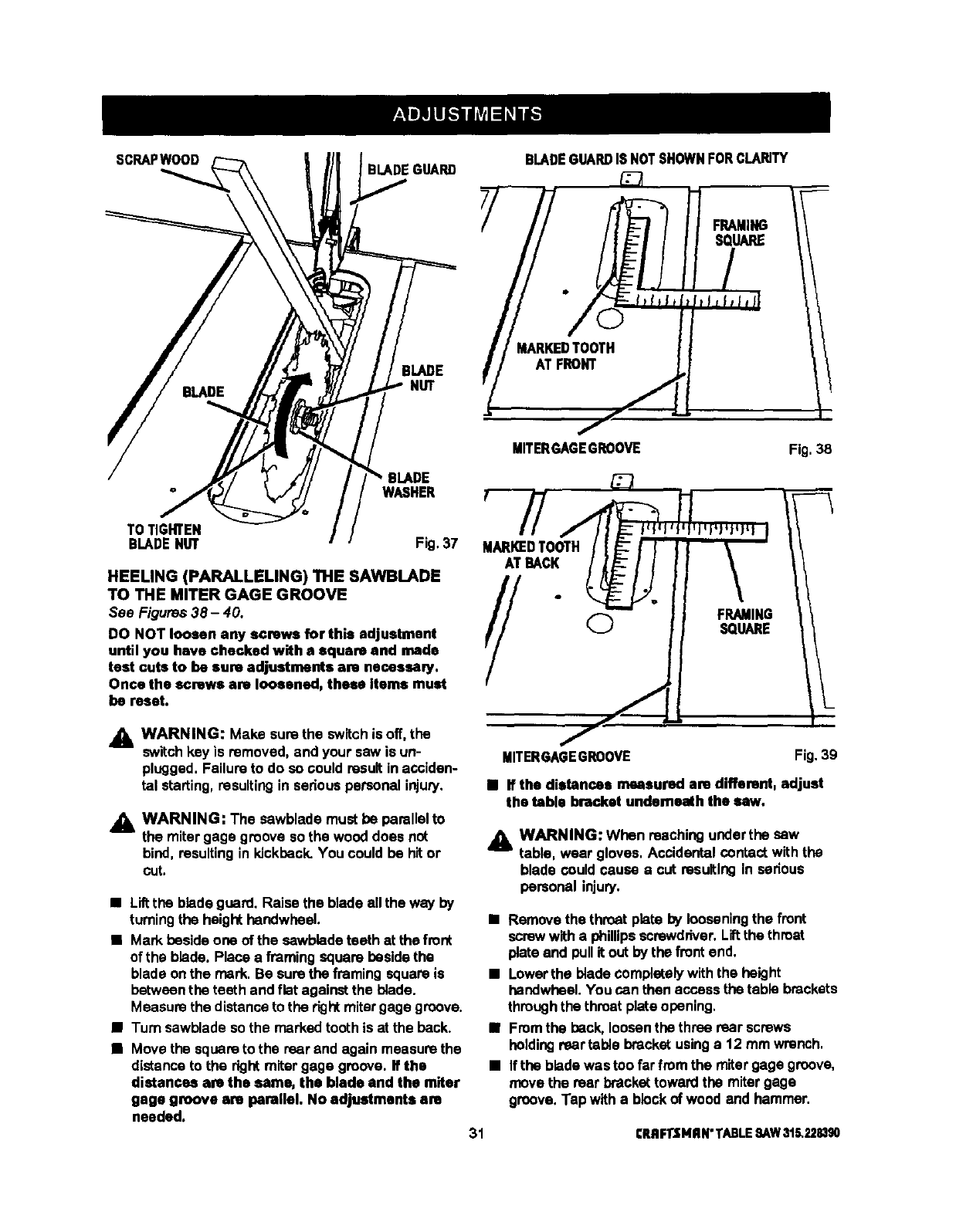
HEELING (PARALLELING) THE SAWlBLADE
TO THE MITER GAGE GROOVE
See Figures 38- 40.
DO NOT loosen any screws for this adjustment
until you have checked with a square and made
test cuts to be sure adjustments am necessmy.
Once the screws are loosened, these Items must
be reset.
BLADEGUARDIS NOTSHOWNFORCLARITY
f
MITERGAGEGROOVE Fig. 38
MARKEDTOOTH
ATBACK
//+
WARNING: Make sure the switchis off, the
switchkey is removed, and your saw is un-
plugged, Failure to do so could resultin acciden-
tal starting, resultingin seriouspersonal injury.
,_ WARNING: The sawblade must be parallelto
the mitergage groove so the wood does not
bind, resulting in kickback,You couldbe hitor
cut.
•Liltthe blade guard. Raise the blade ell the way by
turningthe heighthandwheel.
•Mark besideone of the cawblade teeth at the front
of the blade. Place a framing square besidethe
blade onthe mark. Be surethe framing square is
between the teeth and flat againstthe blade.
Measure the distance to the rightmitergage groove.
•Turn sawblade so the marked tooth is at the back.
•Move the squareto the rear and again measure the
distance to the rightmitergage groove. If the
distances are the same, the blade and the miter
gage groove are parallel. No adjustments am
needed.
MITERGAGEGROOVE Fig.39
• If the distances measured are different, adjust
the table bracket underneath the saw.
j_ WARNING: When reachingunderthe sew
table, wear gloves. Accidental contactwith the
blade could cause a cut resulting in serious
personal injury.
•Removethe throat plate by looseningthe front
screwwitha phillipsscrewdriver,Liftthe throat
plateand pullit out by the frontend,
•Lowerthe blade complatalywith the height
handwheel.You can then access the table brackets
throughthe throat plateopening,
•From the peck, loosenthe three rear screws
holdingrear table bracket usinga 12 mm wrench,
•If the blade was too far from the miter gage groove,
move the rear brackettoward the mitergage
groove, Tap with a blockof wood and hammer.
31 CRRFI"tMRN"TABLE:SAW315.228390
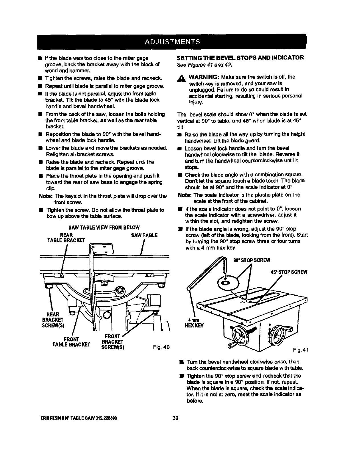
• If the bladewas too close to the miter gage
groove, back the bracket away with the blockof
wood and hammer.
• Tightenthe screws, raise the blade and recheck.
•Repeat untilblade is parallelto mitergage groove,
•If the blade is not parallel, adjustthe front table
bracket. Tilt the blade to 45°with the blade lock
handleand bevel handwheal.
•Fmm the beck of the saw, loosenthe boltsholding
the front table bracket,as well as the reartable
bracket.
•Repositionthe blade to 90°with the bevel hand-
wheel end blade lock handle.
•Lowerthe blade and movethe bracketsas needed,
Retiglten all bracketscrews.
•Raisethe blade and recheck. Repeat untilthe
blade is parallelto the miter gage groove.
•Place the throat plate in the openingand push it
toward the rear of sew base to engage the spring
clip.
Note; The keyslotinthe throat plate willdrop overthe
front screw,
•Tightenthe screw,Do not allowthe throat platato
bow up above the table surface.
SAW TABLE VIEW FROM BELOW
REAR SAWTABLE
TABLEBRACKET /
BRACKET/r'"l I
SCREW(sl/lI7--7 L\
IFRONT/
FRONT BRACKET
TABLEBRACKET SCREW(S) Fig. 40
SETTING THE BEVEL STOPS AND INDICATOR
See Figures 41 and 42.
AWARNING: Make surethe switchis off, the
switchkey is removed,and your sew is
unplugged.Failure to do so could resultin
accidentalstarting, rasuitingin sedous personal
ir_u_.
The bevel scale should show 0°when the blade is set
verticalat 90°to table, and 45°when blade is at 45°
tilt,
•Raise the blade all the way up by turningthe height
handwhsel. Lift the blade guard.
•Loosenbevel lock handleand tam the bevel
handwhselclockwiseto tiltthe blade, Raveme it
and turn the handwheel counterclockwiseuntilit
stops,
•Checkthe bladeangle witha combinationsquare.
Don't letthe square touch a blade tooth, The blade
shouldbe at 90°and the scala indicatorat 0°.
Note: The scale indicatoris the plastic plate on the
scale at the front of the cabinet.
•Ifthe scale indicatordoes notpointto 0°, loosen
the scale indicatorwith a screwdriver,adjust it
withinthe slot, and retightenthe screw.
•If the blade angle Is wrong, adjustthe 90°stop
screw (leftof the blade, lookingfrcm the front),Start
by turningthe 90° stop screw three or four rums
witha 4 mm hex key.
4mm
HEXKEY
90°STOPSCREW
45' STOPSCREW
Fig.41
•Turn the bevel handwheel clockwiseonce, then
beck counterclockwise to square blade withtable.
•Tightenthe 90° stop screw and recheck that the
blade is square in a 90" position.If not, repeat,
When the blade is square, checkthe scala indica-
tor. If it is notat zero, reset the scale indicatoras
before.
CRRFrSNRN"TABLESAW316._83g0 32
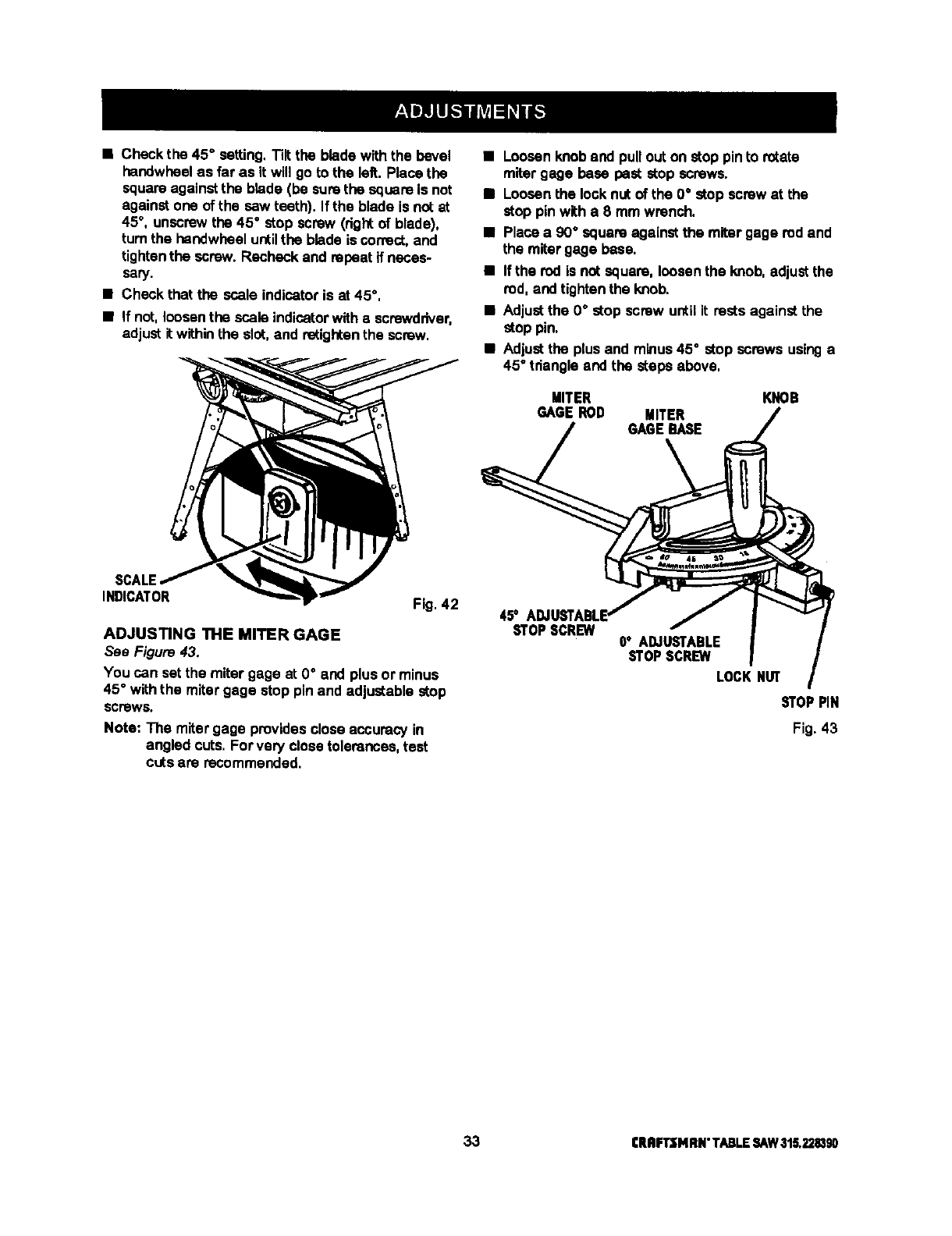
• Check the 45°setting.Tilt the blade with the bevel
handwheel as far as it will go to the left. Place the
square againstthe blade (be surethe square is not
against one of the saw teeth). If the blade is not at
45°, unscrewthe 45 °stop screw (dght of blade),
turnthe hendwheel untilthe blade is correct,and
tightenthe screw. Recheck and repeat if neces-
seW.
• Check that the scale indicatoris at 45°,
•If not, loosenthe scale indicatorwith a screwdriver,
adjust it withinthe slot, and retightenthe screw.
•Loosenknob and pull outon stop pinto rotate
miter gage base pest stop screws.
• Loosenthe lock nut of the 0°stop screw at the
stop pin with a 8 mm wrench.
•Place a 90" square against the miter gage rod and
the mitergage base.
•If the rod is not square, loosenthe knob, adjustthe
rod, and tightenthe knob.
•Adjustthe 0°stop screw until it rests against the
stop pin.
•Adjustthe plus and minus45°stop screws usinga
45°tdangle and the steps above,
MITER
GAGEROD MITER
GAGEBASE
KNOB
SCALE
INDICATOR Fig, 42
ADJUSTING THE MITER GAGE
See Figure 43.
You can setthe miter gage at 0°and plus or minus
45°withthe mitergage stop pin and adjustable stop
SCreWS,
Note: The mitergage provides closeaccuracy in
angled cuts. For very closetolerances, test
cuts are recommended.
45'
STOPSCREW 0°ADJUSTABLE
STOPSCREW
LOCKNUT
STOPPIN
Fig. 43
33 CRflFTSMRN"TABLESAW316.228390
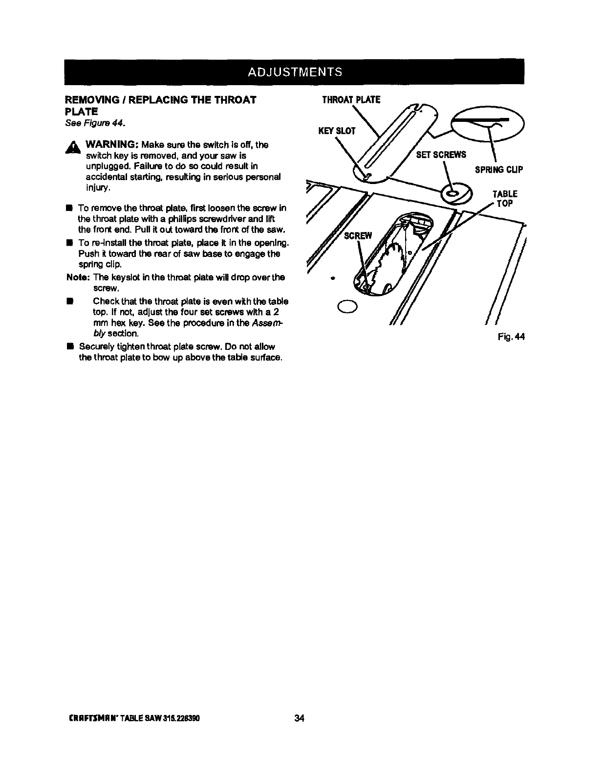
REMOVING IREPLACING THE THROAT
PLATE
See Figure 44.
_k WARNING: Make surethe switchis off, the
switchkey is removed,and your saw is
unplugged.Failure to do so could result in
accidental starting,resultingin sadous personal
injury.
•To remove the throat plata, first loosenthe screw in
the throat platewith a phillipsscrewdriver and lift
the front end. Pull it outtoward the frontof the saw.
•To re-installthe throat plate, place it in the opening.
Push it toward the rear of saw base to engage the
springclip.
Note: The keyslot inthe throat plata will drop overthe
screW.
•Check that the throat plate is even withthe table
top. If not, adjustthe four sat screws witha 2
mm hex key.See the procedureinthe Assam-
b/y section.
•Securelytightenthmat plata screw. Do notallow
the throat plateto bow up above the table surface.
THROATPLATE
KEYSLOT
SPRINGCUP
TABLE
Fig.44
CRRFI"SHHN"TABLESAW31S.2283gO 34
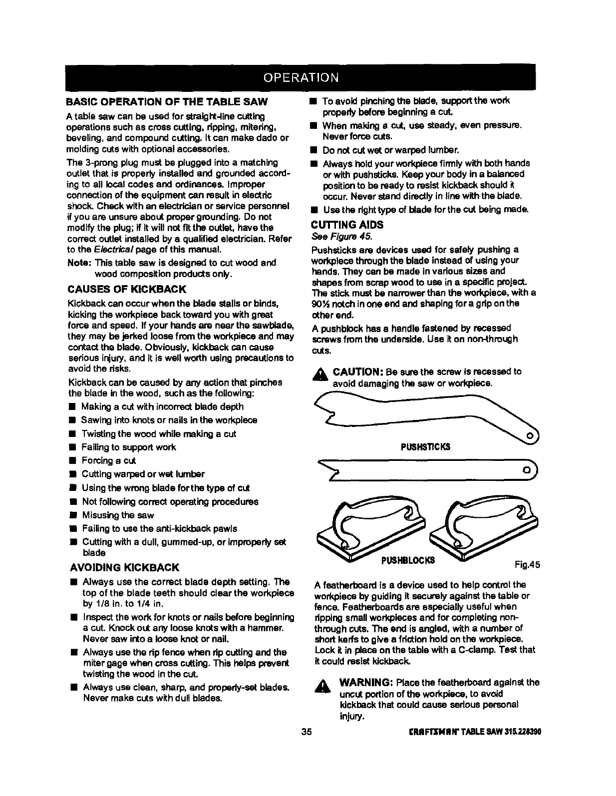
BASIC OPERATION OF THE TABLE SAW
A table sew can be used for straight-linecutting
operationssuchas crosscutting, dpping, mitadng,
beveling,and compoundcutting.It can make dado or
moldingcutswith optionalaccessories.
The 3-prong plugmust be pluggedinto a matching
outlet that is properlyinstalled and grounded accord-
ing to all local codes and ordinances. Improper
connectionof the equipment can resultin electdc
shock. Check with an electdcian or servicepersonnel
if you are unsureabout propergrounding.Do not
modifythe plug;if it will notfit the outlet,have the
correct outlet installedby a qualified electrician.Refer
to the Electrical page of this manual.
Note; This table sew is designed to cut wood and
wood compositionproductsonly,
CAUSES OF KICKBACK
Kickbackcan occurwhen the blade stallsor binds,
kickingthe workplace back toward you with great
force and speed. If your hands are near the sewblade,
they may be jerked loosefrom the workplaceand may
contactthe blade. Obviously,kickbackcan cause
sedous injury,and it is well worth usingprecautionsto
avoid the risks.
Kickbackcan be caused by any actionthat pinches
the blade in the wood, such as the following:
•Making a cutwith incorrectblade depth
•Sawing into knotsor nails in the workplace
•Twistingthe wood while making acut
•Failingto supportwork
•Forcingacut
•Cuttingwarped or wet lumber
•Usingthe wrong blade for tho type of cut
•Not following correct operatingprocedures
•Misusingthe saw
•Failingto use the anti-kickback pawls
•Cuttingwith a dull, gummed-up,or impmpodyset
blade
AVOIDING KICKBACK
•Always use the correct blade depth setting, The
top of the blade teeth should clear the workpiece
by 1/8 in. to 114 in.
•Inspectthe work for knotsor nails before beginning
a cut, Knockout any loose knotswith a hammer.
Never sew ictoa loose knotor nail.
•Alwaysuse the dp fence when dp cutting and the
mitergage when crosscutting.This helps prevent
twistingthe wood inthe cut.
•Alwaysuse clean, sharp, and propsdy-satblades.
Never make cuts withdull blades.
•To avoid pinchingthe blade, supportthe work
properlybefore beginninga cut.
•When makingacut, use steady, even pressure.
Never forcecuts.
•Do notcutwet orwarpsd lumbar.
•Always hold your workpiesefin'nlywith beth hands
or withpushstioks,Keep your body in a balanced
position to be readyto resist kickbackshouldit
occur.Never standdirectlyin line withthe blade.
•Use the dghttype of blade for the cut being made,
CUTTING AIDS
See Figure 45.
Pushsticksare devices used for safely pushinga
workplacethroughthe blade instead of usingyour
hands,They can be made in vadous sizes and
shapesfrom scrapwood to use ina specific project.
The stickmust be nanmwarthanthe workpieca,with a
90'A notchinone endand shapingfora gdp onthe
other end.
A pushblockhas e handlefastened by recessed
screws fromthe underside. Use it on non-through
CutS,
ACAUTION: Be surethe screw is recessedto
avoid damaging the sew orworkplace.
PLI6HSTICKS
A feather'boardis adevice used to help controlthe
workplaceby guidingit securelyagainst the table or
fence. Featherboardsare especiallyusefulwhen
dpping smallwodqolecesand for completingnon-
throughcuts. The end is angled, with a numberof
short kerfsto give a frictionhold onthe workpiese,
Lock it in place on the table witha C-clamp. Test that
it could resistkickback.
&
35
WARNING: Place the featherboardagainst the
uncut portionof the workplace,to avoid
kickback that could cause sedous personal
injury.
rRIIFIrSHIIN"T/L,BLESAW31_228,190
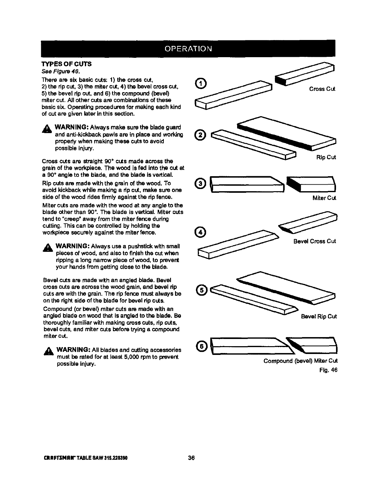
TYPESOFCUTS
See Figure 46.
There are six basic cuts: 1) the cress cut,
2) the rip cut, 3) the mitercut, 4) the bevel cresscut,
5) the bevel dp cut,and 6) the compound(bevel)
miter cut, AJIother cuts are combinationsof these
basic six. Operating proceduresfor making each kind
of cut are given later inthis section,
_, WARNING: Always make surethe blade guard _,t._.._=_ _.._
and anti-kickbackpawls are in place and working IzJ
properlywhen making these cuts to avoid v
possibleinjury.
Cross cuts are straight90°cuts made across the Rip Cut
grain of the workpiece, The wood is fed into the cut at
a 90°angle to the blade, and the blade is vertical.
Rip cuts are made with the grain of the wood. To
avoid kickback while making a dp cut, make sure one
sideof the wood ridesfirmly against the dp fence.
Miter cuts are made withthe wood at any angle to the
blade other than 90°.The blade is vertical. Miter cuts
tendto _creep" away from the miterfence during
cutting.This can be controlledby holdingthe
work.piecesecurelyagainst the miterfence,
_. WARNING: Always use a pushstickwith small
piecesof wood, and also to finishthe cut when
rippinga long narrow piece of wood, to prevent
your handsfrom getting closeto the blade.
®
Miter Cut
o
Bevel Cross Cut
Bevel cuts are made withan angled blade. Bevel
crosscuts are acrossthe wood grain, and bevel rip
cutsare withthe grain. The rip fence must always be
on the rightsideof the blade for bevel dp cuts.
Compound (or bevel) miter cuts are made with an
angled blade on wood that is angled to the blade. Be
thoroughlyfamiliar with making cress cuts, rip cuts,
bevel cuts,and miter cuts before tryingacompound
mitercut,
_IL WARNING: All blades and cuttingaccessories
must be rated for at least 5,000 rpmto prevent
possibleinjury.
Bevel Rip CUt
Compound (bevel) Miter CUt
Fig, 46
CRRFTSNRII"TABLESAW315.228390 36
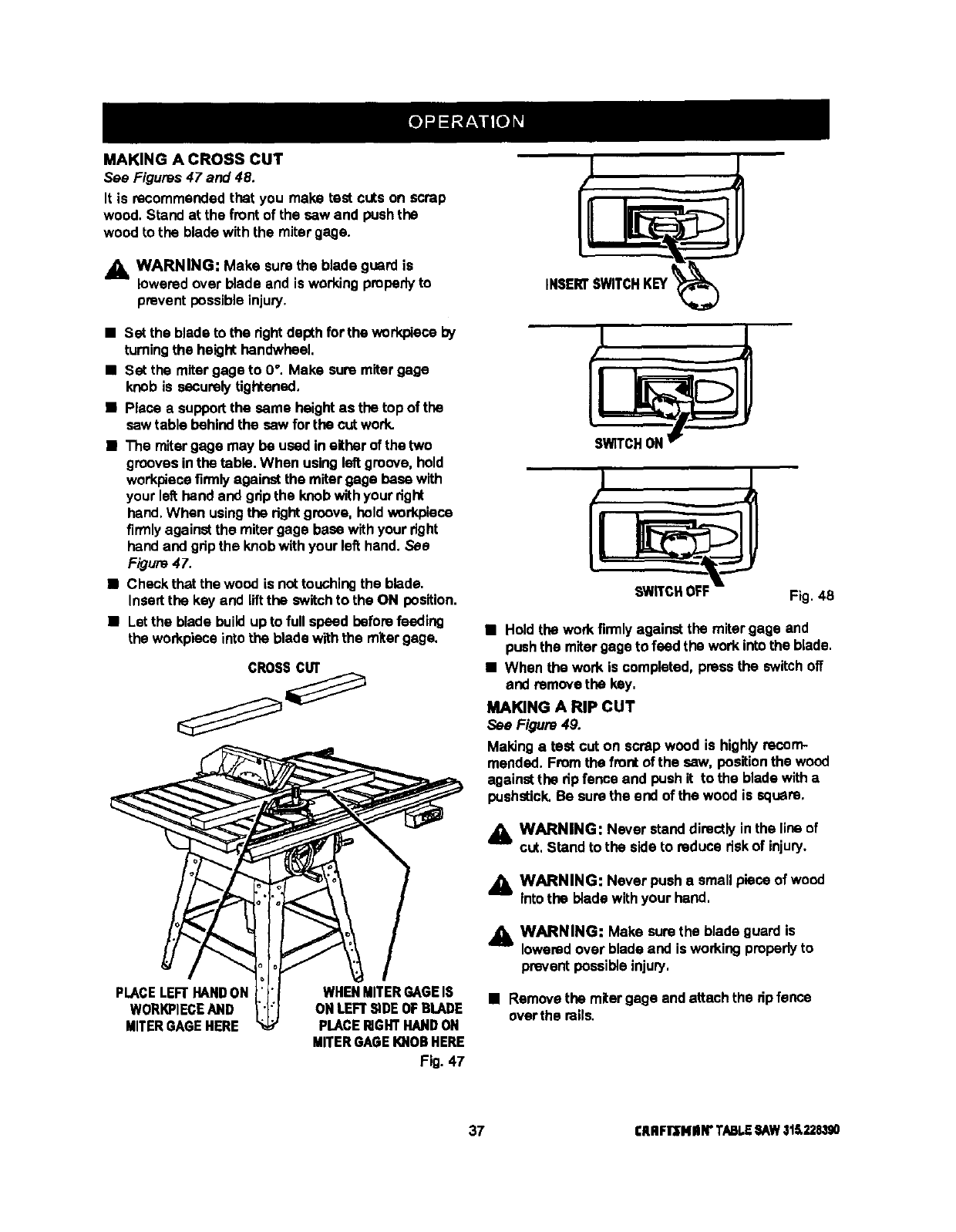
MAKING A CROSS CUT
See Figures 47 and 48.
It is recommendedthat you make test cuts on scrap
wood. Stand at the front of the saw and pushthe
wood to the blade with the miter gage.
_lb WARNING: Make sure the blade guard is
loweredover blade and is working properlyto
prevent possibleinjury.
•Set the blade to the dghtdepth for the wod<pleceby
tumingthe height handwheel.
•Set the mitergage to 0°. Make sum mitergage
knob is securelytightened.
•Place a supportthe same heightas the topof the
sawtable behind the saw for the cut work.
•The mitergage may be used in either of the two
groovesinthe table. When usingleft groove, hold
workpiecefirmlyagainst the mitergage base with
your left:hand and gdp the knobwithyour right
hand,When usingthe rightgroove, holdworkpiece
firmlyagainst the miter gage base withyour right
hand and gripthe knobwithyour left hand. See
F/gum 47.
•Check that the wood is nottouchingthe blade.
Insertthe key and liftthe switchto the ON position.
•Letthe blade buildupto full speed before feeding
the workpieceinto the blade withthe miter gage.
CROSScur
PLACELEFTHAND ON
WORKPIECEAND
MITER GAGE HERE
WHEN MITER GAGE IS
ON LEFT SiDE OF BLADE
PLACERIGHTHAND ON
MITERGAGE IOiOR HERE
Fig. 47
SWITCHOFF Fig. 48
•Hold the work firmlyagainst the miter gage and
pushthe mitergageto feed the workintothe blade.
•When the work is completed, press the switch off
and removethe key,
MAKING A RIP CUT
See Figure 49.
Maldnga test cut on scrapwood is highly recom-
mended. From the front of the saw, positionthe wood
against the dp fence and pushit to the blade witha
pushstick, Be sum the end of the wood is square.
_lb WARNING: Never standdirectly inthe line of
cut, Stand to the side to reducedskof injury.
_1_ WARNING: Never push a small piece of wood
Into the blade withyour hand.
,d_ WARNING: Make surethe blade guard is
loweredover blade and is working properlyto
prevent possible injury,
•Removethe mitergage andattach the dpfence
overthe roils.
37 CRRFlr'SNIIN"TABLESAW31S.228390
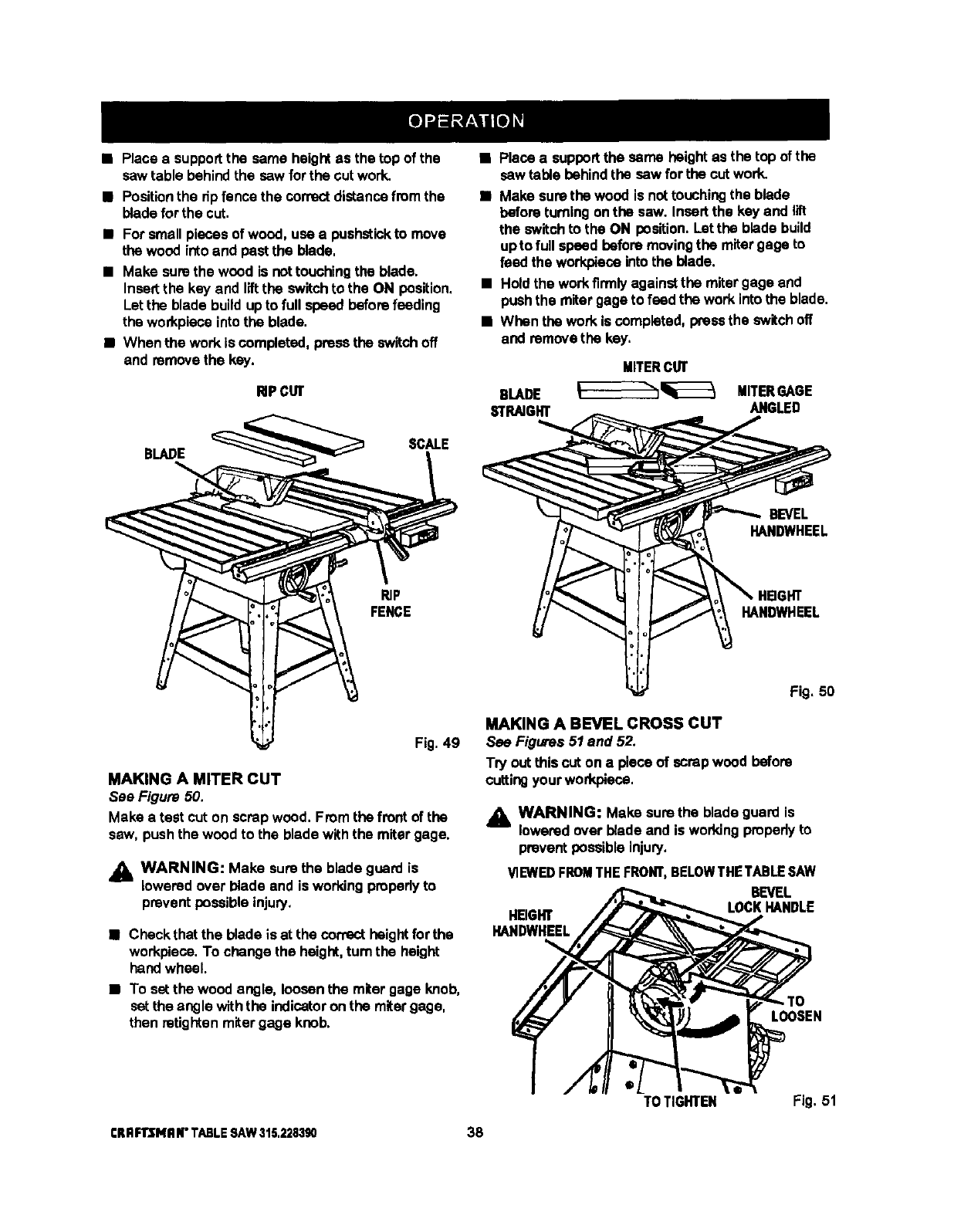
• Place asupportthe same heightas the top of the
sawtable behindthe saw for the cut work.
•Positionthe dpfence the correct distancefrom the
blade forthe cut.
•For smallpieces of wood, use a pushstickto move
the wood intoand past the blade,
•Make surethe wood is nottouchingthe blade.
Insertthe key and liftthe switchto the ON position.
Let the blade build upto full speed before feeding
the workpiecointothe blade.
•When the work is completed, pressthe switch off
and removethe key.
RiPCUT
BLADE SCALE
BF
FENCE
Fig. 49
MAKING A MITER CUT
See Figure 50.
Make a test cut on scrap wood, Fromthe front of the
saw, push the wood to the blade with the miter gage.
j_, WARNING: Make sure the blade guard is
lowered over blade and is workingpropedyto
prevent possibleinjury.
•Check that the blade is at the correct height for the
workpiece, To change the height,turn the height
handwheel.
•To setthe wood angle, loosenthe miter gage knob,
setthe angle withthe indicatoron the mitergage,
then retightenmitergage knob.
•Place a supportthe same height as the top of the
sawtable behindthe saw for the cut work.
•Make sure the wood is nottouchingthe blade
before turningonthe saw. Insert the key and lift
the switch to the ON position. Let the blade build
upto full speed before movingthe mitergage to
feed the workplaco intothe blade.
• Holdthe workfirmlyagainstthe mitergage and
pushthe mitergage to feed the work intothe blade.
•When the work is completed,pressthe switch off
and remove the key,
MITERCUT
BLADE ____________ MITERGAGE
STRAIGHT ANGLED
BEVEL
HANDWHEEL
HANDWHEEL
Fig, 50
MAKING A BEVEL CROSS CUT
See Figures 51 and 52.
Try out thiscut on a pieceof scrap wood before
cuttingyour workpiece,
,_ WARNING: Make surethe blade guard is
lowered over blade and is workingpmpedy to
prevent possible injury,
!/1EWEDFROMTHE FRONT, BELOWTHE TABLE SAW
BEVEL
HEIGHT LOCK HANDLE
HANDWHEEL
LOOSEN
TOTIGHTEN Fig. 51
CRRFll3MR N"TABLE SAW 315.228390 38
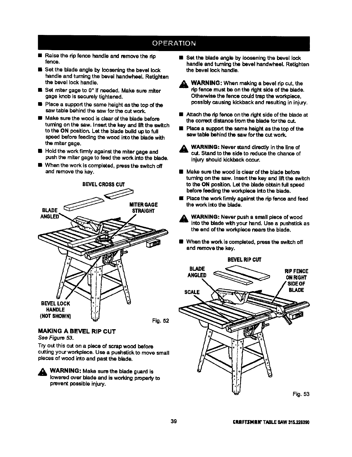
•Raise the dp fence handleand remove the dp
fence,
•Set the blade angle by looseningthe bevel lock
handle and turningthe bevel handwheel. Retighten
the bevel lock handle.
•Set miter gage to 0° if needed. Make sure miter
gage knobis securelytightened.
•Place a supportthe same heightas the top of the
sawtable behind the sew forthe cut work.
•Make surethe wood is clear of the blade before
turningon the saw, Insertthe key and liftthe switch
to the ON position.Letthe blade build upto full
speedbefore feeding the wood intothe blade with
the mitergage.
•Holdthe workfirmly against the mitergage and
pushthe mitergage to feed the work intothe blade.
•When the work is completed,pressthe switch off
and remove the key.
BEVELCROSSCUT
BEVEL LOCK
HANDLE
(NOT SHOWN) Fig. 52
MAKING A BEVEL RIP CUT
See Figure 53.
Try outthis cut on a piece of scrapwood before
cuttingyour workplace. Use a pushstickto move small
piecesof wood into and past the blade.
_k WARNING: Make sure the blade guard is
loweredover blade and is working properlyto
prevent possible injury.
•Set the blade angle by looseningthe bevel lock
handle andturningthe bevel handwhael. Retightan
the bevel lockhandle.
.1_ WARNING: When makinga bevel tip cut,the
dp fence must be on the dghtside of the blade.
OthenNisethe fence couldtrap the workpiece,
possibly causing kickbackand resultingin injury.
•Attachthe dp fence on the rightsideof the bladeat
the correctdistancefromthe blade forthe cut.
•Place a supportthe same heightas the top of the
sew table behindthe sew for the cut work.
,_, WARNING: Never standdirectlyinthe lineof
cut, Stand to the side to reduce the chance of
injuryshould kickback occur.
•Make surethe wood is clearof the blade before
turningontha sew. Insert tha key and liftthe switch
to the ON position. Let the blade obtainfull speed
beforefeedingthe workplaceintothe blade.
•Place the workfirmlyagainstthe ripfence andfeed
the work intothe blade.
_l, WARNING: Never pusha small piece of wood
intothe blade withyour hand. Use e bushstick as
the end oftha workpiece nears the blade.
•When the work iscompleted, pressthe switch off
and removethe key.
BLADE
ANGLED
SCALE
BEVEL_PC_
B_DE
Fig. 53
39 CRRFTSNIIN"TABLE9AW316.228,190
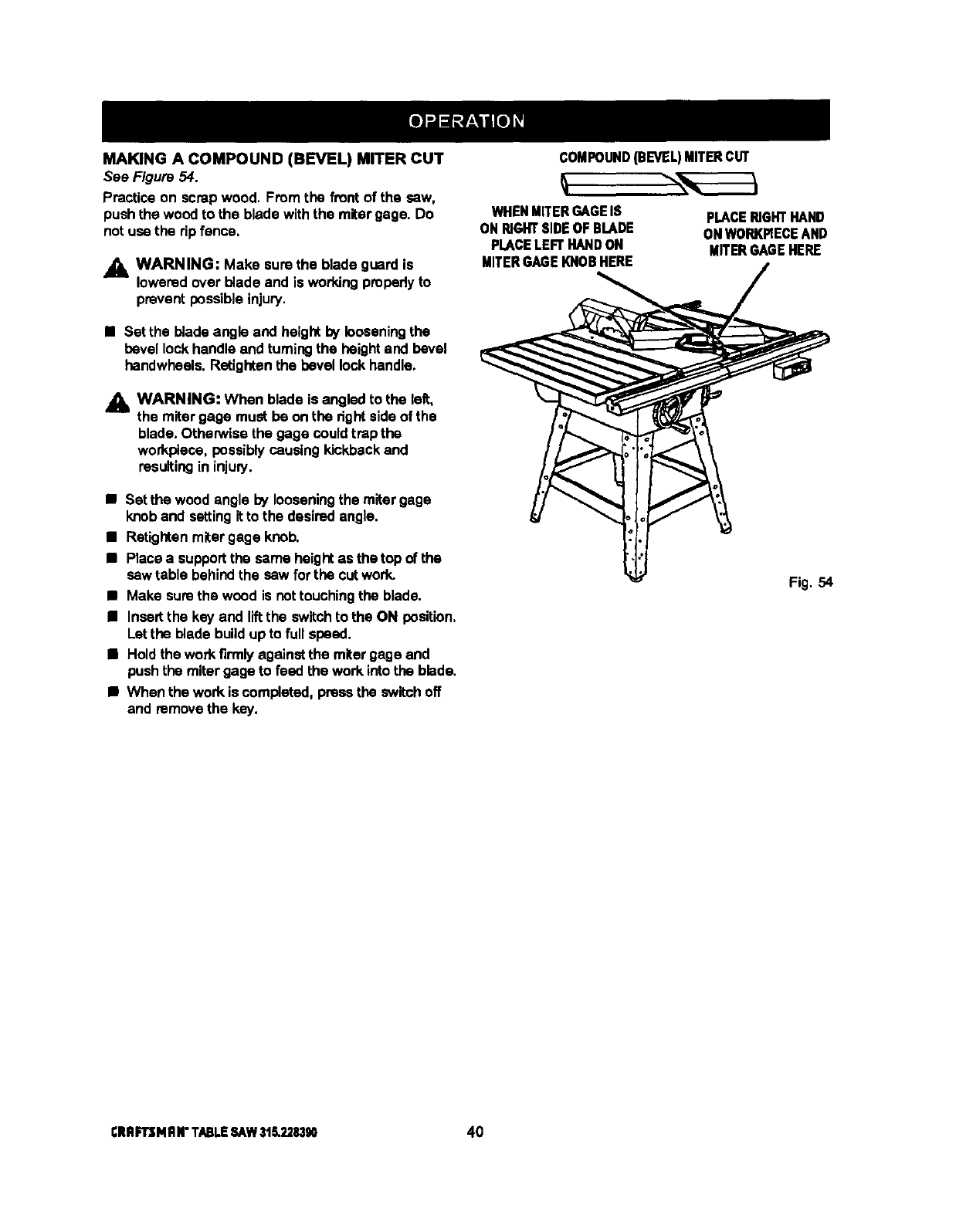
MAKING A COMPOUND (BEVEL) MITER CUT
See Figure 54.
Practice on scrap wood. From the front of the saw,
pushthe wood to the blade withthe mitergage. Do
notuse the rip fence,
•1=WARNING: Make surethe blade guard is
loweredover blade and is workingpropedyto
prevent possibleinjury.
•Set the bladeangle and heightby looseningthe
bevel lockhandle and turningthe heightand bevel
handwheels.Retightenthe bevel lock handle.
_lh WARNING: When blade is angled to the left,
the miter gage must be onthe dgnt sideof the
blade. Othew/ise the gage couldtrap the
workplece, possibly causingkickbackand
resulting in injuly.
•Set the wood anglo by looseningthe mitergage
knob and setting itto the desiredangle.
•Retightenmitergage knob.
•Place a supportthe same heightas the top of the
sew table behindthe sew for the cut work.
•Make sum the wood is nottouchingthe blade.
•Insert the key and llftthe switchto the ON position,
Let the blade build up to full speed.
•Holdthe workfirmly againstthe mitergage and
push the miter gage to feed the work into the blade.
•When the work is completed, pressthe switchoff
and removethe key.
COMPOUND(BEVEL)MITERCUT
WHEN MITERGAGEIS
ON RIGHTSIDE OF BLADE
PLACELEFT HANDON
MITERGAGE KNOB HERE
PLACERIGHTHAND
OHWORKPIECEAND
MITERGAGEHERE
Fig. 54
CRflFrsM RN"TABLESAW318.228390 40
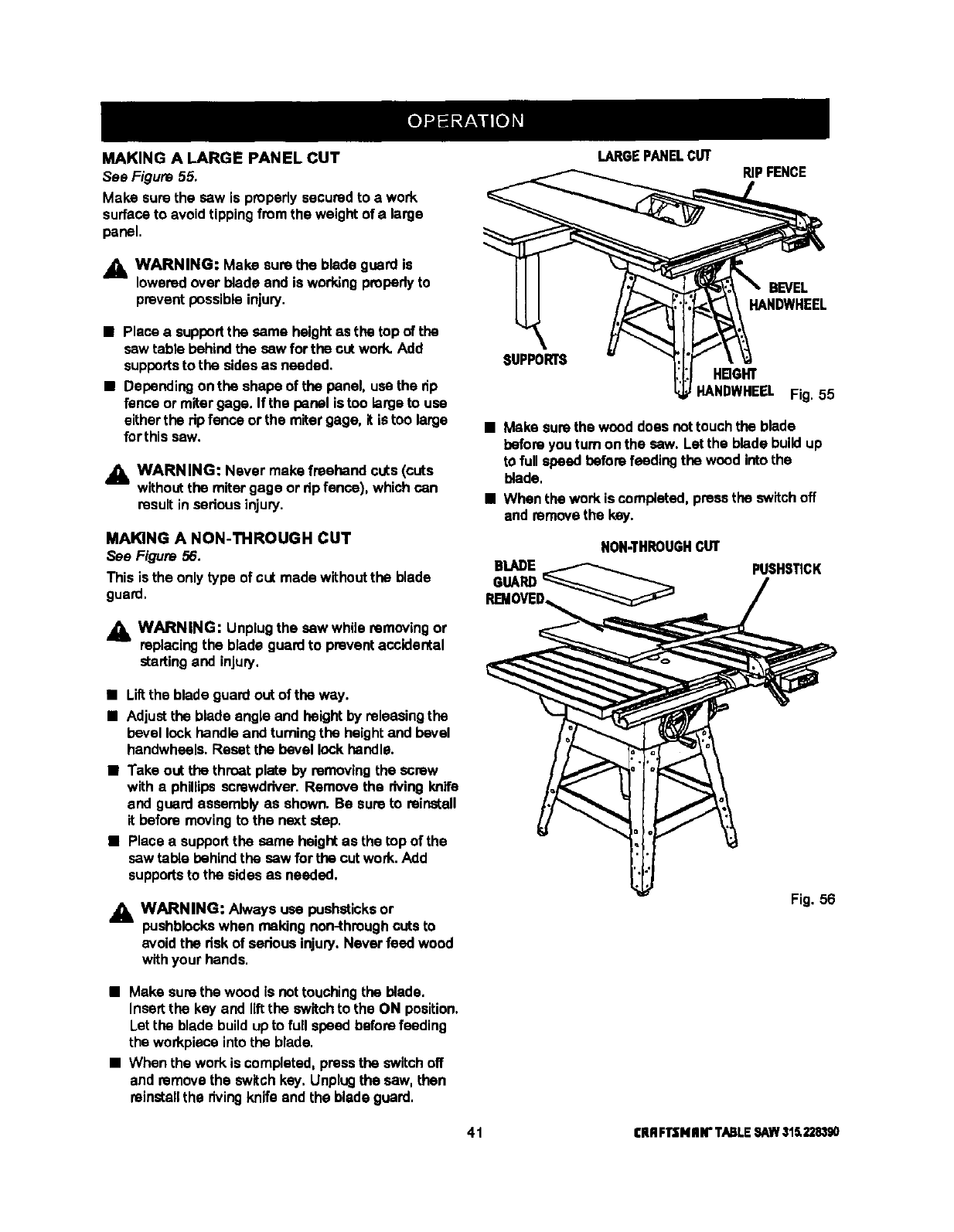
MAKING A LARGE PANEL CUT
Sea Figure 55.
Make surethe saw is properlysecuredto awork
surfaceto avoid tippingfromthe weight of alarge
panel.
LARGEPANELCUT RIPFENCE
,_ WARNING: Make sure the blade guard is
lowered over blade and is working properlyto
prevent possibleinjury.
• Place a supportthe same heightas the top of the
sawtable behindthe saw forthe cut work. Add
supportsto the sidesas needed.
• Dependingonthe shape of the panel, usa the dp
fence or miter gage. If the panel istoo large to usa
eitherthe ripfence or the mitergage. it is too large
for this saw.
_lh WARNING: Never make freehand cuts (cuts
withoutthe mitergage or ripfence), which can
result in sarious injury.
MAKING A NON-THROUGH CUT
See Figure 56.
This is the only type of cut made withoutthe blade
guard.
WARNING: Unplug the saw while removing or
replacing the blade guard to prevent accidental
starting and injury,
BEVEL
HANDWHEEL
SUPPORTS HBGHT
HANDWHEEL Fig. 55
•Make surethe weed does nottouchthe blade
before youturn on the saw. Let the blade build up
to full speed before feedingthe wood intothe
blade.
•When the work is ccmp|efed, pressthe switchoff
and removethe key.
NON-THROUGHCUT
BLADE
GUARD
PUSHSTICK
•LiRthe blade guard out of the way.
•Adjustthe blade angle and height by releasingthe
bevel lockhandleand turningthe heightand bevel
handwheels.Reset the bevel lock handle.
•Take out the throat plate by removingthe screw
with a phillips screwdriver. Remove the riving knife
and guardassembly as shown. Be sureto reinstall
it before movingto the next step.
•Place a supportthe same height as the top of the
saw table behind the saw for the cut work. Add
supportsto the sides as needed.
_IL WARNING: Always usa pushsticksor
pushblaokswhen making non-throughcuts to
avoid the risk of serious injury.Never feed wood
withyour hands.
Fig. 56
•Make surethe wood is not touchingthe blade.
Insert the key and liftthe switch to the ON position.
Let the blade build upto full speed beforefeeding
the workpieceintothe blade.
•When the workis completed, pressthe switchoff
and removethe switchkey. Unplugthe saw, then
reinstallthe rivingknife and the blade guard.
41 I;RRF13NII N"TABLESAW315.228390
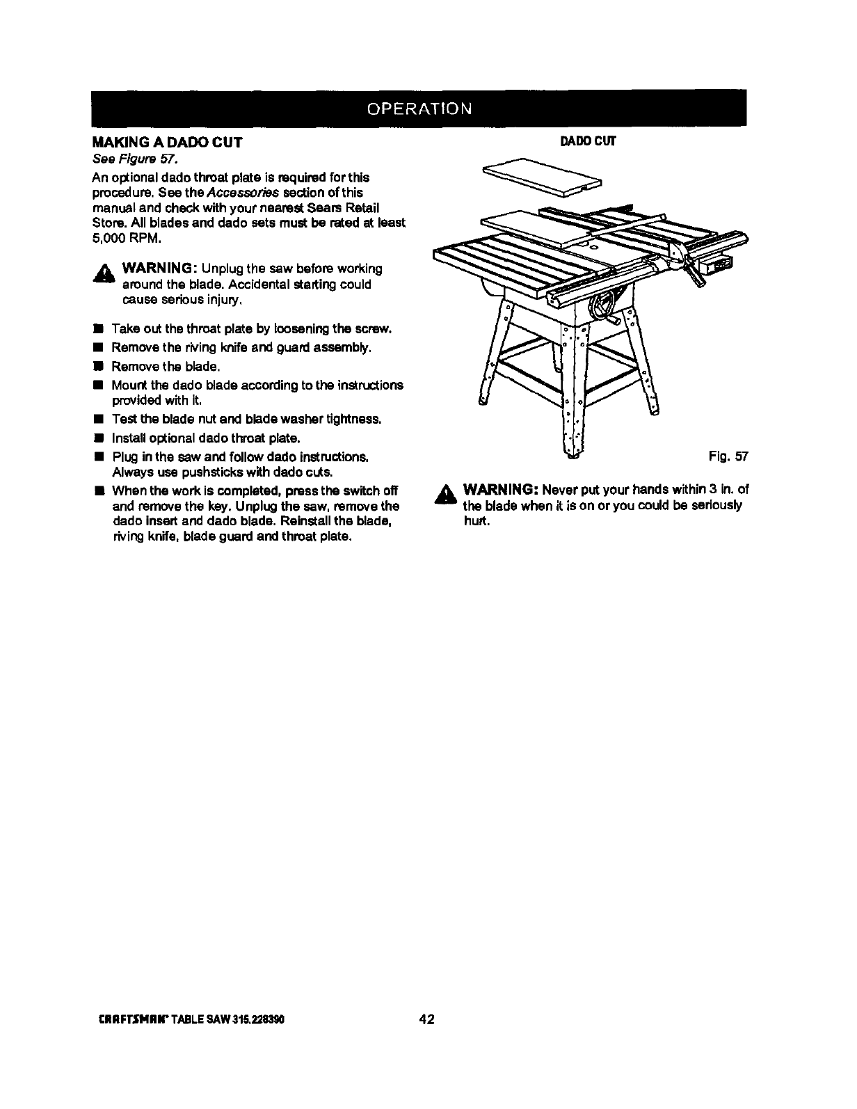
MAKING A DADO CUT
See Figure 5Z.
An optionaldado throat plate is requiredfor this
procedure,See the Accessories sectionof this
manual and check withyour nearest Seam Retail
Store. All bladesand dado sets must be rated at least
5,000 RPM,
,_ WARNING: Unplugthe saw before working
around the blade. Accidental startingcould
cause seriousinjury,
•Take outthe throat plate by loosening the screw.
• Remove the rivingknifeend guardassembly,
•Remove the blade.
•Mountthe dado blade accordingto the instructions
providedwith it,
•Test the blade nut and bladawesher tightness.
•Installoptionaldado throat plate.
•Plug inthe sew and followdado instructions.
Always use pushstickswith dado cuts.
•When the work is completed, pressthe switchoff
and remove the key. Unplugthe saw. remove the
dado insertand dado blade. Reinstallthe blade,
rivingknife, blade guard and throat plate.
DADOCUT
Fig. 57
_1= WARNING: Never put your hands within3 in. of
the blade when it is on or you could be seriously
hu_t.
CIIRFI"SNIIIr TABLESAW315,228390 42
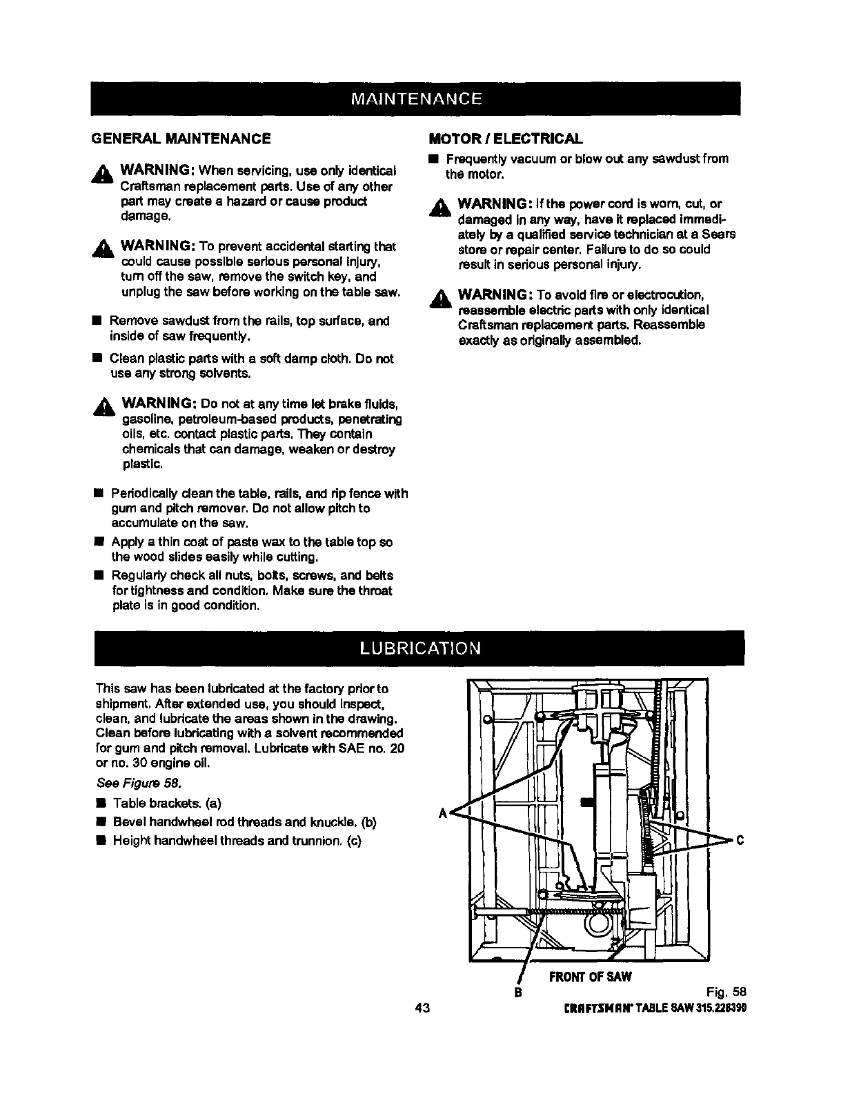
GENERAL MAINTENANCE
_1, WARNING: When servicing,use only identical
Craftsman replacement parts.Use of any other
pert may create a hazard or cause product
damage,
_1= WARNING: To prevent accidentalstartingthat
could cause possible seriouspersonal injury,
turn off the saw, remove the switchkey, and
unplugthe saw before working onthe table saw.
•Remove sawdustfrom the rails,top surface,and
inside of saw frequently,
•Clean plasticparts with a softdamp cloth,Do not
use any strongsolvents.
_i, WARNING: Do not at any time let brakefluids,
gasoline, petroleum-based products,penetrating
oils, etc. contactplastic parts, They contain
chemicals that can damage, weaken or destroy
plastic,
•Pedodically clean the table, rails, and dp fencawith
gum and pitch remover. Do not allow pitch to
accumulate on the saw.
•Apply a thin coat of paste wax to the table top so
the wood slides easilywhile cutting.
•Regularlycheck all nuts, bolts, screws,and belts
fortightnessand condition.Make sure the throat
plate is in goodcondition.
MOTOR /ELECTRICAL
•Frequentlyvacuum or blow out any sawdustfrom
the motor.
,_k WARNING: If the power cord is worn, cut, or
damaged inany way, have it replacedimmedi-
ately by a qualifiedservicetechnicianat a Sears
store or repair center. Failureto do so could
result in sedous personalinjury.
WARNING: To avoid fire or electrocution,
reassemble electdc partswith only identical
Craftsman replacementparts. Reassemble
exactly as originallyassembled.
This saw has been lubricatedat the factory pdorto
shipment,After extended use, you shouldinspect,
clean, and lubricate the areas shown in the drawing.
Clean before lubricatingwitha solvent recommended
for gum and pitch removal. Lubricatewith SAE no, 20
or no. 30 engine oil
See Figure 58.
•Table brackets. (a)
•Bevel handwheel rod threads and knuckle.(b)
•Heighthandwheel threads and trunnion,(c)
43 BFRONTOF_L,_W
Fig. 58
CRIIFTSNRN"TABLESAW315.228,1_
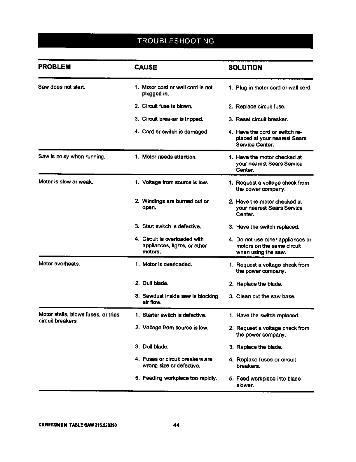
PROBLEM CAUSE SOLUTION
Sawdces notstart. 1. Motor cordorwallcord isnot 1. Plug in motorcord orwallcord.
pluggedin.
2, Circuitfuse is blown. 2.
3, Circuit breaker is tdpped. 3.
4, CON or switchis damaged. 4.
Saw is noisywhen running.
Motoris slowor weak.
Motoroverheats.
Motor stalls, blowsfuses, or tdps
circuitbreakers.
1. Motor needsattention.
1. Voltage from source is low.
2. Windings are bumad out or
open.
3. Start switchis defective,
4. Circuitis ovedoadedwith
appliances,lights,or other
motors.
1. Motor is ovedcaded.
2, Dull blade.
3. Sawdust insidesew is blocking
air flow.
1. Starter switchis defective.
2. Voltage from seume is low.
3, Dull blade.
4. Fuses or circuitbreakersare
wrong size or defective,
5. Feeding workplacetoo rapidly.
1,
1.
2.
3,
4,
1.
2.
3.
Replace circuitfuse.
Reset circuitbreaker,
Have the cord or switch re-
placed at your nearest Sears
Sen/ice Center,
Have the motorchecked at
your nearest Sears Service
Center.
Request a voltage check from
the power company.
Have the motorchecked at
your nearest Sears Service
Center.
Have the switchreplaced.
Do not use other appliances or
motorson the same circuit
when usingthe sew.
Request a voltage checkfrom
the power company.
Replace the blade.
Clean out the saw base.
1. Have the switch replaced.
2. Request a voltage checkfrom
the power company,
3. Replace the blade.
4. Replace fuses or circuit
breakers.
5. Feed workplace intoblade
slower.
CRRFI"$NIIN TABLESAW31&2283_ 44
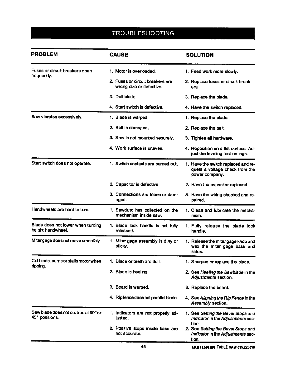
PROBLEM CAUSE SOLUTION
Fusesor circuitbreakers open
frequently. 1. Motor isovedceded.
2. Fuses orcircuitbreakers are
wrong size or defective.
I. Feed work more slowly.
2. Replace fuses or circuit break-
era,
3. Dull blade. 3. Replace the blade.
Saw vibrates excessively.
4, Start switchis defective,
1, Blade is warped.
4. Have the switchreplaced.
1, Replace the blade.
2. Belt is damaged. 2. Replace the belt.
3. Saw is not mounted securely. 3. Tighten all hardware.
4, Work surface is uneven. 4. Repesitionon a fiat surface.Ad-
just the levelingfeet on legs.
Start switch does notoperate. 1. Switch contacts are burned out, 1. Have the switch replaced and ra-
quest a voltage check from the
power company.
2, Capacitor is defective 2, Have the capacitorreplaced,
3. Connectionsare loose or dam- 3. Have the widngchecked and ra-
aged. paired.
Handwheels are herd to turn. 1, Sawdust has collected on the 1. Clean and lubdoatethe mecha-
mechanism insidesew. nism.
Blade does notlower when turning
height handwheel. 1. Blade lock handle is not fully 1. Fully release the blade lock
released, handle.
Mitergage doesnotmove smoothly. 1. Miter gage assembly is dirty or 1, Raleasethe mitergage knoband
sticky, wax the miter gage base and
sides.
Cutbinds,bumsorstalls motorwhen
ripping. 1, Blade orteeth are dull.
2. Blade is heeling,
1. Sharpen or raplasethe blade.
2. See Heelingthe Sawblade inthe
Adjustments section,
3. Board iswarped. 3. Raplacethe board.
4, Ripfencedoeenotperallalblede. 4, SeaAligningtheRipFenoaintha
Assembly section.
Saw bladedoesnotcuttrueat 90°or
45°positions. 1. Indicators are not properly ad-
justed.
2. Positive stops inside base are
notaccurate.
1, See Setting the Bevel Stopsand
IndicatorintheAdjustmentssec-
tion.
2. Sea Setting the Bevel Stops and
Indicatorinthe Adjustmentssec-
tion.
45 I:IUlFTSHRN TABLESAW315,2283_
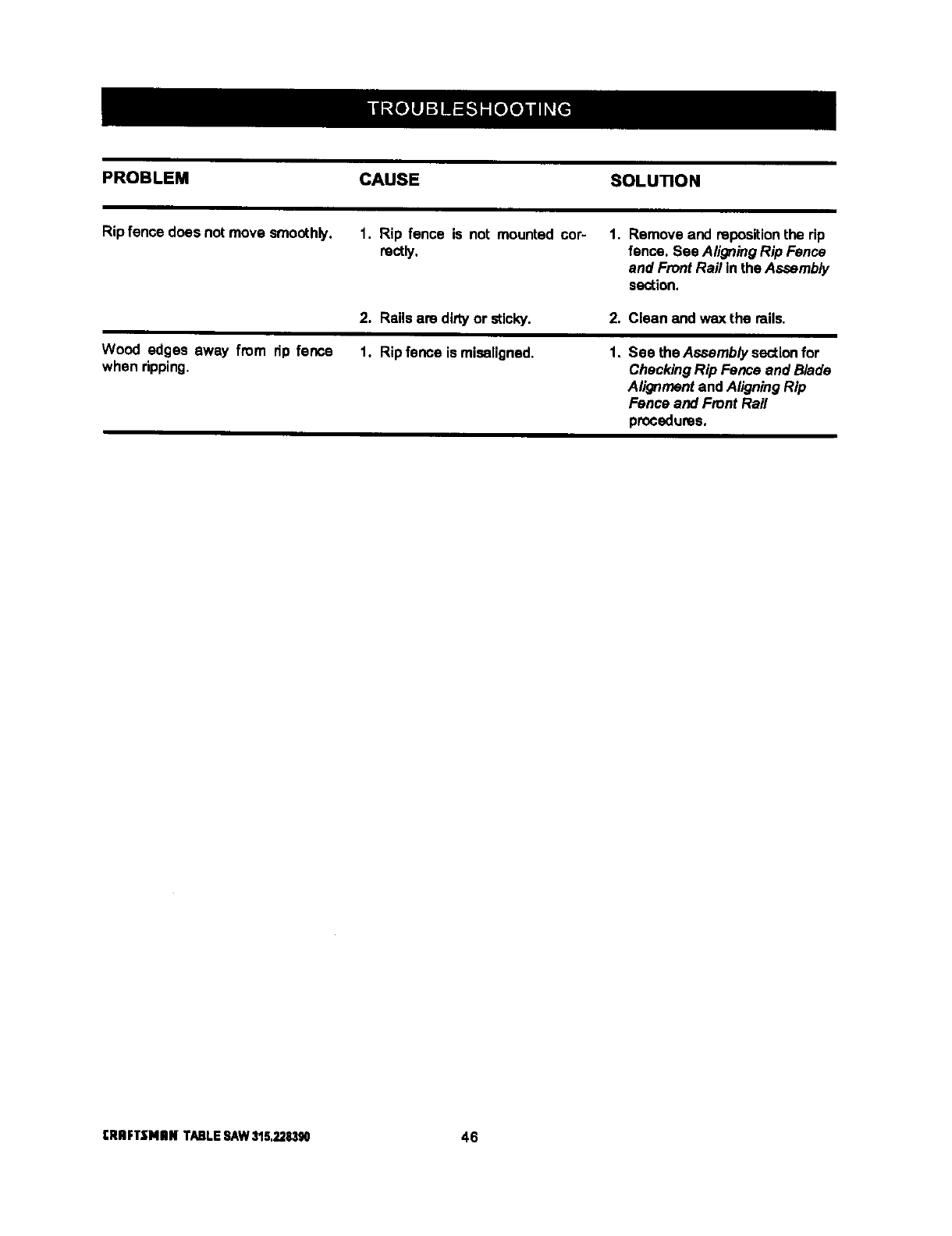
PROBLEM CAUSE SOLUTION
Rip fence does not move smoothly. 1. Rip fence is not mounted cor-
rootly. 1. Remove and repositionthe dp
fence. See AligningRip Fence
and Front Rail inthe Assembly
section.
Wood edges away from dp fence
when dpping.
2. Rails are dirty or sticky.
1. Rip fence is misaligned.
2. Clean and wax the mils.
1. See the Assembly sectionfor
CheckingRip Fence and Blade
Alignmentand AligningRip
Fence and Front Rail
procedures.
rRRFTSNIIH TABLESAW$15,2283g0 46

47 CRIIFTSMRNTABLESAW315.228390
