Craftsman 315275062 User Manual ROUTER Manuals And Guides L0912033
CRAFTSMAN Router Manual L0912033 CRAFTSMAN Router Owner's Manual, CRAFTSMAN Router installation guides
User Manual: Craftsman 315275062 315275062 CRAFTSMAN ROUTER - Manuals and Guides View the owners manual for your CRAFTSMAN ROUTER #315275062. Home:Tool Parts:Craftsman Parts:Craftsman ROUTER Manual
Open the PDF directly: View PDF ![]() .
.
Page Count: 24
OWNER'S
MANUAL
MODEL NO.
315.275062
CAUTION:
Read Rules for
Safe Operation
and All Instruc-
tions Carefully
CRRFTSMRN
Industrial Electronic
Plunge Router
Double Insulated
Thank You for Buying
Craftsman Tools
Warranty
Introduction
Unpacking
Features
Adjustments
Operation
Maintenance
Repair Parts
Designed exclusively lot and sold only by
SEARS, ROEBUCK AND (30, Ho[fman Estates, IL 60t 79
6-95
Prlnled in U,S,A
It thisCraftsmanIndustrialElectronicPlungeRouterfails due to a defectinmatedal orworkmanshipwithinoneyear
fromthe dateof purchase,Sears willrepairit free of charge, Thiswarrantyapplies onlywhilethis productis inuse
in the UnitedStates. WARRANTY SERVICE IS AVAILABLE BY SIMPLY RETURNING THE TOOL TO THE
NEAREST SEARS STORE OR SERVICE CENTER THROUGHOUTTHE LINrrED STATES.
This warrantygives you specifto legal rights, and yDumay also haveother rights whichvary from stateto state.
SITARS;ROEBUCKAND CO
DEPT. 817 WA
HOFFMAN ESTATES, IL 60179
L ........................................................
iNTRODUCTiON
DOUBLE INSULATION is aconcept in safety, in electrlo
powertools,whicheliminates lhe need for the usualthree
wire groundedpower cord and grounded supplysystem.
Whereverthere is electric currantin the toolthere are two
completesets of insulationto protecttheuser, /kit exposed
metal partsare isolatedfrom internalmetal motor compo-
nentswithprotectingInsulation,
READ ALL INSTRUCTIONS
IMPORTANT-Servicing of atool withdouble Insulation
requiresexl_ome care end knowledgeof the systemand
shouldbe pedormedonly by a qualifiedservice technician,
For_ervfcewe suggestyoureturn the tool to your nearest
SearsStoreforrepair, Always use original factoryreplace.
mentpads whenservicing,
RULES FOR SAFE OPERATION
1., KNOW YOUR POWFJRTOOL - Read owner'smanual carefully Learnitsapplicationsandlimitationsas weliasthe
specific potentialhazards related tothistool..
2, GUARD AGAINST ELECTRICAL,SHOCK BY PREVENTINGBODY CONTACT WITH GROUNDED SURFACES.
Forexample: Pipes,radiators,ranges,refrigeratorenclosures
3o KEEP GUARDS tN PLACE and in workingorder,
4, KEEP WORK AREA CLEAN. Clutteredareasand benchesinviteaccidents,
5. /WOLDDANGEROUS ENVIRONMENT, Don'tusepowertoolindampor wetlocationsorexpose torain. Keepwork
area waitiIL
6 KEEP CHILDREN AND VISITORS AWAY. Allvisitorsshould wear safety glassesand be kept a safe _istance
from work area,, Do not I_t visitorscontact too! orextensioncord
7 STORE IDLE TOOLS. When not in use tools should be storedInadry, highor locked-upplace-outof lhe reachof
children
8., DON'T FORCE TOOL. It wilt dothejob better and safer stthe rate for whichit was designed.
9. USE RIGHT TOOL, Don't force small toot or attachment todo thejob of a heavy duty tool Don't usetoot for purpose
notintended -for example- Don't use a circularsaw forcuttingtree limbs ortogs.
10. WEAR PROPER APPAREL. No loose clothingorjewelrytoget caughtinmovingparts_Rubbergrovesand non-
skidfootwear ate recommended whenworkingoutdoors Also,wear protecSvehaircoveringto containlonghairand
keep Itfrom being drawn into airvents
t!, ALWAYS WEAR SAFETY GLASSES. Everyday eyeglasseshave only tmpact-reslstant lenses; they are NOT
safetyglasses,
12 PROTECT YOUR LUNGS, Wear a face or dustmask tfoperation is dusty
13. PROTECT YOUR HEARING. Wear hearing protection dudngextendedperiodso!operation
!4.. DON'T ABUSE CORD. Never carrytoo_by cordor yank itto disconnect from_eceptac_e Keep cordfromheat, eli
and sharpedges.
Page2

RULES FOR SAFE OPERATION (Continued)
15. SECURE WORK. Use ctampsor avise tohold work Bolh hands are needed to operate thetool
16_ DON'T OVERREACH, Keep properfooting and balance at alltimes Do not use on a ladderorunstablesupport
17. MAINTAIN TOOLS WITH CARE Keep tools sharpatafltimes, and cleanfor bestand safestperformance. Follow
instruclionsfor lubricating and changingaccessodes_
18. DISCONNECT TOOLS, When not in use,before servicing, or whenchangingaltachments, blades, bits, cutters,
etc.,all toolsshould be disconnectedf.rampowersupply.
19.. REMOVE ADJUSTING KEYS AND WRENCHES, Formhabitofchec.kingtoseethatkeysandadjuslingwrenches
are removed fromtoolbefore turningiton..
20., AVOID ACCIDENTAL STARTING. Don't carry plugged-in tools with finger on switch Be sureswitchisoff when
pluggingin.,
21. MAKE SURE YOUR EXTENSION CORD IS IN GOOD CONDITION.When using an extension cord,be sureto use
one heavy enoughto carry the currentyour produclwittdraw.An undersized cordwillcause a drop tn linevoltage
resulting in lossof power and ove_eattng. A wlre gauge size (A.W.G) of at least 14 is recommendedfor an
extensioncord 25 feet or less In length.,A cord exceeding25 feet is not recommended,i1in doubt, use lh next
heaviergage. The smallerthe gage number, the heavierthe cord
22. OUTDOOR USE EXTENSION CORDS, When tootis used outdoors,use only extensioncords suitable for use
outdoors,Outdoor approvedcordsare marked withthesuilixW,.A,for example -SJTW-A or SJOW_A.
23. KEEPCUTTERS CLEAN AND SHARP. Shaq_cuttersminimizeslallingandkickback.
24. KEEP HANDS AWAY PROM CUTTING AREA. Keep handsaway from cutlers. Do not reach underneathwork
whilecutteris rotating. Do not attempt toremovematerialwhilecutteris rotating
25 NEVER USE INAN EXPLOSWE ATMOSPHERE. Normalsparkingel the motor couldignite fumes.,
26 INSPECT TOOL CORDS PERIOOICALLY and if damaged, have repaired at your nearest SearsRepairCenter
Stay constantlyaware el cordlocation.
27,. INSPECT EXTENSION CORDS PERIODICALLY andreplacetfdamaged.
28 KEEPHANDLES DRY, CLEAN, AND FREE FROM OIL AND GREASE, Always use a cleanclolhwhencleaning.
Never use brake fluids,gasoline, petroleum.based produclsorany strong solventsto cleanyour tool,
29 STAYALERT. Watchwhat you are doing anduse commonsense. Donor operate tool when you aretired, Donot
rush.
30 CHECK DAMAGED PARTS. Before ludheruse of thetool,aguardor otherpartthatis damaged should be carefully
checkedtodetermine that ttwilloperate properlyand performitsintendedfunction,.Check for alignment of moving
parts,blndtng of moving parts, breakage of parts,mounting,and any otherconditionsthai may affeclitsoperation., A
guard or other part that tsdamaged should be propedy repaired or replaced by an authorized service center unless
Indicated elsewherein thtsinstruction manual
31. DO NOT USE TOOL IF SWITCH DOES NOT TURN IT ON AND OFF. Have defective switches replaced by an
authorizedservicecenter
32 Inspectfor and removeall nailsfrom tumber before muting..
33 DRUGS, ALCOHOL, MEDICATION. Do not operate tool while under the influence oFdrugs, alcohol, or any
medication
34. WHEN SERVICING USE ONLY IDENTICAL CRAFTSMAN REPLACEMENT PARTS.
35 POLARIZED PLUGS, To reduce the rfskofelectricshock,thistoolhasapolarizedplug(oneblade iswiderthan the
other), This plugwtl!fit in a polarized outlet only one way. If theplugdoes not fit fully in the outlet, reverse theplug.
if it stltldoes notfit,contactaqualifiedelectricianto install the proper outteL Do not change lhe plugin any way.
36. DO NOT USE TOOL UNDER "BROWN-OUT" OR OTHERLOW VOLTAGE CONDITIONS, Also. do notuse with
any devicethat could cause lhe power supply voltageto change,,
37. WHEN USING THIS ROUTER WITH A ROUTER TABLE, HELP PREVENT POSSIBLE SERIOUS INJURY BY
KEEPING THE Cbq'TER GUARDED AT ALL TIMES. Useonlyroutertables,wlih guards,thathave beendesigned
for use on reuters thai are of thistype, size, and weigh!
38 SAVETHESE INSTRUCTIONS. Review them frequentlyand usethemto Instructotherswho may use Ibis tool If
youloan someone thistool, loan them theseinstructions also.
Page 3
UNPACKING
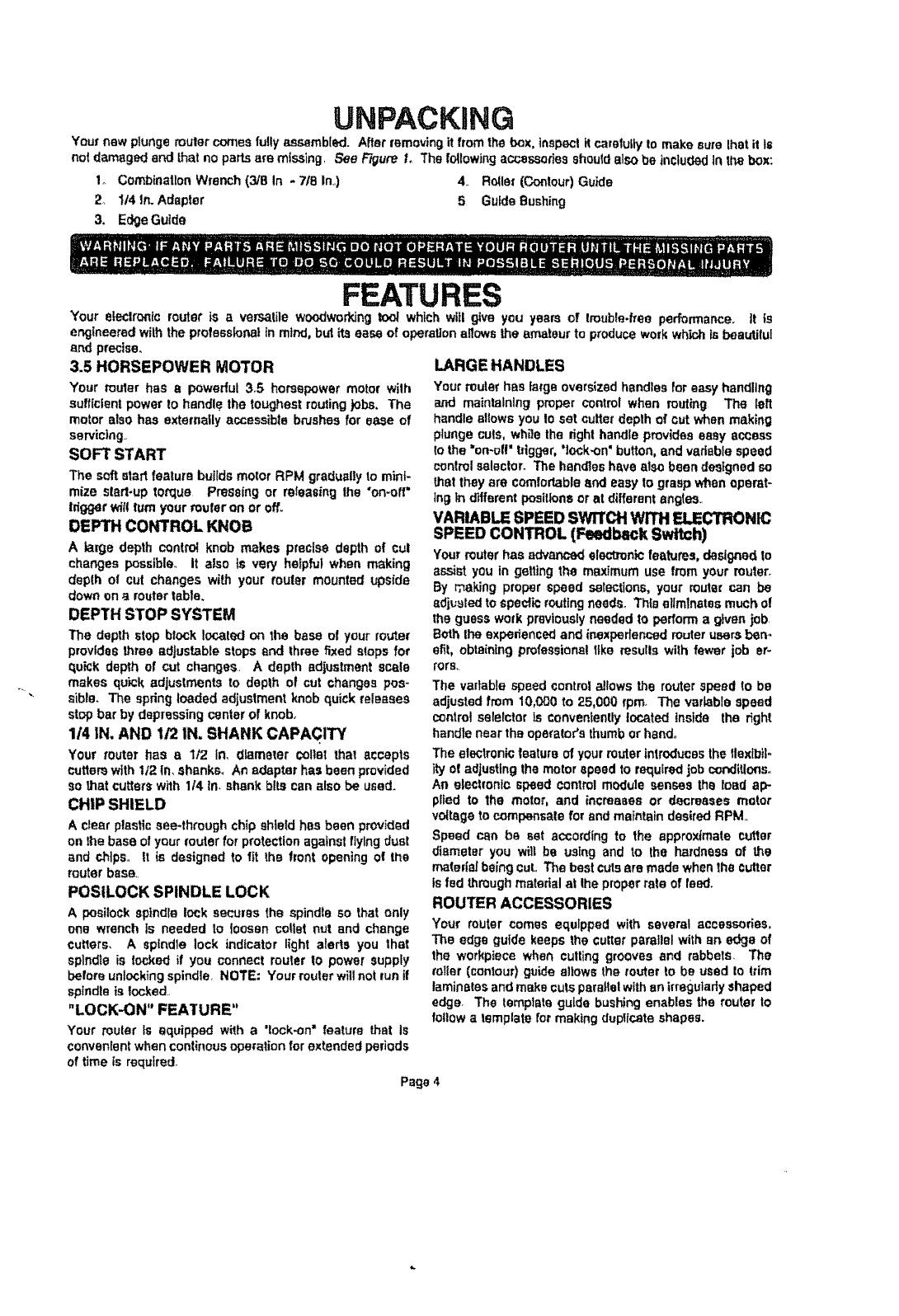
Yournew plungerouter comesfullyassembled. After removing it fromthe box.inspecti_carefuflyto makesure that it Is
not damagedend that no partsare missing, See Figure Io The followingaocesso_es should also be includedin the box"
1o CombinationWrench(3/8 In - 718In.,) 4., Roller(Contour)Guide
2, 1t4In. Adapter 5 GufdeBushing
3. EdgeGuide
FEATURES
Your electronicrouter is a versatile woodworkingtoo! which witl give you years of trouble-free performance. It is
engineeredwiththeprofessionaltn mind, butits ease of operationsnows the amateurto produceworkwhichis beautiful
and precise,,
3.5 HORSEPOWER MOTOR
Your routar has apowerful3°5 horsepowermotor wilh
sufficientpower to handle the toughestroutingjobs. The
motor alsohas externallyaccessiblebnJshesfor ease of
servicing,,
SOFT START
The soft start featurebuildsmotor RPM graduallyto minf_
mize sled.up torque Pressingor releasingthe "on-aft"
tdggert_l{ rumyour reufer on or off_
DEPTH CONTROL KNOB
Alarge depth controlknob makes precise depth of cul
changes possible, it also is very hefpfutwhen making
depth o! cut changes with your router mounted upside
downon_t routertable.
DEPTH STOP SYSTEM
The depthstop block!ocaled on the base of your router
provides three adjustable stops and throe fixed stopsfor
quick depthof cut changes, A depth adiustment scale
makes quick adjustmentsto depth of cut changes pos-
sible. The spring loadedadjustmentknob quickreleases
stop bar by depressingcenterof knob,
1/4 IN. AND !/2 IN. SHANK CAPACITY
Your router has a 1t2 in, ctlameter coital that accepts
cutterswith !/2 in. shanks. An adapter hasbeen provided
Sothat cutterswith 1t4 ln.shank bitscan also be used.
CHIP SHIELD
A clear plasticsee-through chip shield has been provided
onthe baseof yourrouter for protectionagainst flyingdual
and chips,, It is designedto fit the front openingof the
routerbase.,
POStLOCK SPINDLE LOCK
A positockaplndielock securesthe spindleso that only
one wrench is needed to loosen cotternul and change
cutters. A spindle lock indicator light alerts you that
spines is lookedif you connect router to power supply
beforeunlockingspindle, NOTE: Yourrouterwillnotrun if
spindleis locked.,
"LOCK-ON" FEATURE"
Your router Is equipped with a'lock-on" feature that is
convenientwhencontinousoperation forextendedperiods
of time is required
LARGE HANDLES
Your router haslarge oversized handlesfor easyhandling
and maintaining proper controlwhen routing The left
handle allows you to set cutterdepthof cut whenmaking
plungecuts, whitethe dghthandle provideseasy access
to the "on-oil" tdgger, "lock.on'button, and vadsblespeed
controlselector_ Thehandleshave also been desEgnedso
that they are comfortableand easy to grasp whenoperat-
ing in differentpositionsor at different angles,,
VARIABLE SPEED SWITCH WITH ELECTRONIC
SPEED CONTROL (Feedback Switch)
Yourrouterhas advancedelectronic features,designedto
assist you in getting the maximum use from your router_
By making proper speed selections,your muter can be
adjusted to specticrouting needs. Th{eeliminates much of
the guesswork previouslyneeded to performa given job,
BOththeexpenenced and inexperienced router usersben-
slit, obtainingprofessionaltfkerosuIIs with fewer job er-
rors,,
The vadablespeedcontrolallows the routerspeed to be
adjustedfrom 10,060 to 25,000 rpm The variablespeed
controlselelctor is convenientlylocated inside the right
handlenear theoperator'sthumborhand°
The electronicfeature of yourrouter introducesthe tlexibil.
ityo! adlustlng the motor_peed to requiredjobconditlo_so
An electronic speed controlmodulesenses the load alP
plied to the motor, and increases or decreases motor
voltageto compensatefor and maintain desiredRPM
Speed can be set accordfngto the approximatecutter
diameter you will be using and to the hardnessof the
matedaJbeingcuL The best cutsare made whenthecutter
is fedthroughmatedal at the prope_"rate of feed.
ROUTER ACCESSORIES
Your router comes equipped with several accessories,
The edge guide keeps the cutterparallel withan edge of
the workplacewhen culling groovesand rabbets. The
ro|ler (contour)guideallowsthe router to be used to trim
laminatesandmake outs parallelwith an irregularlyshaped
edge. The template guide bushingenablesthe router to
followa template for makingduptfceteshapes.
Page 4
FEATURES
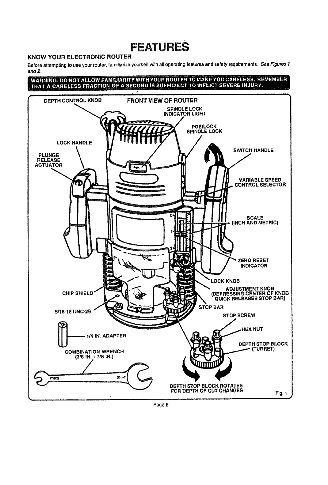
KNOW YOUR ELECTRONIC ROUTER
Belote altempting to use your router, familiarize yourse|l withall operating features and safely requirements. See Figures 1
and 2.
DE 'cobOL KNOB"
LOCK HANDLE
PLUNGE
RELEASE
ACTUATOR
FRONT VIEW OF ROUTER
SPINDLE LOCK
INDICATOR LIGHT
POSILOCK
SPINDLE LOCK
SWITCH HANDLE
VARIABLE SPEED
CONTROL SELECTOR
SCALE
(INCH AND METRIC)
CHIP
5/18-18 UNC_2B
114 tN_ADAPTER
COMBINATION WRENCH
(3t8 IN. -7IB IN.)
ZERO RESET
INDICATOR
KNOB
ADJUSTMENT KNOB
(DEPRESSING CENTER OF KNOB
QUICK RELEASES STOP BAR)
STOP BAR
NUT
DEPTH STOP BLOCK
(TURRET)
DEPTH S'fOP BLOCK ROTATES
FOR DEPTH OF CUT CHANGES
Page 5
Fig. 1
FEATURES
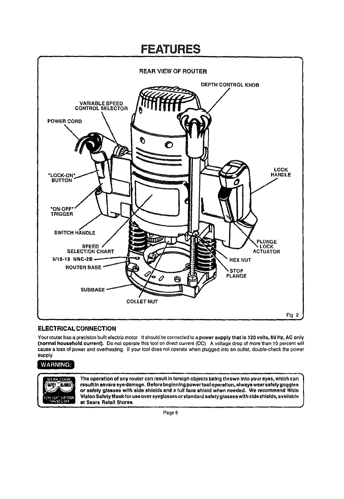
REAR VIEW OF ROUTER
DEPTH CONTROL KNOB
VARIABLE SPEED
CONTROL SELECTOR
POWER CORD k
"LOCK*ON
BUTTON
=ON-OFF
TRIGGER
SWITCH HANDLE
SPEED
SELECTION CHART
5/!6-18 UNC-2E
ROUTER BASE
SUBBASE
LOCK
HANDLE
K
ACTUATOR
HEX NUT
FLANGE
COLL.ETNUT
Fig 2
• . ....L .... , UJ,,.,tvu,u_II UII'L I,. ....I..I -- =
ELECTRICAL CONNECTION
Your routerhasaprecistonbufltelectric motor. It shoutdbecennected toapowersuppiy thatts 120voltr,,60 Hz,AC only
(normal househotd current). Do not operatethistoo] ondirectcurten! (PC) A vo!lagedropof more than 10percent wil!
cause alossofp_we_and overheating, ifyour tooldoes not operatewhen plugged into an oulf_,t,double,check thepower
supply_
i|_ Z _11 The operation of any route, csn result |n fore|gn objects being thrown Into your ayes, which car=
i i _U_ _e_u_t_nsever_eyedamage_Be__rebeg_nnIng_p_wert____p_ra___n_a_way_wearsafetygogg_es|
+-- _or safety glasses with side shields and afull lace shield when needed, We recommend Wid_ |
,. Sea,...,e_,Sto_;,...+........_ ...........................+............... j
Page 6
ADJUSTMENTS
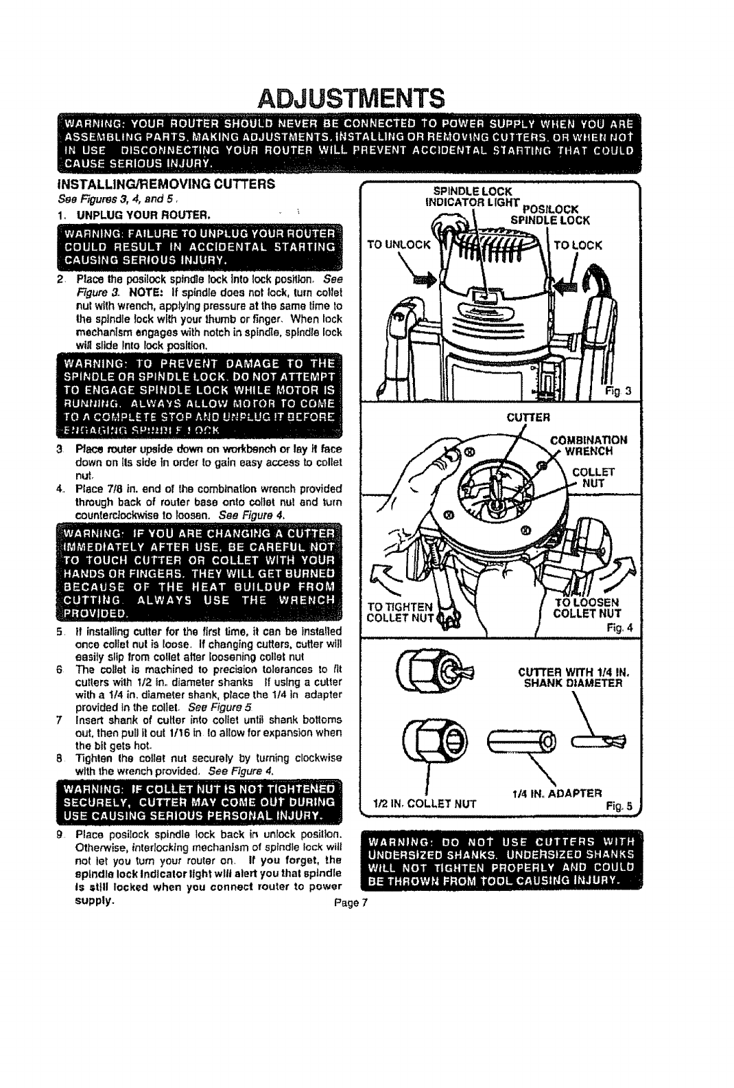
INSTALLING/REMOVING CUTTERS
See Figures3, 4, and 5 _
I. UNPLUG YOUR ROUTER,
2+ Placethe posilock spfndtelock Into lock position, See
Figure3. NOTE: if spindledoes not lock, turncotlet
nut withwrench,applylng pressureat the sametime to
Ihe spindlelock withyourthumbor finger. When lock
mechanism engageswithnotch in spindle,spindlelock
wiltslide Into lockposition.
3 Place touter upsidedownon workbenchor lay it face
down on its sidein orderto gain easy access to collet
nLff_
4, Place 718in, end of the combinationwrenchprovided
throughback of routerbase onto coital nut and turn
counte_ockwisa to loosen. See Figure4,
5 If installing cutterfor the firs! time. it can be installed
once colfetnut is loose+ Ifchangingcutters,cutterwilt
easily slipfromcollet at_erlooseningcolietnut
6 The collar is machined to precisiontolerancesto tit
cutters with I/2. in,,diametershanks If usinga cutter
with a !14 in, diametershank,place the 1/4 in adapter
providedin the colleL See Figure.5
7 Insert shankof cutter into coltet unlit shank bottoms
out. then puii fl out 11t6 in Ioallow forexpansionwhen
the bitgetshot.
8Tighten Ihe coital nut securely by turning clockwise
with thewrenchprovided, See Figure4.
9, Place posilock spindle lock back in unlock position.
Otherwise, interlocking mechanism of sptndle lock will
nol let you turn your router on. If you forget, the
spindle lock Indicator light wilt alert you thai spindle
is still locked when you connect router to power
supply.
TO
SPINDLE LOCK
INDICATOR LIGHT POSILOCK
SPINDLE LOCK
TO LOCK
;t3
CUTTER
COMBIHATIOI, t
WRENCH
COLLET
NUT
TO TIGHTEN
COLLET NUT_
CUTTER WITH 114IN.
SHANK DIAMETER
114IN. ADAPTER
1/2 IN,COLLET NUT Fig.,5_
Page 7
ADJUSTMENTS
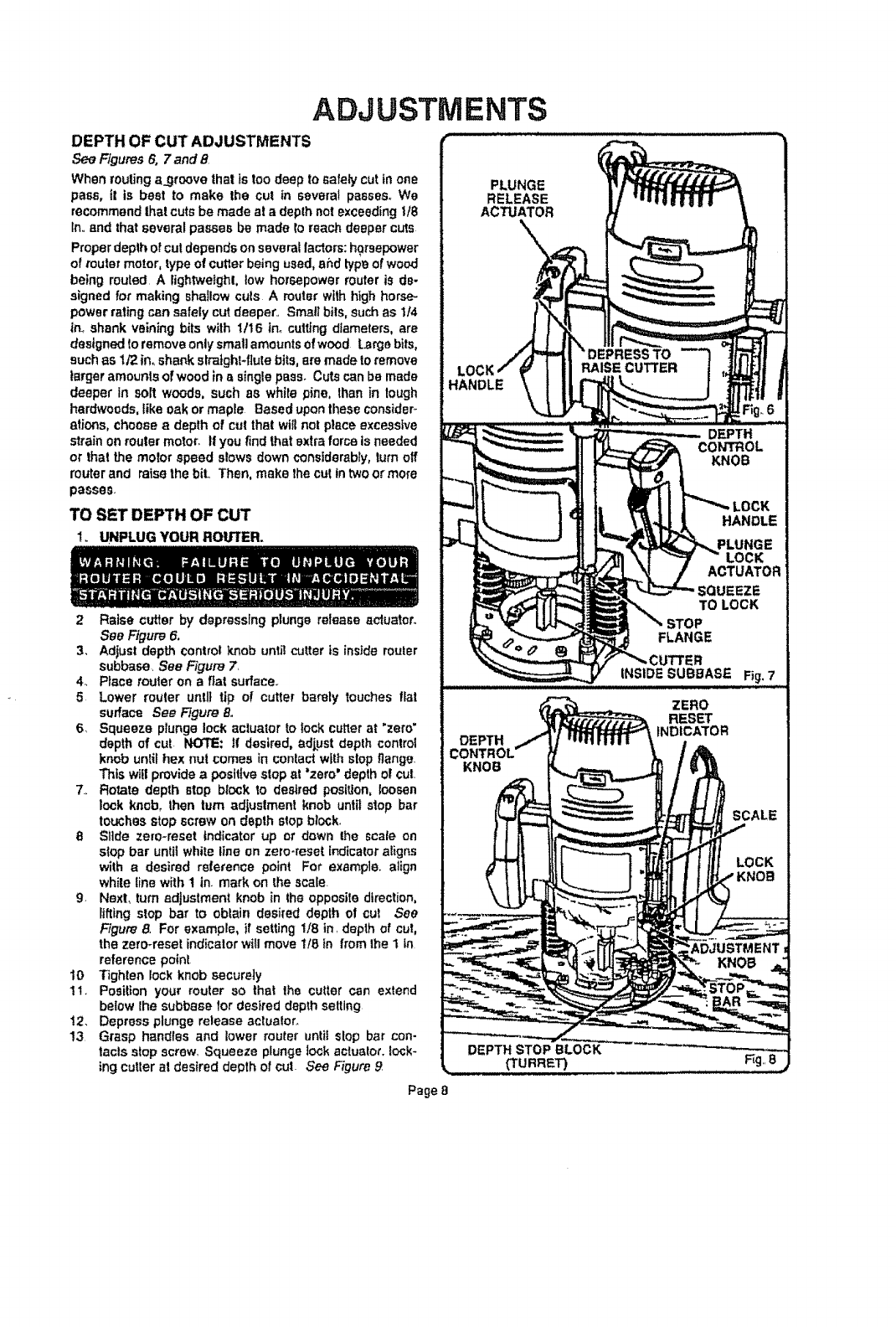
DEPTH OF CUT ADJUSTMENTS
See Figures6, 7 and 8
When routing a_groovethat is too deepto safely cutin one
pass, it is beet to make the cut in several passes.We
recommendthatcute be madeala depthnot exceedingU8
In,.and thatseveral passesbe made re reachdeepercuts
Properdepthofcut dependson severallactors: horsepower
of router motor,typeof cutterbeingused, ahd typeofwood
being routed.A lightweight, low horsepowermuter is de-
signedfor makingshaIIow culs Amuterwithhighhorse-
powerrating can safelycutdeeper.. Smallbils, suchas It4
innshankveiningbits with 1/16 inocuttingdiameters,are
designedto removeontysmallamounts ofwood large bits,
suchas 1/2in, shankslraight-fiutebits,am madeto remove
larger amounts of woodin asinglepass. Cutscanbe made
deeper in soft woods, such as white pine, lhan in lough
hardwoods, like oak ormaple Based upon theseconsider-
aticms,choosea depth of cut that wiltnot place excessive
strainon routermotor. If youfindthatextraforceis needed
or that the reeler speed slowsdownconsiderably,turnoff
muterand raisethe bit. Then,make thecutintweet more
passes.
TO SET DEPTH OF CUT
1. UNPLUG YOUR ROU']rER.
2 Raise cutter by depressing plunge release aduatoro
See Figure 6.
3, Adjust depth control knob unti! c'_tter is inside router
subbese. See Figure 7
4. Place router on a fiat surface..
5 Lower router unlit tip of cutter barely touches flat
surface See Figure 8,
6 Squeeze plunge lock actuator to lock cutter at 'zero'
depth of cut NOTE: tf desired, adjpst depth control
knob until hex nul comes in contact with slop flange.
This wtl!provide a positive stop at "zero" depth of cut.
7., Rotate depth stop block to desired position, loosen
lock knob, then turn adjustment knob until stop bar
touches stop screw on depth stop block,
8Slide ze[o-reset indicator up or down the scale on
stop bar until white line on zero-meet indicator aligns
with a desired reference point For example, align
while line with 1 in. mark on the scale.
g, Next, turn adjustment knob in lhe opposite direction,
lifting stop bar to obtain desired depth of cul See
Figure 8, For example, if setting 1t8 in. depth of cut,
the zero-reset indicator will move 1t8 in from the 1 in
reference point
10 Tighten lock knob securely
11. Position your router so that the cutter can extend
below lhe subbase for desired depth setting
12. Depress plunge release actuaIor.
13 Grasp handles and lower muter until slop bar con-
tacls stop screw. Squeeze plunge lock actuato_. Io_k-
tng cutter at desired depth of cut. See Figure 9
Page 8
ADJUSTMENTS
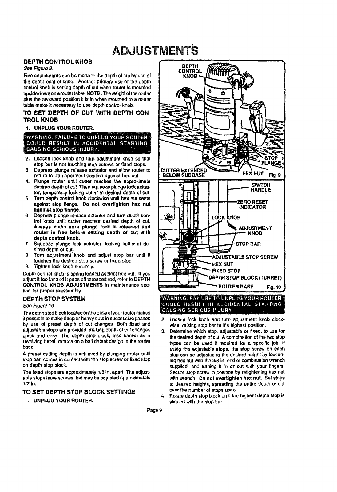
DEPTH CONTROL KNOB
F_ure 9,.
Fineadjustmentscan be made tothedepth otcutby use el
thedepth controlknob, Anotherprimaryusa of the depth
controlknob ts settingdepthof cutwhen ro_er is mounted
upsidedownona fouler table. NOTE: Theweightofthemuter
;_ustheawkward poslt_onitis In whenmountedto a muter
table make tt necessaryto usadepth controlknob_
TO SET DEPTH OF CUT WITH DEPTH CON-
TROL KNOB
1. UNPLUG YOUR ROUTER.
2o Loosenlo<:kknob and turnadjustment knob so that
stopbar is riot touchingstop screwsor fixed stops.
3, Depress plungerelease actuator and allow routerto
returnto tt'a uppermostposttjon againsthex nut,
4o Plun0e router unU!cutler rea_"-hesthe approximate
desked depthofcut,Thensqueezeplungelock _ctua-
tot, t_omdiy Ioddngcutler at deslmddepth o! cut,
5. "rumdepthcontrolknobdod_i_ un_ t_ nutseres
aga_st stopfiange_ Do not overllghten hex nut
against atop flange.
6 Depressplunge release actuatorand turn depthcon-
trol knob until cutter roaches desired depth of cut,
Always make sure plunge lock la released and
router Is free before setting depth of cut with
depth control knob.
7 Squeeze plunge lock actuator, _octdngcutter at de-
sireddepthof cuL
8 Turn adjustment knob and adjust stop bar until it
touchesthe desired stop screwor fixed stop
g, Tfghtenlock knob sacureiy_
Depthcontrol knobls spdng loadedagainst hex nut. If you
adjustit too farand it popsOffthreaded rod,referto DEPTH
CONTROL KNOB ADJUSTMENTS in maintenance sec-
tion for properreassembly..
DEPTH STOP SYSTEM
See Figure 10
Thedeplhstopblocklocated onthebaseofyourroutermakes
itpossibletomake deep or heavycutsin successive passes
by usa of preset depth of cut changes Both t_xsdand
adjustablestopsam provided, makingdepth of cut changes
quick and easy,.The depth stopblock, also known as a
revolving turret,mimeson a ball detent design in therouter
baser
A preset cuttingdepth is achievedby plungingrouter until
stopbar comesin contactwiththestop screworfixedstop
on depthstopblock,,
3he fixed stopsare approximately lIB in. apart The adjust-
ablestopshavescrewsthatmaybe adiustadapproximately
t/2 in,
TO SET DEPTH STOP BLOCK SETTINGS
UNPLUG YOUR ROUTER_
SWRCH
HANDLE
2 Loosen lock knob and turn adjustmentknob clock-
wise, raisingstop bar to It'shighestposition.
3. Delemtlne which stop,adjustableor fixed, to use for
thedesireddepthofct._t,Acombinationofthetwo stop
types can be used it required tar a specificjob. If
usingthe adjustablestops, the stop screw on each
stopcan be _djusted to thedesiredheightby loosen-
inghex nut withthe 3/8 in.end ofcombinationwrench
supplied, and turningit In or out with yoL_rfingers.
Securestopscrew_npositionby retlghteninghexnut
withwrench, Do not overtlghten hex nut, Set steps
to desiredheights,spreadingthe entiredepth at cut
m_erthenumber _t stops used,
4,, Rotatedepthslop block untilthehighestdepthstopis
alignedwith thestop bar.
Page t_
ADJUSTMENTS
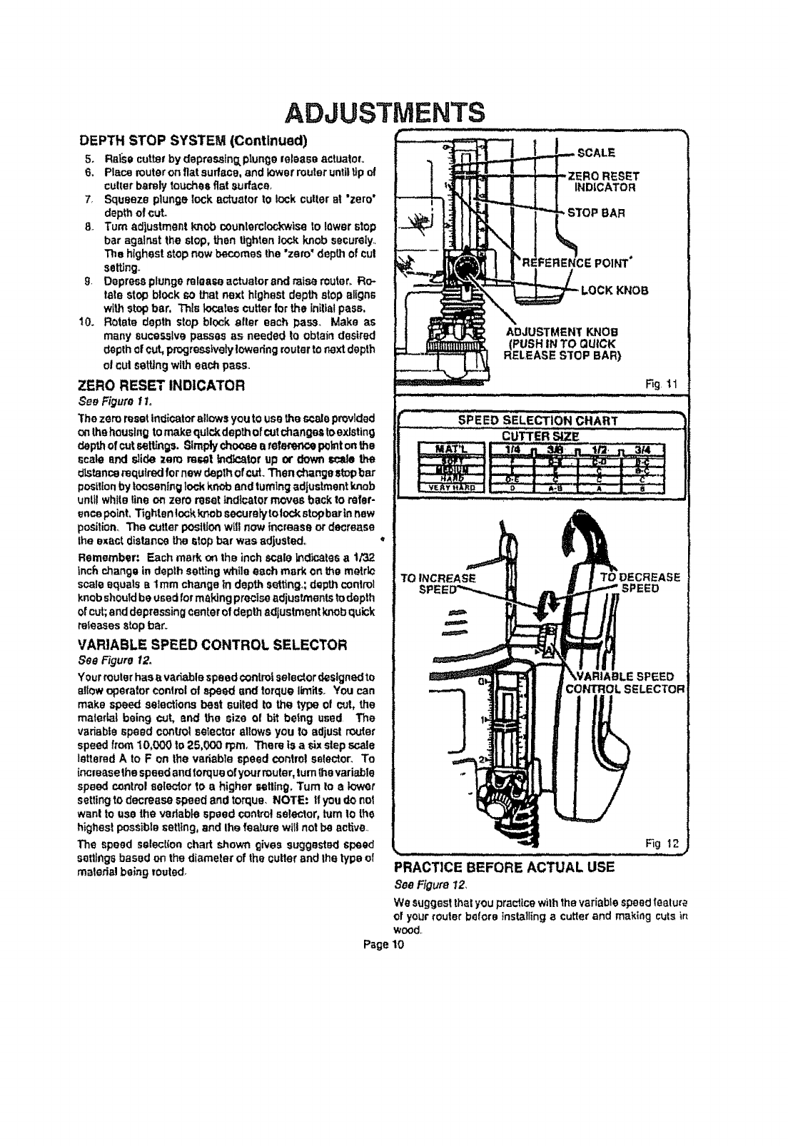
DEPTH STOP SYSTEM (Continued)
5+ Raisecutterbydepmsstng,plungereleaseactuator.
6 Placerouteron fiatsurface,and lowerrouteruntiltipof
cullerbarelytouchesfiatsumface
7 Squeeze plungelock actuator to lock cutterat "zero"
depthofcut°
8 Turnadlustmentknobcounteroloct,:wiseto lowerstop
bar against the stop,then tightenlock knobsecureiy
The higheststopnew becomesthe"zero' depthofcut
setting
9Depress plungereleaseactuator andmiss router_Re-
tate stopblock _,othat next highestdepth stopaligns
withstop bar, Thls k_:atescutterforthe Jniltalpass,
t0. Rotatedepth stop block after each pass Make as
manysucessive passes as neededto obtaindesired
depthofcut,progressivelyloweringrouterto nextdepth
o! cul settingwith eachpass.
ZERO RESET INDICATOR
See Figure 1I.
Thezeroresetindicator allowsyouto usetheso,sisprovided
onthehouslngtomakequtckdepthofcutchangestoexlsting
depthofcutsettL,_gs.Simplychoosearefscencepointonthe
scale and slide zero rose! Indlcatorup or downSCatSthe
dLstencerequiredfornew depthofcut Thenchangestopbar
pos|tionbylooseninglockknobandtum|ng_djustment knob
until white5neon zero resetindicator movesbackto refer-
encepoint,Tightsn!ockknobsecuraiytolockstopbarln new
position The cutler postlJonwillnow increase ordecrease
theexact distancethe Stopb,_rwasadjusted
Remember: Each mark_the inchscaleIndk'.atesa t/32
tnch changein depthsetting whileeach markon the metrk:
scatssquats s lmm changein depthsetting=,;depthcon|re1
knobshould beusedformakingpreciseadjustmentstodepth
ofcut;anddepressingcenterofdepthadjustmentknobquick
releasesstop bar
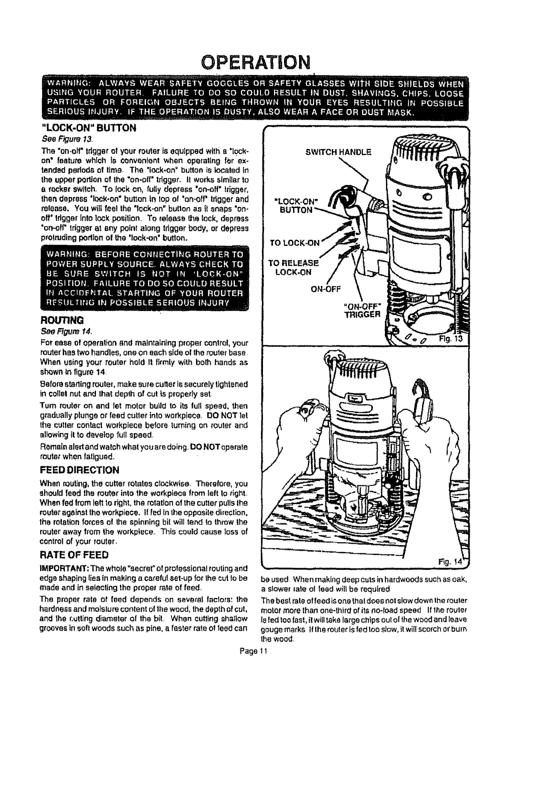
VARIABLE SPEED CONTROL SELECTOR
See Figure 12_
Yourrouterhasavadable speedcontrolselectordesignedto
sttOwoperatorcontrolof speed and torquetirnitsoYoucan
make speed selections best suitedto the type of cut, the
maletta| being cut, end the size o! bit betng used The
vadsbIespeed contlotselectorallows you to adjustrouter
speedfrom10,000 to 25,000 rprn, There is a sixstepscale
letteredA to F on the vadable speedcontrolselector To
increasethespeedandtorqueofyourrouter,turnthevariable
speedcontrolselectorto a higher setting Turn to a lower
settingto decreasespeed and torque NOTE: tf youdonot
wantto use the vadabtespeedcontro!selector,turn!o the
highestpossiblesetting,and thefeaturewit|notbe acSve
The speed selectionchart showngives suggesh_:l speed
settings basedon thediameterof the cutter'andthe typeof
matedal beingrouted
............ Si 'EEOSELECr ONC.X.
TO INCREASE TO DECREASE
O
SPEED
CONTROL SELECTOR
Fig t2
PRACTICE BEFORE ACTUAL USE
SeeFigure 12,
Wesuggestthatyou practicewiththe variablespeedteatur_
of yourtouterbators installingacutterand makingcutsir_
wood
Page 10
OPERATION
"LOCK-ON" BUTTON
See Figure13
The "on.off"tdggerof your routerisequippedwitha"lock-
on" featute which ls convenientwhen operatingfor ex.
tendedpedodsof time, The 'lock.on"buttonis totaled In
theupperportionof the "on-off"tdggero it workssimilarto
a rocker switch.,To lock on, futiy depress "on-off"trigger,
thendepress"lock-on=button in topo! 'on-off"triggerand
release. Youwill feel the "lock-on"buttonas it snaps"on*
off' tdggerIntolock position,To release the lock, depress
'on-off"triggerat any pointalong tdggerbody, or depress
protrudingpodtonol the "lock-on"butlon.
ROUTING
See Figure 14,
Forease of operationand maintaining propercontrol,your
muter hastwohandles,one on eachsideofthe routerbase,
When usingyour muter hold It firmlywith both handsas
shownin figure14.
Beforestartingrouter,makesurecutterissecurelytightened
in collarnut andthat depth of cutis properlyest.
Tum muter on and let motor butldto its full speed, then
graduallyplungeor feedcutterintoworkpiece,130NOT let
the cutlercontactworkplacebefore turningon routerand
allowingit to develop full speed,,
Remainaledand watchwhatyou aredoing. DONOT operate
router when fatigued.
FEED DIRECTION
Whenmuting, thecutter rotates clockwise.Therefore,you
should feed the muter into the workpiecefrom leftto right°
Whenfed fromleft to right,the rotation of thecutterpullsthe
muter against thework_iece. If fedtn the opposite direction,
the rotation forcesof the spinningbi!willtend to throwthe
muteraway fromthe workpiece,,This couldcause lossof
controlof your router,
RATE OF FEED
IMPORTANT:The whole "secret" of professional routingand
edge shaping ties in making acareful set-up for the cut to be
made and in selecting the proper rate of feed,,
The proper rate of feed depends on severalfactors: 1he
hardness and moisture conlent o! tile wood, the depth of cut,
and the cutting diameter of the bit,. When cutting shatlow
grooves in soft woods such as pine, afaster rate of feed can
be used When making deep cuts in hardwoods such as oak,
a slower rote of feed wilt be required
The best rate of feed is one that d_s not slow down the fouler
motor more than one-third of ils no_foadspeed If the router
Is fed too fast, itwill take large chips out of ihe wood and leave
gouge marks ifthe muter Is fed too slow, it will scorch or burr_
the wood,
Page 11
OPERATION
PROPER FEEDING
The right feed is neithertoofast nor too stow It is the rate
atwhichthebil is beingadvanced firmly andsurelyloproduce
a conlinuoussplraIof uniform chips-- withouthoggtnginto
thewoodtOmake fargo individua!chips or,ontheotherhand,
tocreateonlysawdust, tfyouaremaklngasmafldlameter,
shallowgroovein soft, dry wood,the properfeed may be
aboutas fast as youcan travelyourrouteralong yOL_guide
linerOn theolherhand.if thebitIsalarge one,thectJtIsdeep
orthewoodIsherd tocut,theproperfeedmay be a veryslow
one, Then, again, a cross-grain cut may require a slower
pacethanan Identical withgrain cutin thesameworkplace.
There is no fixed ruts, You willlearn by experfence from
practiceand use. The best rate of feed is determined by
listeningto th_soundof the router motor and by feeling the
progressof eachcut. If at all possible,aJwaystesta cuton
ascrappiece of the workplacewood,beforehand
SPEED SELECTION
In general,if thematerialbeing cutis hard,thecuttersize is
large,or thedepthofcutis deep (maximumI/8 in..),thenyour
routershould berunat slowerspeeds.When thesesituations
exist,turnthevariable speed controlselectoruntilthedesired
speed is m.s_.. NOTE: Carbidecutters cut at htgher
speeds than stee! cutlers and shouldbe usedwhen cutting
very hardmalari!!a..
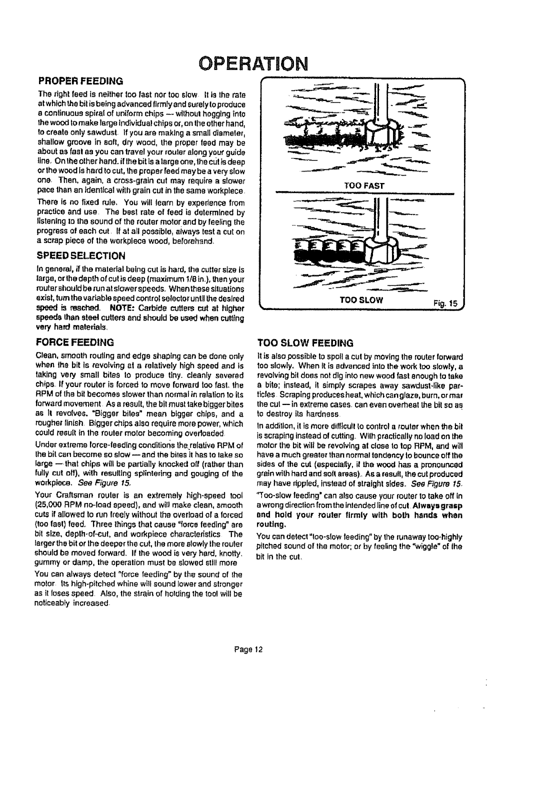
FORCE FEEDING
Clean, smooth routing and edge shaping can be done only
when the bit is revolving at e relatively high speed and ts
taking very small bites Io produce tiny. cleanly severed
chips..If your router is forced to move forward too fast. the
RPM of the bit becomes slower than normal in relation to its
forward movement AS a result, the bit must take bigger bites
as 1! revolves, "Bigger bites" mean bigger chips, and a
rougher finish. Bigger chips also require more power, which
could resuft in the router motor becoming overloaded
Under extreme force-feeding conditions the rstative RPM o!
the bit can become so slow --and the bites it has to lake so
large --. that chips wgt be pa_atty knocked off (rathor than
fully cut off), with resulting splintering and gouging of the
workpiecao See Figure 15,
Your Craftsman router is an extremely high-speed tool
(25,000 RPM no-load speed}, and will make clean, smooth
cuts if allowed to run treefy without the overload of aforced
(too last) feed° Three things that cause "forge feeding" are
bit size, deplh-of.-cut, and workpiece characterfstics The
larger the bit or thedeepar the cut, the more stowty the muter
should be moved forward.+ If the wood ISvery hard, knotty,
gummy or damp, the operation must be slowed still more
You can always de_ecl "force feeding" by the sound of the
motor, tts high-pitched whine will sound tower and shonger
as it loses speed. Also, the strain of holding the tool WIll be
noticeably increased.
TOO SLOW FEEDING
It is atso possible to spoil a cut by moving the router forward
tooslowly° When It is advanced into the work too slowly, a
revolving bit does not dig into new wood fast enough to take
a bite; instead, if simply scrapes away sawdusHike par-
ticles. Scraping produces heat. which can glaze, burn, or mar
the cut -- in extreme cases, can even overheat the bit so as
to destroy Its hardness
In addition, it is more difflcuf! to control a router when the bit
is scraping instead of cutting.. Wtlh practically no load on the
motor the bit wilt be revolving al close to top RPM, and WIll
have amuch greater lhan normal tendency to bounce off lhe
sides of the cut (especlafly, it the woo,d has apronounced
grainwith hard and sofl areas)• As a result, the cut produced
may have dppled, insteadof straight s_des., See Figure tS_
"Too-slow feeding" can also cause your router to take off tn
awrong direction from the Intended line of cut. Always grasp
end hotd your muter firmly with bolh hands when
muting.
You can detect "too-slow feeding" by the runaway too-highly
pitched sound of the motor; or by feeling the "wiggle* of the
bit in the cut,
Page 12
OPERATION
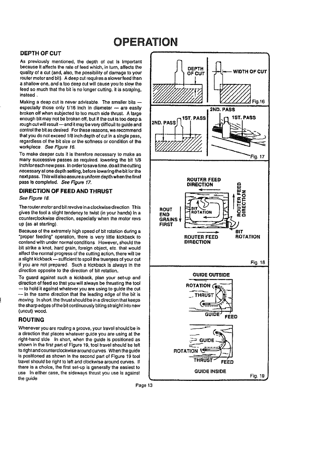
DEPTH OFCUT
As previouslymentioned, the depth of cut is important
becauseit affectslhe rate of feed which,in turn,affectsthe
quality of acut(and,also,thepossibilityof damageto your
muter motor andbit). Adeep cutrequiresa s_owerfeedthen
ashallowone,and e toodeep cutwillcauseyou to slowlhe
feedso much that the bit is nolonger cutting, {tis scraping,
instead..
Makinga deep cutis never advisable. The smallerbits
especially those only It16 fnchtn diameter _are sassy
brokenoffwhensubjectedtotoomuchside thrust, Alarge
enoughbitmaynolbe broken off,but if thecutis toodeep a
rough cutwillresult--and itmaybe verydifficu!ltoguideand
controllhe bitas desired. For_ese reasons,we recommend
thatyoudo notexceed118inchdepthof cutin a slng;epass,
regardless o! the bitsizeor thesoftnessorconditionof the
workplace. See Figure 16.
To make deeper cutsit is therefore necessaryto make as
manysuccessive passes as required,lowering the bit ltB
Inchforeech newpess_inordertosavetime,doail thecutling
necessaryatone depthsetting,beforelowering|he bit [orthe
nextpass, Thtawiltalsoassureauniform depthwhenthefinal
passls complefed, See F/gum1Z
DIRECTION OFFEEDANDTHRUST
_eFigumte,
Theroutermotor andbit revolveinaclockwisedlrection.This
give9 the'Isol a slighttendency totwist(in yourhands)In a
counlerclockwisedirection, especially when lhe motor rays
up (as at starling).
Becauseot theextremely high speed of bit rotationduring a
"properfeeding"operation, there is very liL1tekickback to
contendwithunder normal conditions However,should the
bit strikea knot,hard grain,foreign object,etc. that would
alfect the normal progressof thecullingaction,thereWillbe
a slightkickback--sufficient to spoi!the truenessofyourCUt
if you are not preparad_Such _ ktckback Jsalways tn the
directionopposite to the directionof bit rotation,
To guard againstsuch a ldckback, plan your set-up and
directionoffeed sothatyouwillalwaysbe thrustingthetOOl
-- tOholdit againstwhateveryouare usingto guidethe cut
-- in the same direction that the 3eadingedge of the bit is
moving. In shod.thethrustshouldbeina direction thatkeeps
thesharpedgesofthebitcontinuouslybiting straigh!intonew
(uncut)wood,
ROUTING
Whenever you are muting a groove, your lravel should be in
a direction thai places whatever guide you are using at the
fight-hand side In short, when the guide is posiltoned as
shown in the first pat1 of Figure 19, tool travel shoutd be left
to right and counterclockwise around curves. When the guide
is positioned as shown in the second part of Figure 19 tool
travel should be right to left and clockwise around curves.. If
there is a choice, the first sol-up is generally the easiest to
use In eilher case, the sideways thrust you use is against
the guide
Page t3
DEPTH _WIDTH OF CUT
................. _ Fig,!6
,,,llJ , ILl _..l'l'r
2ND. PASS
_ISTo PASS _,,
__ ,....... _ _,
ROUTER FEED
DIRECTION w
END
GRAINS
FIRST
ROUTER FEED ROTATION
DIRECTION
Fig, !8
GUIDE OUI_IDE
ROTAT N _'_'_
THRUST.J ,"
FEED
GUIDE INSIDE
__ Fig. !9._
OPERATION
EDGE ROUTING
Placerouteron workpieca,making sureIhe router bitdoes
notcontactworkplace Turnrouter onand letmotor buildto
its futlspeed Beginyour cut, gradually feeding cutterInto
workpfeceo
Uponcompletionof cut,tam motor off and let it coma to a
completestopbefore removingrouterfrom work surface.
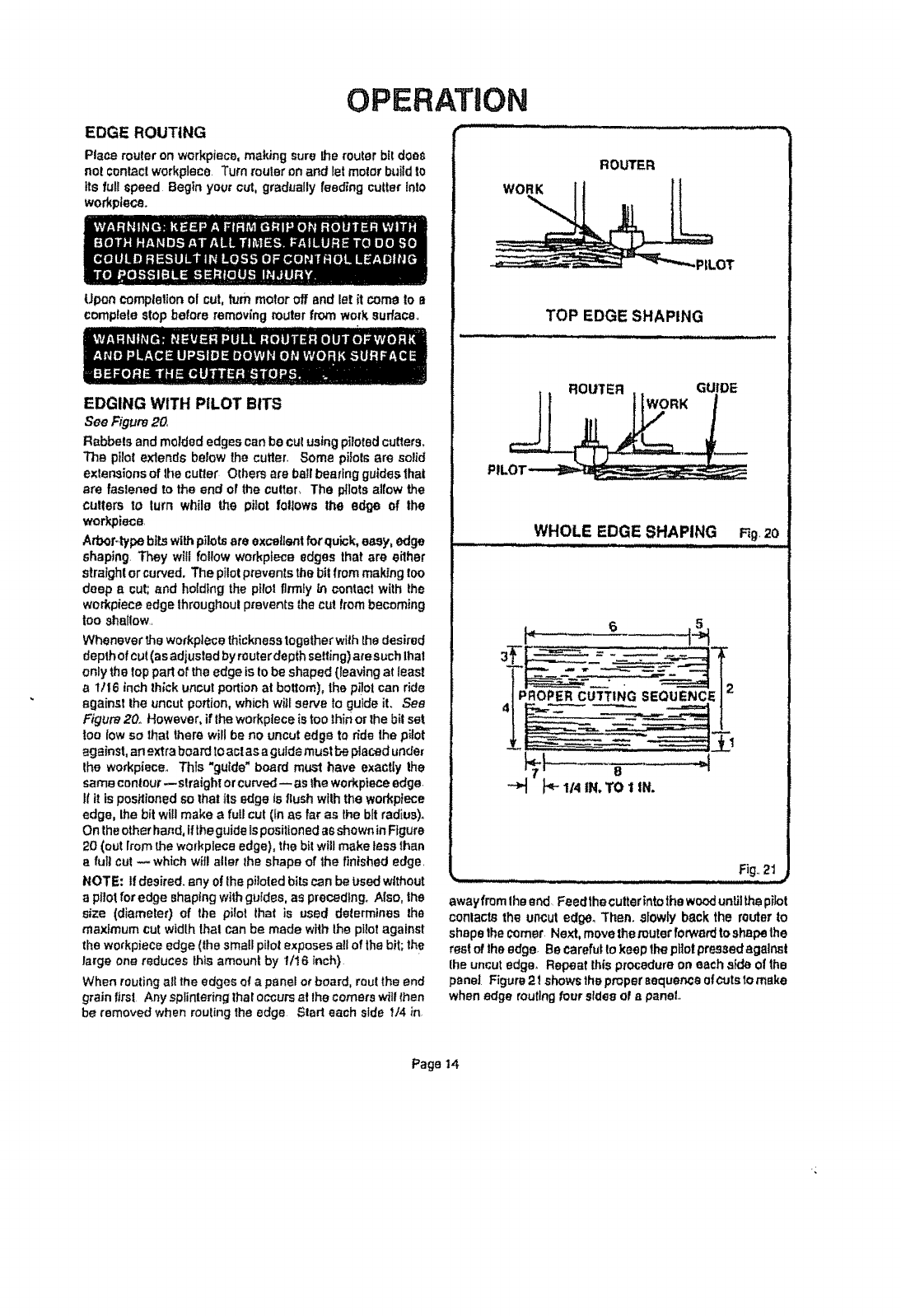
EDGING WITH PILOT BITS
See Figure20,
Rabbetsandmolded edgescanbe cul usingpilotedcutters,
The ptiolextendsbe_owthecutter, Somepilotsare solid
extensionsof the cutler Others are ballbeatingguidesthat
are fastenedto the end of theculter_ The pilots allowthe
cutlers to turn while the pilot follows the edge of the
worP,pieca.
ArboPtypebilewithpilotsare exce!|sntfor quick, easy, edge
shaping.They will follow workplaceedgesthat are either
straight orcurved,The pilotpreventsthebitfrommaking 1oo
deep acut;and hoidlngthepfrotfirmlytn contactwith the
workplace edge throughout prevents thecut frombecoming
too shallow.
Whenevertheworkplacethicknesstogetherwiththe desired
depthofcut(asadjustedby routerde_thsetting)aresuchthai
onlythetop partortheedgeis tobe shaped(leavingat Ieast
a1/16 inchIhJckuncutportionat bottom),thep_etcan ride
against the uncut portion,whichwill serve to guideit. See
Figure20° However,if the workplaceis toothinorthebitset
too low so that there willbe no uncutedge to _de the pilot
against,an extraboardto act asaguide mustbepiecedunder
the workpieceoThts"guide"board mt_l have exactlythe
samecontour--slraight orcurved-- as theworkpieceedge.
Ifit ispesHienedso thatits edgeksflushwiththe workplace
edge,thebit willmake a fuUcut(In as far as the bftradius),
Ontheotherhand,iftheguide tspositionedasshowninFfgure
20(out fromthe workplaceedge),the bit willmake tess than
afullcut _ whichwillalter the shapeof the finishededge.
NOTE: Ifdesired,any ofthepilotedbits canbe Ltsedwithout
a pilotfor edge shapingwithguides, aspreceding,Also, the
size (diameter) of the pilot that is used determines the
maximum cutwidth thai can be made withthe pilotagainst
theworkpieceedge (the smallpilot exposesallof thebit;the
large onereduces Ihis amount by U!6 Inch)
Whenroutingall theedgeso! a panel orbeard, routtheend
grain first Anysplinteringtharoccursalthecomerswfllfhen
be removedwhen routingthe edge Start each sldef/4 in,
ROUTER
-_LOT
TOP EDGE SHAPING
WHOLE EDGE SHAPING F_g,20
x ...:: • :.: ..... _nnlHnl±J.,, m
"-_ PP 1/4 IN.TO tIN.
Fig..21
awayfromtheend. Feedthecutterintothewooduntilthepilot
conlactsthe uncut edge, Then. slowlYbackthe router to
shapethecomer Next,movethe muterforwardtoshape lhe
rest oftheedge. Be carefulto keepthepttotpressedagainst
Ihe uncut edge, Repeat thisprocedureon eachaide of the
panel Figure2f showsthepmpersaquer_eofcutstomake
whenedge mutingfour sidesof apanel
Page14
OPERATION
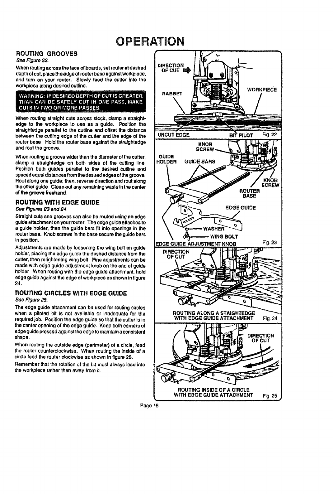
ROUTING GROOVES
See Figure22._
Whenroutingacrossthefaceofboards,set muteratdesired
depthofcut,placetheedgeof routerbaseagainstwod_piece,
and turn on your muter. Slowly feed the cutterinto the
workplacealongdesired cutlino.
When muting straight cuts across stock, clampastraight-
edge to the workplace to USe as a guide_ Positionthe
straightedgepsmtlelto the cutllne and offsetthe distsnca
betweenthe cuttingedge of the cutterand the edge of the
router base. Hold the routerbass agains!theslralghtedge
and rout thegroove..
V_en _oulinga groovewiderthan thediameterof thecutter,
damp a straightedgeon both sides of the cutting line.
Position both guides porollel to the desired cutltne and
spaced equal distancesfromthe desirededges ofthegrceveo
Routalong oneguide;then,reverse dtrsclionandroutalong
theotherguide..Cleanout anyrerna|n[ngwasteIn thecenter
of the gtom,'efmeha.ndo
ROUTING WITH EDGE GUIDE
See FK_T.tres23 and 24.,
Straightcutsand groovescan alsobe routedusingen edge
guideattachmenton yourmuter._Theedge guide attachesto
a guide holder,then the guidebars fit into openingsin the
muterbase. Kttobscrewsin the basesecurethe guidebars
inposition.
Adjustmentsare made bylooseningthe wingbolton guide
holder,placingtheedge guide thedesireddistance fromthe
cutter,thenretighientngwingbolt. Fine adjustmentscanbe
made withedge guideadjustmentknobon the end of guide
holder. When mutingwith the edge guideattachment, hold
edgeguideagainst theedgeof workplaceas showninfigure
24_
ROUTING CIRCLES WITH EDGE GUIDE
See Figure25,
The edge guideattachmentcan be used for routingc|mles
when apiloted bit Is not available or inadequatefor the
requiredjob° Positiontheedge guideso thatthe cutteris in
thecenteropeningof the edgeguide. Keep bolh comersof
edgeguidepressedagainsttheedgetomaintaJnaconsistent
shape.
When mutingthe outsideedge (perimeter)of a circle,feed
Ihe muter counterclockwise.When routingtheinsideof a
circlefeed therouter clockwiseasshowntnfigure25.
Remember that the rotationof the bitmustalways lead_nto
_heworkplace ratherthan away from i1,
UNCUTEDGE
KNOB
GUIDE
HOLDER GUIDE BARS
ROUTER
BASE
EDGE GUIDE
WING BOLT
EDGI_GUIDE ADJUSTMENT KNOB
SCREW
Page t5
OPERATION
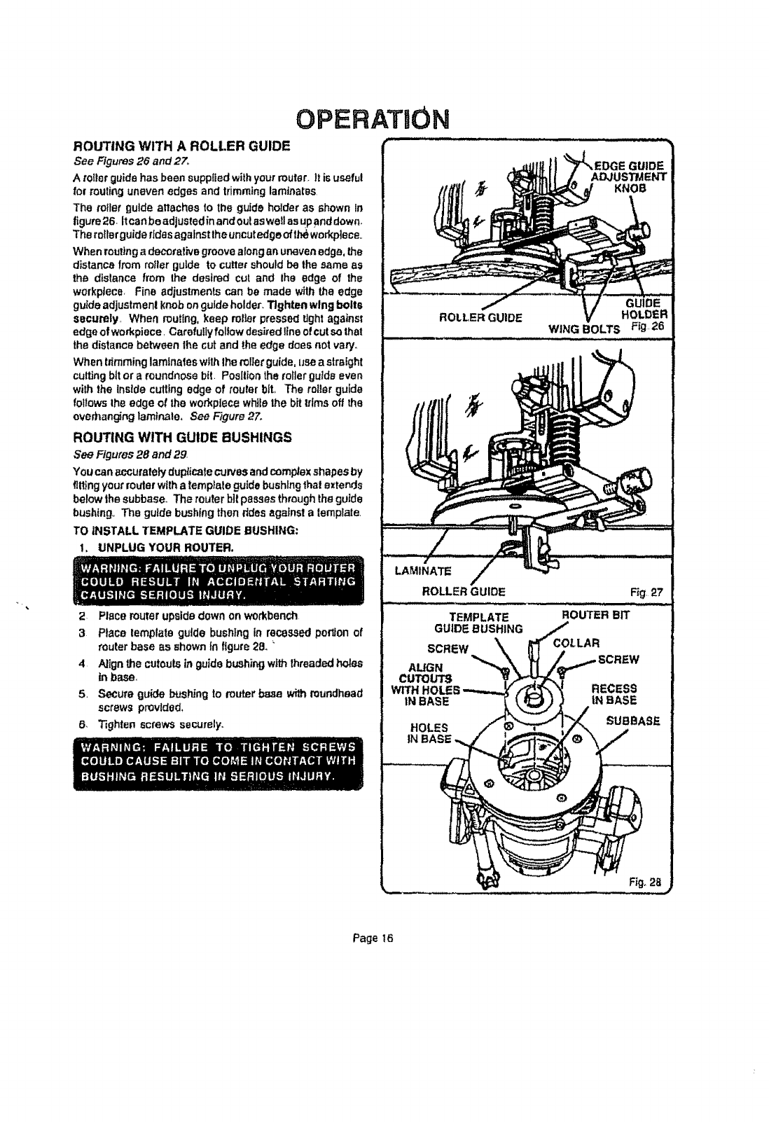
ROUTING WITH A ROLLER GUIDE
See Figures26 and27.
A roiterguide has been suppfledwithyourrouter,it is useful
for routing unevenedges and trimming laminates
The miler guide attachesto theguide holder as shown In
figure26. Itcanbeadjustedinandoutaswellasupand down,
Therotlerguideridesagalnsttheuncutedge oftt_ workpiece
Whenroutingadecorative groovealonganunevenedge,the
distance fromroiter guide to cutletshouldbe thesame as
the distance from the desired cut and ihe edge of the
wed<piece Fine adjustments can be made withthe edge
guide adjustmen!knob onguideholder.Tighten wingbolts
securely When routing,keep roller pressed tightagainst
edge of wofkpJece r Carefullyfollowdesiredline ofcutsothat
thedistance between lhe cut and _e edge doesnot vary.
Whentrimminglaminates withlhe milerguide,use astrelght
cutting bit or a roundn0se bit Positiontherof]erguide even
with the Inside cutting edge of router bit, The roller guide
followsthe edge ot the wed<piecewhilethe bit trimsoff the
ovedlanginglaminate, See Figure27.
ROUTING WITH GUIDE BUSHINGS
See Figures28 and29
Youcanaccuratelyduplicatecurvesandcomplexshapesby
fittingyourrouter wtlha templateguide bushing thai extends
belowthe subbaseoThe router bit passes throughtheguide
bushing The guidebushing thenddesagainstatemplate
TO INSTALL TEMPLATE GUIDE BUSHING:
1. UNPLUG YOUR ROUTER.
2 Placerouterupsidedownon workbench
3Place template guide bushing in recessedporUonof
routerbase as shOWnIn figure:28.
4Align thecutoutsinguidebushingwithlhreaded holes
inbase_
5. Secure guidebushJngto muter base withroundhead
screws provided,
6, Tighten screws securely_
GUIDE
ROLLER GUIDE HOLDER
WING BOLTS F_g 26
TEMPLATE ROUTER BIT
GUIDEBUSHING
SCREW
ALIGN
CUTOUTS
WITH HOLES
IN BASE
HOLES
INBASE
Page t6
OPERATION
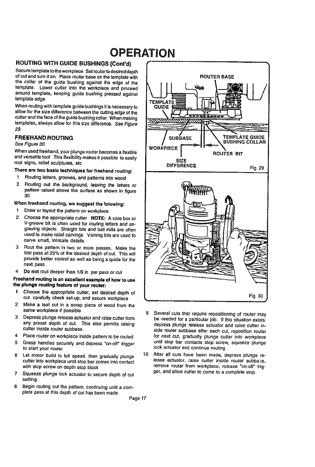
ROUTING WITH GUIDE BUSHINGS (Cont'd)
secure templatelethe workplace Set routertodesireddepth
of cut and turnIfon- Placerouterbase onthe _mptate with
the co]lar of tl_e guide bushing againstIhe edge of the
template. Lower cutter into the workplaceand proceed
around template, keepingguide bushing pressed againsl
templateedge,
Whenroutingwithiemplate guidebushingsIt isnecessaryto
allow for the sizeditfemncebetweenIhe cuttingedgeof the
cutterand lhefaceof thegutde bushing ce_lar..Whenmaking
templates, alwaysallowfor thissizedifferenct),See Figure
29,
FREEHAND ROUTING
See Figure3o_
Whenusedfreehand,yourplungerouter becomesaf_exibfe
and versatIletoot. ThisI|exibitltymakes ft posstble toeasily
routsigns, relief sculptures, etc
3"heroare two basic teChnfquesfor freehand routing:
1Routingletters,grooves,end patternsintowood
2.. Routing out lhe background, ie_vIng the ferlers or
paffem raised above the surface as shownin figure
30.
When freehand routing, we suggeet the folowing:
1. Draw or layoutthepatternon workpiece.
2. Choose the appropriate cutter_NOlrE: A corebox or
V-groove bit is often used for toutingletters and en-
graving objects° Straight bits and ball mJUSere often
used Io make reliefea_ings Veiningbits areused to
carve small, Intricate details.
3 Rout the pattern in two or more passes, Make the
first passat 25% of the desired depthof cuL Thiswilt
providebettercontrolas wellas being a quideforlhe
next pass.
4 Do not rout deeperthan 1/8in per passor cut
Freehand ro_tlng is an excellent a_ampleof howto use
the plunge routing feature of your route_:
t. Choose the appropriatecutter,set desired depth of
cut. carefullycheckset-up, end secure workplace.
2. Make a test cut in a scrap piece of woodfrom the
same workplaceifpossible. 9
3. Depressplunge rereasoactuatorand raise cutterfrom
any preset depth of cut.. This also perrnttsraising
cutterInside routersubbase,.
4Place router on workpiece Insidepattern Io be touted
5Grasp handles securely and depress "on-off" tdgger
Io start your router,
6Let motor build to full speed, thengraduallyplunge 10.
cutterInto workplaceuntilstop bar comesinto conlact
withstopscrew on depth stepblock
7Squeeze plunge lockactuator to secure depth of cu!
setting.
8, Begin routing out thepattern,continutr_guntila com.
plate passat thisdepthof cut hasbeen made Page 17
WORKPIECE
SIZE
DIFFERENCE
ROUTER BIT
Fig.,29
Several cuts that require reposilioning of rouler may
be needed for a parlicular job, if this situalion exists,
depress plunge release actuator and ralse cutter in-
side router subbase after each cul, reposftion router
for next CUt, gradually plunge culler into workpiece
until stop bar contacts stop screw, squeeze plunge
lock actuator and continue routing,
After all cuts have been made, depress plunge re-
tease actuator, raise cutter inside router subba;e,
remove router from wmkplece, release "on.elf" trig-
ger, end allow cutter to come to a complele stop..
GENERAL
MAINTENANCE
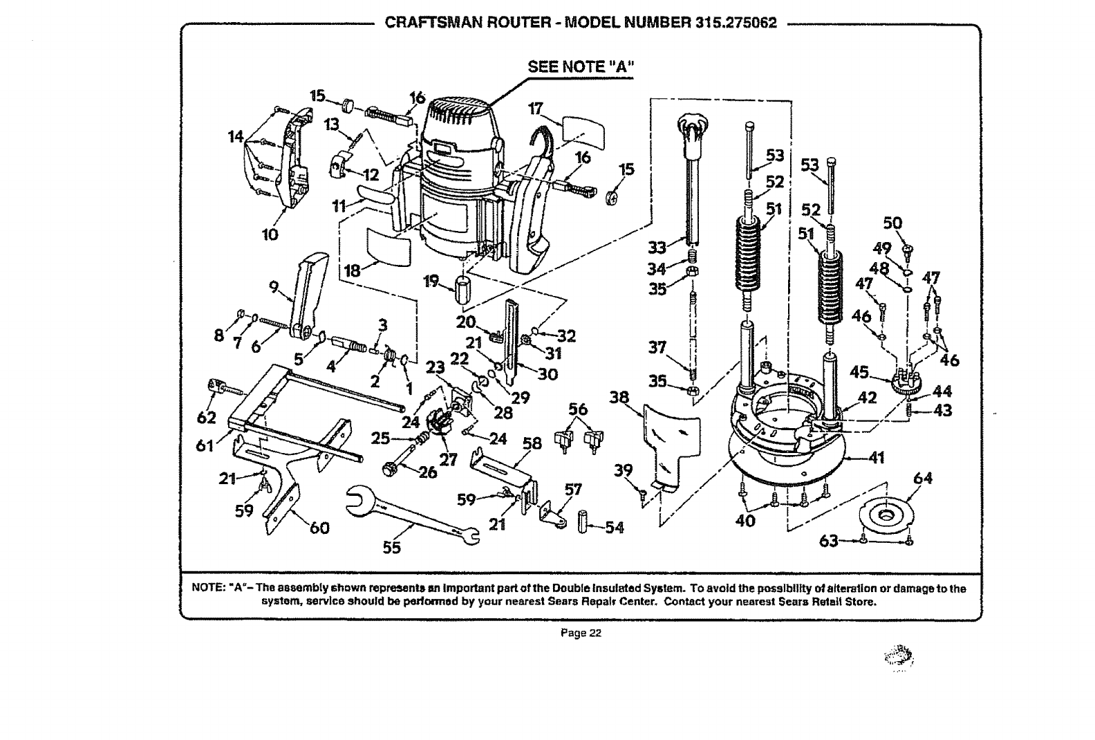
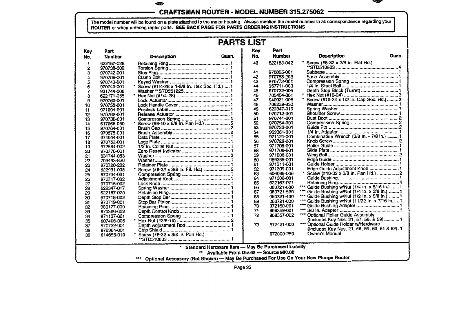
Onlythe partsshownon pads list,page 23, are Intendedto
be repatred or replaced by the customer AI! otherparts
represent an importantpart of the doubleinsulationsy.stem
and Shouldbe servicedonly by aqualified Seam _ervice
technician.
Avoid using solvents when cleaning plastic paR& Most
plastP..sare r_._sceptibleto various _pes of commercial
solvents and may be damaged by their use, Use clean
clothsto remove dirt,carbondusl, etc_
When electdc Iools are used on fiberglass boats, sports
cars, wallboard, spackling compounds,or plaster, it has
been foundthat they are subject to acceleratedwear and
possiblepremature failure, as the fiberglass chips and
grfndtngs are highly abrasive to beatings, brushes,
commutator,etc. Consequently,it ts not recommended
thatthis toot be used for ax_endedwork on any fiberglass
material, wallboard, spackling compounds, or plaster.
Duringany use on fiberglassit is ewtremelyimportant that
the too! Is cleaned frequently by blowingwithan air Jet.
PROPER CARE OF CUTTERS
Get fastermore accuratecuttingresultsby keeptngcutters
clean andsharp.RemOveallaccumulatedpitchandgumfrom
cuttersafter each use..
When sharpeningculters, sharpen only the inside of the
cuttingedge_Nevergrindtheoutsidediameter..8e surewhen
sharpening theend ofaculler togrind theclearance angle the
same as orlglna!lyground
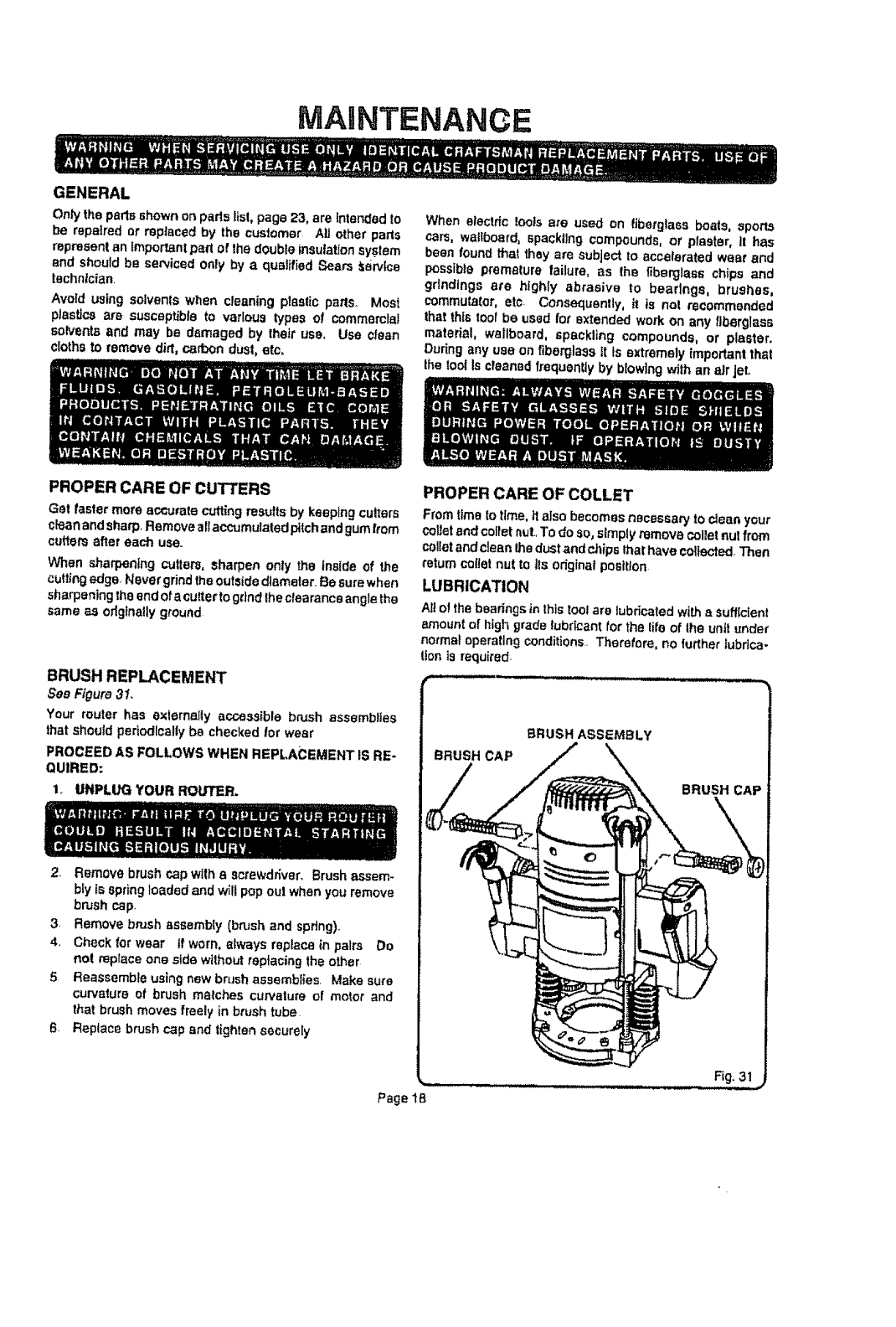
BRUSH REPLACEMENT
See Figure3I.
Your router has externally accessible brush assemblies
that shouldperlodlcallybe checkedfor wear
PROCEED AS FOLLOWS WHEN REPLACEMENT IS RE-
QUIRED:
1.. UNPLUG YOUR RoL,rrER.
PROPER CAREOFCOLLET
FromtimeLotime,italso becomes necessaryto clean your
callerendcallernut..To do so, simplyremovecallernu! from
callerandcleanthedustand¢J_ips,hathave collected.Then
_etumcol_etnut to Its odginafposition
LUBRICATION
Al!at the bearings in this tool are lubricated with a sufficient
amount of high grads lubricant for the lifo of the unit under
normal operating conditions, Therefore, no further lubdca-
lion is required,
2, Remove brush cap with a screv_d_ver, Brush assem-
bly is spring loaded and will pop out when you remove
brush cap.
3. Remove brash sssembty (bn_sh and spdng),
4, Check for wear tf worn, always replace in pairs Do
not replace one side without replacing the other
5 Reassemble using new brush assemblies. Make sure
curvature of brush malches curvature of motor and
that brush moves freely in brush tube
6Reptace brush cap and tighten securely
Page lE,
MAINTENANCE
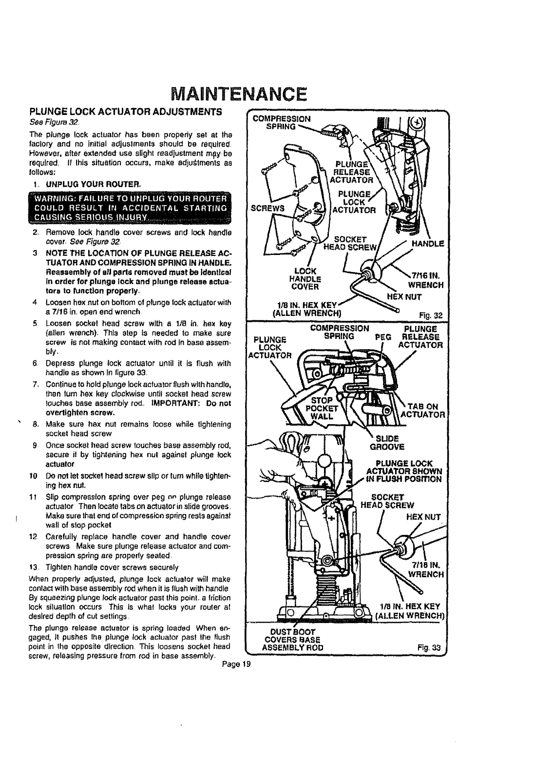
PLUNGE LOCK ACTUATOR ADJUSTMENTS
SeeFigure32
The plunge tack actuator has been properly set at the
factory and no initial adjustments should be required,
However, after extended use slight readjustment mlty,be
required, If this situation occurs, make adjul_tments as
follows:
t, UNPLUG YOUR ROUTER.
2. Remove lock handle cover screws end lock handle
cover_ See Figure 32
3 NOTE THE LOCATION OF PLUNGE RELEASE AC-
TUATOR AND COMPRESSION SPRING IN HANDLE.
Reassembly of all parts removed must be identica!
In order for plunge lock and plunge release ac!lua,_
tara to function properly,,
4 Loosen hex nut on bottom of plunge lock actuator with
a7/16 inoopen end wrench,
5 Loosen socket head screw with a 118 in, hex key
(allen wrench). This step is needed to make sure
screw Is not making contact with tad tn base assem-
bly.
6, Depress ptunge lock actuator unlil it ts flush with
handle as shown In ligure 33,
7< Continue to hold plunge lock actuator flush with handle,
then turn hex key clockwise until socket head screw
touches base assembly rod,, IMPORTANT: Do not
overtighten screw,
8o Make sure hex nut remains loose while tightening
socket head screw
9Once socket head screw touches base assembly rod,
secure it by tightening hex nul againsl plunge lock
actuator
l0 Do not let socket head screw slip or turn while lighten-
ing hex nut,
11 Slip compression spring over peg or, plunge release
actualor Then locate tabs °n actuat°r in slide gre°ves '
Make sure that end of compression spring rests against
wall ofslop pocket.
12, Carefully replace handle cover and handle cover
screws Make sure plunge release actuator and com-
pression spring are propedy seated,
t3, Tighten handfo cover screws securely
When propedy adjusted, plunge lock actuator will make
conlacl with base assembly rod when it is flush with handle
By squeezing plunge lock actuator past this point, alliclion
lock siluatlan occurs This ts what locks your router at
desfred depth of cut settings,
The plunge release actuator is spring toacted When en-
gaged, It pushes Ihs plunge lock actuator past the flush
point in the opposite direction, This loosens sockel head
screw, releasing pressure from rod in base assembly,,
Page 19
COMPRESSION
SPRING
__ _1.. PLUNGE
|_ RELEASE
_ tACTUATOR
li I PLUNGe,
L_t _ LOCK
S _] ACTUATOR
,_t SOCKET
LOCt_
HANDLE
COVER
HANDLE
i IN,
WRENCH
HEX NUT
1/8 IN. flEX KE'_
(ALLEN WRENCH) Fig, 32
COMPRESSION PLUNGE
PLUNGE SPRING PEG RELEASE
LOCK ACTUATOR
ACTUATOR
MAINTENANCE
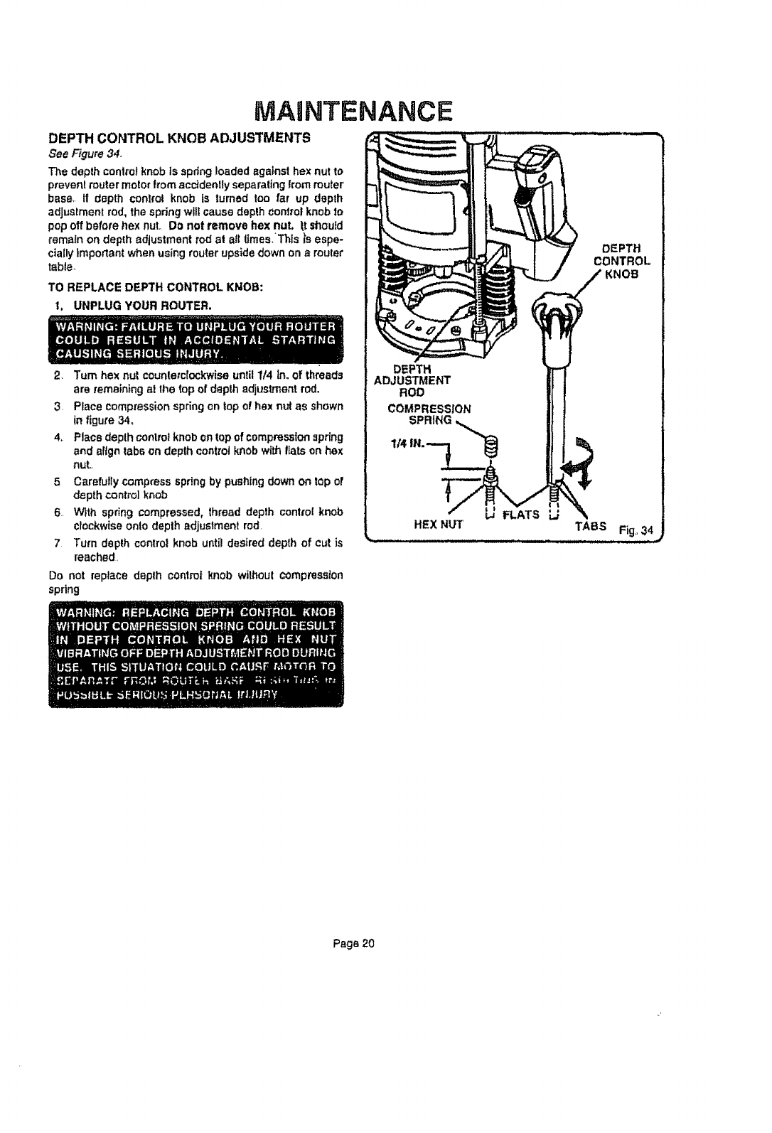
DEPTH CONTROL KNOB ADJUSTMENTS
SeeFigure34.
The depth control knob ts apdng loaded against hex nut to
prevent router motor from acddently separating from router
base,, ff depth control knob is turned too far up depth
adjustment rod, the spring wllf cause depth control knob to
pop off before hex nut., Do not remove hex not. _t should
remain on depth adjustment rod at all fJmes_Thts is espe-
cially important when using router upside down on a router
table.,
TO REPLACE DEPTH CONTROL KI_OB:
1, UNPLUG YOUR ROUTER.
2. Turn hex nut counterclockwise until 1/4 In. of threads
are remaining at the top of depth adjustment rod.
3. Place compression spring on top of hex nut as shown
in figure 34_
4,, Place deplh control knob on top of compression -qpdng
and align tabs on depth control knob with fiats on hex
nut.,
5Carefully compress spring by pushing down on top of
depth control knob
6. With spring compressed, thread depth control knob
Clockwise onlo depth adjustment rod.
7Turn depth control knob until desired depth of cut is
reached,
Do not replace depth controlknob wilhoul compression
spring
DEPTH
CONTROL
DEPTH
ADJUSTMENT
ROD
COMPRESSION
1SPRtNG%
FLATS L,;
HEX NUT TABS Fig, 34
Page 20
O V
CRAFTSMAN ROUTER - MODEL NUMBER 315.275062 ..............
|The model number will be found on a plate _hed to the motor housing. AJways men_,on the model number m at! correspondence regard_j your ]
'e r ee PAGe.FO. mORDe.l I,S O.S .!
Key Part
No. Number
_. 622167-028
2 970738-002
3 970742-001
4 970709-001
5 970743-001
6 970740-001
7931744-006
B 622171-055
9970760-001
10 970758-001
11 971094-001
I2 970762-00I
t3 970736-O01
t4 617966-030
t5 970764-001
i6 970875-001
17 974044-001
18 970752..00t
T9 972564..002
20 970770-O0t
21 931744-063
22 7O3493-820
23 970720-202
24 622931-008
25 970734.-001
26 970717-OO2
27 9707t5,.002
28 622347-0t7
29 622167-070
3O 97O718-O02
31 970719.-001
32 989177-000
33 97O866-002
34 971137-001
35 607406-005
37 970732-001
38 970864-001
39 614658`010
PARTS LIST
Description Qu_n.
Retain|ng Ring .............................................. 1
Torsion Spring ............................................... t
Stop Plug ....................................................... 1
Clamp Bolt .................................................... 1
Keyed Washer .............................................. 1
* Screw (#1/4-2B x 1-5/8 3n. Hex Soc. Hd.) .... 1
Washer "*STD551_5 ................................... I
*Hex Nut (#I/4-28) ........................................ 1
Lock Actuator ............................................... 1
Lock Handle Cover .......................................1
Posilock Label...............................................1
Release Actuator .......................................... 1
Compression Sp_'klg .................................... I
• Screw (#B-t0 x 5/8 |n, Pan Hd.) ................... 5
Brush Cap .....................................................2
Brush Assembly ............................................2
Data Plate ..................................................... 1
Logo Plate ..................................................... 1
112 in.CotletNut ...........................................I
Zero Reset Indicator .....................................I
Washer .......................................................... 3
Washer ..........................................................I
Reteiner Plate ..............................................1
"Screw (#6-32 x 3/8 In. FIL Hd.) ................... 2
Compression Spring ..................................... t
AdjustmentKnob ...........................................1
Lock Knob .....................................................t
SpringWasher ..............................................I
RetainingRing..............................................I
Depth Stop Bar .............................................. 1
Stop Bar Pinion ............................................. 1
Retaining Ring ............................................... 1
Depth ControlKnob .......................................I
ComDresslon Spnng .....................................I
"Hex Nut (#3/8-16) ......................................... 2
Depth Adjuslment Rod .................................. 1
Chip Shie]d ................................................... 1
"Screw (#8-32 x 3/8 In. Pan Hd.)
"STD510803 ................................................ t
Key Part
No. Number
40 622183-042
41 970865-00t
42 970755-203
43 970772-001
44 967711-000
45 970722-005
46 705404-801
47 94002t-'1:)06
48 70623.9-830
49 622347-019
50 970712-001
51 970741-001
52 970754-00t
53 970723-00t
54 969361-001
55 971121-001
56 9707294:)01
57 971705-O01
58 971706-001
59 971308-00!
60 969_1
61 97131 t-0Q1
62 971309-001
63 606068K_16
64 971306-001
65 622t67-O7!
66 080721-630
67 080721-53O
68 060721-43O
69 060721-030
70 972160.-00t
7! 969359-00!
72 969357-002
73 972421--0OO
972000-259
Description Guan.
" Screw (#8-32 x 3/8 in. Rat Hd,]
"STD510803 ................................................4
Subbase ........................................................I
Base Assemb_ .............................................I
Compression bprmg .....................................I
I14In,SteelBall...........................................I
Depth Stop Block (Turret)............................I
" Hex Nut (#10-24) .......................................... 3
*Screw (#10-24 x 1/'2 In. Cap Soc, Hd,) ......... 3
Washer ..........................................................I
SpringWasher ..............................................!
ShoulderScrew .............................................I
Dust Boot ......................................................2
Compression Spring .....................................2
Guide Pin ...................................................... 2
114 In. Adapter .............................................. I
Combination Wrench (3/8 in. - 7t8 In.) ......... 1
Knob Screw ...................................................2
RollerGuide ..................................................I
Slide Plate .....................................................I
Wing Bolt ....................................................... 2
Ed_. Guide ...................................................I
Guide Holder ................................................1
Edge Guide Adjustment Knob .......................I
' Screw (#t0-32 x 3/8 In. Pan Hd.) ................. 2
Guide Bushing...............................................I
RetainingRing..............................................4
"" Guide Bushm.g w/Nut (1/4 in.x 5./16 In.) .......!
*"" Guide Bushing w/NuT (1/4 In. x 3/8 In.) ........ I
"'" Guide Bushing w/Nut (1/2 In. x 5/B In.) ........ _J
"*" Guide Bushing w/Nut (11/32 In.x7/16 Inj...!
"*" Guide Bushing Adepler ............................ :,,.. 1
"°" 3/8 in. Adapter .............................................. 1
'*" Optional Roller Guide Assembly
(Includes Key Nos. 21,57, 5B,, & 59_)........... 1
"'" OpttonaJ Guide Holder w/Hardware
(Includes Key Nos, 21, 56, 59, 60, 61 &62),1
Owner's Manual
_ll,i,
" Stendard Hardwara Item _ May Be Purchased Locally
** Available From D|v.98 _Source 980.00
Optional Accessory (Not Shown)-- May Be Purchased For Use On Your New Plunge Router
Page23
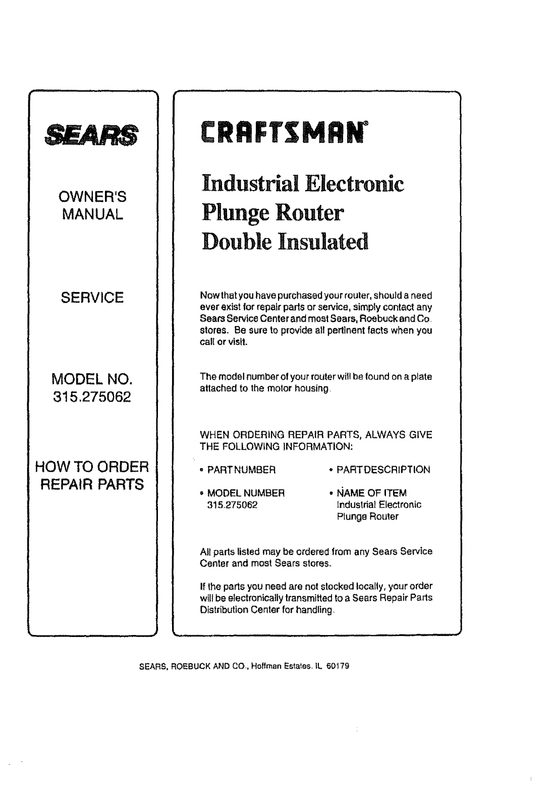
OWNER'S
MANUAL
SERVICE
MODEL NO.
315.275062
HOW TO ORDER
REPAIR PARTS
r-
Industrial Electror c
Plunge Router
Double Insulated
Nov,,that you have purchased your router, should e need
ever exist for repair paris or so.ice, simply contact any
Seam ServiceCenter and most Sears, Roebuckand Co
stores. Be sure to provide all pertinent facts when you
cat{ or visit.
The model number of your router wil! be found on a plate
attached to the motor housing
WHEN ORDERING REPAIR PARTS, ALWAYS GIVE
THE FOLLOWING INFORMATION:
° PART NUMBER ° PARTDESCRIPTION
° MODEL NUMBER
315_275062
•IqAME OF ITEM
IndustrialElectronic
Plunge Router
All parts listed may be ordered from any Sears Service
Center and most Sears stores.
If the parts you need are not stocked locally, your order
will be electronically transmittedto a Sears Repair Parts
Distribution Center for handling
SEARS, ROEBUCK AND CO,. Hoffrnan Estates, IL 50179
