Craftsman 316350220 User Manual CHAIN SAW Manuals And Guides L0611378
CRAFTSMAN Chainsaw, Gas Manual L0611378 CRAFTSMAN Chainsaw, Gas Owner's Manual, CRAFTSMAN Chainsaw, Gas installation guides
User Manual: Craftsman 316350220 316350220 CRAFTSMAN CHAIN SAW - Manuals and Guides View the owners manual for your CRAFTSMAN CHAIN SAW #316350220. Home:Lawn & Garden Parts:Craftsman Parts:Craftsman CHAIN SAW Manual
Open the PDF directly: View PDF ![]() .
.
Page Count: 53
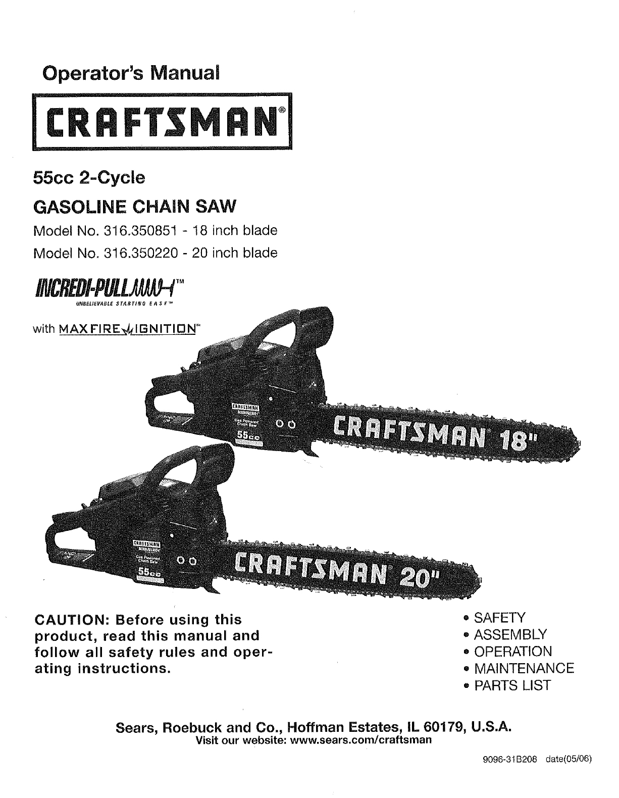
Operator's Manual
55cc 2-Cycle
GASOLINE CHAIN SAW
Model No. 316.350851 - 18 inch blade
Model No. 316.350220 - 20 inch blade
INCREDI.PULL TM
UNB£L/EVABLE STAI_TING E A $ _'_=
with MAX FI RE,vI,__!B N IT113N _
CAUTION: Before using this
product, read this manual and
follow all safety rules and oper-
ating instructions.
= SAFETY
*ASSEMBLY
*OPERATION
= MAINTENANCE
,, PARTS LIST
Sears, Roebuck and Co., Hoffman Estates, IL 60179, U.S.A.
Visit our website: www.sears.com/craftsman
9096-31 B208 date(05/06)
Warranty Page 2
Safety Rules Pages 3 - 8
Oil and Fuel Information Page 9
Starting/Stopping Instructions Pages 10-12
Operation Pages 13- 14
Maintenance and Repair Pages 15 - 21
Troubleshooting Page 22
Specifications Page 23
Repair Parts Page 24
Spanish Pages 27 - 52
One Year Full Warranty
When used and maintained according to the operator's manual, if this chain saw fails due to a
defect in material or workmanship within one year from the date of purchase, return it to any Sears
store, Sears Parts & Repair Service Center or other Craftsman outlet in the United States for free
repair (or replacement if repair proves impossible).
This warranty excludes bar, chain, spark plug and air filter, which are expendable parts that can
wear out from normal use in less than one year.
This warranty applies for only 30 days from the date of purchase if this chain saw is ever used for
commercial or rental purposes,
This warranty gives you specific legal rights, and you may also have other rights which vary from
state to state.
Sears, Roebuck and Co., Hoffman Estates, IL 60179
CALIFORNIA PROPOSITION 65 WARNING
THE ENGINE EXHAUST FROM THIS
PRODUCT CONTAINS CHEMICALS
KNOWN TO THE STATE OF CALIFORNIA
TO CAUSE CANCER, BIRTH DEFECTS
OR OTHER REPRODUCTIVE HARM.
SPARK ARRESTOR NOTE
NOTE: For users on U.S. Forest Land and in the
states of California, Maine, Oregon and Washington.
Alf U.S. Forest Land and the state of California (Public
Resources Codes 4442 and 4443), Oregon and
Washington require, by law that certain internal combus-
tion engines operated on forest brush and/or grass-cov-
ered areas be equipped with a spark arrestor, main-
tained in effective working order, or the engine be con-
structed, equipped and maintained for the prevention of
fire. Check with your state or local authorities for regula-
tions pertaining to these requirements. Failure to follow
these requirements could subject you to liability or a
fine. This unit is factory equipped with a spark
arrestor. If it requires replacement, ask a Sears or other
qualified service dealer to install the Spark Arrestor Kit,
2
The purpose of safety symbols is to attract your atten-
tion to possible dangers, The safety symbols, and their
explanations, deserve your careful attention and under-
standing, The safety warnings do not by themselves
eliminate any danger, The instructions or warnings they
give are not substitutes for proper accident prevention
measures.
SYMBOL MEANING
ISYMBOL MEANING
DANGER: Failure to obey a safety
warning will result in
serious injury to yourself or to others. Always
follow the safety precautions to reduce the
risk of fire, electric shock and personal injury.
I
SAFETY ALERT:
warning or caution. Attention is required in
:order to avoid serious personal injury. May
be used in conjunction with other symbols
or pictographs.
Failure to obey a
= HlunI_,A, safety warning can
result in injury to yourself andothers. Always
foIIow the safety precautions to reduce the
risk of fire, electric shock and personal
injury.
NOTE: Advises you of information or instructions vital to
the operation or maintenance of the equipment,
Read the Operator's Manual(s) and follow all warnings
and safety ,nstructions,
Failure to do so can result in serious injury to the oper-
ator and/or bystanders.
CA| |T|t_i_J. Failure to obey a safe-
r*_,,ua,_,,n I. ty warning may result
in property damage or personal injury to
yourself or to others. Always fotlow the safe-
ty precautions to reduce the risk of fire, elec-
tric shock and personal injury.
• IMPORTANT SAFETY INSTRUCTIONS •
READ ALL INSTRUCTIONS
PLAN AHEAD
WARNING: If correctlyused, the
chain saw is a
quick, easy to handle and efficient tool; if
used improperly or without the due precau-
i tions it could become a dangerous toot. For
Lpleasant and safe work,always strictly corn=
ply with the safety rules that are contained in
this manual.
= Read the instructions carefully. Be familiar with the con-
trols and proper use of the unit.
•Do not operate this unit when tired, ill or under the influ-
ence of alcohol, drugs or medication.
• Children must not operate the unit. Teens must be
accompanied and guided by an adult.
• Only responsible individuals who are familiar with the
instructions may operate the chain saw (no one under
the age of 16). Provide parental supervision at all times.
• Secure hair above shoulder length, Do not wear loose
clothing or jewelry; they can get caught in moving parts.
eInspect the unit before use, Replace all damaged parts
prior to starting. Make sure the unit is in original operat-
ing condition before starting.
• Know the controls and know how to stop the chain saw
quickly.
.Carry the chain saw with the engine stopped, the guide
bar and saw chain to the rear, and the muffler away
from your body.
°When transporting your chain saw, use the appropriate
guide-bar scabbard (sheath).
.Wear protective gear. Always use steel-toed safety
footwear with non-slip soles; snug-fitting clothing;
heavy-duty non-slip gloves; eye protection such as
non-fogging, vented goggles or face screen; an
approved safety hard hat; and hearing protection.
Regular users should have hearing checked regularly as
chain saw noise can damage hearing.
OPERATE YOUR SAW SAFELY
•Do not operate a chain saw that is damaged, not cali-
brated properly or not fully assembled. Always replace
chain, bar, chain brake, and other parts immediately if
damage occurs.
•Do not apply excess force to the chain saw at the end
of the cut. You may lose control of the unit when the cut
has been completed.
•Keep all parts of your body away from the chain when
the engine is running.
•Never start or run the unit inside a closed room or
building. Operate this unit only in a well ventilated out-
door area.
o Use the unit only in daylight or good artificial light.
3
. Avoid accidental starting. Be in the starting position
whenever pulling the starter rope. The operator and unit
must be in a stable position while starting. See
Starting/Stopping Instructions.
• Before you start the engine, make sure the area around
the saw is clear. Never try to start the saw when the
guide bar is engaged in a cut.
•Do not start cutting until you have a clear work area,
secure footing, and a planned retreat path from the
failing tree.
o Do not operate a chain saw that is damaged, improperly
adjusted, or not completely and securely assembled. Be
sure that the saw's chain stops moving when the throttle
control trigger is released.
•Shut off the engine before setting the chain saw down.
•Use extreme caution when cutting small-sized brush
and saplings because slender material may catch the
chain saw and whip towards you or cause you to lose
control.
•When cutting a limb that is under tension, be alert for
springback so that you will not be struck when the ten-
sion in the wood fibers is released.
•Do not cut through nails, rods in the tree, railroad ties or
pallets. Inspect a tree that you are going to cut for for-
eign objects that could cause injury or damage to your
chain saw.
• After striking a foreign object, stop the engine and thor-
oughly inspect for damage. Repair as necessary.
• Keep the handles dry, clean and free of the oil/fuel mix-
ture.
• We do not recommend using the chain saw in a tree or
on a ladder.
MAINTAIN YOUR SAW IN GOOD WORKING ORDER
•All chain saw service, other than the items listed in this
instruction manual maintenance instructions, should be
performed by a Sears or other qualified service dealer.
• Make sure all fasteners are in place and secure.
• Unauthorized replacement parts or the removal of safety
devices may cause damage to the unit and possible
injury to the operator or bystanders. Use only Craftsman
accessories and replacement parts as recommended.
Never modify your saw.
o When not in use, saw should be stored in a dry, highly
secure location away from children.
• When storing saw use a scabbard or carrying case.
HANDLE FUEL WITH CAUTION
•Do not smoke while handling fuel or while operating the
saw.
,, Always eliminate all sources of sparks or flame in areas
where fuel is mixed or poured.
. Always mix and pour fuel in an outdoor area and use an
approved, marked container for all fuels. Always wipe
up all fuel spills before starting saw.
4
@
o
Q
When a chain saw is being used, a fire extinguisher
should be available.
Always move at least 10 feet (3 meters) from fueling site
before starting saw.
When re-fueling, turn the engine off and allow the saw to
cool in a non-combustible area, do not place on dry
leaves, straw, paper, etc. Slowly remove fuel cap and
refuel unit.
Always store the unit and fuel in a cool, dry, well-venti-
lated space where fuel vapors cannot reach sparks or
open flames from water heaters, electric motors or
switches, furnaces, etc.
• All chain saw service, other that the items listed in this
instruction manual maintenance instructions, should be
performed by a Sears or other qualified service dealer.
• Use the right tool. Only use this chain saw for its intend-
ed purpose, to cut wood.
• Never touch the chain or attempt to service the saw
while the engine is running. Make sure all moving parts
have stopped. Allow the chain saw to cool, as the chain
can be hot.
Check the bar and chain at frequent intervals for proper
adjustment. Make sure the bar and chain are properly
tightened and sharpened. Visually inspect for damage.
Repair any damage before restarting or operating the
chain saw.
WARNING: KIOKBA©K may
occur when the
nose or tip of the guide bar touches an
object, or when the wood closes in and
pinches the saw chain in the cut. Tip con-
tact in some cases may cause a lightning-
fast reverse reaction, ktcking the guide bar
up and back towards the operator. Pinching
the saw chain along the top of the guide bar
may push the .g.uide bar rapidly back toward
the operator. Either of these reactions may
cause you to lose control of the saw, which
could result in serious personal injury. Do
not rely exclusively upon the safety devices
built into your saw. As a chain saw user,
you should take several steps to keep your
cutting jobs free from accident or injury.
KICKBACK SAFETY PRECAUTIONS
• With a basic understanding of kickback, you can reduce
or eliminate the element of surprise. Sudden surprise
contributes to accidents. Be alert to the potential for
kickback at all times.
Keep a good firm grip on the saw with both hands, the
right hand on the rear handle and the left hand on the
front handle, when the engine is running. Use a firm grip
with thumbs and fingers encircling the chain saw handles.
A firm grip will help you reduce kickback and maintain
control of the saw. Don't let go.
• Makesurethattheareainwhichyouarecuttingisfree
fromobstructions.Donotletthenoseoftheguidebar
contacta fog,branch,fence,oranyotherobstruction
thatcouldbehitwhileyouareoperatingthesaw.
• Alwayscutwiththeenginerunningatfullspeed.Fully
squeezethethrottletriggerandmaintainasteadycut-
tingspeed.
• Useonlythecorrectoriginalequipmentmanufacturer
replacementbars,chainsandotherpartsandacces-
sories.TheseareavailablefromaSearsorotherquali-
fiedservicedealer.Useofanyunauthorizedpartsor
accessoriescouldleadto seriousinjuryto theuser,or
damageto theunit,andwillvoidyourwarranty.
+ Followthemanufacturer'ssharpeningandmaintenance
instructionsforthesawchain.
• Useonlythereplacementguidebarsandlowkickback
chainsspecifiedforyoursawto avoidinjury.
+Watchforshiftinglogsorotherforcesthatcouldpinch
orfallintochain.
• Alwayshavesawat fullspeedwhenenteringa previous
cut.Alwaysusecautionwhenenteringa previouscut.
+Donotstartacutusingthetip ofthesaw.
OTHER SAFETY PRECAUTIONS
+ Do not operate a chain saw with one hand! Serious
injury to the operator; helpers, bystanders, or any com-
bination of these persons may result from one-handed
operation. A chain saw is intended for two-handed use.
* Do not operate a chain saw if you are fatigued.
= Use safety footwear; snug-fitting clothing; protective
gloves; and eye, hearing, and head protection devices.
Do not allow other persons to be near the chain saw
when starting or cutting with the chain saw. Keep
bystanders and animals out of the work area.
= Do not remove, damage or de-activate any of the safety
devices. Never use a damaged, modified, or improperly
repaired or assembled chain saw. Check their proper
operation regularly. Only use bars and chains of the
length indicated in the table herein.
• Never carry out operations or repairs on your own that
are other than routine maintenance as listed in this
manual.
• Use caution when felling a tree. Make sure you have
planned an escape path when feIling, and keep all
bystanders away.
• Be alert; stop the machine if anyone enters the cutting
area, which is usually 3 to 4 feet around the operator.
,, Use caution when working in a crew to avoid injury to a
fellow worker who may enter the cutting area.
* Only loan your saw to experienced users who are com-
pletely familiar with saw operation and correct use. Give
other users this manual, which they should read before
using the saw.
,, Shut off the engine before setting down the saw. Do not
leave the engine running unattended.
•Never store the unit, with fuel in the tank, inside a build-
ing where fumes may reach an open flame or spark.
Allow the engine to cool before storing or transporting
the chain saw over long distances. For example, let the
engine cool before placing the chain saw in an automo-
bile. Also, be sure to secure the unit while transporting.
•Store the unit in a dry area, locked up, located up high
and located out of the reach of children to prevent
unauthorized use or damage.
, Never douse or squirt the unit with water or any other
liquid. Keep handles dry, clean and free from debris.
Clean after each use.
• Keep these instructions. Refer to them often and use
them to instruct other users. If you loan someone this
unit, also loan them the instructions.
= Do not use the unit in the rain, in a storm or in inclement
weather.
FUEL SAFETY
• Store fuel only in containers specifically designed and
approved for the storage of such materials.
Always stop the engine and allow it to cool before
filling the fuel tank. Never remove the cap of the fuel
tank, or add fuel, when the engine is hot. Never operate
the unit without the fuel cap securely in place. Loosen
the fuel tank cap slowly to relieve any pressure in the
tank.
• Add fuel in a clean, welf-ventilated outdoor area where
there are no sparks or flames. Slowly remove the fuel
cap only after stopping engine. Do not smoke while fuel-
ing or mixing fuel. Wipe up any spilled fuel from the unit
immediately.
A IWARNING: Gasoline is highly
,Jk Iflammable, and its
vapors can explode if ignited. Take the follow-
ing precautions:
•Avoid creating a source of ignition for spilled fuel. Do
not start the engine until fuel vapors dissipate.
+ Move the unit at least 30 feet (9.1 m) from the fueling
source and site before starting the engine. Do not
smoke. Keep sparks and open flames away from the
area while adding fuel or operating the unit.
SAVE THESE INSTRUC-
TIONS
5
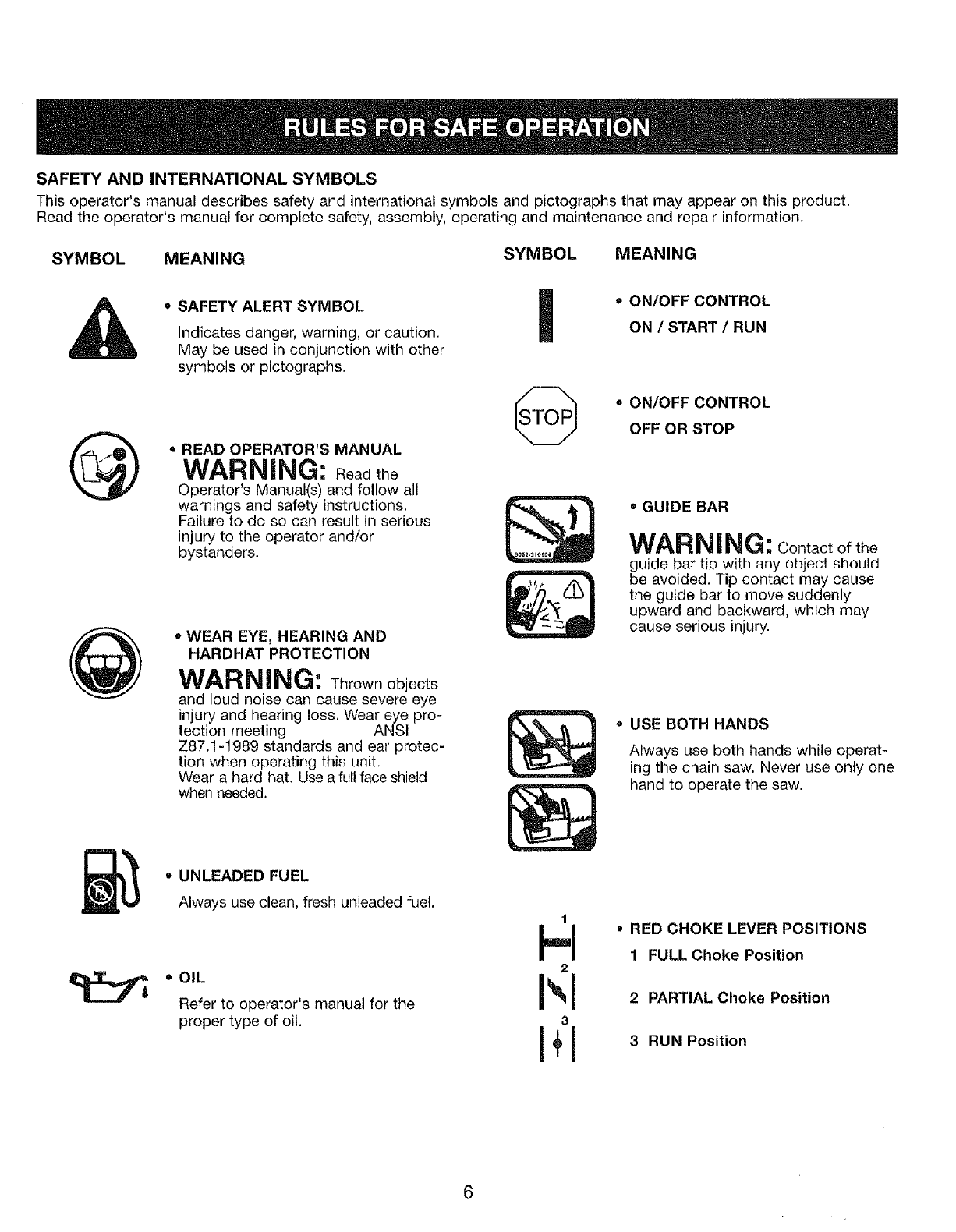
SAFETY AND INTERNATIONAL SYMBOLS
This operator's manual describes safety and international symbols and pictographs that may appear on this product.
Read the operator's manual for complete safety, assembly, operating and maintenance and repair information.
SYMBOL MEANING SYMBOL MEANING
@
•SAFETY ALERT SYMBOL
Indicates danger, warning, or caution.
May be used in conjunction with other
symbols or pictographs.
• READ OPERATOR'S MANUAL
WARNING: Read the
Operator's Manual(s) and follow all
warnings and safety instructions.
Failure to do so can result in serious
injury to the operator and/or
bystanders.
•WEAR EYE, HEARING AND
HARDHAT PROTECTION
WAR NING: Thrownobjects
and loud noise can cause severe eye
injury and hearing loss, Wear eye pro-
tection meeting ANSI
Z87.1-1989 standards and ear protec-
tion when operating this unit.
Wear a hard hat. Use a full face shield
when needed.
•ON/OFF CONTROL
ON /START /RUN
•ON/OFF CONTROL
OFF OR STOP
=GUIDE BAR
WARNING: Contact of the
guide bar tip with any object should
be avoided. Tip contact may cause
the guide bar to move suddenly
upward and backward, which may
cause serious injury.
oUSE BOTH HANDS
Always use both hands while operat-
ing the chain saw. Never use only one
hand to operate the saw.
• UNLEADED FUEL
Always use clean, fresh unleaded fuel.
• OIL
Refer to operator's manual for the
proper type of oil.
t
I-I
2
I',1
3
I+1
RED CHOKE LEVER POSITIONS
1FULL Choke Position
2 PARTIAL Choke Position
3 RUN Position
17
22
24
15
13 14 24
24
23 8
10
11
15
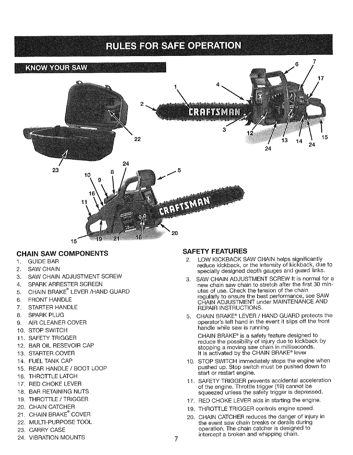
CHAIN SAW COMPONENTS
1. GUIDE BAR
2. SAW CHAIN
3. SAW CHAIN ADJUSTMENT SCREW
4, SPARK ARRESTER SCREEN
5. CHAIN BRAKE ®LEVER/HAND GUARD
6, FRONT HANDLE
7. STARTER HANDLE
8, SPARK PLUG
9. AIR CLEANER COVER
10. STOP SWITCH
11. SAFETY TRIGGER
12, BAR OIL RESEVOIR CAP
13, STARTER COVER
14. FUELTANK CAP
15. REAR HANDLE/BOOT LOOP
16. THROTTLE LATCH
17, RED CHOKE LEVER
18. BAR RETAINING NUTS
I9. THROTTLE /TRIGGER
20. CHAIN CATCHER
2l. CHAIN BRAKE ®COVER
22. MULTI-PURPOSE TOOL
23. CARRY CASE
24. VIBRATION MOUNTS 7
SAFETY FEATURES
2. LOW KICKBACK SAW CHAIN helps significantly
reduce kickback, or the intensity of kickback, due to
specially designed depth gauges and guard links.
3. SAW CHAIN ADJUSTMENT SCREW It is normal for a
new chain saw chain to stretch after the first 30 min-
utes of use. Check the tension of the chain
regularly to ensure the best performance, see SAW
CHAIN ADJUSTMENT under MAINTENANCE AND
REPAIR INSTRUCTIONS,
5. CHAIN BRAKE ® LEVER /HAND GUARD protects the
operator's left hand in the event it slips off the front
handle while saw is running,
CHAIN BRAKE ®is a safety feature designed to
reduce the possibility of injury due to kickback by
stopping a moving saw chain in milliseconds,
It is activated by the CHAIN BRAKE ® lever
10. STOP SWITCH immediately stops the engine when
pushed up. Stop switch must be pushed down to
start or restart engine.
11. SAFETY TRIGGER prevents accidental acceleration
of the engine, Throttle trigger (19) cannot be
squeezed unless the safety trigger is depressed.
17. RED CHOKE LEVER aids in starting the engine.
19, THROTTLE TRIGGER controls engine speed.
20. CHA1N CATCHER reduces the danger of injury in
the event saw chain breaks or derails during
operation. The chain catcher is designed to
intercept a broken and whipping chain,
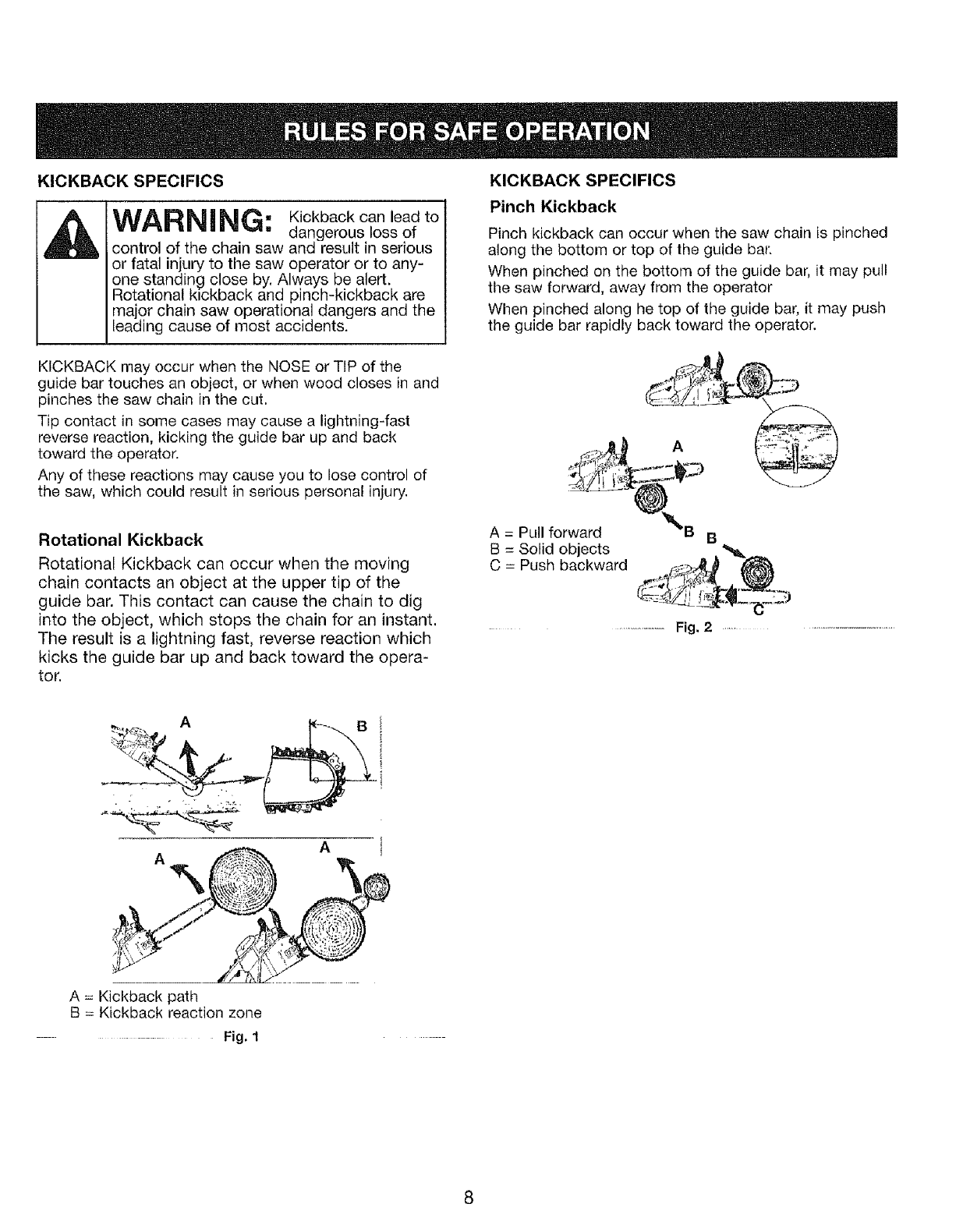
KICKBACK SPECIFICS
WARNING: Kickback can lead to
dangerous loss of
control of the chain saw and result in serious
or fatal injury to the saw operator or to any-
one standing close by. Always be alert.
Rotational kickback and pinch-kickback are
major chain saw operational dangers and the
leading cause of most accidents.
KICKBACK may occur when the NOSE or TIP of the
guide bar touches an object, or when wood closes in and
pinches the saw chain in the cut.
Tip contact in some cases may cause a lightning-fast
reverse reaction, kicking the guide bar up and back
toward the operator.
Any of these reactions may cause you to lose control of
the saw, which could result in serious personal injury.
Rotational Kickback
Rotational Kickback can occur when the moving
chain contacts an object at the upper tip of the
guide bar. This contact can cause the chain to dig
into the object, which stops the chain for an instant.
The result is a lightning fast, reverse reaction which
kicks the guide bar up and back toward the opera-
tor.
KICKBACK SPECIFICS
Pinch Kickback
Pinch kickback can occur when the saw chain is pinched
along the bottom or top of the guide bat:
When pinched on the bottom of the guide bar, it may pull
the saw forward, away from the operator
When pinched along he top of the guide bar, it may push
the guide bar rapidly back toward the operator.
A = Pull forward
B = Solid objects
C = Push backward
BB
..............Fig, 2 .....
A=Kickback path
B=Kickback reaction zone
.......... Fig, 1
OIL AND FUEL MIXING INSTRUCTIONS
Old and/or improperly mixed fuel are the main reasons for
the unit not running properly, Be sure to use fresh (less
than 60 days old) clean unleaded fuel. Follow the instruc-
tions carefully for the proper fuel/oil mixture.
Definition of Blended Fuels
Today's fuels are often a blend of gasoline and oxy_
genates such as ethanol, methanol, or MTBE (ether).
Alcohol-blended fuel absorbs water. As little as 1% water
in the fuel can make fue! and oil separate and lead to for-
mation of acids during storage. When using alcohol-
blended fuel, use fresh fuel.
Using Blended Fuels
If you choose to use a blended fuel, or its use is unavoid-
able, follow recommended precautions:
• Always use the fresh fuel mix explained in this opera-
tor's manual
o Always shake the fuel mix before fueling the unit
•Drain the tank and run the engine dry before storing the
unit
• See Storing Chain Saw in Maintenance and Repair sec-
tion
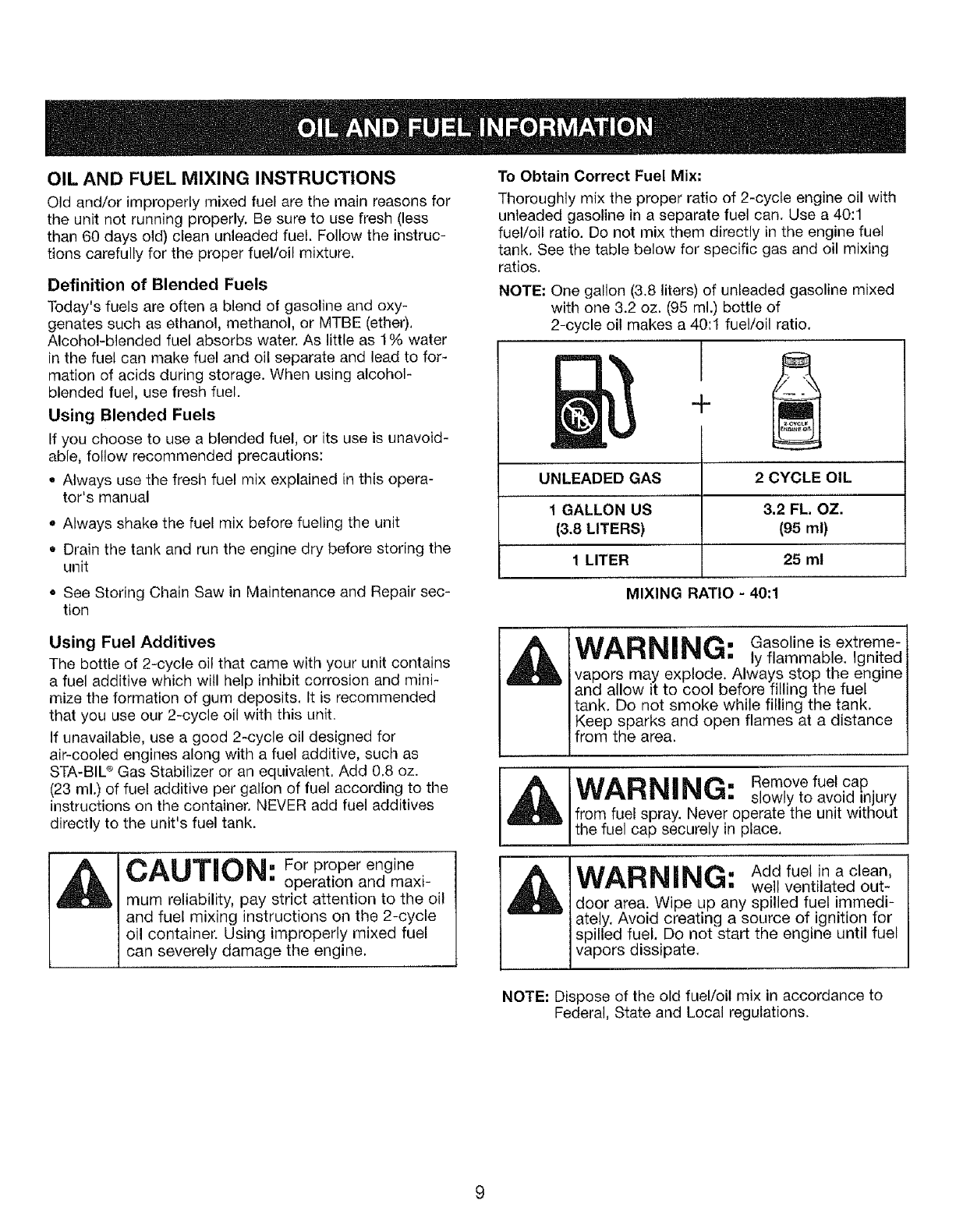
To Obtain Correct Fuel Mix=
Thoroughly mix the proper ratio of 2-cycle engine oil with
unleaded gasoline in a separate fuel can. Use a 40:1
fuel/oil ratio. Do not mix them directly in the engine fuel
tank, See the table below for specific gas and oil mixing
ratios.
NOTE: One gallon (3.8 liters) of unleaded gasoline mixed
with one 3.2 oz. (95 ml.) bottle of
2-cycle oil makes a 40:1 fuel/oil ratio.
I
+
UNLEADED GAS
1 GALLON US
(3.8 LITERS)
1 LITER
MIXING RATIO - 40:1
2 CYCLE OIL
3.2 FL. OZ.
I95 ml)
25 ml
Using Fuel Additives
The bottle of 2-cycle oil that came with your' unit contains
a fuel additive which will help inhibit corrosion and mini-
mize the formation of gum deposits. It is recommended
that you use our 2-cycle oil with this unit.
If unavailable, use a good 2-cycle oil designed for
air-cooled engines along with a fuel additive, such as
STA-BIL ®Gas Stabilizer or an equivalent. Add 0.8 oz.
(23 ml.) of fuel additive per gallon of fuel according to the
instructions on the container. NEVER add fuel additives
directly to the unit's fuel tank.
WARNING: Gasoline is extreme-
ly flammable. Ignited
vapors may explode. Always stop the engine
and allow it to cool before filling the fuel
tank. Do not smoke while filling the tank.
Keep sparks and open flames at a distance
from the area.
_AIA II:}ikll kate_. Remove fuel cap
vvo.._a lalanl,t,_, slowly to avoid in ury
from fuel spray. Never operate the unit without
the fuel cap securely in place.
CAUTION" For proper engine
[] operation and maxi-
mum reliability, pay strict attention to the oil
and fuel mixing instructions on the 2-cycle
oil containelt Using improperly mixed fuel
can severely damage the engine.
WARNING: Add fuel in a clean,
well ventilated out-
door area. Wipe up any spilled fuel immedi-
ately. Avoid creating a source of ignition for
spilled fuel. Do not start the engine until fuel
vapors dissipate.
NOTE= Dispose of the old fuel/oil mix in accordance to
Federal, State and Local regulations.
_l Operate this unit only
WARNING." in awell-ventitated
outdoor area. Carbon
monoxide exhaust fumes can be lethal in a
confined area.
WARNING: Never operate the saw
without the bar and
chain properly installed,
BEFORE STARTING ENGINE
WARNING; Be sure to read the Oil and Fuel Information
section of this manual before you begin. If you do not
understand the oil and fuel information, do not attempt
to fuel your unit. For more information contact your
local Sears service center at 1-800-4-MY-HOME ®,
GUIDE BAR AND CHAIN OIL
The bar and chain require lubrication. The chain oiler
provides continuous lubrication to the chain and guide
bar. Be sure to fill the bar oil tank when you fill the fuel
tank. (Capacity = 6.8 ft. oz.). Lack of oil will quickly
ruin the bar and chain, Too little oil will cause over-
heating with smoke coming from the chain and discol-
oration of the bar. For maximum guide bar and chain
life, we recommend you use Craftsman chain saw bar
oil, If Craftsman bar oil is not available, you may use a
good grade SAE 30 oil until you are able to obtain the
Craftsman brand. The oil output is automatically
metered during operation. Your saw will use approxi-
mately one tank of bar oil for every tank of fuel mix.
Always fill the bar oil tank when you fill the fuel tank.
FUELING THE ENGINE
IMPORTANT:
Gasoline blended with alcohols such as ethanol or
methanol (called gasohol) can attract moisture which
leads to separation and formation of acids during stor-
age. Acidic gas can damage the fuel system of an
engine when in storage. To avoid engine problems, the
fuel system should be emptied before storage for 30
days or longer. See Storing Chain Saw in
Maintenance and Repair section.
CHAIN BRAKE
Be sure the chain brake is disengaged by pulling the
front hand guard back toward the front handle as far
as possible. The chain brake must be disengaged
before cutting with the saw.
WARNING: The chain brake must not move when the
engine runs at idle speed. If the chain brake moves at
idle speed, refer to CARBURETOR ADJUSTMENT in
this manual. Avoid contact with the muffler. A hot muf-
fler can cause serious burns.
IMPORTANT POINTS TO REMEMBER
When pulling the starter rope, do not use the full
extent of the rope as this can cause the rope to break.
Do not let starter rope snap back. Hold the handle and
let the rope rewind slowly. For cold weather starting,
start the unit at FULL CHOKE; allow the engine to
warm up before squeezing the throttle trigger.
DO NOT attempt to cut material with the choke/fast idle
lever in the FULL CHOKE position.
WARNING: Remove fuel cap slowly when refueling.
This engine is certified to operate on unleaded gaso-
line. Before operation, gasoline must be mixed with a
good quality synthetic 2-cycle air-cooled engine oil.
We recommend Craftsman brand synthetic oil. Mix
gasoline and oil at a ratio of 40:1, 40:1 ratio is
obtained by mixing 3.2 ounces of oil with 1 gallon of
unleaded gasoline. Included with this saw is a 3.2
ounce container of oil. Pour the entire contents of this
container into one gallon of gasoline to achieve the
proper fuel mixture. DO NOT use automotive oil or
boat oi!. These oils will cause engine damage, When
mixing fuel, follow the instructions printed on the oil
container, Once oil is added to the gasoline, shake
container momentarily to assure that the fuel is thor-
oughly mixed. Always read and follow the safety rules
relating to fuel before fueling your unit.
10
STOPPING INSTRUCTIONS
1, Release the trigger and allow the engine to return to
the idle speed.
2, Move the STOP switch up to the STOP position (Fig. 4).
NOTE; For emergency stopping, push the lever of the
chain brake lever/hand guard (C) forward and move the
STOP switch up (Fig, 3, 4),
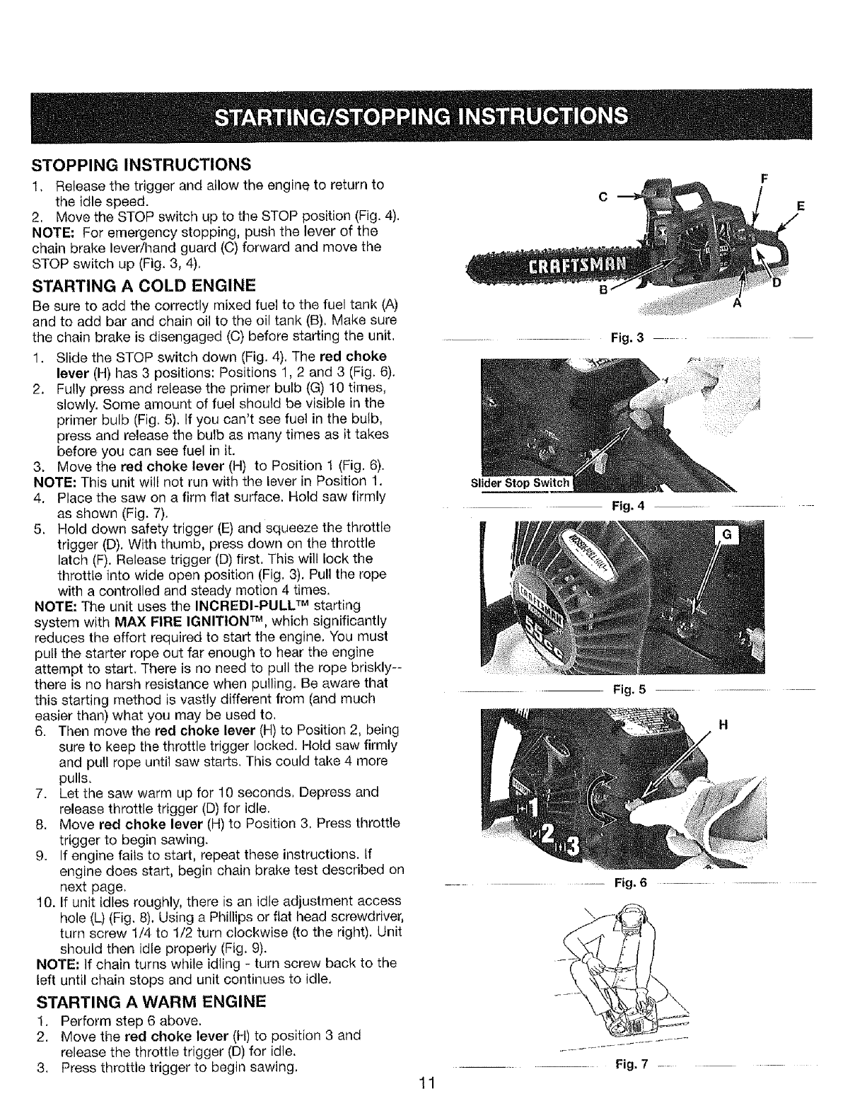
STARTING A COLD ENGINE
Be sure to add the correctly mixed fuel to the fuel tank (A)
and to add bar and chain oil to the oil tank (B), Make sure
the chain brake is disengaged (C) before starting the unit,
1, Slide the STOP switch down (Fig. 4). The red choke
lever (H) has 3 positions: Positions 1, 2 and 3 (Fig. 6),
2. Fully press and release the primer bulb (G) 10 times,
slowly. Some amount of fuel should be visible in the
primer bulb (Fig. 5). If you can't see fuel in the bulb,
press and release the bulb as many times as it takes
before you can see fuel in it.
3, Move the red choke lever (H) to Position 1 (Fig. 6).
NOTE: This unit will not run with the lever in Position 1,
4. Place the saw on a firm flat surface. Hold saw firmly
as shown (Fig. 7).
5. Hold down safety trigger (E) and squeeze the throttle
trigger (D), With thumb, press down on the throttle
latch (F). Release trigger (D) first, This will lock the
throttle into wide open position (Fig. 3). Pull the rope
with a controlled and steady motion 4 times.
NOTE: The unit uses the INCREDI-PULL TM starting
system with MAX FIRE IGNITION TM, which significantly
reduces the effort required to start the engine. You must
putl the starter rope out far enough to hear the engine
attempt to start. There is no need to pull the rope briskly--
there is no harsh resistance when pulling, Be aware that
this starting method is vastly different from (and much
easier than) what you may be used to,
6. Then move the red choke lever (H) to Position 2, being
sure to keep the throttle trigger locked. Hold saw firmly
and pull rope until saw starts. This could take 4 more
pulls.
7. Let the saw warm up for 10 seconds, Depress and
release throttle trigger (D) for idle,
8. Move red choke lever (H) to Position 3, Press throttle
trigger to begin sawing.
9. If engine fails to start, repeat these instructions. If
engine does start, begin chain brake test described on
next page,
10. If unit idles roughly, there is an idle adjustment access
hole (L) (Fig, 8), Using a Phillips or flat head screwdriver,
turn screw 1/4 to 1/2 turn clockwise (to the right), Unit
should then idle properly (Fig, 9).
NOTE: If chain turns while idling - turn screw back to the
left until chain stops and unit continues to idle,
STARTING A WARM ENGINE
1. Perform step 6 above.
2. Move the red choke lever (H) to position 3 and
release the throttle trigger (D) for idle.
3, Press throttle trigger to begin sawing.
C
............................................ Fig. 3 ....
Slider Stop Switch
Fig. 4 ...................
Fig. 5
H
........ Fig. 6...........................................
\
Fig, 7 .........
11
WARNING: ActivatetheC.A,.
BRAKE® slowly and
deliberately. Keep the chain from touching
anything; don't let the saw tip forward.
WAIDlk|li_|t"__. tf chain does not
e'liFSLWl mnl,_,._., stop, turn engine off
and take your unit to the nearest Sears
or other qualified service dealer.
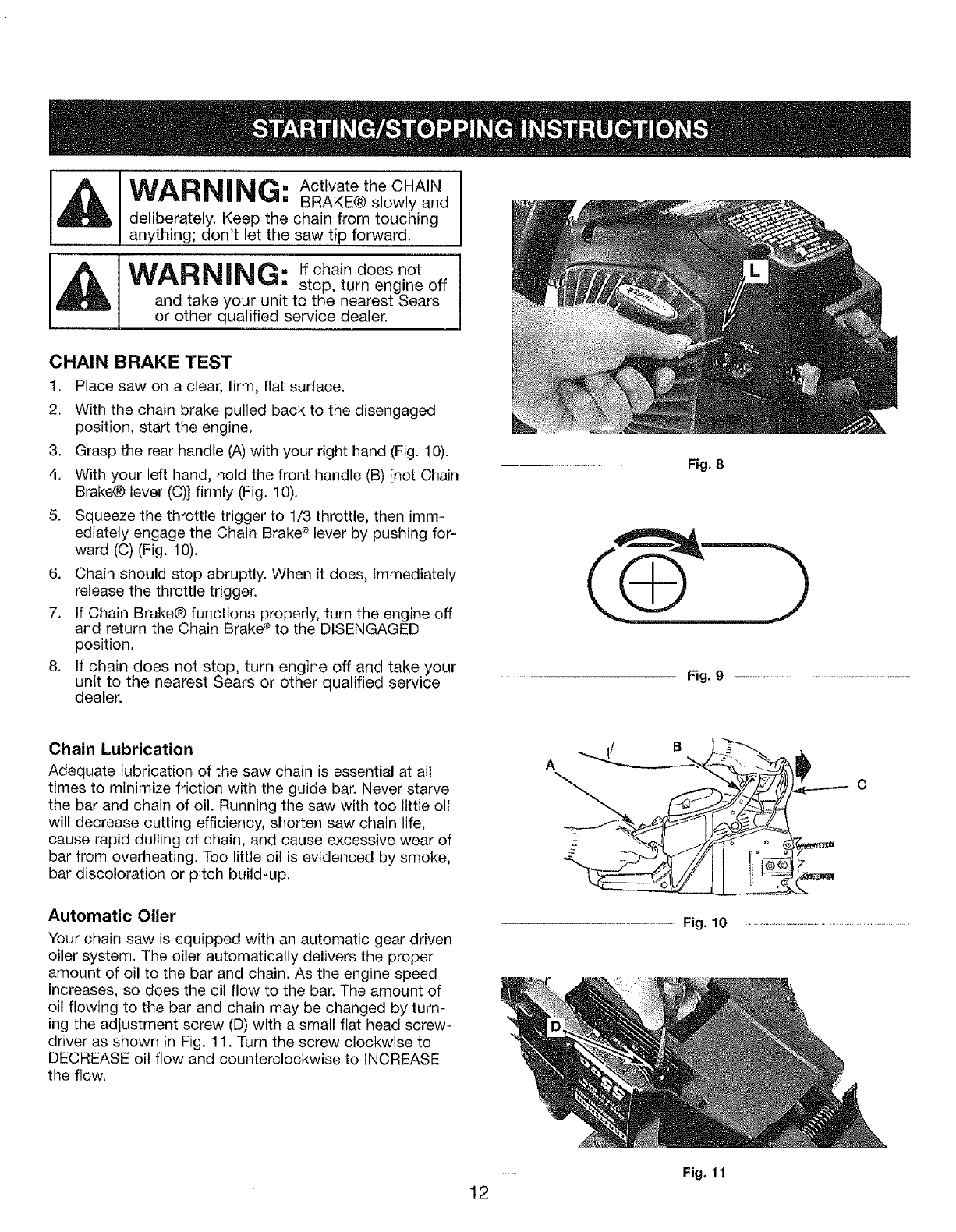
CHAIN BRAKE TEST
1. Place saw on a clear, firm, flat surface.
2. With the chain brake pulled back to the disengaged
position, start the engine,
3, Grasp the rear handle (A) with your right hand (Fig. 10).
4. With your left hand, hold the front handle (B) [not Chain
Brake@ lever (C)] firmly (Fig, 10),
5. Squeeze the throttle trigger to 1/3 throttle, then imm-
ediately engage the Chain Brake _ lever by pushing for-
ward (C) (Fig. 10).
6. Chain should stop abruptly. When it does, immediately
release the throttle trigger.
7. If Chain Brake@ functions properly, turn the engine off
and return the Chain Brake ®to the DISENGAGED
position.
8. If chain does not stop, turn engine off and takeyour
unit to the nearest Sears or other qualified service
dealer.
Fig, 8
Fig. 9 ...............................
Chain Lubrication
Adequate lubrication of the saw chain is essential at all
times to minimize friction with the guide bar. Never starve
the bar and chain of oil. Running the saw with too little oil
will decrease cutting efficiency, shorten saw chain life,
cause rapid dulling of chain, and cause excessive wear of
bar from overheating. Too little oil is evidenced by smoke,
bar discoloration or pitch build-up.
Automatic Oiler
Your chain saw is equipped with an automatic gear driven
oiler system. The oiler automatically delivers the proper
amount of oil to the bar and chain. As the engine speed
increases, so does the oil flow to the bar. The amount of
oil flowing to the bar and chain may be changed by turn-
ing the adjustment screw (D) with a small flat head screw-
driver as shown in Fig. 11. Turn the screw clockwise to
DECREASE oil flow and counterclockwise to INCREASE
the flow,
_ !i B I_-:"Y'--.
A _'--L_..,,..._,__.____._ :_.._;
Fig. 10
...................................... Fig. 11
12
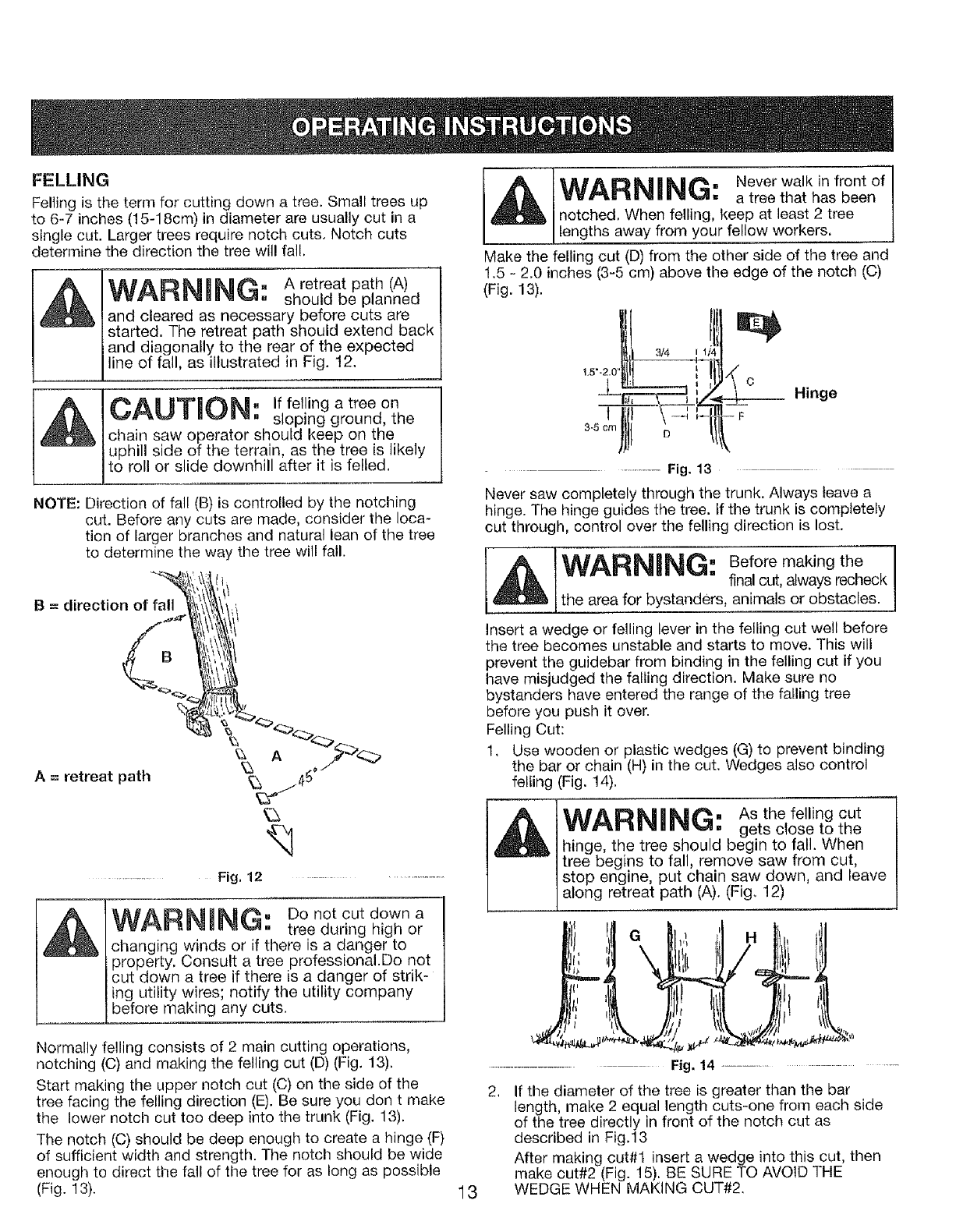
FELLING
Felling is the term for cutting down a tree. Small trees up
to 6-7 inches (15-18cm) in diameter are usually cut in a
single cut. Larger trees require notch cuts, Notch cuts
determine the direction the tree wil! fall.
WARNING: A retreat path (A)
should be planned
and cleared as necessary before cuts are
started. The retreat path should extend back
and diagonally to the rear of the expected
line of fall, as illustrated in Fig. 12.
A __AI mTM_L_II" If felling a tree on
v_,_,m,_,. _. sloping ground, the
chain saw operator should keep on the
uphill side of the terrain, as the tree is likely
to roll or slide downhill after it is felled,
NOTE: Direction of fall (B) is controlled by the notching
cut. Before any cuts are made, consider the loca-
tion of larger branches and natural lean of the tree
to determine the way the tree will fall.
B = direction of fall
A = retreat path
Fig. 12 ........
WARNING: Donotoutdowna
tree during high or
changing winds or if there is a danger to
property. Consult a tree professional.Do not
cut down a tree if there is a danger of strik-
ing utility wires; notify the utility company
before making any cuts.
IAh'A D_II I__|t_. Never walk in front of
wwr'_u uuluu,a,_,.A, a tree that has been
notched. When felling, keep at least 2 tree
lengths away from your fe ow workers,
Make the felling cut (D) from the other side of the tree and
1.5 -, 2.0 inches (3-5 cm) above the edge of the notch (C)
(Fig. 13).
!.5"_
............................ Fig. 13
Never saw completely through the trunk. Always leave a
hinge. The hinge guides the tree. if the trunk is completely
cut through, control over the felling direction is lost.
___c Hinge
--F
WARNING: Before making the !
final cut, always recheck
the area for bystanders, animals or obstacles.
Insert a wedge or felling lever in the felling cut well before
the tree becomes unstable and starts to move. This will
prevent the guidebar from binding in the felling cut if you
have misjudged the falling direction. Make sure no
bystanders have entered the range of the falling tree
before you push it over.
Felling Cut:
1. Use wooden or plastic wedges (G) to prevent binding
the bar or chain (H) in the cut. Wedges also control
felling (Fig. 14).
WARNING: As the felling cut
gets close to the
hinge, the tree should begin to fall. When
tree begins to fall, remove saw from cut,
stop engine, put chain saw down, and leave
along retreat path (A). (Fig. 12)
Normally felling consists of 2 main cutting operations,
notching (C) and making the felling cut (D) (Fig. 13).
Start making the upper notch cut (C) on the side of the
tree facing the felling direction (E). Be sure you don t make
the lower notch cut too deep into the trunk (Fig. 13).
The notch (C) should be deep enough to create a hinge (F)
of sufficient width and strength. The notch should be wide
enough to direct the fall of the tree for as long as possible
(Fig. 13). 13
................. Fig. 14 ...........................................
,If the diameter of the tree is greater than the bar
length, make 2 equal length cuts-one from each side
of the tree directly in front of the notch cut as
described in Fig.13
After making cut#t insert a wedge into this cut, then
make cut#2 (Fig. 15). BE SURE TO AVOID THE
WEDGE WHEN MAKING CUT#2.
Cut 1
.................. Fig. 15 ...........................
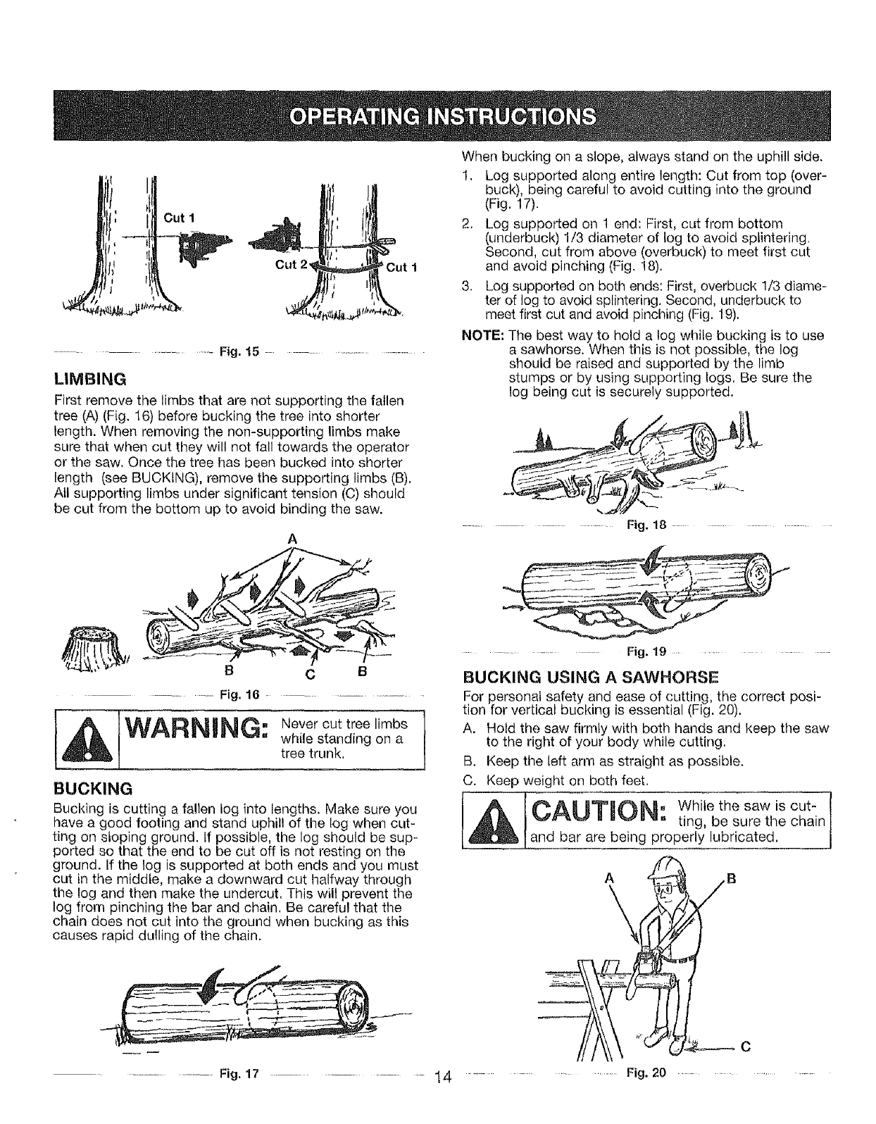
LIMBING
First remove the limbs that are not supporting the fallen
tree (A) (Fig, 16) before bucking the tree into shorter
length. When removing the non-supporting limbs make
sure that when cut they will not fall towards the operator
or the saw, Once the tree has been bucked into shorter
length (see BUCKING), remove the supporting limbs (B),
Atl supporting limbs under significant tension (C) should
be cut from the bottom up to avoid binding the saw.
A
BC
................. Fig. 16 ...............................
while standing on a
tree trunk,
BUCKING
Bucking is cutting a fallen log into lengths. Make sure you
have a good footing and stand uphill of the tog when cut-
ting on sloping ground. If possible, the log should be sup-
ported so that the end to be cut off is not resting on the
ground. If the log is supported at both ends and you must
cut in the middle, make a downward cut halfway through
the log and then make the undercut. This will prevent the
log from pinching the bar and chain. Be careful that the
chain does not cut into the ground when bucking as this
causes rapid dulling of the chain.
__ J
...........................Fig. 17 ................... 14
When bucking on a slope, always stand on the uphill side.
1. Log supported along entire length: Cut from top (over-
buck), being careful to avoid cutting into the ground
(Fig, 17).
2, Log supported on 1 end: First, cut from bottom
(underbuck) 1/3 diameter of tog to avoid splintering,
Second, cut from above (overbuck) to meet first cut
and avoid pinching (Fig. 18),
3. Log supported on both ends: First, overbuck 1/3 diame-
ter of log to avoid splintering, Second, underbuck to
meet first cut and avoid pinching (Fig. 19).
NOTE; The best way to hold a log while bucking is to use
a sawhorse. When this is not possible, the log
should be raised and supported by the limb
stumps or by using supporting logs. Be sure the
log being cut is securely supported,
..................... Fig. 18 ...........................
...................... Fig. 19 ........................
BUCKING USING A SAWHORSE
For personal safety and ease of cutting, the correct posi-
tion for vertical bucking is essential (Fig. 20).
A. Hold the saw firmly with both hands and keep the saw
to the right of your body while cutting.
B. Keep the left arm as straight as possible.
C. Keep weight on both feet.
Tr.AHTmn . While the saw is cut-
j,_,m ,,_,--.,_. ,.. ting, be sure the chain
land bar are being properly lubricated.
A
\
.................... Fig. 20
C
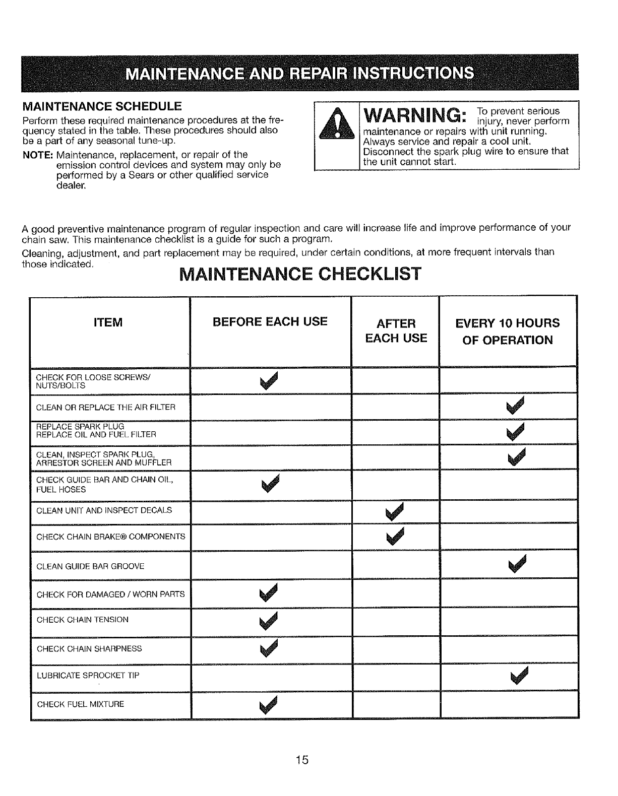
MAINTENANCE SCHEDULE
Perform these required maintenance procedures at the fre-
quency stated in the table. These procedures should also
be a part of any seasonal tune-up.
NOTE: Maintenance, replacement, or repair of the
emission control devices and system may only be
performed by a Sears or other qualified service
dealer.
WARNING" TO prevent serious
=injury, never perform
maintenance or repairs with unit running.
Always service and repair a cool unit.
Disconnect the spark plug wire to ensure that
the unit cannot start.
A good preventive maintenance program of regular inspection and care will increase life and improve performance of your
chain saw. This maintenance checklist is a guide for such a program.
Cleaning, adjustment, and part replacement may be required, under certain conditions, at more frequent intervals than
those indicated, MAINTENANCE CHECKLIST
ITEM
CHECK FOR LOOSE SCREWS/
NUTS!BOLTS
lill ,ll
CLEAN OR REPLACE THE AIR FILTER
REPLACE SPARK PLUG ......
REPLACE OIL AND FUEL FILTER
CLEAN, INSPECT SPARK PLUG,
ARRESTOR SCREEN AND MUFFLER
CHECK GUIDE BAR AND CHAIN OIL,
FUEL HOSES
CLEAN UNIT AND INSPECT DECALS
CHECK CHAIN BRAKE@ COMPONENTS
CLEAN GUIDE BAR GROOVE
CHECK FOR DAMAGED /WORN PARTS
CHECK CHAIN TENSION
CHECK CHAIN SHARPNESS
LUBRICATE SPROCKET TIP
CHECK FUEL MIXTURE
__ ,........ n
BEFORE EACH USE AFTER
EACH USE
EVERY 10 HOURS
OF OPERATION
15
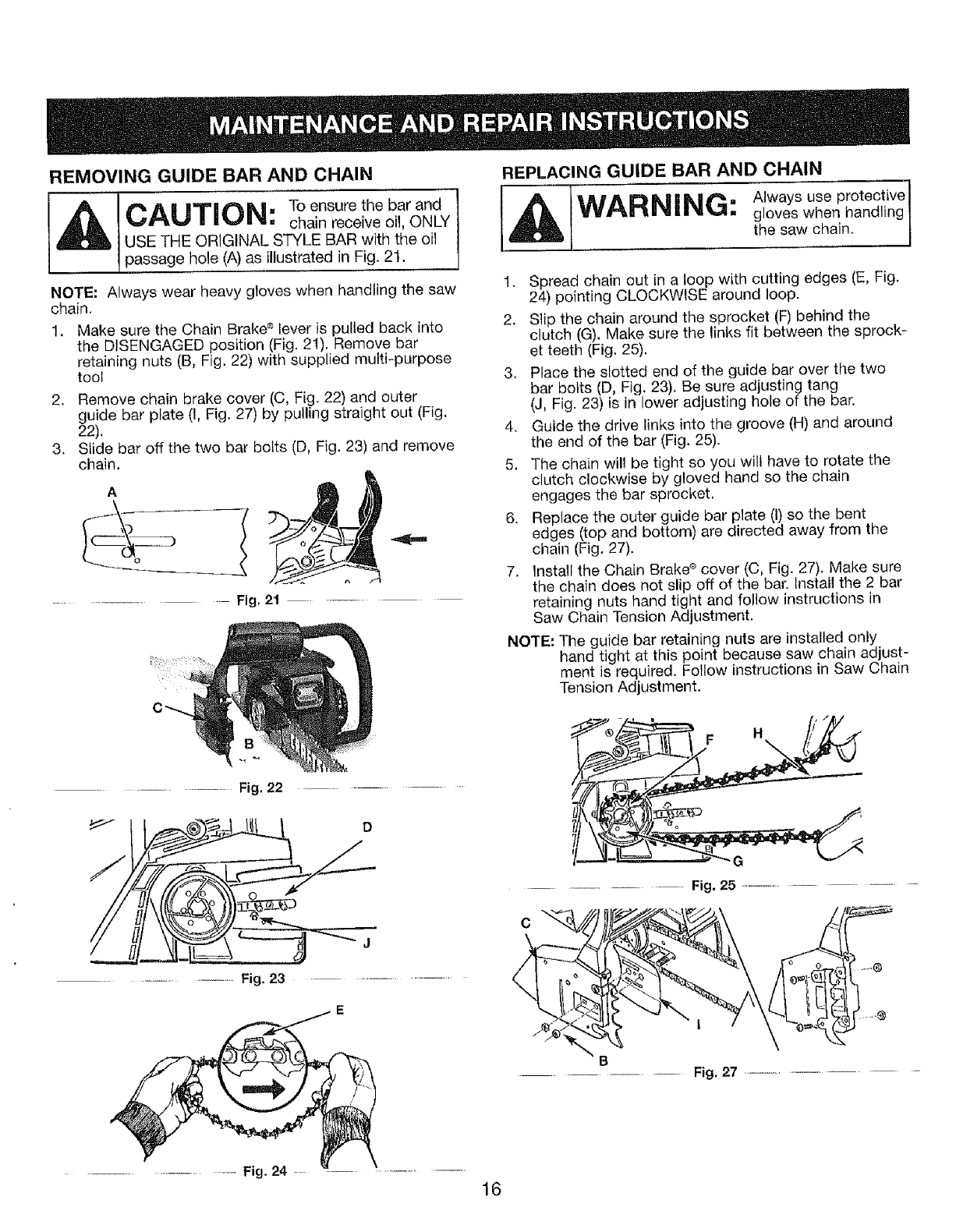
,Er,4OVI.GQUIDEBA.A.DC.AI,
AICAUTION: Toensorethebarand
chain receive oil, ONLY
USE THE ORIGINAL STYLE BAR with the oil
passage hole (A) as illustrated in Fig. 2t,
NOTE: Always wear heavy gloves when handling the saw
chain.
Make sure the Chain Brake s lever is pulled back into
the DISENGAGED position (Fig. 21), Remove bar
retaining nuts (B, Fig. 22) with supplied multi-purpose
tool
2, Remove chain brake cover (C, Fig. 22) and outer
guide bar plate (I, Fig. 27) by pulling straight out (Fig,
22).
3. Slide bar off the two bar bolts (D, Fig. 23) and remove
chain.
A
............... Fig, 21
REPLACING GUIDE BAR AND CHAIN
1. Spread chain out in a loop with cutting edges (E, Fig,
24) pointing CLOCKWISE around loop.
2. Slip the chain around the sprocket (F) behind the
clutch (G), Make sure the links fit between the sprock-
et teeth (Fig. 25).
3, Place the slotted end of the guide bar over the two
bar bolts (D, Fig. 23), Be sure adjusting tang
(J, Fig. 23) is in lower adjusting hole of the bar.
4. Guide the drive links into the groove (H) and around
the end of the bar (Fig. 25).
5. The chain will be tight so you will have to rotate the
clutch clockwise by gloved hand so the chain
engages the bar sprocket.
6. Replace the outer guide bar plate (I) so the bent
edges (top and bottom) are directed away from the
chain (Fig, 27).
7. lnstall the Chain Brake s cover (C, Fig. 27). Make sure
the chain does not slip off of the bar. Install the 2 bat"
retaining nuts hand tight and follow instructions in
Saw Chain Tension Adjustment.
NOTE: The guide bar retaining nuts are installed only
hand tight at this point because saw chain adjust-
ment is required. Follow instructions in Saw Chain
Tension Adjustment.
................................... Fig. 22 .....
D
F H
G
............................. Fig. 25 .....................................
............................ Fig. 23 ...................................
...... Fig, 27
.......................... Fig, 24
16
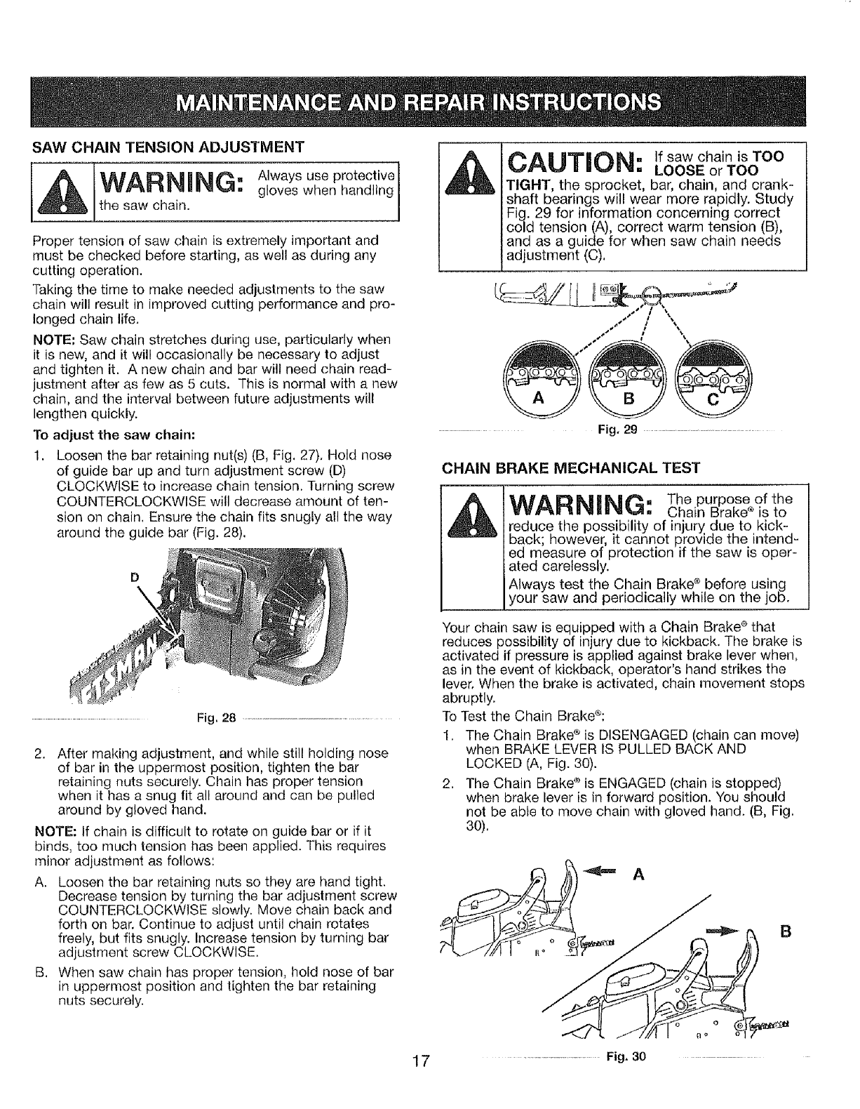
SAW CHAIN TENSION ADJUSTMENT
Always use protective
WARNING: gloves when handling
the saw chain.
Proper tension of saw chain is extremely important and
must be checked before starting, as well as during any
cutting operation.
Taking the time to make needed adjustments to the saw
chain will result in improved cutting performance and pro-
longed chain life.
NOTE: Saw chain stretches during use, particularly when
it is new, and it will occasionally be necessary to adjust
and tighten it. A new chain and bar will need chain read-
justment after as few as 5 cuts. This is normal with a new
chain, and the interval between future adjustments will
lengthen quickly.
To adjust the saw chain:
1. Loosen the bar retaining nut(s) (B, Fig. 27). Hold nose
of guide bar up and turn adjustment screw (D)
CLOCKWISE to increase chain tension. Turning screw
COUNTERCLOCKWISE will decrease amount of ten-
sion on chain. Ensure the chain fits snugly all the way
around the guide bar (Fig. 28).
..................................... Fig. 28 .......................................................................................
2. After making adjustment, and while still holding nose
of bar in the uppermost position, tighten the bar
retaining nuts securely. Chain has proper tension
when it has a snug fit all around and can be pulled
around by gloved hand.
NOTE: If chain is difficult to rotate on guide bar or if it
binds, too much tension has been applied. This requires
minor adjustment as follows:
A. Loosen the bar retaining nuts so they are hand tight.
Decrease tension by turning the bar adjustment screw
COUNTERCLOCKWISE slowly. Move chain back and
forth on bar. Continue to adjust until chain rotates
freely, but fits snugly. Increase tension by turning bar
adjustment screw CLOCKWISE.
B. When saw chain has proper tension, hold nose of bar
in uppermost position and tighten the bar retaining
nuts securely.
17
CAUTaON: ifsawchainisTOO
LOOSE or TOO
TIGHT, the sprocket, bar, chain, and crank-
shaft bearings will wear more rapidly. Study
29 for information concerning correct
tension(A), correct warm tension (B),
and as a guide for when saw chain needs
adjustment (C).
Fig, 29 ............
CHAIN BRAKE MECHANICAL TEST
WARNING: The purpose of the
Chain Brake ® is to
reduce the possibility of injury due to kick-
back however it cannot provide the intend-
ed measure of protection if the saw s oper-
ated carelessly.
Always test the Chain Brake <_before using
your saw and periodically while on the job.
Your chain saw is equipped with a Chain Brake ®that
reduces possibility of injury due to kickback. The brake is
activated if pressure is applied against brake lever when,
as in the event of kickback, operator's hand strikes the
lever. When the brake is activated, chain movement stops
abruptly.
To Test the Chain Brake®:
1. The Chain Brake ® is DISENGAGED (chain can move)
when BRAKE LEVER tS PULLED BACK AND
LOCKED (A, Fig. 30).
2. The Chain Brakd _is ENGAGED (chain is stopped)
when brake lever is in forward position. You should
not be abte to move chain with gloved hand. (B, Fig.
30).
................... Fig. 30
MAINTENANCE REQUIREMENTS
CHECK FOR DAMAGED OR WORN PARTS
Contact a Sears Service Center for replacement of dam-
aged or worn parts.
NOTE: It is normal for a small amount of oil to appear
under the saw after the engine stops. Do not confuse this
with a leaking oil tank.
• STOP Switch - Ensure STOP switch functions properly
by moving the switch up to the STOP position. Make sure
the engine stops; then restart engine and continue.
= Fuel Tank - Do not use saw if fuel tank shows signs of
damage or leaks.
• Oil Tank - Do not use saw if oil tank shows signs of
damage or leaks.
CHECK FOR LOOSE FASTENERS AND PARTS
• Chain Brake Nuts
Chain
• Muffler
• Cylinder Shield
• Air Filter cover
• Handle Screws
= Vibration Mounts
• Starter Housing
o Front Hand Guard
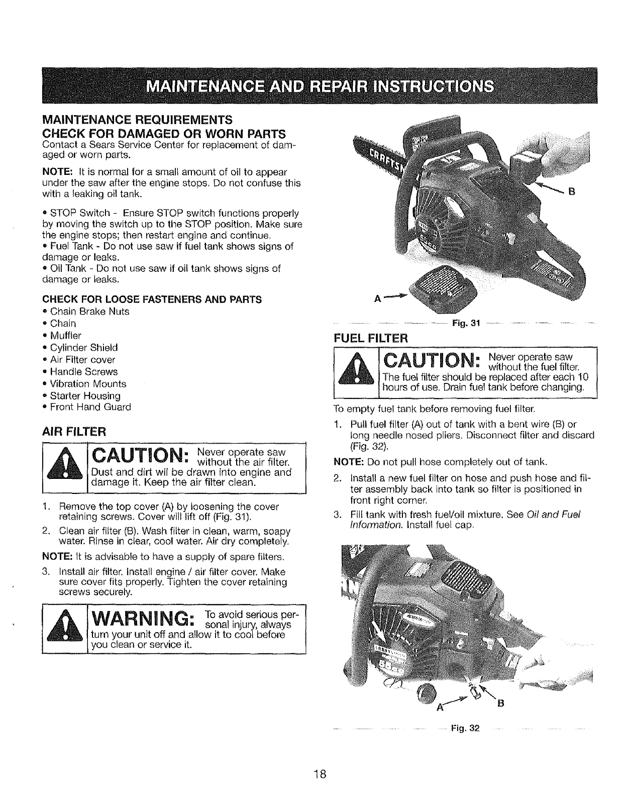
AIR FILTER
, Never operate saw
without the air filter.
Dust and dirt wil be drawn into engine and
damage it, Keep the air filter clean.
1, Remove the top cover (A) by loosening the cover
retaining screws. Cover will lift off (Fig. 31).
2, Clean air filter (B). Wash filter in clean, warm, soapy
water. Rinse in clear, cool water. Air dry completely,
NOTE: It is advisable to have a supply of spare filters.
3. Install air filter. Install engine /air filter cover. Make
sure cover fits properly. Tighten the cover retaining
screws securely.
_I IFl,IA D I_| II_| _. To avoid serious per- |
/
wvn=Le _l'_=ul_=4. sona! injulryy,alwa s J
turn your unit off and allow it to coo_ before
t you c ean or service t.
B
............................. Fig. 31 .....................
FUEL FILTER
CAUTION: Never operate saw
without the fuel filter.
The fuel filter should be replaced after each 10
hours of use, Drain fuel tank before changing.
To empty fuel tank before removing fuel filter.
1. Pull fuel filter (A) out of tank with a bent wire (B) or
long needle nosed pliers, Disconnect filter and discard
(Fig. 32).
NOTE: Do not pull hose completely out of tank,
2, Install a new fuel filter on hose and push hose and fif-
ter assembly back into tank so filter is positioned in
front right corner.
3. Fill tank with fresh fuel/oil mixture. See Oil and Fuel
Information. Install fuel cap.
B
................. Fig, 32 .......................................
18
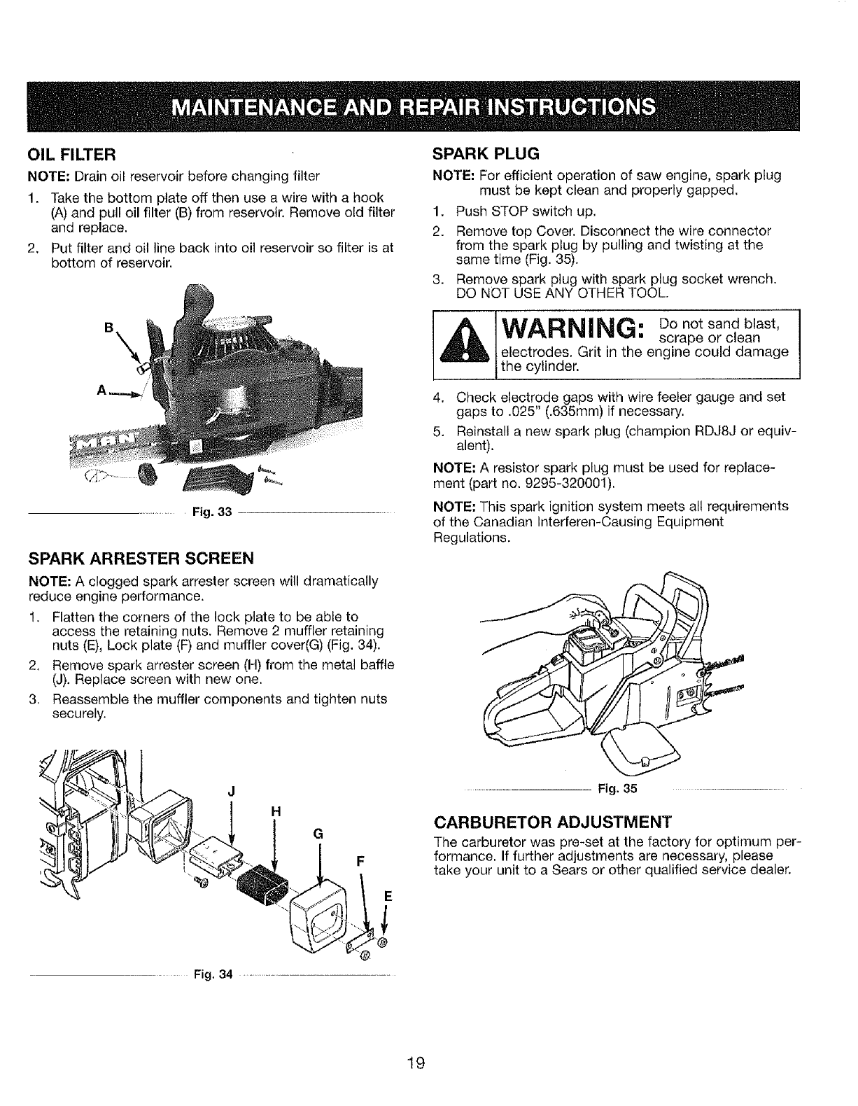
OIL FILTER
NOTE: Drain oil reservoir before changing filter
1. Take the bottom plate off then use a wire with a hook
(A) and pull oil filter (B) from reservoir. Remove old filter
and replace.
2. Put filter and oil line back into oil reservoir so filter is at
bottom of reservoir.
Fig. 33
SPARK ARRESTER SCREEN
NOTE: A clogged spark arrester screen will dramatically
reduce engine performance.
1. Flatten the corners of the lock plate to be able to
access the retaining nuts. Remove 2 muffler retaining
nuts (E), Lock plate (F) and muffler cover(G) (Fig. 34).
2, Remove spark arrester screen (H) from the metal baffle
(J). Replace screen with new one.
3, Reassemble the muffler components and tighten nuts
securely.
r "_. H G F
Fig. 34 ...........................
SPARK PLUG
NOTE." For efficient operation of saw engine, spark plug
must be kept clean and properly gapped,
1. Push STOP switch up.
2. Remove top Cover. Disconnect the wire connector
from the spark plug by pulling and twisting at the
same time (Fig. 35).
3. Remove spark plug with spark plug socket wrench.
DO NOT USE ANY OTHER TOOL.
. Do not sand blast,
] =wm-u =. ,... ,,_,_,. scrape or clean
l electrodes. Grit in the engine could damage
t the cylinder.
4. Check electrode gaps with wire feeler gauge and set
gaps to ,025" (.635mm) if necessary.
5. Reinstall a new spark plug (champion RDJ8J or equiv-
alent).
NOTE: A resistor spark plug must be used for replace-
ment (part no, 9295-320001),
NOTE: This spark ignition system meets all requirements
of the Canadian Interferen-Causing Equipment
Regulations.
CARBURETOR ADJUSTMENT
The carburetor was pre-set at the factory for optimum per-
formance. If further adjustments are necessary, please
take your unit to a Sears or other qualified service dealer.
19
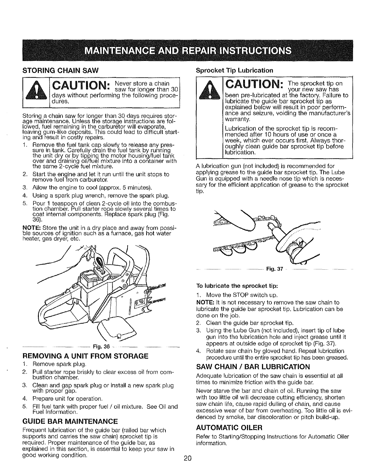
STORING CHAIN SAW
CA| II"T'll#_h|. Never store a chain l
n_L.#ae_,#il, saw for longer than 301
days without performing the following proce-I
dures. J
Storing a chain saw for longer than 30 days requires stor-
age maintenance, Unless the storage instructions are fol-
lowed fuel remaining in the carburetor will evap.orate
leaving gum-like deposits, This could lead to difficult start-
ing and result in costly repairs.
1, Remove the fuel tank cap slowly, to release any pres-
sure in tank. Carefully drain the fuel tank by running,
the unit dry or by tipping the motor housing/fuel tank
over and draining oilYfuel mixture into a container with
the same 2-cycle fuel mixture,
2. Start the engine and let it run until the unit stops to
remove fuel from carburetor,
3. Allow the engine to cool (approx. 5 minutes),
4. Using a spark plug wrench, remove the spark plug,
5. Pour 1 teaspoon of ctean 2-cycle oil into the combus-
tion chamber. Pull starter rope slowly several times to
coat internal components. Replace spark plug (Fig.
36).
NOTE: Store the unit in a dry place and away from possi-
ble sources of ignition such as a furnace, gas hot water
heater, gas dryer, etc.
Fig. 36 .............................
REMOVING AUNIT FROM STORAGE
1. Remove spark plug.
2. Pul! starter rope briskly to clear excess oil from com-
bustion chamber.
3. Clean and gap spark plug or instatl a new spark plug
with proper gap,
4. Prepare unit for operation.
5, Fill fuel tank with proper fuel /oil mixture. See Oil and
Fuel Information.
GUIDE BAR MAINTENANCE
Frequent lubrication of the guide bar (railed bar which
supports and carries the saw chain) sprocket tip is
required. Proper maintenance of the guide bar, as
explained in this section, is essential to keep your saw in
good working condition,
Sprocket Tip Lubrication
CAUTION: The sprocket tip on
your new saw has
been pre-lubricated at the factory. Failure to
lubricate the guide bar sprocket tip as
explained below will result in poor perform-
ance and seizure, voiding the manufacturer s
warranty.
Lubrication of the sprocket tip is recom-
mended after 10 hours of use or once a
week, which ever occurs first, Always thor-
oughly clean guide bar sprocket tip before
lubrication,
A lubrication gun (not included) is recommended for
applying grease to the guide bar sprocket tip, The Lube
Gun is equipped with a needle nose tip which is neces-
sary for the efficient application of grease to the sprocket
tip.
.............. Fig. 37
To lubricate the sprocket tip:
1. Move the STOP switch up.
NOTE: It is not necessary to remove the saw chain to
lubricate the guide bar sprocket tip. Lubrication can be
done on the job.
2. Clean the guide bar sprocket tip.
3. Using the Lube Gun (not included), insert tip of lube
gun into the lubrication hole and inject grease until it
appears at outside edge of sprocket tip (Fig. 37).
4, Rotate saw chain by gloved hand. Repeat lubrication
procedure until the entire sprocket tip has been greased.
SAW CHAIN /BAR LUBRICATION
Adequate lubrication of the saw chain is essential at all
times to minimize friction with the guide bar.
Never starve the bar and chain of oil. Running the saw
with too little oil wil_ decrease cutting efficiency, shorten
saw chain life, cause rapid dulling of chain, and cause
excessive wear of bar from overheating. Too little oil is evi-
denced by smoke, bar discoloration or pitch build-up.
AUTOMATIC OILER
Refer to Starting/Stopping instructions for Automatic Oiler
information.
20
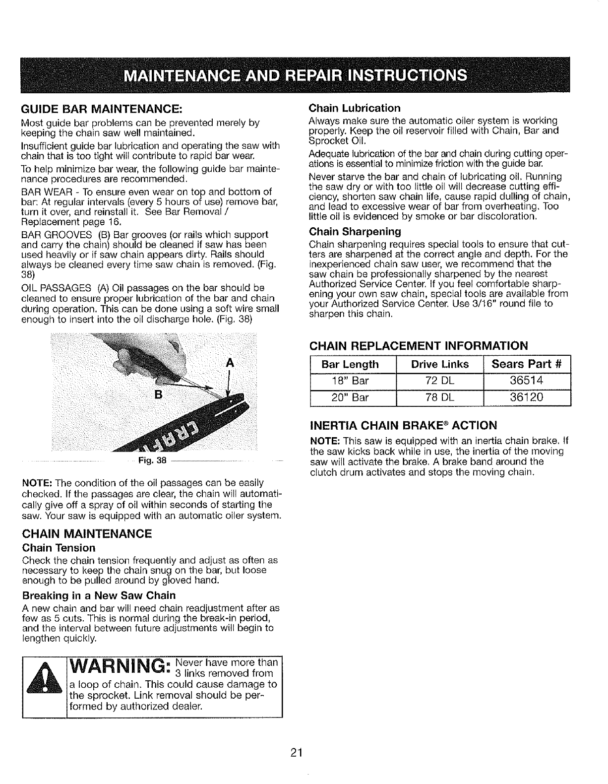
GUIDE BAR MAINTENANCE:
Most guide bar problems can be prevented merely by
keeping the chain saw wel! maintained.
Insufficient guide bar lubrication and operating the saw with
chain that is too tight will contribute to rapid bar wear,
To help minimize bar wear, the following guide bar mainte-
nance procedures are recommended.
BAR WEAR - To ensure even wear on top and bottom of
bar: At regular intervals (every 5 hours of use) remove bar,
turn it over, and reinstall it, See Bar Removal /
Replacement page 16,
BAR GROOVES (B) Bar grooves (or rails which support
and carry the chain) should be cleaned if saw has been
used heavily or if saw chain appears dirty. Rails should
always be cleaned every time saw chain is removed. (Fig.
38)
OIL PASSAGES (A) Oil passages on the bar should be
cleaned to ensure proper lubrication of the bar and chain
during operation, This can be done using a soft wire small
enough to insert into the oil discharge hole, (Fig, 38)
Chain Lubrication
Always make sure the automatic oiler system is working
properly. Keep the oil reservoir filled with Chain, Bar and
Sprocket Oil,
Adequate lubrication of the bar and chain during cutting oper-
ations is essential to minimize friction with the guide bar.
Never starve the bar and chain of lubricating oil. Running
the saw dry or with too little oil will decrease cutting effi-
ciency, shorten saw chain life, cause rapid dulling of chain,
and lead to excessive wear of bar from overheating, Too
little oil is evidenced by smoke or bar discoloration,
Chain Sharpening
Chain sharpening requires special tools to ensure that cut-
ters are sharpened at the correct angle and depth, For the
inexperienced chain saw user, we recommend that the
saw chain be professionally sharpened by the nearest
Authorized Service Center, If you feel comfortable sharp-
ening your own saw chain, special tools are available from
your Authorized Service Center. Use 3/t6" round file to
sharpen this chain.
Fig, 38
NOTE: The condition of the oil passages can be easily
checked. If the passages are clear, the chain will automati-
cally give off a spray of oil within seconds of starting the
saw. Your saw is equipped with an automatic oiler system.
CHAIN MAINTENANCE
Chain Tension
Check the chain tension frequently and adjust as often as
necessary to keep the chain snug on the bar, but loose
enough to be pulled around by gloved hand.
Breaking in a New Saw Chain
A new chain and bar will need chain readjustment after as
few as 5 cuts. This is normal during the break-in period,
and the interval between future adjustments will begin to
lengthen quickly.
CHAIN REPLACEMENT INFORMATION
Bar Length Drive Links Sears Part #
18" Bar 72 DL 36514
20" Bar 78 DL 36120
INERTIA CHAIN BRAKE ®ACTION
NOTE: This saw is equipped with an inertia chain brake. If
the saw kicks back while in use, the inertia of the moving
saw will activate the brake. A brake band around the
clutch drum activates and stops the moving chain.
WAR_|_._I. Never have more than
. .. ,... ,,,w,. 3 links removed from
a loop of chain, This could cause damage to
the sprocket. Link removal should be per-
formed by authorized dea er.
21
CAUSE
1. Incorrect starting procedures
2. Incorrect carburetor mixture adjustment setting
3, Fouled spark plug
4. Empty fuel tank
5. Primer bulb was not pressed enough
k _= =" ._ Q "e :
ACTION
1. Follow instructions in the Starting/Stopping section
2. Have carburetor adjusted by a Sears or other
qualified service dealer
3, Clean and gap or replace plug
4. Fill fuel tank with properly mixed fuel
5. Press primer bulb fully and slowly 10 times
CAUSE
1. Fuel filter is plugged
2. Incorrect choke lever position
3. Dirty spark arrestor screen
4. Dirty air filter
5. Incorrect carburetor mixture adjustment setting
ACTION
1, Replace the fuel filter
2. Move to Position 3
3, Replace spark arrestor screen
4, Remove, clean and reinstall filter
5. Have carburetor adjusted by a Sears or other
qualified service dealer
CAUSE
1. Incorrect carburetor mixture adjustment setting
2. Air filter is plugged
3, Old or improperly mixed fuel
CAUSE
1. Incorrect carburetor mixture adjustment setting
2. Old or improperly mixed fuel
3, Air filter is plugged
4. Fouled spark plug
CAUSE
1. Incorrectly gapped spark plug
2. Plugged spark arrestor
3, Dirty air filter
CAUSE
1. Incorrect carburetor mixture adjustment setting
2. Incorrect fuel mixture
ACTION
1. Have carburetor adjusted by a Sears or other
qualified service dealer
2. Replace or clean the air filter
3. Drain gas tank/add fresh fuel mixture
ACTION
1, Have carburetor adjusted by a Sears or other
qualified service dealer
2. Drain gas tank (SEE STORING CHAIN SAW)/add fresh
ruel mixture
3. Replace or clean the air filter
4, Replace or clean the spark plug
ACTION
1, Clean and gap or replace plug
2. Clean or replace spark arrestor
3, Clean or replace air filter
ACTION
1. Have carburetor adjusted by a Sears or other
qualified service dealer
2, Use properly mixed fuel (40:1 mixture)
For repairs beyond the minor adjustments listed above, contact either Sears Parts & Repair at 1-800-4-MY-HOME e or
another qualified service dealer.
22
Engine Type ................................................................................................................................................ Air-Cooled, 2-Cycle
Displacement ................................................................................................................................................. 55 cc (3.36 cu in.)
Idle Speed RPM ........................................................................................................................................................ 3,400 rpm
Operating RPM ........................................................................................................................................................ 7,200+ rpm
Ignition Type .......................................................................................................................... Electronic-MAX FIRE IGNtTION TM
Ignition Switch ....................................................................................................................................................... Slide Switch
Spark Plug Gap ........................................................................................................................................ 0.025 in. (0.635 mm)
Lubrication ......................................................................................................................................................... Fuel/Oil Mixture
Fuel/Oil Ratio ........................................................................................................................................................................ 40:1
Carburetor ............................................................................................................................................. Diaphragm, All-Position
Starter ................................................................................................................................. tncredi-Pull TM Starting Auto Rewind
Muffler ........................................................................................................................................................... Baffled with Guard
Throttle .................................................................................................. ................................................... Manual Spring Return
Fuel Tank Capacity ....................................................................................................................................... 16.8 oz. (496.8 ml)
Throttle Control ............................................................................................................................................... Finger-Tip Trigger
Approximate Unit Weight (No fuel) .................................................................................................................. 17.6 Ibs. (8 kg)
*All specifications are based on the latest product information available at the time of printing. We reserve the right to
make changes at any time without notice.
23
Item Paris No, Description
1 9NAS.5116*24 NIJT
2 B228-31 B206 FLYWHEEL
32157-B1B20 tSEAt.
4 9DR-6202BI BEAR/#tR
5 9SREB 40124-2,'_2 SCREW
6 9WF8.B,2 WASHER
7 9072-310201F CRANKCASE LOWER
89221-310001 K_Y
B 9228-B_BBB3A C'SFIAFTTC_OCI ASS'Y
10 9"i55_3 t0201 SEARING
I 1 9076.310201 O RING
tB 92_8-Bt B_BB PU_P ASS'Y
t3 9154-3t0201 C()ff'_ NEC'_OR
t4 9SKKSYSII6-B,5 SCREW
lB B124-3 t0201 FITTING, PULSE LINE
16 _07B-310202F CRANKCASE UPPER
t7 8014-31BB_2 GASKET
18 2236-310201 CLAMP, WtRE HOSE
19 B059-31020_ CONDUIT, FLE×
20 BCA 046 RING
21 2PC-IO-32,5 PIN
22 929B-31020! PISTON
23 Bt_!)_BIOB01 RING, PISTON
24 929B-310201F CYUNCER
25 9295-326001 SPARK PLUG
26 2BKKSY10J24_3 6B SCREW
27 99t 4-BIBS03 FLANGE
_8 9_3t-Bt029_ EYELET
29 228B.3t BBB1 -OH IGNITION ASSIY
30 919t-BtOBBl STUD
3t £05_.BIOB02 CONTACT CSOUNT
32 9SKSSY'_B/24 0.72 SCREW
33 9STDZY19F24 -B, ZB SCREW
Item Parts No. Description
34 BOl4,BIOBO8 WASHER
35 9292-BlOBOt BAFFLER
36 B22B_SIO217 MUFFLER BODY ASS'Y
37 9S_KBVtB/24 0=5 SCREW
3B BE11-310201 pLATE
39 9183-310201 SCREEN
40 9062-310205 BAFFLER
41 9017-310204 COVES, MUFFLF.R
42 915B-3102_l LCCKFLATE
43 ERAS- 10/24 NUT
44 9t 3t-3_B203 EYELET
42 9Ot 4-310204 FLANGE
46 9102-3 t 02B2 PLA_I_
47 9O_4.Bt 02B2 GASKET
4B B124-Bt 0203 BOOT
49 9287-31_291 CARS
52 9014-310201 FLANGE
2t B13t_310_O4 _YELET
52 _B24-310202 SPRING
53 9124_310204 BOOT
54 9SREB-t0724-l,625 SCREW
55 9228-31B2rJ_ STARTER/_SS'Y
56 2SKKBVt 0/14,0.625 SCREW
57 2WFZ-B,18 WASI4ER
56 9223-310201 METAL CLIP
B9 9 t83-310202 SCREEN
60 9_28.310205 FUEb'OtL TANK ASS'Y
61 9t 42-31600B PRIMER, REMOTE
62 9t 29-3_92_4 HOSE
63 9SKRSY_OI24q SCREW
64 904B-3 t 92B_ pLATE
95 9124-3t 0296 SPACE
56 9228-3t0206 CAP_ FUEL
Item Parts No. Description
67 9 tBB+310001 FIEF ES, FUEL
68 2129-31B004 HOS_
69 2SKKZYI(WI4-B1 SCREW
70 Ol B4-31 t)BO# BOOT, CARP'
7t 9O?O-3 _O00B VALVE DUCKBILL
72 9129-3_920B HOS_
73 0BI3-3t0201 PLUG
74 9252-Bt 0002 FILTER
75 B13_-Bt 9;-_B6 WASHER
7_ 9043-310203 SLATE, I_AR
11 2043-310202 ELATE, FLANGE
78 BBKRBYBII 9-B,375 SCREW
79 98JKB.12JI4-1,5 SCREW
80 922B-B_ B20_ HASSLE ASS'Y
81 B22B-31021B COVER ASS'V
82 2$KKBVt@I4-0B SCREW
83 BSKKBV 19/14,O_6B SCREW
84 922B-Bt 0204 AIR CLEANER A BE,'Y
85 B067-8102BB COVER
86 2B_4-310101 SCREW
B7 92_B.31 _230 CRONE ASS _Y
88 9t 14-B10202 ROD, CHORE
BB ROt 3-310202 PLUG
9O 922_-2_B2_3 ISOLATOR ASS'Y
Bt _2B-3 t0214 CABLE ASSIY
92 9229-3t 0232 COVES ASS'Y, HANDLE
93 9SKRSYS/16,0 62B SCREW
94 9SKSBV-SII6- tSCREW
95 9010-210SO3 WIRE
96 922B+3102.22 ISOLATOR ASS'Y
97 9WFB.4.9-t 7 WASHER
98 @0B4-310206 SPRIHG
99 B010-BloBot CABLE
Item Parts No, DesDrtptton
t00 9t24+B_0209 GROMMET
IO_ 0028.310202 TRIGGER
102 9028,BlOBOl RE_EASE TRIGGER
103 9072-310203 LATCH, HIGH IDLE
104 9B24-3 _0207 SPRING
_05 B068,310203 FRAN'tE, REAR
106 2BGKSY I 0/24,&5 SCREW
107 _WOC-O8 WASHER
102 9_24 31OBOB SPACER
109 9043,310205 PLATE
110 20_2-23BBOI GROMMET
111 6014,M96A91 WASHER
I_S BI82-EI OlO_ FILTER
lib 9073-310201 GEAR, WORM
_14 2WFN-B.4 WASI-{ER
115 2WSZ-B.722 WASHER
t16 9t 55-310293 BEA}BING
t17 9228-3_0211 DRUM SRRRT ASS'Y
_18 B228_9_92t0 CLUTCH ASS'Y
It9 9f_HC-B9 NCT
120 9124-3tO202 Boolr, CARS
12t 9SRRSYf_14-9.625 SCREW
122 9SKSBYIO/24-05
_23 22203tRBO2
B220-31_203
124 9_4@31A216
9B4O,3_A220
125 9082.31B204
126 2228_31 _245
127 2NAZ-5tIB-I B
128 9072-B! 0208
12B 9035-910201
_39 2B_4-BfO291
_21 2B42_310201
t32 9t_O-MDOTOt
tB3 9017-3_0214
SCREW
18" CHAtN
20" CHAIN
t8 _ BAS
20" BAR
PLA,T_
CHAIN I]RAKE ASS'Y
NUT
pLATE
RUT
SCSEW
WRENCH
CARRY CASE
SCABBARD
24

California /EPA Emission Control Warranty Statement
Your Warranty Rights and Obligations
The California Air Resources Board, The Environmental Protection Agency and Sears, Roebuck and Co., are pleased to
explain the emission control system warranty on your 2005 and later small off-road engine. In California and the 49 states,
new small off-road engines must be designed, built and equipped to meet stringent anti-smog standards. Sears must war-
rant the emission control system on your small off-road engine for the periods of time listed below provided there has been
no abuse, neglect or improper maintenance of your small off-road engine.
Your Emission control system may include parts such as the carburetor or fuel-injection system, the ignition system, and cat-
alytic converter. Also included may be hoses, belts, connectors and other emission-related assemblies.
Where a warrantable condition exists, Sears will repair your small off-road engine at no cost to you including diagnosis, parts
and labor.
The 2005 and later small off-road engines are warranted for two years. If any emission-related part on your engine is
defective, the part will be repaired or replaced by Sears,
Owner's Warranty Responsibilities
• As the small off-road engine owner, you are responsible for the performance of the required maintenance listed in your
operator's manual. Sears recommends that you retain all receipts covering maintenance on your small off-road engine, but
Sears cannot deny warranty solely for the lack of receipts or for your failure to ensure the performance of all scheduled
maintenance.
o As the small off-road engine owner, you should however be aware that Sears may deny you warranty coverage if your small
off-road engine or a part has failed due to abuse, neglect, improper maintenance or unapproved modifications.
• You are responsible for presenting your small off-road engine to a Sears authorized service center as soon as problem
exists. The warranty repairs should be completed in a reasonable amount of time, not to exceed 30 days.
If you have any questions regarding your warranty rights and responsibilities, you should call 1-8O0-4-MY-HOME®.
Manufacturer's Warranty Coverage
= The warranty period begins on the date the engine or equipment is delivered to the retail purchaser.
• The manufacturer warrants to the initial owner and each subsequent purchaser, that the engine is free from defects in mate-
rial and workmanship which cause the failure of a warranted part for a period of one year.
•Repair and replacement of warranted part will be performed at no charge to the owner at an authorized Sears service cen-
ter. For the nearest location please contact Sears at: 1-800-4-MY-HOME®.
• Any warranted part which is not scheduled for replacement, as required maintenance or which is scheduled only for regu-
lal inspection to the effect of Repair or Replace as Necessary Js warranted for the penod. Any warranted part which _s
scheduled for replacement as required maintenance will be warranted for the period of time up to the first scheduled
replacement point for that part.
• The owner will not be charged for diagnostic labor which leads to the determination that a warranted part is defective if the
diagnostic work is performed at an authorized Sears Service Center.
• The manufacturer is liable for damages to other engine components caused by the failure of a warranted part still under
warranty.
Failures caused by abuse, neglect or improper maintenance are not covered under warranty.
• The use of add-on or modified parts can be grounds for disallowing a warranty claim. The manufacturer is not liable to cover
failures of warranted parts caused by the use of add-on or modified parts.
• In order to file a claim, go to your nearest authorized Sears Service Center. Warranty service or repairs will be provided at
all authorized Sears Service Centers.
o Any manufacturer approved replacement part may be used in the performance of any warranty maintenance or repair of
emission related parts and will be provided without charge to the owner. Any replacement part that is equivalent in perform-
ance or durability may be used in non-warranty maintenance or repair and will not reduce the warranty obligations of the
manufacturer.
The following components are included in the emission related warranty: engine, air filter, carburetor, primer, fuel lines, fuel
pick up/fuel filter, ignition module, spark plug and muffler.
25
Repair Protection Agreements
Congratulations on making a smart purchase.
Your new Craftsman ®product is designed and
manufactured for years of dependable opera-
tion. But like all products, it may require repair
from time to time. That's when having aRepair
Protection Agreement can save you money and
aggravation.
Purchase a Repair Protection Agreement now
and protect yourseff from unexpected hassle
and expense.
Here's what's included in the Agreement:
[] Expert service by our 12,000 professional
repair specialists
[] Unlimited service and no charge for parts
and labor on all covered repairs
[] Product replacement if your covered prod-
uct can't be fixed
[] Discount of 10% from regular price of
service and service-related parts not cov-
ered by the agreement; also, 10% off regular
price of preventive maintenance check
[] Fast help by phone - phone support from a
Sears technician on products requiring in-home
repair, plus convenient repair scheduling
Once you purchase the Agreement, a simple
phone call is all that it takes for you to schedule
service. You can call anytime day or night, or
schedule a service appointment online.
Sears has over 12,000 professional repair spe-
cialists, who have access to over 4.5 million
quality parts and accessories. That's the kind of
professionalism you can count on to help pro-
long the life of your new purchase for years to
come. Purchase your Repair Protection Agree-
ment today!
Some limitations and exclusions apply.
For prices and additional information call
1-800-827-6655.
Sears Installation Service
For Sears professional installation of home
appliances, garage door openers, water heaters,
and other major home items, in the U.S.A. call
1-800-4-MY-HOME _
26
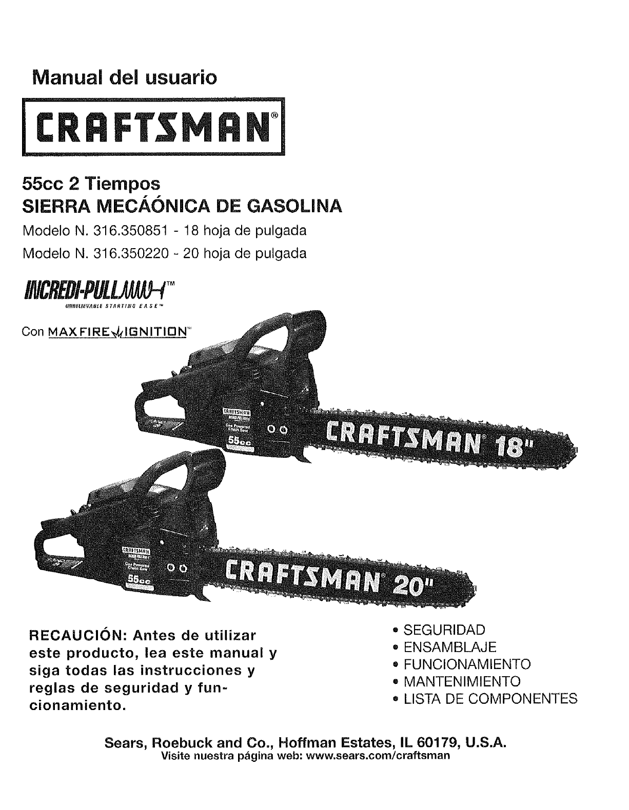
Manual del usuario
55cc 2 Tiempos
SIERRA MECA6NiCA DE GASOLiNA
Modelo N. 316.350851 - 18 hoja de pulgada
Modelo N. 316.350220 _ 20 hoja de pulgada
INCREDI.PULL TM
UNBELIEVABLE S TA R T_NO E A $ E_u
Con MAX FIREVxlGNITIDN"
RECAUCION: Antes de utilizar
este producto, lea este manual y
siga todas las instrucciones y
reglas de seguridad y fun-
cionamiento.
*SEGURIDAD
,ENSAMBLAJE
= FUNCIONAMIENTO
° MANTENIMIENTO
° LISTA DE COMPONENTES
Sears, Roebuck and Co., Hoffman Estates, IL 60179, U.S.A.
Visite nuestra p_gina web: www.sears.com/craftsman
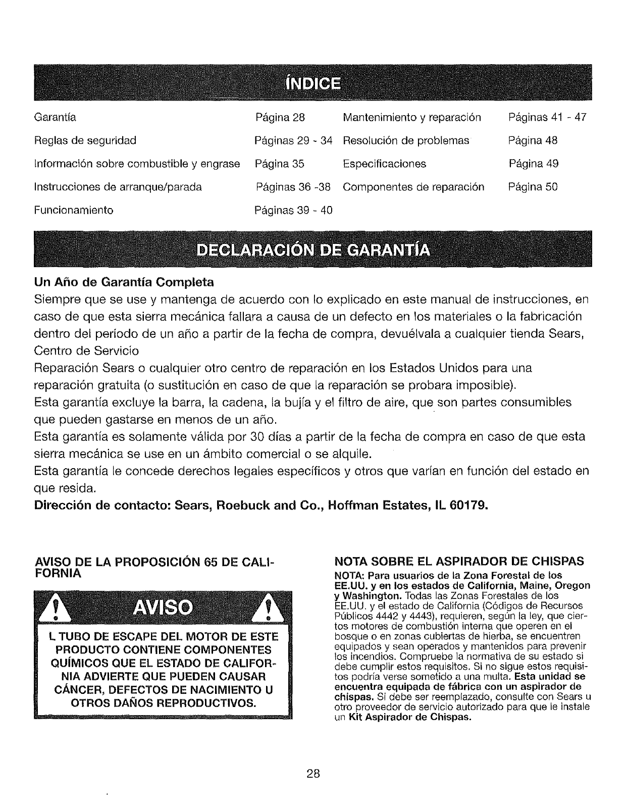
Garantia
Reglas de seguridad
lnformaci6n sobre combustible y engrase
Instrucciones de arranque/parada
Funcionamiento
P&gina 28
P&ginas 29 - 34
P&gina 35
P&ginas 36 -38
P&ginas 39 - 40
Mantenimiento y reparaci6n
Resotuci6n de problemas
Especificaciones
Componentes de reparaci6n
P_.ginas 41 - 47
P_.gina 48
P&gina 49
P&gina 50
Un Aho de Garantia Completa
Siempre que se use y mantenga de acuerdo con !o explicado en este manual de instrucciones, en
caso de que esta sierra mec&nica fallara a causa de un defecto en tos materiates o la fabricaci6n
dentro det periodo de un a_o a partir de la fecha de compra, devuetvala a cualquier tienda Sears,
Centro de Servicio
Reparaci6n Sears o cualquier otro centro de reparaci6n en los Estados Unidos para una
reparaci6n gratuita (o sustituci6n en caso de que ta reparaci6n se probara imposible).
Esta garantfa excluye la barra, la cadena, la bujfa y et filtro de aire, que son partes consumibtes
que pueden gastarse en menos de un aRo.
Esta garantia es solamente vAlida por 30 dias a partir de la fecha de compra en caso de que esta
sierra mec&nica se use en un b.mbito comercial o se alquile.
Esta garantia le concede derechos legales especificos y otros que varian en funci6n del estado en
que resida.
Direccibn de contacto: Sears, Roebuck and Co., Hoffman Estates, IL 60179.
AVISO DE LA PROPOSICION 65 DE CALI-
FORNIA
L TUBO DE ESCAPE DEL MOTOR DE ESTE
PRODUCTO CONTIENE COMPONENTES
QUiMICOS QUE EL ESTADO DE CALIFOR-
NIA ADVIERTE QUE PUEDEN CAUSAR
CANCER, DEFECTOS DE NACIMIENTO U
OTROS DAI_OS REPRODUCTIVOS.
NOTA SOBRE EL ASPIRADOR DE CHISPAS
NOTA: Para usuarios de la Zona Forestal de los
EE.UU. y en los estados de California, Maine, Oregon
y Washington. Todas las Zonas Forestales de los
EE.UU. y e! estado de California (C6digos de Recursos
PL_blicos 4442 y 4443), requieren, seg_n la ley, que cier-
tos motores de combusti6n interna que operen en el
bosque o en zonas cubiertas de hierba, se encuentren
equipados y sean operados y mantenidos para prevenir
los incendios. Compruebe la nermativa de su estado si
debe cumplir estos requisitos. Si no sigue estos requisi-
tos podria verse sometido a una multa. Esta unidad se
encuentra equipada de f&brica con un aspirador de
chispas. Si debe ser reemplazado, consulte con Sears u
otro proveedor de servicio autorizado para que le instale
un Kit Aspirador de Chispas.
28
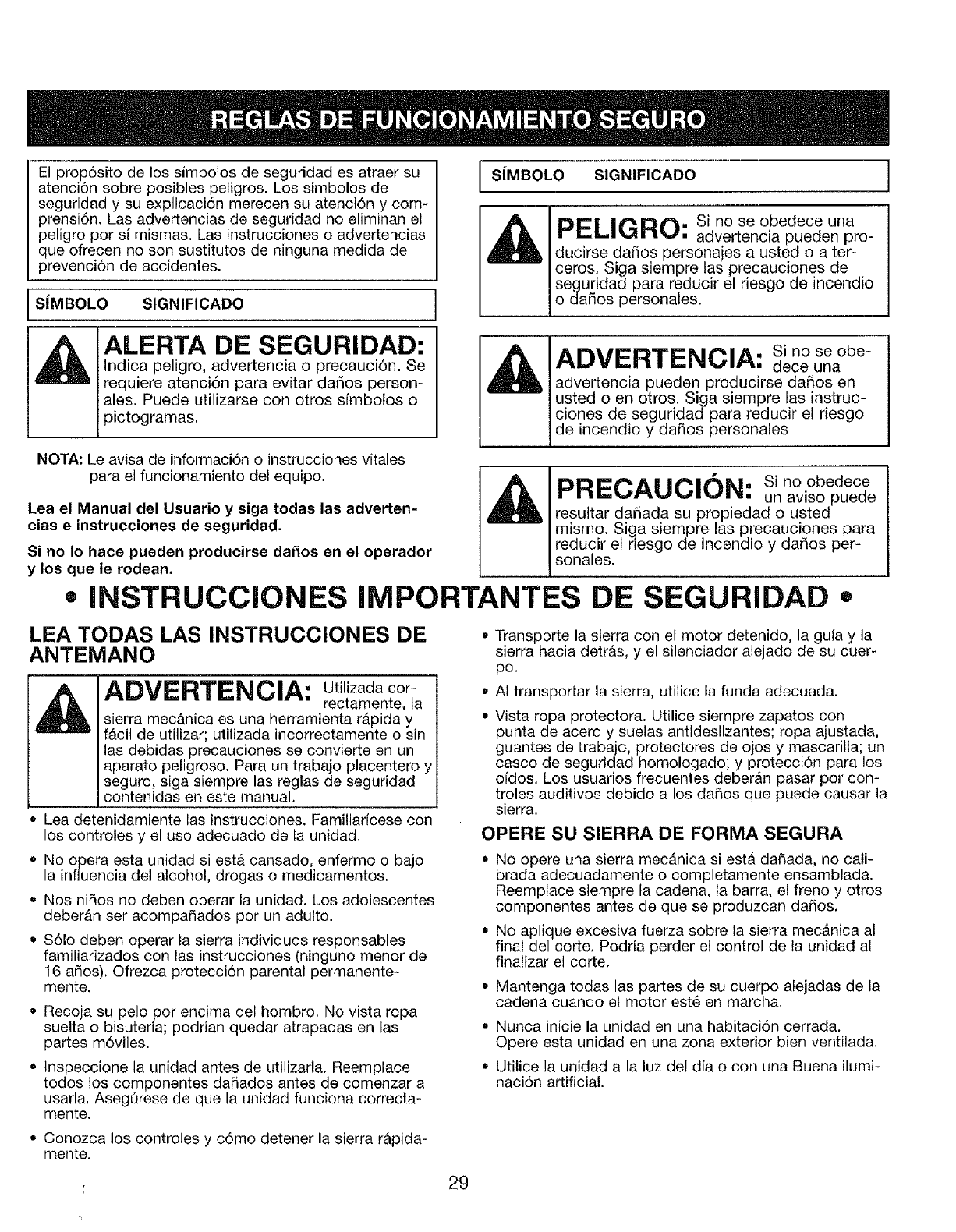
El prop6sito de los simbolos de seguridad es atraer su
atenci6n sobre posibles peligros. Los simbolos de
seguridad y su explicaci6n mereeen su atencidn y com-
prensi6n. Las advertencias de seguridad no eliminan el
peligro por si mismas. Las instrucciones o advertencias
que ofrecen no son sustitutos de ninguna medida de
prevencidn de accidentes.
SJMBOLO SIGNIFICADO
I SiMBOLO SIGNIFICADO I
PELIGRO: si no se obedece una
advertencia pueden pro-
ducirse daSos personajes a usted o a ter-
ceros. Siga siempre las precauciones de
seguridad para reducir el riesgo de incendio
o da_os personales,
ALERTA DE SEGURIDAD:
Indica peligro, advertencia o precauci6n. Se
requiere atenci6n para evitar daSos person-
ales. Puede utilizarse con otros simbolos o
pictogramas.
ADVERTENCIA: Si no se obe-
dece una
advertencia pueden producirse daSos en
usted o en otros. Siga siempre las instruc-
clones de seguridad para reducir el riesgo
de incendio y dafios personales
NOTA: Le avisa de informaci6n o instrucciones vitales
para el funcionamiento del equipo.
Lea el Manual del Usuario y siga todas las adverten-
cias einstrucciones de seguridad.
Si no Io hace pueden producirse dafios en el operador
y los que le rodean.
O
PRECAUCION: Si no obedece
un aviso puede
resultar daSada su propiedad o usted
mismo. Siga siempre las precauciones para
reducir el riesgo de incendio y daSos per-
sonales.
INSTRUCCIONES IMPORTANTES DE SEGURIDAD =
LEA TODAS LAS INSTRUCClONES DE
ANTEMANO
ADVERTENCIA: Utitizada cop
rectamente, la
sierra mec&nica es una herramienta rb.pida y
f&cil de utilizar; utilizada incorrectamente o sin
las debidas precauciones se convierte en un
aparato peligroso. Para un trabajo placentero y
seguro, siga siempre las reglas de seguridad
contenidas en este manual.
• Lea detenidamiente las instrucciones. Familiarfcese con
los controles y el uso adecuado de ta unidad,
• No opera esta unidad si est& cansado, enfermo o bajo
la influencia del alcohol, drogas o medicamentos.
o Nos niSos no deben operar la unidad. Los adolescentes
deber,_n ser acompaSados por un adulto.
• $61o deben operar ta sierra individuos responsables
familiarizados con las instrucciones (ninguno menor de
16 aSos). Ofrezca protecci6n parental permanente-
mente.
• Recoja su pelo por encima del hombro. No vista ropa
suelta o bisuterfa; podrian quedar atrapadas en las
partes m6viles.
• tnspeccione la unidad antes de utilizarla. Reemplace
todos los componentes da_ados antes de comenzar a
usarla, AsegQrese de que fa unidad funciona correcta-
mente.
• Conozca los controles y c6mo detener la sierra r&pida-
mente.
Transporte la sierra con el motor detenido, la guia y la
sierra hacia detras, y el silenciador alejado de su cuer-
po.
AI transportar la sierra, utilice la funda adecuada.
Vista ropa protectora. Utilice siempre zapatos con
punta de acero y suelas antideslizantes; ropa ajustada,
guantes de trabajo, protectores de ojos y mascarilla; un
casco de seguridad homologado; y protecci6n para los
o[dos. Los usuarios frecuentes deberan pasar por con-
troles auditivos debido a los daSos que puede causar la
sierra.
OPERE SU SIERRA DE FORMA SEGURA
•No opere una sierra mec,_.nica si est_ daSada, no calf
brada adecuadamente o completamente ensamblada.
Reemplace siempre ta cadena, la barra, el freno y otros
componentes antes de que se produzoan daSos,
• No aplique excesiva fuerza sobre la sierra mec_.nica al
final del corte, Podrfa perder el control de ta unidad al
finalizar el corte.
•Mantenga todas las partes de su cuerpo alejadas de la
cadena cuando et motor est6 en marcha.
• Nunca inicie la unidad en una habitaci6n cerrada,
Opere esta unidad en una zona exterior bien ventilada.
• Utilice la unidad a la luz del dfa o con una Buena ilumi-
naci6n artificial.
: 29
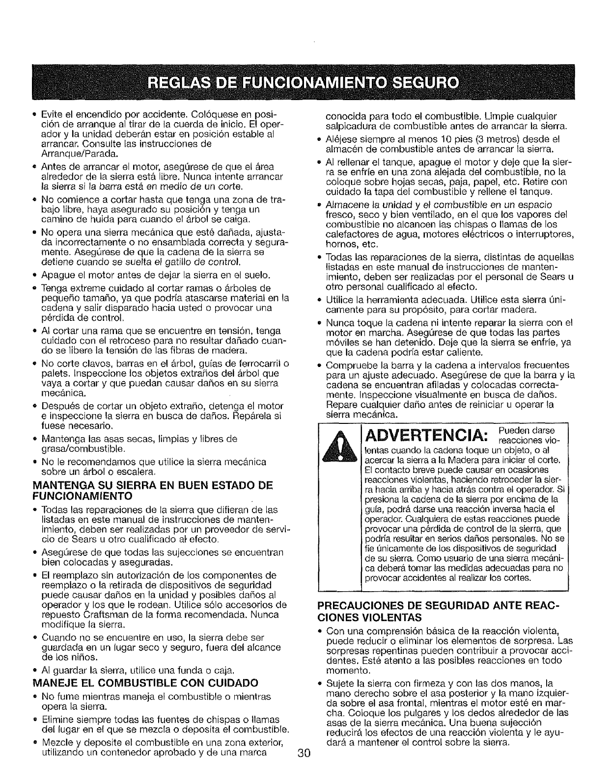
• Evite el encendido por accidente. Col6quese en posi-
ci6n de arranque al tirar de la cuerda de inicio. E! oper-
ador y la unidad deberb.n estar en posici6n estable al
arrancar. Consulte tas instrucciones de
Arranque/Parada.
• Antes de arrancar el motor, asegQrese de que el &tea
alrededor de la sierra est& libre. Nunca intente arrancar
la sierra si la barra est& en medio de un corte.
• No comience a cortar hasta que tenga una zona de tra-
bajo libre, haya asegurado su posicion y tenga un
camino de huida para cuando el &rbol se caiga.
•No opera una sierra mec&nica que est6 dafiada, ajusta-
da incorrectamente o no ensamblada correcta y segura-
mente. AsegQrese de que la cadena de la sierra se
detiene cuando se suelta el gatillo de control,
• Apague el motor antes de dejar la sierra en el suelo.
o Tenga extreme cuidado al cortar ramas o _rboles de
pequefio tamaSo, ya que podr[a atascarse material en la
cadena y salir disparado hacia usted o provocar una
p6rdida de control.
• At cortar una rama que se encuentre en tensidn, tenga
cuidado con el retroceso para no resultar daSado cuan-
do se libere la tensi6n de las fibras de madera.
• No corte clavos, barras en e! &rbol, guias de ferrocarrit o
palets, tnspeccione los objetos extrafios del &rbol que
vaya a cortar y que puedan causar dafios en su sierra
mec&nica.
• Despu6s de cortar un objeto extrafio, detenga el motor
e inspeccione la sierra en busca de dafios. Rep&rela si
fuese necesario,
• Mantenga las asas secas, limpias y libres de
grasa/combustible.
= No le recomendamos que utilice fa sierra mec#.nica
sobre un &rbol o escalera.
MANTENGA SU SIERRA EN BUEN ESTADO DE
FUNClONAMIENTO
-Todas las reparaciones de la sierra que difieran de las
listadas en este manual de instrucciones de manten-
imiento, deben ser realizadas per un proveedor de servi-
cio de Sears u otro cualificado a_'efecto,
• AsegOrese de que todas las sujecciones se encuentran
bien colocadas y aseguradas.
= El reemplazo sin autorizaci6n de los componentes de
reemplazo o la retirada de dispositivos de seguridad
puede causar daSos en la unidad y posibles dafios al
operador y los que le rodean. Utilice s61o accesorios de
repuesto Craftsman de la forma recomendada. Nunca
modifique la sierra,
• Cuando no se encuentre en uso, la sierra debe ser
guardada en un lugar seco y seguro, fuera del afcance
de los nifios.
• AI guardar la sierra, utilice una funda o caja,
MANEJE EL COMBUSTIBLE CON CUIDADO
• No fume mientras maneja el combustible o mientras
opera la sierra.
. Elimine siempre todas las fuentes de chispas o llamas
del lugar en e! que se mezcla o deposita e! combustible,
• Mezcle y deposite el combustible en una zona exterior,
utilizando un contenedor aprobado y de una marca 30
conocida para todo el combustible. Limpie cualquier
salpicadura de combustible antes de arrancar la sierra.
• AI6jese siempre al menos 10 pies (3 metros) desde el
almac6n de combustible antes de arrancar la sierra.
• AI rellenar el tanque, apague el motor y deje que la sier-
ra se enfrie en una zona alejada del combustible, no la
cotoque sobre hojas secas, paja, papel, etc. Retire con
cuidado la tapa del combustible y rellene el tanque.
o Almacene la unidad y el combustible en un espacio
fresco, seco y bien ventilado, en el que los vapores del
combustible no alcancen las chispas o llamas de los
calefactores de agua, motores el_ctricos o interruptores,
hornos, etc.
• Todas las reparaciones de la sierra, distintas de aquetlas
listadas en este manual de instrucciones de manten-
imiento, deben set realizadas por el personal de Sears u
otto personal cualificado al efecto.
• Utilice la herramienta adecuada. Utilice esta sierra Qni-
camente para su prop6sito, para cortar madera.
• Nunca toque la cadena ni intente reparar la sierra con el
motor en marcha. AsegQrese de que todas las partes
m6viles se han detenido. Deje que la sierra se enfrie, ya
que la cadena podr[a estar caliente.
° Compruebe la barra y la cadena a intervalos frecuentes
para un ajuste adecuado. Aseg_rese de que la barra y la
cadena se encuentran afiladas y cotocadas correcta-
mente. Inspeccione visuatmente en busca de dafios.
Repare cualquier dafio antes de reiniciar u operar la
sierra mec_tnica.
ADVERTENCIA: Puedendarse
reacciones vio-
lentas cuando la cadena toque un objeto, o al
acercar ta sierra a la Madera para iniciar el corte,
E1contacto breve puede causar en ocasiones
reaccionesviolentas, haciendo retroceder la sier-
ra hacia arriba y hacia atrAs contra el operador. Si
)resiona la cadena de la sierra pot encima de la
gu[a, podr_t darse una reacci6n inversa hacia el
operador. Cualquiera de estas reacciones puede
3rovocar una p6rdida de control de la sierra, que
3odria resultar en serios da_os personales. No se
fie Qnicamente de los dispositivos de seguridad
de su sierra. Como usuario de una sierra mec_ni-
ca debera tomar las medidas adecuadas para no
_rovocar accidentes al realizar los cortes.
PRECAUCIONES DE SEGURIDAD ANTE REAC-
CLONES VIOLENTAS
Con una comprensi6n b_sica de ta reacci6n violenta,
puede reducir o eliminar los elementos de sorpresa. Las
sorpresas repentinas pueden contribuir a provocar acci-
dentes. Est6 atento alas posibles reacciones en todo
momento.
• Sujete la sierra con firmeza y con las dos manos, la
mano derecho sobre el asa posterior y la mano izquier-
da sobre el asa frontal, mientras el motor est6 en mar-
cha. Cotoque los pulgares y los dedos alrededor de las
asas de la sierra mec_.nica. Una buena sujecci6n
reducir#, los efectos de una reacci6n violenta y le ayu-
dar& a mantener el control sobre la sierra.
• Asegt_resedequelazonaenlaqueest&cortandono
existenobstrucciones.Nodejequelapuntadelagu[a
entreencontactoconuntronco,rama,alambradao
cualquierotraobstrucci6nquepuedaencontrarse
mientrasoperalasierra.
Cortesiempreconel motorenmarchay atodaveloci-
dad.Aprieteelgatilloy mantengaunavelocidaddecot-
tadoestable.
• Utilicesololasbarras,cadenasy otroscomponentesy
accesoriosdelfabricante.Losencontrar&enundis-
tribuidorde Searsu otrosestablecimientosautorizados.
Elusodecomponentessinautorizacidnpoddaprovo-
cardaSosenelusuarioo enlaunidad,yviolar&su
garantia.
° Sigalasinstruccionesdeafiladoy mantenimientodel
fabricanteparalasierramec_.nica.
• Utilicesolobarrasdereemplazoy cadenasespecificas
parasusierraparaevitarcualquierdaSo.
• Est_atentoa lostroncosendesplazamientou otras
fuerzasquepodrAncaersobrelacadena.
Utilicelasierraatodavelocidadalentrarenuncorte
anterior.Tengacuidadoalintroducirseenuncorteante-
rior.
• No inicie un corte utilizando la punta de la sierra.
OTRAS PRECAUCIONES DE SEGURIDAD
• No opere la sierra mecb.nica con una sola mano!
Pueden producirse serios daSos en el operador, sus
ayudantes, aquellos que los rodeen, o cualquier combi-
naci6n de estas personas. Una sierra mec&nica se dis-
eSa para utilizarla con dos manos.
• No opere la sierra mecanica si est,. cansado.
• Utilice calzado de seguridad; ropa ajustada, guantes
protectores; y dispositivos de protecci6n de ojos, oidos
y cabeza.
• No permita que otras personas se encuentren cerca de
la sierra mec_.nica al arrancar o cortar con la sierra.
Aleje a otras personas o animales de la zona de trabajo.
Ni retire, daSe ni desactive ningL_ndispositivo de seguri-
dad. Nunca utilice una sierra mec&nica daSada, modifi-
cada o reparada incorrectamente. Compruebe el fun-
cionamiento correcto regularmente. Utilice solo Ins bar-
ras y cadenas de la Iongitud indicada en la tabta con-
tenida en este manual.
• No tleve a cabo ninguna operaci6n o reparaci6n usted
mismo que difieran de las rutinas de mantenimiento lis-
tadas en este manual.
• Tenga cuidado al derribar un &rbol. AsegQrese de haber
planeado una ruta de escape para la ca[da, y mantenga
atejadas a otras personas.
• Tenga cuidado; detenga la mAquina si alguien entra en
la zona de cortado, que generalmente son 3 o 4 pies (1
o 2 metros) alrededor det operador.
• Tenga cuidado al trabajar en grupo para evitar da_os a
otros trabajadores que entren en la zona de cortado.
• Entregue su sierra s61amente a usuarios experimenta-
dos que se encuentren completamente familiarizados
con el funcionamiento y uso correcto de la sierra.
Entregue este manual a otros usuarios, que deberAn
leerlo antes de utilizar la sierra.
• Detenga el motor antes de soltar la sierra. No deje el
motor en marcha y sin atenci6n.
= No guarde la unidad, con combustible en el tanque, en
el interior de un edificio donde los vapores puedan
alcanzar una llama o chispa.
• Deje que el motor se enfrie antes de guardar o trans-
portar la sierra mec#,nica a largas distancias. Pot ejemp-
Io, deje que el motor se enfr[e antes de colocar la sierra
mec&nica en un autom6vil. Adem&s, asegQrese de ase-
gurar la unidad durante el transporte.
o Guarde la unidad en un lugar seco, cerrado, alto y fuera
del alcance de los niSos para evitar el uso no autoriza-
do.
• No deje penetrar el agua ni cualquier otro liquido en la
unidad. Mantenga sus manos secas, limpias y sin
impurezas. L[mpielas despu6s de cualquier uso.
• Conserve estas instrucciones. ConsL_ltelas a menudo y
utilicelas para instruir otros usuarios. Si presta la unidad
a otra persona, pr6stele tambi6n estas instrucciones.
. No utilice la unidad bajo la iluvia, durante una tormenta
o clima tempestuoso.
SEGURIDAD DE COMBUSTIBLE
• Guarde el combustible en contenedores disedados
especlficamente y homologados para el almacenamien-
to de tales materiales.
•Detenga siempre el motor y deje que se enfrie antes de
rellenar el tanque. No retire la tapa del tanque de com-
bustible, ni a5ada combustible cuando el motor est6
caliente. Nunca opere la unidad sin la tapa de com-
bustible. Afloje lentamente la tapa del combustible para
liberar cualquier presi6n en el tanque.
•ASada combustible en una zona exterior limpia y bien
ventilada en la que no existan chispas ni llamas. Retire
lentamente la tapa det combustible despu6s de detener
el motor, No fume mientras rellena et tanque de com-
bustible. Limpie cualquier salpicadura de la unidad
inmediatamente.
ADVERTENCIA: La gasolina es
altamente
inflamable, y sus vapores pueden explotar si
entran en combusti6n. Tome tas siguientes medi-
das:
Evite que el combustible salpicado entre en combusti6n.
No arranque el motor hasta que se disipen los vapores.
•Mueva la unidad al menos 30 pies (9,1 m) desde la
fuente de combustible y col6quela en el suelo antes de
arrancar el motor. No fume. Mant_ngase alejado de lla-
mas y chispas en el lugar en el que rellene el tanque de
combustible u opere con la unidad.
GUARDE ESTAS INSTRUC-
CLONES
31
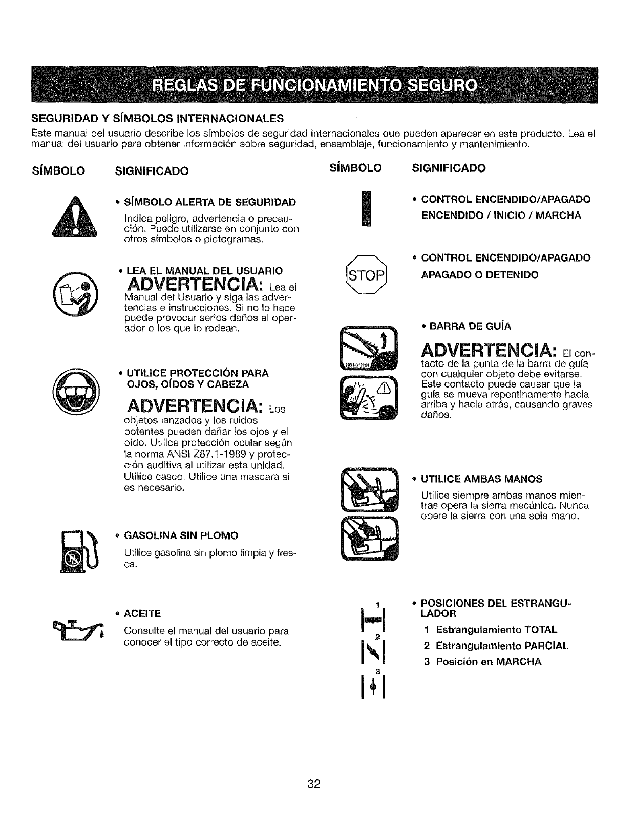
SEGURIDAD Y S|MBOLOS INTERNACIONALES
Este manual del usuario describe los s[mbolos de seguridad internacionales que pueden aparecer en este producto. Lea el
manual del usuario para obtener informaci6n sobre seguridad, ensamblaje, funcionamiento y mantenimiento.
S|MBOLO SIGNIFICADO SJMBOLO SIGNIFICADO
SJMBOLO ALERTA DE SEGURIDAD
Indica peligro, advertencia o precau-
ci6n, Puede utilizarse en conjunto con
otros simbolos o pictogramas.
oLEA EL MANUAL DEL USUARIO
ADVERTENCIA: Leael
Manual del Usuario y siga las adver-
tencias e instrucciones. Si no Io hace
puede provocar serios daSos al oper-
ador o los que to rodean.
=UTILICE PROTECCION PARA
OJOS, OiDOS Y CABEZA
ADVERTENCIA: Los
objetos tanzados y los ruidos
potentes pueden dai_ar los ojos y el
oido, Utilice protecci6n ocular seg_n
ta norma ANSI Z87.1-1989 y protec-
ci6n auditiva al utilizar esta unidad.
Utilice casco. Utilice una mascara si
es necesario,
•GASOLINA SIN PLOMO
Utilice gasolina sin plomo lirnpia y fres-
ca,
* CONTROL ENCENDIDO/APAGADO
ENCENDIDO /INICIO /MARCHA
=CONTROL ENCENDIDO/APAGADO
APAGADO O DETENIDO
• BARRA DE GUJA
ADVERTENCIA: con-
tacto de la punta de ta barra de gu[a
con cuaiquier objeto debe evitarse.
Este contacto puede causar que la
guia se mueva repentinamente hacia
arriba y hacia atr&s, causando graves
dafios.
o UTILICE AMBAS MANOS
Utilice siempre ambas manos mien-
tras opera la sierra mec__nica. Nunca
opere la sierra con una sota mane.
• ACEITE
Consulte el manual de1 usuario para
conocer el tipo correcto de aceite.
t
H
2
I',l
3
I+1
•POSICIONES DEL ESTRANGU-
LADOR
1 Estrangutamiento TOTAL
2 Estrangulamiento PARCIAL
3 Posici6n en MARCHA
32
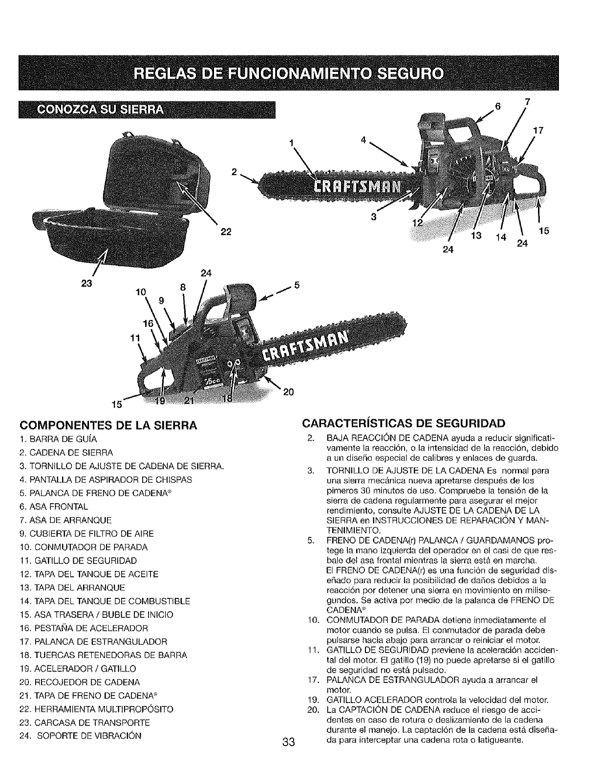
24
23 8
10
22
24
13 14 24
17
15
11
15
COMPONENTES DE LA SIERRA
1. BARRA DE GUIA
2, CADENA DE SIERRA
3. TORNILLO DE AJUSTE DE CADENA DE SIERRA.
4, PANTALLA DE ASPIRADOR DE CHISPAS
5. PALANCA DE FRENO DE CADENA ®
6. ASA FRONTAL
7. ASA DE ARRANQUE
9. CUBIERTA DE FILTRO DE AIRE
10. CONMUTADOR DE PARADA
11. GATILLO DE SEGURIDAD
12. TAPA DEL TANQUE DE ACEITE
13. TAPA DEL ARRANQUE
14. TAPA DEL TANQUE DE COMBUSTIBLE
15. ASA TRASERA/BUBLE DE INICIO
16. PESTAI_A DE ACELERADOR
17. PALANCA DE ESTRANGULADOR
18. TUERCAS RETENEDORAS DE BARRA
19. ACELERADOR /GATILLO
20, RECOJEDOR DE CADENA
21. TAPA DE FRENO DE CADENA ®
22. HERRAMIENTA MULTIPROP6SITO
23. CARCASA DE TRANSPORTE
24. SOPORTE DE VIBRACION 33
CARACTERJSTICAS DE SEGURIDAD
2. BAJA REACCl6N DE CADENA ayuda a reducir significati-
vamente ta reacci6n, o la intensidad de la reacci6n, debido
a un diseSo especial de calibres y enlaces de guarda.
3. TORNILLO DE AJUSTE DE LA CADENA Es normal para
una sierra mec_nica nueva apretarse despu_s de los
pimeros 30 minutos de uso, Compruebe la tensi6n de la
sierra de cadena regularmente para asegurar el mejor
rendimiento, consulte AJUSTE DE LA CADENA DE LA
SIERRA en INSTRUCCIONES DE REPARACION Y MAN-
TENIMIENTO,
5. FRENO DE CADENA(r) PALANCA /GUARDAMANOS pro-
tege la rnano izquierda del operador en el casi de que res-
bale del asa frontal mientras la sierra est_ en march&
El FRENO DE CADENA(r) es una funci6n de seguridad dis-
eSado para reducir la posibilidad de dafios debidos a la
reacci6n por detener una sierra en movimiento en milise-
gundos, Se activa pot medio de la palanca de FRENO DE
CADENA ®
10. CONMUTADOR DE PARADA detiene inmediatamente el
motor cuando se pulsa. El conmutador de parada debe
pulsarse hacia abaio para arrancar o reiniciar el motor.
11. GATILLO DE SEGURIDAD previene la aceleraci6n acciden-
tal del motor. Et gatillo (19) no puede apretarse si et gatillo
de seguridad no est& pulsado.
17. PALANCA DE ESTRANGULADOR ayuda a arrancar el
motor,
19. GATILLO ACELERADOR controla la velocidad del motor.
20. La CAPTACION DE CADENA reduce el riesgo de acci-
dentes en caso de rotura o deslizamiento de la cadena
durante el manejo, La captaci6n de la cadena est& disefia-
da para interceptar una cadena rota o latigueante.
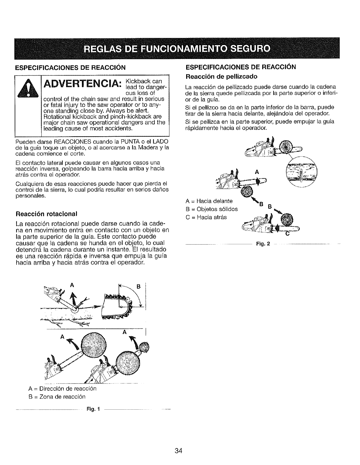
ESPECIFICACIONES DE REACCI6N
ADVERTENCIA: Kickbaokcan
lead to danger _
ous loss of
control of the chain saw and result in serious
or fatal injury to the saw operator or to any-
one standing close by. Always be alert.
Rotational kickback and pinch-kickback are
major chain saw operational dangers and the
leading cause of most accidents.
ESPECIFICACIONES DE REACCION
Reaccibn de pellizcado
La reacci6n de pellizcado puede darse cuando la cadena
de la sierra quede pellizcada pot la parte superior o inferi-
or de ta gu[a.
Si el pellizco se da en la parte inferior de la barra, puede
tirar de la sierra hacia delante, alej#,ndola del operador.
Si se peflizca en ta parte superior, puede empujar la guia
r_.pidamente hacia el operador.
Pueden darse REACCIONES cuando la PUNTA o el LADO
de ta guia toque un objeto, o al acercarse a la Madera y la
cadena comience el corte,
Et contacto lateral puede causar en algunos casos una
reacci6n inversa, golpeando la barra hacia arriba y hacia
atr&s contra el operador.
Cualquiera de esas reacciones puede hacer que pierda el
control de la sierra, Io cual podria resultar en serios dafios
personales.
Reacci6n rotacional
La reacci6n rotacional puede darse cuando ia cade-
na en movimiento entra en contacto con un objeto en
la parte superior de la gufa. Este contacto puede
causar que la cadena se hunda en el objeto, to cual
detendrdt la cadena durante un instante. El resultado
es una reacci6n rapida e inversa que empuja la gura
hacia arriba y hacia atrAs contra el operador.
A = Hacia delante
B = Objetos s61idos
C = Hacia atrb.s
B
Fig, 2
A
A
A = Direcci6n de reacci6n
B = Zona de reacci6n
....................... Fig, 1 ......
34
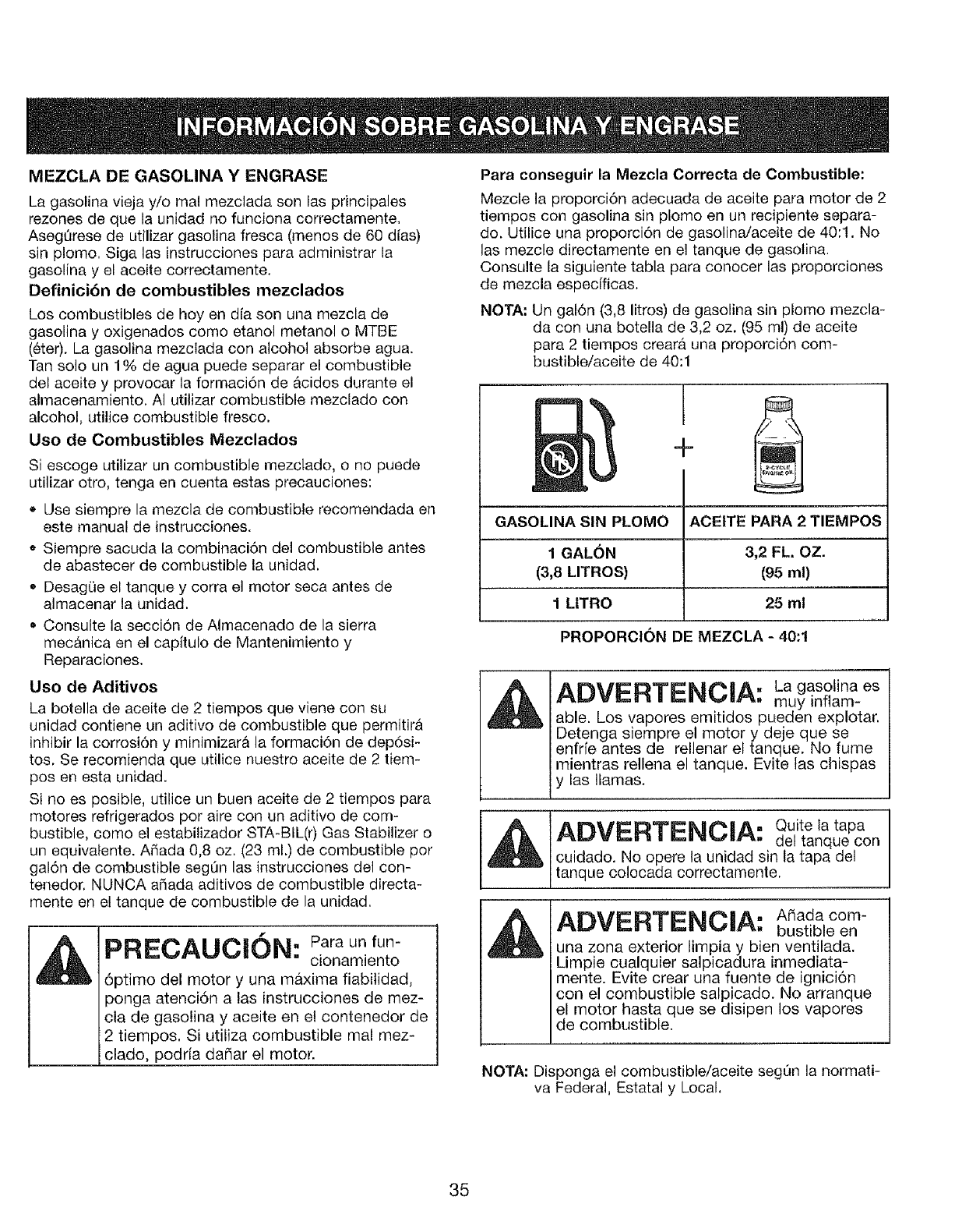
MEZCLA DE GASOLINA Y ENGRASE
La gasolina vieja y/o mal mezclada son fas principales
rezones de que la unidad no funciona correctamente,
AsegdJrese de utilizar gasolina fresca (menos de 60 dias)
sin plomo, Siga las instrucciones para administrar la
gasolina y el aceite correctamente,
Definicibn de combustibles mezclados
Los combustibles de hoy en dfa son una mezcla de
gasolina y oxigenados como etanol metanol o MTBE
(6ter), La gasolina mezclada con alcohol absorbe agua.
Tan solo url 1% de agua puede separar el combustible
del aceite y provocar la formaci6n de &cidos durante el
almacenamiento, AI utitizar combustible mezclado con
alcohol, utilice combustible fresco.
Uso de Combustibles Mezclados
Si escoge utilizar un combustible mezclado, o no puede
utilizar otto, tenga en cuenta estas precauciones:
• Use siempre la mezcla de combustible recomendada en
este manual de instrucciones.
o Siempre sacuda la combinaci6n del combustible antes
de abastecer de combustible la unidad.
• DesagQe el tanque y corra el motor seca antes de
almacenar la unidad.
Consulte la secci6n de Almacenado de la sierra
mecAnica en el capitulo de Mantenimiento y
Reparaciones,
Uso de Aditivos
La botella de aceite de 2 tiempos que viene con su
unidad contiene un aditivo de combustible que permitira
inhibir la corrosi6n y minimizar_ la formaci6n de dep6si-
tos. Se recomienda que utilice nuestro aceite de 2 tiem-
posen esta unidad.
Si no es posible, utilice un buen aceite de 2 tiempos para
motores refrigerados por aire con un aditivo de com-
bustible, como el estabilizador STA-BIL(r) Gas Stabilizer o
un equivalente. A5ada 0,8 oz, (23 ml.) de combustible por
gal6n de combustible segQn las ]nstrucciones del con-
tenedor, NUNCA aSada aditivos de combustible directa-
mente en et tanque de combustible de la unidad.
f
PRECAUCION: Para un fun-
cionamiento
6ptimo del motor y una maxima fiabilidad,
ponga atenci6n alas instrucciones de mez-
cla de gasolina y aceite en el contenedor de
2 tiempos, Si utiliza combustible real mez-
clado, podria daSar el motor.
Para conseguir la Mezcla Correcta de Combustible:
Mezcle la proporci6n adecuada de aceite para motor de 2
tiempos con gasolina sin plomo en un recipiente separa-
do. Utilice una proporci6n de gasolina/aceite de 40:1. No
las mezcle directamente en el tanque de gasotina.
Consulte la siguiente tabla para conocer las proporciones
de mezcla especfficas.
NOTA: Un gal6n (3,8 litros) de gasolina sin plomo mezcla-
da con una botella de 3,2 oz. (95 ml) de aceite
para 2 tiempos creara una proporci6n com-
bustible/aceite de 40:1
+
GASOLINA SIN PLOMO ACEITE PARA 2 TIEMPOS
1GALON 3,2 FL. OZ.
(3,8 LITROS) (95 ml)
1 LITRO 25 mt
PROPORCION DE MEZCLA - 40:1
ADVERTENCIA: Lagasotina es
muy inflam-
able. Los vapores emitidos pueden explotar,
Detenga siempre el motor y deje que se
enfrie antes de rellenar el tanque. No fume
mientras rellena el tanque. Evite las chispas
y las llamas.
Alt_I_PTII_D__|_&- Quite la tapa
L,_,w_.= t.h.. _.w,z-_. del tanque con
cuidado. No opere la unidad sin la tapa del
tanque colocada correctamente,
ADVERTENCIA: A adacom-
bustibleen
una zona exterior limpia y bien ventilada.
Limpie cualquier salpicadura inmediata-
mente. Evite crear una fuente de ignici6n
con el combustible salpicado. No arranque
el motor hasta que se disipen los vapores
de combustible.
NOTA: Disponga el combustible/aceite segQn la normati-
va Federal, Estatal y Local,
35
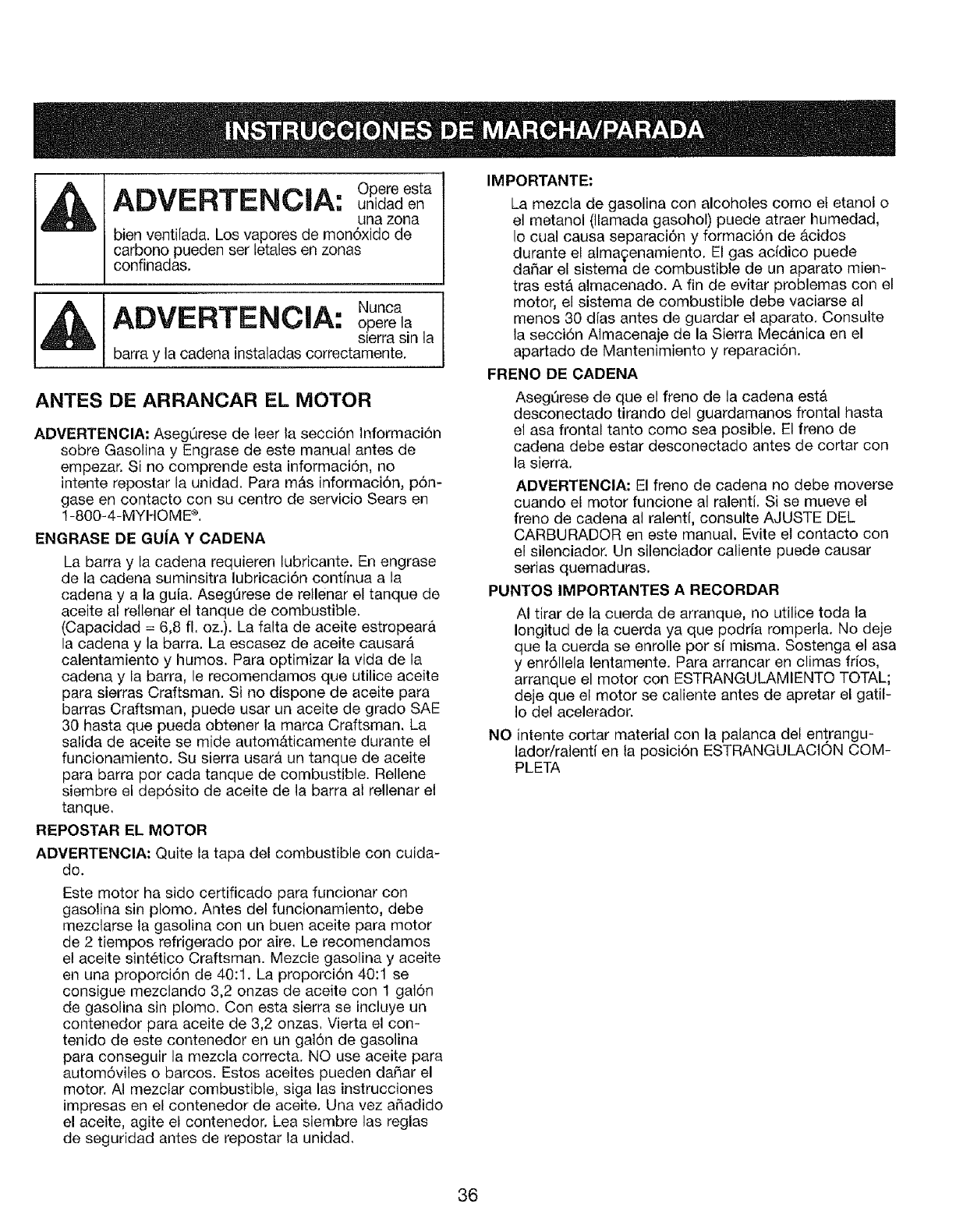
Opere esta
ADVERTENCIA: uo dadeo
una zona
bien ventilada. Los vapores de mon6xido de
carbono pueden ser letales en zonas
confinadas.
, [ADVERTENCIA: Nunca
ojoere la
s=errasin la
barra y la cadena instaladas correctamente.
ANTES DE ARRANCAR EL MOTOR
ADVERTENCIA: AsegOrese de leer la secci6n lnformaci6n
sobre Gasolina y Engrase de este manual antes de
empezar. Si no comprende esta informaciSn, no
intente repostar la unidad. Para m&s informaci6n, p6n-
gase en contacto con su centro de servicio Sears en
1-800-4-MYHOME ®.
ENGRASE DE GUiA Y CADENA
La barra y la cadena requieren lubricante. En engrase
de la cadena suminsitra lubricaci6n continua a la
cadena y a la guia. Aseg0rese de rellenar el tanque de
aceite al rellenar el tanque de combustible.
(Capacidad = 6,8 fl. oz.). La falta de aceite estropear&
la cadena y la barra. La escasez de aceite causar&
calentamiento y humos. Para optimizar la vida de la
cadena y la barra, le recomendamos que utilice aceite
para sierras Craftsman. Si no dispone de aceite para
barras Craftsman, puede usar un aceite de grado SAE
30 hasta que pueda obtener la marca Craftsman. La
salida de aceite se mide autom&ticamente durante el
funcionamiento. Su sierra usarb, un tanque de aceite
para barra por cada tanque de combustible. Rellene
siembre el dep6sito de aceite de la barra al rellenar el
tanque,
REPOSTAR EL MOTOR
ADVERTENCIA: Quite la tapa del combustible con cuida-
do.
Este motor ha sido certificado para funcionar con
gasolina sin plomo. Antes del funcionamiento, debe
mezclarse la gasolina con un buen aceite para motor
de 2 tiempos refrigerado por aire, Le recomendamos
el aceite sint_tico Craftsman. Mezcle gasolina y aceite
en una proporci6n de 40:1. La proporci6n 40:1 se
consigue mezclando 3,2 onzas de aceite con 1 gal6n
de gasolina sin plomo. Con esta sierra se incluye un
contenedor para aceite de 3,2 onzas. Vierta el con-
tenido de este contenedor en un gal6n de gasolina
para conseguir la mezcla correctar NO use aceite para
autom6viles o barcos. Estos aceites pueden daSar el
motor. AI mezctar combustible, siga las instrucciones
impresas en el contenedor de aceite. Una vez aSadido
el aceite, agite el contenedor. Lea siembre las reglas
de seguridad antes de repostar la unidad.
IMPORTANTE:
La mezcla de gasolina con alcoholes como el etanol o
el metanol (llamada gasohol) puede atraer humedad,
Io cual causa separaci6n y formaci6n de &cidos
durante el alma£enamiento. E! gas acidico puede
daSar el sistema de combustible de un aparato mien-
tras est& almacenado. A fin de evitar problemas con el
motor, el sistema de combustible debe vaciarse al
menos 30 dfas antes de guardar el aparato. Consufte
la secci6n Almacenaje de la Sierra Mec&nica en el
apartado de Mantenimiento y reparaci6n.
FRENO DE CADENA
Asegt_rese de que el freno de la cadena est&
desconectado tirando del guardamanos frontal hasta
el asa frontal tanto como sea posible. El freno de
cadena debe estar desconectado antes de cortar con
la sierra.
ADVERTENCIA: El freno de cadena no debe moverse
cuando el motor funcione al ralenti. Si se mueve el
freno de cadena al ralenti, consulte AJUSTE DEL
CARBURADOR en este manual. Evite el contacto con
el silenciador. Un silenciador caliente puede causar
serias quemaduras.
PUNTOS IMPORTANTES A RECORDAR
AI tirar de la cuerda de arranque, no utilice toda la
Iongitud de la cuerda ya que podria romperla. No deje
que la cuerda se enrolle por sf misma. Sostenga el asa
y enr611elalentamente. Para arrancar en climas frios,
arranque el motor con ESTRANGULAMIENTO TOTAL;
deje que el motor se caliente antes de apretar el gatil-
Io del acelerador.
NO intente cortar material con la palanca del entrangu-
lador/ralenti en la posici6n ESTRANGULACION COM-
PLETA
36
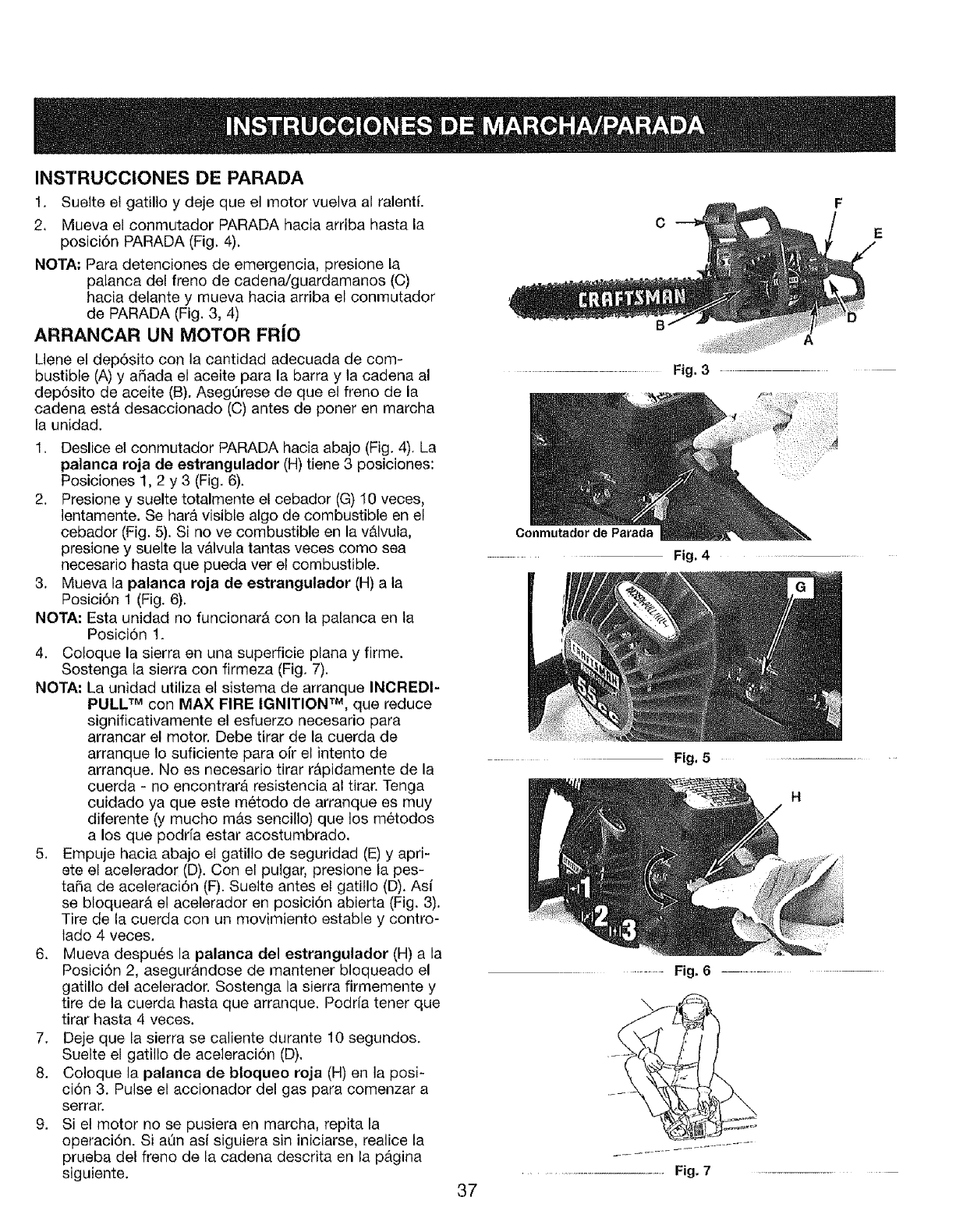
INSTRUCCIONES DE PARADA
1. Suelte et gatillo y deje que el motor vuelva al ralentL
2, Mueva el conmutador PARADA hacia arriba hasta la
posici6n PARADA (Fig. 4).
NOTA; Para detenciones de emergencia, presione la
palanca del freno de cadena/guardamanos (C)
hacia delante y mueva hacia arriba el conmutador
de PARADA (Fig. 3, 4)
ARRANCAR UN MOTOR FR|O
Llene el dep6sito con la cantidad adecuada de com-
bustible (A) y afiada el aceite para la barra y la cadena al
dep6sito de aceite (B). AsegOrese de que el freno de la
cadena est& desaccionado (C) antes de poner en marcha
la unidad.
1. Deslice el conmutador PARADA hacia abajo (Fig. 4). La
palanca roja de estrangulador (H) tiene 3 posiciones:
Posiciones 1, 2 y 3 (Fig. 6).
2. Presione y suelte totalmente el cebador (G) 10 veces,
lentamente. Se hara visible algo de combustible en el
cebador (Fig. 5). Si no ve combustible en la vb,lvula,
presione y suelte la v_Jvula tantas veces como sea
necesario hasta que pueda ver el combustible.
3. Mueva la palanca roja de estrangulador (H) a la
Posici6n ! (Fig. 6).
NOTA: Esta unidad no funcionar_ con la palanca en ta
PosiciOn 1.
4. Coloque la sierra en una superficie plana y firme.
Sostenga la sierra con firmeza (Fig. 7).
NOTA" La unidad utiliza et sistema de arranque INCREDI-
PULL TM con MAX FIRE IGNITION TM, que reduce
significativamente el esfuerzo necesario para
arrancar el motor. Debe tirar de la cuerda de
arranque to suficiente para oi'r el intento de
arranque. No es necesario tirar r&pidamente de la
cuerda - no encontrarA resistencia al tirar. Tenga
cuidado ya que este m6todo de arranque es muy
diferente (y mucho m&s sencillo) que los m6todos
a los que podrfa estar acostumbrado.
5, Empuje hacia abajo el gatillo de seguridad (E) y apri-
ete el acelerador (D). Con el pulgar, presione la pes-
tara de aceleraciOn (F). Suelte antes et gatitlo (D). Asi
se bloquear_, el acelerador en posici6n abierta (Fig. 3).
Tire de la cuerda con un movimiento estable y contro-
tado 4 veces.
6. Mueva despu6s la palanca del estrangulador (H) a la
Posici6n 2, asegur&ndose de mantener bloqueado el
gatillo del acelerador. Sostenga la sierra firmemente y
tire de la cuerda hasta que arranque. Podrfa tener que
tirar hasta 4 veces.
7. Deje que la sierra se caliente durante 10 segundos.
Suelte el gatitlo de aceleraci6n (D),
8. Cotoque la palanca de bloqueo roja (H) en la posi-
ci6n 3. Pulse el accionador del gas para comenzar a
serrar.
9. Si el motor no se pusiera en marcha, repita la
operaci6n. Si a[in asf siguiera sin iniciarse, realice la
prueba del freno de la cadena descrita en la p_.gina
siguiente. 37
......................................... Fig. 3
Conrnutador de Parada
Fig. 4
....... Fig, 5
H
......... Fig. 6 .......................................................
...................................................................Fig. 7 ...........
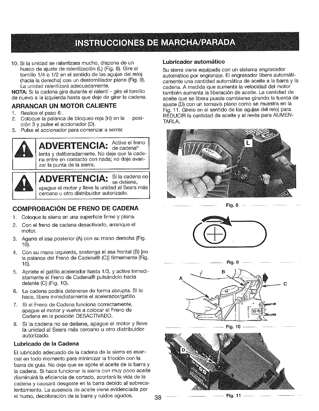
10. Si la unidad se ralentizara mucho, dispone de un
hueco de ajuste de ralentizaci6n (L) (Fig. 8), Gire el
tornilto 1/4 o 1/2 en el sentido de 1as agujas del reloj
(hacia ta derecha) coil un destornillador piano (Fig. 9).
La unidad ralentizar& adecuadamente.
NOTA: Si la cadena gira durante el ralenti - gire el tornillo
de nuevo a la izquierda hasta que deje de girar la cadena.
ARRANCAR UN MOTOR CALIENTE
1. Realice el paso 6.
2. Coloque la palanca de bloqueo roja (H) en la posi-
ci6n 3 y pulse el accionador (D).
3. Pulse el accionador para comenzar a serrar.
Lubricador automatico
Su sierra viene equipada con un sistema engrasador
automb,tico pot engranaje. El engrasador libera autom&ti-
camente una cantidad autom_tica de aceite a la barra y la
cadena. A medida que aumenta fa velocidad del motor
tambi6n aumenta fa liberaci6n de aceite, La cantidad de
aceite que se libera puede cambiarse girando la tuerca de
ajuste (D) con un tornavis piano como se muestra en la
Fig, 11. Girelo en et sentido de las agujas del reloj para
REDUCIR la cantidad de aceite y al rev6s para AUMEN-
TARLA.
ADVERTENCIA: Active el freno
de cadena e
lenta y deliberadamente. No deje que ta cade-
na entre en contacto con nada; no deje avan-
zar la punta de la sierra.
Ah_I'_:}'T'_Nt_',_" Si la cadena no 1
r_,ww.=. _--k_. ,.v., ,. se detiene, !
apague el motor y Ileve la unidad al Sears m_s /
cercano u otro distribuidor autorizado. |
J
COMPROBACION DE FRENO DE CADENA
1. Coloque la sierra en una superficie firme y plana.
2. Con el freno de cadena desactivado, arranque el
motor.
3. Agarre el asa posterior (A) coil su mano derecha (Fig.
t0).
4. Con su mano izquierda, sostenga el asa frontal (B) [no
la palanca del Freno de Cadena® (C)] firmemente (Fig.
10).
5. Apriete el gatillo acelerador hasta 1/3, y active inmedi-
atamente el Freno de Cadena® puls&ndoto hacia
delante (C) (Fig. 10).
6. La cadena podria detenerse de forma abrupta. Si Io
hace, libere inmediatamente el acelerador/gatillo.
7. Si el Freno de Cadena funciona correctamente,
apague el motor y vuelva a colocar el Freno de
Cadena en la posici6n DESACT1VADO.
8. Si la cadena no se detiene, apague el motor y Ileve
la unidad al Sears m_s cercano u otro distribuidor
autorizado.
Lubricado de la Cadena
El lubricado adecuado de la cadena de la sierra es esen-
cial en todo momento para minimizar la fricci6n con la
barra de guia. No deje que se agote el aceite de ta barra y
la cadena. Si hace funcionar la sierra con muy poco aceite
disminuir& la eficiencia de cortado, acortar_t la vida de la
cadena y causar& desgaste en la barra debido al sobreca-
lentamiento, La ausencia de aceite viene evidenciada por
el humo, decoloraci6n de la barra y ruidos agudos. 38
.........................................Fig. 8 .............
........... Fig. 9................
........... Fig. 10 .......................
............. Fig, 11 .......................
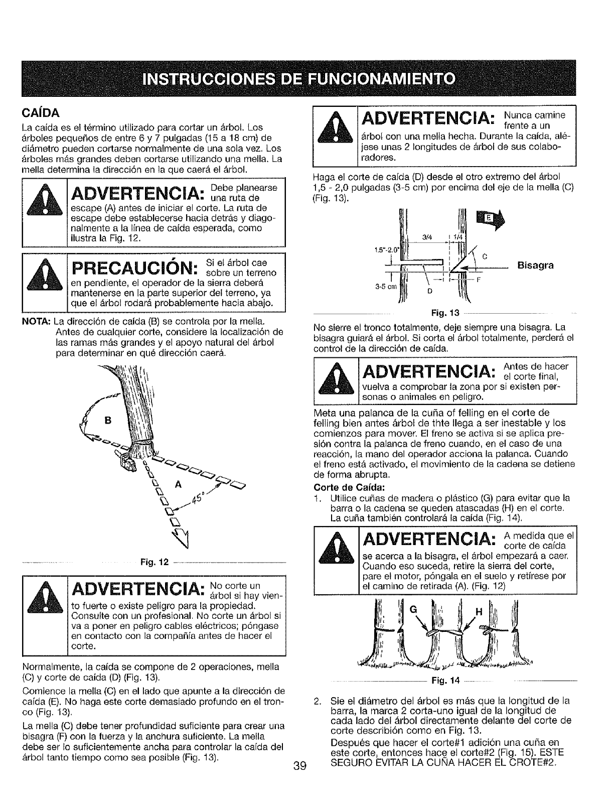
CAiDA
La caida es el t@mino utilizado para cortar un _rbol. Los
_rboles pequefios de entre 6 y 7 puigadas (15 a 18 cm) de
di&metro pueden cortarse normalmente de una sola vez. Los
&rbofes mgtsgrandes deben cortarse utilizando una mella. La
mella determina la direcci6n en ]a que eaergtel &rbol,
A_II_I_'TCI_|_|A. Debe planearse
n='Q,w,,_v'wu,-m_ui.,.,m_'_=_nEn"*., una ruta de
escape (A) antes de iniciar el corte. La ruta de
escape debe establecerse hacia detr_,s y diago-
nalmente a la linea de caida esperada, como
ustra a Fg. 12.
_T IE_I[_)_£"_'AN N£"_'N£_hI_.II. Si el _rbol cae
| rnl=._,#r'L_,l_._m_#n'm, sobre un terreno
|en pendiente, el operador de la sierra deber&
|mantenerse en la parte superior del terreno, ya
|que el &rbol rodarA probablemente hacia abajo.
NOTA: La direcci6n de caida (B) se controla por la mella.
Antes de cualquier corte, considere la tocalizaci6n de
las ramas m£,s grandes y el apoyo natural del £.rbol
para determinar en qu6 direcci6n caer&.
Fig. 12
ADVERTENCNA: No corte un
Arbol si hay vien-
to fuer[e o existe peligro para la propiedad.
Consulte con un profesional. No corte un &rbol si
va a porter en petigro cables el_ctricos; p6ngase
en contacto con la compaSfa antes de hacer el
corte.
Normalmente, la caida se compone de 2 operaciones, mella
(C) y corte de eaida (D) (Fig. 13).
Comience la mela ((3)en el lado que apunte a la direcci6n de
caida (E). No haga este corte demasiado profundo en el tron-
co (Fig. 13).
La mella (C) debe tener profundidad suficiente para crear una
bisagra (F) con la fuerza y la anchura suficiente. La mella
debe ser fo suficientemente ancha para controlar la ca[da del
&rbol tanto tiempo como sea posible (Fig. 13). 39
ADVERTENCIA: Nuncacamine
frente a un
_rbot con una melta hecha, Durante la caida, al6-
jese unas 2 longitudes de &rbol de sus colabo-
radores.
Haga el corte de cafda (D) desde el otro extremo del _.rbol
1,5 - 2,0 pulgadas (3-5 cm) por encima del eje de la mella (C)
(Fig. 13).
3/4 I
1.5"-2.(
Bisagra
Fig. 13
No sierre el tronco totalmente, deje siempre una bisagra, La
bisagra guiar& el &rbol. Si corta el &rbol totalmente, perdera el
control de la direcci6n de caida.
ADVERTENCIA Antes de hacer" el corte final,
vuelva a comprobar la zona por si existen per-
sonas o an ma es en pe gro.
Meta una palanca de la curia of felling en el corte de
felling bien antes &rbot de thte Ilega a set inestable y los
comienzos para mover. El freno se activa si se aplica pre-
sidn contra la palanca de freno cuando, en el caso de una
reacci6n, la mano del operador acciona la palanca. Cuando
el freno est& activado, el movimiento de la cadena se detiene
de forma abrupta.
Corte de Caida;
t. Utilice cutlas de madera o pl&stico (G) para evitar que la
barra o la cadena se queden atascadas (H) en el corte.
La curia tambi_n controlarA la caida (Fig. 14),
Ar V gTl= i&. A medida que el
se acerca a la bisagra, el _rbol empezar& a caer.
Cuando eso suceda, retire la sierra del corte,
pare el motor, pdngala en el suelo y retirese por
el camino de retirada (A). (F g, 12)
........... Fig. 14 ........
,Sie el di&metro del _rbol es m&s que la Iongitud de la
barra, la marca 2 corta-uno igual de la Iongitud de
cada lado del &rbol directamente delante del corte de
corte describidn como en Fig. 13.
Despu_s que hacer el corte#1 adicidn una cuSa en
este corte, entonces hace el corte#2 (Fig. 15). ESTE
SEGURO EVlTAR LA CUNA HACER EL CROTE#2.
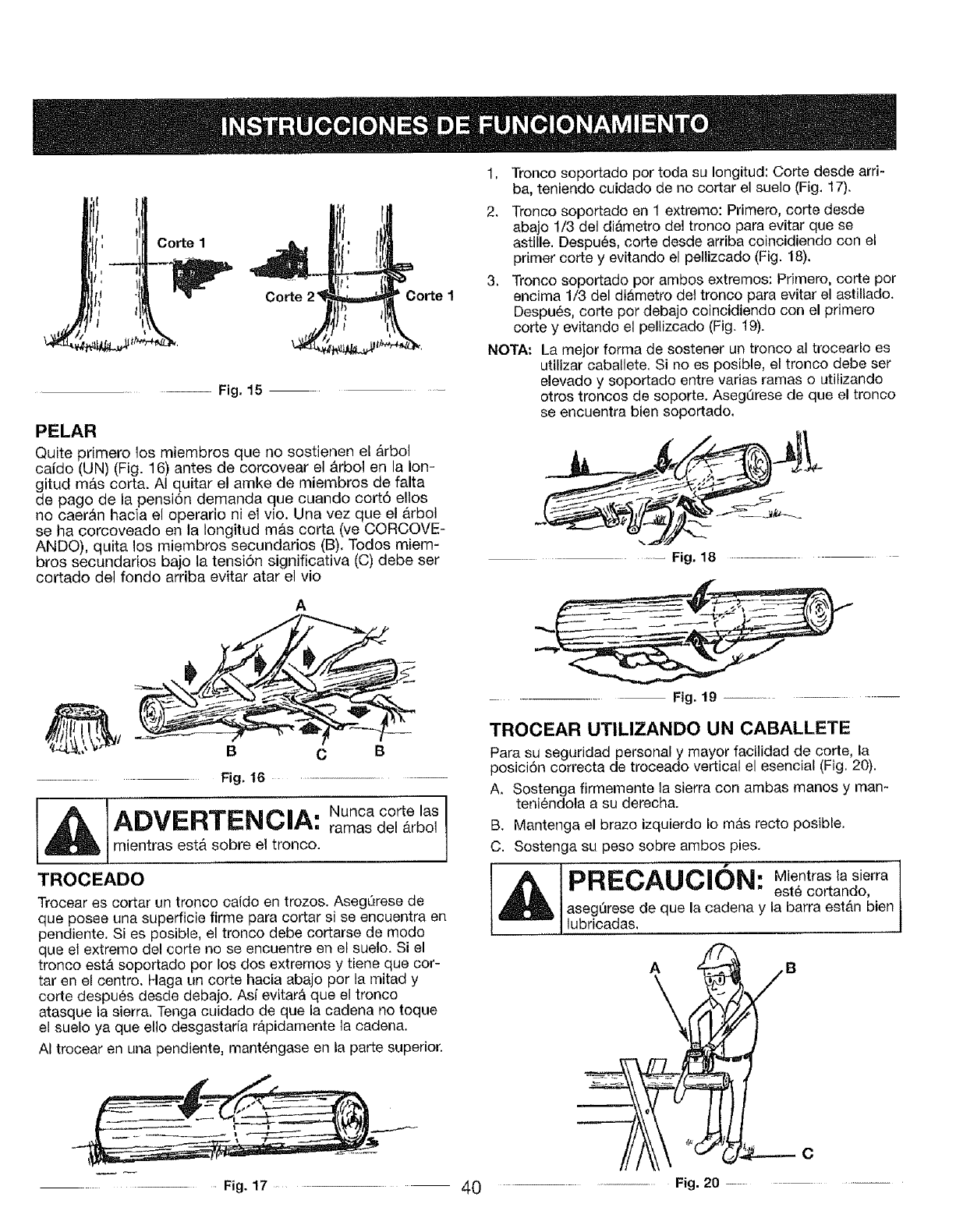
" 1
f:-4,'
r! ;I
I
Co_el
Co_e Co_el
Fig. 15
PELAR
Quite primero los miembros que no sostienen el _rbol
caido (UN) (Fig. 16) antes de corcovear el b_rbolen la Ion-
gitud m&s corta. AI quitar et amke de miembros de falta
de pago de la pensi6n demanda que cuando cort6 ellos
no caer&n hacia el operario ni el vio. Una vez que el arbol
se ha corcoveado en la Iongitud m#,s corta (ve CORCOVE-
ANDO), quita los miembros secundarios (B). Todos miem-
bros secundarios bajo la tensi6n significativa (C) debe ser
cortado del fondo arriba evitar atar el vio
A
.......... Fig, I6
C B
1ADVERTENCIA:.ooo.ooze I
ramas del _.rbol
j mientras est& sobre et tronco.
TROCEADO
Trocear es cortar un tronco caido en trozos. AsegQrese de
que posee una superficie firme para cortar si se encuentra en
pendiente. Si es posible, el tronco debe cortarse de modo
que el extremo del corte no se encuentre en el suelo. Si el
tronco estersoportado por los dos extremos y tiene que cor-
tar en el centro. Haga un corte hacia abajo por la mitad y
corte despues desde debajo. Asi evitar& que el tronco
atasque la sierra, Tenga cuidado de que la cadena no toque
el suelo ya que ello desgastarfa r_pidamente ta cadena.
AI trocear en una pendiente, mant6ngase en la parte superior.
Fig. 17 ..... 4O
1, Tronco soportado por toda su Iongitud: Corte desde arri-
ba, teniendo cuidado de no cortar el suelo (Fig. 17).
2. Tronco soportado en 1 extremo: Primero, corte desde
abajo 1/3 del di&metro del tronco para evitar que se
astille. Despu6s, corte desde arriba coincidiendo con el
primer corte y evitando el pellizcado (Fig. 18).
3. Tronco soportado por ambos extremos: Primero, corte por
encima 1/3 del di&metro del tronco para evitar el astillado.
Despu6s, corte pot debajo coincidiendo con el primero
corte y evitando el pellizcado (Fig. 19).
NOTA; La mejor forma de sostener un tronco al trocearlo es
utilizar caballete. Si no es posible, el tronco debe set
elevado y soportado entre varias ramas o utilizando
otros troncos de soporte. AsegQrese de que el tronco
se encuentra bien soportado.
........ Fig, 18 ...........
Fig. 19 .....................................
TROCEAR UTILIZANDO UN CABALLETE
Para su seguridad personal y mayor facilidad de corte, la
posici6n correcta de troceado vertical el esencial (Fig, 20).
A, Sostenga firmemente la sierra con ambas manos y man-
teni6ndola a su derecha.
B. Mantenga el brazo izquierdo Io m_.s recto posible.
C. Sostenga su peso sobre ambos pies.
1PRECAUCIQN: est6Mientras,asierracortando,
aseg_rese de que la cadena y la barra estb,n bien
, lubricadas,
AGENDA DE MANTENIMIENTO
Lteve a cabo los procesos de mantenimiento necesarios
con la frecuencia de la tabla. Estos procesos deben for-
mar parte de la puesta a punto de temporada.
NOTA: El mantenimiento, reemplazo o reparaci6n de los
dispositivos de control de emisiones debe set
realizado pot el personal de Sears u otro personal
cualificado.
NOTA: El mantenimiento, reemplazo o reparaci6n debe de
los dispositivos de control debe ser realizado por
Sears u otto personal cualificado,
Para evitar
ADVERTENCIA: erios,
nunca Ileve a
cabo las labores de mantenimiento o reparaci6n
con la unidad en march& Repare la unidad en
fifo. Desconecte el arrancador para asegurarse
de que no se puede arrancar la unidad,
Un buen programa de mantenimiento preventivo y de inspecciones regulates aumentar_, la vida de su sierra. Esta lista de
comprobaci6n de mantenimiento es una guia de tal programa.
La limpieza, ajusle y reemplazo de componentes puede set necesario en determinadas condiciones, a intervalos m_.s fre-
cuentes de los indicados. LISTA PARA EL MANTENIMIENTO
ELEMENTO
COMPRUEBE QUE NO EXISTEN TORNIL_
LOS/TUERCABiPERNOS SUELTOS
LIMPIAR O REEMPLAZAR EL FILTRO DE
AIRE
REPLACE LA BUJiA, CAMBIE EL ACEITE
Y EL FILTRO DEL COMBUSTIBLE
ii ,
LIMPIE E INSPECCIONE LA BUJIA, LA PAN-
TALLA DEL SUPRESOR Y EL SILENCIADOR
UMPtE E INSPECCiONE LA BUJiA Y LA
PANTALLA DEL ASPI_DOR /SILENCI-
ADOR
LIMP]AR LA UNIDAD E INSPECCIONAR
ETIQUETAS
,i
COMPROBAR LOS COMPONENTES DEL
FRENO DE CADENA _'
LIMPIAR LA BARRA DE GU{A
COMPROBAR COMPONENTES
DAI_ADOS/GASTADOS
m
COMPROBAR LA TENSION DE b _.
CEDNA
COMPROBAR EL AFILADO DE LA CADE-
NA
LUBRICAR ENGRANAJES
COMPROBAR LA MEZCLA DE COM-
BUSTIBLE
ANTES DE CADA USO DESPUI_S DE CADA 10 HORAS
CADA USO DE USO
.... i,ll,
41
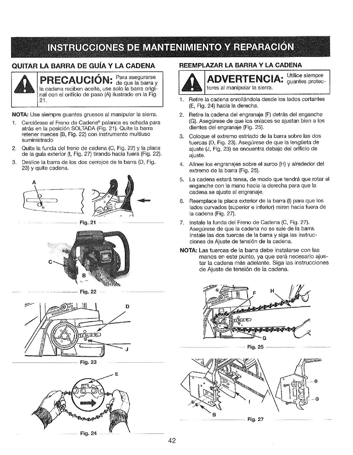
QUITAR LA BARRA DE GU|A Y LA CADENA
PRECAUCION Paraasogurarse
" de que la barra y
la cadena reciben aceite, use solo fa barra origi-
nal con el orificio de paso (A) ilustrado en la Fig,
21,
NOTA: Use siempre guantes gruesos al manipular la sierra.
1. Cerci6rese el Freno de Cadena®palanca es eohada para
atr&s en la posici6n SOLTADA (Fig, 21). Quite la barra
retener nueces (B. Fig. 22) con instrumento multiuso
suministrado
2, Quite la funda del freno de cadena (C, Fig. 22) y ta placa
de la guia exterior (I, Fig. 27) tirando hacia fuera (Fig. 22),
3. Deslice la barra de los dos cerrojos de ta barra (D, Fig.
23) y quite cadena.
-Fig, 21
REEMPLAZAR LA BARRA Y LA CADENA
1ADVERTENCJA: Utitioesiempre
guantes protec-
tores al manipular la sierra.
1. Retire la cadena enroll&ndofa desde los lados cortantes
(E, Fig. 24) hacia la derecha.
2. Retire la cadena del engranaje (F) detr&s del enganche
(G). AsegOrese de que los enlaces se ajustan bien a los
dientes del engranaje (Fig. 25).
3. Coleque el extremo estriado de la barra sobre las dos
tuercas (D, Fig. 23). Aseg_rese de que la leng(Jeta de
ajuste (J, Fig. 23) se encuentra debajo del orlficio de
ajuste.
4, Alinee los engranajes sobre el surco (H) y alrededor del
extremo de la barra (Fig. 25),
5, La cadena estar_, tensa, de modo que tendr_ que rotar el
enganche con la mano hacia la derecha para que la
cadena se ajuste al engranaje.
6. Reemplace la placa exterior de la barra (I) para que los
lados curvados (superior e inferior) miren hacia fuera de
la cadena (Fig. 27).
7. lnstale la funda del Freno de Cadena (C, Fig. 27).
AsegQrese de que la cadena no se sale de la barra.
Instale las dos tuercas de la barra y alga las instruc-
ciones de Ajuste de tensi6n de la cadena.
NOTA: Las tuercas de la barra debe instalarse con las
manos en este punto, ya que ser& necesario ajus-
tar la cadena m&s adelante. Siga las instrucciones
de Ajuste de tensi6n de la cadena.
Fig. 23
D
F H
G
-- Fig, 25 ................................................
Fig. 24
42
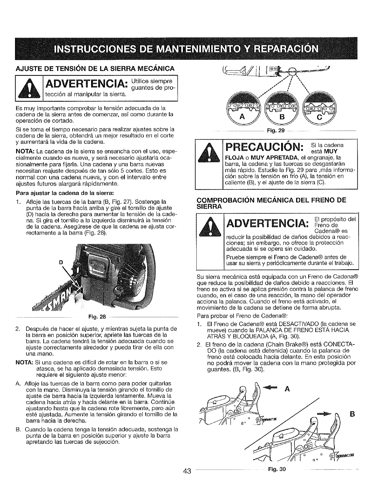
AJUSTE DE TENSI(_N DE LA SIERRA MECANICA
ADVERTENCIA: Utilicesiempre
guantes de pro-
_ltecci6n al manipular la sierra.
Es muy importante comprobar la tensi6n adecuada de la
cadena de la sierra antes de comenzar, asi como durante la
operaci6n de cortado.
Si se toma el tiempo necesario para realizar ajustes sobre la
cadena de la sierra, obtendrb, un mejor resultado en el corte
y aumentar_ la vida de la cadena.
NOTA; La cadena de la sierra se ensancha con el use, espe-
cialrnente cuando es nueva, y ser_ necesario ajustarla oca-
sionatmente para fijarla. Una cadena y una barra nuevas
necesitan reajuste despu6s de tan s61o5 cortes. Esto es
normal con una cadena nueva, y con el intervalo entre
ajustes futuros alargar_ r#,pidamente=
Para ajustar la cadena de la sierra:
1. Afloje las tuercas de la barra (B, Fig, 27). Sostenga la
punta de la barra hacia arriba y gire el tomillo de ajuste
(13)hacia ta derecha para aumentar la tensi6n de la cade-
na. Si gira el tomillo a la izquierda disminuirb, ta tensi6n
de la cadena, AsegOrese de que la cadena se ajusta cor-
rectamente a la barra (Fig. 28).
Fig, 28
2. Despu_s de hacer el ajuste, y mientras sujeta la punta de
la barra en posici6n superior, apriete las tuercas de la
barra. La cadena tendr& la tensidn adecuada cuando se
ajuste correctamente alrededor y pueda tirar de ella con
una mane.
NOTA; Si una cadena es dificil de rotar en la barra o si se
atasca, se ha aplieado demasiada tensi6n. Esto
requiere el siguiente ajuste menor:
A. Afloje las tuercas de ta barra come para poder quitarlas
con la mane. Disminuya la tensi6n girando el tomillo de
ajuste de barra hacia la izquierda lentamente. Mueva la
cadena hacia atrb.s y hacia delante en la barra. Contin_e
ajustando hasta que la cadena rote libremente, pero ann
est6 ajustada. Aumente la tensi6n girando el tornilio de la
barra hacia la derecha.
B. Cuando la cadena tenga la tensi6n adecuada, sostenga la
punta de la barra en posici6n superior y ajuste la barra
apretando las tuercas de sujecci6n.
--- Fig, 29 ...................
f
PRECAUCION: silacadena
est_ MUY
FLOJA oMUY APRETADA, el engranaje, la
barra, ta cadena y las tuercas se desgastar_n
mb,s r_pido. Estudie la Fig. 29 para ,m_.s informa-
ci6n sobre la tensi6n en frio (A), la tensi6n en
caliente (B), y el ajuste de la sierra (C).
COMPROBACION MECANICA DEL FRENO DE
SIERRA
ADVERTENCIA: FrenoE prop6sitOdedel
Cadena@ es
reducir la posibilidad de daSos debidos a reac-
clones; sin embargo, no ofrece la pretecci6n
adecuada si se opera sin cuidado.
Pruebe siempre el Freno de Cadena@antes de
usar su sierra y peri6dicamente durante el trabajo.
Su sierra mecb.nica estA equipada con un Freno de Cadena@
que reduce la posibilidad de daSos debido a reacciones. El
freno se activa si se aplica presidn contra la palanca de freno
cuando, en el caso de una reacci6n, la mane del operador
acciona la palanca. Cuando el freno estA activado, el
movimiento de la cadena se detiene de forma abrupta.
Para probar el Freno de Cadena@:
1. El Freno de Cadena® esta DESACTiVADO (la cadena se
mueve) cuando fa PALANCA DE FRENO EST/_,HAClA
ATRAS Y BLOQUEADA (A, Fig, 30).
2. El freno de la cadena (Chain Brake@) est& CONECTA-
DO (ta cadena est& detenida) cuando la palanca de
freno est& colocada hacia delante, En esta posici6n
no podr& mover la cadena con la mano protegida por
guantes, (B, Fig, 30),
B
43 Fig. 30 ..............................
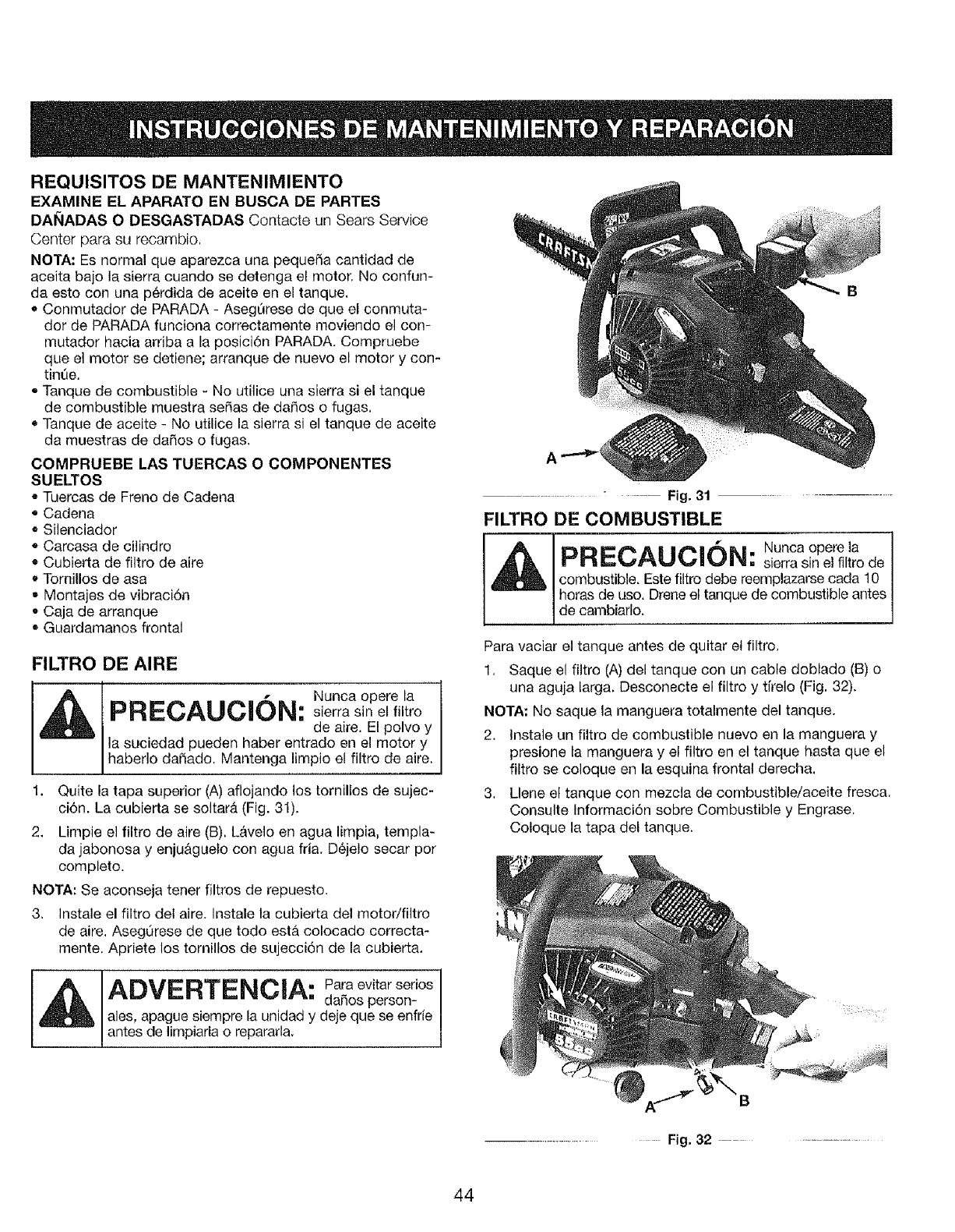
REQUISITOS DE MANTENIMIENTO
EXAMINE EL APARATO EN BUSCA DE PARTES
DAI_IADAS O DESGASTADAS Contacte un Sears Sewice
Center para su recambio,
NOTA: Es normal que aparezca una peque_a cantidad de
aceita bajo la sierra cuando se detenga et motor, No confun-
da esto con una p6rdida de aceite en el tanque,
• Conmutador de PARADA - Asegt_rese de que el conmuta-
dor de PARADA funciona correctamente moviendo el con-
mutador hacia arriba a la posici6n PARADA. Compruebe
queet motor se detiene; arranque de nuevo el motor y con-
tint_e.
•Tanque de combustible - No utilice una sierra si el tanque
de combustible muestra se_as de da_os o fugas,
Tanque de aceite - No utilice la sierra si el tanque de aceite
da muestras de dar_os o fugas,
COMPRUEBE LAS TUERCAS O COMPONENTES
SUELTOS
•Tuercas de Freno de Cadena
° Cadena
• Silenciador
Carcasa de cilindro
• Cubierta de filtro de aire
• Tornillos de asa
• Montajes de vibraci6n
• Caja de arranque
Guardamanos frontal
FILTRO DE AIRE
-- Nunca opere la
FIRE=CAUC_ON: sierra sin el filtro
de aire. El polvo y
la suciedad pueden haber entrado en el motor y
haberlo da_ado, Mantenga limpio el filtro de aire.
1. Quite la tapa superior (A) aflojando los tornillos de sujec-
ci6n. La cubierta se soltar_. (Fig. 31).
2. Limpie el filtro de aire (B), L&velo en agua limpia, templa-
da jabonosa y enju&guelo con agua fria. D6jelo secar por
completo.
NOTA: Se aconseja tener filtros de repuesto.
3, Instale el filtro del aire. Instale la cubierta del motor/filtro
de ape, AsegQrese de que todo esta. colocado correcta-
mente. Apriete los tornillos de sujecci6n de la cubierta.
ADVERTENCIA: Paraevitarseries
da_os person-
ales, apague siempre la unidad y deje que se enfr[e
antes de limpiarfa o repararla,
--_ ........ Fig. 31 ..........................
FILTRO DE COMBUSTIBLE
f
PRECAUCION: Nunca opere ia
sierra sin el filtro de
combustible. Este filtro debe reemplazarse cada 10
horas de uso. Drene el tanque de combustible antes
de cambiarlo.
Para vaciar el tanque antes de quitar et filtro,
1, Saque el fittro (A) del tanque con un cable doblado (B) o
una aguja larga. Desoonecte el filtro y tirelo (Fig, 32).
NOTA: No saque la manguera totalmente del tanque.
2. Instale un filtro de combustible nuevo en la manguera y
presione la manguera y el fittro en el tanque hasta que el
filtro se coloque en la esquina frontal derecha,
3. Llene ef tanque con mezcla de combustible/aceite fresca,
Consulte Informaci6n sobre Combustible y Engrase,
Coloque la tapa def tanque.
A7 B
Fig, 32
44
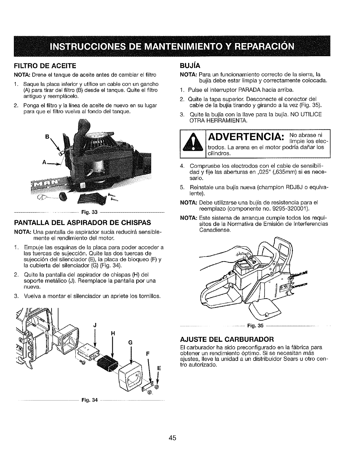
FILTRO DE ACEITE
NOTA: Drene el tanque de aceite antes de cambiar el filtro
1. Saque la placa inferiory utilice un cable con un gancho
(A) para tirar del filtro (B) desde el tanque. Quite el filtro
antiguo y reempt&celo.
2. Ponga el filtro y la linea de aceite de nuevo en su lugar
para que el filtro vuelva al fondo del tanque.
B
........................................ Fig. 33
PANTALLA DEL ASPIRADOR DE CHISPAS
NOTA: Una pantalla de aspirador sucia reducirA sensible-
mente el rendimiento del motor.
I, Empuje las esquinas de la ptaca para poder acceder a
las tuercas de sujecci6n. Quite las dos tuercas de
sujecci6n del silenciador (E), ]a placa de bloqueo (F) y
la cubierta del silenciador (G) (Fig. 34).
2. Quite la pantalla del aspirador de chispas (H) del
soporte metatico (J). Reemplace la pantatla por una
nueva.
BUJ|A
NOTA: Para un funcionamiento correcto de la sierra, la
bujia debe estar limpia y correctamente colocada.
1. Pulse el interrupter PARADA hacia arriba.
2. Quite la tapa superior. Desconecte el conector del
cable de la bujia tirando y girando a la vez (Fig. 35).
3. Quite la bujia con la llave para la bujia. NO UTILICE
OTRA HERRAMIENTA.
• No abrase ni
ADVERTENCIA. limpie los elec-
trodos. La arena en el motor podria daSar los
I cilindros.
4. Compruebe los electrodos con el cable de sensibili-
dad y fije las aberturas en ,025" (,635mm) si es nece-
sario.
5. Reinstale una bujia nueva (champion RDJ8J o equiva-
lente).
NOTA: Debe utilizarse una bujia de resistencia para el
reemplazo (componente no. 9295-320001).
NOTA: Este sistema de arranque cumple todos los requi-
sitos de la Normativa de Emisi6n de Interferencias
Canadiense.
3. Vuelva a montar el silenciador un apriete los tornillos.
JH
Fig, 34
.......... Fig. 35
AJUSTE DEL CARBURADOR
El carburador ha sido preconfigurado en la f_brica para
obtener un rendimiento 6ptimo. Si se necesitan m_.s
ajustes, Ileve la unidad a un distribuidor Sears u otro cen-
tro autorizado.
45
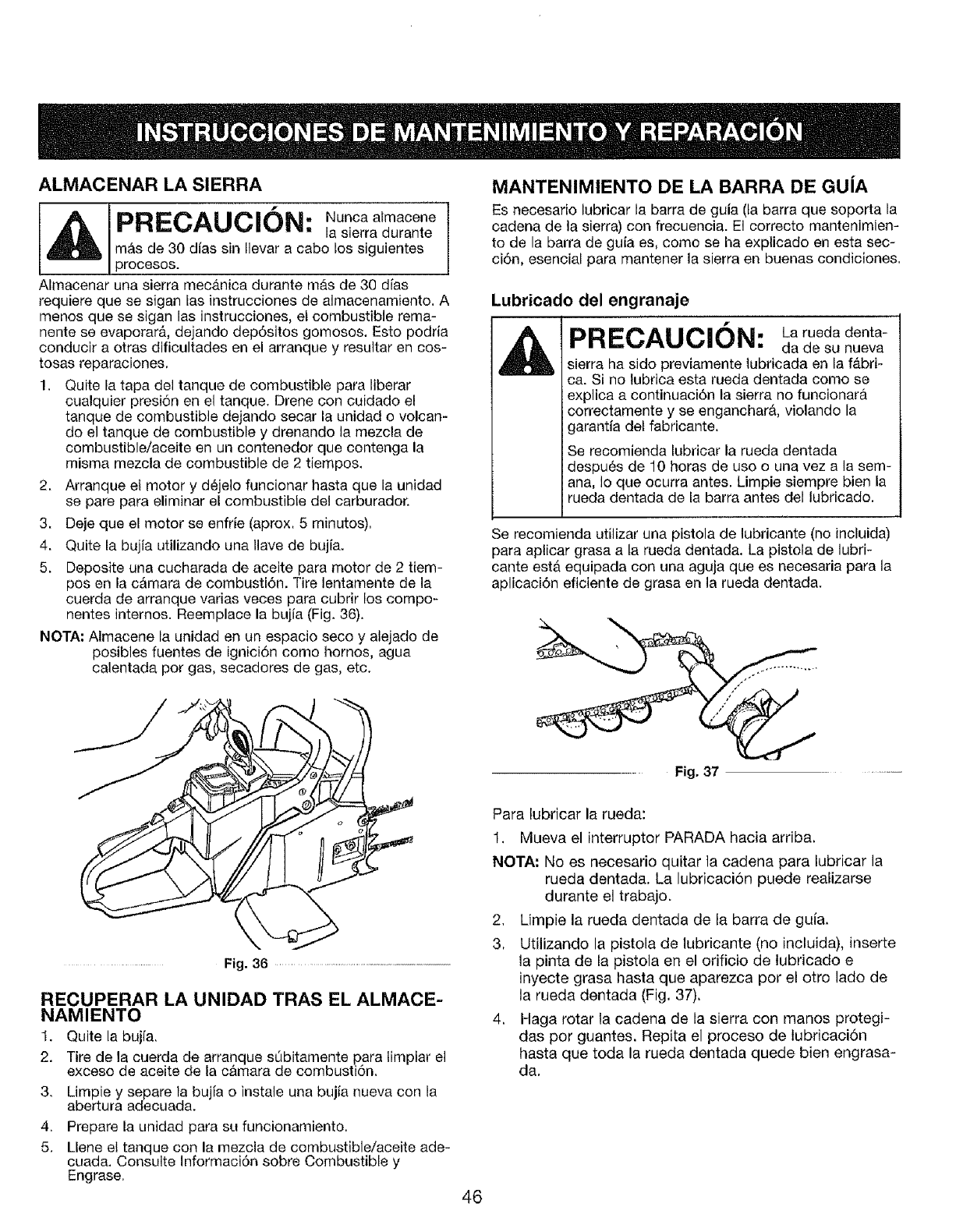
ALMACENAR LA SIERRA
I_, Nunca atmaoene
PRECAUCl0N: lasierradurante
m&s de 30 dies sin tlevar a cabo los siguientes
procesos.
Almacenar una sierra mec&nica durante mAs de 30 dies
requiere que se sigan fas instrucciones de almacenamiento. A
menos que se sigan las instrucciones, el combustible rema-
nente se evaporar&, dejando depesitos gomosos. Esto podria
conducir a otras dificultades en el arranque y resultar en cos-
tosas reparaciones.
1. Quite la tapa del tanque de combustible para liberar
cualquier presi6n en el tanque. Drene con ouidado el
tanque de combustible dejando secar la unidad o volcan-
do el tanque de combustible y drenando la mezcla de
combustible/aceite en un contenedor que contenga la
misma mezcla de combustible de 2 tiempos.
2. Arranque ef motor y dCjelo funcionar hasta que la unidad
se pare para eliminar el combustible del carburador.
3. Deje que el motor se enfrie (aprox. 5 minutos).
4. Quite la bujia utilizando una llave de bujia.
5. Deposite una cucharada de aceite para motor de 2 tiem-
posen la cAmara de combusti6n. Tire lentamente de la
cuerda de arranque varias veces para cubrir los compo-
nentes internos. Reemplace la bujia (Fig. 36),
NOTA: Almacene la unidad en un espacio seco y alejado de
posibles fuentes de ignici6n como hornos, agua
calentada pot gas, secadores de gas, etc.
MANTENIMIENTO DE LA BARRA DE GUIA
Es necesario lubricar la barra de guia (ta barra que soporta la
cadena de la sierra) con frecuencia. El correcto mantenimien-
to de la barra de guia es, como se ha expticado en esta sec-
ci6n, esencial para mantener la sierra en buenas condiciones.
Lubricado del engranaje
f
PRECAUCION: Laruedadenta-
da de su nueva
sierra ha sido previamente lubricada en la f#,bri-
ca. Si no lubrica esta rueda dentada como se
explica a continuaci6n la sierra no funcionar&
correctamente y se enganchar#,, violando la
garantia det fabricante.
Se recomienda lubricar la rueda dentada
despues de 10 horas de uso o una vez a la sem-
ana, Io que ocurra antes. Limpie siempre bien la
rueda dentada de la barra antes del lubricado.
Se recomienda utilizar una pistola de lubricante (no incluida)
para aplicar grasa a la rueda dentada. La pistola de lubri-
cante est,. equipada con una aguja que es necesaria para la
aplieaoi6n eflciente de grasa en la rueda dentada.
Fig. 36 ........................................................................................
RECUPERAR LA UNIDAD TRAS EL ALMACE-
NAMIENTO
1. Quite la bujfa.
2. Tire de la cuerda de arranque s_bitamente para timpiar et
exceso de aceite de la c&mara de combusti6n.
3. Limpie y separe la bujfa o instale una bujia nueva con la
abertura adecuada.
4. Prepare la unidad para su funcionamiento.
5. Llene et tanque con la mezcla de combustible/aceite ade-
cuada. Consulte Informaci6n sobre Combustible y
Engrase. 46
Para lubricar la rueda:
1. Mueva el interruptor PARADA hacia arriba.
NOTA: No es necesario quitar ta cadena para lubricar la
rueda dentada. La lubricaci6n puede realizarse
durante el trabajo.
2, Limpie la rueda dentada de la barra de gufa,
3, Utilizando la pistola de lubricante (no incluida), inserte
la pinta de la pistola en el orificio de lubricado e
inyecte grasa hasta que aparezca pot el otro lado de
la rueda dentada (Fig. 37),
4. Haga rotar la cadena de la sierra con manos protegi-
das por guantes. Repita el proceso de lubricaci6n
hasta que toda la rueda dentada quede bien engrasa-
da.
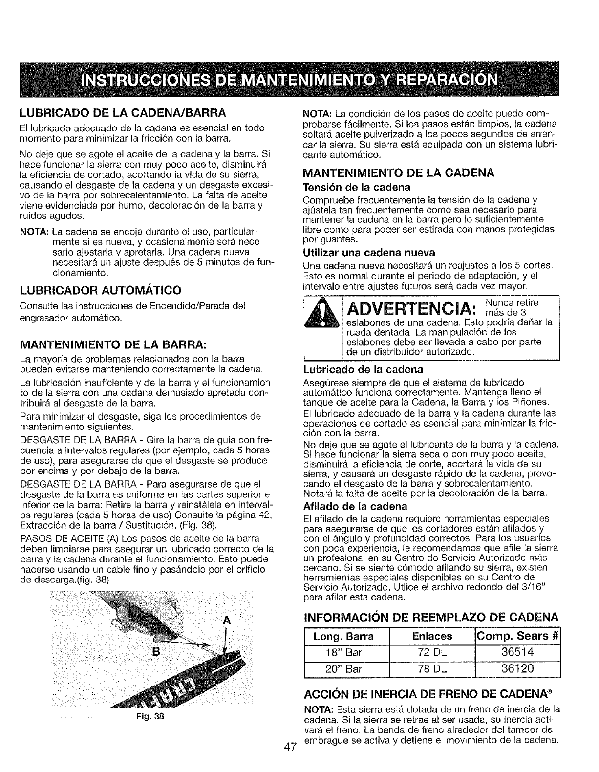
LUBRiCADO DE LA CADENA/BARRA
El lubricado adecuado de la cadena es esencial en todo
momento para minimizar la fricciSn con la barra,
No deje que se agote el aceite de la cadena y la barra, Si
hace funcionar la sierra con muy poco aceite, disminuir&
la eficiencia de cortado, acortando la vida de su sierra,
causando e! desgaste de la cadena y un desgaste excesi-
vo de ta barra pot sobrecalentamiento. La falta de aceite
viene evidenciada por humo, decoloraci6n de la barra y
ruidos agudos.
NOTA: La cadena se encoje durante el uso, particular-
mente si es nueva, y ocasionalmente ser#. nece-
sario ajustarla y apretarla. Una cadena nueva
necesitar#t un ajuste despues de 5 minutos de fun-
cionamiento.
LUBRICADOR AUTOMATICO
ConsuJte las instrucciones de Encendido/Parada del
engrasador automatico.
MANTENIMIENTO DE LA BARRA:
La mayoria de problernas relacionados con la barra
pueden evitarse manteniendo correctamente la cadena.
La lubricaci6n insuficiente y de la barra y el funcionamien-
to de la sierra con una cadena demasiado apretada con-
tribuir& al desgaste de la barra.
Para minimizar el desgaste, siga los procedimientos de
mantenimiento siguientes.
DESGASTE DE LA BARRA -Gire la barra de guia con fre-
cuencia a intervalos regulates (por ejemplo, cada 5 horas
de uso), para asegurarse de que el desgaste se produce
por encima y pot debajo de la barra.
DESGASTE DE LA BARRA - Para asegurarse de que el
desgaste de la barra es uniforme en las partes superior e
inferior de la barra: Retire la barra y reinst#.lela en interval-
os regulares (cada 5 horas de uso) Consulte la pb.gina 42,
Extracci6n de la barra /Sustituci6n. (Fig, 38).
PASOS DE ACEITE (A) Los pasos de aceite de la barra
deben limpiarse para asegurar un lubricado correcto de la
barra y la cadena durante e! funcionamiento, Esto puede
hacerse usando un cable fino y pas_.ndolo pot el orificio
de descarga.(fig. 38)
i
Fig. 38 .........................................
47
NOTA= La condici6n de los pasos de aceite puede com-
probarse f&cilmente. Si los pasos est_.n limpios, la cadena
soltar_t aceite pulverizado a los pocos segundos de arran-
car la sierra. Su sierra est,. equipada con un sistema lubri-
cante autom__tico,
MANTENIMIENTO DE LA CADENA
Tensibn de la cadena
Compruebe frecuentemente la tensi6n de la cadena y
ajL_stela tan frecuentemente como sea necesario para
mantener la cadena en la barra pero Io suficientemente
libre como para poder ser estirada con manos protegidas
por guantes.
Utilizar una cadena nueva
Una cadena nueva necesitara un reajustes a los 5 cortes.
Esto es normal durante el periodo de adaptaci6n, y el
intervalo entre ajustes futuros ser_. cada vez mayor,
ADVERTENCIA: Nuocaretire
m&s de 3
eslabones de una cadena. Esto podda daSar la
rueda dentada, La manipulaci6n de los
eslabones debe ser Ilevada a cabo por parte
de un distribuidor autorizado.
Lubricado de la cadena
AsegQrese siempre de queet sistema de lubricado
automb.tico funciona correctamente. Mantenga Ileno et
tanque de aceite para ta Cadena, la Barra y los Pi5ones.
El lubricado adecuado de la barra y la cadena durante las
operaciones de cortado es esencial para minimizar la fric-
ci6n con la barra.
No deje que se agote el lubricante de la barra y la cadena.
Si hace funcionar la sierra seca o con muy poco aceite,
disminuira la eficiencia de core, acortarb, la vida de su
sierra, y causara un desgaste r_pido de la cadena, provo-
cando el desgaste de la barra y sobrecalentamiento.
NotarA ta falta de aceite por la decoloraci6n de ta barra,
Afilado de la cadena
El afilado de ia cadena requiere herramientas especiales
para asegurarse de que los cortadores est_,n afilados y
con el &ngulo y profundidad correctos. Para los usuarios
con poca experiencia, le recomendamos que afile la sierra
un profesional en su Centro de Servicio Autorizado mb,s
cercano. Si se siente c6modo afilando su sierra, existen
herramientas especiales disponibles en su Centro de
Servicio Autorizado. Utlice el archivo redondo det 3/16"
para afilar esta cadena.
INFORMACION DE REEMPLAZO DE CADENA
Long. Barra Enlaces Comp. Sears #
18" Bar 72 DL 36514
20" Bar 78 DL 36120
ACCION DE INERCIA DE FRENO DE CADENA _
NOTA: Esta sierra est,. dotada de un freno de inercia de la
cadena. Si la sierra se retrae al ser usada, su inercia acti-
varA el freno. La banda de freno alrededor del tambor de
embrague se activa y detiene el movimiento de la cadena.
CAUSA
1. Proceso de arranque incorrecto
2. Ajuste incorrecto de mezcla de combustible en car
burador
3. Fallo en la bujia
4. Tanque de combustible vacio
5. La v&lvula principal no ha sido presionada
D
CAUSA
1, Filtro de combustible suoio
2, Posici6n incorrecta de la palanca
3, Pantatla de aspirador de chispas sucia
4. Filtro de aire sucio
5. Ajuste incorrecto de mezcla de combustible en carbu-
rador
CAUSA
1. Ajuste incorrecto de mezcla de combustible en carbu-
rador
2. Filtro de aire sucio
3. Combustible antiguo o mat mezclado
CAUSA
1. Ajuste incorrecto de mezcla de combustible en carbu-
rador
2. Combustible antiguo o mal mezclado
3. Filtro de aire sucio
4, Fallo en la buj[a
CAUSA
1. Buj[a con abertura incorrecta
2. Aspirador de chispas sucio
3. Filtro de aire sucio
CAUSA
1. Ajuste incorrecto de mezcla de combustible en carbu-
rador
2. Mezcla incorrecta de combustible
ACCIbN
1. Siga las instrucciones de la secci6n Arranque/Parada
2. Permita que un distribuidor de servicio Sears ajuste el
carburador de su unidad.
3. Limpie y distancie o sustituya el enchufe
4. Llene el tanque de combustible con combustible bien
mezclado
5. Presione la v#,lvula primaria tentamente 10 veces
ACCION
1. Cambie e] filtro de combustible
2. Mu6vala a ta posici6n 3
3, Cambie la pantalla
4. Quite, limpie y reinstale el filtro
5, Permita que un distribuidor de servicio Sears ajuste el
carburador de su unidad.
ACCION
1. Deje que un distribuidor le ajuste el carburador
2. Cambie o ]impie el filtro de aire
3. Vacie el tanque de gasolina y aSada mezcla
ACCION
1. Deje que un distribuidor le ajuste el carburador
2. Vacie el tanque de gasolina (yea AImacenamiento)
/a5ada mezcla fresca
3. Camb[e o limpie el fittro de aire
4, Cambie o limpie la bujia
ACCION
1. Limpie y distancie o sustituya el enchufe
2. Limpie o cambie el aspirador de chispas
3. Limpie o cambie el filtro de aire
ACCION
1. Permita que un distribuidor de servicio Sears ajuste el
carburador de su unidad.
2. Utilice combustible bien mezctado (mezcla 40:1)
Para reparaciones que vayan m&s all0,de ajustes menores, contacte con Sears Parts & Repair en et tel6fono (1-800-4-
MY-HOME@) u otro servicio cualificado.
48
Tipo de Motor ........................................................................................................................... Refrigerado por aim, 2 Tiempos
Desplazamiento .............................................................................................................................................. (55 cc)(3,36 cu in.)
Velocidad al ralenti RPM ............................................................................................................................................ 3,400 rpm
Velocidad en funcionamiento RPM ........................................................................................................................... 7,200+ rpm
Tipo de arranque ............................................................................................................... Electr6nico-MAX FIRE IGNITION(tm)
Conmutador de arranque ................................................................................................................................ De deslizamiento
Espacio de bujia ........................................................................................................................................ 0,025 in. (0,635 mm)
Lubricado ......................................................................................................................................... Mezcla Combustible/Aceite
Relaci6n Combustible/Aceite ................................................................................................................................................ 40:1
Carburador ............................................................................................................................... Diafragma, Todas las posiciones
Arranque ....................................................................................................... Arranque Incredi-Pull(tm) Rebobinado autom&tico
Silenciador ................................................................................................................................................ Deflector con guarda
Aceleraci6n ....................................................................................................................................... Muelle manual con retomo
Capacidad de tanque de combustible ........................................................................................................... 16,8 oz. (496,8 ml)
Control de aceleraci6n ..................................................................................................................................... Gatillo para dedo
Peso aproximado de la unidad (Sin combustible) .............................................................................................. 17,6 Ibs. (8 kg)
*Todas las especificaciones se basan en la QItima informaci6n disponible acerca del producto en el momento de la impre-
si6n. Nos reservamos el derecho de realizar cambios sin aviso previo.
49
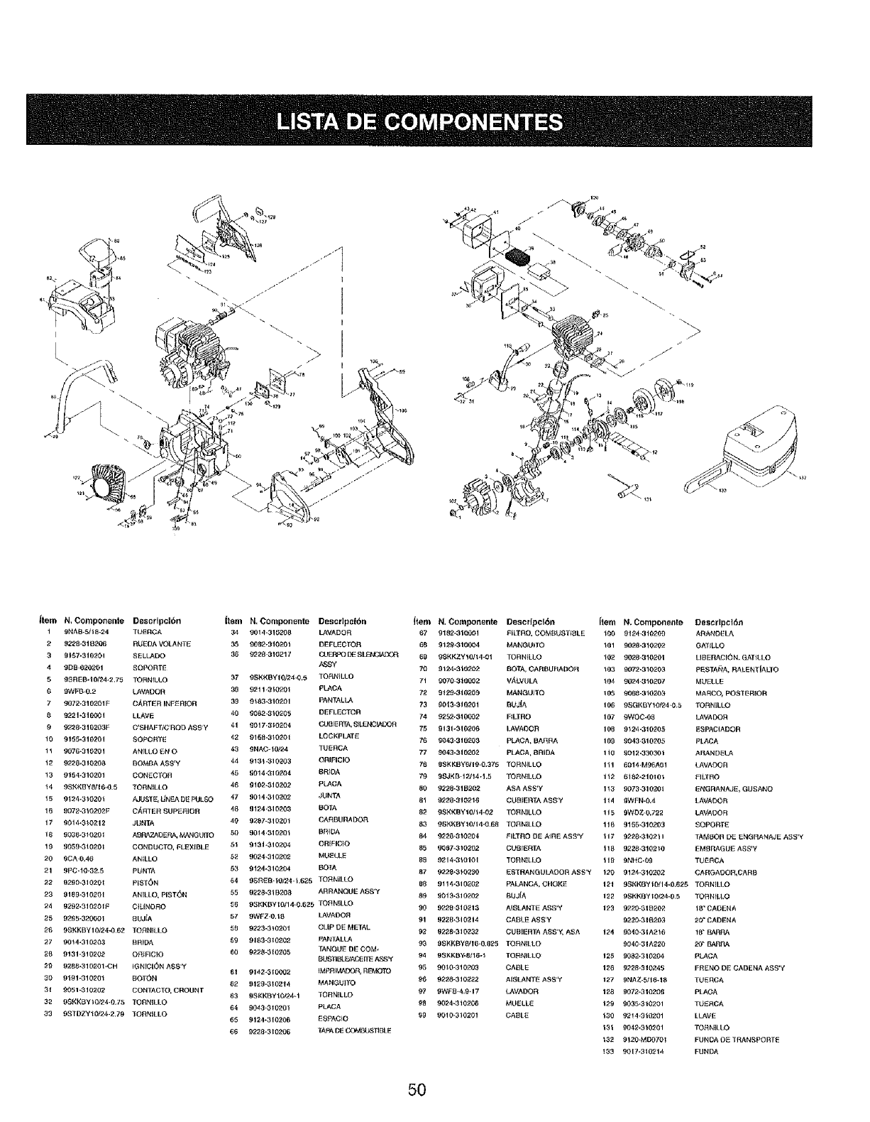
I
L
Item N, Compone=lte Descrlpcl6n item N, Componente Descdpci6n
1 gNAB-5/t B_24 TUERCA 34 9014-310208 LAVADCR
2 9228-318_06 RUEDA VOLANTE 35 9082-31020_ DEFLECTO_
3 g157-310201 SELLADO 36 9228 3102'17 _DE _L_NCIADO_
4909,620201 SOPORTE ASS'Y
59_REB-10124-2,75 TORNtLLO 37 9SKKBYI 0/24-Q,0 TOF_LLO
0 9WFB*0.2 LAVADOR 38 9211-3_020t PI_,OA
79072-3102_31F C/_RTER INFERIOR 39 9983-310201 PANTAL LA
99221-310001 LLAVE 40 90_2-310205 DEFLECTOR
9 9220_310203F C_SHAFTtC'RQD A88 y41 0017_3_0204 CL_I_RTA, _LENCMDOR
10 9155-310201 SOPORYE 42 0158-3_0201 LCCKPLATE
1_ 9076-310201 ANrLLO _t_ O 43 9NAC-10t_4 TUERCA
t2 9228-310209 BO_3A A$_'Y 44 913_ -310203 ORIFICIO
13 9_54-310201 CON_CTOR 45 9914.310204 BRFOA
!4 9S}_K_3YS/I _-0.5 TORNILLO 46 9102-_10202 PLACA
_5 912zt -310201
16 9072-310202F
17 9014-9_o_12
]9 9030-3_01
19 9059-3_0201
20 _CA 0,46
21 9PC-IO-3_.5
_'_ _290_31920t
23 _19_-3102_1
24 9202.3102OIF
i_LIST E_ L_NF_ £_Et_ULSO 47 _014-319202 JUNTA
C_,FtTER SUPEf_]OR 48 9124 31_99 BOTA
JUNTA 49 _297=31 _0_ CAF_BURADOR
ASRA?J_OE F_ Ntt¢_3 Uf[O 50 90_4.31020_ B_OA
CONI3UCTO, FLEXIBLE 51 9131 _310204 ORIFIC]O
AN_L£O 52 9024-31020_ MU_LLE
PUNTA 53 9124-310204 BOTA
PIS]_N F:4 99£_!_8,_@?.4- L625 TO_NILLO
ANIL[O. PIST_)N 55 0228,-31920_ AR_ANQUE A$8*Y
CILINOF{O 5_ 09KKBYt0!14-O 625 TORN_LLO
25 92_5-3200Ot 8UJiA 57 9WFZ-0,t9 LAVADOR
26 9_KKBYI0}24-062 TO_INILLO 59 9223-3_020_ CLIP DE METAL
27 9914_310203 _RIDA _9 9183-9_9202 PANTALLA
28 0131,31020_. Oi_FICIO 69 9228-310_05 TANCIU E DE COM-
BU_BLEfAC_IIE ASS_
_9 0288-910,201 -CH IG I_ICI(_N A_;_'Y 61 9142_310002 IMPRIMACO.R_ REMOTO
30 0191-31029_ BOT_N 82 9129-3t0_1'_ MANGUITO
3t 9951 _310202 CONTACTO, CROUNT 83 gSKk'BY'_0124_I TCRNILLO
32 9SK_<8"Y t0!24,0.75 "fORN_LLO 64 _043-310201 PLACA
33 091"BZY_Ot24 279 _fOF{NILLO 05 9124_310206 _SPACIO
99 9_28-310206 TAFA DE COMSL_T1BLE
Item N, Cor=*_ponente Descdpclbn
67 9182.310001 Fl[3_l_O, COMI_USTFI_LE
69 9_29-9 _00_4 MANGU_TO
69 98KKZY_0/t 4-0_ TOFIN_LLO
7_ 9t24-3_02_2 BOTA, CARBURADOR
71 9070 3_9002 VALVULA
7_ 9t29-3_9209 MANGU]TO
73 00_3-310201 BU3(A
74 025;_310{_32 F_LTRO
75 0131-310206 LAVAOOF{
76 _043,319208 PLACA, BAF_t_A
77 _9=13-310202 PLACA, 8_IDA
78 gSKKBY6_I 9-0.370 TOF_N_LLO
79 g_JKB-12714*1.5 TOF_N]LLO
80 9220-319202 ASA ASS'Y
81 9220-310216 CUBIERTA A88'Y
92 98KKBYI01_4-02 TORNILLO
89 99_KBY_0/_4-9 68 TO_NtLLO
84 9228-310204 _ILTF_O DE A_FiE ASS'¥
95 9087-310202 GUB_E_TA
BB 921 'f-3101_1 "rORN_LLO
Item N. Compone_te Descrlpcl(_n
1oo 9124.31o2o9 ARANO_L_
_01 9020-310202 GAT_LLO
_02 90_8-310201 LIBERACI_N. GAT_LLO
_03 9072-310293 PESTA_tA, RALENTtALTO
t04 9024-3102{}7 MUELLE
105 90_0-310203 MAF_CO, POSTERIOR
196 99GKBYIOf24,0,5 TOF_NILLO
197 9WOC-00 t_VADOR
108 9524-310205 ESPACIADOR
109 9043,_10205 PLACA
1_0 991_-33030_ ARANDELA
Ill 6014,M96A01 LAVAOOR
1!2 6182_219t0_ _:ILTRO
1t3 9973-31020t _GRANAJE, GUSANO
IH _WFN,9.4 I.AVAOOR
115 9WI3Z-0.72_ LAVAOOR
116 9155-310203 SOPORT_
117 9229_310_t ITAMBOR DE ENG_ANAJE ASS'Y
118 9_;_0-3102 $0 EMBRAGUE ASS'Y
119 9NHC,0_ TUEF_CA
87 9;_28-3_0_'30 ESTRANGULADOF_ ASS'Y }20 9124-310202 CARGAOOFt,CARB
89 9114-319202 PALANCA, CHOKE 19_ 09KKBY_0/I,I,0.625 TOF_NILI.O
89 9_19_310202 BUJ_A 1_2 0SKKE_Y t 0t2_9 5TOF_N_LLO
90 9228 31021_ A_SLANTE ASS'Y 123 9220-8t 8_07. f B" CADENA
91 _228,310214 CABLE A_S'Y 9220-319203 20" CADENA
02' _)228,3102.32 CU_IER'I_ A$_'Y, A_A 124 _040-31A216 18 _ BARRA
93 99KKBYS/t6_0.6_5 TOF_NILLO 9940_31A_20 2iT BAI_t_
94 991_KBY-8i1_-_ TORN_LLO 120 _092-31 _04 PL._C_A
95 99_0_310203 CABLE 126 92_8._10245 FRENO D_. CADENA ASS'Y
96 9928-3102_2 AI_LANTE A_S'Y 127 9NAZ,5!10-10 TUERCA
97 9WF_9,4.9,17 LAVADOR 128 9972-310_06 PkACA
9924-310208 MUELLE 129 9035-319201 TUS_CA
99 9019_310201 CABL;E 130 92_4_3t9201 LLAVE
131 0042-3_0201 TOF_N_LLO
_32 9120_M007OI FUNOAO_ TRANSPORT_E
_33 9017-31021_ FUNDA
5O

Declaracibn de Garantia de Control de Emisiones EPA /California
Sus derechos y obligaciones de garantia
El consejo de Recursos A6reos de California, La Agencia de Protecci6n Medioambiental y Sears, Roebuck and Co., tienen el
placer de explicarle el sistema de control de garantfa de su pequeSo motor para 2005 y posterior. En California y los 49 esta-
dos, los nuevos motores pequedos deben ser dise_ados, construidos y equipados para cumplir la estricta normativa anti-
smog. Sears debe garantizar que la emisi6n del sistema de control de su motor pequeSo para los periodos de tiempo lista-
dos a continuaci6n no abusan, incumplen o mantienen incorrectamente su motor.
Su sistema de control de emisiones puede incluir componentes como un sistema de inyecci6n de combustible al carburador,
el sistema ignici6n y un convertidor catalftico. Tambi6n puede incluir manquitos, abrazaderas, conectores y otros compo _
nentes relacionados con la emisi6n.
Donde exista una condici6n garantizable, Sears repararA su motor sin coste inciuyendo el diagn6stico, los componentes y fa
mano de obra.
Los motores pequehos de 2005 en adelante estbn garantizados durante dos ahos. Si alg_n componente relacionado
con la emisibn estb defectuoso, el componente serb reparado o reernplazado pot Sears.
Responsabilidades del propietario de la garantfa
*Como propietario de un motor peque_o, usted es responsable del funcionamiento y de] mantenimiento necesario men-
cionado en su manual de usuario. Sears le recomienda que conserve todos los recibos relacionados con el mantenimiem
to de su motor peque_o, aunque Sears no podrA denegar la garantfa por la falta de recibos o por su fallo al asegurarse de1
buen funcionamiento det programa de mantenimiento.
o Como propietario de un motor peque_o, debe tener en cuenta que Sears puede denegar su garantia si su motor o un com-
ponente del mismo ha fallado debido a abusos, negligencias, mantenimiento inadecuado o modificaciones no aprobadas..
o Es usted responsable de presentar su motor en un Centro de Servicios Autorizados por Sears en el momento en et que
exista un probtema, Las reparaciones en garantia se completar&n en una cantidad de tiempo razonable, sin exceder los 30
dias,
Si tiene alguna pregunta acerca de sus derechos en garantia y sus responsabilidades, puede Ilamar al 1-800-4-MY-HOME®.
Cobertura de la Garantia del Fabricante
. El periodo de garantia comienza en la fecha en la que el equipo o motor ha sido entregado al comprador en el establec-
imiento.
• El fabricante garantiza al propietario incial y a los siguientes compradores, que el motor est& tibre de defectos de material
y mano de obra que causen el fallo de un componente en garantfa durante un periodo de un a_o.
-La reparaci6n y reemplazo de un componente en garantfa ser& realizada sin cargo pot un Centro de Servicios Autorizados
por Sears. Para conocer su centro mas cercano, p6ngase en contacto con Sears en el: 1-800-4-MY-HOME®.
• Cualquier componente en garantia que no deba ser cambiado, sino mantenido o inspeccionado regularmente al efecto de
"Reparar o Reemplazar si es necesario" se encuentra garantizado durante la garant[a. Cualquier componente garantizado
que deba ser cambiado ser_. garantizado durante un tiempo hasta ta primera fecha de cambio de ese componente.
• El propietario no tendr_ que pagar pot las labores de diagn6stico que conducirAn a la determinaci6n de que un compo-
nente garantizado estA defectuoso si el diagn6stico se realiza en un Centro de Servicios Autorizados por Sears.
• El fabricante es responsable de los da_os a otros componentes del motor causados por el fallo de un componente en
garant[a que alan se encuentre en garantia.
Los fallos provocados por el abuso, negligencia o mantenimiento incorrecto no ser_n incluidos en esta garantia.
• El uso de componentes modificados o accesorios no autorizados pot el fabricante violaran su garantfa. El fabricante no es
responsable de la cobertura de los fallos en componentes garantizados pot el uso de accesorios o componentes modifi-
cados.
• Para realizar una reclamaci6n, dirijase a su Centro de Servicios Autorizados pot Sears m_,s cercano. Las reparaciones en
garantia ser&n realizadas en todos los Centro de Servicios ALItorizados por Sears.
• Cualquier componente cuyo cambio haya sido aprobado por el fabricante puede ser utilizado para la reparaci6n de com-
ponentes relacionados con las emisiones y se entregar& sin cargo al propietario. Cualquier componente de reemplazo que
sea equivatente en rendimiento o durabilidad puede ser utilizado durante el mantenimiento fuera de garant a y no reduc r#.
las obligaciones de la garantia del fabricante.
• Los siguientes componentes se incluyen en la garant[a de componentes relacionados con las emisiones: motor, filtro de
aire, carburador, detonador, lineas de combustible, captaci6n/filtro de combustible, m6dulo de ignicion, bujia y silenciador.
51
Acuerdo de Proteccion de Reparaciones
Le felicitamos por su compra inteligente. Su nuevo produc-
to Craftsman@ ha sido disefiado y fabricado para durar
aSos en funcionamiento. Pero como todos los productos,
puede necesitar reparaciones de vez en cuando. Es el
momento de que un Acuerdo de Protecci6n de
Reparaciones le ahorre dinero y problemas,
Compre un Acuerdo de Protecci6n de Reparaciones ahora
y prot6jase de problemas y gastos inesperados.
Esto es Io que se incluye en el Acuerdo
[] $ervioio experto por nuestros 12.000 profesionales
especialistas en reparaci6n
[] Reparaciones ilimitadas y sin cargo de componentes
y mano de obra en todos las reparaciones cubiertas
[] Reemplazo del producto si el producto en cuesti6n
no puede set reparado.
[] Descuento del 10% de los gastos regulates de
reparaci6n y componentes no cubiertos por este
acuerdo; adem_s, un 10% de descuento sobre el
precio normal de comprobaci6n de mantenimiento
preventivo
[] Ayuda r_pida por tel_fono -ayuda por tel6fono por
un t6cnico de Sears en el caso de productos que
requieran reparaci6n en casa, y programaci6n de
reparaciones.
Una vez que compre su acuerdo, una sola ltamada telef6ni-
ca ser_. todo Io que necesitara para conseguir su
reparaci6n. Puede Ilamar a cualquier hora del dia o de la
noche, o pedir una cita de reparaci6n online.
Sears tiene m&s de 12.000 profesionales especialistas en
reparaci6n, que tienen acceso a mb.s de 4,5 rnillones de
componentes y accesorios. Ese es el tipo de profesionales
con los que puede contar para ayudarle a prolongar la vida
de su nueva compra durante afios, Compre boy su Acuerdo
de Protecci6n de Reparaciones,
Son aplicables algunas limitaciones y exclusiones. Para
conocer los precios y otra informacibn, Ilame at 1-800-
827-6655
Servicio de Instalacibn de Sears
Si necesita el servicio de instalaci6n de electrodom6sticos,
puertas de garaje, calefactores de agua, y otros productos
dom6sticos en los EE.UU., Ilame al 1-800-4-MY-HOME@
52

Your Home
For repair- in your home -of all major brand appliances,
lawn and garden equipment, or heating and cooling systems,
no matter who made it, no matter who sold it!
For the replacement parts, accessories and
owner's manuals that you need to do-it-yourself.
For Sears professional installation of home appliances
and items like garage door openers and water heaters.
I=800-4-NIY-HOME ® (1-800-469-4663)
Call anytime, day or night (U.S.A. and Canada)
www.sears.com www.sears.ca
Our Home
For repair of carry-in items like vacuums, lawn equipment,
and electronics, call or go on-line for the location of your nearest
Sears Parts & Repair Center.
1°800-488°1222
Calf anytime, day or night (U.S.A. only)
www.sears.corn
To purchase a protection agreement (U.S.A.)
or maintenance agreement (Canada) on a product serviced by Sears:
1-800-827-6655 (U.S.A,)
Para pedir servicio de reparaci6n
a domicilio, y para ordenar piezas:
1-888-SU-HOGAR sM
(1-888-784-6427)
1-800-361-6665 (Canada)
Au Canada pour service en frangais:
I=800-LE-FOYER Mc
(1-800-533-6937)
www.sears.ca
_M
® Registered Trademark /TMTrademark /Service Mark of Soars, Roebuck and Co.
® Marca Registrada /Marca de F&brica /s_4Marca de Servicio de Sears, Roebuck and Co.
MCMarque de commerce / _D Marque d6posee de Sears, Roebuck and Co. © Sears, Roebuck and Co.
