Craftsman 316731700 User Manual GAS TRIMMER Manuals And Guides 1212364L
User Manual: Craftsman 316731700 316731700 CRAFTSMAN GAS TRIMMER - Manuals and Guides View the owners manual for your CRAFTSMAN GAS TRIMMER #316731700. Home:Lawn & Garden Parts:Craftsman Parts:316731700 Craftsman Grass trimmer (weed wacker) Manual
Open the PDF directly: View PDF ![]() .
.
Page Count: 48

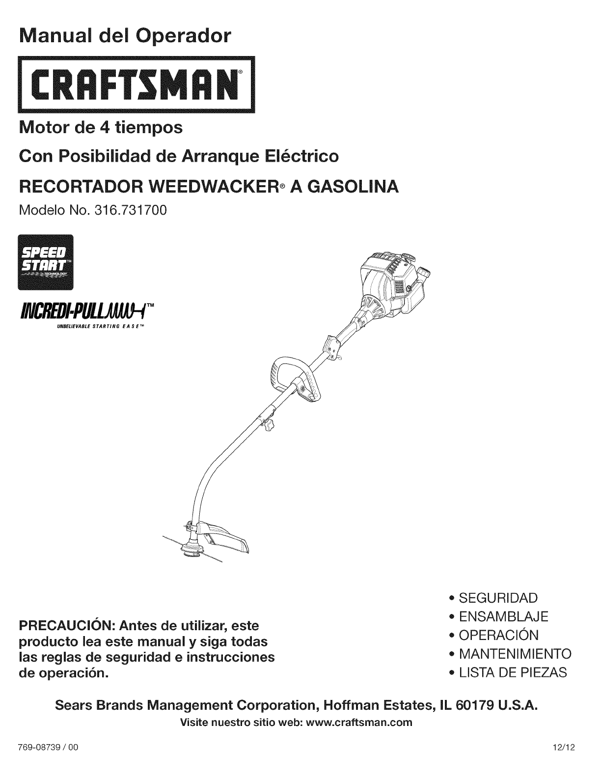
Operator's Manual
M
4-CycJe
Electric Start Capable
WEEDWACKER® GAS TRIMMER
Model No. 316.731700
U_F_VABLE STAftTt_6 EA $$_
CAUTION: Before using this product,
read this manual and follow all its Safety
Rules and Operating instructions.
,, SAFETY
*ASSEMBLY
*OPERATION
*MAINTENANCE
*PARTS LIST
*ESPANOL, R 23
Sears Brands Management Corporation, Hoffman Estates, IL 60179 U.S.A.
Visit our website: www.craftsman.com
769-08739 /00 12/12
TABLEOFCONTENTS
Safety............................................... 2
Warranty............................................. 5
KnowYourUnit........................................ 6
Specifications......................................... 6
Assembly............................................. 7
OilandFuel........................................... 9
StartingandStopping.................................. 11
Operation............................................ 13
Maintenance......................................... 14
CleaningandStorage.................................. 19
Troubleshooting....................................... 20
RepairProtectionAgreements........................... 21
PartsList............................................ 46
ServiceNumbers.............................. BackCover
Allinformation,illustrationsandspecificationsinthismanualarebased
onthelatestproductinformationavailableatthetimeofprinting.We
reservetherighttomakechangesatanytimewithoutnotice.
©SearsBrands,LLC
Thepurposeofsafetysymbolsistoattractyourattentionto
possibledangers.Thesafetysymbols,andtheirexplanations,
deserveyourcarefulattentionandunderstanding.Thesafety
warningsdonotbythemselveseliminateanydanger.The
instructionsorwarningstheygivearenotsubstitutesforproper
accidentpreventionmeasures.
i SYMBOL MEANING
DANGER: Signals an EXTREME hazard.
Failure to obey a safety DANGER signal WILL result in
serious injury or death to yourself or to others.
WARNING: Signals a SERIOUS hazard.
Failure to obey a safety WARNING signal CAN result in
serious injury to yourself or to others.
CAUTION: Signals a MODERATE hazard.
Failure to obey a safety CAUTION signal MAY result in
property damage or injury to yourself or to others.
NOTE: Advises you of information or instructions vital to the
operation or maintenance of the equipment.
SPARK ARRESTOR NOTE
NOTE: For users on U.S. Forest Land and in the states of
California, Maine, Oregon and Washington. All U.S. Forest Land
and the state of California (Public Resources Codes 4442 and
4443), Oregon and Washington require, by law that certain internal
combustion engines operated on forest brush and/or grass-covered
areas be equipped with a spark arrestor, maintained in effective
working order, or the engine be constructed, equipped and
maintained for the prevention of fire. Check with your state or local
authorities for regulations pertaining to these requirements. Failure
to follow these requirements could subject you to liability or a fine.
This unit is factory equipped with a spark arrestor. Replacement
requires Muffler Assembly Part #753-08052, installed at a Sears
Parts & Repair Service Center.
CALIFORNIA PROPOSITION 65
WARNING: Engine exhaust, some of its constituents and
certain finished components contain or emit chemicals known
to the State of California to cause cancer and birth defects or
other reproductive harm. Wash hands after handling.
Read the operator's manual and follow all warnings and safety
instructions. Failure to do so can result in serious injury to the
operator and/or bystanders.
•iMPORTANT SAFETY iNSTRUCTiONS
READ ALL iNSTRUCTiONS BEFORE OPERATING
I'1
o
o
o
o
o
o
o
WARNING: When using the unit, all safety rules must be
followed. Please read these instructions before operating
the unit in order to ensure the safety of the operator and any
bystanders. Please keep these instructions for later use.
Read the instructions carefully. Be familiar with the controls and
proper use of the unit.
Do not operate this unit when tired, ill or under the influence of
alcohol, drugs or medication.
Children must not operate the unit. Teens must be accompanied
and guided by an adult.
All guards and safety attachments must be installed properly
before operating the unit.
Inspect the unit before use. Replace damaged parts. Check for
fuel leaks. Make sure all fasteners are in place and secure.
Replace parts that are cracked, chipped, or damaged in any
way. Do not operate the unit with loose or damaged parts.
Only use the trimming line described in the Specifications section
of this manual. Never use metal-reinforced line, wire, chain or
rope. These can break off and become dangerous projectiles.
Be aware of risk of injury to the head, hands and feet.
Carefully inspect the area before starting the unit. Remove
rocks, broken glass, nails, wire, string and other objects that
may be thrown or become entangled with the unit.
Clear the area of children, bystanders and pets; keep them
outside a 50-foot (15 m) radius, at a minimum. Even then, they are
still at risk from thrown objects. Encourage bystanders to wear
eye protection. If you are approached, stop the unit immediately.
Squeeze the throttle control and check that it returns
automatically to the idle position. Make all adjustments or
repairs before using the unit.
SAFETY WARNINGS FOR GAS UNITS
_WARNING: Gasoline is highly flammable and its vapors j
can explode if ignited. Take the following precautions:
• Store fuel only in containers specifically designed and approved
for the storage of such materials.
Always stop the engine and allow it to cool before filling the
tank. Never remove the fuel tank cap or add fuel when the
engine is hot. Always loosen the fuel tank cap slowly to relieve
any pressure in the tank before fueling.
Always add fuel in a clean, well-ventilated outdoor area where
there are no sparks or flames. DO NOT smoke.
Never operate the unit without the fuel cap securely in place.
Avoid creating a source of ignition for spilled fuel. Wipe up any
spilled fuel from the unit immediately, before starting the unit.
Move the unit at least 30 ft. (9.1 m) from the fueling source and
site before starting the engine. DO NOT smoke.
Never start or run the unit inside a closed room or building.
Breathing exhaust fumes can kill. Operate this unit only in a well
ventilated outdoor area.
WHILE OPERATING
Wear safety glasses or goggles that meet current ANSI Z87.1
standards and are marked as such. Wear ear/hearing protection
when operating this unit. Wear a face mask or dust mask if the
operation is dusty.
Wear heavy long pants, boots, gloves and a long sleeve shirt. Do
not wear loose clothing, jewelry, short pants, sandals or go
barefoot. Secure hair above shoulder level.
The cutting head shield must always be in place while operating
the unit. Do not operate the unit without both trimming lines
extended and the proper line installed. Do not extend the
trimming line beyond the length of the shield.
This unit has a clutch. The cutting head remains stationary when
the engine is idling. If it does not, take the unit to a Sears or
other qualified service dealer for an adjustment.
Adjust the handle to provide the best grip.
Make sure the attachment is not in contact with anything before
starting the unit.
Use the unit only in daylight or good artificial light.
Avoid accidental starting. Be in the starting position whenever
pulling the starter rope. The operator and unit must be in a stable
position while starting. Refer to Starting and Stopping.
Use the right tool. Only use this tool for its intended purpose.
Always hold the unit with both hands when operating. Keep a
firm grip on both handles or grips.
Do not overreach. Always keep proper footing and balance. Take
extra care when working on steep slopes or inclines.
Keep hands, face, and feet away from all moving parts. Do not
touch or try to stop moving parts.
Do not touch the engine, gear housing or muffler. These parts get
extremely hot from operation, even after the unit is turned off.
Do not operate the unit faster than the speed needed to do the job.
Do not run the unit at high speed when not in use.
Do not force the unit. It will do a better, safer job when used at
the intended rate.
Always stop the unit when operation is delayed or when walking
from one location to another.
If you strike or become entangled with a foreign object, stop the
unit immediately and check for damage. Do not operate the unit
before repairing damage. Do not operate the unit with loose or
damaged parts.
Turn the engine to off and disconnect the spark plug for
maintenance or repair.
Use only original equipment manufacturer (OEM) replacement
parts and accessories for this unit, as listed in the Parts List
section of this manual. Use of any other parts or accessories
could lead to serious injury to the user, or damage to the unit,
and void the warranty.
Keep the unit clean. Carefully remove vegetation and other
debris that could block moving parts.
To reduce fire hazard, replace a faulty muffler and spark arrestor.
Keep the engine and muffler free from grass, leaves, excessive
grease or carbon build up.
If the unit starts to vibrate abnormally, stop the unit immediately.
Inspect the unit for the cause of the vibration. Vibration is
generally an indicator of trouble.
3
OTHER SAFETY WARNINGS
• All service, other than the maintenance procedures described in
this manual, should be performed by a Sears or other qualified
service dealer.
Before inspecting, servicing, cleaning, storing, transporting or
replacing any parts on the unit:
1. Stop the unit.
2. Make sure all moving parts have stopped.
3.Allow the unit to cool.
4. Disconnect the spark plug wire.
Secure the unit while transporting.
Never store the unit with fuel in the tank, inside a building where
fumes may reach an open flame (pilot lights, etc.) or sparks
(switches, electrical motors, etc.).
Store the unit in a dry place, secured or at a height to prevent
unauthorized use or damage. Keep the unit out of the reach of
children.
Never douse or squirt the unit with water or any other liquid.
Keep handles dry, clean and free from debris. Clean the unit
after each use. Refer to Cleaning and Storage.
Keep these instructions. Refer to them often and use them to
instruct other users. If you loan this unit to others, also loan
them these instructions.
SAVE THESE INSTRUCTIONS
,, SAFETY & INTERNATIONAL SYMBOLS ,,
This operator's manual describes safety and international symbols and pictographs that may appear on this product. Read the operator's
manual for complete safety, assembly, operating and maintenance and repair information.
SYMBOL MEANING
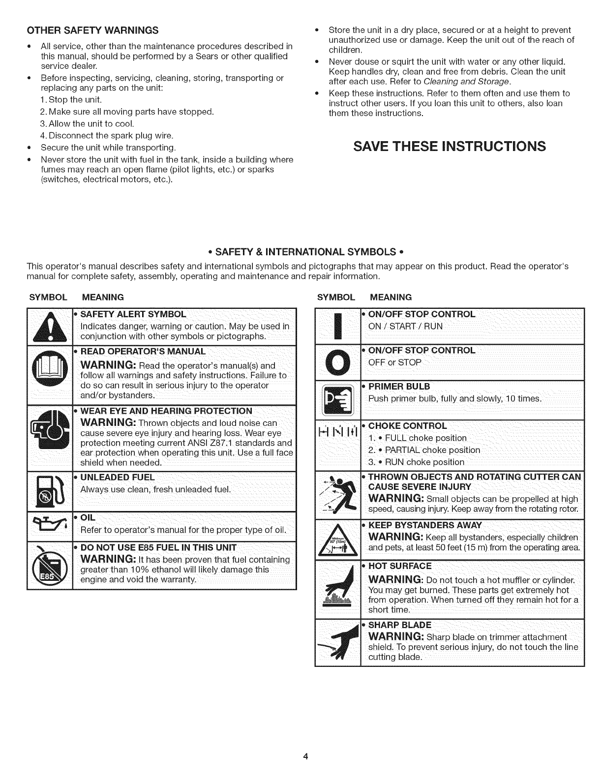
oSAFETY ALERT SYMBOL
Indicates danger, warning Or caut!0n. MaYbe used in
conjunction with other symbo!s or pictographs,
oREAD OPERATOR'S MANUAL
WARNING: Read t,e oPerat0FS manUal(s)and
follow all warnings and safety instructions. Failure to
do so can result in serious injury to the operator
and!or bystanders, ............
r_,_ t _ oWEAR EYE AND HEARING PROTECTION
WARNING: Thi0wn objects and ioUd noiSe
.-m_1 _ i cause severe eye !njury and hearing loss, Wear eye
PProtection meeting current ANSI Z87:1 standards and
ear protection when operating this unit, Use afull face
shield when needed.
Always USeclean; fresh Unleaded fuel.
.*OIL !Refer to operator s manual for the proper type Of oil.
_ o DO NOT USE E85 FUEL IN THIS UNIT
WARNING: it has been Pr0ven that fuel Containing
greater than10% ethanol will likely damage this
engine and void the warranty.
SYMBOL MEANING
!
'ON/OFF STOP CONTROLOFF or STOP
' PRIMER BULBPush primer bulb, fully and slowly, 10 times.
._ ' ' 'CHOKE CONTROL
_" { 1., FULLchoke position
, 2. • PARTIAL choke position
3. *RUN choke position
_.71_.,,=_ , THROWN OBJECTS AND ROTATING CUTTER CAN
.- cAusESEVERE,NJURY
WARNING: Small objects can be propelled at high
J_'_ speed, causing injury. Keep away from the rotating rotor.
_. _ KEEP BYSTANDERS AWAY
,_;_,_ WARNING: Keep all bystanders, especially children
J_*-*l_, and pets, at least 50 feet (15 m) from the operating area.
HOT SURFACE
WARNING: Do not touch a hot muffler or cylinder.
You may get burned. These parts get extremely hot
from operation. When turned off they remain hot for a
short time.
, SHARP BLADE
WARNING: Sharp blade on trimmer attachment
shield. To prevent serious injury, do not touch the I ne
cutting blade.

CRAFTSMANTWO YEAR FULL WARRANTY
FOR TWO YEARS from the date of purchase, this product is warranted against any defects in material or workmanship. A defective product
will receive free repair or replacement if repair is unavailable.
ADDITIONAL LIMITED WARRANTY on TRIMMER SHAFTS
FOR THE THIRD THROUGH TENTH YEAR from the date of purchase, the outer metal housing of the upper and lower trimmer shafts is
warranted against any defects in material or workmanship. With proof of purchase, a new housing will be supplied free of charge. You are
responsible for the labor cost of installation. This additional coverage does not apply to inner trimmer shaft components.
For warranty coverage details to obtain free repair or replacement, visit the web site: www.craftsman.com
This warranty covers ONLY defects in material and workmanship. Warranty coverage does NOT include:
• Expendable items that can wear out from normal use within the warranty period, such as cutting line, spark plugs, or filters.
• Product damage resulting from user attempts at product modification or repair or caused by product accessories.
• Repairs necessary because of accident or failure to operate or maintain the product according to all supplied instructions.
• Preventive maintenance, or repairs necessary due to improper fuel mixture, contaminated or stale fuel.
This warranty is void if this product is ever used while providing commercial services or if rented to another person.
This warranty gives you specific legal rights, and you may also have other rights which vary from state to state.
Sears Brands Management Corporation, Hoffman Estates, IL 60179
To order parts or schedule service for this product, call 1-800-469-4663.
5
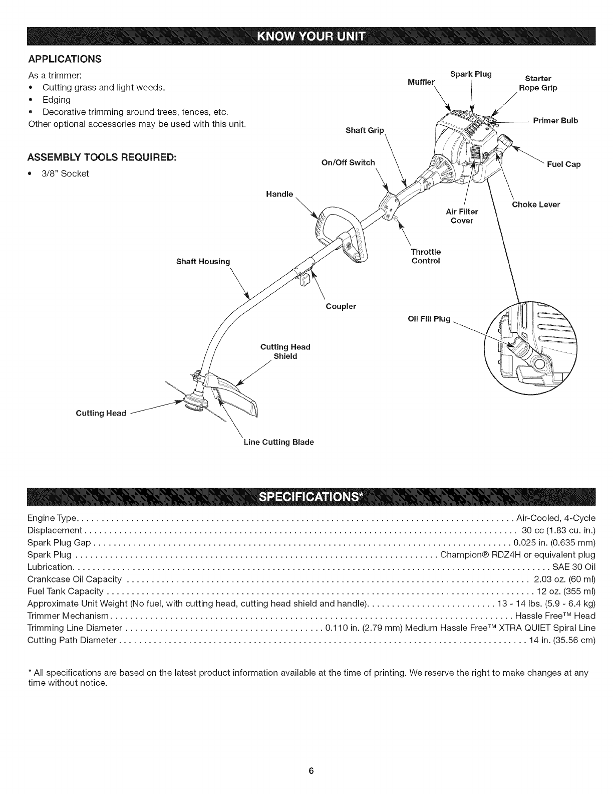
APPLiCATiONS
Asatrimmer:
• Cuttinggrassandlightweeds.
Edging
Decorativetrimmingaroundtrees,fences,etc.
Otheroptionalaccessoriesmaybeusedwiththisunit. Shaft Gri
Spark Plug Starter
Muffler Rope Grip
Primer Bulb
ASSEMBLY TOOLS REQUIRED:
3/8" Socket
Handle \
On/Off Switch
Air Filter
Cover
Fuel Cap
Choke Lever
Throttle
Shaft Housing Control
Cutting Head
Shield
Coupler
Cutting Head
Line Cutting Blade
Engine Type ........................................................................................ Air-Cooled, 4-Cycle
Displacement ....................................................................................... 30 cc (1.83 cu. in.)
Spark Plug Gap .................................................................................... 0.025 in. (0.635 mm)
Spark Plug ......................................................................... Champion® RDZ4H or equivalent plug
Lubrication ................................................................................................ SAE 30 Oil
Crankcase Oil Capacity ................................................................................. 2.03 oz. (60 ml)
Fuel Tank Capacity ...................................................................................... 12 oz. (355 ml)
Approximate Unit Weight (No fuel, with cutting head, cutting head shield and handle) .......................... 13 - 14 Ibs. (5.9 - 6.4 kg)
Trimmer Mechanism ................................................................................. Hassle FreeTM Head
Trimming Line Diameter ........................................ 0.110 in. (2.79 mm) Medium Hassle FreeTM XTRA QUIET Spiral Line
Cutting Path Diameter .................................................................................. 14 in. (35.56 cm)
* All specifications are based on the latest product information available at the time of printing. We reserve the right to make changes at any
time without notice.
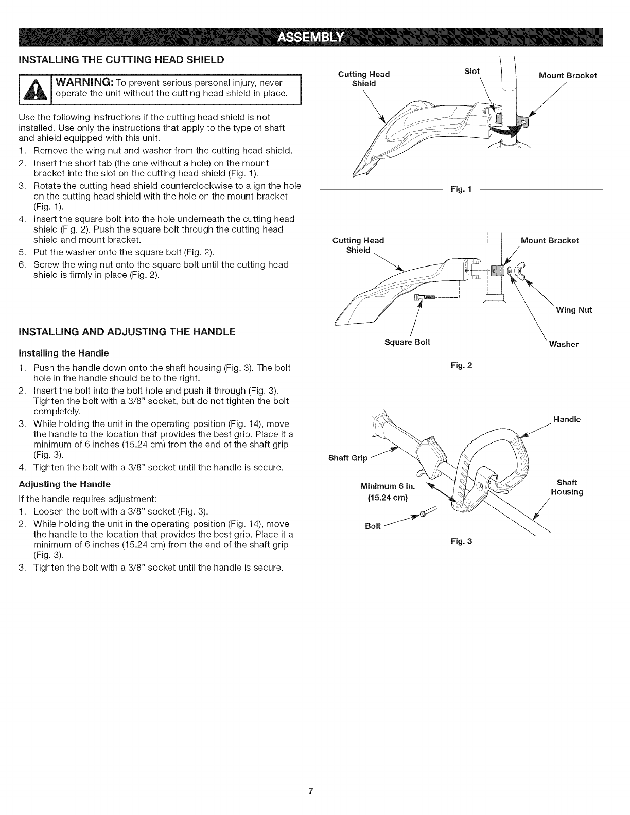
iNSTALLiNG THE CUTTING HEAD SHIELD
_ WARNING: To prevent serious personal injury, never ]
operate the unit without the cutting head shield in place.
Cutting Head Slot Mount Bracket
Shield
Use the following instructions if the cutting head shield is not
installed. Use only the instructions that apply to the type of shaft
and shield equipped with this unit.
1. Remove the wing nut and washer from the cutting head shield.
2. Insert the short tab (the one without a hole) on the mount
bracket into the slot on the cutting head shield (Fig. 1).
3. Rotate the cutting head shield counterclockwise to align the hole
on the cutting head shield with the hole on the mount bracket
(Fig. 1).
4. Insert the square bolt into the hole underneath the cutting head
shield (Fig. 2). Push the square bolt through the cutting head
shield and mount bracket.
5. Put the washer onto the square bolt (Fig. 2).
6. Screw the wing nut onto the square bolt until the cutting head
shield is firmly in place (Fig. 2).
iNSTALLiNG AND ADJUSTING THE HANDLE
installing the Handle
1. Push the handle down onto the shaft housing (Fig. 3). The bolt
hole in the handle should be to the right.
2. Insert the bolt into the bolt hole and push it through (Fig. 3).
Tighten the bolt with a 3/8" socket, but do not tighten the bolt
completely.
3. While holding the unit in the operating position (Fig. 14), move
the handle to the location that provides the best grip. Place it a
minimum of 6 inches (15.24 cm) from the end of the shaft grip
(Fig. 3).
4. Tighten the bolt with a 3/8" socket until the handle is secure.
Adjusting the Handle
If the handle requires adjustment:
1. Loosen the bolt with a 3/8" socket (Fig. 3).
2. While holding the unit in the operating position (Fig. 14), move
the handle to the location that provides the best grip. Place it a
minimum of 6 inches (15.24 cm) from the end of the shaft grip
(Fig. 3).
3. Tighten the bolt with a 3/8" socket until the handle is secure.
Cutting Head
Shield
Square Bolt
Shaft Grip
Minimum 6 in.
(15.24 cm)
Bolt J
Fig. 1
Fig. 2
Fig. 3
Mount Bracket
Wing Nut
Washer
Handle
Shaft
Housing
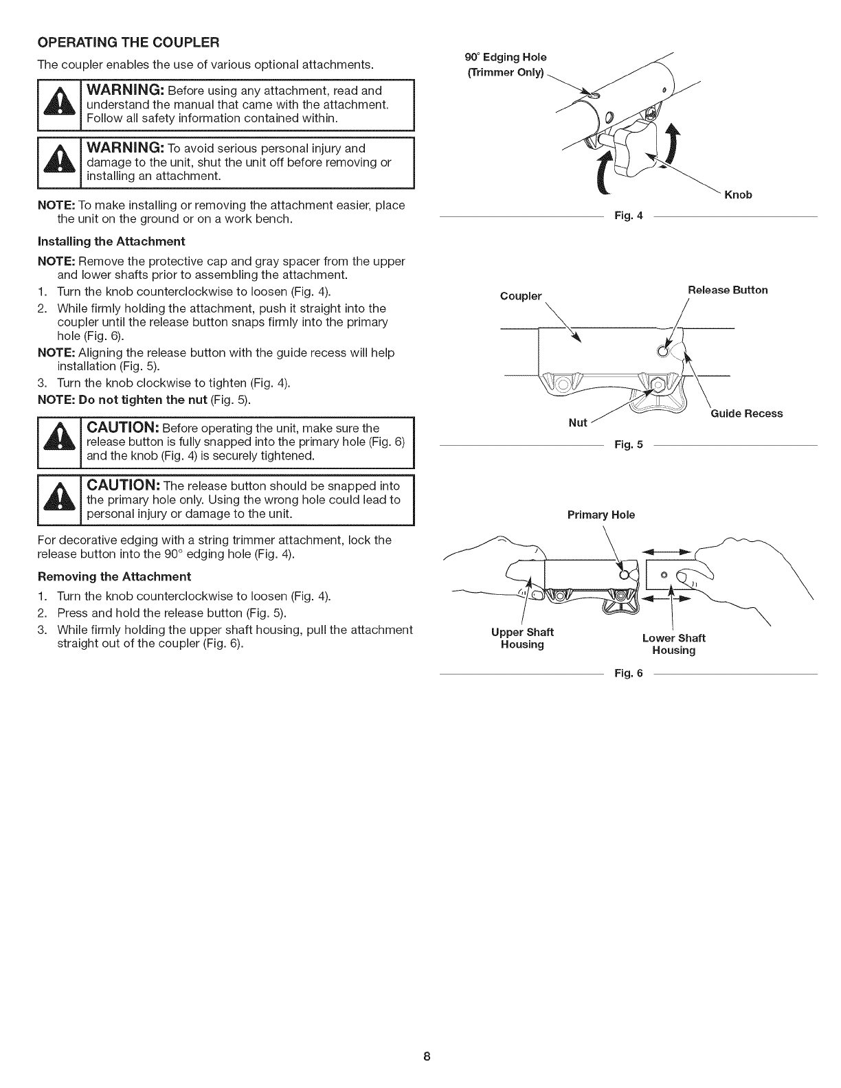
OPERATING THE COUPLER
The coupler enables the use of various optional attachments.
_ WARNING: Before using any attachment, read and
understand the manual that came with the attachment. J
Follow all safety information contained within.
_ WARNING: To avoid serious personal injury and j
damage to the unit, shut the unit off before removing or
installing an attachment.
NOTE: To make installing or removing the attachment easier, place
the unit on the ground or on a work bench.
installing the Attachment
NOTE: Remove the protective cap and gray spacer from the upper
and lower shafts prior to assembling the attachment.
1. Turn the knob counterclockwise to loosen (Fig. 4).
2. While firmly holding the attachment, push it straight into the
coupler until the release button snaps firmly into the primary
hole (Fig. 6).
NOTE: Aligning the release button with the guide recess will help
installation (Fig. 5).
3. Turn the knob clockwise to tighten (Fig. 4).
NOTE: Do not tighten the nut (Fig. 5).
IAIc,u ,o°; e,o eo e ati theun,t, a esu etheI
release button is fully snapped into the primary hole (Fig. 6)
and the knob (Fig. 4) is securely tightened.
_ CAUTION: The release button should be snapped into i
the primary hole only. Using the wrong hole could lead to 1personal injury or damage to the unit.
For decorative edging with a string trimmer attachment, lock the
release button into the 90° edging hole (Fig. 4).
Removing the Attachment
1. Turn the knob counterclockwise to loosen (Fig. 4).
2. Press and hold the release button (Fig. 5).
3. While firmly holding the upper shaft housing, pull the attachment
straight out of the coupler (Fig. 6).
90°Edging Hole
(Trimmer Only)
Fig. 4
Knob
Release Button
Coupler
Fig. 5
Primary Hole
Upper Shaft
Housing Lower Shaft
Housing
Fig. 6
USING THE RIGHT OIL
Use a high-quality SAE 30 weight oil. DO NOT use dirty oil. Failure
to use clean oil of the correct type can cause premature engine
wear and failure.
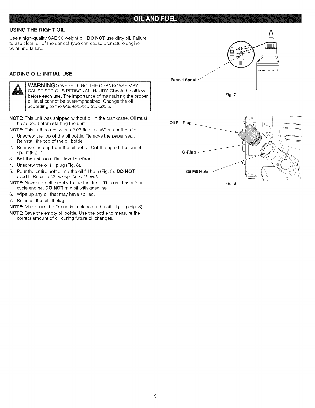
ADDING OIL: INITIAL USE
WARNING: OVERFILLING THE CRANKCASE MAY
CAUSE SERIOUS PERSONAL INJURY. Check the oil level
before each use. The importance of maintaining the proper
oil level cannot be overemphasized. Change the oil
according to the Maintenance Schedule.
Funnel Spout _(_ 4hCycle Motor Oil
Fig. 7
NOTE: This unit was shipped without oil in the crankcase. Oil must
be added before starting the unit.
NOTE: This unit comes with a 2.03 fluid oz. (60 ml) bottle of oil.
1. Unscrew the top of the oil bottle. Remove the paper seal.
Reinstall the top of the oil bottle.
2. Remove the cap from the oil bottle. Cut the tip off the funnel
spout (Fig. 7).
3. Set the unit on a fiat, level surface.
4. Unscrew the oil fill plug (Fig. 8).
5. Pour the entire bottle into the oil fill hole (Fig. 8). DO NOT
overfill. Refer to Checking the Oil Level.
NOTE: Never add oil directly to the fuel tank. This unit has a four-
cycle engine. DO NOT mix oil with gasoline.
6. Wipe up any oil that may have spilled.
7. Reinstall the oil fill plug.
NOTE: Make sure the O-ring is in place on the oil fill plug (Fig. 8).
NOTE: Save the empty oil bottle. Use the bottle to measure the
correct amount of oil during future oil changes.
Oil Fill Plug
O-Ring
OilFIllHole
Fig. 8
Ji! ti ii .....
9
USING THE RIGHT FUEL
The use of old fuel is the most common cause of performance
problems. Use only fresh, clean unleaded gasoline.
NOTE: This unit has a four-cycle engine. DO NOT mix oil with gasoline.
Definition of Blended Fuels
Today's fuels are often a blend of gasoline and oxygenates such as
ethanol, methanol or MTBE (ether). Alcohol-blended fuel absorbs
water. As little as 1% water in the fuel can make fuel and oil
separate, forming acids when stored. ALWAYS use fresh fuel (less
than 30 days old).
NOTE: Dispose of old fuel according to federal, state and local
regulations.
Using Blended Fuels
If using a blended fuel:
• Always use fresh unleaded gasoline
Use the fuel additive STA-BIL Qor an equivalent
Drain the tank and run the engine dry before storing the unit
__ IWARNING: DO NOT USE E85 FUEL IN THIS UNIT.
!
1
It has been proven that fuel containing greater than 10%
ethanol will likely damage this engine and void the warranty.
Using Fuel Additives
Use a fuel additive, such as STA-BIL Fuel Stabilizer or an
equivalent, to inhibit corrosion and minimize gum deposits. Add 0.8
oz. (23 ml) of fuel additive per gallon of fuel, according to the
instructions on the container. NEVER add fuel additives directly to
the unit's fuel tank.
FUELING THE UNiT
WARNING: Gasoline is extremely flammable, ignited
vapors may explode. Always stop the engine and allow it
to cool before filling the fuel tank. Do not smoke while
filling the tank. Keep sparks and open flames at a distance
from the area.
WARNING: Remove the fuel cap slowly to avoid injury
from fuel spray. Never operate the unit without the fuel cap
securely in place.
WARNING: Add fuel in a clean, well ventilated outdoor
area. Wipe up any spilled fuel immediately. Avoid creating
a source of ignition for spilled fuel. Do not start the engine
until fuel vapors dissipate.
1. Position the unit with the fuel cap facing up.
2. Remove the fuel cap.
3. Place the fuel container spout into the fill hole on the fuel tank
and fill the tank.
NOTE: Do not overfill the tank.
4. Wipe up any fuel that may have spilled.
5. Reinstall the fuel cap.
6. Move the unit at least 30 ft. (9.1 m) from the fuel container and
the fueling site before starting the engine.
10
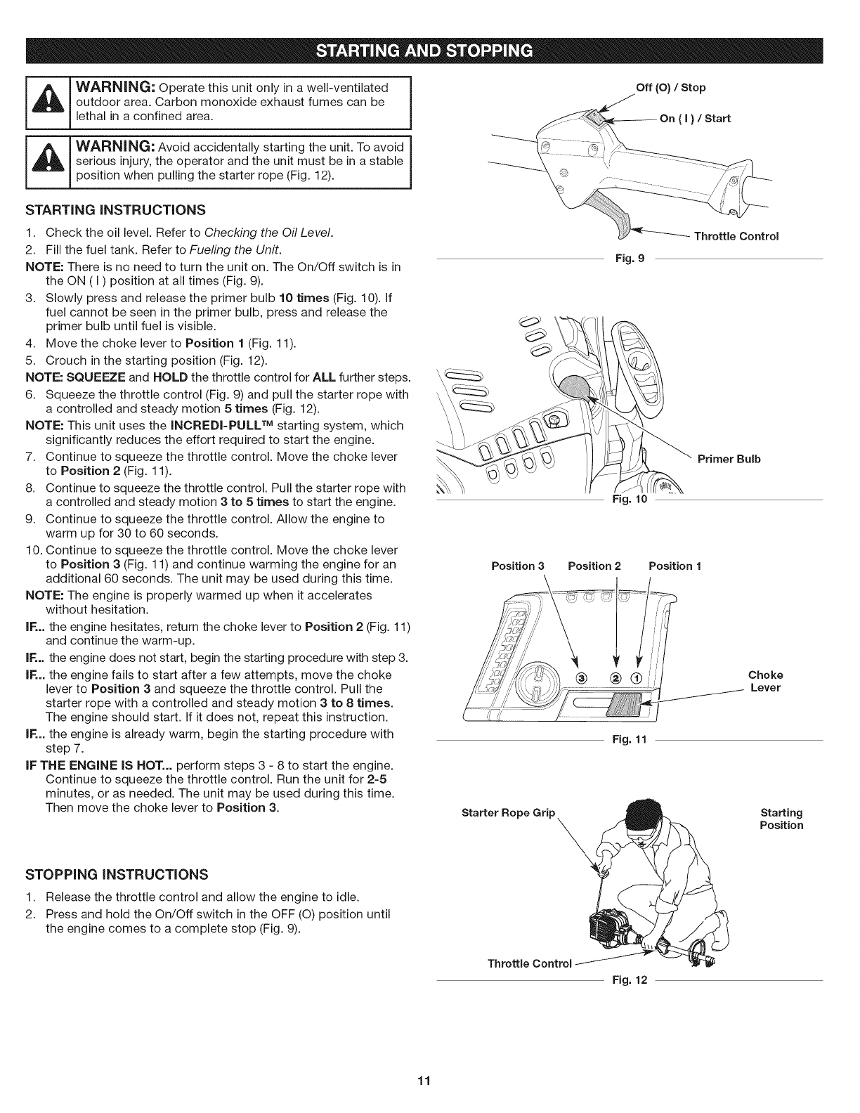
I_ I WARNING: Operate this unit only in a well-ventilated
!outdoor area. Carbon monoxide exhaust fumes can be
lethal in a confined area.
__ I WARNING: Avoid accidentally starting the unit. To avoid
serious injury, the operator and the unit must be in a stable J
position when pulling the starter rope (Fig. 12).
Off (O) /Stop
STARTING INSTRUCTIONS
1. Check the oil level. Refer to Checking the Oil Level.
2. Fill the fuel tank. Refer to Fueling the Unit.
NOTE: There is no need to turn the unit on. The On/Off switch is in
the ON (I) position at all times (Fig. 9).
3. Slowly press and release the primer bulb 10 times (Fig. 10). If
fuel cannot be seen in the primer bulb, press and release the
primer bulb until fuel is visible.
4. Move the choke lever to Position 1 (Fig. 11).
5. Crouch in the starting position (Fig. 12).
NOTE: SQUEEZE and HOLD the throttle control for ALL further steps.
6. Squeeze the throttle control (Fig. 9) and pull the starter rope with
a controlled and steady motion 5 times (Fig. 12).
NOTE: This unit uses the INCREDI-PULL TM starting system, which
significantly reduces the effort required to start the engine.
7. Continue to squeeze the throttle control. Move the choke lever
to Position 2 (Fig. 11).
8. Continue to squeeze the throttle control. Pull the starter rope with
a controlled and steady motion 3 to 5 times to start the engine.
9. Continue to squeeze the throttle control. Allow the engine to
warm up for 30 to 60 seconds.
10. Continue to squeeze the throttle control. Move the choke lever
to Position 3 (Fig. 11) and continue warming the engine for an
additional 60 seconds. The unit may be used during this time.
NOTE: The engine is properly warmed up when it accelerates
without hesitation.
IF... the engine hesitates, return the choke lever to Position 2 (Fig. 11)
and continue the warm-up.
IF... the engine does not start, begin the starting procedure with step 3.
IF... the engine fails to start after a few attempts, move the choke
lever to Position 3 and squeeze the throttle control. Pull the
starter rope with a controlled and steady motion 3 to 8 times.
The engine should start. If it does not, repeat this instruction.
IF... the engine is already warm, begin the starting procedure with
step 7.
IF THE ENGINE IS HOT... perform steps 3 - 8 to start the engine.
Continue to squeeze the throttle control. Run the unit for 2-5
minutes, or as needed. The unit may be used during this time.
Then move the choke lever to Position 3.
STOPPING INSTRUCTIONS
1. Release the throttle control and allow the engine to idle.
2. Press and hold the On/Off switch in the OFF (O) position until
the engine comes to a complete stop (Fig. 9).
Fig. 9
Fig. 10
Position 3 Position 2Position 1
Fig. 11
Starter Rope Grip_
Primer Bulb
Choke
Lever
Starting
Position
Throttle Control
Fig. 12
11
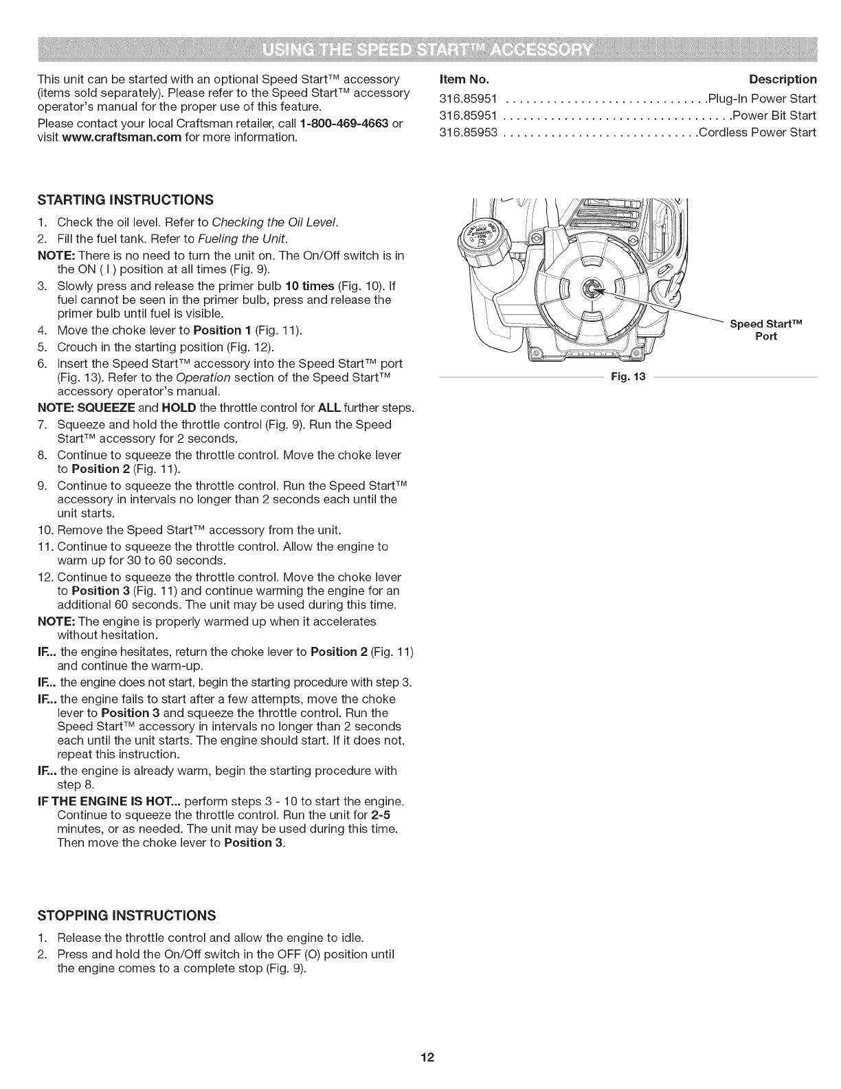
ThisunitcanbestartedwithanoptionalSpeedStartTM accessory
(items sold separately). Please refer to the Speed Start TM accessory
operator's manual for the proper use of this feature.
Please contact your local Craftsman retailer, call 1-800-469-4663 or
visit www.craftsman.com for more information.
item No. Description
316.85951 .............................. Plug-in Power Start
316.85951 .................................. Power Bit Start
316.85953 ............................. Cordless Power Start
STARTING iNSTRUCTiONS
1. Check the oil level. Refer to Checking the Oil Level.
2. Fill the fuel tank. Refer to Fueling the Unit.
NOTE: There is no need to turn the unit on. The On/Off switch is in
the ON (I) position at all times (Fig. 9).
3. Slowly press and release the primer bulb 10 times (Fig. 10). If
fuel cannot be seen in the primer bulb, press and release the
primer bulb until fuel is visible.
4. Move the choke lever to Position 1 (Fig. 11).
5. Crouch in the starting position (Fig. 12).
6. insert the Speed Start TM accessory into the Speed Start TM port
(Fig. 13). Refer to the Operation section of the Speed Start TM
accessory operator's manual.
NOTE: SQUEEZE and HOLD the throttle control for ALL further steps.
7. Squeeze and hold the throttle control (Fig. 9). Run the Speed
Start TM accessory for 2 seconds.
8. Continue to squeeze the throttle control. Move the choke lever
to Position 2 (Fig. 11).
9. Continue to squeeze the throttle control. Run the Speed Start TM
accessory in intervals no longer than 2 seconds each until the
unit starts.
10. Remove the Speed Start TM accessory from the unit.
11. Continue to squeeze the throttle control. Allow the engine to
warm up for 30 to 60 seconds.
12. Continue to squeeze the throttle control. Move the choke lever
to Position 3 (Fig. 11) and continue warming the engine for an
additional 60 seconds. The unit may be used during this time.
NOTE: The engine is properly warmed up when it accelerates
without hesitation.
iF... the engine hesitates, return the choke lever to Position 2 (Fig. 11)
and continue the warm-up.
iF... the engine does not start, begin the starting procedure with step 3.
iF... the engine fails to start after a few attempts, move the choke
lever to Position 3 and squeeze the throttle control. Run the
Speed Start TM accessory in intervals no longer than 2 seconds
each until the unit starts. The engine should start. If it does not,
repeat this instruction.
iF... the engine is already warm, begin the starting procedure with
step 8.
iF THE ENGINE IS HOT... perform steps 3 - 10 to start the engine.
Continue to squeeze the throttle control. Run the unit for 2-5
minutes, or as needed. The unit may be used during this time.
Then move the choke lever to Position 3.
Fig. 13
_il"i
......._------- Speed Start TM
Port
STOPPING INSTRUCTIONS
1. Release the throttle control and allow the engine to idle.
2. Press and hold the On/Off switch in the OFF (O) position until
the engine comes to a complete stop (Fig. 9).
12
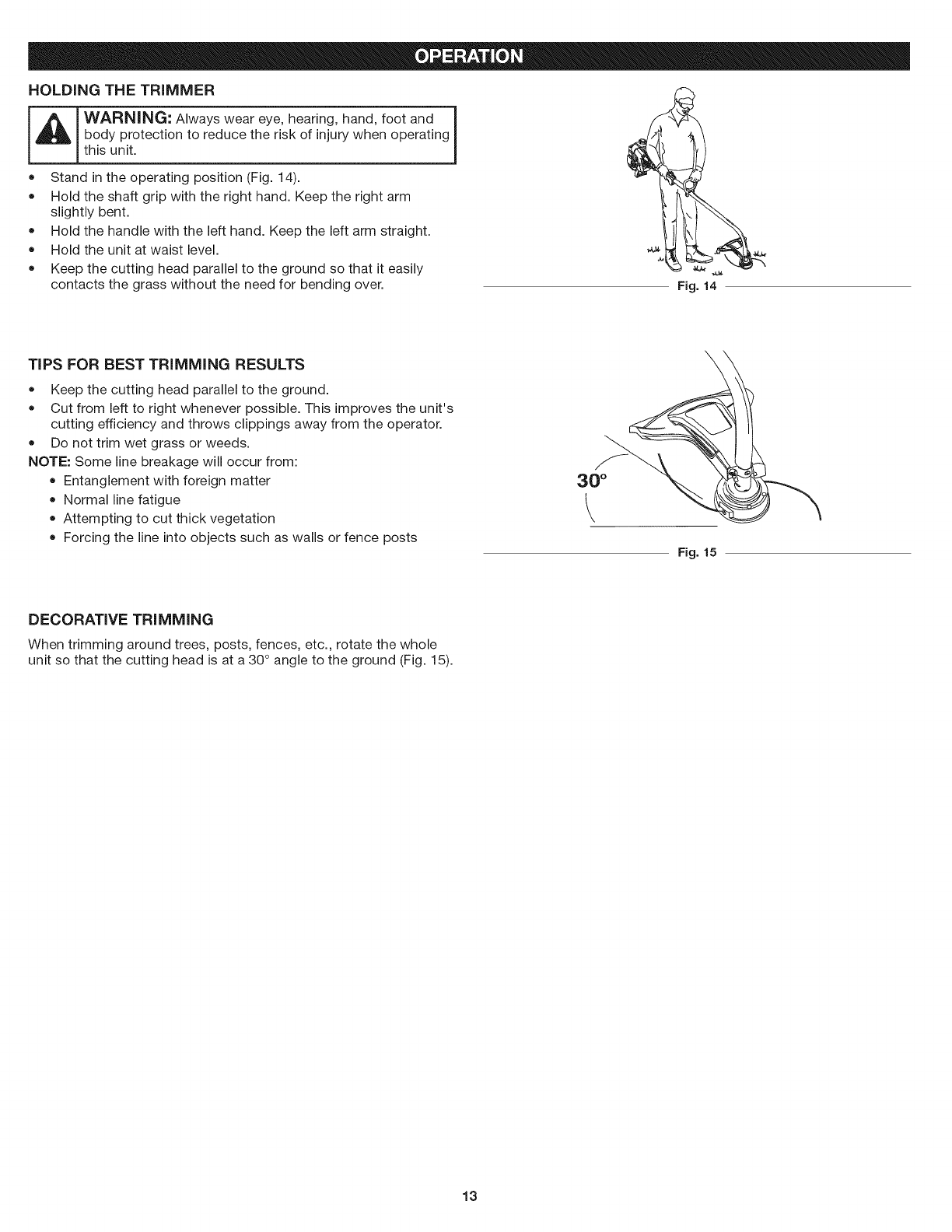
HOLDINGTHE TRIMMER
WARNING: Always wear eye, hearing, hand, foot and I
body protection to reduce the risk of injury when operating|
this unit. J
• Stand in the operating position (Fig. 14).
Hold the shaft grip with the right hand. Keep the right arm
slightly bent.
Hold the handle with the left hand. Keep the left arm straight.
Hold the unit at waist level. ,44_
Keep the cutting head parallel to the ground so that it easily
contacts the grass without the need for bending over. Fig. 14
TiPS FOR BEST TRiMMiNG RESULTS
= Keep the cutting head parallel to the ground.
Cut from left to right whenever possible. This improves the unit's
cutting efficiency and throws clippings away from the operator.
Do not trim wet grass or weeds.
NOTE: Some line breakage will occur from:
Entanglement with foreign matter
Normal line fatigue
Attempting to cut thick vegetation
Forcing the line into objects such as walls or fence posts
\
Fig. 15
DECORATIVE TRIMMING
When trimming around trees, posts, fences, etc., rotate the whole
unit so that the cutting head is at a 30 ° angle to the ground (Fig. 15).
13
WARNING: To prevent serious injury, never perform
maintenance or repairs while the unit is running. Always
allow the unit to cool before servicing or repairing the unit.
Disconnect the spark plug wire to prevent the unit from
starting accidentally.
MAINTENANCE SCHEDULE
Perform these required maintenance procedures at the frequency
stated in the table. These procedures should also be a part of any
seasonal tune-up.
NOTE: Some maintenance procedures may require special tools or
skills. If unsure about these procedures, take the unit to a Sears
or other qualified service dealer. Call 1-800-469-4863 for more
information.
NOTE: Maintenance, replacement, or repair of the emission control
devices and system may be performed by a Sears or other qualified
service dealer. Call 1-800-469-4663 for more information.
NOTE: Please read the California/EPA statement that came with the
unit for a complete listing of terms and coverage for the
emissions control devices, such as the spark arrestor, muffler,
carburetor, etc.
FREQUENCY
Every 10 hours
After the first
10 hours and
at 38 hours
MAINTENANCE REQUIRED
• Clean and re-oil the air filter. Refer to
Maintaining the Air Filter.
Change the oil. Refer to Changing the Oil.
Have the rocker arm clearance checked by
a Sears or other qualified service dealer.
Check the spark plug condition and gap.
Refer to Maintaining the Spark Plug.
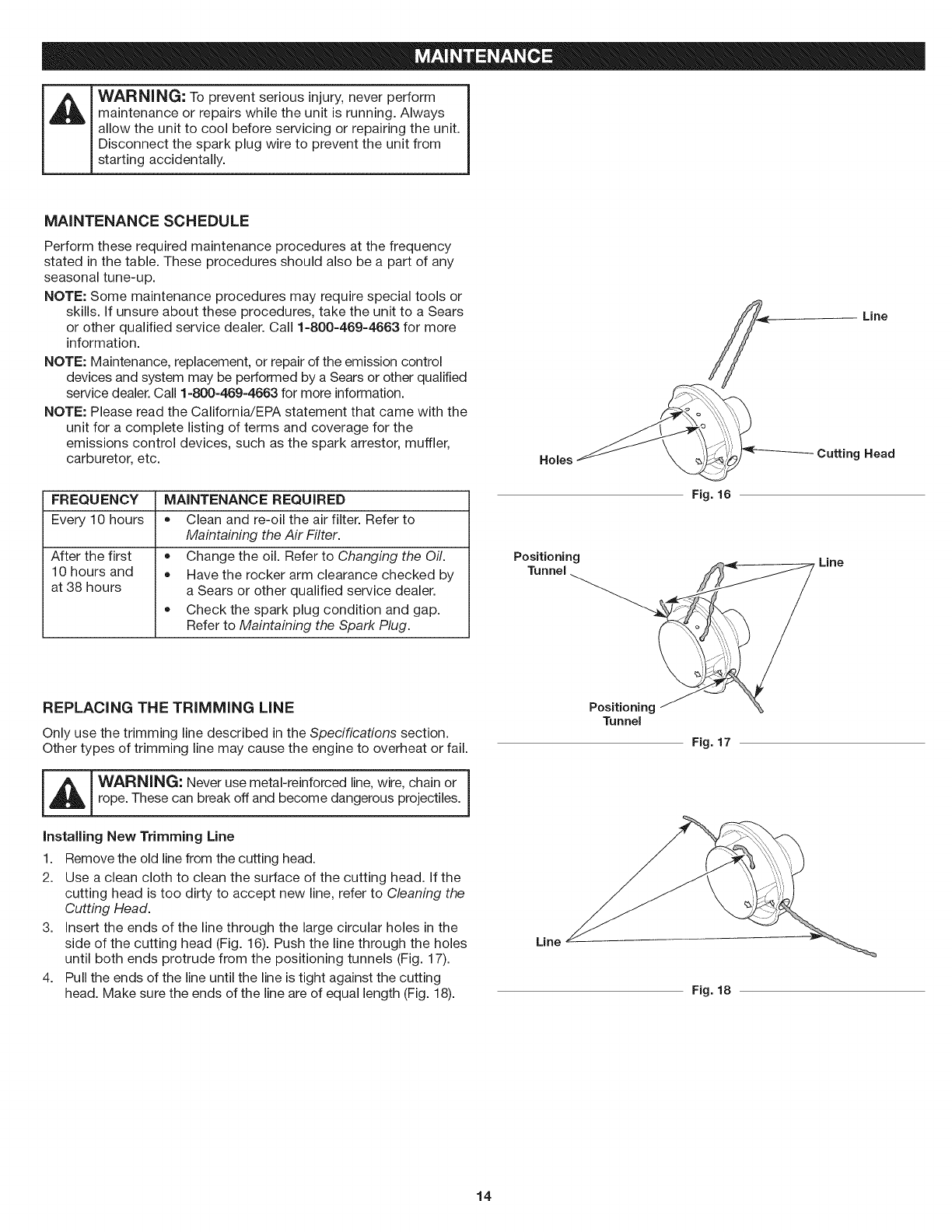
REPLACING THE TRiMMiNG LiNE
Only use the trimming line described in the Specifications section.
Other types of trimming line may cause the engine to overheat or fail.
_ WARNING: Never use metal-reinforced line, wire, chain or
|
rope. These can break off and become dangerous projectiles. ]
Installing New Trimming Line
1. Remove the old line from the cutting head.
2. Use a clean cloth to clean the surface of the cutting head. If the
cutting head is too dirty to accept new line, refer to Cleaning the
Cutting Head.
3. Insert the ends of the line through the large circular holes in the
side of the cutting head (Fig. 16). Push the line through the holes
until both ends protrude from the positioning tunnels (Fig. 17).
4. Pull the ends of the line until the line is tight against the cutting
head. Make sure the ends of the line are of equal length (Fig. 18).
Line
Holes
Fig. 16
Cutting Head
Positioning
Tunnel _//_ _ Line
Positioning __
Tunnel
Fig. 17
Line
Fig. 18
14
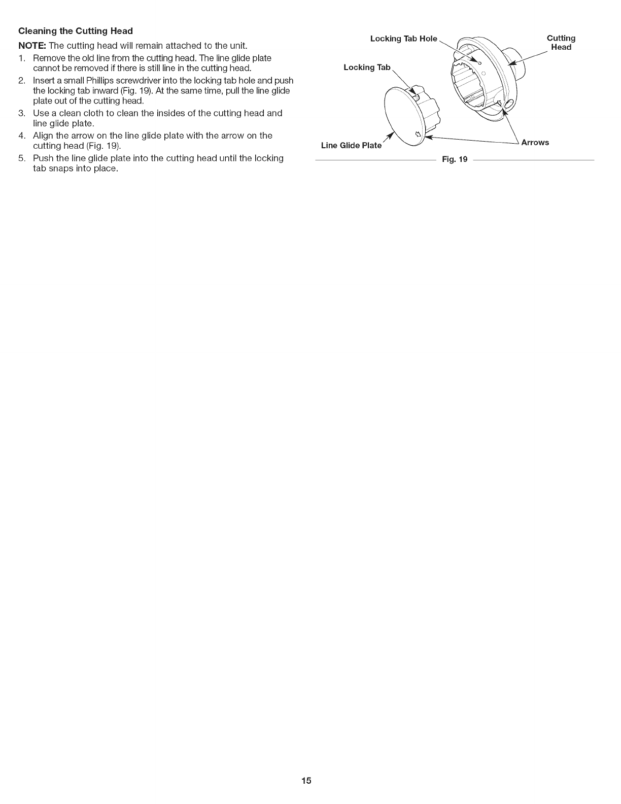
CleaningtheCuttingHead
NOTE: The cutting head will remain attached to the unit.
1. Remove the old line from the cutting head. The line glide plate
cannot be removed if there is still line in the cutting head.
2. Insert a small Phillips screwdriver into the locking tab hole and push
the locking tab inward (Fig. 19). At the same time, pull the line glide
plate out of the cutting head.
3. Use a clean cloth to clean the insides of the cutting head and
line glide plate.
4. Align the arrow on the line glide plate with the arrow on the
cutting head (Fig. 19).
5. Push the line glide plate into the cutting head until the locking
tab snaps into place.
Locking Tab Hole_
Locking Tab_ __
Line Glide Plate/' _-_/-
Fig. 19
Cutting
Head
15
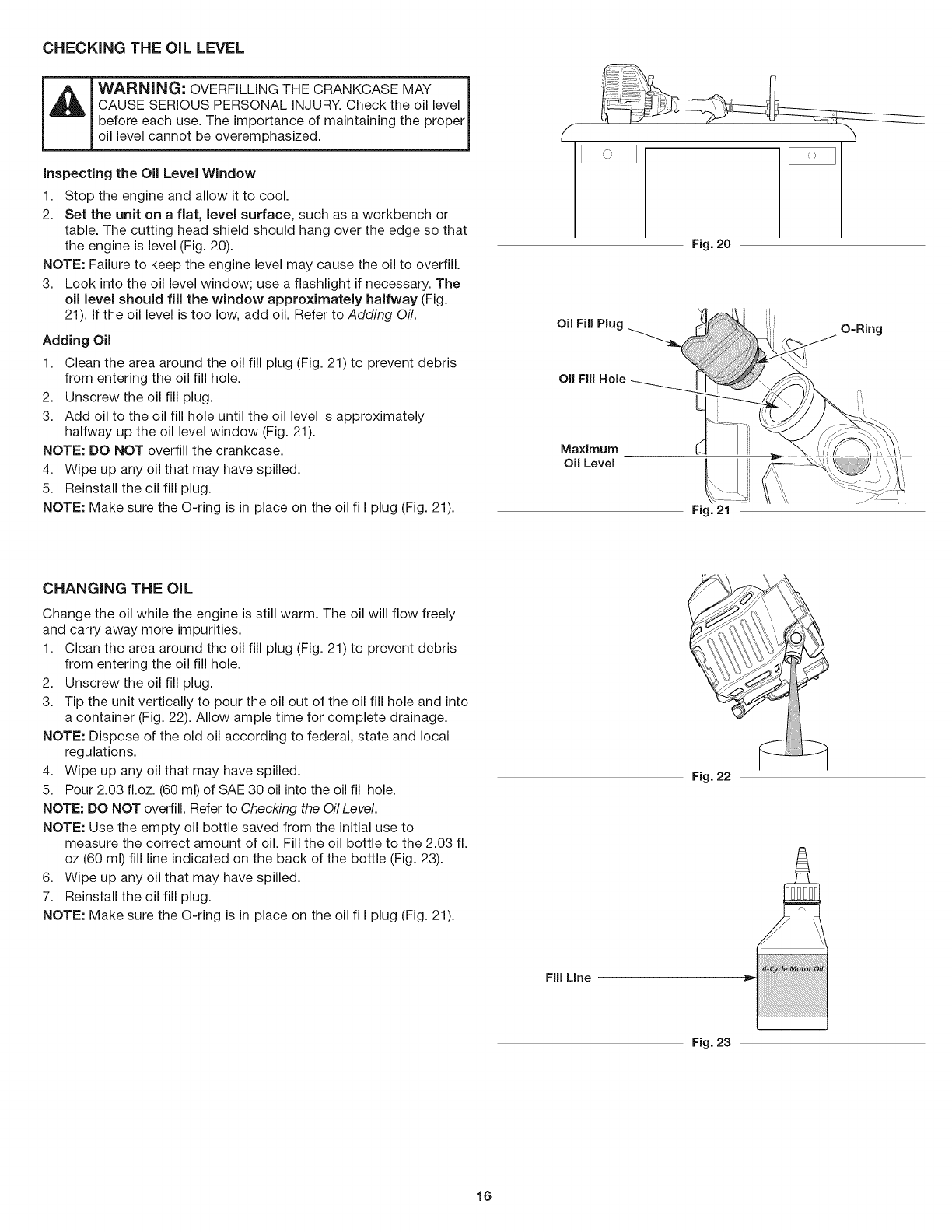
CHECKING THE OiL LEVEL
WARNING: OVERFiLLiNG THE CRANKCASE MAY
CAUSE SERIOUS PERSONAL iNJURY. Check the oil level
before each use. The importance of maintaining the proper
oil level cannot be overemphasized.
inspecting the Oil Level Window
1. Stop the engine and allow it to cool.
2. Set the unit on a flat, level surface, such as a workbench or
table. The cutting head shield should hang over the edge so that
the engine is level (Fig. 20).
NOTE: Failure to keep the engine level may cause the oil to overfill.
3. Look into the oil level window; use a flashlight if necessary. The
oil level should fill the window approximately halfway (Fig.
21). If the oil level is too low, add oil. Refer to Adding Oil.
Adding Oil
1. Clean the area around the oil fill plug (Fig. 21) to prevent debris
from entering the oil fill hole.
2. Unscrew the oil fill plug.
3. Add oil to the oil fill hole until the oil level is approximately
halfway up the oil level window (Fig. 21).
NOTE: DO NOT overfill the crankcase.
4. Wipe up any oil that may have spilled.
5. Reinstall the oil fill plug.
NOTE: Make sure the O-ring is in place on the oil fill plug (Fig. 21).
Fig. 20
Oil Fifl Plu{
Oil Fifl Hole
Maximum
Oil Level
Fig. 21
O=Ring
CHANGING THE OiL
Change the oil while the engine is still warm. The oil will flow freely
and carry away more impurities.
1. Clean the area around the oil fill plug (Fig. 21) to prevent debris
from entering the oil fill hole.
2. Unscrew the oil fill plug.
3. Tip the unit vertically to pour the oil out of the oil fill hole and into
a container (Fig. 22). Allow ample time for complete drainage.
NOTE: Dispose of the old oil according to federal, state and local
regulations.
4. Wipe up any oil that may have spilled.
5. Pour 2.03 fl.oz. (60 ml) of SAE 30 oil into the oil fill hole.
NOTE: DO NOT overfill. Refer to Checking the Oil Level.
NOTE: Use the empty oil bottle saved from the initial use to
measure the correct amount of oil. Fill the oil bottle to the 2.03 fl.
oz (60 ml) fill line indicated on the back of the bottle (Fig. 23).
6. Wipe up any oil that may have spilled.
7. Reinstall the oil fill plug.
NOTE: Make sure the O-ring is in place on the oil fill plug (Fig. 21).
Fig. 22
Fig. 23
16
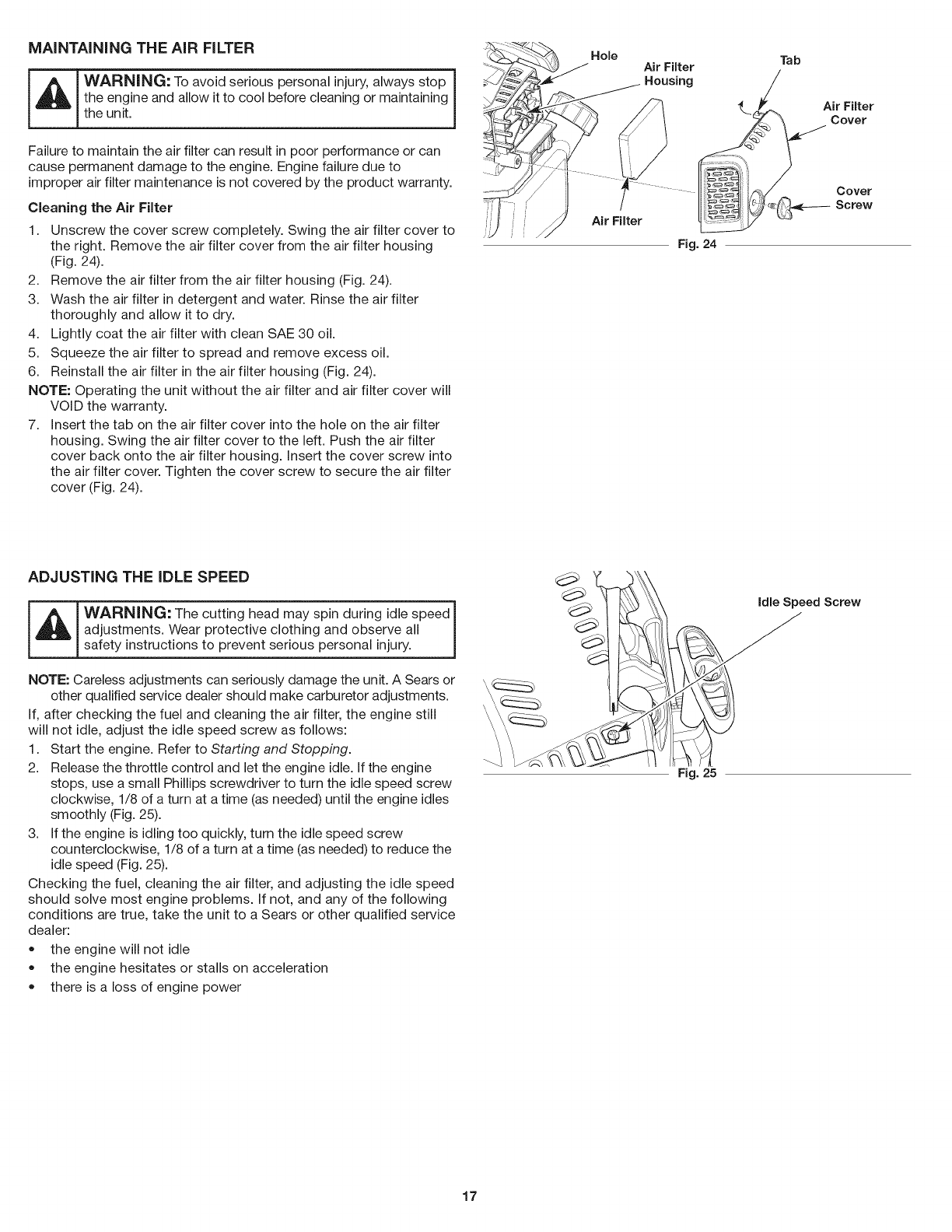
MAiNTAiNiNG THE AiR FILTER
WARNING: To avoid serious personal injury, always stop |
the engine and allow it to cool before cleaning or maintaining J
the unit.
Failure to maintain the air filter can result in poor performance or can
cause permanent damage to the engine. Engine failure due to
improper air filter maintenance is not covered by the product warranty.
Cleaning the Air Filter
1. Unscrew the cover screw completely. Swing the air filter cover to
the right. Remove the air filter cover from the air filter housing
(Fig. 24).
2. Remove the air filter from the air filter housing (Fig. 24).
3. Wash the air filter in detergent and water. Rinse the air filter
thoroughly and allow it to dry.
4. Lightly coat the air filter with clean SAE 30 oil.
5. Squeeze the air filter to spread and remove excess oil.
6. Reinstall the air filter in the air filter housing (Fig. 24).
NOTE: Operating the unit without the air filter and air filter cover will
VOiD the warranty.
7. insert the tab on the air filter cover into the hole on the air filter
housing. Swing the air filter cover to the left. Push the air filter
cover back onto the air filter housing. Insert the cover screw into
the air filter cover. Tighten the cover screw to secure the air filter
cover (Fig. 24).
Hole
Air Filter
Air Filter
Fig. 24
Tab
Air Filter
Cover
Cover
Screw
ADJUSTING THE iDLE SPEED
WARNING: The cutting head may spin during idle speed I
adjustments. Wear protective clothing and observe all
safety nstruct ons to prevent serous persona njury, j
NOTE: Careless adjustments can seriously damage the unit. A Sears or
other qualified service dealer should make carburetor adjustments.
if, after checking the fuel and cleaning the air filter, the engine still
will not idle, adjust the idle speed screw as follows:
1. Start the engine. Refer to Starting and Stopping.
2. Release the throttle control and let the engine idle. if the engine
stops, use a small Phillips screwdriver to turn the idle speed screw
clockwise, 1/8 of a turn at a time (as needed) until the engine idles
smoothly (Fig. 25).
3. if the engine is idling too quickly, turn the idle speed screw
counterclockwise, 1/8 of a turn at a time (as needed) to reduce the
idle speed (Fig. 25).
Checking the fuel, cleaning the air filter, and adjusting the idle speed
should solve most engine problems, if not, and any of the following
conditions are true, take the unit to a Sears or other qualified service
dealer:
• the engine will not idle
the engine hesitates or stalls on acceleration
there is a loss of engine power
Fig. 25
17
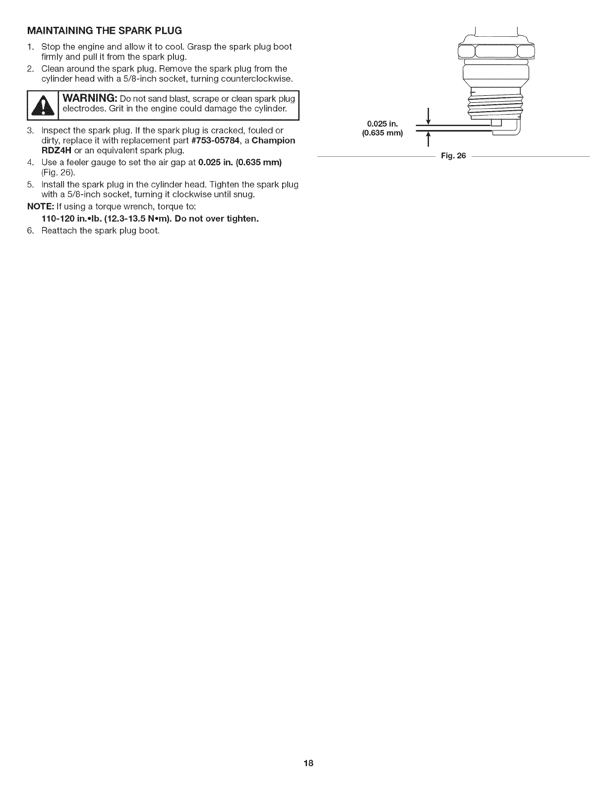
MAiNTAiNiNG THE SPARK PLUG
1. Stop the engine and allow it to cool. Grasp the spark plug boot
firmly and pull it from the spark plug.
2. Clean around the spark plug. Remove the spark plug from the
cylinder head with a 5/8-inch socket, turning counterclockwise.
_ WARNING: Do not sand blast, scrape or clean spark plug
|
electrodes. Grit in the engine could damage the cylinder. J
3. inspect the spark plug. If the spark plug is cracked, fouled or
dirty, replace it with replacement part #753-05784, a Champion
RDZ4H or an equivalent spark plug.
4. Use a feeler gauge to set the air gap at 0.025 in. (0.635 ram}
(Fig. 26).
5. install the spark plug in the cylinder head. Tighten the spark plug
with a 5/8-inch socket, turning it clockwise until snug.
NOTE: If using a torque wrench, torque to:
110-120 in..lb. (12.3-13.5 Nora}. Do not over tighten.
6. Reattach the spark plug boot.
0.025 in.
(0.635 ram}
\
Fig. 26
18
CLEANING
WARNING" To avoid serious personal injury, always stop
the engine and allow it to cool before cleaning or maintaining ]
the unit.
Use a small brush to clean the outside of the unit. Do not use strong
detergents. Household cleaners that contain aromatic oils such as
pine and lemon, and solvents such as kerosene, can damage plastic.
Wipe off any moisture with a soft cloth.
STO RAG E
• Never store a fueled unit where fumes may reach an open flame
or spark.
Allow the engine to cool before storing.
Lock up the unit to prevent unauthorized use or damage.
Store the unit in a dry, well-ventilated area.
Store the unit out of the reach of children.
Short-term Storage (1-2 weeks)
1. Store the unit in a horizontal position. If this is not possible, store
the unit vertically with the engine at the top.
Long-term Storage
1. Remove the fuel cap, tip the unit and drain the fuel into an
approved container. Reinstall the fuel cap.
2. Start the engine and allow it to run until it stalls. This ensures
that all fuel has been drained from the carburetor.
3. Allow the engine to cool. Remove the spark plug and put 5 drops
of any high quality motor oil into the cylinder. Pull the starter rope
slowly to distribute the oil. Reinstall the spark plug.
4. Thoroughly clean the unit and inspect it for any loose or
damaged parts. Repair or replace damaged parts and tighten
loose screws, nuts or bolts.
Preparing the Unit for Use after Long=term Storage
1. Remove the spark plug and drain all of the oil from the cylinder.
2. Change the oil. Refer to Changing the Off.
NOTE: Do not use fuel that has been stored for more than 30 days.
Dispose of old fuel according to federal, state and local regulations.
19

PROBLEM
The primer bulb was not pressed enough
The spark plug is fouled
SOLUTION
Press the primer bulb 10 times or until fuel is visible
Replace the spark plug
The fuel is old (over 30 days)
The fuel is old (over 30 days)
The air filter is dirty
,=i iI II
The fuel is old (over 30 days)
The spark plug is fouled
Drain the fuel tank and add fresh fuel
Drain the fuel tank and add fresh fuel
Clean or replace the air filter
Drain the fuel tank and add fresh fuel
Replace the spark plug
2O

Congratulations on making a smart purchase. Your new Craftsman® product is designed and manufactured for years of dependable
operation. But like all products, it may require repair from time to time. That's when having a Repair Protection Agreement can save you
money and aggravation.
Here's what the Repair Protection Agreement* includes:
[] Expert service by our 10,000 professional repair specialists
[] Unlimited service and no charge for parts and labor on all covered repairs
[] Product replacement up to $1500 if your covered product can't be fixed
[] Discount of 25% from regular price of service and related installed parts not covered by the agreement; also, 25% off regular price of
preventive maintenance check
[] Fast help by phone -we call it Rapid Resolution - phone support from a Sears representative. Think of us as a "talking owner's manual."
Once you purchase the Repair Protection Agreement, a simple phone call is all that it takes for you to schedule service. You can call anytime
day or night, or schedule a service appointment online.
The Repair Protection Agreement is a risk-free purchase. If you cancel for any reason during the product warranty period, we will provide a
full refund. Or, a prorated refund anytime after the product warranty period expires. Purchase your Repair Protection Agreement today!
Some limitations and exclusions apply. For prices and additional information in the U.S.A. call 1-800-827-6655.
*Coverage in Canada varies on some items. For full details call Sears Canada at 1-800-361-6665.
Sears Instaflation Service
For Sears professional installation of home appliances, garage door openers, water heaters, and other major home items, in the U.S.A. or
Canada call 1-800-4-MY-HOME.
21

22
Manual del Operador
M
Motor de 4 tiernpos
Con Posibilidad de Arranque El_ctrico
RECORTADOR WEEDWACKER_ A GASOLINA
Modelo No. 316.731700
U_F_VABLE $7_A_T_G EA $ E _
PRECAUCION: Antes de utilizar, este
producto lea este manual y siga todas
las reglas de seguridad einstrucciones
de operaci6n.
o SEGURIDAD
o ENSAMBLAJE
o OPERACION
o MANTENIMIENTO
LISTA DE PIEZAS
Sears Brands Management Corporation, Hoffman Estates, IL 60179 U.S.A.
Visite nuestro sitio web: www.craftsrnan.corn
769-08739 /00 12/12
iNDICE
Seguridad........................................... 24
Garantia............................................. 28
Conozcasuunidad.................................... 29
Especificaciones...................................... 29
Montaje............................................. 30
Aceiteycombustible................................... 32
Arranquey detenci6n.................................. 34
Funcionamiento....................................... 36
Mantenimiento........................................ 37
Limpiezayalmacenamiento............................. 42
Soluci6ndeProblemas................................. 43
Conveniodeprotecci6ndereparaci6n..................... 44
Listadepiezas....................................... 46
NQmerosdeservicio......................... Contraportada
Todalainformaci6n,lasilustracionesylasespecificacionesquese
incluyenenelpresentemanualsebasanenlainformaci6nmas
recientesobreelproductodisponiblealmomentodelaimpresi6n.
Nosreservamoselderechoarealizarcambiosencualquiermomento
sinprevioaviso.
©SeamBrands,LLC
Elobjetivodelossimbolosdeseguridadesdirigirsuatenci6nhacia
posiblespeligros.Lossimbolosdeseguridad,asicomosus
explicaciones,necesitansuatenci6ny comprensi6ncompletas.Las
advertenciasdeseguridadnoeliminanporsimismasningQn
peligro.Lasinstruccionesoadvertenciasquecontienenno
reemplazanalasmedidasadecuadasdeprevenci6ndeaccidentes.
SJMBOLOSSIGNIFICADO
[_._ ELIGRO: Indica un peligro EXTREMO.
Si no se cumple una advertencia de seguridad de
PELIGRO usted mismo u otras personas sufriran lesiones
graves o la muerte.
_ DVERTENCIA: Indica un peligro GRAVE.
Si no se cumple una ADVERTENOIA de seguridad usted
mismo u otras personas PUEDEN sufrir lesiones graves.
PRECAUClON: Indica un peligro de GRAVEDAD
MODERADA.
Si no se cumple una serial de seguridad de PREOAUOION
usted mismo o a otras personas PUEDEN sufrir lesiones o
se PUEDEN producir dafios materiales.
NOTA: Proporciona informaci6n o instrucciones de vital importancia
para el funcionamiento o el mantenimiento del equipo.
NOTA SOBRE EL AMORTIGUADOR DE CHISPAS
NOTA: Para usuarios de los territorios de bosques de EE. UU. y
de los estados de California, Maine, Oregon y Washington.
Todos los territorios de bosques de EE. UU. y los estados de
California (C6digos de Recursos PQblicos 4442 y 4443), Oregon y
Washington exigen por ley, que determinados motores de
combusti6n interna que se operan en zonas cubiertas por malezas
de bosque y/o hierbas cuenten con un amortiguador de chispas
que se debera mantener en condiciones de uso adecuadas o que el
motor se disefie, equipe y mantenga para prevenir incendios.
Corrobore con las autoridades estatales o locales cuales son las
normativas correspondientes a dichas exigencias. El
incumplimiento de dichos requerimientos podria generarle una
responsabilidad o una multa. La presente unidad se equipa en la
f_brica con un amortiguador de chispas. El reemplazo requiere la
pieza No. 753-08052 del conjunto del silenciador, instalada en un
Centro de Piezas y Servicio de Reparaciones de Sears.
PROPOSICION 65 DE CALIFORNIA
ADVERTENClA: El escape del motor de este producto,
algunos de sus componentes y algunos componentes
terminados contienen o liberan sustancias quimicas que el
estado de California considera que pueden producir
cancer, defectos de nacimiento u otros problemas
reproductivos. Lavese las manos despues de estar en
contacto con estos componentes.
Lea el manual del operador y siga todas las advertencias e
instrucciones de seguridad. Si no Io hace, el operador y/o los
observadores pueden sufrir lesiones graves.
24
•INSTRUCCIONES DE SEGURIDAD IMPORTANTES •
LEA TODAS LAS INSTRUCCIONES ANTES DE USAR LA
UNIDAD
I'l
o
o
o
o
o
o
o
ADVERTENCIA: Se deben respetar todas las normas
de seguridad al usar la unidad. Pot favor, lea estas
instrucciones antes de utilizar la unidad para garantizar la
seguridad del operador y los observadores. Por favor,
guarde estas instrucciones para su uso posterior.
Lea las instrucciones con atenci6n. Debe familiarizarse con los
controles y con el uso apropiado de la unidad.
No opere esta unidad siesta cansado, enfermo o bajo la
influencia de alcohol, drogas o medicamentos.
La unidad no debe set utilizada pot nidos. Los adolescentes
deben contar con la compadia y guia de un adulto.
Se deben instalar correctamente todos los protectores y
accesorios de seguridad antes de operar la unidad.
Inspeccione la unidad antes de usarla. Reemplace las piezas
dadadas. Compruebe si hay perdidas de combustible.
Compruebe que todas las sujeciones esten en su lugar y bien
ajustadas. Reemplace las piezas que esten agrietadas,
astilladas o dadadas de cualquier manera. No utilice la unidad si
hay piezas sueltas o dadadas.
Use Onicamente el hilo de recorte que se describe en la secci6n
Especificaciones de este manual. Nunca use un hilo, un cable,
una cadena o una cuerda de metal reforzados. Podrian
separarse y convertirse en proyectiles peligrosos.
Tenga en cuenta el riesgo de lesiones en la cabeza, las manos y
los pies.
Inspeccione el Area con atenci6n antes de arrancar la unidad.
Extraiga las rocas, los vidrios rotos, los clavos, los cables,
cordeles y demas objetos que podrian ser arrojados o enredarse
en la unidad.
Despeje la zona de nidos, observadores y mascotas;
mantengalos fuera de un radio de 50 pies (15 m), como minimo.
Incluso a esa distancia, sigue el riesgo de ser alcanzados pot
los objetos arrojados por el aire. Sugierales a los observadores
que usen protecci6n ocular. Si alguien se le aproxima, detenga
la unidad de inmediato.
Apriete el control del acelerador y verifique que vuelva
automaticamente a la posici6n de ralenti. Realice todos los
ajustes o las reparaciones antes de usar la unidad.
ADVERTENCIAS DE SEGURIDAD PARA LAS UNIDADES
AGASOLINA
__ I ADVERTENCIA: La gasolina es sumamente inflamable
y sus vapores pueden exp otar s se eric enden. Adopte asl
siguientes precauciones: J
• Almacene el combustible Onicamente en recipientes disedados
especificamente y aprobados para el almacenamiento de dichos
materiales.
Detenga siempre el motor y dejelo enfriar antes de Ilenar el
dep6sito. Nunca retire la tapa del dep6sito de combustible ni
agregue combustible cuando el motor este caliente. Afloje siempre
lentamente la tapa del dep6sito de combustible para descargar la
presi6n que haya en el dep6sito antes de recargar combustible.
Agregue siempre combustible en una zona al aire libre, limpia y
bien ventilada, en la que no haya chispas ni llamas. NO fume.
Nunca opere la unidad si la tapa del combustible no esta bien
sujeta en su lugar.
Evite que se genere una fuente de encendido para el
combustible derramado. Limpie de inmediato el combustible
derramado de la unidad, antes de encenderla. Mueva la unidad
al menos 30 pies (9.1m) de la fuente de combustible y del sitio
antes de arrancar el motor. NO fume.
Nunca arranque ni use la unidad dentro de una habitaci6n o de
una construcci6n cerrada. La inhalaci6n de humos de escape
puede ser mortal. Opere esta unidad Onicamente en una zona
bien ventilada, al aire libre.
DURANTE LA OPERACION
Utilice anteojos o antiparras de seguridad que cumplan con las
normas ANSI Z87.1 vigentes y que tengan la identificaci6n
correspondiente. Utilice una protecci6n auditiva al operar esta
unidad. Utilice una mascara facial o para polvos si la maquina
levanta polvo durante su funcionamiento.
Use pantalones largos y gruesos, botas, guantes y camisa de
mangas largas. No use ropa holgada, alhajas, pantalones
cortos, sandalias ni ande descalzo. Sujetese el cabello a nivel de
los hombros.
El protector del cabezal de corte siempre debe estar colocado
mientras se opera la unidad. No utilice la unidad si no estan
extendidos ambos hilos de recorte y si no esta instalado el hilo
adecuado. No extienda el hilo de recorte mas alia de la Iongitud
del protector.
Esta unidad tiene un embrague. El cabezal de corte permanece
fijo cuando el motor esta en ralenti. De no hacerlo, Ileve la unidad
a Sears o a otro distribuidor de servicio calificado para su ajuste.
Ajuste la manija para que brinde el mejor agarre.
• Compruebe que el accesorio no este en contacto con nada
antes de poner en marcha la unidad.
Use la unidad solamente con luz de dia o con una buena luz artificial.
Evite arranques accidentales. Permanezca en la posici6n de
arranque siempre que tire de la cuerda de arranque. El operador
y la unidad deben estar en una posici6n estable durante el
arranque. Consulte Arranque y Parada
Utilice la herramienta apropiada. Use esta herramienta s61o para
el prop6sito para el que fue disedada.
Sostenga siempre la unidad con ambas manos durante la
operaci6n. Sostenga firmemente ambas manijas o empu5aduras.
No se extienda demasiado. Siempre debe estar bien afirmado y
mantener el equilibrio adecuado. Tenga cuidado al trabajar en
pendientes o inclinaciones empinadas.
Mantenga las manos, el rostro y los pies alejados de todas las
piezas m6viles. No toque ni intente detener las piezas m6viles.
No toque el motor, el alojamiento del engranaje ni el silenciador.
Estas partes se ponen extremadamente calientes pot el
funcionamiento, incluso despues de que se apaga la unidad.
No opere la unidad a una velocidad mayor a la necesaria para la
tarea. No haga funcionar la unidad a alta velocidad cuando no
esta en uso.
No exija demasiado a la unidad. Si se usa a la velocidad para la
que fue disedada, realizara un trabajo mas eficiente y seguro.
Detenga siempre la unidad cuando la operaci6n este demorada
o cuando camine de un lugar a otto.
Si golpea un objeto extra5o o si este se engancha en la unidad,
detengala de inmediato y controle si se produjeron dados. No
utilice la unidad hasta haber reparado el dado. No utilice la
unidad si hay piezas sueltas o dadadas.
Apague el motor y desconecte la bujia para realizar tareas de
mantenimiento o reparaci6n.
25
• Utilicesolamentelaspiezasderepuestoy accesoriosdel
fabricanteoriginal(OEM)queselistanenlasecci6nLista de
piezas de este manual. Si usa cualquier otra pieza o accesorio,
el usuario podria lesionarse gravemente o la unidad podria
da_arse y se anularia la garantia.
Mantenga limpia la unidad. Quite con cuidado cualquier resto de
vegetaci6n u otros residuos que puedan bloquear las piezas m6viles.
A fin de reducir el riesgo de incendio, reemplace el silenciador y
el amortiguador de chispas si estan averiados. Mantenga el
motor y el silenciador libres de hierbas, hojas y de la
acumulaci6n excesiva de grasa o de carbono.
Si la unidad comienza a vibrar en forma anormal, detengala de
inmediato. Inspeccione la unidad para determinar la causa de la
vibraci6n. La vibraci6n por Io general indica que hay algQn problema.
OTRAS ADVERTENCIAS DE SEGURIDAD
Todos los servicios, que no sean los procedimientos de
mantenimiento descritos en este manual, deberan realizarse por
un centro de Sears u otto centro de servicio calificado.
Antes de inspeccionar, limpiar, guardar o transportar la unidad, o
de hacer tareas de reparaci6n o mantenimiento o reemplazar
alguna de sus piezas:
1. Detenga la unidad.
2. AsegQrese de que se hayan detenido todas las piezas m6viles.
3. Deje que la unidad se enfrie.
4. Desconecte el cable de la bujia.
Sujete la unidad durante el transporte.
Nunca almacene la unidad con combustible en el dep6sito, en el
interior de una construcci6n donde las emanaciones puedan
alcanzar una llama abierta (luces piloto, etc.) o chispas
(interruptores, motores electricos, etc.).
Almacene la unidad en un lugar seco, asegurada o a una altura
que evite que se la use sin autorizaci6n o se la da_e. Mantenga
la unidad lejos del alcance de los ni_os.
Nunca rocie ni arroje chorros de agua ni de ningQn otto liquido a la
unidad. Mantenga las manijas secas, limpias y sin residuos. Limpie
la unidad luego de cada uso. Consulte Limpieza y almacenamiento.
Guarde estas instrucciones. ConsQltelas con frecuencia y Qselas
para capacitar a otros usuarios. Si le presta esta unidad a otras
personas, tambien debe prestarles estas instrucciones.
GUARDE ESTAS INSTRUCCIONES
26
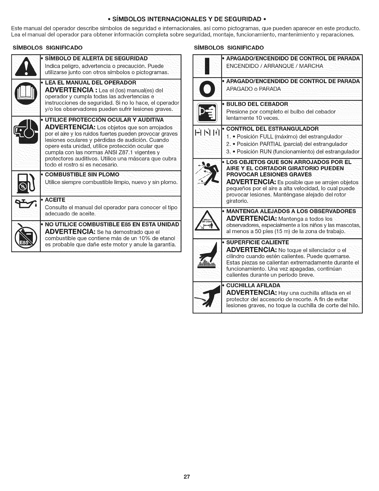
• SJMBOLOSINTERNAClONALESY DE SEGURIDAD •
Este manual del operador describe simbolos de seguridad einternacionales, asi como pictogramas, que pueden aparecer en este producto.
Lea el manual del operador para obtener informaci6n completa sobre seguridad, montaje, funcionamiento, mantenimiento y reparaciones.
SJMBOLOS SIGNIFICADO
_i_ ioSJMBOLO DEALERTA DESEGURIDAD
Indica peligro, advertencia o PiecaUci6n: Puede
Utilizarse Junto C0n 0tros SJmb0!0s 0 pictogramas:
, LEAEL MANUAL DEL OPERADOR
ADVERTENC A:L aeii oSimanuaiiesidem
operador y cumpla todas las advertencias e
instrucciones de Seguridad. S! no Io hace, el operador
y/o los observadores pueden sufrir lesiones graves.
_, UTlUCE PROTECCION OCULAR YAUDITJVA
_I ADVERTENCJA: L0s oh]eros son arrojad0s
|Ipot e! aire y !os ruidos fuertes pueden p[ov0car graves
leSiones ocu!ares y p@d das de audici6nl Cuando
0pete esta unidad, utiiice protecci6n ocuiar que
cump!a con las normas ANSI Z87:1 vigentes y
protectores auditivos: Uti!ice una m4scara que Cubra
todo ei rostro si es necesarJo.
' CtilicMeBsiUeSmTIprBLcEo_NuPst_bleMiOmpi:,
_,ACEITE
conSuitemanua operadoiparac0n0cert po
adecuado de aceite.
,NO UTILICE COMBUSTIBLE E85 EN ESTA UNJDAD
ADVERTENCIA: hademostiad0 qUe e
combustible que cont!ene mAs de un 10% de etano!
es probable que daSe este motor y anule la garantia.
SJMBOLOS SIGNIFICADO
,_ _,APAGADO/ENCENDIDO DE CONTROL DE PARADA
U APAGADO o PARADA
B
(_1 'BULBO DEL CEBADOR
Presione pot completo el buibo del cebador
lentamente 10 veces.
_,_. o CONTROL DEL ESTRANGULADOR
'_' J'{" I 1. • Posici6n FULL (mAximo) del estrangulador
2. • Posici6n PARTIAL (parcial) del estrangulador
I 3. • Posici6n RUN (funcionamiento) del estrangulador
wLOS OBJETOS CUE SON ARROJADOS POR EL
AiRE YEL CORTADOR GIRATORIO PUEDEN
PROVOCAR LESiONES GRAVES
ADVERTENCIA: Es posible que se arrojen objetos
pequeSos pot el aire a alta velocidad, Io cual puede
provocar lesiones. Mant6ngase alejado del rotor
giratorio.
'MANTENGA ALEJADOS A LOS OBSERVADORES
ADVERTENCIA: Mantenga a todos los
observadores, especialmente a los ni5os y los mascotas,
. al menos a 50 pies (15 m) de la zona de trabajo.
"SUPERFICiE CALIENTE
ADVERTENCIA: No toque el siienciador o el
I cilindro cuando est6n calientes. Puede quemarse.
,_l_!_l_ll_, I Estas piezas se calientan extremadamente durante el
I funcionamiento. Una vez apagadas, continQan
. calientes durante un periodo breve.
__ 'CUCHILLA AFILADA
ADVERTENCIA: Hay una cuchilla afiiada en el
"_,_ protector del accesorio de recorte. A fin de evitar
_"#_' ; lesiones graves, no toque ia cuchiiia de corte del hilo.
27
GARANTJA TOTAL POR DOS AltOS CRAFTSMAN
Este producto se garantiza POR DOS AltOS a partir de la fecha de compra, contra cualquier defecto de materiales o mano de obra. Un
producto defectuoso se reparara sin costo alguno o se remplazara si no es posible repararlo.
GARANTJA UMITADA ADICIONAL para los EJES DEL CORTADOR
A PARTIR DEL TERCER Y HASTA EL DC:CJMOANO desde la fecha de compra, el cuerpo externo de metal de los ejes superior e inferior del
cortador estan garantizados contra defectos de materiales o fabricaci6n. Se proporcionara un cuerpo nuevo gratis con la presentaci6n del
comprobante de compra. Es su responsabilidad cubrir el costo de mano de obra de instalaci6n. Esta cobertura adicional no se aplica a los
componentes internos del eje de la cortadora.
Para conocer los detaHes de la cobertura de garantia para la reparaci6n o reemplazo gratuitos, visite el sitio web: www.craftsman.com
Esta garantia cubre SOLAMENTE defectos de materiales o mano de obra. La cobertura de garantia NO incluye:
• Los componentes consumibles que se desgasten debido al uso normal dentro del periodo de garantia como lineas de corte, bujias o filtros.
• Los dafios al producto a consecuencia de intentos de modificaci6n o reparaci6n del usuario u ocasionados por accesorios del producto.
• Las reparaciones necesarias por un accidente o por no operar o mantener el producto de acuerdo con todas las instrucciones suministradas.
• El mantenimiento preventivo ni las reparaciones necesarias debido a una mezcla incorrecta de combustible o a al uso de un combustible
viejo o contaminado.
Esta garantia se anula si el producto en alg_n momento se utiliza para prestar servicios comerciales o se alquila a otra persona.
Esta garantia le confiere a usted derechos legales especificos y usted puede tener, ademas, otros derechos que difieren de un estado a otro.
Sears Brands Management Corporation, Hoffman Estates, IL 60179
Para ordenar refacciones o agendar mantenimiento para este producto, llame a 1-800-469-4663.
28
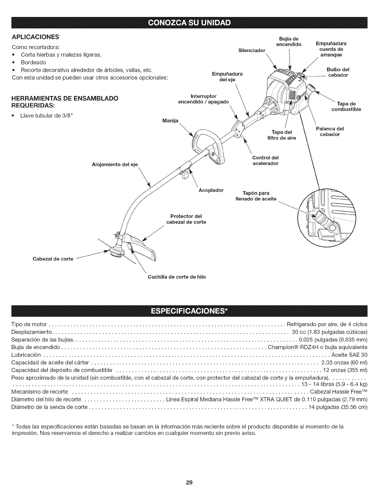
APLICACIONES
Comorecortadora:
• Cortahierbasymalezasligeras.
Bordeado
Recortedecorativoalrededordearboles,vallas,etc.
Conestaunidadsepuedenusarotrosaccesoriosopcionales:
Silenciador
EmpuSadura
del eje
Bujia de
encendido ErnpuSadura
cuerda de
a rra nq ue
Bulbo del
cebador
HERRAMIENTAS DE ENSAMBLADO
REQUERIDAS:
Llave tubular de 3/8"
Interruptor
encendido /apagado \
Manija Tapa del
filtro de aire
Tapa de
combustible
Palanca del
cebador
AIojamientodel eje
Control del
acelerador
Acoplador
Protector del
cabezal de corte
Tap6n para
Uenado de aceite
Cabezal de corte
CuchiUa de corte de hilo
Tipo de motor ............................................................................ Refrigerado pot aire, de 4 ciclos
Desplazamiento ............................................................................ 30 cc (1.83 pulgadas cQbicas)
Separaci6n de las bujias ........................................................................ 0.025 pulgadas (0.635 mm)
Bujia de encendido .................................................................. Champion® RDZ4H o bujia equivalente
Lubricaci6n ............................................................................................ Aceite SAE 30
Capacidad de aceite del carter ......................................................................... 2.03 onzas (60 ml)
Capacidad del dep6sito de combustible .................................................................. 12 onzas (355 ml)
Peso aproximado de la unidad (sin combustible, con el cabezal de corte, con protector del cabezal de corte y la empu5adura) ............
............................................................................................ 13 - 14 libras (5.9 - 6.4 kg)
Mecanismo de recorte ............................................................................ Cabezal Hassle FreeTM
Diametro del hilo de recorte .......................... Linea Espiral Mediana Hassle Free TM XTRA QUIET de 0.110 pulgadas (2.79 mm)
Diametro de la senda de corte ...................................................................... 14 pulgadas (35.56 cm)
* Todas las especificaciones estan basadas se basan en la informaci6n mas reciente sobre el producto disponible al momento de la
impresi6n. Nos reservamos el derecho a realizar cambios en cualquier momento sin previo aviso.
29
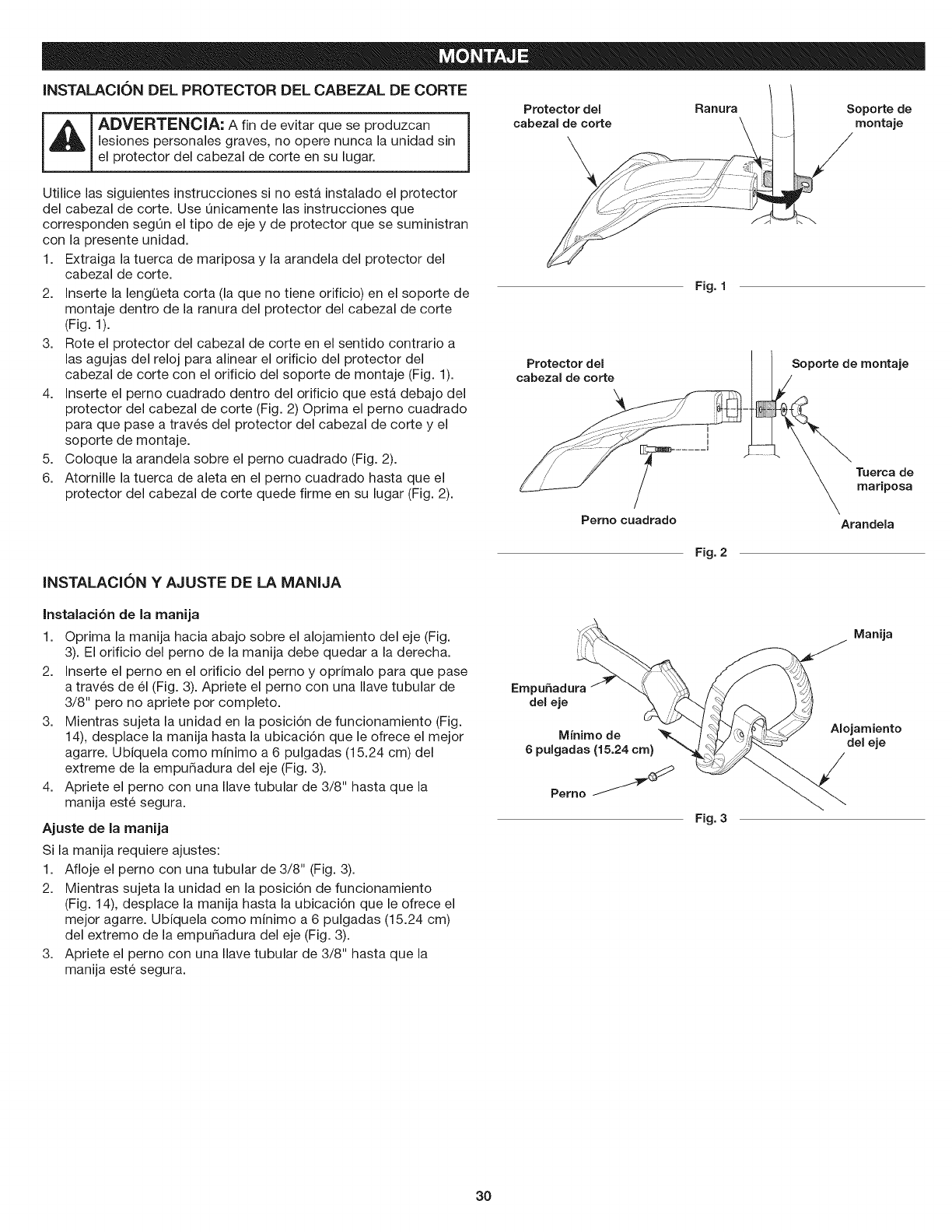
INSTALACK)N DEL PROTECTOR DEL CABEZAL DE CORTE
_ DVERTENCIA: A fin de evitar que se produzcan
lesiones personales graves, no opere nunca la unidad sin
el protector del cabezal de corte en su lugar.
Utilice las siguientes instrucciones si no esta instalado el protector
del cabezal de corte. Use Onicamente las instrucciones que
corresponden segOn el tipo de eje y de protector que se suministran
con la presente unidad.
1. Extraiga la tuerca de mariposa y la arandela del protector del
cabezal de corte.
2. Inserte la lengQeta corta (la que no tiene orificio) en el soporte de
montaje dentro de la ranura del protector del cabezal de corte
(Fig. 1).
3. Rote el protector del cabezal de corte en el sentido contrario a
las agujas del reloj para alinear el orificio del protector del
cabezal de corte con el orificio del soporte de montaje (Fig. 1).
4. Inserte el perno cuadrado dentro del orificio que esta debajo del
protector del cabezal de corte (Fig. 2) Oprima el perno cuadrado
para que pase a traves del protector del cabezal de corte y el
soporte de montaje.
5. Coloque la arandela sobre el perno cuadrado (Fig. 2).
6. Atornille la tuerca de aleta en el perno cuadrado hasta que el
protector del cabezal de corte quede firme en su lugar (Fig. 2).
Protector del Ranura
cabezal de corte
Protector del
cabezal de corte
Fig. 1
Soporte de
montaje
Soporte de montaje
Tuerca de
mariposa
Perno cuadrado Arandela
INSTALACION YAJUSTE DE LA MANIJA
Fig. 2
Instalaci6n de la manija
1. Oprima la manija hacia abajo sobre el alojamiento del eje (Fig.
3). El orificio del perno de la manija debe quedar a la derecha.
2. Inserte el perno en el orificio del perno y oprimalo para que pase
a traves de 61 (Fig. 3). Apriete el perno con una Ilave tubular de
3/8" pero no apriete pot completo.
3. Mientras sujeta la unidad en la posici6n de funcionamiento (Fig.
14), desplace la manija hasta la ubicaci6n que le ofrece el mejor
agarre. Ubiquela como minimo a 6 pulgadas (15.24 cm) del
extreme de la empur_adura del eje (Fig. 3).
4. Apriete el perno con una Ilave tubular de 3/8" hasta que la
manija este segura.
Ajuste de la manija
Si la manija requiere ajustes:
1. Afloje el perno con una tubular de 3/8" (Fig. 3).
2. Mientras sujeta la unidad en la posici6n de funcionamiento
(Fig. 14), desplace la manija hasta la ubicaci6n que le ofrece el
mejor agarre. Ubiquela como minimo a 6 pulgadas (15.24 cm)
del extremo de la empur_adura del eje (Fig. 3).
3. Apriete el perno con una Ilave tubular de 3/8" hasta que la
manija este segura.
EmpuSadura
deJ eje
Minimo de
6pulgadas (15.24 cm)
Perno
Fig. 3
Manija
AlojamJento
del eje
30
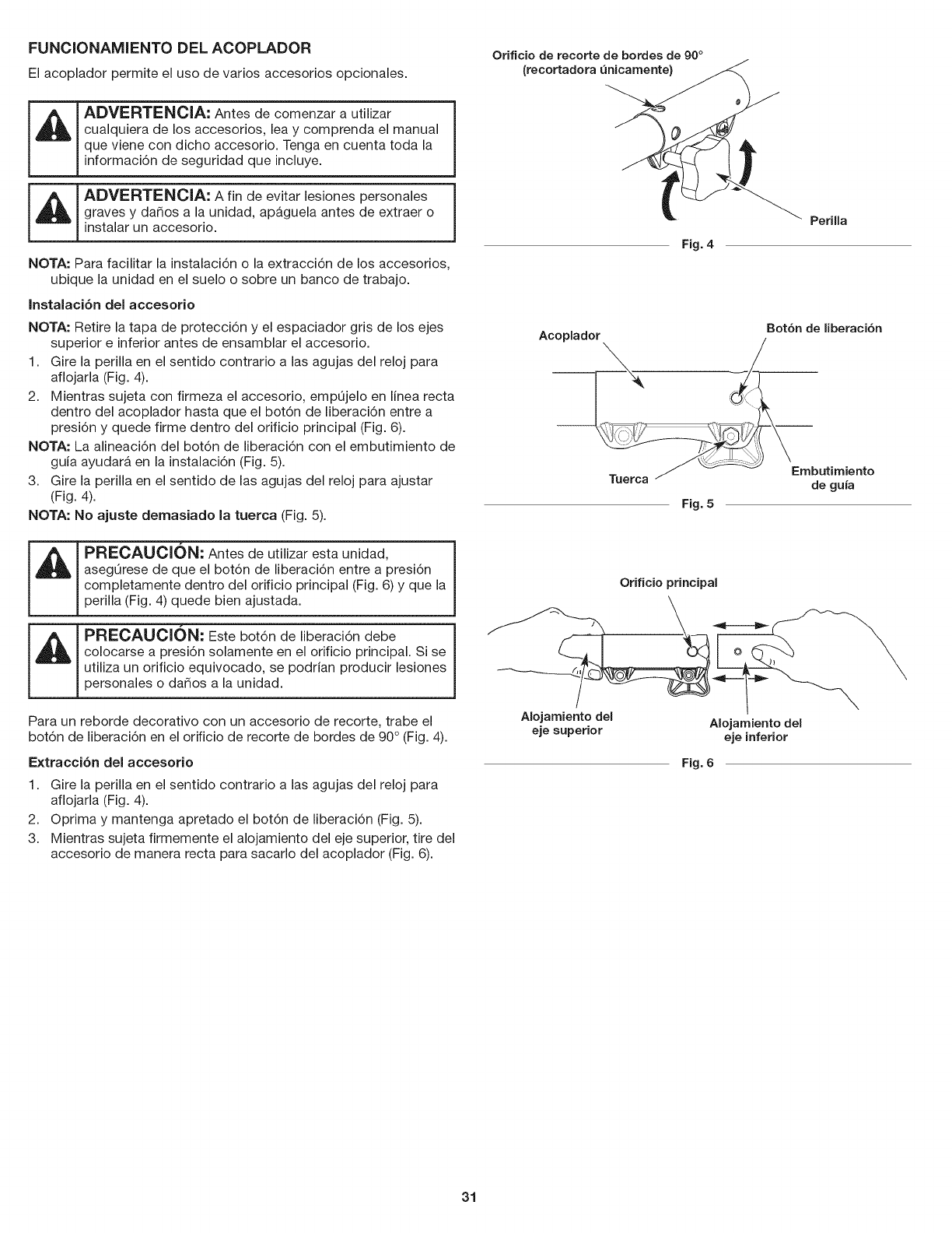
FUNCIONAMIENTO DEL ACOPLADOR
El acoplador permite el uso de varios accesorios opcionales.
ADVERTENClA: Antes de comenzar a utilizar
cualquiera de los accesorios, lea y comprenda el manual
que viene con dicho accesorio. Tenga en cuenta toda la
informaci6n de seguridad que incluye.
ADVERTENOIA: A fin de evitar lesiones personales
graves y dar_os a la unidad, apaguela antes de extraer o
instalar un accesorio.
NOTA: Para facilitar la instalaci6n o la extracci6n de los accesorios,
ubique la unidad en el suelo o sobre un banco de trabajo.
Instalaci6n del accesorio
NOTA: Retire la tapa de protecci6n y el espaciador gris de los ejes
superior e inferior antes de ensamblar el accesorio.
1. Gire la perilla en el sentido contrario a las agujas del reloj para
aflojarla (Fig. 4).
2. Mientras sujeta con firmeza el accesorio, empOjelo en linea recta
dentro del acoplador hasta que el bot6n de liberaci6n entre a
presi6n y quede firme dentro del orificio principal (Fig. 6).
NOTA: La alineaci6n del bot6n de liberaci6n con el embutimiento de
guia ayudar_, en la instalaci6n (Fig. 5).
3. Gire la perilla en el sentido de las agujas del reloj para ajustar
(Fig. 4).
NOTA: No ajuste demasiado la tuerca (Fig. 5).
PRECAUCl0N: Antes de utilizar esta unidad,
asegOrese de que el bot6n de liberaci6n entre a presi6n
completamente dentro del orificio principal (Fig. 6) y que la
perilla (Fig. 4) quede bien ajustada.
PRECAUCION: Este bot6n de liberaci6n debe
colocarse a presi6n solamente en el orificio principal. Si se
utiliza un orificio equivocado, se podrian producir lesiones
personales o dar_os a la unidad.
Para un reborde decorativo con un accesorio de recorte, trabe el
bot6n de liberaci6n en el orificio de recorte de bordes de 90° (Fig. 4).
Extracci6n del accesorio
1. Gire la perilla en el sentido contrario a las agujas del reloj para
aflojarla (Fig. 4).
2. ©prima y mantenga apretado el bot6n de liberaci6n (Fig. 5).
3. Mientras sujeta firmemente el alojamiento del eje superior, tire del
accesorio de manera recta para sacarlo del acoplador (Fig. 6).
Orificio de recorte de bordes de 90°
(recortadora _nicamente) _
PeriUa
Fig. 4
Bot6n de liberaci6n
Acoplador
de guia
Fig. 5
Orificio principal
Aiojarniento deI Aiojamiento deI
eje superior eje inferior
Fig. 6
31
USO DEL ACEITE CORRECTO
Use un aceite pesado de alta calidad SAE 30. NO utilice aceite
sucio. Si no se utiliza aceite limpio del tipo adecuado se puede
producir un desgaste y una falla prematura del motor.
INCORPORACI()N DE ACEITE: USO INIClAL
_DVERTENCIA: sl SE LLENA EXCESIVAMENTEEL
CARTER SE PUEDEN PRODUCIR LESIONES
PERSONALES GRAVES. Controle el nivel de aceite antes
de cada uso. No est,. de m_.s insistir en la importancia de
mantener el nivel de aceite adecuado. Cambie el aceite de
acuerdo con el Programa de mantenimiento.
NOTA: Esta unidad se envi6 sin aceite en el carter. Se debe agregar
aceite antes de arrancar la unidad.
NOTA: Esta unidad viene con una botella de aceite de 2.03 onzas
liquidas (60 ml).
1. Desenrosque la parte superior de la botella de aceite. Quite el sello
de papel. Vuelva a instalar la parte superior de la botella de aceite.
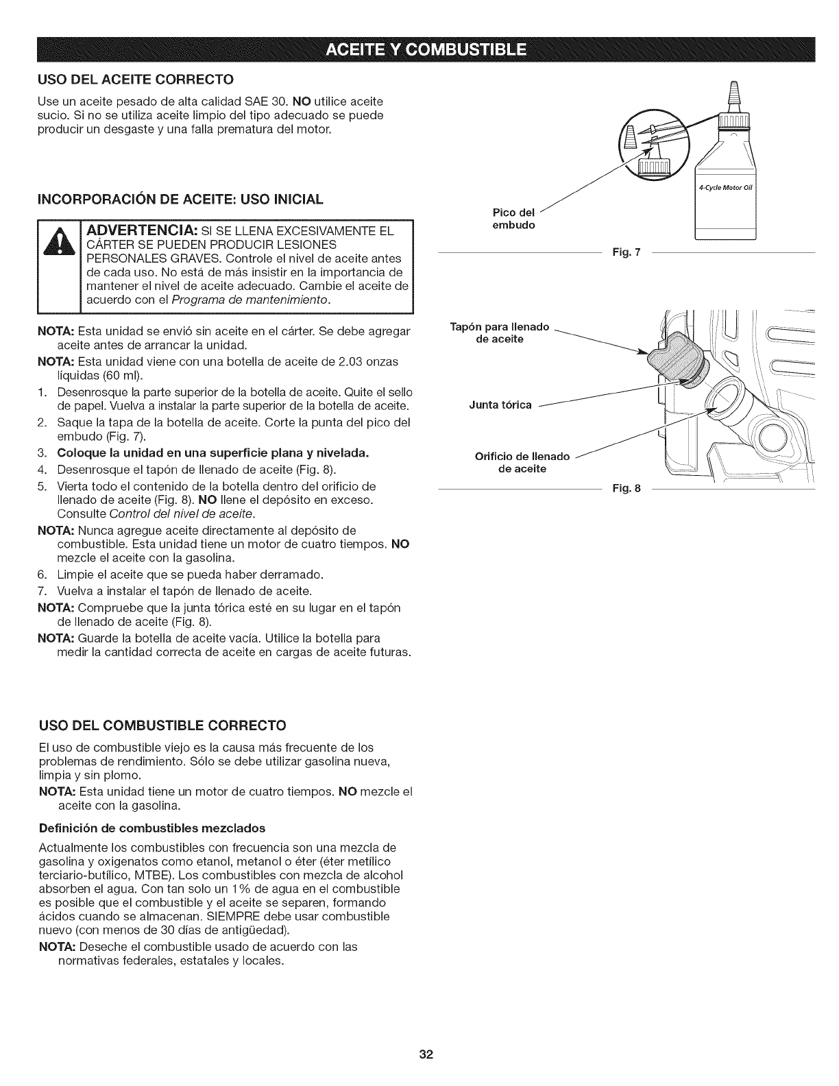
2. Saque la tapa de la botella de aceite. Corte la punta del pico del
embudo (Fig. 7).
3. Coloque la unidad en una superficie plana y nivelada.
4. Desenrosque el tap6n de Ilenado de aceite (Fig. 8).
5. Vierta todo el contenido de la botella dentro del orificio de
Ilenado de aceite (Fig. 8). NO Ilene el dep6sito en exceso.
Consulte Control del nivel de aceite.
NOTA: Nunca agregue aceite directamente al dep6sito de
combustible. Esta unidad tiene un motor de cuatro tiempos. NO
mezcle el aceite con la gasolina.
6. Limpie el aceite que se pueda haber derramado.
7. Vuelva a instalar el tap6n de Ilenado de aceite.
NOTA: Compruebe que la junta t6rica este en su lugar en el tap6n
de Ilenado de aceite (Fig. 8).
NOTA: Guarde la botella de aceite vacia. Utilice la botella para
medir la cantidad correcta de aceite en cargas de aceite futuras.
Pico del __
embudo
Fig. 7
Tapbn para llenado
de aceite
J
Junta tbrica
Orificio de Ilenado
de aceite
Fig. 8
USO DEL COMBUSTIBLE CORRECTO
El uso de combustible viejo es la causa mas frecuente de los
problemas de rendimiento. S61o se debe utilizar gasolina nueva,
limpia y sin plomo.
NOTA: Esta unidad tiene un motor de cuatro tiempos. NO mezcle el
aceite con la gasolina.
Definici6n de combustibles mezclados
Actualmente los combustibles con frecuencia son una mezcla de
gasolina y oxigenatos como etanol, metanol o eter (eter metilico
terciario-butilico, MTBE). Los combustibles con mezcla de alcohol
absorben el agua. Con tan solo un 1% de agua en el combustible
es posible que el combustible y el aceite se separen, formando
acidos cuando se almacenan. SlEMPRE debe usar combustible
nuevo (con menos de 30 dias de antigQedad).
NOTA: Deseche el combustible usado de acuerdo con las
normativas federales, estatales y locales.
32
Uso de combustibles mezclados
Si utiliza un combustible mezclado:
• Utilice siempre gasolina nueva sin plomo
• Use el aditivo para combustible STA-BIL ° u otro equivalente
• Drene el dep6sito y ponga en marcha el motor en seco antes de
almacenar la unidad
ADVERTENCIA: NO UTILICE COMBUSTIBLE E85 EN
ESTA UN IDAD.
Se ha demostrado que el combustible que contiene mas
de un 10% de etanol es probable que daSe este motor y
anule la garantia.
Uso de aditivos para el combustible
Utilice un aditivo para el combustible, como el estabilizador de
combustible STA-BIL u otro equivalente, para inhibir la corrosi6n y
minimizar los dep6sitos de goma. Agregue 0.8 onzas (23 ml) de
aditivo para combustible por gal6n de combustible segQn las
instrucciones del recipiente. NUNCA agregue aditivos para el
combustible directamente al dep6sito de combustible de la unidad.
CARGA DE COMBUSTIBLE EN LA UNIDAD
ADVERTENClA: La gasolina es extremadamente
inflamable. Los vapores encendidos pueden explotar.
Detenga siempre el motor y dejelo enfriar antes de Ilenar el
dep6sito de combustible. No fume mientras Ilena el
dep6sito. Mantenga las chispas y llamas abiertas a una
distancia de la zona.
ADVERTENClA: Retire la tapa del combustible
lentamente a fin de evitar lesiones ocasionadas por
salpicaduras de combustible. Nunca opere la unidad si la
tapa del combustible no esta bien sujeta en su lugar.
ADVERTENClA: Agregue combustible en una zona al
aire libre, limpia y bien ventilada. Limpie de inmediato la
gasolina que se haya derramado. Evite que se genere una
fuente de encendido para el combustible derramado. No
arranque el motor hasta que se hayan disipado los
vapores del combustible.
1. Ubique la unidad con la tapa del combustible orientada hacia arriba.
2. Extraiga la tapa de combustible.
3. Ubique el pico del recipiente de combustible dentro del orificio
de Ilenado del dep6sito de combustible y Ilene el dep6sito.
NOTA: No Ilene en exceso el dep6sito de combustible.
4. Limpie el combustible que se pueda haber derramado.
5. Vuelva a colocar la tapa del combustible.
6. Mueva la unidad al menos 30 pies (9.1m) del recipiente de
combustible y del sitio de carga de combustible antes de
arrancar el motor.
33
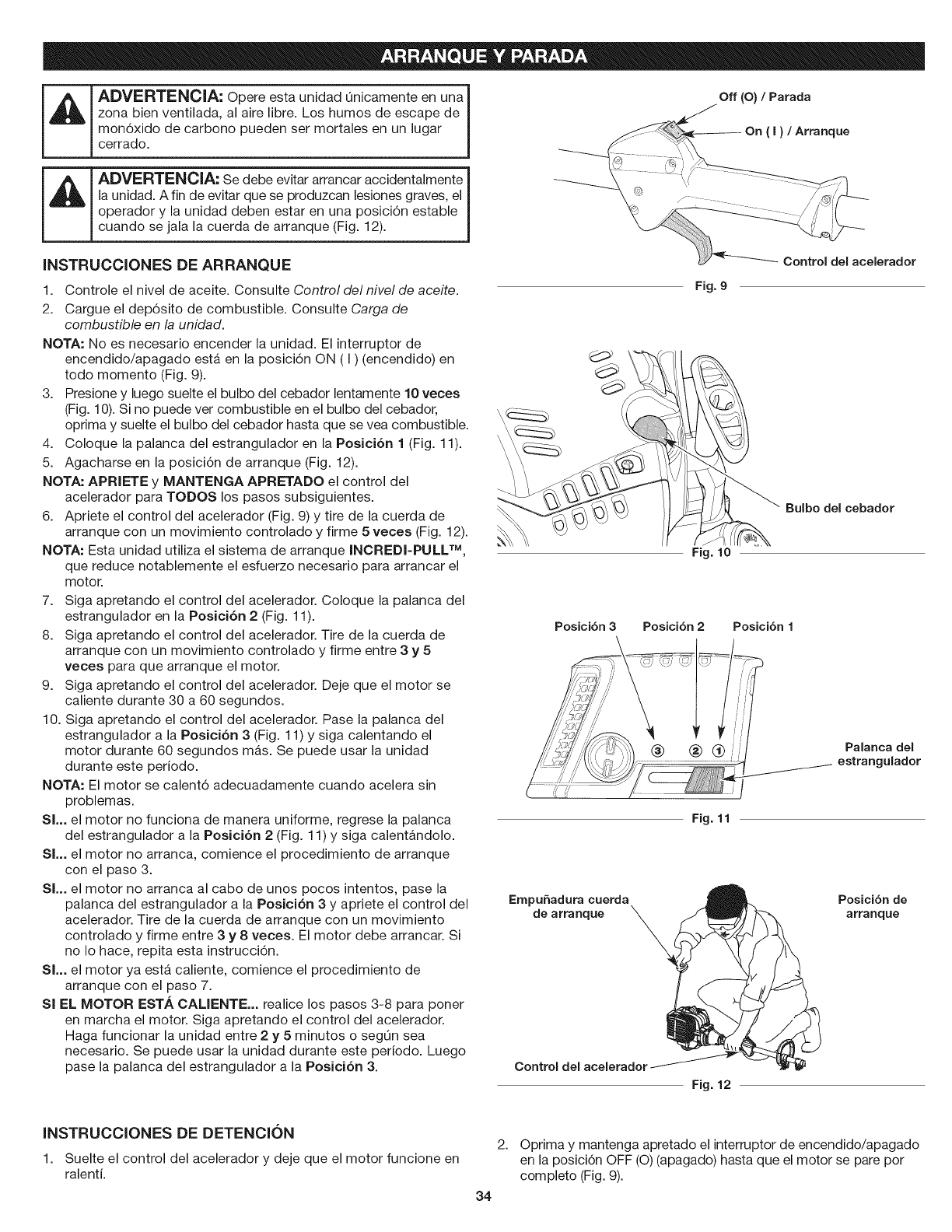
_ DVERTENClA: Opere esta unidad Onicamente en una
zona bien ventilada, al aire libre. Los humos de escape de
mon6xido de carbono pueden ser mortales en un lugar
cerrado.
_ DVERTENOIA" Se debe evitar arrancar accidentalmente
la unidad. A fin de evitar que se produzcan lesiones graves, el
operador y la unidad deben estar en una posici6n estable
cuando se jala la cuerda de arranque (Fig. 12).
INSTRUCCIONES DE ARRANQUE
Off (O) /Parada
On (I)/Arranque
1. Controle el nivel de aceite. Consulte Control de/nivel de aceite.
2. Cargue el dep6sito de combustible. Consulte Carga de
combustible en la unidad.
NOTA: No es necesario encender la unidad. El interruptor de
encendido/apagado esta en la posici6n ON (I) (encendido) en
todo momento (Fig. 9).
3. Presione y luego suelte el bulbo del cebador lentamente 10 veces
(Fig. 10). Si no puede ver combustible en el bulbo del cebador,
oprima y suelte el bulbo del cebador hasta que se vea combustible.
4. Coloque la palanca del estrangulador en la Posici6n 1 (Fig. 11).
5. Agacharse en la posici6n de arranque (Fig. 12).
NOTA: APRIETE y MANTENGA APRETADO el control del
acelerador para TODOS los pasos subsiguientes.
6. Apriete el control del acelerador (Fig. 9) y tire de la cuerda de
arranque con un movimiento controlado y firme 5 veces (Fig. 12).
NOTA: Esta unidad utiliza el sistema de arranque INOREDI-PULL TM,
que reduce notablemente el esfuerzo necesario para arrancar el
motor.
7. Siga apretando el control del acelerador. Coloque la palanca del
estrangulador en la Posici6n 2 (Fig. 11).
8. Siga apretando el control del acelerador. Tire de la cuerda de
arranque con un movimiento controlado y firme entre 3 y 5
veces para que arranque el motor.
9. Siga apretando el control del acelerador. Deje que el motor se
caliente durante 30 a 60 segundos.
10. Siga apretando el control del acelerador. Pase la palanca del
estrangulador a la Posici6n 3 (Fig. 11) y siga calentando el
motor durante 60 segundos mas. Se puede usar la unidad
durante este periodo.
NOTA: El motor se calent6 adecuadamente cuando acelera sin
problemas.
SL. el motor no funciona de manera uniforme, regrese la palanca
del estrangulador a la Posici6n 2 (Fig. 11) y siga calent_.ndolo.
SL. el motor no arranca, comience el procedimiento de arranque
con el paso 3.
SL. el motor no arranca al cabo de unos pocos intentos, pase la
palanca del estrangulador a la Posici6n 3 y apriete el control del
acelerador. Tire de la cuerda de arranque con un movimiento
controlado y firme entre 3 y 8 veces. El motor debe arrancar. Si
no Io hace, repita esta instrucci6n.
SL. el motor ya esta. caliente, comience el procedimiento de
arranque con el paso 7.
Sl EL MOTOR ESTA CALIENTE... realice los pasos 3-8 para poner
en marcha el motor. Siga apretando el control del acelerador.
Haga funcionar la unidad entre 2 y 5 minutos o segQn sea
necesario. Se puede usar la unidad durante este periodo. Luego
pase la palanca del estrangulador a la Posici6n 3.
Fig. 9
Fig. 10
Control del acelerador
Posicibn 3 Posici6n 2Posicibn 1
Bulbo del cebador
Palanca del
estrangulador
Fig. 11
EmpuSadura cuerda Posici6n de
de arranque _ arranque
\
Control del
Fig. 12
INSTRUCCIONES DE DETENCK)N
1. Suelte el control del acelerador y deje que el motor funcione en
ralenti.
2.
34
Optima y mantenga apretado el interruptor de encendido/apagado
en la posici6n OFF (O) (apagado) hasta que el motor se pare por
completo (Fig. 9).
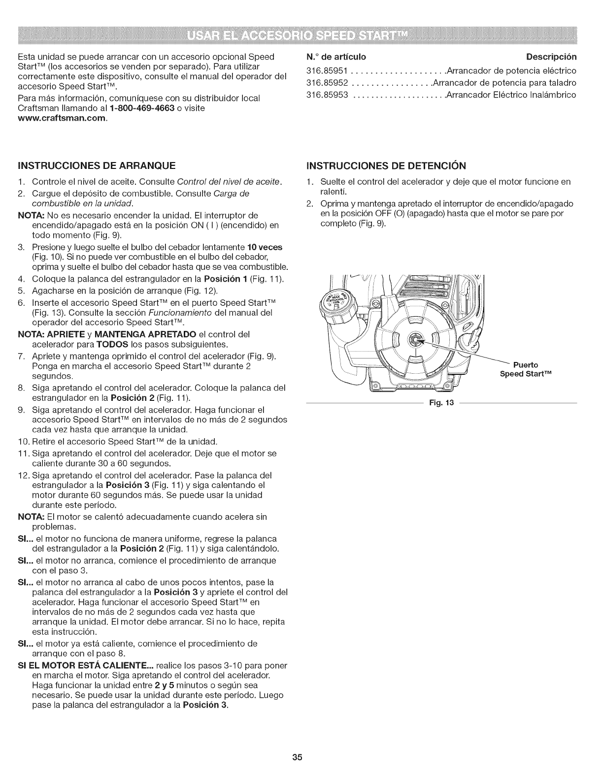
EstaunidadsepuedearrancarconunaccesorioopcionalSpeed
StartTM (los accesorios se venden por separado). Para utilizar
correctamente este dispositivo, consulte el manual del operador del
accesorio Speed Start TM.
Para mas informaci6n, comuniquese con su distribuidor local
Craftsman Ilamando al 1-800-469-4663 o visite
www.craftsman.com.
N.° de articulo Descripci6n
316.85951 .................... Arrancador de potencia electrico
316.85952 ................. Arrancador de potencia para taladro
316.85953 ..................... Arrancador Electrico Inalambrico
iNSTRUCCiONES DE ARRANQUE
1. Controle el nivel de aceite. Consulte Control del nivel de aceite.
2. Cargue el dep6sito de combustible. Consulte Carga de
combustible en la unidad.
NOTA: No es necesario encender la unidad. El interruptor de
encendido/apagado esta en la posici6n ON ( I ) (encendido) en
todo momento (Fig. 9).
3. Presione y luego suelte el bulbo del cebador lentamente 10 veces
(Fig. 10). Si no puede ver combustible en el bulbo del cebador,
oprima y suelte el bulbo del cebador hasta que se vea combustible.
4. Coloque la palanca del estrangulador en la Posici6n 1 (Fig. 11).
5. Agacharse en la posici6n de arranque (Fig. 12).
6. Inserte el accesorio Speed Start TM en el puerto Speed Start TM
(Fig. 13). Consulte la secci6n Funcionamiento del manual del
operador del accesorio Speed Start TM.
NOTA: APRIETE y MANTENGA APRETADO el control del
acelerador para TODOS los pasos subsiguientes.
7. Apriete y mantenga oprimido el control del acelerador (Fig. 9).
Ponga en marcha el accesorio Speed Start TM durante 2
segundos.
8. Siga apretando el control del acelerador. Coloque la palanca del
estrangulador en la Posici6n 2 (Fig. 11).
9. Siga apretando el control del acelerador. Haga funcionar el
accesorio Speed Start TM en intervalos de no mas de 2 segundos
cada vez hasta que arranque la unidad.
10. Retire el accesorio Speed Start TM de la unidad.
11. Siga apretando el control del acelerador. Deje que el motor se
caliente durante 30 a 60 segundos.
12. Siga apretando el control del acelerador. Pase la palanca del
estrangulador a la Posici6n 3 (Fig. 11) y siga calentando el
motor durante 60 segundos mas. Se puede usar la unidad
durante este periodo.
NOTA: El motor se calent6 adecuadamente cuando acelera sin
problemas.
SL. el motor no funciona de manera uniforme, regrese la palanca
del estrangulador a la Posici6n 2 (Fig. 11) y siga calentandolo.
Sl... el motor no arranca, comience el procedimiento de arranque
con el paso 3.
SL. el motor no arranca al cabo de unos pocos intentos, pase la
palanca del estrangulador a la Posici6n 3 y apriete el control del
acelerador. Haga funcionar el accesorio Speed Start TM en
intervalos de no mas de 2 segundos cada vez hasta que
arranque la unidad. El motor debe arrancar. Si no Io hace, repita
esta instrucci6n.
Sl... el motor ya esta caliente, comience el procedimiento de
arranque con el paso 8.
Sl EL MOTOR ESTA CALIENTE... realice los pasos 3-10 para poner
en marcha el motor. Siga apretando el control del acelerador.
Haga funcionar la unidad entre 2 y 5 minutos o segOn sea
necesario. Se puede usar la unidad durante este periodo. Luego
pase la palanca del estrangulador a la Posici6n 3.
iNSTRUCCiONES DE DETENCi()N
1. Suelte el control del acelerador y deje que el motor funcione en
ralenti.
2. Oprima y mantenga apretado el interruptor de encendido/apagado
en la posici6n OFF (O) (apagado) hasta que el motor se pare por
completo (Fig. 9).
Puerto
Speed Start TM
Fig. 13
35
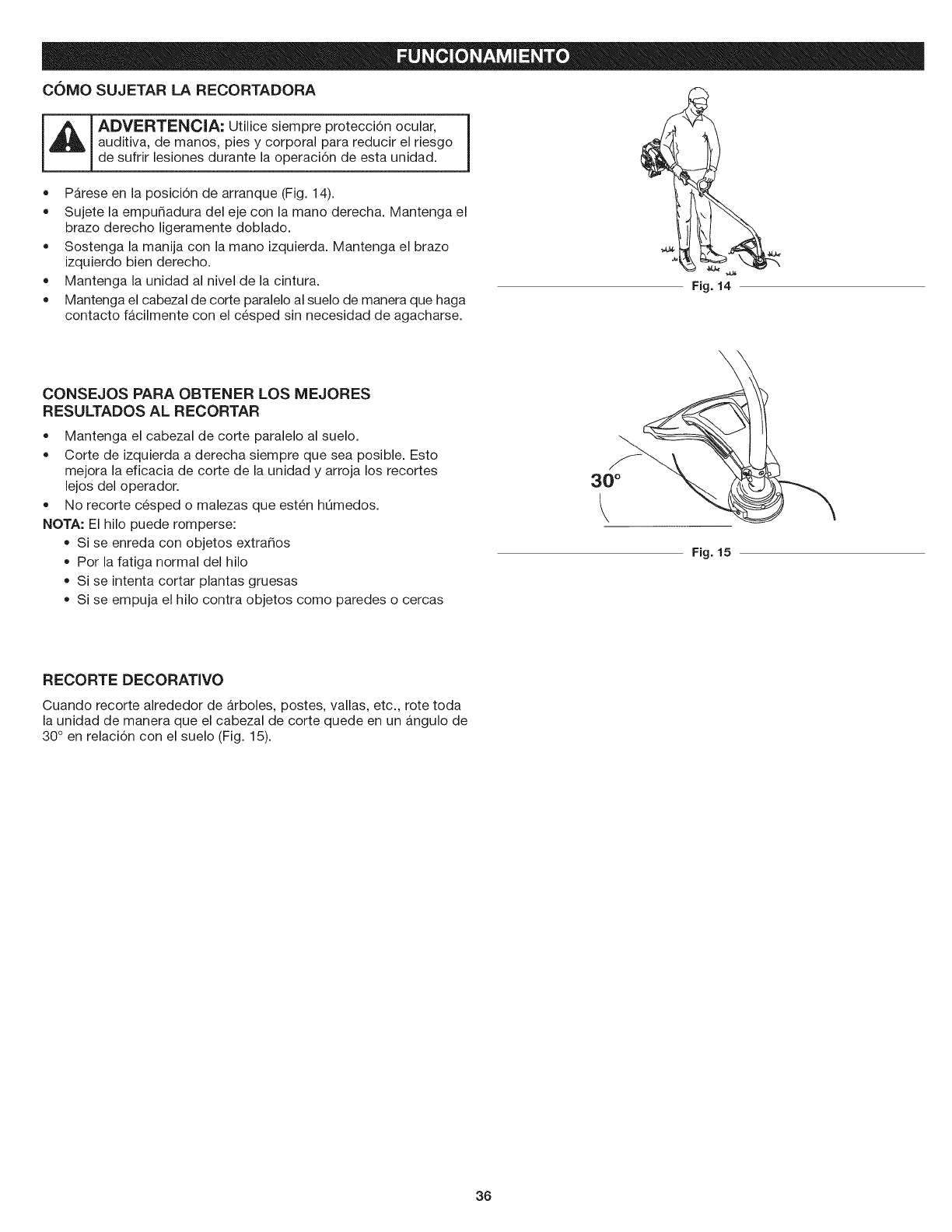
C(_MO SUJETAR LA RECORTADORA
iA!,ov,o,,°c,,;Uti"oes'em re 'oteoo"noo 'a',I
auditiva, de manos, pies y corporal para reducir el riesgo
de sufrir lesiones durante la operaci6n de esta unidad.
• Parese en la posici6n de arranque (Fig. 14).
Sujete la empudadura del eje con la mano derecha. Mantenga el
brazo derecho ligeramente doblado.
Sostenga la manija con la mano izquierda. Mantenga el brazo
izquierdo bien derecho.
Mantenga la unidad al nivel de la cintura.
Mantenga el cabezal de corte paralelo al suelo de manera que haga
contacto facilmente con el cesped sin necesidad de agacharse.
Fig. 14
CONSEJOS PARA OBTENER LOS MEJORES
RESULTADOS AL RECORTAR
Mantenga el cabezal de corte paralelo al suelo.
Corte de izquierda a derecha siempre que sea posible. Esto
mejora la eficacia de corte de la unidad y arroja los recortes
lejos del operador.
No recorte cesped o malezas que esten hOmedos.
NOTA: El hilo puede romperse:
Si se enreda con objetos extraSos
Por la fatiga normal del hilo
Si se intenta cortar plantas gruesas
Si se empuja el hilo contra objetos como paredes o cercas
30 °
k
\
Fig. 15
RECORTE DECORATIVO
Cuando recorte alrededor de arboles, postes, vallas, etc., rote toda
la unidad de manera que el cabezal de corte quede en un angulo de
30° en relaci6n con el suelo (Fig. 15).
36
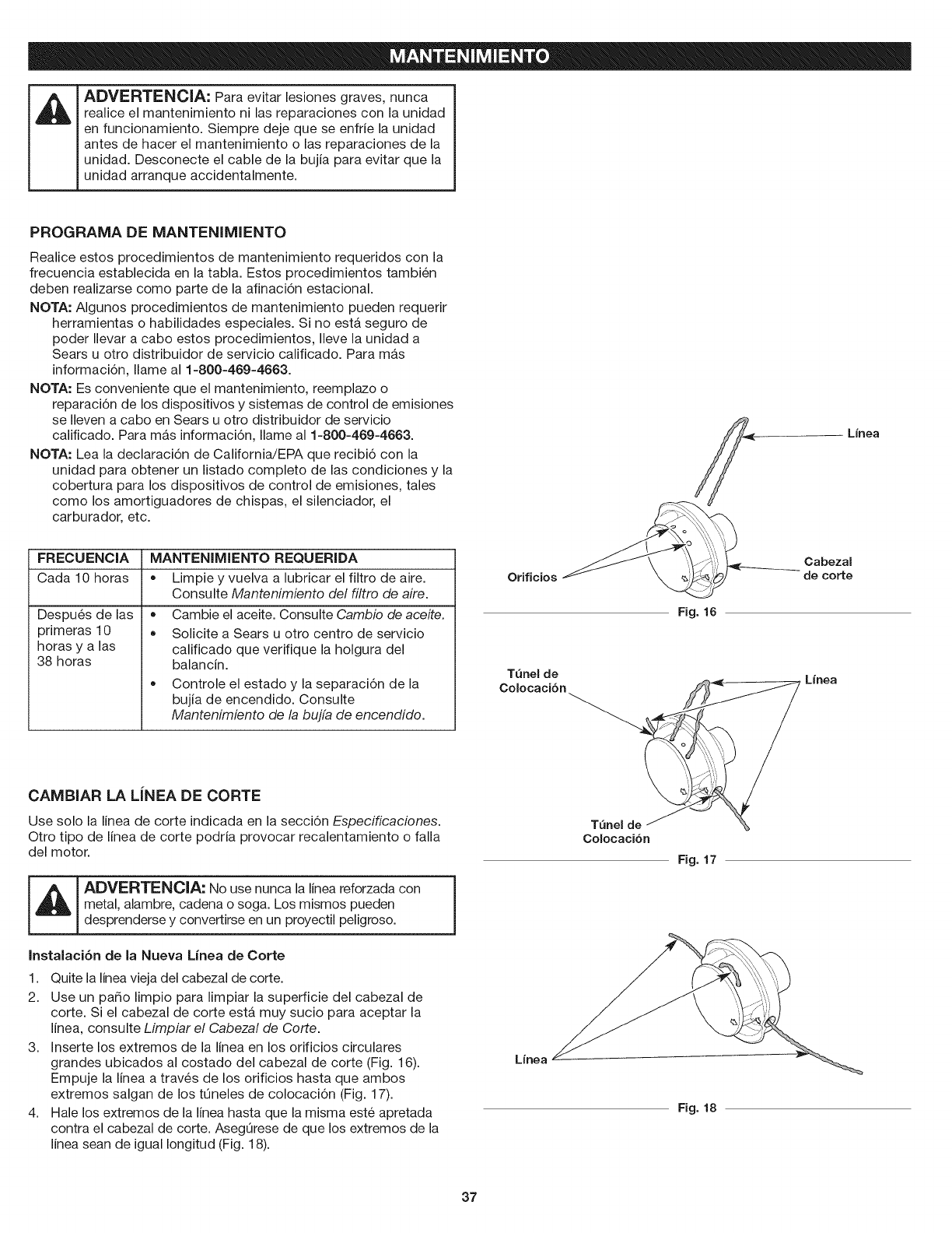
ADVERTENClA: Para evitar lesiones graves, nunca
realice el mantenimiento ni las reparaciones con la unidad
en funcionamiento. Siempre deje que se enfrie la unidad
antes de hacer el mantenimiento o las reparaciones de la
unidad. Desconecte el cable de la bujia para evitar que la
unidad arranque accidentalmente.
PROGRAMA DE MANTENIMIENTO
Realice estos procedimientos de mantenimiento requeridos con la
frecuencia establecida en la tabla. Estos procedimientos tambien
deben realizarse como parte de la afinaci6n estacional.
NOTA: Algunos procedimientos de mantenimiento pueden requerir
herramientas o habilidades especiales. Si no esta seguro de
poder Ilevar a cabo estos procedimientos, Ileve la unidad a
Sears u otro distribuidor de servicio calificado. Para mas
informaci6n, Ilame al 1-800-469-4663.
NOTA: Es conveniente que el mantenimiento, reemplazo o
reparaci6n de los dispositivos y sistemas de control de emisiones
se Ileven a cabo en Sears u otro distribuidor de servicio
calificado. Para m_,s informaci6n, Ilame al 1-800-469-4663.
NOTA: Lea la declaraci6n de California/EPA que recibi6 con la
unidad para obtener un listado completo de las condiciones y la
cobertura para los dispositivos de control de emisiones, tales
como los amortiguadores de chispas, el silenciador, el
carburador, etc.
FRECUENClA
Cada 10 horas
Despu6s de las
primeras 10
horas y a las
38 horas
MANTENIMIENTO REQUERIDA
= Limpie y vuelva a lubricar el filtro de aire.
Consulte Mantenimiento del filtro de aire.
• Cambie el aceite. Consulte Cambio de aceite.
Solicite a Sears u otro centro de servicio
calificado que verifique la holgura del
balancin.
Controle el estado y la separaci6n de la
bujia de encendido. Consulte
Mantenimiento de la bujfa de encendido.
CAMBIAR LA LiNEA DE CORTE
Use solo la linea de corte indicada en la secci6n Especificaciones.
Otro tipo de linea de corte podria provocar recalentamiento o falla
del motor.
I_ I ADVERTENCIA: No usenunca la linea reforzada con
Imetal, alambre, cadena o soga. Los mismos pueden
desprenderse y convertirse en un proyectil peligroso.
Instalaci6n de la Nueva Linea de Corte
1. Quite la linea vieja del cabezal de corte.
2. Use un patio limpio para limpiar la superficie del cabezal de
corte. Si el cabezal de corte esta muy sucio para aceptar la
linea, consulte Limpiar el Cabezal de Corte.
3. Inserte los extremos de la linea en los orificios circulates
grandes ubicados al costado del cabezal de corte (Fig. 16).
Empuje la linea a traves de los orificios hasta que ambos
extremos salgan de los tQneles de colocaci6n (Fig. 17).
4. Hale los extremos de la linea hasta que la misma este apretada
contra el cabezal de corte. AsegQrese de que los extremos de la
linea sean de igual Iongitud (Fig. 18).
I
Linea
Orificios
Fig. 16
Cabezal
de corte
TQnel de
Colocacibn _ "=_-
Colocacibn
Linea
Fig. 17
Linea
Fig. 18
37
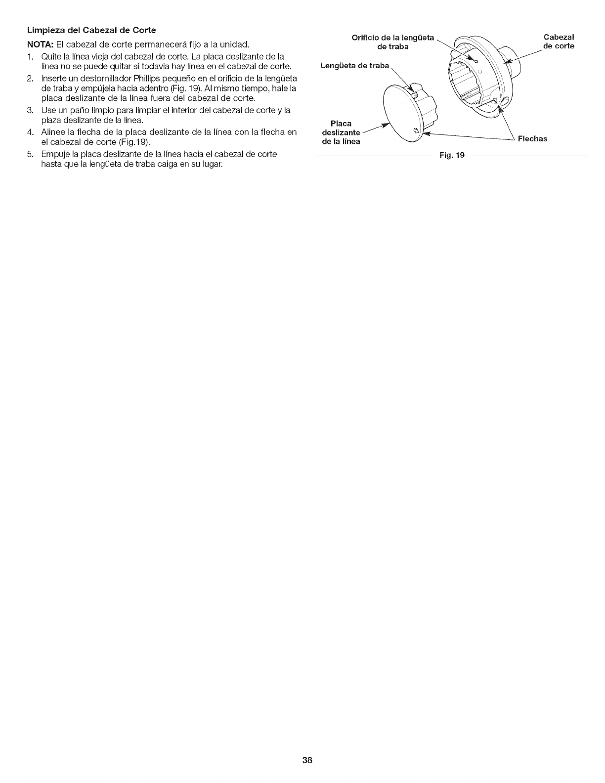
Umpieza del Cabezal de Corte
NOTA: El cabezal de corte permanecera fijo a la unidad.
1. Quite la linea vieja del cabezal de corte. La placa deslizante de la
linea no se puede quitar si todavia hay linea en el cabezal de corte.
2. Inserte un destornillador Phillips pequedo en el orificio de la lengOeta
de traba y empOjela hacia adentro (Fig. 19).AI mismo tiempo, hale la
placa deslizante de la linea fuera del cabezal de corte.
3. Use un pado limpio para limpiar el interior del cabezal de corte y la
plaza deslizante de la linea.
4. Alinee la flecha de la placa deslizante de la linea con la flecha en
el cabezal de corte (Fig.19).
5. Empuje la placa deslizante de la linea hacia el cabezal de corte
hasta que la lengOeta de traba caiga en su lugar.
Orificio de la leng_Jeta_
de traba "_/_
Leng_Jetade traba , _ _'i_
Cabezal
de corte
Flechas
Fig. 19
38
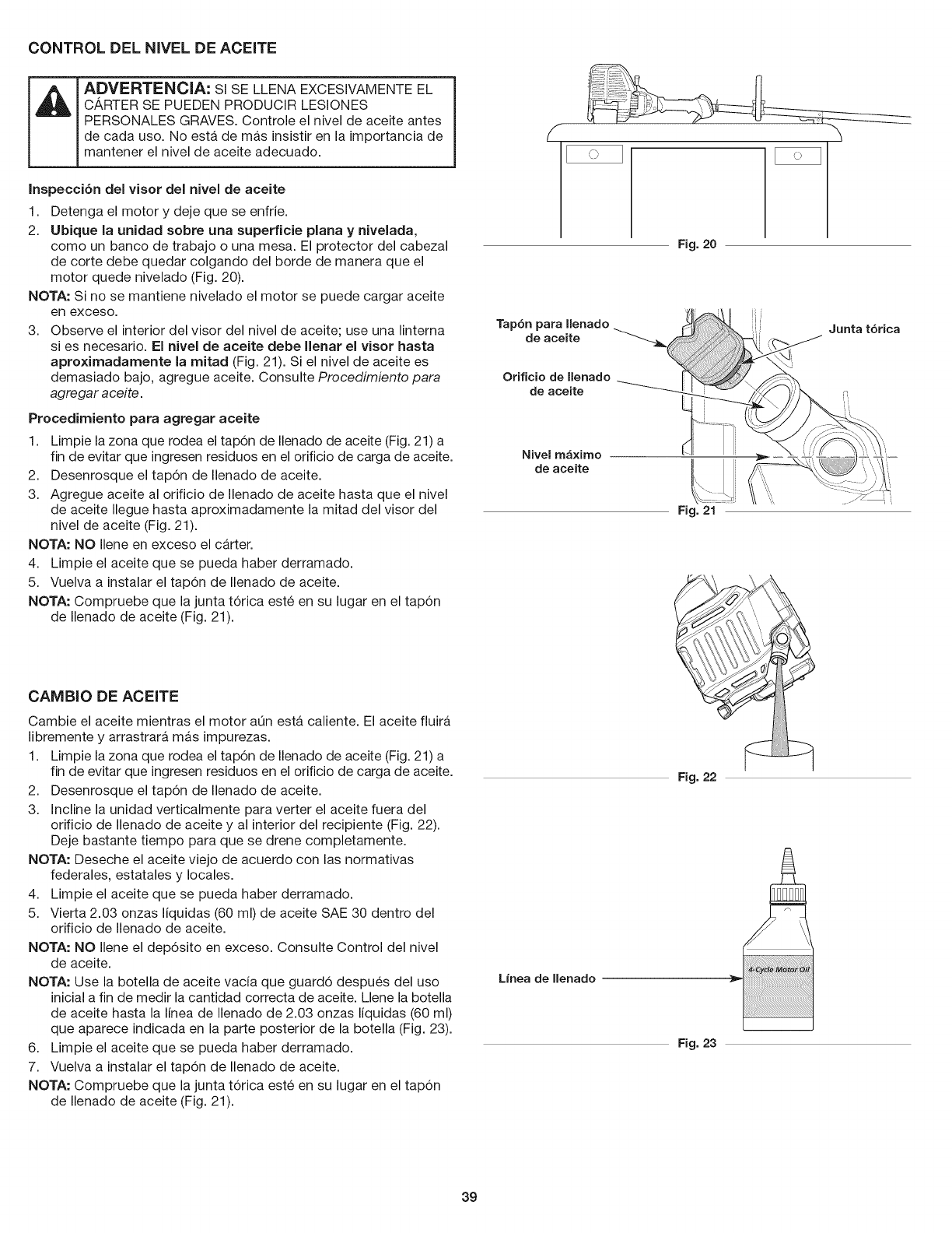
CONTROL DEL NIVEL DE ACEITE
ADVERTENClA: sl SE LLENA EXCESIVAMENTEEL
CARTER SE PUEDEN PRODUCIR LESIONES
PERSONALES GRAVES. Controle el nivel de aceite antes
de cada uso. No esta de mas insistir en la importancia de
mantener el nivel de aceite adecuado.
Inspecci6n del visor del nivel de aceite
1. Detenga el motor y deje que se enfrie.
2. Ubique la unidad sobre una superficie plana y nivelada,
como un banco de trabajo o una mesa. El protector del cabezal
de corte debe quedar colgando del borde de manera que el
motor quede nivelado (Fig. 20).
NOTA: Si no se mantiene nivelado el motor se puede cargar aceite
en exceso.
3. Observe el interior del visor del nivel de aceite; use una linterna
si es necesario. El nivel de aceite debe llenar el visor hasta
aproximadamente la mitad (Fig. 21). Si el nivel de aceite es
demasiado bajo, agregue aceite. Consulte Procedimiento para
agregar aceite.
Procedimiento para agregar aceite
1. Limpie la zona que rodea el tap6n de Ilenado de aceite (Fig. 21) a
fin de evitar que ingresen residuos en el orificio de carga de aceite.
2. Desenrosque el tap6n de Ilenado de aceite.
3. Agregue aceite al orificio de Ilenado de aceite hasta que el nivel
de aceite Ilegue hasta aproximadamente la mitad del visor del
nivel de aceite (Fig. 21).
NOTA: NO Ilene en exceso el carter.
4. Limpie el aceite que se pueda haber derramado.
5. Vuelva a instalar el tap6n de Ilenado de aceite.
NOTA: Compruebe que la junta t6rica este en su lugar en el tap6n
de Ilenado de aceite (Fig. 21).
CAMBIO DE ACEITE
Cambie el aceite mientras el motor aQn esta caliente. El aceite fluira
libremente y arrastrara mas impurezas.
1. Limpie la zona que rodea el tap6n de Ilenado de aceite (Fig. 21) a
fin de evitar que ingresen residuos en el orificio de carga de aceite.
2. Desenrosque el tap6n de Ilenado de aceite.
3. incline la unidad verticalmente para verter el aceite fuera del
orificio de Ilenado de aceite y al interior del recipiente (Fig. 22).
Deje bastante tiempo para que se drene completamente.
NOTA: Deseche el aceite viejo de acuerdo con las normativas
federales, estatales y locales.
4. Limpie el aceite que se pueda haber derramado.
5. Vierta 2.03 onzas liquidas (60 ml) de aceite SAE 30 dentro del
orificio de Ilenado de aceite.
NOTA: NO Ilene el dep6sito en exceso. Consulte Control del nivel
de aceite.
NOTA: Use la botella de aceite vacia que guard6 despues del uso
inicial a fin de medir la cantidad correcta de aceite. Llene la botella
de aceite hasta la linea de Ilenado de 2.03 onzas liquidas (60 ml)
que aparece indicada en la parte posterior de la botella (Fig. 23).
6. Limpie el aceite que se pueda haber derramado.
7. Vuelva a instalar el tap6n de Ilenado de aceite.
NOTA: Compruebe que la junta t6rica este en su lugar en el tap6n
de Ilenado de aceite (Fig. 21).
Fig. 20
Tapbn para Ilenado
de aceite
Orificio de Ilenado
de aceite
Nivel rn_xirno
de aceite
Fig. 21
i
Fig. 22
Linea de Uenado
Fig. 23
Junta t6rica
39
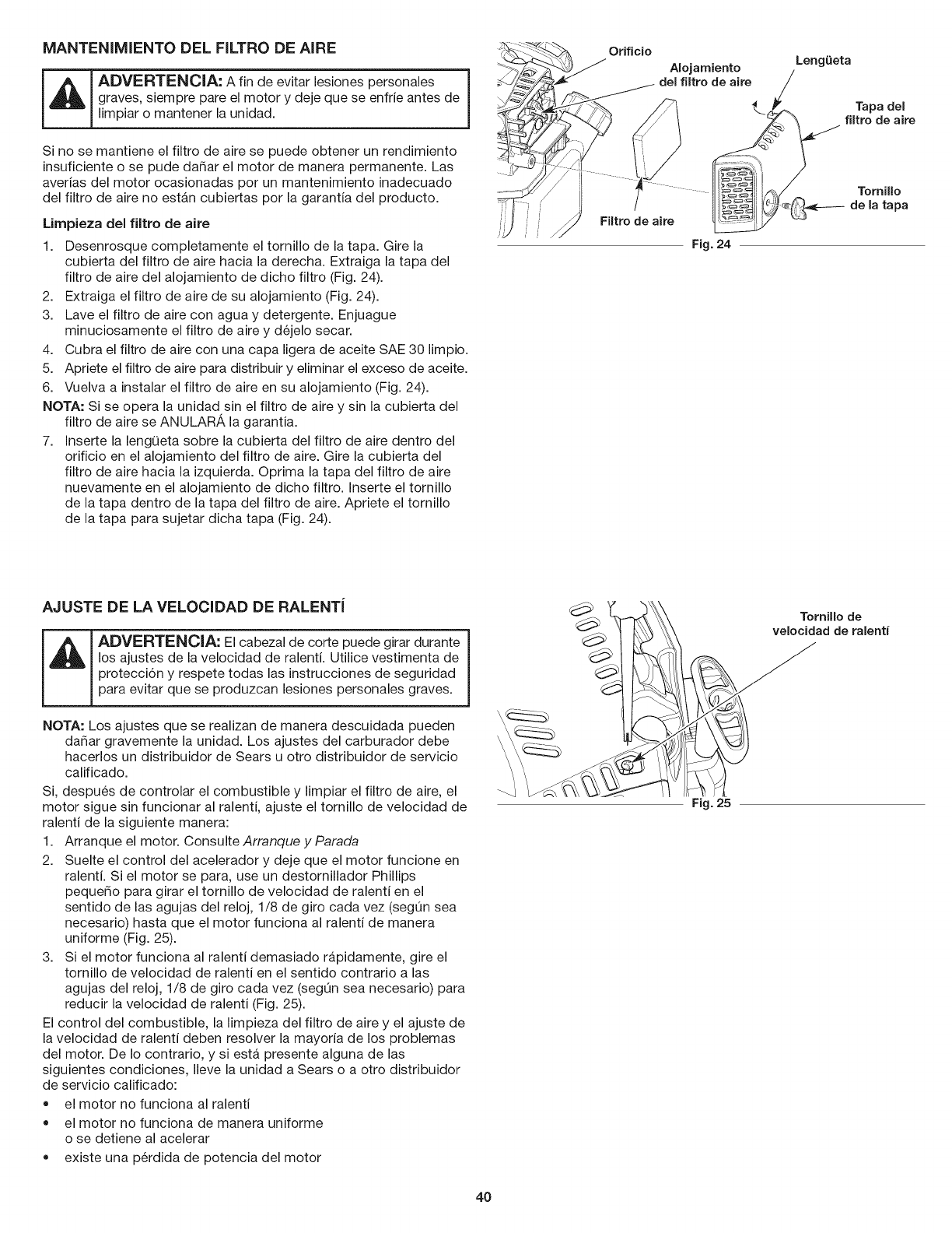
MANTENIMIENTO DEL FILTRO DE AIRE
_ ADVERTENCIA: A fin de evitar lesiones personales
graves, siempre pare el motor y deje que se enfrie antes de J
limpiar o mantener la unidad.
Si no se mantiene el filtro de aire se puede obtener un rendimiento
insuficiente o se pude dahar el motor de manera permanente. Las
averias del motor ocasionadas pot un mantenimiento inadecuado
del filtro de aire no estan cubiertas pot la garantia del producto.
Lirnpieza del filtro de aire
1. Desenrosque completamente el tornillo de la tapa. Gire la
cubierta del filtro de aire hacia la derecha. Extraiga la tapa del
filtro de aire del alojamiento de dicho filtro (Fig. 24).
2. Extraiga el filtro de aire de su alojamiento (Fig. 24).
3. Lave el filtro de aire con agua y detergente. Enjuague
minuciosamente el filtro de aire y dejelo secar.
4. Cubra el filtro de aire con una capa ligera de aceite SAE 30 limpio.
5. Apriete el filtro de aire para distribuir y eliminar el exceso de aceite.
6. Vuelva a instalar el filtro de aire en su alojamiento (Fig. 24).
NOTA: Si se opera la unidad sin el filtro de aire y sin la cubierta del
filtro de aire se ANULAR_, la garantia.
7. Inserte la lengQeta sobre la cubierta del filtro de aire dentro del
orificio en el alojamiento del filtro de aire. Gire la cubierta del
filtro de aire hacia la izquierda. Oprima la tapa del filtro de aire
nuevamente en el alojamiento de dicho filtro. Inserte el tornillo
de la tapa dentro de la tapa del filtro de aire. Apriete el tornillo
de la tapa para sujetar dicha tapa (Fig. 24).
AJUSTE DE LA VELOCIDAD DE RALENTi
ADVERTENClA: El cabezal de corte puede girar durante
los ajustes de la velocidad de ralenti. Utilice vestimenta de
protecci6n y respete todas las instrucciones de seguridad
para evitar que se produzcan lesiones personales graves.
NOTA: Los ajustes que se realizan de manera descuidada pueden
dahar gravemente la unidad. Los ajustes del carburador debe
hacerlos un distribuidor de Sears u otto distribuidor de servicio
calificado.
Si, despues de controlar el combustible y limpiar el filtro de aire, el
motor sigue sin funcionar al ralenti, ajuste el tornillo de velocidad de
ralenti de la siguiente manera:
1. Arranque el motor. ConsulteArranque y Parada
2. Suelte el control del acelerador y deje que el motor funcione en
ralenti. Si el motor se para, use un destornillador Phillips
pequer]o para girar el tornillo de velocidad de ralenti en el
sentido de las agujas del reloj, 1/8 de giro cada vez (segQn sea
necesario) hasta que el motor funciona al ralenti de manera
uniforme (Fig. 25).
3. Si el motor funciona al ralenti demasiado rapidamente, gire el
tornillo de velocidad de ralenti en el sentido contrario alas
agujas del reloj, 1/8 de giro cada vez (segQn sea necesario) para
reducir la velocidad de ralenti (Fig. 25).
El control del combustible, la limpieza del filtro de aire y el ajuste de
la velocidad de ralenti deben resolver la mayoria de los problemas
del motor. De Io contrario, y siesta presente alguna de las
siguientes condiciones, Ileve la unidad a Sears o a otto distribuidor
de servicio calificado:
• el motor no funciona anralenti
•el motor no funciona de manera uniforme
o se detiene al acelerar
•existe una perdida de potencia del motor
Tornillo de
velocidad de ralentf
Fig. 25
40
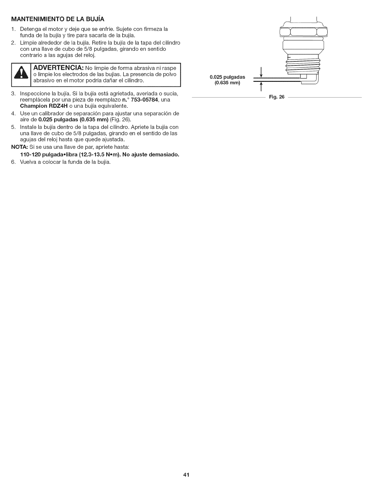
MANTENIMIENTO DE LA BUJiA
1. Detenga el motor y deje que se enfrie. Sujete con firmeza la
funda de la bujia y tire para sacarla de la bujia.
2. Limpie alrededor de la bujia. Retire la bujia de la tapa del cilindro
con una Ilave de cubo de 5/8 pulgadas, girando en sentido
contrario alas agujas del reloj.
_ADVERTENClA: No limpie de forma abrasiva ni raspe |
|
o limpie los electrodos de las bujias. La presencia de polvo ]
abrasivo en el motor podria dadar el cilindro.
3. Inspeccione la bujia. Si la bujia esta agrietada, averiada o sucia,
reemplacela por una pieza de reemplazo n. ° 753-05784, una
Champion RDZ4H o una bujia equivalente.
4. Use un calibrador de separaci6n para ajustar una separaci6n de
aire de 0.025 pulgadas (0.635 ram) (Fig. 26).
5. Instale la bujia dentro de la tapa del cilindro. Apriete la bujia con
una Ilave de cubo de 5/8 pulgadas, girando en el sentido de las
agujas del reloj hasta que quede ajustada.
NOTA: Si se usa una Ilave de par, apriete hasta:
110-120 pulgada,libra (12.3-13.5 Nora}. No ajuste demasiado.
6. Vuelva a colocar la funda de la bujia.
0.025 pulgadas
(0.635 mm) t
Fig. 26
41
LIMPIEZA
_ ADVERTENClA: A fin de evitar lesiones personales
graves, siempre pare el motor y deje que se enfrie antes de J
limpiar o mantener la unidad.
Use un cepillo pequedo para limpiar el exterior de la unidad. No
utilice detergentes fuertes. Los productos de limpieza para el hogar
que contienen aceites aromaticos como pino y lim6n, y los
disolventes como el queroseno, pueden dadar el plastico. Limpie
todo rastro de humedad con una tela suave.
ALMACENAMIENTO
• Nunca almacene la unidad con combustible en lugares donde
las emanaciones pueden alcanzar llamas abiertas o chispas.
Deje que se enfrie el motor antes de almacenar la unidad.
Trabe la unidad para evitar que se la utilice sin permiso o que se
provoquen dados.
Almacene la unidad en una zona seca y bien ventilada.
Almacene la unidad lejos del alcance de los niSos.
AImacenamiento a corto plazo (1-2 semanas)
1. Almacene la unidad en posici6n horizontal. Si esto no es posible,
almacene la unidad de manera vertical con el motor arriba.
Almacenamiento a largo plazo
1. Retire la tapa de combustible, incline la unidad y drene el
combustible en un recipiente aprobado. Vuelva a colocar la tapa
del combustible.
2. Arranque el motor y dejelo correr hasta que se detenga. Esto
asegura que todo el combustible se haya drenado del carburador.
3. Deje que el motor se enfrie. Retire la bujia y ponga 5 gotas de un
aceite para motor de alta calidad dentro del cilindro. Jale la
cuerda de arranque para distribuir el aceite. Coloque
nuevamente la bujia.
4. Limpie minuciosamente la unidad einspeccione si hay alguna
pieza suelta o dadada. Repare o reemplace las piezas dadadas
y ajuste los tornillos, tuercas o pernos que esten flojos.
Preparaci6n de la unidad para su uso luego del
almacenamiento a largo plazo
1. Retire la bujia y drene todo el aceite del cilindro.
2. Cambie el aceite. Consulte Cambio de aceite.
NOTA: No use combustible que haya estado guardado durante mas
de 30 dias. Deseche el combustible usado de acuerdo con las
normativas federales, estatales y locales.
42

PROBLEMA
El bulbo del cebador no se presion6 Io suficiente
La bujia esta averiada
SOLUCION
Oprima el bulbo del cebador 10 veces o hasta que se vea combustible
Vuelva a colocar la bujia
El combustible esta viejo (mas de 30 dias)
El combustible esta viejo (mas de 30 dias)
El filtro de aire esta sucio
El combustible esta viejo (mas de 30 dias)
La bujia esta averiada
Drene el dep6sito de combustible y agregue combustible nuevo
Drene el dep6sito de combustible y agregue combustible nuevo
Limpie o reemplace el filtro de aire
Drene el dep6sito de combustible y agregue combustible nuevo
Vuelva a colocar la bujia
,, iiii:i:i:i:iiiiiiii
SITA AYUDA? ii
,_Busque en Intemet _ste y todos los dem&s manua[es de sus pmductos.
,_ Pregfmtele a nuestro equipo de expertos de( hogar, l
_ Reciba un plan de mantenimiento persona_izado para su hogar.
_ Busque informaci6n y herramientas que _o ayuden en sus proyectos de_ hogar.
43

Felicitaciones por haber hecho una compra inteligente. Su nuevo producto Craftsman@ fue dise_ado y fabricado con vistas a una operaci6n
confiable por a_os. Pero como todos los productos, es posible que sea necesario repararlo alguna vez. Ahi es cuando tener un Convenio de
Protecci6n de Reparacidn puede ahorrarle dinero y problemas.
Esto es Io que incluye el Convenio de Protecci6n de Reparaci6n*:
[] Servicio de experto por nuestros 10,000 profesionales, especialistas en reparaciones
[] Servicio ilimitado y sin costo alguno en piezas y mano de obra para todas las reparaciones cubiertas
[] Reemplazo del producto por otro que cueste hasta $1500 si el producto cubierto no tiene reparaci6n
[] Descuento del 25% del precio normal por el servicio y las piezas instaladas que no cubra el convenio; asi como tambien el 25% de
descuento por el mantenimiento preventivo
[] Ayuda rApida por tel6fono - la Ilamamos Soluci6n Rapida - asistencia tecnica por telefono de un representante de Sears.
Considerenos un "manual de usuario que habla".
Una vez que adquiera el Convenio de Protecci6n de Reparaci6n, todo Io que necesita es hacer una simple Ilamada para programar el
servicio. Puede Ilamar a cualquier hora del dia o de la noche o programar el servicio por Internet.
El Convenio de Protecci6n de Reparaci6n es una compra libre de riesgo. Si usted Io cancela por cualquier motivo mientras dure la garantia
del producto, le haremos un reembolso completo. Si Io hace en cualquier momento despues de vencida la garantia, le haremos un
reembolso prorrateado, iAdquiera hoy mismo su Convenio de Proteccidn de Reparacidn!
Se aplJcan algunas limitaciones y exclusiones. Para precios einformaci6n adicionaJ en Estados Unidos, Ilame al 1=800=827=6655.
*La cobertura en Canada varia en algunos articulos. Para todos los detalles, Ilame a Sears de Canada al 1=800=361=6665.
Servicio de Instalaci6n Sears
Para la instalacidn de electrodomesticos, abrepuertas de garajes, calentadores de agua, y otros productos para el hogar por profesionales
de Sears, en Estados Unidos o CanadA, Ilame al 1=800=4=MY=HOME.
44

45
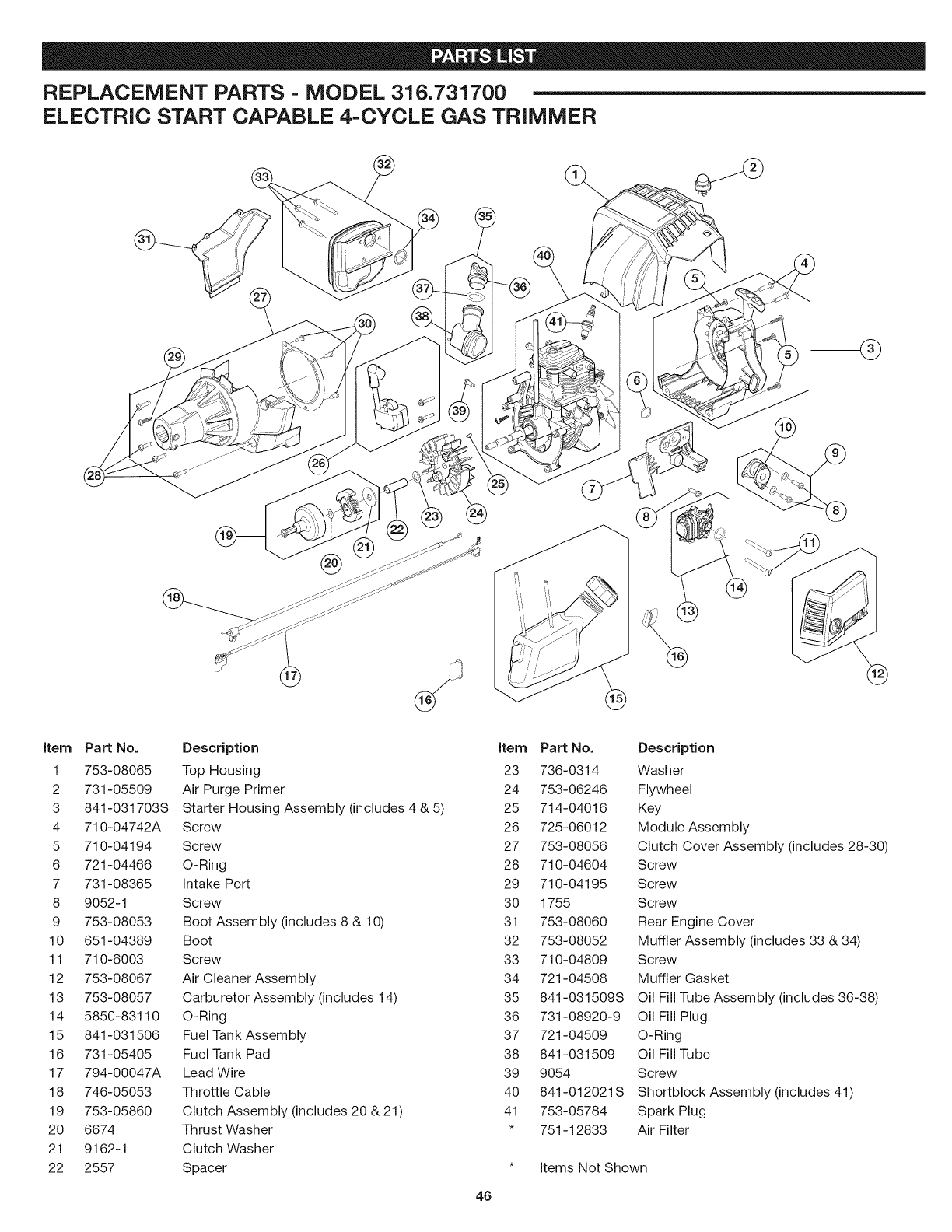
REPLACEMENT PARTS -MODEL 316.731700
ELECTRIC START CAPABLE 4-CYCLE GAS TRIMMER
item Part No. Description item Part No. Description
1 753-08065 Top Housing 23 736-0314 Washer
2 731-05509 Air Purge Primer 24 753-06246 Flywheel
3 841-031703S Starter Housing Assembly (includes 4 & 5) 25 714-04016 Key
4 710-04742A Screw 26 725-06012 Module Assembly
5 710-04194 Screw 27 753-08056 Clutch Cover Assembly (includes 28-30)
6 721-04466 O-Ring 28 710-04604 Screw
7 731-08365 Intake Port 29 710-04195 Screw
8 9052-1 Screw 30 1755 Screw
9 753-08053 Boot Assembly (includes 8 & 10) 31 753-08060 Rear Engine Cover
10 651-04389 Boot 32 753-08052 Muffler Assembly (includes 33 & 34)
11 710-6003 Screw 33 710-04809 Screw
12 753-08067 Air Cleaner Assembly 34 721-04508 Muffler Gasket
13 753-08057 Carburetor Assembly (includes 14) 35 841-031509S Oil Fill Tube Assembly (includes 36-38)
14 5850-83110 O-Ring 36 731-08920-9 Oil Fill Plug
15 841-031506 Fuel Tank Assembly 37 721-04509 O-Ring
16 731-05405 Fuel Tank Pad 38 841-031509 Oil Fill Tube
17 794-00047A Lead Wire 39 9054 Screw
18 746-05053 Throttle Cable 40 841-012021S Shortblock Assembly (includes 41)
19 753-05860 Clutch Assembly (includes 20 & 21) 41 753-05784 Spark Plug
20 6674 Thrust Washer *751-12833 Air Filter
21 9162-1 Clutch Washer
22 2557 Spacer * Items Not Shown
46
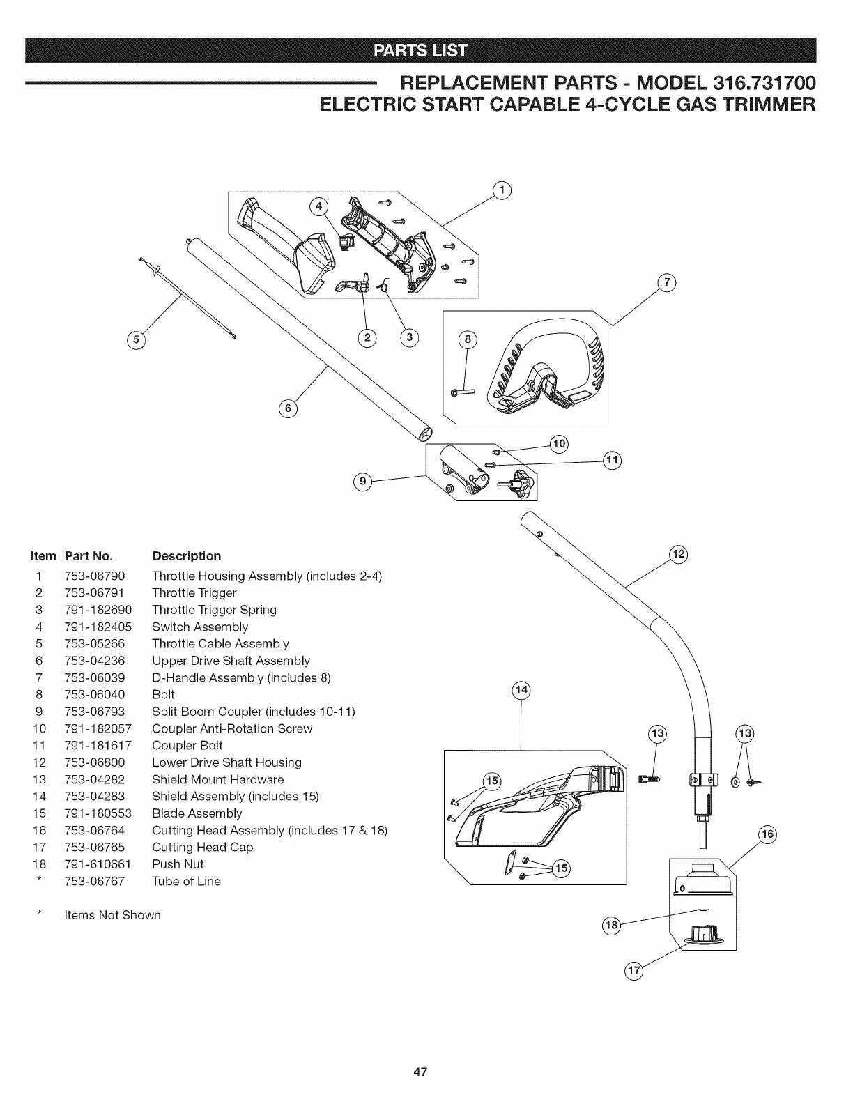
REPLACEMENT PARTS -MODEL 316.731700
ELECTRIC START CAPABLE 4-CYCLE GAS TRIMMER
@
item Part No.
1 753-06790
2 753-06791
3 791-182690
4 791-182405
5 753-05266
6 753-04236
7 753-06039
8 753-06040
9 753-06793
10 791-182057
11 791-181617
12 753-06800
13 753-04282
14 753-04283
15 791-180553
16 753-06764
17 753-06765
18 791-610661
* 753-06767
Items Not Shown
Description
Throttle Housing Assembly (includes 2-4)
Throttle Trigger
Throttle Trigger Spring
Switch Assembly
Throttle Cable Assembly
Upper Drive Shaft Assembly
D-Handle Assembly (includes 8)
Bolt
Split Boom Coupler (includes 10-11)
Coupler Anti-Rotation Screw
Coupler Bolt
Lower Drive Shaft Housing
Shield Mount Hardware
Shield Assembly (includes 15)
Blade Assembly
Cutting Head Assembly (includes 17 & 18)
Cutting Head Cap
Push Nut
Tube of Line
47

Your Home
For troubleshooting, product manuals and expert advice:
managemylife
www.managernylife.com
For repair - in your home - of all major brand appliances,
lawn and garden equipment, or heating and cooling systems,
no matter who made it, no matter who sold it!
For the replacement parts, accessories and
owner's manuals that you need to do-it-yourself.
For Sears professional installation of home appliances
and items like garage door openers and water heaters.
1-800-4-MY-HOME ® (1-8oo-469-460s)
Call anytime, day or night (U.S.A. and Canada)
www.sears.oorn www.sears.ca
Our Home
For repair of carry-in items like vacuums, lawn equipment,
and electronics, call anytime for the location of your nearest
Sears Parts & Repair Service Center
1-800-488-1222 (U.S.A.) 1-800-469-4663 (Canada)
www.sears.corn www.sears.ca
To purchase a protection agreement on a product serviced by Sears:
1-800-827-6655 (U.S.A.) 1-800-361-6665 (Canada)
Para pedir servicio de reparaci6n
a domicilio, y para ordenar piezas:
1-888-SU-HOGAR ®
(1-888-784-6427)
Au Canada pour service en fran(_ais:
I=800=LE=FOYER No
(1-800-533-6937
www.sears.ca
www.sears.com S@SFS
® Registered Trademark /TMTrademark of KCD IP, LLC in the United States, or Sears Brands, LLC in other countries
® Marca Registrada /TMMarca de F&brica de KCD IP, LLC en Estados Unidos, o Sears Brands, LLC in otros paises
MCMarque de commerce /MDMarque d6pos6e de Sears Brands, LLC
