Craftsman 32021195 User Manual 7 1/4 COMPOUND MITER SAW Manuals And Guides L0703163
CRAFTSMAN Miter Saw Manual L0703163 CRAFTSMAN Miter Saw Owner's Manual, CRAFTSMAN Miter Saw installation guides
User Manual: Craftsman 32021195 32021195 CRAFTSMAN 7 1/4 COMPOUND MITER SAW - Manuals and Guides View the owners manual for your CRAFTSMAN 7 1/4 COMPOUND MITER SAW #32021195. Home:Tool Parts:Craftsman Parts:Craftsman 7 1/4 COMPOUND MITER SAW Manual
Open the PDF directly: View PDF ![]() .
.
Page Count: 45
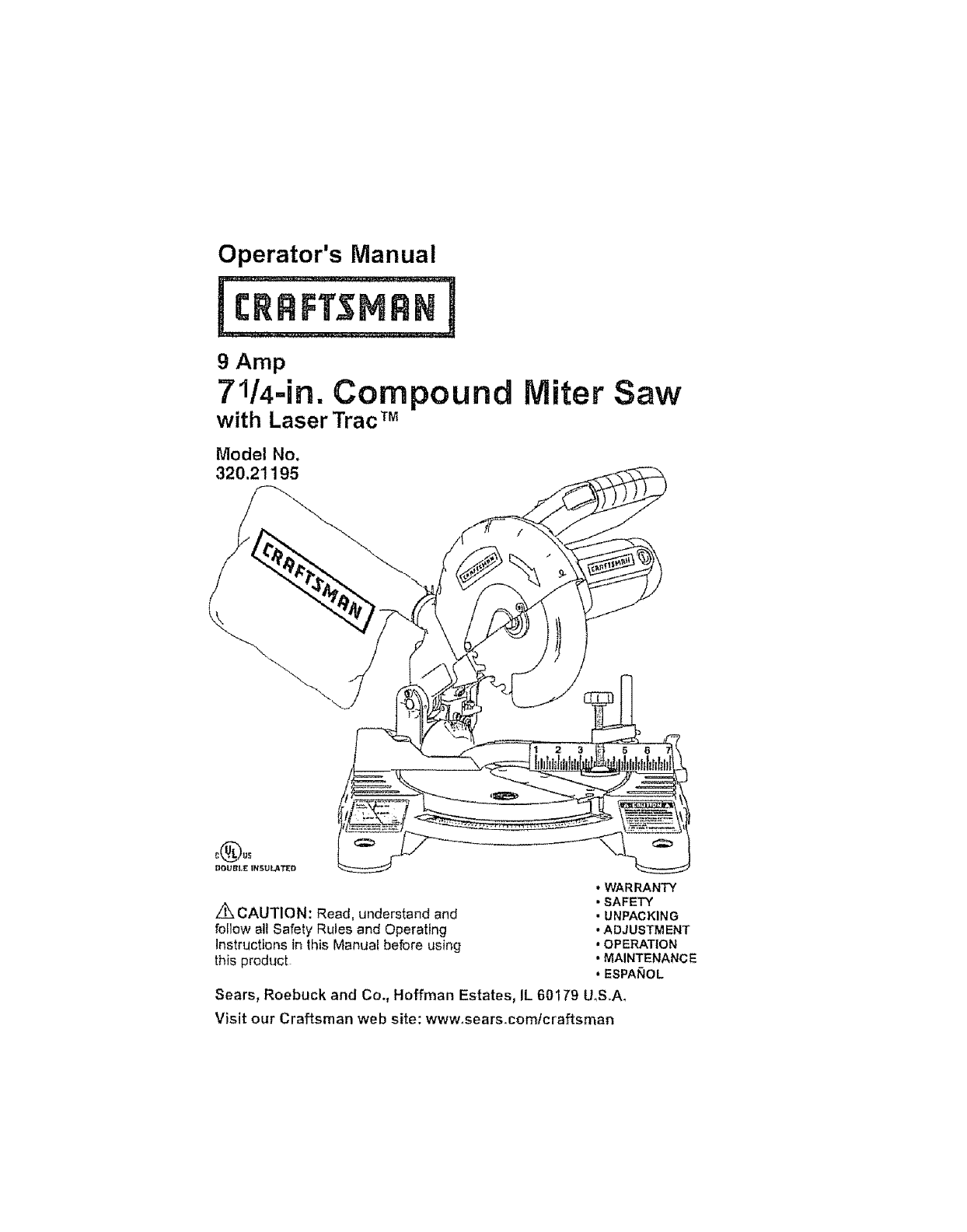
Operator's Manual
9 Amp
71/4-in. Compound
with Laser Trac TM
Model No.
320.21195
Miter Saw
z_CAUTION: Read, understand and
follow all Safety Rules and Operating
instructions in this Manual before using
this product
•WARRANTY
•SAFETY
• UNPACKING
• ADJUSTMENT
. OPERATION
• MAINTENANCE
• ESPAI_O L
Sears, Roebuck and Co., Hoffman Estates, IL 60179 U.S.A_
Visit our Craftsman web site: www.sears.comtcraftsman
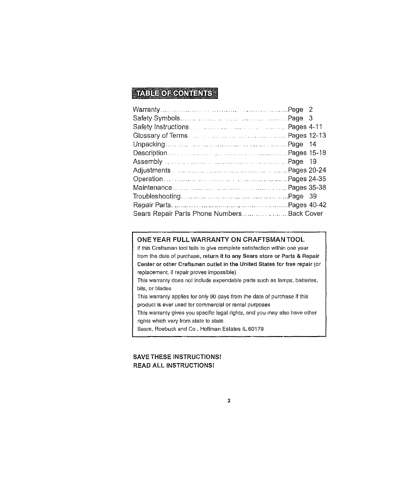
Warranty ..................................................... Page 2
Safety Symbols ................................................. Page 3
Safety Instructions ....................................... Pages 4-11
Glossary of Terms ......................................... Pages 12-13
Unpacking ............................................................... Page 14
Description ................................................... Pages 15-18
Assembly ........................................................... Page 19
Adjustments ............................................................. Pages 20-24
Operation ............................................................... Pages 24-35
Maintenance ................................................................... Pages 35-38
Troubleshooting .............................................................. Page 39
Repair Parts ......................................................................... Pages 40-42
Sears Repair Parts Phone Numbers ......................... Back Cover
ONE YEAR FULLWARRANTY ON CRAFTSMAN TOOL
If this Craftsman too! fails to give complete satisfaction within one year
from the date of purchase, return it to any Sears store or Parts & Repair
Center or other Craftsman outlet in the United States for free repair (or
replacement, if repair proves impossible)
This warranty does not include expendable parts such as lamps, batteries,
bits, or blades
This warranty applies for only 90 days from the date of purchase if this
producl is ever used for commercial or rental purposes
This warranty gives you specific legal rights, and you may also have other
rights which vary from state to state
Sears, Roebuck and Co, Hoffman Estates tL 60179
SAVE THESE INSTRUCTIONSI
READ ALL INSTRUCTIONS!
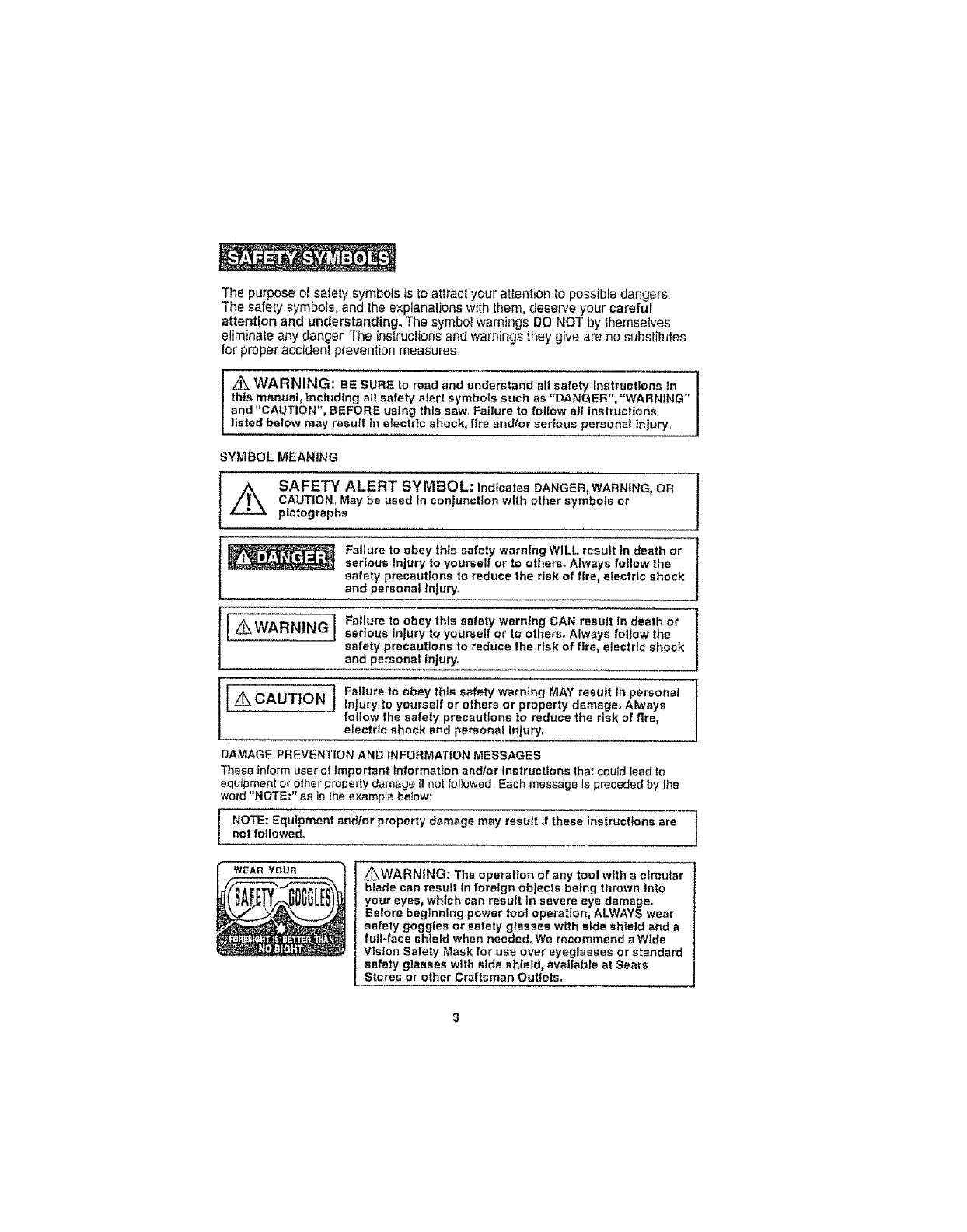
The purpose of safety symbols is to attract your attention to possible dangers
The safety symbols, and the explanations with them, deserve your careful
attention and understanding. The symbol warnings DO NOT by lhemselves
eliminate any danger The instruclions and warnings they give are no substitutes
for proper accident prevention measures
I z_ WARNING: BE SURE to read and understand sit safety instructions in
this manual, Including all safety alert symbols such as "DANGER", "WARNING"
and "CAUTION", BEFORE using this saw. Failure to fotlow atl instructions
listed below may result In electric shock, fire andlor serious personal injury.
SYMBOL MEANING
L_ SAFETY ALERT SYMBOL: IndicatesDANGER,WARNING,OR
CAUTION, May be used In conjunction with other symbols or
plctographs
Failure to obey this safety warning WILL result in death or
serious Injury to yourself or to others. Always follow the
safety precautions to reduce the risk of flre_ electric shock
and personal |nJury..
lL_ WARNING l Failureto obeythissafetywarningCANresultIn deathor
serious Injury to yourself or to others. Always follow the
safety precautions to reduce the risk of fire, electric shock
and personal injury..
l i Failure to obey this safety warning MAY result In personal
L_ CAUTION J injury to yourself or others or property damage° Always
follow the safety precautions to reduce the risk of fire,
electric shock and personal Injury_
DAMAGE PREVENTION AND INFORMATION MESSAGES
These inform user o! Important Information andlor Instructions that could lead to
equipment or other property damage _fnot followed Each message ls preceded by the
word "NOTE;" as in the example below:
l OTE: Equipment andlor property damage may result If these instructions arenot followed.,
WEAR YOUR L_WARN|NG: The operation of any tool with a circular
blade can result tn foretgn objects being thrown Into
your eyes, which can result tn severe eye damage°
Before beginning power tool operation, ALWAYS wear
safety goggles or safety glasses with side shield end a
full-face shteld when needed. We recommend e Wide
Vision Safety Mask for use over eyeglasses or standard
safety glasses with side shield, available at Sears
Steres or other CraRsman Outlets.
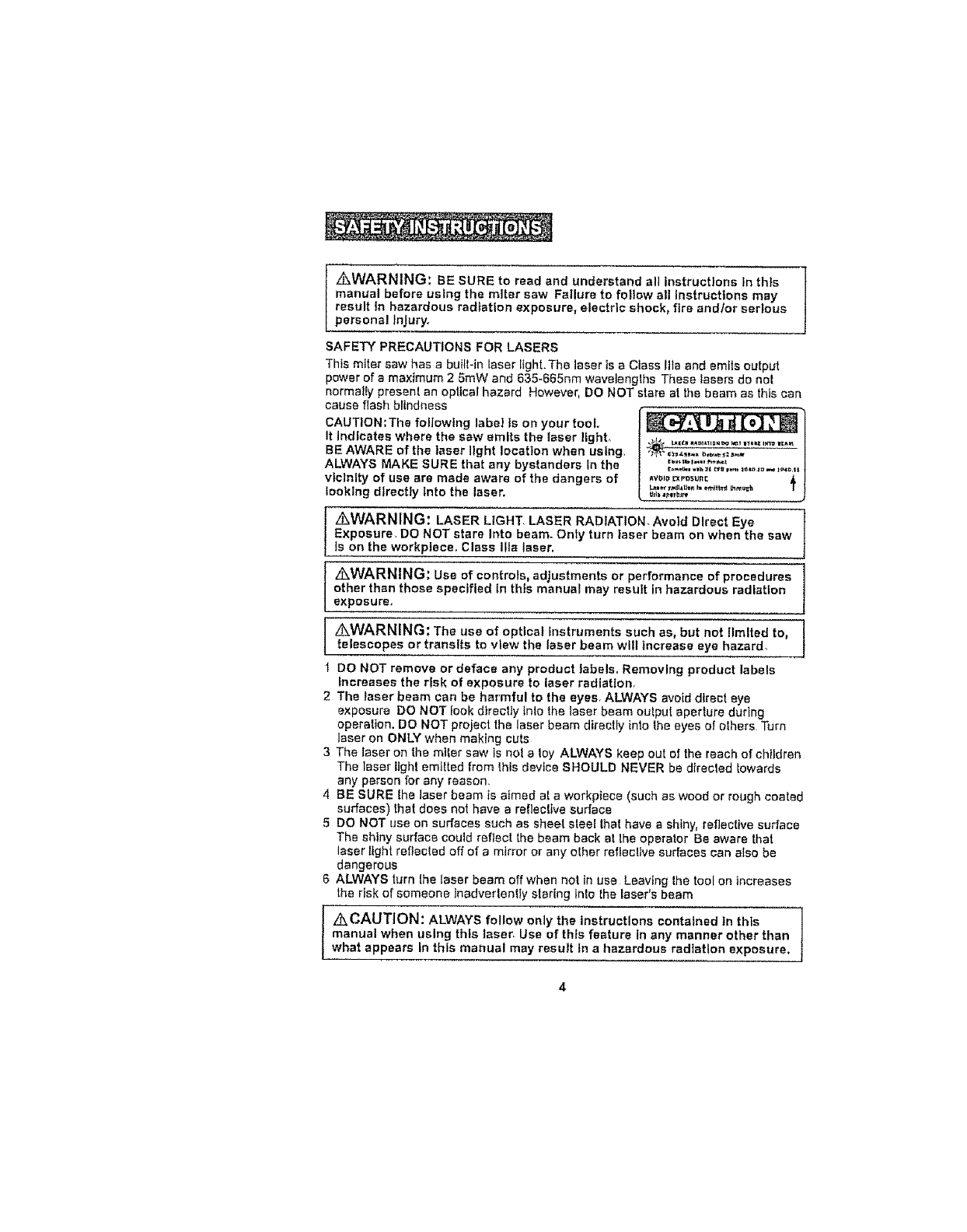
[ _WARNING: BE SURE to read and understand alt instructions In this
manual before ustng the miter sew Failure to foliow all Instructions may
result tn hazardous radiation exposure, electric shock, fire andtor serious
personal Injury.
SAFETY PRECAUTIONS FOR LASERS
This miter saw has a built-in laser Fight.The laser is a Ciass Ilia and emHs output
power of a maximum 2 5mW and 635-665nm wavelenglhs These lasers do nol
normatIy presenl an opttcal hazard However, DO NOT stare at tile beam as this can
cause flash blindness
CAUTiON:The following label Is on your tool
It indicates where the saw emits the inset lighL
BE AWARE of the laser light location when using.
ALWAYS MAKE SURE that any bystanders in the
vlclnlty of use ere made aware of the dangers of
looking directly into the laser,
_VDI_ t:X ¥r_._ttflit
z_,WARNING: LASER LIGHT. LASER RADIATION.Avold Direct Eye
Exposure. DO NOT stare Into beam. Only turn laser beam on when the saw
is on the workplece, Class Ilia laser.
/IkWARNING: Use of controls, adjustments or performance of procedures
other than those specified in this manual may result in hazardous radiation
exposure,,
z_WARNING: The use of optical instruments such as, but not limited to,
telescopes or transits to view the laser beam will increase eye hazard,
DO NOT remove or deface any product }abels. Removing product labels
increases the risk of exposure to laser radiatlon.
2 The laser beam can be harmful to the eyes, ALWAYS avoid dtrect eye
exposure DO NOT look dtrecily inlo the laser beam ouIput aperture during
operation. DO NOT project the laser beam directly into the eyes of olhers Turn
laser on ONLY when making cuts
3 The laser on the miter saw is noI a loy ALWAYS keep out of the reach of children
The laser light emllted from this device SHOULD NEVER be direcled Iowards
any person for any reason.
4 BE SURE the laser beam ts aimed at a workpiece (such as wood or rough coated
surfaces) that does not have a refleclive surface
5 DO NOT use on surfaces such as sheet sleel lhat have a shiny, reflective surface
The shiny surface could reflect the beam back at lhe operator Be aware that
laser light refiecled off of a mirror or any oLher reflec!Ive surfaces can also be
dangerous
6 ALWAYS turn lhe laser beam off when not in use Leaving Ihe tool on increases
the risk of someone inadverlen_ly staring Inlo the laser's beam
' _CAUTION: ALWAYS follow only the instructions contained in this
manual when using this laser. Use of this feature in any manner other than
what appears in this manual may result tn a hazardous radiation exposure.
SAFETY PRECAUTIONS FOR LASERS conL
7DO NOT attempt to modify the performance of this laser device in any way This
may result in a dangerous exposure to laser radiation,
8 ALWAYS use only the accessories that are recommended by Sears for use with
th_s product,. Use of accessories that have been designed for use with other laser
tools could result in serious injury,
9For further information regarding lasers, refer to ANSI-Z136,1 The STANDARD
FOR THE SAFE USE OF LASERS, available from the Laser Institute of Amedca
(407) 380-1553
WORK AREA SAFETY
1. Keep your work area clean and well lit. DO NOT leave tools or wood scraps on
the saw while it is In operation. Cluttered workbenches and dark areas Invite
accidents
2DO NOT operate power tools in explosive atmospheres, such as In the
presence of flammable liquids, gases, or dust, Power tools create sparks
which may ignite the dust or fumes.
3 ALWAYS keep bystanders, children and visitors away while operating a
power tool. Distractions can cause you to lose control,
4 Make your workshop cht|dpreof with padtocks and master switches Lock tools
away when not in use.
5 MAKE SURE the work area has ample tlghtlng so you can see the work and
that there are no obstructions that will interfere with safe operation BEFORE
using your saw
PERSONAL SAFETY
1 KNOW your power tool., Read the operator's manual caretu#y Learn the saw's
applications and limitations, as welt as the specific potential hazards related to
_his tool
2, STAY ALERT, watch what you are doing and use common sense when operating
a power tool
3DO NOT use lool while tired or under the influence of drugs, a_cehe/or
medication A momenl of inattention while operating power tools may result in
serious personal injury
4DRESS properly, DO NOT wear loose clothing or jewelry Pull back long hai_,
Keep your hair. clothing, anrJ gEoves away from moving parts Loose clolh[ng or
long hair can be caught in moving pads Air vents often cover moving parts and
should aise be avoided
5 AVOID accidental starling Be sure switch is in "OFF" posit}on before plugging in
6REMOVE adjusting keys or blade wrenches before turning the too[ "ON".
Awrench lhat is left attached to a relating part of lhe tool may result in persona!
injury
7 DO NOT overreach. Keep proper footing and balance at ell times. Proper
fooling and balance enables better control of the too__n unexpected situations
PERSONALSAFETYeont,
8 ALWAYSSECUREYOURWORK° Use clamps or avise to hold work when
practical It is safer than using your hand and frees both hands to operate tool
g USE SAFETY EQUIPMENT, Always wear eye protection, Dust mask, non-skid
safety shoes, hard hat, or hearing protection must be used for appropriate
conditions
10 NEVER stand on too!, Serious injury could occur if the tool is tipped or tf the
blade is accidentally contacted
TOOL USE AND CARE SAFETY
I _WARNING: SE SURE to read and understand ell Instructions before
operating this saw. Failure to follow all instructions listed below may result
In electric shook, fire and/or serious personal injury,
1. ALWAYS Use clamps or other practical ways to secure and support the
workplace to a stable plat/otto. Holding the work by hand or against your body
is unstable and may lead to loss of control.
2. DO NOT force the tool. Use the correct tool and blade for your application.
The correct loci and blade will do the job better and safer at the rate tor which it
is designed,
3 DO NOT use the tool If switch does not turn tt "On"or "Off"° Any tool that
cannot be controlled with the switch Is dangerous and must be repaired
4 DISCONNECT the plug from the power source before making any
adlustments, changing accessories or storing the tool. Such preventive
safety measures reduce the risk of starling the tool accidentally.
5, NEVER leave the tool running unattended, ALWAYS turn It off° DO NOT
leave until the tool comes to acomplete stop.
6STORE Idle tools out of the reach of children and other untrained persons.
Tools are dangerous tn the hands of untrained users
7 MAINTAIN tools with care. Keep cutting tools sharp and clean. Properly
maintained tools wtth sharp cutting edges are tess likely to bind and are easier
to control
8CHECK for mlsaftgnment or binding of moving parts, breakage of parts,
and any other condition thai may affect the tool's operation tf damaged, have
the tool serviced before using Many accidents are caused by poorly maintained
lools
g USE ONLY accessories that are recommended for this tool. Accessories that
may be suitable for one tool may become hazardous when used on another tool
10 NEVER cut metals or masonry products with thts tool, This miter saw is designed
for use ONLY on wood and wood-like products
11 KEEP blade guards tn place and In good working order.
ELECTRICALSAFETY
z& WARNING: Do not permit fingers to touch the terminal or plug when
Installing or removing the plug from an outleL
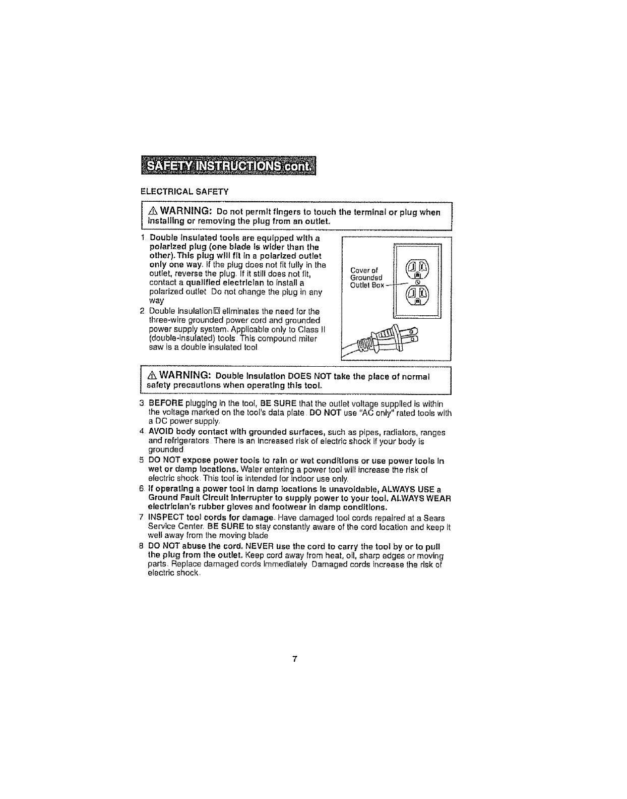
1Double insulated tools are equipped w_th a
polarized plug (one blade is wider than the
other)_Thls plug will fit in a polarized outlet
only one way_ If the plug does not fit fully in the Cover of (_lj_'_
outlet, reverse the plug_ If it still does not lit, Grounded
contact a qualified electrlctan to install a Outlet Box-- _ _.._-.
polarized outlet Do not change the plug in any (_..j It'_
way
2 Double lnsulalfonD eliminates the need for the
three-wire grounded power cord and grounded
power supply system. Applicable only to Class tl
(double-insulated) tools This compound miter
saw is a double insulated tool
z_WARNING: Double Insulation DOES NOT take the place of normal
safety precautions when operating thts tool.
3 BEFORE plugging in lhe tool, BE SURE that the outlet voltage supplied is withtn
the voltage marked on the tool's data plate DO NOT use "AC only" rated tools with
a DC power supply,
4 AVOID body contact with grounded surfaces, such as pipes, radiators, ranges
and refrigerators There Is an increased risk of electric shock if your body is
grounded
5DO NOT expose power tools to rain or wet conditions or use power too_s In
wet or damp locations. Water entering a power tool wtl_ increase the rlsk of
electric shock This tool is intended for indoor use only
6 if operating apower tool In damp locations Is unavoidable, ALWAYS USE a
Ground Fault Circuit Interrupter to supply power to your toot. ALWAYS WEAR
electrfelan's rubber gloves and footwear In damp conditions,
7INSPECT tool cords for damage. Have damaged toot cords repaired at a Sears
Service Center BE SURE to stay constantly aware of the cord location and keep it
welt away from the moving blade
8 DO NOT abuse tile cord° NEVER Use the cord to carry the toot by or to pull
the plug from the outlet. Keep cord away from heat, oil, sharp edges or moving
parts Replace damaged cords immediately Damaged cords increase the risk of
electric shock
EXTENSION CORDS
Use aproper extension cord. ONLY use cords listed by Underwriters Laboratories
(UL) Other extension cords can cause a drop in line voltage, resulting in a loss of
power and overheating of tool
For this tool an AWG (American Wire Gauge) size of a least 14-gauge is
recommended for an extension cord of 25- ft. or less in length Use 12-gauge for an
extension cord of 50-It Extension cords 100-fto or longer are not recommended.,
Remember, a smaller wire gauge size has greater capacity than a larger number
(14-gauge wire has more capacily than 16-gauge wire; 12-gauge wire has more
capacity than 14-gauge) When in doubl use lhe smaller number
When operating a power tool outdoors, use an outdoor extension cord marked
"W-A" or "W" These cords are rated for outdoor use and reduce the risk of electric
shock,
Z_ CAUTION: Keep the extension cord clear of the working arem Posltfon
the cord so that it will not get caught on lumber, tools or other obstructions
while you are working with apower tool,
Z_ WARNING: Check extension cords before each use+ If damaged
replace immediately, Never use tool with e damaged cord since touching
the damaged area could cause electrical shock, resulting In serloue Injury,
The label on your tool may include the following symbols
V ............................... Volts
A ............................ Amps
Hz ........................ Hedz
W.......................... Watts
rain .................. Minu_es
'-,............................. Alternating Current
................... Direct Current
No-lead Speed
Q ....................... Class II construction
,/min ............... Revolulions or Strokes per minule
Z_ ......... Indicates danger, warning caution
It means altentiont Your safety is involved
SERVICE SAFETY
1 tf any part of this saw Is missing or should break, bend, or fall In any way;
or should any electrical component fall to perform properly: SHUT OFF the
power switch and remove the saw plug from the power source and have the
missing, damaged or failed parts replaced BEFORE resuming operation
2 Tool service must be performed only at aSears Parts and Repair Cente_
Service or maintenance performed by unqualified personnel could result in a risk
of injury
3 When servicing a tool, use onJy fdentlca] replacement parts° Follow
instructions in the maintenance sectlon of this manual. Use of unauthorized
parts or failure to follow maintenance instructions may create a risk of etectdc
shock or Injury
SAFETY RULES FOR MITER SAWS
1Know your power tool. Read operator's manual carefully. Learn the
applications and limitations, as well as the specific potential hazards
related to thls tool. Following this rule will reduce the risk of electric shock, fire
or serious injury
2ALWAYS firmly clamp or bolt your miter saw to a secure, stable workbench or
table at approximately hip height
3 BE SURE that all adjustments are secure BEFORE making a cut,
4ALWAYS make sure that the miter table and saw arm (beret function) are locked
in position BEFORE operating your saw_ Lock the miter table by securely
tightening the miter lock lever, Lock the saw arm (bevel function) by securely
tightening the bevel lock knob
5 USE the hold down clamp (included) to secure the workpiece, WHENEVER
possible.
6 BE SURE that the blade path Is free of nails. ALWAYS carefully Inspect lumber
and remove all nails BEFORE cutting
7 ALWAYS be sure that the blade clears the workplece, NEVER start the saw
with the blade touching the workptece, ALWAYS allow the motor to come up
to full speed BEFORE starting a cut
8SUPPORT iong workpleces when cuttfng to mlnlmlze the risk of blade
pinching or kickback. The saw may stip, walk or stIde while cutting tong or heavy
boards,
9 NEVER use a length-stop on the free (scrap end) of a cfamped workplsce,
NEVER hold onto or bind the free scrap end of the workplace in any operation
If a work clamp and length stop are used together, THEY MUST BOTH BE
INSTALLED on the SAME SIDE of the saw table to prevent the saw from
catching the ioose end and kicking up
10, NEVER cut more than one piece at a tlmeo DO NOT STACK more than one
workpfece on the worktable at e ttme.
I1 AVOID awkward operations and hand posltlorts where asudden slip could
cause your hand to move Into the blade. ALWAYS make sure that you have
good balance. NEVER operate your saw on the floor or In a crouched
posltlom
12 NEVER stand or have any part of your body In line with the path of
the blade.
SAFETY RULES FOR MITER SAWS cOnto
13, ONLY USE the correct blades° Use the rlght blade size, style and cutting speed
tor the material and the type or cut, DO NOT use biades with Incorrect size holes
NEVER use blade washers or blade bolts that are detective or incorrect The
maximum blade capacity for this saw is 7V4-inehes
14 ALWAYS keep blades clean, sharp and with the sufficient seL Sharp blades
minimize stalling and kickback
15 DO NOT use dul! or damaged blades. Bent blades can break easity, or cause
kickback
16 DO NOT remove the saw's blade guards, NEVER operate the saw with any
guard or cover removed. MAKE SURE that all guards are operating properly
BEFORE each use,
17 NEVER hand hold a workplace that Is too smelt to be clamped, ALWAYS
keep your hands clear of the "no hands" zone.
18 NEVER perform any operation freehand. ALWAYS place the workplace to be
cut on the miler saw tabie and position it firmty against the fence as a backstop
ALWAYS use the fence
lg NEVER appfy lubricants to the blade when it is running. NEVER use sotvents to
clean plastic parts. Solvents could posstbty dissolve or otherwise damage the
material
20, KEEP YOUR HANDS AWAY from the cutting area, DO NOT reach under the
material being cut or in the blade's cutting path with your fingers or hand for any
reason. ALWAYS turn the power off
z_,WARNING: Blade continues to turn after power to sew cuts ell To
avoid possible serious Injury, after releasing trigger switch to cut power,
allow the saw biade to stop rotating BEFORE raising the blade out of the
workpteceo
21. NEVER reach behind, under or within three Inches of the blade and its
cutting path with your hands or fingers for any reason,
22, NEVER, for any reason, touch the bfade or other moving parts during usm
23 DO NOTturn the motor switch on end off rapldly, This could cause the blade
to loosen, which could create a hazard. Should this ever occur, stand clear and
allow the saw blade to come to a complete stop. Disconnect the saw trom the
power source and securely tighten the blade boJt
24 ALWAYS turn off the saw before disconnecting It to avoid accidental starting
when reconnecting the saw to a power supply. NEVER leave the saw unattended
whtte connected to a power supply
25, KEEP THE MOTOR AIR SLOTS clean and free of chips or dusl. To avoid motor
damage, the motor should be blown out or vacuumed frequently to keep sawdust
from interfering with the motor ventilation,
26 NEVER lift this tool by gripping the cutting handle or the miter fenceoThls
may cause mtsallgnment. ALWAYS carry saw by holding the base or carry
by the support bracket/carrying hendfe after you have locked the saw srm
In the "DOWN" position.
10
SAFETY RULES FOR MITER SAWS conL
WARNING: Some dust particles created by power sandlng_ sawing,
grinding, drilling and other construction jobs contain chemicals known to
cause cancer, birth defects or other reproductive harm. Some examples of
these chemicals are:
•Lead from lead-based paints.
°Crystalline sltica from bricks and cement and other masonry products
•Arsenic and chromium from chemtca]iy4reated lumber,
Your risk from these exposures varies, depending upon how often you do
this type of work. To reduce your exposure to these chemicals:
,, Work In a wel!-venti]ated area
• Work with approved safety equipment, such as these dust masks that are
specially designed to filter out microscopic particles.
ADDITIONAL RULES FOR SAFE OPERATION
z_WARNING: Use of this tool can generate and!or disburse dust, which
may cause serious and permanent respiratory or other injury. Always Use
NIOSHtOSHA approved respiratory protection appropriate for the dust
exposure. Direct particles away from face and body_
1 Know your power toolo Read operator's manual carefully° Learn the
applications and limitations, as welt as the specific potential hazards retsted
to this tool. Following this rule will reduce the nsk of electric shock, fire or serious
injury
2. ALWAYS wear safety glasses or eye shields when using this saw, Everyday
eyeglasses have only impact-resistant lenses; they are NOT safety glasses. All
users and bystanders MUST wear eye protection that conforms to ANSI Z87 1
3 PROTECT your lungs° Wear a face mask or dust mask if the operation is dusty
4PROTECT your hearing. Wear appropriate personal hearing protection during
use. Under some conditions and duration of use, noise from this product may
contribute to hearing less
5ALL VISTORS AND BYSTANDERS MUST wear the same safety equipment that
the operator of the saw wears
6. iNSPECT the tool cords periodically and if damaged have them repaired at your
nearest Sears Service Center or other Authorized Service Facility. BE AWARE of
the cord location when operaling the saw
7ALWAYS check the too! for damaged parts,. Before further use of the tool,
a guard or other part that is damaged should be carefully checked to determine if
it will operate properly and perform its Intended function Check for mlsalignment
or binding of moving parts, breakage of parts, and any other condition that may
affect the tool's operation. A guard or other part that is damaged should be
properly repaired or replaced at a Sears Service center
8 INSPECT and remove all nails from lumber before sawing.
9SAVETHESE INSTRUCTIONS,. Refer to them frequently and use them to
Instruct others who may use this tool, If someone borrows this tool, make
sure they have these instructions alsoo
1I

Arbor
The revolving shaft on whfch a b_ade or cutting tool is mounted,
Arbor Lock
Allows the user to stop blade from rotating while tightening or loosening the arbor
screw during blade replacement or removaf
Revolutlons Per Minute (RPM)
The number of turns completed by a spinning object in one minute
No Hands Zone
The area between the marked lines on the left and right sfde of the miter table base
This zone is identified by no hands zone symbols inside the marked lines on the
miter table base.
Throat Plate
A ptastic throat plate inserted in the miter saw's table that allows for blade clearance
Saw Blade Path
The area over, under, behind or in front of the blade, as it applies to the workpiece,
That area which will be or has been cut by the blade
Set
The distance that the saw blade tooth is bent (or set) outward from the face of
the biade
M_ter Cut
A cutting operation made with the blade at any angle other than go ° lo the fence-
Compound Miter Cut
A compound miter cut is a cut made using a miler angle and a bevel angle at the
same time,
Cross cut
A cutting or shaping operation made against the grain of the workptece
Bevel Cut
A cutting operation made with the blade at any angle other lhan 90 ° to the miter table,
Dado Cut
A non-through cut which produces a square-slded notch or trough in the workplace
(requires special blade)
12
Chamfer Cut
A cut removtng a wedge from a block of wood so the end (or part of the end} is
angled at other than 90 _'
Ripping or Rip Cut
A cutting operation along the length of the workpiece
Freehand Cut
Performing acut without using afence, miter gauge, fixture, work clamp, or other
proper device to keep the workpiece from twisting or moving during the cut,
Through Sawing
Any cutting operation where the blade extends completely through the thickness of
the workpiece
Non-Through Cuts
Any cutting operation where the b}ade does not extend comptetely through the
thickness of the workptece,
Kerf
The material removed by the blade in a through cut or the siot produced by the blade
in a non-through or partial cut
Kickback
A hazard that can occur when the blade binds or stalls, throwing the workptece
back toward operator
Workplece or Matertal
The Item on which the cutting operation is being done The surfaces of a workpiece
are commonly referred to as faces, ends and edges
Gum
A sticky, sap-based residue from wood products
Resin
A sticky, sap-based substance that has hardened
13
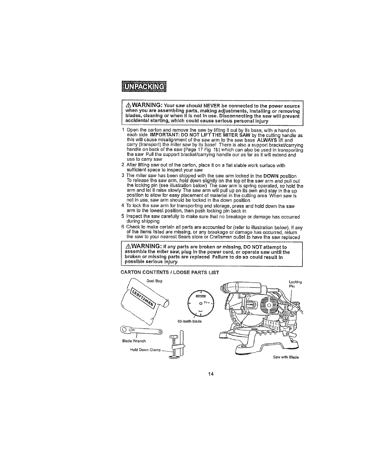
I,4kWARNtNG: Your saw should NEVER be connected to the power source
when you are assembling parts, making adjustments, Installing or removing
blades, cleaning or when it ts not In use. Disconnecting the saw will prevent
accidental starting, which could cause serious personal Injury
I Open lhe cation and remove the sew by lifting il out by _ls base, wtlh ahand on
each side IMPORTANT: DO NOT LIFTTHE MITER SAW by the culling handfe as
this will cause misatignment of the saw arm to the saw base ALWAYS fiftand
carry (transpod) Ihe miter saw by its base! There is also a support brackeUcarrying
handle on back of the saw (Page 17 Fig lb) which can also be used in transporting
the saw Pull the support bracket/carrying handle our as far as it will extend and
use to carry saw
2 After lifting saw ou_ of lhe carlon place Jton a flat stable work surface wIlh
suffic ent space to inspecl your saw
3 The miter sew has been shipped with Ihe saw arm locked in the DOWN position
To release the saw arm, hold down sltghlly on the top of the saw arm and puf_ oul
the Iocklng pin (see Illustration below) The saw arm _sspring eperaled, so hold lhs
arm and let tl raise slowly The saw arm will pull up on tfs own and slay in the up
position to allow for easy placement of material [n lhe cutting area When saw is
not in use, saw arm should be Iocked in the down position
4 To lock the saw arm for transport{rig and storage, press and hold down the saw
arm 1o the Iowesl posllbn, then push locking pln back in
5 Inspec[ lhe saw carefully lo make sure lhat no breakage or damage has occurred
during shipping
6 Check lo make certain all parts are accounted for (refer to illustration below). If any
of the items t[sled are missing, or any breakage or damage has occurred, return
the saw to your nearest Sears store or Craftsman ou[le| lo have lhe saw replaced
/kWARNING: If any parts are broken or missing, DO NOT attempt to ]
assemble the miter saw, plug In the power cord, or operate saw until the /
broken or missing parts are replaced. Failure to de so could resutt In
possible serious injury.
CARTON CONTENTS ILOOSE PARTS LIST
Sew wllh B_adB
I4
KNOWYOURMITER SAW (Fig, la &lb)
INOTE: Before attempting to use your saw, familiarize yourself with all of the ]operating features and safety requirements, /
Your m_ter saw has a precision-built electric motor and It should only be connected
to a t20welt, 60-Hz AC ONLY power supply (normal household current) DO NOT
operate on dlreei current (DC) The large voltage drop would cause a loss of power
and the motor would overheat. If the saw does not operate when plugged into correct
120-volt, 6O-Hz AC ONLY outlet, check the power supply. The saw comes with a 6-it,
power cord (no adapter needed)
This Compound Miter Saw has the following features:
1.9.0 Amp, 5000 RPM (noqoad speed) motor. Provides power and torque for last,
90" cross cuts, 45" miter, bevel and compound cuts in decorative wood moldings
such as chair rail, cove, shoe and baseboard, and cuts 2 X 4's with ease
2. Easy-to-read bevel and miter scales° Positive miter stops at 0 °, 15", 225 _, 30 _,
and 45 =left and right for exact miter cuts
3 Ergonomlcally designed handle with molded-ln comfort grip for maximum
controt and eomfodable hand support when cutting
4 Includes two, Craftsman ®, 7-1/4qn. carbide-tipped, steel blades; a 24qooth
blade for rapid cutting, and a 60-tooth blade for smooth, finish cutting, Both
blades are suitable for cutting wood and wood-like materials 5/8-in arbor.
Arbor loci{ for quick, easy blade changes
5 Die-east aluminum upper blade guard, table, fence and base are lightweight
and durable. Saw weighs only 'i6-tbs, one of the tightest, most compact miter
saws on the market
6Durable htghqmpact plastic lower blade guard allows view of workplace and
laser cutting line,
7Sawdust ejection port hooks up to dust bag (included) or a 1 V4-tn hose adapter
for a welJdry vac (so_d separately).
8 Easy-to-use knob and iever for quick miter, bevel end compound miter
adjustments, no tools needed
gProject ruler etched on right fence for quick reference; 1 to 7inches In
1/84n increments
10 Permanently lubricated 100% bah bearings for long toof life and smooth
operation,
1,_WARNING: DO NOT allow familiarity wtth your saw to make you
careless. Remember that a careless fraction of a second Is sufficient to
Inflict serious Injury,
t 1 Saw arm locktng pin locks saw arm In DOWN posilton when pushed In Pull
locking ptn out to release saw arm
12 Arbor lock button stops arbor from rotating for easy blade changes
15
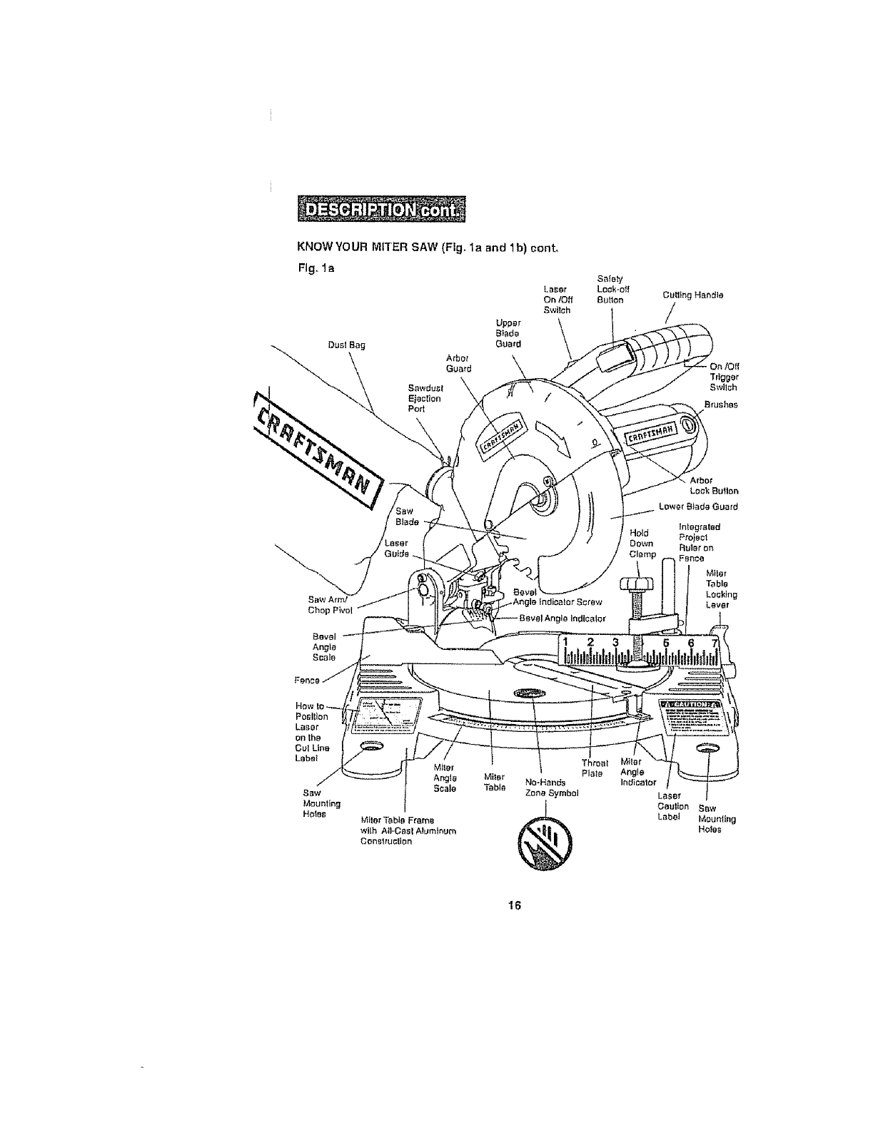
KNOWYOUR MITER SAW (Flg. la and 1b) cont_
Fig. I a
Hold
Down
\Arbor
Lock Butlon
Lower Btada Guard
Miler
Table
Throat Miter
Plale Ang!e
No-Hands Indicator
Zone Symbol Laser
Caution Sow
Label Mounting
HO_aS
16
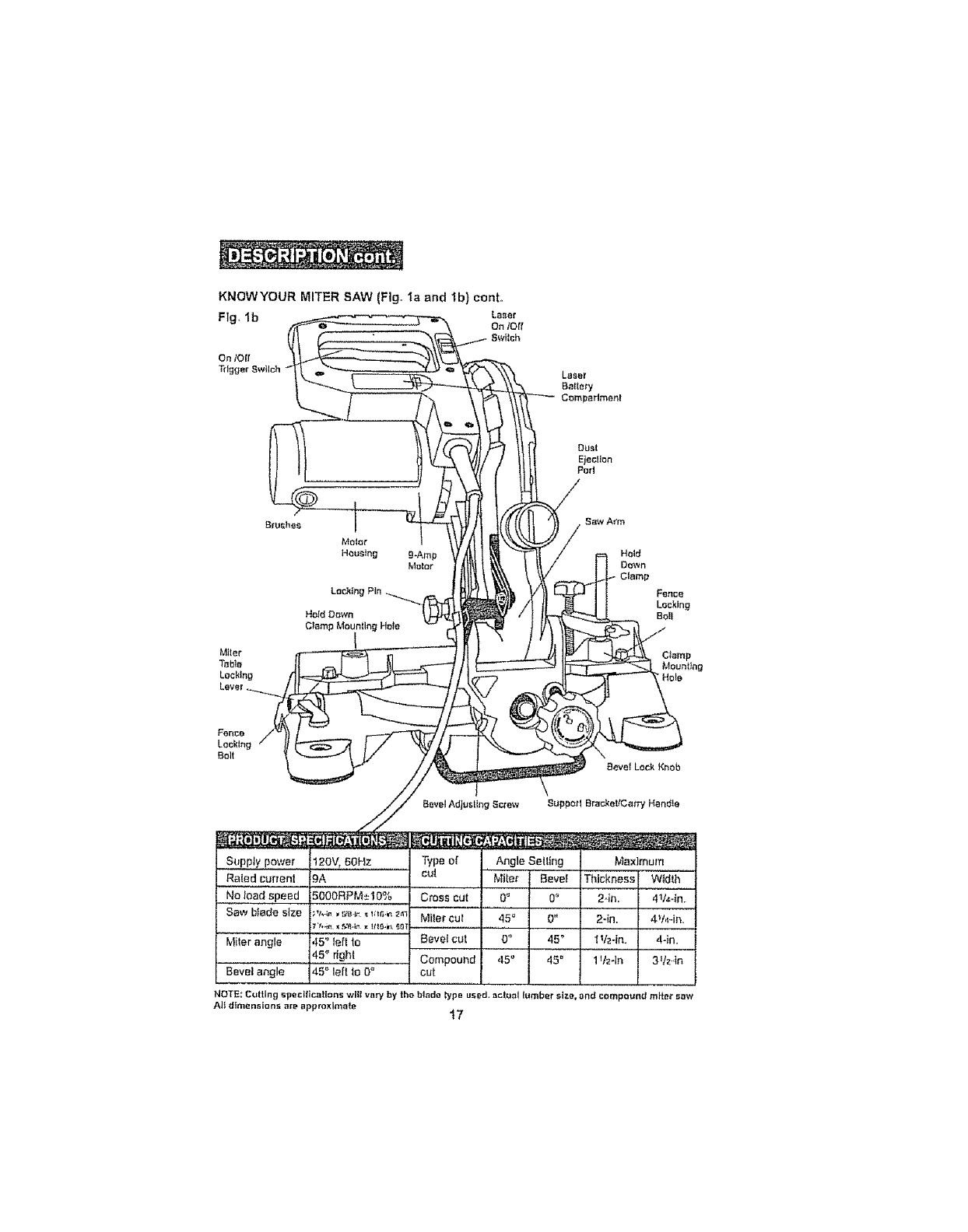
KNOWYOUR MITER SAW (Fig, ta and 1b) cool
Fig.Ib L_ar
On loll
Switch
On I0[!
Trigger 8wilch
Dust
Ejecllon
Purl
Mtter
LacNng
Lever.
Meier
Housing
Fence
Locking
Bolt
Supply power 120V, 6OHz
Rated current 9A
.......No,,!oad,speed- 5000RPM±t0%
Saw blade stze ;,1,4,,, -.,,_._ _ ,_,_._ _,_,
7%_11X,_'8,;?xt/IG,i_ _O
Miler angle ,I5" tell to
45° dghl
Bevel angle 45 _' leit to O"
Typeo[
cu|
Angle Selting
Miter Bevel
CR3ss cut
Miter cur
Bevel cut
Compound
cut
O_ 0o
45" O"
O_ 45 _
,15" 45"
Maximum
Thickness Width
2.1n. 4V,_-in
2-irL 4V,_-in.
t V2-in. 4-in.
11M-in 3Vz,tn
NOTE: Cutting specifications wilt var,/by the btad_ lypo used, _ctool tembar stze, and compound mite_" saw
A]_ dimensions are approximate I7
KNOW YOUR MITER SAW (Fig,, la and lb) cent.
Laser On/Off Switch
To turn on laser, push the laser switch to "On"
On/Off Trigger Switch and Safety Lock-Off Button
To turn on saw, push safety lock button in with thumb whiSesqueezing the On/Off
Trigger Switch located under the handle (Fig, lb) To shut off saw, simply
release both,
Easy-to-read miter and bevel scales:
Miter angle scats marked in 1/2" increments, emphasis on every 5", from 0 ° to 45 ° left
and right Positive miter stops at 0°, 15°, 22.5 °, 30 °, and 45 _ for exact cuts
Bevel angle scale marked in 1° increments, emphasis on every 5°, from 0° to 45 _ feft
with 33.9" marked
MIterTable Locking Lever
The miter table locking lever locks the saw table at the desired miter angfe, 0 ° to 45 °
left or right The table turns teft or right by releasing the miler lock lever and moving
the base of the cutting assembiy (which moves the miler table) while holding the
miter tabte frame secure
Bevel Lock Knob
The bevel lock knob securely locks your compound miter saw at the desired bevel
angies_ To loosen the knob, turn counterclockwise and t$1tthe saw head to set to the
desired angle as shown on the bevel scale. The blade can be positioned at any angle,
from a 90 ° straight cut (0 n on the scale) to a 45" left bevel (Fig lb) Tighten the bevel
lock knob to secure the saw head
Miter Fence
The miter fence is in two pieces, with a numbered ruler on the right side and a
slightly taller left side for additional support. Hold the workpiece securely against the
miter fence when making all cuts, Use the hold down clamp to secure the workpiece
whenever possible,
Seff-Retracttng Lower Blade Guard
The lower blade guard is made of shock-resistant, see4hrough plastic and it provides
protection from each side of the blade It retracts over the upper blade guard as the
blade is bwered into the workpiece,
Hold Down Clamp
Mounts on left or right side ol fence to securely clamp workpiece
Carrying Hendfe/Support Bracket
Use to carry and transpod saw, Also stabilizes the saw (front to back) on flat surface,
19
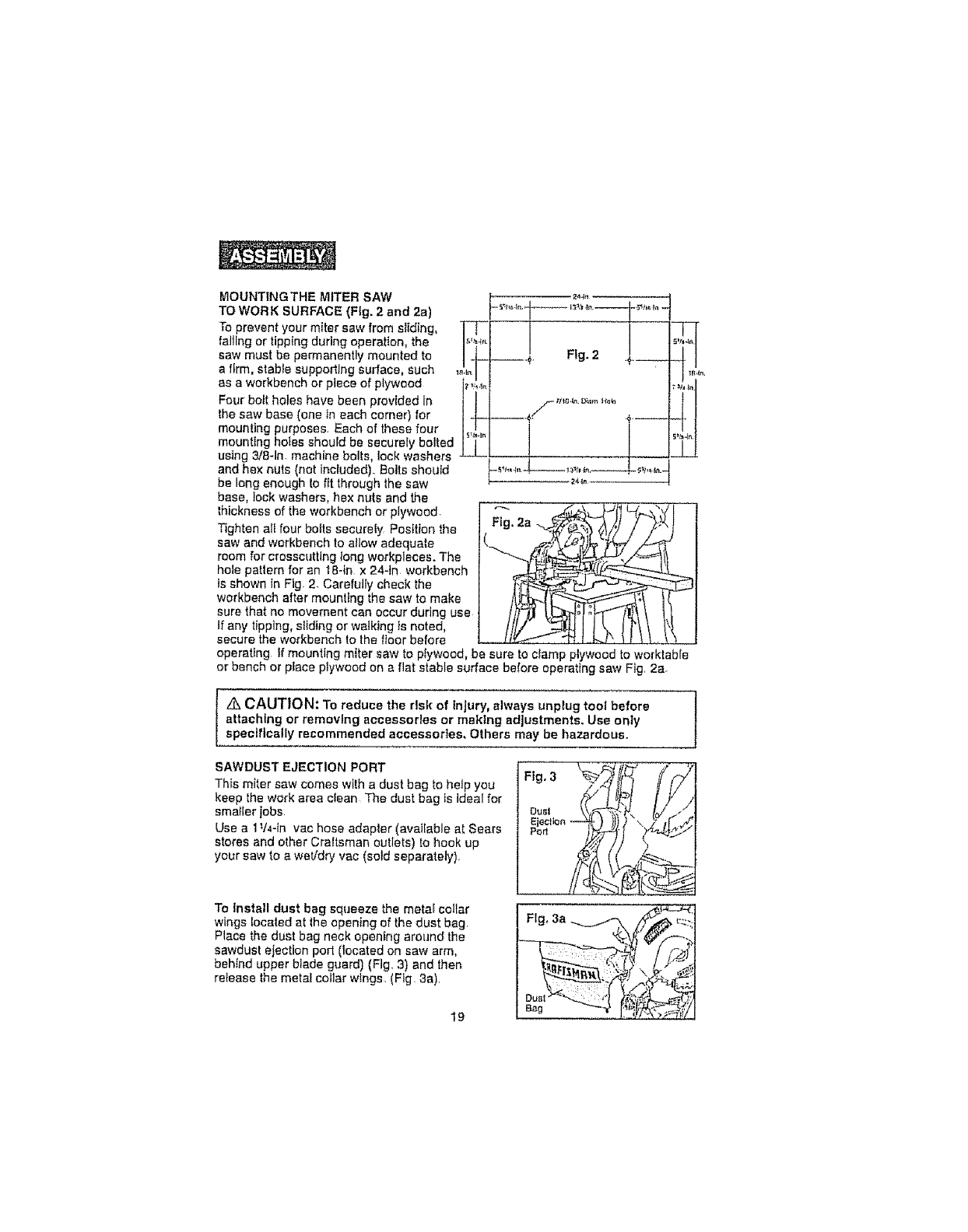
MOUNTINGTHEtvltTER SAW
TO WORK SURFACE (Fig. 2 and 2a)
To prevent your miter saw from sliding, it
saw must be permanently mounted to
afirm, stable supporting surface, such ,,,
as a workbench or piece of plywood i_.,_._.
Four bolt holes have been provided in
the saw base (one in each corner) for
mounting purposes. Each of these four
mounting holes should be securely bolted
using 3t8-1n. machine bolts, lock washers
and hex nuts (not included). Bolts should
be long enough to fit through lhe saw
base, lock washers, hex nuts and the
thickness of the workbench or plywood [ "-"
Tighten eli four bolts securely Position the I Flg. 2a
saw and workbench to allow adequate
room for crosscutting tong workpleces. The
hole pattern for an 1a-in x 24-1n workbench
is shown in Fig 2. Carefully check the
workbench after mounting the saw to make
sure that no movement can occur during use
If any tipping, sfld]ng or walking Is noted,
secure the workbench to the floor before
operating tf mounting miter saw to plywood, be sure to clamp plywood to worktable
or bench or place plywood on a flat stable surface before operating saw Fig. 2a.
244n
"1
Z_ CAUTION: To reduce the risk of Injury, always unplug tool before
attaching or removing accessories or making adjustments. Use only I
specifically recommended accessories, Others may be hazardous.
SAWDUST EJECTION PORT
This miter saw comes with a dust bag to help you
keep the work area cEean The dust bag _sideal for
smaller jobs
Use a 11/4-tn vac hose adapter (available at Sears
stores and other Craltsman outlets) to hook up
your saw to a wet/dry vac (sold separately).
To Install dust bag squeeze the metaf collar
wings located at lhe opening of the dust bag
Place the dust bag neck opening around the
sawdust ejection port (located on saw arm,
behind upper blade guard) (Fig, 3) and lhen
release the metal collar wtngs. (Fig. 3a).
I9
Fig, 3a
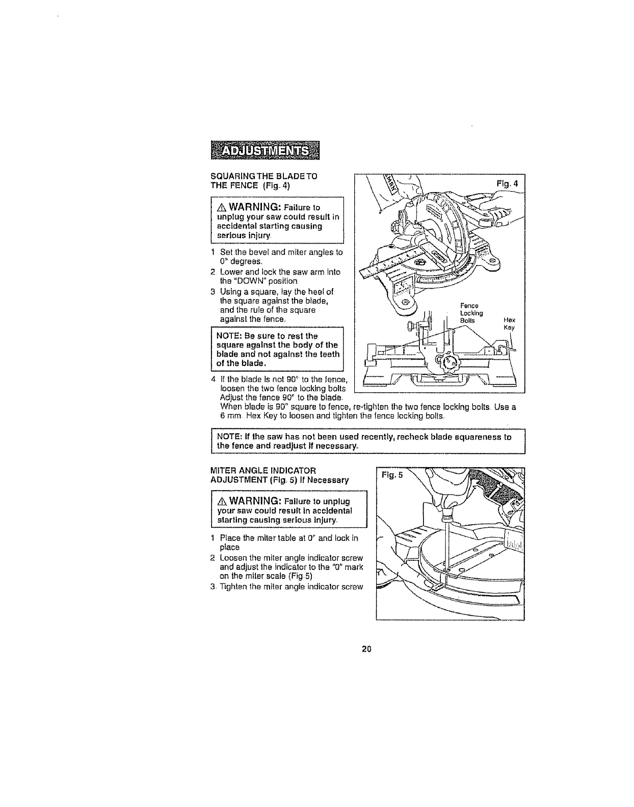
SQUARINGTHEBLADETO '_' " _&_ J
THE FENCE (Fig. 4) \ \_\ _ Fig. 4
unplug your saw could result in
accidental starting causing
serious njury, _
I Set the bevel and miter angles to
0 _'degrees, _ _
2 Lower and lock the saw arm into _i._._'_ '=4:_
the "DOWN" position " . ,_
the square against the blade, "_ ._)) F.nco
and the rule of the square Jt_ Locking
against ths fence, _,_L_ _1 8o_ls He×
square against the body of the |
blade and not against the teeth /
of the blade. J
4{fthe blade Is not 90" to the fence,
toosen the two fence locking bolts
AdIust the fence gO° to the blade.
When blade is gO" square to fence, re-tighten the two fence Iock{ng botts Use a
6 mm Hex Key to foosen and tighten the fence lock{ng boils,
NOTE: If the saw has not been used recently, recheck blade squareness to
the fence and readlust If necessary.
MITER ANGLE INDICATOR
ADJUSTMENT (Fig, 5) If Necessary
&WARNING: Failure to unplug I
your saw could result In accidental
starting causing serious Injury,
1 Place the miter table at 0 _ and lock in
p_ace
2 Loosen the miter angle Indicator screw
and adjust the indicator to the "0" mark
on the miter scale (Fig 5)
3, T_ghten the miter angle indicator screw
2O
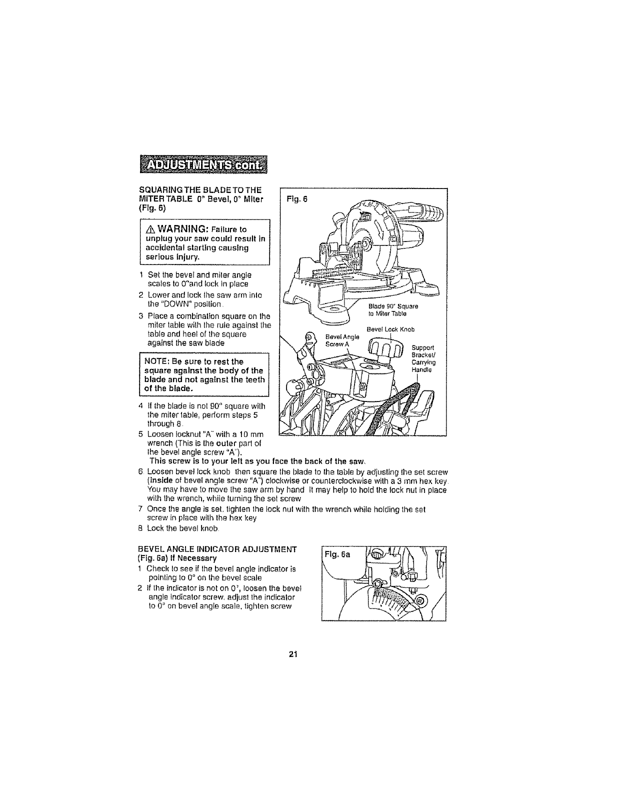
SQUARING THE SLA DETO THE
MITERTABLE 0" Bevel, 0° Miter
(Fig. 6)
Z_ WARNING: Failure to l
unplug your saw could result in
accidental starting causing
serious Injury.
t Set the bevel and miler angle
scales to 0_and lock in place
2 Lower and lock lhe saw arm inie
the "DOWN" position
3 PIacea combination square on the
miter table wilh the rule against the
table and heel of the square
against the sew blade
I NOTE; Be sure to rest the
square against the body of the
blade and not against the teeth
of the blade.
4 ff the blade is nol 90 ° square with
the miter labte, peflorm sleps 5
thro'_Jgh8
5 Loosen Iocknut "A" wilh a 10 turn
wrench (This is lhe outer part of
lhe bevel angle screw "A").
Fig. 6
BILtde 90 _ Squats
to Miter Tabte
eeve_ Lock Kneb
_,, J_,.4" ecrewA [[(7 f'_ _ Support
This screw ts to your left as you face the back of the saw,
6 Loosen bevel lock knob then square the blade to lhe labia by adiustlng the set screw
(inside of bevel angle screw "A") clockwise or counlerdockwise wilh a 3 mm he× key
You may have to move Ihe saw arm by hand It may help to hold the lock nut in place
with the wrench, while turning lhe set screw
7 Once the angle is set, tighlen the lock nul with the wrench while holding the set
screw in place wilh lhe hex key
8 Lock the bevel knob
BEVEL ANGLE INDICATOR ADJUSTMENT
(Fig. 6a) If Necessary
1 Check to see if the bevel angle indicator is
pointing to 0 ° on the bevel scale
2 If the indicator is not on 0 _, loosen the bevel
angte indicator screw, adjust the indicator
to 0 "_on bevet angle scale, lighten screw
Fig, 6a
21
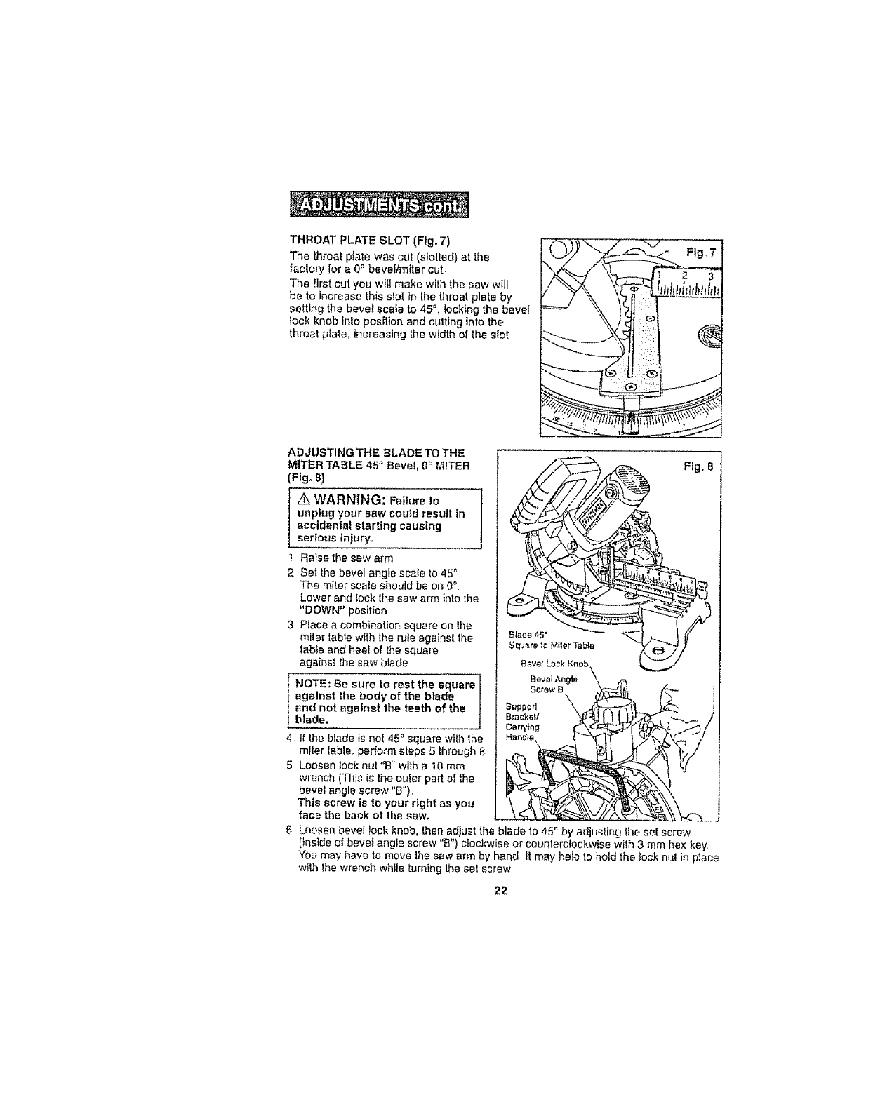
THROAT PLATE SLOT (Fig, 7)
The th;roatplate was cut (slotted) at the
factory' for a 0= bevel/miter cut
The first cut you wifl make with the saw will
be to increase this slot in the throat plate by
setting the bevel scale to 45 °, locking the bevel
lock knob into position and cutting into the
throat piate, increasing the width of the sIot
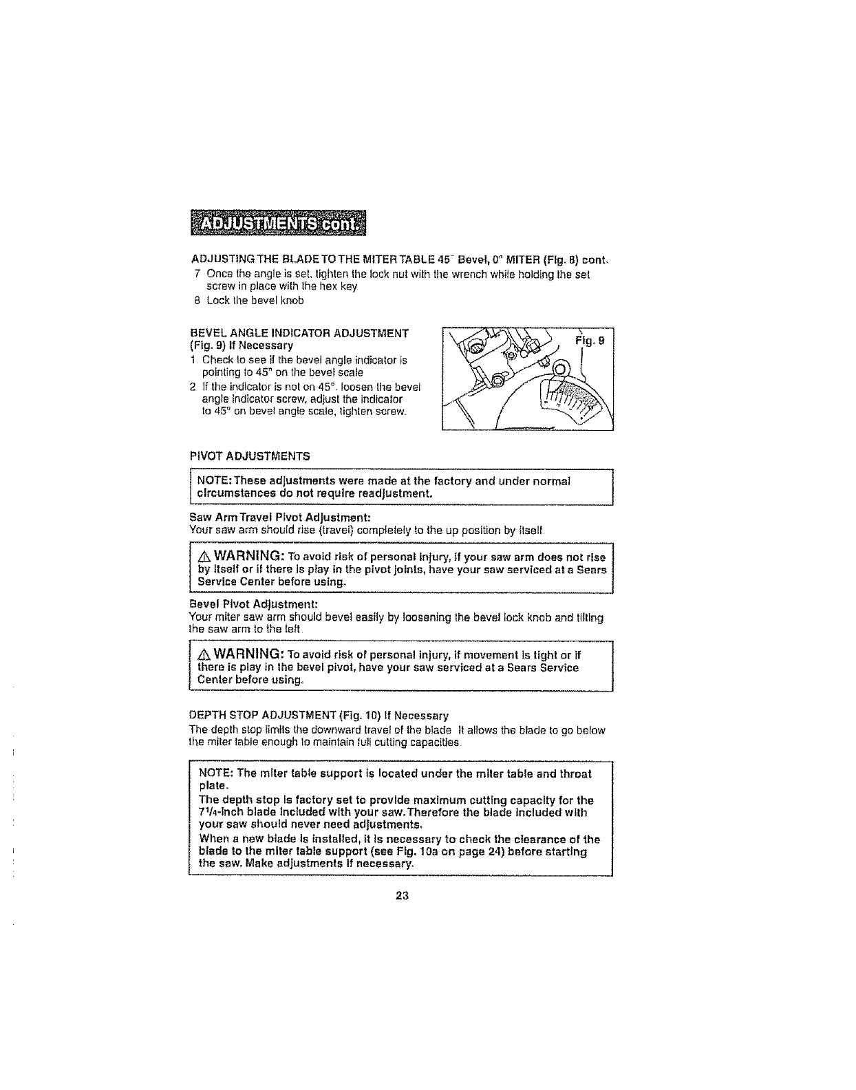
ADJUSTING THE BLADE TO THE
MITER TABLE 45 °Bevel, 0 = MITER
(Fig° 8)
/k WARNING: Failureto
unplug your saw could resul! in
accidental starting causing
serious injury°
1 Raise the sew arm
2 Set the bevel angle scale to 45 '_
The miter scale should be on 0"
Lower and lock the saw arm into tile
"DOWN" position
3 Place a combination square on the
miter table with lhe rule against lhe
1able and heel of the square
against the saw blade
I OTE: Be sure to rest the square
against the body of the b}ade
and not against the teeth of the
blade.
4If the b_ade is not 45" square with_h'e
miter labia, perform slops 5 through 8
5 Loosen lock nut "B" with a 10 mm
wrench (This is the outer part o! the
bevel angle screw "B").
This screw is to your right as you
face the back of the saw,
Fig. 8
6 Loosen bevel lock knob, than adiust lhe blade to 45" by adjusting the set screw
(inside of bevel angle screw "B") ctockwiss or counterclockwise with 3 mm hex key
You may have to move the saw arm by hand _tmay help to hold the lock nul in place
w{lh the wrench while turning the set screw
22
ADJUSTtNGTHEBLADETOTHEMITERTABLE45_Bevel,0"MITER(F}g_8)conL
7 Oncetheangleisset,tightenthelocknutwiththewrenchwhileholdingtheset
screwinplacewiththehexkey
8 Lockthebevelknob
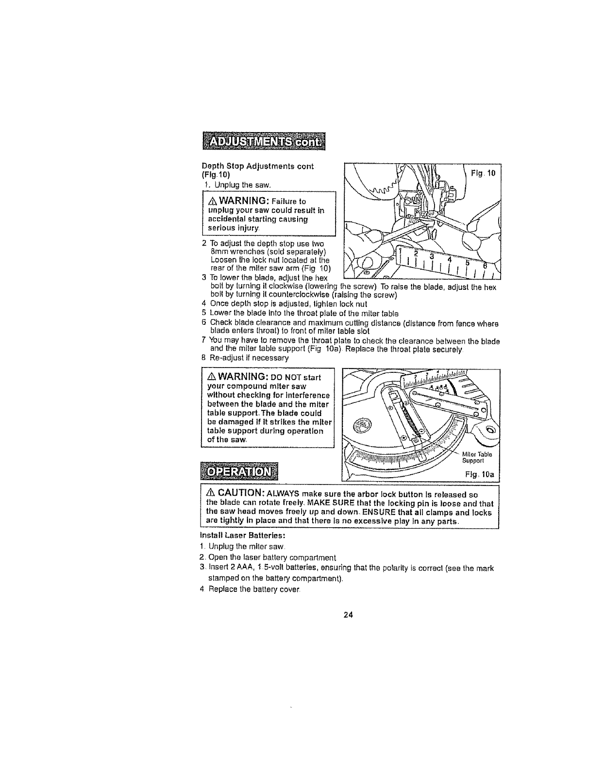
BEVELANGLEINDICATORADJUSTMENT
(Fig.9)IfNecessary
1 Checkloseeifthebevelangleindicatorts
pointingto45"onthebevefscate
2 Iftheindicalorisnoton45°.Ioosenthebevel
angleindicatorscrew,adjusttheindicator
to45_onbeve_anglescale,Iighlenscrew
,VOTAOJOST °TS
1 Jcircumstances do not require readjustment.
Saw ArmTravef P_vet Adjustment:
Your saw arm should rise (travel) completely to the up position by ttsell
/k WARNING: TO avoid risk of personal injury, if your saw arm does not rise "t
by Itself or if there is play in the pivot Joints, have your saw serviced at a Sears 1
Service Center before using° 1
Bevel Pivot Adjustment:
Your miter saw arm should beret easily by loosening the bevel lock knob and tilting
the saw arm to the _eft
z_ WARNING: "re avoid risk of personal injury, if movement is tight or if t
there is play in the bevel pivot, have your saw serviced at a Sears Service J
Center before using_
DEPTH STOP ADJUSTMENT (Fig,. 10) If Necessary
The deplh stop Iimtls the downward travel of the blade It allows the blade to go below
the miter table enough Iomaintain full cutting capacities
NOTE: The miter tabte support ts located under the miter table and throat
plate.
The depth stop is factory set to provide maximum cutting capacity for the
711,_-tnch blade Included with your saw.Therefore the blade Included with
your saw should never need adjustments,
When a new blade Is installed, tt Is necessary to check the clearance of the
blade to the miter table support (see Fig. 10a on page 24) before starting
the saw. Make adjustments If necessary.
23
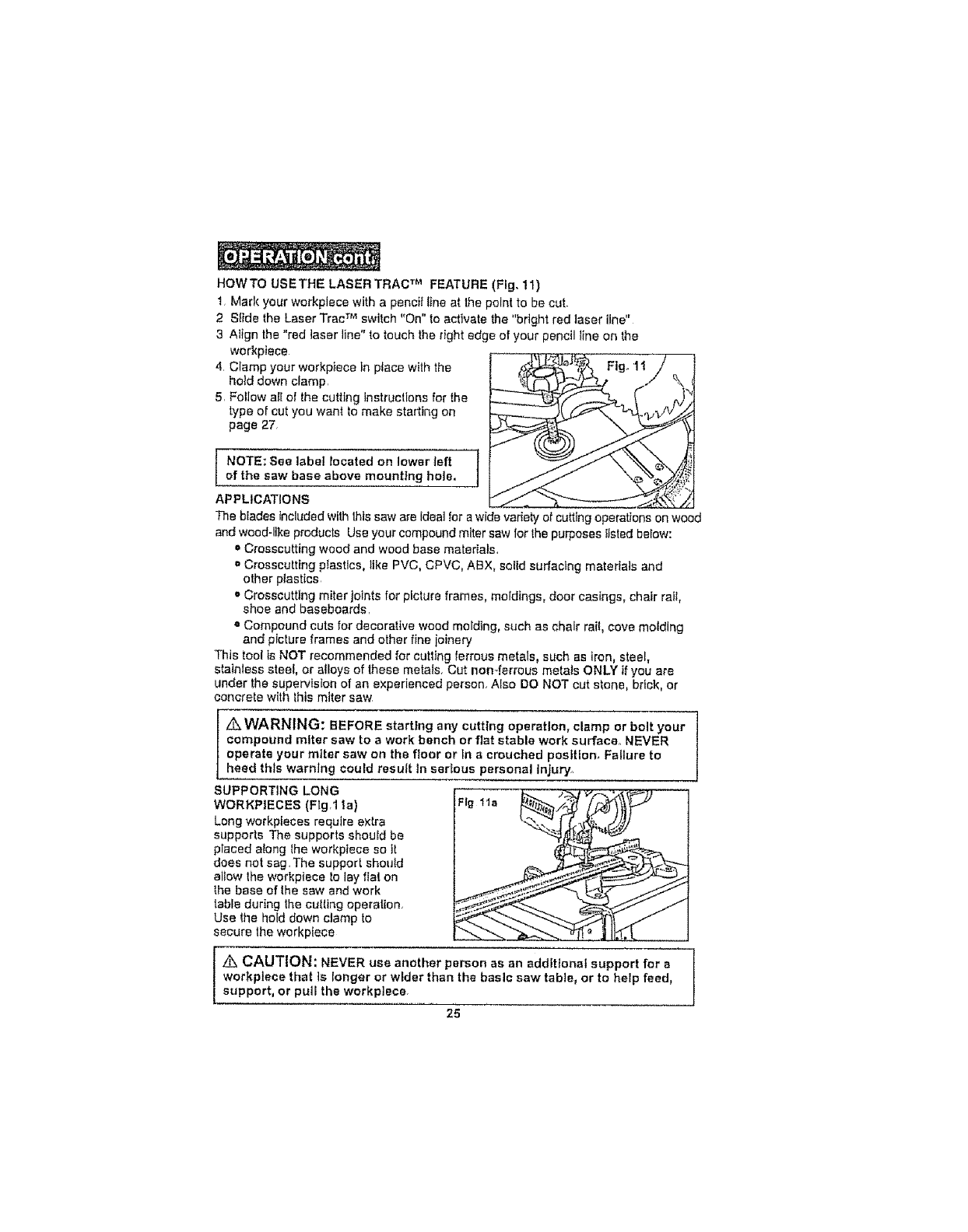
Depth Stop Adjustments cent
(FIg-lO)
t. Unplug the saw.
I _WARNING: Failure to
unplug your saw could result in
accidental starting causing
serious Injury,
2 To adjust the depth stop use two
8ram wrenches (sold separately)
Loosen the lock nut tocated at the
rear of the miter saw arm (Fig 10)
3 To lower the blade, adjust the hex
bo!l by turning it clockwise (lowering the screw) To ra+se the blade, adjust the hex
belt by turning +tcounterclockwise (raising the screw)
4 Once depth stop is adjusted, lighten lock nut
5 Lower Ihe blade Into the throat plate of the miter table
6 Check blade clearance and maximum culling distance (distance from fence where
blade enters throat) to front of miler table slot
7 You may have to remove the throat plate to check the clearance between the blade
and the m+ler table support (F+g 10a) Replace the throat plate securely
8 Re-adjust tf necessary.
Z_WARNING: DO NOTstart
your compound miter saw
without checking for Interference
between the blade and the miter
table support,The blade could
be damaged If It strikes the miter
tabte support during operation
of the saw,
z_ CAUTION: ALWAYS make sure the arbor lock button Is released so
the blade can rotate freely. MAKE SURE that the locking pin is loose and that
the saw head moves freely up and down. ENSURE that all clamps and locks
are tightly In place and that there is no excessive play tn any parts.
Install Laser Batteries:
1. Unplug the miler saw.
2. Open the laser battery compartment
3 lnsert 2 AAA, ! 5-volt batteries, ensuring that the polarity is correct (see the mark
stamped on the battery compadment)
4 Replace the battery cover
24
HOWTO USETHE LASER TRAC TM FEATURE (Fig. 11)
I, Mark your workpiece with a pencit line at the point to be cut.
2 SIide the Laser Trac TM switch "On" to activate the "bright red laser line"
3 Align the "red laser line" to touch the right edge of your pencil t{ne on the
workptece
4 Ciamp your workpiece tn place with the
hold down cfamp,
5, Follow a{[ of the cutting instructions for the
type of cut you want to make starting on
page 27,
NOTE: See label located on lower left }
of the saw base above mounting hole, ]
Fig. 11
APPLICATIONS
The blades included wilh this saw are ldeat for a wide vadety of cutting operations on wood
and weed-like products Use your compound miter saw for the purposes IJsted below:
= Crosscutting wood and wood base materials,
= Crosscutting plastics° like PVC, CPVC, ABX, solld surfacing materials and
other plastics
='Crosscutting miter joints for picture frames, moldings, door casings, chair rail,
shoe and baseboards,
e Compound cuts for decorative wood molding, such as chair rai{, cove mofdlng
and picture frames and other fine joinery
This tool is NOT recommended for cutting ferrous metals, such as iron, steel,
stainless steel, or alloys of these metals_ Cut non-ferrous metats ONLY if you are
under the supervision of an experienced person, A{so DO NOT cut stone, brick, or
concrete with this miter saw
WARNING: BEFORE starting any cutting operation, clamp or bolt your
compound miter saw to awork bench or flat stable work surface, NEVER
operate your miter saw on the floor or tn acrouched position, Failure to
heed thts warning could resutt In serious personal Injury,
SUPPORTING LONG
WORKP|ECES (Fig,1 1a) Fig 11a
Long workpieces require extra
supports The supports should be
placed a{ong the workpiece so it
does not sag, The support shoutd
al$ow the workpiece lo lay flat on
the base of the saw and work
table during Ihe cut{lng operation,
Use the hold down clamp to
secure the workplece
Z_ CAUTION: NEVER use another person as an additional support for a
workptece that is longer or wider than the basic saw table, or to help feed,
support, or pull the workp]ece
25
A WARNING: When using the hold down clamp included or a C-clamp
(sold separately) to secure the workplace, clamp the workplace on one
side of the blade ONLY.The workplace MUST remain unclamped on the
other sfde of the blade to prevent the blade from binding in the workpieceo
The workplace binding the blade will cause the motor to stall and cause
kickback, resulting In possfble serious Injury.
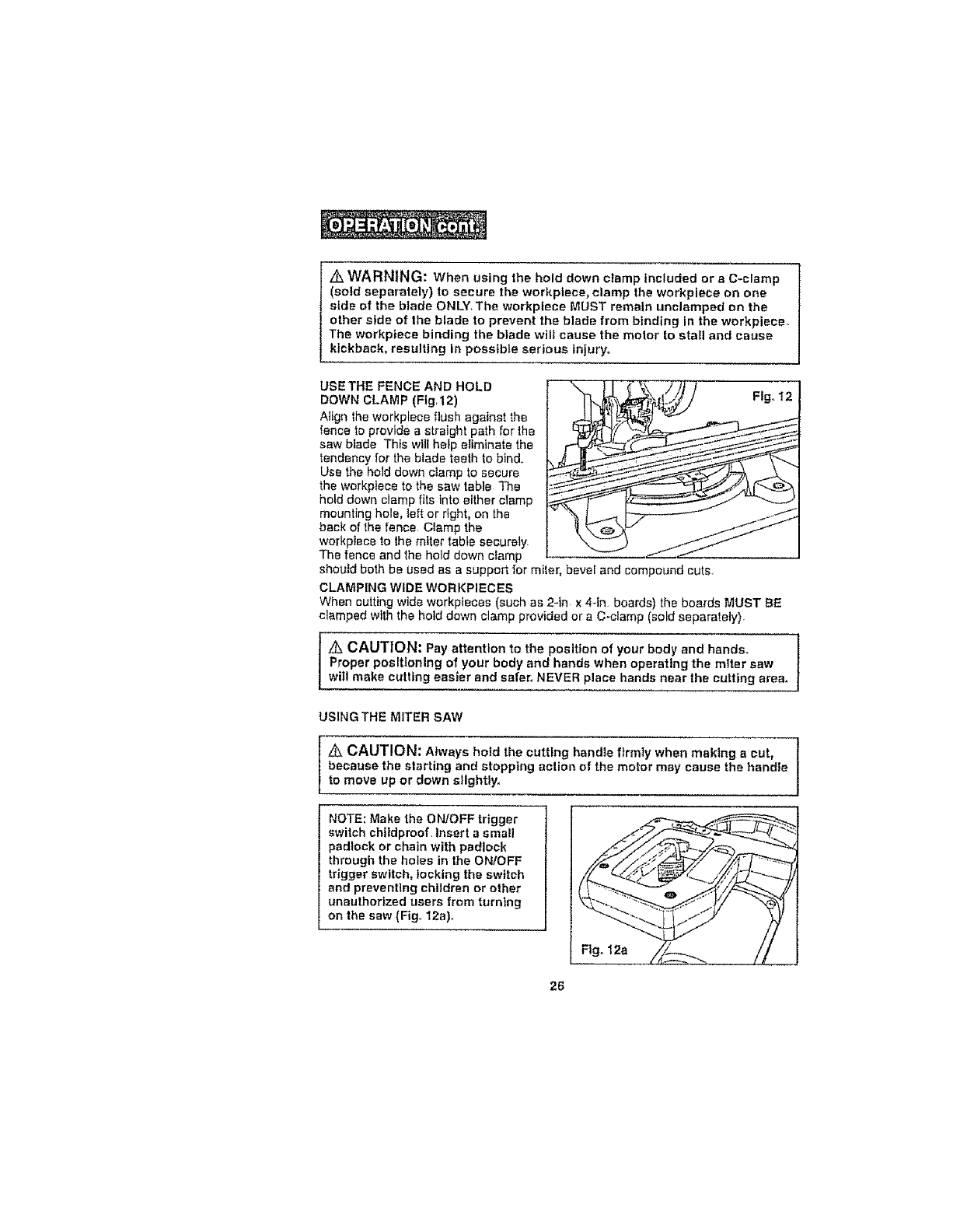
USETHE FENCE AND HOLD
DOWN CLAMP (Ftg,12)
Aftgn the workplace flush against the
fence to provide sstraight path for the
saw blade This will help e_iminate the
tendency for the blade teeth to binds.
Use the hold down ctamp to secure
the workpiece to the saw table The
hold down clamp fits into either cramp
mounting hole, teft or right, on the
back of the fence. Clamp the
workpiece to the miter table securely.
The fence and lhe hold down clamp
should both be used as a support for miter, bevel and compound cuts.
CLAMPING WIDE WORKPIECES
When cutting wide workpiaces (such as 2-tn x 4-tn. boards) the boards MUST BE
clamped wtth the hold down clamp provided or a C-clamp (sold separately)
z_ CAUTION: Pay attention to the position of your body and hands.
Proper positioning of your body and hands when operating the miter saw
witl make cutting easier and safer,. NEVER place hands near the cutting area.
USING THE MITER SAW
Z_ CAUTION: Always hold the cutting handle firmly when making a cut,
because the slatting and stopping action of the motor may cause the handle
to move up or down slightly..
NOTE: Make the ON/OFF trigger
switch chitdproof. Insert a small
padlock or chain with padlock
through the holes in the ON/OFF
trigger switch, locking the switch
and preventing children or other
unauthorized users from turning
on the saw (Fig. 12a)_
F, 12a tl
26
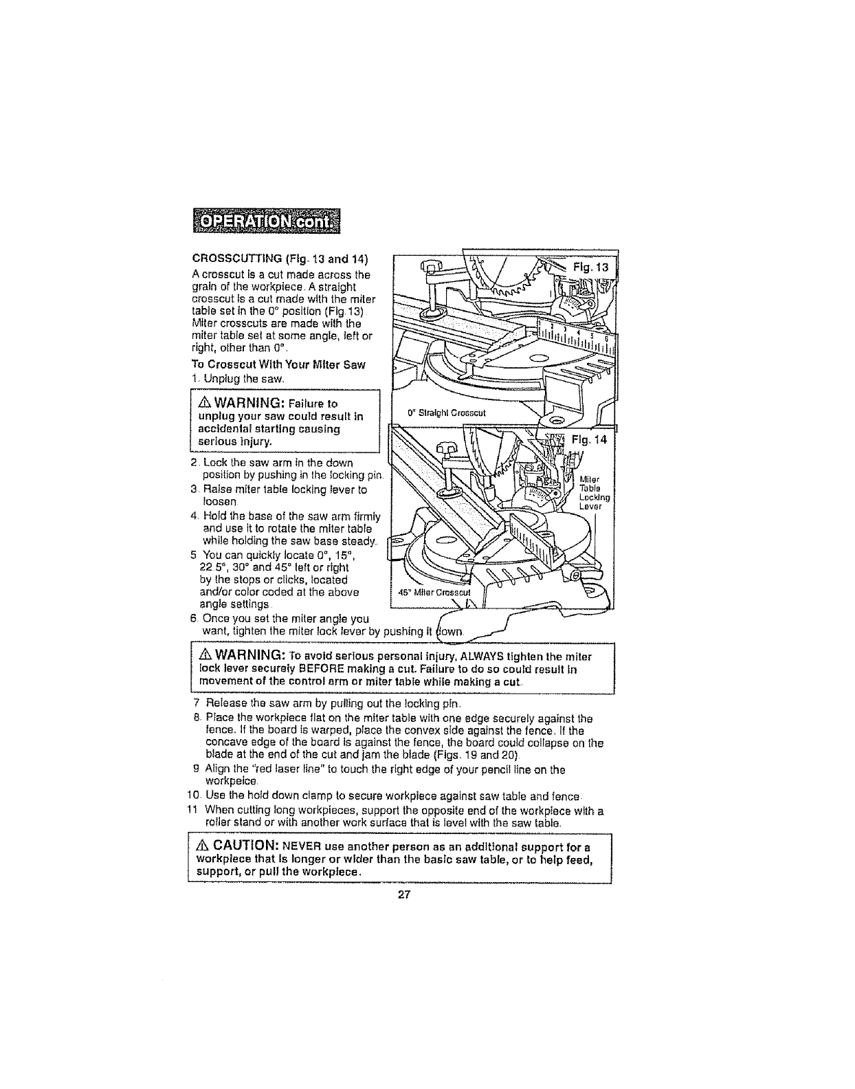
CROSSCUTTING (Fig° 13 and 14) _ _'_ , ;.... "_---- ........
A crosscut is a out made across the '_ _ _"_ 'L'I_._..._'__ .,,__
grain of the workpiece. A straight _1 _-. _ _"L_ _ ,f_l'l_'[},_)
crosscut is a cut made with the miter _ LJ _ _t ,,
table set in the 0 ° position (Fig 13) _ '_"_. _"__q'-_;_._.)..d /
Miter crosscuts are made wilh the _
miter table sol at some angle, left or _L-"_-"'_ _ _th_..__
ToOroeocutW,thYoorM,tor,ow
l Unplug the saw, _ _-"_
I unptug your saw could resuit in _ 0°SlralghlO,o_cut _l.J_,'_ t1
j accidental starting causing ,.-- i _"_-_---_ _/"_._J_, ".'_--.
thesawarm,nthedown
position by pushing in the locking pin _.__ I°_L_.) ._,._,,e,
3 Raise miler table locking lever to "%._t_r--_l_z i _:ab_,
4, Hold 1he base of the saw arm firmly i',,.,.,..x_>_._,__X. \\",_t%,._'_-'_ _x I
and use it to rotate the miter table _._ _" X_'X7_ ._7_t,,_ ._I
whi_e holding the saw base steady., _f_L O__t_j) t
5 Youcanqutckly locate 0 , 15", ..,_t k_"--_,_"y",=_ll_,,h_.
22 5,30 and 45 `=left or right _"_-_"__.. _
by the stops or clicks, located "_"-_'X _ u
and/or color coded at the above 4s_ M_lerCl"osscut l/
angle settings __ I,",, II
6 Once you set the miter angle you _ _ W
want, tighten the miler lock levar by pushing tt own,
Ztl WARNING: To avoid serious personal tniury, ALWAYS tighten the miter
lock lever securely BEFORE making a cut. Failure to do so could result In
movement of the control arm or miter table while making acut.
Release the saw arm by pulling out the locking p_n,
8. Pface the workpiece flat on the miter table with one edge securety against the
fence. If the board ts warped, place the convex side against the fence, If the
concave edge of the board ts agatnst the fence, the board could collapse on the
blade at the end of the cut and iam the blade (Figs, 19 and 20)
gAlign lhe "red laser line" to touch the right edge of your pencil Itne on the
workpeice
10. Use the hold down clamp to secure workpiece against saw table and fence
11 When cutting long workpieces, supped the opposite end of the workptece with a
roller stand or with another work surface that is level with the saw table.
Zi&CAUTION: NEVER use another person as an additional support for a /
workplece that Is longer or wider than the basic saw table, or to help feed, J
support, or pull the workpIece.
27
CROSSCUTTINGcont. (Ffg, 13 and I4)
Z_ WARNING: To avoid serious personal injury, ALWAYS keep your hands
outside the "no hands zone", as marked on the saw table, which is at least 3
inches from the blade.. Also, NEVER perform any cutting operation "freehand"
(i.e. without holding the workpiece against the fence); the brads couid grab the
workptece, causing it to slip and twisL
t2. BEFORE turning on the saw, perform adry run of the cutting operation by
towering the saw arm to make sure that no problems will occur when the cut
is made
13 Hold the saw handle and use your index finger to turn on the laser switch by
pushing it forward,
14 To turn on saw, push the safety lock button in wilh your thumb while squeezing
the On!Of! {rigger switch tocated under the handle (Fig la and lb) Allow several
seconds for the blade to reach maximum speed.
15. Slowly lower the blade into and through the workpiece.
16 Re,ease the safety lock and trigger switch and turn off the laser switch Allow the
saw biade to stop rotating BEFORE raising the blade out of the workpteee
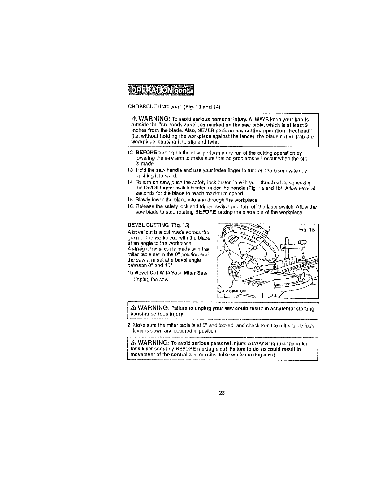
BEVEL GUTTING (FIg. tS) _ _ _
A bevel cut is a cut made across the Fig,, I5
grain of the workpiece with the blade !{ /._--_ _"_ 17 m
A straight bevel cut ts made w{th the
miter table set tn the 0 ° position and
the saw arm set at a bevel angle
between 0" and 45"
To Bevel Cut With Your Miter Saw _/t.._ =' _ '
1 Unplug the saw
=4s_BevelOut l
L/_ I...-q..!
z_ WARNING; Failure to unplug your saw could result in accidental starting
causing serious injury.
2 Make sure the miter table is at 0_ and }ocked, and check that the miter table lock
lever is down and secured in position
Z_ WARNING: To avoid serious personal injury, ALWAYS tighten the miler
_ock lever securely BEFORE making a cut. Failure to do so could result in
movement of the control arm or miter table while making a cut,.
28
BEVELCUTTINGconto (flg, 15)
3. Release the saw arm by pulttng out the locking pin,
4 To make a bevel cut, loosen the bevel lock knob (Fig lb) by turning the knob
counterclockwise
5 Tilt the saw arm to the desired bevel angle as shown on the bevel scale. The blade
can be positioned at any angle, from a 90 ° straight cut (0" on the scale) to a 45"
left here! (Fig 15)
Z_WARNING: Ttghten the bevel lock knob to secure the saw arm [n its position° ]
6 Place the workplece fiat on the miter table wilh one edge securety against the
fence tf the board is warped, place the convex side against the fence if the
concave edge of the beard Is against the fence, the board could collapse on the
blade at the end of the cut and jam the blade (Fig lg and 20)
7 Align the "red laser Itne" to touch the right edge of your pencil line on the
workptece
8 Use the hold down clamp to secure workptece against saw table and fence
9 When cutting long workpieces, supped the opposite end of the workpiece with a
roller stand or with another work surface that Is levef with the saw table,
z_ CAUTION: NEVER use another person as an additional support for a
workptece that Is longer or wider than the basic saw table, or to help feed,
support, or pull the workpteceo
Z_,WARNING: To avoid serious personal injury, ALWAYS keep your hands
outside the "no hands zone", as marked on the saw table, which is at least 3
inches from the blade° Also, NEVER perform any cutting operation "freehand"
(t.e° without holding the workp[ece against the fence); the blade could grab the
workpiece, causing II to slip and twtst.
10 BEFORE turning on the saw, perform a dry run of the cutting operation by
lowering the saw arm to make sure that no problems will occur when the cut
is made
tl Hotd the saw handle and use your index finger to turn on the laser switch by
pushing it forward
12 To turn on saw, push the safety tock button In wtih your thumb while squeezing
the On/Off trigger switch located under the handle (Fig la and lb)Allow several
seconds for the blade to reach maximum speed
13 Slowly iower 1he btade into and through lhe workplece
t4 Release the safety lock and trigger switch, and turn off the laser switch Atlow the
saw blade to stop relating BEFORE raising the blade out of the workpiece
29
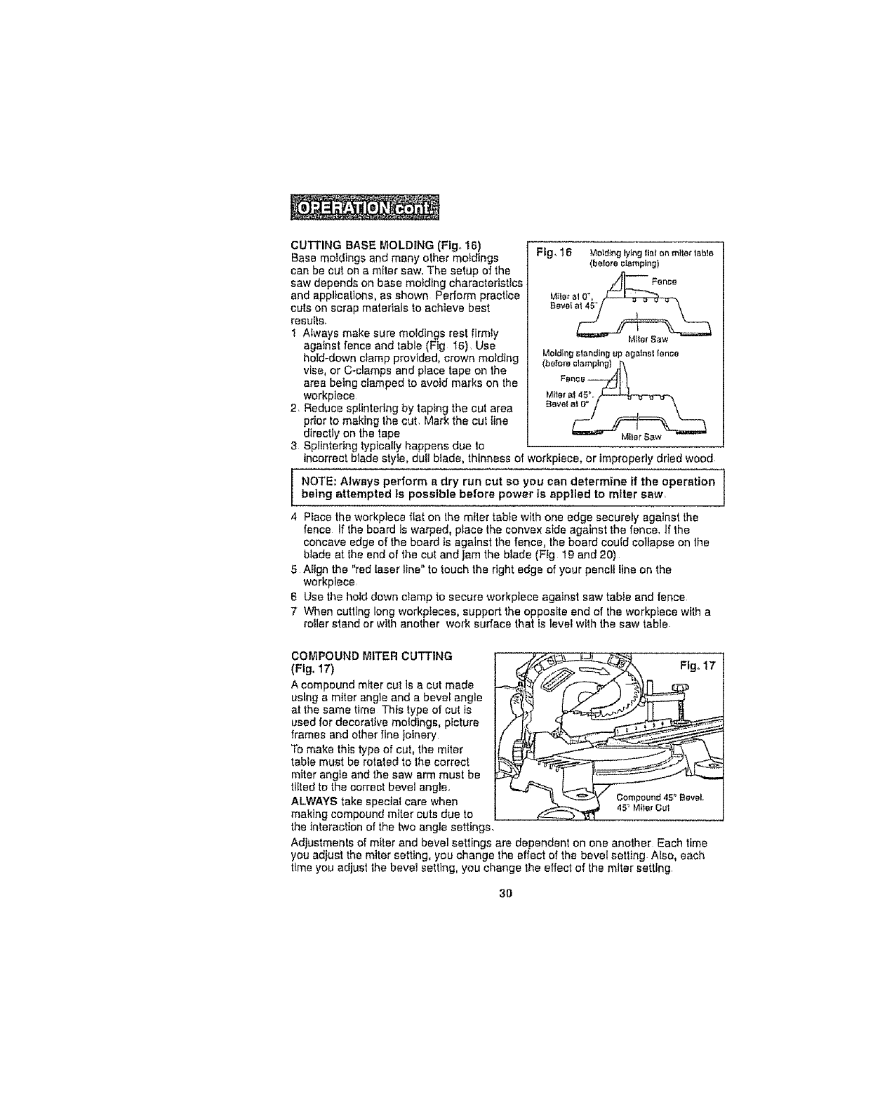
CUTTING BASE MOLDING (Fig_ 16)
Base moldings and many other moldings
can be cut on a miter saw. The setup of the
saw depends on base molding characteristics
and applications, as shown Perform practice
cuts on scrap materials to achieve best
results.
1 Always make sure moldings rest firmly
against fence and table (Fig 16). Use
hold-down cfarnp provided, crown molding
vise, or C-clamps and place tape on the
area being clamped to avoid marks on the
workpiece
2. Reduce splintering by taping the cut area
prior to making the cut. Mark the cut line
directly on the tape
3 Splintering typically happens due to
FIg_ 16 Mold{ng lying flat or, miler labia
(bale:re clamping)
,_, FenctJ
Miter at O',
BeveI a_
...... _llef N_W
Molding slendieg up agatnsl fence
(before clamping} _,
Bore{ _
M_ler Saw
incorrect blade style, du{lblade, thinness of workpiece, or Improperly dried wood
NOTE: Always perform a dry run cut so you can determine if the operation {
being attempted ls possible before power is applied to miter sew. t
4 Place the workp]ece flat on the miter table with one edge securely agalnsf the
fence If the board is warped, place the convex side against the fence. If the
concave edge of the board is against the fence, the board cou{d collapse on the
blade at the end of the cut and jam the blade (Fig 19 and 20)
5 Align the "red laser line" to touch the right edge of your pencil line on the
workplace
6 Use the hold down clamp to secure workplece against saw table and fence
7 When cutting long workpteces, support the opposite end of the workptece with a
roiter stand or with another work surface that is level with the saw table
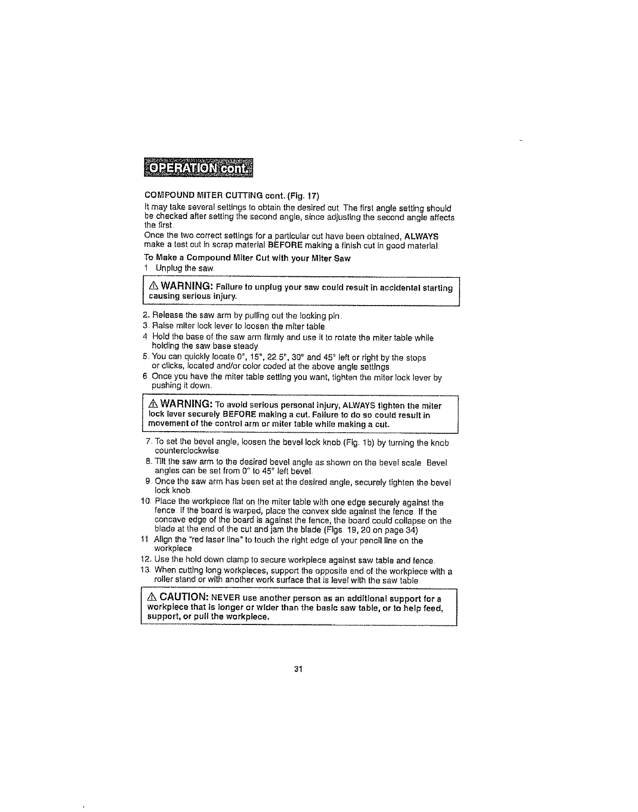
COMPOUND MITER CUTTING
(Fig. 17)
A compound miter cut is a cut made
using s m{ter angle and a bevel angle
at the same time This type of cut ts
used for decorative moldings, picture
frames and olher fine joinery
To make this type of cut, the miter
table must be rotated to the correct
miter ang}e and the saw arm must be
tlt!ed to the correct bevel angle_
ALWAYS take special care when Oompeund45_Bevel,
45 _ M_ler Gut
making compound miter cuts due to
the interactbn of the two angle settings,
Adjustmenls of miter and bevel settings are dependent on one another Each time
you adjust the miter setting, you change the effect of the bevel setting Also, each
time you adjust the bevel settlng, you change the effect of the miter setting,
Flgo 17 I
3O
COMPOUNDMITERCUTTINGcent. (FIg_ 17)
It may take several settings to obtain the desired cut. The first angle setting should
be checked after setting the second angle, since adjusting the second angle affects
the first.
Once the two correct settings for a particular cut have been obtained, ALWAYS
make a test cut in scrap material BEFORE making a finish cut in good material
To Make a Compound Mtter Cut with your Miter Saw
Unplug the saw
Z_WARNING: Fatlure to unplug your saw could result in accidental starting 1
causing serious injury. I
2, Ralaase the saw arm by pulling out the rocking pin.
3 ;Raise miter lock {ever to loosen the miter table
4 Hold the base of the saw arm firmly and use {tto rotate the miter fabte while
holding the saw base steady
5 You can quickly locate 0 "_,15% 22 5 _, 30" and 45 = left or right by the stops
or clicks, located and/or color coded at the above angle settings
6 Once you have the miter table setting you want, tighten the m_ter lock lever by
pushing it down.
WARNING: To avoid serious personal injury, ALWAYS tighten the miter
lock lever securely BEFORE making a cut.. Failure to do so cou{d result in
movement of the control arm or miter table while making a cut.
7 To set the bevel angle, loosen the bevel lock knob(Fig, lb) by turning Ihe knob
counterclockwise
8. Tilt the saw arm to the desired bevel angle as shown on the hove{ scale Bevel
angles can be set from 0'_to 45 ° left bevel.
9 Once the saw arm has been set at the desired angle, securely tighten the bevel
lock knob
10 Place the werkpfece fiat on lhe miter table with one edge securely against the
fence If the board is warped, place the convex side against the fence If the
concave edge of _he board is against the fence, the board could collapse on the
blade at the end of the cut and jam the blade (Figs 19, 20 on page 34)
1l Align the "red laser line" to touch the right edge of your pencil line on the
workpiece
12. Use the hold down c{amp to secure workpiece against saw table and fence
13 When cutting long workpleces, support the opposite end of the workpiece with a
roller stand or with another work surface that is level with the saw table
,_ CAUTION: NEVER use another person as an addlt{onel support for a ]
workplece that is longer or wider than the basic saw table, or to help feed,
support, or pull the workplace,
31
COMPOUND MITER CUTTING conL (Fig, 17)
/k WARNING: To avoid serious persona{ in)ury, ALWAYS keep your hands
outside the "no hands zone", as marked on the sew table, which is at least 3
Inches from the blade Also, NEVER perform any cutting operation "freehand"
(Le, without holding the workplece against the fence); the blade could grab the
workpteoe, causing it to slip and b,vleL
14 Make sure that there will be no obstructions to interfere with when making the cut
15 Hold the saw handfe and use your index finger to turn on the laser switch by
pushing It forward
16. To turn on saw, push the safety lock button in with your thumb while squeezing
the On/Off trigger switch located under the handle (Fig.Is and lb) Allow several
seconds for the blade to reach maximum speed
17. Slowly lower the blade lnlo and through the workptece.
18 Release the safety lock and trigger swtteh, and turn off the laser switch Allow the
saw blade to stop rotating BEFORE raising the blade out of the workplace
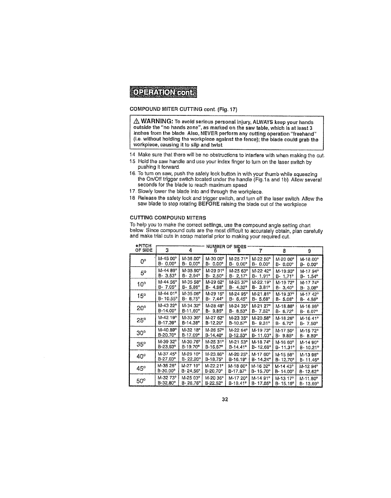
CUlq'ING COMPOUND MITERS
To help you to make the correct settings, use the compound angle setting chart
befow Since compound cuts are the most difficult to accurately obtain, plan carefully
and make trial cuts in scrap material prior to making your required cut.
*PITCH _'_ur_J_=Hu_-_:u=_
OF SIDE 3 456
M-45 O0_' M-38.00° M-30.O0_']M-25 7I °
0o B- 0.00 ° B- 0.00° B- 0,00° J B- 0,00_'
5°M-44 89° M-35.90_' M-29 9I °M-25 63='
B- 3.53 _' B- 2.94 ° B- 2.50° 8- 2.17_
10 ° M-44 56°M-35 58° M-29 62° M-25 37_
B* 7.05 ° B_ 5.66° B- 4.98° B- 4.32 °
15 ° M-4401 '_ M-35.05°M-2915" M-2495 _
B-i0.55 _' B- &75 _ B- 7.44° B- 6.45°
20 ° M-4322" M-34.32_' M-28 46°M-24 350
B'14.00 _' B-tl.60 °B- 9.85° B- 8.53°
M-42 19° M-33 36_' M_2762 ° M-23 35°
25 ° Bq7.39_, B-14.38°B*I2.20 ° B-10.57o
M-40.69 _' M.32 18_' M-26 57° 'M.22 64_'i
30° B-20.70° B-17.09.°.....B,:14.46. B-t2.53 °
M-39 32 _' M.30.76=' M-28 31=, M-21 53_'
35 °;B.23.93o B-19.70o B.16.67_ B.14.41o
400 M'3745 ° M.2910 = M_23.86_ M-2025 _
8-27.03 = B-22.20 ° B-1&75 ° B-16.19 °
M-35 26°M-27 19_' M-22.21_ M-t6 80°
45° B-30.0D" B-24.56 ° B-20.70_' B=17.87°
M-32 73_' M-2503 _ M-2036 =' M-1720 °
50 ° B.32.80 o 8.26.76 _' B.22.52=, B.16.41 °
7 8
M-22 50 ° M-20 O0_'
B- 0.00_ B* 0.00_
ivl-2242° M-18_93°
B" 1.91_' B- 1.71_'
M-22.19 _ M-19 72_
B- 3.8! °B- 3.40°
M-21..81° M-19 37_
B- 5.66° B- 5.08°
M-21 27_''' M'tB.8B _
B- 7,52 _ 8- 6.72_
M-20.56 ° M-18.26°
B* 8.31 _ B- 6.720
M-19 73°M-17.50"
B- 11.03°B;..9.85_'
M-IB 74_' M-16 60°
B- 12.66°B- 11.3t o
g
Mq8.00 _
B_ 0.00_
M-17 94_
B- 1.54°
M-17 74c'
B- 3.08_
M-17 42_
B- 4.59_
M-16 98°
B- 6.07°
M-16 41°
B- 7.50 °
M-15 72_'
B- 8.86°
M-'I4 90_'
B- t0.21 '_
M-17 68_ M-15 58°M-13 98°
B_14.24° B*12.70 = B-11.46 °
!M-t632 _ M-1443 • M-1294 °
B- t5.70 {, B- 14.00_ 8- 12.62°
M-14 91_'! M-13 I_ M-tl.80 °
i B-t7.05_i B-15.18_i B-!3,89 _
32
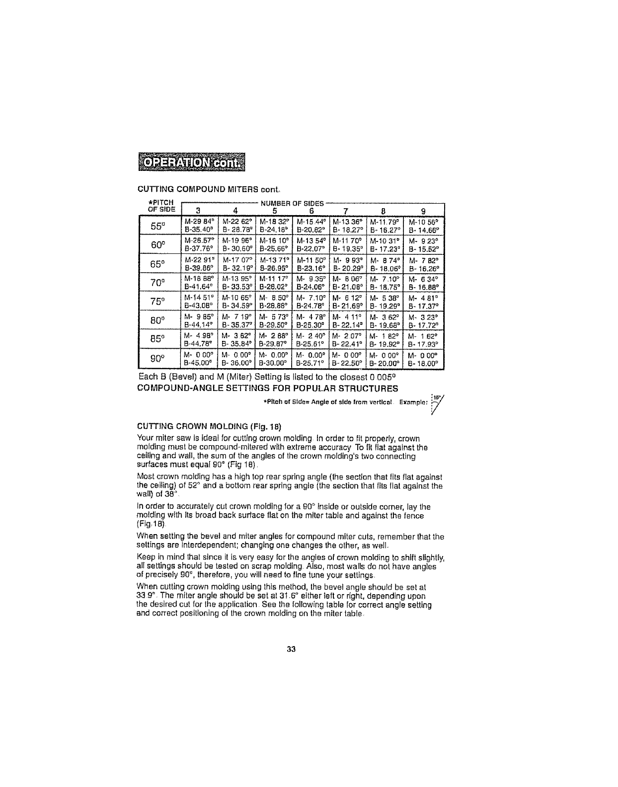
CUTTING COMPOUND MITERS canto
*PITCH NUMBER OF SIDES
OF StDE 34 5 6
M-29 84° M-22 62_ M-t8 32 ° M-1544 _
550 8_35.40= B- 28.78°B-24.t8 _' B_20.82_
M-26.57° M-1996 _ M-1610 n M-1354 °
600 B-37.76_' B- 30.60 _ B-25.65° B-22.07_
i M-22 9! _' M-1707 ° M-137t _' M-11 50_
650 B-39.85° B- 32.!9 ° 8-26.95 ° B-23.16 °
M-18 88°M-!3 95_' M-1t 17_ M-935 °
70e B-41.64° B- 33,53 ° B-28.02° R-24.06_
M-_4 5t = MqO 65° M- 850 '_ M- 7,10"
75 ° B.43,08_ B-34.59 ° B,28.88° B-24_78_
80 ° Me 985°i M° 7t9 _' M- 573 ° M- 478 '_
B.,|4.14.° B-35.37 ° B-29.50°B-25.30°
85 ° M- 498 _' M- 362 ° M- 288 ° M- 240 °
B-44.78'_ B- 35.84° B-29.87_' B-25.61°
_0o M* 0 00_ M- 000 ° M- 0,00_' M- 0,00_'
8-45.00 _ B- 36.00_ B-30.00° B-25.71°
7 8 9
M-t336 °M-1t.79 ° M.1056 _
B-!8.27 '_ B_16.27oB_14,68°
...... , !
M-1170 °M-1031 ° M- 923 _
a-19.3st, B-)7.,23°I B-15.52°
M-993° 1M. 874o 1 M-782 °
B-20.29 r' ! B-18.05 _ B-16.26 _
M-8o_; _-7io; M-e34_
B-21.08 _ B- 1&75 °B- 16.88°
M- 612 = M- 538 ° M- 481 =
B- 21.69 _ B- 19.29" :B-17.37_
M- 4!1 '_ M- 362 °M- 323 _
B-22.14 ° B-19.68 ° 8-17.72 °
M- 207 °M- t82 ° M- 162 °
B-22,4t _' B-19.92 _' B-17.93 °
M- 000 ° M- 000 °M- 000 °
B-22.50 °B-20.00 '= B- 18.00_'
Each B (Bevel) and M (Miter) Setting is listed to the closest 0 005 o
COMPOUND-ANGLE SETTINGS FOR POPULAR STRUCTURES
*Pitch_f Side=Angleof sidefrom vertl_;a! Example;"i;_1_
CUTTING CROWN MOLDING (Fig. 18)
Your miter saw is ideal for cutting crown motding In order to fit properly, crown
mo_ding must be compound-mitered with extreme accuracy To fit Itat against lhe
ceiling and wall, the sum of the angles of the crown motdlng's two connecting
surfaces must equal g0 ° (Fig 18).
Most crown molding has a high top rear spring angle (the section that fits flat against
the celltng) of 52 _'and a bottom rear spring angle (the section that t_isflat against the
waif) of 38%
In order to accurately cut crown melding for a g0 ° Inside or outside corner, lay the
molding with its broad back surface flat on the miter table and against the fence
(Fig 18)
When setting the bevel and miter angles for compound miter cuts, remember that the
settings are interdependent; changing one changes the elher, as well
Keep in mind that since it is very easy for the angles of crown molding to shift slighUy,
afl settings shoutd be tested on scrap molding Also, most walls do not have angles
of precisely 90% therefore, you will need to fine tune your settings.
When cutting crown motding using thts method, the beve_ angle should be set at
33 9". The miter angle should be set at 31.6" etlher left or right, depending upon
the desired cut for the application See Ihe to!lowing table for correct angte setting
and correct positioning of lhe crown molding on the miter table
33
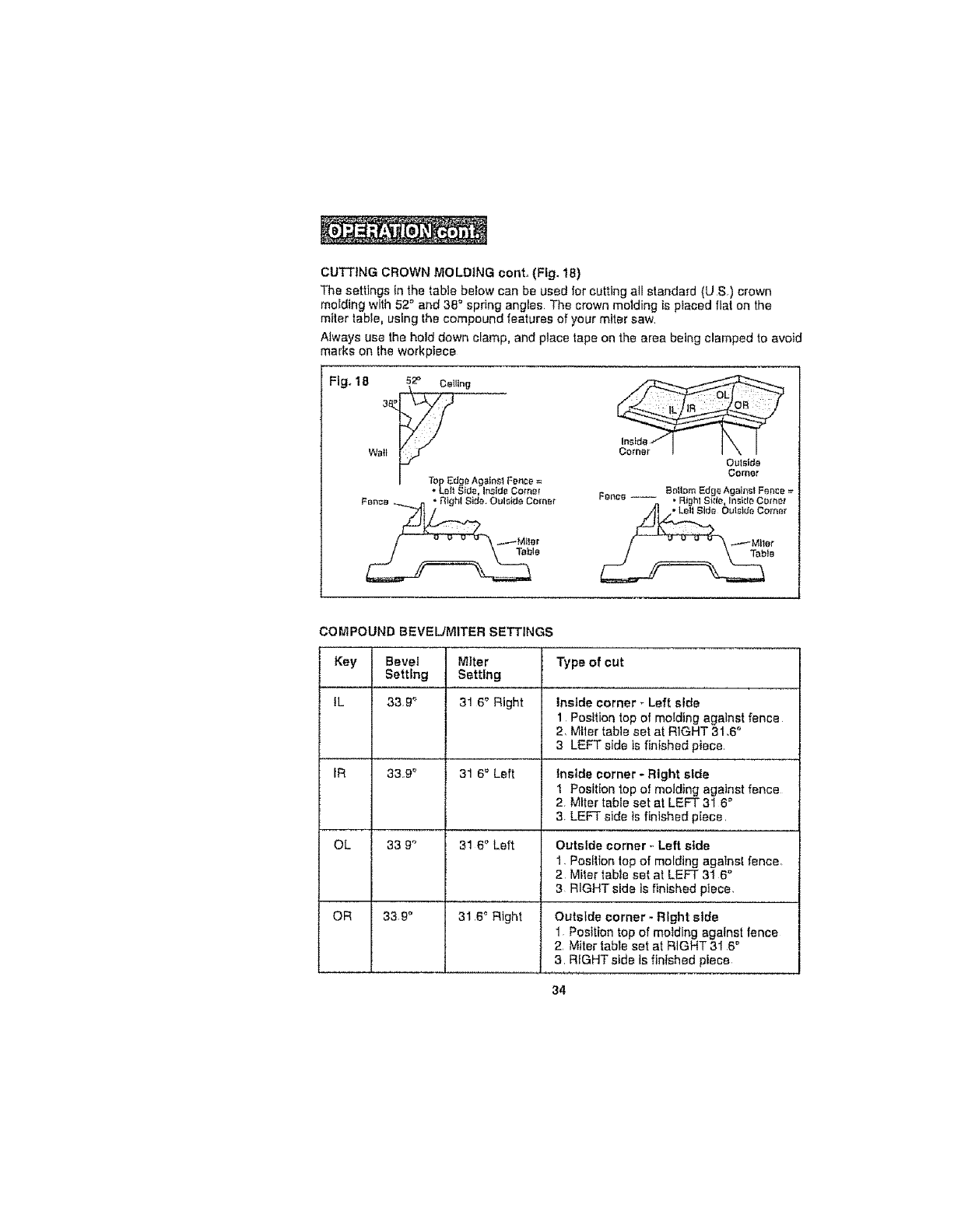
CUTTINGCROWN MOLDING cont. (Fig. 18)
The settings in the table below can be used for cutting all standard (U S.) crown
molding with 52"_and 38 ° spring angles The crown molding is placed flat on the
miter table, using the compound features of your miter saw
Always use the hold down clamp, and place tape on the area being clamped to avoid
marks on the workpiece
Fig. 18 52° Catting
Wall
I TOp Edge Agains_ Fonce =
• Lo|_ Side, inside Corner
COMPOUND BEVEL/MITER SETTINGS
Key Bevel Miter
Settfng Setting
IL
tR
OL
OR
33.g _ 31 6 ° Right
33.9 _ 31 6 _ Left
33 9°` 31 6 _ Left
339" 31,6 _ Right
Type of cut
Inside corner _Left side
1 Posltion top of molding agalnst fence
2. Miler table set at RIGHT 31.6 °
3 LEFT side is finished piece.
Inside corner - Right side
1 Position top of molding against fence
2 Miter table set at LEFT 31 6 °
3. LEFT side is finlshed piece,
Outside corner -Left side
1. Posftion top of molding against fence
2 Miter table set at LEFT 3I 6 °
3RIGHTside is finished piece,
Outside corner -Right side
1 Position top of molding against fence
2, Miter table set at RIGHT 3I 6 °
3, RIGHT side Is finished piece
34
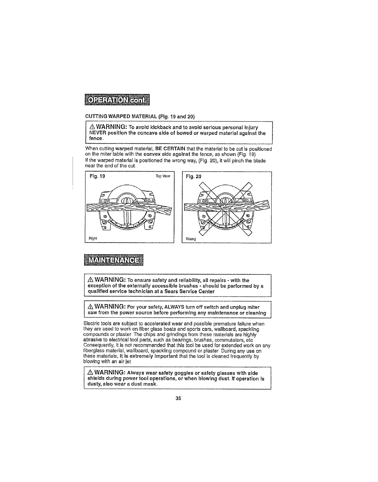
CUTTINGWARPEDMATERIAL (Flgo 19 and 20)
Z_WARNING: To avoid kickback and to avoid serious personal Injury
NEVER position the concave side of bowed or warped material against the
fence,
When cutting warped material, BE CERTAIN that the mateda[ to be cut is positioned
on the miter table with the convex side against the fence, as shown (Fig. 19)
If the warped material is positioned the wrong way, (Fig 20), it will pinch the blade
near the and of the cut.
Fig.19 TopvJ_v
Rtght
F{go20
W_ong
Z_WARNING; To ensure safety and rellabllity_ all repairs - with the
exception of the externally accessible brushes *should be performed by a
qualified service technfc_an at aSears Service Center
z_ WARNING: For your safety, ALWAYS turn off switch and unplug miter
saw from the power source before performing any maintenance or cleaning
Electric tools are subject to accelerated wear and possible premature failure when
they are used to work on fiber glass boats and sports cars, waflboard, spackling
compounds or plaster The chips and grindings from these materials are highIy
abrasive to electflcal tool parts, such as bearings, brushes, commutators, etc
Consequently, it Is not recommended that this loci be used for extended work on any
fiberglass material, wallboard, spackling compound or plaster During any use on
these materiels, It is extremely Important that the tool is cleaned frequently by
btow[ng with an air jet
] _WARNING: Always wear safety goggles or safety glasses with side
shields during power tool operations, or when blowing dust,. If operation ls
dusty, also wear a dust mask.
35
ROUTINE MAINTENANCE
z:_WARNING: DO NOT at any time let brake fluids, gasoline, petroleum-
based products, penetrating oils, etc.. come In contact with plastic parts,
Chemicals can damage, weaken or destroy plastic, which may result In
serlous personal injury.
Periodic maintenance allows for tong life and trouble4ree operation A cleaning,
lubrication and maintenance schedule should be maintained. As a common
preventive maintenance practice, follow these recommended steps:
1 When work has been completed, c_ean the toot to allow smooth functioning of the
tool over time
2. Use clean damp ctoths to wipe the tool.
3 Check the state of all electrical cables
4 Keep the motor air openings free from oil, grease and sawdust or woodchips and
store tool in a dry place.
5 Be certain thal all moving parts are well lubrtcaled, particularly after lengthy
exposure to damp and/or dirty conditions
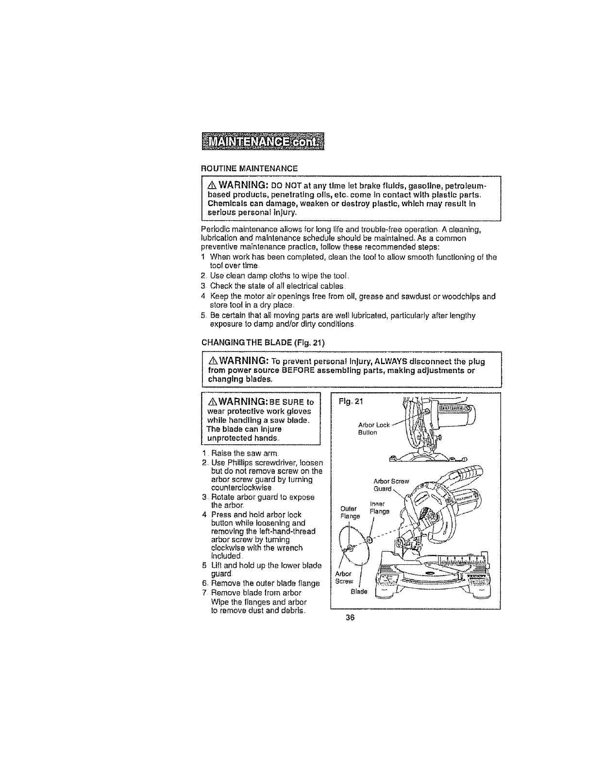
CHANGING THE BLADE (Figo21)
Z_WARNING: To prevent personal injury, ALWAYS disconnect the plug
from power source BEFORE assembling parts, making adjustments or
changing blades,
Z_WARNING: BESUREto
wear protective work gloves
white handling a saw blade.
The blade can injure
unprotected hands,
1. Raise the saw arm
2, Use Phillips screwdriver, loosen
but do not remove screw on the
arbor screw guard by turning
counterc_ockwIse
3- Rotate arbor guard to expose
the arbor
4 Press and hold arbor lock
button wht!e loosening and
removing the left-hand4hread
arbor screw by turning
clockwise with the wrench
included
5 Lift and hold up the lower blade
guard
6. Remove the outer blade flange
7 Remove blade lrom arbor
Wipe the flanges and arbor
to remove dust and debris.
CHANGINGTHEBLADEcont_(seeFig.21)
8Takethenewbladeandmatchthedirectionofthe arrow on it with the direction of
the arrow on the upper blade guard Make sure the blade teeth are pointing
downward lnstalt the blade by sliding the blade Into the upper blade guard and
_llactng the blade up and onto the arbor
ote: inner flange will already be on the arbor
9. Replace the outer blade flange, making sure the flat side of the flange is against
the blade. Replace the arbor screw and tighten counterclockwise with the
supplied wrench while holding In the arbor lock button unti! Iock engages then
tightening he arbor screw secure y
10 Rotate the arbor guard into position and securely tighten its screw by turning
clockwise with the Phttltps screwddvett
11 Lower the saw arm and check the clearance between the blade and the miter
tabte. The blade should rotate freely. See Depth Stop Adjustment on
(Fig t0 on page 24)
Z_CAUTION: ALWAYS make sure the spindle lock button ts released so
the blade can rotate freely MAKE SURE that the locking pin is loose and that 1
the saw head moves freely up and down. ENSURE that all clamps and Iooke
are tightly tn place and that there Is no excessive play In any parts,
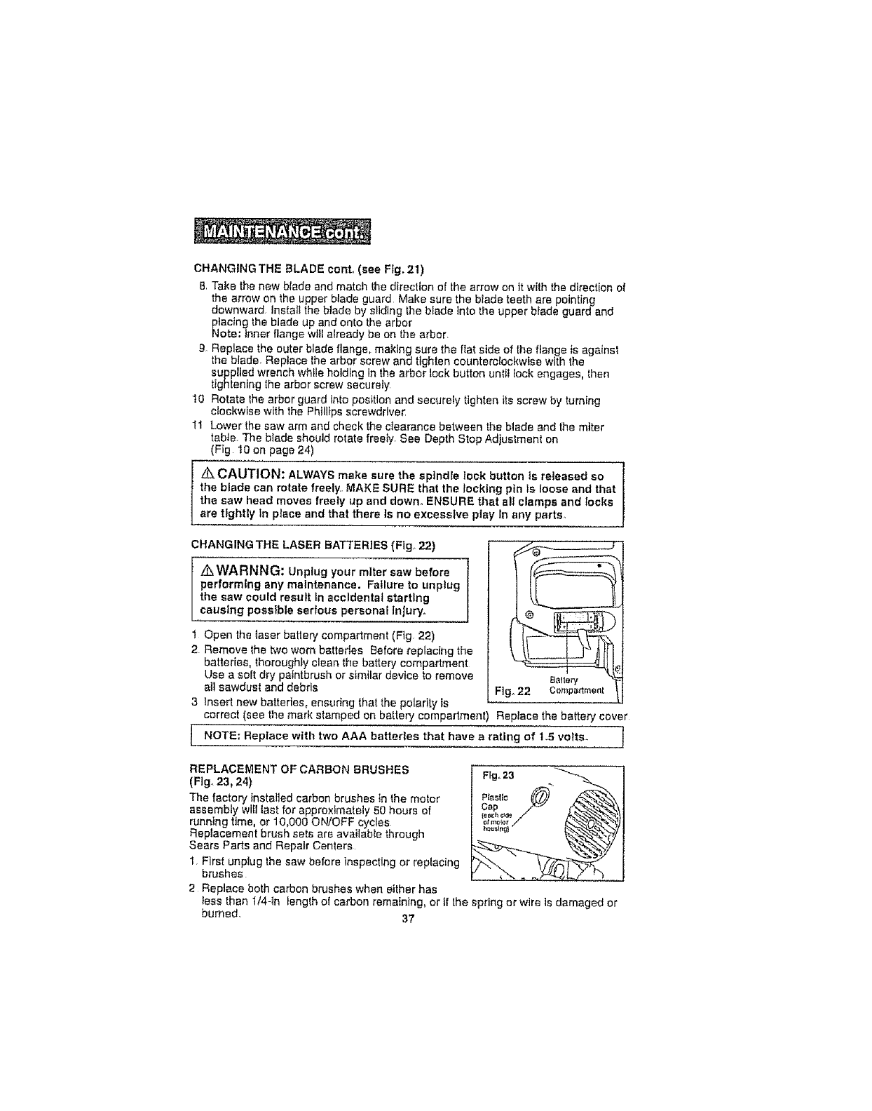
CHANGINGTHE LASER BATTERIES (Fig. 22)
z_WARNNG: Unplug your miter saw before
performing any maintenance. Failure to unplug
the saw could result In accidental starting
causing possible serfous personal Injury.
1 Open the laser batter,/compartment (Fig 22)
2 Remove the two worn batteries Before replacing the
batteries, thoroughly clean the battery compartment
Use a soft dry paintbrush or similar device to remove
all sawdust and debris
3 Insert new batteries, ensuring that the polarity is
correct (see the mark stamped on batter,/compartment) Replace the battery cover
Replace with two AAA batteries that have arating of 1_5 volts. 1
NOTE;
REPLACEMENT OF CARBON BRUSHES
(Fig. 23, 24)
The factory installed carbon brushes in the motor
assembly will last for approximately 50 hours of
running time, or 10,000 ON/OFF cycles
Replacement brush sets are available through
Sears Parts and Repair Centers
1, First unplug the saw before inspecting or replacing
brushes
2 Reptace both carbon brushes when either has
Cap
less than 1/4-in lenglh of carbon remaining, or if the spring or wire is damaged or
burned. 37
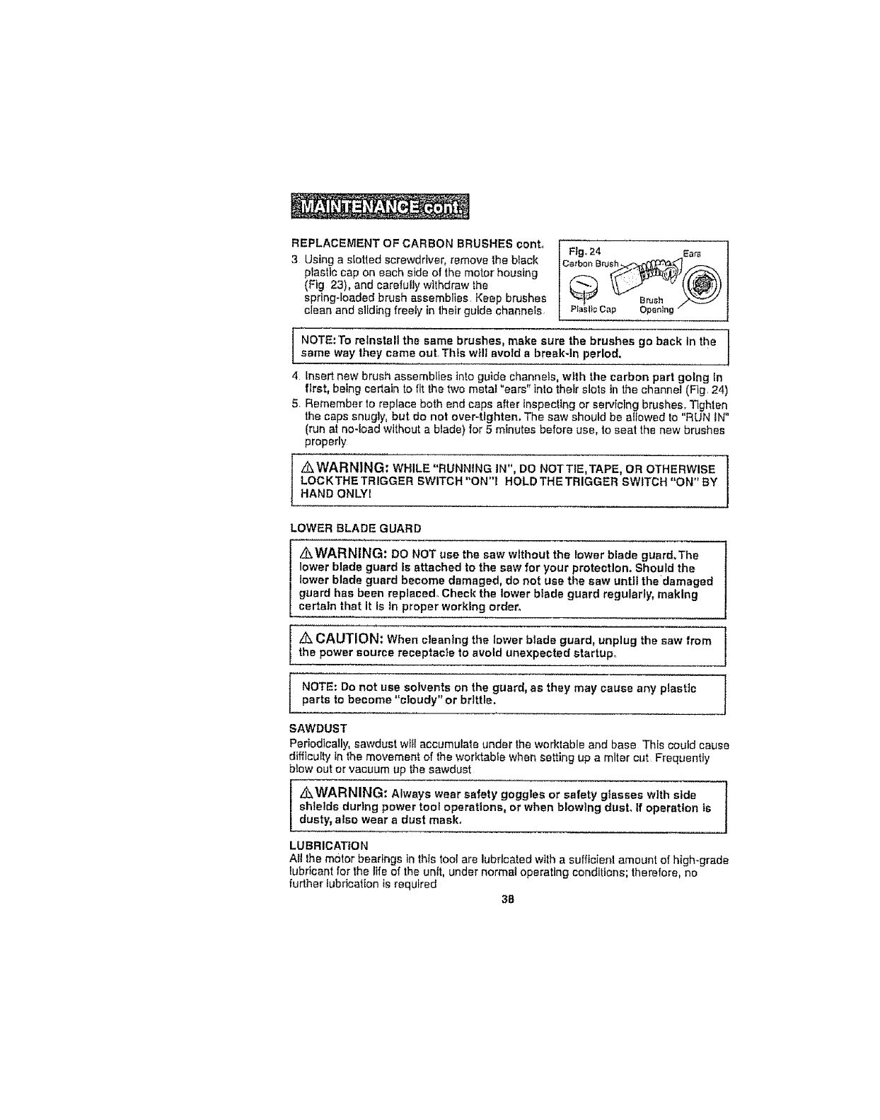
REPLACEMENTOFCARBON BRUSHES cent.
3Using a siotled screwdriver, remove the black
piastlc cap on each side of the motor housing
{Fig 23), and carefully withdraw the
spring-loaded brush assemblies Keep brushes
clean and sliding freely in their guide channels
Fig. 24 Ears
Catb0n B___ __
-'*_J Brush
P_BI_;Cap Opening
NOTE:To reinstall the same brushes, make sure the brushes go back In the
same way they came out, This will avoid a break-in period.
4 insert new brush assemblies into guide channels, with the carbon part going In
first, being cedatn to fit the two metal "ears" into their slots in the channel (Fig. 24)
5. Remember to replace both end caps after Inspectlng or servicing brushes. Tighten
the caps snugly, but do not over-tlghtem The saw should be allowed to "RUN iN"
(run at no-load without a blade) for 5 minutes before usa, to seat the new brushes
properly
z_WARNING: WHILE "RUNNING IN*', DO NeTTlE,TAPE, OR OTHERWISE ]
LOCKTHETRIGGER SWITCH"ON"! HOLDTHETRIGGER SWITCH "ON"BY J
HAND ONLYI
LOWER BLADE GUARD
_WARNING: DO NOT use the saw without the lower blade guard.The
lower blade guard is attached to the saw for your protection. Should the
lower blade guard become damaged, do not use the saw until thedamaged
guard has been replacedo Check the lower blade guard regularly, making
certain that it Is In proper working order°
z%,CAUTION: When cleaning the lower blade guard, unplug the saw from
the power source receptacle to avoid unexpected startUpo
NOTE; Do not use solvents on the guard, as they may cause any plastic
parts to become "c;oudy" or brittle.
SAWDUST
Periodically, sawdust wffl accumulate under the worktable and base This could cause
difficulty in the movement of the worktable when setting up a miter cut Frequently
blow out or vacuum up the sawdust
z&WARNING: Always wear safety goggles or safety glasses with slde
shletds during power tooi operations, or when blowing dust. If operation ts
dusty, also wear sdust mask,
LUBRICATION
AII Ihe motor bearings in th_stool are lubricated wttha sufficient amount of high-grade
lubricant for the life of the unit, under normal operating conditions; therefore, no
further lubrication is required
38
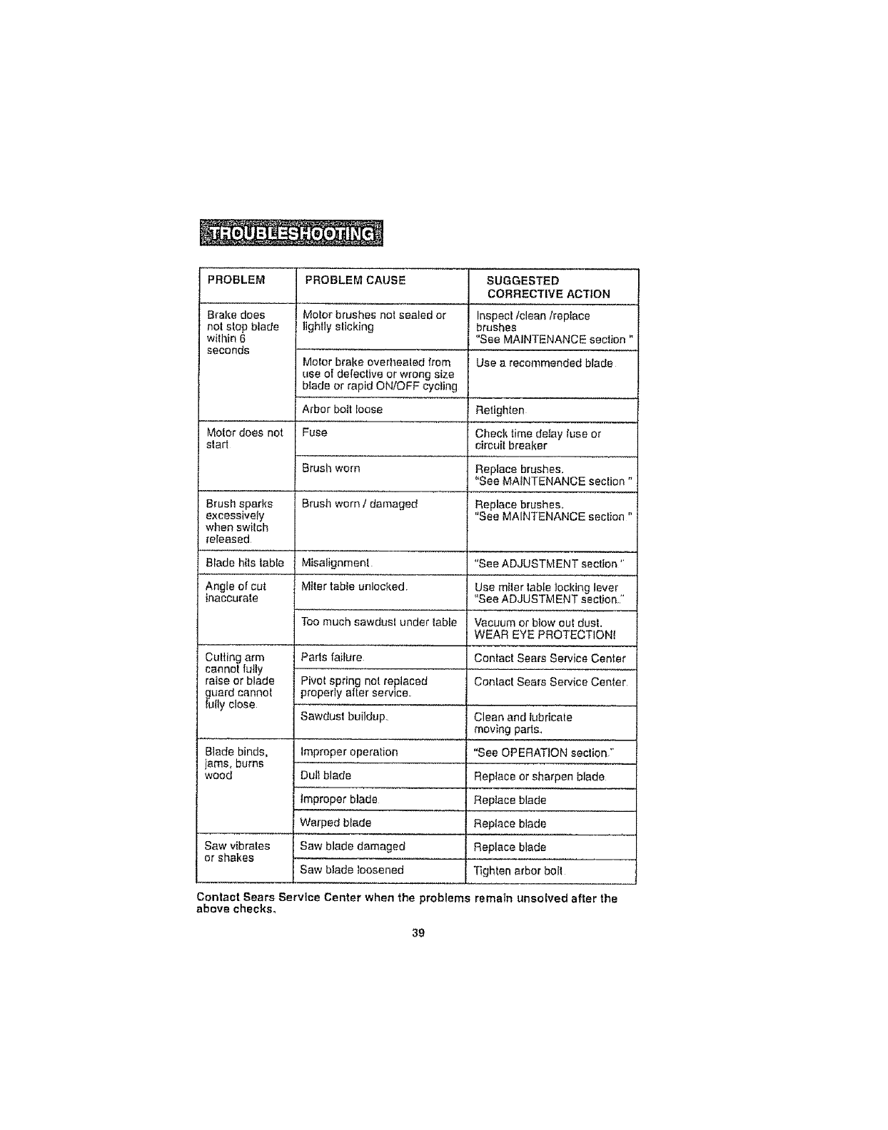
PROBLEM
Brake does
not stop blade
within6
seconds
Motor does not
slad
Brush sparks
excessively
when swilch
released
Blade hits table
Angle of cut
inaccurate
Culling arm
cannot lully
raise or blade
guard cannot
luily close
Blade binds,
jams, burns
wood
PROBLEM CAUSE
Motor brushes not sealed or
lighlly sticking
Molor brake overhealed from
use o[ defective or wrong size
blade or rapid ON!OFF cycling
Arbor bott loose
Fuse
Brush worn
Brush worn Idamaged
Misalignment
Miter table unlocked
Too much sawdusl under labte
Pads failure
Pivot spring not replaced
properly after service,
Sawdust buildup.
SUGGESTED
CORRECTIVE ACTION
Inspect/clean/repIace
brushes
"See MAINTENANCE section "
Use a recommended blade
Improper operation
Oult blade
Improper blade
Warped blade
Saw blade damaged
Saw blade loosened
Retighten
Check time delay fuse or
circuit breaker
Replace brushes.
"See MAINTENANCE section"
Replace brushes,
"See MAINTENANCE section "
"See ADJUSTMENT section '*
Use miler lable locking lever
"See ADJUSTMENT section."
Vacuum or blow out dust.
WEAR EYE PROTECTIONI
Conlact Sears Service Center
Conlact Sears Service Center
Clean and lubricate
moving pads,
"See OPERATION section,"
Replace or sharpen blade
Replace blade
Replace blade
Saw vibrates Replace blade
or shakes ...............
Tighten arbor boll
Contact Sears Service Center when the problems remain unsolved after the
above checks,
39
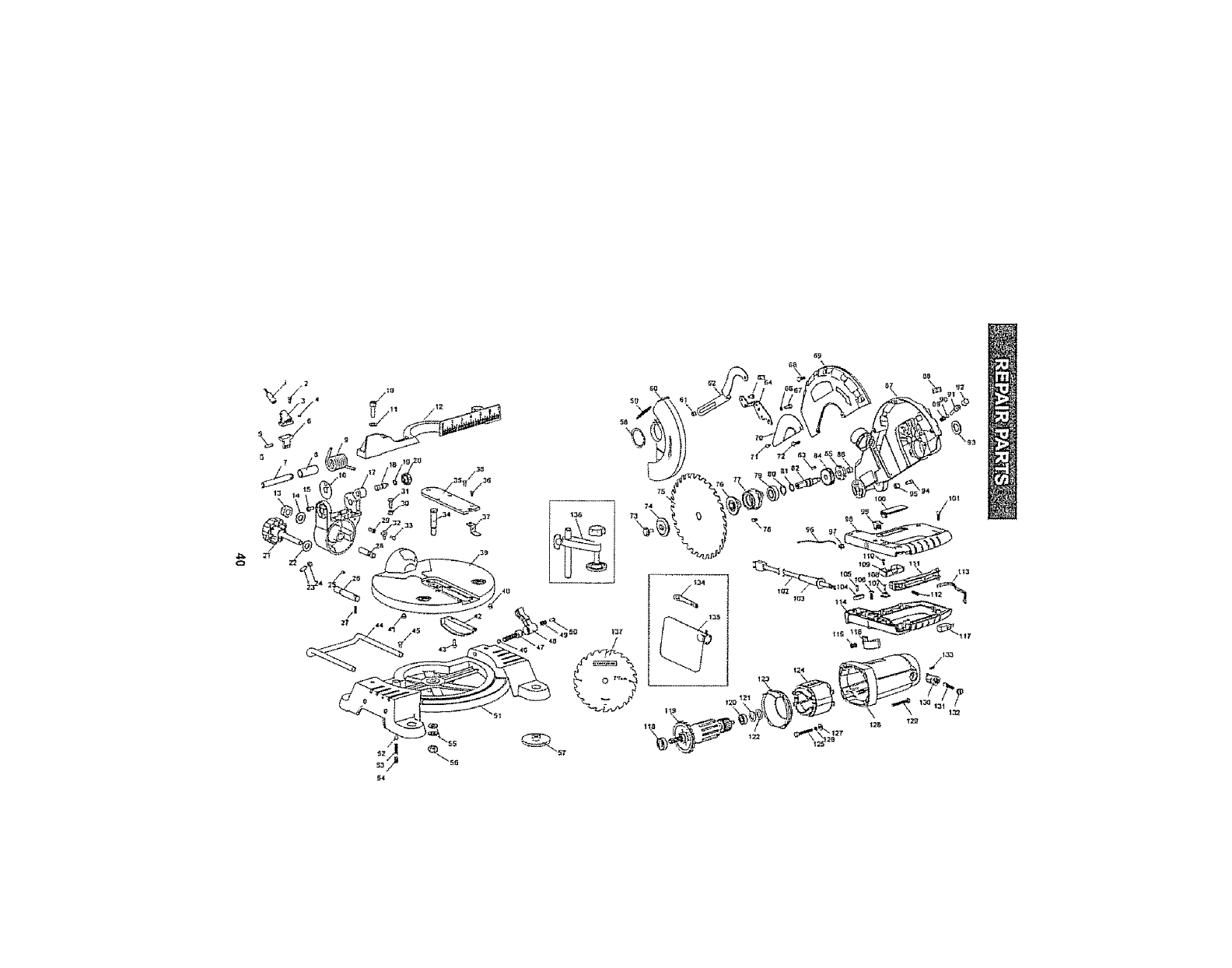
\

71!4-in.FINISHING SAW- MODEL NUMBER 320.21195
The Mode_Number wilf be found on _heNameplate. AIways mention _heModel Number in atl correspondence regarding your tool.
I_=m No. I P_r_s NQ. [
I DS.JGI_LO
2 T0203010212
3I 31212?7000
4 I T82640053tl
5 I 557002B000
6
?
P=rt Description
_t:tew
La_e_ Holdof
Sctow
Pin
L_e_ ,.Supoort
_hafl
BSh_tt_ _le_w
Sprig
10 Screw
11 F_fa_n W4she_
12 Fixed F_m;e
13 Prttvailln_ T_,_u_ lylle H_
Nt_t wl No_-M_lallir. fn_rt
14 T041203031 P_lr, W'aShBr
15 5_2019_000 Sc_
1_ I 5550045000 1 wasl_er
17 I 342030300(} I Be*_etSL_ppQt{
B3S593370(}0 jLrscI,JI_ _in
I9 T(}52061822 *0 _ Rmg
20 31212750013 L_:_in_3 Pin Kttcb
21 3_lQOI3t430(}0 Be_e! LOCk tLq_b
22 T041 _(}3(}31 F_la_ Washe_
_3 T02_D 14212 Sczew
_5_4 _'i'(}3_(}_ 1(}21 Hexag_aIS_r_wNU! Slvle 1
2g 35_0336OrJ0 j _11_.I_
_t20304000
35503358(}0
355_t47500(}
3_0140000
TOZOSO;5212
T04(}803(}21
34_(}30_D00
T031215(}52
C_ty.
i
2
!"2
I,
2
[
I
I
r'1
I
I
1
1
I z
1
_t_rrt No.
3B
37
38
3g
40
44
42
43
44
45
46
47
48
45
5(}
51
52
53
54
55
56
Pa_s NO.
T0234(}08311
3121274_00
T(}214008212
34_0305GO0
312_14_0(}0
3121129000
3121275000
: T0"214(}0_21_
355£,_C02(}00
T02140(}821_
3121_7!£4}0
_55_72000
31_1_720_0
p_rt Description
Screw
I_d=ct_[o_
SCrew
"i'umI_Ie
POM In._ert
F_OM !ascII
Sczew
SqJrew
POM Inse_
Miler Lock 80_t
L_ver
36601338(}0 1 Smin_ --.
5620206600 IScrew
T07(}000(}81 _i{
366(}_42(}00 Spr_nrt
"[041003(}31 P_a_t W,r_he r
T031015(}_ Pt eveilin_ T_rq_B T'ipo H_
57 3121 t 3_000 F'o_t
56111: I T043513031 I C_rcf;ps(otSl', I-Tvpr*A
59 356013_0(}0 SF_in _
60 24001501;00 Lower Guard
51 T0305 _5(}21 Prevailir_g Tot que T'tpo Hex
37(}Ot537P.(}Q L_r_k
t Ot't.
5
3
f
i
I
2
i°i ....
25 35503?7000 T Boil
29 Bs.csTo.2.6T sc,_,
38 T0305¢11022 Hexago_lel N_I Stvle I
3% Tlfilg_Olfi2_ Screw
32 37(}13_3B(}00 Inffi_"
33 T0_ 14(}0_12 S_" _w
34 3550338(}00 Stl_,_t
35 31_ 1273(}00 T_Ie Insure
(}3 _ 56_0207_00
i 64 I 370063_00
I 56 T0405_(}(}31
I
i _7 I T0"_(}5_12331
_8 j T(}11501_551
i ........
S_ew
Lin5 Support
$intjIa Coil _pIl_g Lock
S¢_8w
U
3
SEE BACK PAGE FOR PARTS ORDERING INSTRUCTIONS

b_
71/4-in.FINISHING SAW -MODEL NUMBER 320.21195
The Model Number will be found on the Nameplate. Always mention the Mode[ Number in aUcorrespondence regarding your tool,
6_ 3420301000
70 3700_3£000
71 L0632_0_AI
7_ T0_5_0B211
7_4 j 3550471000
77
T013501255t
P_rt D_scr_pt fort
Uppr_r Gualff
BlBde Coves
Rivo{
Screw
Ou[er Rang_
m_et FIa=3_e
Sc_eY-t
00 _04At wave Was_er
e_ 355037600o
83 5660018000
B4 3550473000
85 35505_3000
B_ TO9508199G
3420297000
88 LDT_IOZ2DAI
89 35601_5000
80 T0409_3031
9! 35504T_000
_2 L01321204AI
£3 LD232040_A1
94 T02140252t_
_S 3550551000
T15283114A
96 T15283114A
T152B3112A
97 31_1437000
_8 3320_1_800
_0 3_21141060
312113_000
r01t42_g511
I02 lT]4_53_2_41
103 T_,HTL3
G_+_rSt+a+t
Cup HP.(I(_ey
Gem"
Lcck Rtn_
E_ea_ OiIines_
Gear Co._e
(_su(aled P_[I
Sp_in_
Arbor Lock
Screw
_ush'
L_t Wire
Upper H(l_dfe
8a{(_ Cover
Po_er Cor_ _nd p(ur_
Cord G_
Qt¥,
I
i
l
T
I
I
(
2
)
i
J
i
I
(
(
(
}
1
I
i
I
I
i
I
i
I
I
i
SEE BACK PAGE FOR PARTS ORDERING INSTRUCTIONS

NOTES
43

NOTES
44

Get it fixed, at your home or ours!
Your Home
For repair-In your home-of all meier brand appliances,
Uawnand garden equipment, or heating and cooling system,
no matter who made it, no matter who sold itl
For the replacement parts, accessories and
owner's manuals that you need to do-it-yourself
For Sears professional installation of home appliances
and items like garage door openers and water heaters
!-800-4-MY-HOME _ (1.8go_46g.46631
Call anylime, day or night [US A and Canada)
W'W'_Y S, ee r@ _:Om tA_W'Wr @_ BrS ,ca
Our Home
For re 3air of carry4n items like vacuums, lawn equipment,
and electronic, call or go onqine for the location of your nearest
Sears Parts & Repair Center,.
1-800-488-1222
Cell anytime, day or night (U S A only)
"_,r_,SOarS eO_
To purchase a proteclion agreement (U S A.)
or maintenance agreement (Canada) on a product serviced by Sears:
1-800-827.6655 (USA,) 1-800-361-6665 [Canada)
Pare pedir Sarvicio de reparaciSn
adomidl_, yparaor_enar piezas:
1-888-SU-HOGAR ®
[1-888-784-6427)
Au Canada pour Se_'ice en tr[an_3fs:
1-800-LE-FOYER _c
(1-800-533-6937)
_V Sears Ca
, ea/f
t_tSears Brands. LLC
® Registered Trademark /Tu Trademark Isu Service Malk of Sears Brands LLC
® Marca Regtslrada /TWMarca de F btica /S_t Marca de Berv_cio do So_rs Brands. LLC
uc Marque de commerce t_r_ Ma[q_Je d_po_e de Sears Brands. LLC
