Craftsman 328395900 User Manual Lawnmower Power Reel Manuals And Guides L0060106
CRAFTSMAN Lawnmower Power Reel Manual L0060106 CRAFTSMAN Lawnmower Power Reel Owner's Manual, CRAFTSMAN Lawnmower Power Reel installation guides
User Manual: Craftsman 328395900 328395900 CRAFTSMAN Lawnmower Power Reel - Manuals and Guides View the owners manual for your CRAFTSMAN Lawnmower Power Reel #328395900. Home:Lawn & Garden Parts:Craftsman Parts:Craftsman Lawnmower Power Reel Manual
Open the PDF directly: View PDF ![]() .
.
Page Count: 20
Sears
OWNER'S
MANUAL
MODEL NO.
328.395900
CAUTION:
Read SAFETY
RULES and
INSTRUCTIONS
carefully
[RRFTSMRN°
3.75 HP 20" 7-Blade
Power Propelled Reel Mower
•Assembly
•Operating
•Maintenance
•Service & Adjustments
•Repair Parts
•Safety Rules
I SEARS, ROEBUCK AND CO., Hoffman Estates, IL 60179 U.S.A I
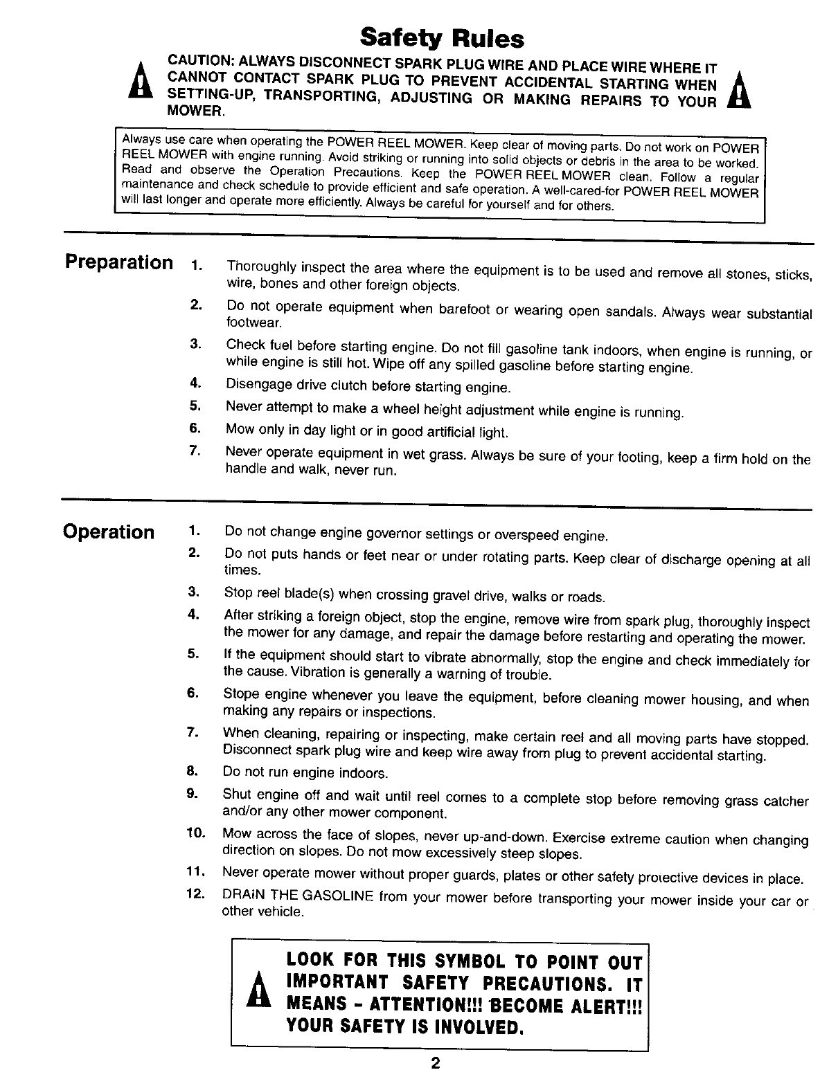
Safety Rules
CAUTION: ALWAYS DISCONNECT SPARK PLUG WIRE AND PLACE WIRE WHERE IT
_CANNOT CONTACT SPARK PLUG TO PREVENT ACCIDENTAL STARTING WHEN _1_
_ti
SETTING-UP,TRANSPORTING,ADJUSTINGORMAKINGREPAIRSTOYOUR
MOWER.
Always use care when operating the POWER REEL MOWER. Keep clear of moving parts. Do not work on POWER ]
REEL MOWER with engine running. Avoid striking or running into solid objects or debris in the area to be worked.
Read and observe the Operation Precautions. Keep the POWER REEL MOWER clean. Follow a regular]
maintenance and check schedule to provide efficient and safe operation. A well-cared-for POWER REEL MOWER
wIast onger and operate more eff cent y, A ways be careful for yourself and for others.
Preparation 1. Thoroughly inspect the area where the equipment is to be used and remove all stones, sticks,
wire, bones and other foreign objects.
2. Do not operate equipment when barefoot or wearing open sandals. Always wear substantial
footwear.
3. Check fuel before starting engine. Do not fill gasoline tank indoors, when engine is running, or
while engine is still hot. Wipe off any spilled gasoline before starting engine.
4. Disengage drive clutch before starting engine.
5. Never attempt to make a wheel height adjustment while engine is running.
6. Mow only in day light or in good artificial light.
7. Never operate equipment in wet grass. Always be sure of your footing, keep a firm hold on the
handle and walk, never run.
Operation 1. Do not change engine governor settings or overspeed engine.
2. Do not puts hands or feet near or under rotating parts. Keep clear of discharge opening at all
times.
3. Stop reel blade(s) when crossing gravel drive, walks or roads.
4. After striking a foreign object, stop the engine, remove wire from spark plug, thoroughly inspect
the mower for any damage, and repair the damage before restarting and operating the mower.
5. If the equipment should start to vibrate abnormally, stop the engine and check immediately for
the cause. Vibration is generally a warning of trouble.
6. Stope engine whenever you leave the equipment, before cleaning mower housing, and when
making any repairs or inspections.
7. When cleaning, repairing or inspecting, make certain reel and all moving parts have stopped.
Disconnect spark plug wire and keep wire away from plug to prevent accidental starting.
8. Do not run engine indoors.
9. Shut engine off and wait until reel comes to a complete stop before removing grass catcher
and/or any other mower component.
10. Mow across the face of slopes, never up-and-down. Exercise extreme caution when changing
direction on slopes. Do not mow excessively steep slopes.
11. Never operate mower without proper guards, plates or other safety projective devices in place.
12. DRAIN THE GASOLINE from your mower before transporting your mower inside your car or
other vehicle.
LOOK FOR THIS SYMBOL TO POINT OUT
IMPORTANT SAFETY PRECAUTIONS. IT
MEANS -ATTENTION!H "BECOME ALERTZ!!
YOUR SAFETY IS INVOLVED.
2
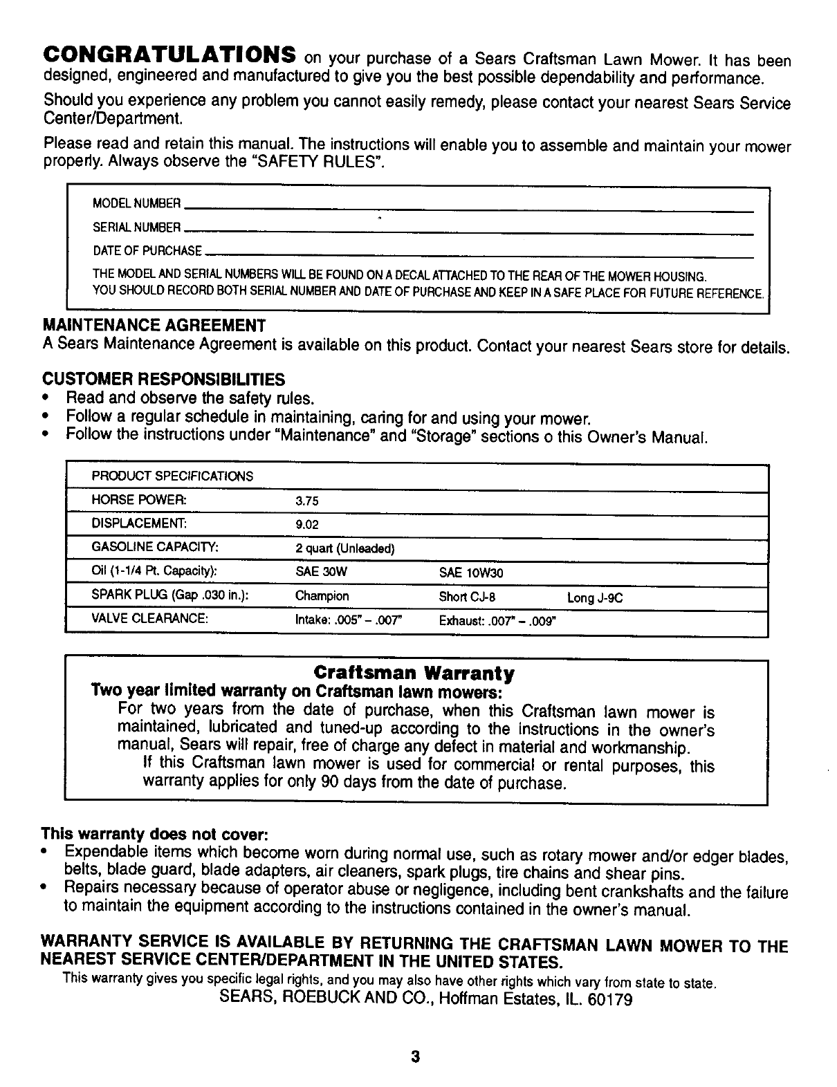
CONGRATULATIONS on your purchase of a Sears Craftsman Lawn Mower. It has been
designed, engineered and manufactured to give you the best possible dependability and performance.
Should you experience any problem you cannot easily remedy, please contact your nearest Sears Service
Center/Department.
Please read and retain this manual. The instructions will enable you to assemble and maintain your mower
properly. Always observe the "SAFETY RULES".
MODELNUMBER
SERIALNUMBER
DATEOF PURCHASE
THE MODELAND SERIALNUMBERSWILLBEFOUNDON ADECALATTACHEDTO THE REAROF THE MOWER HOUSING,
YOU SHOULD RECORDBOTH SERIALNUMBERAND DATEOF PURCHASEANDKEEP INASAFE PLACEFOR FUTURE REFERENCE.
MAINTENANCE AGREEMENT
A Sears Maintenance Agreement is available on thisproduct.Contact your nearest Sears store for details.
CUSTOMER RESPONSIBILITIES
• Read and observe the safety rules.
•Followa regularschedule in maintaining,caringfor and usingyour mower.
•Follow the instructionsunder "Maintenance" and "Storage" sectionso this Owner's Manual.
PRODUCT SPECIFICATIONS
HORSE POWER: 3.75
DISPLACEMENT: 9.02
GASOLINE CAPACITY: 2 quart (Unleaded)
Oil (1-1/4 Pt. Capacity): SAE 30W SAE lOW30
SPARK PLUG (Gap .030 in.): Champion ShortCJ-8 Long J-gC
VALVE CLEARANCE: Intake: .005"- .OOT' Exhaust: .007"-.009"
Craftsman Warranty
Two year limited warranty on Craftsman lawn mowers:
For two years from the date of purchase, when this Craftsman lawn mower is
maintained, lubricated and tuned-up according to the instructions in the owner's
manual, Sears will repair, free of charge any defect in material and workmanship.
If this Craftsman lawn mower is used for commercial or rental purposes, this
warranty applies for only 90 days from the date of purchase.
This warranty does not cover:
•Expendable items which become worn during normal use, such as rotary mower and/or edger blades,
belts, blade guard, blade adapters, air cleaners, spark plugs, tire chains and shear pins.
•Repairs necessary because of operator abuse or negligence, including bent crankshafts and the failure
to maintain the equipment according to the instructions contained in the owner's manual.
WARRANTY SERVICE IS AVAILABLE BY RETURNING THE CRAFTSMAN LAWN MOWER TO THE
NEAREST SERVICE CENTER/DEPARTMENT IN THE UNITED STATES.
This warranty gives you specific legal rights, andyoumayalsohaveotherrightswhichvaryfromstatetostate.
SEARS, ROEBUCK AND CO., Hoffman Estates, IL 60179
3
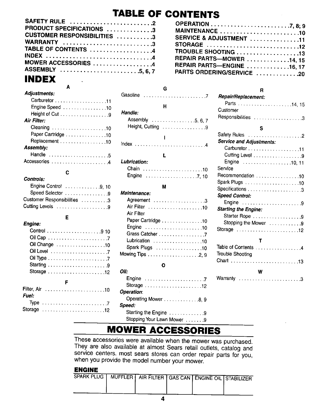
TABLE OF CONTENTS
SAFETY RULE ......................... 2
PRODUCT SPECIFICATIONS .............. 3
CUSTOMER RESPONSIBILITIES ........... 3
WARRANTY ........................... 3
TABLE OF CONTENTS ................... 4
INDEX ................................ 4
MOWER ACCESSORIES .................. 4
ASSEMBLY ........................ 5, 6, 7
INDEX A
Adjustments:
Carburetor ................... 11
Engine Speed ................ 10
Heightof Cut .................. 9
Air Filter:
Cleaning .................... 10
PaperCartridge ............... t0
Replacement................. 10
Assembly:
Handle ...................... 5
Accessories..................... 4
C
Controls:
EngineControl ............. 9, 10
Speed Selector ................ 9
Customer Responsibilities .......... 3
Cutting Levels ................... g
E
Engine:
Control .................... 9 10
Oil Cap ...................... 7
Oil Change .................. 10
Oil Level ..................... 7
OilType ...................... 7
Starting ...................... 9
Storage ..................... 12
F
Filter,Air ...................... 10
Fuel:
Type ........................ 7
Storage ....................... 12
OPERATION ........................ 7, 8; 9
MAINTENANCE ........................ 10
SERVICE & ADJUSTMENT ............... 11
STORAGE ............................ 12
TROUBLE SHOOTING ................... 13
REPAIR PARTS--MOWER ............. 14, 15
REPAIR PARTS--ENGINE ............. 16, 17
PARTS ORDERING/SERVICE ............. 20
G
Gasoline ....................... 7
H
Handle:
AssemtYy ................ 5, 6, 7
Height, Cutting ................ 9
I
Index .......................... 4
L
Lubrication:
Chain ...................... 10
Engine ................... 7, 10
M
Maintenance:
Agreement ................... 3
Air Filter .................... 10
Air Filter
PaperCartridge ............... 10
Engine ..................... 10
Grass Catcher ................. 7
Lubrication .................. 10
SparkPlugs ................. 10
MowingTips ................... 2, 9
O
Oil:
Engine ...................... 7
Storage ..................... 12
Operation:
Operating Mower ............. 8, 9
Speed:
Starting the Engine ............. 9
Stopping Your Lawn Mower ....... 9
R
Repair/Replacement:
Parts .................... 14, 15
Customer
Responsibilities .................. 3
S
Safety Rules .................... 2
Service and Adjustments:
Carburetor ................... 11
Cutting Level .................. 9
Engine .................. 10, 11
Service
Recommendation ................ 10
Spark Plugs .................... 10
Specifications .................... 3
Speed Control:
Engine ...................... 9
Starting the Engine:
Starter Rope .................. 9
Steppingthe Mower ............ 9
Storage ....................... 12
T
Table of Contents ................. 4
Trouble Shooting
Chart ......................... 13
w
Warranty ....................... 3
MOWER ACCESSORIES
These accessories were available when the mower was purchased.
They are also available at almost Sears retail outlets, catalog and
service centers, most sears stores can order repair parts for you,
when you provide the model number your mower.
ENGINE
SPARK PLUG MUFFLER AIR FILTER GAS CAN ENGINE OtL STABILIZER
4
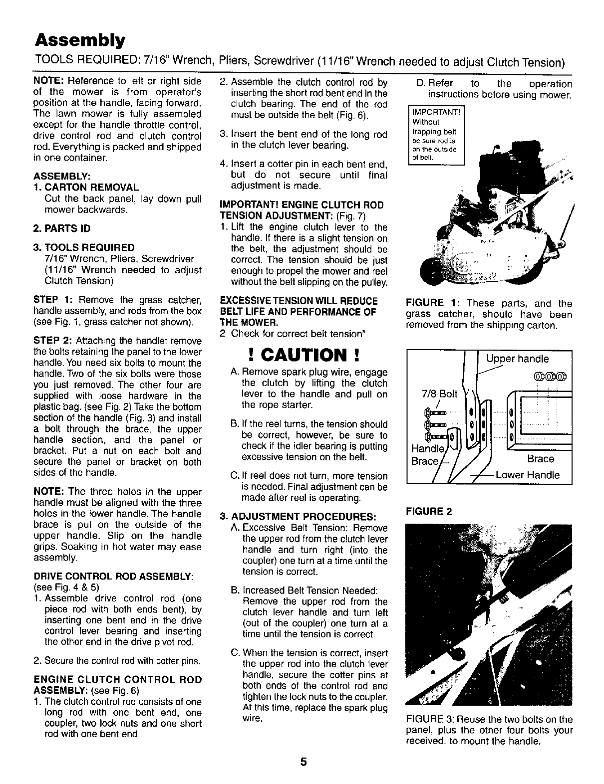
Assembly
TOOLS REQUIRED: 7/16" Wrench, Pliers, Screwdriver (11/16" Wrench needed to adjust Clutch Tension)
NOTE: Reference to left or right side
of the mower is from operator's
position at the handle, facing forward.
The lawn mower is fully assembled
except for the handle throttle control,
drive control rod and clutch control
rod. Everything is packed and shipped
in one container.
ASSEMBLY:
1. CARTON REMOVAL
Cut the back panel, lay down pull
mower backwards.
2. PARTS ID
3. TOOLS REQUIRED
7/16" Wrench, Pliers, Screwdriver
(11/16" Wrench needed to adjust
Clutch Tension)
2. Assemble the clutch control rod by
inserting the short rod bent end in the
clutch bearing. The end of the rod
must be outside the belt (Fig. 6).
3. Insert the bent end of the long rod
in the clutch lever bearing.
4. Insert a cotter pin in each bent end,
but do not secure until final
adjustment is made.
IMPORTANT! ENGINE CLUTCH ROD
TENSION ADJUSTMENT: (Fig. 7)
1. Lift the engine clutch lever to the
handle. If there is a slighttension on
the belt, the adjustment should be
correct. The tension should be just
enough to propel the mower and reel
withoutthe belt slipping onthe pulley.
D. Refer to the operation
instructions before using mower.
be sure rod is
on the outside
STEP 1: Remove the grass catcher,
handle assembly, and rods from the box
(see Fig. 1, grass catcher not shown).
STEP 2: Attaching the handle: remove
the bolts retainingthe panel to the lower
handle. You need six bolts to mount the
handle. Two of the six bolts were those
you just removed. The other four are
supplied with loose hardware in the
plastic bag. (see Fig, 2) Take the bottom
section of the handle (Fig. 3) and install
a bolt through the brace, the upper
handle section, and the panel or
bracket. Put anut on each bolt and
secure the panel or bracket on both
sides of the handle.
NOTE: The three holes in the upper
handle must be aligned with the three
holes in the lower handle. The handle
brace is put on the outside of the
upper handle. Slip on the handle
grips. Soaking in hot water may ease
assembly.
DRIVE CONTROL ROD ASSEMBLY:
(see Fig. 4 & 5)
1. Assemble drive control rod (one
piece rod with both ends bent), by
inserting one bent end in the drive
control lever bearing and inserting
the other end in the drive pivot rod.
2. Secure the control rod with cotter pins.
ENGINE CLUTCH CONTROL ROD
ASSEMBLY: (see Fig. 6)
1. The clutch controlrod consistsof one
long rod with one bent end, one
coupler, two lock nuts and one short
rod with one bent end.
EXCESSIVE TENSION WILL REDUCE
BELT LIFE AND PERFORMANCE OF
THE MOWER,
2 Check for correct belt tension"
!CAUTION !
A. Remove spark plug wire, engage
the clutch by lifting the clutch
lever to the handle and pull on
the rope starter.
B. If the reel turns, the tension should
be correct, however, be sure to
check if the idler bearing is putting
excessive tension on the belt.
C. If reel does not turn, more tension
is needed. Final adjustment can be
made after reel is operating.
3. ADJUSTMENT PROCEDURES:
A. Excessive Belt Tension: Remove
the upper rod from the clutch lever
handle and turn right (into the
coupler)one turn at a time until the
tensionis correct.
B. Increased Belt Tension Needed:
Remove the upper rod from the
clutch lever handle and turn left
(out of the coupler) one turn at a
time until the tension is correct.
C. When the tension is correct, insert
the upper rod into the clutch lever
handle, secure the cotter pins at
both ends of the control rod and
tighten the lock nuts to the coupler.
At this time, replace the spark plug
wire.
FIGURE 1: These parts, and the
grass catcher, should have been
removed from the shipping carton.
7/8 Bolt
Upper handle
Brace
-Lower Handle
FIGURE 2
FIGURE 3: Reuse the two bolts on the
panel, plus the other four bolts your
received, to mount the handle.
5
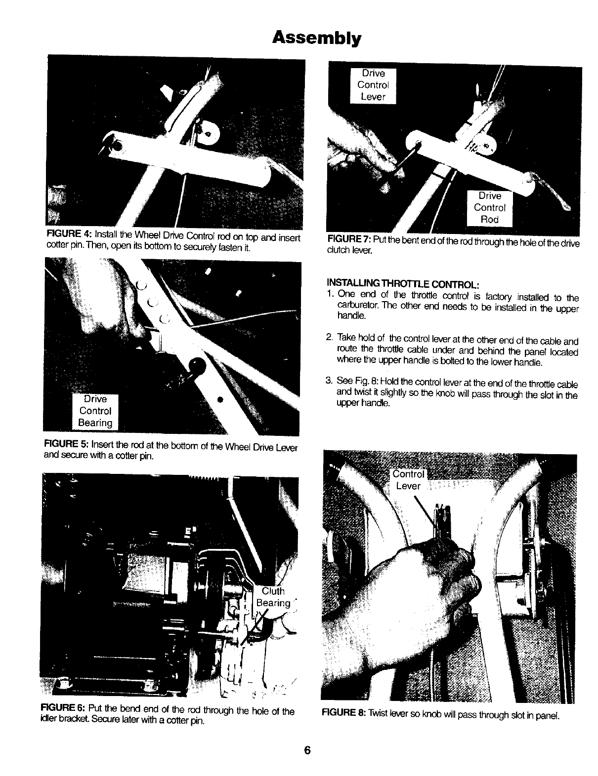
Assembly
FIGURE 4: Installthe Wheel DriveControl rodon top and insert
cotter pin.Then, open itsbottom to securely fastenit.
RGURE 5: Insert the rod at the bottom of the Wheel Drive Lever
and secure with a cotter pin.
FIGURE7: Putthe Pentendof the rodthrough the holeof the drive
dutch lever.
INSTALLING THRO'I-rLE CONTROL.
1. One end of the throttle control is factory installed to the
carburetor.The other end needs to be installed in the upper
handle,
2. Take hold of the controllever at the other end of the cable and
route the throttle cable under and behind the panel located
where the upper handle is pelted to the lower handle.
3. See Fig. 8: Hold the control leverat the end of the throttle cable
andtwist it slightly so _e knob willpass through the slot inthe
upper handle.
Cluth
J
t'i ¸_.
RGURE 6: PUtthe bend end of the rod through the hole of the
idler bracket.Securelaterwitha cotter p_n.
6
RGURE 8: Twistlever so knob will pass through slot in panel.
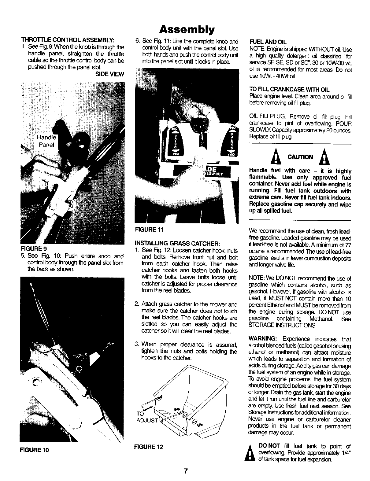
THROTFLE CONTROL ASSEMBLY:
1. See F_g.9:When the knob isthroughthe
handle panel, straighten the thro_e
cableso the throttle controlbody can be
pushed through the panel slot•
SIDE VIEW
Handle
FIGURE 9
5. See Fig. 10: Push entire knob and
controlbody through the panelslotfrom
the beck asshown.
FIGURE 10
Assembly
6. See Fig. 11: Une the complete knob and
controlbody unit ,,V_ the panelslot. Use
both handsendpush thecontrolbody unit
intothe panelslot untilit locks in place.
RGURE 11
INSTALLING GRASS CATCHER:
1. See Fig. 12: Loosencatcher hook, nuts
and belts. Remove front nut and bolt
from each catcher hook. Then raise
catcher hooks and fasten both hooks
with the belts. Leave belts loose until
catcher is adjusted for proper clearance
from the reel blades.
2. Attach grass catcher to the mower and
make sure the catcher does not touch
the reel Uedes. The catcher hooks are
slotted so you can easily adjust the
catcher so itwill dear the reel blades.
3. When proper clearance is assured,
tighten the nuts and bolts holding the
hooks to the catcher.
TO
FIGURE 12
FUELAND OIL
NOTE:Engineis shippedWITHOUT oil Use
a high quality detergent oil classified "for
serviceSF,SE, SD or SC".30 or 10W-30wt.
oilis recommendedfor most areas. Do net
use 10Wt-40Wt oil•
TO RLL CRANKCASEWITH OIL
Place enginelevel.Clean area aroundoil fill
beforeremovingoilfill plug.
OIL FILLPLUG. Remove oil fill plug. Fill
crankcase to pint of overflowing. POUR
SLOWLY.Capacityapproximately20 ounces.
Replaceoilfillplug.
Handle fuel with care - it is highly
flammable. Use only approved fuel
container.Never add fuel whila engine is
running. Fill fuel tank outdoors with
extreme care. Never fill fuel tank indoors.
Replacegasoline cap securely and wipe
up allspilledfuel.
We recommendthe use of dean, fresh lead-
free gasoline.Leadedgasolinemaybe used
if lead-freeis not available.A minimum of 77
octaneis recommended.Theuseof _ead-frse
gasolineresultsinfewercembustiondeposits
and longervalvelife.
NOTE:We DO NOT recommendthe use of
gasoline which contains alcohol, such as
gasohol.However,ifgasoline with alcohol is
used, it MUST NOT contain more than 10
percentEthanolandMUST be removedfrom
the engine during storage. DO NOT use
gasoline containing Methanol See
STORAGEINSTRUCTIONS
WARNING: Experience indicates that
alcoholblendedfuels(calledgasoholorusing
ethanol or methanol) can attract moisture
which leads to separationend formationof
acidsdunngstorage.Aciditygascan damage
the fuel systemof an enginewhile instorage.
To avoid engine problems, the fuel system
shouldbe e_ beforestoragefor 30 days
orlonger.Drainthe gastank,startthe engine
andlet itrununlitthefuel lineandcarburetor
are empty.Use fresh fuel next season.See
StorageInstructionsforadditionalinformation.
Never use engine or carburetor cleaner
products in the fuel tank or permanent
damage mayoccur.
DONOT fill fuel tank to point of
overflowLng.Provideapproximately1/4"
of tankspacefor fuel expansion.
7
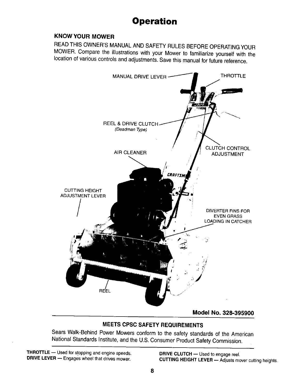
Operation
KNOW YOUR MOWER
READ THIS OWNER'S MANUAL AND SAFETY RULES BEFORE OPERATING YOUR
MOWER. Compare the illustrations with your Mower to familiarize yourself with the
location of various controls and adjustments. Save this manual for future reference.
MANUAL DRIVE LEVER /THROTTLE
REEL & DRIVE
(Deadman Type)
AIR CLEANER CLUTCH CONTROL
ADJUSTMENT
CUTTING HEIGHT
ADJUSTMENT LEVER
/DIVERTER FINS FOR
EVEN GRASS
LOADING IN CATCHER
REEL //
Model No. 328-395900
MEETS CPSC SAFETY REQUIREMENTS
Sears Walk-Behind Power Mowers conform to the safety standards of the American
National Standards Institute, and the U.S. Consumer Product Safety Commission.
THROTTLE -- Used for s!opping and engine speeds.
DRIVE LEVER -- Engages wheelthal drives mower. DRIVE CLUTCH -- Used to engage reel.
CUTTING HEIGHT LEVER -- Adjustsmover cutting heights.
8
HOW TO USE YOUR MOWER
THROTTLE CONTROL:
The engine speed is controlled by the
throtlfe lever located at the top of the
handle.The leveralso controls starting and
stopping.
DRIVE CLUTCH LEVER:
This lever is located on the left side of the
mower and when raised, engages the
clutch which driws the reel. For safety,
when the lever is released, the real and
mower stops immediately
MANUAL DRIVE LEVER:
The drive lever is located on the dght side
of the handle.When pushed forward the
drivewheelengagesthe groundanddrives
the mower. Activatedthe clutchleverfirst,
then the drive lever to propel mower
forward.
CAUTION
The Operation of any lawn mower can
result in foreign objects thrown into the
eyes, which can result in severe eye
damage. Always wear safety glasses or
eye shields before starting your lawn
mower and while mowing. We
recommend Wide Vision Safety Mask for
over the spectacles or standard safety
glasses, available at Sears Retail or
CatalogStores.
HEIGHT ADJUSTMENT
•The cutting height of the mower is
adjustablefrom 3/16"to 1-1/4".
•Front wheel assembly bar may be
moved in 2 holes (in side panels) to
adjust height (Fig. 13).
•For best performanceusa onlytop two
cuftJngheight adjustment holes.
FIGURE 13
CAUTION: To avoid possible damage to
front wheels do not start mower before
setting height adjustment. Notchedheight
bracket at right front of mower (Fig. 14)
be placed at desired cuttingheight
pps .
Operation
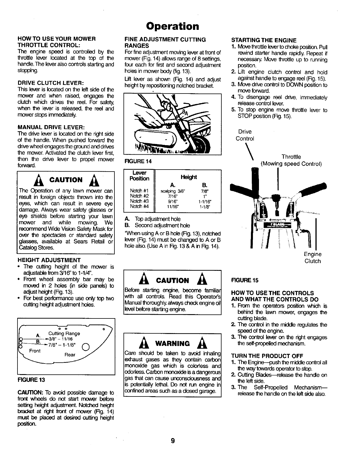
FINE ADJUSTMENT CUTTING
RANGES
Forfine adjustmentmoving lever at front of
mower(Fig.14) allowsrangeof 8 satltngs,
four each for first and second adjustment
holes in mower body (fig.13).
Lift lever as shown (Fig. 14) and adjust
height by reppsitioningnotchedbracket.
RGURE 14
Lever
Position Height
A. B.
Notch#1 scalping3/8" 718"
Notch#2 7/16" 1"
Notch#3 9/16" 1-1/16"
Notch#4 11/16" 1-1/8"
A. Top adjustment hole
B. Second adjustment hole
*When using A or Bhole(Fig.13), notched
lever (Fig. 14) must be changed to A or B
hole also.(Use A in Fg. 13 & A in Fig.14).
._ CAUTION
Before starting engine, become famiUai
with all controls. Read this Operator's
Manual thoroughly,always check engineol
levelbefore starting engine.
._ WARNING
Care should be taken to avoid inhalin¢
exhaust gases as they contain carbor
monoxide gas which is colorless anc
odorless.Carbon monoxide is a dangerous
gas that can cause unconsciousness ant
is potentially lethal. Do not run engine ir
confined areas such as a dosed garage.
STARTING THE ENGINE
1. Move throttielever tochoke position.Pull
rewind starter handle rapidly.Repeat if
necessary. Move throttle up to running
position.
2. Lift engine clutch control and hold
against handle to engage reel (Fig.15).
3, Move drive controlto DOWN positionto
move forward.
4, To disengage reel drive, immediately
release control lever.
5. To stop engine mov_ throttle lever to
STOP position (Fig.15).
Drive
Control
\Throttle
(Mowing speed Control)
I
Engine
Clutch
RGURE 15
HOW TO USE THE CONTROLS
AND WHAT THE CONTROLS DO
1. From the operators pceitionwhich is
behind the lawn mower, engages the
cutting blade.
2. The control in the middle regulatesthe
speed of the engine.
3. The control lever on the right engages
the self-propelledmechanism.
TURN THE PRODUCT OFF
1. The Engine--push the middle controlall
the way towards operator to stop.
2. Cutting Bla_lease the handle on
the leftside.
3. The Self-Propelled Mechanism_
release the handle on the leftside also.
9
GENERAL RECOMMENDATION
1. The spark plug and air filter should be
rep_ced once a year.This wilt assure
better engine performance and longer
engine life.
2. Check allfastenersand be sure they are
tight.
3. Follow all maintenance instructions
lis-l_d on the following pages an the
sem_e schedule.
CA nON:,.SCON.EC SPARKI
LUG WIRE FROM SPARK PLUG I
ANDP .CEW,REW,ERE
CANNOT COME IN CONTACT
WITH SPARK PLUG.
Maintenance
SERVICE RECOMMENDATIONS
SERVICE RECORD
REEL BACKLAPPED
CHECK & ADJUST BELT TENSION
LUBRICATE MOWER
ENGINE OIL CHANGE
ENGINE OIL CHECK
SERVICE AIR CLEANER
CLEAN/REPLACE SP_K PLUG
CHECK MUFFLER
CLBAN f_OW f.R
CLEAN AIR CLEANER
SCHEDULE
FIRST EVERY EVERY E':E_Y
5 25 50 l{:!:_s.
HOURS HOURS HOURS OF_SON
X
X
x
x
x
SERVICE DATES
FILL IN WHEN SERVICE
EVERY IS COMPLETED
USE
x
x
@
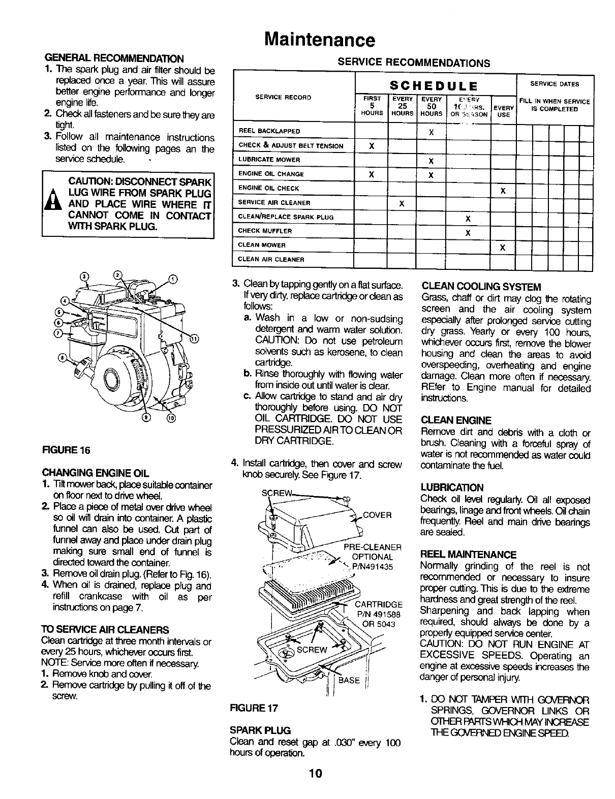
RGURE 16
CHANGING ENGINE OIL
1. Tiltmower back, place suitablecontainer
on floor next to drive wheel.
2. Place a piece of metal over drive wheel
so oil will drain into container. A plastic
funnel can also be used. Cut part of
funnel away and place under drain plug
making sure small end of funnel is
directedtowardthe container.
3. Removeoildrainplug.(Referto Fig.16).
4. When oil is dreJned, replaceplug and
refill crankcase with oil as per
instructionson page 7.
TO SERVICE AIR CLEANERS
Clean cartridge at three month intervals or
every25 hours,whicheveroccurs first.
NOTE: Service more often if necessary.
1. Remove knob and cover.
2. Remove cartridge by pulling it off of the
screw.
3. Clean by tapping gently on a flatsurface.
Ifvery dirty,replace cartridge or dean as
follows:
a, Wash in a low or non-sudsing
detergent and warm water solution.
CAUTION: Do net use petroleum
sc4ventssuch as kerosene, to clean
cartridge.
b. Rinse thoroughly with flowing water
from inside out until water is clear.
¢, Allow cartridge to stand and air dry
thoroughlybefore using. DO NOT
OIL CARTRIDGE. DO NOT USE
PRESSURIZED AIRTO CLEAN OR
DRY CARTRIDGE.
4. Install cartridge, then cover and screw
knob securely.See Figure 17.
COVER
IPRE-CLEANER
OPTIONAL
"-. P/N491435
P/N 491588
OR 5043
,ASEi!
FIGURE 17
SPARK PLUG
Clean and reset gap at .030" every 100
hoursof opera'_n.
CLEAN COOUNG SYSTEM
Grass, chaff or dirt may clog the rotating
screen and the air cooling system
especially after prolonged service cutting
dry grass, Yearly or every 100 hours,
whichever occurs first, remove the blower
housing and dean the areas to avoid
overspeeding, overheating and engine
damage. Clean more often if necessary.
REfer to Engine manual for detailed
instructions.
CLEAN ENGINE
Remove dirt and debris with a doth or
brush. Cleaning with a forceful spray of
water is not recommended as water could
contaminate the fuel.
LUBRICATION
Check oil level regularly. Oil all exposed
bearings, linageand frent wheels. Oil chain
frequently. Reel and main drive bearings
are sealed.
REEL MAINTENANCE
Normally grinding of the reel is not
recommended or necessary to insure
proper cutting.This is due to the extreme
hardness and great strength of the reel.
Sharpening and back lapping when
required, should always be done by a
prebedyequipped service center.
CAUTION: DO NOT RUN ENGINE AT
EXCESSIVE SPEEDS. Operating an
engineat excessivespeedsincreasesthe
danger of personal injury.
1, DO NOT TAMPER WITH GOVERNOR
SPRINGS, GOVERNOR LINKS OR
OTHER PARTSWHICHMAYINCREASE
THE GOVERNEDENGINESPEED.
10
SERVICE AND ADJUSTMENTS
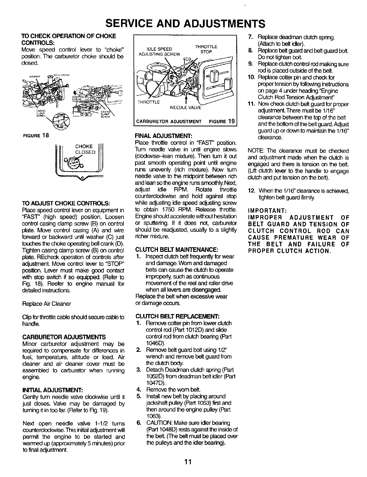
TO CHECK OPERATION OF CHOKE
CONTROLS:
Move speed control lever to "choke"
position. The carburetor choke should be
dosed.
WAS_n BELL CRANK
FIGURE 18
4_ U
CASING t '_
CHOKE
TO ADJUST CHOKE CONTROLS:
Place speed control lever on equipment in
"FAST' (high speed) position. Loosen
control casing clamp screw (B) on control
plate. Move control casing (A) and wire
forward or backward until washer (C) just
touches the choke operating bellcrank (D).
]]ghten casing clamp screw (B) on control
plate. REcheck operation of controls after
adjustment. Move control lever to "STOP"
position. Lever must make good contact
wen step switch if so equipped. (Refer to
Fig. 18). Reefer to engine manual for
detailed instructions.
ReplaceAir Cleaner
IDLE SPEED TH RO]q'LE
STOP
ADJUSTING SCREW
THROTTLE
NEEDLE VALVE
CARBURETOR ADJUSTMENT FIGURE 19
FINAL ADJUSTMENT:
Place throttle control in "FAST' posi_on.
Turn needle valve in until engine slows
(clockwise-lean mixture). Then rum it out
pest smooth operating point until engine
runs unevenly (rich mixture). Now tum
needle valve to the midpoint between rich
and lean so theengine runs smoothly.Next,
adjust idle RPM. Rotate throttle
counterclockwise and hold against step
while adjusting idle speed adjusting screw
to obtain 1750 RPM. Release throttle.
Engineshould acceleratewithout hesitation
or sputtering. If it does not, carburetor
should be readjusted, usually to a slightly
richermixture.
CLUTCH BELT MAINTENANCE:
1. Insbectclutch beitfrequentJyforwear
and demaga. Wom and damaged
belts can cause the dutch to operate
improperly,such as con_nuous
movement of the reel and rollerdrive
when all leversare dL%=ngaged.
Replace the belt when excessive wear
or damage occurs.
7. Replacedaadman dutch spring.
(Attachto belt idler).
8. Replacebelt guard and belt guard belt.
Do not tighten bolt.
9. Replaceclutchcontrolrod makingsure
red is paced outsideof the belt.
10. Replace cotter pin and check for
propertension by followinginstructions
on page 4 under heading "Engine
Clutch Red TensionAdjustmenf'
11. Now check dutch belt guard for proper
adjustment.Thare must be 1/16"
clearancebetween the top of the belt
andthe bottomof the belt guard. Adjust
guard upor down to maintainthe 1/16"
clearance.
NOTE: The dearance must be checked
and adjustment made when the dutch is
engaged and there is tension on the belt.
(Lift clutch lever to the handle to engage
dutch and put tension on the belt).
12. Whenthe 1/16"dearance isachieved,
tighten belt guard firmly.
IMPORTANT:
IMPROPER ADJUSTMENT OF
BELT GUARD AND TENSION OF
CLUTCH CONTROL ROD CAN
CAUSE PREMATURE WEAR OF
THE BELT AND FAILURE OF
PROPER CLUTCH ACTION.
Clip fer throttlecable should secure cable to
handle.
CARBURETOR ADJUSTMENTS
Minor carburetor adjustment may be
required to compensate for differences in
fuel, temperature, altitude or load. Air
cleaner and air cleaner cover must be
assembled to carburetor when running
engine.
INmAL ADJUSTMENT:
Gently tum needle valve clockwise until it
just doses. Valve may be damaged by
tuming it in tee far.(Referto Fig. 19).
Next open needle valve 1-1/2 turns
counterclockwise.This initialadjustment will
permit the engine to be started and
warmed up (approximately5 minutes) prior
to final adjustment.
CLUTCH BELT REPLACEMENT:
1. Remove cotterpinfrom lowerdutch
control rod (Part 1012D) and slide
control rod from dutch bearing (Part
1046D).
2. Remove belt guard bolt using 1/Z'
wrench and remove belt guard from
the clutch body.
3. Detach Deadman clutch spring (Part
1052D) from deadman belt idler (Part
1047D).
4. Remove the worn belt.
5. Install new belt by placing around
jackshaft pulley (Part 1053)first and
then around the engine pulley (part
I063).
6. CAUTION: Make sure idler bearing
(part I048D) rests againstthe inside of
the belt.O'ha belt must be placed over
the pulleysand the idlerbearing).
11
STORAGE
MOWER:
•Clean all debris off mower and engine with a
rag or brush.
• Do not use water.
• Oil all chains and wipe off excess oil with a
rag.
ENGINE:
Engines to be stored over 30 days should be
completely drained of fuel to prevent gum
deposits forming on essential carburetor parts,
fuel filter and tank.
NOTE: The use of a fuel additive, such as STA-BIL®,
or an equivalent, will minimize the formation of
fuel gum deposits during storage. Such an
additive may be added to the gasoline in the fuel
tank of the engine, or to the gasoline in a storage
container.
a. All fuel should be removed from the tank.
Run the engine until it stops from lack of fuel.
b. While engine is still warm, drain oil from
crankcase. Refill with fresh oil.
c. Remove spark plug, pour approximately 1/2
ounce (15 cc) of engine oil into cylinder and
crank slowly to distribute oil. Replace spark plug.
IMPORTANT:.
IT IS IMPORTANT TO PREVENT GUM
DEPOSITS FROM FORMING IN ESSENTIAL
FUEL SYSTEM PARTS SUCH AS THE
CARBURETOR, FUEL FILTER, FUEL HOSE,
OR TANK DURING STORAGE. ALSO,
EXPERIENCE INDICATES THAT ALCOHOL
BLENDED FUELS (CALLED GASOHOL OR
USING ETHANOL OR METHANOL) CAN
ATTRACT MOISTURE WHICH LEADS TO
SEPARATION AND FORMATION OF ACIDS
DURING STORAGE. ACIDIC GAS CAN
DAMAGE THE FUEL SYSTEM OF AN ENGINE
WHILE IN STORAGE.
OTHER:
Do not store gasoline from one season to another.
•Replace your gasoline can if your can starts
to rust. Rust and/or dirt in your gasoline can
cause problems.
• Do not store your mower under any plastic
cover. Plastic cannot breathe which allows
condensation to form and can cause your
mower to rust.
d. Clean dirt and chaff from cylinder, cylinder
head fins, blower housing, rotating screen
and muffler areas.
e. Store in a clean and dry area.
12
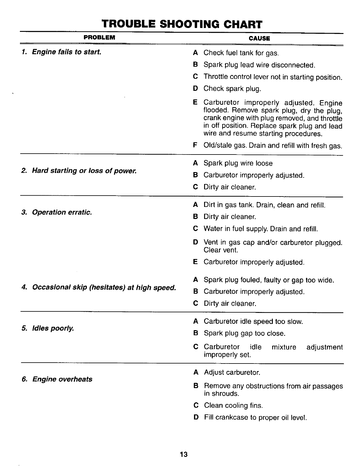
TROUBLE SHOOTING CHART
PROBLEM CAUSE
1. Engine fails to start. A
B
C
D
Check fuel tank for gas.
Spark plug lead wire disconnected.
Throttle control lever not in starting position.
Check spark plug.
ECarburetor improperly adjusted. Engine
flooded. Remove spark plug, dry the plug,
crank engine with plug removed, and throttle
in off position. Replace spark plug and lead
wire and resume starting procedures.
F Old/stale gas. Drain and refill with fresh gas.
2. Hard starting or loss of power.
A Spark plug wire loose
B Carburetor improperly adjusted.
C Dirty air cleaner.
3. Operation erratic.
ADirt in gas tank. Drain, clean and refill.
BDirty air cleaner.
C Water in fuel supply. Drain and refill.
D Vent in gas cap and/or carburetor plugged.
Clear vent.
E Carburetor improperly adjusted.
4. Occasional skip (hesitates) at high speed.
A Spark plug fouled, faulty or gap too wide.
B Carburetor improperly adjusted.
C Dirty air cleaner.
5. Idles poorly. A Carburetor idle speed too slow.
B Spark plug gap too close.
C Carburetor idle mixture
improperly set. adjustment
6. Engine overheats A Adjust carburetor.
B Remove any obstructions from air passages
in shrouds.
C Clean cooling fins.
D Fill crankcase to proper oil level.
13
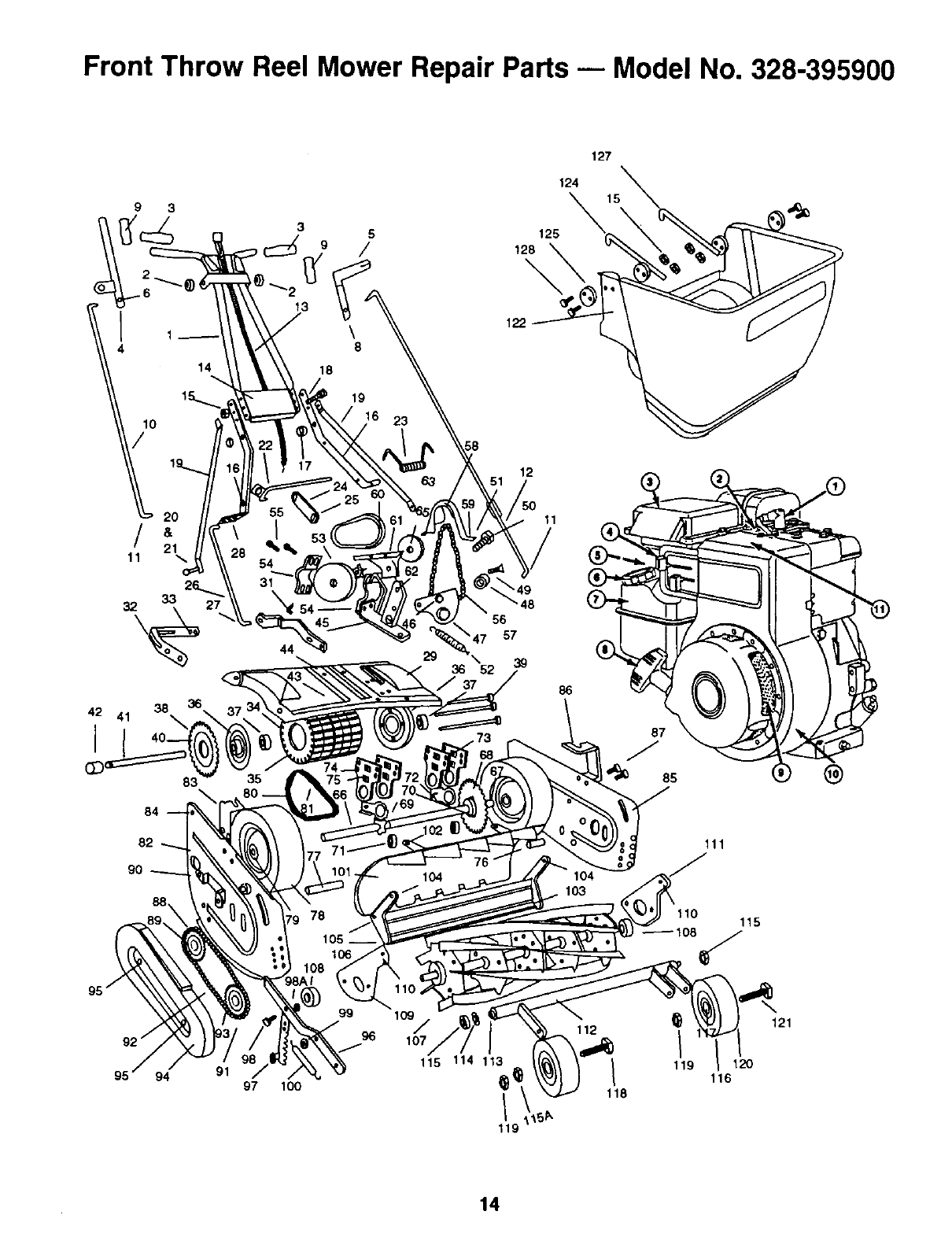
Front Throw Reel Mower Repair Parts nModel No. 328-395900
93
6
1
14
2O
/
11
42 41 38\
I
8
84
82
90
88
28
44
5
9/
\
127
124
125
128
\
122
12
11
'49
56
\47 57
111
110 115
®
94 91 97 lOO
115 114 113
119
118
€
119 120
116
121
14
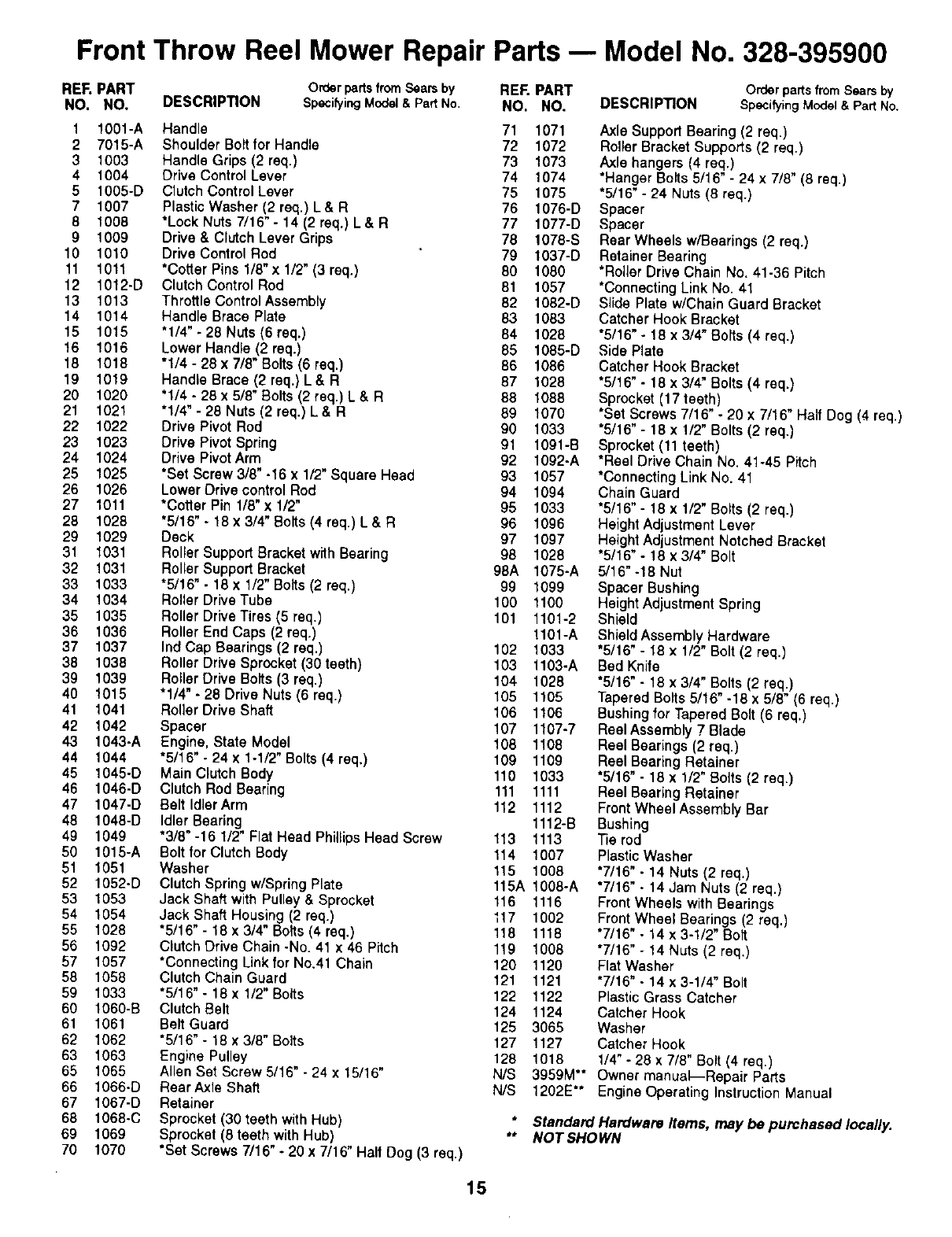
Front Throw Reel Mower Repair Parts -- Model No. 328-395900
REF. PART OrderpartsfromSearsby REF. PART
NO. NO. DESCRIPTION SpecifyingModel& PartNo. NO. NO.
1 1001-A Handle 71 1071
2 7015-A ShoulderBoltfor Handle 72 1072
3 1003 HandleGrips (2 req.) 73 1073
4 1004 Drive ControlLever 74 1074
5 1005-D ClutchControlLever 75 1075
7 1007 PlasticWasher (2 req.) L& R 76 1076-D
81008 "LockNuts7/16" - 14 (2 req.) L & R 77 1077-D
9 1009 Drive & ClutchLever Grips 78 1078-S
10 1010 DriveControlRod 79 1037-D
11 1011 *Cotter Pins1/8"x 1/2"(3 req,) 80 1080
12 1012-D ClutchContml Rod 81 1057
13 1013 ThrottleControlAssembly 82 1082-D
14 1014 Handle Brace Plate 83 1083
15 1015 '1/4" _28 Nuts(6 req.) 84 1028
16 1016 Lower Handle (2 req.) 85 1085-D
18 1018 "1/4 - 28 x 7/8" Bolts(6 req.) 86 1086
19 1019 HandleBrace (2 req.) L& R 87 1028
20 1020 '114 - 28 x 5/8"Bolts(2 req.) L & R 88 1088
21 1021 "1/4"- 28 Nuts(2 raq.) L& R 89 1070
22 1022 Drive Pivot Rod 90 1033
23 1023 Drive PivotSpring 91 1091-B
24 1024 Drive Pivot Arm 92 10g2-A
25 1025 *Set Screw3/8" -16 x 1/2" Square Head 93 1057
26 1026 Lower Drive controlRod 94 1094
27 1011 "CotterPin 1/8"x 1/2" 95 1033
28 1028 '5/16" - 18 x 3/4"Bolts (4 req.) L & R96 1096
29 1029 Deck 97 1097
31 t031 Roller SupportBracketwith Bearing 98 1028
32 1031 Roller Support Bracket g8A 1075-A
33 1033 "5/16" - 18 x 1/2" Bolts (2 req.) 99 1099
34 1034 Roller Drive Tube 100 1100
35 1035 Rotter DriveTires (5 req.) 101 1101-2
36 1036 Roller End Caps (2 req.) 1101-A
37 1037 tnd Cap Bearings (2 req.) 102 1033
38 1038 Roller Drive Sprocket (30teeth) 103 1103-A
39 1039 Roller Drive Bolts (3 req.) 104 1028
40 1015 "1/4"- 28 Drive Nuts (6 req.) 105 1105
41 1041 Roller Drive Shaft 106 1106
42 1042 Spacer 107 1107-7
43 1043-A Engine, State Model 108 1108
44 1044 "5/16"- 24 x 1-1/2" Bolts(4 req.) 109 1109
45 1045-D Main ClutchBody 110 1033
46 1046°D ClutchRod Bearing 111 1111
47 1047-D Belt IdlerArm 112 1112
48 1048-D Idler Bearing 1112-B
4g 1049 "3/8"-16 1/2" Flat Head PhillipsHead Screw 113 1113
50 1015-A Boltfor ClutchBody 114 1007
51 1051 Washer 115 1008
52 1052-O ClutchSpringw/Swing Plate 115A 1008-A
53 1053 Jack Shaft with Pulley& Sprocket 116 1116
54 1054 Jack Shaft Housing(2 req.) 117 1002
55 1028 "5/16"- 18 x 3/4" Bolts (4 req.) 118 1118
56 1092 Clutch Drive Chain -No. 41 x 46 pitch 119 1008
57 1057 *Connecting Link for No.41 Chain 120 1120
58 1058 Clutch Chain Guard 121 1121
59 1033 "5/16"- 18 x 1/2" Bolts 122 1122
60 1060-B ClutchBelt 124 1124
61 1061 Belt Guard 125 3065
62 1062 %/16" - 18 x 3/8" Bolts 127 1127
63 1063 Engine Pulley 128 1018
65 1065 Allen Set Screw 5/16" - 24 x15116" N/S
66 1066-D Rear AxleShaft N/S
67 1067-D Releiner
68 1068-C Sprocket (30 teeth with Hub)
69 1069 Sprocket(8 teeth withHub)
70 1070 *Set Screws 7/16" - 20 x 7/16" Half Dog (3 req.)
DESCRIPTION Order parts from Sears by
SpecifyingMod_ & Pad No.
AxleSuppod Bearing (2 req.)
Roller Bracket Supports (2 req.)
Axle hangers(4 req.)
*Hanger Bolts 5116"- 24 x 7/8" (8 req.)
"5/16" - 24 Nuts (8 req.)
Spacer
Spacer
Rear Wheels w/Bearings(2 req.)
Retainer Bearing
*Roller Drive Chain No. 41-36 Pitch
*Connecting Link No. 41
Slide Plate w/Chain Guard Bracket
Catcher Hook Bracket
"5/16" - 18 x 3/4" Bolts (4 req.)
Side Plate
Catcher Hook Bracket
"5/16" - 18 x 3/4"Bolts (4 req.)
Sprocket (17 teeth)
*Set Screws 7/16" - 20 x 7/16" Half Dog (4 req.)
"5/16" - 18 x 1/2" Bolts (2 raq.)
Sprocket (11 teeth)
*Reel Drive Chain No. 41-45 Pitch
*Connecting Link No. 41
Chain Guard
"5/16" - 18 x 1/2" Bolts (2 raq.)
Height Adjustment Lever
Height Adjustment Notched Bracket
"5/16" - 18 x 3/4" Bolt
5/16" -18 Nut
Spacer Bushing
Height Adjustment Spring
Shield
ShieldAssembly Hardware
"5/16"- 18 x 1/2" Bolt(2 req,)
Bed Knife
"6/16" - 18 x 3/4"Bolts(2 req.)
TaperedBolts5/16" -18 x 5/8" (6 req,)
Bushing for TaperedBolt (6 req.)
Reel Assembly 7 Blade
Reel Bearings (2 req.)
Reel BearingRetainer
"5/16" - 18 x 1/2" Bo_ls (2 req.)
ReelBearing Retainer
FrontWheel AssemblyBar
Bushing
Tie rod
PlasticWasher
"7/16" - 14 Nuts(2 req.)
"7/16" - 14 Jam Nuts (2 req.)
FrontWheels with Bearings
FrontWheel Bearings(2 req.)
"7/16"- 14 x 3-1/2" Bott
"7/16" -14 Nuts (2 req.)
Flat Washer
"7/16"• 14 x 3-1/4" Bolt
PlasticGrass Catcher
Catcher Hook
Washer
Catcher Hook
1/4"- 28 x 7/8" Bolt (4 req.)
3959M** Owner manual_Repair Parts
1202E** Engine Operating Instruction Manual
* Standard Hardware Items, may be purchased locally.
** NOT SHOWN
15

NOTES-- MAINTENANCE RECORD
16

NOTES mMAINTENANCE RECORD
17

NOTES-- MAINTENANCE RECORD
18

NOTES mMAINTENANCE RECORD
19
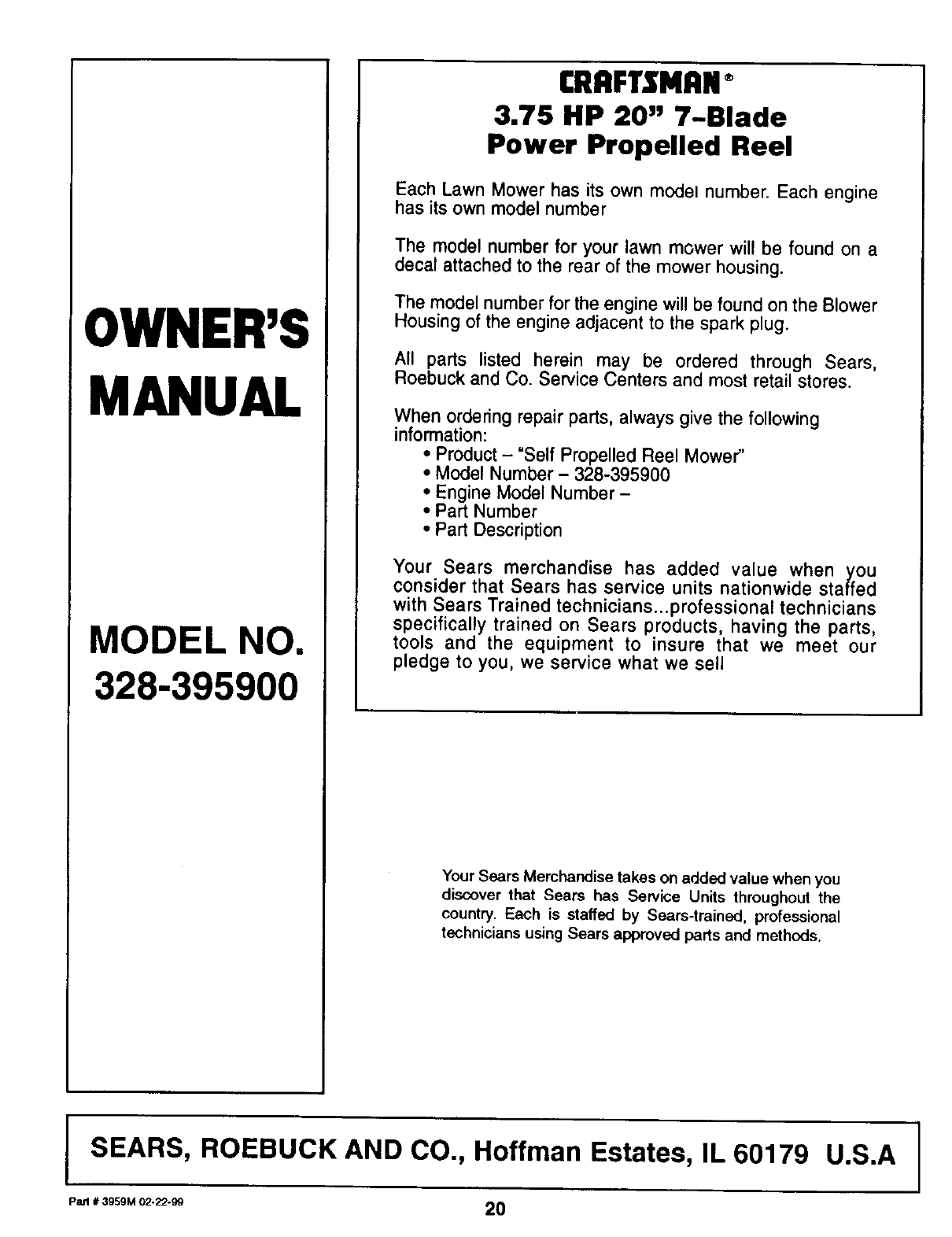
OWNER'S
MANUAL
MODEL NO.
328-395900
CRRFTSHRN ®
3.75 HP 20" 7-Blade
Power Propelled Reel
Each Lawn Mower has its own model number. Each engine
has its own model number
The model number for your lawn mower will be found on a
decal attached to the rear of the mower housing.
The model number for the engine will be found on the Blower
Housing of the engine adjacent to the spark plug.
All parts listed herein may be ordered through Sears,
Roebuck and Co. Service Centers and most retail stores.
When ordering repair parts, always give the following
information:
•Product- "Self Propelled Reel Mower"
• Model Number - 328-395900
• Engine Model Number -
• Part Number
• Part Description
Your Sears merchandise has added value when you
consider that Sears has service units nationwide staffed
with Sears Trained technicians...professional technicians
specifically trained on Sears products, having the parts,
tools and the equipment to insure that we meet our
pledge to you, we service what we sell
Your Sears Merchandise takes on added value when you
discover that Sears has Service Units throughout the
country. Each is staffed by Sears-trained, professional
technicians using Sears approved parts and methods.
SEARS, ROEBUCK AND CO., Hoffman Estates, IL 60179 U.S.A I
p=l,,_gs+m02-z2-9o 20
