Craftsman 351211241 User Manual GRINDER BENCH Manuals And Guides 1304029L
User Manual: Craftsman 351211241 351211241 CRAFTSMAN GRINDER BENCH - Manuals and Guides View the owners manual for your CRAFTSMAN GRINDER BENCH #351211241. Home:Tool Parts:Craftsman Parts:Craftsman GRINDER BENCH Manual
Open the PDF directly: View PDF ![]() .
.
Page Count: 19

Owner's Manual
IIIIIIIIIIIIII I III
IERRFT$iVlFiN I
G-in Wheel
1/6 Horsepower (continuous duty)
3600 R.P.M. (rating speed)
6-in
BENCH GRINDER
Model No.
351.211241
3168328
Conforms to UL Std, No. 987
Certified to CAN/CSA Std. C22,2 NO. 7!1.2
CAUTION:
FOR YOUR OWN SAFETY; Read
and follow all of the Safety and
Operating Instructions before
Operating this Bench Grinder
Customer Helpline
1-800-266-9079
Please have your Model No.
and Serial No. available.
Sears Brands Management Corporation, Hoffman Estates, IL 60179 U.S.A.
www.craftsman.com
36276.00Draft(07111112) EspaSol pg. 19
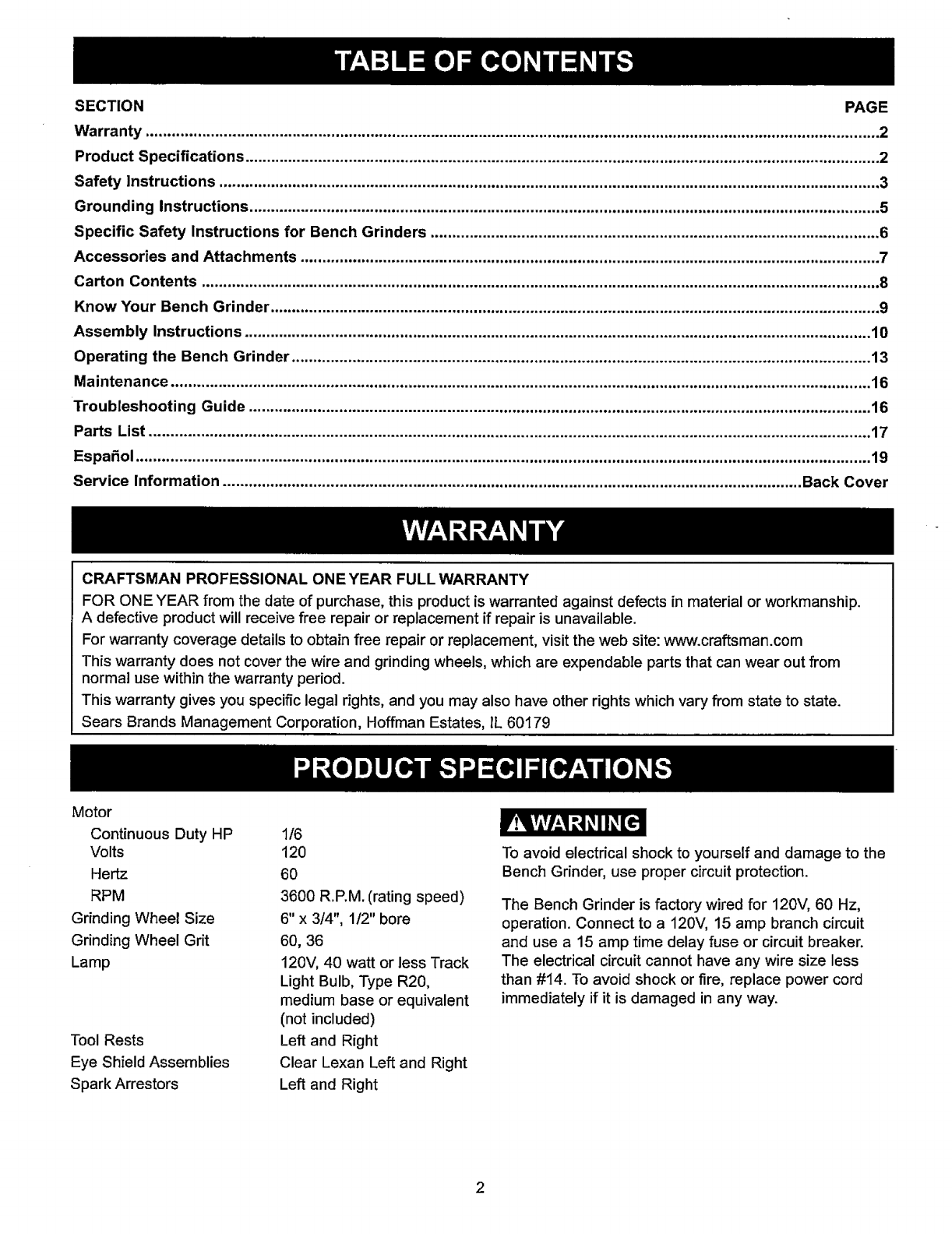
SECTION PAGE
Warranty .......................................................................................................................................................................... 2
Product Specifications ................................................................................................................................................... 2
Safety Instructions ......................................................................................................................................................... 3
Grounding Instructions .................................................................................................................................................. 5
Specific Safety Instructions for Bench Grinders ........................................................................................................ 6
Accessories and Attachments ...................................................................................................................................... 7
Carton Contents ............................................................................................................................................................. 8
Know Your Bench Grinder ............................................................................................................................................. 9
Assembly Instructions ................................................................................................................................................. 10
Operating the Bench Grinder ...................................................................................................................................... 13
Maintenance .................................................................................................................................................................. 16
Troubleshooting Guide ................................................................................................................................................ 16
Parts List ....................................................................................................................................................................... 17
Espa_ol .......................................................................................................................................................................... 19
Service Information ...................................................................................................................................... Back Cover
CRAFTSMAN PROFESSIONAL ONE YEAR FULL WARRANTY
FOR ONE YEAR from the date of purchase, this product iswarranted against defects in material or workmanship.
A defective product will receive free repair or replacement if repair is unavailable.
For warranty coverage details to obtain free repair or replacement, visitthe web site: www.craftsman.com
This warranty does not cover the wire and grinding wheels, which are expendable parts that can wear out from
normal use within the warranty period.
This warranty gives you specific legal rights, and you may also have other rights which vary from state to state.
Sears Brands Management Corporation, Hoffman Estates, IL 60179
Motor
Continuous Duty HP
Volts
Hertz
RPM
Grinding Wheel Size
Grinding Wheel Grit
Lamp
Tool Rests
Eye Shield Assemblies
Spark Arrestors
1/6
120
60
3600 R.P.M. (rating speed)
6" x 3/4", 1/2" bore
60, 36
120V, 40 watt or less Track
Light Bulb, Type R20,
medium base or equivalent
(not included)
Left and Right
Clear Lexan Left and Right
Left and Right
To avoid electrical shock to yourself and damage to the
Bench Grinder, use proper circuit protection.
The Bench Grinder is factory wired for 120V, 60 Hz,
operation. Connect to a 120',./,15 amp branch circuit
and use a 15 amp time delay fuse or circuit breaker.
The electrical circuit cannot have any wire size less
than #14. To avoid shock or fire, replace power cord
immediately if it is damaged in any way.

GENERAL SAFETY INSTRUCTIONS
Operating a Bench Grinder can be dangerous if safety
and common sense are ignored. The operator must be
familiar with the operation of the tool. Read this manual
to understand this Bench Grinder. DO NOT operate this
Bench Grinder if you do not fully understand the limita-
tions of this tool. DO NOT modify this Bench Grinder in
any way.
BEFORE USING THE BENCH GRINDER
To avoid serious injury and damage to the tool, read
and follow all of the Safety and Operating Instructions
before operating the Bench Grinder.
I. Some dust created by using power tools contains
chemicals known to the State of California to cause
cancer, birth defects, or other reproductive harm.
Some examples of these chemicals are:
•Lead from lead-based paints.
•Crystalline silica from bricks, cement, and other
masonry products.
• Arsenic and chromium from chemically treated
lumber.
"(our risk from these exposures varies, depending
on how often you do this type of work. To reduce
your exposure to these chemicals: work in a well-
ventilated area, and work with approved safety
equipment, such as those dust masks that are spe-
cially designed to filter out microscopic particles
2. READ the entire Owner's Manual. LEARN how to
use the tool for its intended applications.
3. GROUND ALL TOOLS. If the tool is supplied with a
3-prong plug, it must be plugged into a 3-contact
electrical receptacle. The 3rd prong is used to
ground the tool and provide protection against
accidental electric shock. DO NOT remove the 3rd
prong. See Grounding Instructions on page 4.
4, AVOID A DANGEROUS WORKING ENVIRON-
MENT. DO NOT use electrical tools in a damp
environment or expose them to rain.
5. DO NOT use electrical toots in the presence of
flammable liquids or gasses.
6. ALWAYS keep the work area clean, well lit, and
organized. DO NOT work in an environment with
floor surfaces that are slippery from debris, grease,
and wax.
.KEEP VISITORS AND CHILDREN AWAY. DO NOT
permit people to be in the immediate work area,
especially when the electrical tool is operating.
.
g.
DO NOT FORCE THE TOOL to perform an opera-
tion for which it was not designed. It will de a safer
and higher quality job by only performing operations
for which the tool was intended.
WEAR PROPER CLOTHING. DO NOT wear loose
clothing, gloves, neckties, or jewelry. These items
can get caught in the machine during operations
and pun the operator into the moving parts. The
user must wear a protective cover on their hair, if
the hair is long, to prevent it from contacting any
moving parts.
10. CHILDPROOF THE WORKSHOP AREA by remov-
ing switch keys, unp,ugging tools from the electrical
recaptacles, and using padlocks.
11. DO NOT use electrical tools in the presence of
flammable liquids or gasses.
t2. ALWAYS UNPLUG THE TOOL FROM THE ELEC-
TRICAL RECEPTACLE when making adjustments,
changing parts or performing any maintenance.
13. KEEP PROTECTIVE GUARDS IN PLACE AND IN
WORKING ORDER.
14.
15.
AVOID ACCIDENTAL STARTING. Make sure that
the power switch is in the "OFF" position before
plugging in the power cord to the electrical
receptacle.
REMOVE ALL MAINTENANCE TOOLS from the
immediate area prior to turning "ON" the Bench
Grinder.
16. USE ONLY RECOMMENDED ACCESSORIES.
Use of incorrect or improper accessories could
cause serious injur_jto the operator and cause
damage to the tool. If in doubt, check the instruction
manual that comes with that particular accessory.
17. NEVER LEAVE A RUNNING TOOL UNATTENDED.
Turn the power switch to the "OFF" position. DO
NOT leave the tool until it has come to a complete
stop.
18.
19.
DO NOT STAND ON A TOOL. Serious injury could
result if the tool tips over or you accidentally contact
the tool.
DO NOT store anything above or near the tool
where anyone might try to stand on the tool to
reach it.
20. MAINTAIN YOUR BALANCE. DO NOT extend
yourself over the tool. Wear oil resistant rubbersoled
shoes. Keep floor clear of debris, grease, and wax.
2t. MAINTAIN TOOLS WITH CARE. Always keep tools
clean and in good working order. Keep all blades
and tool bits sharp.
3

22.EACH AND EVERY TIME, CHECK FOR DAMAGED
PARTS PRIOR TO USING THE TOOL. Carefully
check all guards to see that they operate properly,
are not damaged, and perform their intended func-
tions. Check for alignment, binding or breaking of
moving parts. A guard or other part that is damaged
should be immediately repaired or replaced.
23. CHILDPROOF THE WORKSHOP AREA by remov-
ing switch keys, unplugging tools from the electrical
receptacles, and using padlocks.
24. DO NOT OPERATE TOOL IF UNDER THE INFLU-
ENCE OF DRUGS OR ALCOHOL.
25. SECURE ALL WORK. Use clamps or jigs to secure
the workpiece. This is safer than attempting to hold
the workpiece with your hands.
26. STAY ALERT, WATCH WHAT YOU ARE DOING,
AND USE COMMON SENSE WHEN OPERATING
A POWER TOOL. DO NOT USE A TOOL WHILE
TIRED OR UNDER THE INFLUENCE OF DRUGS,
ALCOHOL, OR MEDICATION. Amoment of in-
attention while operating power tools may result in
serious personal injury.
27. ALWAYS WEAR A DUST MASK TO PREVENT
INHALING DANGEROUS DUST OR AIRBORNE
PARTICLES, including wood dust, crystalline silica
dust and asbestos dust. Direct particles away from
face and body. Always operate tool in well venti-
lated area and provide for proper dust removal. Use
dust collection system wherever possible. Exposure
to the dust may cause serious and permanent res-
piratory or other injury, including silicosis (a serious
lung disease), cancer, and death. Avoid breathing
the dust, and avoid prolonged contact with dust.
Allowing dust to get into your mouth or eyes, or lay
on your skin may promote absorption of harmful
material. Always use properly fitting NIOSH/OSHA
approved respiratory protection appropriate for the
dust exposure, and wash exposed areas with soap
and water.
28. USE A PROPER EXTENSION CORD IN GOOD
CONDITION. When using an extension cord, be
sure to use one heavy enough to carry the current
your product will draw. The table at right shows the
correct size to use depending on cord length and
nameplate amperage rating. If in doubt, use the
next heavier gauge. The smaller the gauge number,
the larger diameter of the extension cord. If in doubt
of the proper size of an extension cord, use a short-
er and thicker cord. An undersized cord will cause a
drop in line voltage resulting in a loss of power and
overheating. USE ONLY A 3-WIRE EXTENSION
CORD THAT HAS A 3-PRONG GROUNDING
PLUG AND A 3-POLE RECEPTACLE THAT
ACCEPTS THE TOOL'S PLUG.
SAVE THESE INSTRUCTIONS.
GUIDELINES FOR
EXTENSION CORDS
If you are using an extension cord outdoors, be sure
it is marked with the suffix "W-A" ("W" in Canada) to
indicate that it is acceptable for outdoor use.
Be sure your extension cord is properly sized, and
in good electrical condition. Always replace a damaged
extension cord or have it repaired by a qualified person
before using it.
Protect your extension cords from sharp objects,
excessive heat, and damp or wet areas.
0to 6Amps
6to 10Amps
t0 to 12Arnps
120VOLT OPERATIONONLY
25' LONG
18AWG
18AWG
I6 AWG
50' LONG 100' LONG
16AWG 16AWG
16AWG 14AWG
16AWG I4 AWG
150' LONG
14 AWG
12 AWG
12AWG
4
THIS TOOL MUST BE GROUNDED WHILE IN USE
TO PROTECT THE OPERATOR FROM ELECTRIC
SHOCK.
IN THE EVENT OF A MALFUNCTION OR BREAK-
DOWN, grounding provides the path of least resistance
for electric current and reduces the risk of electric
shock. This tool is equipped with an electric cord that
has an equipment grounding conductor and a ground-
ing plug. The plug MUST be plugged into a matching
electrical receptacle that is properly installed and ground-
ed in accordance with ALL local codes and ordinances.
DO NOT MODIFY THE PLUG PROVIDED. If it will not
fit the electrical receptacle, have the proper electrical
receptacle installed by a qualified electrician.
IMPROPER ELECTRICAL CONNECTION of the equip-
ment grounding conductor can result in risk of electric
shock. The conductor with the green insulation (with or
without yellow stripes) is the equipment grounding
conductor. DO NOT connect the equipment grounding
conductor to a live terminal if repair or replacement of
the electric cord or plug is necessary.
CHECK with aqualified electrician or service personnel
if you do not completely understand the grounding
instructions, or if you are not sure the tool is properly
grounded.
USE ONLY A 3-WIRE EXTENSION CORD THAT HAS
A 3-PRONG GROUNDING PLUG AND A 3-POLE
RECEPTACLE THAT ACCEPTS THE TOOUS PLUG.
REPLACE A DAMAGED OR WORN CORD IMMED-
IATELY.
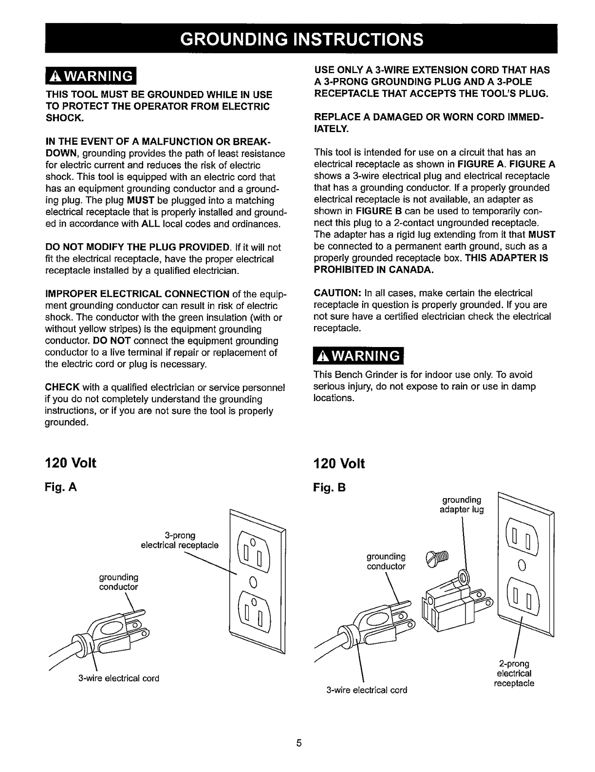
This tool is intended for use on a circuit that has an
electrical receptacle as shown in FIGURE A. FIGURE A
shows a 3-wire electrical plug and electrical receptacle
that has a grounding conductor. If a properly grounded
electrical receptacle is not available, an adapter as
shown in FIGURE Bcan be used to temporarily con-
nect this plug to a 2-contact ungrounded receptacle.
The adapter has a rigid lug extending from it that MUST
be connected to a permanent earth ground, such as a
properly grounded receptacle box. THIS ADAPTER IS
PROHIBITED IN CANADA.
CAUTION: In all cases, make certain the electrical
receptacle in question is properly grounded. If you are
not sure have a certified electrician check the electrical
receptacle.
This Bench Grinder is for indoor use only. To avoid
serious injury, do not expose to rain or use in damp
locations.
120 Volt
Fig. A
120 Volt
Fig. B
grounding
adapter lug
3-prong
electrical receptacle
grounding
conductor
3-wire electrical cord
0
grounding
conductor
3-wire electrical cord
2-prong
electrical
receptacle
5

SPECIFIC SAFETY INSTRUCTIONS
FOR BENCH GRINDERS
The operation of any grinder can result in debris being
thrown into your eyes, which can result in severe eye
damage. ALWAYS WEAR EYE PROTECTION. Any
power tool can throw debris during operations, which
could cause severe and permanent eye damage.
Everyday eyeglasse are NOT safety glasses. ALWAYS
wear Safety Goggles (that comply with ANSI standard
Z87.1) when operating power tools. Safety Goggles are
available at Sears Retail Stores.
Basic precautions should always be followed when
using your bench grinder. To reduce the risk of injury,
electrical shock, or fire, comply with the safety rules
listed below:
.
.
ALWAYS USE THE EYE SHIELDS AND WHEEL
GUARDS provided with the grinder.
REPLACE A CRACKED OR DAMAGED GRIND-
ING WHEEL IMMEDIATELY. A damaged wheel can
discharge debris at a high velocity towards the
operator. Carefully handle the grinding wheels since
they are abrasive, Prior to replacing a grinding
wheel, check it for cracks. DO NOT remove the
blotter or label on both sides of the grinding wheel.
Tighten the spindle nut just enough to hold the
grinding wheel firmly to the Bench Grinder. Do not
over-tighten the nut. Excessive clamping force can
damage the grinding wheel, Only use the wheel
flanges provided with the grinder. When selecting a
replacement grinding wheel, verify that the grinding
wheel has a higher R.P.M. rating than the maximum
R.P.M. of the Bench Grinder.
.THE DIAMETER OF THE GRINDING WHEELS
WILL DECREASE WITH USE. Adjust the tool rests
and spark arrestors to maintain a distance of 1/16"
from the wheel.
,
.
DO NOT STAND IN FRONT OF THE BENCH
GRINDER WHEN STARTING IT. Stand to one side
of the Bench Grinder and turn it "ON". Wait at the
side for one minute until the grinder comes up to
full speed. There is always a possibility that debris
from a damaged grinding wheel may be discharged
towards the operator.
THE BENCH GRINDER WILL PRODUCE SPARKS
AND DEBRIS DURING GRINDING OPERATIONS.
Be sure that there are not any flammable materials
in the vicinity. Frequently clean grinding dust from
the back of the Bench Grinder.
7. KEEP ALL WHEEL GUARDS IN PLACE. DO NOT
USE THE BENCH GRINDER WITH THE WHEEL
GUARDS REMOVED.
8. KEEP THE TOOL RESTS FIRMLY TIGHTENED.
9. ALWAYS USE THE SUPPLIED WHEEL DRESSER
TO RESURFACE THE FACE OF THE GRINDING
WHEEL.
10. REMOVE ADJUSTING KEYS AND WRENCHES.
Form habit of checking to see that keys and adjust-
ing wrenches are removed from tooI before turning
it on.
11.
12.
DIRECTION OF FEED. Feed work into a btade or
cutter against the direction of rotation of the blade
or cutter only.
USE RIGHT TOOL. Don't force tool or attachment
to do a job for which it was not designed.
13. DO NOT overtighten wheel nut.
14. ONLY use flanges furnished with the grinder.
15. FREQUENTLY clean grinding dust from beneath
grinder.
16. DO NOT FORCE THE TOOL to perform an opera-
tion for which it was not designed. It will do a safer
and higher quality job by only performing operations
for which the tool was intended.
17. ADDITIONAL INFORMATION regarding the safe and
proper operation of this product is available from:
• Power Tool Institute
1300 Summer Avenue
Cleveland, OH 44115-2851
www.powertoolinstitute.org
-National Safety Council
1121 Spring Lake Drive
Itasca, IL 60143-3201
° American National Standards Institute
25 West 43rd Street, 4th Floor
New York, NY 10036
www.ansi.org
°ANSI 01.1 Safety Requirements for
Woodworking Machines and the
U.S. Department of Labor regulations
www.osha.gov
18. SAVE THESE INSTRUCTIONS. Refer to them
frequently and use them to instruct others.
.NEVER FORCE THE WORKPIECE AGAINST A
GRINDING WHEEL, especially if the wheel is cold.
Apply the workpiece slowly, allowing the grinding
wheel an opportunity to warm up. This will minimize
the chance of wheel breakage. DO NOT grind using
the sides of the grinding wheels, DO NOT apply
coolant directly to the grinding wheel.
6
AVAILABLE ACCESSORIES
Visit your Sears Hardware Department or see the
Sears Power and Hand Tool Catalog for the following
accessories.
ITEM
Replacement grinding wheels
Wire and Buffing wheels
Spacers
Wheel dressers
Universal stand
Sears may recommend other accessories not listed in
this manual.
See your nearest Sears Hardware Department or Sears
Power and Hand Tool Catalog for other accessories.
Do not use any accessory unless you have completely
read the Owner's Manual for that accessory.
Use only accessories recommended for this Bench
Grinder. Using other accessories may cause serious
injury and cause damage to the Bench Grinder.
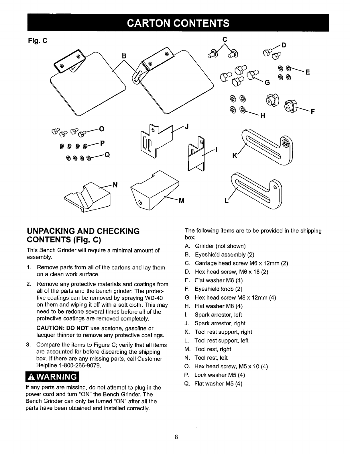
Fig. C
_ _.---_P
B
C
UNPACKING AND CHECKING
CONTENTS (Fig. C)
This Bench Grinder will require a minimal amount of
assembly.
I. Remove parts from all of the cartons and lay them
on a clean work surface.
2. Remove any protective materials and coatings from
all of the parts and the bench grinder. The protec-
tive coatings can be removed by spraying WD-40
on them and wiping it off with a soft cloth. This may
need to be redone several times before all of the
protective coatings are removed completely.
CAUTION: DO NOT use acetone, gasoline or
lacquer thinner to remove any protective coatings.
3. Compare the items to Figure C; verify that all items
are accounted for before discarding the shipping
box. If there are any missing parts, call Customer
Helpline 1-800-266-9079.
If any parts are missing, do not attempt to plug in the
power cord and turn "ON" the Bench Gdnder. The
Bench Grinder can only be turned "ON" after all the
parts have been obtained and installed correctly.
The following items are to be provided in the shipping
box:
A. Grinder (not shown)
B. Eyeshield assembly (2)
C. Carriage head screw M6 x 12mm (2)
D. Hex head screw, M6 x 18 (2)
E. Fiat washer M6 (4)
F. Eyeshield knob (2)
G. Hex head screw M8 x 12ram (4)
H. Flat washer M8 (4)
1. Spark arrestor, left
J. Spark arrestor, right
K. Tool rest support, right
L. Tool rest support, left
M. Tool rest, right
N. Tool rest, left
O. Hex head screw, M5 x 10 (4)
P. Lock washer M5 (4)
Q. Flat washer M5 (4)
I.
2.
3.
4.
5.
6,
.
8.
13
14
15
11
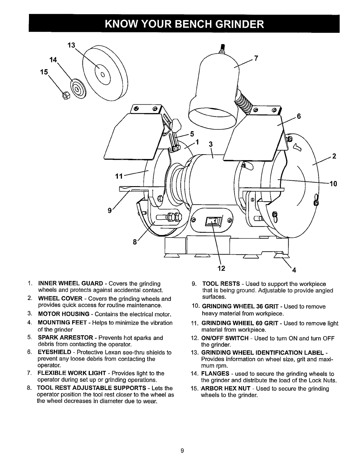
INNER WHEEL GUARD - Covers the grinding
wheels and protects against accidental contact,
WHEEL COVER - Covers the grinding wheels and
provides quick access for routine maintenance.
MOTOR HOUSING - Contains the electrical motor.
MOUNTING FEET - Helps to minimize the vibration
of the grinder
SPARK ARRESTOR - Prevents hot sparks and
debris from contacting the operator.
EYESHIELD - Protective Lexan see-thru shields to
prevent any loose debris from contacting the
operator,
FLEXIBLE WORK LIGHT - Provides light to the
operator during set up or grinding operations.
TOOL REST ADJUSTABLE SUPPORTS -Lets the
operator position the tool rest closer to the wheel as
the wheel decreases in diameter due to wear.
3
12
2
9. TOOL RESTS - Used to support the workpiece
that is being ground. Adjustable to provide angled
surfaces.
10. GRINDING WHEEL 36 GRIT - Used to remove
heavy material from workpiece.
11. GRINDING WHEEL 60 GRIT- Used to remove light
material from workpiece,
12. ON/OFF SWITCH - Used to turn ON and turn OFF
the grinder.
13. GRINDING WHEEL IDENTIFICATION LABEL -
Provides information on wheel size, grit and maxi-
mum rpm.
14. FLANGES -used to secure the grinding wheels to
the grinder and distribute the load of the Lock Nuts,
15. 'ARBOR HEX NUT - Used to secure the grinding
wheels to the grinder.
I.
,
3_
DO NOT assemble the Bench Grinder until you are
sure the tool IS NOT plugged in.
DO NOT assemble the Bench Grinder until you are
sure the power switch is in the "OFF" position.
DO NOT assemble the Bench Grinder until you are
sure the grinding wheels are firmly tightened to the
Bench Grinder.
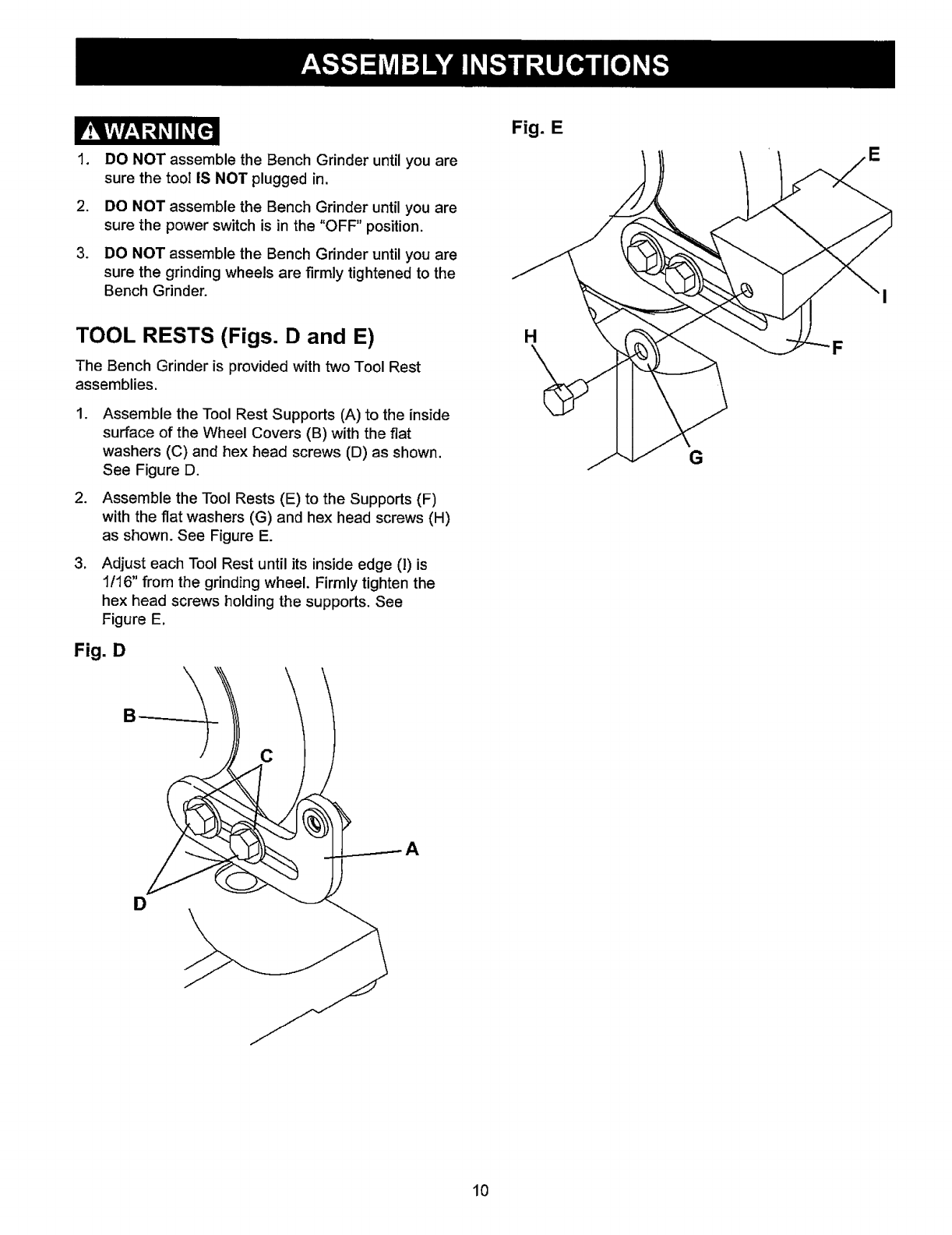
TOOL RESTS (Figs. D and E)
The Bench Grinder is provided with two Tool Rest
assemblies.
,
.
,
Assemble the Tool Rest Supports (A) to the inside
surface of the Wheel Covers (B) with the flat
washers (C) and hex head screws (D) as shown.
See Figure D.
Assemble the Tool Rests (E) to the Supports (F)
with the flat washers (G) and hex head screws (H)
as shown. See Figure E.
Adjust each Tool Rest until its inside edge (1)is
1/16" from the grinding wheel. Firmly tighten the
hex head screws holding the supports. See
Figure E.
Fig. D
Fig. E
H
G
E
C
D
10
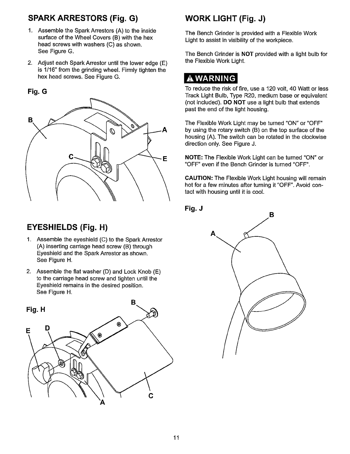
SPARK ARRESTORS (Fig. G)
.Assemble the Spark Arrestors (A) to the inside
surface of the Wheel Covers (B) with the hex
head screws with washers (C) as shown.
See Figure G.
2. Adjust each Spark Arrestor until the lower edge (E)
is 1/t 6" from the grinding wheel. Firmly tighten the
hex head screws. See Figure G.
Fig. G
B\
E
EYESHIELDS (Fig. H)
.Assemble the eyeshield (C) to the Spark Arrestor
(A) inserting carriage head screw (B) through
Eyeshield and the Spark Arrestor as shown.
See Figure H.
2. Assemble the flat washer (D) and Lock Knob (E)
to the carriage head screw and tighten until the
EyeshieZd remains in the desired position.
See Figure H.
B
Fig. H
WORK LIGHT (Fig. J)
The Bench Grinder is provided with a Flexible Work
Light to assist in visibilityof the workpiece.
The Bench Grinder is NOT provided with a light bulb for
the Flexible Work Light.
To reduce the risk of fire, use a 120 volt, 40 Watt or less
Track Light Bulb, Type R20, medium base or equivalent
(not included). DO NOT use a light bulb that extends
past the end of the light housing.
The Flexible Work Light may be turned "ON" or "OFF"
by using the rotary switch (B) on the top surface of the
housing (A). The switch can be rotated in the clockwise
direction only. See Figure J.
NOTE: The Flexible Work Light can be turned "ON" or
"OFF" even if the Bench Grinder is turned "OFF".
CAUTION: The Flexible Work Light housing will remain
hot for a few minutes after turning it "OFF". Avoid con-
tact with housing until it is cool.
Fig. J B
A
E D
C
11
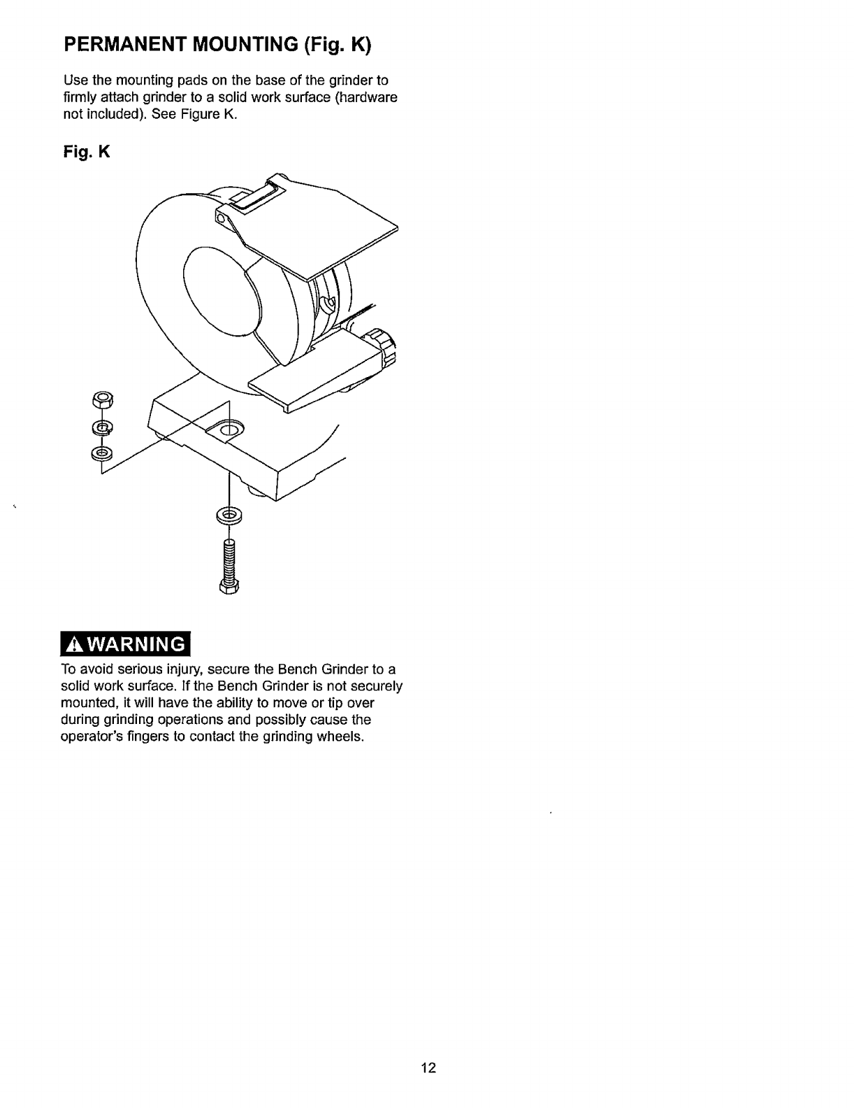
PERMANENT MOUNTING (Fig. K)
Use the mounting pads on the base of the grinder to
firmly attach grinder to a solid work surface (hardware
not included). See Figure K.
Fig. K
To avoid serious injury, secure the Bench Grinder to a
solid work surface. If the Bench Grinder is not securely
mounted, it will have the ability to move or tip over
during grinding operations and possibly cause the
operator's fingers to contact the grinding wheels.
12

TheBenchGrinderisdesignedforhandheldgrinding,
sharpening,andcleaningoperations.
ALWAYSWEAREYEPROTECTION!Hotsparksare
produced during grinding operations.
1. The Power Switch must be in the "OFF" position.
2. Stand to the side of the Bench Grinder and plug in
the power cord to a suitable power source.
3. Remain to the side of the Bench Grinder and turn it
"ON" by moving the power switch to the up position.
4. Allow the grinding wheels to come up to a steady
speed for at least one minute.
5. The Flexible Work Light may be turned "ON" if
desired.
6. Adjust the eyeshields. Place the workpiece on the
appropriate tool rest for the desired operation.
7. Move the workpiece towards the grinding wheel
until it lightty touches. Move the workpiece back
and forth across the front surface of the grinding
wheeI removing the amount of material desired.
8_
.
10.
To avoid serious injury, never grind on the sides
of the grinding wheels.
After completing the grinding operations, turn "OFF"
the Bench Grinder by pushing down on the Power
Switch. CAUTION: It will take a few minutes for the
grinding wheels to come to a complete stop.
Turn "OFF" the Flexible Work Light. CAUTION: The
Flexible Work Light housing will remain hot for a
few minutes after turning it "OFF".
Avoid contact with housing until it is cool. Unplug
the Bench Grinder from the power source.
13
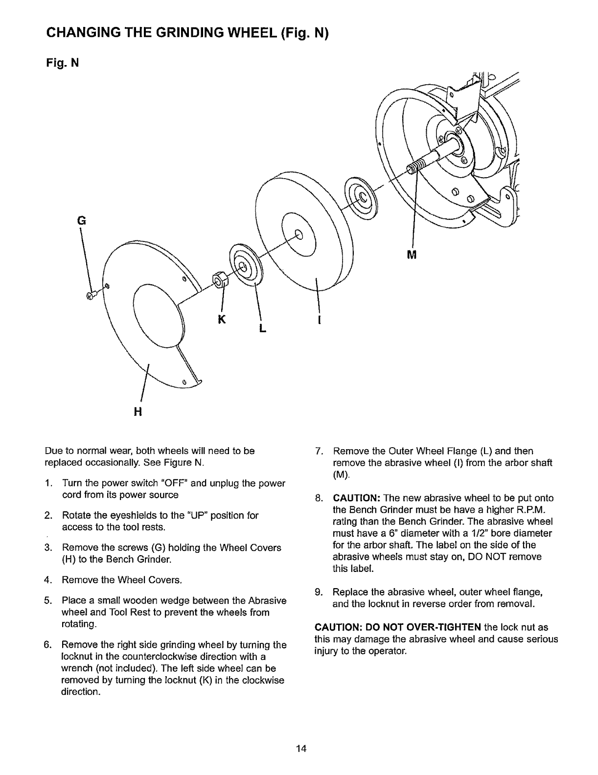
CHANGING THE GRINDING WHEEL (Fig. N)
Fig. N
G
M
KL
H
Due to normal wear, both wheels will need to be
replaced occasionally. See Figure N.
1. Turn the power switch "OFF" and unplug the power
cord from its power source
2. Rotate the eyeshields to the "UP" position for
access to the too] rests.
3. Remove the screws (G) holding the Wheel Covers
(H) to the Bench Grinder.
4. Remove the Wheel Covers.
5. Place a small wooden wedge between the Abrasive
wheel and Tool Rest to prevent the wheels from
rotating.
.Remove the right side grinding wheel by turning the
locknut in the counterclockwise direction with a
wrench (not included), The left side wheel can be
removed by turning the locknut (K) in the clockwise
direction.
7. Remove the Outer Wheel Flange (L) and then
remove the abrasive wheel (I) from the arbor shaft
(M).
.CAUTION: The new abrasive wheel to be put onto
the Bench Grinder must be have a higher R.P.M.
rating than the Bench Grinder. The abrasive wheel
must have a 6" diameter with a 112" bore diameter
for the arbor shaft. The labeI on the side of the
abrasive wheels must stay on, DO NOT remove
this label.
9. Replace the abrasive wheel, outer wheel flange,
and the Iocknut in reverse order from removal.
CAUTION: DO NOT OVER.TIGHTEN the lock nut as
this may damage the abrasive wheel and cause serious
injury to the operator.
14
Turnthepowerswitch"OFF"andunplugthepower
cordfromitspowersourcepriorto anymaintenance.
LUBRICATION
The Bench Grinder has sealed lubricated bearings in
the motor housing that do not require any additional
lubrication from the operator.
CLEANING
With the Bench Grinder unplugged, rotate the abrasive
wheels slowly and inspect for any damage or trapped
shavings.
CAUTION: REPLACE the abrasive wheels if there is
any damage at all. FAILURE to replace a damaged
wheel can cause serious injury to the operator.
CAUTION: DO NOT USE FLAMMABLE MATERIALS
to clean the Bench Grinder. A clean dry rag or brush is
all that is needed to remove dust and debris buildup.
Repairs to the Bench Grinder should be performed by
trained personnel only. Contact your nearest Sears
Service Center for authorized service.
Unauthorized repairs or replacement with non-factory
parts could cause serious injury to the operator and
damage to the Bench Grinder.
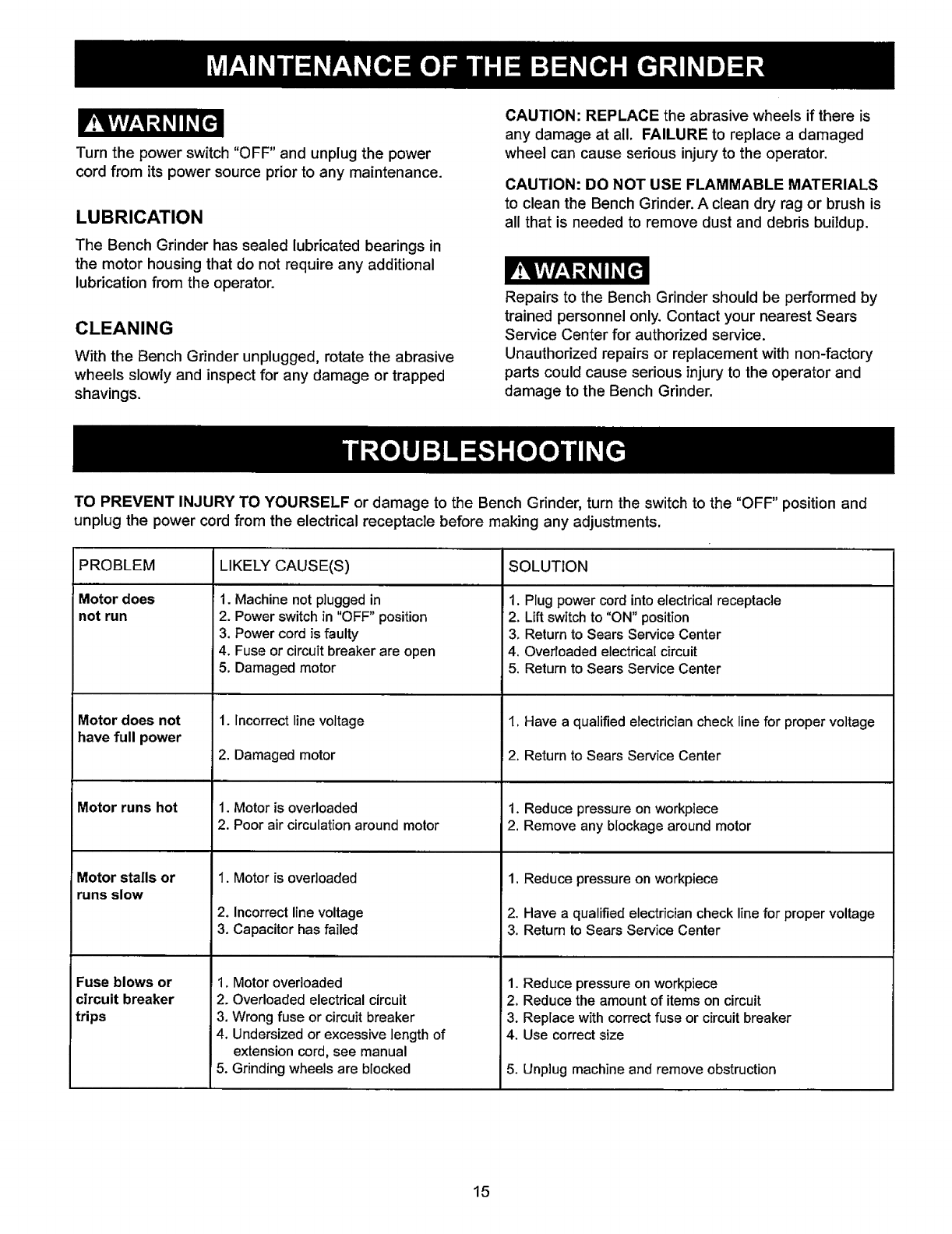
TO PREVENT INJURY TO YOURSELF or damage to the Bench Gdnder, turn the switch to the "OFF" position and
unplug the power cord from the electrical receptacle before making any adjustments.
PROBLEM
Motor does
not run
Motor does not
have full power
Motor runs hot
Motor stalls or
runs slow
Fuse blows or
circuit breaker
trips
LIKELY CAUSE(S)
1. Machine not plugged in
2. Power switch in "OFF" position
3, Power cord is faulty
4. Fuse or circuit breaker are open
5. Damaged motor
1. Incorrect line voltage
2. Damaged motor
1. Motor is overloaded
2. Poor air circulation around motor
1. Motor is overloaded
2. Incorrect line voltage
3. Capacitor has failed
1, Motor overloaded
2. Overloaded electrical circuit
3. Wrong fuse or circuit breaker
4, Undersized or excessive length of
extension cord, see manual
5. Grinding wheels are blocked
SOLUTION
1. Plug power cord into electrical receptacle
2. Lift switch to "ON" position
3. Return to Sears Service Center
4, Overloaded electrical circuit
5. Return to Sears Service Center
1. Have a qualified electrician check line for proper voltage
F2. Return to Sears Service Center
,,,,,........................,,,,,,,,,,,, ,, ,, ,,,
1. Reduce pressure on workpiece
2. Remove any blockage around motor
1. Reduce pressure on workpiece
2. Have a qualified electrician check line for proper voltage
3. Return to Sears Service Center
1. Reduce pressure on workpiece
2, Reduce the amount of items on circuit
3. Replace with correct fuse or circuit breaker
4. Use correct size
5. Unplug machine and remove obstruction
15
r.15vAv/__W_.4_,II_[€']l
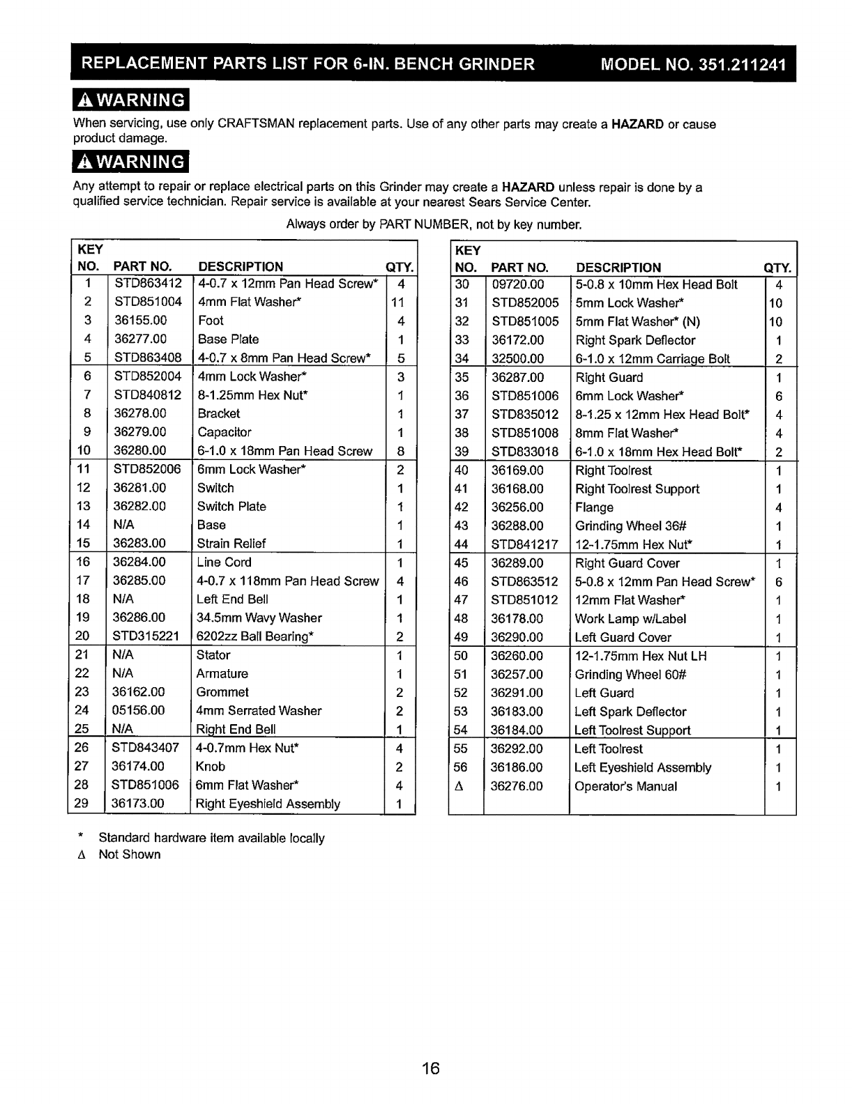
When servicing, use only CRAFTSMAN replacement parts. Use of any other parts may create a HAZARD or cause
product damage.
Any attempt to repair or replace electrical parts on this Grinder may create a HAZARD unless repair is done by a
qualified service technician. Repair service is available at your nearest Sears Service Center.
Always order by PART NUMBER, not by key number.
KEY
NO.
1
2
3
4
5
6
7
8
9
10
11
12
13
14
15
16
17
18
19
20
21
22
23
24
25
26
27
28
29
PART NO,
STD863412
STD851004
36155.00
36277.00
STD863408
STD852004
STD840812
36278.00
36279.00
36280.00
STD852006
36281.00
36282.00
NIA
36283.OO
36284.00
36285.00
N/A
36286.00
STD315221
N/A
N/A
36162.00
05156,00
NIA
STD843407
36174.OO
STD851006
36173.00
DESCRIPTION
4-0.7 x 12mm Pan Head Screw*
4mm Flat Washer*
Foot
Base Plate
4-0.7 x 8mm Pan Head Screw*
4mm Lock Washer*
8-1.25mm Hex Nut*
Bracket
Capacitor
6-1.0 x 18mm Pan Head Screw
' 6mm Lock Washer*
Switch
Switch Plate
Base
Strain Relief
Line Cord
4-0.7 x 118mm Pan Head Screw
Left End Bell
34,5mm WCavyWasher
6202zz Ball Bearing*
Stator
Armature
Grommet
4mm Serrated Washer
Right End Bell
4-0.7mm Hex Nut*
Knob
6mm Rat Washer*
Right Eyeshield Assembly
QTY.
4
11
4
1
5
3
1
1
1
8
2
1
1
1
1
1
4
1
1
2
1
1
2
2
1
4
2
4
1
KEY
NO, PART NO.
30 O9720.00
31 STD852005
32 STD851005
33 36172.00
34 32500.00
35 36287.00
36 STD851006
37 STD835012
38 STD851008
39 STD833018
40 36169,00
41 36168.00
42 36256.00
43 36288.00
44 STD841217
45 36289.00
46 STD863512
47 STD851012
48 36178,00
49 36290.00
50 36260.00
51 36257.00
52 36291.00
53 36183.00
54 36184.00
55 36292.00
56 36186.00
A 36276.00
DESCRIPTION QTY.
5-0.8 x 10mm Hex Head Bolt 4
5mm Lock Washer* 10
5mm Flat Washer* (N) 10
Right Spark Deflector 1
6-1.0 x 12mm Carriage Bolt 2
Right Guard 1
6mm Lock Washer* 6
8-1.25 x12ram Hex Head Bolt* 4
8mm Fiat Washer* 4
6-1.0 x18mm Hex Head Bolt* 2
Right Toolrest 1
Right Tooirest Support 1
Flange 4
Grinding Wheel 36# 1
12-1.75mm Hex Nut* 1
Right Guard Cover 1
5-0.8 x 12mm Pan Head Screw* 6
12mm Flat Washer* 1
Work Lamp wlLabel 1
Left Guard Cover 1
12-1.75mm Hex Nut LH 1
i Grinding Wheel 60# 1
Left Guard 1
Left Spark Deflector 1
Left Toolrest Support 1
Left Toolrest 1
Left Eyeshield Assembly 1
Operator's Manual 1
*Standard hardware itemavaiJablelocally
_, Not Shown
16
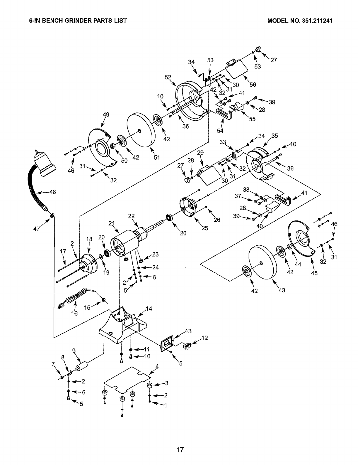
6-IN BENCH GRINDER PARTS LIST MODEL NO. 351.211241
52
\
34 53
10
46
2
1
_34/35
38
4
42
\
45
17

NOTES
18

i
!
J
, i
! t
i z
!
[ z
Get it fixed, at your home or ours!
. ,............................................................................................. =....................................................................................................... _._
Your Home
For troubleshooting, product manuals and expert advice:
managemylife
www.managemylife.com
For repair- in your home - of all major brand appliances,
lawn and garden equipment, or heating and cooling systems,
no matter who made it, no matter who sold it!
For the replacement parts, accessories and
owner's manuals that you need to do-it-yourself.
For Sears professional installation of home appliances
and items like garage door openers and water heaters.
1-800-4-MY-HOME ® (1-800-469-4663)
Call anytime, day or night (U.S.A. and Canada)
www.sears.com www, sears.ca
Our Home
For repair of carry-in items like vacuums, lawn equipment,
and electronics, call anytime for the location of your nearest
Sears Parts & Repair Service Center
1-800-488-1222 (U.S.A.) 1-800-469-4663 (Canada)
www.sears.com www.sears, ca
To purchase a protection agreement on a product serviced by Sears:
1-800-827-6655 (U.S.A.) 1-800-361-6665 (Canada)
Para pedir servicio de reparaci6n
a domicilio, y para ordenar piezas:
1-888-SU-HOGAR ®
(1-888-784-6427)
i • !
i'
J
i
/,
®Registered Trademark 1TMTrademark of KCD IP, LLC in the United Star es, or Sears Brands, LLC in other countries
TM
® Marca Registrada IMarca de F_brica de KCD IP, LLC en Estados Unidos, o Sears Brands, LLC in otros paises
McMarque de commerce IMoMarque d6pos6e de Sears Brands, LLC
