Craftsman 351215080 User Manual SANDER Manuals And Guides L0309510
CRAFTSMAN Sander Manual L0309510 CRAFTSMAN Sander Owner's Manual, CRAFTSMAN Sander installation guides
User Manual: Craftsman 351215080 351215080 CRAFTSMAN SANDER - Manuals and Guides View the owners manual for your CRAFTSMAN SANDER #351215080. Home:Tool Parts:Craftsman Parts:Craftsman SANDER Manual
Open the PDF directly: View PDF ![]() .
.
Page Count: 39
Operator's Manual g
4 X 8" and
6 x 12"
SANDING CENTERS
Model Nos.
351.215080
351.21 5160
CAUTION: Read and follow
all Safety Rules and Operating
Instructions before First Use
of this Product.
Sears, Roebuck and Co., Hoffman Estates, IL 60179 U.S.A.
www.sears.com/craftsrnan
20666.01 Draft (07/01{03)
az_n_r_x 9110/2003 I0:38 PAGE 3141 RightF&x
Warranty ......................................... 2
Safety Rules ...................................... 2
Unpacking ....................................... 3
Assembly ...................................... 3-6
Installation ...................................... 6-7
Operation ..................................... 8-11
Maintenance .................................... 12
Troubleshooting .................................. 13
parts Illustrattan and List ........................ 14-25
Espa5ol ...................................... 26-39
FULL ONEYEAR _RRANTY
If _is product fails du6 to a defect in material or workmanship
within one year from the date of purchase, Sears will at its
option repair or replace itfree of charge. Contact your nearest
Sears Service Center (1-800-4.MY-HOME) to arrange for prod-
uct repair, or mtum this product to place of purchase for
replacement
If this product is used for commercial or rental purposes, this
warranty will apply for 90 days from the data of purchase.
This warranty appitas only willie this product is used in the
United States
This warranty gives you spastic legal rights, and you may also
have other rights which very from state to state.
Sears, Roebuck and Co., Dept, 817WA, Hoffman Estates,
IL 60179
WARNING: For your own safety, mad all of the Insfructlons
and precautions before operating tool,
CAUTION: Always follow proper operating procedures as
defined in this n'_nual even if you are familiar with use of this
or similar tools. Remember that being careless for even a
fraction of a second can result In severe pemonal Injury.
BE PREPARED FOR JOB
• Wear proper apparel, Do not wear loose clothing, gloves,
neckties, dnga, bracelets or other jewelry which may get
caught in moving parts of machine.
•Wear protective hair covering to contain long hair.
• Wear safety shoes with non-slip soles.
• Wear safety glasses complying with United States ANSI
Z87.1. Everyday glasses have only impact resistant lenses.
They are NOT safety glasses.
•Wear face mask or dust mask if operation is dusty
•Be alert and think clearly. Never operate power tools when
tired, intoxicated or when taking medica_orls that cause
drowsiness.
PREPARE WORK AREA FOR JOB
• Keep work area ctean. Cluttared work areas invite accidents
• Oo not use power tools in dangerous environments. Do not
use power tools in damp or wet locations. Do not expose
power tools to rain.
•Work area should be prepedy lighted.
• Proper electrical receptacle should be available for toot
Three prong plug should be plugged direcSy into properly
grounded, three-prong receptacte.
•Extsosien cords snduld have a grounding prong and the thr,..=e
wires of the extension cord should be of the correct g_uge.
• Keep visitors at a safe distance from work area.
•Keep children out of workplace. Make workshop childproof.
Use padlocks, master switches or remove switch keys to
prevent any unintant{ocal use of power too{s.
TOOL SHOULD BE MAINTAINED
•Always unplug tool prior to Inspection.
•Consult manual for sbeciflc maintaining and adjusting
procedures.
•Keep tool lubricated end clean for safest operation,
•Remove adjusting tools. Form habit of checking to see that
adjusting tcx_tsare removed before switching machine on.
•Keep all paris in w_rking order. Check ta determine that the
guard or other parts will operate properly and perform their
intended function.
•Check for damaged parts. Check for alignment of moving
parts, binding, breakage, mounting and any other condition
that may affect a _ol's operation.
• A guard or other part that is damaged should be properly
repaired or replaced. Do not perform makesh_ repairs
(Use parts list provided to order replacement parts.)
KNOW HOWTO USE TOOL
•Use nght tool for job. Do not force tool or attachment to do
a job for which it was not designed.
•Disconnect tool when changing belt or abrasive disc.
• Avoid accJdantal start-up Make sure that the tool is in the
"OFF" posilJon before plugging in.
•Do not forca tool. It will work most efficiently at the rate for
which it was designed.
•Keep bends away from moving parts and sanding surfaces
•Never leave tool running unattended. Turn the power off
and do not leave tool until It comes to acomplete stop
•Do not overreach. Keep proper footing and balance.
•Never stand on tool. Serious injury could occur If tool is
tipped or ff beltordiscare unlntentioneltyconta_ed.
•Know your tool. Learn the t_::#s ope,,'ati_n, app_icat)ot_ and
specific limitations,
•Use Recommended Accessories (refer to pages 19 and
25). Use of improper accessories may cause risk of injury
to persons.
•Handle the workplace correctly. Protect hands from possi-
ble injury.
•Turn machine otf if itjams. Beltjams when it digs too deeply
intoworkpiece. (Motor force keeps it stuck in the work,)
• Support workplace with miter gauge, belt platen or work
table.
•Maintain 'As_ maximum ciearanse hetweerl table and sand-.
ing belt or disc.
CAUTION: Think safety! Safety is a combination of operator
common sense and alertness at air times when tool is being
used.
WARNING'. Do not attempt to operate tool until it is com-
pletely essembisd according to the instructions.
©Sears, Roebuck and Co. 2
_i_htFax 9/10/2003 10:38 PAGE 4/41 RightFax
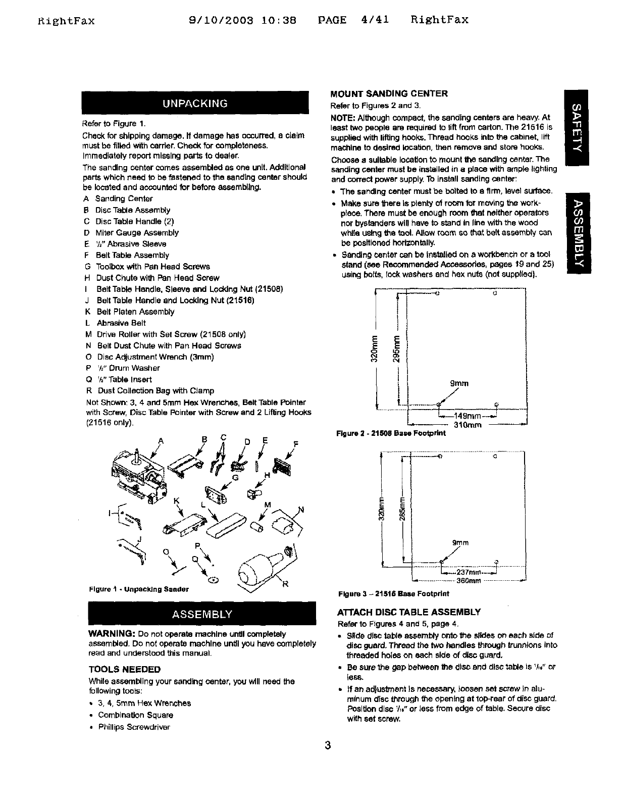
Refer to Figure 1.
Check for shipping damage, If damage has occurred, a claim
must be filled with carrier, Check for completeness.
Immediately repeit missing pal"is to dcoter.
The sanding center comes assembled as one unit. Additional
parts which need to be fastened to the sand[rig center should
be located and accounted for before assembling.
A Sanding Center
BDisc Table Assembly
C Disc Table Handle (2)
D Miter Gauge Assembly
E%" Abrasive Sleeve
F Belt Table Assembly
GToolbox with Pan Head Screws
H Dust Chute with Pan Head Screw
I Belt Table Handle, Sleeve and Locking Nut (21508)
J Belt Table Handle and Locking Nut (21516)
K Belt Platen Assembly
LAbrasive Belt
MDrive Roller with Set Screw (21508 only)
N Belt Dust Chute with Pan Head Screws
ODisc Adjustment Wrench (3ram)
PV="Drum Washer
O%'Table Insert
R Dust Collection Bag with Clamp
Not Shown: 3, 4 and 5ram Hex Wrenches, Belt Table Pointer
with Screw, Disc Table Pointer with Screw and 2Lifting Hooks
(21516 only).
ASCDE
%o
Figure t-Unpacking Bander @ __\R
WARNING: Do not operate machine until coreptetely
assembled. Do not operate machine until you have completely
read and understood this manual.
TOOLS NEEDED
While assembling your sanding center, you will need the
following tools:
•3, 4,5ram Hex Wrenches
• Combination Square
•Phillips Screwdriver
MOUNT SANDING CENTER i
Refer to Figures 2 and 3.
NOTE: Although compact, the sanding centers are heavy, At
least two people are required to riftfrom carton. The 21516 is
supplied with lifting hooks. Thread hooks into the cabinet, lift
machine to desired lecaUon, then remove and store hooks,
Choose asuitable location to mount the sanding center. The
sanding center must be installed in aplace with ample lighting
and correct power supply. To install sanding center:
•"The sanding center must be bolted to a firm, level surface.
•Make sure there Is plenty of room for moving the work-
place, There must be enough room that neither operators
nor bystanders will have to stand In line with the wood
white L_sthgthe tool. Allow room so that belt assembly can
be positioned horizontally.
•Sanding center can be Installed on a workbench or a tool
stand _sse Recommended Accesoodes, pages t9 and 25)
using bolts, t_:t_ washers end hex nuts (not suppl(ed).
E E
E E
O4
L i, ./
9tara
L._149m m _...J=
-- 310mm
Figure 2 -21508 Base Footprint
I._,....i
E E
.::IL-L-e............ .,j......
grllm
/
./
...................360ram .................
Figure 3 -21516 Base Footprint
ATTACH DISC TABLE ASSEMBLY
Refer to Figures 4 and 5, page 4.
•Silde disc table assembly outo the slides on each side of
disc guard. Thread the two handles through truenlons into
threaded holes on each side of disc guard.
• Be sure the gap between the disc and disc table Is V,," or
tess.
• )f an adjustment }s necessary, loosen set screw in alu-
minum disc througt_ the opening at top-rear of disc guard.
Posltlen disc V,," or less from edge of table. Secure disc
with set screw.
3
Rlghtr&X 9110/2003 10:38 PAGE 5141 RightFaX
Trunnion
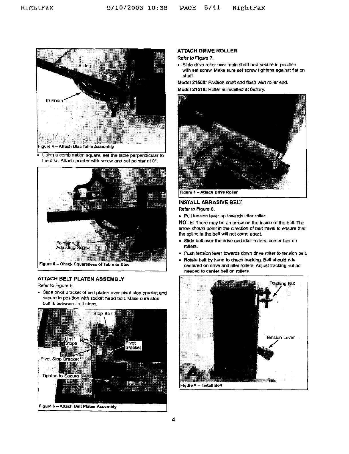
Figure 4 - Attach Disc i-able ASSembly
• Using a combination square, set the table perpendicular to
the disc. Attach pointer with screw and set pointer at 0 °.
Figure 5 - Check Squarenes= of Table to Disc
I
ATTACH BELT PLATEN ASSEMBLY
Refer to Figure 6,
• Slide pivot bracket of belt platen over pivot stop bracket and
secure in position with socket head bolt. Make sure stop
bo!t is between limit stops.
Pivot Stop Bracket
Tighten to Secure
Figure 6 - Attach Belt Platen As=embly
A'FFACH DRIVE ROLLER
Refer to Figure 7,
• Slide drive miler over main shaft and secure in position
with set sorew. Make sure set screw tightens against fiat on
shaft.
Model 21508: Posltlon shaft end flush with rotter end.
Modal 21518: Roller is installed at factory,
Figure 7 - Attach Drive Roller
INSTALL ABRASIVE BELT
Refer to Figure 8.
• Pull tension lever up towards idler roller.
NOTE: There may be an arrow on the inside of the belt. The
arrow should point tn the _rection of belt travel to ensure that
the splice in the belt will not come apart.
• Slide belt over the ddve and idler milers; center belt on
milers.
•Push tension lever towards down drive miler to tension belt.
•Rotate belt by hand to sheck tracking. Belt should r_de
centered on drive and idler rollers. Adjust kacking nut as
needed to center belt on rollers
To gNut
Tension Lever
Belt
4
KzgntPax 9/10/2003 i0:38 PAGE 6/41 RightFax
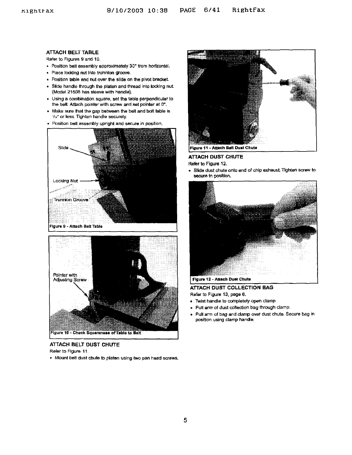
ATTACH BELT TABLE
Refer to Figures 9 and 10.
•Position belt assembly approximately 30" from horizontal,
• Place locking nut Into trunnion groove.
•Position table and nut over the slide on the pivot bracket.
•Slide handle _mugh the platen and thread into locking nut.
(Model 21508 has sleeve with handle).
•Using acombination square, set the table perpendicular to
the bell Attach pointer with screw and set pointer at 0".
•Make sure thai the gap between the belt and bolt table is
'/_," or less Tighten handle securely.
• Position belt assembly upright and secure in position.
Figure 9 - Attach Belt Table
- Check Squareness o :Table to Belt
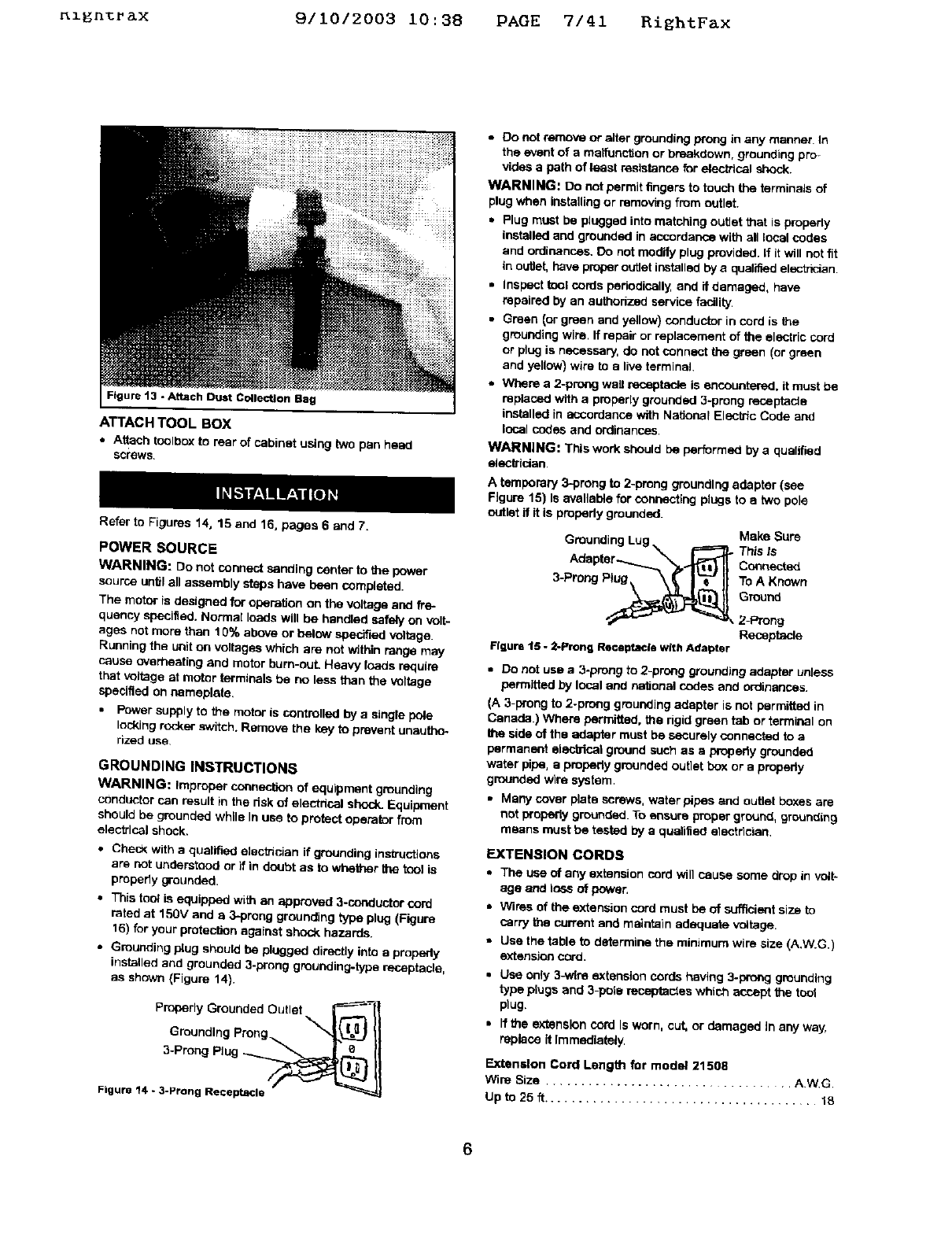
ATTACH BELT DUST CHUTE
Refer to Figure 11.
•Mount belt dust chute to p/aten using two pan head screws.
Igure 11 -Attach Belt Dust Chute
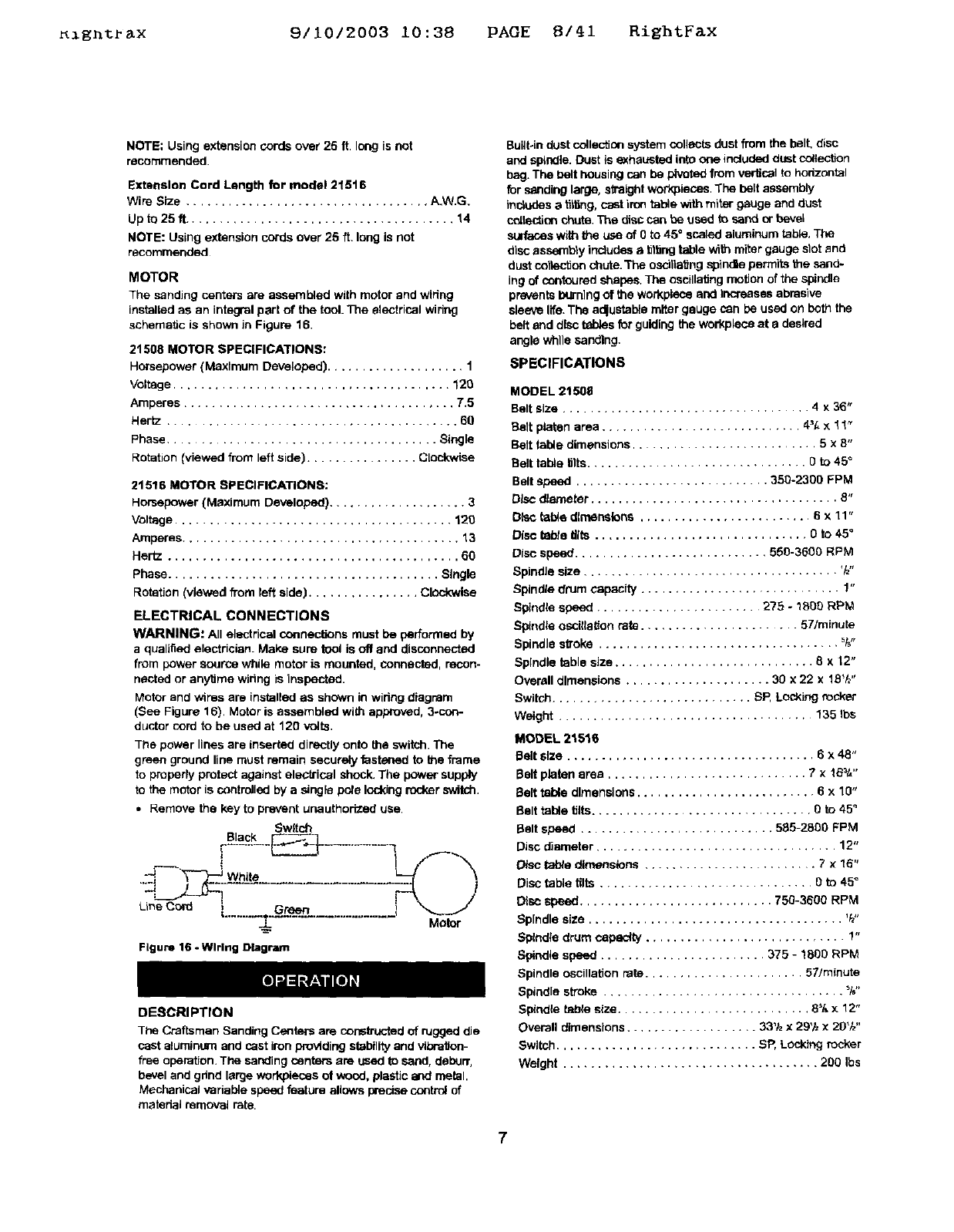
ATTACH DUST CHUTE
Refer to Ffguse 12.
•Slide dust chute onto end of chip exhaust. T'_jhtan so'-ew to
secure In _tt[on.
Figure 12 -Attach Dust Chute
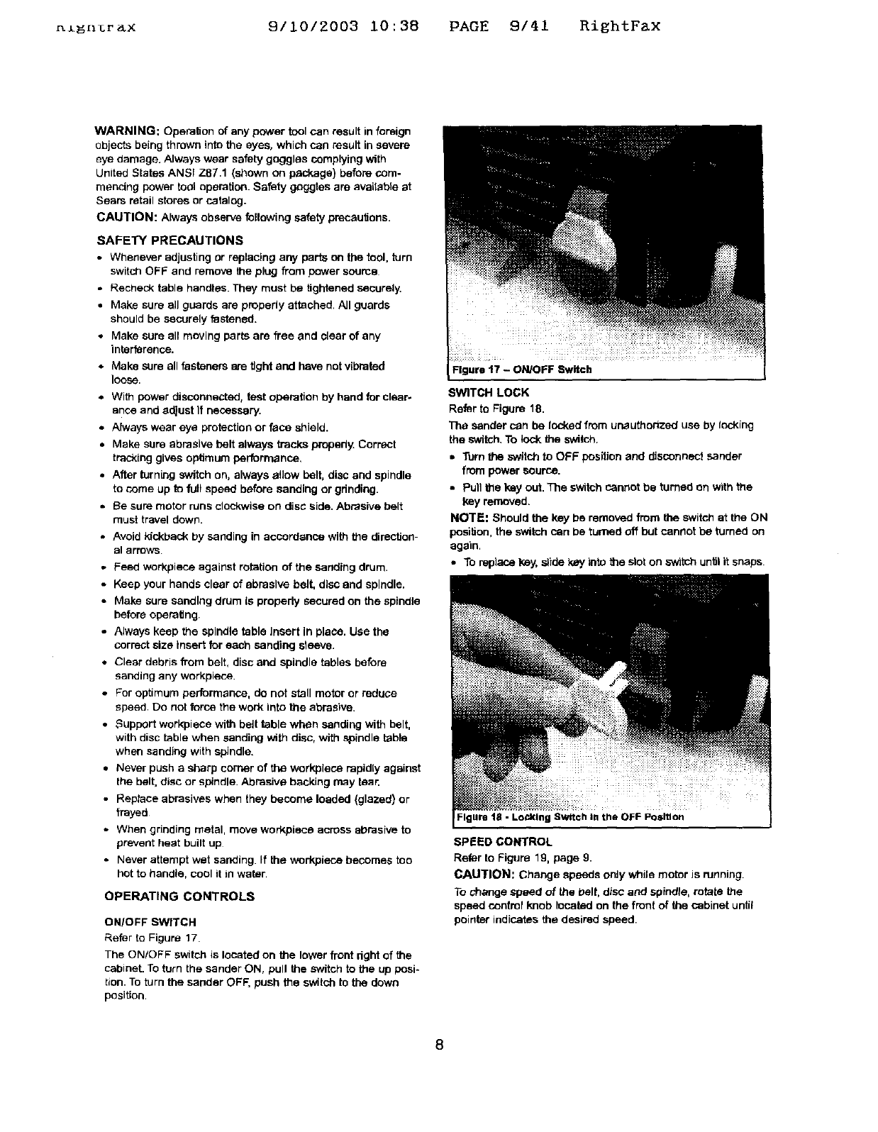
ATTACH DUST COLLECTION BAG
Refer to Figure 13, page 6.
•Twist handle to completely open clamp
•Pull arm of dust collection bag through clamp.
•Pull arm of bag and clamp over dust chute. Secure bag in
position using clamp handle.
5
_l_n%r_x 9/1012003 10:38 PAGE 7/41 RightFax
Figure 13 -Attach Dust Collection Bag
ATTACH TOOL BOX
•Attach toolbox to rear of cabinet using two pan heed
screws.
Refer to Figures 14, 15 and 16, pages 6 and 7.
POWER SOURCE
WARNING: De not connect sanding center to the power
source _ntif a_ assembly steps have been comp|eted.
The motor is designed for operation on the voltage and fre-
quency specified. Normal loads will be handled sately on volt-
ages not more than 10% above or below specified voltage.
Running the unit on voltages which are not within range may
cause overheating and motor bum-ouL Heavy toads require
that voltage at motor terminals be no less than the voltage
specified on nameplate.
•Power supply to the motor is controlled by a single pole
locking rocker switch. Remove the key to prevent unautho-
rized use
GROUNDING INSTRUCTIONS
WARNING: Improper connection of equipment grounding
conductor can result in the dsk of electdcal shock_Equipment
should be grounded while In use to protect operator from
electrical shock.
•Check With a quatif_ etectn_an ff grounding ins_uctions
are not understood or if in doubt as to whether the tcol is
properly grounded.
•This tool is equipped with an approved 3-coeductor cord
rated at 15or and e 3-preng grounding type plug (Figure
16) for your protecl_n against shock hazards.
•Grounding plug should be plugged directly into a properly
installed and grounded 3-prong grounding-type receptacle,
as shown (Figure 14}.
Properly Grounded Outlet _----_
Groundthg Prong _"J_) II
3-Prong Plug -___
Figure 14 - 3-Prong Receptacle
•0o not remove or alter grounding prong in any manner. In
the event of a maifunction or breakdown, grounding pro-
vides a path of least resistance for electhcal shock.
WARNING: Do not permit _ngers to tov_h the terminals of
plug when installing or removing from outlet.
•Plug must be plugged into matching outlet that is properly
installed and grounded in accordance with all local codas
and ordinances. Do not modify plug provided. If Itwill not fit
in outlet, have proper outlet installed by a qualified electhcian
•Inspect _ol cords pehodicsily, and if damaged, have
repaired by an authedzed service facility.
•Green _orgreen and yetlow)conductorincord is the
gmueding wire. If repair or replacement of the electric cord
or plug is necessary, do not connect _green (or green
and yellow) wire to a tire terminal
•Where a 2-prong wail receptac_ is encountered, it must be
replaced with a properly grounded 3-preng receptacle
installed in accordance with National Electric Code and
local codes and ordinances.
WARNING: This work should be performed by a qualified
electttdan
A temporary 3-prong to 2-preng grounding adapter (see
Figure 15) Is evetleb_e for cor,r,ec'_',gptugs to etwo pole
outlet if it is propedy grounded.
Grounding Lug _ _Make Sure
This Is
Aria pter--......._.'"_, .._ Connected
3-ProngPtug\ \_ I'_--"II ToAK_,,o
round
_2-Prong
Receptacle
Figure 15 -2-Prong Re©eptacle with Adapter
•Do not use a3-prong to 2-prong grounding adapter unless
permitted by local and nationsi codes and ordinances.
(A 3-prong to 2-prong grounding adapter is not permitted in
Canada.) Where permitted, the rigid green tab or terminal on
the side of the adapter must be securely connected to a
permanent alecbical ground such as a prepedy grounded
water pipe, e property grounded outlet boy.or a properly
grounded wire system.
•Many cover plate screws, watar pipes and outlet boxes are
not properly grounded. To ensure proper ground, grounding
means must be tested by a qualified etectdcian.
EXTENSION CORDS
•The use of any extension cord will cause some drop in volt-
age and loss of power.
=Wires of the extension cord must be of sufficient size to
carry the current and maintain adequate v_tage.
•Use the table to determine the minimum wire size (A.W.G.I
extension cord.
• Use only 3-wtre extension cords having 3-prong grounding
type ptugs and 3-pole te_des which acr_pt the toot
plug.
• Ifthe extension cord Is worn, cut, or damaged In any way,
replace it Immediately,
Extension Cord Lengt_ for model 21508
Wire Size .................................. AWG
Up to 25 ft ....................................... 18
Ignt ax 9/10/2003 10:38 PAGE 8/41 RiEhtFax
NOTE: Using extension cords over 25 ft. long is not
recommended.
Extension Cord Length for model 21516
Wire Size ................................... A.W.G.
Upto25ff ....................................... 14
NOTE: Using extension cords over 25 ft. long is not
recommended
MOTOR
The sanding centers are assembled with motor and wiring
installed as an integral part of the tool. The electrical wiring
schematic is shown in Figure 16.
21508 MOTOR SPECIFICATIONS:
Horsepower (Maxlmurn Developed) .................... 1
Voltage ........................................ 120
Amperes ....................................... T,5
Hertz .......................................... 60
Phase ..................................... Single
Rotation (viewed from left side) ................ Cl_-kwise
21516 MOTOR SPECIFICATIONS:
Horsepower (Maximum Developed} .................... 3
Voltage ........................................ 120
Amperes ........................................ 13
Hertz .......................................... 60
phase ....................................... Single
Rotation (viewed @ore left side) ................ Clockwise
ELECTRICAL CONNECTIONS
WARNING: All electrical connec_ns must be performed by
a qualified electrician. Make sure tool is off and disconnected
from power source while motor is mounted, connected, recon-
nected or anytime wiring is inspected.
Motor and wires are installed as shown in wiring diagram
(See Figure 16). Motor is assembled with approved, 3-con-
ductor cord to be used at 120 volts.
The power lines are inserted directly onto the switch. The
green ground line must remain securely fastened to the frame
to properly protect against electrical shock. The power supply
to the motor is controlled by a single pole idoldng rocker switch.
• Remove the key to prevent unauthorized use.
Sw_tch
oS_lac_L__-----3___ ........
Li eco, ,........ ..................
Figure 16 - Wlrteg Diagram
Motor
DESCRIPTION
The Craftsman Sanding Centers are constructed of rugged die
cast aluminum and cast iron providing stability and vibration-
free operation. The sanding centers are used to sand, deburr,
bevel and grind large workpieces of wood, plastic and metal.
Mechanical variable speed feature allows precise control of
matedal removal rate.
Built-in dust colle_on system collects dust from the belt, disc
and spindle. Dust is exhausted into one included dust collection
bag. The belt housing can be pivoted from vertical to horizontal
for sanding large, straight workpieces. The belt assembly
includesa t_16ng,cast iron table with miter gauge and dust
collection chute. The disc can be used to sand or bevel
SUlfates with the use of 0to 45" scaled aluminum table. The
disc assambly includes a tilting table with miter gauge slot and
dust coltactionchute. The osdtiaiJng spindle pern#rtsthe sand-
ing of contoured shapes. The oscillating motion of the spindle
prevents I_'nlng of the workptace end Increases abrasive
sleeve life. The a_ustab_e miter gauge can be used on both the
belt and disc tables for guiding the workplece at adesired
angle while sanding.
SPECIFICATIONS
MODEL 21508
Belt size .................................... 4 x 36"
Belt platen area ............................. 4_[, x 1 ! _
Belt table dimensions ........................... 5 x 8"
Belt table tilts................................ 0 to 45 °
Belt speed ............................ 350-2300 FPM
Disc diameter .................................... 8"
Disc table direanslens ......................... 6 x 11"
Disc tsbte firs ............................... O to 4Y
Disc speed ............................ 550-3500 RPM
SpindJe size ..................................... _1_"
Spindle drum capacity ............................. 1"
Spindle speed ........................ 275 -1000 RPM
Spindle oscitialion rate ...................... 57/mintae
Spindle sf_oke ................................... _"
Spindle table size ............................. 8 x 12"
Overall dimensions ..................... 30 x 22 x 18Vz"
Switch ............................. SP, LoCking rocker
Weight ..................................... 135 ths
MODEL 2151S
Belt size .................................... 6 x 48"
Belt platen area ............................. 7 × 1B_t,"
Belt table dimensions .......................... 6x10"
Belt table tilts................................ 0 to 45 °
Belt speed ............................ 505-2800 FPM
Disc diameter ................................... 12"
Disc I_ble dimensions ......................... 7x15"
Disc table lilts ............................... 0 to 45 °
Disc Speed ............................ 750-3600 RPM
Spindle size ..................................... V_"
Spindle drum capacity ............................. 1"
Spindle speed ........................ 375 - 1800 RPM
Spindle oscillation rate ....................... 57/minute
Spindle stroke ................................... _f,"
Sp_ndis table size ............................ 8% x 12"
Overall dimensions ................... 33'1zx29'h x 20'/,,"
Switch ............................. SR Locking rocker
Weight ..................................... 200 Ibs
7
_1_n_rax 9/10/2003 10:38 PAGE 9/41 RightFax
WARNING: Operation of any power tool can result in foreign
objects being thrown into the eyes, which can result in severe
eye damage. Always wear safety goggles complying with
United States ANSi Z87.1 (sl_own on package} before com-
mencing power tool operation. Safety goggles are available at
Sears retail stores or catalog.
CAUTION: Always observe following safety precautions.
SAFETY PRECAUTIONS
•Whenever adjusting or replacing any parts on the tool, turn
switch OFF and remove the plug from power seams
•Recheck table handles. They must be tightened securely.
• Make sure ell guards are properly attached, All guards
should be securely fastened.
•Make sure all moving parts are free and clear of any
interference.
•Make sure all fasteners are tight and have not vibrated
loose.
•With power disconnected, test operation by hand for clear°
ance and adjust If necessary.
° Always wear eye protection or face shield.
°Make sure abrasive belt always tracks properly. Correct
tracking gives optimum performance,
• After turning switch on, always allow belt, disc and spindle
to come up to full speed before sanding or grinding.
• Be sure motor runs clockwise on disc side. Abrasive belt
must travel down.
• Avoid kickback by sanding in accordance with the direction-
sl a rrow_
• Feed workplace against rotation of the sanding drum.
•Keep your hands clear of abrasive belt, disc end spindle.
• Make sure sanding drum Is properly secured on the spindle
before operating.
°Always keep the spindle table Insert In place. Use the
correct size insert for each sanding sleeve.
* Clear debris from belt, disc and spindle tables before
sanding any workplace.
• For optimum performance, do not stall motor or reduce
speed. Do not force the work into the abrasive.
•Support workplace with belt table when sanding with belt,
with disc table when sanding with disc, with spindle table
when sanding with spindle.
.Never push a sharp comer of the work.piece rapidly against
the belt, disc or spindle. Abrasive backing may tear.
•Replace abrasives when they become loaded (glazed) or
frayed
• When grinding metal, move workpisce across abrasive to
prevent heat built up
•Never attempt wet sanding. If the workpieoa becomes too
hot to handle, cool it in water,
OPERATING CONTROLS
ON/OFF SWITCH
Refer to Figure 17.
The ON/OFF sw_tch is located on the lower front right of the
cabinet. To turn the sander ON, pull the switch to the up posi-
tion. To turn the sander OFF, push the switch to the down
position.
Figure t7 -ON/OFF Switch
SWITCH LOCK
Refer to Figure 18.
The sander can be locked from unauthorized use by tacking
the switch. To lock the switch.
•Turn the switch to OFF position and disconnect sander
from power source.
•Pull the key out. The switch cannot be turned on with the
key removed.
NOTE: Should the key be removed from the switch at the ON
position, the switch can be turned off but cannot be turned on
again.
•To replace key, slide key into the slot on _th.h until it snaps
Figure 18 - Lo_klng Switch I. the OFF Position
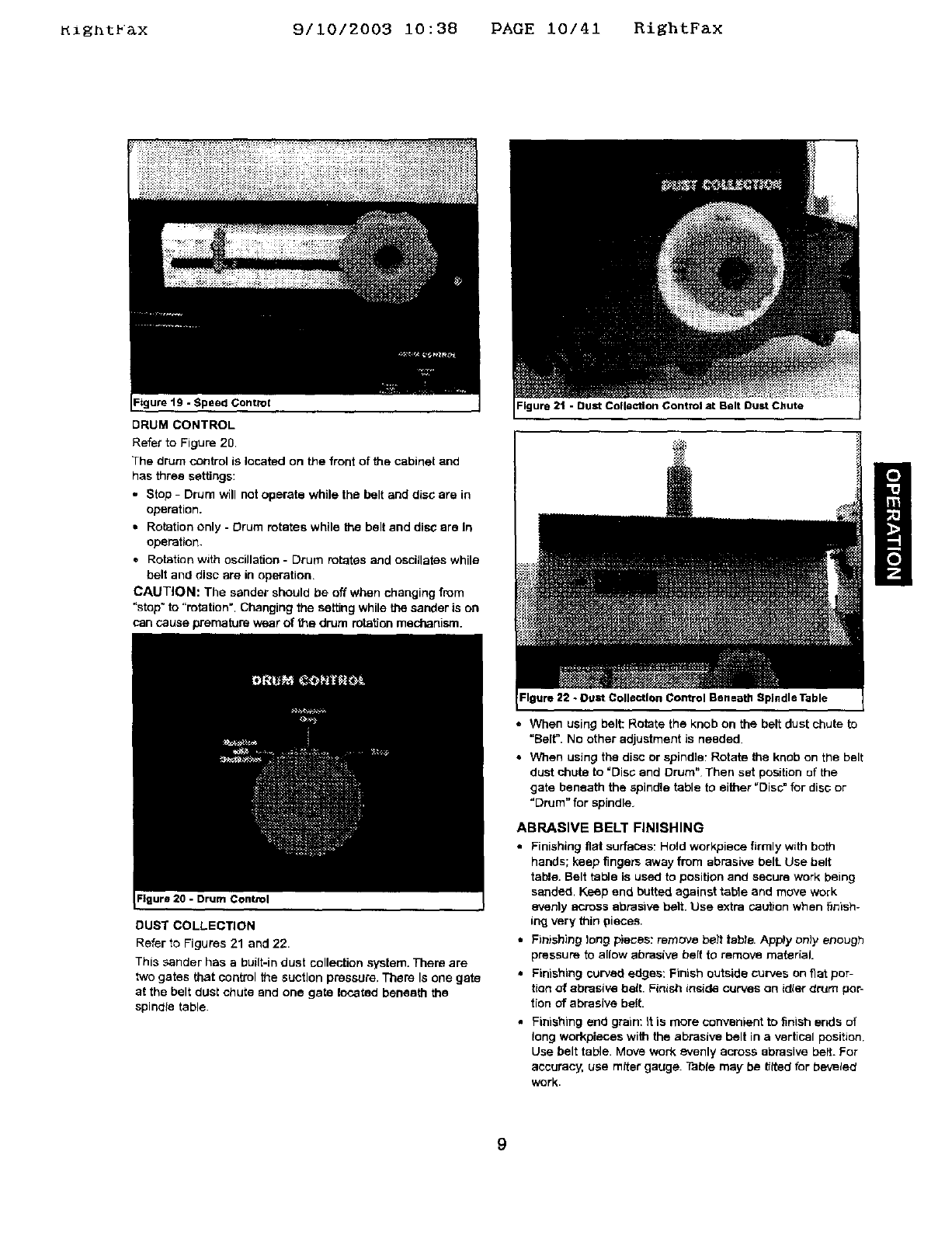
SPEED CONTROL
Refer to Figure 19, page 9.
CAUTION: Change speeds only while motor Jsrunning.
To change speed of the belt, disc and spindle, rotate the
speed control knob located on the front of the cabinet until
pointer indicates the desired speed.
8
_ight_&x 9/10/2003 i0:38 PAGE 10/41 RightFax
Figure 19 -Speed Control
DRUM CONTROL
Refer to Figure 20
The drum control is located on the front of the cabinet and
has three settings:
. Stop -Drum will not operate while the belt and disc are in
operation.
•Rotation only - Drum rotates while the belt end disc ere In
operation.
•Rotation with oscillation - Drum rotates and oscillates while
belt and disc are in operation,
CAUTION: The sander should be off when changing from
"stop" to "rotation". Changing the setting while the sander is on
can cause premature wear of the drum rotation mechanism.
:lgure 20 - Drum Control
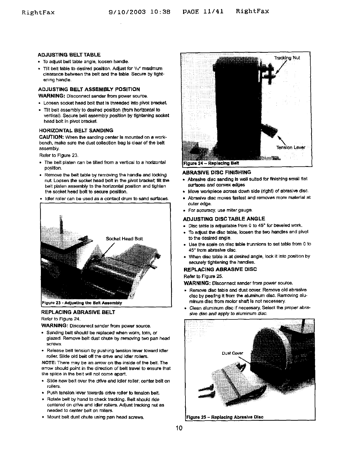
DUST COLLECTION
Refer to Figures 21 and 22.
This sander has a built-in dust collection system. Them are
two gates that control the suction pressure, There Is one gate
at the belt dusl chute and one gate located beneath the
spindle table.
=lgura21 -Bust Collection Control at Belt Dust Chute
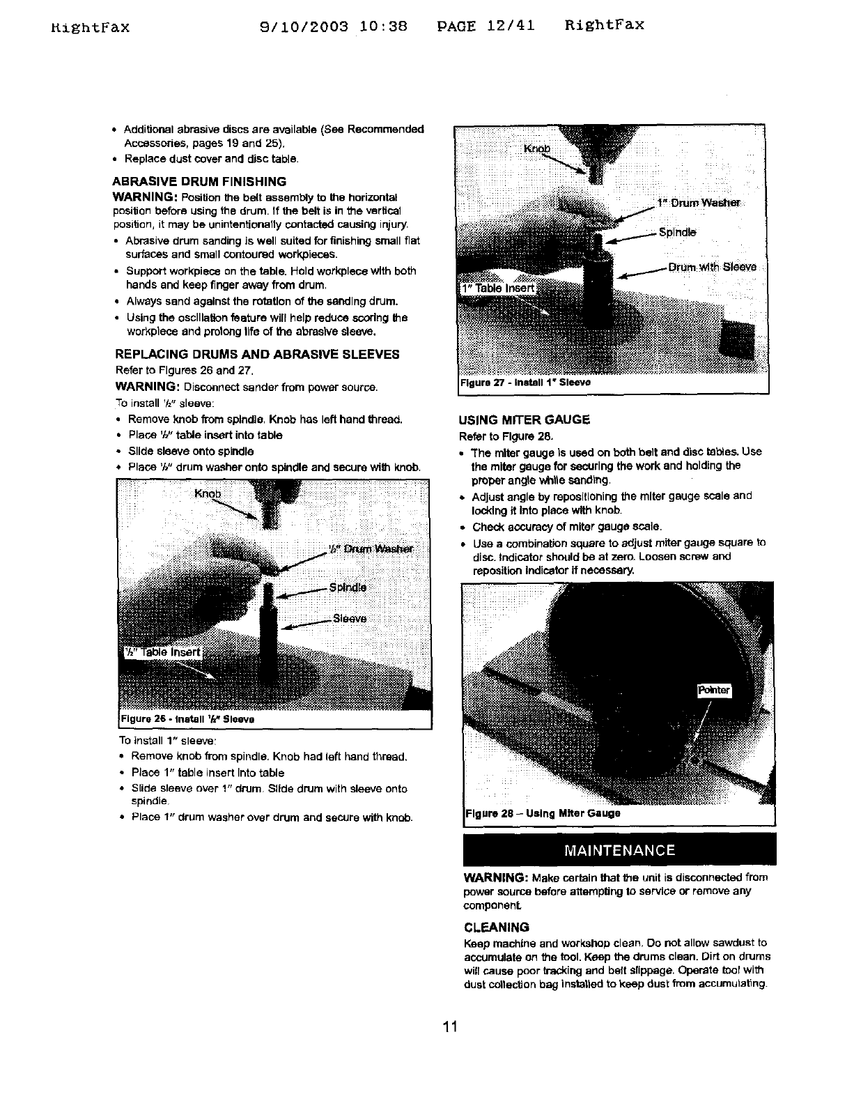
Figure 22 -Duct Collection Control Beneath Spindle Table
• When using belt: Rotate the knob on the belt dust chute to
"Belt. No other adjustment is needed.
• When using the disc or spindle: Rotate the knob on the belt
dust chute to "Disc and Drum" Then set position of the
gate beneath the spindle table to either =Disc_ for disc or
"Drum" for spindle.
ABRASIVE BELT FINISHING
•Finishing flat surfaces: Hold workplace firmly with both
hands; keep fingers away from abrasive bell Use belt
table. Belt table is used to position and secure work being
sanded, Keep end butted against table and move work
evenlyacross abrasive belt. Use extra cau_on when finish-
ing very thin pieces.
•Finishing long plies: remove bait tebte. Apply only enough
pressure to allow abrasive belt to remove material.
•Finishing curved edges: Finish outside curves on fiat por-
tion of abrasive belt. Finish inside curves on idler d_um por-
tion of abrasive belt.
Finishing end grain: it is more convenient to finish ends of
long workpieces with the abrasive belt in a vertical position.
Use belt table. Move work evenly across abrasive belt. For
accuracy, use miter gauge. Table may be _lted for bevelect
work.
9
RightFax 9/10/2003 i0:38 PAGE ii/41 RightFax
ADJUSTING BELT TABLE
•TOadjust belt table angle, loosen bendta.
•Tilt belt table to desired position. Adjust for 'h6"maximum
clearance between the belt end the table. Secure by tJghto
ening handle.
Tre_ng NUt
ADJUSTING BELT ASSEMBLY POSITION
WARNING: Disconnectsanderfrom powersource,
•Loosensockethead boltthat [sthreaded Intopivotbracket.
•Tiltbelt assemblyto desiredposition(fromhodzontelto
vertical),Secure beltassemblypositionbytighteningsocket
head bolt In pivotbracket.
HORIZONTAL BELT SANDING
CAUTION: When the sandtagcenter Is mounted on awork-
bench, make sure the dust collection bag Is clear of the belt
assembly.
Refer to Figure 23.
•The belt platen can be tilted from a vertical to a horizontal
po.Sltlon.
• Remove the belt table by removing the handle arid locking
nuL Loosen the socket head bolt in the pivot bracket;,tilt the
belt platen assembly to the hodzental position and tighten
the socket head bolt to secure posiUoo.
•Idler roller can be used as a contact drum to sand surfaces.
Socket Head Belt
the Belt Aasembly
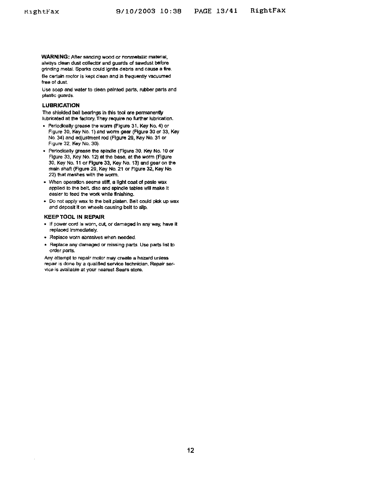
REPLACING ABRASIVE BELT
Refer te Figure 24.
WARNING: Disconnect sander from power source.
•Sanding belt should be replaced when worn, torn, or
glazed. Remove belt dust chute by removing two pan head
screws
•Release belt tension by pushing tension lever toward idler
roller. Slide old belt off the ddve and idler rollers.
NOTE: There may be an arrow on the inside of the belt, The
arrow should point in the direction of belt b-avel to assure that
the splice in the belt will not come apart.
•Slide new belt over the drive and idler roller; center belt on
rollers.
• Push tension lever towards drive roller to tension belt,
•Rotate belt by hand to check traddng. Belt should dde
centered on drive and idler rollers. Adjust tracldng nut as
needed to center belt on rollers.
•Mount belt dust chute using pan head screws.
ure 24 - Replacing Belt
ABRASIVE DISC FINISHING
• Abrasive disc eand[ng Is well suited for finishing smell fiat
surfaces end convex edges
• Move workpiece across down side {right) of abrasive disc.
•Abrasive disc moves fastest and removes more material at
outer edge.
•For accuracy, uce miter gauge.
ADJUSTING DISC TABLE ANGLE
• Disc table is adiustab_e from 0 to 45 ° for beveled work,
• To adjust the disc table, loosen the two handles and pivot
to the desired angle.
•Use the scale on disc table trunnions to set table from O io
45 °from abrasive disc.
• When disc table is at desired angle, lock it into position by
securely tightening the handles.
REPLACING ABRASIVE DISC
Refer to Figure 25,
WARNING: Disconnect sander from power source,
•Remove disc table end dust cover, Remove old abrasive
dlso by peeling It from the aluminum disc. Removing alu-
minute disc from motor shaft Is not necessary'.
• Clean aluminum disc if necessary. Select the proper abre-
she disc and apply to z_]uminumdisc.
DuSt Cover
Figure 25 -Replacing Abrasive Disc
10
RiEhtFax 9/10/2003 10:38 PAGE 12/41 RightFax
•Additional abrasive discs are available (See Recommended
Accessories, pages 19 and 25).
• Replace dust cover and disc table.
ABRASIVE DRUM FINISHING
WARNING: Position the belt assembly to the horizontal
posiUon before using the drum, If the belt is in the vertical
position, it may be unintentionally contacted causing injury,
• Abrasive drum sanding is well suited for finishing small fiat
surfaces and small contoured work,pieces.
• Support worl<piece on the table. Hold workplece with both
hands and keep finger away from drum,
• Always sand against the rotation of the sanding drum.
•Using the oscillation feature will help reduce scoring the
weft<piece and protong life of the abrasive sleeve.
REPLACING DRUMS AND ABRASIVE SLEEVES
Refer to Figures 26 and 27.
WARNING: Disconnect sander from power source,
To install '/="sleeve:
•Remove knob from spindle, Knob has left hand thread,
•Place 'M" table insert into table
•Slide sleeve onto spindle
•Place 'W' drum washer ont_ spindle and secure with knob.
To install 1" sleeve,
• Remove knob from spindle. Knob had left hand thread.
•Place 1" table insert Into table
• S[ide sleeve over 1" drum Slide drum with sleeve onto
spindle
•Place 1" drum washer over drum and seCUre with knob.
Figure 27 - Install 1" Sleeve
USING MITER GAUGE
Referto Figure28.
•"Themiter gauge Is used on both belt and disctables.Use
the miter gauge for securingthe work and holdingthe
properangle whtieeendtng.
•Adjustangle by repostiloningthemiter gauge scale and
lockingit Intoplace withknob.
•Checkaccuracyof miter gauge scala.
•Use a combination square to adjustmiter gaugesquare to
disc.Indicatorshouldbe at zero. Loosenscrewand
reposttionIndicatorifnecessary.
Miter Gauge
WARNING: Make certain that the unit is disconnected from
power source before attempting to service or remove any
componenL
CLEANING
Keep machine and workshop clean. Do not allow sawdust to
accumulate on the tool. Keep the drums clean. Dirt on drums
will cause poor tracking and belt slippage. Operate tool with
dust cotiectlon bag instattad to keep dust from accumutat_ng
11
KightFax 9110/2003 10:38 PAGE 13141 RiEhtFax
WARNING: After sanding wood or nonmetallic material,
always clean dust collector and guards of sawdust be_re
gdnding metal. Sparks could ignite debris and cause a fire.
Be cedain motor is kept clean and is frequently vacuumed
free of dust,
Use soap and water to cleanpainted parts, rubberparts and
ptast_cguards.
LUBRICATION
The shielded ball bearings in this tool are perr_nen@y
lubricated at the factory. They require no further lubrication.
•Perlodlcatly grease the worm (Figure 31, Key No. 4) or
Figure 30, Key No. 1) and worm gear (Figure 30 or 33, Key
No. 34) and adjustment rod (Figure 29, Key No, 31 or
Figure 32, Key No, 30).
•Perlodisally grease the spindle (Figure 30, Key No. 10 or
Figure 33, Key No. 12) at the base, at the worm (Figure
30, Key No. 11 or Figure 33, Key No, 13) end gear on the
main shaft (Figure 29, Key No. 21 or Figure 32, Key No.
22) that meshes with the worm.
•When operation seems stiff, a light coat of paste wax
applied to the belt, disc end spindle tables will make It
easier to feed the work while finishing.
•Do not apply wax to the belt platen. Belt could pick up wax
and deposit it on wheels causing belt to slip.
KEEP TOOL IN REPAIR
• If power cord Is worn, cut, or damaged in any way, have it
replaced Immediately.
•Replace worn abrasives when needed,
•Replace any damaged or missing parts, Use parts list to
order parts.
Any attempt to repair motor may create a hazard unless
repair is dane by a quaJified service technician. Repair ser-
vice is available at your nearest Sears store.
12
_zgntr_x 9/10/2003 10:38 PAGE 14/41 RightFax
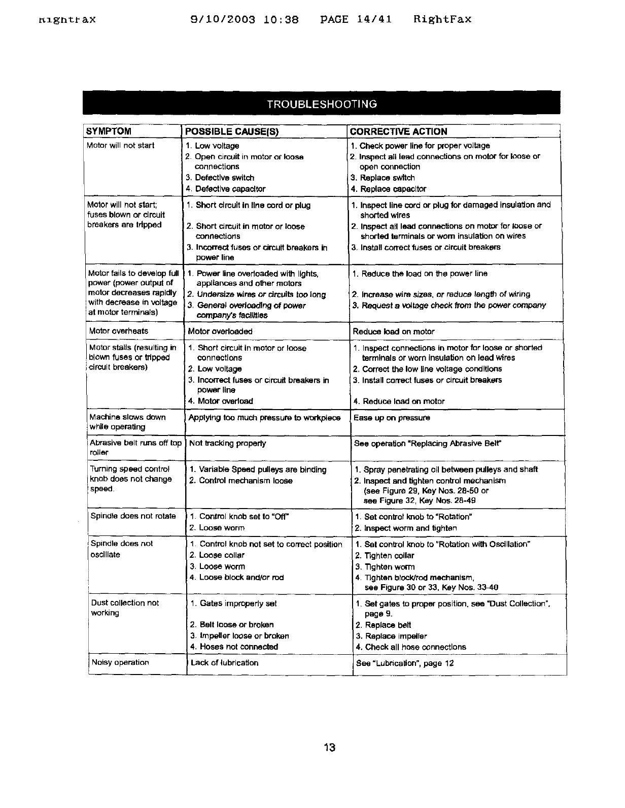
SYMPTOM
MoOr willnot Mart
Motor will not start;
fuses blown or circuit
breakersare tripped
Motor fails to develop full
power (power output of
motor decreases rapidly
with decrease in voltage
Iat motor termmals)
Motor overheats
Motor stalls (resulting in
blown fuses or tripped
circuit breakere)
POSSIBLE CAUSE(S)
1. Low voltage
2Open circuit in mutor or loose
connections
3. Defective switch
4. Defective capecltor
1. Short circuit in line serd or plug
2. Short circuit in motor or loose
connections
3. Incorrect fuses or circuit brenkem in
power line
!1. Power line overloaded with lights,
appliances and other motors
2. Undersize wires or circuits too long
3. General overloading of power
company_s fedJfflec
Motor overloaded
1. Short circuit inmotor or loose
connections
2. Low voltage
3. Incorrect fuses or circuit breakers in
power line
4. Motor ovedoad
CORRECTIVE ACTION
1. Check power line for proper voltage
2. Inspect all lead connections on moor for loose or
open connection
3. Replace switch
4. Replace capacitor
1. Inspect line cord or plug for damaged insulation and
shorted wires
2. Inspect all lead connections on motor for loose or
shorted terminals or wom insulation on wires
3. install correct fuses or circuit breakers
1. Reduce the load on the power line
2. Increase wire sizes, or reduce length of wiring
3. Request a _,,_tage check from the power company
Reduce load on motor
1. Inspect connections in motor for loose or shorted
terminals or worn insulation on ]eed wires
2. Correct the low line votiage conditions
3. Install correct fuses or circuit breakers
4. Reduce Iood on motor
Machine slows down Applying ten much pressure to wonV_ece Ease up on pressure
while operating
Abrasive holt runs off top Not kacldng propedy See operation "Replacing Abrasive Belt"
roller
Turning speed control 1. Varial_e Speed pulleys are binding 1. Spray penetrating oil between pulleys and shaft
knob does not change 2. Control mechanism loose 2. Inspect and gghtan control mechanism
speed. (see Figure 29, Key Nos. 28.50 or
see Figure 32, Key Nos. 28-49
Spindle does not rotate 1. Control knob set to "Off=1. Set oontrol knob to "Rotation"
2. Loose worm 2. Inspect worm and tighten
Spindle does not 1. Control knob not set to correct position 1, Set control knob to "Rotation with Oscillation"
oscillate 2. Loose collar 2. Tighten collar
3. Loose worm 3, Tighten worm
4. Loose block and/or rod 4. 33ghten block/red mechanism,
see Figure 30 or 33, Key Nos. 33_10
Dust collection not I 1. Gates irepropedy set
working
2. Belt loose or broken
3. Impeller loose or broken
4. Hoses not connected
Lack of lubrication
Noisy operation
1. Set gates to proper position, see =Dust Colleclion",
page 9.
2. Replace belt
3. Replace impetier
4. Check all hose connections
See =Lubrication", page 12
13
_lEnt_ax 9/10/2003 10:38 PAGE 15/41 BiEhtF&x
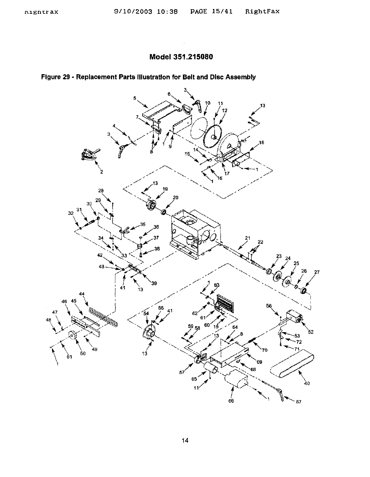
Model 351.215080
Figure 29 -Replacement Parts Illustration for Belt and Disc Assembly
5?
40
14
Kzgnt_ax 9/10/2003 10:38 PAGE 18/41 RightFax
KEY
NO.
I
2
3
4
5
5
7
8
9
10
11
12
13
14
'15
16
17
q8
19
20
21
22
23
24
25
20
27
20
29
30
31
32
33
34
35
36
37
PART NO,
01784.00
20584.00
20585.00
20586.00
20587.00
20588.00
20589.00
01505.00
20590.00
20591,00
06983.00
20592.00
_1766,00
!0593.00
0863400
20594.00
20595.00
20596.00
20567.00
!BTD315236
20568.00
20569.00
20570.00
20571 00
20672.00
01900.00
STD315246
05284.00
2063700
20638.00
20639.00
20640.00
STD852005
STD640506
20641.00
00221.00
2064200
DESCRIPTION
54).8 X 10mm Pan Head Screw
Miter Gauge Assembly
Handle
Angle Label
Disc Table
iLeft Trunnion
Right Trunnion
6-1.0 x 12rnm Socket Head Bolt
Dust Cover
Abrasive Disc, 100 gd{
6-1.0 x 8turn Set Screw
Aluminum Disc
6-1.0 x 16mm Socket Heed Bolt
Slide
4 x 12ram Spdng Pin
Pointer
Disc Guard
Dust Cover
Disc Bearing Bracket
6203ZZ_ Ball Beadn@*
Main Shaft
5 x 5 x 14ram Key
51107 Thrust Ball Beadng
inner Variable Pulley
Outer Variable Pulley
3AMI-25 Retaining Ring
6204ZZ Ball Boadng*
5-0 8 x 25ram Socket Head Bolt
Bracket Plate
Nut
Adjustment Rod
Spacer
5mm Lock Washer*
5-0.Bmm Hex Nut*
Fork
3AMI-IO Retaining Ring
Clevis
*Standard hardware item available locally
&Not shown
QTY.
14
1
2
1
1
1
1
5
1
1
3
1
12
2
6
1
1
1
1
1
1
2
1
1
1
1
1
2
2
1
1
1
2
2
1
1
1
KEY
NO.
39
40
41
42
43
44
40
46
47
48
49
50
51
52
53
54
55
56
57
58
59
6O
61
62
63
64
65
66
67
68
69
70
71
72
pARt'NO.
120643.00
120644.00
20613.00
05331.00
03069.00
20645.00
20646.00
20647.00
20648.00
20649,00
01930.00
20650.00
20651.00
STD851005
20612.00
20611.00
20597.00
20598.00
05153.00
20599.00
ISTD840810
01775.00
20600.00
20601,00
20602,00
20603,00
STD862008
20604.00
20605.00
20806.00
20607.00
20608.00
20609,00
STD833030
20610.00
DESCRIPTION
Clevis Pin
Plate
Abrasive Belt, 100 Grit
_-0.8 x 1 2ram Socket Head Bol
5.0.8 x 6ram Set Screw
Spacer
Guide
Rack
Guard
Pointer
4-0.7 x 6ram Pen Head Screw
4.8-1.6 x 22ram Thread Forming
Screw
Knob
5ram Flat Washer"
idler Roller Assembly
Tension Lever
pivot Stop Bracket
Stop
6-1.0ram Fiber Hex Nut*
Pivot Bracket
6-1.0ram Hex Nut"
6-1.0 x 25turn Socket Head Bolt
Slide
Belt Table
Locking Nut
Pointer
6ram LOck Washer*
Ddve Roller
Belt Dust Chute
Handle
Angle Label
platen
Spring
6-1.0 x 30ram Hex Head Bolt*
Handle
'/
1i
I
I
I
I
2
1
1
1
1
1
2
1
1
1
1 i
1
1
1
1
5
1
1
1
1
I!
15
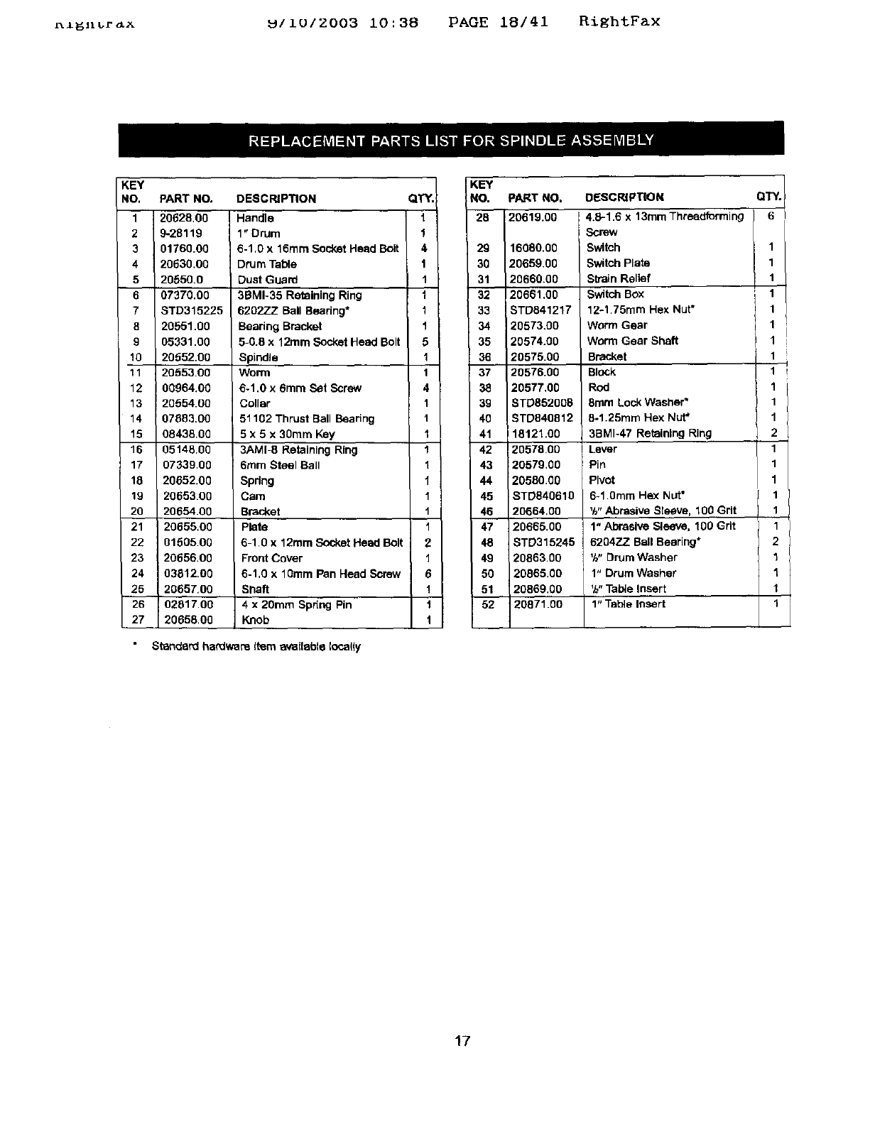
KightFax 9/10/2003 10:38 PAGE 17/41 RightFax
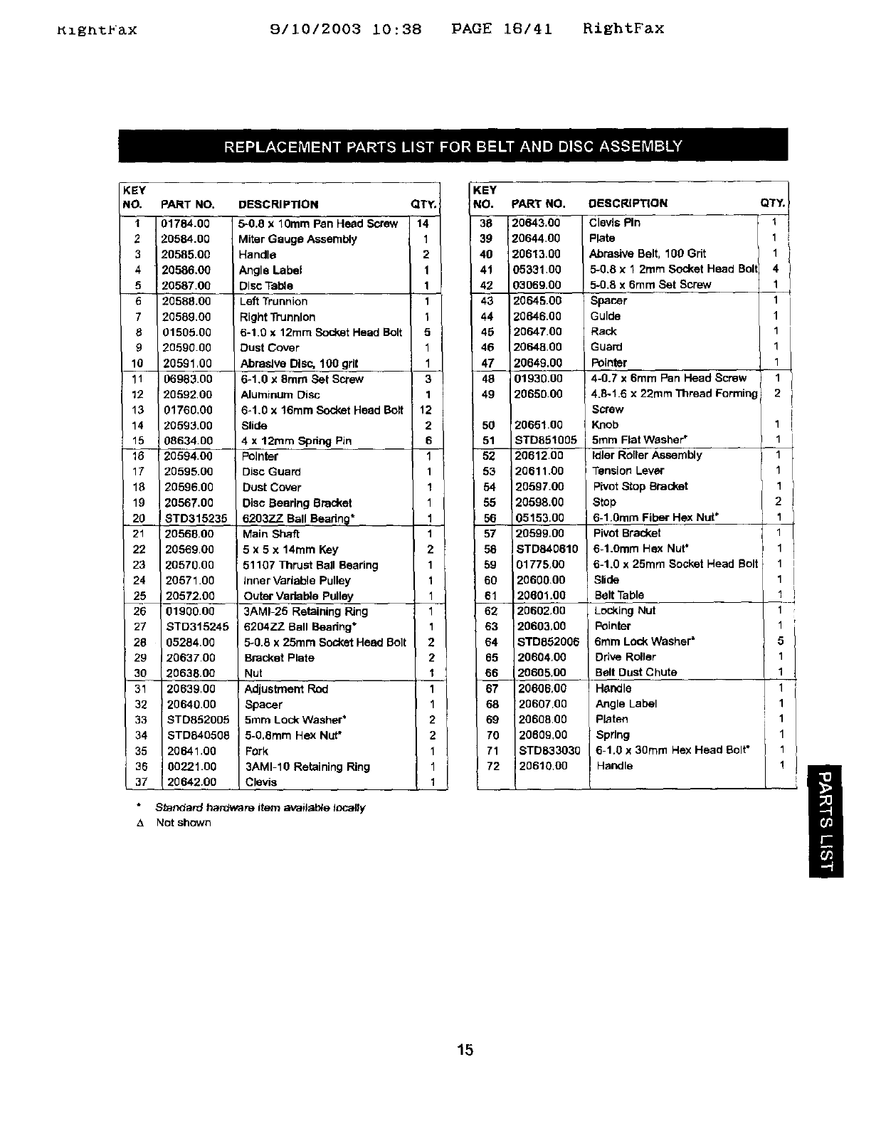
Model 351.215080
Figure 30 -Replacement Parts Illustration for Spindle Assembly
52
_4
26
"_ a3
28
36 35
37
39
16
r_l_n_r_x _IIUIZ003 10:38 PAGE 18/41 RightFax
KEY
NO,
1
2
3
4
5
6
7
8
9
10
11
15
16
17
18
19
20
21
22
23
24
25
26
27
PART NO.
20628.00
9-28119
01760.00
20630.00
20650.0
07370.00
STD315225
20551.00
05331.00
20652.00
2055:100
00964,00
20554.00
07883.00
08435.00
0514600
07339.00
20652,00
20653.00
20654.00
20655.00
0160600
2065600
03812.00
20657.00
02817.00
20658.00
DESCRIPTION
Handle
1" Drum
6-1,0 x 16mm Soc_ketHead Bolt
DrUm Table
Dust Guard
3BMI-35 Retaining Ring
6202ZZ Ball Bearing*
Beadng Bracket
5-0.8 x 12ram Socket Head Bolt
Spindle
Worn_
6-1,0 x 6ram Set Screw
Collar
51102 Thrust Ball Bearing
5 x 5 x 30ram Key
3AMI_ Retaining Ring
6ram Steel Ball
Spring
Cam
Bracket
plate
6-1,0 x 12ram Socket Head Bolt
Front Cover
6-1,0 x 10ram Pan Head Screw
Shaft
4 x 20ram Spdng Pin
Knob
Standard hardware l_m _(table Iocafly
QTY.
t
1
4
1
1
t
1
1
5
1
1
4
1
1
1
1
1
1
1
1
1
2
1
6
1
1
t
KEY
:NO. PART NO. DBSCRIPT[ON QTY.
2130293231120619"0020659"002066120660.0020573.008TD84121716080"00.00Screw4"8"168witchSwitChwormSWitChStrain12.1.75mmReliefGearPlateBoxX13mmHexThreadformingNut. 6111111
33_5 t 20574.00 Worm Gear Shaft 1
20575.00 B_ket 1
_ /20576.00 Block 11
20577,00 Rod 1 /
39 | BTD852005 8mm Lock Washer* 1
40 / STD840812 5.1.25mm Hex Nut* 1
41 18121.00 3BMI-47 Retaining Ring 2
42 20578.00 Lever 1
20579.00 Pin 1
20580.00 Pivot 1
45 STD840610 6-1.0ram Hex Nut*
46_ 20664.00 %. Abrasive Sleeve, 100 Grit
20655,00 1" Abrasive Sleeve. 100 Grit
8TD315245 620477 Ball Bearing*
49 20863.00 _h"DrumWasher
50 20065.00 1" Drum Washer
51 20869.00 '/_"Tabta Insert
52 20871.00 1" Table Insert
17
5igntbaX 9/10/2003 10:38 PAGE 19/41 RightFax
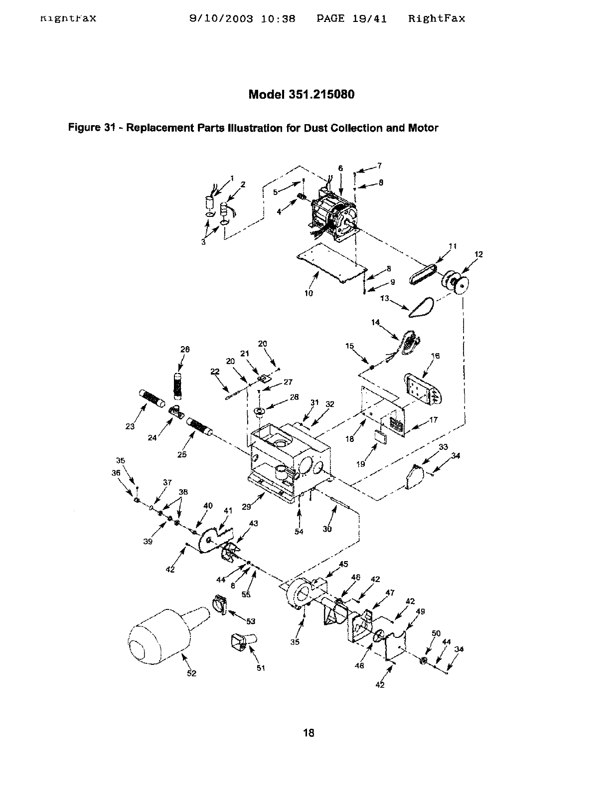
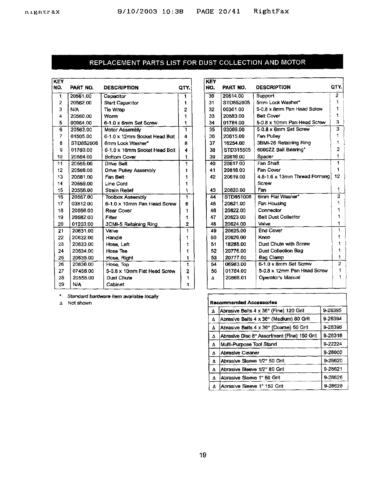
Model 351.215080
Figure 31 - Replacement Parts Illustration for Dust Collection and Motor
1
43
39
54
!
35
31 32
46 42
47 42
49
/50
44 34
18
_ga_r&x 911012003 10:38 PAGE 20141 RightF&x
KEY
NO.
1
2
3
4
5
6
7
8
9
10
11
12
13
14
15
15
17
18
19
2O
21
22
23
24
25
26
27
28
29
PART NO,
20561.00
20562.00
N/A
20560.00
00964.00
20563,00
01505.00
STDB52006
01760.00
20564.00
20565.00
20566.00
20581.00
20559.00
20558.00
20557.00
03812.00
20556.00
20582.00
01203.00
20631.00
20632.00
20633.00
20634,00
20635.00
2063600
07458.00
2O555.0O
N/A
DESCRIPTION
Capacitor
Start Capacitor
Tie Wrap
Worm
6-1.0 x 6rnm Set Screw
Motor Assembly
6-1.0 x 12ram Socket Head Bolt
6mm Lock Washer*
6-1.0 x 16ram Socket Head Bolt
Bottom Cover
Ddve Belt
DrNe Pulley Assembly
Fan Belt
Line Cord
Strain Relief
Toolbox Assembly
6-1.0 x 10ram Pan Head Screw
Rear Cover
Filter
3CM1-5 Retainin 9 Rin_
Valve
Handle
Hose, Left
Hose Tee
Hose, Right
Hose, Top
5-0.8 X 10ram Flat Head Screw
Dust Chute
Cabinet
*Standard hardware item avaitab_e locally
_. Not shown
KEY
QTY. NO.
1 30
1 31
2 32
1 33
1 34
1 35
4 36
8 37
4 30
1 39
1 40
1 41
1 42
1
143
1 44
6 45
1 46
1 47
2 48
1 49
1 50
1 51
152
1 53
1 54
2 55
1
1
PART NO.
20614,00
STD852005
00361,00
20583,00
01784,00
03069,00
20615.00
16254.00
STD315505
20616,00
20617,00
20618.00
20619.00
20620.00
18TD851006
i20621.00
20622,00
20623.00
20624.00
20625.00
20626.00
18268.00
20776.00
2O777.OO
06983.00
01784.00
20666.01
DESCRIPT(ON
Support
5ram Loc_ Washer"
5-0.8 x 8ram Pan Head Screw
Belt Cover
5-0.8 x 10ram Pan Head Screw
5-0.8 x 6ram Set Screw
Fan Pulley
36MI-26 Retaining Ring
60O0ZZ Ball Bsedng*
Spacer
Fan Shaft
Fen Cover
4,8-1.6 x 13rnm Thread Forming
Screw
Fan
8mrn Flat Washer*
Fan Housing
Connector
Belt Dust Collector
Valve
End Cover
Knob
Dust Chute with Screw
Dust Collection Bag
Bag Clamp
6-1.0 x 8rnrn Set Screw
5-0.8 x 12ram Pan Head Screw
Operator's Manual
QTY.
2
1
1
1
3
3
1
1
2
1
1
1
12
I
2
1
1
1
1
1
1
1
1
2
I
1
Recommend_l Accessories
_A
&
A
z_
&
A
A
Abrasive Belts 4 x 36" (Fine) 120 Grit
:Abrasive Belts 4 x 36" (Medium) 80 Gdt
&brasive Belts 4 x 36" (Coarse) 50 Grit
Abrasive Disc 8" Assortment (Rne) 150 Grit
Multi-Purpose Tool Stand
Abrasive Cleaner
Abrasive Sleeve 1/2" 50 Grit
Abrasive Sleeve 1/2" 80 Grit
Abrasive Sleeve 1" 50 Grit
Abrasive Sleeve 1" 150 Grit
9-283951
9-28394
9-28396
9-28318
9-22224
9-28000
9-28620
9-25621
9-28626
9-28628
19
Ki_ht_&X 9/10/2003 10:38 PAGE 21/41 RiEhtFax
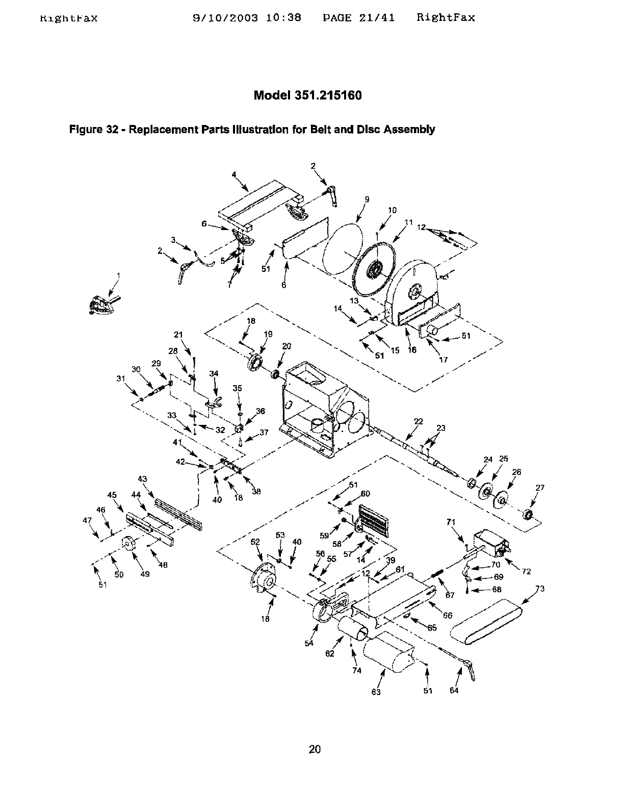
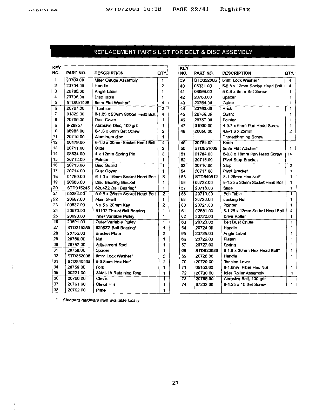
Model 351.215160
Figure 32 - Replacement Parts Illustration for Belt and Disc Assembly
2
\ \
9
/Io
I
2,
51
72
!
54
74
63 51 64
2O
,,_ ...._^ _/Lu/zuu_ i0:_8 PAOE 22/41 RightFax
KEY
NO, PART NO. DESCRIPTION QTY.
1 20703.00 Miter Gauge Assembly 1
2I20704.00 Handle 2
320705,00 Angle Label 1
4 20706.00 Disc Table 1
5 STD851008 8rare Flat Washer* 4
6 20707.00 D'unnion 2
701822.00 8-1.25 x 20ram Socket Head Bolt 4
8 20709.00 Dust Cover 1
9 9-28957 Abrasive Disc. 100 gdt 1
10 06983.00 6-1.0 x 8rare Set Screw 2
11 20710.00 AJuminure disc 1
12 00179.00 6-1.0 x 20mrn Socket Head Bolt 4
13 20711.00 Slide 2
t 4 08634.00 4 x 12rare Spring Pin 8
15 20712.00 Pointer 1
16 20713.00 Disc Guard 1
17 20714.00 Dust Cover 1
18 01760.00 6-1.0 x 16ram Socket Head Bolt 8
19 20686.00 Disc Bearing Bracket 1
20 STD315245 6204ZZ Ball Searing* 1
21 05284.00 5-0.6 x25ram Socket Head Bolt 2
22 20687.00 Main Shaft 1
23 00537.00 5x5x20rare Key 2
24 20570.00 51107 Thrust Ball Beadng 1
25 20690.00 Inner Variable Pulley 1
26 20691.00 Outer Vadable Pulley 1
27 STD315255 620572. Ball Bearing* 1
28 20755.00 Bracket Plate 2
29 2075600 Nut t
30 20757,00 Adjustment Rod 1
31 20758.00 Spacer 1
32 STD852005 5ram Lock Washer" 2
33 STD840508 5-O.8mm Hex Nut" 2
34 20759.00 Fork 1
35 00221.00 3AMI-10 Retaining Ring 1
20760.00 Clevis
20761.00 Clevis Fin
20762.00 Plate
Standard hardware itere availa_e locally
KEY
NO. PART NO.
39 STD852008
40 05331.0g
41 03060.00
42 20763.00
43 120754.g0
44 '20765.0g
45 120766.00
46 20767.00
47 01930.00
48 20650.00
49
5O
51
52
53
54
_55
56
!57
158
59
160
61
62
63
64
65
66
67
68
69
70
71
72
20769.00
STDB51005
01704.00
20715.00
20716.00
_0717.00
STD640812
00732.00
2071&00
20719,00
20720.00
20721,00
02681.00
20722.00
20723.00
20724.00
20725.00
20726.00
20727.00
8TD033030
20728.00
20729.00
05153.00
20730.00
20768.00
07202.00
DESCRIPTION
8ram Lock Washer*
5-0.8 x 12mm Socket Head BoJt
5-0.8 x 6mm Set Screw
Spacer
Guide
Rack
Guard
Pointer
4-0.7 x 6rare Pan Head Screw
4.8-1.6 x 22mm
Threadforming Screw
Knob
5mre Flat Washer*
5-0,8 x 10tern Pan Head Screw
PIvot Stop Bracket
Stop
Pivot Bracket
8-1.25ram Hex Nut*
8-1.25 x30turn Socket Head Bolt
Slide
Belt Table
Loddng Nut
Pointer
8-1.25 x 12rare Socket Heed Bolt
Drive Roller
Belt Dust Chute
Handle
Angle Label
Platen
!Spring
6-1.0 x 30rare Hex Head Bolt"
IHandle
Tension Lever
6-1.0mre Fiber He,'<Nut
Idler Roller Assembly
Abrasive Belt, 100 grit
8-1.25 x 10 Set Screw
QTY.
4
4
1
1
1
1
1
1
1
2
1
1
14
t
2
1
1
1
1
1
1
1
4
1
1
1
1
1
1
1
1
1
1
1
21
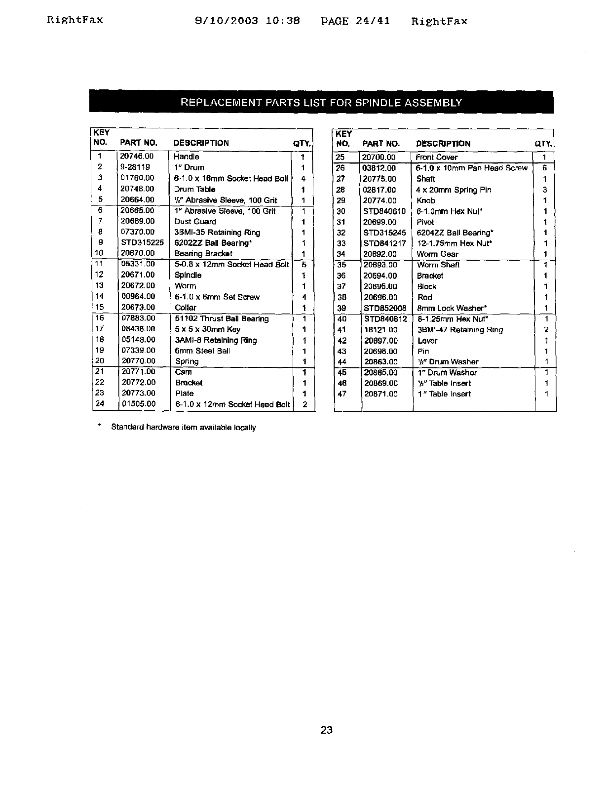
RightFax 9/10/2003 10:38 PAGE 24/41 RightF_x
KEY
NO,
1
2
3
4
5
7
8
g
!0
11
12
13
14
15
16
17
16
19
2o
21
22
23
24
PAR'r NO.
20746.00
9-28119
01760.00
20748.00
20664.00
20665.00
20669.00
07370.00
STD315225
20670.00
05331.00
20671.00
20672.00
00964.00
20673.00
07883,00
08438.00
05148,00
07339 00
20770.00
20771,00
20772.00
20773,00
01505.00
DESCRIPTION
Handle
1" Drum
6-1.0 x 16ram Socket Head Bolt
Drum Table
'h" Able Sleeve, 100 Gdt
1" Abrasive Sleeve, 100 Gdt
Dust Guard
39MI.35 Retaining Ring
6202ZZ Ball Beedng*
Beadng Bracket
5-0.8 x 12ram Socket Head Bolt
Spindle
Worm
6-1.0 x 6turn Set Screw
Collar
51102 Thrust Bail Bearing I
5 x 5 x 30ram Key
3AMI-8 Retaining Ring
0ram Steel Ball
Spring
Cam
Bracket
Plate
6-1.0 x 12ram Socket Head Bolt
QT_,
1
1
4
1
1
1
1
1
1
1
5
1
1
4
1
1
1
1
1
1
1
1
1
2
Standard hardware item available locally
KEY
I NO.
25
12o
27
28
29
3O
31
32
33
34
35
36
37
38
39
4O
41
42
43
44
45
46
47
PART NO.
20700.00
03812.00
20775,00
02817.00
20774,00
STD040610
20699.00
STD315245
STD841217
20692.00
120693,00
20694.00
20695.00
20696,00
STD852008
STD840812
18121,00
20697,00
20698.00
20863,00
20865,00
20869.00
20871.00
DESCRIPTION
Front Cover
6-1.0 x 10ram Pan Head Screw
Shaft
4x 20mm Spring Pin
Knob
6-1.0ram Hex Nut*
Pivot
62047_Z Ball Beadng*
12-1.75mm Hex Nut*
Worm Gear
Worm Shaft
Bracket
Block
Rod
8ram Lock Washer*
8-1.25mm Hex Nut*
3BMI-47 Retaining Ring
Laver
Pin
'1_"Drum Washer
1" Drum Washer
'h" Table Insert
1"Table Insert
QTY.
1
6
1
3
1
1
1
1
1
1
I
1
1
1
1
1
2
1
1
1
1
1
1
23
_ightFax 9/10/2003 i0:38 PAGE 25/41 RightFax
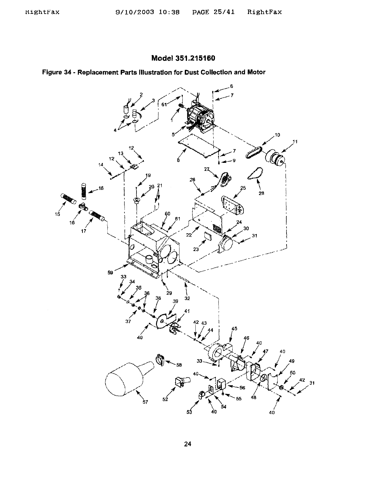
Model 351.215160
Figure 34 - Replacement Parts Illustration for Dust Collection and Motor
2
5 28
24
30
31
24
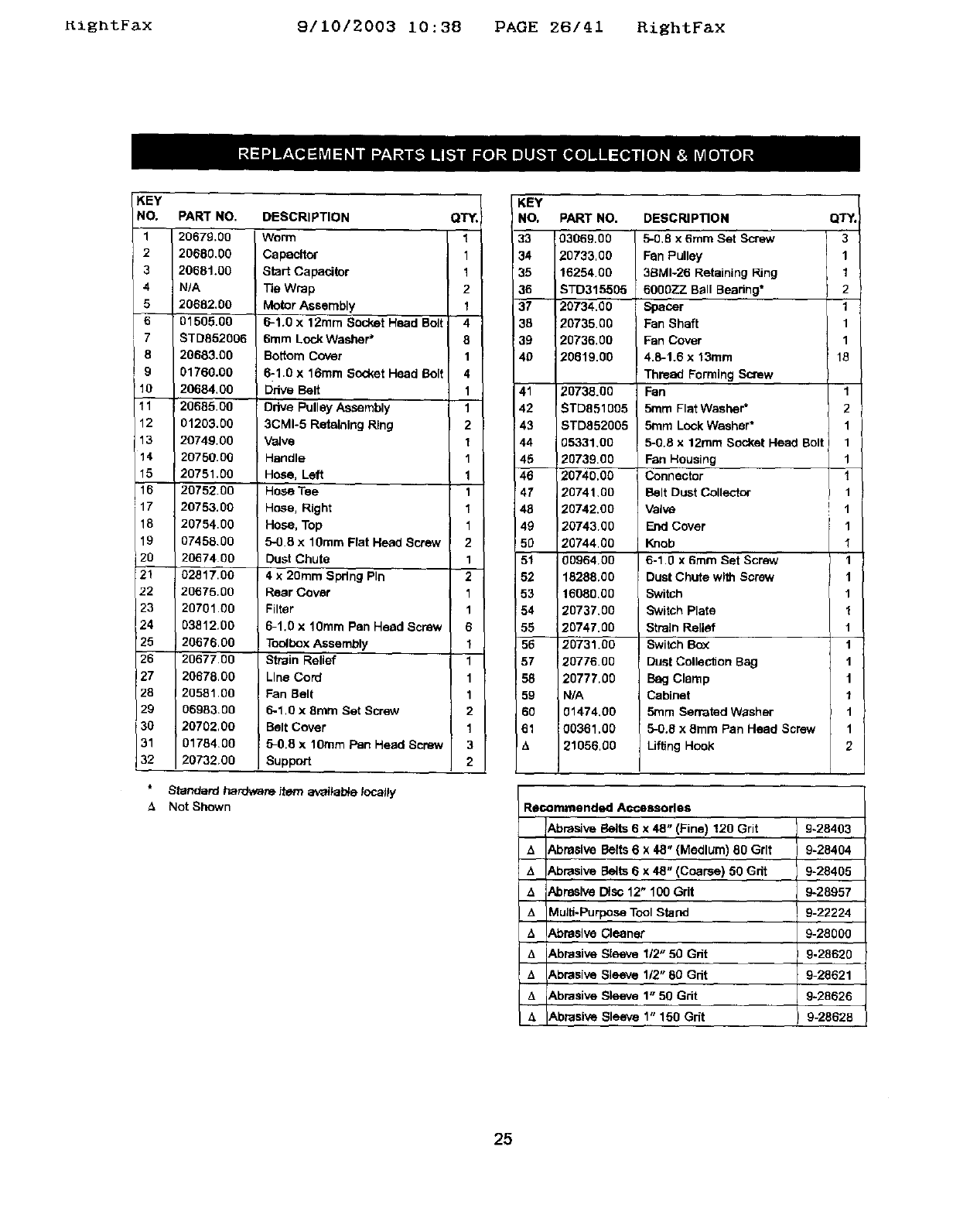
KightFax 9/10/2003 10:38 PAGE 26/41 RightFax
KEY
NO.
1
2
3
4
5
6
7
8
9
10
11
12
13
14
15
16
117
18
19
120
21
22
23
24
25
26
27
28
29
30
31
32
PART NO.
20679.00
20680.00
20681.00
N/A
20682.00
01505.00
ST0852006
20683.00
01760.00
20684.00
20685.00
01203.00
20749.00
20750.00
20751.00
2075200
20753.00
20754.00
07458.00
2067400
02817.00
20675.00
20701.00
03812.00
20676.00
20677.00
20678.00
20581.00
06983.00
20702,00
01784.00
20732.00
DESCRIPTION
Worm
Capacitor
Start Capacitor
Tie Wrap
Motor Assembly
6-1.0 x 12ram Socket Head Bolt
6ram Lock Washer"
Bottom Cover
6-1.0 x 16ram Socket Head Bolt
Ddve Belt
Drive Pulley Assembly
3CMI-5 Retaining Ring
Valve
Handle
Hose, Left
Hose Tee
Hose, Right
Hose, Top
5-0.8 x 10ram Flat Head Screw
Dust Chute
4 x 20mm Spring Pin
Rear Cover
Filter
6-1.0 x 10ram Pan Head Screw
iAssembly
Strain Relief
Line Cord
!Fan Belt
5-1.0 x 8ram Set Screw
Belt Cover
5-0.8 x 10ram Pan Head Screw
Support
Standard hardware item arvaital_e looalty
Not Shown
QT_,
1
1
1
2
1
4
8
1
4
1
1
2
1
1
1
1
1
1
2
1
2
1
1
6
1
1
1
1
2
1
3
2
KEY
I NO, PART NO. QT_
33 03069,00 3
34 20733,00 1
35 16254.00 1
36 STD315505 2
37 20734.00 1
36 20735.00 1
39 20736.00 1
40 20819.00 18
41
42
43
44
45
46
47
46
49
5O
51
52
53
54
55
56
57
58
59
6O
61
14
20738.00
ST0851005
STD852005
05331.00
2073900
20740.00
20741.00
20742.00
20743.00
20744.00
00964.00
18288.00
16080.00
20737.00
20747.00
20731.00
20776.00
20777,00
N/A
01474.00
00361.00
21056.00
DESCRIPTION
5-0.8 x 6mm Set Screw
Fan Pulley
38MI-26 Retaining Ring
60OOZZ Ball Bearing*
Spacer
Fan Shaft
Fan Cover
4.6-1.6 x 13mm
Thread Forming Screw
Fan
5ram Flat Washer*
5mm Lock Washer*
5-0.8 x 12ram Socket Hea0 Bolt
Fan Housing
Connector
Belt Dust Collector
Valve
End Cover
Knob
6-1.0 x 6ram Set Screw
Dust Chute with Screw
Switch
Switch Plate
Strain Relief
Switch Bc0_
Dust Collection Bag
Bag Clamp
Cabinet
5ram Serrated Washer
5-0.8 x 8mm Pan Head Screw
Liffing Hook
1
2
1
1
1
1
1
!1
1
I
1
1
1
1
1
1
1
1
1
1
1
2
R_mmended Accessories
Abrasive Belts 6 x 48" (Fine) 120 Grit 9-28403
AAbrasive Belts 6 x 48" (Medium) 80 Grit 9-28404
,', Abrasive Belts 6 x 48" (Coarse) 50 Grit 9-28405
&Abrasive Disc 12" 100 Grit 9-28957
/1 Multi-Purpose Tool Stand 9-22224
AAbrasive Cleaner 9-28000
A Abrasive Sleeve 112"50 Gdt 9.28820
t_ Abrasive Sleeve 112"60 Cdt 9-28621
t, Abrasive Sleeve 1" 50 Grit 9-28626
A Abrasive Sleeve 1" 150 Grit 9-28628
25
RightFax 9/10/2003 10:38 PAGE 27/41 RightFax
4x 8"y 6 x 12"
CENTROS DE LIJADO
Modelos No.
351.21 5080
351.21 5160
PRECAUCION: Lea y siga redes las Reglas
de Seguridad y las Instrucciones de Operacibn
antes de user este producto par pdmera vez.
Jngl_s ........................................ 2-13
Ilustraci6n yLlsta de Partes ...................... 14-25
Garantfa ........................................ 26
Reglas de Seguridad ........................... 26-27
Desempaque ................................... 27
Mcotaje ...................................... 27-30
Instalacl6n .................................... 30-32
Operaci6n ................................... 32-36
Mantenimiento ................................... 37
Identlflcac_bn de Prebleraes ...................... 38-39
GARANTIA COMPLETA DE UN A_IO
Si fallara este producto par cause de defectce en el material o
en la mane de obra en un tapso de un abe apartir de ta fecha
de compra_ Sears Io reparard oteemplaza_, a su elecck_n,
sin costa adicional. Solicite al Centre de Servlcio Sears rnds
cercano (1-800-4-MY-HOME) la repamci6n del producto o
devud(valo al establecimiento donde Io adqulri6.
Sieste producto se usa pare fines cornerciatas ode atquitar,
esta garantfa msv&lida par 90 dIas a parUr de la fecha de
compra
Esta garantla aplica _lnicaraenta si el producto se utilize an los
Estados Unidos.
Esta garantia le otorga detaches legales especificos ytam-
Di_,n puede usted tener otros derechos qua varlen de estado a
es_do,
Sears, Roebuck and Co., Dept. 817WA, Hoffmae Estates,
IL 6017g
ADVERTENClA: Pare su proplssegurldad,lea todas
1asIostrucclones ytas pracaucionesantes de operarIs
herramfenta,
PRECAUCION: Slem/xe slgalos pmcedlmlentosde
operacl6ncorrectos,tel comase deflnen en este manual,
aun cuandeest_ familiadzade con el usa de 6sta o de arras
herramlantasslmllares,Recuerde qua desoufdarseaunque
s610sea par una fraccl6nde segunde puede ocaslonarla
graves]eslones,
PREPARESE PARA EL TRABAJO A REALIZAR
•Use raps apropiada. No use rope helgada, guantas, car-
bates, anillos, pulseras ni etres joyas qua puedan atas-
cares en fas piezas m6viles de fa mdquina,
* Use una cubierta protectora pare e_ calbello, pare sujatar a}
cabello largo.
•Use zapatos de seguridad con suelas antidesllzantes.
,Use gates de segurided qua cutup]an con la aortae ANSI
Z87.1 de los Estados Unldos. Los anteoJos comunes tlenan
lentes qua s_o son reslstentes al Impacto. NO son antcoJos
de segudded.
•Use una mbscera pare la cam ouna re&scare centre el
potvo,sl al utl/fzar fa herraaraienta se produce touche poivo.
•Est_ aleda y pierce clararsente. Nunea maneje henaralentas
mecdnlses cuando est_ cansedo, Intoxleado o baJola im
fluencla de medlcacldn qu_ produzca somnolenc[a.
PREPARE EL AREA DE TRA_.JO PARA
LA TAREA A REALIZAR
•Mantenga el drea de trabajo limpia. Las <'_n_asde trabajo
desordenadas ab"aen accidentes.
•No use herramien_ mec_nicas en am_e_tas pehgtos(_. No
use harremientas mec_nices en iugares ht'_rraedosomojades.
NOexponga las herramieNtaa mec_s aha IILMa.
•El "_reade trabaje debe ester iluminada ad_amente.
• De_e haber disponib_e una toms de comeste adecuada
para taharremienta.El enchL_ede tree puntes debe
enchufarae directamente a un receptdculo pare tres
puntes puesto a tierra correctamente.
•Los cordones de e0_tensi6ndeben tarter una imJntade
cone0d6na/Jerra y los fres hires del cord6n de extensi6n
deben ser del calibre correcto.
•Mantenga a los visitantes a una distancia prudenta del
drea de trabajo,
•Mantenga a los ni_ fueradel tugar de traba)o. Haga qua
su taller sea aprueba de nifios. Use candados, interrup-
tares maestros y extraiga las Ilaves del a_dor pare
irapedir cuelqu{er use involuntano de [as herramientas
mecdnica.s.
ES IMPORTANTE DARLES MANTENIMIENTO
A L._S HERRAMIENTAS
•Desenchufa siernpre ta hen_miente antes de inspeccionada.
•Consulte eJmanual pane Informarse sabre los proca@mien-
tos de mantenlmlesto y ejuste especfflcos,
•Mantenga la harramlanta lubrl_de y Ilmpia de mode que
funcione de fa manera rodssegura.
•Retire les herramlentas de aJuste. Deserrolle el h&btto de
veriflcar que hayan side retlmdas las herramle_tas de
aJuste antes de encander la mdqulna.
• Mantenga redes les panes Ilstas pare func_onar. Revise
el i_otector u arras p_ezes pare determiner s/funcionan
correctamente yheosn el treDaJoqua deben h_.
•Re'/ise qua no haya partes da_adas. Vedfique el ati-
neamlento de les padse m6v_tes, si hay atascamfento,
returns y montaJe o cualqulet olx'acondicibn qua pudlera
afeetat el fundoneralento de le herramlenta.
•S_hay una proteccidn o cualquier ob'a parte decade, dstas
deberdn repararse correc_amente o ear reempfazadas. No
hega reparac_coes provlslonales (vdlgaso de la Iista de
plazas Incluida pare soticitar plazas de reempfazo).
26
RightFax 9/10/2003 10:38 PAGE 28/41 RiEhtFax
EL OPERADOR DEBE SABER UBAR
LA HERRAMIENTA
•Use Is herramlenta corrects papa cede trabaJo. No fuerce 18
herramienta o el asossodo ni los use pare une tares pare
le qua no fueron diseffados.
•Dasconecte le herramlenta cuande semble la cortesoel
disco sbreslvo.
•Evlte que 18herremlenta se enclende par acddente.
Aseg_rese de que el Interrupter de le herramienta astd an
Is poslclbn OFF (apagado) antes de enchufad8.
•No fueme la hermm]enta. Funelonard en le forms rods eft-
clente ata vetcolded pare ta cut,Ise dlselSb.
•Mantenga [as manes alejadas de las partes moviblas y de
les superficies de lijado.
•Nunca deje desatendida una herremiente en funciona-
miento. Descondctela y no abandone el lugar haste qua
se hays detenido per complete.
* No Irate de alcanzar demasiado lejos. Mant&ngase flrme y
equdibrado.
•Nunce se celoque de pie sobre ia herramtenta. Se pueden
producir lesiones graves si la herrareienta se vuelca o hase
contecto con la cortes o at disco.
•Cc¢_ozca su herramiente, Apsenda a rsesejar te herra-
relents, su eplicaci6n y limitecionas especffises.
•Use los accesorios recomendades (consulte las pdginas
19 y25}. Si se usan acoesonos incorrastos, puede sufrir
lesiones o leeloner aalguien.
•Maneje te plaza de trabajo en forms correcta. Pmt_jase las
manes de posibles lasionas.
• Apague la mdquina sise atasse. La correa se atesse si
se introduce muy profundamente an te pieza de trabajo
(Is fuerza del motor te mantiene trabada er, la plaza
de _aDalo ).
•proporelone soporte ata piasa de trabejo con la gufa de
ingletes, plato de ia cortes o mesa de trabajo.
•Mantenga un aspeclo Ilbre maxlmo de V_,"enke la mesa y
el disco o la correa de lijado.
PRECAUCION: iPlense en la seguddadl La seguridad es
use oomblnadi6n del sentlclo comun del operader y un estade
de alerts permasente 81 user la herramienta.
ADVERTENClA: No trate de maneJar la hermmiente haste
que hays side complemmente armada seg0n 1as Instruccior, es.
ConsuHe la Figure 1.
Verifique qua no hayan ocurrido defies dumnto el envlo. Si
hay deSos, se deber_ presenter un redamo ala compaSla
de transporte. Verifique qua est_ complete. Avfse inmediate*
mento al distribuider el falten partos.
El centre de lijado viene montado coreo une unidad. Ser_
necesario Iocalizar y ver qua no falten las partes adicioneles
qua deben monterse en el centre de lijado, antes de instelarles.
ACentre de lijado
B Conjunto de la mesa del disco
C Manija de la mesa del disco (2)
DConjunto de la guia de ingtetas
EMange abrasive de %"
FConiunto de mesa de 19 corraa
GCaja de herremientes con tornillos de cabeza de pteos
H Canal pare polvo con tornillo de cabeza de place
I Manija de la mesa de la cortes, mange y tuerca de
segudded (21585)
J ManlJe de la mesa de [a correa y tuerse de segurided
(21516)
K ConJunto de plato de 18cortes
L Correa abrasive
M Rodilto impulsor con tornillo de fljack_n (21508 selamente)
N Canal pare polvo con tornillos de cabeza de pteca
OUave de ajuste del disco {3 ram)
P APandela del tambor de 'h"
Q Ioserto pare la mesa de _h"
R Boise de recolecol6n de polvo con abrazadera
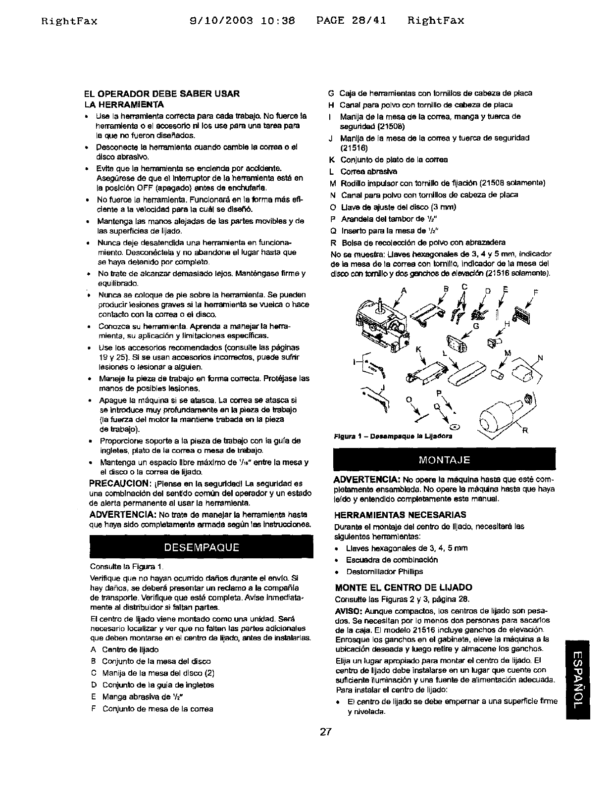
No se mueelta: Llavas hexagoneles de 3, 4y 5 ram, Indicador
de le mesa de ta cones con tornltto, Indlcador de la mesa del
disco con tort_Jo y dos ganchos de eJevacJ_ (21516 seJemente).
ADVERTENCIA: No opere la m_qules haste qua est6 com-
pletamente ensemblede. No opera 18 m_quine haste qua hays
lefdo y entendldo completemente este manual,
HERRAMIENTAS NECESARIAS
Dumnte el monteJe del centre de IlJado, neceslterd las
slgulentes herramlentas:
•Llavas hexagoneles de 3, 4, 5 mm
•Escuadra de comblsecidn
•Destornillsdor Phillips
MONTE EL CENTRe DE LIJADO
Consulte las Figures 2y3, p_gina 28.
AVISO: Aunque compactos, Lossentros de lijade son pese-
dos. Se necesitan per Io manes dos personas pare secedes
de la c_ja. El rnodelo 21516 ineluye ganchos de elevac46n.
Enrosque los ganchos en el gabinete, eleve Is n_quina e la i
ubiseci6n deseade y luego retire y almacene los genchos, m
Elija un lugar apreptedo pard reenter el centre de lij_do, El U
centre de lijado debe instatarse en un lugar qua cuente con
suflciento ituminacibn y una fuente de alimenteci6n adecuade.
PaPa instelar el sentro de lijado:
•El centre de lijade se debe empernar auna superficie %rme
ydivelada.
27
RightFax 9/10/2003 10:38 PAGE 29/41 RightFax
• AsagL_rese de que exista suflciente espacio para mover la
pieza de trabajo. Deberd haber suficiente espacio de ma-
nera qua ni los operadores ni dem&s personas tengan qua
pararse en Ilnea con la modem mientras se usa la herra.
mienta. Deje espacio para poder colocar horizontalmente el
conjunto de la correa
• El cenlro de lijado puede instalarse sabre un banco de tra-
bajo o una plataforma para herramienta (yea Accesonos
recomendades, pdginas 19 y 25) usande pemos, arandelas
de seguridad y tuercas hexagnaales (no suministradas).
I..........i:2F;:::22:[:':_ ......................... T_-............
L
E E
EE
9mm
L,,--.149 mm -_-_
310 mm --
Flgura 2 - Dimensiones de la Base 2'1508 .J
}
E
E
C_
¢q
¢rJ
9mrn
.,/ r
............... 360 rnm............. _.J
Figura 3 - Olmenslones de la Base 21516
ACOPLE EL CONJUNTO DE MESA DEL DISCO
Consulte _as Figuras 4 y 5,
• Deslice la mess del disco en las con'ederas acada lado de
la proteccidn del diso3. Pase las dos manijas a Iravds de
los mu_ones dentro de los orfficJos rososdos a cada lado
de la protecoi6n del disco.
• AsegL_rese de que el espacio entre el disco y la mesa del
disco sea de '/,_" o menos.
,, Si se requiere un ajuste, afloje el tornillo de fijaciSn en e]
disco de aluminio a tray,s de la abertura en la parte supe-
rior trasera de Is protecdSn del disco. Coloque el disco a
V_,"o menos del borde de la mesa. Asegure el disco con el
tornillo de fijad6n.
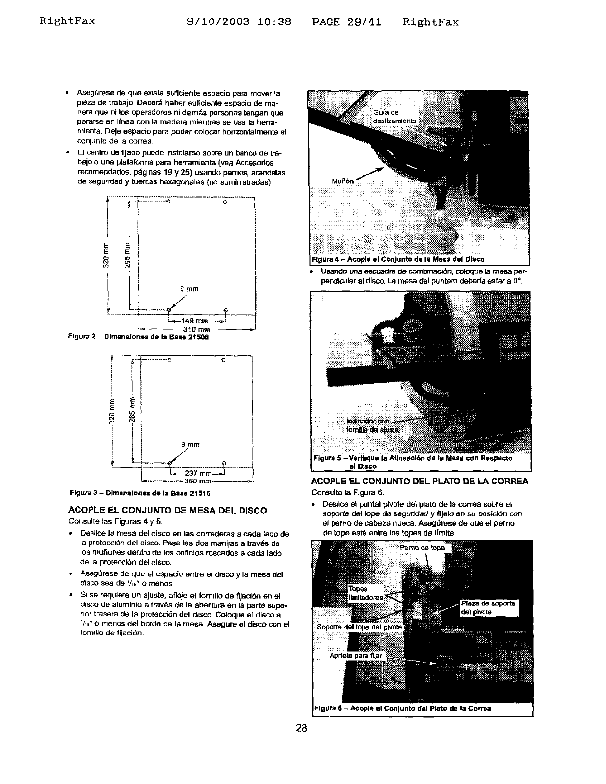
Flgura 4 - Acople el Conjunto de la Mesa del Ol_o
• Usando una escuadra de cornbinaot:_, co}oque ia mesa per-
pendicu_r al disco. La mesa del puntero _a estar a 0°.
Flgura 5 -Verffique la AIIneactbn de la Mesa con Respecto
al Disco
ACOPLE EL CON JUNTO DEL PLATO DE LA CORREA
Consulte la FJgura 6.
•Desiios el pantal pirate del ptato de la correa sabre el
soporto del topo de seguddad y ffjalo en so posici6n con
el perno de cabeza hueca. AsegQrese de qua el pemo
de tope est8 entre los topes de Ilmite.
Flgura 6 - A¢OplQ el ConJunta d@l plato de la Corn_
28
_ightFax 8/10/2003 10:38 PAGE 30/41 RightFax
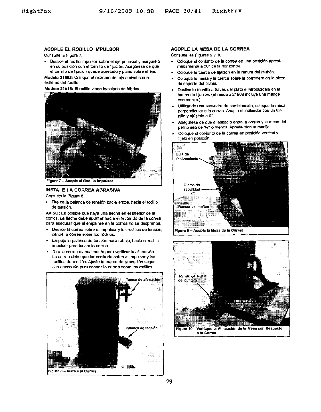
ACOPLE EL RODILLO IMPULSOR
Consulte la Figure 7.
• DesJice el rodillo Impulsor sobre el eJe prlnclpel y asegurelo
en su posicibn con el tomillo de fijacibn. AsegOrese de que
el tornillo tie fljaci6n quede apretado y plane sobre el eje.
Modelo 21508: Celoque el extreme del eJe a nivel con el
extreme del mdllle.
Modelo 21516: El rodillo vlene In_'talado de f_brlce,
Figure 7 - A©ople el Rodlllo Impulsor
INSTALE LA CORREA ABRASIVA
Consulte la Figure 8.
+ Tire de la palance de tensl6n haole 8rrlba, hac_a el rodfllo
de tensiSn+
AVISO: Es poslble que heya una flecha en el Interior de la
correa. La flecha debe apuntar haci8 el recorrtdo de la coffee
peru aeegurar que el empalme en 18 correa no se desprende.
• Deslice la correa sobre el Jmpulsor y los rodillos de tenelbn;
centre 18con-ea sobre los rodillos.
•Empuje la pelance de tensi6n hada abajo, hacia el rodillo
impulsor pare tenser la correa.
• Gire Ja correa manuelmente pare verific_r Ja alJneack_n.
La cerrea debe querier centrada sobre el impulsor y 10s
rodittos de tensi6n. Ajuste la tuerca de alineaci6n segt3n
sea necesario pare centrar la correa sobre los rodillos.
Figur_ 8 - Instale la Corre;)
ACOPLE LA MESA DE LA CORREA
Consulte las Figures 9y 10.
•Colpeue el conjunto de la correa en una peslci6n aproxf-
madamente a 30" de la horizontal
•Coloque le tuerca de fl|acl6n en la ranura del mui=,6n.
•Coloque 18mesa y la tuerce sobre la corredera en la plez8
de soporte del plvote.
• Deslice la menlll8 etrav6s del plato e intr_lQzcela en la
tuerca de flJacibn. (El medelo 21508 incluye una mange
con manlJa.)
Uf_lizando una escuadra de cornbinaci6n, celoque la mesa
perpendicular ala correa. Acople el Indlcedor con un tor-
nillo y aJOsteloa 0°
•Aseg=3resede que el espacio entre la correa y la mesa del
perno sea de _h6"omenos. Apriete bien la manija.
• Coloque el conjunto de la correa en posici6n verUcal y
f(jelo en posid(_n.
Figure 10 - Verlflque la AIIneacl6n de la Mesa con Respecto
a Is Corroa
29

RightFax 9/10/2003 10:38 PAGE 31/41 RightFax
INSTALE EL CANAL PARA POLVO DE LA CORREA
Consulte la Figura 11.
• Monte el canal para pelvo de la correa en el plato usando
dos tornillos de cabeza de placa.
Figura 11 - ACOpleel Canal papaPolvo de la Correa
ACQPLE EL CANAL PARA POLVO
Consulte la Figupa 12.
• Desllca el canal peru pelvo hasta el extreme del asplrador
de astillas. Apfiete el tornillo para fijado en su posielbn.
Flgura 12 -Acople el Canal para Polvo
INSTALE LA BOLSA RECOLECTORA DE POLVO
Consulte Ja Figupa 13.
• Glre la manlvela para abrir comptetamente la abrazadera.
•Tire del braze de la bolsa de recolecdbn de polvo atravds
de la abraz_em.
•T{re del braze de la bolsa y la abrazadera sobre el canal
para polvo. Asegure la boLca en poslctbn usando la
manivela de la abrazadera.
Figure 13 - Acople la Bolea de Recolecci6n de Polvo
ACOPLE LA CAJA DE HERRAMIENTAS
• Acople la caja de herramientas a la parte trasera del
armado usando des tomillos do cabeza de placa.
Consulte las Figupas 14, 15 y 16 en las p_ginas 31 y 32.
FUENTE DE ENERGIA ELECTRICA
ADVERTENCIA: No conecte el centre de fijade a fa fuenta
de alirnentack_n basra qua haya completado todca los pasos
del mordaje.
El mot_r ha side dise£_ade para ftmc_onar al v_taje y f_uen-
cia especJficados. Las cargas normales se pueden manajar
sin riesgos dentro de un intervafo del 10% respecto al voltaje
especificado. Si se hace funcionar la unidad aun voltaje fuera
de este intervalo, se puede recalentar y quemar el motor Las
cargas pesadas exigen qua el voltaic en los terminales dal
motor no sea inferior al especificado.
•La fuente de alimentacibn del motor est_ controlada per un
intemJptor oscilante enclavado unipolar. Extraiga la Ilave
pare evitar el use no autonzado.
INaTRUCCIONES PARA LA CONEXION A TIERRA
ADVERTENCIA: Si no se conecta correctamente el con-
ductor a f_erra del equipo, se cone e_ riesgo de un electxo-
cheque. El equipo debe estar conectado a tierra mientras se
usa papa proteger al opepador de un electrochoque
•Sinocomprendelasinstruccionesdecone_J6natlerrao
IJene dudes en cuanto a si la herramJenta est_ correcta-
manta conectada atierra, consulte aun elecb-icista
calificado.
• Afln de protegedo contra una descarga et_:.'trica, esta
hernamienta estd equipada con un cab/e de b-asconducto-
ms aprobado y clasificade para 150 V, as[ come con un
enchufe de k'es clavijas tipo conexi6n a tierra (Figura 16,
pdgina 32).
•El enchufe de conexi6n a tierra deber_ conectarse directa-
manta a un z(_calo pare 3 davijas instalado y cormctado
debidamente atierra, tal come so muestra en la Figura 14,
p_ina 31.
3O
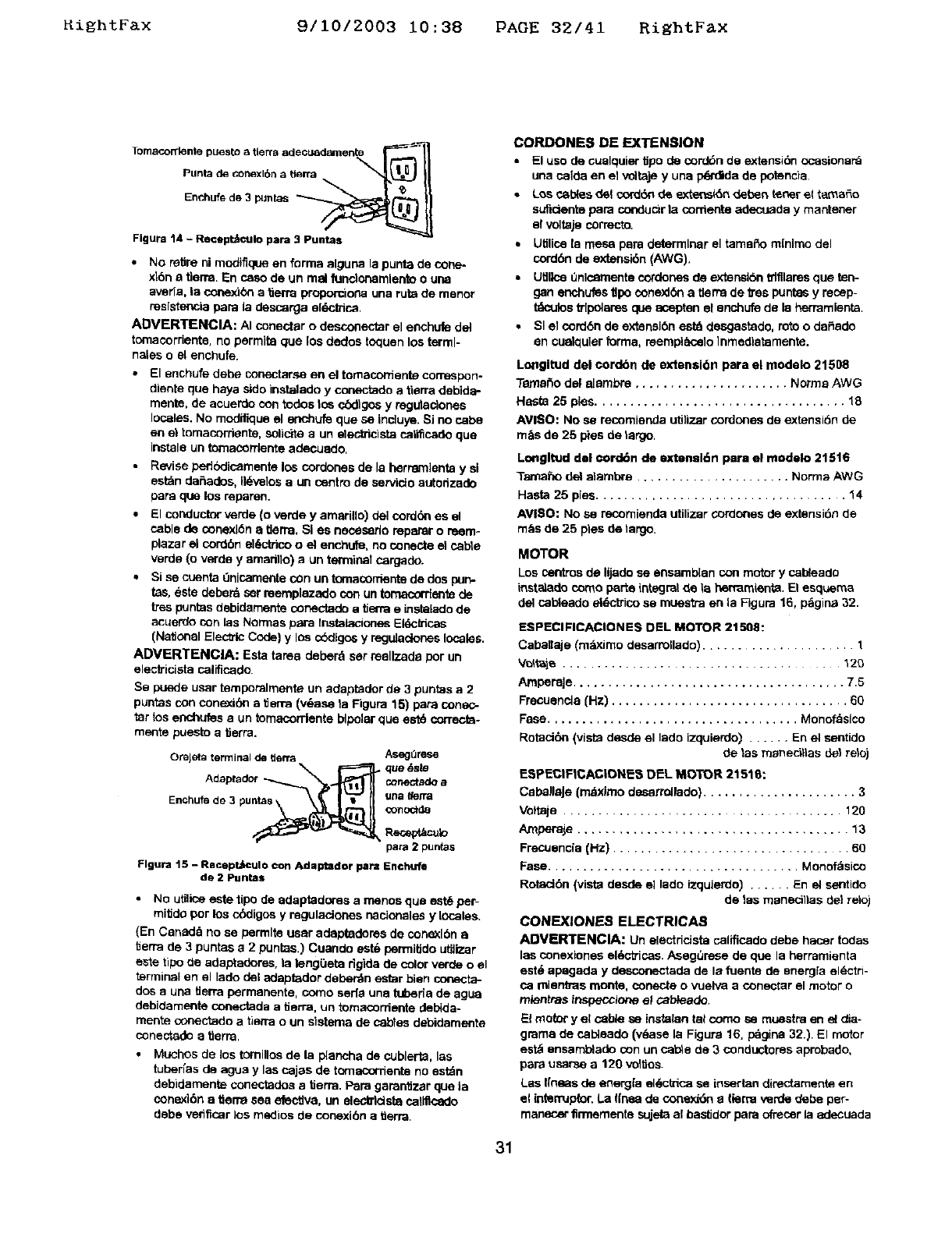
_ightFax 9/10/2003 10:38 PAGE 32/41 RightFax
Enchufede 3 puntas __----_/I
Figure 14 - Recept_CUlo pare 3_
•No retire ni modiflque en forms alguna la punts de cone_
xl6n a tlerra. En osso de un real fundonemlento o une
averia, la conex_bn a tierra proporciona una ruts de menor
resistencia papa la descarga eldctrios.
ADVERTENClA: AI conectar o desconectar el enchufe del
tomacordente, no permits que los dedos toquen los terml-
nales oel enchufe.
•El enchufe debe conectarse en el tomaconiente correspon.
diente que hays side instelado yconectado a tierra debida-
mente, de acuerde con redes le_ cbdlgos y regutaclones
locales. No modifique el enchufe que se inciuye. Si no cabs
en el tomacorrienta, solloite aun elec_cista call_cado que
instale un tomacontente adecuade,
•Revise pedbdicamente los cordones de la herramlenta y si
est_n defiades, Ildvelos aun centre de sarvido autorizade
papa que los reparen.
•El conductor verde (o verde y amarillo) del cord(_n es el
cable de conexldn a tlerm. SI es necesarlo reparar o reem-
plazar el corden ekT_ctricoo el enchufe, no conec_ el cable
verde (o verde yamarillo) aun terminel cargado.
• Si se cuenta i:lnicamellta COn un tornacor_snta de dos purl-
tas, %ste deberd sar reemplazado con un tomacordente de
tTespuntas debidamente conectade a tierra e instalado de
acuerdo con las Normas papa Instalaclones Eldc_icas
(National Elec_lc Code) y lOscbdlgos y regulaclones locales.
ADVERTENClA: Esta tame deberd ser reellzade Per un
eleclricista calificado.
Se puede user temporalmente un adaptader de 3 puntas a 2
puntas con conexibn a tierra (v_,asa ta Figure 15) pare conec-
tar los enchufes eun tomacordente bipolar que est6 ¢orrecta-
mente puesloa tierra.
Orejeta terminal de tterra AsegOrese
_rn_B_ que _s_
Adaptsdor _ne_a_ a
Enchu_ de 3 puntas gna Ii_fi'tl
Reo_vt/=culo
pare 2 pun(as
Figure 15 - Recept,_culo con Adaptador 10am En©hufe
de 2 Puntas
• No utilloe este tipo de adaptaderes a menos que est_ per-
mitide per los c(_digos y reguladones nacloneles y locales.
(En Canade no se permits user adeptadoms de conexl6n a
tierra de 3 puntes a 2 puntas.) Cuanclo est% permiUdo utilizer
este ripe tie adaptadores, la leng(_eta dgida de color verde o el
terminal en el lade del ndaptador deberdn estar bien conecta-
dos a una tlerra permanente, come saris une tuberla de ague
debidamente conectada a tierra, un tomacordente debida-
merits conectado a tierra oun elstama de cables debidamente
conectade a tlerra,
•Muchos de los tornlllos de le plancha de cublerta, les
tuderfas de ague y las cajes de tomacornente no estdn
debidamenta conectades a'0errs. Pare garantizar que la
conexi6n a tierm sea elective, un eleda'ldsta callflcado
debe verifiosr los medios de conexi6n atierra.
CORDONE8 DE EXTENSION
• El use de cuelquier _po de cord6n de extensidn ccasionard
una calda en el voltaje y una pq_'didade potencia
•Los c_l_es de! cord_ de exte_skSndeden _osr el tamale
suficiente papa conducir ta cements adecuada y mantener
el voltaje correcto.
•Utilios le mesa pare determiner el tamaffo mlnlmo del
cord6n de e0deesi6n (AWG).
• Utlllne Onlcamente cordones de extensl6n _tfllares que ten-
gan enchufes t_po conexl6n a tlerra de _s puntes y reosp-
tdculos trlpolsres que aospten el enchufe de la herramlenta.
•SI el cord6n de extensl6n estd deegastade, rote o daffado
an cualquler forms, reempl_elo lnmedlatamente.
Lo_ngltud del eordbn de exteseibn para el modelo 21508
Temar_o del aJembre ...................... Norms AWG
Hast_ 25 pies.................................... le,
AVISO: No sa recomienda utilizer condones de extensi6n de
m_s de 25 pies de largo.
Lm_gltud del eord6n de extensl6n para el medelo 21516
Tarsafio del alembre ...................... Norms AWG
Hasta 25 pies .................................... 14
AVI$O: NO sa recomienda utilizer cordones de ext_snsi6nde
m&s de 25 pies de largo.
MOTOR
Los osntros de lijade sa ensamblan con motor y cabtaade
instelado come por_e integral de la hermmienta. El esquem8
del cablesde sl6ctrico se muestra es la Figure 16, p_gina 32.
ESPECIFICACIONES DEL MOTOR 21508:
Caballaje (mdximo desarrollade) .................... 1
V_t_ie ........................................ 120
AmporaJe....................................... 7.5
Frecuencla (Hz) .................................. 60
Fase .................................... Monofaslco
Rotaci6n (vista desde el lade izquierdo) ...... En el sentido
de 1as m_ne_i_las de_ relo)
ESPECIFICACIONE8 DEL MOTOR 21518:
CsbellaJe (mdximo desarrollado) ...................... 3
Voftaje ...................................... 120
Amper_e ...................................... 13
Frecuencia(Hz) .................................. 60
Fase .................................... Monofdsico
Rotec_6n(vistadesde ellade izquierdo)...... En elsentido
de 1as manecillas tie1 relo)
CONEXIONE -_ ELECTRICAS
ADVERTENCIA: Un electric_sta califlosdo debe haoer todas
las conexlones el*_otricas.AsegQrese de que la ndrramienta
est_ apagada y desconectade de la fuente de energ[a eldctri-
ca mientms monte, conecte o vuelva a conectar el motor o
mlentras inspecclone el cabtaade.
El motor y el cable sa instalan tel come sa muestra en el dia-
gmrna de osbtaado (v_asa la Figure 16. pdgina 32.). El motor
est_ ensamb_ado con un cel_e de 3 condectores aprobado,
psra usarse a 120 vol'_os.
Los I[ness de energfa el*_ctrica se insertan direct_menta en
el interruplor. La Ifnsa de conexi6n etlerra verde debe per-
manener firrnementa sujeta al bestidor pare _'_=osr la adecuade
31
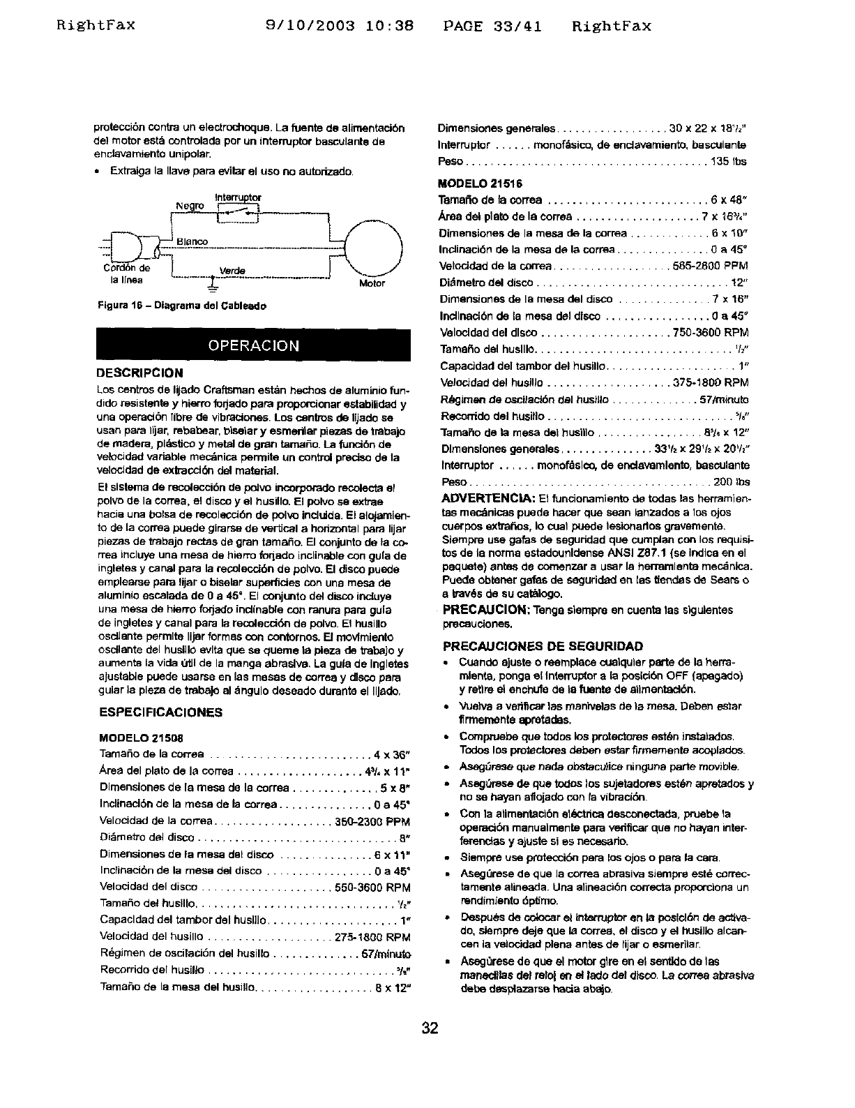
RightFax 9/10/2003 10:38 PAGE 33/41 RightFax
proteccibn contra un electrochoque. La fuente de alimentacibn
del motor est_ controlada per un intemJptor basculanta de
enclava miento unipolar.
•Extraiga la Ilave pare eviiar el use no aut_izado.
Negro
Cord6nde
la lines
Figure 16 -Dlagrama del Cableado
Motor
DESCRIPCION
Los centms de I@adoCraftsman estan hechos de aluminio fun-
dido resistante yhierm forjado papa proporcmnar estabiUdad y
una operaci6n fibre de vibraciones. Los osntros de IVado se
usan pare 11jar,rebabear, t_iselar yesmedlar pieces de traba)o
de readers, pldmticoy metal de gran tamale. La funol6n de
vek:_Jdad variable mec_nica permits un control preolso de la
velocidad de extraceldn del material.
El sisterna de recolecci6n de poJvo incorpo,rado recolecta el
polvo de la correa, el disco yel husillo. El polvo se extras
t_acia una bolsa de recolecci6n de pol_ incluida. El slojamien-
to de la correa puede girarse de vertical a horizontal pare lijar
piezas de trabajo rectas de gran tamafio. El conjunto de la co.
rrea incluye una mesa de hierro foqado inclinable con gula de
ingletes y canal pare la recolecci6n de polvo. El disco puede
emplearse pare lijar o bisalar superficies con una mesa de
aluminio escalada de 0a 45 °. El conjunto del disco ineluye
una mesa de hiarro forjado inclinable con ranura pare gula
de ingletes y canal pare la recolecoldn de polvo. El husJllo
oscllante permits Iljer formas con contornos. [] movfmlento
osdlante del huslllo evlta que sa queme la pleza de trabajo y
aumenta la vide Otll de la mange abraslw, La guia de inglates
ajustabie puede usarse en las mesas de correa y disco pare
gular la pieza de tmbejo al dngulo deseado durante el IlJsdo.
ESPEClFICACIONES
MODELO 21608
Tama6o de la cortes .......................... 4 x 36"
Area del plato de la cortes .................... 4_/, x 11"
Dlmensiooss de la mesa de la correa .............. 5 x 8"
Inclinaci6n de la mesa de la correa ............... 0 a 45"
Velocidad de la cortes ................... 350-2300 PPM
Di_metro del disco ................................ 8"
Dimensiones de la mesa dal disco ............... 6 x 11"
Inclinaci6n de la mesa del disco ................. 0 a 45"
Velocidad del disco ..................... 550-3600 RPM
Tamale del huslllo ................................ %,
Capacldad del tambor del husHlo ..................... 1"
Velocidad del husillo .................... 275-1800 RPM
R_gimen de osciiaci6n del husillo .............. 57/mlouto
Recorrido del husillo .............................. %.
Tama6o de la mesa del husillo................... 6x12"
Dimansiones generales .................. 30 x 22 x 18Vz"
Interrupter ...... rnonofdsico, de encJsvamiento, basculante
Peso ....................................... 135 Ibs
MODELO 21516
Tamafio de fa correa .......................... 6 x 48"
Area del plato de le corres .................... 7 x 25_/,"
Dimensiones de la mesa de la correa ............. 6 x10"
Ineliosci6n de la mesa de la correa ............... 0e 45 °
Velocidad de la cornea ................... 585-2806 PPM
Didmetro del disco ............................... 12"
Dimensiones de la mesa del disco ............... 7 x 16"
Incllnad6n de la mesa del disco ................. 0 a 45"
Velonidad del disco ..................... 750-3600 RPM
Tamefio del huslllo................................ '/z"
CapacJdad de] tambor del husillo ..................... 1"
VelocJdad del husillo .................... 375-1800 RPM
P._imen de oscilac_6n del husillo .............. 57/minute
Recomdo dal husiflo .............................. %"
lamaho de la mesa del husnlo ................. 8,16x 12"
Dlmenslones generales ............... 33% x 29% x 20t/2"
Interrupter ...... monofdslco, de encJavemlento, basculante
Peso ...................................... 200 Ibs
ADVERTENClA: El funcionamiento de todas las herrsmien-
tea mec_nicas puede hacer qua saan ianzados alos ojos
cuerpos extratios, lo oust puede lesionarlos gravemente.
Siampre use galas de seguridad qua cumplan son los requisi-
tes de le norms estadounldensa ANSI Z87.1 (se indlca en el
paquete) antes de comenzar a user Is hermmlsnta mecdnlca.
Puede obianer gafas de segudded an les tlendas de Sears e
a trav6s de su seth|ego,
PRECAUClON: Tangs siampre en cuenta tas slgulentes
precauciones.
PRECAUCIONES DE SEGURIDAD
•Cuande aJuste o rosmplace cualqular parts de ia here-
relents, ponga el interrupter a ia posid6n OFF (ap_gado)
y retire el enchufe de le fuente de sllmentacl6n.
•Vuehta aveflficar 1as rnanivelas de ta mesa. Deben ester
firmaments apmtadas.
•C_npruebe qua todos los protectores est_n instalados.
Todos los protect_res deben ester firrnementa aco_lados
•Asag_resequenedeobstacu}iceningunepanemovlole.
•Asag0resa de que todDs los sujetadores est6n apretados y
no se hayan aflojado con fa vibracidn
•Con la alimentaci6n et_-'tdca desconectada, pruebe la
operacibn manualmente pare vedficar qua no hayan inter-
fet_-=e_asyajuste si es n_rio.
•8iempre use p_'otecck_n pare los ojos o pare la cam
•AsegOrese de qua la cortes abrasive siempre este correc-
tamente alineada. Una alineaci6n coKecta proporciona un
rendimiento dpfimo.
•Despu_s de colocar el lnternJpb:_" en ta poslol6n de sctiva-
do, siampre deje que ia correa, et disco y el husiJloalcan-
cenia velocided piana antes de lijar o esmerilar.
•Aseg0rese de clue el motor glre en el santido de tas
manecgiaa del relo_ en el iado del disco. La cortes abrasive
debe desplazarse hacia abajo,
32
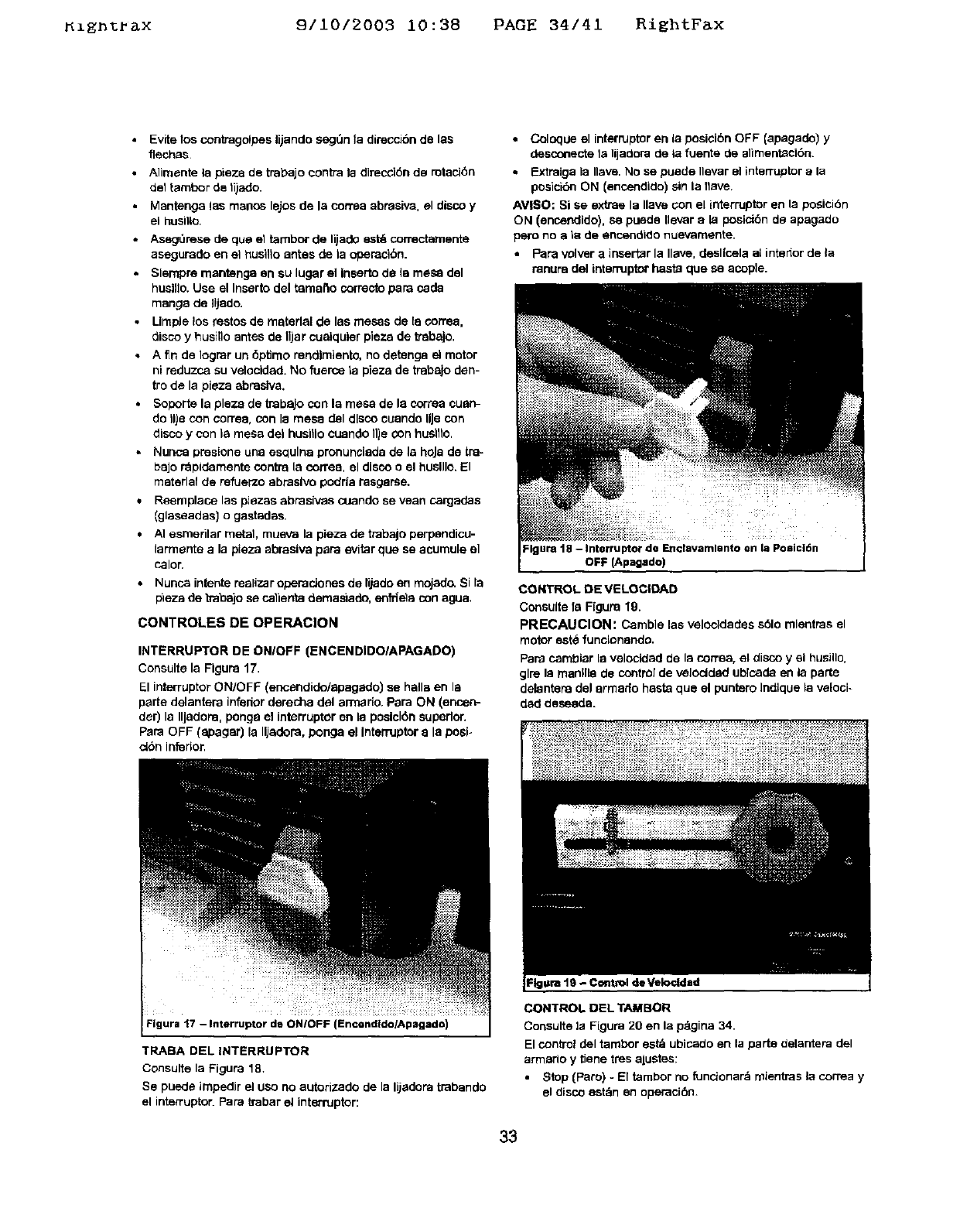
_zgn%_x 9/10/2003 10:38 PAGE 34/41 RightFax
•Evite los conb'agelpes lijando segt_n t& direccibn de t&s
flech_s
• Alimente la pieza de trabajo centre la direcci6n ds rotaci6n
deltambor de li)ado.
•Mantenga las manes lajos de la cornea abrasiva, el disco y
el husilto.
•Aseg0rese cle qua el tambor de liiado est_ correctamente
asegurado en el _usillo antes de t& openaci6n.
Slempre mantenga an su lugar el Inserto de t& rne_ dal
huelfla. Use el Inserto del tamano correcto pare cada
mange de Iijado.
•LimpJe los testes de matert&l de las mesas de t& coffee,
disco yhusilla antes de IIjar cuelquler plaza de 'e_balo.
• A fin de Iograr un 6ptimo rendlmtento, no detanga el motor
ni reduzco su velaeldad. No fuerce t& pieza de tmbajo den-
tra de la pteza abraelva.
• Soporte la plaza de trabaJo con la mesa de le correa cuen-
do Ilia con oorrea, con la mesa del dlaco cuando UJacon
disco y con la mesa del huelllo cuando 11jecon haalfla.
•Nunca preslone una esqulna pronunct&da de t& hoJa de tra-
bajo r_pldamente centre la correa, el disco a el huelllo. El
material de refuerzo abraelvo padrt& rasgarse.
•Reemplace las piezas abrasives cuando se vean cargadas
(glaseadas} o gastadas.
•AI esmerilar metal, rnueva la pieza de trabajo perpandico-
larmante ala pt&za abrasive pare evitar qua se acumule el
taler,
• Nunca intente realizer operaelones de lijado en mojado_ Si la
pileza de b_bajo se calienta demast&do, enfrlela con a_Ja.
CONTROLES DE OPERAClON
INTERRUPTER DE ONIOFF (ENCENDIDOIAPAGADO)
Consulte la Figure 17.
El interrupter ON/OFF (encendido/apagado) se halle en la
parte delantera inferior derecha del armario. Para ON (encen-
der) la IlJadom, ponga el interrupter en le poelclOn superior.
Pare OFF (epagar) la IIJadora, ponga el Interrupter e la pasi-
c_n Inferior.
•Coloque el interrupter en In posiel6n OFF (apagado) y
desconecte la lijadora de iafuente de slirnent;aci6n.
• Extraiga t& Ilave, No se puede Ilevar el interrupter ala
posicibn ON (encendido) sin la flaMe.
AVI$O: Si se exttae 13Ilave con el interrupter en la posici6n
ON (encendido), se pueda Ilavar ala posici6n da apagado
pare no ela de encendido nuevamente.
•Pare velver a inserter la Ilave, desl|cela at intador de t&
ranura del interrupter haste que se acople.
Figure 18 -Interrupter de Endavamlento en la Poeicl6n
OFF {Apagsdo)
CONTROL DE VELOCIDAD
Consulte t& Figure 19.
PRECAUCION: Carnble las velocldades s61o mientras el
motor eat4 funclonanda.
Pare cambiar la velocidacl de Is con-ea, el disco y el husillo,
glre la manllle de control de veloctd_d ublcada en la parte
dalantara dal armada haste que el puntero Indlque t& veloci-
dad desaeda.
Figure "17-Interrupter de ON/oFF (Encendldo/Apagado)
TRABA DEL INTERRUPTER
Consulte la Figure 18.
Se puede impedir el use no autorizado de la lijadora trabanda
el interrupter. Pare trabar et interrupter:
CONTROL DI=L TAMBOR
Consulte la Figure 20 en la p_lgina 34.
El control del tambor eat& ubicado en la parte delantera del
anmsrio y tJenetres ajuates:
•Stop {Pare) - El tambor no funcionar& mientras la correa y
el disco est_n en operaci_.
33
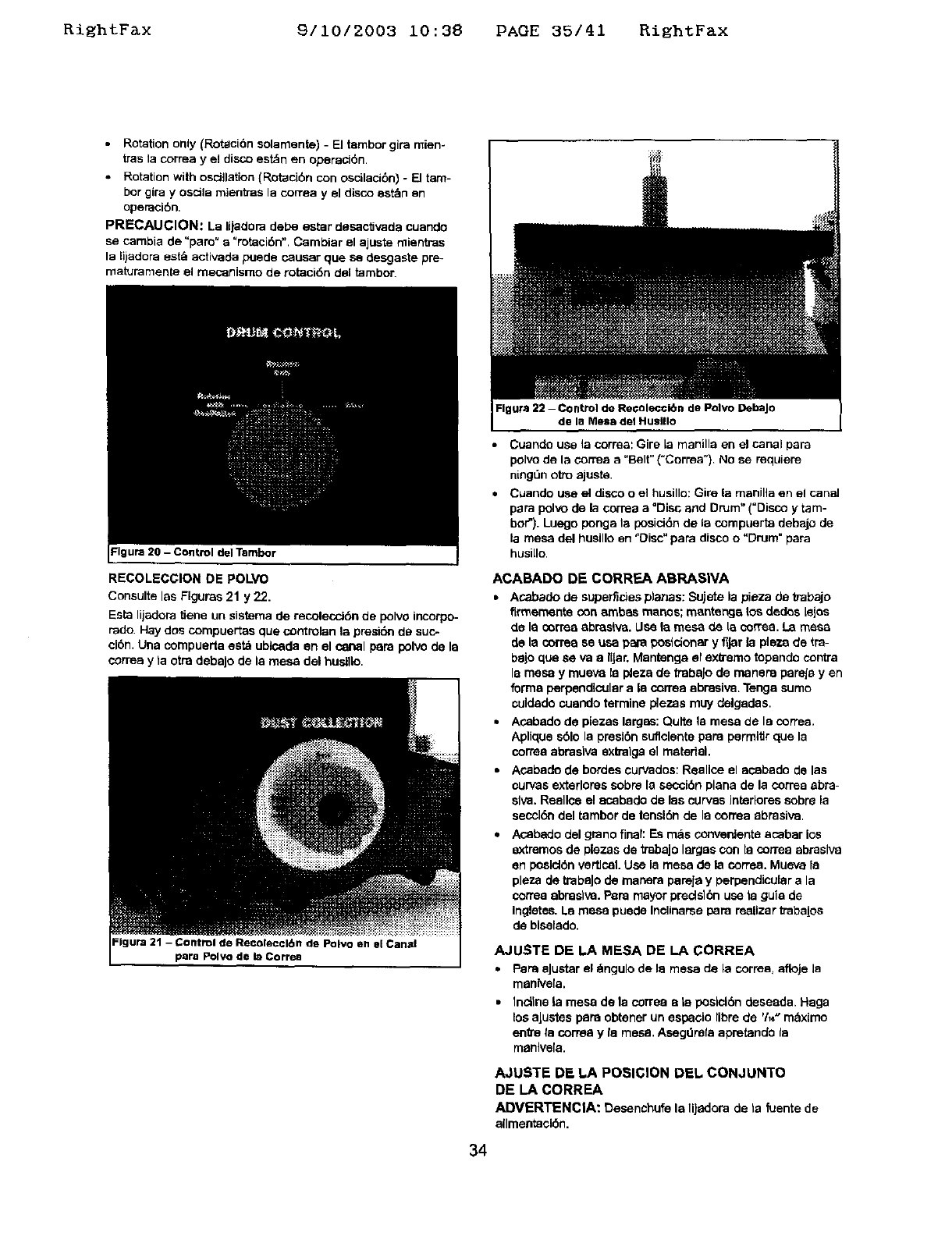
Ri_htF&x 9/10/2003 10:38 PAGE 35/41 RightFax
•Rotation only (Rotaci6n solamente) -El tembor gira mien-
tras la correa y el disco estdn en oparaci6n.
• Rotation with osci}lztion (Rotaci6n con oscilacibn) - [] tam-
her gira yoscila mientras la corrsa y el disco est_n en
operaci6n.
PRECAUCION: La lijaclora pebe ester desaclJvada cuando
se cambia de =pare" a=rotaci6n". Cambiar el ajuste rnientras
la lijadora est_, activada puecle causer que se desgaste pre-
maturamente el mecanismo de rotaci6n clal tambor.
Figure 20 -Control del Tambor
RECOLECGION DE POLVO
Consulte les Flgurss 21 y 22.
Esta lijadopa tiene un sistema de recoleccJ6n de polvo incorpo-
fade. Hay dos compuertas qua controlan la presi6n de suc-
clon. Una compuerta satb ublsada an el conal pare polvo de la
correa y ta otra debaJo de la mesa del huslllo.
Figure 21 - Control de Recol_ccl6n de Polvo sn el Canal
pare Polvo de la Correa
Fig ura 22 -Control de Re_olec©lbn de Polvo DebaJo
de la Mesa del Huslllo
•Ccande use la correa: Gire [a manilla en el canal para
polvo de la correa a "Belt" ("Correa") No se requiere
ningt3n otto ajuste.
• Cuando use el disco o el husille: Gire la manilla en el canal
pare polvo de la correa a =Disc and Drum" ("Disco y tam-
bof'). Luego ponga la posici6n de la compuerta debajo de
la mesa del husillo en "Oisc" papa disco o"Drum =pare
husi[Io.
ACABADO DE CORREA ABRASIVA
• Acabado de superfirJes planes: Sujete la pieza de tTabajo
flrmemente con ambes manes; mantenge _os dedes tales
de la CO[TeaabrssNa. Use la mesa de is coffee. La mesa
de la correa se usa pare pesldenar yflJar la ple'/.a de tm-
bejo qua sava a IIJar, Mentenga el extreme topando centre
la mesa y mueva la p_eza de trabaJo de manera pareJe yen
forma perpendicular ala correa abresiva. Tenga sumo
culdado cuando termine plezas muy delgades,
• Acapedo de piezes lergsa: Quite la mesa de la correa.
Aplique sblo la presl6n suflclente pars permltlr que la
corree abrasiva exb'alga el material.
• Acabado de bordes curvados: Reallce el acabado de les
curves exterlores scbre la sacci6n plane de la correa abrs-
siva. Reellce el ecabedo de las curves intedores scbra la
saccl6n pal tambor de tensl6n de la correa abrasive.
•Asapedo del grano final: Es m_s converdenta acabar los
extremes de plazas de tmbajo larges COn la correa abrasive
an peslclbn vertical. Use la mesa de la coffee. Mueva le
plaza de trabaJo de masara pareja y perpendicular a la
corma ebnsaIva. Papa mayor precls16n usa la guia de
Ingletsa. La mesa puede Incllnarse para reallzar trabalos
de biselado.
AJUSTE DE LA MESA DE LA CORREA
• PaneaJustarel _,ngulode la mesa de la correa,afloje la
manlvela.
•Incline la mesa de la correa ate poslcl6n desaada. Haga
losaJustes pars obtener un espacio libre de 'h_" maxlmo
enVe fa correa y le mesa. Asagdrefa apretando la
manlve[a.
AJUSTE DE hA POSIGION DEL CONJUNTO
DE LA CORREA
ADVERTENCIA: Desanchufe la lijadora de ta fuentede
allmsataci6n.
34
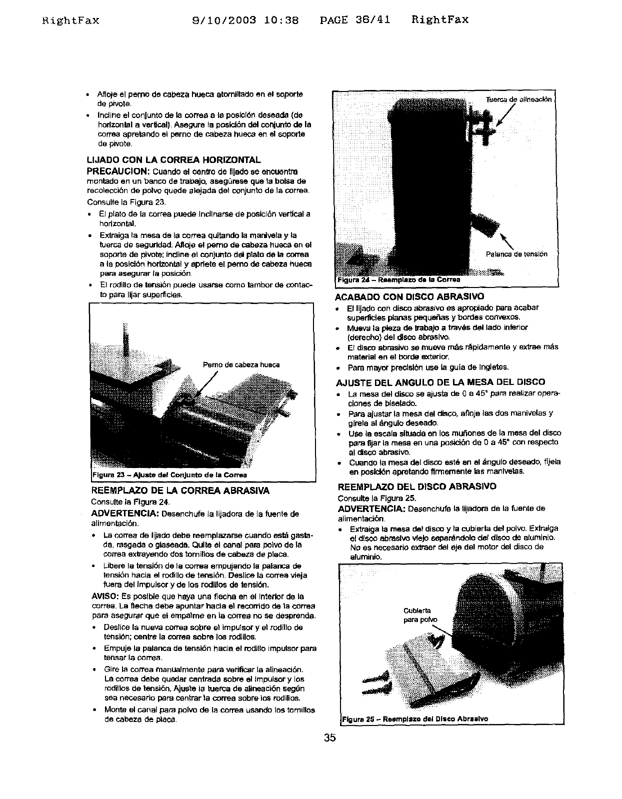
KishtFax 9/10/2003 i0:38 PAGE 38/41 RightFax
Aflo)e el pemo de cabeza hueca atomitiade en el soporta
de pivots.
Incline el conJunto de la cortes a la posicf6n desaada (de
horizontal a vertical). Asegure la posld6n de_conjunto de la
correa apretando el perno de cabeza husca en el soporte
de pivots.
LIJADO CON LA CORREA HORIZONTAL
PRECAUCION: Cuando el cenffode Illado se encoentra
rnontado en un banco de tral_ajo, aseg0rese qua la bolSa de
recoleccibn de polvo quede alejada del conjunto de la cornea.
Consulte la Figura 23.
•El plato de la correa puede Inclinarse de posicl6n vertical a
hodzontal.
•Extraiga la mesa de la correa quJtando la mar*,.._ia yla
tuerca de segurided. Afloja el pemo de cabeza hueca en el
soporte de pivots; incline el conjunto del plato de la con'ea
a la poslct6n horizontal yapdete el perno de cabeza hueca
pars asagurar la posicl6n.
•El rOdlllo de ter_16n puede us_rse como tambor de contac-
to para lijar superficies,
Perno de cabeza hueca
REEMPLAZO DE LA CORREA ABRASIVA
Consults la Rgura 24.
ADVERTENCIA: Desenchufe la lijadera de la fuente de
alimentaci6n.
•La correa de lijado debe reemplazarse ouando estd gasta-
da, rasgada o glaseade. Quite el canal pare polvo de la
cortes extrayendo dos torniltos de cabeza de placa.
Liberela tensi6n de la cornsa empujando la palanca de
tensi6n hacia el rodillo de tensi6n. Deslica la carrea vfeja
fuera del Impulsor y de los rodUlos de tensi6n.
AVISO: Es poslble que hays una flechs en el Interior de la
correa. La _echa debe apuntar hacla el recorrido de ta cornea
pars asegurar que el empalme en la correa no se desprenda.
Desiice la nueva cortes sobre et impulsor y et rodillo de
tensl6n; centre la cortes sobre los Iodlllos.
•Empuje la palanca de tensidn hacla el rodi,o impuisor pars
tensar la cornea.
•GJrela correa manualmente pars veriflc_r la alineacl6n.
La cortes dede quedar cantrada sobre el Impulsor y los
roditlos de terlsi6n. Ajusta la tuerca de atineacl6n seg_n
sea necesado pars cantrar la cortes sobre los roditlos.
•Monte el canal pars polvo de la correa usando los tornillos
de cabeza de placa.
Palanca de tensibn
ACABADO CON DISCO ABRASIVe
*El lijado con disco abrasive as apropiado pars acabar
supen_cies planas peque_as y hordes con_sxos,
.Mueva la pieza de trabajo a travl_s del lade inferior
(derecho) del disco abrasive,
•El disco abrasive se rnueve m_s r_pidamante y extras m_s
material en el horde e0<terior.
. Pars mayor predslbn use la guia de Ingletes,
AJUSTE DEL ANGULO DE LA MESA DEL DISCO
La mesa del disco se ajusta de 0 a45 ° pare raalizar opera-
clones de blsalado.
•Pars ajustar la mesa del disco, afloje las dos manivelas y
glrela al dngulo deseade.
•Use la escala situada an los muftones de la mesa del disco
pars fijar la mesa en una posicibn de 0a45 ° con respecto
al disco abrasive.
• Cuando la mesa del disco est_ an el &ngulo deseado, f[jeis
en poslclbn apretando flr'rnementa fes manlvelas.
REEMPLAZO DEL DISCO ABRASIVe
Consults la Figura 25.
ADVERTENCIA: Dasanchufe la lij=_lora de la fuente de
alimentacibn.
• Extraiga la mesa del disco y la cubierta del pclvo, Extraiga
a_ disco ebnaelvo vieJosepar_ndelo def disco de elumtn{o.
No as necesario extraer del eje del motor del disco de
eluminio.
Cubterta
pars polVo
_igura 25 - Reemplszo del DI:©o Abrasive
35
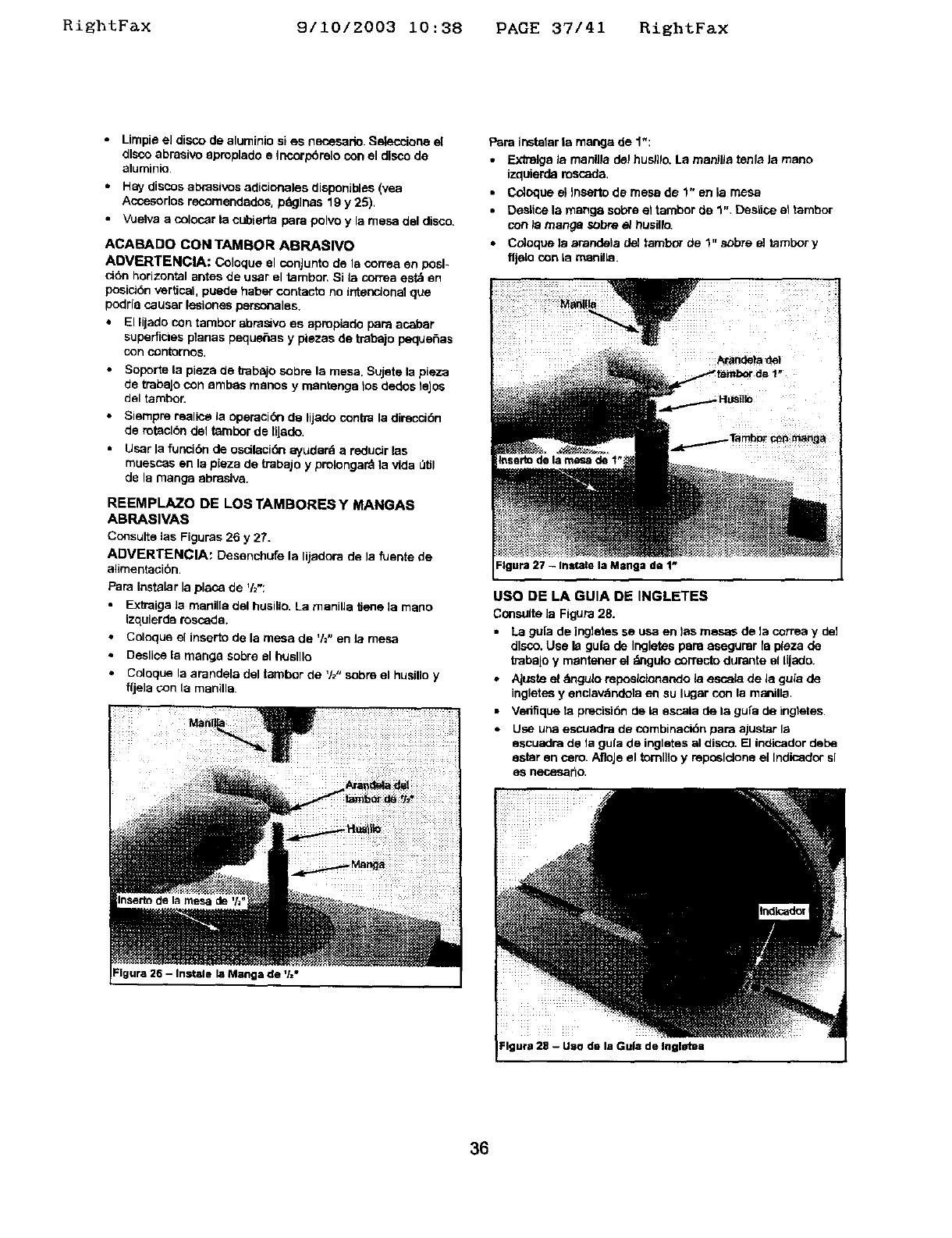
RightFax 9/10/2003 10:38 PAGE 37/41 RightFax
•Limpie el disco de aluminio si es necesario. Selecciorte el
disco abraelvo apmplado e Incorp6relo con el disco de
aluminio
•Hay discos al:_rasivosadicionales disponJbles (yea
Accesodos reoomendades, prig]has 19 y 25),
• Vuelva a colocar la cubierta pars polvo y la mesa del disco.
ACABADO CON TAMBOR ABRASlVO
ADVERTENCIA: Coloque el conJunto de Is cortes en posl-
ci6n horizontal antes de user el tambor. Si la correa est& en
posici6n vertical, puede haber contacto no intencmnel qua
1oodrfacauser lesiones personales.
* El lijado con tambor abrasivo es apropiado pars acabar
superficies planas peque6as y piezas de trabajo peque6as
con contornos.
•Soporte la plaza de babajo sabre la mesa. Sujete la pieza
de trabaJocon ambas manos y mantengs los dedos leJsa
del tambor.
• Siempre malice la operaci(Snde lijado contra la direcci6n
de rotaclbn del tambor de tlJade.
•User la funcibn de oscilaci6n ayudard a reducer las
muescas en la pieza de trabajo y prolongard la vida _lJl
de la mange abnaslva.
REEMPLAZO DE LOS TAMBORES Y MANGAS
ABRASIVAS
Consults ias Figuras 26 y 27.
ADVERTENCIA: DesenchLlfe la liiadora de la fuente de
alimentacibn.
PaPa Instalar la place de '12":
Extraiga Ja manil[a del husillo. La manifla Uen® ]a mano
izqulerda roscada.
• Coloque el insarto de la mesa de 'h" en la mesa
•Deslice la mange sabre el huslllo
• Coloque la arandela del tambor de 'h" sabre el husillo y
fljela con la manilla
FIgura 26 - Instals la Manga de '/="
Pars instalar ia mange de 1":
•Extrelga la manUla del hus/]lo. La manWa tenla la maria
izquierda mscada.
•Coloque el Jnsartode mesa de 1" en la mesa
•Deslisa la mange sabre el tambor de 1". Desiice el tambor
con/a mange sabre e/t_usillo.
• Cdoque la arandela de] tambor de 1" s_bre el tambor y
fljelo con Is manlike.
Inssrto de la _de t"i
USO DE LA GUIA DE INGLETES
Consults Ja Figure 28.
•La gu[a de ing]etes se usa en )as mesas de la correa y de]
disco. Use la gufa de Ingletes pars asagumr fa plaza de
trabajo y mantener el _mgulo correcto durante el lijado.
•Ajuste el dmgu]oreposlc!onando la escela de la gufa de
ingletes y enclav_ndela en su lugar con la manilla.
•Ve_ique la pPecisi6n de la sscala de la gu[a de ingtates.
•Usa una escusdra de combinacidn pars ajustar la
sscuadra de fa gu(a de inglstes al disco. [] indicador debe
ester en com. AfloJeel tomlilo y reposlclone el Indisador sl
es necesar_a.
Igura 28 -Uso de la Gu|a de Ingletes
36
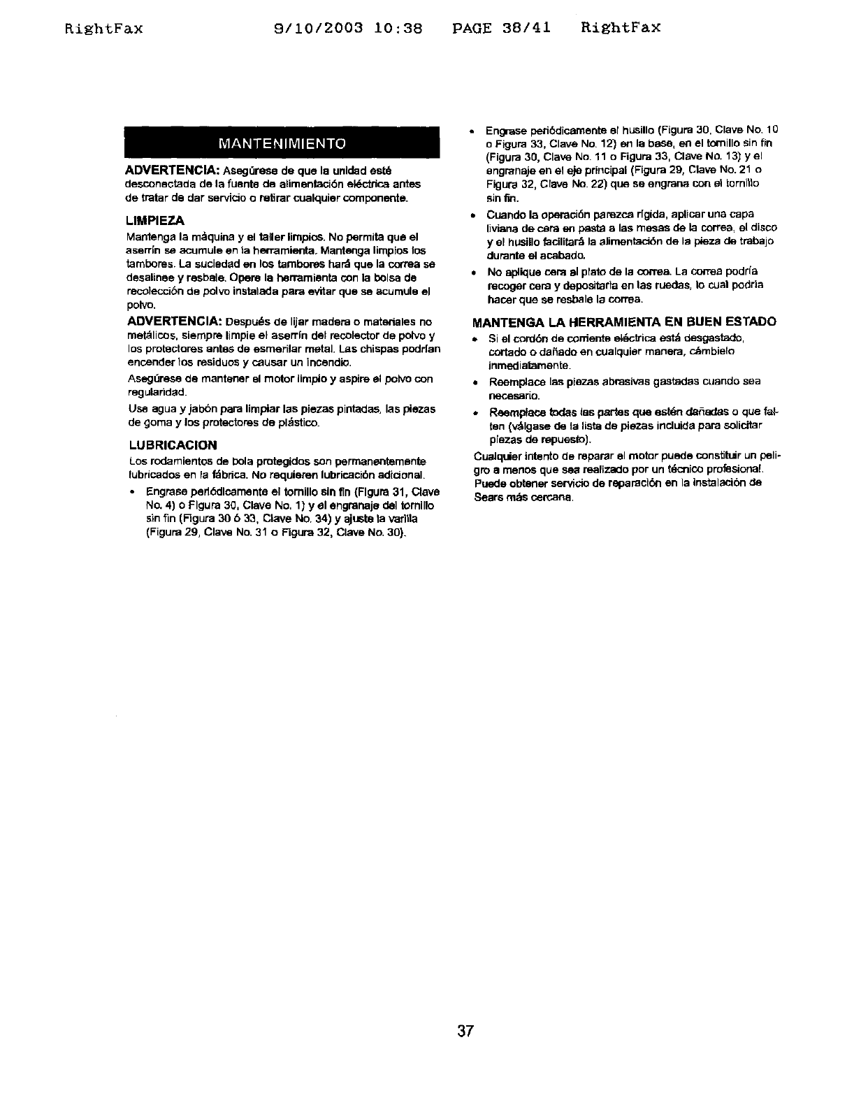
RightF&x 9/10/2003 10:38 PAGE 38/41 RightFax
ADVERTENCIA: AsogOre_ de que la unldad est_
desconactada de la fuenta de alimentaci6n el_ctdca antes
de tratar de der servicio oretirar cualquier componente.
LIMPIEZA
Mantenga la rn_quina yel taller limpios. No perrnita qua el
aserrin s_ acumule en la hen_mtanta. Mantenga limplas los
tambores. La suciadad en los tambores hard qua la correa se
desalinae y resbale. Opens la herremienta con la bolsa de
resoleccibn de polvo instatada para avitar qua se acumule el
polve.
ADVERTENCIA: Despu_s de lijar madera o materieles no
met_licos, siernpre lirnpie el aserrln del recolector de polvo y
los protectores antes de esmerilar metal. Las chispas podrfan
encender los residuos y causar un incandio.
Asegt3rese de rnantaner el motor limpio y aspire el polvo con
regularided
Use agua y ial0bn para limpiar las plazas pintades, las plazas
de gorna y los protectores de pl_stico.
LUBRICAClON
Los rodamientos de i0ola protegidos son permanentamante
lubricados en la f_bdca. No requieren lubricacibn adicional.
•Engrase perlddlcarnenta el tomillo sin 'tin(Flguna 31, Clave
No. 4) o Flgura 30, Clave No, 1) y el engmnaja de1 tomlllo
sin fin (Figure 30 b33, Clave No. 34) y ajusta ta vedtla
(Figura 29, Clave No. 31 o FigL_a 32, Clave No. 30).
Engrase pedt_ciicarnente el husillo (Figure 30, Clave No. 10
oFigura 33, Clave No. 12) en la base, en el tomillo sin fin
(Figura 30, Clave No. 11 o Figura 33, Clave No. 13) yel
engranaje en el eje principal (Figure 29, Clave NO.21 o
Figura 32, Clave No. 22) qua se engraos con el tornilla
sin fro.
Cuande la operacJ6n parezca dgida, aplicar una capa
Iiviana de c_ra en pasta a las mesas de la correa, el disco
y el hUsillo facilita_ la elimentac_n de la ptaza de trabajo
durante el acabado.
No aplique cemal plato de la oorrea. La correa podrfa
recoger cere y depositarla an las ruedes, la cual podda
hacer que se resbale la correa.
MANTENG, A LA HERRAMIENYA EN BUEN ESTADO
• Si el cord6n de coniente el_cb'ica estd desgastado,
cortado odaSado an cualquier manera, c_mbielo
inmediatamente.
•Reemplace las piezas abrasivas gastadas cuando sea
neces_rio.
•Reempleos todas tas partas qua estdn del_iltas oclue fat-
ten (v_lgase de la Iista de piezas incluida para solicitor
10,iezasde repuesto},
Cualquier interito de reparar el motor puede constitlir un peN÷
gro a menos que sea realizado por un tdcinicoprofesional.
Puede obtaner servicio de raparack_l en la instalacibn de
Sears rods <_=rcana.
37
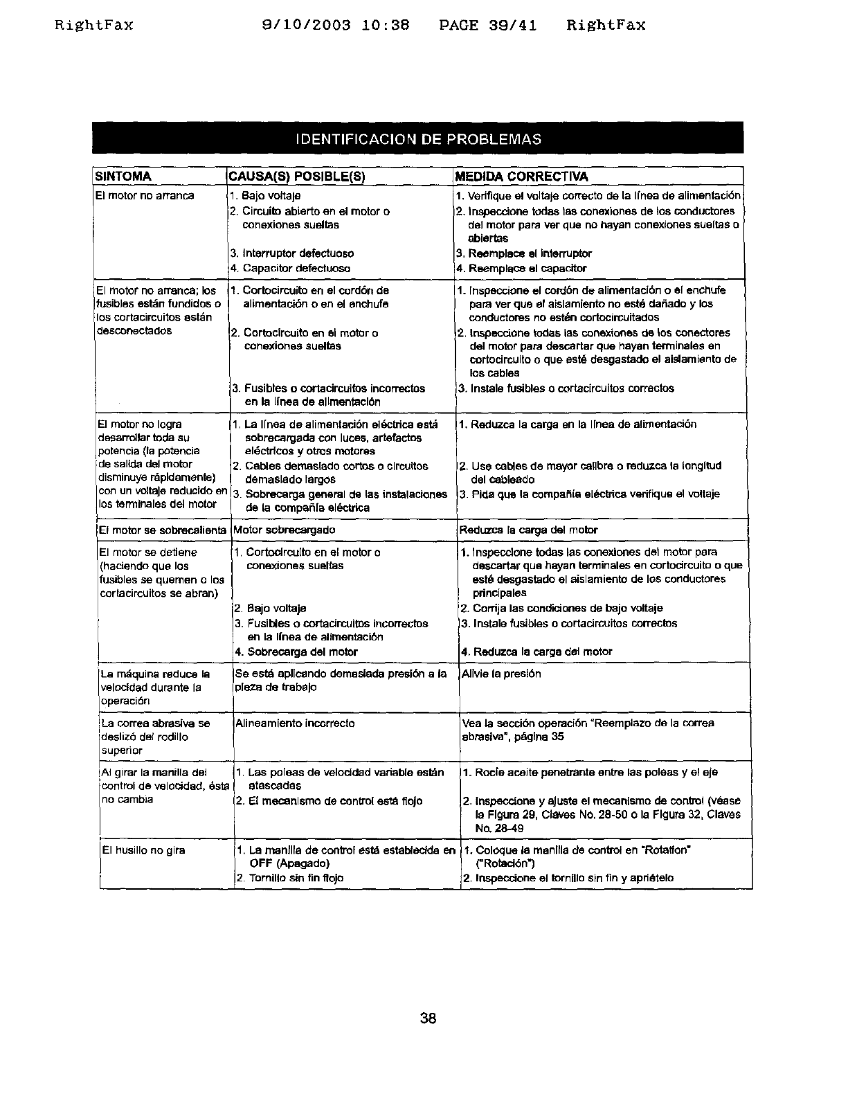
RiEhtFax 9/10/2003 10:38 PAGE 39/41 RiEhtFax
SINTOMA
El motorno arranca
El motor no arranca; los
fusibles est_n fundidos o
los cortacircuitos estdn
desconectados
El motor no Iogra
Jesarr_lar tod_ su
3otencia (la potencia
de sallda del motor
:lisminuye rdpldemente)
un voltoJereducldo en
lostermlnales del motor
CAUSA(S) POSIBLE(S)
I1 8ajo voltaje
2. Circuito abie_o en el motor o
conextones sueltas
3. Interruptor defectuoso
4. Capacitor defectuosa
1. Cortocircuito en el cord6n de
alimentacibn o en el enchufe
2. Cortocircuito en el motor o
conexiones sueltos
3. Fusibleso cortacircuitosincorrectos
en la Ifneade allraentaci6n
1. La I[nea de alimentaci6n el_ctrica est_
sobrecargade con lucas, artefactos
el_,ctrtoos y otras motores
2. Cables deraaslado cortos o clrcultos
dernaslado largos
3 Sobrecarga general de las tostsiaciones
de la compafifa el_=ctrica
MEDIDA CORRECTIVA
1. Vedfique el voltale correcto de la Ifnea de alimentackSn
2. tnspecctone todes tas conexiones de los conductores
deJmotor papa ver que no hayan conexiones sueftas o
ablertas
3, Reemplaco el interruptor
!4. Reemplac_ el capacitor
I1. fnspeccione el cordbn de alimentaci6n o el enchufe
para ver que el aislamiento no est& der_ado y los
conductores no est*_n cortocircuitados
2. tospecelone todas ias conextones de tos conectores
del motor para descartar que hayan terminales en
cortocircuito o que est_ desgastado el aislamiento de
los cables
3. Instale fusibles o cortacircuitos correctos
1. Reduzca 18carga en la I[nea de alimentacidn
2. Use cables de mayor calibre oradu.zca la tongltod
del cobleado
3 Pide que la corapafiia e[Sctrica verifique el voitaje
Et motor se sobrecelienta blotor sobrecargado Reduzca la carga del motor
1. Cortoclrcuito en el motor o
conexJones sueltas
2Bajovoltaje
3 Fusibleso cortacircuitosincorrectos
en la Ifnea de allraentaci6n
4. Sobrecarga del motor
El motor se detiene
(hacJendo que los
fusibles se quemen o los
cortacircuitos se abran)
La rndquina reduce 18
velocidad durante la
operaci6n
Se estd apllcandoderaasladapresibna 18
,[e_ade trabaJo
1. Inspecc]one todas las conexlones de1 motor para
descartar que hayan _rminales en cortodrcuito o que
est_ desgastado el aislaraiento de los conductores
pnncipales
'2. Cordja las condictones de bajo voltaje
3. Instale fustoles o cortacirauitos correctos
4, Reduzca la carg8 del motor
AlIviela presl6n
La correa abrasiva se Alineamiento incorrecto Vea la secci(Snoperad6n =Reemplazo de la correa
des z6 de rod o 8brasiva", paglna 35
superior
!A} girar Is manilla dol 1 Las poleas de velocided variable estdn 1. Rode acaite penetrante entre las poleas y el eje
icontrol de velocidad, 6st8 @tascades
no cambia 2, El meconlsmo de con(to[ est_ floJo 2 Inspeccione y aJuste el mecan[smo de control (vease
la Flgura 29, Claves No, 28-50 o la Flgura 32, Claves
No. 28-49
El husillo no gira 1. LaoFFmanflfa(Apagado)decontrol estd estab_eclda en 1. (=Rotacl6n'}C°l°quela raanlfla de control en =Rotatfon"
2 Tornilto sin fin lfojo 2. Inspeccione el tornillo sin fin y apd6telo
38

Kight_ax 9/10/2003 10:38 PAGE 40/41 RightFax
SINTOMA CAUSA{S) POSIBLE(S) MEDIDA CORRECTIVA
El husillo no oscila 1. La manilla de conirol est_ establecida 1, Colaque la manilla de control en "Rota_on with
en OFF (Apagado) Oscillation" (=Rotacidn con oscilaci6n =)
2. Collar fl_jo 2, Apdete el collar
3. Tomillo sin fin floJo 3. Apdete el tornlllo sin fin
4. BIoque y/o vadila flojos 4. Apdete el mecanismo de bloque/vadlla, vea la Figura
30 633, C]aves No, 33-40
El slstema de recoleocl6n 1, Compuertas ajustadas incon'ectamente
de polvo no funciona
Operad6n ruidosa
2. Correa fioja o rota
3, Rueda rndvilfloja o rota
4., Mangueras no conectadas
Falta de lubricaci_
1. Ajuste las cornpuertas a la posici6n correcta, vea
"Recolaccidn de polvo", pdgina 34
;'. Carnbie la correa
3. Reemplace la rueda rn6vil
_. Revfse todas las conexlones de las mangueras
Vea "Lubrlcaci6n', p_gina 37
39

nzgntrax 9110/2003 10:38 PAGE 41141 RightFax
_iii!ii_iiiii!_i_iiiiiiii!!iiii_i:__:_:_i_if!!!!i!ii_33!!_ i_i!!_::;:_:_!iiiii_iii!i_:;__ i!i!_3_iiii_i_ _i_ _:;:_ii_ !_ililii_i_i_ili_i_iii!iii_!!iiii!iliii!¸_i__:::i_iiiiL iiii_i_iiii¸
i i: i ili!iiii;:................................................
Your Home .........
For repair-in your home-of all major brand appliances,
lawn and garden equipment, or heating and cooling systems,
no matter who made it, no matter who sold it!
........... For the replacement parts, accessories and _::_
_:::: owner's manuals that you need to do-it-yourself
For Sears professional installation of home appliances
and items like garage door openers and water heaters.
1 800 4 MY HOME ®(1 800-469-4663) _:_
::;_::_ Call anytime , day or night (U,S .A. and Canada) :::;::,...........
....,:: www.sears.com www.sears.ca :::;::
Our Home _:_:
For repair of carry-in items like vacuums, lawn equipment,
and electronics, call or go on-line for the location of your nearest _iiiiiii!i
Sears Parts & Repair Center. :;!i!_iii:i:
iiiiiiiiii
....... 1-800-488-1222
::::: Call anytime, day or night (U S A. only)
• .
Www.$ear$._om
To purchase aprotection agreement (U.S.A.) :,:.::........
or maintenance agreement (Canada) on a product serviced by Sears: ::::::
1"800"827-6655 (U,S.A,) 1"800"361"6665 (Canada) , .:
Para pedir servicio de reparacibn
a domicilio, y para ordenar piezas:
1-888-SU-HOGAR _
(1-B88-784-6427}
Au Canada pour service en fran_;ais:
1-800 LE FOYER _ ....
(1-800-533-6937) ii;;i,i_
WWW.SP.,_t'S.Ca :::::::
!_i_!!ii:i!i_i_i_ii_i_i_iiii!iii:i_i:!i_ii!_:;iii:ii_iii_!iii!i!iii:ii!_i_ii_!!i_iiii_i_ii!i_i_:_'':
RegisteredTrademark/_uTrademark /w ServiosMarkofSeam, Roebuckand Co
Mama ReglSVada/TM Mama deF_bfica!s_Mama de Setvldode Seam,RoebuckandCo.
_c Marque decomrnerce/"° Marque d_p_sdede Sears.Roebuckand Co, _Sears,RoebuckandCo.
