Craftsman 351221140 User Manual TABLE Manuals And Guides L1002108
CRAFTSMAN Saw Table Manual L1002108 CRAFTSMAN Saw Table Owner's Manual, CRAFTSMAN Saw Table installation guides
User Manual: Craftsman 351221140 351221140 CRAFTSMAN TABLE - Manuals and Guides View the owners manual for your CRAFTSMAN TABLE #351221140. Home:Tool Parts:Craftsman Parts:Craftsman TABLE Manual
Open the PDF directly: View PDF ![]() .
.
Page Count: 92

Owner" s anUal
N
1.5 Horsepower (continuous duty)
3450 R.P.iVl. (no load R.P.lVl.)
10-in. TA LE SAW
Model No.
351.221140
®
C US
CAUTION'.
FOR YOUR OWN SAFETY; Read
and follow all of the Safety and
Operating Instructions before
Operating this Table Saw.
Customer Helpline
1-800-266-9079
Please have your Model No.
and Serial No. available.
Sears, Roebuck and Co., Hoffman Estates, IL 60179 U.S.A.
Part No. OR91551
VER. 9.08 EspaSol pg. 49
SECTION PAGE
Warranty ........................................................................................................................................................................... 2
Product Specifications ................................................................................................................................................... 2
Safety instructions .......................................................................................................................................................... 3
Guidelines for Extension Cords .................................................................................................................................... 4
Grounding Instructions .................................................................................................................................................. 5
Specific Safety Instructions for Table Saw .................................................................................................................. 6
Glossary of Terms ........................................................................................................................................................... 8
Accessories and Attachments ....................................................................................................................................... 9
Carton Contents ............................................................................................................................................................ 11
Know Your Table Saw ................................................................................................................................................... 14
Assembly Instructions .................................................................................................................................................. 15
Operations and Adjustment ......................................................................................................................................... 25
Maintenance ................................................................................................................................................................... 39
Troubleshooting Guide ................................................................................................................................................. 41
Part List .......................................................................................................................................................................... 42
Espanol .......................................................................................................................................................................... 48
Service Information ....................................................................................................................................................... 92
ONE-YEAR FULL WARRANTY ON CRAFTSMAN TOOL
If this Craftsman tool fails due to a defect in material or workmanship within one year from the date of purchase,
CALL 1-800-4-MY-HOME® TO ARRANGE FOR FREE REPAIR (or replacement if repair proves impossible).
If this tool is used for commercial or rental purposes, this warranty will apply for only ninety days from the date of
purchase.
This warranty applies only while this tool is in the United States.
This warranty gives you specific legal rights, and you may also have other rights, which vary, from state to state.
Sears, Roebuck and Co., Hoffman Estates, IL 60179
10-in. Table Saw
Motor type Induction
Continuous duty HP 1.5 HP
Amps 15/7.5 A
Volts 120/240 V
Hertz 60 Hz
RPM 3450 R.RM. (no load R.RM.)
Blade tilt Left tilt
Blade drive Poly-V Belt
Blade diameter 10-in.
Blade arbor 5/8-in.
Number of teeth 40
Blade speed 3450 R.RM.
Fence type Front locking, Extruded
aluminum Fence and Rails
Max depth-of-cut at 90-degree
Max depth-of-cut at 45-degree
3-3/8-in.
2-1/4-in.
Max rip to the right of the blade 25-in.
Max rip to the left of the blade 24-in.
Table in front of blade at max depth-of-cut 12-1/2-in.
Max dado width 13/16-in.
Max dado blade diameter 8-in.
Left and right table wing 10-in, Cast Iron
Weight of table saw 315 Ibs.
To avoid electrical shock to yourself and damage to the
Table Saw, use proper circuit protection. Do not expose to
rain, or use in a damp environment.
The Table Saw is factory wired for 120V, 60 Hz, operation.
Connect to a 120V, 15 amp branch circuit and use a 15
amp time delay fuse or circuit breaker. The electrical circuit
cannot have any wire size less than #14AWG. To avoid
shock or fire, replace power cord immediately if it is dam-
aged in any way.
GENERAL SAFETY INSTRUCTIONS
Operating a Table Saw can be dangerous if safety and
common sense are ignored. The operator must be
familiar with the operation of the tool. Read this manual
to understand this Table Saw. DO NOT operate this
Table Saw if you do not fully understand the limitations
of this tool. DO NOT modify this Table Saw in any way.
REMEMBER: Your personal safety is your
responsibility.
BEFORE USING THE TABLE SAW
To avoid serious injury and damage to the tool, read
and follow all of the Safety and Operating Instructions
before operating the Table Saw.
,
,
,
,
,
,
Some dust created by using power tools contains
chemicals known to the State of California to cause
cancer, birth defects, or other reproductive harm.
Some examples of these chemicals are:
• Lead from lead-based paints.
• Crystalline silica from bricks, cement, and other
masonry products.
• Arsenic and chromium from chemically treated
lumber.
Your risk from these exposures varies, depending
on how often you do this type of work. To reduce
your exposure to these chemicals: work in a well-
ventilated area, and work with approved safety
equipment, such as those dust masks that are spe-
cially designed to filter out microscopic particles.
READ the entire Owner's Manual. LEARN how to
use the tool for its intended applications.
GROUND ALL TOOLS. If the tool is supplied with
a 3-prong plug, it must be plugged into a 3-contact
electrical receptacle. The 3rd prong is used to
ground the tool and provide protection against
accidental electric shock. DO NOT remove the 3rd
prong. See Grounding Instructions.
AVOID A DANGEROUS WORKING ENVIRON-
MENT. DO NOT Use electrical tools in a damp
environment or expose them to rain.
DO NOT use electrical tools in the presence of
flammable liquids or gasses.
ALWAYS keep the work area clean, well lit, and
organized. DO NOT work in an environment with
floor surfaces that are slippery from debris, grease,
and wax.
,
,
,
10.
KEEP VISITORS AND CHILDREN AWAY from the
table saw. DO NOT permit people to be in the
immediate work area, especially when the electrical
tool is operating.
DO NOT FORCE THE TOOL to perform an opera-
tion for which it was not designed. It will do a safer
and higher quality job by only performing operations
for which the tool was intended.
WEAR PROPER CLOTHING. DO NOT wear loose
clothing, gloves, neckties, or jewelry. These items
can get caught in the machine during operations
and pull the operator into the moving parts. Users
must wear a protective cover on their hair, if the
hair is long, to prevent it from contacting any
moving parts.
ALWAYS WEAR EYE PROTECTION. Any power
tool can throw debris into the eyes during opera-
tions, which could cause severe and permanent
eye damage. Everyday eyeglasses are NOT safety
glasses. ALWAYS wear Safety Goggles (that com-
ply with ANSI standard Z87.1) when operating
power tools. Safety Goggles are available at Sears
Retail Stores. Hearing equipment should comply
with ANSI $3.19 Standards.
11. ALWAYS UNPLUG THE TOOL FROM THE ELEC-
TRICAL RECEPTACLE when making adjustments,
changing parts or performing any maintenance.
12. KEEP PROTECTIVE GUARDS IN PLACE AND IN
WORKING ORDER.
13.
14.
15.
16.
17.
AVOID ACCIDENTAL STARTING. Make sure
that the power switch is in the "OFF" position
before plugging in the power cord to the electrical
receptacle.
REMOVE ALL MAINTENANCE TOOLS from the
immediate area prior to turning the tool "ON".
USE ONLY RECOMMENDED ACCESSORIES.
Use of incorrect or improper accessories could
cause serious injury to the operator and cause
damage to the tool. If in doubt, check the instruction
manual that comes with that particular accessory.
NEVER LEAVE A RUNNING TOOL UNATTENDED.
Turn the power switch to the "OFF" position. DO
NOT leave the tool until it has come to a complete
stop.
DO NOT STAND ON A TOOL. Serious injury could
result if the tool tips over or you accidentally contact
the tool.
18.DONOTstoreanythingaboveor nearthetool
whereanyonemighttryto standonthetoolto
reachit.
19.MAINTAINYOURBALANCE.DONOTextend
yourselfoverthetool.Wearoil resistantrubber-
soledshoes.Keepfloorclearofdebris,grease,
andwax.
20.MAINTAINTOOLSWITHCARE.Alwayskeeptools
cleanandingoodworkingorder.Keepallblades
andtoolbitssharp.
21.EACH AND EVERY TIME, CHECK FOR DAM-
AGED PARTS PRIOR TO USING THE TOOL.
Carefully check all guards to see that they operate
properly, are not damaged, and perform their
intended functions. Check for alignment, binding or
breaking of moving parts. A guard or other part that
is damaged should be immediately repaired or
replaced.
22. CHILDPROOF THE WORKSHOP AREA by re-
moving switch keys, unplugging tools from the
electrical receptacles, and using padlocks.
23. DO NOT OPERATE TOOL IF UNDER THE
INFLUENCE OF DRUGS OR ALCOHOL.
24. SECURE ALL WORK. When it is possible, use
clamps or jigs to secure the workpiece. This is safer
than attempting to hold the workpiece with your
hands.
25. STAY ALERT, WATCH WHAT YOU ARE DOING,
AND USE COMMON SENSE WHEN OPERATING
A POWER TOOL. DO NOT USE A TOOL WHILE
TIRED OR UNDER THE INFLUENCE OF DRUGS,
ALCOHOL, OR MEDICATION. A moment of
inattention while operating power tools may result
in serious personal injury.
26. USE A PROPER EXTENSION CORD IN GOOD
CONDITION. When using an extension cord, be
sure to use one heavy enough to carry the current
your product will draw. Please see "MINIMUM
RECOMMENDED GAUGE FOR EXTENSION
CORDS (AWG)" table for correct sizing of an
extension cord. If in doubt, use the next heavier
gauge.
27. DIRECTION OF FEED. Feed work into a blade or
cutter against the direction of rotation of the blade
or cutter only.
GUIDELINES FOR
EXTENSION CORDS
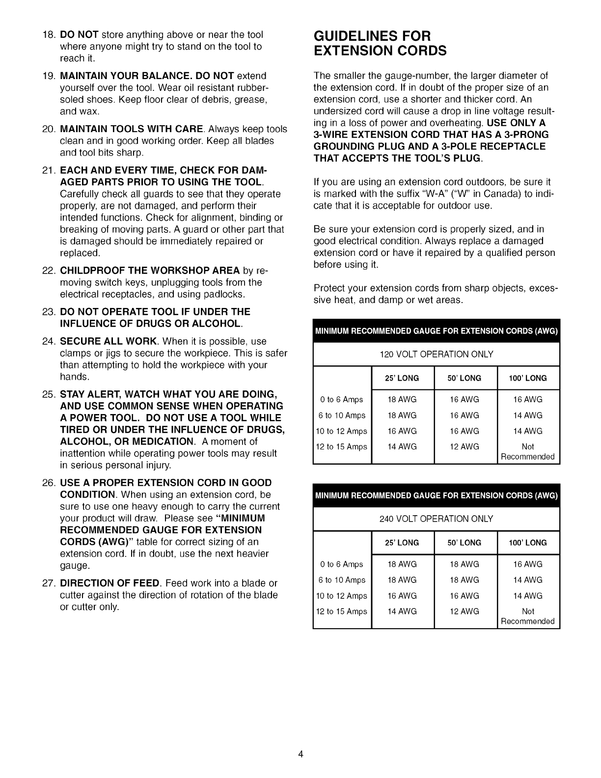
The smaller the gauge-number, the larger diameter of
the extension cord. If in doubt of the proper size of an
extension cord, use a shorter and thicker cord. An
undersized cord will cause a drop in line voltage result-
ing in a loss of power and overheating. USE ONLY A
3-WIRE EXTENSION CORD THAT HAS A 3-PRONG
GROUNDING PLUG AND A 3-POLE RECEPTACLE
THAT ACCEPTS THE TOOL'S PLUG.
If you are using an extension cord outdoors, be sure it
is marked with the suffix "W-A" ("W" in Canada) to indi-
cate that it is acceptable for outdoor use.
Be sure your extension cord is properly sized, and in
good electrical condition. Always replace a damaged
extension cord or have it repaired by a qualified person
before using it.
Protect your extension cords from sharp objects, exces-
sive heat, and damp or wet areas.
I
120VOLTOPERATIONONLY
25' LONG 50' LONG 100' LONG
0 to 6 Amps
6 to 10 Amps
10 to 12 Amps
12 to 15 Amps
18 AWG
18 AWG
16 AWG
14 AWG
16 AWG
16 AWG
16 AWG
12 AWG
16 AWG
14 AWG
14 AWG
Not
Recommended
I
240 VOLTOPERATIONONLY
0 to 6 Amps
6 to 10 Amps
10 to 12 Amps
12 to 15 Amps
25' LONG 50' LONG 100' LONG
18 AWG
18 AWG
16 AWG
14 AWG
18 AWG
18 AWG
16 AWG
12 AWG
16 AWG
14 AWG
14 AWG
Not
Recommended
THIS TOOL MUST BE GROUNDED WHILE IN USE
TO PROTECT THE OPERATOR FROM ELECTRIC
SHOCK.
IN THE EVENT OF A MALFUNCTION OR BREAK-
DOWN, grounding provides the path of least resistance
for electric current and reduces the risk of electric
shock. This tool is equipped with an electric cord that
has an equipment-grounding conductor and a ground-
ing plug. The plug MUST be plugged into a matching
electrical receptacle that is properly installed and
grounded in accordance with ALL local codes and
ordinances.
DO NOT MODIFY THE PLUG PROVIDED. If it will not
fit the electrical receptacle, have the proper electrical
receptacle installed by a qualified electrician.
IMPROPER ELECTRICAL CONNECTION of the equip-
ment-grounding conductor can result in risk of electric
shock. The conductor with the green insulation (with
or without yellow stripes) is the equipment-grounding
conductor. DO NOT connect the equipment-grounding
conductor to a live terminal.
CHECK with a qualified electrician or service personnel
if you do not completely understand the grounding
instructions, or if you are not sure the tool is properly
grounded.
The motor supplied with your Table Saw is a dual
voltage 120/240 volts, 60 hertz alternating current,
single phase motor. It is shipped wired for 120 volts
application. Never connect the green or ground wire
to a live terminal.
USE ONLY A 3-WIRE EXTENSION CORD THAT HAS
A 3-PRONG GROUNDING PLUG AND A 3-POLE
RECEPTACLE THAT ACCEPTS THE TOOL'S PLUG.
REPLACE A DAMAGED OR WORN CORD IMMEDI-
ATELY.
FOR GROUNDED, CORD-CONNECTED MACHINES
INTENDED FOR USE ON ASUPPLY CIRCUIT HAVING
A NOMINAL RATING LESS THAN 150 VOLTS.
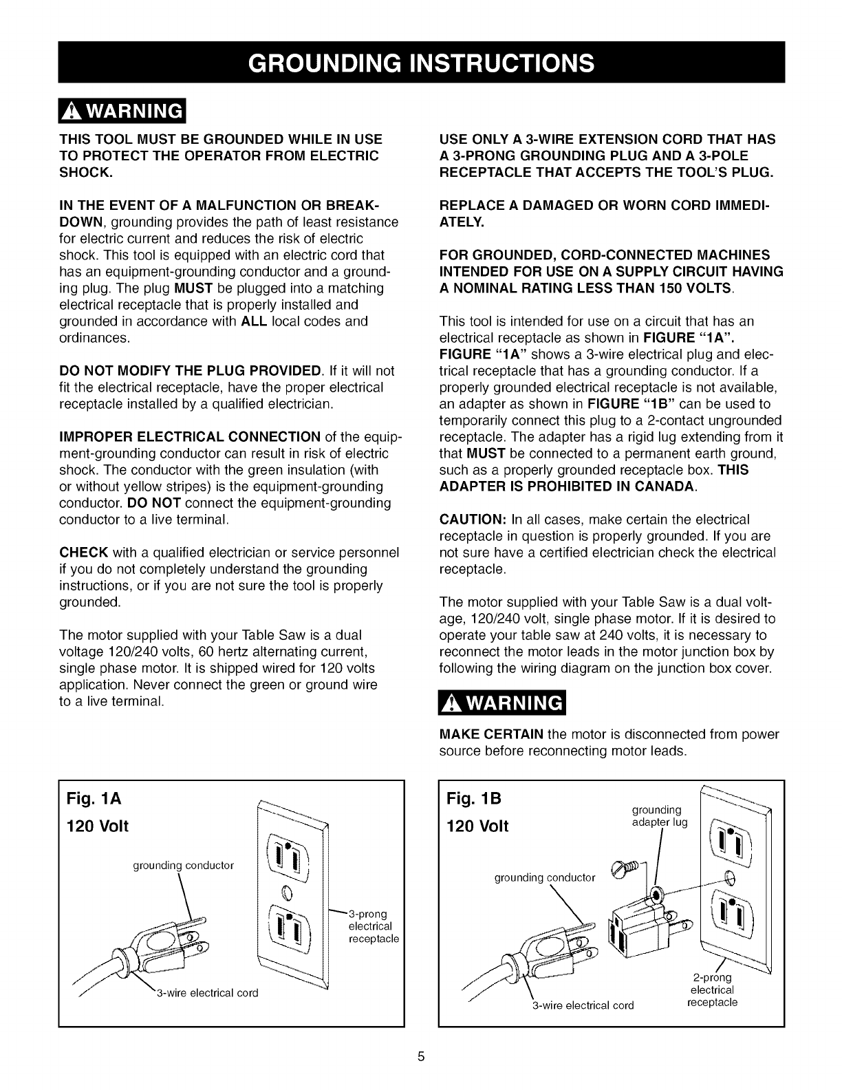
This tool is intended for use on a circuit that has an
electrical receptacle as shown in FIGURE "IA".
FIGURE "IA" shows a 3-wire electrical plug and elec-
trical receptacle that has a grounding conductor. If a
properly grounded electrical receptacle is not available,
an adapter as shown in FIGURE "IB" can be used to
temporarily connect this plug to a 2-contact ungrounded
receptacle. The adapter has a rigid lug extending from it
that MUST be connected to a permanent earth ground,
such as a properly grounded receptacle box. THIS
ADAPTER IS PROHIBITED IN CANADA.
CAUTION: In all cases, make certain the electrical
receptacle in question is properly grounded. If you are
not sure have a certified electrician check the electrical
receptacle.
The motor supplied with your Table Saw is a dual volt-
age, 120/240 volt, single phase motor. If it is desired to
operate your table saw at 240 volts, it is necessary to
reconnect the motor leads in the motor junction box by
following the wiring diagram on the junction box cover.
MAKE CERTAIN the motor is disconnected from power
source before reconnecting motor leads.
Fig. 1A
120 Volt
grounding conductor
_j/__trical cord
electrical
receptacle
Fig. 1B grounding
120 Volt adapt,
grounding conductor
3-wire electrical cord
2-prong
electrical
receptacle
It is also necessary to replace the 120 volt plug, sup-
plied with the motor, with a UL/CSA Listed plug suitable
for 240 volts and rated current of the saw. Contact a
local qualified electrician for proper procedures to install
the plug. The table saw must comply with all local and
national electrical codes after the 240 volt plug is
installed.
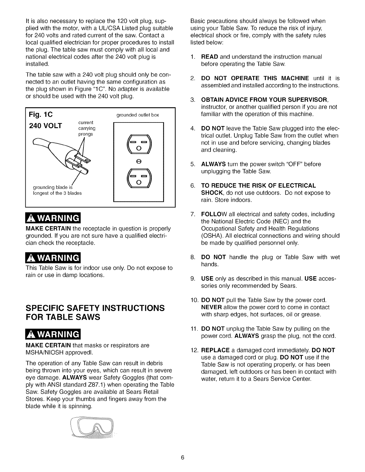
The table saw with a 240 volt plug should only be con-
nected to an outlet having the same configuration as
the plug shown in Figure "1C". No adapter is available
or should be used with the 240 volt plug.
Fig. 1C
current
240 VOLT carrying
prongs
grounding blade is
longest of the 3 blades
grounded outlet box
@
e
@
MAKE CERTAIN the receptacle in question is properly
grounded. If you are not sure have a qualified electri-
cian check the receptacle.
This Table Saw is for indoor use only. Do not expose to
rain or use in damp locations.
SPECIFIC SAFETY INSTRUCTIONS
FOR TABLE SAWS
MAKE CERTAIN that masks or respirators are
MSHA/NIOSH approvedl.
The operation of any Table Saw can result in debris
being thrown into your eyes, which can result in severe
eye damage. ALWAYS wear Safety Goggles (that com-
ply with ANSI standard Z87.1) when operating the Table
Saw. Safety Goggles are available at Sears Retail
Stores. Keep your thumbs and fingers away from the
blade while it is spinning.
Basic precautions should always be followed when
using your Table Saw. To reduce the risk of injury,
electrical shock or fire, comply with the safety rules
listed below:
1. READ and understand the instruction manual
before operating the Table Saw.
2. DO NOT OPERATE THIS MACHINE until it is
assembled and installed according to the instructions.
3. OBTAIN ADVICE FROM YOUR SUPERVISOR,
instructor, or another qualified person if you are not
familiar with the operation of this machine.
,DO NOT leave the Table Saw plugged into the elec-
trical outlet. Unplug Table Saw from the outlet when
not in use and before servicing, changing blades
and cleaning.
5. ALWAYS turn the power switch "OFF" before
unplugging the Table Saw.
6. TO REDUCE THE RISK OF ELECTRICAL
SHOCK, do not use outdoors. Do not expose to
rain. Store indoors.
,FOLLOW all electrical and safety codes, including
the National Electric Code (NEC) and the
Occupational Safety and Health Regulations
(OSHA). All electrical connections and wiring should
be made by qualified personnel only.
8. DO NOT handle the plug or Table Saw with wet
hands.
9. USE only as described in this manual. USE acces-
sories only recommended by Sears.
10. DO NOT pull the Table Saw by the power cord.
NEVER allow the power cord to come in contact
with sharp edges, hot surfaces, oil or grease.
11. DO NOT unplug the Table Saw by pulling on the
power cord. ALWAYS grasp the plug, not the cord.
12. REPLACE a damaged cord immediately. DO NOT
use a damaged cord or plug. DO NOT use if the
Table Saw is not operating properly, or has been
damaged, left outdoors or has been in contact with
water, return it to a Sears Service Center.
13 DONOTusetheTableSawasatoy.DONOTuse
nearoraroundchildren. 27.NEVERperformlayout,assemblyorset-upworkon
thetable/workareawhenthemachineisrunning.
14.TheTableSawisdesignedforhomeuseor light
commercialdutyONLY. 28.NEVERresetthethermal-overloadbuttonbefore
youhaveturnedthetablesaw"OFF".
15.CONNECTTableSawto a properlygroundedoutlet
only.Seegroundinginstructions.
16.ALWAYSUSEtheguardswheneverpossible.
Checkto seethattheyareinplace,securedand
workingcorrectly.
29.
30.
PROPERLY SUPPORT long or wide workpiece.
TURN THE SAW "OFF" and unplug from power
source. Clean off the table/work area before leav-
ing the saw. LOCK the START/STOP switch with
padlock provided to prevent unauthorized use.
17. AVOID KICKBACK by:
• Keeping blade sharp and free of rust and pitch.
• Keeping rip fence parallel to saw blade.
• Using saw blade guard and splitter assembly for
every possible operation, including all through-
sawing.
• Pushing the workpiece past the saw blade prior to
release.
• Never rip a workpiece that is twisted or
warped, or does not have a straight edge to guide
along the fence.
• Using featherboards when the blade guard and
splitter assembly cannot be used.
• Never sawing a large workpiece that cannot be
controlled.
• Never using the fence as a guide when cross-
cutting.
• Never sawing a workpiece with loose knots or
other flaws.
18. REMOVE cut-off pieces and debris from the table
before starting the saw. The vibration of the saw
may cause them to move into the saw blade and be
thrown out. After cutting, turn the saw off. When
the blade has come to a complete stop, unplug the
saw and remove all debris.
19. NEVER START the saw with the workpiece against
the blade.
20. NEVER perform "free-hand" operations. Use either
the fence or miter gauge to position and guide the
workpiece. Hold the workpiece firmly against the
miter gauge or fence.
21. USE a push stick(s) for ripping a narrow workpiece.
22. AVOID AWKWARD OPERATIONS AND HAND
POSITIONS where a sudden slip could cause a
hand to move into the blade.
23. KEEP arms, hands and fingers away from the blade.
24. NEVER have any part of your body in line with the
path of the saw blade.
25. NEVER reach around or over the blade.
26. NEVER attempt to free a stalled blade without first
turning the machine "OFF" and unplugging it from
the power source.
31.
32.
33.
34.
35.
ALWAYS position auxiliary fence at least 2-inches
in front of saw blade when using auxiliary fence as
a stop when cross cutting.
The right extension wing MUST BE completely
assembled and motor cover closed and fastened
before table saw is to be connected to the power
source.
DIRECTION OF FEED. Feed work into a blade or
cutter against the direction of rotation of the blade
or cutter only.
ADDITIONAL INFORMATION regarding the safe
and proper operation of this product is available
from the National Safety Council, 1121 Spring Lake
Drive, Itasca, IL 60143-3201 in the Accident
Prevention Manual for Industrial Operation and also
in the Safety Data Sheets provided by the NSC.
Please also refer to the American National
Standards Institute ANSI 01.1 Safety Requirements
for Woodworking Machinery and the U.S.
Department of Labor OSHA 1910.213 Regulations.
SAVE THESE INSTRUCTIONS. Refer to them
frequently and use them to instruct other users.
Information regarding the safe and proper operation of
this tool is available from the following sources:
Power Tool Institute
1300 Summer Avenue
Cleveland, OH 44115-2851
www.powertoolinstit ute.org
National Safety Council
1121 Spring Lake Drive
Itasca, IL 60143-3201
American National Standards Institute
25West 43rd. St, 4th Floor
New York, NY. 10036
ANSI 01.1 Safety Requirements
For Woodworking Machines
WWW.ANSI.ORG
U.S. Department of Labor Regulations
OSHA 1910.213 Regulations
WWW.OSHA.GOV
Anti-KickbackFingers- Asafetydeviceattachedto
thebladeguardandsplitterassemblydesignedto stop
aworkpiecefrombeingthrownbackduringa cutting
operation.
Arbor- Theshaftonwhichthebladeoraccessorycut-
ting-toolismounted.
BevelCut- Theoperationof makinganycutwiththe
bladesetatanangleotherthan90degrees.
CompoundCut- Theoperationof makingbotha
bevelandamitercutatonetime.
Kickback- Whentheworkpieceisthrownback
towardstheoperatorduringa cuttingoperationwhen
theworkpieceinitiallycontactsthebladeorif thework-
piecepinchestheblade.Kickbackisdangerousand
canresultinseriousinjury.
MiterCut- Theoperationof makingacutusingthe
mitergaugeatanyangleotherthanzerodegrees.
PushStick- Anaccessorydevicethatcanbemadeor
purchasedto helppushtheworkpiecethroughthe
blade.Apushstickisusedto keeptheoperator's
handsawayfromthebladewhenrippinga narrow
workpiece.
Crosscut- Theoperationofmakinga cutacrossthe
grainorwidthof aworkpiece.
Dado- Anon-throughcutthatproducesa square
notch.Adadoistypicallyfrom1/8-in.to 13/16-in.wide.
Adadorequiresa specialsetofblades,notincluded
withthistablesaw.
Featherboard- Anaccessorydevicethatcanbemade
orpurchasedto helpguideor holddowna workpiece
duringcuttingoperations.
Freehand- Averydangerousoperationof makinga
cutwithoutusingthefenceor mitergaugeina cutting
operation.Freehandcutsmustneverbeperformedon
aTableSaw.
Gum,Pitchor Resin- A sticky,sapbasedresiduethat
comesfromwoodproducts.
Heel- Themisalignmentofthebladeto themiterslots;
whenthebladeisnotparallelto themiterslots.
Kerf- Thematerialremovedfromtheworkpiecebythe
bladeduringanycuttingoperation.
Rabbet- Asquarenotchintheedgeoftheworkpiece.
Resaw- Theoperationof makingacutto reducethe
thicknessoftheworkpiece.
RipCut- Theoperationof makingacutwiththegrain
ordownthelengthoftheworkpiece.
SawBladePath- Theareathatisdirectlyinlinewith
theblade,includingareaover,under,behindandin
frontof it.
Setof theSawBlade- Thedistancethatthetipsof
thesawbladeareangledoutwardsfromthethickness
oftheblade.Thesetofthesawbladeteethallowsfor
thebladebodyto passsafelythroughallcuts.
Table/WorkArea- Thetotalsurfaceof thetopofthe
tablesawonwhichtheworkpiecerestswhileset-upor
cuttingoperationsarebeingperformed.
ThroughSawing- Theprocessof cuttinginwhichthe
bladecutscompletelythroughtheworkpiece.
AVAILABLE ACCESSORIES
May be available at your Sears Hardware Department or
see the Sears Power and Hand tool Catalog or visit
WWW.SEARS.COM for the following accessories.
iTEM
* Auxiliary Fence, Rip Fence
* Miter Gauge Extension & Stop
* Stock Clamp, Miter Gauge
* Dust Chute with Dust Port
* Micro-Adjustment Assembly
* Table Insert - Standard
* Table Insert - Dado
* Table Insert - Molding Cutterhead
* Table Insert - Zero Clearance
* Fence Guide System
STOCK NUMBER
29878
29879
29880
22102
29881
29882
29885
29887
29889
32371
Sears may recommend other accessories not listed in
this manual.
See your nearest Sears Hardware Department or Sears
Power and Hand Tool Catalog for other accessories.
Do not use any accessory unless you have completely
read the Owner's Manual for that accessory.
Use only accessories recommended for this table saw.
Using other accessories may cause serious injury and
cause damage to the table saw.
Fig. 2A
CONSTRUCTING A FEATHERBOARD
24"
[
I
kerf should be
about 1/4" apart I
I
I
[
5"
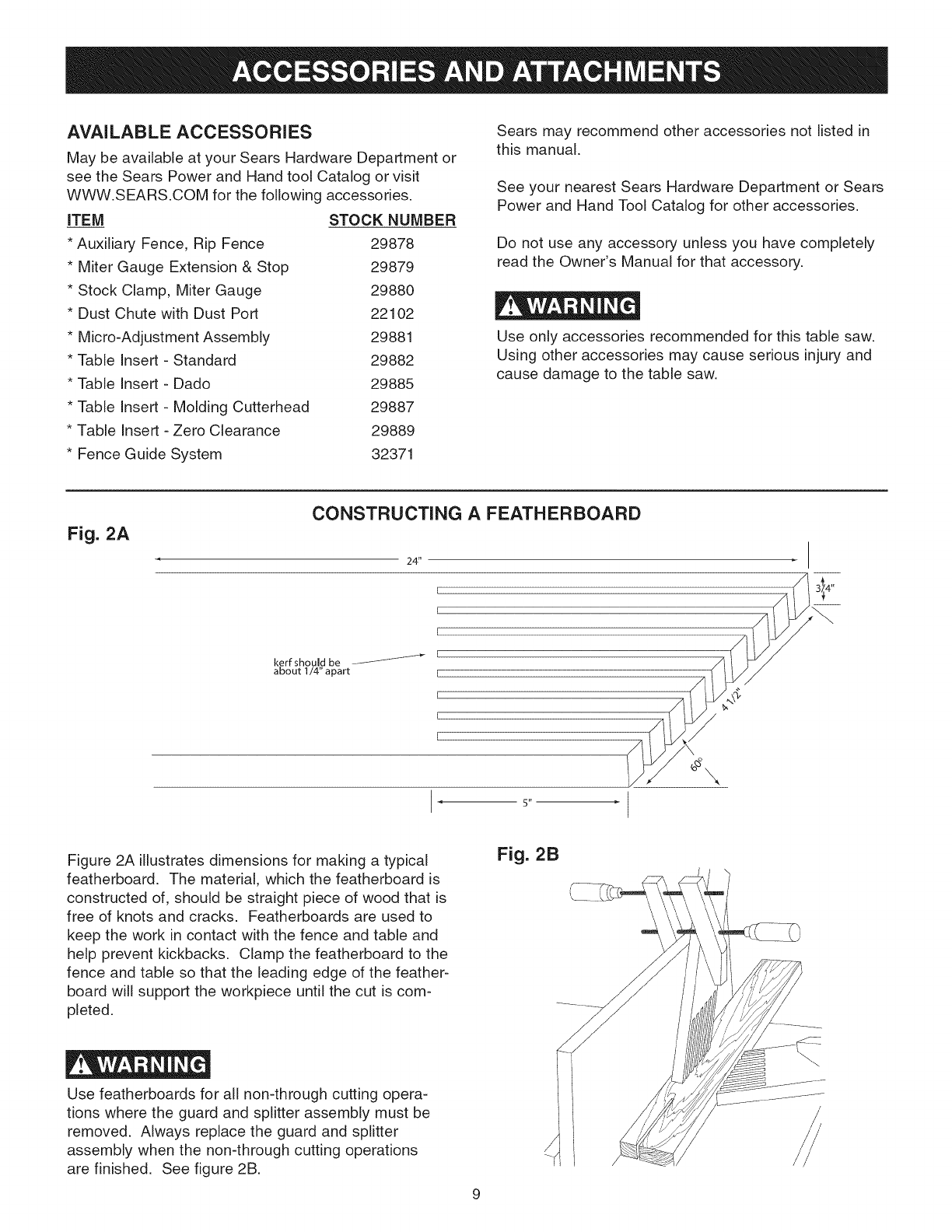
Figure 2A illustrates dimensions for making a typical
featherboard. The material, which the featherboard is
constructed of, should be straight piece of wood that is
free of knots and cracks. Featherboards are used to
keep the work in contact with the fence and table and
help prevent kickbacks. Clamp the featherboard to the
fence and table so that the leading edge of the feather-
board will support the workpiece until the cut is com-
pleted.
Use featherboards for all non-through cutting opera-
tions where the guard and splitter assembly must be
removed. Always replace the guard and splitter
assembly when the non-through cutting operations
are finished. See figure 2B.
Fig. 2B
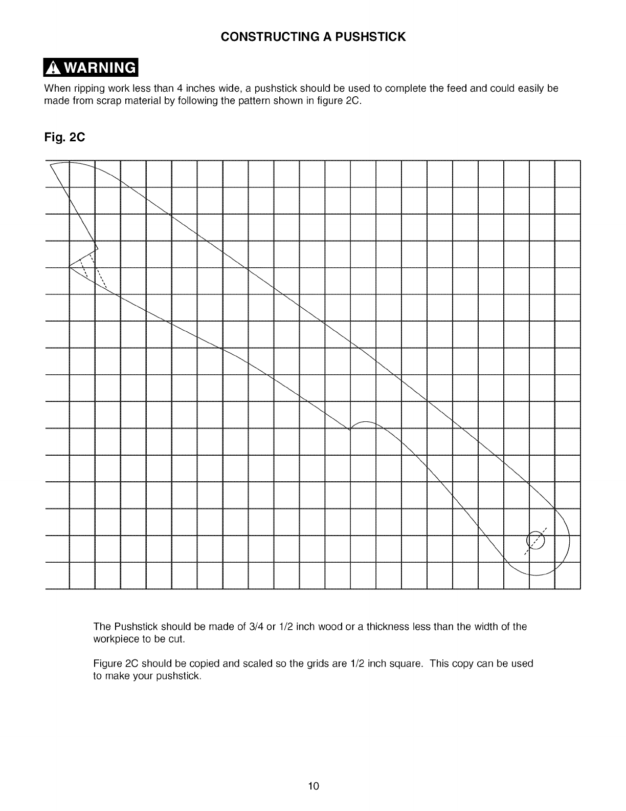
CONSTRUCTING A PUSHSTICK
When ripping work less than 4 inches wide, a pushstick should be used to complete the feed and could easily be
made from scrap material by following the pattern shown in figure 2C.
Fig. 2C
The Pushstick should be made of 3/4 or 1/2 inch wood or a thickness less than the width of the
workpiece to be cut.
Figure 2C should be copied and scaled so the grids are 1/2 inch square. This copy can be used
to make your pushstick.
10
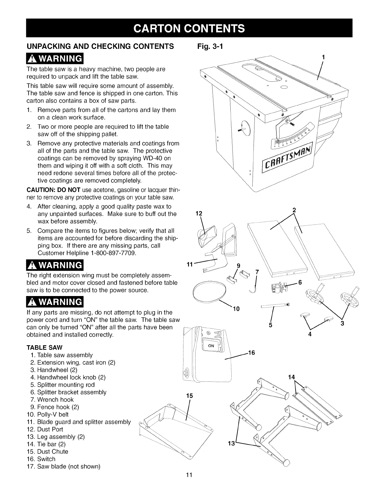
UNPACKING AND CHECKING CONTENTS Fig. 3-1
The table saw is a heavy machine, two people are
required to unpack and lift the table saw.
This table saw will require some amount of assembly.
The table saw and fence is shipped in one carton. This
carton also contains a box of saw parts.
1. Remove parts from all of the cartons and lay them
on a clean work surface.
2. Two or more people are required to lift the table
saw off of the shipping pallet.
3. Remove any protective materials and coatings from
all of the parts and the table saw. The protective
coatings can be removed by spraying WD-40 on
them and wiping it off with a soft cloth. This may
need redone several times before all of the protec-
tive coatings are removed completely.
CAUTION: DO NOT use acetone, gasoline or lacquer thin-
ner to remove any protective coatings on your table saw.
4. After cleaning, apply a good quality paste wax to
any unpainted surfaces. Make sure to buff out the
wax before assembly.
5. Compare the items to figures below; verify that all
items are accounted for before discarding the ship-
ping box. If there are any missing parts, call
Customer Helpline 1-800-897-7709.
The right extension wing must be completely assem-
bled and motor cover closed and fastened before table
saw is to be connected to the power source.
If any parts are missing, do not attempt to plug in the
power cord and turn "ON" the table saw. The table saw
can only be turned "ON" after all the parts have been
obtained and installed correctly.
11
12 2
\\\\\\\
9
4
\\\\
TABLE SAW
1. Table saw assembly
2. Extension wing, cast iron (2)
3. Handwheel (2)
4. Handwheel lock knob (2)
5. Splitter mounting rod
6. Splitter bracket assembly
7. Wrench hook
9. Fence hook (2)
10. Polly-V belt
11. Blade guard and splitter assembly
12. Dust Port
13. Leg assembly (2)
14. Tie bar (2)
15. Dust Chute
16. Switch
17. Saw blade (not shown)
15
11
14
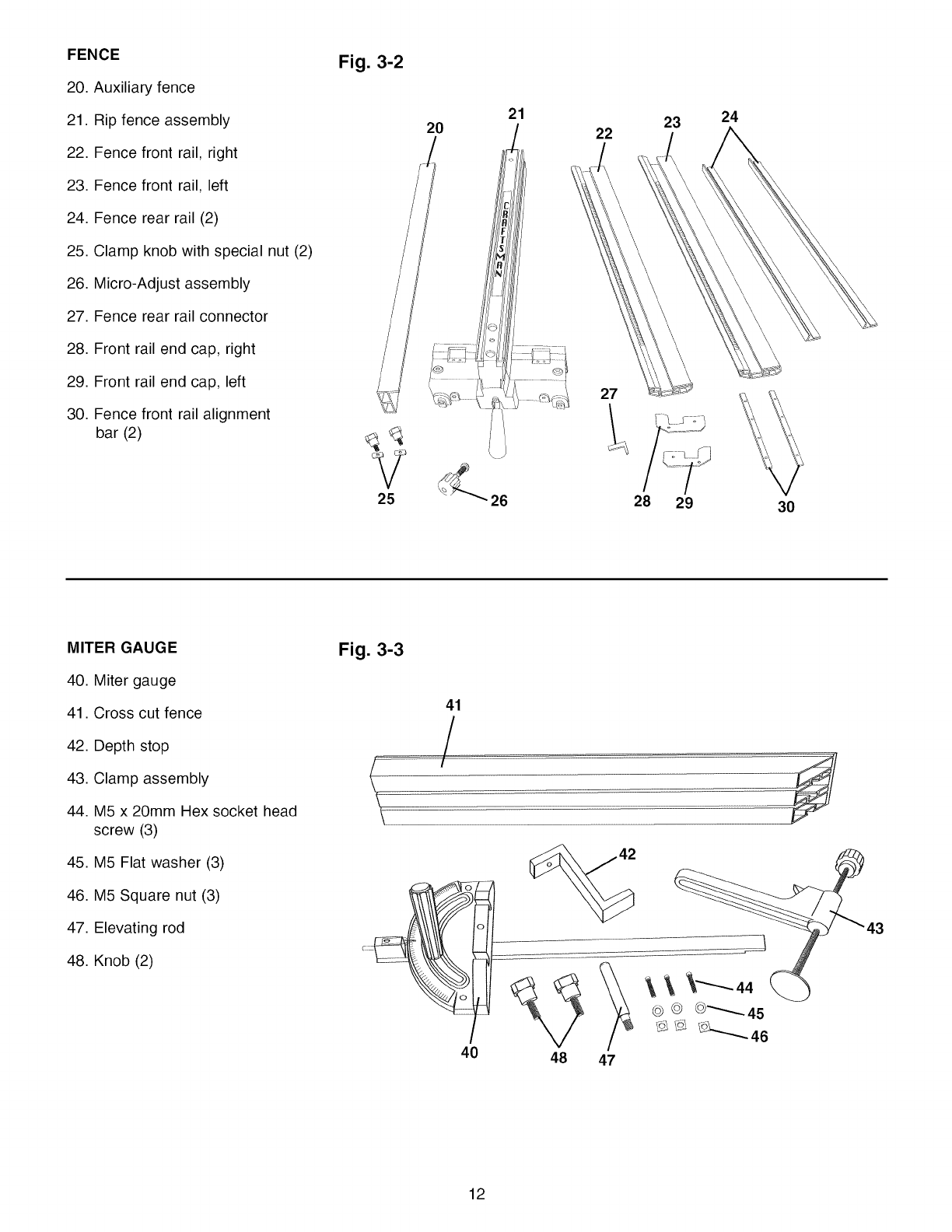
FENCE
20.Auxiliaryfence
21.Ripfenceassembly
22.Fencefrontrail,right
23.Fencefrontrail,left
24.Fencerearrail(2)
25.Clampknobwithspecialnut(2)
26.Micro-Adjustassembly
27.Fencerearrailconnector
28.Frontrailendcap,right
29.Frontrailendcap,left
30.Fencefrontrailalignment
bar(2)
Fig. 3-2
20 21
22
\27
23
28 29
24
30
MITER GAUGE
40. Miter gauge
41. Cross cut fence
42. Depth stop
43. Clamp assembly
44. M5 x 20mm Hex socket head
screw (3)
45. M5 Flat washer (3)
46. M5 Square nut (3)
47. Elevating rod
48. Knob (2)
Fig. 3-3
41
/
47
43
\
@ © @_45
% \!£ tq_ 46
12
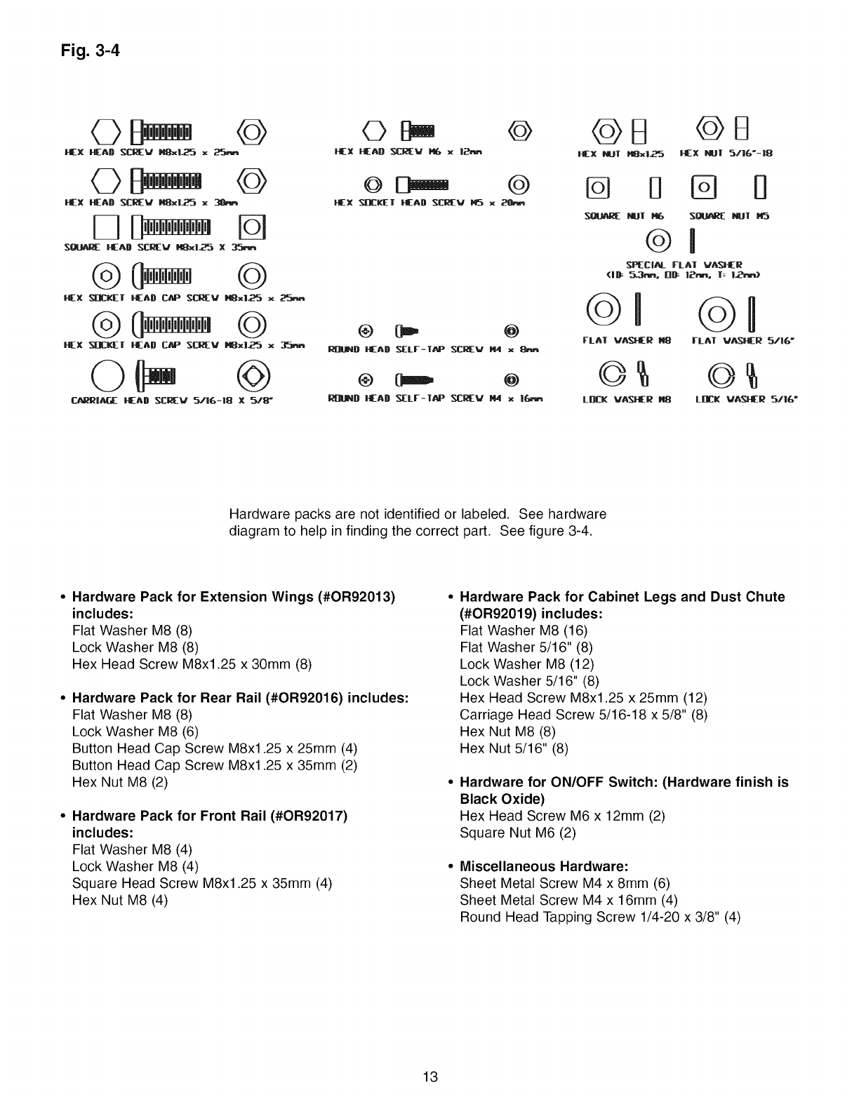
Fig. 3-4
@
F_EX S[L'klE]r HEAD C_ SCREV HSxl.Z_ x
HEX SnCKIE_I" HEAD CAP NCL_EV _xl.25 x
@
CAI_RiA6E HEAD _V 5/16=18 X.518"
HEX ilEAl) _v _ x I_
I_i[]lLeND lEAD S[LF-1AP _v t!4 x See
R[WJ_D _AD _LF-l_ _[aEV _ x i_e_n
_X NUT HSxl_ I-EX _[ %/10"-|8
L[_CK V_HER _LBC[ VA_I[R 5/16"
Hardware packs are not identified or labeled. See hardware
diagram to help in finding the correct part. See figure 3-4.
• Hardware Pack for Extension Wings (#OR92013)
includes:
Flat Washer M8 (8)
Lock Washer M8 (8)
Hex Head Screw M8x1.25 x 30mm (8)
• Hardware Pack for Rear Rail (#OR92016) includes:
Flat Washer M8 (8)
Lock Washer M8 (6)
Button Head Cap Screw M8x1.25 x 25mm (4)
Button Head Cap Screw M8x1.25 x 35mm (2)
Hex Nut M8 (2)
•Hardware Pack for Front Rail (#OR92017)
includes:
Flat Washer M8 (4)
Lock Washer M8 (4)
Square Head Screw M8x1.25 x 35mm (4)
Hex Nut M8 (4)
Hardware Pack for Cabinet Legs and Dust Chute
(#OR92019) includes:
Flat Washer M8 (16)
Flat Washer 5/16" (8)
Lock Washer M8 (12)
Lock Washer 5/16" (8)
Hex Head Screw M8x1.25 x 25mm (12)
Carriage Head Screw 5/16-18 x 5/8" (8)
Hex Nut M8 (8)
Hex Nut 5/16" (8)
Hardware for ON/OFF Switch: (Hardware finish is
Black Oxide)
Hex Head Screw M6 x 12mm (2)
Square Nut M6 (2)
Miscellaneous Hardware:
Sheet Metal Screw M4 x 8mm (6)
Sheet Metal Screw M4 x 16mm (4)
Round Head Tapping Screw 1/4-20 x 3/8" (4)
13
26
1
27 2
5 4 38 9
6711
10
12
24 23
22
21 2O 18
9
17
16
14
15
13
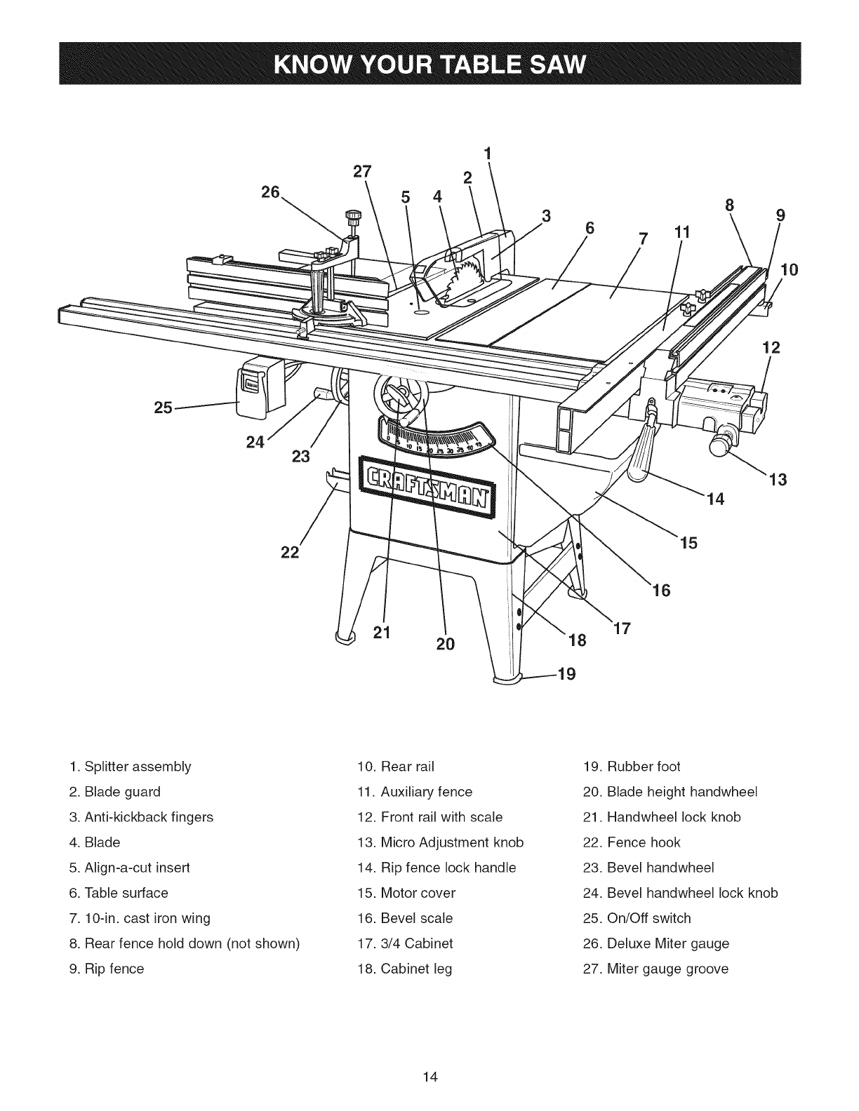
1. Splitter assembly
2. Blade guard
3. Anti-kickback fingers
4. Blade
5. Align-a-cut insert
6. Table surface
7.10-in. cast iron wing
8. Rear fence hold down (not shown)
9. Rip fence
10. Rear rail
11. Auxiliary fence
12. Front rail with scale
13. Micro Adjustment knob
14. Rip fence lock handle
15. Motor cover
16. Bevel scale
17.3/4 Cabinet
18. Cabinet leg
19. Rubber foot
20. Blade height handwheel
21. Handwheel lock knob
22. Fence hook
23. Bevel handwheel
24. Bevel handwheel lock knob
25. On/Off switch
26. Deluxe Miter gauge
27. Miter gauge groove
14
TOOLS REQUIRED
The following tools are needed for assembly and align-
ment. Note: Two blade wrenches and five hex wrenches
are provided with your table saw. The remaining tools
are typical shop tools and are not included with your
table saw.
18ram wrench 8ram wrench
13ram wrench 3/16-in. hex wrench
10ram wrench #2 Phillips screwdriver
,Attach two tie bars (F) inside and between front and
rear legs already attached to the cabinet with (G)
eight 5/16-18 x 5/8" carriage head screws, 5/16" flat
washers, 5/16" lock washers and 5/16-18 hex nuts
and securely tighten all hardware. See figure 4-1.
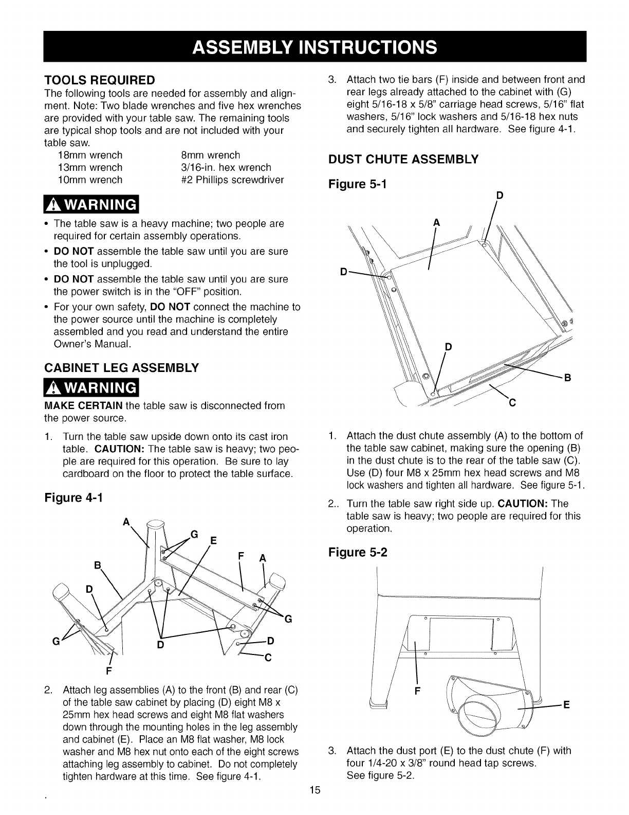
DUST CHUTE ASSEMBLY
Figure 5-1 D
• The table saw is a heavy machine; two people are
required for certain assembly operations.
• DO NOT assemble the table saw until you are sure
the tool is unplugged.
• DO NOT assemble the table saw until you are sure
the power switch is in the "OFF" position.
• For your own safety, DO NOT connect the machine to
the power source until the machine is completely
assembled and you read and understand the entire
Owner's Manual.
CABINET LEG ASSEMBLY
MAKE CERTAIN the table saw is disconnected from
the power source.
,Turn the table saw upside down onto its cast iron
table. CAUTION: The table saw is heavy; two peo-
ple are required for this operation. Be sure to lay
cardboard on the floor to protect the table surface.
Figure 4-1
A
E
B
D
FA
G
,
D
F
Attach leg assemblies (A) to the front (B) and rear (C)
of the table saw cabinet by placing (D) eight M8 x
25mm hex head screws and eight M8 flat washers
down through the mounting holes in the leg assembly
and cabinet (E). Place an M8 flat washer, M8 lock
washer and M8 hex nut onto each of the eight screws
attaching leg assembly to cabinet. Do not completely
tighten hardware at this time. See figure 4-1.
A
\
C
B
,
,,
Attach the dust chute assembly (A) to the bottom of
the table saw cabinet, making sure the opening (B)
in the dust chute is to the rear of the table saw (C).
Use (D) four M8 x 25mm hex head screws and M8
lock washers and tighten all hardware. See figure 5-1.
Turn the table saw right side up. CAUTION: The
table saw is heavy; two people are required for this
operation.
Figure 5-2
15
3. Attach the dust port (E) to the dust chute (F) with
four 1/4-20 x 3/8" round head tap screws.
See figure 5-2.
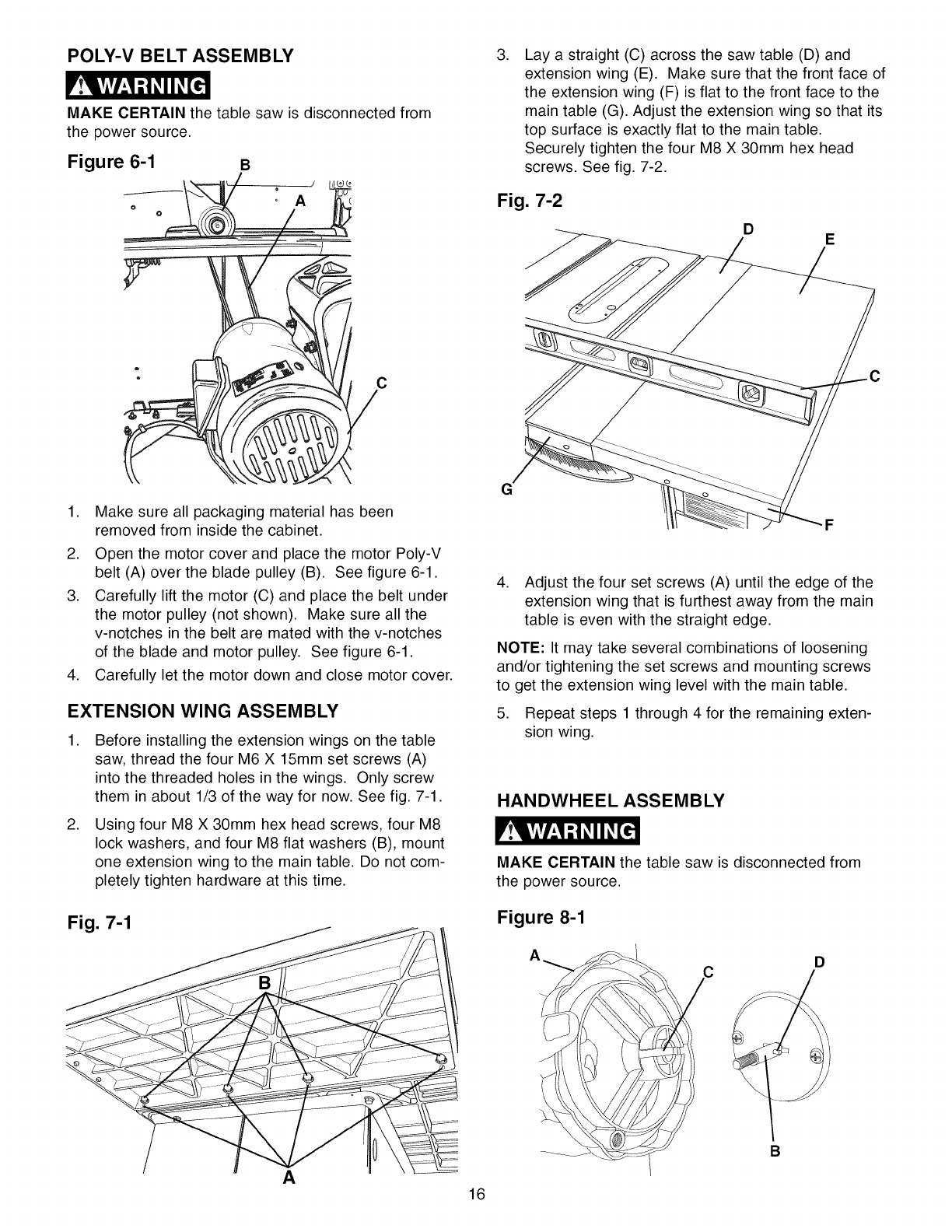
POLY-V BELT ASSEMBLY
MAKE CERTAIN the table saw is disconnected from
the power source.
Figure 6-1 B
A
C
.Lay a straight (C) across the saw table (D) and
extension wing (E). Make sure that the front face of
the extension wing (F) is flat to the front face to the
main table (G). Adjust the extension wing so that its
top surface is exactly flat to the main table.
Securely tighten the four M8 X 30ram hex head
screws. See fig. 7-2.
Fig. 7-2
DE
C
1. Make sure all packaging material has been
removed from inside the cabinet.
2. Open the motor cover and place the motor Poly-V
belt (A) over the blade pulley (B). See figure 6-1.
3. Carefully lift the motor (C) and place the belt under
the motor pulley (not shown). Make sure all the
v-notches in the belt are mated with the v-notches
of the blade and motor pulley. See figure 6-1.
4. Carefully let the motor down and close motor cover.
EXTENSION WING ASSEMBLY
.
.
Before installing the extension wings on the table
saw, thread the four M6 X 15ram set screws (A)
into the threaded holes in the wings. Only screw
them in about 1/3 of the way for now. See fig. 7-1.
Using four M8 X 30mm hex head screws, four M8
lock washers, and four M8 flat washers (B), mount
one extension wing to the main table. Do not com-
pletely tighten hardware at this time.
Fig. 7-1
A16
G
4. Adjust the four set screws (A) until the edge of the
extension wing that is furthest away from the main
table is even with the straight edge.
NOTE: It may take several combinations of loosening
and/or tightening the set screws and mounting screws
to get the extension wing level with the main table.
5. Repeat steps 1 through 4 for the remaining exten-
sion wing.
HANDWHEEL ASSEMBLY
MAKE CERTAIN the table saw is disconnected from
the power source.
Figure 8-1
D
B
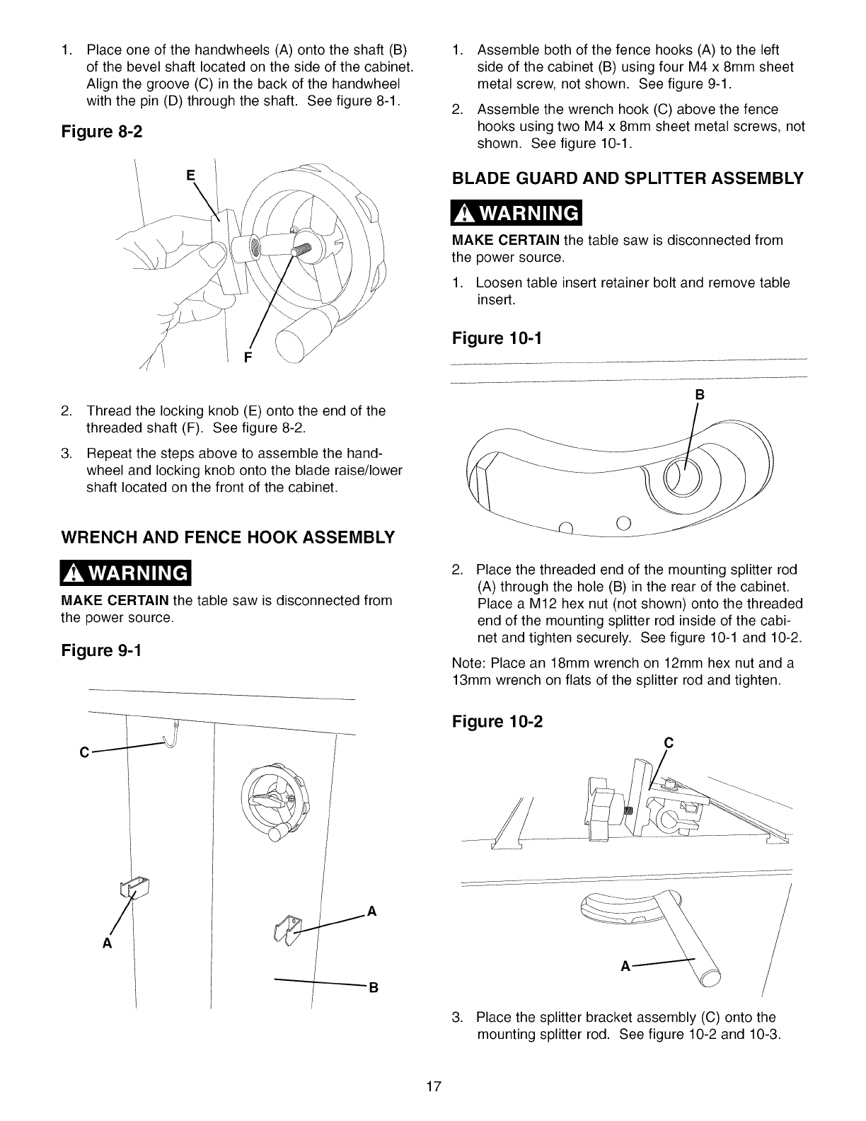
,Place one of the handwheels (A) onto the shaft (B)
of the bevel shaft located on the side of the cabinet.
Align the groove (C) in the back of the handwheel
with the pin (D) through the shaft. See figure 8-1.
Figure 8-2
,
,
Assemble both of the fence hooks (A) to the left
side of the cabinet (B) using four M4 x 8mm sheet
metal screw, not shown. See figure 9-1.
Assemble the wrench hook (C) above the fence
hooks using two M4 x 8mm sheet metal screws, not
shown. See figure 10-1.
BLADE GUARD AND SPLITTER ASSEMBLY
MAKE CERTAIN the table saw is disconnected from
the power source.
1. Loosen table insert retainer bolt and remove table
insert.
Figure 10-1
,
,
Thread the locking knob (E) onto the end of the
threaded shaft (F). See figure 8-2.
Repeat the steps above to assemble the hand-
wheel and locking knob onto the blade raise/lower
shaft located on the front of the cabinet.
WRENCH AND FENCE HOOK ASSEMBLY
MAKE CERTAIN the table saw is disconnected from
the power source.
Figure 9-1
1
B
_Q ©
,Place the threaded end of the mounting splitter rod
(A) through the hole (B) in the rear of the cabinet.
Place a M12 hex nut (not shown) onto the threaded
end of the mounting splitter rod inside of the cabi-
net and tighten securely. See figure 10-1 and 10-2.
Note: Place an 18mm wrench on 12mm hex nut and a
13mm wrench on flats of the splitter rod and tighten.
Figure 10-2
C
A
3. Place the splitter bracket assembly (C) onto the
mounting splitter rod. See figure 10-2 and 10-3.
17
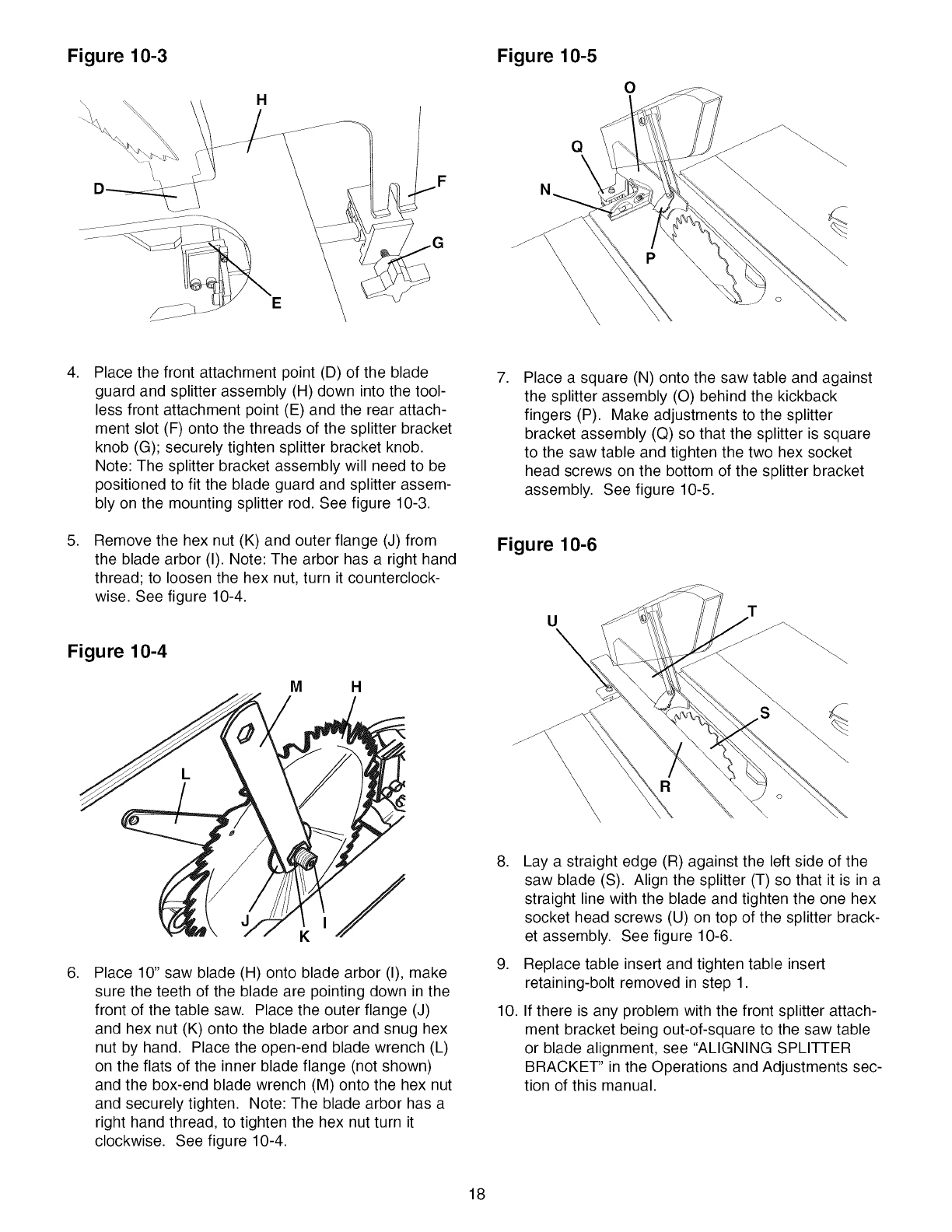
Figure 10-3 Figure 10-5
Q
N
0
P
.
.
Place the front attachment point (D) of the blade
guard and splitter assembly (H) down into the tool-
less front attachment point (E) and the rear attach-
ment slot (F) onto the threads of the splitter bracket
knob (G); securely tighten splitter bracket knob.
Note: The splitter bracket assembly will need to be
positioned to fit the blade guard and splitter assem-
bly on the mounting splitter rod. See figure 10-3.
Remove the hex nut (K) and outer flange (J) from
the blade arbor (I). Note: The arbor has a right hand
thread; to loosen the hex nut, turn it counterclock-
wise. See figure 10-4.
Figure 10-4
MH
.Place a square (N) onto the saw table and against
the splitter assembly (O) behind the kickback
fingers (P). Make adjustments to the splitter
bracket assembly (Q) so that the splitter is square
to the saw table and tighten the two hex socket
head screws on the bottom of the splitter bracket
assembly. See figure 10-5.
Figure 10-6
UT
\
.Place 10" saw blade (H) onto blade arbor (I), make
sure the teeth of the blade are pointing down in the
front of the table saw. Place the outer flange (J)
and hex nut (K) onto the blade arbor and snug hex
nut by hand. Place the open-end blade wrench (L)
on the flats of the inner blade flange (not shown)
and the box-end blade wrench (M) onto the hex nut
and securely tighten. Note: The blade arbor has a
right hand thread, to tighten the hex nut turn it
clockwise. See figure 10-4.
.
.
10.
Lay a straight edge (R) against the left side of the
saw blade (S). Align the splitter (T) so that it is in a
straight line with the blade and tighten the one hex
socket head screws (U) on top of the splitter brack-
et assembly. See figure 10-6.
Replace table insert and tighten table insert
retaining-bolt removed in step 1.
If there is any problem with the front splitter attach-
ment bracket being out-of-square to the saw table
or blade alignment, see "ALIGNING SPLITTER
BRACKET" in the Operations and Adjustments sec-
tion of this manual.
18
RiP FENCE ASSEMBLY
MAKE CERTAIN the table saw is disconnected from
the power source,
Figure 11-1
CB
\
A
B
C
A
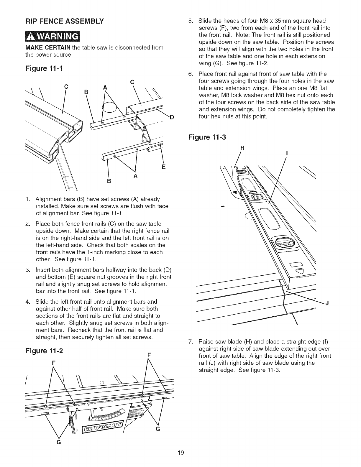
,
,
,
,
Alignment bars (B) have set screws (A) already
installed. Make sure set screws are flush with face
of alignment bar. See figure 11-1.
Place both fence front rails (C) on the saw table
upside down. Make certain that the right fence rail
is on the right-hand side and the left front rail is on
the left-hand side. Check that both scales on the
front rails have the 1-inch marking close to each
other. See figure 11-1.
Insert both alignment bars halfway into the back (D)
and bottom (E) square nut grooves in the right front
rail and slightly snug set screws to hold alignment
bar into the front rail. See figure 11-1.
Slide the left front rail onto alignment bars and
against other half of front rail. Make sure both
sections of the front rails are flat and straight to
each other. Slightly snug set screws in both align-
ment bars. Recheck that the front rail is flat and
straight, then securely tighten all set screws.
Figure 11-2
F
/o
G
G
D
19
,
,
Slide the heads of four M8 x 35mm square head
screws (F), two from each end of the front rail into
the front rail. Note: The front rail is still positioned
upside down on the saw table. Position the screws
so that they will align with the two holes in the front
of the saw table and one hole in each extension
wing (G). See figure 11-2.
Place front rail against front of saw table with the
four screws going through the four holes in the saw
table and extension wings. Place an one M8 flat
washer, M8 lock washer and M8 hex nut onto each
of the four screws on the back side of the saw table
and extension wings. Do not completely tighten the
four hex nuts at this point.
Figure 11-3
H
,Raise saw blade (H) and place a straight edge (I)
against right side of saw blade extending out over
front of saw table. Align the edge of the right front
rail (J) with right side of saw blade using the
straight edge. See figure 11-3.
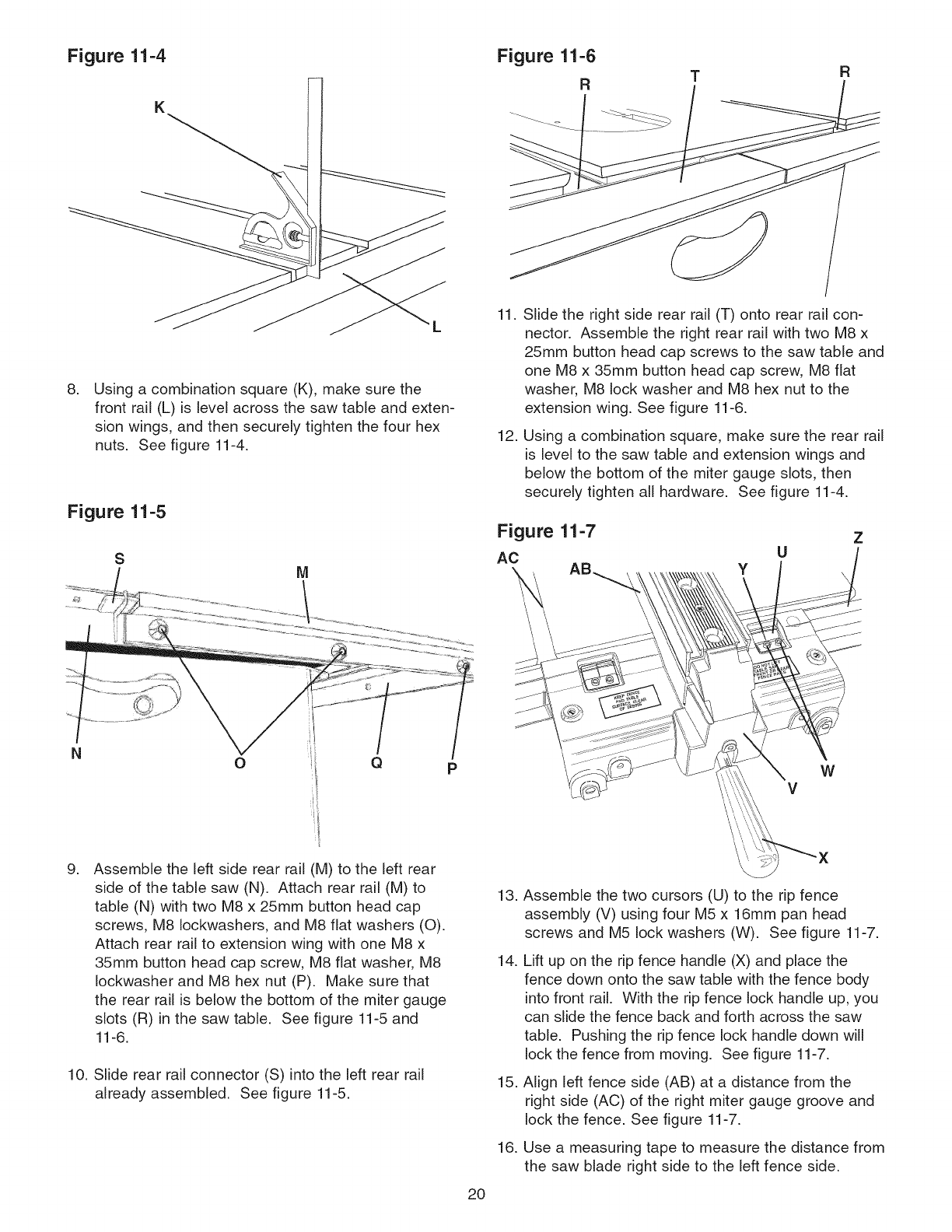
Figure 11-4
,Using a combination square (K), make sure the
front rail (L) is level across the saw table and exten-
sion wings, and then securely tighten the four hex
nuts. See figure 11-4.
Figure 11-5
S
Figure 11-6
RF{
11.
12.
Slide the right side rear rail (T) onto rear rail con-
nector. Assemble the right rear rail with two M8 x
25mm button head cap screws to the saw table and
one M8 x 35mm button head cap screw, M8 flat
washer, M8 lock washer and M8 hex nut to the
extension wing. See figure 11-6.
Using a combination square, make sure the rear rail
is level to the saw table and extension wings and
below the bottom of the miter gauge slots, then
securely tighten all hardware. See figure 11-4.
Figure 11-7 z
U
AC y X
oQPW
V
g, Assemble the left side rear rail (M) to the left rear
side of the table saw (N). Attach rear rail (M) to
table (N) with two M8 x 25mm button head cap
screws, M8 Iockwashers, and M8 flat washers (O).
Attach rear rail to extension wing with one M8 x
35mm button head cap screw, M8 flat washer, M8
Iockwasher and M8 hex nut (P). Make sure that
the rear rail is below the bottom of the miter gauge
slots (R) in the saw table. See figure 11-5 and
11-6.
10. Slide rear rail connector (S) into the left rear rail
already assembled. See figure 11-5.
13.
14.
15.
16.
2O
Assemble the two cursors (U) to the rip fence
assembly (V) using four M5 x 16mm pan head
screws and M5 lock washers (W). See figure 11-7.
Lift up on the rip fence handle (X) and place the
fence down onto the saw table with the fence body
into front rail. With the rip fence lock handle up, you
can slide the fence back and forth across the saw
table. Pushing the rip fence lock handle down will
lock the fence from moving. See figure 11-7.
Align left fence side (AB) at a distance from the
right side (AC) of the right miter gauge groove and
lock the fence. See figure 11-7.
Use a measuring tape to measure the distance from
the saw blade right side to the left fence side.
17.Assemblethecursor(U)to therightsideoffence
crossarmwithtwoM5x 16mmpanheadscrews
andM5lockwashers(W).Donotcompletelytight-
enscrews.Seefigure11-7.
18.Aligncursorwiththescale(Z)sothatthethinblack
line(Y)isonthesamenumberasthedistance
measuredinstep16.Tightenthecursorscrews.
19.Removefencefromtableandrepositionit onleft
sideof sawblade.Alignrightfencesideata dis-
tancefromtheleftsideof leftmitergaugegroove
andlockthefence.
20.Usea measuringtapeto measurethedistancefrom
thesawbladeleftsidetotherightfenceside.
21.Assemblethesecondcursorto leftsideoffence
crossarmwithtwoM5x 16mmpanheadscrews
andM6lockwashers.Donotcompletelytighten
screws.
22.Aligncursorwiththescalesothatthethinblackline
isonthesamenumberasthedistancemeasuredin
step20.Tightenthecursorscrews.
Figure 11-8
AUXILIARY FENCE ASSEMBLY
ALWAYS position auxiliary fence at least 2-inches in
front of the saw blade when using auxiliary fence as a
stop when crosscutting.
Figure 13-1
DB
C
A
AA
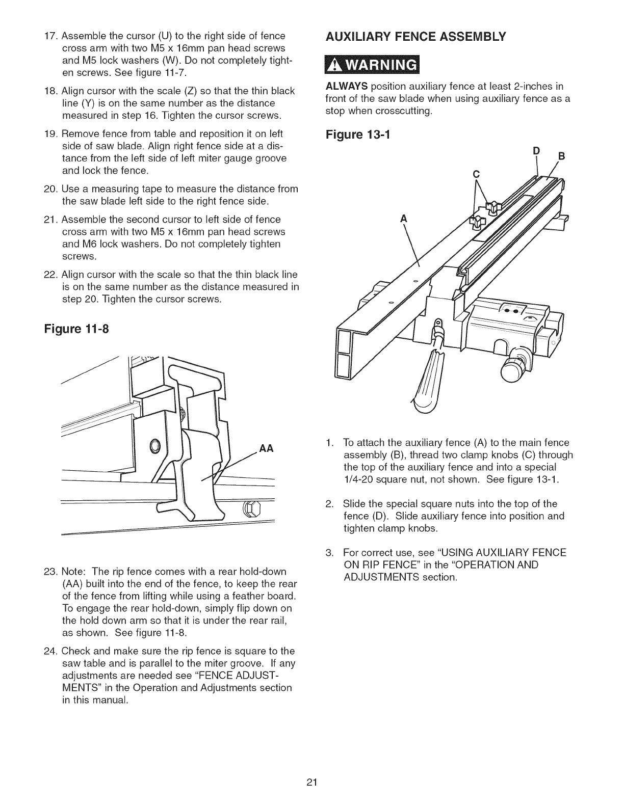
23. Note: The rip fence comes with a rear hold-down
(AA) built into the end of the fence, to keep the rear
of the fence from lifting while using a feather board.
To engage the rear hold-down, simply flip down on
the hold down arm so that it is under the rear rail,
as shown. See figure 11-8.
24. Check and make sure the rip fence is square to the
saw table and is parallel to the miter groove. If any
adjustments are needed see "FENCE ADJUST-
MENTS" in the Operation and Adjustments section
in this manual.
,
,
To attach the auxiliary fence (A) to the main fence
assembly (B), thread two clamp knobs (C) through
the top of the auxiliary fence and into a special
1/4-20 square nut, not shown. See figure 13-1.
Slide the special square nuts into the top of the
fence (D). Slide auxiliary fence into position and
tighten clamp knobs.
For correct use, see "USING AUXILIARY FENCE
ON RIP FENCE" in the "OPERATION AND
ADJUSTMENTS section.
21
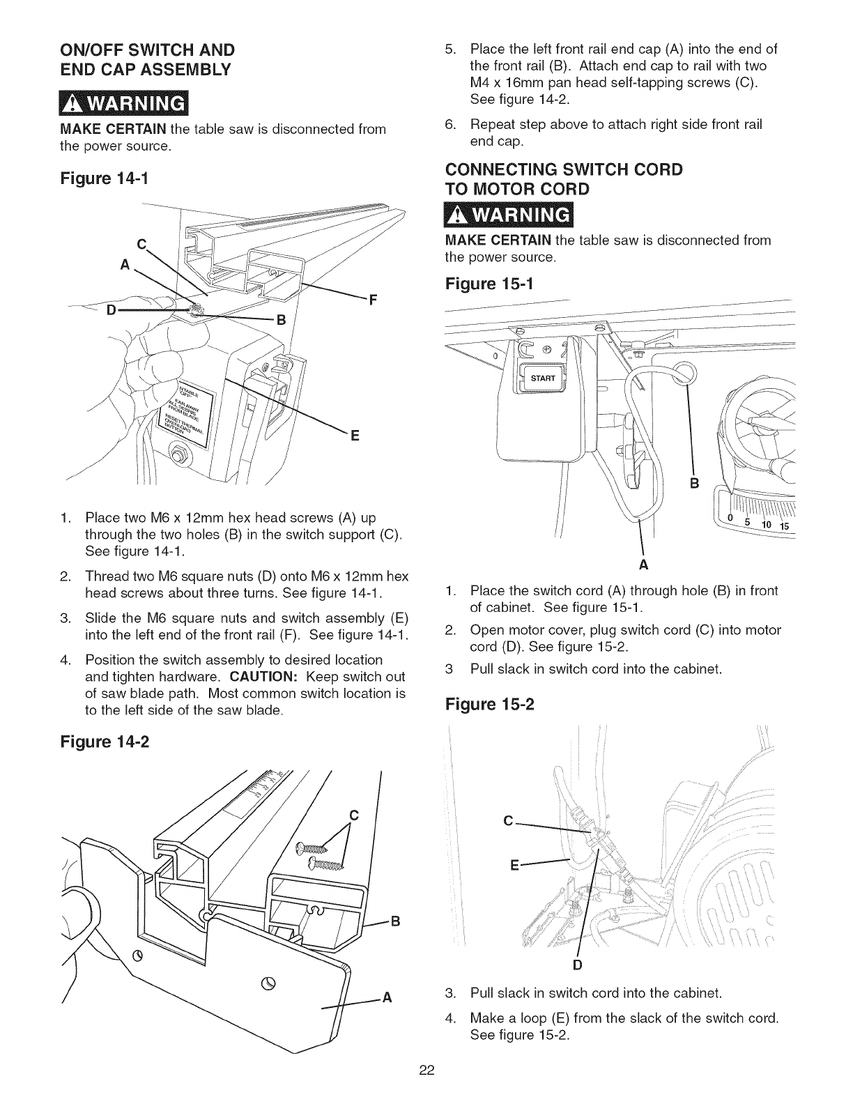
ON/OFF SWITCH AND
END CAP ASSEMBLY
MAKE CERTAIN the table saw is disconnected from
the power source,
Figure 14-1
,
,
Place the left front rail end cap (A) into the end of
the front rail (B). Attach end cap to rail with two
M4 x16mm pan head self-tapping screws (C),
See figure 14-2.
Repeat step above to attach right side front rail
end cap.
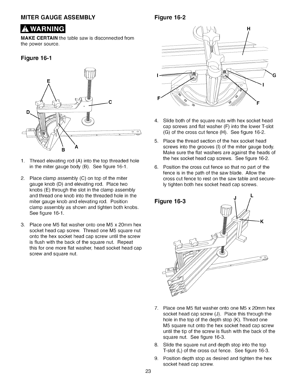
CONNECTING SWITCH CORD
TO MOTOR CORD
A
C
E
,
,
,
,
Place two M6 x 12mm hex head screws (A) up
through the two holes (B) in the switch support (C).
See figure 14-1.
Thread two M6 square nuts (D) onto M6 x 12mm hex
head screws about three turns. See figure 14-1.
Slide the M6 square nuts and switch assembly (E)
into the left end of the front rail (F). See figure 14-1.
Position the switch assembly to desired location
and tighten hardware. CAUTION: Keep switch out
of saw blade path. Most common switch location is
to the left side of the saw blade.
Figure 14-2
C
MAKE CERTAIN the table saw is disconnected from
the power source,
Figure 15-1
B
A
1. Place the switch cord (A) through hole (B) in front
of cabinet. See figure 15-1.
2. Open motor cover, plug switch cord (C) into motor
cord (D). See figure 15-2.
3 Pull slack in switch cord into the cabinet.
Figure 15-2
E
D
3. Pull slack in switch cord into the cabinet.
4. Make a loop (E) from the slack of the switch cord.
See figure 15-2.
22
MITER GAUGE ASSEMBLY Figure 16-2
MAKE CERTAIN the table saw is disconnected from
the power source.
Figure 16-1
E
.
.
.
A
B
Thread elevating rod (A) into the top threaded hole
in the miter gauge body (B). See figure 16-1.
Place clamp assembly (C) on top of the miter
gauge knob (D) and elevating rod. Place two
knobs (E) through the slot in the clamp assembly
and thread one knob into the threaded hole in the
miter gauge knob and elevating rod. Position
clamp assembly as shown and tighten both knobs.
See figure 16-1.
Place one M5 flat washer onto one M5 x 20ram hex
socket head cap screw. Thread one M5 square nut
onto the hex socket head cap screw until the screw
is flush with the back of the square nut. Repeat
this for one more flat washer, head socket head cap
screw and square nut.
.
.
.
Slide both of the square nuts with hex socket head
cap screws and flat washer (F) into the lower T-slot
(G) of the cross cut fence (H). See figure 16-2.
Place the thread section of the hex socket head
screws into the grooves (I) of the miter gauge body.
Make sure the flat washers are against the heads of
the hex socket head cap screws. See figure 16-2.
Position the cross cut fence so that no part of the
fence is in the path of the saw blade. Allow the
cross cut fence to rest on the saw table and secure-
ly tighten both hex socket head cap screws.
Figure 16-3
L
J
23
7. Place one M5 flat washer onto one M5 x 20ram hex
socket head cap screw (J). Place this through the
hole in the top of the depth stop (K). Thread one
M5 square nut onto the hex socket head cap screw
until the tip of the screw is flush with the back of the
square nut. See figure 16-3.
8. Slide the square nut and depth stop into the top
T-slot (L) of the cross cut fence. See figure 16-3.
9. Position depth stop as desired and tighten the hex
socket head cap screw.
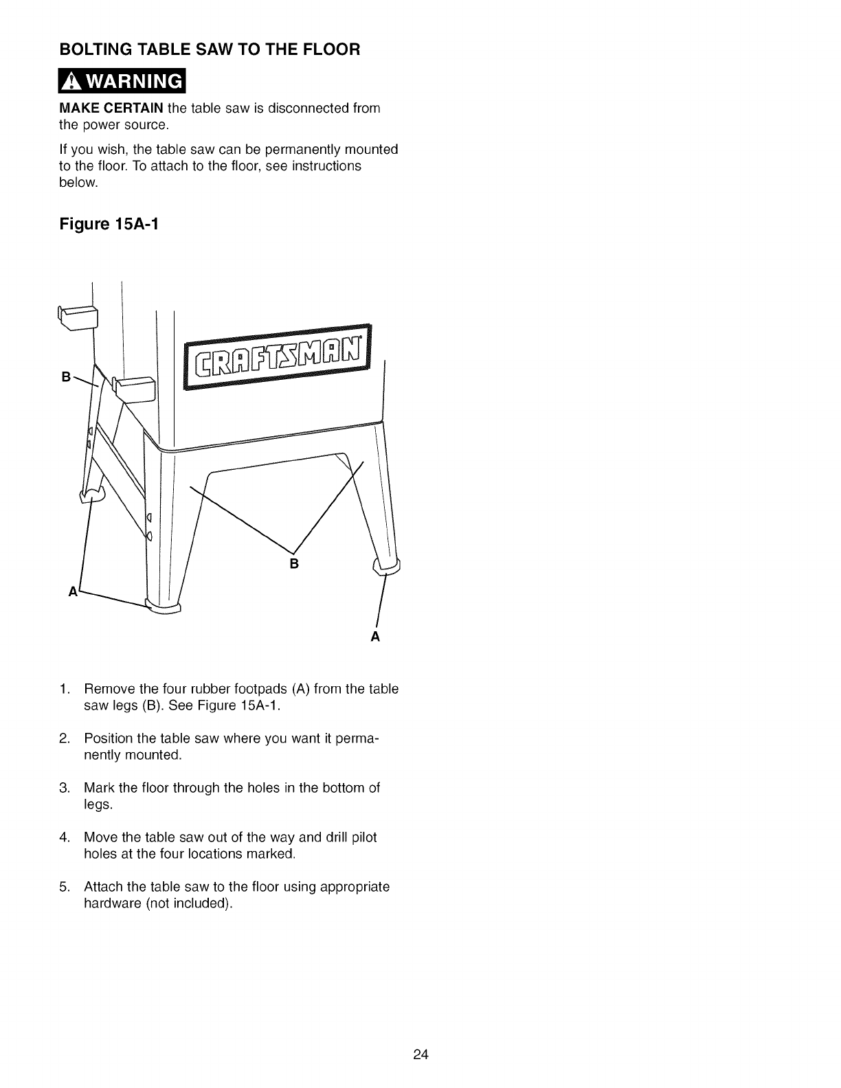
BOLTING TABLE SAW TO THE FLOOR
MAKE CERTAIN the table saw is disconnected from
the power source.
If you wish, the table saw can be permanently mounted
to the floor. To attach to the floor, see instructions
below.
Figure 15A-1
B
A
.
.
.
.
.
Remove the four rubber footpads (A) from the table
saw legs (B). See Figure 15A-1.
Position the table saw where you want it perma-
nently mounted.
Mark the floor through the holes in the bottom of
legs.
Move the table saw out of the way and drill pilot
holes at the four locations marked.
Attach the table saw to the floor using appropriate
hardware (not included).
24
CAUTION
• A separate electrical circuit should be used for your
table saw. The table saw comes pre-wired for 120-volt
use. The circuit should not be less than #14 AWG wire
and should be protected with a 15-amp time lag fuse.
• Have a qualified electrician repair or replace damaged
or worn cord immediately.
• Before connecting the motor to the power line, make
certain the switch is in the "OFF" position and be sure
that the electric current is of the same characteristics
as the motor nameplate. All line connections should
make good contact.
• Running on low voltage or long extension cords will
damage the motor.
LOCKING ON/OFF SWITCH
,
,
,
When the table saw is not in use, the "ON" button
should be locked so that it cannot be started.
Using the padlock included with your table saw, lift
the "red "OFF" paddle and place the padlock
through the holes (C) in the side of the "ON" button
and then lock the padlock. Make sure keys have
been removed from padlock and placed where no
children can get them. See figure 17-1.
To use the table saw, unlock and remove the pad-
lock from the "ON" button.
THERMAL-OVERLOAD PROTECTION
• DO NOT expose the table saw to rain or operate the
in damp locations.
•MAKE SURE all parts have been assembled correctly
and are in working order.
•KEEP table surface clear of tools and debris before
starting table saw.
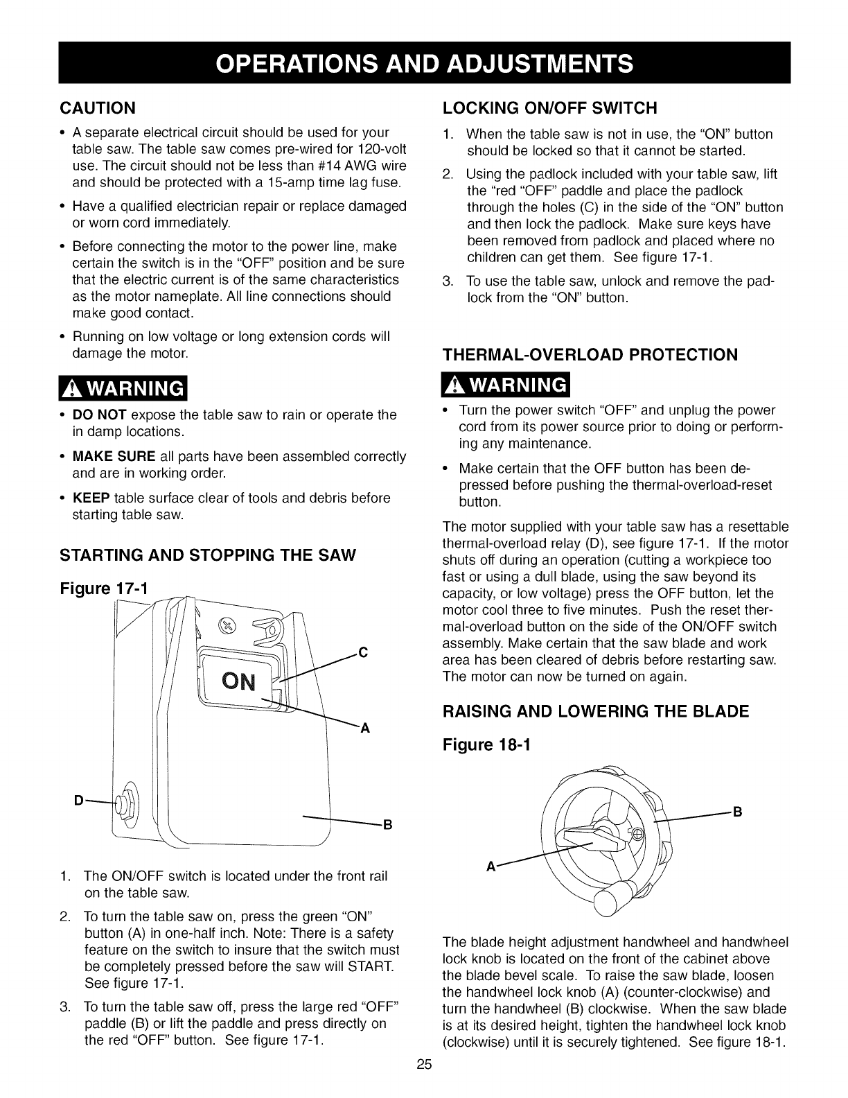
STARTING AND STOPPING THE SAW
Figure 17-1
D _
_A
,
,
,
The ON/OFF switch is located under the front rail
on the table saw.
To turn the table saw on, press the green "ON"
button (A) in one-half inch. Note: There is a safety
feature on the switch to insure that the switch must
be completely pressed before the saw will START.
See figure 17-1.
To turn the table saw off, press the large red "OFF"
paddle (B) or lift the paddle and press directly on
the red "OFF" button. See figure 17-1.
Turn the power switch "OFF" and unplug the power
cord from its power source prior to doing or perform-
ing any maintenance.
Make certain that the OFF button has been de-
pressed before pushing the thermal-overload-reset
button.
The motor supplied with your table saw has a resettable
thermal-overload relay (D), see figure 17-1. If the motor
shuts off during an operation (cutting a workpiece too
fast or using a dull blade, using the saw beyond its
capacity, or low voltage) press the OFF button, let the
motor cool three to five minutes. Push the reset ther-
mal-overload button on the side of the ON/OFF switch
assembly. Make certain that the saw blade and work
area has been cleared of debris before restarting saw.
The motor can now be turned on again.
RAISING AND LOWERING THE BLADE
Figure 18-1
AB
25
The blade height adjustment handwheel and handwheel
lock knob is located on the front of the cabinet above
the blade bevel scale. To raise the saw blade, loosen
the handwheel lock knob (A) (counter-clockwise) and
turn the handwheel (B) clockwise. When the saw blade
is at its desired height, tighten the handwheel lock knob
(clockwise) until it is securely tightened. See figure 18-1.
Tolowerthesawblade,loosenthehandwheellock
knob(counterclockwise)andturnthehandwheel
counterclockwise.Whenthesawbladeisat itsdesired
height,tightenthehandwheellockknob(clockwise)
untilit issecurelytightened.
TILTING THE BLADE
The blade bevel handwheel and handwheel lock knob
is located on the left side of the cabinet. To increase
the saw blade-bevel, loosen the handwheel lock knob
(A) (counterclockwise) and turn the handwheel (B)
clockwise. When the saw blade is at its desired
degree, tighten the handwheel lock knob (clockwise)
until it is securely tightened. See figure 18-1
To return the saw blade bevel to zero degrees, loosen
the handwheel lock knob (counterclockwise) and turn
the handwheel counterclockwise. When the saw blade
is back to zero degrees it will come into contact with the
adjustable positive stop which will cause the blade to
stop. Tighten the handwheel lock knob (clockwise) until
it is securely tightened.
To tilt the blade bevel to 45-degrees, loosen the hand-
wheel lock knob (counterclockwise) and turn the hand-
wheel clockwise. When the saw blade is at 45-degrees
it will come into contact with the adjustable positive stop
which will cause the blade to stop, tighten the hand-
wheel lock knob (clockwise) until it is securely tightened.
ADJUSTING BLADE BEVEL
POSITIVE STOPS
Figure 19-1
A
B
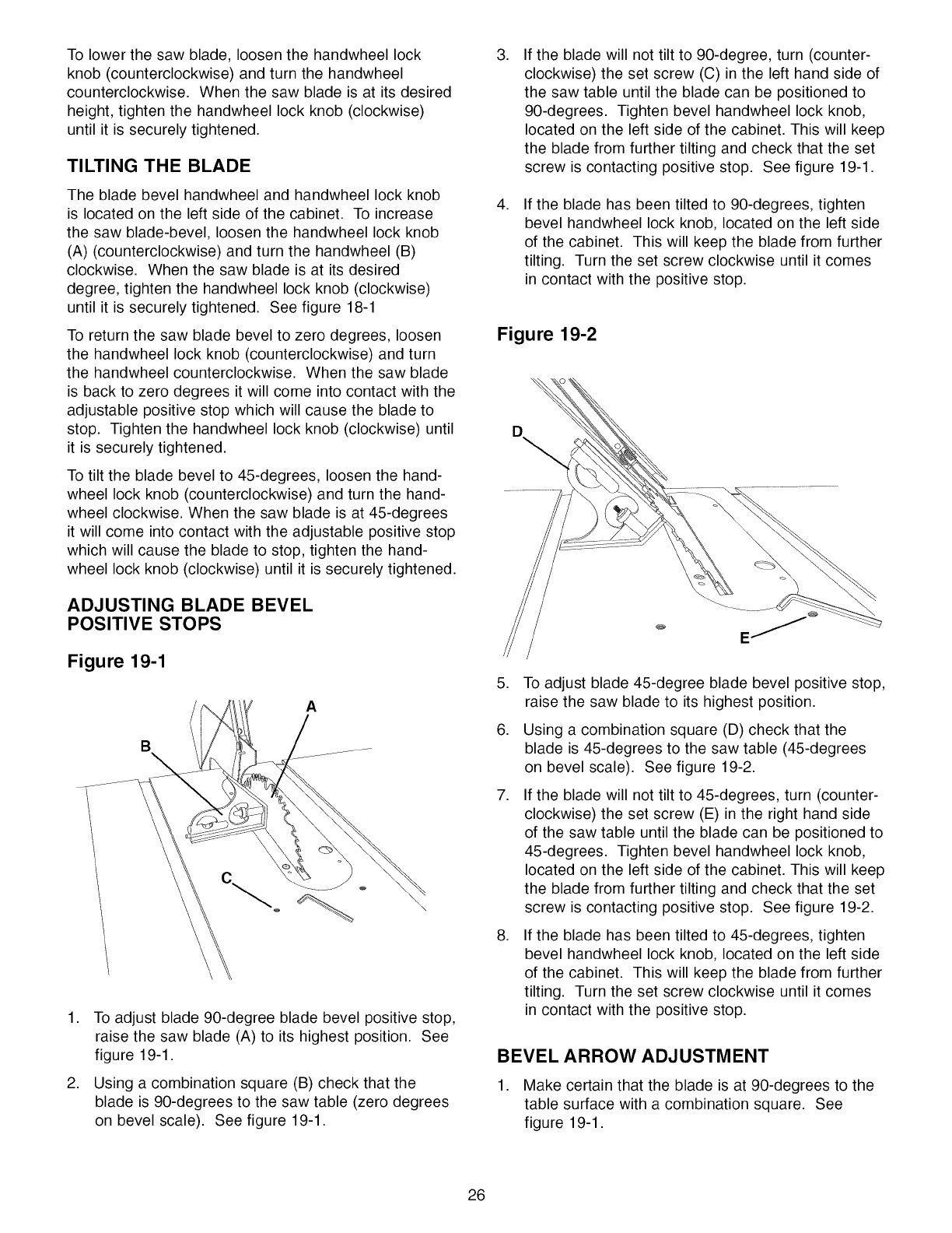
,
,
To adjust blade 90-degree blade bevel positive stop,
raise the saw blade (A) to its highest position. See
figure 19-1.
Using a combination square (B) check that the
blade is 90-degrees to the saw table (zero degrees
on bevel scale). See figure 19-1.
,
,
If the blade will not tilt to 90-degree, turn (counter-
clockwise) the set screw (C) in the left hand side of
the saw table until the blade can be positioned to
90-degrees. Tighten bevel handwheel lock knob,
located on the left side of the cabinet. This will keep
the blade from further tilting and check that the set
screw is contacting positive stop. See figure 19-1.
If the blade has been tilted to 90-degrees, tighten
bevel handwheel lock knob, located on the left side
of the cabinet. This will keep the blade from further
tilting. Turn the set screw clockwise until it comes
in contact with the positive stop.
Figure 19-2
,
,
,
,
To adjust blade 45-degree blade bevel positive stop,
raise the saw blade to its highest position.
Using a combination square (D) check that the
blade is 45-degrees to the saw table (45-degrees
on bevel scale). See figure 19-2.
If the blade will not tilt to 45-degrees, turn (counter-
clockwise) the set screw (E) in the right hand side
of the saw table until the blade can be positioned to
45-degrees. Tighten bevel handwheel lock knob,
located on the left side of the cabinet. This will keep
the blade from further tilting and check that the set
screw is contacting positive stop. See figure 19-2.
If the blade has been tilted to 45-degrees, tighten
bevel handwheel lock knob, located on the left side
of the cabinet. This will keep the blade from further
tilting. Turn the set screw clockwise until it comes
in contact with the positive stop.
BEVEL ARROW ADJUSTMENT
1. Make certain that the blade is at 90-degrees to the
table surface with a combination square. See
figure 19-1.
26
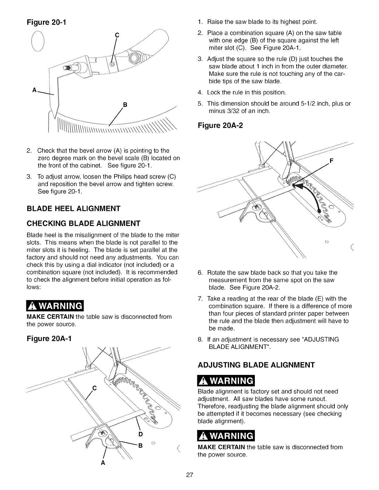
Figure 20-1
C
.
2.
.
.
5.
Raise the saw blade to its highest point.
Place a combination square (A) on the saw table
with one edge (B) of the square against the left
miter slot (C). See Figure 20A-1.
Adjust the square so the rule (D) just touches the
saw blade about 1 inch in from the outer diameter.
Make sure the rule is not touching any of the car-
bide tips of the saw blade.
Lock the rule in this position.
This dimension should be around 5-1/2 inch, plus or
minus 3/32 of an inch.
Figure 20A-2
.
.
Check that the bevel arrow (A) is pointing to the
zero degree mark on the bevel scale (B) located on
the front of the cabinet. See figure 20-1.
To adjust arrow, loosen the Philips head screw (C)
and reposition the bevel arrow and tighten screw.
See figure 20-1.
BLADE HEEL ALIGNMENT
CHECKING BLADE ALIGNMENT
Blade heel is the misalignment of the blade to the miter
slots. This means when the blade is not parallel to the
miter slots it is heeling. The blade is set parallel at the
factory and should not need any adjustments. You can
check this by using a dial indicator (not included) or a
combination square (not included). It is recommended
to check the alignment before initial operation as fol-
lows:
MAKE CERTAIN the table saw is disconnected from
the power source.
Figure 20A-1
O
.
.
.
Rotate the saw blade back so that you take the
measurement from the same spot on the saw
blade. See Figure 20A-2.
Take a reading at the rear of the blade (E) with the
combination square. If there is a difference of more
than four pieces of standard printer paper between
the rule and the blade then adjustment will have to
be made.
If an adjustment is necessary see "ADJUSTING
BLADE ALIGNMENT".
ADJUSTING BLADE ALIGNMENT
J
A
D
27
Blade alignment is factory set and should not need
adjustment. All saw blades have some runout.
Therefore, readjusting the blade alignment should only
be attempted if it becomes necessary (see checking
blade alignment).
MAKE CERTAIN the table saw is disconnected from
the power source.
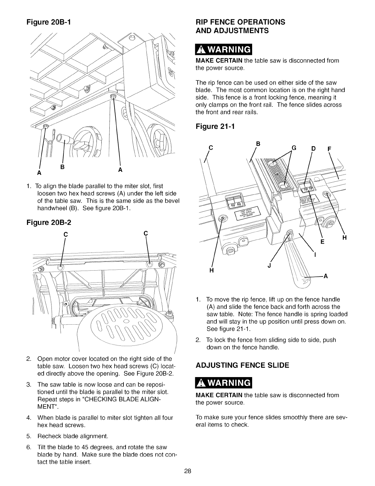
Figure 20B-1
\
RIP FENCE OPERATIONS
AND ADJUSTMENTS
MAKE CERTAIN the table saw is disconnected from
the power source.
The rip fence can be used on either side of the saw
blade. The most common location is on the right hand
side. This fence is a front locking fence, meaning it
only clamps on the front rail. The fence slides across
the front and rear rails.
Figure 21-1
B
C G D F
ABA
1. To align the blade parallel to the miter slot, first
loosen two hex head screws (A) under the left side
of the table saw. This is the same side as the bevel
handwheel (B). See figure 20B-1.
Figure 20B-2
cC
H
E
I
H
.
.
.
.
6.
Open motor cover located on the right side of the
table saw. Loosen two hex head screws (C) locat-
ed directly above the opening. See Figure 20B-2.
The saw table is now loose and can be reposi-
tioned until the blade is parallel to the miter slot.
Repeat steps in "CHECKING BLADE ALIGN-
MENT".
When blade is parallel to miter slot tighten all four
hex head screws.
Recheck blade alignment.
Tilt the blade to 45 degrees, and rotate the saw
blade by hand. Make sure the blade does not con-
tact the table insert.
.
.
To move the rip fence, lift up on the fence handle
(A) and slide the fence back and forth across the
saw table. Note: The fence handle is spring loaded
and will stay in the up position until press down on.
See figure 21-1.
To lock the fence from sliding side to side, push
down on the fence handle.
ADJUSTING FENCE SLIDE
MAKE CERTAIN the table saw is disconnected from
the power source.
To make sure your fence slides smoothly there are sev-
eral items to check.
28
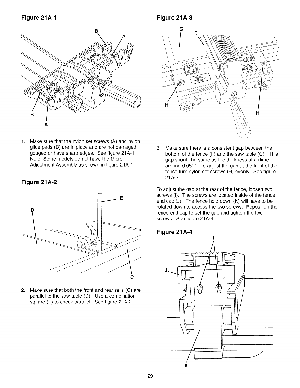
Figure 21A-1
B
A
BA
Figure 21A-3
G
/
H
F
H
,Make sure that the nylon set screws (A) and nylon
glide pads (B) are in place and are not damaged,
gouged or have sharp edges. See figure 21A-1.
Note: Some models do not have the Micro-
Adjustment Assembly as shown in figure 21A-1.
Figure 21A-2
E
D
\
C
2. Make sure that both the front and rear rails (C) are
parallel to the saw table (D). Use a combination
square (E) to check parallel. See figure 21A-2.
29
,Make sure there is a consistent gap between the
bottom of the fence (F) and the saw table (G). This
gap should be same as the thickness of a dime,
around 0.050". To adjust the gap at the front of the
fence turn nylon set screws (H) evenly. See figure
21A-3.
To adjust the gap at the rear of the fence, loosen two
screws (I). The screws are located inside of the fence
end cap (J). The fence hold down (K) will have to be
rotated down to access the two screws. Reposition the
fence end cap to set the gap and tighten the two
screws. See figure 21A-4.
Figure 21A-4
/
K
/
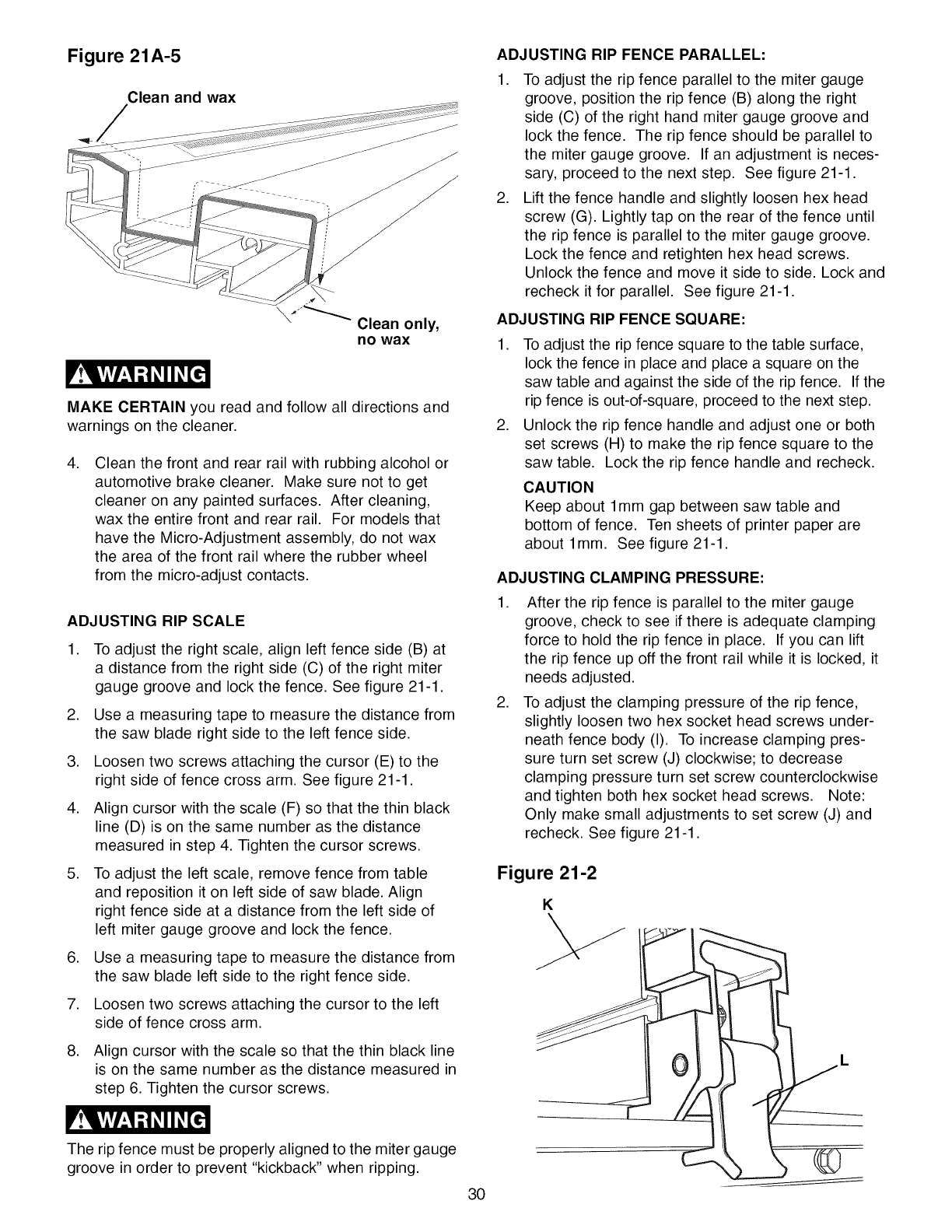
Figure 21A-5
Clean and wax
MAKE CERTAIN you read and follow all directions and
warnings on the cleaner.
.Clean the front and rear rail with rubbing alcohol or
automotive brake cleaner. Make sure not to get
cleaner on any painted surfaces. After cleaning,
wax the entire front and rear rail. For models that
have the Micro-Adjustment assembly, do not wax
the area of the front rail where the rubber wheel
from the micro-adjust contacts.
ADJUSTING RIP SCALE
.
.
.
.
.
.
.
To adjust the right scale, align left fence side (B) at
a distance from the right side (C) of the right miter
gauge groove and lock the fence. See figure 21-1.
Use a measuring tape to measure the distance from
the saw blade right side to the left fence side.
Loosen two screws attaching the cursor (E) to the
right side of fence cross arm. See figure 21-1.
Align cursor with the scale (F) so that the thin black
line (D) is on the same number as the distance
measured in step 4. Tighten the cursor screws.
To adjust the left scale, remove fence from table
and reposition it on left side of saw blade. Align
right fence side at a distance from the left side of
left miter gauge groove and lock the fence.
Use a measuring tape to measure the distance from
the saw blade left side to the right fence side.
Loosen two screws attaching the cursor to the left
side of fence cross arm.
8. Align cursor with the scale so that the thin black line
is on the same number as the distance measured in
step 6. Tighten the cursor screws.
ADJUSTING RIP FENCE PARALLEL:
1. To adjust the rip fence parallel to the miter gauge
groove, position the rip fence (B) along the right
side (C) of the right hand miter gauge groove and
lock the fence. The rip fence should be parallel to
the miter gauge groove. If an adjustment is neces-
sary, proceed to the next step. See figure 21-1.
2. Lift the fence handle and slightly loosen hex head
screw (G). Lightly tap on the rear of the fence until
the rip fence is parallel to the miter gauge groove.
Lock the fence and retighten hex head screws.
Unlock the fence and move it side to side. Lock and
recheck it for parallel. See figure 21-1.
ADJUSTING RIP FENCE SQUARE:
.
.
To adjust the rip fence square to the table surface,
lock the fence in place and place a square on the
saw table and against the side of the rip fence. If the
rip fence is out-of-square, proceed to the next step.
Unlock the rip fence handle and adjust one or both
set screws (H) to make the rip fence square to the
saw table. Lock the rip fence handle and recheck.
CAUTION
Keep about 1ram gap between saw table and
bottom of fence. Ten sheets of printer paper are
about 1ram. See figure 21-1.
ADJUSTING CLAMPING PRESSURE:
.
.
After the rip fence is parallel to the miter gauge
groove, check to see if there is adequate clamping
force to hold the rip fence in place. If you can lift
the rip fence up off the front rail while it is locked, it
needs adjusted.
To adjust the clamping pressure of the rip fence,
slightly loosen two hex socket head screws under-
neath fence body (I). To increase clamping pres-
sure turn set screw (J) clockwise; to decrease
clamping pressure turn set screw counterclockwise
and tighten both hex socket head screws. Note:
Only make small adjustments to set screw (J) and
recheck. See figure 21-1.
Figure 21-2
K
The rip fence must be properly aligned to the miter gauge
groove in order to prevent "kickback" when ripping.
30
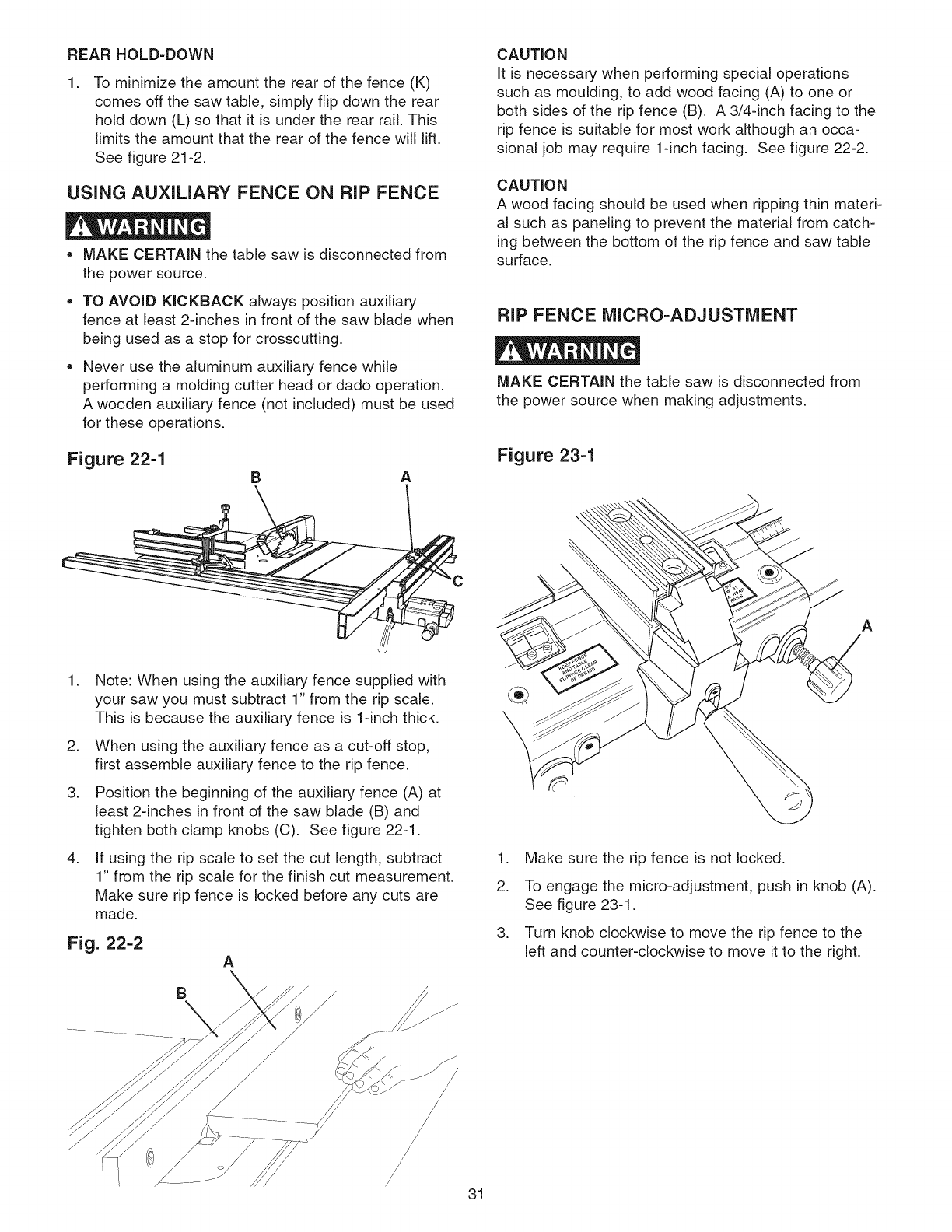
REARHOLD=DOWN
.To minimize the amount the rear of the fence (K)
comes off the saw table, simply flip down the rear
hold down (L) so that it is under the rear rail. This
limits the amount that the rear of the fence will lift.
See figure 21-2.
USING AUXILIARY FENCE ON RiP FENCE
= MAKE CERTAIN the table saw is disconnected from
the power source,
TO AVOID KICKBACK always position auxiliary
fence at least 2-inches in front of the saw blade when
being used as a stop for crosscutting.
Never use the aluminum auxiliary fence while
performing a molding cutter head or dado operation.
A wooden auxiliary fence (not included) must be used
for these operations.
Figure 22-1 B A
CAUTION
It is necessary when performing special operations
such as moulding, to add wood facing (A) to one or
both sides of the rip fence (B). A 3/4qnch facing to the
rip fence is suitable for most work although an occa-
sional job may require 1-inch facing. See figure 22-2.
CAUTION
A wood facing should be used when ripping thin materi-
al such as paneling to prevent the material from catch-
ing between the bottom of the rip fence and saw table
surface.
RiP FENCE MICRO-ADJUSTMENT
MAKE CERTAIN the table saw is disconnected from
the power source when making adjustments.
Figure 23-1
.
.
.
.
Note: When using the auxiliary fence supplied with
your saw you must subtract 1" from the rip scale.
This is because the auxiliary fence is 1-inch thick.
When using the auxiliary fence as a cut-off stop,
first assemble auxiliary fence to the rip fence.
Position the beginning of the auxiliary fence (A) at
least 2-inches in front of the saw blade (B) and
tighten both clamp knobs (C). See figure 22-1.
If using the rip scale to set the cut length, subtract
1" from the rip scale for the finish cut measurement.
Make sure rip fence is locked before any cuts are
made.
Fig. 22-2 A
B
s
f/
A
1. Make sure the rip fence is not locked.
2. To engage the micro-adjustment, push in knob (A).
See figure 23-1.
3. Turn knob clockwise to move the rip fence to the
left and counter-clockwise to move it to the right.
/31
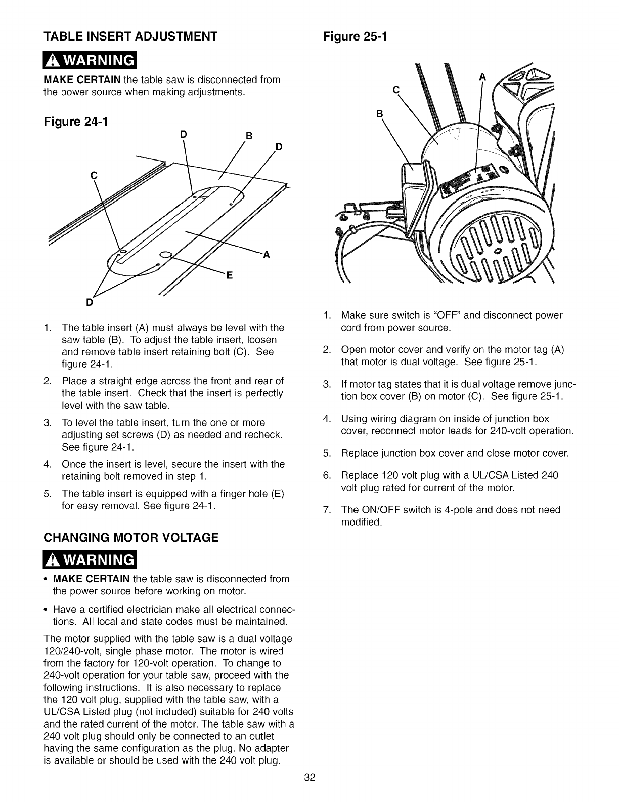
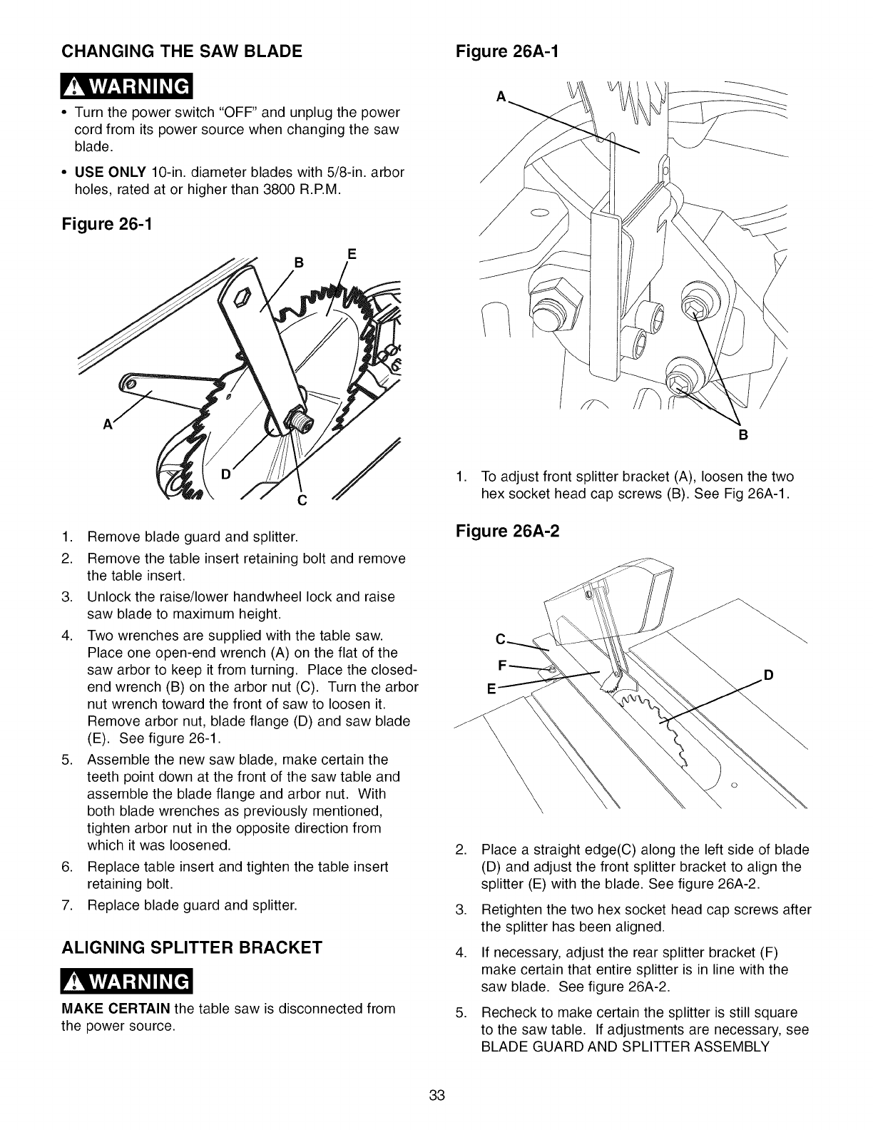
TABLE INSERT ADJUSTMENT Figure 25-1
MAKE CERTAIN the table saw is disconnected from
the power source when making adjustments.
Figure 24-1
D B D
C
B
C
A
D
1. The table insert (A) must always be level with the
saw table (B). To adjust the table insert, loosen
and remove table insert retaining bolt (C). See
figure 24-1.
2. Place a straight edge across the front and rear of
the table insert. Check that the insert is perfectly
level with the saw table.
,
,
,
To level the table insert, turn the one or more
adjusting set screws (D) as needed and recheck.
See figure 24-1.
Once the insert is level, secure the insert with the
retaining bolt removed in step 1.
The table insert is equipped with a finger hole (E)
for easy removal. See figure 24-1.
CHANGING MOTOR VOLTAGE
1. Make sure switch is "OFF" and disconnect power
cord from power source.
2. Open motor cover and verify on the motor tag (A)
that motor is dual voltage. See figure 25-1.
3. If motor tag states that it is dual voltage remove junc-
tion box cover (B) on motor (C). See figure 25-1.
4. Using wiring diagram on inside of junction box
cover, reconnect motor leads for 240-volt operation.
5. Replace junction box cover and close motor cover.
6. Replace 120 volt plug with a UL/CSA Listed 240
volt plug rated for current of the motor.
7. The ON/OFF switch is 4-pole and does not need
modified.
•MAKE CERTAIN the table saw is disconnected from
the power source before working on motor.
• Have a certified electrician make all electrical connec-
tions. All local and state codes must be maintained.
The motor supplied with the table saw is a dual voltage
120/240-volt, single phase motor. The motor is wired
from the factory for 120-volt operation. To change to
240-volt operation for your table saw, proceed with the
following instructions. It is also necessary to replace
the 120 volt plug, supplied with the table saw, with a
UL/CSA Listed plug (not included) suitable for 240 volts
and the rated current of the motor. The table saw with a
240 volt plug should only be connected to an outlet
having the same configuration as the plug. No adapter
is available or should be used with the 240 volt plug.
32
CHANGING THE SAW BLADE Figure 26A-1
•Turn the power switch "OFF" and unplug the power
cord from its power source when changing the saw
blade.
•USE ONLY 10-in. diameter blades with 5/8-in. arbor
holes, rated at or higher than 3800 R.P.M.
Figure 26-1
E
B
1. Remove blade guard and splitter.
2. Remove the table insert retaining bolt and remove
the table insert.
3. Unlock the raise/lower handwheel lock and raise
saw blade to maximum height.
4. Two wrenches are supplied with the table saw.
Place one open-end wrench (A) on the flat of the
saw arbor to keep it from turning. Place the closed-
end wrench (B) on the arbor nut (C). Turn the arbor
nut wrench toward the front of saw to loosen it.
Remove arbor nut, blade flange (D) and saw blade
(E). See figure 26-1.
5. Assemble the new saw blade, make certain the
teeth point down at the front of the saw table and
assemble the blade flange and arbor nut. With
both blade wrenches as previously mentioned,
tighten arbor nut in the opposite direction from
which it was loosened.
6. Replace table insert and tighten the table insert
retaining bolt.
7. Replace blade guard and splitter.
ALIGNING SPLITTER BRACKET
MAKE CERTAIN the table saw is disconnected from
the power source.
B
1. To adjust front splitter bracket (A), loosen the two
hex socket head cap screws (B). See Fig 26A-1.
Figure 26A-2
,
,
,
,
Place a straight edge(C) along the left side of blade
(D) and adjust the front splitter bracket to align the
splitter (E) with the blade. See figure 26A-2.
Retighten the two hex socket head cap screws after
the splitter has been aligned.
If necessary, adjust the rear splitter bracket (F)
make certain that entire splitter is in line with the
saw blade. See figure 26A-2.
Recheck to make certain the splitter is still square
to the saw table. If adjustments are necessary, see
BLADE GUARD AND SPLITTER ASSEMBLY
33
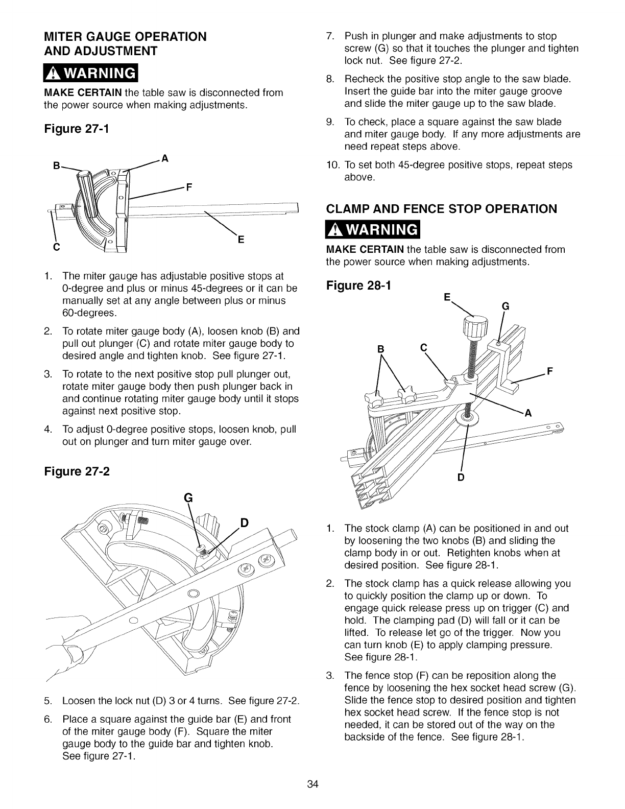
MITER GAUGE OPERATION
AND ADJUSTMENT
MAKE CERTAIN the table saw is disconnected from
the power source when making adjustments.
Figure 27-1
.
.
.
10.
Push in plunger and make adjustments to stop
screw (G) so that it touches the plunger and tighten
lock nut. See figure 27-2.
Recheck the positive stop angle to the saw blade.
Insert the guide bar into the miter gauge groove
and slide the miter gauge up to the saw blade.
To check, place a square against the saw blade
and miter gauge body. If any more adjustments are
need repeat steps above.
To set both 45-degree positive stops, repeat steps
above.
CLAMP AND FENCE STOP OPERATION
CE
.
.
.
.
The miter gauge has adjustable positive stops at
0-degree and plus or minus 45-degrees or it can be
manually set at any angle between plus or minus
60-degrees.
To rotate miter gauge body (A), loosen knob (B) and
pull out plunger (C) and rotate miter gauge body to
desired angle and tighten knob. See figure 27-1.
To rotate to the next positive stop pull plunger out,
rotate miter gauge body then push plunger back in
and continue rotating miter gauge body until it stops
against next positive stop.
To adjust 0-degree positive stops, loosen knob, pull
out on plunger and turn miter gauge over.
Figure 27-2
G
D
.
6.
Loosen the lock nut (D) 3 or 4 turns. See figure 27-2.
Place a square against the guide bar (E) and front
of the miter gauge body (F). Square the miter
gauge body to the guide bar and tighten knob.
See figure 27-1.
MAKE CERTAIN the table saw is disconnected from
the power source when making adjustments.
Figure 28-1 EG
B C
-A
D
.
.
.
The stock clamp (A) can be positioned in and out
by loosening the two knobs (B) and sliding the
clamp body in or out. Retighten knobs when at
desired position. See figure 28-1.
The stock clamp has a quick release allowing you
to quickly position the clamp up or down. To
engage quick release press up on trigger (C) and
hold. The clamping pad (D) will fall or it can be
lifted. To release let go of the trigger. Now you
can turn knob (E) to apply clamping pressure.
See figure 28-1.
The fence stop (F) can be reposition along the
fence by loosening the hex socket head screw (G).
Slide the fence stop to desired position and tighten
hex socket head screw. If the fence stop is not
needed, it can be stored out of the way on the
backside of the fence. See figure 28-1.
34
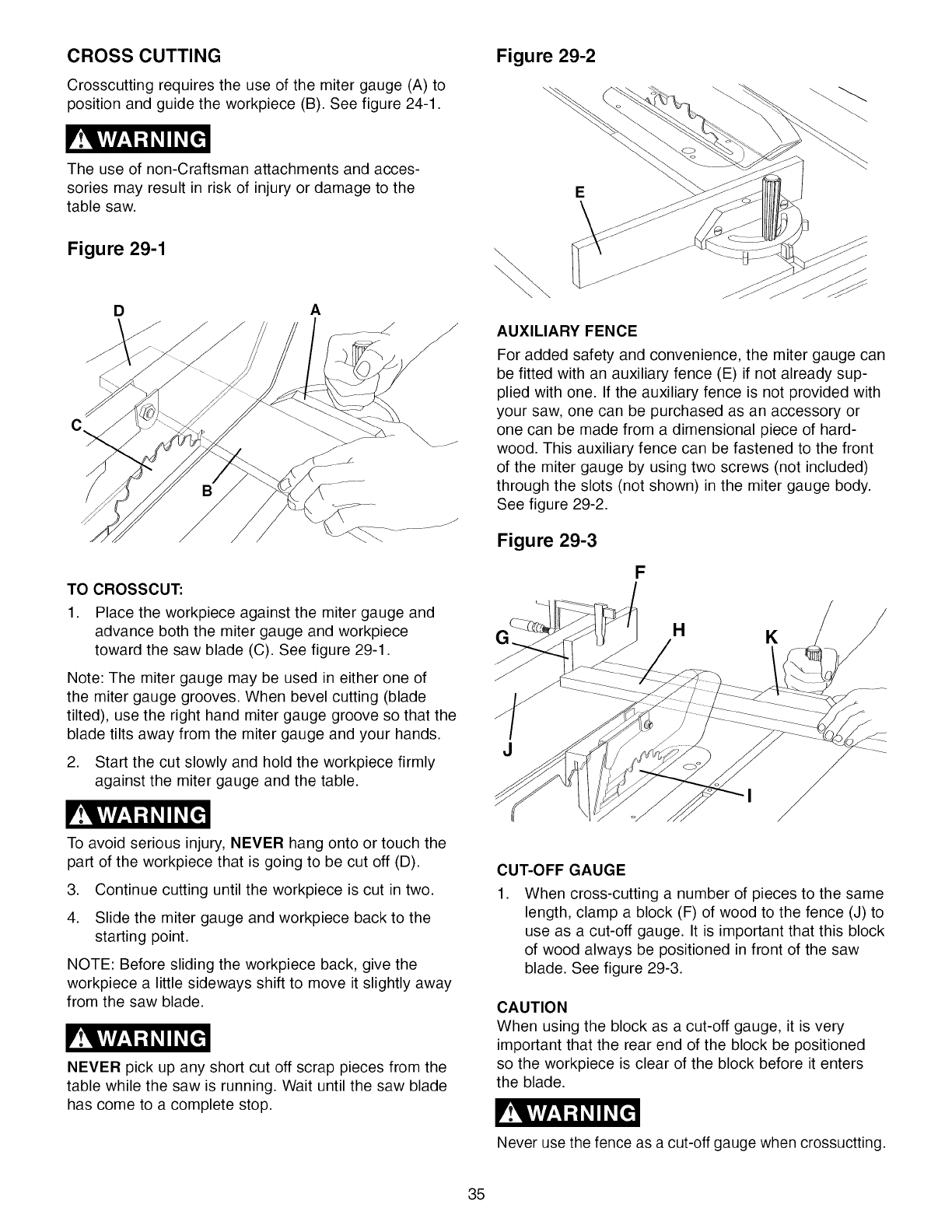
CROSS CUTTING
Crosscutting requires the use of the miter gauge (A) to
position and guide the workpiece (B). See figure 24-1.
The use of non-Craftsman attachments and acces-
sories may result in risk of injury or damage to the
table saw.
Figure 29-1
DA
TO CROSSCUT:
1. Place the workpiece against the miter gauge and
advance both the miter gauge and workpiece
toward the saw blade (C). See figure 29-1.
Note: The miter gauge may be used in either one of
the miter gauge grooves. When bevel cutting (blade
tilted), use the right hand miter gauge groove so that the
blade tilts away from the miter gauge and your hands.
2. Start the cut slowly and hold the workpiece firmly
against the miter gauge and the table.
Figure 29-2
E
AUXILIARY FENCE
For added safety and convenience, the miter gauge can
be fitted with an auxiliary fence (E) if not already sup-
plied with one. If the auxiliary fence is not provided with
your saw, one can be purchased as an accessory or
one can be made from a dimensional piece of hard-
wood. This auxiliary fence can be fastened to the front
of the miter gauge by using two screws (not included)
through the slots (not shown) in the miter gauge body.
See figure 29-2.
Figure 29-3
F
G(HK
To avoid serious injury, NEVER hang onto or touch the
part of the workpiece that is going to be cut off (D).
3. Continue cutting until the workpiece is cut in two.
4. Slide the miter gauge and workpiece back to the
starting point.
NOTE: Before sliding the workpiece back, give the
workpiece a little sideways shift to move it slightly away
from the saw blade.
NEVER pick up any short cut off scrap pieces from the
table while the saw is running. Wait until the saw blade
has come to a complete stop.
CUT-OFF GAUGE
1. When cross-cutting a number of pieces to the same
length, clamp a block (F) of wood to the fence (J) to
use as a cut-off gauge. It is important that this block
of wood always be positioned in front of the saw
blade. See figure 29-3.
CAUTION
When using the block as a cut-off gauge, it is very
important that the rear end of the block be positioned
so the workpiece is clear of the block before it enters
the blade.
Never use the fence as a cut-off gauge when crossuctting.
35
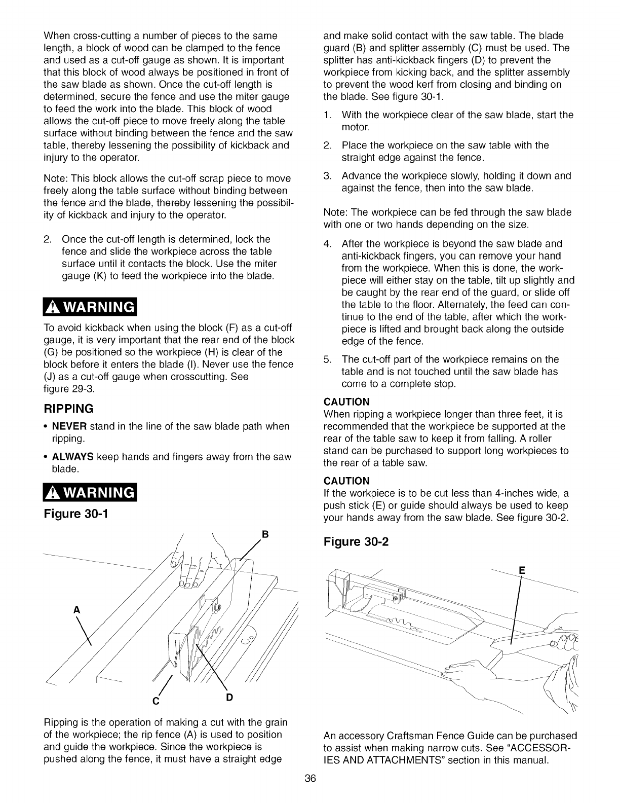
Whencross-cuttinga numberof piecesto thesame
length,a blockofwoodcanbeclampedtothefence
andusedasacut-offgaugeasshown.Itis important
thatthisblockofwoodalwaysbepositionedinfrontof
thesawbladeasshown.Oncethecut-offlengthis
determined,securethefenceandusethemitergauge
to feedtheworkintotheblade.Thisblockof wood
allowsthecut-offpieceto movefreelyalongthetable
surfacewithoutbindingbetweenthefenceandthesaw
table,therebylesseningthepossibilityof kickbackand
injuryto theoperator.
Note:Thisblockallowsthecut-offscrappieceto move
freelyalongthetablesurfacewithoutbindingbetween
thefenceandtheblade,therebylesseningthepossibil-
ityof kickbackandinjuryto theoperator.
,Once the cut-off length is determined, lock the
fence and slide the workpiece across the table
surface until it contacts the block. Use the miter
gauge (K) to feed the workpiece into the blade.
To avoid kickback when using the block (F) as a cut-off
gauge, it is very important that the rear end of the block
(G) be positioned so the workpiece (H) is clear of the
block before it enters the blade (I). Never use the fence
(J) as a cut-off gauge when crosscutting. See
figure 29-3.
RIPPING
• NEVER stand in the line of the saw blade path when
ripping.
• ALWAYS keep hands and fingers away from the saw
blade.
Figure 30-1
B
and make solid contact with the saw table. The blade
guard (B) and splitter assembly (C) must be used. The
splitter has anti-kickback fingers (D) to prevent the
workpiece from kicking back, and the splitter assembly
to prevent the wood kerf from closing and binding on
the blade. See figure 30-1.
1. With the workpiece clear of the saw blade, start the
motor.
,
,
Place the workpiece on the saw table with the
straight edge against the fence.
Advance the workpiece slowly, holding it down and
against the fence, then into the saw blade.
Note: The workpiece can be fed through the saw blade
with one or two hands depending on the size.
,
,
After the workpiece is beyond the saw blade and
anti-kickback fingers, you can remove your hand
from the workpiece. When this is done, the work-
piece will either stay on the table, tilt up slightly and
be caught by the rear end of the guard, or slide off
the table to the floor. Alternately, the feed can con-
tinue to the end of the table, after which the work-
piece is lifted and brought back along the outside
edge of the fence.
The cut-off part of the workpiece remains on the
table and is not touched until the saw blade has
come to a complete stop.
CAUTION
When ripping a workpiece longer than three feet, it is
recommended that the workpiece be supported at the
rear of the table saw to keep it from falling. A roller
stand can be purchased to support long workpieces to
the rear of a table saw.
CAUTION
If the workpiece is to be cut less than 4-inches wide, a
push stick (E) or guide should always be used to keep
your hands away from the saw blade. See figure 30-2.
Figure 30-2
E
A
CD
Ripping is the operation of making a cut with the grain
of the workpiece; the rip fence (A) is used to position
and guide the workpiece. Since the workpiece is
pushed along the fence, it must have a straight edge
\
An accessory Craftsman Fence Guide can be purchased
to assist when making narrow cuts. See "ACCESSOR-
IES AND ATTACHMENTS" section in this manual.
36
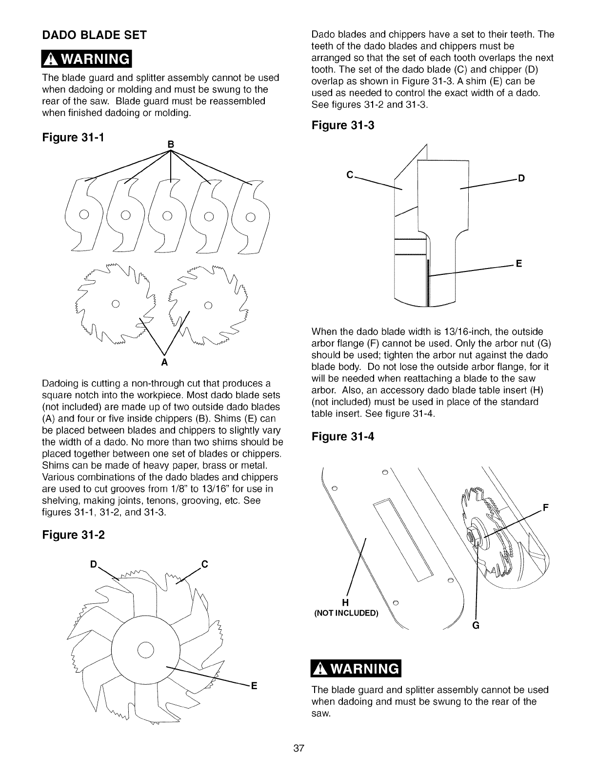
DADO BLADE SET
The blade guard and splitter assembly cannot be used
when dadoing or molding and must be swung to the
rear of the saw. Blade guard must be reassembled
when finished dadoing or molding.
Figure 31-1 B
A
Dadoing is cutting a non-through cut that produces a
square notch into the workpiece. Most dado blade sets
(not included) are made up of two outside dado blades
(A) and four or five inside chippers (B). Shims (E) can
be placed between blades and chippers to slightly vary
the width of a dado. No more than two shims should be
placed together between one set of blades or chippers.
Shims can be made of heavy paper, brass or metal.
Various combinations of the dado blades and chippers
are used to cut grooves from 1/8" to 13/16" for use in
shelving, making joints, tenons, grooving, etc. See
figures 31-1, 31-2, and 31-3.
Figure 31-2
Dado blades and chippers have a set to their teeth. The
teeth of the dado blades and chippers must be
arranged so that the set of each tooth overlaps the next
tooth. The set of the dado blade (C) and chipper (D)
overlap as shown in Figure 31-3. A shim (E) can be
used as needed to control the exact width of a dado.
See figures 31-2 and 31-3.
Figure 31-3
.---D
J
......-E
When the dado blade width is 13/16-inch, the outside
arbor flange (F) cannot be used. Only the arbor nut (G)
should be used; tighten the arbor nut against the dado
blade body. Do not lose the outside arbor flange, for it
will be needed when reattaching a blade to the saw
arbor. Also, an accessory dado blade table insert (H)
(not included) must be used in place of the standard
table insert. See figure 31-4.
Figure 31-4
©
Ho
(NOT INCLUDED)
G
EThe blade guard and splitter assembly cannot be used
when dadoing and must be swung to the rear of the
saw.
37
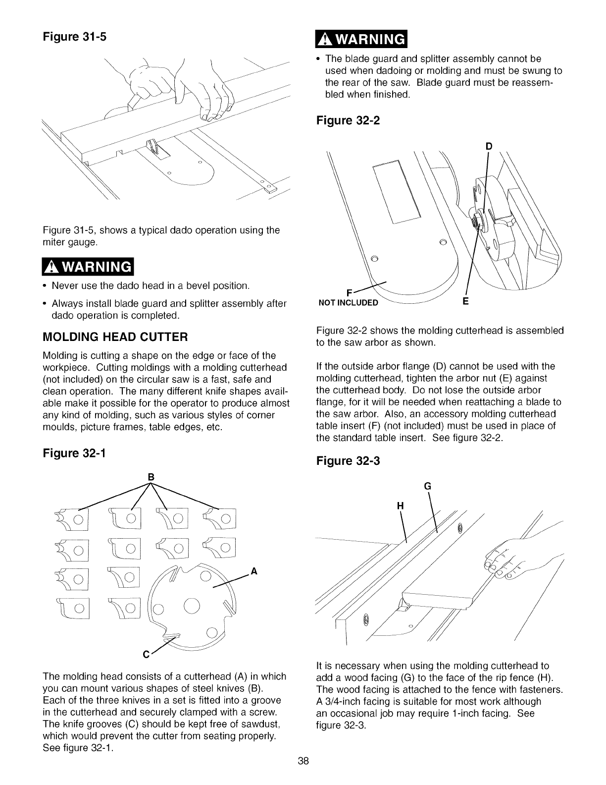
Figure 31-5
\The blade guard and splitter assembly cannot be
used when dadoing or molding and must be swung to
the rear of the saw. Blade guard must be reassem-
bled when finished.
Figure 32-2
D
Figure 31-5, shows a typical dado operation using the
miter gauge.
• Never use the dado head in a bevel position.
• Always install blade guard and splitter assembly after
dado operation is completed.
MOLDING HEAD CUTTER
Molding is cutting a shape on the edge or face of the
workpiece. Cutting moldings with a molding cutterhead
(not included) on the circular saw is a fast, safe and
clean operation. The many different knife shapes avail-
able make it possible for the operator to produce almost
any kind of molding, such as various styles of corner
moulds, picture frames, table edges, etc.
Figure 32-1
B
The molding head consists of a cutterhead (A) in which
you can mount various shapes of steel knives (B).
Each of the three knives in a set is fitted into a groove
in the cutterhead and securely clamped with a screw.
The knife grooves (C) should be kept free of sawdust,
which would prevent the cutter from seating properly.
See figure 32-1.
NOTINCLUDED E
Figure 32-2 shows the molding cutterhead is assembled
to the saw arbor as shown.
If the outside arbor flange (D) cannot be used with the
molding cutterhead, tighten the arbor nut (E) against
the cutterhead body. Do not lose the outside arbor
flange, for it will be needed when reattaching a blade to
the saw arbor. Also, an accessory molding cutterhead
table insert (F) (not included) must be used in place of
the standard table insert. See figure 32-2.
Figure 32-3
G
H
It is necessary when using the molding cutterhead to
add a wood facing (G) to the face of the rip fence (H).
The wood facing is attached to the fence with fasteners.
A 3/4-inch facing is suitable for most work although
an occasional job may require 1-inch facing. See
figure 32-3.
38
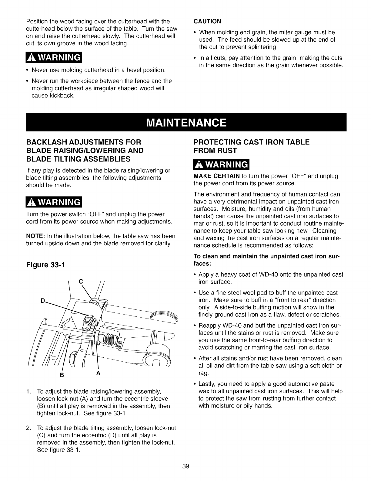
Positionthewoodfacingoverthecutterheadwiththe
cutterheadbelowthesurfaceofthetable.Turnthesaw
onandraisethecutterheadslowly.Thecutterheadwill
cutitsowngrooveinthewoodfacing.
• Neverusemoldingcutterheadina bevelposition.
• Neverruntheworkpiecebetweenthefenceandthe
moldingcutterheadasirregularshapedwoodwill
causekickback.
CAUTION
Whenmoldingendgrain,themitergaugemustbe
used.Thefeedshouldbeslowedupattheendof
thecutto preventsplintering
Inallcuts,payattentiontothegrain,makingthecuts
inthesamedirectionasthegrainwheneverpossible.
BACKLASH ADJUSTMENTS FOR
BLADE RAISING/LOWERING AND
BLADE TILTING ASSEMBLIES
If any play is detected in the blade raising/lowering or
blade tilting assemblies, the following adjustments
should be made.
Turn the power switch "OFF" and unplug the power
cord from its power source when making adjustments.
NOTE: In the illustration below, the table saw has been
turned upside down and the blade removed for clarity.
Figure 33-1
c
BA
,
,
To adjust the blade raising/lowering assembly,
loosen lock-nut (A) and turn the eccentric sleeve
(B) until all play is removed in the assembly, then
tighten lock-nut. See figure 33-1
To adjust the blade tilting assembly, loosen lock-nut
(C) and turn the eccentric (D) until all play is
removed in the assembly, then tighten the lock-nut.
See figure 33-1.
PROTECTING CAST IRON TABLE
FROM RUST
MAKE CERTAIN to turn the power "OFF" and unplug
the power cord from its power source.
The environment and frequency of human contact can
have a very detrimental impact on unpainted cast iron
surfaces. Moisture, humidity and oils (from human
hands!) can cause the unpainted cast iron surfaces to
mar or rust, so it is important to conduct routine mainte-
nance to keep your table saw looking new. Cleaning
and waxing the cast iron surfaces on a regular mainte-
nance schedule is recommended as follows:
To clean and maintain the unpainted cast iron sur-
faces:
• Apply a heavy coat of WD-40 onto the unpainted cast
iron surface.
Use a fine steel wool pad to buff the unpainted cast
iron. Make sure to buff in a "front to rear" direction
only. A side-to-side buffing motion will show in the
finely ground cast iron as a flaw, defect or scratches.
Reapply WD-40 and buff the unpainted cast iron sur-
faces until the stains or rust is removed. Make sure
you use the same front-to-rear buffing direction to
avoid scratching or marring the cast iron surface.
After all stains and/or rust have been removed, clean
all oil and dirt from the table saw using a soft cloth or
rag.
Lastly, you need to apply a good automotive paste
wax to all unpainted cast iron surfaces. This will help
to protect the saw from rusting from further contact
with moisture or oily hands.
39
LUBRICATION
The table saw has sealed lubricated bearings in the
motor housing that do not require any additional lubrica-
tion from the operator.
CLEANING
With the table saw unplugged, blow off motor with low-
pressure air to remove dust or dirt. Air pressure above
50 P. S. I. should not be used as high-pressured air
may damage insulation. The operator should always
wear eye protection when using compressed air.
Do not allow chips and dust to accumulate under table
saw. Keep area clean and in safe order.
CAUTION: DO NOT USE FLAMMABLE MATERIALS
to clean table saw.
Only trained personnel should perform repairs to the
table saw. Contact your nearest Sears Service Center
for authorized service. Unauthorized repairs or replace-
ment with non-factory parts could cause serious injury
to the operator and damage to the table saw.
40
TOPREVENTINJURYTOYOURSELFordamagetothetablesaw,turnthepowerswitchtothe"OFF"positionand
unplugthepowercordfromtheelectricalreceptaclebeforemakinganyadjustments.
PROBLEM
Motor does not
start:
Motor stalls,
thermal-overload
trips or circuit
breakers open
frequently:
Motor starts
slowly or fails to
come to full speed:
Motor running too
hot:
Handwheels are hard
to turn:
Miter gauge does not
move smoothly:
Workpiece binds,
burns or stalls motor
when ripping:
Saw blade does not
cut true at 90 or 45
degrees:
LIKELY CAUSE(S) SOLUTION
1. 1.
Switch not pressed in far enough or switch
in the "OFF" position.
2. Defective switch.
3. Defective capacitor.
4. Low line voltage.
5. Defective motor.
1. Circuit overload.
2. Low line voltage.
3. Motor overload.
4. Incorrect fuses on circuit breakers.
5. Short circuit in motor; loose connections or
worn insulation on lead wires.
1. Low line voltage.
2. Defective motor windings.
3. Defective capacitor.
1. Restricted air circulation due to dust
accumulation.
2. Motor overload.
1. Handwheel Lock Knob has not been loosened.
2. Dust accumulation on tilting or beveling gears
inside of cabinet.
1. Miter gauge groove and miter gauge bar are
dirty.
2. Set-screws in miter gauge bar are out of
adjustment.
1. Blade is dull.
2. Board is warped or twisted.
3. Rip fence is not parallel to blade.
1. Blade is dull.
2. Indicator arrow is not properly adjusted.
3. Positive stops are not set properly.
Depress switch in 1/2 inch or make sure switch is in the
"ON" position.
2. Have switch replaced.
3. Have capacitor replaced.
4. Correct low line voltage condition. If saw is plugged into an
extension cord, plug saw directly into wall outlet.
5. Have motor replaced.
NOTE: 3 and 4 must be done by a qualified service
technician.
1. Blade is warped.
2. Drive belt is damaged.
1,
2.
Reduce circuit load (turn off other appliances)
Correct low line voltage condition. Check line voltage with a
multi-meter. If saw is plugged into an extension cord,
unplug saw from extension cord and plug saw directly to
wall outlet.
3. Reduce load on motor, slow down feed rate of workpiece
being pushed into blade.
4. Have correct fuses on circuit breakers installed by a quali-
fied electrician.
5. Inspect terminals in motor for damaged insulation and
shorted wires and have them replaced. Check all power
lead connections.
1, Correct low line voltage condition. Check line voltage with a
multi-meter. If saw is plugged into an extension cord,
unplug saw from extension cord and plug saw directly to
wall outlet.
2. Have motor replaced.
3. Have capacitor replaced
1. Clean dust and restore normal air circulation around motor.
2. Reduce load on motor,
1. Loosen Handwheel Lock Knob.
2. Clean off tilt and bevel gear assemblies.
1. Clean miter gauge groove and bar.
2. Adjust set-screws in miter gauge bar.
1. Sharpen or replace blade.
2. Replace board.
3. See "Fence Alignment" in Operation and Adjustment
Section.
1. Sharpen or replace blade.
2. Adjust bevel indicator arrow.
3. Adjust 90 and 45-degree positive stops.
Rip fence does not 1. Rip fence is not mounted properly. 1. See "Fence Alignment" in Operation and Adjustment Section.
move smoothly: 2. Rails are dirty or sticky. 2. Clean and apply paste wax to rails.
Saw vibrates
excessively:
3. Work surface is uneven.
4. Saw is not mounted securely.
1. Replace blade.
2. Replace drive belt.
3. Reposition saw on a flat surface. Adjust leveling feet, if
supplied with saw.
4. Tighten all hardware.
41

104N.TABLE SAW MODEL NO. 351.221140
When servicing, use only CRAFTSMAN replacement parts. Use of any other parts may create a HAZARD or cause
product damage.
Any attempt to repair or replace electrical parts on this table saw may create a HAZARD unless a qualified service
technician does repairs. Repair service is available at your nearest Sears Service Center.
Always order by PART NUMBER, not by key number.
*AVAILABLE AT MOST RETAIL STORES
Key No. PART No.
N/A OR91551
N/A OR91710
N/A OR91711
1OR91785
2OR91781
3OR91027
3A OR91574
3B OR91575
4 OR91782
5 OR91008
6 OR91834
7 OR91745
8 OR91031
9 OR91812
9A OR90502
10 OR91011
11 OR91051
12 OR91012
13 OR91820
14 OR90502
15 OR91758
16 OR91015
17 OR91048
18 OR91760
19 OR91820
20 OR91758
21 OR91010
21A OR91781
22 OR91013
23 OR91753
24 OR91795
25 OR91009
30 OR91789
31 OR91014
32 OR91052
33 OR91034
33A OR90283
34 OR91821
35 OR91021
36 OR90311
37 OR90248
38 OR90308
39B OR91093
40 OR91817
41 OR90248
42 OR91752
60 OR91040
60A OR90375
61A OR91712
63A
65
67
100
N/A
101
102
103
104
106
106
107
108
108
110
111
112
113
OR91579
OR91822
OR90333
OR91065
OR92012
OR91066
OR91067
OR91068
OR91796
OR91069
OR91070
OR91797
OR91071
OR91072
OR91073
OR90143
OR91774
OR91075
Description Qty. Key No. PART No.
OWNER'S MANUAL - #22114 10"' Table Saw 1 N/A OR35933
BLADE GUARD ASSEMBLY, (NOT SHOWN)
CONSISTS OF REF #: 1,2, 3, 3a, 3b 4, 5, 6, 7, 16, 24 & 25 N/A
SPLITTER BRACKET ASSEMBLY, (NOT SHOWN) 114 OR91076
CONSISTS OF REF #: 9, 9a, 10, 11, 12, 13, 14, 15 & 17 N/A 115 OR91077
PUSH NUT (CHROME) 2 116 OR81074
PIN 1 117 OR81118
"SEE THRU" BLADE GUARD 1 118 OR91078
WARNING LABEL 1 119 OR91078
WARNING LABEL PICTORAL 1 120 OR81763
PIN 1 121 OR91783
GUARD BRACKET 1 122 OR81774
PUSH NUT (BLACK) 1 123 OR81080
GUARD SPRING 1 124 OR81081
SPLITTER MOUNTING ROD 1 125 OR91082
HEX SOCKET HEAD SCREW M6 x 22rnrn 2 126 OR91775
LOCK WASHER M6 2 127 OR81776
SPLITTER REAR MOUNT LOWER 1 127A OR90078
SPLITTER MOUNT SQUARE NUT 2 128 OR91756
SPLITTER REAR MOUNT UPPER 1 129 OR91823
SPECIAL FLAT WASHER (ID:6.4mm, OD:18mm, T:1.6rnrn) 1 130 OR91573
LOCK WASHER M6 1 131 OR91084
HEX SOCKET HEAD SCREW M6 x 16rnrn 1 132 OR91085
SPLITTER 1 133 OR91086
SPLITTER KNOB 1 134 OR91756
HEX SOCKET HEAD SCREW M6 x 6rnrn 2 134A OR91823
SPECIAL FLAT WASHER (ID:6.4rnm, OD:18rnm, T:1.6mrn) 2 135 OR91087
HEX SOCKET HEAD SCREW M6 x 16mrn 2 136 OR91118
SPLITTER FRONT MOUNT 1 N/A OR93811
SPRING PIN 3mrn x 10ram 1
SPLITTER SPRING CLIP 1
SPECIAL HEX NUT M12 1
SPRING PIN 4rnrn x 22mrn 1 200 OR91767
ANTI - KICKBACK FINGER 2 201 OR91020
SET SCREW 1/4-28 x 3/8", NYLOCK 4 202 OR91824
TABLE INSERT- STANDARD 1 203 OR91734
TABLE INSERT RETAINING BOLT 1 203A OR91732
TABLE 1 204 OR91733
M6 X 8MM HEX SOC SET SCR 8 205 OR91004
HEX SOCKET SET SCREW M8 x 20rnm 2 206 OR91024
ALIGN-A-CUT INSERT 1 207 OR91801
FLAT WASHER M8 8 208 OR91733
LOCK WASHER M8 8 209 OR91022
HEX HEAD SCREW M8x1.25 x 30mm 8 210A OR91720
EXTENSION WING 10" CAST IRON 2 211 OR91026
SPECIAL FLAT WASHER (ID:8.4, OD:25, 323.5) 4 212 OR91050
LOCK WASHER M8 4 213 OR91746
HEX HEAD SCREW M8x1.25 x 25rnm 4 214 OR90230
SWITCH PADDLE 1 215 OR91003
PADLOCK AND KEY 1 216 OR90230
SWITCH ASSEMBLY, (NOT SHOWN) CONSISTS OF: 61, 62, 217 OR90227
62a, 63, 63a, 64, 66, 68, 69, 70,71,72, 73,74,75, 75a & 76 1 218 OR90228
SWITCH RESET LABEL 1 220 OR81721
SQUARE NUT M6 (11mrn Square) 2 221 OR90253
HEX HEAD SCREW M6 x 12rnm 2 222 OR91023
CLAMP KNOB 2 223 OR91770
CLAMPING BODY ASSEMBLY (NOT SHOWN) CONSISTS OF: 224B OR91722
101, 102,103, 104, 105, 106, 107,108, 109, 110, 111,112 & 113 N/A 224C OR91723
CLAMP BODY 1 224D OR91724
UPPER BUSHING 1 225B OR91576
ELEVATING KNOB 1 225C OR91578
SPRING PIN 4rnrn x 25mrn 1 226 OR90308
QUICK RELEASE SPRING 1 226A OR90311
QUICK RELEASE BRACKET 1 227 OR90311
SPRING PIN 6rnrn x 25mrn 1 228 OR91001
LOWER BUSHING 1 229 OR90248
ELEVATING ROD 1 230 OR90307
CLAMP FOOT 1 231 OR91825
FLAT WASHER M4 1 232 OR91771
PAN HEAD SCREW M4 x 10rnm 1 233 OR91784
CLAMP PAD 1 234 OR91802
Description
MITER GAUGE ASSEMBLY ACCESSORY, (NOT INCLUDED)
(NOT SHOWN)CONSISTS OF: 114, 115, 116,119, 120, 121, 122,
123, 124, 125, 126, 127, 127a, 130, 131 & 132
MITER GAGE BODY
SPECIAL WASHER, T-SLOT
SPECIAL SCREW
SQUARE NUT M5
CROSS CUT FENCE
GUIDE BAR
HEX SOCKET SET SCREW M4 x 16rnm
PIN 1/4" x 3/4"
PAN HEAD SCREW M4 x 10rnm
PLUNGER
PLUNGER BLOCK
CURSOR
PAN HEAD SCREW M4 x 16ram
PAN HEAD SCREW M4 x 20rnm
HEX NUT M4
HEX SOCKET HEAD SCREW M5 x 20ram
SPECIAL FLAT WASHER (ID:5.3, OD:12, T:1.2
MITER SCALE
SPECIAL WASHER, MITER HANDLE
MITER GAUGE KNOB
ELEVATING ROD
HEX SOCKET HEAD SCREW M5 x 20ram
SPECIAL FLAT WASHER (ID:5.3, OD:12, T:1.2
DEPTH STOP
SQUARE NUT M5
ARBOR/ELEVATING BRACKET ASSEMBLY
INCLUDES: 1-OR91767, 1-OR91020, 1-OR91824, 1-91734,
1-OR91732, 2-OR81733, 1-OR91004, 1-OR91024, 1-OR91801,
1-OR81022
JAM NUT 5/8-18-LH
ARBOR PULLEY
KEY 5rnrn x 5turn x 15ram
BEARING CLOSURE NUT
ARBOR SPACER
BALL BEARING <6203 LLB>
ELEVATING BRACKET
ARBOR SLEEVE
WAVE WASHER <BWW 6203>
BALL BEARING <6203 LLB>
ARBOR SHAFT
10" BLADE, 40 TOOTH, A.T.B., 5/8" BORE
BLADE FLANGE
BLADE HEX NUT-RH
HEX HEAD SCREW M10×1.5 x 45ram
FLAT WASHER M10
REAR BRACKET
FLAT WASHER M10
LOCK WASHER M10
HEX NUT M10×1.5
BELT (28" 6Rib Jsection PolyV )+E142
HEX SOCKET SET SCREW M5 x 12ram
MOTOR PULLEY
KEY 5rnm x 5turn x 36ram
MOTOR ASSEMBLY 1.5 HP
START CAPACITOR
RUN CAPACITOR
MOTOR SPEC PLATE 1.5 HP
MOTOR WIRING DIAGRAM LABEL
HEX HEAD SCREW M6×1.25 x 30ram
FLAT WASHER M8
FLAT WASHER M6
MOTOR BRACKET
LOCK WASHER M8
HEX NUT M8x1.25
SPRING PIN 8rnrn x 35ram
LOCK NUT 1/2-13UNC
PLATE WASHER
WAVE WASHER
Qty.
N/A
1
1
1
2
1
1
4
1
2
1
1
1
1
3
3
2
2
1
1
1
1
1
1
1
1
1
1
1
1
1
1
1
1
1
1
1
1
1
1
1
2
2
1
2
2
2
1
1
1
1
1
1
1
1
1
4
4
4
1
4
4
1
3
1
1
42

10-iN.TABLE SAW MODEL NO. 351.221140
Key No. PART No.
235 OR91054
236 OR91056
237 OR91057
240 OR91790
241 OR91757
N/A OR91118
242 OR91744
242A OR91792
243 OR91118
243 OR91047
244 OR91793
245 OR91766
248 OR91803
249 OR91800
251 OR91028
252 OR91029
253 OR91019
254 OR90059
255 OR91826
N/A OR91804
258 OR91045
256A OR91041
258B OR91038
258C OR91044
258 OR91048
N/A OR91117
259 OR91744
260 OR91792
261 OR91117
261 OR91033
261A OR91793
262 OR91738
263 OR91006
264 OR90230
265 OR91746
266 OR91018
266A OR91740
266B OR91137
266C OR91762
267 OR91816
268 OR90381
268A OR91827
269 OR91017
270 OR91786
N/A OR91804
271 OR91048
271A OR91041
271B OR91038
271C OR91044
273 OR91046
274 OR91768
278 OR90230
276 OR90227
277 OR90228
280 OR91726
281 OR91727
282 OR90289
283 OR90290
284 OR90291
285 OR91728
286 OR91729
287 OR91808
290 OR91814
291 OR91787
401 OR91166
402 OR91165
403 OR91167
N/A OR91714
404 OR91828
405 OR91168
405A OR91870
406 OR91169
406A OR91764
406B OR91828
407 OR91199
408 OR91197
409 OR91198
410 OR91182
411 OR91761
Description Qty.
MOTOR MOUNT STUD 1
MOTOR SPRING 1
STUD 1
SHAFT 1
HEX SOCKET HEAD SCREW M5 x 20ram, NYLOK 2
ELEVATING SHAFTASSEMBLY, CONSISTS OF:
242, 242A, 243 & 244 N/A
GEAR 1
SPRING PIN 3ram x 15ram
ELEVATING SHAFTASSEMBLY, CONSISTS OF:
1-#OR91744, 1-#OR91792 & 1-#OR91047 1
ELEVATING SHAFT 1
SPRING PIN 3ram x 20ram 1
JAM NUT 5/8-18 1
TRUNNION ASSEMBLY, (NOT SHOWN) CONSISTS OF REF #'s:
238 (2-#OR91053), 239 (1-#OR91002), 246, 247, 248, 219 & 250
(4-#OR91772) 1
WAVE WASHER E188 1
RAISE/LOWER SLEEVE 1
RAISE/LOWER SPACER 1
POINTER 1
FLAT WASHER M6 1
CHEESE HEAD SCREW M8 x 16mm 1
HANDWHEEL ASSEMBLY, (NOT SHOWN) CONSISTS OF:
1 - #OR91045, 1 - #OR91041, 1 - #OR91038 & 1 - #OR91044 N/A
HANDWHEEL 1
ELEVATING KNOB ASSEMBLY 1
KNOB BOLT 1
KNOB END CAP 1
HANDWHEEL LOCK KNOB 1
TILT SHAFT ASSEMBLY, (NOT SHOWN) CONSISTS OF:
259, 260, 261 & 281A N/A
GEAR 1
SPRING PIN 3rnm x 15mm 1
TILT SHAFT ASSEMBLY, (NOT SHOWN) CONSISTS OF:
1-#OR91744, 1-#OR91792 & 1-#OR91033 1
TILT SHAFT 1
SPRING PIN 3turn x 20mm 1
ECCENTRIC 1
FRONT BRACKET 1
FLAT WASHER M10 2
HEX HEAD SCREW M10x1.5 x 45mm 2
TILT COLLAR 1
FIBER WASHER 3/8" 1
COLLAR 1
HEX SOCKET SET SCREW 1/4-20 X 1/4" 2
HEX SOCKET SET SCREW M6 x 8mm 1
HEX NUT M8 2
SPECIAL FLAT WASHER (ID:5.3, OD:18, 323) 2
TILT BRACKET 1
ROUND HEAD SCREW M8 x 25rnm 2
HANDWHEEL ASSEMBLY, (NOT SHOWN) CONSISTS OF:
1 - #OR91045, 1 - #OR91041, 1 - #OR91038 & 1 - #OR91044 N/A
HANDWHEEL 1
TILTING KNOB ASSY 1
KNOB BOLT 1
KNOB END CAP 1
HANDWHEEL LOCK KNOB 1
JAM NUT 9/16-18 1
FLAT WASHER M10 2
LOCK WASHER M10 2
HEX NUT M10x1.5 2
BOX END WRENCH 1
OPEN END WRENCH 1
2.Smrn ALLEN WRENCH 1
3rnm ALLEN WRENCH 1
4rnm ALLEN WRENCH 1
5rnm ALLEN WRENCH 1
8ram ALLEN WRENCH 1
1/8-in. ALLEN WRENCH 1
CABLE CLAMP 1
ROUND HEAD TAP SCREW 1/4-20 x 3/8" 1
CLAMP KNOB 2
AUXILIARY FENCE 1
SQUARE NUT 1/4-20 2
FENCE ASSEMBLY (NOT SHOWN) CONSISTS OF: 404, 405, 406,
406A, 407, 408, 409, 410, 411,412, 413, 414, 422, 426, 427, 428,
430, 431,432, 433, 434, 435, 436,437,438, 439, 439A, 439B, 440,
446, 447, 448, 449 & 450 N/A
PAN HEAD SELF TAP SCREW M4 x 16mm 2
FENCE TOP 1
CRAFTSMAN LABEL, VERTICLE 1
FENCE END CAP 1
HEX SOCKET SET SCREW M8 x 10turn 1
PAN HEAD SELF TAP SCREW M4 x 16mm 2
FENCE HOLD DOWN 1
PIVOT PIN 1
PIVOT BUSHING 2
FENCE EXTRUSION 1
HEX SOCKET HEAD SCREW MSx1.28 x 28mm 2
Key No. PART No.
411A OR90311
412 OR91778
413 OR90462
414 OR91182
415 OR91195
416A OR91806
416B OR90307
416C OR90248
416D OR90311
416E OR91164
416F OR91809
416G OR90248
416H OR90311
417 OR91828
418 OR91194
419 OR91705
419A OR91813
419B OR90307
419C OR90248
419D OR90311
420 OR91706
420A OR91569
420B OR91568
421 OR91185
422 OR91764
423 OR91773
424 OR91187
425 OR91829
426 OR91196
427 OR91736
428 OR91191
430 OR91812
431 OR90502
432 OR91830
433 OR91739
434 OR91189
435 OR91188
436 OR90502
437 OR91755
438 OR91731
439 OR91183
439A OR91571
439B OR91572
440 OR91730
441 OR91192
444 OR91138
445 OR90239
446 OR91748
447 OR91831
448 OR90059
449 OR91138
450 OR90235
501 OR91200
501A OR91562
501B OR91565
501C OR91560
501D OR91566
502 OR91103
502A OR90381
502B OR90462
503 OR91787
504 OR91123
504A OR91564
505 OR91777
506 OR91058
527 OR91134
527A OR91832
528 OR91135
529 OR91787
529A OR91832
530 OR91177
531 OR91174
532 OR91787
533 OR91128
534 OR90307
535 OR90248
536 OR90311
538 OR91173
539 OR91179
540 OR91181
541 OR90064
542 OR90386
543 OR90338
544 OR91752
545 OR90311
546 OR91752
547 OR90248
Description Qty.
FLAT WASHER M8 2
PAN HEAD SCREW M5 x 16turn 4
FLAT WASHER M8 4
CURSOR 2
REAR RAIL CONNECTOR 1
HEX BUTTON HEAD CAP SCREW M8x1.28 x 28mm 4
HEX NUT M8x1.28 2
LOCK WASHER M8 2
FLAT WASHER M8 4
REAR RAIL 2
HEX BUTTON HEAD CAP SCREW M8x1.28 x 35ram 2
LOCK WASHER M8 4
FLAT WASHER M8 4
PAN HEAD SELF TAP SCREW M4 x 16mm 4
END CAP, RIGHT HAND 1
FRONT RAIL WITH SCALE, RIGHT HAND (25") ASSEMBLY
(NOT SHOWN) CONSISTS OF : 1 - #OR91163 & 1 - #OR91569 1
SQUARE HEAD SCREW M8 x 35ram 4
HEX NUT MSx1.28 4
LOCK WASHER M8 4
FLAT WASHER M8 4
FRONT RAIL WITH SCALE, LEFT HAND (24") ASSEMBLY
(NOT SHOWN) CONSISTS OF : 1 - #OR91163 & 1 - #OR91868 1
SCALE, RIGHT HAND - 25-inch 1
SCALE, LEFT HAND - 24-inch 1
MICRO-ADJUST SHAFT OVERMOLD ASSEMBLY 1
HEX SOCKET SET SCREW M8 x 10turn 1
MICRO-ADJUST SPRING 1
MICRO-ADJUST KNOB ASSEMBLY 1
FLAT HEAD SCREW M4 X 10mm 1
HANDLE PIVOT SHAFT 1
CLAMP CAM 1
FENCE KNOB ASSEMBLY 1
HEX SOCKET HEAD SCREW M6 x 22rnm 2
LOCK WASHER M6 2
SPECIAL FLAT WASHER (ID:6.4, OD18, T:1.6) 2
E-RING #8 2
BRACKET 1
TENSION CLIP 1
LOCK WASHER M6 1
HEX SOCKET BUTTON HEAD SCREW M8 x 12mm 1
SPECIAL SCREW M8 x 20rnm 2
HEAD CASTING 1
DEBRIS WARNING LABEL 1
LIFTING WARNING LABEL 1
SPECIAL PLASTIC SET SCREW M8 x 16turn 2
END CAP, LEFT HAND 1
ALIGNMENT BAR 2
HEX SOCKET SET SCREW M6 X 6mm 8
HEX HEAD SCREW M8 X 22mm 2
INTERNAL TOOTH LOCK WASHER M8 2
FLAT WASHER M6 2
GLIDE PAD 2
HEX NUT M6 2
CABINET ASSY WELDMENT 1
SPEC TAG 1
BEVEL SCALE 1
NAMEPLATE 1
BLADE ELEVATION AND TILT LABEL 1
HINGE ASSEMBLY 1
HEX NUT M8 4
FLAT WASHER M8 4
ROUND HEAD TAP SCREW 1/4-20 x 3/8" 3
MOTOR COVER 1
WARNING LABEL 1
PAN HEAD SCREW M5 X 15mm 4
LATCH BLACK SWELL ASSEMBLY 2
WRENCH HOOK 1
M4 X 8MM PAN HD SCR 2
FENCE HOOK 2
ROUND HEAD TAP SCREW 1/4-20 x 3/8" 4
TRIANGLE TAP SCREW M4 x 8rnm 2
LEG ASSEMBLY WELDMENT 2
RUBBER FOOT PAD 4
ROUND HEAD TAP SCREW 1/4-20 x 3/8" 4
DUST PORT 1
HEX NUT M8x1.28 8
LOCK WASHER M8 8
FLAT WASHER M8 8
DUST CHUTE WELDMENT 1
TIE BAR 2
CARRIAGE HEAD SCREW 5/16-18 x 5/8" 8
FLAT WASHER 5/18" 8
LOCK WASHER 5/18" 8
HEX NUT 5/18"-18 8
HEX HEAD SCREW M8x1.28 x 28rnm 8
FLAT WASHER M8 8
HEX HEAD SCREW M8x1.28 x 28rnm 4
LOCK WASHER M8 4
43
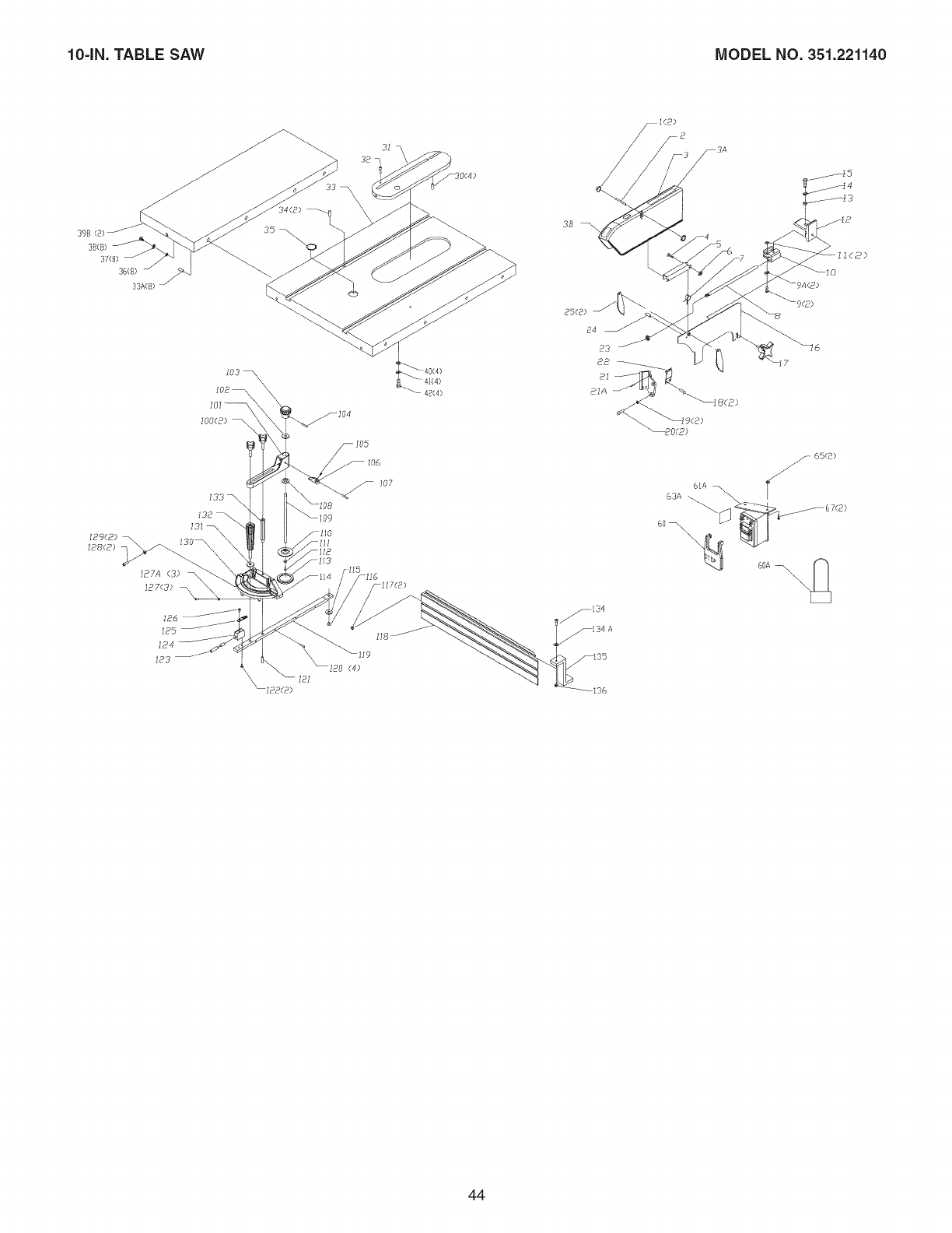
104N.TABLE SAW MODEL NO. 351.221140
£
39_(8
38(8)
37(8)
36(8) /
33A(8)
]B9(8)
[88(2)
I03 k
102 --
136
6IA
63A
\
44
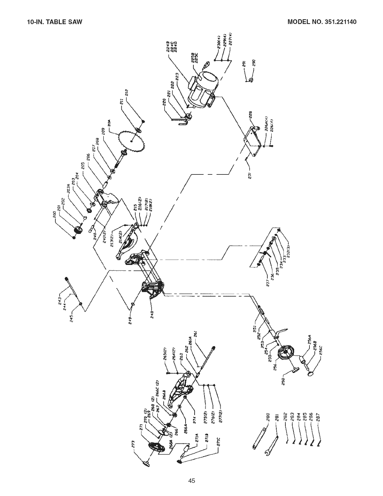
10=iN.TABLE SAW MODEL NO. 351.221140
/
/
/
/
/
\
o_
/
45
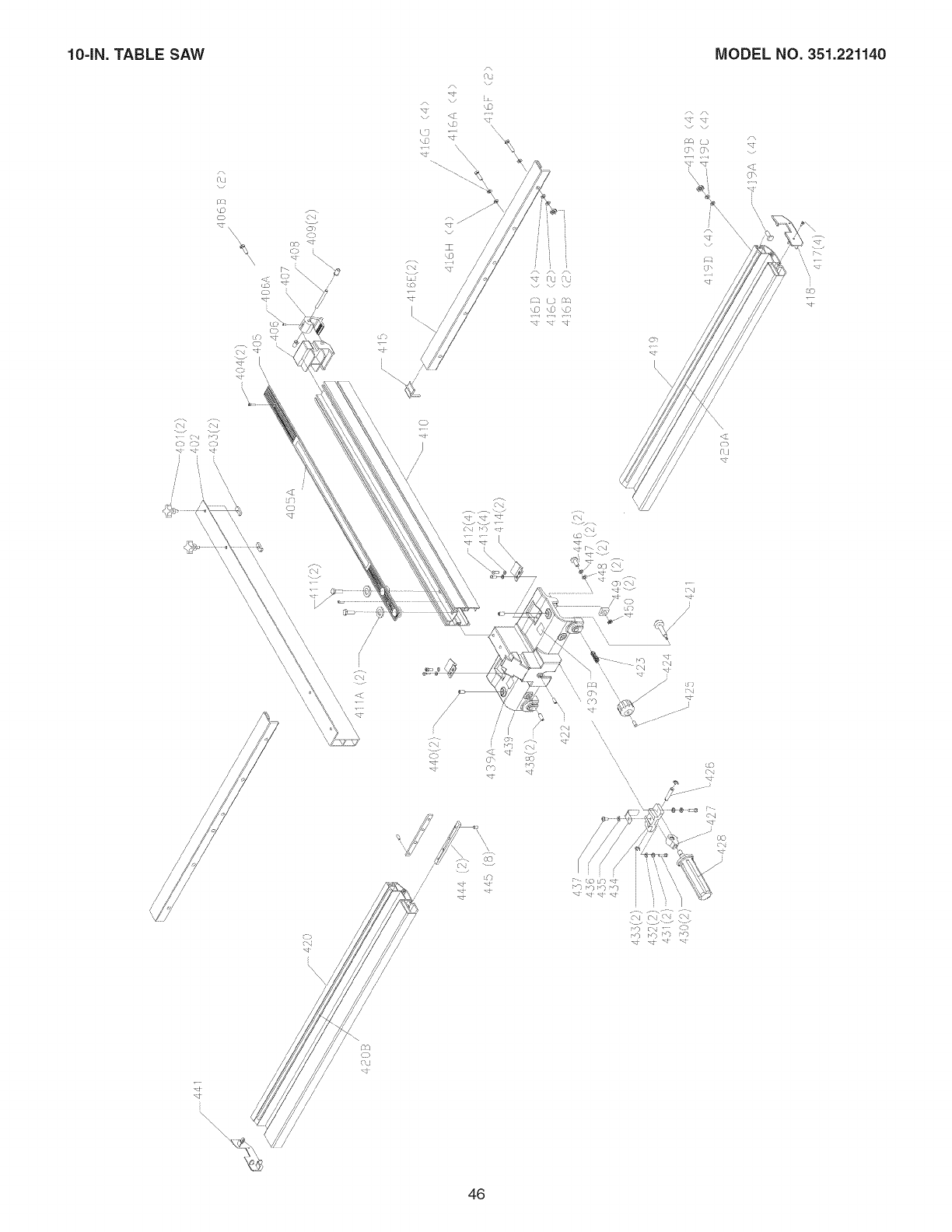
10-IN.TABLE SAW MODEL NO. 351.221140
-.j _J
_P
i
\s
\\\ c).
6c) "<t )
\\ \-.
c)
),
_Q --
\\
'\ \
\\ \\ %"
\\,\_ \\\\
\\\ _ \\\
\ "\ \
\'\ \_
'\ \
\
i
/
/
/
/
/
/
/
(J
i
\
\\\
\0
, i
v
\
co,
,c- I-- _l
/,\
(ja
/
/
/
/
/
/
/
/
/
46
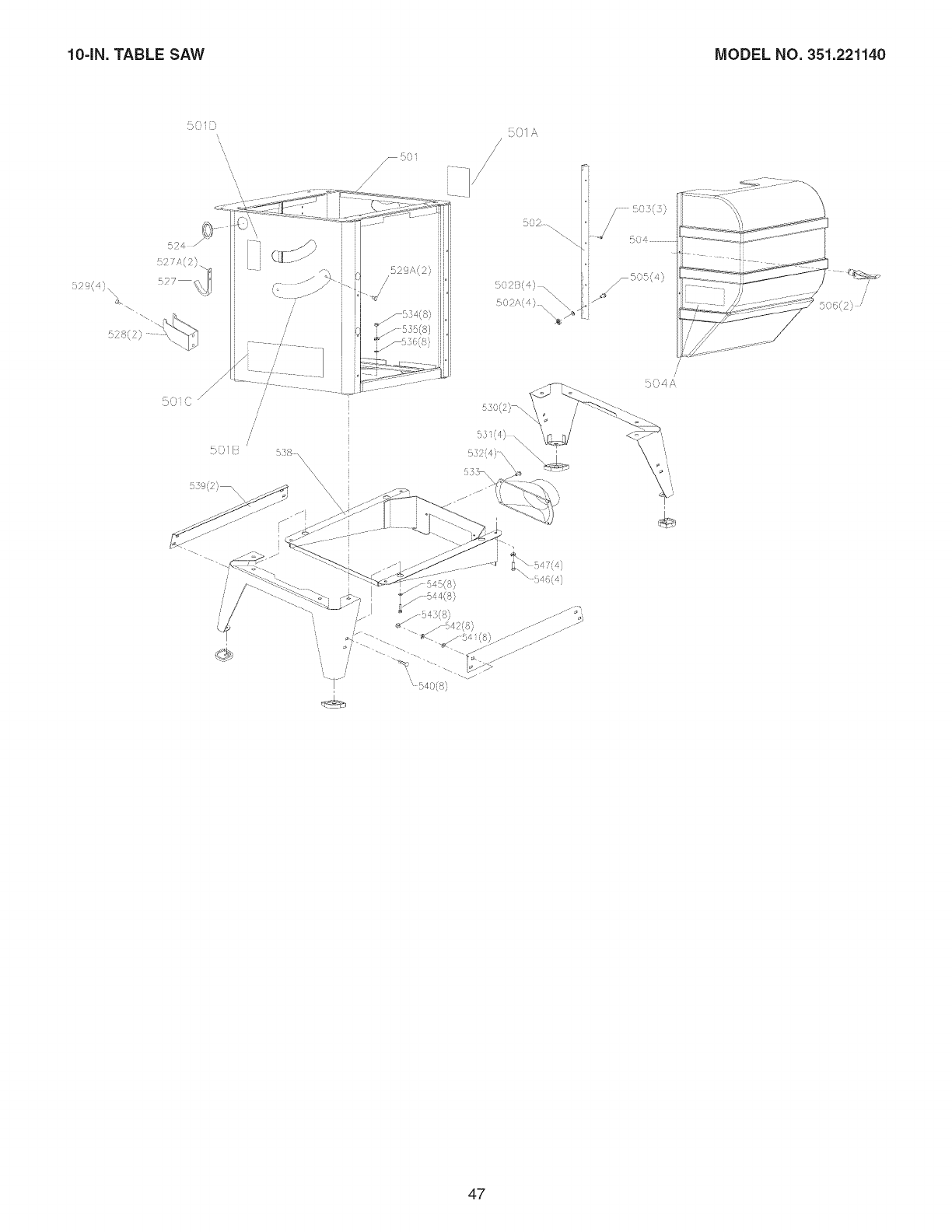
10=IN.TABLE SAW MODEL NO. 351.221140
:;q;,{
b',' oo_,
oo_o-- o -7_ !_-j
502..
5s0(2)_
47

e, NOTES e,
48
anual del Proprietario
N
1.5 caballos de fuerza (servicio continuo)
3450 R.P.iVI. (R.P.lVI. sin carga)
EESA de 1pulg.
®
C US
PRECAUCION'.
PARA SU SEGURIDAD PERSONAL:
Lea y obedezca todas las Instrucciones
de Seguridad y Funcionamiento antes
de accionar esta Sierra de Mesa.
Lfnea de Ayuda al Cliente
1-800-266-9079
Sirvase tener listo su
No, de Modelo y No, de Serie,
Sears, Roebuck and Co., Hoffman Estates, IL 60179 U.S.A.
VER. 9.08
49
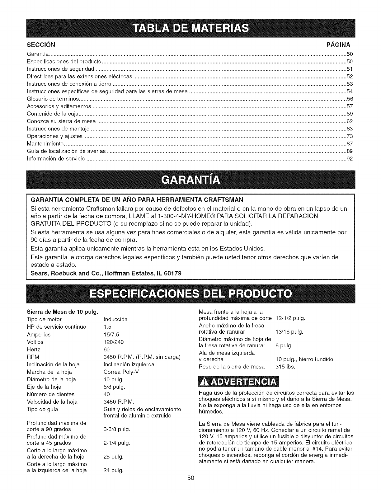
SECClON PAGINA
Garantia ............................................................................................................................................................................................... 50
Especificaciones del producto ............................................................................................................................................................. 50
Instrucciones de seguridad ................................................................................................................................................................. 51
Directrices para las extensiones el6ctricas ........................................................................................................................................ 52
Instrucciones de conexi6n a tierra ...................................................................................................................................................... 53
Instrucciones especificas de seguridad para las sierras de mesa ..................................................................................................... 54
Glosario de t@minos ............................................................................................................................................................................ 56
Accesorios y aditamentos ................................................................................................................................................................... 57
Contenido de la caja ............................................................................................................................................................................ 59
Conozca su sierra de mesa ............................................................................................................................................................... 62
Instrucciones de montaje .................................................................................................................................................................... 63
Operaciones y ajustes ......................................................................................................................................................................... 73
Mantenimiento ..................................................................................................................................................................................... 87
Guia de Iocalizaci6n de averias .......................................................................................................................................................... 89
Informaci6n de servicio ....................................................................................................................................................................... 92
GARANTIA COMPLETA DE UN ANO PARA HERRAMIENTA CRAFTSMAN
Siesta herramienta Craftsman fallara por causa de defectos en el material o en la mano de obra en un lapso de un
a_o a partir de la fecha de compra, LLAME al 1-800-4-MY-HOME® PARA SOLICITAR LA REPARACION
GRATUITA DEL PRODUCTO (o su reemplazo si no se puede reparar la unidad).
Siesta herramienta se usa alguna vez para fines comerciales o de alquiler, esta garantia es vAlida Qnicamente por
90 dias a partir de la fecha de compra.
Esta garantia aplica unicamente mientras la herramienta esta en los Estados Unidos.
Esta garantia le otorga derechos legales especificos y tambien puede usted tenor otros derechos que varien de
estado a estado.
Sears, Roebuck and Co., Noffman Estates, IL 60179
Sierra de Mesa de 10 pulg.
Tipo de motor
HP de servicio continuo
Amperios
Voltios
Hertz
RPM
Inclinaci6n de la hoja
Marcha de la hoja
Diametro de la hoja
Eje de la hoja
N0mero de dientes
Velocidad de la hoja
Tipo de guia
Profundidad maxima de
corte a 90 grados
Profundidad maxima de
corte a 45 grados
Corte a Io largo maximo
a la derecha de la hoja
Corte a Io largo maximo
a la izquierda de la hoja
Inducci6n
1.5
15/7.5
120/240
60
3450 R.RM. (R.RM. sin carga)
Inclinaci6n izquierda
Correa Poly-V
10 pulg.
5/8 pulg.
4O
3450 R.RM.
Guia y rieles de enclavamiento
frontal de aluminio extruido
3-3/8 pulg.
2-1/4 pulg.
25 pulg.
24 pulg.
Mesa frente a la hoja a la
profundidad maxima de corte 12-1/2 pulg.
Ancho maximo de la fresa
rotativa de ranurar
Diametro maximo de hoja de
la fresa rotativa de ranurar
Ala de mesa izquierda
y derecha
Peso de la sierra de mesa
13/16 pulg.
8 pulg.
10 pulg., hierro fundido
315 Ibs.
Haga uso de la protecci6n de circuitos correcta para evitar los
choques el_ctricos a si mismo y el da_o a la Sierra de Mesa.
No la exponga a la Iluvia ni haga uso de ella en entornos
h0medos.
La Sierra de Mesa viene cableada de fabrica para el fun-
cionamiento a 120 V, 60 Hz. Conectar a un circuito ramal de
120 V, 15 amperios y utilice un fusible o disyuntor de circuitos
de retardaci6n de tiempo de 15 amperios. El circuito el_ctrico
no podra tener un tama_o de cable menor al #14. Para evitar
choques o incendios, reponga el cord6n de energia inmedi-
atamente siesta da_ado en cualquier manera.
50
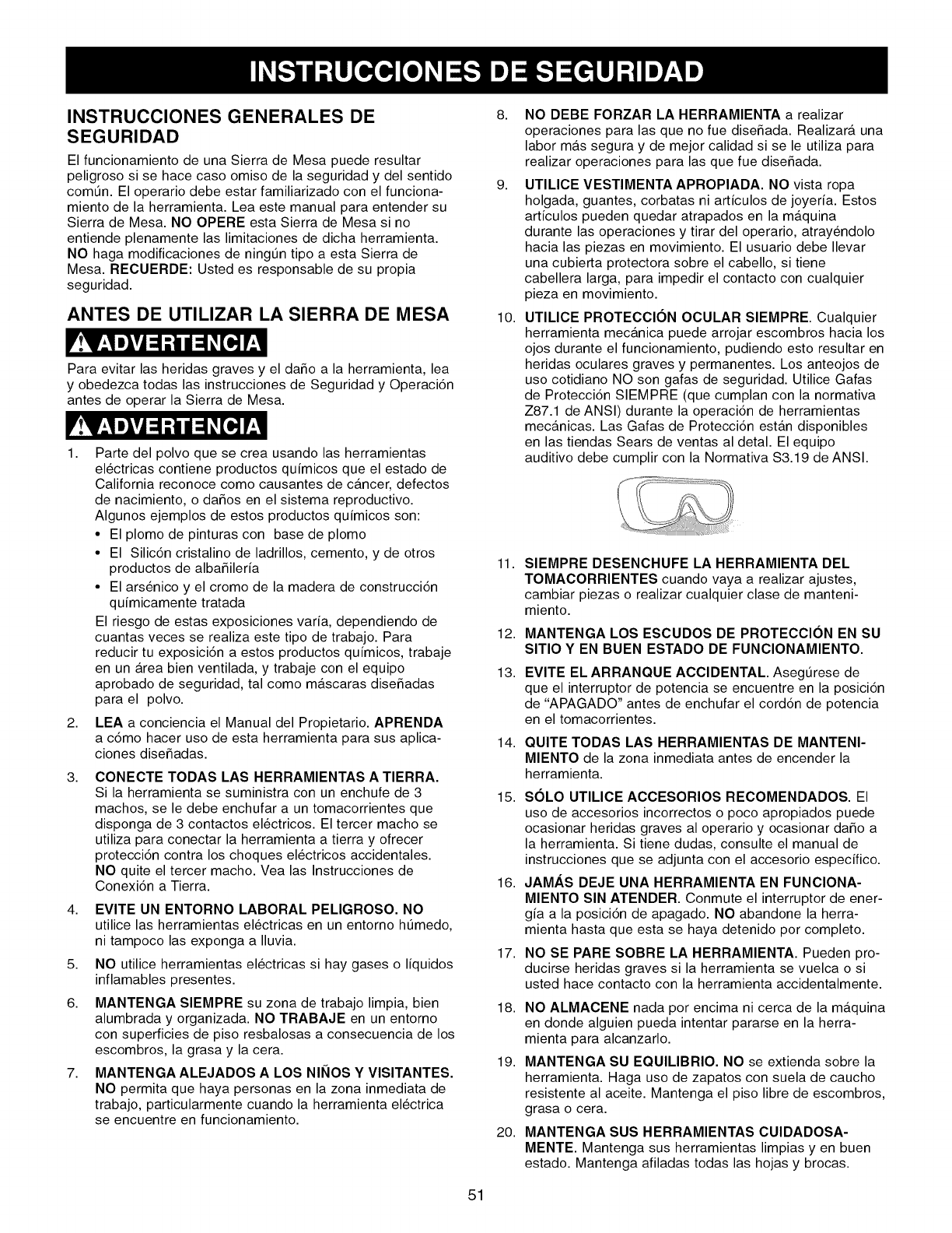
INSTRUCCIONES GENERALES DE
SEGURIDAD
El funcionamiento de una Sierra de Mesa puede resultar
peligroso si se hace caso omiso de la seguridad y del sentido
com_n. El operario debe estar familiarizado con el funciona-
miento de la herramienta. Lea este manual para entender su
Sierra de Mesa. NO OPERE esta Sierra de Mesa si no
entiende plenamente las limitaciones de dicha herramienta.
NO haga modificaciones de ningtJn tipo a esta Sierra de
Mesa. RECUERDE: Usted es responsable de su propia
seguridad.
ANTES DE UTILIZAR LA SIERRA DE MESA
Para evitar las heridas graves y el daSo a la herramienta, lea
y obedezca todas las instrucciones de Seguridad y Operaci6n
antes de operar la Sierra de Mesa.
1,
2,
3,
4,
5,
6.
7,
Parte del polvo que se crea usando las herramientas
el6ctricas contiene productos quimicos que el estado de
California reconoce como causantes de cancer, defectos
de nacimiento, o daSos en el sistema reproductivo.
Algunos ejemplos de estos productos quimicos son:
• El plomo de pinturas con base de plomo
• El Silic6n cristalino de ladrillos, cemento, y de otros
productos de albaSileria
• El arsenico y el cromo de la madera de construcci6n
quimicamente tratada
El riesgo de estas exposiciones varia, dependiendo de
cuantas veces se realiza este tipo de trabajo. Para
reducir tu exposici6n a estos productos quimicos, trabaje
en un Area bien ventilada, y trabaje con el equipo
aprobado de seguridad, tal como mascaras diseSadas
para el polvo.
LEA a conciencia el Manual del Propietario. APRENDA
a c6mo hacer uso de esta herramienta para sus aplica-
ciones diseSadas.
CONECTE TODAS LAS HERRAMIENTAS A TIERRA.
Si la herramienta se suministra con un enchufe de 3
machos, se le debe enchufar a un tomacorrientes que
disponga de 3 contactos el6ctricos. El tercer macho se
utiliza para conectar la herramienta a tierra y ofrecer
protecci6n contra los choques el6ctricos accidentales.
NO quite el tercer macho. Vea las Instrucciones de
Conexi6n a Tierra.
EVITE UN ENTORNO LABORAL PELIGROSO. NO
utilice las herramientas el6ctricas en un entorno htJmedo,
ni tampoco las exponga a Iluvia.
NO utilice herramientas el6ctricas si hay gases o liquidos
inflamables presentes.
MANTENGA SIEMPRE su zona de trabajo limpia, bien
alumbrada y organizada. NO TRABAJE en un entorno
con superficies de piso resbalosas a consecuencia de los
escombros, la grasa y la cera.
MANTENGA ALEJADOS A LOS NINOS Y VlSlTANTES.
NO permita que haya personas en la zona inmediata de
trabajo, particularmente cuando la herramienta el6ctrica
se encuentre en funcionamiento.
8,
9,
10.
NO DEBE FORZAR LA HERRAMIENTA a realizar
operaciones para las que no fue diseSada. Realizara una
labor mas segura y de mejor calidad si se le utiliza para
realizar operaciones para las que fue diseSada.
UTILICE VESTIMENTA APROPIADA. NO vista ropa
holgada, guantes, corbatas ni articulos de joyeria. Estos
articulos pueden quedar atrapados en la maquina
durante las operaciones y tirar del operario, atray6ndolo
hacia las piezas en movimiento. El usuario debe Ilevar
una cubierta protectora sobre el cabello, si tiene
cabellera larga, para impedir el contacto con cualquier
pieza en movimiento.
UTILICE PROTECCI(SN OCULAR SlEMPRE. Cualquier
herramienta mecanica puede arrojar escombros hacia los
ojos durante el funcionamiento, pudiendo esto resultar en
heridas oculares graves y permanentes. Los anteojos de
uso cotidiano NO son gafas de seguridad. Utilice Gafas
de Protecci6n SIEMPRE (que cumplan con la normativa
Z87.1 de ANSI) durante la operaci6n de herramientas
mecanicas. Las Gafas de Protecci6n estan disponibles
en las tiendas Sears de ventas al detal. El equipo
auditivo debe cumplir con la Normativa $3.19 de ANSI.
11.
12.
13.
14.
SIEMPRE DESENCHUFE LA HERRAMIENTA DEL
TOMACORRIENTES cuando vaya a realizar ajustes,
cambiar piezas o realizar cualquier clase de manteni-
miento.
MANTENGA LOS ESCUDOS DE PROTECClON EN SU
SlTIO Y EN BUEN ESTADO DE FUNClONAMIENTO.
EVITE EL ARRANQUE ACCIDENTAL. Asegt_rese de
que el interruptor de potencia se encuentre en la posici6n
de "APAGADO" antes de enchufar el cord6n de potencia
en el tomacorrientes.
QUITE TODAS LAS HERRAMIENTAS DE MANTENI-
MIENTO de la zona inmediata antes de encender la
herramienta.
15. S(SLO UTILICE ACCESORIOS RECOMENDADOS. El
uso de accesorios incorrectos o poco apropiados puede
ocasionar heridas graves al operario y ocasionar daSo a
la herramienta. Si tiene dudas, consulte el manual de
instrucciones que se adjunta con el accesorio especifico.
16. JAMAS DEJE UNA HERRAMIENTA EN FUNClONA-
MIENTO SIN ATENDER. Conmute el interruptor de ener-
gia a la posici6n de apagado. NO abandone la herra-
mienta hasta que esta se haya detenido por completo.
17.
18.
19.
20.
NO SE PARE SOBRE LA HERRAMIENTA. Pueden pro-
ducirse heridas graves si la herramienta se vuelca o si
usted hace contacto con la herramienta accidentalmente.
NO ALMACENE nada por encima ni cerca de la maquina
en donde alguien pueda intentar pararse en la herra-
mienta para alcanzarlo.
MANTENGA SU EQUlLIBRIO. NO se extienda sobre la
herramienta. Haga uso de zapatos con suela de caucho
resistente al aceite. Mantenga el piso libre de escombros,
grasa o cera.
MANTENGA SUS HERRAMIENTAS CUIDADOSA-
MENTE. Mantenga sus herramientas limpias yen buen
estado. Mantenga afiladas todas las hojas y brocas.
51
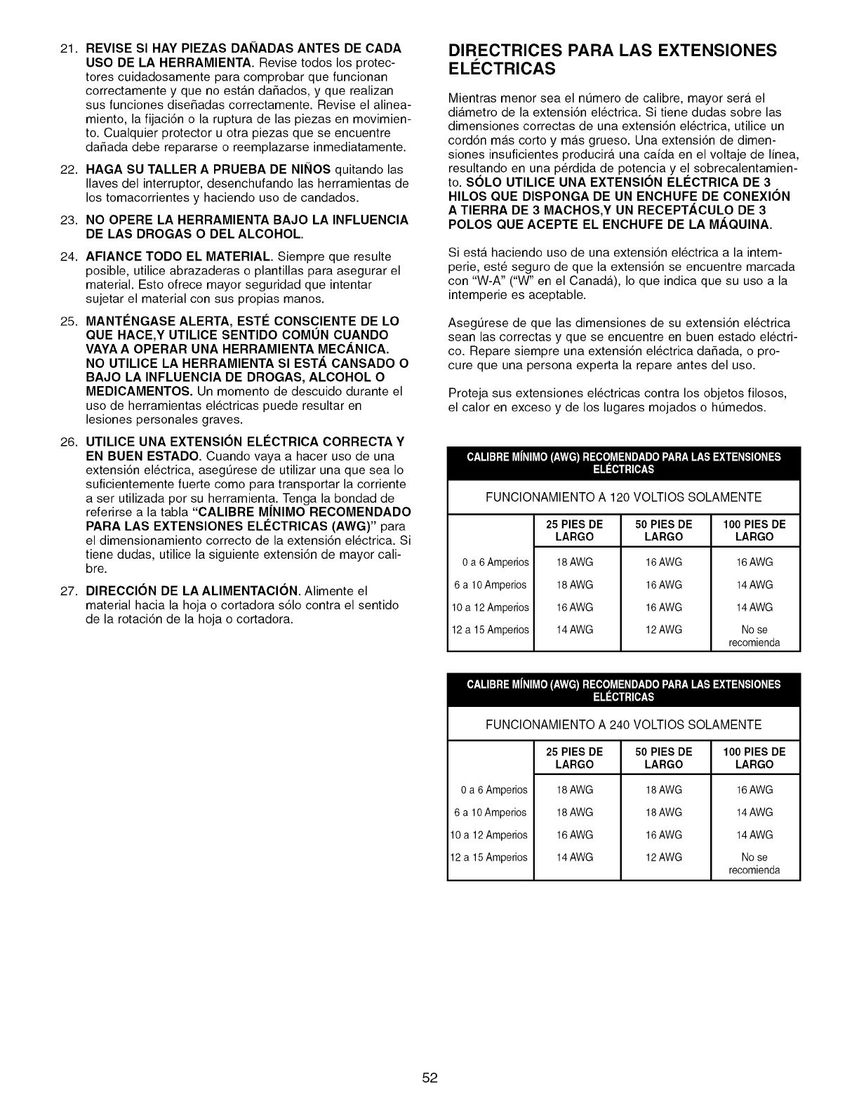
21. REVISE SI HAY PIEZAS DANADAS ANTES DE CADA
USO DE LA HERRAMIENTA. Revise todos los protec-
tores cuidadosamente para comprobar que funcionan
correctamente y que no estan da_ados, y que realizan
sus funciones dise_adas correctamente. Revise el alinea-
miento, la fijaci6n o la ruptura de las piezas en movimien-
to. Cualquier protector u otra piezas que se encuentre
da_ada debe repararse o reemplazarse inmediatamente.
22. HAGA SU TALLER A PRUEBA DE NINOS quitando las
Ilaves del interruptor, desenchufando las herramientas de
los tomacorrientes y haciendo uso de candados.
23. NO OPERE LA HERRAMIENTA BAJO LA INFLUENCIA
DE LAS DROGAS O DEL ALCOHOL.
24. AFIANCE TODO EL MATERIAL. Siempre que resulte
posible, utilice abrazaderas o plantillas para asegurar el
material. Esto ofrece mayor seguridad que intentar
sujetar el material con sus propias manos.
25.
26.
MANTC'NGASE ALERTA, ESTI_ CONSCIENTE DE LO
QUE HACE,Y UTILICE SENTIDO COMUN CUANDO
VAYA A OPERAR UNA HERRAMIENTA MECANICA.
NO UTILICE LA HERRAMIENTA Sl ESTA CANSADO O
BAJO LA INFLUENCIA DE DROGAS, ALCOHOL O
MEDICAMENTOS. Un momento de descuido durante el
uso de herramientas el_ctricas puede resultar en
lesiones personales graves.
UTILICE UNA EXTENSION ELI_CTRICA CORRECTA Y
EN BUEN ESTADO. Cuando vaya a hacer uso de una
extensi6n el_ctrica, asegtJrese de utilizar una que sea Io
suficientemente fuerte como para transportar la corriente
a ser utilizada por su herramienta. Tenga la bondad de
referirse a la tabla "CALIBRE MINIMO RECOMENDADO
PARA LAS EXTENSlONES ELI_CTRICAS (AWG)" para
el dimensionamiento correcto de la extensi6n el_ctrica. Si
tiene dudas, utilice la siguiente extensi6n de mayor cali-
bre.
27. DIRECClON DE LA ALIMENTAClON. Alimente el
material hacia la hoja o cortadora s61o contra el sentido
de la rotaci6n de la hoja o cortadora.
DIRECTRICES PARA LAS EXTENSIONES
ELI CTRICAS
Mientras menor sea el n0mero de calibre, mayor sera el
diametro de la extensidn el_ctrica. Si tiene dudas sobre las
dimensiones correctas de una extensidn el_ctrica, utilice un
corddn mas corto y mas grueso. Una extensidn de dimen-
siones insuficientes producira una caida en el voltaje de linea,
resultando en una p@dida de potencia y el sobrecalentamien-
to. SOLO UTILICE UNA EXTENSION ELI_CTRICA DE 3
HILOS QUE DISPONGA DE UN ENCHUFE DE CONEXION
ATIERRA DE 3 MACHOS,Y UN RECEPT/_,CULO DE 3
POLOS QUE ACEPTE EL ENCHUFE DE LA M/_,QUlNA.
Siesta haciendo uso de una extensi6n el_ctrica a la intem-
perie, este seguro de que la extensi6n se encuentre marcada
con "W-A" ("W" en el CanadA), Io que indica que su uso a la
intemperie es aceptable.
Aseg0rese de que las dimensiones de su extensi6n el_ctrica
sean las correctas y que se encuentre en buen estado el_ctri-
co. Repare siempre una extensi6n el_ctrica da_ada, o pro-
cure que una persona experta la repare antes del uso.
Proteja sus extensiones el_ctricas contra los objetos filosos,
el calor en exceso y de los lugares mojados o ht_medos.
FUNCIONAMIENTO A 120 VOLTIOS SOLAMENTE
0 a 6 Amperios
6 a 10Amperios
10 a 12 Amperios
12 a 15 Amperios
25 PIES DE
LARGO
18 AWG
18 AWG
16 AWG
14 AWG
50 PIES DE
LARGO
16 AWG
16 AWG
16 AWG
12 AWG
100 PIES DE
LARGO
16 AWG
14 AWG
14 AWG
No se
recomienda
FUNCIONAMIENTO A 240 VOLTIOS SOLAMENTE
0 a 6 Amperios
6 a 10Amperios
10 a 12 Amperios
12 a 15 Amperios
25 PIES DE
LARGO
18 AWG
18 AWG
16 AWG
14 AWG
50 PIES DE
LARGO
18AWG
18AWG
16AWG
12AWG
100 PIES DE
LARGO
16 AWG
14 AWG
14 AWG
No se
recomienda
52
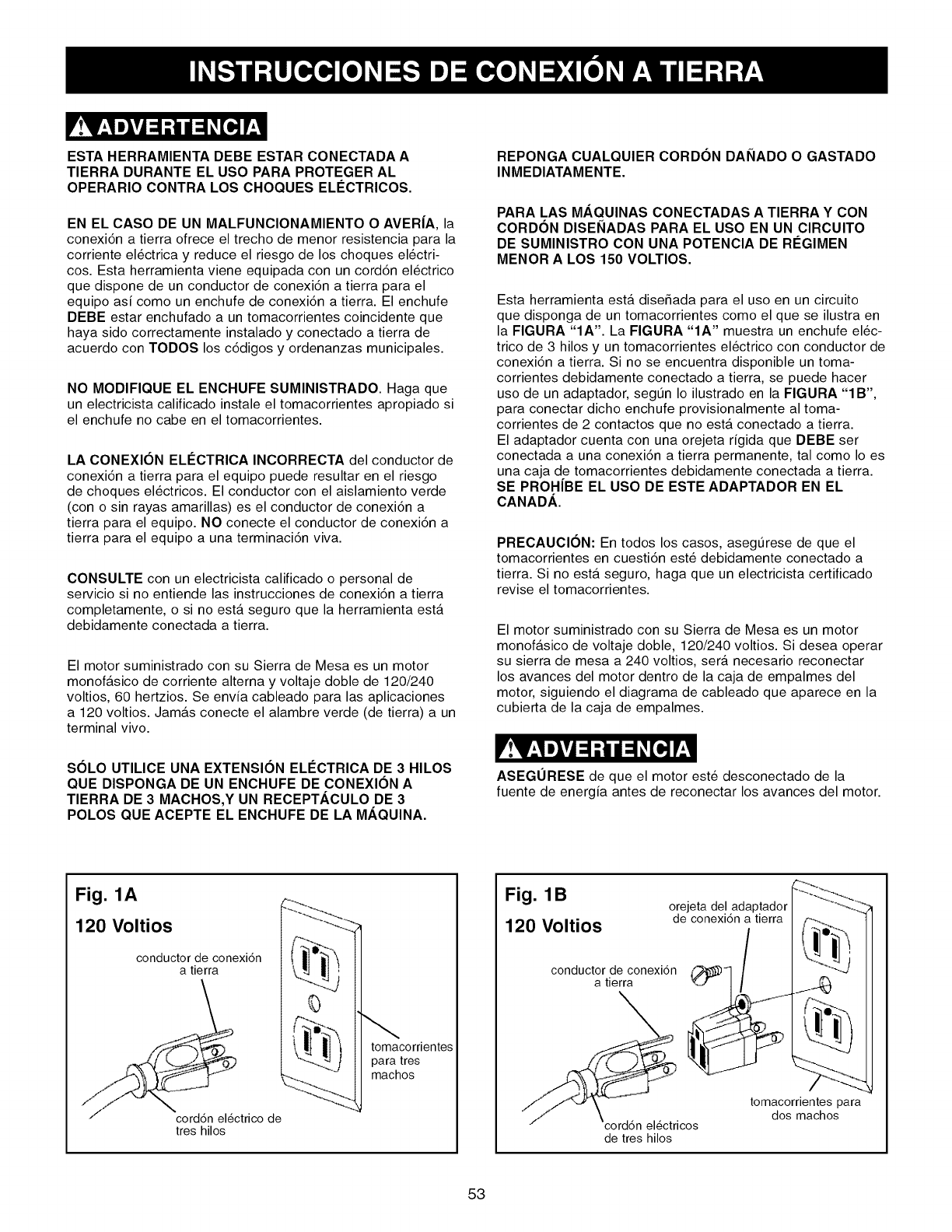
ESTA HERRAMIENTA DEBE ESTAR CONECTADA A
TIERRA DURANTE EL USO PARA PROTEGER AL
OPERARIO CONTRA LOS CHOQUES ELC'CTRICOS.
EN EL CASO DE UN MALFUNCIONAMIENTO OAVER|A, la
conexi6n a tierra ofrece el trecho de menor resistencia para la
corriente el_ctrica y reduce el riesgo de los choques el_ctri-
cos. Esta herramienta viene equipada con un cord6n el_ctrico
que dispone de un conductor de conexi6n a tierra para el
equipo asi como un enchufe de conexi6n a tierra. El enchufe
DEBE estar enchufado a un tomacorrientes coincidente que
haya sido correctamente instalado y conectado a tierra de
acuerdo con TODOS los c6digos y ordenanzas municipales.
NO MODIFIQUE EL ENCHUFE SUMINISTRADO. Haga que
un electricista calificado instale el tomacorrientes apropiado si
el enchufe no cabe en el tomacorrientes.
LA CONEXI()N ELleCTRICA INCORRECTA del conductor de
conexi6n a tierra para el equipo puede resultar en el riesgo
de choques el_ctricos. El conductor con el aislamiento verde
(con o sin rayas amarillas) es el conductor de conexi6n a
tierra para el equipo. NO conecte el conductor de conexi6n a
tierra para el equipo a una terminaci6n viva.
CONSULTE con un electricista calificado o personal de
servicio si no entiende las instrucciones de conexi6n a tierra
completamente, o si no esta seguro que la herramienta esta
debidamente conectada a tierra.
El motor suministrado con su Sierra de Mesa es un motor
monofasico de corriente alterna y voltaje doble de 120/240
voltios, 60 hertzios. Se envia cableado para las aplicaciones
a 120 voltios. Jamas conecte el alambre verde (de tierra) a un
terminal vivo.
REPONGA CUALQUIER CORDON DANADO O GASTADO
INMEDIATAMENTE.
PARA LAS MAQUINAS CONECTADAS A TIERRA Y CON
CORDON DISENADAS PARA EL USO EN UN ClRCUITO
DE SUMINISTRO CON UNA POTENCIA DE RC'GIMEN
MENOR A LOS 150 VOLTIOS.
Esta herramienta esta diseSada para el uso en un circuito
que disponga de un tomacorrientes como el que se ilustra en
la FIGURA "IA'. La FIGURA "IA" muestra un enchufe el_c-
trico de 3 hilos y un tomacorrientes el_ctrico con conductor de
conexi6n a tierra. Si no se encuentra disponible un toma-
corrientes debidamente conectado a tierra, se puede hacer
uso de un adaptador, segtJn Io ilustrado en la FIGURA "IB",
para conectar dicho enchufe provisionalmente al toma-
corrientes de 2 contactos que no esta conectado a tierra.
El adaptador cuenta con una orejeta rigida que DEBE ser
conectada a una conexi6n a tierra permanente, tal como Io es
una caja de tomacorrientes debidamente conectada a tierra.
SE PROH|BE EL USO DE ESTE ADAPTADOR EN EL
CANADA.
PRECAUCI()N: En todos los casos, asegtJrese de que el
tomacorrientes en cuesti6n este debidamente conectado a
tierra. Si no esta seguro, haga que un electricista certificado
revise el tomacorrientes.
El motor suministrado con su Sierra de Mesa es un motor
monofasico de voltaje doble, 120/240 voltios. Si desea operar
su sierra de mesa a 240 voltios, sera necesario reconectar
los avances del motor dentro de la caja de empalmes del
motor, siguiendo el diagrama de cableado que aparece en la
cubierta de la caja de empalmes.
S(SLO UTILICE UNA EXTENSION ELC'CTRICA DE 3 HILOS
QUE DISPONGA DE UN ENCHUFE DE CONEXI(SN A
TIERRA DE 3 MACHOS,Y UN RECEPTACULO DE 3
POLOS QUE ACEPTE EL ENCHUFE DE LA MAQUINA.
ASEGURESE de que el motor este desconectado de la
fuente de energia antes de reconectar los avances del motor.
Fig. 1A
120 Voltios
conductor de conexi6n
a tierra
corddn electrico de
tres hilos
tomacorrientes
para tres
machos
Fig. 1B
120 Voltios orejeta del adaptador
de conexi6n a tierra
conductor de conexi6n
a tierra
cord6n electricos
de tres hilos
tomacorrientes para
dos machos
53
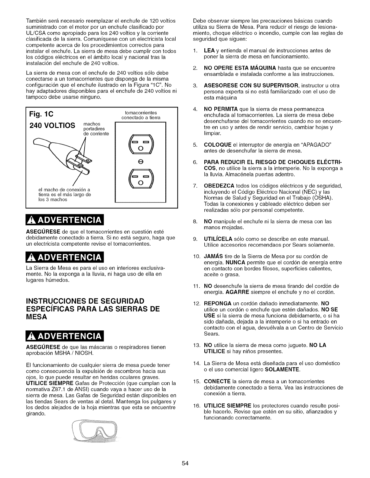
Tambi_n sera necesario reemplazar el enchufe de 120 voltios
suministrado con el motor por un enchufe clasificado por
UL/CSA como apropiado para los 240 voltios y la corriente
clasificada de la sierra. Comuniquese con un electricista local
competente acerca de los procedimientos correctos para
instalar el enchufe. La sierra de mesa debe cumplir con todos
los c6digos el_ctricos en el ambito local y nacional tras la
instalaci6n del enchufe de 240 voltios.
La sierra de mesa con el enchufe de 240 voltios s61o debe
conectarse a un tomacorrientes que disponga de la misma
configuraci6n que el enchufe ilustrado en la Figura "1C". No
hay adaptadores disponibles para el enchufe de 240 voltios ni
tampoco debe usarse ninguno.
Fig. 1C
240 VOLTIOS machos
portadires
de corriente
el macho de conexidn a
tierra es el mils largo de
los 3 machos
tomacorrientes
conectado a tierra
@
e
@
ASEGURESE de que el tomacorrientes en cuesti6n este
debidamente conectado a tierra. Si no estA seguro, haga que
un electricista competente revise el tomacorrientes.
La Sierra de Mesa es para el uso en interiores exclusiva-
mente. No la exponga a la Iluvia, ni haga uso de ella en
lugares htJmedos.
INSTRUCCIONES DE SEGURIDAD
ESPECiFICAS PARA LAS SIERRAS DE
MESA
ASEGURESE de que las mascaras o respiradores tienen
aprobaci6n MSHA /NIOSH.
El funcionamiento de cualquier sierra de mesa puede tener
como consecuencia la expulsi6n de escombros hacia sus
ojos, Io que puede resultar en heridas oculares graves.
UTILIOE SIEMPRE Gafas de Protecci6n (que cumplan con la
normativa Z87.1 de ANSI) cuando vaya a hacer uso de la
sierra de mesa. Las Gafas de Seguridad estan disponibles en
las tiendas Sears de ventas al detal. Mantenga los pulgares y
los dedos alejados de la hoja mientras que esta se encuentre
girando.
Debe observar siempre las precauciones basicas cuando
utiliza su Sierra de Mesa. Para reducir el riesgo de lesiona-
miento, choque el_ctrico o incendio, cumple con las reglas de
seguridad que siguen:
1,
2,
LEA y entienda el manual de instrucciones antes de
poner la sierra de mesa en funcionamiento.
NO OPERE ESTA M/_,QUINA hasta que se encuentre
ensamblada e instalada conforme alas instrucciones.
3,
4,
5,
6,
7,
8,
9,
10.
11.
12.
ASESORESE CON SU SUPERVISOR, instructor u otra
persona experta si no esta familiarizado con el uso de
esta maquina
NO PERMITA que la sierra de mesa permanezca
enchufada al tomacorrientes. La sierra de mesa debe
desenchufarse del tomacorrientes cuando no se encuen-
tre en uso y antes de rendir servicio, cambiar hojas y
limpiar.
COLOQUE el interruptor de energia en "APAGADO"
antes de desenchufar la sierra de mesa.
PARA REDUCIR EL RIESGO DE CHOQUES ELI_CTRI-
COS, no utilice la sierra a la intemperie. No la exponga a
la Iluvia. Almacenela puertas adentro.
OBEDEZCA todos los c6digos el_ctricos y de seguridad,
incluyendo el C6digo El_ctrico Nacional (NEC) y las
Normas de Salud y Seguridad en el Trabajo (OSHA).
Todas la conexiones y cableado el_ctrico deben ser
realizadas s61o por personal competente.
NO manipule el enchufe ni la sierra de mesa con las
manos mojadas.
UTIL|CELA s61o como se describe en este manual.
Utilice accesorios recomendaos por Sears solamente.
JAMAS tire de la Sierra de Mesa por su cord6n de
energia. NUNCA permite que el cord6n de energia entre
en contacto con bordes filosos, superficies calientes,
aceite o grasa.
NO desenchufe la sierra de mesa tirando del cord6n de
energia. AGARRE siempre el enchufe y no el cord6n.
REPONGA un cord6n daSado inmediatamente. NO
utilice un cord6n o enchufe que esten daSados. NO SE
USE si la sierra de mesa funciona debidamente, o si ha
sido daSada, dejada a la intemperie o si ha entrado en
contacto con el agua, devu_lvala a un Centro de Servicio
Sears.
13. NO utilice la sierra de mesa como juguete. NO LA
UTILICE si hay niSos presentes.
14. La Sierra de Mesa esta diseSada para el uso dom_stico
o el uso comercial ligero SOLAMENTE.
15. CONECTE la sierra de mesa a un tomacorrientes
debidamente conectado a tierra. Vea las instrucciones de
conexi6n a tierra.
16. UTILICE SIEMPRE los protectores cuando resulte posi-
ble hacerlo. Revise que esten en su sitio, afianzados y
funcionando correctamente.
54
17. EVlTE LOS CONTRAGOLPES haciendo Io siguiente:
• Manteniendo la hoja afilada y libre de oxidaci6n y
alquitran.
• Manteniendo la guia de corte a Io largo paralela con la
hoja de la sierra.
• Usando el protector de la hoja de la sierra y el ensam-
blado del hendidor para todas las operaciones posibles,
incluyendo el aserrado directo.
• Empujando el material mas alia de la hoja de la sierra
antes de soltarlo.
• No cortando a Io largo jamas ning0n material que este
torcido o alabeado, o que no disponga de un borde
recto para guiarlo a Io largo de la guia de corte.
• Usando tablas de refrentado cuando no pueda utilizarse
el protector de hoja y el ensamblado del hendidor.
• No aserrando jamas una pieza de material grande que
no pueda controlarse.
• No usando jamas la guia durante el corte transversal.
• No aserrando jamas un material con nudos sueltos u
otras imperfecciones.
18. RETIRE las piezas troceadas y los escombros de la
mesa antes de arrancar la sierra. La vibraci6n de la
sierra puede hacer que se muevan hacia la hoja de la
sierra, expulsandolas. Despu_s de realizar el corte,
apague la sierra. Cuando la hoja se haya detenido por
completo, desenchufe la sierra y retire los escombros.
19. JAMAS ARRANQUE la sierra con el material contra la
hoja.
20. JAMAS realice operaciones "a mano libre". Haga uso de
la guia de corte o de la guia de ingletes para orientar y
guiar el material. Sujete el material firmemente contra la
escuadra de ingletes o la guia de corte.
21. UTILICE una varilla o varillas de empuje para cortar
materiales angostos a Io largo.
22. EVITE OPERACIONES Y POSICIONES MANUALES
TORPES en las que un deslizamiento repentino puede
hacer que su mano haga contacto con la hoja de la
sierra.
23. MANTENGA brazos, manos y dedos alejados de la hoja.
24. JAMAS ponga ninguna parte de su cuerpo en linea con
el trayecto de la hoja de la sierra.
25. JAMAS intente alcanzar alrededor ni por encima de la
hoja.
26. JAMAS intente liberar una hoja atascada sin primero
apagar y desenchufar la hoja de la fuente de energia.
27. JAMAS realice labores de trazado, ensamblado o mon-
taje sobre la mesa /zona de trabajo cuando la maquina
se encuentre en funcionamiento.
28. JAMAS reestablezca el bot6n de sobrecarga termica sin
haber apagado antes la sierra de mesa.
29. APOYE los materiales largos o anchos correctamente.
30. APAGUE LA SIERRA y desench0fela de la fuente de
energia. Limpie la mesa /zona de trabajo antes de aban-
donar la sierra. BLOQUEE el interruptor de ARRANQUE
/PARADA (START/STOP) con el candado suministrado
para impedir el uso desautorizado.
31. POSlCIONE SlEMPRE la guia auxiliar por Io menos
2 pulgadas en frente de la hoja de la sierra cuando vaya
a usar la guia auxiliar como tope de parada durante el
corte transversal.
32.
33.
El ala de extensi6n derecha DEBE ESTAR plenamente
ensamblado y la cubierta del motor debe estar cerrada y
afianzada antes de que se conecte la sierra de mesa a la
fuente de energia.
DIRECClON DE LA ALIMENTAClON. Alimente el trabajo
en una lamina o un cortador contra la direcci6n de la
lamina o un cortador solamente.
34. INFORMAClON ADIClONAL sobre el funcionamiento
seguro y correcto de este producto esta disponible de
parte del National Safety Council, 1121 Spring Lake
Drive, Itasca, IL 60143-3201 en el Manual de Prevenci6n
de Accidentes para Operaciones Industriales asi como en
las Hojas de Datos de Seguridad suministradas por el
NSC. Tenga la bondad de referirse tambi_n a los
Requisitos de Seguridad para la Maquinaria de
Ebanisteria ANSI 01.1 de la American National Standards
Institute y el Reglamento OSHA 1910.213 del U.S.
Department of Labor.
35. GUARDE ESTAS INSTRUCCIONES. Refi_rase a elias
con frecuencia y utilicelas para instruir a los demas.
Las fuentes que aparecen a continuaci6n tienen informaci6n
disponible acerca de la venta y funcionamiento correcto de
esta herramienta:
Power Tool Institute
1300 Summer Avenue
Cleveland, OH 44115-2851
www.powertoolinstitute.org
National Safety Council
1121 Spring Lake Drive
Itasca, IL 60143-3201
American National Standards Institute
25West 43rd. St, 4th Floor
New York, NY. 10036
ANSI 01.1 Safety Requirements
For Woodworking Machines
WWW.ANSI.ORG
U.S. Department of Labor Regulations
OSHA 1910.213 Regulations
WWW.OSHA.GOV
55
Alefriz - Muesca cuadrada en el borde del material.
Contragolpe - Cuando el material es arrojado hacia el oper-
ario durante una operaci6n de corte en el momento que el
material hace contacto inicial con la hoja, o si el material hace
constricci6n sobre la hoja. Los contragolpes son peligrosos y
pueden resultar en heridas graves.
Corte a Io largo - La operaci6n de hacer un corte a Io largo
de la veta a siguiendo la Iongitud de la pieza de madera
Corte compuesto - La operaci6n de hacer cortes tanto de
biselado como de ingletes a la misma vez.
Corte de biselado - La operaci6n de hacer cualquier corte
con la cuchilla fijada en un angulo que no sea 90 °.
Corte de ingletes - La operaci6n de hacer un corte utilizan-
do la escuadra de ingletes a cualquier angulo que no sea de
cero grados.
Corte repetido - La operaci6n de realizar un corte para
reducir el grosor del material.
Corte transversal - La operaci6n de realizar un corte a Io
ancho del grano o el ancho del material.
Dedos anti-contragolpe - Dispositivo de seguridad conec-
tado al protector de hoja y al ensamblado del hendidor
diseSado para evitar la expulsi6n de un material durante las
operaciones de corte.
Eje - El eje sobre el cual esta montada la hoja o la herra-
mienta cortante de accesorio.
Entalladura - El material que es removido por la cuchilla
durante cualquier operaci6n de corte.
Fresa rotativa de ranurar - Corte no directo que produce
una muesca cuadrada. Una fresa rotativa tiene, tipicamente,
un ancho de 1/8 a 13/16 pulg. Una fresa rotativa requiere un
conjunto especial de hojas que no estan incluidas con esta
sierra de mesa.
Goma, alquitran o resina - Residuo pegajoso y basado en
la savia producido por los productos de madera.
Gradacion de la hoja de la sierra - La distancia en que las
puntas de la hoja de la sierra estan anguladas hacia afuera
desde el grosor de la hoja. La gradaci6n de los dientes de la
hoja de la sierra permite que el cuerpo de la hoja atraviese
todos los cortes con seguridad.
Ladeo - El mal alineamiento de la hoja con las ranuras de
ingletes, o cuando la hoja no esta paralela con las ranuras de
ingletes.
Mano libre - Una operaci6n muy peligrosa para efectuar un
corte sin hacer uso de la guia de corte ni la escuadra de
ingletes durante una operaci6n de corte. Los cortes a mano
libre jamas deben realizarse con una Sierra de Mesa.
Mesa /zona de trabajo - La superficie total de la parte
superior de la sierra de mesa sobre la que descansa el
material mientras que se realizan operaciones de montaje o
de corte.
Refrentado - Dispositivo accesorio que puede hacerse o
comprarse para ayudar a la guia o sujetar un material durante
las operaciones de corte.
Trayecto de la hoja de la sierra - La zona que esta directa-
mente en linea con la hoja, incluyendo la zona por encima,
por debajo y por delante de la misma.
Vara de empuje - Dispositivo accesorio que puede hacerse o
comprarse para ayudar a empujar el material a traves de la
hoja. Se hace uso de una vara de empuje para evitar que las
manos del operario entren en contacto con la hoja durante el
corte a Io largo de materiales angostos.
Con aserrar. El proceso de cortar adentro que la lamina corta
totalmente a trav_s del objeto.
56
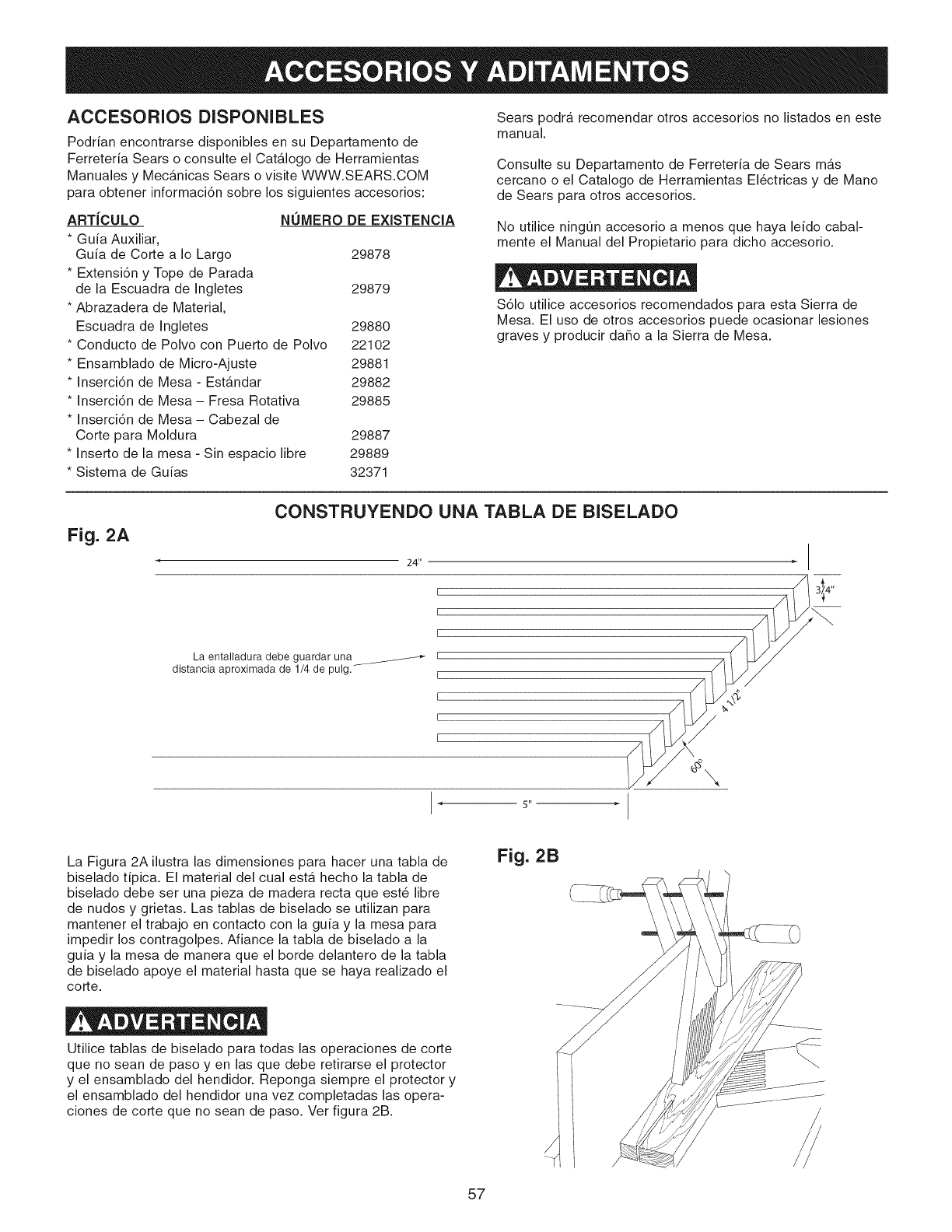
ACCESORIOS DISPONIBLES
Podrian encontrarse disponibles en su Departamento de
Ferreteria Sears o consulte el Catalogo de Herramientas
Manuales y Mecanicas Sears o visite WWW.SEARS.COM
para obtener informaci6n sobre los siguientes accesorios:
ARTJCULO
*Guia Auxiliar,
Guia de Corte a Io Largo
*Extensi6n y Tope de Parada
de la Escuadra de Ingletes
*Abrazadera de Material,
Escuadra de Ingletes 29880
*Conducto de Polvo con Puerto de Polvo 22102
*Ensamblado de Micro-Ajuste 29881
* Inserci6n de Mesa - Estandar 29882
* Inserci6n de Mesa - Fresa Rotativa 29885
* Inserci6n de Mesa - Cabezal de
Corte para Moldura 29887
* Inserto de la mesa - Sin espacio libre 29889
* Sistema de Guias 32371
NUMERO DE EXISTENCIA
29878
29879
Sears podra recomendar otros accesorios no listados en este
manual.
Consulte su Departamento de Ferreteria de Sears mas
cercano o el Catalogo de Herramientas EI6ctricas y de Mano
de Sears para otros accesorios.
No utilice ningOn accesorio a menos que haya leido cabal-
mente el Manual del Propietario para dicho accesorio.
S61o utilice accesorios recomendados para esta Sierra de
Mesa. El uso de otros accesorios puede ocasionar lesiones
graves y producir da_o a la Sierra de Mesa.
Fig. 2A
CONSTRUYENDO UNA TABLA DE BISELADO
24"
[
[
La entalladura debe guardar una _ r
distancia aproximada de 1/4 de pulg.- I
I
I
[
5"
La Figura 2A ilustra las dimensiones para hacer una tabla de
biselado tipica. El material del cual esta hecho la tabla de
biselado debe ser una pieza de madera recta que est6 libre
de nudos y grietas. Las tablas de biselado se utilizan para
mantener el trabajo en contacto con la guia y la mesa para
impedir los contragolpes. Afiance la tabla de biselado a la
guia y la mesa de manera que el borde delantero de la tabla
de biselado apoye el material hasta que se haya realizado el
corte.
Utilice tablas de biselado para todas las operaciones de corte
que no sean de paso yen las que debe retirarse el protector
y el ensamblado del hendidor. Reponga siempre el protector y
el ensamblado del hendidor una vez completadas las opera-
ciones de corte que no sean de paso. Ver figura 2B.
Fig. 2B
/
57
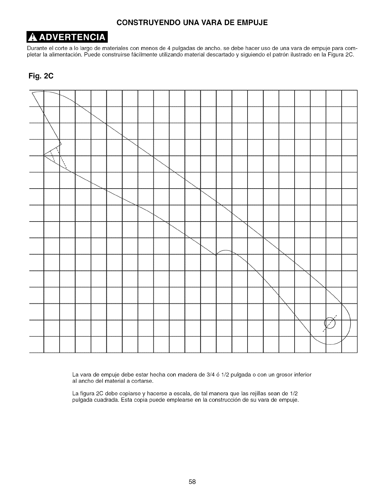
CONSTRUYENDO UNA VARA DE EMPUJE
Durante el corte a Io largo de materiales con menos de 4 pulgadas de ancho, se debe hacer uso de una vara de empuje para com-
pletar la alimentaci6n. Puede construirse facilmente utilizando material descartado y siguiendo el patr6n ilustrado en la Figura 2C.
Fig. 2C
....,
\ \
\ \
\ \
\ \
J
La vara de empuje debe estar hecha con madera de 3/4 6 1/2 pulgada o con un grosor inferior
al ancho del material a cortarse.
La figura 2C debe copiarse y hacerse a escala, de tal manera que las rejillas sean de 1/2
pulgada cuadrada. Esta copia puede emplearse en la construcci6n de su vara de empuje.
58
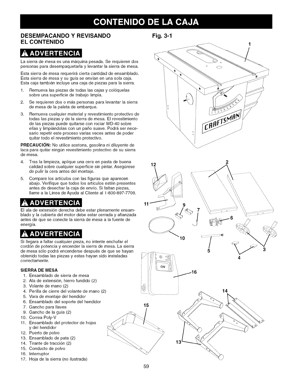
DESEMPACANDO Y REVISANDO
EL CONTENIDO Fig. 3-1
La sierra de mesa es una maquina pesada. Se requieren dos
personas para desempaquetarla y levantar la sierra de mesa.
Esta sierra de mesa requerira cierta cantidad de ensamblado.
Esta sierra de mesa y su guia se envian en una sola caja.
Esta caja tambi_n incluye una caja de piezas para la sierra.
1. Remueva las piezas de todas las cajas y col6quelas
sobre una superficie de trabajo limpia.
2,
3.
Se requieren dos o m_,s personas para levantar la sierra
de mesa de la paleta de embarque.
Remueva cualquier material y revestimiento protectivo de
todas las piezas y de la sierra de mesa. El revestimiento
de las piezas puede quitarse con rociar WD-40 sobre
elias y limpiandolas con un paso suave. Podra ser nece-
sario repetir este proceso varias veces antes de poder
quitar todo el revestimiento protectivo.
PRECAUCION: No utilice acetona, gasolina ni diluyente de
laca para quitar ningtJn revestimiento protectivo de su sierra
de mesa.
4. Tras la limpieza, aplique una cera en pasta de buena
calidad sobre cualquier superficie sin pintar. AsegtJrese
de pulir la cera antes del montaje.
5. Compare los articulos con las figuras que aparecen
abajo. Verifique que todos los articulos esten presentes
antes de desechar la caja de envio. Si faltan piezas,
Ilame a la Linea de Ayuda al Cliente al 1-800-897-7709.
El ala de extensi6n derecha debe estar plenamente ensam-
blado y la cubierta del motor debe estar cerrada y afianzada
antes de que se conecte la sierra de mesa a la fuente de
energia.
Si Ilegara a faltar cualquier pieza, no intente enchufar el
cord6n de potencia y encender la sierra de mesa. La sierra
de mesa s61o podra encenderse despu_s de que se hayan
obtenido todas las piezas y estas hayan sido instaladas
correctamente.
SIERRA DE MESA
1. Ensamblado de sierra de mesa
2. Ala de extensi6n, hierro fundido (2)
3. Volante de mano (2)
4. Perilla de cierre del volante de mano (2)
5. Vara de montaje del hendidor
6. Ensamblado del soporte del hendidor
7. Gancho para Ilaves
9. Gancho de la guia (2)
10. Correa Poly-V
11. Ensamblado del protector de hojas
y del hendidor
12. Puerto de polvo
13. Ensamblado de pata (2)
14. Tirante de tracci6n (2)
15. Conducto de polvo
16. Interruptor
17. Hoja de la sierra (no ilustrada)
11
15
59
12
\\
14
\\\
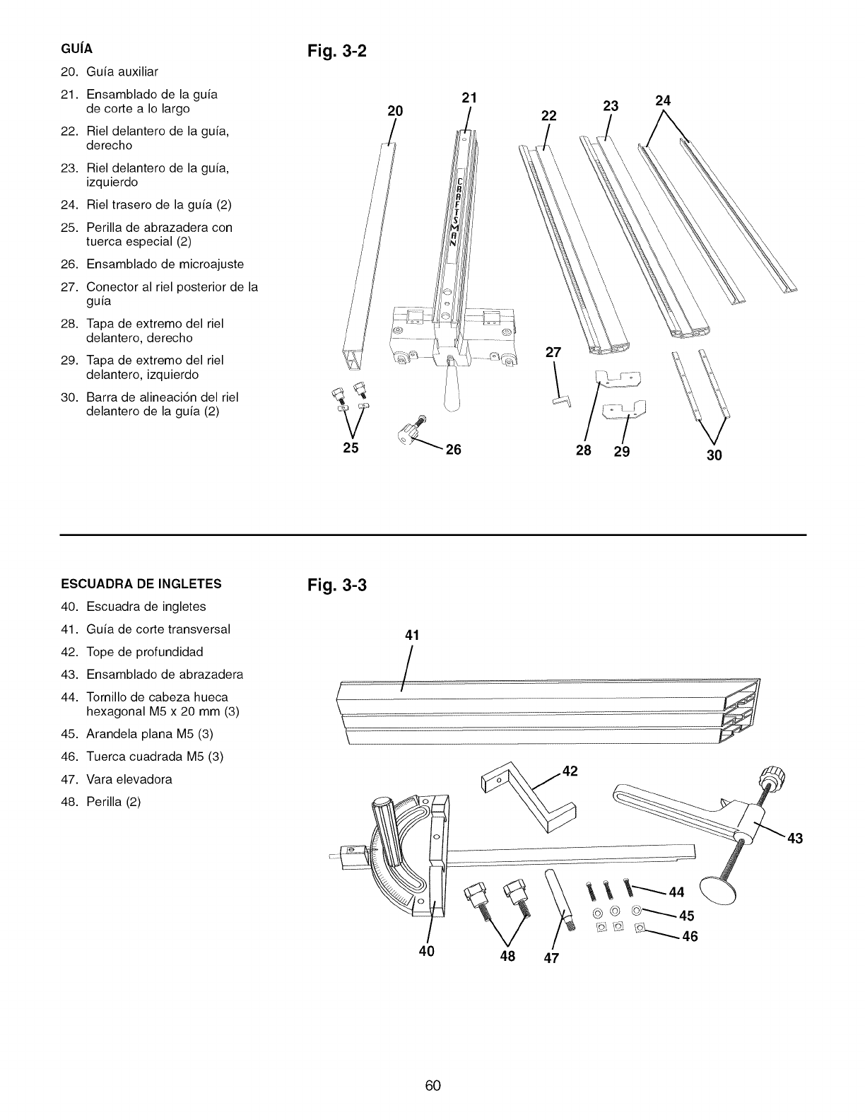
GU|A
20. Guia auxiliar
21. Ensamblado de la guia
de corte a Io largo
22. Riel delantero de la guia,
derecho
23. Riel delantero de la guia,
izquierdo
24. Riel trasero de la guia (2)
25. Perilla de abrazadera con
tuerca especial (2)
26. Ensamblado de microajuste
27. Conector al riel posterior de la
guia
28. Tapa de extremo del riel
delantero, derecho
29. Tapa de extremo del riel
delantero, izquierdo
30. Barra de alineaci6n del riel
delantero de la guia (2)
Fig. 3-2
V
25
20 21
22
27
28
23
29
24
30
ESCUADRA DE INGLETES
40. Escuadra de ingletes
41. Guia de corte transversal
42. Tope de profundidad
43. Ensamblado de abrazadera
44. Tornillo de cabeza hueca
hexagonal MS x 20 mm (3)
45. Arandela plana MS (3)
46. Tuerca cuadrada MS (3)
47. Vara elevadora
48. Perilla (2)
Fig. 3-3
\
41
/
6O
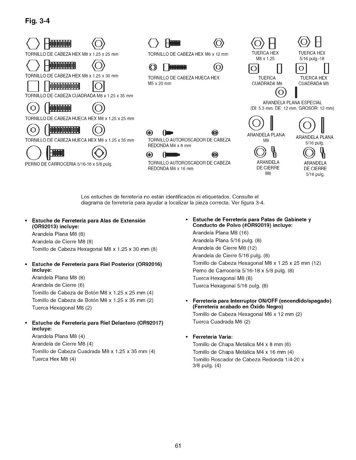
Fig. 3-4
TORNILLODECABEZAHEXM8x 1.25x 25mm
TORNILLODECABEZAHEXM8x 1.25x 30mm
TORNILLODECABEZACUADRADAM8x 1.25x 35mm
©
TORNILLODE CABE7AHUECAHEXM8x 1.25 x 25 mm
TORNILLODE CABE7AHUECAHEXM8x 1.25 x 35 mm
PERNO DECARROCERIA5/16-18 x 5/8 pulg.
©© Q
TORNILLODECABEZAHEXM6x 12mm
TORNILLODE CABEZAHUECAHEX
M5x 2Omm
TORNILLOAUTOROSCADORDECABEZA
REDONDAM4x 8 mm
TORNILLOAUTOROSCADORDECABEZA
REDONDAM4x 16 mm
@E! @B
TUERCAHEX TUERCAHEX
M8x 1.25 5/16pulg.-18
@ B @ B
TUERCA TUERCAHEX
CUADRADAM6 CUADRADAM5
@1
ARANDELA PLANA ESPECIAL
(DI: 5.3 mm, DE: 12 mm, GROSOR: 12 mm)
©
ARANDELAPLANA
M8
ARANDELA
DE CIERRE
M8
©H
ARANDELAPLANA
5/16 pulg.
ARANDELA
DEClERRE
5/16 pulg.
Los estuches de ferreteria no estan identificados ni etiquetados. Consulte el
diagrama de ferreteria para ayudar a Iocalizar la pieza correcta. Ver figura 3-4.
Estuche de Ferreteria para Alas de Extension
(OR92013) incluye:
Arandela Plana M8 (8)
Arandela de Cierre M8 (8)
Tornillo de Cabeza Hexagonal M8 x 1.25 x 30 mm (8)
Estuche de Ferreteria para Riel Posterior (OR92016)
incluye:
Arandela Plana M8 (8)
Arandela de Cierre (6)
Tornillo de Cabeza de Bot6n M8 x 1.25 x 25 mm (4)
Tornillo de Cabeza de Bot6n M8 x 1.25 x 35 mm (2)
Tuerca Hexagonal M8 (2)
Estuche de Ferreteria para Riel Delantero (OR92017)
incluye:
Arandela Plana M8 (4)
Arandela de Cierre M8 (4)
Tornillo de Cabeza Cuadrada M8 x 1.25 x 35 mm (4)
Tuerca Hex M8 (4)
Estuche de Ferreteria para Patas de Gabinete y
Conducto de Polvo (#OR92019) incluye:
Arandela Plana M8 (16)
Arandela Plana 5/16 pulg. (8)
Arandela de Cierre M8 (12)
Arandela de Cierre 5/16 pulg. (8)
Tornillo de Cabeza Hexagonal M8 x 1.25 x 25 mm (12)
Perno de Carroceria 5/16-18 x 5/8 pulg. (8)
Tuerca Hexagonal M8 (8)
Tuerca Hexagonal 5/16 pulg. (8)
Ferreteria para Interruptor ON/OFF (encendido/apagado)
(Ferreteria acabado en Oxido Negro)
Tornillo de Cabeza Hexagonal M6 x 12 mm (2)
Tuerca Cuadrada M6 (2)
Ferreteria Varia:
Tornillo de Chapa Metalica M4 x 8 mm (6)
Tornillo de Chapa Metalica M4 x 16 mm (4)
Tornillo Roscador de Cabeza Redonda 1/4-20 x
3/8 pulg. (4)
61
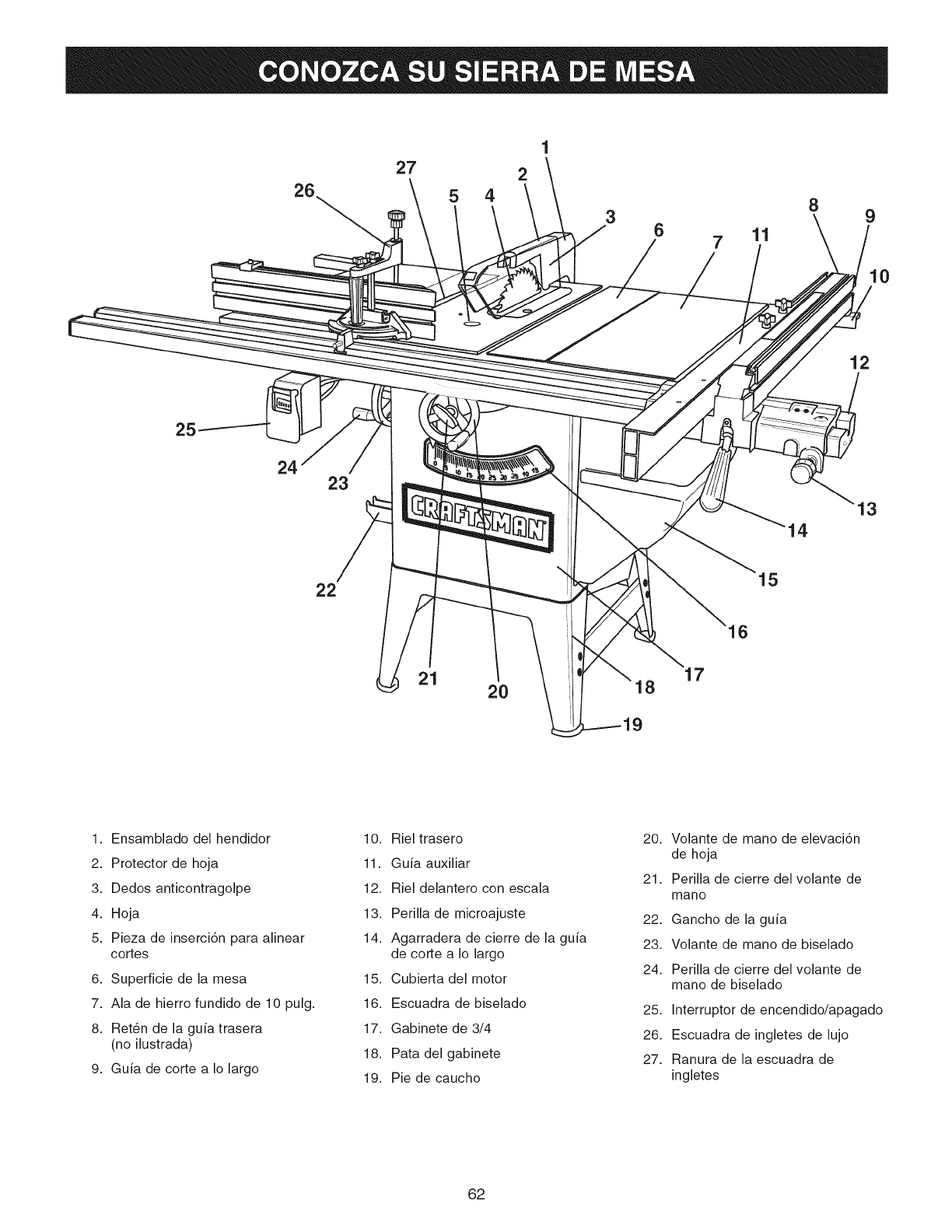
27 2
26 5 4
38 9
6 7 11
10
12
25
23
14
13
22
16
15
21 2O 17
1. Ensamblado del hendidor
2. Protector de hoja
3. Dedos anticontragolpe
4. Hoja
5. Pieza de inserci6n para alinear
cortes
6. Superficie de la mesa
7. Ala de hierro fundido de 10 pulg.
8. Ret_n de la guia trasera
(no ilustrada)
9. Guia de corte a Io largo
10. Riel trasero
11. Guia auxiliar
12. Riel delantero con escala
13. Perilla de microajuste
14. Agarradera de cierre de la guia
de corte a Io largo
15. Cubierta del motor
16. Escuadra de biselado
17. Gabinete de 3/4
18. Pata del gabinete
19. Pie de caucho
20. Volante de mano de elevaci6n
de hoja
21. Perilla de cierre del volante de
mano
22. Gancho de la guia
23. Volante de mano de biselado
24. Perilla de cierre del volante de
mano de biselado
25. Interruptor de encendido/apagado
26. Escuadra de ingletes de lujo
27. Ranura de la escuadra de
ingletes
62
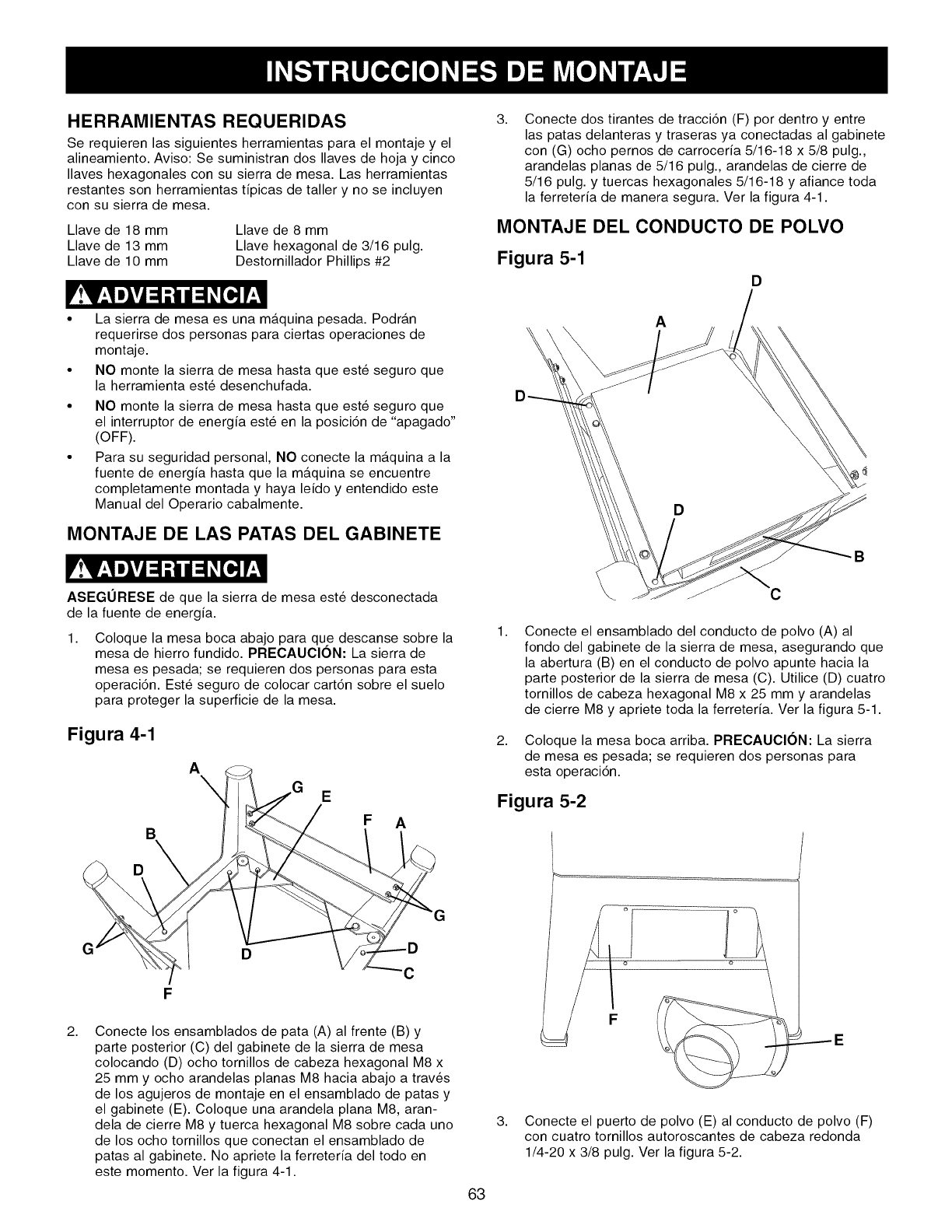
HERRAMIENTAS REQUERIDAS
Se requieren las siguientes herramientas para el montaje y el
alineamiento. Aviso: Se suministran dos Ilaves de hoja y cinco
Ilaves hexagonales con su sierra de mesa. Las herramientas
restantes son herramientas tipicas de taller y no se incluyen
con su sierra de mesa.
Llave de 18 mm
Llave de 13 mm
Llave de 10 mm
Llave de 8 mm
Llave hexagonal de 3/16 pulg.
Destornillador Phillips #2
3, Conecte dos tirantes de tracci6n (F) por dentro y entre
las patas delanteras y traseras ya conectadas al gabinete
con (G) ocho pernos de carroceria 5/16-18 x 5/8 pulg.,
arandelas planas de 5/16 pulg., arandelas de cierre de
5/16 pulg. y tuercas hexagonales 5/16-18 y afiance toda
la ferreteria de manera segura. Ver la figura 4-1.
MONTAJE DEL CONDUCTO DE POLVO
Figura 5-1
D
La sierra de mesa es una maquina pesada. Podran
requerirse dos personas para ciertas operaciones de
montaje.
NO monte la sierra de mesa hasta que este seguro que
la herramienta este desenchufada.
NO monte la sierra de mesa hasta que este seguro que
el interruptor de energia este en la posici6n de "apagado"
(OFF).
Para su seguridad personal, NO conecte la maquina a la
fuente de energia hasta que la maquina se encuentre
completamente montada y haya leido y entendido este
Manual del Operario cabalmente.
MONTAJE DE LAS PATAS DEL GABINETE
ASEGURESE de que la sierra de mesa este desconectada
de la fuente de energia.
1, Coloque la mesa boca abajo para que descanse sobre la
mesa de hierro fundido. PRECAUCION: La sierra de
mesa es pesada; se requieren dos personas para esta
operaci6n. Este seguro de colocar cart6n sobre el suelo
para proteger la superficie de la mesa.
Figura 4-1
A
E
B
D
F A
GD
C
F
2, Conecte los ensamblados de pata (A) al frente (B) y
parte posterior (C) del gabinete de la sierra de mesa
colocando (D) ocho tornillos de cabeza hexagonal M8 x
25 mm y ocho arandelas planas M8 hacia abajo a trav_s
de los agujeros de montaje en el ensamblado de patas y
el gabinete (E). Coloque una arandela plana M8, aran-
dela de cierre M8 y tuerca hexagonal M8 sobre cada uno
de los ocho tornillos que conectan el ensamblado de
patas al gabinete. No apriete la ferreteria del todo en
este momento. Ver la figura 4-1.
63
A
\
C
B
1,
2,
Conecte el ensamblado del conducto de polvo (A) al
fondo del gabinete de la sierra de mesa, asegurando que
la abertura (B) en el conducto de polvo apunte hacia la
parte posterior de la sierra de mesa (C). Utilice (D) cuatro
tornillos de cabeza hexagonal M8 x 25 mm y arandelas
de cierre M8 y apriete toda la ferreteria. Ver la figura 5-1.
Coloque la mesa boca arriba. PRECAUClON: La sierra
de mesa es pesada; se requieren dos personas para
esta operaci6n.
Figura 5-2
3. Conecte el puerto de polvo (E) al conducto de polvo (F)
con cuatro tornillos autoroscantes de cabeza redonda
1/4-20 x 3/8 pulg. Ver la figura 5-2.
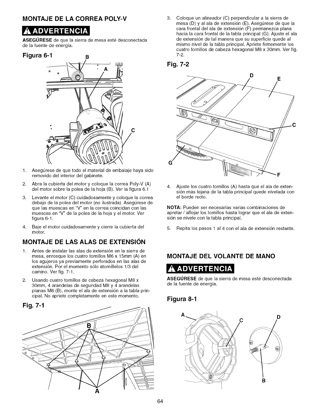
MONTAJE DE LA CORREA POLY-V
ASEGORESE de que la sierra de mesa este desconectada
de la fuente de energia.
Figura 6-1 B
A
C
I,
2.
Asegt_rese de que todo el material de embalaje haya sido
removido del interior del gabinete.
Abra la cubierta del motor y coloque la correa Poly-V (A)
del motor sobre la polea de la hoja (B). Ver la figura 6.1
3, Levante el motor (C) cuidadosamente y coloque la correa
debajo de la polea del motor (no ilustrada). Asegt_rese de
que las muescas en "V" en la correa coincidan con las
muescas en "V" de la polea de la hoja y el motor. Ver
figura 6-1.
4. Baje el motor cuidadosamente y cierre la cubierta del
motor.
MONTAJE DE LAS ALAS DE EXTENSION
1, Antes de instalar las alas de extensi6n en la sierra de
mesa, enrosque los cuatro tornillos M6 x 15mm (A) en
los agujeros ya previamente perforados en las alas de
extensi6n. Por el momento s61o atornillelos 1/3 del
camino. Ver fig. 7-1.
2, Usando cuatro tornillos de cabeza hexagonal M8 x
30mm, 4 arandelas de seguridad M8 y 4 arandelas
planas M8 (B), monte el ala de extensi6n a la tabla prin-
cipal. No apriete completamente en este momento.
Fig. 7-1
A
3, Coloque un alineador (C) perpendicular a la sierra de
mesa (D) y al ala de extensi6n (E). AsegOrese de que la
cara frontal del ala de extensi6n (F) permanezca plana
hacia la cara frontal de la tabla principal (G). Ajuste el ala
de extensi6n de tal manera que su superficie quede al
mismo nivel de la tabla principal. Apriete firmemente los
cuatro tornillos de cabeza hexagonal M8 x 30mm. Ver fig.
7-2.
Fig. 7-2
DE
C
G
4, Ajuste los cuatro tornillos (A) hasta que el ala de exten-
si6n m_.s lejana de la tabla principal quede nivelada con
el borde recto.
NOTA: Pueden ser necesarias varias combinaciones de
apretar /aflojar los tornillos hasta Iograr que el ala de exten-
si6n se nivele con la tabla principal.
5. Repita los pasos 1 al 4 con el ala de extensi6n restante.
MONTAJE DEL VOLANTE DE MANO
ASEGURESE de que la sierra de mesa este desconectada
de la fuente de energia.
Figura 8-1
D
B
64
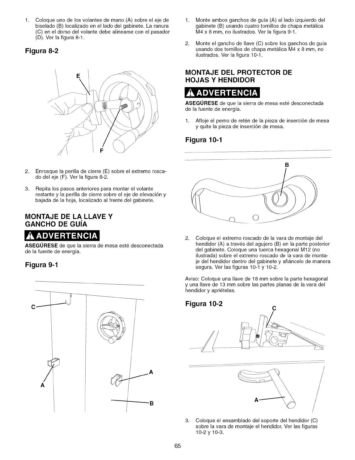
1, Coloque uno de los volantes de mano (A) sobre el eje de
biselado (B) Iocalizado en el lado del gabinete. La ranura
(C) en el dorso del volante debe alinearse con el pasador
(D). Ver la figura 8-1.
Figura 8-2
1,
2,
Monte ambos ganchos de guia (A) al lado izquierdo del
gabinete (B) usando cuatro tornillos de chapa metalica
M4 x 8 mm, no ilustrados. Ver la figura 9-1.
Monte el gancho de Ilave (C) sobre los ganchos de guia
usando dos tornillos de chapa metalica M4 x 8 mm, no
ilustrados. Ver la figura 10-1.
EMONTAJE DEL PROTECTOR DE
HOJAS Y HENDIDOR
ASEGURESE de que la sierra de mesa este desconectada
de la fuente de energia.
1. Afloje el perno de reten de la pieza de inserci6n de mesa
y quite la pieza de inserci6n de mesa.
Figura 10-1
2,
3,
Enrosque la perilla de cierre (E) sobre el extremo rosca-
do del eje (F). Ver la figura 8-2.
Repita los pasos anteriores para montar el volante
restante y la perilla de cierre sobre el eje de elevaci6n y
bajada de la hoja, Iocalizado al frente del gabinete.
B
MONTAJE DE LA LLAVE Y
GANCHO DE GUiA
ASEGURESE de que la sierra de mesa este desconectada
de la fuente de energia.
Figura 9-1
A
2, Coloque el extremo roscado de la vara de montaje del
hendidor (A) a trav6s del agujero (B) en la parte posterior
del gabinete. Coloque una tuerca hexagonal M12 (no
ilustrada) sobre el extremo roscado de la vara de monta-
je del hendidor dentro del gabinete y afiancelo de manera
segura. Ver las figuras 10-1 y 10-2.
Aviso: Coloque una Ilave de 18 mm sobre la parte hexagonal
y una Ilave de 13 mm sobre las partes planas de la vara del
hendidor y apri6telas.
Figura 10-2 C
3. Coloque el ensamblado del soporte del hendidor (C)
sobre la vara de montaje el hendidor. Ver las figuras
10-2 y 10-3.
65
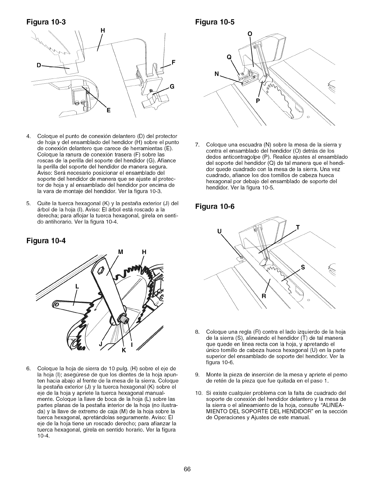
Figura 10-3 Figura 10-5
Q
N
0
P
\
4,
5,
Coloque el punto de conexi6n delantero (D) del protector
de hoja y del ensamblado del hendidor (H) sobre el punto
de conexi6n delantero que carece de herramientas (E).
Coloque la ranura de conexi6n trasera (F) sobre las
roscas de la perilla del soporte del hendidor (G). Afiance
la perilla del soporte del hendidor de manera segura.
Aviso: Sera necesario posicionar el ensamblado del
soporte del hendidor de manera que se ajuste al protec-
tor de hoja y al ensamblado del hendidor por encima de
la vara de montaje del hendidor. Ver la figura 10-3.
Quite la tuerca hexagonal (K) y la pestaSa exterior (J) del
arbol de la hoja (I). Aviso: El arbol esta roscado a la
derecha; para aflojar la tuerca hexagonal, girela en senti-
do antihorario. Ver la figura 10-4.
Figura 10-4
M H
7, Coloque una escuadra (N) sobre la mesa de la sierra y
contra el ensamblado del hendidor (O) detras de los
dedos anticontragolpe (P). Realice ajustes al ensamblado
del soporte del hendidor (Q) de tal manera que el hendi-
dor quede cuadrado con la mesa de la sierra. Una vez
cuadrado, afiance los dos tornillos de cabeza hueca
hexagonal por debajo del ensamblado de soporte del
hendidor. Ver la figura 10-5.
Figura 10-6
U
\
6, Coloque la hoja de sierra de 10 pulg. (H) sobre el eje de
la hoja (I); asegtJrese de que los dientes de la hoja apun-
ten hacia abajo al frente de la mesa de la sierra. Coloque
la pestaSa exterior (J) y la tuerca hexagonal (K) sobre el
eje de la hoja y apriete la tuerca hexagonal manual-
mente. Coloque la Ilave de boca de la hoja (L) sobre las
partes planas de la pestaSa interior de la hoja (no ilustra-
da) y la Ilave de extremo de caja (M) de la hoja sobre la
tuerca hexagonal, apretandolas seguramente. Aviso: El
eje de la hoja tiene un roscado derecho; para afianzar la
tuerca hexagonal, girela en sentido horario. Ver la figura
10-4.
8,
9,
10.
Coloque una regla (R) contra el lado izquierdo de la hoja
de la sierra (S), alineando el hendidor (T) de tal manera
que quede en linea recta con la hoja, y apretando el
tJnico tornillo de cabeza hueca hexagonal (U) en la parte
superior del ensamblado de soporte del hendidor. Ver la
figura 10-6.
Monte la pieza de inserci6n de la mesa y apriete el perno
de reten de la pieza que fue quitada en el paso 1.
Si existe cualquier problema con la falta de cuadrado del
soporte de conexi6n del hendidor delantero y la mesa de
la sierra o el alineamiento de la hoja, consulte "ALINEA-
MIENTO DEL SOPORTE DEL HENDIDOR" en la secci6n
de Operaciones y Ajustes de este manual.
66
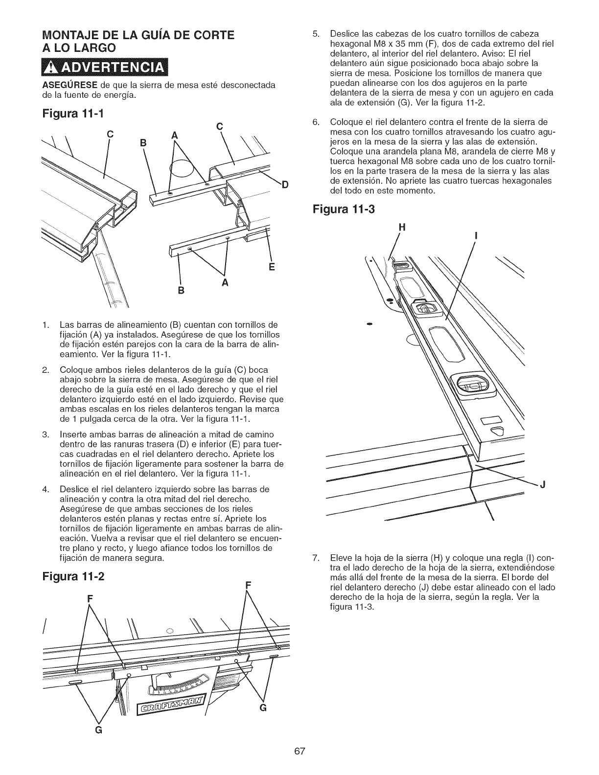
NIONTAJE DE LA GUIA DE CORTE
A LO LARGO
ASEGURESE de que la sierra de mesa est6 desconectada
de la fuente de energia.
Figura 11-1
C A
B
C
"D
BA
1. Las barras de alineamiento (B) cuentan con tornillos de
fijaci6n (A) ya instalados. Aseg0rese de que los tornillos
de fijaci6n est6n parejos con la cara de la barra de alin-
eamiento. Ver la figura 11-1.
2. Coloque ambos rieles delanteros de la guia (C) boca
abajo sobre la sierra de mesa. Aseg0rese de que el riel
derecho de la guia este en el lado derecho y que el riel
delantero izquierdo est6 en el lado izquierdo. Revise que
ambas escalas en los rieles delanteros tengan la marca
de 1 pulgada cerca de la otra. Ver la figura 11-1.
3. Inserte ambas barras de alineaci6n a mitad de camino
dentro de las ranuras trasera (D) e inferior (E) para tuer-
cas cuadradas en el riel delantero derecho. Apriete los
tornillos de fijaci6n ligeramente para sostener la barra de
alineaci6n en el riel delantero. Ver la figura 11-1.
4. Deslice el riel delantero izquierdo sobre las barras de
alineaci6n y contra la otra mitad del riel derecho.
AsegOrese de que ambas secciones de los rieles
delanteros est6n planas y rectas entre si. Apriete los
tornillos de fijaci6n ligeramente en ambas barras de alin-
eaci6n. Vuelva a revisar que el riel delantero se encuen-
tre piano y recto, y luego afiance todos los tornillos de
fijaci6n de manera segura.
Figura 11-2 F
F
/O
G
G
5. Deslice las cabezas de los cuatro tornillos de cabeza
hexagonal M8 x 35 mm (F), dos de cada extremo del riel
delantero, al interior del riel delantero. Aviso: El riel
delantero aOn sigue posicionado boca abajo sobre la
sierra de mesa. Posicione los tornillos de manera que
puedan alinearse con los dos agujeros en la parte
delantera de la sierra de mesa y con un agujero en cada
ala de extensi6n (G). Ver la figura 11-2.
6. Coloque el riel delantero contra el frente de la sierra de
mesa con los cuatro tornillos atravesando los cuatro agu-
jeros en la mesa de la sierra y las alas de extensi6n.
Coloque una arandela plana M8, arandela de cierre M8 y
tuerca hexagonal M8 sobre cada uno de los cuatro tornil-
los en la parte trasera de la mesa de la sierra y las alas
de extensi6n. No apriete las cuatro tuercas hexagonales
del todo en este momento.
Figura 11-3
H
7. Eleve la hoja de la sierra (H) y coloque una regla (I) con-
tra el lado derecho de la hoja de la sierra, extendi6ndose
mas alia del frente de la mesa de la sierra. El borde del
riel delantero derecho (J) debe estar alineado con el lado
derecho de la hoja de la sierra, segOn la regla. Ver la
figura 11-3.
67
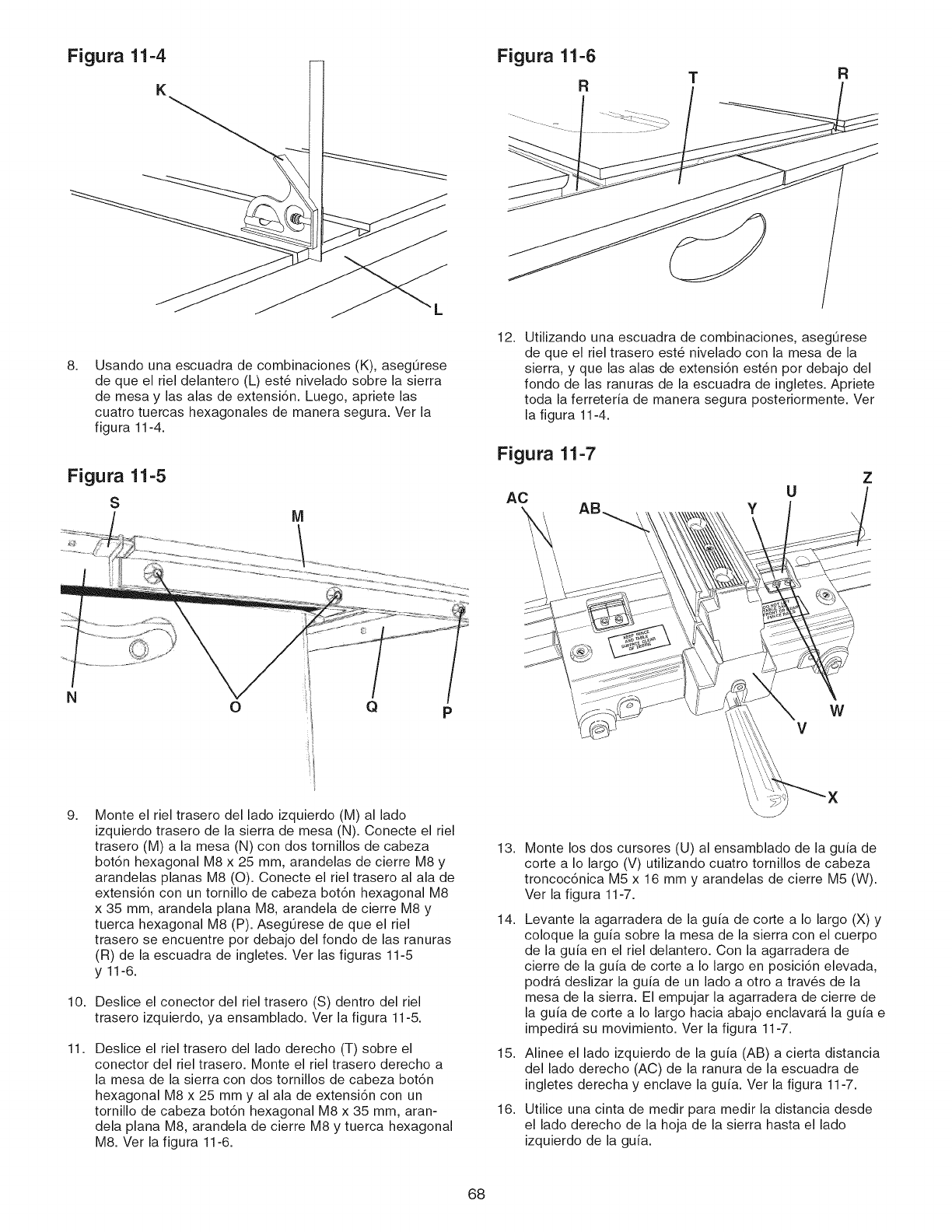
Figura 11-4
8. Usando una escuadra de combinaciones (K), aseg0rese
de que el riel delantero (L) est6 nivelado sobre la sierra
de mesa y las alas de extensi6n. Luego, apriete las
cuatro tuercas hexagonales de manera segura. Ver la
figura 11-4.
Figura 11-5
S
Figura 11-6
RTR
12. Utilizando una escuadra de combinaciones, aseg0rese
de que el riel trasero est6 nivelado con la mesa de la
sierra, y que las alas de extensi6n est6n por debajo del
fondo de las ranuras de la escuadra de ingletes. Apriete
toda la ferretefia de manera segura posteriormente. Ver
la figura 11-4.
Figura 11-7
AC YUZ
NoQPW
V
9.
10.
11.
Monte el riel trasero del lado izquierdo (M) al lado
izquierdo trasero de la sierra de mesa (N). Conecte el riel
trasero (M) a la mesa (N) con dos tornillos de cabeza
bot6n hexagonal M8 x 25 mm, arandelas de cierre M8 y
arandelas planas M8 (O). Conecte el riel trasero al ala de
extensi6n con un tornillo de cabeza bot6n hexagonal M8
x 35 mm, arandela plana M8, arandela de cierre M8 y
tuerca hexagonal M8 (P). AsegOrese de que el riel
trasero se encuentre por debajo del fondo de las ranuras
(R) de la escuadra de ingletes. Ver las figuras 11-5
y 11-6.
Deslice el conector del riel trasero (S) dentro del riel
trasero izquierdo, ya ensamblado. Ver la figura 11-5.
Deslice el riel trasero del lado derecho (T) sobre el
conector del riel trasero. Monte el riel trasero derecho a
la mesa de la sierra con dos tornillos de cabeza bot6n
hexagonal M8 x 25 mm y al ala de extensi6n con un
tornillo de cabeza bot6n hexagonal M8 x 35 mm, aran-
dela plana M8, arandela de cierre M8 y tuerca hexagonal
M8. Ver la figura 11-6.
13.
14.
15.
16.
Monte los dos cursores (U) al ensamblado de la guia de
corte a Io largo (V) utilizando cuatro tornillos de cabeza
troncoc6nica M5 x 16 mm y arandelas de cierre M5 (W).
Ver la figura 11-7.
Levante la agarradera de la guia de corte a Io largo (X) y
coloque la guia sobre la mesa de la sierra con el cuerpo
de la guia en el riel delantero. Con la agarradera de
cierre de la guia de corte a Io largo en posici6n elevada,
podra deslizar la guia de un lado a otro a trav6s de la
mesa de la sierra. El empujar la agarradera de cierre de
la guia de corte a Io largo hacia abajo enclavar_, la guia e
impedir_, su movimiento. Ver la figura 11-7.
Alinee el lado izquierdo de la guia (AB) a cierta distancia
del lado derecho (AC) de la ranura de la escuadra de
ingletes derecha y enclave la guia. Ver la figura 11-7.
Utilice una cinta de medir para medir la distancia desde
el lado derecho de la hoja de la sierra hasta el lado
izquierdo de la guia.
68
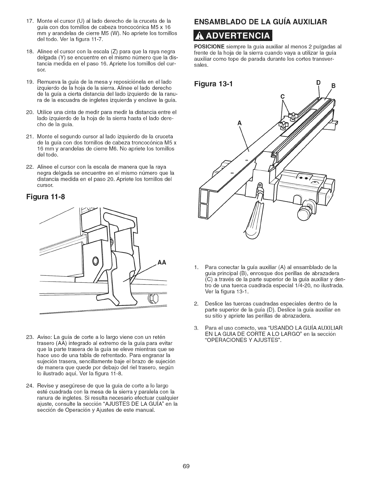
17. Monte el cursor (U) al lado derecho de la cruceta de la
guia con dos tornillos de cabeza troncoc6nica M5 x 16
mm y arandelas de cierre M5 (W). No apriete los tornillos
del todo. Ver la figura 11-7.
18. Alinee el cursor con la escala (Z) para que la raya negra
delgada (Y) se encuentre en el mismo n0mero que la dis-
tancia medida en el paso 16. Apriete los tornillos del cur-
sor.
19. Remueva la guia de la mesa y reposici6nela en el lado
izquierdo de la hoja de la sierra. Alinee el lado derecho
de la guia a cierta distancia del lado izquierdo de la ranu-
ra de la escuadra de ingletes izquierda y enclave la guia.
20. Utilice una cinta de medir para medir la distancia entre el
lado izquierdo de la hoja de la sierra hasta el lado dere-
cho de la guia.
21. Monte el segundo cursor al lado izquierdo de la cruceta
de la guia con dos tornillos de cabeza troncoc6nica M5 x
16 mm y arandelas de cierre M6. No apriete los tornillos
del todo.
22. Alinee el cursor con la escala de manera que la raya
negra delgada se encuentre en el mismo n0mero que la
distancia medida en el paso 20. Apriete los tornillos del
cursor.
Figura 11-8
ENSAMBLADO DE LA GUIA ALiXlLIAR
POSICIONE siempre la guia auxiliar al menos 2 pulgadas al
frente de la hoja de la sierra cuando vaya a utilizar la guia
auxiliar como tope de parada durante los cortes transver-
sales.
Figura 13-1 D B
C
A
AA
23. Aviso: La guia de corte a Io largo viene con un ret_n
trasero (AA) integrado al extremo de la guia para evitar
que la parte trasera de la guia se eleve mientras que se
hace uso de una tabla de refrentado. Para engranar la
sujeci6n trasera, sencillamente baje el brazo de sujeci6n
de manera que quede por debajo del riel trasero, segOn
Io ilustrado aqui. Ver la figura 11-8.
24. Revise y asegOrese de que la guia de corte a Io largo
est6 cuadrada con la mesa de la sierra y paralela con la
ranura de ingletes. Si resulta necesario efectuar cualquier
ajuste, consulte la secci6n "AJUSTES DE LA GUIA" en la
secci6n de Operaci6n y Ajustes de este manual.
2.
3.
Para conectar la guia auxiliar (A) al ensamblado de la
guia principal (B), enrosque dos perillas de abrazadera
(C) a trav6s de la parte superior de la guia auxiliary den-
tro de una tuerca cuadrada especial 1/4-20, no ilustrada.
Ver la figura 13-1.
Deslice las tuercas cuadradas especiales dentro de la
parte superior de la guia (D). Deslice la guia auxiliar en
su sitio y apriete las perillas de abrazadera.
Para el uso correcto, vea "USANDO LA GUJAAUXILIAR
EN LA GUIA DE CORTE A LO LARGO" en la secci6n
"OPERACIONES Y AJUSTES".
69
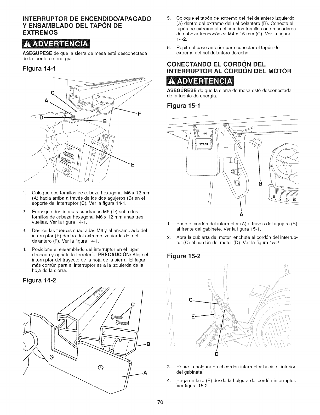
INTERRUPTOR DE ENCENDIDO/APAGADO
YENSAMBLADO DEL TAPON DE
EXTREMOS
ASEGURESE de que la sierra de mesa est6 desconectada
de la fuente de energia.
Figura 14-1
5. Coloque el tap6n de extremo del riel delantero izquierdo
(A) dentro del extremo del riel delantero (B). Conecte el
tap6n de extremo al riel con dos tornillos autoroscadores
de cabeza troncoc6nica M4 x 16 mm (C). Ver la figura
14-2.
6. Repita el paso anterior para conectar el tap6n de
extremo del riel delantero derecho.
CONECTANDO EL CORDON DEL
INTERRUPTOR AL CORDON DEL MOTOR
C
A
E
1. Coloque dos tornillos de cabeza hexagonal M6 x 12 mm
(A) hacia arriba a trav_s de los dos agujeros (B) en el
soporte del interruptor (C). Ver la figura 14-1.
2. Enrosque dos tuercas cuadradas M6 (D) sobre los
tornillos de cabeza hexagonal M6 x 12 mm unas tres
vueltas. Ver la figura 14-1.
3. Deslice las tuercas cuadradas M6 y el ensamblado del
interruptor (E) dentro del extremo izquierdo del riel
delantero (F). Ver la figura 14-1.
4. Posicione el ensamblado del interruptor en el lugar
deseado y apriete la ferreteria. PRECAUClON: Aleje el
interruptor del trayecto de la hoja de la sierra. El lugar
mas comOn para el interruptor es a la izquierda de la
hoja de la sierra.
Figura 14-2
C
ASEGURESE de que la sierra de mesa est6 desconectada
de la fuente de energia.
Figura 15-1
B
1.
2.
A
Pase el cord6n del interruptor (A) a trav_s del agujero (B)
al frente del gabinete. Vet la figura 15-1.
Abra la cubierta del motor, enchufe el cord6n del interrup-
tor (C) al cord6n del motor (D). Ver la figura 15-2.
Figura 15-2
i
....F_p"
xE
D
3.
4.
Retire la holgura en el cord6n interruptor hacia el interior
del gabinete.
Haga un lazo (E) desde la holgura del cord6n interruptor.
Ver figura 15-2.
7O
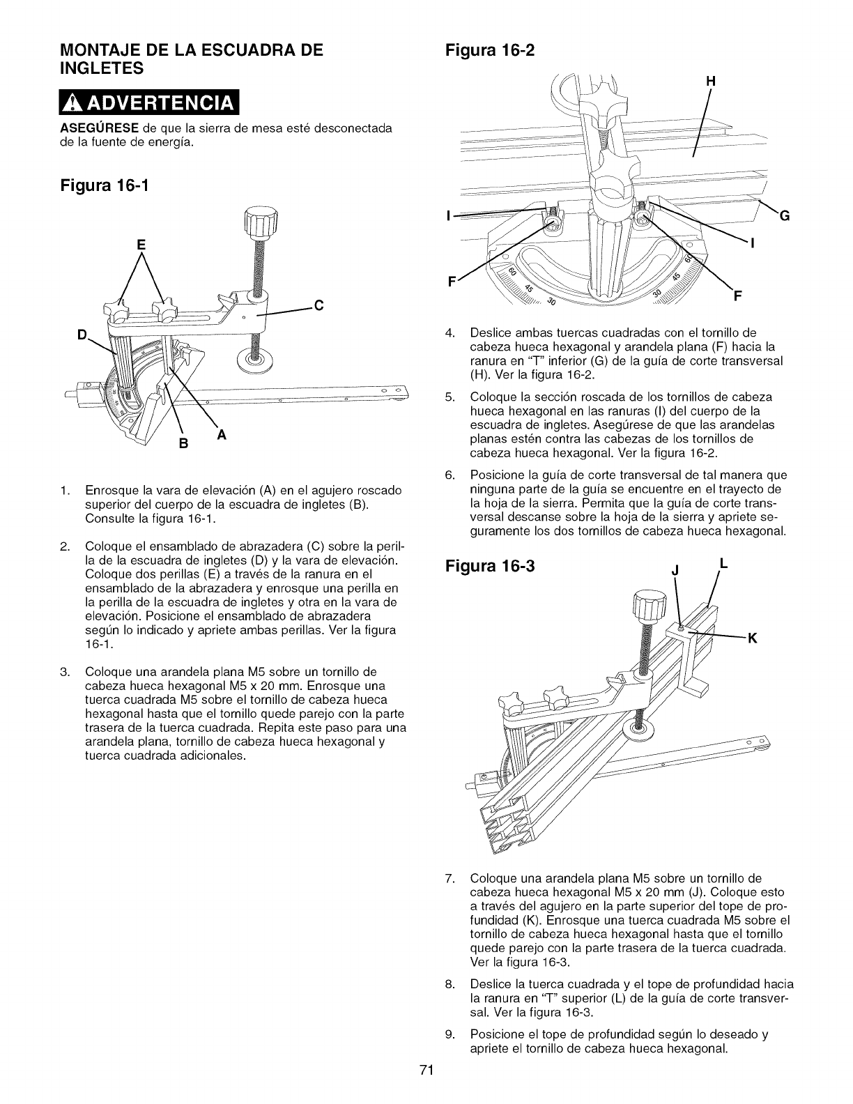
MONTAJE DE LA ESCUADRA DE
INGLETES
ASEGORESE de que la sierra de mesa este desconectada
de la fuente de energia.
Figura 16-1
E
Figura 16-2
H
1,
2,
3,
Enrosque la vara de elevaci6n (A) en el agujero roscado
superior del cuerpo de la escuadra de ingletes (B).
Consulte la figura 16-1.
Coloque el ensamblado de abrazadera (C) sobre la peril-
la de la escuadra de ingletes (D) y la vara de elevaci6n.
Coloque dos perillas (E) a trav_s de la ranura en el
ensamblado de la abrazadera y enrosque una perilla en
la perilla de la escuadra de ingletes y otra en la vara de
elevaci6n. Posicione el ensamblado de abrazadera
segen Io indicado y apriete ambas perillas. Ver la figura
16-1.
Coloque una arandela plana M5 sobre un tornillo de
cabeza hueca hexagonal M5 x 20 mm. Enrosque una
tuerca cuadrada M5 sobre el tornillo de cabeza hueca
hexagonal hasta que el tornillo quede parejo con la parte
trasera de la tuerca cuadrada. Repita este paso para una
arandela plana, tornillo de cabeza hueca hexagonal y
tuerca cuadrada adicionales.
4,
5,
6,
Deslice ambas tuercas cuadradas con el tornillo de
cabeza hueca hexagonal y arandela plana (F) hacia la
ranura en "T" inferior (G) de la guia de corte transversal
(H). Ver la figura 16-2.
Coloque la secci6n roscada de los tornillos de cabeza
hueca hexagonal en las ranuras (I) del cuerpo de la
escuadra de ingletes. AsegOrese de que las arandelas
planas esten contra las cabezas de los tornillos de
cabeza hueca hexagonal. Ver la figura 16-2.
Posicione la guia de corte transversal de tal manera que
ninguna parte de la guia se encuentre en el trayecto de
la hoja de la sierra. Permita que la guia de corte trans-
versal descanse sobre la hoja de la sierra y apriete se-
guramente los dos tornillos de cabeza hueca hexagonal.
Figura 16-3 j
71
7,
8,
9,
Coloque una arandela plana M5 sobre un tornillo de
cabeza hueca hexagonal M5 x 20 mm (J). Coloque esto
a trav_s del agujero en la parte superior del tope de pro-
fundidad (K). Enrosque una tuerca cuadrada M5 sobre el
tornillo de cabeza hueca hexagonal hasta que el tornillo
quede parejo con la parte trasera de la tuerca cuadrada.
Ver la figura 16-3.
Deslice la tuerca cuadrada y el tope de profundidad hacia
la ranura en "T" superior (L) de la guia de corte transver-
sal. Ver la figura 16-3.
Posicione el tope de profundidad segtJn Io deseado y
apriete el tornillo de cabeza hueca hexagonal.
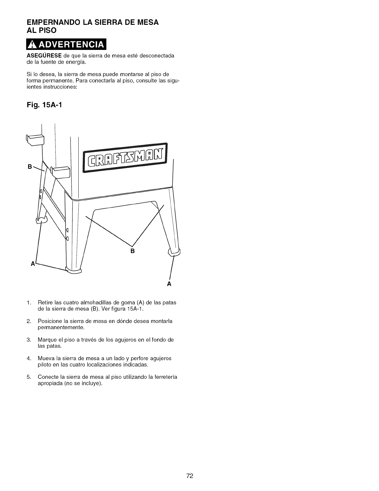
EMPERNANDO LA SIERRA DE MESA
AL PISO
ASEGORESE de que la sierra de mesa este desconectada
de la fuente de energia.
Si Io desea, la sierra de mesa puede montarse al piso de
forma permanente. Para conectarla al piso, consulte las sigu-
ientes instrucciones:
Fig. 15A-1
B
A
1. Retire las cuatro almohadillas de goma (A) de las patas
de la sierra de mesa (B). Ver figura 15A-1.
2. Posicione la sierra de mesa en d6nde desea montarla
permanentemente.
3. Marque el piso a trav_s de los agujeros en el fondo de
las patas.
4. Mueva la sierra de mesa a un lado y perfore agujeros
piloto en las cuatro Iocalizaciones indicadas.
5. Conecte la sierra de mesa al piso utilizando la ferreteria
apropiada (no se incluye).
72
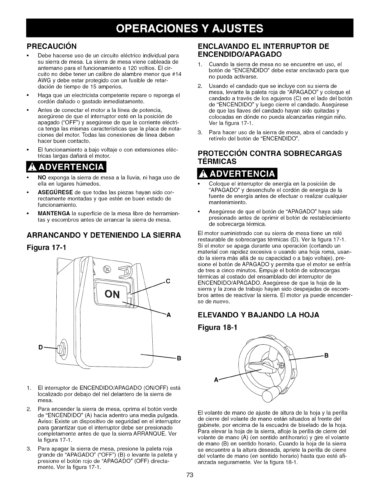
PRECAUClON
Debe hacerse uso de un circuito el_ctrico individual para
su sierra de mesa. La sierra de mesa viene cableada de
antemano para el funcionamiento a 120 voltios. El cir-
cuito no debe tener un calibre de alambre menor que #14
AWG y debe estar protegido con un fusible de retar-
daci6n de tiempo de 15 amperios.
Haga que un electricista competente repare o reponga el
cord6n daSado o gastado inmediatamente.
Antes de conectar el motor a la linea de potencia,
asegt_rese de que el interruptor este en la posici6n de
apagado ("OFF") y asegt_rese de que la corriente el_ctri-
ca tenga las mismas caracteristicas que la placa de nota-
ciones del motor. Todas las conexiones de linea deben
hacer buen contacto.
• El funcionamiento a bajo voltaje o con extensiones el_c-
tricas largas daSara el motor.
ENCLAVANDO EL INTERRUPTOR DE
ENCENDIDO/APAGADO
1,
2,
3,
Cuando la sierra de mesa no se encuentre en uso, el
bot6n de "ENCENDIDO" debe estar enclavado para que
no pueda activarse.
Usando el candado que se incluye con su sierra de
mesa, levante la paleta roja de "APAGADO" y coloque el
candado a traves de los agujeros (C) en el lado del bot6n
de "ENCENDIDO" y luego cierre el candado. AsegtJrese
de que las Ilaves del candado hayan sido quitadas y
colocadas en d6nde no pueda alcanzarlas ningt_n ni_o.
Ver la figura 17-1.
Para hacer uso de la sierra de mesa, abra el candado y
retirelo del bot6n de "ENCENDIDO".
PROTECCION CONTRA SOBRECARGAS
TERMICAS
• NO exponga la sierra de mesa a la Iluvia, ni haga uso de
ella en lugares htJmedos.
• ASEGURESE de que todas las piezas hayan sido cor-
rectamente montadas y que esten en buen estado de
funcionamiento.
MANTENGA la superficie de la mesa libre de herramien-
tas y escombros antes de arrancar la sierra de mesa.
ARRANCANDO YDETENIENDO LA SIERRA
Figura 17-1
D------
J
_A
_B
1,
2,
3,
El interruptor de ENCENDIDO/APAGADO (ON/OFF) esta
Iocalizado por debajo del riel delantero de la sierra de
mesa.
Para encender la sierra de mesa, oprima el bot6n verde
de "ENCENDIDO" (A) hacia adentro una media pulgada.
Aviso: Existe un dispositivo de seguridad en el interruptor
para garantizar que el interruptor debe ser presionado
completamente antes de que la sierra ARRANQUE. Ver
la figura 17-1.
Para apagar la sierra de mesa, presione la paleta roja
grande de "APAGADO" ("OFF") (B) o levante la paleta y
presione el bot6n rojo de "APAGADO" (OFF) directa-
mente. Ver la figura 17-1.
Coloque el interruptor de energia en la posici6n de
"APAGADO" y desenchufe el cord6n de energia de la
fuente de energia antes de efectuar o realizar cualquier
mantenimiento.
• AsegtJrese de que el bot6n de "APAGADO" haya sido
presionado antes de oprimir el bot6n de restablecimiento
de sobrecarga termica.
El motor suministrado con su sierra de mesa tiene un rel_
restaurable de sobrecargas termicas (D). Ver la figura 17-1.
Si el motor se apaga durante una operaci6n (cortando un
material con rapidez excesiva o usando una hoja roma, usan-
do la sierra m_.s all_. de su capacidad o a bajo voltaje), pre-
sione el bot6n de APAGADO y permita que el motor se enfria
de tres a cinco minutos. Empuje el bot6n de sobrecargas
termicas al costado del ensamblado del interruptor de
ENCENDIDO/APAGADO. Asegt_rese de que la hoja de la
sierra y la zona de trabajo hayan sido despejadas de escom-
bros antes de reactivar la sierra. El motor ya puede encender-
se de nuevo.
ELEVANDO Y BAJANDO LA HOJA
Figura 18-1
AB
El volante de mano de ajuste de altura de la hoja y la perilla
de cierre del volante de mano estan situados al frente del
gabinete, por encima de la escuadra de biselado de la hoja.
Para elevar la hoja de la sierra, afloje la perilla de cierre del
volante de mano (A) (en sentido antihorario) y gire el volante
de mano (B) en sentido horario. Cuando la hoja de la sierra
se encuentre a la altura deseada, apriete la perilla de cierre
del volante de mano (en sentido horario) hasta que este afi-
anzada seguramente. Ver la figura 18-1.
73
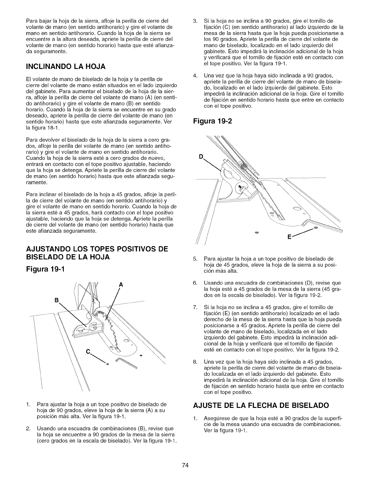
Para bajar la hoja de la sierra, afloje la perilla de cierre del
volante de mano (en sentido antihorario) y gire el volante de
mano en sentido antihorario. Cuando la hoja de la sierra se
encuentre a la altura deseada, apriete la perilla de cierre del
volante de mano (en sentido horario) hasta que este afianza-
da seguramente.
INCLINANDO LA HOJA
El volante de mano de biselado de la hoja y la perilla de
cierre del volante de mano estan situados en el lado izquierdo
del gabinete. Para aumentar el biselado de la hoja de la sier-
ra, afloje la perilla de cierre del volante de mano (A) (en senti-
do antihorario) y gire el volante de mano (B) en sentido
horario. Cuando la hoja de la sierra se encuentre en su grado
deseado, apriete la perilla de cierre del volante de mano (en
sentido horario) hasta que este afianzada seguramente. Ver
la figura 18-1.
Para devolver el biselado de la hoja de la sierra a cero gra-
dos, afloje la perilla del volante de mano (en sentido antiho-
rario) y gire el volante de mano en sentido antihorario.
Cuando la hoja de la sierra este a cero grados de nuevo,
entrara en contacto con el tope positivo ajustable, haciendo
que la hoja se detenga. Apriete la perilla de cierre del volante
de mano (en sentido horario) hasta que este afianzada segu-
ramente.
Para inclinar el biselado de la hoja a 45 grados, afloje la peril-
la de cierre del volante de mano (en sentido antihorario) y
gire el volante de mano en sentido horario. Cuando la hoja de
la sierra este a 45 grados, hara contacto con el tope positivo
ajustable, haciendo que la hoja se detenga. Apriete la perilla
de cierre del volante de mano (en sentido horario) hasta que
este afianzada seguramente.
AJUSTANDO LOS TOPES POSITIVOS DE
BISELADO DE LA HOJA
Figura 19-1
A
B
1,
2,
Para ajustar la hoja a un tope positivo de biselado de
hoja de 90 grados, eleve la hoja de la sierra (A) a su
posici6n mas alta. Ver la figura 19-1.
Usando una escuadra de combinaciones (B), revise que
la hoja se encuentre a 90 grados de la mesa de la sierra
(cero grados en la escala de biselado). Ver la figura 19-1.
3,
4,
Si la hoja no se inclina a 90 grados, gire el tornillo de
fijaci6n (C) (en sentido antihorario) al lado izquierdo de la
mesa de la sierra hasta que la hoja pueda posicionarse a
los 90 grados. Apriete la perilla de cierre del volante de
mano de biselado, Iocalizado en el lado izquierdo del
gabinete. Esto impedira la inclinaci6n adicional de la hoja
y verificara que el tornillo de fijaci6n este en contacto con
el tope positivo. Ver la figura 19-1.
Una vez que la hoja haya sido inclinada a 90 grados,
apriete la perilla de cierre del volante de mano de bisela-
do, Iocalizado en el lado izquierdo del gabinete. Esto
impedira la inclinaci6n adicional de la hoja. Gire el tornillo
de fijaci6n en sentido horario hasta que entre en contacto
con el tope positivo.
Figura 19-2
O.
5. Para ajustar la hoja a un tope positivo de biselado de
hoja de 45 grados, eleve la hoja de la sierra a su posi-
ci6n mas alta.
6. Usando una escuadra de combinaciones (D), revise que
la hoja este a 45 grados de la mesa de la sierra (45 gra-
dos en la escala de biselado). Ver la figura 19-2.
7, Si la hoja no se inclina a 45 grados, gire el tornillo de
fijaci6n (E) (en sentido antihorario) Iocalizado en el lado
derecho de la mesa de la sierra hasta que la hoja pueda
posicionarse a 45 grados. Apriete la perilla de cierre del
volante de mano de biselado, Iocalizada en el lado
izquierdo del gabinete. Esto impedira la inclinaci6n adi-
cional de la hoja y verificara que el tornillo de fijaci6n
este en contacto con el tope positivo. Ver la figura 19-2.
8, Una vez que la hoja haya sido inclinada a 45 grados,
apriete la perilla de cierre del volante de mano de bisela-
do Iocalizada en el lado izquierdo del gabinete. Esto
impedira la inclinaci6n adicional de la hoja. Gire el tornillo
de fijaci6n en sentido horario hasta que entre en contacto
con el tope positivo.
AJUSTE DE LA FLECHA DE BISELADO
1. Asegt_rese de que la hoja este a 90 grados de la superfi-
cie de la mesa usando una escuadra de combinaciones.
Ver la figura 19-1.
74
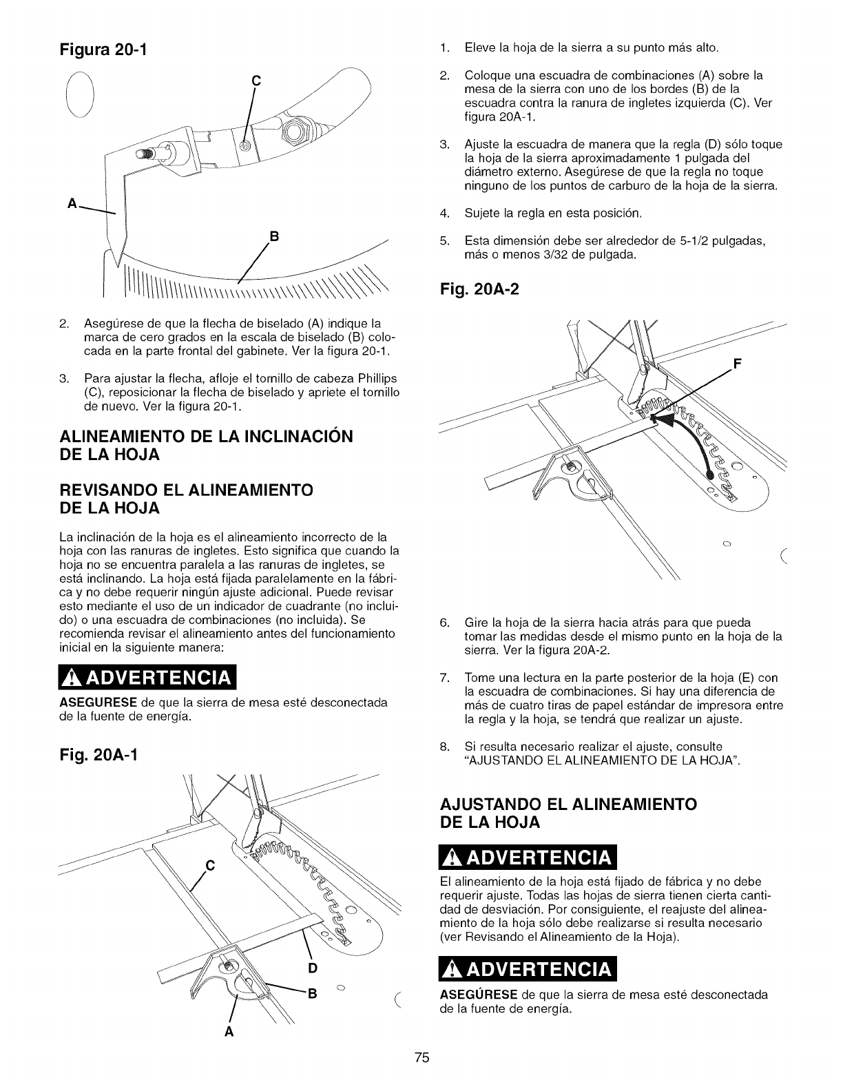
Figura 20-1
A
B
2. AsegtJrese de que la flecha de biselado (A) indique la
marca de cero grados en la escala de biselado (B) colo-
cada en la parte frontal del gabinete. Ver la figura 20-1.
3. Para ajustar la flecha, afloje el tornillo de cabeza Phillips
(C), reposicionar la flecha de biselado y apriete el tornillo
de nuevo. Ver la figura 20-1.
ALINEAMIENTO DE LA INCLINACION
DE LA HOJA
REVISANDO EL ALINEAMIENTO
DE LA HOJA
La inclinaci6n de la hoja es el alineamiento incorrecto de la
hoja con las ranuras de ingletes. Esto significa que cuando la
hoja no se encuentra paralela alas ranuras de ingletes, se
esta inclinando. La hoja esta fijada paralelamente en la fabri-
ca y no debe requerir ningtJn ajuste adicional. Puede revisar
esto mediante el uso de un indicador de cuadrante (no inclui-
do) o una escuadra de combinaciones (no incluida). Se
recomienda revisar el alineamiento antes del funcionamiento
inicial en la siguiente manera:
ASEGURESE de que la sierra de mesa este desconectada
de la fuente de energia.
Fig. 20A-1
1,
2.
3,
4,
5.
Eleve la hoja de la sierra a su punto mas alto.
Coloque una escuadra de combinaciones (A) sobre la
mesa de la sierra con uno de los bordes (B) de la
escuadra contra la ranura de ingletes izquierda (C). Ver
figura 20A-1.
Ajuste la escuadra de manera que la regla (D) s61o toque
la hoja de la sierra aproximadamente 1 pulgada del
diametro externo. AsegtJrese de que la regla no toque
ninguno de los puntos de carburo de la hoja de la sierra.
Sujete la regla en esta posici6n.
Esta dimensi6n debe ser alrededor de 5-1/2 pulgadas,
m_.s o menos 3/32 de pulgada.
Fig. 20A-2
6,
7,
8,
Gire la hoja de la sierra hacia atras para que pueda
tomar las medidas desde el mismo punto en la hoja de la
sierra. Ver la figura 20A-2.
Tome una lectura en la parte posterior de la hoja (E) con
la escuadra de combinaciones. Si hay una diferencia de
mas de cuatro tiras de papel estandar de impresora entre
la regla y la hoja, se tendra que realizar un ajuste.
Si resulta necesario realizar el ajuste, consulte
"AJUSTANDO EL ALINEAMIENTO DE LA HOJA".
A
AJUSTANDO EL ALINEAMIENTO
DE LA HOJA
El alineamiento de la hoja esta fijado de fabrica y no debe
requerir ajuste. Todas las hojas de sierra tienen cierta canti-
dad de desviaci6n. Por consiguiente, el reajuste del alinea-
miento de la hoja s61o debe realizarse si resulta necesario
(ver Revisando el Alineamiento de la Hoja).
ASEGURESE de que la sierra de mesa este desconectada
de la fuente de energia.
75
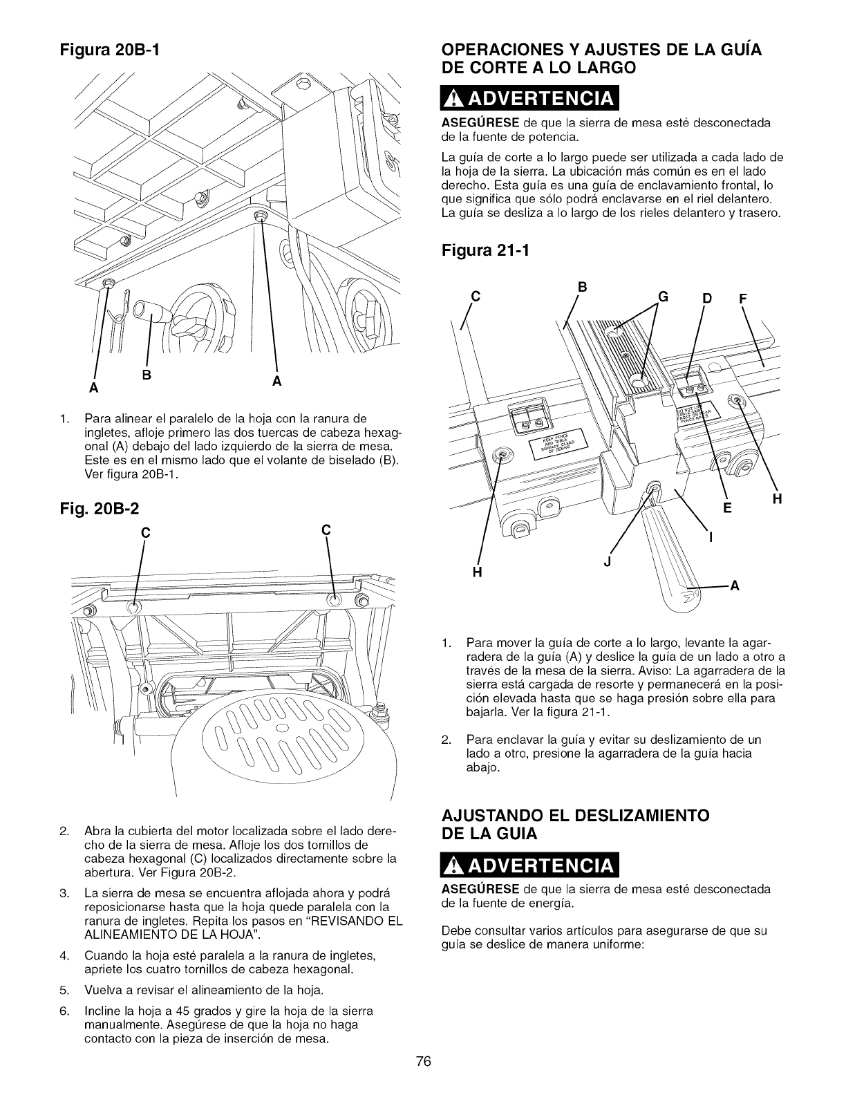
Figura 20B-1 OPERACIONES Y AJUSTES DE LA GUiA
DE CORTE A LO LARGO
ASEGURESE de que la sierra de mesa este desconectada
de la fuente de potencia.
La guia de corte a Io largo puede ser utilizada a cada lado de
la hoja de la sierra. La ubicaci6n mas comtJn es en el lado
derecho. Esta guia es una guia de enclavamiento frontal, Io
que significa que s61o podra enclavarse en el riel delantero.
La guia se desliza a Io largo de los rieles delantero y trasero.
Figura 21-1
B
C G D F
ABA
1, Para alinear el paralelo de la hoja con la ranura de
ingletes, afloje primero las dos tuercas de cabeza hexag-
onal (A) debajo del lado izquierdo de la sierra de mesa.
Este es en el mismo lado que el volante de biselado (B).
Ver figura 20B-1.
Fig. 20B-2
CC
H
E
I
H
1,
2,
Para mover la guia de corte a Io largo, levante la agar-
radera de la guia (A) y deslice la guia de un lado a otro a
trav_s de la mesa de la sierra. Aviso: La agarradera de la
sierra esta cargada de resorte y permanecera en la posi-
ci6n elevada hasta que se haga presi6n sobre ella para
bajarla. Ver la figura 21-1.
Para enclavar la guia y evitar su deslizamiento de un
lado a otro, presione la agarradera de la guia hacia
abajo.
2,
3,
4,
5.
6.
Abra la cubierta del motor Iocalizada sobre el lado dere-
cho de la sierra de mesa. Afloje los dos tornillos de
cabeza hexagonal (C) Iocalizados directamente sobre la
abertura. Ver Figura 20B-2.
La sierra de mesa se encuentra aflojada ahora y podra
reposicionarse hasta que la hoja quede paralela con la
ranura de ingletes. Repita los pasos en "REVISANDO EL
ALINEAMIENTO DE LA HOJA".
Cuando la hoja este paralela a la ranura de ingletes,
apriete los cuatro tornillos de cabeza hexagonal.
Vuelva a revisar el alineamiento de la hoja.
Incline la hoja a 45 grados y gire la hoja de la sierra
manualmente. AsegtJrese de que la hoja no haga
contacto con la pieza de inserci6n de mesa.
AJUSTANDO EL DESLIZAMIENTO
DE LA GUIA
ASEGURESE de que la sierra de mesa este desconectada
de la fuente de energia.
Debe consultar varios articulos para asegurarse de que su
guia se deslice de manera uniforme:
76
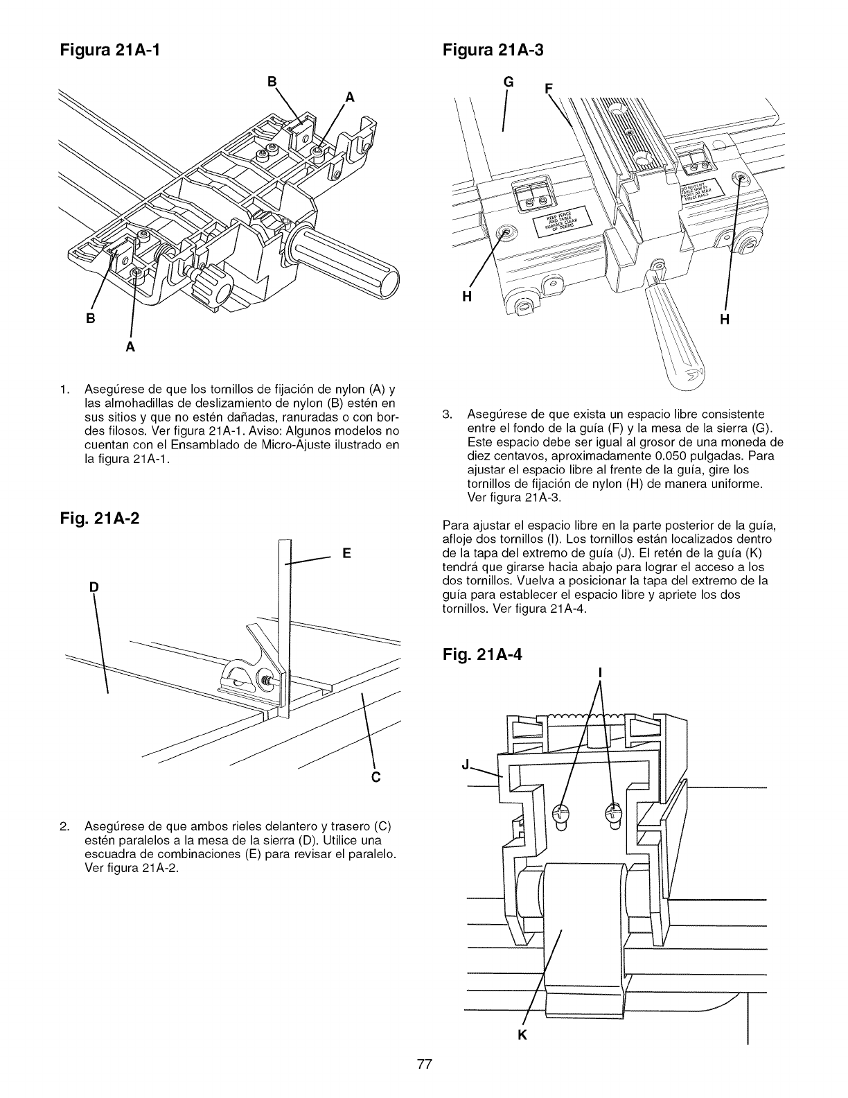
Figura 21A-1
B
A
BA
Figura 21A-3
G F
H
H
1, AsegtJrese de que los tornillos de fijaci6n de nylon (A) y
las almohadillas de deslizamiento de nylon (B) esten en
sus sitios y que no esten da_adas, ranuradas o con bor-
des filosos. Ver figura 21A-1. Aviso: Algunos modelos no
cuentan con el Ensamblado de Micro-Ajuste ilustrado en
la figura 21A-1.
Fig. 21A-2
E
D
C
2, AsegOrese de que ambos rieles delantero y trasero (C)
esten paralelos a la mesa de la sierra (D). Utilice una
escuadra de combinaciones (E) para revisar el paralelo.
Ver figura 21A-2.
3, Asegurese de que exista un espacio libre consistente
entre el fondo de la guia (F) y la mesa de la sierra (G).
Este espacio debe ser igual al grosor de una moneda de
diez centavos, aproximadamente 0.050 pulgadas. Para
ajustar el espacio libre al frente de la guia, gire los
tornillos de fijaci6n de nylon (H) de manera uniforme.
Ver figura 21A-3.
Para ajustar el espacio libre en la parte posterior de la guia,
afloje dos tornillos (I). Los tornillos estan Iocalizados dentro
de la tapa del extremo de guia (J). El reten de la guia (K)
tendra que girarse hacia abajo para Iograr el acceso a los
dos tornillos. Vuelva a posicionar la tapa del extremo de la
guia para establecer el espacio libre y apriete los dos
tornillos. Ver figura 21A-4.
77
Fig. 21A-4
I
/
/
K
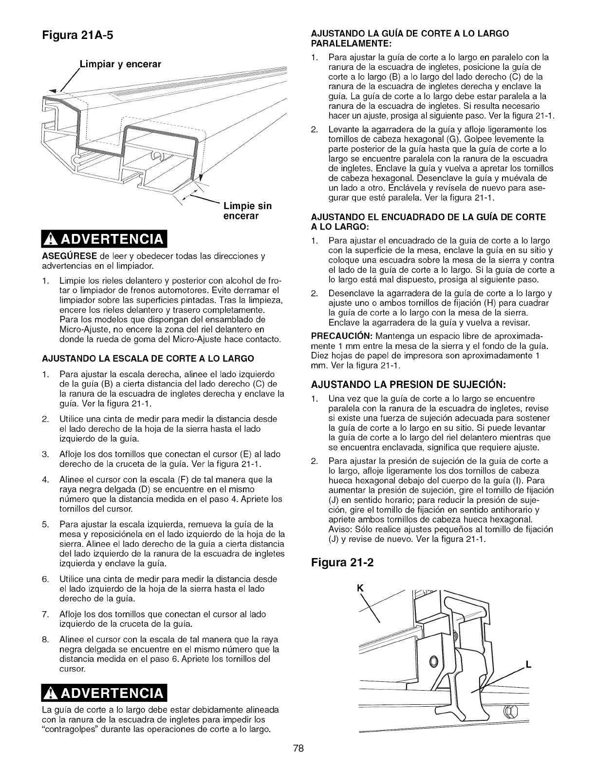
Figura 21A-5
Limpiar y encerar
_J_ Limpie sin
encerar
ASEGURESE de leer y obedecer todas las direcciones y
advertencias en el limpiador.
1, Limpie los rieles delantero y posterior con alcohol de fro-
tar o limpiador de frenos automotores. Evite derramar el
limpiador sobre las superficies pintadas. Tras la limpieza,
encere los rieles delantero y trasero completamente.
Para los modelos que dispongan del ensamblado de
Micro-Ajuste, no encere la zona del riel delantero en
donde la rueda de goma del Micro-Ajuste hace contacto.
AJUSTANDO LA ESCALA DE CORTE ALO LARGO
1,
2,
3,
Para ajustar la escala derecha, alinee el lado izquierdo
de la guia (B) a cierta distancia del lado derecho (C) de
la ranura de la escuadra de ingletes derecha y enclave la
guia. Ver la figura 21-1.
Utilice una cinta de medir para medir la distancia desde
el lado derecho de la hoja de la sierra hasta el lado
izquierdo de la guia.
Afloje los dos tornillos que conectan el cursor (E) al lado
derecho de la cruceta de la guia. Ver la figura 21-1.
4, Alinee el cursor con la escala (F) de tal manera que la
raya negra delgada (D) se encuentre en el mismo
ntJmero que la distancia medida en el paso 4. Apriete los
tornillos del cursor.
5, Para ajustar la escala izquierda, remueva la guia de la
mesa y reposici6nela en el lado izquierdo de la hoja de la
sierra. Alinee el lado derecho de la guia a cierta distancia
del lado izquierdo de la ranura de la escuadra de ingletes
izquierda y enclave la guia.
6. Utilice una cinta de medir para medir la distancia desde
el lado izquierdo de la hoja de la sierra hasta el lado
derecho de la guia.
7. Afloje los dos tornillos que conectan el cursor al lado
izquierdo de la cruceta de la guia.
8, Alinee el cursor con la escala de tal manera que la raya
negra delgada se encuentre en el mismo nt_mero que la
distancia medida en el paso 6. Apriete los tornillos del
cursor.
AJUSTANDO LA GU|A DE CORTE A LO LARGO
PARALELAMENTE:
1,
2,
Para ajustar la guia de corte a Io largo en paralelo con la
ranura de la escuadra de ingletes, posicione la guia de
corte a Io largo (B) a Io largo del lado derecho (C) de la
ranura de la escuadra de ingletes derecha y enclave la
guia. La guia de corte a Io largo debe estar paralela a la
ranura de la escuadra de ingletes. Si resulta necesario
hacer un ajuste, prosiga al siguiente paso. Ver la figura 21-1.
Levante la agarradera de la guia y afloje ligeramente los
tornillos de cabeza hexagonal (G). Golpee levemente la
parte posterior de la guia hasta que la guia de corte a Io
largo se encuentre paralela con la ranura de la escuadra
de ingletes. Enclave la guia y vuelva a apretar los tornillos
de cabeza hexagonal. Desenclave la guia y mu_vala de
un lado a otro. Enclavela y revisela de nuevo para ase-
gurar que este paralela. Ver la figura 21-1.
AJUSTANDO EL ENCUADRADO DE LA GU|A DE CORTE
A LO LARGO:
1, Para ajustar el encuadrado de la guia de corte a Io largo
con la superficie de la mesa, enclave la guia en su sitio y
coloque una escuadra sobre la mesa de la sierra y contra
el lado de la guia de corte a Io largo. Si la guia de corte a
Io largo esta mal dispuesto, prosiga al siguiente paso.
2. Desenclave la agarradera de la guia de corte a Io largo y
ajuste uno o ambos tornillos de fijaci6n (H) para cuadrar
la guia de corte a Io largo con la mesa de la sierra.
Enclave la agarradera de la guia y vuelva a revisar.
PRECAUCION: Mantenga un espacio libre de aproximada-
mente 1 mm entre la mesa de la sierra y el fondo de la guia.
Diez hojas de papel de impresora son aproximadamente 1
mm. Ver la figura 21-1.
AJUSTANDO LA PRESION DE SUJECION:
1, Una vez que la guia de corte a Io largo se encuentre
paralela con la ranura de la escuadra de ingletes, revise
si existe una fuerza de sujeci6n adecuada para sostener
la guia de corte a Io largo en su sitio. Si puede levantar
la guia de corte a Io largo del riel delantero mientras que
se encuentra enclavada, significa que requiere ajuste.
2, Para ajustar la presi6n de sujeci6n de la guia de corte a
Io largo, afloje ligeramente los dos tornillos de cabeza
hueca hexagonal debajo del cuerpo de la guia (I). Para
aumentar la presi6n de sujeci6n, gire el tornillo de fijaci6n
(J) en sentido horario; para reducir la presi6n de suje-
ci6n, gire el tornillo de fijaci6n en sentido antihorario y
apriete ambos tornillos de cabeza hueca hexagonal.
Aviso: $61o realice ajustes pequeSos al tornillo de fijaci6n
(J) y revise de nuevo. Ver la figura 21-1.
Figura 21-2
La guia de corte a Io largo debe estar debidamente alineada
con la ranura de la escuadra de ingletes para impedir los
"contragolpes" durante las operaciones de corte a Io largo.
78
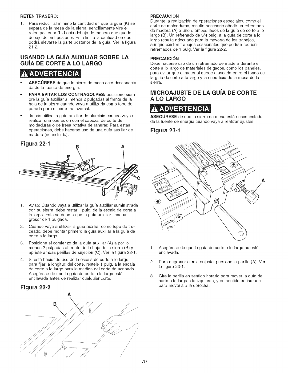
RETEN TRASERO:
1. Para reducir al minimo la cantidad en que la guia (K) se
separa de la mesa de la sierra, sencillamente vire el
ret6n posterior (L) hacia debajo de manera que quede
debajo del riel posterior. Esto limita la cantidad en que
podr_, elevarse la parte posterior de la guia. Ver la figura
21-2.
USANDO LA GUIA AUXILIAR SOBRE LA
GUiA DE CORTE A LO LARGO
ASEGURESE de que la sierra de mesa est6 desconecta-
da de la fuente de energia.
PARA EVITAR LOS CONTRAGOLPES: posicione siem-
pre la guia auxiliar al menos 2 pulgadas al frente de la
hoja de la sierra cuando vaya a utilizarla como tope de
parada para el corte transversal.
Jamas utilice la guia auxiliar de aluminio cuando vaya a
realizar una operaci6n con el cabezal de corte de
moldaduras o de fresa rotativa de ranurar. Para estas
operaciones, debe hacerse uso de una guia auxiliar de
madera (no incluida).
Figura 22-1 B A
1.
2.
3.
4.
Aviso: Cuando vaya a utilizar la guia auxiliar suministrada
con su sierra, debe restar 1 pulg. de la escala de corte a
Io largo. Esto se debe a que la guia auxiliar tiene un
grosor de 1 pulgada.
Cuando vaya a utilizar la guia auxiliar como tope de tro-
ceado, debe montar primero la guia auxiliar a la guia de
corte a Io largo.
Posicione el comienzo de la guia auxiliar (A) a pot Io
menos 2 pulgadas al frente de la hoja de la sierra (B) y
apriete ambas perillas de sujeci6n (C). Ver la figura 22-1.
Siesta haciendo uso de la escala de corte a Io largo
para fijar la Iongitud del corte, r6stele 1 pulg. a la escala
de corte a Io largo para la medida del corte de acabado.
Aseg0rese de que la guia de corte a Io largo est6
enclavada antes de realizar cualquier corte.
Figura 22-2
A
B
,/
79
PRECAUCION
Durante la realizaci6n de operaciones especiales, como el
corte de moldaduras, resulta necesario a_adir un refrentado
de madera (A) a uno o ambos lados de la guia de corte a Io
largo (B). Un refrenado de 3/4 pulg. a la guia de corte a Io
largo resulta adecuado para la mayoria de los trabajos,
aunque existen trabajos ocasionales que podr_.n requerir
refrentados de 1 pulg. Ver la figura 22-2.
PRECAUCION
Debe hacerse uso de un refrentado de madera durante el
corte a Io largo de materiales delgados, como los paneles,
para evitar que el material quede atascado entre el fondo de
la guia de corte a Io largo y la superficie de la mesa de la
sierra.
iVIICROAJUSTE DE LA GUiA DE CORTE
A LO LARGO
ASEGURESE de que la sierra de mesa est6 desconectada
de la fuente de energia cuando vaya a realizar ajustes.
Figura 23-1
A
1.
2.
3.
Aseg0rese de que la guia de corte a Io largo no est6
enclavada.
Para engranar el microajuste, presione la perilla (A). Ver
la figura 23-1.
Gire la perilla en sentido horario para mover la guia de
corte a Io largo a la izquierda, yen sentido antihorario
para moverla a la derecha.
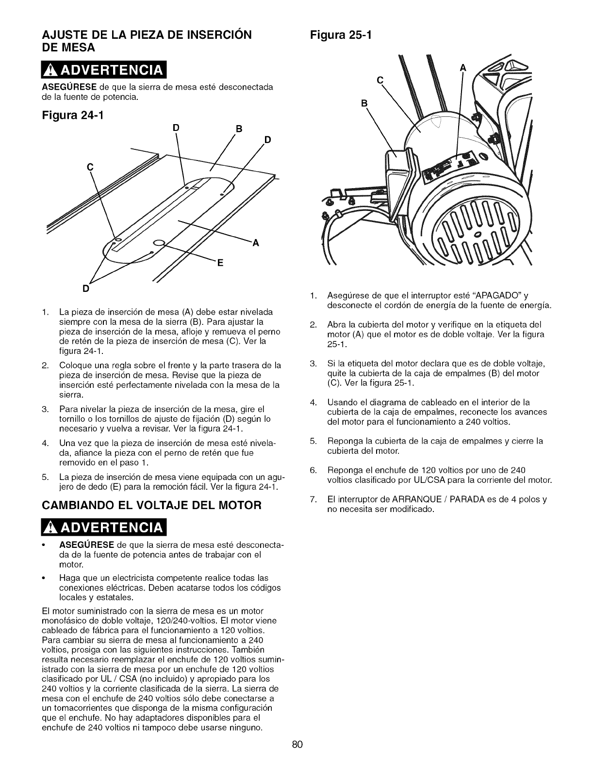
AJUSTE DE LA PIEZA DE INSERCION
DE MESA
ASEGORESE de que la sierra de mesa este desconectada
de la fuente de potencia.
Figura 24-1 DBD
C
Figura 25-1
B
C
A
D
1. La pieza de inserci6n de mesa (A) debe estar nivelada
siempre con la mesa de la sierra (B). Para ajustar la
pieza de inserci6n de la mesa, afloje y remueva el perno
de reten de la pieza de inserci6n de mesa (C). Ver la
figura 24-1.
2. Coloque una regla sobre el frente y la parte trasera de la
pieza de inserci6n de mesa. Revise que la pieza de
inserci6n est_ perfectamente nivelada con la mesa de la
sierra.
3,
4,
5,
Para nivelar la pieza de inserci6n de la mesa, gire el
tornillo o los tornillos de ajuste de fijaci6n (D) segt_n Io
necesario y vuelva a revisar. Ver la figura 24-1.
Una vez que la pieza de inserci6n de mesa este nivela-
da, afiance la pieza con el perno de reten que fue
removido en el paso 1.
La pieza de inserci6n de mesa viene equipada con un agu-
jero de dedo (E) para la remoci6n facil. Ver la figura 24-1.
CAMBIANDO EL VOLTAJE DEL MOTOR
1. AsegtJrese de que el interruptor este "APAGADO" y
desconecte el cord6n de energia de la fuente de energia.
2. Abra la cubierta del motor y verifique en la etiqueta del
motor (A) que el motor es de doble voltaje. Ver la figura
25-1.
3. Si la etiqueta del motor declara que es de doble voltaje,
quite la cubierta de la caja de empalmes (B) del motor
(C). Ver la figura 25-1.
4. Usando el diagrama de cableado en el interior de la
cubierta de la caja de empalmes, reconecte los avances
del motor para el funcionamiento a 240 voltios.
5. Reponga la cubierta de la caja de empalmes y cierre la
cubierta del motor.
6. Reponga el enchufe de 120 voltios por uno de 240
voltios clasificado por UL/CSA para la corriente del motor.
7. El interruptor de ARRANQUE /PARADA es de 4 polos y
no necesita ser modificado.
•ASEGURESE de que la sierra de mesa este desconecta-
da de la fuente de potencia antes de trabajar con el
motor.
• Haga que un electricista competente realice todas las
conexiones el_ctricas. Deben acatarse todos los c6digos
locales y estatales.
El motor suministrado con la sierra de mesa es un motor
monofasico de doble voltaje, 120/240-voltios. El motor viene
cableado de fabrica para el funcionamiento a 120 voltios.
Para cambiar su sierra de mesa al funcionamiento a 240
voltios, prosiga con las siguientes instrucciones. Tambi_n
resulta necesario reemplazar el enchufe de 120 voltios sumin-
istrado con la sierra de mesa por un enchufe de 120 voltios
clasificado por UL /CSA (no incluido) y apropiado para los
240 voltios y la corriente clasificada de la sierra. La sierra de
mesa con el enchufe de 240 voltios s61o debe conectarse a
un tomacorrientes que disponga de la misma configuraci6n
que el enchufe. No hay adaptadores disponibles para el
enchufe de 240 voltios ni tampoco debe usarse ninguno.
8O
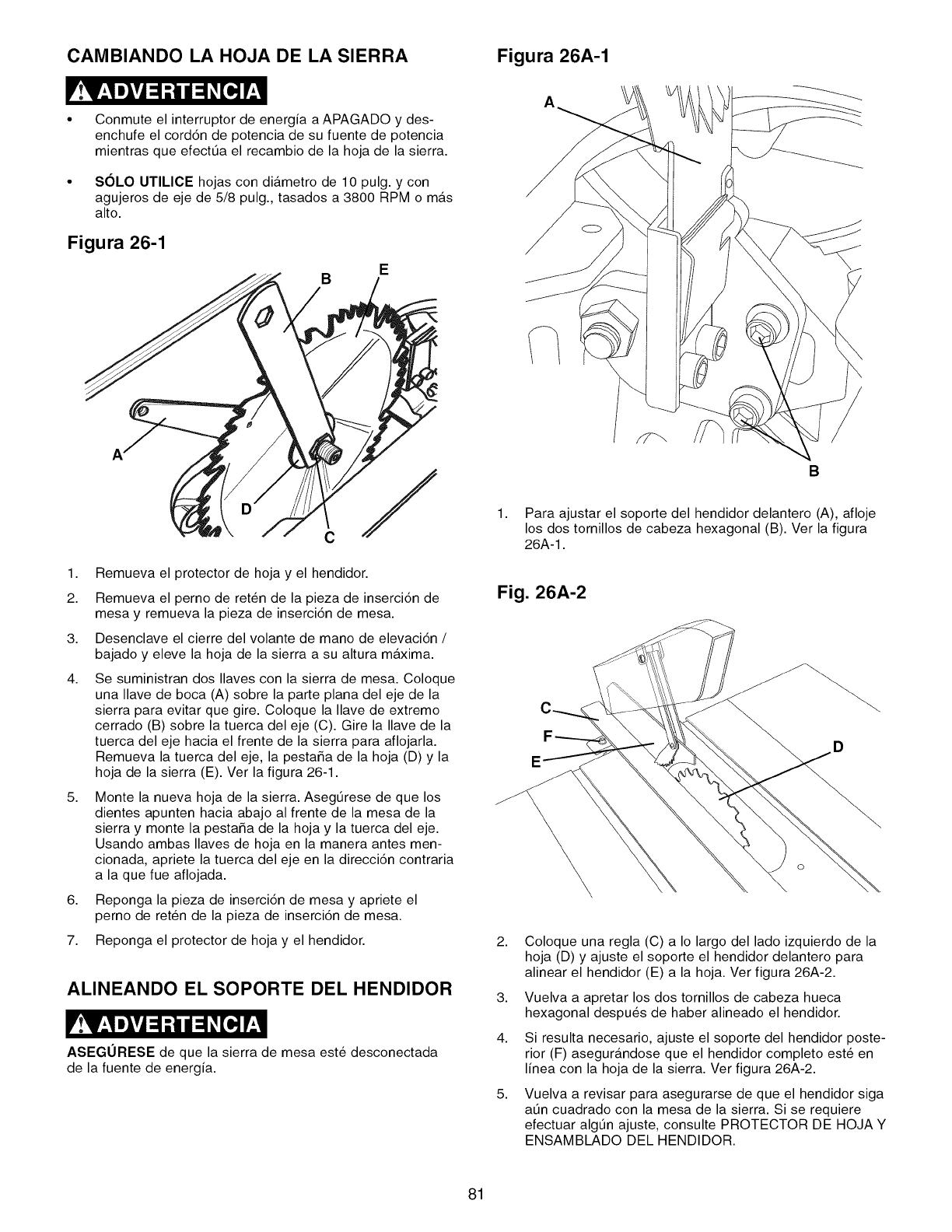
CAMBIANDO LA HOJA DE LA SIERRA Figura 26A-1
Conmute el interruptor de energia a APAGADO y des-
enchufe el cord6n de potencia de su fuente de potencia
mientras que efectt_a el recambio de la hoja de la sierra.
SOLO UTILICE hojas con diametro de 10 pulg. y con
agujeros de eje de 5/8 pulg., tasados a 3800 RPM o mAs
alto.
Figura 26-1
B
1,
2.
3.
4.
5,
6,
7.
Remueva el protector de hoja y el hendidor.
Remueva el perno de reten de la pieza de inserci6n de
mesa y remueva la pieza de inserci6n de mesa.
Desenclave el cierre del volante de mano de elevaci6n /
bajado y eleve la hoja de la sierra a su altura maxima.
Se suministran dos Ilaves con la sierra de mesa. Coloque
una Ilave de boca (A) sobre la parte plana del eje de la
sierra para evitar que gire. Coloque la Ilave de extremo
cerrado (B) sobre la tuerca del eje (C). Gire la Ilave de la
tuerca del eje hacia el frente de la sierra para aflojarla.
Remueva la tuerca del eje, la pesta_a de la hoja (D) y la
hoja de la sierra (E). Ver la figura 26-1.
Monte la nueva hoja de la sierra. Asegt_rese de que los
dientes apunten hacia abajo al frente de la mesa de la
sierra y monte la pesta_a de la hoja y la tuerca del eje.
Usando ambas Ilaves de hoja en la manera antes men-
cionada, apriete la tuerca del eje en la direcci6n contraria
a la que fue aflojada.
Reponga la pieza de inserci6n de mesa y apriete el
perno de reten de la pieza de inserci6n de mesa.
Reponga el protector de hoja y el hendidor.
ALINEANDO EL SOPORTE DEL HENDIDOR
ASEGURESE de que la sierra de mesa este desconectada
de la fuente de energia.
B
1. Para ajustar el soporte del hendidor delantero (A), afloje
los dos tornillos de cabeza hexagonal (B). Ver la figura
26A-1.
Fig. 26A-2
D
2,
3,
4.
5,
Coloque una regla (C) a Io largo del lado izquierdo de la
hoja (D) y ajuste el soporte el hendidor delantero para
alinear el hendidor (E) a la hoja. Ver figura 26A-2.
Vuelva a apretar los dos tornillos de cabeza hueca
hexagonal despu_s de haber alineado el hendidor.
Si resulta necesario, ajuste el soporte del hendidor poste-
rior (F) asegurandose que el hendidor completo este en
linea con la hoja de la sierra. Ver figura 26A-2.
Vuelva a revisar para asegurarse de que el hendidor siga
at_n cuadrado con la mesa de la sierra. Si se requiere
efectuar algtJn ajuste, consulte PROTECTOR DE HOJA Y
ENSAMBLADO DEL HENDIDOR.
81
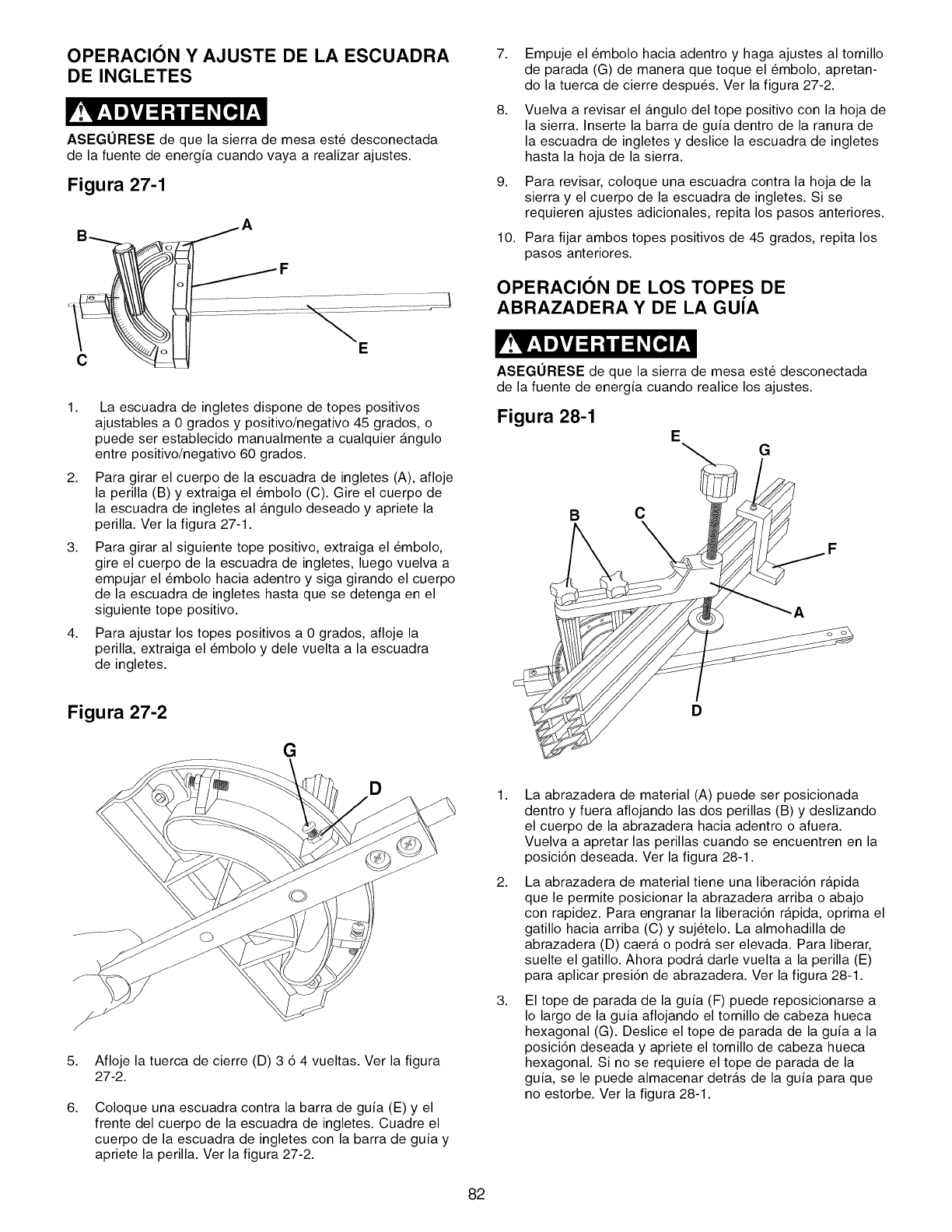
OPERACION Y AJUSTE DE LA ESCUADRA
DE INGLETES
ASEGURESE de que la sierra de mesa este desconectada
de la fuente de energia cuando vaya a realizar ajustes.
Figura 27-1
7,
8,
9,
10.
Empuje el _mbolo hacia adentro y haga ajustes al tornillo
de parada (G) de manera que toque el _mbolo, apretan-
do la tuerca de cierre despu_s. Ver la figura 27-2.
Vuelva a revisar el angulo del tope positivo con la hoja de
la sierra. Inserte la barra de guia dentro de la ranura de
la escuadra de ingletes y deslice la escuadra de ingletes
hasta la hoja de la sierra.
Para revisar, coloque una escuadra contra la hoja de la
sierra y el cuerpo de la escuadra de ingletes. Si se
requieren ajustes adicionales, repita los pasos anteriores.
Para fijar ambos topes positivos de 45 grados, repita los
pasos anteriores.
OPERAClON DE LOS TOPES DE
ABRAZADERA Y DE LA GUiA
C
1,
2,
3,
4,
La escuadra de ingletes dispone de topes positivos
ajustables a 0 grados y positivo/negativo 45 grados, o
puede ser establecido manualmente a cualquier angulo
entre positivo/negativo 60 grados.
Para girar el cuerpo de la escuadra de ingletes (A), afloje
la perilla (B) y extraiga el _mbolo (C). Gire el cuerpo de
la escuadra de ingletes al angulo deseado y apriete la
perilla. Ver la figura 27-1.
Para girar al siguiente tope positivo, extraiga el _mbolo,
gire el cuerpo de la escuadra de ingletes, luego vuelva a
empujar el _mbolo hacia adentro y siga girando el cuerpo
de la escuadra de ingletes hasta que se detenga en el
siguiente tope positivo.
Para ajustar los topes positivos a 0 grados, afloje la
perilla, extraiga el _mbolo y dele vuelta a la escuadra
de ingletes.
Figura 27-2
G
D
5,
6,
Afloje la tuerca de cierre (D) 3 6 4 vueltas. Ver la figura
27-2.
Coloque una escuadra contra la barra de guia (E) y el
frente del cuerpo de la escuadra de ingletes. Cuadre el
cuerpo de la escuadra de ingletes con la barra de guia y
apriete la perilla. Ver la figura 27-2.
ASEGURESE de que la sierra de mesa este desconectada
de la fuente de energia cuando realice los ajustes.
Figura 28-1 EG
B C
A
D
1,
2,
3,
La abrazadera de material (A) puede ser posicionada
dentro y fuera aflojando las dos perillas (B) y deslizando
el cuerpo de la abrazadera hacia adentro o afuera.
Vuelva a apretar las perillas cuando se encuentren en la
posici6n deseada. Ver la figura 28-1.
La abrazadera de material tiene una liberaci6n rapida
que le permite posicionar la abrazadera arriba o abajo
con rapidez. Para engranar la liberaci6n rapida, oprima el
gatillo hacia arriba (C) y suj_telo. La almohadilla de
abrazadera (D) caera o podra ser elevada. Para liberar,
suelte el gatillo. Ahora podra darle vuelta a la perilla (E)
para aplicar presi6n de abrazadera. Ver la figura 28-1.
El tope de parada de la guia (F) puede reposicionarse a
Io largo de la guia aflojando el tornillo de cabeza hueca
hexagonal (G). Deslice el tope de parada de la guia a la
posici6n deseada y apriete el tornillo de cabeza hueca
hexagonal. Si no se requiere el tope de parada de la
guia, se le puede almacenar detras de la guia para que
no estorbe. Ver la figura 28-1.
82
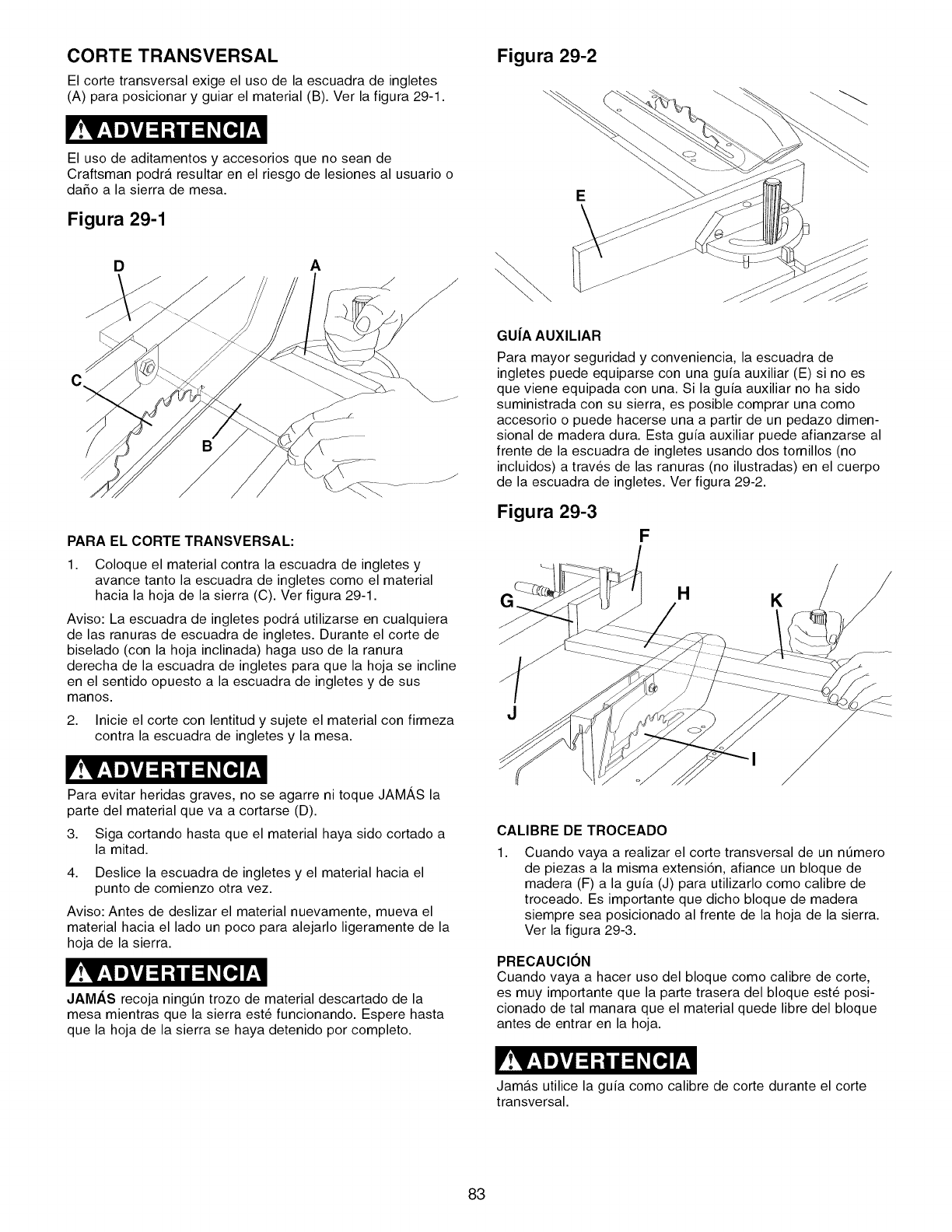
CORTE TRANSVERSAL
El corte transversal exige el uso de la escuadra de ingletes
(A) para posicionar y guiar el material (B). Ver la figura 29-1.
El uso de aditamentos y accesorios que no sean de
Craftsman podra resultar en el riesgo de lesiones al usuario o
daSo a la sierra de mesa.
Figura 29-1
D A
PARA ELCORTETRANSVERSAL:
1. Coloque el material contra la escuadra de ingletes y
avance tanto la escuadra de ingletes como el material
hacia la hoja de la sierra (C). Ver figura 29-1.
Aviso: La escuadra de ingletes podra utilizarse en cualquiera
de las ranuras de escuadra de ingletes. Durante el corte de
biselado (con la hoja inclinada) haga uso de la ranura
derecha de la escuadra de ingletes para que la hoja se incline
en el sentido opuesto a la escuadra de ingletes y de sus
manos.
2. Inicie el corte con lentitud y sujete el material con firmeza
contra la escuadra de ingletes y la mesa.
Figura 29-2
E
\\
GU|A AUXILIAR
Para mayor seguridad y conveniencia, la escuadra de
ingletes puede equiparse con una guia auxiliar (E) si no es
que viene equipada con una. Si la guia auxiliar no ha sido
suministrada con su sierra, es posible comprar una como
accesorio o puede hacerse una a partir de un pedazo dimen-
sional de madera dura. Esta guia auxiliar puede afianzarse al
frente de la escuadra de ingletes usando dos tornillos (no
incluidos) a trav_s de las ranuras (no ilustradas) en el cuerpo
de la escuadra de ingletes. Ver figura 29-2.
Figura 29-3
F
HK
Para evitar heridas graves, no se agarre ni toque JAMAS la
parte del material que va a cortarse (D).
3. Siga cortando hasta que el material haya sido cortado a
la mitad.
4. Deslice la escuadra de ingletes y el material hacia el
punto de comienzo otra vez.
Aviso: Antes de deslizar el material nuevamente, mueva el
material hacia el lado un poco para alejarlo ligeramente de la
hoja de la sierra.
JAMAS recoja ningtJn trozo de material descartado de la
mesa mientras que la sierra este funcionando. Espere hasta
que la hoja de la sierra se haya detenido por completo.
CALIBRE DE TROCEADO
1, Cuando vaya a realizar el corte transversal de un ntJmero
de piezas a la misma extensi6n, afiance un bloque de
madera (F) a la guia (J) para utilizarlo como calibre de
troceado. Es importante que dicho bloque de madera
siempre sea posicionado al frente de la hoja de la sierra.
Ver la figura 29-3.
PRECAUCION
Cuando vaya a hacer uso del bloque como calibre de corte,
es muy importante que la parte trasera del bloque este posi-
cionado de tal manara que el material quede libre del bloque
antes de entrar en la hoja.
Jamas utilice la guia como calibre de corte durante el corte
transversal.
83
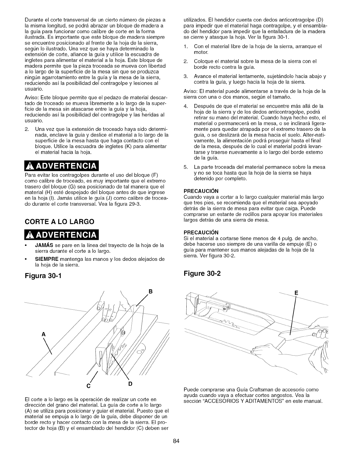
Durante el corte transversal de un cierto ntJmero de piezas a
la misma Iongitud, se podra abrazar un bloque de madera a
la guia para funcionar como calibre de corte en la forma
ilustrada. Es importante que este bloque de madera siempre
se encuentre posicionado al frente de la hoja de la sierra,
segtJn Io ilustrado. Una vez que se haya determinado la
extensi6n de corte, afiance la guia y utilice la escuadra de
ingletes para alimentar el material a la hoja. Este bloque de
madera permite que la pieza troceada se mueva con libertad
a Io largo de la superficie de la mesa sin que se produzca
ningtJn agarrotamiento entre la guia y la mesa de la sierra,
reduciendo asi la posibilidad del contragolpe y lesiones al
usuario.
Aviso: Este bloque permite que el pedazo de material descar-
tado de troceado se mueva libremente a Io largo de la super-
ficie de la mesa sin atascarse entre la guia y la hoja,
reduciendo asi la posibilidad del contragolpe y las heridas al
usuario.
2, Una vez que la extensi6n de troceado haya sido determi-
nada, enclave la guia y deslice el material a Io largo de la
superficie de la mesa hasta que haga contacto con el
bloque. Utilice la escuadra de ingletes (K) para alimentar
el material hacia la hoja.
Para evitar los contragolpes durante el uso del bloque (F)
como calibre de troceado, es muy importante que el extremo
trasero del bloque (G) sea posicionado de tal manera que el
material (H) este despejado del bloque antes de que ingrese
en la hoja (I). Jamas utilice le guia (J) como calibre de trocea-
do durante el corte transversal. Vea la figura 29-3.
CORTE A LO LARGO
• JAMAS se pare en la linea del trayecto de la hoja de la
sierra durante el corte a Io largo.
• SIEMPRE mantenga las manos y los dedos alejados de
la hoja de la sierra.
Figura 30-1
B
utilizados. El hendidor cuenta con dedos anticontragolpe (D)
para impedir que el material haga contragolpe, y el ensambla-
do del hendidor para impedir que la entalladura de la madera
se cierre y atasque la hoja. Ver la figura 30-1.
1. Con el material libre de la hoja de la sierra, arranque el
motor.
2. Coloque el material sobre la mesa de la sierra con el
borde recto contra la guia.
3. Avance el material lentamente, sujeta.ndolo hacia abajo y
contra la guia, y luego hacia la hoja de la sierra.
Aviso: El material puede alimentarse a trav6s de la hoja de la
sierra con una o dos manos, segtJn el tama_o.
4, Despu6s de que el material se encuentre m_.s all_. de la
hoja de la sierra y de los dedos anticontragolpe, podra
retirar su mano del material. Cuando haya hecho esto, el
material o permanecera en la mesa, o se inclinara ligera-
mente para quedar atrapada por el extremo trasero de la
guia, o se deslizara de la mesa hacia el suelo. Alter-nati-
vamente, la alimentaci6n podra proseguir hasta el final
de la mesa, despu6s de Io cual el material podra levan-
tarse y traerse nuevamente a Io largo del borde externo
de la guia.
5. La parte troceada del material permanece sobre la mesa
y no se toca hasta que la hoja de la sierra se haya
detenido por completo.
PRECAUCION
Cuando vaya a cortar a Io largo cualquier material mas largo
que tres pies, se recomienda que el material sea apoyado
detras de la sierra de mesa para evitar que caiga. Puede
comprarse un estante de rodillos para apoyar los materiales
largos detras de una sierra de mesa.
PRECAUCION
Si el material a cortarse tiene menos de 4 pulg. de ancho,
debe hacerse uso siempre de una varilla de empuje (E) o
guia para mantener sus manos alejadas de la hoja de la
sierra. Ver figura 30-2.
Figure 30-2
A
CD
El corte a Io largo es la operaci6n de realizar un corte en
direcci6n del grano del material. La guia de corte a Io largo
(A) se utiliza para posicionar y guiar el material. Puesto que el
material se empuja a Io largo de la guia, debe disponer de un
borde recto y hacer contacto con la mesa de la sierra. El pro-
tector de hoja (B) y el ensamblado del hendidor (C) deben ser
Puede comprarse una Guia Craftsman de accesorio como
ayuda cuando vaya a efectuar cortes angostos. Vea la
secci6n "ACCESORIOS Y ADITAMENTOS" en este manual.
\
84
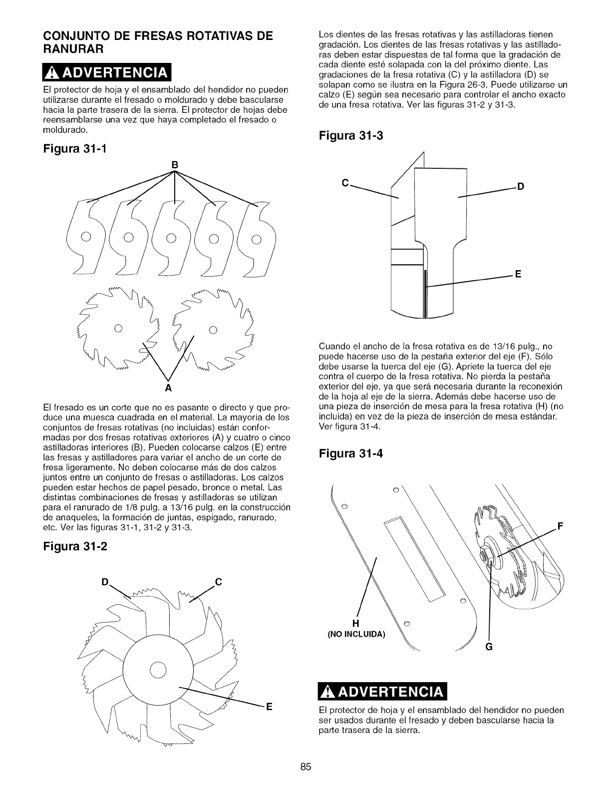
CONJUNTO DE FRESAS ROTATIVAS DE
RANURAR
El protector de hoja y el ensamblado del hendidor no pueden
utilizarse durante el fresado o moldurado y debe bascularse
hacia la parte trasera de la sierra. El protector de hojas debe
reensamblarse una vez que haya completado el fresado o
moldurado.
Figura 31-1
B
Los dientes de las fresas rotativas y las astilladoras tienen
gradaci6n. Los dientes de las fresas rotativas y las astillado-
ras deben estar dispuestas de tal forma que la gradaci6n de
cada diente este solapada con la del pr6ximo diente. Las
gradaciones de la fresa rotativa (C) y la astilladora (D) se
solapan como se ilustra en la Figura 26-3. Puede utilizarse un
calzo (E) segt_n sea necesario para controlar el ancho exacto
de una fresa rotativa. Ver las figuras 31-2 y 31-3.
Figura 31-3
ID
I
A
El fresado es un corte que no es pasante o directo y que pro-
duce una muesca cuadrada en el material. La mayoria de los
conjuntos de fresas rotativas (no incluidas) esta.n confor-
madas por dos fresas rotativas exteriores (A) y cuatro o cinco
astilladoras interiores (B). Pueden colocarse calzos (E) entre
las fresas y astilladores para variar el ancho de un corte de
fresa ligeramente. No deben colocarse mas de dos calzos
juntos entre un conjunto de fresas o astilladoras. Los calzos
pueden estar hechos de papel pesado, bronce o metal. Las
distintas combinaciones de fresas y astilladoras se utilizan
para el ranurado de 1/8 pulg. a 13/16 pulg. en la construcci6n
de anaqueles, la formaci6n de juntas, espigado, ranurado,
etc. Ver las figuras 31-1,31-2 y 31-3.
Figura 31-2
Cuando el ancho de la fresa rotativa es de 13/16 pulg., no
puede hacerse uso de la pesta_a exterior del eje (F). $61o
debe usarse la tuerca del eje (G). Apriete la tuerca del eje
contra el cuerpo de la fresa rotativa. No pierda la pesta_a
exterior del eje, ya que sera necesaria durante la reconexi6n
de la hoja al eje de la sierra. Ademas debe hacerse uso de
una pieza de inserci6n de mesa para la fresa rotativa (H) (no
incluida) en vez de la pieza de inserci6n de mesa estandar.
Ver figura 31-4.
Figura 31-4
©
C
H
(NO INCLUIDA)
o
G
El protector de hoja y el ensamblado del hendidor no pueden
ser usados durante el fresado y deben bascularse hacia la
parte trasera de la sierra.
85
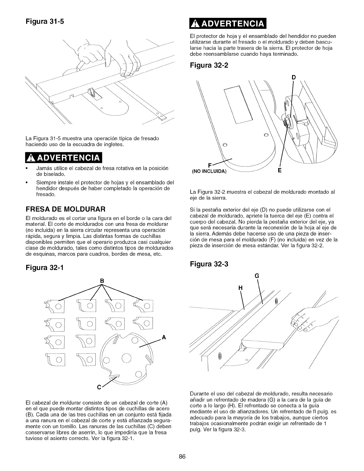
Figura 31-5
\El protector de hoja y el ensamblado del hendidor no pueden
utilizarse durante el fresado o el moldurado y deben bascu-
larse hacia la parte trasera de la sierra. El protector de hoja
debe reensamblarse cuando haya terminado.
Figura 32-2
D
La Figura 31-5 muestra una operaci6n tipica de fresado
haciendo uso de la escuadra de ingletes.
Jamas utilice el cabezal de fresa rotativa en la posici6n
de biselado.
Siempre instale el protector de hojas y el ensamblado del
hendidor despu6s de haber completado la operaci6n de
fresado.
FRESA DE MOLDURAR
El moldurado es el cortar una figura en el borde o la cara del
material. El corte de moldurados con una fresa de moldurar
(no incluida) en la sierra circular representa una operaci6n
rapida, segura y limpia. Las distintas formas de cuchillas
disponibles permiten que el operario produzca casi cualquier
clase de moldurado, tales como distintos tipos de moldurados
de esquinas, marcos para cuadros, bordes de mesa, etc.
Figura 32-1
B
(NO INCLUIDA) E
La Figura 32-2 muestra el cabezal de moldurado montado al
eje de la sierra.
Si la pesta_a exterior del eje (D) no puede utilizarse con el
cabezal de moldurado, apriete la tuerca del eje (E) contra el
cuerpo del cabezal. No pierda la pesta_a exterior del eje, ya
que sera. necesaria durante la reconexi6n de la hoja al eje de
la sierra. Ademas debe hacerse uso de una pieza de inser-
ci6n de mesa para el moldurado (F) (no incluida) en vez de la
pieza de inserci6n de mesa esta.ndar. Ver la figura 32-2.
Figura 32-3
H
G
C
El cabezal de moldurar consiste de un cabezal de corte (A)
en el que puede montar distintos tipos de cuchillas de acero
(B). Cada una de las tres cuchillas en un conjunto esta. fijada
a una ranura en el cabezal de corte y esta. afianzada segura-
mente con un tornillo. Las ranuras de las cuchillas (C) deben
conservarse libres de aserrin, Io que impediria que la fresa
tuviese el asiento correcto. Ver la figura 32-1.
Durante el uso del cabezal de moldurado, resulta necesario
a6adir un refrentado de madera (G) a la cara de la guia de
corte a Io largo (H). El refrentado se conecta a la guia
mediante el uso de afianzadores. Un refrentado de fl pulg. es
adecuado para la mayoria de los trabajos, aunque ciertos
trabajos ocasionalmente podran exigir un refrentado de 1
pulg. Ver la figura 32-3.
86
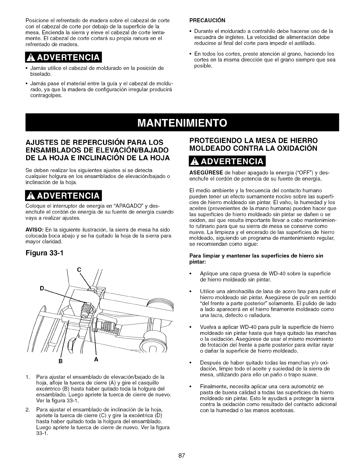
Posicione el refrentado de madera sobre el cabezal de corte
con el cabezal de corte por debajo de la superficie de la
mesa. Encienda la sierra y eleve el cabezal de corte lenta-
mente. El cabezal de corte cortara su propia ranura en el
refrentado de madera.
• Jamas utilice el cabezal de moldurado en la posici6n de
biselado.
• Jamas pase el material entre la guia y el cabezal de moldu-
rado, ya que la madera de configuraci6n irregular producira
contragolpes.
PRECAUClON
• Durante el moldurado a contrahilo debe hacerse uso de la
escuadra de ingletes. La velocidad de alimentaci6n debe
reducirse al final del corte para impedir el astillado.
• En todos los cortes, preste atenci6n al grano, haciendo los
cortes en la misma direcci6n que el grano siempre que sea
posible.
AJUSTES DE REPERCUSION PARA LOS
ENSAMBLADOS DE ELEVACI()N/BAJADO
DE LA HOJA E INCLINACION DE LA HOJA
Se deben realizar los siguientes ajustes si se detecta
cualquier holgura en los ensamblados de elevaci6n/bajado o
inclinaci6n de la hoja.
Coloque el interruptor de energia en "APAGADO" y des-
enchufe el cord6n de energia de su fuente de energia cuando
vaya a realizar ajustes.
AVlSO: En la siguiente ilustraci6n, la sierra de mesa ha sido
colocada boca abajo y se ha quitado la hoja de la sierra para
mayor claridad.
Figura 33-1
C
BA
1,
2,
Para ajustar el ensamblado de elevaci6n/bajado de la
hoja, afloje la tuerca de cierre (A) y gire el casquillo
excentrico (B) hasta haber quitado toda la holgura del
ensamblado. Luego apriete la tuerca de cierre de nuevo.
Ver la figura 33-1.
Para ajustar el ensamblado de inclinaci6n de la hoja,
apriete la tuerca de cierre (C) y gire la excentrica (D)
hasta haber quitado toda la holgura del ensamblado.
Luego apriete la tuerca de cierre de nuevo. Ver la figura
33-1.
PROTEGIENDO LA MESA DE HIERRO
MOLDEADO CONTRA LA OXIDACION
ASEGURESE de haber apagado la energia ("OFF") y des-
enchufe el cord6n de potencia de su fuente de energia.
El medio ambiente y la frecuencia del contacto humano
pueden tener un efecto sumamente nocivo sobre las superfi-
cies de hierro moldeado sin pintar. El vaho, la humedad y los
aceites (provenientes de la mano humana) pueden hacer que
las superficies de hierro moldeado sin pintar se daSen o se
oxiden, asi que resulta importante Ilevar a cabo mantenimien-
to rutinario para que su sierra de mesa se conserve como
nueva. La limpieza y el encerado de las superficies de hierro
moldeado, siguiendo un programa de mantenimiento regular,
se recomiendan como sigue:
Para limpiar y mantener las superficies de hierro sin
pintar:
• Aplique una capa gruesa de WD-40 sobre la superficie
de hierro moldeado sin pintar.
Utilice una almohadilla de lana de acero fina para pulir el
hierro moldeado sin pintar. AsegtJrese de pulir en sentido
"del frente a parte posterior" solamente. El pulido de lado
a lado aparecera en el hierro finamente moldeado como
una lacra, defecto o ralladura.
Vuelva a aplicar WD-40 para pulir la superficie de hierro
moldeado sin pintar hasta que haya quitado las manchas
o la oxidaci6n. Asegt]rese de usar el mismo movimiento
de frotaci6n del frente a parte posterior para evitar rayar
o da_ar la superficie de hierro moldeado.
• Despu_s de haber quitado todas las manchas y/o oxi-
daci6n, limpie todo el aceite y suciedad de la sierra de
mesa, utilizando para ello un paso o trapo suave.
Finalmente, necesita aplicar una cera automotriz en
pasta de buena calidad a todas las superficies de hierro
moldeado sin pintar. Esto le ayudara a proteger la sierra
contra la oxidaci6n como resultado del contacto adicional
con la humedad o las manos aceitosas.
87
LUBRICAClON
La sierra de mesa tiene cojinetes lubricados sellados en la
carcasa del motor que no requieren lubricaci6n adicional por
parte del operario.
LIMPIEZA
Con la sierra de mesa desenchufada, sople aire a baja pre-
si6n sobre el motor para quitar el polvo o la suciedad. No
debe hacerse uso de una presi6n de aire en exceso de 50
RS.I., ya que el aire de alta presi6n puede dafiar el ais-
lamiento.EI operario debe utilizar protecci6n ocular siempre
cuando vaya a utilizar aire comprimido.
No permita que se acumulen astillas y polvo debajo de la
sierra de mesa. Mantenga la zona limpia yen buen estado.
PRECAUCION: NO UTILICE MATERIALES INFLAMABLES
para limpiar la sierra de mesa.
S61o personal competente debe realizar reparaciones a la
sierra de mesa. Comuniquese con su Centro de Servicio
Sears mas cercano para obtener servicio autorizado. Las
reparaciones desautorizadas o el reemplazo con piezas que
no sean de fabrica podrian ocasionar lesiones graves al
operario y dafio a la sierra de mesa.
88
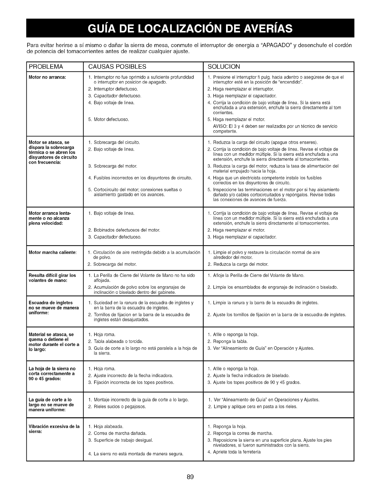
Para evitar herirse a si mismo o daSar la sierra de mesa, conmute el interruptor de energia a "APAGADO" y desenchufe el cord6n
de potencia del tomacorrientes antes de realizar cualquier ajuste.
PROBLEMA SOLUCION
Motor no arranea:
Motor se atasca, se
dispara la sobrecarga
termica o se abren los
disyuntores de circuito
con frecuencia:
Motor arranca lenta-
mente o no alcanza
plena velocidad:
Motor marcha caliente:
Resulta dificil girar los
volantes de mano:
Escuadra de ingletes
no se mueve de manera
uniforme:
Material se atasca, se
quema o detiene el
motor durante el corte a
Io largo:
La hoja de la sierra no
corta correctamente a
90 o 45 grados:
La gufa de corte a Io
largo no se mueve de
manera uniforme:
Vibraci6n excesiva de la
sierra:
CAUSAS POSIBLES
1. Interruptor no fue oprimido a suficiente profundidad 1.
o interruptor en posicion de apagado.
2. Interruptor defectuoso. 2.
3. Capacitador defectuoso. 3.
4. Bajo voltaje de linea. 4.
5. Motor defectuoso. 5.
1. Sobrecarga del circuito. 1.
2. Bajo voltaje de linea. 2.
3. Sobrecarga del motor. 3.
4. Fusibles incorrectos en los disyuntores de circuito. 4.
5. Cortocircuito del motor; conexiones sueltas o 5.
aislamiento gastado en los avances.
1. Bajo voltaje de linea. 1.
2. Bobinados defectuosos del motor. 2.
3. Capacitador defectuoso. 3.
1. Circulaci6n de aire restringida debido a la acumulacion
de polvo.
2. Sobrecarga del motor.
1. La Perilla de Cierre del Volante de Mano no ha sido
afiojada.
2. Acumulacion de polvo sobre los engranajes de
inclinacion o biselado dentro del gabinete.
1. Suciedad en la ranura de la escuadra de ingletes y
en la barra de la escuadra de ingletes.
2. Tornillos de fijacion en la barra de la escuadra de
ingletes estan desajustados.
1. Hoja roma.
2. Tabla alabeada o torcida.
3. Guia de corte a Io largo no esta paralela a la hoja de
la sierra.
1. Hoja roma.
2. Ajuste incorrecto de la flecha indicadora.
3. Fijacion incorrecta de los topes positivos.
1. Montaje incorrecto de la guia de corte a Io largo.
2. Rieles sucios o pegajosos.
1. HoD alabeada.
2. Correa de marcha daSada.
3. Superficie de trabajo desigual.
4. La sierra no ester montada de manera segura.
Presione el interruptor fi pulg. hacia adentro o aseg0rese de que el
interruptor este en la posicion de "encendido".
Haga reemplazar el interruptor.
Haga reemplazar el capacitador.
Corrija la condicion de bajo voltaje de Ifnea. Si la sierra ester
enchufada a una extension, enchufe la sierra directamente al tom
corrientes.
Haga reemplazar el motor.
AVlSO: El 3 y 4 deben ser realizados por un tecnico de servicio
competente.
Reduzca la carga del circuito (apague otros enseres).
Corrija la condicion de bajo voltaje de Ifnea. Revise el voltaje de
linea con un medidor m01tiple. Si la sierra esta enchufada a una
extension, enchufe la sierra directamente al tomacorrientes.
Reduzca la carga del motor, reduzca la tasa de alimentacion del
material empujado hacia la hoja.
Haga que un electricista competente instale los fusibles
correctos en los disyuntores de circuito.
Inspeccione las terminaciones en el motor por si hay aislamiento
daSado y/o cables cortocircuitados y repongalos. Revise todas
las conexiones de avances de fuerza.
Corrija la condicion de bajo voltaje de Ifnea. Revise el voltaje de
linea con un medidor m01tiple. Si la sierra esta enchufada a una
extension, enchufe la sierra directamente al tomacorrientes.
Haga reemplazar el motor.
Haga reemplazar el capacitador.
1. Limpie el polvo y restaure la circulacion normal de aire
alrededor del motor.
2. Reduzca la carga del motor.
1. Afloje la Perilla de Cierre del Volante de Mano.
2. Limpie los ensamblados de engranaje de inclinacion o biselado.
1. Limpie la ranura y la barra de la escuadra de ingletes.
2. Ajuste los tornillos de fijacion en la barra de la escuadra de ingletes.
1. Afile o reponga la hoja.
2. Reponga la tabla.
3. Ver "Alineamiento de Gufa" en Operacion y Ajustes.
1. Afile o reponga la hoja.
2. Ajuste la flecha indicadora de biselado.
3. Ajuste los topes positivos de 90 y 45 grados.
1. Ver "Alineamiento de Gufa" en Operaciones y Ajustes.
2. Limpie y aplique cera en pasta a los rieles.
1. Reponga la hoja.
2. Reponga la correa de marcha.
3. Reposicione la sierra en una superficie plana. Ajuste los pies
niveladores, si fueron suministrados con la sierra.
4. Apriete toda la ferreteria
89

e, NOTAS e,
90

e, NOTAS e,
91

Your Home
For expert troubleshooting and home solutions advice:
www,managemyhome.com
For repair - in your home - of all major brand appliances,
lawn and garden equipment, or heating and cooling systems,
no ma_er who made it, no matter who sold it!
For the replacement parts, accessories and
owner's manuals that you need to do-it-yourself.
For Sears professional installation of home appliances
and items like garage door openers and water heaters.
1-800-4-MY-HOME ®
Call an_ime, day or night (U,S,A. and Canada)
www,sears,com www,sears.oa
Our Home
For repair of carry-in items like vacuums, lawn equipment,
and electronics, call anytime for the location of your nearest
Sears Pads & Repair Service Center
1-800-488-1222 (U.S.A.) 1-800-469-4663 (Canada)
www,sears,com www.sears,ca
To purchase a protection agreement on a product serviced by Sears:
1-800-827-6655 (u.S.A.) 1-800-361-6665 (Canada)
Para pedir servicio de reparaci6n Au Canada pour service en fran£ais:
a domicilio, y para ordenar piezas: 1.800.LE.FOYERMC
(1-888-784-6427)
(1 _800-533-6937)
www.sears.ca
TM SM
@Registered Trademark ITrademark /Service Mark of Sears Brands, LLC
@Marca Registtada /TMMarca de F_dca /s,_Marca de Servicio de Sears Brands, LLC
McMarque de commerce /MDMarque depos_ de Sears Brands, LLC @Sears Brands, LLC
