Craftsman 351229000 User Manual DRILL PRESS Manuals And Guides 1206151L
User Manual: Craftsman 351229000 351229000 CRAFTSMAN DRILL PRESS - Manuals and Guides View the owners manual for your CRAFTSMAN DRILL PRESS #351229000. Home:Tool Parts:Craftsman Parts:Craftsman DRILL PRESS Manual
Open the PDF directly: View PDF ![]() .
.
Page Count: 60

struction anual
®
1/2 Horsepower (continuous duty)
12-Speed, Step Pulley
300 - 3100 R.P.iVi. Drill Speed Range
15-in iLL P
with LASER-TRAC _"
Model No.
351.229000
C US
CAUTION'.
FOR YOUR OWN SAFETY; Read
and follow all of the Safety and
Operating Instructions before
Operating this Drill Press.
Customer Helpline
1-800-266-9079
Please have your Model No.
and Serial No. available.
Sears, Roebuck and Co.
Hoffman Estates, IL 60179 U.S.A.
Part No. OR93512
VER. 10.08 EspaSol, pg. 31

SECTION PAGE
Warranty..........................................................................................................................................................................2
ProductSpecifications...................................................................................................................................................3
Safetyinstructions.........................................................................................................................................................4
Guidelinesfor extension cords ..................................................................................................................................... 5
Grounding instructions .................................................................................................................................................. 6
Specific Safety instructions .......................................................................................................................................... 7
Accessories and Attachments ...................................................................................................................................... 8
Know Your Machine ....................................................................................................................................................... 9
Carton Contents ............................................................................................................................................................ 11
Assembly instructions ................................................................................................................................................. 13
Operations and Adjustment ........................................................................................................................................ 18
Maintenance .................................................................................................................................................................. 26
Troubleshooting Guide ................................................................................................................................................ 27
Part List ......................................................................................................................................................................... 28
EspaSol .......................................................................................................................................................................... 31
Service information ........................................................................................................................................ Back Page
ONE-YEAR FULL WARRANTY ON CRAFTSMAN TOOL
If this Craftsman tool fails due to a defect in material or workmanship within one year from the date of purchase,
CALL 1-800-4-MY-HOME® TO ARRANGE FOR FREE REPAIR (or replacement if repair proves impossible).
If this tool is used for commercial or rental purposes, this warranty will apply for only ninety days from the date of
purchase.
This warranty applies only while this tool is in the United States.
This warranty gives you specific legal rights, and you may also have other rights, which vary, from state to state.
Sears, Roebuck and Co., Hoffman Estates, IL 60179

15=in. Drill Press with Laser=Trac TM Depth Scale Yes
Column Diameter 2-7/8" (73mm)
Motor Specifications: Base Work Area 10-1/4" wide x 8-1/4"
Continuous duty HP 1/2 depth
Amps 8.6 Depth of Throat 7-1/2"
Volts 120 Height 67-1/4"
Phase Single Width 12-1/2"
Hertz 60 Depth 27-1/2"
R.RM. 1725 (no load) Weight 180 pounds
Product Specifications:
Belt Type
Pulley Type
Belt Tensioning
Number of Speeds
Drill Speeds
Spindle Taper
Chuck Taper
Chuck Type
Chuck capacity
Chuck to Table dimension
Min.
Chuck to Table dimension
Max.
Chuck to Base dimension
Quill Diameter
Quill Travel
Quill Lock
Handle Operation
Motor Control
Table Size
Table Tilt
Table Movement
Table Material
Depth Stop
Depth Stop Type
Poly-V
Step
Sliding motor
12
300, 400, 450, 600,650,
700, 1100, 1600, 1700,
1900, 2600, 31O0
#2 Morse Taper
Jacobs 3
Keyless
0.040"- 5/8" (1-16mm)
0_
24 _
43-3/4"
1-7/8" (47mm)
4 _
Yes
360 degree rotation
Toggle with removable
key
12" wide x 12" depth
Yes
Rack and pinion
Cast Iron
Yes
Quick Set
Convenience:
Light Yes, left or right side
mount
Laser Yes
To avoid electrical shock to yourself and damage to the
drill press, use proper circuit protection. Do not expose
to rain, or use in a damp environment.
The drill press is factory wired for 120V, 60 Hz, opera-
tion. Connect to a 120V, 15 amp branch circuit and use
a 15 amp time delay fuse or circuit breaker. The electri-
cal circuit cannot have any wire size less than #14. To
avoid shock or fire, replace power cord immediately if it
is damaged in any way.
CALIFORNIA PROPOSITION 65
Some dust created by using power tools contains
chemicals known to the State of California to cause
cancer, birth defects, or other reproductive harm. Some
examples of these chemicals are:
Lead from lead-based paints.
Crystalline silica from bricks, cement, and other
masonry products.
Arsenic and chromium from chemically treated lumber.
Your risk from these exposures varies, depending on
how often you do this type of work.
To reduce your exposure to these chemicals: work in a
well-ventilated area, and work with approved safety
equipment, such as those dust masks that are specially
designed to filter out microscopic particles.

GENERAL SAFETY INSTRUCTIONS
Operating a drill press can be dangerous if safety and
common sense are ignored. The operator must be
familiar with the operation of the tool. Read this manual
to understand this drill press. DO NOT operate this drill
press if you do not fully understand the limitations of
this tool. DO NOT modify this drill press in any way.
REMEMBER: Your personal safety is your responsibility.
BEFORE USING THE DRILL PRESS
To avoid serious injury and damage to the tool, read
and follow all of the Safety and Operating Instructions
before operating the drill press.
.
.
.
.
.
Some dust created by using power tools contains
chemicals known to the State of California to cause
cancer, birth defects, or other reproductive harm.
Some examples of these chemicals are:
• Lead from lead-based paints.
• Crystalline silica from bricks, cement, and other
masonry products.
• Arsenic and chromium from chemically treated
lumber.
Your risk from these exposures varies, depending
on how often you do this type of work. To reduce
your exposure to these chemicals: work in a well-
ventilated area, and work with approved safety
equipment, such as those dust masks that are spe-
cially designed to filter out microscopic particles.
READ the entire Instruction Manual. LEARN how to
use the tool for its intended applications.
ALWAYS WEAR EYE PROTECTION. Any power
tool can throw debris into the eyes during opera-
tions, which could cause severe and permanent
eye damage. Everyday eyeglasses are NOT safety
glasses. ALWAYS wear Safety Goggles (that
comply with ANSI standard Z87.1) when operating
power tools. Safety Goggles are available at Sears
Retail Stores.
ALWAYS WEAR HEARING PROTECTION. Plain
cotton is not an acceptable protective device.
Hearing equipment should comply with ANSI
$3.19 Standards.
ALWAYS WEAR A DUST MASK TO PREVENT
INHALING DANGEROUS DUST OR AIRBORNE
PARTICLES, including wood dust, crystalline silica
dust and asbestos dust. Direct particles away from
face and body. Always operate tool in well ventilat-
ed area and provide for proper dust removal. Use
dust collection system whenever possible.
Exposure to the dust may cause serious and per-
.
manent respiratory or other injury, including silicosis
(a serious lung disease), cancer, and death. Avoid
breathing the dust, and avoid prolonged contact
with dust. Allowing dust to get into your mouth or
eyes, or lay on your skin may promote absorption of
harmful material. Always use properly fitting
NIOSH/OSHA approved respiratory protection
appropriate for the dust exposure, and wash
exposed areas with soap and water.
ALWAYS keep the work area clean, well lit, and
organized. DO NOT work in an environment with
floor surfaces that are slippery from debris, grease,
and wax.
7. ALWAYS unplug the tool from the electrical recep-
tacle when making adjustments, changing parts or
performing any maintenance.
8. AVOID ACCIDENTAL STARTING. Make sure that
the power switch is in the "OFF" position before
plugging in the power cord to the electrical
receptacle.
9. AVOID A DANGEROUS WORKING ENVIRON-
MENT. DO NOT Use electrical tools in a damp
environment or expose them to rain.
10. CHILDPROOF THE WORKSHOP AREA by remov-
ing switch keys, unplugging tools from the electrical
receptacles, and using padlocks.
11. DO NOT use electrical tools in the presence of
flammable liquids or gasses.
12. DO NOT FORCE THE TOOL to perform an opera-
tion for which it was not designed. It will do a safer
and higher quality job by only performing operations
for which the tool was intended.
13.
14.
17.
DO NOT stand on a tool. Serious injury could result
if the tool tips over or you accidentally contact the
tool.
DO NOT store anything above or near the tool
where anyone might try to stand on the tool to
reach it.
DO NOT operate tool if under the influence of drugs
or alcohol.
EACH AND EVERY TIME, CHECK FOR DAMAGED
PARTS PRIOR TO USING THE TOOL. Carefully
check all guards to see that they operate properly,
are not damaged, and perform their intended func-
tions. Check for alignment, binding or breaking of
moving parts. A guard or other part that is damaged
should be immediately repaired or replaced.
GROUND ALL TOOLS. If the tool is supplied with a
3-prong plug, it must be plugged into a 3-contact
electrical receptacle. The 3rd prong is used to
ground the tool and provide protection against
accidental electric shock. DO NOT remove the 3rd
prong. See Grounding Instructions.

18.KEEPVISITORSANDCHILDRENAWAYfromthe
drillpress.DONOTpermitpeopleto beinthe
immediateworkarea,especiallywhentheelectrical
toolisoperating.
19.KEEPPROTECTIVEGUARDSINPLACEANDIN
WORKINGORDER.
20.MAINTAIN YOUR BALANCE. DO NOT extend
yourself over the tool. Wear oil resistant rubber-
soled shoes. Keep floor clear of debris, grease, and
wax.
21. MAINTAIN TOOLS WITH CARE. Always keep tools
clean and in good working order. Keep all blades
and tool bits sharp.
22. NEVER LEAVE A RUNNING TOOL UNATTENDED.
Turn the power switch to the OFF position. DO
NOT leave the tool until it has come to a complete
stop.
23. REMOVE ALL MAINTENANCE TOOLS from the
immediate area prior to turning the tool ON.
24. SECURE ALL WORK. Use clamps or jigs to secure
the workpiece. This is safer than attempting to hold
the workpiece with your hands.
25. STAY ALERT, watch what you are doing, and use
common sense when operating a power tool. DO
NOT USE a tool while tired or under the influence
of drugs, alcohol, or medication. A moment of
inattention while operating power tools may result
in serious personal injury.
26. USE ONLY RECOMMENDED ACCESSORIES.
Use of incorrect or improper accessories could
cause serious injury to the operator and cause
damage to the tool. If in doubt, check the instruction
manual that comes with that particular accessory.
27. USE A PROPER EXTENSION CORD IN GOOD
CONDITION. When using an extension cord, be
sure to use one heavy enough to carry the current
your product will draw. Please see "MINIMUM
RECOMMENDED GAUGE FOR EXTENSION
CORDS (AWG)" table for correct sizing of an exten-
sion cord. If in doubt, use the next heavier gauge.
28. WEAR PROPER CLOTHING. DO NOT wear loose
clothing, gloves, neckties, or jewelry. These items
can get caught in the machine during operations
and pull the operator into the moving parts. Users
must wear a protective cover on their hair, if the
hair is long, to prevent it from contacting any
moving parts.
GUIDELINES FOR EXTENSION CORDS
The smaller the gauge number, the larger diameter of
the extension cord is. If in doubt of the proper size of an
extension cord, use a shorter and thicker cord. An
undersized cord will cause a drop in line voltage result-
ing in a loss of power and overheating. USE ONLY A
3-WIRE EXTENSION CORD THAT HAS A 3-PRONG
GROUNDING PLUG AND A 3-POLE RECEPTACLE
THAT ACCEPTS THE TOOL'S PLUG.
If you are using an extension cord outdoors, be sure
it is marked with the suffix "W-A" ("W" in Canada) to
indicate that it is acceptable for outdoor use.
Be sure your extension cord is properly sized, and
in good electrical condition. Always replace a damaged
extension cord or have it repaired by a qualified person
before using it.
Protect your extension cords from sharp objects,
excessive heat, and damp or wet areas.
120 VOLT OPERATION ONLY
25' LONG 50' LONG 100'LONG
0 to 6 Amps
6 to 10 Amps
10 to 12 Amps
12 to 15 Amps
18 AWG
18 AWG
16 AWG
14 AWG
16 AWG
16 AWG
16 AWG
12 AWG
16 AWG
14 AWG
14 AWG
Not
recommended
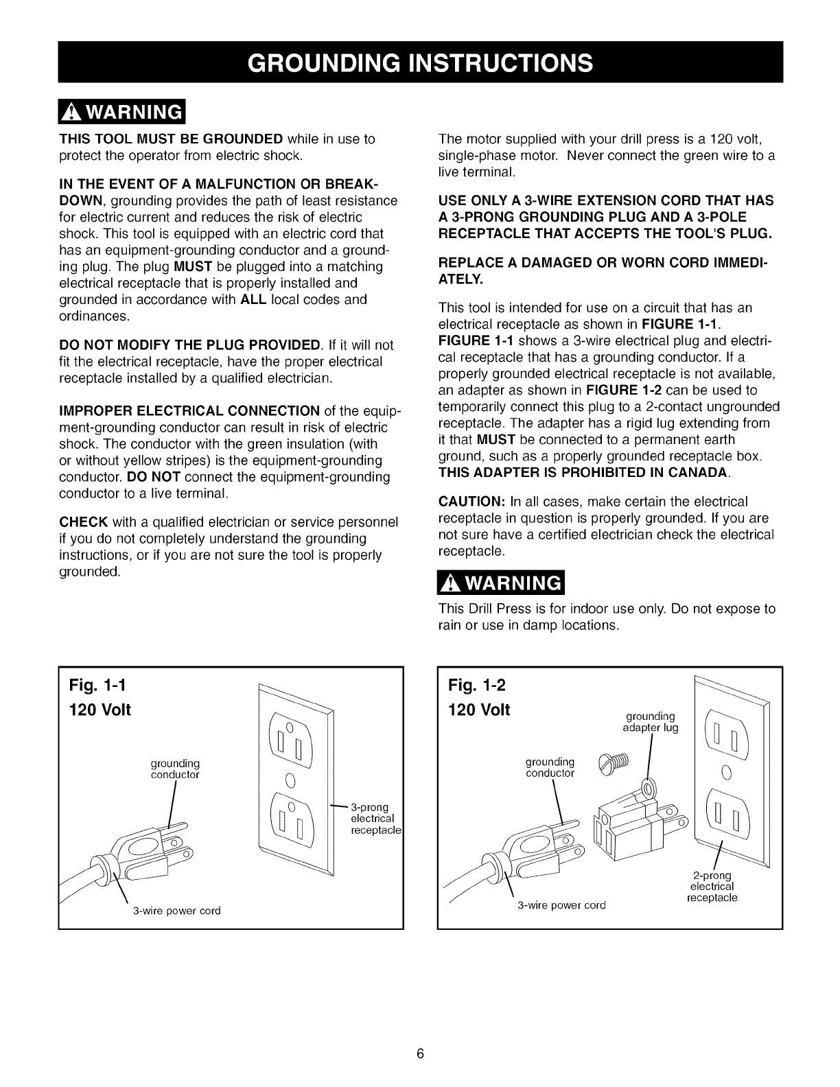
THIS TOOL MUST BE GROUNDED while in use to
protect the operator from electric shock.
IN THE EVENT OF AMALFUNCTION OR BREAK-
DOWN, grounding provides the path of least resistance
for electric current and reduces the risk of electric
shock. This tool is equipped with an electric cord that
has an equipment-grounding conductor and a ground-
ing plug. The plug MUST be plugged into a matching
electrical receptacle that is properly installed and
grounded in accordance with ALL local codes and
ordinances.
DO NOT MODIFY THE PLUG PROVIDED. If it will not
fit the electrical receptacle, have the proper electrical
receptacle installed by a qualified electrician.
IMPROPER ELECTRICAL CONNECTION of the equip-
ment-grounding conductor can result in risk of electric
shock. The conductor with the green insulation (with
or without yellow stripes) is the equipment-grounding
conductor. DO NOT connect the equipment-grounding
conductor to a live terminal.
CHECK with a qualified electrician or service personnel
if you do not completely understand the grounding
instructions, or if you are not sure the tool is properly
grounded.
The motor supplied with your drill press is a 120 volt,
single-phase motor. Never connect the green wire to a
live terminal.
USE ONLY A 3-WIRE EXTENSION CORD THAT HAS
A 3-PRONG GROUNDING PLUG AND A 3-POLE
RECEPTACLE THAT ACCEPTS THE TOOL'S PLUG.
REPLACE A DAMAGED OR WORN CORD IMMEDI-
ATELY.
This tool is intended for use on a circuit that has an
electrical receptacle as shown in FIGURE 1-1.
FIGURE 1-1 shows a 3-wire electrical plug and electri-
cal receptacle that has a grounding conductor. If a
properly grounded electrical receptacle is not available,
an adapter as shown in FIGURE 1-2 can be used to
temporarily connect this plug to a 2-contact ungrounded
receptacle. The adapter has a rigid lug extending from
it that MUST be connected to a permanent earth
ground, such as a properly grounded receptacle box.
THIS ADAPTER IS PROHIBITED IN CANADA.
CAUTION: In all cases, make certain the electrical
receptacle in question is properly grounded. If you are
not sure have a certified electrician check the electrical
receptacle.
This Drill Press is for indoor use only. Do not expose to
rain or use in damp locations.
Fig. 1-1
120 Volt
grounding
conductor
3-wire power cord
0
3-prong
electrical
receptacle
Fig. 1-2
120 Volt grounding
ada
grounding (_
conductor
3-wire power cord
0
2-prong
electrical
receptacle

SPECIFIC SAFETY INSTRUCTIONS
The operation of any drill press can result in debris
being thrown into your eyes, which can result in severe
eye damage. ALWAYS WEAR EYE PROTECTION. Any
power tool can throw debris into the eyes during opera-
tions, which could cause severe and permanent eye
damage. Everyday eyeglasses are NOT safety glasses.
ALWAYS wear Safety Goggles that comply with ANSI
standard Z87.1 when operating power tools. Safety
Goggles are available at Sears Retail Stores.
Basic precautions should always be followed when
using your drill press. To reduce the risk of injury, elec-
trical shock or fire, comply with the safety rules listed
below:
,
,
,
,
READ and understand the instruction manual
before operating the drill press.
AVOID AWKWARD OPERATIONS AND HAND
POSITIONS. A sudden slip could cause a serious
injury.
CHECK all drill bits, cutting tools, sanding drums, or
other accessories for damage before installing in
the drill press chuck. Damaged items can cause
damage to the drill press and or serious injury.
Before leaving the drill press, LOCK or REMOVE
the ON/OFF switch/key to prevent unauthorized
use.
,DO NOT install or use any drill bit that exceeds
7-inches in length or that extends 6-inches below
the chuck jaws. The drill bit can suddenly bend or
break.
,
,
,
,
DO NOT try to drill a workpiece that is too small to
be securely held to the table or in a vise.
DO NOT operate this drill press until it is assembled
and installed according to the instruction manual.
DO NOT leave the drill press plugged into the elec-
trical outlet. Unplug the drill press from the outlet
when not in use and before servicing, changing bits
and cleaning.
DO NOT USE router bits, shaper cutters, circle (fly)
cutters, rotary planers or wire wheels in this drill
press.
10. FOLLOW all electrical and safety codes, including
the National Electric Code (NEC) and the
Occupational Safety and Health Regulations
(OSHA). All electrical connections and wiring should
be made by qualified personnel only.
11. LET THE CHUCK REACH FULL SPEED before
starting drill operations.
12. MAKE SURE there are no foreign objects, nails,
stones in the workpiece.
13.
14.
15.
16.
17.
18.
19.
20.
21.
22.
23.
24.
25.
26.
NEVER PERFORM LAYOUT, ASSEMBLY OR
SETUP WORK on the table/work area when the
drill press is running.
NEVER START THE DRILL PRESS BEFORE
CLEANING THE TABLE OF ALL OBJECTS (tools,
scrap pieces, etc.). Debris can be thrown at high
speed.
NEVER START THE DRILL PRESS with the drill
bit, cutting tool, or sanding drum against the work-
piece. Loss of control of the workpiece can cause
serious injury.
OBTAIN ADVICE FROM YOUR SUPERVISOR,
instructor, or another qualified person if you are not
familiar with the operation of this drill press.
PROPERLY SUPPORT long or wide workpiece and
clamp to the table.
PROPERLY SECURE the drill bit, cutting tool, or
sanding drum in the chuck before operating the drill
press.
REPLACE a damaged cord immediately. DO NOT
use a damaged cord or plug. If the drill press is not
operating properly, or has been damaged, left out-
doors or has been in contact with water, return it to
a Sears Service Center.
SECURE the drill press to the floor or work bench.
Vibration can cause the drill press to slide, walk or
tip over.
SECURE the workpiece firmly against the table.
Do not attempt to drill a workpiece that does not
have a flat surface against the table, or that is not
secured by a vise. Prevent the workpiece from
rotating by clamping it to the table or by securing it
against the drill press column. Loss of control of
the workpiece can cause serious injury.
SECURELY LOCK the head and table support to
the column, and the table to the table support
before operating the drill press.
The drill press is designed for home use or light
commercial duty ONLY.
TO REDUCE THE RISK OF ELECTRICAL
SHOCK, do not use outdoors. Do not expose to
rain. Store indoors in a dry area.
TURN THE DRILL PRESS OFF and unplug from
power source. Wait for the drill bit, cutting tool, or
sanding drum to come to a complete STOP before
cleaning off the table/work area, removing or secur-
ing workpiece, or changing setup.
USE only drill bits, cutting tools, sanding drums, or
other accessories with proper shank size recom-
mended in this instruction manual. The wrong size
shank can cause damage to the drill press and/or
serious injury.

27.USEonlyasdescribedinthisinstructionmanual.
USEaccessoriesonlyrecommendedbySears.
28.USE RECOMMENDED SPEEDS for all operations.
Other speeds may cause the machine to malfunc-
tion causing damage to the drill press and or
serious injury.
29. REMOVE ADJUSTING KEYS AND WRENCHES.
Form habit of checking to see that keys and adjust-
ing wrenches are removed from tool before turning
it on.
30. USE RIGHT TOOL. Don't force tool or attachment
to do a job for which it was not designed.
31. Information regarding the safe and proper operation
of this tool is also available from the following
sources:
Power Tool Institute
1300 Summer Avenue
Cleveland, OH 44115-2851
www.powertoolinstit ute.org
National Safety Council
1121 Spring Lake Drive
Itasca, IL 60143-3201
American National Standards Institute
25 West 43rd Street, 4th floor
New York, NY 10036
www.ansi.org
ANSI 01.1 Safety Requirements for
Woodworking Machines, and the
U.S. Department of Labor regulations
www.osha.gov
32. SAVE THESE INSTRUCTIONS. Refer to them
frequently and use them to instruct other users.
ADDITIONAL SAFETY RULES
FOR THE LASER
1. LASER LIGHT - DO NOT STARE INTO BEAM,
APERTURE, or into a reflection from a mirror-like
surface.
.
.
AVOID EXPOSURE - LASER LIGHT IS EMITTED
FROM BOTH SIDES OF LASER ASSEMBLY.
Use of controls or adjustments, or performance of
procedures other than those specified herein may
result in hazardous laser light exposure.
DO NOT DISASSEMBLE LASER MODULE. The
laser is a CLASS II LASER PRODUCT that can
emit laser power up to 1 mW MAX at 635 rim,
which could result in exposure with the module
disassembled. The laser unit complies with 21
CFR 1040.10 and 1040.11.
.
.
USE OF CONTROLS OR ADJUSTMENTS OR
PERFORMANCE OF PROCEDURES OTHER
THAN THOSE SPECIFIED HEREIN MAY RESULT
IN HAZARDOUS RADIATION EXPOSURE.
The use of optical instruments with this product will
increase eye hazard.
AVAILABLE ACCESSORIES
Visit your Sears Hardware Department or see the
Craftsman Power and Hand Tool Catalog for the
following accessories.
ITEM STOCK NUMBER
* Circle Cutter 25293
* Clamping Kit 26426
*8-in. Vise 24077
*4-in. Vise 24081
*3-in. Vise 24071
*21 pc. Sanding Drum Kit 25262
Sears may recommend other accessories not listed in
this manual.
See your nearest Sears Hardware Department or
Craftsman Power and Hand Tool Catalog for other
accessories.
Do not use any accessory unless you have completely
read the Instruction Manual for that accessory.
Use only accessories recommended for this drill press.
Using other accessories may cause serious injury and
cause damage to the drill press.
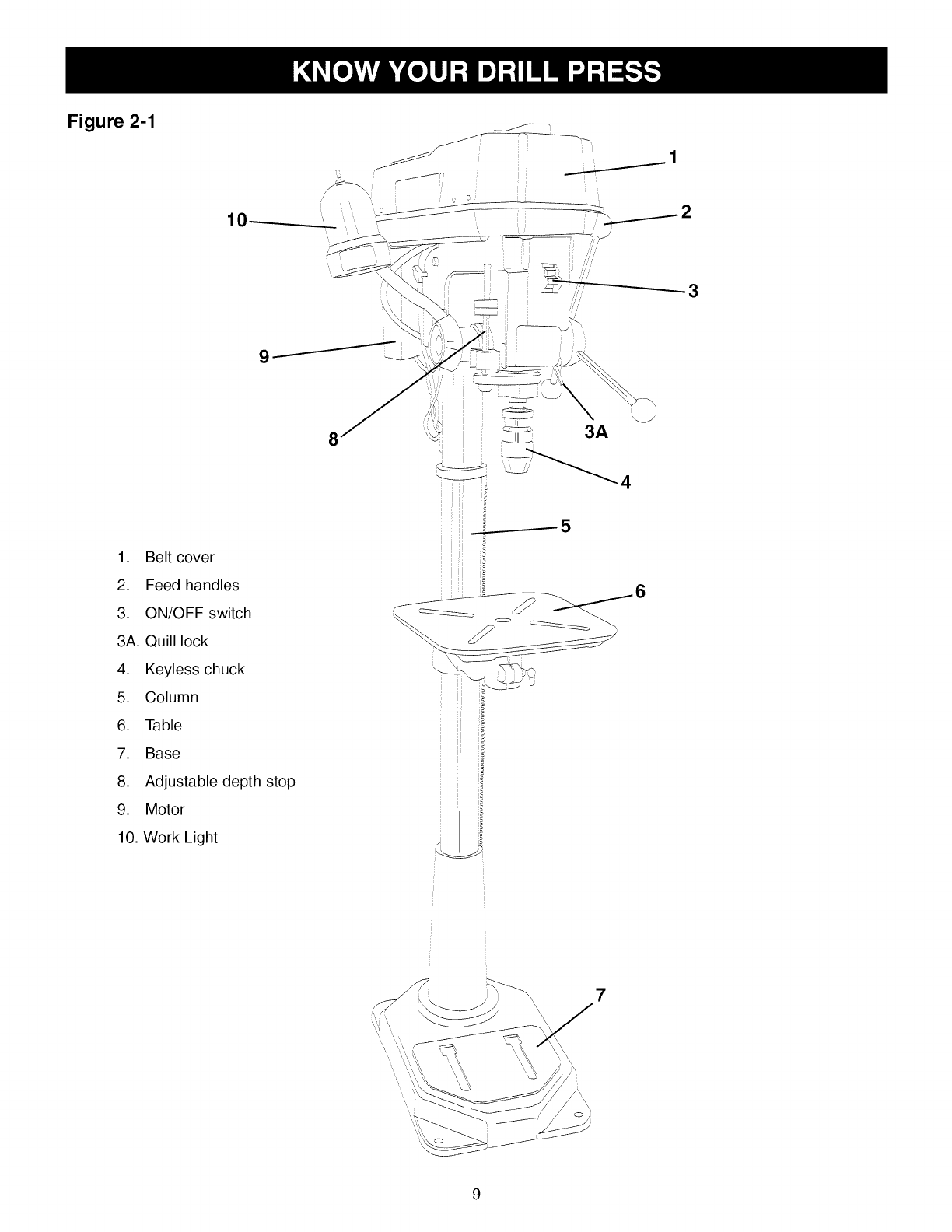
Figure 2-1
10
j_
J
E
jS __ 1
f
f
f
1. Belt cover
2. Feed handles
3. ON/OFF switch
3A. Quill lock
4. Keyless chuck
5. Column
6. Table
7. Base
8. Adjustable depth stop
9. Motor
10. Work Light
7
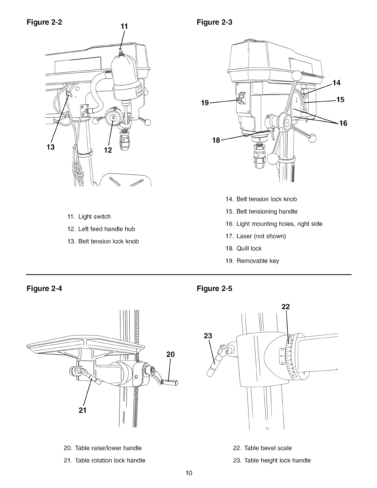
Figure 2-2 11
11. Light switch
12. Left feed handle hub
13. Belt tension lock knob
Figure 2-3
18
14. Belt tension lock knob
15. Belt tensioning handle
16. Light mounting holes, right side
17. Laser (not shown)
18. Quill lock
19. Removable key
16
Figure 2-4 Figure 2-5
20
23
22
21
20. Table raise/lower handle
21. Table rotation lock handle
10
22. Table bevel scale
23. Table height lock handle
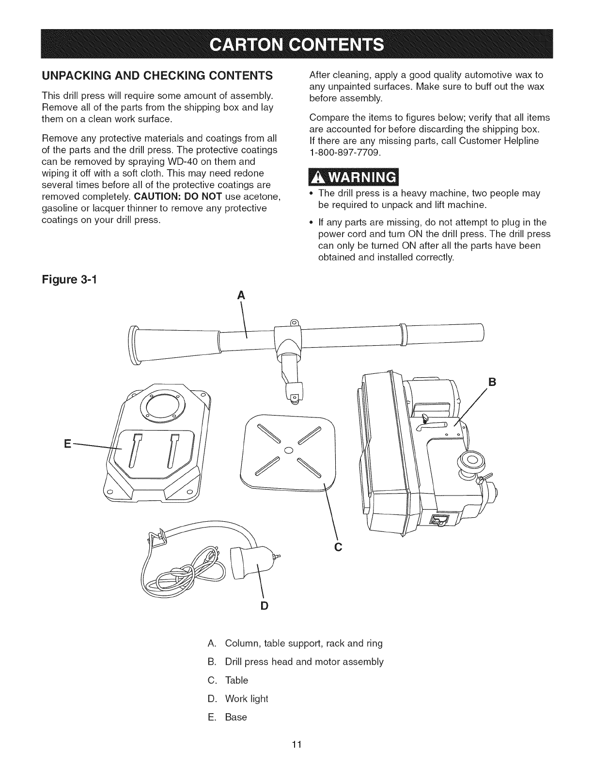
UNPACKING AND CHECKING CONTENTS
This drill press will require some amount of assembly.
Remove all of the parts from the shipping box and lay
them on a clean work surface.
Remove any protective materials and coatings from all
of the parts and the drill press. The protective coatings
can be removed by spraying WD-40 on them and
wiping it off with a soft cloth. This may need redone
several times before all of the protective coatings are
removed completely. CAUTION: DO NOT use acetone,
gasoline or lacquer thinner to remove any protective
coatings on your drill press.
After cleaning, apply a good quality automotive wax to
any unpainted surfaces. Make sure to buff out the wax
before assembly.
Compare the items to figures below; verify that all items
are accounted for before discarding the shipping box.
If there are any missing parts, call Customer Helpline
1-800-897-7709.
•The drill press is a heavy machine, two people may
be required to unpack and lift machine,
If any parts are missing, do not attempt to plug in the
power cord and turn ON the drill press, The drill press
can only be turned ON after all the parts have been
obtained and installed correctly,
Figure 3-1
A
E
C
)
B
A. Column, table support, rack and ring
B. Drill press head and motor assembly
C. Table
D. Work light
E. Base
11
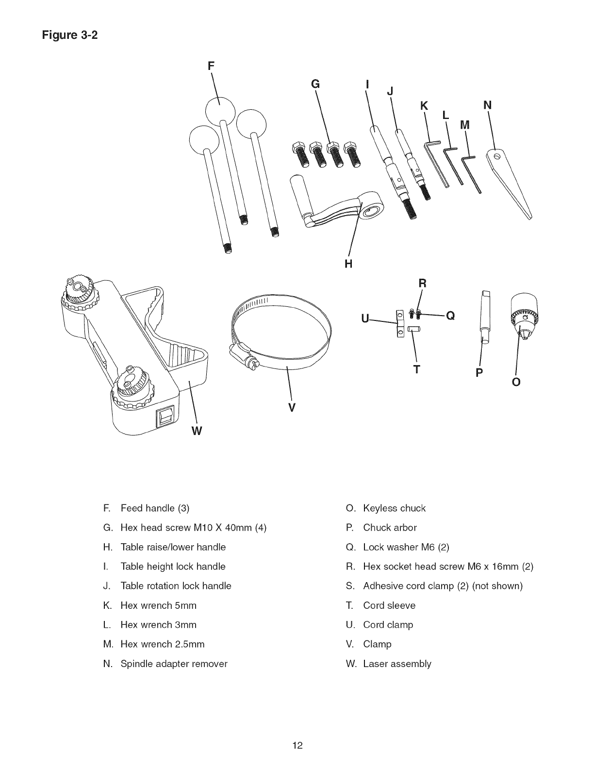
Figure 3-2
W
F
GJ
H
V
R
M
T p O
R Feed handle (3)
G. Hex head screw MIO X 40mm (4)
H. Table raise/lower handle
I. Table height lock handle
J. Table rotation lock handle
K. Hex wrench 5mm
L. Hex wrench 3mm
M. Hex wrench 2.5mm
N. Spindle adapter remover
O. Keyless chuck
P. Chuck arbor
Q. Lock washer M6 (2)
R. Hex socket head screw M6 x 16mm (2)
S. Adhesive cord clamp (2) (not shown)
T, Cord sleeve
U. Cord clamp
V. Clamp
W. Laser assembly
12
TOOLS REQUIRED
The following tools are needed for assembly and align-
ment. Note: Hex wrenches are provided. The remaining
tools are typical shop tools and are not included with
your drill press.
• 17mm Open end wrench • Straight screwdriver
Hammer and block of wood • Combination square
The drill press is a heaw machine; two people may
be required for certain assembly operations.
• DO NOT assemble the drill press until you are sure
the tool is unplugged.
• DO NOT assemble the drill press until you are sure
the power switch is in the "OFF" position.
• For your own safety, DO NOT connect the drill press
to the power source until the machine is completely
assembled and you read and understand the entire
Instruction Manual.
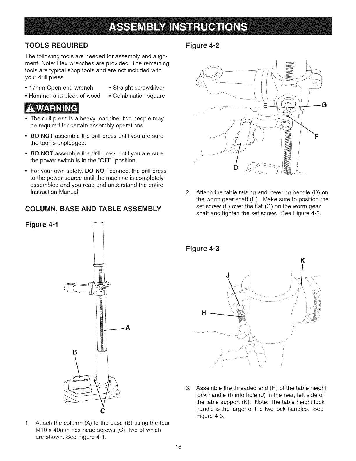
COLUMN, BASE AND TABLE ASSEMBLY
Figure 4-1
B
.
C
Attach the column (A) to the base (B) using the four
MIO x 40mm hex head screws (C), two of which
are shown. See Figure 4-1.
Figure 4-2
F
D
.Attach the table raising and lowering handle (D) on
the worm gear shaft (E). Make sure to position the
set screw (F) over the flat (G) on the worm gear
shaft and tighten the set screw. See Figure 4-2.
Figure 4-3
J
K
/
J
.Assemble the threaded end (H) of the table height
lock handle (I) into hole (J) in the rear, left side of
the table support (K). Note: The table height lock
handle is the larger of the two lock handles. See
Figure 4-3.
13
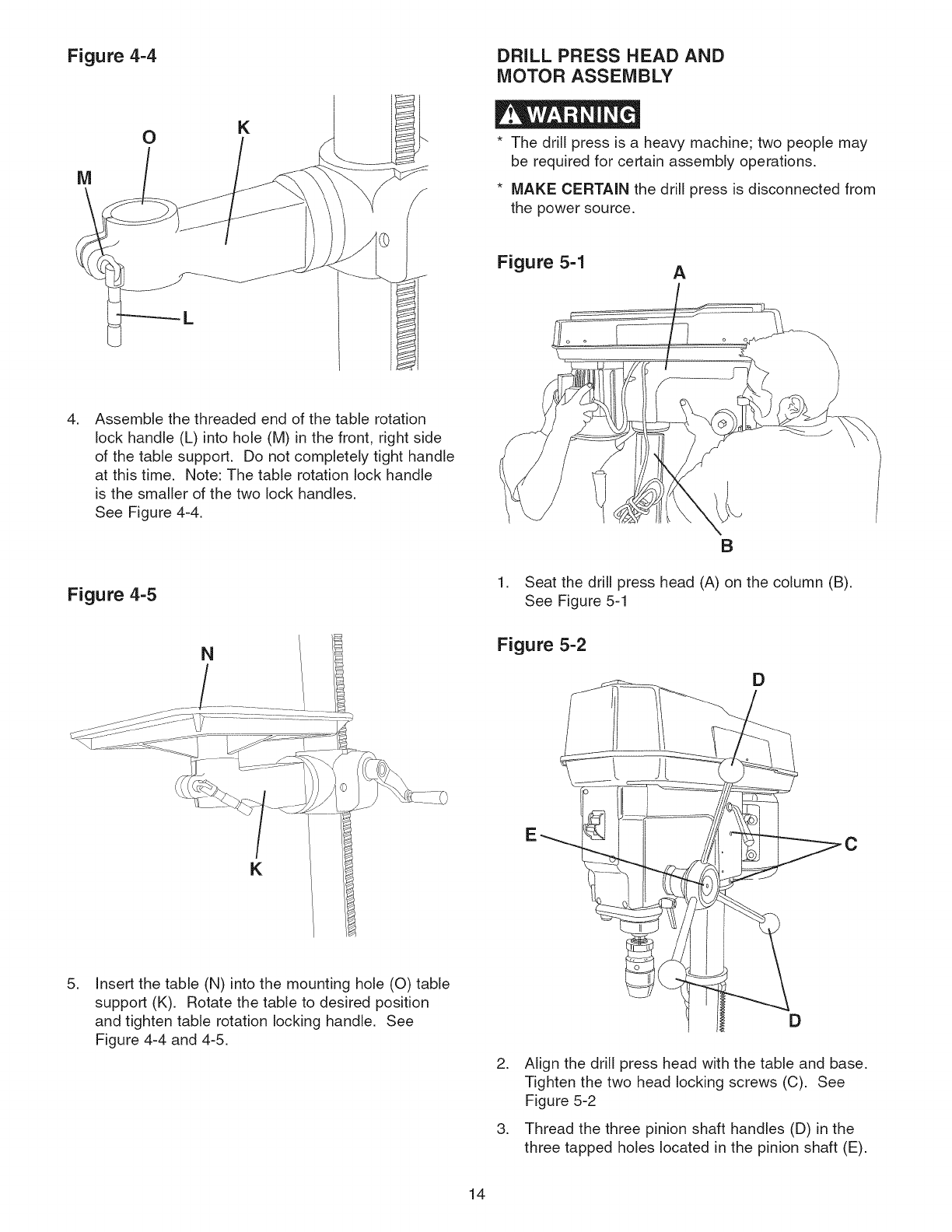
Figure 4-4 DRILL PRESS HEAD AND
MOTOR ASSEMBLY
OKThe drill press is a heavy machine; two people may
be required for certain assembly operations.
MAKE CERTAIN the drill press is disconnected from
the power source.
Figure 5-1 A
,Assemble the threaded end of the table rotation
lock handle (L) into hole (M) in the front, right side
of the table support. Do not completely tight handle
at this time. Note: The table rotation lock handle
is the smaller of the two lock handles.
See Figure 4-4.
Figure 4-5
N
K
B
1. Seat the drill press head (A) on the column (B).
See Figure 5-1
Figure 5-2
D
,Insert the table (N) into the mounting hole (O) table
support (K). Rotate the table to desired position
and tighten table rotation locking handle. See
Figure 4-4 and 4-5.
,
,
D
Align the drill press head with the table and base.
Tighten the two head locking screws (C). See
Figure 5-2
Thread the three pinion shaft handles (D) in the
three tapped holes located in the pinion shaft (E).
14
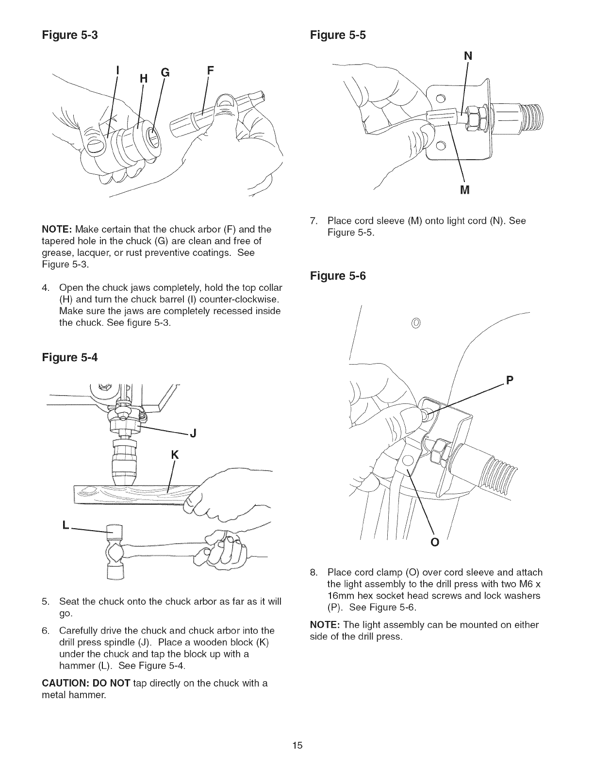
Figure 5-3 Figure 5-5
G F
H
N
M
NOTE: Make certain that the chuck arbor (F) and the
tapered hole in the chuck (G) are clean and free of
grease, lacquer, or rust preventive coatings. See
Figure 5-3.
.Open the chuck jaws completely, hold the top collar
(H) and turn the chuck barrel (I) counter-clockwise.
Make sure the jaws are completely recessed inside
the chuck. See figure 5-3.
7. Place cord sleeve (M) onto light cord (N). See
Figure 5-5.
Figure 5-6
©
Figure 5-4
P
L
0
5. Seat the chuck onto the chuck arbor as far as it will
go.
.Carefully drive the chuck and chuck arbor into the
drill press spindle (J). Place a wooden block (K)
under the chuck and tap the block up with a
hammer (L). See Figure 5-4.
CAUTION: DO NOT tap directly on the chuck with a
metal hammer.
.Place cord clamp (0) over cord sleeve and attach
the light assembly to the drill press with two M6 x
16mm hex socket head screws and lock washers
(P). See Figure 5-6.
NOTE: The light assembly can be mounted on either
side of the drill press.
15
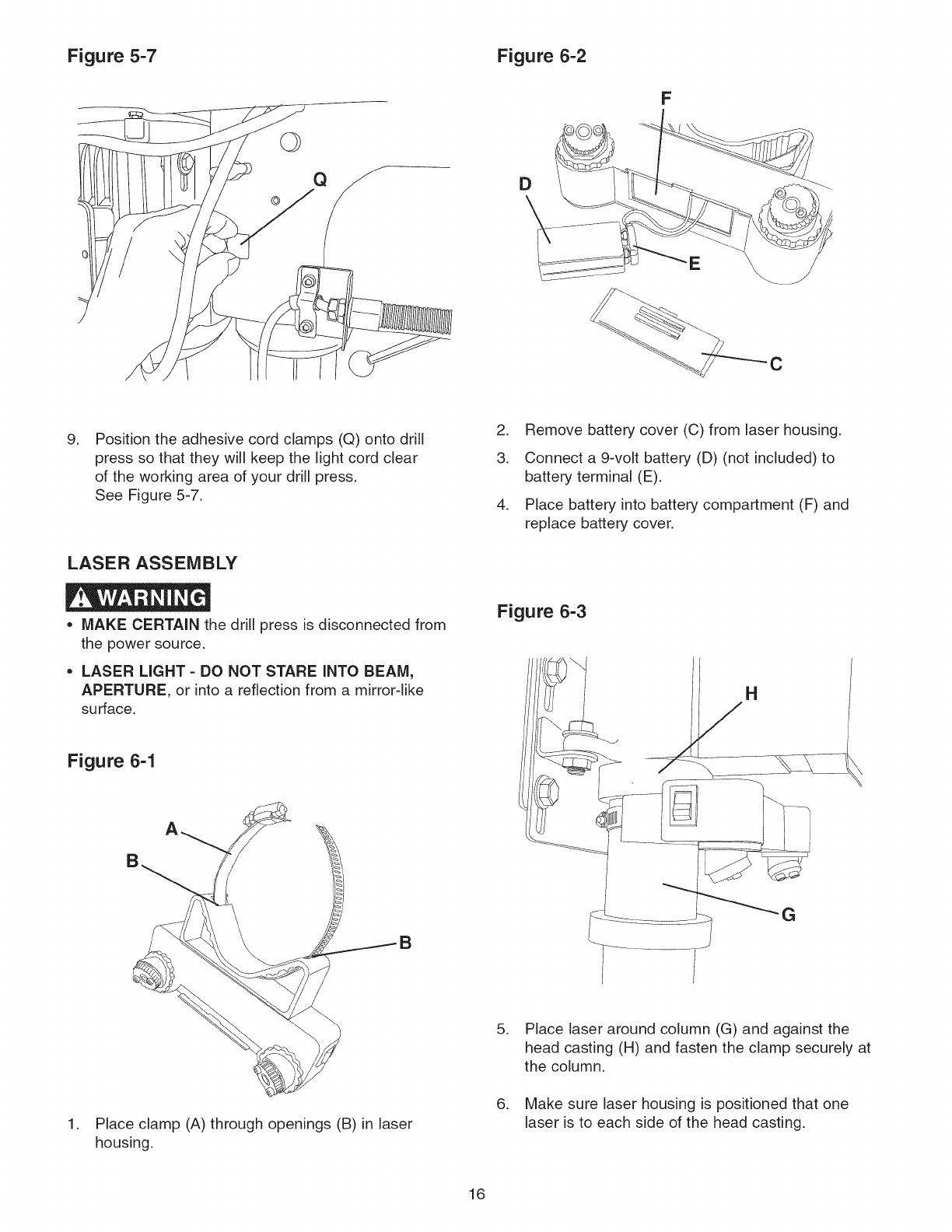
Figure 5-7 Figure 6-2
©
F
C
.Position the adhesive cord clamps (Q) onto drill
press so that they will keep the light cord clear
of the working area of your drill press.
See Figure 5-7.
LASER ASSEMBLY
2. Remove battery cover (C) from laser housing.
3. Connect a 9-volt battery (D) (not included) to
battery terminal (E).
4. Place battery into battery compartment (F) and
replace battery cover.
• MAKE CERTAIN the drill press is disconnected from
the power source.
• LASER LIGHT = DO NOT STARE INTO BEAM,
APERTURE, or into a reflection from a mirror-like
surface.
Figure 6-1
Figure 6-3
H
.Place clamp (A) through openings (B) in laser
housing.
.
.
Place laser around column (G) and against the
head casting (H) and fasten the clamp securely at
the column,
Make sure laser housing is positioned that one
laser is to each side of the head casting.
16
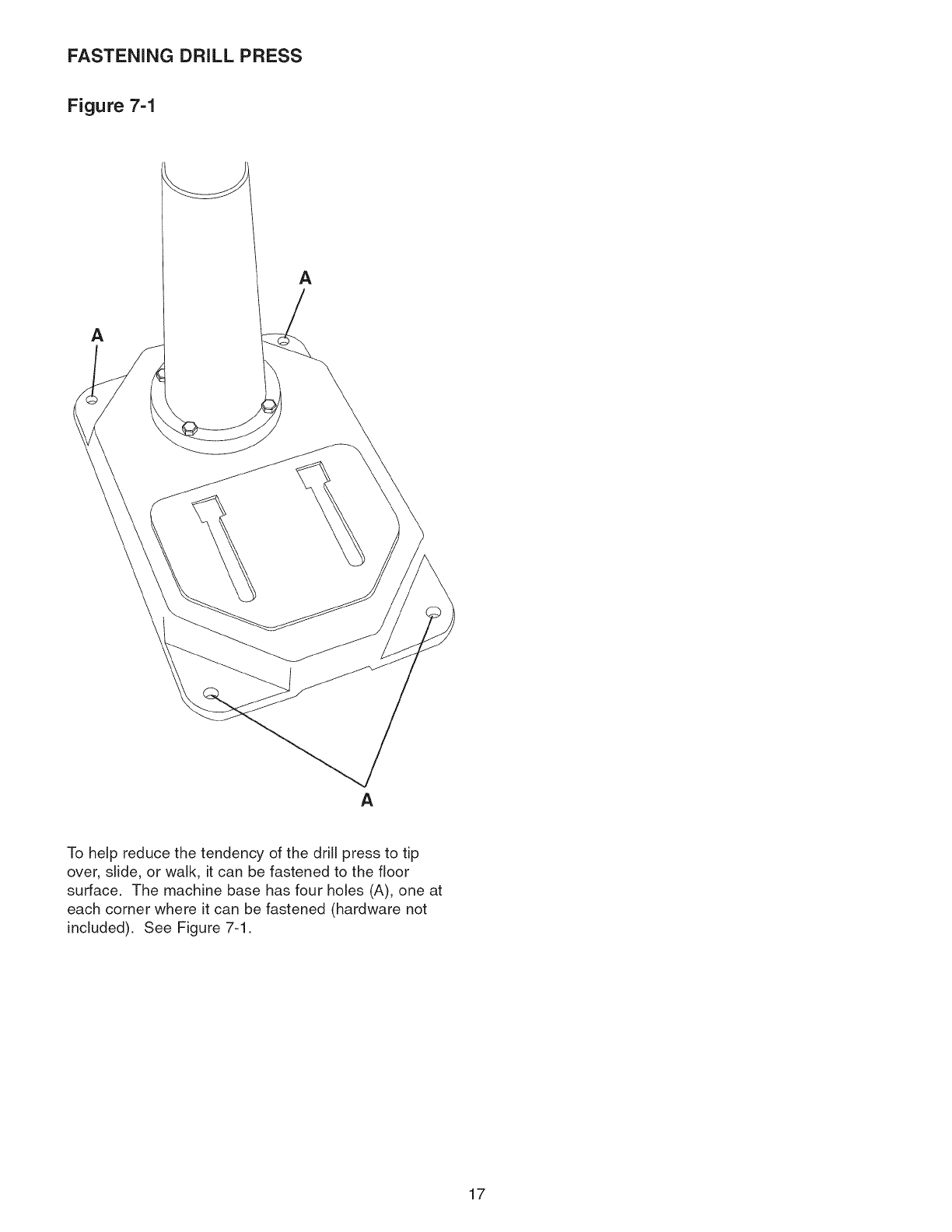
FASTENING DRILL PRESS
Figure 7-1
A
A
A
To help reduce the tendency of the drill press to tip
over, slide, or walk, it can be fastened to the floor
surface. The machine base has four holes (A), one at
each corner where it can be fastened (hardware not
included). See Figure 7-1.
17
•DO NOT expose the drill press to rain or operate it in
damp locations.
•MAKE SURE all parts have been assembled correctly
and are in working order.
.With the switch toggle removed, the switch will not
operate. However, should the switch toggle be
removed while the drill press is operating, the
switch can still be turned OFF, but cannot be
restarted without inserting the switch toggle.
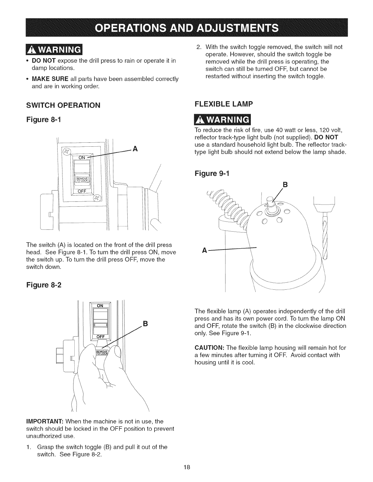
SWITCH OPERATION
Figure 8-1
\
The switch (A) is located on the front of the drill press
head. See Figure 8-1. To turn the drill press ON, move
the switch up. To turn the drill press OFF, move the
switch down.
Figure 8-2
B
IMPORTANT: When the machine is not in use, the
switch should be locked in the OFF position to prevent
unauthorized use.
1. Grasp the switch toggle (B) and pull it out of the
switch. See Figure 8-2.
FLEXIBLE LAMP
To reduce the risk of fire, use 40 watt or less, 120 volt,
reflector track-type light bulb (not supplied). DO NOT
use a standard household light bulb. The reflector track-
type light bulb should not extend below the lamp shade.
Figure 9-1
B
The flexible lamp (A) operates independently of the drill
press and has its own power cord. To turn the lamp ON
and OFF, rotate the switch (B) in the clockwise direction
only. See Figure 9-1.
CAUTION: The flexible lamp housing will remain hot for
a few minutes after turning it OFR Avoid contact with
housing until it is cool.
18
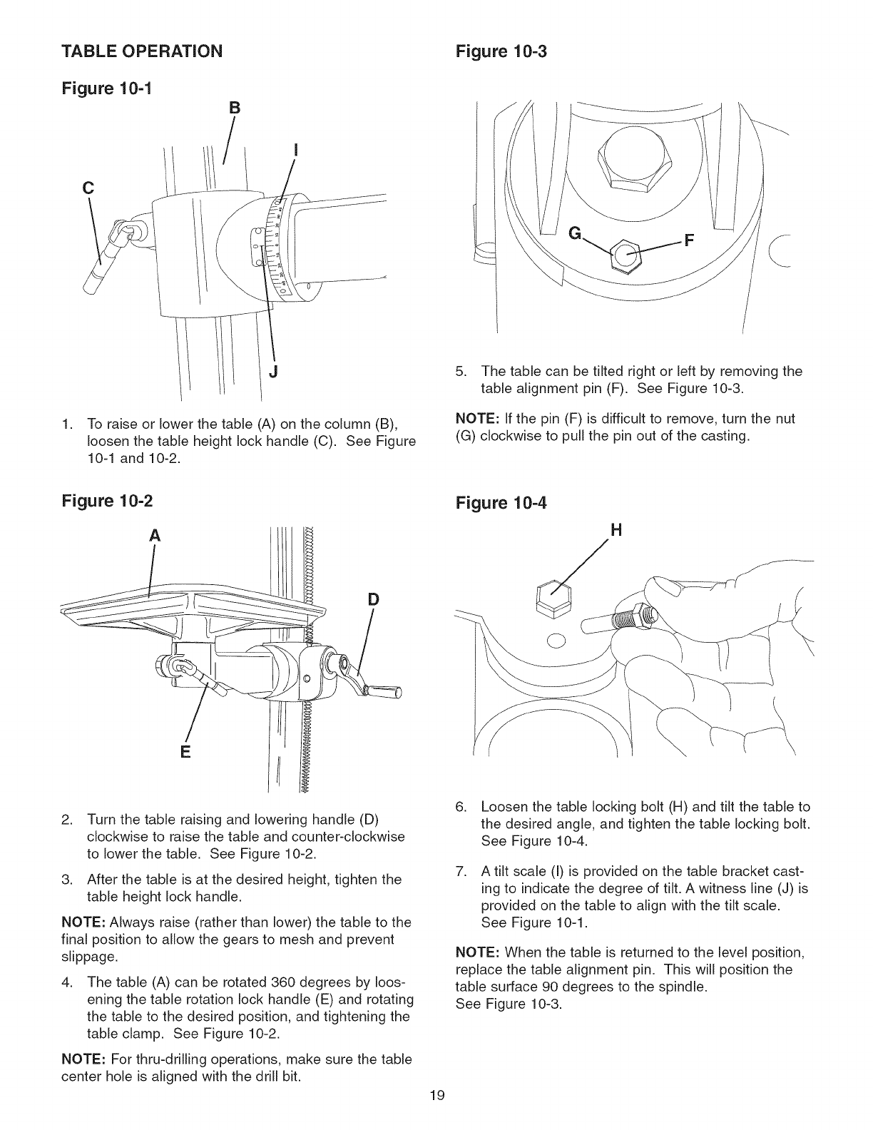
TABLE OPERATION
Figure 10-1 B
,
C
J
I
To raise or lower the table (A) on the column (B),
loosen the table height lock handle (C). See Figure
10-1 and 10-2.
Figure 10-3
5. The table can be tilted right or left by removing the
table alignment pin (F). See Figure 10-3.
NOTE: If the pin (F) is difficult to remove, turn the nut
(G) clockwise to pull the pin out of the casting.
Figure 10-2
A
E
D
Figure 10-4
H
2. Turn the table raising and lowering handle (D)
clockwise to raise the table and counter-clockwise
to lower the table. See Figure 10-2.
3. After the table is at the desired height, tighten the
table height lock handle.
NOTE: Always raise (rather than lower) the table to the
final position to allow the gears to mesh and prevent
slippage.
,The table (A) can be rotated 360 degrees by loos-
ening the table rotation lock handle (E) and rotating
the table to the desired position, and tightening the
table clamp. See Figure 10-2.
NOTE: For thru-drilling operations, make sure the table
center hole is aligned with the drill bit.
6. Loosen the table locking bolt (H) and tilt the table to
the desired angle, and tighten the table locking bolt.
See Figure 10-4.
,A tilt scale (I) is provided on the table bracket cast-
ing to indicate the degree of tilt. A witness line (J) is
provided on the table to align with the tilt scale.
See Figure 10-1.
NOTE: When the table is returned to the level position,
replace the table alignment pin. This will position the
table surface 90 degrees to the spindle.
See Figure 10-3.
19
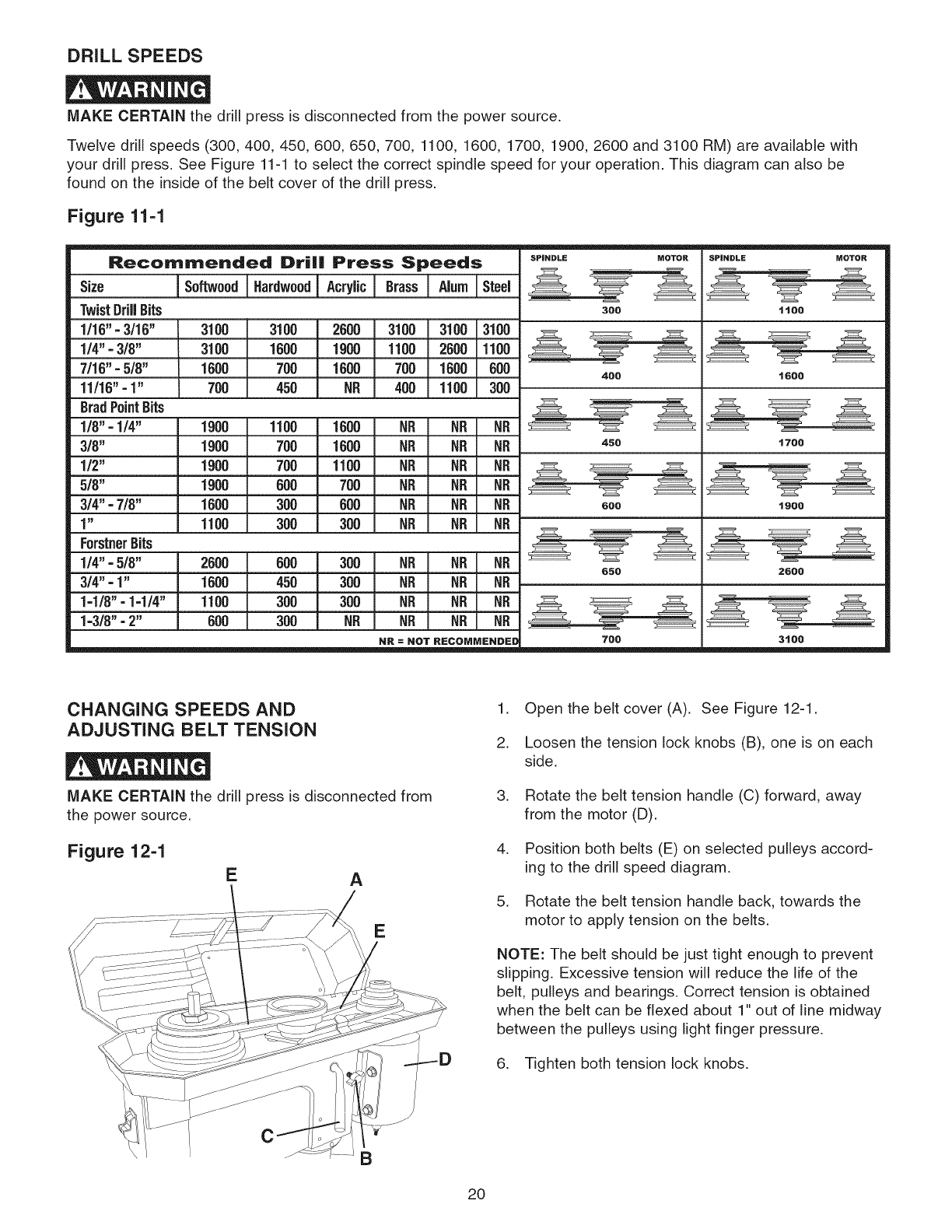
DRILL SPEEDS
MAKE CERTAIN the drill press is disconnected from the power source.
Twelve drill speeds (300,400, 450, 600, 650, 700, 1100, 1600, 1700, 1900, 2600 and 3100 RM) are available with
your drill press. See Figure 11-1 to select the correct spindle speed for your operation. This diagram can also be
found on the inside of the belt cover of the drill press.
Figure 11-1
Recommended Drill Press Speeds
Softwood Hardwoodj Acrylic! Brass ! Alum I Steel
Size
TwistDrillBits
1/16"=3/16"
1/4" =3/8"
7/16"=5/8"
11/16"=1"
BradPointBits
1/8" -1/4"
3/6"
1/2"
5/6"
3/4"=7/8"
1"
ForstnerBits
1/4" =5/8"
314"=1"
1-1/6" =1-1/4"
1=3/6"=2"
3100
3100
1600
700
3100 2600 3100 3100 3100
1600 1900 1100 2600 1100
700 1600 700 1600 600
450 NR 400 1100 300
1900
1900
1900
1900
1600
1100
1100 1600 NB NR NR
700 1600 NB NR NR
700 1100 NB NR NR
600 700 NR NR NR
300 600 NB NR NR
300 300 NR NR NR
2600 600 300 NB NR NR
1600 450 300 NR NR NR
1100 300 300 NB NR NR
600 300 NR NR NR NR
SPINDLE MOTOR SPINDLE MOTOR
300
4OO
450
600
650
ttoo
16OO
1700
t9OO
2600
3t00700
CHANGING SPEEDS AND
ADJUSTING BELT TENSION
MAKE CERTAIN the drill press is disconnected from
the power source.
Figure 12-1
EA
E
\
B
1. Open the belt cover (A). See Figure 12-1.
2. Loosen the tension lock knobs (B), one is on each
side.
3. Rotate the belt tension handle (C) forward, away
from the motor (D).
4. Position both belts (E) on selected pulleys accord-
ing to the drill speed diagram.
5. Rotate the belt tension handle back, towards the
motor to apply tension on the belts.
NOTE: The belt should be just tight enough to prevent
slipping. Excessive tension will reduce the life of the
belt, pulleys and bearings. Correct tension is obtained
when the belt can be flexed about 1" out of line midway
between the pulleys using light finger pressure.
6. Tighten both tension lock knobs.
2O
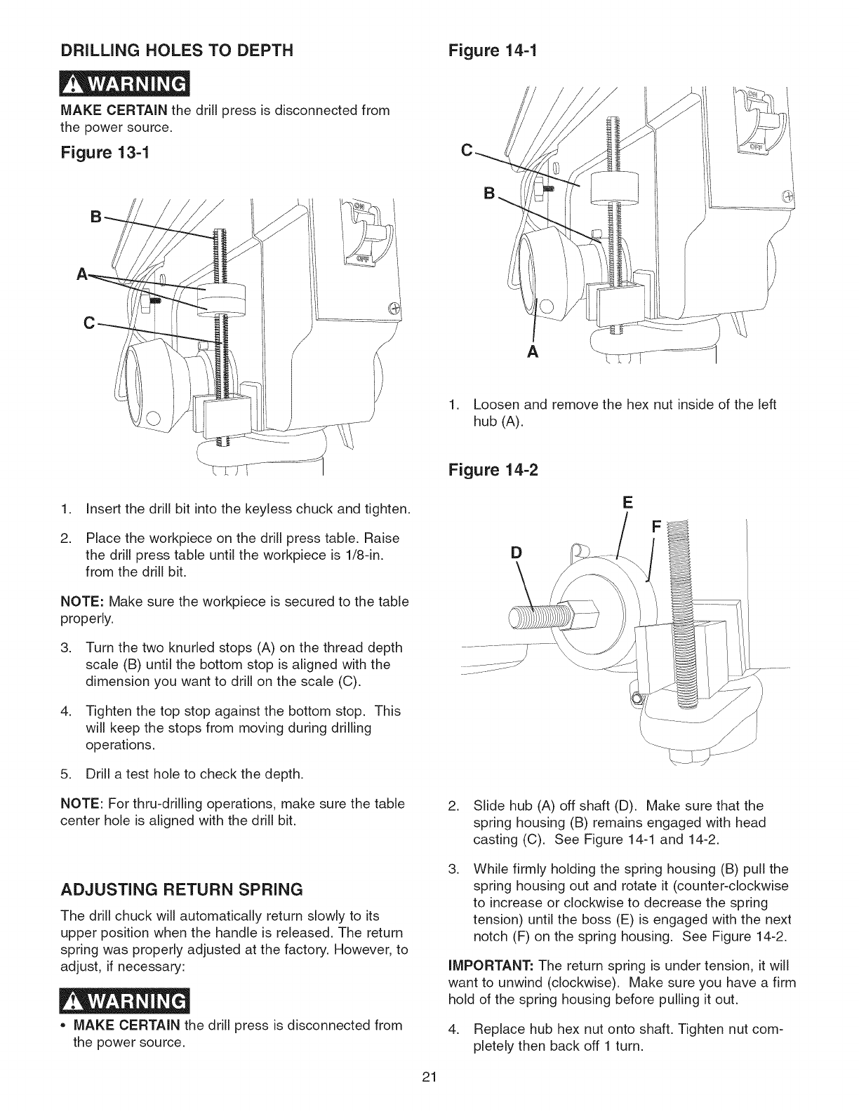
DRILLING HOLES TO DEPTH Figure 14-1
MAKE CERTAIN the drill press is disconnected from
the power source.
Figure 13-1
C
C
A
1. Insert the drill bit into the keyless chuck and tighten.
2. Place the workpiece on the drill press table. Raise
the drill press table until the workpiece is 1/8-in.
from the drill bit.
NOTE: Make sure the workpiece is secured to the table
properly.
3. Turn the two knurled stops (A) on the thread depth
scale (B) until the bottom stop is aligned with the
dimension you want to drill on the scale (C).
4. Tighten the top stop against the bottom stop. This
will keep the stops from moving during drilling
operations.
5. Drill a test hole to check the depth.
NOTE: For thru-drilling operations, make sure the table
center hole is aligned with the drill bit.
ADJUSTING RETURN SPRING
The drill chuck will automatically return slowly to its
upper position when the handle is released. The return
spring was properly adjusted at the factory. However, to
adjust, if necessary:
MAKE CERTAIN the drill press is disconnected from
the power source.
21
1. Loosen and remove the hex nut inside of the left
hub (A).
Figure 14-2
E
D
2. Slide hub (A) off shaft (D). Make sure that the
spring housing (B) remains engaged with head
casting (C). See Figure 14-1 and 14-2.
,While firmly holding the spring housing (B) pull the
spring housing out and rotate it (counter-clockwise
to increase or clockwise to decrease the spring
tension) until the boss (E) is engaged with the next
notch (F) on the spring housing. See Figure 14-2.
IMPORTANT: The return spring is under tension, it will
want to unwind (clockwise). Make sure you have a firm
hold of the spring housing before pulling it out.
4. Replace hub hex nut onto shaft. Tighten nut com-
pletely then back off 1 turn.
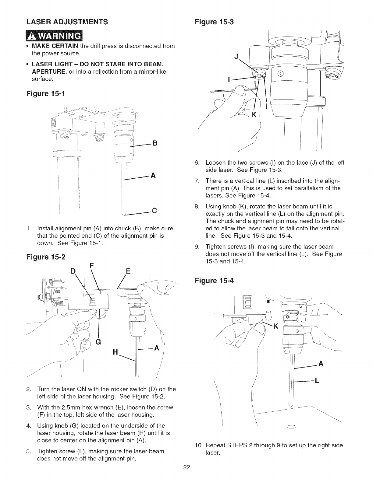
LASER ADJUSTMENTS Figure 15-3
* MAKE CERTAIN the drill press is disconnected from
the power source.
• LASER LIGHT - DO NOT STARE INTO BEAM,
APERTURE or into a reflection from a mirror-like
surface.
Figure 15-1
H
ii
r>
'7 ¸ i ....
i i ----C
1. Install alignment pin (A) into chuck (B); make sure
that the pointed end (C) of the alignment pin is
down. See Figure 15-1.
Figure 15-2
DFE
.
.
.
g.
Loosen the two screws (I) on the face (J) of the left
side laser. See Figure 15-3.
There is a vertical line (L) inscribed into the align-
ment pin (A). This is used to set parallelism of the
lasers. See Figure 15-4.
Using knob (K), rotate the laser beam until it is
exactly on the vertical line (L) on the alignment pin.
The chuck and alignment pin may need to be rotat-
ed to allow the laser beam to fall onto the vertical
line. See Figure 15-3 and 15-4.
Tighten screws (I), making sure the laser beam
does not move off the vertical line (L). See Figure
15-3 and 15-4.
Figure 15-4
.
.
.
.
G
H
Turn the laser ON with the rocker switch (D) on the
left side of the laser housing. See Figure 15-2.
With the 2.5mm hex wrench (E), loosen the screw
(F) in the top, left side of the laser housing.
Using knob (G) located on the underside of the
laser housing, rotate the laser beam (H) until it is
close to center on the alignment pin (A).
Tighten screw (F), making sure the laser beam
does not move off the alignment pin.
10.
22
\L
Repeat STEPS 2 through 9 to set up the right side
laser.
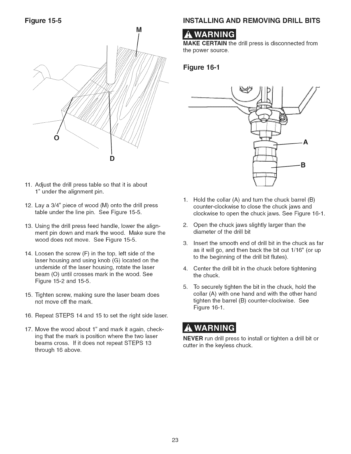
Figure 15-5 iNSTALLiNG AND REMOVING DRILL BiTS
M
MAKE CERTAIN the drill press is disconnected from
the power source.
Figure 16-1
D
11. Adjust the drill press table so that it is about
1" under the alignment pin.
12. Lay a 3/4" piece of wood (M) onto the drill press
table under the line pin. See Figure 15-5.
13. Using the drill press feed handle, lower the align-
ment pin down and mark the wood. Make sure the
wood does not move. See Figure 15-5.
14. Loosen the screw (F) in the top, left side of the
laser housing and using knob (G) located on the
underside of the laser housing, rotate the laser
beam (O) until crosses mark in the wood. See
Figure 15-2 and 15-5.
15. Tighten screw, making sure the laser beam does
not move off the mark.
16. Repeat STEPS 14 and 15 to set the right side laser.
17. Move the wood about 1" and mark it again, check-
ing that the mark is position where the two laser
beams cross. If it does not repeat STEPS 13
through 16 above.
.
.
.
.
.
Hold the collar (A) and turn the chuck barrel (B)
counter-clockwise to close the chuck jaws and
clockwise to open the chuck jaws. See Figure 16-1.
Open the chuck jaws slightly larger than the
diameter of the drill bit
Insert the smooth end of drill bit in the chuck as far
as it will go, and then back the bit out 1/16" (or up
to the beginning of the drill bit flutes).
Center the drill bit in the chuck before tightening
the chuck,
To securely tighten the bit in the chuck, hold the
collar (A) with one hand and with the other hand
tighten the barrel (B) counter-clockwise. See
Figure 16-1.
NEVER run drill press to install or tighten a drill bit or
cutter in the keyless chuck,
23
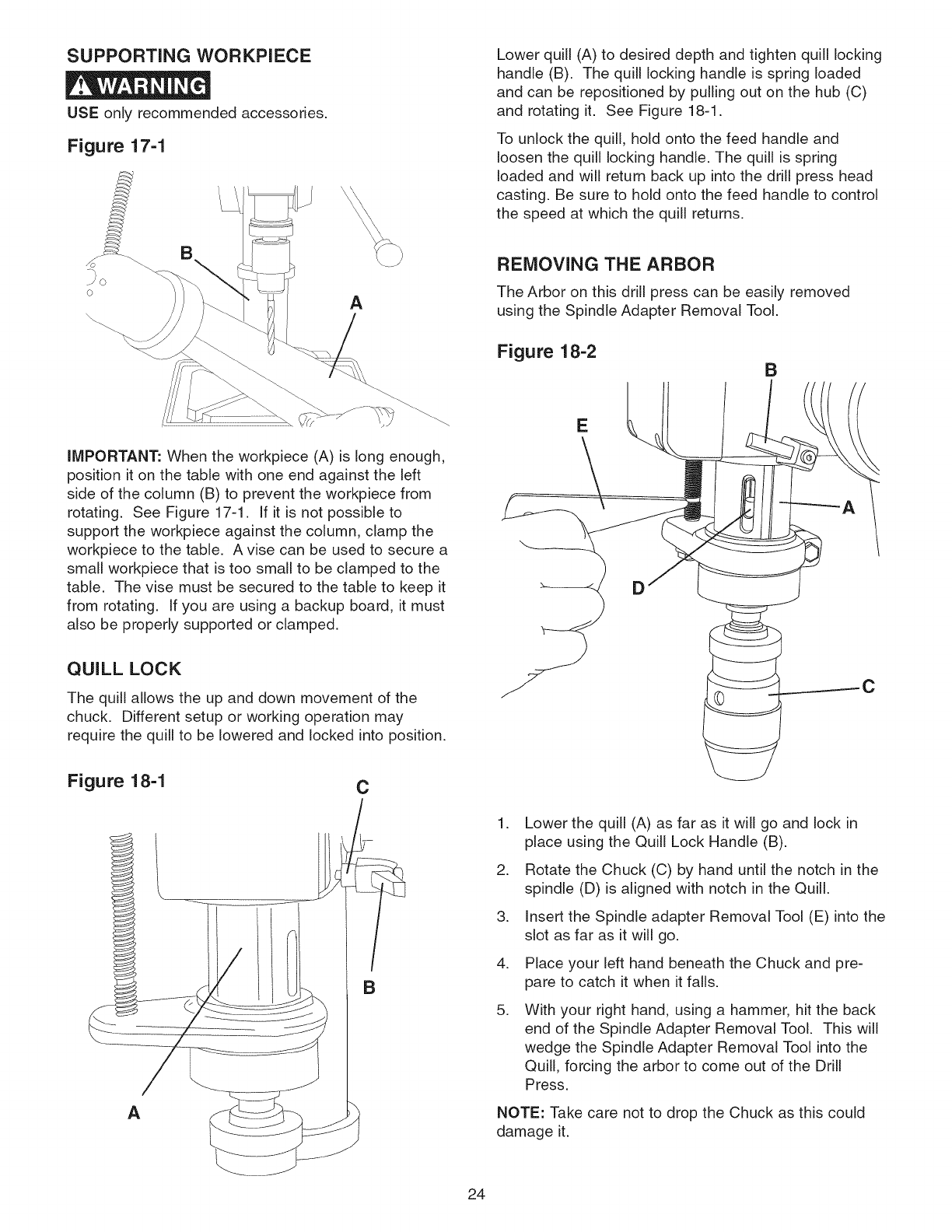
SUPPORTING WORKPIECE
USE only recommended accessories.
Figure 17-1
Lower quill (A) to desired depth and tighten quill locking
handle (B). The quill locking handle is spring loaded
and can be repositioned by pulling out on the hub (C)
and rotating it. See Figure 18-1.
To unlock the quill, hold onto the feed handle and
loosen the quill locking handle. The quill is spring
loaded and will return back up into the drill press head
casting. Be sure to hold onto the feed handle to control
the speed at which the quill returns.
A
iMPORTANT: When the workpiece (A) is long enough,
position it on the table with one end against the left
side of the column (B) to prevent the workpiece from
rotating. See Figure 17-1. If it is not possible to
support the workpiece against the column, clamp the
workpiece to the table. A vise can be used to secure a
small workpiece that is too small to be clamped to the
table. The vise must be secured to the table to keep it
from rotating. If you are using a backup board, it must
also be properly supported or clamped.
QUILL LOCK
The quill allows the up and down movement of the
chuck. Different setup or working operation may
require the quill to be lowered and locked into position.
Figure 18-1
A
C
B
REMOVING THE ARBOR
The Arbor on this drill press can be easily removed
using the Spindle Adapter Removal Tool.
Figure 18-2 B
c
.
.
.
.
.
Lower the quill (A) as far as it will go and lock in
place using the Quill Lock Handle (B).
Rotate the Chuck (C) by hand until the notch in the
spindle (D) is aligned with notch in the Quill.
Insert the Spindle adapter Removal Tool (E) into the
slot as far as it will go.
Place your left hand beneath the Chuck and pre-
pare to catch it when it falls.
With your right hand, using a hammer, hit the back
end of the Spindle Adapter Removal Tool. This will
wedge the Spindle Adapter Removal Tool into the
Quill, forcing the arbor to come out of the Drill
Press.
NOTE: Take care not to drop the Chuck as this could
damage it.
24
CORRECT DRILLING SPEEDS
Factors that determine the correct speed are: the work-
piece, the size of the hole, the type of bit or other cutter,
and the quality of cut wanted.
Use the recommended speed for the drill bit and work-
piece.
DRILLING WOOD
Twist drill bits, usually intended for metal drilling, can
also be used for boring holes in wood. However, brad
point or Forstner bits are generally preferred for working
in wood. These bits cut a flat bottom hole and are
designed for removal of wood chips. Do not use hand
bits which have a screw tip or auger bits. At drill press
speeds, they will lift and rotate the workpiece.
For through boring, align the table so that the bit will go
through the center hole. Scribe a vertical line on the
front of the column and a matching mark on the table
bracket and the drill press head, so that the table and
drill press head can be clamped in the center position
at any height.
Feed the bit slowly when it is close to cutting through
the wood to prevent splintering the bottom face. Use a
scrap piece of wood as backup under the workpiece.
This helps to reduce splintering and protects the point
of the bit.
DRILLING METAL,
ALUMINUM OR BRASS
NEVER hold the workpiece in your bare hands.
ALWAYS use clamps or vises to hold your workpiece.
Twist drill bits should only be used in drilling metals.
Never hold the workpiece in your bare hands; always
use clamps or vises. The drill bit may seize the work at
any time, especially when breaking through the work-
piece. If the workpiece is whirled out of the operator's
hand, the operator may be injured. The drill bit will be
broken if the workpiece strikes the column.
The workpiece must be clamped or securely held in a
vise while drilling. Any tilting, twisting, or shifting results
not only in a rough hole, but also increases drill bit
breakage. For flat work, lay the workpiece on a wooden
base and clamp it firmly down against the table to pre-
vent it from turning. If the workpiece is of irregular
shape and cannot be laid flat on the table, it should be
securely blocked and clamped.
When drilling metal, it will be necessary to lubricate the
tip of the drill bit with oil to prevent it from overheating.
DRILLING OPERATION
Use a center punch to dent the workpiece where you
want the hole. This will keep the bit from walking when
you start the drill operation. Before turning the drill
press ON, turn the laser ON and align the cross-hairs
with center mark on the workpiece. Make sure the
workpiece is properly supported or secured to the table.
For thru-drilling, make sure the table center hole is
aligned with the drill bit. Turn the drill press ON and
start to feed the drill chuck down with the feed handles.
FEEDING TOO RAPIDLY may cause the belt or drill bit
to slip or break, the motor to stall, the workpiece to pull
loose from the table. Never try to rush your work; allow
the drill press to work smoothly.
25
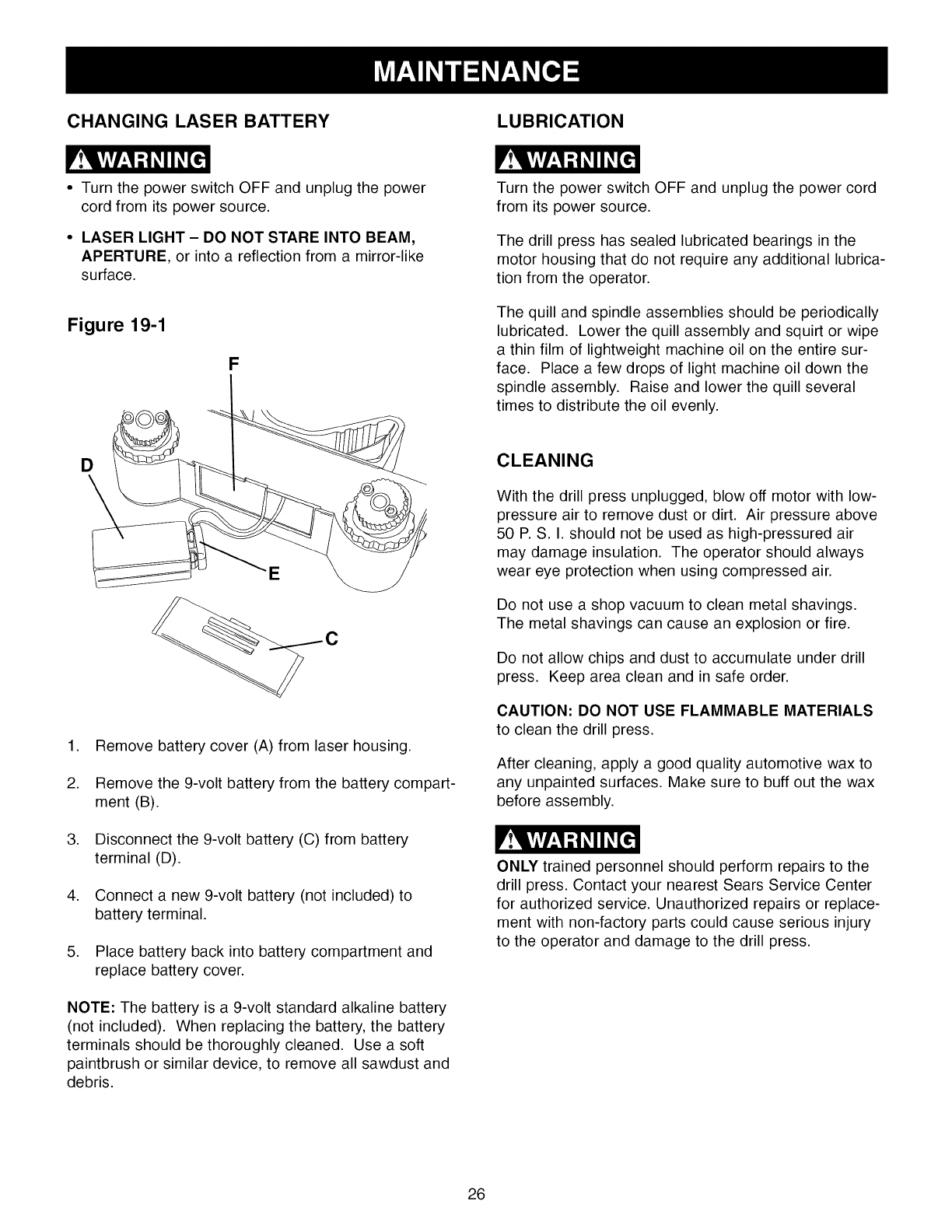
CHANGING LASER BATTERY LUBRICATION
•Turn the power switch OFF and unplug the power
cord from its power source.
•LASER LIGHT - DO NOT STARE INTO BEAM,
APERTURE, or into a reflection from a mirror-like
surface.
Figure 19-1
F
Turn the power switch OFF and unplug the power cord
from its power source.
The drill press has sealed lubricated bearings in the
motor housing that do not require any additional lubrica-
tion from the operator.
The quill and spindle assemblies should be periodically
lubricated. Lower the quill assembly and squirt or wipe
a thin film of lightweight machine oil on the entire sur-
face. Place a few drops of light machine oil down the
spindle assembly. Raise and lower the quill several
times to distribute the oil evenly.
D
E
C
1. Remove battery cover (A) from laser housing.
2. Remove the 9-volt battery from the battery compart-
ment (B).
3. Disconnect the 9-volt battery (C) from battery
terminal (D).
4. Connect a new 9-volt battery (not included) to
battery terminal.
5. Place battery back into battery compartment and
replace battery cover.
NOTE: The battery is a 9-volt standard alkaline battery
(not included). When replacing the battery, the battery
terminals should be thoroughly cleaned. Use a soft
paintbrush or similar device, to remove all sawdust and
debris.
CLEANING
With the drill press unplugged, blow off motor with low-
pressure air to remove dust or dirt. Air pressure above
50 P. S. I. should not be used as high-pressured air
may damage insulation. The operator should always
wear eye protection when using compressed air.
Do not use a shop vacuum to clean metal shavings.
The metal shavings can cause an explosion or fire.
Do not allow chips and dust to accumulate under drill
press. Keep area clean and in safe order.
CAUTION: DO NOT USE FLAMMABLE MATERIALS
to clean the drill press.
After cleaning, apply a good quality automotive wax to
any unpainted surfaces. Make sure to buff out the wax
before assembly.
ONLY trained personnel should perform repairs to the
drill press. Contact your nearest Sears Service Center
for authorized service. Unauthorized repairs or replace-
ment with non-factory parts could cause serious injury
to the operator and damage to the drill press.
26
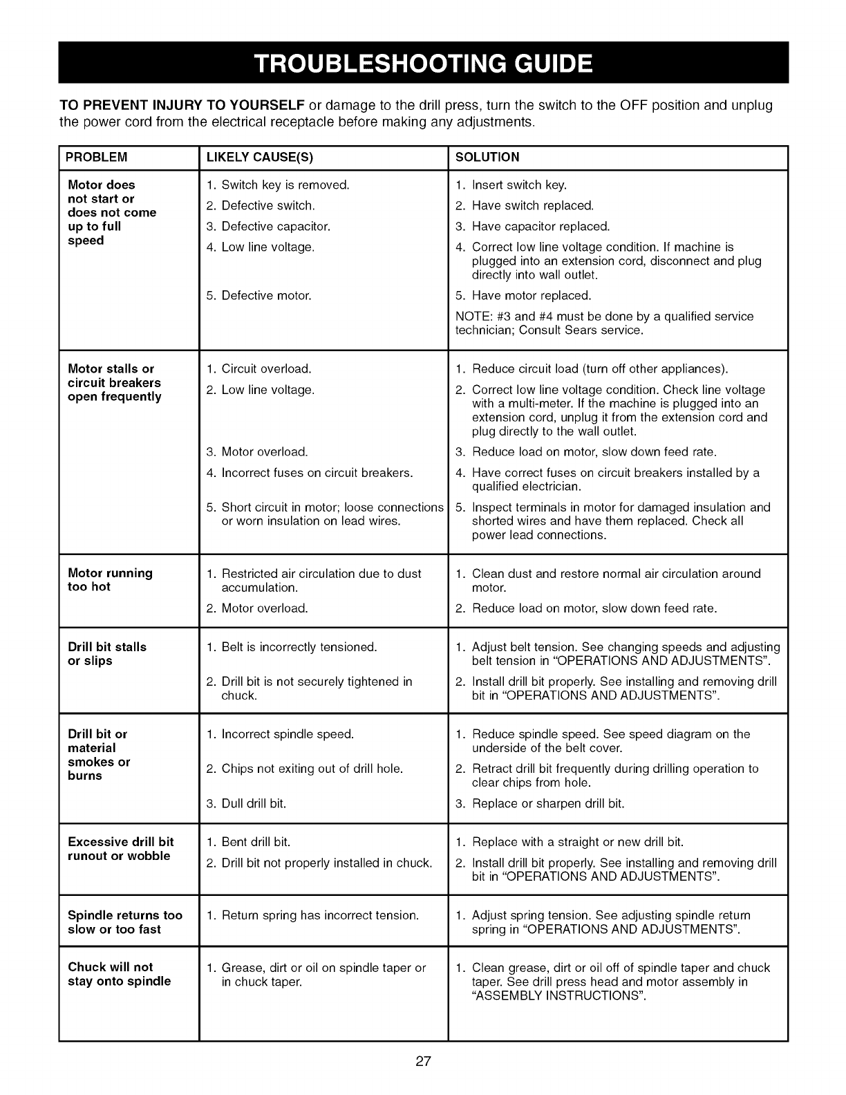
TOPREVENTINJURYTOYOURSELFordamagetothedrillpress,turntheswitchto theOFFpositionandunplug
thepowercordfromtheelectricalreceptaclebeforemakinganyadjustments.
PROBLEM LIKELY CAUSE(S) SOLUTION
Motor does
not start or
does not come
up to full
speed
Motor stalls or
circuit breakers
open frequently
Motor running
too hot
Drill bit stalls
or slips
Drill bit or
material
smokes or
burns
Excessive drill bit
runout or wobble
Spindle returns too
slow or too fast
Chuck will not
stay onto spindle
1. Switch key is removed.
2. Defective switch.
3. Defective capacitor.
4. Low line voltage.
5. Defective motor.
1. Circuit overload.
2. Low line voltage.
3. Motor overload.
4. Incorrect fuses on circuit breakers.
5. Short circuit in motor; loose connections
or worn insulation on lead wires.
1. Restricted air circulation due to dust
accumulation.
2. Motor overload.
1. Belt is incorrectly tensioned.
2. Drill bit is not securely tightened in
chuck.
1. Incorrect spindle speed.
2. Chips not exiting out of drill hole.
3. Dull drill bit.
1. Bent drill bit.
2. Drill bit not properly installed in chuck.
1. Return spring has incorrect tension.
1. Grease, dirt or oil on spindle taper or
in chuck taper.
1. Insert switch key.
2. Have switch replaced.
3. Have capacitor replaced.
4. Correct low line voltage condition. If machine is
plugged into an extension cord, disconnect and plug
directly into wall outlet.
5. Have motor replaced.
NOTE: #3 and #4 must be done by a qualified service
technician; Consult Sears service.
1,
2.
3,
4.
5,
Reduce circuit load (turn off other appliances).
Correct low line voltage condition. Check line voltage
with a multi-meter. If the machine is plugged into an
extension cord, unplug it from the extension cord and
plug directly to the wall outlet.
Reduce load on motor, slow down feed rate.
Have correct fuses on circuit breakers installed by a
qualified electrician.
Inspect terminals in motor for damaged insulation and
shorted wires and have them replaced. Check all
power lead connections.
1. Clean dust and restore normal air circulation around
motor.
2. Reduce load on motor, slow down feed rate.
1,
2.
Adjust belt tension. See changing speeds and adjusting
belt tension in "OPERATIONS AND ADJUSTMENTS".
Install drill bit properly. See installing and removing drill
bit in "OPERATIONS AND ADJUSTMENTS".
1,
2.
3.
Reduce spindle speed. See speed diagram on the
underside of the belt cover.
Retract drill bit frequently during drilling operation to
clear chips from hole.
Replace or sharpen drill bit.
1. Replace with a straight or new drill bit.
2. Install drill bit properly. See installing and removing drill
bit in "OPERATIONS AND ADJUSTMENTS".
1. Adjust spring tension. See adjusting spindle return
spring in "OPERATIONS AND ADJUSTMENTS".
1. Clean grease, dirt or oil off of spindle taper and chuck
taper. See drill press head and motor assembly in
"ASSEMBLY INSTRUCTIONS".
27

15=in.Drill Press MODEL NO. 351.229000
When servicing, use only CRAFTSMAN replacement parts. Use of any other parts may create a HAZARD or cause
product damage.
Any attempt to repair or replace electrical parts on this drill press may create a HAZARD unless a qualified service
technician does repairs. Repair service is available at your nearest Sears Service Center.
Always order by PART NUMBER, not by key number.
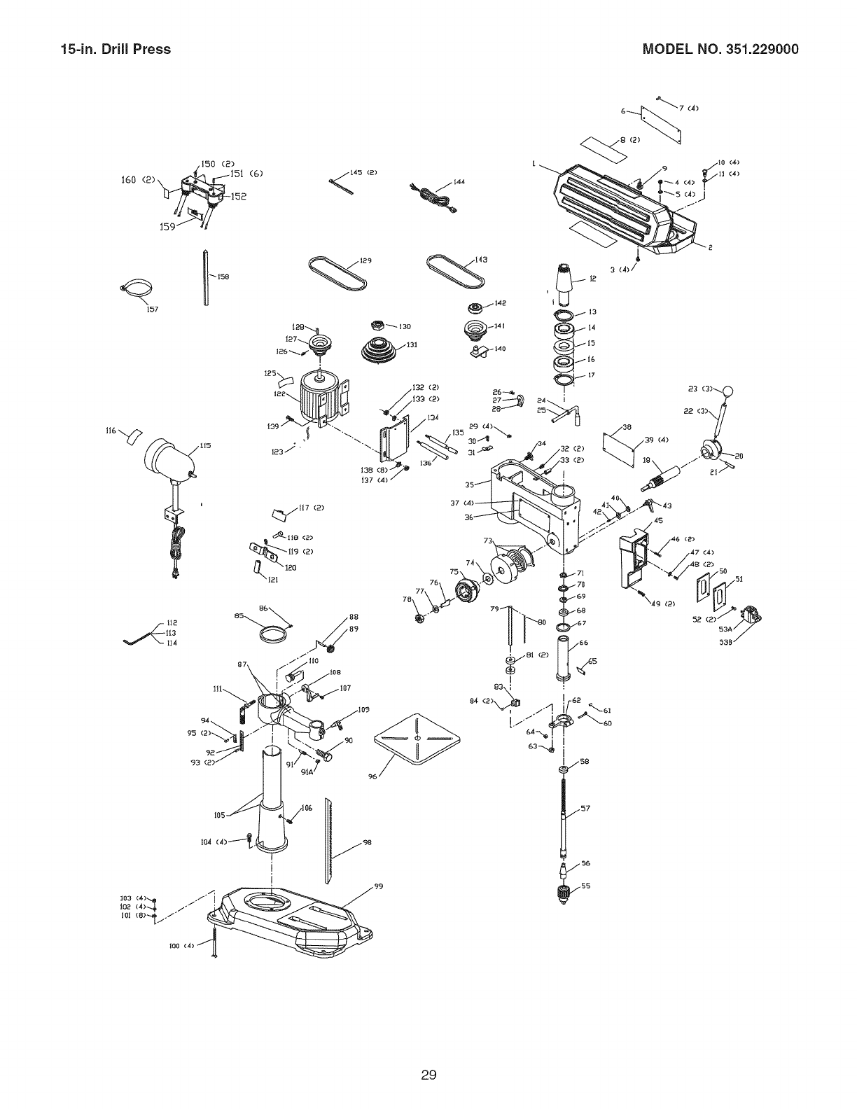
KEY PART KEY PART
NO. NO. DESCRmPTmON QTY. NO. NO.
OR92300 Pulley Cover Assy const of, (1,2,3,4,5,6,7,8,9) 1 81 OR92302
1 OR92301 Upper Pulley Cover 1 83 OR92356
2 OR92304 Bottom Pulley Cover 1 84 OR93531
3 OR91774 M4xl0mm Cheese Hd Screw 4 85 OR92362
4 OR90078 M4 Hex Nut 4 86 OR93552
5 OR90431 M4.3 Ext Tooth Washer 4 87 OR92363
6 OR93451 Speed Chart 1 88 OR92365
7 OR93541 M3.5x9.5mm Pan Hd Tap Screw 4 89 OR92364
8 OR92382 Nameplate 2 90 OR93545
9 OR93542 M4.2xg.5mm Pan Hd Tap Screw 1 91 OR92699
10 OR90241 M6x12mm Cheese Hd Screw 4 91A OR90071
11 OR90059 M6.4 Flat Washer 4 92 OR92367
12 OR92305 Sleeve 1 93 OR92728
13 OR92306 Retaining Ring 1 94 OR92366
14 OR90366 Ball Bearing 6204 1 95 OR92728
15 OR92307 Spacer 1 96 OR92371
16 OR90366 Ball Bearing 6204 1 98 OR92373
17 OR92306 Retaining Ring 1 99 OR92374
OR93549 Pinion Assy const of, (18,20,21 ) 1 100 OR92725
18 OR92333 Pinion 1 101 OR91499
20 OR92334 Hub (R.H.) 1 102 OR90248
21 OR92721 M5x20mm Spring Pin 1 103 OR90307
22 OR92332 Handle 3 104 OR93546
23 OR92331 Knob 3 105 OR92372
24 OR93523 Ext Ret Ring 1 106 OR93524
25 OR92330 Tension Handle 1 107 OR90222
26 OR90310 M8x16mm Hex Hd Screw 1 108 OR92369
27 OR92328 Eccentric 1 109 OR92370
28 OR92329 Pin 1 110 OR92416
29 OR92327 Foam Washer 4 111 OR92368
30 OR90382 M5x16mm Cheese Hd Screw 1 112 OR90290
31 OR92324 Clamp 1 113 OR90289
32 OR93524 M10x12mm Hex Soc Set Screw 2 114 OR93547
33 OR93548 M6x24mm Spring Pin 2 115 OR92375
34 OR92326 Lock Screw 2 116 OR91317
35 OR92323 Headstock incl, (36,37,38,39) 1 OR93795
36 OR93504 Serial Number Label 1
37 OR92728 5ram Drive Screw 4 117 OR92377
38 OR92325 Warning Label 1 118 OR91758
39 OR92728 5ram Drive Screw 4 119 OR90502
40 OR90228 M10 Hex Nut 1 120 OR92376
41 OR90647 3/8" Lock Washer 1 121 OR92487
42 OR92335 Special Screw 1 122 OR92316
43 OR92336 Lock Handle 1 123 OR92320
45 OR92341 Switch Box 1 125 OR93507
46 OR90382 M5x16mm Cheese Hd Screw 2 126 OR90222
47 OR90362 M5.3 Ext Tooth Washer 4 127 OR92313
48 OR90507 M5x8mm Pan Hd Screw 2 128 OR92312
49 OR93543 M5x28mm Pan Hd Screw 2 129 OR92308
50 OR92342 Insulator 1 130 OR92315
51 OR92343 Switch Cover 1 131 OR92314
52 OR90716 M4.2x12mm Pan Hd Tap Screw 2 132 OR93550
53A OR90037 Switch incl (53B) 1 133 OR93539
53B OR90038 Key 1 134 OR92317
55 OR92359 Chuck 1 135 OR92318
56 OR92358 Arbor 1 136 OR92319
57 OR92357 Spindle 1 137 OR90307
58 OR93544 Ball Bearing 6205 1 138 OR91499
60 OR93533 M6x45mm Hex Hd Screw 1 139 OR90308
61 OR90306 M6x12mm Hex Soc Set Screw 1 OR93796
62 OR92350 Stop Collar 1
63 OR93550 M12 x 1.75 Lock Nut 1 140 OR92311
64 OR90235 M6 Hex Nut 1 141 OR92310
65 OR92349 Spindle Adapter Remover 1 142 OR90075
66 OR92348 Quill 1 143 OR92309
67 OR92347 Rubber Washer 1 144 OR92321
68 OR90218 Ball Bearing 6203 1 145 OR92322
69 OR92346 M17.5 Flat Washer 1 150 OR92717
70 OR92345 Ring 1 151 OR92718
71 OR92344 Nut 1 152 OR92428
73 OR92338 Spring Assy with Retainer (OR92337) 1
74 OR92379 Special Flat Washer 1 157 OR92709
75 OR92339 Hub (L.H.) 1 158 OR92710
76 OR92340 Plate 1 159 OR92714
77 OR90304 M12.4 Flat Washer 1 160 OR92731
78 OR93551 M12 x 1.5 Lock Nut 1 161 OR93512
79 OR92351 Depth Rod incl, (80) 1 162 OR93797
80 OR93505 Depth Scale 1 28
DESCRmPTmON QTY.
Knurl nut 2
Mounting Bracket 1
M6x12mm Flat Hd Screw 2
Ring 1
M6x8mm Hex Soc Set Screw 1
Table Bracket Assy incl, (88,89,90,91,92,93,94,95) 1
Shaft 1
Pinion Gear 1
M16x35mm Hex Hd Screw 1
Thread Pin 1
1/4-20 Hex Nut
Scale 1
5ram Drive Screw 2
Indicator 1
5ram Drive Screw 2
Table 1
Rack 1
Base 1
M8x125mm Hex Hd Screw 4
M8.4 Flat Washer 8
M8.1 Lock Washer 4
M8 Hex Nut 4
M10x40mm Hex Hd Screw 4
Column Assy incl, (106) 1
M10x12mm Hex Soc Set Screw 1
M6xl0mm Hex Soc Set Screw 1
Handle Assy 1
Lock Handle Assy (Table) 1
Worm Gear 1
Lock Handle Assy (Column) 1
3ram Hex Wrench 1
2.5mm Hex Wrench 1
5ram Hex Wrench 1
Light Assy incl, (116) 1
Light Warning Label 1
Light Assembly Mounting Hardware
(Consists of Ref. No's.: 117, 118, 119, 120, 121)
Light Cord Clamp 2
M6x16mm Hex Soc Hd Screw 2
M6mm Lock Washer 2
Cord Clamp 1
Cord Sleeve 1
Motor incl, (123, 125) 1
Motor Cord 1
Motor Spec Label 1
M6xl0mm Hex Soc Set Screw 1
Motor Pulley 1
Key 1
Belt (J27) 1
Spindle Pulley Nut 1
Spindle Pulley 1
M12 x 1.75 Lock Nut 2
1/2" Lock Washer 2
Motor Bracket 1
Motor Tension Rod (R.H.) 1
Motor Tension Rod (L.H.) 1
M8 Hex Nut 4
M8.4 Flat Washer 8
M8x20mm Hex Hd Screw 4
Center Pulley Assembly
(Consists of Ref. No's.: 140, 141, 142)
Eccentric 1
Center Pulley 1
Ball Bearing 6202 1
Belt (J25) 1
Power Cord 1
Tie wire 2
M4x14mm Hex Soc Hd Screw 2
M3x14mm Hex Soc Hd Screw 6
Laser Assembly (Includes Key No's.: 150, 151, 152, 157, 1
158, 159, 160)
Hose Clamp 1
Alignment Pin 1
Door 1
Laser Warning Label 2
Owner's Manual (Not Shown) 1
Hardware Pack for #22900 & #22901(Consists of Ref. No's.:
100, 101,102, 103, 104, 112, 113, 114)
15-in. Drill Press MODEL NO. 351.229000
.150 (2)
160 (2)_ 151 (6)
159 _ _d
I12
114
_9 _3
37
73
(4)
(2)
47 (4)
(2)
100 (4)
29

30

anual de Instrucciones
R R
1/2 Caballo de Fuerza (servicio continuo)
12 Velocidades, Polea Escalonada
Gama de Velocidades de Perforaci6n
300-3100 R.P.iVl
TALAD
CO 15 pulg.
con LASER-TRAC _"
iVlodelo No.
351.229000
®
C US
PRECAUCION
PARA SU SEGURIDAD PERSONAL, lea y
obedezca todas las Instrucciones de
Seguridad y Operaci6n antes de operar
esta Taladradora de Banco
Linea deAyudaal Cliente
1-800-266-9079
Sirvase tenet listo su
No, de Modelo y No, de Serie
Sears, Roebuck and Co.
Hoffman Estates, IL 60179 U.S.A.
No. de Pieza OR93512 31 VER. 10.08
SECCl6N PAGINA
Garantfa.........................................................................................................................................................................32
Especificacionesdel producto....................................................................................................................................33
Instruccionesdeseguridad.........................................................................................................................................34
Directficesparalase×tensiones el_ctficas ............................................................................................................... 35
Instrucciones de cone×i6n a tierra ............................................................................................................................. 36
Instrucciones de seguridad especfficas .................................................................................................................... 37
Accesorios y aditamentos ........................................................................................................................................... 38
Conozca su m_quina .................................................................................................................................................. 39
Contenido de la caja .................................................................................................................................................... 41
Instrucciones de montaje ............................................................................................................................................ 43
Operaciones y ajuste ................................................................................................................................................... 48
Mantenimiento .............................................................................................................................................................. 56
Gufa de Iocalizaci6n de averfas .................................................................................................................................. 57
Listado de piezas .......................................................................................................................................................... 58
Informaci6n de servicio .......................................................................................................................... Contraportada
GARANTIA COMPLETA DE UN ANO PARA HERRAMIENTA CRAFTSMAN
Si esta herramienta Craftsman fallara por causa de defectos en el material o en la mano de obra en un lapso de un aSo a partir de
la fecha de compra, LLAME al 1-800-4-MY-HOME® PARA SOLICITAR LA REPARACION
GRATUITA DEL PRODUCTO (o su reemplazo si no se puede reparar la unidad).
Siesta herramienta se usa alguna vez para fines comerciales o de alquiler, esta garantia es v&lida _nicamente por 90 dias a partir
de la fecha de compra.
Esta garantia aplica unicamente mientras la herramienta esta en los Estados Unidos.
Esta garantia le otorga derechos legales especfficos y tambi6n puede usted tenor otros derechos que vafien de estado aestado.
Sears, Roebuck and Co., Hoffman Estates, IL 6017g
32
Taladradora de Banco de 15 pulg. con Tipo de tope de profundidad Quick-Set
Laser=Trac TM Escala de profundidad Si
Especificaciones del Motor: Diametro de columna 2-7/8 pulg. (73 mm)
Servicio continuo 1/2 HP Zona de trabajo bAsica 10-1/4 pulg. de ancho x
Amperios 8.6 8-1/4 pulg. de profundidad
Voltios 120 Profundidad de garganta 7-1/2 pulg.
Fase MonofAsico Alto 67-1/4 pulg.
Hertzios 60 Ancho 12-1/2 pulg.
R.RM. 1725 (sin carga) Profundidad 27-1/2 pulg.
Peso 180 libras
Especificaciones del Producto:
Tipo de correa
Tipo de polea
Tensi6n de correa
NOmero de velocidades
Velocidades de perforaci6n
Ahusado del huso
Ahusado del mandrino
Tipo de mandrino
Capacidad del mandrino
Dimensi6n mandrino a mesa,
rain.
Dimensi6n mandrino a mesa,
mAx.
Dimensi6n mandrino a base
DiAmetro del Arbol hueco
Recorrido del arbol hueco
Cierre del Arbol hueco
Operaci6n de agarradera
Control del motor
Dimensiones de mesa
Inclinaci6n de mesa
Movimiento de mesa
Material de mesa
Tope de profundidad
Poly "V"
Escalonada
Motor deslizante
12
300, 400, 450, 600, 650,
700, 1100, 1600, 1700,
1900, 2600, 3100
Ahusado Morse #2
Jacobs 3
Sin Ilave
0.040-5/8 pulg. (1-16 mm)
0 pulg.
24 pulg.
49-3/4 pulg.
1-7/8 pulg. (47 mm)
4 pulg.
Si
Rotaci6n a 360 grados
Interruptor de palanca con
Ilave desmontable
12 pulg. de ancho x
12 pulg. de profundidad
Si
Cremallera y pi_6n
Hierro moldeado
Si
Conveniencia:
Luz Si, montaje en el costado
izquierdo o derecho
LAser Si
Use la protecci6n adecuada de circuitos para evitar los
choques el6ctricos y el da_o a la taladradora. No la exponga
a la Iluvia ni haga uso de ella en entornos h0medos.
La taladradora viene cableada de fabrica para el funciona-
miento a 120 V, 60 Hz. Conectela a un circuito de derivaci6n
de 120 V, 15 amperios y utilice un fusible de retardaci6n de
tiempo o un disyuntor de circuitos de 15 amperios. El circuito
el6ctrico no podrA tener un tama_o de alambre inferior al #14.
Para evitar choques el6ctricos o incendios, reponga el cord6n
de energia tan pronto como quede da_ado de cualquier
manera.
LA PROPOSICION DE CALIFORNIA 65
Parte del polvo que se crea usando las herramientas el6ctric-
as contiene productos quimicos que el estado de California
reconoce como causantes de cancer, defectos de nacimiento,
o da_os en el sistema reproductivo. Algunos ejemplos de
estos productos quimicos son:
El plomo de pinturas con base de plomo
El Silic6n cristalino de ladrillos, cemento, y de otros
productos de alba_ileria
El ars6nico y el cromo de la madera de construcci6n
quimicamente tratada
El riesgo de estas exposiciones varia, dependiendo de cuan-
tas veces se realiza este tipo de trabajo. Para reducir tu
exposici6n a estos productos quimicos, trabaje en un Area
bien ventilada, y trabaje con el equipo aprobado de seguri-
dad, tal como mascaras dise_adas para el polvo.
33
INSTRUCCIONES GENERALES
DE SEGURIDAD
El uso de una taladradora puede ser peligroso si se hace
caso omiso de la seguridad y el sentido comOn. El operario
debe estar familiarizado con el funcionamiento de esta herra-
mienta. Lea este manual para entender esta taladradora. NO
OPERE esta taladradora si no entiende plenamente las limita-
ciones de esta herramienta. NO MODIFIQUE este taladradora
de ninguna manera. RECUERDE: Su seguridad personal es
su responsabilidad.
ANTES DE HACER USO
DE LA TALADRADORA
Lea y obedezca todas las instrucciones de Seguridad y
Operaci6n antes de operar la taladradora para evitar heridas
graves y da_o a la herramienta.
1,
2,
3.
4,
5,
Parte del polvo que se crea usando las herramientas
el_ctricas contiene productos quimicos que el estado de
California reconoce como causantes de cancer, defectos
de nacimiento, o da_os en el sistema reproductivo.
Algunos ejemplos de estos productos quimicos son:
• El plomo de pinturas con base de plomo
• El Silic6n cristalino de ladrillos, cemento, y de otros
productos de alba_ileria
• El arsenico y el cromo de la madera de construcci6n
quimicamente tratada
El riesgo de estas exposiciones varia, dependiendo de
cuantas veces se realiza este tipo de trabajo. Para
reducir tu exposici6n a estos productos quimicos, trabaje
en un Area bien ventilada, y trabaje con el equipo
aprobado de seguridad, tal como mascaras dise_adas
para el polvo.
LEA el Manual de Instrucciones cabalmente. APRENDA
como usar la herramienta para su aplicaci6n propuesta.
UTILICE PROTECCION OCULAR SIEMPRE. Cualquier
herramienta mecanica puede expulsar escombros hacia
los ojos durante las operaciones, causando daSo ocular
grave y permanente. Los anteojos de uso cotidiano NO
son gafas de seguridad. Utilice gafas de seguridad (que
cumplan con la normativa Z87.1 de ANSI) SIEMPRE
cuando vaya a operar herramientas mecanicas. Las
gafas de seguridad estan disponibles en las tiendas de
Ventas al Detal de Sears.
UTILICE PROTECCION AUDITIVA SIEMPRE. El algo-
d6n por si solo no constituye un dispositivo de protecci6n
aceptable. El equipo auditivo debe cumplir con las
normativas $3.1 9 de ANSI.
UTILICE SIEMPRE UNA CARETA CONTRA EL POLVO
PARA EVITAR ASPIRAR POLVOS PELIGROSOS O
PART|CULAS EN EL AIRE, incluyendo polvo de madera,
polvo de silice cristalino y polvo de asbesto. Dirija las
particulas en direcci6n opuesta al rostro y el cuerpo.
Opere la herramienta siempre en una zona bien ventilada
y proporcione la remoci6n apropiada del polvo. Utilice un
sistema de recolecci6n de polvo siempre que sea posi-
ble. La exposici6n al polvo puede ocasionar daSos respi-
ratorios graves y permanentes u otras heridas, incluyen-
do silicosis (una enfermedad pulmonar grave), cancer y
la muerte. Evite aspirar el polvo y evite el contacto pro-
Iongado con el polvo. El permitir la entrada del polvo en
su boca u ojos, o dejar que permanezca sobre su piel,
puede promover la absorci6n de material daSino. Utilice
protecci6n respiratoria aprobada por NIOSH/OSHA, de
ajuste correcto y apropiada para la exposici6n al polvo, y
lave las zonas expuestas con jab6n y agua.
6. Mantenga la zona de trabajo limpia, bien iluminada y
organizada EN TODO MOMENTO. NO trabaje en un
entorno con superficies de piso resbalosas debido a los
escombros, grasas y cera.
7. Desenchufe la herramienta del tomacorrientes SIEMPRE
que vaya a realizar cualquier ajuste, recambio de piezas
o Ilevar a cabo cualquier tarea de mantenimiento.
8. EVITE LOS ARRANQUES ACCIDENTALES. AsegtJrese
de que el interruptor de energia se encuentre en la posi-
ci6n de "OFF" (apagado) antes de enchufar el cord6n de
potencia y causar daSo a la herramienta.
9. EVlTE UN ENTORNO DE TRABAJO PELIGROSO. NO
utilice las herramientas el_ctricas en entornos htJmedos
ni las exponga a la Iluvia.
10. HAGA SU TALLER A PRUEBA DE NINOS al quitar las
Ilaves de los interruptores, desenchufando las herramien-
tas de sus tomacorrientes y usando candados.
11. NO utilice herramientas el_ctricas en la presencia de
liquidos o gases inflamables.
12. NO FUERCE LA HERRAMIENTA a realizar una
operaci6n para la que no fue diseSada. Realizara un
trabajo mas seguro y de mayor calidad s61o efectuando
aquellas operaciones para las que fue diseSada.
13. NO se pare sobre la herramienta. Esto podria resultar en
heridas graves si la herramienta se vuelca o si usted
hace contacto accidental con la herramienta.
14.
15.
16.
NO almacene nada sobre o cerca de la herramienta
donde alguien pueda intentar pararse sobre la herra-
mienta para alcanzarlo.
NO opere la herramienta si se encuentra bajo la influen-
cia del alcohol o de las drogas.
EN TODA YCADA OCASION, REVISE SI EXISTEN
PIEZAS DANADAS ANTES DE OPERAR LA HERRA-
MIENTA. Revise todos los protectores cuidadosamente
para asegurarse de que funcionen correctamente, que no
esten daSados, y que realicen sus funciones destinadas.
Revise la alineaci6n y busque la atascadura o ruptura de
todas las piezas en movimiento. Un protector, una pieza
de inserci6n u otra pieza daSada debe repararse y susti-
tuirse inmediatamente.
17. CONECTE TODAS LAS HERRAMIENTAS ATIERRA.
Si la herramienta viene equipada con un enchufe de tres
machos, se le debe enchufar en un tomacorrientes de
tres contactos. El tercer macho se utiliza para conectar la
herramienta a tierra y ofrecer protecci6n contra los
choques el_ctricos accidentales. NO quite el tercer
macho. Ver Instrucciones de Conexi6n a Tierra.
18. MANTENGA ALEJADOS A LOS VlSlTANTES Y NINOS
de la taladradora. NO permita que haya gente en la zona
inmediata de trabajo, sobre todo cuando la herramienta
el_ctrica se encuentre en funcionamiento.
34
19. MANTENGA TODOS LOS PROTECTORES EN SUS
SITIOS Y EN BUENAS CONDICIONES DE TRABAJO.
20. MANTENGA SU EQUILIBRIO. NO se extienda sobre la
herramienta. Utilice calzado con suelas de caucho y
resistentes al aceite. Mantenga el piso despejado de
escombros, grasas o cera.
21. MANTENGA SUS HERRAMIENTAS CON CUIDADO.
Mantenga sus herramientas limpias yen buen estado de
funcionamiento siempre. Mantenga filosas todas las
hojas y las brocas.
22. NUNCA DEJE UNA M/_,QUlNA EN FUNClONAMIENTO
SIN ATENDER. Apague el interruptor de energia a la
posici6n de "OFF" (apagado). NO se aleje de la maquina
hasta que se haya detenido por completo.
23. RETIRE TODAS LAS HERRAMIENTAS DE MANTENI-
MIENTO de la zona inmediata antes de ENCENDER la
herramienta.
24. AFIANCE TODO EL TRABAJO. Cuando sea posible,
haga uso de abrazaderas o plantillas para posicionar
para afianzar el material. Esto resulta mas seguro que
intentar sujetar el material con sus manos.
25. MANTE_NGASE ALERTA, mire Io que esta haciendo y
tenga sentido comtJn cuando vaya a hacer uso de una
herramienta mecanica. NO UTILICE una herramienta
cuando este cansado ni bajo la influencia de drogas,
alcohol o medicamentos. Un momento de inatenci6n
durante el uso de herramientas mecanicas puede resultar
en heridas personales graves.
26. SOLO UTILICE LOS ACCESORIOS RECOMENDADOS.
El uso de accesorios incorrectos o indebidos puede
resultar en heridas graves al operario y causar daSo a la
herramienta. Si tiene dudas, consulte el manual de
instrucciones que viene con ese accesorio en particular.
27. UTILICE UNA EXTENSION ELI_CTRICA EN BUEN
ESTADO. Cuando vaya a hacer uso de una extensi6n
el_ctrica, asegtJrese de utilizar una que sea Io suficiente-
mente pesada como para portar la corriente requerida
por su producto. Tenga la bondad de ver el cuadro
"CALIBRES MINIMOS RECOMENDADOS PARA LAS
EXTENSIONES ELC:CTRICAS (AWG)" para el dimen-
sionamiento correcto de una extensi6n el_ctrica. Si tiene
dudas, utilice el pr6ximo calibre mas pesado.
28. UTILICE LA VESTIMENTA CORRECTA. NO utilice ropa
holgada, guantes, corbatas ni articulos de joyeria. Estos
articulos pueden quedar atrapados en la maquina
durante las operaciones y arrastrar al operario hacia las
piezas en movimiento. El usuario debe Ilevar una cubier-
ta protectiva sobre su cabello, si tiene cabello largo, para
protegerlo contra el contacto con cualquier pieza en
movimiento.
DIRECTRICES PARA LAS
EXTENSIONES ELI CTRICAS
Mientras menor sea el ntJmero de calibre, mayor sera el
diametro de la extensi6n el_ctrica. Si tiene dudas sobre las
dimensiones correctas de una extensi6n el_ctrica, utilice una
extensi6n mas corta y gruesa. Una extensi6n de tama_o
reducido producira un baj6n en la tensi6n de linea, resultando
en la p@dida de energia y el sobrecalentamiento. USE SOLO
UNA EXTENSION ELI_OTRIOA DE TRES ALAMBRES CON
ENCHUFE DE CONEXlON A TIERRA DE TRES MACHOS Y
UN RECEPT/_,CULO DE TRES MACHOS QUE ACEPTE EL
ENCHUFE DE LA HERRAMIENTA.
Si va a hacer uso de una extension electrica a la intem-
perie, este seguro de que este marcado con el sufijo "W-A"
("W" en Canada,) para indicar que es aceptable para el uso a
la intemperie.
Este seguro de que su extension electrica tenga las
dimensiones correctas y este en buen estado de funciona-
miento. Reponga siempre una extensi6n el_ctrica da_ada o
haga que una persona competente la repare antes de hacer
uso de ella.
Proteja sus extensiones electricas contra los objetos
filosos, el calor excesivo y los lugares htJmedas o mojadas.
FUNCIONAMIENTO A 120 VOLTIOS SOLAMENTE
0 to 6 Amperios
6 to 10 Amperios
10 to 12 Amperios
12 to 15 Amperios
25 PIES DE
LARGO
18 AWG
18 AWG
16 AWG
14 AWG
50 PIES DE
LARGO
16 AWG
16 AWG
16 AWG
12 AWG
100 PIES DE
LARGO
16 AWG
14 AWG
14 AWG
No se
recomienda
35
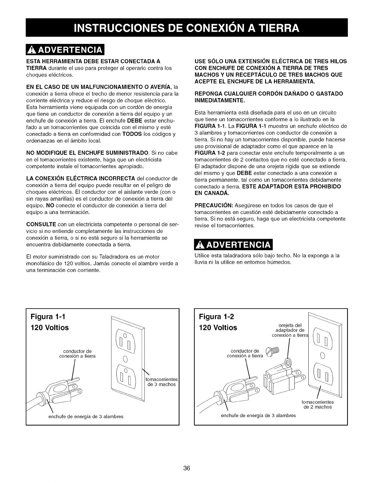
ESTA HERRAMIENTA DEBE ESTAR CONECTADA A
TIERRA durante el uso para proteger al operario contra los
choques el_ctricos.
EN EL CASO DE UN MALFUNCIONAMIENTO O AVER|A, la
conexi6n a tierra ofrece el trecho de menor resistencia para la
corriente el_ctrica y reduce el riesgo de choque el_ctrico.
Esta herramienta viene equipada con un cord6n de energia
que tiene un conductor de conexi6n a tierra del equipo y un
enchufe de conexi6n a tierra. El enchufe DEBE estar enchu-
fado a un tomacorrientes que coincida con el mismo y este
conectado a tierra en conformidad con TODOS los c6digos y
ordenanzas en el ambito local.
NO MODIFIQUE EL ENCHUFE SUMINISTRADO. Si no cabe
en el tomacorrientes existente, haga que un electricista
competente instale el tomacorrientes apropiado.
LA CONEXION ELI_CTRICA INCORRECTA del conductor de
conexi6n a tierra del equipo puede resultar en el peligro de
choques el_ctricos. El conductor con el aislante verde (con o
sin rayas amarillas) es el conductor de conexi6n a tierra del
equipo. NO conecte el conductor de conexi6n a tierra del
equipo a una terminaci6n.
CONSULTE con un electricista competente o personal de ser-
vicio si no entiende completamente las instrucciones de
conexi6n a tierra, o si no esta seguro si la herramienta se
encuentra debidamente conectada a tierra.
El motor suministrado con su Taladradora es un motor
monofasico de 120 voltios. Jamas conecte el alambre verde a
una terminaci6n con corriente.
USE SC)LO UNA EXTENSIC)N ELI_CTRICA DE TRES HILOS
CON ENCHUFE DE CONEXIC)N ATIERRA DE TRES
MACHOS Y UN RECEPT/_,CULO DE TRES MACHOS QUE
ACEPTE EL ENCHUFE DE LA HERRAMIENTA.
REPONGA CUALQUIER CORDC)N DANADO O GASTADO
INMEDIATAMENTE.
Esta herramienta esta diseSada para el uso en un circuito
que tiene un tomacorrientes conforme a Io ilustrado en la
FIGURA 1-1. La FIGURA 1-1 muestra un enchufe el_ctrico de
3 alambres y tomacorrientes con conductor de conexi6n a
tierra. Si no hay un tomacorrientes disponible, puede hacerse
uso provisional de adaptador como el que aparece en la
FIGURA 1-2 para conectar este enchufe temporalmente a un
tomacorrientes de 2 contactos que no este conectado a tierra.
El adaptador dispone de una orejeta rigida que se extiende
del mismo y que DEBE estar conectado a una conexi6n a
tierra permanente, tal como un tomacorrientes debidamente
conectado a tierra. ESTE ADAPTADOR ESTA PROHIBIDO
EN CANADA.
PRECAUCION: AsegtJrese en todos los casos de que el
tomacorrientes en cuesti6n este debidamente conectado a
tierra. Si no esta seguro, haga que un electricista competente
revise el tomacorrientes.
Utilice esta taladradora s61o bajo techo. No la exponga a la
Iluvia ni la utilice en entornos htJmedos.
Figura 1-1
120 Voltios
conductor de
conexi6n a tierra 0
enchufe de energia de 3 alambres
\
tomacorrientes
de 3 machos
Figura 1-2
120 Voltios orejeta del
adaptador de
conexion a tierra
conductor de (_
conexi6n a tierra 0
tomacorrientes
de 2 machos
enchufe de energia de 3 alambres
36
INSTRUCCIONES ESPECiFICAS
DE SEGURIDAD
El uso de cualquier taladradora puede expulsar escombros
hacia los ojos durante las operaciones, Io que puede causar
daSo ocular grave y permanente. UTILICE PROTECCION
OCULAR SIEMPRE. El uso de cualquier herramienta
mecanica puede expulsar escombros durante las opera-
ciones, Io que puede causar daSo ocular grave y permanente.
Los anteojos cotidianos NO son gafas de seguridad. Utilice
Gafas de Seguridad (que cumplan con la normativa Z87.1 de
ANSI) SIEMPRE cuando vaya a operar herramientas mecani-
cas. Las gafas de seguridad estan disponibles en las tiendas
de Ventas al Detal de Sears.
Deben seguirse ciertas precauciones basicas durante el uso
de su taladradora. Para reducir el riesgo de heridas, choques
el_ctricos o incendios, cumpla con las reglas de seguridad
que aparecen a continuaci6n:
1,
2,
3,
4,
5,
6,
7,
LEA y entienda el manual de instrucciones antes de
operar esta herramienta meca,nica.
EVITE LAS OPERACIONES Y POSICIONES DE MANO
TORPES. Un desliz repentino puede resultar en heridas
graves.
REVISE todas las brocas, herramientas de corte, tam-
bores de lijado u otros accesorios antes de instalarlas en
el mandrino de la taladradora por si existen seSales de
daSo. Los articulos daSados pueden producir daSo a la
taladradora y/o heridas graves.
Antes de alejarse de la taladradora, ClERRE CON CAN-
DADO oDESMONTE el interruptor /Ilave de ENCENDI-
DO /APAGADO para evitar el uso desautorizado.
NO instale ni use cualquier broca que sobrepase las
7 pulgadas de largo o que se extienda a 6 pulgadas por
debajo de las mandibulas del mandrino. La broca podra
torcerse y romperse repentinamente.
NO intente perforar un material que sea demasiado
pequeSo para ser firmemente afianzado a la mesa o con
una prensa.
NO opere esta taladradora hasta que este montada e
instalada conforme al manual de instrucciones.
8,
9,
NO deje la taladradora enchufada al tomacorrientes.
Desenchufe la taladradora del tomacorrientes cuando no
se encuentre en uso, y antes del servicio, recambie las
brocas y realice la limpieza.
NO USE brocas recortadoras, cortadoras limadoras,
cortadoras circulares (volantes), cepilladoras rotativas
o ruedas de alambre con esta taladradora.
10.
11.
OBEDEZCA todos los c6digos el_ctricos y de seguridad,
incluyendo el C6digo El_ctrico Nacional (NEC) y los
Reglamentos de Seguridad y Salud en el Trabajo
(OSHA). Todas las conexiones y cableado deben ser
realizadas por personal competente solamente.
PERMITA QUE EL MANDRINO ALCANCE VELOCIDAD
PLENA antes de comenzar las operaciones de per-
foraci6n.
12. ASEGURESE de que no existan objetos extra_os, clavos
ni piedras en el material.
13.
14.
JAMAS REALICE LABORES DE TRAZADO, ENSAM-
BLADO O MONTAJE sobre la mesa /zona de trabajo
cuando la maquina este funcionando.
JAMAS ARRANQUE LA TALADRADORA SIN ANTES
HABER DESPEJADO TODOS LOS OBJETOS DE LA
MESA (herramientas, trozos de material descartado,
etc.). Los escombros podran ser expulsados a alta
velocidad.
15. JAMAS ARRANQUE LA M/_,QUINA con la broca, la
herramienta de corte o el tambor de lijado contra el
material. La p_rdida de control del material puede resul-
tar en heridas graves.
16. ASESORESE CON SU SUPERVISOR, instructor u otra
persona capacitada si no esta familiarizado con las
operaciones de esta taladradora.
17.
18.
19.
20.
21.
22.
23.
24.
25.
APOYE CORRECTAMENTE los materiales largos o
anchos y suj_telos a la mesa con abrazaderas.
AFIANCE CORRECTAMENTE la broca, la herramienta
de corte o el tambor de lijado en el mandrino antes de
operar la taladradora.
REPONGA cualquier cord6n da_ado inmediatamente.
NO utilice un cord6n o enchufe da_ado. Si la taladradora
no funciona correctamente, o si se ha da_ado, dejado a
la intemperie o entrado en contacto con agua, devu_lvala
a un centro de servicio Sears.
AFIANCE la taladradora al suelo o a un banco de traba-
jo. Las vibraciones pueden hacer que la maquina se
deslice, camine o se vuelque.
AFIANCE el material firmemente contra la mesa. No
intente perforar un material que no tenga una superficie
plana contra la mesa, o que no este afianzada con un
tornillo de banco. Impida que el material gire abrazandolo
a la mesa o afianzandolo contra la columna de la prensa.
La p_rdida de control sobre el material puede resultar en
heridas graves.
ENCLAVE el apoyo del cabezal y de la mesa a la colum-
na firmemente, y la mesa al apoyo de la mesa, antes de
operar la taladradora.
La taladradora esta diseSada para el uso domestico o el
uso comercial ligero SOLAMENTE.
PARA REDUClR EL PELIGRO DE LOS CHOQUES
ELI_CTRICOS, no use la herramienta a la intemperie. No
la exponga a la Iluvia. Almacenela bajo techo.
APAGUE LA TALADRADORA y desenchtJfela de la
fuente de energfa. Espere a que la broca, herramienta de
corte o tambor de lijado dejen de girar antes de limpiar la
mesa/zona de trabajo, retirar o asegurar el material, o
cambiar el montaje.
26. USE s61o brocas, herramientas cortantes, tambores de
lijado u otros accesorios con el tamaSo de espiga
recomendada en este manual de servicio. El accesorio
de tamaSo incorrecto puede ocasionar daSo a la tala-
dradora y/o heridas graves.
27. SOLO utilice esta maquina de acuerdo con este manual
de instrucciones. SOLO utilice los accesorios recomen-
dados por Sears.
37
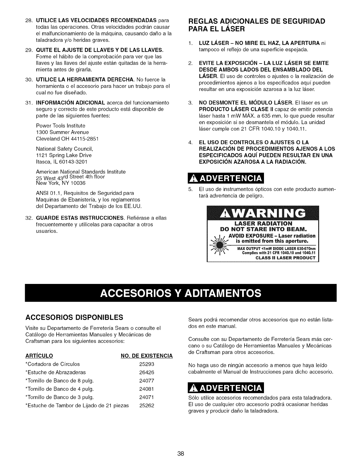
28.
29.
30.
31.
32.
UTILICE LAS VELOCIDADES RECOMENDADAS para
todas las operaciones. Otras velocidades podran causar
el malfuncionamiento de la maquina, causando daSo a la
taladradora y/o heridas graves.
QUITE EL AJUSTE DE LLAVES Y DE LAS LLAVES.
Forme el habito de la comprobaci6n para ver que las
Ilaves y las Ilaves del ajuste estan quitadas de la herra-
mienta antes de girarla.
UTILICE LA HERRAMIENTA DERECHA. No fuerce la
herramienta o el accesorio para hacer un trabajo para el
cual no fue diseSado.
INFORMAClON ADIClONAL acerca del funcionamiento
seguro y correcto de este producto esta disponible de
parte de las siguientes fuentes:
Power Tools Institute
1300 Summer Avenue
Cleveland OH 44115-2851
National Safety Council,
1121 Spring Lake Drive
Itasca, IL 60143-3201
American National Standards Institute
25 West 43rd Street 4th floor
New York, NY 10036
ANSI 01.1, Requisitos de Seguridad para
Maquinas de Ebanisteria, y los reglamentos
del Departamento del Trabajo de los EE.UU.
GUARDE ESTAS INSTRUCClONES. Refi_rase a elias
frecuentemente y utilicelas para capacitar a otros
usuarios.
REGLAS ADICIONALES DE SEGURIDAD
PARA EL LASER
1. LUZ LASER- NO MIRE EL HAZ, LAAPERTURA ni
tampoco el reflejo de una superficie espejada.
2. EVITE LA EXPOSICION - LA LUZ LASER SE EMITE
DESDE AMBOS LADOS DEL ENSAMBLADO DEL
LASER. El uso de controles oajustes o la realizaci6n de
procedimientos ajenos a los especificados aqui pueden
resultar en una exposici6n azarosa a la luz laser.
3. NO DESMONTE EL MODULO LASER. El laser es un
PRODUCTO LASER CLASE II capaz de emitir potencia
laser hasta 1 mW MAX. a 635 mm, Io que puede resultar
en exposici6n si se desmantela el m6dulo. La unidad
laser cumple con 21 CFR 1040.10 y 1040.11.
4. EL USO DE CONTROLES OAJUSTES OLA
REALIZAClON DE PROCEDIMIENTOS AJENOS A LOS
ESPEClFICADOS AQU| PUEDEN RESULTAR EN UNA
EXPOSlClON AZAROSA A LA RADIAClON.
5. El uso de instrumentos 6pticos con este producto aumen-
tara advertencia de peligro.
ILASER RADiATiON
DO NOT STARE iNTO BEAM.
.I.# AVOID EXPOSURE -Laser radiation
is emitted from this aperture,
/"r \ Complies wilh 21 CFR 1040.t0 and 1040,11
CLASS II LASER PRODUCT
ACCESORIOS DISPONIBLES
Visite su Departamento de Ferreteria Sears o consulte el
Catalogo de Herramientas Manuales y Mecanicas de
Craftsman para los siguientes accesorios:
ARTiCULO
*Cortadora de Circulos
*Estuche de Abrazaderas
*Tornillo de Banco de 8 pulg.
*Tornillo de Banco de 4 pulg.
*Tornillo de Banco de 3 pulg.
*Estuche de Tambor de Lijado de 21 piezas
NO. DE EXISTENClA
25293
26426
24077
24081
24071
25262
Sears podra recomendarotros accesorios que no estanlista-
dos en este manual.
Consulte con su Departamento de Ferreteria Sears mas cer-
cano o su Catalogo de Herramientas Manuales y Mecanicas
de Craftsman para otros accesorios.
No haga uso de ningtJn accesorio a menos que haya leido
cabalmente el Manual de Instrucciones para dicho accesorio.
S61o utilice accesorios recomendados para esta taladradora.
El uso de cualquier otro accesorio podra ocasionar heridas
graves y producir daSo la taladradora.
38
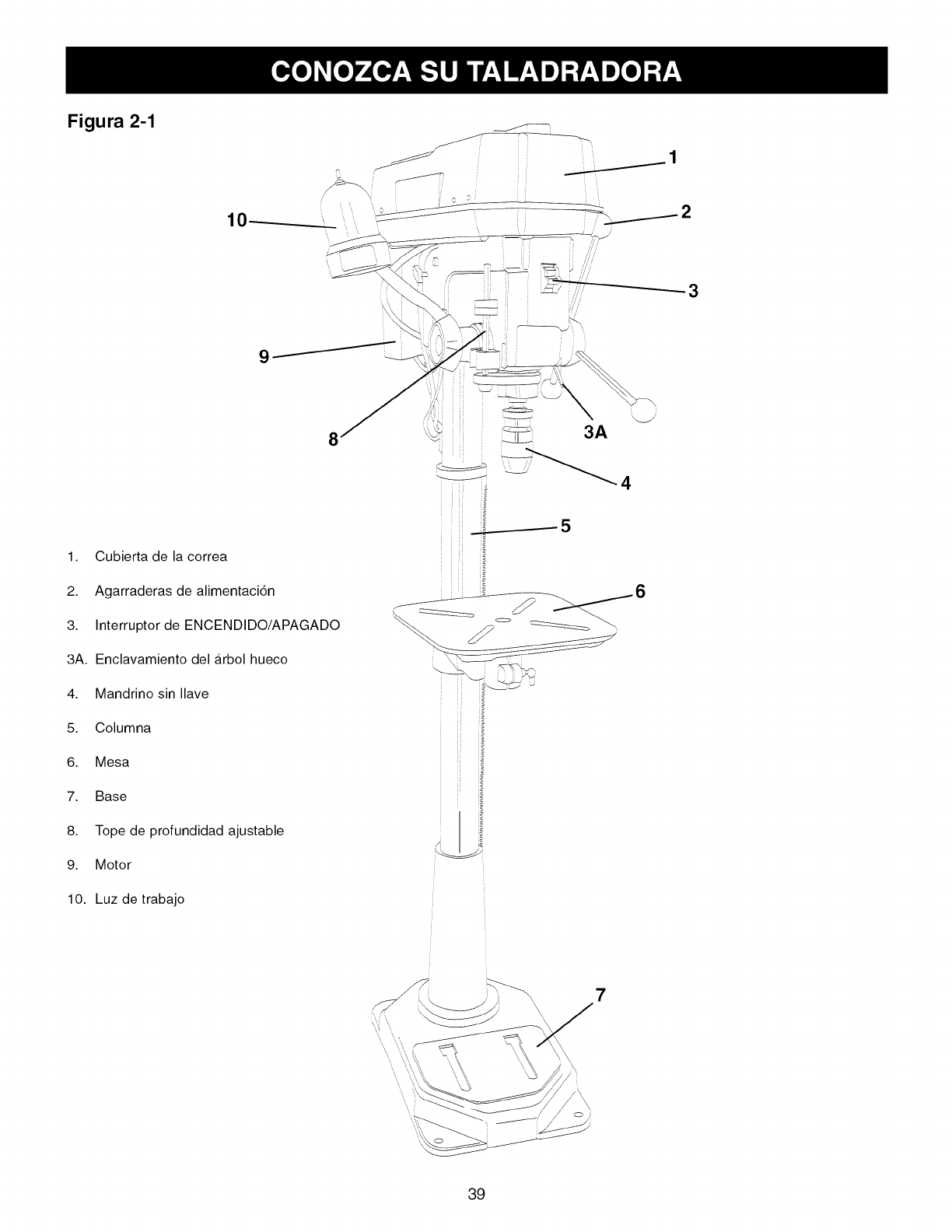
Figura 2-1
10
j_
jS __ 1
f
1. Cubiertade lacorrea
2. Agarraderas de alimentaci6n
3. Interruptor de ENCENDIDO/APAGADO
3A. Enclavamiento del firbol hueco
4. Mandrino sin Ilave
5. Columna
6. Mesa
7. Base
8. Tope de profundidad ajustable
9. Motor
10. Luz de trabajo
FJ
#
\
3A
7
39
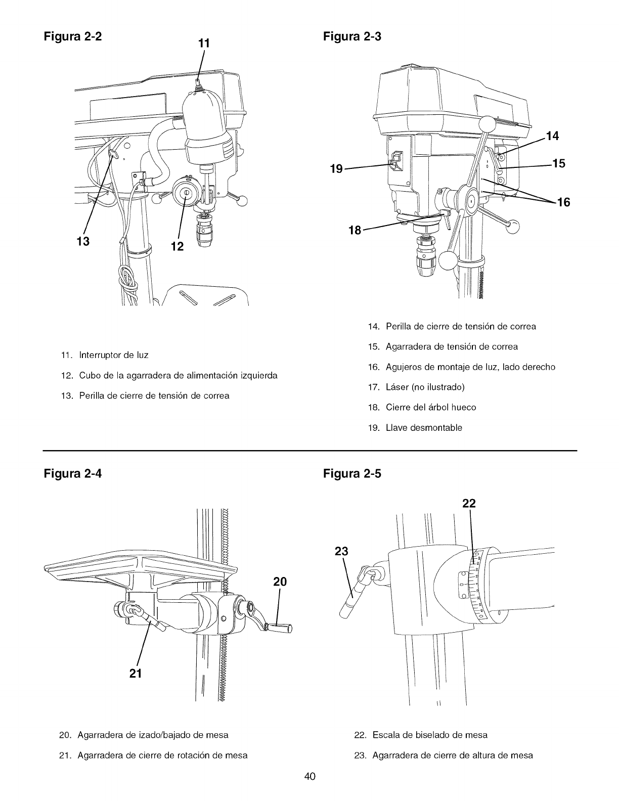
Figura 2-2 11
11. Interruptor de luz
12. Cubo de la agarradera de alimentaci6n izquierda
13. Perilla de cierre de tensi6n de correa
Figura 2-3
1c.
18
14. Perilla de cierre de tensi6n de correa
15. Agarradera de tensi6n de correa
16. Agujeros de montaje de luz, lado derecho
17. LAser (no ilustrado)
18. Cierre del arbol hueco
19. Llave desmontable
16
Figura 2-4 Figura 2-5
2O
23
22
21
20. Agarradera de izado/bajado de mesa
21. Agarradera de cierre de rotaci6n de mesa
22. Escala de biselado de mesa
23. Agarradera de cierre de altura de mesa
40
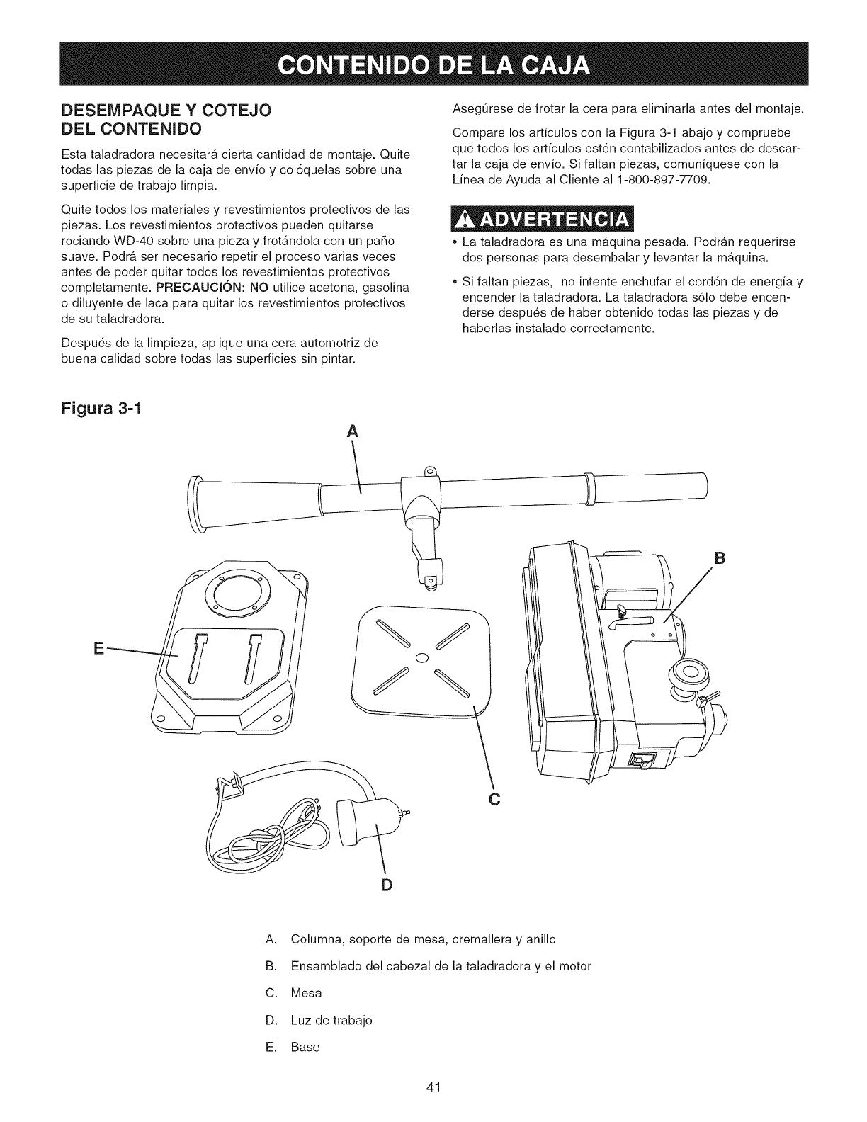
DESENIPAQUE YCOTEJO
DEL CONTENIDO
Esta taladradora necesitara cierta cantidad de montaje. Quite
todas las piezas de la caja de envfo y col6quelas sobre una
superficie de trabajo limpia.
Quite todos los materiales y revestimientos protectivos de las
piezas. Los revestimientos protectivos pueden quitarse
rociando WD-40 sobre una pieza y frot_.ndola con un paso
suave. Podr_, ser necesario repetir el proceso varias veces
antes de poder quitar todos los revestimientos protectivos
completamente. PRECAUCl6N: NO utilice acetona, gasolina
o diluyente de laca para quitar los revestimientos protectivos
de su taladradora.
Despu_s de la limpieza, aplique una cera automotriz de
buena calidad sobre todas las superficies sin pintar.
AsegOrese de frotar la cera para eliminarla antes del montaje.
Compare los artfculos con la Figura 3-1 abajo y compruebe
que todos los artfculos esten contabilizados antes de descar-
tar la caja de envfo. Si faltan piezas, comunfquese con la
Linea de Ayuda al Cliente al 1-800-897-7709.
,, La taladradora es una maquina pesada. PodrAn requerirse
dos personas para desembalar y levantar la m_.quina.
• Si faltan piezas, no intente enchufar el cord6n de energia y
encender la taladradora. La taladradora s61o debe encen-
derse despu_s de haber obtenido todas las piezas y de
haberlas instalado correctamente.
Figura 3-1
A
E
C
)
B
A. Columna, soporte de mesa, cremallera y anillo
B. Ensamblado del cabezal de la taladradora y el motor
C. Mesa
D. Luz de trabajo
E. Base
41
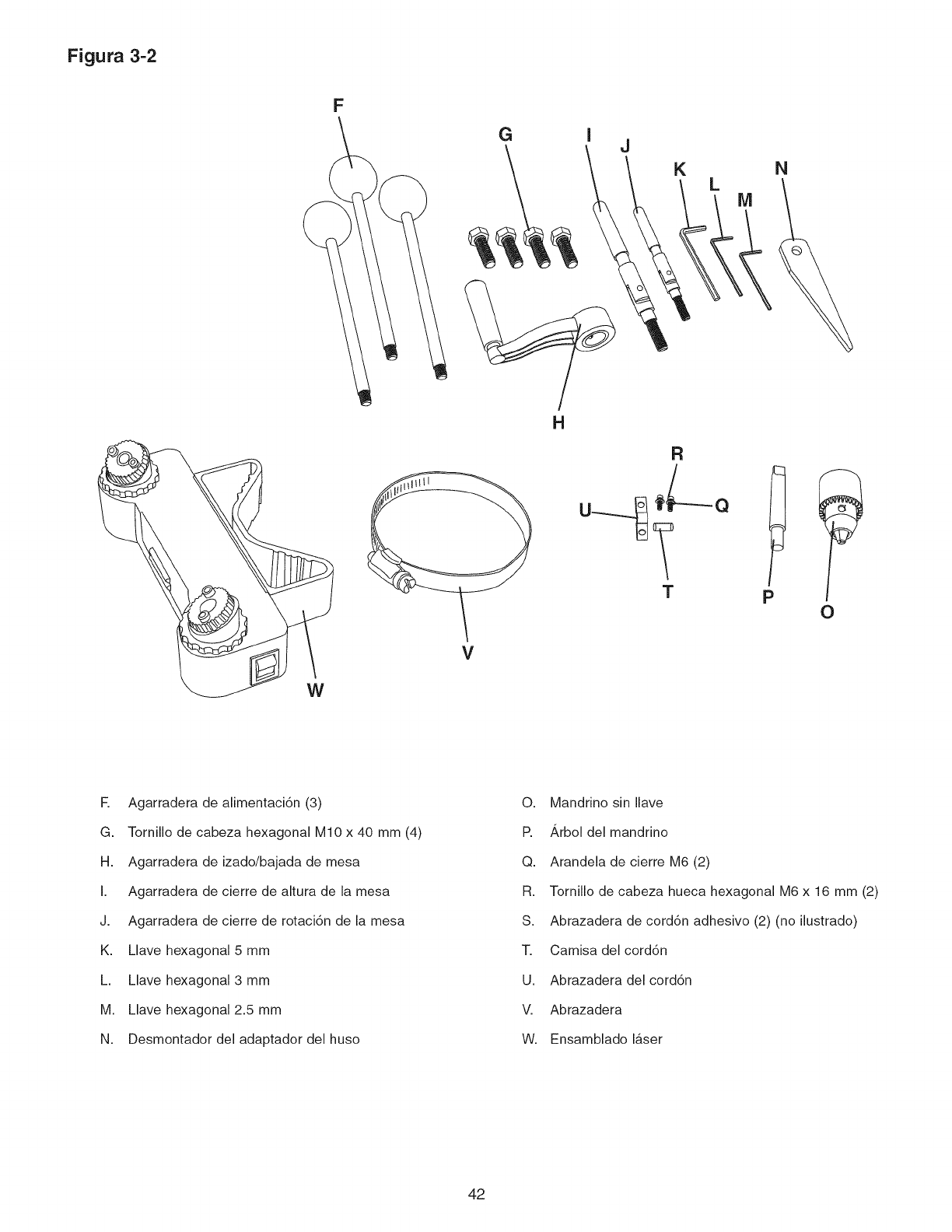
Figura 3-2
F
W
G I
H
V
J
K N
L
R
M
T p O
R Agarradera de alimentaci6n (3)
G. Tornillo de cabeza hexagonal M10 x 40 mm (4)
H. Agarradera de izado/bajada de mesa
I. Agarradera de cierre de altura de la mesa
J. Agarradera de cierre de rotaci6n de la mesa
K. Llave hexagonal 5 mm
h Llave hexagonal 3 mm
M. Llave hexagonal 2.5 mm
N. Desmontador del adaptador del huso
O. Mandrino sin Ilave
R,_rbol del mandrino
Q. Arandela de cierre M6 (2)
R. Tornillo de cabeza hueca hexagonal M6 x 16 mm (2)
S. Abrazadera de cord6n adhesivo (2) (no ilustrado)
T. Camisa del cord6n
U. Abrazadera del cord6n
V. Abrazadera
W. Ensamblado laser
42
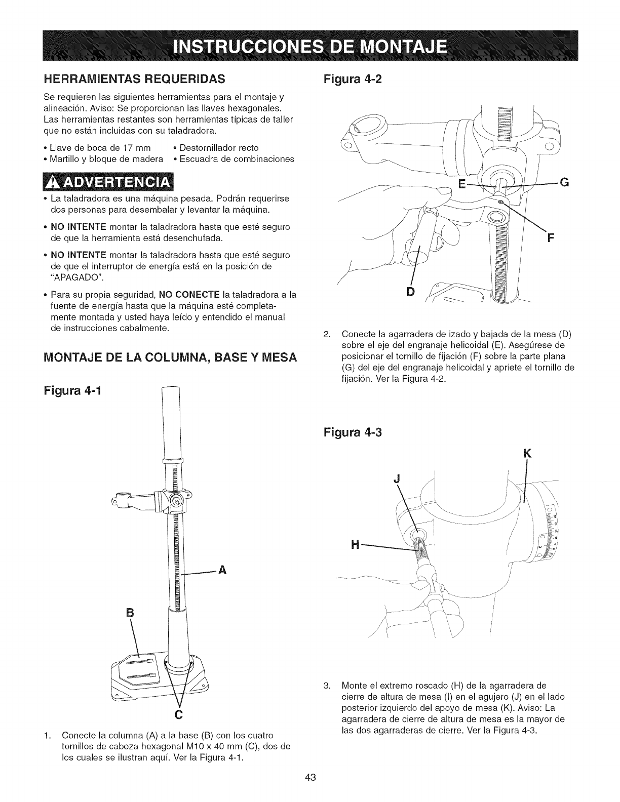
HERRAMIENTAS REQUERIDAS
Se requieren las siguientes herramientas para el montaje y
alineaci6n. Aviso: Se proporcionan las Ilaves hexagonales.
Las herramientas restantes son herramientas tipicas de taller
que no estan incluidas con su taladradora.
• Llave de boca de 17 mm • Destornillador recto
Martillo y bloque de madera • Escuadra de combinaciones
• La taladradora es una maquina pesada. PodrAn requerirse
dos personas para desembalar y levantar la m_.quina.
• NO INTENTE montar la taladradora hasta que est6 seguro
de que la herramienta est& desenchufada.
• NO INTENTE montar la taladradora hasta que est_ seguro
de que el interruptor de energia est& en la posici6n de
"APAGADO".
• Para su propia seguridad, NO CONECTE la taladradora a la
fuente de energia hasta que la maquina est6 completa-
mente montada y usted haya leido y entendido el manual
de instrucciones cabalmente.
MONTAJE DE LA COLUMNA, BASE Y MESA
Figura 4-1
B
1,
C
Conecte la columna (A) a la base (B) con los cuatro
tornillos de cabeza hexagonal M10 x 40 mm (C), dos de
los cuales se ilustran aqui. Ver la Figura 4-1.
Figura 4-2
F
D
2, Conecte la agarradera de izado y bajada de la mesa (D)
sobre el eje del engranaje helicoidal (E). Aseg_rese de
posicionar el tornillo de fijaci6n (F) sobre la parte plana
(G) del eje del engranaje helicoidal y apriete el tornillo de
fijaci6n. Ver la Figura 4-2.
Figura 4-3
J
K
/
/
3, Monte el extremo roscado (H) de la agarradera de
cierre de altura de mesa (I) en el agujero (J) en el lado
posterior izquierdo del apoyo de mesa (K). Aviso: La
agarradera de cierre de altura de mesa es la mayor de
las dos agarraderas de cierre. Ver la Figura 4-3.
43
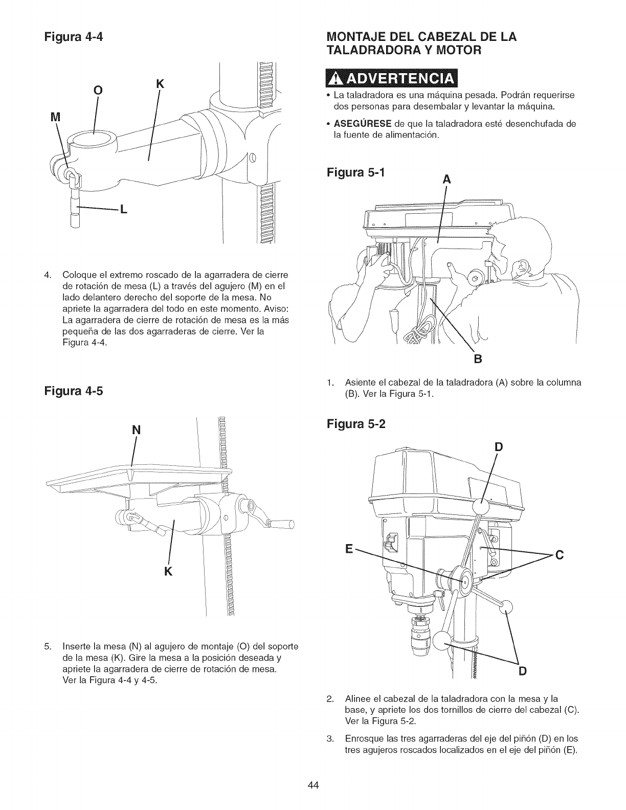
Figura 4=4
K
MONTAJE DEL CABEZAL DE LA
TALADRADORA Y MOTOR
,, La taladradora es una maquina pesada. Podran requerirse
dos personas para desembalar y levantar la m_.quina.
• ASEGURESE de que la taladradora est6 desenchufada de
la fuente de alimentaci6n.
Figura 5-1 A
4, Coloque el extremo roscado de la agarradera de cierre
de rotaci6n de mesa (L) a trav_s del agujero (M) en el
lado delantero derecho del soporte de la mesa. No
apriete la agarradera del todo en este momento. Aviso:
La agarradera de cierre de rotaci6n de mesa es la m_.s
peque_a de las dos agarraderas de cierre. Ver la
Figura 4-4.
Figura 4-5 1,
B
Asiente el cabezal de la taladradora (A) sobre la columna
(B). Ver la Figura 5-1.
N
K
Figura 5-2
D
5, Inserte la mesa (N) al agujero de montaje (O) del soporte
de la mesa (K). Gire la mesa a la posici6n deseada y
apriete la agarradera de cierre de rotaci6n de mesa.
Ver la Figura 4-4 y 4-5. D
2,
3,
Alinee el cabezal de la taladradora con la mesa y la
base, y apriete los dos tornillos de cierre del cabezal (C).
Ver la Figura 5-2.
Enrosque las tres agarraderas del eje del pi_6n (D) en los
tres agujeros roscados Iocalizados en el eje del pi_6n (E).
44
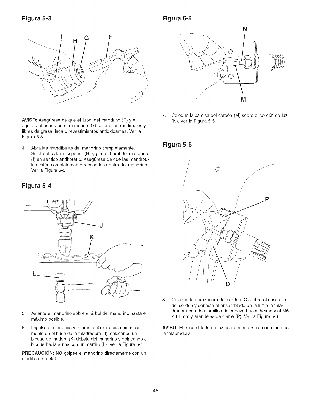
Figura 5-3 Figura 5-5
G F
H
N
AVlSO: AsegOrese de que el arbol del mandrino (F) y el
agujero ahusado en el mandrino (G) se encuentren limpios y
libres de grasa, laca o revestimientos antioxidantes. Ver la
Figura 5-3.
4. Abra las mandibulas del mandrino completamente.
Sujete el collarin superior (H) y gire el barril del mandrino
(I) en sentido antihorario. Aseg_rese de que las mandibu-
las est6n completamente recesadas dentro del mandrino.
Ver la Figura 5-3.
7. Coloque la camisa del cord6n (M) sobre el cord6n de luz
(N). Ver la Figura 5-5.
Figura 5-6
©
Figura 5-4
P
L
0
5. Asiente el mandrino sobre el arbol del mandrino hasta el
maximo posible.
6. Impulse el mandrino y el arbol del mandrino cuidadosa-
mente en el huso de la taladradora (J), colocando un
bloque de madera (K) debajo del mandrino y golpeando el
bloque hacia arriba con un martillo (L). Ver la Figura 5-4.
PRECAUCION: NO golpee el mandrino directamente con un
martillo de metal.
8. Coloque la abrazadera del cord6n (O) sobre el casquillo
del cord6n y conecte el ensamblado de la luz a la tala-
dradora con dos tornillos de cabeza hueca hexagonal M6
x 16 mm y arandelas de cierre (P). Ver la Figura 5-6.
AVlSO: El ensamblado de luz podr_, montarse a cada lado de
la taladradora.
45
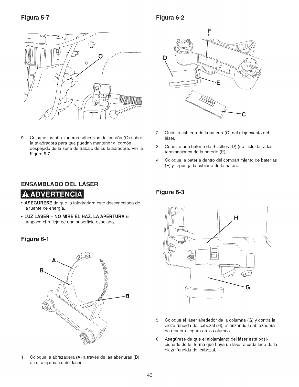
Figura 5-7 Figura 6-2
©
F
C
9, Coloque las abrazaderas adhesivas del cord6n (Q) sobre
la taladradora para que puedan mantener al cord6n
despejado de la zona de trabajo de su taladradora. Ver la
Figura 5-7.
2,
3,
4,
Quite la cubierta de la bateria (C) del alojamiento del
laser.
Conecte una bateria de 9-voltios (D) (no incluida) alas
terminaciones de la bateria (E).
Coloque la bateria dentro del compartimiento de baterias
(F) y reponga la cubierta de la bateria.
ENSAMBLADO DEL LASER
•ASEGURESE de que la taladradora est6 desconectada de
la fuente de energia.
• LUZ LASER - NO MIRE EL HAZ, LA APERTURA ni
tampoco el reflejo de una superficie espejada.
Figura 6-1
Figura 6-3
H
1, Coloque la abrazadera (A) a trav6s de las aberturas (B)
en el alojamiento del laser.
5,
6,
Coloque el laser alrededor de la columna (G) y contra la
pieza fundida del cabezal (H), afianzando la abrazadera
de manera segura en la columna.
AsegQrese de que el alojamiento del laser est6 posi-
cionado de tal forma que haya un laser a cada lado de la
pieza fundida del cabezal.
46
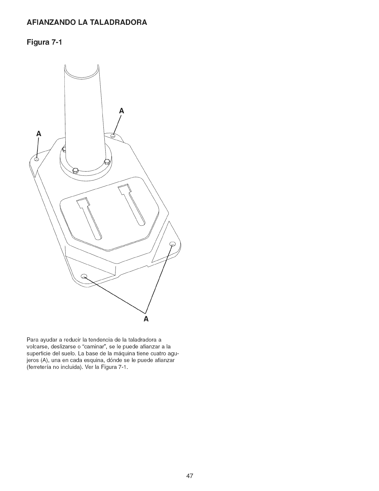
AFIANZANDO LA TALADRADORA
Figura 7-1
A
A
A
Para ayudar a reducir la tendencia de la taladradora a
volcarse, deslizarse o "caminar", se le puede afianzar a la
superficie del suelo. La base de la maquina tiene cuatro agu-
jeros (A), una en cada esquina, d6nde se le puede afianzar
(ferreteria no incluida). Ver la Figura 7-1.
47
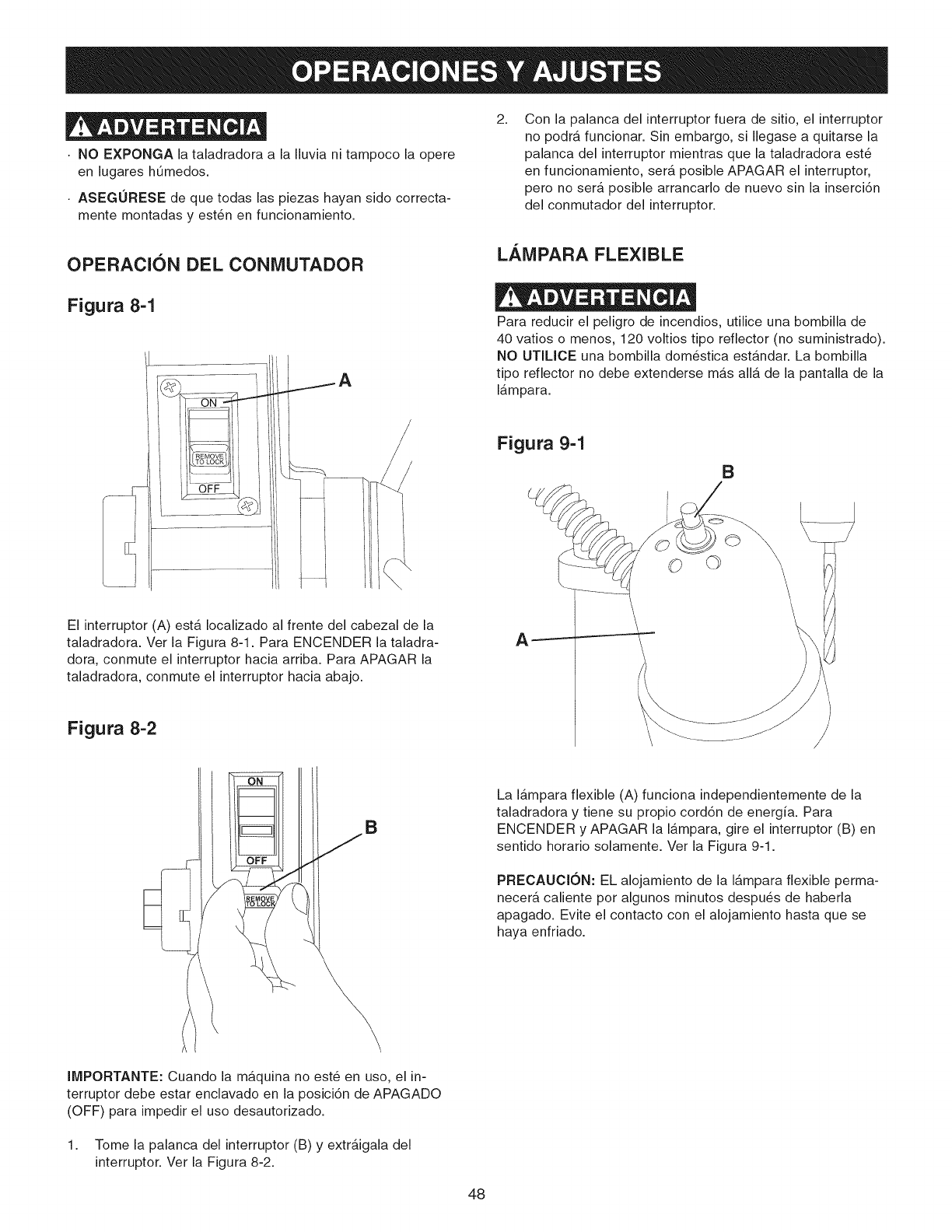
NO EXPONGA la taladradora a la Iluvia ni tampoco la opere
en lugares hQmedos.
ASEGURESE de que todas las piezas hayan sido correcta-
mente montadas y est6n en funcionamiento.
2, Con la palanca del interruptor fuera de sitio, el interruptor
no podra funcionar. Sin embargo, si Ilegase a quitarse la
palanca del interruptor mientras que la taladradora est6
en funcionamiento, ser_. posible APAGAR el interruptor,
pero no sera posible arrancarlo de nuevo sin la inserci6n
del conmutador del interruptor.
OPERACI6N DEL CONMUTADOR
Figura 8-1
\
El interruptor (A) esta Iocalizado al frente del cabezal de la
taladradora. Vet la Figura 8-1. Para ENCENDER la taladra-
dora, conmute el interruptor hacia arriba. Para APAGAR la
taladradora, conmute el interruptor hacia abajo.
Figura 8-2
LAMPARA FLEXIBLE
Para reducir el peligro de incendios, utilice una bombilla de
40 vatios o menos, 120 voltios tipo reflector (no suministrado).
NO UTILICE una bombilla dom_stica est_.ndar. La bombilla
tipo reflector no debe extenderse mas alia de la pantalla de la
lampara.
Figura 9-1
B
B
La lampara flexible (A) funciona independientemente de la
taladradora y tiene su propio cord6n de energfa. Para
ENCENDER y APAGAR la lampara, gire el interruptor (B) en
sentido horario solamente. Ver la Figura 9-1.
PRECAUCI6N: EL alojamiento de la lampara flexible perma-
necerA caliente por algunos minutos despu_s de haberla
apagado. Evite el contacto con el alojamiento hasta que se
haya enfriado.
IMPORTANTE: Cuando la m_.quina no est_ en uso, el in-
terruptor debe estar enclavado en la posici6n de APAGADO
(OFF) para impedir el uso desautorizado.
1. Tome la palanca del interruptor (B) y extr_.igala del
interruptor. Ver la Figura 8-2.
48
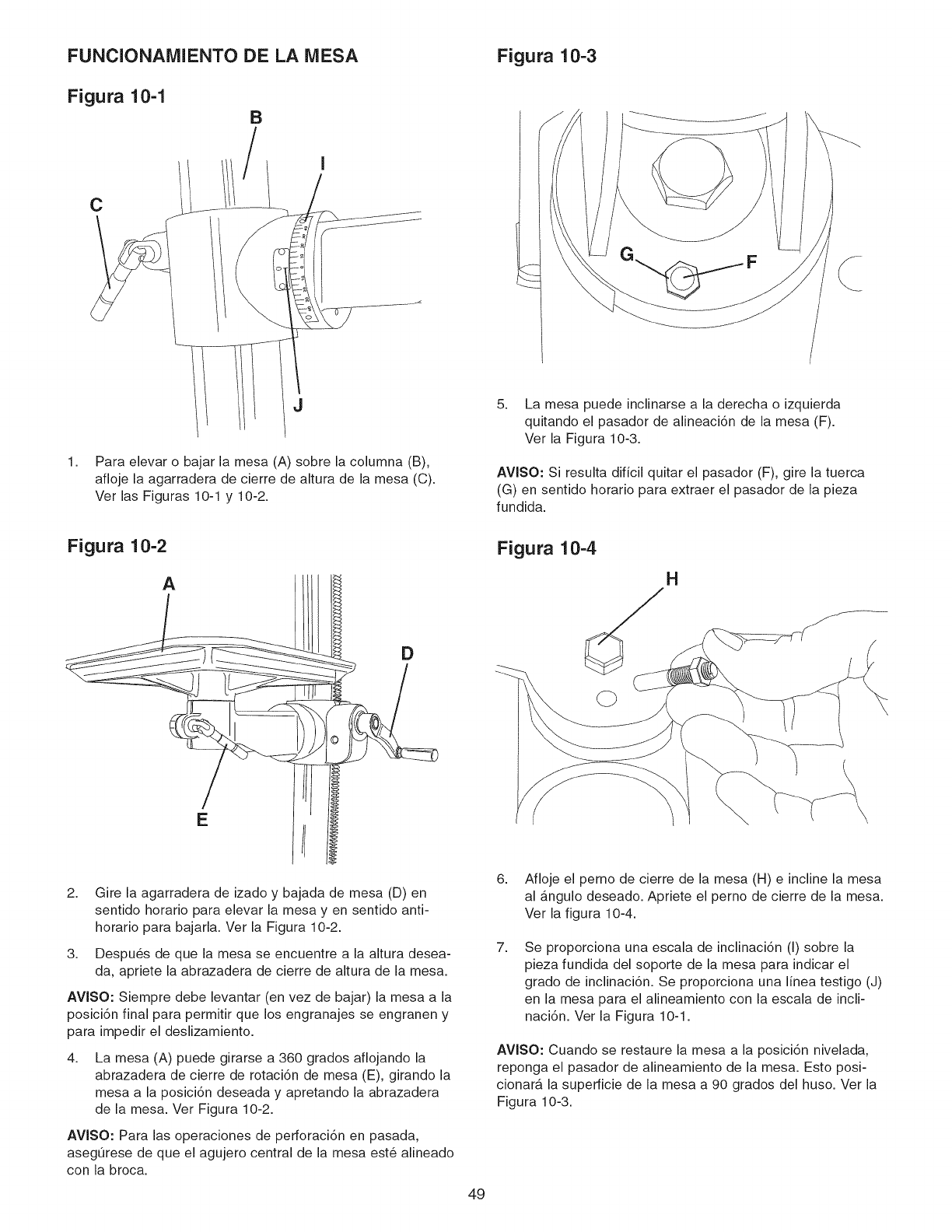
FUNCIONAMIENTO DE LA MESA
Figura 10-1 B
1,
C
J
I
Para elevar o bajar la mesa (A) sobre la columna (B),
afloje la agarradera de cierre de altura de la mesa (C).
Ver las Figuras 10-1 y 10-2.
Figura 10-3
5. La mesa puede inclinarse a la derecha o izquierda
quitando el pasador de alineaci6n de la mesa (F).
Ver la Figura 10-3.
AVISO: Si resulta dificil quitar el pasador (F), gire la tuerca
(G) en sentido horario para extraer el pasador de la pieza
fundida.
Figura 10-2
A
E
D
Figura 10-4
H
2. Gire la agarradera de izado y bajada de mesa (D) en
sentido horario para elevar la mesa yen sentido anti-
horario para bajarla. Ver la Figura 10-2.
3. Despu_s de que la mesa se encuentre a la altura desea-
da, apriete la abrazadera de cierre de altura de la mesa.
AVISO: Siempre debe levantar (en vez de bajar) la mesa a la
posici6n final para permitir que los engranajes se engranen y
para impedir el deslizamiento.
4, La mesa (A) puede girarse a 360 grados aflojando la
abrazadera de cierre de rotaci6n de mesa (E), girando la
mesa a la posici6n deseada y apretando la abrazadera
de la mesa. Ver Figura 10-2.
AVISO: Para las operaciones de perforaci6n en pasada,
asegOrese de que el agujero central de la mesa est6 alineado
con la broca.
49
6. Afloje el perno de cierre de la mesa (H) e incline la mesa
al angulo deseado. Apriete el perno de cierre de la mesa.
Ver la figura 10-4.
7, Se proporciona una escala de inclinaci6n (I) sobre la
pieza fundida del soporte de la mesa para indicar el
grado de inclinaci6n. Se proporciona una linea testigo (J)
en la mesa para el alineamiento con la escala de incli-
naci6n. Ver la Figura 10-1.
AVlSO: Cuando se restaure la mesa a la posici6n nivelada,
reponga el pasador de alineamiento de la mesa. Esto posi-
cionarA la superficie de la mesa a 90 grados del huso. Ver la
Figura 10-3.
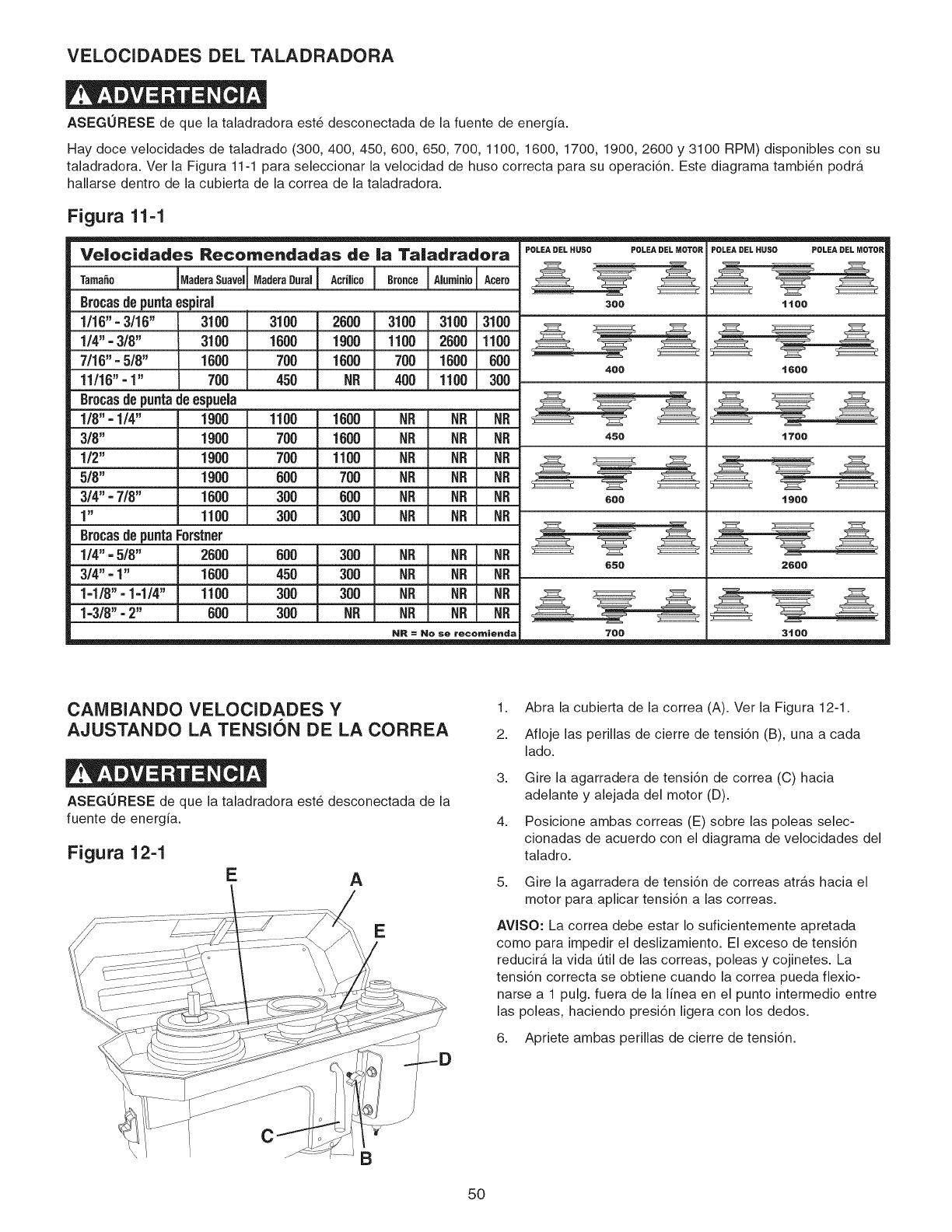
VELOCIDADES DEL TALADRADORA
ASEGURESE de que la taladradora est6 desconectada de la fuente de energia.
Hay doce velocidades de taladrado (300, 400, 450, 600, 650, 700, 1100, 1600, 1700, 1900, 2600 y 3100 RPM) disponibles con su
taladradora. Ver la Figura 11-1 para seleccionar la velocidad de huso correcta para su operaciTn. Este diagrama tambi6n podra
hallarse dentro de la cubierta de la correa de la taladradora.
Figura 11-1
Velocidades Recomendadas de |a Taiadradora
1/8" = 1/4"
3/8"
1/2"
5/8"
3/4" =7/8"
1"
Tama_o MaderaSuavel
grocasde punta espiral
1/16" = 3/16" 3100
1/4" - 3/8" 3100
7/16" = 5/8" 1600
11/16" = 1" 700
grocasde punta deespuela
1900
1900
1900
1900
1600
1100
Brocasde puntaForstner
1/4" = 5/8" 2000
3/4" = 1" 1600
1=1/8" = 1=1/4" 1100
1=3/8" =2" 600
.0°o.00..0,!A0.,,,oo! ..o°ooIA,°o,°,o!Ao0.o
3100 2600 3100 3100 3100
1600 1900 1100 2600 1100
700 1600 700 1600 600
450 NR 400 1100 300
1100 1600 NR NR NR
700 1600 NR NR NR
700 1100 NR NR NR
600 700 NR NR NR
300 600 NR NR NR
300 300 NR NR fir
600 300 NR NR NR
450 300 NR NR NR
300 300 NR NR NR
300 NR NR NR NR
NR = No se recomienda
POLEA DEL HUSO POLEA IBEL MOTOR
300
400
450
600
650
706
POLEA DEL HUSO POLEA DEL MOTOR
ttoo
t6oo
1700
1900
2600
3tOO
CAiVIBIANDO VELOCIDADES Y
AJUSTANDO LA TENSION DE LA CORREA
ASEGURESE de que la taladradora est6 desconectada de la
fuente de energia.
Figura 12-1 EA
E
\
B
1. Abra la cubierta de la correa (A). Ver la Figura 12-1.
2. Afloje las perillas de cierre de tensi6n (B), una a cada
lado.
3.
4.
Gire la agarradera de tensi6n de correa (C) hacia
adelante y alejada del motor (D).
Posicione ambas correas (E) sobre las poleas selec-
cionadas de acuerdo con el diagrama de velocidades del
taladro.
5. Gire la agarradera de tensi6n de correas atr_.s hacia el
motor para aplicar tensi6n a las correas.
AVlSO: La correa debe estar Io suficientemente apretada
como para impedir el deslizamiento. El exceso de tensiTn
reducira la vida Otilde las correas, poleas y cojinetes. La
tensiTn correcta se obtiene cuando la correa pueda flexio-
narse a 1 pulg. fuera de la linea en el punto intermedio entre
las poleas, haciendo presiTn ligera con los dedos.
6. Apriete ambas perillas de cierre de tensi6n.
50
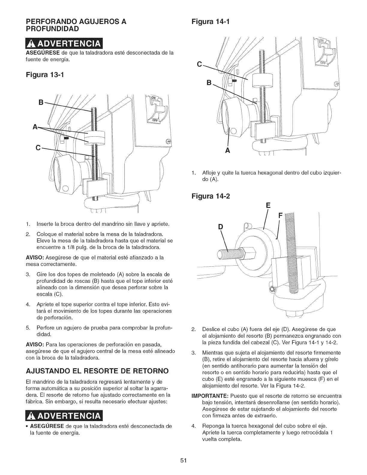
PERFORANDO AGUJEROS A
PROFUNDIDAD
ASEGURESE de que la taladradora est6 desconectada de la
fuente de energia.
Figura 13-1
C
1. Inserte la broca dentro del mandrino sin Ilave y apriete.
2. Coloque el material sobre la mesa de la taladradora.
Eleve la mesa de la taladradora hasta que el material se
encuentre a 1/8 pulg. de la broca de la taladradora.
AVISO: Aseg0rese de que el material est6 afianzado a la
mesa correctamente.
3.
4.
5.
Gire los dos topes de moleteado (A) sobre la escala de
profundidad de roscas (B) hasta que el tope inferior est6
alineado con la dimensi6n que desea perforar sobre la
escala (C).
Apriete el tope superior contra el tope inferior. Esto evi-
tara el movimiento de los topes durante las operaciones
de perforaci6n.
Perfore un agujero de prueba para comprobar la profun-
didad.
AVISO: Para las operaciones de perforaci6n en pasada,
aseg0rese de que el agujero central de la mesa est6 alineado
con la broca de la taladradora.
AJUSTANDO EL RESORTE DE RETORNO
El mandrino de la taladradora regresara lentamente y de
forma automb,tica a su posici6n superior al soltar la agarra-
dera. El resorte de retorno fue ajustado correctamente en la
f_.brica. Sin embargo, si resulta necesario efectuar ajustes:
•ASEGURESE de que la taladradora est6 desconectada de
la fuente de energia.
Figura 14-1
C
A
1. Afloje y quite la tuerca hexagonal dentro del cubo izquier-
do (A).
Figura 14-2
E
D
2.
3.
Deslice el cubo (A) fuera del eje (D). AsegOrese de que
el alojamiento del resorte (B) permanezca engranado con
la pieza fundida del cabezal (C). Ver Figura 14-1 y 14-2.
Mientras que sujeta el alojamiento del resorte firmemente
(B), retire el alojamiento del resorte hacia afuera y girelo
(en sentido antihorario para aumentar la tensi6n del
resorte o en sentido horario para reducirla) hasta que el
cubo (E) est6 engranado a la siguiente muesca (F) en el
alojamiento del resorte. Ver la Figura 14-2.
IMPORTANTE: Puesto que el resorte de retorno se encuentra
bajo tensi6n, intentarA desenrollarse (en sentido horatio).
AsegOrese de estar sujetando el alojamiento del resorte
con firmeza antes de extraerlo.
4. Reponga la tuerca hexagonal del cubo sobre el eje.
Apriete la tuerca completamente y luego retroc6dala 1
vuelta completa.
51
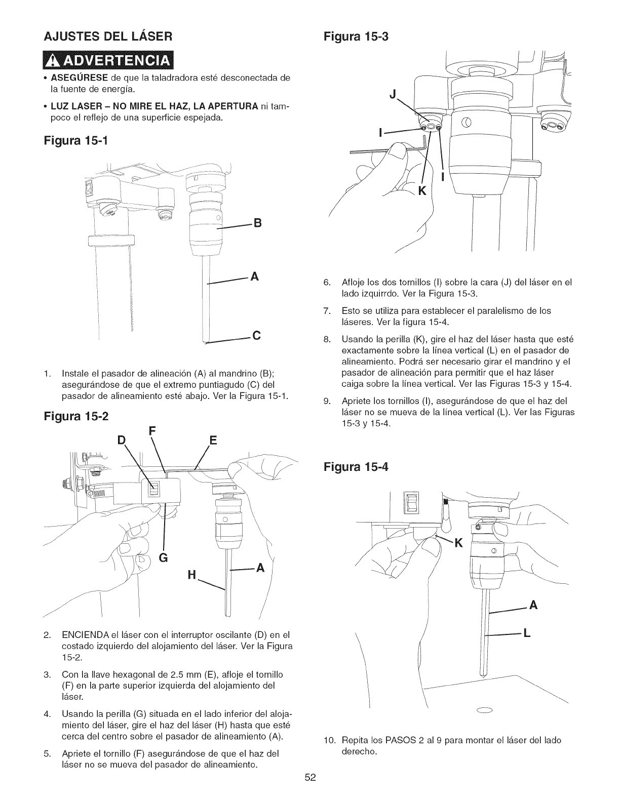
AJUSTES DEL LASER Figura 15-3
•ASEGURESE de que la taladradora est6 desconectada de
la fuente de energia.
•LUZ LASER - NO MIRE EL HAZ, LA APERTURA ni tam-
poco el reflejo de una superficie espejada.
Figura 15-1
i _J B
i ...... 7
i i
1. Instale el pasador de alineaci6n (A) al mandrino (B);
asegurandose de que el extremo puntiagudo (C) del
pasador de alineamiento est6 abajo. Ver la Figura 15-1.
Figura 15-2
F
D E
6.
7.
8.
9.
Afloje los dos tornillos (I) sobre la cara (J) del laser en el
lado izquirrdo. Ver la Figura 15-3.
Esto se utiliza para establecer el paralelismo de los
laseres. Ver la figura 15-4.
Usando la perilla (K), gire el haz del laser hasta que est_
exactamente sobre la linea vertical (L) en el pasador de
alineamiento. Podra ser necesario girar el mandrino y el
pasador de alineaci6n para permitir que el haz laser
caiga sobre la linea vertical. Ver las Figuras 15-3 y 15-4.
Apriete los tornillos (I), asegurandose de que el haz del
laser no se mueva de la linea vertical (L). Ver las Figuras
15-3 y 15-4.
Figura 15-4
2.
3.
4.
5.
G
ENCIENDA el laser con el interruptor oscilante (D) en el
costado izquierdo del alojamiento del laser. Ver la Figura
15-2.
Con la Ilave hexagonal de 2.5 mm (E), afloje el tornillo
(F) en la parte superior izquierda del alojamiento del
laser.
Usando la perilla (G) situada en el lado inferior del aloja-
miento del laser, gire el haz del laser (H) hasta que est6
cerca del centro sobre el pasador de alineamiento (A).
Apriete el tornillo (F) asegurandose de que el haz del
laser no se mueva del pasador de alineamiento.
\L
c-Z>
10. Repita los PASOS 2 al 9 para montar el laser del lado
derecho.
52
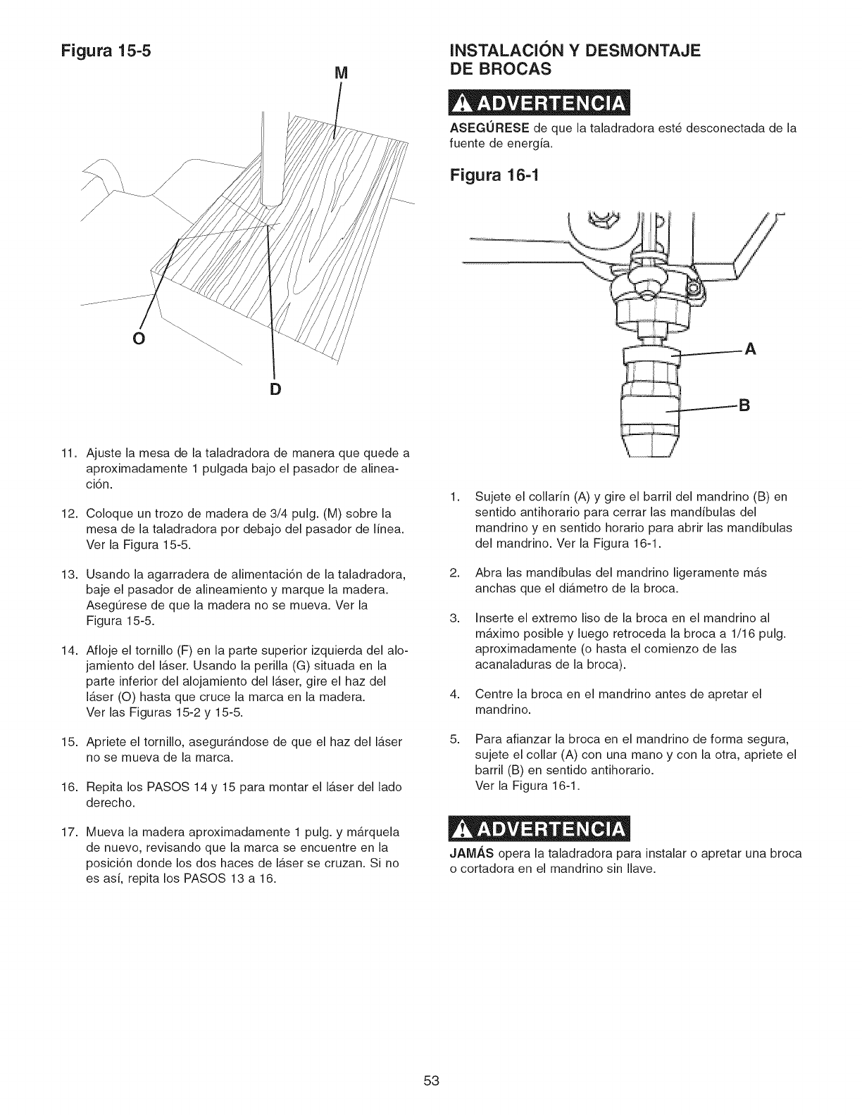
Figura 15-5
M
D
11. Ajuste la mesa de la taladradora de manera que quede a
aproximadamente 1 pulgada bajo el pasador de alinea-
ci6n.
12. Coloque un trozo de madera de 3/4 pulg. (M) sobre la
mesa de la taladradora por debajo del pasador de linea.
Ver la Figura 15-5.
13. Usando la agarradera de alimentaci6n de la taladradora,
baje el pasador de alineamiento y marque la madera.
AsegOrese de que la madera no se mueva. Ver la
Figura 15-5.
14. Afloje el tornillo (F) en la parte superior izquierda del alo-
jamiento del laser. Usando la perilla (G) situada en la
parte inferior del alojamiento del laser, gire el haz del
I_,ser (O) hasta que cruce la marca en la madera.
Ver las Figuras 15-2 y 15-5.
15. Apriete el tornillo, asegurandose de que el haz del laser
no se mueva de la marca.
16. Repita los PASOS 14 y 15 para montar el laser del lado
derecho.
17. Mueva la madera aproximadamente 1 pulg. y marquela
de nuevo, revisando que la marca se encuentre en la
posici6n donde los dos haces de laser se cruzan. Si no
es asi, repita los PASOS 13 a 16.
INSTALACION YDESMONTAJE
DE BROCAS
ASEGURESE de que la taladradora est6 desconectada de la
fuente de energia.
Figura 16-1
1,
2,
3,
4,
Sujete el collarin (A) y gire el barril del mandrino (B) en
sentido antihorario para cerrar las mandibulas del
mandrino y en sentido horario para abrir las mandibulas
del mandrino. Ver la Figura 16-1.
Abra las mandibulas del mandrino ligeramente mas
anchas que el diametro de la broca.
Inserte el extremo liso de la broca en el mandrino al
maximo posible y luego retroceda la broca a 1/16 pulg.
aproximadamente (o hasta el comienzo de las
acanaladuras de la broca).
Centre la broca en el mandrino antes de apretar el
mandrino.
5, Para afianzar la broca en el mandrino de forma segura,
sujete el collar (A) con una mano y con la otra, apriete el
barril (B) en sentido antihorario.
Ver la Figura 16-1.
JAM_,S opera la taladradora para instalar o apretar una broca
o cortadora en el mandrino sin Ilave.
53
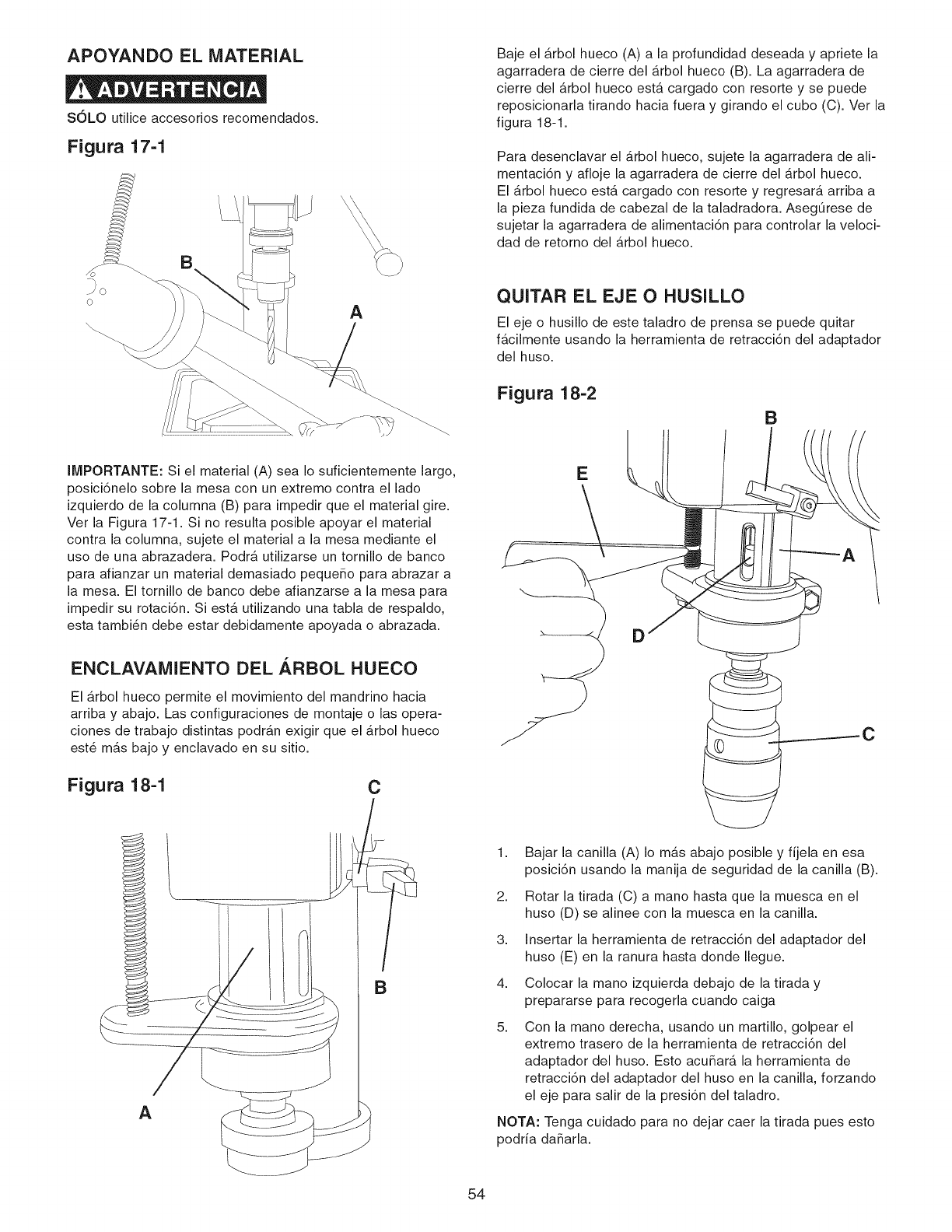
APOYANDO EL MATERIAL
SOLO utilice accesorios recomendados.
Figura 17-1
Baje el _.rbol hueco (A) a la profundidad deseada y apriete la
agarradera de cierre del arbol hueco (B). La agarradera de
cierre del _.rbol hueco estb, cargado con resorte y se puede
reposicionarla tirando hacia fuera y girando el cubo (C). Ver la
figura 18-1.
Para desenclavar el _.rbol hueco, sujete la agarradera de ali-
mentaci6n y afloje la agarradera de cierre del _.rbol hueco.
El arbol hueco esta cargado con resorte y regresar_, arriba a
la pieza fundida de cabezal de la taladradora. AsegOrese de
sujetar la agarradera de alimentaci6n para controlar la veloci-
dad de retorno del _.rbol hueco.
A
IMPORTANTE: Si el material (A) sea Io suficientemente largo,
posici6nelo sobre la mesa con un extremo contra el lado
izquierdo de la columna (B) para impedir que el material gire.
Vet la Figura 17-1. Si no resulta posible apoyar el material
contra la columna, sujete el material a la mesa mediante el
uso de una abrazadera. Podrb, utilizarse un tornillo de banco
para afianzar un material demasiado peque_o para abrazar a
la mesa. El tornillo de banco debe afianzarse a la mesa para
impedir su rotaci6n. Si est,. utilizando una tabla de respaldo,
esta tambi6n debe estar debidamente apoyada o abrazada.
ENCLAVAMIENTO DEL ARBOL HUECO
El _.rbol hueco permite el movimiento del mandrino hacia
arriba y abajo. Las configuraciones de montaje o las opera-
ciones de trabajo distintas podran exigir que el _.rbol hueco
est6 m_.s bajo y enclavado en su sitio.
Figura 18-1 C
/
B
54
QUITAR EL EJE O HUSILLO
El eje o husillo de este taladro de prensa se puede quitar
f_.cilmente usando la herramienta de retracci6n del adaptador
del huso.
Figura 18-2
B
c
1,
2,
3,
4,
8,
Bajar la canilla (A) Io mas abajo posible y fijela en esa
posici6n usando la manija de seguridad de la canilla (B).
Rotar la tirada (C) a mano hasta que la muesca en el
huso (D) se alinee con la muesca en la canilla.
Insertar la herramienta de retracci6n del adaptador del
huso (E) en la ranura hasta donde Ilegue.
Colocar la mano izquierda debajo de la tirada y
prepararse para recogerla cuando caiga
Con la mano derecha, usando un martillo, golpear el
extremo trasero de la herramienta de retracci6n del
adaptador del huso. Esto acu_arA la herramienta de
retracci6n del adaptador del huso en la canilla, forzando
el eje para salir de la presi6n del taladro.
NOTA: Tenga cuidado para no dejar caer la tirada pues esto
podria da_arla.
VELOCIDADES DE PERFORACION
APROPIADAS
Los factores que determinan la mejor velocidad a ser utilizada
en cualquier funci6n de taladrado son: el tipo de material a
ser elaborado, el tamafio del agujero, tipo de broca u otra
cortadora, y la calidad del corte deseado.
Utilice la velocidad recomendada para la broca y el material.
PERFORACION DE MADERAS
Las brocas espirales, aunque esten disefiadas para la per-
foraci6n de metales, pueden ser utilizadas tambi_n para el
taladrado de agujeros en la madera. No obstante, se prefiere
por Io general el uso de brocas de espuela o brocas Forstner
para la perforaci6n de madera, ya que cortan un agujero de
fondo cuadrado y estan disefiadas para la extracci6n de
astillas de madera. No utilice las brocas de mano con punta
de tornillo, ya que alas velocidades de la taladradora, levan-
taran y haran girar la madera.
Para la perforaci6n en pasada, debe alinear la mesa para que
la broca entre en el agujero central. Trace una linea vertical
en la parte delantera de la columna y una marca de referen-
cia sobre el soporte de la mesa y el cabezal de la taladra-
dora, de modo que la mesa y el cabezal de la taladradora
puedan ser abrazadas en la posici6n central a cualquier
altura.
Alimente la broca lentamente cuando la broca este a punto
de cortar a trav_s de la madera para impedir el astillamiento
de la cara inferior. Utilice un trozo de madera descartada
como respaldo debajo del material. Esto ayuda a reducir el
astillamiento y protege la punta de la broca.
PERFORACION DE METALES,
ALUMINIO O BRONCE
NUNCA sujete el material con las manos descubiertas.
SIEMPRE utilice abrazaderas o tornillos de banco para
sujetar su material.
$61o debe hacerse uso de brocas espirales en la perforaci6n
de materiales. Nunca sujete el material con las manos des-
cubiertas; utilice abrazaderas o tornillos de banco en todo
momento. La broca puede atrapar el material en cualquier
momento, particularmente cuando se rompe a trav_s del
material. Si el material se escapa de la mano del operario,
este tJltimo puede resultar herido. En todo caso, la taladra-
dora quedara averiada si el material se golpea contra la
columna.
El material debe ser abrazado o sujetado con firmeza en un
tornillo de banco durante la perforaci6n. Cualquier inclina-
miento, torcedura o movimiento lateral tiene como resultado
no s61o un agujero rudimentario, sino que aumenta el riesgo
de ruptura de la broca. Para materiales pianos, coloque el
material sobre una base de madera y abracela firmemente
contra la mesa para impedir que gire. Si el material es de
forma irregular y no puede colocarse de manera plana sobre
la mesa, debe ser bloqueado y abrazada de manera segura.
Durante la perforaci6n de metales sera necesario lubricar la
punta de la broca con aceite para impedir su sobrecalenta-
miento.
OPERACION DE PERFORACION
Utilice un punz6n de centrar para impactar el material en
d6nde desea el agujero. Esto impedira que la broca camine
al iniciar la operaci6n de perforaci6n. Antes de encender la
taladradora, encienda el laser y alinee las crucetas con la
marca central en el material. AsegtJrese de que el material
este debidamente apoyado o afianzado a la mesa. Para la
perforaci6n en pasada, asegtJrese de que el agujero central
de la mesa este alineado con la broca. Encienda la taladra-
dora y comience a alimentar el mandrino de la taladradora
hacia abajo con las agarraderas de alimentaci6n.
LA ALIMENTACION EXCESIVAMENTE R/_PIDA podra
hacer que la correa o la broca se deslicen o se rompan, que
el motor se atasque, o que el material se afloje de la mesa.
Jamas trate de apresurar el trabajo. Permita que la taladra-
dora funcione de manera uniforme.
55
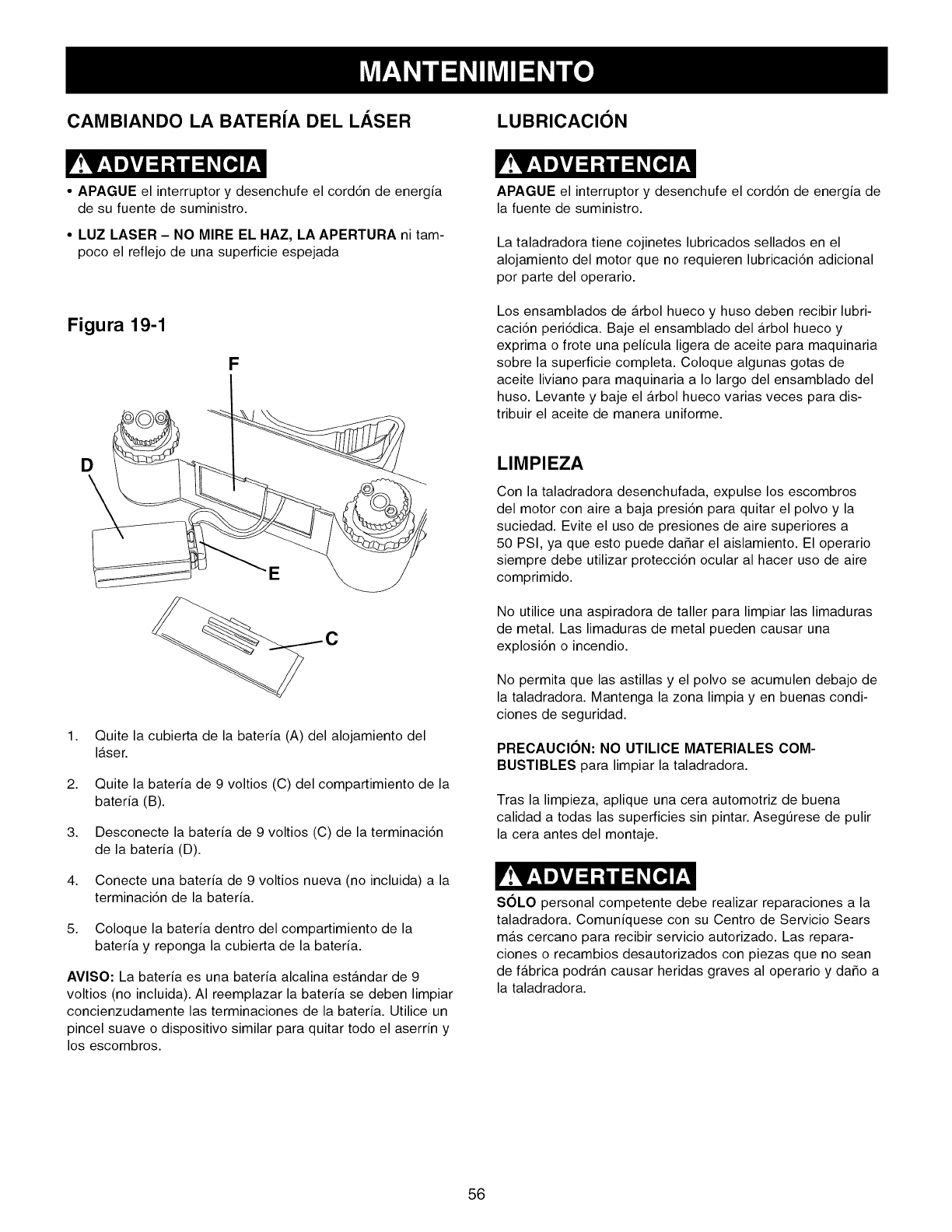
CAMBIANDO LA BATER(A DEL LASER LUBRICACION
•APAGUE el interruptor y desenchufe el cord6n de energia
de su fuente de suministro.
•LUZ LASER - NO MIRE EL HAZ, LA APERTURA ni tam-
poco el reflejo de una superficie espejada
Figura 19-1
F
APAGUE el interruptor y desenchufe el cord6n de energia de
la fuente de suministro.
La taladradora tiene cojinetes lubricados sellados en el
alojamiento del motor que no requieren lubricaci6n adicional
por parte del operario.
Los ensamblados de arbol hueco y huso deben recibir lubri-
caci6n peri6dica. Baje el ensamblado del arbol hueco y
exprima o frote una pelicula ligera de aceite para maquinaria
sobre la superficie completa. Coloque algunas gotas de
aceite liviano para maquinaria a Io largo del ensamblado del
huso. Levante y baje el arbol hueco varias veces para dis-
tribuir el aceite de manera uniforme.
D
E
C
1. Quite la cubierta de la bateria (A) del alojamiento del
laser.
2. Quite la bateria de 9 voltios (C) del compartimiento de la
bateria (B).
3. Desconecte la bateria de 9 voltios (C) de la terminaci6n
de la bateria (D).
4. Conecte una bateria de 9 voltios nueva (no incluida) a la
terminaci6n de la bateria.
5. Coloque la bateria dentro del compartimiento de la
bateria y reponga la cubierta de la bateria.
AVISO: La bateria es una bateria alcalina estAndar de 9
voltios (no incluida). AI reemplazar la bateria se deben limpiar
concienzudamente las terminaciones de la bateria. Utilice un
pincel suave o dispositivo similar para quitar todo el aserrin y
los escombros.
LIMPIEZA
Con la taladradora desenchufada, expulse los escombros
del motor con aire a baja presi6n para quitar el polvo y la
suciedad. Evite el uso de presiones de aire superiores a
50 PSI, ya que esto puede da_ar el aislamiento. El operario
siempre debe utilizar protecci6n ocular al hacer uso de aire
comprimido.
No utilice una aspiradora de taller para limpiar las limaduras
de metal. Las limaduras de metal pueden causar una
explosi6n o incendio.
No permita que las astillas y el polvo se acumulen debajo de
la taladradora. Mantenga la zona limpia yen buenas condi-
ciones de seguridad.
PRECAUCION: NO UTILICE MATERIALES COM-
BUSTIBLES para limpiar la taladradora.
Tras la limpieza, aplique una cera automotriz de buena
calidad a todas las superficies sin pintar. AsegtJrese de pulir
la cera antes del montaje.
S(SLO personal competente debe realizar reparaciones a la
taladradora. Comuniquese con su Centro de Servicio Sears
mas cercano para recibir servicio autorizado. Las repara-
ciones o recambios desautorizados con piezas que no sean
de fabrica podran causar heridas graves al operario y da_o a
la taladradora.
56
PARA EVlTAR HERIRSE A Sl MISMO o causar daSo a la taladradora, conmute el interruptor a la posici6n de apagado (OFF) y
desenchufe el cord6n de energia del tomacorrientes antes de realizar cualquier ajuste.
PROBLEMA CAUSA(S) POSIBLES SOLUClON
Motor no arranca
o no alcanza
velocidad plena
Motor se ahoga o
los disyuntores de
circuito se disparan
con frecuencia
El motor se
recalienta
La broca se atasca
o se resbala
La broca o el
material despiden
humo o arden
Exceso de deriva o
bamboleo por parte
de la broca
El huso regresa muy
lento o muy r_pido
El mandrino no
permanece sobre
el huso
1. Llave del interruptor fuera de su sitio
2. Interruptor defectuoso
3. Capacitador defectuoso
4. Baja tensi6n de linea
1. Inserte la Ilave del interruptor.
2. Mande a reponer el interruptor.
3. Mande a reponer el capacitador.
4. Corrija la condici6n de baja tensi6n de linea. Si la m4quina est4
enchufada a una extensi6n el_ctrica, des-con_ctela y enchtJfela
directamente al tomacorrientes.
5. Mande a recambiar el motor.
AVlSO: 3 y 4 deben ser realizados por un t_cnico de servicio com-
petente; consulte con el servicio de Sears.
5. Motor defectuoso
1. Sobrecarga del circuito
2. Baja tensi6n de linea
3. Sobrecarga del motor
4. Fusibles incorrectos en los disyuntores
de circuito
5. Cortocircuito del motor; conexiones sueltas
o aislamiento desgastado en los avances
1. Restricci6n en la circulaci6n del aire debido
a la acumulaci6n de polvo
2. Sobrecarga del motor
1. Tensi6n incorrecta de la correa
2. La broca no estb. afianzada de manera
segura dentro del mandrino
1. Velocidad incorrecta del huso
2. Astillas no estb.n siendo expulsadas por el
agujero de perforaci6n
3. Broca roma
1. Broca torcida
2 Broca incorrectamente instalada al
mandrino
1. El resorte de retorno tiene la tensi6n
incorrecta
1. Grasa, suciedad o aceite sobre el ahusado
del huso o en el ahusado del mandrino.
1.
2.
Reduzca la carga del circuito (apague otras aplicaciones).
Corrija la condici6n de baja tensi6n de linea. Revise la tensi6n
de linea con un multimetro. Si la taladradora est4 conectada a
una extensi6n el_ctrica, desenchtJfela del cord6n de extensi6n y
enchtJfela directamente a un tomacorrientes.
3. Reduzca la carga al motor; reduzca el ritmo de alimentaci6n.
4. Haga que un electricista competente instale los fusibles correc-
tos al disyuntor.
5. Inspeccione las terminaciones del motor por si existe aislamien-
to dafiado y alambres cortocircuitados y haga que sean reem-
plazados. Revise todos las conexiones de avances de energia.
1. Limpie el polvo y restaure la circulaci6n normal del aire en torno
al motor.
2. Reduzca la carga al motor; reduzca el ritmo de alimentaci6n.
1. Ajuste la tensi6n de la correa. Ver el cambio de velocidades y
el ajuste de la tensi6n de correa en "OPERACIONES Y
AJUSTES".
2. Instale la broca correctamente. Ver la instalaci6n y desmontaje
de la broca en "OPERACIONES Y AJUSTES".
1.
2.
3.
Reduzca la velocidad del huso. Vea el diagrama de veloci-
dades en el fondo de la cubierta de la correa.
Retracte la broca frecuentemente durante la operaci6n de
perforaci6n para expulsar astillas del agujero.
Reponga o afile la broca.
1. Rep6ngala con una broca recta o nueva.
2. Instale la broca correctamente. Ver instalaci6n y desmontaje de
la broca en "OPERACIONES Y AJUSTES".
1. Ajuste la tensi6n del resorte. Ver el ajuste del resorte de
retorno en "OPERACIONES Y AJUSTES".
1. Limpie la grasa, suciedad o aceite sobre el ahusado del huso o
en el ahusado del mandrino. Ver el ensamblado del cabezal de
la taladradora y el ensamblado del motor en "INSTRUC-
CLONES DE MONTAJE".
57

Taladradora de Banco de 15 Pulg. NO. DE MODELO 351.229000
Cuando vaya a rendir servicio, solo utilice piezas de recambio CRAFTSMAN. El uso de cualquier otro tipo de piezas podra crear
un PELIGRO o producir daOo al producto.
Cualquier intento pot reparar o reemplazar las piezas el_ctricas de esta taladradora podr_, crear un PELIGRO a menos que la
reparaciOn sea efectuada pot un tOcnico de servicio competente. El servicio de reparaciOn esta disponible en su Centro de
Servicio Sears mas cercano.
Encargue siempre por NOMERO DE PIEZAy no por nOmero de clave.
No de No. de No de No. de
Clave Piezas DescripciOn Cant. Clave Piezas DescripciOn Cant.
a* 0R92300 Ensamblado de cubierta de poleas, consiste en 1 83 0R92358 Soporte de montaje 1
(1,2,3,4,5,8,7,8,9) 84 0R93531 Tornillo cab. plana M6 x 12 mm 2
1 0R92301 Cubierta de polea superior 1 85 0R92362 Anillo 1
2 0R92304 Cubierta de polea inferior 1 88 0R93552 Tornillo de fijacion de cab. hueca hex. M8 x 8 mm 1
3 OR91774 Tornillo de cabeza cilindrica plana M4 x 10 mm 4 87 0R92363 Ensam. de soporte de la mesa, incl. 1
4 QR90078 Tuerca Hex M4 4 (88, 89, 90, 91, 92, 93, 94, 95)
5 ©R90431 Arandela con dientes ext. M4.3 4 88 ©R92365 Eje 1
6 OR93451 Cuadro de velocidades 1 89 ©R92364 Engranaje del pihOn 1
7 QR93541 Tornillo roscador troncocOnico M3.5 x 9.5 mm 4 90 OR93545 Tornillo de cabeza hex. M 16 x 35 mm 1
8 ©R92382 Placa de notaciones 2 91 ©R92699 Pasador de enroscado 1
9 OR93542 Tomillo roscador troncoconico M4.2 x 9.5 mm 1 91A ©R90071 Tuerca hex. 1/4-20
10 ©R90241 Tornillo de cabeza cilindrica plana M6 x 12 mm 4 92 OR92367 Escala 1
11 OR90059 Arandela plana M6.4 4 93 ©R92728 Tornillo de marcha 5 mm 2
12 ©R92305 Casquillo 1 94 OR92366 Indicador 1
13 OR92306 Anillo de reten 1 95 ©R92728 Tornillo de marcha 5 mm 2
14 ©R90366 Cojinete 6204 1 96 ©R92371 Mesa 1
15 ©R92307 Separador 1 98 OR92373 Cremallera 1
16 OR90366 Cojinete 6204 1 99 OR92374 Base 1
17 ©R92306 Anillo de reten 1 100 ©R92725 Tornillo de cab. hex. M8 x 125 mm 4
©R93549 Ensam. del pihon consistiendo en (18, 20, 21) 1 101 OR91499 Arandela plana M8.4 8
18 OR92333 PiF10n 1 102 OR90248 Arandela de cierre M8.1 4
20 ©R92334 Cubo (derecho) 1 103 ©R90307 Tuerca hex. M8 4
21 ©R92721 Pasador de resorte M5 x 20 mm 1 104 OR93546 Tornillo cab. hex. M10 x 40 mm 4
22 OR92332 Agarradera 3 105 ©R92372 Ensam. columna, incl. (106) 1
23 ©R92331 Perilla 3 106 ©R93524 Tornillo fijacion cab. hueca hex. M10 x 12 mm 1
24 OR93523 Anillo de reten ext. 1 107 OR90222 Tornillo fijacion cab. hueca hex. M6 x 10 mm 1
25 OR92330 Agarradera de tension 1 108 OR92369 Ensam. agarradera 1
26 ©R90310 Tornillo de cabeza hex. M8 x 16 mm 1 109 ©R92370 Ensam. agarradera de cierre (mesa) 1
27 ©R92328 Excentrica 1 110 OR92416 Engranaje helicoidal 1
28 OR92329 Pasador 1 111 ©R92368 Ensam. agarradera de cierre (columna) 1
29 ©R92327 Arandela de espuma 4 112 ©R90290 Llave hex. 3 mm 1
30 ©R90382 Tornillo de cabeza cilindrica plana M5 x 16 mm 1 113 OR90289 Llave hex. 2.5 mm 1
31 OR92324 Abrazadera 1 114 ©R93547 Llave hex. 5 mm 1
32 QR93524 Tomillo de fijacion cab. hueca hex. M10 x 12 mm 2 115 ©R92375 Ensam. luz, incl. (116) 1
33 ©R93548 Pasador de resorte M6 x 24 mm 2 116 OR91317 Etiqueta advertencia de luz 1
34 OR92326 Tornillo de cierre 2 ©R93795 Ensam. luz Mounting Hardware incl. (117, 118, 119, 120, 121)
35 ©R92323 Cabezal, incl. (36, 37, 38, 39) 1 117 OR92377 Abrazadera del cordon de luz 2
36 ©R93504 Etiqueta del numero de serie 1 118 ©R91758 Tornillo de cab. hueca hex. M6 x 16 mm 2
37 OR92728 Tornillo de marcha 5 mm 4 119 OR90502 Arandela de cierre M6 2
38 ©R92325 Etiqueta de advertencias 1 120 ©R92376 Abrazadera del cordon 1
39 ©R92728 Tornillo de marcha 5 mm 4 121 ©R92487 Casquillo del cordon 1
40 OR90228 Tuerca hex. M10 1 122 OR92316 Motor, incl. (123, 125) 1
41 ©R90647 Arandela de cierre 3/8 pulg. 1 123 ©R92320 CordOn del motor 1
42 ©R92335 Tornillo especial 1 125 ©R93507 Etiqueta espec, motor 1
43 OR92336 Agarradera de cierre 1 126 OR90222 Tornillo fijaciOn cab. hueca hex. M6 x 10 mm 1
45 ©R92341 Caja del interruptor 1 127 ©R92313 Polea del motor 1
46 OR90382 Tomillo de cabeza cilindrica plana M5 x 16 mm 2 128 ©R92312 Llave 1
47 ©R90362 Arandela con dientes ext. M5.3 4 129 OR92308 Correa (J27) 1
48 ©R90507 Tornillo de cabeza troncocOnica M5 x 8 mm 2 130 ©R92315 Tuerca de polea del huso 1
49 OR93543 Tornillo de cabeza troncoconica M5 x 28mm 2 131 ©R92314 Polea del huso 1
50 ©R92342 Aislador 1 132 OR93550 Tuerca de cierre M12 x 1.75 2
51 ©R92343 Cubierta del interruptor 1 133 ©R93539 Arandela de cierre 1/2 pulg. 2
52 OR90716 Tornillo de cabeza troncocOnica M4.2 x 12 mm 2 134 ©R92317 Soporte del motor 1
53A OR90037 Interruptor, incl. (53B) 1 135 OR92318 Vara de tension del motor (derecha) 1
53B ©R90038 Llave 1 136 ©R92319 Vara de tension del motor (izquierda) 1
55 OR92359 Mandrino 1 137 ©R90307 Tuerca hex. M8 4
56 ©R92358 A,rbol 1 138 OR91499 Arandela plana M8.4 8
57 ©R92357 Huso 1 139 ©R90308 Tornillo cab. hex. M8 x 20 mm 4
58 OR93544 Cojinete 6205 1 OR93796 Ensam. polea central incl. (140, 141, 142) 1
60 ©R93533 Tomillo de cabeza hexagonal M6 x 45 mm 1 140 ©R92311 Excentrica 1
61 ©R90306 Tomillo de fijaci0n de cab. hueca hex. M6 x 12 mm 1 141 ©R92310 Polea central 1
62 OR92350 Collarin de parada 1 142 OR90075 Cojinete 6202 1
63 ©R93550 Tuerca de cierre M12 x 1.75 1 143 ©R92309 Correa (J25) 1
64 OR90235 Tuerca hex. M6 1 144 ©R92321 Cordon de energia 1
65 ©R92349 Desmontador del adaptador del huso 1 145 OR92322 Atadura 2
66 OR92348 A,rbol hueco 1 OR92428 Ensam. loser, consiste de:
67 QR92347 Arandela de caucho 1 (150, 151,152, 153, 154, 155, 156, 157, 158, 159, 160)
68 ©R90218 Cojinete 6203 1 150 OR92717 Tornillo cab. hueca hex. M4 x 14 mm 2
69 OR92346 Arandela plana M17.5 1 151 ©R92718 Tornillo cab. hueca hex. M3 x 14 mm 6
70 ©R92345 Anillo 1 152 ©R92711 Cubierta superior 1
71 ©R92344 Tuerca 1 153 OR92712 Alojamiento principal 1
73 OR92338 Ensamblado del resorte con reten (OR92337) 1 154 ©R92713 Interruptor
74 ©R92379 Arandela especial plana 1 155 ©R92715 Portador 2
75 ©R92339 Cubo (izquierdo) 1 156 OR92716 Ensam. modulo loser 2
76 OR92340 Placa 1 157 ©R92709 Abrazadera de manguera 1
77 ©R90304 Arandela plana M12.4 1 158 ©R92710 Pasador de alineacion 1
78 OR93551 Tuerca de cierre M12 x 1.5 1 159 OR92714 Puerta 1
79 ©R92351 Vara de profundidad, incl. (80) 1 160 ©R92731 Etiqueta de advertencia loser 2
80 OR93505 Escala de profundidad 1 161 OR93512 Manual del propietario (no ilustrado) 1
81 ©R92302 Tuerca de moleteado 2 162 ©R93797 Hardware Pack for #22900 & #22901 (Consists of Ref. No's.:
100, 101,102, 103, 104, 112, 113, 114)
58
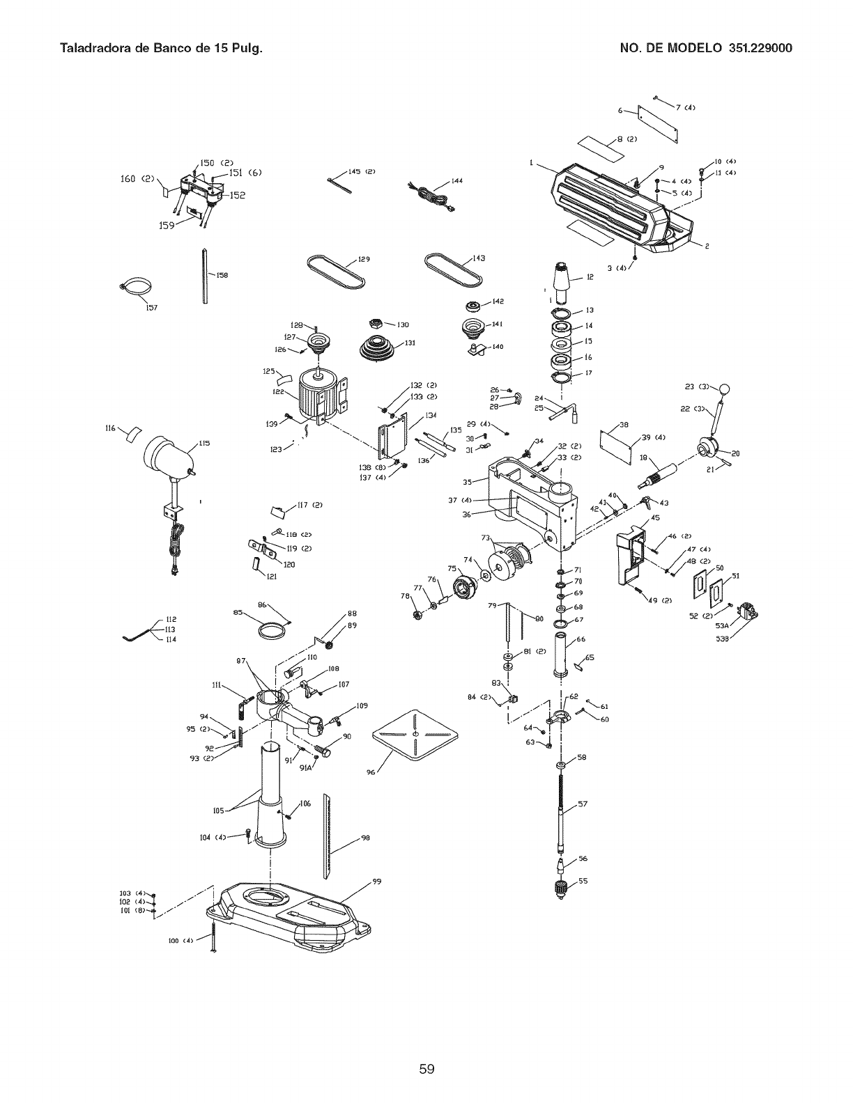
Taiadradora de Banco de 15 Pulg. NO. DE IVIODELO 351.229000
.150 (2)
IGO (2)_ 15' (G)
159_ _
76
73
(4)
49 (2)
23 (3)_
22
(2>
47 (4)
(2)
52
59

Your Home
For expert troubleshooting and home solutions advice:
www,managemyhome,com
For repair - in your home- of all major brand appliances,
lawn and garden equipment, or heating and cooling systems,
no ma_er who made it, no matter who sold it!
For the replacement parts, accessories and
owner's manuals that you need to do-it-yourself.
For Sears professional installation of home appliances
and items like garage door openers and water heaters.
1-800-4-MY-HOME ®
Call an_ime, day or night (U.S.A. and Canada)
www,sears,com www,sears,ca
Our Home
For repair of carry-in items like vacuums, lawn equipment,
and electronics, call anytime for the location of your nearest
Sears Parts & Repair Service Center
1-800'-488-1222 (U.S.A.) 1-800'-469'-4663 (Canada)
www,sears,corn www.sears,ca
To purchase a protection agreement on a product serviced by Sears:
1-800-827-6655 (U.S.A.)
Para pedir servicio de reparaci6n
a domicilio, y para ordenar piezas:
(1-888-784_6427)
1-800-361-6665 (Canada)
Au Canada pour service en fran{;ais:
1-800-LE-FOYER Mc
(1-800-533-6937)
v_pww.sears.ca
TM SM
_) Registered Trademark /Trademark /Service Mark of Sears Brands, LLC
_4)Marca R_istrada /TM Marca de F&brica /sMMarca de Servicio de Sears Brands, LLC
MCMarque de commerce/MD Marque depos_ de Sears Brands, LLC © Sears Brands, LLC
