Craftsman 351231060 User Manual 6 BENCH GRINDER Manuals And Guides L0306059
CRAFTSMAN Grinder Bench Manual L0306059 CRAFTSMAN Grinder Bench Owner's Manual, CRAFTSMAN Grinder Bench installation guides
User Manual: Craftsman 351231060 351231060 CRAFTSMAN 6 BENCH GRINDER - Manuals and Guides View the owners manual for your CRAFTSMAN 6 BENCH GRINDER #351231060. Home:Tool Parts:Craftsman Parts:Craftsman 6 BENCH GRINDER Manual
Open the PDF directly: View PDF ![]() .
.
Page Count: 8
6r_ VARIABLE SPEED
BENCH GRINDER
351.231060
Read carefully and foflow all safety rules and operating instructions before
first use of this product.
179_4.00_110_
Palmgren Operating Manual & Parts Ust 82064
This Palmgren Bench Grinder is equipped wiSh a totally endosed
ball bearing motor. Armature assembly is dynamically balanced for
smooth operation. Motor housing is compact so long pieces of
work can press against both wheels without touching the motor
frame, Grinder operates at 3450 rpm for gdnding and also at 2000-
3300 rpm for sharpening. Removable wheel guards allow for easy
changing of wheels.Two-way tool rests are adjustable for wheel
wear and angle grinding.Grinder comes complete with spark
guards, safety eyeshields and dust collection hose.
Check for shipping damage. If damage has occurred, a claim must
be filed with the carrier immediately. Check for co¢_pleteness.
Immediately report missing parts to dealer.
SPECIFICATIONS
Horsepower ................................................. _1_
Voltage .................................................... 120
Amperes ................................................... 3,5
Hertz ...................................................... .60
Phase ................................................... Single
RPM ........................................... 20OQ-3300, 3450
Rotation (viewed from left side) ....................... .L"_ockw|se
Wheel diameter ............................................. .6"
Wheel bore ................................................. Yz"
WARNING: For your own safety, read operating instructions man-
ual before operating tool.
BE PREPARED FOR JOB
•Wear proper apparel Do not wear foose dothlng, gloves, neck-
ties, rings, bracelets or other jewelry which may get caught in
moving parts of machine.
•Wear protective hair covering to contain fong hair.
•Wear sa|ety shoes with non-slip soles.
•Wear _afety glasses complying with United States ANSI Z87.1.
Everyday glasses have only impact resistant lenses.They are
NOT safety glasses.
•Wear face mask or dust mask if operation is dust 7.
Be alert and think cleady. Never operate power tools when
tired, intoxicated or when taking medications that cause
drowsiness.
PREPARE WORK AREA FOR JOB
Keep work area dean. Cluttered work areas and work benches
invite accidents.
Do not use power tools in dangerous environments.Do not use
power tools in damp or wet locations. Do not expose power
tools to rain.
•Work area should be proporly lighted.
• Proper efectdcal plug should be plugged directly into propody
grounded, three-prong receptacfe.
• Extension cords should have agrounding prong and the three
wires of the extension cord should be of the correct gauge.
Keep v_sitors at asafe distance from work area.
Keep children out of the wot_ace. Make workshop chitdprooE
Use padlocks, master switches or remove switch keys to pm
vent any unintentiona( use of power tobls.
TOOL SHOULD BE MAINTAINED
•Always unplug tool prior to inspection.
•Consult manual for specificmalntalning and adjusting proce-
dures.
Keep tool clean for safest operation
•Remove adjusting tools. Form habit of checking to see that
adjusting tools are removed before turning machine on
•Keep air parts in working order.Check to determine that the
guard or other parts w_IIoperate pl"opedy and pe_orm their
intended function.
• Check for damaged parts. Check for alignment of moving parts,
binding of moving parts, breakage of parts, mounting and any
other condition that may affect atodi's operation.
•A guard or other part that is damaged should be properly
repaired or replaced, Do not perform makeshift repairs. (Use
the parts list to order replacement parts.)
KNOW HOW TO USE TOOL
• Use dght too_ for )o_ Do not force tobl or attachment to do a
job for which it was not designed.
* Disconnect tool from power when changing accessories such
as grinding wheels, buffing wheels and the like.
• Avoid accidental start-up.Make sure that the switch is in the off
position before plugging in.
•Do not force tool, It will work most effic]enBy at the rate for
which it was designed.
•Keep hands away from moving parts and grinding surfaces.
• Never reave a tool running unattended.Turn the power _ff and
do not leave tool unt(I it comes to a complete stop.
•Do not overreadm Keep proper footing and balance.
• Never stand on tool.Serious injury could occur if tool is tipped
ovel_.
•Know your tool. Learn the todi's operation, application and spe-
cific limifaEons.
•Use recommended accessories.Understand and obey all safety
instructions supplied with accessories,The useof improper
accessoriesmay cause risk of injury to persons.
• Do not over tighten wheel nut. Replace cracked wheel immedi.
arely.Use only flanges supplied with the gdnder.
•Adjust distance between wheel and tool rest to maintain '/,," or
lessgap,
•Handlesheworkpiececorrectly.Wheneverpossible, usetool
rest to support workpiece during g_inding operation.Turn tool
off if it jams.
•Alwaysuseguards and eyeshfelds,
•Qean grinding dust from beneath tool fTequentJy.
2
9almgren Operating Manua_ & Parts Us,t 82964
Parts to be fastened to the unitshould be located and accounted
for (See List and Figure 1).
IMPORTANT: Do not attempt assembly if parts are missing. Use
thls manual to order replacement parts.
A '/,_ 18 x 1%" Carriage bolt, 2 each
B Tool rest bracket, 2 each
C *%" Rat washer, 4 each
D*'/."-16 Hex nut,4each
ETool rest. 2each
FV_r,"Flat washer, 2 each
Gs/_"-18, Hex nut, 2 each
H*_/rl 6 x 1¼" Hex bolt, 4 each
IKnob, 2each
JSpark guard. 2each
KEyeshield, 2 each
L Lower eyeshieid bracket,2 each
M Upper eyeshield bracket, 2 each (left and right)
N #10-24 x'J_"_an head scTew, 4 each
O%20 x 'A" Flange screw, 2each
P '//' Flat washer, 2 eadn
Q Spacer. 2 each
R Dust collector hose (not shown)
NOTE; Parts marked with an asterisk (*) are mounted to the
grinder at the factory.
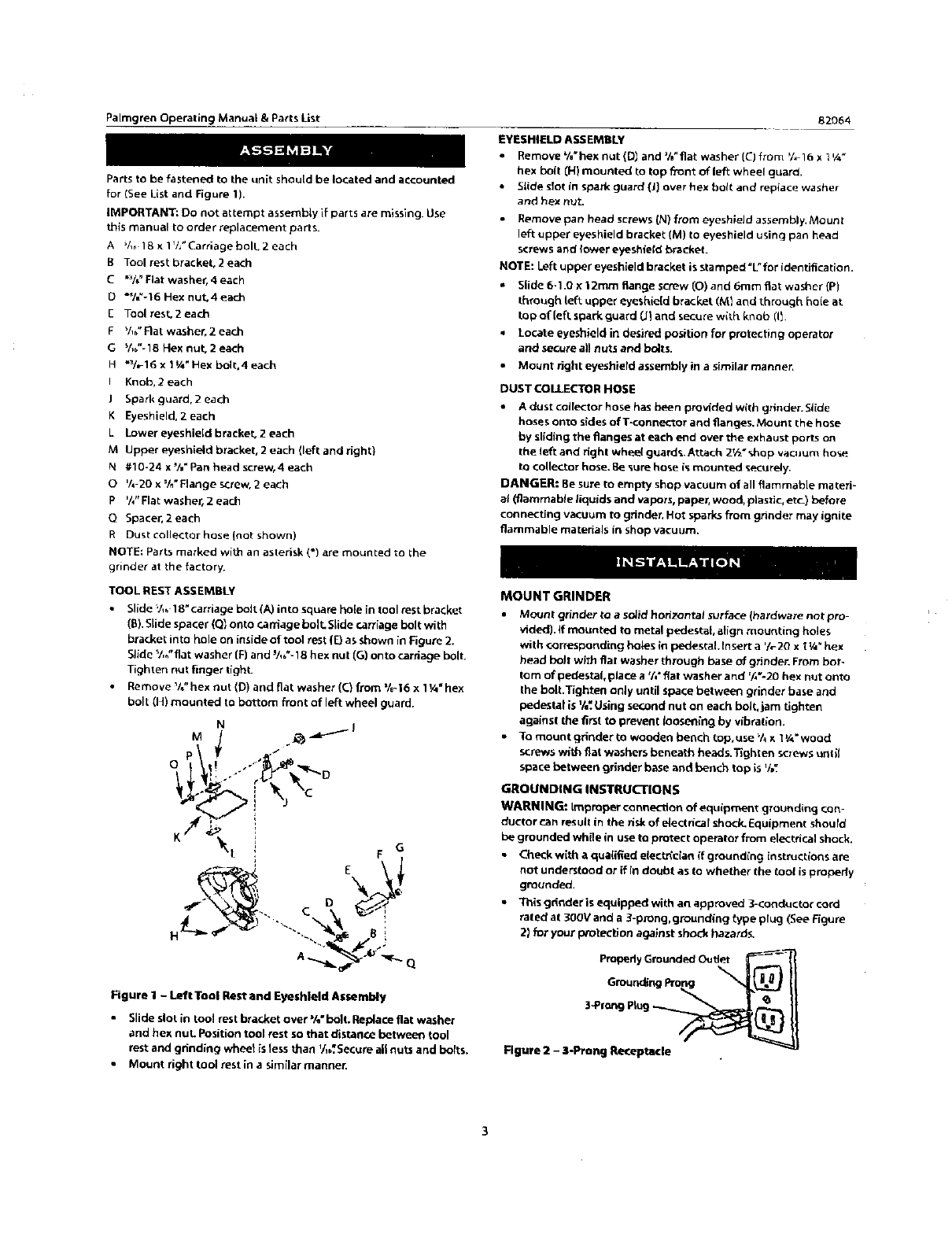
TOOL REST ASSEMBLY
•Slide V,_ 18" carriage bolt (A) into square hole in tool rest bracket
(E). Slide spacer (Q] onto r.arriage boll SLide can'iage bolt with
bt_et into hole on inside of t`ool rest (_ as SfnOW_in _gure 2.
SEde %_"flat washer [F) and _/,,"-18 hex nut (G) onto caniage bolt.
Tighten nut finger tighL
•Remove%"hexnut(D)andflatwasher(C}from%_16x1¼"hex
bolt (HI mounted to bottom front of left wheel guard.
Figure I - Left Tool Rest and Eyeshleld Assembly
• Slide slot in too] rest bracket over %" bolt. Replace flat washer
and hex nut Position tool rest so that distanr.e between tool
rest and grinding whee_ )s less _an '/,b'.Secure a|t nuts and bolts.
• Mount right tool rest in a similar manner.
EYESHIELD ASSEMBLY
•Remove %" hex nut (D_ and %"fiat washer (C) from '/,- 16 x l ¼_
hex bolt (H) mounted to top fi'ont of left wheel guard.
• Slide slot in spark guard (J) over hex holt and reptace washer
and hex nut.
•Remove pan head screws (N) from eyeshieJd assembly, Mount
left upper eyes hield bracket (M) to eyeshield using pan head
screws and lower eyeshield bracket.
NOTE: Left upper eyesh[eld bracket is stamped "L" for identification.
• Slide 6-1.0 x t2mm flange screw (0) and 6ram flat waslqer (P)
through left upper eyeshie[d bracket (M} and through hole at.
top of(eftspark guard (J_and secure with knob (11.
Locate eyeshield in desired position for protecting operator
and secure all nuts and bolts.
•Mount right eyeshiefd assembly in a similar manner,
DUST COLLECTOR HOSE
•A dust collector hose has been provided with grinder. Slide
hoses onto sides ofT-connector and flanges. Mount the hose
by sliding the flanges at each end over the exhaust ports on
the left and right whee( guard% Attach 2t_ * shop vacuum hose
to colle_r hose. Be _ure hose is mounted securely,
DANGER: Be sure to empty shop vacuum of all flammable ma teri-
a_ (flammable _iquids and vapors, paper, wood, plastic, etc.) before
connecting vacuum to grinder, Hot sparks from grinder may ignite
flammable materials in shop vacuum.
MOUNT GRINDER
•Mount grinder to asoJidhorizontal surface(hardware not pro-
vided), if mounted to metal pede_;tal, align mounting holes
with corresponding bok==sin pedestal tnsett a _h-2Oxt¼"hex
head bolt with fiat washer through base of grinder. From bot-
tom ofpedestal,placea %"fiatwasherand %'-20 hex nutonto
thebolt.Tightenonlyuntilspacebetween grinderbaseand
pedestalisV,_.U_ingsecondnuton each bolt,jam tighten
againstthefirsttopreventlooseningby vib_afion.
• To mount grindertowooden bench top.use_/_x 1¼" wood
screw_ w_thflat washers beneath head_.Tighten screws unlit
spacebetween grinderbase and bench topis'/,_
GROUNDING INSTRUCTIONS
WARNING: Improper connection of equipment grounding con-
ductor can result in the risk of electrical shock_ Equipment should
be grounded while in use to protect operator from electrical shock,
•Check with a qua(ified eleet_c{a_ {f grounding instructions are
not understood or if in doubt as to whether the tool is propedy
grounded,
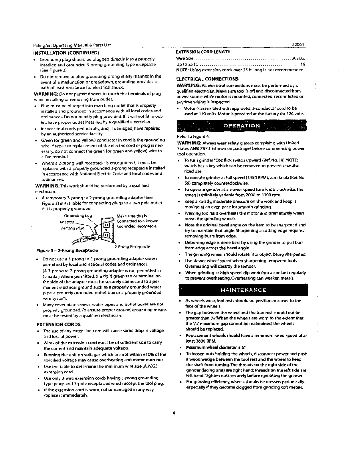
•This gdnder is equipped with an approved 3-conductor cord
rated' at 300V and a 3-prong, grounding _ype plug (See Figure
2) for your protection against shock hazards,
3*Pf_'_J P_ug_
Rgu_e 11- 3-Pro_ Re_eptatle
PalmgrenOperatingManual&Parts List
INSTALLATION {CONTINUED}
• Grounding plug should be plugged directly into a properly
installed and grounded :_ prong grounding_type receptacle
(See Figure 2).
•Donotremoveoraltergroundingpronginanymanner._nthe
event of a malfunction or breakdown, groun_ng provides a
path of least resistance for electrical shock.
WARNING: Do not permit fingers to touch the terminals of plug
when installing or removing from outlet.
•Plug must be plugged into matching oudet that is propedy
installed and grounded in accordance with all local codes and
ordin antes. Do not modify plug provided.If it will not fit in out-
let, have proper outlet installed by aqualified electrician.
Inspect tool cords periodically, and, ff damaged, have repaired
by an authorized service facility.
°Green (or green and yellow) conductor in cord is the grounding
wire. If repair or replacement of the electric cord or plug is nec-
essary" do not connect the green Ior green and yellow) wire to
a I_ve terminal.
° Where a 2-prong wall receptacle is encountered, it must be
replaced with a propedy grounded B-prong receptacle installed
in accordance with National Electric Code and Ic_:al codes and
ordinances.
WARNING;This work should be performed by a qualified
electrician.
•Atemporary 3-prong to 2-prong grounding adapter (See
Figure 3) is available for connecting plugs to a two pole outlet
if it is properly grounded.
Grounding Lug Make sure this is
Adapte:___._ Conn_ to aknown
3_ro Grounded Recep tare
2Prong Recepfacle
Figure 3 - 2-Prong Receptacle
Do not use a 3-prong to 2 prong grounding adapter unless
permitted by local a_d national codes and ordinances.
(A 3 prong to 2-prong grounding adapter is not permitted in
Canada{ Where permitted, the rigid green tab or terminal on
the side of the adapter must be securely _onnectod to ape_
manent electrical ground such as aproperly grounded water
pipe, apropedy grounded oudet box ar a propedy grounded
wire system.
• Many cover plate screws, water pipes and outlet boxes are not
properly grounded.To ensure proper ground, grounding means
must be tested by a qualified etectTician.
EXTENSION CORDS
The use of any extension card will cause some drop in voltage
and loss of power.
Wires of the extension cord must be of suffident size to carry
the current and maintain adequate voltage,
Running the unit on voltages which are not within _1 G% of the
specified voltage may cause overheating and motor burn-out.
Use the table to determine the minimum wire size (A.W.G.)
extension cord.
Use only 3 wire extension cords having 3-pT'ong grounding
type plugs and 3-pole receptades which accept the tool plug.
If the extension cord is worn. cut or damaged in any way,
replace it immediately.
82064
EXTENSION CORD LENGTH
Wire Size ............................................... _,.W.G.
Up to 25 It ................................................... 16
NOTE: Using extension cords over 25 ft. long is not recommended.
ELECTRICAL CONNECTIONS
WARNING: All electrical €onnecfions must be pe_ormed by a
qualified elect dc_an. Make sum tool is off and d(sconnected from
power source while motor is mounted, connected, reconnected or
anytime wiring is inspected.
• Motor is assembled with approved, 3-conductor cord to be
used at 12G vdit s. Motor is prewlred at the factory for t ZO volts.
Refer to Figure 4,
WARNING_ Alwayswear safetyglassescomplying with United
States ANSi Z_7.1 (shown on package) before commencing power
tool operation.
• TOtom gdnder "O N_flickswitch upward (Ref.No. 3gl. NOTE:
switch has a key which canbe removed to prevent unautho-
rized use.
•Toope_te grinder at foil speed (34S0 RPMI,turn knob (ReL No.
5g) completely counte_dockwise.
To ope_aLegdnder at aslower speed tom knob clockwise.The
speed is infinitely variable from 2000 to _,300rpm.
•Keepa steady, moderate pressureon the work and keep it
moving at an even pace for smooth grinding.
•Pressingtoo hard overheats the motor and prematurely wears
down the grinding wheels.
Note the origina) bevel angle o_ the item to be sharpened and
try to maintain that angle. Sharpening a cutting edge requires
removing burrsfrom edge.
•Debuning edge isdone best by using the gdnder to pull burr
fi'om edge acrossthe bevel angle.
• The grinding wheel should rotate into object being shaqoened,
•Use dower wheel speed when sharpening tempered tools.
Overheating will dest]oy the tofnper.
•When grinding at high speed, dip work into a coolant regulady
to prevent ovei'heat_ng,Overheedng can weaken metals.
As wheels wear, tool zests should be positioned closer to the
face of the wheels.
The gap bebveen the wheel and the Cool rest should not be
greater than _/_When the wheels are worn to the extent that
the _/_ maximum gap cannot be maintained, the wheels
should be replaced.
Replacement wheels should have a minimum rated speed of at
least 3600 RPM.
Maximum wheel diameter is 6."
To }oosen nuts holding the wheels, disconnect powe_" and push
a wood wedge between the tool rest and the wheel to keep
the shaft horn turning.The threads on the right side of the
gffnder (facing unit} are right hand; threads on the left side are
left hand._ghten nuts securely before operatfag the gdnder.
For gdnding effidenc, y, wheels should be dressed periodically,
espe_ally if they become clogged _rom gdndiag soft n_ta/s.
4
Palmgren Operating Manual & Parts List 82064
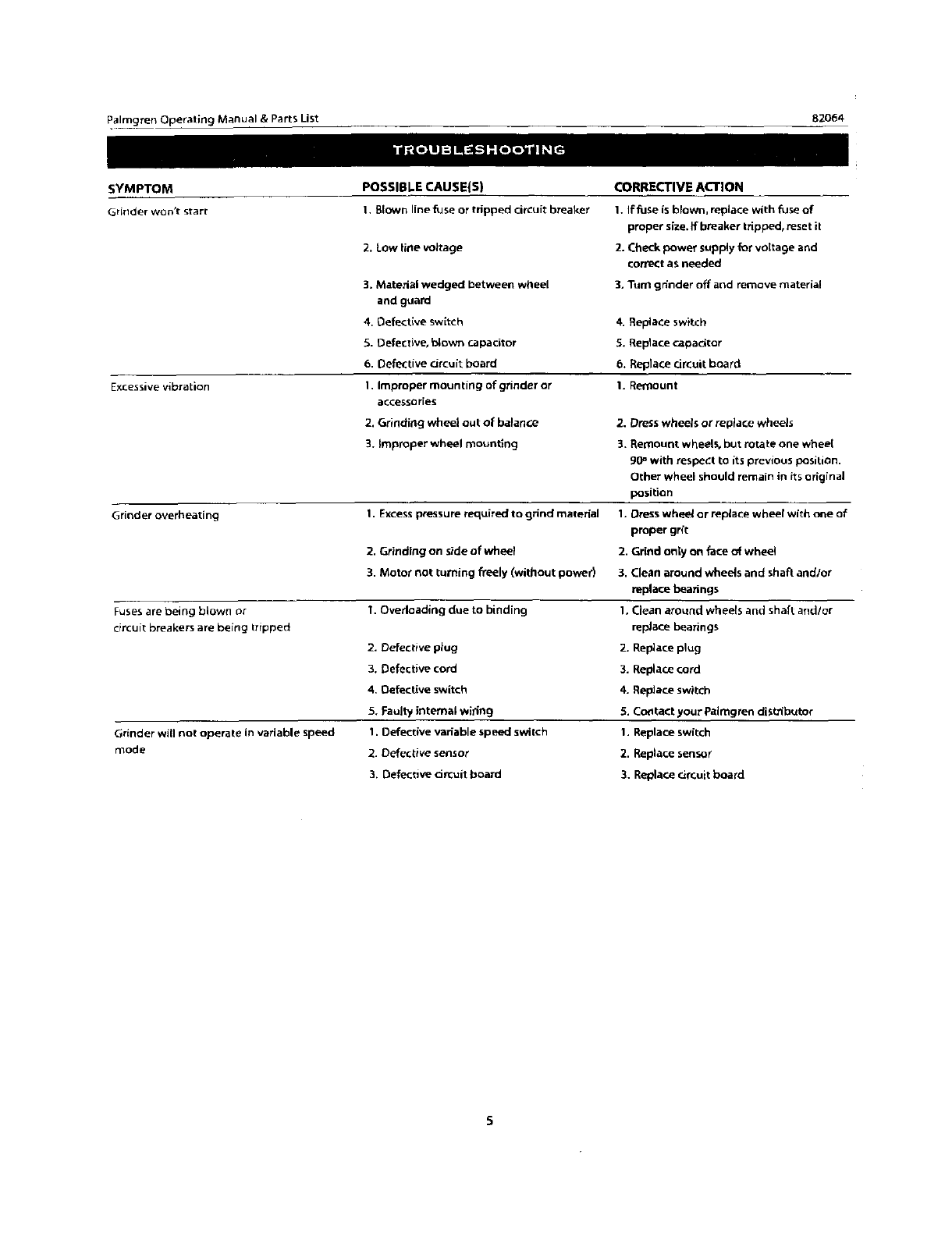
SYMPTOM POSSIBLE CAUSE(S) CORRECTIVE ACTION
Grinder won't start 1. Blown line fuse or tripped ciKuit breaker 1. If fuse is blown, replace with fuse of
proper size. if breaker tripped, reset it
2. Check power suppty for voltage and
correct as needed
3, "rum grinder off and remove material
Excessive vibration
Grinder overheating
Fuses are being blown or
circuit breakers are being tripped
Grinder will not operate in variable speed
n_ode
2. Low line voltage
3. Material wedged between wheel
and guard
4. Oef_ct(ve switch
_. Defective, _own capacitor
6. Defective circuit board
1. Improper mounting of grinder or
accessories
2. Grinding wheel out of balance
3. _mpmper wheel mounting
1. Excess pressure required to grind matorial
2, Grinding on side of wheel
3. Motor not turning freely (without powed
I. Overloading due to binding
2. Defective plug
3. Defective cord
4, Oefective switch
5, Faulty internal wi_Jng
1. Defect{ve variable speed switch
2. Defective sensor
3. Defective drcuit board
4, Replace switch
5. Replacecapadtor
6. Replace d_uit board
1. Remount
2. Dress whee/s or replace wheels
3, Remount wheelS, but rotate one wheel
RO_with respect to its previous position.
Other wheel should remain in its original
position
t. Dress wheel or replace wheel wfth one of
proper grft
2. Grind only on face of wheet
3. Clean around wheels and shaft and/or
replace bearings
1. CJean around wheels and shaft and/or
replace bearings
2. Replace plug
3. Replace cord
4. Replace switch
5. CcJzltact your PaJmgren distributor
1. Replace switch
2. Replace sensor
3. Replace circuit board
PaJmgTe.nJ_.._ing Manual&PartsLi_t 82064
4\
727
2
O_
4 29
16 11
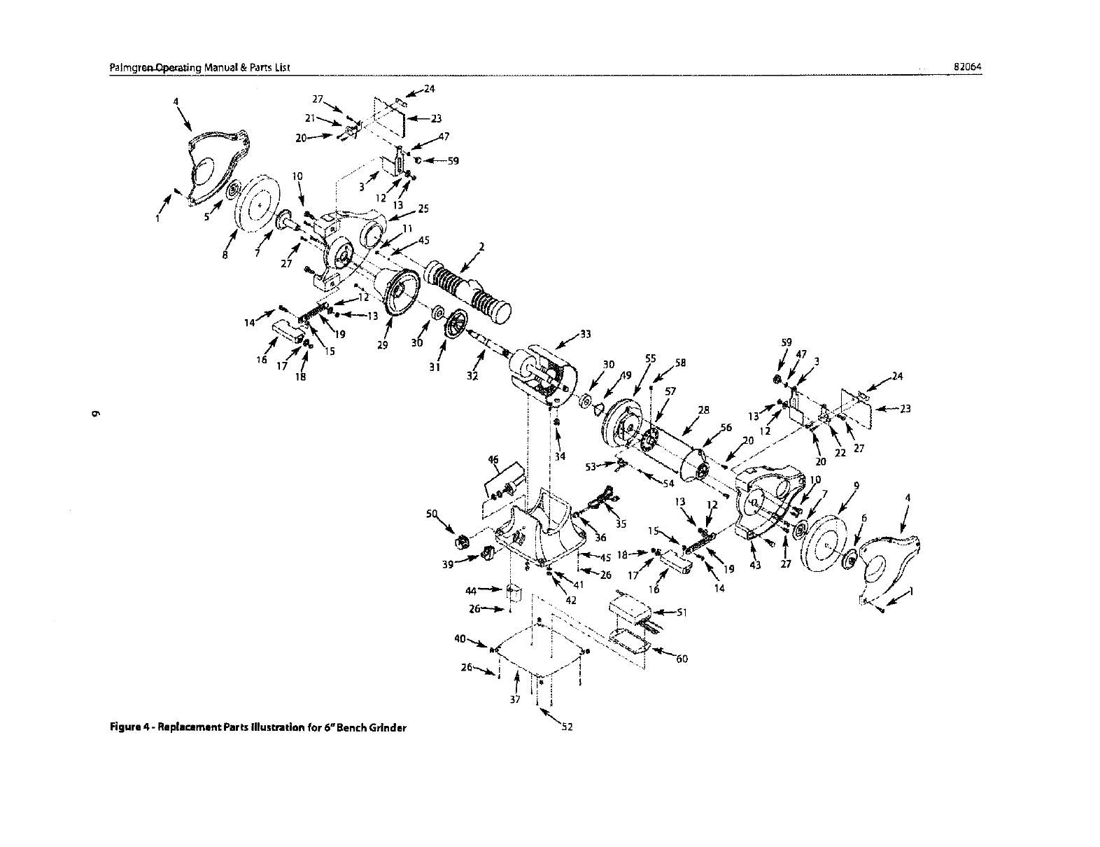
Figure 4 - Rep|eozment Parts illustration for 6" Bench Grinder
31 55
30
57
28
14
59
47 3
g4
°/
Falmgmn Operating Manual & PartsList 82064
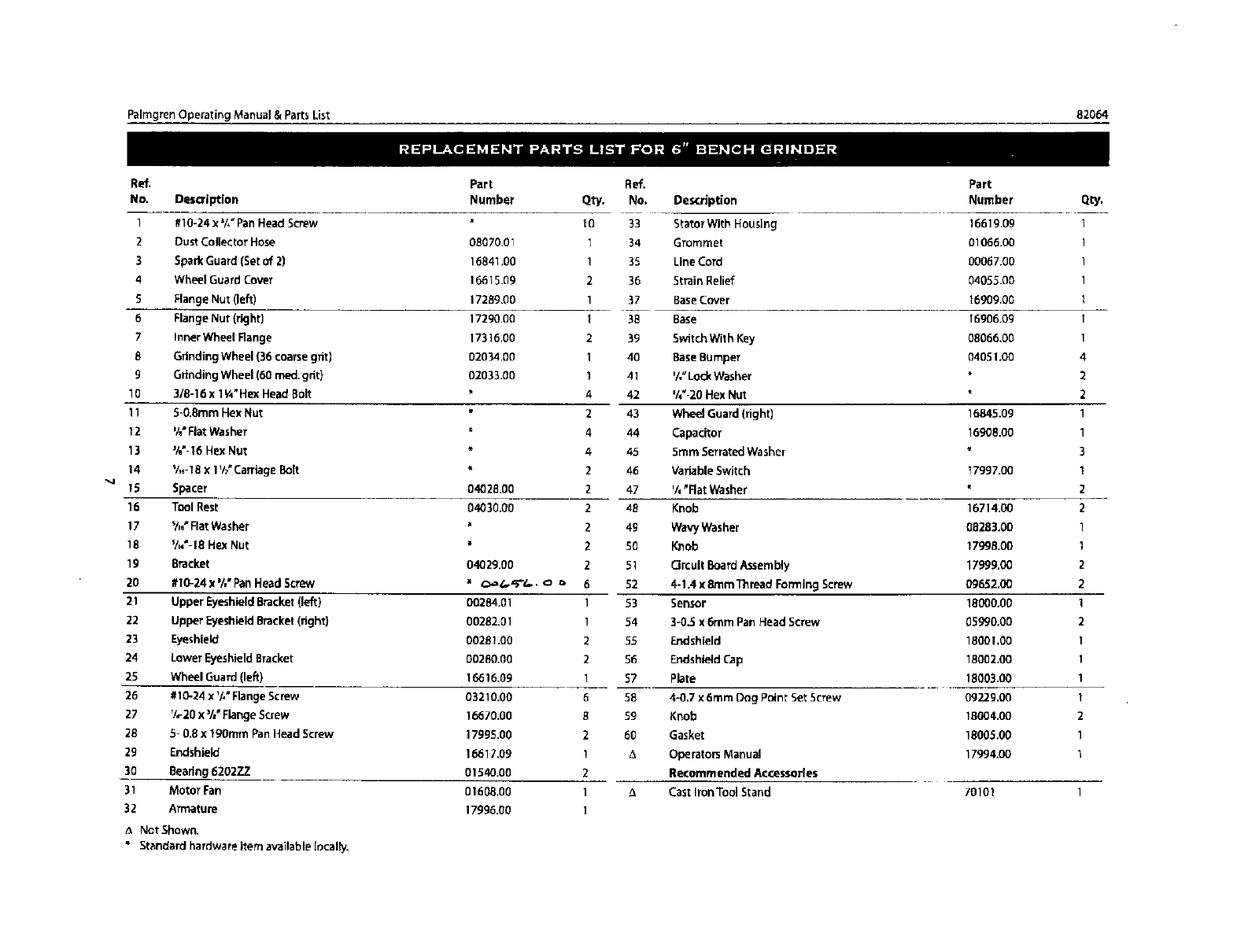
Ref.
No. Description
1 #10-24 x_/,"Pan HeadScrew
2DustCollector Hose
3 SparkGuard (Setof 2)
4 Wheel Guard Covet
SFlange Nut (left)
6 Flange Nut (right)
7Inner Wheel Range
8 GrindingWheel (36 coarsegfitl
gGrindingWheel (60 meal.grit}
10 318-16x 1¥4"Hex Head Bolt
11 S-0.8mm Hex Nut
12 %"FlatWasher
13 %" 16 Hex Nut
14 V,_-t8x l'h_Carriage Bolt
1S Spacer
16 Tool Rest
17 V,,"Flat Washer
tB '/_'-18 Hex Nut
19 Bracket
20 #10-24 x%" Pan HeadScrew
21 Upper Eyeshield Bracket(left)
22 Upper EyeshieldBracket(fight)
23 Eyeshield
24 Lower EyeshieldBracket
25 Wheel Guard (left)
26 #10-24 x '/," Flange Screw
27 7,-20 x%" FlangeScrew
28 S*0.8 x 19gram FanHead Screw
29 Endshield
30 Beadng620277
31 Motor Fan
32 Armature
Part
Number
08070.01
16841.00
16615.09
172Bg.O0
17290.00
17316.00
02034.00
02033.00
04028.00
04030.00
04029.00
00284.01
00282.01
00281.OO
00280.00
16616.09
03210.00
16670.00
1799S.00
16617.09
01540.00
016_,00
17996.00
Ref.
Qty, No. Description
1O 33 StatorWith Housing
t 34 Grommet
135 Line Cord
236 Strain Relief
137 BaseCover
I38 Base
2 39 Switch With Key
140 BaseBumper
1 41 '/,"LodeWasher
4 42 %"-20 Hex Nut
2 43 Wheel Guard (fight)
4 44 Capacitor
4 45 5mm SerratedWasher
2 46 Variable Switch
247 %_Rat Washer
2 4B Knob
24B WavyWasher
2 5B Knob
251 CircuitBoard Assembly
652 4-1.4 x 8ram Thread FormingScrew
1 53 Sensor
!54 3-0.5 x 6mrn Pan Head Screw
255 Endshield
2 50 EndshieldCap
157 Plate
6 BE 4-0.7 x6turn Dog Point Set Screw
B59 Knob
260 Gasket
! _, Oparator5 Manual
2Recommended Accessories
1_CastIron Tool Stand
1
Part
Number
16619.09
01066.00
00067.00
04055.00
16909.00
16906,09
08066.00
04051.00
16845.09
16908.00
17997.00
16714.00
08283.00
1799B.00
17999.00
09652.00
18000,00
05990.00
18(301.00
18002.00
18003.00
09229.00
18004.00
18005.00
17994.00
70101
_, Not Shown.
*Standard hardware item available local;y,
Qty.
1
1
1
1
1
1
1
4
2
2
1
1
3
1
2
2
1
t
2
2
1
2
1
1
1
1
2
1
1

Palmgren Operating Manual &Parts Ust 82054
FULL TWO YEAR WARRANTY ON PALMGREN BENCH GRIN DER
I[ wiLhin two full years from the dale of purchase, this Palmgren Bench Grinder fails due to adefect in material or
workmanship, Palmgren will repair it free of charge.
To order parts for a non-warranty repair, please contact your preferred Paling ten distributor.To obtain the names of Palmgren
distributors or to arrange warranty return, please calf Palmgren Steel Products directly at (8001 621 _ 145.
This warranty gives you specific legal rights and you may have other rights which vary from state to state.
Palmgren Steel Products, Inc., B383 S.Chicago Avenue, Chicago, IL 60617
