Craftsman 358350160 User Manual GASOLINE CHAIN SAW Manuals And Guides 99030002
CRAFTSMAN Chainsaw, Gas Manual 99030002 CRAFTSMAN Chainsaw, Gas Owner's Manual, CRAFTSMAN Chainsaw, Gas installation guides
User Manual: Craftsman 358350160 358350160 CRAFTSMAN GASOLINE CHAIN SAW - Manuals and Guides View the owners manual for your CRAFTSMAN GASOLINE CHAIN SAW #358350160. Home:Lawn & Garden Parts:Craftsman Parts:Craftsman GASOLINE CHAIN SAW Manual
Open the PDF directly: View PDF ![]() .
.
Page Count: 24
Operator's Manual
CRAFTSMRN
2.2 cu. in./36cc 2-Cycle
GASOLINE CHAIN SAW
Model No.
358.350160 -- 16 in. Bar
@
WARNING:
Read and follow all Safety Rules and Operating
Instructions before first use of this product.
For answers to your questions about this product:
Call 7 am-7 pro, Mon.-Sat., or 10 am-7 pm, Sun.
•1"800-235-5878 (Hourslisted are Central Time)
Sears, Roebuck and Co., Hoffman Estates, IL 60179 USA
530087755 1/11/99
Warranty 2 Storage 16
Safety Rules 2 Trouble Shooting Chart 17
Assembly 5 Parts List 20
Operation 6 Spanish 24
Maintenance 11 Parts & Ordering Back
Service and Adjustments 14
FULL ONE YEAR WARRANTY ON CRAFTSMAN ®GAS
CHAIN SAW
For one year from the date of purchase, when this Craftsman Gas Chain Saw is
malntai0ed, lubdcated and tuned up according to the owner's manual, Sears will
repalr_free of charge, any defect in material or workmanship.
This Warrantyexcludes the bar, chain, spark plug and air filter, which are
expendable parts, and become worn during normal use.
If this Gas Chain Saw is used for commercial or rental purposes, thiswarranty
applies for 30 days from the date of purchase.
WARRANTY SERVICE IS AVAILABLE BY RETURNING THIS CHAIN SAW TO
THE NEAREST SEARS SERVICE CENTER IN THE UNITED STATES.
This warranty gives you specific legal dghts, and you may also have other dghts
which vary from state to state.
Sears, Roebuck and Co., D/817 WA, Hoffman Estates, IL 60179
WARNING: Always disconnect spark
plugwire when making repairs except
for carburetor adjustments. Because a
chain saw is a high-speed woodcutting
tool, careless or improper use of this
tool can cause serious injury.
PLAN AHEAD
•Restrict the use of your saw to adult
users who understand and can follow
the safety rules, precautions, and op- °
erating instructionsfound.in this •
manual.
Hearing _ _Safety Hat
Protection_ __ Eye
=wet---- Protection
Snug _
F_ng "--_J Heavy Duty
_,oming _ .Gloves
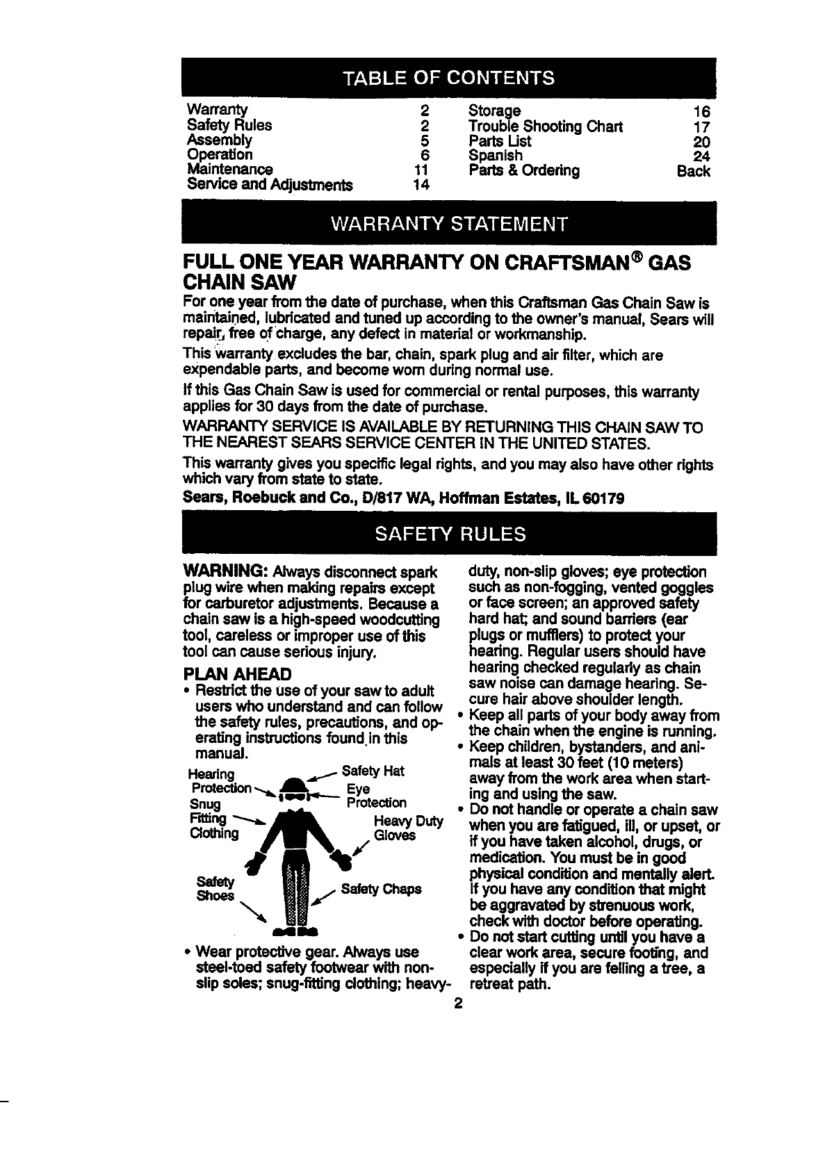
• Wear protective gear. Always use
etesl-toed safety footwear with non-
slip soles; snug-firing clothing; heavy- 2
duty, non-slipgloves; eye protection
such as non-fogging, vented goggles
or face screen; an approved safety
hard hat; and sound barriers (ear
plugs or mufflers) to protect your
hearing. Regular users should have
hearing checked regularly as chain
saw noise can damage headng. Se-
cure hair above shoulder length.
Keep all parts of your body away from
the chain when the engine is running.
Keep children, bystanders, and ani-
mals at least 30 feat (10 meters)
away from the work area when start-
ing and usingthe saw.
Do not handle or operate a chain saw
when you are fatigued, ill, or upset, or
if you have taken alcohol, drugs, or
medication. You must be in good
physicalcondition and mentally alert.
If you have any condition that might
be aggravated by strenuous work,
check with doctor before operating.
Do not start cuffing untilyou have a
clear work area, secure foob'ng,and
especially if you are felling a tree, a
retreat path.
OPERATE YOUR SAW SAFELY
• Donotoperatewithonehand.Seri-
ousinjuryto the operator,helpers,or
bystandersmayresultfrom one-
handedoperation.A chainsawis in-
tendedfor two-handeduse.
• Operatethe chain saw only in awell-
ventilated outdoor area.
•Do not operate saw from a ladder or
in a tree, unless you are specifically
trained to do so.
• Make sure the chain will not make
contact with any object while starting
the engine. Never try to start the saw
when the guide bar is in a cut.
• Do not put pressure on the saw, es-
pecially at the end ofthe cut. Doing
so can cause you to lose control
when the cut is completed.
•Stop engine before setting saw down.
•Hand carry saw only when engine is
stopped. Carry with muffler away from
body; guide bar & chain projecting be-
hind you; guide bar preferably cov-
ered with a scabbard.
MAINTAIN YOUR SAW IN GOOD
WORKING ORDER
•Have all chain saw service performed
by a qualified service dealer except
the items listed inthe maintenance
section of this manual.
•Make certain the saw chain stops
moving when the throttle trigger is re-
leased. For correction, refer to "Car-
buretor Adjustments."
•Keep the handles dry, clean, and free
from oil or fuel mixture.
• Keep caps and fasteners securely
tightened.
•Use only Craftsman accessodas and
replacement parts as recommended.
Never modify your saw.
HANDLE FUEL WITH CAUTION
•Do not smoke while handling fuel or
while operating the saw.
• Eliminate all sources of sparks or flame
in areas where fuel is mixed or poured.
•Mix and pour fuel in an outdoor area
and use an approved, marked con-
tainer for all fuel purposes. Wipe up
all fuel spills before starting saw.
•Move at least 10 feet (3 meters) from
fueling site before starting.
•Turn the engine off and let saw cool in
a non-combustible area, not on dry
leaves, straw, paper, etc. Slowly re-
move fuel cap and refuel unit.
•Store the unit and fuel in a cool, dry
well ventilated space where fuel va-
pors cannot reach sparks or open
flames from water heaters, electric
motors or switches, furnaces, etc.
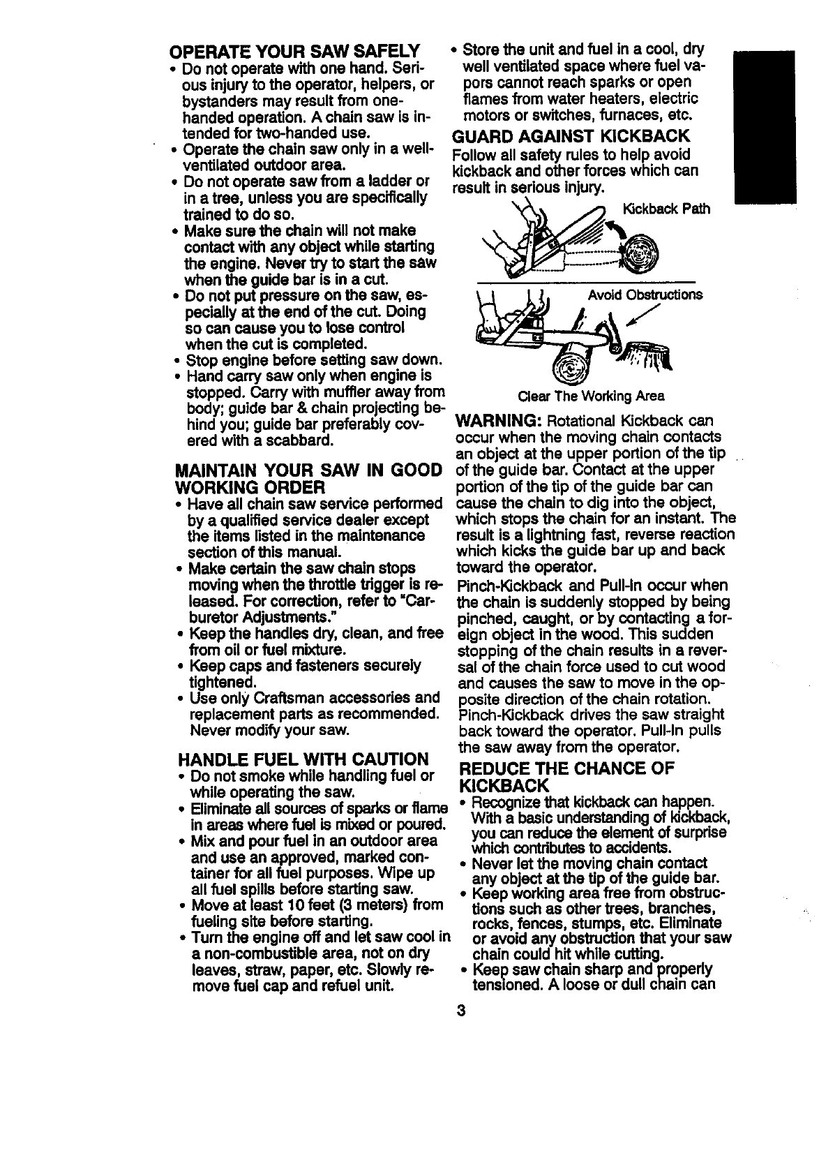
GUARD AGAINST KICKBACK
Follow all safety rules to help avoid
kickback and other forces which can
result in sedous injury.
'_ _ Kickback Path
Avoid Obstructions
ClearThe Working Area
WARNING: Rotational Kickback can
occur when the moving chain contacts
an object at the upper portion of the tip
of the guide bar. Contact at the upper
portion of the tip of the guide bar can
cause the chain to dig into the object,
which stops the chain for an instant. The
result is a lightning fast, reverse reaction
which kicks the guide bar up and back
toward the operator.
Pinch-Kickback and Pull-in occur when
the chain is suddenly stopped by being
pinched, caught, or by contacting a for-
eign object in the wood. This sudden
stopping of the chain results in arever-
sal of the chain force used to cut wood
and causes the saw to move in the op-
posite direction of the chain rotation.
Pinch-Kickback drives the saw straight
back toward the operator. Pull-In pulls
the saw away from the operator.
REDUCE THE CHANCE OF
KICKBACK
•Recognize that kickbackcan happen.
With a basic understandingof Idckback,
you can reducethe element of surpdse
which contributesto accidents.
Never !at the moving chain contact
_any at the ofthe guide bar.
object Up
Keep working area free from obstruc-
tions such as other trees, branches,
rocks,fences, stumps, etc. Eliminate
or avoid any obstruction that your saw
chain could hRwhile cutting.
•Kee? saw chain sharp and properly
tanmoned. A loose or dull chain can
3
increasethe chanceof kickback.Fol-
lowmanufacturer'schainsharpening
and maintenance instructions. Check
tension at regular intervals, but never
with engine running. Make sure bar
clamp nuts are securely tightened.
•Begin and continue cutting at full
speed. If the chain is moving at a
slower speed, there is greater chance
of kickback occurring.
•Use extreme caution when reentering
a cut.
•Do not attempt cuts starting with the
tip of the bar(plunge cuts).
•Watch for shifting logs or other forces
that could close a cut and pinch or fall
into chain.
•Use the specified Reduced-Kickback
Guide Bar and Low-Kickback Chain,
Avoid Pinch-Kickback:
•Be extremely aware of situations or
obstructions that can cause material
to pinch the top of or otherwise stop
the chain.
•Do not cut more than one log at a
time.
•Do not twist saw as bar is withdrawn
from an undercut when bucking.
Avoid Pull-in:
•Always begin cutting with the engine
at full speed and the saw housing
against wood.
•Use wedges made of plastic or wood.
Never use metal to hold the cut open.
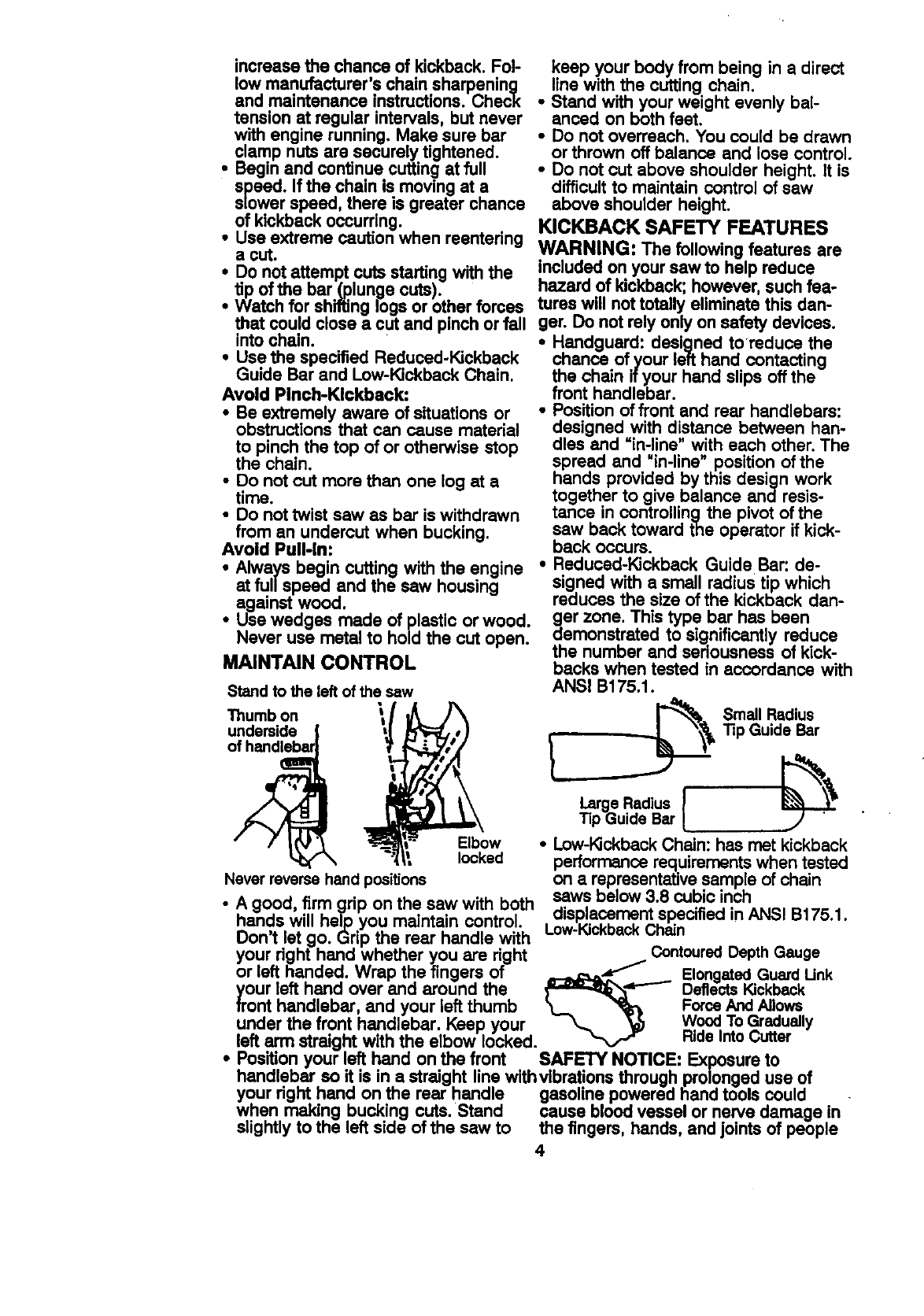
MAINTAIN CONTROL
Stand to the left of the saw
Thumbon
underside_
of handleba= \!
keep your body from being in a direct
line with the cutting chain.
•Stand with your weight evenly bal-
anced on both feet.
•Do not overreach. You could be drawn
or thrown off balance and lose control.
•Do not cut above shoulder height. It is
difficult to maintain control of saw
above shoulder height,
KICKBACK SAFETY FEATURES
WARNING: The following features are
included on your saw to help reduce
hazard of kickback; however, such fea-
tures will not totally eliminate this dan-
ger. Do not rely only on safety devices.
•Handguard: designed to reduce the
chance of your left hand contacting
the chain if your hand slips off the
front handlebar.
•Position of front and rear handlebars:
designed with distance between han-
dles and =in-line" with each other. The
spread and "in-line" position of the
hands provided by this design work
together to give balance and resis-
tance in controllingthe pivot of the
saw back toward the operator if kick-
back occurs.
•Reduced-Kickback Guide Bar: de-
signed with a small radius tip which
reduces the size of the kickback dan-
ger zone. This type bar has been
demonstrated to significantly reduce
the number and seriousness of kick-
backs when tested in accordance with
ANSI B175.1.
Small Redius
Tip Guide Bar
Elbow • Low-KickbackChain: has met kickback
locked performance requirements when tested
Neverreversehandpositions on a representative sample of chain
• • • saws below 3 8 cubic inch
A good, firm onp on the saw with both .... " .............
han ' ••oksplacemen_specmea m Areal U] (_ ]
ds w=llhel'oyou maJntam control........... ••
. LOW F_ICKDSCK _n_,n
Don_t let go. _rlp the rear handle with "
your right hand whether you are right _ContouredDepth Gauge
or left handed. Wrap the fingers of _-- Elongated GuardUnk
your left hand over and around the _--_"P"- DeflectsKickback
front handlebar, and your left thumb 'L_ _FarceAndAllows
under the front ha_..dlebar.Keep your _ _k5 WoodTo Gradually
left _ straight with the elbow locked. _RideIntoCutter
•Pos=tlonyour !.e.Rhand on the front SAFETY NOTICE: Exposure to
handlebar so it =sin a straight line withvibrafions through prolonged use of
your fight hand on the rear handle gasoline powered hand tools could
when making bucking cuts. Stand cause blood vessel or nerve damage in
slightly to the left side of the saw to the fingers, hands, and joints of people
4
proneto circulationdisordersor
abnormalswelling. Prolonged use in
cold weather has been linked to blood
vessel damage in otherwise healthy
people. If symptoms occur such as
numbness, pare, loss of strength,
change in skin color or texture, or loss
of feeling in the fingers, hands, or joints,
discontinue the use of this tool and
seek medical attention. An
anti-vibration system does not
guarantee the avoidance of these
problems. Users who operate power
tools on a continual and regular basis
must closely monitor their physical
condition and the condition of this tool.
CHAIN BRAKE If this saw is to be u_sbd
for commercial logging, you must order
and install a chain brake to comply with
Federal OSHA Regulations for Com-
mercial Logging. Contact your Sears
Service Center or call 1-800-235-5878.
SPARK ARRESTOR: Your saw is
equipped with a temperature limiting
muffler and spark arresting screen
which meets the requirements of
California Codes 4442 and 4443. All
U.S. forest land and the states of
California, Idaho, Maine, Minnesota,
New Jersey, Oregon, and Washington
require by law that many internal
combustion engines be equipped with a
spark arrestor screen. If you operate a
chain saw in a state or locale where
such regulations exist, you are legally
responsible for maintaining the
operating condition of these parts.
Failure to do so is a violation of the law.
Refer to Customer Responsibilities
chart in the k_AtWi'ENANCEsection.
STANDARDS: This chain saw is listed
by Underwriters Laboratories, Inc. in
accordance with American National
Standards for Gasoline-Powered Chain
Saws Safety Requirements (ANSI
B175.1-1991).
CARTON CONTENTS
Check carton contents against the fol-
lowing list.
Model 358.350160
• Chain Saw (fully assembled)
• Bar tool
•2-cycle engine oil
• Log Carder
•Carrying Case
•Examine parts for damage. Do not
use damaged parts.
•If you need assistance or find that
parts are missing or damaged, please
call 1-800-235-5878.
NOTE: It is normal to hear the fuel filter
raffle in an empty fuel tank.
Your unit has been factory tested and
the carburetor precisely adjusted. As a
result you may smell gasoline or find a
drop of oil/fuel residue on the muffler
when you unpack the unit.
ASSEMBLY
Your saw is fully assembled; no
assembly is necessary.
5
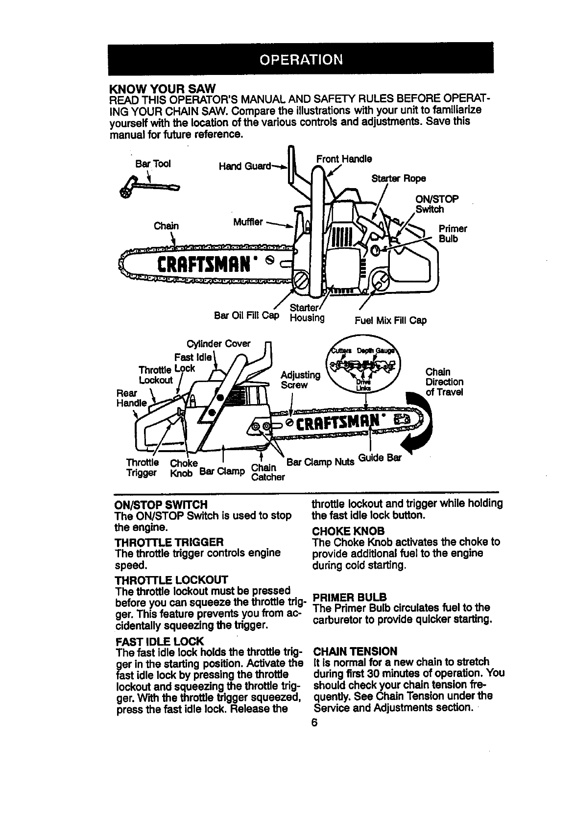
KNOW YOUR SAW
READTHISOPERATOR'SMANUALANDSAFETYRULESBEFOREOPERAT-
INGYOURCHAINSAW.Comparethe illustrationswith yourunitto familiarize
yourseffwith the location of the various controls and adjustments. Save this
manual for future reference.
•,_..... " . _ FrontHandle
iu_ ,u_, HandGuara.--.b_ yStart, Rope
,-"= go=o,
Chain Muffler"'"='1 t_ _ _'_ _J/_ Primer
/Starter /
BarOil FillCap HousJn FuelMixFill Cap
Cylinder Cover
Throttle Look Adjusting Chain
Lockout Screw Direction
Rear of Travel
Handle
Throttle Choke Bar Clamp Nuts Guide Bar
Tdgger Knob Bar Clamp Chain
Catcher
ON/STOP SWITCH
The ON/STOP Switch is used to stop
the engine.
THROTTLE TRIGGER
The throttle trigger controls engine
speed.
THROTTLE LOCKOUT
The throttle lockout must be pressed
before you can squeeze the throttle trig-
ger. Thin feature prevents you from ac-
cidentally squeezing the trigger.
FAST IDLE LOCK
The fast idle lock holds the throttle trig-
ger in the starting position. Activate the
fast idle lock by pressing the throttle
lockoutand squeezing the throttle trig-
ger. With the throttle trigger squeezed,
press the fast idle lock. Release the
throttle lockout and trigger while holding
the fast idle lock button.
CHOKE KNOB
The Choke Knob activates the choke to
provide additional fuel to the engine
during cold starting.
PRIMER BULB
The Primer Bulb circulates fuel to the
carburetor to provide quicker starting.
CHAIN TENSION
It is normal for a new chain to stretch
during first 30 minutes of operation. You
should check your chain tension fre-
quently. See Chain Tension under the
Service and Adjustments section.
6
BEFORE STARTING ENGINE
WARNING: Be sure to read the fuel
handling in._.rmation in the safety rules
section of th,s manual before you begln.
If you do not understand the fuel han-
dling information do not attempt to fuel
your unit. Seek help from someone that
does understand the information or call
the customer assistance help line at
1-800-235-5878.
GUIDE BAR AND CHAIN OIL
The chain oiler provides continuous lu-
brication to the chain and guide bar. Be
sure to fill the bar oil tank when you fill
the fuel tank (Capacity = 6.8 ft. oz.).
For maximum guide bar and chain life,
we recommend you use Craftsman
chain saw bar oil. if Craftsman bar oil is
not available, you may use a good
grade SAlE30 oil until you are able to
obtain Craftsman brand. The oil output
is automatically metered during opera-
tion. Your saw will use approximately
one tank of bar oil for every tank of fuel
mix. Always fill the bar oil tank when
you fill the fuel tank.
FUELING ENGINE
This engine is certified to operate on
unleaded gasoline. Before operation,
gasoline must be mixed with a good
quality 2-cycle air-cooled engine oil. We
recommend Craftsman brand oil. Mix
gasoline and oil at a ratio of 40:1 (A
40:1 ratio is obtained by mixing 3.2
ounces of oil with 1 gallon of unleaded
gasoline). DO NOT USE automotive oil
or boat oil. These oils will cause engine
damage. When mixing fuel follow the
instructions printed on the container.
Once oil is added to the gasoline,
shake container momentarily to assure
that the fuel is thoroughly mixed.
Always read and follow the safety rules
relating to fuel before fueling your unit.
IMPORTANT
Experience indicatesthat alcohol blended
fuels (calledgasohol or usingethanol or
methanol) can at_act moisturewhich
leads to separationand formationof
acidsdudng storage. Acidicgas can
damage the fuel system of an engine
while in storage.
To avoid engine problems,the fuel sys-
tem shouldbe emptied before storagefor
30 days or longer. Drain the gas tank,
startthe engine and let it run untilthe fuel
linesand carburetorare empty. Use fresh
fuel next season. See STORAGEinstruc-
tions for additional information.
Never use engine or carburetor cleaner
products in the fuel tank or permanent
damage may occur.
See the STORAGE section for additional
information.
STOPPING YOUR ENGINE
•Move On/Stop switch to STOP.
•If engine does not stop, pullchoke
knob out fully.
STARTING YOUR ENGINE
COLD ENGINE OR WARM ENGINE
AFTER RUNNING OUT OF FUEL
•Fuel engine with 40:1 fuel mix.
•Fill bar oil tank with bar oil.
•Prime engine by pressing pdmer bulb
six times.
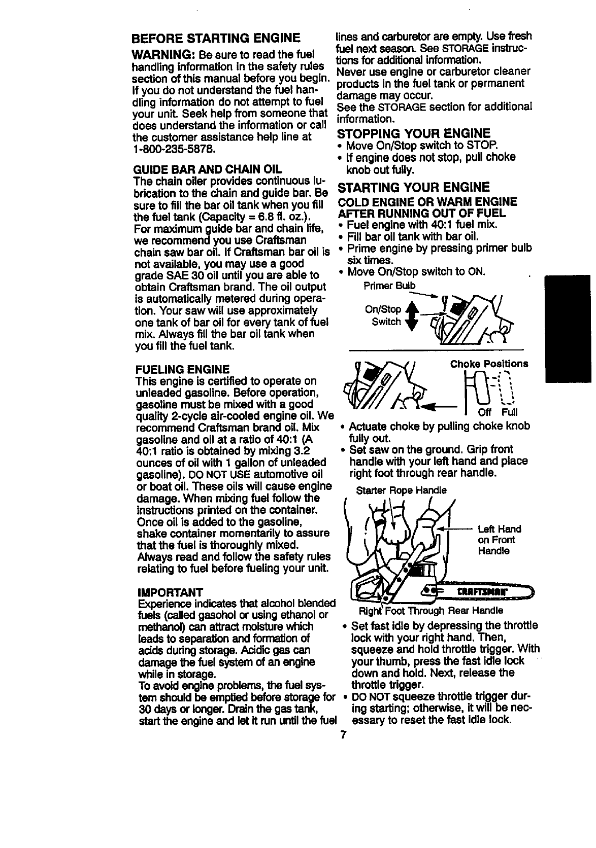
•Move On/Stop switch to ON.
Primer Bulb
Choke Posl_ons
t I
•1/I// 4._ lqI[_ Off Full
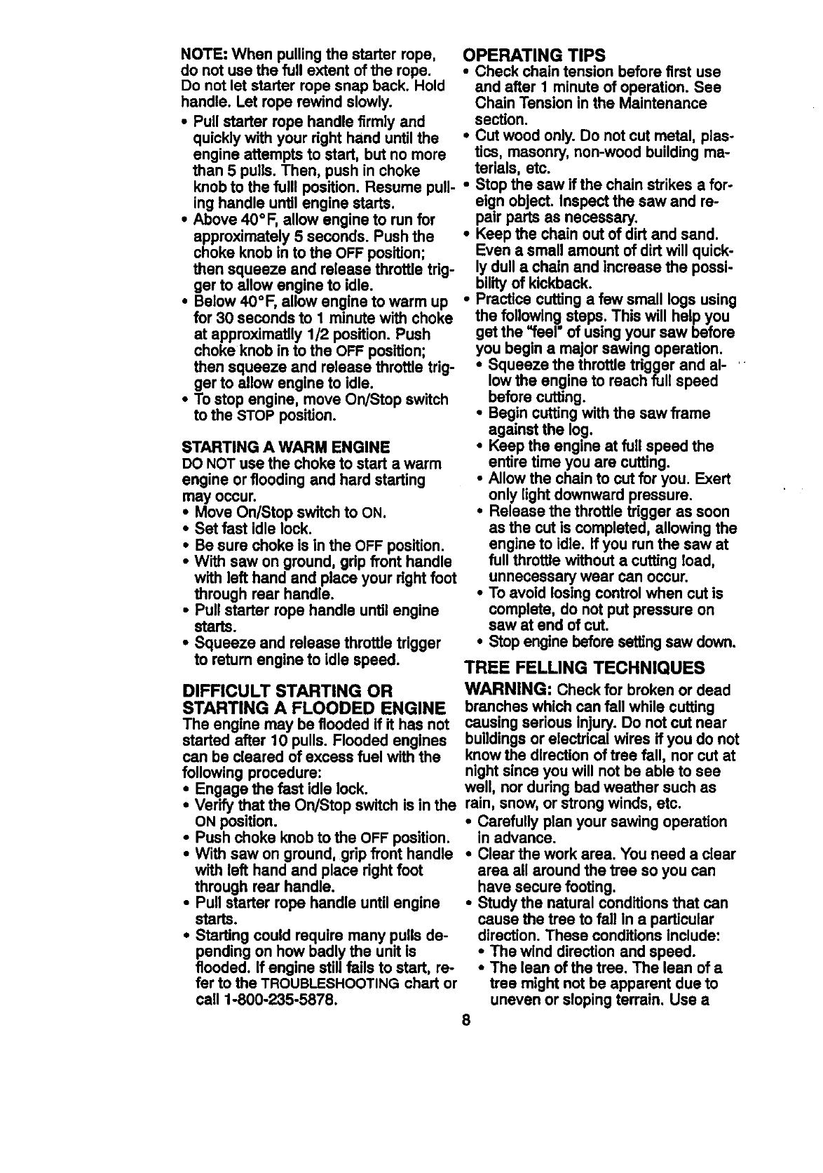
•Actuate choke by pulling choke knob
fully out.
•Set saw on the ground, Grip front
handle with your left hand and place
right foot through rear handle.
Starter Rope Handle
Left Hand
on Front
Handle
Foot Through Rear Handle
•Set fast idle by depressing the throttle
lock with your dght hand. Then,
squeeze and hold throttle trigger. With
your thumb, press the fast idle lock '
down and hold. Next, release the
throttle trigger.
•DONOT squeeze throttle trigger dur-
ing starting; otherwise, it will be nec-
essary to reset the fast idle lock.
7
NOTE:When pullingthe starterrope,
do notusethe full extentof the rope.
Do not let starter rope snap back. Hold
handle. Let rope rewind slowly.
•Pull starter rope handle firmly and
quickly with your right hand until the
engine attempts to start, but no more
than 5 pulls. Then, push in choke
knob to the fulll position. Resume pull-
ing handle until engine starts.
•Above 40°F, allow engine to run for
approximately 5 seconds. Push the
choke knob in to the OFF position;
then squeeze and release throttle trig-
ger to allow engine to idle.
•Below 40°F, allow engine to warm up
for 30 seconds to I minute with choke
at approximatily 1/2 position. Push
choke knob into the OFF position;
then squeeze and release throttle trig-
ger to allow engine to idle.
•To stop engine, move On/Stop switch
to the STOP position.
STARTING A WARM ENGINE
DO NOT use the choke to start a warm
engine or flooding and hard starting
may occur.
•Move On/Stop switch to ON.
•Set fast idle lock.
•Be sure choke is in the OFF position.
•With saw on ground, grip front handle
with left hand and place your right foot
through rear handle.
•Pull starter rope handle until engine
starts.
• Squeeze and release throttle trigger
to return engine to idle speed.
DIFFICULT STARTING OR
STARTING A FLOODED ENGINE
The engine may be flooded if it has not
started after 10 pulls. Flooded engines
can be cleared of excess fuel with the
following procedure:
•Engage the fast idle lock.
•Verify that the On/Stop switch is in the
ON position.
•Push choke knob to the OFF position.
•With saw on ground, grip front handle
with left hand and place right foot
through rear handle.
•Pull starter rope handle until engine
starts.
•Starting could require many pulls de-
pending on how badly the unit Is
flooded. If engine still fails to start, re-
fer to the TROUBLESHOOTINGchart or
call 1-800-235-5878.
OPERATING TIPS
•Check chain tension before first use
and after I minute of operation. See
Chain Tension in the Maintenance
section.
•Cut wood only. Do not cut metal, plas-
tics, masonry, non-wood building ma-
terials, etc.
•Stop the saw if the chain strikes a for-
eign object. Inspect the saw and re-
pair parts as necessary.
•Keep the chain out of dirt and sand.
Even a small amount of dirt will quick-
ly dull a chain and increase the possi-
bility of kickback.
•Practice cutting a few small logs using
the following steps. This will help you
get the =feel" of using your saw before
you begin a major sawing operation.
•Squeeze the throttle trigger and al-
low the engine to reach full speed
before cutting.
•Begin cutting with the saw frame
against the log.
•Keep the engine at full speed the
entire time you are cuffing.
•Allow the chain to cut for you. Exert
only light downward pressure.
•Release the throttle trigger as soon
as the cut is completed, allowing the
engine to idle. If you run the saw at
full throttle without a cutting load,
unnecessary wear can occur.
•To avoid losing control when cut is
complete, do not put pressure on
saw at end of cut.
•Stop engine before settingsaw down.
TREE FELLING TECHNIQUES
WARNING: Check for broken or dead
branches which can fall while cutting
causing serious injury. Do not cut near
buildingsor electrical wires if you do not
know the direction of tree fall, nor cut at
nightsince you will not be able to see
well, nor during bad weather such as
rain, snow, or strong winds, etc.
•Carefully plan your sawing operation
in advance.
•Clear the work area. You need a clear
area all around the tree so you can
have secure footing.
•Study the natural conditions that can
cause the tree to fall in a particular
direction. These conditions include:
•The wind direction and speed.
•The lean of the tree. The lean of a
tree might not be apparent due to
uneven or sloping terrain. Use a
8
plumbor levelto determinethe di-
rectionoftree lean.
•Weight and branches on one side.
•Surrounding trees and obstacles.
•Look for decay and rot. If the trunk is
rotted, it can snap and fall toward the
operator.
•Make sure there is enough room for
the tree to fall. Maintain a distance of
2-1/2 tree lengths from the nearest
person or other objects. Engine noise
can drown out a warning call.
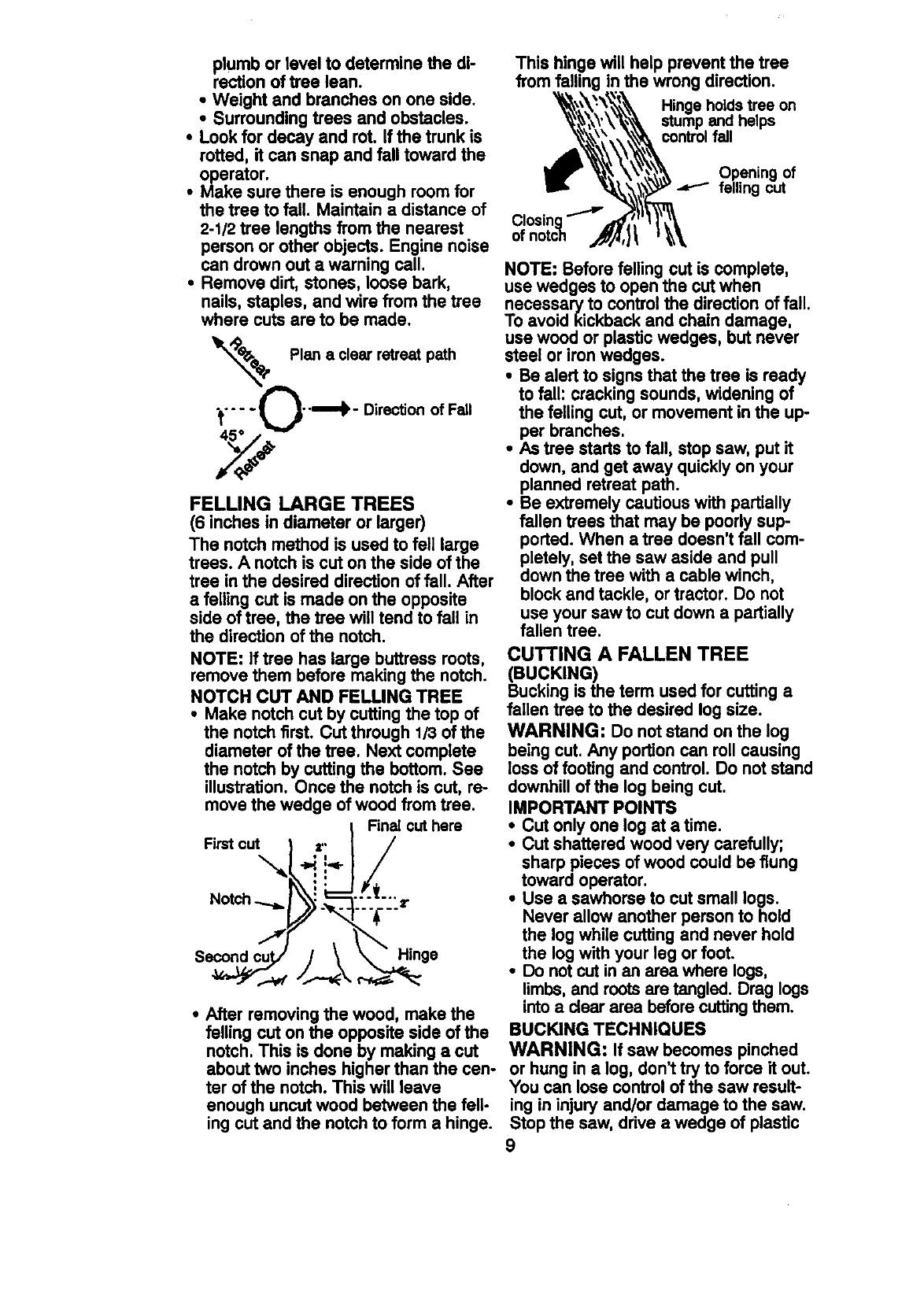
•Remove dirt, stones, loose bark,
nails, staples, and wire from the tree
where cuts are to be made.
Plan a clearretreatpath
;_.... L ._--'m'_ - Direction of Fall
FELLING LARGE TREES
(6 inches in diameter or larger)
The notch method is used to fell large
trees. A notch is cut on the side of the
tree in the desired direction of fall. After
afelling cut is made on theopposite
side oftree, the tree will tend to fall in
the direction of the notch.
NOTE: If tree has large buttress roots,
remove them before making the notch.
NOTCH CUT AND FELLING TREE
•Make notch cut by cuffing the top of
the notch first. CUtthrough 1/3 of the
diameter of the tree. Next complete
the notch by cutting the bottom. See
illustration. Once the notch is cut, re-
move the wedge of wood from tree.
Finalcuthere
Firstcut
Hinge
•After removing the wood, make the
falling cut on the opposite side of the
notch. This is done by making a cut
about two inches higher than the cen-
ter of the notch. This will leave
enough uncut wood between the felt-
ing cut and the notch to form a hinge.
This hinge will help prevent the tree
from falling in the wrong direction.
Hinge holds tree on
stump and helps
control fail
Opening of
felling cut
NOTE: Before felling cut is complete,
use wedges to open the cut when
necessar,/to controlthe direction of fall.
To avoidklckback and chain damage,
use wood or plastic wedges, but never
steel or iron wedges.
•Be alert to signs that the tree is ready
to fall: cracking sounds, widening of
the felling cut, or movement in the up-
per branches.
•As tree starts to fall, stop saw, put it
down, and get away quickly on your
planned retreat path.
•Be extremely cautious with partially
fallen trees that may be poody sup-
ported. When a tree doesn't fall com-
pletely, set the saw aside and pull
down the tree with a cable winch,
block and tackle, or tractor. Do not
use your sawto cut down a partially
fallen tree.
CUTTING A FALLEN TREE
(BUCKING)
Bucking is the term used for cutting a
fallen tree to the desired log size.
WARNING: Do not stand on the log
being cut. Any portion can roll causing
loss of footing and control. Do not stand
downhill of the log being cut.
IMPORTANT POINTS
• Cut only one log at a time.
•Cut shattered wood very carefully;
sharp pieces of wood could be flung
toward operator.
•Use a sawhorse to cut small logs.
Never allow another person to hold
the log while cutting and never hold
the logwith your leg or foot.
•Do not cut in an area where logs,
limbs,and roots are tangled. Drag logs
into a clear area before cuttingthem.
BUCKING TECHNIQUES
WARNING: If saw becomes pinched
or hung in a log, don_ttry to force it out.
You can lose control of the saw result-
ing in injury and/or damage to the saw.
Stop the saw, drive a wedge of plastic
9
orwoodintothe cutuntilthe saw can be
removed easily. Restartsaw and carefully
reenter the cut. Do not use a metal
wedge. Do not attemptto restartyour
saw when it is pinchedor hung in a log.
Use a wedge to remove pinched saw
Turn saw OFF and use a plastic or
wooden wedge to force cut open.
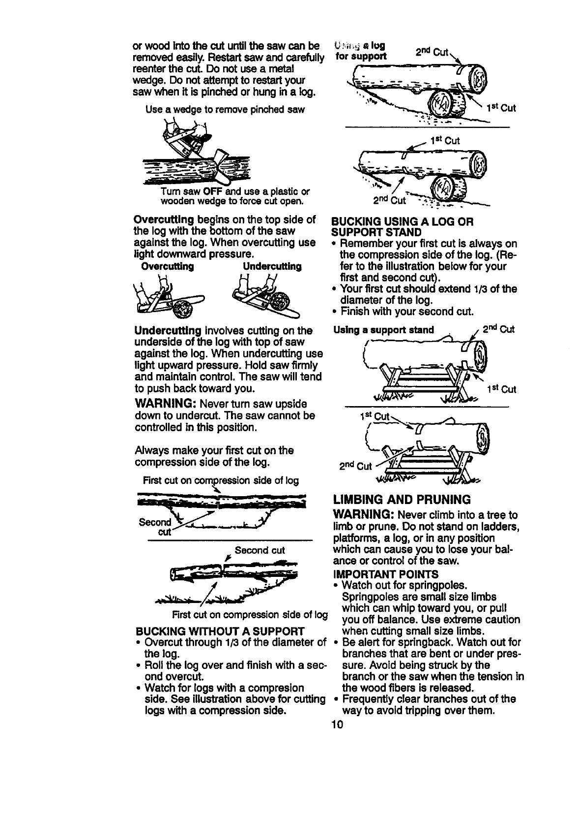
Overcutting begins on the top side of
the log with the bottom of the saw
against the log. When overcuffing use
light downward pressure.
Overcutting Undercutting
Undercutting involves cutting on the
underside of the log with top of saw
against the log. When undercutting use
light upward pressure. Hold saw firmly
and maintain control. The saw will tend
to push back toward you.
WARNING: Never turn saw upside
down to undercut, The saw cannot be
controlled in this position.
L_,;_ ,_ log
for support _2nd Cut,,_
_st Cut
I stCut
2nd Cut _
BUCKING USING A LOG OR
SUPPORT STAND
• Remember your first cut is always on
the compression side of the log. (Re-
fer to the illustration below for your
first and second cut).
•Your first cut should extend 1/3 of the
diameter of the log,
•Finishwith your second cut.
Using/_ ndCut
_
_Y/:x'''"_/_" "" 1stCut
Always make your first cut on the
compression side of the log,
First cut on compassion side of log
Second cut
#
First cut on compression slde of log
BUCKING WITHOUT A SUPPORT
•Overcut through 1/3 of the diameter of
the log.
• Roll the log over and finish with a sec-
ond overcut.
•Watch for logs with a compresion
side. See illustration above for cutting
logs with a compression side.
2nd(
LIMBING AND PRUNING
WARNING: Never climb into a tree to
limb or prune, Do not stand on ladders,
platforms, a log, or in any position
which can cause you to lose your bal-
ance or control of the saw.
IMPORTANT POINTS
•Watch out for springpoles.
Springpoles are small size limbs
which can whip toward you, or pull
you off balance, Use extreme caution
when cuffing small size limbs.
•Be alert for springback, Watch out for
branches that are bent or under pres-
sure. Avoid being struck by the
branch or the saw when the tension in
the wood fibers is released.
•Frequently clear branches out of the
way to avoid tripping over them.
10
LIMBING
•Limb a tree only after it is cut down.
•Leave the larger limbs underneath the
felled tree to support the tree as you
work.
•Start at the base of the felled tree and
work toward the top, cutting branches
and limbs. Remove small limbs with
one cut.
•Keep the tree between you and the
chain.
•Remove larger, supporting branches
with the 1/3, 2/3 cutting techniques de-
scribed in the bucking section.
•Always use an overcut to cut small
and freely hanging limbs. Undercut-
ting could cause limbs to fall and
pinch the saw.
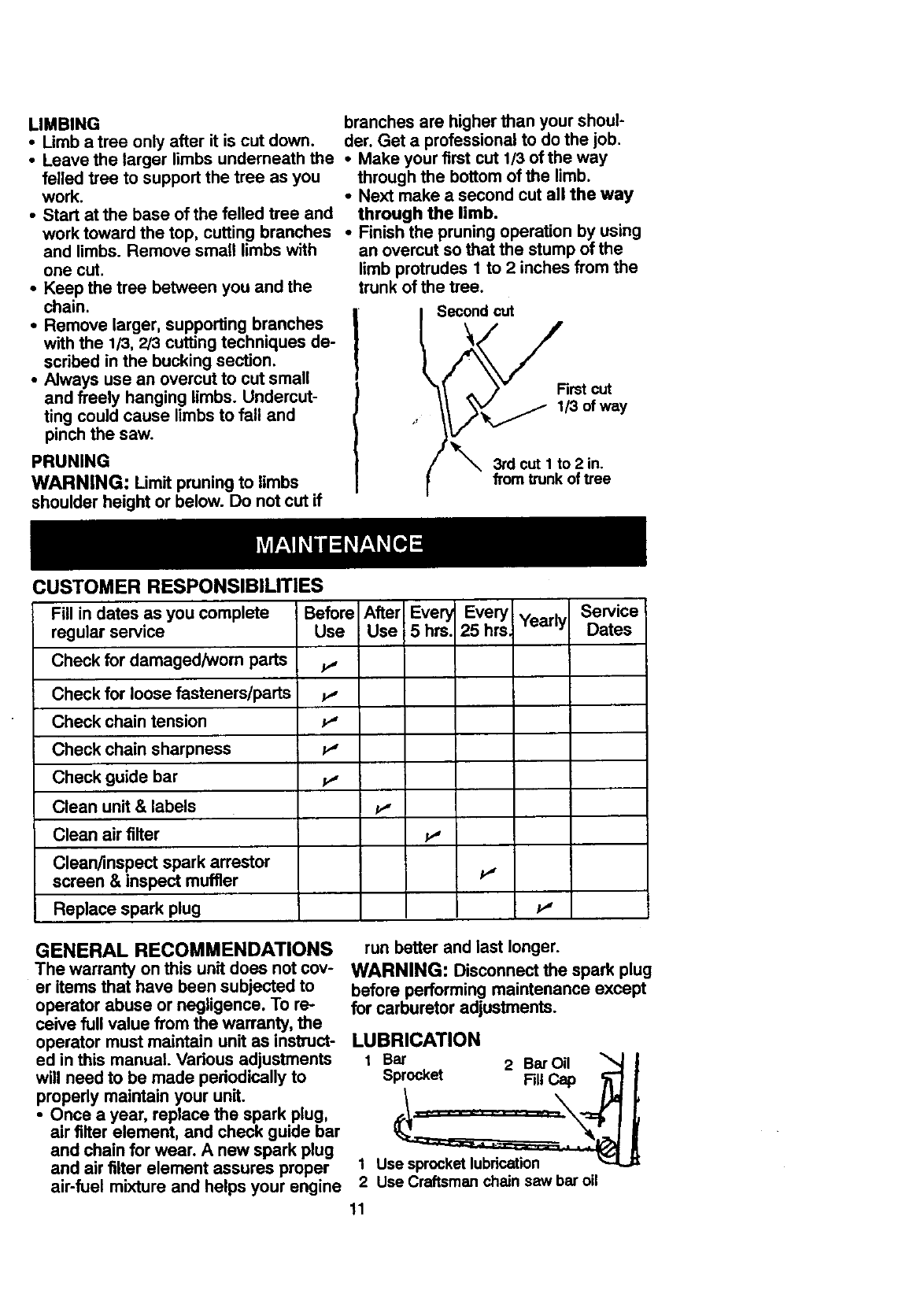
PRUNING
WARNING: Limit pruning to limbs
shoulder height or below. Do not cut if
CUSTOMER RESPONSIBILITIES
branches are higher than your shoul-
der. Get a professional to do the job.
•Make your first cut 1/3 of the way
through the bottom of the limb.
•Next make a second cut all the way
through the limb.
•Finish the pruning operation by using
an overcut so that the stump of the
limb protrudes 1 to 2 inches from the
trunk of the tree.
ISecond_
First cut
1/3 of way
3rd cut I to 2 in.
from trunk of tree
Fill in dates as you complete Before After Every EveryIYearly
regular service Use Use 5 hrs. 25 hrs_
Check for damaged/worn parts v"
Check for loose fasteners/parts _,
Check chain tension P"
Check chain sharpness P"
Check guide bar
Clean unit & labels _,,
Clean air filter _,
Clean/inspect spark arrestor
screen & inspect muffler P"
Replace spark plug _'
Service
Dates
GENERAL RECOMMENDATIONS
The warranty on this unit does not cov-
er items that have been subjected to
operator abuse or negligence. To re-
ceive full value from the warranty, the
operator must maintain unit as instruct-
ed in this manual. Various adjustments
will need to be made periodically to
properly maintain your unit.
•Once a year, replace the spark plug,
air filter element, and check guide bar
and chain for wear. A new spark plug
and air filter element assures proper
air-fuel mixture and helps your engine
run better and last longer.
WARNING: Disconnect the spark plug
before performing maintenance except
for carburetor adjustments.
LUBRICATION
1 Bar 2 Bar Oil
Sprocket FillCap
1 Use sprocket lubrication
2 Use Craftsman chain saw bar oil
11
CHECK FOR DAMAGED OR
WORN PARTS
Replacement of damaged/_wom parts
should be referred to your Sears Ser-
vice Center.
NOTE: It is normal for a small amount
of oil to appear under the saw after en-
gine stops. Do not confuse this with a
leaking oil tank.
•On/Stop Switch -Ensure On/Stop
switch functions properly by moving
the switch to the =Stop" position.
Make sure engine stops; then restart
engine and continue.
•Fuel Tank - Do not use saw if fuel
tank shows signs of damage or leaks.
• Oil Tank - Do not use saw if oil tank
shows signs of damage or leaks.
CHECK FOR LOOSE
FASTENERS AND PARTS
•Bar Clamp Nut
•Chain
•Muffler
•Cylinder Shield
•Air Filter
•Clutch Drum/Sprocket
•Handle Screws
•Vibration Mounts
•Starter Housing
•Handguard
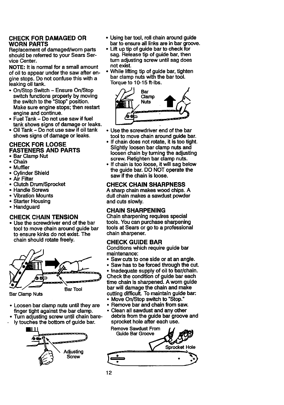
CHECK CHAIN TENSION
•Use the screwdriver end of the bar
tool to move chain around guide bar
to ensure kinks do not exist. The
chain should rotate freely.
Bar Clamp Nuts Bar Tool
•Loosen bar clamp nuts until they are
finger tight against the bar clamp.
•Turn adjusting screw until chain bare-
ly touches the bottom of guide bar.
•Using bar tool, rollchain around guide
barto ensure all linksare in bar groove.
•Lift up tip of guide bar to check for
sag. Release tip of guide bar, then
turn adjusting screw until sag does
not exist.
•While lifting tip of guide bar, tighten
bar clamp nuts with the bar tool.
Torque to 10-15 ft-lbs.
•Use the screwdriver end of the bar
tool to move chain around guide bar.
•If chain does not rotate, it is too tight.
Slightly loosen bar clamp nuts and
loosen chain by tuming the adjusting
screw. Retighten bar clamp nuts.
•If chain is too loose, it will sag below
the guide bar. DO NOT operate the
saw if the chain is loose.
CHECK CHAIN SHARPNESS
A sharp chain makes wood chips. A
dull chain makes a sawdust powder
and cuts slowly,
CHAIN SHARPENING
Chain sharpening requires special
tools. You can purchase sharpening
tools at Sears or go to a professional
chain sharpener.
CHECK GUIDE BAR
Conditions which require guide bar
maintenance:
•Saw cuts to one side or at an angle.
•Saw has to be forced through the cut.
•Inadequate supply of oil to bar/chain.
Check the condition of guide bar each
time chain is sharpened. A worn guide
bar will damage the chain and make
cutting difficult. To maintain guide bar:
•Move On/Stop switch to =Stop.n
•Remove bar and chain from saw.
•Clean all sawdust and any other
debris from the guide bar groove and
sprocket hole after each use.
Remove Sawdust From IJ J_..
Guide Bar Groov_
_i_ Sprocket Hole,
12
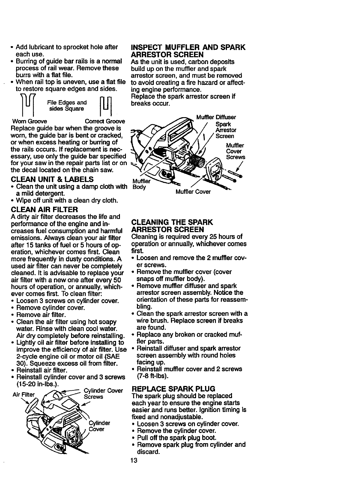
•Add lubricant to sprocket hole after
each use.
• Burring of guide bar rails is a normal
process of rail wear. Remove these
burrs with a flat file.
•When rail top is uneven, use a fiat file
to restore square edges and sides.
File Edges andsides Square
Worn Groove Correct Groove
Replace guide bar when the groove is
worn, the guide bar is bent or cracked,
or when excess heating or burring of
the rails occurs. If replacement is nec-
essary, use only the guide bar specified
for your saw in the repair parts list or on
the decal located on the chain saw.
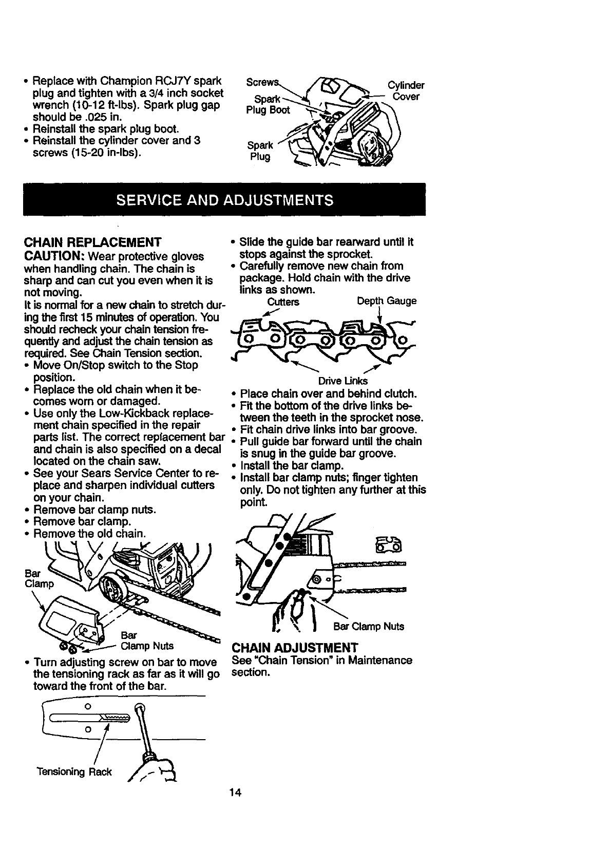
INSPECT MUFFLER AND SPARK
ARRESTOR SCREEN
As the unit is used, carbon deposits
build up on the muffÊerand spark
arrestor screen, and must be removed
to avoid creating a fire hazard or affect-
ing engine performance.
Replace the spark arrestor screen if
breaks occur.
Muffler Diffuser
Spark
Arrestor
Screen
Muffler
Cover
/
CLEAN UNIT & LABELS Muffler
•Clean the unit using a damp cloth with Body
amild detergent.
•Wipe off unit with a clean dry cloth.
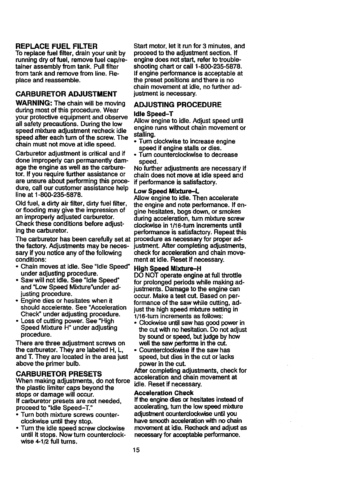
CLEAN AIR FILTER
A dirty air filter decreases the life and
performance of the engine and in-
creases fuel consumption and harmful
emissions. Always clean your air filter
after 15 tanks of fuel or 5 hours of op-
eration, whichever comes first. Clean
more frequently in dusty conditions. A
used air filter can never be completely
cleaned. It is advisable to replace your
air filter with a new one after every 50
hours of operation, or annually, which-
ever comes first. To clean filter:
•Loosen 3 screws on cylinder cover.
•Remove cylinder cover.
•Remove air filter.
•Clean the air filter using hot soapy
water. Rinse with clean cool water.
Air dry completely before reinstalling.
•Lightly oil air filter before installing to
improve the efficiency of air filter. Use
2-cycle engine oil or motor oil (SAE
30). Squeeze excess oil from filter.
•Reinstall air filter.
•Reinstall cylinder cover and 3 screws
(15-20 in-lbs.). Cylinder Cover
Air Filter Screws
Cylinder
Cover
Muffler Cover
CLEANING THE SPARK
ARRESTOR SCREEN
Cleaning is required every 25 hours of
operation or annually, whichever comes
first.
•Loosen and remove the 2 muffler cov-
er screws.
•Remove the muffler cover (cover
snaps off muffler body).
•Remove muffler diffuser and spark
arrestor screen assembly. Notice the
orientation of these parts for reassem-
bling.
•Clean the spark arrestor screen with a
wire brush. Replace screen if breaks
are found.
•Replace any broken or cracked muf-
fler parts.
•Reinstall diffuser and spark arrestor
screen assembly with round holes
facing up.
•Reinstall muffler cover and 2 screws
(7-8 ft-lbs).
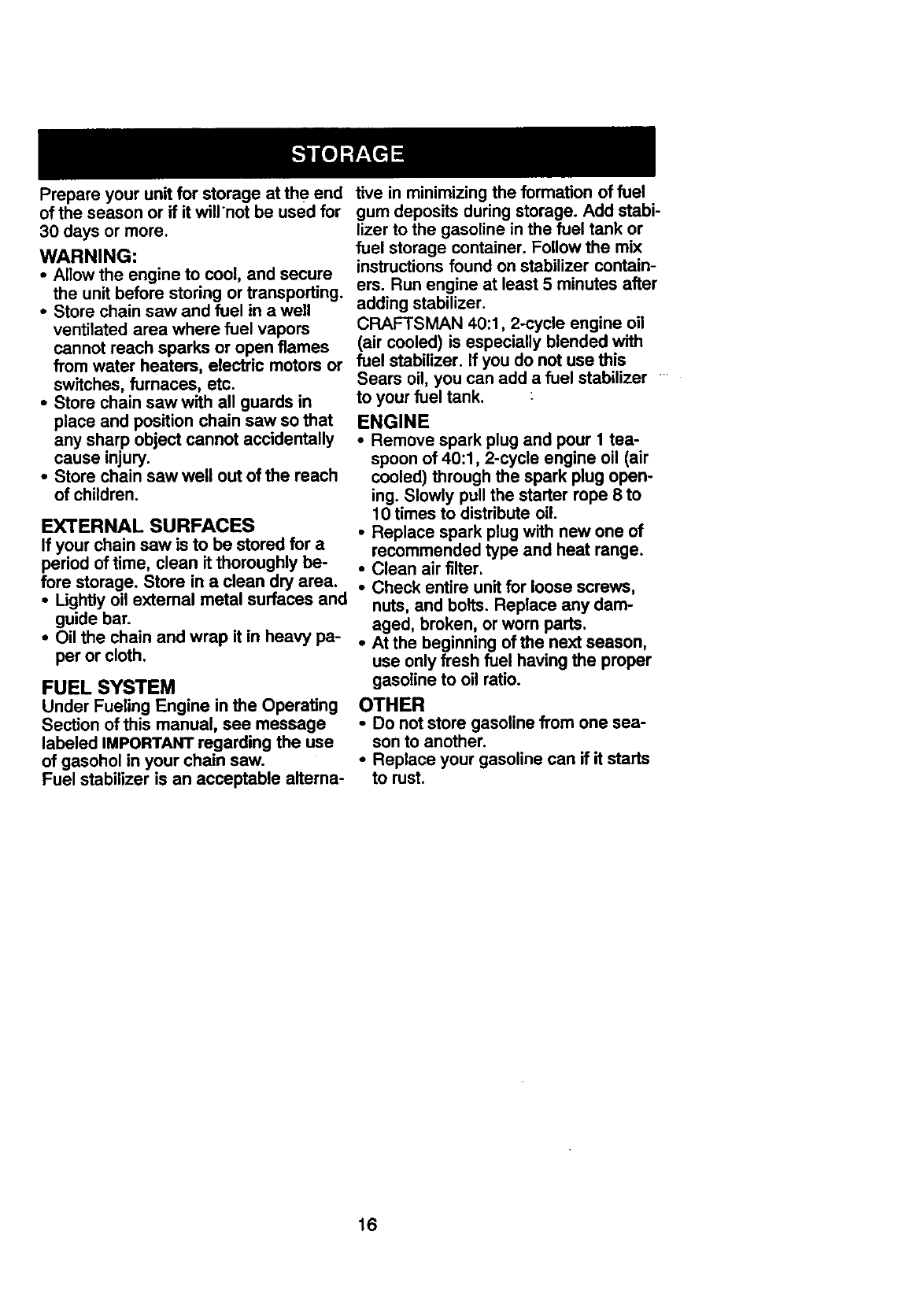
REPLACE SPARK PLUG
The spark plug should be replaced
each year to ensure the engine starts
easier and runs better. Ignition timing is
fixed and nonadjustable.
•Loosen 3 screws on cylinder cover.
•Remove the cylinder cover.
•Pull offthe spark plug boot.
•Remove spark plug from cylinder and
discard.
13
• Replace with Champion RCJ7Y spark
plug and tighten with a3/4 inch socket
wrench (10-12 ft-lbs). Spark plug gap
should be .025 in.
•Reinstall the spark plug boot.
•Reinstall the cylinder cover and 3
screws (15-20 in-lbs).
Plug Boot
Plug
Cylinder
Cover
CHAIN REPLACEMENT • Slide the guide bar rearward until it
CAUTION: Wear protective gloves stops against the sprocket.
when handling chain. The chain is •Carefully remove new chain from
sharp and can cut you even when it is package. Hold chain with the drive
not moving, links as shown.
It is normal for a new chainto stretchdur-
ing the first 15 minutes of operation. You
shouldrecheck your chain tension fre-
quentlyand adjustthe chain tension as
required.See Chain Tension section,
•Move On/Stop switch to the Stop
position.
•Replace the old chain when it be-
comes worn or damaged.
•Use onlythe Low-Kickback replace-
ment chain specified inthe repair
parts list. The correct replacement bar
and chain is also specified on a decal
located on the chain saw.
•See your Sears Service Center to re-
place and sharpen individual cutters
on your chain.
•Remove bar clamp nuts.
•Remove bar clamp.
•Remove the old chain.
Bar
Clamp
Bar pNuts
•"rum adjusting screw on bar to move
the tensioning rack as far as it will go
toward the front of the bar.
Cutters DepthGauge
DriveUnks
•Place chain over and behind clutch.
•Fit the bottom of the drive links be-
tween the teeth in the sprocket nose,
•Fit chain drive links into bar groove.
•Pull guide bar forward until the chain
is snug in the guide bar groove.
•Install the bar clamp.
•Install bar clamp nuts; finger tighten
only. Do nottighten any further at this
point.
Bar Clamp Nuts
CHAIN ADJUSTMENT
See =Chain Tension" in Maintenance
section.
o
o
Tensioning Rack
14
REPLACE FUEL FILTER
Toreplacefuel filter, drainyour unitby
runningdryof fuel, removefuel cap/re-
tainerassemblyfromtank. Pullfiller
fromtankandremovefrom line. Re-
place and reassemble.
CARBURETOR ADJUSTMENT
WARNING: The chain will be moving
during most of this procedure. Wear
your protective equipment and observe
all safety precautions. During the low
speed mixture adjustment recheck idle
speed after each turn of the screw. The
chain must not move at idle speed.
Carburetor adjustment is critical and if
done improperly can permanently dam-
age the engine as well as the carbure-
tor. If you require further assistance or
are unsure about performing this proce-
dure, call our customer assistance help
line at 1-800-235-5878.
Old fuel, a dirty air filter, dirty fuel filter,
or flooding may give the impression of
an improperly adjusted carburetor.
Check these conditions before adjust-
ing the carburetor.
The carburetor has been carefully set at
the factory. Adjustments may be neces-
sary if you notice any of the following
conditions:
•Chain moves at idle. See Uldle Speed"
under adjusting procedure.
•Saw will not idle. See "Idle Speed"
and "Low Speed Mixture"under ad-
justing procedure.
•Engine dies or hesitates when it
should accelerate. See =Acceleration
Check" under adjusting procedure.
•Loss of cutting power. See =High
Speed Mixture H" under adjusting
procedure.
There are three adjustment screws on
the carburetor. They are labeled H, L,
and T. They are located in the area just
above the primer bulb.
CARBURETOR PRESETS
When making adjustments, do not force
the plastic limiter caps beyond the
stops or damage will occur.
If carburetor presets are not needed,
proceed to =Idle Speed-T."
•Turn both mixture screws counter-
clockwise until they stop.
•Tum the idle speed screw clockwise
until it stops. Now turn counterclock-
wise 4-1/2 full turns.
Start motor, let it run for 3 minutes, and
proceed to the adjustment section. If
engine does not start, refer to trouble-
shooting chart or call 1-800-235-5878.
If engine performance is acceptable at
the preset positions and there is no
chain movement at idle, no further ad-
justment is necessary.
ADJUSTING PROCEDURE
Idle Speed-T
Allow engine to idle. Adjust speed until
engine runs without chain movement or
stalling.
•Turn clockwise to increase engine
speed if engine stalls or dies.
•Turn counterclockwise to decrease
speed.
No further adjustments are necessary if
chain does not move at idle speed and
if performance is satisfactory.
Low Speed Mixture-L
Allow engine to idle. Then accelerate
the engine and note performance. If en-
gine hesitates, bogs down, or smokes
during acceleration, turn mixture screw
clockwise in 1/16-turn increments until
performance is satisfactory. Repeat this
procedure as necessary for proper ad-
justment. After completing adjustments,
check for acceleration and chain move-
ment at idle. Reset if necessary.
High Speed Mixture-H
DO NOT operate engine at full throttle
for prolonged periods while making ad-
justments. Damage to the engine can
occur. Make a test cut. Based on per-
formance of the saw while cutting, ad-
just the high speed mixture setting in
1/16-turn increments as follows:
•Clockwiseuntilsaw has good power in
the cut with no hesitation.Do not adjust
by soundor speed, butjudge by how
well the saw performs in the cut.
•Counterclockwise if the saw has
speed, butdies in the cut or lacks
power in the cut.
After completing adjustments, check for
acceleration and chain movement at
idle. Reset if necessary.
Acceleration Check
If the engine dies or hesitates insteadof
accelerating,turnthe low speed mixture
adjustmentcounterclockwiseuntilyou
have smoothaccelerationwith no chain
movement at idle. Recheck and adjust as
necessaryfor acceptable performance.
15
Prepare your unit for storage at the end tive in minimizing the formation of fuel
of the season or if it willnot be used for
30 days or more.
WARNING:
• Allow the engine to cool, and secure
the unit before storing or transporting.
•Store chain saw and fuel in awell
ventilated area where fuel vapors
cannot reach sparks or open flames
from water heaters, electric motors or
switches, furnaces, etc.
•Store chain saw with all guards in
place and position chain saw so that
any sharp object cannot accidentally
cause injury.
•Store chain saw well out of the reach
of children.
EXTERNAL SURFACES
If your chain saw is to be stored for a
period of time, clean it thoroughly be-
fore storage. Store in a clean dry area.
• Lightly oil external metal surfaces and
guide bar.
•Oil the chain and wrap it in heavy pa-
per or cloth.
FUEL SYSTEM
Under Fueling Engine in the Operating
Section of this manual, see message
labeled IMPORTANT regarding the use
of gasohol in your chain saw.
Fuel stabilizer is an acceptable aiterna-
gum deposits during storage. Add stabi-
lizer to the gasoline in the fuel tank or
fuel storage container. Follow the mix
instructions found on stabilizer contain-
ers. Run engine at least 5 minutes after
adding stabilizer.
CRAFTSMAN 40:1, 2-cycle engine oil
(air cooled) is especially blended with
fuel stabilizer. If you do not use this
Sears oil, you can add a fuel stabilizer
to your fuel tank. :
ENGINE
•Remove spark plug and pour 1tea-
spoon of 40:1,2-cycle engine oil (air
cooled) through the spark plug open-
ing. Slowly pullthe starter rope 8 to
10 times to distribute oil.
•Replace spark plug with new one of
recommended type and heat range.
•Clean air filter,
•Check entire unit for loose screws,
nuts, and bolts. Replace any dam-
aged, broken, or worn parts.
•At the beginning of the next season,
use only fresh fuel having the proper
gasoline to oil ratio.
OTHER
•Do not store gasoline from one sea-
son to another.
•Replace your gasoline can if it starts
to rust.
16
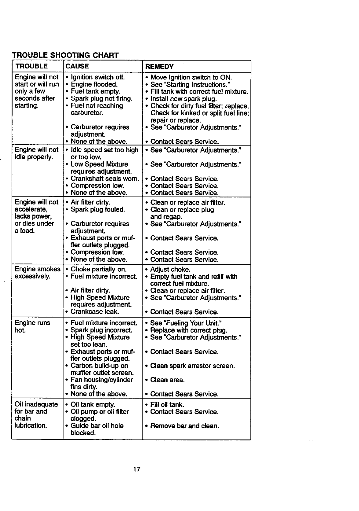
TROUBLE SHOOTING CHART
TROUBLE
Engine will not
start or will run
only a few
seconds after
starting.
Engine will not
idle properly.
Engine will not
accelerate,
lacks power,
or dies under
a load.
Engine smokes
excessively.
Engine runs
hot.
Oil inadequate
for bar and
chain
lubrication.
CAUSE
•Ignition switch off.
•Engine flooded.
•Fuel tank empty.
•Spark plug not firing.
•Fuel not reaching
carburetor.
•Carburetor requires
adjustment.
I° None of the above.
I, Idle speed set too high
or too low.
•Low Speed Mixture
requires adjustment.
_oCrankshaft seals wom.
i= Compression low.
i•None ofthe above.
!• Air filter dirty.
!, Spark plug fouled.
•Carburetor requires
adjustment.
•Exhaust ports or muf-
fler outlets plugged.
•Compression low.
•None ofthe above.
•Choke partially on.
•Fuel mixture incorrect.
•Air filter dirty.
•High Speed Mixture
requires adjustment.
•Crankcase leak.
• Fuel mixture incorrect.
• Spark plug incorrect.
REMEDY
•Move Ignition switch to ON.
!, See =Starting Instructions."
I, Fill tank with correct fuel mixture.
I° Install new spark plug.
J• Check for dirtyfuel filter; replace.
Check for kinked or split fuel line;
•repair or replace.
See =CarburetorAdjustments."
J• Contact Sears Service.
I° See =Carburetor Adjustmer_ts."
•See "Carburetor Adjustments."
•Contact Sears Service.
• Contact Sears Service.
;•Contact Sears ServiCe.
•Clean or replace air filter.
•Clean or replace plug
and regap.
•See "Carburetor Adjustments."
• Contact Sears Service.
• Contact Sears Service.
• Contact Sears Service.
•Adjust choke.
•Empty fuel tank and refill with
correct fuel mixture.
•Clean or replace air filter.
•See "Carburetor Adjustments."
•Contact Sears Service.
•See "Fueling Your Unit."
•Replace with correct plug.
•High Speed Mixture
set too lean.
•Exhaust pods or muf-
fler outlets plugged.
•Carbon build-up on
muffler outlet screen.
•Fan housing/cylinder
fins dirty.
•None of the above.
•Oil tank empty.
•Oil pump or oil filter
clogged,
•Guide bar oil hole
blocked.
•See "Carburetor Adjustments."
•Contact Sears Service.
•Clean spark arrestor screen.
•Clean area.
• Contact Sears Service.
•Fill oil tank.
• Contact Sears Service.
•Remove bar and clean.
17
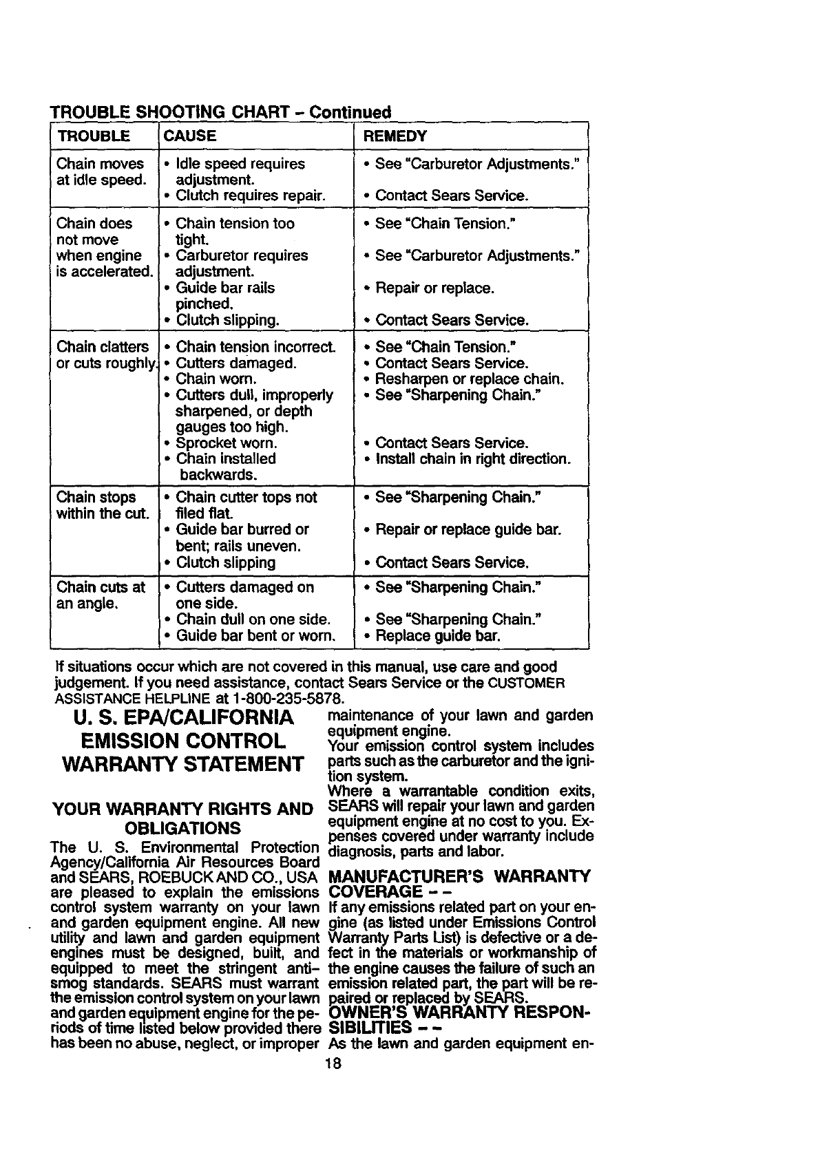
TROUBLE SHOOTING CHART - Continued
TROUBLE
Chain moves
at idle speed.
Chain does
not move
when engine
is accelerated.
Chain clatters
or cuts roughly
CAUSE
• Idle speed requires
adjustment.
• Clutch requires repair.
•Chain tension too
tight.
•Carburetor requires
adjustment.
•Guide bar rails
pinched,
•Clutch slipping.
•Chain tension incorrect.
•Cutters damaged.
•Chain worn.
•Cutters dull, impropedy
sharpened, or depth
gauges too high.
•Sprocket worn.
•Chain installed
backwards.
REMEDY
•See "Carburetor Adjustments."
•Contact Sears Service.
•See "Chain Tension."
•See "Carburetor Adjustments."
•Repair or replace.
•Contact Sears Service.
•See "Chain Tension."
• Contact Sears Service.
•Resharpen or replace chain.
•See "Sharpening Chain."
• Contact Sears Service.
•Install chain in dght direction.
Chain stops *Chain cutter tops not •See =Sharpening Chain."
within the cut. filed fiat.
•Guide bar burred or •Repair or replace guide bar.
bent; rails uneven.
•Clutch slipping •Contact Sears Service.
Chain cuts at *Cutters damaged on *See =Sharpening Chain."
an angle, one side.
•Chain dull on one side. *See =Sharpening Chain."
•Guide bar bent or worn, *Replace guide bar.
If situations occur which are not covered in this manual, use care and good
judgement. If you need assistance, contact Sears Service or the CUSTOMER
ASSISTANCE HELPLINE at 1-800-235-5878.
U. S. EPA/CALIFORNIA
EMISSION CONTROL
WARRANTY STATEMENT
YOUR WARRANTY RIGHTS AND
OBLIGATIONS
The U. S. Environmental Protection
Agency/California Air Resources Board
and SEARS, ROEBUCKAND CO., USA
are pleased to explain the emissions
control system warranty on your lawn
and garden equipment engine. All new
util',rty and lawn and garden equipment
engines must be designed, built, and
equipped to meet the stringent anti-
smog standards. SEARS must warrant
the emission control system on your lawn
and garden equipment engine for the pe-
dods of time listed below provided there
has been no abuse, neglect, or improper
maintenance of your lawn and garden
equipment engine.
Your emission control system includes
parts such asthe carburetor and the igni-
tion system.
Where a warrantable condition exits,
SEARS will repair your lawn and garden
equipment engine at no cost to you. Ex-
penses covered under warranty include
diagnosis, pads and labor.
MANUFACTURER'S WARRANTY
COVERAGE - -
If any emissions related part on your en-
gine (as listed under Emissions Control
Warranty Parts List) =sdefective or a de-
fect in the materials or workmanship of
the engine causes the failure of such an
emission related part, the part will be re-
paired or replaced =bySEARS.
OWNER'S WARRANTY RESPON-
SlBIUTIES - -
As the lawn and garden equipment en-
18
gine owner, you are responsible for the shall be warranted for the period
performance of the required mainte- of time up to the first scheduled replace-
nance listed in your Owner's Manual• ment point for that part._
SEARS recommends that you retain all DIAGNOSIS - -
receipts covering maintenance on your ............
• • .ne owner snal, not De cnargea for olag-
lawn and garden equ,pment engine, but .............
nosnc laDor wnlcn ,eaos to me ueter-
SEARS cannot deny warranty solely for . .
•• m,nat,on that a warranteo part
the lack of receipts or for your fa,lure to ;_ .4^_^...; .^ _,_.^ .4:..... .:.... i. :....
ensure the performance of all scheduled '= u=.=_.=,v= ,, u== u,=y,,uou_, wu,_ ,_.I:,.=.-
maintenance, formed at an approved SEARS servicing
As the lawn and garden equipment en-
gine owner, you should be aware that
SEARS may deny you warranty cover-
age if your lawn and garden equipment
engine or a part of it has failed due to
abuse, neglect, improper maintenance,
unapproved modifications, or the use of
parts not made or approved by the origi-
nal equipment manufacturer.
You are responsible for presenting your
lawn and garden equipment engine to a
center.
CONSEQUENTIAL DAMAGES--
SEARS may be liable for damages to oth-
er engine components caused bythe fail-
ure of a warranted part still under war-
ranty.
WHAT IS NOT COVERED - -
All failures caused by abuse, neglect, or
improper maintenance are not covered•
ADD-ON OR MODIFIED PARTS --
SEARS authorized repair center as soon The use of add-on or modifiedparts can
as a problem exists. Warranty repairs be grounds for disallowing a warranty
should be completed in a reasonable claim. SEARS
_fmount of time, not to exceed 30 days, is notliableto cover failures ofwarranted
you nave any quesbons reg.ar..amgyour partscaused bythe use of add-on or too-
warranty ngnm ana respons,o,,mes, you dified parts.
should contact your nearest authorized
service center or call SEARS at HOW TOFILEACLAIM--
1-800-473-7247.
WARRANTY COMMENCEMENT
DATE - -
The warranty period begins on the date
the lawn and garden equipment engine is
purchased.
LENGTH OF COVERAGE - -
This warranty shall befor aperiod oftwo
years from the initial date of purchase.
WHAT IS COVERED - -
]fyou have any questions regarding your
warranty rightsand responsibilities, you
should contact your nearest authorized
service center or call SEARS at
1-800-473-7247.
WHERE TO GET WARRANTY
SERVICE - -
Warranty services or repairs shall be pro-
vided at all SEARS at 1-800-473-7247
servicecenters.
MAINTENANCE, REPLACEMENT
REPAIR OR REPLACEMENT AND REPAIR OF EMISSION RE-
OF PARTS - - LATED PARTS - -
Repair or replacement of any warranted Any SEARS approved replacement part
part will be performed at no charge to the used in the performance of anywarranty
owner at an approved SEARS servicing maintenance or repair on emission re-
center, lated parts will be provided without
Ifyou have any questions regarding your charge to the owner if the part is under
warranty rights and responsibilities, you warranty.
should contact your nearest authorized
service center or call SEARS at EMISSION CONTROL WARRAN-
1-800-473-7247. TY PARTS LIST - -
WARRANTY PERIOD - - 1. Carburetor
Any warranted part which is not sched- 2. IgnitionSystem
a. Spark Plug, covered up to
uledfor replacement as required mainte- maintenance schedule.
nance, orwhich is scheduled only for reg- b. Ignition Module
ular inspection to the effect of =repa,r or
replace as necessary" shall be war- MAINTENANCE STATEMENT--
ranted for 2 years. Any The owner is responsible for the perfor-
warranted part which is scheduled for re- mance of all required maintenance as
placement as required maintenance defined in the owner's manual.
19
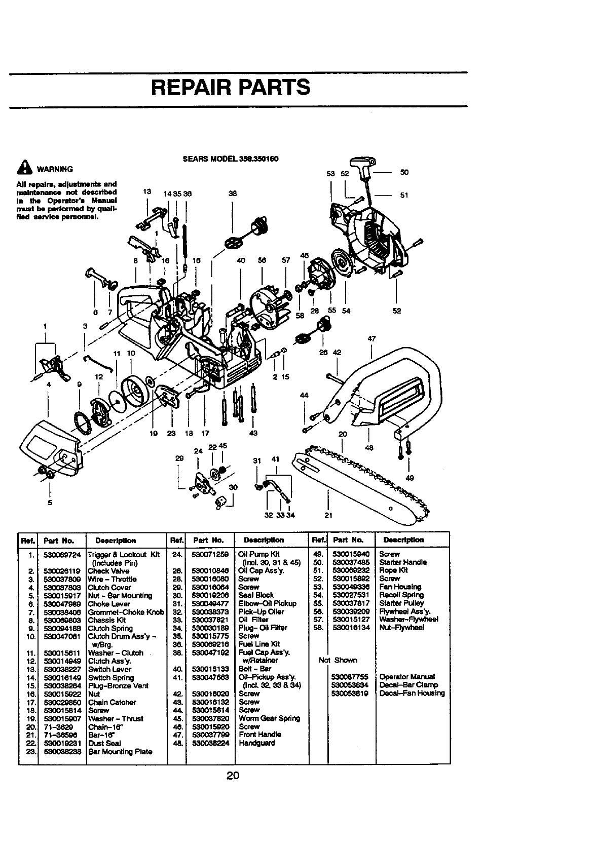
REPAIR PARTS
WARNING
67
1 3
13
19
SEARS MODEL _160
143536 38
53 52 50
I -- 51
28 55 54 52
2642
23 18 17
2 15
20 ]
Ref. Part No.
1. 53OO69724
. 53O026119
53OO378O9
6. _7_9
7. 530038406
9. 530O94188
11. 53l_1_11
16, £_ 1E_'_
17 _
18 530015814
21 71-_
DeecrlptJon Fief. Part No.
Trigger&Lockout Kit 24, 530071259
(IncludesPin)
Check Valve 26. 530010846
Wire- Throttle 28. 530016080
Clutch Cover 29. 530016064
Nut - Bar Mounting 30. 530019206
Choke Lever 81. 530049477
Gtorrcnet-Choke Knob 32. 530038373
Chassis Kit 33. 530G_7821
Clutch Spring 34. 530030189
Clutch DrumAss'y - 35. 530015775
w/Brg. 36. 5300_Q210
Washer-Clutch . 38, 530047192
ClutchAss'y.
Sw_tchLever 40. 530010133
SwitchSpdng 41, 5300476_3
Piug-Bronze Vent
Nut 42. 53(X)10020
Chain Catcher 43. 530010132
Screw 44. 53001,5814
Washer- Thrust 45. 5300_7820
Chain-l_' 4& 530015020
BSPI_" 47. 5300_
Dust Seal 48. 53O038224
Bar Mounting Plate
D,.,=r_ao.
Oil Pump Kit
(Incl. 30, 31 & 45)
Oil Cap Ass'y,
Screw
Screw
Seal Block
Elbow-Oil Pickup
Pick-Up Oiler
Oil Filter
Plug- Oil Filter
Screw
Fuel LineKit
Fu_capAss_/.
w/Retainer
Bolt - Bar
Oil-Pickup Ass_.
(]ncL_, 33 & S4)
Screw
Screw
Screw
Worm Gear Spdng
Screw
FrontHandle
Handguard
Ref.i Part No.
49. 530015940
50. 5300_7485
51. 5300_9232
52. 530015892
53. 530049336
54. 530027531
5,5. 5300_7817
58.
57. 530015127
58. 53001_134
Not Shown
530087755
5300_3819
o_eee
Screw
StaderHandle
RopeIGt
Screw
FanHousing
Re¢o.Spdng
StarterPulley
Rywhe_lA.'y_
Washer-Rywh_d
Nut-Flywheel
Operator Manual
Decal-Bar Clamp
Decal-Fan Housing
2O
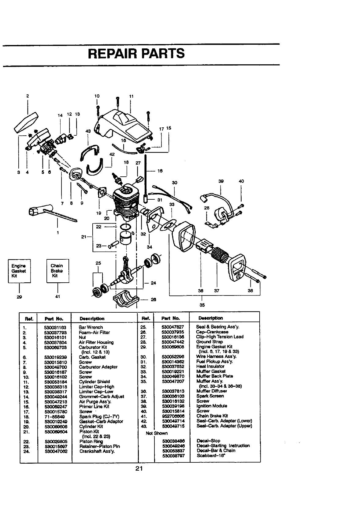
REPAIR PARTS
2
3 4 5 6
29
lO 11
I
1.
2.
3,
4,
5.
41
ReL Pint No,
3O
530031163
5300377_
530016101
53OO378O4
53O0_703
6. 53OO19239
7, 530015810
& 530049700
9. 530016187
10. 5_001a102
11. 530053184
12. 5300_8318
13. 53O038317
14. 53004g_44
15. 530047213
16. 53006_247
17. 53OO1578O
18. 71-85849
19. 530019249
20. 53o069606
21.
39 4O
38 37
I
35
38
22.
23. 530015_Q7
24. 530047(_2
DeserlpUoe
Ear Wrench
Foam--AirFilter
Nut
Air FilterHoualng
Carburetor Kit
(Incl. !2 &13)
Garb. Gasket
Screw
CarburetorAdapter
Screw
Screw
CylinderShletd
LJmiterGap-High
Umiter Cap-Low
Gromrnet-Carb Adjust
Air Purge Ass'y.
Pdrner Line Kit
Scow
Spark Rue (CJ-7"q
Gasket-Carb Adaptor
Cylinder Kit
Piston Kit
Onc]. 22 a2S)
Pietc_ Ring
Retalner-Pieto_ Pin
CrankshaftAss_J.
Refo Part No.
25. 530047827
26. 530037935
27. 530016136
28. 530047442
29. 530069608
30. 530052296
31. 530014_
32. 530067652
33. 530019221
34. 530049870
35. 530047201
38 5300_7813
37. 53(X)3810_
38. 530018132
30. 530(_9198
40. 530015814
41. g52"/'0e60e
42. 530040714
43. 530049715
Not Shown
52O03O4_
53004_40
,532O_>3_7
53O038797
D_edpUoe
Seal &Eaadng Ass'y.
Gap-Crankcase
Clip-High Tension Lead
Ground Strap
EngineGasket Kit
(Incl. 8, 17, 19 & 33)
Wire Harness Assay
Fuel PickupAss'y.
Heat Insulator
MufflerGasket
MufflerBack P_ete
Muffle¢Ass'y.
(Incl. 33-34 & 36-38)
Muffler Diffuser
Spark Screen
Screw
IgnitionModule
Screw
Chain Brake Kit
Sea_Gar_ Adapter (Lower)
Seal-Carb. Adapter {Upper)
Decal-Stop
Decal-Startiue Instruction
Decal-Bar & Chain
Scabha_'d-18"
21
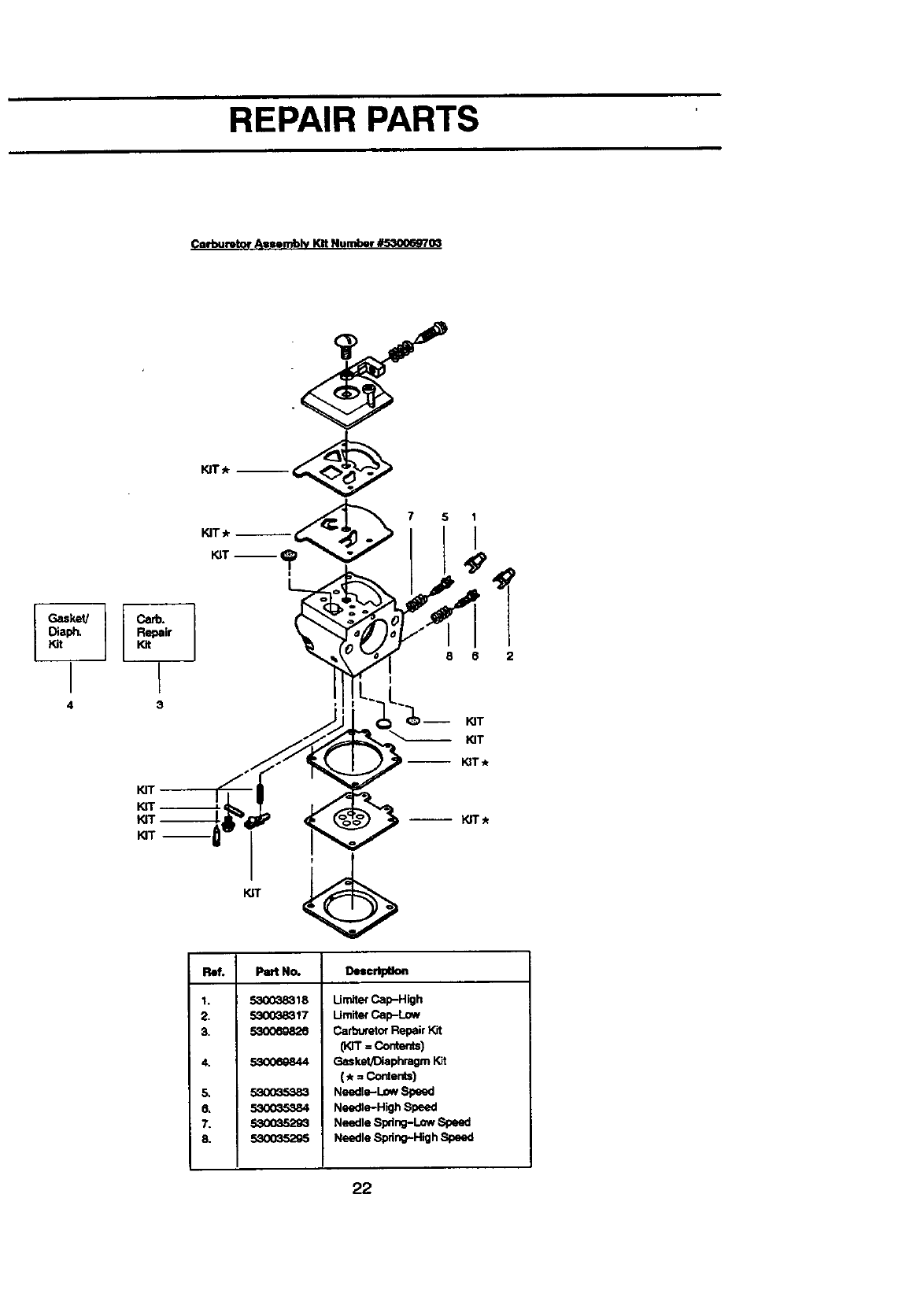
REPAIR PARTS
Carburetor Auemblv Kit Number _03
Gasket/ Carb.
Diaph. Repair
Kit Kit
IT
4 3
KIT_--
KIT
KIT--
R_. Pe_ No. Dem©dldlOn
1.
2.
3,
4.
5,
6.
7.
8.
530038818
5300_8317
53OO69826
530069844
530_5383
53OO35384
5300352_
,530035295
Umit_ Cap-High
Umit$,rCap-Low
Cart_J_torRepair Kit
(Kn"=Conter_s)
Gasket/Diaphragm Kit
(.=Contents)
Needle-Low Speed
Needle-High Speed
Needle Spdng-Low Speed
Needle Spring-High Speed
22

r-orthe repairor replacementparts you need
delivered directly to your home
Call 7 am - 7 pm, 7 days a week
1-800-366-PART
(!-800-366-7278)
Para ordenar pJezascon entrega a
domicilio - 1-800-659-7084
For in-house major brand repair service
Call 24 hours a day, 7 days a week
1-800-4-REPAIR
(1-800-473-7247)
Para pedir servicio de reparaci6n a
domicilio - 1-800-676-5811
For the location of a Sears Parts and
Repair Center in your area
Call 24 hours a day, 7 days a week
1-800-488-1222 |||m
For information on purchasing a Sears
Maintenance Agreement or to inquire
about an existing Agreement
Call 9 am - 5 pm, Monday-Saturday
1-800-827-6655
When requestingserviceor ordering
parts,always providethe following
information:
• Product Type •Part Number
•Model Number • Part Description
SBAR$
America'sRepair Specialists
