Craftsman 358352161 User Manual GAS CHAIN SAW Manuals And Guides L0708268
CRAFTSMAN Chainsaw, Gas Manual L0708268 CRAFTSMAN Chainsaw, Gas Owner's Manual, CRAFTSMAN Chainsaw, Gas installation guides
User Manual: Craftsman 358352161 358352161 CRAFTSMAN GAS CHAIN SAW - Manuals and Guides View the owners manual for your CRAFTSMAN GAS CHAIN SAW #358352161. Home:Lawn & Garden Parts:Craftsman Parts:Craftsman GAS CHAIN SAW Manual
Open the PDF directly: View PDF ![]() .
.
Page Count: 32
IMPORTANT MANUAL Do Not Throw Away
Operator's
Manual
Model No
358.352161
CUSTOMER
ASSISTANCE
1-800-235-5878
HOURS (CST)
Mon _Sat 7am-7pm
Sun 10am-7pm
WARNING:
READ THE OPERATOR'S
MANUAL AND FOLLOW
ALL WARNINGS AND
SAFETY INSTRUCTIONS.
FAILURE TO DO SO CAN
RESULT IN SERIOUS
INJURY.
CRAFTSMAN"
Always Wear Eye Protection
CRRFTSMRNo
2.2 cu. in./36cc 2-CYCLE ENGINE
16 inch Guide Bar
GASOLINE CHAIN SAW
•Assembly
•Operation
•Customer Responsibilities
•Service and Adjustments
•Repair Parts
Sears Roebuck and Co, Hoffman Estates, IL 60179 USA
530"084295-O2/20/96
SAFETY RULES
WARNING:
ALWAYS DISCONNECT SPARK PLUG WIRE AND PLACE WIRE WHERE IT CANNOT'CONTACT SPARK
PLUG TO PREVENT ACCIDENTAL STARTING WHEN SETTING UP, TRANSPORTING, ADJUSTING OR
MAKING REPAIRS EXCEPT CARBURETOR ADJUSTMENTS.
BECAUSE A CHAIN SAW IS A HIGH-SPEED WOOD-CUTI'ING TOOL, SPECIAL SAFETY PRECAUTIONS
MUST BE OBSERVED TO REDUCETHE RISK OF ACCIDENTS. CARELESS OR IMPROPER USE OFTHIS
TOOL CAN CAUSE SERIOUS INJURY.
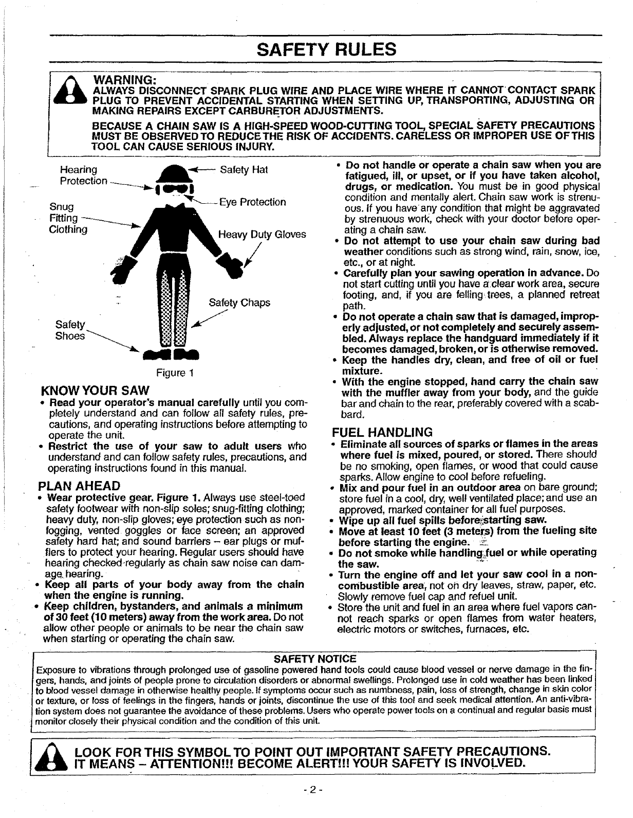
Safety Chaps
Safety
Shoes
Figure I
KNOW YOUR SAW
•Read your operator's manual carefully until you com-
pletely understand and can follow all safety rules, pre-
cautions, and operating instructions before attempting to
operate the unit.
•Restrict the use of your saw to adult users who
understand and can follow safety rules, precautions, and
operating instructions found in this manual.
PLAN AHEAD
•Wear protective gear. Figure 1. Always use steel-toed
safety footwear with non-slip soles; snug-fitting clothing;
heavy duty, non-slip gloves; eye protection such as non-
fogging, vented goggles or face screen; an approved
safety hard hat; and sound barriers - ear plugs or muf-
flers to protect your hearing. Regular users should have
hearing checked-regularly as chain saw noise can dam-
age. hearing.
°Keep all parts of your body away from the chain
when the engine is running.
•Keep children, bystanders, and animals a minimum
of 30 feet (10 meters) away from the work area. Do not
allow other people or animals to be near the chain saw
when starting or operating the chain saw.
•Do not handle or operate achain saw when you are
fatigued, ill, or upset, or if you have taken alcohol,
drugs, or medication. You must be in good physical
condition and mentally alert. Chain saw work is strenu-
ous. If you haveany condition that might be aggravated
by strenuous work, check with your doctor before oper-
ating a chain saw.
• Do not attempt to use your chain saw during bad
weather conditions such as strong wind, rain, snow, ice,
etc., or at night.
°Carefully plan your sawing operation in advance. Do
not start cutting until you have a:clear work area, secure
footing, and, if you are felling trees, a planned retreat
path.
•Do not operate a chain saw that is damaged, improp-
erly adjusted, or not completely and securely assem-
bled. Always replace the handguard immediately if it
becomes damaged, broken, or is otherwise removed.
•Keep the handles dry, clean, and free of oil or fuel
mixture.
• With the engine stopped, hand carry the chain saw
with the muffler away from your body, and the guide
bar and chain to the rear, preferably covered with a scab-
bard.
FUEL HANDLING
•Eliminate all sources of sparks or flames in the areas
where fuel is mixed, poured, or stored. There should
be no smoking, open flames, or wood that could cause
sparks. Allow engine to cool before refueling.
°Mix and pour fuel in an outdoor area on bare ground;
store fuel in a cool, dry, wel! ventilated place; and use an
approved, marked container for all fuel purposes.
•Wipe up all fuel spills before_tarting saw.
•Move at least 10 feet (3 meter.s) from the fueling site
before starting the engine, _.
°Do not smoke while handling_fuel or while operating
the saw.
•Turn the engine off and let your saw cool in a non-
combustible area, not oh dry leaves, straw, paper, etc.
Slowly remove fue! cap and refuel unit.
°Store the unit and fuel in an area where fuel vapors can-
not reach sparks or open flames from water heaters,
electric motors or switches, furnaces, etc.
IExp SAFETY NOTICE
zosure to vibrations through prolonged use of gasoline powered hand tools could cause blood vessel or nerve damage in the fin-
gets, hands, and joints of people prone to c_rculat_ondisorders or abnormal swellings. Prolonged use in cold weather has been linked
to blood vessel damage in otherwise healthy people. If symptoms occur such as numbness, pain, loss of strength, change in skin color
or texture, or loss of feelings in the fingers, hands or joints, discontinue the use of this tool and seek medical attention° An anti-vibra-
lion system does not guarantee the avoidance of these problems. Users who operate power tools on acontinual and regular basis must
monitor closely their physical condition and the condition of this unit.
LOOK FOR THIS SYMBOLTO POINT OUT IMPORTANT SAFETY PRECAUTIONS.
IT MEANS - A'I-rENTION!!! BECOME ALERT!!! YOUR SAFETY IS INVOLVED.
-2-
SAFETY RULES
OPERATE YOUR SAW SAFELY
°Do not operate a chain saw with one hand. Serious
injury to the operator, helpers, bystanders or any combi-
nation of these persons may result from 0ne-handed oper-
ation. A chain saw is intended for two-handed use.
-Operate the chain saw only in well-ventilated outdoor
areas.
•Do not operate saw from aladder or in a tree, unless
specifically trained to do so.
• Position all parts of your body to the left of cut and
away from the chain when the engine is running.
• Cut wood only. Do not use your saw to pry orshove away
limbs, roots, or other objects.
°Make sure the chain will not make contact with any
object while starting the engine, Never try to start the
saw when the guide bar is in a cut or kerr.
•Use extreme caution when cutting small size brush
MAINTAIN YOUR SAW IN GOOD WORKING
ORDER , .-
•Have all chain saw service performed by your Sears
Service Center with the exception of the items listed in
the =Customer Responsibilities" section of this manual. For
example, if improper tools are used to remove or hold the
flywheel when servicing the clutch, structural damage to
the flywheel can occur and cause the flywheel to burst.
•Make certain the chain stops moving when the throt-
tle trigger is released. For correction, referto "Carburetor
Adjustments."
•Stop the saw if the chain strikes a foreign object.
Inspect unit and repair or replace parts as necessary.
• Disconnect the spark plug before performing any
maintenance except for carburetor adjustments.
•Never modify your saw in any way. Use only SEARS
accessories and replacement parts as recommended.
and saplings. Slender material can catch the chain and . TRANSPORTING:AND STORAGE
be whipped toward you or pull you off balance .... : .. -:Stopthe unitbefore.transporting.
•Be alert for springback whencutting a limb that is under ...... °Allow engine to,cool,-c0ver the guide bar and chain, and
tension so you.will not be struck by the limb or saw when secure the unit before storing or transporting in a vehicle.
the tension in the wood fibers is released.
•Do not put pressure on the saw at the end of a cut.
Applying pressure can cause you to lose control when the
cut is completed.
* Stop the engine before setting the saw down.
•Keep fuel and oil caps, screws, and fasteners secure-
ly tightened.
• Empty fuel tank before storing or transporting the unit. Use
up any fuel left in the carburetor by starting the engine and
letting the engine run until it stops.
°Store unit and fuel in an area where fuel vapors cannot
reach sparks or open flames from water heaters, _ectric
motors or switches, furnaces, etc.
•Store unit so the chain cannot accidentally cause injury.
• Store the unit out of the reach of children.
GUARD AGAINST KICKBACK - Kickback is a dangerous reaction that can lead to serious injury.
_KICKBACK WARNING:
KICKBACK CAN OCCUR WHEN THE MOV-
ING CHAIN CONTACTS AN OBJECT ATTHE
UPPER PORTION OFTHE TIP OFTHE GUIDE
BAR OR WHEN THE WOOD CLOSES IN AND
PINCHES THE CHAIN IN THE CUT. CONTACT
AT THE UPPER PORTION ()F THE TIP OF
THE GUIDE BAR CAN CAUSE THE CHAIN
TO DIG INTO THE OBJECT, WHICH STOPS
THE CHAIN FOR AN INSTANT.THERESULT
IS A LIGHTNING FAST, REVERSE: REACTION
WHICH KICKS THE GUIDE BAR UP AND
BACK TOWARD THE OPERATOR. IF THE
CHAIN IS PINCHED ALONG THE TOP OF
THE GUIDE BAR, THE GUIDE BAR CAN BE
DRIVEN RAPIDLY BACK TOWARD THE
OPERATOR. EITHER OFTHESE REACTIONS
CAN CAUSE LOSS OF SAW CONTROL
WHICH CAN RESULT IN SERIOUS INJURY.
DO NOT RELY ONLY ON THE SAFETY
DEVICES PROVIDED WITH YOUR SAW. AS
A CHAIN SAW USER, YOU MUST TAKE
SPECIAL SAFETY PRECAUTIONS TO HELP
KEEP YOUR CUTTING JOBS FREE FROM
ACCIDENT OR INJURY.
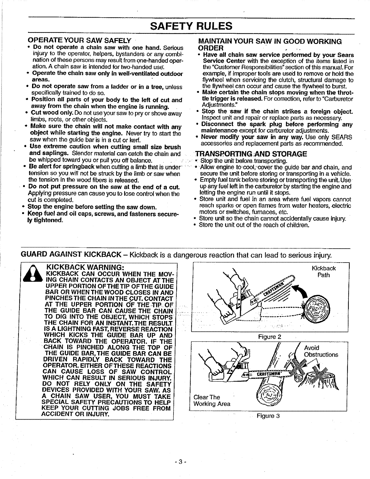
Kickback
Path
Figure 2
Avoid
Obstructions
Clear The
Working Area
Figure 3
-3-
SAFETY RULES
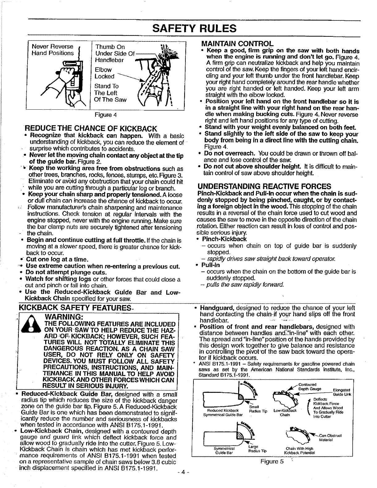
Never Reverse Thumb On _f_I_
Hand Positions Under Side O --
__ _t_\ Handlebar
Elbow
Locked
Stand To
The Left
Of The Saw
Figure 4
REDUCE THE CHANCE OF KICKBACK
*Recognize that kickback can happen. With a basic
understanding of kickback, you can reduce the element of
surprise which contributes to accidents.
•Never let the m_oving chain contact any object at the tip
of the guide bar. Figure 2.
•_Keep the working area free from obstructions such as
other trees, branches, rocks,fences, stumps, etc. Figure 3.
Eliminate or av_0idany obstructionthat your chain could hit
•while you are cutting through aparticular log or branch.
•Keep your chain sharp and properly tensioned. Aloose
or dull chain can increase the chance of kickbackto occur.
,Follow manufacturer's chain sharpening and maintenance
instructions. Check tension at regular intervals with the
engine stopped, never with the engine running.Make sure
the bar clamp nuts are securely tightened after tensioning
the chain.
oBegin and continue cutting at full throttle. If the chain is
moving at aslower speed, there is greater chance for kick*
back to occur.
,Cut one log at a time.
_o Use extreme caution when re-entering a previous cut.
-Do not attempt plunge cuts.
•Watch for shifting logs or other forces that could close a
cut and pinch or fall into chain.
,, Use the Reduced-Kickback Guide Bar and Low-
Kickback Chain specified for your saw.
KICKBACK SAFETY FEATURES-
THE FOLLOWING FEATURES ARE INCLUDED
ON YOUR SAW TO HELP REDUCE THE HAZ-
ARD *OF, KICKBACK; HOWEVER, SUCH FEA-
TURES WILL NOT TOTALLY ELIMINATE THIS
DANGEROUS REACTION. AS A CHAIN SAW
USER, DO NOT RELY ONLY ON SAFETY
DEVICES. YOU MUST FOLLOW ALL SAFETY
PRECAUTIONS, INSTRUCTIONS, AND MAIN-
TENANCE IN THIS MANUAL TO HELP AVOID
KICKBACK AND OTHER FORCES WHICH CAN
RESULT IN SERIOUS INJURY.
Reduced-Kickback Guide Bar, designed with a small
radius tip which reduces the size of the kickback danger
zone on the guide bar tip. Figure 5. A Reduced-Kickback
MAINTAIN CONTROL
* Keep a good, firm grip on the saw with both hands
when the engine is running and don't let go. Figure 4.
Afirm grip can neutralize kickback and help you maintain
control of the saw. Keep the fingers of your left hand encir-
cling and your left thumb under the front handlebar. Keep
your right hand completely around the rear handle whether
you are right handed or left handed. Keep your left arm
straight with the elbow locked.
.Position your left hand on the front handlebar so it is
in a straight line with your right hand on the rear han-
dle when making bucking cuts. Figure 4. Never reverse
right and left hand positionsfor any type of cutting.
° Stand with your weight evenly balanced on both feet.
• Stand slightly to the left side of the saw to keep your
body from being in a direct line with the cutting chain.
Figure 4.
•Do not overreach. You could be drawn or thrown off bal-
ance and lose control of thesaw.
•Do not cut above shoulder height. It is difficultto main-
tain control of saw above shoulder height.
UNDERSTANDING REACTIVE FORCES
Pinch-Kickback and PulHn occur when the chain is sud-
denly stopped by being pinched, caught, or by contact-
ing a foreign object in the wood. This stopping of the chain
results in a reversal of the chain force used to cut wood and
causes the saw to move in the opposite direction of the chain
rotation.Either reaction can result in loss of control and pos-
sible serious injury.
•Pinch-Kickback
-occurs when chain on top of guide bar is suddenly
stopped.
-rapidly drives saw straight back toward operator.
• Pull-In
- occurs when the chain on the bottom of the guide bar is
suddenly stopped.
-pulls the saw rapidly forward.
• Handguard, designed to reduce the chance of your left
hand contacting the chain:if your hand slips off the front
handlebar. ....... ,_ -
•Position of front and rear handlebars, designed with
distance between handles and_'in-line" with each other.
The spread and "in-line" position of the hands provided by
this design work together to give balance and resistance
in controlling the pivot;_f the saw back toward the opera-
tor if kickback occurs.
* ANSi B175.1-1991 - Safety requirements for gasoline powered chain
saws as set by the American National Standards Institute, Inc.,
Standard B175.t-1991.
Guide Bar is one which has been demonstrated to signif-
icantly reduce the number and seriousness of kickbacks
when tested in accordance with ANSI Bt75.1-199t.
Low-Kickback Chain, designed with a contoured depth
gauge and guard link which deflect kickback force and
allow wood to gradually ride into the cutter. Figure 5. Low-
Kickback Chain is chain which has met kickback perfor-
mance requirements of ANSI B175.1-1991 when tested
on a representative sample of chain saws below 3.8 cubic
inch displacement specified in ANSI B175.1-1991. -4"
./_ Cotttoured
L-_."_II_ 13epth Gauge Elongate:l
_,._ G u_de Unk
'_ ]# /_backFo_
"
ReducedKickback Radius Tip Low-K_'_ And AllowsWood
TO Gr_dua_ Ride
Symmetrica_ Guide Bat Chain Into Cutter
Mateda_
Symmetrical Large Chain With High
Guide Ba_ Radius Tip Kickback Pote_bal
Figure 5 :
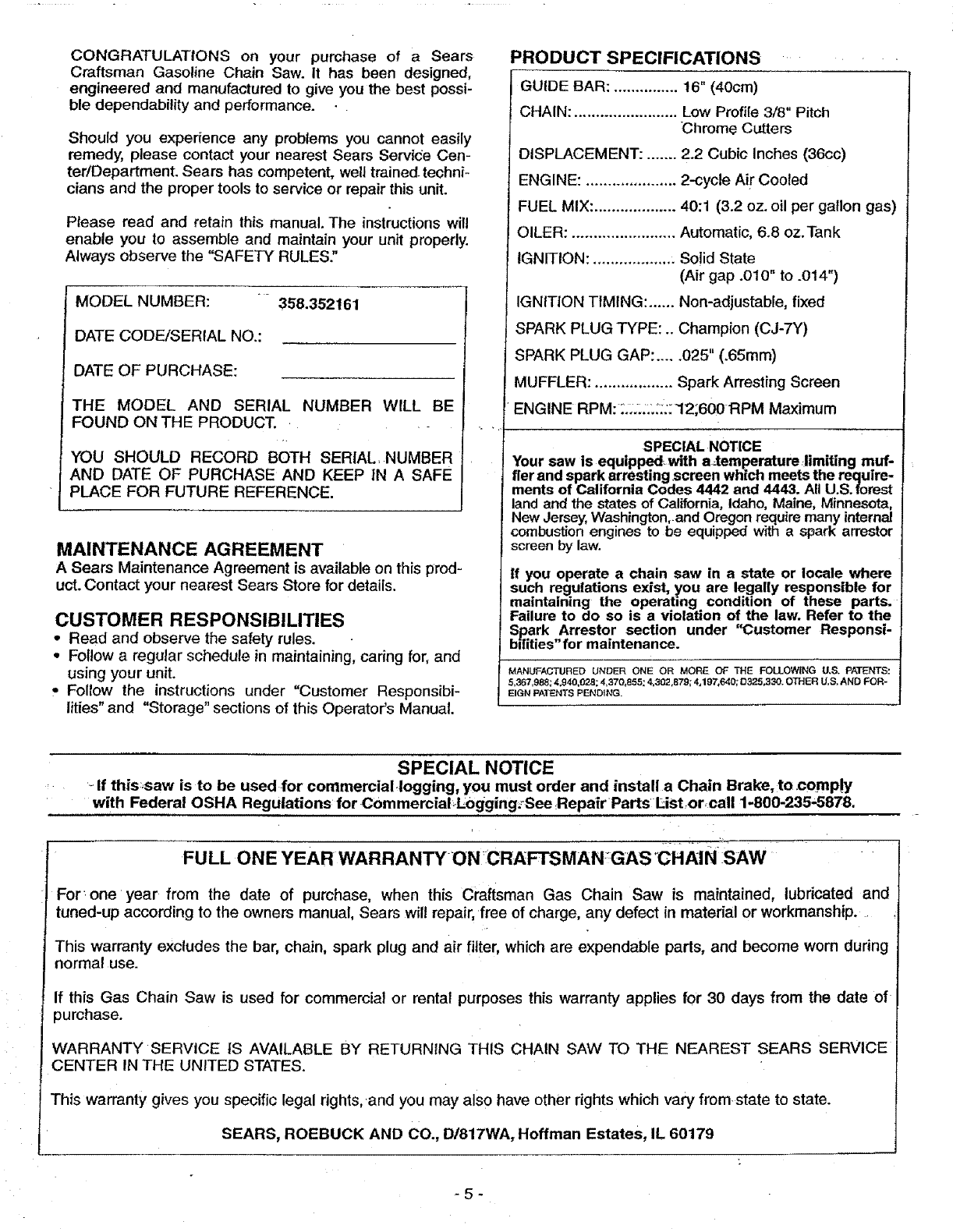
CONGRATULATIONS on your purchase of a Sears
Craftsman Gasoline Chain Saw. It has been designed,
engineered and manufactured to give you the best possi-
ble dependability and performance.
Should you experience any problems you cannot easily
remedy, please contact your nearest Sears ServiCe Cen-
ter/Department. Sears has competent, well trained, techni-
cians and the proper tools to service or repair this unit.
Please read and retain this manual. The instructions will
enable you to assemble and maintain your unit properly.
Always observe the "SAFETY RULES."
MODEL NUMBER: 358.352161
DATE CODE/SERIAL NO.:
DATE OF PURCHASE:
THE MODEL AND SERIAL NUMBER WILL BE
FOUND ON THE PRODUCT.
YOU SHOULD RECORD BOTH SERIAL, NUMBER
AND DATE OF PURCHASE AND KEEP tN A SAFE
PLACE FOR FUTURE REFERENCE.
MAINTENANCE AGREEMENT
A Sears Maintenance Agreement is available on this prod-
uct.Contact your nearest Sears Store for details.
CUSTOMER RESPONSIBILITIES
• Read and observe the safety rules.
• Follow aregular schedule in maintaining, caring for, and
using your uniL
°Follow the instructions under "Customer Responsibi-
lities" and "Storage" sections of this Operator's Manual.
PRODUCT SPECIFICATIONS
GUIDE BAR: ............... 16" (40cm)
CHAIN: ........................ Low Profile 3/8" Pitch
Chrome Cutters
DISPLACEMENT: ....... 2.2 Cubic Inches (36cc)
ENGINE: ..................... 2-cycle Ai_"Cooled
FUEL MIX: ................... 40:1 (3.2 oz. oil per gallon gas)
OILER: ........................ Automatic, 6.8 oz.Tank
IGNITION: ................... Solid State
(Air gap .010" to .014")
IGNITION TIMING: ...... Non-adjustable, fixed
SPARK PLUG TYPE: .. Champion (CJ-7Y)
SPARK PLUG GAP: ..... 025" (.65ram)
MUFFLER: .................. Spark Arresting Screen
ENGINE RPM: __LL_.:;::12;600RPM Maximum
SPECIAL NOTICE
Your saw is equipped with alemperature limiting muf-
fler and spark arresting ,screen which meets the require-
ments of California Codes 4442 and 4443. All U.S. forest
land and the states of California, Idaho, Maine, Minnesota,
New Jersey, Washington,and Oregon require many internal
combustion engines to be equipped with a spark arrestor
screen by law.
if you operate a chain saw in a state or locale where
such regulations exist, you are legally responsible for
maintaining the operating condition of these parts.
Failure to do so is a violation of the law. Refer to the
Sp..ark Arrestor section under "Customer Responsi-
bdities"for maintenance.
MANUFACTURED UNDER ONE OR MORE OF THE FOLLOWING U,& PATENTS:
&367,988; 4,940,028; 4,370_855; 4,302,879; 4,197,640; 13325,330. OTHER U,S, AND FOR-
EIGN PATENTS PENDING.
SPECIAL NOTICE
-. If this,saw is to be used for commercial,logging, you must order and install aChain Brake, to .comp!y
with Federal OSHA Regulations forCommerciaI,Logging,,SeeRepairPartsl_ist,orcaU 1-800-235-5878.
FULL ONE YEAR WARRANTY ONCRAFTSMAN;GAS CHAIN:SAW " "
For one year from the date of purchase, when this craftsman Gas Chain Saw is maintained, lubricated and
tuned-up according to the owners manual, Sears will repair, free of charge, any defect in material or workmanship.
This warranty excludes the bar, chain, spark plug and air filter, which are expendable pads, and become worn during
normal use.
If this Gas Chain Saw is used for commercial or rental purposes this warranty applies for 30 days from the date of
purchase.
WARRANTY SERVICE tS AVAILABLE BY RETURNING THIS CHAIN SAW TO THE NEAREST SEARS SERVICE
CENTER IN THE UNITED STATES.
This warranty gives you specific legal rights, and you may also have other rights which vary fromstate to state.
SEARS, ROEBUCK AND CO., D/817WA, Hoffman Estates, IL 60179
-5-
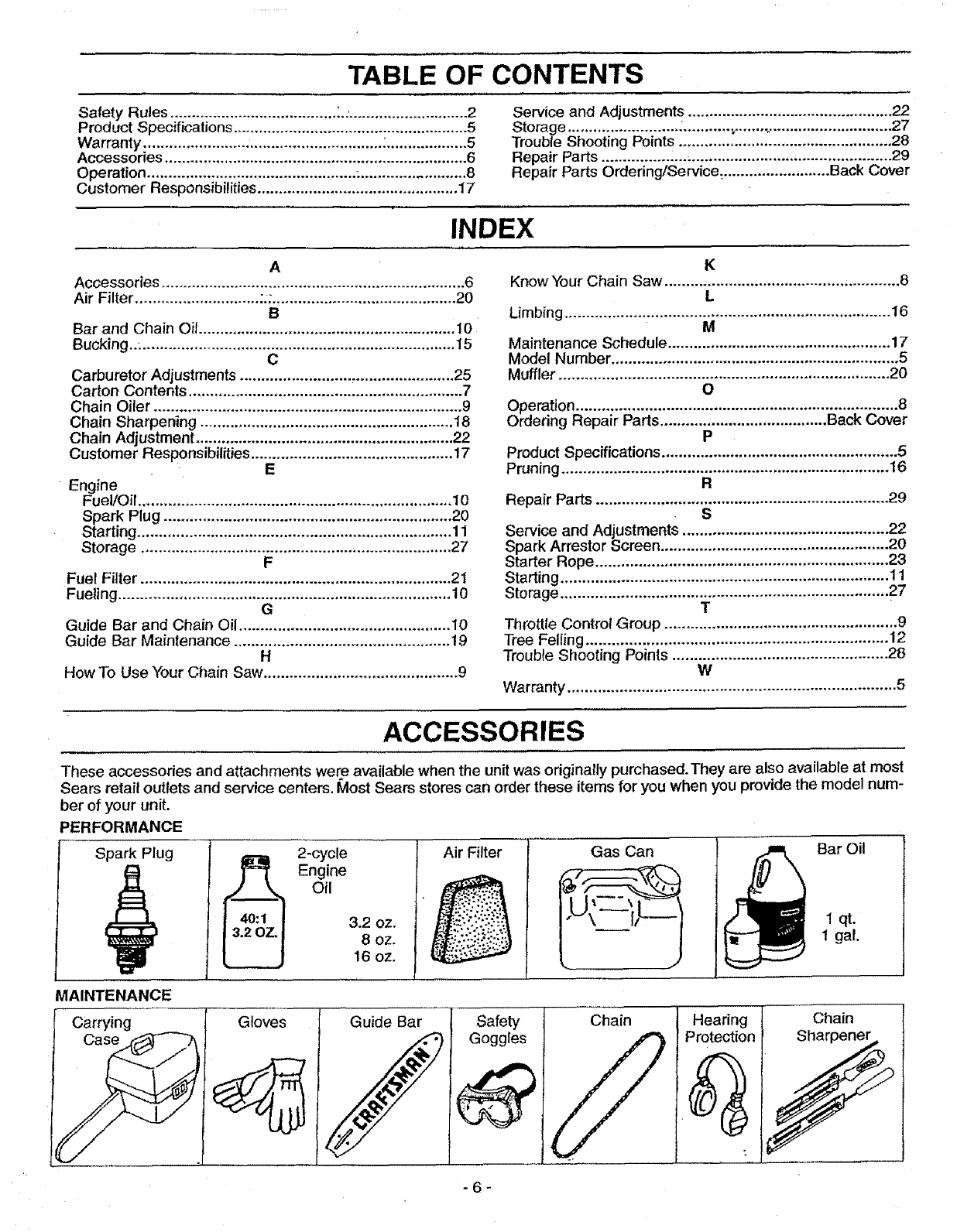
TABLE OF CONTENTS
Safety Rules ....................................... L-............................ 2
Product Specifications ....................................................... 5
Warranty ........................................................ :................... 5
Accessories ....................................................................... 6
Operation ................................................. ......................... 8
Customer Responsibilities ............................................... I7
Service and Adjustments ................................................ 22
Storage .......................... _........... ,o.................................... 27
Trouble Shooting Points .................................................. 28
Repair Parts .................................................................... 29
Repair Parts Ordedng/Service_ ......................... Back Cover
INDEX
A
Accessories ....................................................................... 6
Air Filter ............................. ;:: ........................................... 20
B
Bar and Chain Oil ............................................................ 10
Bucking..: ......................................................................... 15
C
Carburetor Adjustments .......................... ,....................... 25
Carton Contents ................................................................ 7
Chain Oiler ........................................................................ 9
Chain Sharpening ........................................................... 18
Chain Adjustment ............................................................ 22
Customer Responsibilities ............................................... 17
E
Engine
FuellOil ......................................................................... 10
Spark Plug ................................................................... 20
Starting ......................................................................... 11
Storage ........................................................................ 27
F
Fuel Filter ........................................................................ 21
Fueling ............................................................................. 10
G
Guide Bar and Chain Oil ................................................. 10
Guide Bar Maintenance .................................................. 19
H
How To Use Your Chain Saw ............................................. 9
K
Know Your Chain Saw .......................................... _............ 8
L
Limbing ............................................................................ 16
M
Maintenance Schedule .................................................... 17
Model Number ................................................................... 5
Muffler ............................................................................. 20
O
Operation ........................................................................... 8
Ordering Repair Parts ....................................... Back Cover
P
Product Specifications ....................................................... 5
Pruning ........................................... . ............................... 16
R
Repair Parts .................................................................... 29
•S
Spa_aer_stAdj_Streemen?!S:::::::::::::::::::::::::::::::::::::::::::::::: 22
Starter Rope .................................................................... 23
Starting ............................................................................ 11
Storage ............................................................................ 27
T
Throttle Control Group ...................................................... 9
Tree Felling ...................................................................... 12
Trouble Shooting Points .................................................. 28
W
Warranty ............................................................................ 5
ACCESSORIES
These accessories and attachments were available when the unit was originally purchased. They are also available at most
Sears retail outlets and service centers, lVlost Sears stores can order these items for you when you provide the model num-
ber of your unit.
PERFORMANCE
Spark Plug
MAINTENANCE
2-cycle
_ Engine
0il
3.2 oz.
8 oz.
16 oz.
Air Filter Gas Can
.'--"\ _ I/L____
_, ,J
Bar Oil
1 qt.
1 gal.
Carrying Gloves Guide Bar
/Safety
Goggles
Chain
jHearing
Protection
Chain
y
-6-
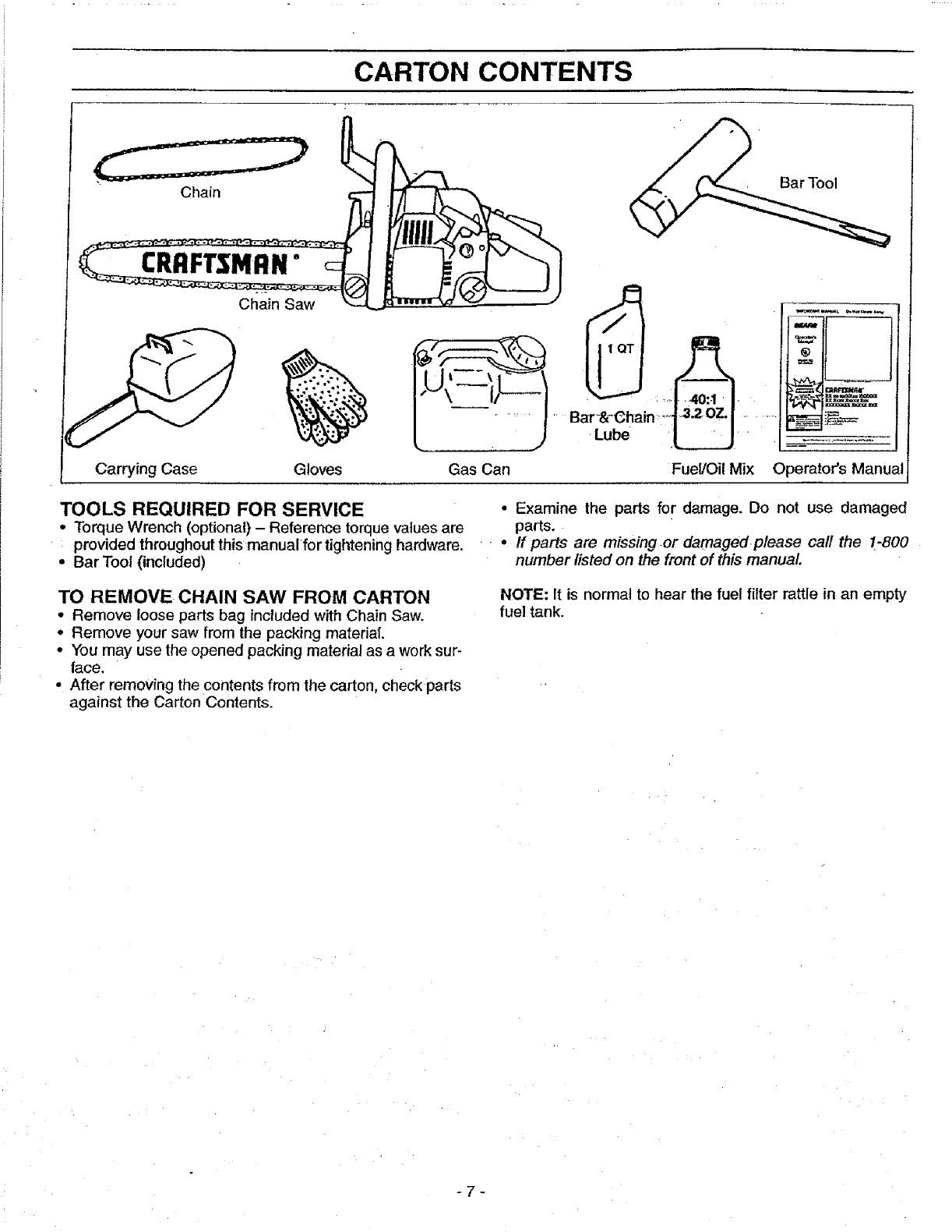
CARTON CONTENTS
Carrying Case Gloves
\ I/ _.
Gas Can
•Lu_
Fuel/Oil Mix Operator's Manual
TOOLS REQUIRED FOR SERVICE
•Torque Wrench (optional) - Reference torque values are
provided throughout this manual for tightening hardware.
• Bar Tool (included)
TO REMOVE CHAIN SAW FROM CARTON
• Remove loose parts bag included with Chain Saw.
• Remove your saw from the packing material.
• You may use the opened packing material as a work sur-
face,
• After removing the contents from the carton, check parts
against the Carton Contents.
•Examine the parts for damage. Do not use damaged
parts.
••If parts are missing or damagedplease call the 1.-800
number listed on the front of this manual
NOTE: It is normal to hear the fuel filter rattle in an empty
fuel tank.
-7-
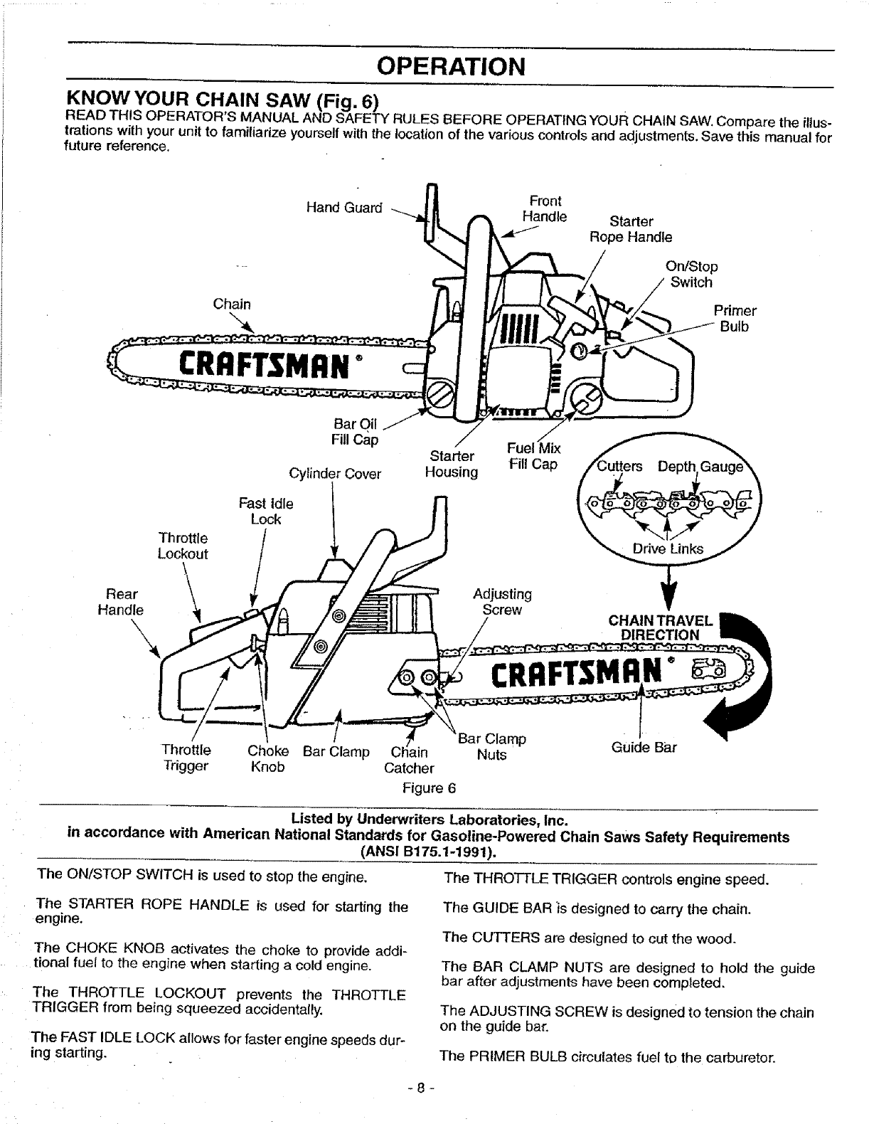
OPERATION
KNOW YOUR CHAIN SAW (Fig. 6)
READ THIS OPERATOR'S MANUAL AND SAFETY RULES BEFORE OPERATING YOUR CHAIN SAW, Compare the illus-
trations with your unit to familiarize yourself with the location of the various controls and adjustments, Save this manual for
future reference,
Hand Guard
Chain
CRRFTSNRNo
Throttle
Lockout
Bar Oil "J
Fill Cap /
Starter
Cylinder Cover Housing
Fast Idle
Lock
Front
Handle
Fuel Mix
Fil! Cap
Starter
Rope Handle
On/Stop
Switch
_j_._ Primer
Bulb
Rear Adjusting
Handle Screw CHAIN TRAVEL
DIRECTION
CRRFTSM N °
Throttle Choke Bar Clamp
Trigger Knob Catcher
Figure 6
Clamp Guide Bar
Nuts
Listed by Underwriters Laboratories, Inc.
in accordance with American National Standards for Gasoline-Powered Chain Saws Safety Requirements
(ANSI B175.1-1991).
The ON/STOP SWITCH is used to stop the engine, The THRO'I-TLE TRIGGER controls engine speed.
The STARTER ROPE HANDLE is used for starting the
engine,
The CHOKE KNOB activates the choke to provide add!-
•t onal fuel to the engfne when starting a cold engine.
The THROTTLE LOCKOUT prevents the THROTTLE
TRIGGER from being squeezed accidentally.
The FAST IDLE LOCK allows for faster engine speeds dur-
ing starting.
The GUIDE BAR 'is designed to carry the chain.
The CUTTERS are designed to cut the wood,
The BAR CLAMP NUTS are designed to hold the guide
bar after adjustments have been completed.
The ADJUSTING SCREW is designed to tension the chain
on the guide bar,
The PRIMER BULB circulates fuel to the carburetor.
-8-
OPERATION
HOW TO USE YOUR CHAIN SAW
STOPPING YOUR ENGINE
• Move onlstop switch to the "Stop" position.
• If engine does not stop, pull blue choke knob out fully.
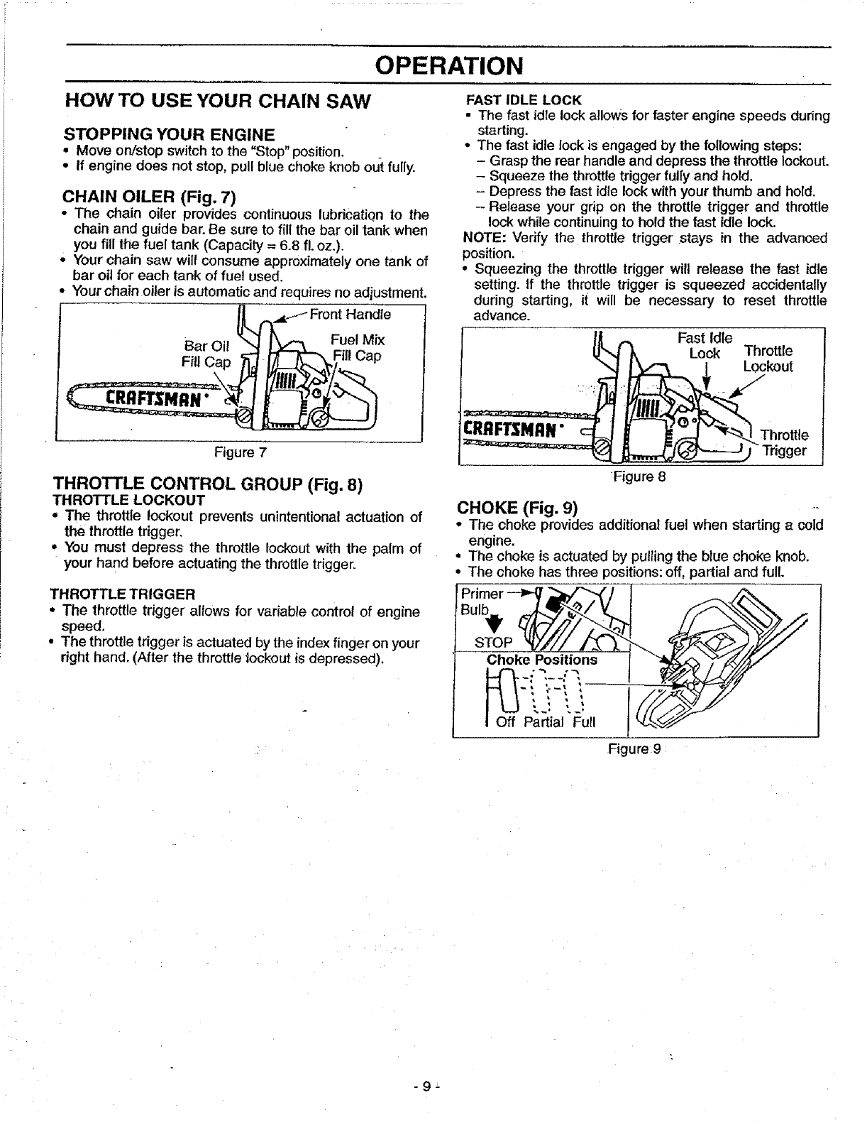
CHAIN OILER (Fig. 7)
•The chain oiler provides continuous lubricatiQn to the
chain and guide bar. Be sure to fill the bar oil tank when
you fill the fuel tank (Capacity = 6.8 fL oz.).
• Your chain saw will consume approximately one tank of
bar oil for each tank of fuel used.
• Your chain citer is automatic and requires no adjustment.
L,./,_._f _ Front Handle
... _,, _,_1 I\ _ Fuel Mix
___FTSMRN" e
Figure 7
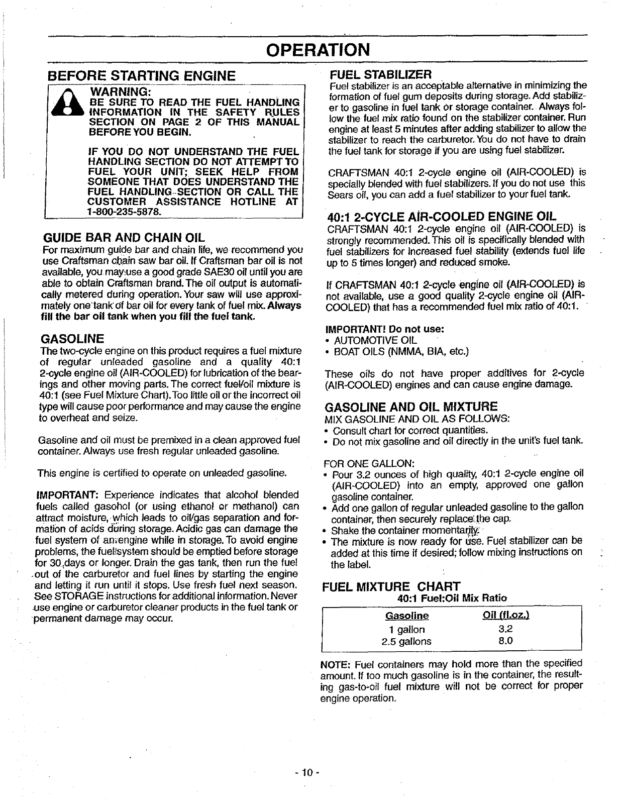
THROTTLE CONTROL GROUP (Fig. 8)
THROTTLE LOCKOUT
•The throttle lockout prevents unintentional actuation of
the throttle trigger,
•You must depress the throttle lockout with the palm of
your hand before actuating the throttle trigger.
THROTTLE TRIGGER
•The throttle trigger allows for variable control of engine
speed.
•The throttle trigger is actuated by the index finger on your
right hand. (After the throttle lockout is depressed).
FAST IDLE LOCK
•The fast idle lock allows for faster engine speeds during
starting.
• The fast idle lock is engaged by the following steps:
- Grasp the rear handle and depress the throttle lockout.
- Squeeze the throttle trigger fully and hold.
- Depress the fast idle lock with your thumb and hold.
-Release your grip on the throttle trigger and throttle
lock while continuing to hold the fast idle lock.
NOTE: Verify the throttle trigger stays in the advanced
position.
• Squeezing the throttle trigger wilt release the fast idle
setting, tf the throttle trigger is squeezed accidentally
during starting, it will be necessary to reset throttle
advance.
IJ .,,. Fast Idle
_%,_ _ Lock Throttle
",J | _/"_ / Lockout
-Trigger
Figure 8
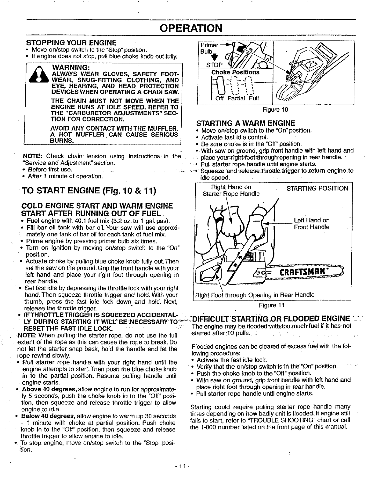
CHOKE (Fig. 9) --
• The choke provides additional fuel when starting a cold
engine.
•The choke is actuated by pulling the blue choke knob.
• The choke has three positions: off, partial and full.
Primer "-_ _'_f/ ]_i
STOP
Choke Positions [
._ j
Partial _Eull
Figure 9
-9-
OPERATION
BEFORE STARTING ENGINE
WARNING:
BE SURE TO READ THE FUEL HANDLING
INFORMATION IN THE SAFETY RULES
SECTION ON PAGE 2OF THIS MANUAL
BEFORE YOU BEGIN.
IF YOU DO NOT UNDERSTAND THE FUEL
HANDLING SECTION DO NOT ATTEMPT TO
FUEL YOUR UNIT; SEEK HELP FROM
SOMEONE THAT DOES UNDERSTAND THE
FUEL HANDLING.SECTION OR CALL THE
CUSTOMER ASSISTANCE HOTLINE AT
1-800-235-5878.
GUIDE BAR AND CHAIN OIL
For maximum guide bar and chain life, we recommend you
use Craftsman chain saw bar oil. If Craftsman bar oil is not
available, you may_se a good grade SAE30 oil until you are
able to obtain Craftsman brand. The oil output is automati-
caUy metered during operation. Your saw will use approxi-
mately onetank'0f bar oil for every tank of fuel mix. Always
fill the bar oil tank when you fill the fuel tank.
GASOLINE
The two-cycle engine on thisproduct requires a fuel mixture
of regular unleaded gasoline and a quality 40:1
2_cycle engine oil (AIR-COOLED) for lubricationof the bear-
ings and other moving parts. The correct fuel/oil mixture is
40:1 (see Fuel Mixture Chart).Too little oil or the incorrect oil
type will cause poor performance and may cause the engine
to overheat and seize.
Gasoline and oil must be premixed in a clean approved fuel
container. Always use fresh regular unleaded gasoline.
This engine is certified to operate on unleaded gasoline.
IMPORTANT: Experience indicates that alcohol blended
fuels called gasohol (or using ethanol or methanol) can
attract moisture, which leads to oil/gas separation and for-
mation of acids during storage. Acidic gas can damage the
fuel system of amengine while in storage. To avoid engine
problemS, the fuel_;system should be emptied before storage
for 30,days or longer. Drain the gas tank, then run the fuel
-out of the carburetor and fuel lines by starting the engine
and letting it run until it stops. Use fresh fuel next season.
See STORAGE instructions for additional information. Never
use engine or carburetor cleaner products in the fuel tank or
permanent damage may occur.
FUEL STABILIZER
Fuel stabilizer is an acceptable alternative in minimizing the
formation of fuel gum deposits during storage. Add stabiliz-
er to gasoline in fuel tank Or storage container. Always fol-
low the fuel mix ratio found on the stabilizer container. Run
engine at least 5 minutes after adding stabilizer to allow the
stabilizer to reach the carburetor. You do not have to drain
the fuel tank forstorage if you are using fuel stabilizer.
CRAFTSMAN 40:1 2-cycle engine oil (AIR-COOLED) is
specially blended with fuel stabilizers. If you do not use this
Sears oil, you can add a fuel stabilizer to your fuel tank.
40:1 2-CYCLE AiR-COOLED ENGINE OIL
CRAFTSMAN 40:1 2-cycle engine oil (AIR-COOLED) is
strongly recommended.This oil is specifically blended with
fuel stabilizers for increased fuel stability (extends fue! life
up to 5 times longer) and reduced smoke.
If CRAFTSMAN 40:1 2-cycle engine oil (AIR-COOLED) is
not available, use a good quality 2-cycle engine oil (AIR-
COOLED) that has a recommended fuet mix ratio of 40:1. •
IMPORTANT! Do not use:
• AUTOMOTIVE OIL
• BOAT OILS (NMMA, BIA, etc.)
These oils do not have proper additives for 2-cycle
(AIR-COOLED) engines and can cause engine damage.
GASOLINE AND OIL MIXTURE
MIX GASOLINE AND OIL AS FOLLOWS:
• Consult chart for correct quantities.
• Do not mix gasoline and oil directly in the unit's fuel tank.
FOR ONE GALLON:
•Pour 3.2 ounces of high quatity, 40:t 2-cycle engine oil
(AIR-COOLED) into an empty, approved one gallon
gasoline container.
• Add one gallon of regular unleaded gasoline to the gallon
container, then securely replace:the cap,
Shake the container momentar)ly:
The mixture is now ready for _e. Fuel stabilizer can be
added at this time if desired; follow mixing instructions on
the label.
FUEL MIXTURE CHART
40:1 Fuel:Oil Mix Ratio
Gasoline Oil {fl.oz.)
1gallon 3.2
2.5 gallons 8.0
NOTE: Fuel containers may hold more than the specified
amount. If too much gasoline is in the container, the result-
ing gas-to-oil fuel mixture will not be correct for proper
engine operation.
-10-
OPERATION
STOPPING YOUR ENGINE '
oMove on/stop switch to the "Stop" position.
• If engine does not stop, pull blue choke knob out fully.
WARNING:
ALWAYS WEAR GLOVES, SAFETY FOOT-
WEAR, SNUG-FITTING CLOTHING, AND
EYE, HEARING, AND HEAD PROTECTION
DEVICES WHEN OPERATING A CHAIN SAW.
THE CHAIN MUST NOT MOVE WHEN THE
ENGINE RUNS AT IDLE SPEED. REFER TO
THE ='CARBURETOR ADJUSTMENTS" SEC-
TION FOR CORRECTION.
AVOID ANY CONTACT WITH THE MUFFLER.
A HOT MUFFLER CAN CAUSE SERIOUS
BURNS.
STOP
Choke Positions
Off Partial Full I
Figure 10
NOTE: Check chain tension using instructions_ in the. ,. place:your:right_oot_hrough::opening in rear handle..
"Service and Adjustment" section. ".- _- Pull starter rope handle.until engine starts.
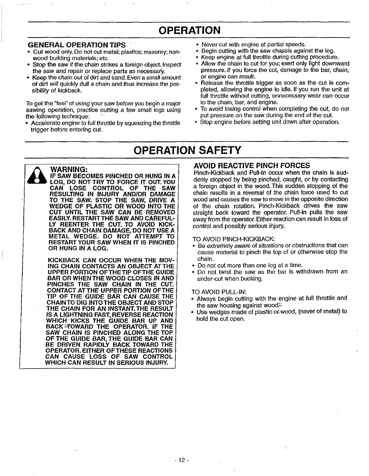
STARTING A WARM ENGINE
•Move on/stop switch to the "On" position.
•Activate fast idle control.
•Be sure choke is in the "Off" position.
-. With saw on ground, grip front handle with left hand and
• Before first use ......
• After I minute of operation.
TO START ENGINE (Fig. 10 & 11)
COLD ENGINE START AND WARM ENGINE
START AFTER RUNNING OUT OF FUEL.
•Fuel engine with 40:1 fuel mix (3.2 oz.to 1 gal. gas).
•Fill bar oil tank with bar oil. Your saw will use approxi-
mately one tank of bar oil for each tank of fuel mix.
• Prime engine by pressing primer bulb six times.
•Turn on ignition by moving on/stop switch to the "On"
position.
•Actuate choke by pulling blue choke knob fully out.Then
set the saw on the ground. Grip the front handle with your
left hand and place your right foot through opening in
rear handle,
• Set fast idle by depressing the throttle lock with your right
hand. Then squeeze throttle trigger and hold. With your
thumb, press the fast idle lock down and hold. Next,
release the throttle trigger.
:;_. _';.,• Squeeze and _-elease_lhrottle:lrigger to .return engine to
idle speed.
[Right Hand on STARTING POSITION
Starter Rope Handle
l[t_l_'_ _ Left Hand on
II tI_. _}_[ _ i Front Handle
ight Foot through Opening in Rear Handle
Figure 11
oIFTHROTTLETRIGGER IS SQUEEZED ACCIDENTAL- _..:._._ ....... ._..... ...... ..... FLOODEDENGINE ......
UilP_It._ULI _.iAi'_.LiI_I,._ UM
LY DURING STARTING IT WlEL' BENECESSARYTO "_"_=........ ..... "_ _' ' _ ........
RESETTHE FAST IDLE LOCK. " .... ;:' Theengine maybe.ffooded_with:_too much fuel if it has not
knob in to the "Off" position, then squeeze and release
throttle trigger to allow engine to idle.
•To stop engine, move on/stop switch to the "Stop" posi-
tion.
NOTE: When pulling the starter rope, do not use the full
extent of the rope as this can cause the rope to break. Do
not let the starter snap back, hold the handle and let the
rope rewind slowly.
o:Pull starter rope.handle with Your right hand until the
engine attempts to start. Then push the blue choke knob
in to the partial position. Resume pulling handle until
engine starts.
•Above 40 degrees, allow engine to run for approximate-
ly 5 seconds, push the choke knob in to the "Off" posi-
tion, then squeeze and release throttle trigger to allow
engine to idle.
• Below 40 degrees, allow engine to warm up 30 seconds
- I minute with choke at partial position. Push choke
:started after_:t0 pulls:. _ ._ .. :
Flooded engines can be cleared of excess fuel with the fol-
lowing procedure:
• Activate the fast idle lock.
•Verify thai the ordstop switchis iiilthe =On" position: " "
• Push the choke knob to the "Off" position.
•With saw on ground, grip front handle with left hand and
place right foot through opening in rear handle.
• Pull starter rope handle until engine starts.
Starting could require pulling starter rope handle many
times depending on how badly unit is flooded. If engine still
fails to start, refer to 'q'ROUBLE SHOOTING" chart or call
the 1-800 number listed on the front page of this manual.
-11 -
iOPERATION
GENERAL OPERATION TIPS '
• Cut wood only. Do not cut metal; plastics; masonry; non-
wood building materials; etc.
• Stop lhe saw if the chain strikes a foreign object. Inspect
the saw and repair or replace parts as necessary.
•Keep the chain out of dirt and sand. Even a small amount
of dirt will quickly dull a chain and thus incre&se the pos-
sibility of kickback.
To get the "feel" of using your saw before you begin a major
sawing operation, practice cutting a few small logs using
the following technique: "
° Accelerate engine to full throttle by squeezing the throttle
trigger before entering cut.
•Never cut with engine at partial speeds.
•Begin cutting with the saw chassis.against the log.
• Keep engine at full throttle during cutting procedure.
•Allow the chain to cut for you; exert only light downward
pressure. If you force the cut, damage to the bar, chain,
or engine can result.
• Release the throttle trigger as soon as the cut is com-
pleted, allowing the engine to idle. If you run the unit at
full throttle without cutting, unnecessary wear can occur
to the chain, bar, and engine.
• To avoid losing control when completing the cut, do not
put pressure on the saw during the end of the cut.
• Stop engine before setting unit down after operation.
OPERATION SAFETY
WARNING:
IF SAW BECOMES PINCHED OR HUNG IN A
LQG, DO NOT TRY TO FORCE IT OUT. YOU
CAN LOSE CONTROL OF THE SAW
RESULTING IN INJURY AND/OR DAMAGE
TO THE SAW. STOP THE SAW, DRIVE A
WEDGE OF PLASTIC OR WOOD INTO THE
CUT UNTIL THE SAW CAN BE REMOVED
EASILY. RESTARTTHE SAW AND CAREFUL-
LY REENTER THE CUT. TO AVOID KICK-
BACK AND CHAIN DAMAGE, DO NOT USE A
METAL WEDGE. DO NOT ATTEMPT TO
RESTART YOUR SAW WHEN IT IS PINCHED
OR HUNG IN A LOG.
KICKBACK CAN OCCUR WHEN THE MOV-
ING CHAIN CONTACTS AN OBJECT ATTHE
UPPER PORTION OFTHETIP OFTHE GUIDE
BAR OR WHEN THE WOOD CLOSES IN AND
PINCHES THE SAW CHAIN IN THE CUT.
CONTACT AT THE UPPER PORTION OF THE
TiP OF THE GUIDE BAR CAN CAUSE THE
CHAINTO DIG INTOTHE OBJECT AND STOP
THE CHAIN FOR AN INSTANT.THE RESULT
IS A LIGHTNING FAST, REVERSE REACTION
WHICHKICKS THE GUIDE BAR UP AND
BACK:_TOWARD THE OPERATOR. IF THE
SAW CHAIN IS PINCHED ALONG THE TOP
OF THE GUIDE BAR, THE GUIDE BAR CAN
BE DRIVEN RAPIDLY BACK TOWARD THE
OPERATOR. EITHER OF THESE REACTIONS
CAN CAUSE LOSS OF SAW CONTROL
WHICH CAN RESULT IN SERIOUS INJURY.
AVOID REACTIVE PINCH FORCES
Pinch-Kickback and Pull-In occur when the chain is sud-
denly stepped by being pinched, caught, or by contacting
a foreign object in the wood, This sudden stopping of the
chain results in a reversal of the chain force used to cut
wood and causes the saw to move in the opposite direction
of the chain rotation. Pir,ch-Kickback drives the saw
straight back toward the operator. Pull-In pulls the saw
away from the operator. Either reaction can result in loss 6f
control and possibly serious ihjury.
TO AVOID PINCH-KICKBACK:
• Be extremely aware of situations or obstructions that can
cause material to pinch the top of or otherwise stop the
chain.
•Do not cut more than one log at atime.
• Do not twist the saw as the bar is withdrawn from an
under-cut when bucking.
TO AVOID PULL-IN:
° Always begin cutting with the engine at full throttle and
the saw housing against wood_s:
° Use wedges made of plastic or.wood, (never of metal) to
hold the cut open.
-12-
OPERATION
TREE FELLING
WARNING:
IF THE TRUNK OR LIMBS ARE ROTTING,
THEY CAN FALL UNEXPECTEDLY AND
CAUSE SERIOUS INJURY.
AS YOU MAKE YOUR FELLING CUT, IFTHE
SAW APPEARS TO BE BINDING, THE TREE
IS STARTING TO FALL IN THE WRONG
DIRECTION. IMMEDIATELY STOP THE SAW
AND USE A FELLING WEDGE AND MAUL
(HAMMER) TO FORCE THE FELLING CUT
OPEN. THE WEDGE WILL HOLD THE
FELLING CUT OPEN ALLOWING YOU TO
R EMOVE THE SAW. KEEP EVERYONE AWAY
FROM THE TREE IN ALL DIRECTIONS.
DETERMINE THE NATURAL FALL DIRECTION
• Wind - Atree evenly balanced wiltfall in the same direc-
tion the wind is blowing.
• Lean - Use a carpenter's level or plumbbob to deter-
. mine if tree has anatural tean, Aleaning tree will tend to
fall in direction of lean.
• • Shape - A tree wilt tend to fall towards side that is more
heavily branched.
•Other Factors - Contacting or nearby trees, buildings, or
wires can influence the direction the tree will fall.
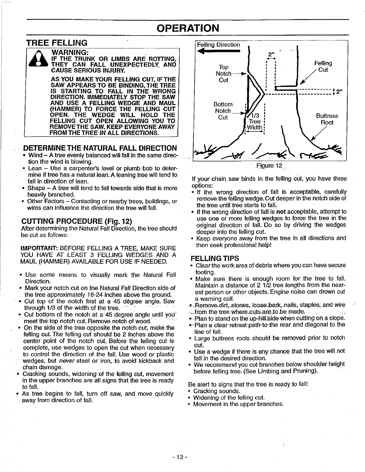
CUTTING PROCEDURE (Fig. 12)
After determining the Natura! Fall Direction, the tree should
be cut as follows:
IMPORTANT: BEFORE FELLING A TREE, MAKE SURE
YOU HAVE AT LEAST 3 FELLING WEDGES AND A
MAUL (HAMMER) AVAI_BLE FOR USE IF NEEDED.
•Use some means to visually mark the Natural Fall
Direction.
°Mark your notch cut on the Natural Fall Direction side of
the tree approximately 18-24 inches above the ground.
•: Cut top of the notch first at a 45 degree angle.: Saw
through 1/3 of the width of the tree: ..................
•Cut bottom of the notch at a: 45 idegree .angle until yoly
meet the top notch cut. Remove notch of wood.' .... _....
°On the side of the tree opposite the notch cut, make the
felling cut. The fe!ling cut should be 2 inches above the
center point of the notch cut. Before the felling cut is
complete, use wedges to open the cut when necessary
to control the direction of the fall. Use wood or plastic
wedges, but never steel or iron, to avoid kickback and
chain damage.
•Cracking sounds, widening of the felling cut, movement
in the upper branches are all signs that the tree is ready
to fall.
• As tree begins to fall, turn off saw, and move quickly
away from direction of tall.
m
Felling Direction
Top
Notch
Cut
Bottom
Notch
Cut
Felling
FCut
....... t
Buttress
Root
• .Ogure 12.:
If your chain saw binds in the felling cut, you have three
options:
• if the wrong direction of fal! is acceptable, carefully
remove the feffing wedge. Cut deeper in the notch side of
the 'tree until tree starts to fall.
• If the wrong direction of fall is not acceptable, attempt to
use one or more felling wedges to force the tree in the
original direction of fall. Do so by driving the wedges
deeper into the felling cut.
• Keep everyone away from the tree in all directions and
then seek professional help!
FELLING TIPS
•Clearthe work area of debris where you can have secure
footing.
Make sure there is enough room for the tree to fall.
Maintain a distance of 21/2 tree lengths from the near,
est person or other objects. Engine noise can drown out
a warning call.
::,Remove_dirt,.stones, Ioose_bark,::nails,staples; and wire
.._._fromthe .treewhere_cuts_m:_o be made, _ . ......
-.Plan to stand on the up-hill;side,when cutting on a slope.
• .--Planaclearretreat_path-.to-the rear and diagonal to the
line of fall.
•Large buttress roots should be removed prior to notch
cut.
• Use a wedge if there is any chance that the tree will not
fall in the desired direction.
• We recommend you cut branches below shoulder height
before felling tree. (See Limbing and Pruning). "
Be alert to signs that the tree is ready to fall:
• Cracking sounds.
-. Widening of the felling cut.
• Movement in the upper branches.
-13-
OPERATION SAFETY
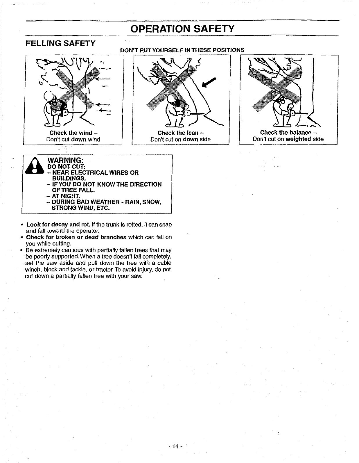
FELLING SAFETY DON'T PUT YOURSELF IN THESE POSITIONS
Check the wind -
Don't cut down wind Check the lean -
Don't cut on down side
I_ ARNING:
DO NOT_CUT:
- NEAR ELECTRICAL WIRES OR
BUILDINGS.
- IF YOU DO NOT KNOW THE DIRECTION
OFTREE FALL.
- AT NIGHT.
- DURING BAD WEATHER -RAIN, SNOW,
STRONG WIND, ETC.
Check the balance -
Don't cut on weighted side
•Look for decay and rot. If the trunk is rotted, itcan snap
and fal{ toward the operator.
-Check for broken or dead branches which can fall on
you while cutting.
•Be extremehJ cautious with partially fallen trees that may
be poody supported. When a tree doesn't fal! completely,
set the saw aside and pull down the tree with a cable
winch, block and tackle, or tractor.To avoid injury, do not
cut down a partially fallen tree with your saw.
-!4-
OPERATION
BUCKING
Bucking is cutting a fallen tree to the desired• log size.
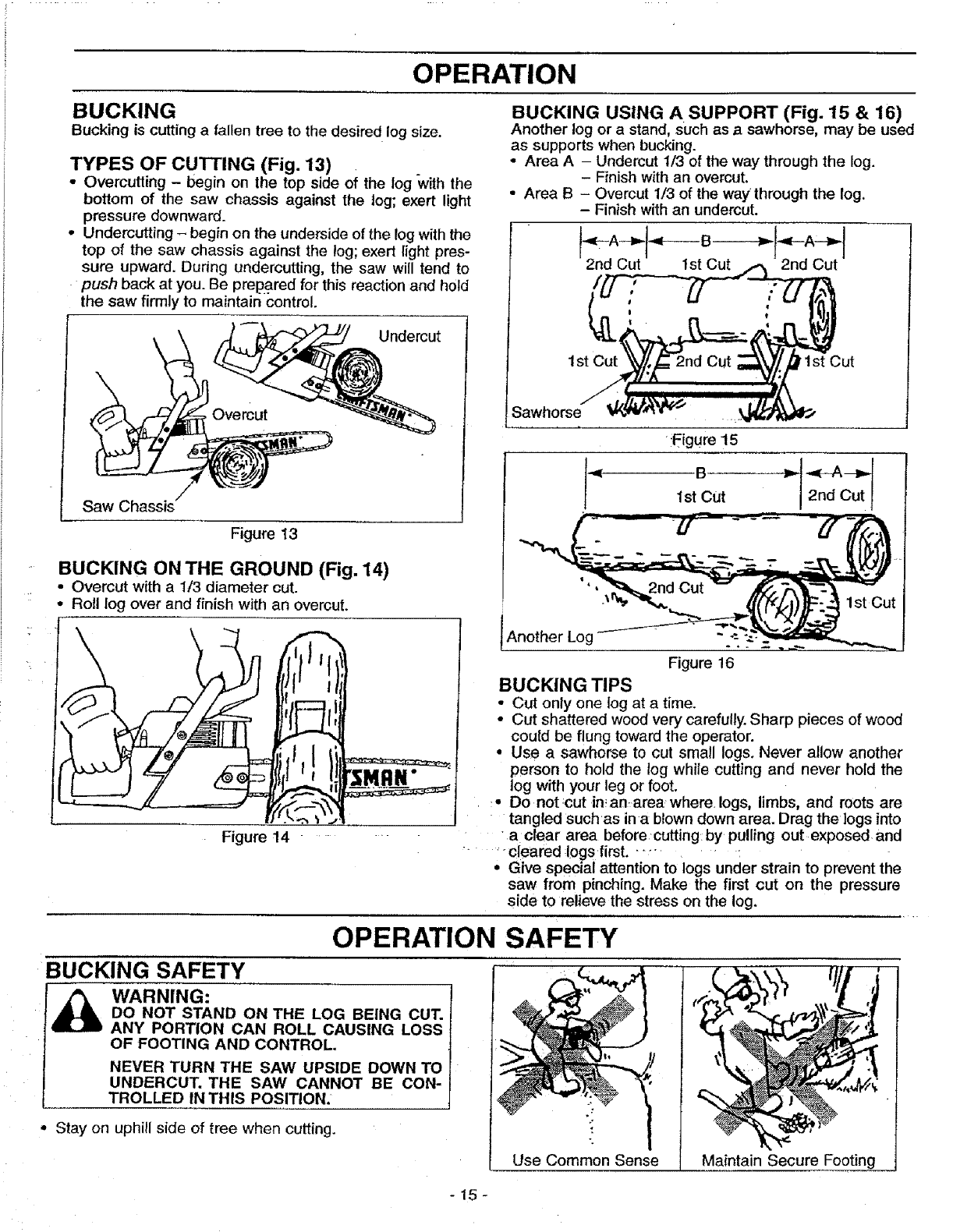
"I_nPES OF CU'I-rlNG (Fig. 13) •
Overcutting -begin on the top side of the log with the
bottom of the saw chassis against the log; exert light
pressure downward.
• Undercutting -begin on the underside of the log with the
top of the saw chassis against the log; exert light pres-
sure upward. During undercutting, the saw will tend to
push back at you. Be prep.ared for this reaction and hold
the saw firmly to maintain control.
Saw Chassis
Figure 13
BUCKING ON THE GROUND (Fig. 14)
• Overcut with a 1t3 diameter cut.
• Roll log over and finish with an overcut.
/
Figure 14
BUCKING USING A SUPPORT (Fig. 15 & 16)
Another log or a stand, Such as a sawhorse, may be used
as supports when bucking.
•Area A - Undercut 1/3 of the way through the log.
- Finish with an ovemut.
• Area B - Overcut 1/3 of the way through the log.
- Finish with an undercut.
2nd Cut 2nd Cut
1st !1st Cut
Sawhorse
Another Log
Figure 16
BUCKING TIPS
• Cut only one log at a time.
• Cut shattered wood very carefully. Sharp pieces of wood
could be flung toward the operator.
• Use a sawhorse to cut small logs. Never allow another
person to hold the log while cutting and never hold the
log with your leg or foot.
:- Do not:cut in_anarea where, logs, limbs, and roots are
tangled suchas ina blown down area. Drag the logs into
a clear area beforecutting by pulling out exposed, and
....... cleared logs first. -...... :
• Give special attention to logs under strain to prevent the
saw from pinching. Make the first cut on the pressure
side to relieve the stress on the log.
OPERATION SAFETY
BUCKING SAFETY
WARNING:
DO NOT STAND ON THE LOG BEING CUT'.
ANY PORTION CAN ROLL CAUSING LOSS
OF FOOTING AND CONTROL.
NEVER TURN THE SAW UPSIDE DOWN TO
UNDERCUT. THE SAW CANNOT BE CON-
TROLLED IN THIS POSITION.
° Stay on uphill side of tree when cutting.
Use Common Sense Maintain Secure Footing
-15-
OPERATION
PRUNING AND LIMBING
Pruning is removing branches from astanding tree.
Limbing is removing branches from a felled tree.
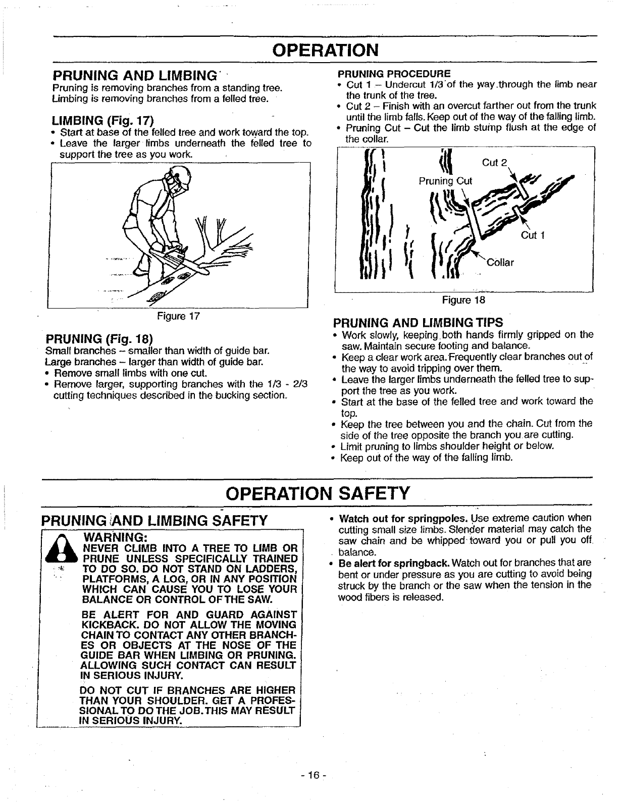
LIMBING (Fig. 17)
* Start at base of the felled tree and work toward the top.
- Leave the larger limbs underneath the felled tree to
support the tree as you work.
Figure 17
PRUNING (Fig. 18)
Small branches -smaller than width of guide bar.
Large branches - larger than width of guide bar.
•Remove small limbs with one cut.
• Remove larger, supporting branches with the 1/3 - 2/3
cutting techniques described in the bucking section.
PRUNING PROCEDURE
• Cut 1 - Undercut 1/3of the way.through the limb near
the trunk of the tree.
°Cut 2-Finish with an overcut farther out from the trunk
untilthe limb falls. Keep out of the way of the falling limb.
•Pruning Cut - Cut the limb stump flush at the edge of
the collar.
'itl Cut 2
Pruning Cut
)
I
J
Figure 18
PRUNING AND LIMBING TIPS
•Work slowly, keepingboth hands firmly gripped on the
saw. Maintain secure footing and balance,
•Keep aclear work area.'Frequently clear branches out of
the way to avoid tripping over them.
•Leave the larger limbs underneath the felled tree to sup-
port the tree as you work.
•Start at the base of the fetled tree and work toward the
top.
•Keep the tree between you and the chain. Cut from the
side of the tree opposite the branch you are cutting.
•Limit pruning to limbs shoulder height or below.
• Keep out of the way of the falling limb.
OPERATION SAFETY
PRUNING AND LIMBING SAFETY
T
_WARNING:
NEVER CLIMB INTO A TREE TO LIMB OR
PRUNE UNLESS SPECIFICALLY TRAINED
'_ TO DO SO. DO NOT STAND ON LADDERS,
"" PLATFORMS, A LOG, OR IN ANY POSITION
WHICH CAN CAUSE YOU TO LOSE YOUR
BALANCE OR CONTROL OFTHE SAW.
BE ALERT FOR AND GUARD AGAINST
KICKBACK. DO NOT ALLOW THE MOVING
CHAIN TO CONTACT ANY OTHER BRANCH-
ES OR OBJECTS AT THE NOSE OF THE
GUIDE BAR WHEN UMBING OR PRUNING.
ALLOWING SUCH CONTACT CAN RESULT
IN SERIOUS INJURY.
DO NOT CUT IF BRANCHES ARE HIGHER
THAN YOUR SHOULDER. GET A PROFES-
SIONAL TO DO THE JOB. THIS MAY RESULT
IN SERIOUS INJURY.
,Watch out for springpoles. Use extreme caution when
cutting small size limbs. Slender material may catch the
saw chain and be whipped' toward you or pull you off
• balance.
• Be alert for springback. Watch out for branches that are
bent or under pressure as you are cutting to avoid being
struck by the branch or the saw when the tension in the
wood fibers is released.
-16-
CUSTOMER RESPONSIBILITIES
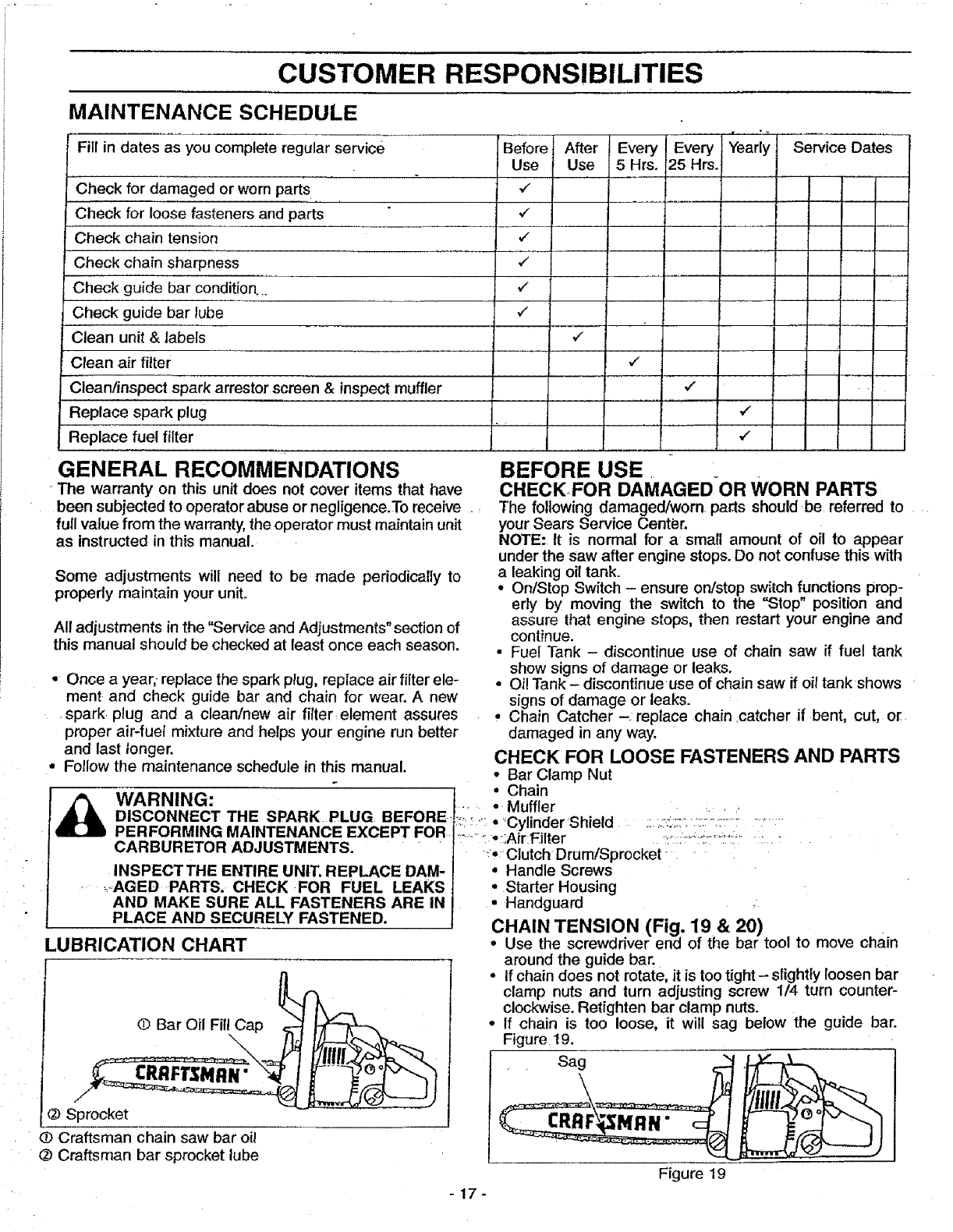
MAINTENANCE SCHEDULE
Fill in dates as you complete regular service Before After Every Every Yearly Service Dates
Clean/inspect spark arrestor screen & inspect muffler
Replace spark plug
Replace fuel filter
GENERAL RECOMMENDATIONS
The warranty on this unit does not cover items that have
been subjected to operator abuse or negligence,To receive .:
full value from the warranty,the operator must maintain unit
as instructed in this manual.
Some adjustments will need to be made periodically to
properly maintain your unit.
All adjustments in the "Service and Adiustments" section of
this manual should be checked at least once each season.
•Once a year, replace the spark plug, replace air filter ele-
ment and check guide bar and chain for wear. A new
spark plug and a clean/new air fitterelement assures
proper air-fuel mixture and helps your engine run better
and last longer.
• Follow the maintenance schedule in this manual.
WARNING:
DISCONNECT THE SPARK. PLUG BEFORE-,
PERFORMING MAINTENANCE EXCEPT FOR
CARBURETOR ADJUSTMENTS.
INSPECTTHE ENTIRE UNIT. REPLACE DAM-
•.AGED PARTS. CHECK FOR FUEL LEAKS
AND MAKE SURE ALL FASTENERS ARE IN
PLACE AND SECURELY FASTENED.
LUBRICATION CHART
©BarOilFil/Cap _
@ Sprocket
(# Craftsman chain saw bar oil
@ Craftsman bar sprocket lube
v"
v_
v"
I ...........
BEFORE USE
CHECKFOR DAMAGEDOR WORN PARTS
The following damaged/worn pa_ts should be referred to
your Sears Service Center.
NOTE: It is normal for a small amount of oil to appear
under the saw after engine stops. Do not confuse this with
a leaking oil tank.
°On/Stop Switch - ensure on/stop switch functions prop-
erly by moving the switch to the "Stop" position and
assure that engine stops, then restart your engine and
continue.
• Fuel Tank - discontinue use of chain saw if fuel tank
show signs of damage or leaks.
•Oi! Tank - discontinueuse of chain saw if oil tankshows
signs of damage or leaks.
° Chain Catcher -replace chain ,catcher if bent, cut, or
damaged in any way.
CHECK FOR LOOSE FASTENERS AND PARTS
•Bar Clamp Nut
° Chain
....... Muffler
:_:': •'CylinderShietd
......... :-:;Air:Filter :i :-_":'!::f:';..... ; "
_.Clutch Drum/Sprocket .....
°Handle Screws
°Starter Housing
•Handguard
CHAIN TENSION (Fig. 19 & 20)
Use the screwdriver end of the bar toot to move chain
around the guide bar.
• If chain does not rotate, itis too tight - slightly loosen bar
clamp nuts and turn adjusting screw 1/4 turn counter-
clockwise. Retighten bar clamp nuts.
•If chain is too loose, it will sag below the guide bar.
Figure 19.
sa0===j;
Figure 19
-17-
Use Use 5 Hrs. 25 Hrs.
Check for damaged or worn parts ,/ ....
...... I .....
Check for loose fasteners and parts ,/
Check chain tension ./
Check chain sharpness ,,I
Check guide bar condition_., v"
Check guide bar lube v"
Clean unit & labels ,/
Clean air filter ,/
CUSTOMER RESPONSIBILITIES
• If chain is too loose, refer to "Chain Adjustment." Loosen
bar clamp nuts; then, turn adjusting screw 1/4 turn clock-
wise. Lift up tip of guide bar to check for sag. Retighten
bar clamp nuts. Figure 20.
Adjusting Screw
1/4 Turn Bar Clamp
Nuts
CRRFTSMRN"
Bar
Tool
Figure 20
SHARPENIN_ CHAIN
(Fig. 21,22,23,24 , 25, 26 & 27)
WARNING:
IMPROPER CHAIN SHARPENING TECH-
NIQUES AND/OR DEPTH GAUGE MAINTE-
NANCE WILL INCREASE THE CHANCE OF
KICKBACK, WHICH CAN RESULT IN SERI-
OUS INJURY.
ALWAYS WEAR GLOVES WHEN HANDLING
THE CHAIN. THE CHAIN CAN BE SHARP
ENOUGH TO CUT YOU EVEN THOUGH IT IS
TOO DULLTO CUTWOOD.
CHAIN TERMINOLOGY & PART NAMES
Preset Tie Strap
Left Hand Cutter
Fie Strap Drive Link
Right Han: ..: "e _trap
CHAIN CUTTER PART NAMES
,_ Top Gullet Depth Gauge
Hole
CHAIN "GAUGE"
Pitch refers to chain mea-
surement. A chain's pitch is
the distance between any
three of its rivets divided by
two.
Tl_ckness of bottom mj=._ I i_.,=r_
section of _idve tink _= I _
Gauge refers to thickness
of that portion of drive link
which fits into saw bar
groove.
Tools required:
•Flat file
•.025 depth gauge
•4.5mm round file &file holder
Conditions which indicate the need for chain sharpening:
•Reduction in size of wood chips. The size of the wood
chip will decrease as the chain gets duller until it
becomes more like apowder than a chip. Note that dead
or rotted wood will not produce a good chip.
• Saw cuts to one side or at an angle.
•Saw requires excessive force to cut.
• Noticeable loss of cutting speed.
Sharpening instructions:
• Move on/stop switch to the "Stop" position.
•Check chain for proper tension. Adjust chain tension if
necessary. (See Chain Tension/Adjustment).
• Check and lower depth gauges before sharpening cutters.
• Depth gauges should be checked every third sharpen-
ing. When cutting frozen wood!he depth gauges should
be checked each time you_sharpen the chain_
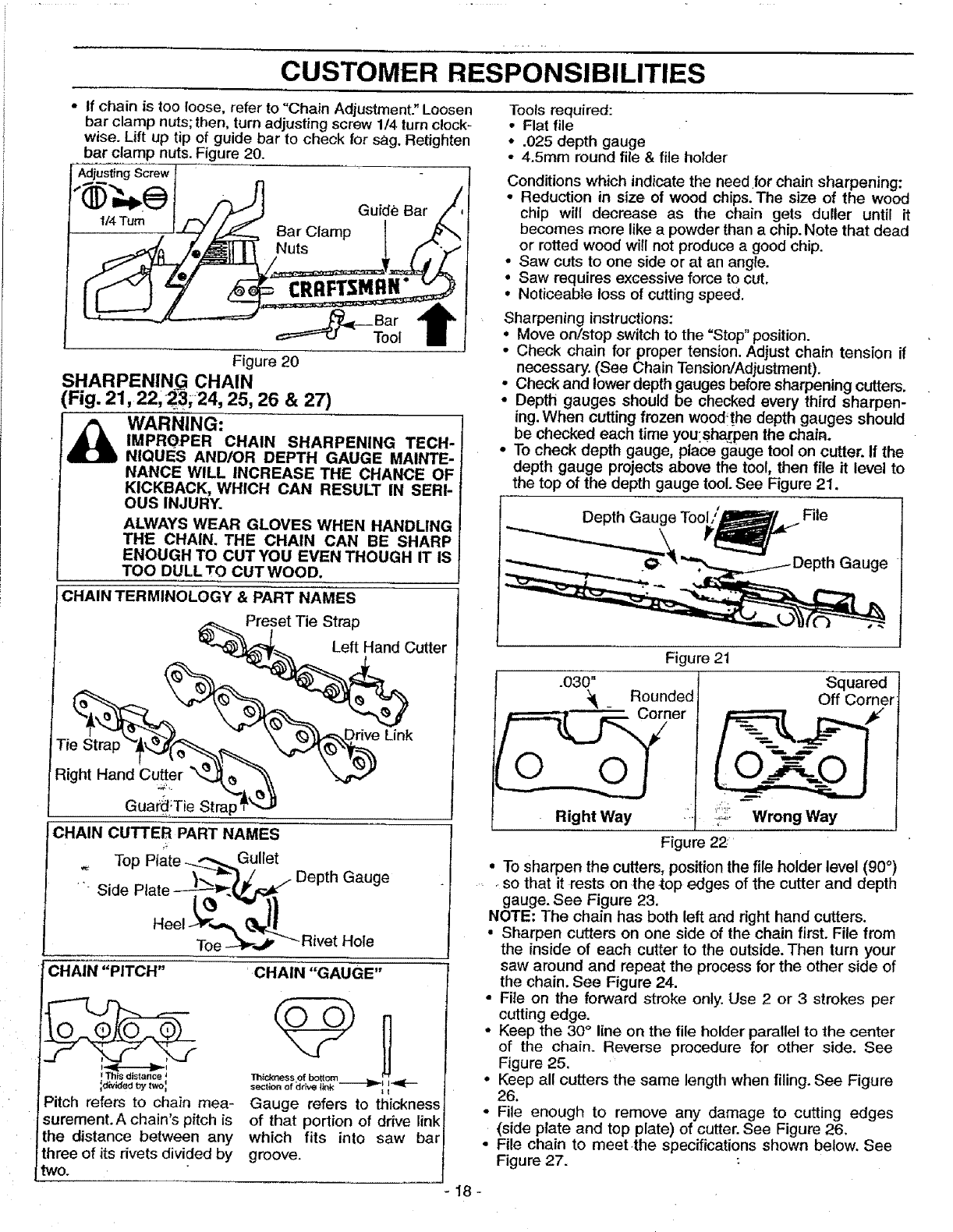
•To check depth gauge, place gauge tool on cutter, If the
depth gauge projects above the tool, then file it level to
the top of the depth gauge tool. See Figure 21.
Depth Gauge File
Figure 21
.030" Squared
:_ _Rounded Off Corner
ner
Right Way £_ _i£2 Wrong Way
Figure 22
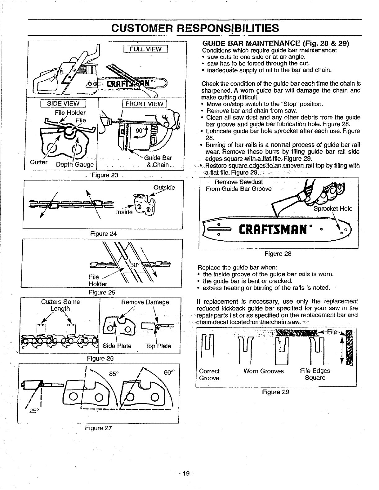
•To sharpen the cutters, position the file holder level (90°)
so that it rests on the top edges of the cutter and depth
gauge. See Figure 23.
NOTE: The chain has both left and right hand cutters.
• Sharpen cutters on one side of the chain first. File from
the inside of each cutter to the outside. Then turn your
saw around and repeat the process for the other side of
the chain. See Figure 24.
• File on the forward stroke only. Use 2 or 3 strokes per
cutting edge.
•Keep the 30° line on the file holder parallel to the center
of the chain, Reverse procedure for other side. See
Figure 25.
•Keep all cutters the same length when filing, See Figure
26,
•File enough to remove any damage to cutting edges
(side plate and top plate) of cutter. See Figure 26,
File chain to meet the specifications shown below, See
Figure 27.
CUSTOMER RESPONSIBILITIES
1 FULLVIEW I
I SiDE VIEW l
File Holder
tl.--___,_ File
Cu__
FRONT VIEW
.. Figure 23 ........
.,_side
Inside'_
Cutters Same
Figure 24
Holder
Figure 25
Remove Damage
Side Plate
25 °
Figure 26
I
!85 °
i
GUIDE BAR MAINTENANCE (Fig. 28 & 29)
Conditionswhich requireguide bar maintenance:
•saw cuts to one side or at an angle,
• saw has _o be forced through the cut.
°inadequate supply of oil to the bar and chain..
Check the condition of the guide bar each time the chain is
sharpened. A worn guide bar will damage the chain and
make cutting difficult.
• Move on/stop switch to the "Stop" position.
• Remove bar and chain from saw.
• Clean all saw dust and any other debris from the guide
bar groove and guide bar lubrication hole. Figure 28.
•Lubricate guide bar hole sprocket after each use. Figure
28.
• Burring of bar rails is anormal process of guide bar rail
wear. Remove these burrs by filing guide bar rail side
edges, square,with_flat_ile_ Figure 29.
:-,,..Restore square.:edges_to_,'_.n.uneven.rail top by filing with
• i:a:flat file.Figure 29. :..::,.::.........
Remove Sawdust ...... _'_(
From,Guide Bar Groove_
_t_" --Sprocket Hole
ERAFTiMAN'v
Figure 28
Replace the guide bar when:
•the inside groove of the guide bar rails is worn.
• the guide bar is bent or cracked.
• excess heating or burring of the rails is noted.
If replacement is necessary, use only the replacement
reduced kickback guide bar specified for your saw in the
repair.parts list or as specified on the replacement bar and
chain:decal Iocated_on-/he,:chain saw. _:
Correct
Groove Worn Grooves File Edges
Square
Figure29
Figure 27
-19-
CUSTOMER RESPONSIBILITIES
AFTER USE "
CLEAN UNIT AND LABELS
•Clean the unit using adamp cloth with a mild detergent.
•Wipe off the unit with a clean dry cloth.
EVERY 5 HOURS
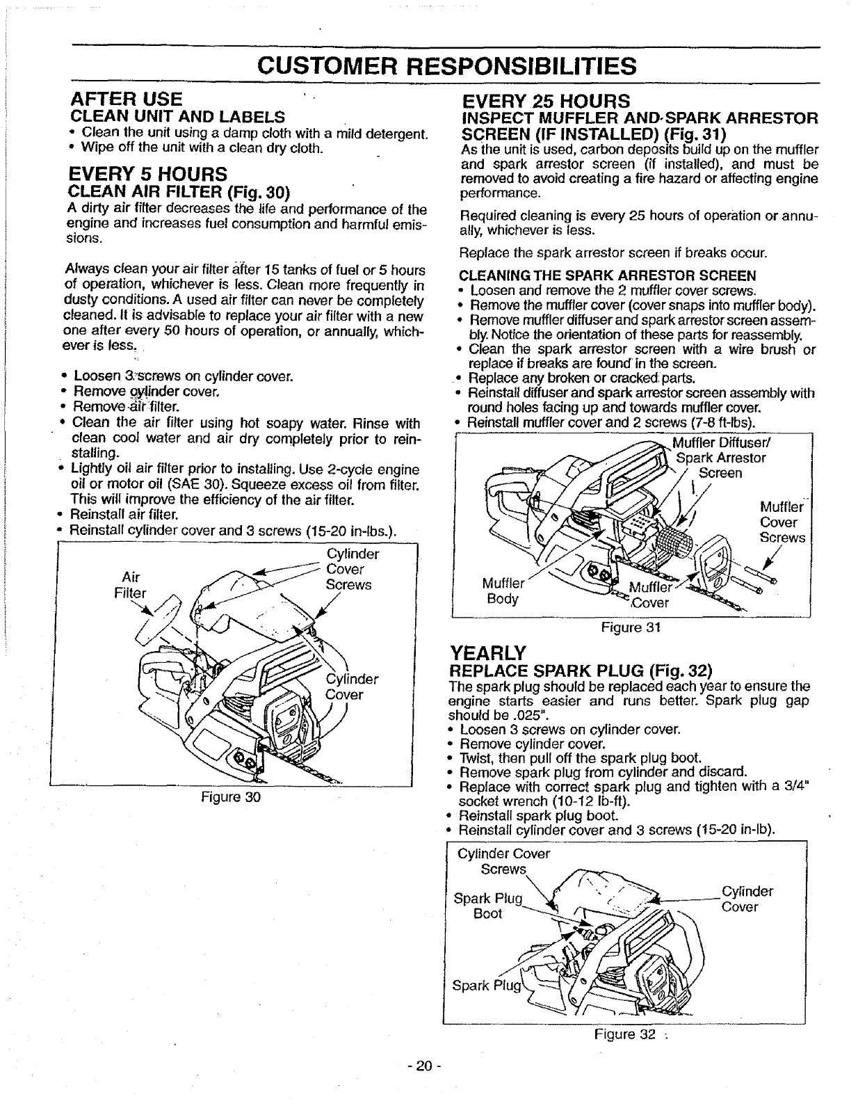
CLEAN AIR FILTER (Fig. 30)
A dirty air filter decreases the life and performance of the
engine and increases fuel consumption and harmful emis-
sions.
Always clean your air filter a{ter 15 tanks of fuel or 5 hours
of operation, whichever is less. Clean more frequently in
dusty conditions. A used air filter can never be completely
cleaned. It is advisable to replace your air filter with a new
one after every 50 hours of operation, or annually, which-
ever is less,
*Loosen 3._'scttewson cylinder cover.
Remove _y|inder cover.
"* Remove;&it :filter.
° Clean the air filter using hot soapy water. Rinse with
clean cool water and air dry completely prior to rein-
stalling.
° Lightly oil air filter prior to installing. Use 2-cycle engine
oil or motor oil (SAE 30). Squeeze excess oil from filter.
This will improve the efficiency of the air filter.
° Reinstall air filter.
= Reinstall cylinder cover and 3 screws (15-20 in-lbs.).
Cylinder
Cover
Air Screws
Filter
Cylinder
r
Figure 30
EVERY 25 HOURS
INSPECT MUFFLER AND-SPARK ARRESTOR
SCREEN (IF INSTALLED) (Fig, 31)
As the unit is used, carbon deposits build up on the muffler
and spark arrestor screen (if installed), and must be
removed to avoid creating a fire hazard or affecting engine
performance.
Required cleaning is every 25 hours of operation or annu-
ally, whichever is less.
Replace the spark arrestor screen if breaks occur.
CLEANING THE SPARK ARRESTOR SCREEN
•Loosen and remove the 2 muffler cover screws.
*Remove the muffler cover (cover snaps into muffler body).
•Remove mufflerdiffuser and spark arrestor screen assem-
bly, Notice the orientation of these parts for reassembly.
•Clean the spark arrestor screen with awire brush or
replace if breaks are found in the screen.
•Replace any broken or cracked:parts.
,Reinstall diffuserand spark arrestor screen assembly with
round holes facing up and towards muffler cover.
•Reinstall muffler cover and 2 screws (7-8 ft-lbs),
.____,/Muffler Diffuser/
Spark Arrestor
Screen
t
Figure 31
YEARLY
REPLACE SPARK PLUG (Fig. 32)
The spark plug should be replaced each year to ensure the
engine starts easier and runs better. Spark plug gap
should be .025".
•Loosen 3 screws on cylinder cover.
•Remove cylinder cover.
* Twist, then pull off the spark plug boot.
•Remove spark plug from cylinder and discard.
•Replace with correct spark plug and tighten with a3/4"
socket wrench (10-12 Ib-ft).
•Reinstall spark plug boot.
•Reinstall cylinder cover and 3screws (t5-20 in-lb).
Cylinder Cover
Screws
Spark Plug W / \ -'3"/_ Cy'inder
Boot ____._,,,_'_ _over
Figure 32 :
- 20 -
CUSTOMER RESPONSIBILITIES
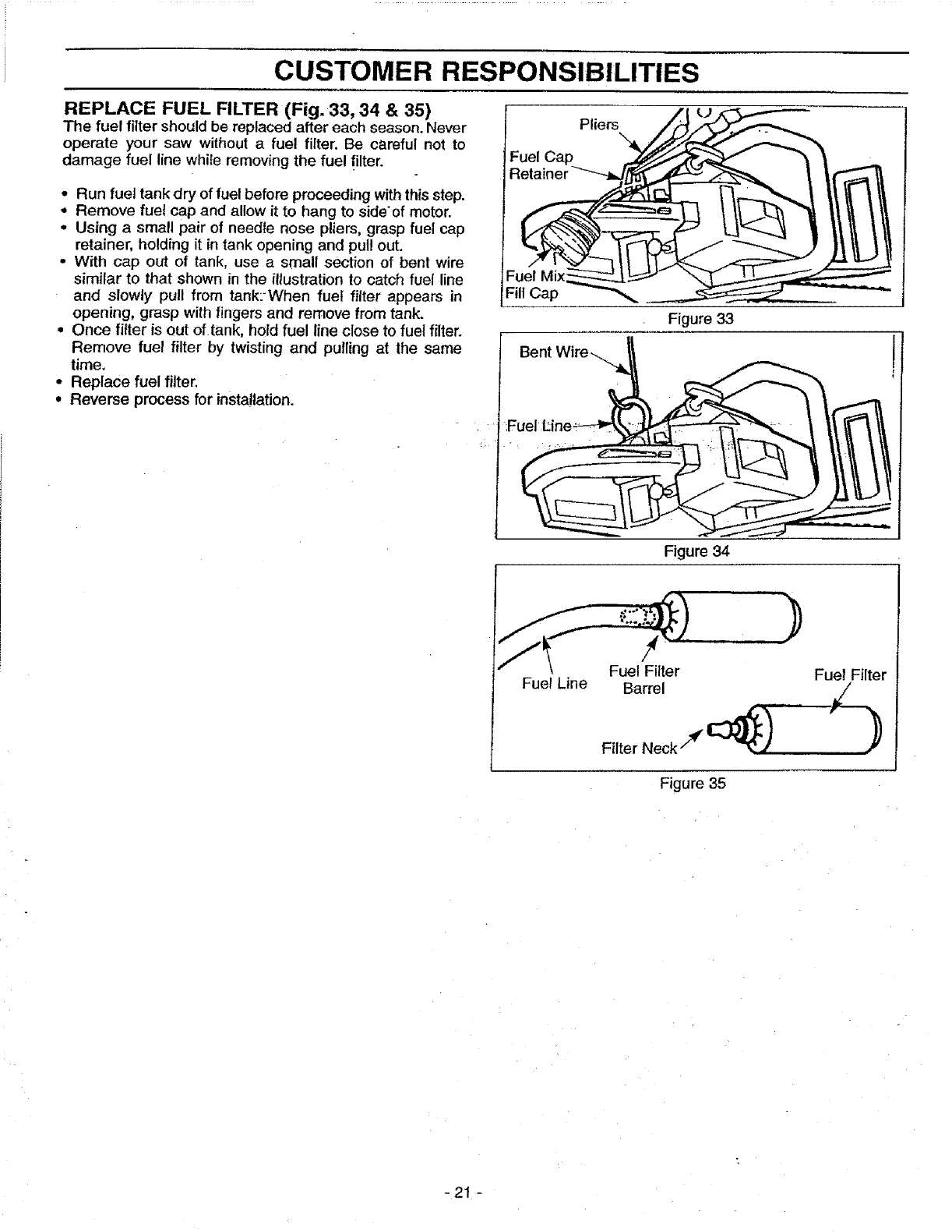
REPLACE FUEL FILTER (Fig. 33, 34 & 35)
The fuel filter should be replaced after each season. Never
operate your saw without a fuel filter. Be careful not to
damage fuel line while removing the fuel filter.
Run fuel tank dry of fuel before proceeding withthis step.
Remove fuel cap and allow it to hang to side'of motor.
Using a small pair of needle nose pliers, grasp fuel cap
retainer, holding it in tank opening and pul! out.
With cap out of tank, use asmall section of bent wire
similar to that shoWn in the illustration to catch fuel line
and slowly pull from tank:When fuel filter appears in
opening, grasp with fingers and remove from tank.
Once filter is out of tank, hold fuel line close to fuel filter.
Remove fuel filter by twisting and pulling at the same
time.
Replace fuel filter.
Reverse process for installation.
Fuel Cap
Fill Cap
Pliers
Figure 33
Figure 34
Fuel Line
!
Fuel Filter
Barrel
Filter Neck "_ _) ......
Fuel Filter
Figure 35
-21 -
SERVICE AND ADJUSTMENTS
Now proceed to the "Chain Adjustment" section.
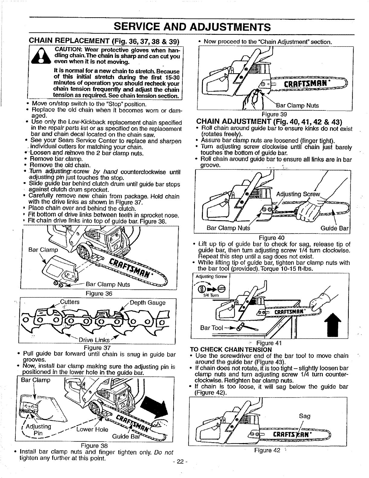
CHAIN REPLACEMENT (Fig. 36, 37, 38 & 39)
_CAUTION: Wear protective gloves when han-
dling chain.The chain is sharp and can cut you
even when it is not moving.
it is normal for a new chain to stretch. Because
of this initial stretch during the first 15-30 i
minutes of operation you should recheck your
chain tension frequently and adjust the chain
tension as required. See chain tension section.
Move on/stop switch to the "Stop" position.
•Replace the old chain when it becomes worn or dam-
aged.
•Use on!y the Low-Kickback replacement chain specified
in the repair parts list or as specified on the replacement
bar and chain decal located on the chain saw.
•See your Sears Service Center to replace and sharpen
..individual cutters for matching your chain.
•,Loosen and re"move the 2 bar clamp nuts.
•Remove I:Jarclamp.
•Remove the old chain.
•.Turn adjusting_,screw by hand counterclockwise until
.adjusting pin just touches the stop.
•Slide guide bar behind clutch drum until guide bar stops
, against clutch drum sprocket.
• Carefully remove new chain from package. Hold chain
with the drive links as shown in Figure 37.
,Piace chain over and behind the clutch.
,Fit bottom of drive links between teeth in sprocket nose.
, Fit chain drive links into top of guide bar. Figure 38.
Bar Clamp
\
Clamp Nuts
Figure 36
• _/Cutte rs _/Depth Gauge
Figure 37
•Pull guide bar forward until chain is snug in guide bar
grooves.
•Now, install bar clamp making sure the adjusting pin is
positioned in the lower hole in the guide bar.
Bar Clamp
Adjusting .--"_
tt Lower Hole
\ Pin .i Guide
Figure 38
• install bar clamp nuts and finger tighten only. Do not
tighten any further at this poinL - 22 -
Nuts
Figure 39
CHAIN ADJUSTMENT (Fig. 40, 41, 42 & 43)
Roll chain around guide bar to ensure kinks do not exist
(rotates freely).
•Assure bar clamp nuts are loosened (finger tight).
• Turn adjusting screw clockwise until chain just barely
touches the bottom of guide bar.
• Roll chain around guide bar to ensure all links are in bar
groove ...... -,_
Bar Clamp Nuts Guide Bar
Figure 40
• Lift up tip of guide bar to check for sag, release tip of
guide bar, then turn adjusting screw 1/4 turn clockwise.
Repeat this step until asag does not exist.
• While lifting tip of guide bar, tighten bar clamp nuts with
the bar tool (provided). Torque 10-15 ft-lbs.
Adjusting Screw
U4Tum
_, Figure 41
TO CHECK CHAIN TENSION
•Use the screwdriver end of the bar tool to move chain
around the guide bar (Figure 43).
•If chain does not rotate, it is too tight- slightly loosen bar
clamp nuts and turn adjusting screw 1/4 turn counter-
clockwise. Retighten bar clamp nuts.
•If chain is too loose, it will sag below the guide bar
(Figure 42).
_ ..... Sag
Figure 42 :
SERVICE AND ADJUSTMENTS
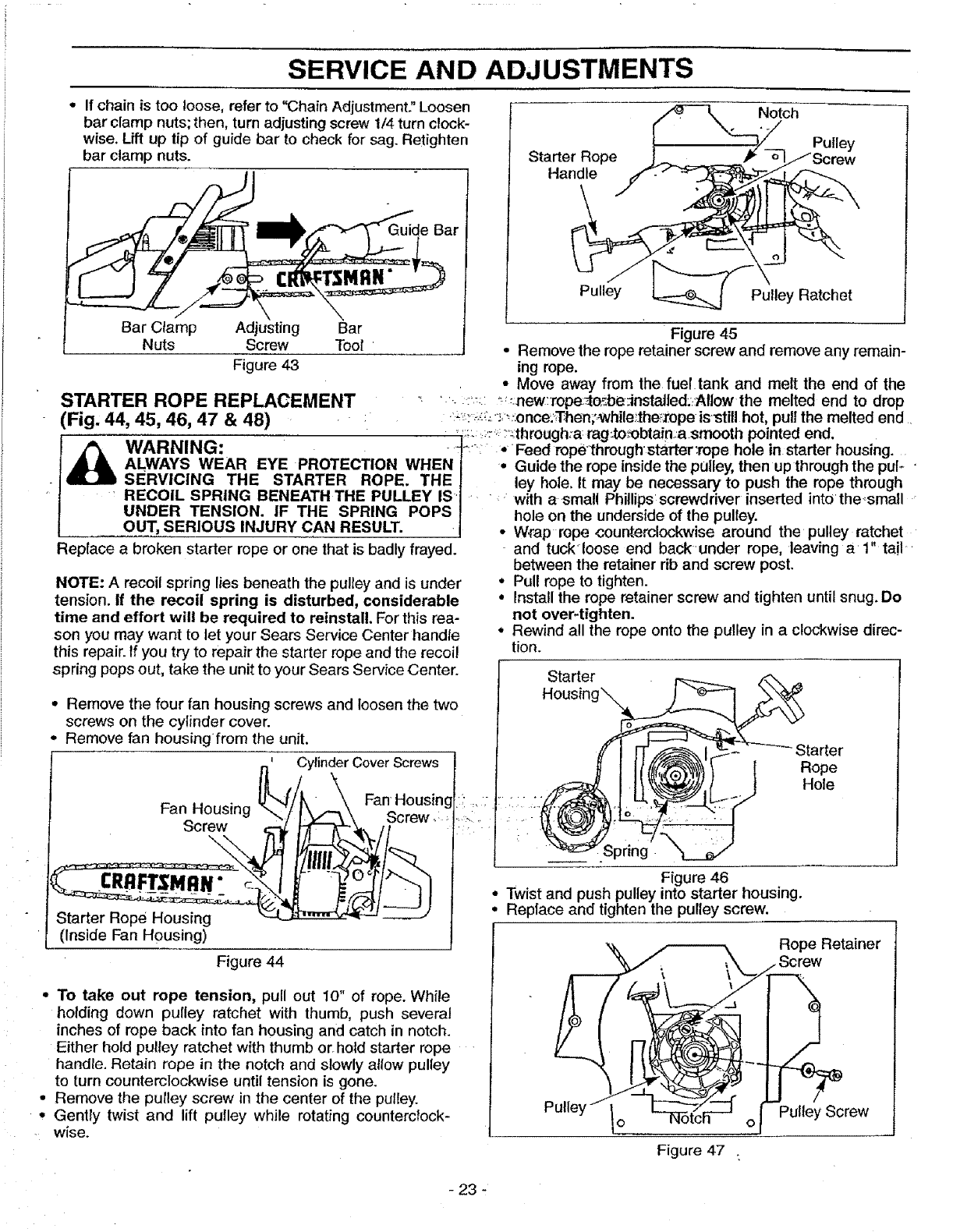
*If chain is too loose, refer to "Chain Adjustment" Loosen
bar clamp nuts; then, turn adjusting screw 1/4 turn clock-
wise. Lift up tip of guide bar to check for sag. Retighten
bar clamp nuts.
Guide Bar
/0---_ Notch Pu,,o
Starter Rope Jr..__ _ N/Screw
Han_
Pulley _J Putley Ratchet
Bar Clamp Adjusting Bar Figure 45
Nuts Screw Tool • Remove the rope retainer screw and remove any remain-
Figure 43 ing rope.
• Move away from the fueltank and melt the end of the
_TARTER ROPE REPLACEMENT _ ' :'_:: _new:'rope_o_be_nstalled._:Allow the melted end to drop
:Fig, '__:::-_'_,_;:onee..Then;_while_theizope isstill hot, pull the melted end
44_,45, 46, 47 _&48) _ L _ : _.;;. ;: _.through:a_rag:to_btain:,a smooth pointed end.
AWARNING: '_-: *Feed rope throughstarter:rope hole in starter housing.
ALWAYS WEAR EYE PROTECTION WHEN| •Guide the rope inside the pulley, then up through the pul-
U SERVICING THE STARTER ROPE. THEJ ley hole. It may be necessary to push the rope through
RECOIL SPRING BENEATH THE PULLEY IS t : with a small Phillips screwdriver inserted into the_small
UNDER TENSION. IF THE SPRING POPS| hole on the underside of the oullev
OUT, SERIOUS INJURY CAN RESULT. I • W_ap rope counterclockwise' around the pulley ratchet
NOTE: A recoil spring lies beneath the pulley and is under
tension, if the recoil spring is disturbed, considerable
time and effort will be required to reinstall. For this rea-
son you may want to let your Sears Service Center handle
this repair. If you try to repair the starter rope and the recoil
spring pops out, take the unit to your Sears Service Center.
Replace abroken starter rope or one that is badly frayed, and tuck'loose end back'under rope, leaving a 1" tail _
between the retainer rib and screw post.
•Pull rope to tighten.
° Install the rope retainer screw and tighten until snug. Do
not over-tighten.
° Rewind all the rope onto the pulley in a clockwise direc-
tion.
Starter
° Remove the four fan housing screws and loosen the two
screws on the cylinder cover.
* Remove fan housingfrom the unit.
n' Cylinder CoverScrews 1
Fan-Housing _"_/_\/, _i,,,,-__ FansH°reUwSing,
I
(Inside Fan Housing)
Figure 44
* To take out rope tension, pull out 10" of rope. While
holding down pulley ratchet with thumb, push several
inches of rope back into fan housing and catch in notch.
Either hold pulley ratchet with thumb errhold starter rope
handle. Retain rope in the notch and slowly allow pulley
to turn counterclockwise until tension is gone.
°Remove the pulley screw in the center of the pulley.
Gently twist and lift pulley while rotating counterclock-
-wise.
Starter
Rope
Hole
__ i Spring
Figure 46
•Twist and push pulley into starter housing.
°Replace and tighten the pulley screw.
Rope Retainer
Figure 47 .
Pulley Screw
- 23 -
SERVICE AND ADJUSTMENTS
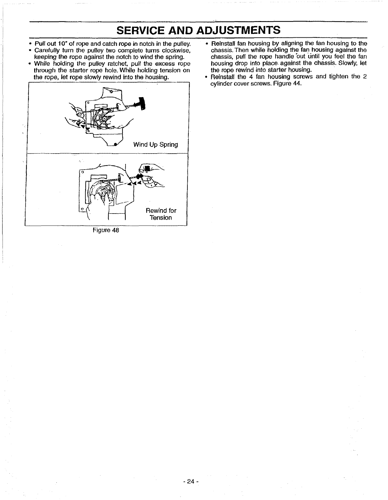
•Pull out 10" of rope and catch rope in notch in the puttey.
•Carefully turn the pulley two complete turns clockwise,
keeping the rope against the notch to wind the spring.
°White holding the pulley ratchet, pull the excess rope
through the starter rope hole. While holding tension on
the rope, let rope slowly rewind into the housing.
_ndUp Spring
Rewind for
Tension
•Reinstall fan housing by aligning the fan housing to the
chassis. Then while holding the fan housing against the
chassis, pull the rope handle "out "until you feel the fan
housing drop into place against the chassis. Slowly, let
the rope rewind into starter housing.
• Reinstall the 4 fan housing screws and tighten the 2
cylinder cover screws. Figure 44.
Figure 48
- 24 -
SERVICE AND ADJUSTMENTS
CARBURETOR ADJUSTMENTS
Carburetor adjustment is critical and if done improper-
ly can permanently damage the engine aswell as the
carburetor. Please read all instructions and consult the
Trouble Shooting section of this manual before'begin-
ning this process. If the engine does not operate
according to these instructions after repeating the
adjusting steps, do not use the unit. For further assis-
tance, please call our customer assistance hotline at
1-800-235-5878.
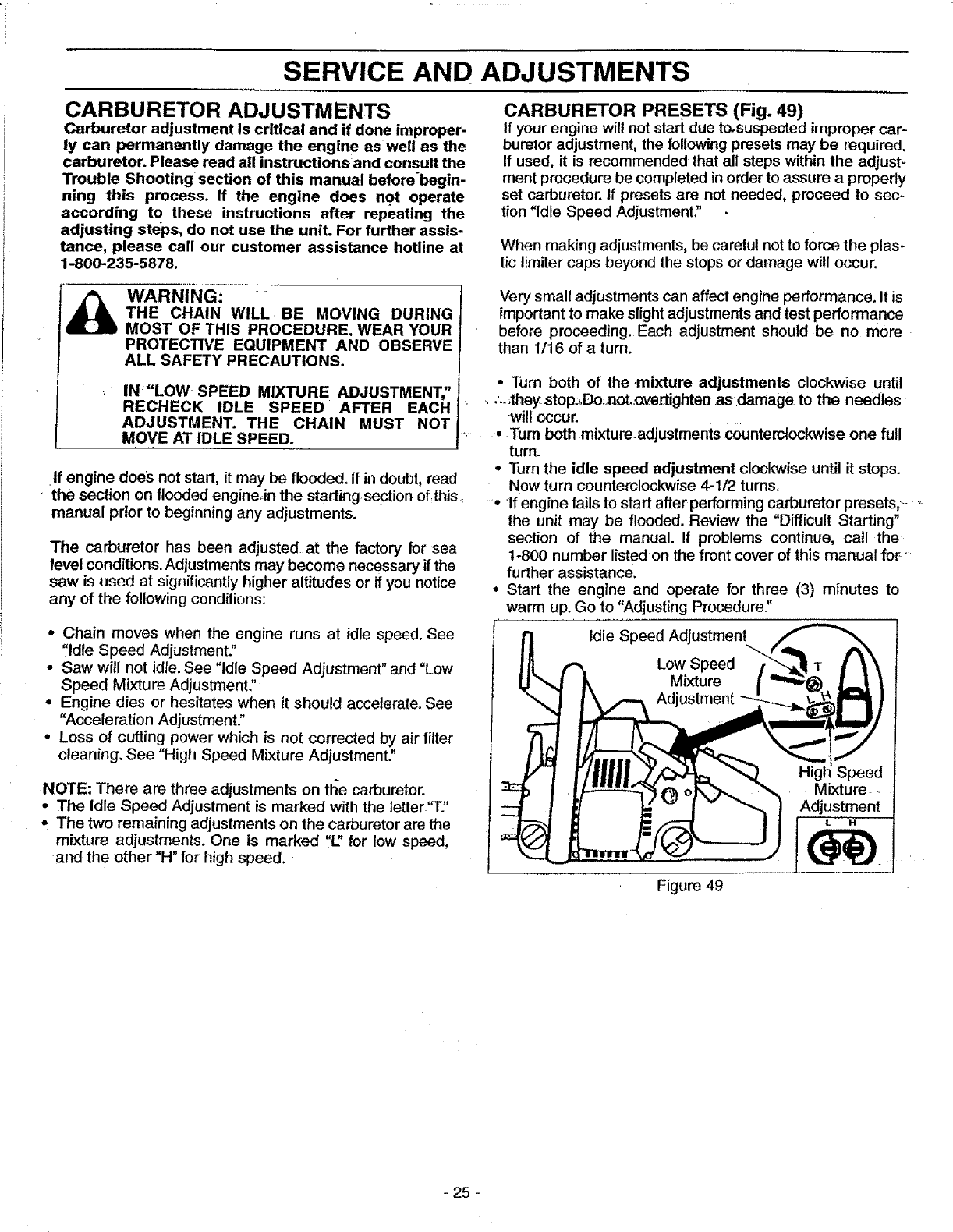
CARBURETOR PRESETS (Fig, 49)
If your engine will not start due to,suspected improper car-
buretor adjustment, the following presets may be required.
If used, it is recommended that all steps within the adjust-
ment procedure be completed in order to assure a properly
set carburetor. If presets are not needed, proceed to sec-
tion "Idle Speed Adjustment."
When making adjustments, be careful not to force the plas-
tic Iimiter caps beyond the stops or damage will occur.
WARNING:
THE CHAIN WILL BE MOVING DURING
MOST OF THIS PROCEDURE. WEAR YOUR
PROTECTIVE EQUIPMENT AND OBSERVE
ALL SAFETY PRECAUTIONS.
IN "LOW SPEED MIXTURE ADJUSTMENT;'
RECHECK IDLE SPEED AFTER EACH
ADJUSTMENT. THE CHAIN MUST NOT
MOVE AT IDLE SPEED.
If engine does not start, it may be flooded. If in doubt, read
• the section on flooded engineJn the starting section of,this,
manual prior to beginning any adjustments.
The carburetor has been adjusted at the factory for sea
level conditions. Adjustments may become necessary if the
saw is used at significantly higher altitudes or if you notice
any of the following conditions:
° Chain moves when the engine runs at idle speed. See
"Idle Speed Adjustment."
- Saw will not idte. See "Idle Speed Adjustment" and "Low
Speed Mixture Adjustment."
•Engine dies or hesitates when it should accelerate. See
"Acceleration Adjustment."
• Loss of cutting power which is not corrected by air _ter
cleaning. See "High Speed Mixture Adjustment."
NOTE: There are three adjustments on tl_e carburetor.
•The idle Speed Adjustment is marked with the letter"T:'
• The two remaining adjustments on the carburetor are the
mixture adjustments. One is marked "L" for low speed,
and the other "H" for high speed.
Very small adjustments can affect engine performance. It is
important to make slight adjustments and test performance
before proceeding. Each adjustment should be no more
than 1/16 of a turn.
•Turn both of the mixture adjustments clockwise until
o_,they stop,,Do;noL.Qvertighten as damage to the needles
wilt occur.
•.Turn beth mixtureadjustments €0unterclockwise one full
turn.
• Turn the idle speed adjustment clockwise until it stops.
Now turn counterclockwise 4-1/2 turns.
• If engine fails to start afterperforming carburetor presets/_ ....
the unit may be flooded. Review the "Difficult Starting"
section of the manual. If problems continue, call the
1-800 number listed on the front cover of this manual for'
further assistance.
° Start the engine and operate for three (3) minutes to
warm up. Go to "Adjusting Procedure."
Idle Speed Adjustment
Low Speed
Mixture
Adj
Figure 49
Higt
Mixture-.
Adjustment
-25 :
SERVICE AND ADJUSTMENTS
ADJUSTING PROCEDURE
IDLE SPEED ADJUSTMENT "T"
•Allow the warm engine to idle.
o Adjust the Idle Speed until the engine continues to run
without stalling and without the chain moving.
-Turn clockwise to increase engine speed ff engine
stalls or dies.
-Turn counterclockwise to slow engine down and/or to
keep the chain from turning.
•No further adjustments are necessary if chain does not
move at idle speed and if performance is satisfactory.
i_- LOW SPEED MIXTURE ADJUSTMENT"L"
°Allow engine to idle.
•Turn the Low Speed Mixture Adjustment slowly clock-
wise until the RPM starts to drop. Note the position.
°Turn the Low Speed Mixture Adjustment slowly counter-
clockwise unt_thb' RPM speeds up and starts to drop
again. Note th_ position.
• Set the Low Speed Mixture at the midpoint between the
two positions_-
HIGH SPEED MIXTURE ADJUSTMENT "H"
IMPORTANT: DO NOT OPERATEoENGINE AT FULL
THROTTLE FOR PROLONGED PERIODS WHILE MAK-
ING HIGH SPEED ADJUSTMENTS AS DAMAGE TO THE
ENGINE CAN OCCUR.
• Make a test cut.
•Based on performance of the saw while cutting, adjust
the high speed mixture in 1/16 turn increments as fol-
lows:
-Clockwise if saw loses power in the cut. Do not adjust
for best power by sound or speed, but judge by how
well the saw performs in the cut.
-Counterclockwise if the saw has speed while out of the
cut, but dies in the cut-o[ Jackspower while cutting.
• Repeat the test cut.
°Continue with 1t16 turn adjustments until the saw perfor-
mance is acceptable while cutting.
• Aftercompleting adjustments; check for acceleration.
ACCELERATION CHECK
*If the engine dies or hesitates instead of accelerating,
turn the Low Speed Mixture Adjustment 1/16 of a turn at
a time counterclockwise until you have smooth accelera-
tion.
• Check the idle speed for stability and no chain move-
ment: Adjust as necessary.
• Recheck for smooth acceleration and stable idle. RePeat
process as necessary for acceptable performance.
-26 -
STORAGE
Immediately prepare your unit for storage at the end of the
season or if it will not be used for 30 days or more.
I_bb WARNING:
ALLOW THE ENGINE TO COOL,-AND
SECURE THE UNIT BEFORE STORING OR
TRANSPORTING IN A VEHICLE.
STORE UNIT AND FUEL IN AN AREA
WHERE FUEL VAPORS CANNOT REACH
SPARKS OR OPEN FLAMES FROM WATER
HEATERS, ELECTRIC MOTORS OR SWITCH-
ES, FURNACES, ETC.
STORE UNIT WITH ALL GUARDS IN PLACE.
POSITION SO THAT ANY SHARP OBJECT
. _. CANNOT ACCIDENTALLY CAUSE INJURY
• TO PASSERS'BY.
STORE THE UNIT OUT OF THE REACH OF
CHILDREN. :
WEAR PROTECTIVE GLOVES WHEN'
HANDLING CHAIN. THE CHAIN IS SHARP_
AND CAN CUT YOU EVEN WHEN IT IS NOT
MOVING.
GAS CHAIN SAW STORAGE INSTRUCTIONS
If your chain is to be sto_'_d for a period of time, clean it
thoroughly pdor to storage. Remove any dirt, sawdust,
leaves, oil, grease, etc. Store in a clean dry area.
•Clean the entire unit.
°Clean air filter. Refer to '_ustomer Responsibilities."
• Inspect the bar clamp area and clean any dirt, sawdust,
grass, or debris that has collected. Inspect the guide bar
and chain; replace a guide bar that is bent, warped,
cracked, broken, or damaged in any other way. Replace
a damaged or worn chain.
°Lightly oil external metal surfaces to prevent rust from
forming.
•Apply a coating of oil to the entire surface of the guide
bar and chain; wrap it in heavy paper or cloth.
• Be sure al! handles and guards are Jn place and are
securely fastened. Replace any damaged parts.
FUEL SYSTEM
IMPORTANT: It is important to prevent gum deposits from
forming in essential fuel System parts such as the carbure-
tor, fuel filter, fuel hose or tank during storage. Also, expe-
rience indicates that alcohol blended fuels, those that use
ethanol or methanol (called gasohol or oxygenated fuel),
can attract moisture and form acidic gas which will damage
your engine. To avoid engine problems, the fuel system
should be emptied before storage of 30 days or longer.
Fuel stabilizer is an acceptable alternative in minimizing
the formation of fuel gum deposits during storage. Add sta-
bilizer to the gasoline in the fuel tank or fuel storage con-
tainer. Always follow the mix instructions found on stabilizer
containers. Run engine at least 5 minutes after adding sta-
bilizer to allow the stabilizer to reach the carburetor.
CRAFTSMAN 40:1 ;?.-cycle engine oil (AIR-COOLED) is
........speciallyblended_N_th_fuelstabilizer. If you do not use this
.: ..:Sears:oil; you can_add _ifuelstabilizer to your fuel tank.
............ INTERNALENG1NE: ......:::::
•Remove spark plug and pour t teaspoon of 40:1 2-cycle
engine oil (AIR-COOLED) through the spark plug open-
ing. Slowly pull the starter rope 8 to 10 times to distribute
oil to inner engine surfaces.
•Replace spark plug with a new one of the recommended
type and heat range. Refer to "Product Specifications."
•Clean air filter. Refer to "Customer Responsibilities."
•Re-install all covers and hardware removed for access;
tighten all screws and fasteners.
•Check entire unit for loose screws, nuts, and bolts.
Replace any damaged, broken, or worn parts.
• Lightly oil external metal surface to prevent rust from
forming.
•Use fresh fuel having the proper gasoline to oil ratio at
the beginning of the next season.
OTHER
•Do not store gasoline from one season to another.
• Replace your gasoline can ff your can starts to rust. Rust
.-, _.-and/or,dirt inyour.fuel,system will cause problems..
........_-Store'your unit in a well--ventilated area and covered, if
possible, to prevent dust and dirt accumulation. Do not
Never use engine or carburetor cleaner products inthe fuel .... __cover with plastic. Plastic cannot breathe "and will'induce
tank or permanent damage may occur to fuel system corn- condensation and eventual rust or corrosion.
ponents. Follow these instructions:
•Drain the fue! from the unit into an approved fuel con- IMPORTANT: NEVER COVER UNIT WHILE ENGINE
tainer. AND EXHAUST AREAS ARE STILL WARM.
°Drain the fuel lines and carburetor bystarting the engine
and letting it run until it stops.
Allow the engine to cool before storage.
- 27-

TROUBLE SHOOTING POINTS
TROUBLE SHOOTING CHART,
SYMPTOM
Engine will not start er
will only run only for a
few seconds after
starting.
Engine will not idle
propedy.
Engine will not
accelerate, lacks
power, or dies;"
under a load,:
Engine smokes
excessively.
Engine runs hot.
Oil inadequate for bar
and chain lubrication.
CAUSE CORRECTION
1. Fue! tankempty.
2. Engine flooded.
3. Spark plug not firing.
4. Fuel not reachihg carburetor.
5. Carburetor requires adjustment.
6. On/Step switch in "Stop" position.
7. None of the above.
1. Idle speed set toe fast er too stow,
2. Low speed mixture requires adjustment.
3. Crankshaft seals worn.
4, Compression tow,
5. None ef the above.
1. Air filter dirty,
2. Spark plug fouled.
3. Carburetor requires adjustment.
4. Exhaust ports er muffler outlets plugged.
5. Compression low.
6. None ef the above.
1. Air filter dirty.
2. Fuel mixture incerrect.
3, High speed mixture requires adjustmenL
4, Choke partially on.
5. Crankcase leak.
1, Fuel mixture incorrect.
2. High speed mixture set tee low (lean).
3. Spark plug incorrect.
4. Exhaust ports or muffler outlets plugged.
5, Carbon build-up en muffler eutlet screen.
6. Fan heusing/cylinder fins dirty.
7. None of the above.
1. Oil tank empty.
2. Oil pump er eil filter clogged.
3, Guide bar oil hole blocked,
Chain moves at idle
speed.
Chain does nqt_move
when engine_is
accelerated, i_' 3.
Chain clatters or cuts 1.
rodghly. 2.
3,
4.
Chain stops within the
cut.
Chain cuts at an angle,
t. Idle speed requires adjustment,
2. Clutch requires repair,
1. Chain tension too tight.
2. Carburetor requires adjustment.
Guide bar rails pinched.
Clutch slipping.
Chain tension incorrect.
Cutters damaged
Chain worn.
Cutters dull, improperly sharpened, er
depth gauges too high.
Sprocket worn.
Chain installed backwards.
Chain cutter tops not filed flat.
Guide bar burred er bent; rails uneven.
Clutch slipping.
Cutters damaged on ene side.
Chain dull en ene side.
Guide bar bent or worn.
!. Fill tank with correct fuel mixture.
2. See "Starting Instructions."
3. Install new plug/check ignition system.
4. Replace fuel filter; inspect fuel line.
5. See "Carburetor Adjustments_
6. Move switch to the "On" position.
7. Contact your Sears Service Center/Dept.
t, See "Carburetor Adjustments,"
2. See =Carburetor Adjustments."
3, Contact your Sears Service Center/Dept.
4. Contact your Sears Service Center/Dept.
5. Contact your Sears Service Center/Dept.
1. Clean or replace air filter.
2. Clean er replace spark plug and re-gap.
3. See "Carburetor Adjustments."
4. Contact your Sears Service Center/Dept.
5. Contact your Sears Service Center/Dept.
6. Contact your Sears Service Center/Dept.
1. Clean or replace air filter.
2. Refuel with correct fuel mixture.
3. See "Carburetor Adjustments."
4. Push blue choke knob in.
5. Contact your Sears Service Center/Dept.
1. See "Fueling Your Unit."
2. See "Carburetor Adjustments."
3. Replace with correct plug.
4. Contact your Sears Service Center/Dept.
5. Clean spark arrestor screen.
6. Clean area.
7. Contact your Sears Service Center/Dept.
1. Fill oil tank.
2. Contact your Sears Service Center/Dept.
3, Remove bar and clean.
1. See "Carburetor Adjustments."
2. Contact your Sears Service Center!Dept.
1. See "Chain Tensie_."
2. See "Carburetor:A'djustments."
3. Repair or replace:,:
4. Contact your Searsr Service Center/Dept.
1. See "Chain Tension."
2._-Contact'your-Sears Service Center/Dept:
3. Resharpen or replace chain.
4, See "Sharpening Chain,"
5. Contact your Sears Service Center/Dept.
6. Install chain in right direction,
1. See "Sharpening Chain."
2. Repair er replace guide bar.
3. Contact your Sears Service Center/Dept.
1. See "Sharpening Chain"
2. See "Sharpening Chain"
3. Replace guide bar.
ff situations occur which are not covered in this manual, use care and good judgement,
If you need assistance, contact your SEARS Service Center/Department or the
CUSTOMER ASS/STANCE HOTLtNE at 1-800-235-5878.
- 28 -
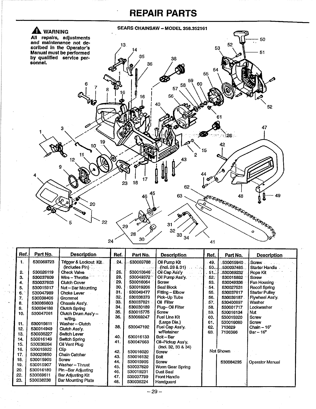
REPAIR PARTS
WARNING
All repairs, adjustments
and maintenance not de-
scribed In the Operator's
Manual must be performed
by qualified service per-
sonnel.
SEARS CHAINSAW - MODEL 358.352161
14
-35 38
36 _54
55
59
J57
!56
I \
t40
52
53
52
2O
Ref. Part No.
1, 530069723
2. 530026119
3. 530037809
4. 530037803
5. 530015917
6. '530047989
7. 530038406
8. 530069803
9, 530094188
10. 530047061
11. 530015611"
12. 530014949
13. 530038227
14. 530016149
t5. 530038264
I6. 530015922
17. 530029850
18. 530015905
19. 530015907
20. 530016180
22. 530069611
23. 530038238
22
61
42
47
23 18
Description
Tdgger& LockoutKtL.
(IncludesPin) _-
CheckValve
Wire - Throttle........
ClutchCover
Nut- Bar Mounting
Choke Lever
Grommet
ChassisAss'y.
ClutchSpring
ClutchDrumAss'y-
w/Brg.
Washer- Clutch
ClutchAss'y.
Sw_tchLever
!SwitchSpring
Cll Vent Plug
Cl_p
ChainCatcher
Screw
Washer- Thrust
Pin-Bar Adjusting
Bar AdjustingKit
! Bar Mounting Plate
24
Ref.
26.
28/
-:29.
30.
31.
32
33.
34.
35.
36.
38_
40.
41.
I 42,
43,
44.
45.
46.
47.
48.
45
46
3t
32 33
PaN No.
....530069788_
530010846_
5300493724
530016064
530019206
530049477
530038373
530037821
530030189
530015775
530069247
530047192
530016133
530047663
530016020
530016132
530O15905
530037820
530019231
530037799
530038224
J
62
63
34
Part No. Des0riptlon,
:,530015940,. •Screw ......
._530037485.. StarterHandle ."
:530069232 .RopeKit -
"530015892 " Screw
530049336 Fan Housing
530027531 RecoilSpring
630037817 StarterPulley
530039187. RywhealAss'y.
530400697 Washer
530001717 Lockwasher
530016134 Nut
530015920 Screw
530016080 Screw
713829 Chain - 16"
7136366 !Bar- 16"
41
Operator Manual
- 29 -
Description Ref.
Oil PumpKit •49.
!., (1n;¢1_,28&31) ...... . -.;. 50...
Oil_?,apA,ss'y :.. 51._.
otr PompAss'y. ..... 52:
Screw 53.
Seal Block " i 54.
Fitting- Elbow 55.
Pick-UpTube 56.
.i Oil Rlter 57.
Plug- Oil Filter 58.
Screw .59.
Fuel Une _t 60.
(Large Dia.) 61.
FuelCap Ass*y. 62,
w/Retainer 63,
Bolt- Bar
Oil-Pickup Ass'y.
(Inc{;32, 33 &34)
Screw
Bolt
Screw
Worm Gear Spdng
DustSeal
FrontHandle
IHandguard
44
Not Shown
530084295
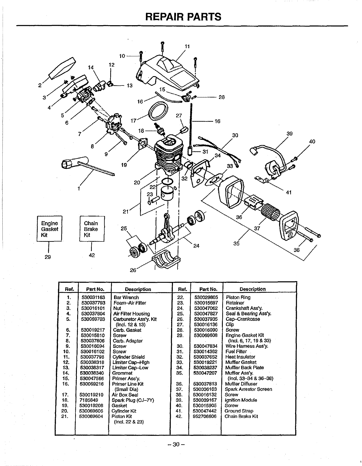
REPAIR PARTS
14 12
28
5
6
I Engine 1 [ Chain
Gasket _ Brake
Kit LKit
l i
29 42
Ref,
1.
2.
3.
4.
5.
6o
7,
8.
9.
10,
11.
12.
13.
t4,
15,
16.
17.
18,
19.
20.
21.
19
17
25
20
27
31
3O 39
41
36
37
Part No.
530031163
530037793
530016101
530037804
530069703
530019217
530015810
530037806
530016094
530016102
530037798
530038318
530038317
530038340
530047566
530069216
530019210
7185849
530019208
530069606
530069604
24 35
26
Description
Bar Wrench
Foam-Air Filter
Nut
Air_RIter Housing
Carburetor Ass'y. Kit
0nd. 12& 13)
Carb. Gasket
!Screw
Carb. Adapter
Screw
Screw
Cylinder Shield
Lirniter Cap-High
Umiter Cap-Low
Grommet
Pdmer Ass'y.
Primer Line Kit
(Small Dia)
Air Box Sea!
Spark Plug (CJ-7Y)
Gasket
Cylinder Kit
=Piston Kit
(lncL 22 & 23)
ReL PadNo.
22. 530029805
23, 530015697
24. 530047062
25. 530047827
26. 530037935
27. 530016136
28. 530016090
29. 530069608
30. 530047834
31. 530014362
32. 530037652
33. 530019221
34. 530038237
35. 530047207
36. 530037813
37. 530036103
38. 530016132
39. 530039167
40, 5300159O5
41, 530047442
42. 952706606
Description
Piston Ring
Retainer
Crankshaft Ass'y.
Seal & Bearing Ass'y.
Cap-Crankcase
Clip
Screw
Engine Gasket Kit
(Incl. 6, 17, 19 &33)
Wire Harness Ass'y,
Fuel Filter
Heat Insulator
Muffler Gasket
Muffler Back Plate
Muffler Ass'y.
(Incl. 33-34 & 36-38)
Muffler Diffuser
Spark Arrestor Screen
Screw
Ignition Module
Screw
Ground Strap
Chain Broke Kit
-30 -
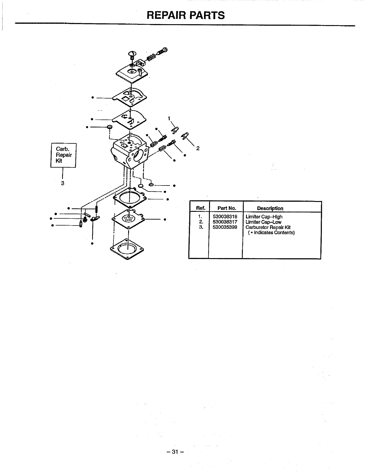
REPAIR PARTS
Iarb, t
Repair
K_t
1
3
ReL Pa_ No.
1, 530038318
2. 530038317
&530035399
Description
Lim|terCap-High
LirniterCap-Low
CarburetorRepairKit
( ° IndicatesContents)
-31 -
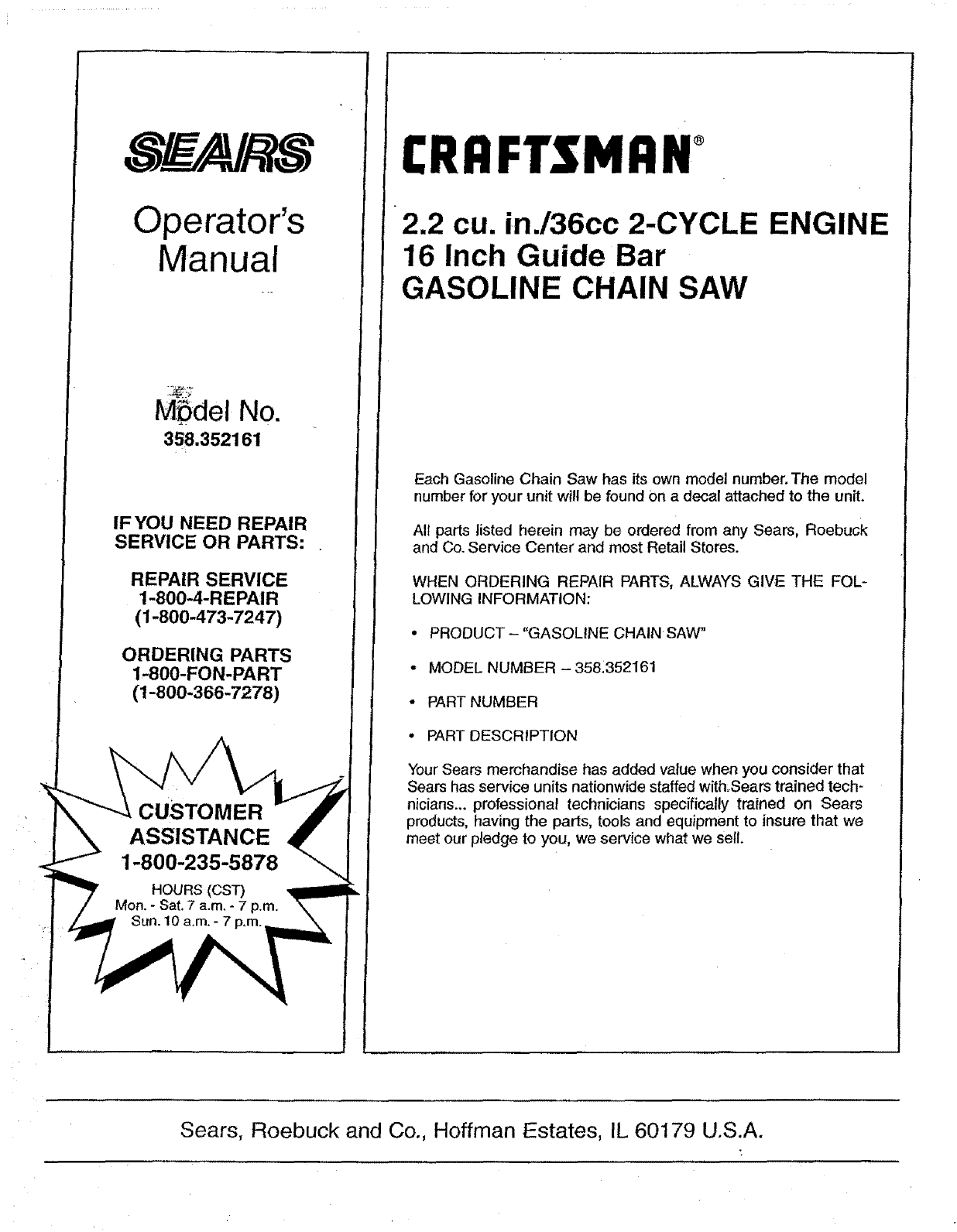
Operator's
Manual
M5del No.
358.352161
IF YOU NEED REPAIR
SERVICE OR PARTS: .
REPAIR SERVICE
1-800-4-REPAIR
(1-800-473-7247)
ORDERING PARTS
1-800-FON-PART
(1-800-366-7278)
ASSISTANCE
CRAFTSMAN
2.2 cu. in./36cc 2-CYCLE ENGINE
16 Inch Guide Bar
GASOLINE CHAIN SAW
Each Gasoline Chain Saw has its own model number. The model
number for your unit will be found On a decal attached to the unit.
All parts listed herein may be ordered from any Sears, Roebuck
and Co. Service Center and most Retail Stores.
WHEN ORDERING REPAIR PARTS, ALWAYS GIVE THE FOL -
LOWING INFORMATION:
• PRODUCT - "GASOLINE CHAIN SAW"
• MODEL NUMBER - 358_352161
• PART NUMBER
° PART DESCRIPTION
Your Sears merchandise has added value when you consider that
Sears has service units nationwide staffed with:Sears trained tech-
nicians.., professional technicians specifically trained on Sears
products, having the parts, tools and equipment to insure that we
meet our pledge to you, we service what we sell.
Sears, Roebuck and Co., Hoffman Estates, IL 60179 U.S.A.
