Craftsman 358354831 User Manual 3.7/18, 3.7/18 PS CHAIN SAWS Manuals And Guides L0904588
CRAFTSMAN Chainsaw, Gas Manual L0904588 CRAFTSMAN Chainsaw, Gas Owner's Manual, CRAFTSMAN Chainsaw, Gas installation guides
User Manual: Craftsman 358354831 358354831 CRAFTSMAN CRAFTSMAN 3.7/18, 3.7/18 PS CHAIN SAWS - Manuals and Guides View the owners manual for your CRAFTSMAN CRAFTSMAN 3.7/18, 3.7/18 PS CHAIN SAWS #358354831. Home:Lawn & Garden Parts:Craftsman Parts:Craftsman CRAFTSMAN 3.7/18, 3.7/18 PS CHAIN SAWS Manual
Open the PDF directly: View PDF ![]() .
.
Page Count: 32

I i
owner's
manual
: i_ • •
• Assembly
• Operation
• Maintenance
•e_ Repair Parts .......
MODEL NO.
358,354831-3.7118"
358.354871-3.7/18"PS
,Jn
WARNING:
Carefully read and follow
Safety •Rules, Precautions
and Operating Instructions.
Failure to =do so can result
in serious personal injury.-:-__-
r. ,
C RRFTSM R,N
3.7/18"_ ,,3.7/18PS
•CHAIN SAWS
Record in the space provided below the Model No. and Serial No. of
,your saw. These numbers are located on the starting instruction
decal.
Serial No.
Retain these numbers for future reference.
ii •
Sears, Roebuck and Co., Chicago, Ill. 60684 U.S.A.
rirn
64983-3-24483-1-24483 PRINTED IN U. S. A.
FULL ONE YEAR WARRANTY ON GASOLINE CHAIN SAW
(Excluding Bar, Chain, Spark Plug, Air Filter and Starter Rope)
For one year from date of purchase, when you maintain, lubricate, and tune up this chain saw according tothe operating
and maintenance instructions in the owner's manual, Sears wilt repair defects in material or workmanship in this gasoline
chain saw.0at no charge.
This warranty excludes the bar, chain, spark plug, air filter, and starter rope which are expendable parts and become worn
during normal use. ,. _:4 .... r" _
If this chain saw is used for commercial Or:l_entalpurposes, this warranty applies for only 30 days from date of purchase.
WARRANTY SERVICE IS AVAILABLE By RETURNING THE CHAIN SAW TO THE NEAREST SEARS STORE OR.SERVICE
CENTER IN THE UNITED STATES. .:,
This warranty gives you specific legal rights, and you: ma-y-_so have other rights which vary from state to state.
..... :•rSears,:,Roebuck and Co., Sears Tower, Dept. 698/731A, Chicago, IL 60684
TABLE OF CONTENTS ,
Specifications ............................... 2 Using The Power Sharp System ........ ,......... 11
Safety Rulesand Precautions ........... .. _... 3 Types of Cutting. _ 13
Know Your Chain Saw . . ..................... \. ,_. 4. - A. Basic Cutting Technique _.;:. ...... ' ....... .:13
A. Introduction ......... . ........ .... ;......-...... 4 B. TreeFellingTechniques_. :_.;,%_..,.;;;..,_-..... 13
B. State and Locai Ordinances ..: .... ._::_.ii4: C: Bucking... ;..;..: ..... ::.'.. ..... :.:... 14
C. carton _ntents.. ,-............... :.: ,:_;:::_4•:: :_ D. Debranching and Pruning ................. 15
Preparing YourSawFor Use _;, ... ....... :;. !=:_i.:::_:_::5 Maintenance ...... :......................... 16
A. Getting Ready,,.:;.:_:,..:.. :......... , 5::: :: A, Guide Bar and Chain .................... 16
B. Attaching the HandgiJard ,: ;.:,.. ...... 5 ::: B. Ignition, Cooling, and Exhaust Systems .... 18
C. Attaching the Spur. : 5 C. Starter Rope Repair and Replacement ...... 19
D. Attaching the Barand Chain ..... :-:.. .... .. 6
E. Chain Tension ............ ............... 7
F. Engine Fuel Mixture ..................... 7
G. Barand Chain Oil ....................... 8
UsingYour Saw ............................. 9
A. Control Devices ........................ 9
B. Starting instructions .................... 9
C. Controlling Kickback .................... 10
D. :Clutch, Drumand Sprocket ....... •.......... 20
IF_ Carburetor Adjustments 21
F. Air Filter ............................... 22
G: Counter-Vibe TMVibration System ...... -. ; .. 22
H. Storage .................................. 22 _
I. Maintenance Accessories ..... 22
J. Trouble Shooting Chart.. :...... ,:.. ;.... :.. 23
PartsList .................. _.,..,. ..... .... 24
QulckReference Page..! ...... :..... ......... , 31
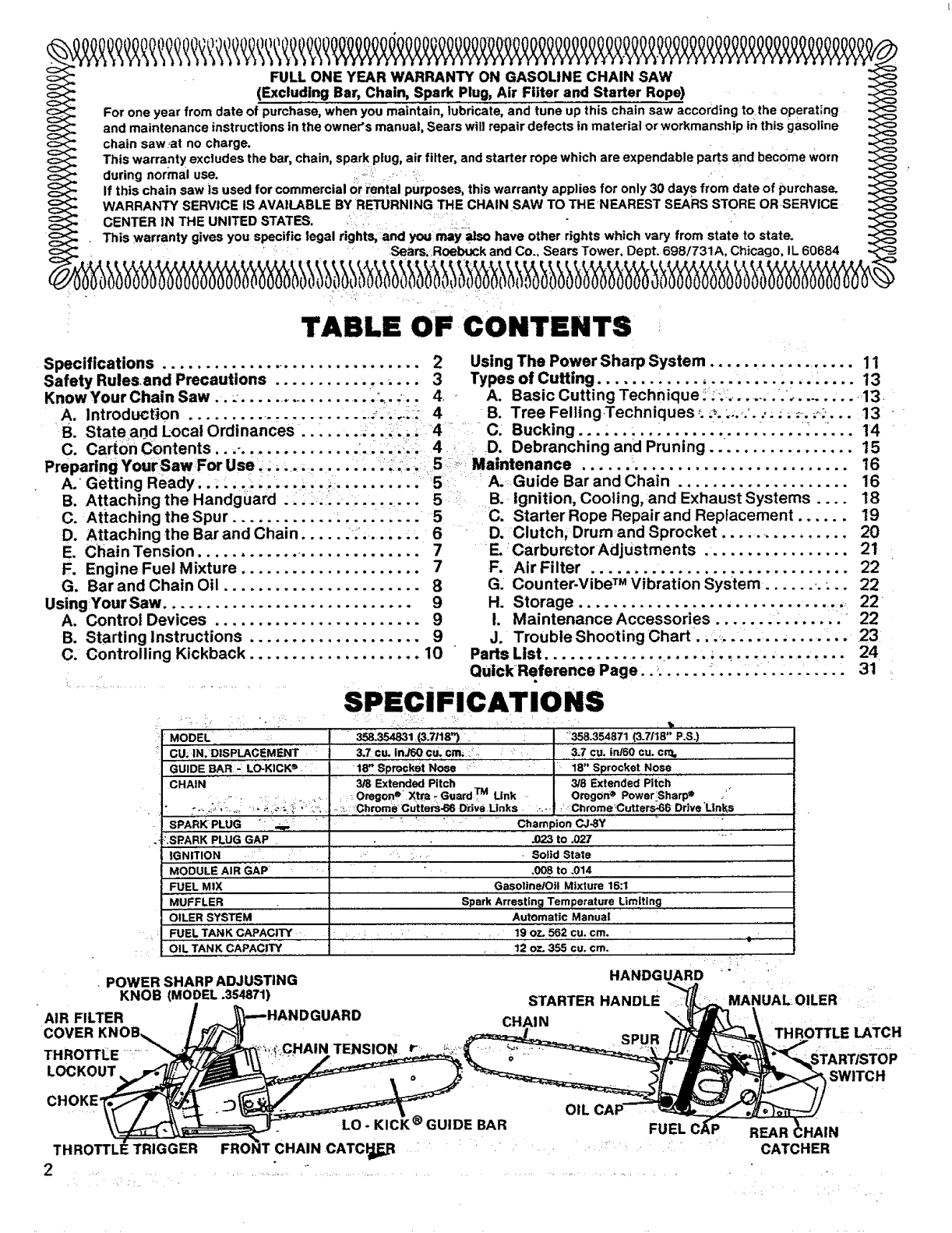
SPECIFICATIONS
MODEL ' .... " 358.354831 :(3.7118_) :'358.354871,,,(3.7118" P.S.)
CU; 1N.:DtSPLACEMENT : 3.7 cu. in360 cu. cm_::; _:, ......... 3:.7 ,¢u, inl60 cu. cr_
GUIDE BAR":: LO-KICK", 18". ,Sp_:ket N_e' __' : 18" Sprocket NOSe ,
CHAIN '3/8 Extended Pitch ...................._............ 3/8 Extended Pitch
:: ; Oregon e" Xtra- Guard TM Link., OregOn ®PowerSharp e /°
:---:i:;'::_,.,i_ '_ _:,:i_ _,\' ,_"'_ ..:_,'_:Chrome cutters-66 Drive.Unks ...... '.-Chrome'Cutters_66 Drive'Links
SPARK PLUG " • ........ _ _ :": Champion CJ-8Y ,=.: ........................
.023 to .027:,SPARK PLUG GAP ,
IGNITION •:
MODULE AIR GAP
FUEL MIX
MUFFLER
OILER SYSTEM
FUEL TANK CAPACITY
,,r
OIL TANK CAPACITY
POWER SHARP ADJUSTING
KNOB (MODEL .354871)
•Solid State
,008 to .014
Gasoline/Oil Mixture 16:1
Spark Arrestin 9 Temperature Limiting
Automatic Manual
19 oz, 562 cu. cm.
. 12 o7- 355 cu. cm. ..........I
HANDGUARD _ _ ,
_UARD STARTER HANDLE
CHAIN THROTTLE LATCH
AIR FILTER
COVER KNOB_
THROTFLE:=_
LOCKOUT
CHOKE" lSWITCH
REAR
CATCHER
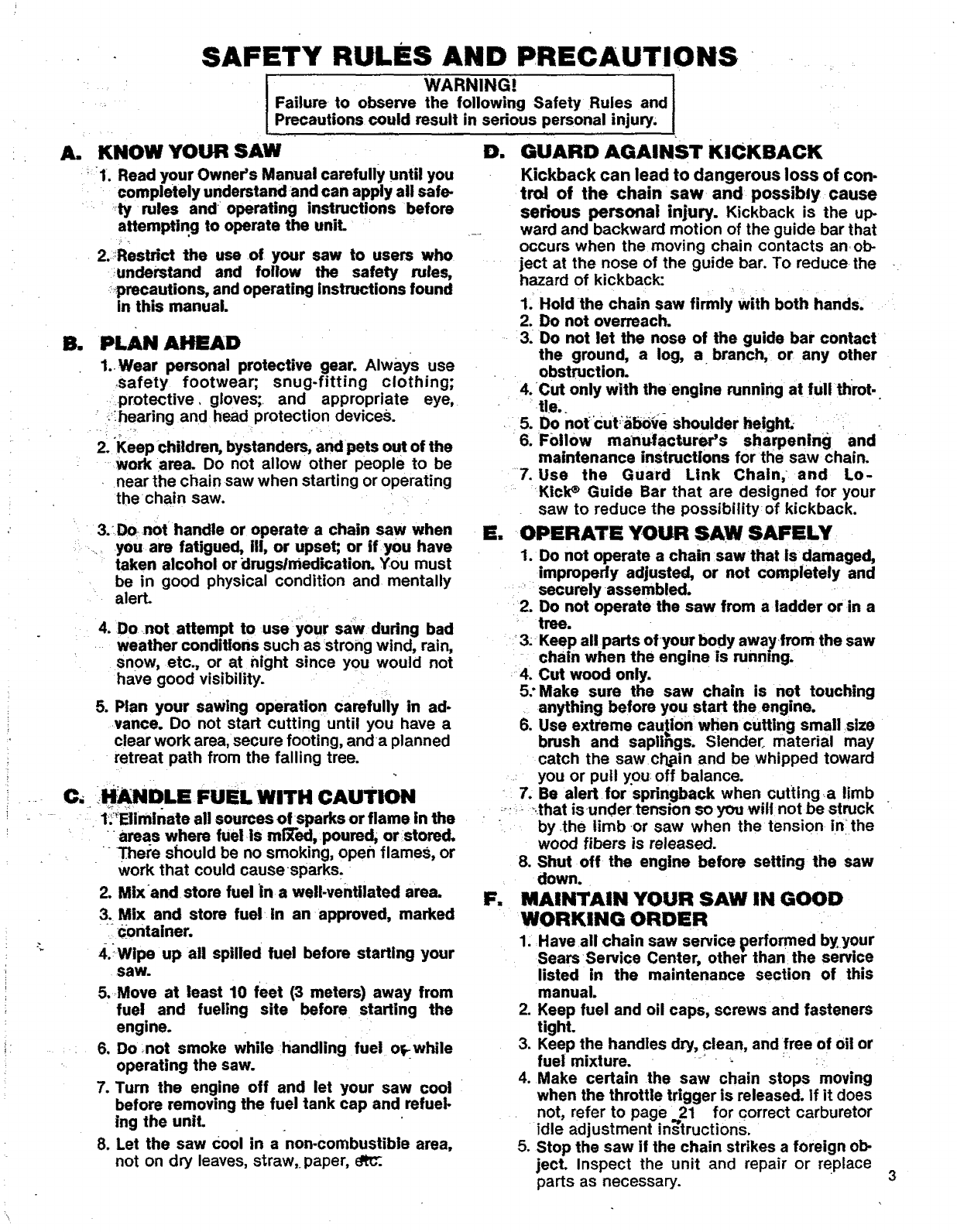
SAFETY RULES AND PRECAUTIONS
A. KNOW YOUR SAW
_1. Read your Owner's Manual carefully until you
completely understand and can apply all safe.
ty rules and operating instructions before
attempting to operate the uniL
2.Restrict the use of your saw to users who
;understand and follow the safety rules,
_;_precautions, and operating instructions found
in this manual.
IWARNING!
Failure r to observe the following Safety Rules and
Precautions could result in serious personal injury;
B. PLAN AHEAD
1..Wear personal protective gear. AlwaYs use
safety footwear; snug-fitting clothing;
_protective, gloves;_ and appropriate eye,
i?ihearing and head protection devices.
2. Keep children, bystanders, and pets out of the
work area. Do not allow other people to be
near the chain saw when starting or operating
thechain saw. i
•3.DOrnOt handle or operate a chain saw when
_ you are fatigued, III, or upset;, or if you have
taken alcohol or drugsirnedication. You must
be in good physical condition and mentally
alert.
4. Do not attempt to useyour saw during bad
weather conditions such as strong wind, rain,
snow, etc., or at night since you would not
have good visibility. •
5. Plan your sawing operation carefully in ad-
vance. Do not start cutting until you have a
clear work area, secure footing, anda planned
retreat path from the falling tree.
C, HANDLE FUEL WITH CAUTION
1;_Elirninate all sources of sparks or flame in the
• " areas where fuel is mi'X'ed, poured, or stored.
There should be no smoking, open flameS, or
work that could cause =sparks.
2. Mixand store fuel in a well-ventilated area.
3. Mix and store fuel in an appreved, marked
_container.
4._Wlpe up all spilled fuel before starting your
saw.
5.Move at least 10 feet (3 meters) away from
fuel and fueling site before, starting the
engine.
_6. Do ;not smoke while handling fuel orrwhile
operating the saw.
7. Turn the engine off and let your saw cool
before removing the fuel tank cap and refuel-
lng the unit.
8. Let the saw Cool in a non-combustible area,
not on dry leaves, straw,, paper,
D. GUARD AGAINST KICKBACK
Kickback can lead to dangerous loss of con.
trol of the chain saw and possibly cause
serious personal injury. Kickback is the up-
ward and backward motion of the guide bar that
occurs when the moving chain contacts anot>
ject at the nose of the guide bar. To reduce the
hazard of kickback:
1_Hold the chain saw firmly with both hands,
2. Do not overreach.
3. Do not let the nose of the guide bar contact
the ground, a log, a branch, or any other
obstruction.
4. Cut only with the engine running at lull throt..
tie,.
.5. Do not cut;_ab0_e shoulder height.- .... i
6.Follow manufacturer's sharpening and
maintenance instructions for the saw chain.
7. Use the Guard Link Chain; and Lo-
KiciP Guide Bar that are designed for your
saw to reduce the possibility of kickback.
E, OPERATE YOUR SAW SAFELY
1. Do not operate a chain saw that isdamaged,
improperly adjusted, or not completely and
._' securely assembled.
2. Do not operate the saw from a ladder orin a
tree.
_;3: Keep all parts ofyour body awayfrom the saw
chain when the engine is running.
4. Cut wood only.
5:Make sure the saw chain is not touching
anything before you start the engine.
6. Use extreme caution when cutting small size
brush and saplings. Slender.. material may
catch the sawci'Lain and be whipped toward
you or pull you: off balance.
:7. Be alert for spdngback when cuttinga limb
...._ _.that isunder tension soyou wilt notbe struck
" by the limb-or saw when the tension inthe
wood fibers is released.
8. Shut off the engine before setting the saw
down.
F, MAINTAIN YOUR SAW IN GOOD
WORKING ORDER
1. Have all chain saw service E)erformed by.your
Sears Service Center, other than the service
listed in the maintenance section of this
manual.
2. Keep fuel and oil caps, screws and fasteners
tight.
3. Keep the handles dry, clean, and free of oil or
fuel mixture. -_ • - _ :
4. Make certain the saw chain stops moving
when the throttle trigger is released, if it does
not, refer to page 21 for correct carburetor
idle adjustment mstruchons.
5. Stop the saw if the chain strikes a foreign ob-
ject. Inspect the unit and repair or replace
parts as necessary.
Gm CARRY AND STORE YOUR SAW
SAFELY
1. Never carry your saw while climbing. Both
hands are needed for safe climbing.
2. Carry the unit with the engine stopped, the
Guide Bar and Chain to the rear, and the Muf-
fler away from your body.
3. Carry the saw with Guide Bar and Chain
covered, preferably with an appropriate scab-
bard.
4. Allow your saw tocool completely before
transporting inany vehicle or storing in any
enclosure.
5. Drain oil and fuel tank before storing for more
than 30 days,
6. Store in a dry area out of the reach of children
and away from where fuel vapors can reach
an open flame from hot water heaters, fur-
nances, etc.
KNOW YOUR CHAIN SAW
A.
as
,
INTRODUCTION
,The information found in this manual will help
you -i_roperly prepare your chain saw for use,
Understand how to operate your san-safely, and
perform maintena'nce reqbire_dto keep your unit
in go0dworking condition.
Your saw has been designed with safety in mind
and includes the following safety features as
standard equipment:
_Handguard
Lo-Kick ®Guide Bar
Guard Link Chain
The chain saw should never be Operated unless
these devices are properly installed on the uniL
The Lo-Kick ®Guide Bar and Guard Link Chain
have been designed to reduce the incident of
kickbaCk.You should thoroughly read and
understand the section,"Controlling Kickback,"
on page 10.
STATE AND LOCAL ORDINANCE
REQUIREMENTS
Your saw is equipped with a temperature
limiting muffler and spark arresting-screen
which meets the requirements of_Califomia
_.;CodesA442 and 4443. All U.S: forest.land and :the-_
states of California, Ma_ne, Washington and
Oregon require many internal combustion
engines to be equipped with a spark arrestor
screen and a temperature limiting muffler by
law.
tf you operate a chain saw in a state or locale
where such regulations exist, you are legally
responsible for maintaining the operating condi-
tion of these parts. Failure to do so could sub-
ject youto liability or to a fine. Muffler and spark
arrestor maintenance is found on page18.
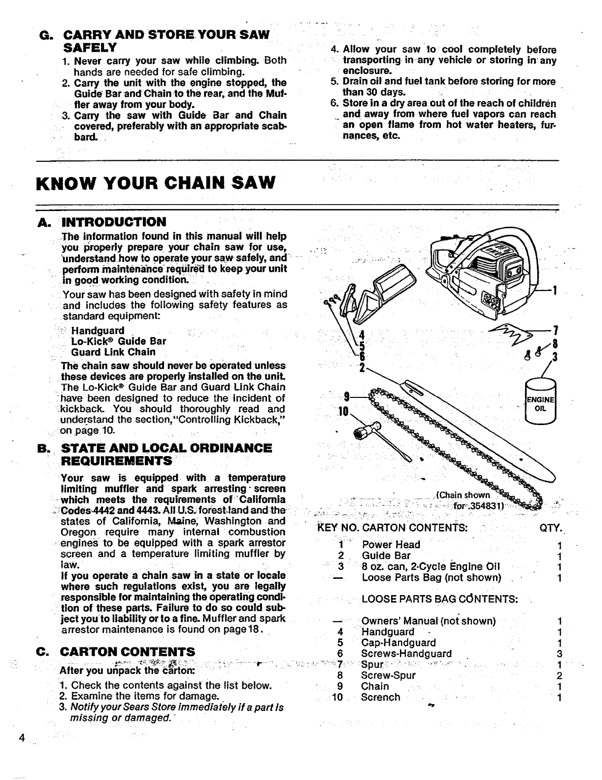
C. CARTON CONTENTS
After you unpack me barton:
1. Check the contents against the list below.
2. Examine the items for damage.
3. Notify your Sears Store immediately if a part is
missing or damaged.
!
KEY NO.
1
2
3
CARTON CONTENTS:
Power Head
Guide Bar
8oz. can, 2-Cycle Engine Oil
Loose Parts Bag (not shown)
LOOSE PARTS BAG C(JNTENTS:
m
4
5
6
8
9
10
Owners' Manual-(not shown)
Handguard
Cap-Handguard
Screws-Handguard
Spur-:* • ......... • "
Screw-Spur
Chain
Scrench
QTY.
1
1
1
1
1
1
1
3
1
2
1
1
PREPARING YOUR SAW FOR USE
A. GETTING READY
READ YOUR OWNER, S MANUAL CARE.
FULLY.
Your Owner's Manual has been developed to
help you prepare your saw for use and to-
understand, its safe operation. It is important
that you read your manual completely to
become •familiar with the unit .before you
begin assembly.
2, HAVE THE FOLLOWING AVAILABLE:
-a, Protectivegloves
b. Approved, marked fuel container
:c.'One gallon regular gasoline
d.Bar and Chain Lubricant {See pageS).
e. Scrench--provided with your unit.No other
.... tool is necessary for assembly. The long
end of the tool can be used as a slotted,
screwdriver. The small pipe end can be us.
edras a socket wrench. The larger pipe end
can be used to remove the spark plug, •
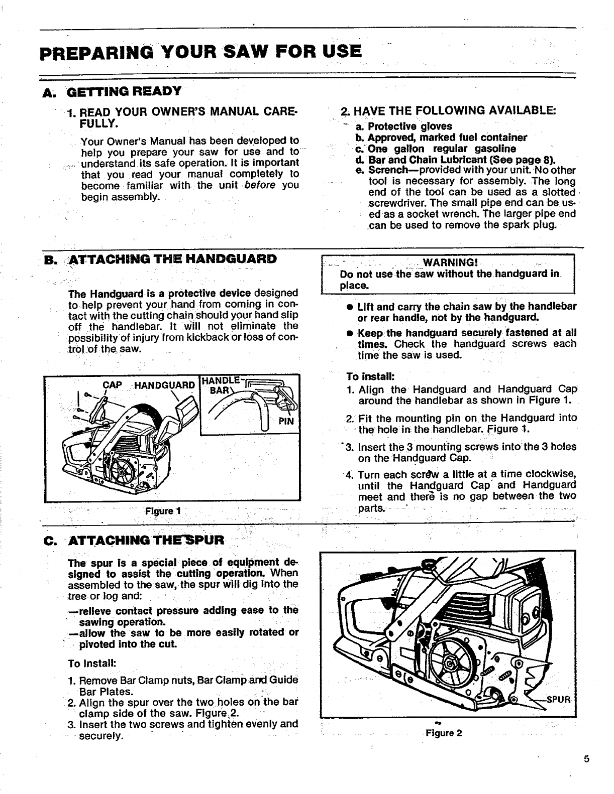
B.: _ATTACHING THE HANDGUARD
The Handguard is a protective device designed
to help prevent your hand from coming in con-
tact with the cutting chain should your hand slip
off the handlebar. It Will not eliminate the
possibility of injury from kickbackor loss of con-
tro!:of the saw.
CAP HANDGUARD
J:..:: • -. ..... _.... WARNING!. : .... ,:._ I
Do not use the•:saw without the handguard in I
place. •
• Lift and carry the chain saw by the handlebar
or rear handle, not by the handguard.
• :Keep:the handguard securelY.: fastened at all
times. Check the handguard screws each
'time rthe saw is used..
• :, _L • Figure I
To install:
1. Align the Handguard and Handguard Cap
around the handlebar as shown in Figure 1. •
2. Fit the mounting pin onthe Handguard into
....... the hole:in the ;handlebar. Figure 1.
"3. Insert th e 3 mounting screws into the 3 holes
on the Handguard Cap. ::
4_ Turn each scr_hv a little at a time clockwise,
until the Handguard Cap" and Handguard
meet and ther_ is no gap between the two
•.... parts, _-" ..... _. _...... :_,.......
C. ATTACHINGTHE_PUR
The spur is a special piece of equipment de-
signed to assist the cutting operation. When
assembled to the saw, the spur will dig into the
_ree or log and:
--relieve contact pressure adding ease to the
sawing operation.
--allow the saw to be more easily rotated or
" pivoted into the cut.
To Install:
1. Remove Bar Clamp nuts, Bar Clamp and Guide
Bar Plates.
2. Align the spur over the two holes on the bar
clamp side of the saw. Figure_2.
3. Insert the two screws and tighten evenly and
securely.
UR
............ Figure 2 ..........
5
6
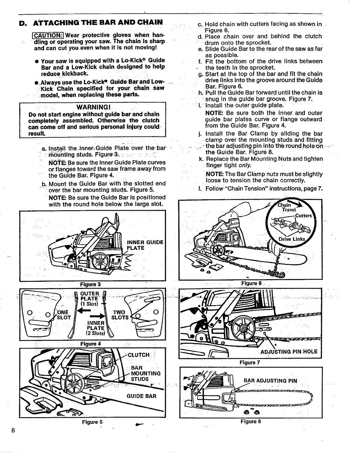
D. ATTACHING THE BAR AND CHAIN
H •
ICAUTION:]Wear protective gloves when han-
....dling or operating your saw. The chain is sharp. ""
and can cut you even when it is not moving!
• Your saw is equipped with a Lo-Klck® Guide
Bar and a Low.Kick chain designed to help
reduce kickback.
e.Always use the Lo-KiclP Guide Bar and Low-
:Kick Chain specified for your chain saw
_model, when replacing these parts.
. L
_WARNING!
Donot start engine without guide bar and chain
completely assembled. Otherwise the clutch
can come off and sedous personal injury could-
resulL
a, Install theJnner, Guicle Pla-te Over the'bar-,
' .;n_;Gbnting studs. Figur_ 3;, : ,, .....i r:_ _:
.... NO_ Be sure the Inner Guide Plate curves
o!_flanges toward the saw frame away from
' the Guide Bar. Figure 4.
,,b, Mount the Guide Bar with the slotted end
over thebar mounting studs.: Figure 5.
NOTE: Be sure the Guide Bar is positioned
with the round hole below the large slot.
Figure 5
c. Hold Chain with cutters facing as shown in ,
....Figure 6.
d. Place chain over and behind the clutch
'_ drum onto the sprocket.
e. Slide Guide Bar to the rear of the saw as far
as possible.
f. Fit the bottom of the drive links between
the teeth in the sprocket.
g. Start at the top of the bar and fit the chain
drive links into the groove around the Guide
Bar. Figure 6.
h. Pull the Guide-Bar forward until the chain is
, .:snug in the guide bar groove. Figure 7.
i. Install the Outer guide plate.
NOTE: Be sure both the inner and outer
guide bar plates curve or flange outward
from the Guide Bar. Figure 4.
j. Install the Bar Clamp by sliding the bar
clamp over the mounting studs and ,fitting
.... -_the bar adjusting, pin into tlTe round hole_on -......
• the Guide Bar. Figure 8.
k. Replace the Bar Mounting Nuts and tighten
finger tight only.
NOTE: The Bar Clamp nuts must be slightly
loose to tension the chain correctly.
1. Follow "Chain Tension" instructions, page 7.
Figure 6
ADJUSTING PIN HOLE
Figure 7
BAR ADJUSTING PIN
Figure 8
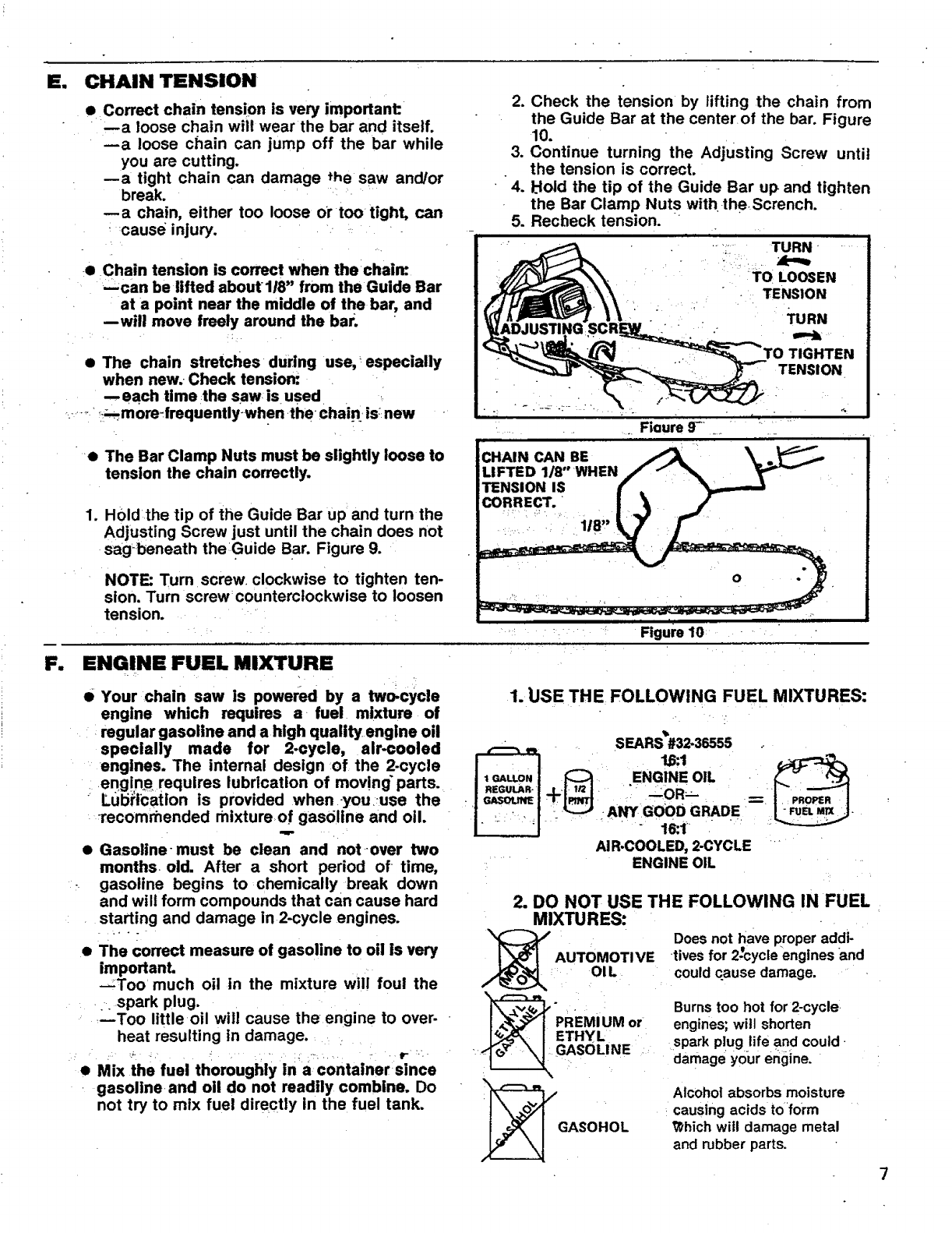
mw CHAIN TENSION
•Correct chain tension is very important:
--a loose chain will wear the bar and itself.
--a loose chain can jump off the bar while
you are cutting.
--a tight chain can damage the saw and/or
break.
--a chain, either too loose Ortoo rtight, can
cause injury.
eChain tension is correct when the chain:
--can be lifted about 1/8" from the Guide Bar
at a point near the middle of the bar, and
--will move freely around the bar.
•The chain stretches during use, especially
when new.. Check tension:.
--each time ,the saw, is used
..... _._m0re_frequentlywhen the chain: is;:new
2. Check the tension by lifting the chain from
the Guide Bar at the center of the bar. Figure
10.
3. Continue turning the Adjusting Screw until
the tension is correct.
4. Idoid the tip of the Guide Bar up and tighten
the Bar Clamp Nuts with. theScrench.
5. Recheck tension.
TURN
TO LOOSEN
TENSION
TURN
TIGHTEN
TENSION
Fiaure 9-
_e
.
The Bar Clamp Nuts must be slightly loose to
tension the chain correctly.
H01d the tip of the Guide Bar up and turn the
Adjusting Screw just until the chain does not
sagbeneath theGuide Bar. Figure 9.
NOTE: Turn screw clockwise to tighten ten-
sion. Turn screw counterclockwise to loosen
tension.
Figure 10
F. ENGINE FUEL MIXTURE
• Your chain saw is powered by a two-cycle
engine which requires a fuel mixture of
=regular gasoline and a high quality engine oil
specially made for 2-cycle, air-cooled
engines. The internal design of the 2-cycle
engin_ requires lubrication of moving" parts.
Lubi:icatlon is provided whenyouuse the
Tecomrnended mixture of gasoline and oi1.
•Gasoline-must be clean and not over two
months• old. After a short period of • time,
gasoline begins to chemically break down
and will form compounds that can cause hard
starting and damage in 2-cycle engines.
• The correct measure of gasoline to oil is very
important.
--:Too much oil in the mixture will foul the
spark plug.
--Too little oil will cause the engine to over-
heat resulting in damage.
r •
•Mix the fuel thoroughly in a container since
gasoline and oil do not readily combine. Do
not try to mix fuel directly in the fuel tank.
1. USE THE FOLLOWING FUEL MIXTURES:
'o,
. SEARS #32-36555
I"'
1r_u.o" ENGINE OIL -
. __OR__ _
• _ = ANYGOOD GRADE --
AIR-COOLED, 2-CYCLE
ENGINE OIL
2. DO NOT USE THE FOLLOWING IN FUEL
MIXTURES:
_AUTOMOTI VE
OIL
GASOHOL
Does not have proper addi-
tives for 2;cycteengines and
could cause damage.
Burnstoo hot for 2-cycle
engines;will shorten
spark plug life and could •
damage your engine.
Alcoholabsorbs moisture
causing acids to form
_hich will damage metal
and rubber parts.
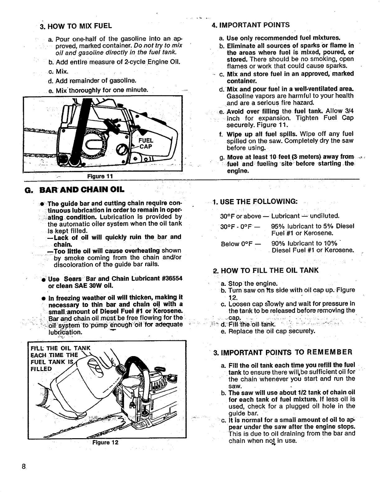
3. HOW TO MIX FUEL 4. IMPORTANT POINTS
a. Pour one-half of the gasoline into an ap-
proved, marked container. Do not try to mix
oil and gasoline directly in the fuel tank.
b. Add entire measure of 2-cycleEngine Oil.
c_ Mix.
d. Add remainder of gasoline.
e. Mix'thoroughly for one minute.
_- Figure 11
a. Use only recommended fuel mixtures.
b. Eliminate all sources of sparks Or flame in
the areas where fuel is mixed, poured, or
stored. There should be no smoking, open
flames or work that could cause sparks.
c. Mix and store fuel in an approved, marked
container.
d. 'Mix and pour fuel in a well.ventilated area.
Gasoline vapors are harmful to your health
and are a serious fire hazard.
e. Avoid over lilling the fuel tank, Allow 3/4
inch for expansion. Tighten Fuel Cap
securely. Figure 11.
f. Wipe up all fuel spills. Wipe off any fuel
spilled on the saw. Completely dry the saw
before using.
g. Move at least 10 feet(3, meters) away from .....
_fuel andfuelihg sitebefore starting,the
engine.
G. BARAND CHAIN OIL
,e_The guide bar and cutting chain require con-
tinuous lubrication in order to remain in oper-
i:ating condition. Lubrication is provided by
the automatic oiler system when the oil tank
iskept filled.
--Lack of oil will quickly ruin the bar and
chain.
--Too little oil will cause overheating shown
..... by smoke coming from the chain and/or
discoloration of the guide bar rails.
• Use Sears Bar and Chain Lubdcant #36554
or clean SAE 30W oil.
•in freezing weather oil will thicken, making it
necessary to thin bar and chain oi! with a
small:amount of Diesel Fuel #1 or Kerosene.
Bar and chain oil mustbe free flowing for the
i`= ';::_:_6ili_:sY_stemtO'puml_ ie_0ugh"oit 'for adequate
lubd'_tion.
i
FI1.L THE OIL TANK
EACH TIME THE
FUEL TANK 1_
FILLED
Figure 12
1. USE THE FOLLOWING:
30°F or above -- Lubricant -_ undiluted.
30OF - 0°F 95% lubricant to 5% Diesel
Fuel #1 or Kerosene.
Below 0°F 90% lubricant to 10%
Diesel Fuel #1 or Kerosene.
o
2. HOW TO FILL THE OIL TANK
a. Stopthe engine.
b. Turn saw on its side with oil cap up. Figure
!.2.
c. Loosen cap slowly and wait for pressure in
the tank to be released before removing the
......cap ..... :....
d: Filiith_e :oil, tank: ,. ::_i: -:...........
e. Replace the oil cap securely.
' 3. IMPORTANT POINTS TO REMEMBER
a. Fill the oil tank each time you refill the fuel
tank to ensure there will, be sufficient oil for
the chain whenever you start and run the
saw.
b. The saw will use about 112 tank of chain oil
for each tank of fuel mixture. If less oil is
used, check for a plugged oil hole in the
guide bar.
...._ :c. it is normal for a small amountofoil to ap
pear under the saw after the engine stops.
This is due to oil draining from the bar and
chain when not in use.
,
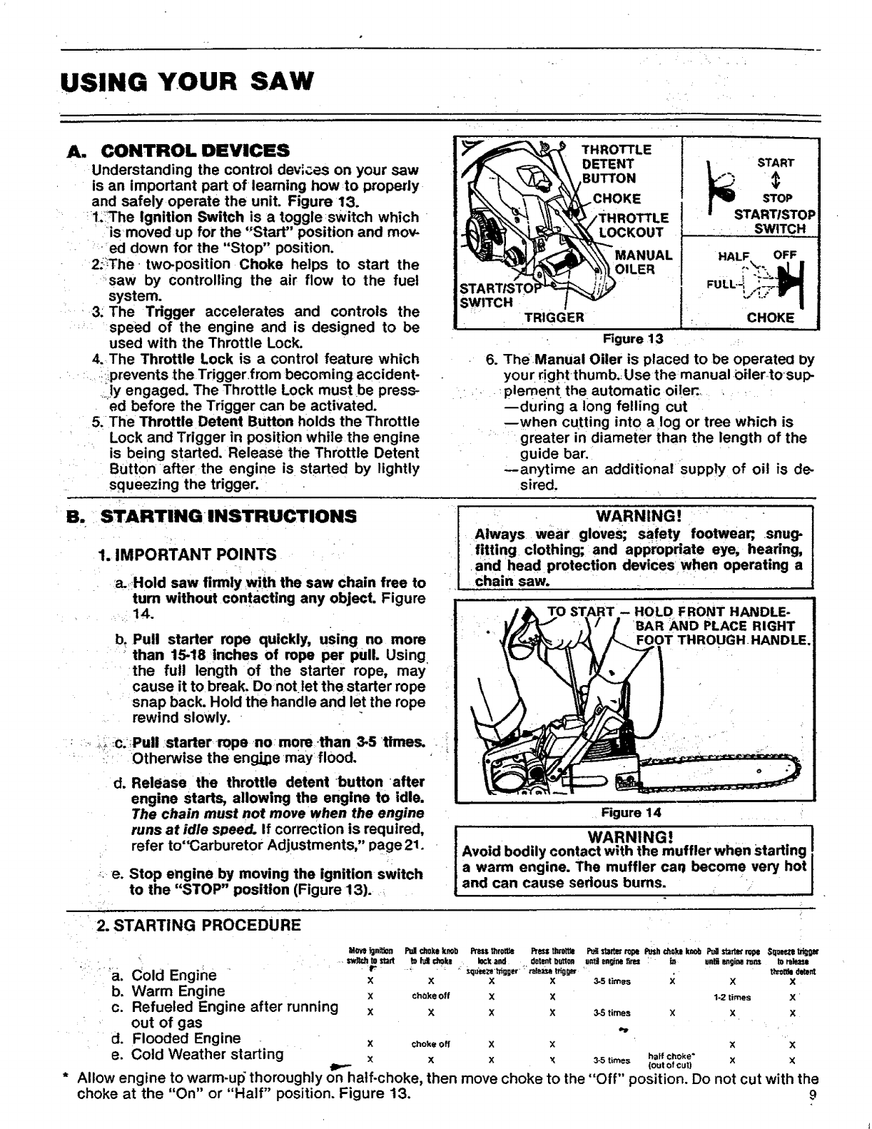
USING YOUR SAW
A. CONTROL OEVICES
Understanding the control dev_es on your saw
is an important part of learning how .to properly
and safely operate the unit. Figure 13.
1;'!The Ignition Switch is a toggle switch which
is moved up for the "Start" position and mov-
ed down for the "Stop" position.
2;-!The two-position Choke helps to start the
:saw by controlling the air flow to the fuel
system.
..... 3; The Trigger accelerates and controls the
speed of the engine and is designed to be
used with the Throttle Lock.
4.The Throttle Lock is a control feature which
_ ,_prevents the Trigger from becoming accident-
ly engaged, The Throttle Lock must be press-
ed before the Trigger can be activated,
5. The Throttle Detent Button holds the Throttle
Lock and Trigger in position while the engine
is being started. Release the Throttle Detent
Button afterthe engine is started by lightly
squeezing the trigger.
B. ii STARTING iNSTRUCTIONS
1. IMPORTANT POINTS
a.Hold saw firmly with the saw chain free to
turn without contacting any object. Figure
_,_14.
b. Pull starter rope quickly, using no more
than 15-18 'inches of rope per pull. Using,
the full length of the starter rope, may
cause it to break. Do notlet the starter rope
snap back. Hold the handle and let the rope
rewind slowly.
:: _-_i_i_ic,°!Pull starter rope .no more:than 3-5 times.
Otherwise the eng_e mayflood.
d. Release the throttle detent button after
engine starts, allowing the engine to idle.
The chain must not move when the engine
runs at idle speed. If correction is required,
refer to"Carburetor Adjustments," page 21.
_: e. Stop engine by moving the ignition switch
to the "STOP" position (Figure 13). ,_
TRIGGER
THROTTLE
DETENT
BUTTON .., START
•, SWITCH
_CHOKE
Figure 13 •
TO START -- HOLD FRONT HANDLE-
BAR AND PLACE RIGHT
FOOT THROUGH. HANDLE.
Figure 14
WARNING. =!
Avoid bodily contact with the muffler when Starting
a warm engine. The muffler car become very hot I
and can cause serious bums. ..... J
' 2. STARTING PROCEDURE
"_" gine r
a. Cold En x
b. Warm Engine x
c. Refueled Engine after running x x xx3-Stimes x x x
out of gas .,
d. Flooded Engine xchokeo, X x XX
e. Cold Weather starting x x x x _t_== ,=_fc,o,s- xx
(out of cut)
*Allow engine to warm-ul_ thoroughly on half-choke, then move choke to the "Off" position. Do not cut with the
choke at the "On" or "Half" position. Figure 13. 9
Movo Tgn_*_n Pull choke knob Prsssthroms Press tisrottto PuRst;sKi_tope Push chokil kr_otiPua s'_" rope Squeezet]rl_
to I_t choke lock and delent T)utton untJ engfnefires "in unW _glM m_ to _m
Lsquee,-_'_igg_' ralezze trigger tt_t_l _d
XXX3-5 times X XX
choke Off X X 1-2 times X
WARNING!
Always wear gloves; safety footwear;, .snug-
fitting clothing; and appropriate eye, hearing,
and head protection devices when operating a
Chain saw.
6. The Manual Oiler is placed to be operated by
your r!ght-thumb._ Use the manual OHer_tosup-
plement the automatic oilen.
during a long felling cut
when cutting into a log or tree which is
greater in diameter than the length of the
guide bar.
--anytime an additional supply of oil is de-
sired.
CONTROLLING KICKBACK
t0 ¸
Kickback is a dangerous chain saw reaction that
can cause sedous personal injury. Carefully
study this section before you make the first cut
with your new saw. You must understand what
causes kickback, how :you can reduce the
chance of kickback, and how you can remain in
the best control of the saw it kickback does
Occur.
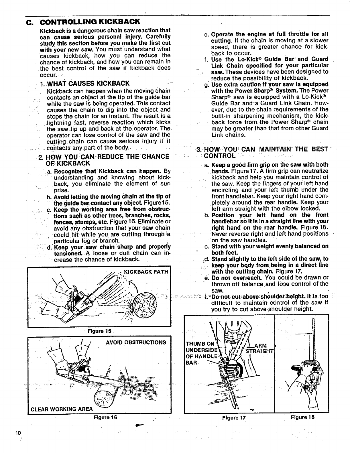
•.1. WHAT CAUSES KICKBACK ....
Kickback can happen when the moving chain
contacts an object at the tip of the guide bar
while the saw is being operated. This contact
causes the chain to dig into the object and
stops the chain for an instant. The result is a
lightning fast, reverse reaction which kicks
the saw.tip up and back at the operator. The
operator can lose control of the saw and the
cutting chain can cause serious injury if it
,_co._t'aats anypart:of thebody._ .,
2. HOW YOU 'CAN REDUCE THE:CHANCE
OFr_KICKBACK .
a. Recognize that Kickback can happen. By
understanding and knowing about kick-
back, you eliminate the element of sur-
prise.
b. Avoid letting the moving Chain at the tip of
" • •the guide bar:contact any object. Figure15.
.c. Keep the working area free from obstruc-
tions suchas other trees, branches, recks,
fences, stumps, etc. Figure 16. Eliminate or
avoid any Obstruction that your saw chain
could hit while you are cutting through :a
particular 10g or branch.
,- d..Keep yoursaw chain sharp and properly
tensioned. A loose or dull chain can in-
crease the chance of kickback.
K! CKBACK PATH
Figure 15
AVOID OBSTRUCTIONS
CLEAR WORKING AREA
Figure 16
e. Operate the engine at full throttle for all
cutting. If the chain is moving at a slower
speed, there is greater chance for kick-
back to occur..
Use the Lo-Kick ®Guide Bar' and Guard
Link Chain specified for your particular
saw. These devices have been designed to
reduce the possibility of kickback.
g: Use extra caution if yoursaw is equipped
with the Power Sharp ®System. The Power
Sharp ® saw isequipped with a Lo-Kick ®
....Guide Bar and a Guard Link Chain. How-
ever, due to the chain requirements of the
built-in sharpening mechanism, the kick-
back force from the Power Sharp ®chain
may be greater than that from other Guard
Link chains.
f.
:"3: HOW YOU_ CAN -MAINTAIN" THE BEST '
.,r...........CONTROL/ .... ....
a. Keep a good firm grip on the saw with both
hands. Figure 17. A firm grip can neutralize
kickback and help you maintain control of
the saw. Keep the fingers of your left hand
encircling and your left thumb under the
front handlebar: Keep your right hand com-
pletely around the rear handle. Keep your
left arm straight with the elbow locked.
b. Position your left hand on the front
handlebar so it is in a straight line with your
right hand on the rear handle, Figure 18.
Never reverse right and left hand positions
on the saw handles.
c. Stand with your weight evenly balanced on
both feet,
d. Stand slightly to the left side of the saw, to
keep your bqdy from being in a direct line
with the cutting chain. Figure 17.
e. Do not overreach. You could be drawn or
thrown off balance and lose control of the
saw.
•_.;",:;:-"_.;L_Do_notcut,:above_shbulderheight, It is too
difficult to maintain control of the saw if
you try to cut above •shoulder height.
OF
BAR
\t
:r
Figure 17 Figure 18

USING THE POWER SHARP ®SYSTEM (MODEL .354871)
Model .354871 is equipped with a PowerSharp _.
System that will perform approximately 80% of
the sharpening necessary for the saw chain.
•The Power Sharp ®System uses a built-in grind-
ing stone to sharpen the cutter top plates and
set depth gauges. As the built-in sharpener is_
.used, the cutter side plates gradually will be
altered. Hand filing is required to correct the
_icutter side plates.
•Sharpen the saw chain when:
--wood chips become small and powdery;
_• i: . _Wood chips made by the chain should be
: about the sizeof the teeth of the chain.
--saw cuts to one side.
• _ --saw has to be forced through,the cut;
[CAUTION:] ALways wear gloves when handling
the chain. The chain can be sharp enough tocut
.... you, even when it is too dull to cut wood.
_r
•Always replace the sharpening stone when
--sparks are no longer seen at full adjust.
ment
--only 1/4 inch of stone is remainlng
--stone has become cracked or damaged.
_--a new chain is installed. The used stone
will be worn to the shape of the 01d chain
and can cause excessive wear to a new
chain. Replacement chain comes supplied
with Stone Cartridge Replacement#69099.
Refer to replacement instructions on page
12.
• Always remove the sharpening stone/f a con.
ventional chain is substituted for the PoWer
Sharp ®Chain. See instructions for removing
the Stone Cartridge on page 12. Use replace-
ment chain #32-3638. Follow chain sharpen-
ing instructions on page 16.
A. _AUTOMATIC SHARPENING
1. Stop the engine.
2. P!ace the saw on a,solid, flat surface and
make sure that the chain will not contact
anY0bject..
3. Adjustthe chain with correct tension. Refer
to Chain Tension, page 7.
_IMPORTANT: The chain must be tensioned
..... correctly for proper sharpening to occur.
'°4. Start the engine and operate at half to three/
quarters throttle during steps "5", "6" "7",
and"8" ''
_ NOTE: Saw must be running at half to three/
quarters throttle before.....knob is i_ressed.
_;_5.pushthe Power Sharp ® Knob dow n slowly _
_ _ u_ntiifully pressed down. Figure 19.
NOTE: if stone should contact chain before
knob is fully pressed ddwn, release knob
and turn knob counterclockwise until condi-
tion does not exist. Repeat Step "5" again.
6. Turn knob slowly clockwise until sparks can
be seen as shown in Figure 19.
POWER S_
SPARKS ARE SEEN HERE
/. _-:"-_
Figure 19 ill""
NOTE: Proper sharpening occurs when a light
flow of sparks is seen.:lmpropersharpening is
shown by a heavy flowOf sparks or no sparks.
7. Release knob and turn one additional "click"
clockwise.
NOTE: It is important to turn the knob only
one "click" each time the knob is pressed.
More turnswill result in making the chain dull
instead of sl_arp.
8. Press knob firmly againstchain and hold for
10-15 seconds or until sparks can no longer
be seen,
-,_. 9;-Re!ease _nob _nd stop-the :engine..
10. Inspect chain cutters.
NOTE: A properly sharpened cutter will show
grinding marks across its entire width. Figure
20. If cutters do not appear sharp or burrs are
seen on the top front of the cutters, repeat
Steps "7" and "8".
e
INSPECT CUTTERS FOR GRINDING MARKS
TOP VIEW OF CUTTER
Figure 20
11
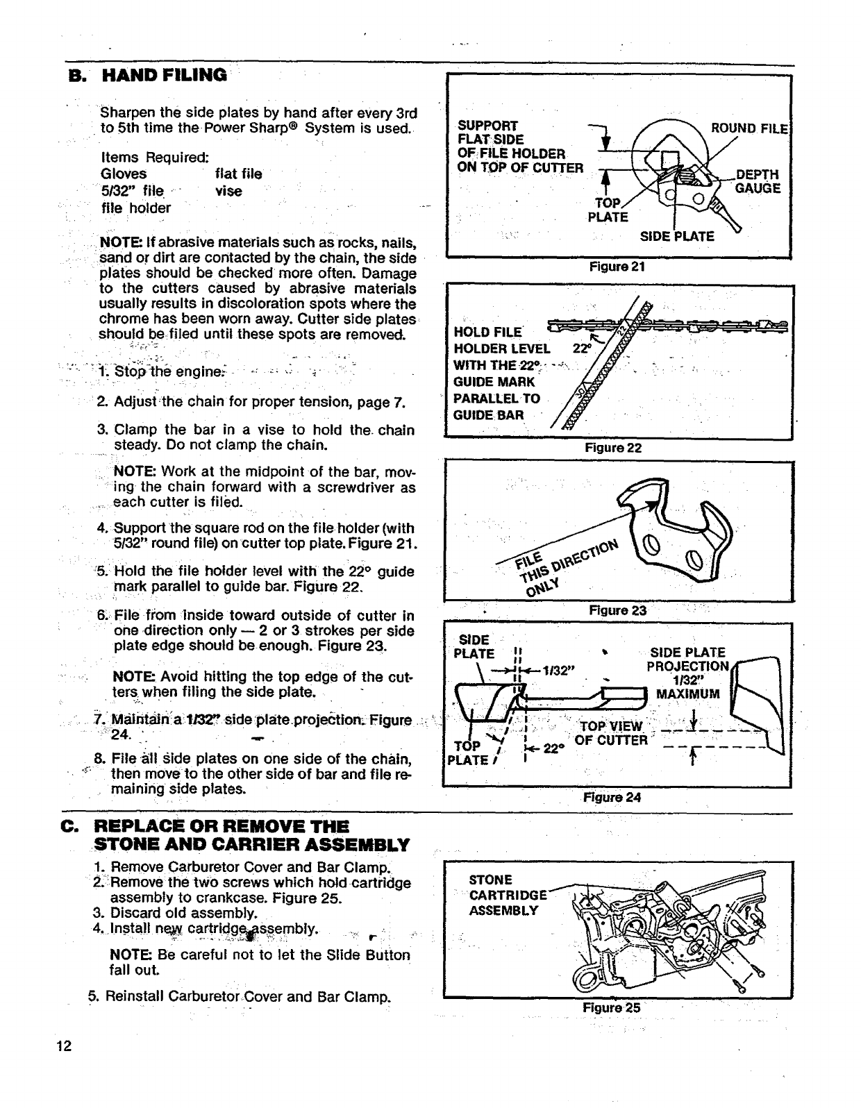
B. HAND FILING
.... Sharpen the side plates by hand after every 3rd
• to 5th time the Power Sharp® System is used..
Items Required:
Gloves flat file
5/32" file .vise
' fileholder " '....
i _ NOTE: If abrasive materials such as rocks, nails,
..... sand or dirt are contacted by the chain, the side
•plates should be checked more often. Damage
to the cutters caused by abrasive materials
usually results in discoloration spots where the
chrome has been worn away. Cutter side plates
should befi!ed until these spots are removed.
2. Adj_Jst"the chain for proper tension, page 7.
3. Clamp the bar in a vise to hold the. chain
steady. Do not clamp the chain.
,. NOTE: Work at the midpoint of the bar, mov-
....ing the chain forward with a screwdriver as
each cutter is filed.
4. Support the square rod on the file. holder (with
5t32" round file) on cutter top plate. Figure 21.
5.: Hold the file holder level with the 22 °guide
mark parallel to guide bar. Figure 22.
6.:.File from "inside toward outside of cutter in
.... one ,direction only -- 2 or 3 strokes per side
plate edge should be enough. Figure 23.
...... • NOTE: Avoid hitting the top edge of the cut-
ters when filing the side plate.
=._ 7. Mainf_in!a!l,/32_side-plate.proje(.'tion:_ Figure. :. '_
_24. "= .,,.
8. File ._llside plates on one side of the chain,
-• _; then move to the other side of bar and file re-
maining side plates.
SUPPORT -- _N
FLAT SIDE "-_ D FIL!
OFFILE HOLDER
ON TOP OF CUTrER-_-_(_3_ DEPTH
i"%
SIDE PLATE
Figure 21
HOLD FILE
HOLDER LEVEL
WITH THE-22°; .....
GUIDE MARK
PARALLEL TO
GUIDE BAR
Figure 23
SIDE
PLATE It •SIDE PLATE
-"-_--11 "PROJECTION
\. II 32... "1t32"
'T' :" "; :........ -,. • ""
TdP_ i -o OFCUi3"ER-' .... " I !
,L ;E/="J
Figure 24
Ci REPLACE OR REMOVE THE
.STONE AND CARRIER ASSEMBLY
1. Remove Carburetor Cover and Bar Clamp,
2:!Remove the two screws which hold cartridge
assembly to crankcase. Figure 25.
3. Discard old assembly.
4. Install ne_y cartridg_ssembly.
NOTE: Be careful not to let the Slide But_ton
fall out.
5. Reinstall CarburetorCover and Bar Clamp.
ASSEMBLY
12
TYPES OF CUTTING
A. BASIC CUTTING TECHNIQUE
1. iMPORTANT POiI',ITS.
' • a. Cut wood only. Do not cut metal, plastics,
masonry, non-wood, building materials;
.... etc .....
-Stop the saw if the chain strikes a foreign
........ objecL Inspect the unit and repair or
repace parts as necessary.
..... ;_. Keep the chain out of dirt and sana.Even a
small amount of" dirt will quickly dull a
chain and thus, increase the possibility of
kickback.
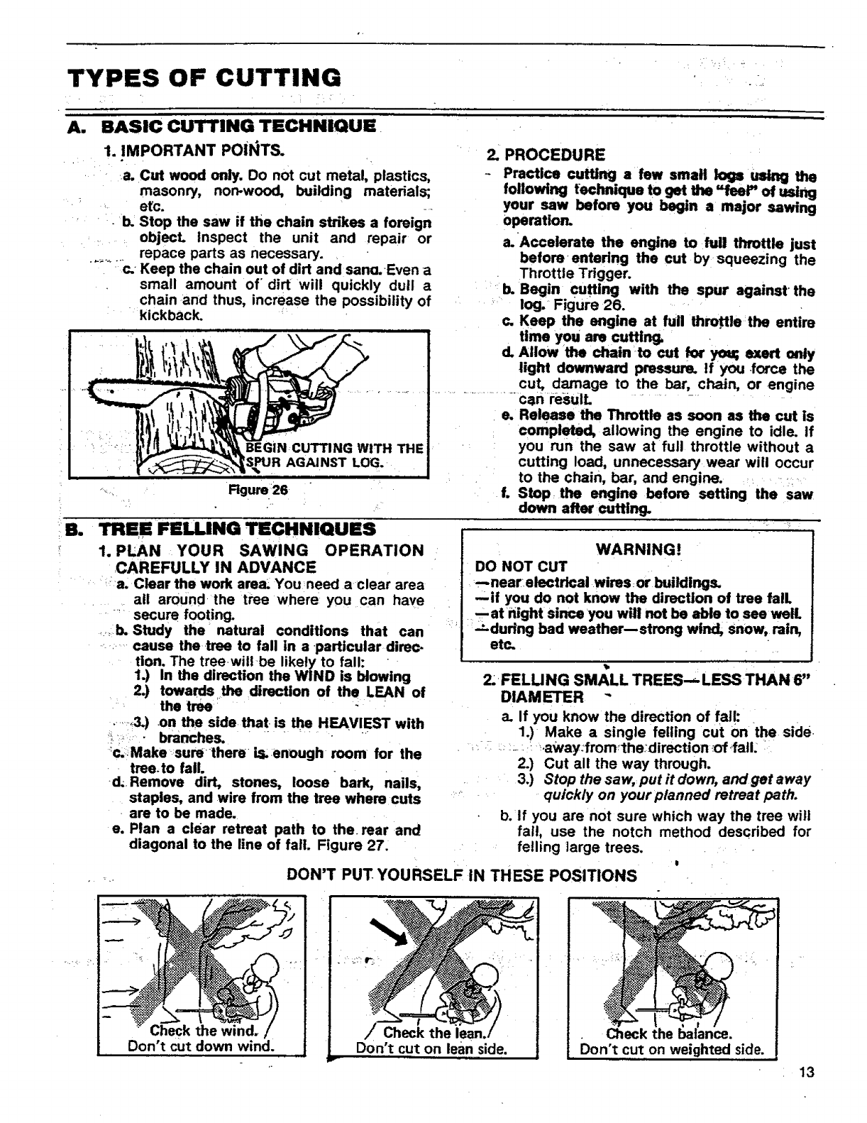
2. PROCEDU RE
- Practice cutting a few small logs using the
following feclmique to get the "feel" of using
your saw before you begin a major sawing
operation.
a.Accelerate the engine to full thfottle just
before _entering the cut by _squeezing the
Throttle Trigger,
b. Begin Cuffing with the spur against' the
_: log. Figure 26. ,
c. Keep the engine at full throttle:the entire
time you are cuffing,
d, Allow the chain-to cut for you; exert only
light downward pressure. If you .force the
cut, damage to the bar, chain, or engine
...................... can resulL
e. Release the Throttle as soon as the cut is
completed, allowing the engine to idle. If
you run the saw at full throttle without a
cutting load, unnecessary wear will occur
to the chain, bar, and engine. ::•
f. Stop the engine before setting the saw
down after cutting.
WARNING!
DO NOT CUT
..near:electrical wires: or buildings.
qif you do not know the direction of tree fall
--atfright since you will not be able to see well
"-'during bad weather--strong wind, snow, rain,
etc.
TREE FELLING TECHNIQUES
1. PLAN YOUR SAWING OPERATION
CAREFULLY IN ADVANCE
:a. Clear the work area, You need a clear area
all around, the tree where you can have
secure footing.
.....:b. Study the natural conditions that can
...........cause the tree to fall in a.particular direc.
tion. The treewill be likely to fall:
1.) In the direction the WIND is blowing
2.) towards .the direction of the LEAN of
the tree -
.....:,3.) on the side that is the HEAVIEST with
!_.'::: • branches. ........
_c.Make-:surethere is.enough room for the
..tree.to fall.
d;.Remove dirt, stones, loosebark, nails,
staples, and wire from the tree where cuts
are to be made,
e, Plan a clear retreat path to the. rear and
diagonal to the line of fall. Figure 27.
2.FELU NG SMALL TREES--,- LESS THAN 6"
DIAMETER -
a. If you know the direction of fail:
1.) Make a single felling cut on the side•
= _: .: :::- :.: _.away:fromthe:direction -of.-fall: .
2.) Cut all the way through.
3.) Stop the saw,: put it down, and get away
....... quickly on your planned retreat path.
b./f you are not sure which way the tree wilt
fai!, use the notch method described for
felling large trees.
DON'T PUT YOURSELF IN THESE POSITIONS
Check the wind.
Don't cut down wind. ,,/ Check the
Don't cut on lean side.
r
Check race.
Don't cut on weighted side.
13
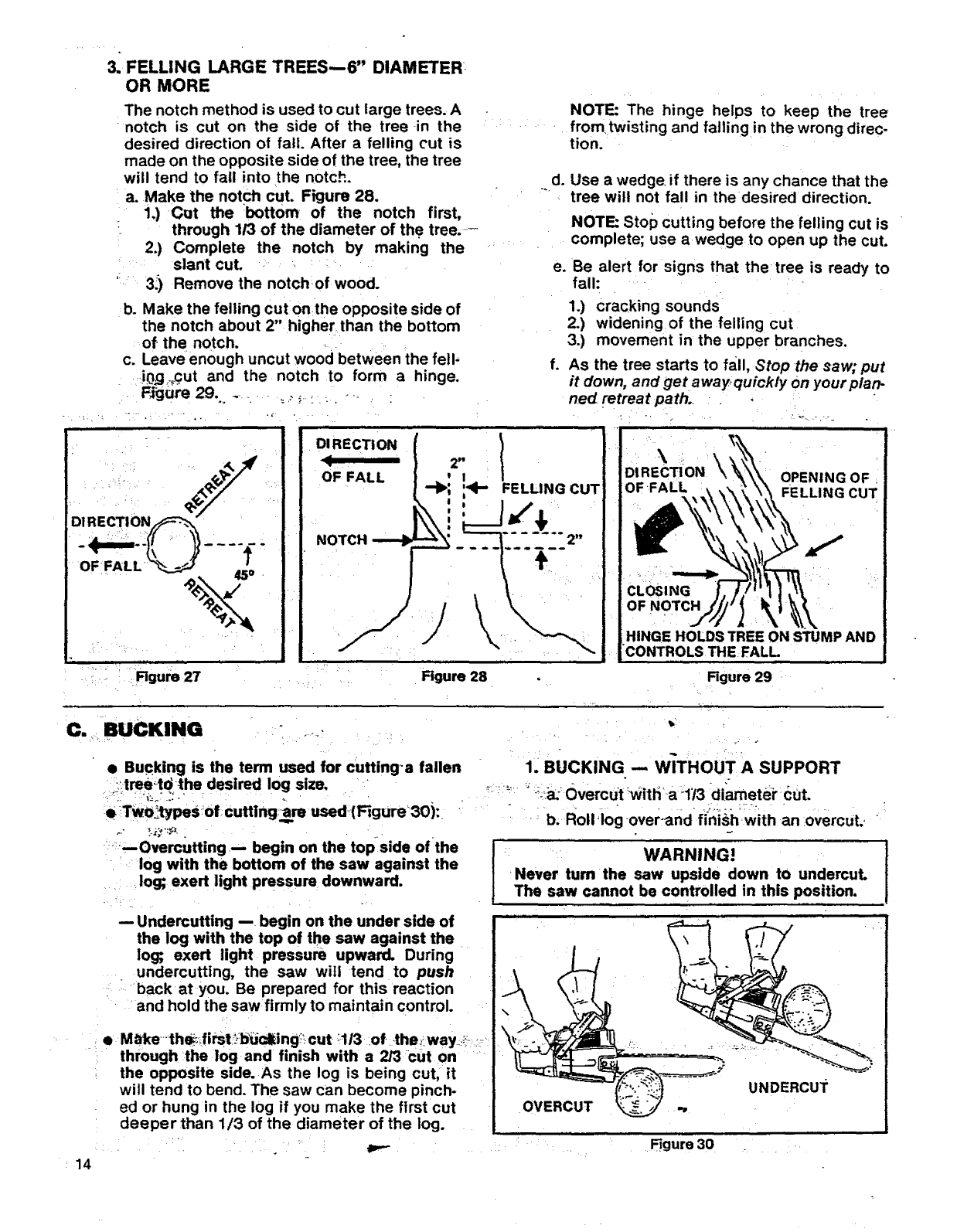
3. FELLING LARGETREES---6" DIAMETER.
OR MORE
The notch method is used to cut large trees. A
notch is cut on the side of the tree in the
desired direction of fail. After a felling cut is
made on the opposite side of the tree, the tree
will tend to fall into the notch.
a. Make the notch cut. Figure 28.
%) CQt the bottom of the notch first,
through 1/3 of the diameter of the tree.--
2.) Complete the notch by making the
slant cut.
3_) Remove the notchof wood.
b. Make the felling cut onthe opposite side of
the notch about 2" higher than the bottom
of the notch.
c. Leave enough uncut wood between the fell,
_i0,g,__qutand the notch to form a hinge.
J
DIRECTION_
o-,.LU 2.
Figure 27
NOTE: The hinge helps to keep the tree
fromtwisting and falling in the wrong direc-
tion.
d. Use a wedge if there is any chance that the
tree will not fall in the desired direction.
NOTE: Stop cutting before the felling cut is
complete; use awedge to open up the cut,
e. Be alert for signs that the tree is ready to
fall:
1.) cracking sounds
2.) widening of the felling cut
3.) movement in the upper branches.
f. As the tree starts to fall, Stop thesaw;put
it down, and get awayquickly on your plan-
ned retreat path.
DIRECTI ON
OF FALL
NOTCH---.-._
Figure 28
\ \
DiRECTi ON OPENING OF
OF FELLING CUT
CLOSING
OF NOTCH
HINGE HOLDS TREE ON STUMP AND
CONTROLS THE FALL J
Figure 29
C._ BUCKING •-T
• Bucking is the term used for cutting_a fallen
;i._tree_t_the desired log size.
• Two,typeS !of cuffing:am used- (Fig ure_30 ):
---Overcutting _ begin on the topside ofthe
log with the bottom of the saw against the
log; exert light pressure downward.
14
Undercutting -- begin on the under side of
the log with the top of the saw against the
log; exert light pressure upward. During
undercutting, the saw witl tend to push
back at you. Be prepared for this reaction
and hold the saw firmly to maintain control.
• M_4(e_th_ifitst_]_ucl_ing_! cut :1/3 of .the?way .;_=:
through the log and finish with a 2/3 cut on
the opposite side. As the log is being cut, it
will tend to bend. The saw can become pinch-
ed or hung in the log if you make the first cut
deeper than 1/3 of the diameter of the log.
1. BUCKING -- WITHOUT A SUPPORT
...... _-_ Overcut 'witha 1/3 diametbrcut.
b; Roll!og over-and fini_,hwith an overcut.-
WARNING!
'Never turn the saw upside down to undercut.
The saw cannot be controlled in this position.
OVERCUT _ -,
UNDERCUT
Figure 30
i iiii i
WARNING!
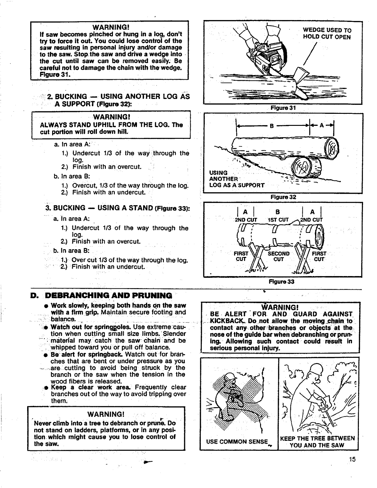
If saw becomes pinched or hung in a log, don't
try to force it out. You could lose control of the
saw resulting in personal injury and/or damage
to the saw. Stop.the saw and drive a wedge into.
the cut until saw can be removed easily. Be
careful not to damage the chain with the-wedge.
.Rg.re31.
_-:!;;2. BUCKING--USING ANOTHER LOG AS
A SUPPORT (Rgure 32):
r.......... WARNING!
ALWAYS STAND UPHILL FROM THE LOG. The
cut portion will roll down hill
i
a. In area Ai_ '
1.) Undercut 1/3 of the way through the
log.
2.) Finish with an overcut. ._
b. In area B:
1.) Overcut, 113of the way through the log.
2.) Finish with an undercut.
:3. BUCKING -- USING A STAND (Figure 33):
........a. in area A: ...........
1.) Undercut 113 of the way through the
log.
2.) Finish with an overcut. .
:_b. In area B:.. i
•.: 1.) Over cut:ll3 of the way through the log.
::. " 2.) Finishwith an undercut.
D. DEBRANCHINGAND PRUNING
• Work slowly, keeping both hands On the saw
with a firm grip, Maintain secure footing and
\WEDGE USED TO
HOLD CUT OPEN
//
Figure 31
USING - - .....
ANOTHER"
LOG AS A SUPPORT
Figure 32
1,1 :. t,I
.... 12ND CUT 1ST CUT 2ND CUT ' •
' _, R_ _//-SECO._\]Ii R_r
C_ ,_. CUT_/,_ cuT_
Rgum 33
t=
•BE. ALERT FOR. AND. GUARD' AGAINST
., :;:_ balance,.., =_............................................. _KICKBACi_, Donotallow the moying_chain to:
:::i• .Watch Out for spdngBoles, Use ext_'eme:cau- __: contactany.other_bPancheS or objects at the,..
.tion when cutting srnatl size limbs.Slender ......
..... :materfal may/catch the. saw:chain'=:and be
"i whipped toward youor pull off balance.
• Bealert for springback. 'Watch •outfor bran- •
ches that are bent or under pressure as you
..........are: cutting to avoid being struck by the
branch or the saw when the tension in the
wood fibers is released.
_o Keep a clear work area. _Frequently clear
branches out of the way to avoid tripping over
them;
•nose ofthe guide bar whendebranching or prun, '
ing. _Allowing such contact could result in
serious personal injury. :
KEEP THE TREE BETWEEN
YOU AND THE SAW
USE COMMON SENSE
WARNING! ...............
"Never climb intoa tree to debranch'or prune. Do
not stand on ladders, platforms, or in any posi*
tion:which might cause ,you to lose control of
the s_w.
15
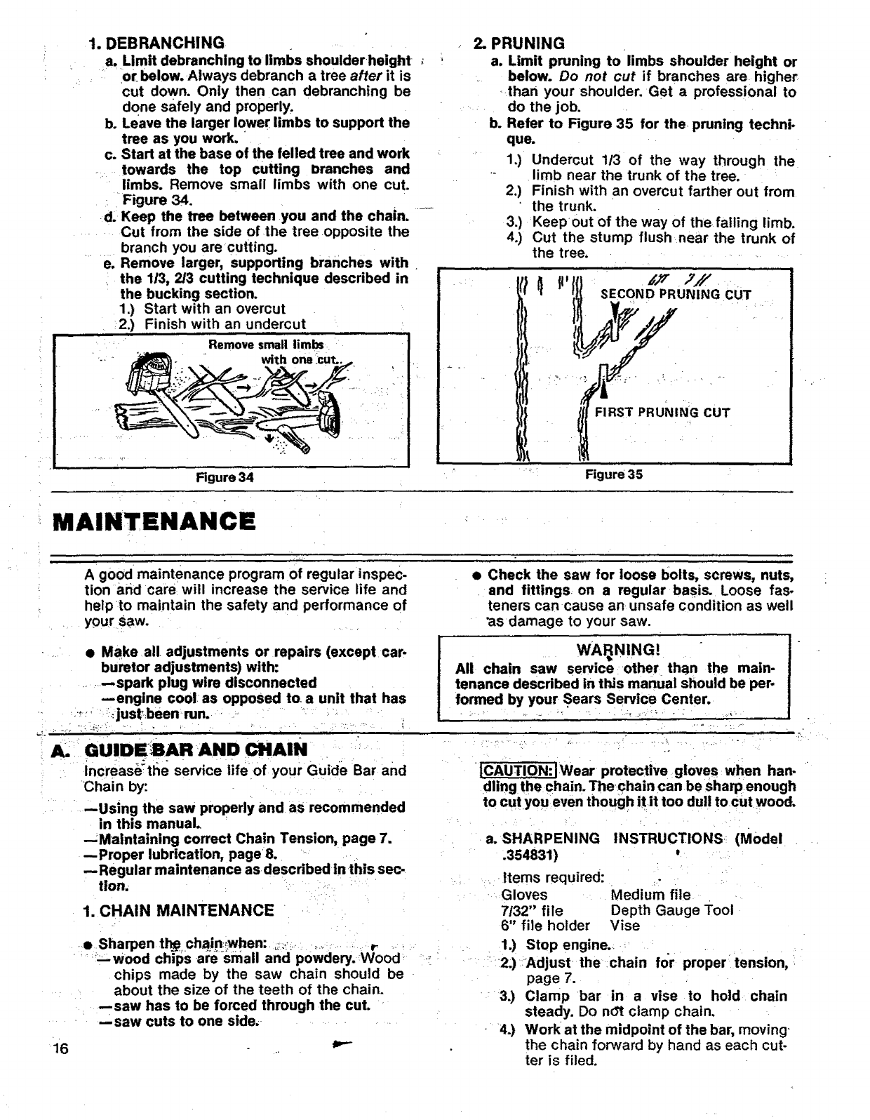
1. DEBRANCHING
a. Limit debranching to limbs shoulderheight
or. below. Always debranch a tree after it is
cut down. Only then can debranching be
done safely and properly.
b. Leave the larger lower limbs to support the
tree as you work.
c. Start at the base of the felled tree and work
towards the top cutting =)ranches and
limbs. Remove small limbs with one cut.
Figure 34.
d. Keep the tree between you and the chain.
Cut from the side of the tree opposite the
branch you are cutting.
e. Remove larger, supporting branches with
the 113, 2/3 cutting technique described in
the bucking section.
1.) Start with an overcut
2.) Finish with an undercut
Remove small limbs
with one :cut..
Figure 34
MAINTENANCE
2. PRUNING
a. Limit pruning to limbs shoulder height or
below. Do not cut if branches are higher
than your shoulder. Get a professional to
do the job.
b. Refer to Figure 35 for the pruning techni-
que.
1.) Undercut 1/3 of the way through the
limb near the trunk of the tree.
2.) Finish with an overcut farther out from
the trunk.
3.) Keep out of the way of the falling limb.
4.) Cut the stump flush near the trunk of
the tree.
]l, h'Y J//
SECOND PRUNING CUT
FIRST PRUNING CUT
J,
Figure 35
A good maintenance program of regular inspec.
tion and care will increase the service life and
help to maintain the safety and performance of
your saw.
• Make all adjustments or repairs (except car-
buretor adjustments) with:
--spark plug wire disconnected
--engine cool as opposed to a unit that has
_: _just' been run.
A,
,i6
GUIDESAR AND CIltAIN
Increas_tlle service life of your Guide Bar and
• Check the saw for loose bolts, screws, nuts,
and fittings on a regular basis. Loose fas-
teners can cause an unsafe condition as well
ks damage to your saw.
WAI_NING!
All chain saw service other than the main-
tenance described in this manual should be per-
formed by your Sears Service Center.
JCAUTION:IWear protective gloves when hart-
Chain by:
--Using the saw properly and as recommended
in this manual.
--Maintaining correct Chain Tension, page 7.
--Proper lubrication, page8.
--Regular maintenance as described in this sec-
tion.
1. CHAIN MAINTENANCE
••Sharpen t_.., chain_when: ,;._-_- ,..... r_-
_:-'wood chips-a_small and powdery. Wood
chips made by the saw chain should be
about the size of the teeth of the chain.
--saw has to be forced through the cut.
--saw cuts to one side,
dllng the chain. Thechaln can be sharpenough
to cut you even though itit too dull tocut wood.
a. SHARPENING INSTRUCTIONS (Model
.354831)
Items required:
Gloves Medium file
7/32" file Depth Gauge Tool
6" file holder Vise
1.) Stop engine.
2;):Adjust -the chain for proper tension,
page 7.
3.) Clamp bar in a vise to hold chain
steady. Do not clamp chain.
4.) Work at the midpoint of the bar, moving,
the chain forward by hand as each cut-
ter is filed.
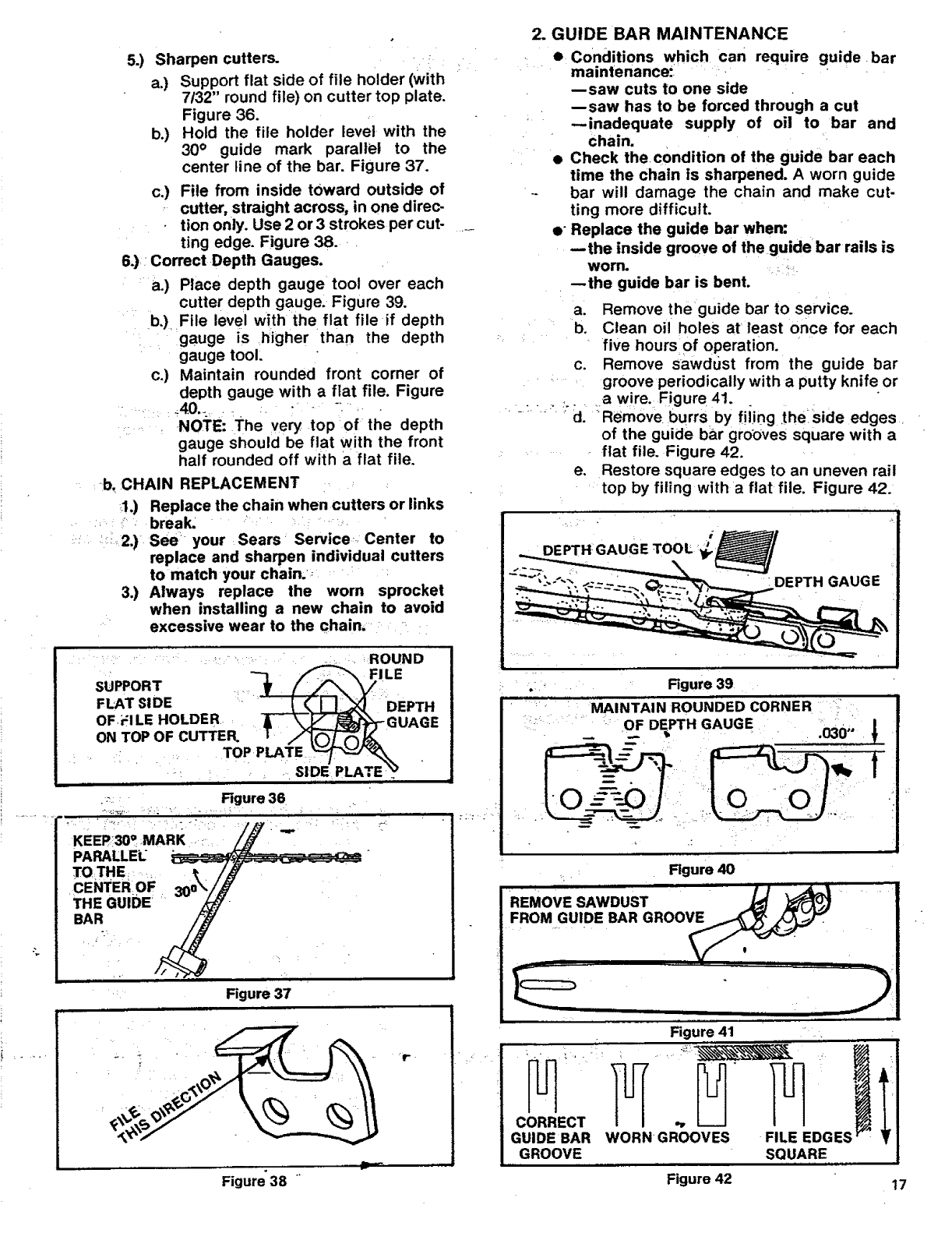
5.) Sharpen cutters.
a.) Support fiat side of file holder (with
7/32" round file) on cutter top plate.
Figure 36.
b.) Hold the file holder levet with the
30 ° guide mark parallel to the
center line of the bar. Figure 37.
c:) File from inside toward outside of
:cutter, straight across, in one direc-
tion only. Use 2 or 3 strokes per cut-
ring edge. Figure 38.
6.): Correct Depth Gauges.
:a,) Place depth gauge tool over each
cutter depth gauge. Figure 39.
b.), File level with the flat file if depth
. gauge is higher than the depth
gauge tool:
c.) Maintain rounded front corner of
depth gauge with a flat file. Figure
.... , -NOTE: The very top:of the depth
gauge should be flat with the front
half rounded off with a flat file.
b. CHAIN REPLACEMENT
,1.) Replace the chain when cutters or links
break. " -_
_::;_2,) See" your Sears _Service--. Center to
replace and sharpen individual cutters
to match your chain.,
3.) Always replace the worn sprocket
when installing a new chain to avoid
excessive wear to the chain,
........... ' ..... : _ROUND
_ _FILE
SUPPORT =_ [_F'_ '_/
FLATSIOE :"'"" _ _ "DEPTH
OF, ir:lLE HOLDE R _ GUAGE
ON TOP OF cUTTER. I _]_.
."TOP PLATE '_.J"_
"'"..... , _i SIDE' PLATE "_ "
KEEP:30a MARK,
PARALLEL
TO!THEE
CENTER OF
THE GUIDE
BAR
.' Figure 37
'r-.
2. GUIDE BAR MAINTENANCE
••Conditions which can require
maintenance- .• guide, bar
:L :
--saw cuts to one side
--saw has to be forced through a cut
• --inadequate supply of oil to bar and
chain.
• Check the, condition of the guide bar each
time the chain is sharpened. A worn guide
-- bar will damage the chain and make cut-
ting more difficult.
e" Replace the guide bar when:
--the inside groove of the guide bar rails is
worn .... _.
--the guide bar is bent.
a. Remove the guide bar to service.
b. Clean oil holes at least once for each
five hours of operation.
c. Remove sawdust from the guide bar
...... groove periodically with a putty knife or
.... :_.... a wire. Figure 41.
" ..... _ ' d. _Remove burrs, by fiiing ,theside edges _
of the guide bar groc)ves square with a
fiat file. Figure 42.
e. Restore square edges to an uneven rail
top by filing with aflat file. Figure 42.
"H GAUGE TOOL -_,
DEPTH GAUGE
Figure 39
MAINTAIN ROUNDED CORNER
OF DEPTH GAUGE .030"
Figure 40 .,, . ,..,
FROM GUIDE BAR GROOV_
Vr.'
_ =. ,.
CORRECT
GUIDE BAR
GROOVE
ii i i i ii_
Figure 41
WORN GROOV'ES" FIL_EEDGES_"
SQUARE
Figure 38 Figure 42 17
B. IGNITION, COOLING!AND EXHAUST SYSTEMS
,18
DCarbon deposits will build up on exhaust
pods, spark arrestor, •muffler, and spark plug
as the saw is used. All of these parts should
be cleaned at the same time to prevent
engine damage, overheating, loss of power,
and hard starting.
• Clean pads:
--as required
--at least once for each 25-30 hours of op-
eration
1. COOLING AND EXHAUST SYSTEM
• Carbon build-up on the cooling and ex-
haust system can cause the engine to
loose power in a cut.
• Keep the spark arrestor clean at all times.
• Red, ace the sparkari_stor_whenbreaks in _
the:iscreen are found.-
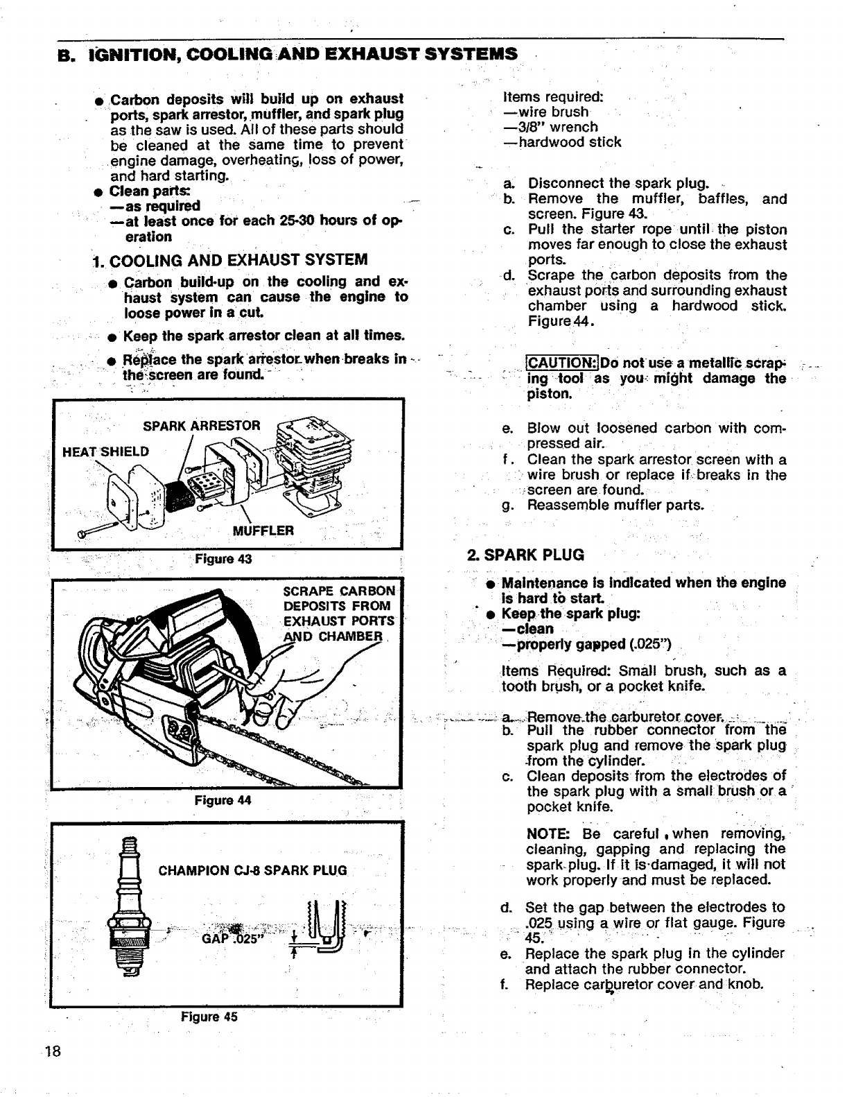
SPARK ARRESTOR
HEAT SHIELD
MUFFLER
Figure 43
Figure 44
Figure 45
Items required:
--wire brush
--3/8" wrench
--hardwood stick
a. Disconnect the spark plug.
b. Remove the muffler, baffles, and
screen. Figure 43.
c. Pull the starter rope until the piston
moves far enough to close the exhaust
ports.
d. Scrape the carbon deposits from the
exhaust ports and surrounding exhaust
chamber using a hardwood stick.
Figure44.
ICAUTION:JDo notuse a metall;€ scrap
ing tool as you-: might damage the
piston,
e. Blow out loosened carbon with com-
pressed air.
f. Clean the spark arrestor screen with a
wire brush or replace if breaks in the
:_screen are found.
g. Reassemble muffler parts.
2. SPARK PLUG
• Maintenance is indicated when the engine
is hard tb start.
•Keepthe spark plug:
--clean
--properly gapped (.025")
Items Required: Small brush, such as a
tooth brush, or a pocket knife.
............. _ a_,..Remove.the ,carbureto[ cover. _:_ _........
b. Pull the rubber connector from the
spark plug and remove the spark plug
-from the cylinder.
c. Clean deposits from the electrodes of
the spark plug with a small brush or a
pocket knife.
NOTE: Be careful ,when removing,
cleaning, gapping and replacing the
spark_plug. If it is-damaged, it will not
work properly and must be replaced.
d,
e.
f.
Set the gap between the electrodes to
525 using a wire or flat gauge. Figure
Replace the spark plug in the cylinder
and attach the rubber connector.
Replace carburetor cover and knob.
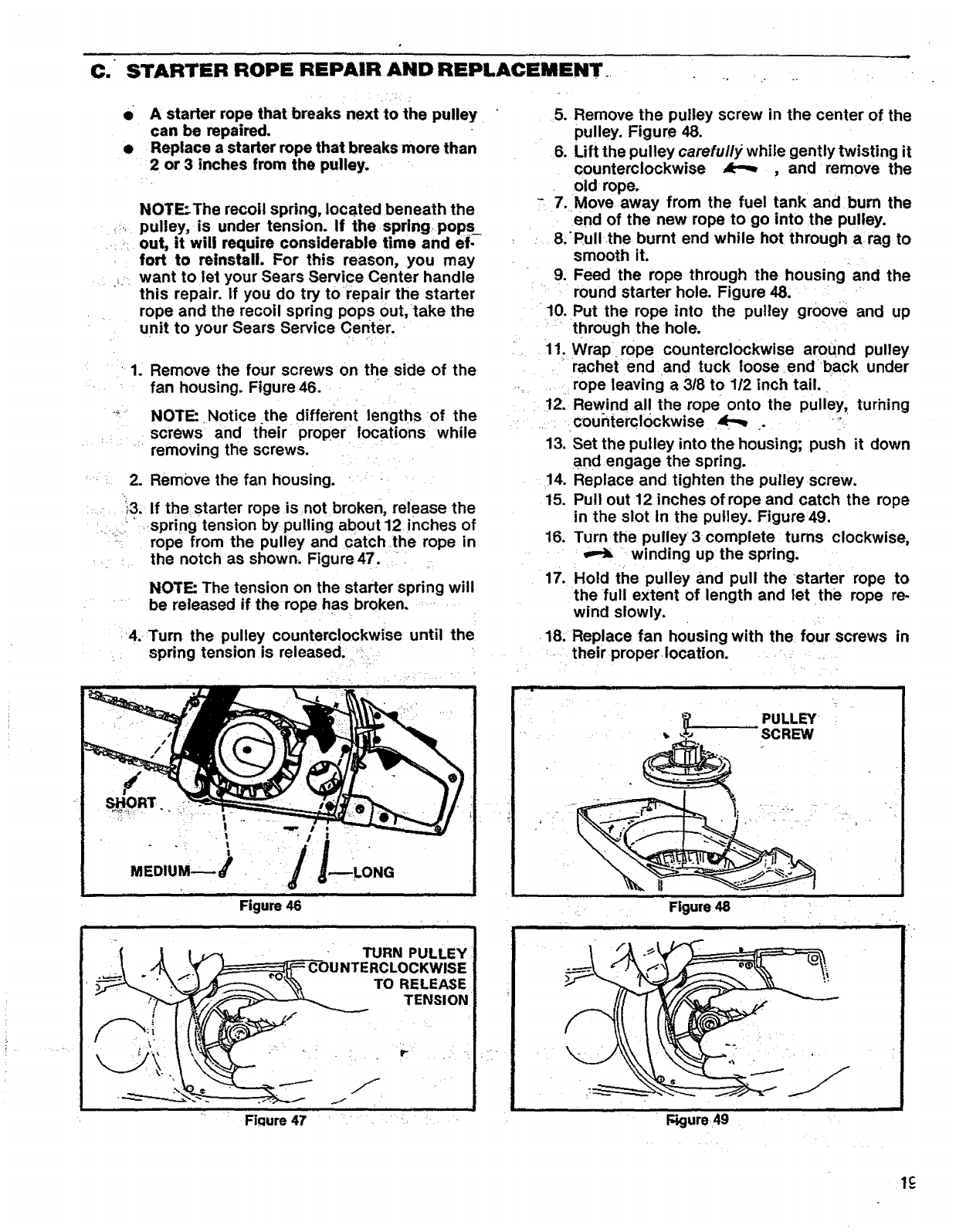
C. STARTER ROPE REPAIR AND REPLACEMENT
• A starter rope that breaks next to the pulley
can be repaired.
• Replace a starter rope that breaks more than
2 or 3 inches from the pulley.
NOTE_The recoil spring, located beneath the
pulley, is under tension. If the spring poPs_
out, it will require considerable time and ef-
fort to reinstall. For this reason, you may
want to let your Sears Service Center handle
this repair, if you do try to repair the starter
rope and the recoil spring pops out, take the
unit to your Sears Service Center.
1. Remove the four screws on the side of the
fan housing. Figure 46.
.... NOTE: Notice the different lengths of the
screws and their proper locations while
removing the screws.
2. Remove the fan housing.
;3. If the starter rope is not broken, release the
spring tension by pulling about 12 inches of
;: rope from the pulley and catch the rope in
the notch as shown. Figure 47.
NOTE: The tension on the starter spring will
be released if the rope has broken.
4. Turn the pulley counterclockwise until the
spring tension is released.
Figure 46
i i i
- TURN PULLEY
UNTERCLOCKWISE
To
Fiqure 47
5. Remove the pulley screw in the center of the
pulley. Figure 48.
6. Lift the pulley carefully while gently twisting it
counterclockwise _, and remove the
old rope.
-7. Move away from the fuel tank and burn the
end of the new rope to go into the pulley.
8.Pull the burnt end while hot through a rag to
smooth it.
9. Feed the rope through the housing and the
round starter hole. Figure 48.
10. Put the rope into the pulley groove and up
through the hole.
11. Wrap rope counterclockwise around pulley
rachet end and tuck loose end back under
rope leaving a 3/8 to 1/2 inch tail.
!2. Rewind all the rope onto the pulley, turhing
countercl0ckwise
13. Set the pulley into the housing; push it down
and engage the spring.
14. Replace and tighten the pulley screw.
15. Pull out 12 inches ofrope and catch the rope
in the slot in the putJey. Figure 49.
16. Turn the pulley3 complete turns clockwise,
winding up the spring.
17. Hold the pulley and pull the starter rope to
the full extent of length and let the rope re-
wind slowly.
18. Replace fan housing with the four screws in
their proper location.
_. PULLEY
SCREW
..... ' F_gure49
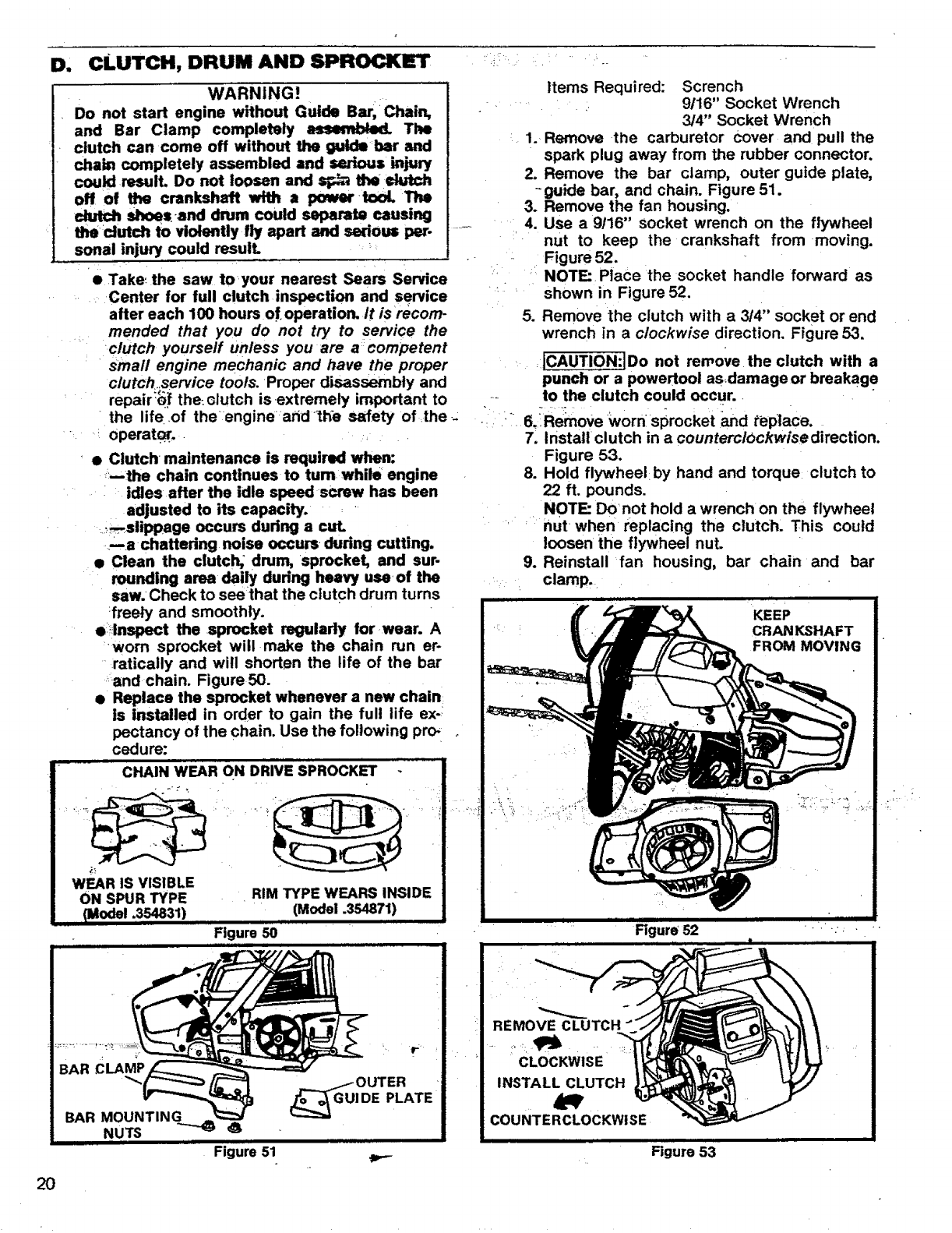
D' CLUTCH, DRUM AND SPROCKET
WARNING!
Do not start engine without Guide Bar, ;Chain,
and Bar Clamp completely a,Jmembted. The
clutch can come off without the guide+bar and
cha_ completely assembled and serious _jury
could result. Do not loosen and _the+clutch
off of the crankshaft with a _ +tool The
clutch shoes+and drum could separate causing
_r =d_ _ to violently fly apart and serious per.
sonal injury could result.
• Take++the saw to your nearest Sears Service
+Center for full clutch inspection and service
after each 100 hours of+operation, it is recom-
mended that you do not try to service the
clutch yourself unless you are acompetent
+small engine mechanic and have the proper
clutch+service tools. Proper disassembly and
repalr'Qf the: clutch is .extremely important to
+the life ,of the +enginearid ++thesafety of the .-
.... operate.. ....
•• Clutch +maintenance is required when:
++--the chain continues to tum while engine
idles after the idle speed +screw has been
adjusted to its capacity. : '
+_+_-_,slippage occurs dudng a cut.
-ma chattering noise occurs _during cutting.
• Clean the clutch, +drum, sprocket, and sur-
rounding area dai_ dudng heavy use, of the
saw. +Check to see that the clutch drum turns
:freely and smoothly.
e+lnsl_Ct the +sprocket regularly forwear. A
worn sprocket will make the chain run er-
ratically and will shorten the life of the bar
.....and chain, Figure 50.
• Replace the sprocket whenever a new chain
is installed in order to gain the full life ex-
pectancy of the chain. Use the following pro+
cedure:
Items Required: Scrench
9116" Socket Wrench
3/4" Socket Wrench
1. Remove the carburetor cover and pull the
spark plug away from the rubber connector.
2. Remove the bar clamp, outer guide plate,
--guide bar, and chain. Figure 51.
3. Remove the fan housing.
4. Use a 9116" socket wrench on the flywheel
nut to keep the crankshaft from +moving.
Figure 52.
NOTE: Place the socket handle forward as
shown in Figure 52.
5. Remove the clutch with a 3/4" socket or end
wrench in aclockwise direction. Figure 53.
_LCAUTION:JDo not remove the clutch with a
punch or a powertool asdamageor breakage
to the clutch could occur.
6._Remove womsprocket and replace.
7. Install clutch in acounterclockwisedirection.
Figure 53.
8. Hold flywheel by hand and torque+ clutch to
22 ft. pounds.
NOTE Donot hold a wrench on the flywheel
nut when replacing the clutch. This could
loosen the flywheel nut.
9. Reinstall fan housing, bar chain and bar
clamp.
KEEP
CRANKSHAFT
FROM MOVING
2O
Figure 50
Figure 51
REMOVE CLUTCH
CLOCKWISE
INSTALL CLUTCH
couNTE RCLOCKWiSE
Figure 52
Figure 53
E. CARBURETOR ADJUSTMENTS
_e The carburetor has been adjusted at the fac-
tory for sea level conditions. Adjustment may
become necessary if the unit is used at
significantly higher altitudes or if you notice.
any of the following conditions:
--Chain moves with the engine at idle speed.
_Loss of cutting power which is not cor-
•rected by air filteror muffler semen clean-
• ing.
mEngine dies or hesitates when it should
accelerate.
r:e permanent damage will occur to the engine if
..... incorrect carburetor adjustments are made. it
.... is best to let your Sears Service Center make
r"carburetor adjustments. If you choose to
make the adjustment yourself, follow the pro-
cedure below very carefully.
I- WARNING!
The-chain maybe moving during this procedure.
Wear your protective gear and observe all of the
•safety precautions.
1. PREPARATION
....... __a.Stop engine.
,b. Use a fresh fuel mixture with proper
gasoline/oil ratio.
c. Place the saw on a. solid, flat surface and
,make sure the chain will not contact any
....object.
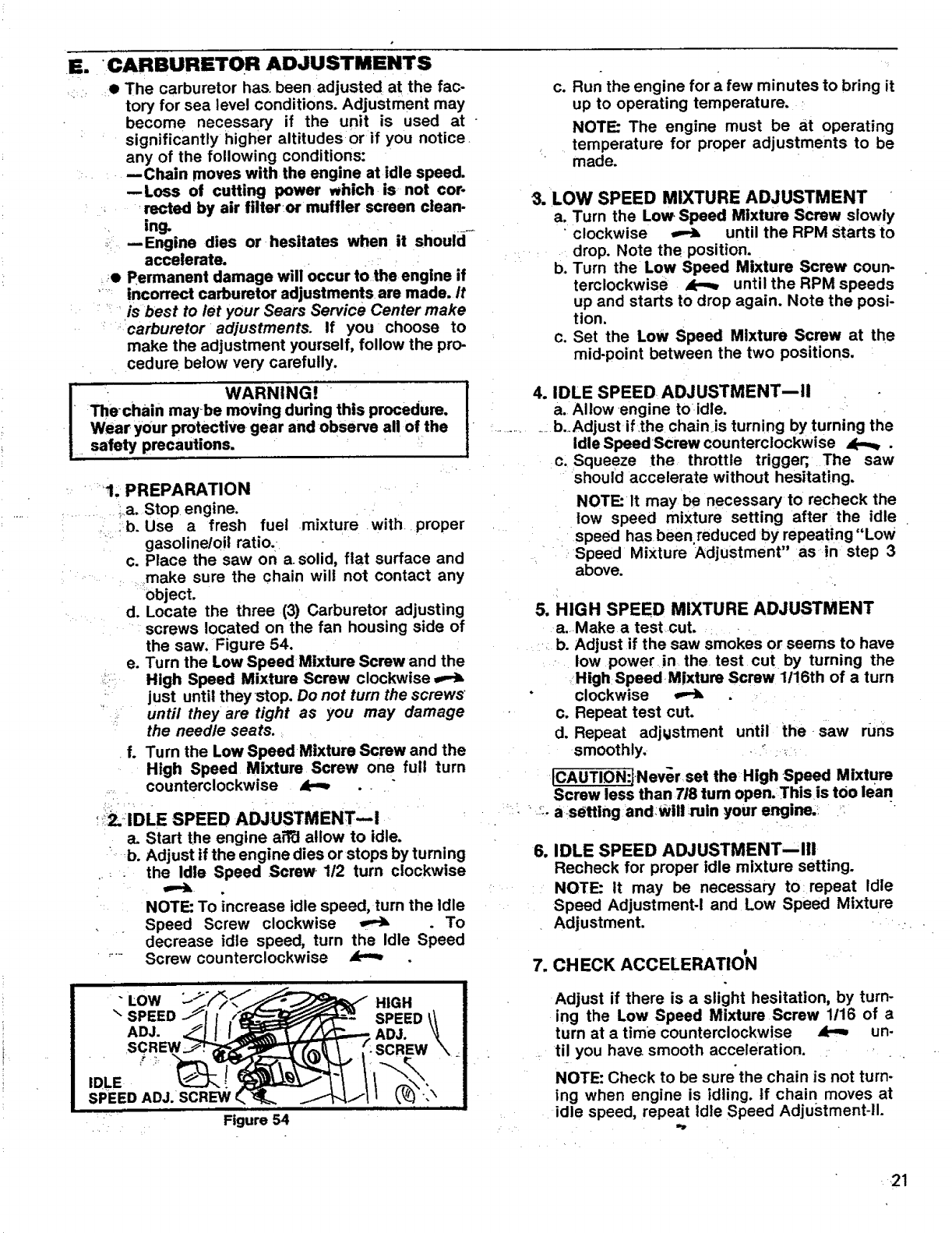
d. Locate the three (3) Carburetor adjusting
screws located on the fan housing side of
the saw. Figure 54.
e. Turn the Low Speed Mixture Screw and the
,:• High Speed Mixture Screw clockwise
_: just until they stop. Do not turn the screws
L_:: until they are tight as you may damage
the needle seats.
f. Turn the Low SpeedMixtum Screw and the
High Speed Mixture Screw one full turn
.... counterclockwise AP_
!_2.'IDLE SPEED ADJUSTMENT--i
a. Start the engine aittl allow to idle.
= b. Adjust if the engine dies or stops by turning
.... the Idle Speed Screw • 1t2 turn clockwise
NOTE: To ;ncrease idle speed, turn the Idle
Speed Screw clockwise _.To
decrease idle speed, turn the Idle Speed
...... Screw counterclockwise
"LOW HIGH
\SPEED SPEED
ADJ. ADJ.
IDLE
SPEED ADJ. SCREW _ \
•Figure 54
c. Run the engine for afew minutes to bring it
up to operating temperature.
NOTE: The engine must be at operating
temperature for proper adjustments to be
made.
3. LOW SPEED MIXTURE ADJUSTMENT
a. Turn the Low Speed Mixture Screw slowly
• clockwise _until the RPM Starts to
drop. Note the position.
b. Turn the Low Speed Mixture Screw coun-
terclockwise _untilthe RPM speeds
up and starts to drop again. Note the posi-
tion.
c. Set the Low Speed Mixture Screw at the
mid-point between the two positions.
4. IDLE SPEED ADJUSTMENTBII
a. Allow engine toidle.
............ b._Adjust if the chain is turning by turning the
Idle SpeedScrew counterclockwise _.
c. Squeeze the throttle trigger;, The saw
should accelerate without hesitating.
NOTE:It may be necessary to recheck the
low speed mixture setting after the idle
speed has been.reduced by repeating "Low
Speed Mixture Adjustment" as in step 3
above.
5, HIGH SPEED MIXTURE ADJUSTMENT
a. Make a test cut.
b. Adjust if the saw smokes or seems to have
low power in the test cut by turning the
High Speed Mixture Screw 1116th of a turn
clockwise
c. Repeat test cut.
d. Repeat adjustment until the saw runs
smoothly. -_
!CAUTION:JNev_r set the High Speed Mixture
Screw less than 7/8 tum open. This is tOOlean
-_:-a s_tting and:will ruin your engine.!
6. IDLE SPEED ADJUSTMENT--Ill
Recheck for proper idle mixture setting.
NOTE: It may be necessary to_ repeat Idle
Speed Adjustment-I and Low Speed Mixture
Adjustment. .- .
7. CHECK ACCELERATION
Adjust if there is a slight hesitation, by turn-
ing the Low Speed Mixture Screw 1116 of a
turn at a time counterclockwise _un-
til you have smooth acceleration.
NOTE: Check to be sure'the chain is not turn-
ing when engine is idling, tf chain moves at
idle speed, repeat Idle Speed Adjustment-ll.
,21
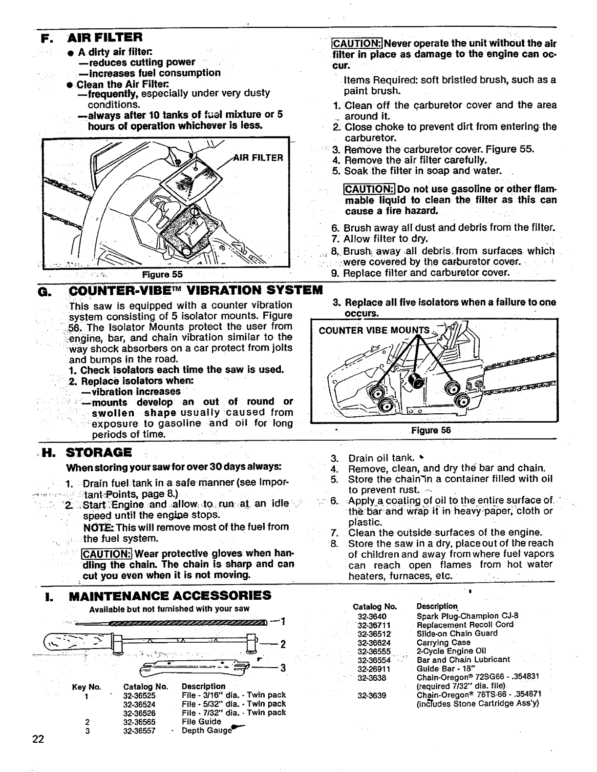
F. AIR FILTER
• A dirty air filter:. •
--reduces cutting power
=_lncreases fuel consumption
•Clean the Air Filten
--frequently, especially under very dusty
conditions.
.always after 10 tanks of f_al mixture or 5
hours of operation whichever is less.
ii i • ,,i ,,,,_,i,,/,i,,,, iiiiiiii i,
1.FILTER
Figure 55 _
[CAUTION:.INever operate the unit without the air
filter in place as damage to the engine can oc-
cur.
Items Required: soft bristled brush, such as a
paint brush.
1. Clean off the carburetor cover =and the area
_ around it.
2. Close choke to prevent dirt from entering the
carburetor.
_3. Remove the carburetor cover. Figure 55.
4. Remove the air filter carefully.
5. Soak_the filter in soap and water.
.... ICAUTION:J Do not use gasoline or other flam.
mable liquid to clean the filter as this can
cause a fire hazard .... _ i
•6. Brush away all dust and debrisfrom the filter.
:7. Allow filter to dry. ......
• i . 80.:Brush_ away ,all debrisofrom surfaces, which .
_.. ,,were coveredby the carburetor cover. - . ,
9. Replace filter and carburetor cover.
G. COiJNTER-VIBE TM VIBRATION SYSTEM
This saw is equipped with a counter vibration
: system consisting of 5 isolator mounts. Figure
•'i_i=_56.The Isolator Mounts protect the user from
i::_engine, bar, and chain vibration similar to the
....... :way shock absorbers on a car protect from jolts
•and bumps in the road.
1. Check isolators each time the saw is used.
2. Replace isolators when:
--vibration increases
_--mounts develop-an out of round or
swollen shape usually caused from
" exposure to gasoline and oil for long
periods of time.
3. Replace all five isolators when a failure to one
OCCUrs.
COUNTER VIBE MOUNTS
Figure 56
•H. STORAGE
When storing your saw for over 30 days always:
1: Drain fueltank in a safe manner (see Impor-
........ ,.o tant._oints, page 8.)
"Z _Start:,Engine .and .-allow, ..to,,run ..at_an idle
speed until the engine stops.
N_This will remove most of the fuel from
the .fuel system.
[CAUTION:t Wear protective gloves when ban.
dling the chain. The chain is sharp and can
cut you even when it is not moving.
3. Drain oil tank. _.
4. Remove, clean, and dry the bar and chain.
5. Store the chain_in a container filled with oil
to prevent rust.._..
6. Apply a coating of oil tO the entire surface of. "
the:bar:and =wral_ i{ in-heavy-p;;per,cloth or
plastic.
7. Clean the.outside:surfaces of the engine.
8. Store the saw in a dry, placeout of the reach
of children and away fromwhere fuel vapors
can reach open flames from hot water
heaters, furnaces, etc.
!. MAINTENANCE ACCESSORIES
Available but not furnished with your saw
22
Key No.
1
2
3
Catalog No.
32-36525
32-36524
32-36526
32-36565
32-36557
Description
File - 3/t6" dia. - Twin pack
File - 5/32" dla. -Twin pack
File - 7/32" dia. - Twin pack
File Guide
Depth GaugeD'"
Catalog No.
32-3640
32.36711
32-36512
32-36624
32.36555
32.36554
32-26911
32.3638
32-3639
Description_
Spark Plug-Champion CJ-8
Replacement Recoil Cord
Slide-on Chain Guard
Carrying Case
2-Cycle Engine Oil
Bar and Chain Lubricant
Guide Bar - 18"
Chain.Oregon ® 72SG66 - .354831
(required 7/32" dia. file)
Chain-Oregon ®76TS-66- °354871
(inc'rudes Stone Cartridge Ass'y)
Ji
TROUBLE-
.................
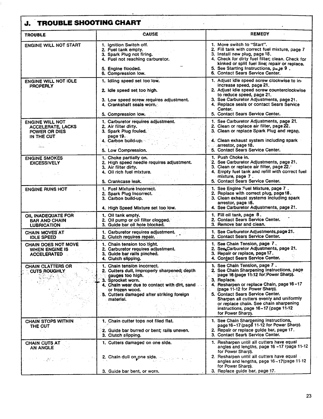
ENGINE WILL NOT START
TROUBLE SHOOTING CHART
CAUSE
1. Ignition Switch off.
PROPERLY
REMEDY
ENGINE wILL NOT
ACCELERATE, LACKS
POWER OR DIES
IN THE CUT
ENGINE sMOKES
EXCESSIVELY
5.
1.
4.
5.
1.
2.
3.
4.
1.
2.
3.
1.
2.
2.
3.
4.
ENGINERuNsHOT
O, ;NAOEOUA FOR
BAR AND CHAIN
LUBRICATION
CHAIN MOVESAT
IDLE SPEED
CHAIN DOES NOT MOVE
WHEN ENGINE IS
ACCELERATED
CHAIN CLA'I_EI_ OR
2. Fuel tank empty,
3. Spark Plug not firing.
4. Fuel not reaching carburetor.
5. Engine flooded.
6. Compression low.
1. idling speed set too"love:
2. Idle speed settoo high. 2.
3. Low speed screw requires adjustment. 3.
4. Crankshaft seals worn.,: 4.
Compression low, ' " • •
Carburetor requires adjustment.
2. Air filter dirty.
3. Spark Plug fouled. "=•.
page 19.
4. Carbon bUild-up: _-_ '•_'
.-
5. Low Compression.
1. C'h'okepartially on.
2. High speed needle requires adjustment.
3. Air filter dirty.
Oil rich fuel mixture.
Crankcase leak.
Fuel Mixture Incorrect.
Spark Plug Incorrect.
Carbon build-up.
High Speed Mixture. set too low.
Oil tank empty.
Oil pump or oil filter clogged.
Guide bar oil hole blocked.
Carburetor requires adjustmenL
Clutch requires repair. _ _ "
Chain tension too_tighL 1.
Carburetor requiresadjustmenL 2.
Guide bar rails pinched. 3.
Clutch slipping. .... 4.
Chain tensibn incorrect. 1-.
1. Move switch to "Start".
2. Fill tank with correct fuel mixture, page 7
3. Install new plug, page 18.
4. Check for dirty fuel filter;, clean. Check for
kinked or split fuel line; repair or replace.
5. See Starting Instructions, p=je 9 .
6. Contact Sears Service Center.
1. Adjust idte speed screw c|ocl_wiseto in.
increase speed, page 21.
Adjust idle speed screw counterclockwise
to reduce speed, page 21.
See Carburetor Adjustments, page21.
Replace seals or contact Sears Service
Center.
5. Contact Sears Service Center.
'1'. See Carburetor Adjustments, page 21."
2. Clean or replace air filter, page22.
3. Clean or replace Spark Plug and regap,
4, C]ean exhaust system including spark '
-...arrestor, page 18.
5. Contact Sears Service Center.
1. Push Choke in.
2. See Carburetor Adjustments, page 21.
3. Clean or replace air filter, page 22."
4, Empty fuel tank and refill with correct fuel
mixture, page 7.
5. Contact Sears Service Center.
1. See Engine Fuel Mixture, page 7.
2. Replace with correct plug, page18.
•3. Clean exhaust systems including spark
arrestor, page t8.
4. See Carburetor Adjustments, page 21.
1. Fill oil tank, page 8.
2. Contact Sears Service Center.
3. Remove bar and clean.
1. See Carburetor Adjustments,page 21.
2. :Contact Sears Service Center:
See Chain Tension, page 7.
See_Carburetor Adjustments, page 21.
Repair or replace, page17. ::
Contact Sears Service Center.
See Chain Tension, page 7'.
:" CUTSROUGHLY
.... i:_ : 3. •Sprocket worn. _.
" _ _ := :" :'•: 4. •Chain wear dueto contact with dirt, sand --
_2. Cutters dull, improperly sharpened; depth 2. See Chain Sharpening Instructions, page
:- ":. gauges too high.... .... , . " _page16.(page 117J2fo_PowerSharp).
• 3. Replace.
: 4. Resharpen or replace Cllafn, page16-17
CHAIN STOPS WITHIN "
THE CUT
CHAIN COTS AT
AN ANGLE '
or frozen wood. •
=5. Cutters damaged after striking foreign
material. -
,.
1. Chain cutter tops not filed fiat.
__2. Guide bar burred or bent; rails uneven.
3. Clutch slipping.
1. Cutters damaged on one side.
_2. Chain dull onrone side. _ .......
3. Guide bar bent, or worn.
(page 11-12 for Power Sharp).
5. Contact Sears Service Center.
Sharpen all cutters evenly and uniformly
or replace chain. See chain sharpening
instructions, page 16-17 (.page 11.12
for Power.Sharp). • .. . .:.
1. See Chain Sharpening instructions,
page16-!7 (pag@11-12 for Power Sharp).
2. Repair or replace guide bar, page 17.
3. Contact Sear_ Service Center.
1. Resharpen until all cutters have equal
angles and lengths, page 16 -17 Ipage 11-12
for PowerSharp).
2. Resharpen until all cutters have equal .
angles and lengths, page 16-_17(page 1t-12
for PowerSharp).
3. Replace guide bar, page 17.
23
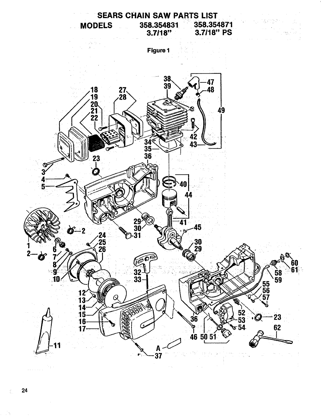
.... SEARS CHAIN SAW PARTS LIST ....
MODELS .... 358.354831 358.354871
3.7118" 3.7118" PS
Figure I i:
k=
19
23 36
43
44
\
;25
26
30/
31
.
29
56
60
62
24
Key
1
2
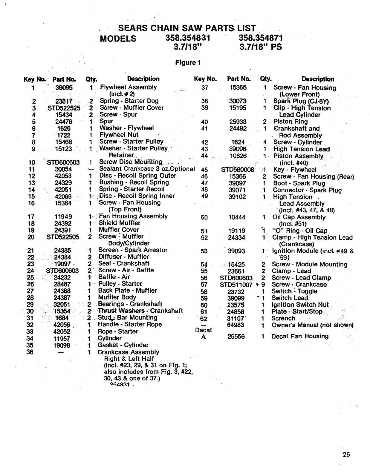
SEARS CHAINSAW PARTS LIST
MODELS 358.354831 358'354871
3.7118" 3.7118" PS
Figure I
No.
4
5
6
7
8
9
10
11
12
13
14
15
16
Part No. Qty.
39095 1
2381:7 2
STD522525 "2
15434 2
24476 -1
1626 1
1722 1
15468 1
15123 1
STD600603
30054
42053
24329
42051
42066 :
15364
17 11949
18 24392
19 24391
20 STD522505
Description
Flywheel Assembly
(incl. #2)
Spring. Starter Dog
Screw - Muffler Cover
Screw -Spur
Spur
Washer - Flywheel
Flywheel Nut
Screw - Starter Pulley
• Washer - Starter Pulley-
Retainer
1Screw Disc MOddting :_, :
Sealant Crankcase 3 oz.Optional
1 Disc- Recoil Spring Outer
1 Bushing - Recoil Spring
1 Spring - Starter Recoil
•1- :Disc- Recoil Spring Inner
1 Screw- Fan Housing
(Top Front)
1- :::Fan Housing Assembly
1-: Shield Muffler
1 Muffler Cover
2Screw: Muffler
BocJylCylinder
1 Screen- Spark Arrestor
2 Diffuser- Muffler
2Seal Crankshaft
2 Screw - Air - Baffle
t- Baffle - Air
1 " Pulley - Starte_
1 Back Plate. Muffler
21 24385
22 24384
23 _::19097 -
24 STD600603
25 .... 24232
26 28487
27 24388
28
29
::30
31
32
33
34
35
36
24387 "1 Muffler Body
• 32051• - 2 Bearings - Crankshaft
_./::15354. :2 ,Thrust Washer s .;Crankshaft
": 168;4 2 . Stud.= Bar Mounting
"42056. 1 Handle -Starter Rope
42052 1 Rope - Starter
11957 1 Cylinder
19098 1 Gasket - Cylinder
1 Crankcase Assembly
Right & Left Half
• (incl. #23, 29, & 31 on Fig. 1;
also includes from Fig. 3, #22,
30, 43 & one of 37.)
"__4_ql .
Key No. Part No. Qty.
37 15365 1
38 30073
39 15195 1
1
40 25933 2
41 24492 ., 1
42
43
44
t624• 4
39096 -1
10626 1.
STD580008 ,:I
15366 2
39097 1
39071 1
39102 1
46
46
47
48
49
50 10444 1
51 19119 1
52 24334 1
53 -39O93
15425 2
23661 2
STDC00603 2
STD511007 _, 9
23732 1
39099 "1
23575 1
24858 1
31107 1
64983 • 1
25556
5.4
55
56
57
58
59
60
61
"62
Decal
A
Description
Screw- Fan Housing
(Lower Front)
Spark Plug (CJ-SY)
Clip -High Tension
Lead Cylinder
Piston Ring
Crankshaft and
Rod Assembly
Screw - Cylinder
High Tension Lead
Piston Assemb!y_
(inct: #40) ._
Key- Flywheel
Screw- Fan Housing (Rear)
Boot - Spark Plug
Connector- Spark Plug
High Tension
Lead Assembly
(Incl. #43, 47, & 48)
Oil Cap Assembly
(IncL #51)
"O" Ring- Oil cap
Clamp- High Tension Lead
(Crankcase)
Ignition Module (incl. #49 &
59)
Screw- Module Mounting
Clamp- Lead
Screw- Lead Clamp
Screw - Crankcase
Switch" Toggle
Switch Lead
Ignition Switch Nut
Plate _StartlStop
Scrench
Owner's Manual (not shown)
1 Decal Fan Housing
25
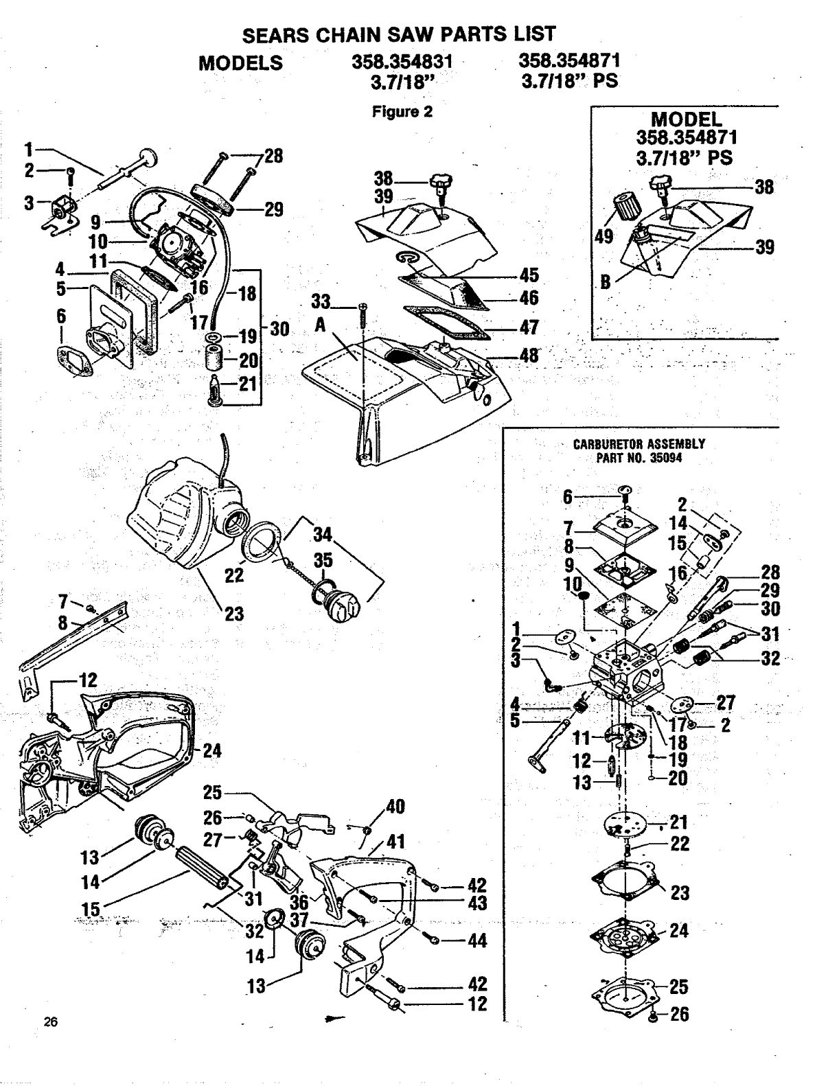
1
• | |
6
I
SEARS CHAIN SAW PARTS LIST
MODELS 358.354831 358'354871
3.7/18" 3.7118'" PS
+
Figure 2
39
45
39
26
22
23
42
12
CARBURETORASSEMBLY
PARTNO.35094
2
26
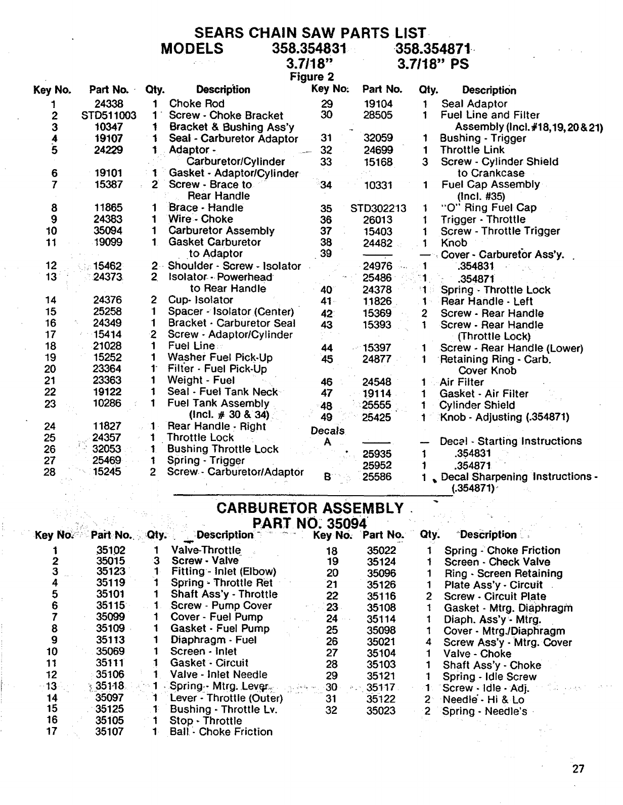
Key No.
1
2
3
4
5
6
7
8
9
10
11
12
13
14
15
16
17
18
19
20
21
22
23
24
25
26
27
28
Part No. -
24338
STD511003
10347
19107
24229
19101
15387
11865
24383
35094
19099
15462
24373
24376
25258
24349
15414
21028
15252
23364
23363
19122
10286
11827
24357
;32053
25469
-15245
SEARS CHAIN SAW PARTS LIST
MODELS
Qty. Description
1Choke Rod
1"Screw -Choke Bracket
1 Bracket & Bushing Ass'y
1 Seal -Carburetor Adaptor
1 Adaptor -
Carburetor/Cylinder
1 Gasket -AdaptorlCylinder
2 Screw -Brace to
Rear Handle
1 Brace - Handle
1 Wire- Choke
1 Carburetor Assembly
1 Gasket Carburetor
to Adaptor
2 Shoulder- Screw- Isolator
2 Isolator--Powerhead
to Rear Handle
2 Cup- Isolator
1 Spacer-Isolator (Center)
1 Bracket -Carburetor Seal
2 Screw -AdaptortCytinder
1 Fuel Line
1 Washer Fuel Pick-Up
1Filter- Fuel Pick-Up
1 Weight- Fuel
1 Seal - Fuel Tank Neck
1 Fuel Tank Assembly
(Incl. #30 &34)
1 Rear Handle. Right
1 Throttle Lock
1 Bushing Throttle Lock
1 Spring - Trigger
2 Screw- CarburetorlAdaptor
358.354831
3.7118"
Figure 2
Key No:
29
30
31
32
33
34
358.354871-
3.7118" PS
Pad No.
19104
28505
32059
24699
15168
10331
35 STD302213
36 26013
37 15403 1
38 24482 .1
39
24976 -- 1
25486-. Jl
40
41
42
43
44
45
46
47
48
49
Decals
A
B
Qty. Description
1 Seal Adaptor
1 Fuel Line and Filter
Assembly (Incl.,_18,19,20&21)
1 Bushing - Trigger
1 Throttle Link
3 Screw- Cylinder Shield
to Crankcase
1 Fuel Cap Assembly
(Incl. #35)
1 "O" Ring Fuel Cap
1 Trigger- Throttle
Screw - Throttle Trigger
Knob
Cover - Carburetor Ass'y.
.354831 - .,_
•_.35487i
:1 Spring -Throttle Lock
24378
11826 •
15369
15393
--15397
24877
24548
19114
25555
25425
1Rear Handle- Left
2Screw- Rear Handle
1Screw- Rear Handle
(Throttle Lock)
1 Screw - Rear Handle (Lower)
1 Retaining Ring- Carb.
Cover Knob
1 Air Filter
1 Gasket - Air Filter
1 Cylinder Shield
1 :Knob- Adjusting (.354871)
25935
25952
25586
-- Decal -Starting Instructions
1.354831 '
1354871 ' "
1 ,, Decal Sharpening Instructions -
(.354871),-
Key No.:: PaPI No .... Qty;
35102
35015
35123
35119
35101
35115
35099
35109
35113
35069
35111
35106
1
3
1
1
1
1
1
1
1
1
1
CARBURETOR ASSEMBLY .
PART NO: 35094
.,,Description ............. Key No. Part No.. •Qty:
'_35!-18
35097
35125
35105
35107
18 35022 1
19 35124 1
20 35096 1
21 35126 1
22 35116 2
23 35108 1
24 35114 1
25 35098 1
26 35021 4
27 35104 1
28 35103 1
29 35121 1
,-_,35117 1
35122 2
35023 2
Valve-Throttle.
Screw- Valve
Fitting- Inlet (Elbow)
Spring =Throttle Ret •
Shaft Ass'y -Throttle
Screw - Pump Cover
Cover- Fuel Pump
Gasket - Fuel Pump
Diaphragm - Fuel
Screen - Inlet
Gasket - Circuit
Valve- Inlet Needle
1
2
3
4
5
6
7
8
9
10
11
12
.13
14
15
16
17
-1 , Spring:: Mtrg. Ley,_i.::, :.,,,......:. 30
t Lever- Throttle (Outer) 31
I Bushing - Throttle Lv. 32
1 Stop- Throttle
1 Ball. . Choke Friction
;Description il
Spring ChoKe Friction
Screen - Check Valve
Ring - Screen Retaining
Plate Ass'y- Circuit
Screw - Circuit Plate
Gasket- Mtrg. DiaPhragm
Diaph. Ass'y- Mtrg..
Cover- MtrgJDiaptiragm
Screw Ass'y - Mtrg. Cover
Valve - Choke
Shaft Ass'y - Choke
spring - Idle Screw
•Screw - Idle - Adj.
Needle'- Hi &Lo
Spring - Needle's.
27
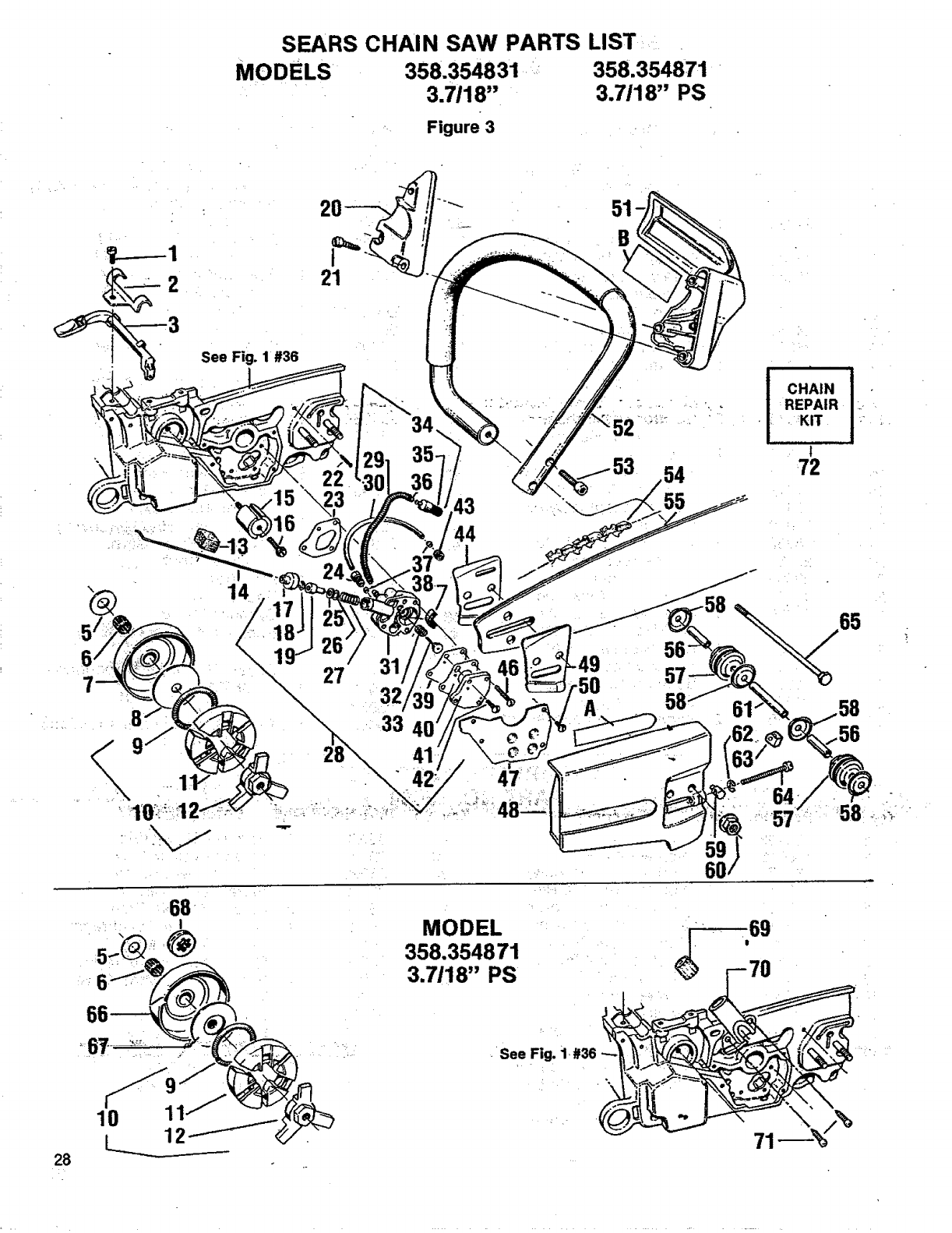
SEARS CHAIN SAW PARTS LIST
MODELS 358.354831 358.354871
3.7118" 3.7118" PS
Figure 3
21
"- 51
B
\
See Fig. 1 #36
22 54
'_3 43
44
| i
CHAIN I "•
REPAIR :
•KIT , , +
!
72 •
%_65
64/
...._57 ....
6O
68
IMODEL
358.354871
3.7/18" PS
28
10
L...
See Fig.
\
71 %/%
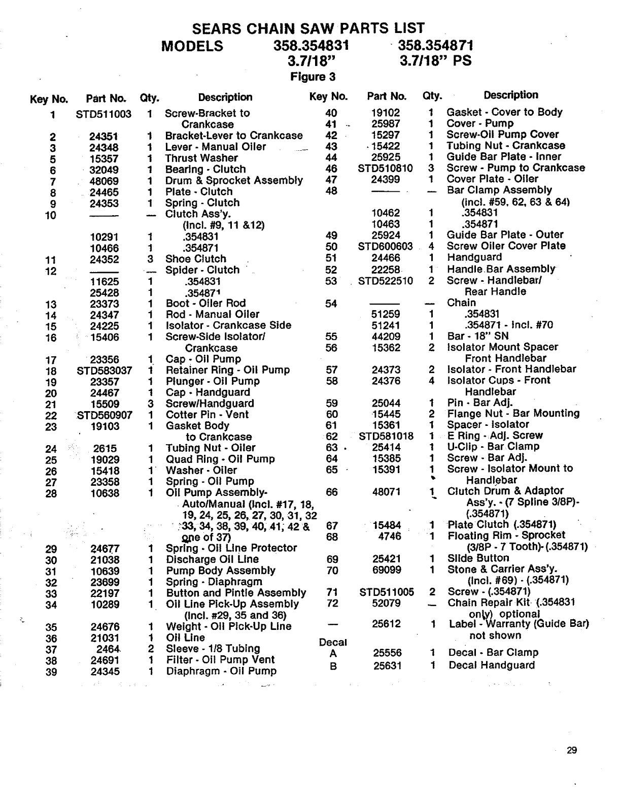
Key No,
1
2
3
5
6
7
8
9
10
11
12
13
14
15
16
17
18
19
20
21
22
23
Part No.
STD511003
24351
24348
15357
•32049
• 48069
24465
24353
10291
10466
24352
11625
25428
23373
24347
24225
i_15406
23356
STD583037
23357
24467
15509
STD560907
19103
24 _:i 2615
25 19029
26 15418
27 23358
28 10638
29
30
31
32
33
34
35
36
37
38
39
246.77
21038
10639
23699
22197
10289
24676
21031
2464
24691
24345
SEARS CHAIN SAW PARTS LIST
MO DELS 358.354831 358.3548 71
3.7118" 3.7/18" PS
Figure 3
Description Key No.
Qty.
1 Screw-Bracket to 40
Crankcase 41 --
1 Bracket-Lever to Crankcase 42
1 Lever- Manual Oiler .... 43
1 Thrust Washer 44
1 Bearing- Clutch 46
1 Drum & Sprocket Assembly 47
1 Plate* Clutch 48
1 Spring - Clutch
-- Clutch Ass'y.
(Incl. #9, 11 &12)
1 .354831 49
1 .354871 50
3 Shoe Clutch •51
-- Spider- Clutch 52
1.354831 53
1 .354871
1 Boot -Oiler Rod 54
1 Rod -Manual Oiler
1 Isolator- Crankcase Side
1 Screw-Side Isolator/ 55
Crankcase 56
1 Cap-Oil Pump
1 Retainer Ring -Oil Pump 57
1 Plunger- Oil Pump 58
1 Cap -Handguard
3 Screw/Handguard 59
1 Cotter Pin -Vent 60
1 Gasket Body 61
to Crankcase 62
1 Tubing Nut- Oiler 63 •
1 Quad Ring -Oil Pump 64
1 Washer-Oiler 65 •
1 Spring -Oil Pump
1 Oil Pump Assembly- 66
• AutolManual (Incl. #17, 18,
19, 24, 25, 26, 27, 30, 31, 32
...... :_33,34, 38, 39, 40, _41, 42 & 67
D_Deof 37) 68
1 Spring -O!1 Line Protector
1 Discharge Oil Line 69
1 Pump Body Assembly 70
1 Spring -Diaphragm
1 Button and Pintle Assembly 71
1 Oil Line Pick-Up Assembly 72
(incl. _r29, 35 and 36)
1 Weight-Oil Pick-Up Line --
1 Otl Line Decal
2 Sleeve -1/8 Tubing A
1Filter. Oil Pump Vent
1 Diaphragm - Oil Pump B
Part No. Qty.
19102 1
25987 1
15297 1
.15422 1
25925 1
STD510810 3
24399 1
10462
10463
25924
STD600603
24466
22258
STD522510
51259
51241
44209
15362
24373
24376
25044
15445
15361
STD581018
25414
15385
15391
48071
15484
4746
25421
69099
STD511005
52079
25612
25556
25631
Description
Gasket - Cover to Body
Cover- Pump
Screw-Oil Pump Cover
Tubing Nut - Crankcase
Guide Bar Plate- Inner
Screw -Pump to Crankcase
Cover Plate - Oiler
Bar Clamp Assembly
(incl. #59, 62, 63 & 64)
1.354831
1 .354871
1 Guide Bar Plate- Outer
4 Screw Oiler Cover Plate
1 Handguard
1 Handle.Bar Assembly
2 Screw, Handlebar/
Rear Handle
-- Chain
1.354831
1 .354871 - Incl. #70
1 Bar- 18" SN
2 Isolator Mount Spacer
Front Handlebar
2 Isolator- Front Handlebar
4 Isolator Culos -Front
Handlebar
1 Pin- BarAdj.
2 Flange Nut- Bar Mounting
1 Spacer - isolator
1 E Ring .Adj. Screw
1 U-Clip - Bar,Clamp
1 Screw- Bar Adj.
1 Screw- Isolator Mount to
_' Handlebar
1 Clutch Drum & Adaptor
Ass'y. -(7 Spline 3t8P)-
(.354871)
1 PiateClutch (.354871) _
1 Floating Rim - Sprocket
(318P -7 Tooth)- (.354871)
1 Slide Button
1 Stone & Carrier Ass'y.
(Incl. #69)- (.354871)
2 Screw - (.354871)
_ Chain Repair Kit. (.354831
one) optional
1 Label - Warranty (Guide Bar)
not shown
1 Decal - Bar Clamp
1 Decal Handguard
29

NOTES
u,
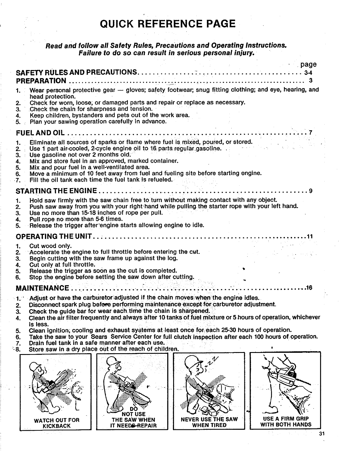
QUICK REFERENCE PAGE
Read and follow all Safety Rules, Precautions and Operating Instructions.
Failure to do so can result in serious personal injury.
page
SAFETY RULES AND PRECAUTIONS ............... :........................... 3-4
PREPARATION ........................................................................... 3
1. Wear personal protective gear gloves; safety footwear, snug fitting clothing; and eye, hearing, and
head protection.
2. Check for worn, loose; or damaged parts and repair or replace as necessary.
3. .Check the chain for sharpness and tension.
4. Keep children, bystanders and pets out of the work area.
5. Plan your sawing operation carefully in advance.
OIL '7
FUEL AND .................................................. •.............
1. Eliminate all sources of sparks or flame where fuel is mixed, poured, or stored.
2. Use I part air-cooled, 2-cycle engine oil to 1.6 parts regular_gasolJne. _
3. Use gasoline not over 2 months old:
4. Mix and store fuel in an approved, marked container.
5. Mix and pour fuel in awell-ventilated area.
6. Move a minimum of 10 feet away from fuel and fueling site before starting engine.
,7. Fill the oil tank each time the fuel tank is refueled.
STARTING THE ENGINE ........................................................ g
1. Hold saw firmly with the saw chain free to turn withoutmaking contact with any object.
2. Push saw away frorrt you with your right,hand while pulling the starter rope with your left hand.
3. Use no more than 15-18 inches of rope per pull.
4. Pulirope no more than 5-6 times.
5. Release the trigger after'engine starts allowing engine to idle.
OPERATING THE UNIT... ...................................................... 11
WATCH OUT FOR
KICKBACK
1. Cut wood only.
2. Accelerate the engine to full throttle before entering the cut. .
3. Begin cutting with the saw frame up against the log.
4. Cut only at full throttle.
5. Release the trigger as soon as the cut is completed. "
6. Stop the engine before setting the saw down after Cutting ....
MAINTENANCE .' ._....... :_'_'! i ..16
... • • 'm'= =.o • • = • • = t,'=,. D...= •=•• • • w • • • - = • = ==•• = • • _1== w =• ==_
•1:" =A_ust or have the carbUretor::adjusted if the chain movesiwhenthe engine idles.=
2. Disconnect spark plugbefefe performing maintenanceexcePtf0rcarburetor adjustment.
3. Check the guide bar for wear each.time the chain is sharpened. !'
4. Clean the air filter frequently and:always after 10 tanks offuel mixture or 5hours of operation, whichever
is less. _ •
5. Clean ignition; cooling and exhaust systems at .least once for,each 25-30 hours of operation.
6. Take the saw to your Sears Service Center for full clutch inspection after each 100 hours of operation.
7. Drain fuel tank in a safe mannerafter each use. :-=_
_8. Store saw in adry place out of the reach of children. ' .
"== NOT USE
THE SAW WHEN II NEVER USE THE S,
IT NEEDE_REPAIR j L_WH__T!RED
NEVER USE THE SAW USE A FIRM GRIP
WHEN TIRED WITH BOTH HANDS
31
[Searsl
J
MODEL NO.
358.354831-3.7118"
358.354871-3.7118" PS
How to Order
Repair Parts
SEARS SERVICE
The Model Number will be found under the handle with the Serial
Number. Always mention the Model Number when requesting ser-
vice or repair parts for your Chain Saw.
rt '"'
All pa slisted herein may be ordered from any Sears Service Center
and most Sears Stores.
WHEN ORDERING REPAIR PARTS, ALWAYS GIVE THE
FOLLOWING INFORMATION AS SHOWN IN THIS LIST.
1. The PART NUMBER 3. The PART DESCRIPTION
2. The MODI_L NUMBER
358.354831.3.7118"
358.354871.3.7118" PS
4. The NAME OF ITEM
Chain Saw
If the parts you need are not stocked locally, your order will be
electronically transmitted to a Sears Repair Parts Distribution.
" -"center forexpedited'han_:lling." : .......
When you buy merchandise
from Sears you get an extra
something that nobody else
can offer ... Sears Service.
Across town or across the
country, Sears Service follows
you, providing trustworthy,
competent" service technicians
using only Sears specified
factory parts.
iiii iiii i i.i
64983-3-24483-1-24483
/,
Sears, Roebuckand Co., Chicago, II£ 6068 U.S.A.
PRINTED IN U.S.A.
