Craftsman 358356281 User Manual GASOLINE CHAIN SAW Manuals And Guides L0805040
CRAFTSMAN Chainsaw, Gas Manual L0805040 CRAFTSMAN Chainsaw, Gas Owner's Manual, CRAFTSMAN Chainsaw, Gas installation guides
User Manual: Craftsman 358356281 358356281 CRAFTSMAN GASOLINE CHAIN SAW - Manuals and Guides View the owners manual for your CRAFTSMAN GASOLINE CHAIN SAW #358356281. Home:Lawn & Garden Parts:Craftsman Parts:Craftsman GASOLINE CHAIN SAW Manual
Open the PDF directly: View PDF ![]() .
.
Page Count: 28
IMPORTANT MA_-_A L Do Not Throw Away
IIIIIIIIII II I i iii iiiiiiii i iiiiiii i j ii
Operator's
Manual
•Assembly
Operation
•Maintenance
•Repair Parts
MODEL NO.
358356281-2.8118"
358.356332,3.3120"
d_WARNING:
Carefully read and follow
Safety Rules, Precautions
and Operating instructions.
Failure to do so can result
in serious personal injury.
/C.RFIFTSMFIN,
2.8118" 33/20"
GASOLI NE CHAIN SAW
...................... ., ..... ,, ,- 1'- , ,,,, , ' i"
Record in the space provided below the Model No. and Serial No. of
your saw. These numbers are located on the starting instructions
decal.
Model No. Serial No.
Retain these numbers for future reference.
-k
Sold by Sears, Roebuck and Co., Hoffman Estates, IL 60179 USA
•• / | j • i i, ii
.... L i i -. ,,,,, ,
530.081372-2-09/15/93 © 1993, Sears, Roebuck and (20.
FULL ONE YEAR WARRANTY ON GASOLINE CHAIN SAW :__
(Excluding Bar, Chain, Spark Plush Air Filter and Starter RoPe)
For one year from date of purchase, when you maintain, lubncate, and tune up this chain saw according to the operating arid mam-
_nance instructions in the o.pe.ra,tor's, manual, Sears wifl repair defects in material or workmanship in this gasoline chain saw at no
cnarge. I hiswarranty excludes oar, cnain, spark plug, air flRer, and starter rope which are expendable parts and become w0m our ng
normal use.
if this chain saw is used for commercial or rental purposes, this warranty does not apply.
WARRANTY SERVICE IS AVAILABLEBY REDJRNiNG THE CHAIN SAW TO THE NEAREST SEARS SERVICE CENTER/DEPARTMENT
IN THE UNITED STATES,
This warranty gives you specific legal dghts, and you may also have other rights which vary from state to state.
_>e_. .................... ....... Sears, ,Roebuck and Co., Dept. D/731-CR.W, Sears Tower, Ch!cago, !L 60684
Sold by Sears, Roebuck and Co., Dept. D/817W_ Hoffinan Estate, IL 60179 USA ._
TABLE OF CONTENTS
Specifications ............................... 2
SPECIAL SAFETY SECTION ..................... 3
Know Your Chain Saw 6
Preparing Your Saw For Use ................... 7
Accessories ......... _.......... ............ .1()
Using Your Saw ........................... 11,
TyPes of Cutting ' "12
Maintenance ........... : ................... 16
Repair Parts 23
Quick Reference Page " 27
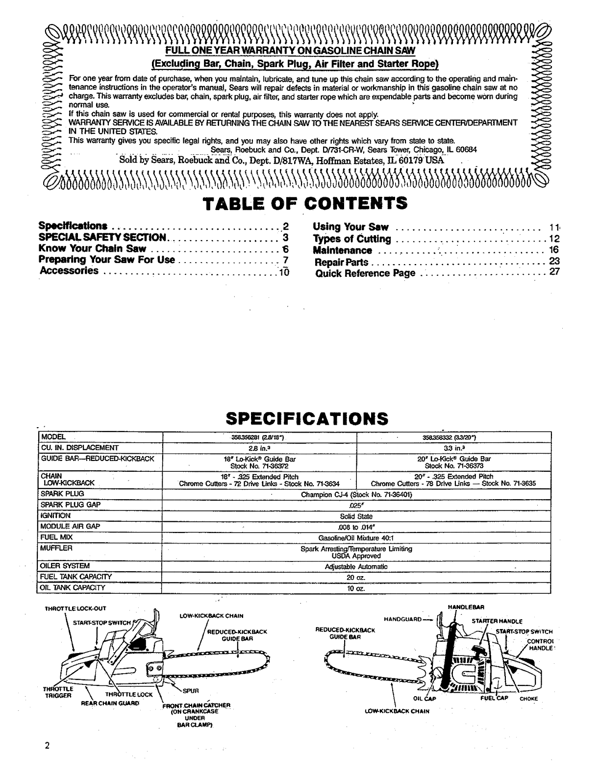
SPECIFICATIONS
CU, IN. DISPLACEMENT
GU_D__--_UC_mCK_K' '
CHAIN
LOW-KICKE_CK
SPARKPLUG
SPARKPLUG GAP
iGNITiON
MODULE.AIR GAP
FUEL MIX
MUFFLER
3583ss2_ (2_;}
................... , , ,: ,
2.8 in._
18" Lo._ck ® Guide Bar
StockNo. 71-36372
!8" - 325 ExtendedPitch
Chrome Cut_rs - 72 Drive Unks-StockNo. 71.3634
,,, _ • ,.......
OIL TANKCAPAX3WY
33 in.=
20_ Lo-Kick® Guide Bar
Stock No, 71-36373
20_- 325 ExtendedPitch
ChromeCutters - 78 Drive Unks_StockNo. 71-3635
Champion CJ-4 (StOCkNo. 71-36401)
.025_
......... s0:i_"_
,008 tO.0i4"
Gasofine/OitMixture"40'it................
SparkArresting/TemperatureUmiting
USDA Approv.ed..............
AdjustableAutomatic
20 oz.
10 oz.
THROTTLELOCK-OUT HANDLEBAR
LOW-KICK_C_ CHAIN HANOGUARD ---;,- STARTERHANDLE
START-STOP SW|TCH •
REDUCE D-KICK_J_,CK START-STOP SWITCH
GUIDE BAR GU_tDE BAR CONTROl
TRIGGER
FRONT,CHA!N C_kTCHER
(ON CR AN¥,£TJkSE
UNDER
BARClAMP)
FUEL CHOK_
2
! , ......... .IHI ii i iiii ,,,, ,,,,,,,,,,,,,,,,
SPECIAL SAFETY SECTION
GUARD AGAINST KICKBACK
Kickback is adangerousreac onthatcanmeadtoserous
personalinjury.Donotretyonlyonthesafefydevicespro-
v/ded w/th yoursaw. As a chain saw user, you must take
special safety precautions to help keep your cutting jobs
free from accident or injury.
AKICKBACK WARNING
Kickback can occur when the moving chain contacts
an _at the upperportionofthetipoftheguide bar
orwhen thewood €loses in and ptncheethesew chain
inthe cut, Contact at the upper portton of the tip ofthe
guide barcan causethe chain todig into theobject and
stop the chain for an Instant. The result is slightning
fast, reverse reaction which k_cksthe guide barupand
back toward the operator, ff the saw chain ispinched
along the top of the gulde bar, the guide bar can be
driven rapidly back toward the operator. Either of
these reactions can cause loss of saw control which
can result in serious 'injury.
CLEAR
WORKING AREA
NEVER
REVERSE
HAND
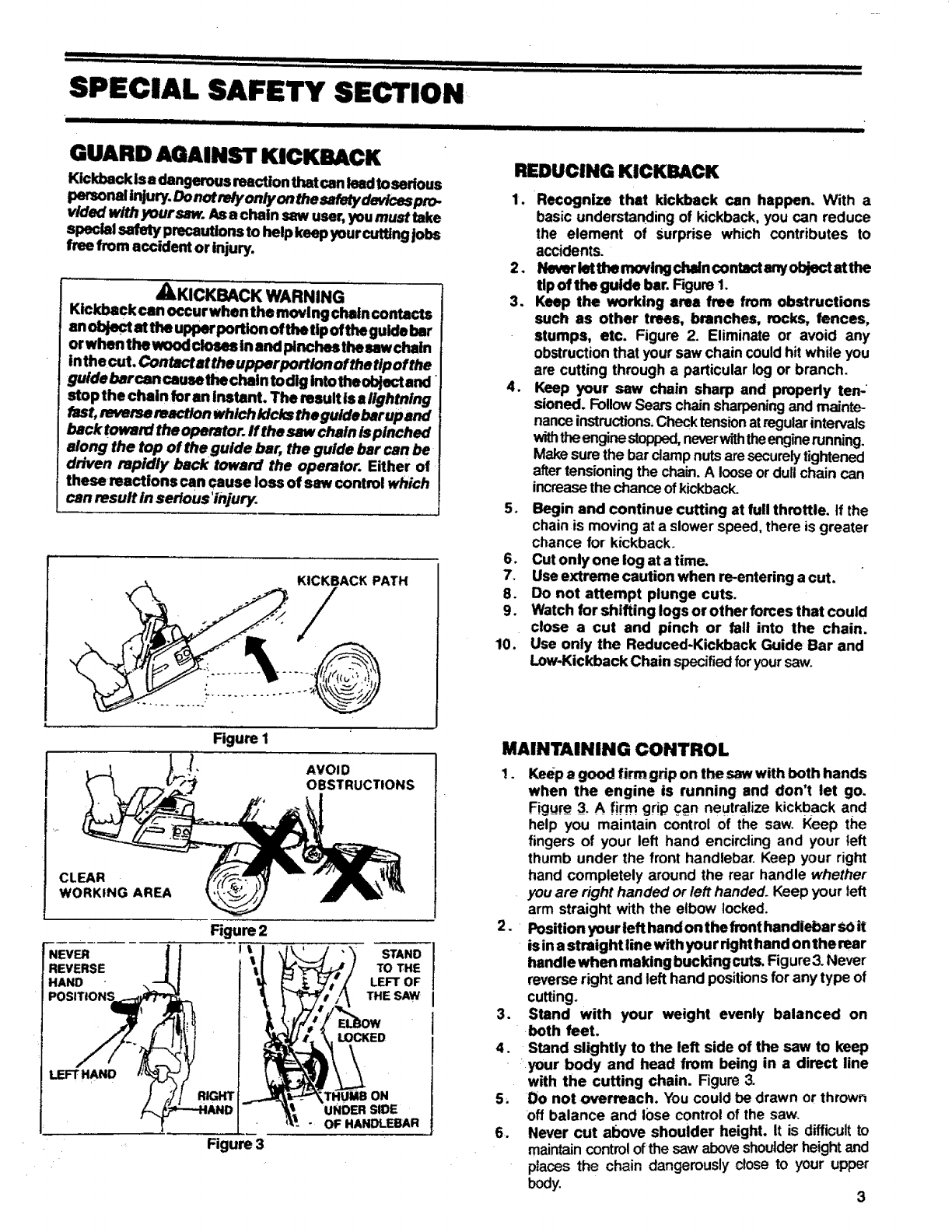
KICKBACK PATH
/
Figure I
AVOID
OBSTRUCTIONS
Figure 2
!STAND
TO THE
LEFT OF
THE SAW
LOCKED
LEFTHAND
Figure 31
UNOF.RSlOe
OF HANDLEBAR
,,,,,,,,,,,,,,,,,,,,,!,,, ..............,=, ,, || i
REDUCING KICKBACK
1. Recognize that kickback can happen. With a
basic understanding of kickback, you can reduce
the element of Surprise which contributes to
accidents.
2. Neveriat the moving chain €ontactanyobject atthe
Up of the guide bar. Figure1.
3. Keep the working area free from obstructions
such as other trees, branches, rocks, fences,
stumps, etc. Figure 2. Eliminate or avoid any
obstructionthat your saw chain couldhit while you
are cutting through aparticular log or branch.
4. Keep your saw chain sharp and properly ten-
sioned. FollowSears chainsharpeningand mainte-
nanceinstructions.Checktensionat regular intervals
withtheenginestopped,neverwiththeenginerunning.
Make sure the barclampnutsare securelytightened
after tensioningthe chain.A looseor dull chain can
increasethe chanceof kickback.
5. Begin and continue cutting at lull throttle, if the
chain is moving at a slower speed, there is greater
chance for kickback.
6. Cut only one log at a time.
7. Use extreme caution when re-entering a cut.
8. Do not attempt plunge cuts.
9. Watch for shifting logs orotherforces that could
close a cut and pinch or fail into the chain.
10. Use only the Reduced-Kickback Guide Bar and
Low.Kickback Chain specifiedforyoursaw.
MAINTAINING CONTROL
1. Keep a good firm gdp on the saw with both hands
when the engine is running and don't let go.
Figu_r_e3, A firm grip can neutralize kickback and
help you maintain control of the saw. Keep the
fingers of your left hand encircling and your left
thumb under the front handlebar. Keep your right
hand completely around the rear handle whether
you are right handed or left handed. Keep your left
arm straight with the elbow locked.
2. Position your left handon the fronthandlebar SOit
isin a streight line with your dght hand onthe rear
handle when making bucking cuts. Figure3. Never
reverse right and left hand positionsfor any type of
cutting.
3. Stand with your weight evenly balanced on
both feet.
4. Stand slightly to the left side of the saw to keep
your body and head from being in a direct line
with the cutting chain. Figure 3.
5. Do not overreach. You could be drawn or thrown
Loftbalance and lose control of the saw.
6. Never cut above shoulder height. It is difficultto
maintaincontrolofthe saw aboveshoulderheightand
places the chain dangerously close to your upper
body. 3
i i IIIIHIII II ..............................................................
ij i i, ,i
SPECIAL SAFETY SECTION (continued)
IIIIII i iIIIIIIiii ,,,, IH iii
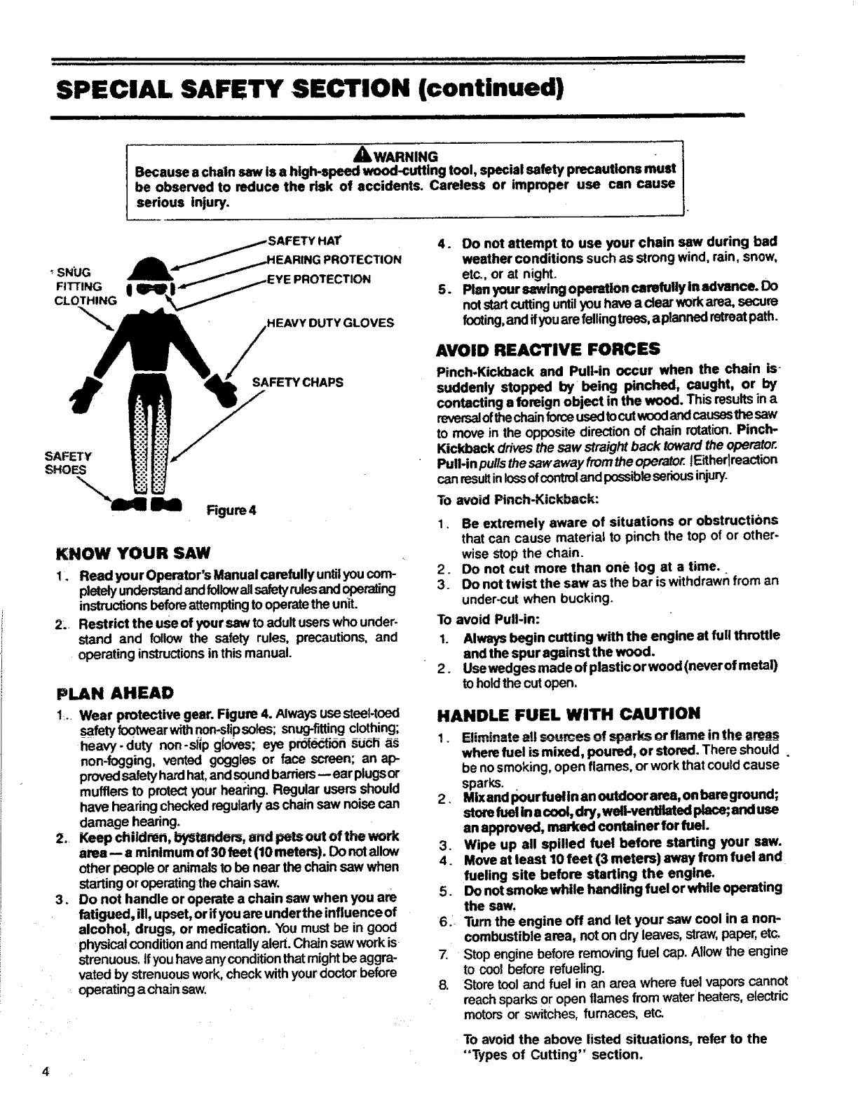
AWARNING
SNUG
FITTING
CLOTHING
PROTECTION
GLOVES
SAFETY CHAPS
Figure4
KNOW YOUR SAW
1. Read your Operator's Manualcarefully untilyoucom-
pletelyunderstandandfollowallsafetyrulesandoper_ng
instnJctionsbeforeattemptingto operatethe unit.
2.. Restrict the useof yoursew to adultuserswhounder-
stand and fo!low the safety rules, precautions, and
operating instructionsinthismanual.
PLAN AHEAD
2_L
.
Wear protective gear. Figure 4. Alwaysusesteel-toed
sa=fetyfootwear withnon-slipsoles;snug-fittingclothing;
heavy, duty non-sl_p g_:_s; eye pr(ff_"tion such a._
non-fogging, vented goggles or face screen; an ap-
provedsafetyhardhat,and soundbarriers-- ear plugsor
mufflers to protectyour hearing. Regular users should
have hearing checkedregularlyas chain saw noisecan
damage hearing.
Keep chiidrert, ly_staltdem,and petsout of the work
area-- a minimum of 30 feet (10 meters). Do notallow
other people or animalsto be near the chain saw when
startingor operatingthechain saw.
Do not handle or operate a chain saw when you are
fatigued, ill, upset, orif youare underthe influenceof
alcohol, drugs, or medication. You must be in good
physicalconditionand mentally alert. Chainsaw work is
strenuous, Ifyouhaveanycond_on that might be aggra-
vated by strenuous work,check withyourdoctorbefore
operatingachain saw.
4
4. Do not attempt to use your chain Saw during bad
weather conditions such as strong wind, rain, snow,
etc.. or at night.
5. Plan your sawing operation carefully inadvance. Do
notstartcuttinguntilyou have a clearworkarea, secure
footjng,andifyouare fellingtrees,a plannedretreatpath.
AVOID REACTIVE FORCES
Pinch-Kickback and Pull-in occur when the chain is-
suddenly stopped bybeing pinched, caught, or by
contacting a foreign object in the wood. This resultsina
reversalofthechainforceusedtocutwoodandcausesthesaw
to move in the opposite directionof chain rotation.Pinch-
Kickback drivesthe saw straightback towardthe operator.
Pull-in pullsthe sawaway fromthe opera_. JEitherlreaction
canresultinlossofcontrolandpossibleserious injury.
To avoid Pinch-Kickback:
1, Be extremely aware of situations or obstructions
that can cause material to pinch the top of or other-
wise stop the chain.
2. Do not cut more than one log at atime,
3. Do not twist the saw as the bar is withdrawr_ from an
under-cut when bucking.
avoid Pull-in:To
1.
2_
Always begin cutting with the engine at full throttle
and the spur against the wood.
Use wedges made of plastic or wood (neverof metal)
toholdthe cut open,
HANDLE FUEL WITH CAUTION
I. Elimin=te a!! soumes of =,z_pa_rksor flame in the am_a_
where fuel is mixed, poured, or stored. There should
be no smoking, open flames, or workthat could cause
sparks.
2. Mixand pour fuelin an outdoor area, on bareground;
store fuel ina cool, dry, wetl-venUlated place;and use
an approved, marked container for fuel.
3. Wipe up all spilled fuel before starting your saw.
4. Move at least 10 feet (3 meters) away from fuel and
•fueling site before starting the engine.
Do not smoke while handling fuel or while operating
the sew.
6. Turn the engine off and let your saw cool in a non-
combustible area, noton dry leaves, straw,paper,etc.
7. Stop engine before removingfuel cap. Allowthe engine
to cool before refueling.
8. Store tool and fuel in an area where fuel vapors cannot
reachsparksoropen flames from waterheaters,electric
motors or switches, furnaces, etc.
To avoid the above listed situations, refer to the
"Types of Cutting" section.
,,. iiiiiiiiiii
SPECIAL SAFETY SECTION (continued)
lllmlll ii ii i iiiii i iiiiiiiiiiiiiiiiiiiiiiiiiiiiii iiii
OPERATE YOUR SAW SAFELY
1. Do not operate achain saw that is damaged, im-
properly adjusted, or not completely and securely
assembled.
2. Operate the chain m only inoutdoor areal
3. Do not operate the saw from a ladder or in atree.
4: Position all parts of your body to the left of cut and
away from the law cltlin when the engine is
running.
5. Cut wood only. Do not cut metal,plastics,masonry,
non-woodbuildingmaterials,etc. Inspect materialto
be cut; remove any foreign materialssuch as nails,
wire, etc. Do not use yoursaw to pry or shoveaway
limbs, roots,or other objects.
6. Make sure the chain wilt not make contact with
any object before starting the motor. Nevertry to
start the saw when the guide bar is in acut.
7. Use extreme caution when cutting small size brush
and saplings. Slender material can catch the saw
chain and be whipped toward you or pull you off
balance.
8. Be alert for springback when cutting alimb that is
under tension so you wiii not be struck by the limb oF
saw when the tension in the wood fibers is released.
9. Do not put pressure on the saw at the end of a cut.
This can cause you to lose control when the cut is
completed.
10. Stop the engine before setting the saw down.
MAINTAIN YOUR SAW IN GOOD
WORKING ORDER
1. Have all chain sawservice performed byyourSears
Service Center/Department withthe exceptionof the
items listedinthe maintenance sectionofthismanual.For
example, ifimpropertoolsare usedto removeorholdthe
flywheelwhen servicingthe clutch,structural damageto
the flywheel can occur and causethe flywheeltoburst.
2. Keep fueland oilcaps, screws,aiidP_tene_=iy
tightened.
3. Keep the handles dry, clean, and free of oil or fuel
mixture.
4. Make certain the saw chain stops moving when the
throttle trigger is released. For correction, refer to
"Carburetor Adjustment" instructions.
5. Stop the saw if the chain strikes a foreign object.
Check foralignment, binding,breakage,and mount-
ing of moving partsand any othercondition that may
affect the operation of the unit.Check guardsand all
other parts to see if each willoperate propedyand
perform its intended function. Any part that is dam-
aged shouldbe propedy repairedor replacedbyusing
the instructionsin thismanualor by seeingyour Sears
Service Center.
6. Disconnect the spark plug before performing any
maintenance except for carburetor adjustments,
,
8.
9.
Never modify your saw in any way. Use onlyattach.
ments suppliedorspecificallyrecommendedby Sears.
Always replace the handguard immediately if it
becomesdamaged, broken, or is otherwise removed.
Keepthevibrationisolators ingood condition. Period-
icallyinspectisolatorsfor tears, rips,orseparationof the
rubberportionfromthemetalmountings.HaveyourSears
ServiceCenter/Departmentreplacethe isolatorsifwomor
damaged,ifvibrationincreases,or ifmountsdevelopan
outofroundorswollenshape from exposuretogasoline
and/oroil.Ris recommendedthatallisolators bereplaced
whena failure toone occurs.
CARRY AND STORE YOUR SAW SAFELY
1. Handcarrythe unit with theengine stopped, the muf-
tier awayfromyour body, and theguidebarandchainto
the rearcoveredpreferablywitha scabbard.
2. Before transporting in any vehicle or stodng in any
enclosure, allowyoursaw to coolcompletely,coverthe
barandchain,andproperlysecuretoavoid turnover,fuel
spillage,ordamage.
3. _B._fom=stodng=thetool, use up ,_,el left in the _-_rbu-
retorand fuel tines by starting the engine and letting
it run until_itstops.
4. Store in a dry area out of the reach of children and
a_ from where fuel vapors can reach sparks or an
open flame from hotwater heaters, furnaces,et_
SAVE THESE INSTRUCTIONS
NOTE: Exposureto vibrations through prolonged use of
gasoline powered hand tools could cause blood
vesselor nervedamage inthe fingers, hands,and
wristsof people prone to circulation disorders or
abnormal swellings. Prolonged use in cold
weather has be6ri linked to b166diie_i dania_le
in otherwise healthy people. If symptoms occur
suchasnumbness, pain, loss of strength, change
in skin color or texture, or loss of feeling in the
fingers, hands, or wrists, discontinue the use of
this tool and seek medical attention. An anti-
vibration system does not guarantee the
avoidanceof these problems. Users who operate
powertoolson acontinual and regularbasismust
monitor closely their physical condition and the
condition of this tool.
Notice: Refer to the Code of Federal Regulations,Section
1910.266(5);2_5.1 of American National Standard
SafetyRequirements for Pulpwood Logging,ANSI
03.1-1978;and relevant state safety codes when
usinga chainsaw fortogging purposes.
NOTE: When cutting fibrous materialsuch as palms,pampas grass, yucca, etc.,cleanthe cooling system(includingcylinder
cooling fins) after every other refueling. 5
KNOW YOUR CHAIN SAW
IIIIIIIIII II I I I U I I ,II II
A. INTRODUCTION
Yoursaw has been desig.nedwithsafetyin mind and
inc_Jdesthetoiiowing featuresasstandard equipment:
-- Reduced-KickbackGuide"Bar(Lo-Kicl_)
-- Low-Kickback Chain (ElongatedGuard Link)
-- Spark Arrestor
--Temperature Limiting Muffler
-- Handguards
"--Full VibrationIsolationSystem
AWARNING
The following features are includedon your saw to help
reduce the hazard of kickback; however,such features
+will not totally eliminate this dangerousreaction. Asa
chain saw user,do not rely only onsafety devices. You
must follow all safety precautions, instructions, and
•maintenance in this manual to helpavoid kickbackand
other forces which can result inserious injury.
B, KICKBACK SAFETY FEATURES
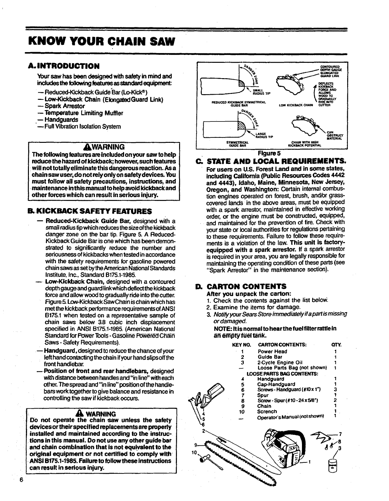
-- Reduced;Kickback Guide Bar, designed with a
srna;lradiustipwhichreducesthesizeofthekicld_ck
danger zone on the bar tip. Figure 5. A Reduced-
KickbackGuide Baris onewhichhas beendemon-
strated to significantly reduce the number and
seriousnessofkickbackswhentestedinaccordance
with the safety requkementsfor gasoline powered
chainsawsassetbytheAmericanNationalStandards
Institute,inc., StandardBI75.1-1985.
-- Low-Kickback Chain, designedwithacontoured
depthgaugeandguardlinkwhichdeflectthe kickback
forceandallowwoodto graduallyrideintothe cutter,
Figure.5Low-KickbackSawChainischainwhichhas
metthe kickbackperformancerequirementsofANSI
B175.1when tested on arepresentativesampleof
chain saws below 3.8 cubic inch displacement
specifiedin ANSI B175+1-1985.(American National
Stat_trd forPowerTo, is -G_3iine P_'_f_fCPi_i_
Saws- SafetyRequirements).
"Handguard, designedto reducethechanceofyour
: lefthandcontactingthechain ifyourhandslipsoffthe
front handlebE
--Position of front and rear handlebars, designed
withdistancebetweenhandlesand"inline"witheach
other.Thespreadand"in line"positionof thehandle-
barsworktogetherto givebalanceand resistancein
controllingthe saw ifkickbackoccurs.
' A WARNING
Do not operate the chain saw unless the safety
devices or their specified replacements are properly
installed and maintained according to the instruc-
itions in this manual. Do notuse any other guide bar
and chain combination that is not equivalent to the
+original equipment or not certified to comply with
ANSI BI75.1-1985. Failure to followthese instructions
can result in serious injury.
6
_,_€+) • CO/(TtXN_ED
_....,---" _GAUGE
/ _ONGATED
GUIDE BAR LOW KtCK_IkGK CHAI# CUTTER
..... J"RADIUS TIP OBSTRUCT
M/mERIAL
SYMML=R'RfCAL CHAIN WITH
GUIDE BAR KICKtMC;K POlrI_NTIAL
Figure 5
C, STATE AND LOCAL REQUIREMENTS.
For users on U.S. Forest Land and in some states,
including California (Public Resources Codes 4442
and 4443), Idaho, Maine, Minnesota, New Jersey,
Oregon, and Washington: Certain internalcombus-
tion engines operatedon forest, brush, and/or grass-
covered lands in the above areas, must be equipped
with a spark arrestor,maintained in effectiveworking
order,or the engine must be constructed, equipped,
+and maintained for the prevention of fire. Check with
yourstateor localauthoritiesfor regulationspertaining
to these requirements.Failure to followthese require-
mentsis aviolationof the law. This unit is factory-
equipped with a spark a_estor, if aspark arrestor
isrequiredin yourarea, you are lega!lyresponsiblefor
maintainingthe operatingconditionof these parts(see
"Spark Arrestor" in the maintenance section).
D. CARTON CONTENTS
After you unpack the carton:
1. Check the contents against the list below.
2. Examine the items for damage.
3. Notih/yourSearsStoreimmediate/yffapartismissing
or damaged.
NOTE: it is normalto hear the fuelfilter rattlein
an eml_ty f_iellank.
KEY NO. CARTON CONTENTS: QTY.
1 Power Head 1
2 Guide Bar 1
32,Cycle Engine Oil 1
-- Loose Parts Bag (not ShOwn) 1
LOOSE PARTS BAG CONTENTS:
4 Handguard 1
5 Cap-Handguard 1
6 Screws -Handguard (#10x t ") 3
7Spur 1
8Screw - Spur (#I0 - 24 x 5/8") 2
9Chain 1
!0 ScrenC,h 1
_ Operator's Manual (not shown) 1
........................ 7;......,....... ....._....................................... I.................
PREPARING YOUR SAW FOR USE-
............................ iiiii i iiiiiiii i,,,,,, ,,, ,,,,,,,,,,, . ,
A. GETTING READY
!. READ YOUR OPERATOR'S MANUAL
YourOperator'sManualhasbeendevelopedtohelp
youprepare yoursaw foruse andto understandits
safe operation. It is important that you read your
manual completelyto become familiar withthe unit
beforeyoubeginassemblyor attemptoperation.
........................... ,,,,,,,,,,,,
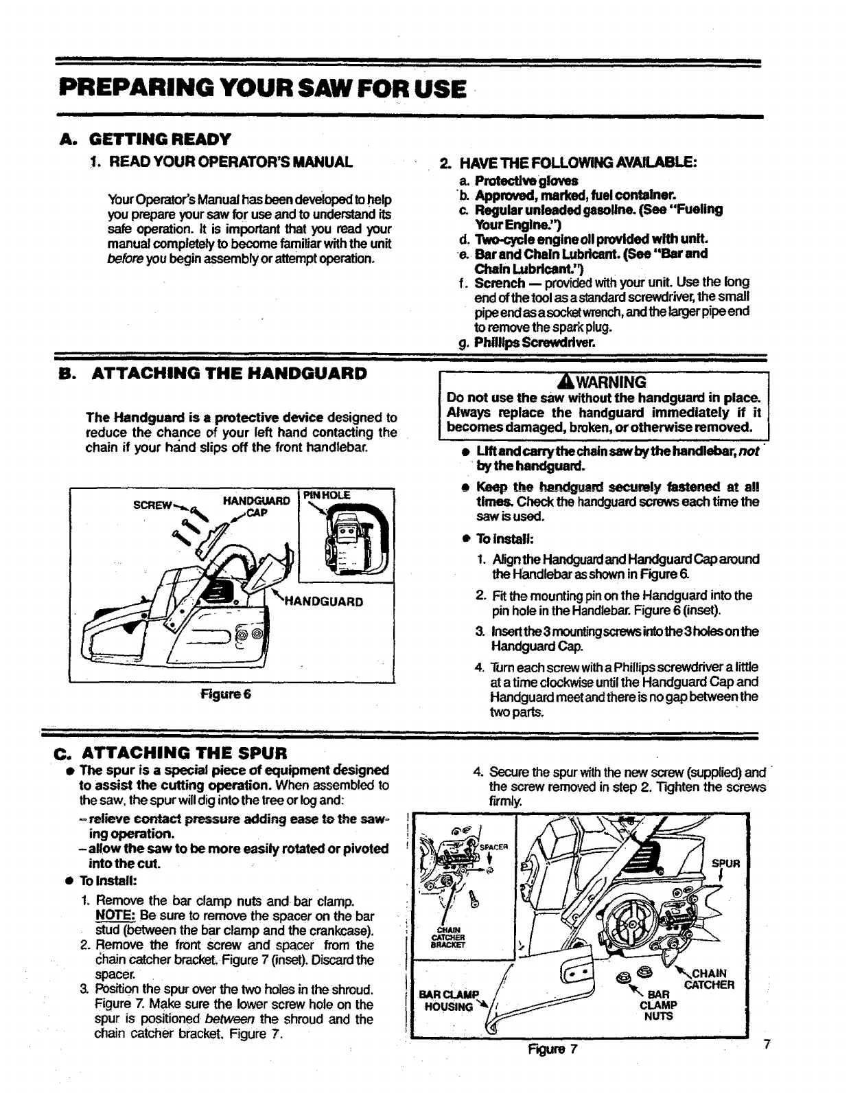
B. ATTACHING THE HANDGUARD
The Handguard is aprotective device designed to
reduce the chance of your left hand contacting the
chain if your hand slips off the front handlebar.
Figure6
HANDGUARD PINHOLE
UARD
i
2. HAVE THE FOLLOWING AVAILABLE:
_
•,,!,,;;,;;...................
a. Proteotivegloves
"b. Approved, marked, fuelcontainer.
c_ Regular unleaded gasoline. (See "Fueling
Your Engine.")
d. Two-cycle engine oil provided with unit.
e.. Bar and Chain Lubricant. (See "Bar and
Chain Lubdcant")
f. Scrench -- providedwithyour unit. Use the long
end ofthetoolas astandardscrewdriver,the small
pipeendasasockBtwrench,andthe largerpipeend
to removethe sparkplug.
Phtlllps Screwddver.
, ,_,;,,,I.................. ' , , '......................................""_" ' ':
AWARNING
Do not use the saw withoutthe handguard in place.
Always replace the handguard immediately if it
becomes damaged, broken, or otherwise removed.
• Uftandcorrythechalnsawbythehandlebar, not"
by the handguard.
•Keep Lhe .handguardL_,N:_mly fastened at a!!
times. Check the handguardscrews each time the
sawis used.
•To Install:
1. Alignthe HandguardandHandguardCaparound
the Handlebarasshownin Figure 6_
2. Fit the mountingpinonthe Handguard intothe
pin holein the Handlebar.Figure6 (inset).
3. Insertthe3 mountingscrewsintothe3holesonthe
HandguardCap.
4. Turneach screwwitha Phillipsscrewdnver a little
ata time clockwiseuntilthe HandguardCap and
Handguardmeetandthere is nogap between the
two parts.
' ....... """':"':' "'" .... ' iiiiiiiiiii 'iiiii]1_11111_111iiii .......... i
C. ATTACHING THE SPUR
• The spur is a special piece of equipment designed
to assist the cutting operation. When assembledto
thesaw. the spurwilldigintothe tree orlogand:
=relieve contact pressure adding ease to the saw-
ing operation.
-allow the saw to be more easily rotated or pivoted
into the cut.
•To Install:
1. Remove the bar clamp nuts and-bar clamp.
NOTE: Be sure to remove the spacer on the bar
stud (betweenthe bar clamp and the crankcase).
2. Remove the front screw and spacer from the
chaincatcherbrackeLFigure 7 Onset).Discardthe
spacer.
3. Positionthe spur overthe two holes inthe shroud.
Figure 7. Make sure the lower screw hole on the
spur is positioned between the shroud and the
chain catcher bracket. Figure .7.
,,,i,,,,,i_ -, ................... ,,,,,,,,,,,,,,,,,,,,,
4. Securethe spurwiththe new screw(supplied)and
the screw removedin step 2. Tighten the screws
firmly.
Figure 77
. ii iiiiiii ii IIIIIHIIIIIIIIIIIII II Jill III IIII IIIIIII IIH IIIIIIIIIIIIIIIIIIIIIIIIIIIIIIIIIIIIIIIII •
"1 _m,r .... ,, ,,,,,I_UII,I,I I I .=, _,,, ii
DI
Wear protective gloveswhan handltng
or _yoursaw. Thechain ISsharpandcan _.t
you even when it Is not movingl
• Your saw isequipped with aReduced-KIckbeck
Guide Bar and a Low-Kickbeck Chain.
• Use onlythe Reduced-Kickback GuideBarand
Low-Kickback Chain specified for your chain
s_rw model when replacing these parts. See
"Specifications:'
z
1 AWARNING
Do not start engine without guide bar end chain com-
pletMy asumbisd. Otherwise, the dutch can come off
and serious'Injury can moult.
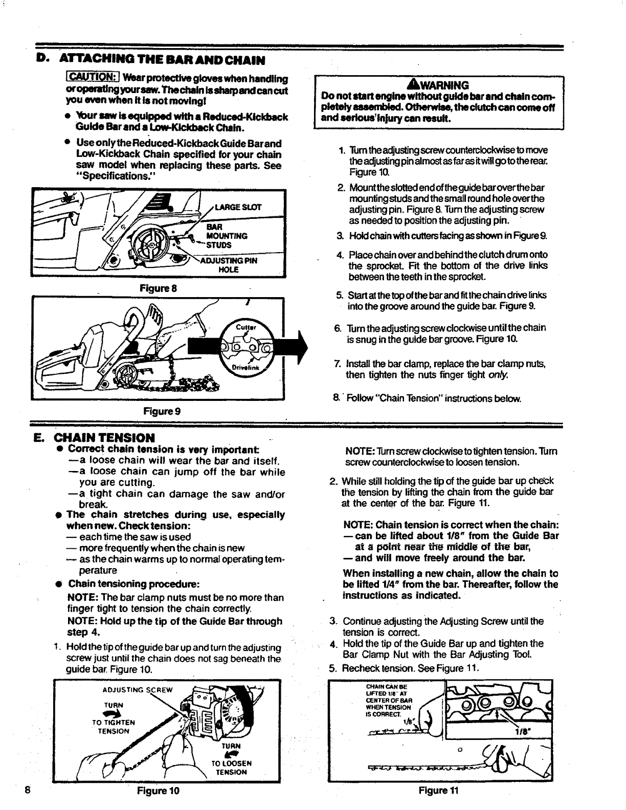
1. Tumtheadjustingscrewcounterclockwisetomove
theadjustingpinalmostasfar asitwillgotother_.
Figure 10.
2. Mounttheslottsdendoftheguidebaroverthebar
Figure 8
4.
.
7.
Figure 9
E. CHAIN TENSION
• Correct chain tension is very important:
--a loose chain wilt wear the bar and itself.
--a loose chain can jump off the bar while
you are cutting.
--a tight chain can damage the saw and/or
break.
• The chain stretches during use, especially
when new. Check tension:
each time the saw is used
-- more t_requentiywhen the chain isnew
as the chain warms up to normaloperatingtem-
perature
• Chain tensioning procedure:
NOTE: The bar clamp nuts must be no more than
finger tight to tension the chain correctly.
NOTE: Hold up the tip of the Guide Bar through
step 4.
1. Holdthetipof theguide barupandturnthe adjusting
screw just untilthe chain does notsag beneath the
guide bar. Figure10.
ADJUSTING SCREW
TURN
TO LOOSEN
TENSION
TURN
TO TIGHTEN
TENSION
Figure 10
.
mountingstudsandthesmallroundhole overthe
adjusting pin.Figure8 Turnthe adjustingscrew
as neededtopositionthe adjustingpin.
HoldchainwithcuttersfacingaSshowninFK:jure9.
Place chainoverandbehind theclutchdrumonto
the sprocket.Fit the bottom of the ddve links
between the teeth inthe sprocket.
Startatthetopofthe barandfitthechaindrivelinks
into the groovearoundthe guidebar. Figure9.
Tumthea_usting screwclockwiseuntilthe chain
issnug inthe guide bargroove.Figure 10.
installthe bar clamp,replace the bar clamp nuts,
then tightenthe nuts finger tight on_
8."Foliow"ChainTension"instructionsbelow.
IIIIIHIII
NOTE: Turnscrewclockwisetotighten tension.Turn
screwcounterclockwiseto loosentension,
While still holdingthe tipof the guidebar up che_k
the tension by liftingthe chain fromthe guide bar
at the center of the b_ Figure 11.
NOTE: Chain tension is correct when the chain:
--can be lifted about 1/8" from the Guide Bar
at a point neat the middle of the bar,
--and will move freely around the bar.
When installing a new chain, allow the chain to
be lifted 114"from the bar, Thereafter, follow the
instructions as indicated,
3. Continueadjustingthe AdjustingScrew untilthe
tension is correct.
4. Holdthe tip of the Guide Bar up and tightenthe
Bar Clamp Nut with the Bar Adjusting Tool.
5. Rechecktension. See Figure 11.
11
Figure 11
ii,lllll
F. FUEUNG YOUR ENGINE
1. FUEL SAFETY
a. Use only recommended fuel mixtures.
b. MIx and pour fuel outdoors and where there are
no sparks or flames.
c. Use a container approved for fuel.
d. Do notsmoke or allow smoking near fuelor the
tool or while using the tool.
e. Wipe up all fuel spills before starting engine.
h Move at least 10 feet away from fueling site
before starting engine.
g, Stop engine before removing fuel cap. Allow
the engine to cool before refueling.
h. Before storing the tool, use up fuel left in the
carburetorand fue!linesbystartingthe engineand
letting it run until it stops.
i. Store tool and fuel in an area where fuel vapors
cannot reach sparks or open flames from water
heaters, electric motors orswitches, furnaces,
etc.
2. FUEL MIXTURE
* Your tool Is powered by • two-cycle engtne
which requires a fuel mixture of regular
•unleaded ga=ollne and ahigh quality engine oll
specially made for 2-cycle, air cooled engines.
The internal designof the 2-cycleengine requires
lubricationof moving parts.Lubricationisprovided
when therecommendedmixture ofgasolineandoil
is used.
•Gasoline must be clean andnot overtwo months
old. Gasolinewill chemicallybreakdown andform
compoundsthatcause hardsta_ingand damage in
2-cycle engines.
important. Toomuchoil inthe mixturewill foulthe
spark plug.
[CAUTION:!Toolittle oil or incorrect oil will cause
the engine to overheat and seize.
• Always mix the fuel thoroughly in a container
sincegasolineandoildonotreadilycombine.Donor
mix gasolineand oi!directlyinthe fuel tank.
3. USE THE FOLLOWING ONLY:
SEARS CRAFTSMAN 2-CYCLE ENGINE OIL
MIXED AT 40:1 IS*STRONGLY RECOMMENDED.
CONSULT THE INSTRUCTIONS ON THE OIL
CONTAINER FOR PROPER MIXING.
1 Part Oil to 40 Parts Gasoline :
3.2 FI Oz Oil to 1 Gallon Gasoline
8.0 FI Oz Oil to 2.5 Gallon Gasoline
Not allair-cooledengine oilshavethe same qual-
ities.If Sears Craftsman2-cycleengine oil is not
available, use agood quality,2-cycle engine oil
recommendedfor air-cooledengines Mixat a ratio
of 16:1(8 07. oilto 1 gallon gasoline).A 16:1 fuel
mixturewith these oilswillassureadequate lubri-
cationfor your engine.
4. DO NOT USE:
• NMMA Oil -- National Marine Manufacturers
Association {formerly BIA)
Does not have proper additivesfor 2-cycle, air-
cooledengines and can c_use engine damage.
• AUTOMOTIVE OIL --
Does not have proper additives for 2-cycle, air-
cooledengines and can cause engine damage.
CAUTION
Experience indicates that alcohol blended fuels (called
gasohol or using ethanol or methanol) can attract
moisture which leads to separation and formation of
acids dudng storage. Acidic gas can damage the fuel
system of an engine while in storage.To avoid engine
problems, do not leave fuel in the unit when storing
for 30 days or longer. Start the engine and let it run
untilthe fuel lines and carburetor are empty. Use fresh
fuel next season. See the "Storage" section for addi-
tional information. Never use engine or carburetor
cleaner pmdu,#_s in the fuel tank or permanent
damage can occur.
NOTE: if youdo not want to removethe gasoline
from your unit, SEARS CRAFTSMAN Fuel
Stabilizer(#71-33500) may be added to gasoline
te_ in the tank to minimize gum deposi_ and
adds. If the tank is almost empty, mix stabilizer
with fresh gasoline in aseparate containerand
add to the tank.
5. HOWTO MiX FUELAND FILL TANK
a. pourthe proper measure of engine oil intoan approved,
marked container. The, fill the container with regular
unleaded gasoline,
NOTE: If fuel is already in the container, add the proper
measureof engine oil. Then, closethe containertightlyand
sh_i it momentarily.
NOTE.'Do not mix gasoline and oi/ dimcth/in the rue/tank.
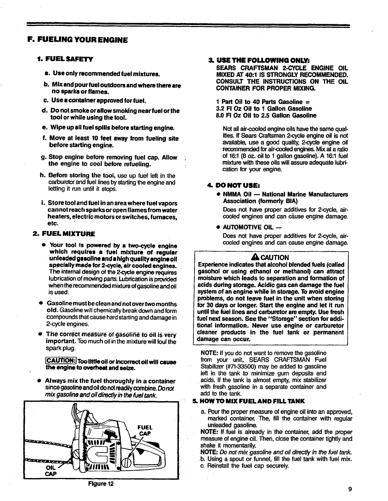
b, Using aspout or funnel, fill the fuel tank with fuel mix,
c. Reinstal!the fuel cap securely.
Rgure 12 9
O. liAR AND CHAIN LUBRICANT 3. ADJUSTING THE AUTOMATIC OILER
.
o
• The Guide Bar and Cuttingchain mquirecon.
tinuous lubricationto remaininoperating con*
dition. Lubricationis providedby the automatic
oilersystemwhenthe oiltank iskeptfilled.
-- Lack ofoil willquloldyruinthe barandchain.
-- Toollttle oil wiltcauseoverheatlngshownby
smokecomingfromthechainand/ordiscolora-
tionof the guidebar rails
eUse Sears Bar and Chain Lubricant (#71-36554-
gal. or #71-36556-qt.) to fill the oil tank. CleanSAlE
3(7,Noil may alsobe used, butis lesseffective.Never
use waste oil for 1hispurpose.
• Infreezingweatheroilwillthicken, making itneces-
sary to thin bar and chain oil with asmall amount
of#1 Diesel FuelorKemsene. Barandchainoilmust
be free flowingforadequatelubrication.
usE THE FOLLOWING:
30° or above -- Lubricantundiluted
30°to 0°F, -- 950/oLubricant to 5%
#1 Diesel fuel or Kerosene.
Below OOF. -- 90% Lubricant to 10%
#1 Diesel fuel or Kerosene.
HOW TO RLL THE OIL TANK
a. Stopthe engine,
b. 7am sawon itssidewithoilcap up. Figure 12.
c, Loosencapslowlyandwaitfor pressureinthe tank
to be releasedbeforeremovingthe cap.
d. Fillthe oiltank,
e. Replace the oilcap securely.
!
Figure 13
111"1 "1 m l_ IIIIIIIIIIIIIIII II 11111/IIII I I1!11111// I IIIIIIII
.
e
e
e
o
The adjustable automatic oiler_sot for max-
imum output at the factory. Some types of
cutting will require adjusting the oiler.
-- less oil is required for soft or freshly cut
wood.
-- maximum oil is required for bardwood or
wood that has beancut for aperiod of time.
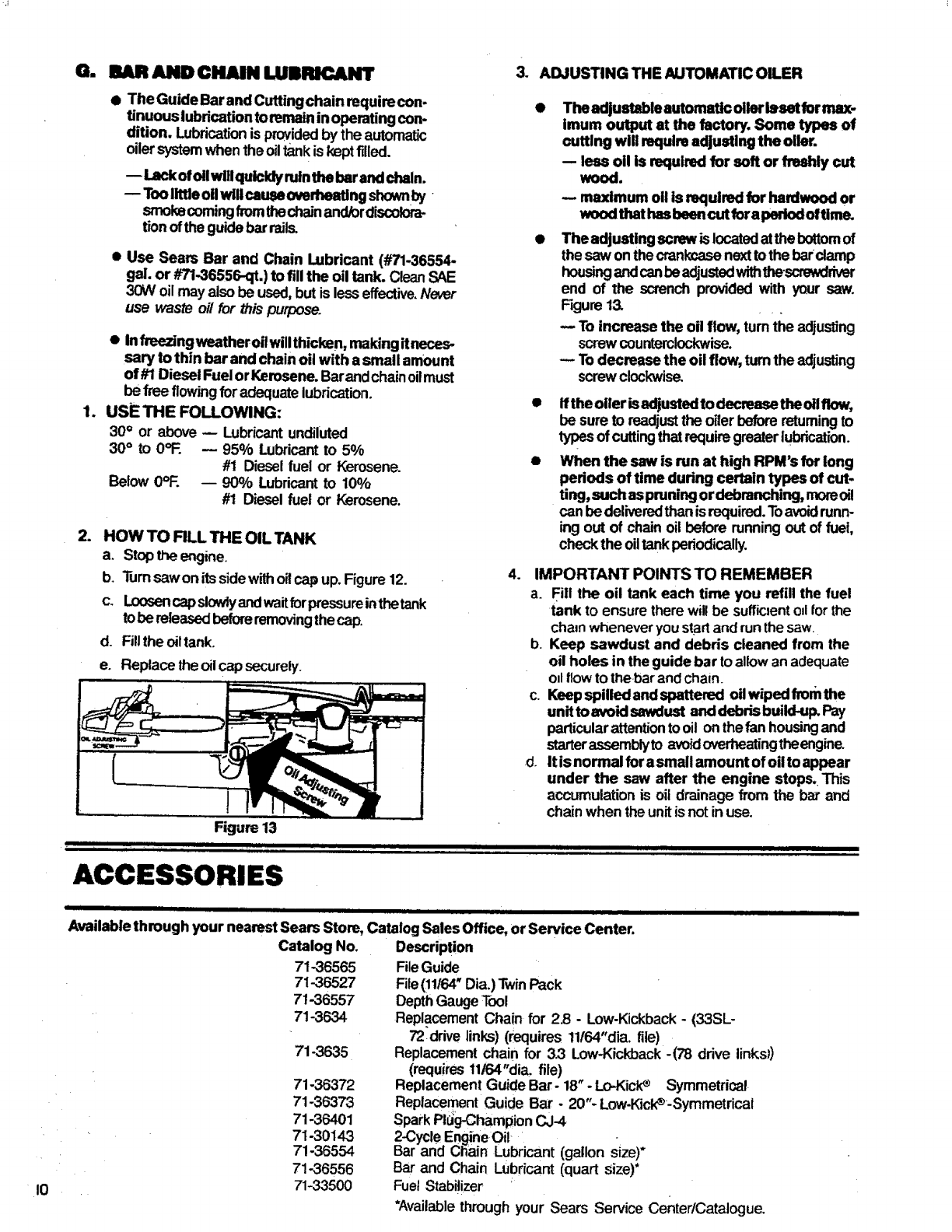
The adjusting screw islocatedatthe bottomof
the saw onthe crankcasenexttothe barclamp
housingandcanbeadjustedwiththe,screwdriver
end of the scrench provided with your saw.
Figure 13. ,_,
-- To increase the oil flow, turn the adjusting
screwcounterclockwise.
-- Todecrease the oil flow, turnthe adjusting
screwclockwise.
tfthe oiler isadjustedto decrease the oil flow,
be sureto readjustthe oilerbefore returningto
types of cuttingthatrequiregreaterlubrication.
When the saw is run at high RPM's for long
pedods of time during certain types of cut-
ring, such aspmning or debmnching, moreoil
can be deliveredthanis required.Toavoidrunn-
ing out of chain oil before runningoutof fuel,
checkthe oiltankperiodically.
IMPORTANT POINTS TO REMEMBER
a. Fill the oil tank each time you refill the fuel
tank to ensure therewill be sufficientodfor the
chain whenever youstartand runthe saw
b. Keep sawdust and debris cleaned from the
oil holes in the guide bar to allowan adequate
oilflow to thebar and chain.
c. Keepspilled and spattered oUwiped fromthe
unit toavoid sawdust and debds build-up.Pay
particularattention tooil onthe fan housingand
starterassemblytoavo{doverheating theengine.
d. It isnormal for asmail amount of oiito appear
under the saw after the engine stops. This
accumulation is oil drainage from the bar and
chain when the unitis not inuse.
I I /I I IJlIIlU I Jill
ACCESSORIES
10
II i I i iiii i i HI ,...............................
Available through your nearest Sears Store, Catalog Sales Office, or Service Center.
Catalog No.
71-36565
71-36527
71-36557
71-3634
71-3635
71-36372
71-36373
71-36401
71-30143
71-36554
71.,36556
71-33500
Description
FileGuide
File (11/64"Dia.)Twin Pack
Depth Gauge Tool
Replacement Chain for 2,8 - Low-Kickback - (33SL-
72 drive links) (requires 11/64"dia. file)
Replacement chain for 33 Low-Kickback -(78 drive linksl)
(requires 11i64"dia. file)
Replacement Guide Bar- 18" - Lo-Kick_ Symmetrical
Replacement Guide Bar - 20"-Low-Kicl_-Symmetrical
SparkPl(_g-ChampionCJ4
2-CycleEngineOil-
Bar and Chain Lubricant (gallon size)*
Bar and Chain Lubricant (quart Size)*
Fuel Stabilizer
*Available through your Sears Service center/Catalogue,
I IIIIIIII I IIIIIIIIIIIIIIIIIIIIIII II I 711111111111II IIII I I
USING YOUR SAW
II i ! i ]11111
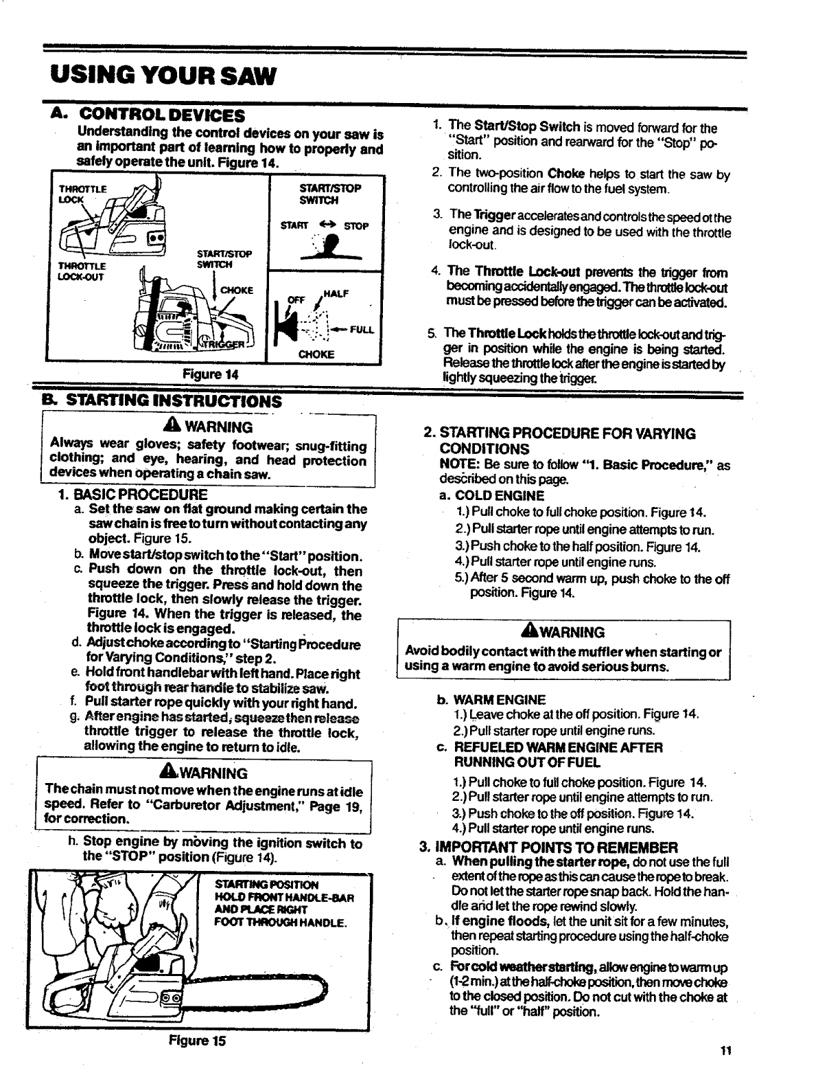
A. CONTROL DEVICES
Understanding the control devices on your saw is
an important part of leamlng how to properly and
safely operate the unit. Figure 14.
START/STOP
SWITCH
STAre <"Y STOP
'(_ WARNING
Always wear gloves; safety footwear; snug-fitting
clothing; and eye, hearing, and head protection
devices when Operating a chain saw.
1. BASIC PROCEDURE
a. Set the saw on fiat ground making certain the
sawchain is free to turn without contacting any
object. Figure 15.
b. MovestartJstopswitch to the"Start" position.
c. Push down on the throffle lock-out, then
squeeze the trigger. Press and hold down the
throttle lock, then slowly release the trigger.
Figure 14. When the trigger is released, the
throttle lock is engaged.
d. Adjustchokeaccordingto "Startingl_rocedure
for Varying Conditions," step 2.
e. Hold front handlebar with left hand.Place right
foot through rear handle to stabilize saw.
f. Pull starter rope quickly with your right hand.
g, Afterengine has started_squeezethen release
throttle trigger to release the throttle lock,
allowing the engine to return to idle.
t _I_WARNING
The chain must not move when the engine runs at idle
speed. Refer to "Carburetor Adjustment;' Page 19,
tfor correction.
h. Stop engine by m_ving the ignition switch to
the"STOP" position (Figure 14).
HOLD F-HONTHANDLE-BAR
ANDPLACEiW'.,HT
FOOT THROUGH HANDLE.
1. The Start/Stop Switch is moved forward for the
"Start" positionand rearwardfor the "Stop" po-
sition.
2. The two-positionChoke helps to startthe sawby
controllingthe airflowtothe fuelsystem.
.
.
The Triggeracceleratesandcontrolsthespeedotthe
engine and is designedto be usedwith the throttle
lock-out
The Throttle Lock-out prevents the trigger from
becomingaccidentallyengaged.Thethrottlelock-out
mustbe pressedbeforethetriggercanbe activated.
5. The ThrottleLockholdsthethrottlelock-outandtrig-
ger in positionwhile the engine is being started.
Releasethe throttlelockaftertheengine isstarl_ by •
lightlysqueezingthetrigger.
....i_.......... ,,,i,,i H,,,I ,,,,I I m||m I ii IllilillllllilI I I
2. STARTING PROCEDURE FOR VARYING
CONDITIONS
NOTE: Be sure to follow"1. Basic Procedure," as
describedonthispage.
a. COLD ENGINE
1.)Pullchoketo fullchokeposition. Figure14.
2) Pull starterrope untilengineattemptsto run.
3.)Push choketothe halfposition. Figuret4.
4.) Pullstarterrope untilengineruns.
5.)After 5 secondwarm up, push choketo the off
position.Figure 14.
_WARNING
Avoidbodily contact with the muffler when starting or
using a warm engine to avoid serious bums,
b. WARM ENGINE
1.)Leave chokeat theoffposition.Figure 14.
2.) Pullstarter ropeuntilengine runs.
c. REFUELED WARM ENGINE AFTER
RUNNING OUT OF FUEL
1.) Pullchoketo full chokeposition.Figure 14.
2.) Pullstarter ropeuntilengine attempts to run
3.) Pushct'_ke tothe offposit_on.Figure14.
4.) Pull starter ropeuntilengine runs.
3. IMPORTANT POINTS TO REMEMBER
a. When pulling the starter rope, donotuse thefull
extentofthe ropeasthiscancausetheropetobreak.
Do notletthe starterropesnap back.Holdthe han-
dle ar,d let the roperewindslowly.
b. If engine floods, letthe unitsit fora few minutes,
thenrepeatstartingprocedureusingthe half-choke
position.
c. Foreold weathorstarting, allowengir_towarmuP
(1-2rain.)atthehalf-cho_ position, thenmoveclio_
tothe closedpos'_ion.Do notcutwiththe chokeat
the "full" or "haft" position.
Figure 15 11
TYPES OF CUTTING
HillIIII II I
A. BASIC CUTTING TECHNIQUE
1. IMPORTANT POINTS.
a. Cut wood only, Do not cut metal, plastics,
ma._nr'f,non-woodbuildingmaterials,etc:Donot
use yoursawto pryorshoveawaylimbs,roots,or
otherobjects.
b. Stop the saw tf the chain strikes aforeign
object. Inspect the unit and repair or replace
partsasnecessary.
c. Keep the chain out of dirt and sand. Evena
smallamount of dirt willquick_ dulla chainand
increasethe possibilityof kickbacl_
AKICKBACK WARNING
Kickbackcan occur when the moving chain contactsan
object st the upper portion of the tip of the guide bar or
when the wood closes in and pinches the saw chain in
the cut. Contact at the upper portion of the tip of the
guide barcan causa the chsin to dig into the object and
stop the chain foran instant. The result is s lightning
fast, reveme reaction which kicks the guide bar upand
back toward the operator. If the saw chain is pinched
along the top of the guide bar, the guide bar can be
drivenrapidlybacktowardtheoperator. Eitherof these
reactions can cause loss of saw control which can
result in serious/injury.
2. UNDERSTAND REACTIVE FORCES
Pinch-Kickback and Pult-ln occur when the chain
is suddenly stopped by being pinched, caught, or
by contacting a foreign object in the wood. This
resultsinareversalofthe chainforceusedto cutwood
•andcausesthesawto moveintheoppositedirectionof
chain rotation.Either reactioncan resultinloss ofcon-
trotand aossibleserious personalinjury.
•Pinch-Kickback
-- occurswhenthe chain ontop ofthe bar is suddenly
stoppedwhenthe topofthe baris usedfor cuing.
-- rapidly drives the saw straight back toward the
I I I I IIIlll I II I I Illl IJll
3. PROCEDURE
Practk_cuttingalewsmalltogsusingthefo_wing ted-,ni-
quetogetthe'feel" ofusingyoursawbeforeyoubegina
maw sawingoperation.
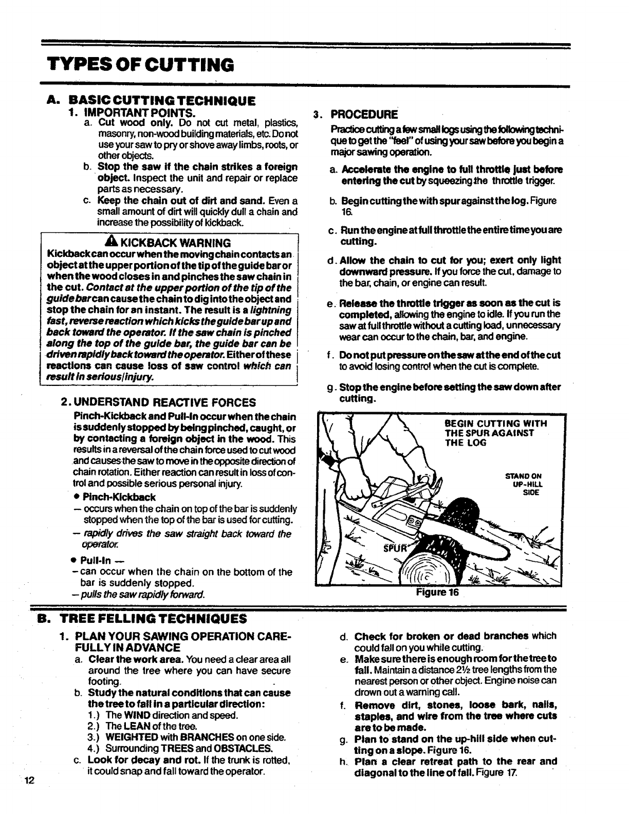
a. Accelerate the engine to full throttle Just before
entering the cut bysqueezingthe throttletrigger.
b. Begin cutting thewith spuragainstthe log. Figure
16
c. Run the engineat full throttle the entiretimeyou are
cutting.
d. Allow the chain to cut for you; exert only light
downward pressure. If youforce the cut, damageto
the bar, chain,orengine can result.
e. Release the throttle trigger as soon as the cut is
completed, allowingthe engineto idle.If yourunthe
sawat full throttlewithouta cuttingload,unnecessary
wear can occurtothe chain, bar,andengine.
f. Donot put pressureonthesawat theend ofthe cut
to avoid !osingcontre!when the cut iscomplete.
g. Stop the engine before setting the saw down after
cutting.
12
•Pull-In
-can occur when the chain on the bottom of the
bar is suddenly stopped.
-pulls the saw rapidly forward.
B. TREE FELLING TECHNIQUES
Figure 16
=PLAN YOUR SAWING OPERATION CARE-
FULLY IN ADVANCE
a. Clear the work area. Youneed a clear area all
around the tree where you can have secure
footing.
b. Study the natural conditions that can cause
the tree to fall in aparticular direction:
1.) The WIND directionand speed.
2.) The LEAN of the tree.
3.) WEIGHTED with BRANCHES on oneside.
4.) SurroundingTREES and OBSTACLES.
c. Look for decay and rot. If the trunk is rotted,
itcould snap and fall toward the operator.
d. Check for broken or dead branches which
could fal! on youwhile cutting.
e. Makesure there is enough room for thetreeto
fall. Maintainadistance21/2tree lengthsfromthe
nearestpersonorother object.Engine noisecan
drownouta warningcall.
f. Remove dirt, stones, loose bark, nails,
staples, and wire from the tree where cuts
are to be made.
g. Plan rostand on the up-hill side when cut-
ting on a slope. Figure 16.
h. Plan s clear retreat path to the rear and
diagona! to the line of fall. Figure 17.
2. FELUNG SMALL TREES _LESS THAN 6"
IN DIAMETER
aIfyou knowthedirectionoffall:
1.) Make asingle,horizontalfelling cut on the
side away from the directionof the fall.
2.) CutallLheway through.
3.) Stop the saw, put it down, and get away
quicklyonyourplannedretreatpath.
b. If you are not sure which way the tree willfall,
use the notchmethod describedforfellinglarge
trees.
AWARNING
IX) NOT CUT:
near electrical wires or buildings.
if you do notknow the direcUon of tree fall.
_at night since you will not be able to see well.
--during bad wealher _strong wind, snow, rain,
etc.
1FELMNG LARGE TREES -- 6" DIAM_
OR MORE
The notch method is used to cut large trees. A
notch is cut on the side of the tree in the desired
direction of fall. After a felling cut is made on the
opposite side of the tree, the tree will tend to fall
intothe notch.
Rgure 17 Figure 18
_,,,,,,,,,,,, ,
l-t
<l,===,,m,_ zt
I_F*_JL |_! I Cut-
lcut 2 ....,.["i It" ."_-"
lwr_tKx_ls'
t_ID _'rNE FMJ-
Figure 19 Rgure 20
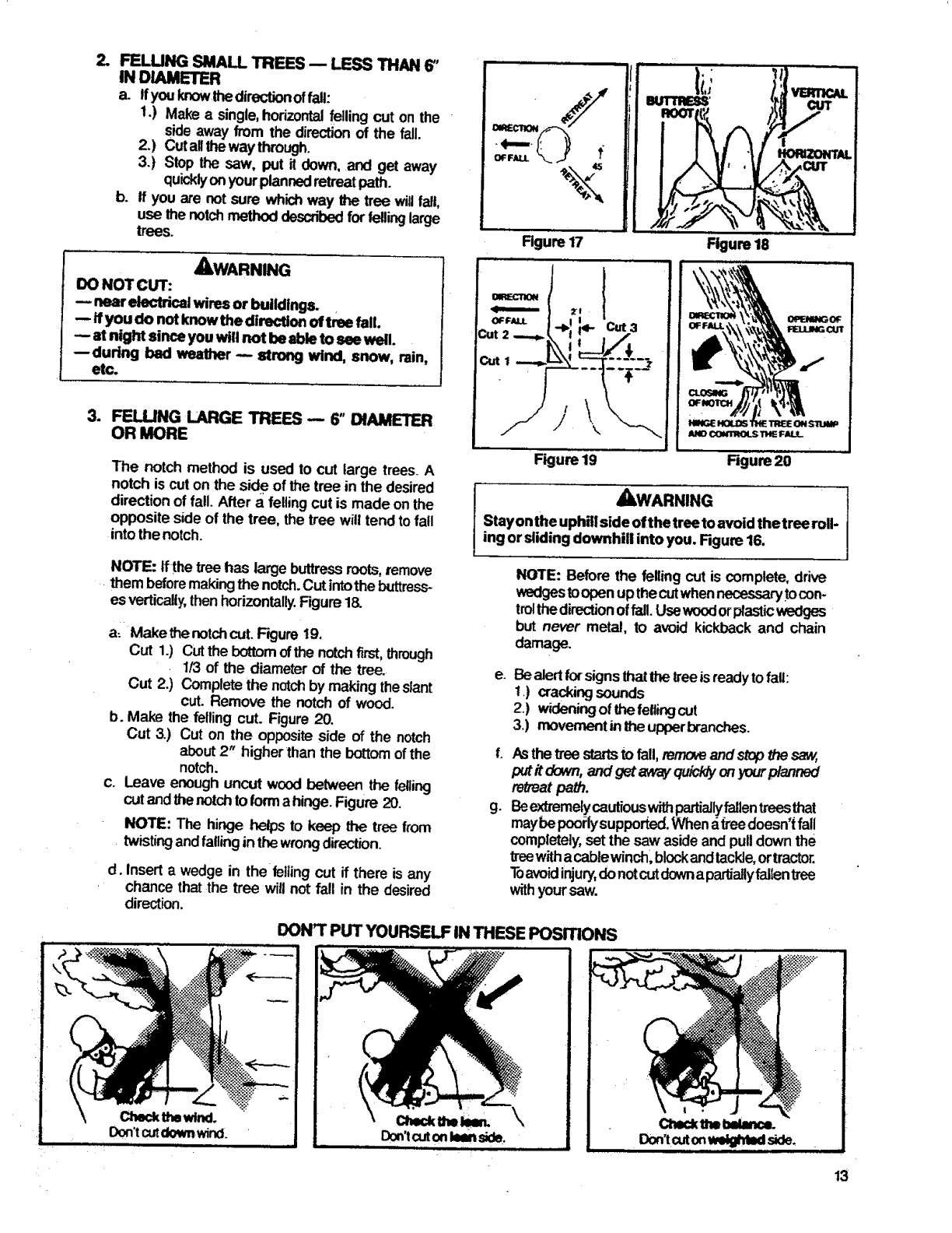
AWARNING
Stay onthe uphill side of the tree to avoid the tree roll-
ing or sliding downhill into you, Figure 16.
NOTE: Ifthe tree has large buttress roots,remove
. them before makingthe notch.Cutintothe buttress-
es vertically,thenhorizontally.Figure 18.
al Make the notchcut. F_ure 19.
Cut 1.) Cutthe bottomofthe notchfirst, through
1/3 of the diameter of the tree.
Cut 2.) Completethe notchby making the slant
cut. Remove the notch of wood.
b. Make the felling cut. Figure 20.
Cut 3.) Cut on the oppositeside of the notch
about 2" higherthan the bottomof the
notch.
c. Leave enough uncut wood between the felling
cut andthenotchto formahinge. Figure 20.
NOTE: The hinge helps to keep the tree from
twisting andfailing in the wrongdirection.
d, insert awedge in the felling cut if there is any
chance that the tree will not fall in the desired
direction.
e.
g.
NOTE: Before the felling cut is complete, drive
wedgestoopen up the cutwhennecessarytocon-
trolthe directionof fall. Usewoodorplasticwedges
but never metal, to avoid kickback and chain
damage.
Be alertforsigns thatthe treeis readyto fall:
t.) crackingsounds
2.) wideningof thefeilingcut
3,) movement inthe upperbranches.
Asthe tree stadsto fall,_andstopthe sa_,
putit down,and get awayqu'_Vyonyourp/anneal
re, at path.
Beextremelycautiouswithpartiallyfallentr__,that
maybepoodysupported.Whenatree doesn ifal!
completely, set the saw aside and pulldown the
treewithacable winch,block andtackle,or tractor.
Toavoid injury,donot cut downapartiallyfallen tree
withyoursaw.
DON'T PUT YOURSEU =IN THESE POSITIONS
¸
13¸
III IIlll --.,.,,, lllll_iiiiiiiiiiiiiiiiiiiiiiiiiiiiiiii ....... III III IIII II I ] II I I I : I I I I •
!4
C; BUCKING
Bucking is the term used for cutting a fallen tree
to the desired log size,
1. IMPORTANT POINTS
a,
b.
C,
dr
e.
CutonlyoneIogata _me.
Cut shattered wood very carefully. Sharp
pieces of w(xx:l could be flung toward the
operator.
Use a sawhorse to cut small logs. Never
allow another personto holdthe togwhile cut-
ringand neverholdthetogwithyour legor foot.
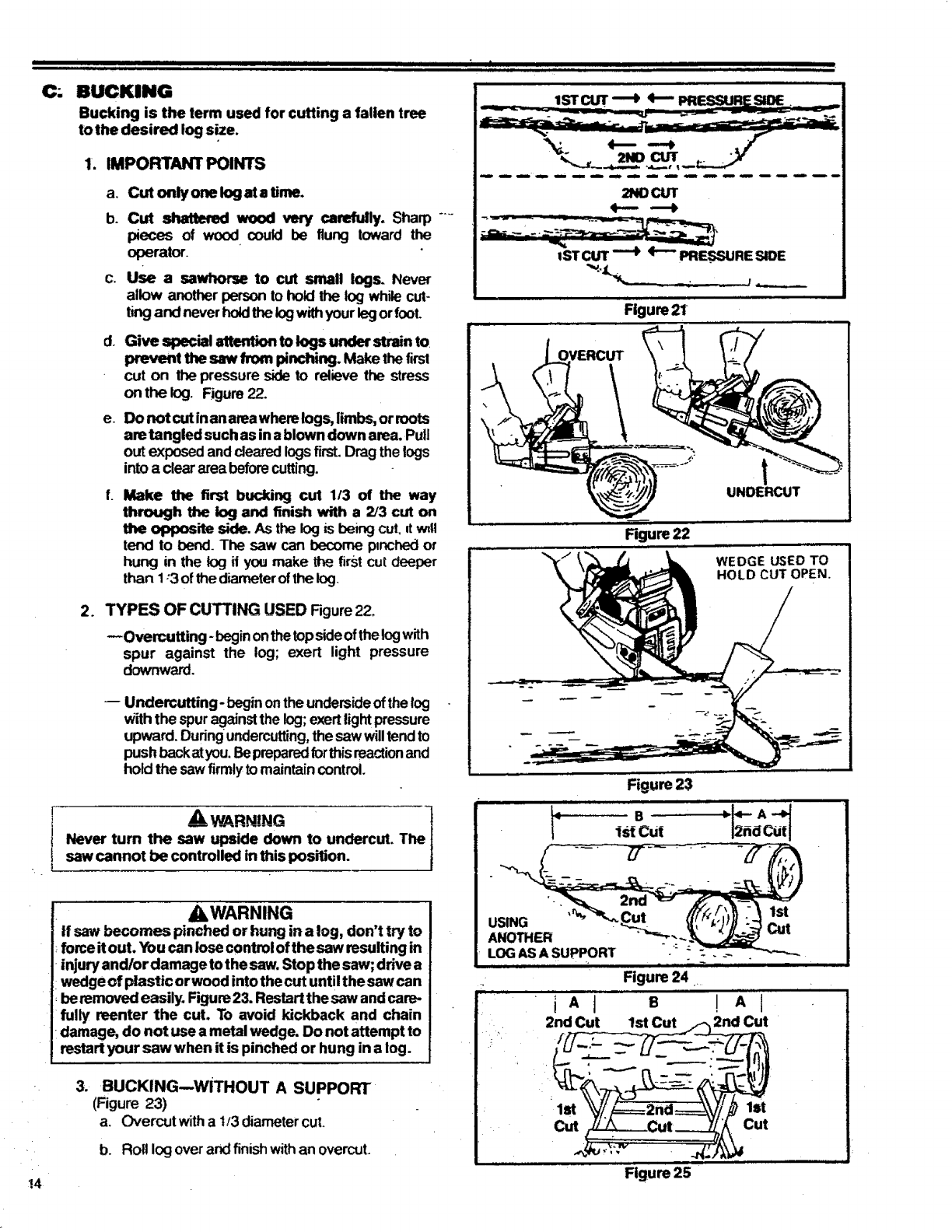
Give special attention to logs under strain to
prevent the saw from pinching. Make the first
cut on the pressure side to relieve the stress
on the log. Figure 22.
Do not cut inan area wherelogs, limbs, or roots
aretangled such as ina blown down area. Puff
out exposed andcleared logsfirst.Drag the logs
into acleararea beforecutting.
Make the first bucking cut 113 of the way
through the log and finish with a 2/3 cut on
the olpposite side. As the log is being cut, d wdl
tend to bend. The saw can become ptnched or
hung in the log if you make the first cut deeper
than 1:3 of the diameter of the log.
2. TYPES OF CUTTING USED Figure 22.
--Ovemutting- beginonthe topsideofthe logwith
spur against the log; exert light pressure
downward.
Undercutting- beginonthe undersideof thelog
Withthe spuragainstthe log;exertlightpressure
upward. Dudng undercutting,the saw willtendto
push backatyou.Bepreparedfor thisreactionand
hold the sawfirmlyto maintaincontrol.
,,r_A WARN!HG
tever turn the saw upside down to un_mut. The
saw cannot be controlled in this position.
AWARNING
if saw becomes pinched or hung in a log, don't try to
forceit out. You can losecontrolofthesaw resulting in
injury and/or damage to the saw, Stop the saw; drive a
wedge of plastic or wood into the cut unti !the saw can
beremoved easily. Figure23. Restartthe saw and care-
fully reenter the cut. To avoid kickback and chain
damage, do not use a metal wedge. Do not attempt to
restart your saw when it is pinched or hung in a log.
3. BUCKING--WiTHOUT A SUPPORT
(Figure23)
a. Overcut witha t/3 diametercut.
b. Rol! log overandfinish withan overcut.
ISTCljrT _ 4---- PRESSURESIOE__
2NOCUT
ISTCUT _4"-'- PRESSUREStOE
i i HH I =, I
Figure 21
//
UNOERCUT
Figure22
WEDGE USED TO
HOLD CUTOPEN.
/
Figure 23
_ B
1StCut 2nd
*,% 1st
,USING
.. Figure 24 ....
i A tB! Ai
Figure 25
4. BUCKING -- USING ANOTHER LOG AS A
SUPPORT (Figure 24)
jAWARNING
Do not stand onthe log beingcut, Any portion can roll
.using loss of foot!ng and control
a. inarea A:
1.)Undercut 1/3ofthewaythroughthelog.
2.) Finishwithan overcut.
b. Inarea B:
1.)Overcut 1/3ofthe waythrough the log;
2.) Finishw'rthan undercut.
5. BUCKING -- USING A STAND (Figure 25)
a. In area A:
1.)Undercut 1/3 ofthewaythroughthelog.
2.) Finishwithan overcuL USE COMMON SENSE
I_ In area B:
1.)Overcut1/3of the waythroughthe log.
2.)Finishwithan undercut.
MAINTAIN SECURE FOOTING
;,_,,,- ................." ' ....... :;;;; ;............ '_' - " : ,i,,,,,,_,_......................_,,,,,,,,;;;;;_,,,........................,..................: ,,i.................
D. DEBRANCHING AND PRUNING 2. PRUNING
•Work slowly, keeping both hands firmly gripped .a.
on the saw. Maintain securefootingandbalance.
• Watch out for spfingpoles. Use extreme caution
when cuttingsmall size limbs.Slender material can
catchthesaw chain-andbewhippedtowardyouorpull b.
you off balance.
•-Be alert for springback. Watch Outfor branches
that are bent or underpressure as yOUare cutting
to.avoidbeing struckbythe branchorthe saw when
the tension inthe woodfibersisreleased.
•Keep a clear workarea. Frequently,clearbranches
•outofthe wayto avoidtrippingoverthem.
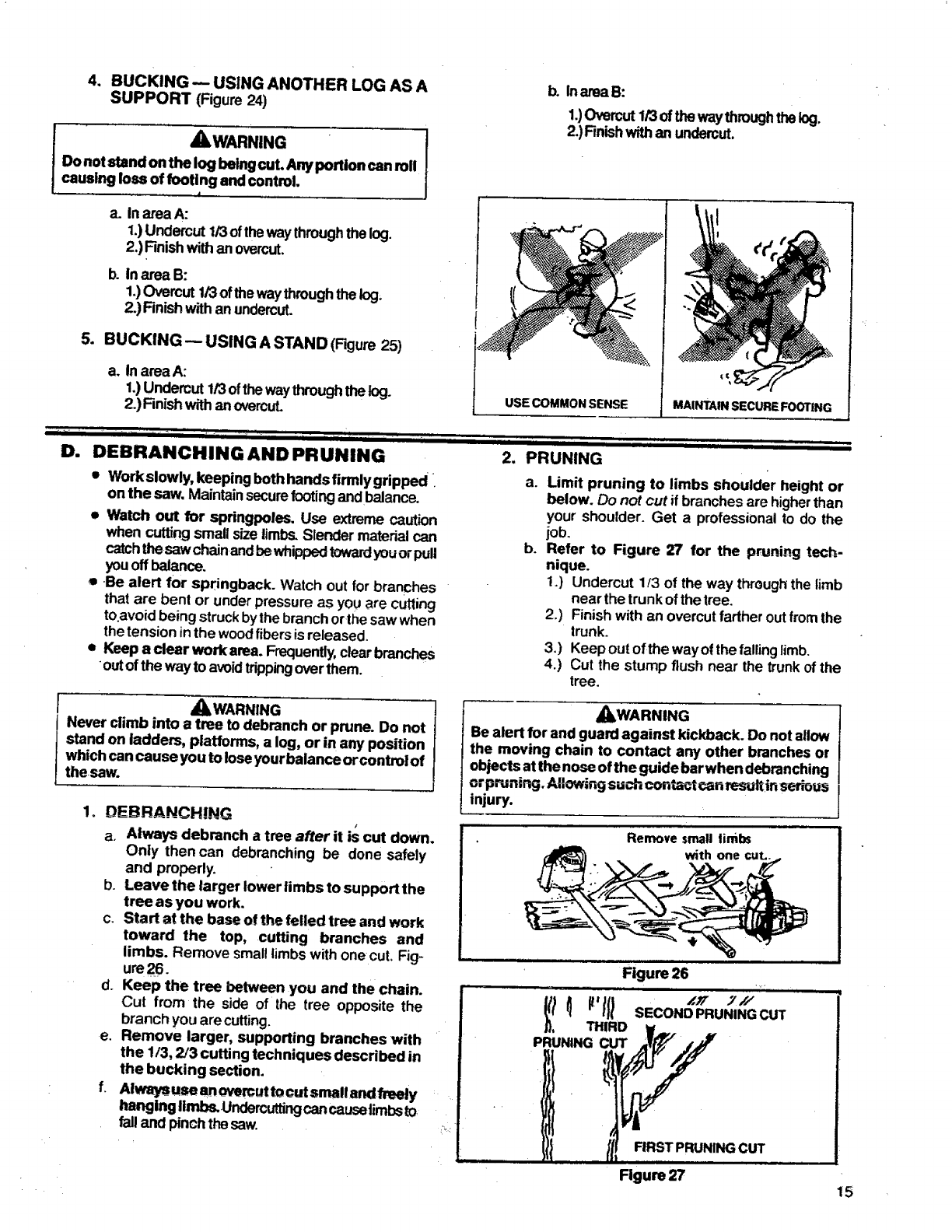
Limit pruning to limbs Shoulder height or
below. Do not cut if branches are higherthan
your shoulder. Get a professional to do the
job.
Refer to Figure 27 for the pruning tech-
nique.
1.) Undercut 1/3 of the way throughthe limb
near the trunkof the tree.
2.) Finish with an overcutfarther outfromthe
trunk.
3.) Keep out of the wayof thefalling timb.
4.) Cut the stump flush near the trunkof the
tree.
_kWARNING
Never climb into a tree to debmnch or prune. Do not
stand on ladders, platforms, a log, or in any position
which can cause you to loseyour balance orcontroi of
thesaw.
,DEBRANCH!NG /
a. Always debranch atree after it is cut down.
Only then can debranching be done safely
and properly.
b. Leave the larger lower limbs to support the
tree as you work.
c. Start at the base of the felled tree and work
toward the top, cutting branches and
limbs. Remove smal! limbswith one cut. Fig-
ure26.
d. Keep the tree between you and the chain.
Cut from the side of the tree opposite the
branch you are cutting.
e. Remove larger, supporting branches with
the 1/3, 2/3 cutting techniques described in
the bucking section.
f. Alwaysuseanovemuttocutsmallandfreely :
hanglng limbs. Undercuttingcancausetimbs to
falland pinchthe saw.
=_IbWARNING
Be alert for and guard against kickback. Do not allow
the moving chain to contact any other branches or
objects at the nose of the guide bar when debranching
orpruning. Allowingsuch,contact can resultin seriotJs
injury.
Removesmalllimbs
with one cut..
Figure 26
sEco.oP UN,NG =
THIRD
PRUNINGCUT
FIRSTPRUNINGCUT
Flgure 27 15
MAINTENANCE
A good maintenance program of regular inspec-
tion and care will increase the service life and help
to maintain the safety and performance of your
SaW.
* Checkthe sawfor loose bolts, screws, nuts, and
flffings regularly, Loose fasteners can cause an
unsafeconditionaswellasdamagetoyoursaw.Tools
requiredaredescribedonpage 7.
• Make all adjustments or repairs (except car-
buretor adjustments) with:
-- spark plug wire disconnected.
-- engine cool as opposed to a unit that has
just been run.
IIII
AI
A WARNING
Have all chain saw service performed bY your Sears
Service Centerwith the exception of the itemslisted
in the maintenance section ofthis manual
GUIDE BAR AND CHAIN
Increase the service life of your Guide Bar and
Chain by:
--Using the saw propedy and as recommended
in this manual.
--Maintaining correct Chain Tension, page'9.
--Proper lubrication, page 10.
-.-Regular maintenance as described in this sec-
tion.
1. CHAIN MAINTENANCE
• Sharpen the chain when:
--wood chips are small and powdery. Wood
chips made by the saw chain should be
about the size of the teeth of the chain.
_saw has to be forced through the cuL
--saw cuts to one side.
[CAUTION:] Always wear gloves when handling
the chain. The chain is sharp enough to cut you
even though it is too dull to cut wood.
a. SHARPENING INSTRUCTIONS
Items required:
Gloves
11/64"dia. File
6" File Holder
Medium Flat File
Depth Gauge Tool
Vise
1.) Stopengine and disconnect spark plug.
2.) Adjust the chain ferpmper tension, page a
3.) Work at the midpoint of the bar, moving the
chain forward by hand as each cutter is
filed.
4.) Sharpen cutters.
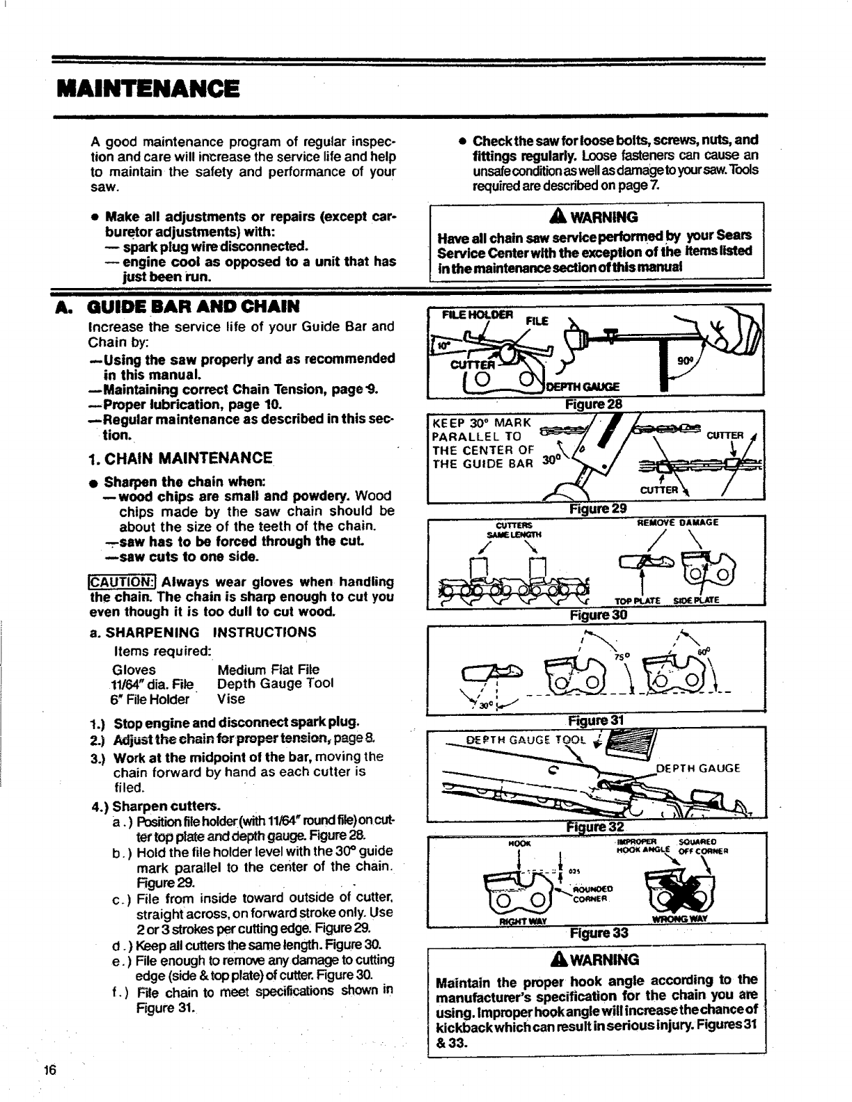
a. ) Positionfileholder(with11/64"roundfile)oncut-
ter top plateand depth gauge. Figure28.
b. ) Hold the file holder level withthe 30° guide
mark parallel to the center of the chain.
Figure29.
c.) File from inside toward outside Of cutter,
straight across, on forwardstrokeonly. Use
2 or3 strokespercuttingedge_Figure29.
d. ) Keep allcuttersthe same length.Figure30.
e. ) File enough toremovean,:/damageto cutting
edge (side & topplate)of cutter.Figure30.
f. ) File chain to meet specifications shown in
Figure 31.
Figure 28
I PARALLEL TO
iFigure 29
¢IJTTERS REMOVE DAMAGE
/--- /\
AWARNING
Maintain the proper hook angle according to the
manufacturer's specification for the chain you are
using. Improper hook angle will increase the chanceof
kickback which can result inserious injury. Figures31
&33.
5.)Correct Depth Gauges.
a.) Place depth gauge tool over each cutter
depth gauge.Figure 32,
b.) File level withthe flat file ifdepth gauge is
higher than the depth gauge toel.
c.) Maintainroundedfrontcomerofdepthgauge
withaflat file, Figures32 &33.
NOTE: The very top of the depth gauge
should be flat with the front half rounded
off with a flat file.
2. GUIDE BAR MAINTENANCE
• Conditions which can require guide bar
maintenance:
--saw cuts to one side
--saw has to be forced through a cut
--inadequate supply of oil to bar and
chain;
• Check the condition of the guide bar each
time the chain is sharpened. A worn guide
bar will damage the chain and make cutting
moredifficult,Reversebar after every cleaning.
I ........... A WARNING r
Depth gauge tool is required to insure proper depth
gauge. Filing the depth gauge too deep will increase
the chance of kickback which can result in serious
;injury. •
b. CHAIN REPLACEMENT
1.) Use only the Low.Kick Chain specified for
your saw in "Specifications" for replace-
mentchain.
2.) Replace the chain when cutters or links
break.
3.) See your Sears Service Center to replace
and sharpen individual cuttersfor match-
ing your chain.
4.) Always have a worn sprocket replaced by
your Sears ServiceCenter when-installing
a newchain to avoidexcessivewear to the
chain.
• Replace the guide bar when:
--the inside groove of the guide bar rails is
worn.
--the guide bar is bent or cracked.
Use only the replacement Reduced-Kickback
Guide Bar specified for your saw in "Specifi-
cations:'
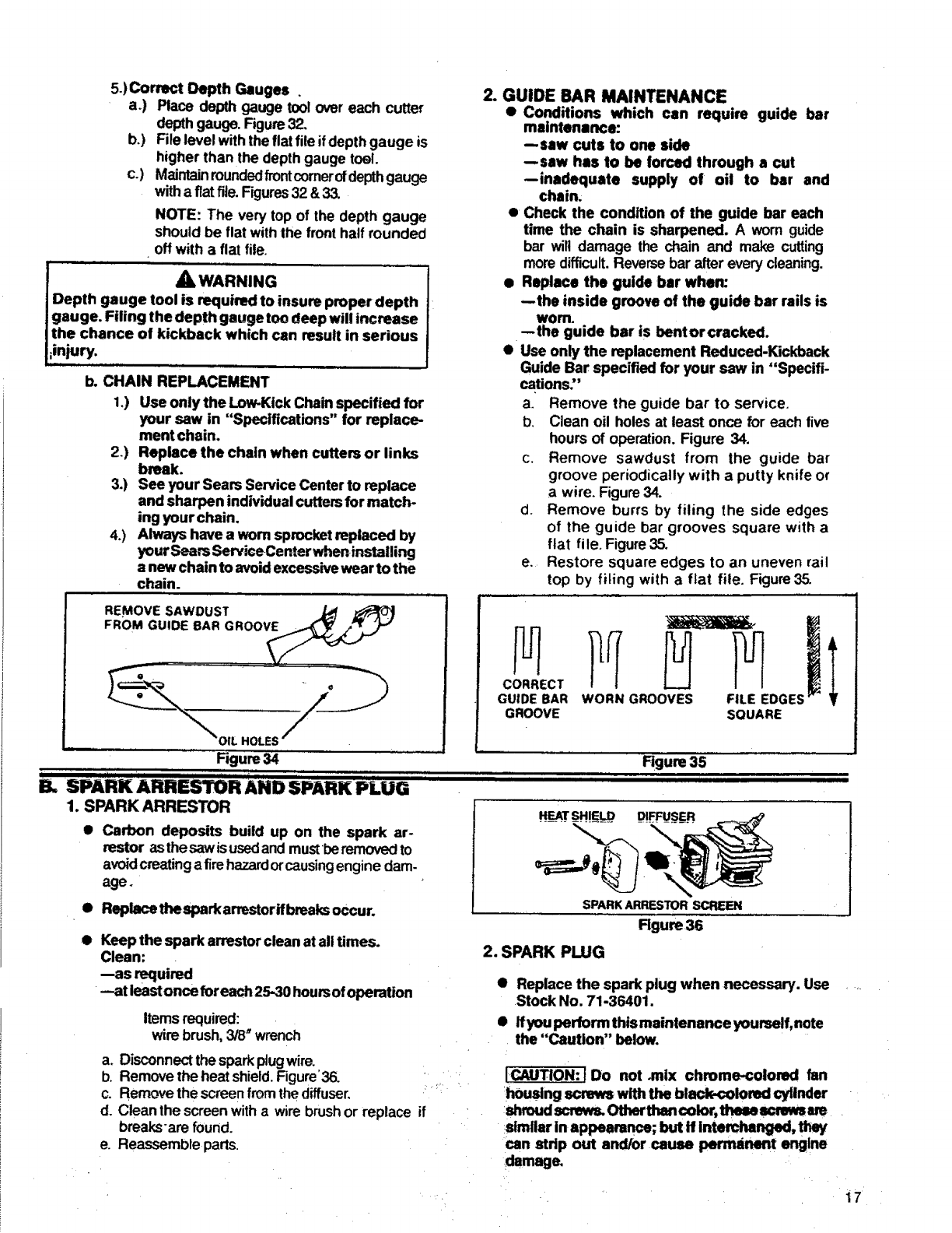
a. Remove the guide bar to service,
b, Clean oil holes at least once for each five
hours of operation. Figure 34.
c. Remove sawdust from the guide bar
groove periodically with aputty knife or
a wire. Figure 34.
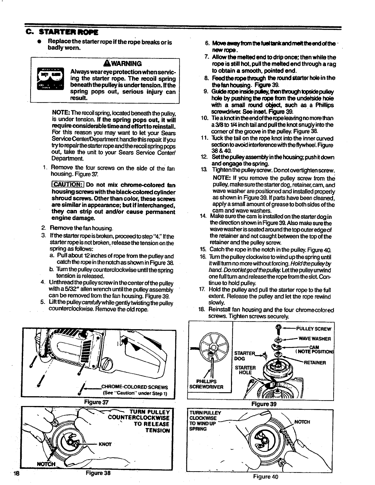
d. Remove burrs by filing the side edges
of the guide bar grooves square with a
flat file. Figure35.
e. Restore square edges to an uneven rail
top by filing with a fiat file. Figure 35
REMOVE SAWDUST
FROM GUIDE BAR GROOVE
CORRECT
GUIDE BAR
GROOVE WORN GROOVES FILE EDGES
SQUARE
Figure34
EL SPARK ARRES'irOR ANb SPARK PLUG
1. SPARK ARRESTOR
•Carbon deposits build up on the spark ar-
restor asthesawisusedand must be removedto
avoidcreatinga fire hazardor causing enginedam-
age,
• Replace the sparkarrestorif breaksoccur.
eKeep the spark arrestor clean at all times.
Clean:
--as required
---at least once for each 25-30hoursof operation
i
Rgure 35
I [ IIIII II
ffEAT _SH!E_=LD_
SPARK ARRESTOR SCREEN
Figure 36
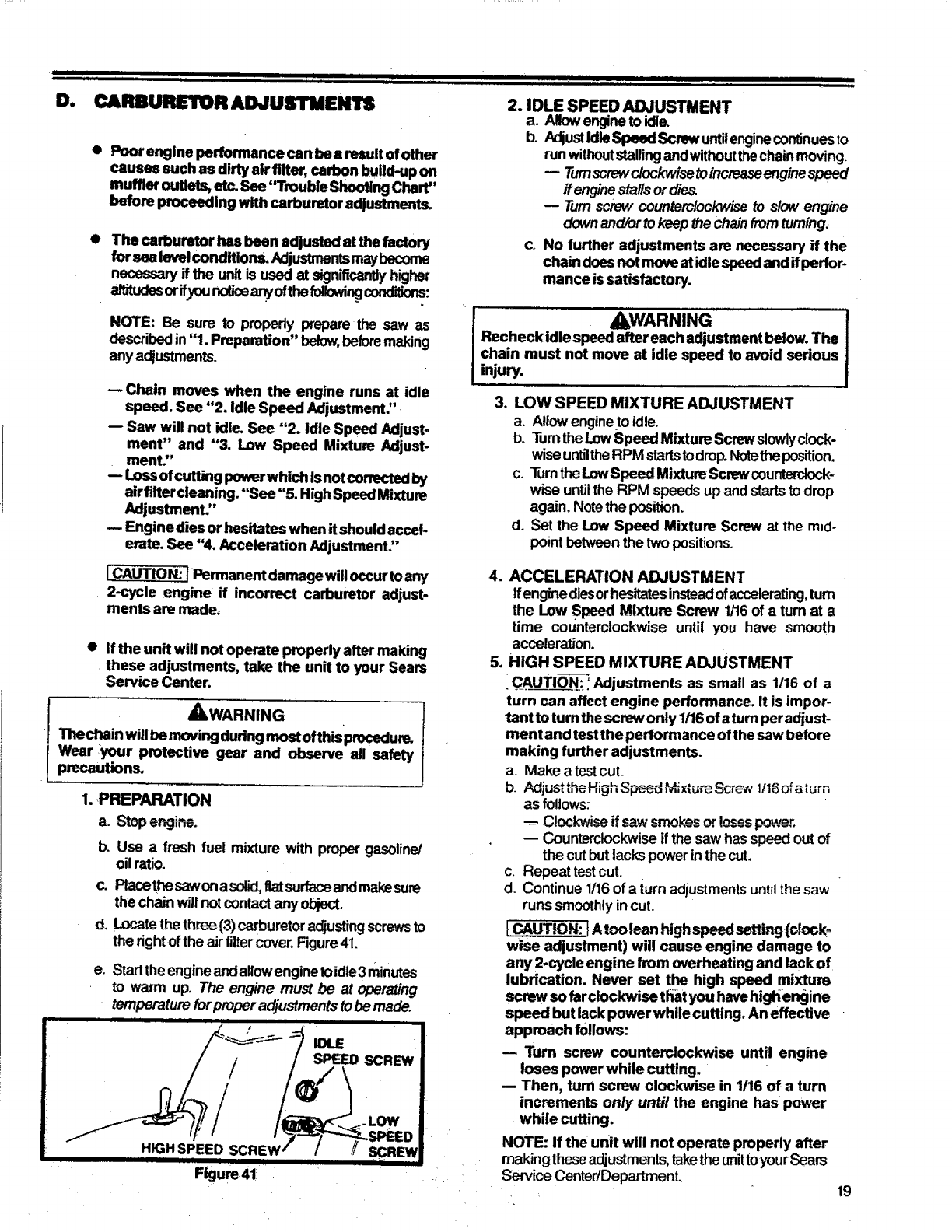
2. SPARK PLUG
• Replace the spark plug when necessary. Use
Stock No. 71-36401.
Items required:
wire brush, 3/8"wrench
a. Disconnectthe sparkplug wire.
b. Remove the heat shield. Figure'36.
c, Remove the screen from the diffuser.
d, Clean the screen witha wire brush or replace if
breaks'are found.
e. Reassemble parts,
• ffyou perform thismaintenance youmelf, note
the "Caution" below.
CAUTION:J Do not .mix chrome.colored fan
housing screws with the block-colored ojtinder
shroud screws.Otherthan color, these _me
similar in appearance; but ff Interchanged, they
can strip out and/or cause permlimmt engine
.damage.
i7
IIIII _ II
,,,ii, _ii 'ii ir III.....II IIIIIII ,i fill IIII!iII IIII.
• Replacethe starter rope if the rope breaks or is
badly worn.
ALWARNING
Always weareyeprotection when servic-
ing the starter rope. The recoil spdng
beneath the pulleyis under tension. If the
spring pops out, serious injury can
result.
1.
NOTE: The recoilspring,locatedbeneaththe pulley,
is under tension.If the spring pops out, it will
require considerabletime andeffort to reinstall.
For this mason you may want to let your Sears
ServiceCenter/Departmenthandlethisrepair.Ifyou
tryto repairthestarterropeandtherecoilspringpops
out, take the unit to your Sears Service Center/
Department.
Remove the four screws on the side of the fan
housing. Figure37.
I CAIUTIOL_: DO not mix chrome-colored fan
housing screwswiththe black-colored cylinder
shroud screws. Other than color, these screws
are similar in appearance; but if interchanged,
they can strip out and/or cause permanent
engine damage.
2. Remove the fan housing.
3. Ifthestartermpeisbmken,proceedtostep"4_"lfthe
starterropeisnotbroken,releasethe tensiononthe
spring asfollows:
a. Pull about 12inchesof ropefromthe pulleyand
catchthe ropeinthenotchasshowninFigure38.
b_Turnthe pulleycounterclockwiseuntitthespring
tension isreleased.
4. Unthreadthe pulleyscrewinthe centerofthe putley
witha 5/32" allenwrenchuntilthe pulleyassembly
can be removedfromthe fan housing.Figure39.
5. Liftthe pulley_/!ywhile gentlytwistingtheputley
countemtockwise_Removethe old rope°
/
,,I r IIIHIll III I iIIII II
,, ,,,, iii i i
6. Move_ fromthefueltankaed n'_t theendofthe •
new rope.
7. Allow the melted end to driponce;then while the
rope is stillhot, pullthe meltedend througha rag
to obtain a smooth,pointed end.
8. Feedtheropethrough the _ statter holein the
theMn housing. F_lum 39.
9. Guidelops klsidepuley,UtonU_ t0Psidepurley
holebypushingtheropefromtheundeisidehere
with a small round object, such as aPhillips
screwdriver.See inset Figure39.
10. T=ea knotintheendofthe ropeleavingnomorethan
a 3/8 to 1/4inchtailand pullthe knotsnuglyintothe
comerof the grooveinthepulley.Figure3a
11. Tuckthe tailontheropeknotintothe innercurved
sectiontoavoidinterferencewiththeflywheel.Fp:jure
38&40.
12. SStthepulleyassemblyinthehousing;pushitdown
andengagethespring.
13. Tightenthepulleyscrew.DonotovertJghtenscrew.
NOTE: If you removethe pulleyscrew fromthe
pulley,make surethestarterdog,retainer,cam,and
wave washerarepositionedandinstalledpropedy
as shownin Figure39. If partshave beencleaned,
applya smallamountofgreaseto bothsidesof the
cam and wavewashers.
14. Make surethe camisinstalledonthe starterdogin
the directionshowninFigure39.Alsomakesurethe
wavewasherisseatedaroundthetopouteredgeof
the retainerand notcaught betweenthe topofthe
retainerand the pulleyscrew.
15. Catchthe ropeinthe notchinthe pulley.Figure40.
16. Turnthe pulleyciockwisetowindupthe springuntil
itwillturnnomore withoutforcing.Ho/dthepu//e/by
hand.DonotletgooHhepul/_. Letthepulleyunwind
onefulltum andreleasethe ropefromtheslot.Con-
tinueto holdpulley.
17. Hold the pulleyand pullthe starterrope tothe full
extenLRelease the pulleyand let the roperewind
slowly.
18. Reinstallfan housingand the four chromecolored
screws.Tighten screwssecurely.
PHILLIPS
SCREWDRIVER
STARTER
HOLE
_'-_---PULLEYSCRL=W
CAM
( NOTEPOSITION
Figure 37 Figure 39
Figure 38
COUNTERCLOCKWISE
TO-RE LEASE
Figure 40
III iiii .......... ii ................. . I........ ii j , iiiiiiiiiii i/ill il i i _
D. _IkRBUREI'OR AI_IU_rMENTS
• Poor engine performance can bea result of other
causes such as dirty air filter, carbon build-up on
muffler outlets, etc, See "Trouble ShootingChart"
before proceeding with carburetor adjustments.
•Thecarburetorhasbeen adjuated at the factory
form levelconditions. Adjustments maybecome
necessary if the unit is used at significanth/higher
al_,ddesorifyouno_e anyofthefolk_ _:
NOTE: Be sure to propedy prepare the saw as
describedin"1. Preparation" below,before making
any adjustments.
--Chain moves when the engine runs at idle
speed. See "2. Idle Speed Adjustment:"
-- Saw will not idle. See "'2. idle Speed Adjust-
ment" and "'3. Low Speed Mixture Adjust-
ment/'
-- Lossof cutting power which isnotcorrectedby
airfilter cleaning. "'See "5. HighSpeed Mixture
Adjustment/'
Engine dies orhesitates when it should accel-
erate. See "4. Acceleration Adjustment"
lCAUTION: tPermanent damage will occur to any
2-c:-ycleengine if incorrect carburetor adjust-
ments are made,
• If the unit will not operate properly after making
these adjustments, takethe unit to your Sears
Service Center.
! _,WARNING
Thechain will be movingduringmostof thisprocedure,
Wear :your protective gear and observe all safety
precautions.
1. PREPARATION
a. Stopengine.
b. Use a {resh fuel mixture with proper gasoline/
oil ratio.
c. Placethe s_on asolid,_surface and makesure
the chain will notcontactany object.
d. Locatethe three(3)carburetoradjusting screwsto
the rightofthe airfiltercover.Figure41.
e. Starttheengineandallowenginetoidle 3minutes
to warm up. The engine must be at operating
temperatureforproper adjustmentstobe made.
Figure 41
IIIUIIIIIII11 • IIIIIIIIIHIIIIIiiiiiii _, i IIIIIIIIIII iiiiiiiiii II
q
2. IDLE SPEED ADJUSTMENT
a. Allowengineto idle.
b. AdjustIdleSpeed Screw untilenginecontinues to
runwithoutstallingand withoutthechainmoving
-- Turnscrewclockwisetoincreaseenginespeed
if enginestaf/sordies
-- Turnscrew counterc/ockwiseto slow engine
downand/ortokeep thechainfromturning.
c. No further adjustments are necessary if the
chain doesnot move atidle speedand if perfor.
mance issatisfactory.
.AWARNING
Recheck/die speed after each adjustment below. The
chain must not move at idle speed to avoid serious
injury.
3. LOW SPEED MIXTURE ADJUSTMENT
a. Allow engineto idle.
b. Turn the LowSpeed Mixture Screwslowly clock-
wise until the RPM startsto drop. Notethe position.
c. "rumtheLowSpeed MixtureScrew counterclock-
wise untilthe RPM speeds up andstartsto drop
again. Notethe position.
d. Set the Low Speed Mixture Screw at the m=d-
pointbetween the twopositions.
.
5_
ACCELERATION ADJUSTMENT
tfenginediesorhesitatesinsteadofaccelerating,turn
the Low Speed Mixture Screw 1/16of a turn at a
time counterclockwise until you have smooth
acceleration.
HIGH SPEED MIXTURE ADJUSTMENT
CAUTI_..] Adjustments as small as 1/16 of a
turn can affect engine performance. It is impor-
tant to turn thescrew only 1/16of aturn perad|ust-
ment and testthe performance of the saw before
making further adjustments.
a. Make a testcut.
b. Adiust theHighSpeed MixtureScrew 1/16ofa turn
as follows:
----C!ockwJseff sawsmokesorlosespower.
-- Counterclockwiseifthe saw hasspeed outof
the cutbutlacks powerinthe cut.
c. Repeat testcut.
d. Continue 1116of a turn adjustmentsuntilthe saw
runs smoothlyincut.
Atoo lean highspeed setting (clock°
wise adjustment) will cause engine damage to
any 2,cycle engine from overheating and lack of
lubrication. Never set the high speed mixture
screw so farclockwise th*atyou have high engine
speed but lack power while cutting. An effective
approach follows:
-- Turn screw counterclockwise until engine
loses power while cutting,
-- Then, turn screw clockwise in 1/16 of a turn
increments only until the engine has power
while cutting.
NOTE: if the unit will not operate properly after
makingthese adjustments, takethe unitto yourSears
Service CenterlDepartment. 19¸
III III II II IIIIUIIIIII H IIIIIIIIIII IIIIIIIIIIIIIIIIIIIIIIIIIIII lhl I i I+I I IIIII
i " i[- + -IIIIIEj_ i El I II i i i .....
E. CLUTCH AND DRUM/SPROCKET F. AIR FILTER
2O
AWARNING
Do notstart enginewithout Guide Bar, Chain, and Bar
Clamp Housing completely assembled. Theclutch can
come off without the guide bar and chain completely
assembled and serious injury can result. The clutch
shoes and drum can separate causing the clutch to
violently fly apart and serious injury can result.
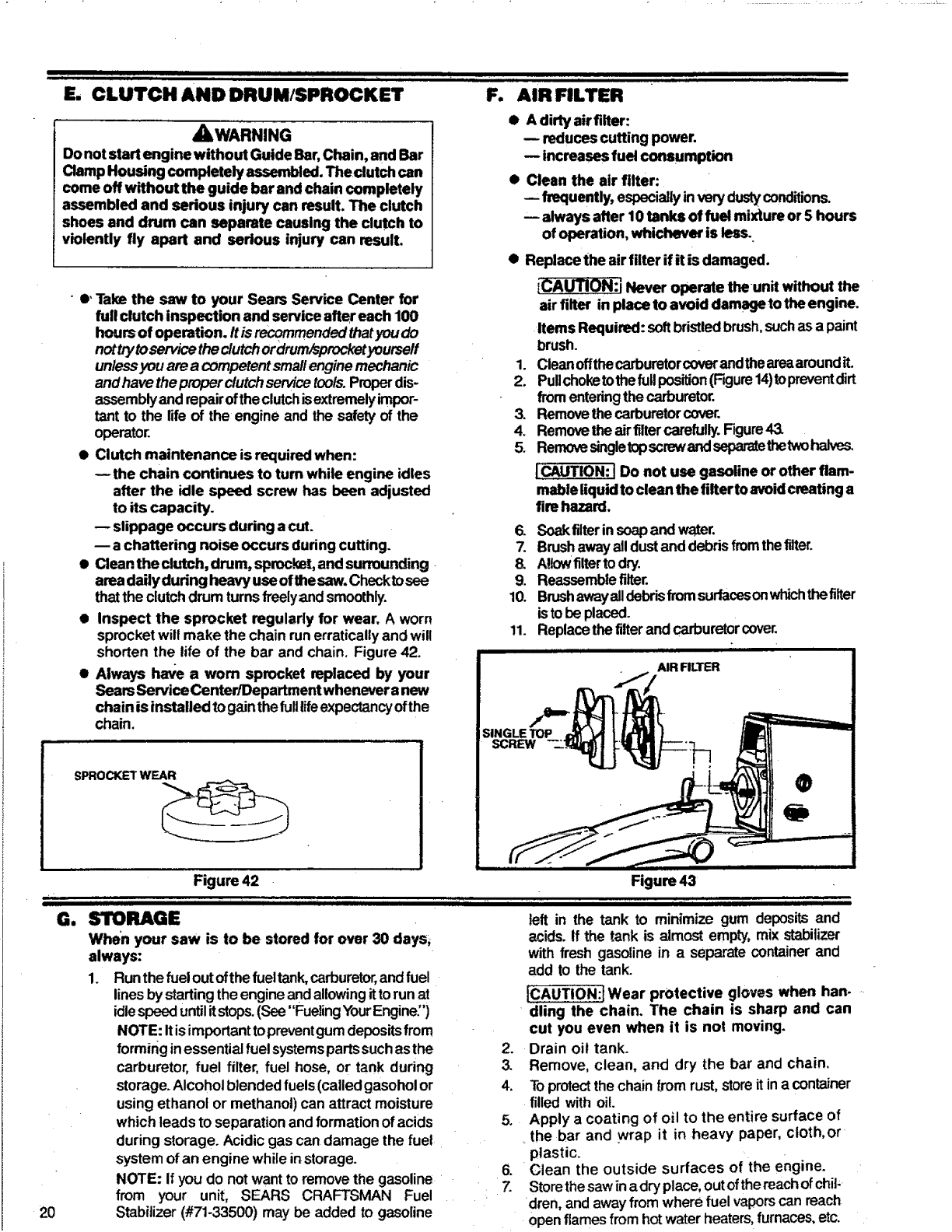
• A dirty airfilter:
-- reduces cutting power.
-- increases fuel consumption
• Clean the air filter:
-- hequenlly, especiallyin very dusty+conditions.
-- always alter 10 tanks of fuel mixture or 5 hours
of operation, whichever is less.
• Replace the air filter if it is damaged.
+•+Take the saw to your Seam Service Center for
full clutch inspection and service alter each 100
hours of operation. It is recommendedthatyoudo
notttytoser_ce theclutch ordrum/sprocketyourself
unlessyouare a competentsmallenginemechanic
and have theproper clutchservicetools.Properdis-
assemblyand repairofthe clutchisextremelyimpor-
tant to the life of the engine and the safety of the
operator.
• Clutch maintenance is required when :
-- the chain continues to turn while engine idles
after the idle speed screw has been adjusted
to its capacity.
-- slippage occurs during a cut.
-- a chattering noise occurs during cutting.
• Clean the clutch, drum, sprocket,and surrounding +
area daily during heavy use ofthe s_w, Checktosee
thatthe clutchdrum turnsfreelyand smoothly.
• Inspect the sprocket regularly for wear. A worn
sprocket will make the chain runerratically and wil!
shorten the life of the bar and chain+Figure 42+
Always hate a worn sprocket replaced by your
Seam Service Center/Department whenever anew
chain is installed to gainthe fulllifeexpectancyofthe
chain.
1o
2.
Figure 42
t
Never operate theunit without the
air filter in place to avoid damage to the engine.
Items Required: softbristledbrush,suchasa paint
brush.
Clean offthecarburetorcoverandtheareaaroundit.
Pullchoketothefullposition(Figure14)topreventdirt
fromenteringthecarburetor.
Removethecarburetorcover.
Removetheairfiltercarefully.Figure43
Removesingletopscrewandseparatethetwohalves
CAUTION: ] Do not use gasoline or other flam-
mable liquid to clean the filter to avoidcreating a
fire hazard.
&
4.
5.
O. STORAGE
When your saw is to be stored for over 30 days;
always:
1. Runthe fuel outofthe fueltank,carburetor,and fuel
linesby startingthe engineandallowingitto run at
idlespeeduntilitstops. (See"Fueling YourEngine:')
NOTE: Itisimportanttopreventgumdepositsfrom
forminginessentialfuelsystemspartssuchasthe
carburetor, fuel filter, fuel hose, or tank during
storage. Alcoholblended fuels(called gasoholor
using ethanol or methanol) can attract moisture
which leads to separation and formationof acids
during storage. Acidic gas can damage the fue!
systemof an engine while instorage.
NOTE: If you do notwant to removethe gasoline
from your unit, SEARS CRAFTSMAN Fuel
Stabilizer (#71-33500) may be added to gasoline
6. Soakfilterin soapand water.
7. Brushawayalldustand debrisfromthefilter.
&A!lowfilter to dry.
9. Reassemblefilter.
10. Brushawayall debrisfromsurfacesonwhichthefilter
isto be placed.
11. Replacethe filterand carburetorcover.
SINGLETOP
SCREW
AIR FILTER
ICAUTiON:I Wear protective gloves when han-
dling the chain. The chain is sharp and can
cut you even when it is not moving.
2. Drain oil tank.
3 Remove, clean, and dry the bar and chain.
4. To protect the chain from rust, store it in a container
filled with oil.
5. Apply a coating of oil to the entire surface of
the bar and wrap it in heavy paper, cloth, or
plastic.
6. Clean the outside surfaces of the engine.
7. Store the saw in adry place, out of the reach of chil+
dren, and away from where fuel vapors can reach
open flames from hot water heaters, furnaces, etc.
left in the tank to minimize gum depositsand
acids. If the tank is almost empty, mix stabilizer
with fresh gasoline in a separate container and
add to the tank.
Figure43
................_ iiiiiiiiiii illl iiiiiiiiiiiiiii
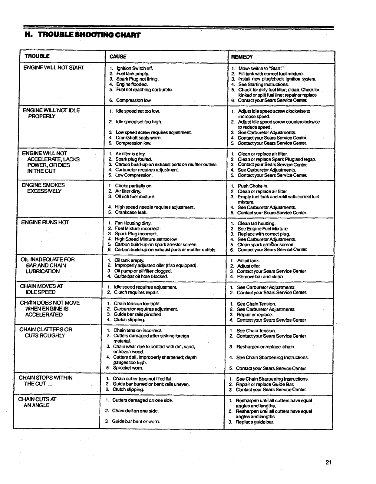
H. IFROUBLE SHI_NQ CHAFrr
iiiiiiiiiiiiiiiiiiiii
ii L J ........... ......
TROUBLE
, i ............
ENGINE WILL NOT START
ENGINE WILLNOT IDLE
PROPERLY
,,, , ....,,,,,,.....
ENGINE WILL NOT
POWER, OR DIES
tN THE CUT
ENGINE SMOKES
EXCESSIVELY
ENGINE RUNS"" 'HoT
CAUSE
1. IgnitionSwitch off:
2. Fueltank.empty.
3. Spark Plugnotfiring.
4. Engineflocded.
5. Fuelnotreaching carburetc,
6. Compressionlow.
1. Idlespsedsettoolow,
2. Idlespeed set too high.
3 Lowspeed screw requires adjustment.
4. Crankshaftsealswom.
5. Compression low.
I. Air filter is dirty.
2. Spark plug _uled.
3 Carbon build-up on exJ_us( portson muffler outtets.
4. Carbutetor requires adjustment.
5. LowCompression.
......, ,,,,, , ,,,,..........
I. Chokepartially on.
2. Airfilter dirty.
3. Oil richfuel mixture.
REMEDY
......,,,,,,,,
1.
2.
4.
5.
Move switchto "Start."
Fill tankwith correctfuel mixture.
InStall new plug/check ignition system.
See Starting Instructions.
Check for dirtyfuelfilter;,clean. Checkfor
kinked orsplitfuel line;repair or replace.
Contact your SearsService Center.
1. Adjustidlespeedscrewclockwiseto
increasesl_d.
2. Adjustidlespeedscrewcounterclockwise
to reducespeed.
:t See CarburetorAdjusUnent_
4. ContactyourSeamServiceCenter.
5. ContactyourSears,?_nsiceCenter,
1.
2.
3.
4.
5.
1.
2.
3.
4. High speed needle requires adjustment. 4.
5. Crankcase leak. 5.
1. Fan Housing dirty. 1.
2. FuelMixture incormcL 2.
3+ SparkPlug incorrect. 3.
4. High Speed Mixture set too low. 4.
5. Carbon build-upon spark arrestorscreen. 5.
6. Carbon build-up on exhaustportsor mufflor outlsts. 6.
,,,,,,,,,,,,,, ................,,_,. , , , .....................
Ctean or replace air filter.
Clean or replace Spark Plug and reg,.
Contact yourSearsService Center.
See CarburetorAdjustments.
Contact yourSeats Service Center.
Push Choke in.
Clean orreplace air filter.
Empty fuel tank and refill with correct fuel
mixture.
See CarburetorAdjustments.
Contact your Sears Service Center.
Clean fan housing.
SeeEngine Fuel Mixture.
Replace with correctplug.
See CarburetorAdjustments.
Clean spark arre_or screen.
Contact yourSears Service Center.
OIL INADEQUATE FOR t. Oiltankempty. 1. Filloiltank.
BARAND CHAIN 2. Improperlyadjustedoiler(ifsoequipped). 2. Adjustoiler.
LUBRICATION 3. Oil pump oroil filter clogged. 3. Contact your Sears Service Canter.
4. Guide baroil hole blocked. 4. Remove bar and clean.
CHAIN MOVES AT 1. Idle speed requires adjustment. 1. See CarburetorAdjustments.
IDLE SPEED 2. Clutch requires repair. 2. Contact your Sears Service Center.
CH,_IN DOES NOT MOVE 1. Chain tension tootight. 1. See Chain Tension.
WHENENGINE IS 2. Carburetor requires adjustment. 2. See CarburetorAdjustments.
ACCELERATED 3. Guide bar rails pinched. 3. Repair orreplace.
,_. Cluf_hslippingo 4. Conta_yourSea.,se_-_P_,_nt_r.
............................... ...................................... ,,,,,,.....
CHAIN CLATTERS OR 1. Chain tension incorrect, t. See Chain Tension.
CUTS ROUGHLY 2. Cuttersdamagedafterstrikingforeign 2. ContactyourSears_Center.
matedai.
Chain wear due to contact withdirt, sand, 3. Resharpen or replsce chain.
or fr_en wood.
Cutters dull, impropedy sharpened;depth 4. See Chain Sh_cening Instructions.
gauges toohigh.
Sprocketworn. I5.
Chain cutter tops not flied fiat. i.
Guide bar burred or bent; rails uneven. 2.
Clutch slipping. 3.
.................,, , ,,,,,,,............
3.
4.
5-
CHAIN STOPS WITHIN ......... I.
THECUT ......... t 2..
3,
Contact yourSears Servk:_eCenter.
See Chain Sharpening instructions.
Repair or replace Guide Bar.
Contact yourSears Service Center.
CHAIN CUTS AT
AN ANGLE 1. Cutters damaged on one side. t. Resharpen until all cutters have equal
anglesandtangtks,
2. Chain dull on one side. 2. Resharpen until allcutters haveequal
and lengths.
3. Guide bar bent or worn. 3. Replace guide bar.
21:
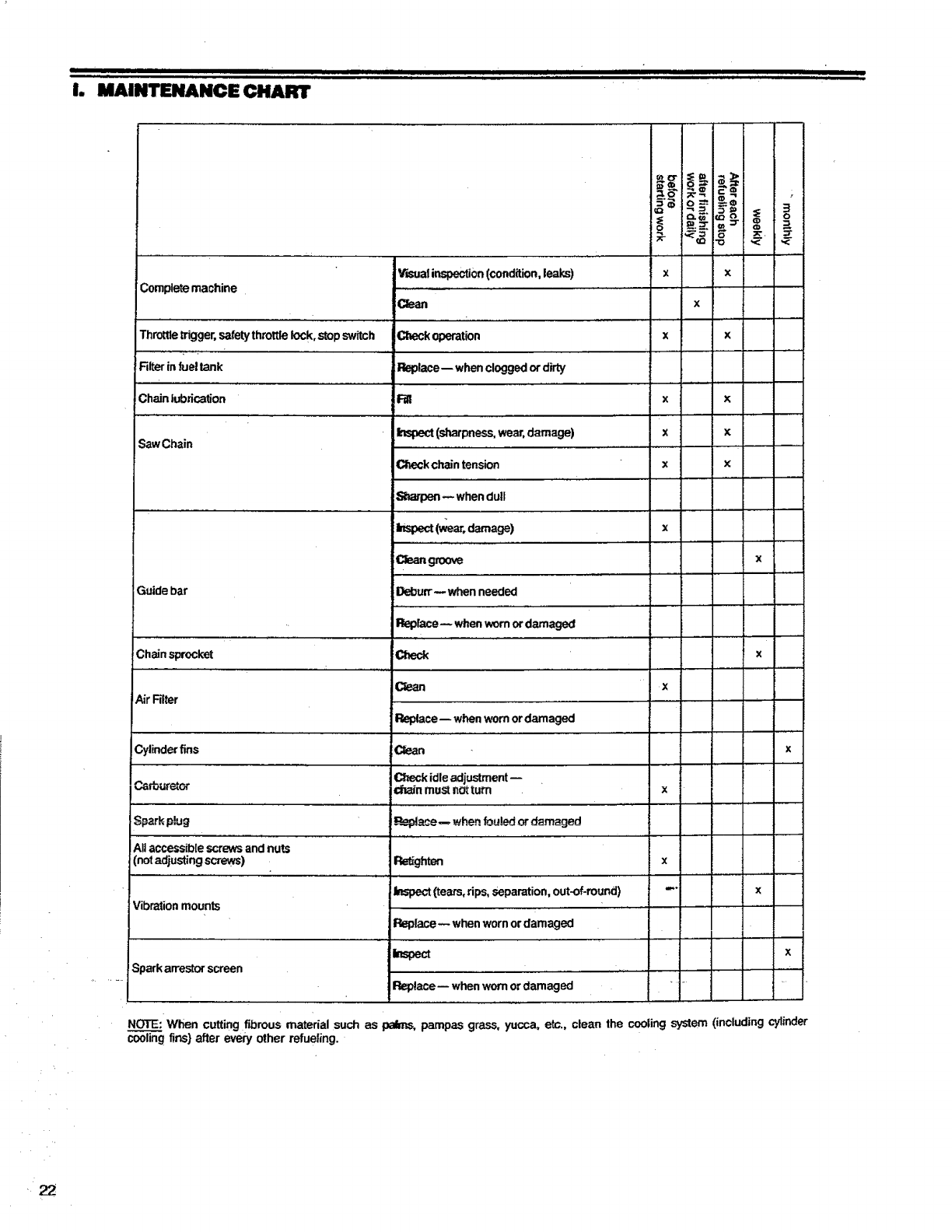
iiiii i H ,,,,,,,,,,,,,,,,,,,,,,_,,,,I llllUilll ........ I I III II. ,.......... ;........ 1,, II III
I. MAINI"r.NAIICE CHART
Completemachine
Throttletrigger,safetythrottlelock, stopswitch
Filterinfuel tank
Chain lubrication
SawChain
Guide bar
Chain sprocket
AirRlter
Cylinderfins
Carburetor
Sparkp!ug
Allaccessible screws and nuts
(notadjustingscrews)
5"_ o= =®
Yisua!inspecIJon(cond_ion, leaks) xx
€_L=an x
,Checkoperation x x
Replace -- when clogged ordirty
F_ x ×
Inspect (sharpness,wear. damage) x x
C[leckchain tension x x
_arpen _ when dull
kspect(wear,damage)
C/eangmove
X
Deburr -- when needed
Pteprace-- when worn or damaged
X
Check
Ctean
Replace --when worn ordamaged
ICOn
CI1eckidleadjustment --
diaJn mu_ not turn
Rslp_ce _ when fouL,,dordam_jed
Ret_hten
X
Vibrationmounts
Spark arrestor screen
ktspect (team, rips, separation, out-of-round)
Replace _when worn or damaged
. _ ; :........ :
x
Inspect
Replace-- when worn ordamaged
X
NOTE: When cutting fibrous material such as pakns, pampaS grass, yucca, etc., clean the cooling system (including cylinder
coolingfins) after every other refueling.
22
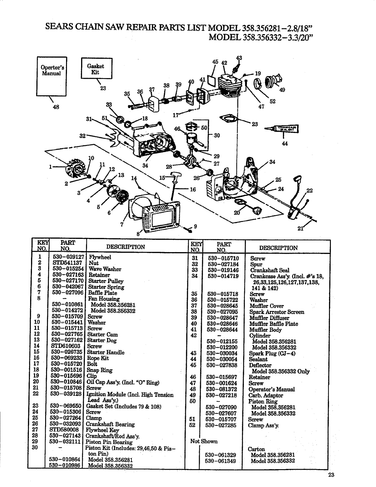
SEARS CHAIN SAW REPAIR PARTS LIST MODEL 358.356281-2.8/18"
MODEL 358.356332-3.3/20"
\48
\23
45
19
47
I
52
34
29
27
NO.
1
2
3
4
5
6
?
8
9
IlO
11
12
13
14
15
16
17 _
18
19
20
21
22
23
24
25
26
27
28
29
30
2
3
PART
NO.
530-039127
STD541137
530-015254
530-027163
630-027170
630-042067
530-027096 i
530-010861
530-014272
530-0157O9
530=016441
530-015713
6.30-027765
530-027162
STD610603
530-026735
530-069233
530-015720 ]
530-001516
530-015696
530-010846
530-_015708
530-039128
530-069560
530-015306
530-027264
530-032093 '_
STD580008
530"027143
530-032111
53o-01o864
530-010986
25
4
6
7
16
DESCRIPTION
Flywheel .......
Nut
WaveWasher
Retainer
Starter Pu_ey
Starter Spring
Baffle Plate
Fan Housing
Mode/358.356281
Model 368_56332
Screw
Wesher
Screw
Starter Cam
Starter Dog
Screw
Starter Handle
............,j, KEY PART....
NO. NO.
31 530-016710
32 530-027184
33 530-019146
34 530-014719
35 530-016718
36 530-015722
37 530-028645
38 530-027095
39 530-028647
40 530-028643
41 530-028644
42 530--012155
530-012200
43 530-030034
44 530"030054
45 530-027838
46 530-015697
47 530-001624
48 530-081372
49 530-027218
530-027090
530-027607
51 530-015707
52 530-027285
, ,, , ,, ,, ,,,, , ,, ,,
DESCRIPTION
Screw
Spur
Crankshaft Seal
Crankcase Ass'y. and. #% 18,
26,33,125,126,127,137,138,
141 & 142)
Screw
Wa_er
Muffler Cover
Spark Arrestor Screen
Muffler Diffuser
M_l_ Baf_e Pla_
Mufflm_Body
O_linder
Mode/368.356281
Model 358.356332
Spark Plug (CJ-4)
Sealant
Deflector
Model 358.356332 Only
Retainer
Screw
Operator's ManueI
Carb.Adaptor
Piston Ring
Model 358,356281
Model 358.356332
Screw
Clamp Ass'y.
Rope Kit
Bolt
SnapRing
Clip
Oil CapAss'y. (Incl. "0" Ring)
Screw
Ignition Module (Incl. High Tension
Lead Ass'y.)
Gasket Set (Includes 79 & 108)
Screw
Clamp
Crankshaft Bearing
Flywheel Key
Cranks_od .Ms'y.
Piston Pin Bearing
Piston Kit (Includes: 29,46,50 & Pie,
ton Pin)
Model 358.356281
M._d 358.358332
NotShown
530-061329
530-061349
Carton¸
Model 358.356281
Model 358.356332
23
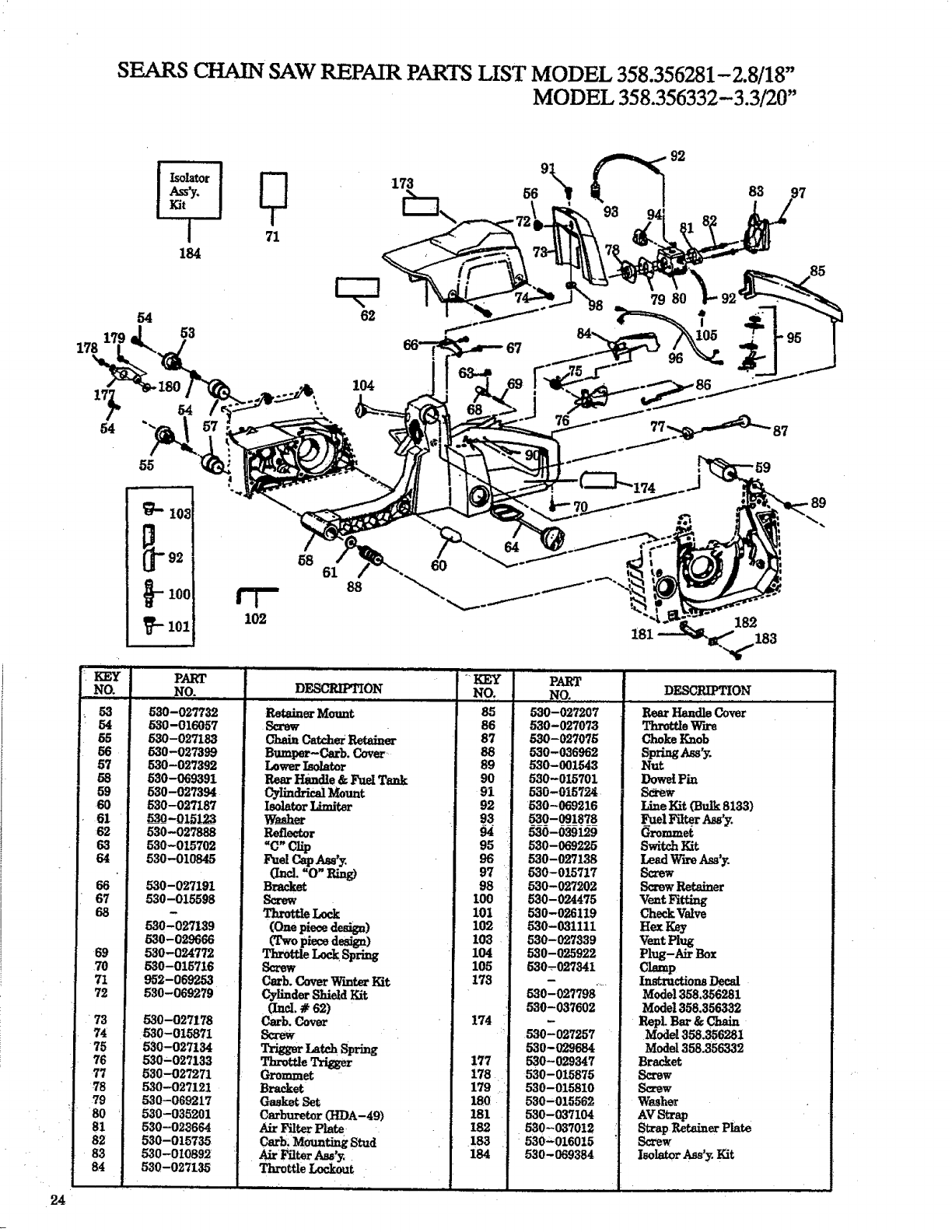
SEARS CHAIN SAW P.JEPAIP.PARTS LIST MODEL 358.356281-2.8/18"
MODEL 358.356332-3.3/20"
178
54
NO,_
53
65
66
57
68
59
60
61
66
67
68
69
70
71
72
73
74
75
76
77
78
79
80
81
82
83
84
[
184
173
93
92
83
64
55
102
62
104
58 61 88
6O
64
76
79 80
174
182183
i i , ,,,,,
PART
NO. .,
630-027732
630-016057
630-027183
530-027399
530-O27392
530-069391
,,, ,
DESCRIP_ON
,H,, .....
Retainer Mount
Screw
Chain Catcher Retainer
Bumper-Carb. Cover
Lower IsoLator
Rear Handle & Fuel Tank
"KEY
NO.
85
86
87
88
89
90
NO.
530-027207
53O-O27O73
530-027076
530-036962
530-001543
530-015701
D_ON
Rear Handle Cover
ThrottleW'we
Choke Knob
Spr_..ngAss'y.
Nut
DowelPin
530-027394
630-027187
5,?_9-01512_
530-027888
530-015702
530-010845
530-027191
530-015598
530-027139
530-029666
530-024772
530-016716
9'52-069253
530-069279
530-027178
530-015871
530-027134
530"027133
530-027271
530-027121
530-069217
530-035201
530 -023664
530-015735
530-010892
530-02713,5
Cyliadricai ]v_unt
Isolator L_iter
W_her
Reflector
"C"Clip
FuelCapA_'y.
and.-o-Ping)
Bracket
Screw
(Onepiece design)
(Twopiece dee_n)
Thro._ L_ Spring
Screw
Oerb.Cover Winter Kit
Cylinder Shield Kit
O.ucl.#62)
Carb. Cover
Screw Lat_ Spring
Throtth Trigger
Grommet
Bracket
Gasket Set
Carburetor (HDA-49)
AirFilterPhte
Carb. MountingStud
ThrottleLockout
91 530-015724
92 630-069216
93 530-091878
9,1 530-039129
95 530-06929,5
96 530-027138
97 530-015717
98 530-027202
I00 530-024475
101 : 530-026119
102 : 530-031111
103 530-027339
104 530-025922
105 630_-02734I
173 530-027798 ......
530-037602
174 530-027257
530-029684
177 530-029347
t.78 530-015875
179 530-015810
180 530-01556_
181 530-037104
182 530-037012
183 530_016015
184 530-O69384
Line Fit (Bulk 8133)
F_e__ter _'y.
Grommet
_mt
Lead Wee Ass'3_
Screw
Screw Retainer
Vent Fitting
CheckValve
Hex Key
Vent Plug
Phg-Air Box
Clamp
Insm_ctions Decal
Model 358.356281
Model 358.356332
RepLBar &Chain
Model 358.356281
Model.358.356332
Bracket
Screw
Screw
Wether
AVStrap
Strap Retainer Plate
Screw
Isolator_'_ Kit
85
24
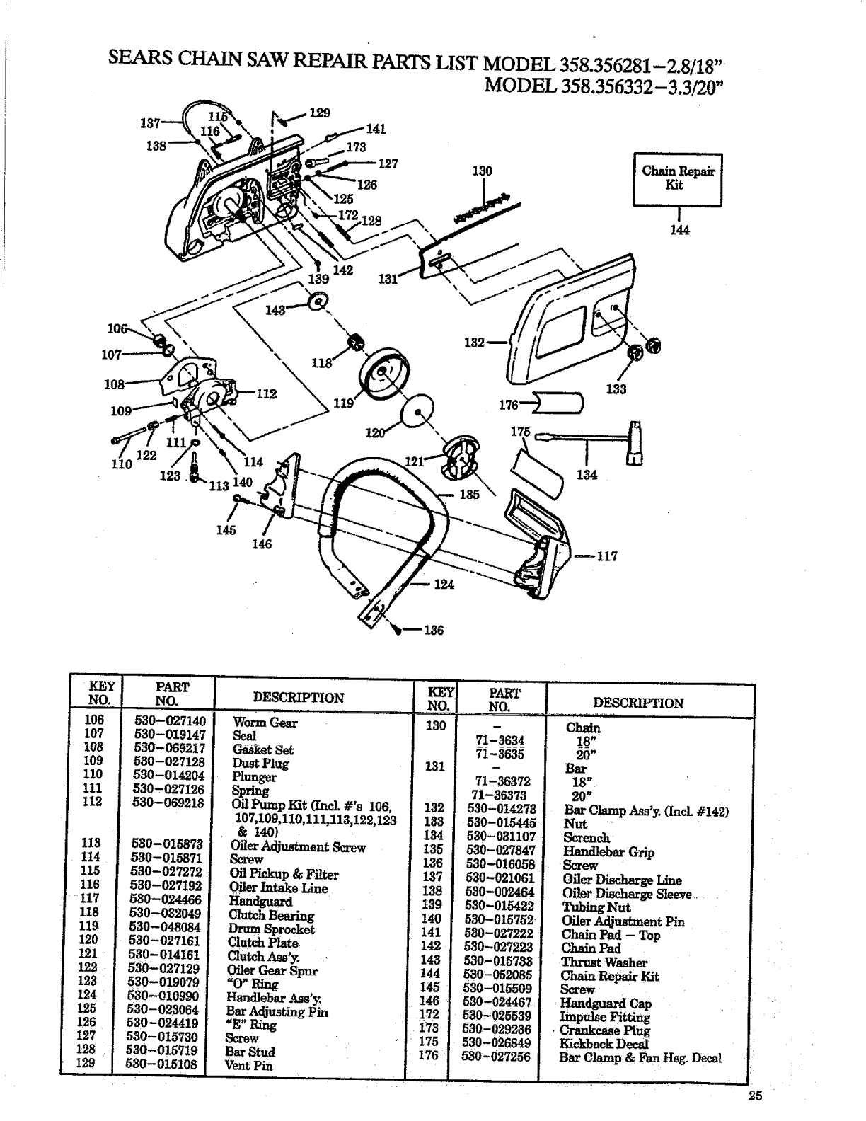
SEARS CHAIN SAW REPAIR PARTS LIST MODEL 358,356281-2.8/18"
MODEL 358.356332-3.3/20"
129
130
142
11o122 1_ 114
I23. _. 113 140
145 146
106
107
I08
109
110
Iii
112
113
114
115
U6
-117
118
119
120
121'
122.
123
124:
125
126 .
127
t28,
I29
PART
NO.
530-027140
530-019147
530-069217
530-027128
530-014204
530-027126
530-069218
DESCRIFrION ................. I
..... J.................
_0. PART
,NO. DESCRIPTION
130 - Chain
71-3634
71-3635
131 -
71.36372
71-36373
132 530-014273
133 530-015445
134 530-031107
135 530-027847
136 530-016058
137 530-021061
138 530-002464
139 530-015422
140 530-015752
141 530-027222
142 530-027223
143 530-015733
144 530-052085
145 530-015509
, 146 530-024467
!72 530_025539
173 530-029236
175 530-026849
176 530-027256
530-016873
530-015871
530-027272
530-027192
530-024466
530--032049
530--048084
530-027161
530-014161
530--027129
530-019079
530-010990
530-023064
530-024419
530-015730
530-015719
530-015108
Worm Gear
Seal
C-_ket Set
Dust Plug
Plunger
Spring
Oil Pump Kit (IncL #'s 106,
107,109,110,1!1,113,122,123
&140)
Offer Adjustment Screw
Screw
Oil Pickup & Filter
Oi!"er Intake Line
Haudguard
Clutch Bearing
Drum Sprocket
Clutd_Plate
ClutchAss'y. ,
O_erGearSpur
"0_Ring
HaadlebarAss'y.
Bar Adjusting Pin
"E" Ring
Screw
Bar Stud
Vent Pin
. i,! i,,,
18"
20"
Bar
18"
20"
Bar Clamp Ass'y. (IncL #142)
Nut
Scren_
Handlebar Grip
Screw
Oiler Discharge Line
Oiler Discharge Sleeve
Tubing Nut
Oiler Adjustment Pin
Chain Pad - Top
Chain Pad
Thn_ Washer
Chain Repair Kit
Screw
H_dguard Cap
Imp_e Fittkig
•C_e Plug
_aekbaek Deea_
Bar Clamp & Fan Hsg. Decal
25
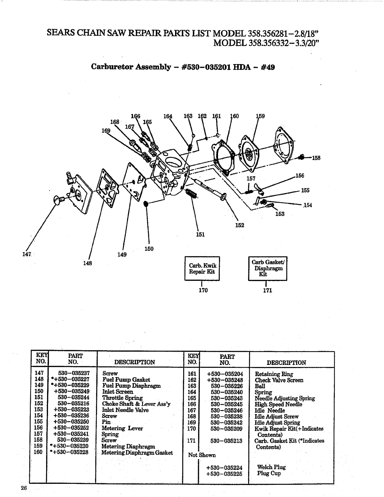
SEARS CHAIN SAW REPAIR PARTS LIST MODEL 358.356281-2.8/18"
MODEL 358.356332-3.3/20"
Carburetor Assembly - #530-036201 HDA- #49
157
148
149
151
.\152
153
I !
170 171
26
KE_
NO.
47
148
149
150
151
I52
153
154
155
156
157
158
• 159
160
NO. -
530-035237
*+530-035227
*+530-035229
+530-035249
530-035244
530-035216
+530-035223
+530-035236
+530-035250
+530-035252
+530-035241
530-035239
*+530-035230
*+530-035228
DESCRI_ION
iJiii ,i
Screw
Fuel Pump Gasket
Fuel Pump Diaphragm
Inlet Screen
Throttle -Spring
Choke Shaft & Lever Ass'y
Inlet Needle Valve
Screw •
Pin, :
Metering Lever
Spring
Screw
M_riag _hragm
bietering Diaphragm Gasket
,;, •
KEY PART
NO. NO.
t61 +530-035204
162 +530-035248
163 530-035226
164 530-035240
I65 .530-035243
166 530-035245
167 530-035246
168 530-035238
169 530-035242
170 530-035209
171 530-035213
Not Shown
+530-035224
+530-035225
DESCRIPTION
Ret_ Ring
Check ValveScreen
Ba_
Spr_ug
Needle AdjustingSpring
SpeedNeedle
Idle Needle
Idle Adjust Screw
Idle Adjust Spring
Kwik Repair Kit(+ Indicates
Contents)
Carb.Gasket Kit(*Indicates
Contents)
WelchPlug:
Plug Cup
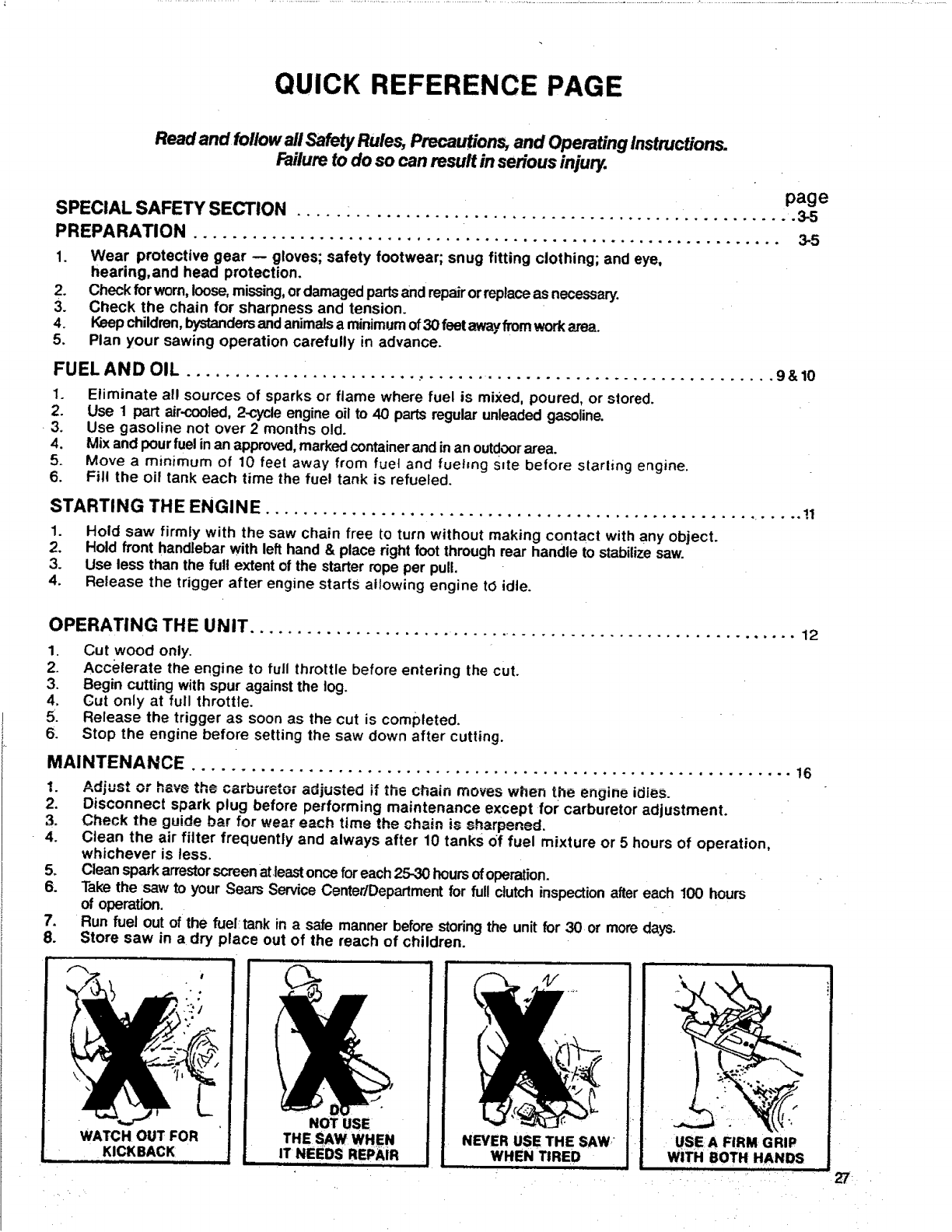
QUICK REFERENCE PAGE
Read and follow alI Safety Rules, Precautions, and Operating Instructions.
Failure to do so can result in serious injury.
page
SPECIAL SAFETY SECTION ..... : .............................................. 3-5
PREPARATION ............................................................. 3-5
1. Wear protective gear -- gloves; safety footwear; snug fitting clothing; and eye,
hearing, and head protection.
2. Check for worn,loose,missing,ordamaged partsand repairorreplaceas necessary.
3. Check the chain for sharpness and tension.
4. Keepchildren,bystandersandanimalsa minimumof30 feetawayfromworkarea.
5. Plan your sawing operation carefully in advance.
FUEL AND OIL ........................ 0..................................... 9 &10
1. Eliminate all sources of sparks or flame where fuel is mixed, poured, or stored.
2. Use 1 part air-cooled, 2-cycle engine oil to 40 paris regular unleaded gasoline.
3. Use gasoline not over 2 months old.
4. Mix and pour fuel in an approved, marked container and in an outdoor area.
5. Move a minimum of 10 feet away from fue{ and fuehng site before starting engine.
6. Fill the oil tank each time the fuel tank iS refueled.
STARTING THE ENGINE ......................................................... !1
1. Hold saw firmly with the saw chain free to turn without making contact with any object.
2. Hold front handlebar with left hand & place right foot through rear handle to stabilize saw.
3. Use less than the full extent of the starter rope per pull.
4. Release the trigger after engine starts allowing engine tO idle.
OPERATING THE UNIT .......................................................... 12
1. Cut wood only.
2. Accelerate the engine to full throttle before entering the cut.
3. Begin cutting with spur against the log.
4. Cut only at full throttle.
Release the trigger as soon as the cut is completed.
6. Stop the engine before setting the saw down after cutting.
MAINTENANCE .............................................................. 16
I. Adjust or have the carburetor adjusted if the chain moves when the engine idies.
2. Disconnect spark plug before performing maintenance except for carburetor adjustment.
3. Check the guide bar for wear each time the chain is sharpened.
4. Clean the air filter frequently and always after 10 tanks Of fuel mixture or 5 hours of operation,
whichever is less.
5. Clean spark arrestorscreen=.least once for each 2,5-,30hoursofoperation.
6. Take the saw to your Sears Service CentedDepartment for ful clutch inspectionafter each 100 hours
of operation.
Run fuel Out of the fuel:tank in a safe manner before storing the unit for 30 or moredays.
Store saw in a dry place out of the reach of children.
i i i i i i ill
.
8.
WATCH OUT FOR
KICKBACK
NOT USE
THE SAW WHEN
IT.eEps.eP_,_ NEVER USE THE SAW
WHEN TIRED USE A FIRM GRIP
WITH BOTH HANDS
,J
r
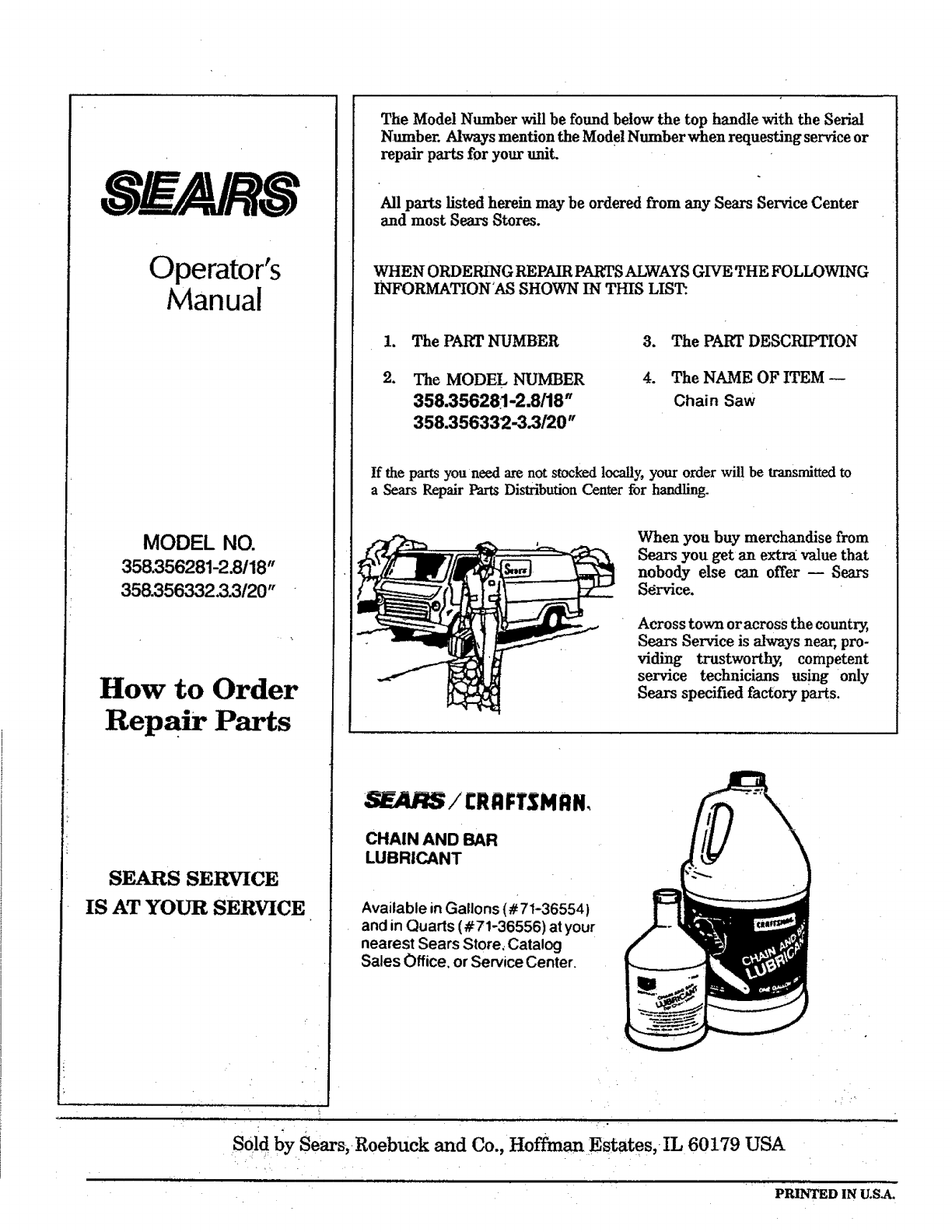
Operator's
Manual
MODEL NO.
358.356281-2.8/18"
358.356332.32120"
How to Order
Repair Parts
SEARS SERVICE
IS AT YOUR SERVICE
The Model Number willbe foundbelow thetop handlewith theSerial
Number. Alwaysmention theMode INumber when requestingserviceor
repairpartsforyour unit.
All parts listed herein may be ordered from any Sears Service Center
and most Sears Stores.
WHEN ORDERING REPAIR PARTS ALWAYS GIVE THE FOLLOWING
INFORMATION'AS SHOWN IN THIS LIST:.
1. The PART NUMBER
2. The MODEL NUMBER
358.35628!-2.8/18"
358.356332-3.3/20"
3. The PART DESCRIPTION
4. The NAME OF ITEM --
Chain Saw
If the parts you need are not stocked locally, your order will be transmitted to
a Sears Repair Parts Distribution Center for handling.
When you buy merchandisefrom
Searsyou getan extravaluethat
nobody else can offer-- Sears
Service.
Acrosstown oracrossthecountry,
Sears Serviceisalwaysnear,pro-
viding trustworthy,competent
service techniciansusing only
Searsspecifiedfactoryparts.
/i:RgFTSMRN,
CHAIN AND BAR
LUBRICANT
Available in Gallons (# 71-36554)
and in Quarts (#71-36556) at your
nearest Sears Store, Catalog
Sales Office, or Service Center.
Soid fly Sears, Roebuck and Co., Hoffman Estates, IL 60179 USA
PRINTED IN U.SA.
