Craftsman 358791051 User Manual TRIMMER Manuals And Guides L0807118
CRAFTSMAN Line Trimmers/Weedwackers, Gas Manual L0807118 CRAFTSMAN Line Trimmers/Weedwackers, Gas Owner's Manual, CRAFTSMAN Line Trimmers/Weedwackers, Gas installation guides
358.791051 L0807118
User Manual: Craftsman 358791051 358791051 CRAFTSMAN TRIMMER - Manuals and Guides View the owners manual for your CRAFTSMAN TRIMMER #358791051. Home:Lawn & Garden Parts:Craftsman Parts:358791051 Craftsman Grass trimmer (weed wacker) Manual
Open the PDF directly: View PDF ![]() .
.
Page Count: 23

25cc/1.5 cu.in. 2-Cycle
17 Inch Cutting Path /0.095 Inch Line
GASOLINE WEEDWAOKER ®
Model No.
358.791051
•Safety
•Assembly
• Operation
•Maintenance
•Parts List
•Espa_ol, p. 24
WARNING:
Read and follow all Safety Rules and Operating
Instructions before first use of this product.
For answers to your questions about this product:
Call 7 am-7 pm, Mon.-Sat., or 10 am-7 pm, Sun.
1-800-235-5878 _Hoo,o ,isted are Central Time)
Sears, Roebuck and Co., Hoffman Estates, IL 60179 U.S.A.
545167684 Rev. 2 6/12/08 BRW
Warranty Statement 2 Storage 18
Identification of Safety Symbols 2 Troubleshooting Table 19
Safety Rules 4 Emissions Statement 20
Assembly 9
Operation 11 Parts List 22
Maintenance 15 Spanish 24
Service & Adjustments 16 Parts and Ordering Back Cover
ONE YEAR FULL WARRANTY ON CRAFTSMAN GAS WEEDWACKER
When used and maintained according to the operator's manual, if this product fails due
to a defect in material or workmanship within one year from the date of purchase, return
it to any Sears store, Sears Service Center, or other Craftsman outlet in the United States
for free repair (or replacement if repair proves impossible).
This warranty excludes cutting line, spark plug and air filter, which are expendable
parts that can wear out from normal use in less than one year.
This warranty applies for only 90 days from purchase date if this product is ever used
for commercial or rental purposes.
This warranty gives you specific legal rights, and you may also have other rights
which vary from state to state.
Sears, Roebuck and Co., Roffman Estates, IL 60179
@
®®®
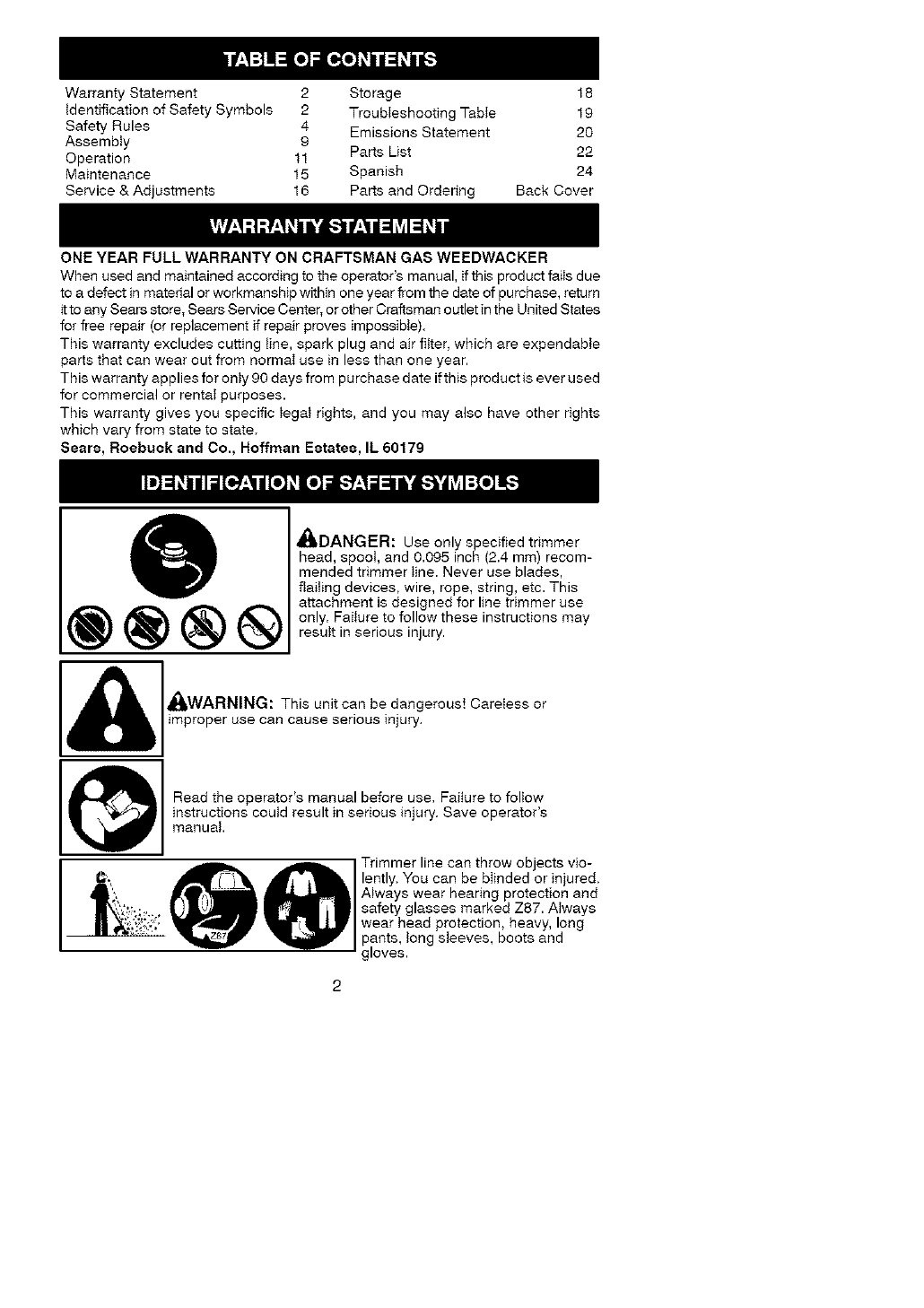
_DANGER: Use only specified trimmer
head, spool, and 0.095 inch (2.4 mm) recom-
mended trimmer line. Never use blades,
flailing devices, wire, rope, string, etc. This
attachment is designed for line trimmer use
only. Failure to follow these instructions may
result in serious injury.
_WARNING: This unit can be dangerous! Careless or
improper use can cause serious injury<
Read the operator's manual before use, Failure to folIow
instructions could result in serious injury> Save operator's
manual,
Trimmer line can throw objects vio-
lently. You can be blinded or injured.
Always wear hearing protection and
safety glasses marked Z87. Always
wear head protection, heavy, long
pants, tong sleeves, boots and
gloves.

Hazardzoneforthrownobjects.
• Trimmerlinethrowsobjectsviolently.
• Youandotherscanbeblinded/injured.
• Keepchildren,bystanders,andanimals
50feet(15meters)away.
1Secure hair above shoulder length.
• _ • /Do not wear jeweIry, loose clothing,
| _IL JR or clothing with loosing hanging
_._J/straps, ties, tassels, etc. They can
'_/be caught in moving parts.
Assist handle to be positioned only below
the arrow.
Never allow children to operate this unit.
Store unit indoors in a high, dry place out of the
reach of children. Store unit and fuel in area where
fuet vapors cannot reach sparks or open flames
from water heaters, electric motors or switches,
furnaces, etc,
@When servicing unit, use only identicaI replace-
ment parts.
Atways stop unit and disconnect spark plug before
cleaning or servicing.
1°_ru swe_hReNul_ tGn:eFaire _aaZmardorNse;e_sm(ixcIPOUrng rsSrntoOrkeggaSoOpIine
Jflames, or work that can cause sparks).
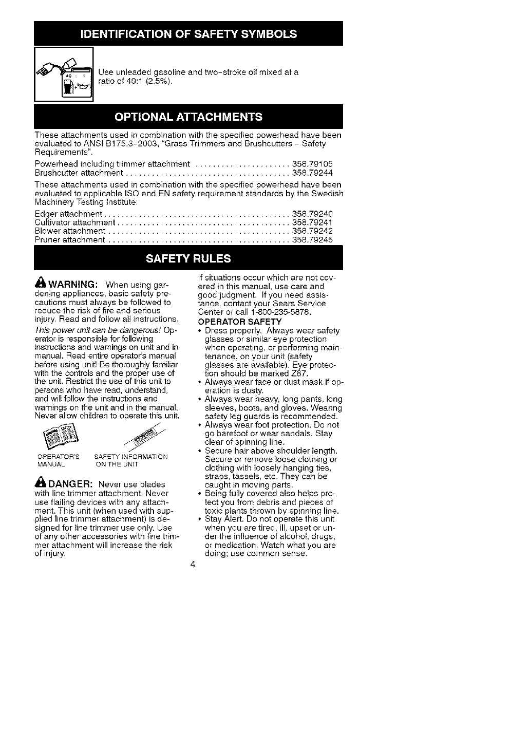
I_] se unleaded gasoline and two-stroke oil mixed at a
ratio of 40:1 (2.5%).
These attachments used in combination with the specified powerhead have been
evaluated to ANSI B175.3-2903, "Grass Trimmers and Brushcutters - Safety
Requirements".
Powerhead including trimmer attachment ...................... 358.79105
Brushcutter attachment ...................................... 358.79244
These attachments used in combination with the specified powerhead have been
evaluated to applicable ISO and EN safety requirement standards by the Swedish
Machinery Testing Institute:
Edger attachment ........................................... 358.79240
Cultivator attachment ........................................ 358.79241
Blower attachment .......................................... 358.79242
Pruner attachment .......................................... 358.79245
,_kWARNING: When using gar-
dening appliances, basic safety pre-
cautions must always be followed to
reduce the risk of fire and serious
injury, Read and fottow aIt instructions.
This power unit can be dangerous! Op-
erator is responsible for following
instructions and wamings on unit and in
manual. Read entire operator's manual
before using unit! Be thoroughly familiar
with the controls and the proper use of
the unit. Restrict the use of this unit to
persons who have read, understand,
and wilt follow the instructions and
warnings on the unit and in the manual.
Never allow children to operate this unit.
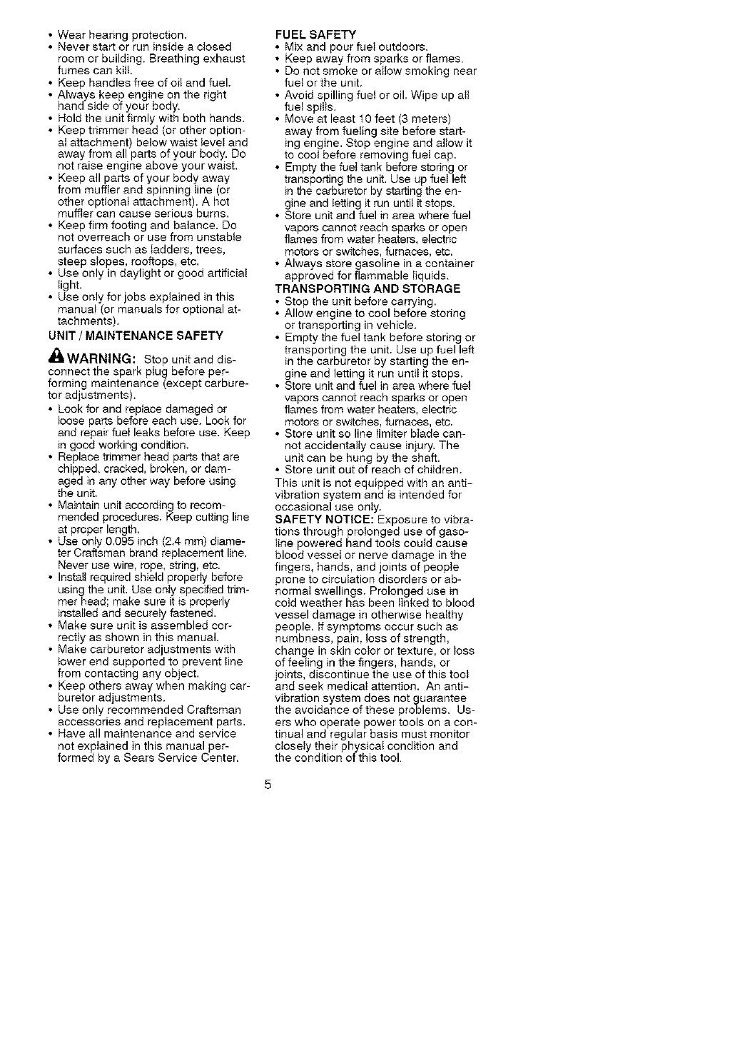
OPERATOR'S SAFETY INFORMATION
MANUAL ON THE UNIT
A_L DANGER: Never use blades
with line trimmer attachment. Never
use flailing devices with any attach-
ment. This unit (when used with sup-
plied line trimmer attachment) is de-
signed for line trimmer use only. Use
of any other accessories with line trim-
mer attachment will increase the risk
of injury.
If situations occur which are not cov-
ered in this manual, use care and
good judgment, tf you need assis-
tance, contact your Sears Service
Center or call 1-800-235-5878.
OPERATOR SAFETY
• Dress properly. Always wear safety
glasses or similar eye protection
when operating, or performing main-
tenance, on your unit (safety
glasses are available), Eye protec-
tion should be marked Z87.
• Always wear face or dust mask if op-
eration is dusty.
• Always wear heavy, long pants, tong
sleeves, boots, and gloves. Wearing
safety leg guards is recommended.
• Always wear foot protection. Do not
go barefoot or wear sandals. Stay
clear of spinning line.
• Secure hair above shoulder length.
Secure or remove loose clothing or
clothing with loosely hanging ties,
straps, tassels, etc. They can be
caught in moving parts.
•Being fully covered also helps pro-
tect you from debris and pieces of
toxic plants thrown by spinning line.
• Stay Alert. Do not operate this unit
when you are tired, ill, upset or un-
der the influence of alcohol, drugs,
or medication. Watch what you are
doing; use common sense.
4
• Wearhearingprotection.
• Neverstartorruninsideaclosed
roomorbuilding.Breathingexhaust
fumescankitL
• Keephandlesfreeofoitandfuel.
• Alwayskeepengineontheright
handsideofyourbody.
• Holdtheunitfirmlywithbothhands.
• Keeptrimmerhead(orotheroption-
atattachment)belowwaisttevetand
awayfromallpartsofyourbody.Do
notraiseengineaboveyourwaist.
• Keepallpartsofyourbodyaway
frommufflerandspinningtine(or
otheroptionatattachment).Ahot
mufflercancauseseriousburns.
• Keepfirmfootingandbalance.Do
notoverreachorusefromunstable
surfacessuchasladders,trees,
steepslopes,rooftops,etc.
• Useonlyindaylightorgoodartificial
light.
• Useonlyforjobsexplainedinthis
manual(ormanualsforoptionalat-
tachments).
UNIT /MAINTENANCE SAFETY
_ItWARNING: Stop unitand dis-
connect the spark plug before per-
forming maintenance (except carbure-
tor adjustments).
• Look for and replace damaged or
loose parts before each use. Look for
and repair fuel leaks before use. Keep
in good working condition.
• Replace trimmer head parts that are
chipped, cracked, broken, or dam-
aged in any other way before using
the unit.
• Maintain unit according to recom-
mended procedures. Keep cutting line
at proper length.
• Use only 0.095 inch (2.4 mm) diame-
ter Craftsman brand replacement line.
Never use wire, rope. string, etc.
• Install required shield properly before
using the unit. Use only specified trim-
mer head; make sure it is properly
installed and securely fastened.
• Make sure unit is assembled cor-
rectly as shown in this manual.
• Make carburetor adjustments with
lower end supported to prevent line
from contacting any object.
• Keep others away when making car-
buretor adjustments.
• Use only recommended Craftsman
accessories and replacement parts.
• Have all maintenance and service
not explained in this manual per-
formed by a Sears Service Center.
FUEL SAFETY
• Mix and pour fueI outdoors.
• Keep away from sparks or flames.
• Do not smoke or allow smoking near
fuet or the unit.
• Avoid spilling fuel or oil. Wipe up all
fuet spitis.
• Move at least t0 feet (3 meters)
away from fueling site before start-
ing engine. Stop engine and atiow it
to cool before removing fuet cap.
• Empty the fuel tank before storing or
transporting the unit. Use up fuel left
in the carburetor by starting the en-
gine and letting it run until it stops.
• Store unit and fuel in area where fuel
vapors cannot reach sparks or open
flames from water heaters, electric
motors or switches, furnaces, etc.
• Always store gasoline in a container
approved for flammable liquids.
TRANSPORTING AND STORAGE
• Stop the unit before carrying.
• Allow engine to cool before storing
or transporting in vehicle.
• Empty the fuel tank before storing or
transporting the unit. Use up fuel left
in the carburetor by starting the en-
gine and letting it run until it stops.
•Store unit and fuel in area where fuel
vapors cannot reach sparks or open
flames from water heaters, electric
motors or switches, furnaces, etc.
• Store unit so line limiter blade can-
not accidentally cause injury. The
unit can be hung by the shaft.
• Store unit out of reach of children.
This unit is not equipped with an anti-
vibration system and is intended for
occasional use only.
SAFETY NOTICE: Exposure to vibra-
tions through prolonged use of gaso-
line powered hand tools could cause
blood vesset or nerve damage in the
fingers, hands, and joints of people
prone to circulation disorders or ab-
normal swellings. Prolonged use in
cotd weather has been linked to blood
vessel damage in otherwise heaithy
people, tf symptoms occur such as
numbness, pain, loss of strength,
change in skin color or texture, or loss
of feeting in the fingers, hands, or
joints, discontinue the use of this tool
and seek medical attention. An anti-
vibration system does not guarantee
the avoidance of these problems. Us-
ers who operate power tools on acon-
tinual and regular basis must monitor
closely their physical condition and
the condition of this tool
SPECIALNOTICE:Thisunitis
equippedwithatemperaturelimiting
muffIerandsparkarrestingscreen
whichmeetstherequirementsofCali-
forniaCodes4442and4443.AttU.S.
foresttandandthestatesofCalifornia,
Idaho,Maine,Minnesota,NewJersey,
Oregon,andWashingtonrequireby
tawthatmanyinternalcombustionen-
ginesbeequippedwithasparkarrest-
ingscreen.Ifyouoperateinalocale
wheresuchregulationsexist,youare
Iegatlyresponsibleformaintainingthe
operatingconditionoftheseparts.
Failuretodosoisaviolationofthe
taw.Fornormalhomeowneruse,the
muffIerandsparkarrestingscreenwiIt
notrequireanyservice.After50hours
ofuse,werecommendthatyourmuf-
flerbeservicedorreplacedbya
SearsServiceCenter.
LINETRIMMERSAFETY
_WARNING: Inspect the area to
be trimmed before each use. Remove
objects (rocks, broken glass, nails,
wire, etc.) which can be thrown by or
become entangled in line. Hard ob-
jects can damage the trimmer head
and be thrown causing serious injury.
• Use only for trimming, scalping, mow-
ing and sweeping. Do not use for
edging, pruning or hedge trimming.
• Cut only from your left to your right.
Cutting on right side of the shieM will
throw debris away from the operator.
ADDITIONAL SAFETY RULES
FOR OPTIONAL ATTACHMENTS
_1' WARNING: For each optional
attachment used, read entire opera-
tot's manual before use and follow all
warnings and instructions in manual
and on attachment.
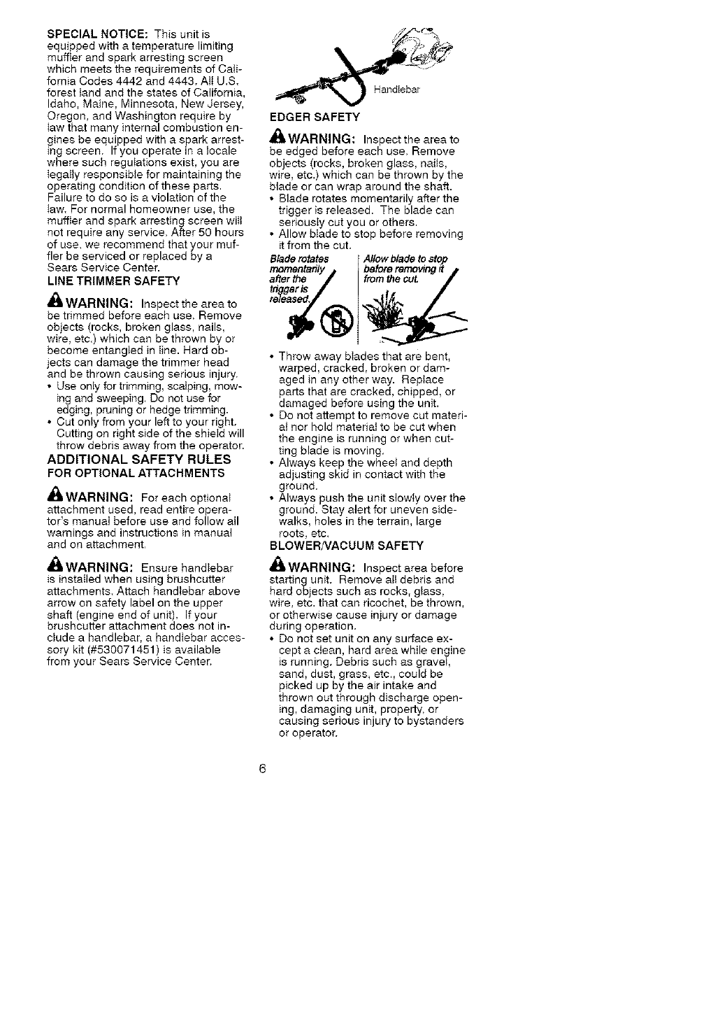
_ItWARNING: Ensure handlebar
is installed when using brushcutter
attachments. Attach handlebar above
arrow on safety label on the upper
shaft (engine end of unit). If your
brushcutter attachment does not in-
clude a handlebar, a handlebar acces-
sory kit (#530071451 ) is available
from your Sears Service Center.
EDGER SAFETY
_WARNING: Inspect the area to
be edged before each use. Remove
objects (rocks, broken glass, naits,
wire, etc.) which can be thrown by the
blade or can wrap around the shaft.
• Blade rotates momentarily after the
trigger is released. The blade can
seriously cut you or others.
• Allow bIade to stop before removing
it from the cut.
Bladerotates Allow blade tostop
before removing
after the fromthe cut,
• Throw away blades that are bent,
warped, cracked, broken or dam-
aged in any other way. Replace
parts that are cracked, chipped, or
damaged before using the unit.
• Do not attempt to remove cut mated-
at nor hold material to be cut when
the engine is running or when cut-
ting blade is moving.
• Always keep the wheet and depth
adjusting skid in contact with the
ground.
• Always push the unit slowly over the
ground. Stay alert for uneven side-
walks, holes in the terrain, large
roots, etc.
BLOWER/VACUUM SAFETY
_WARNING: Inspect area before
starting unit. Remove alt debris and
hard objects such as rocks, glass,
wire, etc. that can ricochet, be thrown,
or otherwise cause injury or damage
during operation.
• Do not set unit on any surface ex-
cept a ctean, hard area while engine
is running. Debris such as gravel,
sand, dust, grass, etc., could be
picked up by the air intake and
thrown out through discharge open-
ing, damaging unit, property, or
causing serious injury to bystanders
or operator.
• Neverptaceobjectsinsidetheblow-
ertubes,vacuumtubesorbiower
outlet.Alwaysdirecttheblowingde-
bdsawayfrompeopte,animals,
gtass,andsotidobjectssuchas
trees,automobiIes,watts,etc.The
forceofaircancauserocks,dirt,or
stickstobethrownortoricochet
whichcanhurtpeopleoranimals,
breakglass,orcauseotherdamage.
• Neverrununitwithouttheproper
equipmentattached.Whenusing
yourunitasabtower,alwaysinstall
biowertubes.
• Checkairintakeopening,blower
tubesorvacuumtubesfrequengy,
alwayswithenginestoppedand
sparkptugdisconnected.Keep
ventsanddischargetubesfreeof
debriswhichcanaccumutateand
restrictproperairflow,
• Neverplaceanyobjectinairintake
openingasthiscouldrestrictproper
airflowandcausedamagetothe
unit.
• Neveruseforspreadingchemicals,
fertilizers,orothersubstanceswhich
maycontaintoxicmaterials.
• Toavoidspreadingfire,donotuse
nearleaforbrushfires,fireplaces,
barbecuepits,ashtrays,etc.
BRUSHCUTTERSAFETY
_IIDANGER: Blade can thrust vio-
lently away from material it does not cut,
Blade thrust can cause amputation of
arms or legs,
_b, WARNING: Do not use tdmmer
head as a fastening device for the
bIade.
_WARNING: Inspect the area to
be cut before each use. Remove ob-
jects (rocks, broken glass, nails, wire,
etc.) which can be thrown or become
entangled in the blade or trimmer tine.
• Throw away and repiace blades that
are bent, warped, cracked, broken
or damaged in any other way.
• Instatt required shieId properly be-
fore using the unit, Use the metal
shield for all metal blade use.
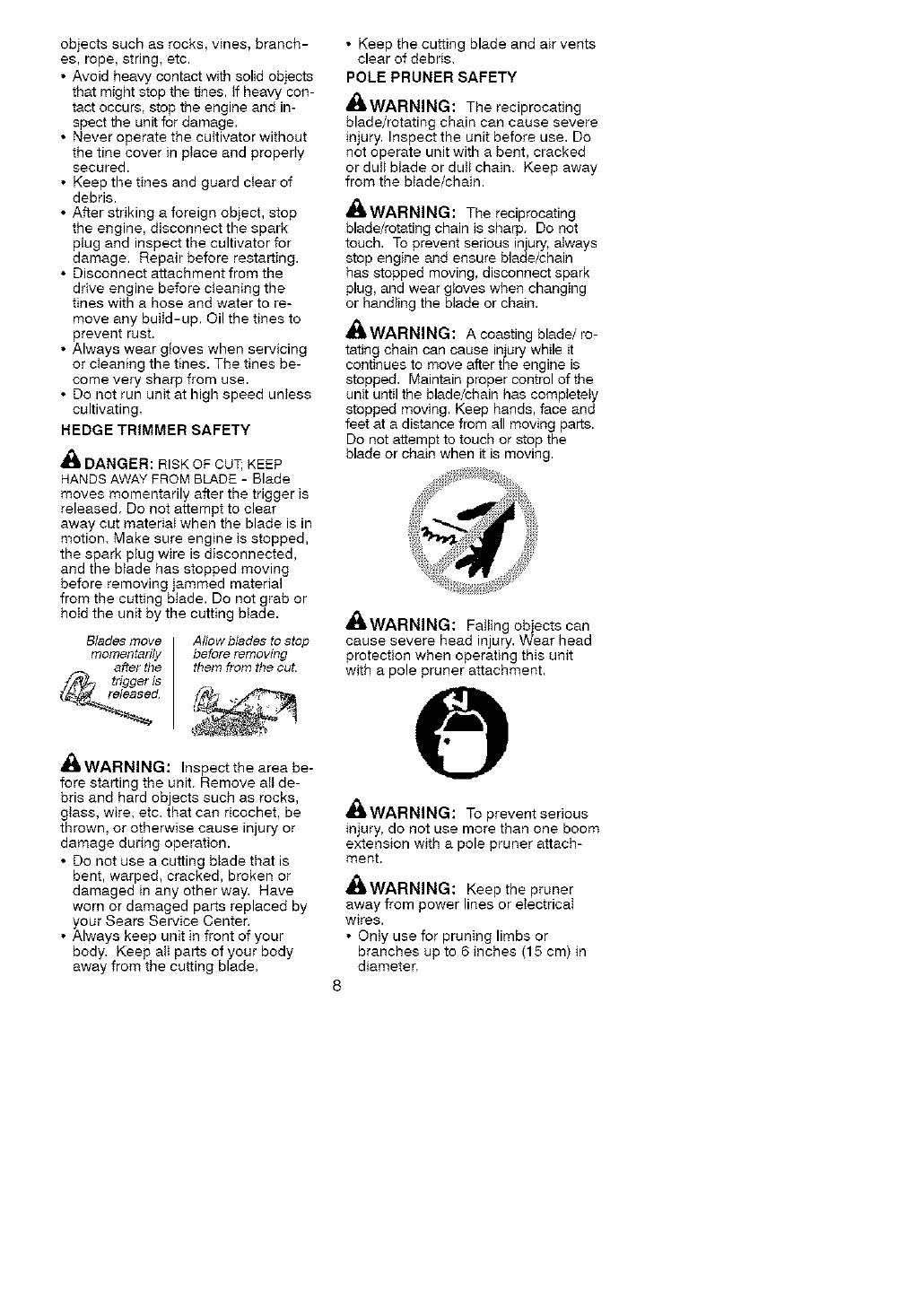
_WARNING: Onty use brushcut-
ter attachments that provide a metal
shield with protruding nose,
• Use only specified blade and make
sure it is properly installed and se-
curely fastened.
• Cut from your left to your right.
• Always use the handlebar and a
properly adjusted shoulder strap
with blade (see ASSEMBLY instruc-
tions in brushcutter attachment oper-
ator's manual).
CULTIVATOR SAFETY
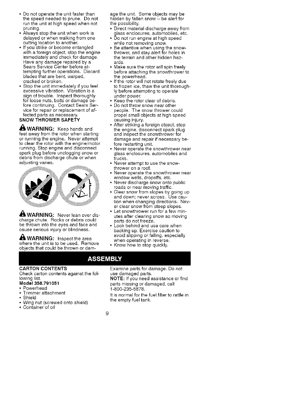
,I_ WARNING: Rotating tines can
cause serious injury, Keep away from
rotating tines, Stop the engine and
disconnect the spark plug before un-
clogging tines or making repairs.
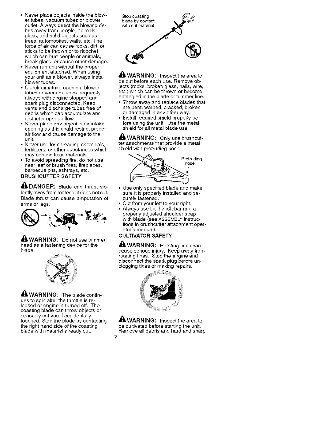
_iLWARNING: The blade contin-
ues to spin after the throttle is re-
Ieased or engine is turned off. The
coasting blade can throw objects or
seriousIy cut you if accidentally
touched. Stop the btade by contacting
the right hand side of the coasting
bIade with material already cut.
_L WARNING: Inspect the area to
be cultivated before starting the unit.
Remove all debris and hard and sharp
7
objects such as rocks, vines, branch-
es, rope, string, etc.
• Avoid heavy contact with solid objects
that might stop the tines, if heavy con-
tact occurs, stop the engine and in-
spect the unit for damage.
• Never operate the cuItivator without
the tine cover in ptace and properIy
secured.
• Keep the tines and guard clear of
debris.
• After striking a foreign object, stop
the engine, disconnect the spark
plug and inspect the cultivator for
damage. Repair before restarting.
• Disconnect attachment from the
drive engine before cteaning the
tines with a hose and water to re-
move any build-up. Oil the tines to
prevent rust.
• Always wear gloves when servicing
or cIeaning the tines. The tines be-
come very sharp from use.
• Do not run unit at high speed untess
cultivating.
HEDGE TRIMMER SAFETY
z_
_1_ DANGER: RISK OF CUT; KEEP
HANDS AWAY FROM BLADE - Blade
moves momentarily after the trigger is
released, Do not attempt to clear
away cut material when the blade is in
motion. Make sure engine is stopped,
the spark plug wire is disconnected,
and the blade has stopped moving
before removing jammed material
from the cutting blade. Do not grab or
hold the unit by the cutting blade.
Blades move Allow blades to stop
momentarily before removing
after the them from the cut.
trigger is
id
,I_ WARNING: Inspect the area be-
fore starting the unit. Remove all de-
bris and hard objects such as rocks,
g_ass, wire, etc. that can ricochet, be
thrown, or otherwise cause injury or
damage during operation.
• Do not use a cutting blade that is
bent, warped, cracked, broken or
damaged in any other way. Have
worn or damaged parts replaced by
your Sears Service Center.
• Always keep unit in front of your
body. Keep all parts of your body
away from the cutting blade.
• Keep the cutting blade and air vents
clear of debris.
POLE PRUNER SAFETY
,I_WARNING: The reciprocating
blade/rotating chain can cause severe
injury, Inspect the unit before use. Do
not operate unit with a bent, cracked
or dull blade or dull chain. Keep away
from the blade/chain.
,_i, WARNING: The reciprocating
blade/rotating chain is sharp. Do not
touch. To prevent serious injury, always
stop engine and ensure blade/chain
has stopped moving, disconnect spark
plug, and wear gtoves when changing
or handling the blade or chain.
_WARNING: A coasting blade/ro-
tating chain can cause iniury while it
continues to move after the engine is
stopped. Maintain proper control of the
unit until the blade/chain has completely
stopped moving. Keep hands, face and
feet at a distance from all moving parts.
Do not attempt to touch or stop the
blade or chain when it is moving.
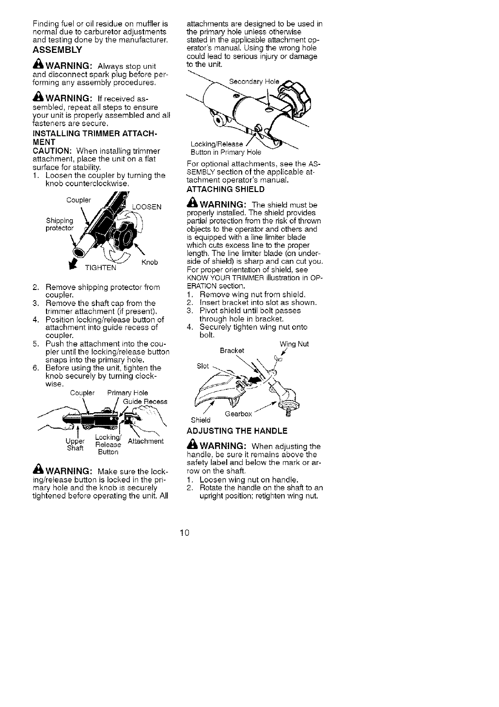
,I_ WARNING: Falting obiects can
cause severe head injury. Wear head
protection when operating this unit
with a pole pruner attachment.
_WARNING: To prevent serious
iniury, do not use more than one boom
extension with a pole pruner attach-
inert,
_,WARNING: Keep the pruner
away from power lines or eIectrica_
wires.
• Only use for pruning limbs or
branches up to 6 inches (15 cm) in
diameter.
• Donotoperatetheunitfasterthan
thespeedneededtoprune.Donot
runtheunitathighspeedwhennot
pruning.
• Alwaysstoptheunitwhenworkis
delayedorwhenwalkingfromone
cuttinglocationtoanother.
• Ifyoustrikeorbecomeentangled
withaforeignobject,stoptheengine
immediatelyandcheckfordamage,
Haveanydamagerepairedbya
SearsServiceCenterbeforeat-
temptingfurtheroperations.Discard
bladesthatarebent,warped,
crackedorbroken.
• Stoptheunitimmediatelyifyoufeet
excessivevibration,Vibrationisa
signoftrouble,inspectthoroughly
forloosenuts,boltsordamagebe-
forecontinuing.ContactSearsSer-
viceforrepairorreplacementofaf-
fectedpartsasnecessary.
SNOWTHROWERSAFETY
_WARNING:Keephandsand
feetawayfromtherotorwhenstarting
orrunningtheengine.Neverattempt
tocleartherotorwiththeengine/motor
running.Stopengineanddisconnect
sparkplugbeforeuncloggingsnowor
debrisfromdischargechuteorwhen
adjustingvanes.
_ltWARNING:Neverteanoverdis-
chargechute.Rocksordebriscould
bethrownintotheeyes and face and
cause serious injury or blindness.
_ik WARNING: Inspect the area
where the unit is to be used. Remove
objects that could be thrown or dam-
age the unit. Some objects may be
hidden by fallen snow -- be alert for
the possibility.
• Direct material discharge away from
glass enclosures, automobiles, etc,
• Do not run engine at high speed
while not removing snow.
• Be attentive when using the snow-
thrower, and stay alert for holes in
the terrain and other hidden haz-
ards.
• Make sure the rotor will spin freely
before attaching the snowthrower to
the powerhead.
• If the rotor witI not rotate freely due
to frozen ice, thaw the unit thorough-
Iy before attempting to operate
under power,
• Keep the rotor clear of debris,
• Do not throw snow near other
people. The snow thrower could
propel small objects at high speed
causing injury.
• After striking a foreign object, stop
the engine, disconnect spark plug
and inspect the snowthrower for
damage and repair if necessary be-
fore restarting unit.
• Never operate the snowthrower near
glass enclosures, automobiles and
trucks.
• Never attempt to use the snow-
thrower on a roof.
• Never operate the snowthrower near
window wells, dropoffs, etc.
• Never discharge snow onto public
roads or near moving traffic.
• Clear snow from slopes by going up
and down; never across. Use cau-
tion when changing directions. Nev-
er clear snow from steep slopes,
• Let snowthrower run for a few min-
utes after clearing snow so moving
parts do not freeze.
• Look behind and use care when
backing up. Exercise caution to
avoid slipping or falling, especially
when operating in reverse.
• Know how to stop quickly.
CARTON CONTENTS
Check carton contents against the fol-
lowing list.
Model 358.791051
• Powerhead
• Trimmer attachment
• Shield
• Wing nut (screwed onto shield)
• Container of oii
Examine parts for damage. Do not
use damaged parts.
NOTE: tf you need assistance or find
parts missing or damaged, call
1-800-235-5878.
It is normal for the fueI filter to rattle in
the empty fuel tank.
Findingfueloroilresidueonmuffleris
normatduetocarburetoradjustments
andtestingdonebythemanufacturer.
ASSEMBLY
A_I'WARNING: Always stop unit
and disconnect spark plug before per-
forming any assemMy procedures.
_WARNING: If received as-
sembIed, repeat all steps to ensure
your unit is properIy assembled and aIt
fasteners are secure,
INSTALLING TRIMMER ATTACH-
MENT
CAUTION: When instalIing trimmer
attachment, place the unit on a fiat
surface for stability.
1. Loosen the coupler by turning the
knob counterclockwise.
Coupler
Shipping
protector
Knob
TIGHTEN
2. Remove shipping protector from
coupler,
3. Remove the shaft cap from the
trimmer attachment (if present),
4. Position tocking/release button of
attachment into guide recess of
coupler,
5. Push the attachment into the cou-
pler until the locking/release button
snaps into the primary hole.
6. Before using the unit, tighten the
knob securely by turning clock-
wise.
Coupler Primary Hole
\/_uide Recess
Upp_tr Reie_ge/ Attachment
Button
A_I_WARNING: Make sure the lock-
ing/release button is locked in the pri-
mary hote and the knob is securely
tightened before operating the unit. All
attachments are designed to be used in
the primary hole unless otherwise
stated in the applicable attachment op-
erator's manual Using the wrong hote
could lead to serious injury or damage
to the unit.
Secondary Hole
Locking/Release
Button in Primary Hole
For optional attachments, see the AS-
SEMBLY section of the applicable at-
tachment operator's manual.
ATTACHING SHIELD
_WARNING: The shield must be
properly instalied. The shield provides
partiaI protection from the risk of thrown
objects to the operator and others and
is equipped with a line limiter blade
which cuts excess tine to the proper
length. The line limiter blade (on under-
side of shield) is sharp and can cut you.
For proper orientation of shield, see
KNOW YOUR TRIMMER illustration in OP-
ERATION section.
1. Remove wing nut from shield.
2. Insert bracket into stot as shown.
3. Pivot shield until bolt passes
through hole in bracket.
4. SecureIy tighten wing nut onto
bolt.
Bracket _)ng Nut
\
Slot
Gearbox
Shield
ADJUSTING THE HANDLE
_.WARNING: When adjusting the
handle, be sure it remains above the
safety label and betow the mark or ar-
row on the shaft.
1. Loosen wing nut on handIe.
2. Rotate the handle on the shaft to an
upright position; retighten wing nut.
10
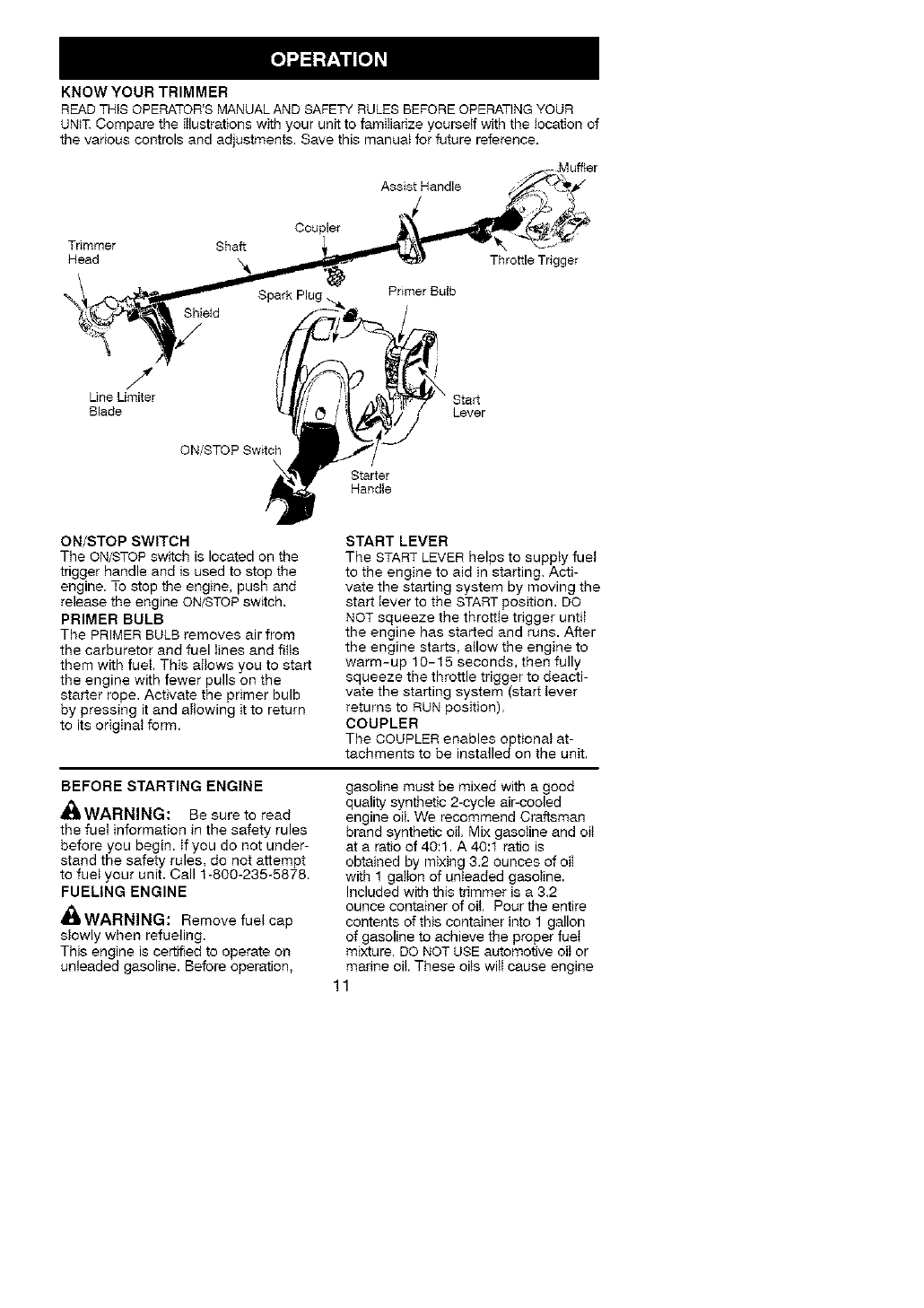
KNOW YOUR TRIMMER
READ THIS OPERATOR'S MANUAL AND SAFETY RULES BEFORE OPERATING YOUR
UNiT Compare the iIlustrations with your unit to famiIiarize yourself with the tocation of
the various controls and adjustments. Save this manual for future reference.
Assist Handle
Trimmer Shaft
Head
__ ShieM
/"
Line Umiter
Blade
ON/STOP Switch
Coupler
Primer Bulb
Starter
Handle
Throttle Trigger
\ Start
Lever
ON/STOP SWITCH
The ON/STOP switch is located on the
trigger handle and is used to stop the
engine. To stop the engine, push and
release the engine ON/STOP switch.
PRIMER BULB
The PRIMER BULB removes air from
the carburetor and fuel lines and fills
them with fuel. This allows you to start
the engine with fewer pulls on the
starter rope. Activate the primer bulb
by pressing it and allowing it to return
to its original form.
START LEVER
The START LEVER helps to supply fuet
to the engine to aid in starting. Acti-
vate the starting system by moving the
start lever to the START position. DO
NOT squeeze the throttle trigger untit
the engine has started and runs. After
the engine starts, atlow the engine to
warm-up 10-15 seconds, then fully
squeeze the throttle trigger to deacti-
vate the starting system (start lever
returns to RUN position),
COUPLER
The COUPLER enables optional at-
tachments to be installed on the unit.
BEFORE STARTING ENGINE
_IIWARNING: Be sure to read
the fuet information in the safety rules
before you begin. If you do not under-
stand the safety rules, do not attempt
to fuel your unit. Call 1-800-235-5878.
FUELING ENGINE
,_ WARNING: Remove fuet cap
slowly when refueling.
This engine is certified to operate on
unleaded gasoline. Before operation,
gasoline must be mixed with a good
quality synthetic 2-cycle air-cooled
engine oil We recommend Craftsman
brand synthetic oil. Mix gasoline and oiI
at a ratio of 40:1. A 40:1 ratio is
obtained by mixing 3.2 ounces of oiI
with 1 gallon of unleaded gasoline.
Included with this trimmer is a 3.2
ounce container of oil Pour the entire
contents of this container into 1 gallon
of gasoline to achieve the proper fuet
mixture, DO NOT USE automotive oit or
marine oil. These oils witt cause engine
11
damage.Whenmixingfuel,follow
instructionsprintedoncontainer.
Onceoilisaddedtogasoline,shake
containermomentarilytoassurethatthe
fuelisthoroughlymixed.Alwaysread
andfollowthesafetyrulesrelatingto
fuelbeforefuelingyourunit.
IMPORTANT
Experienceindicatesthatalcohol
blendedfuels(calledgasoholorusing
ethanolormethanol)canattractmois-
turewhichleadstoseparationand
formationofacidsduringstorage.
Acidicgascandamagethefuelsys-
temofanenginewhileinstorage.To
avoidengineproblems,emptythefuel
systembeforestoragefor30daysor
longer.Drainthegastank,starttheen-
gineandletitrununtilthefuellinesand
carburetorareempty.Usefreshfuel
nextseason.Neveruseengineorcar-
buretorcleanerproductsinthefuel
tankorpermanentdamagemayoc-
cur.SeetheSTORAGEsectionfor
additionalinformation.
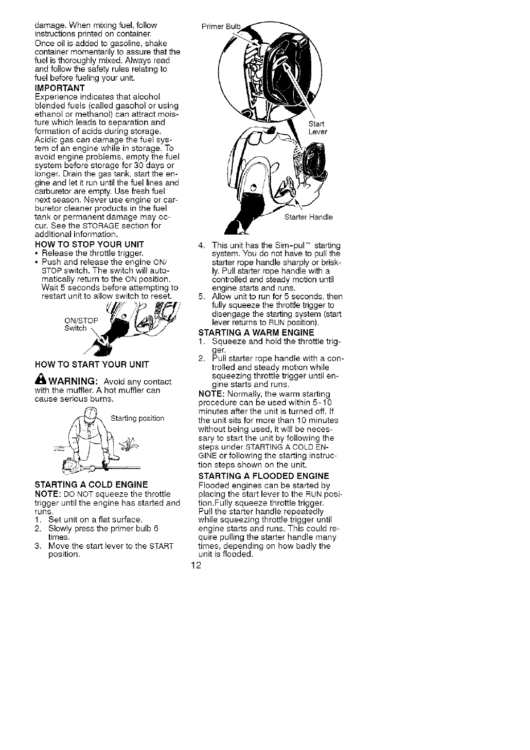
HOWTO STOP YOUR UNIT
• Release the throttle trigger.
• Push and release the engine ON/
STOP switch. The switch wilt auto-
matically return to the ON position.
Wait 5 seconds before attempting to
restart unit to allow switch to reset.
//i /
o. ,TO '
!Air
ROW TO START YOUR UNIT
4_bWARNING: Avoid any contact
with the muffler. A hot muffler can
cause serious burns.
Starting position
STARTING A COLD ENGINE
NOTE: DO NOT squeeze the throttle
trigger until the engine has started and
runs.
1. Set unit on a flat surface.
2. SIowty press the primer butb 6
times.
3. Move the start lever to the START
position.
Start
Lever
Starter Handle
4. This unit has the Sim-pul_ starting
system. You do not have to pull the
starter rope handle sharpty or brisk-
ly. Puti starter rope handle with a
controlled and steady motion until
engine starts and runs.
5. Allow unit to run for 5 seconds, then
fully squeeze the throttle trigger to
disengage the starting system (start
lever returns to RUN position).
STARTING A WARM ENGINE
1, Squeeze and hold the throttle trig-
ger=
2. Pult starter rope handle with a con-
trolled and steady motion while
squeezing throttle trigger until en-
gine starts and runs.
NOTE: Normally, the warm starting
procedure can be used within 5-t0
minutes after the unit is turned off. If
the unit sits for more than 10 minutes
without being used, it wilt be neces-
sary to start the unit by following the
steps under STARTING A COLD EN-
GINE or following the starting instruc-
tion steps shown on the unit.
STARTING A FLOODED ENGINE
Flooded engines can be started by
placing the start lever to the RUN posi-
tion.Fully squeeze throttle trigger.
Pull the starter handle repeatedly
while squeezing throttle trigger until
engine starts and runs. This could re-
quire pulting the starter handle many
times, depending on how badIy the
unit is flooded.
12
Iftheunitstilldoesn'tstart,refertothe
TROUBLESHOOTINGTABLEorcall
1-800-235-5878,
CRAFTSMAN®
CONVERTIBLETM FEATURE
This model is equipped with a coupler
which enables optional attachments to
be installed, The optional attachments
are:
Edger ................. 358.79240
Cultivator .............. 358.79241
Blower ................ 358.79242
Brushcutter ............ 358.79244
Pruner ................ 358.79245
d_kWARNING: Always stop unit
and disconnect spark plug before re-
moving or installing attachments.
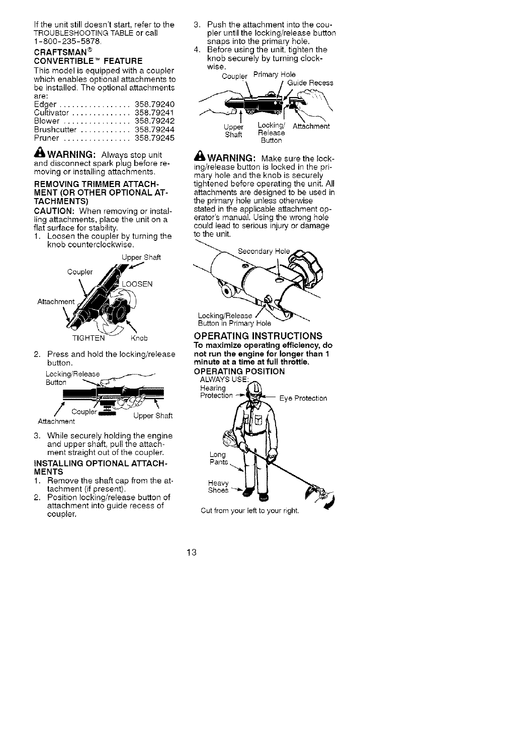
REMOVING TRIMMER ATTACH-
MENT (OR OTHER OPTIONAL AT-
TACHMENTS)
CAUTION: When removing or instal-
Iing attachments, place the unit on a
flat surface for stability.
1. Loosen the coupler by turning the
knob counterclockwise.
Upper Shaft
Coupler
LOOSEN
Attachment
TIGHTEN Knob
2. Press and hold the locking/release
button.
Locking/Release
Button
Upper Shaft
Attachment
3. While securely holding the engine
and upper shaft, pull the attach-
ment straight out of the coupler.
INSTALLING OPTIONAL ATTACH-
MENTS
1. Remove the shaft cap from tbe at-
tachment (if present).
2. Position locking/release button of
attachment into guide recess of
coupler.
3. Push the attachment into the cou-
pler until the locking/release button
snaps into the primary hole.
4. Before using the unit, tighten the
knob securely by turning clock-
wise.
Upper Locking/ Attachment
Shaft Release
Button
'_ WARNING: Make sure the lock-
ing/release button is locked in the pri-
mary hole and the knob is securely
tightened before operating the unit. All
attachments are designed to be used in
the primary hole unless otherwise
stated in the applicable attachment op-
erator's manual. Using the wrong hole
could lead to serious injury or damage
to the unit.
Secondary Hole
Locking/Release
Button inPrimary Hole
OPERATING INSTRUCTIONS
To maximize operating efficiency, do
not run the engine for longer than 1
minute at a time at full throttle.
OPERATING POSITION
ALWAYS USE:
Long
Pants ._
Heavy
Cut from your left to your right.
13
_ILWARNING: Always wear eye
protection. Always use hearing protec-
tion. Never tean over the trimmer head.
Rocks or debris can ricochet or be
thrown into eyes and face and cause
blindness or other serious injury.
When operating unit, stand as shown
and check for the following:
• Wear eye protection and heavy
clothing.
• Hold trigger handle with right hand
and assist handie with teft hand.
• Hold unit so that engine is below
waist level.
• Cut only from your left to your right to
ensure debris is thrown away from
you. Without bending over, keep line
near and parallel to the ground and
not crowded into material being cut.
Do not run the engine at a higher speed
than necessary. The cutting line wilI cut
efficiently when the engine is run at less
than futt throttle. At lower speeds, there
is less engine noise and vibration.
The cutting line wilI last longer and wilI
be tess likely to "we_d" onto the spool.
Always release the throttle trigger and
a_Iow the engine to return to idle
speed when not cutting.
HOW TO STOP YOUR UNIT
• Release the throttie trigger.
• Push and release the engine ON/
STOP switch.
TRIMMER LINE ADVANCE
The trimmer line wilt advance approxi-
mately 2 inches (5 cm) each time the
bottom of the trimmer head is tapped
on the ground with the engine running
at full throttle.
The most efficient line length is the
maximum length allowed by the line
timiter. Always keep the shield in place
when the tool is being operated.
To advance line:
• Operate the engine at futt throttle.
• Hold the trimmer head parallel to
and above the grassy area.
• Tap the bottom of the trimmer head
lightly on the ground one time. Ap-
proximately 2 inches (5 ore) of line
will be advanced with each tap.
Always tap the trimmer head on a
grassy area. Tapping on surfaces such
as concrete or asphalt can cause ex-
cessive wear to the trimmer head.
If the line is worn down to 2 inches (5
cm) or less, more than one tap will be
required to obtain the most efficient line
length.
_WARNING: Use only 0.095 inch
(2.4 ram) diameter line, Other sizes of
Iine witt not advance properly and witt
result in improper cutting head func-
tion or can cause serious injury. Do
not use other materials such as wire,
string, rope, etc. Wire can break off
during cutting and become a danger-
ous missite that can cause serious in-
jury,
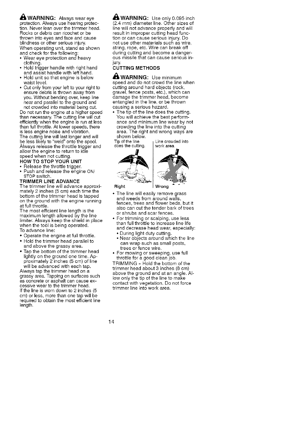
CUTTING METHODS
,I_WARNING: Use minimum
speed and do not crowd the line when
cutting around hard objects (rock,
gravel, fence posts, etc.), which can
damage the trimmer head, become
entangled in the line, or be thrown
causing a serious hazard.
• The tip of the line does the cutting.
You will achieve the best perform-
ance and minimum line wear by not
crowding the line into the cutting
area. The right and wrong ways are
shown below.
Tip of the line Line crowded into
does the cutting, work area.
Right Wrong
• The line will easiIy remove grass
and weeds from around walls,
fences, trees and flower beds, but it
also can cut the tender bark of trees
or shrubs and scar fences.
• For trimming or scalping, use less
than full throttle to increase line life
and decrease head wear, especially:
• During light duty cutting.
• Near objects around which the line
can wrap such as small posts,
trees or fence wire.
• For mowing or sweeping, use full
throttle for a good ctean job,
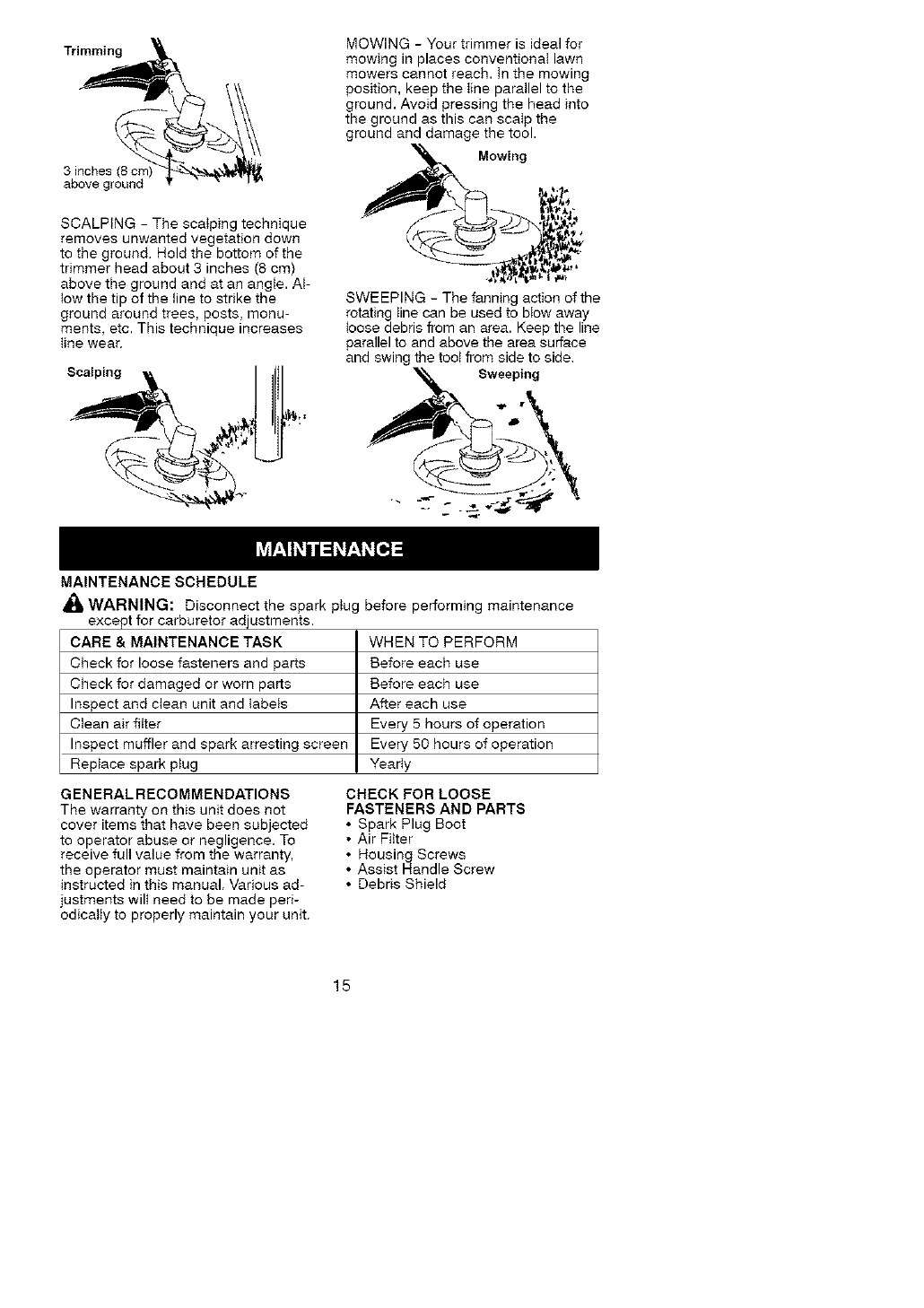
TRIMMING - Hold the bottom of the
trimmer head about 3 inches (8 cm)
above the ground and at an angle. At-
low only the tip of the line to make
contact with vegetation. Do not force
trimmer line into work area.
14
Trimming
3 inches (8 cn
above ground
SCALPtNG- The scalping technique
removes unwanted vegetation down
to the ground. Hold the bottom of the
trimmer head about 3 inches (8 cm)
above the ground and at an angle. At-
low the tip of the line to strike the
ground around trees, posts, monu-
ments, etc. This technique increases
line wear,
Scalping
MOWING - Your trimmer is ideal for
mowing in places conventionaI lawn
mowers cannot reach, tn the mowing
position, keep the line parallel to the
ground. Avoid pressing the head into
the ground as this can scalp the
ground and damage the tool.
Mowing
SWEEPING - The fanning action of the
rotating line can be used to blow away
loose debris from an area. Keep the line
parallel to and above the area surface
and swing the toot from side to side,
MAINTENANCE SCHEDULE
WARNING: Disconnect the spark plug before performing maintenance
except for carburetor adjustments,
CARE&MAINTENANCETASK
Check for loose fasteners and parts
Check for damaged or worn parts
Inspect and clean unit and tabels
Clean air filter
Inspect muffler and spark arresting screen
Replace spark plug
WHEN TO PERFORM
Before each use
Before each use
After each use
Every 5 hours of operation
Every 50 hours of operation
YearIy
G EN ERAL RECOMMENDATIONS
The warranty on this unit does not
cover items that have been subjected
to operator abuse or negligence. To
receive full value from the warranty,
the operator must maintain unit as
instructed in this manual. Various ad-
justments wilt need to be made peri-
odically to properly maintain your unit.
CHECK FOR LOOSE
FASTENERS AND PARTS
• Spark Plug Boot
• Air Filter
• Housing Screws
• Assist Handle Screw
• Debris Shield
15
CHECK FOR DAMAGED OR
WORN PARTS
Contact Sears Service Center for re-
placement of damaged or worn parts.
• ON/STOP Switch - Ensure ON/STOP
switch functions properly by pushing
and releasing the switch. Make sure
engine stops. Wait 5 seconds before
attempting to restart unit to allow
switch to reset. Restart engine and
continue.
• Fuel Tank - Discontinue use of unit
if fuel tank shows signs of damage
or leaks.
• Debris Shield - Discontinue use of
unit if debris shield is damaged.
INSPECT AND CLEAN UNIT AND
LABELS
• After each use, inspect complete
unit for toose or damaged parts,
Clean the unit and labels using a
damp cloth with a mitd detergent.
• Wipe off unit with a clean dry cloth.
CLEAN AIR FILTER
A dirty air filter decreases engine per-
formance and increases fuel con-
sumption and harmful emissions. Al-
ways clean after every 5 hours of
operation.
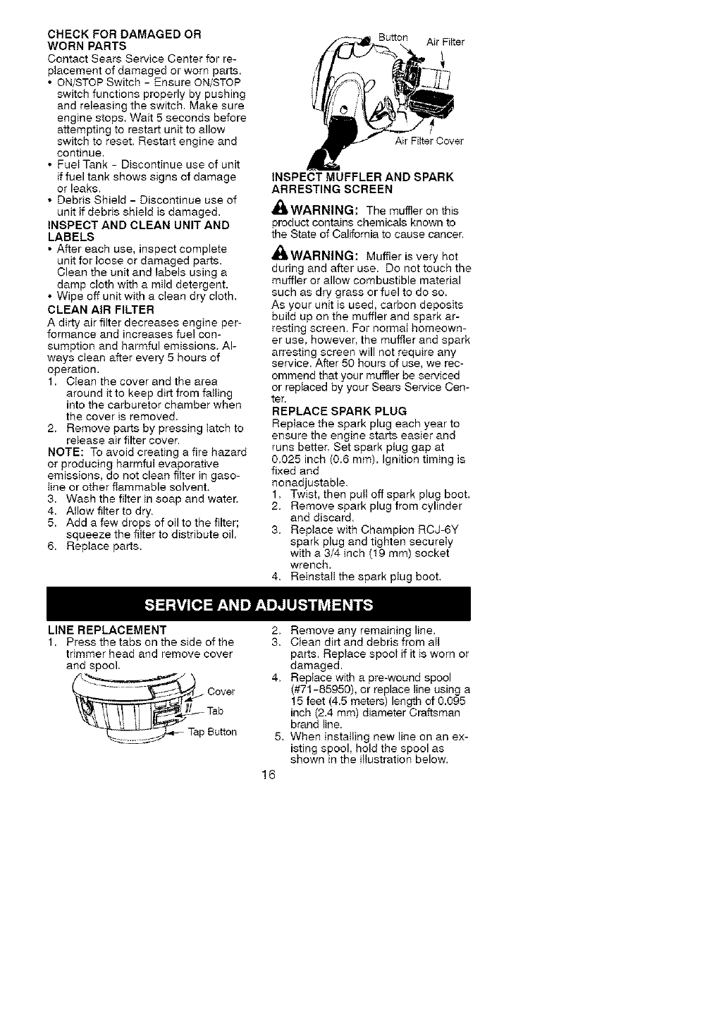
1. Clean the cover and the area
around it to keep dirt from failing
into the carburetor chamber when
the cover is removed.
2. Remove parts by pressing tatch to
release air filter cover.
NOTE: To avoid creating a fire hazard
or producing harmful evaporative
emissions, do not clean filter in gaso-
line or other flammable solvent.
3. Wash the filter in soap and water,
4. Allow filter to dry.
5. Add a few drops of oil to the filter;
squeeze the filter to distribute oil.
6. Replace parts.
Button Air Filter
Air Filter Cover
INSPECT MUFFLER AND SPARK
ARRESTING SCREEN
_WARNING: The muffleron this
product contains chemicals known to
the State of California to cause cancer.
_WARNING: Muffler is very hot
during and after use. Do not touch the
muffler or allow combustible material
such as dry grass or fuel to do so.
As your unit is used, carbon deposits
build up on the muffler and spark ar-
resting screen. For normal homeown-
er use, however, the muffter and spark
arresting screen will not require any
service. After 50 hours of use, we rec-
ommend that your muffler be serviced
or repiaced by your Sears Service Cen-
ter.
REPLACE SPARK PLUG
Replace the spark plug each year to
ensure the engine starts easier and
runs better. Set spark plug gap at
0.025 inch (0.6 mm). Ignition timing is
fixed and
nonadjustable.
1. Twist, then pult off spark plug boot.
2. Remove spark plug from cylinder
and discard.
3. Replace with Champion RCJ-6Y
spark plug and tighten secureiy
with a 3/4 inch (t9 mm) socket
wrench.
4. Reinstall the spark plug boot.
LINE REPLACEMENT
1. Press the tabs on the side of the
trimmer head and remove cover
and spool,
.... _ Cover
Tab
__ Tap Button
2. Remove any remaining line.
3. Clean dirt and debris from alt
parts. Replace spool if it is worn or
damaged.
4. Replace with a pre-wound spool
(#71-85950), or replace line using a
15 feet (4.5 meters) length of 0.095
inch (2.4 mm) diameter Craftsman
brand line.
5. When installing new line on an ex-
isting spool, hold the spool as
shown in the illustration below.
16
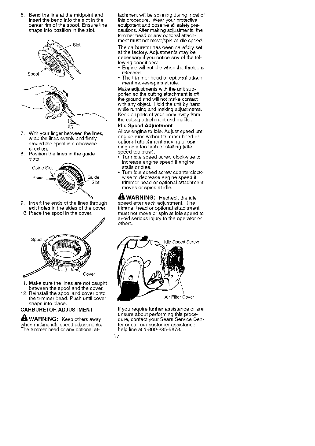
6. Bend the line at the midpoint and
insert the bend into the stot in the
center rim of the spool. Ensure line
snaps into position in the slot.
Spool _
7. With your finger between the lines,
wrap the lines evenly and firmly
around the spool in a clockwise
direction.
8. Position the lines in the guide
slots.
9. tnsert the ends of the lines through
exit holes in the sides of the cover.
10. Place the spool in the cover,
tachment witI be spinning during most of
this procedure. Wear your protective
equipment and observe atl safety pre-
cautions. After making adjustments, tile
trimmer head or any optional attach-
ment must not move/spin at idle speed.
The carburetor has been carefully set
at the factory. Adjustments may be
necessary if you notice any of the fol-
lowing conditions:
• Engine witl not idle when the throttle is
released.
• The trimmer head or optional attach-
ment moves/spins at idle.
Make adjustments with the unit sup-
ported so the cutting attachment is off
the ground and will not make contact
with any object. Hold the unit by hand
while running and making adjustments.
Keep alt parts of your body away from
the cutting attachment and muffler,
Idle Speed Adjustment
Allow engine to idle. Adjust speed until
engine runs without trimmer head or
optional attachment moving or spin-
ning (idle too fast) or stalling (idle
speed too slow).
• Turn idle speed screw clockwise to
increase engine speed if engine
stalls or dies.
• Turn idle speed screw counterclock-
wise to decrease engine speed if
trimmer head or optional attachment
moves or spins at idle.
_,WARNING: Recheck the idle
speed after each adjustment. The
trimmer head or optional attachment
must not move or spin at idle speed to
avoid serious injury to the operator or
others.
Spool Idle Speed Screw
Cover
11. Make sure the lines are not caught
between the spool and the cover.
12. Reinstall the spool and cover onto
the trimmer head. Push until cover
snaps into place.
CARBURETOR ADJUSTMENT
_iLWARNING: Keep others away
when makingidte speed adjustments,
The trimmerhead or any optional at-
Air Filter Cover
If you require further assistance or are
unsure about performing this proce-
dure, contact your Sears Service Cen-
ter or call our customer assistance
help line at 1-800-235-5878.
17
AltWARNING:Performthefollow-
ingstepsaftereachuse:
• Allowenginetocoolbeforestoring
ortransporting.
• Storeunitandfuetinawettventi-
latedareawherefuelvaporscannot
reachsparksoropenflamesfrom
waterheaters,electricmotorsor
switches,furnaces,etc.
• Storeunitwithallguardsinplace.
Positionunitsothatanysharpob-
jectcannotaccidentallycauseinjury.
• Storeunitandfuelweltoutofthe
reachofchildren.
SEASONALSTORAGE
Prepareunitforstorageatendofsea-
sonorifitwillnotbeusedfor30days
ormore.
Ifyourunitistobestoredforaperiod
oftime:
• Cleantheentire unit before lengthy
storage.
• Store in a clean dry area.
• Lightly oil external metal surfaces.
FUEL SYSTEM
Empty the fuel system before storage
for 30 days or longer. Drain the gas
tank, start the engine and let it run un-
til the fuel lines and carburetor are
empty. Use fresh fuel next season,
Under FUELING ENGINE in the OPERA-
TION section of this manual, see mes-
sage labeled IMPORTANT regarding
the use of gasohot in your engine.
Fuel stabilizer is an acceptable alter-
native in minimizing the formation of
fuel gum deposits during storage. Add
stabilizer to the gasoline in the fuel
tank or fuel storage container. Follow
the mix instructions found on stabilizer
container. Run engine at least 3 min-
utes after adding stabilizer.
Craftsman 40:1,2-cycle engine oil (air
cooled) is already blended with fuel
stabilizer, tf you do not use this Sears
oil, you can add a fuel stabilizer to
your fuel tank.
ENGINE
• Remove spark plug and pour 1 tea-
spoon of 40:1,2-cycte engine oil (air
cooled) through the spark plug
opening. Slowly pull the starter rope
8 to 10 times to distribute oil.
• Replace spark plug with new one of
recommended type and heat range.
• Clean air filter.
• Check entire unit for loose screws,
nuts, and bolts. Replace any dam-
aged, broken, or worn parts.
• At the beginning of the next season,
use only fresh fuel having the proper
gasoline to oil ratio.
OTHER
• Do not store gasoline from one sea-
son to another.
• Replace your gasoline can if it starts
to rust.
18
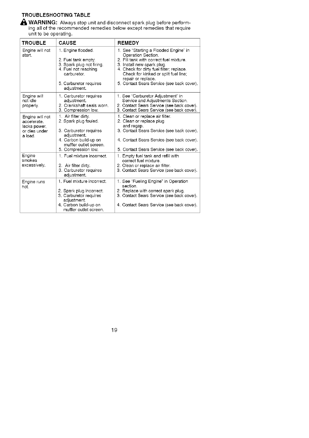
TROUBLESHOOTING TABLE
WARNING: Always stop unit and disconnect spark ptug before perform-
ing all of the recommended remedies below except remedies that require
unit to be operating,
TROUBLE CAUSE REMEDY
Engine wiII not 1. Engine flooded f See "Starting a Flooded Engine" in
start. Operation Section.
2. Fuel tank empty. 2 Fill tank with correct fuel mixture
3. Spark plug not firing. 3 Install new spark plug.
4. Fuel not reaching 4 Check for dirty fuel fiIter; replace
carburetor Check for kinked or split fuel line;
repair or repIace
5 Carburetor requires 5 Contact Sears Service (see back cover)
adjustment.
Engine will t. Carburetor requires 1. See "Carburetor Adjustment" in
not idle adjustment. Service and Adjustments Section
propedy 2 Crankshaft seals worn. 2. Contact Sears Service {see back cover).
3. Compression low. 3. Contact Sears Service {see back cover).
Engine will not 1. Air filter dirty, t. Clean or replace air filter
accelerate, 2 Spark plug fouled 2 Clean or replace plug
lacks powec and regap.
or dies under 3. Carburetor requires 3 Contact Sears Service (see back cover)
a load adjustment.
4. Carbon build-up on 4- Contact Sears Service (see back cover).
muffler outlet screen.
5. Compression low. 5 Contact Sears Service (see back cover).
Engine t. Fuel mixture incorrect 1. Empty fuel tank and refill with
smokes correct fuel mixture
excessively. 2. Air filter dirty. 2. Clean or replace air filter.
3. Carburetor requires 3. Contact Sears Service (see back cover).
adjustment.
Engine runs t. Fuel mixture incorrect. 1. See "Fueling Engine" in Operation
hot. section
2. Spark plug incorrect. 2. RepIace with correct spark plug.
3. Carburetor requires 3. Contact Sears Service {see back cover).
adjustment.
4. Carbon build-up on 4. Contact Sears Service (see back cover).
muffler outlet screen
19

YOUR WARRANTY RIGHTS AND
OBLIGATIONS: The U.S. Environ-
mental Protection Agency/California
Air Resources Board and Sears, Roe-
buck and Co., U.S.A., are pleased to
explain the emissions control system
warranty on your year 2007 and later
smaIt off-road engine, in California, all
smaIt off-road engines must be de-
signed, built, and equipped to meet
the State's stringent anti-smog stan-
dards. Sears must warrant the emis-
sion control system on your small off-
road engine for the periods of time
Iistad below provided there has been
no abuse, neglect, or improper main-
tenance of your small off-road engine.
Your emission control system includes
parts such as the carburetor, the ignition
system and the fuel tank (California
onty). Where a warrantable condition
exists, Sears will repair your small off-
road engine at no cost to you. Ex-
penses covered under warranty in-
clude diagnosis, parts and labor.
MANUFACTURER'S WARRANTY
COVERAGE: tf any emissions related
part on your engine (as listed under
Emissions Control Warranty Parts
List) is defective or a defect in the ma-
terials or workmanship of the engine
causes the faiIure of such an emission
related part, the part wilI be repaired or
replaced by Sears. OWNER'S WAR-
RANTY RESPONSIBILITIES: As the
smalt off-road engine owner, you are
responsible for the performance of the
required maintenance listed in your
operator's manual, Sears recom-
mends that you retain att receipts cov-
ering maintenance on your small off-
road engine, but Sears cannot deny
warranty solely for the lack of receipts
or for your failure to ensure the perfor-
mance of alt scheduled maintenance.
As the small off-road engine owner,
you should be aware that Sears may
deny you warranty coverage if your
smaII off-road engine or a part of it
has failed due to abuse, neglect, im-
proper maintenance, unapproved
modifications, or the use of parts not
made or approved by the original
equipment manufacturer. You are re-
sponsible for presenting your small
off-road engine to a Sears authorized
repair center as soon as a problem
exists. Warranty repairs shouid be
compIetad in a reasonable amount of
time, not to exceed 30 days.
If you have any questions regarding
your warranty rights and responsibili-
ties, you should contact your nearest
authorized service center or cait Sears
at 1-800-469-4663. WARRANTY
COMMENCEMENT DATE: The war-
ranty period begins on the date the
small off-road engine is purchased.
LENGTH OF COVERAGE: This war-
ranty shall be for a period of two years
from the initiaI date of purchase.
WHAT IS COVERED: REPAIR OR
REPLACEMENT OF PARTS. Repair
or replacement of any warranted part
wilt be performed at no charge to the
owner at an approved Sears Service
Center. If you have any questions re-
garding your warranty rights and re-
sponsibilities, you shoutd contact your
nearest authorized service center or
catt Sears at 1-800-469-4663. WAR-
RANTY PERIOD: Any warranted part
which is not scheduled for replace-
ment as required maintenance, or
which is scheduled only for regutar in-
spection to the effect of"repair or re-
place as necessary" shall be war-
ranted for 2 years. Any warranted part
which is scheduled for replacement as
required maintenance shall be war-
ranted for the period of time up to the
first scheduled replacement point for
that part, DIAGNOSIS: The owner
shall not be charged for diagnostic ta-
bor which leads to the determination
that a warranted part is defective if the
diagnostic work is performed at an ap-
proved Sears Service Center. CON-
SEQUENTIAL DAMAGES: Sears
may be liable for damages to other
engine components caused by the
failure of a warranted part still under
warranty. WHAT IS NOT COVERED:
All faiiures caused by abuse, neglect,
or improper maintenance are not cov-
ered. ADD-ON OR MODIFIED
PARTS: The use of add-on or modi-
fied parts can be grounds for disallow-
ing a warranty claim, Sears is not li-
able to cover failures of warranted
parts caused by the use of add-on or
modified parts, HOW TO FILE A
CLAIM: If you have any questions re-
garding your warranty rights and re-
sponsibilities, you shoutd contact your
nearest authorized service center or
catt Sears at 1-800-469-4663.
2O
WHERE TO GET WARRANTY SER-
VICE: Warranty services or repairs
sha}t be provided at alt Sears Service
Centers. Call t-800-469-4663.
MAINTENANCE, REPLACEMENT
AND REPAIR OF EMISSION RE-
LATED PARTS: Any Sears approved
replacement part used in the perfor-
mance of any warranty maintenance
or repair on emission related parts wilt
be provided without charge to the
owner if the part is under warrant'./.
EMISSION CONTROL WARRANTY
PARTS LIST: Carburetor, Ignition Sys-
tem: Spark Plug (covered up to main-
tenance schedule), Ignition Module,
Muffler including catalyst, Fuel Tank
(California onty). MAINTENANCE
STATEMENT:The owner is responsi-
ble for the performance of all required
maintenance as defined in the opera-
tor's manual
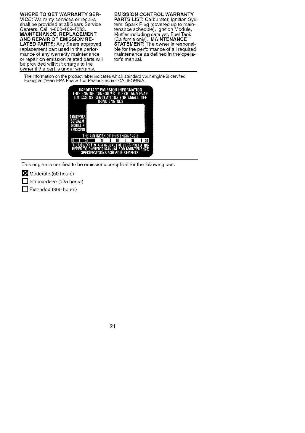
The information on the product label indicates which standard your engine is certified.
Example: (Year) EPA Phase t or Phase 2 and/or CALIFORNIA.
This engine is certified to be emissions compliant for the following use:
[] Moderate (50 hours)
[] Intermediate (125 hours)
[] Extended (300 hours)
21
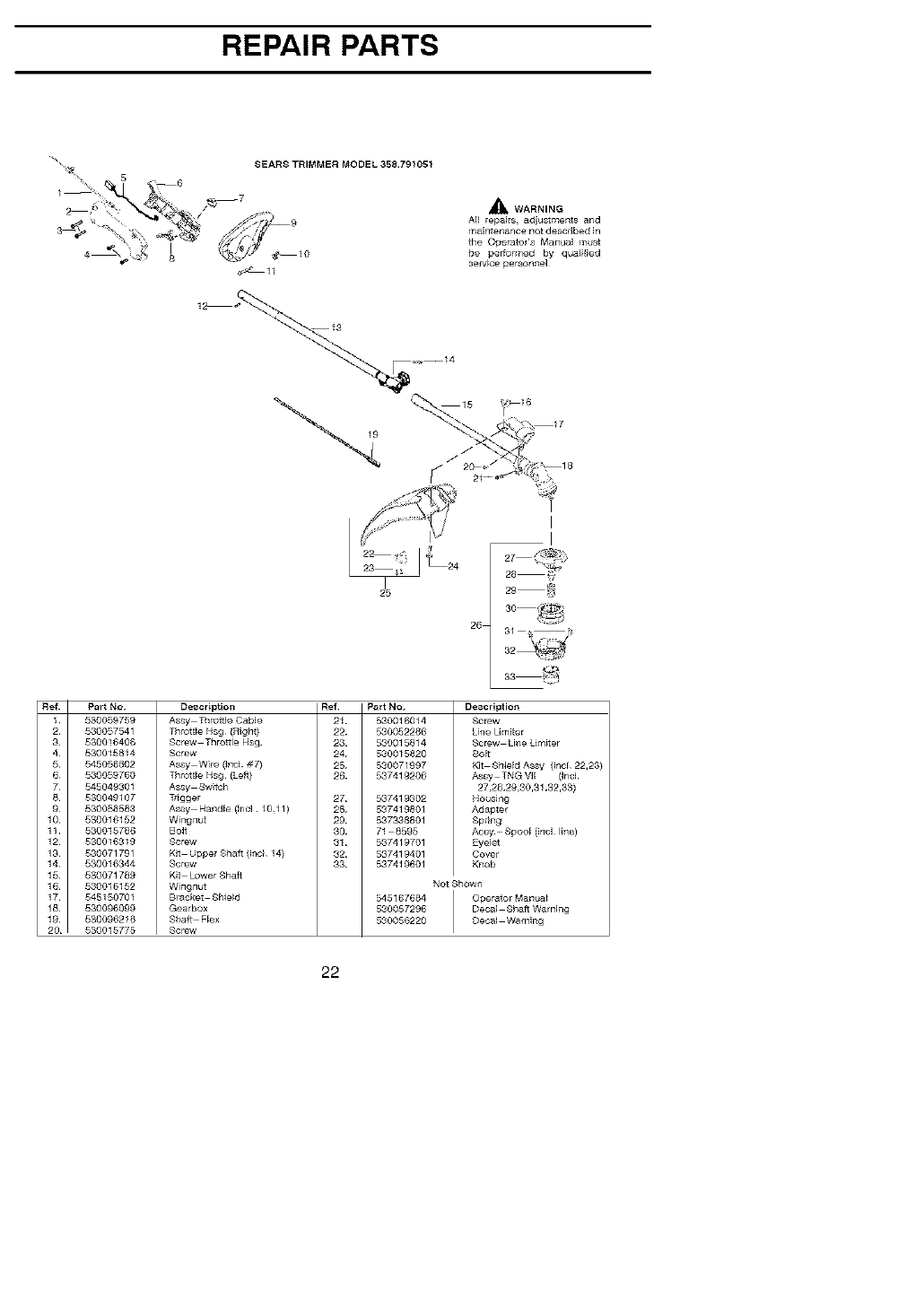
REPAIR PARTS
SEARS TRIMMER MODEL 358.791051
_--7 _ WARNING
A_I repai s, adiu_tments and
maif]t_ance not degcdbed in
the OperatoPs Manual ir_
be pe_o_med by qualified
se_vrce personnel
3
4
5
6
7
8
9
10
11.
12
13
14
15
16
17
18
19
20
Part No.
530059759
530057541
530016406
530015814
545058802
530059760
545049301
530049107
530058583
530016152
530015786
530016819
530071791
530016344
530071789
530016152
546150701
530@6099
530096216
530015775
Description Ref.
Assy Thro_e Cable 21
Throttle Hsg (Righ 0 22
Screw Thro_le HS9 23
Screw 24
Assy Wile (_ncJ #7) 25
Th_tt_e H_g(Lefl) 26
AMy _w_h
Trigger 27
AMy Handle (Inc1!0,11) 28
Wi_gnut 29
Bolt 30
Screw 31
Kit Upper Sha_ (1_c_14) 32
Screw 33
_t Lower Shaft
Wi_gnut
Blacker Shie_d
Gearbox
Shaft Flex
Screw
Part NO. Description
530016014 SCF_W
530052266 Line Umiter
530015814 screw Line Limiter
530015820 £oIt
530071997 Kit Shield As_ (l_cl 22,23)
537419206 As_ TNGWl (]ncJ
27,28,29,30,31,32,33)
537419302 Housing
537419801 Adaptel
537338801 Spring
71 8595 Accy Spool (inc_ line)
53Z419_1 Eyelet
537419401 Covel
537419601 Knob
NotShowa
545167684 OperatorManua_
530057296 Decal Shaft Warning
530056220 Decal Warning
22

REPAIR PARTS
SEARS TRIMMER MODEL 358791051
5
16
21
A WARNING
All repahn, adjustments and
maintena_qce not described in
the Ope/_or's Manila1 mu_ be
pedormed by qua!ified sel_ce
pe_onnel
51
52
53
54
55
56
I57
89 28
Ref. Part No.
1 580015880
2 530058982
3 530057863
4
5
6
7
8
Description
Screw
BoJt Mumer
Assy Muff_er_Shield
(Encl 2/
Screw Cylinder
Spark P!ug (RCJ 6Y I
Cylinder
Sea_ Cylinder (kit)
Kit Piston/Rod Ass
(Incl 9 & !2)
9 530069945 Assy Co_n Rod
10 530055120 pi_to_ Ring
11 530015162 Retainel }_i_on pi_
12 530071883 Kit P_ston(IncJ 10,11
13 580071750 Sea_ Cy_Carb(kit)
14 530057547 Adapter Carb
15 530016441 Screw
16 530071750 Gagket Ca_ (kit)
17 580071811 Kit Calb IOlU W!9
_NOTerHeparr k_[sa_e no{ avaF_ab_e I
fol _hi8 oarbLiretor/ m
8, 530059246 Air BO×
_9_ 530016429 Screw 42_
20_ 580036575 Foam A_I Filter 4G,
21 _ 530057545 Covel A_I BO×
530015953
Champion
530012541
530071750
530071785
Ref Part No.
22 530039228
23 530016357
24 545054801
25 545054901
26 545015803
27 530016886
28 530054834
29 545050409
30 530055122
81 530094189
32 530015772
33 530015814
:34 545050407
35 545080601
86 530015880
87 530059758
88 530016463
39 530039248
40 530071951
41 530012582
Description
Ignition Module
Screw
Assy Wire
SpHn_ St_er
Ashy Fan Hs_
Screw
HandleJSta_el
Kit Ro_e
Assy Clutch
Washel Olutch
Screw
Screw
Kit Pulley Sta_er
Baffle Fan
Screw B_ffle
8pacer
Washer
Assy FEywheel
Assy C_case/O'shafl
(IncL 41,42,46)
Assy Crankcase
(]_cl 43,44,45)
Ref. part No. Description
44 530019264 Sea] O'case
45 530082125 hner Beal}ng
46 530012579 Assy Crankshaft
47 580071750 O Ring C'case (kit)
48 580057954 Assy Plug (il_c147)
49 530016386 Sclew
50 530057639 Shroud Rear
51 580016445 Retainer Tank
52 580057974 Assy Fue_Tank (il]cl
filter, lines & fuel cap)
58 530057978 Assy Fuel Cap
54 580069247 Kit Fue_ Line (Small)
55 530069216 Kit Fue_ Liqe (Large)
56 530095646 Assy Fuel Pickup
57 530071750 Kit Elrgine Gasket
(_ncl 7,1&16,47)
58 530150247 Assy C_utch dlum
59 580059757 Assy C_utch Cover
(hcl 61,62)
60 530015772 Sc[ew
61 530016381 Sclew
62 580016382 Nut #12 24
Not Shown
i
530058709 I Bulb Purr_e
530015941
530055728
RetainRing O'shafl
Outer Beari#g
23
