Craftsman 358797923 User Manual LEAF BLOWER Manuals And Guides L0805054
CRAFTSMAN Blower, Gas Manual L0805054 CRAFTSMAN Blower, Gas Owner's Manual, CRAFTSMAN Blower, Gas installation guides
User Manual: Craftsman 358797923 358797923 CRAFTSMAN LEAF BLOWER - Manuals and Guides View the owners manual for your CRAFTSMAN LEAF BLOWER #358797923. Home:Lawn & Garden Parts:Craftsman Parts:Craftsman LEAF BLOWER Manual
Open the PDF directly: View PDF ![]() .
.
Page Count: 25
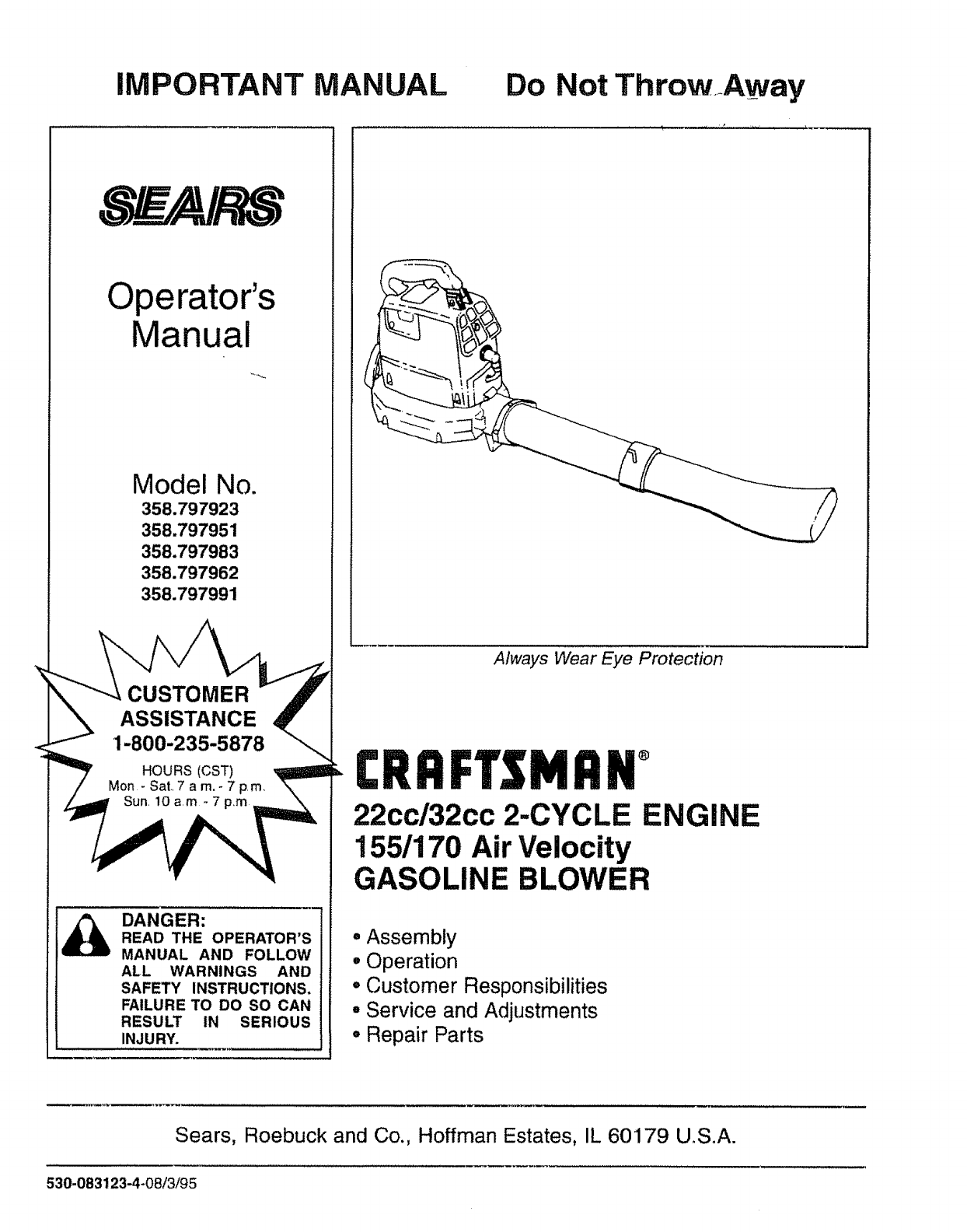
IMPORTANT MANUAL Do Not ThrowAway
Operator's
Manual
Model No.
358.797923
358.797951
358.797983
358.797962
358.797991
CUSTOMER
ASSISTANCE
DANGER:
READ THE OPERATOR'S
MANUAL AND FOLLOW
ALL WARNINGS AND
SAFETY INSTRUCTIONS.
FAILURE TO DO SO CAN
RESULT IN SERIOUS
INJURY.
Always Wear Eye Protection
CRRFTSNRN°
22cc/32cc 2-CYCLE ENGINE
155/170 Air Velocity
GASOLINE BLOWER
• Assembly
oOperation
•Customer Responsibilities
° Service and Adjustments
°Repair Parts
Sears, Roebuck and Co., Hoffman Estates, IL 60179 U.S°A.
530-083123-4-08/3/95

SAFETY RULES
CAUTION: ALWAYS DISCONNECT SPARK PLUG WIRE AND PLACE WIRE WHERE IT CANNOT CONTACT i
SPARK PLUGTO PREVENT ACCIDENTAL STARTING WHEN SETTING UP,TRANSPORTING, ADJUSTING V
OR MAKING REPAIRS°
OPERATOR SAFETY
-Always wear eye protection to prevent rocks or debris from
being blown or ricocheting into eyes and face which can result
inblindness and/or other senous tnjury,
o Always wear a respirator or facemask when working with the
unit in dusty environments.
• Always wear heavy, long pants, boots, and gloves. (To avoid
shock of static electricity, do not wear rubber gloves.) Do not
go barefoot or wear short pants, sandals, jewelry,loose cloth-
ing,or clothing with loosely hanging straps, ties, tassels, etc.;
theycan be caught inmov ng parts Secure hairso it isabove
shoulder length
• Do not operate this unit when you are tired, it],or under-the
influenceof alcohol, drugs, or medication.
• Keep others includingchildren, animals, bystanders and
helpers at least 50 feet (!5 meters) away Stop the engine
immediately if you are approached.
°inspect the area before starting the unit Remove all debris
and hard objects such as rocks, glass,wire, etc.that can rico-
chet, be thrown, or otherwise cause injury or damage during
operation.
UNIT/MAINTENANCE SAFETY
•Disconnect spark plug before perforrning maintenance except
for carburetor adjustment.
•Use only genuine replacement parts as recommended by
SEARS to avoid creating a hazard and/or voiding your war-
ranty,
oCheck air intake openings, blowertubes, elbow tube,and vac-
uum tubes frequently, always with the engine stopped. Keep
vents and tubes free of debris which can accumulate and
restrict proper air flow
° Use only quality SEARS accessories and replacement parts
as recommended for this unit..
°Have al! maintenance and service not explained in this
manual performed by your SEARS Service Center.
FUEL SAFETY
•Mix and pour fuel outdoors.
• Keep away from sparks or flames.
- Use a container approved for fuel.
• Do not smoke or ailow smoking near fuel or the unit or white
using the unit.
• Wipe up all fuel spills before starting engine,
• Move at least 10 feet (3 meters) away from fueling s_tebefore
starting engine.
• Stop engine and allow unit to cool before removingfuel cap.
OPERATION SAFETY
• Stop the engine before opening the vacuum inlet door or
attempting to insert or remove the vacuum tubesThe engine
must be stopped and the impeller blades no longerturning to
avoid serious injuryfrom the rotating blades.
•inspectthe entire unit before each use for worn,loose,miss-
ing, or damaged parts..Do not use until the unit is in proper
working order.
•Keep the outside surfaces free of oil and fuel.
•Never start or run unit inside a closed room or building.
Breathing exhaust fumes can kill.
°Never use for spreading chemicals, fertilizers, or any other
material which may contain toxic substances.
°Do not set the unit on any surface except a clean, hard area
to start the engine or while the engine is running.Debris such
as gravel,sand, dust, grass, etc.could be pickedupby the air
intake and thrown out through the discharge opening, dam-
aging the unit, property, or causing senous injury to
bystanders or the operator.
•Avoid dangerous environments..Do not use in unventilated
areas or where explosive vapors or carbon monoxide build up
could be present.
• Avoid situations which could set the vacuum bag on fire. Do
not vacuum discarded cigars or cigarettes or ash from fire-
places, barbecue pits, brush piles, etcoToavoidspreading fire,
do not use blower near leaf or brush fires, fireplaces,barbecue
pits, ashtrays, etc_
° Do not overTeachor use from unstable surfacessuch as lad-
ders, trees, steep slopes, rooftops,etc. Use extra care when
cleaning on stairways. Keep firm footing and balance at all
times.
= Never place objects inside the blower tubes; always direct the
blowing debris away from people, animals, glass, and solid
objects such as trees, automobiles, walls, etc_Theforce of air
can cause rocks, dirt, or sticks to be thrown or to ricochet
which can hurt people or'animals, break glass, or cause other
damage_Do not allow the unit to be used as a toy.
• Never place any object in the air intakeopening as this could
restrict proper air flow and cause damage to the unit.
•Never run unit without the proper equipment attached.When
used as a blower, always installa blower tube.When used as
a vacuum, always install vacuum tubes and vacuum bag
assembly.
° Use only for jobs explained in thismanual.
TRANSPORTING AND STORAGE
: Stop the unit before transporting
Allow the engine to cool, and secure the unit before storing or
transporting in a vehicle.
•Empty the fuel tank before storingor transportingthe unit.Use
up any fuel left in the carburetor by starting theengine and let-
ting the engine run until it stops.
•Store unit and fuel in an area where fuel vaporscannot reach
sparks or open flames from water heaters, electric motors or
switches,furnaces, etc
•Store the unit out of the reach of children
SAFETY NOTICE
Exposure to vibrations through prolonged use of gasoline powered hand units could cause blood vessel or nerve damage in the
fingers hands and joints of people prone to circulation disorders or abnormal swellings Prolonged use in cold weather has been
linked to blood vessel damage n otherw se healthy people, If symptoms occur' such as numbness pain, loss of strength, change in
skin co or or texture or loss of feelings in the fingers, hands orjoints discontinue the use of this unit and seek medica_ attention, An
anti-vibration system does not guarantee the avoidance of these problems, Users who operate power tools on a continual and regu-
lar basis must monitor closely their physical condition and the condition of this unit
4_ LOOK FOR THIS SYMBOL TO POINT OUT IMPORTANT SAFETY PRECAUTIONS.
IT MEANS - ATTENTION!!! BECOME ALERT!!! YOUR SAFETY IS INVOLVED.
2
SAFETY RULES
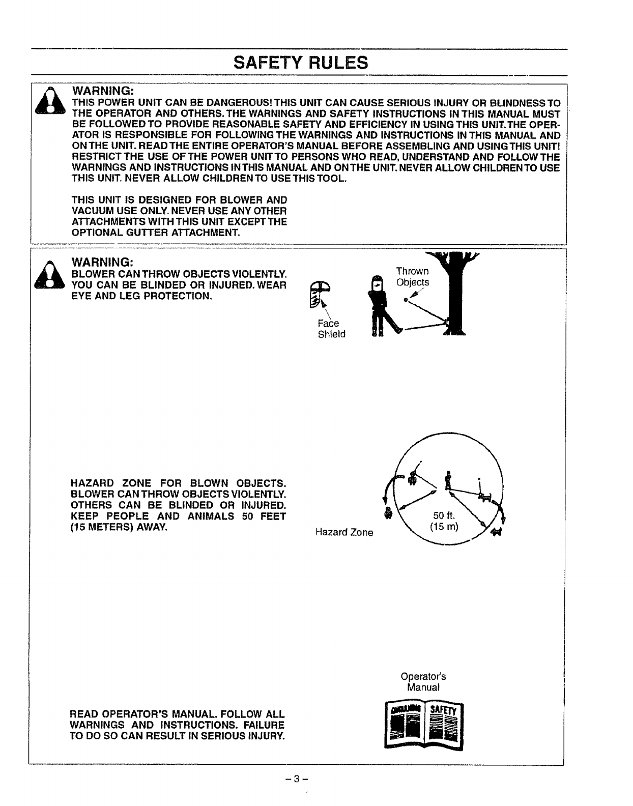
WARNING:
THIS POWER UNIT CAN BE DANGEROUS! THIS UNIT CAN CAUSE SERIOUS INJURY OR BLINDNESS TO
THE OPERATOR AND OTHERS.THE WARNINGS AND SAFETY INSTRUCTIONS IN THIS MANUAL MUST
BE FOLLOWED TO PROVIDE REASONABLE SAFETY AND EFFICIENCY IN USING THIS UNIT.THE OPER-
ATOR IS RESPONSIBLE FOR FOLLOWING THE WARNINGS AND INSTRUCTIONS IN THIS MANUAL AND
ON THE UNIT.READ THE ENTIRE OPERATOR'S MANUAL BEFORE ASSEMBLING AND USING THIS UNIT!
RESTRICT THE USE OF THE POWER UNIT TO PERSONS WHO READ, UNDERSTAND AND FOLLOW THE
WARNINGS AND INSTRUCTIONS INTHIS MANUAL AND ONTHE UNIT. NEVER ALLOW CHILDRENTO USE
THIS UNIT_NEVER ALLOW CHILDREN TO USE THIS TOOL.
THIS UNIT tS DESIGNED FOR BLOWER AND
VACUUM USE ONLY. NEVER USE ANY OTHER
ATTACHMENTS WITH THIS UNIT EXCEPT THE
OPTIONAL GUTTER ATTACHMENT.
WARNING:
BLOWER CAN THROW OBJECTS VIOLENTLY.
YOU CAN BE BLINDED OR INJURED. WEAR
EYE AND LEG PROTECTION_
Shield
Thrown
HAZARD ZONE FOR BLOWN OBJECTS.
BLOWER CAN THROW OBJECTS VIOLENTLY.
OTHERS CAN BE BLINDED OR INJURED.
KEEP PEOPLE AND ANIMALS 50 FEET
(15 METERS) AWAY. Hazard Zone
Operator's
Manual
READ OPERATOR'S MANUAL. FOLLOW ALL
WARNINGS AND INSTRUCTIONS. FAILURE
TO DO SO CAN RESULT IN SERIOUS INJURY.
-3-

CONGRATULATIONS on your purchase of a Sears
Craftsman Gasotine Blower. tt has been designed, engi-
neered and manufactured to give you the best possible
dependability and performance.
Should you experience any problems you cannot easily
remedy, please contact your nearest Sears Service Cen-
ter/Department or call the 1-800 number listed on the front
of this manual_ Sears has competent, well trained techni-
cians and the proper tools to service or repair this unit.
Please read and retain this manual. The instructions will
enable you to assemble and maintain your unit properly.
Always observe the "SAFETY RULES."
MODEL NUMBER: 358,797923
358,797951
358.797983
358.797962
358.797991
DATE CODE!SERIAL Nee:
DATE OF PURCHASE:
THE MODEL AND SERIAL NUMBER WILL BE
FOUND ON THE PRODUCT,
YOU SHOULD RECORD BOTH SERIAL NUMBER
AND DATE OF PURCHASE AND KEEP IN A SAFE
PLACE FOR FUTURE REFERENCE.
MAINTENANCE AGREEMENT
A Sears Maintenance Agreement is available on this
product,, Contact your nearest Sears Store for details_
CUSTOMER RESPONSIBILITIES
• Read and observe the safety rules
• Follow a regular schedule in maintaining, caring for, and
using your unit°
. Follow the instructions under "Customer Responsibi-
lities" and "Storage" sections of this Operator's Manual.
PRODUCT SPECIFICATIONS
YELOGITY
358.797951, 358.797962 ............. 155mph
358.797923, 358.797983 &
358.797991..........................................170mph
AIR VOLUME
358.797951, 358.797962 ...................350 cu. fL/m[n.
358.797923, 358797983 &
358..797991 ......................................... 360 cur ft/m[n.
ENGINE
358.,797951,358.797962...............22.cc2-cycle Air*Cooled
358.797923,358,797983 &
358_797991....................................32cc2-cycle Air-Cooled
ENGINE RPM
Operating...............................................7000-7600
Idle........................................................3800-4600
FUEL/OIL MIX RATIO........................40:1 (3.2 oz.per
gallongas)
IGNITION................................................Solid State
(Airgap010"to ,014")
IGNITIONTIMING.............................Non-adjustable,tixed
SPARK PLUG ..........................................Champion (RCJ-BY)
SPARK PLUG GAP.................................025"
SPECIAL NOTICE
For users on U.S. Forest Land and in some states, including
California (Public Resources Codes 4442 and 4443), Idaho,
Maine, Minnesota, New Jersey, Oregon, and Washington:
Certain internal combustion engines operated on forest,
brush, and/or grass-covered lands in the above areas are
required to be equipped with a spark arrestor, maintained in
effective working order, or the engine must be constructed,
equipped, and maintained for the prevention of fire, Check
with your state or local authorities for regulations pertaining to
these requirements.. Failure to follow these requirements is a
violation of the law..This unit is not factory-equipped with a
spark arrestor; however, a spark arrestor is available as an
optional part, If a spark arrestor is required in your area, con-
tact your SEARS Service CentedDepartmenl for the correct
kit.
MANUFACTURED UNDER ONE OR MORE OF THE FOLLOWING U.S PATENTS:
5 269 665: 52f, 1 144: 5174255; 5035 586; 4940 02B; 4,846123: 4.B74,14_; 4,474,327;
4,413,371; 4,404 706: 4.402,106; 4.387.852; 4,325,163; 4,286,675: Re,33,050; D349,983:
O322,971: D304,510; O299074; O26e,355:D263547 OTHER US AND FOREIGN
PATENTS PENDING.
FULL ONE YEAR WARRANTY ON SEARS BEST GAS BLOWER MODEL 358.797951 & 358.797962
For one (1) year from the date of purchase when this Gas Blower is maintained, lubricated, and tuned-up according to the instructions in the owner's
manual. Sears will repair, free of charge° any defect in material or workmanship
This warranty excludes the blower tubes, spark plug, and air cleaner, which are expendable parts and become worn during normar use..
If this Blower is used for commercial purposes, this warranty applies for 90 days from date of purchase, If this Blower is used for rental purposes this
warranty applies for 30 days from date of purchase This warranty, applies only while this product is in use in the United States
WARRANTY SERVICE IS AVAILABLE BY RETURNING THE BLOWER TO THE NEAREST SEARS SERVICE CENTER IN THE UNITED STATES
This warranty gives you specific legal dghts, and you may also have other rights which vary from state to state.
SEARS, ROEBUCK AND CO. DEPARTMENT 817WA, Hoffman Estates, tL 60179
FULL TWO YEAR WARRANTY ON SEARS BEST GAS BLOWER MODEL 358.797923, 358.797983 & 358,797991
For two (2) years from date of purchase, when this Gas Blower is maintained, lubrtcated_ and tuned L=paccording to the instructions in the owner's
manual, Sears will repair, free of charge any defects in material or workmanship
This warranty excludes blower tubes, spark plug and air cleaner, which are expendable parts and become worn during normal use
f this Bower [s used for commerca purposes, this warranty applies for 90 days from data of purchase, if this Blower is used for rental purposes this
warranty applies for 30 days from date of purchase This warranty appies onfy while this product is in use in the United States
WARRANTY SERVICE 1S AVAILABLE BY RETURNING THE BLOWER TO THE NEAREST SEARS SERVICE CENTER IN THE UNITED STATES
This warranty gives you specific legal rights, and you may also have other rights which vary from state to state.
SEARS, ROEBUCK AND CO,, D/817WA, Hoffman Estates, tL 60179
-4-
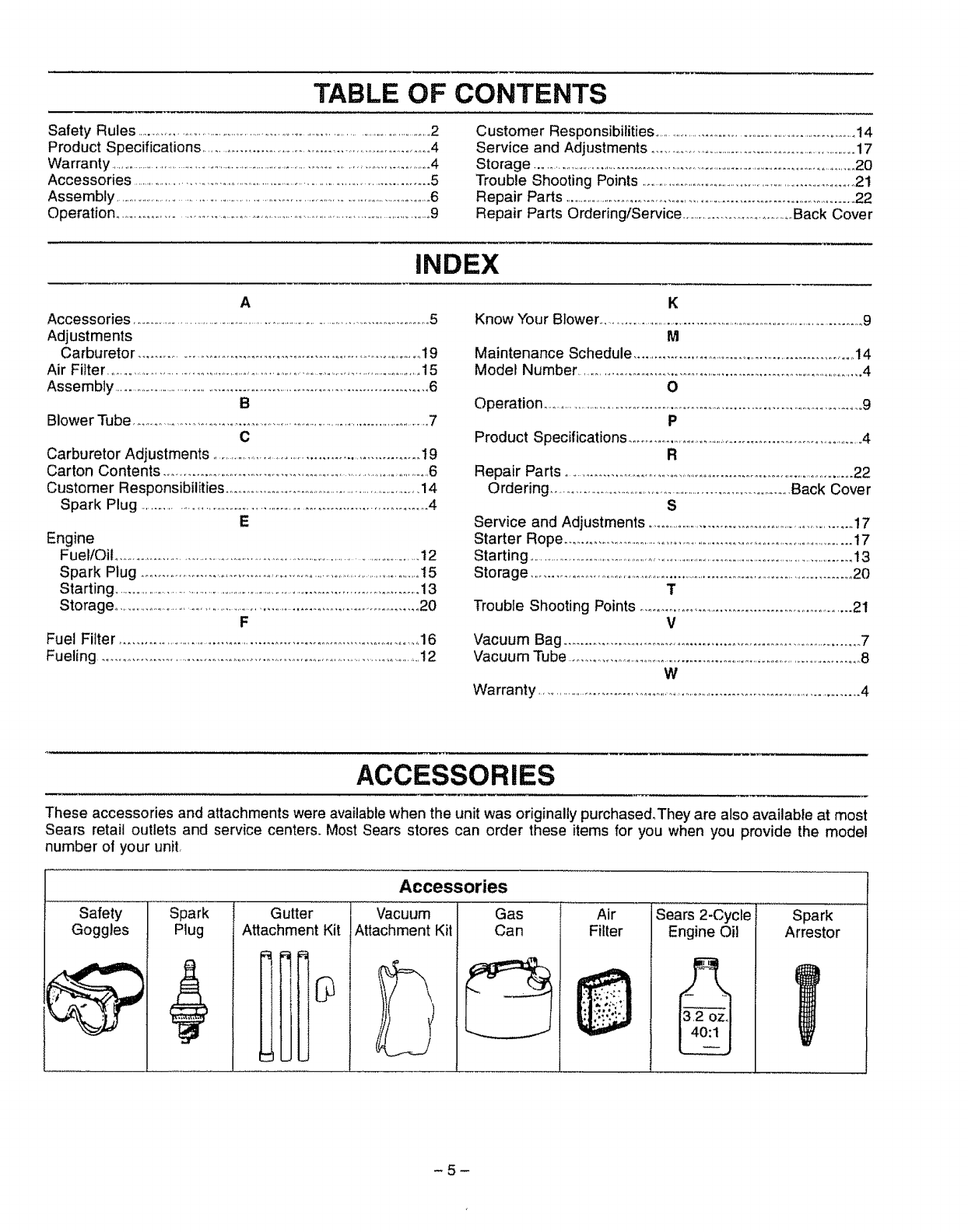
TABLE OF CONTENTS
Safety Rules ...........................................................................................2
Product Specifications ....................................................... o4
Warranty ............................................................................. 4
Accessories ..................................................................... .5
Assembly .....................................................................................6
Operation ..................................................................................9
Customer Responsibilities .................................................................14
Service and Adjustments .............................................................17
Storage ...................................................................................................20
Trouble Shooting Points ...........................................................o21
Repair Parts ..........................................................................................22
Repair Parts Ordering/Service .............................Back Cover
INDEX
A
Accessories ...................................................................................5
Adjustments
Carburetor .............................................................. 19
Air Filter ...........................................................................................15
Assembly .................................................................... 6
B
Blower Tube .......................................................................................7
C
Carburetor Adjustments .......................................... 19
Carton Contents ............................................................... .,6
Customer Responsibilities .......................................................14
Spark Plug ................................................................... 4
E
Engine
Fuel/Oil ...................................................................................12
Spark Plug ............................................................ 15
Starting ............................................................................................13
Storage,, .................................................................... 20
F
Fuel Filter ...............................................................................16
Fueling .....................................................................................! 2
K
Know Your Blower,,.............................................................................9
M
Maintenance Schedule ..................................................... 14
Model Number_ ...........................................................................4
O
Operation ................................................................. ,.9
P
Product Specifications .................................................... A
R
Repair Parts .......................................................................................22
Ordering ...................................................... Back Cover
S
Service and Adjustments ..........................................................17
Starter Rope ........................................................... t7
Starting ................................................................................. 13
Storage .............................................................................. 20
T
Trouble Shooting Points .................................................... 21
V
Vacuum Bag ........................................................................ .7
Vacuum Tube ..................................................................................8
W
Warranty ........................................................................ 4
ACCESSORIES
These accessories and attachments were available when the unit was originally purchased, They are also available at most
Sears retail outlets and service centers. Most Sears stores can order these items for you when you provide the model
number of your unit,
Accessories
..................Safety Spark Gutter .......................Vacuum ..... Gas
Goggles Plug Attachment Kit Attachment Kit Can
Air
Filter Sears 2-Cycle
Engine Oil
_J
3,2 oz.
40:1
..... Spark
Arrestor
-5-
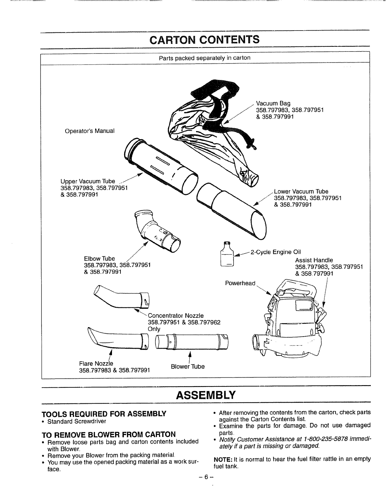
CARTON CONTENTS
Parts packed separately in carton
Vacuum Bag
358.797983, 358.797951
&358,797991
Operator's Manual
Upper Vacuum Tube _._%
358.797983, 358,797951 _ //_"'_/_"_ Lower Vacuum Tube
&358.797991 L/_/J'358.797983, 358.797951
_ & 358°797991
.=....f2-Cycle Engine Oil
&
EIbowTube /I1 Assist Handle
358.797983, 358.797951 _ 358.797983, 358.797951
& 35&797991 & 358797991
"_"-_oncentrator Nozzle
358.797951 & 358.797962
%___
Flare Nozzle Blower Tube
358°797983 & 358°797991
Powerhead
ASSEMBLY
TOOLS REQUIRED FOR ASSEMBLY
•Standard Screwdriver
TO REMOVE BLOWER FROM CARTON
•Remove loose parts bag and carton contents included
with Blower,
° Remove your Blower from the packing material,
•You may use the opened packing material as a work sur-
face.,
• After removing the contents from the carton, check parts
against the Carton Contents list,
• Examine the parts for damage_ Do not use damaged
parts.
•Notify Customer Assistance at 1-800-235-5878 immedi-
ately ff a pat1 is missing or damaged.
NOTE: It is normal to hear the fuel filter rattle in an empty
fuel tank.
-6-
ASSEMBLY
HOW TO ASSEMBLE YOUR BLOWER
WARNING:
Stop the engine before opening the vacuum
inlet door or attempting to insert or remove
the vacuum tubes. The engine must be
stopped and the impeller blades no longer
turning to avoid serious injury from the
rotating blades.
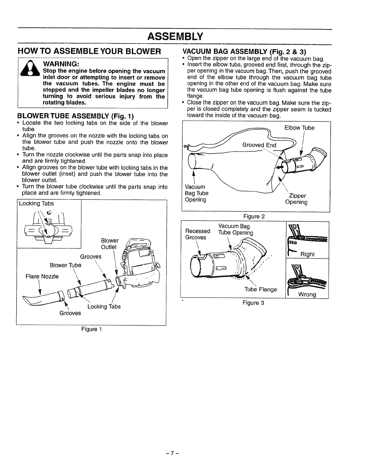
BLOWER TUBE ASSEMBLY (Fig. 1)
• Locate the two locking tabs on the side of the blower
tube.
• Align the grooves on the nozzle with the locking tabs on
the blower tube and push the nozzle onto the blower
tube,,
• Turn the nozzle clockwise until the parts snap into place
and are firmly tightened,
• Align grooves on the blower tube with locking tabs in the
blower outlet (inset) and push the blower tube into the
blower outlet.
° Turn the blower tube clockwise until the parts snap into
place and are firmly lightene&
Locking Tabs
Blower
Outlet
Grooves
Blower Tube ',,
Flare Nozzle \\
LockingTabs
Grooves
VACUUM BAG ASSEMBLY (Fig. 2 &3)
•Open the zipper on the large end of the vacuum bag.
° insert the elbow tube, grooved end first, through the zip-
per opening in the vacuum bag.,Then, push the grooved
end of the elbow tube through the vacuum bag tube
opening in the other end of the vacuum bag,,Make sure
the vacuum bag tube opening is flush against the tube
flange,.
•Close the zipper on the vacuum bag.,Make sure the zip-
per is closed completely and the zipper seam is tucked
toward the inside of the vacuum bag,
Grooved End
Elbow Tube
/
Vacuum \
Bag Tube Zipper
Opening Opening
Figure 2
Vacuum Bag
Recessed Tube Opening
Tube Flange
Right
Figure 3
Figure 1
ASSEMBLY
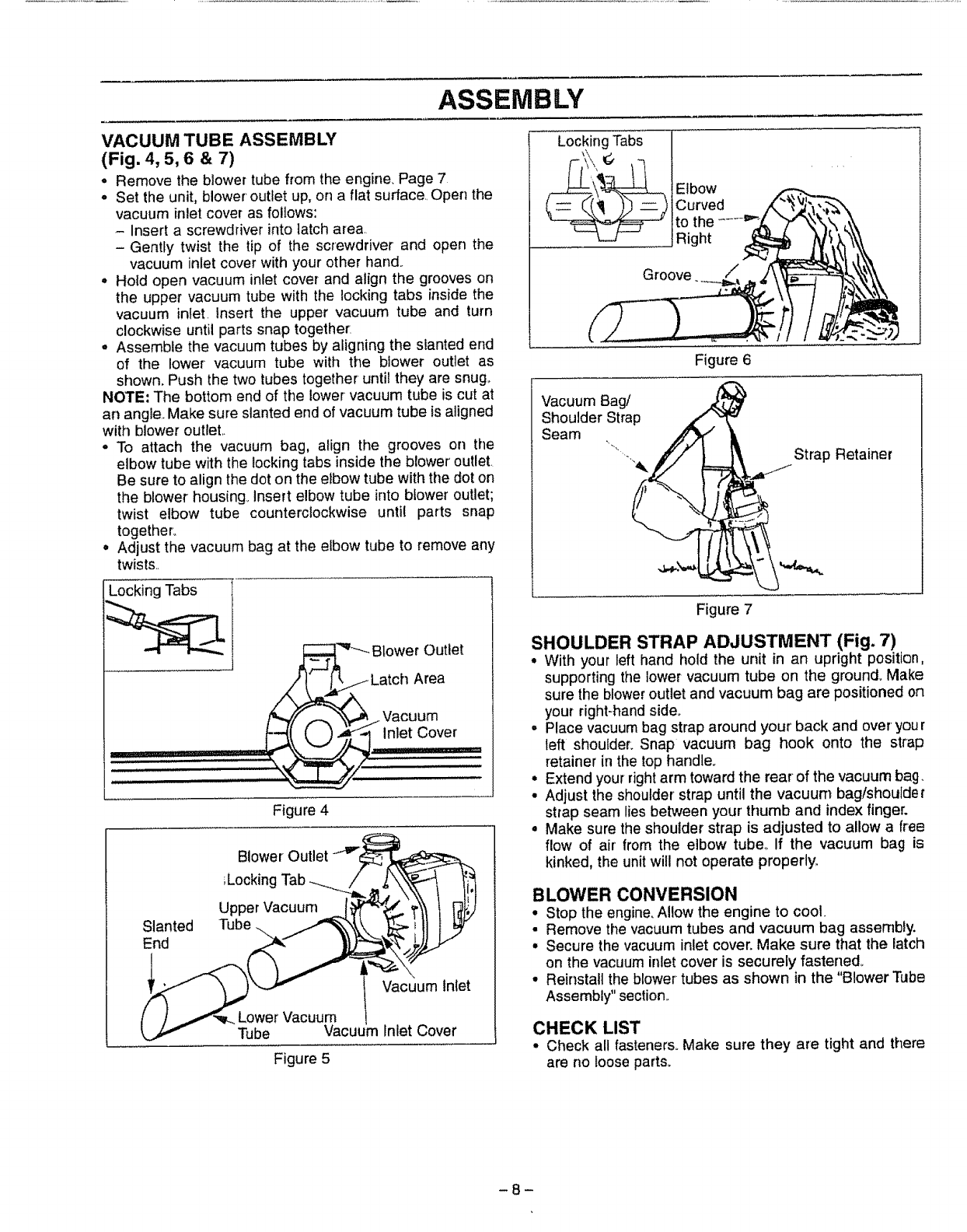
VACUUM TUBE ASSEMBLY
(Fig. 4, 5, 6 & 7)
•Remove the blower tube from the engine_ Page 7
= Set the unit, blower outlet up, on a flat surface.. Open the
vacuum inlet cover as follows:
- Insert a screwdriver into latch area.
-Gently twist the tip of the screwdriver and open the
vacuum inlet cover with your other hand.
=Hold open vacuum inlet cover and align the grooves on
the upper vacuum tube with the locking tabs inside the
vacuum inlet. Insert the upper vacuum tube and turn
clockwise until parts snap together.
° Assemble the vacuum tubes by aligning the slanted end
of the lower vacuum tube with the blower outlet as
shown. Push the two tubes together until they are snug_
NOTE; The bottom end of the lower vacuum tube is cut at
an angle. Make sure slanted end of vacuum tube is aligned
with blower outleL
° To attach the vacuum bag, align the grooves on the
elbow tube with the locking tabs inside the blower' outlet
Be sure to align the dot on the elbow tube with the dot on
the blower housing° Insert elbow tube into blower outlet;
twist elbow tube counterclockwise until parts snap
together,
° Adjust the vacuum bag at the elbow tube to remove any
twists..
Locking Tabs
'_"--- Blower Outlet
_ Latch Area
Vacuum
_,_ inlet Cover
Figure 4
Slanted
End
Blower Outlet
;Locking
Upper Vacuum
Tube ._._
Lower Vacuum 1
Tube vacuum
Figure 5
Vacuum Inlet
Inlet Cover
Locking Tabs
Elbow
Curved
to the
iRight
Groove /
Figure 6
Vacuum Bag/ x,_
Shoulder Strap x'" ."
Seam "...` __=
., Strap Retainer
Figure 7
SHOULDER STRAP ADJUSTMENT (Fig. 7)
•With your left hand hold the unit in an upright position,
supporting the lower vacuum tube on the ground. Make
sure the blower outlet and vacuum bag are positioned on
your right-handside°
•Place vacuumbag strap around your'back and over your
left shoulder. Snap vacuum bag hook onto the strap
retainer in the top handle.
•Extend yourrightarm toward the rear of the vacuum bag.
• Adjust the shoulder' strap until the vacuum bag/shoulder
strap seam lies between your' thumb and index finger.
, Make sure the shoulder strap is adjusted to allow afree
flow of air from the elbow tube. If the vacuum bag is
kinked, the unitwill not operate properly.
BLOWER CONVERSION
°Stop the engine. Allow the engine to cool.
• Remove the vacuum tubes and vacuum bag assembly
° Secure the vacuum inlet cover, Make sure that the latch
on the vacuum inlet cover is securely fastened_
• Reinstall the blower tubes as shown in the "Blower Tube
Assembly" section.
CHECK LIST
° Check all fastener& Make sure they are tight and there
are no Ioose part&
-8-
OPERATION
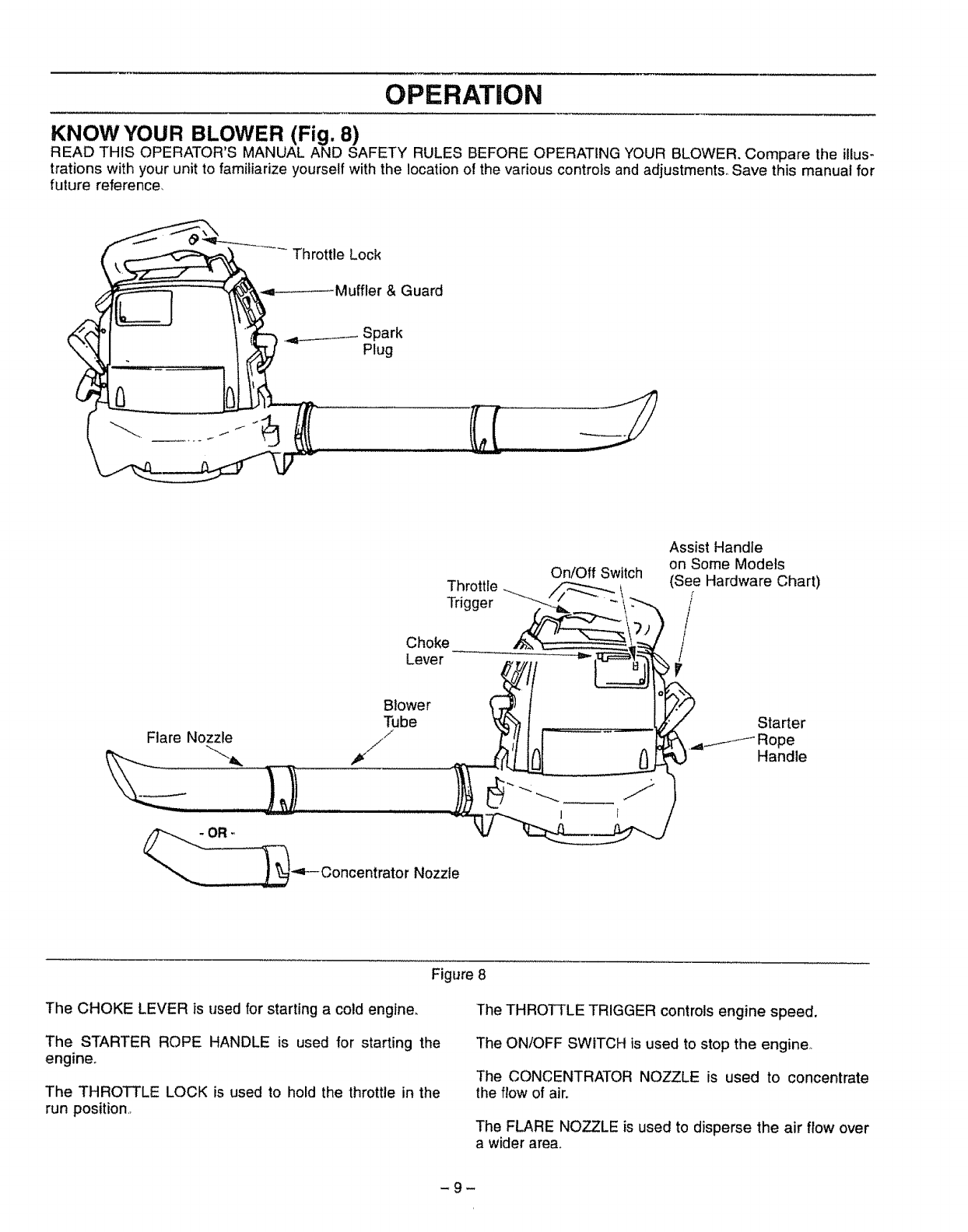
KNOW YOUR BLOWER (Fig. 8)
READ THIS OPERATOR'S MANUAL AND SAFETY RULES BEFORE OPERATING YOUR BLOWER. Compare the illus-
trations with your unit to familiarize yourself with the location of the various controls and adjustments. Save this manual for
future reference,
---- Throttle Lock
& Guard
4_ Spark
Plug
On/Off Switch
Trihggtlele_-___
Choke
Lever
Flare Nozzle
Blower
Tube
.i
__,4F--Concentrator Nozzle
1
Assist Handle
on Some Models
(See Hardware Chart)
/
r
Starter
.4_iJ-- Rope
Handle
Figure 8
The CHOKE LEVER is used for starting a cold engine, The THROTTLE TRIGGER controls engine speed.
The STARTER ROPE HANDLE is used for starting the
engine°
The THROTTLE LOCK is used to hold the throttle in the
run position,,
The ON/OFF SWITCH is used to stop the engine.
The CONCENTRATOR NOZZLE is used to concentrate
the flow of air.
The FLARE NOZZLE is used to disperse the air flow over
a wider area_
-9-
OPERATION SAFETY
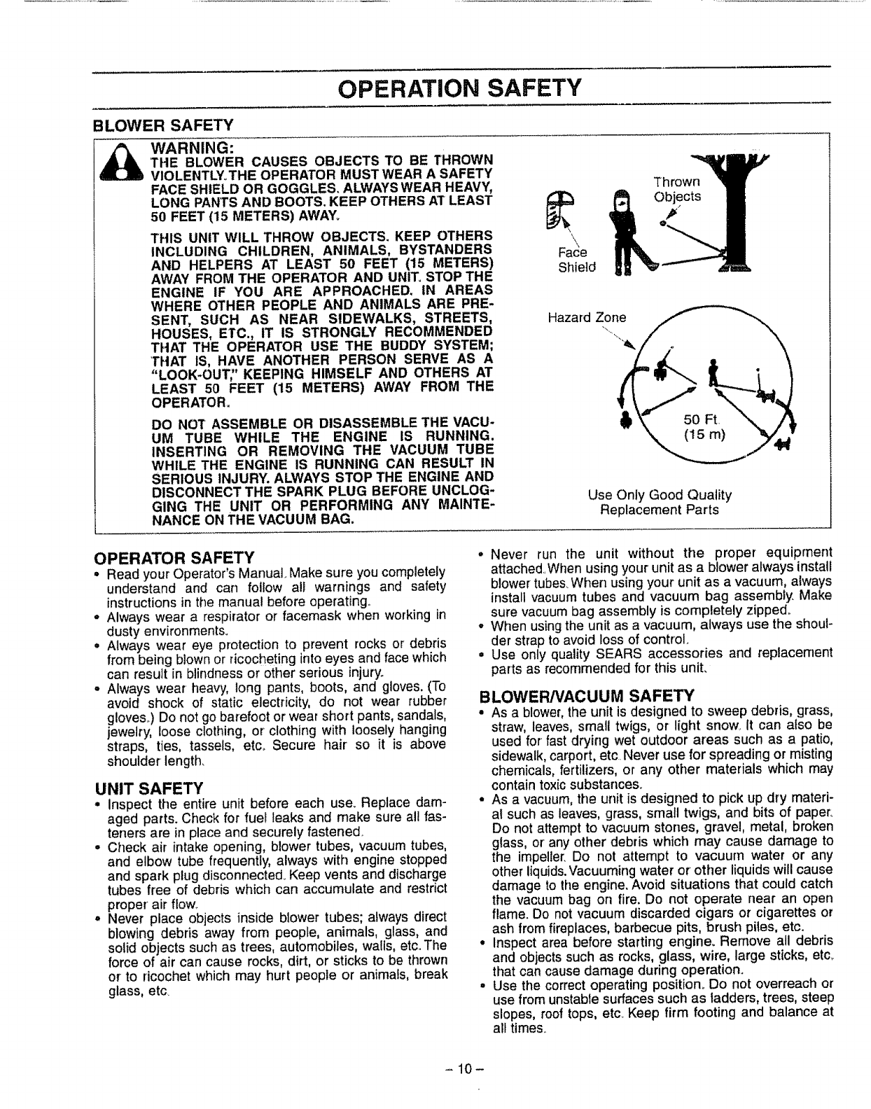
BLOWER SAFETY
WARNING:
THE BLOWER CAUSES OBJECTS TO BE THROWN
VIOLENTLYoTHE OPERATOR MUST WEAR A SAFETY
FACE SHIELD OR GOGGLES, ALWAYS WEAR HEAVY,
LONG PANTS AND BOOTS. KEEP OTHERS AT LEAST
50 FEET (15 METERS) AWAY,
THIS UNIT WILL THROW OBJECTS. KEEP OTHERS
INCLUDING CHILDREN, ANIMALS, BYSTANDERS
AND HELPERS AT LEAST 50 FEET (15 METERS)
AWAY FROM THE OPERATOR AND UNIT_STOP THE
ENGINE IF YOU ARE APPROACHED. IN AREAS
WHERE OTHER PEOPLE AND ANIMALS ARE PRE-
SENT, SUCH AS NEAR SIDEWALKS, STREETS,
HOUSES, ETC., IT IS STRONGLY RECOMMENDED
THAT THE OPERATOR USE THE BUDDY SYSTEM;
'THAT IS, HAVE ANOTHER PERSON SERVE AS A
"LOOK-OUT;' KEEPING HIMSELF AND OTHERS AT
LEAST 50 FEET (15 METERS) AWAY FROM THE
OPERATOR.
DO NOT ASSEMBLE OR DISASSEMBLE THE VACU-
UM TUBE WHILE THE ENGINE IS RUNNING.
INSERTING OR REMOVING THE VACUUM TUBE
WHILE THE ENGINE IS RUNNING CAN RESULT IN
SERIOUS INJURY. ALWAYS STOP THE ENGINE AND
DISCONNECT THE SPARK PLUG BEFORE UNCLOG-
GING THE UNIT OR PERFORMING ANY MAINTE-
NANCE ON THE VACUUM BAG.
Thrown
_LObjects
Shield
Hazard Zone
Use Only Good Quality
Replacement Parts
OPERATOR SAFETY
°Read your Operator's Manual. Make sure you completely
understand and can follow all warnings and safety
instructions in the manual before operating.
-Always wear a respirator or facemask when working in
dusty environments.
oAlways wear eye protection to prevent rocks or debris
from being blown or ricocheting into eyes and face which
can result in blindness or other serious injury.
°Always wear heavy, long pants, boots, and gloves. (To
avoid shock of static electricity, do not wear rubber
gloves..) Do not go barefoot or wear short pants, sandals,
jewelry, loose clothing, or clothing with loosely hanging
straps, ties, tassels, etc_ Secure hair so it is above
shoulder length.
UNIT SAFETY
o inspect the entire unit before each use_ Replace dam-
aged parts. Check for rue! leaks and make sure all fas-
teners are in place and securely fastened
°Check air intake opening, blower tubes, vacuum tubes,
and elbow tube frequently, always with engine stopped
and spark plug disconnected.Keep vents and discharge
tubes free of debris which can accumulate and restrict
proper air flow
,, Never place objects inside blower tubes; always direct
blowing debris away from people, animals, glass, and
solid objects such as trees, automobiles, walls, etc. The
force of air can cause rocks, dirt, or sticks to be thrown
or to ricochet which may hurt people or animals, break
glass, etc
•Never run the unit without the proper equiprnent
attached., When using your unit as a blower always install
blower tubes, When using your unit as a vacuum, always
install vacuum tubes and vacuum bag assembly, Make
sure vacuum bag assembly is completely zipped°
° When using the unit as a vacuum, always use the shoul-
der strap to avoid loss of control,
• Use only quality SEARS accessories and replacement
parts as recommended for this unit,
BLOWER/VACUUM SAFETY
•As ablower, the unit is designed to sweep debris, grass,
straw, leaves, small twigs, or light snow It can also be
used for fast drying wet outdoor areas such as a patio,
sidewalk, carport, etc Never use for spreading or misting
chemicals, fertilizers, or any other materials which may
contain toxicsubstances.
•As a vacuum, the unit is designed to pick up dry materi-
al such as leaves, grass, small twigs, and bits of paper.
Do not attempt to vacuum stones, gravel, metal, broken
glass, or any other debris which may cause damage to
the impeller, Do not attempt to vacuum water or any
other liquids. Vacuuming water or other liquids will cause
damage to the engine, Avoid situations that could catch
the vacuum bag on fire. Do not operate near an open
flame. Do not vacuum discarded cigars or cigarettes or
ash from fireplaces, barbecue pits, brush plies, etc.
• Inspect area before starting engine. Remove all debris
and objects such as rocks, glass, wire, large sticks, etc.
that can cause damage during operation.
°Use the correct operating position° Do not overreach or
use from unstable surfaces such as ladders, trees, steep
slopes, roof tops, etc_Keep firm footing and balance at
al} times.
-10-
OPERATION
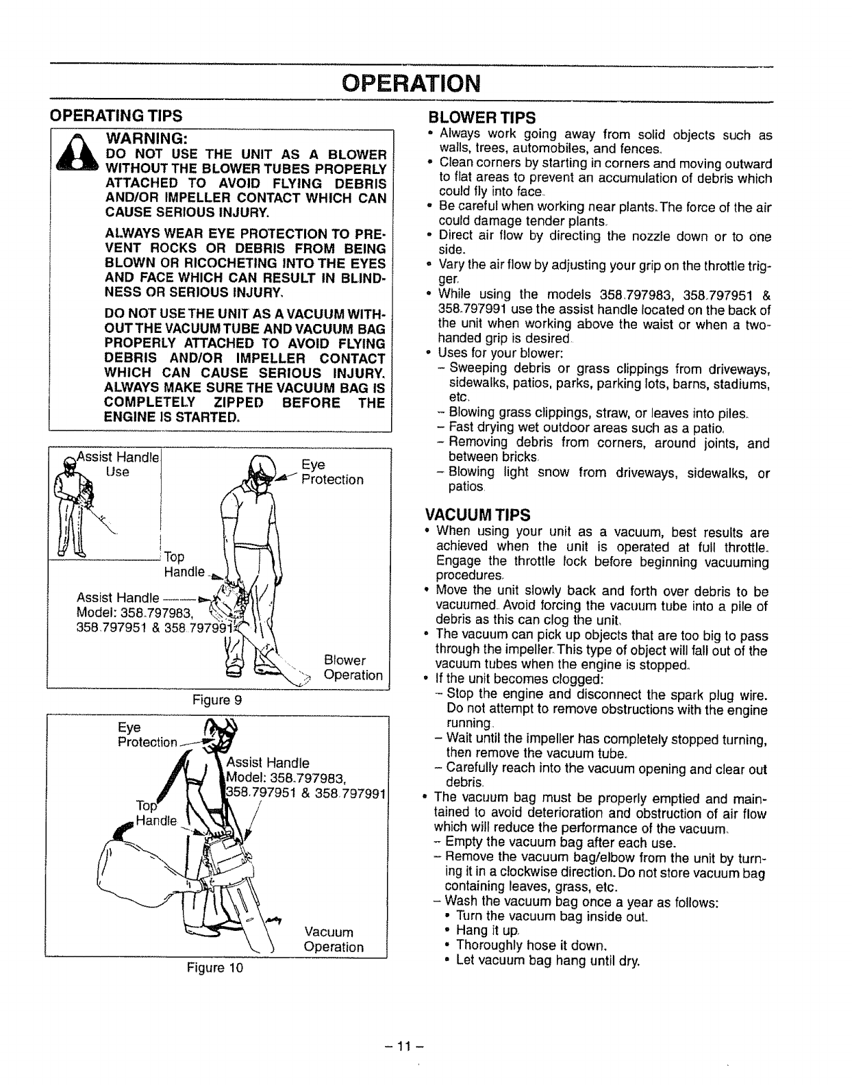
OPERATING TIPS
WARNING:
DO NOT USE THE UNIT AS A BLOWER
WITHOUT THE BLOWER TUBES PROPERLY
ATTACHED TO AVOID FLYING DEBRIS
AND/OR IMPELLER CONTACT WHICH CAN
CAUSE SERIOUS INJURY.
ALWAYS WEAR EYE PROTECTION TO PRE-
VENT ROCKS OR DEBRIS FROM BEING
BLOWN OR RICOCHETING INTO THE EYES
AND FACE WHICH CAN RESULT IN BLIND-
NESS OR SERIOUS INJURY,
DO NOT USETHE UNIT AS A VACUUM WITH-
OUTTHE VACUUM TUBE AND VACUUM BAG
PROPERLY ATTACHED TO AVOID FLYING
DEBRIS AND/OR IMPELLER CONTACT
WHICH CAN CAUSE SERIOUS INJURY,
ALWAYS MAKE SURE THE VACUUM BAG IS
COMPLETEI:Y ZIPPED BEFORE THE
ENGINE IS STARTED_
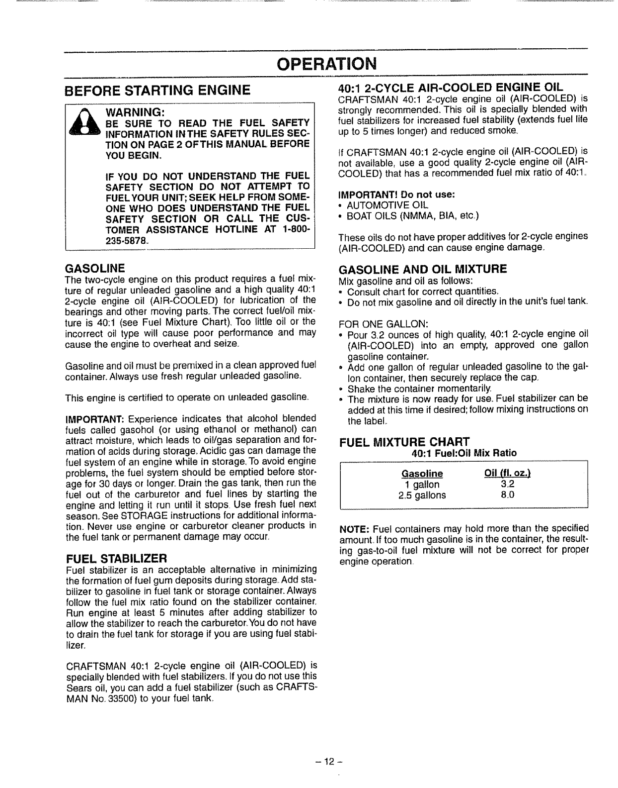
Figure 9
Eye
,_ 1- Eye
",-= Protection
_l Bow er
__ Operation
Assist Handle
Model: 35&797983,
t & 358.797991
Figure 10
Vacuum
Operation
BLOWER TIPS
•Always work going away from solid objects such as
walls, trees, automobiles, and fences..
o Clean corners by starting in corners and moving outward
to flat areas to prevent an accumulation of debris which
could fly into face..
o Be careful when working near plant&The force of the air
could damage tender plants
•Direct air flow by directing the nozzle down or to one
side_
-Vary the air flow by adjusting your grip on the throttletrig-
ger.
• While using the models 358797983, 358°797951 &
35&797991 use the assist handle located on the back of
the unit when working above the waist or when a two-
handed grip is desired.
o Uses for your blower:
-Sweeping debris or grass clippings from driveways,
sidewalks, patios, parks, parking lots, barns, stadiums,
etc,
- Blowing grass clippings, straw, or leaves into piles.
- Fast drying wet outdoor areas such as a patio,
-Removing debris from corners, around joints, and
between bricks
-Blowing light snow from driveways, sidewalks, or
patios.
VACUUM TIPS
° When using your unit as a vacuum, best results are
achieved when the unit is operated at full throttle.
Engage the throttle rock before beginning vacuuming
procedures.
• Move the unit slowly back and forth over debris to be
vacuumed.. Avoid forcing the vacuum tube into a pile of
debris as this can clog the unit.
. The vacuum can pick up objects that are too big to pass
through the impeller, This type of object will fall out of the
vacuum tubes when the engine is stopped°
°If the unit becomes clogged:
-Stop the engine and disconnect the spark plug wire.
Do not attempt to remove obstructions with the engine
running,
- Wait until the impeller has completely stopped turning,
then remove the vacuum tube,.
- Carefully reach into the vacuum opening and clear out
debris.
•The vacuum bag must be properly emptied and main-
tained to avoid deterioration and obstruction of air flow
which wilt reduce the performance of the vacuum.
- Empty the vacuum bag after each use.
- Remove the vacuum bag/elbow from the unit by turn-
ing it in a c!ockwise direction. Do not store vacuum bag
containing leaves, grass, etc.
- Wash the vacuum bag once a year as follows:
• Turn the vacuum bag inside out,,
• Hang it uP
• Thoroughly hose it down,
•Let vacuum bag hang until dry.
-11 -
OPERATHON
BEFORE STARTING ENGINE
_hb ARNING:
BE SURE TO READ THE FUEL SAFETY
INFORMATION IN THE SAFETY RULES SEC-
TION ON PAGE 20FTHIS MANUAL, BEFORE
YOU BEGIN.
IF YOU DO NOT UNDERSTAND THE FUEL
SAFETY SECTION DO NOT' ATTEMPT TO
FUELYOUR UNIT; SEEK HELP FROM SOME-
ONE WHO DOES UNDERSTAND THE FUEL
SAFETY SECTION OR CALL THE CUS-
TOMER ASSISTANCE HOTLINE AT 1-800-
235-5878.
40:1 2-CYCLE AIR-COOLED ENGINE OIL
CRAFTSMAN 40:1 2-cycle engine oil (AIR-COOLED) is
strongly recommended_ This oil is specially blended with
fuel stabilizers for increased fuel stability (extends fuel life
up to 5 times longer')and reduced smoke.
If CRAFTSMAN 40:1 2-cycle engine oil (AIR-COOLED) is
not available, use a good quality 2-cycle engine oil (AIR-
COOLED) that has a recommended fuel mix ratio of 40:1,
IMPORTANT] Do not use:
•AUTOMOTIVE OIL
•BOAT OILS (NMMA, BIA, etc,)
These oilsdo not have proper additives for 2-cycle engines
(AIR-COOLED) and can cause engine damage.
GASOLINE
The two-cycle engine on this product requires a fuel mix-
ture of regular unleaded gasoline and ahigh quality 40:1
2-cycle engine oil (AIR-COOLED) for lubrication of the
bearings and other moving parts. The correct fuel/oil mix-
ture is 40:1 (see Fuel Mixture Chart). Too little oil or' the
incorrect oit type will cause poor performance and may
cause the engine to overheat and seize.
Gasoline and oi! must be premixed in a clean approved fuel
container. Always use fresh regular unleaded gasoline.
This engine is certified to operate on unleaded gasoline._
IMPORTANT: Experience indicates that alcohol blended
fuels called gasohol (or using ethanol or methanol) can
attract moisture, which leads to oil/gas separation and for-
mation of acids during storage,_Acidic gas can damage the
fuel system of an engine while in storage_ To avoid engine
problems, the fuel system should be emptied before stor-
age for 30 days or longer..Drain the gas tar]k, then run the
fuel out of the carburetor and fue! lines by starting the
engine and Ietting it run until it stops Use fresh fuel next
season. See STORAGE instructions for additional informa-
tion.. Never use engine or carburetor cleaner products in
the fuel tank or' permanent damage may occur.
FUEL STABILIZER
Fuel stabilizer' is an acceptable alternative in minimizing
the formation of fuel gum deposits during storage,.Add sta-
bilizer to gasoline in fuel tank or storage container:Always
follow the fuel mix ratio found on the stabilizer container.
Run engine at least 5minutes after adding stabilizer to
allow the stabilizer to reach the carburetor,,Youdo not have
to drain the fuel tank for storage if you are using fuel stabi-
lizer.
GASOLINE AND OIL MIXTURE
Mix gasoline and oit as follows:
-Consult chart for correct quantities,
•Do not mix gasoline and oil directly in the unit's fuel tank°
FOR ONE GALLON:
• Pour 3.2 ounces of high quality, 40:1 2-cycle engine oil
(AIR-COOLED) into an empty, approved one gallon
gasoline container.
• Add one gallon of regutar unleaded gasoline to the gal-
lon container, then securely replace the cap_
•Shake the container momentarily.
•The mixture is now ready for' use_ Fuel stabilizer can be
added at this time if desired; follow mixing instructionson
the label..
FUEL MIXTURE CHART
40:1 Fuel:Oil Mix Ratio
Gasoline Oil (fl. oz.}
1 gallon 32
2.5 gallons 8,0
NOTE: Fuel containers may hotd more than the specified
amount. If too much gasoline is in the container, the result-
ing gas-to-oil fuel mixture will not be correct for proper
engine operation.
CRAFTSMAN 40:1 2-cycle engine oil (AIR-COOLED) is
specially blended with fuel stabilizers. If you do not use this
Sears oit, you can add a fuel stabilizer (such as CRAFTS _
MAN No. 33500) to your fuel tank.
-12-
OPERATION
STOPPING YOUR ENGINE
=Move the on/off switch to the "Off" position
= If engine does not stop, move the choke _everto the "Full
Choke" position,,
DANGER:
WHEN STARTING THE ENGINE, HOLD THE
UNIT AS SHOWN IN FIGURE 11. DO NOT SET
THE UNIT ON ANY SURFACE EXCEPT A
CLEAN, HARD AREA WHILE THE ENGINE IS
RUNNING. DEBRIS SUCH AS GRAVEL, SAND,
DUST, GRASS, ETC. COULD BE PICKED UP
BY THE AIR INTAKE AND THROWN OUT
THROUGH THE DISCHARGE OPENING, DAM-
AGING THE UNIT OR PROPERTY OR CAUS-
ING SERIOUS INJURY TO BYSTANDERS OR
OPERATOR.
FOR SAFE STARTING AND OPERATION, FOL-
LOW ALL SAFETY PRECAUTIONS IN THIS
OPERATOR'S MANUAL AND LABELS ONTHE
UNIT. DRESS PROPERLY BEFORE STARTING
ENGINE.
AVOID ANY CONTACT WITH THE MUFFLER. A
HOT MUFFLER CAN CAUSE SERIOUS
BURNS.
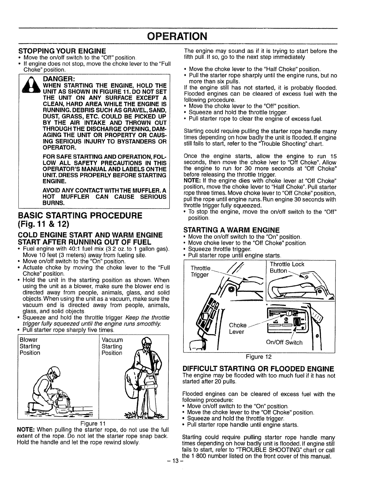
BASIC STARTING PROCEDURE
(Fig. 11 & 12)
COLD ENGINE START AND WARM ENGINE
START AFTER RUNNING OUT OF FUEL
• Fuel engine with 40:1 fue! mix (3,2 oz_to 1 gallon gas),,
Move !0 feet (3 meters) away from fueling site_
• Move on/off switch to the "On" position,,
°Actuate choke by moving the choke lever to the "Full
Choke" position.
° Hold the unit in the starting position as shown, When
using the unit as a blower, make sure the blower end is
directed away from people, animals, glass, and solid
objects.When using the unit as a vacuum, make sure the
vacuum end is directed away from people, animals,
glass, and solid objects
•Squeeze and hold the throttle trigger. Keep the throttle
trigger fully squeezed until the engine runs smoothly.
Pull starter rope sharply five times,
Blower
Starting
Position
Vacuum
Starting
Position
Figure 11
NOTE: When pulling the starter rope, do not use the full
extent of the rope,,Do not let the starter rope snap back_
Hold the handle and let the rope rewind slowly,
The engine may sound as if it is trying to start before the
fifth pull, If so, go to the next step immediately
• Move the choke lever to the "Half Choke" position.
°Pull the starter rope sharply until the engine runs, but no
more than six pulls.
If the engine still has not started, it is probably flooded_
Flooded engines can be cleared of excess fuel with the
following procedure.
• Move the choke lever to the "Off" position°
° Squeeze and hold the throttle trigger.
•Pull starter rope to clear the engine of excess fuelo
Starting could require pulling the starter rope handle many
times depending on how badly the unit is flooded. If engine
still fails to start, refer to the "Trouble Shooting" charL
Once the engine starts, allow the engine to run 15
seconds, then move the choke Iver to "Off Choke". Allow
the engine to run for 30 more seconds at "Off Choke"
before releasing the throttle trigger.,
NOTE: If the engine dies with choke lever at "Off Choke"
position, move the choke lever to "Half Choke",. Pull starter
rope three times. Move choke lever to "Off Choke" position,
pul! the rope until engine runs. Run engine 30 seconds with
throttle trigger fuliy squeezed.
°To stop the engine, move the on/off switch to the "Off"
position,
STARTING A WARM ENGINE
, Move the on/off switch to the "On" position_
°Move choke lever to the "Off Choke" position,
•Squeeze throttletrigger°
°Pull starter rope until engine starts_
.//_ Throttle Lock
Throttle _ Button _
Trigger "-" ..._._=,:..._.... _._
Choke Jf
Lever
On/Off Switch
Figure 12 l
DIFFICULT STARTING OR FLOODED ENGINE
The engine may be flooded with too much fuel if it has not
started after 20 pulls,_
Flooded engines can be cleared of excess fuel with the
following procedure:
° Move on/off switch to the "On" position,
, Move the choke lever to the "Off Choke" position.
•Squeeze and hold the throttle trigger,
° Pull starter rope handle until engine starts.,
Starting could require pulling starter rope handle many
times depending on how badly unit is flooded. If engine still
fails to start, refer to "TROUBLE SHOOTING" chart or call
the 1-800 number listed on the front cover of this manual.
-13-
CUSTOMER RESPONSiBiLiTiES
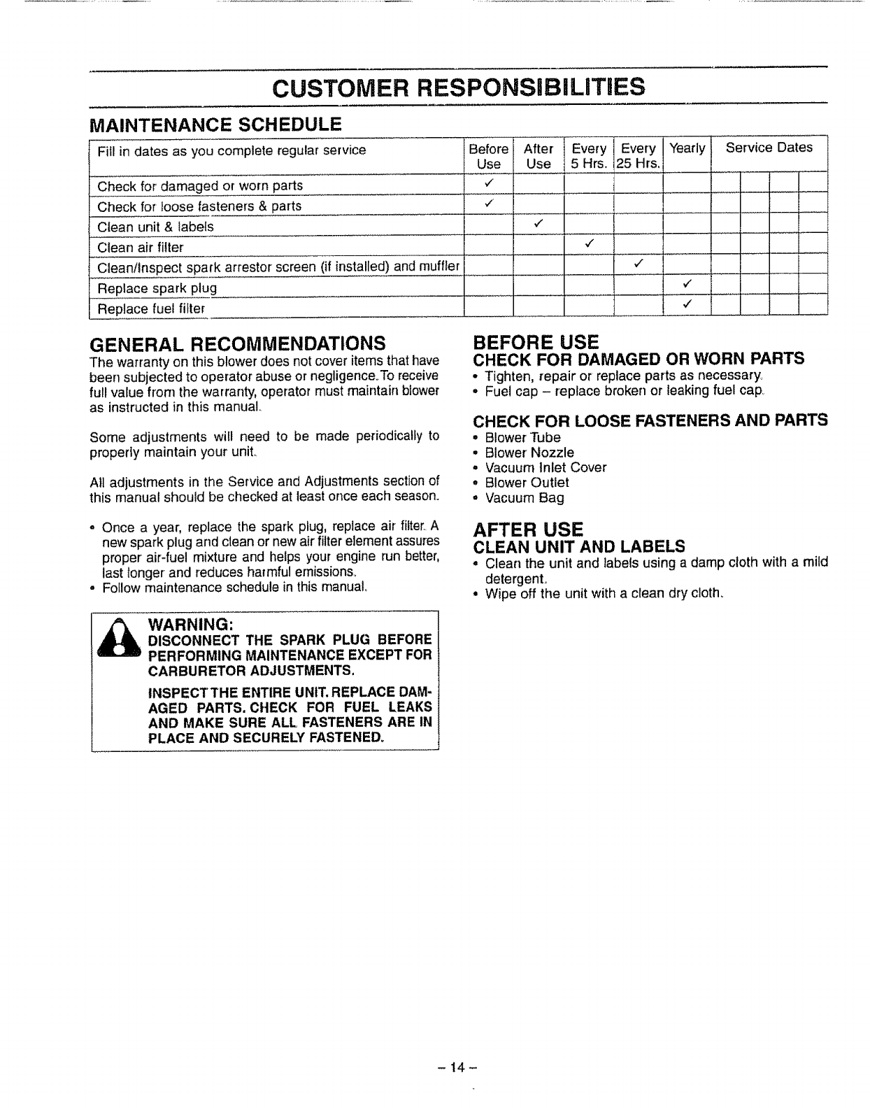
MAINTENANCE SCHEDULE
Fill in dates as you complete regular service
Check for damaged or worn parts
Check for loose fasteners & parts
Clean unit & labels
Clean air filter
Clean/inspect spark arrestor screen (if installed) and muffler
Replace spark plug
Replace fuel filter
I Before After Every Eve;i;l¥e'ylar Service Dates
25 Hrs,
..... t, i ...............
GENERAL RECOMMENDATIONS
The warranty on this blower does not cover items that have
been subjected to operator abuse or negligence.To receive
full value from the warranty, operator must maintain blower
as instructed in this manual.
Some adjustments will need to be made periodically to
properly maintain your unit..
All adjustments in the Service and Adjustments section of
this manual should be checked at least once each season.
o Once a year, replace the spark plug, replace air filter. A
new spark plug and clean or new air filter element assures
proper' air-fuel mixture and helps your engine run better,
last longer and reduces harmful emissions_
• Follow maintenance schedule in this manual
BEFORE USE
CHECK FOR DAMAGED OR WORN PARTS
• Tighten, repair or replace parts as necessary,
• Fuel cap - replace broken or leaking fuel cap
CHECK FOR LOOSE FASTENERS AND PARTS
•Blower Tube
•Blower' Nozzle
°Vacuum Inlet Cover
°Blower Outlet
°Vacuum Bag
AFTER USE
CLEAN UNIT AND LABELS
• Clean the unit and labels using a damp cloth with a mild
detergent,
• Wipe off the unit with a clean dry cloth.
WARNING:
DISCONNECT THE SPARK PLUG BEFORE
PERFORMING MAINTENANCE EXCEPT FOR
CARBURETOR ADJUSTMENTS,
INSPECTTHE ENTIRE UNIT. REPLACE DAM-
AGED PARTS. CHECK FOR FUEL LEAKS
AND MAKE SURE ALL FASTENERS ARE IN
PLACE AND SECURELY FASTENED_
-14-

CUSTOMER RESPONSIBILITIES
EVERY 5 HOURS
CLEAN AIR FILTER (Fig. 13)
CAUTION: TO AVOID CREATING FIRE
HAZARD AND PRODUCING HARMFUL
EMISSIONS, DO NOT CLEAN FILTER IN
GASOLINE OR OTHER FLAMMABLE
SOLVENT.
THE HOLES IN THE AIR FILTER MUST BE
FITTED OVER THE POSTS ON THE AIR FIL-
TER COVER. WHEN INSTALLING THE AIR
FtLTERtCOVER ASSEMBLY, BE SURE THAT
THE FII.TER DOES NOT HANG ON THE
CHOKE LEVER SCREW.
A dirty air filter decreases the life and performance of the
engine and increases fuel consumption and harmful emis _
sionso
Always clean after 5 tanks of fuel or 5 hours of operation,
whichever is less.. Clean more frequently in dusty condi-
tions.
•Move the choked lever to "Full"
'Remove the air filter cover on top of the unit (under the
handle).,
. Wash the air filter in soap and water,
, Squeeze the air filter dry.
• Add 4 or 5 drops of oil to the air filter. Avoid soaking the
air filter with oil.
° Squeeze the air filter to distribute o&
° Reassemble the air filter onto the cover,
° Reassemble air filter/cover assembly to unit. Return
choke lever to the "Off" position.
f
Air Filter
Cover
,\
\
Figure 13
EVERY 25 HOURS
CLEAN AND INSPECT SPARK ARRESTOR
SCREEN
As the unit is used, carbon deposits build up on the muffler
and spark arrestor screen (if installed), and must be
removed to avoid creating a fire hazard or affecling engine
performance
Required cleaning is every 25 hours of operation or annu-
ally, whichever is less.
Replace the spark arrestor screen if breaks occur,
CLEANING THE SPARK ARRESTOR SCREEN
•Remove the (2) two muffler retainer springs,
•Remove the muffler cover (cover snaps into muffler
body)_
° Remove muffler diffuser and spark arrestor screen
assembly. Notice the orientation of these parts for
reassemblyo
o Clean the spark arrestor screen with a wire brush or
replace if breaks are found in the screen.
° Replace any broken or cracked parts.
° Reinstall diffuser and spark arrestor screen assembly°
o Reinstall muffler cover and (2) two springs,
YEARLY
REPLACE SPARK PLUG (Fig. 14)
The spark plug should be replaced each year to ensure the
engine starts easier and runs better.
Spark plug gap should be _025".
°Pul! off the spark plug booL
- Remove and discard the spark plug.
° Replace with correct spark plug and tighten with spark
plug wrenche (10-12 Ib4t).
° Cover spark plug with spark plug boot.
Spark Plug
park Plug
Boot
Figure 14
-15-
CUSTOMER RESPONSIBILITIES
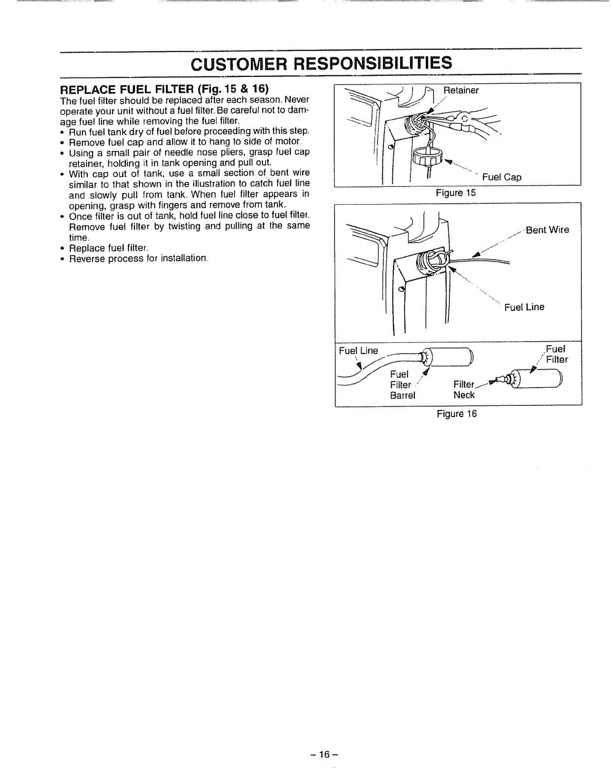
REPLACE FUEL FILTER (Fig. 15 & 16)
The fuel filter should be replaced after each season, Never
operate your unit without a fuel filter,,Be careful not to dam-
age fuel line while removing the fuel filter,
• Run fuel tank dry of fuel before proceeding with this step,.
o Remove fuel cap and allow it to hang to side of motor_
• Using a small pair of needle nose pliers, grasp fuel cap
retainer, holding it in tank opening and pull out.
° With cap out of tank, use a smatl section of bent wire
similar to that shown in the illustration to catch fuel line
and slowly pull from tank. When fuel filter appears in
opening, grasp with fingers and remove from tank_
° Once filter is out of tank, hold fuel line close to fuel filter,
Remove fuel filter' by twisting and pulling at the same
time,
o Replace fuel filter..
°Reverse process for installation.,
Fuel Line
Retainer
,/
"Fuet Cap
Figure 15
/j,,Bent Wire
,h.j
Fuel Line
Fuel _#'
FiIter ,i
Barrel Neck
,Fuel
/
/Filter
Figure 16
-16-
SERVICE AND ADJUSTMENTS
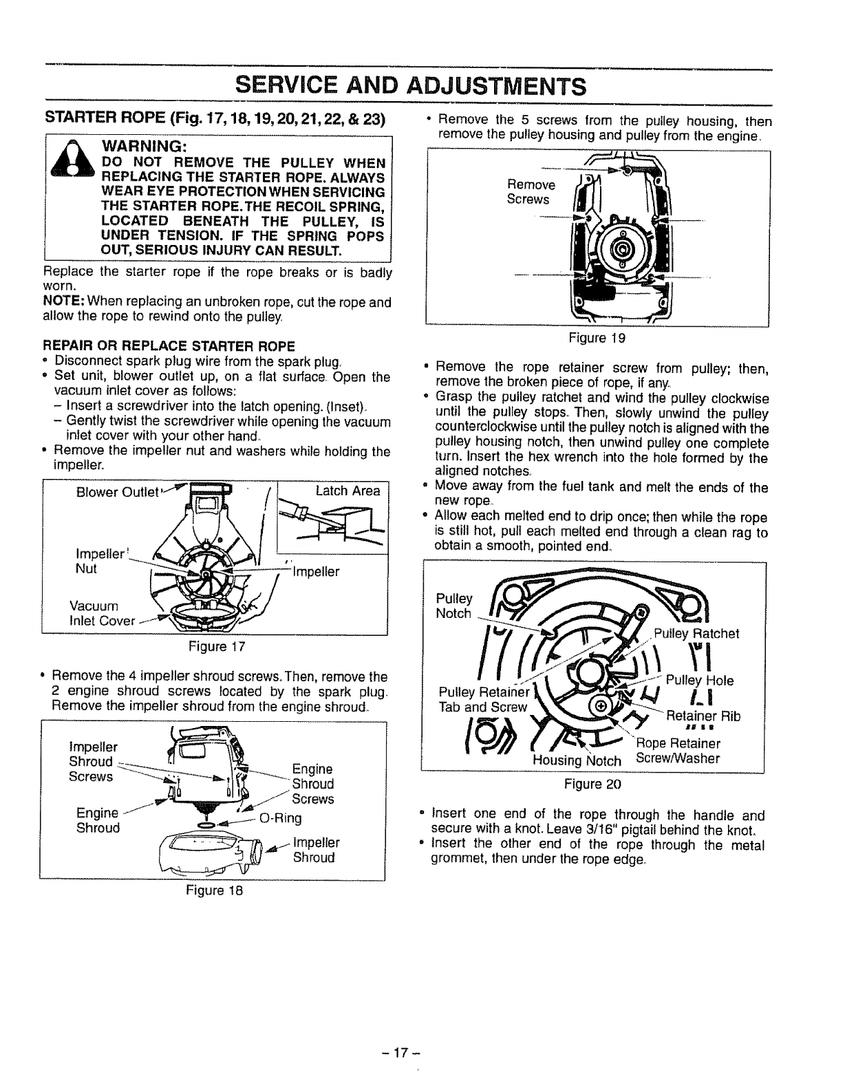
STARTER ROPE (Fig. 17,18,19, 20, 21,22, & 23)
_ARNING:
DO NOT REMOVE THE PULLEY WHEN
REPLACING THE STARTER ROPE. ALWAYS
WEAR EYE PROTECTION WHEN SERVICING
THE STARTER ROPE. THE RECOIL SPRING,
LOCATED BENEATH THE PULLEY, IS
UNDER TENSION. IF THE SPRING POPS
OUT, SERIOUS INJURY CAN RESULT.
Replace the starter rope if the rope breaks or is badly
worn.
NOTE; When replacing an unbroken rope, cut the rope and
allow the rope to rewind onto the pulley
REPAIR OR REPLACE STARTER ROPE
oDisconnect spark plug wire from the spark plug,
°Set unit, blower outlet up, on a fiat surface. Open the
vacuum inlet cover as follows:
- Insert a screwdriver into the latch opening. (Inset).
- Gently twist the screwdriver while opening the vacuum
inlet cover with your other hand.
•Remove the impeller nut and washers while holding the
impeller.
Blower
Nut 'Impeller
Vacuum
Inlet
Figure 17
° Remove the 4 impeller shroud screws. Then, remove the
2 engine shroud screws located by the spark plug.
Remove the impeller shroud from the engine shroud.
Impeller
Shroud
Screws Eng'
Engine
Shroud €=,.,,_i O-Ring
Impeller
Shroud
• Remove the 5 screws from the pulley housing, then
remove the pulley housing and pulley from the engine
Remove
Screws
Figure 19
•Remove the rope retainer screw from pulley; then,
remove the broken piece of rope, if any..
•Grasp the pulley ratchet and wind the pulley clockwise
until the pulley stops,. Then, slowly unwind the pulley
counterclockwise until the pulley notch is aligned with the
pulley housing notch, then unwind pulley one complete
turn. Insert the hex wrench into the hole formed by the
aligned notches.
•Move away from the fuel tank and melt the ends of the
new rope..
•Allow each melted end to drip once; then while the rope
is still hot, pull each melted end through a clean rag to
obtain a smooth, pointed end°
Pulley
Notch
Pulley Retainer
Tab and Screw
Housing Notch
• Pulley Ratchet
Pulley Hole
Li
Retainer Rib
Rope Retainer
ScrewtWasher
Figure 20
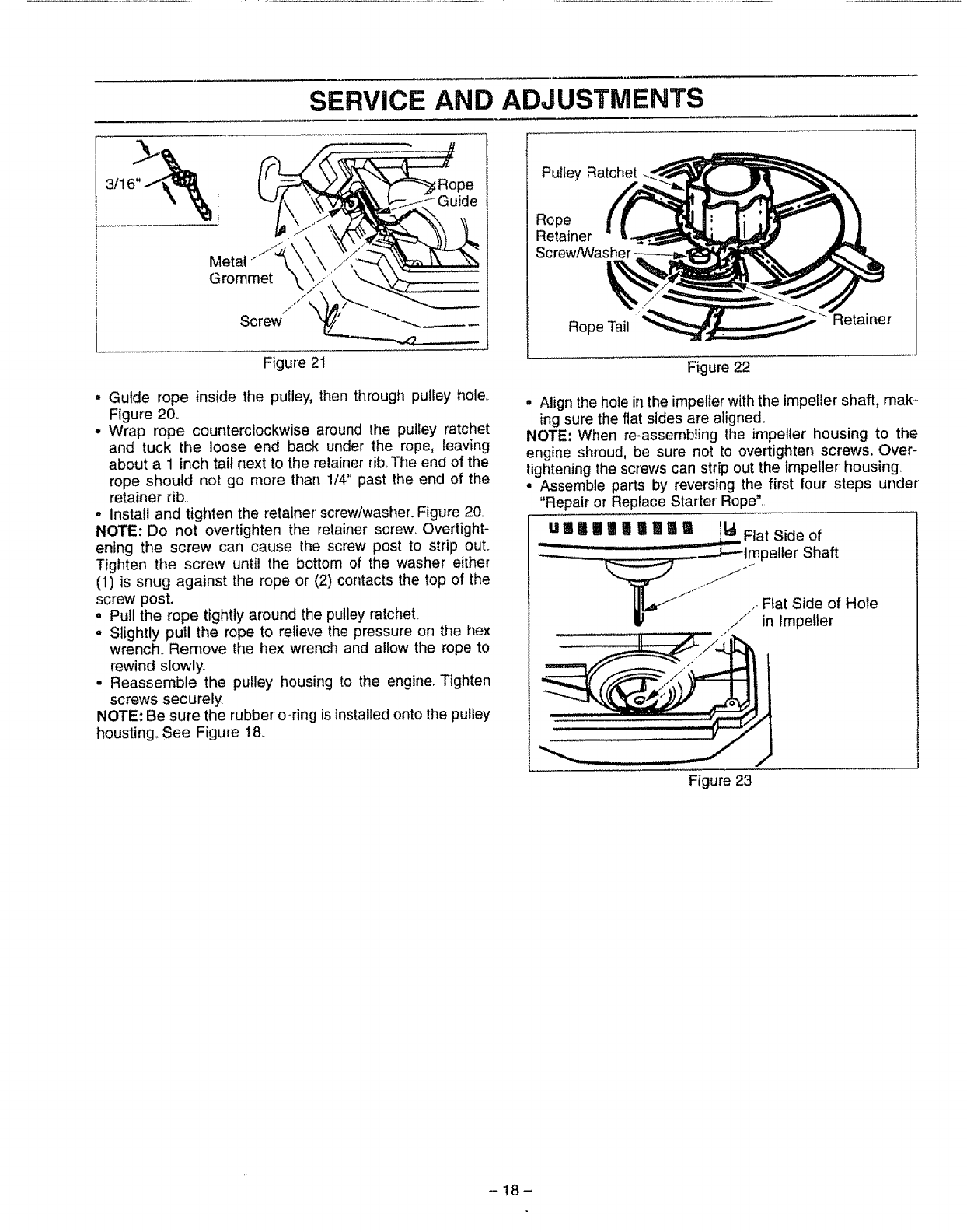
- insert one end of the rope through the handle and
secure with a knot. Leave 3/16" pigtail behind the knoL
• Insert the other end of the rope through the metal
grommet, then under the rope edge.
Figure ! 8
-17-
SERVICE AND ADJUSTMENTS
-/,,V""
Metal .1__ \ \
Grommet \\_._
fjl ,%,
Screw
Figure 21
• Guide rope inside the puIley, then through pulley hole.
Figure 20_
•Wrap rope counterclockwise around the pulley ratchet
and tuck the loose end back under the rope, leaving
about a 1inch tai_next to the retainer tib_The end of the
rope should not go more than 1/4" past the end of the
retainer rib.
°Install and tighten the retainer screw/washer. Figure 20
NOTE: Do not overtighten the retainer screw. Overtight-
ening the screw can cause the screw post to strip out.
Tighten the screw until the bottom of the washer either'
(1) is snug against the rope or (2) contacts the top of the
screw post.
• Pull the rope tightly around the pulley ratchet.
° Slightly pu!l the rope to relieve the pressure on the hex
wrench,, Remove the hex wrench and allow the rope to
rewind slowly,
o Reassemble the pulley housing to the engine. Tighten
screws securely
NOTE: Be sure the rubber o-ring is installedonto the pulley
houstingo See Figure 18.
Pulley Ratchet
Rope
Retainer
Screw/Washer,
Rope Tail Retainer
Figure 22
• Align the hole in the impeller withthe impeller shaft, mak-
ing sure the flat sides are aligned,
NOTE: When re-assembling the impeller housing to the
engine shroud, be sure not to overtighten screws. Over-
tightening the screws can strip out the impeller housing,,
= Assemble parts by reversing the first four steps under
"Repair or RepJace Starter Rope",
UnI I I I | I | |_Flat Side of
" '......... _tmpeller Shaft
'/z "_Flat Side of Hole
/" in ImpelLer
Figure 23
-t8-
SERVICE AND ADJUSTMENTS
CARBURETOR ADJUSTMENTS
Carburetor adjustment is critical and if done improperly
can permanently damage the engine as well as the car-
buretor. Please read all instructions and consult the
Trouble Shooting section of this manual before begin-
ning this process. If the engine does not operate accord-
ing to these instructions after repeating the adjusting
steps, do not use the unit. For further assistance, please
call our customer assistance hotline at 1-800-235-5878.
WARNING:
THE IMPELLER WILL BE SPINNING DURING
THIS PROCEDURE. WEAR YOUR PROTECTIVE
EQUIPMENT AND OBSERVE ALL SAFETY
INSTRUCTIONS.
KEEP OTHERS AWAYWHEN MAKING CARBU-
RETOR ADJUSTMENTS_
THE MIXTURE SEBrlNG IS A HIGHLY CRITI-
CAL ADJUSTMEI_,n". IF SET INCORRECTLY,
PERMANENT DAMAGE WILL OCCUR TO THE
ENGINE. DO NOT RUN ENGINE AT FULL
THROTTLE FOR PROLONGED PERIODS
WHILE MAKING THE MIXTURE ADJUSTMENT.
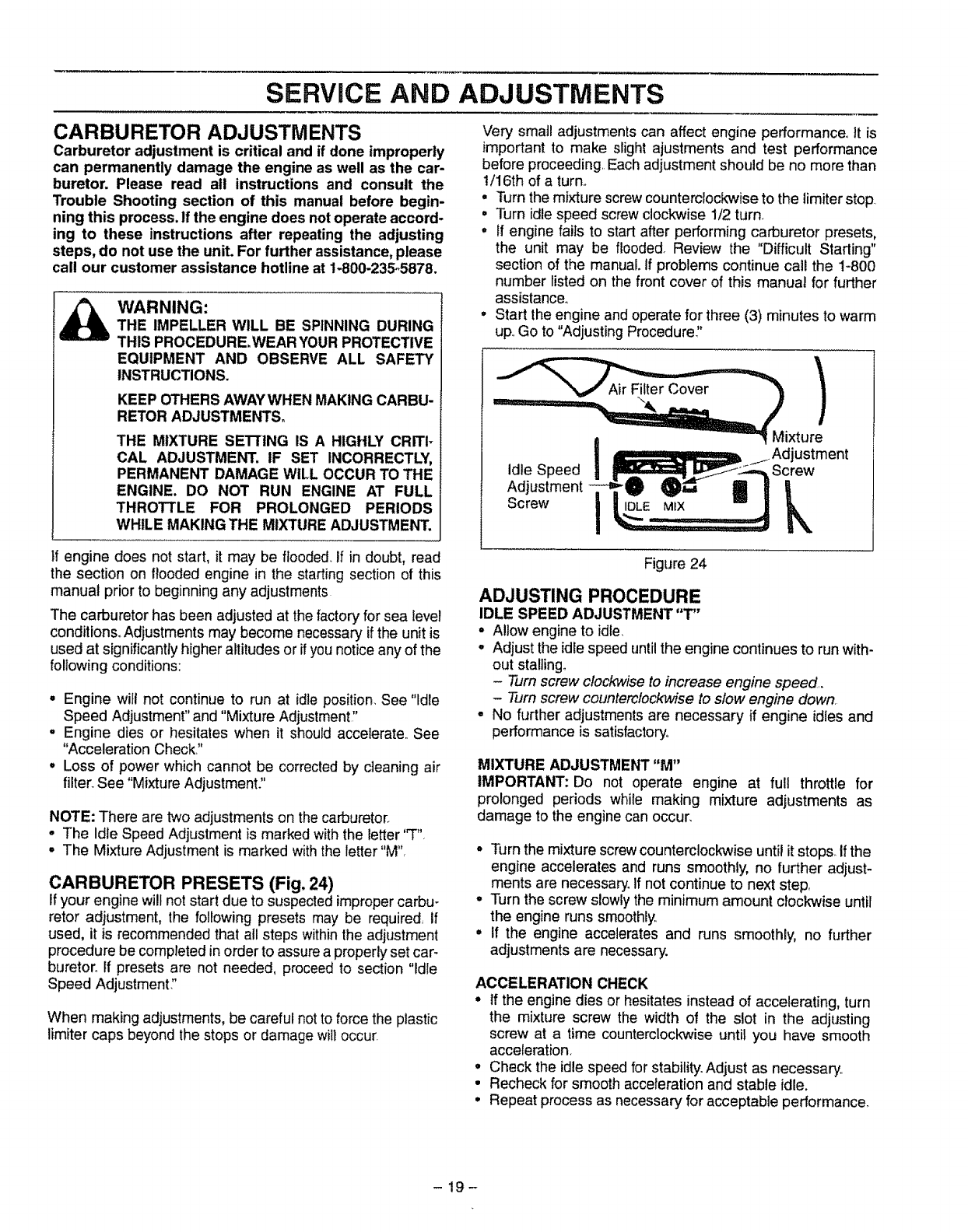
Very small adjustments can affect engine performance° It is
important to make slight ajustments and test performance
before proceeding, Each adjustment should be no more than
t/16th of a turn.,
o Turn the mixture screw counterclockwise to the limiter stop
° Turn idle speed screw clockwise 1/2 turn.
=If engine fails to start after performing carburetor presets,
the unit may be flooded. Review the "Difficult Starling"
section of the manual, if problems continue call the 1-800
number listed on the front cover of this manual for further
assistance°
°Start the engine and operate for three (3) minutes to warm
up.,Go to "Adjusting Procedure"
Idle Speed
Adjustment "O _1 I
Screw
Mixture
ustment
Screw
k
If engine does not start, it may be flooded If in doubt, read
the section on flooded engine in the starting section of this
manual prior to beginning any adjustments
The carburetor has been adjusted at the factory for sea level
conditions. Adjustments may become necessary if the unit is
used at significantly higher altitudes or if you notice any of the
following conditions:
° Engine will not continue to run at idle position. See "Idle
Speed Adjustment" and "Mixture Adjustment!'
. Engine dies or hesitates when it should accelerate,, See
"Acceleration Check,"
• Loss of power which cannot be corrected by cleaning air
filter. See "Mixture Adjustment"
NOTE: There are two adjustments on the carburetor.
•The Idle Speed Adjustment is marked withthe letter "T",
• The Mixture Adjustment is marked with the letter "M",
CARBURETOR PRESETS (Fig. 24)
if your enginewill not start due to suspected impropercarbu-
retor adjustment, the following presets may be required if
used, it is recommended that all steps within the adjustment
procedure be completed in order to assure a properly set car-
buretor., If presets are not needed, proceed to section "Idle
Speed Adjustment:'
When making adjustments, be careful not to force the plastic
limiter caps beyond the stops or damage will occur.
Figure 24
ADJUSTING PROCEDURE
IDLE SPEED ADJUSTMENT "T"
•Allow engine to idle
°Adjust the idle speed until the engine continues to run with-
out staltingo
-Turn screw clockwise to increase engine speed,.
-Turn screw counterclockwise to slow engine down,
•No further adjustments are necessary if engine idles and
performance is satisfactory°
MIXTURE ADJUSTMENT "M"
IMPORTANT: Do not operate engine at full throttle for
prolonged periods while making mixture adjustments as
damage to the engine can occur,
. Turn the mixture screw countemlockwise until it stops, if the
engine accelerates and runs smoothly, no further adjust-
ments are necessary. If not continue to next step,
,, Turn the screw slowly the minimum amount clockwise until
the engine runs smoothly.,
° If the engine accelerates and runs smoothly, no further
adjustments are necessary.
ACCELERATION CHECK
° if the engine dies or hesitates instead of accelerating, turn
the mixture screw the width of the slot in the adjusting
screw at a time counterclockwise until you have smooth
acceleration.
• Check the idle speed for stability. Adjust as necessary..
° Recheck for smooth acceleration and stable idle.
• Repeat process as necessary for acceptable performance.
-19-
STORAGE
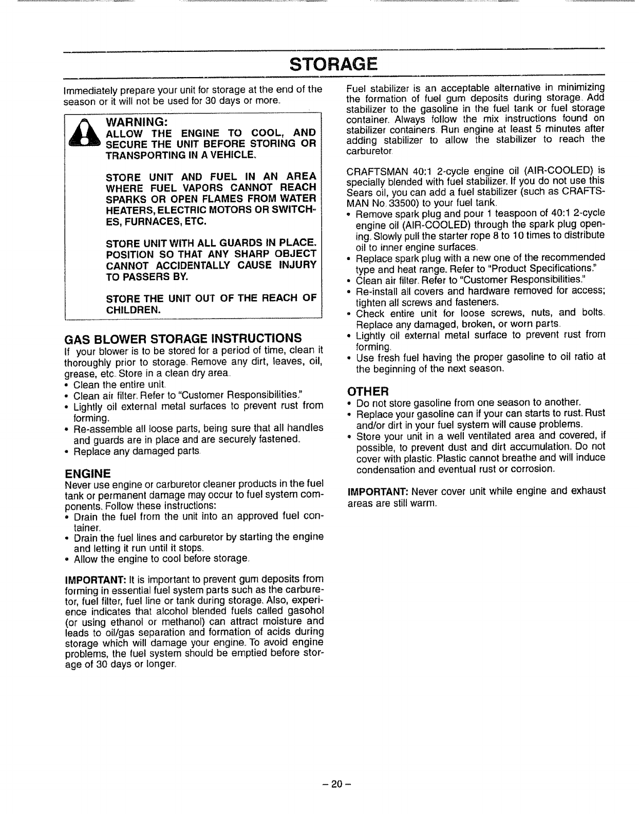
Immediately prepare your unit for storage at the end of the
season or it will not be used for 30 days or more,
WARNING:
ALLOW THE ENGINE TO COOL, AND
SECURE THE UNIT BEFORE STORING OR
TRANSPORTING IN A VEHICLE°
STORE UNIT AND FUEL IN AN AREA
WHERE FUEL VAPORS CANNOT REACH
SPARKS OR OPEN FLAMES FROM WATER
HEATERS, ELECTRIC MOTORS OR SWITCH-.
ES, FURNACES, ETC.
STORE UNIT WITH ALL GUARDS IN PLACE.
POSITION SO THAT ANY SHARP OBJECT
CANNOT ACCIDENTALLY CAUSE INJURY
TO PASSERS BY_
STORE THE UNIT OUT OF THE REACH OF
CHILDREN.
GAS BLOWER STORAGE INSTRUCTIONS
If your blower is to be stored for a period of time, clean it
thoroughly prior to storage.. Remove any dirt, leaves, oil,
grease, etc. Store in a clean dry are&
• Clean the entire unit.
•Clean air filter:,Refer to "Customer Responsibilities,"
• Lightly oil external metal surfaces to prevent rust from
forming.
• Re-assemble all loose parts, being sure that all handles
and guards are in place and are securely fastened.
• Replace any damaged parts.
ENGINE
Never use engine or carburetor cleaner products inthe fuel
tank or permanent damage may occur to fuel system com-
ponents,. Follow these instructions:
° Drain the fuel from the unit into an approved fuel con-
tainer:
° Drain the fuel lines and carburetor by starting the engine
and letting it run until it stops.
° Allow the engine to cool before storage
Fuel stabilizer is an acceptable alternative in minimizing
the formation of fuel gum deposits during storage, Add
stabilizer to the gasoline in the fuel tank or fuel storage
container_ Always follow the mix instructions found on
stabilizer containers Run engine at least 5 minutes after
adding stabilizer to allow the stabilizer to reach the
carburetor:
CRAFTSMAN 40:1 2-cycte engine oil (AIR-COOLED) is
specially blended with fuel stabilizer. If you do not use this
Sears oil, you can add a fuel stabilizer (such as CRAFTS-
MAN No. 33500) to your fuel tank.
°Remove spark plug and pour 1 teaspoon of 40:1 2-cycle
engine oil (AIR-COOLED) through the spark plug open-
ing.Slowly pull the starter rope 8 to t0 times to distribute
oil to inner engine surfaces,
° Replace spark plug with a new one of the recommended
type and heat range. Refer to "Product Specifications_'
° Clean air _ter, Refer to "Customer Responsibilities?
° Re-install all covers and hardware removed for access;
tighten aUscrews and fasteners.
°Check entire unit for loose screws, nuts, and bolt&
Replace any damaged, broken, or worn parts.
° Lightly oil external metal surface to prevent rust from
forming
°Use fresh fuel having the proper' gasoline to oil ratio at
the beginning of the next season.
OTHER
•Do not store gasoline from one season to another.
°Replace your gasoline can if your can starts to rust Rust
and/or dirt in your fuel system will cause problems.
° Store your unit in a well ventilated area and covered, if
possible, to prevent dust and dirt accumulation,. Do not
cover with plastic. Plastic cannot breathe and will induce
condensation and eventual rust or corrosion.,
IMPORTANT: Never cover unit while engine and exhaust
areas are still warm_
IMPORTANT: It is important to prevent gum deposits from
forming in essential fuel system parts such as the carbure-
tor, fuel filter, fuel line or tank during storage, Also, experi-
ence indicates that alcohol blended fuels called gasohol
(or using ethanol or methanol) can attract moisture and
leads to oil/gas separation and formation of acids during
storage which will damage your engine. To avoid engine
problems, the fuel system should be emptied before stor-
age of 30 days or tonger.
- 20 -
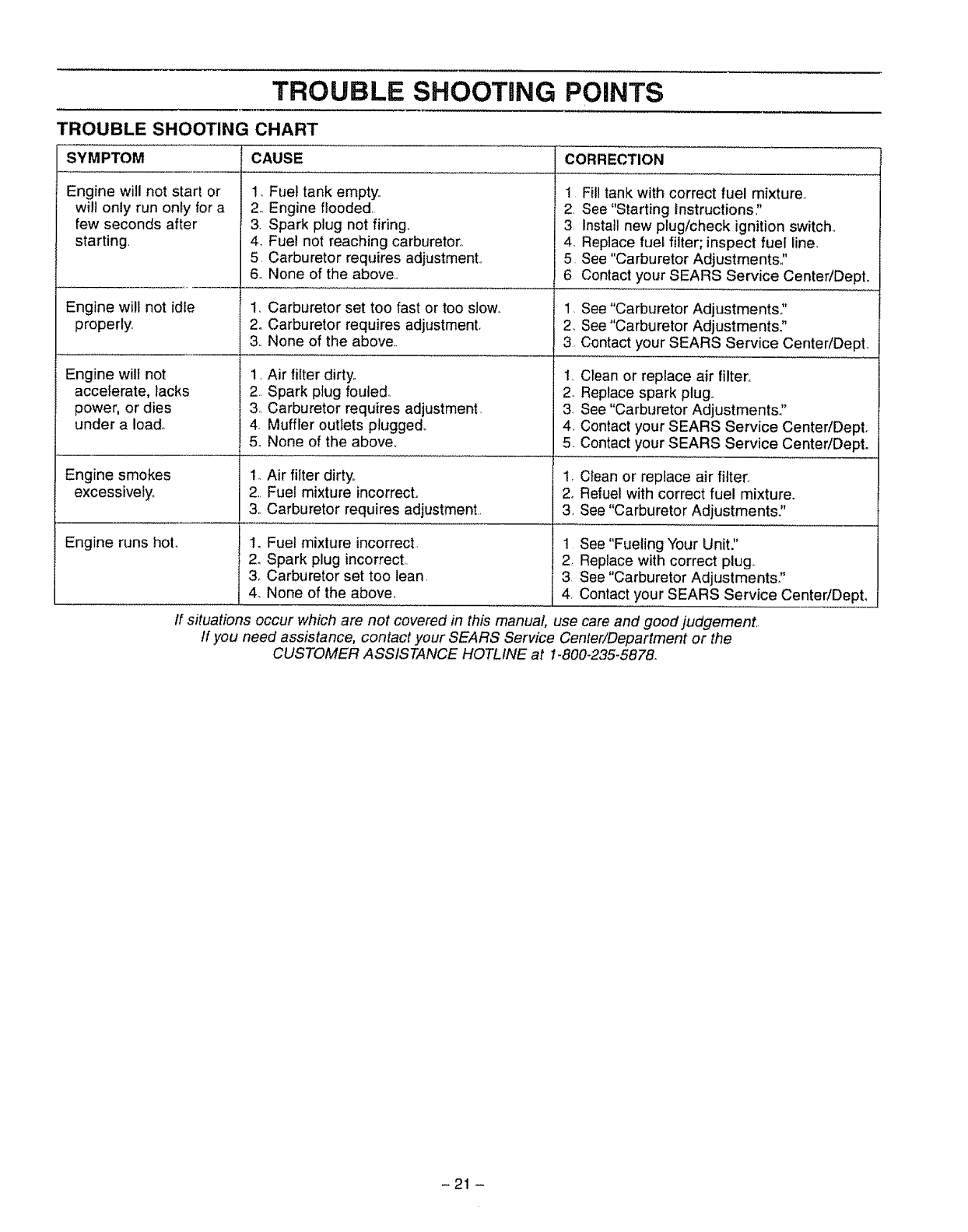
TROUBLE SHOOTaNG POINTS
TROUBLE SHOOTING CHART
SYMPTOM CAUSE CORRECTION
Engine will not start or 1. Fuel tank empty_,
will only run only for a 2., Engine flooded,
few seconds after 3 Spark plug not firing,,
starting. 4. Fue! not reaching carburetor.
5, Carburetor requires adjustment,
6o None of the above,,
Engine will not idle 1, Carburetor set too fast or too slow.
properly, 2o Carburetor requires adjustment,
3,. None of the above..
Engine will not 1, Air filter dirty,,
accelerate, lacks 2, Spark plug fouled.,
power, or dies 3., Carburetor requires adjustment,
under a Ioad_ 4. Muffler outlets plugged,
5. None of the above.
Engine smokes 1. Air filter dirty.,
excessively_ 2, Fuel mixture incorrect.
3oCarburetor requires adjustment,.
Engine runs hot, I. Fuel mixture incorrect,
2o Spark plug incorrect,.
3. Carburetor set too lean.
4. None of the above,
1
2.
3
4,
5
6
Fill tank with correct fuel mixture.,
See "Starting Instructions,"
Install new plug/check ignition switch,
Replace fuel filter; inspect fuel line.
See "Carburetor Adjustments,?
Contact your SEARS Service Center!Dept,,
,
2.
3
See "Carburetor Adjustments?
See "Carburetor Adjustments."
Contact your SEARS Service Center/DepL
,
2,,
3.
4,
5.
Clean or replace air filter,,
Replace spark plug,,
See "Carburetor Adjustments"
Contact your SEARS Service Center/Dept.
Contact your SEARS Service CentedDept.
1, Clean or replace air filter,
2. Refuel with correct fuel mixture.
3. See "Carburetor Adjustments."
1 See "Fueling Your Unit:'
2. Replace with correct plug
3 See"Carburetor Adjustments?
4, Contact your SEARS Service Center/Dept.
If situations occur which are not covered in this manual use care and good judgement,,
If you need assistance, contact your SEARS Service Center/Department or the
CUSTOMER ASSISTANCE HOTLINE at 1-800-235-5878_
-21 -
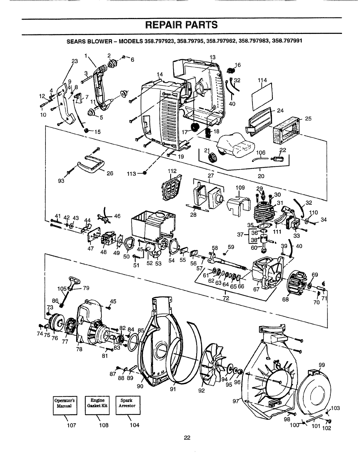
REPAIR PARTS
10
SEARS BLOWER - MODELS 358.797923, 358.79795, 358.797962, 358,797983, 35&797991
93
26
46
!12
19
32
4O
2O
3O
25
32
10
34
48 49
87 88 89
52 53 54 55
91
22
92
59
65 66
69
€
99
9810( 102
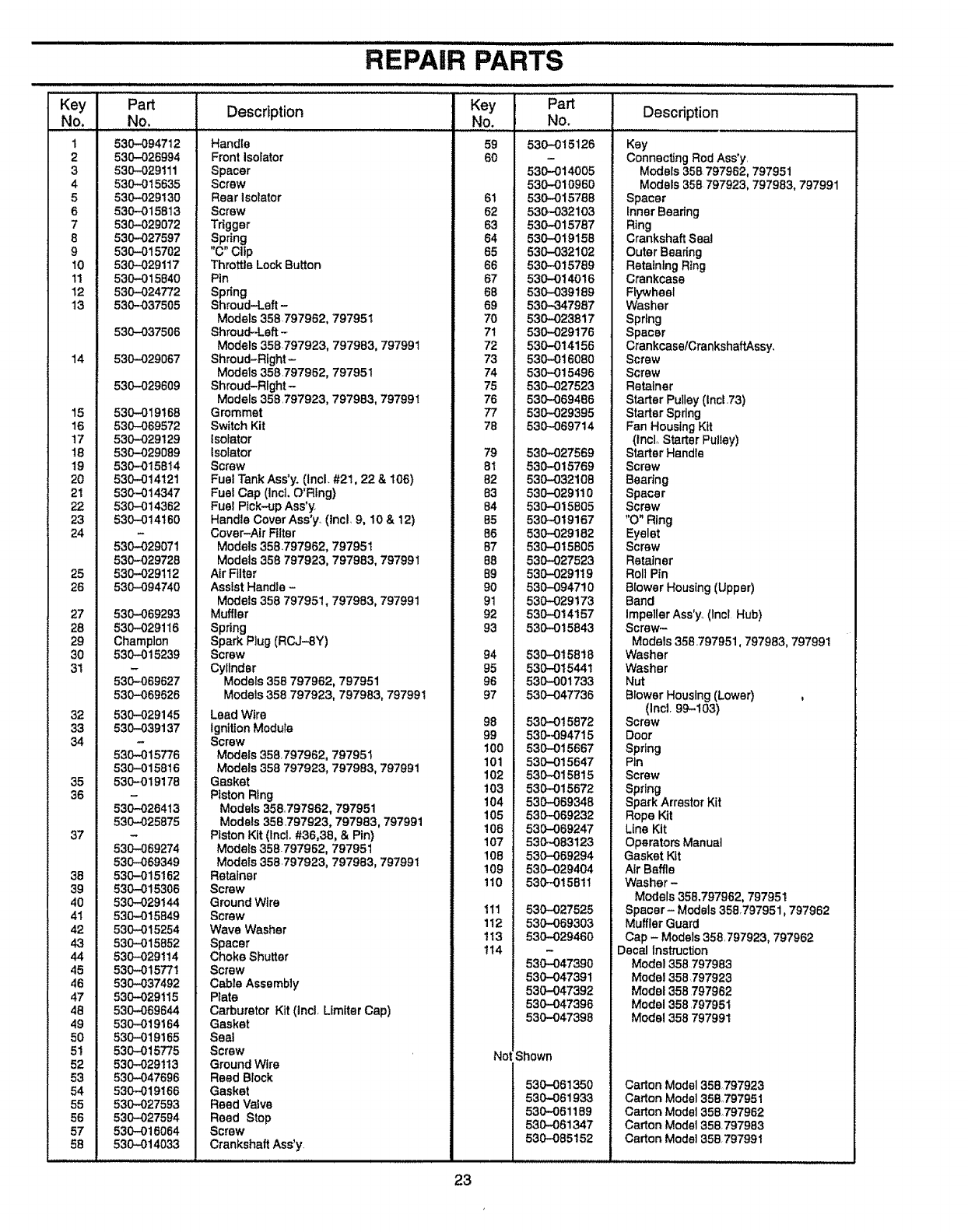
...................... REPAIR PARTS ........................
iL
Key Part Description
No. No.
1530-094712
2 530-026994
3 530--029111
4 530-015635
5 530-029130
6 530-015813
7 530-029072
8 530,-027597
9530-015702
10 530-029117
11 530-015840
12 530-024772
13 530-037505
530-037506
14 530-029067
53O-O29609
15 530-019168
16 530-069572
17 530-029129
18 530-029089
19 530-015814
20 530-014121
21 530-014347
22 530-014362
23 530-014160
24
530-029071
530-029728
25 530-029112
26 530-094740
27
28
29
30
31
32
33
34
35
36
37
38
39
40
41
42
4.3
44
45
46
47
48
49
50
5!
52
53
54
55
56
57
58
530-069293
530-029116
Champlon
530-015239
530--069627
530-069626
530-029145
530-039137
530--015776
530-015816
530-019178
530-026413
530-025875
530-069274
530-069349
530-015162
530-015306
530-029144
53O-O15849
530-,-015254
530-015852
530-,,029114
530-015771
530-037492
530-029115
530-069644
530,-019164
530--019165
530-015775
530-029113
530-047696
530--019166
530-027593
530-027594
530-016064
530-014033
Handle
Front isolator
Spacer
Screw
Rear Isolator
Screw
Trigger
Spring
"C" Clip
Throttle Lock Button
Pin
Spring
Shroud-Left-
Models 358797962, 797951
Shroud-Left-
Models 358,797923, 797983, 797991
Shroud-Right-
Models 359,797962, 797951
Shroud-Rfght-
Models 358,797923, 797983, 797991
Grommet
Switch Kit
Isofator
tsotator
Screw
Fuel Tank Ass'y, (Incl+ #2t, 22 & 106)
Fuel Cap (IncL O'Rfng)
Fuel Pick-up Ass'y
Handle Cover Ass'y. (lncL 9. 10 & 12)
Cover-Air Filter
Models 358.797962, 797951
Models 358 797923, 797983, 797991
Air Filter
Assist Handle -
Models 358 797951, 797983, 797991
Muffler
Spring
Spark Plug (RCJ--8Y)
Screw
Cyltnder
Models 358 797962, 797951
Models 358 797923. 797983, 797991
Lead Wire
Ignition Modute
Screw
Models 358,797962, 797951
Models 359 797923, 797983, 797991
Gasket
Piston Ring
Models 358, 797962, 797951
Models 358,797923, 797993, 797991
Piston Kit (Incl, #36,38, & Pin)
Models 358-797962, 797951
Models 359,797923, 797983, 797991
Retainer
Screw
Ground Wire
Screw
Wave Washer
Spacer
Choke Shutter
Screw
Cable Assembly
Plate
Carburetor Kit (Incl, Llmfter Cap)
Gasket
Seal
Screw
Ground Wire
Reed Block
Gasket
Reed Valve
Reed Stop
Screw
Crankshaft Ass'y,
Key
No.
59
60
61
62
63
64
65
66
57
88
69
7O
71
72
73
74
75
76
77
78
79
81
82
83
84
85
56
87
88
89
90
91
92
93
94
95
96
97
98
99
t00
101
102
103
104
105
106
107
108
109
110
1!1
112
113
114
Part
No.
530-015126
530-014005
530-019960
530-015788
530-032103
530-015787
530-019158
530-032102
530-015769
530-014016
530-039189
530-347987
53O-023817
530-029176
530-014156
530-016080
53O-015496
530-027523
530-069486
53O--029395
530-069714
530-027569
530-015769
530-032108
530-029110
530,-015805
530-019167
530-029182
530-015805
530-027523
530-029119
530--094710
530-029173
530-014157
530--015843
530-015818
530-015441
530-001733
530-047736
530-015872
530-_94715
530-015667
530-015647
530-015815
530-015672
530-069348
53O-069232
530-069247
530-083123
530-069294
530-029404
530+-015811
530-027525
530-069303
530-029460
Descdption
Key
Connecting Rod Ass*y,
Models 358 797962. 797951
Models 358 797923, 797983, 797991
Spacer
Inner Beadng
Ring
Crankshaft Seal
Outer Bearing
Retaining Ring
Crankcase
Ftywheel
Washer
Spring
Spacer
Crankcase/CrankshaftAssy,
Screw
Screw
Retainer
Starter Pulley (lnci .73)
Starter Spdng
Fan Housing Kit
(tncl+,Starter Pulley)
Starter Handle
Screw
Beadng
Spacer
Screw
"O" Ring
Eyelet
Screw
Retainer
Roll Pin
Btower Housing (Upper)
Band
Impeller Ass'y, (Incl Hub)
Screw-
Models 358,797951,797983, 797991
Washer
Washer
Nut
Blower Housing (Lower)
(Inct 99-103)
Screw
Door
Spring
Pin
Screw
Spring
Spark Arrestor Kit
Rope Kit
Line Kit
Operators Manual
Gasket Kit
AirBaffle
Washer -
Models 358.797962, 797951
Spacer- Models 358,797951, 797962
Muffler Guard
Cap - Models 358,797923, 797962
Decal Instruction
530-047390
530-047391
530-047392
530-047396
530-047398
Not Shown
530-061350
530-061933
530-061189
530,-061347
530-095152
Model 358797983
Model 358 _797923
Model 358 797962
Model 358,797951
Model 358 797991
Carton Model 358,797923
Carton Model 355,797951
Carton Model 358797962
Carton Model 358, 797983
Carton Model 358,797991
23
REPAIR PARTS
ji iii........i .i.i. i i i i iu ui
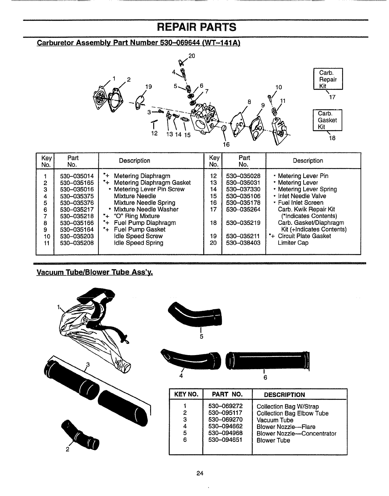
Carburetor Assembly Part Number 530--069644 (_-141A)
2
/
_(/20
19 5,_,_' /6 7 10 ICarb,
Repair
Kit
17
Carb_
Gasket
Kit
I8
1
Key
No,
1
2
3
4
5
6
7
8
9
10
11
Part
No.
.......,,,,j,, J ,,,,,,,,,,
530-035014
530-035165
530-035016
530-035375
530-035376
530-035217
530-035218
530-035166
530-035164
530-035203
530-035208
Description Key
No.
*+ Metering Diaphragm 12
'% Metering Diaphragm Gasket 13
* Metering Lever Pin Screw 14
Mixture Needle !5
Mixture Needle Spring 16
* Mixture Needle Washer 17
"+ "O" Ring Mixture
*+ Fuel Pump Diaphragm 18
*+ Fuel Pump Gasket
Idle Speed Screw 19
Idle Speed Spring 20
Part
No.
i,J i
530-035028
530-035031
530-037330
530-035106
530-O35178
530-035264
530-035219
530--035211
530--038403
Description
* Metering Lever Pin
*Metering Lever
, Metering Lever Spring
, Inlet Needle Valve
* Fue_Inlet Screen
Carb, Kwik Repair Kit
(*Indicates Contents)
Carb. Gasket/Diaphragm
Kit (+indicates Contents)
*+ Circuit Plate Gasket
Limiter Cap
Vacuum TubelB!ower Tube Ass'y.
4
5
KEY NO.
1
2
3
4
5
6
6
PART NO. DESCRIPTION
530-069272
530-095117
530-069270
530-094662
53O-094968
530-094651
Collection Bag W/Strap
Collection Bag Elbow Tube
Vacuum Tube
Blower Nozzle---Flare
Blower Nozzle--Concentrator
Blower Tube
24
Operator's
anual
Model No.
358,797923
358.797951
358.797983
358.797962
358.797991
IF YOU NEED REPAIR
SERVICE OR PARTS:
REPAIR SERVICE
1-800-4-REPAIR
(1-800-473-7247)
ORDERING PARTS
1-800-FON-PART
(1-800-366-7278)
CUSTOMER
ASSISTANCE
1-800-235-5878
HOURS (CST)
Mort.- Sat 7 a,m.- 7 p,,m "\,,
CRRFTSMRN°
22 cc/32 cc 2-CYCLE
155/170 Air Velocity
GASOLINE BLOWER
ENGINE
Each Gas Blowed_has its own model number, The model number
for your unit will be found on a decal attached to the uniL
All parts listed herein may be ordered from any Sears, Roebuck
and Co, Service Center and most Retail Stores,
WHEN ORDERING REPAIR PARTS, ALWAYS GIVE THE FOL-
LOWING INFORMATION AS SHOWN iN THIS LIST:
• PRODUCT-"GASOL1NE BLOWER"
•MODEL NUMBER -35&797923
35&797951
358,797983
358.797962
358°797991
° PART NUMBER
• PART DESCRIPTION
Your Sears Merchandise has added value when you consider that
Sears has service units nationwide staffed with Sears trained tech+
nicians,_ professional technicians specifically trained on Sears
products, having the parts, tools and equipment to insure that we
meet our pledge to you, we service what we sell,
Sears, Roebuck and Co_, Hoffman Estates, IL 60179 U+S+A.
