Craftsman 39719580 User Manual 1/3 H.P. GRINDER Manuals And Guides L0912099
CRAFTSMAN Grinder Manual L0912099 CRAFTSMAN Grinder Owner's Manual, CRAFTSMAN Grinder installation guides
User Manual: Craftsman 39719580 39719580 CRAFTSMAN CRAFTSMAN 1/3 H.P. GRINDER - Manuals and Guides View the owners manual for your CRAFTSMAN CRAFTSMAN 1/3 H.P. GRINDER #39719580.
Open the PDF directly: View PDF ![]() .
.
Page Count: 6
ASSEMBLY, OPERATING INSTRUCTIONS
AND PARTS LIST FOR
CRAFTSMAN 1/3 H.P. GRINDER
Split Phase, 115 volts, 60 cycle, 3450 ReP.M.
MODEL NUMBER 397.19580
This is the Model Number of your CRAFTSMAN GRINDER. It will be
found on the nameplate attached to the Grinder. Always mention this
Model Number when communicating with us regarding your Grinder or
when ordering parts.
HOW TO ORDER REPAIR PARTS
All parts listed herein may be ordered through SEARS, ROEBUCK and
CO. or SIMPSONS-SEARS LIMITED. When ordering parts by mail from
the mail order store which serves the territory in which you live, selling
prices will be furnished on request or parts will be shipped at prevailing
prices and you will be billed accordingly.
WHEN ORDERING REPAIR PARTS ALWAYS GIVE THE FOLLOWING
INFORMATION:
1. The PART NUMBER :3. The MODEL NUMBER 397.19580
2. The PART NAME 4. The NAME of item- 1/3 H.P. Grinder
COAST TO COAST NATION-WIDE
SERVICE FROM SEARS
FOR YOUR CRAFTSMAN GRINDER
SEARS, ROEBUCK AND CO. and
SIMPSONS-SEARS LIMITED in
Canada back up your investment with
quick, expert mechanical service and
genuine CRAFTSMAN replacement
parts.
If and when you need repairs or serv-
ice, call on us to protect your invest-
ment in this fine piece of equipment.
SEARS, ROEBUCK AND CO.-U.S.A.
IN CANADA, SIMPSONS- SEARS LIMITED
C-2371 Printed in U.S.A.
CL._-
__ o
_-0< _- ___
u
_>_z " _'
_ i- .ic c 11_
I--I--- _ 0 -I_
c _
a .__
•_- 0
OZZ _ _-=°--
z_ _
_ z -_
o 0
_ Z
0
O ...........
soa
o
S_ : : : : : :". : : : : : : : : :'!.
,,, I.,.4 ..... _ : : : : :_
• o :-"u : : : : ...... o. . .
._\,_ .... _ ........
:: ..... sZ
__-__ _ a_ _ ............ oo. ": ._:L'-q
_ _ _ _ , ,.I= ••• ___ • .-_,_,'T'm\-,: -,: " X
4_: = u_°_-_ .".. '-..._.-,_.w-=o__×÷÷-_" >'_'o-'
o . ._ ___
m-l_ -- _ ._ ........... -_ _ _
a_ _ n __ _ 0 _ u 000_.. 0 0 0 ._ u
ua Zoo _- Z ,,_ Zoo uo I--,,_i-- > > _x_ _ _-- k:;uo U
_ _ ___ _0_
Z __ _0 _ _ _ _
______0__
_ __0_ _0_ __ _ _
_ _0___0_ _ __ __
_o___-
-d
¢D
>
o
E
t-
>
0..
o
r
°_
o
U
_0
0
°--
4--
0
E
r
°_
El
U
o
e--
D
U
"0
o
"4--
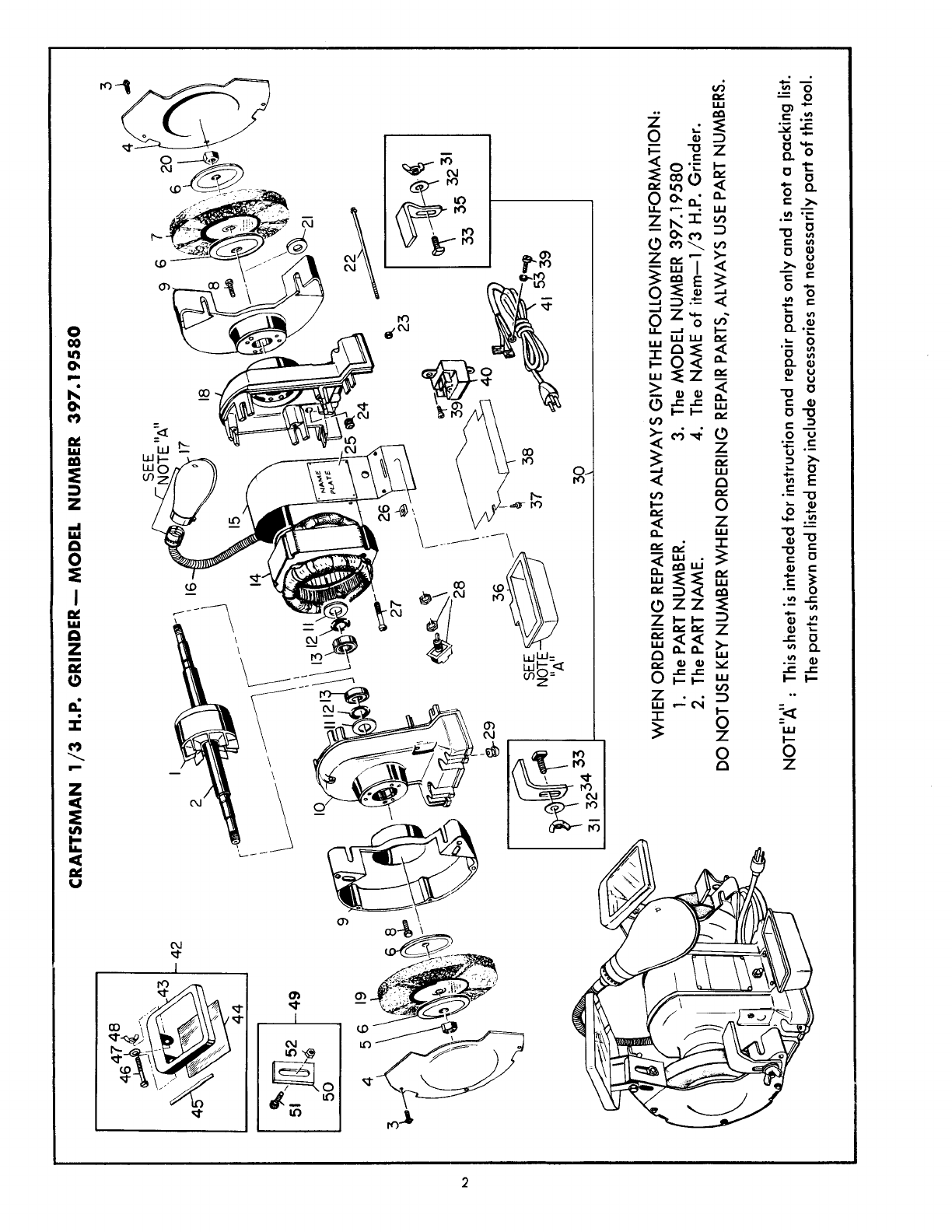
TO ASSEMBLE: Key numbers refer to illus-
trations (also to parts list and exploded
view).
INSPECT GRINDING WHEELS BEFORE USING. THERE
IS ALWAYS A POSSIBILITY OF DAMAGE IN TRANSIT.
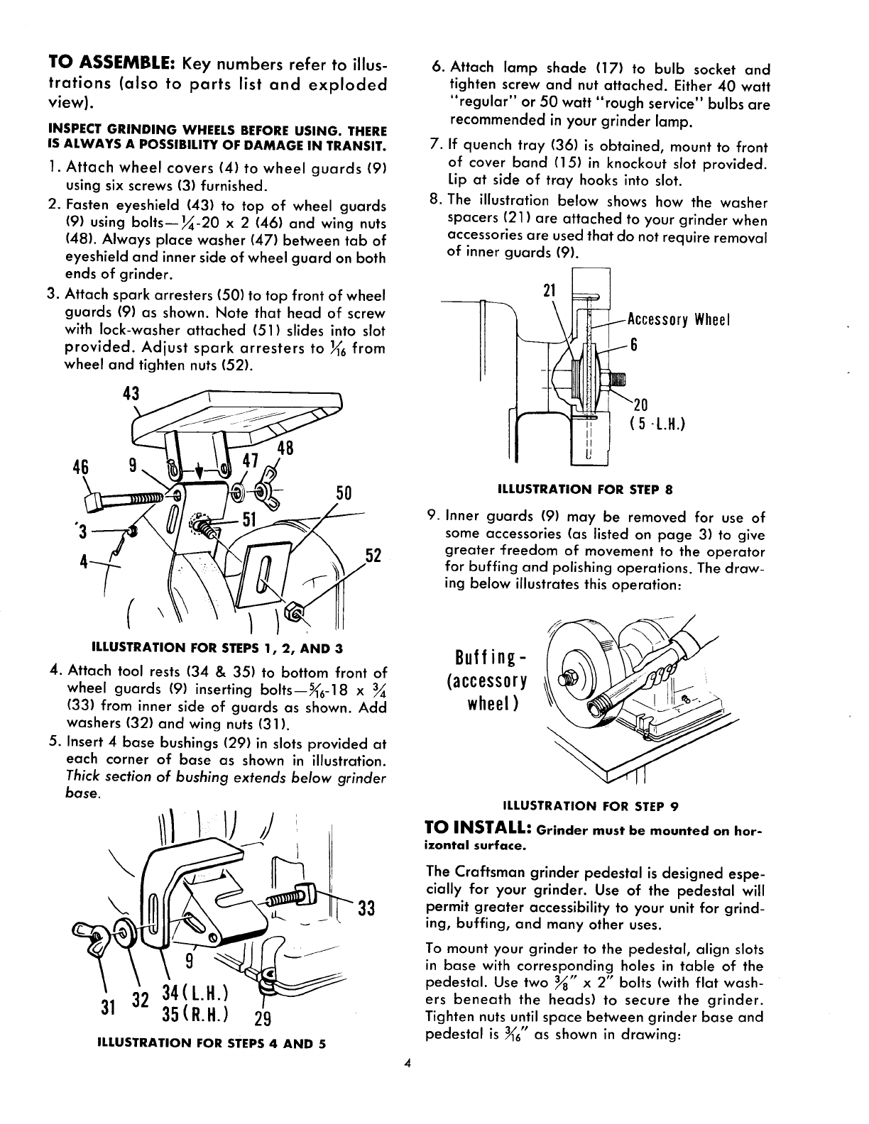
1. Attach wheel covers (4) to wheel guards (9)
using six screws (3) furnished.
2. Fasten eyeshield (43) to top of wheel guards
(9) using bolts--_-20 x 2 (46) and wing nuts
(48). Always place washer (47) between tab of
eyeshield and inner side of wheel guard on both
ends of grinder.
3. Attach spark arresters (50) to top front of wheel
guards (9) as shown. Note that head of screw
with lock-washer attached (51) slides into slot
provided. Adjust spark arresters to _6 from
wheel and tighten nuts (52).
43
46 48
50
52
ILLUSTRATION FOR STEPS 1, 2, AND 3
4. Attach tool rests (34 & 35) to bottom front of
wheel guards (9)inserting bolts--_6-18 x
(33) from inner side of guards as shown. Add
washers (32) and wing nuts (31).
5. Insert 4 base bushings (29) in slots provided at
each corner of base as shown in illustration.
Thick section of bushing extends below grinder
base.
\
33
9
31 32 34(L.H.)
35(R.H.) 29
ILLUSTRATION FOR STEPS 4 AND 5
.
°
,
Attach lamp shade (17) to bulb socket and
tighten screw and nut attached. Either 40 watt
"regular" or 50 watt "rough service" bulbs are
recommended in your grinder lamp.
If quench tray (36) is obtained, mount to front
of cover band (15) in knockout slot provided.
Lip at side of tray hooks into slot.
The illustration below shows how the washer
spacers (21) are attached to your grinder when
accessories are used that do not require removal
of inner guards (9).
--_ 2_ _...---Accessory Wheel
- 20-L.H.)
ILLUSTRATION FOR STEP 8
9. Inner guards (9) may be removed for use of
some accessories (as listed on page 3) to give
greater "Freedom of movement to the operator
for buffing and polishing operations. The draw-
ing below illustrates this operation:
Buffing-
(accessory
wheel) J
ILLUSTRATION FOR STEP 9
TO INSTALL: Grinder must be mounted on hor-
izontal surface.
The Craftsman grinder pedestal is designed espe-
cially for your grinder. Use of the pedestal will
permit greater accessibility to your unit for grind-
ing, buffing, and many other uses.
To mount your grinder to the pedestal, align slots
in base with corresponding holes in table of the
pedestal. Use two 3/8" x 2" bolts (with flat wash-
ers beneath the heads) to secure the grinder.
Tighten nuts until space between grinder base and
pedestal is 3/16"as shown in drawing:
...... .......
I I i I II ........ /BUSHING _, BUSHING
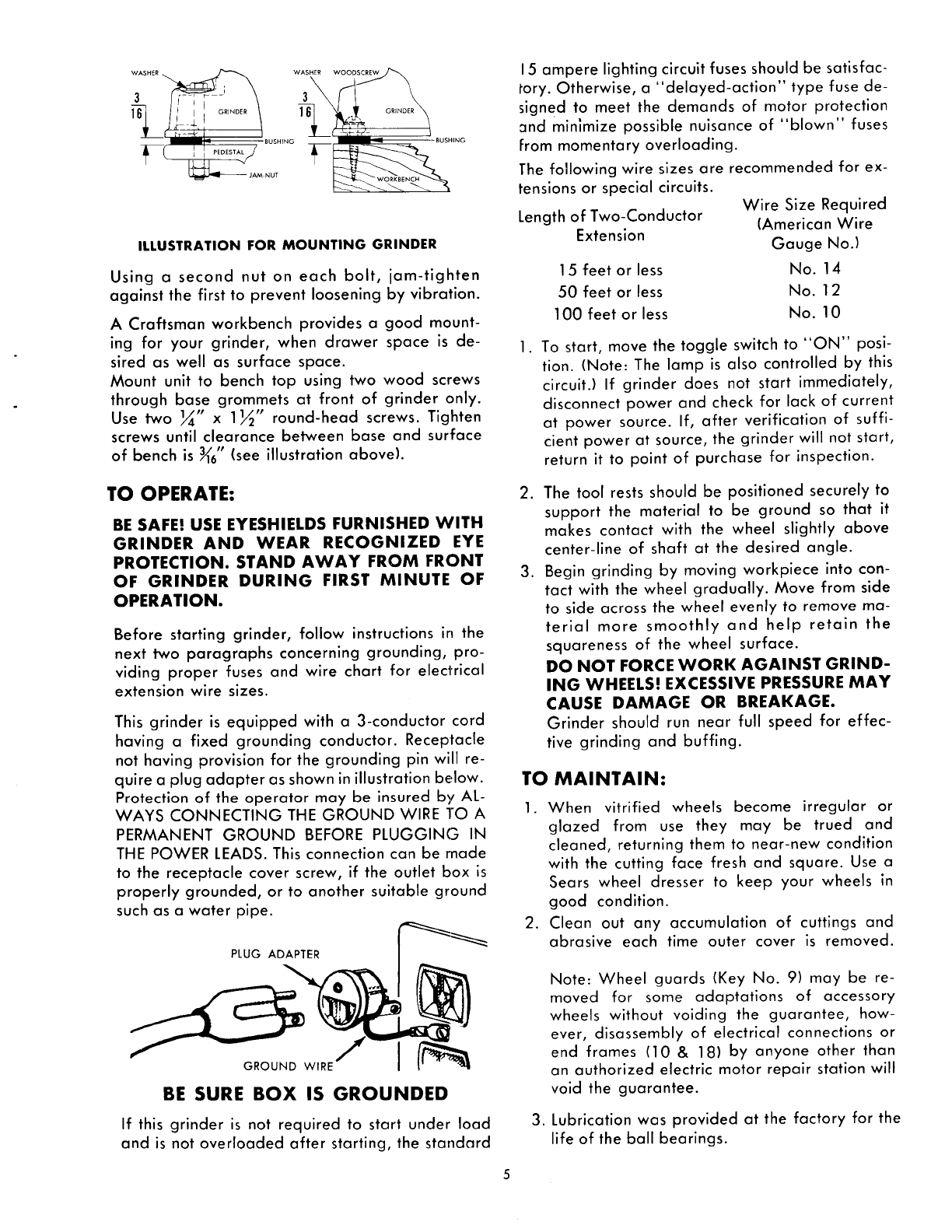
ILLUSTRATION FOR MOUNTING GRINDER
Using a second nut on each bolt, jam-tighten
against the first to prevent loosening by vibration.
A Craftsman workbench provides a good mount-
ing for your grinder, when drawer space is de-
sired as well as surface space.
Mount unit to bench top using two wood screws
through base grommets at front of grinder only.
Use two _" x 1_" round-head screws. Tighten
screws until clearance between base and surface
of bench is 3/16"(see illustration above).
15 ampere lighting circuit fuses should be satisfac-
tory. Otherwise, a "delayed-action" type fuse de-
signed to meet the demands of motor protection
and minimize possible nuisance of "blown" fuses
From momentary overloading.
The following wire sizes are recommended for ex-
tensions or special circuits.
Length of Two-Conductor
Extension
15 feet or less
50 feet or less
100 feet or less
Wire Size Required
(American Wire
Gauge No.)
No. 14
No. 12
No. 10
.To start, move the toggle switch to "ON" posi-
tion. (Note: The lamp is also controlled by this
circuit.) If grinder does not start immediately,
disconnect power and check for lack of current
at power source. If, after verification of suffi-
cient power at source, the grinder will not start,
return it to point of purchase for inspection.
TO OPERATE:
BE SAFE! USE EYESHIELDS FURNISHED WITH
GRINDER AND WEAR RECOGNIZED EYE
PROTECTION. STAND AWAY FROM FRONT
OF GRINDER DURING FIRST MINUTE OF
OPERATION.
Before starting grinder, follow instructions in the
next two paragraphs concerning grounding, pro-
viding proper fuses and wire chart for electrical
extension wire sizes.
This grinder is equipped with a 3-conductor cord
having a fixed grounding conductor. Receptacle
not having provision for the grounding pin will re-
quire a plug adapter as shown in illustration below.
Protection of the operator may be insured by AL-
WAYS CONNECTING THE GROUND WIRE 1"O A
PERMANENT GROUND BEFORE PLUGGING IN
THE POWER LEADS. This connection can be rnade
to the receptacle cover screw, if the outlet box is
properly grounded, or to another suitable ground
such as a water pipe.
PLUG ADAPTER
GROUND WIRE
BE SURE BOX IS GROUNDED
If this grinder is not required to start under load
and is not overloaded after starting, the standard
.
.
The tool rests should be positioned securely to
support the material to be ground so that it
makes contact with the wheel slightly above
center-line of shaft at the desired angle.
Begin grinding by moving workpiece into con-
tact with the wheel gradually. Move from side
to side across the wheel evenly to remove ma-
terial more smoothly and help retain the
squareness of the wheel surface.
DO NOT FORCE WORK AGAINST GRIND-
ING WHEELS! EXCESSIVE PRESSURE MAY
CAUSE DAMAGE OR BREAKAGE.
Grinder should run near full speed for effec-
tive grinding and buffing.
TO MAINTAIN:
1. When vitrified wheels become irregular or
glazed from use they may be trued and
cleaned, returning them to near-new condition
with the cutting face fresh and square. Use a
Sears wheel dresser to keep your wheels in
good condition.
2. Clean out any accumulation of cuttings and
abrasive each time outer cover is removed.
.
Note: Wheel guards (Key No. 9) may be re-
moved for some adaptations of accessory
wheels without voiding the guarantee, how-
ever, disassembly of electrical connections or
end frames (10 & 18) by anyone other than
an authorized electric motor repair station will
void the guarantee.
Lubrication was provided at the factory for the
life of the ball bearings.
GUARANTEE
We will repair, at no cost, grinders that show de-
fects in materials or workmanship, if returned
within one year from the date of purchase.
SEARS, ROEBUCK AND CO.
:31 76153 Installation and Maintenance Instructions 1-12-66
