Craftsman 48624506 User Manual 5HP VAC SYSTEM Manuals And Guides L0010593
CRAFTSMAN Lawn Vacuum Manual L0010593 CRAFTSMAN Lawn Vacuum Owner's Manual, CRAFTSMAN Lawn Vacuum installation guides
User Manual: Craftsman 48624506 48624506 CRAFTSMAN 5HP VAC SYSTEM - Manuals and Guides View the owners manual for your CRAFTSMAN 5HP VAC SYSTEM #48624506. Home:Lawn & Garden Parts:Craftsman Parts:Craftsman 5HP VAC SYSTEM Manual
Open the PDF directly: View PDF ![]() .
.
Page Count: 28
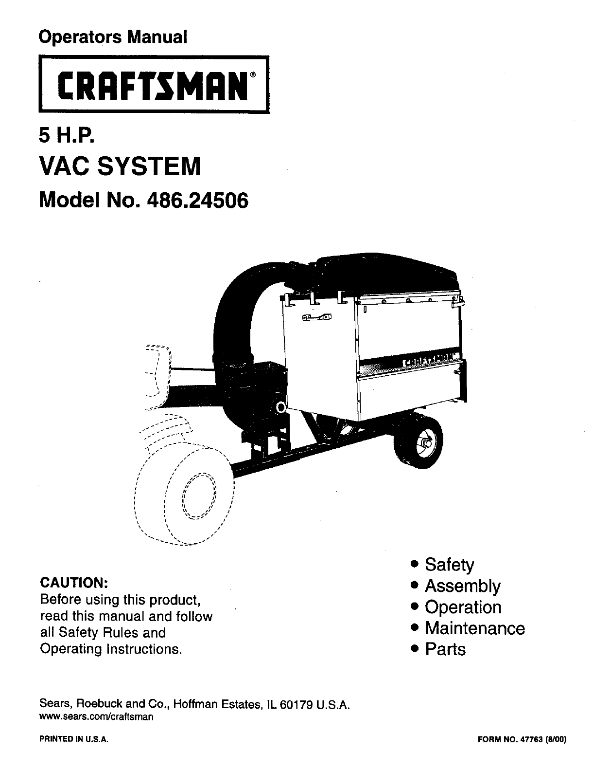
Operators Manual
I CRRFTSMRN°I
5 H.P,
VAC SYSTEM
Model No. 486.24506
CAUTION:
Before using this product,
read this manual and follow
all Safety Rules and
Operating Instructions.
• Safety
• Assembly
• Operation
• Maintenance
• Parts
Sears, Roebuck and Co., Hoffman Estates, IL 60179 U.S.A.
www.sears.com/craftsman
PRINTED IN U.S.A. FORM NO. 47763 (8/00)
WARRANTY ............................................................... 2
SAFETY RULES ........................................................ 3
ACCESSORIES AND ATTACHMENTS ................... 5
FULL SIZE HARDWARE CHART ............................. 6
CARTON CONTENTS ............................................... 8
ASSEMBLY ................................................................ 9
OPERATION ............................................................ 19
MAINTENANCE ....................................................... 21
STORAGE ......... :...................................................... 21
TROUBLESHOOTING ............................................. 22
REPAIR PARTS ILLUSTRATIONS ............ 23,24,26
REPAIR PARTS LISTS ................................ 23,25,26
SLOPE GUIDE ......................................................... 27
PARTS ORDERING/SERVICE ............... Rear Cover
LIMITED WARRANTY ON CRAFTSMAN POWERED TRACTOR ATTACHMENTS
For one (1) year from the date of purchase, if this Craftsman Equipment is maintained, lubricated
and tuned up according to the instructions in the owner's manual, Sears will repair or replace free
of charge any parts found to be defective in material or workmanship. Warranty service is avail-
able free of charge by returning your Craftsman equipment to your nearest Sears Service Center.
In-home warranty service is available but a trip charge will apply. This Warranty applies only
while this product is in the United States.
This Warranty does not cover:
• Expendable items which become worn during normal use, such as spark plugs, air cleaners,
belts, and oil filters.
• Tire replacement or repair caused by punctures from outside objects, such as nails, thorns,
stumps, or glass.
• Repairs necessary because of operator abuse, including but not limited to, damage caused by
impacting objects that bend the frame or crankshaft, or over-speeding the engine.
• Repairs necessary because of operator negligence, including but not limited to, electrical and
mechanical damage caused by improper storage, failure to use the proper grade and amount
of engine oil, or failure to maintain the equipment according to the instructions contained in the
owner's manual.
• Engine (fuel system) cleaning or repairs caused by fuel determined to be contaminated or
oxidized (stale). In general, fuel should be used within 30 days of its purchase date.
• Equipment used for commercial or rental purposes.
LIMITED WARRANTY ON BATTERY
For ninety (90) days from date of purchase, if any battery included with the equipment proves
defective in material or workmanship and our testing determines the battery will not hold a
charge, Sears will replace the battery at no charge. Warranty service is available free of charge
by returning your Craftsman equipment to your nearest Sears Service Center. In-home warranty
service is available but a trip charge will apply. This Warranty applies only while this product is in
the United States.
TO LOCATE THE NEAREST SEARS SERVICE CENTER OR TO SCHEDULE SERVICE,
SIMPLY CONTACT SEARS AT 1-800-4-MY-HOME.
This warranty gives you specific legal rights, and you may also have other rights, which vary from
state to state.
Any power equipment can cause injury if operated improperly or if the user does not understand how to operate the
equipment. Exercise caution at all times, when using power equipment.
•Read and follow all instructions in this manual before
attempting to assemble or operate this equipment. Failure
to comply with these instructions may result in personal
injury. Keep this manual in asafe place for future reference
and for ordedng replacement pads.
•Read this operating and service instruction manual carefully.
Be thoroughly familiar with the controls and proper use of
this power vacuum.
•Read the vehicle owners manual and vehicle safe operation
rules before using this equipment.
• Never allow children under 16 to operate this Mow-N-Vec.
Children 16 years and older should only operate under
close parental supervision.
•Do not allow anyone to operate this equipment without
proper instructions.
•Do not allow passengers to ride on this equipment or on the
towing vehicle.
•Keep the area of operation clear of all persons, particularly
small children. Also keep area clear of pets.
•Check fuel before starting engine. Do not fill fuel tank
indoors, or when engine is_,unning, or while engine is hot.
Wipe off any spilled fuel before starting engine.
•Engine and muffler get hot. Do not touch! To avoid fire
hazard, keep clean of debris and other accumulations.
•Never store Mow-N-Vac with fuel in tank. Allow engine to
cool before storing in any enclosure.
•Do not change engine governor settings.
•Do not operate engine if air cleaner or cover is removed,
except for adjustment. Removal of these parts could create
afire hazard.
•Keep hands, feet, face, long hair and clothing out of inlet
and discharge area. There are ROTATING BLADES inside
these openings.
•Before cleaning, repairing or inspecting, make certain all
moving parts come to a complete stop. Disconnect spark
plug wire and keep wire away from plug to prevent acciden-
tal starting. Keep throtUe control lever in stop position.
•Ifthe Mow-N-Vac should become blocked with debris at any
point, shut engine off and wait until the impeller comes to a
complete stop before attempting to remove the obstruction.
Disconnect spark plug wire to prevent accidental starting.
• If the cuttingmechanismstrikesa foreign object,or if your
Mow-N-Vac should start to vibrate abnormally, stop the
engine immediately, disconnect the spark plug wire and
movethe wireawayfromthe sparkplug. Allowthe machine
to stopand take the following steps.
a. Inspect for damage.
b. Repair or replace any damaged pads.
c. Check for loose parts and tighten to assure
Continuedsafe operation.
•Check all bolts for tightness at frequent intervalsto help
insuresafe operation.
•Check vinyl hard top boot frequently for wear. Replace if
worn or damaged.
•Never operate Mow-N-Vac unless deck adapter, hose,
hose adapter (nozzle), discharge chute (elbow), and top
cover are properlyattached intheir place.
•Do not removetop cover or attempt to empty contentsof
cart while engine is running.
•Never attemptto change hoseadapter (nozzle) orto install
remote hose attachment when engine is running.
•Keep all shields and guards (e.g. discharge chute(elbow)
and hose adapter (nozzle) inplace and securely attached.
•Alwayswear safety glassesorother suitableeye protection
when operatingor maintainingthis equipment.
•Do not stand behind cart in exhaust discharge area while
engine is running.
•Do not operate this equipment while intoxicatedor while
taking drugs or medication that impairs the senses and
reactions."
•When usingthisequipment,startwiththe vehicle transmis-
sion in first (low).gear and then gradually increase speed
only as conditionspermit.
•Operate thisequipmentat reducedspeed onroughterrain,
along creeks and_litches and on slopes to preventtipping
or lossof control.Donotdrive toocloseto acreek or ditch.
•Vehicle brakingand stabilityare affected by the additionof
thisequipment.Do notfill the Mow-N-Vec to itsfull capacity
without checking the capability of the towing vehicle to
safely pulland stopwith the Mow-N-Vac attached.
•Beforeoperatingonany grade (hill)referto the safetyrules
inthe vehicleowner'smanual concerningsafeoperationon
slopes. Also refer to the SLOPE GUIDE onpage 23 ofthis
owner's manual. Do notoperate onslopes inexcess of 10
degrees. STAY OFF STEEP SLOPES.
•Followthe maintenanceinstructionsoutlinedinthismanual.
Look for this symbol to point out important safety precautions. It means--Attentlont! Become alert!1
Your safety is involved.
DANGER: This Vac System was built to be operated according to the rules for safe operation in
this manual. As with any type of power equipment, carelessness or error on the part of the opera-
tor can result in serious injury. This unit is capable of amputating fingers and hands and throwing
objects. Failure to observe the following safety instructions could result in serious injury or death.
3
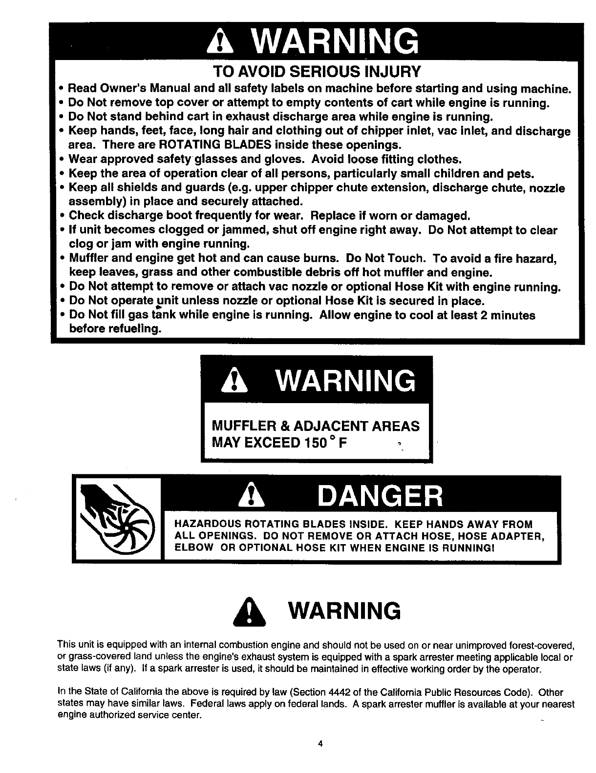
TO AVOID SERIOUS INJURY
• Read Owner's Manual and all safety labels on machine before starting and using machine.
•Do Not remove top cover or attempt to empty contents of cart while engine is running.
•Do Not stand behind cart in exhaust discharge area while engine is running.
•Keep hands, feet, face, long hair and clothing out of chipper inlet, vac inlet, and discharge
area. There are ROTATING BLADES inside these openings.
•Wear approved safety glasses and gloves. Avoid loose fitting clothes.
•Keep the area of operation clear of all persons, particularly small children and pets.
•Keep all shields and guards (e.g. upper chipper chute extension, discharge chute, nozzle
assembly) in place and securely attached.
•Check discharge boot frequently for wear. Replace if worn or damaged.
•If unit becomes clogged or jammed, shut off engine right away. Do Not attempt to clear
clog or jam with engine running•
•Muffler and engine get hot and can cause burns. Do Not Touch• To avoid a fire hazard,
keep leaves, grass and other combustible debris off hot muffler and engine.
•Do Not attempt to remove or attach vac nozzle or optional Hose Kit with engine running.
!• Do Not operate unit unless nozzle or optional Hose Kit is secured in place.
I
i°Do Not fill gas tank while engine is running. Allow engine to cool at least 2 minutes
I before refueling.
MUFFLER & ADJACENT AREAS
MAY EXCEED 150 o F
WARNING
This unit is equipped with an internal combustion engine and should not be used on or near unimproved forest-covered,
or grass-covered land unless the engine's exhaust system is equipped with a spark arrester meeting applicable local or
state laws (if any). If a spark arrester is used, it should be maintained in effective working order by the operator.
In the State of California the above is required by law (Section 4442 of the California Public Resources Code). Other
states may have similar laws. Federal laws apply on federal lands. A spark arrester muffler is available at your nearest
engine authorized service center.
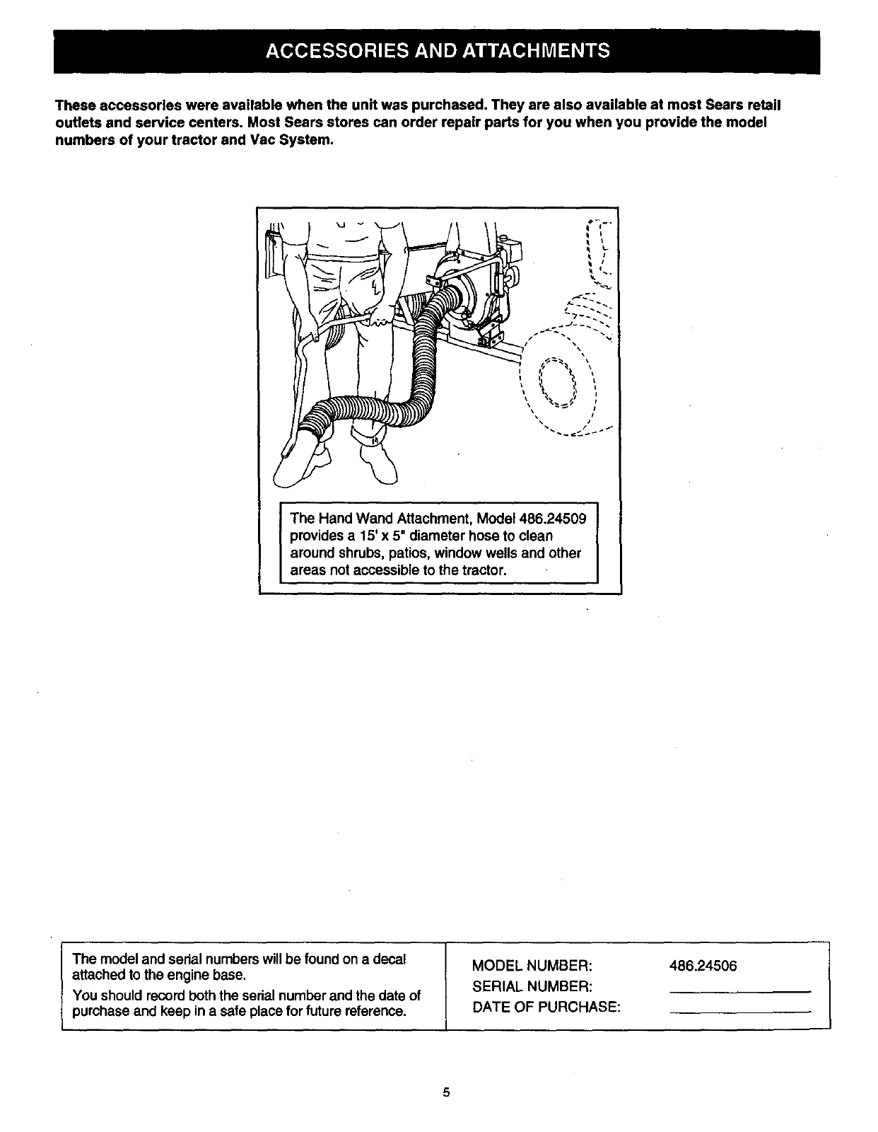
These accessories were available when the unit was purchased. They are also available at most Sears retail
outlets and service centers. Most Sears stores can order repair parts for you when you provide the model
numbers of your tractor and Vac System.
\\ it
I he Hand Wand Attachment, Model 486.24509
provides a15' x 5" diameter hose to clean
around shrubs, patios, window wells and other
areas not accessible to the tractor.
I he model and serial numbers will be found on a decal
attached to the engine base.
You should record both the serial number and the date of
purchase and keep in a safe place for future reference.
MODELNUMBER:
SERIALNUMBER:
DATE OF PURCHASE:
486.24506
5
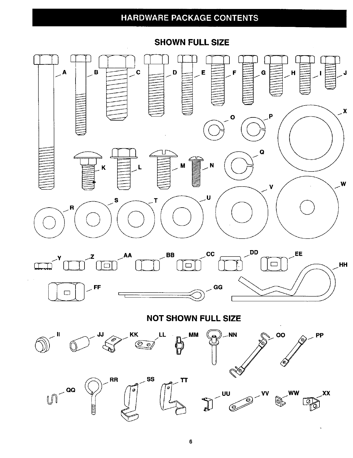
SHOWN FULL SIZE
/Y jZ /AA +/BB jCC /DD +fEE HH
GG
i i [
NOT SHOWN FULL SIZE
/JJ_/KK /LL _)I MM
PP
UU VV WW XX
6
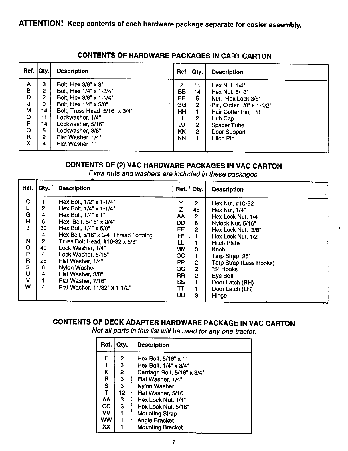
ATTENTION! Keep contents of each hardware package separate for easier assembly.
CONTENTS OF HARDWARE PACKAGES IN CART CARTON
Ref. Qty. Description Ref.
A
B
D
J
M
O
P
Q
R
X
3
2
2
9
14
11
14
5
2
4
Bolt, Hex 3/8" x 3"
Bolt, Hex 1/4" x 1-3/4"
Bolt, Hex 3/8" x 1-1/4"
Bolt, Hex 1/4" x 5/8"
Z
BB
EE
GG
Qty. Description
11 Hex Nut, 1/4"
14 Hex Nut, 5/16"
5 Nut, Hex Lock 3/8"
2 Pin, Cotter 1/8" x 1-1/2"
Bolt, Truss Head 5/16" x 3/4"
Lockwasher, 1/4"
Lockwasher, 5/16"
Lockwasher, 3/8"
Flat Washer, 1/4"
Flat Washer, 1"
HH
II
JJ
KK
NN
1
2
2
2
1
Hair Cotter Pin, 1/8"
Hub Cap
Spacer Tube
Door Support
Hitch Pin
CONTENTS OF (2) VAC HARDWARE PACKAGES IN VAC CARTON
Extra nuts and washers are included in these packages.
Ref. Qty. Description
C 1 Hex Bolt, 1/2" x 1-1/4"
E 2 Hex Bolt, 1/4" x 1-1/4"
G 4 Hex Bolt, 1/4" x 1"
H 6 Hex Bolt, 5/16" x 3/4"
J 30 Hex Bolt, I/4" x 5/8"
L 4 Hex Bolt, 5/16" x 3/4" Thread Forming
N 2 Truss Bolt Head, #10-32 x 5/8"
O 40 Lock Washer, 1/4"
P 4 Lock Washer, 5/16"
R 26 Flat Washer, 1/4"
S 6 Nylon Washer
U 4 Flat Washer, 3/8"
V 1 Flat Washer, 7/16"
W 4 Flat Washer, 11/32" x 1-1/2"
Ref. Qty. Description
Y 2 Hex Nut, #10-32
Z 46 Hex Nut, 1/4"
AA 2 Hex Lock Nut, 1/4"
DD 6 Nylock Nut, 5/16"
EE 2 Hex Lock Nut, 3/8"
FF 1 Hex Lock Nut, 1/2"
LL 1 Hitch P!ate
MM 3 Knob
OO 1 Tarp Str_p, 25 =
PP 2 Tarp Strap (Less Hooks)
QQ 2 "S" Hooks
RR 2 Eye Bolt
SS 1 Door Latch (RH)
TT 1Door Latch (LH)
UU 3 Hinge
CONTENTS OF DECK ADAPTER HARDWARE PACKAGE IN VAC CARTON
Not all parts in thislist will be used for any one tractor.
Ref. Qty. Description
F 2
I 3
K2
R3
S 3
T12
AA 3
CO 3
VV 1
VWV 1
XX 1
Hex Bolt, 5/16" x 1"
Hex Bolt, 1/4" x 3/4"
Carriage Bolt, 5/16" x3/4"
Flat Washer, 1/4"
Nylon Washer
Flat Washer, 5/16"
Hex Lock Nut, 1/4"
Hex Lock Nut, 5/16"
Mounting Strap
Angle Bracket
Mounting Bracket
7

CARTON CONTENTS (Cart Carton)
Ref. Qty. Description Ref. Qty.
1 1 Wheel Support 61
2 1 Rear Tongue 7 1
3 1 Front Tongue 8 1
4 1 Hose Hanger Rod Assembly 9 1
5 2 Cart BooT_es 10 2
Description
Hose
Tailgate Reinforcement Bracket
Axle
Latch Stand Bracket
Wheels
10
1\7
16
\
CARTON CONTENTS (Vac Carton)
Ref. Qty.
1 1
2 2
3 2
4 1
5 1
6 1
7 1
8 2
9 2
Description Ref, Qty. Description
Front Panel 10 1 Deck Adapter
Side Brackets 11 1 Poly Hard Top
Side Panels 12 1 Elbow
Dump Handle 13 1 Skid Plate
Prop Rod (Right) 14 1 Hitch Bracket
Prop Rod (Left) 15 1 Adapter Bracket
Rear Door 16 1 Engine/Impeller Assembly
Tie Rods 17 1 Hose Adapter (Nozzle)
Hose Clamps 18 1 Hose Hanger Bracket
8
This unit is shipped WITHOUT GASOLINE or OIL. After
assembly, see separate engine manual for proper fuel
and engine oil recommendations.
TOOLS REQUIRED FOR ASSEMBLY
(1) Screwdriver
(1) Pliers
(1) 3/8" Wrench
(2) 7/16" Wrenches
(2) 1/2" Wrenches
(2) 9/16" Wrenches
(2) 3/4" Wrenches (only if figure 27 on page 15 is used)
REMOVAL OF PARTS FROM CARTONS
•Remove the hardware packs and all loose parts from
the cartons.
• Lay out and identify parts shown in carton contents.
• Lay out and identify parts in the hardware packs.
Keep contents of each hardware package separate
for easier assembly.
ASSEMBLING THE VAC SYSTEM
• Place cart body halves upright on a smooth level
surface such as a garage floor or a paved driveway.
See figure 1.
ACAUTION: Do not leave the cart unattended
in upright position during assembly. A falling
cart can cause personal injury! Pay close
attention to the stability of the cart while it
remains in an upright position. For best stability,
assemble on a smooth level surface.
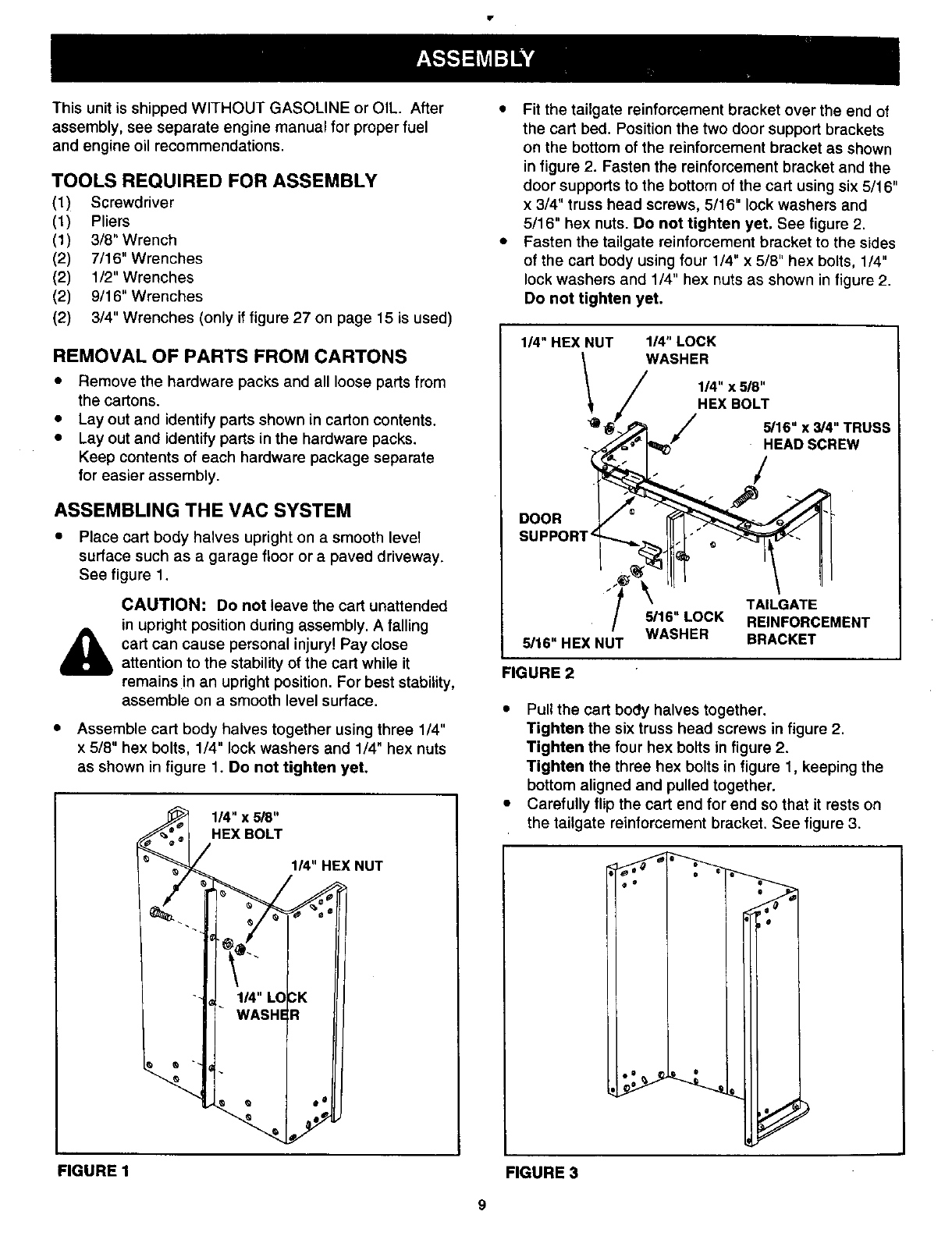
• Assemble cart body halves together using three 1/4"
x 5/8" hex bolts, 1/4" lock washers and 1/4" hex nuts
as shown in figure 1. Do not tighten yet.
1/4" x 518"
HEX BOLT
114" HEX NUT
FIGURE 1
• Fit the tailgate reinforcement bracket over the end of
the cart bed. Position the two door support brackets
on the bottom of the reinforcement bracket as shown
in figure 2. Fasten the reinforcement bracket and the
door supports to the bottom of the cart using six 5/16"
x 3/4" truss head screws, 5/16" lock washers and
5/16" hex nuts. Do not tighten yet. See figure 2.
• Fasten the tailgate reinforcement bracket to the sides
of the cart body using four 1/4" x 5/8" hex bolts, 1/4"
lock washers and 1/4" hex nuts as shown in figure 2.
Do not tighten yet.
1/4" HEX NUT 1/4" LOCK
WASHER
114"x 5/8"
HEX BOLT
//
DOOR
SUPPORT
/"
TAILGATE
5/16" LOCK REINFORCEMENT
5/16" HEX NUT WASHER BRACKET
FIGURE 2
• Pull the cart body halves together.
Tighten the six truss head screws in figure 2.
Tighten the four hex bolts in figure 2.
Tighten the three hex bolts in figure 1, keeping the
bottom aligned and pulled together.
• Carefully flip the cart end for end so that it rests on
the tailgate reinforcement bracket. See figure 3.
FIGURE 3
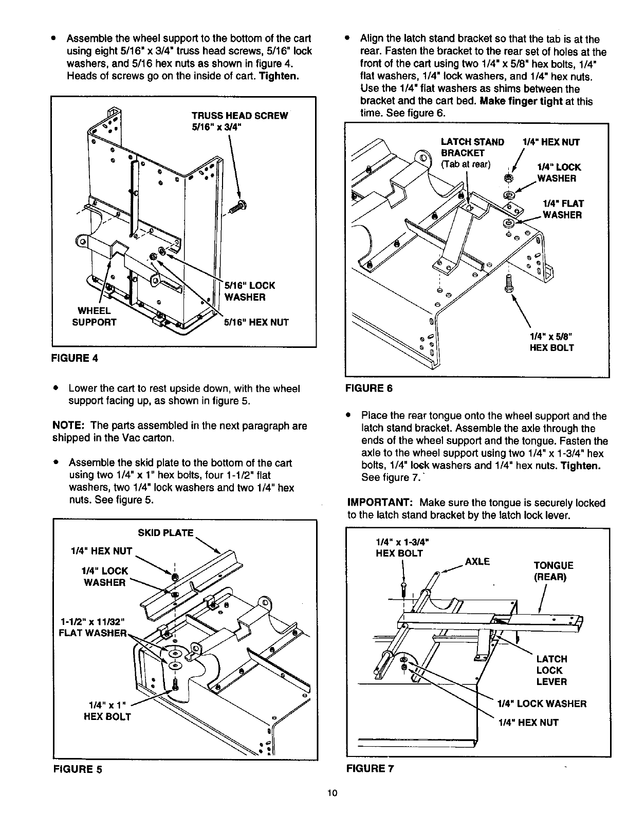
Assemble the wheel support to the bottom of the cart
using eight 5/16" x 314"truss head screws, 5/16" lock
washers, and 5/16 hex nuts as shown in figure 4.
Heads of screws go on the inside of cart. Tighten.
e"
WHEEL
SUPPORT
TRUSS HEAD SCREW
5116"x _4"
'_16"LOCK
WASHER
5116"HEX NUT
FIGURE 4
Align the latch stand bracket so that the tab is at the
rear. Fasten the bracket to the rear set of holes at the
front of the cart using two 1/4" x 518" hex bolts, 114"
flat washers, 1/4" lock washers, and 1/4" hex nuts.
Use the 1/4" flat washers as shims between the
bracket and the cart bed. Make finger tight at this
time. See figure 6.
LATCH STAND 1_" HEX NUT
BRACKET _/ I_"LOCKwAsHER
114"FLAT
\114"x 5/8"
HEX BOLT
• Lower the cart to rest upside down, with the wheel
support facing up, as shown in figure 5.
NOTE: The parts assembled in the next paragraph are
shipped in the Vac carton.
Assemble the skid plate to the bottom of the cart
using two 1/4" x 1" hex bolts, four 1-1/2" flat
washers, two 114" lock washers and two 1/4" hex
nuts. See figure 5.
SKID PLATE
I_"HEX NUT
I_"LOCK
WASHER_
1-1/2" x 11/32"
1_"x1"
HEXBOLT
FIGURE6
Place the rear tongue onto the wheel support and the
latch stand bracket. Assemble the axle through the
ends of the wheel support and the tongue. Fasten the
axle to the wheel support using two 114"x 1-314" hex
bolts, 1/4" lock washers and 1/4" hex nuts. Tighten.
See figure 7.
IMPORTANT: Make sure the tongue is securely locked
to the latch stand bracket by the latch lock lever.
114" x 1-3/4"
HEX BOLT
LATCH
LOCK
LEVER
II4"LOCK WASHER
II4"HEX NUT
FIGURE 5 FIGURE 7
10
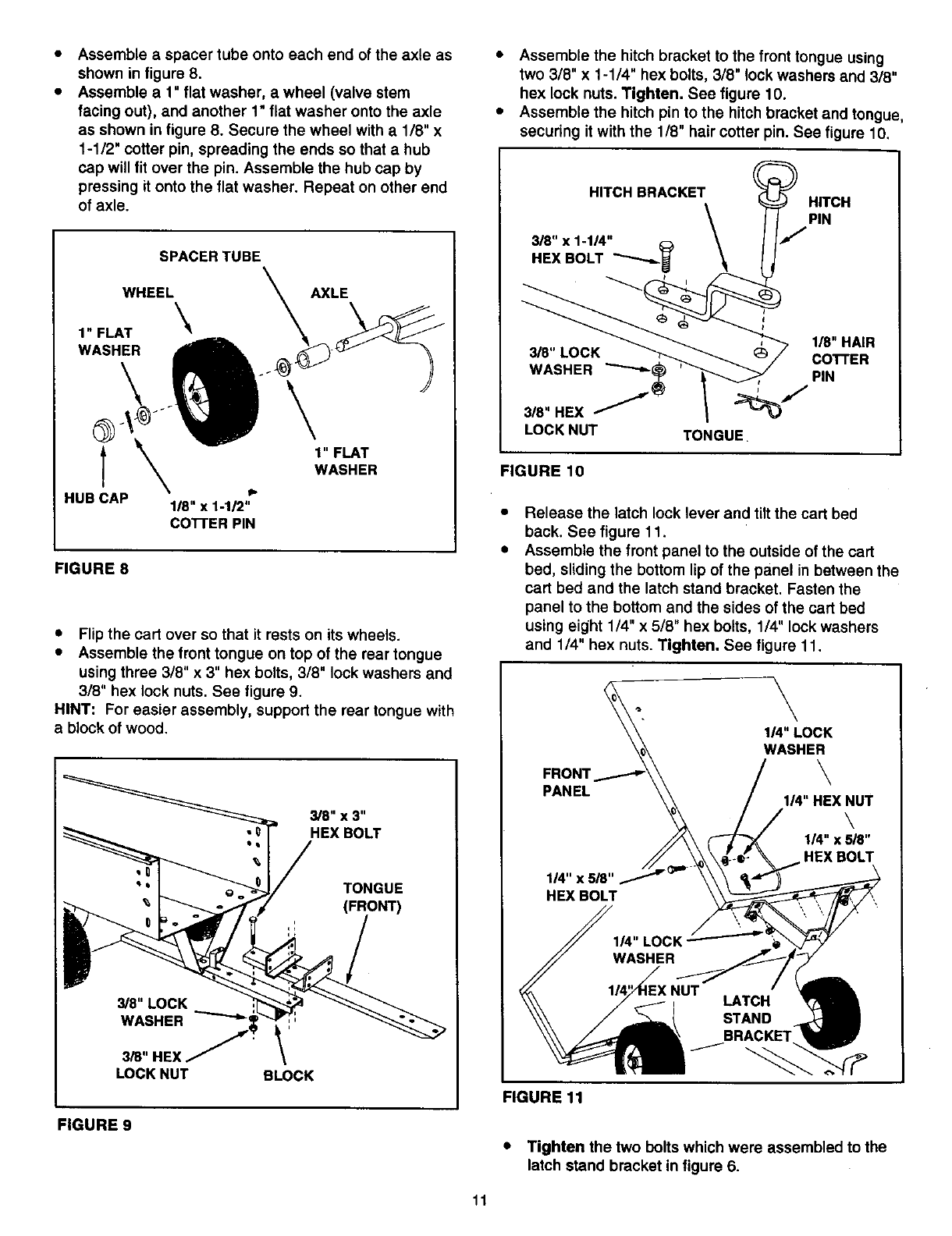
Assemble a spacer tube onto each end of the axle as
shown in figure 8.
Assemble a 1" flat washer, a wheel (valve stem
facing out), and another 1" flat washer onto the axle
as shown in figure 8. Secure the wheel with a 1/8" x
1-1/2" cotter pin, spreading the ends so that a hub
cap will fit over the pin. Assemble the hub cap by
pressing it onto the flat washer. Repeat on other end
of axle.
SPACER TUBE
WHEEL \
1" FLAT _'_
WASHER
\
G
t
HUB CAP ii.
118" x 1-112"
co'n'ER PIN
1" FLAT
WASHER
FIGURE 8
•Flip the cart over so that it rests on its wheels.
•Assemble the front tongue on top of the rear tongue
using three 3/8" x 3" hex bolts, 3/8" lock washers and
3/8" hex lock nuts. See figure 9.
HINT: For easier assembly, support the rear tongue with
ablock of wood.
3/8" x 3"
HEX BOLT
TONGUE
(FRONT)
_8"LOCK
WASHER _:'
3/8"HEX \
LOCK NUT BLOCK
FIGURE 9
•Assemble the hitch bracket to the front tongue using
two 3/8" x 1-1/4" hex bolts, 3/8" lock washers and 318"
hex lock nuts. Tighten. See figure 10.
• Assemble the hitch pin to the hitch bracket and tongue,
securing it with the 1/8" hair cotter pin. See figure 10,
HITCH
PIN
1/8" HAIR
COTTER
PIN
TONGUE
FIGURE 10
Release the latch lock lever and tilt the cart bed
back. See figure 11.
Assemble the front panel to the outside of the cart
bed, sliding the bottom lip of the panel in between the
cart bed and the latch stand bracket. Fasten the
panel to the bottom and the sides of the cart bed
using eight 1/4" x 5/8" hex bolts, 114" lock washers
and 1/4" hex nuts. Tighten. See figure 11.
FRONT
PANEL
1/4"x5_"
HEXBOLT
\
I_"LOCK
WASHER
\
I_"HEX NUT
\
l_"x _8"
HEX BOLT
LATCH
STAND
FIGURE 11
•Tighten the two bolts which were assembled to the
latch stand bracket in figure 6.
11
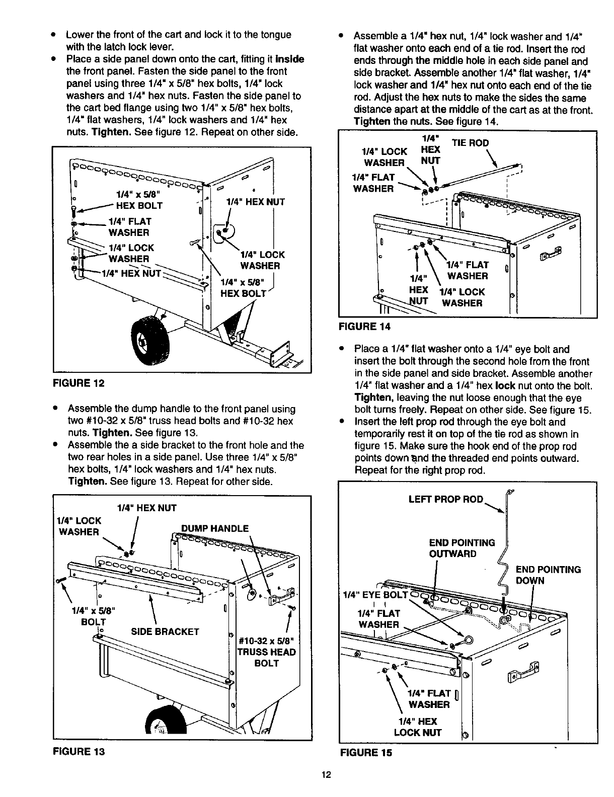
Lower the front of the cart and lock it to the tongue
with the latch lock lever.
Place a side panel down onto the cart, fitting it Inside
the front panel. Fasten the side panel to the front
panel using three 114"x 5/8" hex bolts, 1/4" lock
washers and 1/4" hex nuts. Fasten the side panel to
the cart bed flange using two 1/4" x 5/8" hex bolts,
1/4" flat washers, 1/4" lock washers and 1/4" hex
nuts. Tighten. See figure 12. Repeat on other side.
_/HEXBOLT
114" HEX NUT
114" LOCK
WASHER
114"x 5/8" |
i
f
HEX BOLT
FIGURE 12
Assemble the dump handle to the front panel using
two #10-32 x 518" truss head bolts and #10-32 hex
nuts. Tighten. See figure 13.
Assemble the a side bracket to the front hole and the
two rear holes in a side panel. Use three 1/4" x 5/8"
hex bolts, 114" lock washers and 114" hex nuts.
Tighten. See figure 13. Repeat for other side.
DUMPHANDLE
FIGURE 13
Assemble a 1/4" hex nut, 1/4" lock washer and 1/4"
flat washer onto each end of atie rod. Insert the rod
ends through the middle hole in each side panel and
side bracket. Assemble another 1/4" flat washer, 1/4"
lock washer and 1/4" hex nut onto each end of the tie
rod. Adjust the hex nuts to make the sides the same
distance apart at the middle of the cart as at the front.
Tighten the nuts. See figure 14.
114" FLAT
WASHER
LIT WASHER
FIGURE 14
•Place a 1/4" flat washer onto a1/4" eye bolt and
insert the bolt through the second hole from the front
in the side panel and side bracket. Assemble another
1/4" flat washer and a 1/4" hex lock nut onto the bolt.
Tighten, leaving the nut loose enough that the eye
bolt turns freely. Repeat on other side. See figure 15.
•Insert the left prop red through the eye bolt and
temporarily rest it on top of the tie rod as shown in
figure 15. Make sure the hook end of the prop rod
points down'a.nd the threaded end points outward.
Repeat for the dght prop rod.
LEFT PROP ROD
END POINTING
OUTWARD LEND POINTING
LDOWN
,
1/4" FLAT _, _._ _"_
WASHER _ _ ,,_ "%-_-'_ _-_ _"_
\WASHERII
1/4" LI
LOCK NUT I
FIGURE 15
12
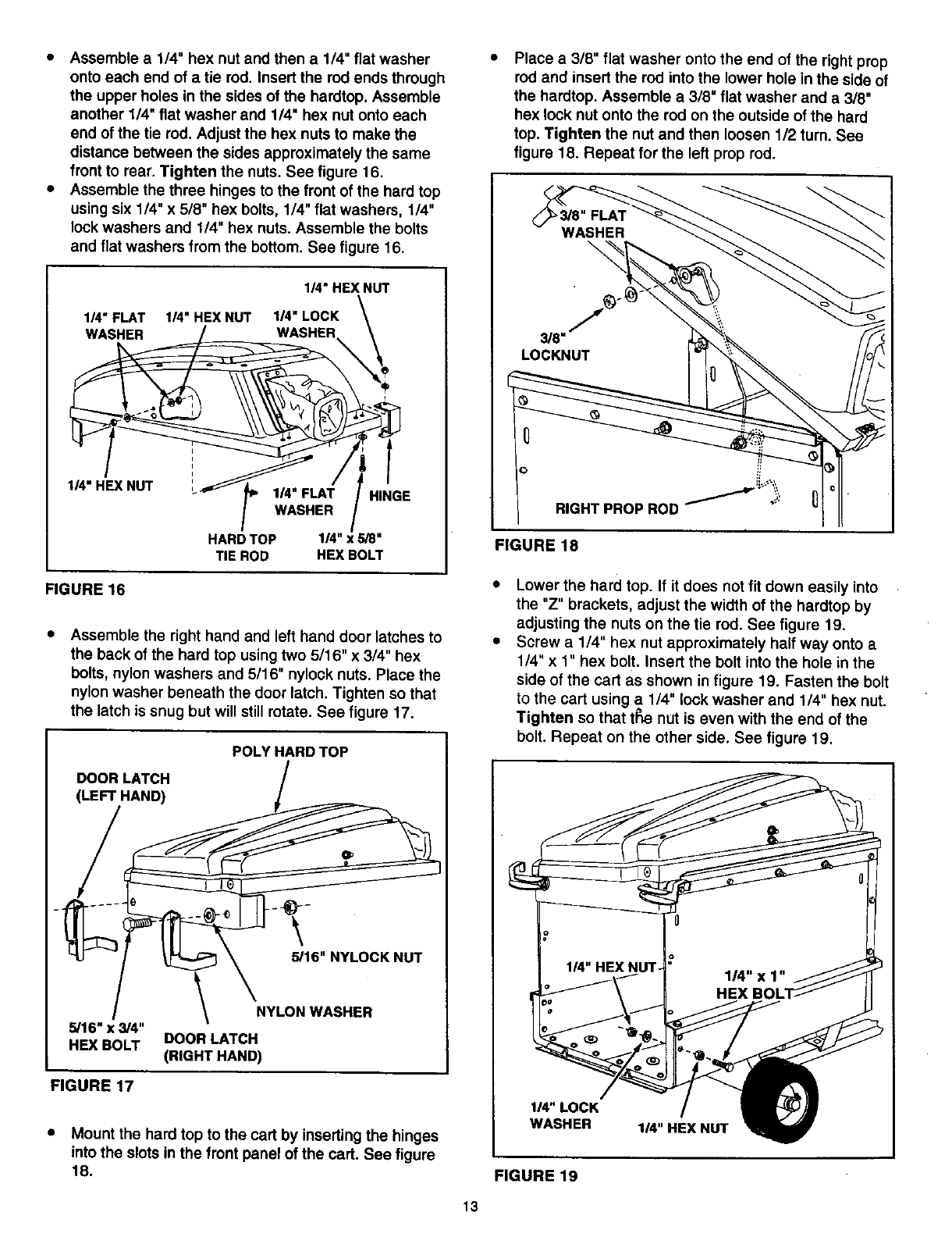
• Assemble a 1/4" hex nut and then a 1/4" flat washer
onto each end of a tie rod. Insert the rod ends through
the upper holes in the sides of the hardtop, Assemble
another 1/4" flat washer and 1/4" hex nut onto each
end of the tie rod. Adjust the hex nuts to make the
distance between the sides approximately the same
front to rear. Tighten the nuts. See figure 16.
• Assemble the three hinges to the front of the hard top
using six 1/4" x 5/8" hex bolts, 114" flat washers, 1/4"
lock washers and 114" hex nuts. Assemble the bolts
and flat washers from the bottom. See figure 16.
114"HEX NUT
1/4" FLAT 114"HEX NUT I/4" LOCK \
,,4".EX.UT ..HOE
HARD TOP 1/4" gS"
TIE ROD HEX BOLT
FIGURE 16
Assemble the right hand and left hand door latches to
the back of the hard top using two 5/16" x 3/4" hex
bolts, nylon washers and 5/16" nylock nuts. Place the
nylon washer beneath the door latch. Tighten so that
the latch is snug but will still rotate. See figure 17.
DOOR LATCH
(LEFT HAND)
POLYHARDTOP
3/16"x 3/4"
HEX BOLT
\
3/16" NYLOCK NUT
NYLON WASHER
DOOR LATCH
(RIGHT HAND)
FIGURE 17
• Mount the hard top to the cart by inserting the hinges
into the slots in the front panel of the cart. See figure
18.
Place a 3/8" flat washer onto the end of the right prop
rod and insert the rod into the lower hole in the side of
the hardtop. Assemble a 3/8" flat washer and a3/8"
hex lock nut onto the rod on the outside of the hard
top. Tighten the nut and then loosen 1/2 turn. See
figure 18. Repeat for the left prop rod.
\
3/8"
LOCKNUT
RIGHT PROP ROD _""w_i--:_'_--_
FIGURE 18
Lower the hard top. If it does not fit down easily into
the "Z" brackets, adjust the width of the hardtop by
adjusting the nuts on the tie rod. See figure 19.
Screw a 114" hex nut approximately half way onto a
1/4" x 1" hex bolt. Insert the bolt into the hole in the
side of the cart as shown in figure 19. Fasten the bolt
to the cart using a 1/4" lock washer and 1/4" hex nut.
Tighten so that t_ nut is even with the end of the
bolt. Repeat on the other side. See figure 19.
114"LOCK
WASHER 1/4" HEX NUT
FIGURE 19
13
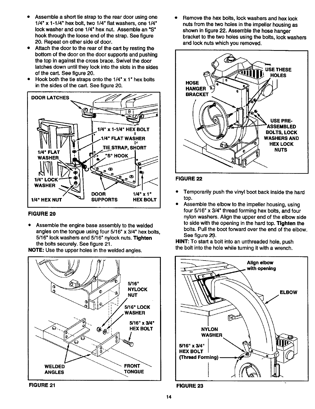
• Assemble ashort tie strap to the rear door using one
1/4" x 1-1/4" hex bolt, two 1/4" flat washers, one 1/4"
lock washer and one 1/4" hex nut. Assemble an "S"
hook through the loose end of the strap. See figure
20. Repeat on other side of door.
•Attach the door to the rear of the cart by resting the
bottom of the door on the door supports and pushing
the top in against the cross brace. Swivel the door
latches down untilthey lock into the slots in the sides
of the cart. See figure 20.
•Hook both the tie straps onto the 114"x 1" hex bolts
in the sides of the cart. See figure 20.
DOOR LATCHES
_R 1/4" x 1•
1/4" x 1-114" HEX BOLT
TIE STRAP, SHORT
WASHER I ,=
,11IV/l_,
1/4" LOCK"_'_ _
WASHER _/_
114"HEX NUT SUPPORTS HEX BOLT
FIGURE 20
•Assemble the engine base assembly to the welded
angles on the tongue using four 5/16" x 3/4" hex bolts,
5116" lock washers and 5/16" nylock nuts. Tighten
the bolts securely. See figure 21.
NOTE: Use the upper holes in the welded angles.
5/16"
NYLOCK
NUT
LOCK
WASHER
,_ 5/16•x 3/4"
HEX BOLT
WELDED
ANGLES TONGUE
Remove the hex bolts, look washers and hex lock
nuts from the two holes in the impeller housing as
shown in figure 22. Assemble the hose hanger
bracket to the two holes using the bolts, lock washers
and look nuts which you removed.
HOSE
HANGER
BRACKET
USE THESE
HOLES
USE PRE-
IBLED
BOLTS, LOCK
WASHERSAND
HEXLOCK
NUTS
FIGURE 22
•Temporarily push the vinyl boot back inside the hard
top.
• Assemble the elbow to the impeller housing, using
four 5116" x 314" thread forming hex bolts, and four
nylon washers. Align the upper end of the elbow side
to side with the opening in the hard top. Tighten the
bolts. Pull the boot forward over the end of the elbow.
See figure 2_..
HINT: To start abolt into an unthreaded hole, push
the bolt into the hole while tuming it with a wrench.
Align elbow
with opening
ELBOW
NYLON
WASHER
_16"x_4"
HEX BOLT
_h_ed
FIGURE 21 FIGURE 23
14
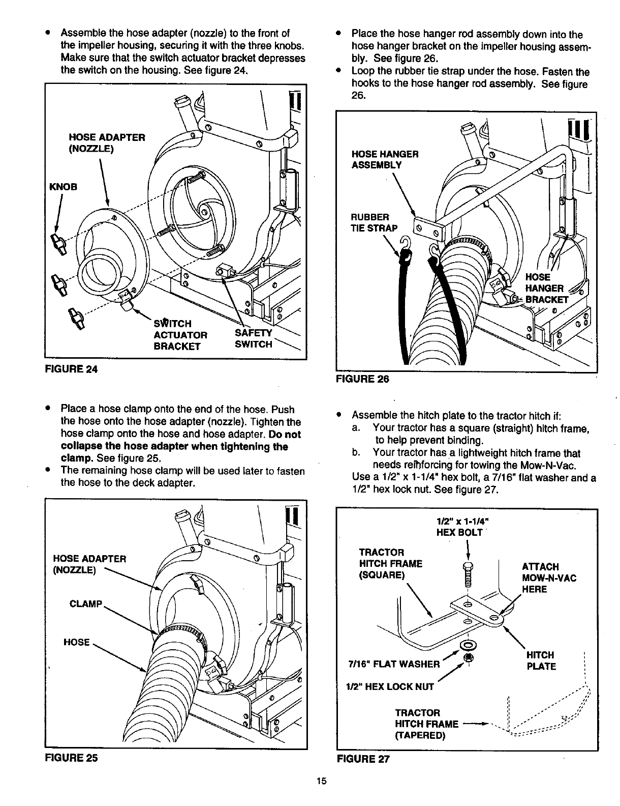
Assemble the hose adapter (nozzle) to the front of
the impeller housing, securing it with the three knobs.
Make sure that the switch actuator bracket depresses
the switch on the housing. See figure 24.
HOSE ADAPTER
(NOZZLE)
KNOB 1
S_ITCH
ACTUATOR SAFETY
BRACKET SWITCH_
FIGURE 24
•Place the hose hanger rod assembly down into the
hose hanger bracket on the impeller housing assem-
bly. See figure 26.
•Loop the rubber tie strap under the hose. Fasten the
hooks to the hose hanger rod assembly. See figure
26.
HOSEHANGER
ASSEMBLY
RUBBER
TIE STRAP
FIGURE 26
•Place a hose clamp onto the end of the hose. Push
the hose onto the hose adapter (nozzle). Tighten the
hose clamp onto the hose and hose adapter. Do not
collapse the hose adapter when tightening the
clamp, See figure 25.
•The remaining hose clamp will be used later to fasten
the hose to the deck adapter.
Assemble the hitch plate to the tractor hitch if:
a. Your tractor has a square (straight) hitch frame,
to help prevent binding.
b. Your tractor has a lightweight hitch frame that
needs rerhfoming for towing the Mow-N-Vac.
Use a1/2" x 1-1/4" hex bolt, a 7/16" flat washer and a
1/2" hex lock nut. See figure 27.
HOSE ADAPTER
(NOZZLE)
CLAMP
FIGURE 25
1_"x1-1_"
HEXBOLT
TRACTOR 1
HITCH FRAME OATFACH
(SQUARE) ,_ MOW-N-VAC
HERE
HITCH
7116"FLAT WA_ PLATE
FIGURE 27
15
ASSEMBLING THE DECK ADAPTER
(#62468) TO THE MOWER DECK
NOTE: Not all of the parts in the deck adapter hardware
package wil! be used for any one particular fit up.
=Remove the mower discharge deflector from your
mower deck. Save the deflector and hardware for
remounting deflector.
IF YOU HAVE A MURRAY TRACTOR WITH A 38"or
40" DECK, SKIP DIRECTLY TO PAGE 17.
IF YOU HAVE A MURRAY TRACTOR WITH A 46"
DECK, SKIP DIRECTLY TO PAGE 18.
&CAUTION: Mower deflector must be
replaced when Vac System deck adapter
is removed. Do Not operate mower
unless adapter or deflector is in place and
properly moun_ed.
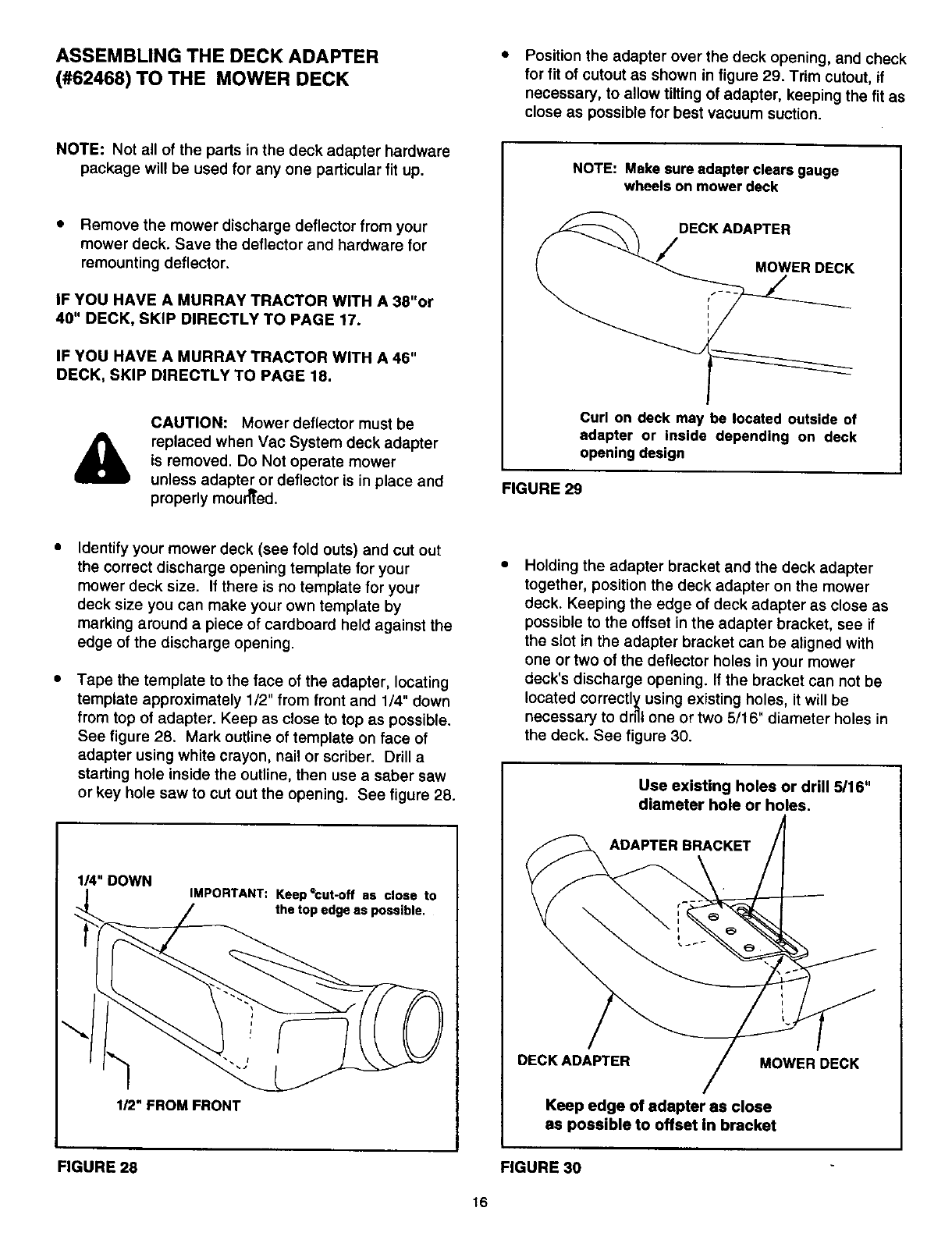
Position the adapter over the deck opening, and check
for fit of cutout as shown in figure 29. Trim cutout, if
necessary, to allow tilting of adapter, keeping the fit as
close as possible for best vacuum suction.
NOTE: Make sure adapter clears gauge
wheels on mower deck
DECK ADAPTER
Curl on deck may be located outside of
adapter or inside depending on deck
opening design
FIGURE 29
Identify your mower deck (see fold outs) and cut out
the correct discharge opening template for your
mower deck size. If there is no template for your
deck size you can make your own template by
marking around a piece of cardboard held against the
edge of the discharge opening.
Tape the template to the face of the adapter, locating
template approximately 1/2" from front and 1/4" down
from top of adapter. Keep as close to top as possible.
See figure 28. Mark outline of template on face of
adapter using white crayon, nai! or scriber. Drill a
starting hole inside the outline, then use a saber saw
or key hole saw to cut out the opening. See figure 28.
1/4" DOWN IMPORTANT: KeepQcut-off as close to
the top edge as possible.
1/2" FROM FRONT
Holding the adapter bracket and the deck adapter
together, position the deck adapter on the mower
deck. Keeping the edge of deck adapter as close as
possible to the offset in the adapter bracket, see if
the slot in the adapter bracket can be aligned with
one or two of the deflector holes in your mower
deck's discharge opening. If the bracket can not be
located correctl_ using existing holes, it will be
necessary to drill one or two 5/16" diameter holes in
the deck. See figure 30.
Use existing holes or drill 5/16"
diameter hole or holes.
ADAPTER BRACKET
DECK ADAPTER MOWER DECK
Keep edge of adapter as close
as possible to offset in bracket
FIGURE 28 FIGURE 30
16
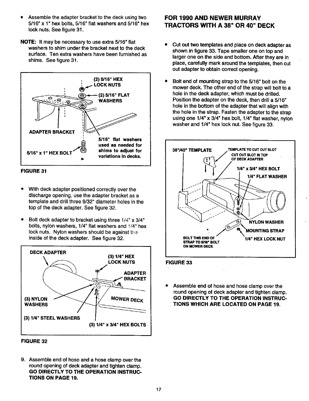
•Assemble the adapter bracket to the deck using two
5/16" x 1• hex bolts, 5/16" flat washers and 5/16" hex
lock nuts. See figure 31.
NOTE: It may be necessary to use extra 5116" flat
washers to shim under the bracket next to the deck
surface. Ten extra washers have been furnished as
shims. See figure 31.
, (2) 5/16" HEX
L
,.j=.=1 LOCK NUTS
I
L
_' _--,---- (2) 5/16" FLAT
._ WASHERS
I i
ADAPTER BRACKET !_
' 5116" flat washers
,,,!_ used as needed for
5/16" x 1" HEX BOLT shims to adjust for
variations in decks.
11.
FIGURE 31
With deck adapter positioned correctly over the
discharge opening, use the adapter bracket as a
template and drill three 9132" diameter holes in the
top of the deck adapter. See figure 32.
Bolt deck adapter to bracket using three 1/4" x 3/4"
bolts, nylon washers, 114"flat washers and !/4" hex
lock nuts. Nylon washers should be against ti_e
inside of the deck adapter. See figure 32.
DECK ADAPTER _)I_"HEX
LOCK NUTS
ADAPTER
BRACKET
(3) NYLON MOWER DECK
WASHERS
(3) 1/4" STEEL WASHERS
(3)1_"x _4"HEXBOLTS
FOR 1990 AND NEWER MURRAY
TRACTORS WITH A 38" OR 40" DECK
Cut out two templates and place on deck adapter as
shown in figure 33. Tape smaller one on top and
larger one on the side and bottom. After they are in
place, carefully mark around the templates, then cut
out adapter to obtain correct opening.
Bolt end of mounting strap to the 5/16 • bolt on the
mower deck. The other end of the strap will bolt to a
hole in the deck adapter, which must be drilled.
Position the adapter on the deck, then drill a 5/16"
hole in the bottom of the adapter that will align with
the hole in the strap. Fasten the adapter to the strap
using one 1/4" x 3/4" hex bolt, 1/4" flat washer, nylon
washer and 1/4" hex lock nut. See figure 33.
38"140"TEMPLATE TEMPLATE TO CUT OUT SLOT
CUT OUT SLOT IN TOP
OF BECK ADAPTER
1/4" x 3/4" HEX BOLT
1/4" FLAT WASHER
NYLON WASHER
BOLT THIS END OF
STRAP TO _glS" BOLT
ON MOWER DECK
1/4" HEX LOCK NUT
FIGURE 33
Assemble end of hose and hose clamp over the
round opening of deck adapter and tighten clamp.
GO DIRECTLY TO THE OPERATION INSTRUC-
TIONS WHICH ARE LOCATED ON PAGE 19.
FIGURE 32
9. Assemble end of hose and ahose clamp over the
round opening of deck adapter and tighten clamp.
GO DIRECTLY TO THE OPERATION INSTRUC-
TIONS ON PAGE 19.
17
FOR 1990 AND NEWER MURRAY
TRACTORS WITH A 46" DECK
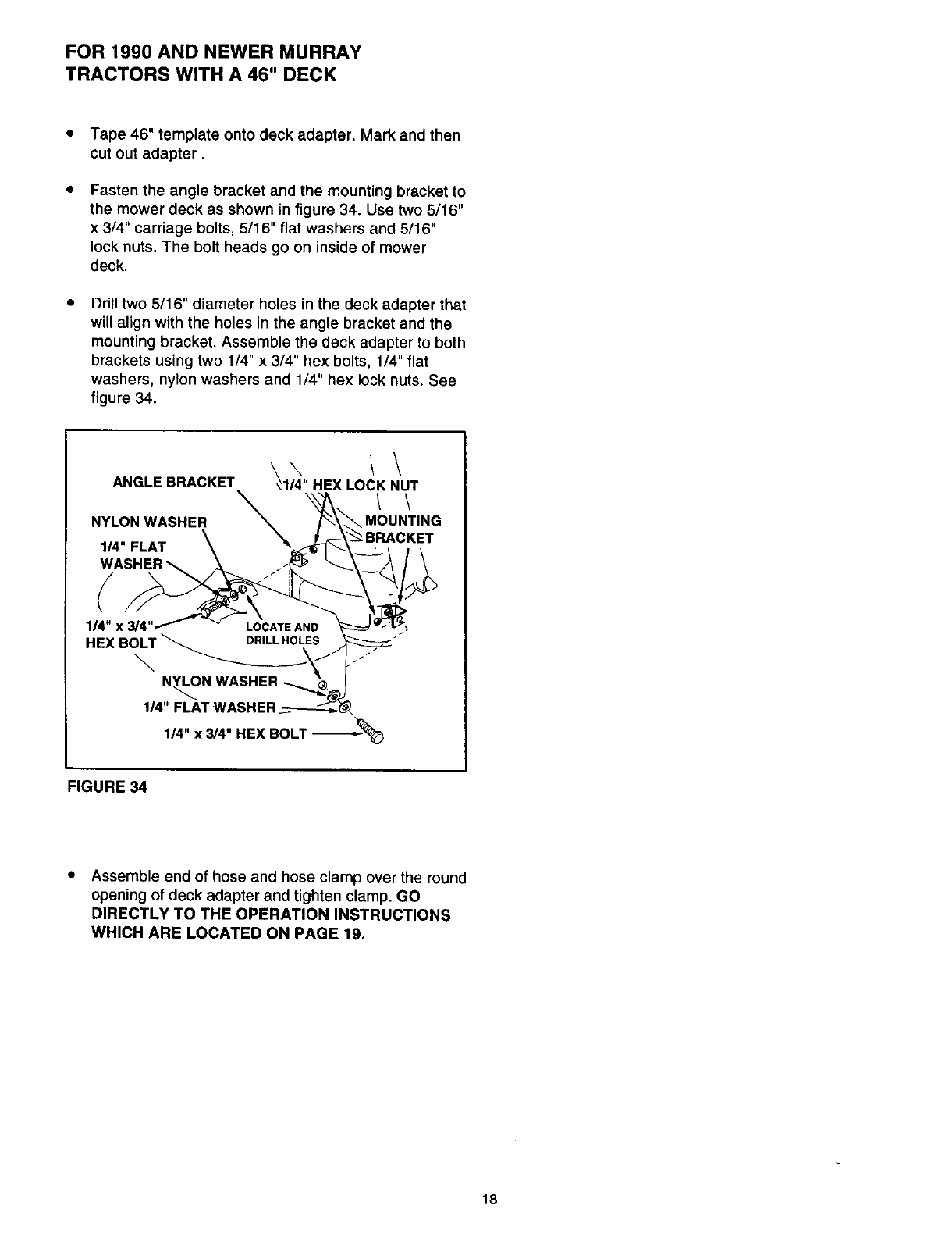
Tape 46" template onto deck adapter. Mark and then
cut out adapter.
Fasten the angle bracket and the mounting bracket to
the mower deck as shown in figure 34. Use two 5/16"
x 3/4" carriage bolts, 5/16" flat washers and 5/16"
lock nuts. The bolt heads go on inside of mower
deck.
Drill two 5/16" diameter holes in the deck adapter that
will align with the holes in the angle bracket and the
mounting bracket. Assemble the deck adapter to both
brackets using two 1/4" x 3/4" hex bolts, 1/4" flat
washers, nylon washers and 1/4" hex lock nuts. See
figure 34.
\\ !\
ANGLE BRACKET 4114 HEX LOCK NUT
NYLON WASHER MOUNTING
1/4" FLAT
1/4" x 3
HEX BOLT__DRILL HOLES .J •
N_N WASHER _
1/4" FLAT WASHER
1/4" x 3/4" HEX BOLT '_%
FIGURE 34
Assemble end of hose and hose clamp over the round
opening of deck adapter and tighten clamp. GO
DIRECTLY TO THE OPERATION INSTRUCTIONS
WHICH ARE LOCATED ON PAGE 19.
18
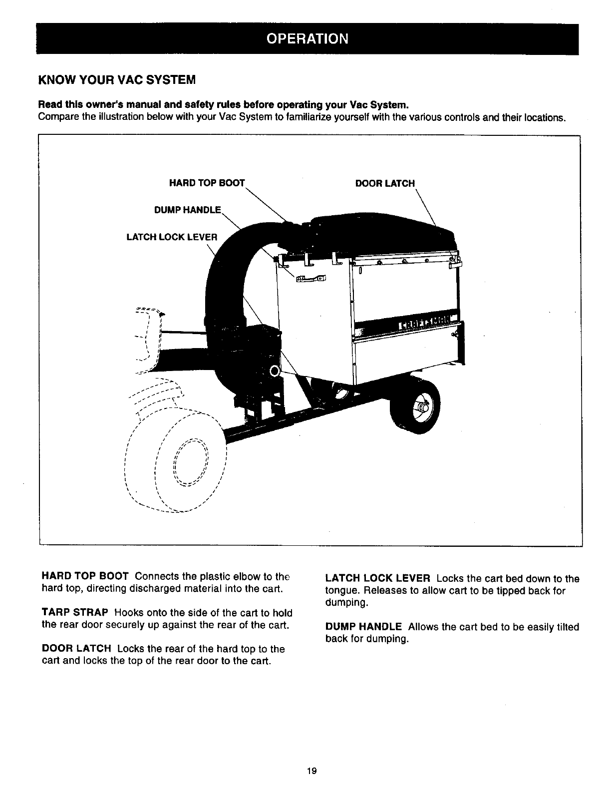
KNOW YOUR MAC SYSTEM
Read this owner's manual and safety rules before operating your Vac System.
Compare the illustration below with your Vac System to familiadze yourself with the various controls and their locations.
HARDTOPBOOT DOOR LATCH
DUMP HANDLE
LATCH LOCK LEVER
\
iI
HARD TOP BOOT Connects the plastic elbow to the
hard top, directing discharged material into the cart.
TARP STRAP Hooks onto the side of the cart to hold
the rear door securely up against the rear of the cart.
DOOR LATCH Locks the rear of the hard top to the
cart and locks the top of the rear door to the cart.
LATCH LOCK LEVER Locks the cart bed down to the
tongue. Releases to allow cart to be tipped back for
dumping.
DUMP HANDLE Allows the cart bed to be easily tilted
back for dumping.
19
BEFORE STARTING
• Your Vac System engine is shipped without oil or
gasoline. Service the engine with oil and gas as
instructed in the separate engine manual.
• Inspect the Vac System to make sure all covers (rear
door, hardtop boot, elbow, hose adapter, hose and
deck adapter are properly attached.
• Check tires for proper inflation (12 - 14 Ibs).
,_ WARNING: Never fill fuel tank indoors, or
with the engine running, or while the engine
is hot. Do not smoke while filling tank.
HOW TO STOP YOUR VAC SYSTEM
• To stop engine, move the throttle control lever to the
OFF position.
• Disconnect spark plug wire from plug to prevent
accidental starting while equipment is unattended or
is being worked on.
,_ CAUTION: _-he muffler and adjacent
areas are hot!
HOW TO START YOUR VAC SYSTEM
A WARNING: Never start or run the
engine without all covers being properly
attached to the blower housing and cart.
• Check oil and gas in Vac engine.
• Attach spark plug wire to spark plug.
• Move choke lever on engine to CHOKE position.
(A warm engine may not require choking.)
• Move throttle control lever on engine to FAST position.
• Grasp starter handle and pull rope out slowly until
engine reaches start of compression cycle (rope will
pull slightly harder at this point). Let the rope rewind
slowly.
• Pull rope with a rapid, continuous, full arm stroke.
Keep a firm grip on starter handle. Let rope rewind
slowly. Do not let starter handle snap back against
starter.
• Repeat instructions in two preceding paragraphs until
engine fires. When engine starts, move choke control
gradually to RUN position.
HOW TO USE YOUR VAC SYSTEM
ACAUTION: Vehicle braking and stability
may be affected with the addition of an
accessory or an attachment. Be aware of
changing conditions on slopes.
• Inspect the Vac to make sure all covers (rear door,
hard top boot, elbow, hose adapter (nozzle), hose and
deck adapter are properly attached.
• Check tires for proper inflation (12 - 14 Ibs).
• Check oil and gas in Vac engine.
• Begin operation at low speed, adjusting forward speed
to match grass height and/or moisture condition to
prevent clogging.
• Do not attempt to vacuum up any material other than
vegetation found in a normal yard, such as light
branches, leaves, twigs, etc.
&WARNING: Should your Vac System
become clogged, shut off tractor and Vac
engines. Before attempting to unclog,
remove wire from spark plug to prevent
accidental starting.
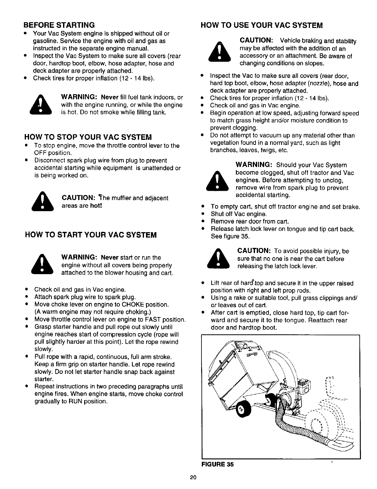
• To empty cart, shut off tractor engine and set brake.
• Shut off Vac engine.
• Remove rear door from cart.
• Release latch lock lever on tongue and tip cart back.
See figure 35.
,_ CAUTION: To avoid possible injury, be
sure that no one is near the cart before
releasing the latch lock lever.
• Lift rear of harcl'.top and secure it in the upper raised
position with right and left prop rods.
• Using a rake or suitable tool, pull grass clippings and/
or leaves out of cart.
• After cart is emptied, close hard top, tip cart for-
ward and secure it to the tongue. Reattach rear
door and hardtop boot.
FIGURE 35
20
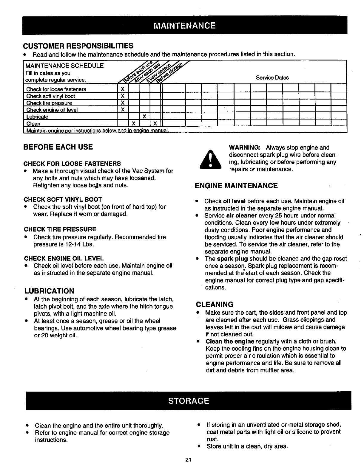
CUSTOMER RESPONSIBILITIES
* Read and follow the maintenancescheduleandthe maintenanceprocedureslistedin thissection.
MAINTENANCE SCHEDULE _._'_ _o_
Fill in dates as you __._"_e_f
complete regular service. //_z_l_/
Check for loose fasteners X
Check soft vinyl boot X
Check tire pressure X
Check enaine oil level X
Lubricate X
Clean X X
Maintain enaine per instructionsbelow and in enaine manual.
Service Dates
BEFORE EACH USE
CHECK FOR LOOSE FASTENERS
• Make a thorough visual check of the Vac System for
any bolts and nuts which may have loosened.
Retighten any loose bo_s and nuts.
CHECK SOFT VINYL BOOT
• Check the soft vinyl boot (on front of hard top) for
wear. Replace if worn or damaged.
CHECK TIRE PRESSURE
• Check tire pressure regularly. Recommended tire
pressure is 12-14 Lbs.
CHECK ENGINE OIL LEVEL
= Check oil level before each use. Maintain engine oil
as instructed in the separate engine manual.
LUBRICATION
•At the beginning of each season, lubricate the latch,
latch pivot bolt, and the axle where the hitch tongue
pivots, with alight machine oil.
• At least once a season, grease or oil the wheel
bearings. Use automotive wheel bearing type grease
or 20 weight oil.
&WARNING: Always stop engine and
disconnect spark plug wire before clean-
ing, lubricating or before performing any
repairs or maintenance.
ENGINE MAINTENANCE
• Check oil level before each use. Maintain engine oil
as instructed in the separate engine manual.
•Service air cleaner every 25 hours under normal
conditions. Clean every few hours under extremely
dusty conditions. Poor engine performance and
flooding usually indicates that the air cleaner should
be serviced. To service the air cleaner, refer to the
separate engine manual.
•The spark plug should be cleaned and the gap reset
once aseason. Spark plug replacement is recom-
mended at thestad of each season. Check the
engine manual for correct plug type and gap specifi-
cations.
CLEANING
a Make sure the cart, the sides and front panel and top
are cleaned after each use. Grass clippings and
leaves left in the cart will mildew and cause damage
if not cleaned out.
• Clean the engine regulady with a cloth or brush.
Keep the cooling fins on the engine housing clean to
permit proper air circulation which is essential to
engine performance and life. Be sure to remove all
dirt and debris from muffler area.
• Clean the engine and the entire unit thoroughly.
• Refer to engine manual for correct engine storage
instructions.
• If storing in an unventilated or metal storage shed,
coat metal parts with light oil or silicone to prevent
rust.
•Store unit in a clean, dry area.
21
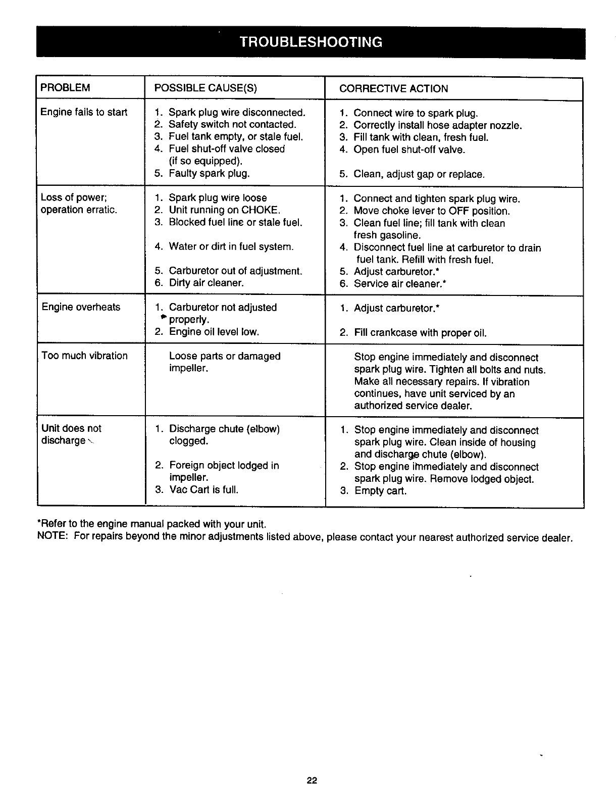
PROBLEM POSSIBLE CAUSE(S) CORRECTIVE ACTION
Engine fails to start
Loss of power;
operation erratic.
1. Spark plug wire disconnected.
2. Safety switch not contacted.
3. Fuel tank empty, or stale fuel.
4. Fuel shut-off valve closed
(if so equipped).
5. Faulty spark plug.
1. Spark plug wire loose
2. Unit running on CHOKE.
3. Blocked fuel line or stale fuel.
4. Water or dirt in fuel system.
5. Carburetor out of adjustment.
6. Dirty air cleaner.
1. Connect wire to spark plug.
2. Correctly install hose adapter nozzle.
3. Fill tank with clean, fresh fuel.
4. Open fuel shut-off valve.
5. Clean, adjust gap or replace.
1. Connect and tighten spark plug wire.
2. Move choke lever to OFF positLon.
3. Clean fuel line; fill tank with clean
fresh gasoline.
4. Disconnect fuel line at carburetor to drain
fuel tank. Refill with fresh fuel.
5. Adjust carburetor.*
6. Service air cleaner.*
Engine overheats 1. Carburetor not adjusted 1. Adjust carburetor.*
*properly.
2. Engine oil level low. 2. Fill crankcase with proper oil.
Too much vibration Loose parts or damaged Stop engine immediately and disconnect
impeller, spark plug wire. Tighten all bolts and nuts.
Make all necessary repairs. If vibration
continues, have unit serviced by an
authorized service dealer.
Unit does not
discharge 1. Discharge chute (elbow)
clogged.
2. Foreign object lodged in
impeller.
3. Vac Cart is full.
1. Stop engine immediately and disconnect
spark plug wire. Clean inside of housing
and discharge chute (elbow).
2. Stop engine itnmediately and disconnect
spark plug wire. Remove lodged object.
3. Empty cart.
*Refer to the engine manual packed with your unit.
NOTE: For repairs beyond the minor adjustments listed above, please contact your nearest authorized service dealer.
22
2
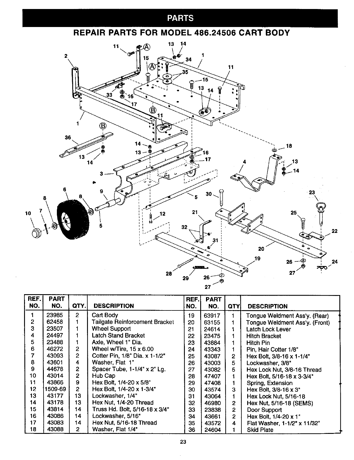
REPAIR PARTS FOR MODEL 486.24506 CART BODY
11 13 14
11
lO\
REF.
NO.
1
2
3
4
5
6
7
8
9
10
11
12
13
14
15
16
17
18
1
36
6
8\8
PART
NO.
23985
62458
23507
24497
23488
46272
43093
43601
44678
43014
43866
1509-69
43177
43178
43814
43086
43083
43088
14
®
9
14
I
I
I
QTY. DESCRIPTION
2 Cart Body
1 Tailgate Reinforcement Bracket
1 Wheel Support
1Latch Stand Bracket
1 Axle, Wheel 1" Dia.
2Wheel w/Tire, 15 x 6.00
2 Cotter Pin, 1/8" Dia. x 1-1/2"
4 Washer, Flat 1"
2 Spacer Tube, 1-1/4" x 2" Lg.
2 Hub Cap
9 Hex Bolt, 1/4-20 x 5/8"
2 Hex Bolt, 1/4-20 x 1-3/4"
13 Lockwasher, 114"
13 Hex Nut, 1/4-20 Thread
14 Truss Hd. Bolt, 5/16-18 x 3/4"
14 Lockwasher, 5116"
14 Hex Nut, 5/16-18 Thread
2 Washer, Flat 1/4"
REF. PART
NO. NO. QT¥ DESCRIPTION
19 63917
20 63155
21 24614
22 23475
23 43884
24 43343
25 43087
26 43003
27 43082
28 47407
29 47408
30 43574
31 43064
32 46980
33 23838
34 43661
35 43572
36 24604
1 Tongue Weldment Ass'y. (Rear)
1 Tongue Weldment Ass'y. (Front)
1 Latch Lock Lever
1 Hitch Bracket
1 Hitch Pin
1 Pin, Hair Cotter 1/8"
2 Hex Bolt, 3/8-16 x 1-114"
5 Lockwasher, 3/8"
5 Hex Lock Nut, 3/8-16 Thread
1 Hex Bolt, 5/16-18 x 3-3/4"
1 Spring, Extension
3 Hex Bolt, 3/8-16 x 3"
1 Hex Lock Nut, 5/16-18
2 Hex Nut, 5/16-18 (SEMS)
2 Door Support
2 Hex Bolt, 1/4-20 x 1"
4 Flat Washer, 1-1/2" x 11/32"
1 Skid Plate
, 24
I
23
30 31
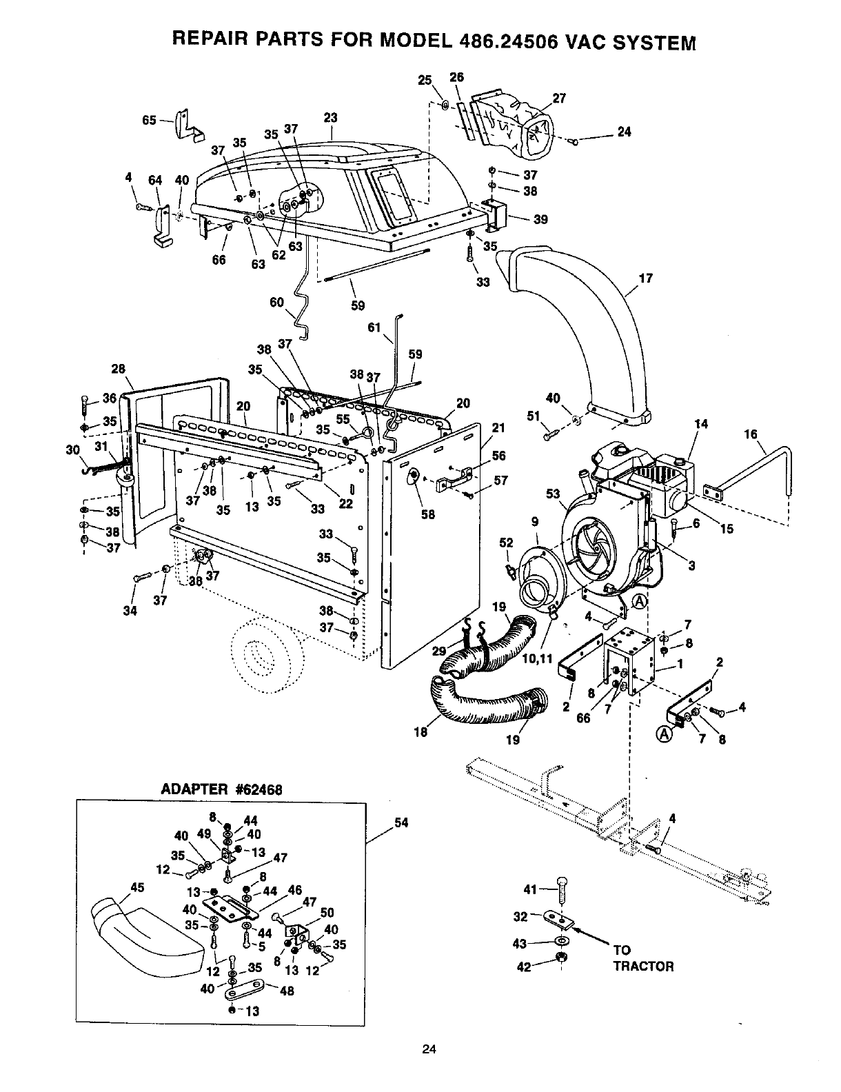
REPAIR PARTS FOR MODEL 486.24506 VAC SYSTEM
35 13 33 22 58 9
53
19
45
/
ADAPTER #62468
40
12_
54
/4
42_, TRACTOR
14 16
7
24
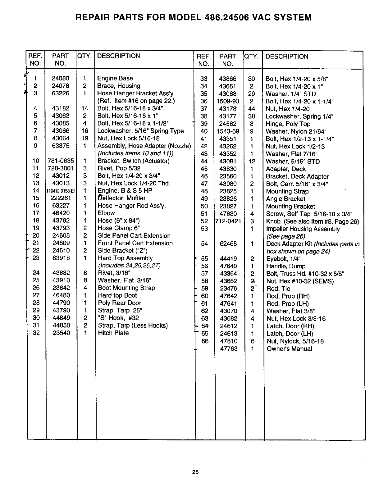
REPAIR PARTS FOR MODEL 486.24506 VAC SYSTEM
REF.
NO.
1
2
3
4
5
6
7
8
9
10
11
12
13
14
15
16
17
18
19
20
21
22
23
24
25
26
27
28
29
3O
31
32
PART
NO.
24080
24078
63226
43182
43063
43085
43086
43064
63375
781-0635
728-3001
43012
43013
11_12_158-E1
222261
63227
46420
43792
43793
24608
24609
24610
63918
43882
43910
23842
46480
44790
43790
44849
44850
23540
QTY. DESCRIPTION REF. PART
NO. NO.
1 Engine Base 33 43866
2 Brace, Housing 34 43661
1 Hose Hanger Bracket Ass'y. 35 43088
(Ref. item #16 on page 22.) 36 1509-90
14 Bolt, Hex 5/16-18 x 3/4" 37 43178
2 Bolt, Hex 5/16-18 x 1" 38 43177
4 Bolt, Hex 5/16-18 x 1-1/2" 39 24582
16 Lockwasher, 5/16" Spdng Type 40 1543-69
19 Nut, Hex Lock 5/16-18 41 43351
1Assembly, Hose Adapter (Nozzle) 42 43262
(Inc/udes items 10 and 11)) 43 43352
1 Bracket, Switch (Actuator) 44 43081
3 Rivet, Pop 5/32" 45 43830
3 Bolt, Hex 1/4-20 x 3/4" 46 23560
3 Nut, Hex Lock 1/4-20 Thd. 47 43080
1 Engine, B & S 5 HP 48 23825
1 I_eflector, Muffler 49 23826
1 Hose Hanger Rod Ass'y. 50 23827
1Elbow 51 47630
1Hose (6" x 84") 52 712-0421
2 Hose Clamp 6" 53
2 Side Panel Cart Extension
1 Front Panel Cart Extension 54 62468
2Side Bracket ("Z")
1 Hard Top Assembly 55 44419
(/nc/udes 24,25,26,27) 56 47640
8 Rivet, 3/16" 57 43364
8 Washer, Flat 3/16" 58 43662
4 Boot Mounting Strap 59 23476
1 Hard top Boot 60 47642
1 Poly Rear Door 61 47641
1 Strap, Tarp 25" 62 43070
2"S" Hook, #32 63 43082
2 Strap, Tarp (Less Hooks) 64 24612
1Hitch Plate 65 24613
66 47810
47763
_TY. DESCRIPTION
2
1
2
2"
1
1
4
4
1
1
6
1
30 Bolt, Hex 1/4-20 x5/8"
2 Bolt, Hex 1/4-20 x1"
29 Washer, 1/4" STD
2 Bolt, Hex 1/4-20 x 1-1/4"
44 Nut, Hex 1/4-20
38 Lockwasher, Spring 1/4"
3 Hinge, Poly Top
9 Washer, Nylon 21/64"
1 Bolt, Hex 1/2-13 x 1-1/4"
1 i Nut, Hex Lock 1/2-13
1 Washer, Flat 7/16"
12 Washer, 5/16" STD
1 Adapter, Deck
1 Bracket, Deck Adapter
2 Bolt, Carr. 5/16" x 3/4"
1 Mounting Strap
1 Angle Bracket
1 Mounting Bracket
4 Screw, Self Tap 5/16-18 x 3/4"
3 Knob (See also Item #8, Page 26)
1 Impeller Housing Assembly
(See page 26)
Deck Adapter Kit (Includes parts in
box shown on page 24)
Eyebolt, 1/4"
Handle, Dump
Bolt, Truss Hd. #10-32 x 5/8"
Nut, Hex #10-32 (SEMS)
Rod, Tie
Rod, Prop (RH)
Rod, Prop (LH)
Washer, Flat 3/8"
Nut, Hex Lock 3/8-16
Latch, Door (RH)
Latch, Door (LH)
Nut, Nylock, 5/16-18
Owner's Manual
25
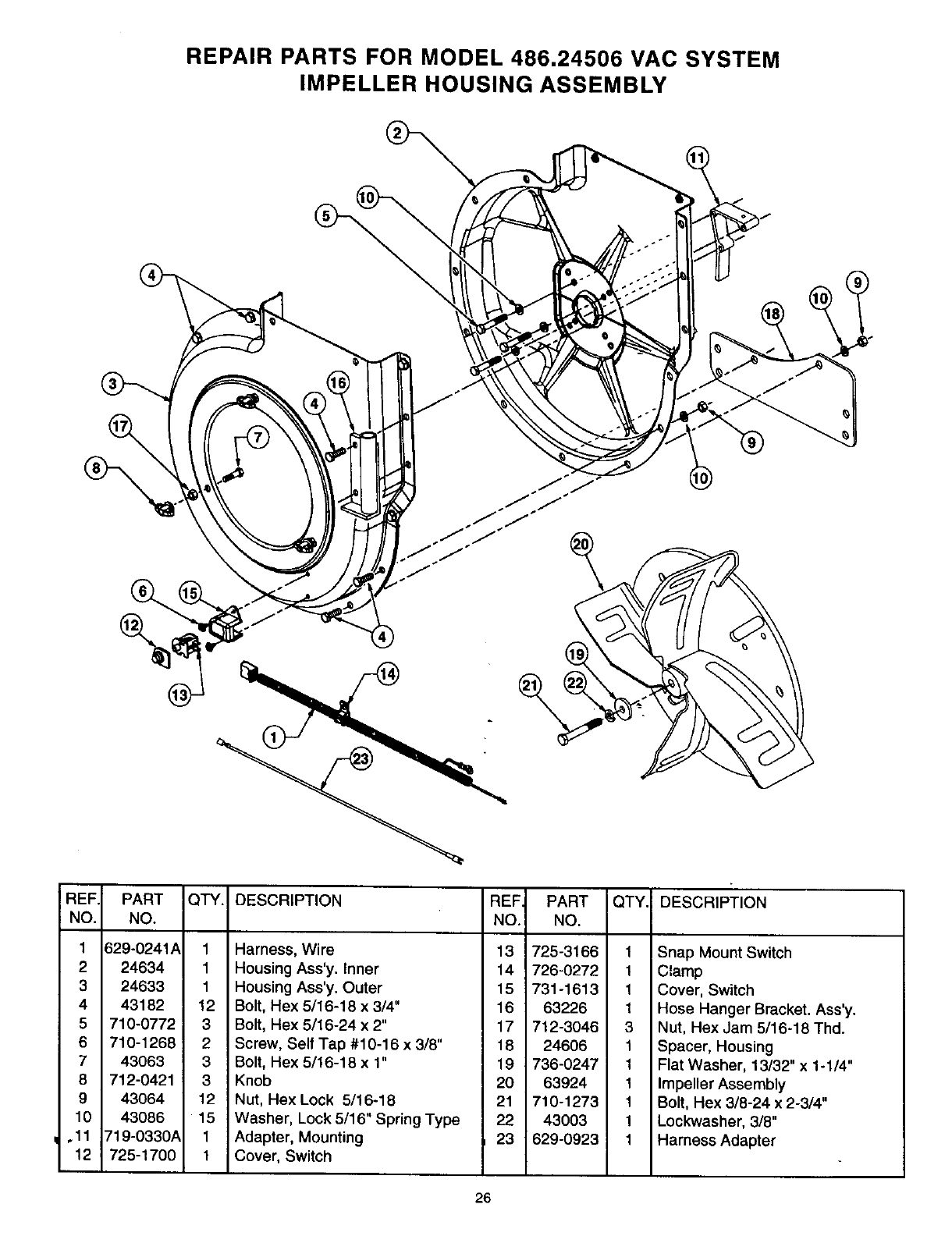
REPAIR PARTS FOR MODEL 486.24506 VAC SYSTEM
IMPELLER HOUSING ASSEMBLY
%
REF.
NO.
1
2
3
4
5
6
7
8
9
10
.11
12
PART
NO.
629-0241A
24634
24633
43182
710-0772
710-1268
43063
712-0421
43064
43086
719-0330A
725-1700
QTY. DESCRIPTION
1 Harness, Wire
1 Housing Ass'y. Inner
1 Housing Ass'y. Outer
12 Bolt, Hex 5/16-18 x 3/4"
3 Bolt, Hex 5/16-24 x 2"
2 Screw, Self Tap #10-16 x 3/8"
3 Bolt, Hex 5/16-18 x 1"
3 Knob
12 Nut, Hex Lock 5/16-18
15 Washer, Lock 5/16" Spring Type
1 Adapter, Mounting
1 Cover, Switch
REF PART
NO. NO.
QTY. DESCRIPTION
13 725-3166 1
14 726-0272 1
15 731-1613 1
16 63226 1
17 712-3046 3
18 24606 1
19 736-0247 1
20 63924 1
21 710-1273 1
22 43003 1
23 629-0923 1
Snap Mount Switch
Clamp
Cover, Switch
Hose Hanger Bracket. Ass'y.
Nut, Hex Jam 5/16-18 Thd.
Spacer, Housing
Flat Washer, 13/32" x 1-1/4"
Impeller Assembly
Bolt, Hex 3/8-24 x 2-3/4"
Lockwasher, 3/8"
Harness Adapter
26
-,4
!
e.
I (nc
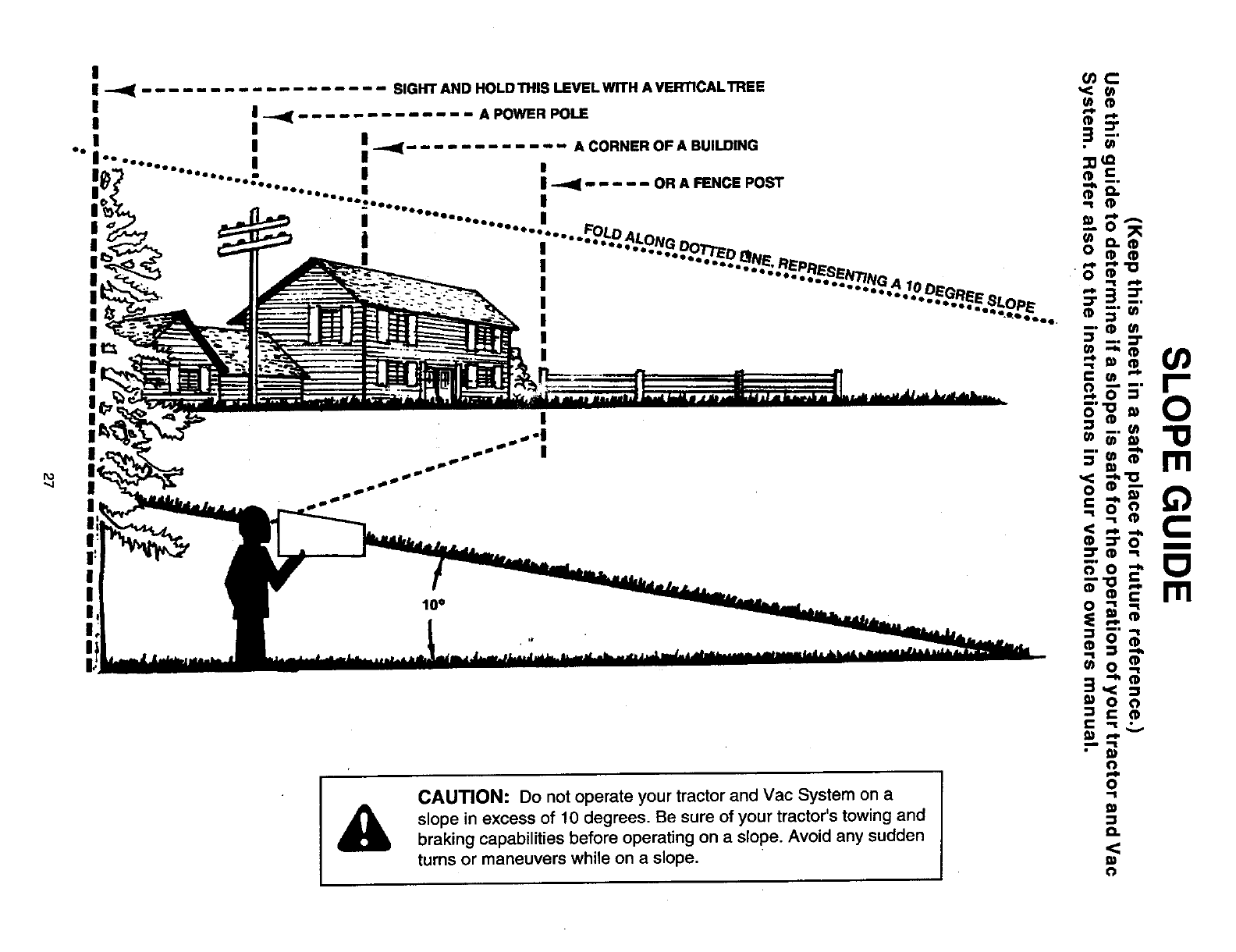
.... SIGHT AND HOLD THIS LEVEL WITH A VERTICAL't REE ,<:
U_ (1)
:-_....... 1__...... A,_RPoLE -_"Z
i II I _ ...... A CORNER OF A BUILDING _
!.........".........'-.... ; I_.i..... OR_NCE,O_ ==
.........,....... , ._
: , "........-....'. Fo,__ ==--
.....,-.-,-..,,o,,,,.= _;.
I="*'... "DO"--
•..... •."_.Eor*,,,-- v m m
II I .......
ACAUTION: Do not operate your tractor and Vac System on a
slope in excess of 10 degrees. Be sure of your tractor's towing and
braking capabilities before operating on a slope. Avoid any sudden
turns or maneuvers while on a slope.
5"__._.
I: _ M'
_'5"
ii m
_=_
mo_
=t,<.,
I_ 0o
_ۥ
0
Q.
Get it fixed, at your home or ours!
For repair of major brand appliances in your own home...
no matter who made it, no matter who sold it!
1-800-4-MY-HOMES MAnytime, day or night
(1-800-469-4663)
www.sears.com
To bring in products such as vacuums, lawn equipment and electronics
for repair, call for the location of your nearest Sears Parts & Repair Center.
1-800-488-1222 Anytime, day or night
www.sears.com
For the replacement parts, accessories and owner's manuals
that you need to do-it-yourself, call Sears PartsDirect SM!
1-800-366-PART 6a.m.-11p.m.CST,
(1-800-366-7278) 7 days a week
www.sears.com/partsdirect "-
TO purchase or inquire about aSears Service Agreement:
1-800-827-6655
7 a.m. - 5 p.m. CST, Mon.- Sat.
Para pedir servicio de reparacibn a domicilio,
y para ordenar piezas con entrega adomicilio:
1-888"SU'HOGARsM
(1-888-784-6427)
Au Canada pour service en fran_ais:
1-877-LE-FOYER s.
ISEARS 1
HomeCentral"
(1-877-533-6937)
®Registered Trademark /TM Trademark of Sears, Roebuck and Co.
irM
©Sears, Roebuck and Co. ®Marca Regist fade /Marca de F_tbrica de Seam, Roebuck and Co.
