Craftsman 486248391 User Manual SNOW THROWER ATTACHMENT Manuals And Guides L0301067
CRAFTSMAN Snow Thrower Attachment Manual L0301067 CRAFTSMAN Snow Thrower Attachment Owner's Manual, CRAFTSMAN Snow Thrower Attachment installation guides
User Manual: Craftsman 486248391 486248391 CRAFTSMAN SNOW THROWER ATTACHMENT - Manuals and Guides View the owners manual for your CRAFTSMAN SNOW THROWER ATTACHMENT #486248391. Home:Lawn & Garden Parts:Craftsman Parts:Craftsman SNOW THROWER ATTACHMENT Manual
Open the PDF directly: View PDF ![]() .
.
Page Count: 28

Owner's Manual
ICRAFI",'SMAN+I
42"- 2 STAGE SNOW THROWER
TRACTO R ATTAC HMENT
Model No. 486.248391
CAUTION:
Before using this product, read
this manual and follow all
Safety Rules and
Operating Instructions.
•Safety
•Assembly
•Operation
•Maintenance
• Parts
IMPORTANT - READ THIS FIRST!!!
For Missing Parts or Assembly Questions
Please Call 217-728-8388
Mon.-Fri. 7 am - 5 pm CST.
FAX 217-728-2032 or e-mail info@agri-fab.com
Missing parts will be sent UPS in 24 hours directly to your home.
Sears, Roebuck and Co., Hoffman Estates, IL 60179 U.S.A.
www.sears.com/craftsman
PRINTED IN U+S.A. FORM NO. 48549 (5/02))
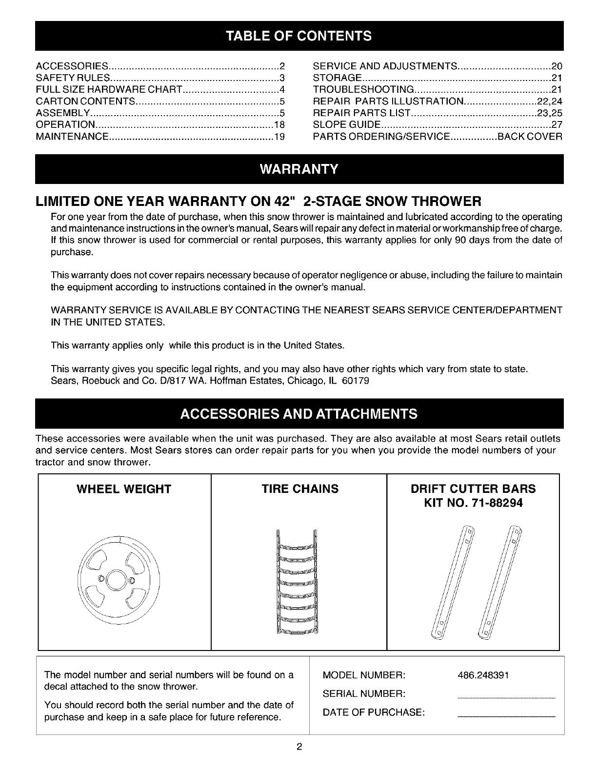
ACCESSORIES ........................................................... 2
SAFETY RULES .......................................................... 3
FULL SIZE HARDWARE CHART ................................. 4
CARTON CONTENTS ................................................. 5
ASSEMBLY ................................................................. 5
OPERATION ............................................................. 18
MAINTENANCE ......................................................... 19
SERVICE AND ADJUSTMENTS ................................ 20
STORAGE ................................................................. 21
TROUBLESHOOTING ............................................... 21
REPAIR PARTS ILLUSTRATION ......................... 22,24
REPAIR PARTS LIST ........................................... 23,25
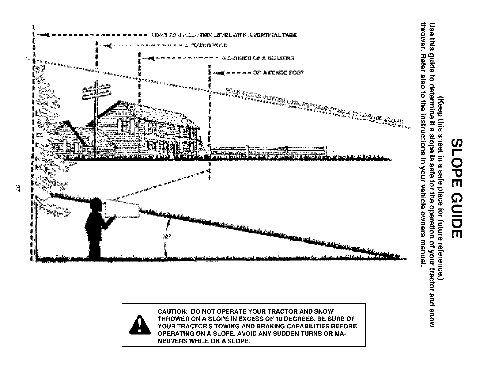
SLOPE GUIDE .......................................................... 27
PARTS ORDERING/SERVICE ................ BACK COVER
LIMITED ONE YEAR WARRANTY ON 42" 2-STAGE SNOW THROWER
For one year from the date of purchase, when this snow thrower is maintained and lubricated according to the operating
and maintenance instructionsinthe owner's manual, Sears willrepair any defect in material or workmanship free of charge.
If this snow thrower is used for commercial or rental purposes, this warranty applies for only 90 days from the date of
purchase.
This warranty does not cover repairs necessary because of operator negligence or abuse, including the failure to maintain
the equipment according to instructions contained in the owner's manual.
WARRANTY SERVICE IS AVAILABLE BY CONTACTING THE NEAREST SEARS SERVICE CENTER/DEPARTMENT
IN THE UNITED STATES.
This warranty applies only while this product is in the United States.
This warranty gives you specific legal rights, and you may also have other rights which vary from state to state.
Sears, Roebuck and Co. D/817 WA. Hoffman Estates, Chicago, IL 60179
These accessories were available when the unit was purchased. They are also available at most Sears retail outlets
and service centers. Most Sears stores can order repair parts for you when you provide the model numbers of your
tractor and snow thrower.
WHEEL WEIGHT TIRE CHAINS DRIFT CUTTER BARS
KIT NO. 71-88294
The model number and serial numbers will be found on a
decal attached to the snow thrower.
You should record both the serial number and the date of
purchase and keep in a safe place for future reference.
MODEL NUMBER:
SERIAL NUMBER:
DATE OF PURCHASE:
486.248391
2
Anypowerequipmentcancauseinjuryif operatedimproperlyor if the userdoesnotunderstandhowto operate
the equipment.Exercisecautionat all times,whenusingpowerequipment.
• Readthisowner'smanualcarefullyandknowhow
to operateyoursnowthrowerandhowto stopthe
unitanddisengagethecontrolsquickly.
• Neverallowchildrento operatetheequipment.
• Neverallowadultsto operatetheequipment
withoutproperinstruction.
• Keeptheareaof operationclearof allpersons,
especiallysmallchildren,andpets.
• Thoroughlyinspecttheareawheretheequipment
isto beusedandremoveall doormats,sleds,
boards,wiresandotherforeignobjects.
• Disengageall clutchesandshiftintoneutralbefore
startingengine.
• Donotoperateequipmentwithoutwearingad-
equatewinteroutergarments.
• Wearsubstantialfootwearwhichwillprotectfeet
andimprovefootingonslipperysurfaces.
• Checkfuelbeforestartingtheengine.Donot
removethefuelcaporfill thefueltankwhilethe
engineis runningorhot.Donotfill thefueltank
indoors.Gasolineisanextremelyflammablefuel.
• Makesurethesnowthrowerheightisadjustedto
clearthetypesurfaceit willbeusedon.
• Donotusethesnowthrowerwithouttherear
weightattachedto thetractor.
• Nevermakeanyadjustmentswhiletheengineis
running.
• Alwayswearsafetyglassesor eyeshieldduring
operationorwhileperformingandadjustmentor
repair.
• Donotplacehandorfeetnearrotatingparts.Keep
clearof thedischargeopeningat all times.
• Useextremecautionwhenoperatingonorcrossing
gravelsurfaces.
• Donotcarrypassengers.
• Afterstrikinga foreignobject,stoptheengine,
removethewirefromthesparkplugandthen
thoroughlyinspectthesnowthrowerfordamage.
Repairanydamagebeforerestartingandoperating
thesnowthrower.
• Ifthesnowthrowerstartsto vibrateabnormally,
stoptheengineimmediatelyandcheckforthe
cause.Vibrationis generallya warningoftrouble.
• Stoptheenginewheneveryouleavetheoperating
position,beforeuncloggingthesnowthroweror
makinganyadjustmentsorinspections.
• Takeall possibleprecautionswhenleavingtheunit
unattended.Disengagetheattachmentclutchlever
orswitch,lowerthesnowthrower,shiftintoneutral,
settheparkingbrake,stoptheengineandremove
thekey.
• Whencleaning,repairingorinspecting,make
certainallmovingpartshavestopped.Disconnect
thesparkplugwireandkeepit awayfromtheplug
to preventaccidentalstarting.
• Donotrunengineindoorsexceptwhentransport-
ingthesnowthrowerin oroutof thebuilding.Open
theoutsidedoors.Exhaustfumesaredangerous.
• Donotclearsnowacrossthefaceof slopes.
Exerciseextremecautionwhenchangingdirection
onslopes.Donotattemptto clearsteepslopes.
Referto theslopeguideonpage27ofthismanual.
• Neveroperatethesnowthrowerwithoutguards,
platesorothersafetyprotectiondevicesin place.
• Neveroperatethesnowthrowernearglassenclo-
sures,automobiles,windowwells,dropoffsetc.
withoutproperadjustmentofthesnowthrower
dischargeangle.
• Neverdirectdischargeat bystandersorallow
anyoneinfrontof thesnowthrower.
• Neverrunthesnowthrowerintomaterialat high
speeds.
• Donotoverloadthemachinecapacitybyattempt-
ingtoclearsnowattoofasta rate.
• Neveroperatethemachineat hightransportspeed
onslipperysurfaces.Lookbehindandusecare
whenbacking.
• Watchfor trafficandstayalertwhencrossingor
operatingnearroadways.
• Disengagepowerto thesnowthrowerwhentrans-
portingorwhennotinuse.
• Useonlyattachmentsandaccessoriesapprovedby
themanufacturerof thesnowthrower(suchas
wheelweights,counterweights,cabsetc.)
• Neveroperatethesnowthrowerwithoutgood
visibilityor light.
,_ Look for this symbol to point out important safety precautions. It mean--Attention!!
Become alert!! Your safety is involved.
3
v
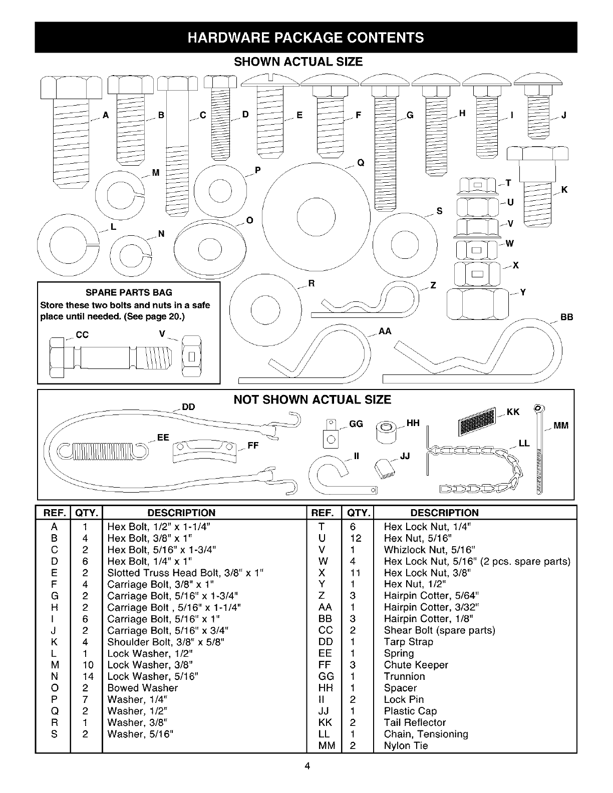
SHOWN ACTUAL SIZE
.AA
NOT SHOWN ACTUAL SIZE
jMM
REF.
A
B
C
D
E
F
G
H
I
J
K
L
M
N
O
P
Q
R
S
QTY.
1
4
2
6
2
4
2
2
6
2
4
1
10
14
2
7
2
1
2
DESCRIPTION
Hex Bolt, 1/2" x 1-1/4"
Hex Bolt, 3/8" x 1"
Hex Bolt, 5/16" x 1-3/4"
Hex Bolt, 1/4" x1"
Slotted Truss Head Bolt, 3/8" x 1"
Carriage Bolt, 3/8" x 1"
Carriage Bolt, 5/16" x 1-3/4"
Carriage Bolt, 5/16" x 1-1/4"
Carriage Bolt, 5/16" x 1"
Carriage Bolt, 5/16" x 3/4"
REF. QTY. DESCRIPTION
T6 Hex Lock Nut, 1/4"
U12 Hex Nut, 5/16"
V 1 Whizlock Nut, 5/16"
W 4 Hex Lock Nut, 5/16" (2 pcs. spare parts)
X 11 Hex Lock Nut, 3/8"
Y 1 Hex Nut, 1/2"
Z 3 Hairpin Cotter, 5/64"
AA 1 Hairpin Cotter, 3/32"
BB 3 Hairpin Cotter, 1/8"
CC 2 Shear Bolt (spare parts)
Shoulder Bolt, 3/8" x 5/8"
Lock Washer, 1/2"
Lock Washer, 3/8"
Lock Washer, 5/16"
Bowed Washer
Washer, 1/4"
Washer, 1/2"
Washer, 3/8"
Washer, 5/16"
DD 1 Tarp Strap
EE 1 Spring
FF 3 Chute Keeper
GG 1 Trunnion
HH 1 Spacer
II 2 Lock Pin
JJ 1 Plastic Cap
KK 2 Tail Reflector
LL 1 Chain, Tensioning
MM 2 Nylon Tie
4
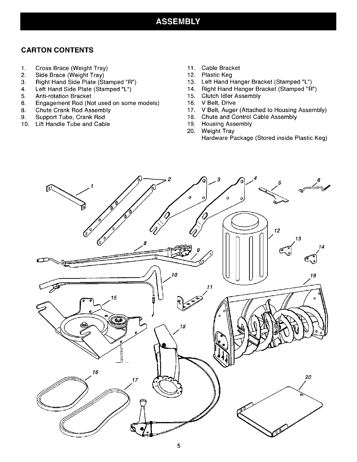
CARTON CONTENTS
1. Cross Brace (Weight Tray)
2. Side Brace (Weight Tray)
3. Right Hand Side Plate (Stamped "R")
4. Left Hand Side Plate (Stamped "L")
5. Anti-rotation Bracket
6. Engagement Rod (Not used on some models)
8. Chute Crank Rod Assembly
9. Support Tube, Crank Rod
10. Lift Handle Tube and Cable
11. Cable Bracket
12. Plastic Keg
13. Left Hand Hanger Bracket (Stamped "L")
14. Right Hand Hanger Bracket (Stamped "R")
15. Clutch Idler Assembly
16. V Belt, Drive
17. V Belt, Auger (Attached to Housing Assembly)
18. Chute and Control Cable Assembly
19. Housing Assembly
20. Weight Tray
Hardware Package (Stored inside Plastic Keg)
4 6
10
11
16
12
/ 13
14
19
2O
/
5
TOOLS REQUIRED FOR ASSEMBLY
(2) 7/16" Wrenches
(2) 1/2" Wrenches
(2) 9/16" Wrenches
(2) 3/4" Wrenches
(1) Knife
ADDITIONAL ITEMS REQUIRED
General Purpose Grease
REMOVAL OF PARTS FROM CARTON
• Remove all parts and hardware packages from the
carton. Lay out parts and hardware and identify using
the illustrations on pages 4 and 5.
NOTE: Not all of the supplied parts and hardware
will be needed for your particular tractor. Unneeded
items may be discarded after you have completed
assembly.
&CAUTION: Before starting to assemble
the snow thrower, remove the spark plug
wire(s), set the parking brake and
remove the key from the tractor ignition.
TRACTOR PREPARATION
Before performing these instructions, refer to the Service
and Adjustments section of your tractor owner's manual
for specific safety instructions.
• Allow engine, muffler and exhaust deflector to cool
before beginning.
• Remove any front or rear attachment which is
mounted to your tractor.
• Remove the mower deck. Refer to your tractor
owner's manual for removal instructions. Mark all
loose parts and save for reassembly.
• Remove the tractor hood and grill assembly. Refer to
your tractor owner's manual for removal instructions.
ITEMS REMOVED FROM TRACTOR
Store all parts that you remove from the tractor and do
not re-use while assembling the snow thrower.
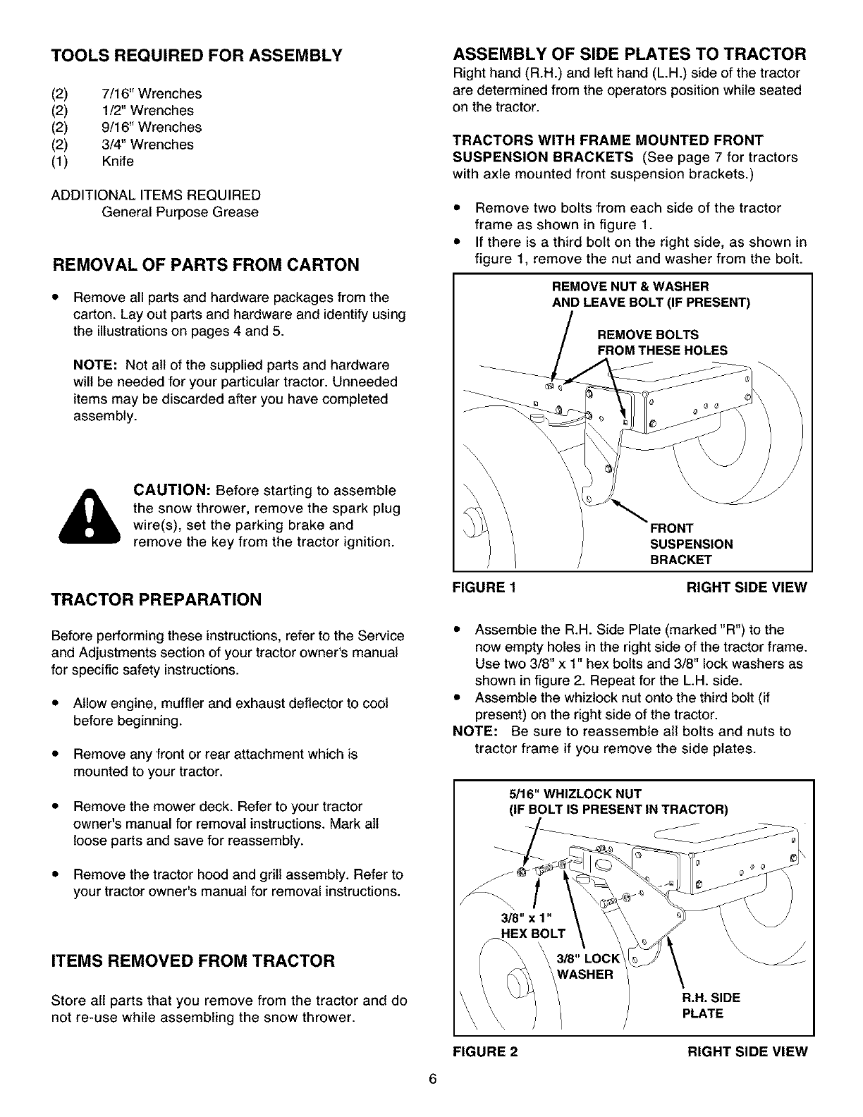
ASSEMBLY OF SIDE PLATES TO TRACTOR
Right hand (R.H.) and left hand (L.H.) side of the tractor
are determined from the operators position while seated
on the tractor.
TRACTORS WITH FRAME MOUNTED FRONT
SUSPENSION BRACKETS (See page 7 for tractors
with axle mounted front suspension brackets.)
• Remove two bolts from each side of the tractor
frame as shown in figure 1.
• If there is a third bolt on the right side, as shown in
figure 1, remove the nut and washer from the bolt.
REMOVE NUT & WASHER
AND LEAVE BOLT (IF PRESENT)
REMOVE BOLTS
FROM THESE HOLES
FIGURE 1
FRONT
SUSPENSION
BRACKET
RIGHT SIDE VIEW
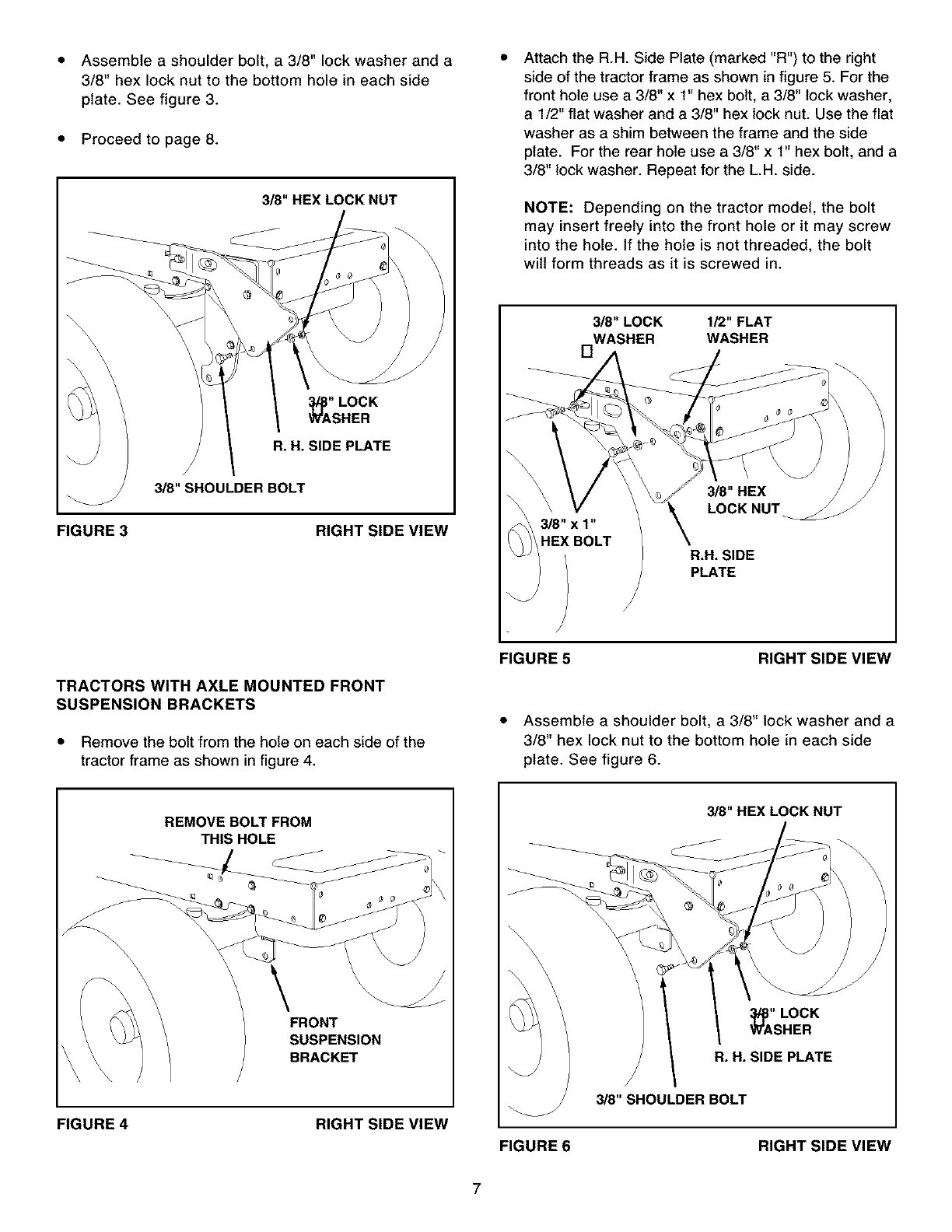
• Assemble the R.H. Side Plate (marked "R") to the
now empty holes in the right side of the tractor frame.
Use two 3/8" x 1" hex bolts and 3/8" lock washers as
shown in figure 2. Repeat for the L.H. side.
• Assemble the whiztock nut onto the third bolt (if
present) on the right side of the tractor.
NOTE: Be sure to reassemble all bolts and nuts to
tractor frame if you remove the side plates.
5/16" WHIZLOCK NUT
(IF BOLT IS PRESENT IN TRACTOR)
t
3/8" x 1"
HEX BOLT
3/8" LOCK
WASHER
\
\\
R.H. SIDE
PLATE
FIGURE 2 RIGHT SIDE VIEW
6
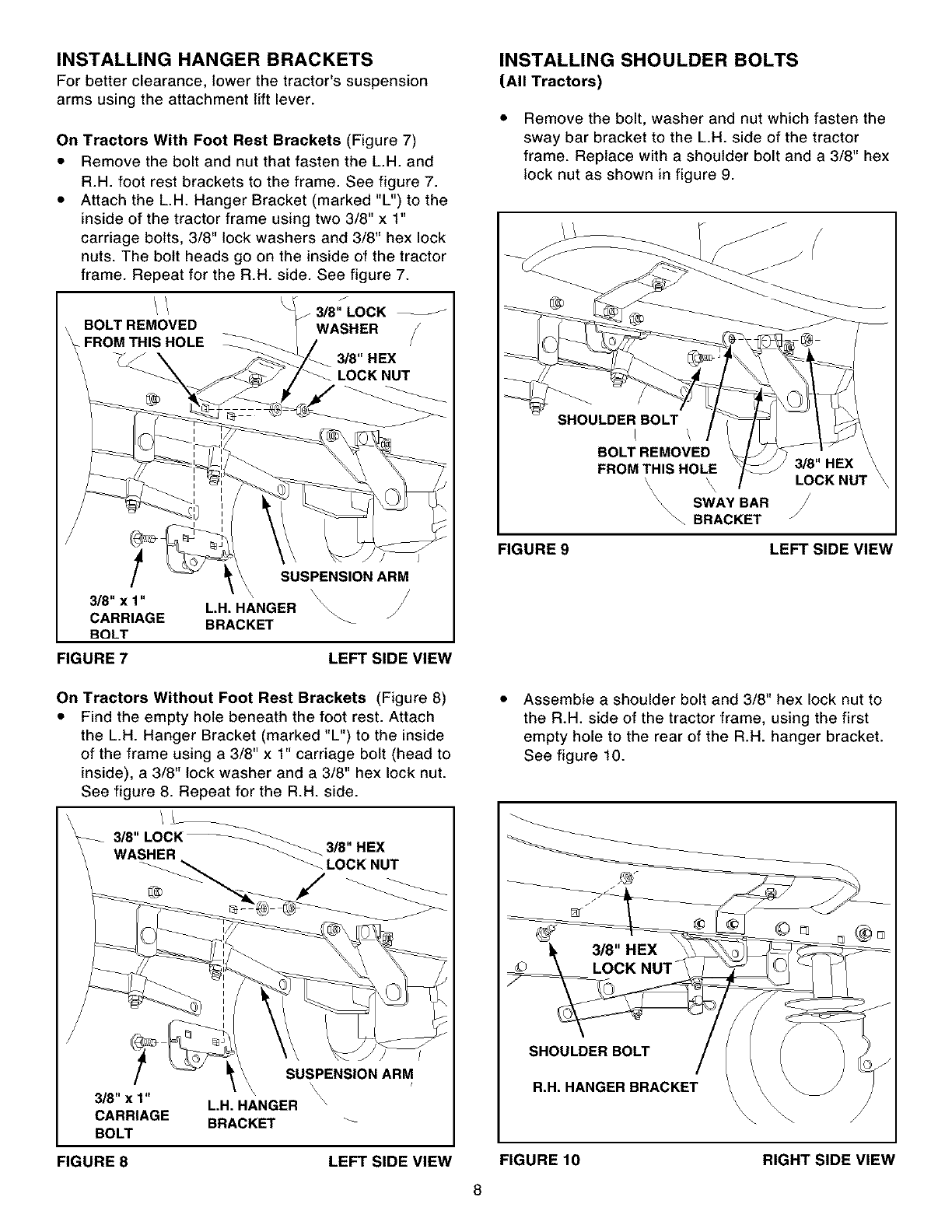
Assemble a shoulder bolt, a 3/8" lock washer and a
3/8" hex lock nut to the bottom hole in each side
plate. See figure 3.
Proceed to page 8.
3/8" HEX LOCK NUT
_A" LOCK
SHER
R. H. SIDE PLATE
3/8" SHOULDER BOLT
FIGURE 3 RIGHT SIDE VIEW
I
Attach the R.H. Side Plate (marked "R") to the right
side of the tractor frame as shown in figure 5. For the
front hole use a 3/8" x 1" hex bolt, a 3/8" lock washer,
a 1/2" flat washer and a 3/8" hex lock nut. Use the flat
washer as a shim between the frame and the side
plate. For the rear hole use a 3/8" x 1" hex bolt, and a
3/8" lock washer. Repeat for the L.H. side.
NOTE: Depending on the tractor model, the bolt
may insert freely into the front hole or it may screw
into the hole. if the hole is not threaded, the bolt
will form threads as it is screwed in.
3/8" LOCK 1/2" FLAT
WASHER WASHER
[]
TRACTORS WITH AXLE MOUNTED FRONT
SUSPENSION BRACKETS
• Remove the bolt from the hole on each side of the
tractor frame as shown in figure 4.
FIGURE 5 RIGHT SIDE VIEW
• Assemble a shoulder bolt, a 3/8" lock washer and a
3/8" hex lock nut to the bottom hole in each side
plate. See figure 6.
REMOVE BOLT FROM
THIS HOLE
\FRONT
SUSPENSION
BRACKET
FIGURE 4 RIGHT SIDE VIEW
FIGURE 6
3/8" HEX LOCK NUT
3t/p" LOCK
WASHER
R. H. SIDE PLATE
318" SHOULDER BOLT
RIGHT SIDE VIEW
7
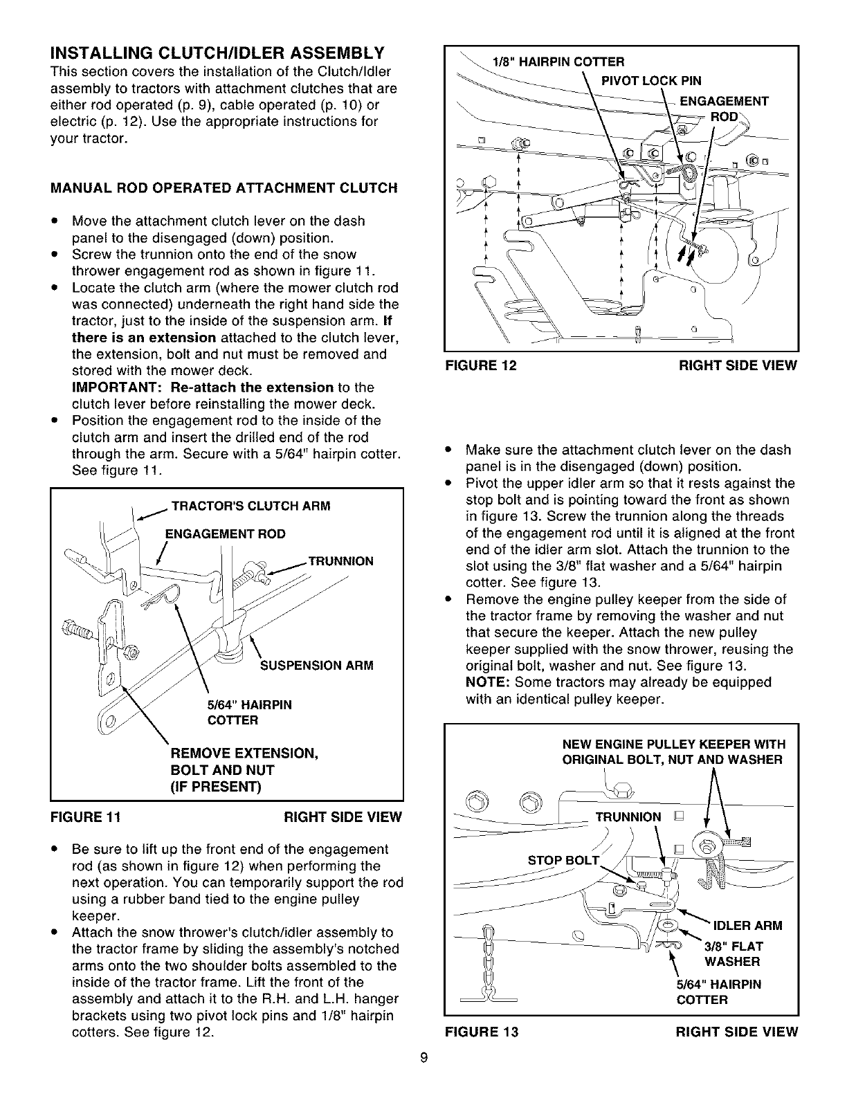
INSTALLING HANGER BRACKETS
For better clearance, lower the tractor's suspension
arms using the attachment lift lever.
On Tractors With Foot Rest Brackets (Figure 7)
•Remove the bolt and nut that fasten the L.H. and
R.H. foot rest brackets to the frame. See figure 7.
• Attach the L.H. Hanger Bracket (marked "L") to the
inside of the tractor frame using two 3/8" x 1"
carriage bolts, 3/8" lock washers and 3/8" hex lock
nuts. The bolt heads go on the inside of the tractor
frame. Repeat for the R.H. side. See figure 7.
3/8" LOCK
BOLT REMOVED WASHER
FROM THIS HOLE
#J 3/8" HEX
-_ _ LOCK NUT
SUSPENSION ARM
L,H, HANGER _
BRACKET _
FIGURE 7 LEFT SIDE VIEW
INSTALLING SHOULDER BOLTS
(All Tractors)
Remove the bolt, washer and nut which fasten the
sway bar bracket to the L.H. side of the tractor
frame. Replace with a shoulder bolt and a 3/8" hex
lock nut as shown in figure 9.
SHOULDER BOLT
L \
BOLT REMOVED
FROM THIS HOLE 3/8" HEX
'\ LOCK NUT
\SWAY BAR
\\\\'-. BRACKET /
FIGURE 9 LEFT SIDE VIEW
On Tractors Without Foot Rest Brackets (Figure 8)
•Find the empty hole beneath the foot rest. Attach
the L.H. Hanger Bracket (marked "L") to the inside
of the frame using a3/8" x 1" carriage bolt (head to
inside), a 3/8" lock washer and a 3/8" hex lock nut.
See figure 8. Repeat for the R.H. side.
3/8,,,OCK
WASHER 3/8" HEX
LOCK NUT
SUSPENSION ARM
\
\ \
3/8" x 1" L,H, HANGER \
CARRIAGE BRACKET _-
BOLT
FIGURE 8 LEFT SIDE VIEW
Assemble a shoulder bolt and 3/8" hex lock nut to
the R.H. side of the tractor frame, using the first
empty hole to the rear of the R.H. hanger bracket.
See figure 10.
SHOULDER BOLT
R.H. HANGER BRACKET
FIGURE 10
8
RIGHT SIDE VIEW
INSTALLING CLUTCH/IDLER ASSEMBLY
Thissectioncoverstheinstallationof theClutch/Idler
assembly to tractors with attachment clutches that are
either rod operated (p. 9), cable operated (p. 10) or
electric (p. 12). Use the appropriate instructions for
your tractor.
MANUAL ROD OPERATED ATTACHMENT CLUTCH
• Move the attachment clutch lever on the dash
panel to the disengaged (down) position.
• Screw the trunnion onto the end of the snow
thrower engagement rod as shown in figure 11.
• Locate the clutch arm (where the mower clutch rod
was connected) underneath the right hand side the
tractor, just to the inside of the suspension arm. If
there is an extension attached to the clutch lever,
the extension, bolt and nut must be removed and
stored with the mower deck.
IMPORTANT: Re-attach the extension to the
clutch lever before reinstalling the mower deck.
• Position the engagement rod to the inside of the
clutch arm and insert the drilled end of the rod
through the arm. Secure with a 5/64" hairpin cotter.
See figure 11.
TRACTOR'S CLUTCH ARM
ENGAGEMENT ROD
SUSPENSION ARM
5/64" HAIRPIN
COTTER
REMOVE EXTENSION,
BOLT AND NUT
(IF PRESENT)
FIGURE 11 RIGHT SIDE VIEW
Be sure to lift up the front end of the engagement
rod (as shown in figure 12) when performing the
next operation. You can temporarily support the rod
using a rubber band tied to the engine pulley
keeper.
Attach the snow thrower's clutch/idler assembly to
the tractor frame by sliding the assembly's notched
arms onto the two shoulder bolts assembled to the
inside of the tractor frame. Lift the front of the
assembly and attach it to the R.H. and L.H. hanger
brackets using two pivot lock pins and 1/8" hairpin
cotters. See figure 12.
1/8" HAIRPIN COTTER
PIVOT LOCK PIN
-ENGAGEMENT
FIGURE 12 RIGHT SIDE VIEW
• Make sure the attachment clutch lever on the dash
panel is in the disengaged (down) position.
• Pivot the upper idler arm so that it rests against the
stop bolt and is pointing toward the front as shown
in figure 13. Screw the trunnion along the threads
of the engagement rod until it is aligned at the front
end of the idler arm slot. Attach the trunnion to the
slot using the 3/8" flat washer and a 5/64" hairpin
cotter. See figure 13.
• Remove the engine pulley keeper from the side of
the tractor frame by removing the washer and nut
that secure the keeper. Attach the new pulley
keeper supplied with the snow thrower, reusing the
original bolt, washer and nut. See figure 13.
NOTE: Some tractors may already be equipped
with an identical pulley keeper.
NEW ENGINE PULLEY KEEPER WITH
ORIGINAL BOLT, NUT AND WASHER
_ION []
f
STOP BOLT
IDLER ARM
3/8" FLAT
WASHER
5/64" HAIRPIN
COTTER
FIGURE 13 RIGHT SIDE VIEW
9
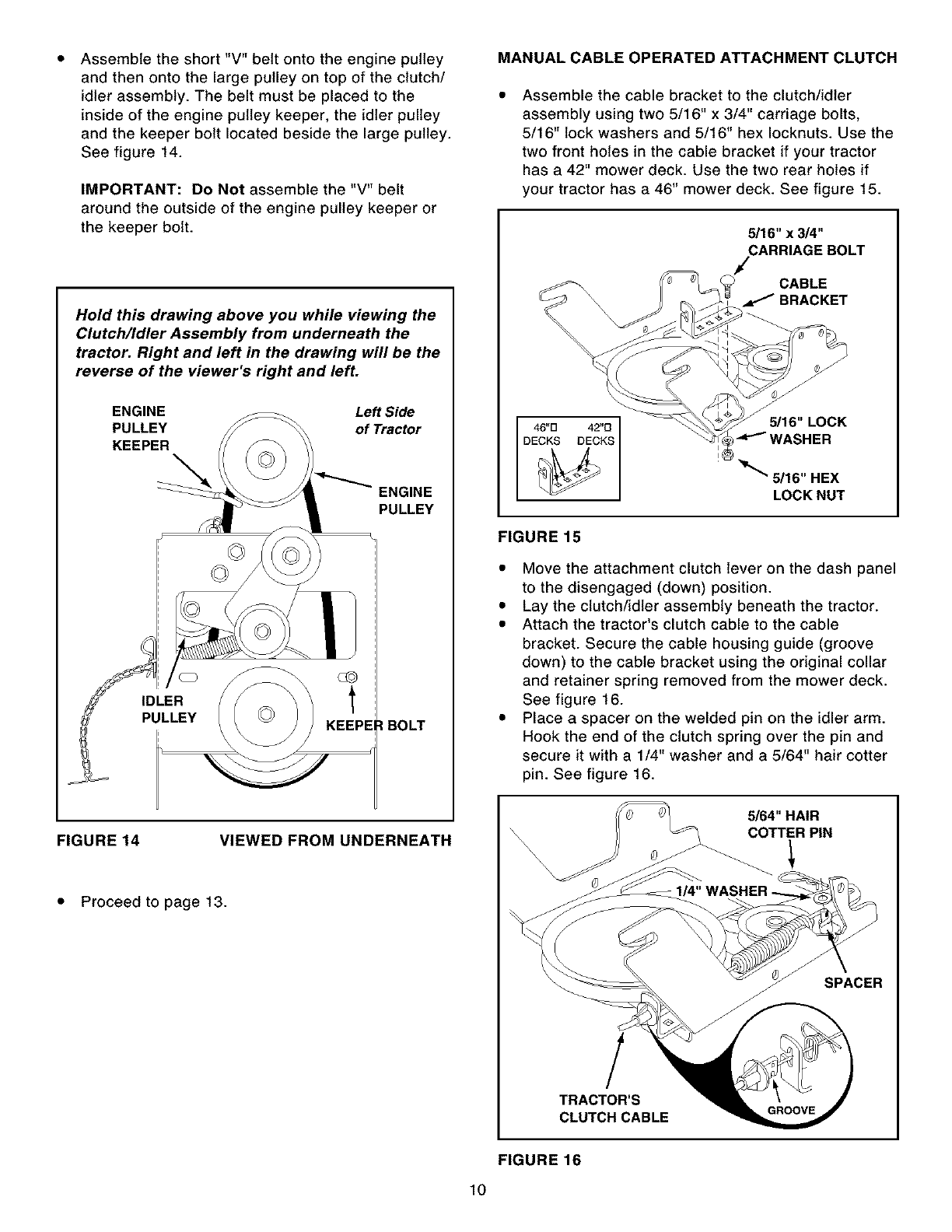
Assemble the short "V" belt onto the engine pulley
and then onto the large pulley on top of the clutch/
idler assembly. The belt must be placed to the
inside of the engine pulley keeper, the idler pulley
and the keeper bolt located beside the large pulley.
See figure 14.
IMPORTANT: Do Not assemble the "V" belt
around the outside of the engine pulley keeper or
the keeper bolt.
Hold this drawing above you while viewing the
Clutch/Idler Assembly from underneath the
tractor. Right and left in the drawing will be the
reverse of the viewer's right and left.
ENGINE Left Side
PULLEY of Tractor
KEEPER
ENGINE
PULLEY
IDLER
PULLEY :l BOLT
FIGURE 14 VIEWED FROM UNDERNEATH
• Proceed to page 13.
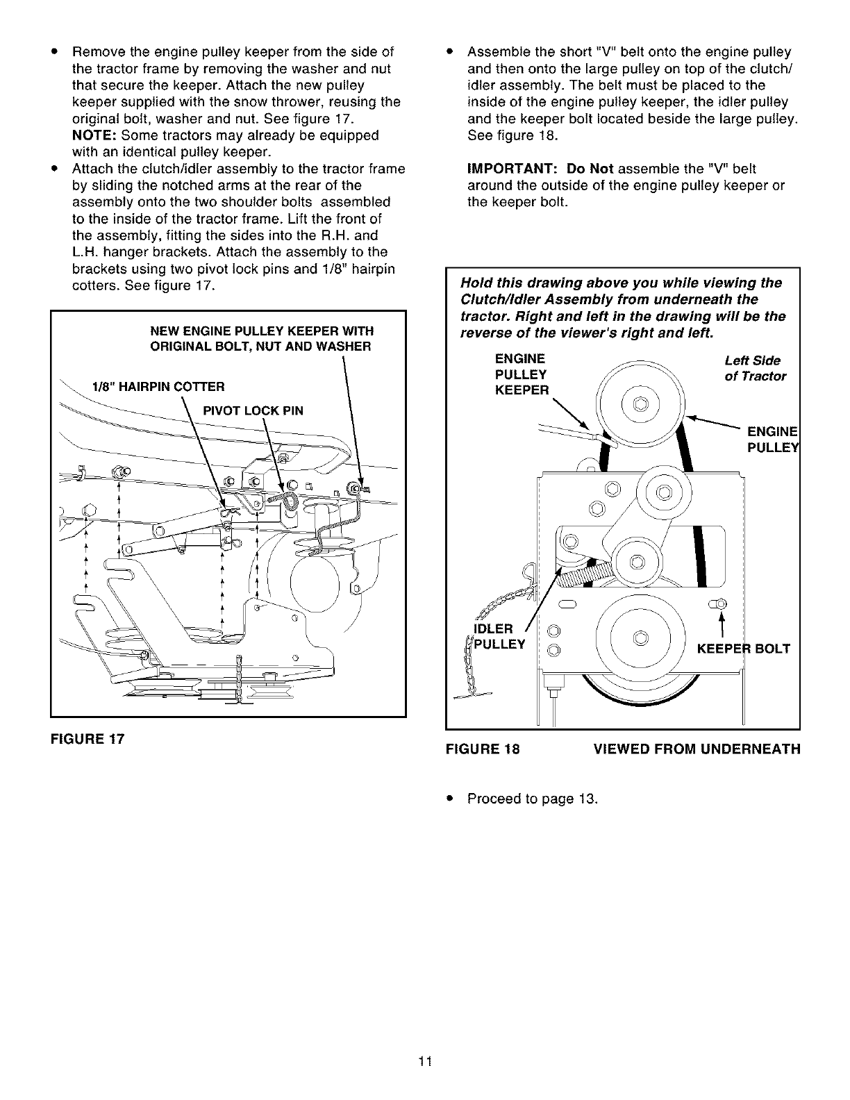
MANUAL CABLE OPERATED ATTACHMENT CLUTCH
Assemble the cable bracket to the clutch/idler
assembly using two 5/16" x 3/4" carriage bolts,
5/16" lock washers and 5/16" hex Iocknuts. Use the
two front holes in the cable bracket if your tractor
has a 42" mower deck. Use the two rear holes if
your tractor has a 46" mower deck. See figure 15.
5/16"x3/4"
CARRIAGE BOLT
CABLE
._ BRACKET
LOCK NUT
FIGURE 15
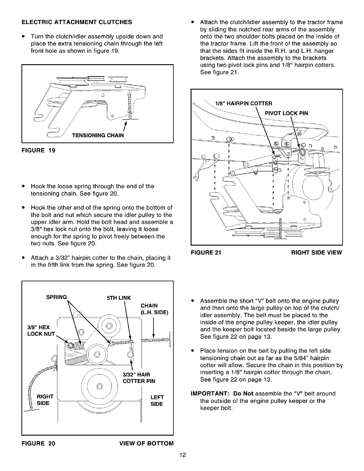
• Move the attachment clutch lever on the dash panel
to the disengaged (down) position.
• Lay the clutch/idler assembly beneath the tractor.
• Attach the tractor's clutch cable to the cable
bracket. Secure the cable housing guide (groove
down) to the cable bracket using the original collar
and retainer spring removed from the mower deck.
See figure 16.
• Place a spacer on the welded pin on the idler arm.
Hook the end of the clutch spring over the pin and
secure it with a 1/4" washer and a 5/64" hair cotter
pin. See figure 16.
5/64" HAIR
COTTER PiN
SPACER
!
TRACTOR'S
CLUTCH CABLE
FIGURE 16
lO
Remove the engine pulley keeper from the side of
the tractor frame by removing the washer and nut
that secure the keeper. Attach the new pulley
keeper supplied with the snow thrower, reusing the
original bolt, washer and nut. See figure 17.
NOTE: Some tractors may already be equipped
with an identical pulley keeper.
Attach the clutch/idler assembly to the tractor frame
by sliding the notched arms at the rear of the
assembly onto the two shoulder bolts assembled
to the inside of the tractor frame. Lift the front of
the assembly, fitting the sides into the R.H. and
L.H. hanger brackets. Attach the assembly to the
brackets using two pivot lock pins and 1/8" hairpin
cotters. See figure 17.
NEW ENGINE PULLEY KEEPER WITH
ORIGINAL BOLT, NUT AND WASHER
1/8" HAIRPIN COTTER
PIVOT LOCK PIN
Assemble the short "V" belt onto the engine pulley
and then onto the large pulley on top of the clutch/
idler assembly. The belt must be placed to the
inside of the engine pulley keeper, the idler pulley
and the keeper bolt located beside the large pulley.
See figure 18.
IMPORTANT: Do Not assemble the "V" belt
around the outside of the engine pulley keeper or
the keeper bolt.
Hold this drawing above you while viewing the
Clutch/Idler Assembly from underneath the
tractor. Right and left in the drawing will be the
reverse of the viewer's right and left.
ENGINE Left Side
PULLEY of Tractor
KEEPER
ENGINE
PULLE_
IDLER
IBOLT
FIGURE 17 FIGURE 18 VIEWED FROM UNDERNEATH
• Proceed to page 13.
11
ELECTRIC ATTACHMENT CLUTCHES
• Turn the clutch/idler assembly upside down and
place the extra tensioning chain through the left
front hole as shown in figure 19.
Attach the clutch/idler assembly to the tractor frame
by sliding the notched rear arms of the assembly
onto the two shoulder bolts placed on the inside of
the tractor frame. Lift the front of the assembly so
that the sides fit inside the R.H. and L.H. hanger
brackets. Attach the assembly to the brackets
using two pivot lock pins and 1/8" hairpin cotters.
See figure 21.
I1/8" HAIRPIN COTTER
PIVOT LOCK PIN
FIGURE 19
Hook the loose spring through the end of the
tensioning chain. See figure 20.
Hook the other end of the spring onto the bottom of
the bolt and nut which secure the idler pulley to the
upper idler arm. Hold the bolt head and assemble a
3/8" hex lock nut onto the bolt, leaving it loose
enough for the spring to pivot freely between the
two nuts. See figure 20.
Attach a 3/32" hairpin cotter to the chain, placing it
in the fifth link from the spring. See figure 20.
FIGURE 21 RIGHT SIDE VIEW
SPRING 5TH LINK
3/8" HEX
LOCK NUT
RIGHT
SIDE
CHAIN
(L.H. SIDE)
3/32"HAIR
COTTER PIN
LEFT
SIDE
Assemble the short "V" belt onto the engine pulley
and then onto the large pulley on top of the clutch/
idler assembly. The belt must be placed to the
inside of the engine pulley keeper, the idler pulley
and the keeper bolt located beside the large pulley.
See figure 22 on page 13.
Place tension on the belt by pulling the left side
tensioning chain out as far as the 5/64" hairpin
cotter will allow. Secure the chain in this position by
inserting a 1/8" hairpin cotter through the chain.
See figure 22 on page 13.
IMPORTANT: Do Not assemble the "V" belt around
the outside of the engine pulley keeper or the
keeper bolt.
FIGURE 20 VIEW OF BOTTOM
12
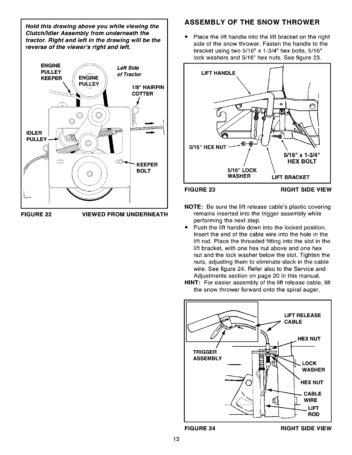
Hold this drawing above you while viewing the
Clutch/Idler Assembly from underneath the
tractor. Right and left in the drawing will be the
reverse of the viewer's right and left.
ENGINE Left Side
PULLEY of Tractor
KEEPER
1/8" HAIRPIN
COTTER
/
IDLER
BOLT
FIGURE 22 VIEWED FROM UNDERNEATH
ASSEMBLY OF THE SNOW THROWER
Place the lift handle into the lift bracket on the right
side of the snow thrower. Fasten the handle to the
bracket using two 5/16" x 1-3/4" hex bolts, 5/16"
lock washers and 5/16" hex nuts. See figure 23.
LIFT HANDLE
5/16" HEX NU1
_5/16" x 1-3/4"
HEX BOLT
5/16" LOCK
WASHER LIFT BRACKET
FIGURE 23 RIGHT SIDE VIEW
NOTE: Be sure the lift release cable's plastic covering
remains inserted into the trigger assembly while
performing the next step.
• Push the lift handle down into the locked position.
Insert the end of the cable wire into the hole in the
lift rod. Place the threaded fitting into the slot in the
lift bracket, with one hex nut above and one hex
nut and the lock washer below the slot. Tighten the
nuts, adjusting them to eliminate slack in the cable
wire. See figure 24. Refer also to the Service and
Adjustments section on page 20 in this manual.
HINT: For easier assembly of the lift release cable, tilt
the snow thrower forward onto the spiral auger.
13
_ _j._ LIFT RELEASE
CABLE
HEX NUT
ASSEMBLY LOCK
_1 WASHER
?;l .ox.o,
/,, _J'_ _ _ CABLE
//-4 / _ 1_WIRE
_ "<"" "------- _ LIFT
_-_- _-L__- -ROD
FIGURE 24 RIGHT SIDE VIEW
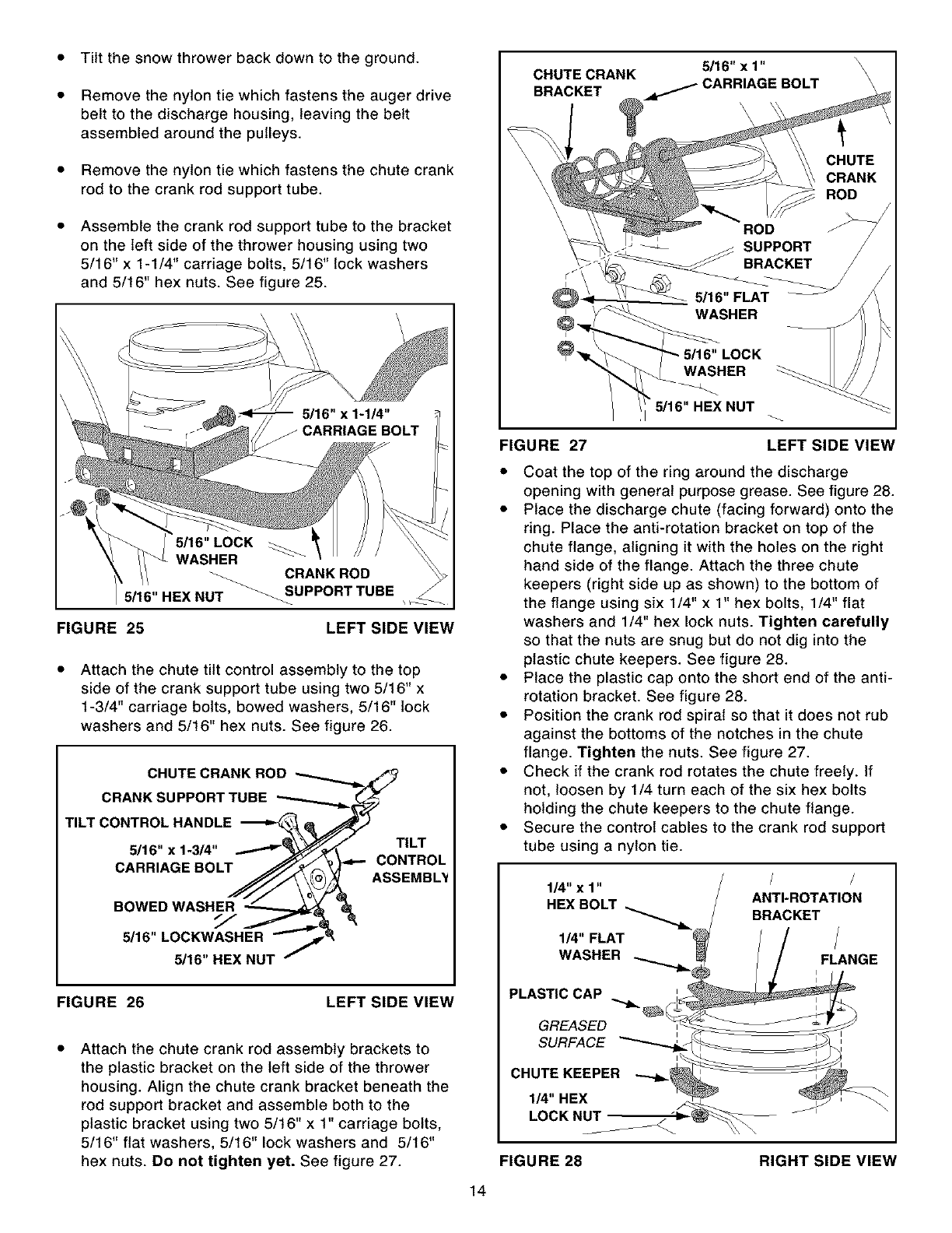
Tilt the snow thrower back down to the ground.
Remove the nylon tie which fastens the auger drive
belt to the discharge housing, leaving the belt
assembled around the pulleys.
Remove the nylon tie which fastens the chute crank
rod to the crank rod support tube.
Assemble the crank rod support tube to the bracket
on the left side of the thrower housing using two
5/16" x 1-1/4" carriage bolts, 5/16" lock washers
and 5/16" hex nuts. See figure 25.
\ \
WASHER
_ CRANK ROD
5/16"HEX NUT "_UPPORTTUBE
FIGURE 25 LEFT SIDE VIEW
Attach the chute tilt control assembly to the top
side of the crank support tube using two 5/16" x
1-3/4" carriage bolts, bowed washers, 5/16" lock
washers and 5/16" hex nuts. See figure 26.
CHUTE CRANK ROD
CRANK SUPPORT TUBE
TILT CONTROL HANDLE_
5/16" x 1-3/4" _TILT
CARRIAGE BOLT CONTROL
ASSEMBL_
BOWED WASHER
5/16" LOCKWASHER
5/16" HEX NUT
FIGURE 26 LEFT SIDE VIEW
Attach the chute crank rod assembly brackets to
the plastic bracket on the left side of the thrower
housing. Align the chute crank bracket beneath the
rod support bracket and assemble both to the
plastic bracket using two 5/16" x 1" carriage bolts,
5/16" flat washers, 5/16" lock washers and 5/16"
hex nuts. Do not tighten yet. See figure 27.
5/16" x 1" \
CHUTE CRANK _ CARRIAGE BOLT \
BRACKET
\\\
14
LOCK
WASHER
•5/16" HEX NUT
FIGURE 27 LEFT SIDE VIEW
• Coat the top of the ring around the discharge
opening with general purpose grease. See figure 28.
• Place the discharge chute (facing forward) onto the
ring. Place the anti-rotation bracket on top of the
chute flange, aligning it with the holes on the right
hand side of the flange. Attach the three chute
keepers (right side up as shown) to the bottom of
the flange using six 1/4" x 1" hex bolts, 1/4" flat
washers and 1/4" hex lock nuts. Tighten carefully
so that the nuts are snug but do not dig into the
plastic chute keepers. See figure 28.
• Place the plastic cap onto the short end of the anti-
rotation bracket. See figure 28.
• Position the crank rod spiral so that it does not rub
against the bottoms of the notches in the chute
flange. Tighten the nuts. See figure 27.
• Check if the crank rod rotates the chute freely. If
not, loosen by 1/4 turn each of the six hex bolts
holding the chute keepers to the chute flange.
• Secure the control cables to the crank rod support
tube using a nylon tie.
1/4" x 1" / /
HEX BOLT ANTI-ROTATION
BRACKET
1/4" FLAT
WASHER FLANGE
PLASTIC CAP
GREASED
SURFACE
CHUTE KEEPER
I_"HEX
LOCK NUT
FIGURE 28 RIGHT SIDE VIEW
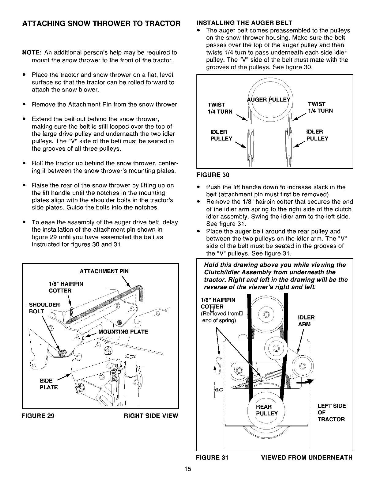
ATTACHING SNOW THROWER TO TRACTOR
NOTE: An additional person's help may be required to
mount the snow thrower to the front of the tractor.
• Place the tractor and snow thrower on a flat, level
surface so that the tractor can be rolled forward to
attach the snow blower.
• Remove the Attachment Pin from the snow thrower.
Extend the belt out behind the snow thrower,
making sure the belt is still looped over the top of
the large drive pulley and underneath the two idler
pulleys. The "V" side of the belt must be seated in
the grooves of all three pulleys.
• Roll the tractor up behind the snow thrower, center-
ing it between the snow thrower's mounting plates.
Raise the rear of the snow thrower by lifting up on
the lift handle until the notches in the mounting
plates align with the shoulder bolts in the tractor's
side plates. Guide the bolts into the notches.
To ease the assembly of the auger drive belt, delay
the installation of the attachment pin shown in
figure 29 until you have assembled the belt as
instructed for figures 30 and 31.
ATTACHMENT PIN
1/8" HAIRPIN
COTTER
SHOULDER
BOLT
\
•MOUNTING PLATE
SIDE 7
PLATE
FIGURE 29 RIGHT SIDE VIEW
INSTALLING THE AUGER BELT
• The auger belt comes preassembled to the pulleys
on the snow thrower housing. Make sure the belt
passes over the top of the auger pulley and then
twists 1/4 turn to pass underneath each side idler
pulley. The "V" side of the belt must mate with the
grooves of the pulleys. See figure 30.
AUGER PULLEY
TWIST TWIST
1/4 TURN 1/4 TURN
IDLER
PULLEY
IDLER
PULLEY
FIGURE 30
• Push the lift handle down to increase slack in the
belt (attachment pin must first be removed).
• Remove the 1/8" hairpin cotter that secures the end
of the idler arm spring to the right side of the clutch
idler assembly. Swing the idler arm to the left side.
See figure 31.
• Place the auger belt around the rear pulley and
between the two pulleys on the idler arm. The "V"
side of the belt must be seated in the grooves of
the "V" pulleys. See figure 31.
Hold this drawing above you while viewing the
Clutch/Idler Assembly from underneath the
tractor. Right and left in the drawing will be the
reverse of the viewer's right and left.
1/8" HAIRPIN
CO_rER
(Removed fromFI
end of spring) IDLER
ARM
LEFT SIDE
OF
TRACTOR
FIGURE 31
15
VIEWED FROM UNDERNEATH
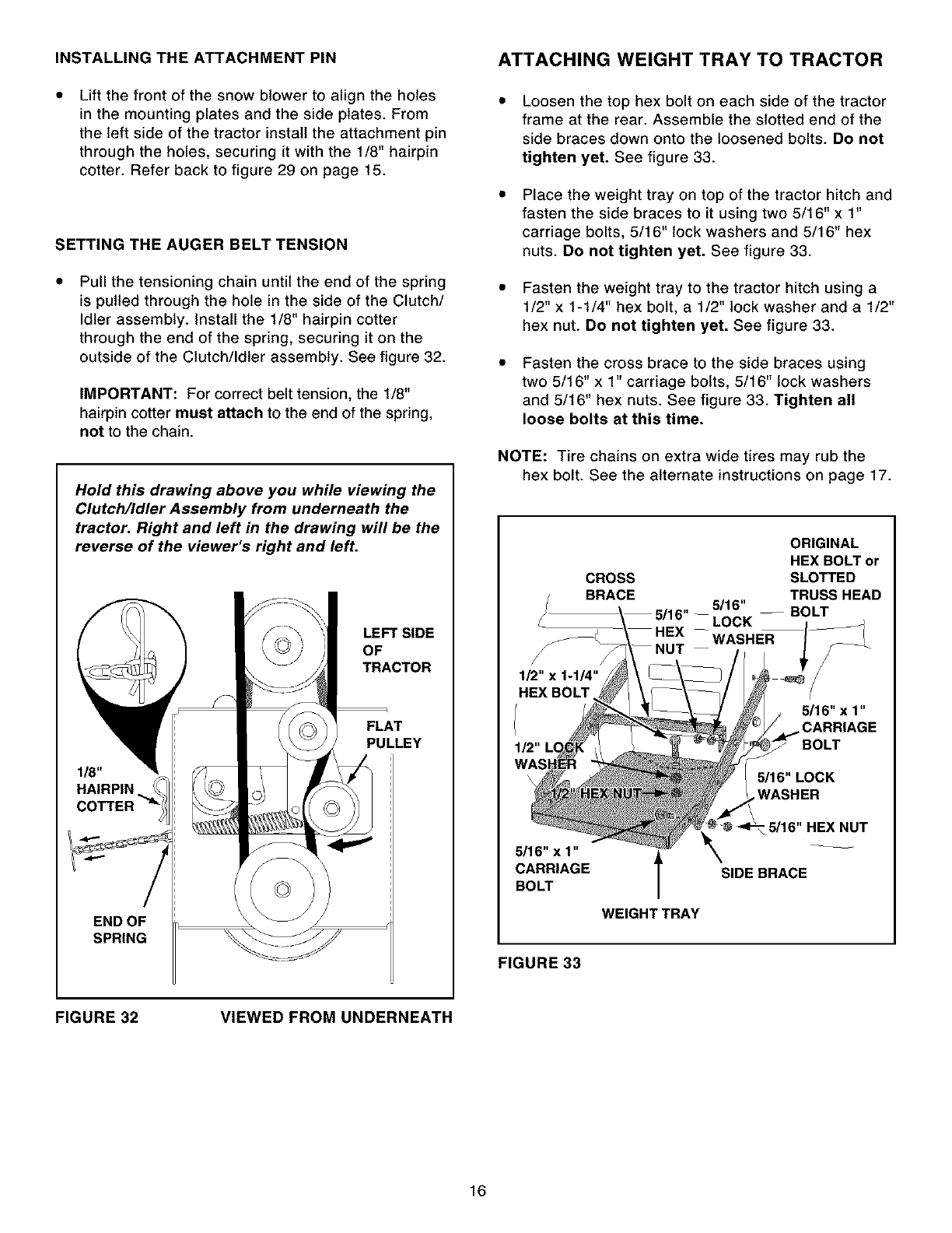
INSTALLINGTHEATTACHMENTPIN
Lift the front of the snow blower to align the holes
in the mounting plates and the side plates. From
the left side of the tractor install the attachment pin
through the holes, securing it with the 1/8" hairpin
cotter. Refer back to figure 29 on page 15.
SETTING THE AUGER BELT TENSION
Pull the tensioning chain until the end of the spring
is pulled through the hole in the side of the Clutch/
Idler assembly. Install the 1/8" hairpin cotter
through the end of the spring, securing it on the
outside of the Clutch/Idler assembly. See figure 32.
IMPORTANT: For correct belt tension, the 1/8"
hairpin cotter must attach to the end of the spring,
not to the chain.
Hold this drawing above you while viewing the
Clutch/Idler Assembly from underneath the
tractor. Right and left in the drawing will be the
reverse of the viewer's right and left.
1/8"
HAIRPIN
COTTER
END OF
SPRING
LEFT SIDE
OF
TRACTOR
F/3
FLAT
PULLEY
ATTACHING WEIGHT TRAY TO TRACTOR
Loosen the top hex bolt on each side of the tractor
frame at the rear. Assemble the slotted end of the
side braces down onto the loosened bolts. Do not
tighten yet. See figure 33.
Place the weight tray on top of the tractor hitch and
fasten the side braces to it using two 5/16" x 1"
carriage bolts, 5/16" lock washers and 5/16" hex
nuts. Do not tighten yet. See figure 33.
• Fasten the weight tray to the tractor hitch using a
1/2" x 1-1/4" hex bolt, a 1/2" lock washer and a 1/2"
hex nut. Do not tighten yet. See figure 33.
Fasten the cross brace to the side braces using
two 5/16" x 1" carriage bolts, 5/16" lock washers
and 5/16" hex nuts. See figure 33. Tighten all
loose bolts at this time.
NOTE: Tire chains on extra wide tires may rub the
hex bolt. See the alternate instructions on page 17.
CROSS
BRACE
5/16"x1"
CARRIAGE
BOLT
WEIGHTTRAY
ORIGINAL
HEX BOLT or
SLOTTED
TRUSS HEAD
5/16" -- BOLT
_LOCK
WASHER
_16"x 1"
CARRIAGE
BOLT
5/16"LOCK
,WASHER
•5/16" HEX NUT
SIDE BRACE
FIGURE 33
FIGURE 32 VIEWED FROM UNDERNEATH
16
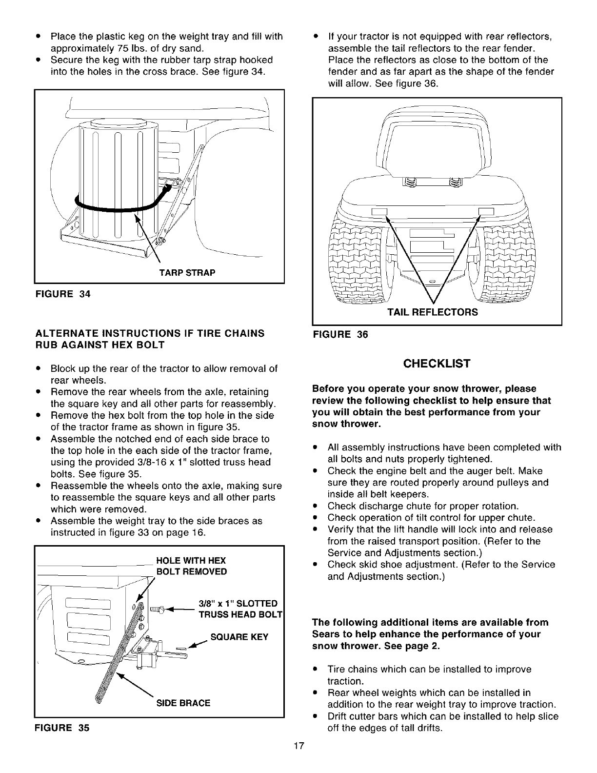
•Place the plastic keg on the weight tray and fill with
approximately 75 lbs. of dry sand.
• Secure the keg with the rubber tarp strap hooked
into the holes in the cross brace. See figure 34.
FIGURE 34
TARPSTRAP
ALTERNATE INSTRUCTIONS IF TIRE CHAINS
RUB AGAINST HEX BOLT
• Block up the rear of the tractor to allow removal of
rear wheels.
• Remove the rear wheels from the axle, retaining
the square key and all other parts for reassembty.
• Remove the hex bolt from the top hole in the side
of the tractor frame as shown in figure 35.
• Assemble the notched end of each side brace to
the top hole in the each side of the tractor frame,
using the provided 3/8-16 x 1" slotted truss head
bolts. See figure 35.
• Reassemble the wheels onto the axle, making sure
to reassemble the square keys and all other parts
which were removed.
• Assemble the weight tray to the side braces as
instructed in figure 33 on page 16.
HOLE WITH HEX
BOLT REMOVED
3/8"xl"SLOTTED
_<_TRUSS HEAD BOLl
_I. SQUARE KEY
FIGURE 35
SIDE BRACE
If your tractor is not equipped with rear reflectors,
assemble the tail reflectors to the rear fender.
Place the reflectors as close to the bottom of the
fender and as far apart as the shape of the fender
will allow. See figure 36.
/
FIGURE 36
TAIL REFLECTORS
CHECKLIST
Before you operate your snow thrower, please
review the following checklist to help ensure that
you will obtain the best performance from your
snow thrower.
• All assembly instructions have been completed with
all bolts and nuts properly tightened.
• Check the engine belt and the auger belt. Make
sure they are routed properly around pulleys and
inside all belt keepers.
• Check discharge chute for proper rotation.
• Check operation of tilt control for upper chute.
• Verify that the lift handle will lock into and release
from the raised transport position. (Refer to the
Service and Adjustments section.)
• Check skid shoe adjustment. (Refer to the Service
and Adjustments section.)
17
The following additional items are available from
Sears to help enhance the performance of your
snow thrower. See page 2.
• Tire chains which can be installed to improve
traction.
• Rear wheel weights which can be installed in
addition to the rear weight tray to improve traction.
• Drift cutter bars which can be installed to help slice
off the edges of tall drifts.
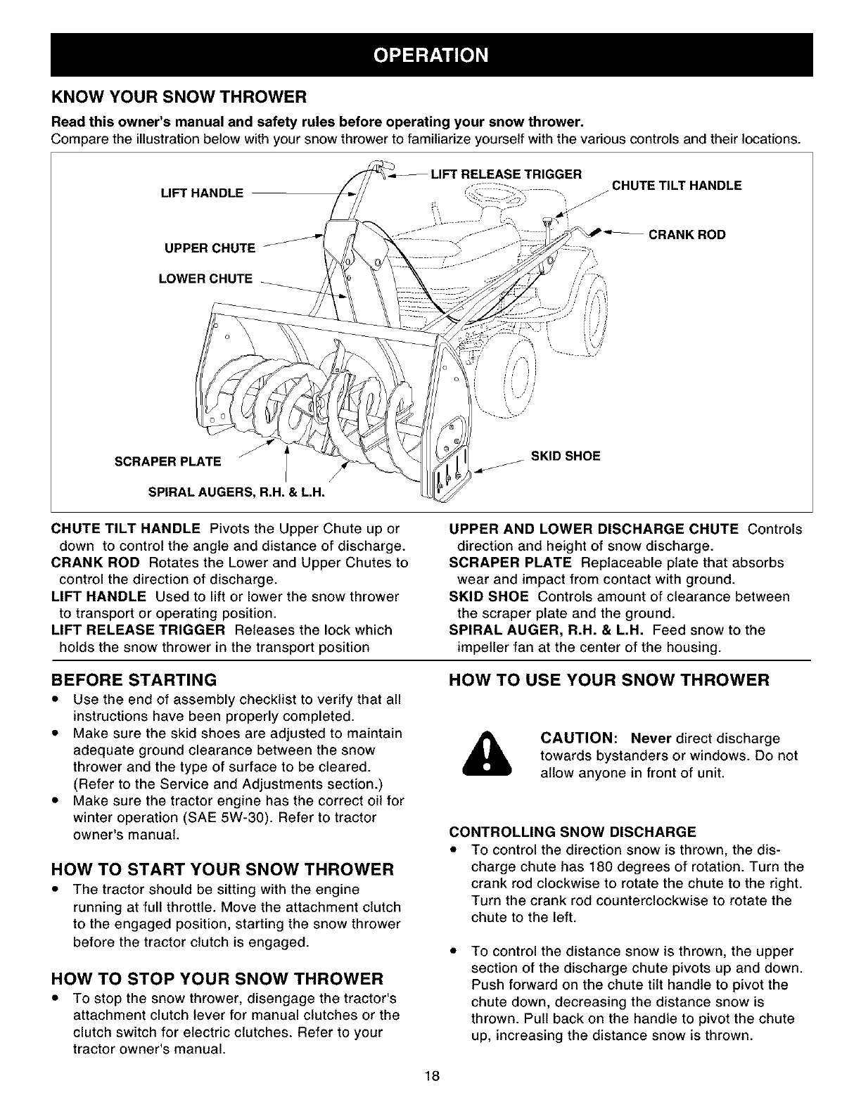
KNOW YOUR SNOW THROWER
Read this owner's manual and safety rules before operating your snow thrower.
Compare the illustrationbelow with your snow thrower to familiarize yourself with the various controls and their locations.
LIFT HANDLE
_ETRIGGER CHUTE TILT HANDLE
UPPER CHUTE CRANK ROD
LOWER CHUTE
SCRAPER PLATE
SPIRAL AUGERS, R.H. & L.H.
SKID SHOE
CHUTE TILT HANDLE Pivots the Upper Chute up or
down to control the angle and distance of discharge.
CRANK ROD Rotates the Lower and Upper Chutes to
control the direction of discharge.
LIFT HANDLE Used to lift or lower the snow thrower
to transport or operating position.
LIFT RELEASE TRIGGER Releases the lock which
holds the snow thrower in the transport position
BEFORE STARTING
• Use the end of assembly checklist to verify that all
instructions have been properly completed.
• Make sure the skid shoes are adjusted to maintain
adequate ground clearance between the snow
thrower and the type of surface to be cleared.
(Refer to the Service and Adjustments section.)
• Make sure the tractor engine has the correct oil for
winter operation (SAE 5W-30). Refer to tractor
owner's manual.
UPPER AND LOWER DISCHARGE CHUTE Controls
direction and height of snow discharge.
SCRAPER PLATE Replaceable plate that absorbs
wear and impact from contact with ground.
SKID SHOE Controls amount of clearance between
the scraper plate and the ground.
SPIRAL AUGER, R.H. & L.H. Feed snow to the
impeller fan at the center of the housing.
HOW TO USE YOUR SNOW THROWER
&CAUTION: Never direct discharge
towards bystanders or windows. Do not
allow anyone in front of unit.
CONTROLLING SNOW DISCHARGE
HOW TO START YOUR SNOW THROWER
• The tractor should be sitting with the engine
running at full throttle. Move the attachment clutch
to the engaged position, starting the snow thrower
before the tractor clutch is engaged.
HOW TO STOP YOUR SNOW THROWER
• To stop the snow thrower, disengage the tractor's
attachment clutch lever for manual clutches or the
clutch switch for electric clutches. Refer to your
tractor owner's manual.
To control the direction snow is thrown, the dis-
charge chute has 180 degrees of rotation. Turn the
crank rod clockwise to rotate the chute to the right.
Turn the crank rod counterclockwise to rotate the
chute to the left.
To control the distance snow is thrown, the upper
section of the discharge chute pivots up and down.
Push forward on the chute tilt handle to pivot the
chute down, decreasing the distance snow is
thrown. Pull back on the handle to pivot the chute
up, increasing the distance snow is thrown.
18
RAISING AND LOWERING
•To raise, push down on the lift handle until the
snow thrower locks in the raised transport position.
•To lower, push down slightly on the lift handle and
pull the trigger. With the trigger pulled, slowly lower
the snow thrower until it reaches the ground.
&CAUTION: Do not operate the snow
thrower without the rear weight attached
to the tractor to provide extra traction
and stability.
REMOVING SNOW
Snow removal conditions vary greatly from light fluffy
snowfall to wet heavy snow. Operating instructions
must be flexible to fit the conditions encountered. The
operator must adapt the lawn tractor and snow thrower
to depth of snow, wind direction, temperature and
surface conditions.
•Before beginning operation, thoroughly inspect the
area of operation and remove all door mats, sleds,
boards, wires and other foreign objects.
•The spiral auger speed is directly related to engine
speed. For maximum snow removal and discharge,
maintain high engine r.p.m. (full throttle). It is
advisable to operate the lawn tractor at a slow
ground speed (1st gear) for safe and efficient snow
removal.
• In deep, drifted or banked snow it will be necessary
to use full throttle and a slow ground speed (1st
gear). Drive forward into the snow, depress the
tractor's clutch-brake pedal and allow the spiral
auger to clear the snow. Repeat this method until a
path is cleared. On the second pass, overlap the
first enough to allow the snow thrower to handle
the snow without repeated stopping and starting of
forward motion.
• In extremely deep snow, raise the snow thrower
from the ground to remove the top layer and drive
forward only until the tractors front tires reach the
uncleared bottom layer of snow. Depress the
tractor's clutch-brake pedal and allow the spiral
auger to clear the snow. Reverse the tractor and
lower the snow thrower to the ground. Drive the
tractor forward until the snow again becomes too
deep. Repeating this process into and out of drifts
will eventually clear even the deepest of snow
piles.
• If the snow thrower becomes clogged with snow or
jammed with a foreign object, disengage the snow
thrower immediately and shut off the tractor engine.
Unclog the snow thrower before resuming opera-
tion.
&DANGER: Shut off engine and
disengage snow thrower before
unclogging discharge chute. Unclog
using a wooden stick, not your hands.
OPERATING TIPS
• Discharge snow down wind whenever possible.
• To help prevent snow from sticking to the snow
thrower, allow the snow thrower to reach outdoor
temperature before using it. A light coat of wax may
also be applied to the inside surface of the snow
thrower housing and discharge chute.
• Use tire chains to improve traction.
• Use rear wheel weights to improve traction.
• Before the first snowfall, remove all stones, sticks
and other objects which could become hidden by
the snow. Permanent obstacles should be marked
for visibility.
• Overlap each pass slightly to assure complete
snow removal.
CUSTOMER RESPONSIBILITIES
• Read and follow the maintenance schedule and the maintenance procedures listed in this section.
MAINTENANCE SCHEDULE &e__. _
complete regular service. ,_k_,'_7
Check for loose fasteners X
Check scraper and shoes for wear X X
Cleaning X
LubricationSection X
Service Dates
LUBRICATION
• Oil all pivot points on the snow thrower.
• Oil the pivot points of the two idler arms on the
clutch/idler assembly.
• Apply penetrating oil to the control cables of the
discharge chute.
• Apply a good grade of spray lubricant to the trigger
assembly and the chute tilt control assembly.
CHECK SCRAPER AND SHOES FOR WEAR
(Refer to figures 37 and 38 on page 20.)
• The scraper plate and skid shoes on the bottom of
the snow thrower are subject to wear. To prevent
damage to the spiral auger housing, replace plate
and shoes before wear is excessive.
19
&CAUTION: Before servicing or adjusting
the snow thrower, shut off the engine,
remove the spark plug wire(s), set the
parking brake and remove the key from
the tractor ignition.
REPLACING AUGER BELT
• Disengage the tractor's attachment clutch.
• Lower the snow thrower to the ground.
• Remove the attachment pin.
• Lock the snow thrower's lift handle in the down
position to decrease belt tension.
• Release the spring tension from the auger belt idler
arm on the bottom of the clutch/idler assembly.
• Remove the auger drive belt from the clutch/idler
assembly and from the spiral auger housing.
• Install new belt over top of large auger drive pulley
and under the two side idler pulleys. Twist the belt
1/4 turn to seat the "V" of the belt in the groove of
each idler pulley. Refer to figure 30 on page 15.
Assemble the belt onto the clutch/idler assembly.
Refer to figures 31 and 32 on pages 15 and 16.
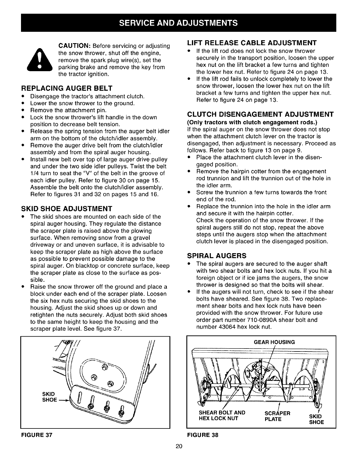
SKID SHOE ADJUSTMENT
• The skid shoes are mounted on each side of the
spiral auger housing. They regulate the distance
the scraper plate is raised above the plowing
surface. When removing snow from a gravel
driveway or and uneven surface, it is advisable to
keep the scraper plate as high above the surface
as possible to prevent possible damage to the
spiral auger. On blacktop or concrete surface, keep
the scraper plate as close to the surface as pos-
sible.
• Raise the snow thrower off the ground and place a
block under each end of the scraper plate. Loosen
the six hex nuts securing the skid shoes to the
housing. Adjust the skid shoes up or down and
retighten the nuts securely. Adjust both skid shoes
to the same height to keep the housing and the
scraper plate level. See figure 37.
LIFT RELEASE CABLE ADJUSTMENT
•If the lift rod does not lock the snow thrower
securely in the transport position, loosen the upper
hex nut on the lift bracket a few turns and tighten
the lower hex nut. Refer to figure 24 on page 13.
• If the lift rod fails to unlock completely to lower the
snow thrower, loosen the lower hex nut on the lift
bracket a few turns and tighten the upper hex nut.
Refer to figure 24 on page 13.
CLUTCH DISENGAGEMENT ADJUSTMENT
(Only tractors with clutch engagement rods.)
If the spiral auger on the snow thrower does not stop
when the attachment clutch lever on the tractor is
disengaged, then adjustment is necessary. Proceed as
follows. Refer back to figure 13 on page 9.
•Place the attachment clutch lever in the disen-
gaged position.
•Remove the hairpin cotter from the engagement
rod trunnion and lift the trunnion out of the hole in
the idler arm.
• Screw the trunnion a few turns towards the front
end of the rod.
•Replace the trunnion into the hole in the idler arm
and secure it with the hairpin cotter.
Check the operation of the snow thrower. If the
spiral augers still do not stop, repeat the above
steps until the augers stop when the attachment
clutch lever is placed in the disengaged position.
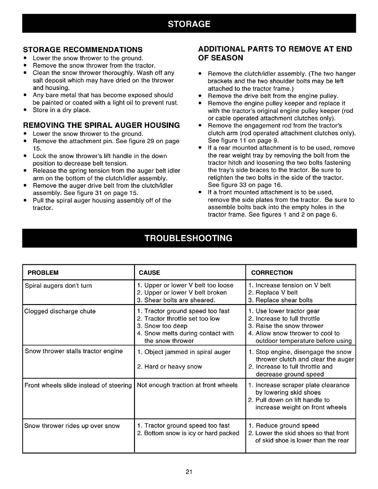
SPIRAL AUGERS
• The spiral augers are secured to the auger shaft
with two shear bolts and hex lock nuts. if you hit a
foreign object or if ice jams the augers, the snow
thrower is designed so that the bolts will shear.
• If the augers will not turn, check to see if the shear
bolts have sheared. See figure 38. Two replace-
ment shear bolts and hex lock nuts have been
provided with the snow thrower. For future use
order part number 710-0890A shear bolt and
number 43064 hex lock nut.
GEAR HOUSING
I !
SHEAR BOLT AND SCRAPER
HEX LOCK NUT PLATE SKID
SHOE
FIGURE 37 FIGURE 38
2O
STORAGE RECOMMENDATIONS
•Lower the snow thrower to the ground.
• Remove the snow thrower from the tractor.
• Clean the snow thrower thoroughly. Wash off any
salt deposit which may have dried on the thrower
and housing.
• Any bare metal that has become exposed should
be painted or coated with a light oil to prevent rust.
• Store in a dry place.
REMOVING THE SPIRAL AUGER HOUSING
• Lower the snow thrower to the ground.
• Remove the attachment pin. See figure 29 on page
15.
• Lock the snow thrower's lift handle in the down
position to decrease belt tension.
• Release the spring tension from the auger belt idler
arm on the bottom of the clutch/idler assembly.
• Remove the auger drive belt from the clutch/idler
assembly. See figure 31 on page 15.
• Pull the spiral auger housing assembly off of the
tractor.
ADDITIONAL PARTS TO REMOVE AT END
OF SEASON
• Remove the clutch/idler assembly. (The two hanger
brackets and the two shoulder bolts may be left
attached to the tractor frame.)
• Remove the drive belt from the engine pulley.
• Remove the engine pulley keeper and replace it
with the tractor's original engine pulley keeper (rod
or cable operated attachment clutches only).
• Remove the engagement rod from the tractor's
clutch arm (rod operated attachment clutches only).
See figure 11 on page 9.
• If a rear mounted attachment is to be used, remove
the rear weight tray by removing the bolt from the
tractor hitch and loosening the two bolts fastening
the tray's side braces to the tractor. Be sure to
retighten the two bolts in the side of the tractor.
See figure 33 on page 16.
• If a front mounted attachment is to be used,
remove the side plates from the tractor. Be sure to
assemble bolts back into the empty holes in the
tractor frame. See figures 1 and 2 on page 6.
PROBLEM CAUSE CORRECTION
Spiral augers don't turn 1. Upper or lower V belt too loose 1. Increase tension on V belt
2. Upper or lower Vbelt broken 2. Replace V belt
3. Shear bolts are sheared. 3. Replace shear bolts
Clogged discharge chute 1. Tractor ground speed too fast 1. Use lower tractor gear
2. Tractor throttle set too low 2. Increase to full throttle
3. Snow too deep 3. Raise the snow thrower
4. Snow melts during contact with 4. Allow snow thrower to cool to
the snow thrower outdoor temperature before using
Snow thrower stalls tractor engine 1. Object jammed in spiral auger 1. Stop engine, disengage the snow
thrower clutch and clear the auger
2. Hard or heavy snow 2. Increase to full throttle and
decrease ground speed
Front wheels slide instead of steering Not enough traction at front wheels 1. Increase scraper plate clearance
by lowering skid shoes
2. Pull down on lift handle to
increase weight on front wheels
Snow thrower rides up over snow 1. Tractor ground speed too fast 1. Reduce ground speed
2. Bottom snow is icy or hard packed 2. Lower the skid shoes so that front
of skid shoe is lower than the rear
21
21 27
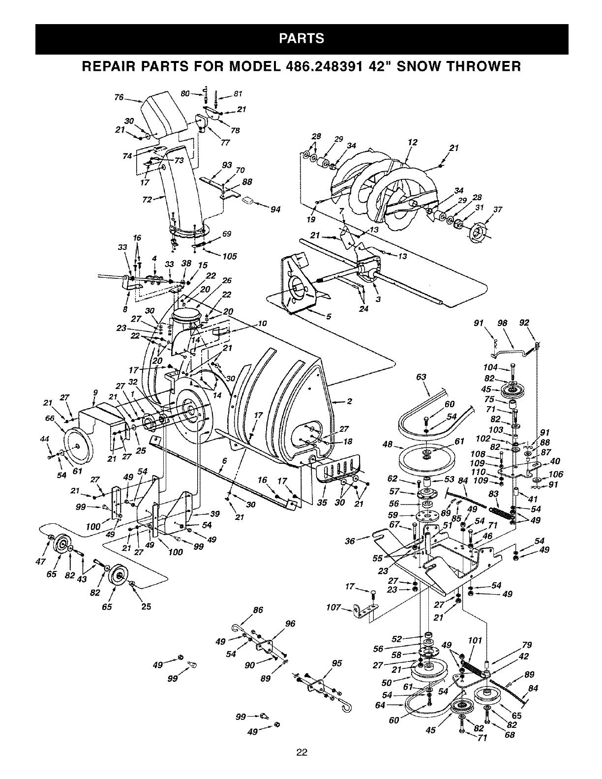
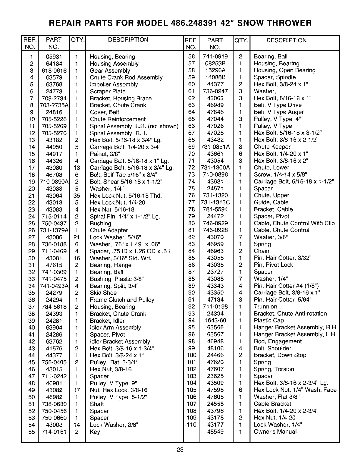
REPAIR PARTS FOR MODEL 486.248391 42" SNOW THROWER
17
72 _.
16
33
!
8 30
9
26
lO
28 29
19
3
24
12
63
21
/
34 28
_1 37
91 98 92
54 61 27
21
47
65 824,
82
65
49
27
25
7 _
4999
\21
86 96
89
22
27
35 30 21
95
/
64_
60
19
_8
.87
84
REPAIR PARTS FOR MODEL 486.248391 42" SNOW THROWER
REF.
NO.
1
2
3
4
5
6
7
8
9
10
11
12
13
14
15
16
17
18
19
20
21
22
23
24
25
26
27
28
29
3O
31
32
33
34
35
36
37
38
39
4O
41
42
43
44
45
46
47
48
49
5O
51
52
53
54
55
PART
NO.
05931
64184
618-0616
63579
63768
24773
703-2734
703-2735A
24816
705-5226
705-5269
705-5270
43182
44950
44917
44326
43080
46703
710-0890A
43088
43064
43013
43083
715-0114
750-0437
731-1379A
43086
736-0188
711-0469
43081
47615
741-0309
741-0475
741-0493A
24279
24294
784-5618
24393
24281
63904
24286
63762
41576
44377
756-0405
43015
711-0242
46981
43082
46982
738-0680
750-0456
750-0660
43003
714-0161
QTY. DESCRIPTION REF. PART QTY. DESCRIPTION
NO. NO.
1 Housing, Bearing 56 741-0919 2 Bearing, Ball
1 Housing Assembly 57 08253B 1 Housing, Bearing
1 Gear Assembly 58 15296A 1 Housing, Open Bearing
1 Chute Crank Rod Assembly 59 14088B 1 Spacer, Spindle
1 Impeller Assembly 60 44377 2 Hex Bolt, 3/8-24 x 1"
1 Scraper Plate 61 736-0247 3 Washer,
1 Bracket, Housing Brace 62 43063 3 Hex Bolt, 5/16-18 x 1"
1 Bracket, Chute Crank 63 46989 1 Belt, V Type Drive
1 Cover, Belt 64 47846 1 Belt, V Type Auger
1 Chute Reinforcement 65 47044 3 Pulley, V Type 4"
1 Spiral Assembly, L.H. (not shown) 66 47026 1 Pulley, V Type
1 Spiral Assembly, R.H. 67 47025 1 Hex Bolt, 5/16-18 x 3-1/2"
2 Hex Bolt, 5/16-18 x 3/4" Lg. 68 43432 1 Hex Bolt, 3/8-16 x 2-1/2"
5 Carriage Bolt, 1/4-20 x 3/4" 69 731-0851A 3 Chute Keeper
1 Palnut, 3/8" 70 43661 6 Hex Bolt, 1/4-20 x 1"
4 Carriage Bolt, 5/16-18 x 1" Lg. 71 43054 3 Hex Bolt, 3/8-16 x 2"
13 Carriage Bolt, 5/16-18 x 3/4" Lg. 72 731-1300A 1 Chute, Lower
6 Bolt, Self-Tap 5/16" x 3/4" 73 710-0896 1 Screw, 1/4-14 x 5/8"
2 Bolt, Shear 5/16-18 x 1-1/2" 74 43681 1 Carriage Bolt, 5/16-18 x 1-1/2"
5 Washer, 1/4" 75 24571 1 Spacer
35 Hex Lock Nut, 5/16-18 Thd. 76 731-1320 1 Chute, Upper
5 Hex Lock Nut, 1/4-20 77 731-1313C 1 Guide, Cable
4 Hex Nut, 5/16-18 78 784-5594 1 Bracket, Cable
2 Spiral Pin, 1/4" x 1-1/2" Lg. 79 24472 1 Spacer, Pivot
2 Bushing 80 746-0929 1 Cable, Chute Control With Clip
1 Chute Adapter 81 746-0928 1 Cable, Chute Control
21 Lock Washer, 5/16" 82 43070 7 Washer, 3/8"
6 Washer, .76" x 1.49" x .06" 83 46959 1 Spring
4 Spacer, .75 ID x 1.25 OD x .5 L 84 46963 2 Chain
16 Washer, 5/16" Std. Wrt. 85 43055 1 Pin, Hair Cotter, 3/32"
2 Bearing, Flange 86 43038 2 Pin, Pivot Lock
1 Bearing, Ball 87 23727 1 Spacer
2 Bushing, Plastic 3/8" 88 43088 7 Washer, 1/4"
4 Bearing, Split, 3/4" 89 43343 4 Pin, Hair Cotter #4 (1/8")
2 Skid Shoe 90 43350 4 Carriage Bolt, 3/8-16 x 1"
1 Frame Clutch and Pulley 91 47134 3 Pin, Hair Cotter 5/64"
2 Housing, Bearing 92 711-0198 1 Trunnion
1 Bracket, Chute Crank 93 24394 1 Bracket, Chute Anti-rotation
1 Bracket, Idler 94 1643-60 1 Plastic Cap
1 Idler Arm Assembly 95 63566 1 Hanger Bracket Assembly, R.H.
1 Spacer, Pivot 96 63567 1 Hanger Bracket Assembly, L.H.
1 Idler Bracket Assembly 98 46948 1 Rod, Engagement
2 Hex Bolt, 3/8-16 x 1-3/4" 99 48106 4 Bolt, Shoulder
1 Hex Bolt, 3/8-24 x 1" 100 24466 2 Bracket, Down Stop
2 Pulley, Flat 3-3/4" 101 47620 1 Spring
1 Hex Nut, 3/8-16 102 47607 1 Spring, Torsion
1 Spacer 103 23625 1 Spacer
1 Pulley, V Type 9" 104 43509 1 Hex Bolt, 3/8-16 x 2-3/4" Lg.
17 Nut, Hex Lock, 3/8-16 105 47598 6 Hex Lock Nut, 1/4" Wash. Face
1 Pulley, V Type 5-1/2" 106 47605 1 Washer, Flat 3/8"
1 Shaft 107 24558 1 Cable Bracket
1 Spacer 108 43796 1 Hex Bolt, 1/4-20 x 2-3/4"
1 Spacer 109 43178 2 Hex Nut, 1/4-20
14 Lock Washer, 3/8" 110 43177 1 Lock Washer, 1/4"
2 Key 48549 1 Owner's Manual
23
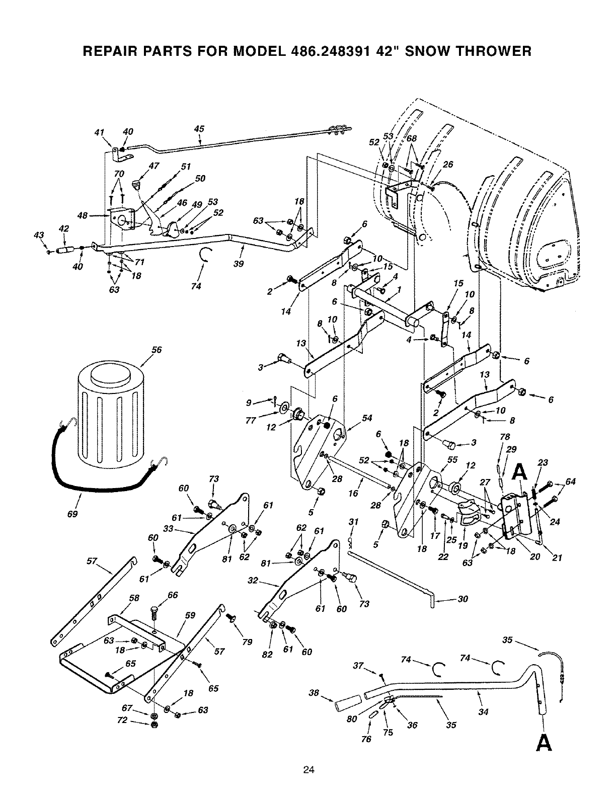
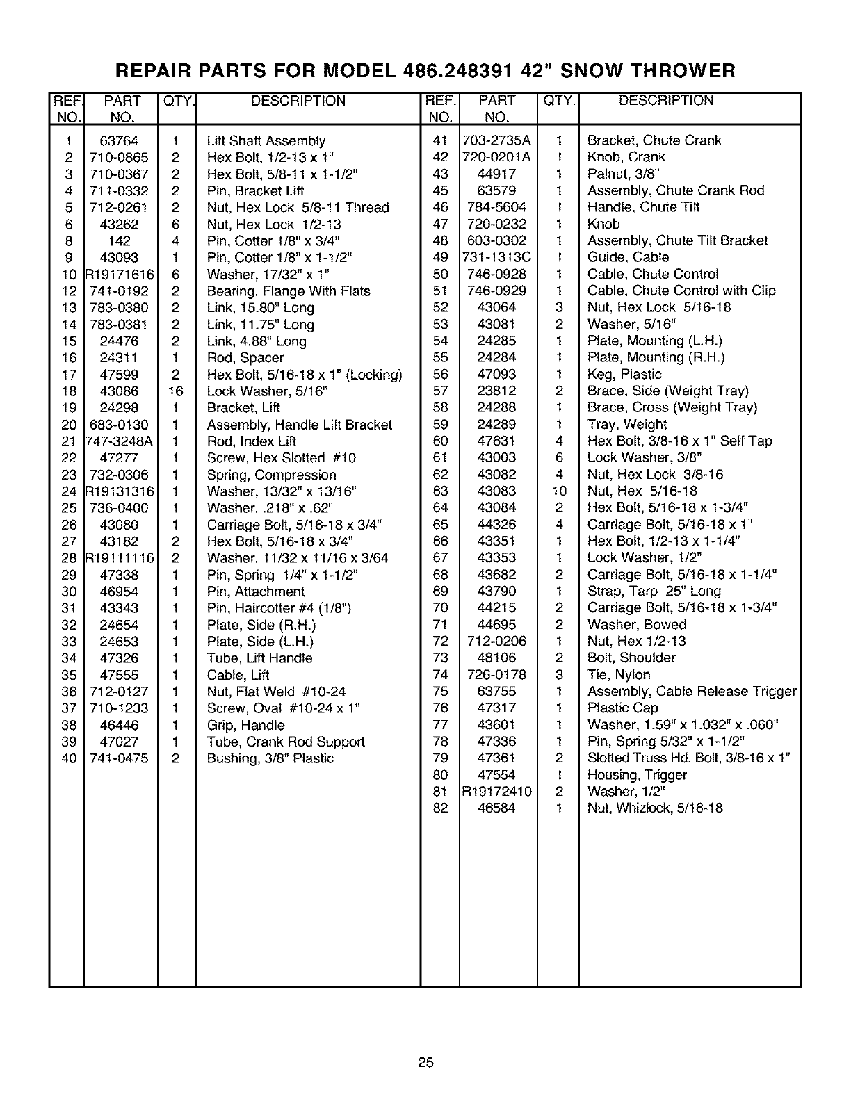
REPAIR PARTS FOR MODEL 486.248391 42" SNOW THROWER
43
\
41 40 45
\52
47 51
50
42
C
40 V,8 !
63 74
56
!
69
53 18
52
73
60 !
\
39
14
61
/
54
6\
"_ 16
/ 28
5
62 61
61
31
/5
\\ 73
60
15
6
8
78
55 12 23
64
24
18 22 63
57
\65
79
82
38
37.,,,,_
80
76
35
\o\ 35
75 A
24
REF
NO.
1
2
3
4
5
6
8
9
10
12
13
14
15
16
17
18
19
20
21
22
23
24
25
26
27
28
29
30
31
32
33
34
35
36
37
38
39
4O
REPAIR PARTS FOR MODEL 486.248391 42" SNOW THROWER
PART QTY DESCRIPTION REF. PART QTY. DESCRIPTION
NO. NO. NO.
63764 1 LiftShaft Assembly 41 703-2735A 1 Bracket, Chute Crank
710-0865 2 Hex Bolt, 1/2-13 x 1" 42 720-0201A 1 Knob, Crank
710-0367 2 Hex Bolt, 5/8-11 x 1-1/2" 43 44917 1 Palnut, 3/8"
711-0332 2 Pin, Bracket Lift 45 63579 1 Assembly, Chute Crank Rod
712-0261 2 Nut, Hex Lock 5/8-11 Thread 46 784-5604 1 Handle, Chute Tilt
43262 6 Nut, Hex Lock 1/2-13 47 720-0232 1 Knob
142 4 Pin, Cotter 1/8" x 3/4" 48 603-0302 1 Assembly, Chute Tilt Bracket
43093 1 Pin, Cotter 1/8" x 1-1/2" 49 731-1313C 1 Guide, Cable
:119171616 6 Washer, 17/32" x 1" 50 746-0928 1 Cable, Chute Control
741-0192 2 Bearing, Flange With Flats 51 746-0929 1 Cable, Chute Control with Clip
783-0380 2 Link, 15.80" Long 52 43064 3 Nut, Hex Lock 5/16-18
783-0381 2 Link, 11.75" Long 53 43081 2 Washer, 5/16"
24476 2 Link, 4.88" Long 54 24285 1 Plate, Mounting (L.H.)
24311 1 Rod, Spacer 55 24284 1 Plate, Mounting (R.H.)
47599 2 Hex Bolt, 5/16-18 x 1" (Locking) 56 47093 1 Keg, Plastic
43086 16 Lock Washer, 5/16" 57 23812 2 Brace, Side (Weight Tray)
24298 1 Bracket, Lift 58 24288 1 Brace, Cross (Weight Tray)
683-0130 1 Assembly, Handle Lift Bracket 59 24289 1 Tray, Weight
_'47-3248A 1 Rod, Index Lift 60 47631 4 Hex Bolt, 3/8-16 x 1" Self Tap
47277 1 Screw, Hex Slotted #10 61 43003 6 Lock Washer, 3/8"
732-0306 1 Spring, Compression 62 43082 4 Nut, Hex Lock 3/8-16
:119131316 1 Washer, 13/32"x 13/16" 63 43083 10 Nut, Hex 5/16-18
736-0400 1 Washer, .218"x .62" 64 43084 2 Hex Bolt, 5/16-18 x 1-3/4"
43080 1 Carriage Bolt, 5/16-18 x 3/4" 65 44326 4 Carriage Bolt, 5/16-18 x 1"
43182 2 Hex Bolt, 5/16-18 x 3/4" 66 43351 1 Hex Bolt, 1/2-13 x 1-1/4"
:119111116 2 Washer, 11/32 x 11/16 x 3/64 67 43353 1 Lock Washer, 1/2"
47338 1 Pin, Spring 1/4"x 1-1/2" 68 43682 2 Carriage Bolt, 5/16-18 x 1-1/4"
46954 1 Pin, Attachment 69 43790 1 Strap, Tarp 25" Long
43343 1 Pin, Haircotter #4 (1/8") 70 44215 2 Carriage Bolt, 5/16-18 x 1-3/4"
24654 1 Plate, Side (R.H.) 71 44695 2 Washer, Bowed
24653 1 Plate, Side (L.H.) 72 712-0206 1 Nut, Hex 1/2-13
47326 1 Tube, Lift Handle 73 48106 2 Bolt, Shoulder
47555 1 Cable, Lift 74 726-0178 3 Tie, Nylon
712-0127 1 Nut, Flat Weld #10-24 75 63755 1 Assembly, Cable Release Trigger
710-1233 1 Screw, Oval #10-24 x 1" 76 47317 1 Plastic Cap
46446 1 Grip, Handle 77 43601 1 Washer, 1.59" x 1.032" x .060"
47027 1 Tube, Crank Rod Support 78 47336 1 Pin, Spring 5/32" x 1-1/2"
741-0475 2 Bushing, 3/8" Plastic 79 47361 2 Slotted Truss Hd. Bolt, 3/8-16 x 1"
80 47554 1 Housing, Trigger
81 R19172410 2 Washer, 1/2"
82 46584 1 Nut, Whizlock, 5/16-18
25

NOTES
26
ro
,,.j
|
&CAUTION: DO NOT OPERATE YOUR TRACTOR AND SNOW
THROWER ON A SLOPE IN EXCESS OF 10 DEGREES. BE SURE OF
YOUR TRACTOR'S TOWING AND BRAKING CAPABILITIES BEFORE
OPERATING ON A SLOPE, AVOID ANY SUDDEN TURNS OR MA-
NEUVERS WHILE ON A SLOPE.
1-800-4-MY-HOME sMAnytime, day or night
(1-800-469-4663)
SEARS
TM
® Registered Trademark /Trademark of Sears, Roebuck and Co.
@ Sears, Roebuck and Co. ® Marca Registrada /TM Marca de F&brica de Sears, Roebuck and Co.
