Craftsman 502249274 User Manual GRASS CATCHER Manuals And Guides L0212167
CRAFTSMAN Grass Catcher Manual L0212167 CRAFTSMAN Grass Catcher Owner's Manual, CRAFTSMAN Grass Catcher installation guides
User Manual: Craftsman 502249274 502249274 CRAFTSMAN GRASS CATCHER - Manuals and Guides View the owners manual for your CRAFTSMAN GRASS CATCHER #502249274. Home:Lawn & Garden Parts:Craftsman Parts:Craftsman GRASS CATCHER Manual
Open the PDF directly: View PDF ![]() .
.
Page Count: 20
SF/A/RS
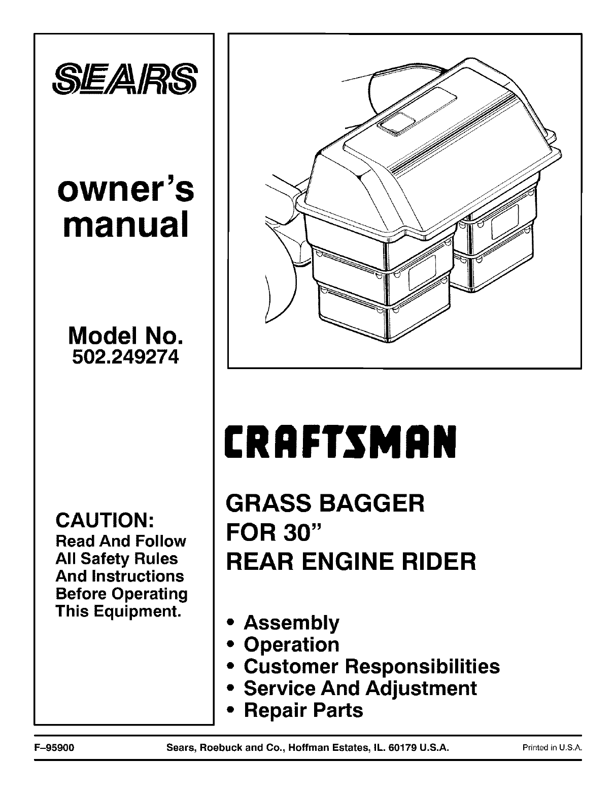
owner's
manual
Model No.
502.249274
CAUTION:
Read And Follow
All Safety Rules
And Instructions
Before Operating
This Equipment.
[RRFTSMRN
GRASS BAGGER
FOR 30"
REAR ENGINE RIDER
•Assembly
•Operation
•Customer Responsibilities
•Service And Adjustment
•Repair Parts
F-95900 Sears, Roebuck and Co., Hoffman Estates, IL. 60179 U.S.A. PrintedinUSA

TABLE OF CONTENTS
WARRANTY .................................
CUSTOMER RESPONSIBILITIES ..............
GRASS BAGGER FEATURES .................
SAFETY RULES ..............................
ASSEMBLY ..................................
HOW TO MOUNT THE FRAME ASSEMBLY...
HOW TO MOUNT THE COVER ..............
HOW TO MOUNT THE EXTENSION TUBE ....
HOW TO MOUNT THE CONNECTOR TUBE
HOW TO ASSEMBLE THE CONTAINERS ...
HOW TO MOUNT THE CONTAINERS .......
HOW TO INSTALL THE FRONT WEIGHT ....
CONTAINER LININGS .....................
OPERATION ................................
HOW TO USE THE GRASS BAGGER .......
CUSTOMER RESPONSIBILITIES ..............
HOW TO CLEAN THE GRASS BAGGER .....
REPAIR PARTS ..............................
SLOPE GUIDE ...............................
INDEX .......................................
2
3
3
4
6
7
8
9
10
11
12
12
12
13
13
14
14
15
18
19
LIMITED ONE YEAR WARRANTY
ON ATTACHMENTS
For one (1) year from the date of purchase, Sears will repair any defect in material or workmanship in this Attachment at no
charge.
This warranty does not cover:
• Expendable items which become worn during normal use, such as blades and blade adapters.
• Repairs necessary because of operator abuse, negligence, improper storage or accident or the failure to maintain the
equipment according to the instructions contained in the owner's manual.
• Equipment used for commercial or rental purposes.
WARRANTY SERVICE IS AVAILABLE BY RETURNING THE ATTACHMENT TO THE NEAREST SEARS SERVICE
CENTER/DEPARTMENT IN THE UNITED STATES.
This warranty gives you specific legal rights, and you may also have other rights which may vary from state to state.
Sears, Roebuck and Co., D/871WA, Hoffman Estates, Illinois 60684.
F-95900 2
Congratulations on your purchase of a Sears Grass Bagger. It has been designed,
engineered and manufactured to give you the best possible dependability and
performance.
If you experience any problems you cannot easily remedy, please see your nearest Sears
Service Department. We have competent, well trained technicians and the proper tools to
service or repair this unit.
Please read and keep this manual. The instructions will enable you to assemble and
maintain your unit properly. Always observe the "Safety Rules".
CUSTOMER RESPONSIBILITIES
•Carefully read and follow the rules for safe operation. Inspect the unit.
• Follow all the assembly instructions. Carefully adjust the unit.
• Know how to operate all standard and accessary equipment on the unit. Make sure
the operator can correctly operate the unit.
• Operate the unit only with guards, shields and other safety items in place and working
correctly.
• Complete all maintenance on the unit. Service the unit only with authorized or
approved replacement parts.
MAINTENANCE AGREEMENT
A Sears Maintenance Agreement is available on this unit. See the nearest Sears Store for
information.
GRASS BAGGER FEATURES
See Through Window ......... Lets you know when the containers are full.
Large Capacity Containers ..... Containers are quickly removed and easy to empty.
GRASS BAGGER
Record in the space below the serial number and the date
of purchase of this unit.
The model number and serial number are found on a decal
attached to the unit.
Model Number: 502.249274
Serial Number:
Date of Purchase:
Keep these numbers for future reference.
F-95900 3

SAFETY RULES
Safe Operation Practices for Riding Vehicles
As Recommended by American National Standards Institute
WARNING: This cutting machine is capable of amputating hands and feet and throwing objects. Failure to observe the
following safety instructions could result in serious injury or death to the operator or bystanders.
GENERAL OPERATION:
1. Read, understand and follow all instructions in the Instruction Book, on the machine, the engine and with any attachments before
starting.
2. Only allow responsible adults familiar with the instructions to operate the machine.
3. Clear the area of objects such as rocks, toys, wire, etc. which could be picked up and thrown by the blade.
4. Be sure the area is clear of other people before mowing. Stop the machine if anyone enters the area.
5. Never carry passengers.
6. Disengage power to the mower or any attachments before backing up. Do not mow in reverse unless absolutely necessary. Always
look down and behind before and while backing.
7. Be aware of the direction the mower discharges. Do not point discharge from the mower at anyone or at places where people may be.
Do not operate the mower without either the entire grass bagger or the mower guard in place.
8. Slow down before turning.
9. Never leave a machine unattended with the engine running. Always disengage the blade(s), set the parking brake, stop the engine and
remove the key before dismounting.
10. Disengage power to attachment(s) when transporting or not in use. Disengage the blade(s) when not mowing.
11. Stop the engine before removing the grass bagger or unclogging the chute.
12. Mow only in daylight or good artificial light.
13. DO not operate the machine while under the influence of alcehol or drugs or when very tired.
14. Watch for traffic when operating near or crossing roadways.
15. Use extra caution when loading or unloading the machine when using a trailer or truck for transporting.
16. Disengage all attachment clutches and shift into Neutral before attempting to start the engine.
17. Always wear safety glasses or an eye shield when you operate the unit to protect your eyes from foreign objects that can be thrown
from the unit. Always wear eye protection when you make an adjustment or repair to the machine.
18. Use care when pulling loads or using heavy equipment.
a. Use only approved drawbar hitch points.
b. Limit loads to those you can safely control.
c. Do not turn sharply. Use care when backing.
d. Use counterweights or wheel weights when suggested in the Instruction Book.
19. Do not operate this machine if you are taking drugs or other medication which can cause drowsiness or affect your ability to operate
this machine.
20. Do not use this machine if you are mentally or physically unable to operate this machine safely.
SLOPE OPERATION:
Slopes and rough terrain are major factors related to loss of control and tip over accidents which can result in severe injury or
death. ALL slopes require extra caution. If you cannot back up the slope or if you feel uneasy on the slope, do not mow it. See the
"Slope Guide" in the back of this book to check for safe operation.
DO
1. Mow up and down slopes, not across.
2. Remove obstacles such as rocks, limbs, etc...
3. Watch for holes, ruts or bumps. Uneven terrain could overturn the machine. "Tall grass can hide obstacles."
4. Use slow speed. Choose a low enough gear so that you will not have to stop or shift while on the slope.
5. Follow the manufacturer's recommendations for wheel weights or counterweights to improve stability.
6. Use extra care with grass baggers or other attachments, they can change the stability of the machine.
7. Keep all movement on the slopes slow and gradual. Do not make sudden changes in speed or direction.
8. Avoid starting or stopping on a slope. If tires lose traction, disengage the blades and proceed slowly straight down the slope.
DO NOT
1. Do not turn on slopes unless absolutely necessary, then only turn slowly and gradually downhill, if possible.
2. Do not mow near drop-offs, ditches or embankments. A wheel over the edge or an edge caving in could cause a sudden overturn and
an injury or death.
3. Do not mow on wet grass. Reduced traction could cause sliding.
F-95900

4. Do not try to stabilize the machine by putting your foot on the ground.
5. Do not use a grass bagger or other rear mounted accessories on steep slopes (greater than 10 degrees).
CHILDREN:
Tragic accidents can occur if the operator is not alert to the presence of children. Children are often attracted to the machine and
the mowing activity. NEVER assume that children will remain where you last saw them,
1. Keep children out of the mowing area and in the watchful care of an adult other than the operator.
2. Be alert and turn the engine off if children enter the area.
3. Before and when backing, look behind end down for small children.
4. Never carry children or any passengers. They may fall off and be seriously injured or interfere with the safe operation of the machine.
5. Never allow children to operate the machine. Instruct children in the dangers of the machine.
6. Use extra care when approaching blind corners, shrubs, trees or other objects that may obscure vision.
SERVICE:
1. Use extra care when handling gasoline and other fuels. Fuels are flammable and the vapors are explosive.
a. Use only an approved container.
b. Never remove the gas cap or add fuel with the engine running. Allow the engine to cool for several minutes before refueling. Do
not smoke.
c. Never refuel the machine indoors.
d. Never store the machine with fuel in the tank or fuel container inside where there is an open flame, such as a water heater.
2. Never start or run the engine inside a closed area.
3. Keep all nuts and bolts, especially the blade attachment nuts tight. Frequently check the blade(s) for wear or damage such as cracks
and nicks. A blade that is bent or damaged must be immediately replaced with an original equipment blade from an authorized service
dealer. For safety, replace the blade every two years. Keep the equipment in good condition.
4. Never tamper with the safety devices. Check their proper operation regularly.
5. To reduce fire hazards keep the machine free of grass, leaves or other debris buildup. Clean up oil or fuel spills. Allow the machine
to cool before storing.
6. Stop and inspect the equipment if you strike an object. Repair, if necessary, before restarting.
7. Never make adjustments or repairs with the engine running. The carburetor can be adjusted with the engine running. Do not change
the engine governor settings or overspeed the engine.
8. Grass bagger components are subject to wear, damage and deterioration, which could expose moving parts or allow objects to be
thrown. For storage, always make sure the grass bag is empty. Frequently check components and replace with manufacturer's recom-
mended parts when necessary.
9. Mower blade(s) are sharp and can cut. Wrap the blade(s) or wear gloves and use extra caution when servicing them or the blade housing
area.
10. Check the brake operation frequently. Adjust and service as required.
11. Wait for all movement to stop before servicing any part of the unit.
RESPONSIBILITY OF THE OWNER
Environmental Awareness
•Do not fill the engine's fuel tank completely full.
• Drain fuel for off season storage.
• Use only unleaded gasoline.
• Servicethe air cleaner regularly.
• Change oil regularly. Use 30W oil in summer.
• Tune-up the engine regularly.
• Keep equipment in efficient operating condition.
• Dispose of used engine oil properly.
Look for this symbol to indicate important safety
precautions. This symbol indicates: "Attention!
Become Alert! Your Safety Is At Risk."
F-95900 5
ASSEMBLY
ASSEMBLY
Read and follow the assembly, operation and maintenance instruc-
tions. All fasteners are in the parts bag. Do not discard any parts or
material until the unit is assembled.
TOOLS REQUIRED
1. Pliers (1)
2. Adjustable open end wrenches (2
3. Blade type screwdriver (1)
4. Phillips screwdriver (1)
5. Short blade type screwdriver (1)
6. Open end wrench, 1/2" 9/16"
7. Open end wrench, 3/8" - 7/16"
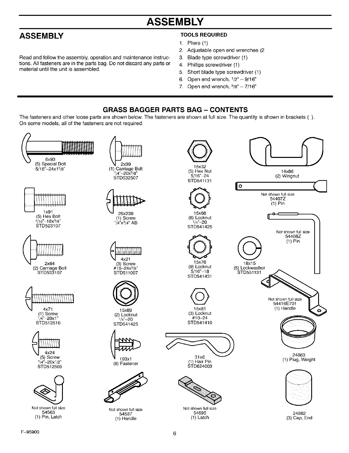
GRASS BAGGER PARTS BAG - CONTENTS
The fasteners and other loose parts are shown below. The fasteners are shown at full size. The quantity is shown in brackets ().
On some models, all of the fasteners are not required.
6x93
(5) Special Bolt 15x32
5/16"-24xlS/8" 1 Carriage Bolt (5) Hex Nut 14x86
/4"_20x5/8 "
STD532507 5/16"-24 (2) Wingnut
sxo64t13t n°
Q o shown ,, ize
544077
(1) Pin
15x66
(t) Screw (6) Locknut
Y4"x3/4" AB Y4"-20
STD541425
(5) Hex Bolt
5/16"_18x3/4"
STD523107
Not shown full size
o o 4o8z
(1) Pin
(3) Screw 15x76 18xl 5
(2) Carriage Bolt #10-24xS/8 " (9) Locknut (5) Lockwesher
STD533107 STD511007 5/16'%18 STD551131
STD541431
_) Not shown full size
54416E701
15x89 15x81 (1) Handle
1 Screw (2!/4,, 20 (3) Locknut @
/4"-20xl" Locknut #10-24
STD512510 STD541425 STD541410
31x6 24863
1/4"-20x1/2" (8) Fastener (1) Hair Pin (1) Plug, Weight
STD512505 STD624003
Not shown full size Not shown full size Not shownfull size
54563 54537 54695 24862
(1) Pin, Latch (1) Handle (1) Latch (3) Cap, End
F-95900 6
ASSEMBLY
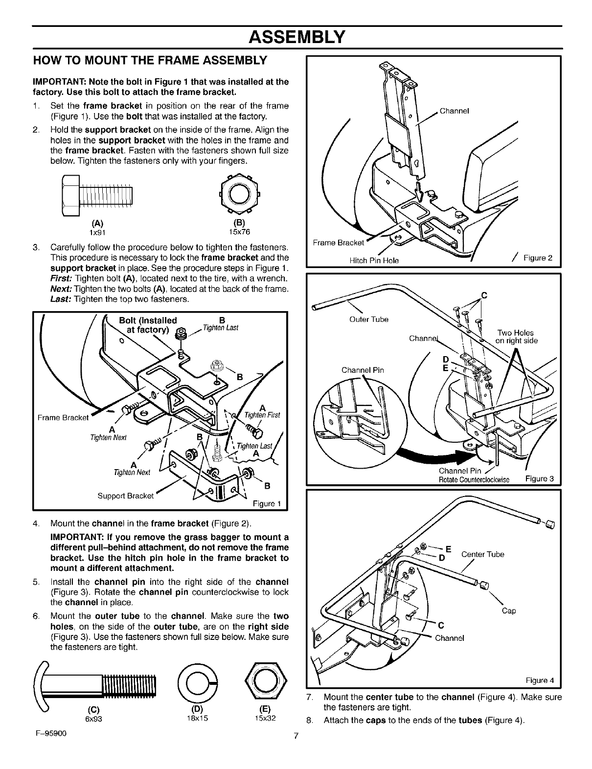
HOW TO MOUNT THE FRAME ASSEMBLY
IMPORTANT: Note the bolt in Figure 1 that was installed at the
factory. Use this bolt to attach the frame bracket.
1,
2.
Set the frame bracket in position on the rear of the frame
(Figure 1). Use the bolt that was installed at the factory.
Hold the support bracket on the inside of the frame. Align the
holes in the support bracket with the holes in the frame and
the frame bracket. Fasten with the fasteners shown full size
below. Tighten the fasteners only with your fingers.
©
(A) (B)
lx91 15x76
3, Carefully follow the procedure below to tighten the fasteners.
This procedure is necessary to lock the frame bracket and the
support bracket in place. See the procedure steps in Figure 1.
First: Tighten bolt (A), located next to the tire, with a wrench.
Next: Tighten the two bolts (A), located at the back of the frame.
Last: Tighten the top two fasteners.
B
A
TightenNext
4,
5,
6.
A
TightenNext
B
Figure 1
Mount the channel in the frame bracket (Figure 2).
IMPORTANT: If you remove the grass bagger to mount a
different pull-behind attachment, do not remove the frame
bracket. Use the hitch pin hole in the frame bracket to
mount adifferent attachment.
Install the channel pin into the right side of the channel
(Figure 3). Rotate the channel pin counterclockwise to lock
the channel in place.
Mount the outer tube to the channel. Make sure the two
holes, on the side of the outer tube, are on the right side
(Figure 3). Use the fasteners shown full size below. Make sure
the fasteners are tight.
Hitch Pin Hole
Outer Tube
Channel Pin
,Channel
/Figure 2
Two Holes
on right side
Channel Pin
RotateCounterclockwise Figure 3
ECenter Tube
/
\Cap
(C) (D) (E)
6x93 18xl 5 15x32
F-95900
Figure 4
7. Mount the center tube to the channel (Figure 4). Make sure
the fasteners are tight.
8. Attach the caps to the ends of the tubes (Figure 4).
ASSEMBLY
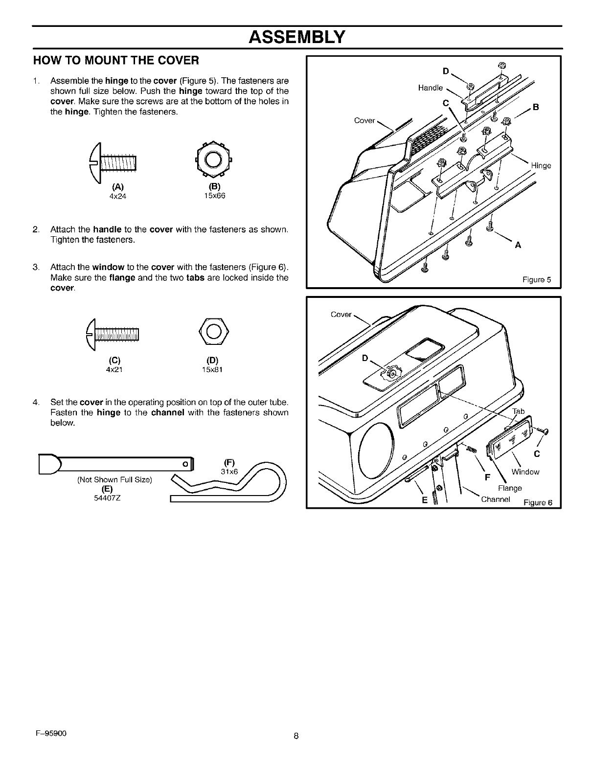
HOW TO MOUNT THE COVER
1, Assemble the hinge to the cover (Figure 5). The fasteners are
shown full size below. Push the hinge toward the top of the
cover. Make sure the screws are at the bottom of the holes in
the hinge. Tighten the fasteners.
¢= Q
(A) (B)
4x24 15x66
2. Attach the handle to the cover with the fasteners as shown.
Tighten the fasteners.
3. Attach the window to the cover with the fasteners (Figure 6).
Make sure the flange and the two tabs are locked inside the
cover.
Cover
Handle
C
A
Figure 5
4,
©
(C) (D)
4x21 15x81
Set the cover in the operating position on top of the outer tube.
Fasten the hinge to the channel with the fasteners shown
below.
(Not Shown Full Size)
(E)
54407Z
Cover_,
E
Tab
C
Window
Flange
Figure 6
F-95900 8
ASSEMBLY
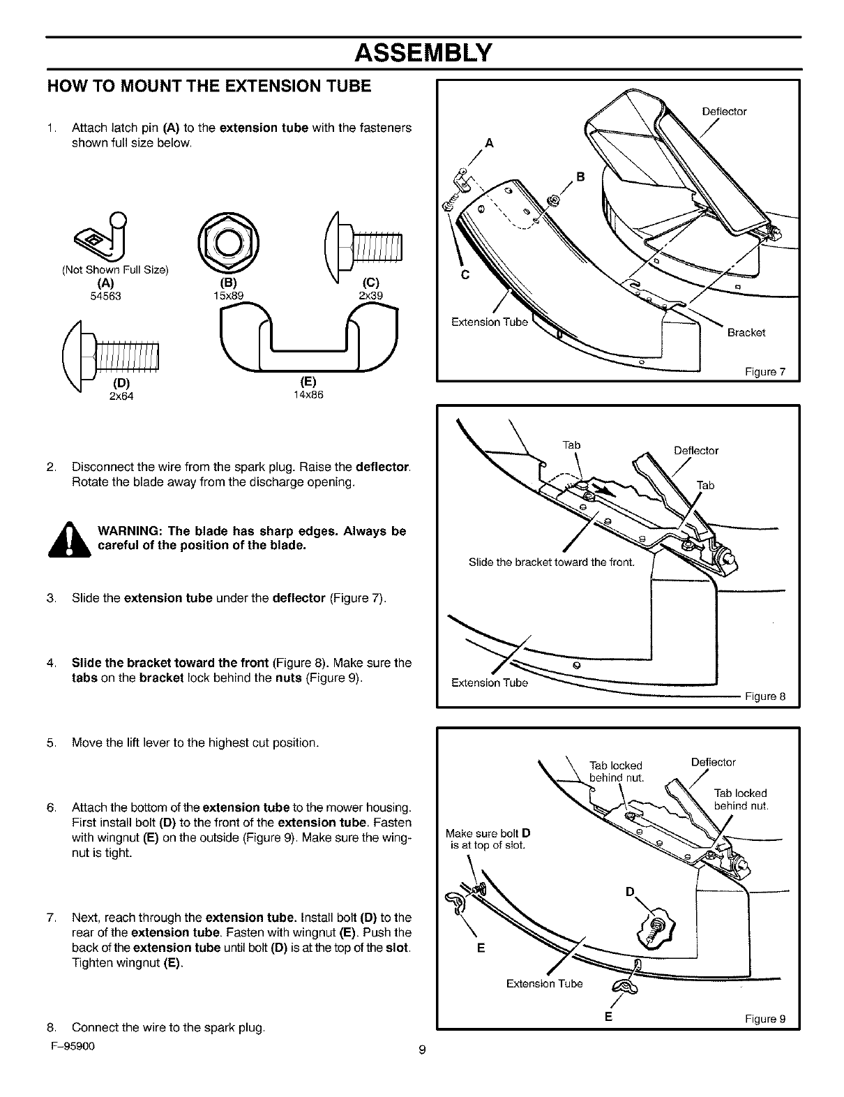
HOW TO MOUNT THE EXTENSION TUBE
1. Attach latch pin (A) to the extension tube with the fasteners
shown full size below.
®
(Not Shown Full Size)
(A) (B)
54563 15x89 2x39
2x64 (E)
14x86
A
/
Extension Tube
Deflector
Bracket
Figure7
2. Disconnect the wire from the spark plug. Raise the deflector.
Rotate the blade away from the discharge opening.
_hlL ARNING: The blade has sharp edges. Always becareful of the position of the blade.
3. Slide the extension tube under the deflector (Figure 7).
4. Slide the bracket toward the front (Figure 8). Make sure the
tabs on the bracket lock behind the nuts (Figure 9).
Tab
Slide the bracket toward the front.
Extension Tube
Deflector
Tab
Figure 8
5. Move the lift lever to the highest cut position.
6, Attach the bottom of the extension tube to the mower housing.
First install bolt (D) to the front of the extension tube. Fasten
with wingnut (E) on the outside (Figure 9). Make sure the wing-
nut is tight.
7, Next, reach through the extension tube. Install bolt (D) to the
rear of the extension tube. Fasten with wingnut (E). Push the
back of the extension tube until bolt (D) is at the top of the slot.
Tighten wingnut (E).
Make sure bolt D
is at top of slot.
Tab locked
behind nut.
Deflector
Tab locked
behind nut.
E
Extension Tube /
EFigure 9
8. Connect the wire to the spark plug.
F-95900 9
ASSEMBLY
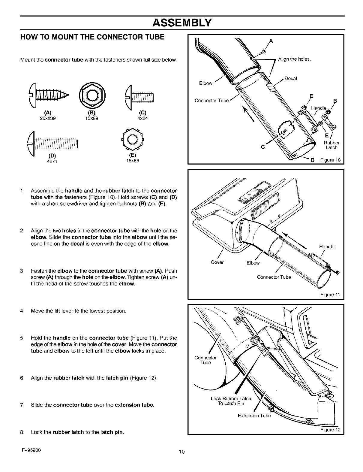
HOW TO MOUNT THE CONNECTOR TUBE
Mount the connector tube with the fasteners shown full size below.
(A) (B) (C)
26x239 15x89 4x24
4x71
Q
(E)
15x66
Elbow
A
/
Align the holes.
j Decal
C
E
/
D
Rubber
Latch
Figure 10
1,
2,
3,
Assemble the handle and the rubber latch to the connector
tube with the fasteners (Figure 10). Hold screws (C) and (D)
with a short screwdriver and tighten Iocknuts (B) and (E).
Align the two holes in the connector tube with the hole on the
elbow. Slide the connector tube into the elbow until the se-
cond line on the decal is even with the edge of the elbow.
Fasten the elbow to the connector tube with screw (A). Push
screw (A) through the hole on the elbow. 3]ghten screw (A) un-
til the head of the screw touches the elbow.
Cover Elbow
Connector Tube
Handle
Figure 11
4. Move the lift lever to the lowest position.
5, Hold the handle on the connector tube (Figure 11). Put the
edge of the elbow in the hole of the cover. Move the connector
tube and elbow to the left until the elbow locks in place.
6. Align the rubber latch with the latch pin (Figure 12).
7. Slide the connector tube over the extension tube.
8. Lock the rubber latch to the latch pin.
Conne_or
Tube
Lock Rubber Latch
To Latch Pin
Extension Tube
Figure 12
F-95900 10
ASSEMBLY
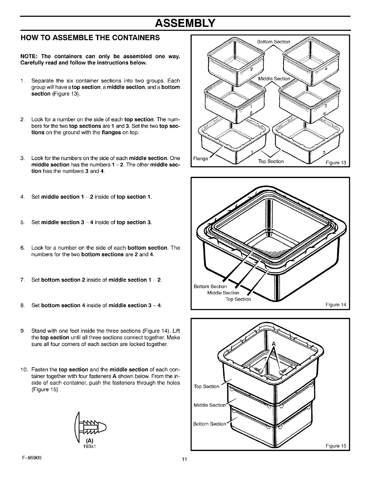
HOW TO ASSEMBLE THE CONTAINERS
NOTE: The containers can only be assembled one way.
Carefully read and follow the instructions below.
1. Separate the six container sections into two groups. Each
group will have atop section, amiddle section, and a bottom
section (Figure 13).
2. Look for a number on the side of each top section. The num-
bers for the two top sections are I and 3. Set the two top sec-
tions on the ground with the flanges on top.
3. Look for the numbers on the side of each middle section. One
middle section has the numbers I 2. The other middle sec-
tion has the numbers 3 and 4.
Bottom Section
Top Section Figure 13
4. Set middle section 1 -2inside of top section 1.
5. Set middle section 3- 4 inside of top section 3.
6, Look for a number on the side of each bottom section. The
numbers for the two bottom sections are 2 and 4.
7. Set bottom section 2 inside of middle section 12.
8. Set bottom section 4 inside of middle section 3 4.
Bottom Section
Middle Section
Top Section
Figure 14
9. Stand with one foot inside the three sections (Figure 14). Lift
the top section until all three sections connect together. Make
sure all four corners of each section are locked together.
10. Fasten the top section and the middle section of each con-
tainer together with four fasteners A shown below. From the in-
side of each container, push the fasteners through the holes
(Figure 15).
193xl
¢
Bottom Section"
)
Figure 15
F-95900 11
ASSEMBLY
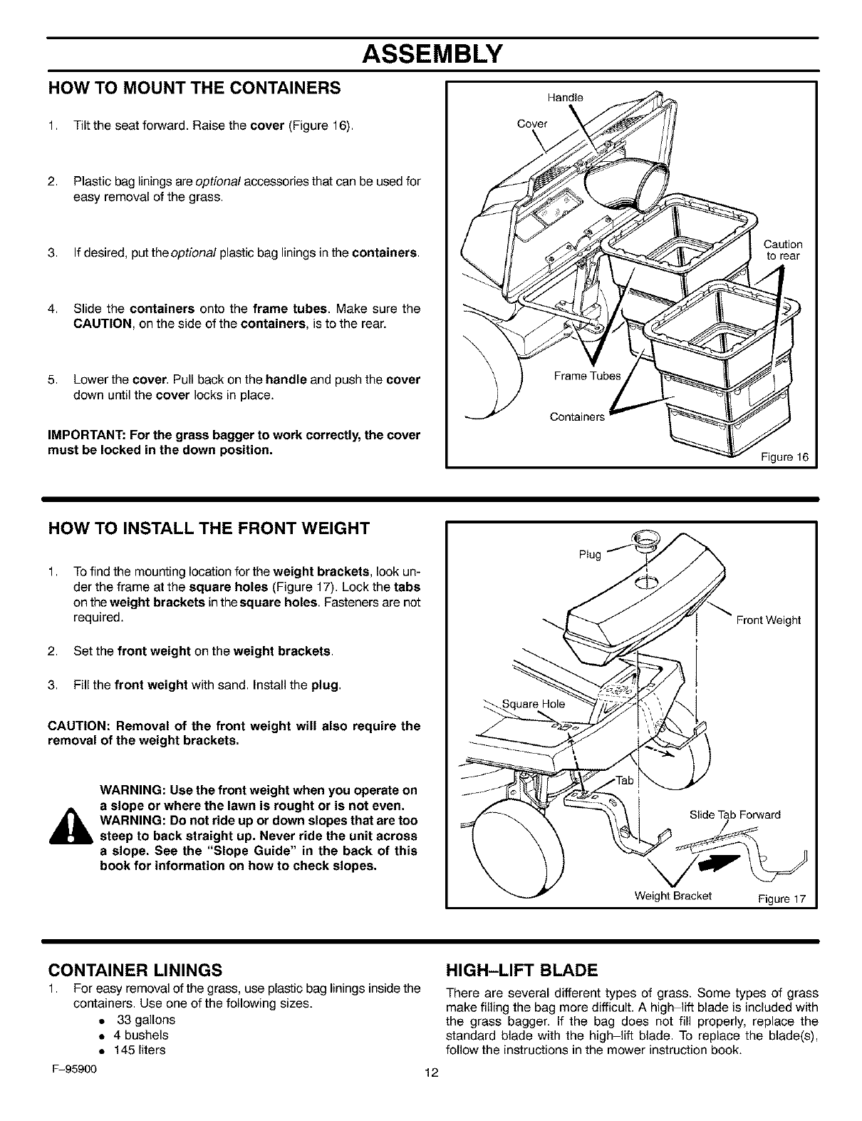
HOW TO MOUNT THE CONTAINERS
1. Tilt the seat forward. Raise the cover (Figure 16).
2. Plastic bag linings are optional accessories that can be used for
easy removal of the grass.
3. If desired, put the optional plastic bag linings in the containers.
4. Slide the containers onto the frame tubes. Make sure the
CAUTION, on the side of the containers, is to the rear.
5. Lower the cover. Pull back on the handle and push the cover
down until the cover locks in place.
IMPORTANT: For the grass bagger to work correctly, the cover
must be locked in the down position.
Handle
Cover
\
Frame Tubes
Containers
Caution
to rear
Figure 16
HOW TO INSTALL THE FRONT WEIGHT
1,
2,
3.
To find the mounting location for the weight brackets, look un-
der the frame at the square holes (Figure 17). Lock the tabs
on the weight brackets in the square holes. Fasteners are not
required.
Set the front weight on the weight brackets.
Fill the front weight with sand. Install the plug.
CAUTION: Removal of the front weight will also require the
removal of the weight brackets.
WARNING: Use the front weight when you operate on
a slope or where the lawn is rought or is not even.
WARNING: Do not ride up or down slopes that are too
steep to back straight up. Never ride the unit across
a slope. See the "Slope Guide" in the back of this
book for information on how to check slopes.
SlideTab Forward
Weight Bracket Figure 17
CONTAINER LININGS
1. For easy removal of the grass, use plastic bag linings inside the
containers. Use one of the following sizes.
• 33 gallons
• 4 bushels
• 145 liters
F-95900 12
HIGH-LIFT BLADE
There are several different types of grass. Some types of grass
make filling the bag more difficult. A high lift blade is included with
the grass bagger. If the bag does not fill properly, replace the
standard blade with the high lift blade. To replace the blade(s),
follow the instructions in the mower instruction book.
OPERATION
HOW TO USE THE GRASS BAGGER
WARNING: Do not ride up or down slopes that are too
steep to back straight up. Never ride the unit across
a slope. See the "Slope Guide" in the back of this
book for information on how to check slopes.
OPERATION
To operate with the grass bagger, follow the steps below.
IMPORTANT: Do not cut wet grass. Wet grass will not
discharge correctly into the grass bagger.
1. Start the engine.
2. Move the throttle control to FAST position.
3. Move the shift lever to FIRST (1) position. To fill the containers,
always operate at the slowest speed.
4. If the height of the grass is more than 31/2inches (9cm), cut the
grass with the mower housing in the highest position. Then,
lower the mower housing and cut the grass again. You can also
cut at V2to 2/3of the full cutting width of the mower housing.
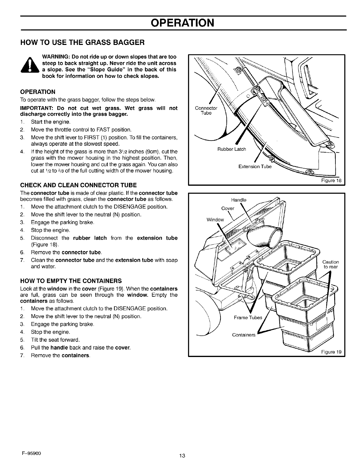
CHECK AND CLEAN CONNECTOR TUBE
The connector tube is made of clear plastic. If the connector tube
becomes filled with grass, clean the connector tube as follows.
1. Move the attachment clutch to the DISENGAGE position.
2. Move the shift lever to the neutral (N) position.
3. Engage the parking brake.
4. Stop the engine.
5. Disconnect the rubber latch from the extension tube
(Figure 18).
6. Remove the connector tube.
7. Clean the connector tube and the extension tube with soap
and water.
HOW TO EMPTY THE CONTAINERS
Look at the window in the cover (Figure 19). When the containers
are full, grass can be seen through the window. Empty the
containers as follows.
1. Move the attachment clutch to the DISENGAGE position.
2. Move the shift lever to the neutral (N) position.
3. Engage the parking brake.
4. Stop the engine.
5. Tilt the seat forward.
6. Pull the handle back and raise the cover.
7. Remove the containers.
Conne_or
Tube
RubberL_ch
Extension Tube
Handle
Cover
Window _
Figure 18
Caution
to rear
Frame Tubes
Containers
Figure 19
F-95900 13
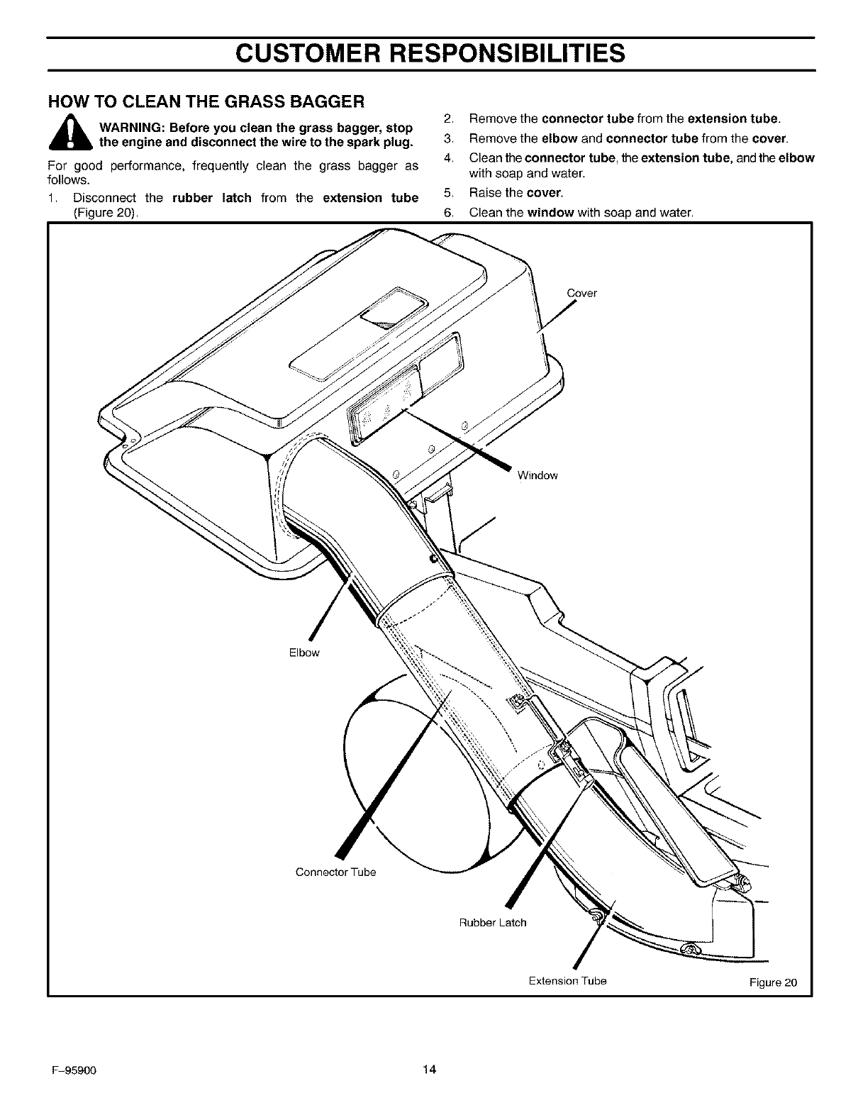
CUSTOMER RESPONSIBILITIES
HOW TO CLEAN THE GRASS BAGGER
_lb WARNING: Before you clean the grass bagger, stop
the engine and disconnect the wire to the spark plug.
For good performance, frequently clean the grass bagger as
follows.
1. Disconnect the rubber latch from the extension tube
(Figure 20).
2. Remove the connector tube from the extension tube.
3. Remove the elbow and connector tube from the cover.
4. Clean the connector tube, the extension tube, and the elbow
with soap and water.
5. Raise the cover.
6. Clean the window with soap and water.
Cover
Window
Elbow
Connector Tube
Rubber Latch
Extension Tube Figure 20
F-95900 14

REPAIR PAR !'S
F-95900 15
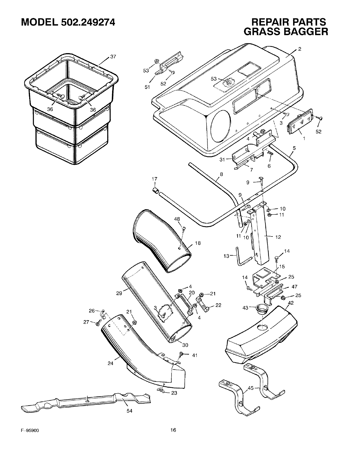
MODEL 502.249274 REPAIR PARTS
GRASS BAGGER
31
5
52
1
17
10
11 10 12
24
29"
21\
23
_7 14
t15
14 25
47
54
F-95900 16

MODEL 502.249274
Key
No. Description
1 Window
2 Cover
3 Screw
4 Locknut
5 Tube, "U"
6 Pin, Hair
7 Pin, Hinge
8 Tube, Center
9 Bolt, Special
10 Lockwasher
11 Nut, Hex
12 Channel Assembly
13 Pin, Channel
14 Bolt, Hex
15 Hitch Assembly
17 Cap, End
18 Elbow
20 Handle, Connector Tube
21 Locknut, Flange
22 Latch, Rubber
23 Wingnut
24 Tube, Chute Extension
25 Locknut
26 Pin, Latch
27 Bolt, Carriage
29 Tube, Connector
30 Screw
31 Hinge, Cover
36 Fastener, Plastic *
37 Containers (Quantity 2)
41 Bolt, Carriage
42 Shell, Front Weight
43 Plug, Front Weight
45 Bracket, Front Weight
47 Bracket, Support
48 Screw
51 Handle, Plastic
52 Screw
53 Nut, Hex
54 Blade, High-Lift
- Owner's Manual (English)
- Owner's Manual (Spanish)
PaN No.
54575
54577
STD512505
STD541425
54410E701
STD624003
54407Z
54412E701
6x93Z
STD551131
STD541131
54422E701
54408Z
STD523107
54499E701
24862
54415
54416E701
STD541425
54695
STD541631
54519
STD541431
54563
STD532507
54555
STD512510
54398E701
193xl
54727SE
STD533107
55442
24863
54551E701
54562E701
26x239
54537
STD511007
STD541410
56246E701
F-95900
F-95900 SP
REPAIR PARTS
GRASS BAGGER
Mfg. No.
4x24
15x66
31x6
18x15
15x32
lx91
15x89
14x83
15x76
2x39
4x71
2x64
4x21
15x81
*Included with Key No. 37.
F-95900 17

_D
O
03
JSLOPE GUIDE
.... •,--..7.b'..D_(_z_,,._ SIGHT AND HOLD THIS GUIDE LEVEL WITH A VERTICAL TREE,
r ....... _S A CORNER OF A STRUCTURE, A POWER LINE POLE, OR A FENCE.
.........!..........................................................
1
I
I10 DEGREES
IOperate a walk-behind mower
across the face of slopes,
never up or down slopes.
15 DEGREES
Operate a riding mower
up or down slopes, never
across the face of slopes.
On a riding mower to determine if a slope is safe to mow: (1) disengage the blade(s), (2) put the unit in reverse, and (3) try to back straight up the
slope. If you can back up the slope, it is generally safe to mow. However, if you do not feel safe, or if you are not completely sure, use this guide
and do not mow a slope that is greater than 15 degrees. If the riding mower is used with a pull-behind or rear mounted attachment,
do not operate the unit on a slope that is greater than 10 degrees.
A 15 degree slope is a hill that increases in height at approximately 2.5 feet in 10 feet.
A 10 degree slope is a hill that increases in height at approximately 1.7 feet in 10 feet.
Use extreme care at all times, and avoid sudden turns or maneuvers. Follow other instructions in this manual for safety in mowing on
slopes. Operate a riding mower up or down slopes, never across the face of slopes. Operate a walk-behind mower across the face
of slopes, never up or down slopes. Use extra care when operating on or near slopes and obstructions.
CUT HERE TO USE SLOPE GUIDE
INDEX
C
Container Linings, 12
G
Grass Bagger
Clean, 14
Connector Tube, 10
Containers, 11,12
Cover, 8
Extension Tube, 9
Frame Assembly, 7
Operation, 13
O
Operation, Grass Bagger, 13
S
Safety Rules, American National Standard Institute, 4_5
Service And Adjustment, Grass Bagger, 14
Slope Guide, 18
W
Weight, Install, 12
F-95900 19
SF/A/RS
owner's
manual
Model No.
502.249274
How To Order
Repair Parts
CRRFTSMRN
GRASS BAGGER
REAR ENGINE RIDER
The Model Number for the grass bagger isfound on a decal attached to the unit.
Always give the Model Number when you call for service or order repair parts
for your unit.
Repair parts can be ordered from any Sears Service Center/Department and
most Sears Stores.
WHEN ORDERING REPAIR PARTS, ALWAYS HAVE THE FOLLOWING
INFORMATION AS SHOWN IN THIS LIST.
• PRODUCT- GRASS BAGGER
• MODEL NUMBER 502.249274
• PART NUMBER
• PART DESCRIPTION
Your Sears merchandise has added value when you consider Sears has service units
nationwide staffed with Sears trained technicians. Sears technicians have the necessary
parts, tools and equipment to meet the Sears pledge, "We Service What We Sell".
F-95900 Sears, Roebuck and Co., Hoffman Estates, IL. 60179 U.S.A. Printedin U.S.A.
