Craftsman 536252570 User Manual HYDROSTATIC DRIVE TRACTOR Manuals And Guides LR708009
CRAFTSMAN Lawn, Tractor Manual LR708009 CRAFTSMAN Lawn, Tractor Owner's Manual, CRAFTSMAN Lawn, Tractor installation guides
User Manual: Craftsman 536252570 536252570 CRAFTSMAN HYDROSTATIC DRIVE TRACTOR - Manuals and Guides View the owners manual for your CRAFTSMAN HYDROSTATIC DRIVE TRACTOR #536252570. Home:Lawn & Garden Parts:Craftsman Parts:Craftsman HYDROSTATIC DRIVE TRACTOR Manual
Open the PDF directly: View PDF ![]() .
.
Page Count: 72

iiii iii
OWNER'S
MANUAL
MODEL NO.
536.252570
Caution:
Read and follow
all Safety Rules
and Instructions
Before Operating
This Equipment
®
16.5 HP OHV
ALL-WHEEL STEER
43" MOWER DECK
HYDROSTATIC DRIVE
LAWN TRACTOR
o Ass-ernbiy•
=operation
° Customer Responsibilities
° Service and Adjustment
o Repair Parts
ii ii illll
,,,H,i i iiiiiiii1,1
SEARS, ROEBUCK AND CO., HOFFMAN ESTATES, IL 60179
iiml , ,,,,,,,,,,
............................ SAFETY RULES............................................................
ill,, ,,, Lira
Sate Operation Practices for Riding Vehicles As Recommended by American National Standards Institute
WARNING: This cutting machine is capable of amputating hands and feet and throwing objects. Failure to observe
the following safety instructions could result in serious injury or death to the operator or bystanders
GENERAL OPERATION:
1. Read, understand and follow all instructions in the Owner'stOperator's Manual, on the machine, the engine and with any
attachments before starting,
2, Only allow responsible adults familiar with the instructionsto operate the machine
3 Clear the area of objects such as rocks, toys, wire, etc, which could be picked up and thrown by the blade
4 Be sure the area is clear of other people before mowing Stop the machine if anyone enters the area
5 Never carry passengers.
6, Disengagepowertothemoweroranyattachmentsbeferebackingup. Do not mow in reverse untess absolutely neces_ary Aiways
look down and behind before and while backing
7, Be aware of the direction the mower discharges Do not point discharge from the mower at anyone or at places where people may
be, Do not operate the mower without either the entire grass bagger or the mower guard in-place
8, Slow down before turning.
9, Never leave a machine unattended with the engine running Aiways disengage the blade(s), set the parking brake, stop the engine
and remove the key before dismounting
10. Disengage power to attachment(s) when transporting or not in use Disengage the btade(s) when not mowing
11.. Stop the engine before removing the grass bagger or unclogging the chute
12 Mow only in daylight or good artificial light
I3, Do not operate the machine whife under the influence of alcohol or drugs or when very tired
14 Watch for traffic when operating near or crossing roadways
15, Use extra caution when tending or unloading the machine when using a trailer or truck for transporting
16, Disengage all attachment clutches and shift into Neulraf before attempting to start the engine (on gear drive models)
17 Disengage all attachment ciutches betore attempting to start the engine (on hydro modefs)
18 Always wear safety glasses or an eye shield when you operate the unit to protect your eyes from foreign objecls that can be thrown
from the unit Atways wear eye protection when you make an a_djustment or repair to the machine
19 Use care when p ull!ng Ioads or using heavy equipment
a Use only approved drawbar hitch points
b Limit loads to those you can safely control.
c Do not turn sharply Use care when backing
d, Use counterweights when suggested in the Owner's/Operator's Manuai
SLOPE OPERATION:
Slopes and rough terrain are major lactors related to loss of control and tip over accidents which can result in severe injury
or death. ALL slopes require extra caution,. If you cannot back up the slope or if you feel uneasy on the slope, do not mow
it. See the "Slope Guide" in the back of this book to check for safe operation.
DO
1 Mow up and down slopes, not across
2.. Remove obstacles such as rocks, limbs, etc
3 Watch for hates, ruts or bumps Uneven terrain could overturn the machine "Tall grass can hide obstacles"
4 Use stow speed. Choose a low enough gear so that you will not have to stop or shift while on the slope Ion gear crave models)
5 Use slow speed on slopes Do not make sudden speed changes, (on hydro models) .......
6. Follow the manufacturer's recommendations for wheel weights or counterweights to improve stability
7, Use extra care with grass baggers or other attachments, they can change the stability of the machine
8. Keep ali movement on the slopes slow and gradual Do not make sudden changes in speed or direction
9 Avoid starting or stopping on a slope If tires lose traction, disengage the blades and proceed slowly straight down ;he slope

SAFETY RULES
DO NOT
1_ Do not turn on slopes unless absolutely necessary, then only turn slowly and graduafly downhill, if possible
2, Do not mow near drop-offs, ditches or embankments A wheel over the edge or an edge caving in could cause a sudden overturn
and an injury or death,.
3, Do not mow on wet grass. Reduced traction could cause sliding
4. Do not try to stabilize the machine by putting your foot on the ground
5. Do not use a grass catcher or other rear mounted accessories on steep slopes_(greater than 10 degrees}
CHILDREN:
Tragic accidents can occur if the operator isnot alert to the presence of children° Children are often attracted tothe machine
and the mowing actlvity_ NEVER assume that children will remain where you last saw them,
1o Keep children out of the mowing area and in the watchful care of an adult other than the operator
2_ Be alert and turn the engine oil if children enter the area.
3 Before and when backing, look behind and down for small children
4, Never carry children or any passengers They may fall off and be seriously injures or interIere with the sale operation ol the
machine.
5. Never allow children to operate the machine Instruct children in the dangers ol the machine
6. Use extra care when approaching blind corners, shrubs, trees or other objects that may obscure vision
SERVICE:
1 Use extra care when handling gasoline and other luels Fuels are llammable and the vapors are explosive
a, Use only an approved container
b Never remove the gas cap or add fuel with the engine running Allow the engine to cool for several minutes before refueling
Do not smoke
c Never refuel the machine indoors
d, Never slore the machine with fuel in the tank or fuel container inside where there is an open flame, such as a water heater
2 Never start or run the engine inside a closed area
3., Keep all nuts and bolts, especiatly the blade attachmenl nuts tight Frequently check th_ blade(s) for wear or damage such as
cracks and nicks A blade that is bent or damaged musf be immediately replaced with an original equipment blade(s) from an
authorized service dealer. For safety, replace the blade(s) every two years Keep the equipment in good condition
4. Never tamper with the safety devices. Check their proper operation regularly
5, To reduce fire hazards keepthe machine lree of grass, leaves or olherdebris build-up Clean up oil or fuel spills Allow the machine
to cool before storing
6 Stop and inspect the equipment if your strike an object Repair, if necessary, before restarting
7., Never make adjustments or repairs with the engine running The carburetor can be adjusted with the engine Funning Do not
change the engine governor settings or over-speed the engine
8, Grass bagger components are subject to wear, damage and deterioration, which could expose moving parts or allow objects to
bethrown, Forsiorage, alwaysmakesurethegrassbagisempty Frequentlycheckcomponenlsandreplacewilhmanufacturer's
recommended paris when necessary
9, Mower blade(s) are sharp and can cut Wrap the blade(s) or wear gloves and use extra caution when servicing them or the mower
deck area.
10. Check the brake operation frequently Adjust and service as required
! 1, Wait for all movement to slop before servicing any part o! the unit
ENVIRONMENTAL AWARENESS
. • Do not fit! the engine's luel tank completely full
• Drain fuel for off-season storage
• Use oniy unleaded gasoline
• Service the air cleaner regularly
•Change oil regularly, Use 30W oil in summer
•Tune-upthe engine regularly
OKeep equipment in efficient operating condition
ODispose of used engine oil properly
Look for this symbol to indicate important safety precautions. This symbol indicates Attent'on? Become Alert"
Your Safety Is At Risk.,"

CONGRATULATIONS on your purchase of a Sears
Craftsman Tractor. It has been designed, engineeted
and manufactured to give you the best possible depend-
ability and performance_
Should you experience any problem you cannot easily
remedy, please +contact your nearest Sears Service
CentedDepartmenL We have comPetent, well-trained
technicians and the proper tools to service or repair this
unit..
Please read and retain this manual. The instructions will
enable you to assemble and maintain your tractor
propedy Always observe the "SAFETY RULES."
MODEL
NUMBER 536 25257"0
SERIAL
NUMBER
'DATE OF
PURCHASE
THE MODEL AND SERIAL NUMBERS WILL BE
FOUND ON A PLATE UNDER THE SEAT.
YOU SHOULD RECORD BOTH SERIAL NUMBER
AND DATE OF PU RCHASE AND KEEP IN A SAFE
PLACE FOR FUTURE REFERENCE
MAINTENANCE AGREEMENT
A Sears Maintenance Agreement is available on this
product+ Contact your nearest Sears Store for details
CUSTOMER RESPONSIBILITIES
= Read and observe safety rutes.
o Follow a regular schedule in maintaining, caring for and
using your unit.
o Follow the instructions under "Customer Responsi-
bilities" and "Storage" sections of this manual+
PRODUCT SPECIFICATIONS
HORSE POWER: 16+5
GASOLINE 2 GALLONS
CAPACITY: UNLEADED REGULAR
OIL 64 oz. w/filter SAE 30 - above 32°F.
55 oz. w/o_ter 5W - 30* - below32_F+
SPARK PLUG : Champion N4C
(GAP .030 in.)
VALVE Intake: +004in+
CLEARANCE: Exhaust: +004 In+.
GROUND FORWARD 0-5.70 MPH
REVERSE: 3.70 MPH
TIRE PRESSURE: FRONT: 14PSI
REAR: 10 PSI
CHARGING SYSTEM:
LIGHTING (AC SIDE) t 18 VOLTS @ 3300 RPM
CHARGING (DCSIDE) 2.8 AMPS @ 125 VOLTS
BLADE BOLT TORQUE: 30-35 FT+ LBS+
WARNING: This unit is equipped with an internal com-
bustion engine and should not be-used on or near any
unimproved forest-covered, brush-covered or grass-
covered land unless the engine's exhaust system is
equipped with a spark arrester meeting applicable local
or state laws (if any)If a spark arrester is used, it should
be maintained in effective working order by the operator
In the state of California the above is required by law
(Section 4442 of the California Public Resources Code)
Other states may have similar iaws_ Federal taws apply
on federal lands+A spark attester (part number 336967)
for the muffler is available through your nearest Sears
Authorized Service Center
CRAFTSMAN ELECTRIC START RIDING EQUIPMENT
LIMITED TWO YEAR WARRANTY ON ELECTRIC START RIDING EQUIPMENT
For two (2) years from the date of purchase_ifthisriding equipment is maintained, lubricatedand tuned-up according to the
instructions inthe owner's manual, Sears willrepair or replace, any pa_s found to be defective in materia_or workmanship
This warranty does not cover:
• Expendable items which become worn during normal use, such as btades, spark plugs_air cteaners and belts
• Tire replacement or repaircaused by punctures fromoutside objects, suchas nails,thorns, stumps, or gfass_
• Repairs necessary because of operatol:abuse, negligence, improperstorage or accident ar the failure to maintain the
equipment according tothe instructions contained inthe operator*smanual+
• Riding equipmentused for commercial or rental purposes.
LIMITED 90 DAY WARRANTY ON BATTERY
For 90 days from the date of purchase, if any battery included with this riding equipment proves defective in materiat or
workmanship _d our testing determines thebattery wilt not hold a charge, Sears w_ltreplace the battery at no charg e
WARRANTY SERVICE IS AVAILABLE BY RETURNING THE RIDING EQUIPMENT TO THE NEAREST SEARS SERVICE
CENTER/DEPARTMENT IN THE UNITED STATES.
This warranty gives you specific legal rights, and you may also have other rights which may vary from state to
state.
SEARS, ROEBUCK AND CO, D/817WA, HOFFMAN ESTATES, IL 60179
lUll in
i lUlll n
inll ii _
SAFETY RULES .....................................................................2-3
PRODUCT SPECIFICATIONS .................................................4
CUSTOMER RESPONSIBILITIES ....................... 4, 17_22
WARRANTY .......................................................................... 4
TABLE OF CONTENTS ...................................................... 5
INDEX ............................................................................................ 5
TRACTOR ACCESSORIES ............................................... 6
CONTENTS OF HARDWARE PACK ..................................7
ASSEMBLY ..............................................................................8-11
OPERATION ................................................................. 12-16
i lU lUllnnll iii iii iiiiiiil,lllrll
TAB,LE OF CONTENTS ...............................
SERVICE AND ADJUSTMENTS ..................... 23-33
TROUBLE SHOOTING ....................................... 34-35
STO RAGE ........................................................................ 36
SLOPE GUIDE ..................................................................... 37
REPAIR PARTS ............................................................. 38-62
ENGINE REPAIR PARTS ......................................... 63-68
TRANSAXLE REPAIR PARTS .............................. 69-70
NOTES .................................................................................... 71
PARTS ORDERtNCdSERVICE ...................................... 72
A
Accessories ......................................................6
Adjustments:
Blade Brake ............................................26
Blade Drive Belt .....................................26
Carburetor ...............................................33
Mower Deck Leveling:
Front-To-Rear ..................................25
Side-To-Side ..........................................24
Mower Deck Height ..............................25
Seat .............................................................28
Steering Gear ................................... 30
Throttle Control Cable .......................33
Tractor Brake ........................................29
Tractor Drive Belt .............................. 27
Transmission Control .........................31
Assembly ...............................................8-11
B
Battery:
Charging ..........................................9-I 0
Cleaning ....................................................20
Installation ..................................................11
Preparation .............................................9
Starting with Weak Battery ...............32
Storage ........................................................36
Terminals ............................................20
Belt:
Tractor Drive
RemovalfReplacement ......................28
Mower Blade Drive
Removal!Replacement ......................27
Blade:
Sharpening ............................................20
Replacement .......................................19
Brake Adjustment .....................................29
C
Carburetor Adjustment ..........................33
Controls, Tractor .....................................12
Customer Responsibilities ..........4, 17-22
Air Cleaner ..............................................22
Battery ........................................................20
BeIts ........................................................20
Blade .................................................19-20
Brake Operation ...................................19
Cleaning .......................................... 22
Cooling System, Engine ................ 21
Engine Oil ........................................4, 21
Fuel Filter ........................................ 22
Lubrication Chart .................................18
Muffler ..................................................22
Mulching Plug ............................. 20
Schedule ..................................... 17
Spark Plugs .................................... 22
Tire Care ................................10, 19, 30
Transaxle Cooling .................... 20
INDEX
Cutting Height, Mower ...........................14
E
Electrical:
interlocks and Relays ..........................32
Engine:
Air Cteaner ..........................................22
Air Intake Screen ................................21
Cooling System ............................... 21
Oil Change ...........................................21
Oil Level ............................................15, 21
Oil Type .............................................4, 21
Preparation .........................................15
Starting ....................................................15
Storage .......................................... 36
F
Filter:
Fuel ............................................................22
Fuel:
Type ..................................................4, 15
Storage ..................................................36
H
Headlights ..............................................32
Hood Removal/installation ..................33
L
Leveling, Mower Deck ...................24-25
Lubrication:
Chart ....................................................18
M
Mower:
Adjustment, Front-To-Rear ...............26
Adjustment, Side-To-Side .................24
Adjustment, Deck Height ....... ;.........25
Blade Sharpening ..................................20
Blade Replacement .......................... 19
Brake Adjustment ............................ 29
Cutting Height ................................... 14
Installation .................. ................. 23-24
Operation ........................................... 14
Removal .......................................... 23
Mowing Tips ................................................ 16
Mulching Mowing Tips ......................... 16
Muffler ................................................... 22
Spark Arrestor ............................. 4, 22
Mulching Plug:
Installation .................................... 20
O
Oil:
Cold Weather Conditions ................ 21
Engine ............................................. 21
Storage ............................................... 36
Type ............................................. 4, 21
Operation ...................................... 12-16
Operating Your Mower .................... t4
Options:
Accessories ....................... 6
Spark Arrestor ................................4, 22
P
Parking Brake ...........................................13
Parts Bag .........................................................7
Product Specifications ..............................4
R
Repair Parts:
Engine ...........................................63-68
Tractor ........................................ 38-62
Transaxle ............................. 69-70
S
Safety Rules ...........................................2-3
Service and Adjustments ........... 23-33
Battery .............................................. 32
Blade Brake ...................................... 26
Carburetor .................................................33
Control Lever ..........................................31
Fuse ............................................................32
Hood Removaltlnstallation ....................33
Headlight bulb .......................................32
Interlocks and Relays ..........................32
Mower Biade Drive Belt:
Adjustment .............................................26
Removal/Replacement ....................27
Mower Deck Level Adjustment:
Front-To-Rear ............................... 25
Side*To-Side .....................................24
Mower Deck Height ........................ 25
Mower Deck Installation ........... 23-24
Mower Deck Removal ................... 23
Seat .............................................. 28
Steering Gear .............................. 30
Throttle Control Cable .......................33
Tractor Brake .......................................29
Tractor Drive Belt:
RemovaltReplacement ............ 27-28
Transmission Controf ................... 31
Wheel Repair ................................ 30
Spark Plugs .............................. : ..........22
Specifications .........................................4
Starting the Engine ............................. 15
Steering Wheel .................................. 8
Stopping the Tractor ............................ 13
Storage ...................................... 36
T
Table of Contents ......................... 5
Throttle Controt Cable
Adjustment ............................ 33
Tires ........................... 1o, ! 9,30
Tire Pressure .............. 4, 10, 19
Transaxle:
Cooling .................................. 20
Troubleshooting Points ....... 34-35
W
Warranty ................. 4
ACCESSORIES AND ATTACHMENTS
These accessories and attachments were available when the unit was purchased They are also available at most Sears retail
outlets, catalog and service centers, Most Sears stores can order these items for you when you provide the model number of your
tractor.
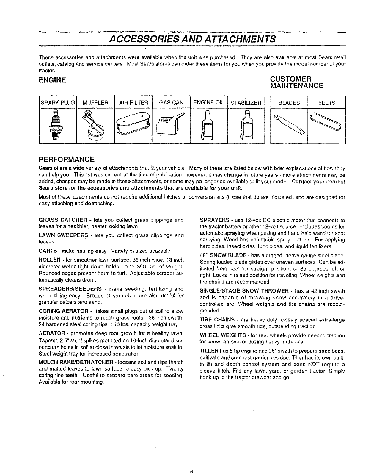
ENGINE CUSTOMER
MAINTENANCE
SPARK PLUG AIR FILTER BLADESMUFFLER GAS CAN ENGINE OIL STAE_iLIZER BELTS
PERFORMANCE
Sears offers a wide variety of attachments that fit your vehicEe Many of these are listed below with brief explanations of how they
can help you, This list was current at the time of publication; however, it may change in luture years - more attachments may be
added, changes may be made in these attachments, or some may no longer be available or fit your model Contact your nearest
Sears store for the accessories and attachments that are available for your unit°
Most of these attachments do not require additional hitches or conversion kits (those that do are indicated) and are designed for
easy attaching and dealtaching
GRASS CATCHER -Iets you collect grass clippings and
leaves for a healthier, nearer looking lawn
LAWN SWEEPERS -tots you collect grass clippings and
_eaves°
CARTS - make hauling easy. Variety of sizes available
ROLLER - for smoother lawn Surface, 36-inch wide, 18 inch
diameter water tight drum holds up to 390 ibs of weight
Rounded edges prevent harm to turf Adjustabfe scraper au-
tomatically cleans drum.
SPREADERS/SEEDERS *make seeding, fertilizing and
weed kilting easy. Broadcast spreaders are also useful for
granular deicers and sand.
CORING AERATOR -takes smalt piugs out of soil to allow
moisture and nutrients to reach grass roots 36-inch swath
24 hardened steal coring tips 150 Ibs capacity weight tray
AERATOR - promotes deep root growth for a healthy lawn
Tapered 2,5" steel spikes mounted on 10-inch diameter discS
puncture holes in soi{ at close intervals to let moisture soak in
Steel weight tray for increased penetration
MULCH RAKE/DETHATCHER - loosens soil and flips thatch
and matted leaves to lawn surface to easy pick up Twenty
spring tine teeth. Useful to prepare bare areas for seeding
Available for rear mounting,
SPRAYERS - use t2:vott DC electric motor that connects to
the tractor battery or other 12-veil source Includes booms for
automatic spraying when pulling and hand held wand for spot
spraying Wand has adjustable spray pattern For applying
herbicides, insecticides, fungicides, and liquid tertilizers
48" SNOW BLADE -has a rugged, heavy gauge steel blade
Spring ioaded blade glides over uneven sudaces Can be ad-
justed from seat for straight position, or 35 degrees left or
right Locks in raised position for traveling Whee_ weights and
tire chains are recommended
SINGLE*STAGE SNOW THROWER - has a 42-inch swath
and is capable of throwing snow accurately in a driver
controlled arc Wheel weights and tire chains are recom-
mended,
TIRE CHAINS - are heavy duty: closely spaced extra-large
cross links give smooth ride, outstanding traction
WHEEL WEIGHTS - for rear wheels provide needed tract=on
for snow removal or dozing heavy materials
TILLER has 5 hp engine and 36 '_swath to prepare seed beds.
cultivate and compost garden residue,, Tiller has its own built-
in llft and depth control system and does NOT require a
sleeve hitch. Fits any lawn, yard. or garden tractor Simply
hook up to the tractor drawbar and go!
........... ............ CONTENTS' = =,HH =HH= = OF HARDWARE'="='"=' == PA_ ....................... _-"
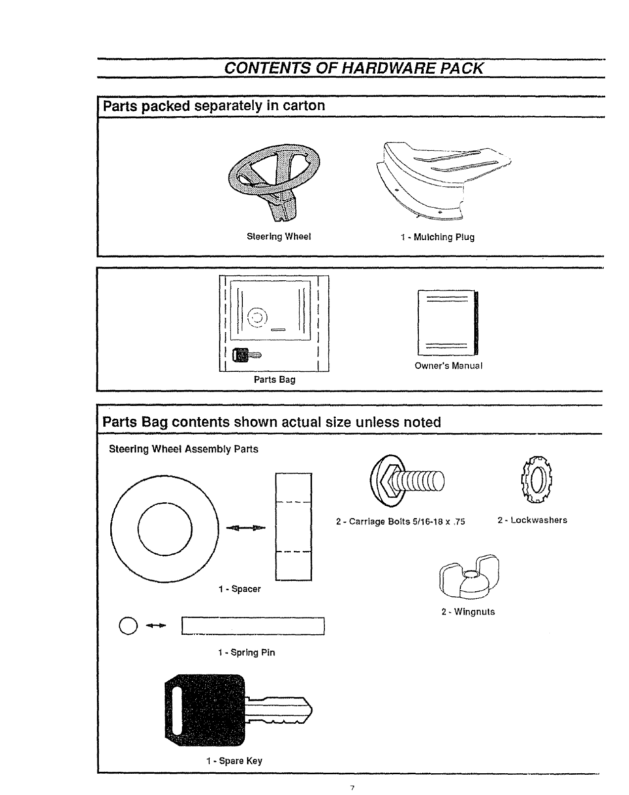
Parts packed separately in carton
........................... ,, ,==,,,,,,,,, JL =H,=,,,,,, J, ,,,, , H L ,,,,,,,,,, , ,=,,, =
Steering Wheel 1 - Mulching Plug
H = , ,H, =,== ==,,,,, , ,,,H,,,, ,, ,H,= ==,,,= , .............................................
IL
Parts Bag
,=, ,, H,,,,,,,, =,,,,
.......I_ Owner's Manual
,,,,,,1,,,,, = 1,1 ,,,,,,,,,,,,,1 L, ,,,,,,,,,,, L,,,,,,, ,,,,,, ,, ,, ,,,,, ,,u,, ,,
H, ,, ,,,,,1,1 _H,J,, =,u ,, L,,,, 1, ,L , ,,,,,uuuuu,,,,,,,.
Parts Bag contents shown actual size unless noted
11,1 H = ,Hi=,,,, , ,1 ,,,,,,,,,,,,,,,11,, ,, ,, ,,,,, L=,,,,,,,, ,1,,,, ,,,,, ,,,
Steering Wheel Assembly Parts
2 - Carriage Botts 5116-18 x,75
0
2 - Lockwashers
J2- Wingnuts
t - Spring Pin
1- Spare Key
=,,,,,,, ,, =, ,,,,
ASSEMBL Y
TOOLS REQUIRED FOR ASSEMBLY
Asocket wrench witl make assembly easier Standard wrench
sizes are listed,,
(1) Pliers
(1) Utility knife
(1) Screwdriver (Small Phillips with a 1/4 inch shank)
(1) Hammer
(1) Tire pressure gauge
(2) 7/16 inch wrenches
(2) I/2 inch wrench
(I) Tape measure
When right and left hand is mentioned in this manual, it
means when you are in fhe operating position (seated behind
the steering wheel),
TO REMOVE TRACTOR FROM
CARTON
UNPACK CARTON
•Open top flaps Remove cardboard from top of wood
crate
e Remove top frame from carton,
•Carefully remove contents of parts box (see CONTENTS
OF HARDWARE PACK on page 7).
• Cut down all four corners with a utility knife and carefu!ly lay
down side panels.
eDiscard cardboard from alongside tractor.
eRemove cardboard from discharge chute
eRemove plastic wrap from seat and hood.
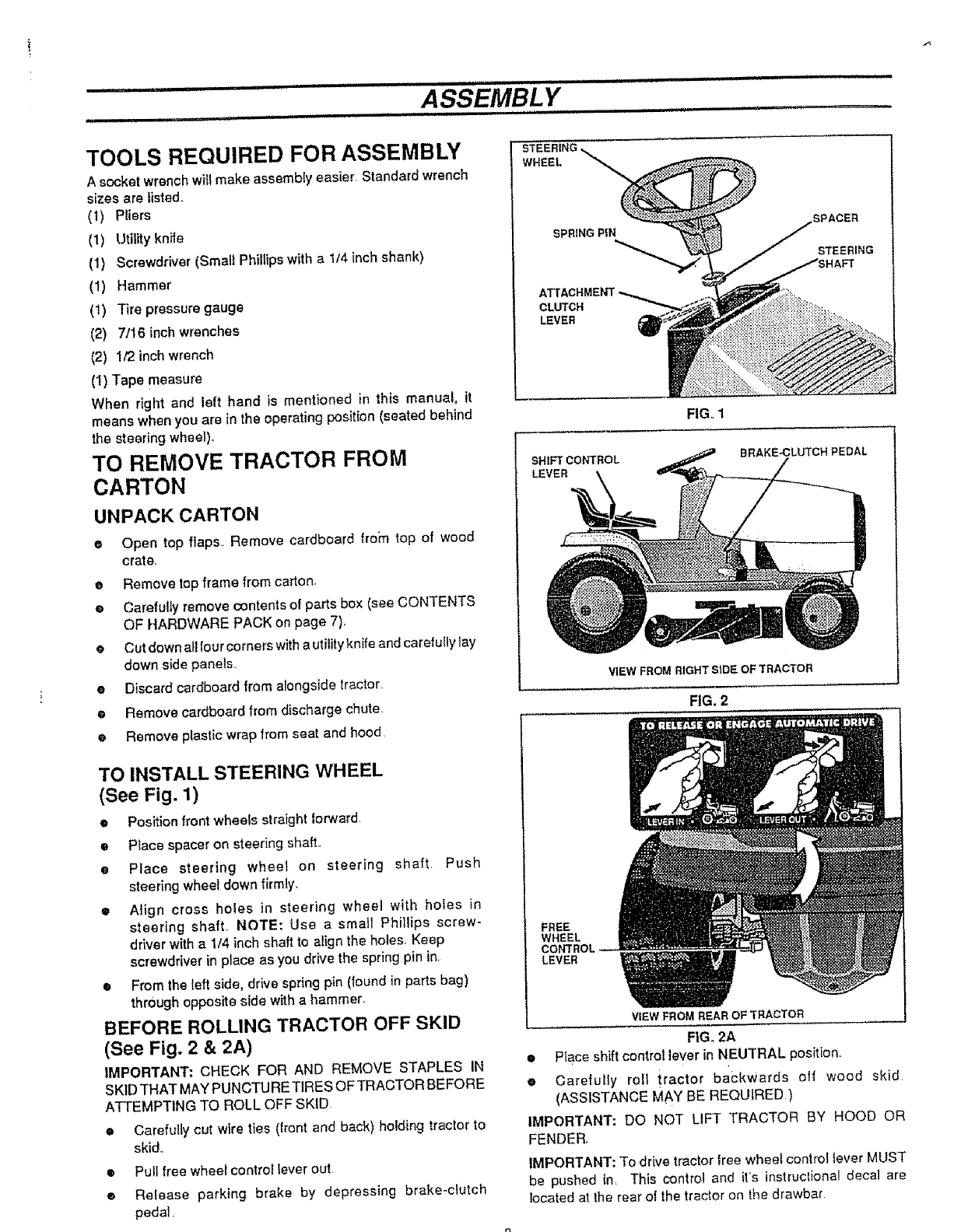
TO INSTALL STEERING WHEEL
(See Fig. 1)
•Position front wheels straight lorward,
•P_ace spacer on steering shaft,,
ePlace steering wheel on steering shaft Push
steering wheel down firmly,
•Afign cross holes in steering wheel with holes in
steering shaft, NOTE: Use a stoat] PhilJips screw-
driver with a 1/4 inch shaft to align the holes. Keep
screwdriver in place as you drive the spring pin in,
•From the left side, drive spring pin (found in parts bag)
through oppos_e side with ahammer,
BEFORE ROLLING TRACTOR OFF SKID
(See Fig. 2 & 2A)
IMPORTANT: CHECK FOR AND REMOVE STAPLES IN
SKID THAT MAY PUNCTURE TIRES OF TRACTOR BEFORE
ATTEMPTING TO ROLL OFF SKID.
eCarefully cut wire ties (front and back) holding tractor to
skid.
•Pull free wheel control lever out,
• Release parking brake by depressing brake-clutch
pedal
STEERING,
WHEEL
SPRING P_N SPACER
STEERING
CLUTCH
LEVER
SHIFT CONTROL
LEVER
FIG., 1
BRAKE.CLUTCH PEDAL
VIEW FROM RIGHT SiDE OF TRACTOR
FIG. 2
FREE
WHEEL
CONTROL
LEVER
VIEW FROM REAR OF TRACTOR
FIG, 2A
•Place shift control lever in NEUTRAL position.
eCarefully roll tractor backwards off wood skid
(ASSISTANCE MAY BE REQUIRED.)
IMPORTANT: DO NOT LIFT TRACTOR BY HOOD OR
FENDER,
IMPORTANT: To drive tractor free whee_ control tever MUST
be pushed in This control and it's instruclional decal are
located at the rear of the tractor on the drawbar
m
iH,IH,HH
II H
.......... ASSEMBLY
ii1,,i,ii ii1,1, ill l ii1,,,
CAUTION: Wear eye and face shield°
Wash hands or clothing immediately if
accidentally in contact with battery acid.
Do not smoke. Fumes from charged battery
acid are explosive.
Follow the CAUTIONSlocatedonthe battery.
Always wear gloves, clothing and goggles to
protect your hands, skin and eyes_
HOW TO SET UP YOUR TRACTOR
PREPARE BA'I-rERY
iMPORTANT: Before you attach the battery cables to the
battery, check the b.artery date code The battery date code tells
ifthe battery must be charged,
@Check the battery date coda on top of the battery,,
OIf the battery is put into use before this date, the battery
cables can be attached without charging the battery. See
TO ATTACH BATTERY CABLES
OIfthe battery is put into use after this date, the battery m_Jst
be charged. To charge see TO CHARGE BATTERY.
[_ Always connect positive (red) cable first. Con-
necting negative cable first can result in sparks
if the wrench touches any metal surface.
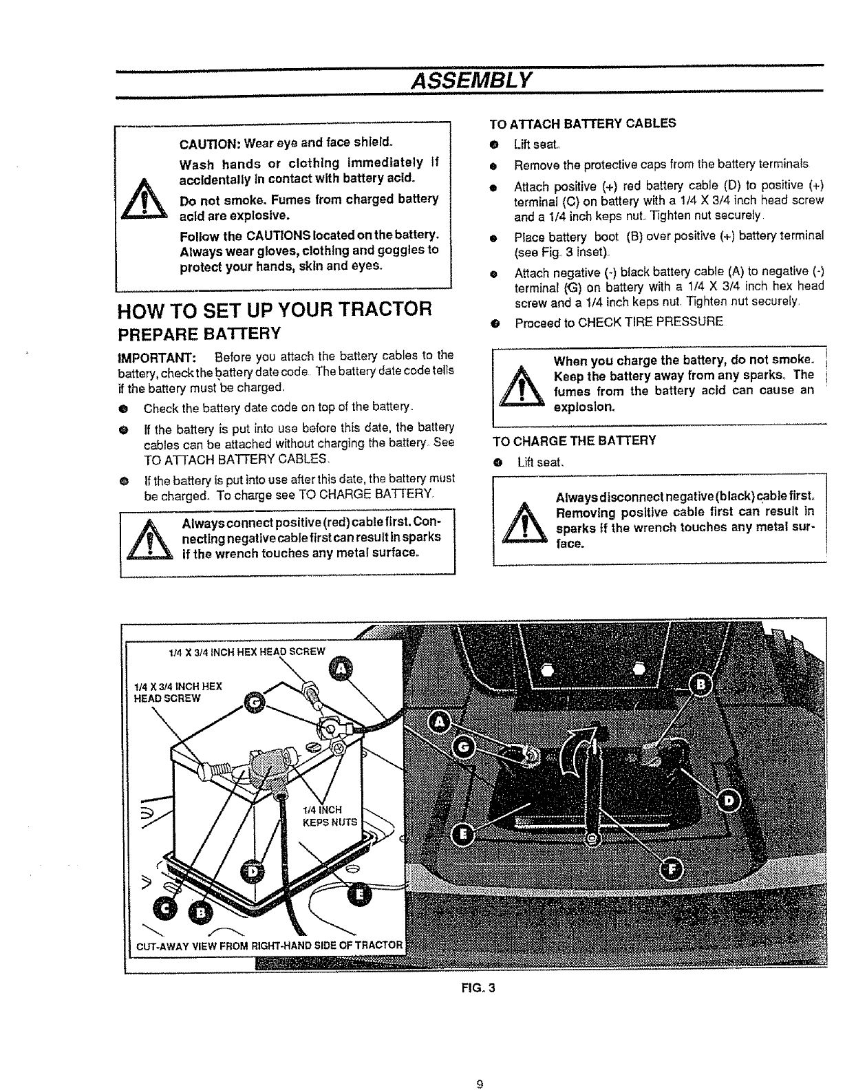
TO A3-rACH BATTERY CABLES
OLift seat,,
•Remove the protective caps from the battery terminals
•Atlach positive (+) red battery cable (D) to positive (+)
terminal (C) on battery with a 1/4 X 3/4 inch head screw
and a 1/4 inch keps nut.,T_ghten nut securety
e Place battery boot (B) over positive (+) battery terminal
(sea Fig, 3 inset),
eAttach negative (-) black battery cable (A) to negative (-)
terminal (<3) on battery with a 1/4 X 3/4 inch hex head
screw and a 1/4 inch keps nut, Tighten nut securely
o Proceed to CHECK TIRE PRESSURE
When you charge the battery, do not smoke, i
_t aep the battery away from any sparks,, The i
fumes from the battery acid can cause an
explosion.
TO CHARGE THE BATTERY
•Lift seat,
Alwaysdisconnect negative (black)cablefirst.
Removing positive cable first can result in
sparks tf the wrench touches any metal sur-
face.
114 X 3/4 iNCH HEX HEAD SCREW
t/4 X3/4 tNCH HEX
HEAD SCREW
iCUT-AWAYVIEWFROMRIGHT-HANDSIDEOFTRACTOR
I
FIG. 3
==HH,I,, =H I=IIHIIIH H=l'l=l Hl l II I=lll,,lll= =,,,,,,,=
ASSEMBLY
ii iiiii ii1,11 ii iii iii IlL =i=11== = = ..................... IIIU[i i H ii1,=1 iii i iiiii t
® Remove the protective caps from the battery terminals,
• Disconnect negative (-) black battery cable (A) with a
7/16" wrench.
•Slide battery boot (B) away from positive (+) battery ter-
minal (C) and disconnect positive (+) red battery cable
(D) with a7/16" wrench.
•Unhook rubber hold-down strap (F),
•Lift battery out of tractor,
• Place battery on level surface°
eUse a12 volt battery chargerto chargethe battery. Charge
at a rate of 6 amperes for one hour. If you do not have a
battery charger, have an authorized service center charge
the battery. Complete assembly section of this manual
while waiting for battery to charge,,
CHECK TIRE PRESSURE
For shipping purposes, the tires on your tractor were over-in-
flated at the factory° Correct tire pressure is important for best
cutting performance.
• Remove hub caps by placing two fingers in hole in each
cap and pulling them from the wheels.
eUse tire pressure gauge to check amount of air in tires
•Reduce tire pressure to PSI shown in "PRODUCT
SPECIFICATIONS" on page 4 of this manual,
e Replace hub caps. Position on wheels and p_]sh firmly,
CHECK FOR PROPER POSITION OF ALL
BELTS
eSee figures shown for replacing motion and mower blade
drive belts in SERVICE AND ADJUSTMENTS
section of this manual. Verify belts are routed correctly.
TO LEVEL MOWER DECK
For best cutting results the mower deck has been leveled at the
factory and should not require any adjustment, 1tin the event the
deck should need to be adjusted see TO LEVEL MOWER DECK
in the SERVICE AND ADJUSTMENTS section of this manual,
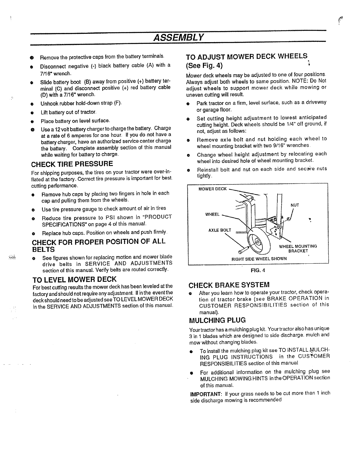
TO ADJUST MOWER DECK WHEELS
(See Fig. 4)
Mower deck wheels may be adjusted to one of four positions.
Always adjust both wheels to same position, NOTE: Do Not
adjust wheels to support mower deck while mowing or
uneven cutting will result,
•Park tractor on afirm, level surface, such as a driveway
or garage floor.
eSet cutting height adjustment to lowest anticipated
cutting height. Deck wheels should be 1/4" off ground, if
not, adjust as follows:
•Remove axle bolt and nut holding each wheel to
wheel mounting bracket with two 9/16" wrenches,
®Change wheel height adjustment by relocating each
wheel into desired hole of wheel mounting bracket.
•Reinstall bolt and nFJton each side and secL_re nuts
tightly,
WHEEL
AXLE BOLT
-\
NUT
WHEEL MOUNTING
BRACKET
RtGHT S;'DE WHEEL SHOWN
FIG. 4
CHECK BRAKE SYSTEM
• After you learn how to operate your tractor, check opera-
tion of tractor brake (see BRAKE OPERATION in
CUSTOMER RESPONSIBILITIES section of this
manual),,
MULCHING PLUG
Your tractorhas a mufching plug kit.rYour tractor also ha sunique
3 in 1 blades which are designed to slde discharge, mufch and
mow without changing blades,
• To instaitthe mulching plug kit see TO INSTALL .MULCH-
ING PLUG INSTRUCTIONS in the CUSI_OMER
RESPONSIBILITIES section of this manual
•For additional information on the muSching plug see
MULCHING MOWING HINTS inthe OPERATION section
of this manual
IMPORTANT: If your grass needs to be cut more than 1 inch
side discharge mowing is recommended
m ,==
i=t., ASSEMBL Y
m,,l= 11 ,,1,,,1 ,, ,1 = , ii ,,,
j_ Always connect positive (red) cable first. Con-
nectlng negative cable first can result insparks
If the wrench touches any metal surface,
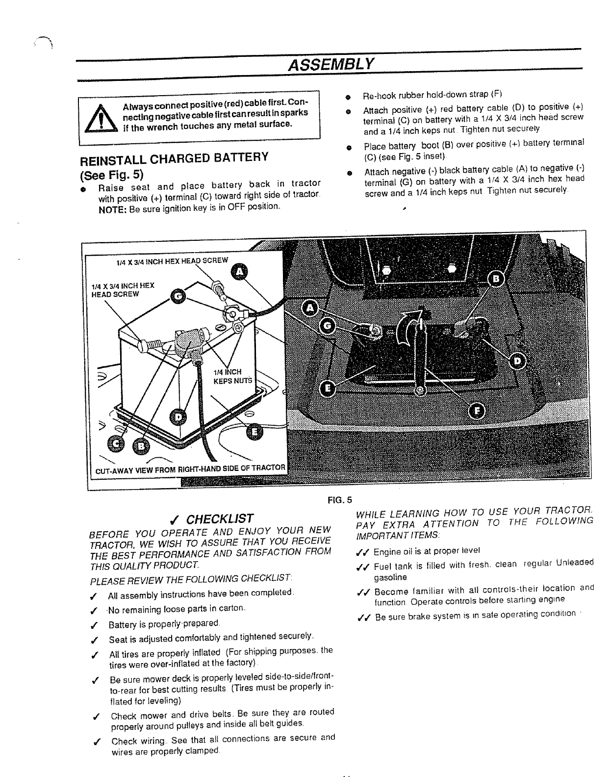
REINSTALL CHARGED BATTERY
(See Fig. 5)
•Raise seat and place battery back in tractor
with positive (+) terminal (C) toward right side of tractor
NOTE: Be sure ignition key is in OFF position°
e Re-hook rubber hold-down strap (F)
e Attach positive (+) red battery cable (D) to positive {+)
terminal (C) on battery with a I/4 X 3/4 inch head screw
and a 1/4 inch keps nut Tighten nut securely
ePlace battery boot (B) over positive (+_ battery terminal
(C) (see Fig 5inset)
eAttach negative (-) black battery cable (A) to negative (-)
terminal (G) on battery with a 1/4 X 3/4 inch hex head
screw and a 1/4 inch keps nut Tighten nut securely
114 X 3/4 INCH HEX HEAD SCREW
1/4 X 314 INCH HEX
HEAD SCREW
CUT-AWAY VIEW FROM RIGHT-HAND SIDE OF TRACTOR
FIG. 5
_" CHECKLIST
BEFORE YOU OPERATE AND ENJOY YOLIR NEW
TRACTOR, WE WISH TO ASSURE THAT YOU RECEIVE
THE BEST PERFORMANCE AND SATISFACTION FROM
THIS QUALITY PRODUCT
PLEASE REVIEW THE FOLLOWING CHECKLIST:
=z All assembly instructions have been compieted
,# No remaining loose parts in carton_
4" Batter:/is properly prepared
./ Seat is adjusted comfortably and tightened securely
4" AI( tires are property inflated (For shipping purposes, the
tires were over-inflated at the factory)
,# Be sure mower deck is properly leveled side-to-side/fronr-
to-rear for best cutting results (Tires must be properly in-
flated for {eveting)
,/ Check mower and drive belts Be sure they are routed
proper(y around pulleys and inside all belt guides
.f Check wiring See that all connections are secure and
wires are properly clamped
WHILE LEARNING HOW TO USE YOUR TRACTOR.
PAY EXTRA ATTENTION TO THE FOLLOWING
IMPOR TAN T ITEMS:
,i'.f Engine oil is at proper level
•/,/" Fuet tank is filled with trash, clean regular Unleaded
gasoline
,/'v" Become familiar with all controls-their location and
lunelion Operate controls before starting eng,ne
v',/ Be sure brake system is Jn sate operating condition
,,,,=,,i ,= ,= H=I,, ,= ,,,,, =,,= = = ===,=,=,,,,,,,,= =,U=U=,LI,,,., ='=' ='"", ='
OPERATION
.................................. ,,1 1,111 ,, 11 = ===,,,,N =HH, ,ill =,,H,,=,,,,_, =
KNOW YOUR TRACTOR
READ THIS OWNER'S MANUAL AND SAFETY RULES BEFORE OPERATING YOUR
TRACTOR
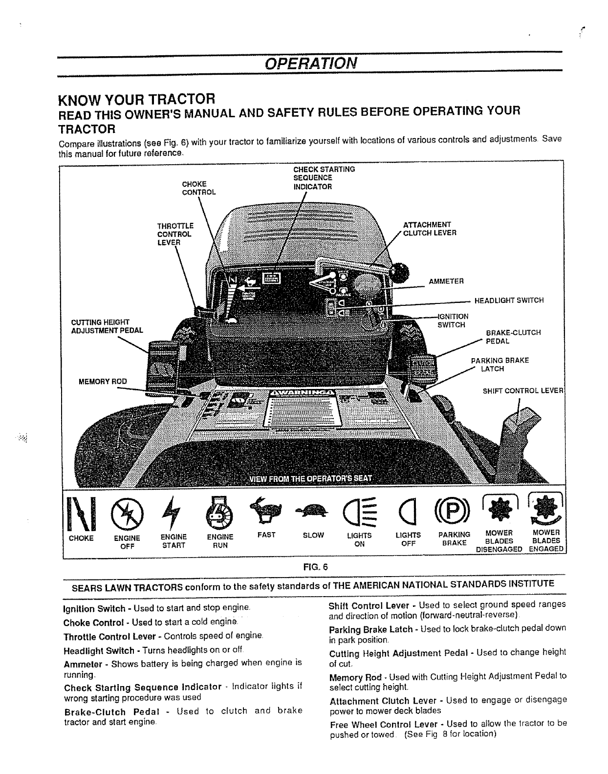
Compare illustrations (see Fig. 6) with your tractor to familiarize yourself with locations of various controls and adiustments Save
this manual for future reference°
CHECK STARTING
SEQUENCE
CHOKE INDICATOR
cONTROL
THROTTLE ATTACHMENT
CONTROL LEVER
LEVER
AMMETER
CUTTING HEIGHT NITION
ADJt_,TMENT PEDAL SW_TCH
HEADLIGHT SWITCH
BRAKE-CLUTCH
PARK}NG BRAKE
LATCH
MEMORY ROD
SHIFT CONTROL LEVE
CHOKE ENGINE ENGINE ENGINE FAST SLOW LIGHTS LIGHTS PARKING MOWER MOWER
OFF START RUN ON OFF BRAKE BLADES BLADES
DISENGAGED ENGAGED
FIGo 6
SEARS LAWN TRACTORS conform to the safety standards of THE AMERICAN NATIONAL STANDARDS iNSTITUTE
Ignition Switch - Used to start and stop engine,
Choke Conlrol -Used to start a cold engine
Throttle Control Lever - Controls speed of engine
Headlight Switch - Turns headlights on or off
Ammeter - Shows battery is being charged when engine is
running
Check Starting Sequence Indicator - Indicator lights if
wrong starting procedure was used
Brake-Clutch Pedal - Used to crutch and brake
tractor and start engine,
Shift Control Lever - Used to select ground speed ranges
and direction of motion (forward_neutraf-reverse)
Parking Brake Latch -Used to lock brake-clutch pedal down
in park position,
Cutting Height Adjustment Pedal -Used to change height
of cut.
Memory Rod - Used with Cutting Height Adjustment Pedal to
select cutting height
Attachment Clutch Lever - Used to engage or disengage
power to mower deck blades
Free Wheel Control Lever - Used to afiow the tractor to be
pushed or towed (See Fig 8 for location)
•!
.............................. OPERATION ......................................................
................... ,, =,J = = ,== =, ==,l ,, ,, =,,,, =,,,,,,,=
,, ,,,,,...,,,u iiiiiii i i1,. Ill II II hill iil,llr,l_ I iiiiiiiiiiiii I ,,11 ii iiiii i,
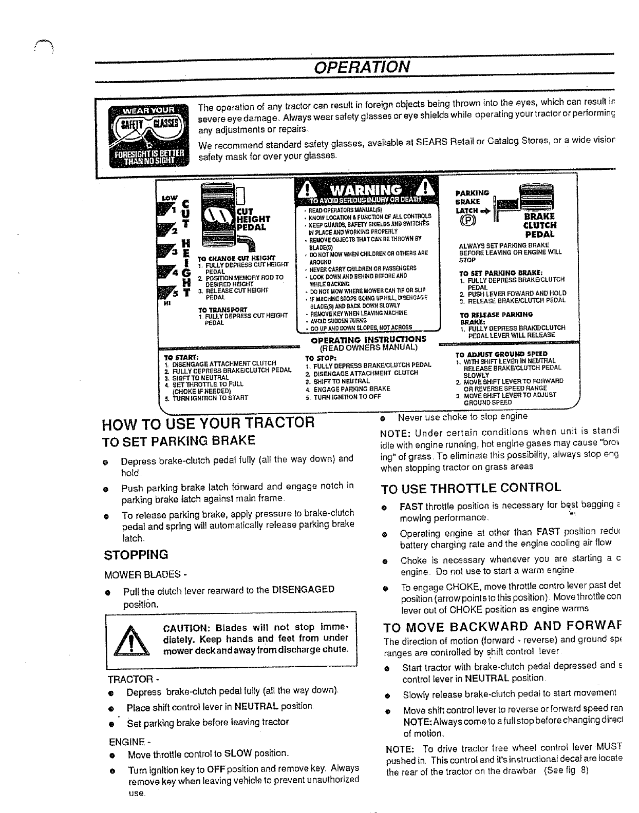
The operation of any tractor can result in foreign objects being thrown into the eyes, which can result ir
severe eye damager Always wear safety glasses or eye shields while operating your tractor or performin G
any adjustments or repairs.
We recommend standard safety glasses, available at SEARS Retail or Catalog Stores, or a wide visior
sa!ety mask for over your glasses.
i i iiiiiiHiiiiiini I ....................... , ,,,,,,,,,,,,,,,,,,,,,, I IIIIIIII _ II1 1
"-0
IF '=uT
_T HEIGHT
PEDAL
t_ 110 CHANGE cUT HEIGHT
1, FULLYDEPRESSCUTHEIGHT
PEDAL
DF.5/REDHEIGHT
H 2, POS_]eNMI_RYRODTO
T 3, RELE,t_E OUT HEIG_
PEDAL
HI
TO TRANSPORT
1FULLY DEPRESS CUT HQGHT
PEDAL
TO b"lr_M_l*=
1, DISENGAGEATTACHMENTCLUTCH
2. RJLLY DEPRESSDRAKE/CLUTCHPEDAL
3. _g'RFTTO NEUTRAL
4, BETTHROTTLE TO FULL
{CHOKE_'FNEEDED)
ETURN IGNrNQNTOSTART
• K_OW LOCATION& FUNCTIOt_Of: ALLCON_0L9
, XE_SUA_ S_F_rYS_S A_Dswnc_r_s
PLACE JL_DWORKtHG PROPERLY
oREUOVE0_JECrS_TCANBETHrowNSY
•OCHOTMOW_C_=LO_ORO_H_SA_E
AEOUND
NEVER CJLRRYC_LDREN OR_AssENGEES
, LOCK DOWHAND EI_I_D BEFOREAND
VtHIL_8,_:l,_e_t3
-DOHOTMOWWHERE UOWER C_'l TIP O_ SUP
,}F _CH_t_E STOPSGOING UPH_LL_DiSEnGaGE
8LA_3E(S]AND fiAQ( DOWN SLOWLY
.REMOVEK_ WHE}_ L_/WIHG MACHIt_E
oAViD S_DDENTdP,NS
• GO UPANO DOWNSLOPES,NOT ACR(_S
OPERATING INSTRUClrlONS
(READOWNERSMANUAL)
TO STOP:
I. FULLY DF.PRE,SS BRAKE/CLDTCH PEDAL
2, DISFJ,IGAGEA'rTACHMENT CLUTCH
3, SHIFTTO NEUTRAL
4ENGAGE PARKING _RAKE
5TURN IGNmON TO (}FF
HOW TO USE YOUR TRACTOR
TO SET PARKING BRAKE
Depress brake-clutch pedal fully (al! the way down) and
hold,
Push parking brake latch forward and engage notch in
parking brake latch against main frame.
e
o
PARKING
BRAKE
LATCI(=4=.
((_) CLUTCH
PEDAL
ALWAYS SET PARt.rJNG BRAKE
BEFORE LEAVING OR ENGINE W_LL
STOP
TO BET PAI_ING BRAKE:
1. FULLYDEPRESSE_RAKE/GLUTCH
PEDAL
Z, PUSHLEVER FOWARDAND HOLD
3, RELEASEBRAKE/CLUTCHPEDAL
TO _pARiNG
BRAKE:
1. FULLYDEPRE.SSBRAKE/CLUTCH
PEDALLEVERWILL RELEASE
, ,,,,,, ,,,, ,,,,,
TO ,¢d_3UST _.OUIFID SPEED
1, WITH SHIFT LEVER IN NEUTRAL
RELEASE SRAKE/OLUTCH PEDAL
SLOWLY
Z MOVE SH_Ft" LEVER TO FORWARD
OR REVERSE SPEED RANGE
3. MOVE SHIFT LEVER TO ADJUBT
GROUND SPEED J
eNever use choke to stop engine
NOTE: Under certain conditions when unit is standi
idle with engine running, hot engine gases may cause "bro_
ing"of grass. Te eliminate this possibility, always stop eng
when stopping tractor on grass areas
TO USE THROTTLE CONTROL
•To release parking brake, apply pressure to brake-ciutch
pedal and spring wiU automaticafly release parking brake
[atcho
STOPPING
MOWER BLADES -
•Pullthe clutch lever rearward to the DISENGAGED
position.
•FAST throttle position is necessary for best bagging
mewing performance
® Operating engine at other than FAST position redu(
battery charging rate and the engine cooting air flow
eChoke is necessary whenever you are starting a c
engine. Do not use to start awarm engine_
• To engage CHOKE, move throttle contro lever past det
position (arrow pointsto lhis position) Move throttle con
lever out of CHOKE position as engine warms
TO MOVE BACKWARD AND FORWAF
The direction of motion (torward. reverse) and ground sp_
ranges are controlled by shift control lever
CAUTION: Blades wilt not step imme-
diately. Keep hands and feet from under
mower deckand away from discharge chute.,
TRACTOR -
• Depress brake-clutch pedal lully (all the way down).
• Place shift control lever in NEUTRAL position
• Set parking brake before leaving tractor
ENGINE -
• Move throttle control to SLOW position..
Turn ignition key to OFF position and remove key Always
remove key when leaving vehicle to prevent unauthorized
use
• Start tractor with brake-clutch peda_ depressed and
control lever in NEUTRAL position
•Slowfy release brake-clutch peda! to start movement
•Move shift control lever to reverse or forward speed ran
NOTE: Always come to a fu!l stop before changing direct
of motion
NOTE: To drive tractor free wheel control lever MUST
pushed in. This controf and it'sinstruc_iona_deca_are locate
the rear of the tractor on the drawbar (See fig 8)
..................... H illl i,,=
......................................OPERATION
i uiH 1,.1 ill ill1. ,i =,.,H,,,.,,UI ................. I ,l'_=_'_=___ ___
%:
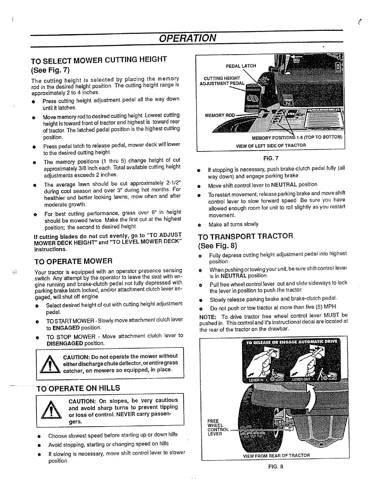
TO SELECT MOWER CUTTING HEIGHT
(See Fig. 7)
The cutting height is selected by placing the memory
rod in the desired height position The cutting height range is
approximateIy 2 to 4 inches,
•Press cutting height adjustment pedal afl the way down
until it latches.
•Move memory rod to desired cutting height Lowest cutting
height is toward front of tractor and highest is toward rear
of tractor. The Iatched pedal position is the highest cutting
position_
ePress pedal latch to release pedal, mower deck witl lower
to the desired cutting height
•The memory positions (1 thru 5) change height of cut
approximately 3/8 inch each. Total available cutting height
adjustments exceeds 2 inches..
•The average lawn should be cut approximately 2-1/2"
dur{ng cool season and over 3" during hot months. For
healthier and better looking lawns, mow often and after
moderate growth.
eFor best cutting performance, grass over 6" in height
should be mowed twiCer Make the first cut at the highest
position; the second to desired height.
If cutting blades do not cut evenly, go to "TO ADJUST
MOWER DECK HEIGHT" and "TO LEVEL MOWER DECK"
instructions°
TO OPERATE MOWER
Your tractor is equipped with an operator presence sensing
switch Anyattempt by the operator to leave the seat with en-
gine running and brake.clutch pedal not fully depressed with
parking brake latch locked, and/or attachment clutch lever en-
gaged, will shut off engine_
•Select desired height of cut with cutting height adjustment
pedal.
e TO STARTMOWER - Slowly move attachment clutch lever
to ENGAGED position.
• TO STOP MOWER -Move attachment crutch lever to
DISENGAGED position.
_CAUTION: Do not operate the mower without
either discharge chute deflector, or entire grass
catcher, on mowers so equipped, in place,
.............. "TOOPERATE ON HILLS
CAUTION: On siopes, be very cautious
and avoid sharp turns to prevent tipping
or loss of control NEVER carry passen-
gers.
•Choose slowest speed before starting up or down hilts
e Avoid stopping, starting or changing speed on hills
eIf slowing is necessary, move shift control lever to slower
position
PEDALLATCH
CUTTING HEIGHT
ADJUSTMENT PEDAL
MEMORY
=k1-5(TOP'TO BOTTOM)
VIEW OF LEFT SIDE OF TRACTOR
FIG. 7
•If stopping is necessary, push brake-clutch peda_ fully (all
way down) and engage parking brake
•Move shift controJ tever to NEUTRAL position.
eTo restart movement, release parking brake and move shift
centre{ lever to slow forward speed Be sure you have
el(owed enough room for unit to rot{ slightly as you restart
movement.
eMake all turns slowly.
TO TRANSPORT TRACTOR
(See Fig, 8)
eFully depress cutting height adjustment pedal into highest
position,
eWhen pushing ortowing your unit, be sure shift control lever
is in NEUTRAL position.
ePull free wheel control lever out and slide sideways to lock
the lever in position to push the tractor
• Slowty release parking brake and brake-clutch pedal
e Do not push or tow tractor at more than five (5) MPH
NOTE: To drive tractor free wheel control tever MUST be
pushed in.. This control and it's instructional decat are located at
the rear of the tractor on the drawbar.
FREE
WHEEL
LEVER
VIEW FROM REAR OF TRACTOR
FIG. 8
BEFORE STARTING THE ENGINE
CHECK ENGINE OIL LEVEL
Read OPERATION and CUSTOMER RESPONSIBILITIES
sections of this manual before trying to start the engine.
e Check to make sure engine crankcase is full of oil. Never
run engine unless crankcase is full of oil and dipstick is
tightened securely into oil tube.
•To charige engine oil, see ENGINE LUBRICATION in
CUSTOMER RESPONSIBILITIES section of this
manual.
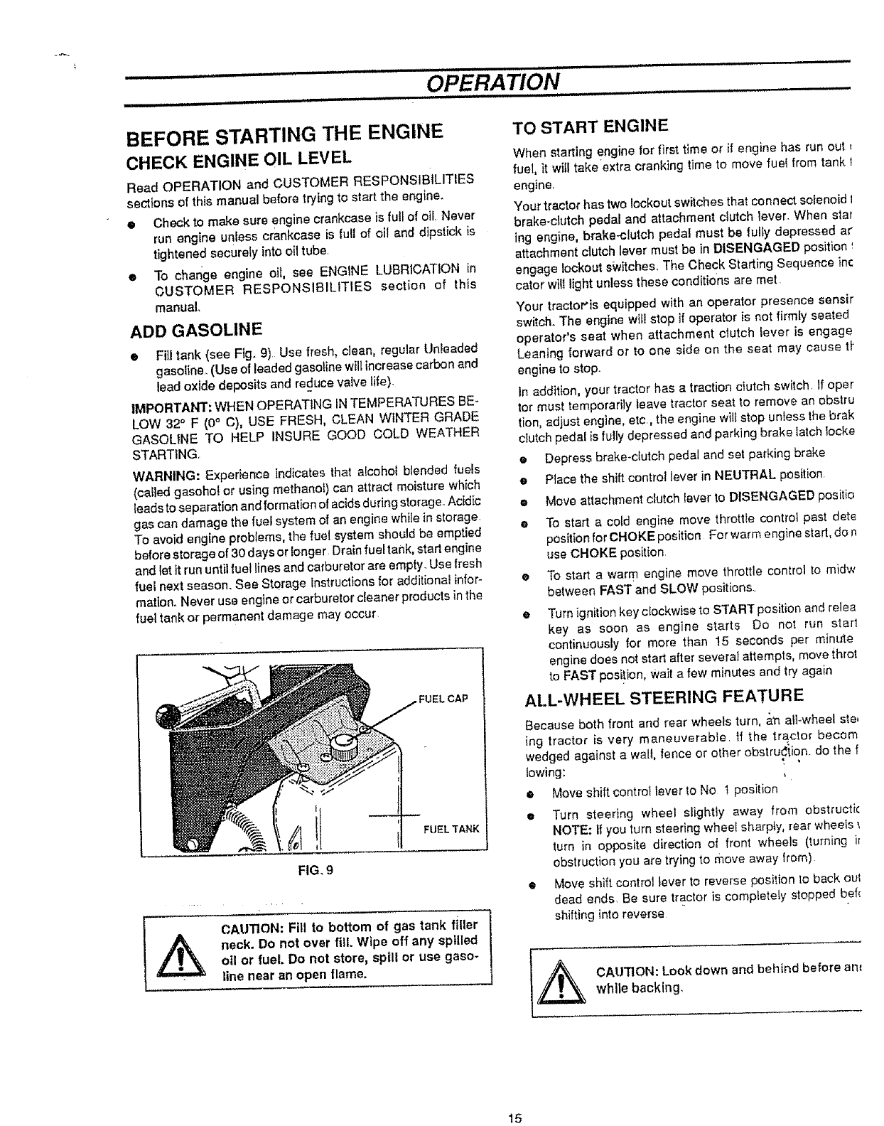
ADD GASOLINE
• Fill tank (see Fig. 9) Use fresh, clean, regular Unleaded
gasoline. (Use of leaded gasoiine will increase carbon and
lead oxide deposits and reduce valve _ife).
IMPORTANT: WHEN OPERATING IN TEMPERATURES BE-
LOW 32 ° F (0 ° C), USE FRESH, CLEAN WINTER GRADE
GASOLINE TO HELP INSURE GOOD COLD WEATHER
STARTING.
WARNING: Experience indicates that alcohol blended fueJs
(coiled gasohol or using methanol) can attract moisture which
leads to separation and formation of acids during storage.. Acidic
gas can damage the fuel system of an engine while in storage
To avoid engine problems, the fuel system should be emptied
before storage of 30 days or Ionger Drain fuel tank, start engine
and let itrun until fuel tines and carburetor are empty_ Use fresh
rue} next season_ See Storage Instructions for additiona_ infor-
mation. Never use engine or carburetor cleaner products inthe
fuel tank or permanent damage may occur
FUEL CAP
FIG, 9
FUEL TANK
CAUTION: Fill to bottom of gas tank filler
neck. Do not over fill. Wipe off any spilled
otl or fuel. Do not store, spill or use gaso-
line near an open flame.
TO START ENGINE
When starting engine for first time or if engine has run out t
fuel, it witl take extra cranking time to move fuel from tank I
engine.
Your tractor has two lockout switches that connect solenoid t
brake-clutch pedal and attachment clutch lever. When star
ing engine, brake-clutch pedal must be fully depressed ar
attachment clutch lever must be in DISENGAGED position
engage lockout switches. The Check Starting Sequence in(:
cator will light unless these conditions are met
Your tracto_'is equipped with an operator presence sensir
switch.. The engine wifl stop if operator is not firmty seated
operator's seat when attachment clutch lever is engage
Leaning forward or to one side on the seat may cause tt"
engine to stop.
In addition, your tractor has a traction clutch switch. If oper
tot must temporarily leave tractor seat to remove an obstru
tion, adjust engine, etc., the engine wiff stop unless the brak
clutch pedal is fully depressed and parking brake latch locke
•Depress brake-clutch pedal and set parking brake
e Ptace the shift control lever in NEUTRAL position
eMove attachment clutch Iever to DISENGAGED positio
eTo start a cold engine move throttle controt past det_
position for CHOKE position For warm engine start, do r_
use CHOKE position
o To start a warm engine move throttle control to m)dw
between FAST and SLOW positions_
eTurn ignitionkey clockwise to STAR]" position and relea
key as soon as engine starts Do not run star1
continuously for more than 15 seconds per minute
engine does not start after several attempts, move throt
to FAST posi!ion, Wait a few minutes and try again
ALL-WHEEL STEERING FEATURE
Because both front and rear whee/s turn, _,_nall-wheel ste,
ing tractor }s very maneuverable if the tractor becom
wedged against a wall, fence or other obstru.,_iion, do the f
lowing:
eMove shift control lever to No 1 position
eTurn steering wheel _lightly away from obstructi(
NOTE: If you turn steering wheel sharpty, rear wheels
turn in opposite direction of front wheels (turning ir
obstruction you are trying to move away from)
• Move shift control lever to reverse position to back out
dead ends Be sure tractor is completely stopped bef_.
shifting into reverse
CAUTION: Look down and behind before am
while backing_
15
....................OPERATION ..................................
Hul ll,il ............_i ......_ :: ill i H,.,,,,ut i.,i.N i,.i
MOWING TIPS
• Do not use tire chains when mower housing is attached to
unff,,
eRun the engine at FAST speed position,
•Control forward ground speed with shift controt lever in
accordance with type and quantity of grass being
mowed° The more grass to be cut, a slower forward
ground speed should be used. When cutting light grass,
forward ground speed can be increased, By observing
cutting action of your mower, you can determine the
forward ground speed,
•Your mower may tend to leave unmowed strips when long
and tender grass is being mowed, Tender grass has a high
internal moisture content and is easily depressed by lawn
tractor wheels, and may not always spring back in time to
be cULTo overcome this condition, we advise mowing lawn
in acounterclockwise direction, overtopping previous cut,
which allows lifting action of rotating blades to lift grass into
cutting path.
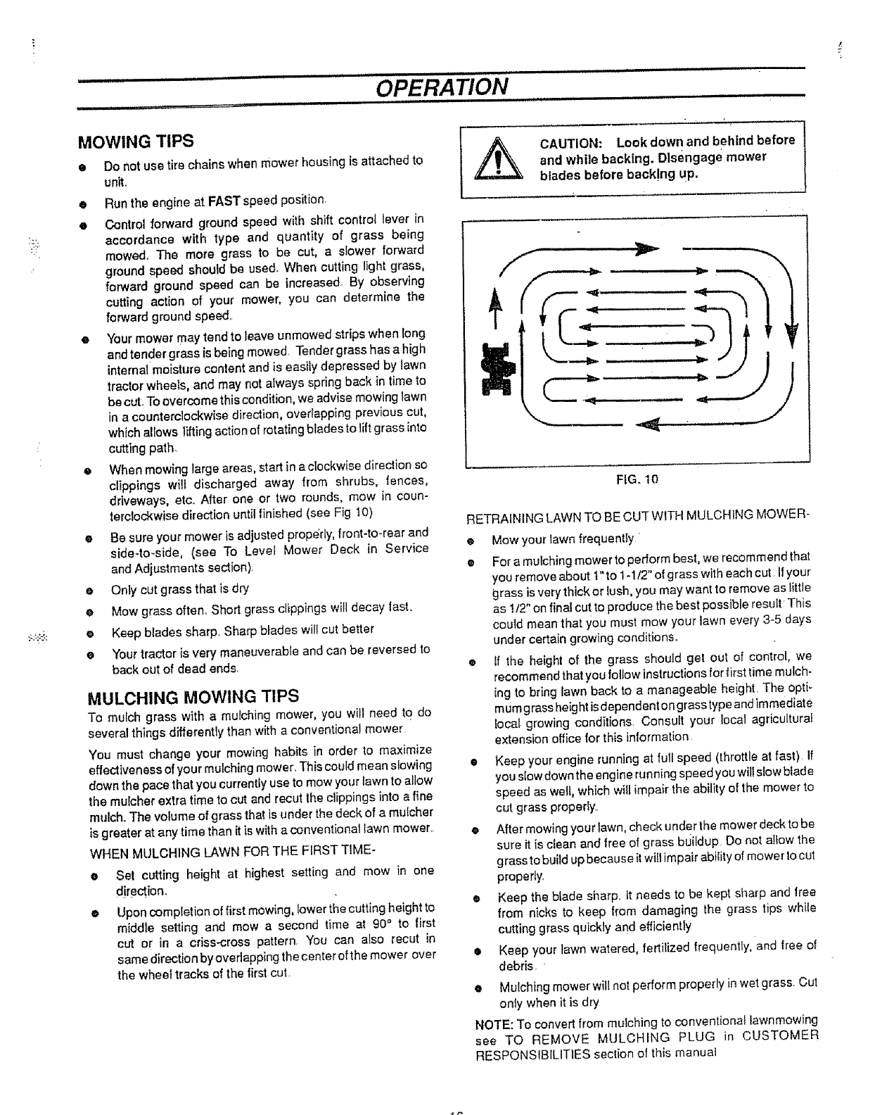
• When mowing targe areas, start in a clockwise direction so
clippings will discharged away from shrubs, fences,
driveways, etc. After one or two rounds, mow in coun-
terclockwise direction until finished (see Fig 10)
o Be sure your mower is adjusted prope'dy, front-to-rear and
side*to-side, (sea To Level Mower Deck in Service
and Adjustments section).
e Only cut grass that is dry
o Mow grass often° Short grass clippings will decay last,
o Keep blades sharp, Sharp blades wilf cut better
e Your tractor is very maneuverabfe and can be reversed to
back out of dead ends.
MULCHING MOWING TIPS
To mulch grass with a mulching mower, you will need to do
several things differently than with a conventional mower
You must change your mowing habits in order to maximize
effectiveness of your mulching mower. This could mean slowing
down the pace that you currently use to mow your lawn to allow
the mulcher extra time to cut and recut the clippings into a fine
mulch° The volume of grass that is under the deck of a mulcher
is greater at any time than it is with aconventional lawn mower.
WHEN MULCHING LAWN FOR THE FIRST TIME-
O
@
Sol cutting height at highest setting and mow in one
direction.
Upon completion of firstmowing, lower the cutting height to
middle setting and mow a second time at 90" to first
cut or in a criss-cross pattern, You can also recut in
same direction by overlapping the center of the mower over
the wheel tracks of the first cut.
CAUTION: Look down and behind before
and while backing. Disengage mower
blades before back!ng up.
FIG. 10
RETRAINING LAWN TO BE CUT WITH MULCHING MOWER-
e Mowyour lawn frequently
eFor a mulching mower to perform best, we recommend tha!
you remove about 1"to 1-1/2" of grass with each cut If your
grass is very thick or lush, you may want to remove as little
as !/2" on final cut to produce the best possible resull: This
could mean that you must mow your lawn every 3-5 days
under certain growing conditions,,
• If the height of the grass should get out of control, we
recommend that you follow instructions for first time mulch-
ing to bring fawn back to a manageable height. The opti_
mum g ross height is dependent o ngrass type and immediate
local growing conditions, Consult your local agricultural
extension office for this information
•Keep your engine running at full speed (throttle at fast) If
you slow down the engine running speed you will slow btade
speed as well, which will impair the ability of the mower to
cut grass properly.,
•After mowing your lawn, check under the mower deck to be
sure it is clean and free of grass bLiildup Do not allow the
grass to build up because itwill impair ability of mower to cut
properly.
•Keep the blade sharp, it needs to be kept sharp and free
from nicks to keep from damaging the grass lips while
cutting grass quickly and efficiently
•Keep your lawn watered, fertilized frequently, and free of
debris
•Mulching mower will not perform properly in wet grass Cut
only when it is dry
NOTE: To converl from mulching to conventionaf _awnmowing
see TO REMOVE MULCHING PLUG in CUSTOMER
RESPONSIBILITIES seclion of this manual
CUSTOMER RESPONSIBILITIES
GENERAL RECOMMENDATIONS
The warranty o n this tractor does not cover items that have been
subjected to operator abuse or negiigence. To receive full value
from warranty, operator must maintain lawn tractor as instructed
in this manual.
Some adjustments will need to be made periodically to properly
maintain your unit.
All adjustments in the SERVICE AND ADJUSTMENTS section
of this manual shoutd be checked at least or_ce each season.
oOnce a year you should replace spark plug, clean or
reptace air filter, and check blades and belts for wear. A
new spark plug and clean air fifter assure proper air-fuel
mixture and help your engine run better and last longer.
BEFORE EACH USE
eCheck engine oil level.
• Check brake operation
• Checktire pressure_
e Check for loose fasteners.
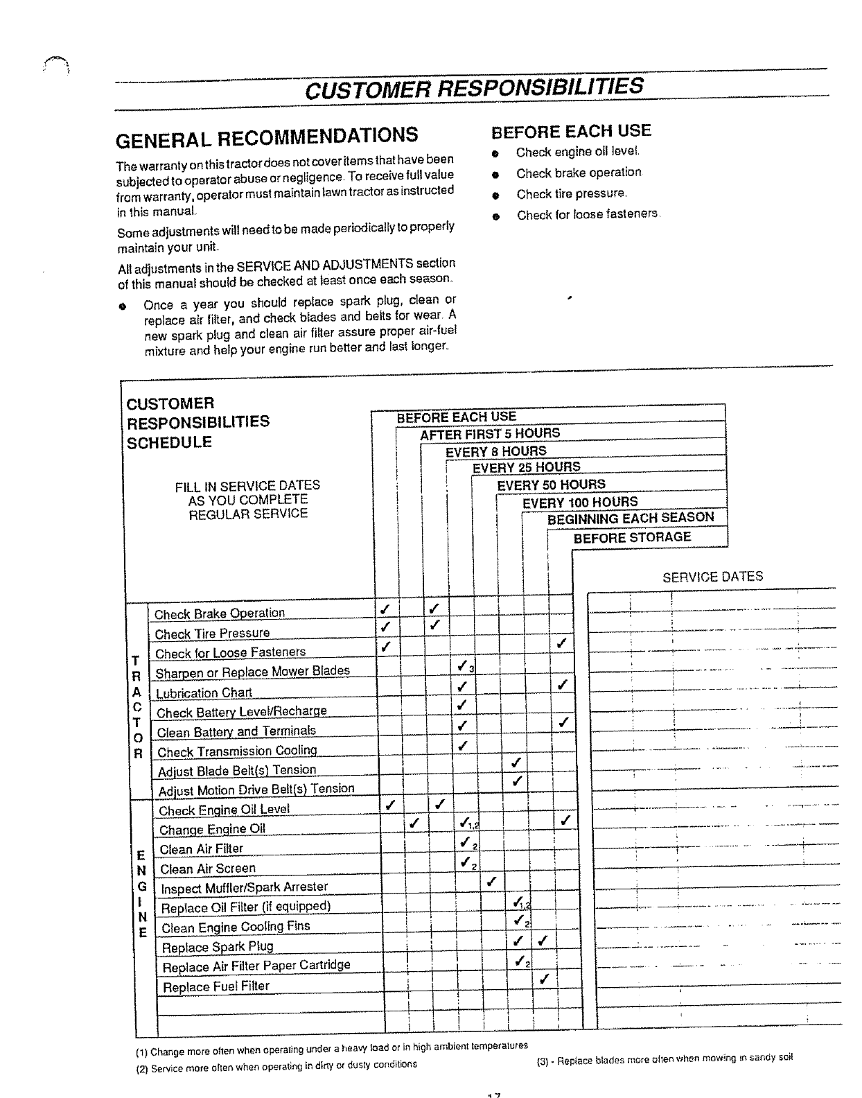
CUSTOMER
RESPONSIBILITIES
SCHEDULE
FILL IN SERVICE DATES
AS YOU COMPLETE
REGULAR SERVICE
........ 4
Check Brake Operation
Check Tire Pressure
TI Check for Loose Fasteners
Rt S____en or Replace Mower Blades
AJ Lubrication Chart
CICheck BattePL
TI
O I C(ean Battery and Terminals
R I Check Transmission Coolinq
! _ Blade Belt(s) Tension
1 Adjust Motion Drive Belt(s) Tension
i Check Encline Oil Level
Change Engine Oil
EClean Air Filter
N ! Clean Air Screen
G I Inspect Muffler/Spark Arrestor
I I Replace Oil Filter (if equipped)
E Clean Engine Cooling Fins
Replace Air Filter Paper Cartridge
Replace Fuel Filter
BEFORE EACH USE
AFTER FIRST 5 HOURS
EVERY 8 HOURS
EVERY 25 HOURS
EVERY 50 HOURS
EVERY 100 HOURS
BEGINNING EACH SEASON
BEFORE STORAGE
(1) Change more o_len when operal_ng under a heavy toad or in high ambient temperalures
(2) Service more olten when operating in d_rty or dusty conditions
SERVICE DATES
!
(3) - Replace blades mote ellen when mowing Jnsandy soil
"I"7
CUSTOMER RESPONSIBILITIES
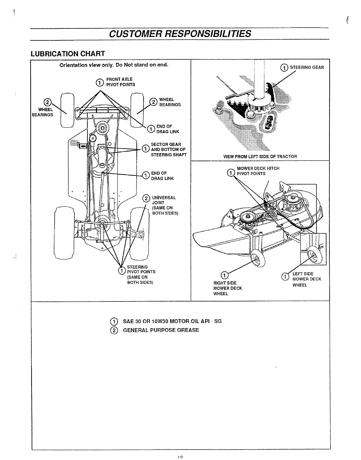
LUBRICATION CHART
Orientation view only. Do Not stand on end.
WHEEL
BEARINGS
QFRONT AXLE
PIVOT POINTS
WHEEL
BEARINGS
_QEND OF
DRAG LINK
SECTOR GEAR
) AND BOTTOM OF
STEERING SHAFT
END OF
DRAG LiNK
OUNIVERSAL
JOINT
(SAME ON
BOTH SIDES)
VIEW FROM LEFT SiDE OF TRACTOR
MOWER DECK HITCH
STEERING
PIVOT POINTS
(SAME ON
BOTH SIDES) RIGHT SiDE
MOWER DECK
WHEEL
OSTEERING GEAR
(_MOWER DECK
WHEEL
QSAE30 OR10W30MOTOR OIL API_SG
QGENERALPURPOSE GREASE
CUSTOMER RESPONSIBILITIES
TRACTOR
Always observe safety rules when performing any
maintenance.
BRAKE OPERATION
Your tractor is equipped with an adjustable disc brake To check
brake operation do the following:
• Stop tractor on alevel surface and place shift control lever
in NEUTRAL position°
•Depress brake-clutch pedal enough to latch parking brake
In 2nd notch,,
Try to push tractor. If you ere unable to push tractor, brake
is too tight and should be loosened (see TO ADJUST
TRACTOR BRAKE in SERVICE AND ADJUSTMENTS
section of this manual,
e Depress brake-clutch pedal enough to latch parking brake
[n 4th notch.
Tryto push tractor, if you are able to push tractor, brake is
too loose and should be tightened (see TO ADJUST
TRACTOR BRAKE in SERVICE AND ADJUSTMENTS
sectionof this manual.
During tractor operation, check for stopping distance. If tractor
requires more than six (6) feet stopping distance at high speed
in highest gear, the brake must be adjusted (see to ADJUST
TRACTOR BRAKE in SERVICE AND ADJUSTMENTS section
of this manual),
TIRES
e Maintain proper air pressure in all tires,, (See "PRODUCT
SPECIFICATIONS" on page 4 of this manual).
• Keep tires free of gasoline, oil, or insect contro{ chemicals
which can harm rubber.
• Avoid stumps, stones, deep ruts, sharp objects and other
hazards that may cause tire damage.
CAUTION: BEFORE PERFORMING ANY
SERVICE OR ADJUSTMENTS
®
Q
O
e Fullydepress brake-clutch pedal and set
parking brake,
Place shift control lever in NEUTRAL
position.
Place attachment clutch lever In DISEN-
GAGED position.
Turn Ignition key OFF and remove key.
Make sure the blades and all moving
parts have completely stopped.
• DO NOT handle blades with bare hands.
Wear gloves or wrap blade with news-
paper or other material while removing
or Installing blade.
BLADE CARE
For best results mower blades must be kept sharp The blades
can be sharpened with a fi{e or on a grinding
wheel, We suggest they be sharpened or replaced after every
25 hours or mewing Check blades more often if mowing in
sandy conditions
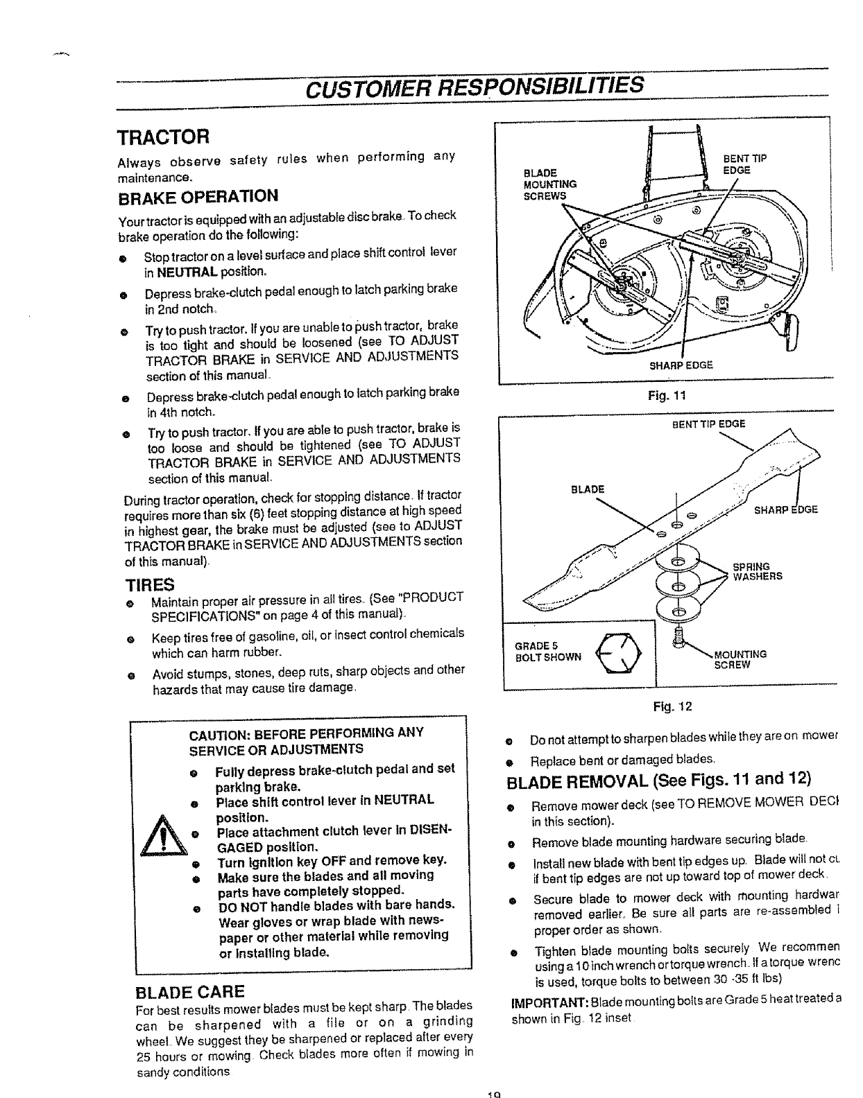
BLADE
MOUNTING
SCREWS
BENTTIP
EDGE
SHARP EDGE
Fig° 11
BENT TIP EDGE
BLADE
,
SHARP E
SPRING
WASHERS
GRADE5 Q
BOLTSHOWN ,MOUNTING
SCREW
Fig. 12
eDo not attempt to sharpen btades whilethey are on mower
•Replace bent or damaged blades
BLADE REMOVAL (See Figs. 11 and 12)
•Remove mowerdeck (seeTO REMOVE MOWER DEC!
in this section).
eRemove blade mounting hardware securing blade
•Install new blade with bent tip edges up Blade will not CL
_fbent tip edges are not up toward top of mower deck
•Secure blade to mower deck with mounting hardwar
removed earlier., Be sure all parts are re-assembled i
proper order as shown.
e Tighten blade mounting bo{ts securely We recommen
using a 10inch wrench or torque wrench, ff a torque wrenc
is used, torque bolts to between 30 -35 {t lbs)
IMPORTANT: Blade mounting botts are Grade 5 heat treated a
shown {n Fig t2 inset
_q
CUSTOMER RESPONSIBILITIES
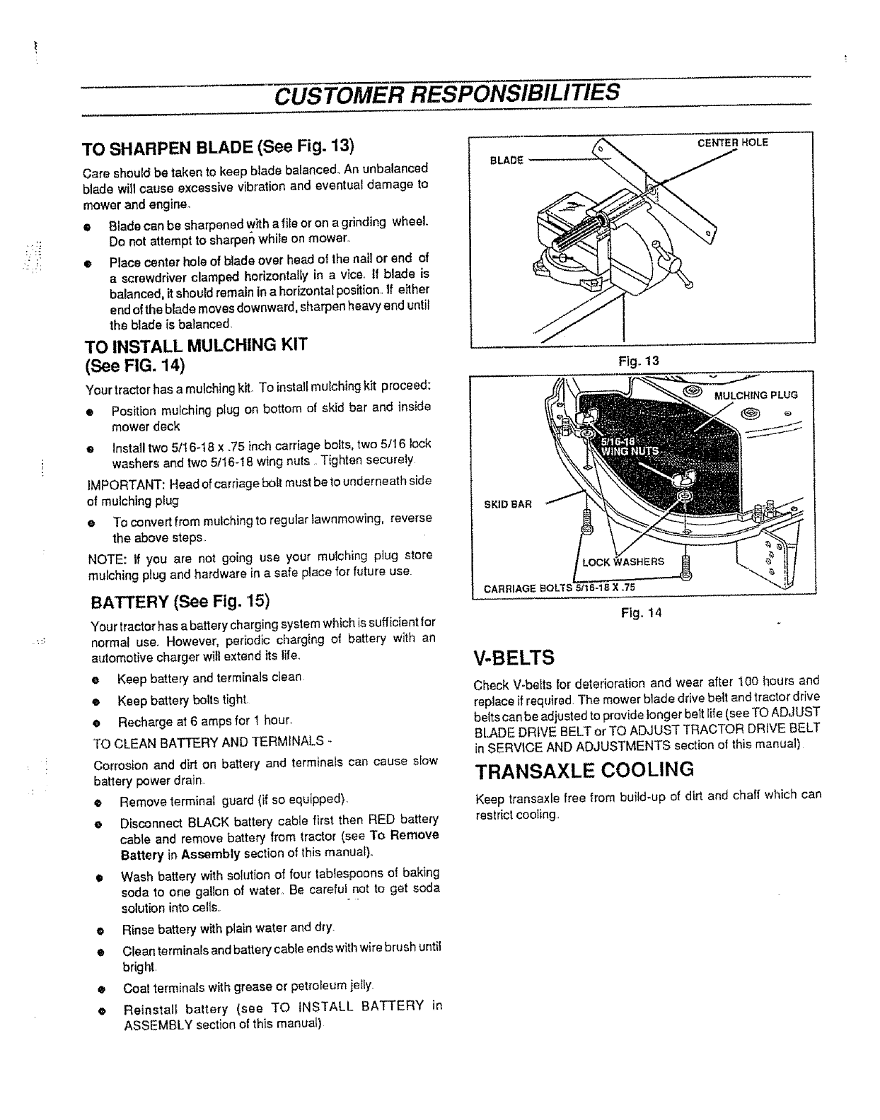
TO SHARPEN BLADE (See Fig. 13)
Care should be taken to keep blade balanced_ An unbalanced
blade will cause excessive vibration and eventual damage to
mower and engine.
• Blade can be sharpened w_tha _e or on agrinding wheel.
Do not attempt to sharpen while on mower,
• Place center hole of blade over head of the nail or end of
a screwdriver clamped horizontally in a vice. If blade is
balanced, it should remain in a horizontal position. If either
end of the blade moves downward, sharpen heavy end until
the blade is balanced,
TO INSTALL MULCHING KIT
(See FIG. 14)
Your tractor has a mulching kit_ To install mulching kit proceed:
• Position mulching plug on bottom of skid bar and inside
mower deck
eInstall two 5/t 6-I 8 x .75 inch carriage bolts, two 5/16 lock
washers and two 5/16-18 wing nuts Tighten securely
IMPORTANT: Head of carriage bolt must be to underneath side
of mulching plug
eTo convert from mulching to regular iawnmowing, reverse
the above steps,
NOTE: If you are not going use your mulching plug store
mulching plug and hardware in a safe place for future use.
BATTERY (See Fig. 15)
Your tractor has a battery charging system which is sufficient for
normal use. However, periodic charging of battery with an
automotive charger will extend its life.
eKeep battery and terminals clean
•Keep battery bolts tight
•Recharge at 6amps for _thour,
TO CLEAN BATTERY AND TERMINALS -
Corrosion and dirt on battery and terminals can cause slow
battery power drain_
eRemove terminal guard (if so equipped),
eDisconnect BLACK battery cable first then RED battery
cable and remove battery from tractor (see To Remove
Battery in Assembly section of this manual),,
•Wash battery with solution of four tablespoons of baking
soda to one gallon of water, Be careful not to get soda
solution into cells, *"
•Rinse battery with plain water and dry.
•Clean terminals and battery cable ends with wire brush until
bright.
•Coat terminals with grease or petroleum jeIIy.
•Reinstall battery (see TO INSTALL BATTERY in
ASSEMBLY section of this manua!)
BLADE
CEN'rER HOLE
Fig°13
MULCHING PLUG
SKID BAR
Fig,,! 4
V-BELTS
Check V-belts for deterioration and wear after 10o hours and
replace ifrequired, The mower blade drive belt and tractor drive
belts can be adjusted to provide longer belt Iife (see TO ADJUST
BLADE DRIVE BELT or TO ADJUST TRACTOR DRIVE BELT
in SERVICE AND ADJUSTMENTS section of this manual)
TRANSAXLE COOLING
Keep transaxle free from build-up of dirt and chaff which can
restrict cooling,,
CUSTOMER RESPONSIBILITIES
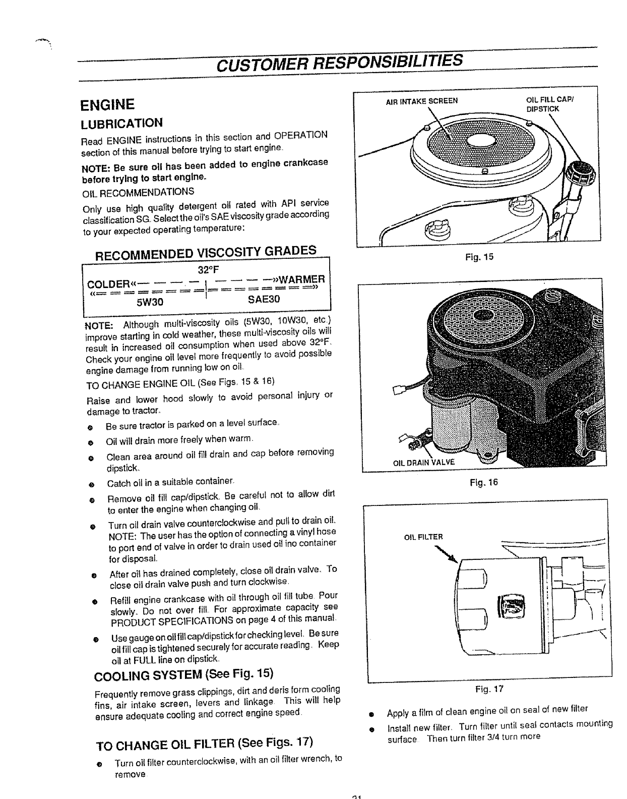
ENGINE
LUBRICATION
Read ENGINE instructions in this section and OPERATION
section of this manual before trying to start engine,
NOTE: Be sure oll has been added to engine crankcase
before trying to start engine.
OIL RECOMMENDATIONS
Only use high quality detergent oii rated with API service
classification SG. Select the oii's SAE viscositygrade according
to your expected operating temperature:
RECOMMENDED VISCOSITY GRADES
SAE30 j
NOTE: Although multi-viscosity oils (5W30, 10W30, etc)
improve starting in cold weather, these multiMscosity oils wiif
resuit in increased oil consumption when used above 32°F,
Check your engine oil levet more frequently to avoid possib{e
engine damage from running low on oil,
TO CHANGE ENGINE OIL (See Figs, 15 & 16)
Raise and lower hood slowfy to avoid personal injury or
damage to tractor.
• Be sure tractor is parked on a leveI surface.
•Oil will drain more freely when warm,
• Clean area around oil fill drain and cap before removing
dipstick_
Catch oil in a suitable container.
e
eRemove oil fill cap/dipstick. Be careful not to allow dirt
to enter the engine when chang}ng oil.
• Turn oil drain valve counterclockwise and pu{{ to drain oil
NOTE: The user has the option of connecting a vinyl hose
to port end of valve in order to drain used oil ino container
for disposal,
e After oil has drained completely, close oil drain valve. To
close oil drain valve push and turn clockwise,
• Refilf engine crankcase with o(I through oii fill tube Pour
slowly. Do not over fill For approximate capacity see
PRODUCT SPECIFICATtONS on page 4 of this manual,
• UsegaugeonoitfillcapldipstickforcheckingleveL Besure
oil fit[ cap is tightened securely for accurate reading. Keep
oil at FULL line on dipstick,
COOLING SYSTEM (See Fig. 15)
Frequently remove grass clippings, dirt and doris form cooling
fins, air intake screen, levers and Iinkage This will help
ensure adequate cooting and correct engine speed.
TO CHANGE OIL FILTER (See Figs. 17)
e Turn oil rifler counterclockwise, with an oil filter wrench, to
remove
o
e
AIR INTAK _; SCREEN OIL FILL CAW
DIPSTICK
Fig. 15
OIL DRAIN VALVE
OIL FILTER
Ftgo16
Fig.. 17
Apply a film of clean engine oi! on seal of new filter
Install new filter. Turn fitter until seal contacts mounting
surface Then turn filter 3/4 turn more
ol
€,
CUSTOMER RESPONSIBILITIES
,1
i
't_t
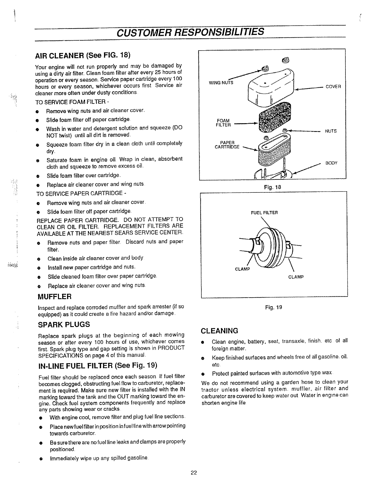
AIR CLEANER (See FIG. 18)
Your engine will not run properly and may be damaged by
using a dirty air lifter. Clean foam filter after every 25 hours ot
operation or every season. Service paper cartridge every 100
hours or every season, whichever occurs first Service air
cleaner more olten under dusty conditions
TO SERVICE FOAM FILTER -
•Remove wing nuts and air cleaner cover.
eSlide foam filter off paper cartridge,
• Wash in water and detergent solution and squeeze (DO
NOT twist) until all dirt is removed
®Squeeze foam filter dry in a clean cloth until completely
dry_
e Saturate foam in engine oil Wrap in clean, absorbent
cloth and squeeze to remove excess oil.
•Slide foam filter over cartridge.
• Replace air cteaner cover and wing nuts
TO SERV(CE PAPER CARTRIDGE -
•Remove wing nuts and air cleaner cover
eSlide foam filter off paper cartridge.
REPLACE PAPER CARTRIDGE. DO NOT ATTEMPT TO
CLEAN OR OiL FILTER. REPLACEMENT FILTERS ARE
AVAILABLE AT THE NEAREST SEARS SERVICE CENTER.
• Remove nuts and paper filter, Discard nuts and paper
filte_'_
eClean inside air cleaner cover and body
e|nsta!l new paper cartridge and nuts.
• S1ide cleaned foam fitter over paper cartridge.
•Replace air cleaner cover and wing nuts
MUFFLER
Inspect and replace corroded muffler and spark arrester (if so
equipped) as it could create a fire hazard and;or damage.
SPARK PLUGS
Replace spark plugs at the beginning of each mowing
season or after every 100 hours of use, whichever comes
first. Spark plug type and gap setting is shown in PRODUCT
SPECIFICATIONS on page 4 of this manuat,
IN-LINE FUEL FILTER (See Fig. 19)
Fuel filter should be replaced once each season If fuel filter
becomes c_gged, obstructing fuel flow to carburetor, replace-
ment is required. Make sure new filter is installed with the IN
marking toward the tank and the OUT marking toward the en-
gine. Check fuel system components frequently and replace
any parts showing wear or cracks
•With engine coo_, remove filter and ptug fuel line sections.
Place new fuel filter in position infuel line with arrow pointing
towards carburetor.
0
o
@
Be sure there are no fue! line Teaksand clamps are properly
positioned,
Immediatety wipe up any spitled gasoline
WiNG NUTS
COVER
FOAM
FALTER
PAPER
CARTRf£}G£' _.,.,,.,,._
_- NUTS
BODY
Fig. 18
FUEL FILTER
CLAMP
CLAMP
Fig.. 19
CLEANING
• Clean engine, battery, seat, transaxle, finish, etc of alf
foreign matter..
eKeep finished surfaces and wheels free of all gasoline, oil
etc
e Protect painted surfaces with automotive type wax
We do not recommend using a garden hose to clean your
tractor unless eiectrica! system, muffler, air filter and
carburetor are covered to keep water out Water in engine can
shorten engine Life
22
SERVICE AND ADJUSTMENTS
CAUTION: BEFORE PERFORMING ANY SERVICE OR ADJUSTMENTS
• Depress brake-clutch pedal and set parking brake,
Place shift control lever tn NEUTRAL position.
Place attachment clutch lever In DISENGAGED position.
• Turn Ignition key OFF and remove key.
• Make sure the blades and all moving parts have completely stopped,
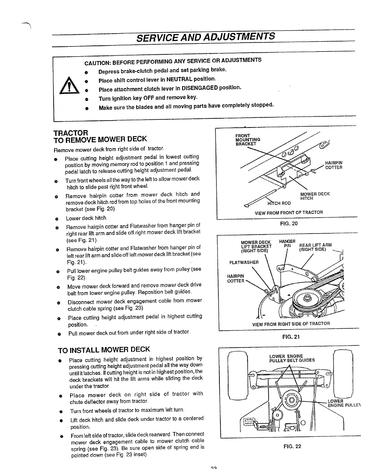
TRACTOR
TO REMOVE MOWER DECK
Remove mower deck from right side of tractor_
ePlace cutting height adjustment pedal {n lowest cutting
position by moving memory rod to position 1 and pressing
pedal latch to release cutting height adjustment pedal.,
•Turn front wheels all the way to the Ieft to allow mower deck
hitch to slide past right front wheel,,
e Remove hairpin cotter from mower deck hitch and
remove deck hitch rod from top holes of the front mounting
bracket (see Fig° 20).
eLower deck hitch.
eRemove hairpin cotter and Flatwasher from hanger pin of
right rear lift.arm and slide off right mower deck lift bracket
(see Fig,, 21 ),
e Remove hairpin cotter and Ftatwasher from hanger pin of
]eft rear lift arm and slide off left mower deck lift bracket (see
Fig, 21).
ePull Rowerengine pulley belt guides away from pulley (see
Fig, 22).
• Move mower deck forward and remove mower deck drive
belt from lower engine pulley, Reposition belt guides,
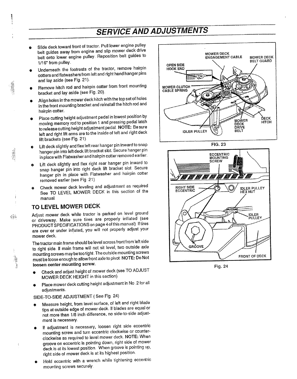
• Disconnect mower deck engagement cable trom mower
clutch cable spring (see Fig, 23).
• Place cutting height adjustment pedal in highest cutting
position.
ePull mower deck out from under right side of tractor
TO INSTALL MOWER DECK
Place cutting height adjustment in highest position by
pressing cutting height adjustment pedal all the way down
until it latches It cutting height is not in highest position, the
deck brackets will hit the fift arms while sliding the deck
under the tractor,
e Place mower deck on right side of tractor with
chute deflector away from tractor
• Turn front wheels of tractor to maximum left turn
e
e
Lift deck hitch and slidedeck under tractor to a centered
position.
From left side of tractor, slide deck rearward Then connect
mower deck engagement cable to mower clutch cable
spring (see Fig,, 23). Be sure open side of spring end is
pointed down (see Fig 23 inset)
FRONT
MOUNTING
BRACKET
HAIRPIN
MOWER DECK
HITCH
ROD
vIEw FROMFRONTOFTRACTOR
FIG. 20
MOWER DECK HANGER
LIFT BRACKET PIN
(RIGHT SIDE)
FLA'TWASHER
HAIRPIN
COTTER _._
REAR LIFT ARM
(RIGHT SIDE
VIEWFROMRIGHTSIDEOFTRACTOR
FIG. 21
LOWER ENGINE
FULLEY BELT GUIDES
LOWER
ENGINE PULLE_
FIG., 22
SERVICE AND ADJUSTMENTS
• Slide deck toward front of tractor. Pull lower engine pulley
beff guides away from engine and slip mower deck drive
belt onto lower engine pulley, Reposition belt guides to
l/16" from pulley.
•Underneath the !ootrests of the tractor, remove hairpin
cotters and flatwashers from lelt and right hand hanger pins
and lay aside (see Fig_ 21),,
• Remove hitch rod and hairpin cotter from front mounting
bracket and lay aside (see Fig. 20).
•Align holes in the mower deck hitch wit h the lop set cf hotes
in the front mounting bracket and reinstall the hitch rod and
hairpin cotter.
e Place cutting height adjustment pedal in lowest position by
moving memory rod to position 1 and pressir_g pedal latch
to release cutting height adjustment pedal NOTE: Be sure
left and right lift arms are to the inside of left and right deck
lift brackets (see Fig. 21)
•Lift deck slightly and f/ex teft rear hanger pin inward to snap
hanger pin into left deck lift bracket slot. Secure hanger pin
in place with Flatwasher and hairpin cotter removed earlier.
eLift deck slightly and flex right rear hanger pin inward to
snap hanger pin into right deck lift bracket slot Secure
hanger pin in place with Ratwasher and hairpin cotter
removed eadier (see Fig 2t)
eCheck mower deck feveting and adjustment as required
See TO LEVEL MOWER DECK in this section of the
manual,
TO LEVEL MOWER DECK
Adjust mower deck while tractor is parked on tevel ground
or driveway. Make sure tires are properly inIlated (see
PRODUCT SPECIFICATIONS on page 4 of this manual) Iftires
are over cr under inf!ated, you will not properly adjust your
mower deck.
The tractor main frame should be Ievel across front from left side
to right side, If main frame will not sit level, twc outside axle
mounting screws may be too tip hi. The outside mo unting screws
must be loose enough to alIow frontaxle to pivot, NOTE: Do Not
loosen center mounting screw.
•Check and adjust height of mower deck (see TO ADJUST
MOWER DECK HEIGHT in this section)
Place mower deck cutting height adiustment in No, 2 tot all
adjustments.
SIDE-TO_StDE ADJUSTMENT ( See Fig. 24)
• Measure height, from level surface, of left and right blade
tips at outside edge of mower deck,, II blades are equaI or
not more than t/8 inch difference, no side-to-side adjust-
ment is necessary.
•If adjustment is necessary, toosen right side eccentric
mounting screw and turn eccentric clockwise or ccunter-
clockwise as required to tevel mower deck, NOTE: When
groove on eccentric is pointing down, right side oI mower
deck is at its lowest position, When groove is pointing up,
right side ol mower deck is at its highest position.
•Hold eccentric with awrench whi_e tightening eccentric
mounting screws securely
OPEN SIDE
HOOK END
MOWER CLUTCH
CABLE SPRING
MOWER DECK
ENGAGEMENT CABLE MOWER DECK
BELT GUARD
IDLER PULLEY
DECK
DRIVE
BELT
HITCH
FIG. 23
Fig. 24
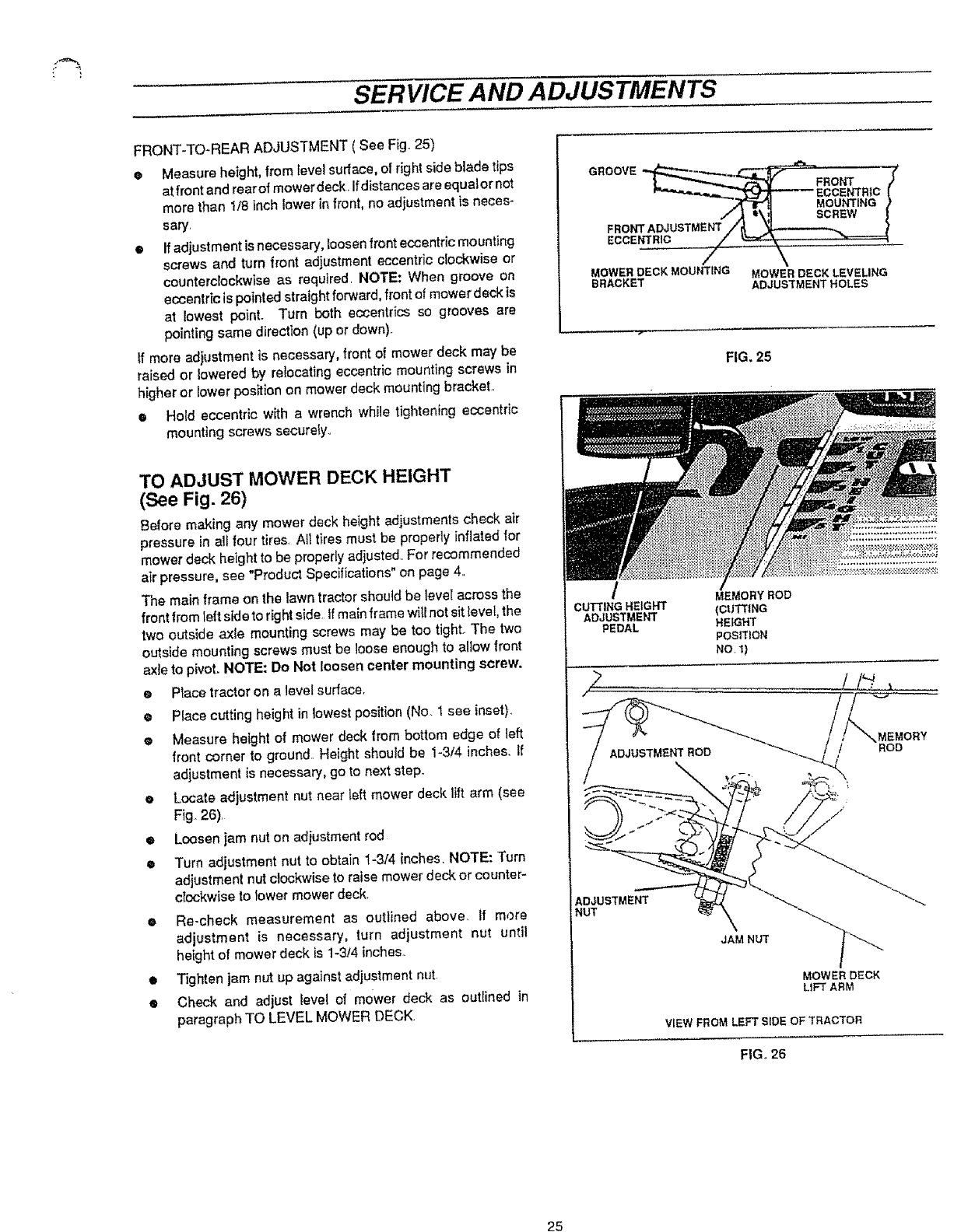
! .
SERVICE AND ADJUSTMENTS
FRONT-TO-REAR ADJUSTMENT ( See Fig. 25)
• Measure height, from level surface, of right side blade tips
at front and rearof mower deck, Ifdistances are equalor not
more than 1/8 inch lower in front, no adjustment is neces-
sary,
•If adjustment isnecessary, loosen fronteccentric mounting
screws and turn front adjustment eccentric clockwise or
counterclockwise as required. NOTE: When groove en
eccentric is pointed straight forward, front of mower deck is
at lowest point. Turn both eccentrics so grooves are
pointing same direction (up or down).
If more adjustment is necessary, front of mower deck may be
raised or lowered by relocating eccentric mounting screws in
higher or tower position on mower deck mounting bracket,
• Hold eccentric with a wrench while tightening eccentric
mounting screws securely.,
TO ADJUST MOWER DECK HEIGHT
(See Fig. 26)
Before making any mower deck height adjustments check air
pressure in all four tires. AITtires must be properly inflated for
mower deck hetght to be properly adjusted,, For recommended
air pressure, see "Product Specifications" on page 4,,
The main frame on the lawn tractor shoutd be leveI across the
front from left side to right side,,If main frame witf not sit lever, the
two outside axle mounting screws may be too tight. The two
outside mounting screws must be loose enough to allow front
axle to pivot. NOTE: Do Not loosen center mounting screw.
•Piece tractor en a level surface,
ePlace cutting height in lowest position (No. 1 see inset),
eMeasure height of mower deck from bottom edge of left
front corner to ground,. Height should be 1-3!4 inches, tf
adjustment is necessary, go to next step.
eLocate adjustment nut near left mower deck lift arm (see
Fig. 26),
•Loosen jam nut on adjustment rod
•Turn adjustment nut to obtain 1-3/4 inches. NOTE: Turn
adjustment nut clockwise to raise mower deck or counter-
clockwise to Iower mower deck.
<= Re-check measurement as outlined above, if more
adjustment is necessary, turn adjustment nut until
height of mower deck is 1-3t4 inches.
•Tighten jam nut up against ad}ustment nut,
•Check and adjust level of mower deck as outlined in
paragraph TO LEVEL MOWER DECK.
• ""'___ ECCENTRtC[
j'[--.IT_lJ MOUNTING )
i_ t\,,]l SCREW t
FRONTADJUSTMENT/_t_ _ }
ECCENTRIC _,____._ "_.,_====_
MOWER DECK MOUNTING MOWER DECK LEVELING
BRACKET ADJUSTMENT HOLES
FIG. 25
/
CUTTINGHEIGHT
ADJUSTMENT
PEDAL
(cUTTING
HEIGHT
POSITION
No. ])
/_'_"-+'_/ ADJUSTMENT ROD _ _ !/ ROD
,7) 1 tt/;
AD_tUSTMENT _' "_'._...
i,itrr _--_ _ .. "-
JAMNUT I_,,,..._
MOWER DECK
LIFT ARM
VIEW FROM LEFT SIDE OF TRACTOR
FIG,, 26
25
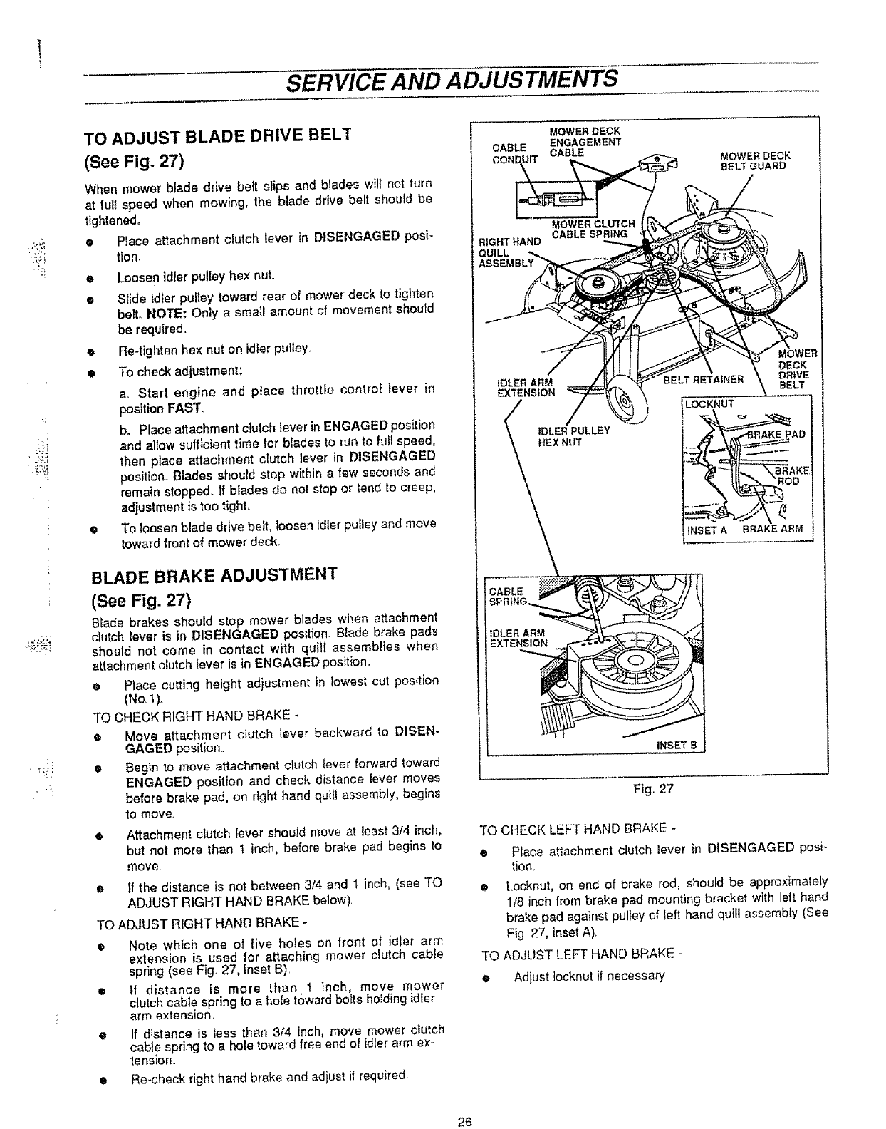
SERVICE AND ADJUSTMENTS
,. :+
=+
TO ADJUST BLADE DRIVE BELT
(See Fig. 27)
When mower blade drive belt slips and blades wil{ not turn
at full speed when mowing, the blade drive belt should be
tightened+
• Place attachment clutch lever in DISENGAGED posi+
tion,
• Loosen idter pulley hex nut.
•Sfide idler pulley toward rear of mower deck to tighten
belt,. NOTE: Only a small amount of movement should
be required..
eRe-tighten hex nut on idler pulley..
•To check adjustment:
ao Start engine and place throttle control lever in
position FAST.
b. Place attachment clutch lever in ENGAGED position
and allow sufficient time for blades to run to full speed,
then place attachment clutch lever in DISENGAGED
position+ Blades should stop within a few seconds and
remain stopped, tf blades do not stop or tend to creep,
adjustment is too tight,
• To loosen blade drive belt, loosen idler pulley and move
toward front of mower deck+
BLADE BRAKE ADJUSTMENT
(See Fig. 27)
Blade brakes should stop mower blades when attachment
clutch lever is in DISENGAGED position, Blade brake pads
should not come in contact with quill assemblies when
attachment clutch lever is in ENGAGED position..
• Place cutting height adjustment in lowest cut position
(No,1)_
TO CHECK RIGHT HAND BRAKE -
e Move attachment clutch lever backward to DISEN-
GAGED position..
• Begin to move attachment clutch lever forward toward
ENGAGED position and check distance lever moves
before brake pad, on right hand quill assembly, begins
to move.,
•Attachment clutch lever should move at least 3f4 inch,
but not more than t inch, before brake pad begins to
move,,
• tf the distance is not between 3/4 and I inch, (see TO
ADJUST RIGHT HAND BRAKE below}
TO ADJUST RIGHT HAND BRAKE -
eNote which one of five holes on front of idler arm
extension is used for attaching mower clutch cable
spring (see Fig. 27, inset B).
• If distance is more than 1 inch, move mower
clutch cable spring to ahole toward bolts holding idler
arm extension.
e If distance is less than 3/4 inch, move mower clutch
cable spring to a hofe toward free end of idler arm ex-
tension.
•Re-check right hand brake and adjust if required
MOWER DECK
CABLE ENGAGEMENT
COND, UIT CABL=E ,_ MOWERDECK
BELT°+°
MOWERCLmCN "
/_l! tl/_ \ \- DECK
IDL_-_BELT REfAINER \ =DR!VE
HEX NUT __AD
INSET A BRAKE ARM
INSET B
Fig+ 27
TO CHECK LEFT HAND BRAKE -
• Place attachment clutch {ever in DISENGAGED posi-
tion,
• Locknut, on end of brake rod, should be approximately
118inch from brake pad mounting bracket with leit hand
brake pad against pultey of teft hand quiJi assembly (See
Fig. 27, inset A)+
TO ADJUST LEFT HAND BRAKE -
• Adjust Iocknut if necessary
26
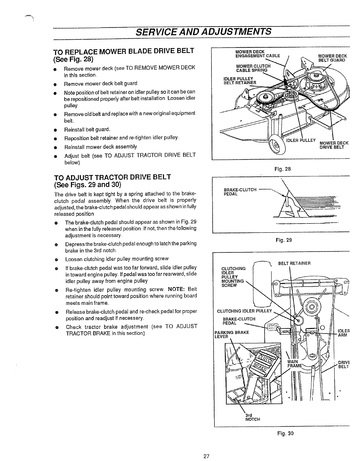
SERVICE AND ADJUSTMENTS
TO REPLACE MOWER BLADE DRIVE BELT
(See Fig. 28)
•Remove mower deck (see TO REMOVE MOWER DECK
in this section.
eRemove mower deck belt guard
•Note position of belt retainer on idlerpulley so itcan be can
be repositioned properly after belt installation Loosen idler
pulley
•Remove oldbelt and replace with a new original equipment
betto
•Reinstall belt guard.
eReposition belt retainer and re-tighten idler pulley
•Reinstall mower deck assembly
eAdjust belt (see TO AEXJUST TRACTOR DRIVE BELT
below)
TO ADJUST TRACTOR DRIVE BELT
(See Figs. 29 and 30)
The drive belt is kept tight by a spring attached to the brake-
clutch pedal assembly When the drive belt is properly
adjusted, the brake-clutch pedal should appear as shown in fully
released position
•The brake-clutch pedal should appear as shown in Fig. 29
when in the lully released position If not, then the following
adjustment is necessary.
eDepress the brake-clutch pedal enough to latch the parking
brake in the 3rd notch
eLoosen c_utching idler pulley mounting screw
® If brake-clutch pedal was too far forward, slide idler pulley
intoward engine pulley. If pedal was too far rearward, slide
idler puIley away from engine pufiey
®Re-tighten idler pulley mounting screw NOTE: Belt
retainer should point toward position where running board
meets main frame.
®Release brake-clutch pedal and re-check pedal for proper
position and readjust if necessary_
e Check tractor brake adjustment (see TO ADJUST
TRACTOR BRAKE in this section)
MOWER DECK
ENGAGEMENT CABLE
MOWER CLUTCH
CABLE SPRING
IDLER PULLEY
BELT RETAINER
MOWER DECK
BELTGUARD
tDLER PULLEY
MOWER DECK
DRIVE BELT
Fig. 28
BBAKE_LUTCH_
PEDAL _ _"
Fig. 29
BELT RETAINER
CLUTCHING
IDLER
PULLEY
MOUNTING
SCREW
PEDAL
DRIVE
" BELT
3rd
NOTCH
Fig. 30
27
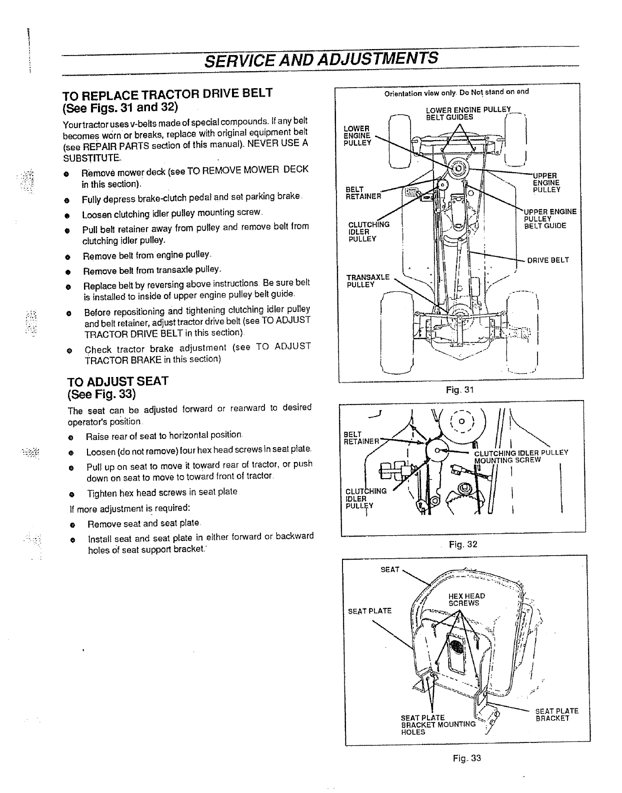
SERVICE AND ADJUSTMENTS
:<,_
TO REPLACE TRACTOR DRIVE BELT
(See Figs. 31 and 32)
Your tractor uses v-belts made of special compounds,, If any belt
becomes worn or breaks, replace with original equipment belt
(see REPAIR PARTS section of this manual),, NEVER USE A
SUBSTITUTE.
•Remove mowed'deck (see TO REMOVE MOWER DECK
in this section),
• Fu)iy depress brake-cJutch pedal and set parking brake
• Loosen c_utching idler pulley mounting screw
• Pull belt retainer away from puttey and remove belt from
clutching idler pulley,,
oRemove belt from engine pulley.
• Remove belt from transaxle puHeyo
• Reptace bert by reversing above instructions Be sure belt
is installed to inside of upper engine pulley belt guide,
oBefore repositioning and tightening clutching idler pulley
and belt retainer, adjust tractor drive beit (see TO ADJUST
TRACTOR DRIVE BELT in this section)
• Check tractor brake a(tjustment (see TO ADJUST
TRACTOR BRAKE in this section)
TO ADJUST SEAT
(See Fig. 33)
The seat can be adjusted forward or rearward to desired
operators position
•Raise rear of seat to horizontal position
eLoosen (do not remove) four hex head screws in seat ptate,
ePutl up on seat to move it toward rear of tractor, or push
down on seat to move to toward front of tractor
• Tighten hex head screws in seat plate
If more adjustment is required:
e Remove seat and seat plate,
• Instal] seat and seat plate in either forward or backward
hotes Ofseat support bracket. •
LOWER
ENGINE
PULLEY
Orientation view only Do Nol stand on end
LOWER ENGINE PULLEY
BELT GUIDES
BELT
RETAINER
ENGINE
PULLEY
CLUTCHING
IDLER
PULLEY t
PULLEY
BELT GUIDE
TRANSAXLE
PULLEY
)
Fig, 31
IDLER
PULLEY
CLUTCHING IDLER PULLEY
MOUNTING SCREW
)
Fig, 32
SEAT.
_E
ELT
SEAT PLATE
SEAT PLATE
BRACKET MOUNTING
HOLES
Fig.. 33
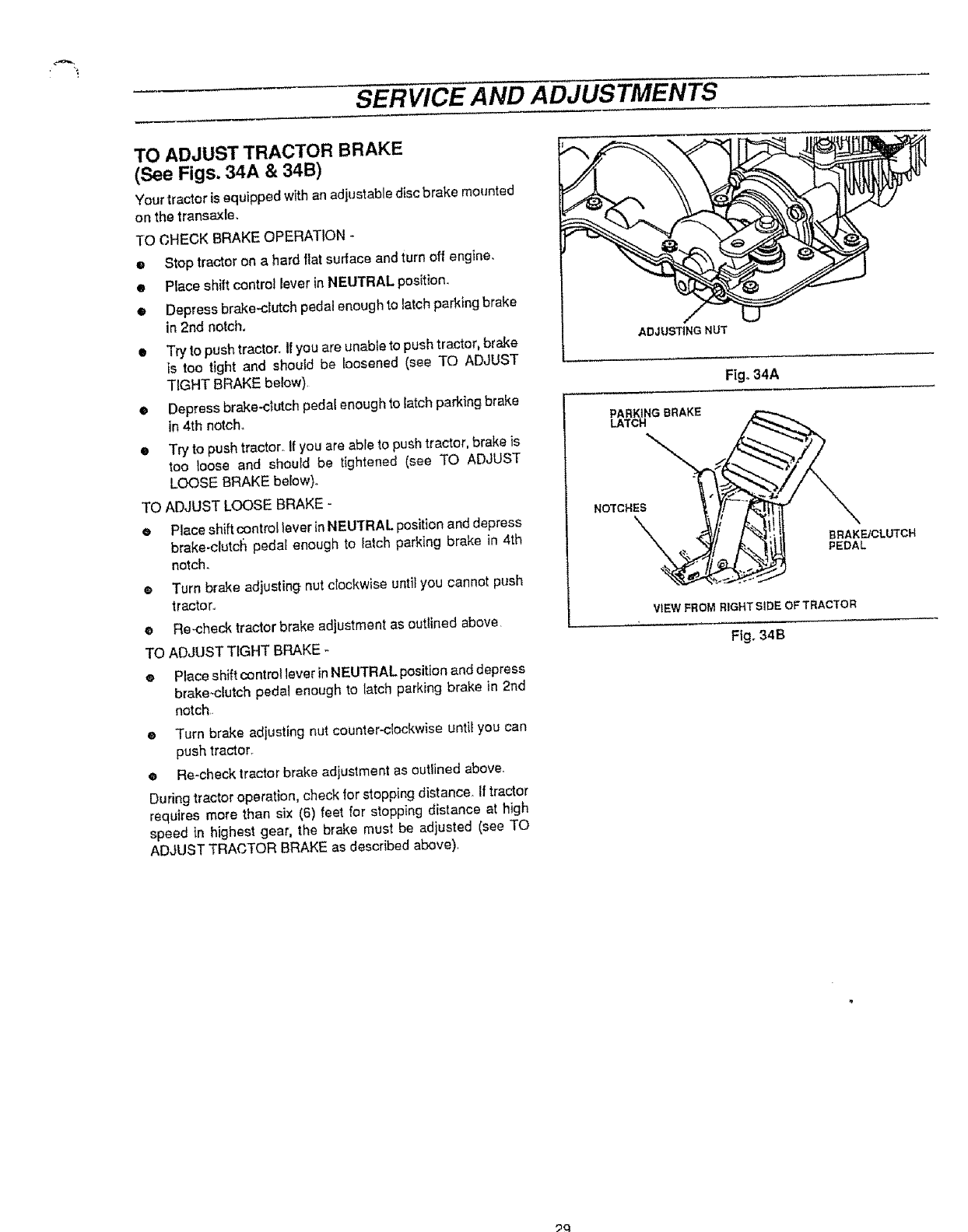
SERVICE AND ADJUSTMENTS
TO ADJUST TRACTOR BRAKE
(See Figs. 34A & 34B)
Your tractor is equipped with an adjustable disc brake mounted
on the transaxfe.
TO CHECK BRAKE OPERATION-
• Stop tractor on a hard flat surface and turn off engine.
• Place shitt control lever in NEUTRAL position.
o Depress brake-clutch pedal enough to latch parking brake
in 2nd notch,
• Try to push tractor, if you are unable to push tractor, brake
is too tight and should be loosened (see TO ADJUST
TIGHT BRAKE below),
eDepress brake-crutch pedal enough to latch parking brake
in 4th notch,,
•Try to push tractor_If you are able to push tractor, brake is
too loose and should be tightened (see TO ADJUST
LOOSE BRAKE below),.
TO ADJUST LOOSE BRAKE -
ePlace shift control laver in NEUTRAL position and depress
brake-ctutc_ pedal enough to latch parking brake in 4th
notch.
®Turn brake adjusting nut ctockwise until you cannot p_sh
tractor,,
•Re-check tractor brake adjustment as outtined above,
TO ADJUST TIGHT BRAKE -
e Place shift control lever in NEUTRAL position and depress
brake-clutch pedal enough to tatch parking brake in 2nd
notch,
eTurn brake adjusting nut counter-clockwise until you can
push tractor.
•Re-check tractor brake adjustment as outlined above.
During tractor operation, check for stopping distance. If tractor
requires more than six (6) feet for stopping distance at high
speed in highest gear, the brake must be adjusted (see TO
ADJUST TRACTOR BRAKE as described above)
ADJUSTING NUT
Fig. 34A
PARKING BRAKE
LATCH
NOTCHES
BRAKEICLUTCH
PEDAL
VIEW FROM RIGHT SIDE OFTRACTOR
Fig, 34B
_9
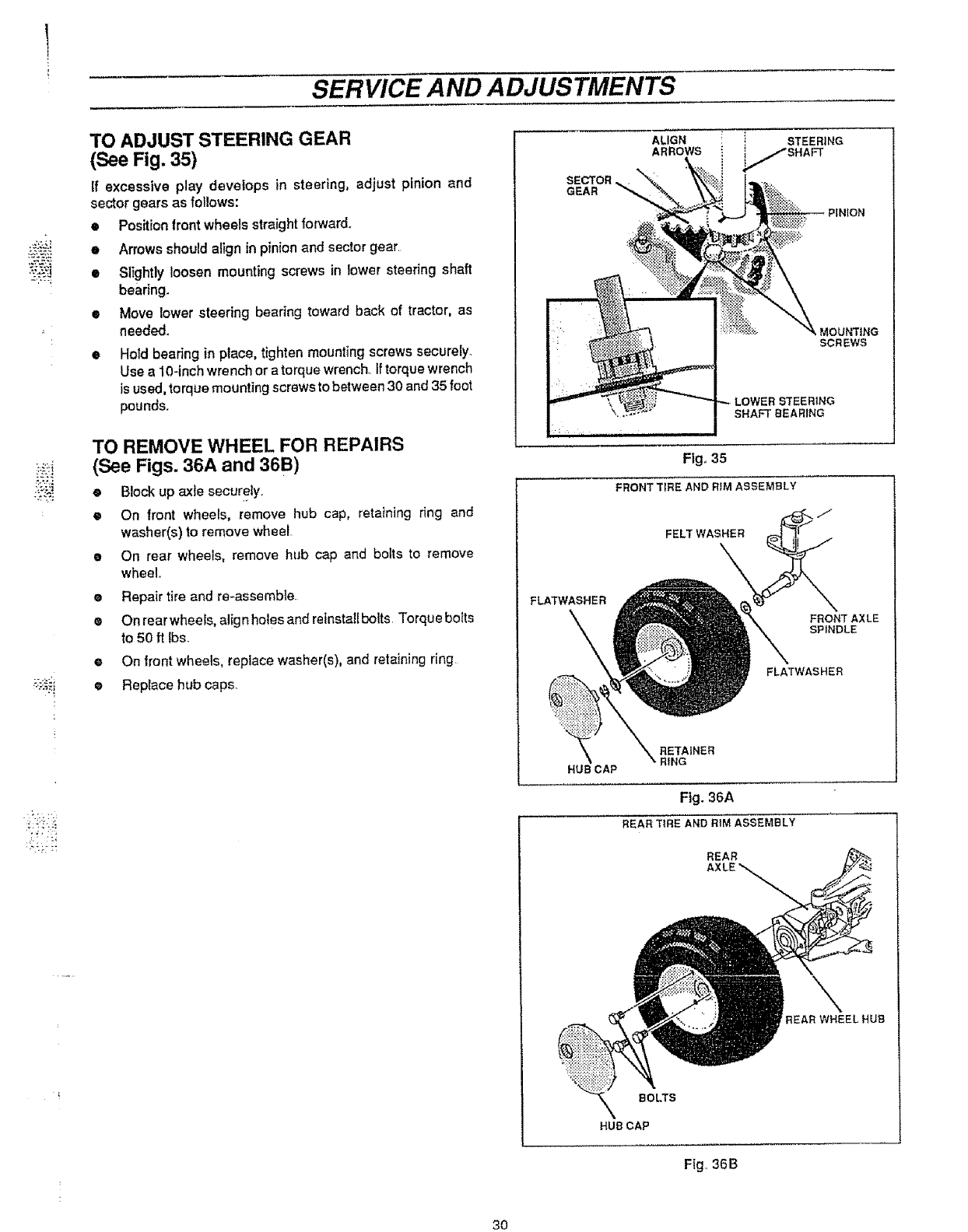
SERVICE AND ADJUSTMENTS
TO ADJUST STEERING GEAR
(SeeFig.35)
if excessive play develops in steering, adjust pinion and
sector gears as foffows:
• Position front wheels straight forward.
•Arrows should align in pinion and sector gear.
• Slightly loosen mounting screws in lower steering shaft
bearing.
•Move lower steering beating toward back of tractor, as
needed.
Hotd bearing in place, tighten mounting screws securety_
Use a 10-inch wrench or a torque wrench, If torque wrench
is used, torque mounting screws to between 30 and 35 foot
pounds.
TO REMOVE WHEEL FOR REPAIRS
(See Figs. 36A and 36B)
•Block up axle securely
®On front wheels, remove hub cap, retaining ring and
washer(s) to remove wheel
e On rear wheels, remove hub cap and bolts to remove
wheel.
•Repair tire and re-assemble.
•Onrearwheets, alignholesandreinstatiboits Torquebo_ts
to 50 ft Ibs_
eOn front wheels, replace washer(s), and retaining ring
•Replace hubcaps.
ALIGN iSTEERING
ARROWS i _,,,,,,_/SHAFT
SECTOR
GEAR
LOWER STEERING
SHAFT BEARING
Fig,, 35
FRONT T_RE AND RIM ASSEMBLY
FELT WASHER
FLATWASHER
FRONT AXLE
SPINDLE
FLATWASHER
RETAINER
RING
HUB CAP
Fig. 36A
REAR T_RE AND RIM ASSEMBLY
REAR
REAR WHEELHUB
BOLTS
HUB CAP
Fig.. 36B
30
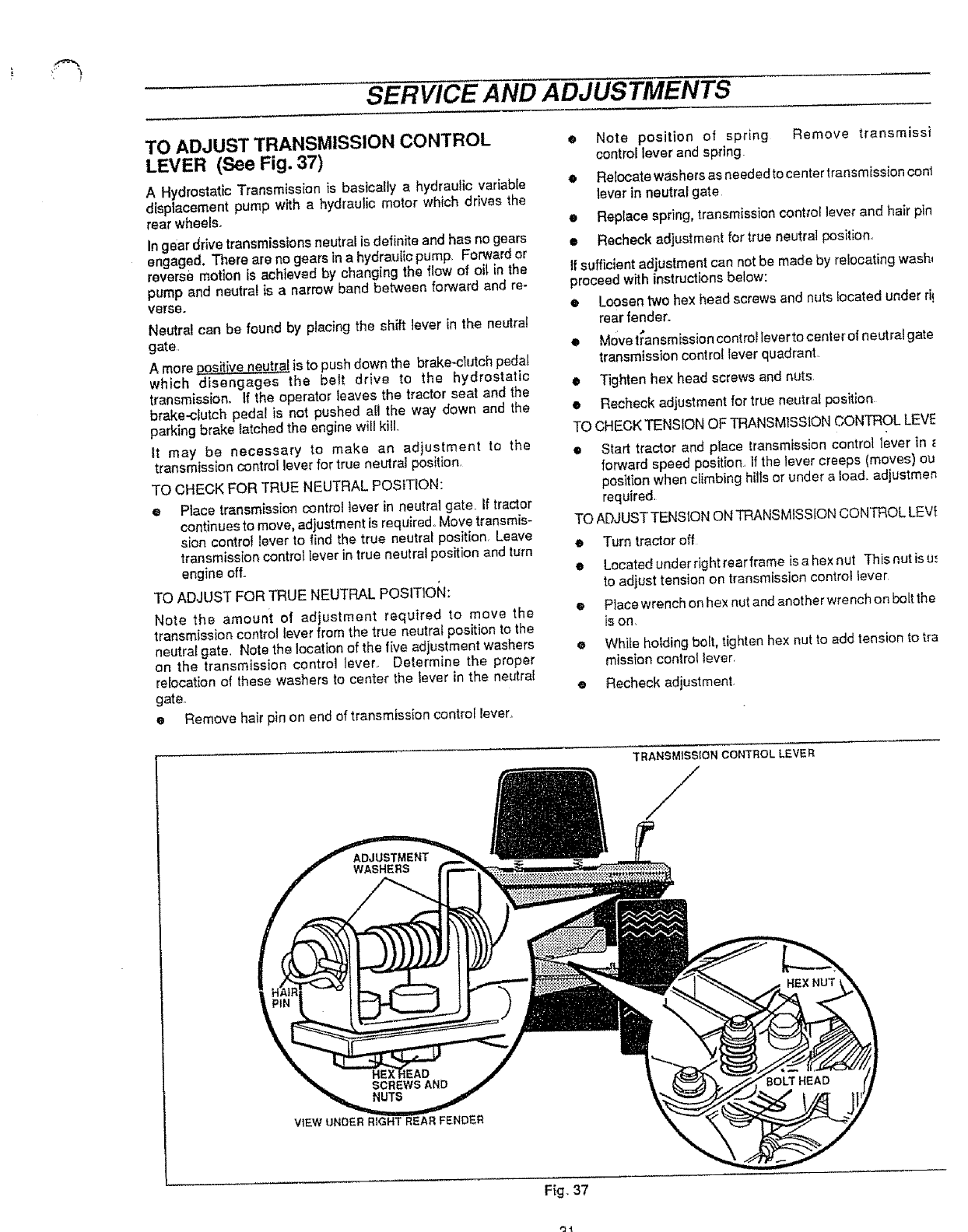
SERVICE AND ADJUSTMENTS
TO ADJUST TRANSMISSION CONTROL
LEVER (See Fig. 37)
A Hydrostatic Transmission is basically a hydraulic variable
displacement pump with a hydraulic motor which drives the
rear wheels_
In gear drive transmissions neutral is definite and has no gears
engaged, There are no gears in a hydraulic pump, Forward or
reverse motion is achieved by changing the flow of oil in the
pump and neutral is a narrow band between forward and re-
verse.
Neutral can be found by placing the shift ]ever in the neutral
gate,
A more _ps_tive _eut[a{ is to push down the brake-clutch pedal
which disengages the belt drive to the hydrostatic
transmission. If the operator leaves the tractor seat and the
brake-clutch pedal is not pushed all the way down and the
parking brake latched the engine will kiU,,
It may be necessary to make an adjustment to the
transmission control lever for true neutral position,
TO CHECK FOR TRUE NEUTRAL POSITION:
•Place transmission control lever in neutral gate. if tractor
continues to move, adjustment is required. Move transmis-
sion control lever to find the true neutral position, Leave
transmission control lever in true neutral position and turn
engine off.
TO ADJUST FOR TRUE NEUTRAL POSITiOkl:
Note the amount of adjustment required to move the
transmission control lever from the true neutral position to the
neutral gate. Note the location of the five adjustment washers
on the transmission control lever. Determine the proper
relocation of these washers to center the laver in the neutral
gate.
• Remove hair pin on end of transmission control lever.
@ Note position of spring Remove transmissi
control lever and spring.
e Relocate washers as needed to center transmission cont
lever in neutral gate
t Replace spring, transmission contro{ lever and hair pin
•Recheck adjustment for true neutral position°
If sufficient adjustment can not be made by re{ocating wash_
proceed with instructions below:
•Loosen two hex head screws and nuts located under ri!
rear fender_
•Move t_ansmission controllever to center o{ neutralgate
transmission control lever quadrant
•Tighten hex head screws and nuts
•Recheck adjustment for true neutra} position
TO CHECK TENSION OF TRANSMISSION CONTROL LEVE
•Start tractor and place transmission control lever in
forward speed position., if the lever creeps (moves) ou
position when climbing hills or under a load. adjustmen
required.
TO ADJUST TENSION ON TRANSMISSION CONTROL LEVI
• Turn tractor off
eLocated under right rear frame is a hex nut This nut is u..
to adjust tension on transmission control lever
ePlace wrench on hex nut and another wrench on bolt the
is on.
•While holding bo_t, tighten hex nut to add tension to tra
mission control lever
•Recheck adjustment
TRANSMISSION CONTROL LEVER
/
HEX NUT,
VIEW UNDER RIGHT REAR FENDER
Fig_ 37
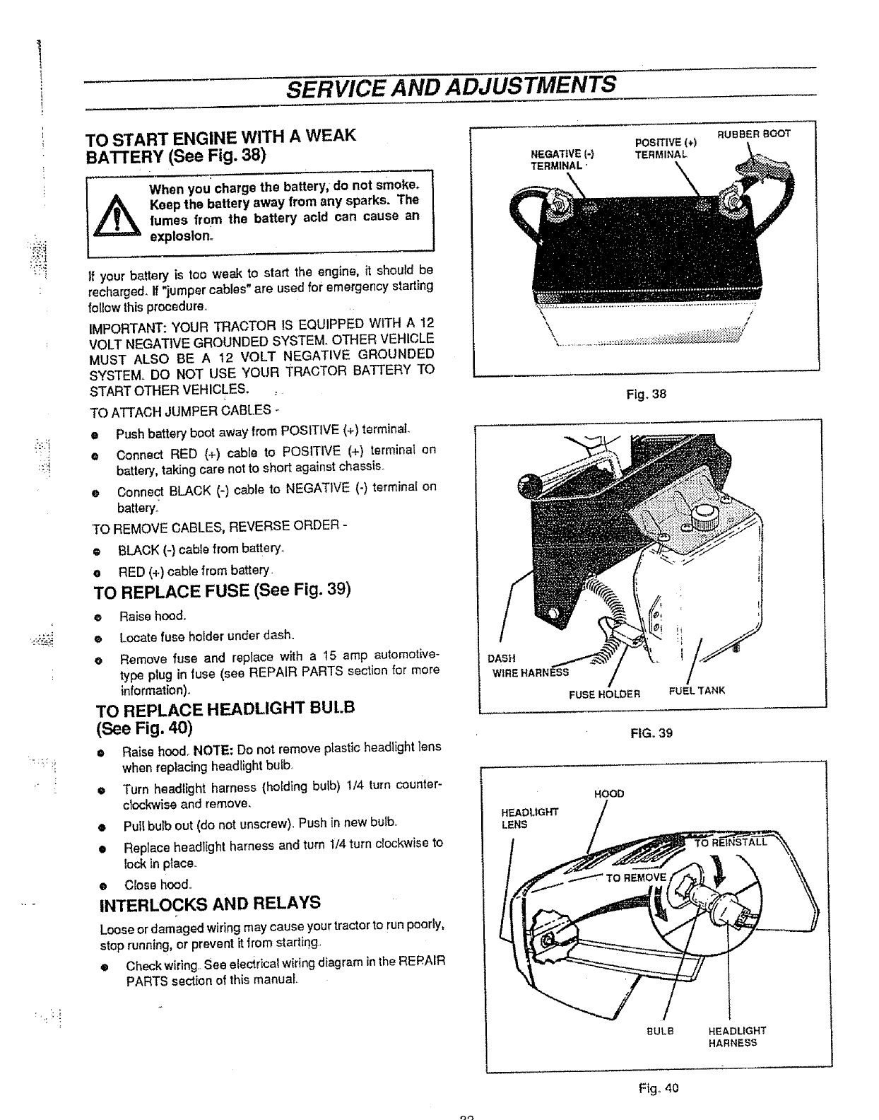
SERVICE AND ADJUSTMENTS
L
TO START ENGINE WITH A WEAK
BATTERY (See Fig. 38)
When you charge the battery, do not smoke.
Keep the battery sway from any sparks. Thefumes from the battery acid can cause an
explosion°
Ifyour batteryisloo weak to startthe engine,itshouldbe
recharged, If "jumper cables" are used for emergency starling
follow this procedure,
IMPORTANT: YOUR TRACTOR IS EQUIPPED WITH A t2
VOLT NEGATIVE GROUNDED SYSTEM. OTHER VEHICLE
MUST ALSO BE A 12 VOLT NEGATIVE GROUNDED
SYSTEM. DO NOT LISE YOUR TRACTOR BATTERY TO
START OTHER VEHICLES.
TO ATTACH JUMPER CABLES -
oPush battery boot sway from POSITIVE (+) terminal
@Connect RED (+) cabFe to POSITIVE (+) terminal en
battery, taking care not to short against chassis.,
oConnect BLACK (-) cable to NEGATIVE (-) terminal on
battery:
TO REMOVE CABLES, REVERSE ORDER -
®BLACK (-) cable from battery,
• RED (+) cable from battery.
TO REPLACE FUSE (See Fig. 39)
•Raise hood.
®Locate fuse herder under dash,
oRemove fuse and rap{ace with a 15 amp automotive-
type plug in fuse (see REPAIR PARTS section for more
information).
TO REPLACE HEADLIGHT BUI.B
(See Fig. 40)
•Raise hood_ NO'rE: Do not remove plastic headlight lens
when replacing headlight bulb
• Turn headlight harness (holding bulb) 1/4 turn counter-
clockwise and remove.
• Puli butb out (do not unscrew). Push in new bulb..
• Replace headlight harness and turn 1/4 turn clockwise to
lock in ptaca.
•Close hood.
INTERLOCKS AND RELAYS
Loose or damaged wiring may cause your tractor to run poorly,
stop running, or prevent itfrom starting
• Checkwiring See eleci.rical wiring diagram in the RERAIR
PARTS section of this manual
NEGATIVE (-)
TERMINAL"
DASH
WIRE HARNE_
FUSE HOLDER
POSITIVE (,)
TERMINAL
RUBBERBOOT
Fig. 38
FUEL TANK
FIG. 39
HOOD
HEADUGHT
LENS
BuLB HEADLIGHT
HARNESS
'3"3
Ftg. 40
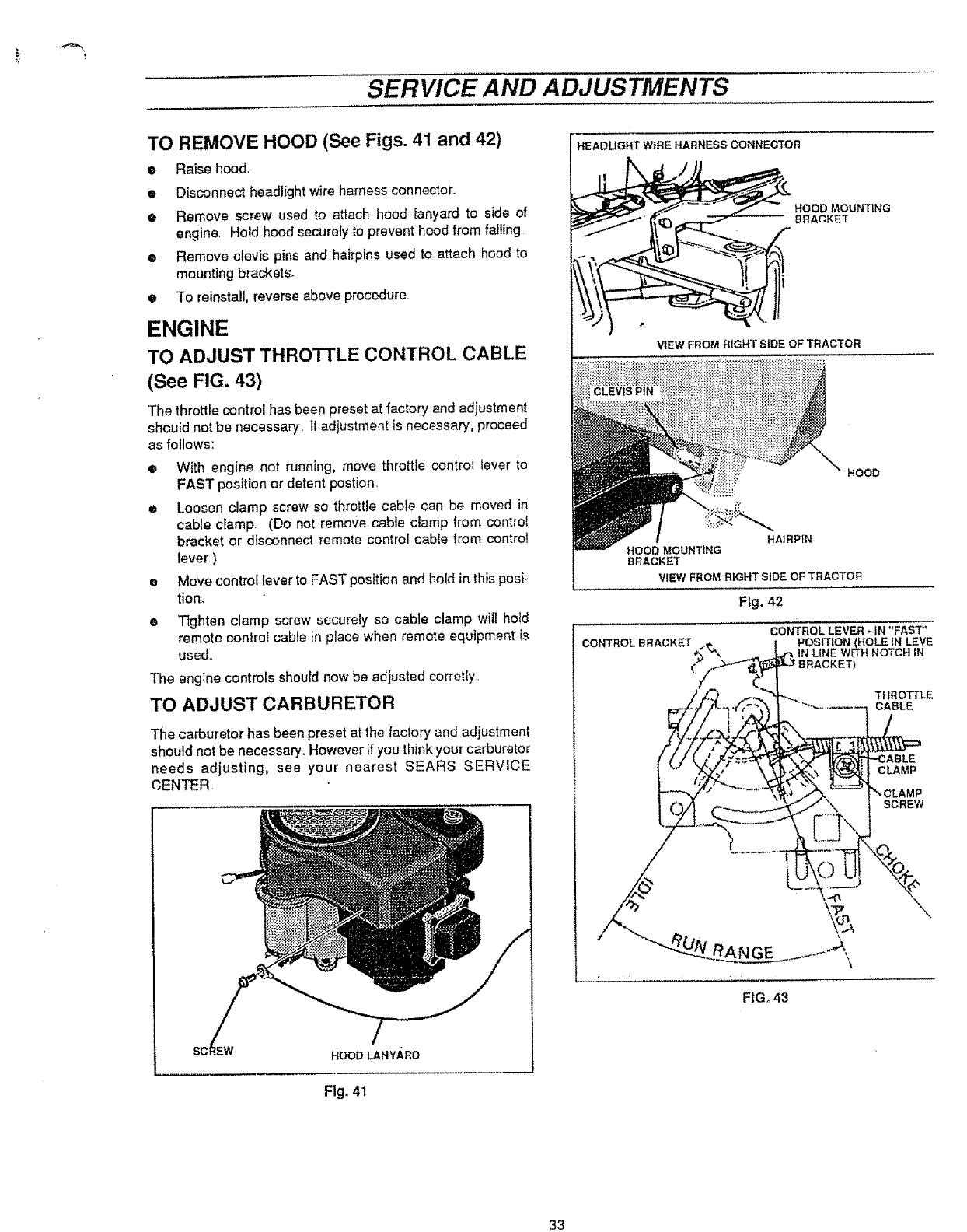
SERVICE AND ADJUSTMENTS
TO REMOVE HOOD (See Figs. 41 and 42)
•Raise hood,,
o Disconnect headlight wire harness connector.,
• Remove screw used to attach hood lanyard to side of
engine, Hold hood securety to prevent hood from falling
® Remove clevis pins and hairpins used to attach hood to
mounting brackets+
• To reinstall, reverse above procedure
ENGINE
TO ADJUST THROTTLE CONTROL CABLE
(See FIG. 43)
The throttle control has been preset at factory and adjustment
should not be necessary, If adjustment is necessary, proceed
as follows:
Q
Q
With engine not running, move throttle control lever to
FAST position or detent postion+
Loosen clamp screw so throttle cable can be moved in
cable clamp+ (Do not remo'_e cable cJamp from controJ
bracket or disconnect remote control cable from control
lever)
Move control lever to FAST position and hold in this posi-
tion.
Tighten clamp screw securety so cabte clamp will hotd
remote control cable in place when remote equipment is
used,,
The engine controls should now be adjusted corretfy,,
TO ADJUST CARBURETOR
The carburetor has been preset at the factory and adjustment
should not be necessary. However if you think your carburetor
needs adjusting, see your nearest SEARS SERVICE
CENTER.
HOOD LANYARD
Fig°41
HEADUGHT WIRE HARNESS CONNECTOR
HOOD MOUNTING
BRACKET
VIEW FROM RIGHT SiDE OF TRACTOR
HOOD
HAIRPIN
HOOD MOUNTING
BRACKET
VIEW FROM RIGHT SIDE OF TRACTOR
Fig+ 42
CONTROL BRACKET CONTROL LEVER - IN *'FAST"
POSMON (HOLE IN LEVE
, IN LINE WETH NOTCH IN
THROTTLE
CABLE
CLAMP
SCREW
,
FIG,, 43
33
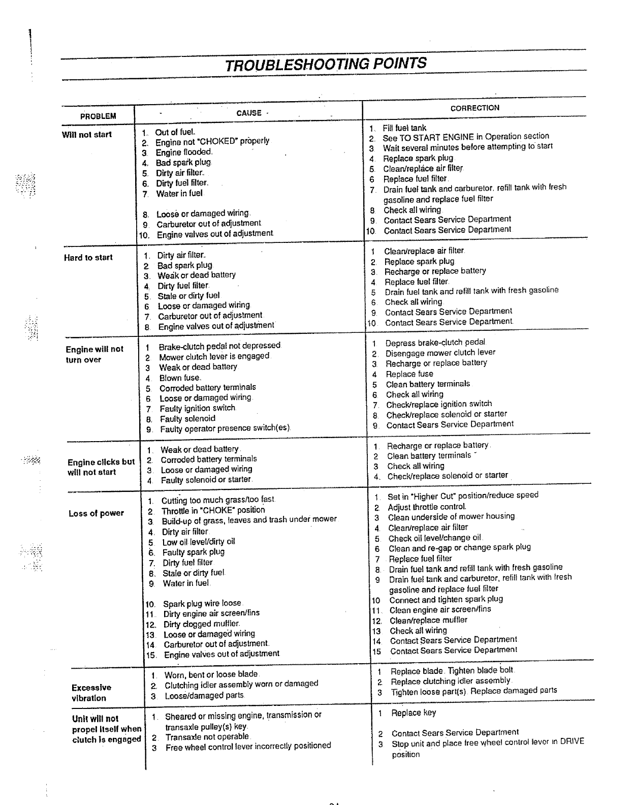
TROUBLESHOOTING POINTS
PROBLEM
Wilt not start
Hard to start
Engine will not
turin over
Engine clicks but
will not start
Loss of power
CAUSE -CORRECTION
1o Out of fuel
2. Engine not'CHOKED" properly
3Engine flooded,
4, Bad spark plug
5Dirty air filter.,
6. Dirty fuel filter.,
7, Waterinfuel
8. Loos_ or damaged wiring.
9 Carburetor out of adjustment
10,. Engine valves out of adjustment.
t, Dirty air filter.,
2, Bad spark plug
3. We_;k or dead battery
4: Dirty fuel filter
5Stale or dirty fuel
6 Loose or damaged wiring
7. Carburetor out of adjustment
8 Engine valves out of adjustment
1 Brake-clutch pedal not depressed
2Mower clutch lever is engaged
3 Weak or dead battery
4 Blown fuse_
5Corroded battery terminals
6 Loose erdamagedwidng
7 Faulty ignition switch
8, Faulty solenoid
9, Faulty operator presence swilch(es)
1Weak or dead battery
2. Corroded battery terminals
3Loose or damage d wiring
4 Faulty solenoid or starter
1, Cutting too much grassftoo fast
2 Throttle in "CHOKE" position
3 Build-up of grass, leaves and trash under mower
4, Dirty air filter
5Low oil levelldirty oil
6. Faulty spark plug
7: Dirty fuel filter
8, Stale or dirty fuel
9. Water in fuel
10. Spark plug wire loose
i11 Dirty engine air screen/fins
12.. Dirty clogged muffler
ii3 Loose or damaged wiring
14 Carburetor out ef adjuslment,
15, Engine valves out of adjustment
1., Fill fuel tank
2, See TO START ENGINE in Operatio n section
3. Wait several minutes before attempting tO start
4 Replace spark plug
5. Ctean/rep_ace air filter
6 Replace fuel filter
7 Drain fuel tank and carburetor, reiil] tank wilh fresh
gasoline and replace fuel filter
8 Check all wiring
9, Contact Sears Service Department
10. Contact Sears Service Department
1 Clean/replace air filter
2, Replace spark plug
3 Recharge or replace battery
4 Replace fuel filter
5 Drain fuel tank and refill tank with fresh gasoline
6 Check all wiring
9, Contact Sears Service Department
"tO Contact Sears Service Department.
I Depress brake-clutch pedal
2 Disengage mower clutch lever
3. Recharge or replace battery
4 Replace fuse
5Clean balter,/terminals
6 Check all wiring
7, Chec_trepiace ignifio_ switch
8 ChecWreplace solenoid or starter
9 Cor_tact Sears Service Department
1 Recharge or replace battery
2 Clean battery terminals "
3 Check all wiring
4. Check/replace solenoid or starter
t Set in "Higher Cut" position/reduce speed
2, Adjust Ihrottle control,
3 Clean underside of mower housing
4 Clean/replace air filter
5 Cheek oil leveltehange oil
6 Clean and re-gap or change spark plug
7 Replace fuel filter
8, Drain fuel tank and refill lank with fresh gasoline
9 Drain fuel tank and carburetor, refill lank with _'resh
gasoline and laplace lue[ filter
tO Connect and tighten spark plug
11 Clean engine air screenlfins
12 Glean/replace muffler
13 Check all wiring
14. Contact Sears Service Department
15 Contact Sears Service Department
1Worn, bent or loose blade I Replace blade. Tighten blade _oolt
Excessive 2., Clutching idler assembly worn or damaged 2 Replace clutching idler assembly
vibration 3 Looseldamaged parts 3 Tighten loose part(s) Replace damaged parts
I 1 RePlace key
,_heared or missing engine, transmission Or
transaxle pulley(s) key.
Transaxle not operable
Free wheel control lever ineorreclly positioned
2
3
URI! wlll not
propel Itself when
clutch is engaged 2Contact Sears Service Department
3 S!op unil and place tree wheel control lever EnDRIVE
position
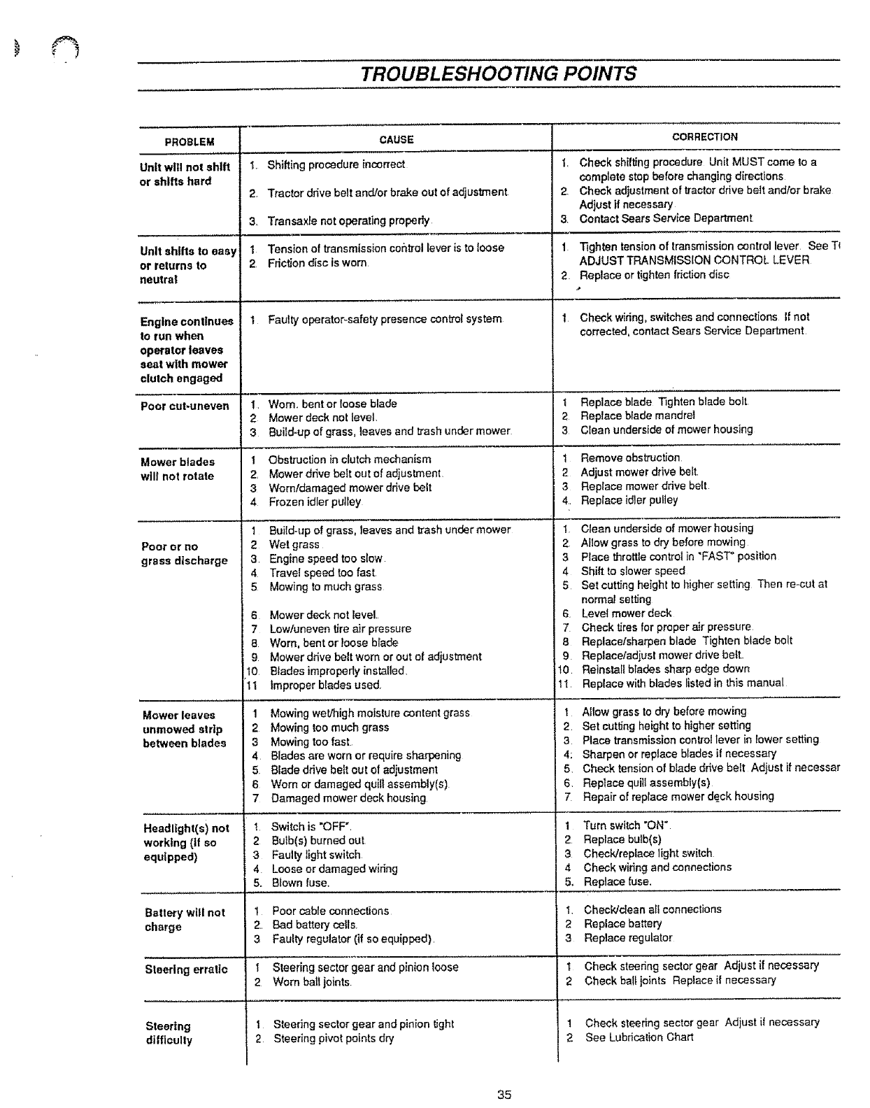
TROUBLESHOOTING POINTS
CORRECTION
PROBLEM
Unit will not shift
or shifts hard
Unit shifts to easy
or returns to
neutral
Engine continues
to run when
operator leaves
seat with mower
clutch engaged
CAUSE
1, Shiftingprocedure incorrect
2 Tractor drivebeltan&Jotbrake outof adjustment
3. Transaxle notoperatingproperly
1 Tension of transmissioncor_trollever isto loose
2 Frictiondiscis worn
I Faulty operator-safety presence control system
2,
3
1
2
Check shifting procedure Unit MUST come to a
complete stop before changing directions
Check adjustment of tractor drive belt and/or brake
Adjust if necessary
Contact Sears Service Department
Tighten tension of transmission control lever See T{
ADJUST TRANSMISSION CONTROL LEVER
Replace or lighten friction disc
Check wiring, switches and connections If not
corrected, contact Sears Serv{ce Department
Poor cut*uneven 1 Worn, bent or loose blade I Replace blade Tighten blade bolt
2Mower deck not level, 2 Replace blade mandrel
3Build-up of grass, teaves and trash under mower 3 Clean underside of mower housing
Mower blades
will not rotate
1 Obstruction in clutch mechanism
2, Mower dr_ve belt out of adjustment
3 Worn/damaged mower drive belt
4 Frozen idlerputtey
1 Build-up of grass, leaves and trash under mower
1Remove obsbuction
2 Adjust mower drive belt,
3Replace mower drive bert
4. Replace idler pulley
1 Clean underside of mower housing
Poor or no
grass discharge
2Wet grass
3Engine speed too slow
4Travel speed too fast
5 Mowing to much grass
6 Mower deck not level,
7Low/uneven tire air pressure
2 Allowgrass to dry before mowing
3Place throttlecontrol in "FAST" position
4 Shift to slower speed
5 Set cutting heighl to higher setting Then re-cut at
normal setting
6 Level mower deck
7 Check tires for proper air pressure
Mower leaves
unmowed strip
between blades
Headlight(s) not
working (If so
equipped)
Battery will not
charge
Steering erratic
Steering
difficulty
B
9
10
11
1
2
3
4
5
6
7
Worn. bent or loose blade 8
Mower drive belt worn or out el edjusb'nent 9
Blades improperly installed, rl!0
improper blades used, t 1
Mowing wet/high moisture content grass 1
Mowing too much grass 2,
Mowing too fast 3
Blades are worn or require sharpening 4;
Blade drive belt out of adjustment 5
Worn or damaged quill assembly(s) 6
Damaged mower deck housing 7
1 Switch is "OFF"
2 Bulb(s) burned out
3Faulty light switch
4 Loose or damaged wiring
5. Blown fuse.
1Poor cable cennections
2,, Bad battery cells.
3Faulty regulator (if so equipped),
1 Steering sector gearand pinion loose
2 Worn bali joints
1 Steering sector gear and pinion tigh!
2 Steering pivot points dry
Replace/sharpen blade Tighten blade bolt
Replace/adiusl mower drive belt.,
Reinstall blades sharp edge down
Replace with blades listed in this manual
Allow grass to dry before mowing
Set cutting height to higher setting
Place transmission control lever in lower setting
Sharpen or replace blades if necessary
Check tension of blade drive belt Adjust il necessar
Replace quill assembly(s)
Repair of replace mower de=okhousing
1 Turn switch "ON"
2 Replace bulb(s)
3Check/replace light switch
4 Check wiring and connections
5, Replace fuse,
1 Check/dean all connections
2 Replace battery
3Replace regulator
1 Check steering sector gear Adjust if necessary
2Check ball joints Replace if necessary
1 Check steering sector gear Adjust if necessary
2 See Lubrication Chart
35
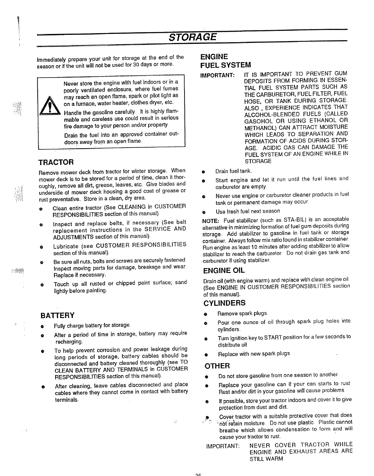
i
Immediately prepare your unit for storage at the end of the
season or if the unit will not be used for 30 days or more°
Never store the engine with fuel indoors or in a
poorty ventilated enclosure, where fuel fumes
may reach an open flame, spark or pilot light as
on a furnace, water heater, clothes dryer, etc.
Handle the gasoline carefully. It is higNy flam-
mable and careless use could result in serious
fire damage to your person and/or property
Drain the fuel into an approved container out-
doors away !torn an open flame.
TRACTOR
Remove mower deck from tractor for winter storage, When
mower deck is to be stored for a period of time, clean it thor-
oughly, remove all dirt, grease, leaves, etc Give blades and
underside of mower deck housing a good coat of grease or
rust preventative. Store in a clean, dry area,
•Clean entire tractor (See CLEANING in CUSTOMER
RESPONSIBILITIES section of this manual)
e Inspect and replace belts, if necessary (See belt
replacement instructions in the SERVICE AND
ADJUSTMENTS section of this manual).
• Lubricate (see CUSTOMER RESPONSIBILITIES
section of this manuaI).
@Be sure al! nuts, botts and screws are securely fastened
Inspect moving parts for damage, breakage and wear
Replace if necessary.
•Touch up all rusted or chipped paint surface; sand
}fghtly before painting.
BATTERY
• Fully charge battery for storage.
e After a period of time in storage, battery may require
recharging.
•To help prevent corrosion and power leakage during
long periods of storage, battery cables should be
disconnected and battery cleaned thoroughly (see TO
CLEAN BA]-FERY AND TERMINALS in CUSTOMER
RESPONSIBILITIES section of this manual)
• After cleaning, leave cables disconnected and place
cables where they cannot come in contact with battery
terminals,
ENGINE
FUEL SYSTEM
IMPORTANT: IT IS IMPORTANT TO PREVENT GUM
DEPOSITS FROM FORMING IN ESSEN-
TIAL FUEL SYSTEM PARTS SUCH AS
THE CARBURETOR, FUEL FILTER, FUEL
HOSE, OR TANK DURING STORAGE
ALSO , EXPERIENCE INDICATES THAT
ALCOHOL-BLENDED FUELS (CALLED
GASOHOL'OR USING ETHANOL OR
METHANOL) CAN ATTRACT MOISTURE
WHICH LEADS TO SEPARATION AND
FORMATION OF ACIDS DURING STOR_
AGE. ACIDIC GAS CAN DAMAGE THE
FUEL SYSTEM OF AN ENGINE WHILE IN
STORAGE
•Drain fuel tank.
@Start engine and let it run until the rue/ lines and
carburetor are empty
• Never use engine or carburetor cleaner products in fuel
tank or permanent damage may occur
e Use fresh fuel next season
NOTE: Fuel stabilizer (such as STA-BtL) is an acceptable
alternative in minimizing formation of fuel gum deposits during
storage Add stabilizer to gasoline in fuei tank or storage
container. Always follow mix ratio found in stabiilzer container
Run engine as least 10 minutes after adding stabilizer to allow
stabilizer to reach the carburetor Do not drain gas tank and
carburetor if using stabilizer
ENGINE OIL
Drain oil (with engine warm) and repface with clean engine oil
(See ENGINE IN CUSTOMER RESPONSIBILITIES section
of this manual).
CYLINDERS
eRemove spark plugs
e Pour one ounce of oil through spark plug holes into
cylinders,
• Turn ignition key to START position for a few seconds to
distribute oil
•Replace with new spark plugs
OTHER
IMPORTANT:
• Do not store gasoline from one season to another
e Replace your gasoline can if your can starts to rust
Rust andtor dirt in your gasoline will cause problems
• If possible, store your tractor indoors and cover it to give
protection from dust and dirt.
.e Cover tractor with a suitable protective cover that does
_:_F "nb{'re_ain moisture. Do not use plastic Plastic cannot
breathe which alIows condensation to form and wilt
cause your tractor to rust
NEVER COVER TRACTOR WHILE
ENGINE AND EXHAUST AREAS ARE
STILL WARM
q_

i
CUT HERE TO USE SLOPE GUIDE
-SIGHT AND HOLD THIS GUIDE LEVEL WITH A VERTICAL
TREE, A CORNER OF A STRUCTURE, A POWER LINE
POLE, OR A FENCE POST.
f-.._
10 DEGREES 15 DEGREES
l l
up or down slopes,
across the face of slopes.
To determine if a slope Is safe to mow: (1) disengage the blade(s), (2) put the unit in reverse, and (3) try to back straight up the slope. If you can
back up the slope, it is generally safe to mow. However, if you do not feel safe, or if you are not completely sure, use this guide and do not mow
a slope that Is greater than 15 degrees. If the rldlng mower is used with a pull-behind attachment, do not operate the unit on a slope that Is greater
than 10 degrees.
A!5 degree slope is a hill that increases in height at approximately 2.5 feet in 10 feet.
A 10 degree slope Is a hill that Increases in height at approximately 1.7 feet in 10 feet.
_k Use extreme care at all times, and avoid sudden turns or maneuvers. Follow other instructions tn this manual for safety tn mowing on
...... _ .... ,,-, -. ,,i,-_=,_.... ,,,=r, .,t ,r,r rl,,'_uJnel_n=_,= n==v_r _P.rt_.,€ the face of slopes. Use extra care when oloeratlng on or near slopes
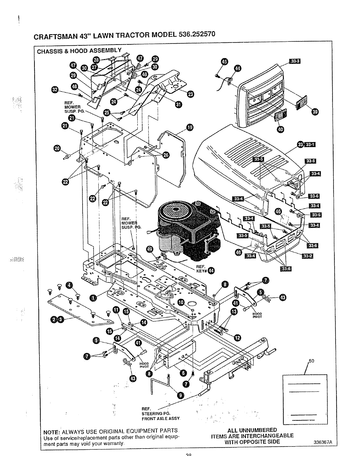
CRAFTSMAN 43" LAWN TRACTOR MODEL 536.252570
CHASSIS & HOOD ASSEMBLY
HOOO
RVOT
REF,
STEERING P(_,
FRONT AXLE ASSY
NOTE: ALWAYS USE ORIGINAL EQUIPMENT PARTS•
Use of Service!replacement parts other than original equip-
ment parts may void your warranty.
ALL UNNUMBERED
ITEMS ARE INTERCHANGEABLE
WITH OPPOSITE SIDE 336367A
q_
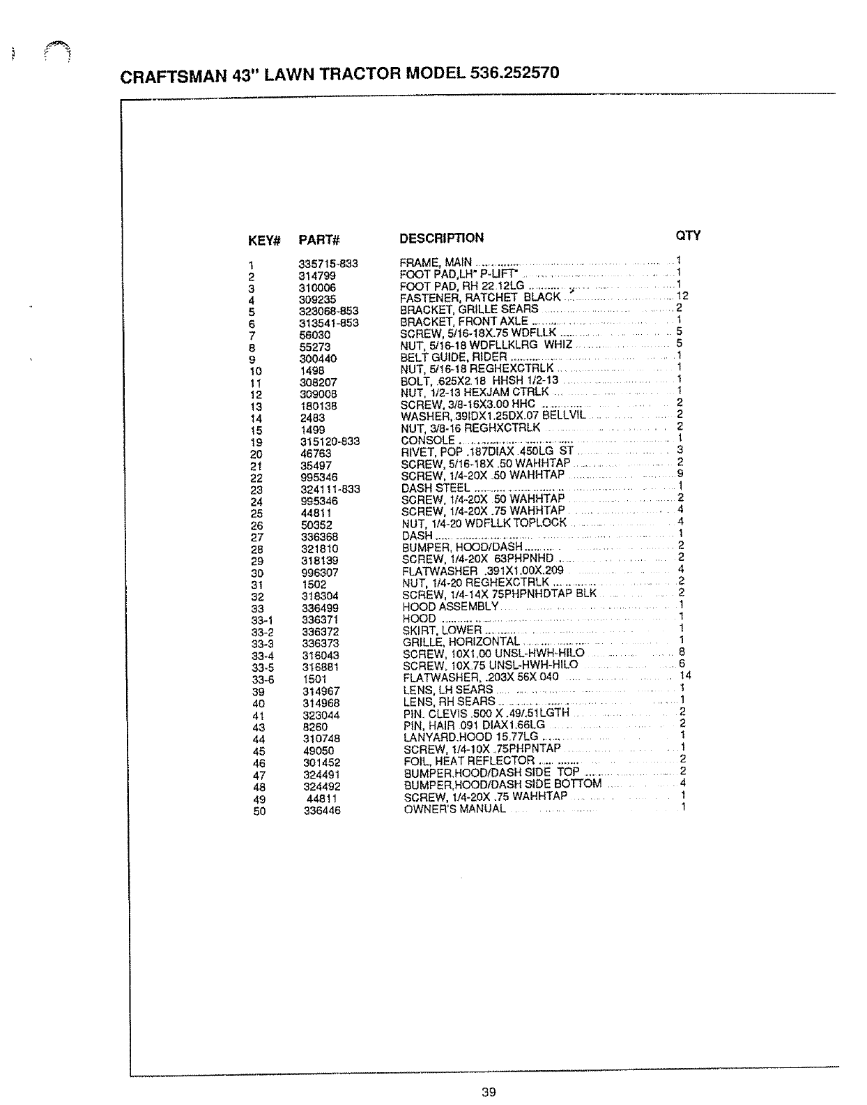
CRAFTSMAN 43" LAWN TRACTOR MODEL 536.252570
KEY# PART# DESCRIPTION
1335715-833
2314799
3 310006
4 309235
5323068-853
6313541-853
7 56030
8 55273
9 800440
10 1498
11 308207
12 309008
13 180138
14 2483
15 1499
19 3151_J0-833
2O 46763
21 35497
22 995346
23 324111-833
24 995346
25 44811
26 50352
27 336368
28 321810
29 318139
30 996307
31 1502
32 318304
33 336499
33-1 336371
33-2 336372
33-3 336373
33-4 316043
33-5 316881
33-6 I501
39 314967
40 314968
41 323044
43 8260
44 310748
45 49050
46 301452
47 324491
48 324492
49 44811
50 336446
QTY
FRAME, MAIN .................................................... I
FOOT PAD,LH* P-LIFT" ............................... 1
FOOT PAD, RH 22 12LG ............................... 1
FASTENER, RATCHET BLACK "_ ........................ 12
BRACKET, GRILLE SEARS .......................... 2
BRACKET, FRONT AXLE .......................................... 1
SCREW, 5/16-I8X.75 WDFLLK .................... 5
NUT, 5/t6-18 WDFLLKLRG WHIZ ................. 5
BELT GUIDE, RIDER .................................... 1
NUT, 5/16-18 REGHEXCTRLK ................................ 1
BOLT, 625X218 HHSH 1t213 ................................... 1
NUT, 1t2q3 HEXJAM CTRLK ................................ 1
SCREW, 3/8-I6)(300 HHC .................. 2
WASHER, 391DX 1 25DX 07 BELLVIL ..................... 2
NUT, 3/8-16 REGHXCTRLK ...................... 2
CONSOLE ......................................................... 1
RLVET, POP .1B7DIAX .450LG ST ....................... 3
SCREW, 5116q 8X .50 WAHHTAP ..................... 2
SCREW, 1/4-20X 50 WAHHTAP ............... 9
DASH STEEL ............................................... 1
SCREW, 1/4-20){ 50 WAHHTAP .................. 2
SCREW, l/4-20X .75 WAHHTAP ............. 4
NUT, I14-20 WDFLLK TOPLOCK .............. 4
DASH ........................................................ 1
BUMPER, HOOD/DASH ....................... 2
SCREW, 1/4-20X 63PHPNHD ........................... 2
FLATWASHER 391Xl 00X209 ...... 4
NUT, 1t4-20 REGHEXCTRLK ........................ 2
SCREW, 1/4 14X 75PHPNNDTAP BLK ............... 2
HOOD ASSEMBLY ............................................ 1
HOOD .................................................1
SKIRT, LOWER ........................... !
GRILLE, HORIZONTAL ....................................... 1
SCREW, IOX1,00 UNSL-HWH-HILO ........... 8
SCREW. 10X75 UNSL-HWH-HILO .......... 6
FLATWASHER, .203X 56X 040 ............. 14
LENS, LH SEARS ............................ I
LENS, RH SEARS .............................................. 1
PiN CLEVIS 500 X 49L51LGTH ...................... 2
PIN, HAIR 09t DIAXI66LG ............................ 2
LANYARDHOOD 15 77LG .................. 1
SCREW, 1/4-10X 35PNPNTAP ........................1
FOIL, HEAT REFLECTOR ............................. 2
BUMPER HOOD/DASH SIDE TOP ....................... 2
BUMPER,HOOD/DASH SIDE BOTTOM ....... 4
SCREW, 1/4-2ox .75 WAHHTAP ........... t
OWNER'S MANUAL ............ 1
39
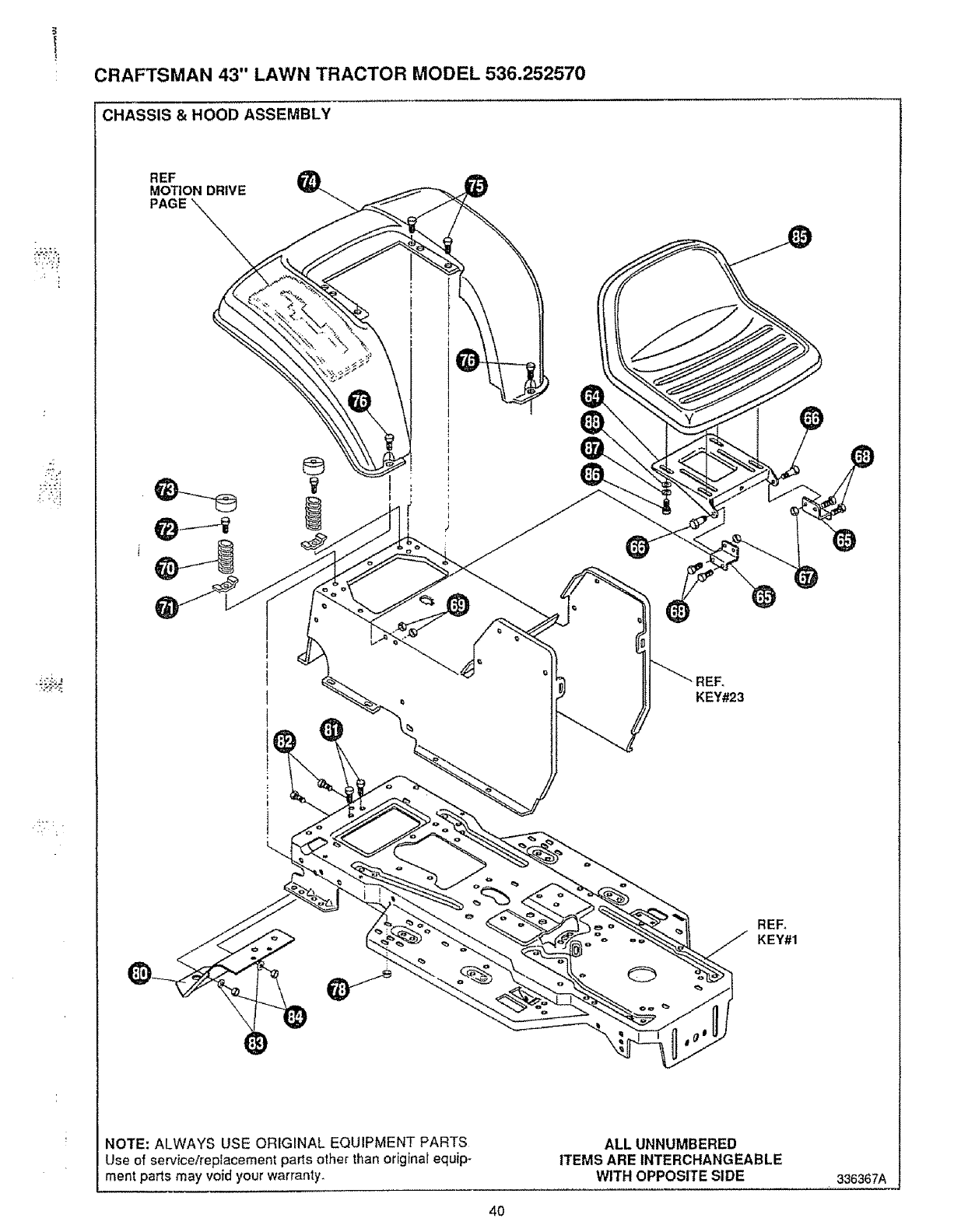
i!+" : ,
CRAFTSMAN 43" LAWN TRACTOR MODEL 536.252570
-CHASSIS & HOOD ASSEMBLY
REF
MOTION DRIVE
PAGE
®
KEY#23
REF,
KEY#1
NOTE: ALWAYS USE ORIGINAL EQUIPMENT PARTS
Use of servicer'replacement parts other than original equip-
ment parts may void your warranty.
ALL UNNUMBERED
ITEMS ARE INTERCHANGEABLE
WITH OPPOSITE SIDE 336367A
4O
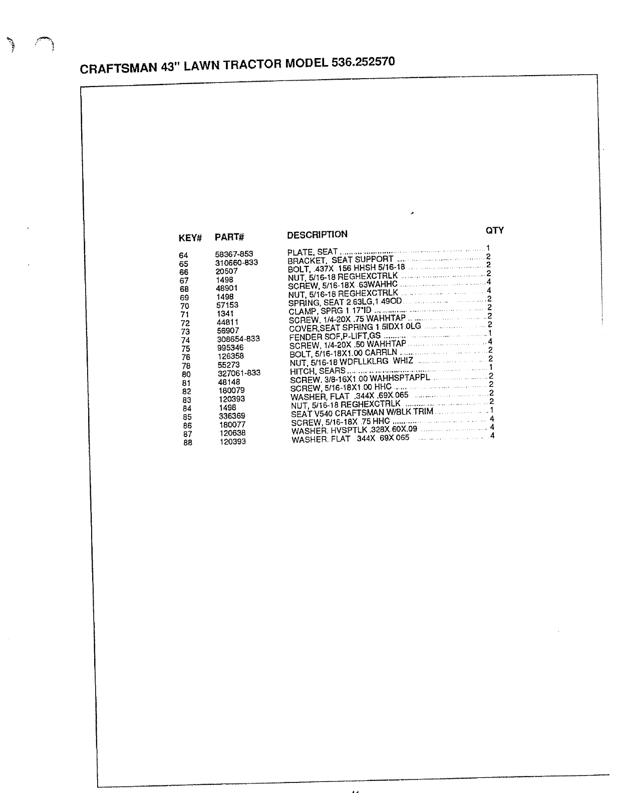
CRAFTSMAN 43" LAWN TRACTOR MODEL 536.252570
KEY# PART# DESCRIPTION
64 58367-853
65 310660-833
66 20507
67 1498
68 48901
69 1498
70 57153
71 1341
72 44811
73 56907
74 308654-833
75 995346
76 126358
78 55273
80 32706 t-633
81 48148
82 160079
83 120393
84 1496
85 336369
86 180077
87 12O638
88 120393
QTY
PLATE, SEAT ...................................................... 1
BRACKET, SEAT SUPPORT .................................... 2
BOLT, .437X 156 HHSH 5116- t8 ............................ 2
NUT, 5/16-18 REGHEXCTRLK .................................. 2
SCREW, 5/16-18X .63WAHHC .................................... 4
NUT, 5116-18 REGHEXCTRLK .............................. 4
SPRING, SEAT 2.63LG,t 4god ........................ 2
CLAMP, SPRG 1 17"1D ......................................... 2
SCREW, 1t4-20X .75 WAHHTAP ..................... 2
COVER,SEAT SPRING 1 51DX10LG ........................... 2
FENDER SOF, P-L1FT,GS ................................... 1
SCREW, 1/4-20X °50 WAHHTAP ....................... 4
BOLT, 5116-18X1.00 CARRLN ........................... 2
NUT, 5/16-18 WDFLLKLRG WHIZ ..................... 2
HITCH, SEARS ......................................................... 1
SCREW. 3,'8-16Xl .00 WAHHSPTAPPL ................... 2
SCREW, 5116-18X1 00 HHC ................................ 2
WASHER, FLAT .344X .69X065 ......................... 2
NUT, 5/16-18 REGHEXCTRLK ............................... 2
SEAT V540 CRAFTSMAN WJBLK TRIM ................. 1
SCREW, 5f16-18X .75 HHC .............................. 4
WASHER. HVSPTLK .328X 60X.09 ...................... 4
WASHER. FLAT 344X 69X065 ................... 4
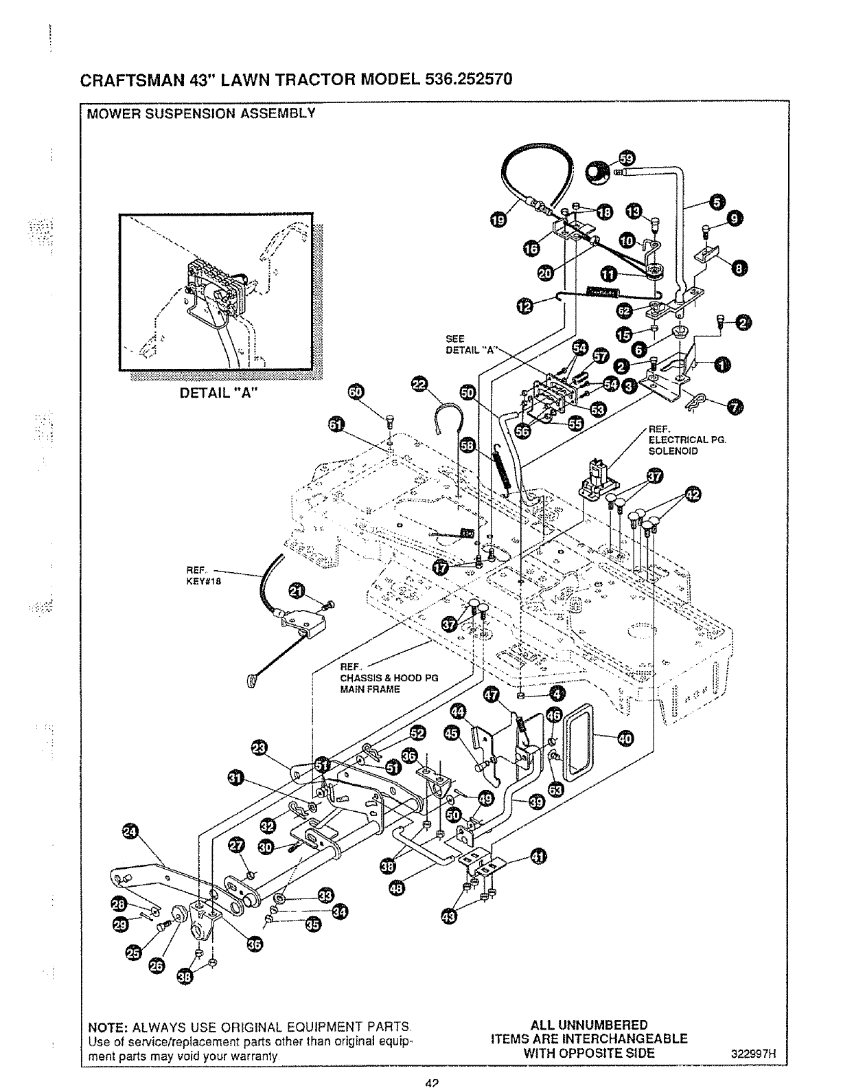
-!
CRAFTSMAN 43" LAWN TRACTOR MODEL 536,252570
MOWER SUSPENSION ASSEMBLY
SEE
DETAIL "A"
REF_
KEY#18
CHASSIS & HOOD PG
MAIN FRAME
ELECTRICAL PG,
SOLENOID
NOTE: ALWAYS USE ORIGINAL EQUIPMENT PARTS,
Use of service/replacement parts other than original equip-
ment parts may void your warranty
ALL UNNUMBERED
ITEMS ARE INTERCHANGEABLE
WITH OPPOSITE SIDE 322997H
4_
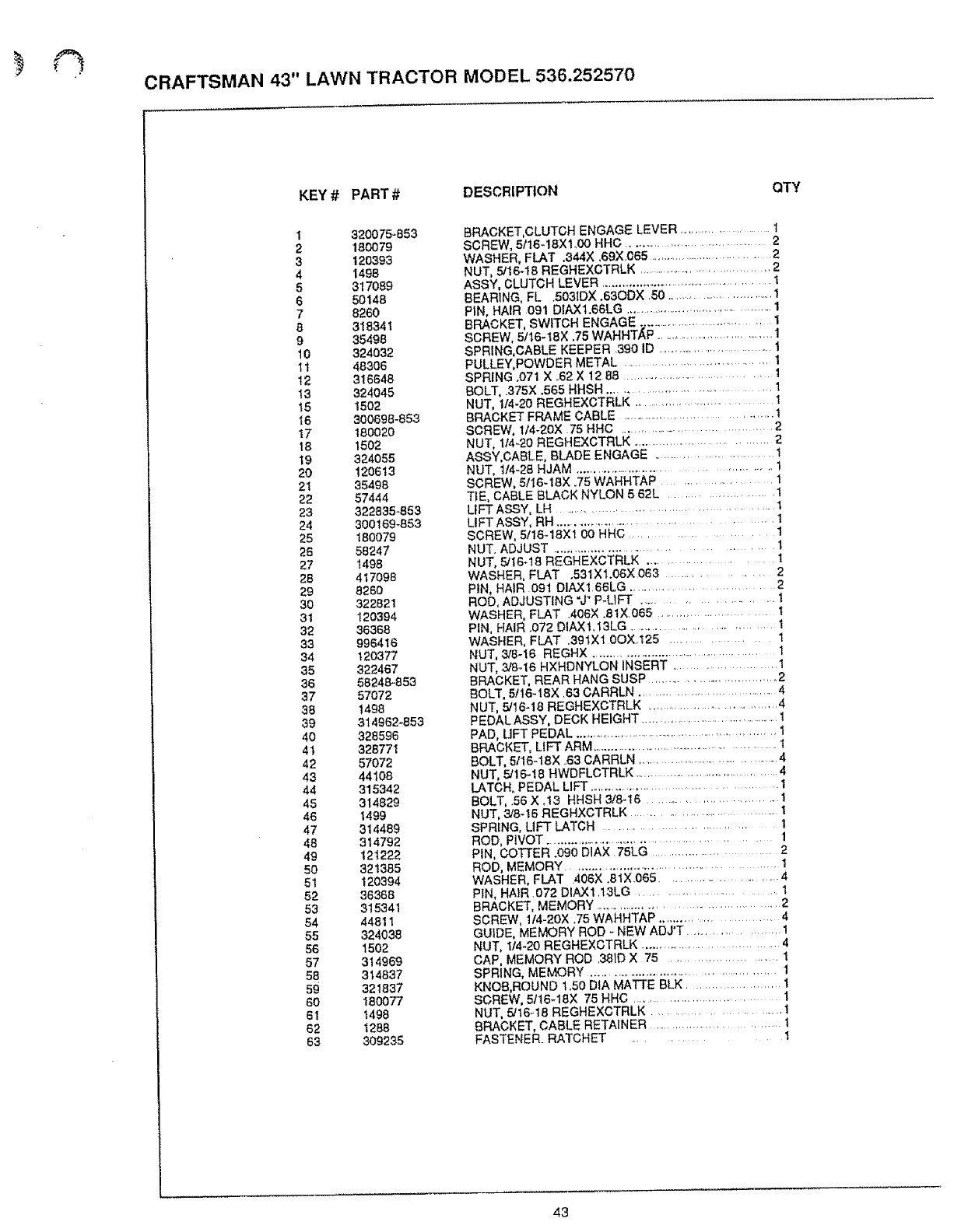
CRAFTSMAN 43" LAWN TRACTOR MODEL 536.252570
KEY # PART #DESCRIPTION QTY
I320075-853
2180079
3120398
4 1498
5 317089
650148
7 8260
8 318341
935498
10 324032
11 48306
12 316646
13 324045
15 1502
16 300698-853
17 18O020
18 1502
19 324055
20 120613
21 35498
22 57444
23 322835-883
24 300169-853
25 180079
26 58247
27 t498
28 417098
29 8260
30 322821
31 120394
32 36368
33 996416
34 120377
35 322467
36 58248-853
37 57072
38 1498
39 314962-853
40 328596
41 328771
42 57072
43 44108
44 315342
45 314829
46 1499
47 314489
48 314792
49 121222
50 321385
51 120394
52 36388
53 315341
84 44811
55 324038
56 1502
57 314969
53 314837
59 321837
80 18OO77
61 t498
62 1288
63 309235
BRACKET, CLUTCH ENGAGE LEVER ................... 1
SCREW, 5116-18Xl.00 HHC ................................. 2
WASHER, FLAT .344X .69X.065 ............................... 2
NUT, 5!16-18 REGHEXCTRLK ................................... 2
ASSY, CLUTCH LEVER ................................................... I
BEARING, FL .5031DX .63ODX .50 ............................... 1
PIN, HAIR 091 DIAX1.66LG ............................................ 1
BRACKET, SWITCH ENGAGE .................................. 1
SCREW, 5116-18X .75 WAHHT._P ................................. 1
SPRING,CABLE KEEPER 390 ID ............................... 1
PULLEY, POWDER METAL ................................. I
SPRING .071 X .62 X 12 88 ................................ 1
BOLT, .375X .565 HHSH ................................. l
NUT, 1/4-20 REGHEXCTRLK ............................. 1
BRACKET FRAME CABLE ...................................... t
SCREW, 114-20X 75 HHC ................................... 2
NUT, 1/4-20 REGHEXCTRLK ................................. 2
ASSY,CABLE, BLADE ENGAGE .................. 1
NUT, 1t4-28 HJAM ............................................ 1
SCREW, 5/16-18X .75 WAHHTAP ........................... 1
T_E, CABLE BLACK NYLON 5 62L ............... 1
LIFT ASSY, LH .......................................... 1
LIFT ASSY, RH .................................. 1
SCREW, 5/t6-18Xt 00 HHC ............................ 1
NUT. ADJUST ................................................. 1
NUT. 5/t6-18 REGHEXCTRLK ................. 1
WASHER, FLAT .531X1.06X063 ........................ 2
PiN, HAiR 091 OlAX166LG ....................... 2
ROD, ADJUSTING =J"P-UFT .................... l
WASHER, FLAT .406X .8tX065 ................................ 1
PEN, HAIR .072 DIAX1.I3LG .......................... 1
WASHER, FLAT .391X1 0OX.125 ................. I
NUT, 3/6-16 REGHX ........................................... 1
NUT, 3!8-16 HXHDNYLON iNSERT .................. I
BRACKET, REAR HANG SUSP ............................... 2
BOLT, 5116-18X .83 CARRLN ............................... 4
NUT, 5/16-18 REGHEXCTRLK .................................. 4
PEDAL ASSY, DECK HEIGHT .....................................
PAD, UFT PEDAL .......................................................... 1
BRACKET, LIFT ARM ................................................. 1
BOLT, 5116-18X .63 CARRLN ................................................. 4
NUT, 5,_16-18 HWDFLCTRLK ................................ 4
LATCH. PEDAL LIFT .......................................... 1
BOLT, .56X.13 HHSH 3/8-16 .............................. 1
NUT, 3/8-16 REGHXCTRLK ................................ I
SPRING, LiFT LATCH ....................... 1
ROD, PIVOT .................................................. 1
PIN, COTTER .090 DiAX. 75LG .................................... 2
ROD, MEMORY ......................................... 1
WASHER, FLAT 406X.81X065 ....................... 4
PiN, HAiR .072 DIAX1 13LG .................. 1
BRACKET, MEMORY ...................................... 2
SCREW, 1/4-20X .75 WAHHTAP ......................... 4
GUIDE, MEMORY ROD - NEW ADJ'T .................. 1
NUT, 114-20 REGHEXCTRLK ............................... 4
CAP, MEMORY ROD .381D X 75 ..................... 1
SPRING, MEMORY ........................................... 1
KNOB, ROUND 1.50 D1A MATTE BLK ................... 1
SCREW, 5/16-18X 75 HHC ............................ 1
NUT, 5/16_18 REGHEXCTRLK ......................... 1
BRACKET, CABLE RETAINER .......................... t
FASTENER. RATCHET .................. 1
43
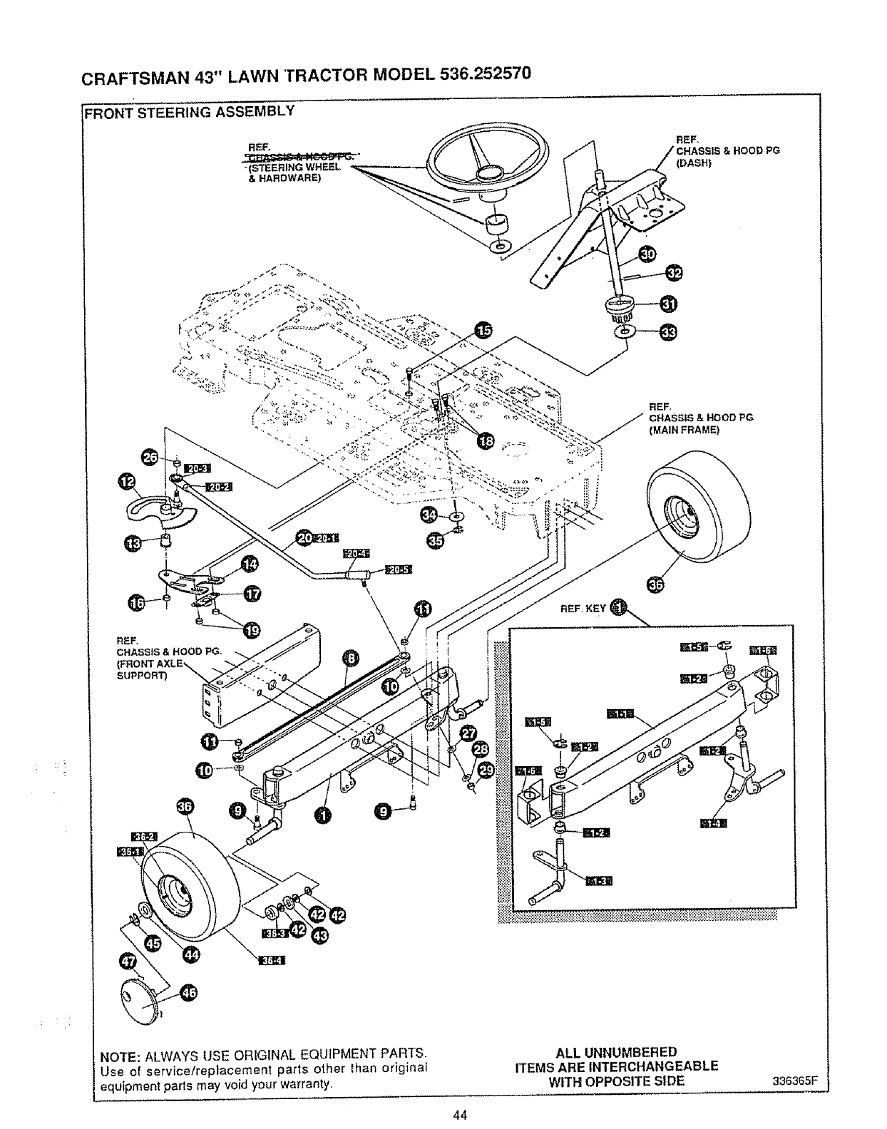
CRAFTSMAN 43" LAWN TRACTOR MODEL 536.252570
REF,
//CHASSIS & HOOD PG
ASH)
REF.
CHASSIS & HOOD PG
(MAIN FRAME,
REF,.
CHASStS & HOOD PG.
SUPPORT)
ee
REF'KEY_. .......
NOTE: ALWAYS USE ORIGINAL EQUIPMENT PARTS.
Use of service/replacement parts other lhan original
equipment parts may void your warranty,
ALL UNNUMBERED
ITEMS AREINTERCHANGEABLE
WITH OPPOSITESIDE 336365F
44
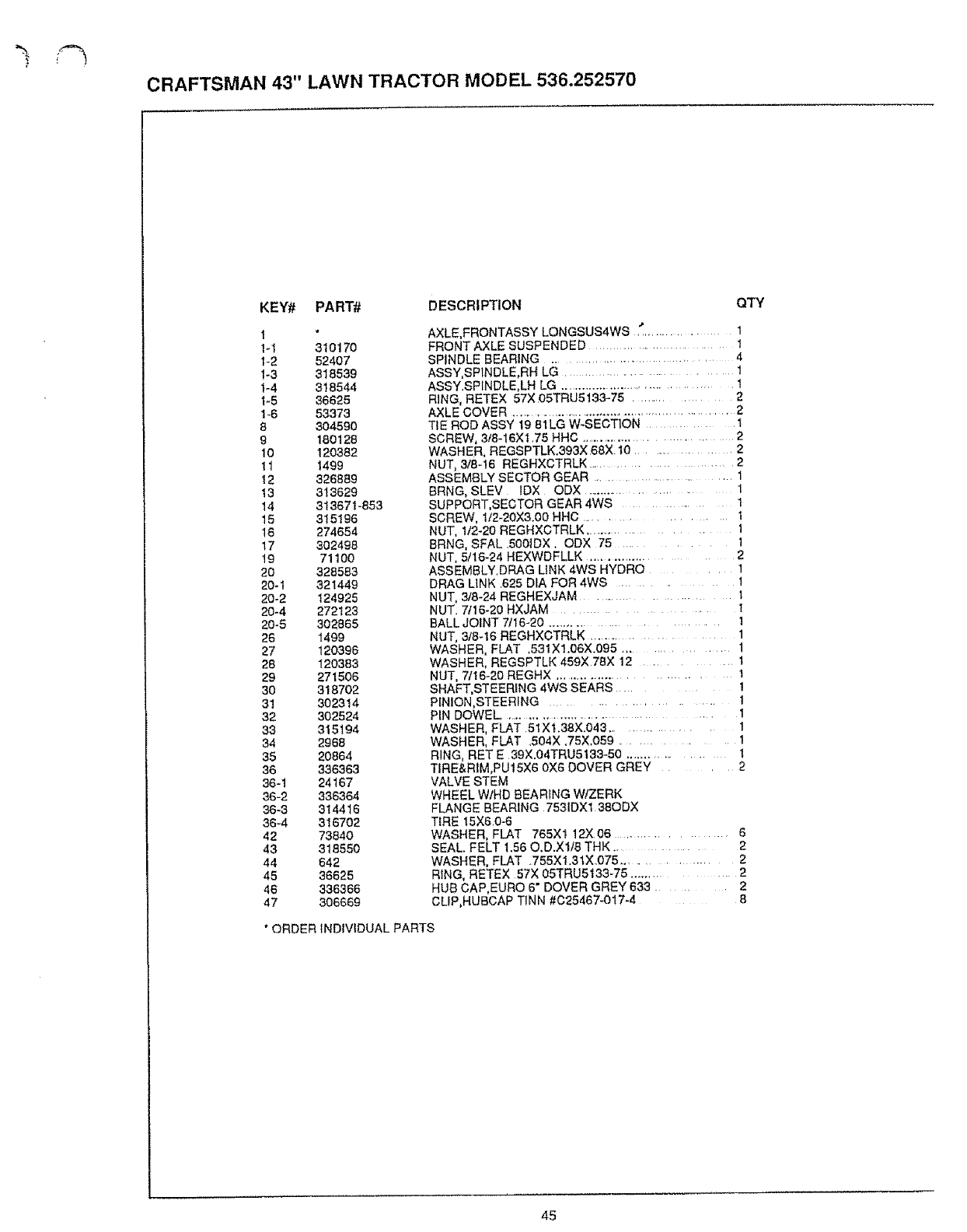
CRAFTSMAN 43" LAWN TRACTOR MODEL 536.252570
KEY# PART# DESCRIPTION
1
1-1 310170
1-2 52407
1-3 318539
1-4 318544
1_5 36625
1_6 53373
8 304590
9 180128
10 120382
11 1499
12 326889
13 3_3629
14 313671-853
15 315196
16 274654
17 302498
19 71100
20 328583
20-1 321449
20-2 124925
20-4 272123
20_5 302865
26 1499
27 120396
28 120383
29 271506
30 318702
31 302314
32 302524
33 315194
34 2968
35 20864
36 336363
36-1 24167
36-2 336364
36-3 314416
36-4 316702
42 73840
43 318550
44 642
45 38825
46 336366
47 306669
QTY
AXLE.FRONTASSY LONGSUS4WS " ............. 1
FRONT AXLE SUSPENDED ............................. 1
SPINDLE BEARING ........................... 4
ASSY,SP_NDLE,RH LG ................................ 1
ASSY,SP[NDLE,LH LG ..................................... 1
RING, RETEX 57X 05TRU5133-75 ............... 2
AXLE COVER .......................................................... 2
TIE ROD ASSY 19 81LG W-SECTION ............. 1
SCREW, 3t8-16X1.75 HHC .................................. 2
WASHER, REGSPTLK.393X68X 10 ............... 2
NUT, 3/8-16 REGHXCTRLK ...................... 2
ASSEMBLY SECTOR GEAR ......................... 1
8RNG, SLEV IDX ODX ........................ 1
SUPPORT,SECTOR GEAR 4WS ............. 1
SCREW, 112-20X3.00 HHC ................. 1
NUT, 1t2-20 REGHXCTRLK ...................... f
BRNG, SFAL .S001DX, ODX 75 ......... 1
NUT, 5/16-24 HEXWDFLLK ....................... 2
ASSEMBLY.DRAG LINK 4WS HYDRO ..... 1
DRAG LINK .625 DIA FOR 4WS .......... 1
NUT, 3/8-24 REGHEXJAM ................. t
NUT. 7/16-20 HXJAM .................... 1
BALL JOINT 7/16-20 .................. 1
NUT, 3/8-16 REGHXCTRLK .................. 1
WASHER, FLAT ,531X1.06X.095 ............... 1
WASHER, REGSPTLK 459X 78X 12 ........ 1
NUT, 7116-20 REGHX ............................. t
SHAFT,STEERiNG 4WS SEARS ...... 1
PINION,STEERING ..................... 1
P_N DOWEL ......................................... 1
WASHER, FLAT 51XI,38X.043 ............ 1
WASHER, FLAT .504X .75X,O59 ............ 1
RING, RET E 39X,04TRU5133-50 ............... l
TIRE&RtM,PU15X6 0X6 DOVER GREY .... 2
VALVE STEM
WHEEL W/HD BEARING W/ZERK
FLANGE BEARING 7531DX1 38ODX
TiRE 15X6 0-6
WASHER, FLAT 765X1 12X06 .............. 6
SEAL. FELT 1.56 O.D.Xlt8 THK ........... 2
WASHER, FLAT 755Xl.31X_075 ................ 2
RING, RETEX 57X 05TRU5133-75 ............. 2
HUB CAP,EURO 6" DOVER GREY 633 ...... 2
CLIP,HUBCAP T1NN #C25467-O17-4 8
*ORDER INDIVIDUAL PARTS
45
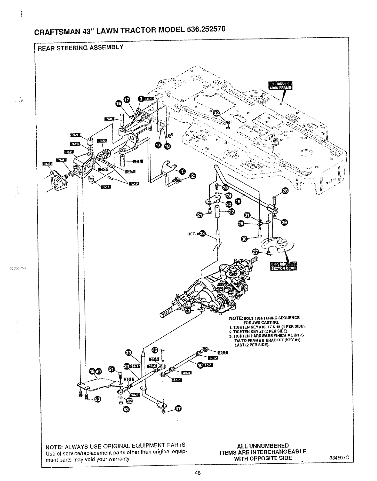
CRAFTSMAN 43" LAWN TRACTOR MODEL 536.252570
REAR STEERING ASSEMBLY
NO"rE:BOLT TIGHTENING SEQUENCE
FOR 4WS CASTING.
1o"lIGHTEN KEY #16,17 & 18 (4 PER SIDE}.
2o'TIGH'I"EN KEY #'2(2 PER SIDE).
3. TIGFrFEht HARDWARE WHICH MOUNTS
TIA TO FRAME & _RACKET {KEY #1)
LAST (2 PER SI_E)°
NOTE: ALWAYS USE ORIGINAL EQUIPMENT PARTS,
Use of servicetreplacement parts other than original equip-
ment parts may void your warranty
ALL UNNUMBERED
ITEMS ARE INTERCHANGEABLE
WITH OPPOSITE SIDE 334507C
46
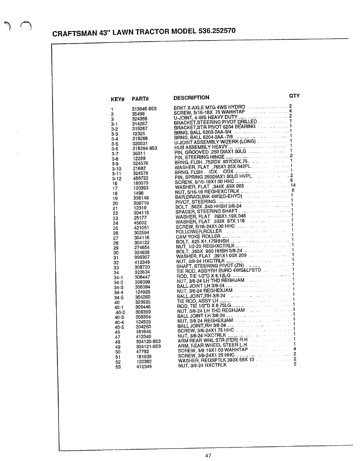
CRAFTSMAN 43" LAWN TRACTOR MODEL 536.252570
KEY# PART# DESCRIPTION
1 313645_853
235498
3 324359
3-1 314267
3-2 315267
3-3 12325
3,4 315268
3-5 320531
3-6 315264-853
3-7 36311
3-8 12289
3-9 324578
3-19 21682
3-11 324578
3-12 456722
16 180979
17 120393
18 1498
19 336148
20 308719
21 12319
22 304115
23 25177
24 45602
25 421051
26 302594
27 304116
28 304122
29 274854
30 324638
3! 996307
32 412349
33 30872O
34 323634
34-1 308447
34_2 308399
34-3 308384
34-4 124925
34-5 304260
49 323635
40-t 308446
49-2 308399
40-3 308384
40-4 124925
40-5 304260
46 181646
47 412349
48 304120-853
49 304121*853
50 47792
51 181639
52 120382
53 412349
QTY
BRKT X-AXLE MTG 4WS HYDRO ............................... 2
SCREW, 5/16-18X 75 WAHHTAP ............................. 4
U_JOINT, 4-WS HEAVY DUTY ................................. 2
BRACKET,STEERING PIVOT DRILLED ................ 1
8RACKBT,STR PIVOT 6204 BEARING ................. I
BRNG, BALL 6293-2AA-3/4 ....................................... 1
BRNG, BALL 6294-2AA -718 .................................. t
U-JOINT ASSEMBLY W/ZERK (LONG) .................. t
HUB ASSEMBLY HEAVY .......................................... 1
PIN, GROOVED .250 DIAX1.5OLG .............................. I
PIN, STEERING HINGE ....................................... 2
BRNG, FLSH .7521DX .937ODX.75 ................. I
WASHER, FLAT .765X125X042PL .......... 1
BRNG, FLSH. tDX. ODX ................................ 1
PIN, SPRING.250DIAX1.50LG HVPL .............. 2
SCREW, 5t16-18X1.00 HHC ................................ 6
WASHER, FLAT .344X .69X 065 .................... 14
NUT, 5/16-18 REGHEXCTRLK ..................... 8
BAR,DRAGLINK 4WS(D-EHYD) ...................... l
PIVOT, STEERING ............................................. I
BOLT..562X .340 HHSH 3/8-24 ...................... 1
SPACER, STEERING SHAFT ........................... 1
WASHER, FLAT 765X1.19X,048 ..................... 1
WASHER, FLAT .3&3X 87)(. 119 ................................ 1
SCREW, 5116-24X1.00 HHC ................................... 1
FOLLOWER,ROLLER ......................... 1
CAM YOKE ROLLER ........................................ I
BOLT, ..625 X1.175HHSH ................................... 1
NUT, 1t2-20 REGHXCTRLK ..................... :1
BOLT, .265X 980 HHSH 9t8-24 ................. 1
WASHER, FLAT .391X1 00X.209 ................ I
NUT, 3/8-24 HXCTRLK ................................ I
SHAFT, STEERING PIVOT (ZN) ..................... 1
TIE ROD, ASSYRH EURO 4WS&LFSTD ................ 1
ROD, TIE 1t2"D X 8.12LG ............................................. 1
NUT, 318-24 1.H THD REGHJAM ........................... 1
BALL JOINT LH 318-24 ........................................ 1
NUT, 3/8-24 REGHEXJAM ....................................... t
BALL JOINT, RH 3/8-24 ............................................ 1
TIE ROD, ASSY LH ................................................ 1
ROD, TIE 1t2"D X 9.75LG ........................ 1
NUT. 3/8-24 LH THD REGHJAM .................. 1
BALL JOINT LH 3/8-24 ........................................... 1
NUT, 3/8-24 REGHEXJAM ......................... 1
BALL JOINT, RH 3/8-24 ................................ 1
SCREW, 318-24X1_75 HHC ........................................... 1
NUT, 3/8-24 HXCTRLK ............................... 1
ARM REAR WHL STR (FER) R H.......................... 1
ARM, F_EAR WHEEL STEER L.H ....................... 1
SCREW, 318-I6X1 00 WAHHTAP ........... 4
SCREW, 3t8-24XI 25 HHC ............................. 2
WASHER, REGSPTLK 393X 68X.19 ...................... 2
NUT, 3/8-24 HXCTRLK ................................. 2
47
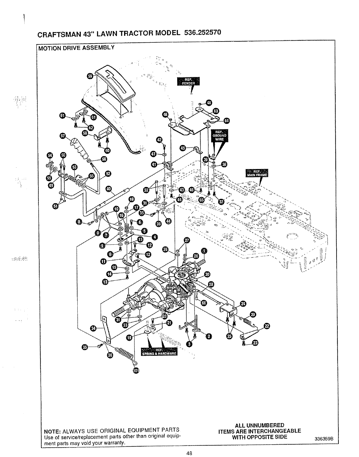
CRAFTSMAN 43" LAWN TRACTOR MODEL 536.252570
MOTION DRIVE ASSEMBLY
';i _:.f2
NOTE: ALWAYS USE ORIGINAL EQUIPMENT PARTS
Use of servicelreplacement parts other than origina! equip-
ment parts may void your warranty.
ALL UNNUMBERED
ITEMS ARE INTERCHANGEABLE
WITH OPPOSITE SIDE 3363598
48
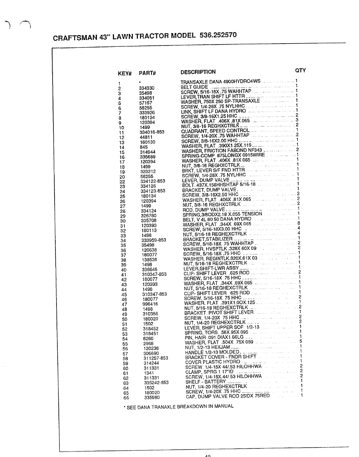
CRAFTSMAN 43" LAWN TRACTOR MODEL 536.252570
KEY# PART# DESCRIPTION QTY
2 334330
335498
4334051
557157
6 56255
7333926
8 180124
9 120394
10 1499
11 334016-853
12 44811
13 180130
14 845
15 314944
t6 335689
17 120394
18 1499
19 323212
20 56255
22 334122-853
23 334126
24 334123-853
25 180134
26 120394
27 t499
28 334124
29 326780
30 335708
31 120393
32 180113
33 1498
34 333959-853
35 35498
36 120638
37 180077
38 138538
39 1498
40 336646
41 310347-853
42 180077
43 120393
44 1498
45 310347-853
46 180077
47 996416
48 1498
49 310356
50 18002O
51 t502
52 318452
53 318451
54 8280
55 2968
56 120238
57 306690
58 311257-853
59 314244
60 311331
6! 1341
62 311331
83 335242-853
64 1502
65 180020
66 335980
TRANSAXLE DANA 4900HYDRO4WS ................. 1
BELT GUIDE ..................................................... 1
SCREW, 5116-18X .75 WAHHTAP ...................... i
LEVER,TRAN SHIFT LF HTTR ..., ........................ 1
WASHER,. 750X 250 SP-TRANSAXLE .................. 1
SCREW, 1/4-28X 75 NYLHHC ........................ 1
LINK, SHIFT LF DANA HYDRO ............................ 1
SCREW, 3/8-16Xl.25 HHC ..................................... 2
WASHER, FLAT .406X .8 I,X 065 ........................... 3
NUT, 3/8-16 REGHXCTRLKo ..................................... 2
QUADRANT, SPEED CONTROL ....................... 1
SCREW, 114-20X .75 WAHHTAP ......................... 2
SCREW, 318-16X2.00 HHG ......................................... 1
WASHER, FLAT ,390Xl .25X.119 ....................... 1
WASHER, FRICTION FABOND NF343 ................... 2
SPRING-COMP 875LONGX 0915WIRE .............. 1
WASHER, FLAT .406X ,8tX 065 ................ t
NUT, 3t8-16 REGHXCTRLK ............... t
BRKT, LEVER StF FND HTTR .............. 1
SCREW, t/4-28X ,75 NYLHHC .............. 1
LEVER, DUMP VALVE ............................. 1
BOLT. 437X.156HHSHTAP 5/16-18 ....... 1
BRACKET, DUMP VALVE ........ 1
SCREW, 3t8-t6X2.50 HHC .............. 2
WASHER, FLAT .406X ,81X 065 ............. 2
NUT, 3/8-16 REGHXCTRLK .......... 2
ROD, DUMP VALVE ....................................... 1
SPRING,3/8ODX2.18 X.055 TENSeON ........ t
BELT, V 4L 8050 DANA HYDRO ............. l
WASHER, FLAT .344X .69X 065 .......... 8
SCREW, 5/16-18X3.00 HHC .............. 4
NUT, 5116-18 REGHEXCTRLK ......... 4
BRACKET,STABILIZER ........................... 1
SCREW, 5.116-t8X 75 WAHHTAP ......... 2
WASHER, HVSPTLK .328X 60X 09 ..... 2
SCREW, 5/16-18X ,75 HHC ................................... 1
WASHER, REGINTLK,320X.61X 03 ......... 1
NUT, 5/16-18 REGHEXCTRLK .................. !
LEVER,SHIFT-LWR ASSY .................. 1
CUP- SHIFT LEVER .625 ROD ............. 2
SCREW, 5/16-18X 75 HHC .................... 1
WASHER, FLAT ,344X .69X 065 ............... 1
NUT, 5/16-18 REGHEXCTRLK ................. 1
CUP- SHIFT LEVER 625 ROD ............ 1
SCREW, 5/16-18X .75 HHC ................ 2
WASHER. FLAT ,391X!.0OX.125 ......... 1
NUT, 5/t6-18 REGHEXCTRLK .......... 2
BRACKET. PIVOT SHIFT LEVER t
SCREW, 114-20X 75 HHC .................... 2
NUT, 1t4-20 REGHEXCTRLK ........... 2
LEVER, SHIFT UPPER SOF 1/2-13 ........ 1
SPRING, TORS. 56X95X 095 ........... 1
PIN, HAIR .O91 DIAXl.66LG ........ 1
WASHER, FLAT .504X 75X 059 ........... 5
NUT, l/2q3 HEXJAM ................. 1
HANDLE 1/2-13 MOLDED .............. 1
BRACKET COVER - FNDR SHIFT ...... 1
COVER PLASTIC HYDRO ................... t
SCREW. t14-15X 441.53 HILOHHWA 2
CLAMP, SPRG 1 17qD ......................... 2
SCREW, 1t4-15X.44153 HfLOHHWA .... 2
SHELF - BATTERY ..................... 1
NUT, 1/4-20 REGHEXCTRLK ........... 1
SCREW, 114-20X .75 HHC ........................... 1
CAP, DUMP VALVE ROD 251DX 75RED t
* SEE DANA TRANAXLE BREAKDOWN IN MANUAL
,4Q
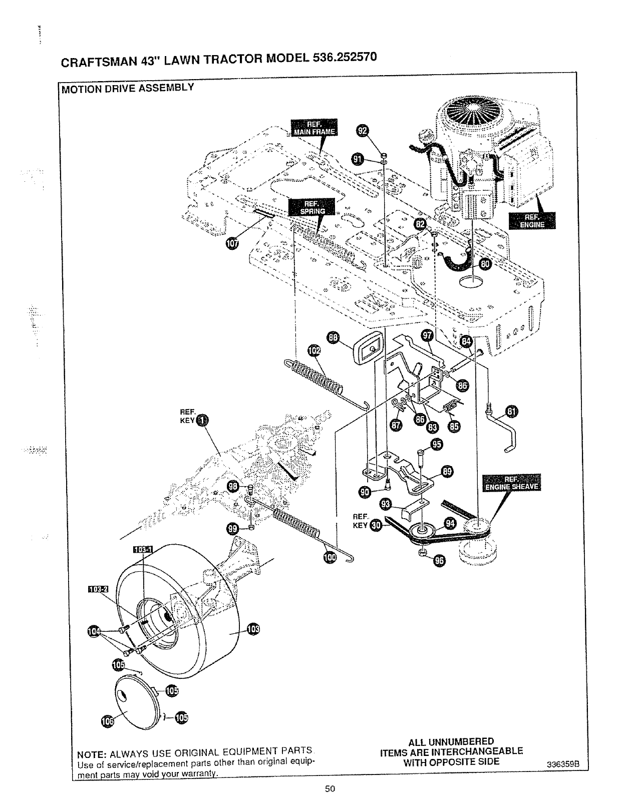
CRAFTSMAN 43" LAWN TRACTOR MODEL 536,252570
MOTION DRIVE ASSEMBLY
REF,,
KEYi
<_,,
i
NOTE: ALWAYS USE ORIGINAL EQUIPMENT PARTS
Use of servicelreplacement parts other than original equip-
me,pl parts may v0!_ you,r,,warrantv,
ALL UNNUMBERED
ITEMS AREINTERCHANGEABLE
WITH OPPOSITE SIDE
5O
336359B
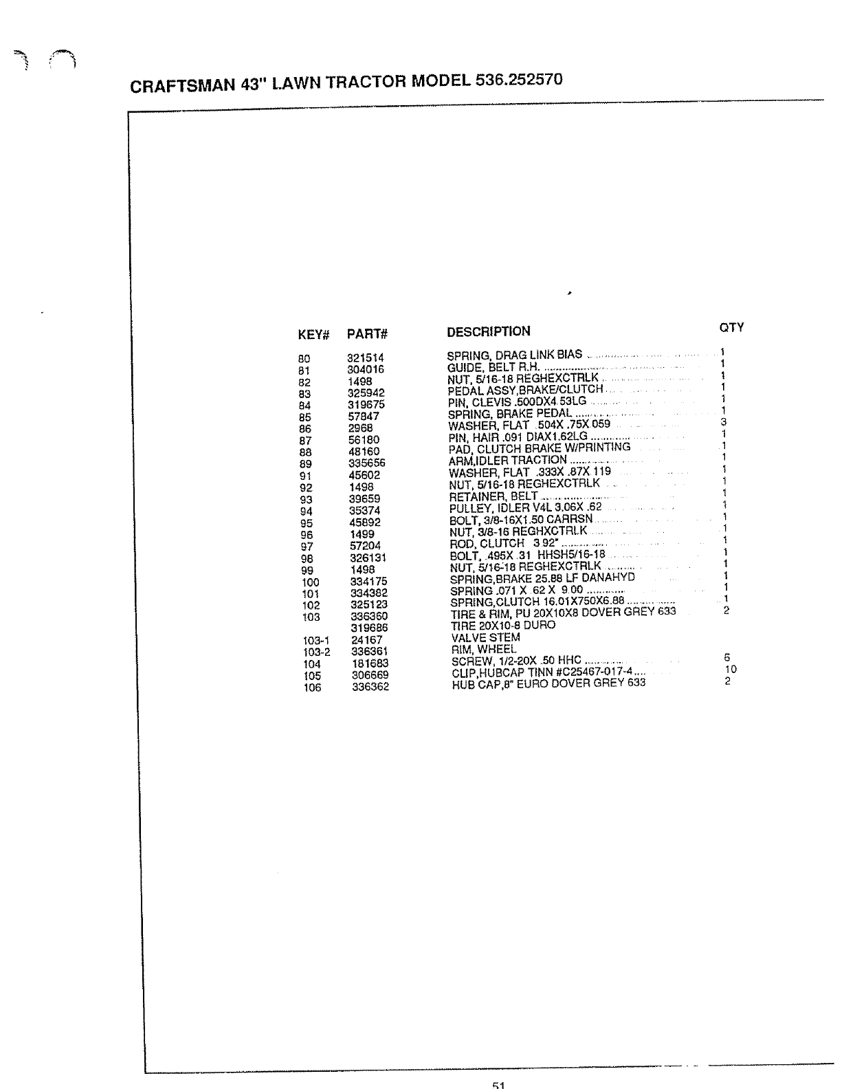
CRAFTSMAN 43" LAWN TRACTOR MODEL 536.252570
KEY# PART# DESCRIPTION
80 321514
81 304016
82 I498
83 325942
84 319675
86 57847
86 2968
87 56180
88 48160
89 335656
91 45602
92 1498
93 39659
94 35374
95 45892
96 1499
97 57204
98 32613i
99 1498
100 334175
101 334382
t02 325123
t03 336360
319686
103-1 24167
103-2 336361
104 181683
105 306669
106 336362
QTY
SPRING, DRAG LINK BIAS .................................. 1
GUIDE, BELT R.H...................................... 1
NUT, 5/16-18 REGHEXCTRLK ................ t
PEDAL ASSY,BRAKFJCLUTCH ................ 1
PIN, CLEVIS .500DX4 53LG ........... t
SPRING, BRAKE PEDAL ............................... 1
WASHER, FLAT 504X ,75X059 .....
PIN, HAIR .091 DtAX!.62LG .................
PAD, CLUTCH BRAKE W/PRINTING ........
ARM,IDLER TRACTION ........................
WASHER, FLAT .333X .87X 119 ...........
NUT, 5/16-18 REGHEXCTRLK .........
RETAINER, BELT ........................
PULLEY, IDLER V4L 3.06X .62 ......
BOLT, 3/8-16XI.50 CARRSN .......
NUT, 3/8q6 REGH×CTRLK ......
ROD, CLUTCH 392", ......................
BOLT,..495X.31 HHSH5/16-I8 ...........
NUT, 5/16:16 REGHEXCTRLK ...................
SPRING, BRAKE 25.B8 LF DANAHYD
SPRING .O71 X 62 X 9100 ...............
SPRING,CLUTCH I&OI X75OX6.88 ................
TIRE & RIM, PU 20X10X6 DOVER GREY 633
TIRE 20X10-8 DURO
VALVE STEM
RIM, WHEEL
SCREW, 1/2-20X °50 HHO .....................
CUP,HUBCAP TINN #C25467-017-4 ....
HUB CAP,8" EURO DOVER GREY 633
3
1
1
1
1
1
t
1
1
1
1
1
1
1
1
2
6
10
2
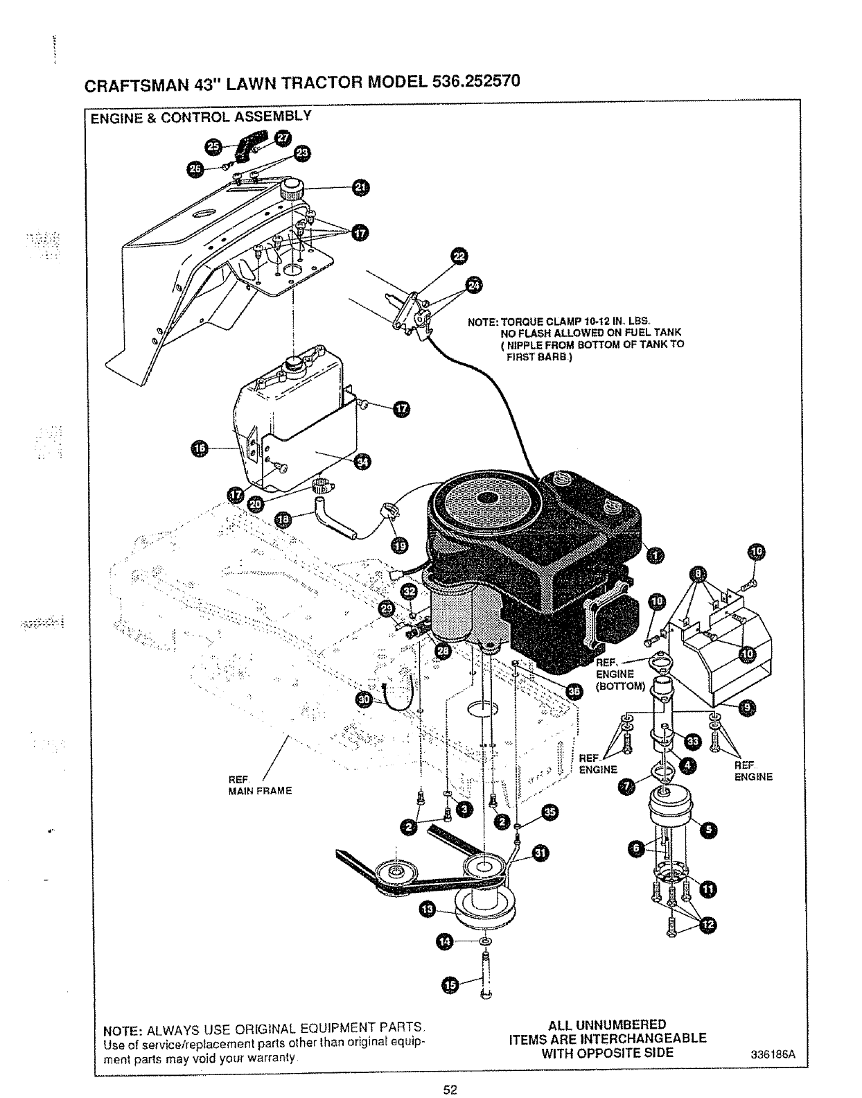
CRAFTSMAN 43" LAWN TRACTOR MODEL 536.252570
ENGINE & CONTROL ASSEMBLY
_'__TE: TORQUE CLAMP 10-12 INnLBS
NO FLASH ALLOWED ON FUEL TANK
( NIPPLE FROM BOTTOM OF TANK TO
FIRST BARB )
NOTE: ALWAYS USE ORIGINAL EQUIPMENT PARTS.
Use of service/replacement parts other than original equip-
ment parts may void your warranty
ALL UNNUMBERED
ITEMS ARE INTERCHANGEABLE
WITH OPPOSITE SIDE 336186A
52
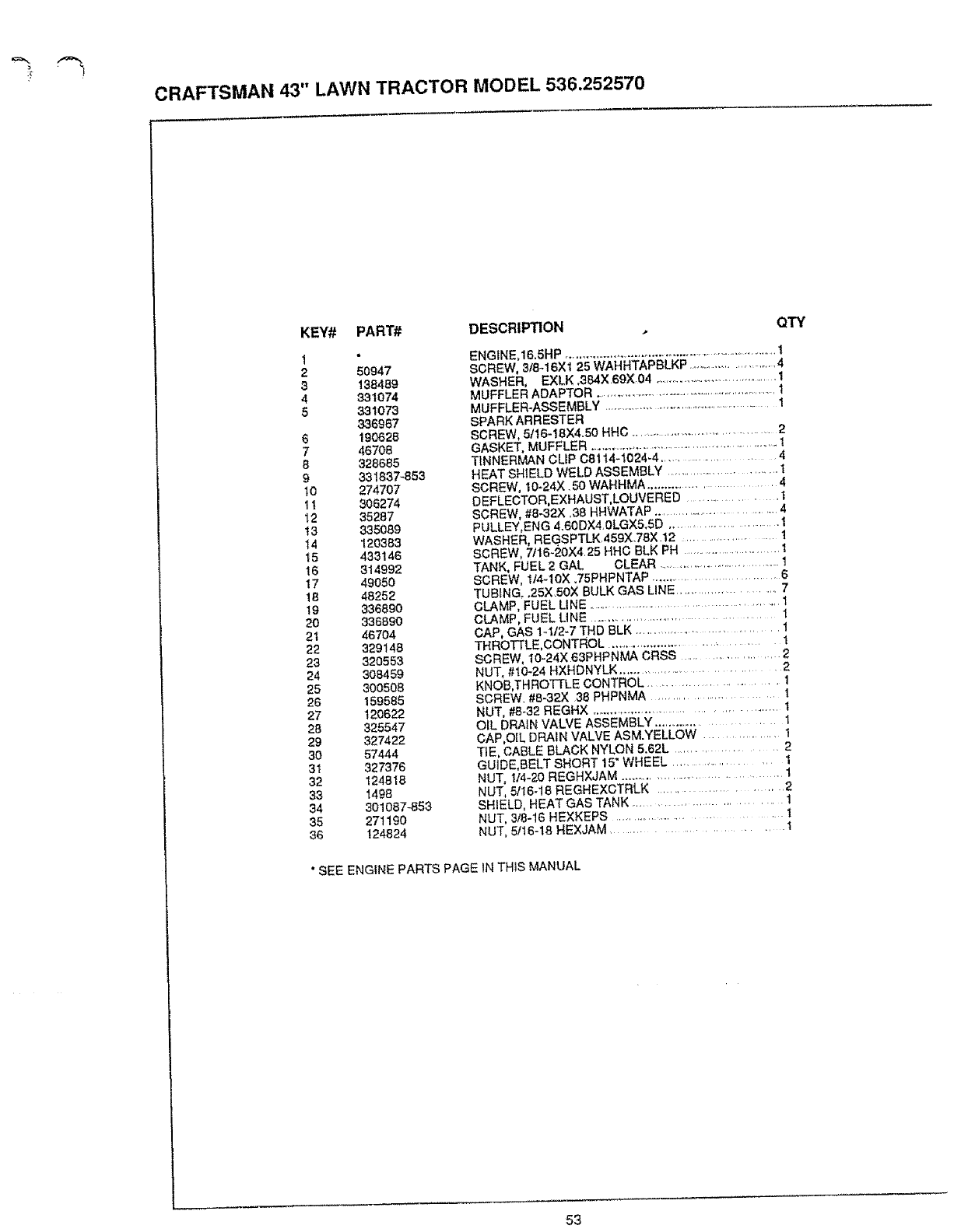
CRAFTSMAN 43" LAWN TRACTOR MODEL 536.252570
KEY# PART# DESCRIPTION
2 50947
3138489
4331074
5 331073
336967
6 190628
746708
8328685
9 331837-853
10 274707
11 306274
12 35287
t3 335089
14 120383
15 433146
16 314992
17 49O50
18 48252
19 336890
20 336890
21 46704
22 329148
23 320553
24 308459
25 300508
26 159585
27 120622
28 325547
29 327422
30 57444
31 327376
32 124818
33 1498
34 301087_53
35 271190
38 124824
QTY
ENGINE,16,5HP .................................................................... 1
SCREW, 3/8-16X1 25 WAHHTAPBLKP ............................ 4
WASHER, EXLK ,3_X.69X04 .........................................I
MUFFLER ADAPTOR .......................................................... 1
MUFFLER-ASSEMBLY ...................................................... 1
SPARK ARRESTER
SCREW, 5/16-18X4.50 HHC ........................................... 2
GASKET, MUFFLER ......................................................... 1
TINNERMAN CLiP C8114-1024-4 ...................... 4
HEAT SHIELD WELD ASSEMBLY .............................. 1
SCREW, I0-24X .50 WAHHMA .......................... 4
OEFLECTOR,EXHAUST, LOUVERED .................. 1
SCREW, #8-32X .38 HHWATAP ................................. 4
PULLEY,ENG 4.60DX4,0LGX5.SD ............................. 1
WASHER, REGSPTLK 459X.78X.12 .................. 1
SCREW, 7t16-20X4.25 HHC BLK PH .............................. 1
TANK, FUEL 2 GAL CLEAR ........................................1
SCREW, 1/4-10X ,75PHPNTAP ............................... 6
TUBING. ,25XSOX BULK GAS LINE ........................... 7
CLAMP, FUEL LINE ................................................ 1
CLAMP, FUEL LINE .......................................... 1
CAP, GAS 1-112-7 THD BLK .............................. 1
THROTTLE, CONTROL .................................... 1
SCREW, 10-24X:63PHPNMA CRSS .................... 2
NUT, #10-24 HXHDNYLK ................................ 2
KNOf3,THROTTLE CONTROL ........................ 1
SCREW. #8-32X 38 PHPNMA .......................... l
NUT, #8-32 REGHX ........................................... t
OiL DRAIN VALVE ASSEMBLY ....................... 1
CAP,O_L DRAIN VALVE ASM.YELLOW ................ I
TIE, CABLE BLACK NYLON 5.62L ................... 2
GUIDE,BELT SHORT 15" WHEEL ........................... 1
NUT, 1/4-20 REGHXJAM .................................... 1
NUT, 5116-18 REGHEXCTRLK ...................... 2
SHIELD, HEAT GAS TANK ............................ t
NUT, 3/8-16 HEXKEPS ............................... 1
NUT, 5/16-18 HEXJAM ....................... 1
"SEE ENGINE PARTS PAGE IN THiS MANUAL
53
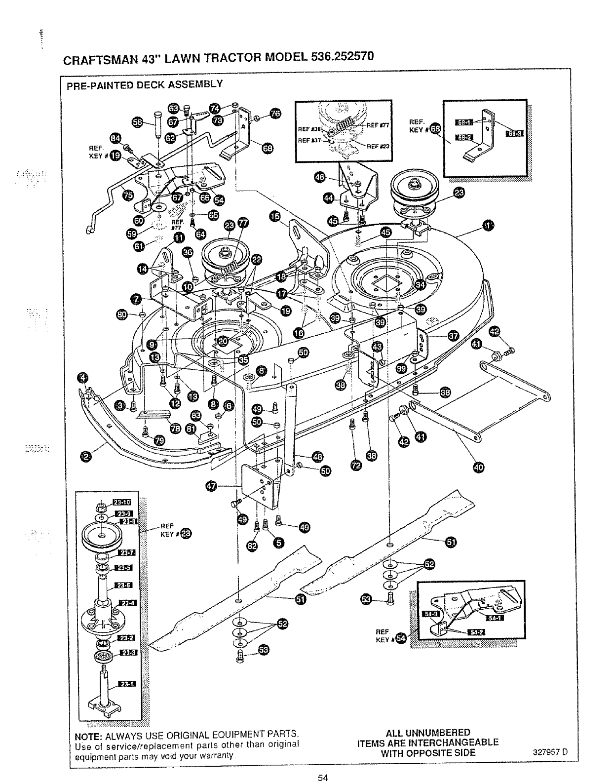
"!,_ _,t ¸¸"
;7.:i :
CRAFTSMAN 43" LAWN TRACTOR MODEL 536.252570
PRE-PAINTED DECK ASSEMBLY
NOTE: ALWAYS ,_SEORIGINAL EQUIPMENT PARTS.
Use of service/re )tacement parts other than original
equipmenl parts may void your warranty
ALLUNNUMBERED
ITEMS AREINTERCHANGEABLE
WITH OPPOSITESIDE 327957 D
54
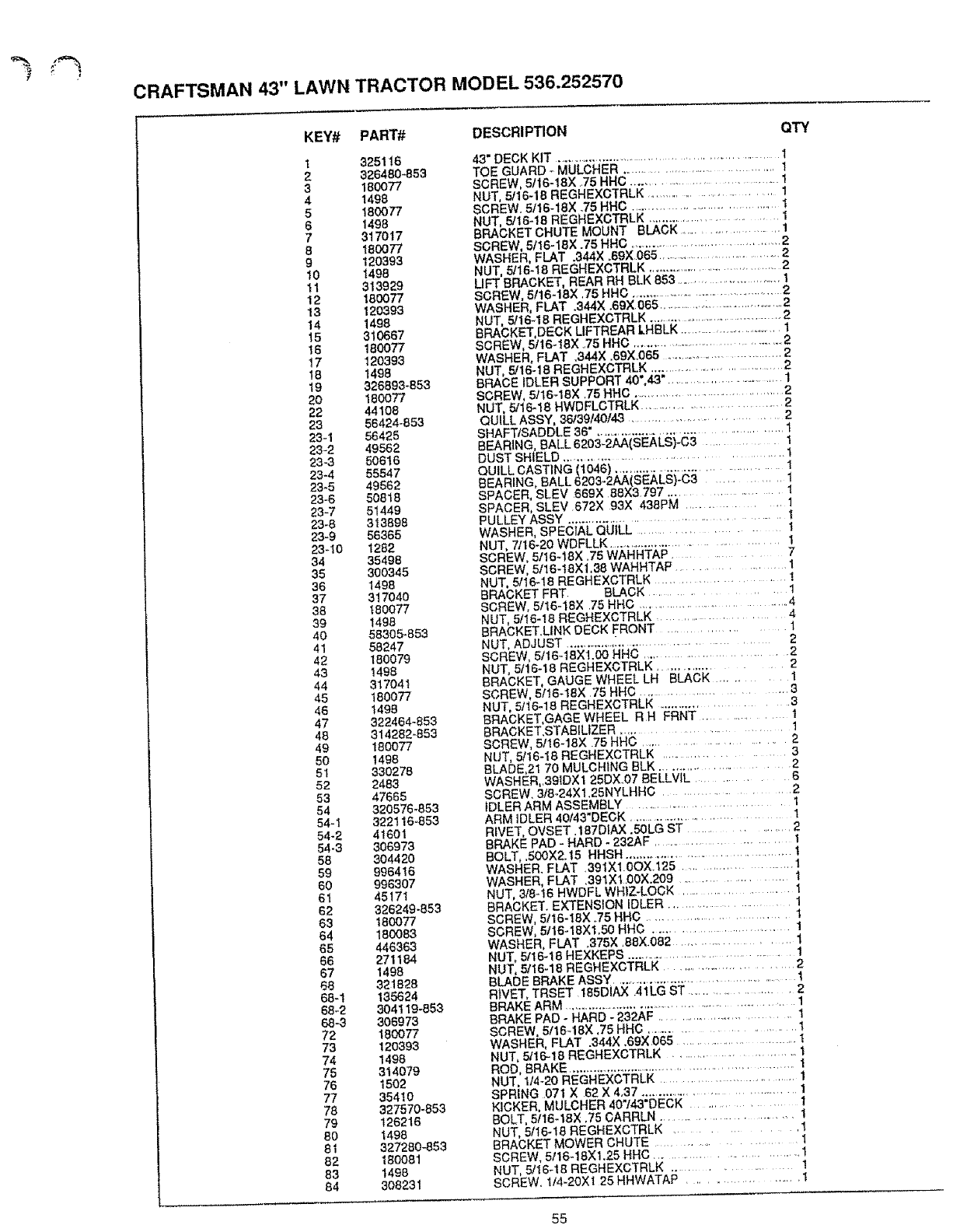
CRAFTSMAN 43" LAWN TRACTOR MODEL 536.252570
KEY# PART# DESCRIPTION
1325116
2 326480..853
3180077
4 1498
518O077
6 1498
7 317017
8 180077
9120393
10 1498
11 313929
12 18O077
13 120393
14 1498
15 310667
16 180077
17 120393
18 t498
19 326693-853
20 180077
22 44108
23 56424-853
23-1 56425
23-2 49562
23-3 50616
23-4 55547
23-5 49562
23-6 50818
23-7 51449
23-6 313898
23-9 56365
23-10 1282
34 35498
35 300345
36 1498
37 317040
38 180077
39 1498
40 58305_853
41 58247
42 180079
43 1498
44 317041
45 180077
46 1499
47 322464-853
48 314282-853
49 180077
50 1498
51 330278
52 2483
53 47665
54 320576-653
54-1 322116-653
54-2 41601
54-3 306973
58 304420
59 996416
60 996307
61 45171
62 326249-853
63 180077
84 180083
65 446363
66 271184
67 1498
68 321828
68-t 135624
68-2 304119-853
68.3 306973
72 160077
73 120393
74 1498
75 314079
76 1502
77 354t0
78 327570-853
79 126216
80 1498
81 327280-853
62 180081
83 1498
84 308231
QTY
43" DECK KIT ............................................................ 1
TOE GUARD -MULCHER ......................................... I
SCREW, 5116-18X ..75 HHC ................................. 1
NUT, 5/16-18 REGHEXCTRLK ................................ 1
SCREW. 5/16-t8X .75 HHC ..................................... !
NUT, 5/16-18 REGHEXCTRLK ............................. 1
BRACKET CHUTE MOUNT BLACK ........................... 1
SCREW, 5t16-18X .75 HHC .......................................... 2
WASHER, FLAT .344X .69X 065 ...................................... 2
NUT, 5/t6-18 REGHEXCTRLK ......................................... 2
LIFT BRACKET, REAR RH BLK 853 ............................ 1
SCREW, 5/16-18X .75 HHC ............................................. 2
WASHER, FLAT .344X .69X 065 ................:........................ 2
NUT, 5/16-18 REGHEXCTRLK ........................................ 2
BRACKET, DECK LIFTREAR LHBLK ................................. 1
SCREW, 5It6-18X .75 HHC ............................................ 2
WASHER, FLAT ,344X .69X.065 .................................. 2
NUT, 5/16-18 REGHEXCTRLK ...................................... 2
BRACE IDLER SUPPORT 40",43"................................ 1
SCREW, 5t16-18X 25 HHC .......................................... 2
NUT, 5/16-18 HWDFLCTRLK .............................. 2
QUILL ASSY, 36139140143 .................................. 2
SHAFTISADDLE 36". .............................................. I
BEARING, BALL 6203-2AA(SEALS)-C3 ............ I
DUST SHIELD ........................................ 1
QUILL CAST|NG 11046) ........................................ 1
BEARING, BALL 6203-2AA(SEALS)-C3 ............ 1
SPACER, SLEV 669X 88X3 797 ................... 1
SPACER, SLEV 672X 93X 438PM ............ 1
PULLEY ASSY .......................................... 1
WASHER, SPECIAL QUILL ................. 1
NUT, 7;16-20 WDFLLK ...................................... 1
SCREW, 5t16-t8X .75 WAHHTAP ............ 7
SCREW, 5t16-t8Xl,38 WAHHTAP ............... 1
NUT, 5116-18 REGHEXCTRLK .................... 1
BRACKET FRT BLACK .................. 1
SCREW, 5t16-18X 75 HHC ..................................... 4
NUT, 5/16-18 REGHEXCTRLK ..................... 4
BRACKET.UNK DECK FRONT .................... 1
NUT, ADJUST .............. ............................. 2
SCREW, 5t16-18X1.00 HHC .............................. 2
NUT, 5f16-18 REGHEXCTRLK ................... 2
BRACKET, GAUGE WHEEL LH BLACK .......... 1
SCREW, 5116-18X 75 HHG ......................... 3
NUT, 5116-18 REGHEXCTRLK ......................... 3
BRACKET,GAGEWHEEL RH FRNT ............. 1
BRACKET,STABILIZER .................... 1
SCREW, 5116-18X 75 HHC .............................. 2
NUT, 5/16-18 REGHEXCTRLK .................... 3
BLADE,21 70 MULCHING BLK .......................... 2
WASHER,.39tDX1 25DX.07 BELLVIL ......... 6
SCREW. 318-24X1.25NYLHHC .....................
IDLER ARM ASSEMBLY ............................ I
ARM IDLER 40143"DECK ................................. 1
RIVET, OVSET. 187DIAX .5OLG ST ............... 2
BRAKE PAD - HARD - 232AF ...................... 1
BOLT, .500X2.15 HHSH ........................................ t
WASHER. FLAT 391X1.0OX.125 ......................... 1
WASHER, FLAT .391XI .00X.209 ..................... 1
NUT, 3t8-16 HWDFL WHIZ-LOCK ...................... 1
BRACKET. EXTENSION IDLER ........................... 1
SCREW, 5t16-18X .75 HHC ............................. 1
SCREW, 5/16-18X1.50 HHC ............................... 1
WASHER, FLAT ,375X .88X.082 ....................... 1
NUT, 5/16-16 HEXKEPS ....................................... 1
NUT, 5/16-18 REGHEXCTRLK .............................. 2
BLADE BRAKE ASSY .............................................. 1
RIVET, TRSET 185DiAX 41LG ST ...................... 2
BRAKE ARM ................................................................ 1
BRAKE PAD - HARD - 232AF .................................. 1
SCREW, 5116-18X ,75 HHC .......................... 1
WASHER, FLAT .344X .69X 065 ............................ I
NUT, 5/16-18 REGHEXCTRLK ......................... 1
ROD, BRAKE .............................................................. I
NUT, 1/4-20 REGHEXCTRLK ............................... 1
SPR{NG 071 X 62 X 4,37 ....................................... 1
KICKER, MULCHER 40"143"DECK .............. 1
BOLT, 5116-18× ,75 CARRLN .............................. 1
NUT, 5116-t8 REGHEXCTRLK ............. I
BRACKET MOWER CHUTE .................... I
SCREW, 5116-18Xl.25 HHC ............................... 1
NUT, 5116-16 REGHEXCTRLK ................ 1
SCREW. I/4-20X1 25 HHWATAP ..................... I
55
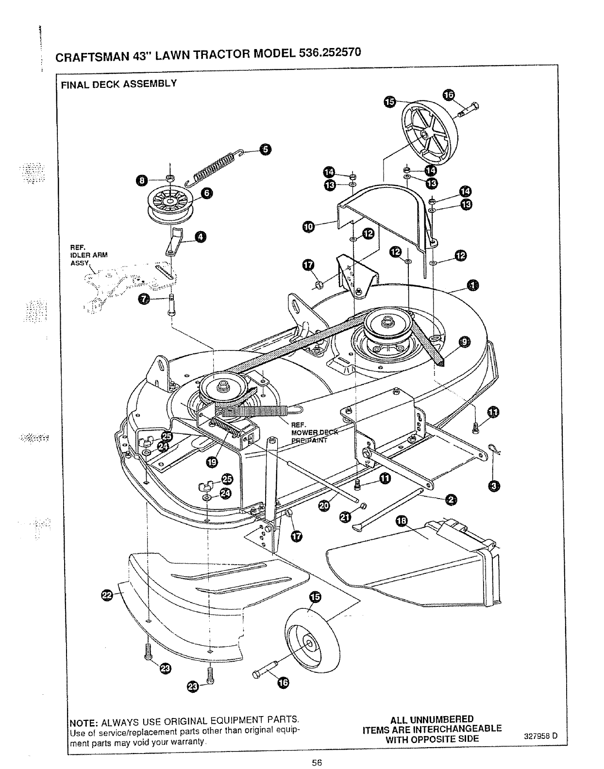
CRAFTSMAN 43" LAWN TRACTOR MODEL 536.252570
_i_i _]
FINAL DECK ASSEMBLY
REF.
IDLER ARM _
ASSY_. ......... ,_
i:iili.....,.......
_OTE: ALWAYS USE ORIGINAL EQUIPMENT PARTS,
Use of service/replacement parts other than original equip-
ment parts may void your warranty,
e
%,
ALL UNNUMBERED
ITEMS AREINTERCHANGEABLE
WITH OPPOSITE SIDE 327958 D
56
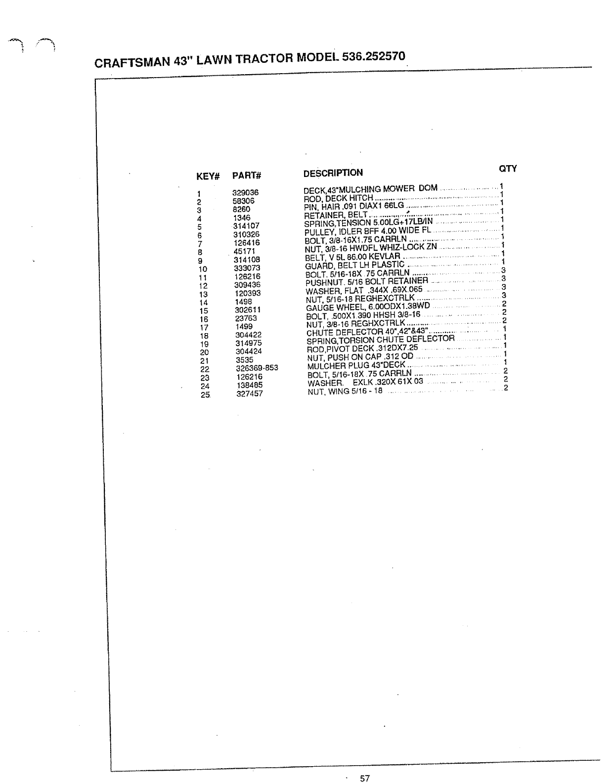
t
CRAFTSMAN 43" LAWN TRACTOR MODEl. 536.252570
KEY# PART# DESCRIPTION
1329036
258306
3 8260
4 1346
5314107
6 310326
7 126416
8 45171
9 314108
10 333073
11 126216
12 309436
13 120393
14 14g8
15 302611
16 23763
17 1499
18 304422
t9 314975
20 304424
21 3535
22 326369*853
23 126216
24 138485
25. 327457
QTY
DECK,43*MULCHING MOWER DOM .......................... t
ROD, DECK HITCH .......................................................... 1
PIN, HAIR ,091 DIAX1 66LG ............................................. 1
RETAINER. BELT._ ................ f. ......................................... 1
SPRING,TENSION 5,00LG+17LB/IN ........................... 1
PULLEY, IDLER BFF 4.00 WIDE FL ............................... 1
BOLT, 318-16Xl.75 CARRLN ................................... 1
NUT, 318-16 HWDFL WHIZ-LOCK ZN .......................... 1
BELT, V 5L 8&0o KEVLAR .......................................... 1
GUARD, BELT LH PLASTIC ....................................... 1
BOLT. 5116-18X 75 CARRLN ............................ 3
PUSHNUT. 5/16 BOLT RETAINER ........................ 3
WASHER, FLAT .344X .69X 065 ..................... 3
NUT, 5116-18 REGHEXCTRLK ............................... 3
GAUGE WHEEL, 6.00ODX1.38WD ................ 2
BOLT, ,500XI,390 HHSH 318-16 .............................. 2
NUT, 3t8-16 REGHXCTRLK ..................................... 2
CHUTE DEFLECTOR 40",42"&43". ....................... 1
SPRiNG, TORSION CHUTE DEFLECTOR ............ 1
ROD,PIVOT DECK .312DX7.25 ........................... 1
NUT, PUSH ON CAP .312 OD .................................. 1
MULCHER PLUG 43"DECK ................................ 1
BOLT, 5/16qBX 75 CARRLN ........................... 2
WASHER, EXLK.320X61X03 ................ 2
NUT, W_NG 5t16 - 18 .................................... 2
57
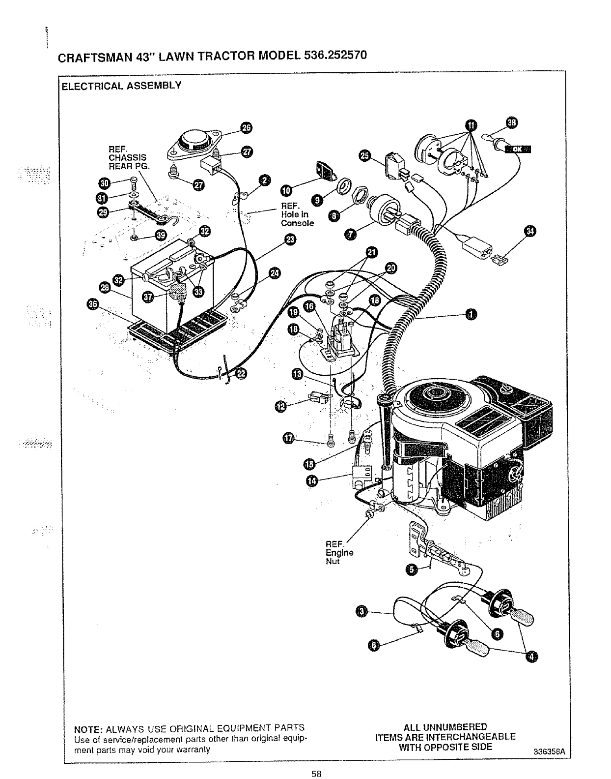
+
CRAFTSMAN 43" LAWN TRACTOR MODEL 536.252570
• ++• • :, +_
ELECTRICAL ASSEMBLY
REF_
CHASSIS
REAR PGo
i
. •
REF°
Hole in
, _E+ Console
REF°
Engine
Nut
NOTE: ALWAYS USE ORIGINAL EQUIPMENT PARTS
Use of service/repfacement parts other than original equip-
ment parts may void your warranty
ALL UNNUMBERED
ITEMS ARE INTERCHANGEABLE
WITH OPPOSITE SIDE 336358A
58
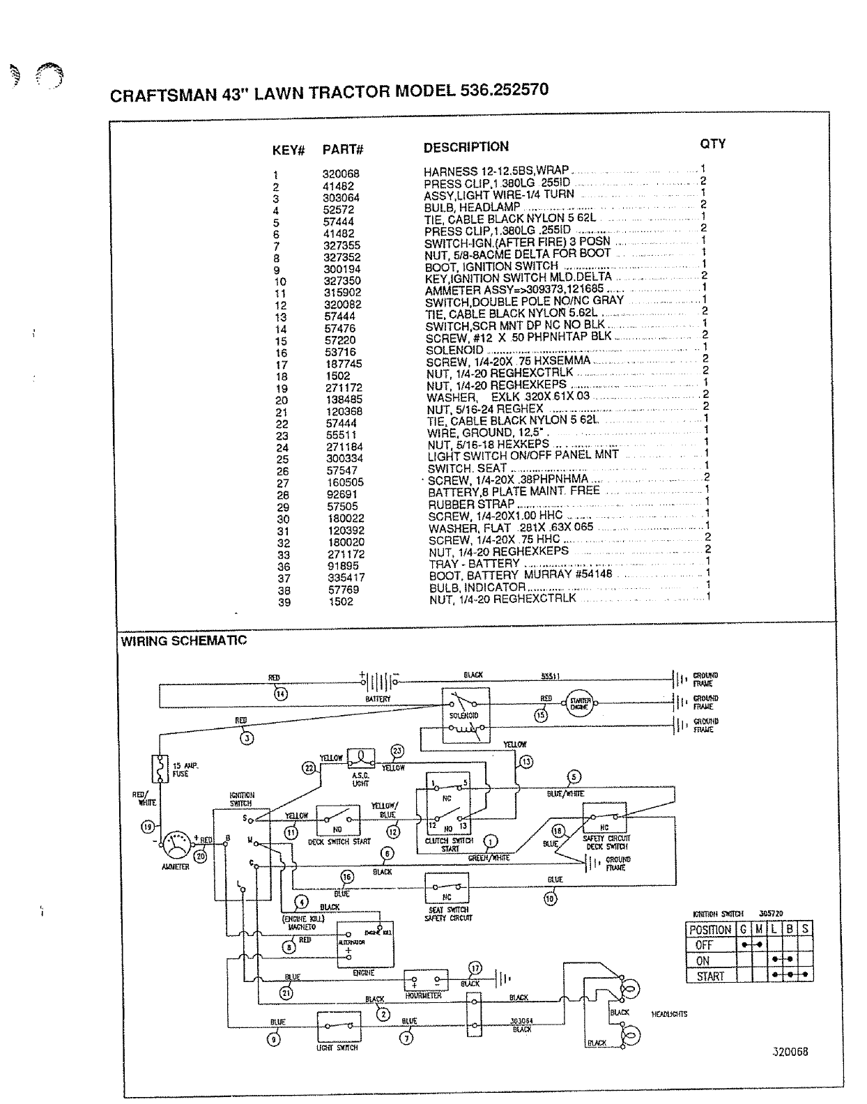
CRAFTSMAN 43" LAWN TRACTOR MODEL 536.252570
KEY# PART# DESCRIPTION
1 320068
2 41482
3 303064
4 52572
557444
6 41482
7327355
6327352
9300194
10 327350
11 315902
t2 320082
t3 57444
14 57476
15 57220
16 53716
17 187745
18 !502
19 271172
20 138485
21 120368
22 57444
23 55511
24 271184
25 300334
26 57547
27 160505
28 92691
29 57505
30 180022
31 120392
32 180020
83 271172
86 91895
87 335417
88 57769
39 1502
QTY
HARNESS 12-t2.5BS,WRAP ....................... 1
PRESS CUP,1 380LG 2551D ....................... 2
ASSY,LIGHT WIRE-114 TURN ................... 1
BULB, HEADLAMP ................................... 2
TIE, CABLE BLACK NYLON 5 62L ....................... 1
PRESS CUP,1.380LG .255ID .................................. 2
SWITCH-IGN.(AFTER FIRE) 3POSN .................... 1
NUT, 5tS-8ACME DELTA FOR BOOT 1
BOOT, IGNITION SWITCH .................................... 1
KEY,IGNITION SWITCH MLD.DELTA ................... 2
AMMETER ASSY=>309373,121685 ....................... 1
SWITCH,DOUBLE POLE NO/NO GRAY .................. 1
TIE, CABLE BLACK NYLOR 5.62L .......................... 2
SWITCH,SCR MNT DP NC NO BLK ........................ t
SCREW, #12 X 50 PHPNHTAP BLK ......................... 2
SOLENOID ...................................................................... 1
SCREW, 114-20X 25 HXSEMMA .............................. 2
NUT, 1/4-20 REGHEXCTRLK .................................. 2
NUT, 1/4-20 REGHEXKEPS .................................. 1
WASHER, EXLK 320X 61X 03 ............................ 2
NUT, 5tt6-24 REGHEX .................................................. 2
TIE, CABLE BLACK NYLON 5 62L ............... 1
WIRE, GROUND, 12,5". .................... 1
NUT, 5116-18 HEXKEPS ......................... 1
LIGHT SWITCH ON/OFF PANEL MNT .......... 1
SWITCH. SEAT ......................................... 1
• SCREW, 114-20X .38PHPNHMA ....................... 2
BATTERY,8 PLATE MAINT. FREE ................... I
RUBBER STRAP ............................................ 1
SCREW, 114-20Xl.00 HHC ............................ 1
WASHER, FLAT 281X .63X 065 ............................... 1
SCREW, 1/4-20X .75 HHC ......................... 2
NUT, 1/4_20 REGHEXKEPS ............................. 2
TRAY * BATTERY ............................................. 1
BOOT, BATTERY MURRAY #54148 ........... 1
BULB, INDICATOR .................................... I
NUT, 1t4-20 REGHEXCTRLK .................. 1
WIRING SCHEMATIC
/_- II= ri_,J,E
[L _UI - ,""......J
14 I Ierr "-
.... [7_____J ON
[_"___._L._,_ I.I _o_o,, I I I%_
320068
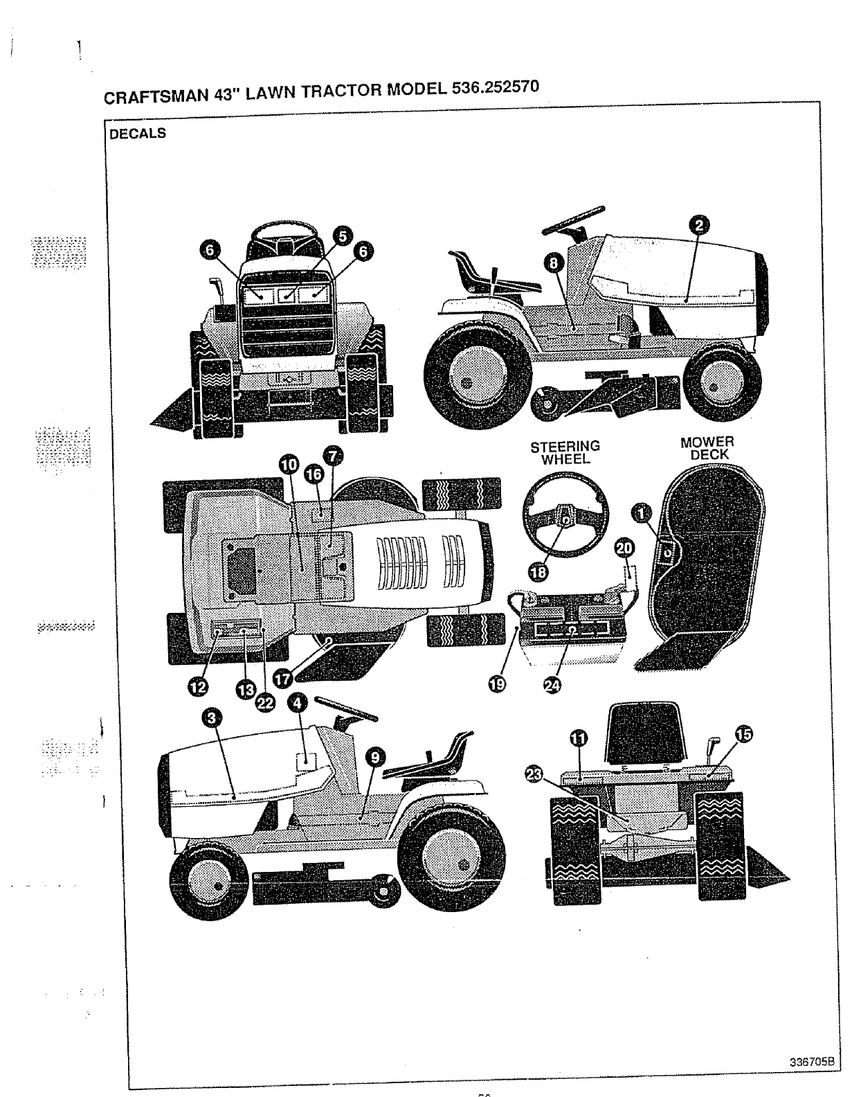
CRAFTSMAN 43" LAWN TRACTOR MODEL 536.252570
)ECALS
®
STEERING
WHEEL
MOWER
DECK
336705B
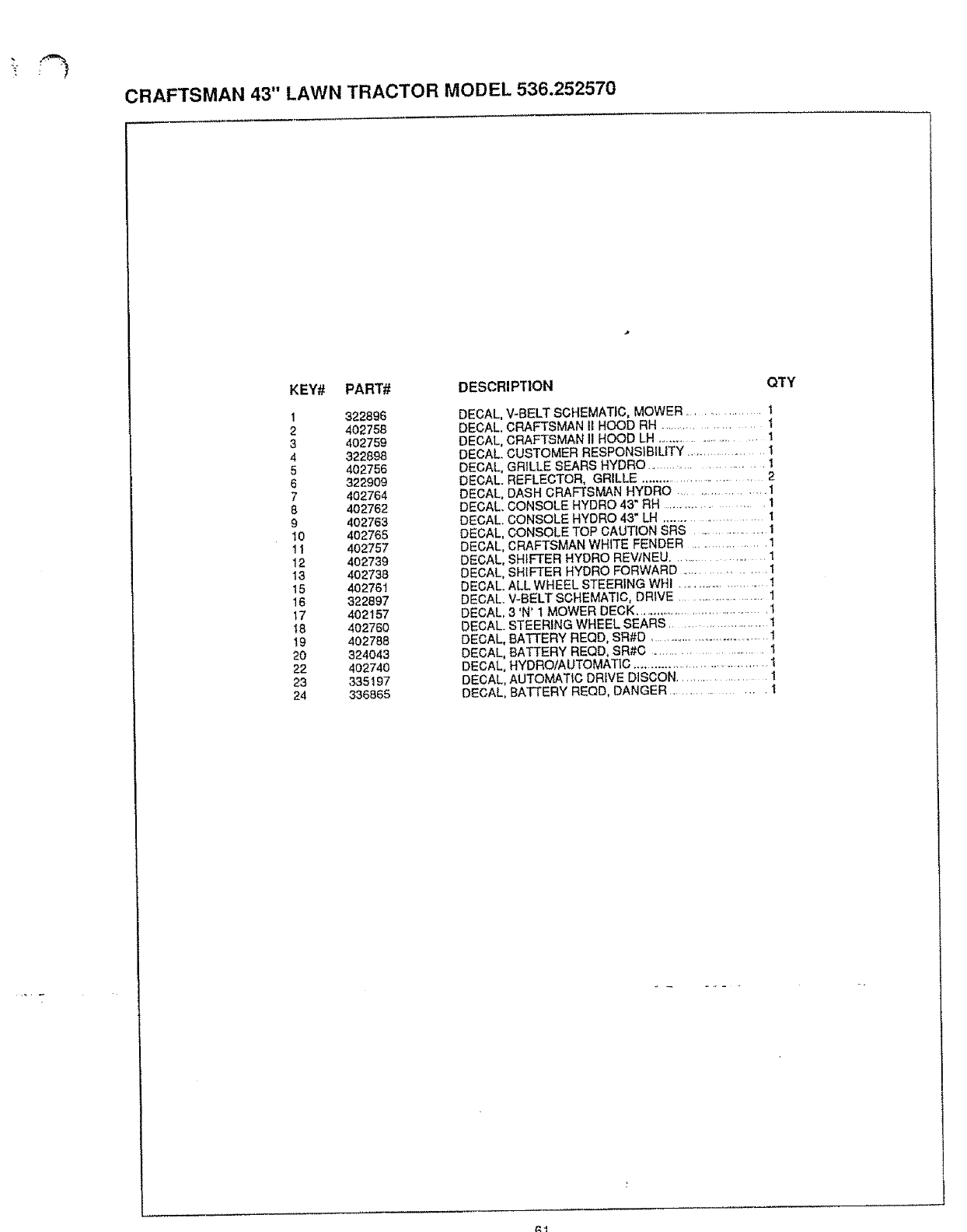
CRAFTSMAN 43" LAWN TRACTOR MODEL 536.252570
KEY# PART# DESCRIPTION
1322896
2 402758
3 402759
4322898
5 402756
6322909
7 402764
8 4O2762
9 402763
10 4O2765
11 402757
12 402739
13 402738
15 402761
16 322897
17 402157
t8 4O276O
I9 402788
20 324043
22 402740
23 335197
24 336865
QTY
DECAL, V-BELT SCHEMATIC, MOWER ................. 1
DECAL. CRAFTSMAN IIHOOD RH ..................... 1
DECAL, CRAFTSMAN II HOOD LH ........................... 1
DECAL. CUSTOMER RESPONSIBILITY .................. 1
DECAL, GRILLE SEARS HYDRO ......................... i
DECAL. REFLECTOR, GRILLE ............................ 2
DECAL, DASH CRAFTSMAN HYDRO .................. 1
DECAL. CONSOLE HYDRO 43" RH ................ 1
DECAL. CONSOLE HYDRO 43" LH ....................... I
DECAL, CONSOLE TOP CAUTION SRS ........................ 1
DECAL, CRAFTSMAN WHITE FENDER .................. 1
DECAL, SHIFTER HYDRO REVtNEU ................. 1
DECAL, SHIFTER HYDRO FORWARD ....................
DECAL. ALL WHEEL STEERING WIll ........................... 1
DECAL. V-BELT SCHEMATIC, DRIVE ........................... 1
DECAL, 3'N' 1 MOWER DECK ...................................... 1
DECAL. STEERING WHEEL SEARS .......................... 1
DECAL, BATTERY REQD, SR#D ....................................... 1
DECAL, BATTERY REQD, SR#C ............................ 1
DECAL, HYDROfAUTOMATIC ..................................... I
DECAL, AUTOMATIC DRIVE DISCON .................... 1
DECAL, BATTERY REQD, DANGER ................. I
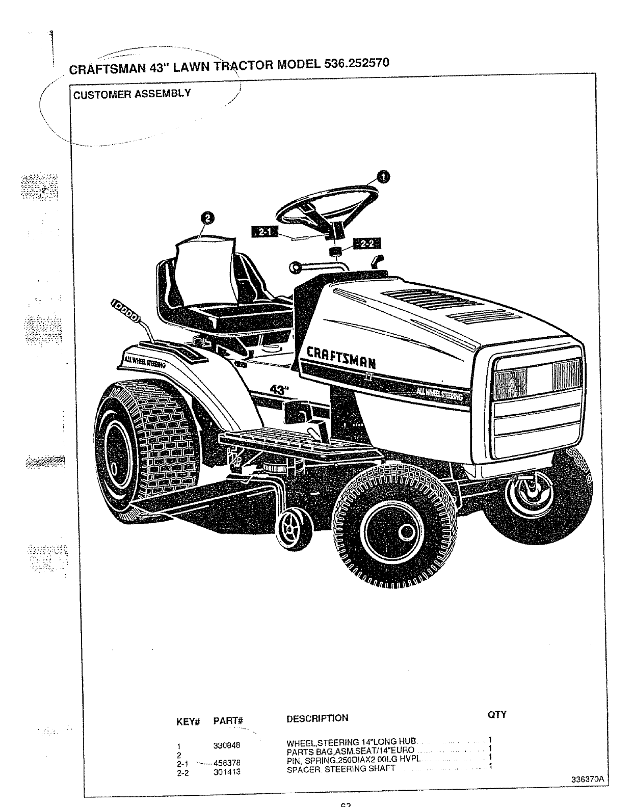
x
i!:!_:)71'!
cRAFTsMAN 43" LAWN TRACTOR MODEL 536.252570
CUSTOMER ASSEMBLY /
KEY# PART# DESCRIPTION
1 330848
2
2-1 ....... 456378
2-2 301413
QTY
WHEEL,STEERING !4"LONG HUB .......... 1
PARTS BAG,ASM.SEATI14"EURO ........... 1
PLN, SPRING.250D1AX2 00LG HVPL ...... l
SPACER STEERtNG SHAFT ....... 1
336370/
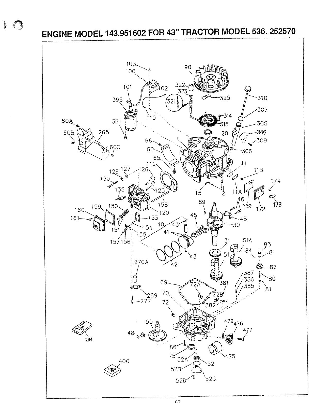
ENGINE MODEL 143.951602 FOR 43" TRACTOR MODEL 536. 252570
3!0
,307
151
53 45
I_30
294
gR
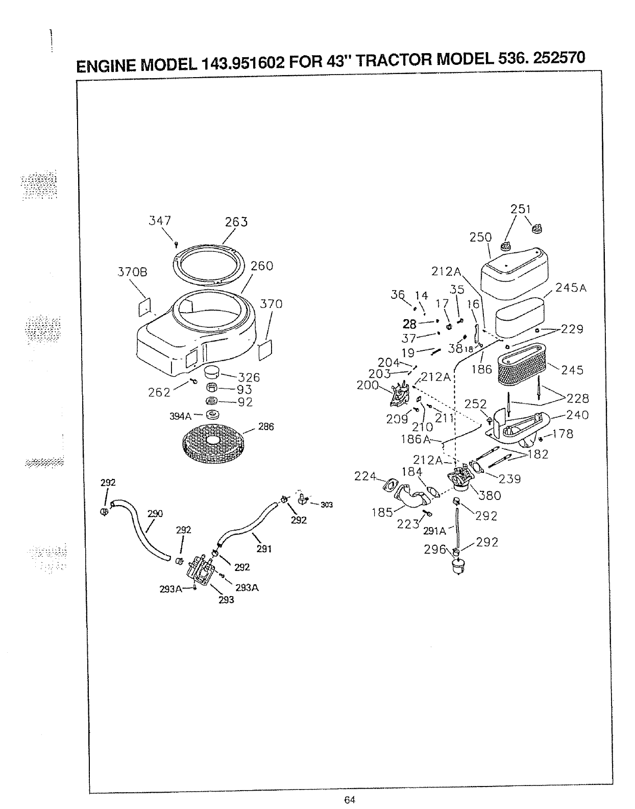
1
ENGINE MODEL 143.951602 FOR 43" TRACTOR MODEL 536. 252570
-'% :'3; "._=;'2.,; ",
347 263
\/
570B 2t2A
37O
292
/\291
292
2:93A--4 293A
293
292
25O
580
A../"_292
296\_J "292
251
245A
64
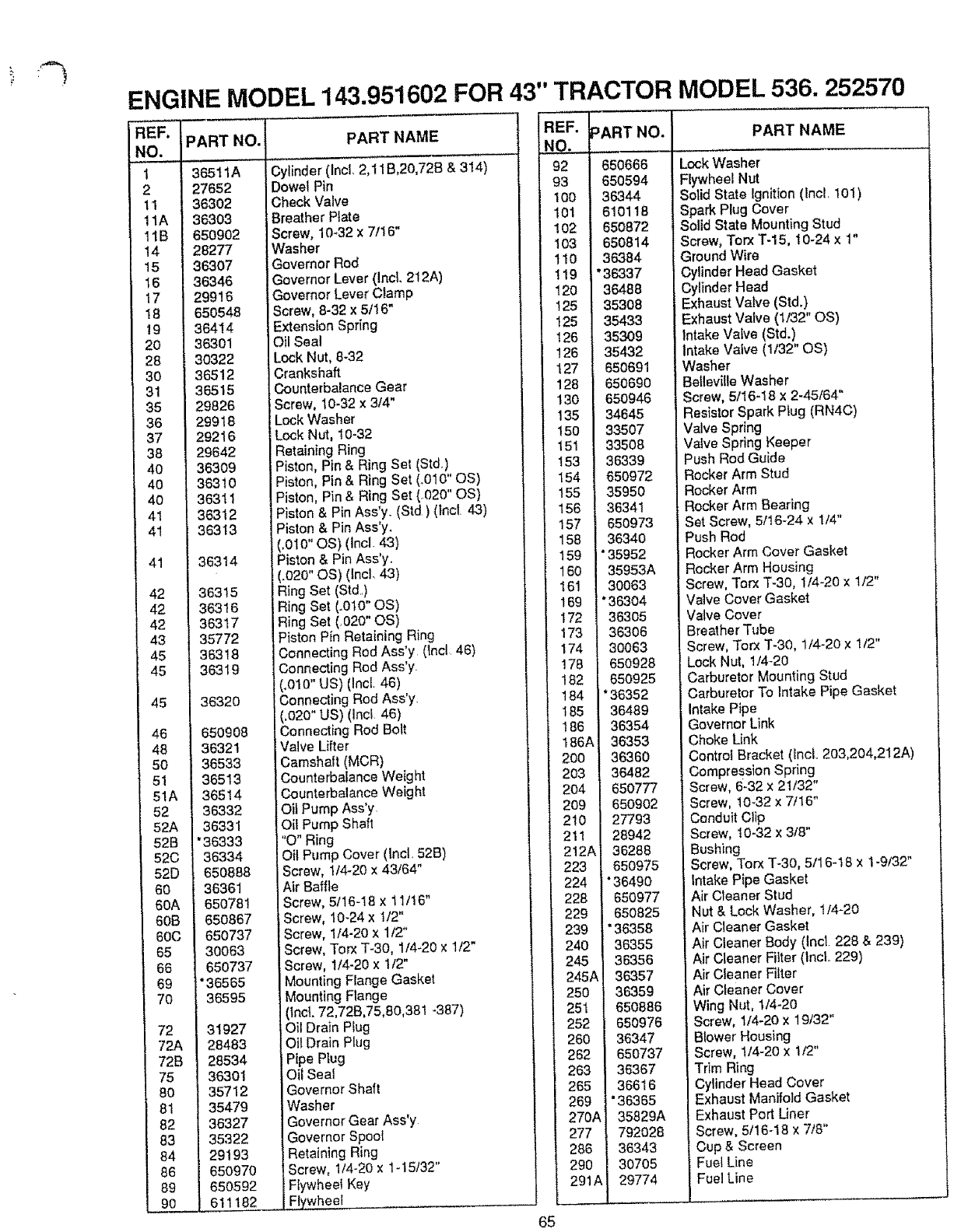
ENGINE MODEL 143.951602 FOR 43" TRACTOR MODEL 536. 252570
iREF.
[NO.
t1
12
Ilia
i11B
14
15
ii6
17
18
19
20
28
30
31
35
36
37
38
40
40
40
41
41
41
42
42
42
43
45
45
45
46
48
50
51
51A
52
52A
52B
520
520
60
60A
80B
60C
65
66
69
70
72
72A
72B
75
80
81
82
83
84
86
89
90
PART NO. PARTNAME
365t 1A
27652
36302
36303
650902
28277
36307
36346
299 ! 6
650548
36414
36301
30322
36512
36515
29826
29918
29216
29642
36309
38310
36311
36312
36313
36314
36315
36316
36317
35772
36318
36319
36320
650908
36321
36533
36513
36514
36332
36331
"36333
36334
650888
36361
650781
650867
650737
30063
650737
*36565
36595
31927
28483
28534
36301
35712
35479
36327
35322
29193
650970
650592
611182
Cylinder (Incl, 2,11B,20,72B & 314)
Dowel Pin
Check Valve
Breather Plate
Screw, 10-32 x 7/16"
Washer
Governor Rod
Governor Lever (IncL 212A)
Governor Lever Clamp
iScrew, 8-32 x 5/16
Extension Spring
_Oil Seal
Lock Nut, 8-32
Crankshaft
Counterbalance Gear
Screw, 10-32 x 3/4"
Lock Washer
Lock Nut, t0-32
Retaining Ring
Piston, Pin & Ring Set (Std,)
Piston, Pin & Ring Set (o010" OS)
Piston, Pin & Ring Set (.020" OS)
Piston & Pin Ass'y (Std) (tnct 43)
Piston & Pin Ass'y.
(.010" OS) (lncl 43)
Piston & Pin Ass'y.
(.020" OS) (lncl. 43)
Ring Set (Std)
Ring Set (.010" OS)
Ring Set (.020" OS)
Piston Pin Retaining Ring
Connecting Rod Ass'y (lncl 46)
Connecting Rod Ass'y
(.010" US) (Incl 46)
Connecting Rod Ass'y
(,020" US) (Incl 46)
Connecting Rod Bolt
Valve Lifter
Camsha{t (MCR)
Counterbalance Weight
Counterbalance Weight
Oil Pump Ass'y
Oil Pump Shaft
"O" Ring
Oil Pump Cover (Incl, 52B)
Screw, 1/4-20 x 43/64"
Air Baffle
Screw, 5/16-18 x 11/16"
Screw, 10-24 x 1/2"
Screw, 1/4-20 x 112"
Screw, Torx T-30, 114-20x 1t2"
Screw, 1/4-20 x 1/2"
Mounting Flange Gasket
Mounting Flange
(tncL 72,72B,75,80,381 -387)
Oil Drain Plug
Oi{ Drain Plug
Pipe Plug
Oit Seal
Governor Shaft
Washer
Governor Gear Ass'y.
Governor Spoo{
Retaining Ring
Screw, 114-20 x 1-15t32"
FtywheeI Key
Flywheel
65
REF.
NO.
92
93
100
101 i
102
I03
110
119
120
125
125
126
126
127
128
130
135
150 I
t51
153
154I
155 1
156 I
157
158 I
159 I
16O
161
169
172
173
174
176 I
182
184
185
186
186t
2OO
2o3
2o4
2o9
210
211
212t
223
224
228
229
239
240
245
245t
25O
251
252
260 !
262
263
26s I
269 ]
270A
277
286 I
290 I
291A I
PART NO.
650666
650594
36344
610118
650872
650814
36384
"36337
36488
35308
35433
35309
35432
650691
650690
650946
34645
33507
33508
36339
650972
35950
36341
650973
36340
*35952
35953A
30063
*363O4
363O5
363O6
30063
650928
650925
*36352
36489
36354
36353
36360
36482
650777
650902
27793
28942
36288
650975
"36490
650977
650825
"36358
36355
36356
36357
36359
650886
650976
36347
650737
36367
36616
*36365
35829A
792028
36343
30705
29774
PART NAME
Lock Washer
Flywheel Nut
Solid State Ignition (Incl, 101)
Spark Plug Cover
Solid State Mounting Stud
Screw, Torx T-15, t0-24 x 1"
Ground Wire
Cylinder Head Gasket
Cylinder Head
Exhaust Valve (Std.)
Exhaust Valve (1/32" OS)
Intake Valve (Std.)
intake Valve (1/32" OS)
Washer
Belleville Washer
Screw, 5/16-18 x 2-45/64"
Resistor Spark Plug (RN4C)
Valve Spring
Valve Spring Keeper
Push Rod Guide
Rocker Arm Stud
Rocker Arm
Rocker Arm Bearing
Set Screw, 5/!6-24 x 1/4"
Push Rod
Rocker Arm Cover Gasket
Rocker Arm Housing
Screw, Torx T-30, 1/4-20 x 1/2"
Valve Cover Gasket
Valve Cover
Breather Tube
Screw, Torx "!"-30, 1/4-20 x 1/2"
Lock Nut, 1/4_20
Carburetor Mounting Stud
Carburetor To Intake Pipe Gasket
Intake Pipe
Governor Link
Choke Link
Control Bracket (lncL 203,204,212A)
Compression Spring
Screw, 6-32 x 21/32"
Screw, 10-32 x 7/16"
Conduit Clip
Screw, 10-32 x 3/8"
Bushing
Screw, Torx "1"-30,5/16-18 x 1-9/32"
Intake Pipe Gasket
Air Cleaner Stud
Nut & Lock Washer, t/4-20
Air Cleaner Gasket
Air Cleaner Body (tnct 228 & 239)
Air Cleaner Filter (Incl 229)
Air Cleaner Filter
Air Cleaner Cover
Wing Nut, 1/4-20
Screw, 1/4-20 x 19/32"
Blower Housing
Screw, 1/4-20 x 1/2"
Trim Ring
Cylinder Head Cover
Exhaust Manifold Gasket
Exhaust Port Liner
Screw, 5/16-18 x 7/8"
Cup & Screen
Fuel Line
Fuel Line
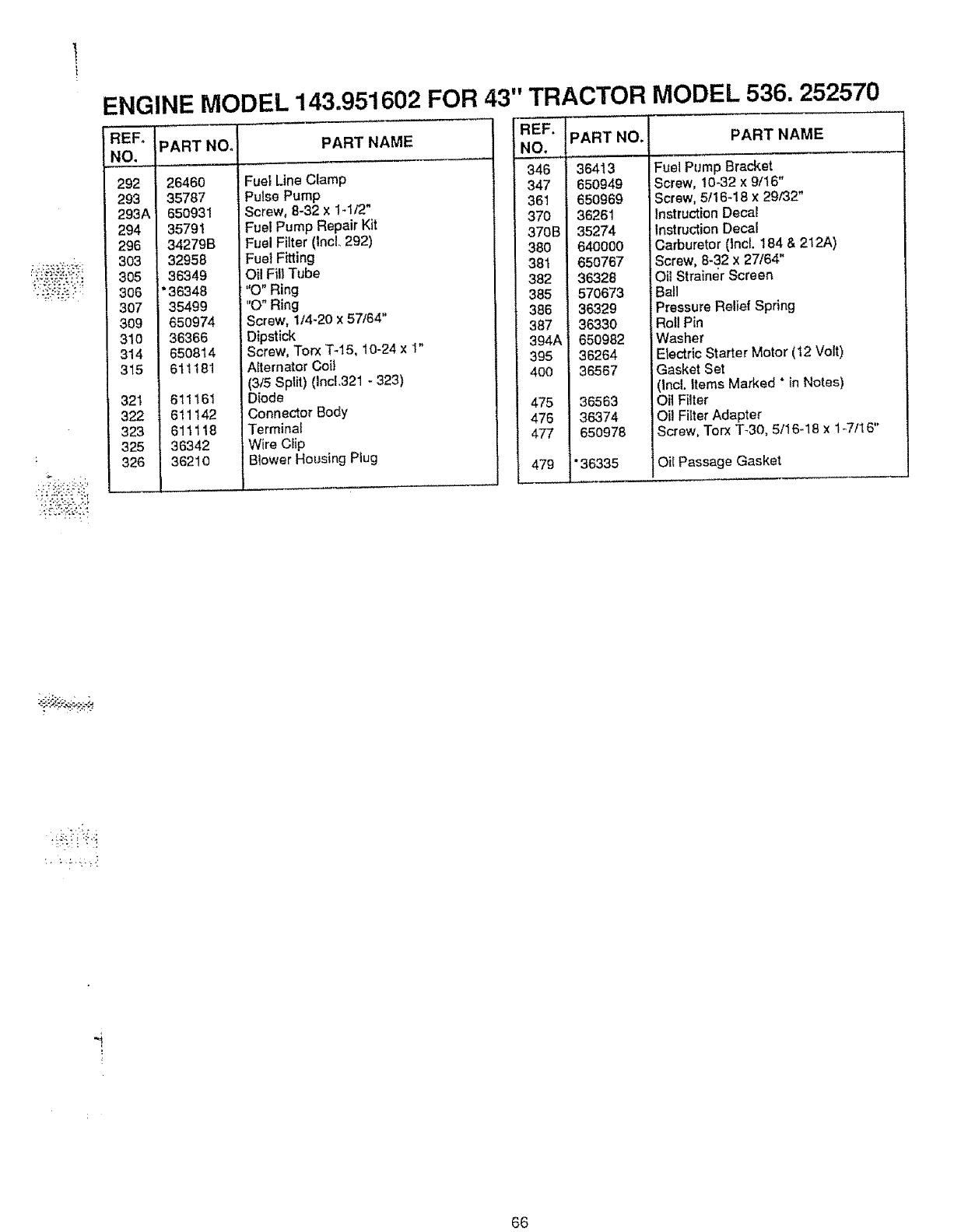
:,; t-'_:_:_ .'.
ENGINE MODEL 143.951602 FOR 43" TRACTOR MODEL 536. 252570
REF_ PART NO.
NO.
292
293
2g3A
294
296
3O3
305
306
307
309
31o
814
315
321 611161
322 611142
323 611118
325 36342
326 36210
26460
35787
65O931
35791
342798
32958
36349
*36348
35499
650974
36366
650814
611181
PART NAME
Fuel Lin_ Clamp
Pulse Pup
Screw, 8-32 x 1-1/2"
Fuel Pun tp Repair Kit
Fuel Filt_ (IncL 292)
Fuel Fitti g
Oil Fill TI
"0" Ring
"O" Ring
Screw, 1/4-20 x 57/64"
Dipstick
Screw, Torx T-16, 10-24 x t"
Afternatc Coil
(3/5 Split Incl.321 - 323)
Diode
Connect{ Body
Termlnat
Wire CIJl:
Blower Housing Plug
REF, PART NO.
NO.
346 I36413
347 650949
361 t 65O969
37O I 36261
370BJ 35274
38O _ 640000
381 ' 650767
382 I 36328
365 I570673
386 36329
387 t 36330
394A1 650982
395 36264
400 I 36567
475 36563
476 I 36374
477 650978
479 '36335
PART NAME
Fuel Pump Bracket
Screw, 10-32 x 9/16"
Screw, 5/16-18 x 29/32"
Instruction Decat
Instruction Decal
Carburetor (incl. 184 & 212A)
Screw, 8-32 x 27/64"
Oil Strainer Screen
Ball
=ressure Relief Spring
Roll Pin
Washer
Electric Starter Motor (12 Volt)
Gasket Set
Incl. Items Marked *in Notes)
Oil Filter
Oi! Filter Adapter
Screw, Torx T-30, 5/16-18 x 1_7/16"
Oil Passage Gasket
•i_!i:i ::!,q
66
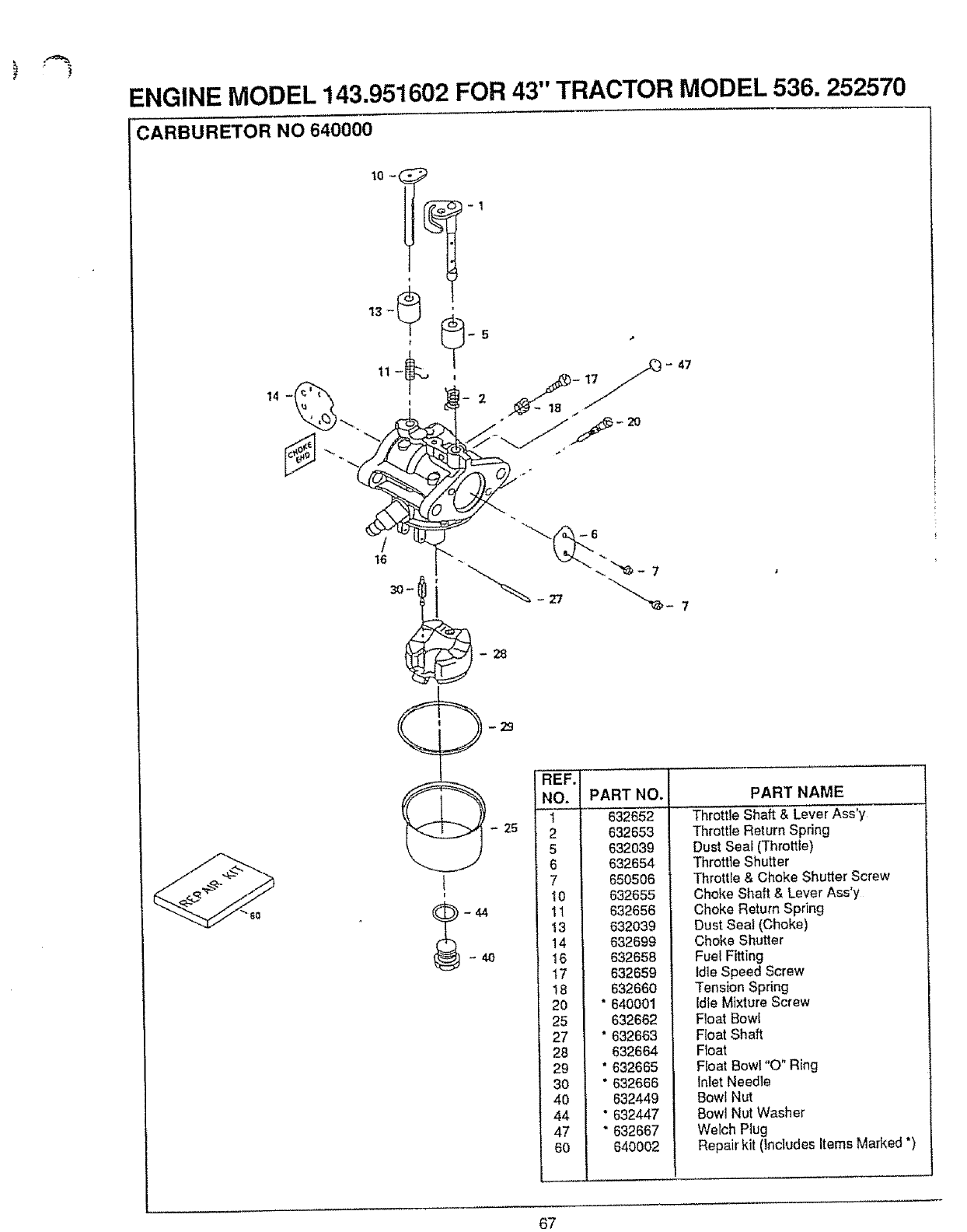
ENGINE MODEL 143.951602 FOR 43" TRACTOR MODEL 536. 252570
CARBURETOR NO 640000
2O
47
4O
25
PART NO.
632652
632653
632039
632654
650506
632655
632656
632039
632699
632658
632659
632660
*640001
632662
°632663
632664
"632665
" 632666
632449
* 632447
" 632667
640002
PART NAME
Throttle Shaft & Lever Ass'y
Throttle Return Spring
Dust Seal (Throttle)
Throttle Shutter
Throttle & Choke Shutter Screw
Choke Shaft & Lever Ass'y
Choke Return Spring
Dust Seal (Choke)
Choke Shutler
Fuel Fitting
Idle Speed Screw
Tension Spring
tdie Mixture Screw
Float Bowl
Float Shaft
Ftoat
Float Bowl "0" Ring
Inlet Needle
Bowl Nut
Bowl Nut Washer
WeFch Plug
Repair kit (Includes Items Marked *)
67
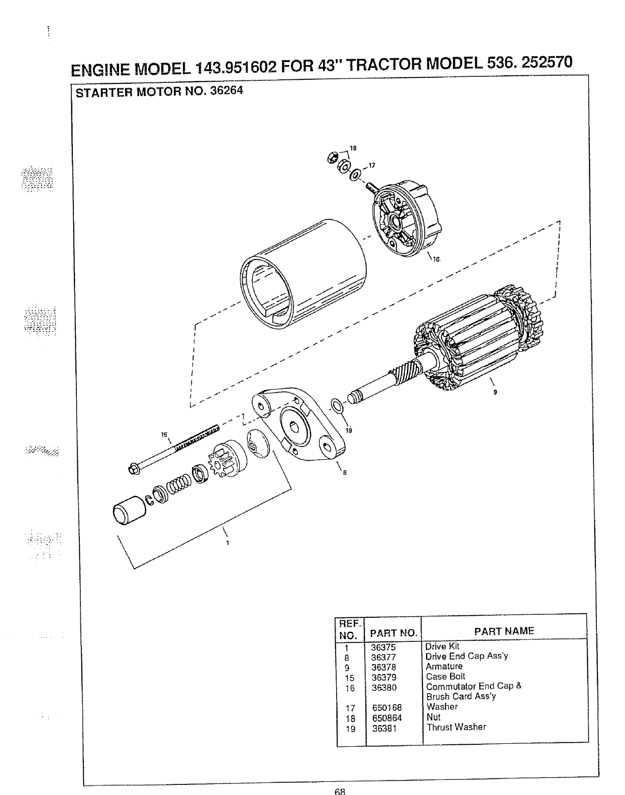
• ]
ENGINE MODEL 143.951602 FOR 43" TRACTOR MODEL 536. 252570
STARTER MOTOR NO. 36264
\
9
NO. I
H I
=4 I
15 I
t6 I
18 I
19 I
PART NO.
36375
36377
36378
36379
36380
650168
650864
36381
PART NAME
Drive Kit
Drive End Cap Ass'y
Armature
Case Bolt
Commutator End Cap &
Brush Card Ass'y
Washer
Nut
Thrust Washer
68
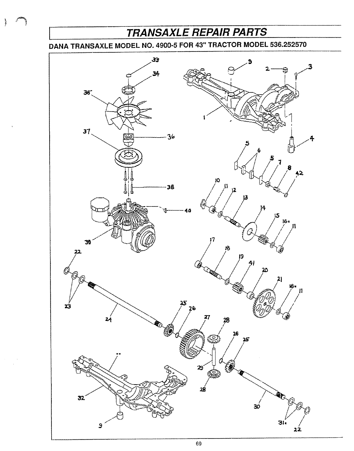
ITRANSAXLE REPAIR PARTS
DANA TRANSAXLE MODEL NO. 4900-5 FOR 43" TRACTOR MODEL 536.252570
,7 /
/
19
1'
I1
//
/
31. /
/
ZZ
69
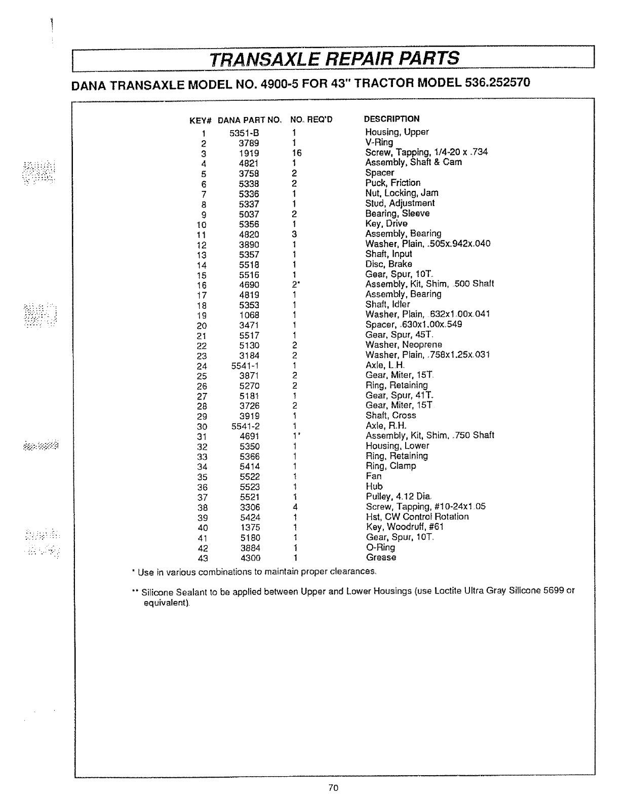
[TRANSAXLE REPAIR PARTS I
DANA TRANSAXLE MODEL NO. 4900-5 FOR 43" TRACTOR MODEL 536.252570
_2!::: _i:i;
KEY# DANA PARTNO, NOoREQ'D DESCRIPTION
I 5351-B 1 Housing, Upper
2 3789 1 V-Ring
3 I919 16 Screw, Tapping, 1/4.-20 x .734
4 4821 1 Assembly, Shaft &Cam
5 3758 2 Spacer
6 5338 2 Puck, Friction
7 5336 1 Nut, Locking, Jam
8 5337 1 Stud, Adjustment
9 5037 2 Bearing, Sleeve
10 5356 1 Key, Drive
11 4820 3 Assembly, Bearing
12 3890 1 Washer, Plain, oS05x:942xo040
13 5357 1 Shaft, Input
14 5518 1 Disc, Brake
15 5516 1 Gear, Spur, 10T..
16 4690 2" Assembly, Kit, Shim, .500 Shaft
17 4819 1 Assembly, Bearing
18 5353 t Shaft, Idler
19 1068 1 Washer, Plain, 632xl .00x.041
20 3471 1 Spacer, _630x1.00x.549
2! 55!7 1 Gear, Spur, 45T.
22 5130 2 Washer, Neoprene
23 3184 2 Washer, Plain, .758xl .25x.031
24 5541-1 1 Axle, LH.
25 3871 2 Gear, Miter, 15T.
26 5270 2 Ring, Retaining
27 518t _Gear, Spur, 41T..
28 3726 2 Gear, Miter, 15T
29 39t9 1 Shaft, Cross
30 5541-2 t Axle, Roll.
31 4691 1*Assembly, Kit, Shim, .750 Shaft
32 5350 1 Housing, Lower
33 5366 1 Ring, Retaining
34 5414 1 Ring, Clamp
35 5522 t Fan
36 5523 t Hub
37 5521 1 Puttey, 4. !2 Dia.
38 3306 4 Screw, Tapping, #10-24xl 05
39 5424 1 Hst, CW Contrcf Rotation
40 1375 1 Key, Woodruff, #61
41 5t80 1 Gear, Spur, 10T_
42 3884 I O-Ring
43 4300 1 Grease
• Use in various combinations to maintain proper clearances.
"* Silicone Sealant to be applied between
equivalent). Upper and Lower Housings (use Loctite Ultra Gray Silicone 5699 or
7O
i
i
........... i

NOTES
71
OWNER'S
MANUAL
MODEL NO.
536.252570
HOW TO ORDER
REPAIR PARTS
CRAFrSMRN
16.5 HP OHV
ALL-WHEEL STEER
43" MOWER DECK
HYDROSTATIC DRIVE
LAWN TRACTOR
Each tractor has its own model number. Each engine has its own model
number.
The Model Number for your tractor will be found on the model plate
located under the seat
The model number for your engine will be found on the blower housing
of the engine
All parts may be ordered through Sears, Roebuck and Company
Service Centers and most Retail Stores°
WHEN ORDERING REPAIR PARTS, ALWAYS GIVE THE FOLLOW-
ING INFORMATION:
o PRODUCT- LAWN TRACTOR
oMODEl.. NUMBER- 536_252570
=ENGINE MODEL NUMBER- 143,95t602
•PART NUMBER
•PART DESCRIPTION
Your Sears merchandise has added value when you consider Sears
has service units nationwide staffed with Sears trained technicians _.
professional technicians specifically trained to insure that we meet
our pledge to you, we service what we sell
........................................... ,,,,i,i, = ===ill =,1,. ill=
SEARS, ROEBUCK AND CO., D/817WA_ HOFFMAN ESTATES, IL 60179
72 Printed in U SA
