Craftsman 536270270 User Manual RIDING MOWER Manuals And Guides L0207061
CRAFTSMAN Lawn, Riding Mower Rear Engine Manual L0207061 CRAFTSMAN Lawn, Riding Mower Rear Engine Owner's Manual, CRAFTSMAN Lawn, Riding Mower Rear Engine installation guides
User Manual: Craftsman 536270270 536270270 CRAFTSMAN RIDING MOWER - Manuals and Guides View the owners manual for your CRAFTSMAN RIDING MOWER #536270270. Home:Lawn & Garden Parts:Craftsman Parts:Craftsman RIDING MOWER Manual
Open the PDF directly: View PDF ![]() .
.
Page Count: 65

Operator's Manual
CRAFTSMAN
Mid-Engine Rider
13.5 HP. Electric Start
30" Mower /Mulcher
Variable Speed
Model 536.270270
•Safety
•Operation
•Maintenance
•Parts
CAUTION: Before using this
product, read this manual
and follow all of its Safety
Rules and Operating
Instructions.
Manual del usario
Tractor cortac_sped
con motor situado
detr_s del siento
Arranque electrico de 13,5 caballos
Cortac_sped /trituradora de 76 cm.
Velocidad variable
Modelo 536.270270
PRECAUCION: Antes de usar este
producto, lea este manual y siga
todas las reglas de seguridad e
instrucciones de operaci6n.
•Seguridad
• Operacibn
•Mantenimiento
•Piezas
Sears, Roebuck and Co., Hoffman Estates, IL. 60179 U.S.A.
F-020611L www.sears.com/craftsman
TABLE OF CONTENTS
WARRANTY .................................... 2 MAINTENANCE ................................. 19
PRODUCT SPECIFICATIONS ..................... 3 SERVICE AND ADJUSTMENT .................... 25
SAFETY RULES ................................. 4 TROUBLE SHOOTING CHART .................... 36
PREPARATION .................................. 7 SLOPE GUIDE .................................. 39
OPERATION .................................... 10 REPAIR PARTS ................................. 40
....
LIMITED WARRANTY ON CRAFTSMAN RIDING EQUIPMENTMID-ENGINE RIDER
For two (2) years from the date of purchase, if this Craftsman Riding Equipment is maintained, lubricated and tuned up J J
according to the instructions in the owner's manual, Sears will repair or replace free of charge any parts that are found to be J J
defective in material or workmanship according to the guidelines of coverage listed below.
Sears will also provide free labor for these applicable warranted parts for the two full years. During the first 30 days of purchase, J J
there will be no charges to service the product at your home for issues covered by this warranty. (See exclusions below).
For your convenience, IN HOME warranty service will still be available after the first 30 days of purchase, but a trip charge will
apply. This charge will be waived if the Craftsman product is dropped off at an authorized Sears location. For the nearest J J
authorized Sears location, please call 1-800-4-MY-HOME®. This warranty applies only while this product is within the United J J
States.
EXCLUSIONS H
This Warranty does not cover: H
• Expendable items which become worn during normal use, including but not limited to blades, spark plugs, air cleaners, J J
belts, and oil filters.
• Standard Maintenance Servicing, oil changes, or tune-ups
• Tire replacement or repair caused by punctures from outside objects, such as nails, thorns, stumps or glass.
• Repairs necessary because of operator abuse, including but not limited to, damage caused by towing objects beyond the
capability of the riding equipment, impacting objects that bend the frame or crankshaft, or over-speeding the engine.
• Repairs necessary because of operator negligence, including but not limited to, electrical and mechanical damage caused J J
by improper storage, failure to use the proper grade and amount of engine oil, failure to keep the deck clear of flammable J J
debris, or failure to maintain the equipment according to the instructions contained in the owner's manual.
• Engine (fuel system) cleaning or repairs caused by fuel determined to be contaminated or oxidized (stale). In general, fuel
should be used within 30 days of its purchase date.
• Normal deterioration and wear of the exterior finishes, or product label replacement.
• Riding equipment used for commercial or rental purposes. JJ
LIMITED WARRANTY ON BATTERY IIH
II
For ninety (90) days from date of purchase, if any battery included with this riding equipment proves defective in material or
workmanship and ourtesting determines the battery will not hold a charge, Sears will replace the battery at no charge. During J J
the first 30 days of purchase, there will be no charges to replace the battery at your home. After the first 30 days, for your conve- J J
nience, IN-HOME warranty service willstill be available but a tripcharge will apply. This charge will be waived ifthe Craftsman J J
product is dropped off at an authorized Sears location. For the nearest authorized Sears location, please call 1-800-4-MY- J J
HOME®. This Warranty applies only while this product is within the United States. This warranty gives you specific legal rights, J J
and you may also have other rights, which vary, from state to state. H
Sears, Roebuck and Co., Dept. 817WA, Hoffman Estates, IL 60179 J J
F-020611 L 2
Congratulations on your purchase of a Craftsman Mid-Engine
Rider. It has been designed, engineered and manufactured to
give you the best possible dependability and performance.
If you experience any problems you cannot easily remedy, please
see your nearest Sears Service Center. We have competent, well
trained technicians and the proper tools to service or repair this
unit.
Please read and keep this manual. The instructions will enable
you to assemble and maintain your unit properly. Always observe
the "Safety Rules".
Craftsman Mid-Engine Rider
Record in the space below the serial number and the date
of purchase of this unit.
The model number and serial number are found on a decal
attached to the unit.
Model Number: 536.270270
Serial Number:
Date of Purchase:
Keep these numbers for future reference.
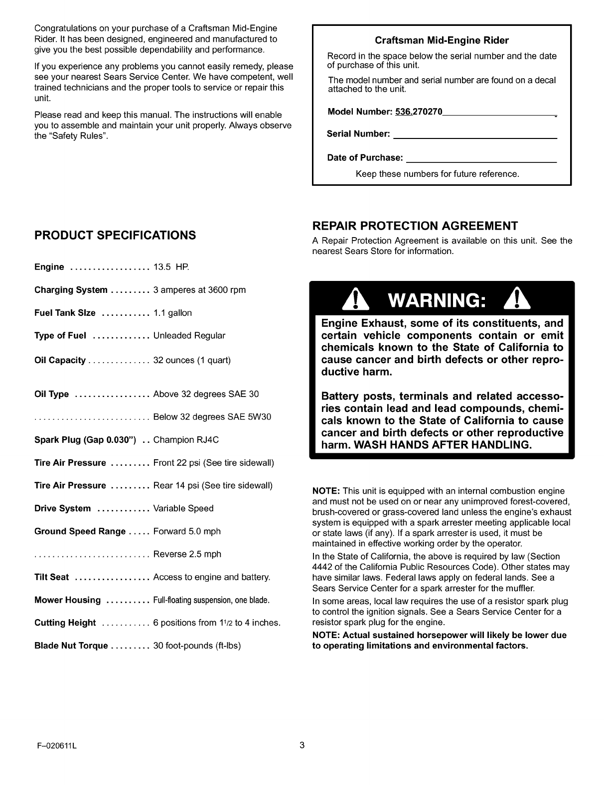
PRODUCT SPECIFICATIONS
Engine .................. 13.5 HP.
Charging System ......... 3 amperes at 3600 rpm
Fuel Tank Size ........... 1.1 gallon
Type of Fuel ............. Unleaded Regular
Oil Capacity .............. 32 ounces (1 quart)
Oil Type ................. Above 32 degrees SAE 30
.......................... Below 32 degrees SAE 5W30
Spark Plug (Gap 0.030") .. Champion RJ4C
Tire Air Pressure ......... Front 22 psi (See tire sidewall)
Tire Air Pressure ......... Rear 14 psi (See tire sidewall)
Drive System ............ Variable Speed
Ground Speed Range ..... Forward 5.0 mph
.......................... Reverse 2.5 mph
Tilt Seat ................. Access to engine and battery.
Mower Housing .......... Full-fl0atingsuspension,oneblade.
Cutting Height ........... 6 positions from 11/2to 4 inches.
Blade Nut Torque ......... 30 foot-pounds (ft-lbs)
REPAIR PROTECTION AGREEMENT
A Repair Protection Agreement is available on this unit. See the
nearest Sears Store for information.
Engine Exhaust, some of its constituents, and
certain vehicle components contain or emit
chemicals known to the State of California to
cause cancer and birth defects or other repro-
ductive harm.
Battery posts, terminals and related accesso-
ries contain lead and lead compounds, chemi-
cals known to the State of California to cause
cancer and birth defects or other reproductive
harm. WASH HANDS AFTER HANDLING.
NOTE: This unit is equipped with an internal combustion engine
and must not be used on or near any unimproved forest-covered,
brush-covered or grass-covered land unless the engine's exhaust
system is equipped with a spark arrester meeting applicable local
or state laws (if any). If a spark arrester is used, it must be
maintained in effective working order by the operator.
In the State of California, the above is required by law (Section
4442 of the California Public Resources Code). Other states may
have similar laws. Federal laws apply on federal lands. See a
Sears Service Center for a spark arrester for the muffler.
In some areas, local law requires the use of a resistor spark plug
to control the ignition signals. See a Sears Service Center for a
resistor spark plug for the engine.
NOTE: Actual sustained horsepower will likely be lower due
to operating limitations and environmental factors.
F-020611 L 3
SAFETY RULES
Safe Operation Practices for Riding Vehicles
As Recommended by American National Standards Institute
WARNING: This cutting machine is capable of amputating hands and feet and throwing objects. Failure to observe the
following safety instructions could result in serious injury or death to the operator or bystanders.
GENERAL OPERATION:
1. Read, understand and follow all instructions in the Instruction
Book, on the machine, the engine and with any attachments
before starting.
2. Only allow responsible adults familiar with the instructions to
operate the machine.
3. Clear the area of objects such as rocks, toys, wire, etc.
which could be picked up and thrown by the blade.
4. Be sure the area is clear of other people before mowing.
Stop the machine if anyone enters the area.
5. Never carry passengers.
6. Disengage power to the mower or any attachments before
backing up. Do not mow in reverse unless absolutely neces-
sary. Always look down and behind before and while back-
ing.
7. Be aware of the direction the mower discharges. Do not point
discharge from the mower at anyone or at places where
people may be. Do not operate the mower without either the
entire grass bagger or the mower guard in place.
8. Slow down before turning.
9. Never leave a machine unattended with the engine running.
Always disengage the blade(s), set the parking brake, stop
the engine and remove the key before dismounting.
10. Disengage power to attachment(s) when transporting or not
in use. Disengage the blade(s) when not mowing.
11. Stop the engine before removing the grass bagger or unclog-
ging the chute.
12. Mow only in daylight or good artificial light.
13. Do not operate the machine while under the influence of al-
cohol or drugs or when very tired.
14. Watch for traffic when operating near or crossing roadways.
15. Use extra caution when loading or unloading the machine
when using a trailer or truck for transporting.
16. Disengage all attachment clutches and shift into Neutral be-
fore attempting to start the engine.
17. Always wear safety glasses or an eye shield when you oper-
ate the unit to protect your eyes from foreign objects that can
be thrown from the unit. Always wear eye protection when
you make an adjustment or repair to the machine.
18. Use care when pulling loads or using heavy equipment.
a. Use only approved drawbar hitch points.
b. Limit loads to those you can safely control.
c. Do not turn sharply. Use care when backing.
d. Use counterweights or wheel weights when suggested in
the Instruction Book.
19. Do not operate this machine if you are taking drugs or other
medication which can cause drowsiness or affect your ability
to operate this machine.
20. Do not use this machine if you are mentally or physically
unable to operate this machine safely.
21. Data indicates that operators, age 60 years and above, are
involved in a large percentage of riding mower related inju-
ries. These operators should evaluate their ability to operate
a riding mower safely enough to protect themselves and oth-
ers from serious injury.
SLOPE OPERATION:
Slopes and rough terrain are major factors related to loss of
control and tip over accidents which can result in severe
injury or death. ALL slopes require extra caution. If you can-
not back up the slope or if you feel uneasy on the slope, do
not mow it. See the "Slope Guide" in the back of this book to
check for safe operation.
DO
1. Mow up and down slopes, not across.
2. Remove obstacles such as rocks, limbs, etc...
3. Watch for holes, ruts or bumps. Uneven terrain could over-
turn the machine. "Tall grass can hide obstacles."
4. Use slow speed. Choose a low enough gear so that you will
not have to stop or shift while on the slope.
5. Follow the manufacturer's recommendations for wheel
weights or counterweights to improve stability.
6. Use extra care with grass baggers or other attachments,
they can change the stability of the machine.
7. Keep all movement on the slopes slow and gradual. Do not
make sudden changes in speed or direction.
8. Avoid starting or stopping on a slope. If tires lose traction,
disengage the blades and proceed slowly straight down the
slope.
DO NOT
1. Do not turn on slopes unless absolutely necessary, then
only turn slowly and gradually downhill, if possible.
2. Do not mow near drop-offs, ditches or embankments. A
wheel over the edge or an edge caving in could cause a sud-
den overturn and an injury or death.
3. Do not mow on wet grass. Reduced traction could cause
sliding.
4. Do not try to stabilize the machine by putting your foot on
the ground.
5. Do not use a grass bagger or other rear mounted accesso-
ries on steep slopes (greater than 10 degrees).
F-020611 L
SAFETY RULES
CHILDREN"
Tragic accidents can occur if the operator is not alert to the
presence of children. Children are often attracted to the ma-
chine and the mowing activity. NEVER assume that children
will remain where you last saw them.
1. Keep children out of the mowing area and in the watchful
care of an adult other than the operator.
2. Be alert and turn the engine off if children enter the area.
3. Before and when backing, look behind and down for small
children.
4. Never carry children or any passengers. They may fall off
and be seriously injured or interfere with the safe operation
of the machine.
5. Never allow children to operate the machine. Instruct chil-
dren in the dangers of the machine.
6. Use extra care when approaching blind corners, shrubs,
trees or other objects that may obscure vision.
SERVICE:
1. Use extra care when handling gasoline and other fuels.
Fuels are flammable and the vapors are explosive.
a. Use only an approved container.
b. Never remove the gas cap or add fuel with the engine
running. Allow the engine to cool for several minutes before
refueling. Do not smoke.
c. Never refuel the machine indoors.
d. Never store the machine with fuel in the tank or fuel con-
tainer inside where there is an open flame, such as a water
heater.
2. Never start or run the engine inside a closed area.
3. Keep all nuts and bolts, especially the blade attachment nuts
tight. Frequently check the blade(s) for wear or damage such
as cracks and nicks. A blade that is bent or damaged must
be immediately replaced with an original equipment blade
from an authorized service dealer. For safety, replace the
blade every two years. Keep the equipment in good condi-
tion.
4. Never tamper with the safety devices. Check their proper
operation regularly.
5. To reduce fire hazards keep the machine free of grass,
leaves or other debris build-up. Clean up oil or fuel spills.
Allow the machine to cool before storing.
6. Stop and inspect the equipment if you strike an object. Re-
pair, if necessary, before restarting.
7. Never make adjustments or repairs with the engine running.
The carburetor can be adjusted with the engine running. Do
not change the engine governor settings or overspeed the
engine.
8. Grass bagger components are subject to wear, damage and
deterioration, which could expose moving parts or allow ob-
jects to be thrown. For storage, always make sure the grass
bag is empty. Frequently check components and replace with
manufacturer's recommended parts when necessary.
9. Mower blade(s) are sharp and can cut. Wrap the blade(s) or
wear gloves and use extra caution when servicing them or
the blade housing area.
10. Check the brake operation frequently. Adjust and service as
required.
11. Wait for all movement to stop before servicing any part of the
unit.
Look for this symbol to indicate important safety
precautions. This symbol indicates: "Attention!
Become Alert! Your Safety Is At Risk."
F-020611 L 5
SAFETY RULES
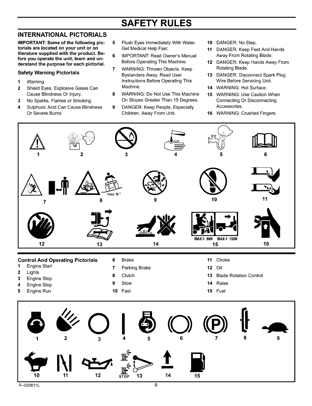
INTERNATIONAL PICTORIALS
IMPORTANT: Some of the following pic-
torials are located on your unit or on
literature supplied with the product. Be-
fore you operate the unit, learn and un-
derstand the purpose for each pictorial.
Safety Warning Pictorials
1Warning
2Shield Eyes. Explosive Gases Can
Cause Blindness Or Injury.
3 No Sparks, Flames or Smoking.
4 Sulphuric Acid Can Cause Blindness
Or Severe Burns
5Flush Eyes Immediately With Water.
Get Medical Help Fast.
6 IMPORTANT: Read Owner's Manual
Before Operating This Machine.
7 WARNING: Thrown Objects. Keep
Bystanders Away. Read User
Instructions Before Operating This
Machine.
8 WARNING: Do Not Use This Machine
On Slopes Greater Than 15 Degrees.
9 DANGER: Keep People, Especially
Children, Away From Unit.
10 DANGER: No Step.
11 DANGER: Keep Feet And Hands
Away From Rotating Blade.
12 DANGER: Keep Hands Away From
Rotating Blade.
13 DANGER: Disconnect Spark Plug
Wire Before Servicing Unit.
14 WARNING: Hot Surface.
15 WARNING: Use Caution When
Connecting Or Disconnecting
Accessories.
16 WARNING: Crushed Fingers.
3 4 5 6
A
7
max,S°
8 9 10 11
12 13 MAX-+ 90N MAX-+150N
14 15 16
Control And Operating Pictorials 6 Brake 11 Choke
1Engine Start 7 Parking Brake 12 Oil
2 Lights 8 Clutch 13 Blade Rotation Control
3 Engine Stop
4 Engine Stop 9 Slow 14 Raise
5 Engine Run 10 Fast 15 Fuel
1 2 3 4 5 6 7 8
10 11 12
ti
STOP 13 14 15
F-020611 L 6
PREPARATION
PREPARATION
Read and follow the preparation instructions for your mower. All
fasteners are in the parts bag. Do not discard any parts or material
until the unit is assembled.
NOTE: In this instruction book, left and right describe the loca-
tion of a part from the viewpoint of someone setting in the oper-
ator's seat.
_k WARNING: Before doing any preparation or mainte-
nance to the mower, remove the wire from the spark
plug.
The unit is completely assembled except for the items shown below.
These items are in the carton along with a parts bag. The parts bag
contains the fasteners needed to complete the preparation of the
unit. Find and remove these items. Do not discard any parts or mate-
rial until the unit is assembled.
HOW TO REMOVE FROM THE CARTON
To remove the unit from the carton, follow the instructions below.
1. Locate the two tear tabs at the top of the carton.
2. Pull the tear tape no more than twelve inches at a time.
3. Re-grasp the tear tape next to the carton and pull again.
4. One the tear tape has been completely removed from both
ends, remove the top wood and set aside.
5. Repeat the process on the tear tabs at the bottom of the carton.
6. Set the panels aside.
7. Move the shift lever to the neutral (N) position.
NOTE: See the Operation section, page 10, for the location
of the controls.
8. If the parking brake is engaged, completely depress the
clutch/brake pedal to release the brake.
9. Move the lift lever to the highest position.
CAUTION: Check the bottom of the carton for staples.
Remove any staples that are in the path of the tires.
10. Remove the mower from the shipping skid.
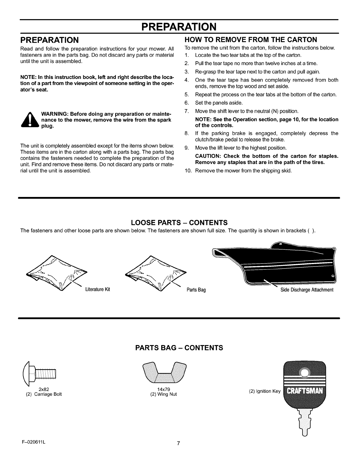
LOOSE PARTS - CONTENTS
The fasteners and other loose parts are shown below. The fasteners are shown full size. The quantity is shown in brackets ().
LiteratureKit PartsBag Side DischargeAttachment
PARTS BAG - CONTENTS
2x82
(2) Carriage Bolt 14x79
(2) Wing Nut (2) Ignition Key
F-020611 L 7
PREPARATION
MAINTENANCE FREE BATTERY 3.
4.
IMPORTANT: Before you attach the battery cables to the
battery, check the battery date. The battery date tells if the
battery must be charged.
1.
2.
3.
4.
Raise the seat support and secure in the UP position with the
seat support rod.
Check the top of the battery for the location of the battery date
(Figure 1).
If the battery is put into service before the battery date, the
battery cables can be attached without charging the battery.
See "How To Install The Battery Cables".
If the battery is put into service after the battery date, the
battery must be charged. See "How To Charge The
Maintenance Free Battery".
HOW TO CHARGE
THE MAINTENANCE FREE BATTERY
_ WARNING: When you charge the battery, do not
smoke. Keep the battery away from any sparks. The
fumes from the battery acid can cause an explosion.
1. To disconnect the battery retainer from the battery tray, push
in on the lower end of the battery retainer.
2. Remove the battery from the right side of the unit.
5.
Remove the protective caps from the battery terminals.
Use a 12 volt battery charger to charge the battery. Charge at
a rate of 6 amperes for one hour. If you do not have a battery
charger, have a Sears or other qualified Service Center charge
the battery.
Install the battery and secure with the battery retainer. Make
sure the positive (+) terminal is on the right side.
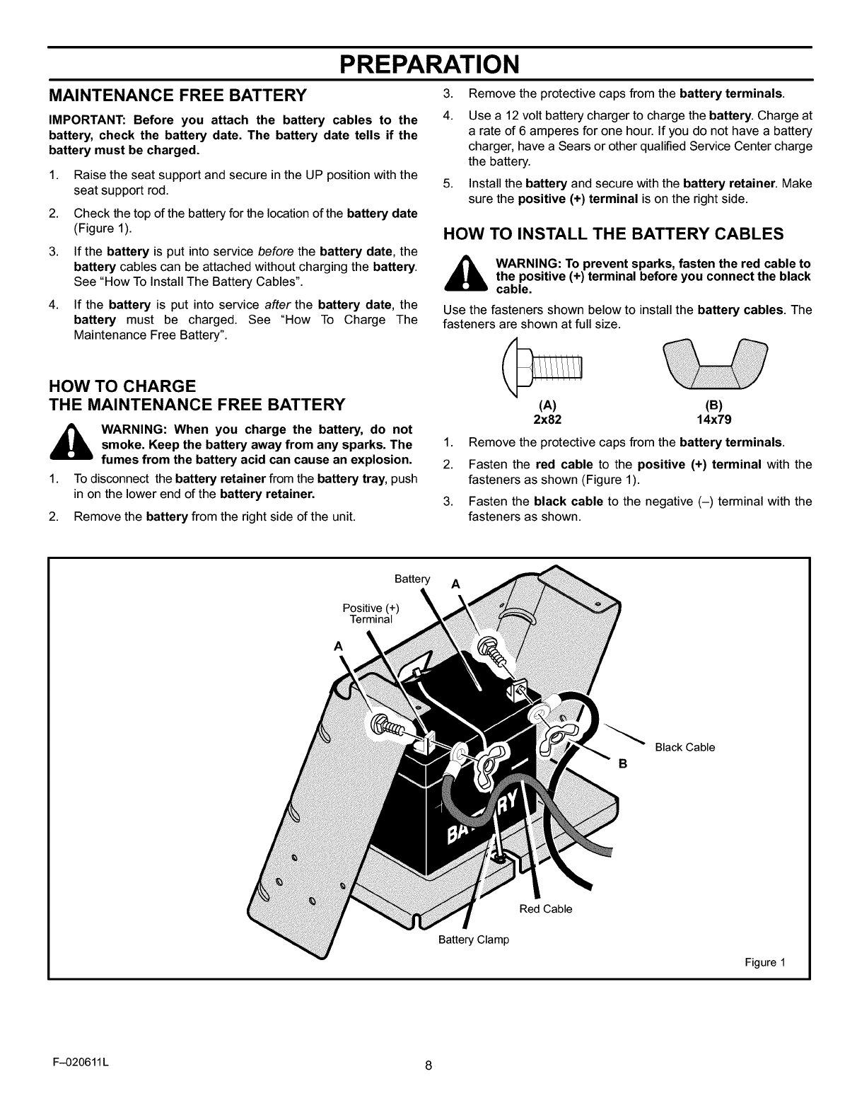
HOW TO INSTALL THE BATTERY CABLES
_ WARNING: To prevent sparks, fasten the red cable to
the positive (+) terminal before you connect the black
cable.
Use the fasteners shown below to install the battery cables. The
fasteners are shown at full size.
(A)
2x82 (B)
14x79
1. Remove the protective caps from the battery terminals.
2. Fasten the red cable to the positive (+) terminal with the
fasteners as shown (Figure 1).
3. Fasten the black cable to the negative (-) terminal with the
fasteners as shown.
Battery A
Positive (+) k
Terminal
A
Black Cable
B
Battery Clamp
Red Cable
Figure 1
F-020611 L 8
PREPARATION
HOW TO PREPARE THE ENGINE
NOTE: The engine was shipped from the factory filled with oil.
Check the level of the oil. Add oil as needed.
Before you use the unit, read the information on safety, operation,
maintenance, and storage.
CHECK THE LEVEL OF THE MOWER HOUSING
Make sure the level of cut is still correct. After you mow a short
distance, look at the area that was cut. If the mower housing does
not cut level, see the instructions on "How To Level The Mower
Housing" in the Service And Adjustment section of this instruction
book.
CHECK THE TIRES
Check the air pressure in the tires. Tires with too much air pressure
will cause the unit to ride rough. Also, the wrong air pressure will
keep the mower housing from cutting level. The correct air pressure
(PSI) is as follows. Semi-pneumatic front tires do not require air.
Front Tires 22 PSI (1.5 BAR)
Rear Tires 14 PSI (1 BAR)
IMPORTANT!
_3
_3
_3
_3
_3
BEFORE YOU START MOWING
Check the engine oil.
Fill the fuel tank with gasoline.
Check the level of the mower housing.
Check the air pressure of the tires.
Make sure the battery cables are attached.
F-020611 L 9
OPERATION
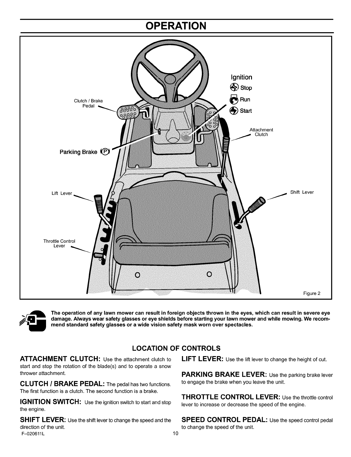
Clutch /Brake
Pedal
Ignition
_') Stop
)Run
Start
Attachment
Clutch
Parkiing Brake
Lift Lever
Throttle Control
Lever
j Shift Lever
Figure 2
/__ The operation of any lawn mower can result in foreign objects thrown in the eyes, which can result in severe eye
damage. Always wear safety glasses or eye shields before starting your lawn mower and while mowing. We recom-
mend standard safety glasses or a wide vision safety mask worn over spectacles.
LOCATION OF CONTROLS
ATTACHMENT CLUTCH" Use the attachment clutch to
start and stop the rotation of the blade(s) and to operate a snow
thrower attachment.
CLUTCH /BRAKE PEDAL: The pedal has two functions.
The first function is a clutch. The second function is a brake.
IGNITION SWITCH: Use the ignition switch to start and stop
the engine.
LIFT LEVER: Use the lift lever to change the height of cut.
PARKING BRAKE LEVER: Usethe parking brake lever
to engage the brake when you leave the unit.
THROTTLE CONTROL LEVER: Usethe throttlecontrol
lever to increase or decrease the speed of the engine.
SHIFT LEVER: Use the shift lever to change the speed and the SPEED CONTROL PEDAL: Use the speed control pedal
direction of the unit. to change the speed of the unit.
F-020611L 10
OPERATION
HOW TO STOP THE UNIT
The electrical system has an operator presence system that
includes a sensor switch mounted in the seat. These components
tell the electrical system if the operator is sitting on the seat. This
system will stop the engine when the operator leaves the seat. For
your protection, always make sure this system operates correctly.
1. Completely push the clutch/brake pedal forward to stop the
unit. Keep your foot on the pedal.
2. Move the attachment clutch to the DISENGAGE position.
3. Move the shift lever to the NEUTRAL position.
4. Set the parking brake.
,_ WARNING: Make sure the parking brake will hold the
unit.
5. Move the throttle control to the SLOW position.
6. To stop the engine, turn the ignitionkey to the OFF position. Re-
move the key.
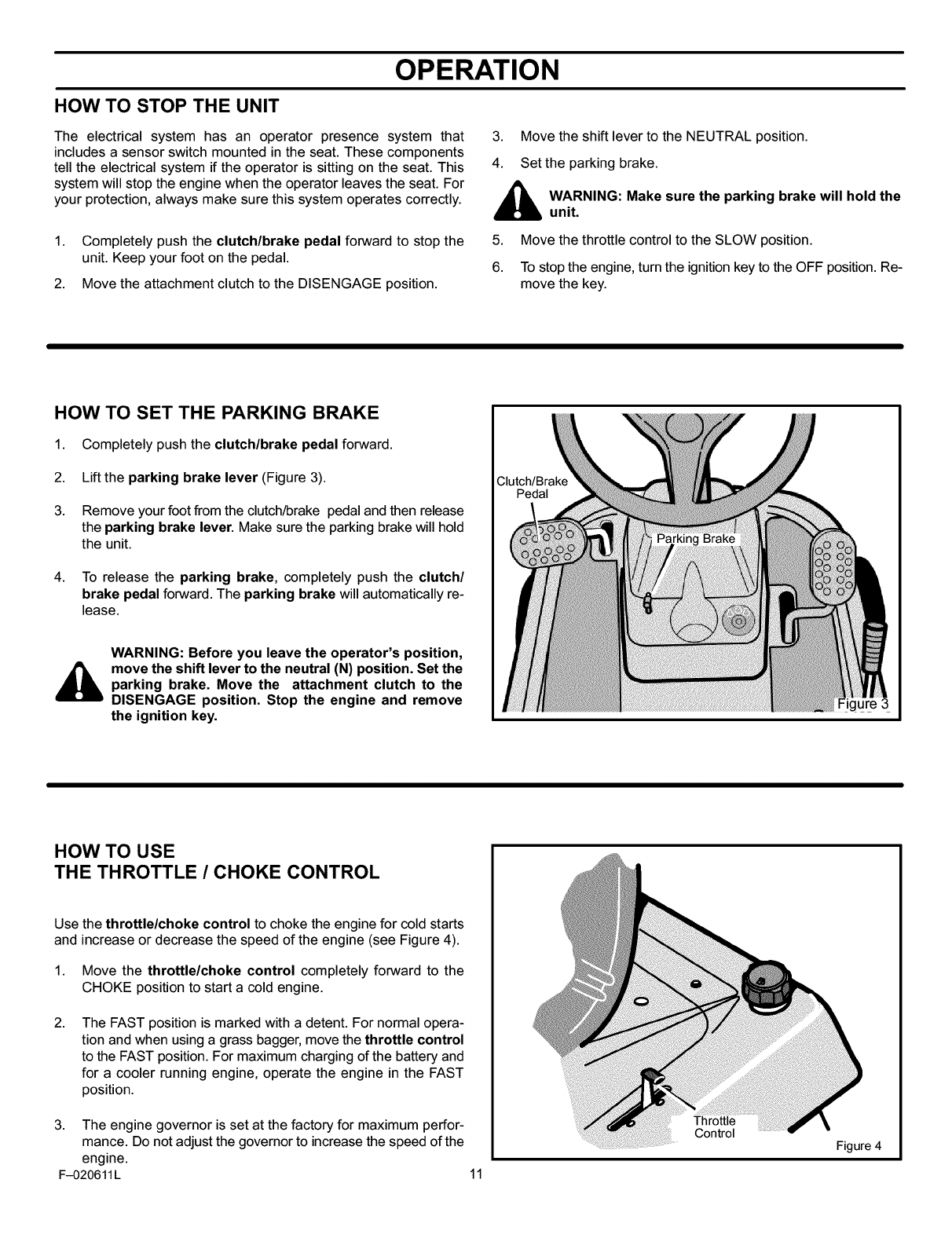
HOW TO SET THE PARKING BRAKE
1. Completely push the clutch/brake pedal forward.
2. Lift the parking brake lever (Figure 3).
3. Remove your foot from the clutch/brake pedal and then release
the parking brake lever. Make sure the parking brake will hold
the unit.
4. To release the parking brake, completely push the clutch/
brake pedal forward. The parking brake will automatically re-
lease.
WARNING: Before you leave the operator's position,
move the shift lever to the neutral (N) position. Set the
parking brake. Move the attachment clutch to the
DISENGAGE position. Stop the engine and remove
the ignition key.
Clutch/Brake
Pedal
Figure 3
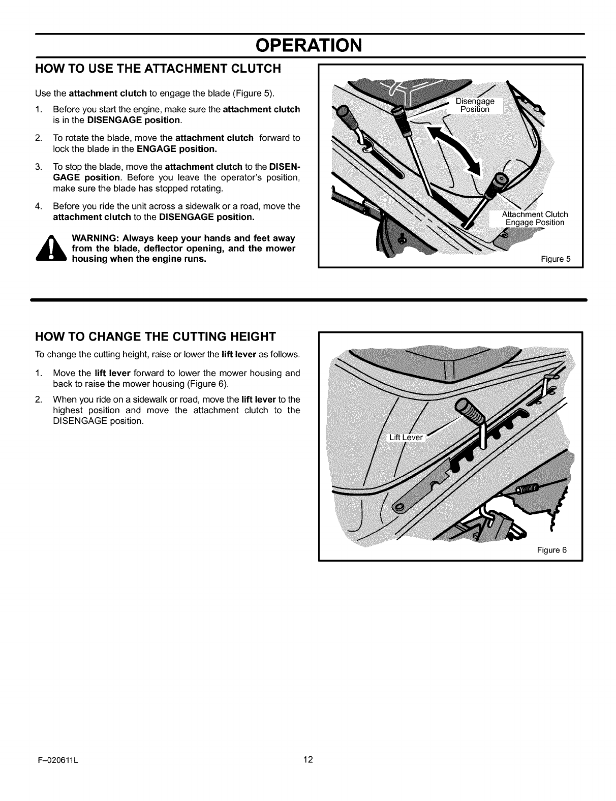
HOW TO USE
THE THROTTLE /CHOKE CONTROL
Use the throttle/choke control to choke the engine for cold starts
and increase or decrease the speed of the engine (see Figure 4).
1. Move the throttle/choke control completely forward to the
CHOKE position to start a cold engine.
2. The FAST position is marked with a detent. For normal opera-
tion and when using a grass bagger, move the throttle control
to the FAST position. For maximum charging of the battery and
for a cooler running engine, operate the engine in the FAST
position.
3. The engine governor is set at the factory for maximum perfor-
mance. Do not adjust the governor to increase the speed of the
engine.
F-020611L 11
Throttle
Control
Figure 4
OPERATION
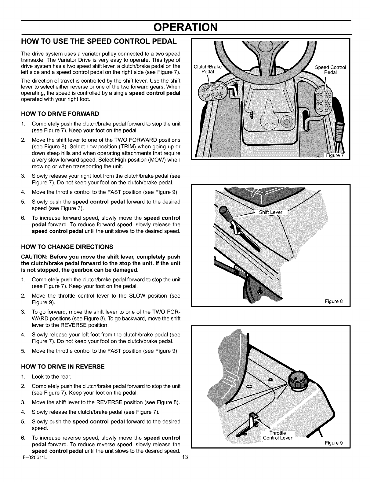
HOW TO USE THE ATTACHMENT CLUTCH
Use the attachment clutch to engage the blade (Figure 5).
1. Before you start the engine, make sure the attachment clutch
is in the DISENGAGE position.
2.
3.
4.
To rotate the blade, move the attachment clutch forward to
lock the blade in the ENGAGE position.
To stop the blade, move the attachment clutch to the DISEN-
GAGE position. Before you leave the operator's position,
make sure the blade has stopped rotating.
Before you ride the unit across a sidewalk or a road, move the
attachment clutch to the DISENGAGE position.
_ WARNING: Always keep your hands and feet away
from the blade, deflector opening, and the mower
housing when the engine runs.
Attachment Clutch
Engage Position
Figure 5
HOW TO CHANGE THE CUTTING HEIGHT
To change the cutting height, raise or lower the lift lever as follows.
1. Move the lift lever forward to lower the mower housing and
back to raise the mower housing (Figure 6).
2. When you ride on a sidewalk or road, move the lift lever to the
highest position and move the attachment clutch to the
DISENGAGE position.
Figure 6
F-020611L 12
OPERATION
HOW TO USE THE SPEED CONTROL PEDAL
The drive system uses a variator pulley connected to a two speed
transaxle. The Variator Drive is very easy to operate. This type of
drive system has a two speed shift lever, a clutch/brake pedal on the
left side and a speed control pedal on the right side (see Figure 7).
The direction of travel is controlled by the shift lever. Use the shift
lever to select either reverse or one of the two forward gears. When
operating, the speed is controlled by a single speed control pedal
operated with your right foot.
HOW TO DRIVE FORWARD
1. Completely push the clutch/brake pedal forward to stop the unit
(see Figure 7). Keep your foot on the pedal.
2. Move the shift lever to one of the TWO FORWARD positions
(see Figure 8). Select Low position (TRIM) when going up or
down steep hills and when operating attachments that require
a very slow forward speed. Select High position (MOW) when
mowing or when transporting the unit.
3. Slowly release your right foot from the clutch/brake pedal (see
Figure 7). Do not keep your foot on the clutch/brake pedal.
4. Move the throttle control to the FAST position (see Figure 9).
5. Slowly push the speed control pedal forward to the desired
speed (see Figure 7).
6. To increase forward speed, slowly move the speed control
pedal forward. To reduce forward speed, slowly release the
speed control pedal until the unit slows to the desired speed.
Clutch/Brak_
Pedal
HOW TO CHANGE DIRECTIONS
CAUTION: Before you move the shift lever, completely push
the clutch/brake pedal forward to the stop the unit. If the unit
is not stopped, the gearbox can be damaged.
1. Completely push the clutch/brake pedal forward to stop the unit
(see Figure 7). Keep your foot on the pedal.
2. Move the throttle control lever to the SLOW position (see
Figure 9).
3. To go forward, move the shift lever to one of the TWO FOR-
WARD positions (see Figure 8). To go backward, move the shift
lever to the REVERSE position.
4. Slowly release your left foot from the clutch/brake pedal (see
Figure 7). Do not keep your foot on the clutch/brake pedal.
5. Move the throttle control to the FAST position (see Figure 9).
HOW TO DRIVE IN REVERSE
1. Look to the rear.
2. Completely push the clutch/brake pedal forward to stop the unit
(see Figure 7). Keep your foot on the pedal.
3. Move the shift lever to the REVERSE position (see Figure 8).
4. Slowly release the clutch/brake pedal (see Figure 7).
5. Slowly push the speed control pedal forward to the desired
speed.
6. To increase reverse speed, slowly move the speed control
pedal forward. To reduce reverse speed, slowly release the
speed control pedal until the unit slows to the desired speed.
F-020611L 13
Speed Control
Pedal
Figure 7
Figure 8
Throttle
Figure 9
OPERATION
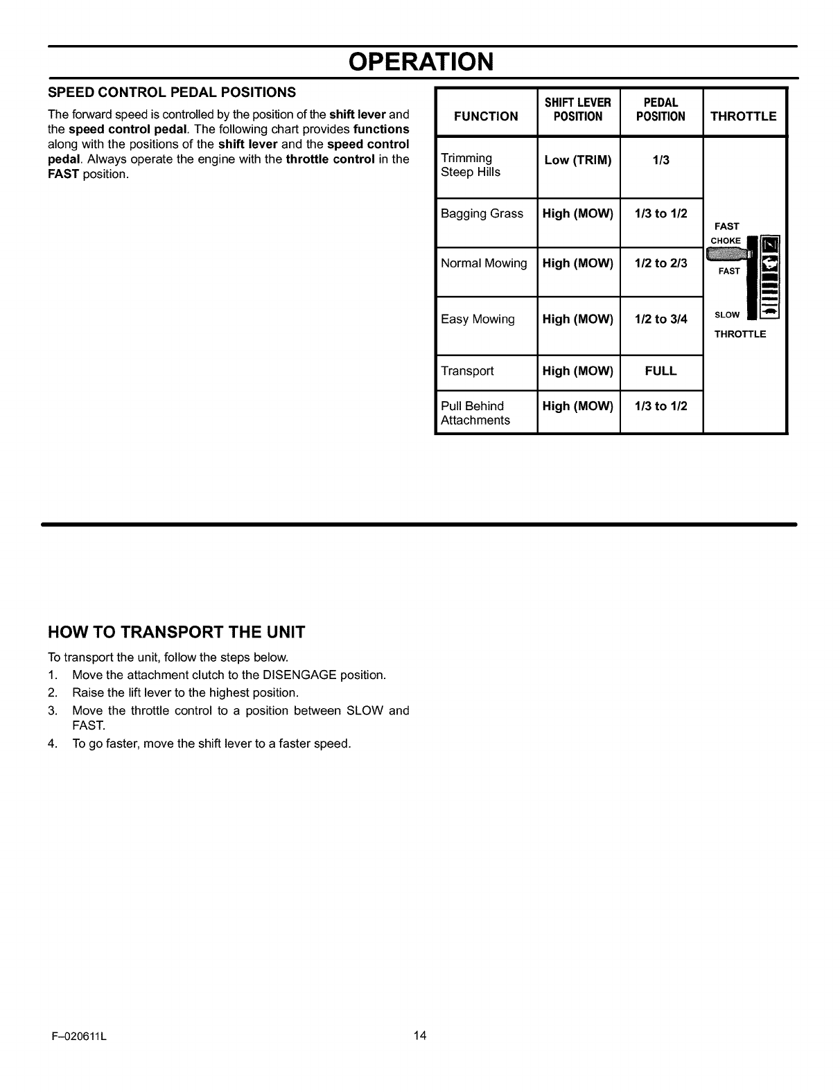
SPEED CONTROL PEDAL POSITIONS
The forward speed is controlled by the position of the shift lever and
the speed control pedal. The following chart provides functions
along with the positions of the shift lever and the speed control
pedal. Always operate the engine with the throttle control in the
FAST position.
SHIFTLEVER
POSITION
PEDAL
POSITIONFUNCTION THROTTLE
Trimming Low (TRIM) 1/3
Steep Hills
Bagging Grass High (MOW) 1/3 to 1/2
FAST i
Normal Mowing High (MOW) 1/2 to 2/3 I_-_
!
Easy Mowing High (MOW) 1/2 to 3/4 SLOWI_
THROTTLE
Transport High (MOW) FULL
Pull Behind High (MOW) 1/3 to 1/2
Attachments
HOW TO TRANSPORT THE UNIT
To transport the unit, follow the steps below.
1. Move the attachment clutch to the DISENGAGE position.
2. Raise the lift lever to the highest position.
3. Move the throttle control to a position between SLOW and
FAST.
4. To go faster, move the shift lever to a faster speed.
F-O20611L 14
OPERATION
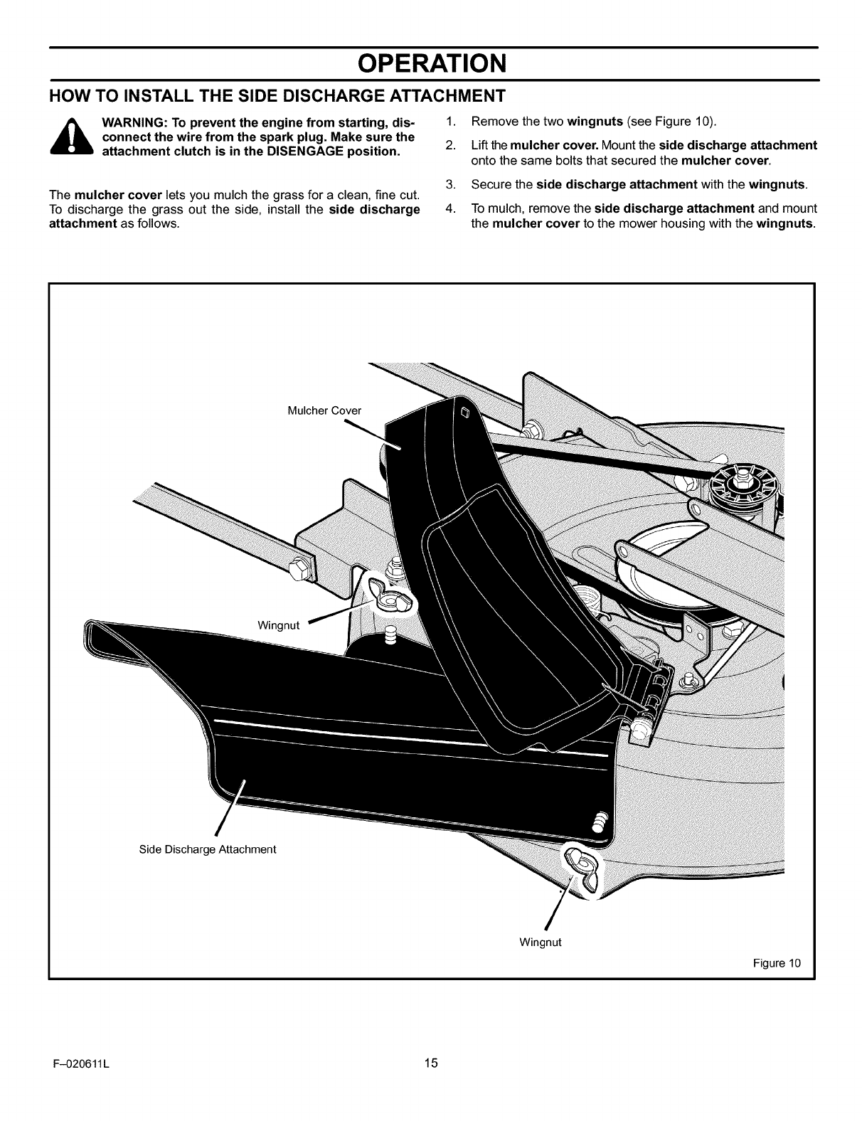
HOW TO INSTALL THE SIDE DISCHARGE ATTACHMENT
_WARNING: To prevent the engine from starting, dis-
connect the wire from the spark plug. Make sure the
attachment clutch is in the DISENGAGE position.
1. Remove the two wingnuts (see Figure 10).
2. Lift the mulcher cover. Mount the side discharge attachment
onto the same bolts that secured the mulcher cover.
The mulcher cover lets you mulch the grass for a clean, fine cut.
To discharge the grass out the side, install the side discharge
attachment as follows.
3. Secure the side discharge attachment with the wingnuts.
4. To mulch, remove the side discharge attachment and mount
the mulcher cover to the mower housing with the wingnuts.
Mulcher Cover
Wingnut
Side Discharge Attachment
Wingnut
Figure 10
F-020611L 15
OPERATION
BEFORE STARTING THE ENGINE
CHECK THE OIL
NOTE: The engine was shipped from the factory filled with SAE
30 weight oil. Check the level of the oil. Add oil as needed.
1. Make sure the unit is level.
NOTE: Do not check the level of the oil while the engine
runs.
2. Clean the area around the dipstick. Remove the dipstick. Wipe
the oil from the dipstick.
3. Insert the dipstick into the oil fill tube. Turn the dipstick clock-
wise until it is tight. Remove the dipstick. Check the oil level on
the dipstick. The oil level must reach the FULL mark on the
dipstick.
4. If necessary, add oil untilthe oil reaches the FULL mark on the
dipstick. The quantity of oil needed from ADD to FULL is shown
on the dipstick. Do not add too much oil.
ADD GASOLINE
WARNING: Always use a safety gasoline container.
Do not smoke when adding gasoline to the fuel tank.Do not add gasoline when you are inside an enclo-
sure. Before you add gasoline, stop the engine and
let the engine cool for several minutes.
Fill the fuel tank with regular FuelTank
unleaded gasoline. Do not use (, /
premium unleaded gasoline.
Make sure the gasoline is fresh
and clean. Leaded gasoline will
increase deposits and shorten
the life of the valves.
CAUTION: Alcohol blended fuels (called gasohol or using
ethanol or methanol) can attract moisture which leads to
separation and formation of acids during storage. Acidic gas
can damage the fuel system of an engine while in storage.
To prevent engine problems with the fuel system, empty the fuel
system before storage of 30 days or longer as follows.
1. Drain the fuel tank.
2. Start the engine. Let the engine run until the fuel lines and the
carburetor are empty.
3. After storage, make sure you use fresh fuel. See the storage
instructions for additional information.
4. Never use engine cleaner or carburetor cleaner in the fuel tank
or permanent damage can occur.
CARBURETOR
The factory settings for the carburetor are for most conditions. If the
engine is operated under the following conditions, you can adjust
the carburetor mixture. See "How To Adjust The Carburetor" in the
Service And Adjustment section.
1. The engine has a loss of power or does not run smooth.
2. A change from summer to winter operation.
3. A 40 degree change in the operation temperature. The carbure-
tor was adjusted at 80 degrees at the factory.
4. The engine is operated above 4,000 feet.
HOW TO START THE ENGINE
WARNING: The electrical system has an operator
presence system that includes a sensor switch
mounted in the seat. These components tell the elec-
trical system if the operator is sitting on the seat. This
system will stop the engine when the operator leaves
the seat. For your protection, always make sure this
system operates correctly.
NOTE: The engine will not start unless you depress the
clutch/brake pedal or engage the parking brake and move the
attachment clutch to the DISENGAGE position.
1. Sit in the middle of the seat. Push the clutch/brake pedal com-
pletely forward. Keep your foot on the pedal.
2. Move the shift lever to the neutral (N) position.
3. Make sure the attachment clutch is in the DISENGAGE posi-
tion.
4. Move the throttle control completely forward to the CHOKE or
FAST position. Some models have a separate choke knob. Pull
the choke knob to the full CHOKE position.
5. Turn the ignition key to the START position. Release the key
when the engine starts.
NOTE: If the engine does not start after four or five tries,
move the throttle control to the FAST position. Again try to
start the engine. If the engine will not start, see the
TROUBLESHOOTING CHART.
6. Slowly move the throttle control to the SLOW position. If model
has a separate choke knob, push in the choke knob.
7. Let a cold engine run for several minutes. Begin work when the
engine is warm. To start a hot engine, move the throttle control
to a position between FAST and SLOW.
HOW TO START WITH AWEAK BATTERY
If the battery is too weak to start the engine, the battery needs to be
charged. If "Jumper Cables" are used to start the engine in an
emergency, follow the procedure below.
NOTE: The unit is equipped with a 12 volt negative to ground
system. Also, the other vehicle must have a 12 volt negative to
ground system.
WARNING: Do not smoke. The fumes from the battery
acid can cause an explosion. Keep the battery away
from any flames or sparks. To prevent sparks, fasten
the red "Jumper cable" to the positive (+) terminal be-
fore connecting the black "Jumper cable".
F-020611 L 16
NOTE: If the seat is raised when starting the engine, move the
attachment clutch to the DISENGAGED position and engage
the parking brake.
1. Connect each end of the RED "Jumper Cable" to the positive
(+) terminals of each battery. Make sure you do not touch the
chassis with the cables.
2. Connect one end of the BLACK "Jumper Cable" to the negative
(-) terminal of the charged battery.
3. Connect the other end of the BLACK "Jumper Cable" to the
mower's engine block.
4. Start the engine that has the weak battery last. Allow the engine
to run.
5. To disconnect the "Jumper Cables", reverse the above steps.
OPERATION
HOWTO OPERATE WITHTHE MOWER HOUSING
WARNING: The mulch cover is a safety device. Do not
remove the mulch cover. The side discharge attach-
ment forces the discharged material toward the
ground. Always keep the side discharge attachment
in the down position. If the side discharge attachment
is damaged, replace the with an original equipment
part from a Sears Service Center.
IMPORTANT: When you operate with the mower housing,
always operate with the throttle control in the FAST position.
1. Start the engine.
2. Move the lift lever to a height of cut position. In high or thick
grass, cut the grass in the highest position first and then lower
the mower housing to a lower position.
CAUTION: Do not operate with the mower housing in the
LEVEL ADJUSTMENT position. If you operate in the
LEVEL ADJUSTMENT position, the mower housing and
blades can be damaged.
3. Move the throttle control to the SLOW position.
4. Move the attachment clutch to the ENGAGE position.
5. Push the clutch/brake pedal completely forward.
6. Move the shift lever to one of the speed settings.
NOTE: When you mow in heavy grass or mow with a
bagger, put the shift lever in the slowest speed.
7. Slowly release the clutch/brake pedal.
8. Move the throttle control to the FAST position. If you need to go
faster or slower, stop the unit and move the shift lever to another
speed setting.
9. Make sure the level of cut is still correct. After you mow a short
distance, look at the area that was cut. If the mower housing
does not cut level, see the instructions on "How To Level The
Mower Housing" in the Service And Adjustment section.
_ARNING: For better control of the unit, always
select a safe speed.
HOW TO OPERATE THE UNIT ON HILLS
_ WARNING: Do not ride up or down slopes that are too
steep to back straight up. Never ride the unit across
a slope. See the "Slope Guide" in the back of this
book for information on how to check slopes.
1. Before you ride up or down a hill, move the shift lever to the
slowest speed.
2. Do not stop or change speed settings on a hill. If you must stop,
quickly push the clutch/brake pedal forward and set the parking
brake.
3. To start again, make sure the shift lever is in the slowest speed.
Move the throttle control to the SLOW position. Slowly release
the pedal.
4. If you must stop or start on a hill, always have enough space
for the unit to roll when you release the brake and engage the
clutch.
5. Be very careful when you change directions on a hill. When on
a slope or in a turn on a hill, move the throttle control to the
SLOW position to help prevent an accident.
ATTACHMENTS
This unit can use many different attachments. It can pull
attachments like a lawn sweeper, a lawn aerator, a hopper spreader,
or a small trailer. This unit cannot use attachments that engage the
ground like a plow, a disk harrow, or a cultivator.
For all pull-behind attachments or trailers, the maximum gross
weight is 200 pounds. Gross weight is the weight of the attachment
or trailer and any load that might be on or in it.
WARNING: To avoid possible serious injury, do not
mow a slope that is greater than 15 degrees. If the rid-ing mower is used with a pull-behind or rear-mounted
attachment, do not operate the unit on a slope that is
greater than 10 degrees.
F-020611L 17
OPERATION
OPERATING TIPS
1.
2.
3.
4.
Check the attachment clutch for correct adjustment. For the
blade(s) to disengage correctly, the adjustment must be cor-
rect.
Before you use the unit, check the oil in the engine and add oil
if necessary.
If the engine will not start, first make sure the wire is attached
to the spark plug.
Make sure all the belts are inside all the belt guides. See the in-
structions on how to remove and install the motion drive and
mower drive belts.
5. Before you make an inspection, adjustment (except for the car-
buretor) or repair, make sure the wire from the spark plug is dis-
connected.
6. Make sure the seat switch wire is connected. If the wire is not
connected, the engine will not start.
7. For longer life of the battery, charge the battery every three
months.
8. Use the shift lever to change the ground speed, not the throttle
control.
9. Belt noise can occur when the blade or clutch is engaged. This
noise is normal and does not affect the operation of the unit.
10. To move forward, always release the clutch/brake pedal slowly.
MOWING AND BAGGING TIPS
1. For a lawn to look better, check the cutting level of the mower
housing. See "How To Level The Mower Housing" in the Ser-
vice And Adjustment section.
2. For the mower housing to cut level, make sure the tires have
the correct amount of air pressure (PSI).
3. Every time you use the unit, check the blade. If the blade is bent
or damaged, immediately replace the blade. Also, make sure
the nut for the blade is tight.
4. Keep the blade(s) sharpened. A worn blade(s) will cause the
ends of the grass to turn brown.
5. Do not cut or bag grass that is wet. Wet grass will not discharge
correctly. Let the grass dry before cutting.
6. Use the left side of the mower housing to trim near an object.
7. Discharge the cut grass onto the mowed area. The result is a
more even discharge of cut grass.
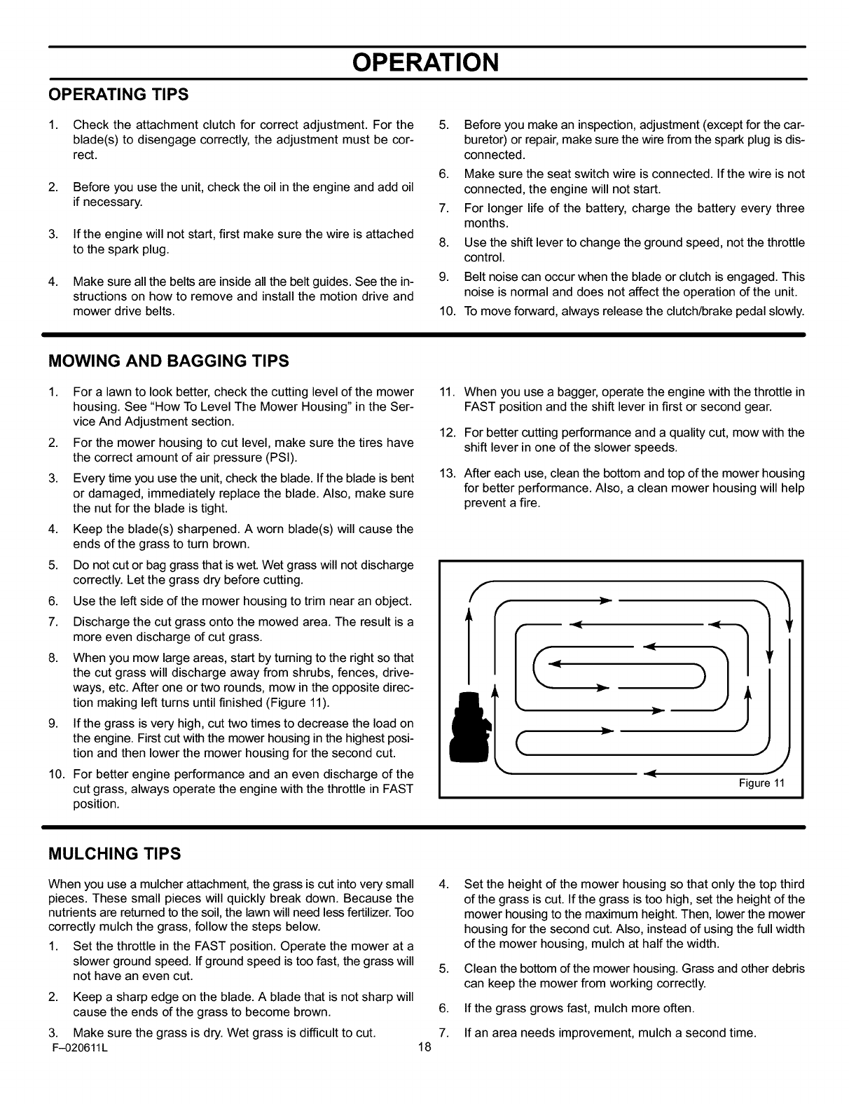
8. When you mow large areas, start by turning to the right so that
the cut grass will discharge away from shrubs, fences, drive-
ways, etc. After one or two rounds, mow in the opposite direc-
tion making left turns until finished (Figure 11).
9. If the grass is very high, cut two times to decrease the load on
the engine. First cut with the mower housing in the highest posi-
tion and then lower the mower housing for the second cut.
10. For better engine performance and an even discharge of the
cut grass, always operate the engine with the throttle in FAST
position.
11. When you use a bagger, operate the engine with the throttle in
FAST position and the shift lever in first or second gear.
12. For better cutting performance and a quality cut, mow with the
shift lever in one of the slower speeds.
13. After each use, clean the bottom and top of the mower housing
for better performance. Also, a clean mower housing will help
prevent a fire.
C •
Figure 11
MULCHING TIPS
When you use a mulcher attachment, the grass is cut into very small 4.
pieces. These small pieces will quickly break down. Because the
nutrients are returned to the soil, the lawn will need less fertilizer. Too
correctly mulch the grass, follow the steps below.
1. Set the throttle in the FAST position. Operate the mower at a
slower ground speed. If ground speed is too fast, the grass will 5.
not have an even cut.
2. Keep a sharp edge on the blade. A blade that is not sharp will
cause the ends of the grass to become brown. 6.
3. Make sure the grass is dry. Wet grass is difficult to cut. 7.
F-020611L 18
Set the height of the mower housing so that only the top third
of the grass is cut. If the grass is too high, set the height of the
mower housing to the maximum height. Then, lower the mower
housing for the second cut. Also, instead of using the full width
of the mower housing, mulch at half the width.
Clean the bottom of the mower housing. Grass and other debris
can keep the mower from working correctly.
If the grass grows fast, mulch more often.
If an area needs improvement, mulch a second time.
MAINTENANCE
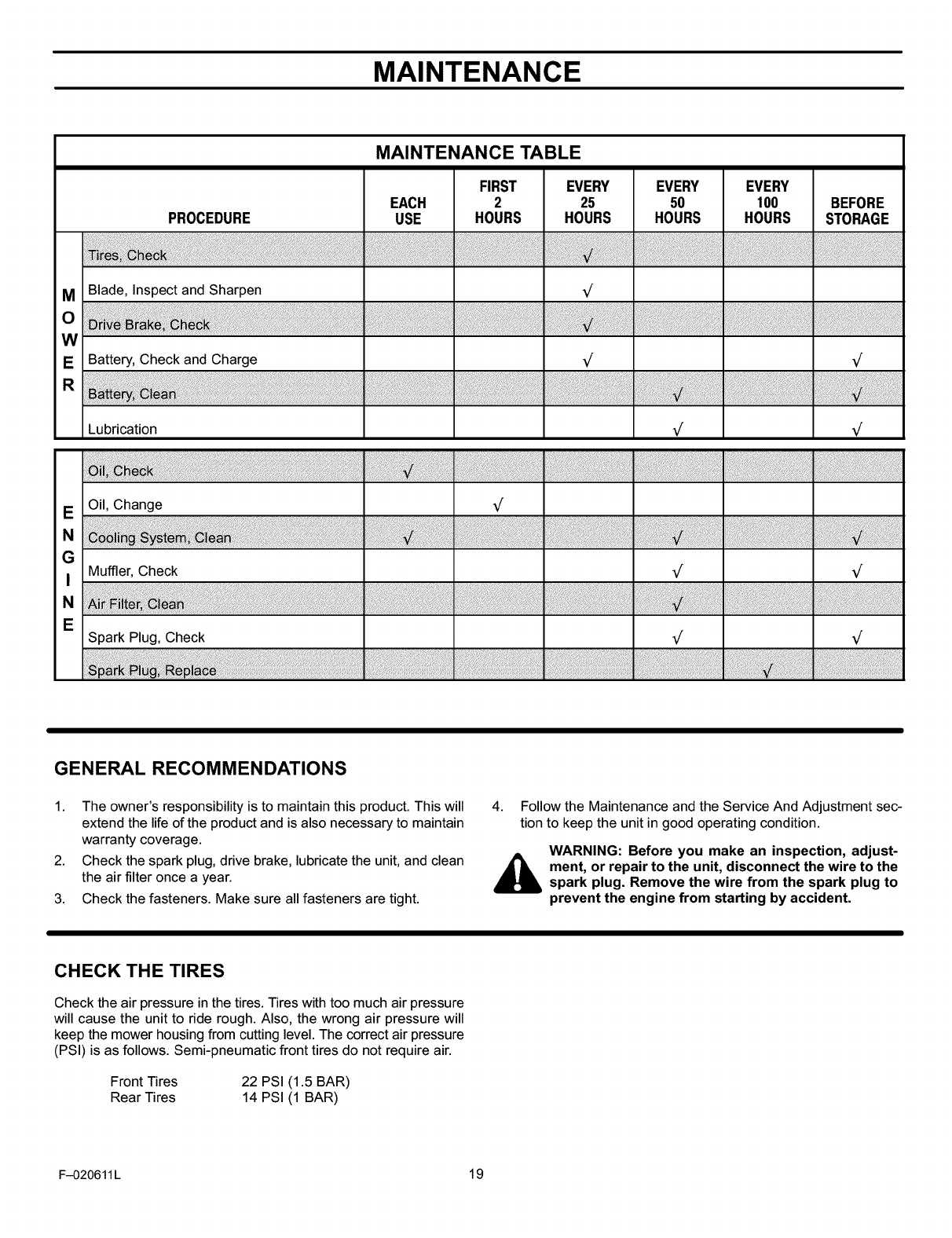
MAINTENANCE TABLE
FIRST EVERY EVERY EVERY
EACH 2 25 50 100 BEFORE
PROCEDURE USE HOURS HOURS HOURS HOURS STORAGE
MBlade, Inspect and Sharpen V'
O
W
EBattery, Check and Charge V' V'
Lubrication V_ V_
EOil, Change V'
N
GMuffler, Check V' V'
N
ESpark Plug, Check V' V'
GENERAL RECOMMENDATIONS
1. The owner's responsibility is to maintain this product. This will
extend the life of the product and is also necessary to maintain
warranty coverage.
2. Check the spark plug, drive brake, lubricate the unit, and clean
the air filter once a year.
3. Check the fasteners. Make sure all fasteners are tight.
4. Follow the Maintenance and the Service And Adjustment sec-
tion to keep the unit in good operating condition.
WARNING: Before you make an inspection, adjust-
_ment, or repair to the unit, disconnect the wire to the
spark plug. Remove the wire from the spark plug to
prevent the engine from starting by accident.
CHECK THE TIRES
Check the air pressure in the tires. Tires with too much air pressure
will cause the unit to ride rough. Also, the wrong air pressure will
keep the mower housing from cutting level. The correct air pressure
(PSI) is as follows. Semi-pneumatic front tires do not require air.
Front Tires 22 PSI (1.5 BAR)
Rear Tires 14 PSI (1 BAR)
F-020611L 19
MAINTENANCE
INSPECT BLADE
WARNING: Before you inspect or remove the blade,
disconnect the wire to the spark plug. If the blade
hits an object, stop the engine. Check the unit for
damage. The blade has sharp edges. When you
hold the blade, use gloves or cloth material to pro-
tect your hands.
If you keep the blade sharp and inspect the blade for damage,
the blade will cut better and be more safe to operate. Frequently
check the blade for excessive wear, cracks, or other damage.
Frequently check the nut that holds the blade. Keep the nut tight.
If the blade hits an object, stop the engine. Disconnect the wire to
the spark plug. See if the blade is bent or damaged. Check the
blade adapter for damage. Before you operate the unit, replace
damaged parts with original equipment parts. See a Sears
Service Center in your area. Every three years, have a qualified
service person inspect the blade or replace the old blade with an
original equipment part.
HOW TO REMOVE AND INSTALL THE BLADE
To Remove
1. Drain the fuel tank.
2. Lift the side of the mower that has the muffler or spark plug.
3. As you loosen the nut, use a piece of wood to keep the blade
from rotating.
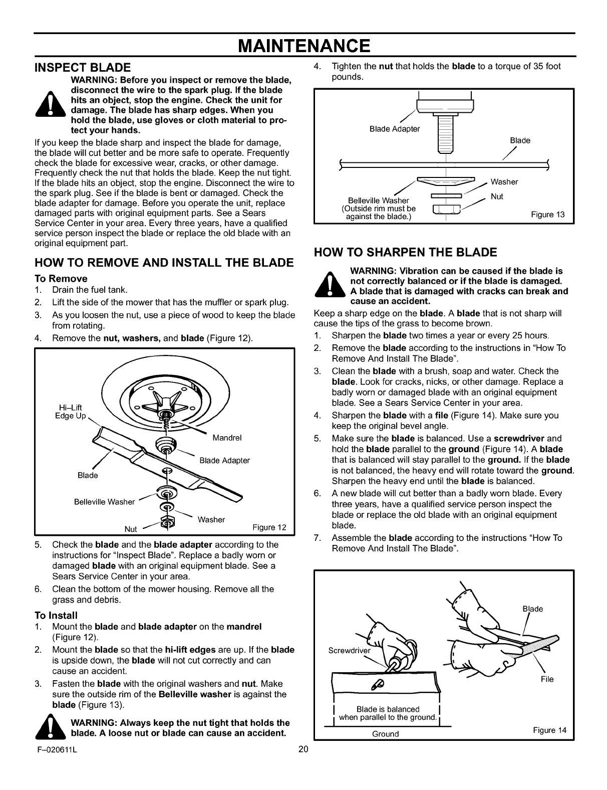
4. Remove the nut, washers, and blade (Figure 12).
Hi-Lift
Mandrel
Blade Adapter
Blade
Belleville Wash_i t ___ Washer
Figure 12
5. Check the blade and the blade adapter according to the
instructions for "Inspect Blade". Replace a badly worn or
damaged blade with an original equipment blade. See a
Sears Service Center in your area.
6. Clean the bottom of the mower housing. Remove all the
grass and debris.
To Install
1. Mount the blade and blade adapter on the mandrel
(Figure 12).
2. Mount the blade so that the hi-lift edges are up. If the blade
is upside down, the blade will not cut correctly and can
cause an accident.
3. Fasten the blade with the original washers and nut. Make
sure the outside rim of the Belleville washer is against the
blade (Figure 13).
_ ARNING: Always keep the nut tight that holds the
blade. A loose nut or blade can cause an accident.
F-020611 L
4. Tighten the nut that holds the blade to a torque of 35 foot
pounds.
Blade Adapter
Blade
Belleville Washer _"J /Nut
(Outside rim must be _
against the blade.) I Figure 13
HOW TO SHARPEN THE BLADE
WARNING: Vibration can be caused if the blade is
not correctly balanced or if the blade is damaged.
A blade that is damaged with cracks can break and
cause an accident.
Keep a sharp edge on the blade. Ablade that is not sharp will
cause the tips of the grass to become brown.
1. Sharpen the blade two times a year or every 25 hours.
2. Remove the blade according to the instructions in "How To
Remove And Install The Blade".
3. Clean the blade with a brush, soap and water. Check the
blade. Look for cracks, nicks, or other damage. Replace a
badly worn or damaged blade with an original equipment
blade. See aSears Service Center in your area.
4. Sharpen the blade with a file (Figure 14). Make sure you
keep the original bevel angle.
5. Make sure the blade is balanced. Use a screwdriver and
hold the blade parallel to the ground (Figure 14). Ablade
that is balanced will stay parallel to the ground. If the blade
is not balanced, the heavy end will rotate toward the ground.
Sharpen the heavy end untilthe blade is balanced.
6. A new blade will cut better than a badly worn blade. Every
three years, have a qualified service person inspect the
blade or replace the old blade with an original equipment
blade.
7. Assemble the blade according to the instructions "How To
Remove And Install The Blade".
Blade
Screwdriver
20
I Blade is balanced
I when para e to the ground.
Ground
File
Figure 14
MAINTENANCE
HOW TO CHECK AND ADJUST THE DRIVE BRAKE
Completely push the clutch/brake pedal forward. Set the parking
brake. Move the shift lever to the neutral (N) position. Push the unit.
If the rear wheels rotate, adjust or replace the brake pads. Adjust the
drive brake as follows.
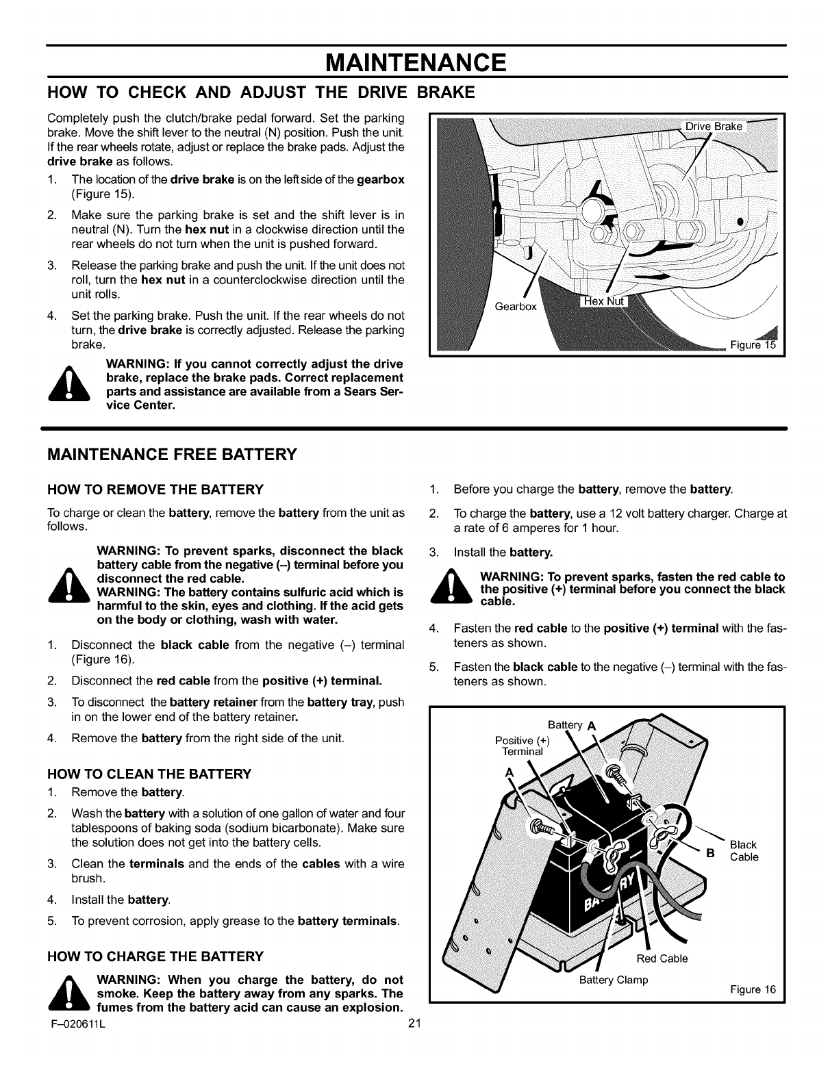
1. The location of the drive brake ison the left side of the gearbox
(Figure 15).
2. Make sure the parking brake is set and the shift lever is in
neutral (N). Turn the hex nut in a clockwise direction until the
rear wheels do not turn when the unit is pushed forward.
3. Release the parking brake and push the unit. If the unit does not
roll, turn the hex nut in a counterclockwise direction until the
unit rolls.
4. Set the parking brake. Push the unit. If the rear wheels do not
turn, the drive brake is correctly adjusted. Release the parking
brake.
WARNING: If you cannot correctly adjust the drive
brake, replace the brake pads. Correct replacement
parts and assistance are available from a Sears Ser-
vice Center.
Gearbox
Drive Brake
Figure 15
MAINTENANCE FREE BATTERY
HOW TO REMOVE THE BATTERY
To charge or clean the battery, remove the battery from the unit as
follows.
WARNING: To prevent sparks, disconnect the black
battery cable from the negative (-) terminal before you
_disconnect the red cable.
WARNING: The battery contains sulfuric acid which is
harmful to the skin, eyes and clothing. Ifthe acid gets
on the body or clothing, wash with water.
1. Disconnect the black cable from the negative (-) terminal
(Figure 16).
2. Disconnect the red cable from the positive (+) terminal.
3. To disconnect the battery retainer from the battery tray, push
in on the lower end of the battery retainer.
4. Remove the battery from the right side of the unit.
HOW TO CLEAN THE BATTERY
1. Remove the battery.
2. Wash the battery with a solution of one gallon of water and four
tablespoons of baking soda (sodium bicarbonate). Make sure
the solution does not get into the battery cells.
3. Clean the terminals and the ends of the cables with a wire
brush.
4. Install the battery.
5. To prevent corrosion, apply grease to the battery terminals.
HOW TO CHARGE THE BATTERY
_ WARNING: When you charge the battery, do not
smoke. Keep the battery away from any sparks. The
fumes from the battery acid can cause an explosion.
F-020611L 21
1. Before you charge the battery, remove the battery.
2. To charge the battery, use a 12 volt battery charger. Charge at
arate of 6amperes for 1hour.
3. Install the battery.
_ WARNING: To prevent sparks, fasten the red cable to
the positive (+) terminal before you connect the black
cable.
4.
5.
Fasten the red cable to the positive (+) terminal with the fas-
teners as shown.
Fasten the black cable to the negative (-) terminal with the fas-
teners as shown.
Positive (+)
Terminal
A
Red Cable
Battery Clamp
Black
Cable
Figure 16
MAINTENANCE
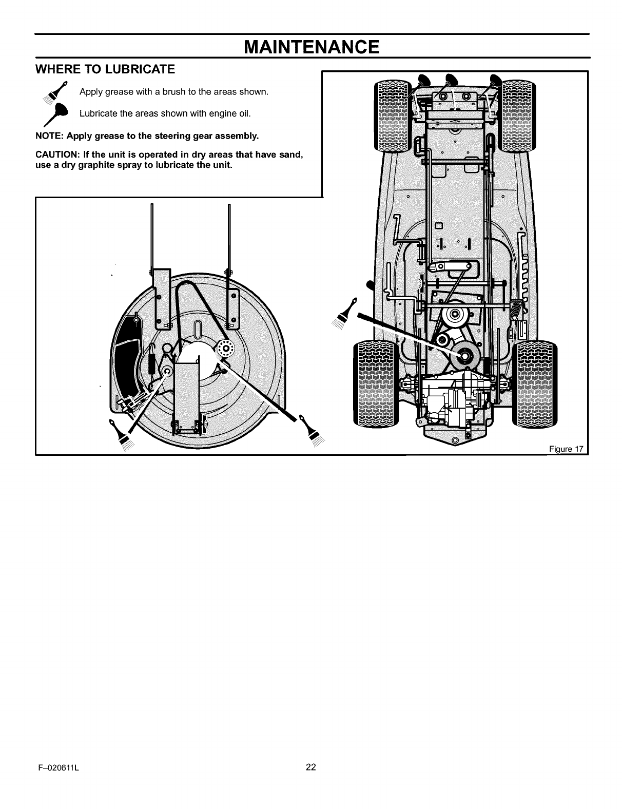
WHERE TO LUBRICATE
Apply grease with a brush to the areas shown.
Lubricate the areas shown with engine oil.
NOTE: Apply grease to the steering gear assembly.
CAUTION: If the unit is operated in dry areas that have sand,
use a dry graphite spray to lubricate the unit.
Figure 17
F-020611 L 22
MAINTENANCE
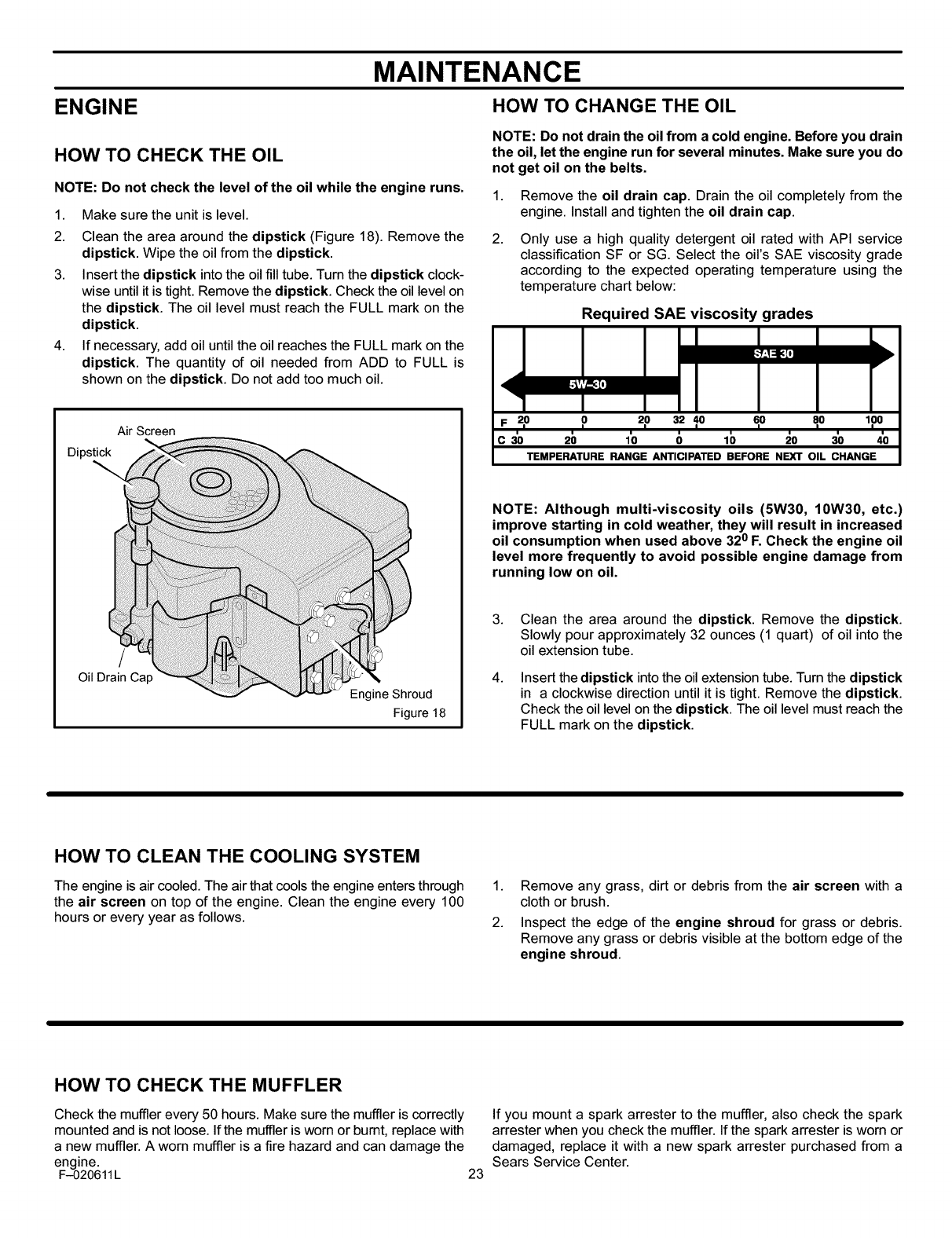
ENGINE HOW TO CHANGE THE OIL
HOW TO CHECK THE OIL
NOTE: Do not check the level of the oil while the engine runs.
1. Make sure the unit is level.
2. Clean the area around the dipstick (Figure 18). Remove the
dipstick. Wipe the oil from the dipstick.
3. Insert the dipstick into the oil fill tube. Turn the dipstick clock-
wise until it is tight. Remove the dipstick. Check the oil level on
the dipstick. The oil level must reach the FULL mark on the
dipstick.
4. If necessary, add oil until the oil reaches the FULL mark on the
dipstick. The quantity of oil needed from ADD to FULL is
shown on the dipstick. Do not add too much oil.
NOTE: Do not drain the oil from a cold engine. Before you drain
the oil, let the engine run for several minutes. Make sure you do
not get oil on the belts.
1.
2.
Remove the oil drain cap. Drain the oil completely from the
engine. Install and tighten the oil drain cap.
Only use a high quality detergent oil rated with API service
classification SF or SG. Select the oil's SAE viscosity grade
according to the expected operating temperature using the
temperature chart below:
Required SAE viscosity grades
z
<
F 2,0 o_o 3_10 e,o 8,o loo
=
c30 2b 1'o _ lb _o 3'0 4'0
TEMPERATURE RANGE ANTICIPATED BEFORE NEXT OIL CHANGE
Air Screen
Dipstick
/
Oil Drain Cap
Engine Shroud
Figure 18
NOTE: Although multi-viscosity oils (5W30, 10W30, etc.)
improve starting in cold weather, they will result in increased
oil consumption when used above 320 F. Check the engine oil
level more frequently to avoid possible engine damage from
running low on oil.
3.
4.
Clean the area around the dipstick. Remove the dipstick.
Slowly pour approximately 32 ounces (1 quart) of oil into the
oil extension tube.
Insert the dipstick into the oil extension tube. Turn the dipstick
in a clockwise direction until it is tight. Remove the dipstick.
Check the oil level on the dipstick. The oil level must reach the
FULL mark on the dipstick.
HOW TO CLEAN THE COOLING SYSTEM
The engine is air cooled. The air that cools the engine enters through
the air screen on top of the engine. Clean the engine every 100
hours or every year as follows.
1. Remove any grass, dirt or debris from the air screen with a
cloth or brush.
2. Inspect the edge of the engine shroud for grass or debris.
Remove any grass or debris visible at the bottom edge of the
engine shroud.
HOW TO CHECK THE MUFFLER
Check the muffler every 50 hours. Make sure the muffler is correctly
mounted and is not loose. If the muffler is worn or bumt, replace with
a new muffler. A worn muffler is a fire hazard and can damage the
engine.
F-020611L 23
If you mount a spark arrester to the muffler, also check the spark
arrester when you check the muffler. If the spark arrester is worn or
damaged, replace it with a new spark arrester purchased from a
Sears Service Center.
MAINTENANCE
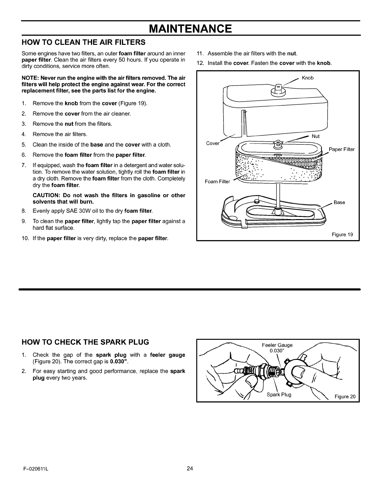
HOW TO CLEAN THE AIR FILTERS
Some engines have two filters, an outer foam filter around an inner
paper filter. Clean the air filters every 50 hours. If you operate in
dirty conditions, service more often.
11. Assemble the air filters with the nut.
12. Install the cover. Fasten the cover with the knob.
NOTE: Never run the engine with the air filters removed. The air
filters will help protect the engine against wear. For the correct
replacement filter, see the parts list for the engine.
1. Remove the knob from the cover (Figure 19).
2. Remove the cover from the air cleaner.
3. Remove the nut from the filters.
4. Remove the air filters.
5. Clean the inside of the base and the cover with a cloth.
6. Remove the foam filter from the paper filter.
7. If equipped, wash the foam filter in a detergent and water solu-
tion. To remove the water solution, tightly roll the foam filter in
a dry cloth. Remove the foam filter from the cloth. Completely
dry the foam filter.
CAUTION: Do not wash the filters in gasoline or other
solvents that will burn.
8. Evenly apply SAE 30W oil to the dry foam filter.
9. To clean the paper filter, lightly tap the paper filter against a
hard flat surface.
10. If the paper filter is very dirty, replace the paper filter.
Cover
r
k.
Knob
Nut
Paper Filter
Foam Filter
Base
Figure 19
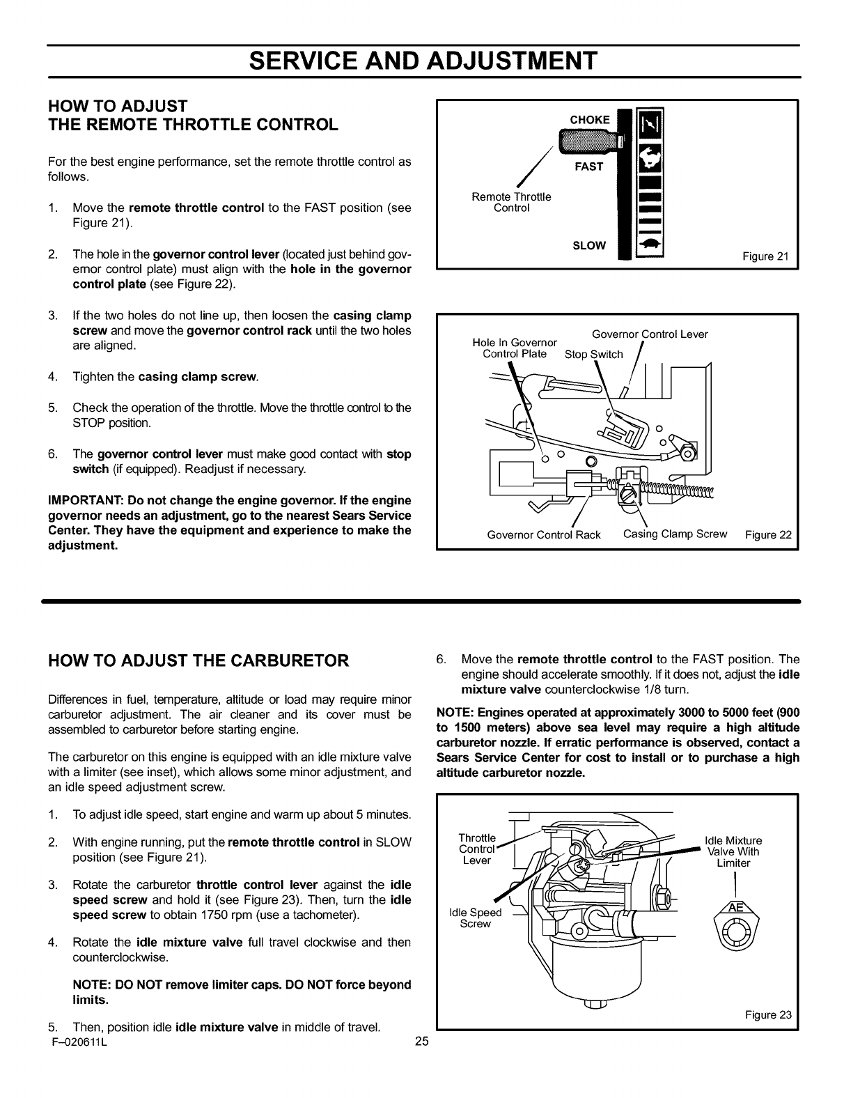
HOW TO CHECK THE SPARK PLUG
1. Check the gap of the spark plug with a feeler gauge
(Figure 20). The correct gap is 0.030".
2. For easy starting and good performance, replace the spark
plug every two years.
Feeler Gauge
0.030"
Spark Plug Figure 20
F-020611 L 24
SERVICE AND ADJUSTMENT
HOW TO ADJUST
THE REMOTE THROTTLE CONTROL
For the best engine performance, set the remote throttle control as
follows.
1. Move the remote throttle control to the FAST position (see
Figure 21).
2. The hole in the governor control lever (located just behind gov-
emor control plate) must align with the hole in the governor
control plate (see Figure 22).
3. If the two holes do not line up, then loosen the casing clamp
screw and move the governor control rack until the two holes
are aligned.
4. Tighten the casing clamp screw.
5. Check the operation of the throttle. Move the throttle control to the
STOP position.
6. The governor control lever must make good contact with stop
switch (if equipped). Readjust if necessary.
IMPORTANT: Do not change the engine governor. If the engine
governor needs an adjustment, go to the nearest Sears Service
Center. They have the equipment and experience to make the
adjustment.
/
Remote Throttle
Control
CHOKE
FAST
SLOW
Figure 21
Governor Control Lever
Hole In Governor
Control Plate Stop
Governor Control Rack Casing Clamp Screw Figure 22
HOW TO ADJUST THE CARBURETOR
Differences in fuel, temperature, altitude or load may require minor
carburetor adjustment. The air cleaner and its cover must be
assembled to carburetor before starting engine.
The carburetor on this engine is equipped with an idle mixture valve
with a limiter (see inset), which allows some minor adjustment, and
an idle speed adjustment screw.
1. To adjust idle speed, start engine and warm up about 5 minutes.
2. With engine running, put the remote throttle control in SLOW
position (see Figure 21).
3.
4.
Rotate the carburetor throttle control lever against the idle
speed screw and hold it (see Figure 23). Then, turn the idle
speed screw to obtain 1750 rpm (use a tachometer).
Rotate the idle mixture valve full travel clockwise and then
counterclockwise.
NOTE: DO NOT remove limiter caps. DO NOT force beyond
limits.
5. Then, position idle idle mixture valve in middle of travel.
F-020611L 25
6. Move the remote throttle control to the FAST position. The
engine should accelerate smoothly. If it does not, adjust the idle
mixture valve counterclockwise 1/8 turn.
NOTE: Engines operated at approximately 3000 to 5000 feet (900
to 1500 meters) above sea level may require a high altitude
carburetor nozzle. If erratic performance is observed, contact a
Sears Service Center for cost to install or to purchase a high
altitude carburetor nozzle.
•" otte 0e xtu e
C°ntr°l_" I _. (_'k/_ ValveWith
Lever_(_ __(_ _Limiter'
IdleSpeed ---_ll\'_7_lTf'_,,___-f_
Screw _
Figure 23
SERVICE AND ADJUSTMENT
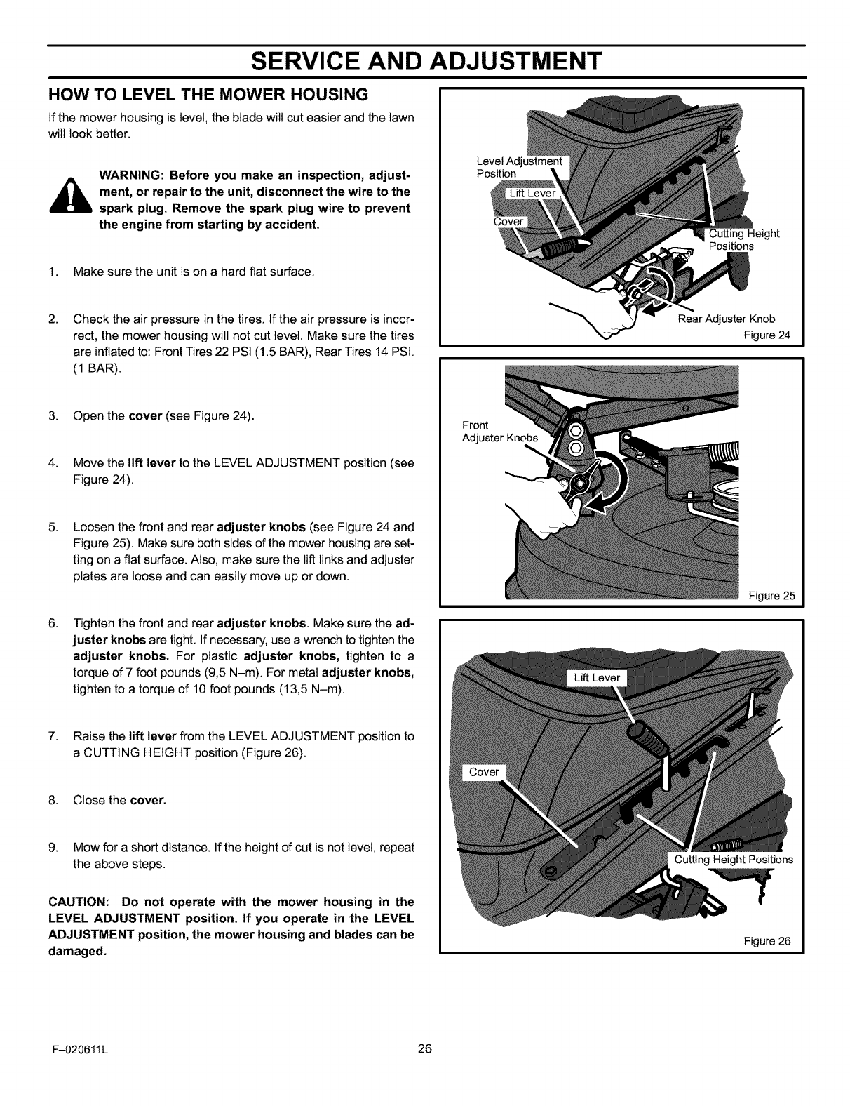
HOW TO LEVEL THE MOWER HOUSING
If the mower housing is level, the blade will cut easier and the lawn
will took better.
WARNING: Before you make an inspection, adjust-
_ment, or repair to the unit, disconnect the wire to the
spark plug. Remove the spark plug wire to prevent
the engine from starting by accident.
1. Make sure the unit is on a hard flat surface.
2. Check the air pressure in the tires. If the air pressure is incor-
rect, the mower housing will not cut level. Make sure the tires
are inflated to: Front Tires 22 PSI (1.5 BAR), Rear Tires 14 PSI.
(1 BAR).
3. Open the cover (see Figure 24).
4. Move the lift lever to the LEVEL ADJUSTMENT position (see
Figure 24).
5. Loosen the front and rear adjuster knobs (see Figure 24 and
Figure 25). Make sure both sides of the mower housing are set-
ting on a flat surface. Also, make sure the lift links and adjuster
plates are loose and can easily move up or down.
Level Adjustment
Position
Cover
Cutting Height
Positions
Rear Adjuster Knob
Figure 24
Front
Adjuster Knobs
Figure 25
6. Tighten the front and rear adjuster knobs. Make sure the ad-
juster knobs are tight. If necessary, use a wrench to tighten the
adjuster knobs. For plastic adjuster knobs, tighten to a
torque of 7 foot pounds (9,5 N-m). For metal adjuster knobs,
tighten to a torque of 10 foot pounds (13,5 N-m).
7. Raise the lift lever from the LEVEL ADJUSTMENT position to
a CUTTING HEIGHT position (Figure 26).
8. Close the cover.
9. Mow for a short distance. If the height of cut is not level, repeat
the above steps.
CAUTION: Do not operate with the mower housing in the
LEVEL ADJUSTMENT position. If you operate in the LEVEL
ADJUSTMENT position, the mower housing and blades can be
damaged.
Cutting Height Positions
Figure 26
F-020611 L 26
SERVICE AND ADJUSTMENT
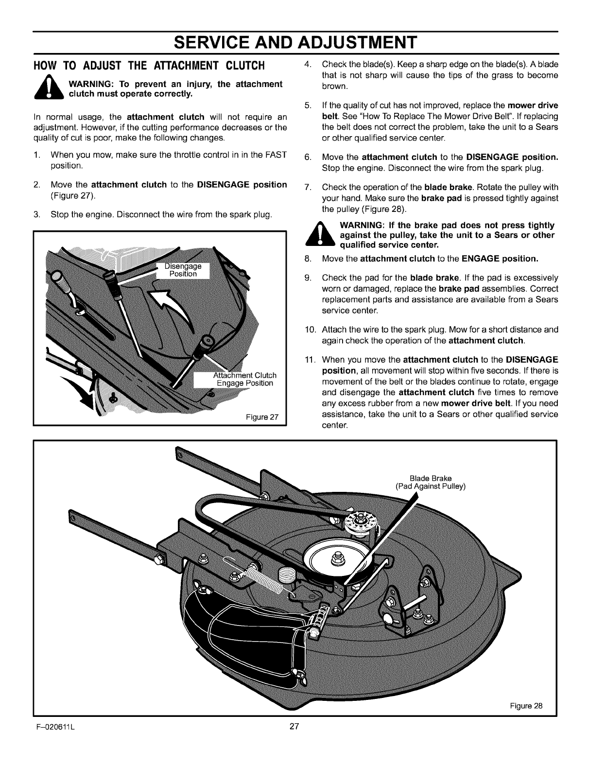
HOW TO ADJUST THE ATTACHMENT CLUTCH
_ARNING: To prevent an injury, the attachment
clutch must operate correctly.
In normal usage, the attachment clutch will not require an
adjustment. However, if the cutting performance decreases or the
quality of cut is poor, make the following changes.
1. When you mow, make sure the throttle control in in the FAST
position.
2. Move the attachment clutch to the DISENGAGE position
(Figure 27).
3. Stop the engine. Disconnect the wire from the spark plug.
Attachment Clutch
Engage Position
Figure 27
4. Check the blade(s). Keep a sharp edge on the blade(s). A blade
that is not sharp will cause the tips of the grass to become
brown.
5.
6.
7.
If the quality of cut has not improved, replace the mower drive
belt. See "How To Replace The Mower Drive Belt". If replacing
the belt does not correct the problem, take the unit to a Sears
or other qualified service center.
Move the attachment clutch to the DISENGAGE position.
Stop the engine. Disconnect the wire from the spark plug.
Check the operation of the blade brake. Rotate the pulley with
your hand. Make sure the brake pad is pressed tightly against
the pulley (Figure 28).
_WARNING: If the brake pad does not press tightly
against the pulley, take the unit to a Sears or other
qualified service center.
8. Move the attachment clutch to the ENGAGE position.
9. Check the pad for the blade brake. If the pad is excessively
worn or damaged, replace the brake pad assemblies. Correct
replacement parts and assistance are available from a Sears
service center.
10.
11.
Attach the wire to the spark plug. Mow for a short distance and
again check the operation of the attachment clutch.
When you move the attachment clutch to the DISENGAGE
position, all movement will stop within five seconds. If there is
movement of the belt or the blades continue to rotate, engage
and disengage the attachment clutch five times to remove
any excess rubber from a new mower drive belt. If you need
assistance, take the unit to a Sears or other qualified service
center.
Blade Brake
(Pad Against Pulley)
Figure 28
F-O20611L 27
SERVICE AND ADJUSTMENT
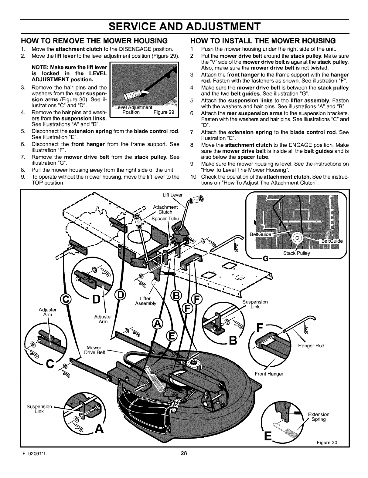
HOW TO REMOVE THE MOWER HOUSING
1. Move the attachment clutch to the DISENGAGE position.
2. Move the lift lever to the level adjustment position (Figure 29).
3.
4.
5.
6.
7.
8.
9.
NOTE: Make sure the lift lever
is locked in the LEVEL
ADJUSTMENT position.
Remove the hair pins and the
washers from the rear suspen-
sion arms (Figure 30). See il-
lustrations "C* and "D*. LevelAdjustment
Remove the hair pins and wash- Position Figure 29
ers from the suspension links.
See illustrations 'W' and "B*.
Disconnect the extension spring from the blade control rod.
See illustration"E*.
Disconnect the front hanger from the frame support. See
illustration "F'.
Remove the mower drive belt from the stack pulley. See
illustration "G*.
Pull the mower housing away from the right side of the unit.
To operate without the mower housing, move the lift lever to the
TOP position.
HOW TO INSTALL THE MOWER HOUSING
1. Push the mower housing under the right side of the unit.
2. Put the mower drive belt around the stack pulley. Make sure
the '_' side of the mower drive belt is against the stack pulley.
Also, make sure the mower drive belt is not twisted.
3. Attach the front hanger to the frame support with the hanger
rod. Fasten with the fasteners as shown. See illustration "F'.
4. Make sure the mower drive belt is between the stack pulley
and the two belt guides. See illustration "G*.
5. Attach the suspension links to the lifter assembly. Fasten
with the washers and hair pins. See illustrations 'W' and "B*.
6. Attach the rear suspension arms to the suspension brackets.
Fasten with the washers and hair pins. See illustrations "C" and
7. Attach the extension spring to the blade control rod. See
illustration "E*.
8. Move the attachment clutch to the ENGAGE position. Make
sure the mower drive belt is inside all the belt guides and is
also below the spacer tube.
9. Make sure the mower housing is level. See the instructions on
"How To Level The Mower Housing".
10. Check the operation of the attachment clutch. See the instruc-
tions on "How To Adjust The Attachment Clutch".
Lift Lever
_" Attachment
Clutch
BeltGuide-
Je
Stack Pulley
G.)
Adjuster
Arm
C
Suspension
Link
Mower
Drive
DLifter
Assembly
Adjuster
Arm
Suspension
Link
' Hanger Rod
Front Hanger
A
Extension
Spring
Figure 30
F-020611 L 28
SERVICE AND ADJUSTMENT
Belt Guide.
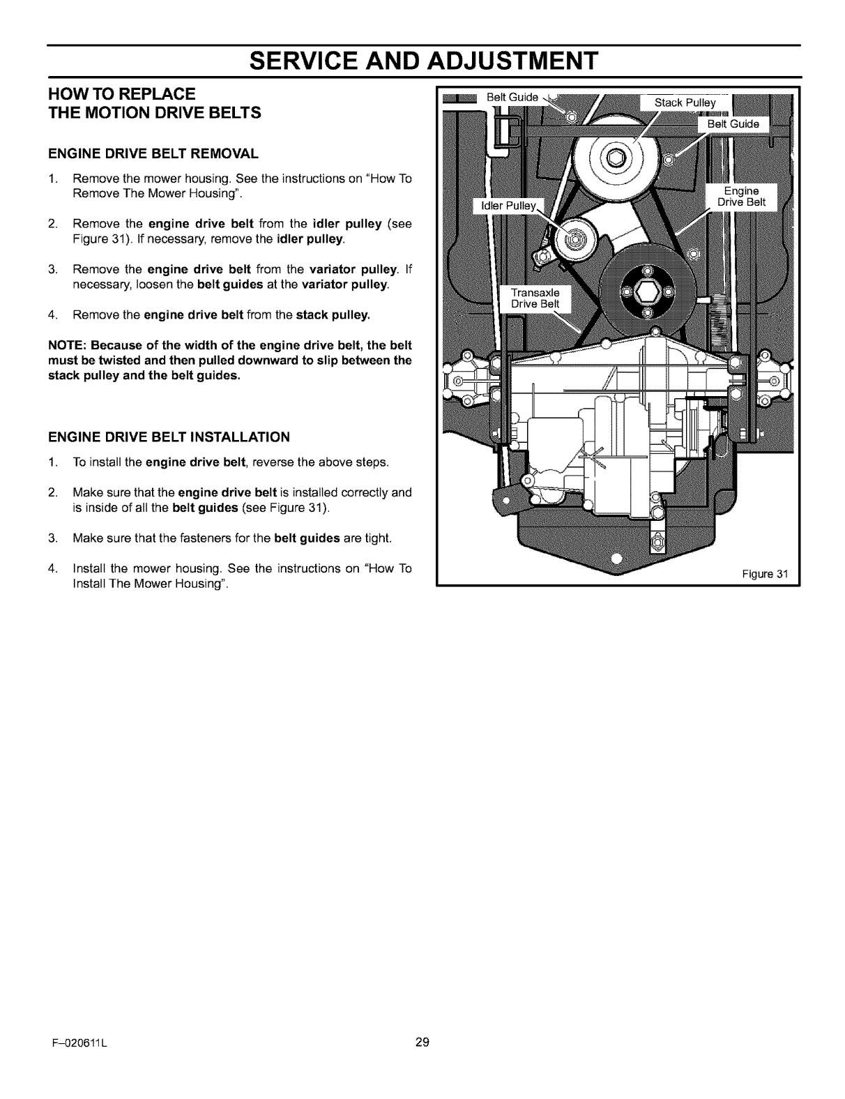
HOW TO REPLACE
THE MOTION DRIVE BELTS
ENGINE DRIVE BELT REMOVAL
1. Remove the mower housing. See the instructions on "How To
Remove The Mower Housing".
2. Remove the engine drive belt from the idler pulley (see
Figure 31). If necessary, remove the idler pulley.
3. Remove the engine drive belt from the variator pulley. If
necessary, loosen the belt guides at the variator pulley.
4. Remove the engine drive belt from the stack pulley.
NOTE: Because of the width of the engine drive belt, the belt
must be twisted and then pulled downward to slip between the
stack pulley and the belt guides.
ENGINE DRIVE BELT INSTALLATION
1. To install the engine drive belt, reverse the above steps.
2. Make sure that the engine drive belt is installed correctly and
is inside of all the belt guides (see Figure 31).
3. Make sure that the fasteners for the belt guides are tight.
4. Install the mower housing. See the instructions on "How To
Install The Mower Housing". Figure 31
F-020611 L 29
SERVICE AND ADJUSTMENT
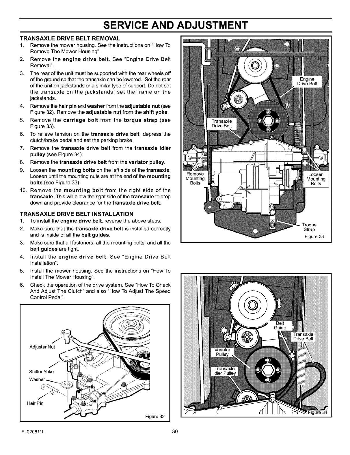
TRANSAXLE DRIVE BELT REMOVAL
1. Remove the mower housing. See the instructions on "How To
Remove The Mower Housing".
2. Remove the engine drive belt. See "Engine Drive Belt
Removal".
3. The rear of the unit must be supported with the rear wheels off
of the ground so that the transaxte can be lowered. Set the rear
of the unit on jackstands or a similar type of support. Do not set
the transaxle on the jackstands; set the frame on the
jackstands.
4. Remove the hair pin and washer from the adjustable nut (see
Figure 32). Remove the adjustable nut from the shift yoke.
5. Remove the carriage bolt from the torque strap (see
Figure 33).
6. To relieve tension on the transaxle drive belt, depress the
clutch/brake pedal and set the parking brake.
7. Remove the transaxle drive belt from the transaxle idler
pulley (see Figure 34).
8. Remove the transaxle drive belt from the vadator pulley.
9. Loosen the mounting bolts on the left side of the transaxle.
Loosen until the mounting nuts are at the end of the mounting
bolts (see Figure 33).
10. Remove the mounting bolt from the right side of the
transaxle. This will allow the right side of the transaxle to drop
down and provide clearance for the transaxle drive belt.
TRANSAXLE DRIVE BELT INSTALLATION
1. To install the engine drive belt, reverse the above steps.
2. Make sure that the transaxle drive belt is installed correctly
and is inside of all the belt guides.
3. Make sure that all fasteners, all the mounting bolts, and all the
belt guides are tight.
4. Install the engine drive belt. See "Engine Drive Belt
Installation".
5. Install the mower housing. See the instructions on "How To
Install The Mower Housing".
6. Check the operation of the drive system. See "How To Check
And Adjust The Clutch" and also "How To Adjust The Speed
Control Pedal".
Adjuster Nut
Shifter Yoke
Hair Pin
Figure 32
Remove
Mounting
Bolts
Loosen
Mounting
Bolts
Troque
Strap
Figure 33
Figure 34
F-020611 L 30
SERVICE AND ADJUSTMENT
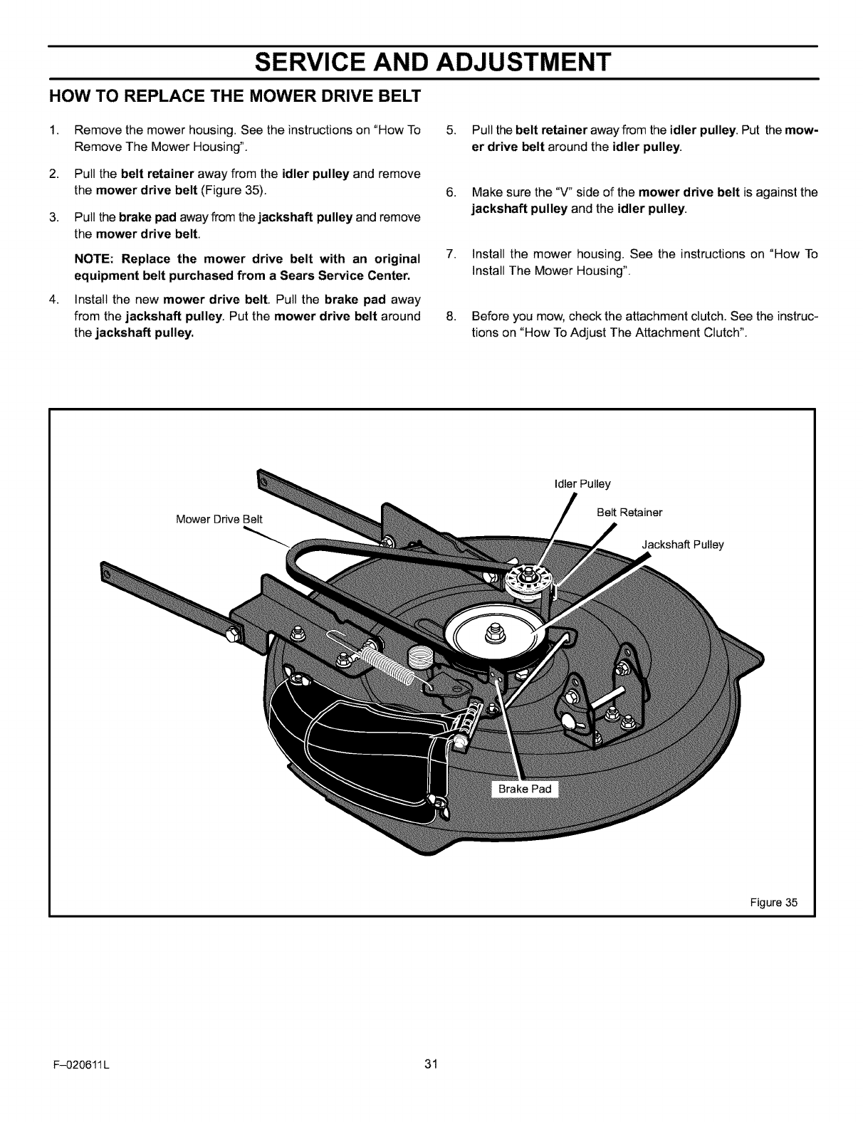
HOW TO REPLACE THE MOWER DRIVE BELT
1,
2,
3,
4,
Remove the mower housing. See the instructions on "How To
Remove The Mower Housing".
Pull the belt retainer away from the idler pulley and remove
the mower drive belt (Figure 35).
Pull the brake pad away from the jackshaft pulley and remove
the mower drive belt.
NOTE: Replace the mower drive belt with an original
equipment belt purchased from a Sears Service Center.
Install the new mower drive belt. Pull the brake pad away
from the jackshaft pulley. Put the mower drive belt around
the jackshaft pulley.
5. Pull the belt retainer away from the idler pulley. Put the mow-
er drive belt around the idler pulley.
6. Make sure the "V" side of the mower drive belt is against the
jackshaft pulley and the idler pulley.
7. Install the mower housing. See the instructions on "How To
Install The Mower Housing".
8. Before you mow, check the attachment clutch. See the instruc-
tions on "How To Adjust The Attachment Clutch".
Mower Drive Belt
Idler Pulley
Belt Retainer
Jackshaft Pulley
Brake Pad
Figure 35
F-020611L 31
SERVICE AND ADJUSTMENT
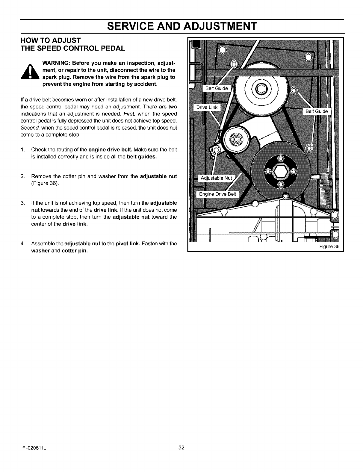
HOW TO ADJUST
THE SPEED CONTROL PEDAL
WARNING: Before you make an inspection, adjust-
_ment, or repair to the unit, disconnect the wire to the
spark plug. Remove the wire from the spark plug to
prevent the engine from starting by accident.
If a drive belt becomes worn or after installation of a new drive belt,
the speed control pedal may need an adjustment. There are two
indications that an adjustment is needed. First, when the speed
control pedal is fully depressed the unit does not achieve top speed.
Second, when the speed control pedal is released, the unit does not
come to a complete stop.
1. Check the routing of the engine drive belt. Make sure the belt
is installed correctly and is inside all the belt guides.
2. Remove the cotter pin and washer from the adjustable nut
(Figure 36).
3. If the unit is not achieving top speed, then turn the adjustable
nut towards the end of the drive link. If the unit does not come
to a complete stop, then turn the adjustable nut toward the
center of the drive link.
4. Assemble the adjustable nut to the pivot link. Fasten with the
washer and cotter pin. Figure 36
F-020611 L 32
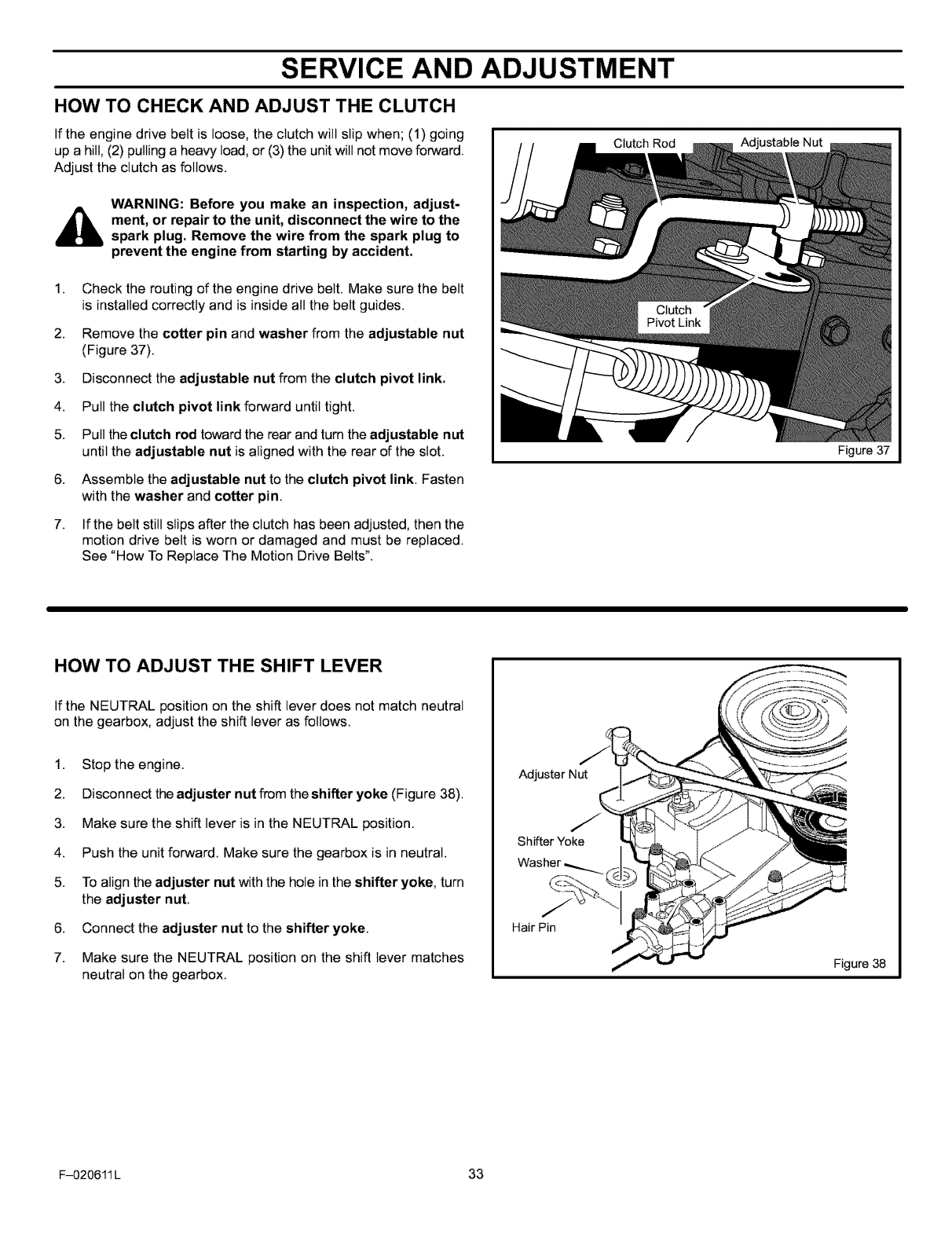
SERVICE AND ADJUSTMENT
HOW TO CHECK AND ADJUST THE CLUTCH
If the engine drive belt is loose, the clutch will slip when; (1) going
up a hill, (2) pulling a heavy toad, or (3) the unit will not move forward.
Adjust the clutch as follows.
WARNING: Before you make an inspection, adjust-
_ment, or repair to the unit, disconnect the wire to the
spark plug. Remove the wire from the spark plug to
prevent the engine from starting by accident.
1. Check the routing of the engine drive belt. Make sure the belt
is installed correctly and is inside all the belt guides.
2. Remove the cotter pin and washer from the adjustable nut
(Figure 37).
3. Disconnect the adjustable nut from the clutch pivot link.
4. Pull the clutch pivot link forward untiltight.
5. Pull the clutch rod toward the rear and turn the adjustable nut
until the adjustable nut is aligned with the rear of the slot.
6. Assemble the adjustable nut to the clutch pivot link. Fasten
with the washer and cotter pin.
7. If the belt still slips after the clutch has been adjusted, then the
motion drive belt is worn or damaged and must be replaced.
See "How To Replace The Motion Drive Belts".
Clutch Rod Adjustable Nut
HOW TO ADJUST THE SHIFT LEVER
If the NEUTRAL position on the shift lever does not match neutral
on the gearbox, adjust the shift lever as follows.
1. Stop the engine.
2. Disconnect the adjuster nut from the shifter yoke (Figure 38).
3. Make sure the shift lever is in the NEUTRAL position.
4. Push the unit forward. Make sure the gearbox is in neutral.
5. To align the adjuster nut with the hole in the shifter yoke, turn
the adjuster nut.
6. Connect the adjuster nut to the shifter yoke.
7. Make sure the NEUTRAL position on the shift lever matches
neutral on the gearbox.
Adjuster Nut
Shifter Yoke
HairPin
Figure 37
Figure 38
F-020611 L 33
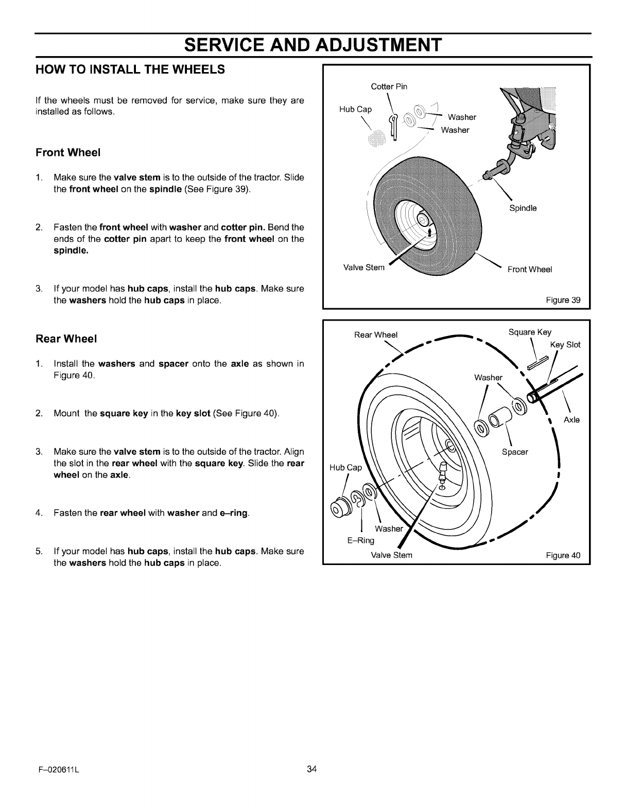
SERVICE AND ADJUSTMENT
HOW TO INSTALL THE WHEELS
If the wheels must be removed for service, make sure they are
installed as follows.
Front Wheel
1. Make sure the valve stem is to the outside of the tractor. Slide
the front wheel on the spindle (See Figure 39).
2. Fasten the front wheel with washer and cotter pin. Bend the
ends of the cotter pin apart to keep the front wheel on the
spindle.
3. If your model has hub caps, install the hub caps. Make sure
the washers hold the hub caps in place.
Cotter Pin
Washer
Valve Stem
Spindle
Front Wheel
Figure 39
Rear Wheel
1. Install the washers and spacer onto the axle as shown in
Figure 40.
2. Mount the square key in the key slot (See Figure 40).
3. Make sure the valve stem is to the outside of the tractor. Align
the slot in the rear wheel with the square key. Slide the rear
wheel on the axle.
4. Fasten the rear wheel with washer and e-ring.
5. If your model has hub caps, install the hub caps. Make sure
the washers hold the hub caps in place.
Rear Wheel f _, _ _ Square Key
> _ Key Slot
Washer
Hub Cap
E-Ring
Valve Stem
Axle
Spacer /
I
/
Figure 40
F-020611 L 34
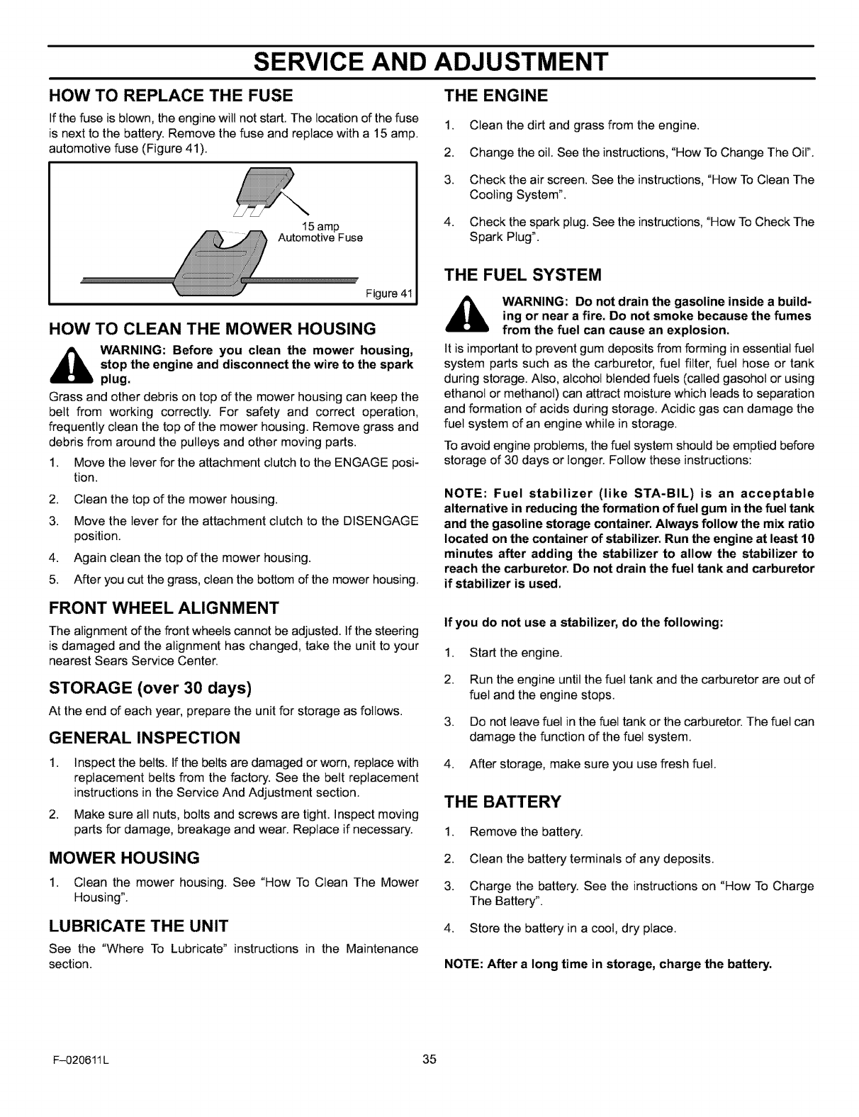
SERVICE AND ADJUSTMENT
HOW TO REPLACE THE FUSE
If the fuse is blown, the engine will not start. The location of the fuse
is next to the battery. Remove the fuse and replace with a 15 amp.
automotive fuse (Figure 41).
THE ENGINE
1. Clean the dirt and grass from the engine.
2. Change the oil. See the instructions, "How To Change The Oil".
15 amp
Automotive Fuse
Figure 41
HOW TO CLEAN THE MOWER HOUSING
_WARNING: Before you clean the mower housing,
stop the engine and disconnect the wire to the spark
plug.
Grass and other debris on top of the mower housing can keep the
belt from working correctly. For safety and correct operation,
frequently clean the top of the mower housing. Remove grass and
debris from around the pulleys and other moving parts.
1. Move the lever for the attachment clutch to the ENGAGE posi-
tion.
2. Clean the top of the mower housing.
3. Move the lever for the attachment clutch to the DISENGAGE
position.
4. Again clean the top of the mower housing.
5. After you cut the grass, clean the bottom of the mower housing.
FRONT WHEEL ALIGNMENT
The alignment of the front wheels cannot be adjusted. If the steering
is damaged and the alignment has changed, take the unit to your
nearest Sears Service Center.
STORAGE (over 30 days)
At the end of each year, prepare the unit for storage as follows.
GENERAL INSPECTION
3.
4.
Check the air screen. See the instructions, "How To Clean The
Cooling System".
Check the spark plug. See the instructions, "How To Check The
Spark Plug".
THE FUEL SYSTEM
WARNING: Do not drain the gasoline inside a build-
ing or near a fire. Do not smoke because the fumes
from the fuel can cause an explosion.
It is important to prevent gum deposits from forming in essential fuel
system parts such as the carburetor, fuel filter, fuel hose or tank
during storage. Also, alcohol blended fuels (called gasohol or using
ethanol or methanol) can attract moisture which leads to separation
and formation of acids during storage. Acidic gas can damage the
fuel system of an engine while in storage.
To avoid engine problems, the fuel system should be emptied before
storage of 30 days or longer. Follow these instructions:
NOTE: Fuel stabilizer (like STA-BIL) is an acceptable
alternative in reducing the formation of fuel gum in the fuel tank
and the gasoline storage container. Always follow the mix ratio
located on the container of stabilizer. Run the engine at least 10
minutes after adding the stabilizer to allow the stabilizer to
reach the carburetor. Do not drain the fuel tank and carburetor
if stabilizer is used.
If you do not use a stabilizer, do the following:
1. Start the engine.
2. Run the engine until the fuel tank and the carburetor are out of
fuel and the engine stops.
3. Do not leave fuel in the fuel tank or the carburetor. The fuel can
damage the function of the fuel system.
1. Inspect the belts. If the belts are damaged or worn, replace with
replacement belts from the factory. See the belt replacement
instructions in the Service And Adjustment section.
2. Make sure all nuts, bolts and screws are tight. Inspect moving
parts for damage, breakage and wear. Replace if necessary.
MOWER HOUSING
1. Clean the mower housing. See "How To Clean The Mower
Housing".
LUBRICATE THE UNIT
See the "Where To Lubricate" instructions in the Maintenance
section.
4. After storage, make sure you use fresh fuel.
THE BATTERY
1. Remove the battery.
2. Clean the battery terminals of any deposits.
3. Charge the battery. See the instructions on "How To Charge
The Battery".
4. Store the battery in a cool, dry place.
NOTE: After a long time in storage, charge the battery.
F-020611 L 35
TROUBLESHOOTING CHART
PROBLEM: The engine will not start.
1. Follow the steps, "How To Start The Engine" in this book.
2. Electric-Start Models: Clean the battery terminals. Tighten the
cables.
3. Drain the fuel tank. Clean the fuel line. Replace the fuel filter.
4. Remove the spark plug(s). Move the throttle to the SLOW posi-
tion. Turn the ignition key to the ON position. Try to start the en-
gine several times. Install the spark plug.
5. Replace the spark plug.
6. Adjust the carburetor.
PROBLEM: The engine will not turn over.
1. Follow the steps, "How To Start The Engine" in this book.
2. Electric-Start Models: Check the level of the acid in the battery.
If needed, add water. Charge the battery.
3. Replace the fuse.
4. Check the wiring harness for damage or a loose connection.
Repair the damaged wire.
5. Electric-Start Models: replace the solenoid. Recoil-Start Mod-
els: replace the module.
2. Check the oil.
3. Adjust the carburetor.
4. Replace the fuel filter.
PROBLEM: Excessive vibration.
1. Replace the blade.
2. Check for loose engine bolts.
3. Decrease the air pressure in the tires.
4. Adjust the carburetor.
5. Check for a damaged belt or damaged pulley. Replace the
damaged parts.
PROBLEM: The grass does not discharge correctly.
1. Stop the engine. Clean the mower housing.
2. Raise the height of cut.
3. Replace or sharpen the blade(s).
4. Move the shift lever to a slower speed.
5. Move the throttle control to the FAST position.
6. Replace the spring for the blade idler.
PROBLEM: The engine is difficult to start.
1. Adjust the carburetor.
2. Replace the spark plug.
3. Replace the fuel filter.
PROBLEM: The engine does not run smooth or has a
loss of power.
1. Check the oil.
2. Clean the air filter.
3. Clean the air screen.
4. Replace the spark plug.
5. The engine is working too hard. Use a lower gear.
6. Adjust the carburetor.
7. Replace the fuel filter.
PROBLEM: The engine does not run smooth at fast
speed.
1. Replace the spark plug.
2. Adjust the throttle control.
3. Clean the air filter.
4. Replace the fuel filter.
PROBLEM: The engine stops when the blades are
engaged.
1. Check the wiringharness for damage or a loose connection.
Repairthe damaged wire.
PROBLEM: On slopes, the engine stops.
1. Mow up and down slopes. Never mow across a slope.
PROBLEM: The engine will not idle.
1. Replace the spark plug.
2. Clean the air filter.
3. Adjust the carburetor.
4. Adjust the throttle control.
5. Drain the fuel tank. Clean the fuel line. Replace the fuel filter.
PROBLEM: A hot engine causes a decrease in power.
1. Clean the air screen.
F-020611L 36
PROBLEM: The mower housing does not cut level.
1. Check the air pressure in the tires.
2. Adjust the level of the mower housing.
3. Check the front axle. If the front axle does not freely pivot, loos-
en the axle bolt(s).
PROBLEM: The mower blades will not rotate.
1. Check the mower drive belt. Make sure the belt is installed cor-
rectly.
2. Replace the mower drive belt.
PROBLEM: The unit will not move when the clutch is
engaged.
1. Check the motion drive belt. Make sure the belt is installed
correctly.
2. Adjust the clutch.
3. Replace the motion drive belt.
PROBLEM: The unit moves slower or stops when the
clutch is engaged.
1. Adjust the clutch.
2. Replacethe motion drive belt.
PROBLEM: When the clutch/brake pedal is released, belt
noise can be heard.
1. Temporary belt noise does not change the operation of the unit.
If belt noise is continuous, check the routing of the belt. Make
sure the belt is inside all belt guides.
2. If the noise is continuous, adjust the clutch.
PROBLEM: The rear wheels spin over uneven terrain.
1. Check the front axle. If the front axle does not freely pivot, loos-
en the axle bolt(s).
PROBLEM: The transaxle is difficult to shift between
gears with the engine running and the clutch depressed.
1. Check the clutch adjustment to make sure the belt stops when
the clutch pedal is depressed with the transaxte in (N) neutral.
2. Check the belt guides around the transaxte drive pulley. Make
sure the belt guides do not touch the pulley.
SEARS, ROEBUCK AND CO.
Federal and California Emission Control Systems Limited Warranty
Small Off-Road Engines
CALIFORNIA & US EPA EMISSION CONTROL WARRANTY
STATEMENT
The U. S. Environmental Protection Agency ("EPA"), the California Air Re-
sources Board ("CARB") and Sears, Roebuck and Co. are pleased to explain
the Federal and California Emission Control Systems Warranty on your new
small off-road engine. In California, new 1995 and later small off-road en-
gines must be designed, built and equipped to meet the State's stringent
anti-smog standards. In other states, new 1997 and later model year en-
gines must be designed, built and equipped, at the time of sale, to meet the
U.S. EPA regulations for small non-road engines. Sears, Roebuck and Co.
will warrant the emission control system on your small off-road engine for the
periods of time listed below, provided there has been no abuse, neglect, un-
approved modification, or improper maintenance of your small off-road en-
gine.
Your emission control system may include parts such as the carburetor, igni-
tion system and exhaust system. Also included may be the compression re-
lease system and other emission-related assemblies.
Where a warrantable condition exists, Sears, Roebuck and Co. will repair
your small off-road engine at no cost to you for diagnosis, parts and labor.
MANUFACTURER'S EMISSION CONTROL SYSTEM
WARRANTY COVERAGE
Emission control systems on 1995 and later model year California small off-
road engines are warranted for two years as hereinafter noted. In other
states, 1997 and later model year engines are also warranted for two years.
If, during such warranty period, any emission-related part on your engine is
defective in materials or workmanship, the part will be repaired or replaced
by Sears, Roebuck and Co.
OWNER'S WARRANTY RESPONSIBILITIES
As the small off-road engine owner, you are responsible for the performance
of the required maintenance listed in your Owner's Manual, but Sears, Roe-
buck and Co. will not deny warranty solely due to the lack of receipts or for
your failure to provide written evidence of the performance of all scheduled
maintenance.
As the small off-road engine owner, you should, however, be aware that
Sears, Roebuck and Co. may deny you warranty coverage if your small off-
road engine or a part thereof has failed due to abuse, neglect, improper main-
tenance or unapproved modifications.
You are responsible for presenting your small off-road engine to a Sears,
Roebuck and Co. Authorized Service Outlet as soon as a problem exists.
The warranty repairs should be completed in a reasonable amount of time,
not to exceed 30 days.
Warranty service can be arranged by contacting either a Sears, Roebuck
and Co. Authorized Service Outlet, or by contacting Sears, Roebuck and Co.
at 1-800-473-7247.
IMPORTANT NOTE
Esta This warranty statement explains your rights and obligations under the
Emission Control System Warranty ("ECS Warranty") which is provided to
you by Sears, Roebuck and Co. pursuant to California law. See also the
Sears, Roebuck and Co. Limited Warranties for Sears, Roebuck and Co.
which is enclosed therewith on a separate sheet and also is provided to you
by Sears, Roebuck and Co. The ECS Warranty applies only to the emission
control system of your new engine. To the extent that there is any conflict in
terms between the ECS Warranty and the Sears, Roebuck and Co. Warran-
ty, the ECS Warranty shall apply except in any circumstances in which the
Sears, Roebuck and Co. Warranty may provide a longer warranty period.
Both the ECS Warranty and the Sears, Roebuck and Co. Warranty describe
important rights and obligations with respect to your new engine.
Warranty service can only be performed by a Sears, Roebuck and Co. Au-
thorized Service Outlet. At the time of requesting warranty service, evidence
F-020611L 37
must be presented of the date of sale to the original purchaser. The purchas-
er shall pay any charges for making service calls and/or for transporting the
products to and from the place where the inspection and/or warranty work
is performed. The purchaser shall be responsible for any damage or loss in-
curred in connection with the transportation of any engine or any part(s)
thereof submitted for inspection and/or warranty work.
If you have any questions regarding your warranty rights and responsibilities,
you should contact Sears, Roebuck and Co. at 1-800-473-7247.
EMISSION CONTROL SYSTEM WARRANTY
Emission Control System Warranty ("ECS Warranty") for 1995 and later
model year California small off-road engines (for other states, 1997 and later
model year engines):
A. APPLICABILITY: This warranty shall apply to 1995 and later model year
California small off-road engines (for other states, 1997 and later model year
engines). The ECS Warranty Period shall begin on the date the new engine
or equipment is delivered to its original, end-use purchaser, and shall contin-
ue for 24 consecutive months thereafter.
B, GENERAL EMISSIONS WARRANTY COVERAGE: Sears, Roebuck
and Co. warrants to the original, end-use purchaser of the new engine or
equipment and to each subsequent purchaser that each of its small off-road
engines is:
1. Designed, built and equipped so as to conform with all applicable regula-
tions adopted by the Air Resources Board pursuant to its authority in Chap-
ters 1 and 2, Part 5, Division 26 of the Health and Safety Code, and
2. Free from defects in materials and workmanship which, at any time during
the ECS Warranty Period, will cause a warranted emissions-related part to
fail to be identical in all material respects to the part as described in the en-
gine manufacturer's application for certification.
C. The ECS Warranty only pertains to emissions-related parts on your en-
gine, as follows:
1. Any warranted, emissions-related parts which are not scheduled for re-
placement as required maintenance in the Owner's Manual shall be war-
ranted for the ECS Warranty Period. If any such part fails during the ECS
Warranty Period, it shall be repaired or replaced by Sears, Roebuck and Co.
according to Subsection 4 below. Any such part repaired or replaced under
the ECS Warranty shall be warranted for any remainder of the ECS Warranty
Period.
2. Any warranted, emissions-related part which is scheduled only for regular
inspection as specked in the Owner's Manual shall be warranted for the ECS
Warranty Period. A statement in such written instructions to the effect of "re-
pair or replace as necessary", shall not reduce the ECS Warranty Period.
Any such part repaired or replaced under the ECS Warranty shall be war-
ranted for the remainder of the ECS Warranty Period.
3. Any warranted, emissions-related part which is scheduled for replace-
ment as required maintenance in the Owner's Manual, shall be warranted for
the period of time prior to the first scheduled replacement point for that part.
If the part fails prior to the first scheduled replacement, the part shall be re-
paired or replaced by Sears, Roebuck and Co. according to Subsection 4 be-
low. Any such emissions-related part repaired or replaced under the ECS
Warranty, shall be warranted for the remainder of the ECS Warranty Period
prior to the first scheduled replacement point for such emissions-related
part.
4. Repair or replacement of any warranted, emissions-related part under
this ECS Warranty shall be performed at no charge to the owner at a Sears,
Roebuck and Co. Authorized Service Outlet.
5. The owner shall not be charged for diagnostic labor which leads to the de-
termination that a part covered by the ECS Warranty is in fact defective, pro-
vided that such diagnostic work is performed at a Sears, Roebuck and Co.
Authorized Service Outlet.
6. Sears, Roebuck and Co. shall be liable for damages to other original en-
gine components or approved modifications proximately caused by a failure
under warranty of an emission-related part covered by the ECS Warranty.
7.ThroughouttheECSWarrantyPeriod,Sears,RoebuckandCo.shall
maintainasupplyofwarrantedemission-relatedpartssufficienttomeetthe
expecteddemandforsuchemission-relatedparts.
8.AnySears,RoebuckandCo.authorizedandapprovedemission-related
replacementpartmaybeusedintheperformanceofanyECSWarranty
maintenanceorrepairandwillbeprovidedwithoutchargetotheowner.Such
useshallnotreduceSears,RoebuckandCo.ECSWarrantyobligations.
9.Unapprovedadd-onormodifiedpartsmaynotbeusedtomodifyorrepair
aSears,RoebuckandCo.engine.SuchusevoidsthisECSWarrantyand
shallbesufficientgroundsfordisallowinganECSWarrantyclaim.Sears,
RoebuckandCo.shallnotbeliablehereunderforfailuresofanywarranted
partsofaSears,RoebuckandCo.enginecausedbytheuseofsuchanun-
approvedadd-onormodifiedpart.
EMISSION-RELATED PARTS INCLUDE THE FOLLOWING:
1. Carburetor Assembly and its Internal Components
a) Fuel filter
b) Carburetor gaskets
c) Intake pipe
2. Air Cleaner Assembly
a) Air filter element
3. Ignition System, including:
a) Spark plug
b) Ignition module
c) Flywheel assembly
4. Catalytic Muffler (if so equipped)
a) Muffler gasket (if so equipped)
b) Exhaust manifold (if so equipped)
5. Crankcase Breather Assembly and its
Components
a) Breather connection tube
Sears, Roebuck and Co., Hoffman Estates, IL 60179 U.S.A.
10/22/99 EPAiCARB
F-020611 L 38

SLOPE GUIDE
Fold this page along dotted line indicated below. Hold page before you so that its left
edge is vertically parallel to a tree trunk or other upright structure. Sight across the
............ i.b".DE'p._._ fold in the direction of the hill or slope you want to measure. Compare the angle of the
I ""--._._._-.ES.. fold with the slope of the hill.
".....i......................
1'I,. .....:--_._.__.,_
_ . _ ...........
ieoeo
!Operate a walk-behind mower
across the face of slopes,
never up or down slopes.
6=..
10 DEGREES 15 DEGREES
Operate a riding mower
up or down slopes, never
across the face of slopes.
O_
03
On a riding mower to determine if a slope is safe to mow: (1) disengage the blade(s), (2) put the unit in reverse, and (3) try to back straight up the
slope. If you can back up the slope, it is generally safe to mow. However, if you do not feel safe, or you are not completely sure, use this guide to
determine the slope angle.
WARNING: To avoid possible serious injury, do not mow a slope that is greater than 15 degrees. If the riding mower is used with a
pull-behind or rear-mounted attachment, do not operate the unit on a slope that is greater than 10 degrees.
................................. _U'T_E'R_fO'U_E'S_6P__U_D'E.................................
_J
O
LL
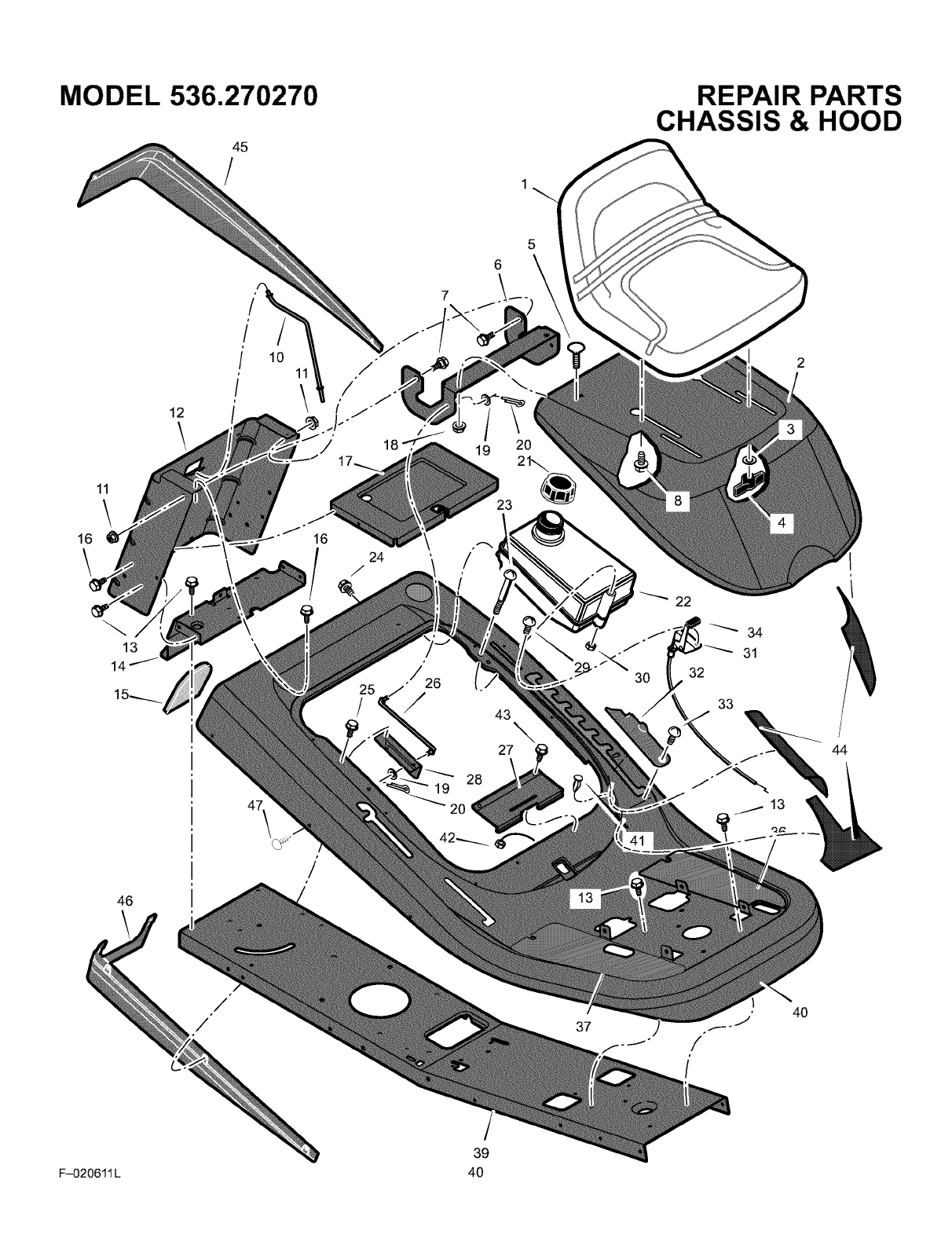
MODEL 536.270270
45
/
11
\
16
13
14
46
,
18
25
/
6
7
/
/26
/
_ 28
19
2O
)
21_
43 \
27
REPAIR PARTS
CHASSIS & HOOD
22
34
J _ 31
o30 32
33
44
37 4O
39
F-020611L 40
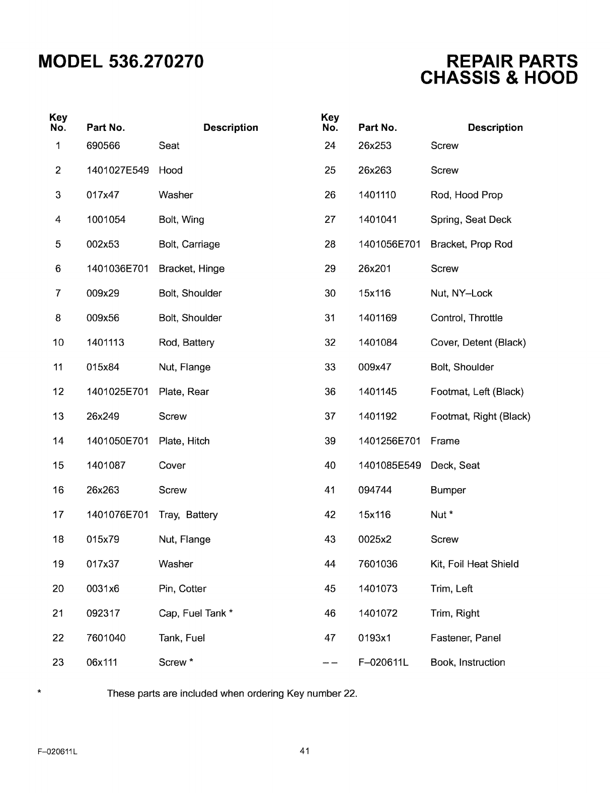
MODEL 536.270270 REPAIR PARTS
CHASSIS & HOOD
Key
No. Part No.
1 690566
2 1401027E549
3 017x47
4 1001054
5 002x53
6 1401036E701
7 009x29
8 009x56
10 1401113
11 015x84
12 1401025E701
13 26x249
14 1401050E701
15 1401087
16 26x263
17 1401076E701
18 015x79
19 017x37
20 0031 x6
21 092317
22 7601040
23 06x111
Key
Description No.
Seat 24
Hood 25
Washer 26
Bolt, Wing 27
Bolt, Carriage 28
Bracket, Hinge 29
Bolt, Shoulder 30
Bolt, Shoulder 31
Rod, Battery 32
Nut, Flange 33
Plate, Rear 36
Screw 37
Plate, Hitch 39
Cover 40
Screw 41
Tray, Battery 42
Nut, Flange 43
Washer 44
Pin, Cotter 45
Cap, Fuel Tank *46
Tank, Fuel 47
Screw *--
Part No.
26x253
26x263
1401110
1401041
1401056E701
26x201
15x116
1401169
1401084
009x47
1401145
1401192
1401256E701
1401085E549
094744
15x116
0025x2
7601036
1401073
1401072
0193x 1
F-020611L
These parts are included when ordering Key number 22.
Description
Screw
Screw
Rod, Hood Prop
Spring, Seat Deck
Bracket, Prop Rod
Screw
Nut, NY-Lock
Control, Throttle
Cover, Detent (Black)
Bolt, Shoulder
Footmat, Left (Black)
Footmat, Right (Black)
Frame
Deck, Seat
Bumper
Nut *
Screw
Kit, Foil Heat Shield
Trim, Left
Trim, Right
Fastener, Panel
Book, Instruction
F-O20611L 41
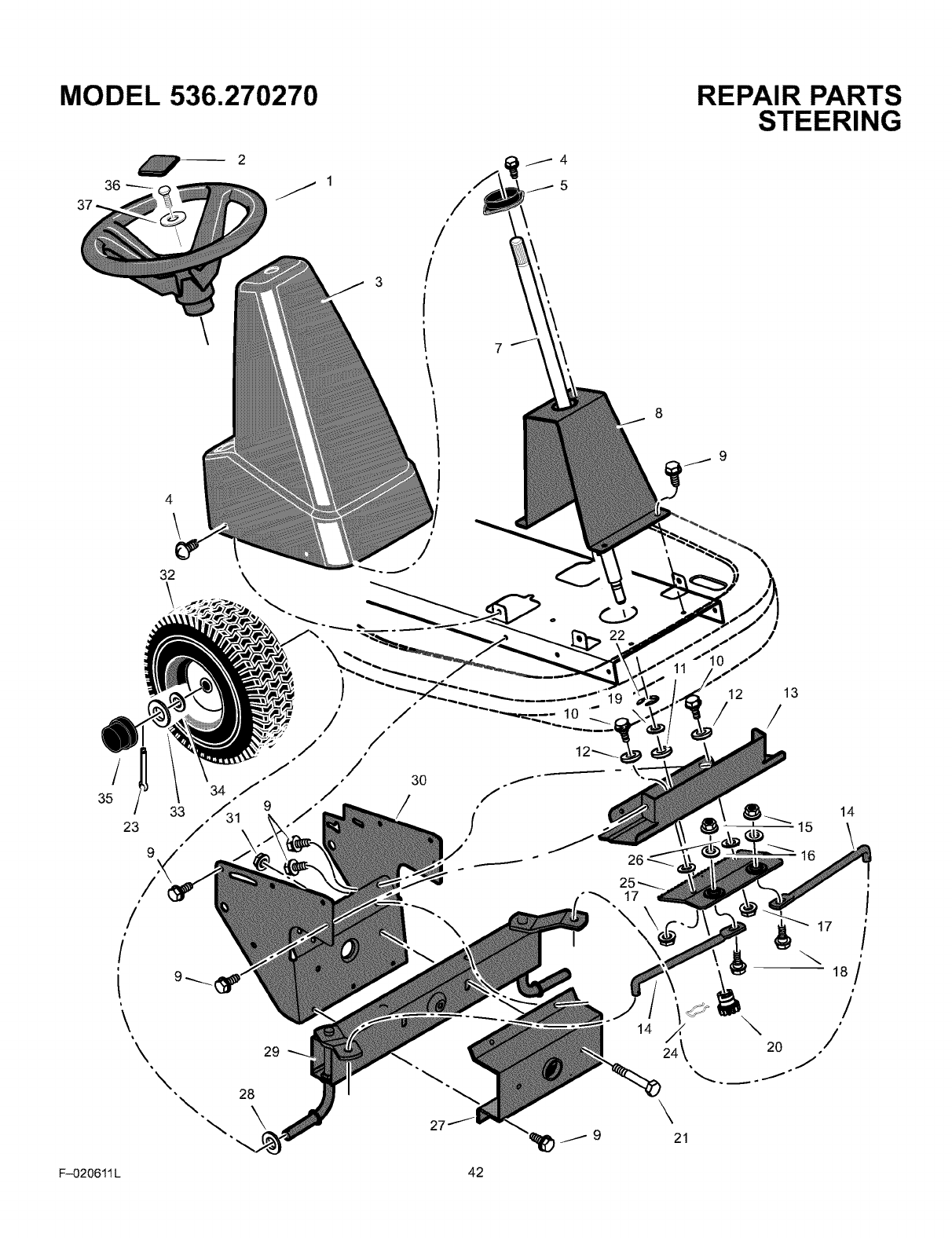
MODEL 536.270270
36
4\
32
REPAIR PARTS
STEERING
I
/
/
35
23 /\
9
/
/•
#
/
\'\
\\
29
28
27
19
17
\\
14
12 13
/ /
\
21
14
\
17
18/
/
#
/
F-020611 L 42
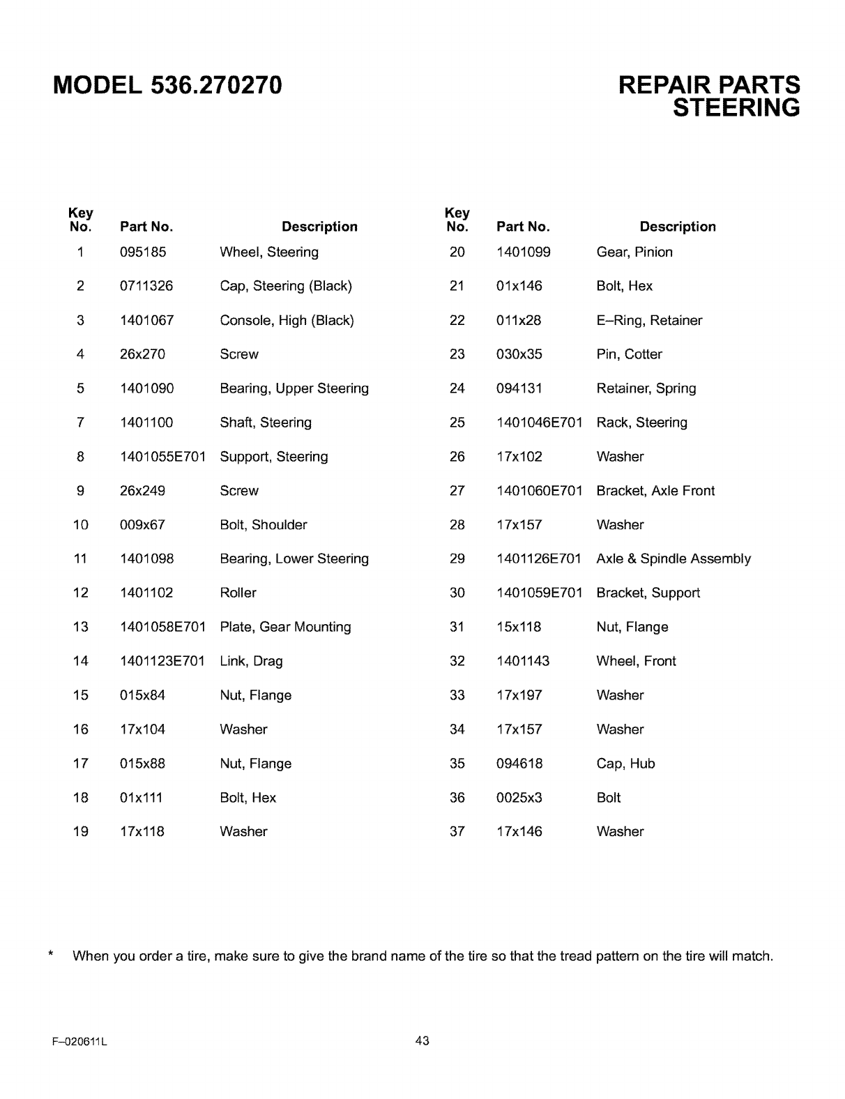
MODEL 536.270270 REPAIR PARTS
STEERING
Key Key
No. Part No. Description No. Part No. Description
1095185 Wheel, Steedng 20 1401099 Gear, Pinion
20711326 Cap, Steering (Black) 21 01x146 Bolt, Hex
3 1401067 Console, High (Black) 22 011x28 E-Ring, Retainer
4 26x270 Screw 23 030x35 Pin, Cotter
5 1401090 Bearing, Upper Steering 24 094131 Retainer, Spring
7 1401100 Shaft, Steering 25 1401046E701 Rack, Steering
8 1401055E701 Support, Steering 26 17x102 Washer
9 26x249 Screw 27 1401060E701 Bracket, Axle Front
10 009x67 Bolt, Shoulder 28 17x157 Washer
11 1401098 Bearing, Lower Steering 29 1401126E701 Axle & Spindle Assembly
12 1401102 Roller 30 1401059E701 Bracket, Support
13 1401058E701 Plate, Gear Mounting 31 15x118 Nut, Flange
14 1401123E701 Link, Drag 32 1401143 Wheel, Front
15 015x84 Nut, Flange 33 17x197 Washer
16 17x104 Washer 34 17x157 Washer
17 015x88 Nut, Flange 35 094618 Cap, Hub
18 01x111 Bolt, Hex 36 0025x3 Bolt
19 17x118 Washer 37 17x146 Washer
*When you order a tire, make sure to give the brand name of the tire so that the tread pattern on the tire will match.
F-020611 L 43
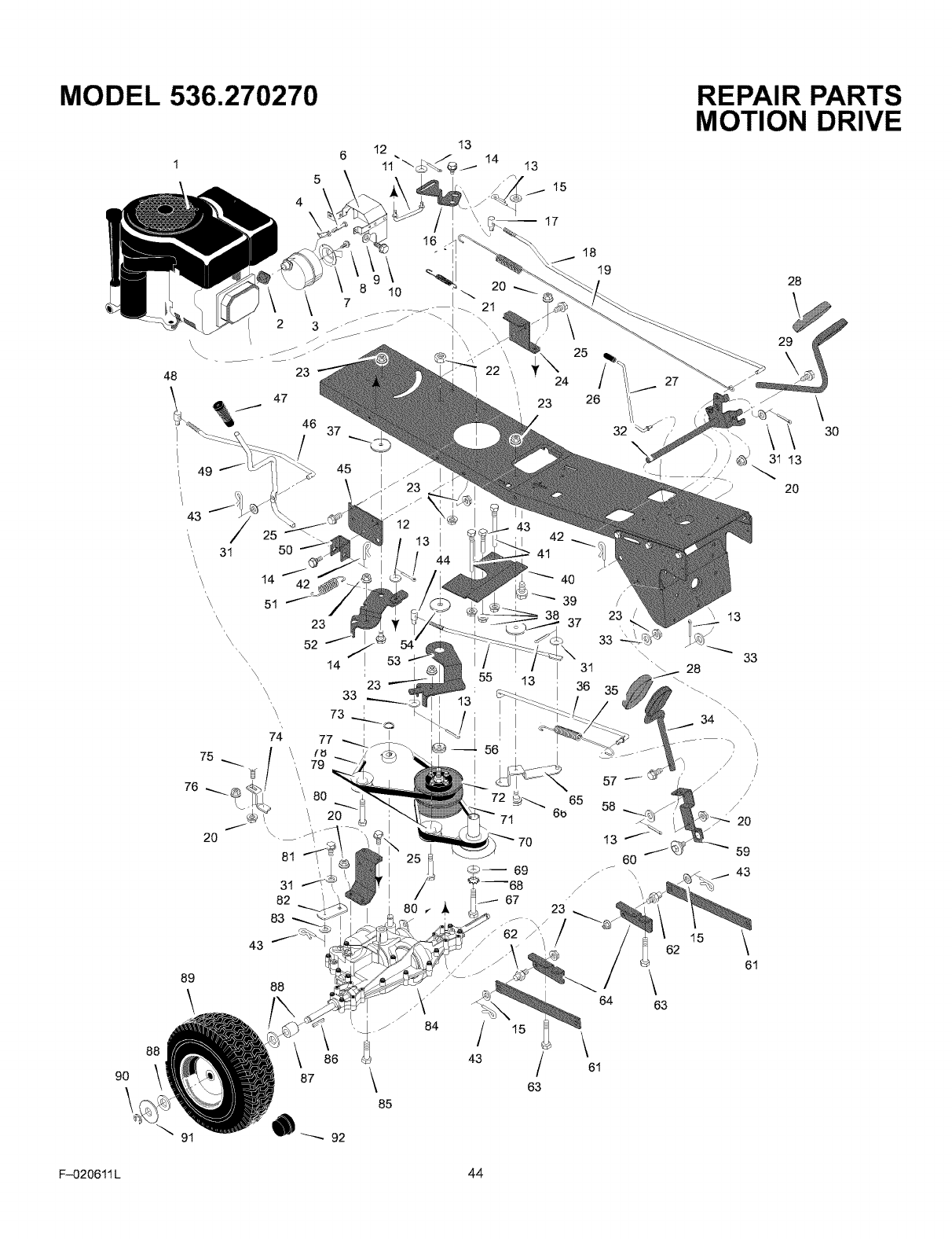
MODEL 536.270270
90
\
48
88
\\\
I 2
23 22 '\
47
46 37
13
15
17
23
49
43
'\t 31
\,
\\
\\
5O
14
51
45
23
_, 52
\\\ 14 53
81
31
82
83
43
I 42
41
25
24
26
55 ' 13
13
37
70
18
19
43
89
\88
84
63
32
REPAIR PARTS
MOTION DRIVE
28
/
/
23 \ 13
/
33
\30
33
31 28
36 35 _,
34 \
\\,
/
6O
/_ \ 43
62 15 \
61
\63
F-020611 L 44
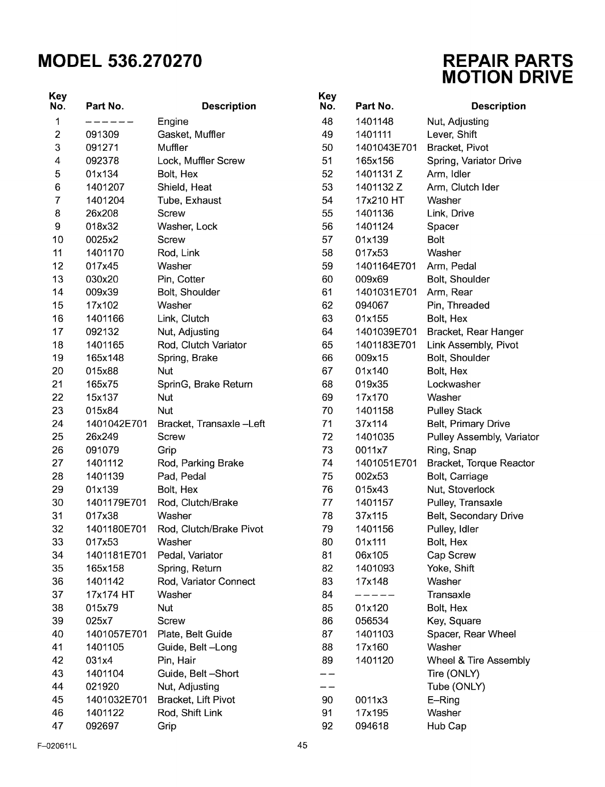
MODEL 536.270270
Key
No. Part No.
1
2 091309
3 091271
4 092378
5 01x134
6 1401207
7 1401204
8 26x208
9018x32
10 0025x2
11 1401170
12 017x45
13 030x20
14 009x39
15 17x102
16 1401166
17 092132
18 1401165
19 165x148
20 015x88
21 165x75
22 15x137
23 015x84
24 1401042E701
25 26x249
26 091079
27 1401112
28 1401139
29 01x139
30 1401179E701
31 017x38
32 1401180E701
33 017x53
34 1401181E701
35 165x158
36 1401142
37 17xl 74 HT
38 015x79
39 025x7
40 1401057E701
41 1401105
42 031x4
43 1401104
44 021920
45 1401032E701
46 1401122
47 092697
Description
Engine
Gasket, Muffler
Muffler
Lock, Muffler Screw
Bolt, Hex
Shield, Heat
Tube, Exhaust
Screw
Washer, Lock
Screw
Rod, Link
Washer
Pin, Cotter
Bolt, Shoulder
Washer
Link, Clutch
Nut, Adjusting
Rod, Clutch Variator
Spring, Brake
Nut
SprinG, Brake Return
Nut
Nut
Bracket, Transaxle-Left
Screw
Grip
Rod, Parking Brake
Pad, Pedal
Bolt, Hex
Rod, Clutch/Brake
Washer
Rod, Clutch/Brake Pivot
Washer
Pedal, Variator
Spring, Return
Rod, Variator Connect
Washer
Nut
Screw
Plate, Belt Guide
Guide, Belt-Long
Pin, Hair
Guide, Belt-Short
Nut, Adjusting
Bracket, Lift Pivot
Rod, Shift Link
Grip
Key
No.
48
49
50
51
52
53
54
55
56
57
58
59
60
61
62
63
64
65
66
67
68
69
70
71
72
73
74
75
76
77
78
79
80
81
82
83
84
85
86
87
88
89
90
91
92
Part No.
1401148
1401111
1401043E701
165x156
1401131 Z
1401132 Z
17x210 HT
1401136
1401124
01x139
017x53
1401164E701
009x69
1401031 E701
094067
01x155
1401039E701
1401183E701
009x15
01x140
019x35
17xl 70
1401158
37x114
1401035
0011x7
1401051 E701
002x53
015x43
1401157
37x115
1401156
01x111
06x105
1401093
17x 148
01x120
056534
1401103
17x160
1401120
0011x3
17x195
094618
REPAIR PARTS
MOTION DRIVE
Description
Nut, Adjusting
Lever, Shift
Bracket, Pivot
Spring, Variator Drive
Arm, Idler
Arm, Clutch Ider
Washer
Link, Drive
Spacer
Bolt
Washer
Arm, Pedal
Bolt, Shoulder
Arm, Rear
Pin, Threaded
Bolt, Hex
Bracket, Rear Hanger
Link Assembly, Pivot
Bolt, Shoulder
Bolt, Hex
Lockwasher
Washer
Pulley Stack
Belt, Primary Drive
Pulley Assembly, Variator
Ring, Snap
Bracket, Torque Reactor
Bolt, Carriage
Nut, Stoverlock
Pulley, Transaxle
Belt, Secondary Drive
Pulley, Idler
Bolt, Hex
Cap Screw
Yoke, Shift
Washer
Transaxle
Bolt, Hex
Key, Square
Spacer, Rear Wheel
Washer
Wheel & Tire Assembly
Tire (ONLY)
Tube (ONLY)
E-Ring
Washer
Hub Cap
F-020611 L 45
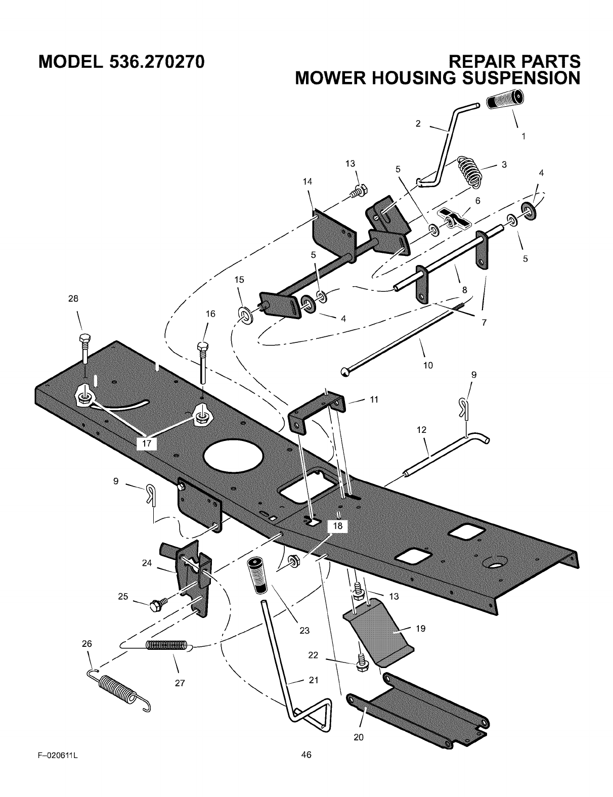
MODEL 536.270270 REPAIR PARTS
MOWER HOUSING SUSPENSION
13 5
14
\
4
28 /15
16
\
11
10
12
9
26
\
23
22
20
13
19
F-020611 L 46

MODEL 536.270270 REPAIR PARTS
MOWER HOUSING SUSPENSION
Key
No. Part No.
1 092697
2 1401117
3 165xl 54
4 094137
5 017x45
6 095004
7 1401033E701
8 1401096
9 0031 x4
10 002x93
11 1401030E701
12 1401118
13 26x249
14 1401262E701
Description
Grip, Lift Lever
Lever, Lift
Spring, Extension
Pad, Friction
Washer
Wingnut
Link, Lift
Tube, Spacer
Pin, Hair
Bolt, Carriage
Bracket, Front Hanger Pivot
Pin, Front Hanger
Screw
Arm Assembly, Lifter
Key
No. Part No. Description
15 17xl 65 Washer
16 091754 Screw, Guide
17 015x79 Nut, Flange
18 015x84 Nut, Flange
19 1401147 Spring, Leaf
20 1401040E701 Hanger, Front
21 1401116 Lever, PTO
22 26x263 Screw
23 094198 Grip, PTO
24 1401199E701 Bracket, PTO
25 009x39 Bolt, Shoulder
26 165x157 Spring, Extension
27 165x92 Spring, Extension
28 020619 Screw, Guide
F-020611 L 47
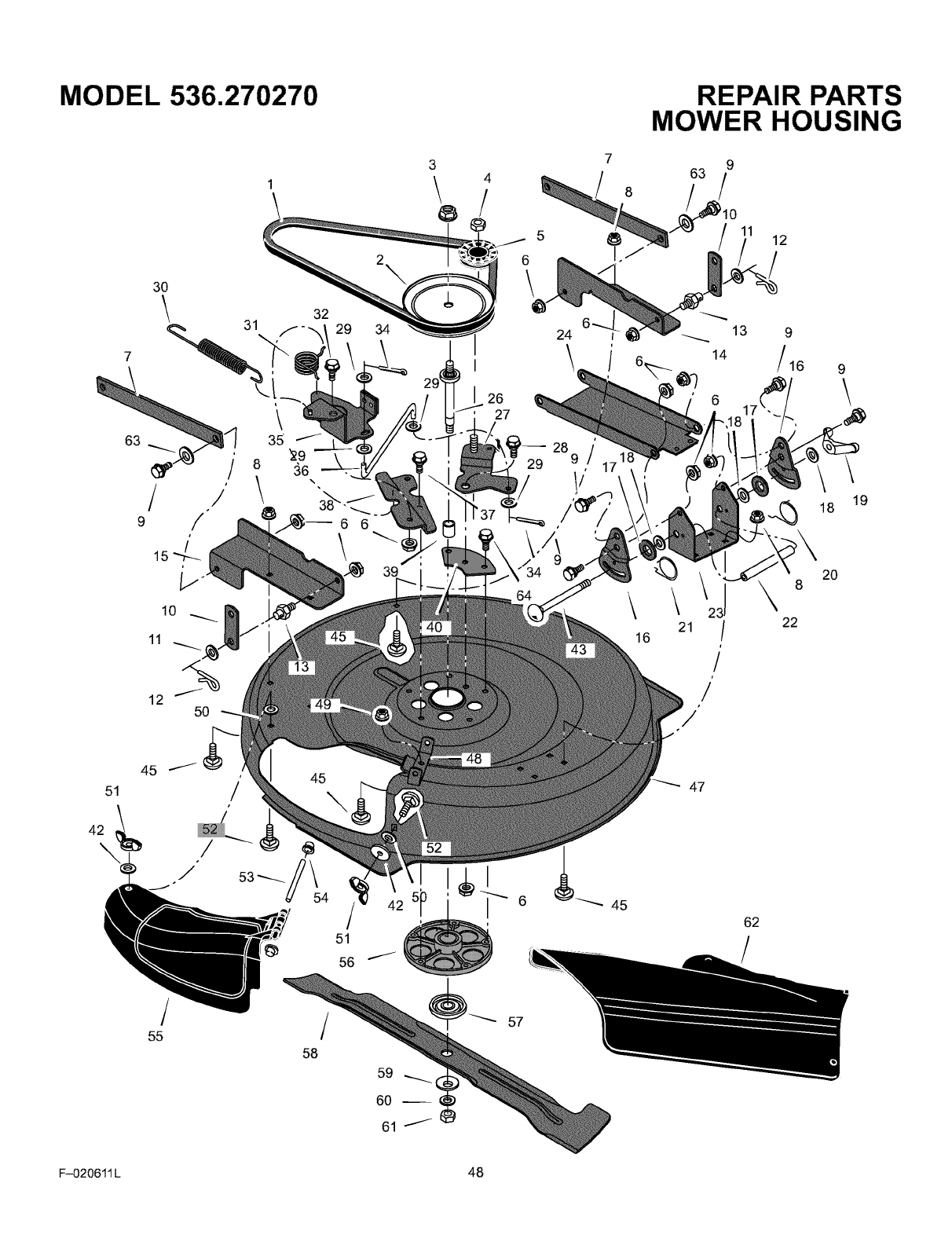
MODEL 536.270270
3
\4
/
@
7
8
REPAIR PARTS
MOWER HOUSING
9
63/
11 12
51
3O
\ 32
31 29 34
10
11
12 5O
/
55
45
/
58
51
56
I
I
27
I
29
24
\,
i
28 9 /
i
1/
14
13 9
16 9
8
18
2O
16 21 /22
/
/
47
45
62
19
F-020611 L 48
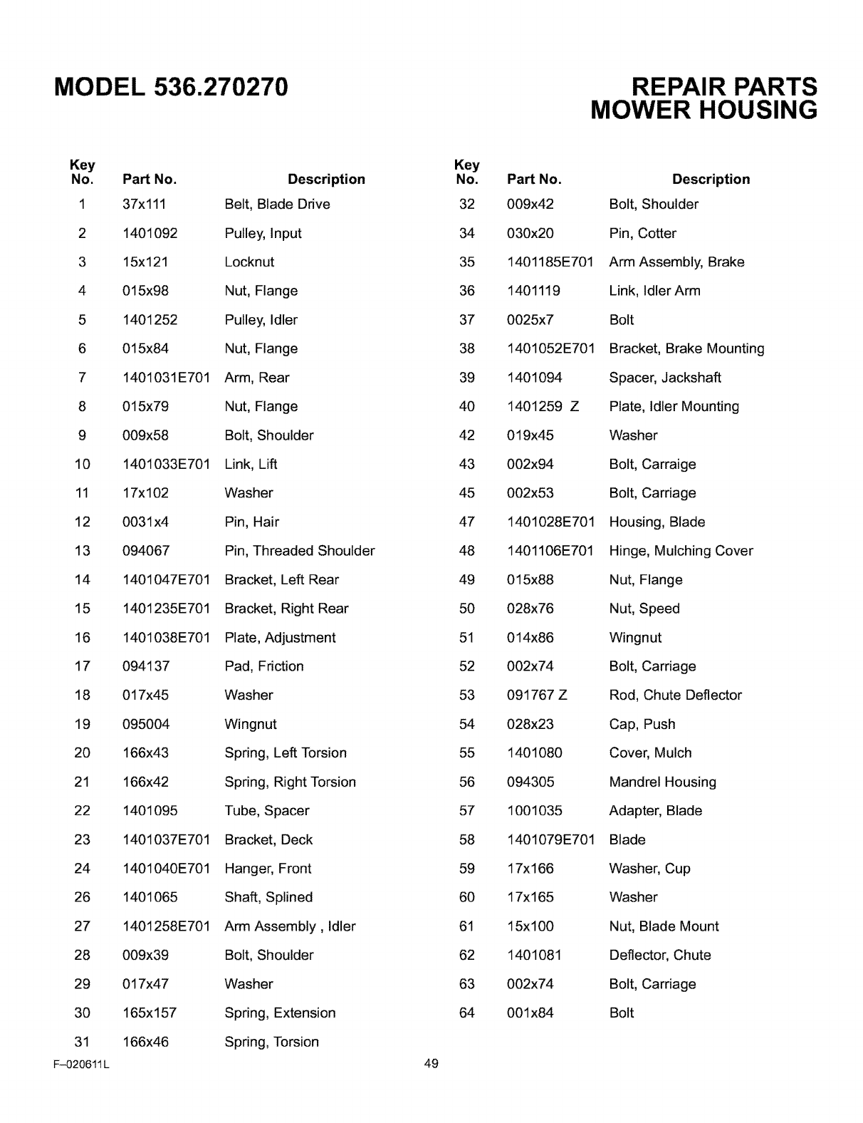
MODEL 536.270270
Key
No. Part No.
1 37x111
2 1401092
3 15x121
4 015x98
5 1401252
6 015x84
7 1401031E701
8 015x79
9 009x58
10 1401033E701
11 17x102
12 0031 x4
13 094067
14 1401047E701
15 1401235E701
16 1401038E701
17 094137
18 017x45
19 095004
20 166x43
21 166x42
22 1401095
23 1401037E701
24 1401040E701
26 1401065
27 1401258E701
28 009x39
29 017x47
30 165x157
31 166x46
F-020611L
Description
Belt, Blade Drive
Pulley, Input
Locknut
Nut, Flange
Pulley, Idler
Nut, Flange
Arm, Rear
Nut, Flange
Bolt, Shoulder
Link, Lift
Washer
Pin, Hair
Pin, Threaded Shoulder
Bracket, Left Rear
Bracket, Right Rear
Plate, Adjustment
Pad, Friction
Washer
Wingnut
Spring, Left Torsion
Spring, Right Torsion
Tube, Spacer
Bracket, Deck
Hanger, Front
Shaft, Splined
Arm Assembly, Idler
Bolt, Shoulder
Washer
Spring, Extension
Spring, Torsion
Key
No.
32
34
35
36
37
38
39
40
42
43
45
47
48
49
5O
51
52
53
54
55
56
57
58
59
60
61
62
63
64
49
Part No.
009x42
030x20
1401185E701
1401119
0025x7
1401052E701
1401094
1401259 Z
019x45
002x94
002x53
1401028E701
1401106E701
015x88
028x76
014x86
002x74
091767 Z
028x23
1401080
094305
1001035
1401079E701
17x166
17x165
15x100
1401081
002x74
001x84
REPAIR PARTS
MOWER HOUSING
Description
Bolt, Shoulder
Pin, Cotter
Arm Assembly, Brake
Link, Idler Arm
Bolt
Bracket, Brake Mounting
Spacer, Jackshaft
Plate, Idler Mounting
Washer
Bolt, Carraige
Bolt, Carriage
Housing, Blade
Hinge, Mulching Cover
Nut, Flange
Nut, Speed
Wingnut
Bolt, Carriage
Rod, Chute Deflector
Cap, Push
Cover, Mulch
Mandrel Housing
Adapter, Blade
Blade
Washer, Cup
Washer
Nut, Blade Mount
Deflector, Chute
Bolt, Carriage
Bolt
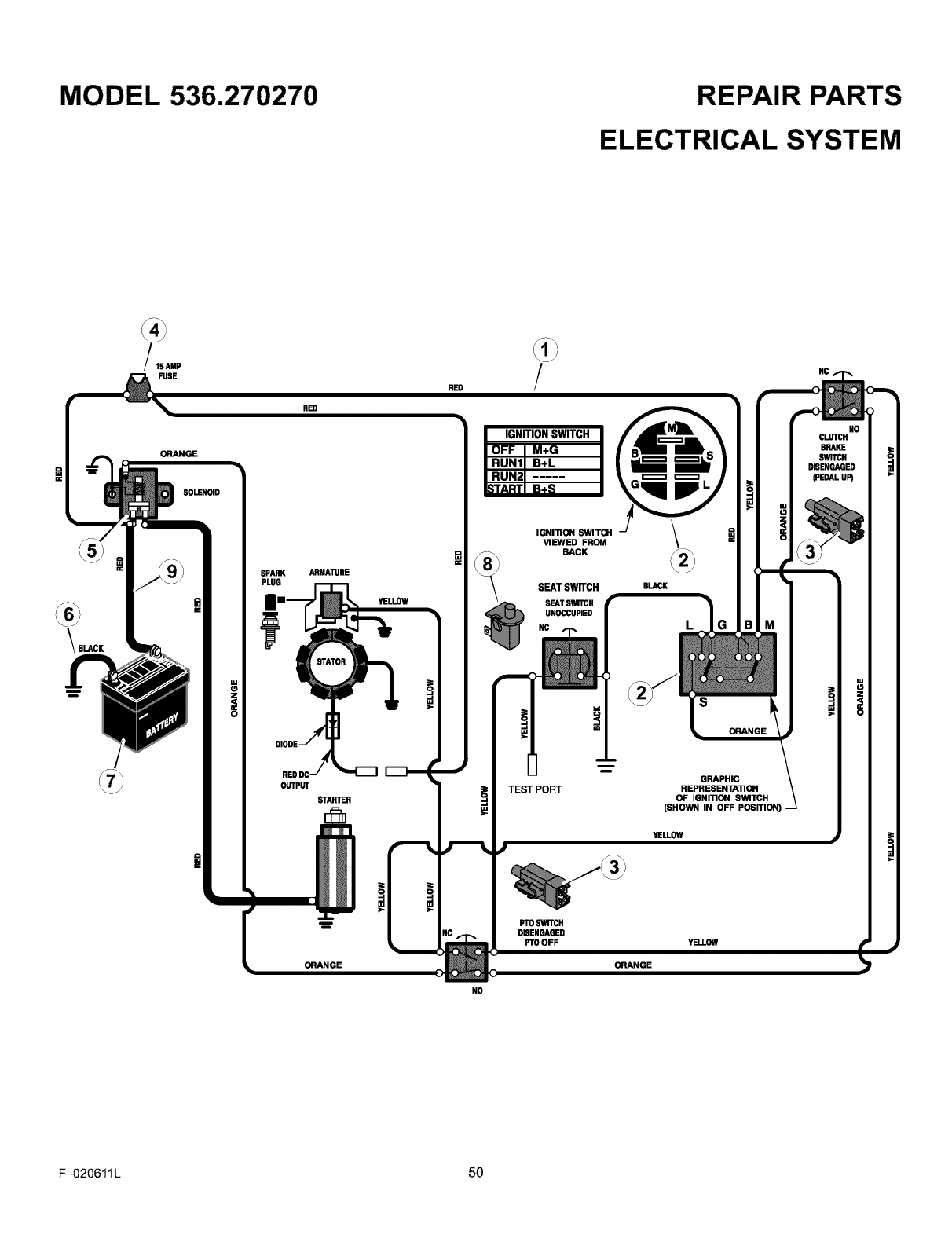
MODEL 536.270270 REPAIR PARTS
ELECTRICAL SYSTEM
BLACK
_AMP
FUSE
ORANGE
SOLENOID
RED
RED !
SPARK
PLUG
OUTPUT
STARTER
ARMAllJRE
YELLOW
IGNITIONSWITCH
IGNI11ON SWITCH
VIEWED FROM
BACK
SEAT SWITCH
SEATSWITCH
UNOCCUPIED
TEST PORT
I)1"0 SWITCH
DISENGAGED
PTO OFF
ORANGE
BLACK
s
ORANGE
GRAPHIC
REPR ESENTA11ON
OF IGNI11ON SWITCH
(SHOWN IN OFF POSITION) -
YELLOW
ORANGE
NC
NO
NO
CLUTCH
BRAKE
SWITCH
DISENGAGED
(PEDAL UP)
F-020611 L 50

MODEL 536.270270 REPAIR PARTS
ELECTRICAL SYSTEM
Key Part
No. No.
250x102
Description
Harness, Chassis Wire
1401149
327349
Switch, Ignition
Key, Ignition
Nut, Hex
Cap, Ignition
3 094136 Switch, Limit
054212
407078
Fuse
Holde_ Fuse
094613
26x229
15x116
Solenoid
Screw, Mounting
Locknut
024x37 Cable, BaKery Ground
Screw, Ground Cable
092739
002x82
014x79
Battery
Bolt, Carriage
Wingnut
8 094159 Switch, Seat Sensor
024x24
690604
Cable, Red Batery
Boot, Positive Terminal
F-020611 L 51
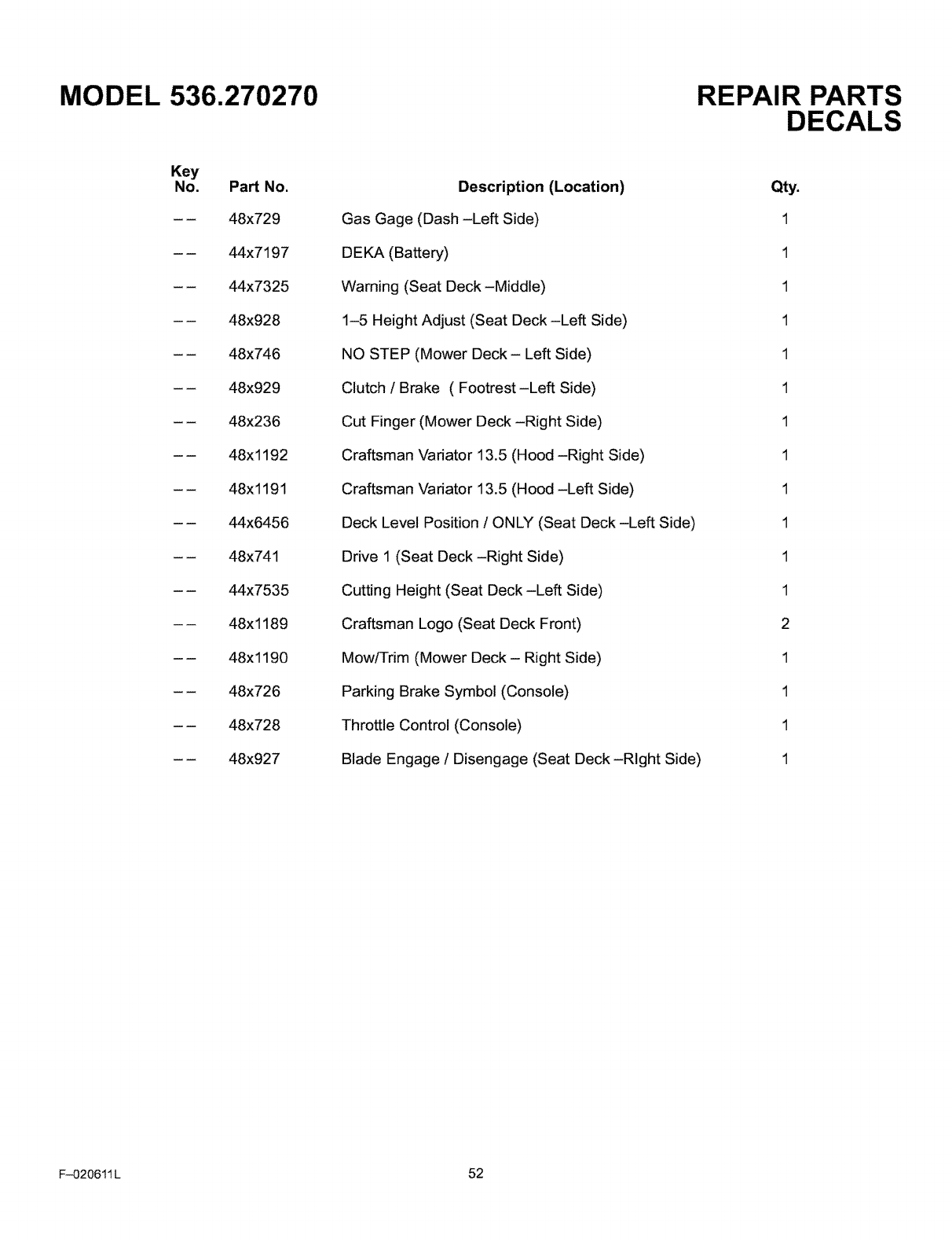
MODEL 536.270270
Key
No. PaN No.
-- 48x729
-- 44x7197
-- 44x7325
-- 48x928
-- 48x746
-- 48x929
-- 48x236
-- 48x1192
-- 48x1191
-- 44x6456
-- 48x741
-- 44x7535
-- 48x1189
-- 48x1190
-- 48x726
-- 48x728
-- 48x927
Description (Location)
Gas Gage (Dash -Left Side)
DEKA (Battery)
Warning (Seat Deck-Middle)
1-5 Height Adjust (Seat Deck -Left Side)
NO STEP (Mower Deck - Left Side)
Clutch /Brake ( Footrest-Left Side)
Cut Finger (Mower Deck -Right Side)
Craftsman Variator 13.5 (Hood -Right Side)
Craftsman Variator 13.5 (Hood -Left Side)
Deck Level Position /ONLY (Seat Deck -Left Side)
Drive 1 (Seat Deck -Right Side)
Cutting Height (Seat Deck -Left Side)
Craftsman Logo (Seat Deck Front)
Mow/Trim (Mower Deck - Right Side)
Parking Brake Symbol (Console)
Throttle Control (Console)
Blade Engage /Disengage (Seat Deck -Right Side)
REPAIR PARTS
DECALS
Qty.
1
1
1
1
1
1
1
1
1
1
1
1
2
1
1
1
1
F-020611 L 52

NOTES
F-020611 L 53
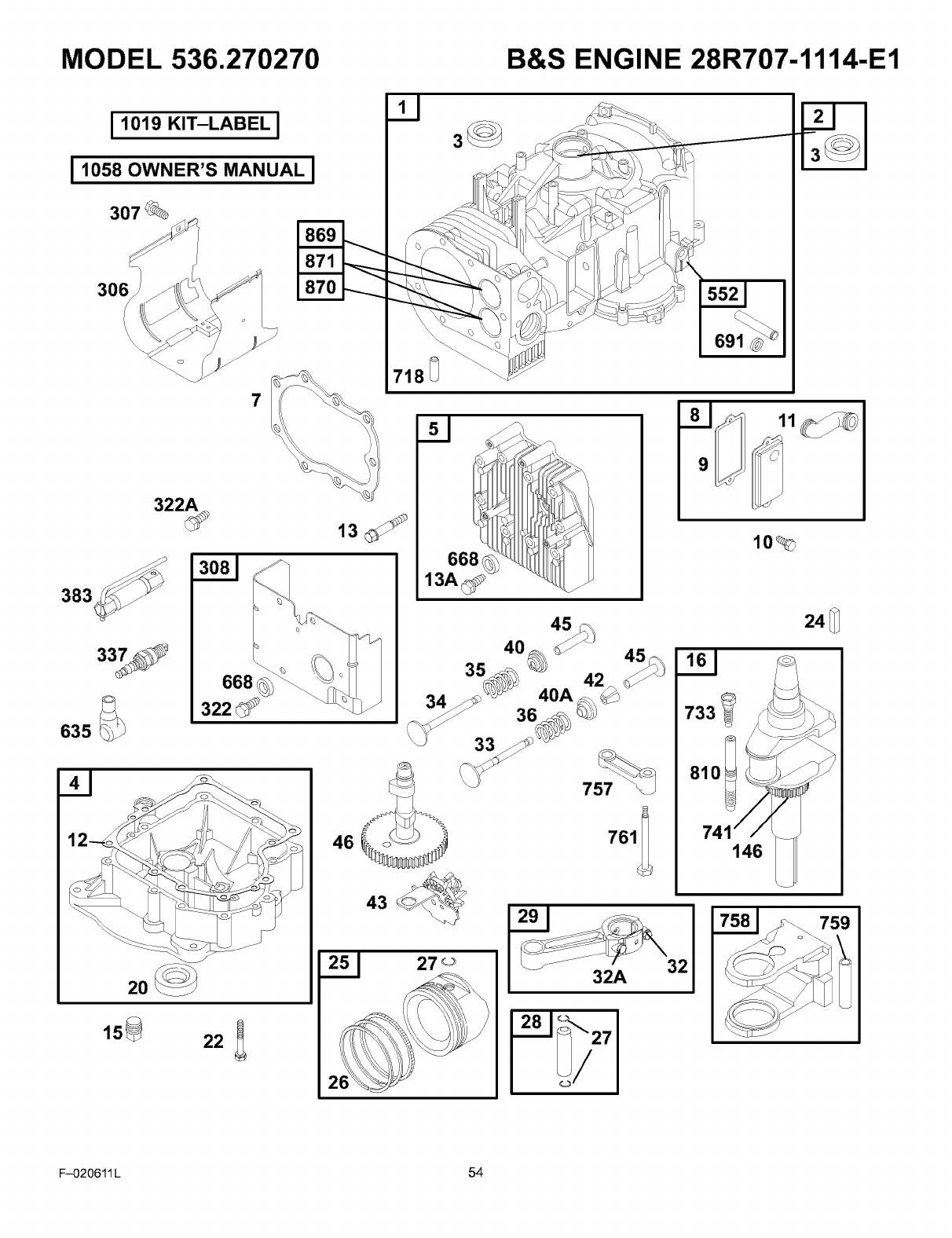
MODEL 536.270270 B&S ENGINE 28R707-1114-E1
I 1019 KIT-LABEL I
11058OWNER'SMANUALI
307_
383
635
7
322A
13
337
20
668
322
718_
32
733
810 t
10_
146
32A
0/
24_
F-020611 L 54
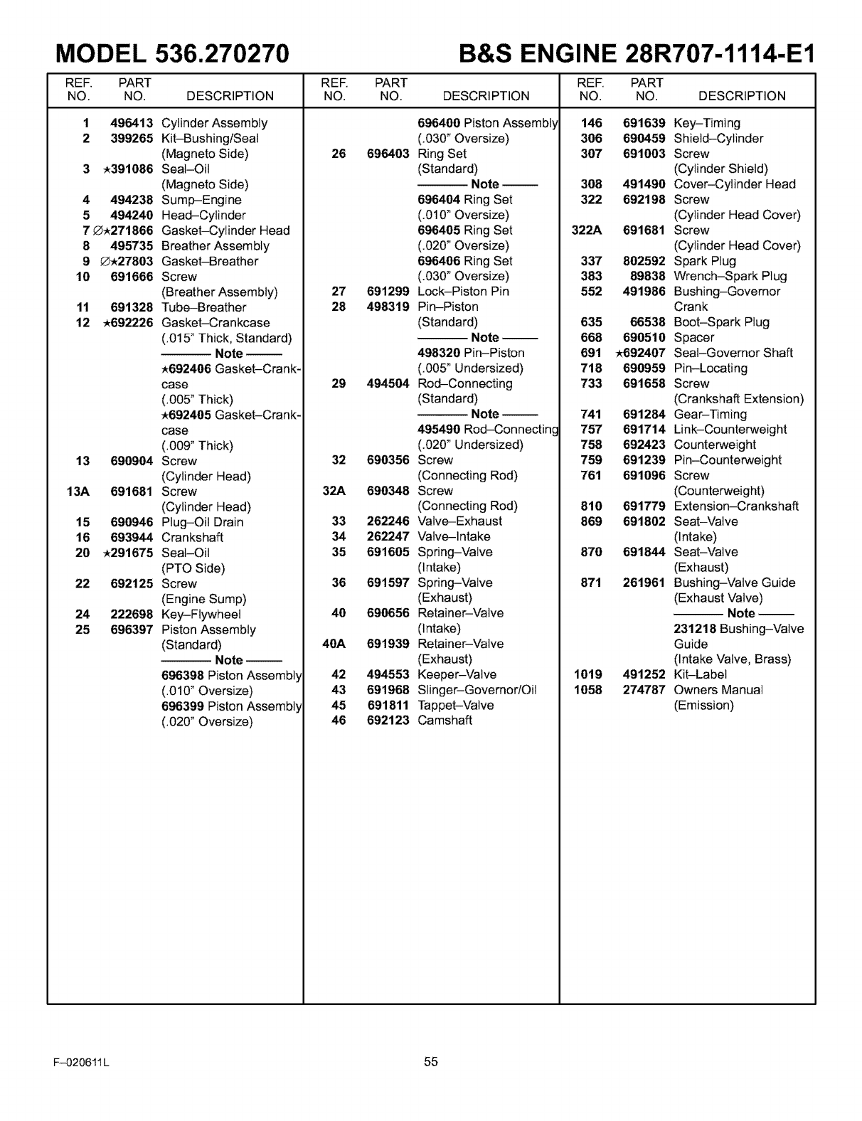
MODEL 536.270270 B&S ENGINE 28R707-1114-E1
REF. PART
NO. NO. DESCRIPTION
1 496413 Cylinder Assembly
2 399265 Kit-Bushing/Seat
(Magneto Side)
3 _391086 Seal-Oil
(Magneto Side)
4 494238 Sump-Engine
5 494240 Head-Cylinder
7_271866 Gasket-Cylinder Head
8 495735 Breather Assembly
9 _27803 Gasket-Breather
10 691666 Screw
(Breather Assembly)
11 691328 Tube-Breather
12 _692226 Gasket-Crankcase
(.015" Thick, Standard)
Note-
_692406 Gasket-Crank-
case
(.005" Thick)
_692405 Gasket-Crank-
case
(.009" Thick)
13 690904 Screw
(Cylinder Head)
13A 691681 Screw
(Cylinder Head)
15 690946 Plug-Oil Drain
16 693944 Crankshaft
20 _291675 Seat-Oil
(PTO Side)
22 692125 Screw
(Engine Sump)
24 222698 Key-Flywheel
25 696397 Piston Assembly
(Standard)Note
696398 Piston Assembl_
(.010" Oversize)
696399 Piston Assembl
(.020" Oversize)
REE PART
NO. NO. DESCRIPTION
696400 Piston Assembl_
(.030" Oversize)
26 696403 Ring Set
(Standard)Note --
696404 Ring Set
(.010" Oversize)
696405 Ring Set
(.020" Oversize)
696406 Ring Set
(.030" Oversize)
27 691299 Lock-Piston Pin
28 498319 Pin-Piston
(Standard)Note
498320 Pin-Piston
(.005" Undersized)
29 494564 Rod-Connecting
(Standard)Note
495490 Rod-Connectin
(.020" Undersized)
32 690356 Screw
(Connecting Rod)
32A 690348 Screw
(Connecting Rod)
33 262246 Valve-Exhaust
34 262247 Valve-Intake
35 691605 Spring-Valve
(Intake)
36 691597 Spring-Valve
(Exhaust)
40 690656 Retainer-Valve
(Intake)
40A 691939 Retainer-Valve
(Exhaust)
42 494553 Keeper-Valve
43 691968 Slinger-Governor/Oil
45 691811 Tappet-Valve
46 692123 Camshaft
REF. PART
NO. NO. DESCRIPTION
146 691639 Key-Timing
306 696459 Shield-Cylinder
307 691003 Screw
(Cylinder Shield)
308 491490 Cover-Cylinder Head
322 692198 Screw
(Cylinder Head Cover)
691681 Screw
(Cylinder Head Cover)
337 802592 Spark Plug
383 89838 Wrench-Spark Plug
552 491986 Bushing-Governor
Crank
635 66538 Boot-Spark Plug
668 690510 Spacer
691 _692407 Seat-Governor Shaft
718 690959 Pin-Locating
733 691658 Screw
(Crankshaft Extension)
741 691284 Gear-Timing
757 691714 Link-Counterweight
758 692423 Counterweight
759 691239 Pin-Counterweight
761 691096 Screw
(Counterweight)
810 691779 Extension-Crankshaft
869 691802 Seat-Valve
(Intake)
870 691844 Seat-Valve
(Exhaust)
871 261961 Bushing-Valve Guide
(Exhaust Valve)
Note
231218 Bushing-Valve
Guide
(Intake Valve, Brass)
491252 Kit-Label
274787 Owners Manual
(Emission)
322A
1019
1058
F-020611 L 55
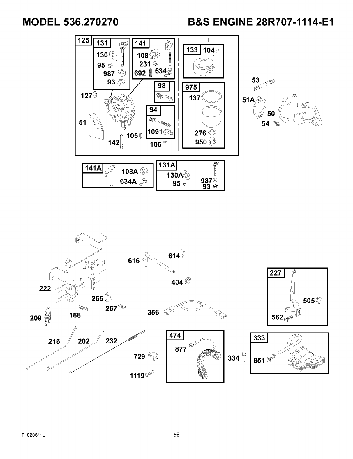
MODEL 536.270270 B&S ENGINE 28R707-1114-E1
1251
51
95
987
93_
142_ 105_
D
lO91_I276
950
108A
634A 987®
95 _93 @
222
209
216
614
616
404
188
265
202 232 f
729©
1119_
877
334 851
F-020611 L 56
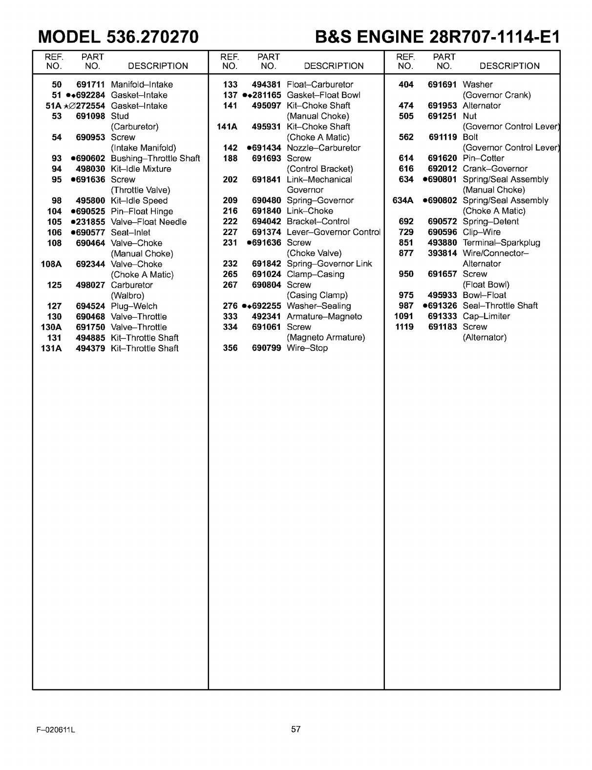
MODEL 536.270270 B&S ENGINE 28R707-1114-E1
REF. PART RER PART REF. PART
NO. NO. DESCRIPTION NO. NO. DESCRIPTION NO. NO. DESCRIPTION
50 691711 Manifold-Intake
51 e+692284 Gasket-Intake
51A _272554 Gasket-Intake
53 691098 Stud
(Carburetor)
54 690953 Screw
(Intake Manifold)
133 494381 Float-Carburetor
137 e+281165 Gasket-Float Bowl
141 495097 Kit-Choke Shaft
(Manual Choke)
141A 495931 Kit-Choke Shaft
(Choke A Mat/c)
142 e691434 Nozzle-Carburetor
404 691691 Washer
(Governor Crank)
474 691953 Alternator
505 691251 Nut
(Governor Control Lever
562 691119 Bolt
(Governor Control Lever
93 e690602 Bushing-Throttle Shaft
94 498030 Kit-Idle Mixture
95 e691636 Screw
(Throttle Valve)
98 495800 Kit-Idle Speed
104 e690525 Pin-Float Hinge
105 e231855 Valve-Float Needle
188 691693 Screw
(Control Bracket)
202 691841 Link-Mechanical
Governor
209 690480 Spring-Governor
216 691840 Link-Choke
222 694042 Bracket-Control
614 691620 Pin-Cotter
616 692012 Crank-Governor
634 e690801 Spring/Seal Assembly
(Manual Choke)
634A e690802 Spring/Seal Assembly
(Choke A Mat/c)
692 690572 Spring-Detent
108A
106 e690577 Seat-Inlet
108 690464 Valve-Choke
(Manual Choke)
692344 Valve-Choke
(Choke A Mat/c)
125 498027 Carburetor
(Watbro)
694524 Plug-Welch
690468 Valve-Throttle
691750 Valve-Throttle
494885 Kit-Throttle Shaft
494379 Kit-Throttle Shaft
127
130
130A
131
131A
227 691374 Lever-Governor Control
231 e691636 Screw
(Choke Valve)
232 691842 Spring-Governor Link
265 691024 Clamp-Casing
267 690804 Screw
(Casing Clamp)
276 e+692255 Washer-Sealing
333 492341 Armature-Magneto
334 691061 Screw
(Magneto Armature)
356 690799 Wire-Stop
729 690596 Clip-Wire
851 493880 Terminal-Sparkplug
877 393814 Wire/Connector-
Alternator
950 691657 Screw
(Float Bowl)
975 495933 Bowl-Float
987 e691326 Seat-Throttle Shaft
1091 691333 Cap-Limiter
1119 691183 Screw
(Alternator)
F-020611 L 57
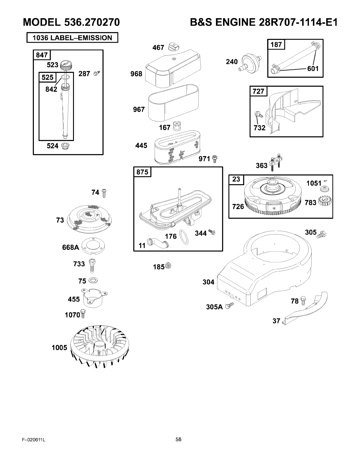
MODEL 536.270270
11036LABEL-SSIONI
523
287
524
74
668A
733 _
75 @
455
1070_
968
967
445
B&S ENGINE 28R707-1114-E1
467
240 601
167
176 344
O
783
1850
304
305A
1005
F-020611 L 58
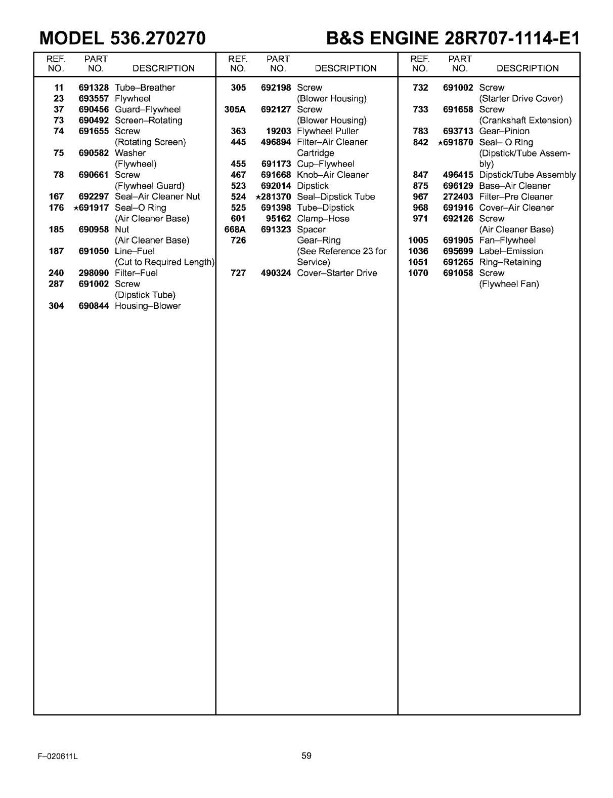
MODEL 536.270270 B&S ENGINE 28R707-1114-E1
REF. PART PART REF. PART
NO. NO. DESCRIPTION NO. DESCRIPTION NO. NO. DESCRIPTION
11 691328 Tube-Breather
23 693557 Flywheel
37 690456 Guard-Flywheel
73 690492 Screen-Rotating
74 691655 Screw
(Rotating Screen)
RER
NO.
305 692198 Screw
(Blower Housing)
305A 692127 Screw
(Blower Housing)
363 19203 Flywheel Puller
445 496894 Fitter-Air Cleaner
732 691002 Screw
(Starter Drive Cover)
733 691658 Screw
(Crankshaft Extension)
783 693713 Gear-Pinion
842 _691870 Seat- O Ring
75 690582 Washer
(Flywheel)
78 690661 Screw
(Flywheel Guard)
167 692297 Seal-Air Cleaner Nut
176 _691917 Seat-O Ring
(Air Cleaner Base)
185 690958 Nut
(Air Cleaner Base)
187 691050 Line-Fuel
(Cut to Required Lengthl
240 298090 Fitter-Fuel
287 691002 Screw
(Dipstick Tube)
304 690844 Housing-Blower
601
668A
726
Cartridge
455 691173 Cup-Flywheel
467 691668 Knob-Air Cleaner
523 692014 Dipstick
524 _281370 Seat-Dipstick Tube
525 691398 Tube-Dipstick
95162 Clamp-Hose
691323 Spacer
Gear-Ring
(See Reference 23 for
Service)
727 490324 Cover-Starter Drive
(Dipstick]Tube Assem-
bly)
847 490415 Dipstick/Tube Assembly
875 696129 Base-Air Cleaner
967 272403 Filter-Pre Cleaner
968 691916 Cover-Air Cleaner
971 692126 Screw
(Air Cleaner Base)
1005 691905 Fan-Flywheel
1036 695699 Label-Emission
1051 691265 Ring-Retaining
1070 691058 Screw
(Flywheel Fan)
F-020611 L 59
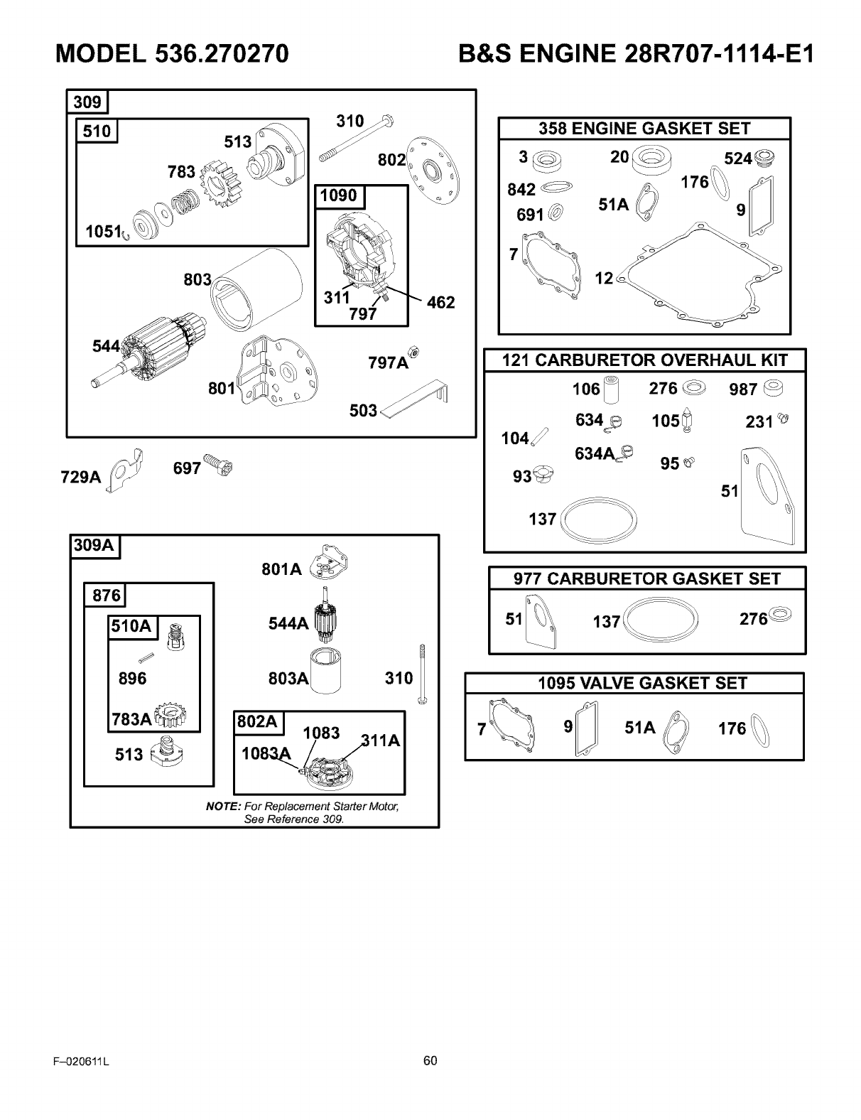
MODEL 536.270270 B&S ENGINE 28R707-1114-E1
513 310
_802
462
797
729A 697_
J
896
801A
544A
NOTE: For Replacement Starter Motor,
See Reference 309.
358 ENGINE GASKET SET
842
691
7
524_
176_
51A 9
12o °
121 CARBURETOR OVERHAUL KIT
106_ 276_ 987
634_ 231 _
137
634A_
977 CARBURETOR GASKET SET
137 276_
1095 VALVE GASKET SET
79_ 51A @176
F-020611 L 60
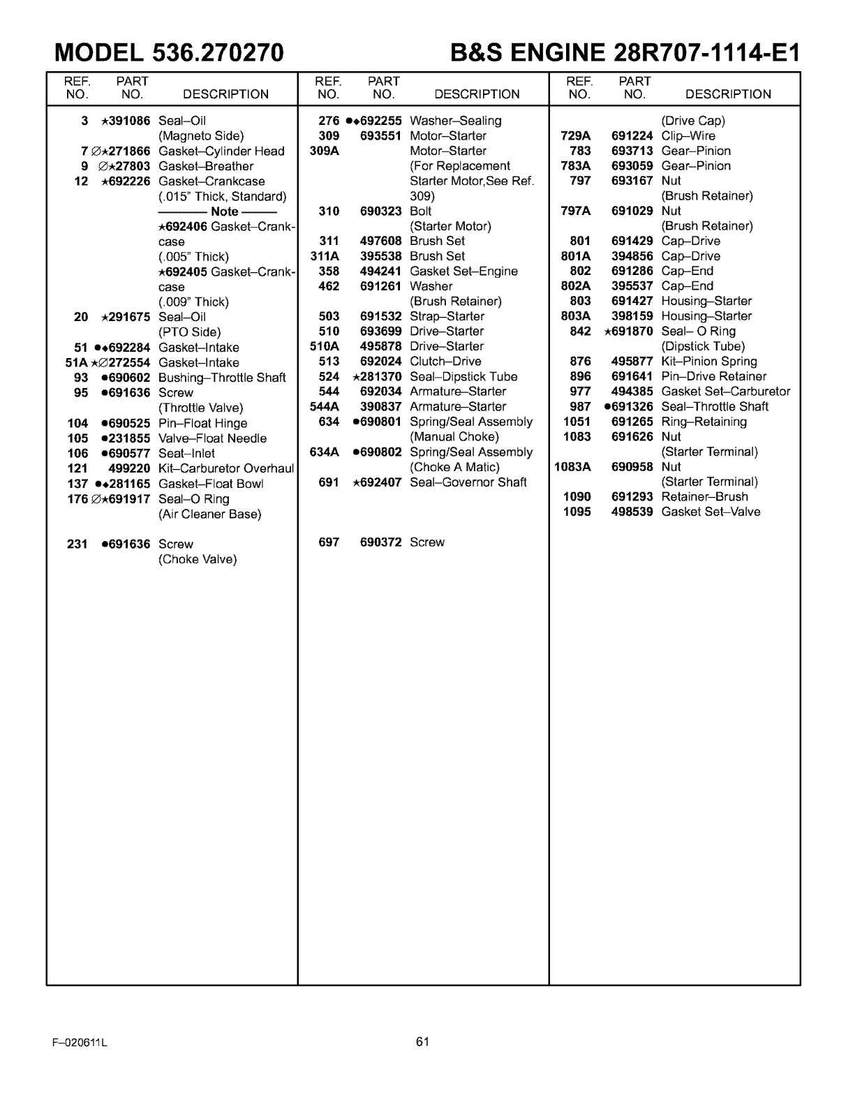
MODEL 536.270270 B&S ENGINE 28R707-1114-E1
REF. PART REF. PART REF. PART
NO. NO. DESCRIPTION NO. NO. DESCRIPTION NO. NO. DESCRIPTION
3_391086 Seal-Oil
(Magneto Side)
7_271866 Gasket-Cylinder Head
9 _27803 Gasket-Breather
12 _692226 Gasket-Crankcase
(.015" Thick, Standard)
Note-
_692406 Gasket-Crank-
case
(.005" Thick)
_692405 Gasket-Crank-
case
(.009" Thick)
20 _291675 Seat-Oil
(PTO Side)
51 e+692284 Gasket-Intake
51A _272554 Gasket-Intake
93 e690602 Bushing-Throttle Shaft
95 e691636 Screw
(Throttle Valve)
104 e690525 Pin-Float Hinge
105 e231855 Valve-Float Needle
106 e690577 Seat-Inlet
121 499220 Kit-Carburetor Overhaul
137 e+281165 Gasket-Float Bowl
176 _691917 Seat-O Ring
(Air Cleaner Base)
231 e691636 Screw
(Choke Valve)
276 e+692255 Washer-Sealing
309 693551 Motor-Starter
309A Motor-Starter
(For Replacement
Starter Motor, See Ref.
309)
310 690323 Bolt
(Starter Motor)
311 497608 Brush Set
311A 395538 Brush Set
358 494241 Gasket Set-Engine
462 691261 Washer
(Brush Retainer)
503 691532 Strap-Starter
510 693699 Drive-Starter
510A 495878 Drive-Starter
513 692024 Clutch-Drive
524 _281370 Seat-Dipstick Tube
544 692034 Armature-Starter
544A 390837 Armature-Starter
634 e690801 Spring/Seal Assembly
(Manual Choke)
634A e690802 Spring/Seal Assembly
(Choke A Matic)
691 _692407 Seat-Governor Shaft
697 690372 Screw
729A
783
783A
797
797A
801
801A
802
802A
803
803A
1051
1083
1083A
1090
1095
(Drive Cap)
691224 Clip-Wire
693713 Gear-Pinion
693059 Gear-Pinion
693167 Nut
(Brush Retainer)
691029 Nut
(Brush Retainer)
691429 Cap-Drive
394856 Cap-Drive
691286 Cap-End
395537 Cap-End
691427 Housing-Starter
398159 Housing-Starter
842 _691870 Seat- O Ring
(Dipstick Tube)
876 495877 Kit-Pinion Spring
896 691641 Pin-Drive Retainer
977 494385 Gasket Set-Carburetor
987 e691326 Seat-Throttle Shaft
691265 Ring-Retaining
691626 Nut
(Starter Terminal)
690958 Nut
(Starter Terminal)
691293 Retainer-Brush
498539 Gasket Set-Valve
F-O20611L 61
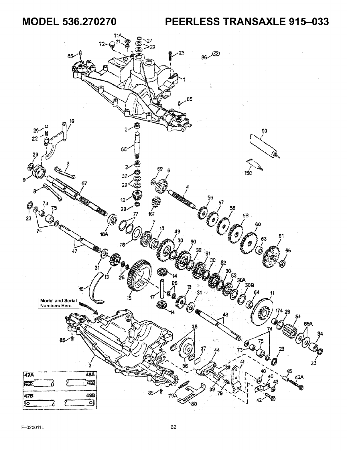
MODEL 536.270270
7_
PEERLESS TRANSAXLE 915-033
73
23
67
47
/
31
Model and Serial
Numbers Here
I,,8i
15
44
/
74
73_ 23
40
F-020611 L 62
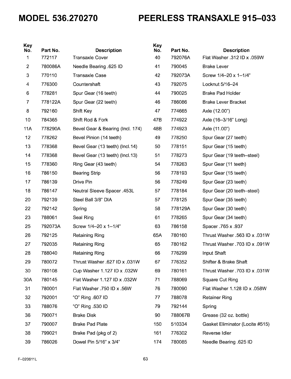
MODEL 536.270270 PEERLESS TRANSAXLE 915-033
Key
No. Part No.
1 772117
2 780086A
3 770110
4 776300
6 778281
7 778122A
8 792160
10 784365
11A 778290A
12 778262
13 778368
14 778368
15 778360
16 786150
17 786139
18 786147
20 792139
22 792142
23 788061
25 792073A
26 792125
27 792035
28 788040
29 780072
30 780108
30A 780145
31 780001
32 792001
33 788076
36 790071
37 790007
38 799021
39 786026
Description
Transaxle Cover
Needle Bearing .625 ID
Transaxle Case
Countershaft
Spur Gear (16 teeth)
Spur Gear (22 teeth)
Shift Key
Shift Rod & Fork
Bevel Gear & Bearing (Incl. 174)
Bevel Pinion (14 teeth)
Bevel Gear (13 teeth) (Incl. 14)
Bevel Gear (13 teeth) (Incl. 13)
Ring Gear (43 teeth)
Bearing Strip
Drive Pin
Neutral Sleeve Spacer .453L
Steel Ball 3/8" DIA
Spring
Seal Ring
Screw 1/4-20 x 1-1/4"
Retaining Ring
Retaining Ring
Retaining Ring
Thrust Washer .627 ID x .031W
Cup Washer 1.127 ID x .032W
Flat Washer 1.127 ID x .032W
Flat Washer .750 ID x .56W
"O" Ring .607 ID
"O" Ring .530 ID
Brake Disk
Brake Pad Plate
Brake Pad (pkg of 2)
Dowel Pin 5/16" x 3/4"
Key
No. Part No. Description
40 792076A Flat Washer .312 ID x .059W
41 790045 Brake Lever
42 792073A Screw 1/4-20 x 1-1/4"
43 792075 Locknut 5/16-24
44 790025 Brake Pad Holder
46 786086 Brake Lever Bracket
47 774665 Axle (12.00")
47B 774922 Axle (16-3/16" Long)
48B 774923 Axle (11.00")
49 778250 Spur Gear (27 teeth)
50 778151 Spur Gear (15 teeth)
51 778273 Spur Gear (19 teeth-steel)
54 778263 Spur Gear (11 teeth)
56 778193 Spur Gear (15 teeth)
56 778249 Spur Gear (23 teeth)
57 778184 Spur Gear (20 teeth-steel)
57 778125 Spur Gear (35 teeth)
58 778129A Spur Gear (30 teeth)
61 778265 Spur Gear (34 teeth)
63 786158 Spacer .765 x .937
65A 780160 Thrust Washer .563 ID x .031W
65 780162 Thrust Washer .703 ID x .091W
66 776299 Input Shaft
67 776352 Shifter & Brake Shaft
69 780161 Thrust Washer .703 ID x .031W
71 788069 Square Cut Ring
76 780090 Flat Washer 1.128 ID x .058W
77 788078 Retainer Ring
79 792144 Spring
90 788067B Grease (32 oz. bottle)
150 510334 Gasket Eliminator (Locite #515)
161 776302 Reverse Idler
174 780085 Needle Bearing .625 ID
F-020611 L 63

NOTES
F-020611 L 64

Your Home
For repair-in your home-of all major brand appliances,
lawn and garden equipment, or heating and cooling systems_
no matter who made it, no matter who sold itr
For the replacement parts, accessories and
owner's manuals that you need te do-it-yourself.
For Sears professional installation of home appliances
and items like garage door openers and water heaters,
Call an_ime, day or night (U.S,A, and Canada)
www,sear&com www,sears;ca
Our Home:
For repair of car_-in items like vacuums, lawn equipment,
and electronics, call or go on.line for the location of your nearest
Sears Parts & Repair Center.
Calf aniline, day or night (U,S,A, only)
www,sears.com
To purchase a protection agreement on a product semiced by Sears:
1-800-827-6655 (U,S,A.) 1-800-361-6665 (Canada)
Para pedir sewicio de reparaeiCn
a domiciiio, y para ordenar piezas:
(1,888,784,6427)
Au Canada pour service en fran:£ais:
(1-800,533-6937)
www.sea_s,o_
® Reg[st_d Trademark /T_ader_'_Ark/ Sew ce Mark dSea[_ Roebuck and _,
® Ma_a Beg s#ad_ Z _Marco de E_bt'i_ fs Marco de 8err c e de Sea_s, Roebuck an_ Ce
Marque de comme[ce /_ Marque d_pesCe de So:ors Roebuck and Co, ',#Sears Reebuckand C&
