Craftsman 536270281 User Manual TRACTOR, LAWN Manuals And Guides L0312272
CRAFTSMAN Lawn, Riding Mower Rear Engine Manual L0312272 CRAFTSMAN Lawn, Riding Mower Rear Engine Owner's Manual, CRAFTSMAN Lawn, Riding Mower Rear Engine installation guides
User Manual: Craftsman 536270281 536270281 CRAFTSMAN TRACTOR, LAWN - Manuals and Guides View the owners manual for your CRAFTSMAN TRACTOR, LAWN #536270281. Home:Lawn & Garden Parts:Craftsman Parts:Craftsman TRACTOR, LAWN Manual
Open the PDF directly: View PDF ![]() .
.
Page Count: 104 [warning: Documents this large are best viewed by clicking the View PDF Link!]
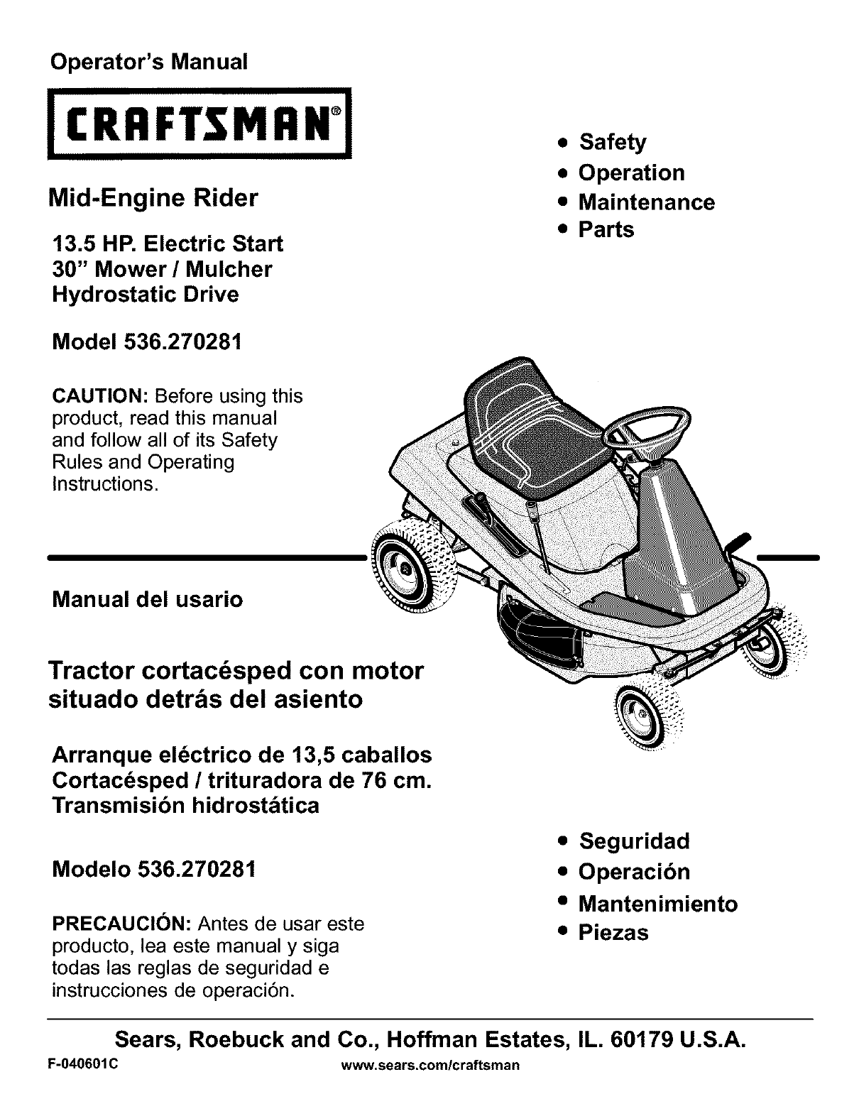
Operator's Manual
(RRFTSMR
Mid-Engine Rider
13.5 HP. Electric Start
30" Mower/Mulcher
Hydrostatic Drive
•Safety
•Operation
•Maintenance
•Parts
Model 536.270281
CAUTION: Before using this
product, read this manual
and follow all of its Safety
Rules and Operating
Instructions.
Manual del usario
Tractor cortacdsped con motor
situado detr_s del asiento
Arranque el_ctrico de 13,5 caballos
Cortac_sped /trituradora de 76 cm.
Transmisibn hidrostdtica
Modelo 536.270281
PRECAUCI6N: Antes de usar este
producto, lea este manual y siga
todas las reglas de seguridad e
instrucciones de operaci6n.
•Seguridad
• Operacibn
•Mantenimiento
•Piezas
Sears, Roebuck and Co., Hoffman Estates, IL. 60179 U.S.A.
F-040601 C www.sears.com/craftsman

TABLE OF CONTENTS
WARRANTY .................................... 2 MAINTENANCE ................................ 19
PRODUCT SPECIFICATIONS .................... 3 SERVICE AND ADJUSTMENT .................... 25
SAFETY RULES ................................ 4 TROUBLE SHOOTING CHART ................... 34
PREPARATION ................................. 7 SLOPE GUIDE .................................. 37
OPERATION ................................... 10 REPAIR PARTS ................................. 38
LIMITED WARRANTY ON CRAFTSMAN RIDING EQUIPMENT
For two (2) years from the date of purchase, if this Craftsman Riding Equipment is maintained, lubricated and tuned up
according to the instructions in the owner's manual, Sears will repair or replace free of charge any parts that are found to be
defective in material or workmanship according to the guidelines of coverage listed below.
Sears willalso providefree labor for these applicable warranted parts for the two full years. During the first 30 days of purchase,
there will be no charges to service the product at your home for issues covered by this warranty. (See exclusions below).
For your convenience, IN HOME warranty service will still be available after the first 30 days of purchase, but a trip charge will
apply. This charge will be waived if the Craftsman product is dropped off at an authorized Sears location. For the nearest
authorized Sears location, please call 1-800-4-MY-HOME®. This warranty applies only while this product is within the United
States.
This Warranty does not cover:
• Expendable items which become worn during normal use, including but not limited to blades, spark plugs, air cleaners,
belts, and oil filters.
• Standard Maintenance Servicing, oil changes, or tune-ups
• Tire replacement or repair caused by punctures from outside objects, such as nails, thorns, stumps or glass.
• Repairs necessary because of operator abuse, including but not limited to, damage caused by towing objects beyond the
capability of the riding equipment, impacting objects that bend the frame or crankshaft, or over-speeding the engine.
• Repairs necessary because of operator negligence, including but not limited to, electrical and mechanical damage caused
by improper storage, failure to use the proper grade and amount of engine oil, failure to keep the deck clear of flammable
debris, or failure to maintain the equipment according to the instructions contained in the owner's manual.
• Engine (fuel system) cleaning or repairs caused by fuel determined to be contaminated or oxidized (stale). In general, fuel
should be used within 30 days of its purchase date.
• Normal deterioration and wear of the exterior finishes, or product label replacement.
• Riding equipment used for commercial or rental purposes.
LIMITED WARRANTY ON BATTERY
For ninety (90) days from date of purchase, if any battery included with this riding equipment proves defective in material or
workmanship and our testing determines the battery will not hold acharge, Sears will replace the battery at no charge. During
the first 30 days of purchase, there will be no charges to replace the battery at your home. After the first 30 days, for your conve-
nience, IN-HOME warranty service will still be available but atrip charge will apply. This charge will be waived if the Craftsman
product is dropped off at an authorized Sears location. For the nearest authorized Sears location, please call 1-SOO-4-MY-
HOME®. This Warranty applies only while this product is within the United States. This warranty gives you specific legal rights,
and you may also have other rights, which vary, from state to state.
Sears, Roebuck and Co., Dept. 817WA, Hoffman Estates, IL 60179
F-040601C 2
Congratulations on your purchase of a Craftsman Mid-Engine
Rider. It has been designed, engineered and manufactured to
give you the best possible dependability and performance.
If you experience any problems you cannot easily remedy, please
see your nearest Sears Service Center. We have competent, well
trained technicians and the proper tools to service or repair this
unit.
Please read and keep this manual. The instructions will enable
you to assemble and maintain your unit properly. Always observe
the "Safety Rules".
Craftsman Mid-Engine Rider
Record in the space below the serial number and the date
of purchase of this unit.
The model number and serial number are found on a decal
attached to the unit.
Model Number: 536.270281
Serial Number:
Date of Purchase:
Keep these numbers for future reference.
PRODUCT SPECIFICATIONS
Engine .................. 13.5 HR
Charging System ......... 3 amperes at 3600 rpm
Fuel Tank Size ........... 1.1 gallon
Type of Fuel ............. Unleaded Regular
Oil Capacity .............. 48 ounces (3 pints)
Oil Type ................. Above 32 degrees SAE 30
.......................... Below 32 degrees SAE 5W30
Spark Plug (Gap 0.030") .. Champion RJ4C
Tire Air Pressure ......... Front 22 psi (See tire sidewall)
Tire Air Pressure ......... Rear 14 psi (See tire sidewall)
Drive System ............ Hydrostatic
Ground Speed Range ..... Forward 5.0 mph
.......................... Reverse 2.5 mph
Tilt Seat ................. Access to engine and battery.
Mower Housing .......... Floating suspension, one blade.
Cutting Height ........... 6 positions from 1_/2to 4 inches.
Blade Nut Torque ......... 30 foot-pounds (ft*lbs)
REPAIR PROTECTION AGREEMENT
A Repair Protection Agreement is available on this unit. See the
nearest Sears Store for information.
Engine Exhaust, some of its constituents, and
certain vehicle components contain or emit
chemicals known to the State of California to
cause cancer and birth defects or other repro-
ductive harm.
Battery posts, terminals and related accesso-
ries contain lead and lead compounds, chemi-
cals known to the State of California to cause
cancer and birth defects or other reproductive
harm. WASH HANDS AFTER HANDLING.
NOTE: This unit is equipped with an internal combustion engine
and must not be used on or near any unimproved forest-covered,
brush-covered or grass-covered land unless the engine's exhaust
system is equipped with a spark arrester meeting applicable local
or state laws (if any). If a spark arrester is used, it must be
maintained in effective working order by the operator.
In the State of California, the above is required by law (Section
4442 of the California Public Resources Code). Other states may
have similar laws. Federal laws apply on federal lands. See a
Sears Service Center for a spark arrester for the muffler.
In some areas, local law requires the use of a resistor spark plug
to control the ignition signals. See a Sears Service Center for a
resistor spark plug for the engine.
NOTE: Actual sustained horsepower will likely be lower due
to operating limitations and environmental factors.
F-040601C 3
SAFETY RULES
Safe Operation Practices for Ride*on Mowers
_ARNING: This cufting machine is capable of amputating hands and feet and throwing objects. Failure to observe the
following safety instructions could result in serious injury or death.
I. General operation
1. Read, understand and follow all instructions in the Instruction
Book, on the machine, the engine and with any attachments be-
fore starting.
2. Only allow responsible adults, who are familiar with the instruc-
tions, to operate the machine.
3. Clear the area of objects such as rocks, toys, wire, etc., which
could be picked up and thrown by the blade.
4. Be sure the area is clear of other people before mowing. Stop
the machine if anyone enters the area.
5. Never carry passengers.
6. Turn off power to the blades or any attachments before backing
up. Do not mow in reverse unless absolutely necessary. Always DO
look down and behind before and while backing. 1.
7. Be aware of the mower discharge direction and do not point it 2.
at anyone. Do not operate the mower without either the entire 3.
grass bagger or the mower guard in place.
8. Slow down before turning. 4.
9. Never leave a machine unattended with the engine running. Al-
ways turn off the blade(s), set the parking brake, stop the en- 5.
gine and remove the key before dismounting.
10. Turn off power to attachment(s) when transporting or not in use. 6.
Turn off the blade(s) when not mowing.
11. Stop the engine before removing the grass bagger or unclog- 7.
ging the chute.
12. Mow only in daylight or good artificial light. DO NOT
13. Do not operate the machine while under the influence of alcohol 1.
or drugs or when very tired.
14. Watch for traffic when operating near or crossing roadways. 2.
15. Use extra caution when loading or unloading the machine into
a trailer or truck.
16. Disengage all attachment clutches and shift into Neutral before
attempting to start the engine.
17. Always wear goggles, safety glasses, or an eye shield when
you operate the unit to protect your eyes from foreign objects
that can be thrown from the unit. Always wear eye protection
when you make an adjustment or repair to the machine.
18. Use care when pulling loads or using heavy equipment.
a. Use only approved drawbar hitch points.
b. Limit loads to those you can safely control.
c. Do not turn sharply. Use care when backing.
d. Use counterweights or wheel weights when suggested in the
instruction Book.
19. Do not operate this machine if you are taking drugs or otber me-
dication which can cause drowsiness or affect your ability to ol3.
erate this machine.
20. Do not use this machine if you are mentally or physically unable
to operate this machine safely.
F-040601C
21. Data indicates that operators, age 60 years and above, are in-
volved in a large percentage of riding mower related injuries.
These operators should evaluate their ability to operate a riding
mower safely enough to protect themselves and others from
serious injury.
II. Slope operation
Slopes and rough terrain are major factors related to loss-of-
control and tip-over accidents, which can result in severe inju*
ry or death. ALL slopes require extra caution. If you cannot
back up the slope or if you feel uneasy on the slope, do not mow
it. See the "Slope Guide" in the back of this book to check for
safe operation.
Mow up and down slopes, not across.
Remove obstacles such as rocks, limbs, etc...
Watch for holes, ruts or bumps. Uneven terrain could overturn
the machine. Tall grass can hide obstacles.
Follow the manufacturer's recommendations for wheel weights
or counterweights to improve stability.
Use extra care with grass baggers or other attachments, they
can change the stability of the machine.
Keep all movement on the slopes slow and gradual. Do not
make sudden changes in speed or direction.
Avoid starting or stopping on a slope. If tires lose traction, turn
off the blades and proceed slowly straight down the slope.
3,
4.
5.
Do not turn on slopes unless absolutely necessary, then only
turn slowly and gradually downhill, if possible.
Do not mow drop-off's, ditches or embankments. A wheel over
the edge or an edge caving in could cause a sudden overturn
and an injury or death.
Do not mow on wet grass. Reduced traction could cause slid-
ing.
Do not try to stabilize the machine by putting your foot on the
ground.
Do not use a grass bagger or other rear mounted accessories
on steep slopes (greater than 10 degrees).
III. Children
Tragic accidents can occur if the operator is not alert to the
presence of children. Children are often attracted to the ma*
chine and the mowing activity. NEVER assume that children
will remain where you last saw them.
1. Keep children out of the mowing area and in the watchful care
of another responsible adult.
2. Be alert and turn the engine off if children enter the area.
3. Before and when backing, look behind and down for small
children.
SAFETY RULES
4.
5.
6.
Never carry children or any passengers, even with the blades 6,
off, They may fall off and be seriously injured or interfere with
the safe operation of the machine, 7,
Never allow children to operate the machine. Instruct children
in the potential dangers of the machine.
Use extra care when approaching blind corners, shrubs, trees
or other objects that may obscure vision.
IV. Service
1.
2.
3.
4.
5.
Use extra care when handling gasoline and other fuels. Fuels
are flammable and the vapors are explosive.
a. Use only an approved container.
b. Never remove the gas cap or add fuel with the engine run-
ning. Allow the engine to cool for several minutes before refuel-
ing. Do not smoke.
c. Never refuel the machine indoors.
d. Never store the machine with fuel in the tank or fuel contain-
er inside where there is an open flame, such as a water heaten
Never start or run the engine inside a closed area.
Keep all nuts and bolts, especially the blade attachment nuts
tight. Frequently check the blade(s) for wear or damage such
as cracks and nicks. A blade that is bent or damaged must be
immediately replaced with an original equipment blade from an
authorized service dealer. For safety, replace the blade every
two years. Keep the equipment in good condition.
Never tamper with the safety devices, Check their proper oper-
ation regularly.
To reduce fire hazards, keep the machine free of grass, leaves
or other debris build-up. Clean up oil or fuel spills. Allow the ma-
chine to cool before storing.
8,
Stop and inspect the equipment if you strike an object. Repair,
if necessary, before restarting.
Never make adjustments or repairs with the engine running.
The carburetor can be adjusted with the engine running. Do not
change the engine governor settings or over-speed the en-
gine.
Grass bagger components are subject to wear, damage and
deterioration, which could expose moving parts or allow objects
to be thrown. For storage, always make sure the grass bag is
empty. Frequently check components and replace with man-
ufacturer's recommended parts when necessary.
9. Mower blade(s) are sharp and can cut. Wrap the blade(s) or
wear gloves and use extra caution when servicing them or the
blade housing area.
10. Check the brake operation frequently. Adjust and service as re-
quired.
11. Wait for all movement to stop before servicing any part of the
unit.
RESPONSIBILITY OF THE OWNER
Environmental Awareness
Do not fill the engine's fuel tank completely full.
Drain fuel for off-season storage.
Use only unleaded gasoline.
Service the air cleaner regularly,
Change oil regularly. Use 30W oil in summer,
Tune-up the engine regularly.
Keep equipment in efficient operating condition,
Dispose of used engine oil properly.
_lb Look for this symbol to indicate important safety
precautions. This symbol indicates: "Attention!
Become Alert! Your Safety Is At Risk."
F-040601C 5
SAFETY RULES
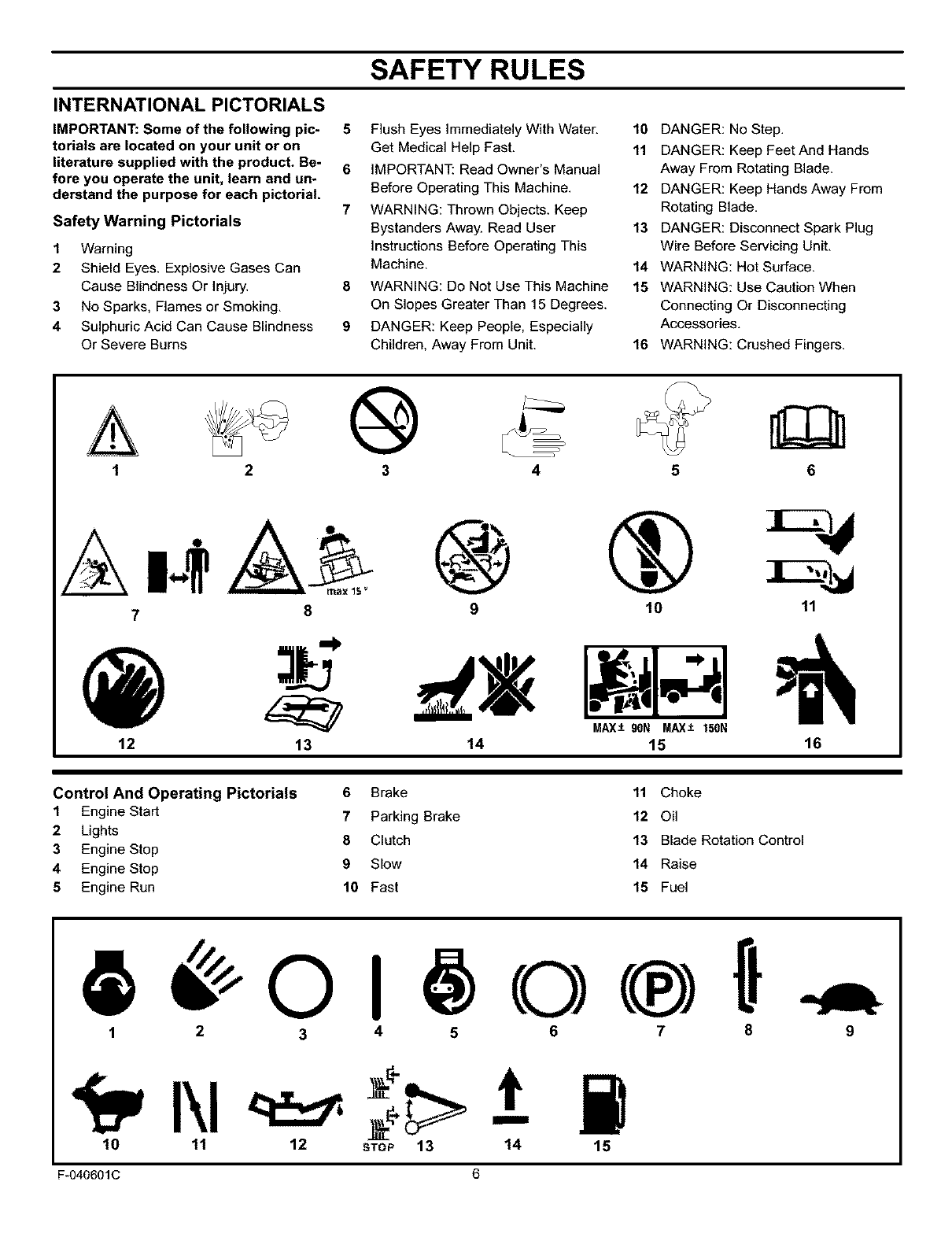
INTERNATIONAL PICTORIALS
IMPORTANT: Some of the following pic-
torials are located on your unit or on
literature supplied with the product. Be-
fore you operate the unit, learn and un-
derstand the purpose for each pictorial.
Safety Warning Pictorials
1Warning
2Shield Eyes. Explosive Gases Can
Cause Blindness Or injury.
3No Sparks, Flames or Smoking.
4 Sulphuric Acid Can Cause Blindness
Or Severe Burns
5 Flush Eyes Immediately With Water.
Get Medical Help Fast.
6 IMPORTANT: Read Owner's Manual
Before Operating This Machine.
7WARNING: Thrown Objects. Keep
Bystanders Away. Read User
Instructions Before Operating This
Machine.
8 WARNING: Do Not Use This Machine
On Slopes Greater Than 15 Degrees.
9DANGER: Keep People, Especially
Children, Away From Unit.
10 DANGER: No Step.
11 DANGER: Keep Feet And Hands
Away From Rotating Blade.
12 DANGER: Keep Hands Away From
Rotating Blade.
13 DANGER: Disconnect Spark Plug
Wire Before Servicing Unit.
14 WARNING: Hot Surface.
15 WARNING: Use Caution When
Connecting Or Disconnecting
Accessories.
16 WARNING: Crushed Fingers.
A
1®46
12
9 10 11
I 1 ,1
13 14 15 16
Control And Operating Pictorials 6 Brake 11 Choke
1Engine Start 7Parking Brake 12 Oil
2 Lights 8 Clutch 13 Blade Rotation Control
3Engine Stop
4 Engine Stop 9Slow 14 Raise
5Engine Run 10 Fast 15 Fuel
1 2 3 4 5 6 7 8
10 11 12 stop 13 14 15
9
F-040601C 6
PREPARATION
PREPARATION 1,
2,
3,
4,
Read and fellow the preparation instructions for your mower. All
fasteners are in the parts bag. Do not discard any parts or material
until the unit is assembled.
NOTE: In this instruction book, left and right describe the loca-
tion of a part from the viewpoint of someone setting in the oper-
ator's seat.
_lb WARNING: Before doing any preparation or mainte*
nance to the mower, remove the wire from the spark
plug.
HOW TO REMOVE FROM THE CARTON
To remove the unit from the carton, follow the instructions below.
Locate the two tear tabs at the top of the carton.
Pull the tear tape no more than twelve inches at a time.
Re-grasp the tear tape next to the carton and pull again.
One the tear tape has been completely removed from both
ends, remove the top wood and set aside.
5. Repeat the process on the tear tabs at the bottom of the carton.
6. Set the panels aside.
7. Move the shift lever to the neutral (N) position.
NOTE: See the Operation section, page 10, for the location
of the controls.
8. If the parking brake is engaged, completely depress the
clutch/brake pedal to release the brake.
9. Move the lift lever to the highest position.
CAUTION: Check the bottom of the carton for staples.
Remove any staples that are in the path of the tires.
10. Remove the mower from the shipping skid.
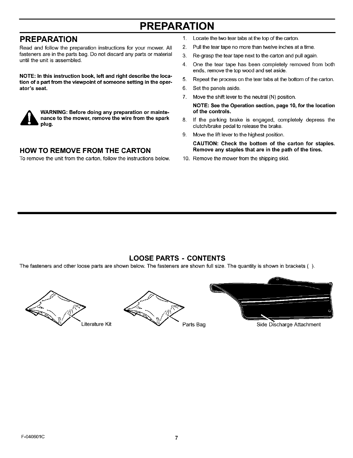
LOOSE PARTS -CONTENTS
The fasteners and other loose parts are shown below, The fasteners are shown full size, The quantity is shown in brackets ().
Literature Kit Parts Bag Side Discharge Attachment
F-040601C 7
PREPARATION
MAINTENANCE FREE BATTERY 4.
IMPORTANT: Before you attach the battery cables to the
battery, check the battery date. The battery date tells if the
battery must be charged.
1. Raise the seat support and secure in the UP position with the
seat support rod.
2.
3.
4.
Check the top of the battery for the location of the battery date
(Figure 1).
If the battery is put into service before the battery date, the
battery cables can be attached without charging the battery.
See "How To Install The Battery Cables".
If the battery is put into service after the battery date, the
battery must be charged. See "How To Charge The
Maintenance Free Battery".
HOW TO CHARGE
THE MAINTENANCE FREE BATTERY
_hlL WARNING: When you charge the battery, do not
smoke. Keep the battery away from any sparks. The
fumes from the battery acid can cause an explosion.
1. To disconnect the battery retainer from the battery tray, push
in on the lower end of the battery retainer.
2. Remove the battery from the right side of the unit.
3. Remove the protective caps from the battery terminals.
5,
Use a 12 volt battery charger to charge the battery. Charge at
a rate of 6 amperes for one hour. If you do not have abattery
charger, have a Sears or other qualified Service Center charge
the battery.
Install the battery and secure with the battery retainer. Make
sure the positive (+) terminal is on the right side.
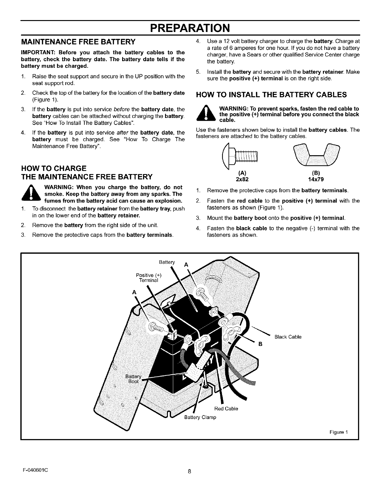
HOW TO INSTALL THE BATTERY CABLES
_lb WARNING: To prevent sparks, fasten the red cable to
the positive (+) terminal before you connect the black
cable.
Use the fasteners shown below to install the battery cables. The
fasteners are attached to the battery cables.
(A)
2x82 (B)
14x79
1. Remove the protective caps from the battery terminals.
2. Fasten the red cable to the positive (+) terminal with the
fasteners as shown (Figure 1).
3. Mount the battery boot onto the positive (+) terminal.
4. Fasten the black cable to the negative (-) terminal with the
fasteners as shown.
Battery A
Positive (+)
Terminal
A \
Red Cable
Battery Clamp
Black Cable
B
Figure 1
F-040601C 8
PREPARATION
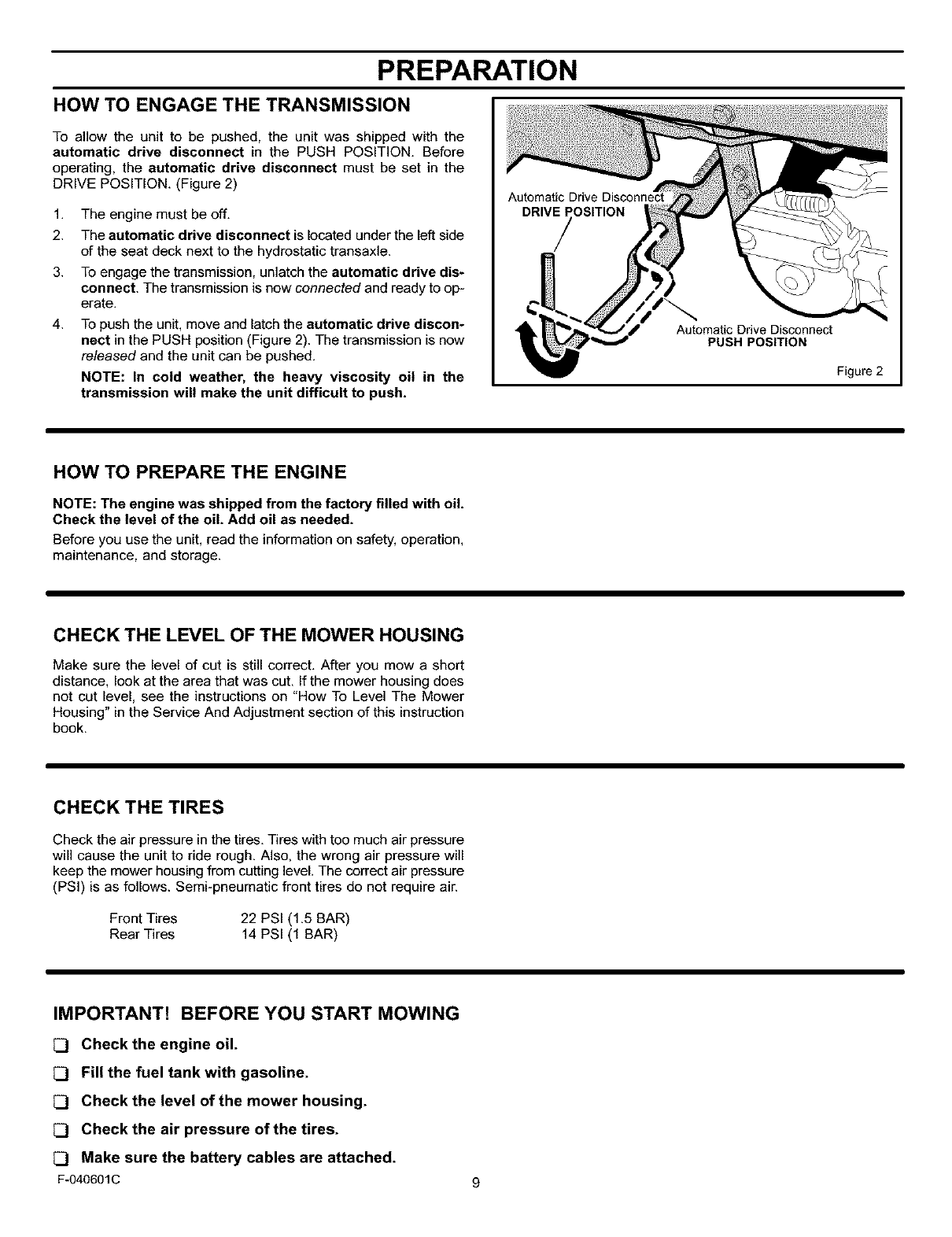
HOW TO ENGAGE THE TRANSMISSION
To allow the unit to be pushed, the unit was shipped with the
automatic drive disconnect in the PUSH POSITION. Before
operating, the automatic drive disconnect must be set in the
DRIVE POSITION. (Figure 2)
1. The engine must be off.
2. The automatic drive disconnect is located under the left side
of the seat deck next to the hydrostatic transaxle.
3. To engage the transmission, unlatch the automatic drive dis-
connect. The transmission is now connected and ready to op-
erate.
4. To push the unit. move and latch the automatic drive discon-
nect in the PUSH position (Figure 2). The transmission is now
released and the unit can be pushed.
NOTE: In cold weather, the heavy viscosity oil in the
transmission will make the unit difficult to push.
Automatic Drive Disconnect
DRIVE POSITION
/
Automatic Drive Disconnect
PUSH POSITION
Figure 2
HOW TO PREPARE THE ENGINE
NOTE: The engine was shipped from the factory filled with oil.
Check the level of the oil. Add oil as needed.
Before you use the unit, read the information on safety, operation.
maintenance, and storage.
CHECK THE LEVEL OF THE MOWER HOUSING
Make sure the level of cut is still correct. After you mow a short
distance, look at the area that was cut. If the mower housing does
not cut level, see the instructions on "How To Level The Mower
Housing" in the Service And Adjustment section of this instruction
book.
CHECK THE TIRES
Check the air pressure in the tires. Tires with too much air pressure
will cause the unit to ride rough. Also, the wrong air pressure will
keep the mower housing from cutting level. The correct air pressure
(PSI) is as follows. Semi-pneumatic front tires do not require air.
Front Tires 22 PSI (1.5 BAR)
Rear Tires 14 PSI (1 BAR)
IMPORTANT! BEFORE YOU START MOWING
[_ Check the engine oil.
Fill the fuel tank with gasoline.
Check the level of the mower housing.
Check the air pressure of the tires.
Make sure the battery cables are attached.
F-O40601C
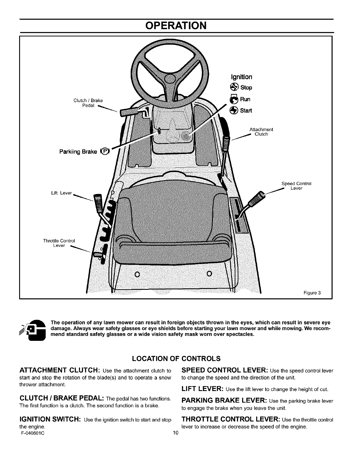
OPERATION
Clutch /Brake
Pedal
Ignition
_) Stop
_Run
Start
Attachment
Clutch
Parkiing Brake
Lift Lever
Speed Control
Lever
Throttle Control
Lever
Figure 3
j_ The operation of any lawn mower can result in foreign objects thrown in the eyes, which can result in severe eye
damage. Always wear safety glasses or eye shields before starting your lawn mower and while mowing. We recom*
mend standard safety glasses or a wide vision safety mask worn over spectacles.
LOCATION OF CONTROLS
ATTACHMENT CLUTCH: Use the attachment clutch to
start and stop the rotation of the blade(s) and to operate a snow
thrower attachment.
CLUTCH /BRAKE PEDAL: The pedal has two functions.
The first function is a clutch. The second function is a brake.
SPEED CONTROL LEVER: Use the speed control lever
to change the speed and the direction of the unit.
LIFT LEVER: use the lift lever to change the height of cut,
PARKING BRAKE LEVER: use the parking brake lever
to engage the brake when you leave the unit.
IGNITION SWITCH: Use the ignition switch to start and stop THROTTLE CONTROL LEVER: Use the throttle control
the engine, lever to increase or decrease the speed of the engine.
F-040601C 10
OPERATION
HOW TO STOP THE UNIT
The electrical system has an operator presence system that
includes a sensor switch mounted in the seat. These components
tell the electrical system if the operator is sitting on the seat. This
system will stop the engine when the operator leaves the seat. For
your protection, always make sure this system operates correctly.
1. Completely push the clutch/brake pedal forward to stop the
unit. Keep your foot on the pedal.
2. Move the attachment clutch to the DISENGAGE position.
3. Move the speed control lever to the NEUTRAL position.
4. Set the parking brake.
_lb ARNING: Make sure the parking brake will hold the
unit.
5, Move the throttle control to the SLOW position,
6, To stop the engine, turn the ignition key to the OFF position, Re-
move the key,
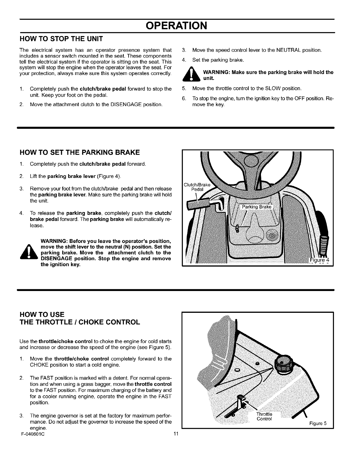
HOW TO SET THE PARKING BRAKE
1. Completely push the clutchlbrake pedal forward.
2. Lift the parking brake lever (Figure 4).
3. Remove your foot from the clutch/brake pedal and then release
the parking brake lever, Make sure the parking brake will hold
the unit.
4. To release the parking brake, completely push the clutch/
brake pedal forward. The parking brake will automatically re-
lease.
WARNING: Before you leave the operator's position,
move the shift lever to the neutral (N) position. Set the
parking brake. Move the attachment clutch to the
DISENGAGE position. Stop the engine and remove
the ignition key.
Clutch/Brake
Pedal
HOW TO USE
THE THROTTLE /CHOKE CONTROL
Use the throttle/choke control to choke the engine for cold starts
and increase or decrease the speed of the engine (see Figure 5).
1. Move the throttle/choke control completely forward to the
CHOKE position to start a cold engine.
2. The FAST position is marked with a detent. For normal opera-
tion and when using a grass bagger, move the throttle control
to the FAST position. For maximum charging of the battery and
for a cooler running engine, operate the engine in the FAST
position.
3. The engine governor is set at the factory for maximum perfor-
mance. Do not adjust the governor to increase the speed of the
engine.
F-O40601C 11
Throttle
Control
Figure 5
OPERATION
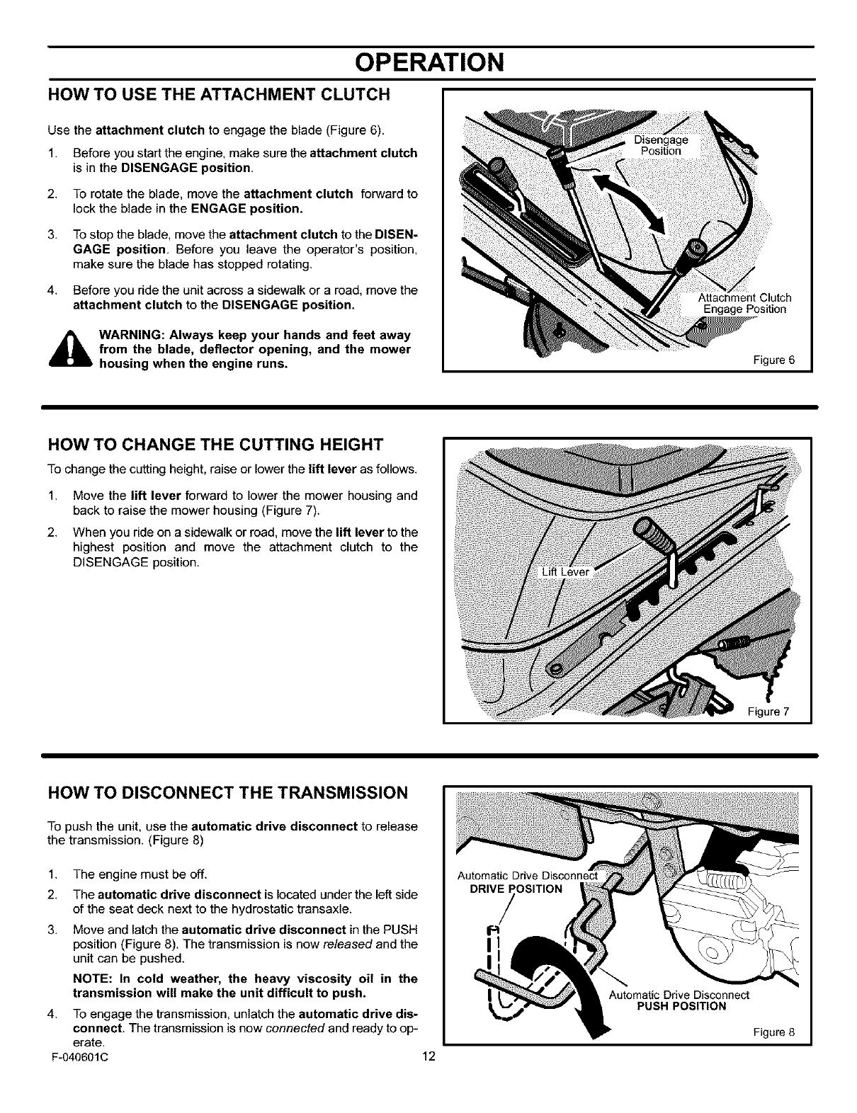
HOW TO USE THE ATTACHMENT CLUTCH
Use the attachment clutch to engage the blade (Figure 6).
1. Before you start the engine, make sure the attachment clutch
is in the DISENGAGE position.
2. To rotate the blade, move the attachment clutch forward to
lock the blade in the ENGAGE position.
3. To stop the blade, move the attachment clutch to the DISEN-
GAGE position. Before you leave the operator's position.
make sure the blade has stopped rotating.
4. Before you ride the unit across a sidewalk or a road. move the
attachment clutch to the DISENGAGE position.
_b WARNING: Always keep your hands and feet away
from the blade, deflector opening, and the mower
housing when the engine runs.
Attachment Clutch
Engage Position
Figure 6
HOW TO CHANGE THE CUTTING HEIGHT
To change the cutting height, raise or lower the lift lever as follows.
1.
2.
Move the lift lever forward to lower the mower housing and
back to raise the mower housing (Figure 7).
When you ride on a sidewalk or road, move the lift lever to the
highest position and move the attachment clutch to the
DISENGAGE position.
Figure 7
HOW TO DISCONNECT THE TRANSMISSION
To push the unit, use the automatic drive disconnect to release
the transmission. (Figure 8)
F-040601C
1. The engine must be off.
2. The automatic drive disconnect is located under the left side
of the seat deck next to the hydrostatic transaxle.
3. Move and latch the automatic drive disconnect in the PUSH
position (Figure 8). The transmission is now released and the
unit can be pushed.
NOTE: In cold weather, the heavy viscosity oil in the
transmission will make the unit difficult to push.
4. To engage the transmission, unlatch the automatic drive dis-
connect. The transmission is now connected and ready to op-
erate. 12
Automatic Drive Disconnect
DRIVE POSITION
/
Automatic Drive Disconnect
PUSH POSITION
Figure 8
OPERATION
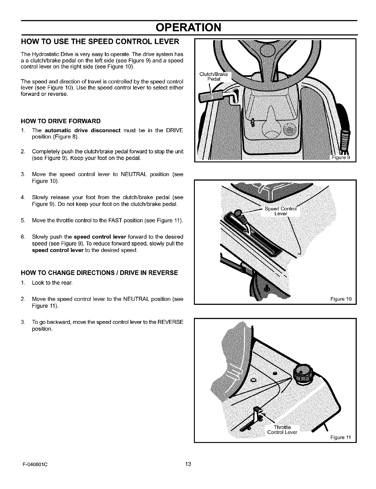
HOW TO USE THE SPEED CONTROL LEVER
The Hydrostatic Drive is very easy to operate. The drive system has
a a clutch/brake pedal on the left side (see Figure 9) and a speed
control lever on the right side (see Figure 10).
The speed and direction of travel is controlled by the speed control
lever (see Figure 10). Use the speed control lever to select either
forward or reverse.
HOW TO DRIVE FORWARD
1. The automatic drive disconnect must be in the DRIVE
position (Figure 8).
2. Completely push the clutch/brake pedal forward to stop the unit
(see Figure 9). Keep your foot on the pedal.
Clutch/Brake
Pedal
Figure 9
3. Move the speed control lever to NEUTRAL position (see
Figure 10).
4. Slowly release your foot from the clutch/brake pedal (see
Figure 9). Do not keep your foot on the clutch/brake pedal.
5. Move the throttle control to the FAST position (see Figure 11).
6. Slowly push the speed control lever forward to the desired
speed (see Figure 9). To reduce forward speed, slowly pull the
speed control lever to the desired speed.
HOW TO CHANGE DIRECTIONS /DRIVE IN REVERSE
1. Look to the rear.
2. Move the speed control lever to the NEUTRAL position (see
Figure 11).
Figure 10
3. To go backward, move the speed control lever to the REVERSE
position.
Throttle
Figure 11
F-040601C 13
OPERATION
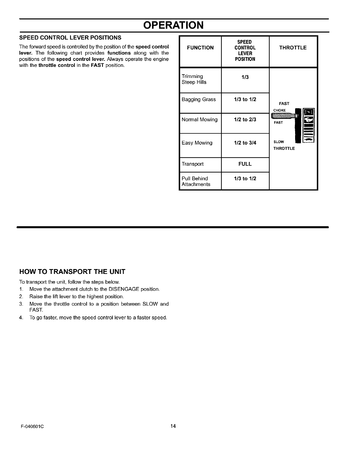
SPEED CONTROL LEVER POSITIONS
The forward speed is controlled by the position of the speed control
lever. The following chart provides functions along with the
positions of the speed control lever. Always operate the engine
with the throttle control in the FAST position.
SPEED
FUNCTION CONTROL
LEVER
POSITION
Trimming 1/3
Steep Hills
Bagging Grass 1/3 to 1/2
Normal Mowing 1/2 to 2/3
Easy Mowing 1/2 to 3/4
Transport FULL
Pull Behind 1/3 to 1/2
Attachments
THROTTLE
FAST
CHOKE
FAST
SLOW
THROTTLE
HOW TO TRANSPORT THE UNIT
To transport the unit, follow the steps below.
1. Move the attachment clutch to the DISENGAGE position.
2. Raise the lift lever to the highest position.
3. Move the throttle control to a position between SLOW and
FAST.
4. To go faster, move the speed control lever to a faster speed.
F-040601C 14
OPERATION
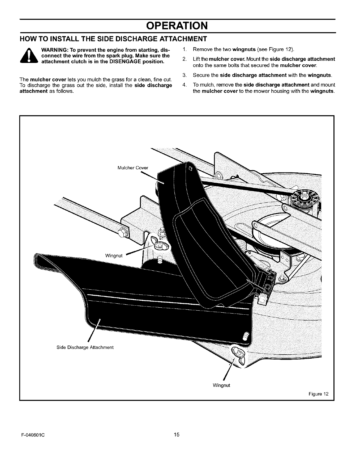
HOW TO INSTALL THE SIDE DISCHARGE ATTACHMENT
WARNING: To prevent the engine from starting, dis*
connect the wire from the spark plug. Make sure the
attachment clutch is in the DISENGAGE position.
1. Remove the two wingnuts (see Figure 12).
2. Lift the mulcher cover. Mount the side discharge attachment
onto the same bolts that secured the mulcher cover.
The mulcher cover lets you mulch the grass for a clean, fine cut.
To discharge the grass out the side, install the side discharge
attachment as follows.
3, Secure the side discharge attachment with the wingnuts,
4, To mulch, remove the side discharge attachment and mount
the mulcher cover to the mower housing with the wingnuts,
Mulcher Cover
Side Discharge Attachment
Wingnut
Figure 12
F-040601C 15
OPERATION
BEFORE STARTING THE ENGINE
CHECK THE OIL
NOTE: The engine was shipped from the factory filled with SAE
30 weight oil. Check the level of the oil. Add oil as needed.
1. Make sure the unit is level.
NOTE: Do not check the level of the oil while the engine
runs.
2. Clean the area around the dipstick. Remove the dipstick. Wipe
the oil from the dipstick.
3. Insert the dipstick into the oil fill tube. Turn the dipstick clock-
wise until it is tight. Remove the dipstick. Check the oil level on
the dipstick. The oil level must reach the FULL mark on the
dipstick.
4. If necessary, add oil until the oil reaches the FULL mark on the
dipstick. The quantity of oil needed from ADD to FULL is shown
on the dipstick. Do not add too much oil.
ADD GASOLINE
WARNING: Always use a safety gasoline container.
Do not smoke when adding gasoline to the fuel tank.
Do not add gasoline when you are inside an enclo-
sure. Before you add gasoline, stop the engine and
let the engine cool for several minutes.
Fill the fuel tank with regular Fuel Tank
unleaded gasoline. Do not use F_II_
premium unleaded gasoline.
Make sure the gasoline is fresh
and clean. Leaded gasoline will
increase deposits and shorten
the life of the valves.
CAUTION: Alcohol blended fuels (called gasohol or using
ethanol or methanol) can attract moisture which leads to
separation and formation of acids during storage. Acidic gas
can damage the fuel system of an engine while in storage.
To prevent engine problems with the fuel system, empty the fuel
system before storage of 30 days or longer as follows.
1, Drain the fuel tank,
2,
3,
Start the engine. Let the engine run until the fuel lines and the
carburetor are empty.
After storage, make sure you use fresh fuel. See the storage
instructions for additional information.
4. Never use engine cleaner or carburetor cleaner in the fuel tank
or permanent damage can occun
CARBURETOR
The factory settings for the carburetor are for most conditions. If the
engine is operated under the following conditions, you can adjust
the carburetor mixture. See "How To Adjust The Carburetor" in the
Service And Adjustment section.
1. The engine has a loss of power or does not run smooth.
2. A change from summer to winter operation.
3. A 40 degree change in the operation temperature. The carbure-
tor was adjusted at 80 degrees at the factory.
4. The engine is operated above 4,000 feet.
HOW TO START THE ENGINE
WARNING: The electrical system has an operator 4,
presence system that includes a sensor switch
mounted in the seat. These components tell the elec-
trical system if the operator is sitting on the seat. This
system will stop the engine when the operator leaves 5,
the seat. For your protection, always make sure this
system operates correctly.
NOTE: The engine will not start unless you depress the
clutch/brake pedal or engage the parking brake and move the
attachment clutch to the DISENGAGE position.
1. Sit in the middle of the seat. Push the clutch/brake pedal corn- 6.
pletely forward. Keep your foot on the pedal.
7.
2. Move the speed control lever to the neutral (N) position.
3. Make sure the attachment clutch is in the DISENGAGE posi-
tion.
Move the throttle control completely forward to the CHOKE or
FAST position. Some models have a separate choke knob. Pull
the choke knob to the full CHOKE position.
Turn the ignition key to the START position. Release the key
when the engine starts.
NOTE: If the engine does not start after four or five tries,
move the throttle control to the FAST position. Again try to
start the engine. If the engine will not start, see the
TROUBLESHOOTING CHART.
Slowly move the throttle control to the SLOW position. If model
has a separate choke knob, push in the choke knob.
Let a cold engine run for several minutes. Begin work when the
engine is warm. To start a hot engine, move the throttle control
to a position between FAST and SLOW.
F-040601C 16
OPERATION
HOWTO OPERATEWITH THE MOWER HOUSING
WARNING: The mulch cover is a safety device. Do not
remove the mulch cover. The side discharge attach-
ment forces the discharged material toward the
ground. Always keep the side discharge attachment
in the down position. If the side discharge attachment
is damaged, replace the with an original equipment
part from a Sears Service Center.
IMPORTANT: When you operate with the mower housing,
always operate with the throttle control in the FAST position.
1. Push the clutch/brake pedal completely forward.
2. Start the engine
3. Put the speed control lever in the NEUTRAL position.
4. Slowly release the clutch/brake pedal.
6,
7.
8.
10.
CAUTION: Do not operate with the mower housing in the
LEVEL ADJUSTMENT position. If you operate in the
LEVEL ADJUSTMENT position, the mower housing and
blades can be damaged.
Move the throttle control to the SLOW position.
Move the attachment clutch to the ENGAGE position
Move_e speed controlleverforward.
NOTE: When you mow in heavy grass or mow with a
bagger, operate at a slow forward speed.
Move the throttle control to the FAST position. If you need to go
faster or slower, move the speed control lever forward or back-
ward
Make sure the level of cut is still correct. After you mow a short
distance, look at the area that was cut. I1"the mower housing
does not cut level see the instructions on "How To Level The
Mower Housing" in the Service And Adjustment section.
5. Move the lift lever to a height of cut position In high or thick _,
grass, cut the grass in the highest position first and then lower
the mower housing to a lower position.
WARNING: For better control of the unit, always
select a safe speed
HOW TO OPERATE THE UNIT ON HILLS
WARNING: Do not ride up or down slopes that are too
steep to back straight up, Never ride the unit across
a slope. See the "Slope Guide" in the back of this
book for information on how to check slopes.
1. Before you ride up or down a hill, move the speed control lever
to a slow speed.
2. Do not stop or change speed settings on a hifl. If you must stop
quickly push the cletch/brake pedal forward and set the parking
brake
3,
4,
5.
To start again, make sure the speed controllever is in a slow
speed. Move the throttle control to the SLOW position Slowly
release the pedal
If you must stop or start on a hill, always have enough space
for the unit to roll when you release the brake and engage the
clutch
Be very careful when you change directions on a hill. When on
a slope or in a turn on a hill, move the throttle control to the
SLOW position to help prevent an accident.
ATTACHMENTS
This unit can use many different attachments. It can pull
attachments like a lawn sweeper, a lawn aerator, a hopper spreader,
or a small trailer. This unit cannot use attachments that engage the
ground like a plow, a disk harrow, or a cultivator.
For all pulFbehind attachments or trailers the maximum gross
weight is 200 pounds Gross weight is the weight of the attachment
or trailer and any load that might be on or in it.
WARNING: To avoid possible serious injury, do not
mow a slope that is greater than 15 degrees. If the rid.
ing mower is used with a pull-behind or rear-mounted
attachment, do not operate the unit on a slope that is
greater than 10 degrees.
F-040601C 17
OPERATION
OPERATING TIPS
1.
2.
3.
4.
Check the attachment clutch for correct adjustment. For the
blade(s} to disengage correctly the adjustment must be coF
tact.
Before you use the unit, check the oil in the engine and add oil
if necessary
If the engine will not start, first make sure the wire is attached
to the spark plug.
Make sure all the belts are inside all the belt guides. See the inn
structions on how to remove and install the motion drive and
mower drive belts.
5,
6,
7.
8.
9.
10.
Before you make an inspection, adjustment (except for the car
buretor) or repair, make sure the wire from the spark plug is dis_
connected
Make sure the seat switch wire is connected. I1"the wire is not
connected the engine will not start.
For longer life of the battery charge the battery every three
months.
Use the shift lever to change the ground speed, not the throttle
control.
Belt noise can occur when the blade or clutch is engaged. This
noise is normal and does not affect the operation of the unit.
To move forward, always release the clutch/brake pedal slowly.
MOWING AND BAGGING TIPS
1. For a lawn to look better, check the cutting level of the mower
housing See "How To Level The Mower Housing" in the Ser-
vice And Adjustment section.
2. For the mower housing to cut level, make sure the tires have
the correct amount of air pressure (PSI)
3. Every time you use the unit, check the blade. If the blade is bent
or damaged, immediately replace the blade. Also, make sure
the nut for the blade is tight.
4. Keep the blade(s) sharpened. A worn blade(s) will cause the
ends of the grass to turn brown.
5. Do not cut or bag grass that is wet. Wet grass will notdischarge
correctly. Let the grass dry before cutting.
6. Use the left side of the mower housing to trim near an object.
7. Discharge the cut grass onto the mowed area. The result is a
more even discharge of cut grass.
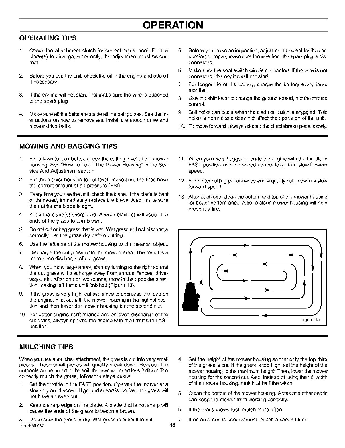
8. When you mow large areas, start by turning to theright so that
the cut grass will discharge away from shrubs fences, drive n
ways etc. After one or two rounds, mow in the opposite direc_
tion making left turns until finished (Figure 13).
9. If the grass is very high cut two times to decrease the load on
theengine Firstcutwiththemower housinginthehighestpesF
tion and then lower the mower housing for the second cut.
10. For better engine performance and an even discharge of the
cut grass, always operate the engine with the throttle in FAST
position.
11. When you use a bagger, operate the engine with the throttle in
FAST position and the speed control lever in a slow forward
speed.
12. For better cutting performance and a quality cut, mow in a slow
forward speed.
13. After each use, clean the bottom and top of the mower housing
for better performance. Also, a clean mower housing will help
prevent a fire.
(
<J
Figure 13
MULCHING TIPS
When you use a mulcher attachment, the grass is cut intovery small
pieces These small pieces will quickly break down. Because the
nutrients are returned to the soil, the lawn will need lessfertilizer. Too
correctly mulch the grass, follow the steps below.
1. Set the throttle in the FAST position. Operate the mower at a
slower ground speed. If ground speed is too fast, the grass will
not have an even cut.
2. Keep a sharp edge on the blade. A blade that is not sharp will
cause the ends of the grass to become brown.
3. Make sure the grass is dry. Wet grass is difficult to cut.
F-0406010 18
4,
5,
6.
7.
Set the height of the mower housing so that only the top third
of the grass is cut. If the grass is too high, set the height of the
mower housing to the maximum height. Then, lower the mower
housing for the second cut. Also, instead of using the full width
of the mower housing mulch at half the width.
Clean thebottom of the mower housing. Grass and other debds
can keep the mower from working correctly
If the grass grows fast, mulch more often.
If an area needs improvement, mulch a second time.
MAINTENANCE
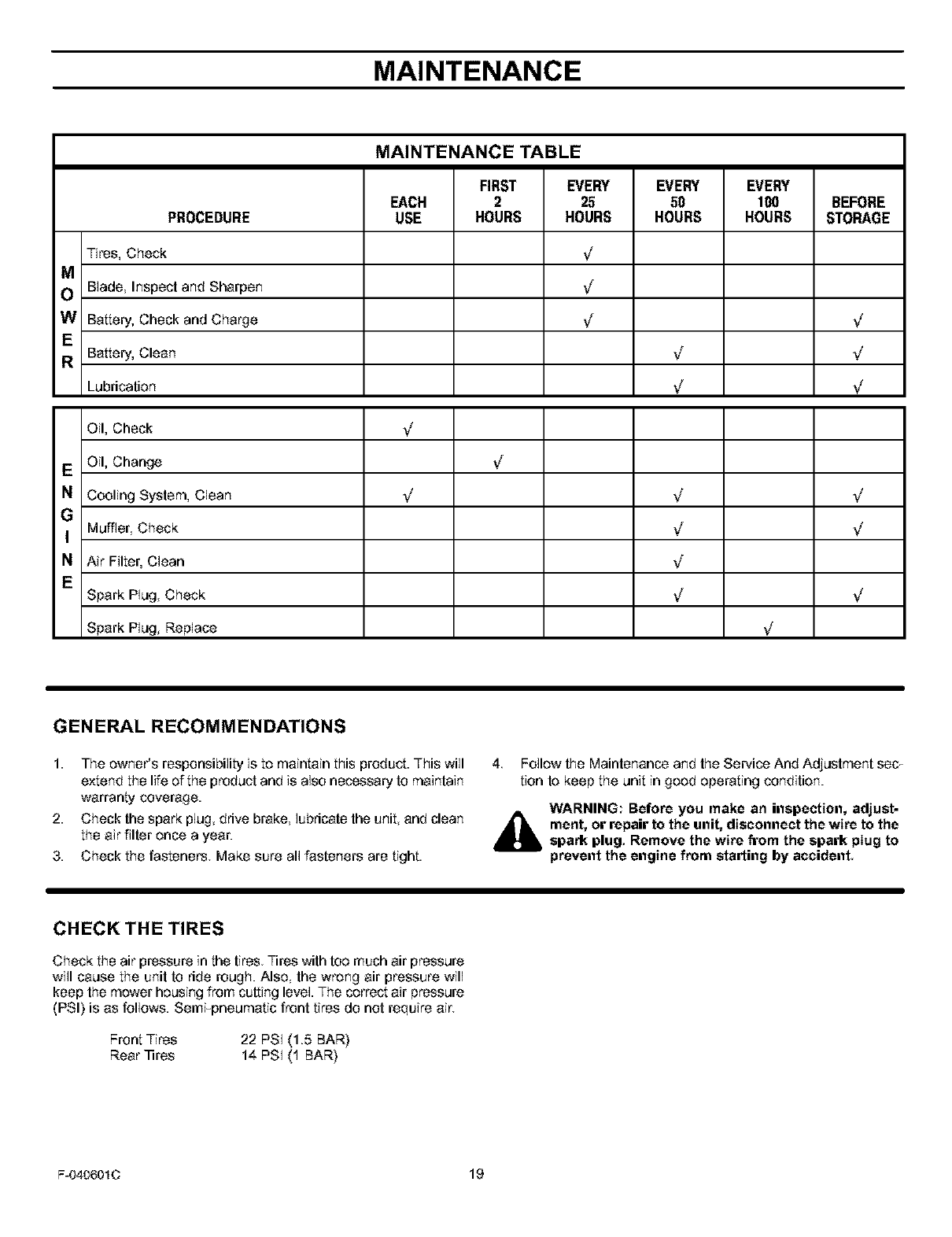
MAINTENANCE TABLE
FIRST EVERY EVERY EVERY
EACH 2 25 50 100 BEFORE
PROCEDURE USE HOURS HOURS HOURS HOURS STORAGE
Tires, Check _/
M
O Blade Inspect and Sharpen ,J
WBattery, Check and Charge .J _,/
E
RBattery, Clean _,f _/
Lubrication ,J _,/
Oil, Cheek _/
E Oil, Change ,J
NCooling System, Clean _/ v_ _/
G
I Muffler, Check ,J ;/
NAir Filter, Clean ._f
ESpark Plug Check ,J _,/
Spark Plug, Replace _/
GENERAL RECOMMENDATIONS
1. The owner's responsibility is to maintain this product. This will 4 FoJlow the Maintenance and the Service And Adjustment sec T
extend the life of the product and is also necessary to maintain tion to keep the unit in good operating condition.
warranty coverage. WARNING: Before you make an inspection, adjust-
2. Check the spark plug drive brake lubricate the unit and clean ,_ ment, or repair to the unit, disconnect the wire to the
the air filter once a year. _ spark plug, Remove the wire firom the spark plug to
3. Check the fasteners Make sure all fasteners are tight, prevent the engine from starting by accident.
CHECK THE TIRES
Check the air pressure in the tires. Tires with too much air pressure
will cause the unit to ride rough. Also the wrong air pressure will
keep the mower housing from cutting level. The correct air pressure
(PSI} is as follows. Semi_pneumatic front tires do not require air.
Front Tires 22 PSI (1.5 BAR}
Rear ]ires 14 PSI (1 BAR}
F-040601C 19
MAINTENANCE
4
INSPECT BLADE
WARNING: Before you inspect or remove the blade,
disconnect the wire to the spark plug, If the blade
4_lb hits an object, stop the engine, Check the unit for
damage, The blade has sharp edges, When you
hold the blade, use gloves or cloth material to pro-
tect your hands.
If you keep the blade sharp and inspect the blade for damage,
the blade will cut better and be mere safe to operate Frequently
check the blade for excessive wear, cracks or other damage
Frequently check the nut that helds the blade Keep the nut tight
If the blade hits an object stop the engine. Disconnect the wire to
the spark plug. See if the blade is bent or damaged. Check the
blade adapter for damage. Before you operate the unit, replace
damaged parts with odginal equipment parts See a Sears
Service Center in your area Every three years, have a qualified
service person inspect the blade or replace the old blade with an
original equipment part.
HOW TO REMOVE AND INSTALL THE BLADE
To Remove
1. Drain the fuel tank.
2. Lift the side of the mower that has the muffler or spark plug
3. As you loosen the nut use a piece of wood to keep the blade
from rotating.
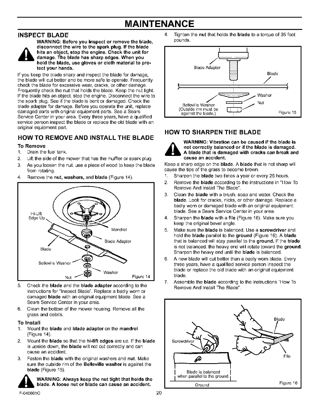
4. Remove the nut, washers, and blade (Figure 14).
Hi-Lift
Blade
Mandrel
Blade Adapter
Washer
Nut Figure 14
5. Check the blade and the blade adapter according to the
instructions for "Inspect Blade". Replace a badly worn or
damaged blade with an odginal equipment blade See a
Sears Service Center in your area.
6. Clean the bottom of the mower housing Remove all the
grass and debris.
To Install
1. Mount the blade and blade adapter on the mandrel
(Figure 14).
2. Mount the blade so that the hi-lift edges are up. If the blade
is upside down, the blade will not cut correctly and can
cause an accident.
3. Fasten the blade with the original washers and nut. Make
sure the outside rim of the Betleville washer is against the
blade (Figure 15}
_hb ARNING: Always keep the nut tight that holds the
blade A loose nut or blade can cause an accident.
F-040601C 20
_ghten the nutthat holds the blade tea torque of 35 foot
pounds.
BladeAdapt
Blade
Washe
(Outside_m must be
against the blade.} I Figure 15
HOW TO SHARPEN THE BLADE
WARNING: Vibration can be caused if the blade is
not correctly balanced or if the blade is damaged,
A blade that is damaged with cracks can break and
cause an accident.
Keep a sharp edge on the blade. A blade that is net sharp will
cause the tips of the grass to become brown
1 Sharpen the blade two times a year or every 25 hours.
2 Remove the blade according to the instructions in "Hew To
Remove And Install The Blade".
3. Clean the blade with a brush, soap and water. Check the
blade. Look for cracks nicks, or other damage Replace a
badly worn or damaged blade with an original equipment
blade See a Sears Service Center in your area
4 Sharpen the blade with a file (Figure 16) Make sure you
keep the odginal bevel angle.
5 Make sure the blade is balanced Use a screwdriver and
hold the blade parallel to the ground (Figure 16) A blade
that is balanced will stay parallel to the ground. If the blade
is not balanced the heavy end will relate toward the ground.
Sharpen the heavy end until the blade is balanced.
6 A new blade will cut better than a badly worn blade. Every
three years, have a qualified service person inspect the
blade or replace the old blade with an original equipment
blade
7 Assemble the blade according to the instructions 'How To
Remove And Install The Blade".
Screwddv__
IBlade is balanced I
I_he_ paralleltothegrou.d,I
Greund
File
Figure 16
MAINTENANCE
MAINTENANCE FREE BATTERY
HOW TO REMOVE THE BATTERY
To charge or clean the battery, remove the battery from the unit as
follows.
WARNING: To prevent sparks, disconnect the black
battery cable from the negative (-) terminal before you
disconnect the red cable.
WARNING: The battery contains sulfuric acid which is
harmfuI to the skin, eyes and clothing If the acid gets
on the body or clothing, wash with water.
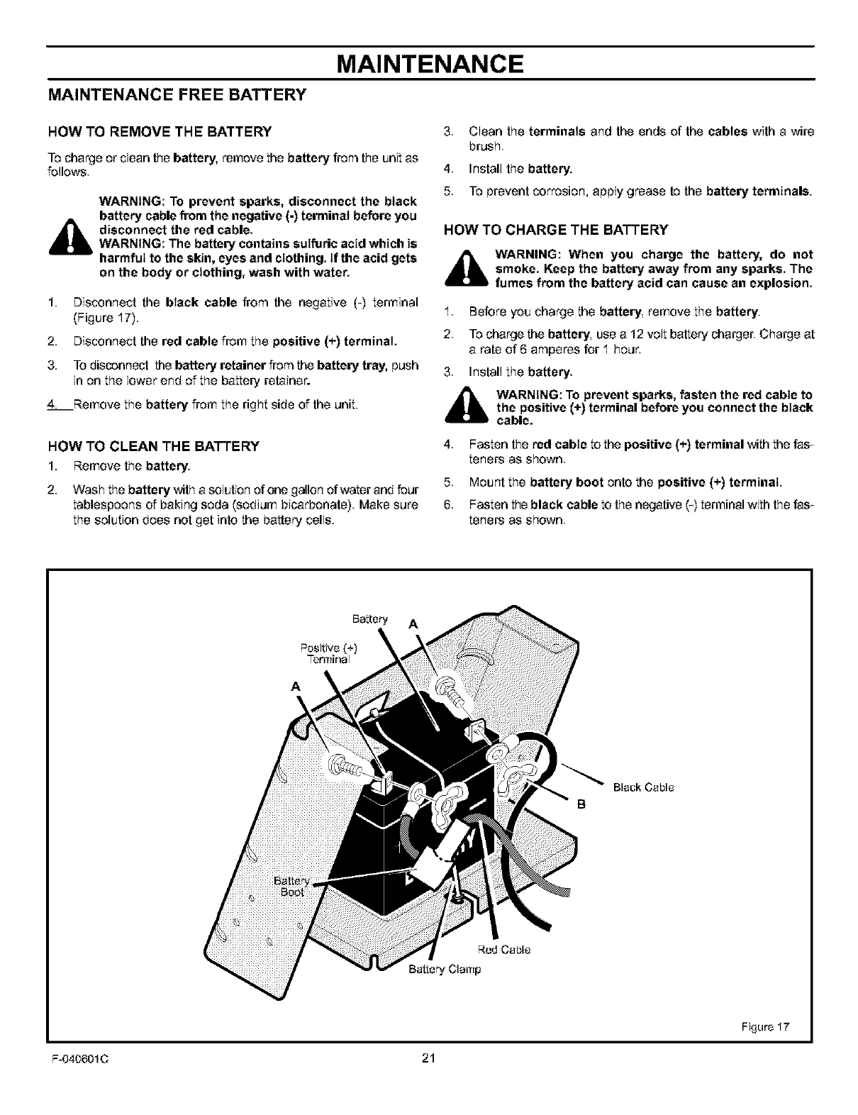
1. Disconnect the black cable from the negative (T) terminal
(Figure 17).
2. Disconnect the red cable from the positive (+) terminal.
3. To disconnect the battery retainer from the battery tray, bush
in on the lower end of the battery retainer.
4. Remove the battery from the right side of the unit.
HOWTO CLEAN THE BATTERY
1. Remove the battery.
2. Wash the battery with a solution of one gallon of water and four
tablespoons of baking soda (sodium bicarbonate}. Make sure
the solution does not get into the battery cells.
3,
4.
5.
Clean the terminals and the ends of the cables with a wire
brush
Install the battery.
To prevent corrosion, apply grease to the battery terminals.
HOW TO CHARGE THE BATTERY
_WARNING: When you charge the battery, do not
smoke. Keep the battery away from any sparks. The
fumes from the battery acid can cause an explosion
1. Before you charge the battery, remove the battery.
2. To charge the battery, use a 12 volt battery charger. Charge at
a rate of 6 amperes for 1 hour.
3. Install the battery.
d_lb WARNING: To prevent sparks, fasten the red cable to
the positive (+) terminal before you connect the black
cable.
4. Fasten the red cable to the positive (+) terminal with the fasT
tenets as shown
5. Mount the battery boot onto the positive (+) terminal.
6 Fasten the black cable to the negative (-) terminal with the fasT
tenets as shown
Battery A
Positive (+)
Terminal
A \
R_ Cable
Battery Clamp
Black Cable
B
Figure 17
F-040601C 21
MAINTENANCE
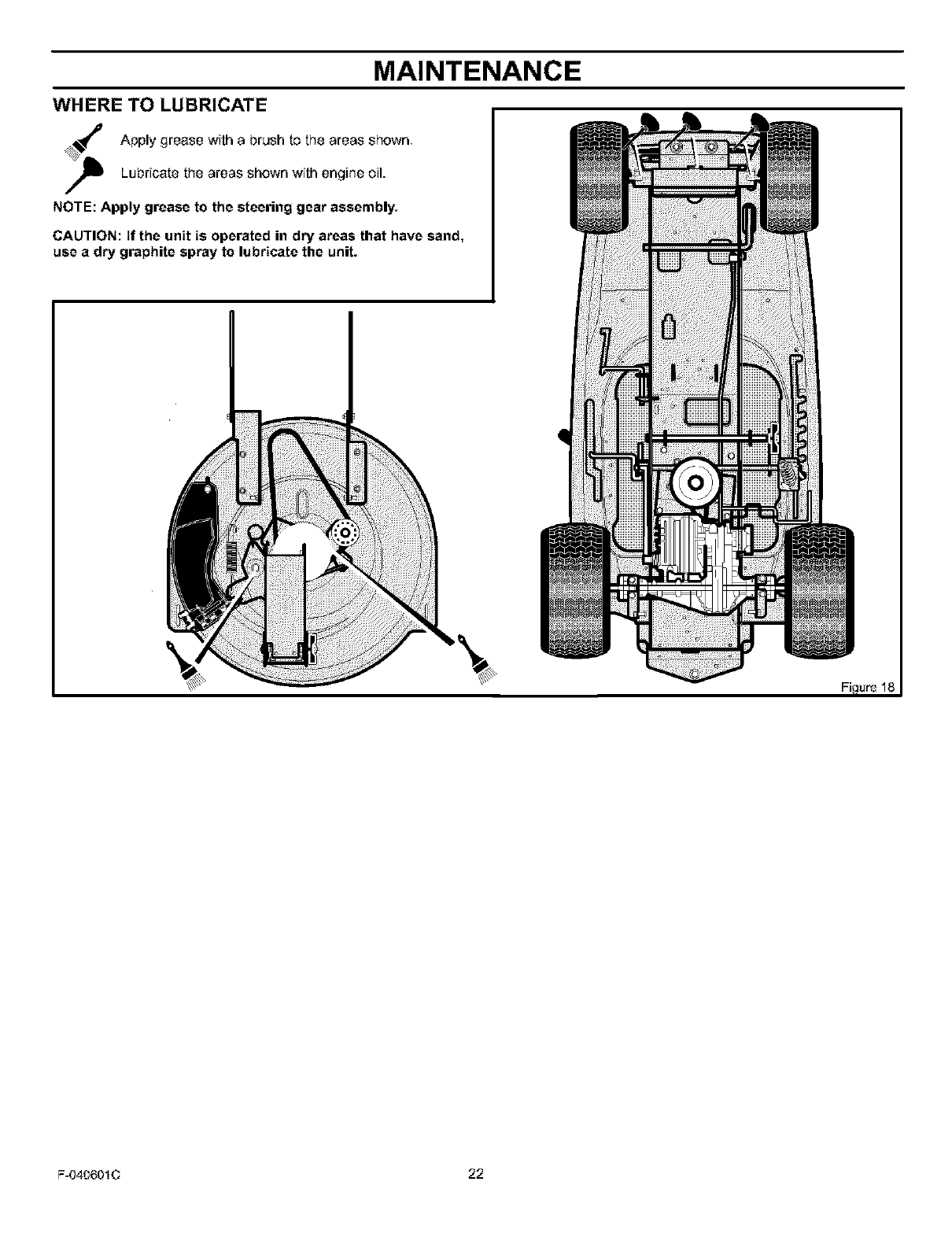
WHERE TO LUBRICATE
Apply grease with a brush to the areas shown
Lubricate the areas shown with engine oil.
NOTE: Apply grease to the steering gear assembly.
CAUTION: If the unit is operated in dry areas that have sand,
use a dry graphite spray to lubricate the unit.
F-040601C 22
MAINTENANCE
ENGINE HOW TO CHANGE THE OIL
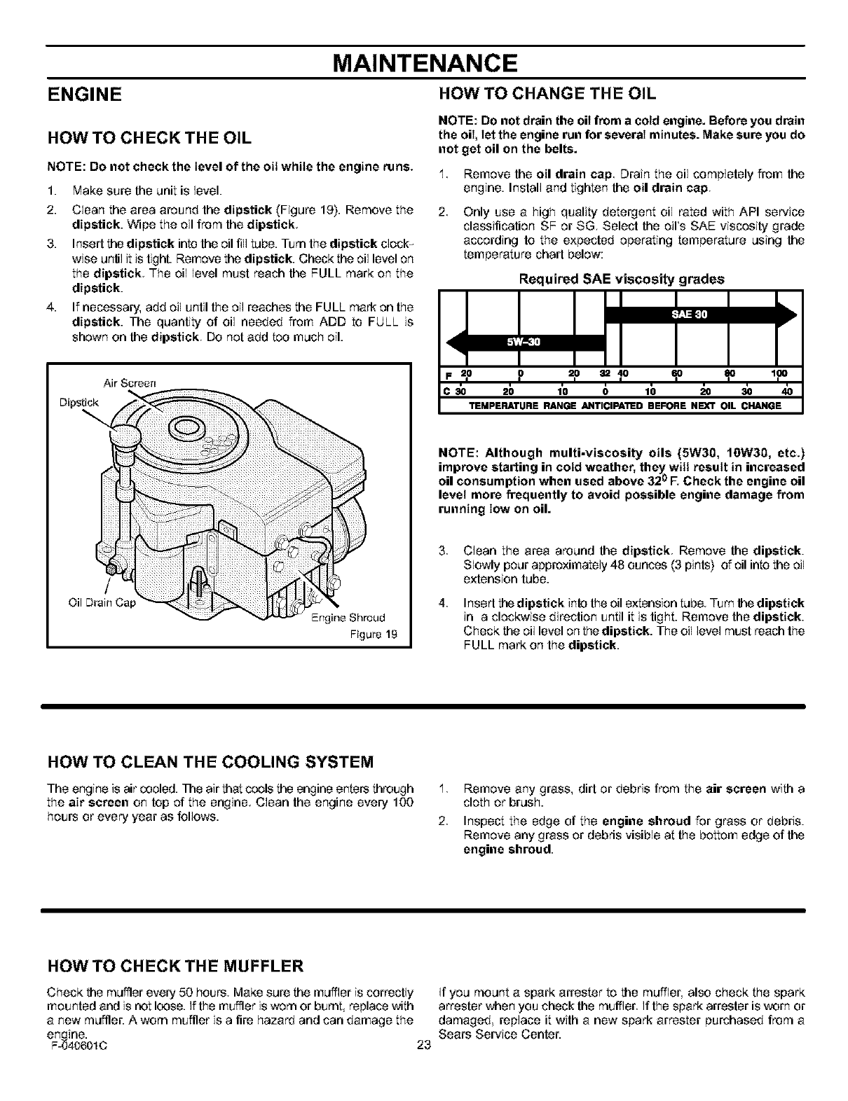
HOW TO CHECK THE OIL
NOTE: Do not check the level of the oil while the engine runs.
1.
2.
Make sure the unit is level.
Clean the area around the dipstick (Figure 19). Remove the
dipstick. Wipe the oil from the dipstick
3. Insed the dipstick intothe oil fill tube. Turn the dipstick clock-
wise unlil it is tight. Remove the dipstick. Check the oil level on
the dipstick. The oil level must reach the FULL mark on the
dipstick.
4. If necessary, add oil until the oil reaches the FULL mark on the
dipstick. The quantity of oil needed from ADD to FULL is
shown on the dipstick. Do not add too much oil.
NOTE: Do not drain the oil from a cold engine. Before you drain
the oil, let the engine run for several minutes. Make sure you do
not get oil on the belts.
1 Remove the oil drain cap Drain the oil completely from the
engine. Install and tighten the oil drain cap.
2, Only use a high quality detergent oil rated with API service
classification SF or SG Select the oil's SAE viscosity grade
according to the expected operating temperature using the
temperature chart below:
Required SAE viscosity grades
,i,=_i
F _,o 13 =? = Io _o _o Ip
C 30 20 1'0 0 10 20 30 40
TEMPERATURE RANGE ANTICIPAI_D BEFORE NEXT OIL CHANGE
Air Scroe_t
Dipstick
/
Oil Drain Cap
Engine Shroud
Figure 19
NOTE: Although multi-viscosity oils (5W30, lOW30, etc.)
improve starting in cold weather, theywill result in increased
oil consumption when used above 32_oF. Check the engine oil
level more frequently to avoid possible engine damage from
running low on oil.
3,
4.
Clean the area around the dipstick Remove the dipstick.
Slowly pour approximately 48 ounces (3 pints) ofoil into the oil
extension tube.
Insert the dipstick into the oil extension tube. Turn thedipstick
in a clockwise direction until it is tight. Remove the dipstick.
Check the oil levelon the dipstick. The oil level must reach the
FULL mark on the dipstick.
HOW TO CLEAN THE COOLING SYSTEM
The engine is air coaled. ]T_eair that cools the engine enters through 1.
the air screen on top of the engine. Clean the engine every 100
hours or every year as follows. 2.
Remove any grass, did or debris from the air screen with a
cloth or brush.
Inspect the edge of the engine shroud for grass or debris.
Remove any grass or debris visible at the bottom edge of the
engine shroud.
HOW TO CHECK THE MUFFLER
Check the muffler every 50 hours. Make sure the muffler is correctly
mounted and is not loose. If the muffler is worn or burnt, replace with
a new muffler. Aworn muffler is a fire hazard and can damage the
en inc.
F-_40601C 23
If you mount a spark arrestor to the muffler, also check the spark
arrestor when you check the muffler If the spark arrestor is worn or
damaged replace it with a new spark arrestor purchased from a
Sears Service Center.
MAINTENANCE
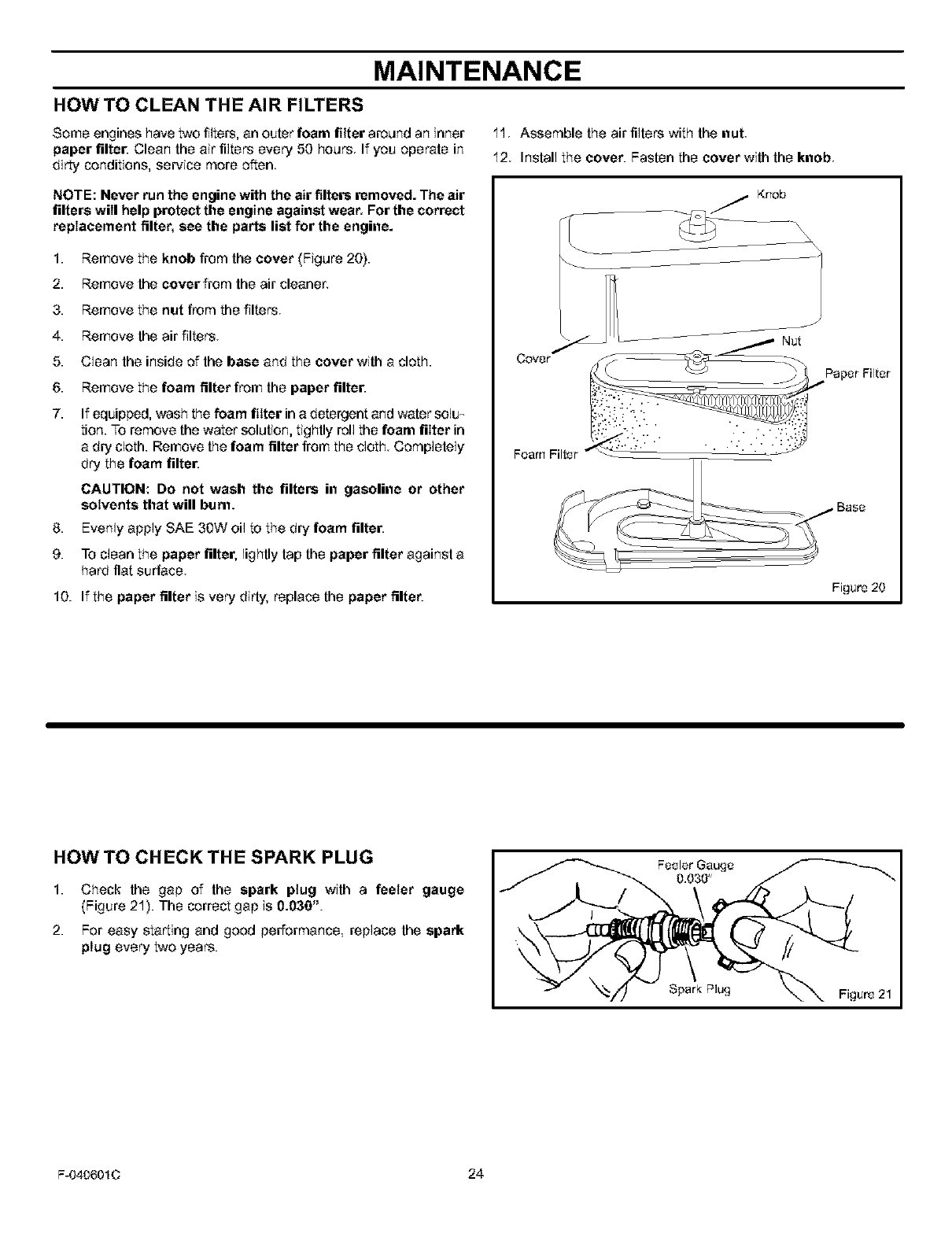
HOW TO CLEAN THE AIR FILTERS
Some engines have two filters, an outer foam filter around an inner I I Assemble the air filters with the nut
paper filte[ Clean the air filters every 50 hours If you operate in
dirty conditions, service more often 12 Install the cover. Fasten the cover with the knob
NOTE: Never run the engine with the air filters removed. The air
filters will help protect the engine against wear. For the correct
replacement filter, see the parts list for the engine.
1. Remove the knob from the cover (Figure 20}.
2. Remove the cover from the air cleaner,
3. Remove the nut from the filters
4. Remove the air filters
5. Clean the inside of the base and the cover with a cloth.
6. Remove the foam filter from the paper filte[
7. If equipped, wash the foam filter ina detergent and water soJu_
tion. To remove the water solution, tightly roll the foam filter in
a dry cloth. Remove the foam filter from the cloth Completely
dry the foam filter.
CAUTION: Do not wash the filters in gasoline or other
solvents that will bum,
8. Evenly apply SAE 30W oil to the dry foam filter.
9. To clean the paper filter, lightly tap the paper filter against a
hard flat surface
10. If the paper filter is very dirty, replace the paper filter. Figure 20
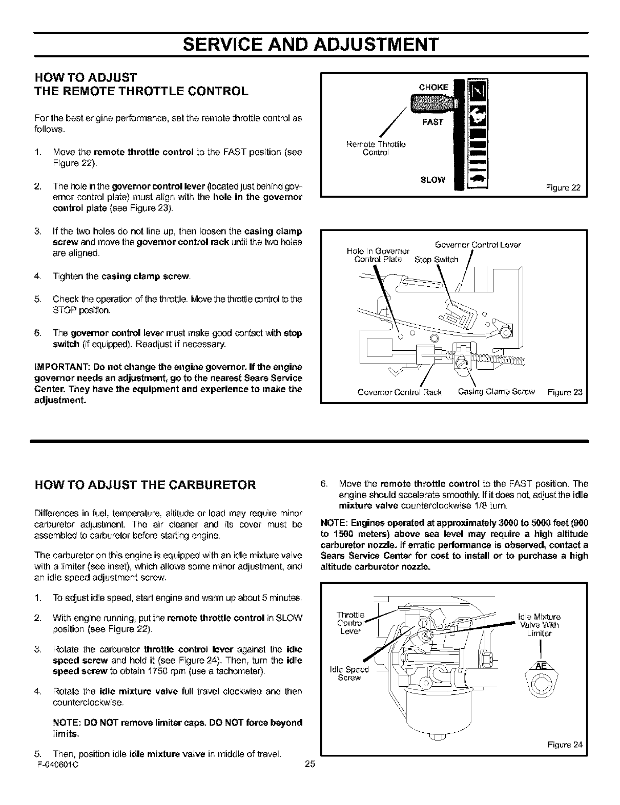
HOW TO CHECK THE SPARK PLUG
1.
2.
Check the gap of the spark plug with a feeler gauge
(Figure 21). The correct gap is 0.030".
For easy starting and good performance, replace the spark
plug every two years.
Feeler Gauge
0.030
Spark Plug Figuro 21
F-040601C 24
SERVICE AND ADJUSTMENT
HOW TO ADJUST
THE REMOTE THROTTLE CONTROL
For the best engine performance, set the remote throttle control as
follows.
1. Move the remote throttle control to the FAST position (see
Figure 22)
2. The hole inthe governor control lever (located just behindgow
emor control plate) must align with the hole in the governor
control plate (see Figure 23}.
3. If the two holes do not line up, then loosen the casing clamp
screw and move the governor control rack until the two holes
are aligned
4. Tighten the casing clamp screw.
5. Check the operation of the throttle. Move the l_rot_lecontrol to the
STOP position.
6. The governor control lever must make good contact with step
switch (if equipped). Readjust if necessary.
IM PORTANT: Do not change the engine governor. If the engine
governor needs an adjustment, go to the nearest Sears Service
Center. They have the equipment and experience to make the
adjustment.
CHOKE
FAST
Remote Throttle
Control
SLOW
Governer Control Lover
Hole In Governor
Control Plato Stop Switch
Figure 22
Governor Control Rack Casing Clamp Screw Figure 23
HOW TO ADJUST THE CARBURETOR
Differences in fuel, temperature, altitude or load may require minor
carburetor adjustment. The air cleaner and its cover must be
assembled to carburetor before starting engine.
The carburetor on this engine is equipped with an idle mixture valve
with a limitar (see inset), which allows some minor adjustment, and
an idle speed adjustment screw
1. To adjust idle speed, start engine and warm up about 5 minutes.
2. With engine running put the remote throttle control in SLOW
position (see Figure 22).
3.
4.
Rotate the carburetor throttle control lever against the idle
speed screw and hold it (see Figure 24) Then turn the idle
speed screw to obtain 1750 rpm (use a tachometer)
Rotate the idle mixture valve full travel clockwise and then
counterclockwise
NOTE: DO NOT remove Iimiter caps, DO NOT force beyond
limits.
6. Move the remote throttle control to the FAST position. The
engine should accelerate smoothly. If it does not adjust the idle
mixture valve counterclockwise 1/8 turn.
NOTE: Engines operated at approximately 3600 to 5600 feet (900
to 1500 meters) above sea level may require a high altitude
carburetor nozzle. If erratic performance is observed, contact a
Sears Service Center for cost to install or to purchase a high
altitude carburetor nozzle.
Throttle
Lever
Idle Speed
Screw
Figure 24
5. Then, position idle idle mixture valve in middle of travel.
F-040601C 25
SERVICE AND ADJUSTMENT
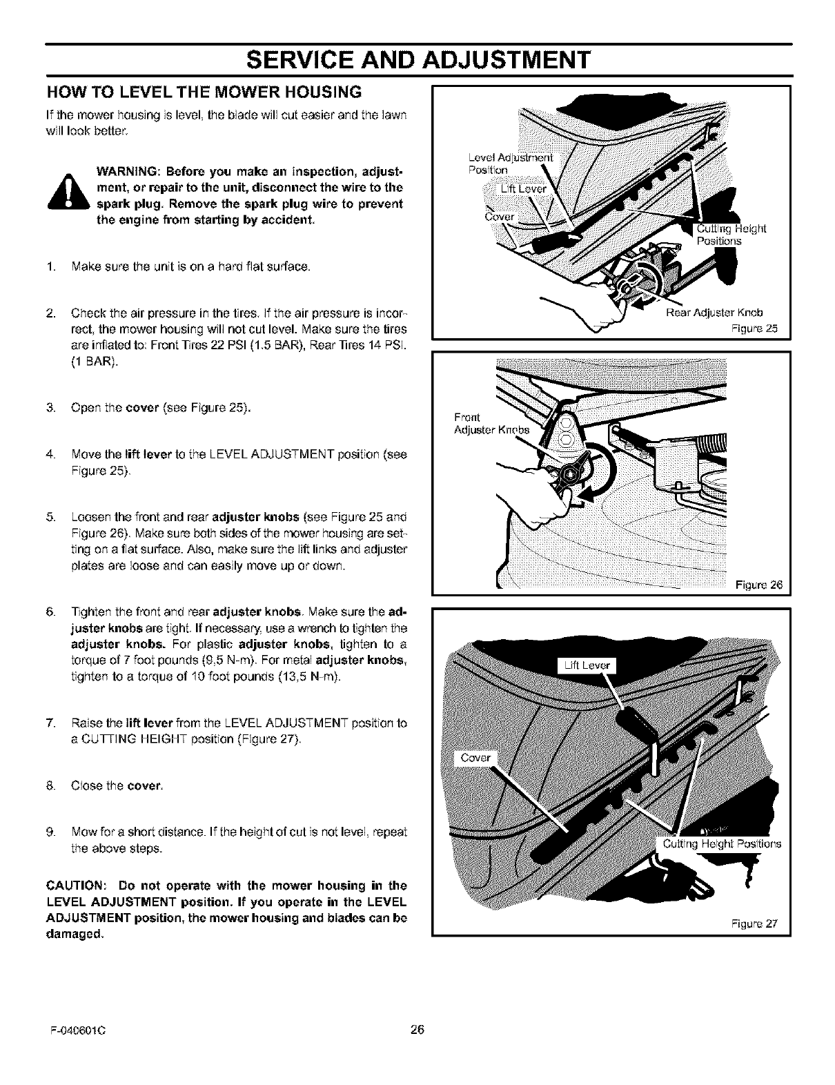
HOW TO LEVEL THE MOWER HOUSING
If the mower housing is level the blade will cut easier and the lawn
will look better.
WARNING: Before you make an inspection, adjust-
ment, or repair to the unit, disconnect the wire to the
spark plug Remove the spark plug wire to prevent
the engine from starting by accident,
1. Make sure the unit is on a hard flat surface.
2. Check the air pressure in the tires If the air pressure is incor-
rect, the mower housing will not cut level. Make sure the tires
are inflated to: Front Tiros 22 PSI (1.5 BAR}, Rear ]]res 14 PSI.
(1 BAR).
3. Open the cover (see Figure 25).
4. Move the lift lever to the LEVEL ADJUSTMENT position (see
Figure 25}
5. Loosen the front and rear adjuster knobs (see Figure 25 and
Figure 26). Make sure both sides of the mower housing are set-
ting on a flat surface. Also, make sure the lift links and adjuster
plates are loose and can easily move up or down.
Position
Rear Adjuster Knob
Front
Adjuster Knebs
Figure 25
Figuro 26
6. Tighten the front and rear adjuster knobs. Make sure the ad-
juster knobs are tight If necossa_ use a wrench to tighten the
adjuster knobs. For plastic adjuster knobs, tighten to a
torque of 7 foot pounds (9,5 N_m) For metal adjuster knobs,
tighten to a torque of 10 foot pounds (13,5 N_m).
7. Raise the lift lever from the LEVEL ADJUSTMENT position to
a CU]q-ING HEIGHT position (Figure 27}
8. Close the cover.
9. Mow for a short distance. If the height of cut is not level, repeat
the above steps.
CAUTION: Do not operate with the mower housing in the
LEVEL ADJUSTMENT position, If you operate in the LEVEL
ADJUSTM ENT position, the mower housing and blades can be
damaged,
Cutting Height Positions
Figure 27
F-040601C 26
SERVICE AND ADJUSTMENT
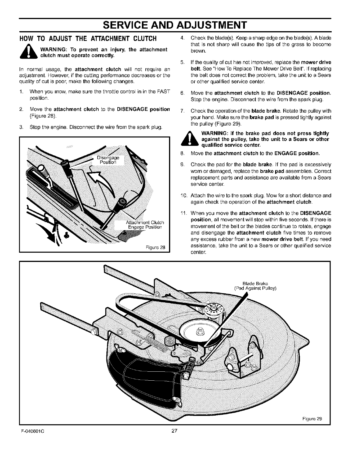
HOW TO ADJUST THE ATTACHMENT CLUTCH
_b ARNING: To prevent an injury, the attachment
clutch must operate correctly.
In normal usage, the attachment clutch wiU not require an
adjustment. However, ifthe cutting performance decreases or the
quality of cut is poor, make the following changes.
1. When you mow, make sure the throttle control in in the FAST
position.
2. Move the attachment clutch to the DISENGAGE position
(Figure 28).
3. Stop the engine. Disconnect the wire from the spark plug.
A_achmentClu_h
Engage PeeiUon
Figure 28
4. Check the blade(s). Keep a sharp edge on the blade(s). A blade
that is not sharp wiU cause the tips of the grass to become
brown.
5, If the quality of cut has not improved, replace the mower drive
belt. See "How To Replace The Mower Drive Belt" If replacing
the belt does not correct the problem, take the unit to a Sears
or other qualified service center.
6. Move the attachment clutch to the DISENGAGE position.
Stop the engine Disconnect the wire from the spark plug
7. Check the operation of the blade brake. Rotate the pulley with
your hand Make sure the brake pad is pressed tightly against
the pulley (Figure 29}.
_lb WARNING: If the brake pad does not press tightly
against the pulley, take the unit to a Sears or other
qualified service center.
8. Move the attachment clutch to the ENGAGE position.
Check the pad for the blade brake. (fthe pad is exceesiveIy
worn or damaged, replace the brake pad essembIies. Correct
replacement parts and assistance are available from a Sears
service center.
10.
11.
Attach the wire to the spark plug. Mow for a short distance and
again check the operation of the attachment clutch.
When you move the attachment clutch to the DISENGAGE
position, all movement will stop withinfive seconds If there is
movement of the be(t or the b(ades continue to rotate engage
and disengage the attachment clutch five times to remove
any excess rubber from a new mower drive belt. If you need
assistance take the unit to a Sears or other qualified service
center.
Blade Brake
(Pad Against Pulley)
Figure 29
F-040601C 27
SERVICE AND ADJUSTMENT
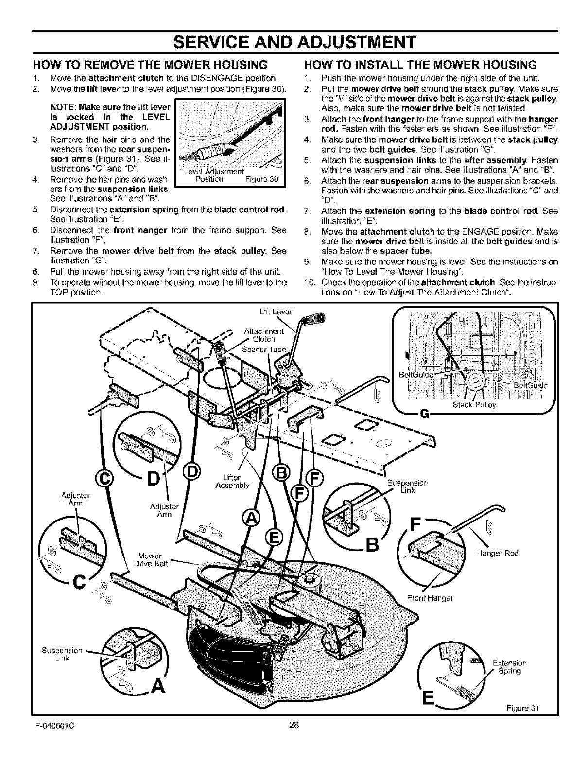
HOW TO INSTALL THE MOWER HOUSINGHOW TO REMOVE THE MOWER HOUSING
1. Move the attachment clutch to the DISENGAGE position
2. Move the lift lever to the level adjustment position (Figure 30).
NOTE: Make sure the lift lever
is locked in the LEVEL
ADJUSTMENT position,
3. Remove the hair pins and the
washers from the rear suspen-
sion arms (Figure 31) See iF
Iostratioos 'C" and "D". Level Adtustmont
4. Remove the hair pins and wash_ Position Figure 30
ors from the suspension links,
See illustrations "A" and 'B"
5. Disconnect the extension spring from the blade control rod.
See illustration "E"
6. Disconnect the front hanger from the frame support. See
illustration "F'L
7. Remove the mower drive belt from the stack pulley. See
illustration "G'L
8. Pull the mower housing away from the right side of the unit.
9. To operate without the mower housing, move the lift lever to the
TOP position.
1 Push the mower housing under the right side of the unit.
2 Put the mower drive belt around the stack pulley, Make sure
the "V" side of the mower drive belt is against the stack pulley.
Also, make sure the mower drive belt is not twisted.
3. Attach the front hanger to the frame support with the hanger
rod. Fasten with the fasteners as shown See illustration "F"
4 Make sure the mower drive belt is between the stack pulley
and the two belt guides. See illustration 'G".
5 Attach the suspension links to the lifter assembly Fasten
with the washers and hair pins. See illustrations "A" and "B"
6 Attach the rear suspension arms to the suspension brackets
Fasten with the washers and hair pins. See illustrations "C" and
'D'.
7. Attach the extension spring to the blade control rod. See
illustration 'E"
8 Move the attachment clutch to the ENGAGE position. Make
sure the mower drive belt is inside all the belt guides and is
also below the spacer tube.
g Make sure the mower housing is level See the instructions on
'How To Level The Mower Housing"
'10 Check the operation of the attachment clutch See the instruc
tions on "How To Adjust The Attachment Clutch"
Li_ Lover
Clutch
GStack Pulley
Adjuster
Arm
DLifter
Assembly
Adjuster
Arm
Suspension
Link
Mowor
D#ve Bolt
BHanger Rod
Front Hanger
E_EAension
Spring
Figuro31
F-040601C 28
SERVICE AND ADJUSTMENT
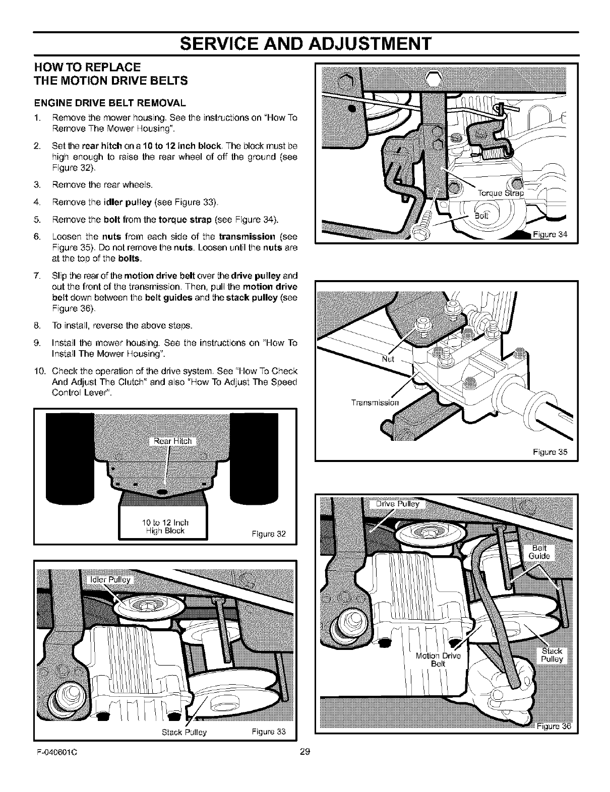
HOW TO REPLACE
THE MOTION DRIVE BELTS
ENGINE DRIVE BELT REMOVAL
1. Remove the mower housing See the instructions on "How To
Remove The Mower Housing".
2. Set the rear hitch on a 10 to 12 inch block The block must be
high enough to raise the rear wheel of off the ground (see
Figure 32).
3. Remove the rear wheels.
4. Remove the idler pulley (see Figure 33}.
5.
6.
Remove the bolt from the torque strap (see Figure 34).
Loosen the nuts from each side of the transmission (see
Figure 35} Do not remove the nuts. Loosen until the nuts are
at the top of the bolts.
7. Slip the rear of the motion drive belt over the drive pulley and
out the front of the transmission Then, pull the motion drive
belt down between the belt guides and the stack pulley (see
Figure 36)
8. To install, reverse the above steps.
9. Install the mower housing. See the instructions on 'How To
Install The Mower Housing".
10. Check the operation of the drive system. See "How To Check
And Adjust The Clutch" and also "How To Adjust The Speed
Control Lever".
Figure 32
Figure 36
Figure 33
F-040601C 29
SERVICE AND ADJUSTMENT
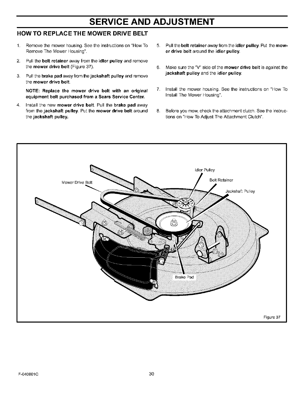
HOW TO REPLACE THE MOWER DRIVE BELT
1.
2.
3.
4.
Remove the mower housing. See the instructions on "How To
Remove The Mower Housing".
Pull the belt retainer away from the idler pulley and remove
the mower drive belt (Figure 37}.
Pull the brake pad away from thejackshaft pulley and remove
the mower drive belt.
NOTE: Replace the mower drive belt with an original
equipment belt purchased from a Sears Service Center.
Install the new mower drive belt. Pull the brake pad away
from the jackshaft pulley, Put the mower drive belt around
the jackshaft pulley.
5. Pull the belt retainer away from the idler pulley. Put the mow-
er drive belt around the idler pulley.
6. Make sure the "V" side of the mower drive belt is against the
jackshaft pulley and the idler pulley,
7. Install the mower housing. See the instructions on "How To
Install The Mower Housing".
8. Before you mow, check the attachment clutch. See the instruc T
tions on "How To Adjust The Attachment Clutch".
Mewer Drive Belt
Idler Pulley
Belt Retainer
Jackshaft Pulley
Figure 37
F-0406010 30
SERVICE AND ADJUSTMENT
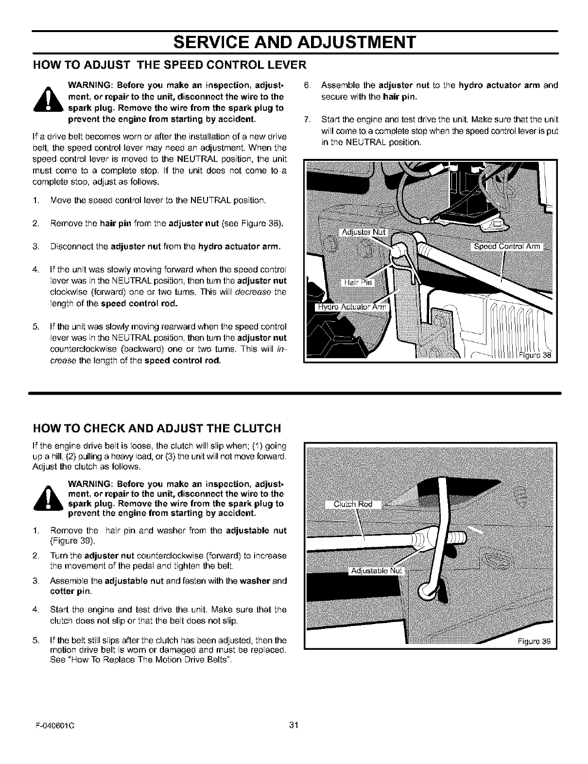
HOW TO ADJUST THE SPEED CONTROL LEVER
WARNING: Before you make an inspection, adjust-
ment, or repair to the unit, disconnect the wire to the
spark plug, Remove the wire from the spark plug to
prevent the engine from starting by accident,
If a drive belt becomes worn or after the installation of a new drive
belt, the speed control lever may need an adjustment. When the
speed control lever is moved to the NEUTRAL position, the unit
must come to a complete stop. If the unit does not come to a
complete stop, adjust as follows.
6. Assemble the adjuster nut to the hydro actuator arm and
secure with the hair pin.
7 Start the engine and test drive the unit. Make sure that the unit
will come to a complete stop when the speed control lever is put
in the NEUTRAL position.
1. Move the speed control lever to the NEUTRAL position.
2. Remove the hair pin from the adjuster nut (see Figure 38).
3. Disconnect the adjuster nut from the hydro actuator arm.
4. If the unit was slowly moving forward when the speed control
lever was in the NEUTRAL position then turn the adjuster nut
clockwise (forward) one or two turns. This will decrease the
length of the speed control rod.
5. If the unit was slowly moving rearward when the speed control
lever was in the NEUTRAL position then turn the adjuster nut
counterclockwise (backward) one or two turns. This will im
crease the length of the speed control rod.
HOW TO CHECK AND ADJUST THE CLUTCH
If the engine drive belt is loose, the clutch will slip when; (1) going
up a hill (2) pulling a heavy load, or (3} the unit will net move forward.
Adjust the clutch as follows.
WARNING: Before you make an inspection, adjust-
ment, or repair to the unit, disconnect the wire to the
spark plug, Remove the wire from the spark plug to
prevent the engine from starting by accident,
1.
2.
3.
Remove the hair pin and washer from the adjustable nut
(Figure 3g).
Turn the adjuster nut counterclockwise (forward) to increase
the movement of the pedal and tighten the belt.
Assemble the adjustable nut and fasten with the washer and
cotter pin.
4. Start the engine and test drive the unit. Make sure that the
clutch does not slip or that the belt does not slip.
5. If the belt still slips after the clutch has been adjusted, then the
motion drive belt is worn or damaged and must be replaced.
See "How To Replace The Motion Drive Belts"
Figure 3B
F-040601C 31
SERVICE AND ADJUSTMENT
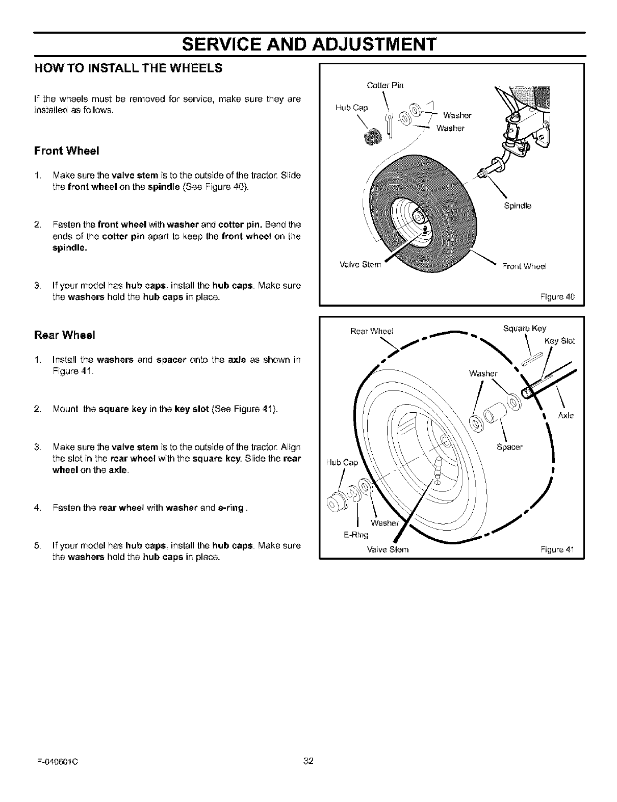
HOW TO INSTALL THE WHEELS
If the wheels must be removed for service, make sure they are
installed as follows.
Front Wheel
1. Makesure the valve stern is to the outside of thetractor.Slide
the front wheel on the spindle (See Figure 40}.
2. Fasten the front wheel with washer and cotter pin. Bend the
ends of the cotter pin apart to keep the front wheel on the
spindle.
3. If your model has hub caps, install the hub caps. Make sure
the washers hold the hub caps in place.
Cotter Pin
Hub Cap \ _,
Washer
/
Spindle
Front Wheel
Figure 40
Rear Wheel
1. Installthe washers and spacer onto the axle as shown in
Figure 41.
2. Mount the square key in the key slot (See Figure 41).
3. Make sure the valve stern is to the outside of the tractor. Align
the slot in the rear wheel with the square key: Slide the rear
wheel on the axle
4. Fasten the rear wheel with washer and e-ring.
5. If your model has hub caps, install the hub caps. Make sure
the washers hoJd the hub caps in place.
Rear Wheel Square Key
>f'_'_ Key Slot
Washer
I Axle
Spacer /
!
/
Figure 41
F-0406010 32
SERVICE AND ADJUSTMENT
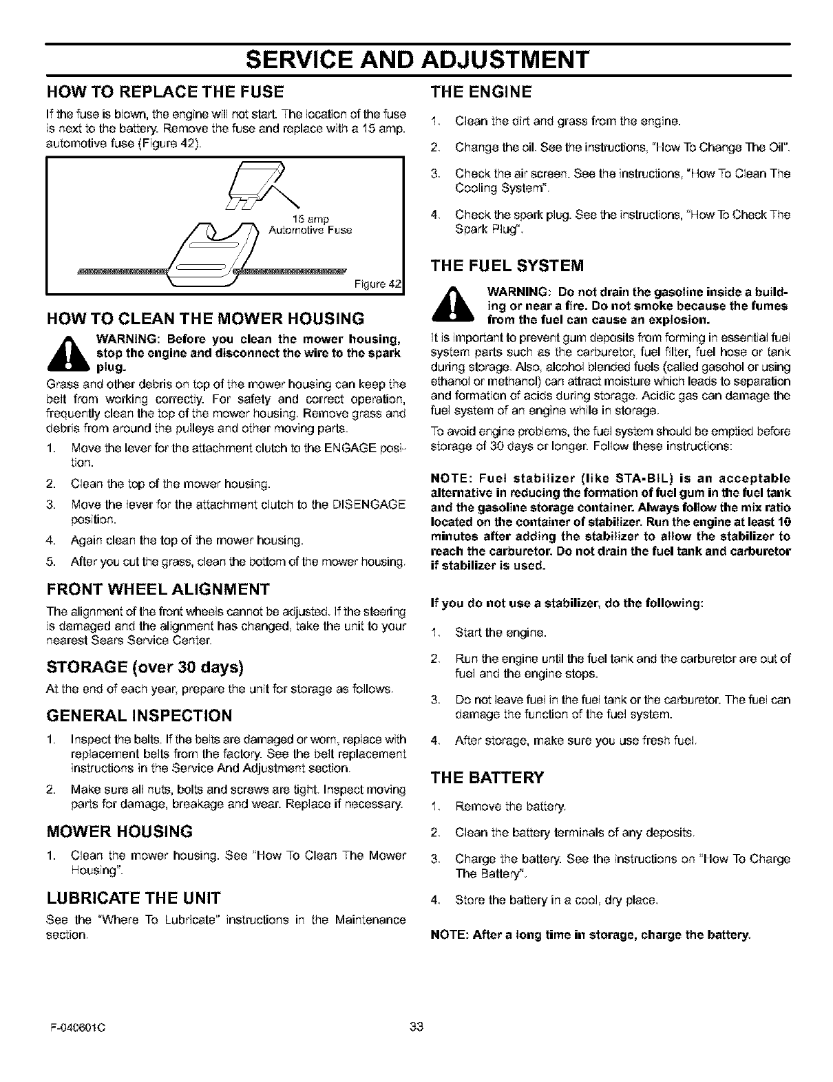
HOW TO REPLACE THE FUSE THE ENGINE
If _,e fuse is blown, the engine wiiI not slat1. The location ef the fuse
is next to the battery. Remove the fuse and replace with a 15 amp.
automotive fuse (Figure 42).
15amp
Figure 42
HOW TO CLEAN THE MOWER HOUSING
4_lb WARNING: Before you clean the mower housing,
stop the engine and disconnect the wire to the spark
plug.
Grass and other debris en top of the mower housing can keep the
belt from working correctly. For safety and correct operation,
frequently clean the top of the mower housing Remove grass and
debris from around the pulleys and other moving pads.
1. Move the lever for the attachment clutch to the ENGAGE posi_
tion.
2. Clean the top of the mower housing.
3. Move the lever for the attachment clutch to the DISENGAGE
position.
4. Again clean the top of the mower housing.
5. After you cut the grass, clean the bottom of the mower housing
FRONT WHEEL ALIGNMENT
The alignment of the front wheels cannot be adjusted If the steedng
is damaged and the alignment has changed, take the unit to your
nearest Sears Service Center.
STORAGE (over 30 days)
At the end of each year_ prepare the unit for storage as follows
GENERAL INSPECTION
1. Inspect the belts. If the belts are damaged or worn replace with
replacement belts from the factory. See the belt replacement
instructions in the Service And Adjustment section
2. Make sure all nuts, bolts and screws are tight Inspect moving
parts for damage, breakage and wear. Replace if necessary.
MOWER HOUSING
1. Clean the mower housing. See 'How To Clean The Mower
Housing".
LUBRICATE THE UNIT
See the "Where To Lubricate" instructions in the Maintenance
section.
1. Clean the dirt and grass from the engine.
2. Change the oil. See the instructions,"How To Change The Oil".
3. Check the air screen. See the instructions "How To Clean The
Cooling System".
4. Check the spark plug. See the instructions, 'How To Check The
Spark Plug".
THE FUEL SYSTEM
WARNING: Do not drain the gasoline inside a build-
ing or near a fire. Do not smoke because the fumes
from the fuel can cause an explosion.
It is important to prevent gum deposits from forming in essential fuel
system parts such as the carburetor, fuel filter, fuel hose or tank
during storage. Also alcohol blended fuels (called gasohol or using
ethanol or methanol) can attract moisture which leads to separation
and formation of acids during storage. Acidic gas can damage the
fuel system of an engine while in storage.
To avoid engine problems, the fuel system should be emptied before
storage of 30 days or longer. Follow these instructions:
NOTE: Fuel stabilizer (like STA-BtL) is an acceptable
alternative in reducing the formation of fuel gum in the fuel tank
and the gasoline storage container. Always follow the mix ratio
located on the container of stabilizer. Run the engine at least 10
minutes after adding the stabilizer to allow the stabilizer to
reach the carburetor. Do not drain the fuel tank and carburetor
if stabilizer is used.
If you do not use a stabilizer, do the following:
1. Start the engine.
2 Run the engine until the fuel tank and the carburetor are out of
fuel and the engine stops.
3 Do not leave fuel in the fuel tank or the carburetor. The fuel can
damage the function of the fuel system.
4 After storage, make sure you use fresh fuel
THE BATTERY
1 Remove the battery
2. Clean the battery terminals of any deposits.
3. Charge the battery. See the instructions on 'How To Charge
The Battery".
4. Store the battery in a cool dry place.
NOTE: After a long time in storage, charge the battery.
F-040601C 33
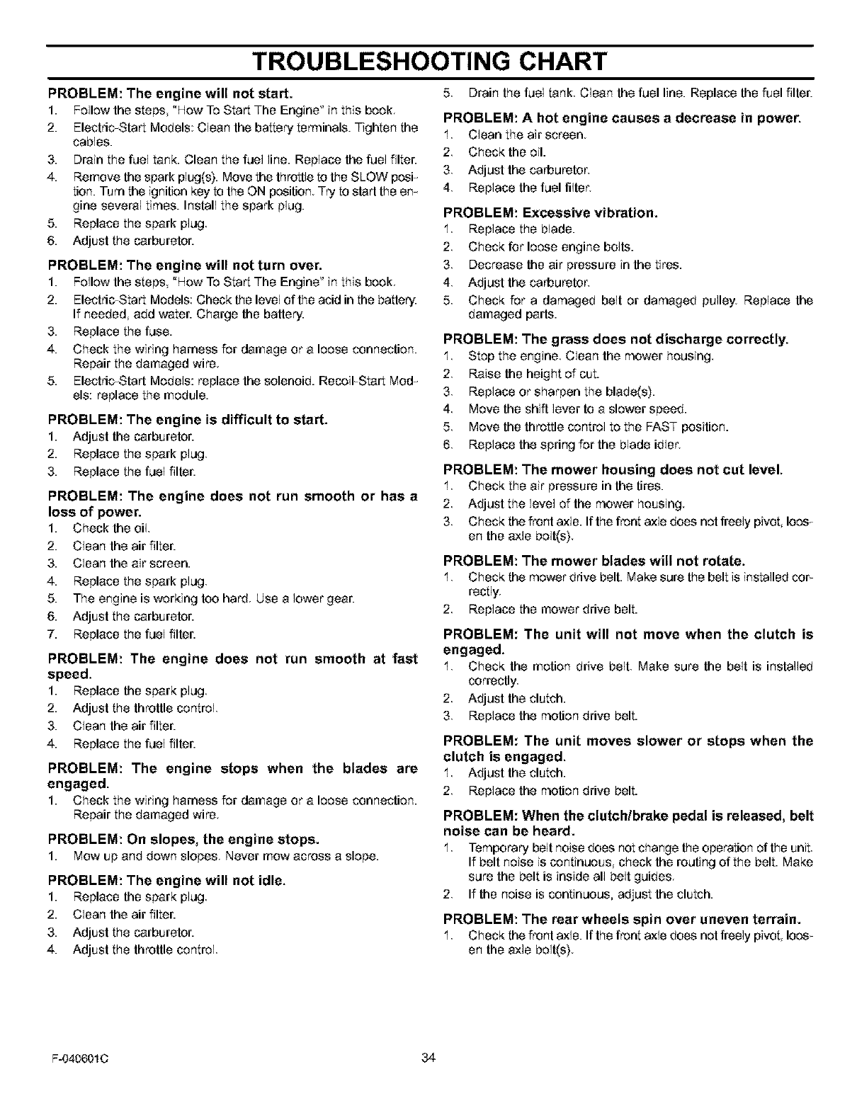
TROUBLESHOOTING CHART
5 Drain the fuel tank Clean the fuel line. Replace the fuel filter.
PROBLEM: The engine will not start.
1. Follow the stops, "How To Start The Engine" in this book
2. Electdc_Start Models: Clean the battery terminals. Tighten the
cables.
3. Drain the fuel tank. Clean the fuel line. Replace the fuel filter.
4. Remove the spark plug(s). Move the throttle to the SLOW posF
tlon. Turn the ignition key to the ON position Try to start the em
gine several times. Install the spark plug.
5. Replace the spark plug
6. Adjust the carburetor.
PROBLEM: The engine will not turn over.
1. Follow the stops "How To Start The Engine" in this book
2. Electdc_Start Models: Check the level of the acid in the battery.
If needed add water. Charge the battery.
3. Replace the fuse.
4. Check the wiring harness for damage or a loose connection.
Repair the damaged wire.
5. Electdc_Start Models: replace the solenoid. RecoiFStart Mod_
els: replace the module.
PROBLEM: The engine is difficult to start.
1. Adjust the carburetor.
2. Replace the spark plug
3. Replace the fuel filter.
PROBLEM: The engine does not run smooth or has a
loss of power.
1. Check the oil.
2. Clean the air filter.
3. Clean the air screen.
4. Replace the spark plug.
5. The engine is working too hard. Use a lower gear.
6. Adjust the carburetor.
7. Replace the fuel filter.
PROBLEM: The engine does not run smooth at fast
speed.
1. Replace the spark plug
2. Adjust the throttle control
3. Clean the air filter.
4. Replace the fuel filter.
PROBLEM: The engine stops when the blades are
engaged.
1. Check the wiring harness for damage or a loose connection.
Repair the damaged wire.
PROBLEM: On slopes, the engine stops.
1. MOWup and down slopes Never mow across a slope.
PROBLEM: The engine will not idle.
1. Replace the spark plug.
2. Clean the air filter.
3. Adjust the carburetor.
4. Adjust the throttle control
PROBLEM: A hot engine causes a decrease in power.
1. Clean the air screen.
2 Check the oil.
3 Adjust the carburetor,
4 Replace the fuel filter,
PROBLEM: Excessive vibration.
1. Replace the blade.
2 Check for loose engine bolts.
3 Decrease the air pressure in the tires.
4 Adjust the carburetor,
5 Check for a damaged belt or damaged pulley Replace the
damaged parts.
PROBLEM: The grass does not discharge correctly.
1. Stop the engine. Clean the mower housing.
2. Raise the height of cut.
3. Replace or sharpen the blade(s).
4 Move the shift lever to a slower speed.
5 Move the throttle control to the FAST position.
6 Replace the spring for the blade idler,
PROBLEM: The mower housing does not cut level.
1. Check the air pressure in the tires.
2 Adjust the level of the mower housing
3 Check the front axle. If the front axle does not freely pivot Ioes_
en the axle bolt(s)
PROBLEM: The mower blades will not rotate.
1. Check the mowerdrive belt. Makesure the belt is installedcoF
rectly,
2 Replace the mower drive belt.
PROBLEM: The unit will not move when the clutch is
engaged.
1 Check the motion drive belt Make sure the belt is installed
correctly.
2. Adjust the clutch.
3. Replace the motion drive belt.
PROBLEM: The unit moves slower or stops when the
clutch is engaged.
1 Adjust the clutch.
2. Replace the motion drive belt.
PROBLEM: When the clutch/brake pedal is released, belt
noise can be heard.
1 Temporary belt noise does not change the operation of the unit
If belt noise is continuous check the routing of the belt. Make
sure the belt is inside all belt guides.
2. If the noise is continuous, adjust the clutch.
PROBLEM: The rear wheels spin over uneven terrain.
1 Check f_e front axle. If the front axle does not freely pivot Ioes_
en the axle bolt(s}
F-0406010 34
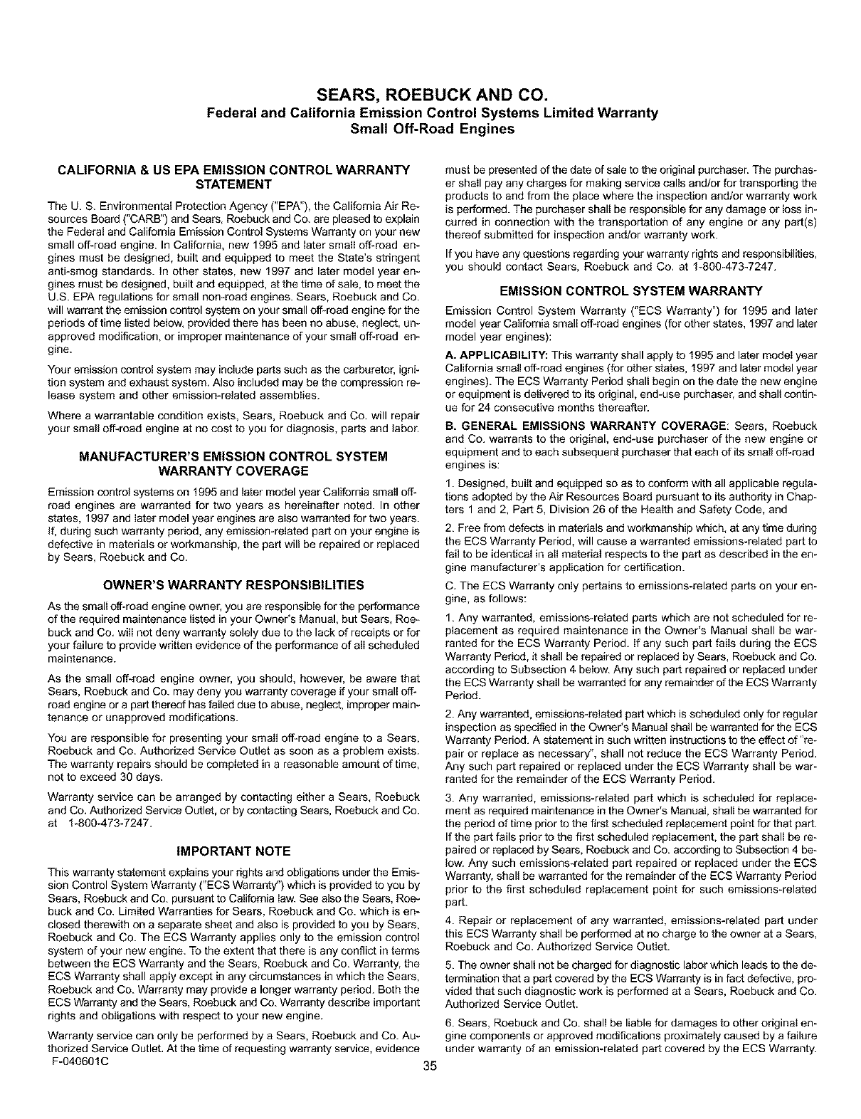
SEARS, ROEBUCK AND CO.
Federal and California Emission Control Systems Limited Warranty
Small Off-Road Engines
CALIFORNIA & US EPA EMISSION CONTROL WARRANTY
STATEMENT
The U. S. Environmental Protection Agency ("EPA"), the California Air Re-
sources Board ("CARB") and Sears, Roebuck and Co. are pleased to explain
the Federal and California Emission Control Systems Warranty on your new
small off-road engine. In California, new 1995 and later small off-road en-
gines must be designed, built and equipped to meet the State's stringent
anti-smog standards, in other states, new 1997 and later model year en-
gines must be designed, built and equipped, at the time of sale, to meet the
U.S. EPA regulations for small non*road engines. Sears, Roebuck and Co.
will warrant the emission control system on your small off-road engine for the
periods of time listed below, provided there has been no abuse, neglect, un-
approved modification, or improper maintenance of your smalI off-road en-
gine.
Your emission control system may include parts such as the carburetor, igni-
tion system and exhaust system. Also included may be the compression re-
lease system and other emission-related assemblies.
Where a warrantable condition exists, Sears, Roebuck and Co. will repair
your small off-road engine at no cost to you for diagnosis, parts and labor,
MANUFACTURER'S EMISSION CONTROL SYSTEM
WARRANTY COVERAGE
Emission control systems on 1995 and later model year California small off-
road engines are warranted for two years as hereinafter noted. In other
states, 1997 and later model year engines are also warranted for two years.
ff, during such warranty period, any emissiomreIated part on your engine is
defective in materials or workmanship, the part will be repaired or replaced
by Sears, Roebuck and Co.
OWNER'S WARRANTY RESPONSIBILITIES
As the small off-road engine owner, you are responsible for the performance
of the required maintenance listed in your Owner's Manual, but Sears, Roe*
buck and Co. will not deny warranty solely due to the lack of receipts or for
your failure to provide written evidence of the performance of alI scheduled
maintenance.
As the small off-road engine owner, you should, however, be aware that
Sears, Roebuck and Co. may deny you warranty coverage if your small off-
road engine or a part thereof has failed due to abuse, neglect, improper main-
tenance or unapproved modifications.
You are responsible for presenting your smalI off-road engine to a Sears,
Roebuck and Co. Authorized Service Outlet as soon as a problem exists.
The warranty repairs should be completed in a reasonable amount of time,
not to exceed 30 days.
Warranty service can be arranged by contacting either a Sears, Roebuck
and Co. Authorized Service Outlet, or by contacting Sears, Roebuck and Co.
at 1-800-473-7247.
IMPORTANT NOTE
This warranty statement explains your rights and obligations under the Emis-
sion Control System Warranty ("ECS Warranty") which is provided to you by
Sears, Roebuck and Co. pursuant to California law. See also the Sears, Roe-
buck and Co. Limited Warranties for Sears, Roebuck and Co. which is en-
closed therewith on a separate sheet and also is provided to you by Sears,
Roebuck and Co. The ECS Warranty applies only to the emission control
system of your new engine. To the extent that there is any conflict in terms
between the ECS Warranty and the Sears, Roebuck and Co. Warranty, the
ECS Warranty shall apply except in any circumstances in which the Sears,
Roebuck and Co. Warranty may provide a longer warranty period. Both the
ECS Warranty and the Sears, Roebuck and Co. Warranty describe important
rights and obligations with respect to your new engine.
Warranty service can only be performed by a Sears, Roebuck and Co. Au-
thorized Service Outlet. At the time of requesting warranty service, evidence
F-040691C 35
must be presented of the date of sale to the original purchaser. The purchas-
er shall pay any charges for making service calls and/or for transporting the
products to and from the place where the inspection and/or warranty work
is performed. The purchaser shall be responsible for any damage Or toss in-
curred in connection with the transportation of any engine or any part(s)
thereof submitted for inspection and/or warranty work.
If you have any questions regarding your warranty rights and responsibilities,
you should contact Sears, Roebuck and Co. at 1-800-473-7247.
EMISSION CONTROL SYSTEM WARRANTY
Emission Control System Warranty ("ECS Warranty") for 1995 and later
model year California small off-road engines (for other states, 1997 and later
model year engines):
A. APPLICABILITY: This warranty shall apply to 1995 and later model year
California small off-road engines (for other states, 1997 and later model year
engines). The ECS Warranty Period shall begin on the date the new engine
or equipment is delivered to its original, end-use purchaser, and shall contin-
ue for 24 consecutive months thereafteE
B. GENERAL EMISSIONS WARRANTY COVERAGE: Sears, Roebuck
and Co. warrants to the original, end*use purchaser of the new engine or
equipment and to each subsequent purchaser that each of its small off-road
engines is:
1. Designed, built and equipped so as to conform with all applicable regula-
tions adopted by the Air Resources Board pursuant to its authority in Chap-
ters 1 and 2, Part 5, Division 26 of the Health and Safety Code, and
2. Free from defects in materials and workmanship which, at any time during
the ECS Warranty Period, will cause a warranted emissions-related part to
fail to be identical in alI material respects to the part as described in the en-
gine manufacturer's application for certification.
C. The ECS Warranty only pertains to emissions-related parts on your en-
gine, as follows:
1. Any warranted, emissions-related parts which are not scheduled for re-
placement as required maintenance in the Owner's Manual shall be war-
ranted for the ECS Warranty Period. If any such part fails during the ECS
Warranty Period, it shall be repaired or replaced by Sears, Roebuck and Co.
according to Subsection 4 below. Any such part repaired or replaced under
the ECS Warranty shall be wa[ranted for any remainder of the ECS Warranty
Period.
2. Any warranted, emissions-related part which is scheduled only for regular
inspection as specified in the Owner's Manual shall be warranted for the ECS
Warranty Period. A statement in such written instructions to the effect of"re-
pair Or replace as necessary", shall not reduce the ECS Warranty Period.
Any such part repaired or replaced under the ECS Warranty shall be war-
ranted for the remainder of the ECS Warranty Period.
3. Any warranted, emissions-related part which is scheduled for replace-
ment as required maintenance in the Owner's Manual, shalI be warranted for
the period of time prior to the first scheduled replacement point for that part.
If the part fails prior to the first scheduled replacement, the part shall be re-
paired or replaced by Sears, Roebuck and Co. according to Subsection 4 be-
low. Any such emissions-related part repaired or replaced under the ECS
Warranty, shall be warranted for the remainder of the ECS Warranty Period
prior to the first scheduled replacement point for such emissions-related
part.
4. Repair or replacement of any warranted, emissions*related part under
this ECS Warranty shall be performed at no charge to the owner at a Sears,
Roebuck and Co. Authorized Service Outlet.
5. The owner shall not be charged for diagnostic labor which leads to the de-
termination that a part covered by the ECS Warranty is in fact defective, pro-
vided that such diagnostic work is performed at a Sears, Roebuck and Co.
Authorized Service Outlet.
6. Sears, Roebuck and Co. shall be liable for damages to other original en-
gine components or approved modifications proximately caused by a failure
under warranty of an emission-related part covered by the ECS Warranty.
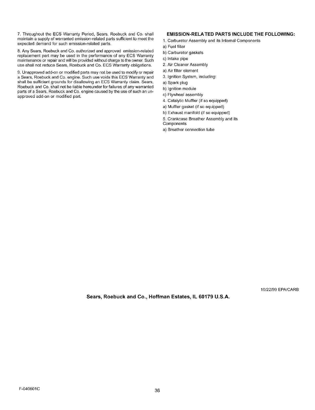
7.ThroughouttheECSWarrantyPeriod,Sears,RoebuckandCo.shall
maintainasupplyofwarrantedemission-relatedpartssufficienttomeetthe
expecteddemandforsuchemission*relatedparts,
8.AnySears,RoebuckandCo.authorizedandapprovedemission-related
replacementpartmaybeusedintheperformanceofanyECSWarranty
maintenanceorrepairandwillbeprovidedwithoutchargetotheowner.Such
useshaIInotreduceSears,RoebuckandCo.ECSWarrantyobligations.
9.Unapprovedadd-onormodifiedpartsmaynotbeusedtomodifyorrepair
aSears,RoebuckandCo.engine.SuchusevoidsthisECSWarrantyand
shallbesufficientgroundsfordisallowinganECSWarrantyclaim.Sears,
RoebuckandCo.shallnotbeliablehereunderforfailuresdany warranted
parts of a Sears, Roebuck and Co. engine caused by the use of such an un-
approved add-on or modified part.
EMISSION-RELATED PARTS INCLUDE THE FOLLOWING:
1. Carburetor Assembly and its Internal Components
a) Fuel filter
b) Carburetor gaskets
c) Intake pipe
2. Air Cleaner Assembly
a) Air filter element
3. Ignition System, including:
a) Spark plug
b) Ignition module
c) Flywheel assembly
4. Catalytic Muffler (if so equipped)
a) Muffler gasket (if so equipped)
b) Exhaust manifold (if so equipped)
5. Crankcase Breather Assembly and its
Components
a) Breather connection tube
Sears, Roebuck and Co., Hoffman Estates, IL 60179 U.S.A.
10/22/99 EPA/CARB
F-0406OlC 36
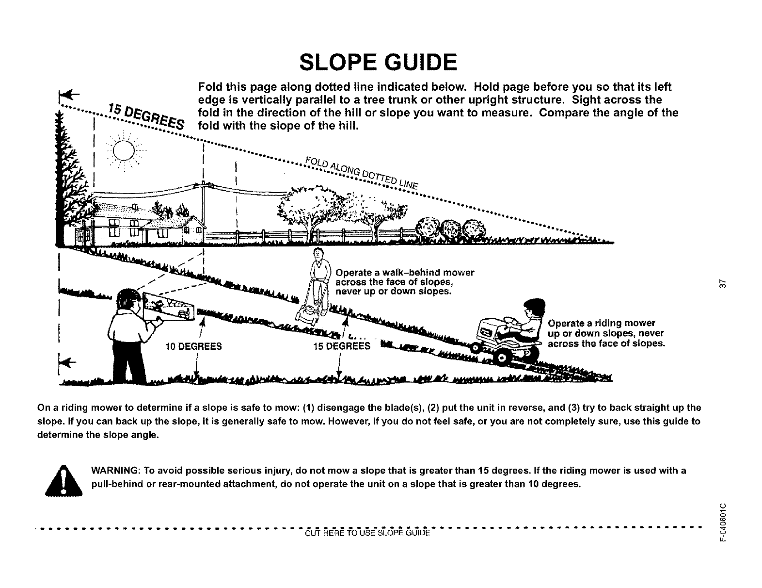
SLOPE GUIDE
Fold this page along dotted line indicated below. Hold page before you so that its left
_edge is vertically parallel to a tree trunk or other upright structure. Sight across the
.......... ./5 O_'p,_,,_ fold in the direction of the hill or slope you want to measure. Compare the angle of the
1_"'"'_-_S fold with the slope of the hill.
i , ....
1
I
I
Operate a walk-behind mower
across the face of slopes,
never up or down slopes.
10DEGREES 15DEGREES
riding mower
up or down slopes, never
across the face of slopes.
03
On a riding mower to determine if a slope is safe to mow: (1) disengage the blade(s), (2) put the unit in reverse, and (3) try to back straight up the
slope. If you can back up the slope, it is generally safe to mow. However, if you do not feel safe, or you are not completely sure, use this guide to
determine the slope angle.
WARNING: To avoid possible serious injury, do not mow a slope that is greater than 15 degrees. If the riding mower is used with a
pull-behind or rear-mounted attachment, do not operate the unit on a slope that is greater than 10 degrees.
................................. _ AE'R#tO'U_E'_6P__D'E .................................
L)
o
LL
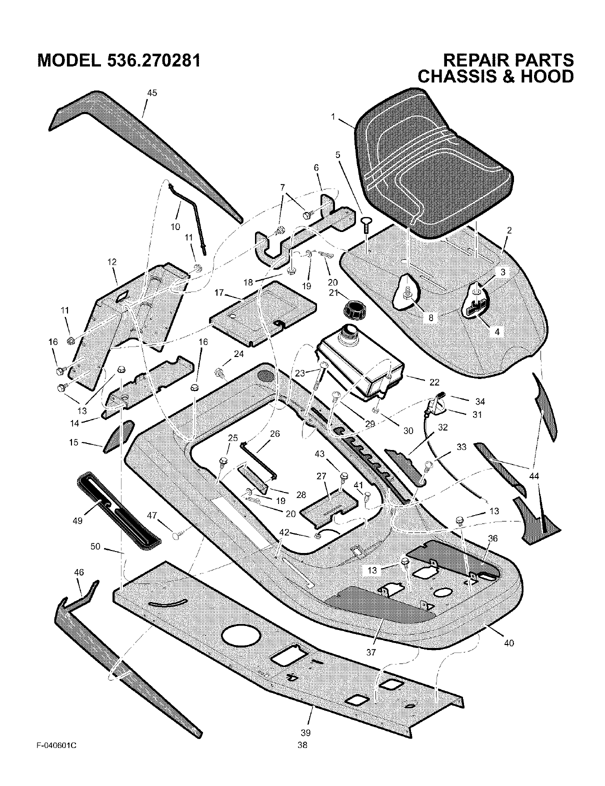
MODEL 536.270281
45
/
REPAIR PARTS
CHASSIS & HOOD
5
6
10
11
13
14 _
49
50
46
47
25 -/26
/43 \
27
34
31
32
33
/
_.13
36
44
40
39
F-040601C 38

MODEL 536.270281
Key
No. Part No. Description
1 690566 Seat
2 1401027E201 Hood
3 017x47 Washer
4 1001054 Bolt, Wing
5 002x53 Bolt, Carriage
6 1401036E701 Bracket, Hinge
7 009x29 Bolt, Shoulder
8 009x56 Bolt, Shoulder
10 1401113 Rod, Battery
11 015x84 Nut, Flange
12 1401025E701 Plate, Rear
13 26x249 Screw
14 1401050E701 Plate, Hitch
15 1401087 Cover
16 26x263 Screw
17 1401076E701 Tray, Battery
18 015x79 Nut, Flange
19 017x37 Washer
20 030x20 Pin, Cotter
21 092317 Cap, Fuel Tank *
22 7601040 Tank, Fuel
23 06x111 Screw *
24 26x253 Screw
REPAIR PARTS
CHASSIS & HOOD
Key
No. Part No. Description
25 26x263 Screw
26 1401110 Rod, Hood Prop
27 1401147 Spring, Seat Deck
28 1401297E701 Bracket, Prop Rod
29 26x201 Screw
30 15x116 Nut, NY-Lock
31 1401248 Control, Throttle
32 1401084 Cover, Detent (Black)
33 009x47 Bolt, Shoulder
36 1401145 Footmat, Left (Black)
37 1401144 Footmat, Right (Black)
39 1401298E701 Frame
40 1401316E201 Deck, Seat
41 094744 Bumper
42 15x116 Nut *
43 0025x2 Screw
44 7601036 Kit, Foil Heat Shield
45 1401073 Trim, Left
46 1401072 Trim, Right
47 0193xl Fastener, Panel
49 1401331 Cover, Long Black
50 028x78 Nut, Push
- - F-040601C Book, instruction
* These parts are included when ordering Key number 22.
F-040601C 39
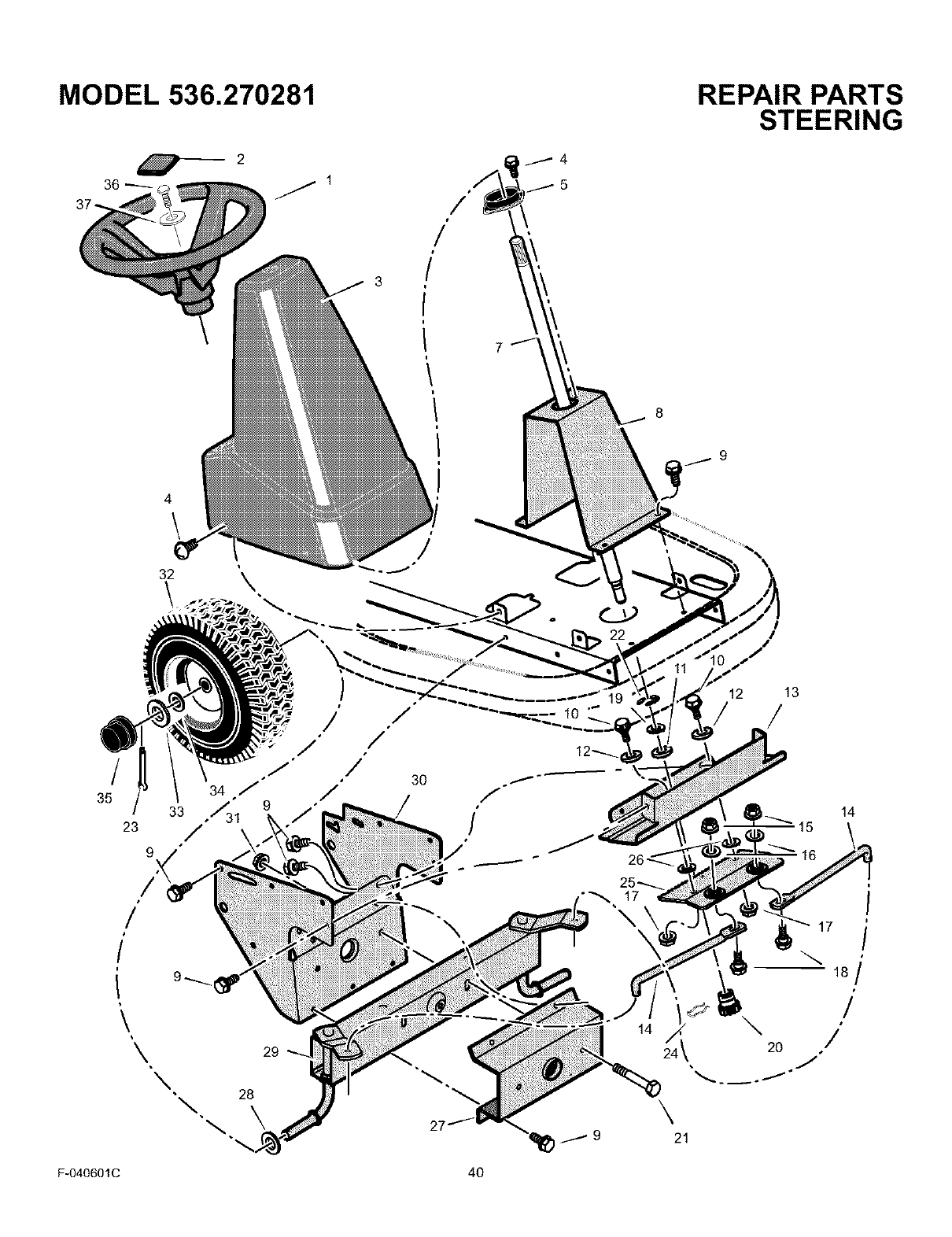
MODEL 536.270281
_2
36_ /1
3
REPAIR PARTS
STEERING
8
7 9
4\
32
/
/
/
35
23
/
\\
34 /
33 ,"/31
/
\28
\
./
./
29
//
30 /
/
\
27
-_, 17
\
19 12 13
//
14
14
15
i
18/
/
\
21
F-040601C 40
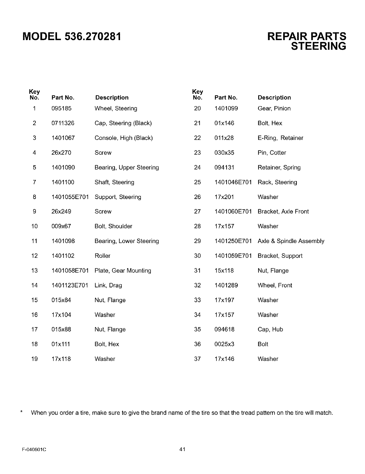
MODEL 536.270281 REPAIR PARTS
STEERING
Key Key
No. Part No. Description No. Part No. Description
1 095185 Wheel, Steering 20 1401099 Gear, Pinion
2 0711326 Cap, Steering (Black) 21 01x146 Bolt, Hex
3 1401067 Console, High (Black) 22 011x28 E-Ring, Retainer
4 26x270 Screw 23 030x35 Pin, Cotter
5 1401090 Bearing, Upper Steering 24 094131 Retainer, Spring
7 1401100 Shaft, Steering 25 1401046E701 Rack, Steering
8 1401055E701 Support, Steering 26 17x201 Washer
9 26x249 Screw 27 140t060E701 Bracket, Axle Front
10 009x67 Bolt, Shoulder 28 17x157 Washer
11 1401098 Bearing, Lower Steering 29 140t250E701 Axle & Spindle Assembly
12 1401102 Roller 30 1401059E701 Bracket, Support
13 1401058E701 Plate, Gear Mounting 31 15xt18 Nut, Flange
14 1401123E701 Link, Drag 32 1401289 Wheel, Front
15 015x84 Nut, Flange 33 17x197 Washer
16 17x104 Washer 34 17x157 Washer
17 015x88 Nut, Flange 35 094618 Cap, Hub
18 01x111 Bolt, Hex 36 0025x3 Bolt
19 17x118 Washer 37 17x146 Washer
When you order a tire, make sure to give the brand name of the tire so that the tread pattern on the tire will match.
F-040601C 41
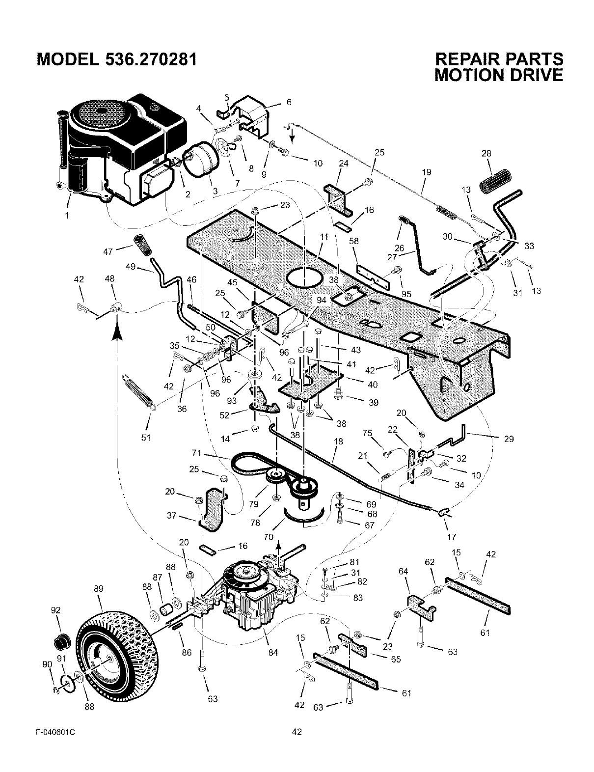
MODEL 536.270281 REPAIR PARTS
MOTION DRIVE
\
24
\
25
/16
19
13
\
28
33
13
89
92
\
90
\
88
20_
\\\ 37 _ i
X
X\
87
88
\
78
70
16
J
86 84
\63 42 63
64
\
23
65
61
17
15 42
62 /
/
61
63
F-040601C 42
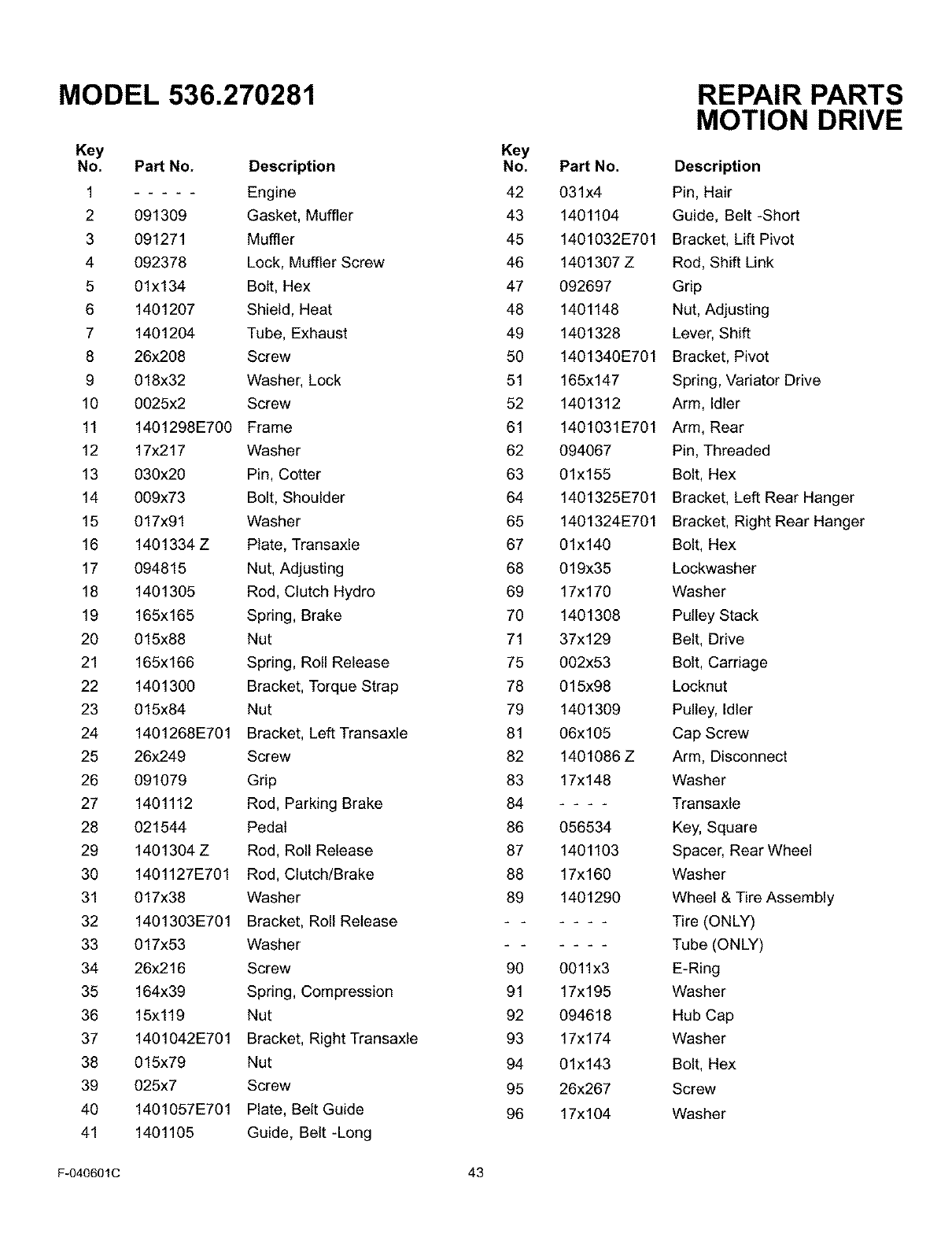
MODEL 536.270281
Key
No. Part No. Description
1 Engine
2 091309 Gasket, Muffler
3 091271 Muffler
4 092378 Lock, Muffler Screw
5 01x134 Bolt, Hex
6 1401207 Shield, Heat
7 1401204 Tube, Exhaust
8 26x208 Screw
9 018x32 Washer, Lock
10 0025x2 Screw
11 1401296E700 Frame
12 17x217 Washer
13 030x20 Pin, Cotter
14 009x73 Bolt, Shoulder
15 017x91 Washer
16 1401334 Z Plate, Transaxle
17 094815 Nut, Adjusting
18 1401305 Rod, Clutch Hydro
19 165x165 Spring, Brake
20 015x88 Nut
21 165x166 Spring, Roll Release
22 1401300 Bracket, Torque Strap
23 015x84 Nut
24 1401268E701 Bracket, Left Transaxle
25 26x249 Screw
26 091079 Grip
27 1401112 Rod, Parking Brake
28 021544 Pedal
29 1401304 Z Rod, Roll Release
30 1401127E701 Rod, Clutch/Brake
31 017x38 Washer
32 1401303E701 Bracket, Roll Release
33 017x53 Washer
34 26x216 Screw
35 164x39 Spring, Compression
36 15x119 Nut
37 1401042E701 Bracket, Right Transaxle
38 015x79 Nut
39 025x7 Screw
40 1401057E701 Plate, Belt Guide
41 1401105 Guide, Belt-Long
REPAIR PARTS
MOTION DRIVE
Key
No. Part No. Description
42 031x4 Pin, Hair
43 1401104 Guide, Belt-Short
45 1401032E701 Bracket, Lift Pivot
46 1401307 Z Rod, Shift Link
47 092697 Grip
48 1401148 Nut, Adjusting
49 1401328 Lever, Shift
50 1401340E701 Bracket, Pivot
51 165x147 Spring, Variator Drive
52 1401312 Arm, Idler
61 1401031E701 Arm, Rear
62 094067 Pin, Threaded
63 01x155 Bolt, Hex
64 1401325E701 Bracket, Left Rear Hanger
65 1401324E701 Bracket, Right Rear Hanger
67 01x140 Bolt, Hex
68 019x35 Lockwasher
69 17x170 Washer
70 1401308 Pulley Stack
71 37x129 Belt, Drive
75 002x53 Bolt, Carriage
78 015x98 Locknut
79 1401309 Pulley, Idler
81 06x105 Cap Screw
82 1401086 ZArm, Disconnect
83 17x148 Washer
84 Transaxte
86 056534 Key, Square
87 1401103 Spacer, Rear Wheel
88 17x160 Washer
89 1401290 Wheel & Tire Assembly
- - Tire (ONLY)
- - Tube (ONLY)
90 0011x3 E-Ring
91 17x195 Washer
92 094618 Hub Cap
93 17xl 74 Washer
94 01x143 Bolt, Hex
95 26x267 Screw
96 17xl 04 Washer
F-040601C 43
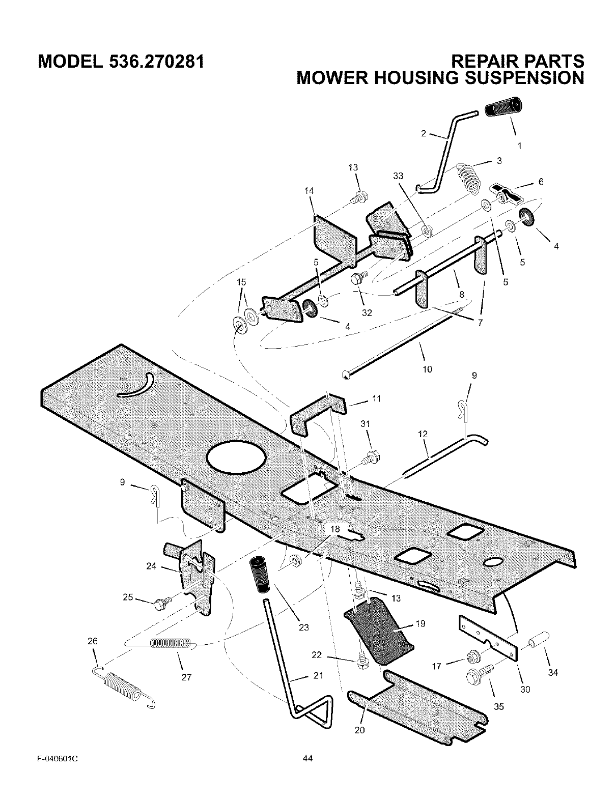
MODEL 536.270281
/
/
\\ \
REPAIR PARTS
MOWER HOUSING SUSPENSION
14
13 33
\
6
\10
8
9
11
9
31
\
26
21 17 \3O
35
34
F-040601C 44

MODEL 536.270281 REPAIR PARTS
MOWER HOUSING SUSPENSION
Key
No. PaN No.
1 092697
2 1401117
3 165x154
4 094137
5 017x45
6 095004
7 1401033E701
8 1401096
9 0031x4
10 002x93
11 1401030E701
12 1401118
13 26x249
14 1401262E701
15 17x206
17 015x79
Description
Grip, Lift Lever
Lever, Lift
Spring, Extension
Pad, Friction
Washer
Wingnut
Link, Lift
Tube, Spacer
Pin, Hair
Bolt, Carriage
Bracket, Front Hanger Pivot
Pin, Front Hanger
Screw
Arm Assembly, Lifter
Washer
Nut, Flange
Key
No. Part No. Description
18 015x84 Nut, Flange
19 1401147 Spring, Leaf
20 1401040 Hanger, Front
21 1401116 Lever, PTO
22 26x263 Screw
23 094198 Grip, PTO
24 1401199E701 Bracket, PTO
25 009x42 Bolt, Shoulder
26 165xl 57 Spring, Extension
27 165x92 Spring, Extension
30 1401260 Plate, Reinforcement
31 26x267 Screw
32 009x76 Bolt, Shoulder
33 015x84 Nut
34 1401337 Grip
35 26x290 Screw
F-040601C 45
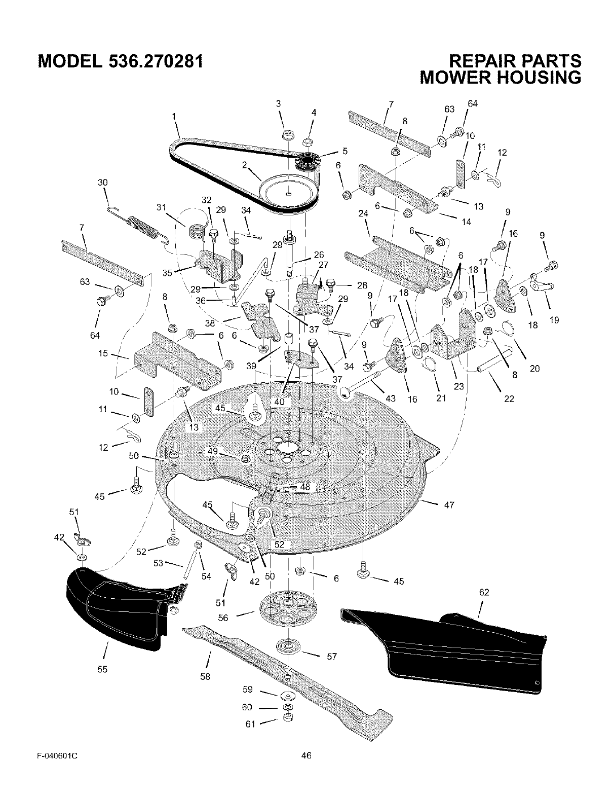
MODEL 536.270281 REPAIR PARTS
MOWER HOUSING
3 7 64
4 63
_/ _ /
Q
30
\ 31 32
I
26
27
14
6_. / /16 9
\
/
64
8
\\
19
18
10_
11
43 16 22
20
8
51
45 47
/
55 /
58
51
56
59
60 --
61
6 45
62
F-040601C 46

MODEL 536.270281
Key
No. Part No. Description
137x111 Belt, Blade Drive
2 1401092 Pulley, Input
3 15x140 Locknut
4 015x98 Nut, Flange
51401252 Pultey, ]diet
6 015x84 Nut, Flange
7 1401031E701 Arm, Rear
8 015x79 Nut, Flange
9 009x58 Bolt, Shoulder
10 1401033E701 Link, Lift
11 017x91 Washer
12 0031x4 Pin, Hair
13 094067 Pin, Threaded Shoulder
14 1401047E701 Bracket, Left Rear
t5 1401296E701 Bracket, Right Rear
16 1401038E701 Plate, Adjustment
17 094137 Pad, Friction
18 017x45 Washer
19 095004 Wingnut
20 166x43 Spring, Left Torsion
21 166x42 Spring, Right Torsion
22 1401095 Tube, Spacer
23 1401037E701 Bracket, Deck
24 1401040E701 Hanger, Front
26 1401065 Shaft, Splined
27 1401258E701 Arm Assembly, Idler
28 009x73 Bolt, Shoulder
29 017x47 Washer
30 165x157 Spring, Extension
31 166x46 Spring, Torsion
F-040601C
REPAIR PARTS
MOWER HOUSING
47
Key
No. Part No. Description
32 009x73 Bolt, Shoulder
34 030x20 Pin, Cotter
35 1401185E701 Arm Assembly, Brake
36 1401119 Link, Idler Arm
37 0025x7 Bolt
38 1401052E701 Bracket, Brake Mounting
39 1401094 Spacer, Jackshaft
40 1401259 Z Plate, Idler Mounting
42 019x45 Washer
43 002x94 Bolt, Carraige
45 002x53 Bott, Carriage
47 1401028E701 Housing, Blade
48 1401106E701 Hinge, Mulching Cover
49 015x88 Nut, Flange
50 028x76 Nut, Speed
51 014x86 Wingnut
52 002x74 Bolt, Carriage
53 091767 Z Rod, Chute Deflector
54 028x23 Cap, Push
55 1401080 Cover, Mulch
56 094305 Mandrel Housing
57 092466 Adapter, Blade
58 1401079E701 Blade
59 17x166 Washer, Cup
60 17x165 Washer
61 15x100 Nut, Blade Mount
62 1401081 Deflector, Chute
63 17x120 Washer
64 009x76 Bolt, Shoulder
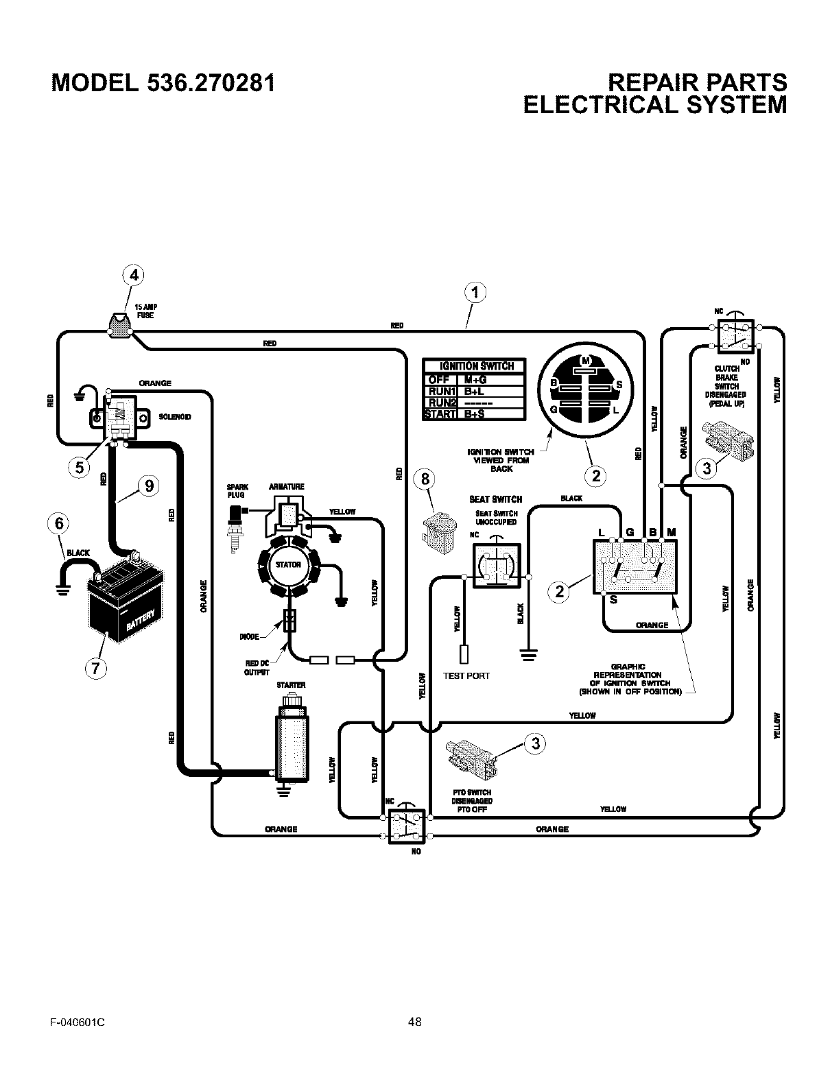
MODEL 536.270281 REPAIR PARTS
ELECTRICAL SYSTEM
=
BLACK
ORANGE
SOLBqOID
PLUG
I RUNll B+L I
IGNIIlION 81M TCH
'vlEWB) FROM
BACK
SEAT SWITCH
gEATSVRTCH
UKQCCUPD
.-r-
e
TEnOrPORT
YELLOW
PTOSlmltH
DISENGAGED
PTOOFF "el.LOW
ORANGE
NO
F-040601C 48

MODEL 536.270281 REPAIR PARTS
ELECTRICAL SYSTEM
Key Part
No. No.
250x115
Description
Harness, Chassis Wire
21401149
327349
Switch, Ignition
Key, Ignition
Nut, Hex
Cap, ignition
3 1001575 Switch, Limit
4 054212
407078
Fuse
Holder Fuse
5094613
26x229
15x116
Solenoid
Screw, Mounting
Locknut
6 024x37 Cable, Battery Ground
Screw, Ground Cable
7 092739
002x82
014x79
Battery
Bolt, Carriage
Wingnut
8 094159 Switch, Seat Sensor
9 024x24
690604
Cable, Red Batery
Boot, Positive Terminal
F-040601C 49
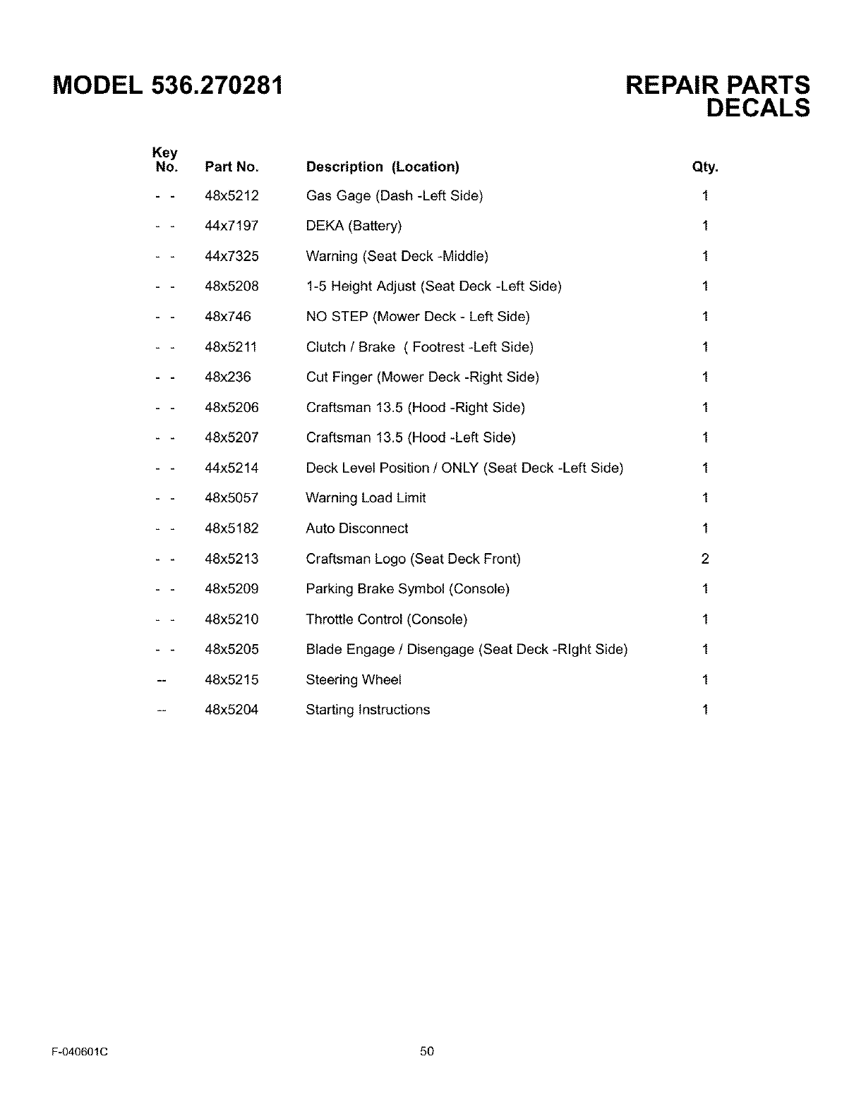
MODEL 536.270281
Key
No. PaN No.
48x5212
44x7197
44x7325
48x5208
48x746
48x5211
48x236
48x5206
48x5207
44x5214
48x5057
48x5182
48x5213
48x5209
48x5210
48x5205
-- 48x5215
-- 48x5204
Description (Location)
Gas Gage (Dash -Left Side)
DEKA (Battery)
Warning (Seat Deck -Middle)
1-5 Height Adjust (Seat Deck -Left Side)
NO STEP (Mower Deck - Left Side)
Clutch /Brake ( Footrest -Left Side)
Cut Finger (Mower Deck -Right Side)
Craftsman 13.5 (Hood -Right Side)
Craftsman 13.5 (Hood -Left Side)
Deck Level Position /ONLY (Seat Deck -Left Side)
Warning Load Limit
Auto Disconnect
Craftsman Logo (Seat Deck Front)
Parking Brake Symbol (Console)
Throttle Control (Console)
Blade Engage /Disengage (Seat Deck -Right Side)
Steering Wheel
Starting Instructions
REPAIR PARTS
DECALS
Qty.
1
1
1
1
1
1
1
1
1
1
1
1
2
1
1
1
1
1
F-040601C 50

NOTES
F-040601C 51
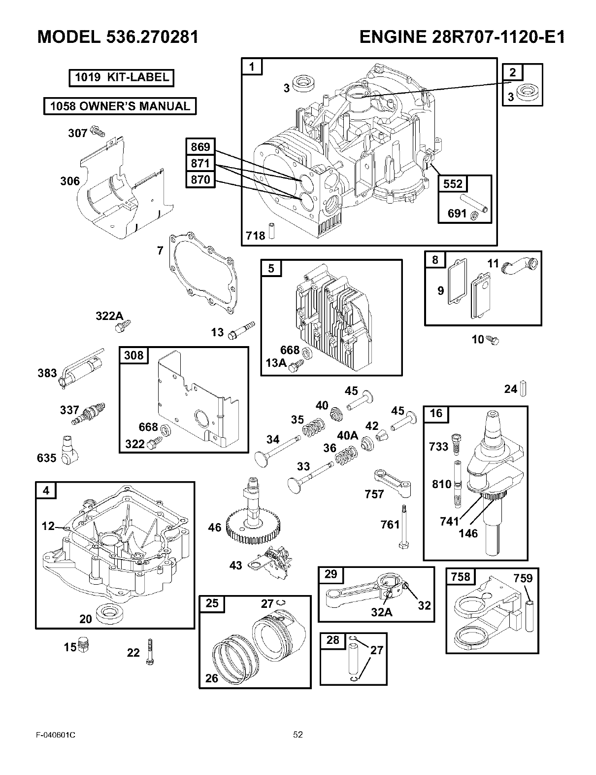
MODEL 536.270281 ENGINE 28R707-1120-E1
I 1019 KIT-LABELI
ILOS8OWNER'SMANUALI
307_
7
383
33_ 668
322_
635
3_
13
668
13A_
46
10_
146
'58 1_759
F-040601C 52
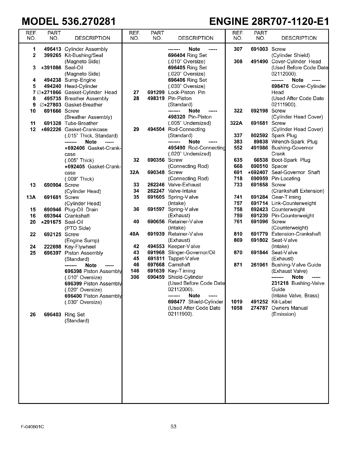
MODEL 536.270281 ENGINE 28R707-1120-E1
REE PART REE PART REE PART
NO. NO. DESCRIPTION NO. NO. DESCRIPTION NO. NO. DESCRIPTION
307 6910031 496413
2 399265
3*391086
4 494238
5 494240
7_.271866
8 495735
9_.27803
10 691666
11 691328
12 *692226
13 690904
13A 691681
15 690946
16 693944
20 *291675
22 692125
24 222698
25 696397
26 696403
Cylinder Assembly
Kit-Bushing/Seal
(Magneto Side)
Seal-Oil
(Magneto Side)
Sump-Engine
Head-Cylinder
Gasket-Cylinder Head
Breather Assembly
Gasket-Breather
Screw
(Breather Assembly)
Tube-Breather
Gasket-Crankcase
(,015" Thick, Standard)
....... Note .....
*692406 Gasket-Crank-
case
(,005" Thick)
*692405 Gasket-Crank-
case
(,009" Thick)
Screw
(Cylinder Head)
Screw
(Cylinder Head)
Plug-Oil Drain
Crankshaft
Seal-Oil
(PTO Side)
Screw
(Engine Sump)
Key-Flywheel
Piston Assembly
(Standard)
....... Note .....
696398 Piston Assembl
(,010" Oversize)
696399 Piston Assembl
(,020" Oversize)
696400 Piston Assembl
(.030" Oversize)
Ring Set
(Standard)
27 691299
28 498319
29 494504
32 690356
32A 690348
33 262246
34 262247
35 691605
36 691597
40 690656
40A 691939
42 494553
43 691968
45 691811
46 697668
146 691639
306 690459
....... Note .....
696404 Ring Set
(,010" Oversize)
696405 Ring Set
(,020" Oversize)
696406 Ring Set
(,030" Oversize)
Lock-Piston Pin
Pin*Piston
(Standard)
....... Note .....
498320 Pin-Piston
(,005" Undersized)
Rod*Connecting
(Standard)
....... Note .....
495490 Rod-Connecting
(,020" Undersized)
Screw
(Connecting Rod)
Screw
(Connecting Rod)
Valve-Exhaust
Valve-Intake
Spring-V alve
(intake)
Spring-V alve
(Exhaust)
Retainer-V alve
(intake)
Retainer-V alve
(Exhaust)
Keeper-V alve
Slinger*Governor/Oil
Tappet-V alve
Camshaft
Key-T lining
Shield-Cylinder
(Used Before Code Date
02112000),
....... Note .....
698477 Shield-Cylinder
(Used After Code Date
02111900).
308 491490
322 692198
322A 691681
337 802592
383 89838
552 491986
635 66538
668 690510
691 *692407
718 690959
733 691658
741 691284
757 691714
758 692423
759 691239
761 691096
810 691779
869 691802
870 691844
871 261961
1019 491252
1058 274787
Screw
(Cylinder Shield)
Cover*Cylinder Head
(Used Before Code Date
02112000),
....... Note .....
698476 Cover-Cylinder
Head
(Used After Code Date
02111900),
Screw
(Cylinder Head Cover)
Screw
(Cylinder Head Cover)
Spark Plug
Wrench*Spark Plug
Bushing-Governor
Crank
Boot*Spark Plug
Spacer
Seal-Governor Shaft
Pin-Locating
Screw
(Crankshaft Extension)
Gear-T lining
Link*Counterweight
Counterweight
Pin-Counterweight
Screw
(Counterweight)
Extension*Crankshaft
SeatWalve
(intake)
SeatWalve
(Exhaust)
Bushing-V alve Guide
(Exhaust Valve)
....... Note .....
231218 BushingWalve
Guide
(intake Valve, Brass)
Kit-Label
Owners Manual
(Emission)
F-040601C 53
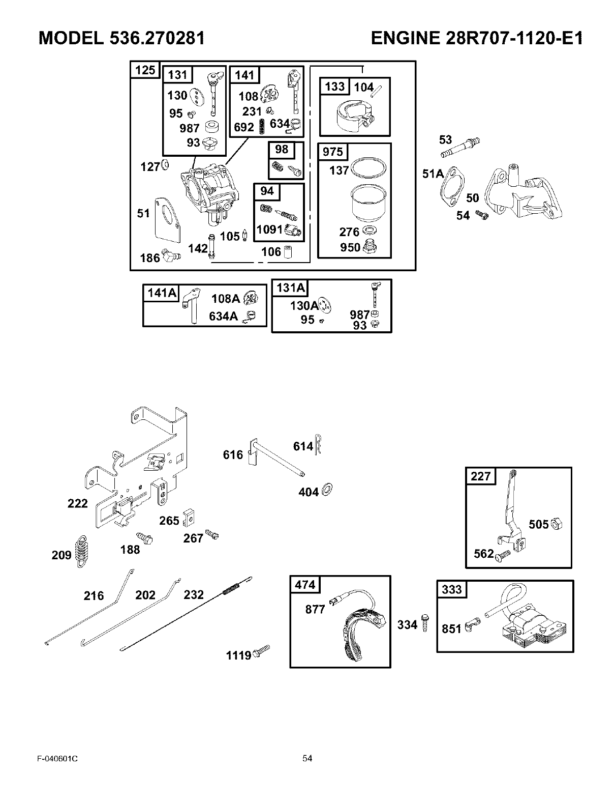
MODEL 536.270281 ENGINE 28R707-1120-E1
1251
130_
95
987
108
231
692 | 634_
N
1091_
106_
-[
137_
276
950
54
634A _9870
93
222
209@
216
616
265_
267 _
188
1119 _
877
334_ 851
_505@
562_
F-040601C 54
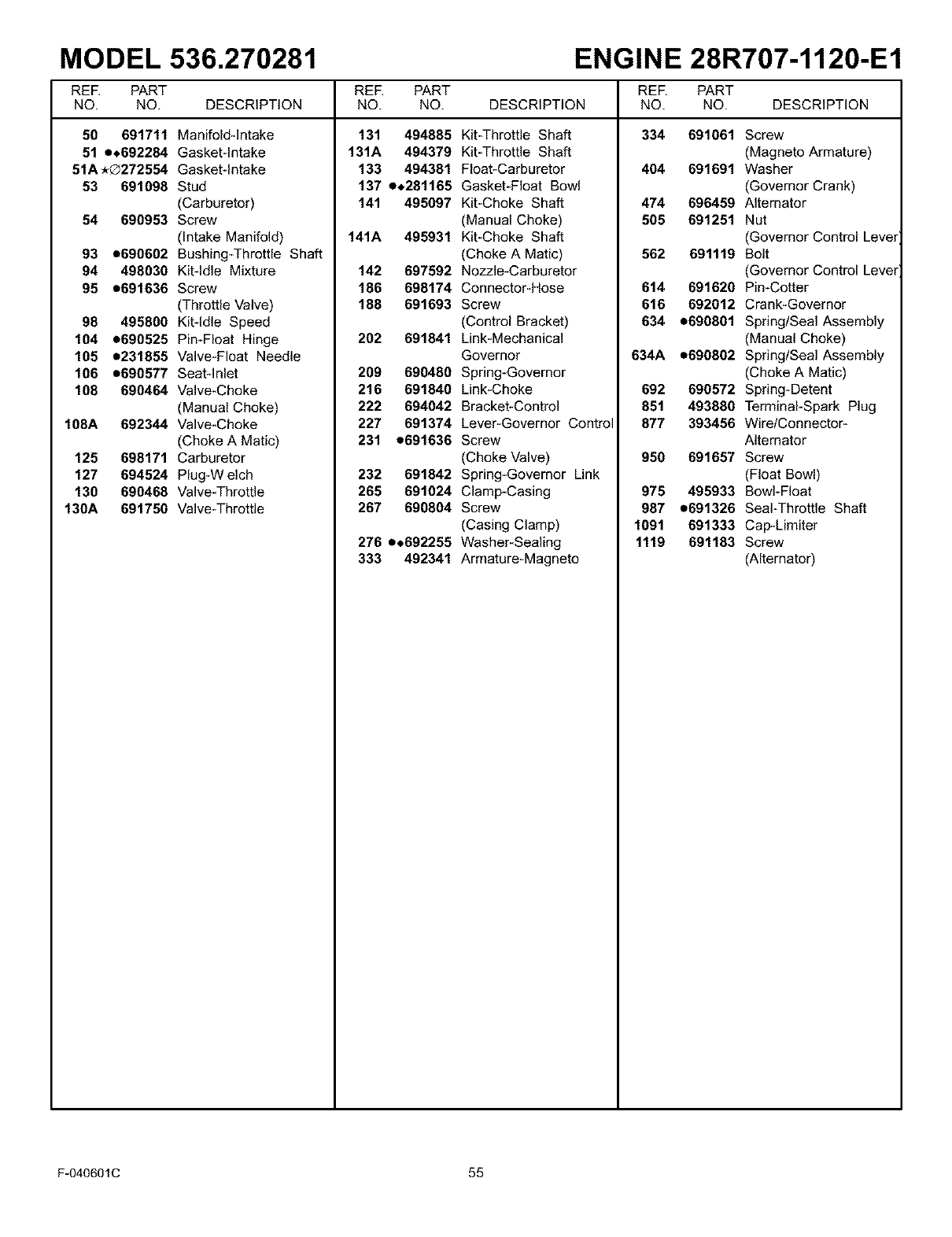
MODEL 536.270281 ENGINE 28R707-1120-E1
REE PART REE PART REE PART
NO. NO. DESCRIPTION NO. NO. DESCRIPTION NO. NO. DESCRIPTION
334 69106150 691711
51 e.692284
51A*®272554
53 691098
54 690953
93 e690602
94 498030
95 e691636
98 495800
104 e690525
105 e231855
106 e690577
108 690464
108A 692344
125 698171
127 694524
130 690468
130A 691750
Manifoldqntake
Gasketqntake
Gasketqntake
Stud
(Carburetor)
Screw
(Intake Manifold)
Bushing_Throttle Shaft
Kitqdle Mixture
Screw
(Throttle Valve)
Kitqdle Speed
PimFIoat Hinge
Valve_FIoat Needle
Seatqnlet
Valve_Choke
(Manual Choke)
Valve_Choke
(Choke A Matic)
Carburetor
Plug-W elch
Valve_Throttle
Valve-Throttle
131 494885
131A 494379
133 494381
137 e,281165
141 495097
141A 495931
142 697592
186 698174
188 691693
202 691841
209 690480
216 691840
222 694042
227 691374
231 e691636
232 691842
265 691024
267 690804
276 e,692255
333 492341
Kit_Throttle Shaft
Kit_Throttle Shaft
Float-Carburetor
Gasket_FIoat Bowl
Kit_Choke Shaft
(Manual Choke)
Kit_Choke Shaft
(Choke A Matic)
Nozzle-Carburetor
Connector-Hose
Screw
(Control Bracket)
Link*Mechanical
Governor
Spring-Governor
Link*Choke
Bracket-Control
Lever-Governor Control
Screw
(Choke Valve)
Spring-Governor Link
Clamp*Casing
Screw
(Casing Clamp)
Washer*Sealing
Armature-Magneto
Screw
(Magneto Armature)
464 691691 Washer
(Governor Crank)
474 696459 Alternator
565 691251 Nut
(Governor Control Lever
562 691119 Bolt
(Governor Control Lever
614 691620 Pin-Cotter
616 692012 Crank*Governor
634 o690801 Spring/Seal Assembly
(Manual Choke)
634A o690802 Spring/Seal Assembly
(Choke A Matic)
692 690572 Spring-Detent
851 493880 Terminal*Spark Plug
877 393456 Wire/Connector-
Alternator
950 691657 Screw
(Float Bowl)
975 495933 Bowl-Float
987 o691326 Seal-Throttle Shaft
1091 691333 Cap*Limiter
1119 691163 Screw
(Alternator)
F-040601C 55
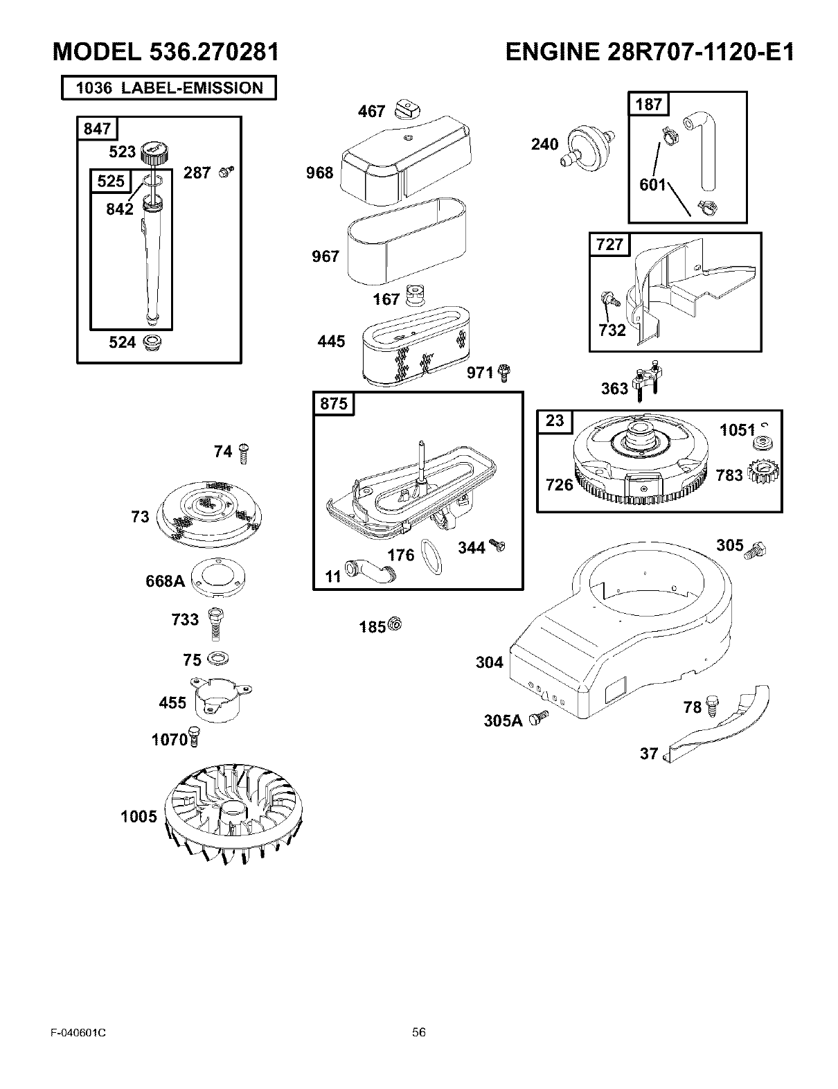
MODEL 536.270281
11036 LABEL-EMISSION I
523
5251 1287
,,_=/
842 t
524
74
668A _
733 _
75_
1070_
968
967
445
167
11 _76
185@
344%
ENGINE 28R707-1120-E1
601
3o5_
J
304
305A_
1005
F-040601C 56
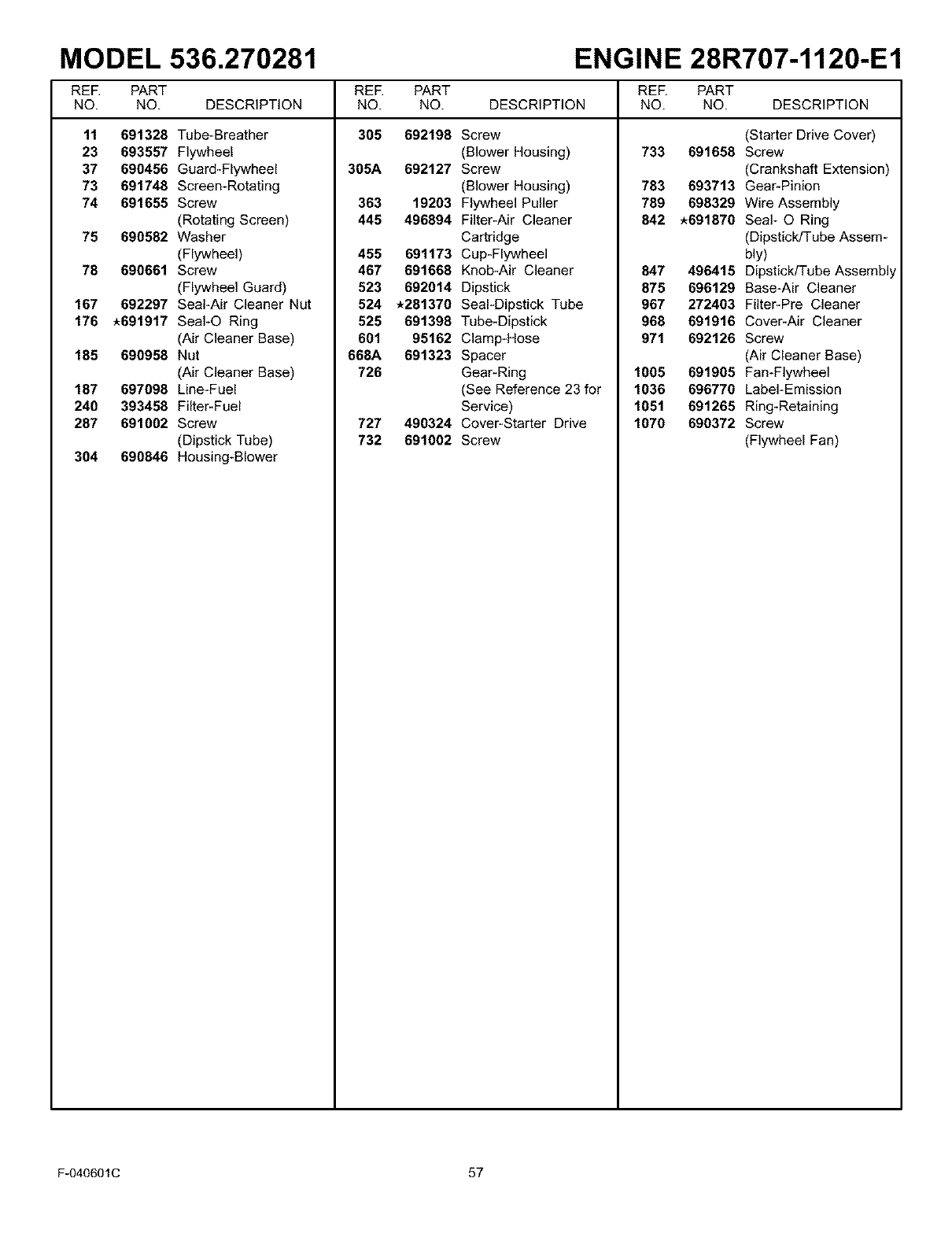
MODEL 536.270281 ENGINE 28R707-1120-E1
REE PART REE PART REE PART
NO. NO. DESCRIPTION NO. NO. DESCRIPTION NO. NO. DESCRIPTION
305 69219811 691328
23 693557
37 690456
73 691748
74 691655
75 690582
78 690661
167 692297
176 *691917
185 690958
187 697098
240 393458
287 691002
304 690846
Tube-Breather
Flywheel
Guard*Flywheel
Screen*Rotating
Screw
(Rotating Screen)
Washer
(Flywheel)
Screw
(Flywheel Guard)
Seal-Air Cleaner Nut
SeaI-O Ring
(Air Cleaner Base)
Nut
(Air Cleaner Base)
Line*Fuel
Filter*Fuel
Screw
(Dipstick Tube)
Housing-Blower
305A 692127
363 19203
445 496894
455 691173
467 691668
523 692014
524 *281370
525 691398
601 95162
668A 691323
726
727 490324
732 691002
Screw
(Blower Housing)
Screw
(Blower Housing)
Flywheel Puller
Filter-Air Cleaner
Cartridge
Cup*Flywheel
Knob-Air Cleaner
Dipstick
Seal*Dipstick Tube
Tube*Dipstick
Clamp*Hose
Spacer
Gear-Ring
(See Reference 23 for
Service)
Cover-Starter Drive
Screw
(Starter Drive Cover)
733 691658 Screw
(Crankshaft Extension)
703 693713 Gear*Pinion
709 698329 Wire Assembly
842 *691070 Seal- O Ring
(Dipstick/Tube Assem*
bly)
847 496415 Dipstick/Tube Assembly
875 696129 Base-Air Cleaner
967 272403 Filter*Pre Cleaner
960 691916 Cover*Air Cleaner
971 692126 Screw
(Air Cleaner Base)
1005 691905 Fan-Flywheel
1036 696770 Label-Emission
1051 691265 Ring-Retaining
1070 690372 Screw
(Flywheel Fan)
F-040601C 57
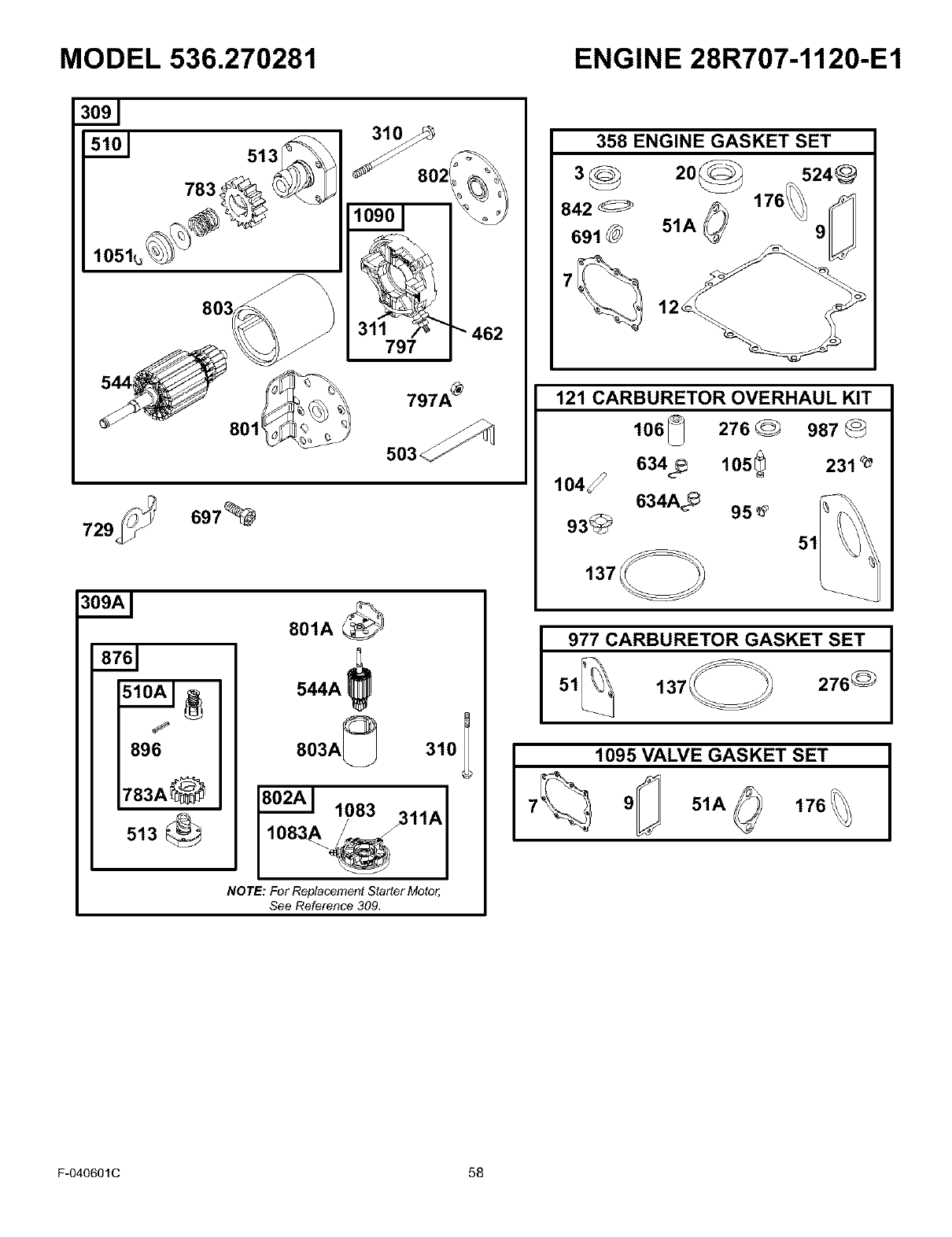
MODEL 536.270281 ENGINE 28R707-1120-E1
310_
_802
10901
797 "" 462
8011
797A _
503<
697_
513@
544A !
803A_
Sa 108'yu3 311A
NOTE: For Replacement Starter Motor,
See Reference 309,
358 ENGINE GASKET SET
842
691 @
20_ 176/ i24j_
51A_ 9U
121 CARBURETOR OVERHAUL KIT
106 _276 _987
634_ 105_ 231 _
lO4_
634A_ 95
93_
137
977 CARBURETOR GASKET SET
137 276 _
1095 VALVE GASKET SET
7_ 9_ 51A 176
F-040601C 58
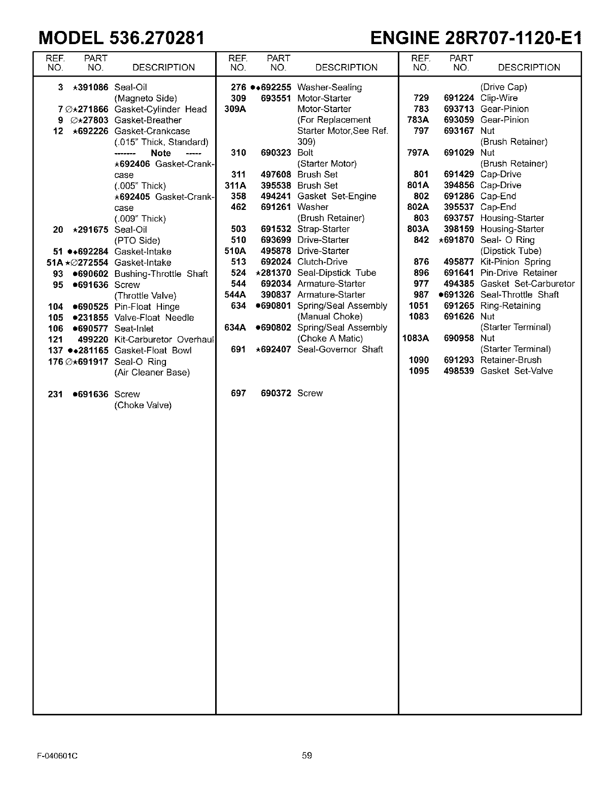
MODEL 536.270281 ENGINE 28R707-1120-E1
REE PART REE PART REE PART
NO. NO. DESCRIPTION NO. NO. DESCRIPTION NO. NO. DESCRIPTION
3*391086 Seal-Oil
(Magneto Side)
7_.271866 Gasket-Cylinder Head
9 _.27803 Gasket-Breather
12 *692226 Gasket-Crankcase
(.015" Thick, Standard)
....... Note .....
*692406 Gasket-Crank-
case
(,005" Thick)
*692405 Gasket-Crank-
case
(,009" Thick)
20 *291675 Seal-Oil
(PTO Side)
51 e,692284 Gasketqntake
51A*®272554 Gasketqntake
93 e690602 Bushing-Throttle Shaft
95 e691636 Screw
(Throttle Valve)
104 e690525 Pin-Float Hinge
105 e231655 Valve-Float Needle
106 e690577 Seatqnlet
121 499220 Kit-Carburetor Overhaul
137 e,281165 Gasket-Float Bowl
176®.691917 SeaI-O Ring
(Air Cleaner Base)
231 e691636 Screw
(Choke Valve)
276 e,692255
309 693551
309A
310 690323
311 497608
311A 395538
358 494241
462 691261
503 691532
510 693699
510A 495878
513 692024
524 *281370
544 692034
544A 390837
634 e690801
634A e690802
691 *692407
Washer-Sealing
Motor-Starter
Motor-Starter
(For Replacement
Starter Motor, See Ref.
309)
Bolt
(Starter Motor)
Brush Set
Brush Set
Gasket Set-Engine
Washer
(Brush Retainer)
Strap-Starter
Drive-Starter
Drive-Starter
Clutch-Drive
Seal-Dipstick Tube
Armature-Starter
Armature-Starter
Spring/Seal Assembly
(Manual Choke)
Spring/Seal Assembly
(Choke A Matic)
Seal-Governor Shaft
697 690372 Screw
(Drive Cap)
729 691224 Clip-Wire
783 693713 Gear-Pinion
783A 693059 Gear-Pinion
797 693167 Nut
(Brush Retainer)
797A 691029 Nut
(Brush Retainer)
801 691429 Cap-Drive
8OlA 394856 Cap-Drive
802 691286 Cap-End
802A 395537 Cap-End
803 693757 Housing-Starter
803A 398159 Housing-Starter
842 *691870 Seal- O Ring
(Dipstick Tube)
876 495877 Kit-Pinion Spring
896 691641 Pin-Drive Retainer
977 494385 Gasket Set-Carburetor
987 e691326 Seal-Throttle Shaft
1051 691265 Ring-Retaining
1083 691626 Nut
(Starter Terminal)
1083A 690958 Nut
(Starter Terminal)
1090 691293 Retainer-Brush
1095 496539 Gasket Set-Valve
F-040601C 59
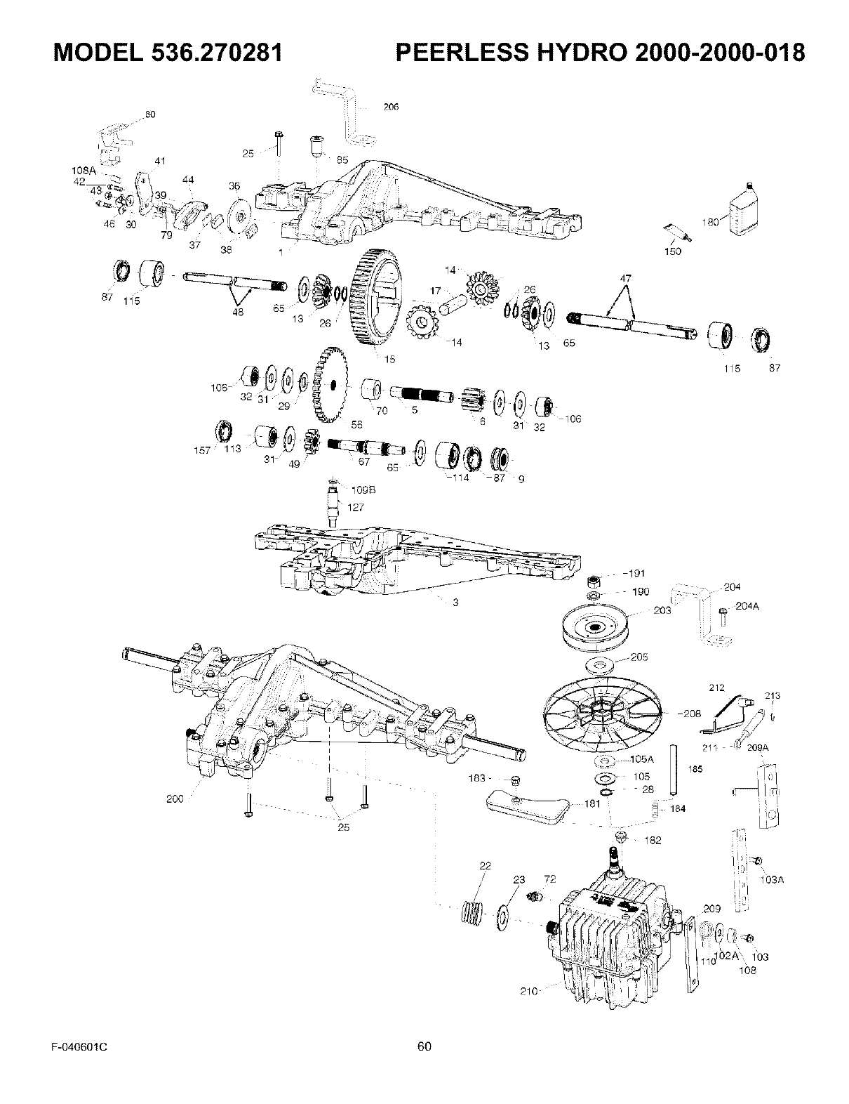
MODEL 536.270281 _i=-...........
2O6
2O0
47
6O
F.0406010
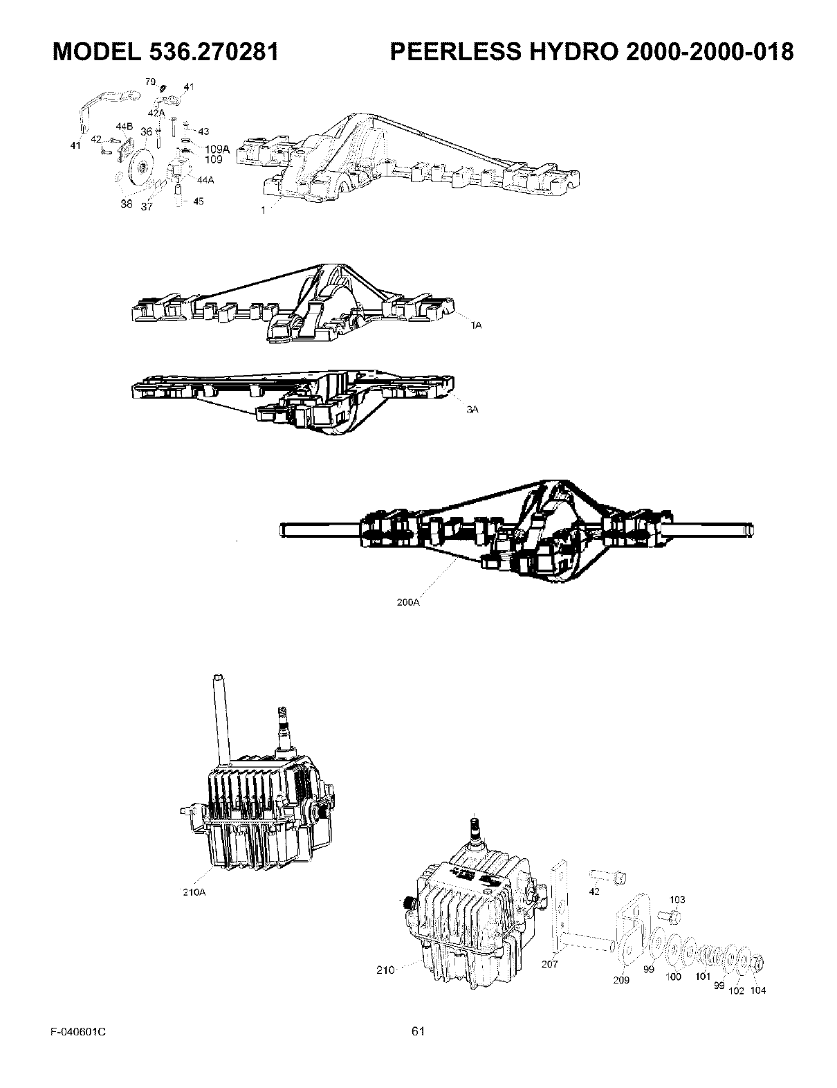
MODEL 536.270281 PEERLESS HYDRO 2000-2000-018
79
41 =_ 109A
109
1A
3#,
200A
210A
210 2O7
42 103
99 100 101
209 '
99 102 104
F-040601C 61

MODEL 536.270281 PEERLESS HYDRO 2000-2000-018
Key
No. PaN No.
1A 772152
3A 770136
5 776441
6 778263
9 786197
13 778368
14 778368
15 778373
17 786139
22 792194
23 792195
25 792073A
26 792125
28 792035
29 780065
31 780189
36 790071
37 790103
38 799021
41 790101
42 792202
42A 792203
44A 790100
44B 790099
45 790101
47 775120
48 778121A
49 778311
56 778310
65 780001
67 776440
70 786196
79 792201
85 792154
Description
Cover RH (Mach)
Case RH (Cast)
Counter Shaft
Spur Gear 11T
Neutral Sleeve .572L
Bevel Gear 13T (incl. 14)
Bevel Gear 13T (incl. 13)
Ring Gear 54T
Drive Pin
Spring
Washer .7501D .032T
Screw 1/4-20 x 1.25
Retaining Ring
Retaining Ring
Washer .6271D .091W
Washer .5631D .062W
Brake Disk
Brake Pad Plate
Brake Pad
Brake Lever
Screw 1/4-20 x .750
Screw 1/4-20 x 1.750
Inside Brake (Mach)
Outside Brake
Actuator Rod
Axle 17.219"
Axle 12.062"
Spur Gear 10T (steel)
Spur Gear 34T (steel)
Washer .7501D .56W
Brake Shaft
Spacer .625
Spring
OilFillPlug
Key
No. Part No. Description
87 788088A Oil Seal .750
99 792141 Washer .3771D .058W
100 792200 Snubber Washer
102 792184 Washer .4371D. 078W
103 792193 Screw 1/4-28
103 792193 Screw 1/4-28 x .490
104 792198 Hex Nut 3/8-24 Lock
105 780096 Washer .6251D .057W
105A 780153 Washer .6271D .140W
106 786162 Sleeve & Bearing Assy
107 792202 Screw 1/4-20 x 3/4"
109 788069 Square Cut O'Ring
109A 792145 Pushnut 1/2"
109B 788104 O-Ring .364tD
110 792199 Neutral Return Spring
113 786199 Sleeve Assembly (incl. 157)
114 786200 Sleeve Assembly (incl. 87)
115 786198 Sleeve Assembly (incl. 87)
127 784385 Shift Lever Assembly (Incl. 109)
150 788093A Liquid Gasket RTV Silicon
157 788102 Oit Seat .5625tD
180 730229B Gear Oil 80W90
181 798064 Overflow Bottle
182 788103 Grommet
190 792150 Washer .4431D .109W
191 792151 Nut 7/16-20
200A 794812 Differential (Gear Reduction
Drive)
203 798065 Pulley & Hub Assembly
205 792212 Washer 1.281D .140W
207 798053 Mounting Plate
208 798040 Fan
209 798066 Control Lever
210A 794811 Hydro Module RH (Foot Control)
F-040601C 62

INDEX
A
Adjustments
Clutch, 31
Mower Housing, Level, 26
Air Screen, 23
Attachments, 17
Automatic Drive Disconnect,
Operation, 12
B
Battery
Charge, 21
Check, 8
Clean, 21
Install, 8
Removal, 21
Storage, 33
Belt
Drive Belt, Adjust, 31
Motion Drive
Adjust, 31
Replace, 29
Mower Drive, Replace, 30
Blade
Inspect, 20
Remove And install, 20
Sharpen, 20
C
Clutch
Adjust, 31
Check, 31
Clutch /Brake Pedal, Location, 10
Controls, Location, 10
Cutting Height
Adjust, 26
Change, 12
O
Drive Belt, Adjust, 31
E
Engine
Cooling System, 23
Fuel, 9, 16
Lubrication, 23
Muffler, 23
Oil, 9, 16, 23
Preparation, 9
Spark Arrester, 9, 23
Starting, 16
Storage, 33
Throttle Control, 11
F
Filter, Air, 24
Fuel, Type, 16
Fuse, 33
Ignition Switch, Location, 10
L
Lift Lever
Location, 10
Operation, 12
Lubrication
Engine, 23
Mower, 22
M
Maintenance
Battery
Charge, 21
Clean, 21
Belt
Motion Drive, 29
Mower Drive, 30
Blade, 20
Clutch, 31
Filter, Air, 24
Fuse, 33
Install, Wheels, 32
Lubrication, 22
Mower Housing
Clean, 33
Install, 28
Level, 26
Remove, 28
Muffler, 23
Spark Plug, 24
Service And Adjustment,
Carburetor, 25
Maintenance Chart, 19
Motion Drive Belt
Adjust, 31
Replace, 29
Mower Drive Belt, Replace, 30
Mower Housing
Clean, 33
Cutting Height, 12
Install, 28
Level Adjustment, 26
Operation, 17
Remove, 28
Muffler, 23
Spark Arrester, 23
Mulcher, Operation, 18
Mulcher Cover, Remove, 15
O
Oil
Change, 23
Check, 16, 23
Type, 16
Operation
Attachments, 17
Automatic Drive Disconnect, 12
Clutch /Brake Pedal, 10
Ignition Switch, 10
Lift Lever, 10, 12
Location Of Controls, 10
Mower Housing, 17
Mowing And Bagging, 18
Mulching, 18
Operate On Hills, 17
Parking Brake, 10, 11
Speed Control Lever, 10
Speed Control Lever, 13
Start The Engine, 16
Stop The Unit, 11
Throttle Control, 10, 11
Transport, 14
P
Parking Brake
Location, 10
Operation, 11
S
Safety Rules, American National
Standard Institute, 4-5
Seat Switch, Operation, 11, 16
Side Discharge Attachment,
Install, 15
Slope Guide, 37
Spark Arrester, 9, 23
Spark Plug, 24
Speed Control Lever
Location, 10
Operation, 13
Speed Control Leverl, Adjust, 31
T
Throttle Control
Location, 10
Operation, 11
Tire Pressure, 9, 19
Trouble Shooting Chart, 34
W
Warranty, 2
Wheel Alignment, 33
F-030614L 63

NOTES
F-O30614L 64
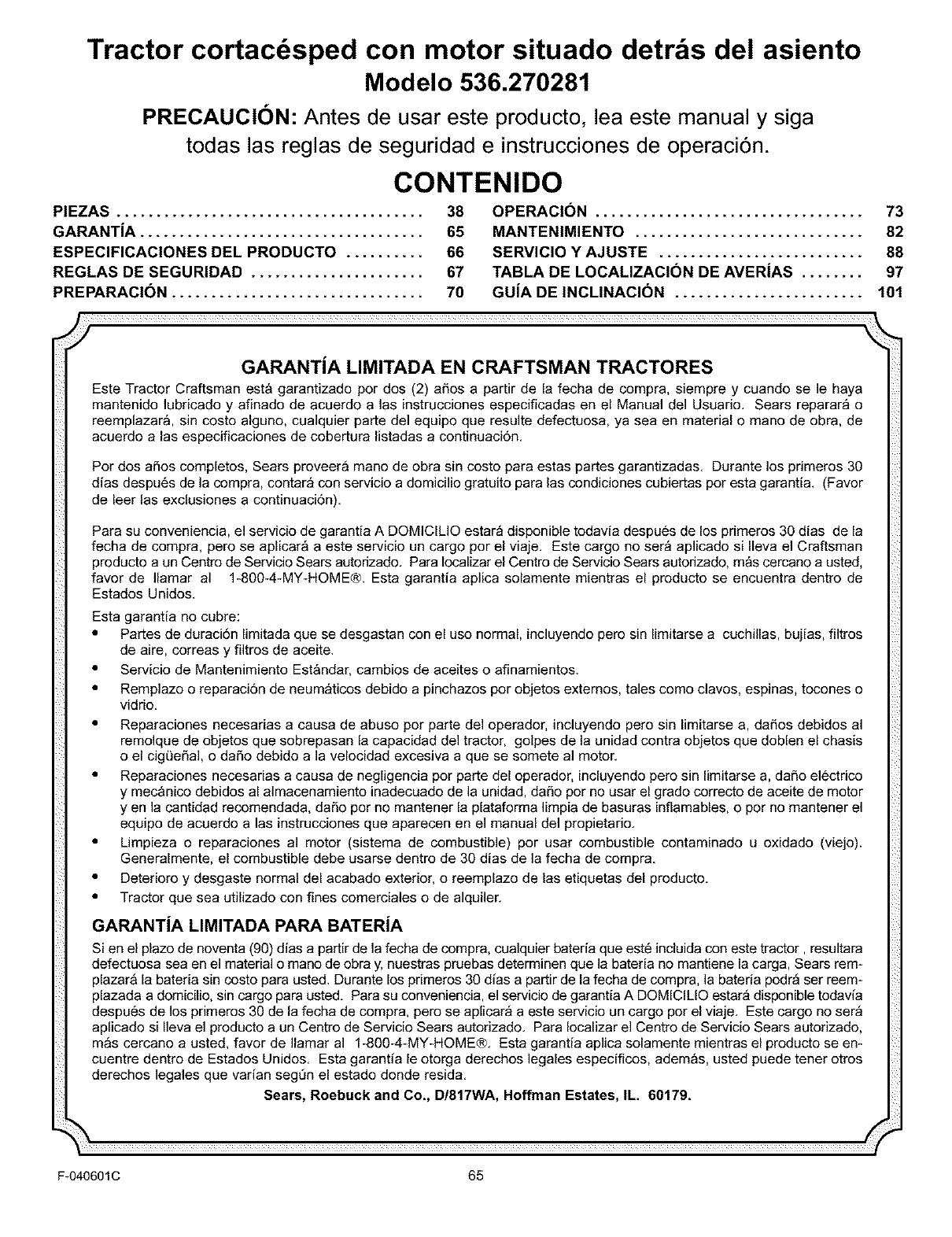
Tractor cortacdsped con motor situado detr s del asiento
Modelo 536.270281
PRECAUCION: Antes de usar este producto, lea este manual y siga
todas las reglas de seguridad e instrucciones de operaci6n.
CONTENIDO
PIEZAS ....................................... 38
GARANTiA .................................... 65
ESPEClFICAClONES DEL PRODUCTO .......... 66
REGLAS DE SEGURIDAD ...................... 67
PREPARAClON ................................ 70
OPERACION .................................. 73
MANTENIMIENTO ............................. 82
SERVIClO Y AJUSTE .......................... 88
TABLA DE LOCALIZAClC)N DE AVERiAS ........ 97
GUiA DE INCLINAClON ........................ 101
GARANTiA LIMITADA EN CRAFTSMAN TRACTORES
Este Tractor Craftsman esta garantizado por dos (2) aSos a partir de la fecha de compra, siempre y cuando se le haya
mantenido lubricado y afinado de acuerdo a las instrucciones especificadas en el Manual del Usuario. Sears reparar_ o
reemplazara, sin costo alguno, cualquier parte del equipo que resulte defectuosa, ya sea en material o mano de obra, de
acuerdo alas especificaciones de cobertura listadas a continuac[6n.
Por dos aSos completos, Sears proveer& mano de obra sin costo para estas partes garantizadas. Durante los primeros 30
dias despu6s de la compra, contar_ con servicio a domicilio gratuito para las condiciones cubiertas por esta garant[a. (Favor
de leer las exclusiones a continuaci6n).
Para su conveniencia, el servicio de garantia A DOMICILIO estar_ disponible todavia despues de los primeros 30 dias de la
fecha de compra, pero se aplicar& a este servicio un cargo por el viaje. Este cargo no ser_ aplicado si Ileva el Craftsman
producto a un Centro de Servicio Sears autodzado. Para Iocalizar el Centro de Servicio Sears autodzado, mas cercano a usted,
favor de Ilamar al 1-800-4-MY-HOME®. Esta garantia aplica solamente mientras el producto se encuentra dentro de
Estados Unidos.
Esta garantia no cubre:
•Partes de duraci6n limitada que se desgastan con el uso normal, incluyendo pero sin limitarse a cuchillas, bujias, filtros
de aire, correas y filtros de aceite.
• Servicio de Mantenimiento Estandar, cambios de aceites o afinamientos.
• Remplazo o reparaci6n de neum_ticos debido a 9inchazos por objetos externos, tales como clavos, espinas, tocones o
vidrio.
• Reparaciones necesarias a causa de abuso por parte del operador, induyendo pero sin limitarse a, daSos debidos al
remolque de objetos que sobrepasan la capacidad del tractor, golpes de la unidad contra objetos que doblen el chasis
o el cigL_eSal, o daSo debido a la velocidad excesiva a que se somete al motor.
• Reparaciones necesarias a causa de negligencia por parte del operador, incluyendo pero sin limitarse a, daSo electrico
y mecanico debidos al almacenamiento inadecuado de la unidad, daSo por no usar el grado correcto de aceite de motor
yen la cantidad recomendada, daSo por no mantener la plataforma limpia de basuras inflamables, o por no mantener el
equipo de acuerdo a ]as [nstrucc[ones que aparecen en el manual del propietario.
• Limpieza o reparaciones al motor (sistema de combustible) por usar combustible contaminado u oxidado (viejo).
Generalmente, el combustible debe usarse dentro de 30 dias de la fecha de compra.
• Deterioro y desgaste normal del acabado exterior, o reemplazo de las etiquetas del producto.
• Tractor que sea utilizado con fines comerciales o de alquiler.
GARANTiA LIMITADA PARA BATERiA
Si en el plazo de noventa (90) d_asa partir de la fecha de compra, cualquier bateda que est6 incluida con este tractor, resultara
defectuosa sea en el material o mano de obra y, nuestras pruebas determinen que la bateria no mantiene la carga, Sears rem-
plazar& la bateria sin costo para usted. Durante los primeros 30 d_as a partir de la fecha de compra, la bateria podr_ ser reem-
plazada a domicilio, sin cargo para usted. Para su conveniencia, el servicio de garantia A DOMICILIO estar_ disponible todav_a
despues de los primeros 30 de la fecha de compra, pero se aplicar_ a este servicio un cargo por el viaje. Este cargo no ser_
aplicado si Ileva el producto a un Centro de Servicio Sears autorizado. Para Iocalizar el Centro de Servicio Sears autorizado,
m&s cercano a usted, favor de Ilamar al 1-800-4-MY-HOME®. Esta garantia aplica solamente mientras el producto se en-
cuentre dentro de Estados Unidos. Esta garantia le otorga derechos legales especificos, adem&s, usted puede tener otros
derechos legales que var_an segOn el estado donde resida.
Sears, Roebuck and Co,, D/817WA, Hoffman Estates, tL, 60179,
F-040601C 65
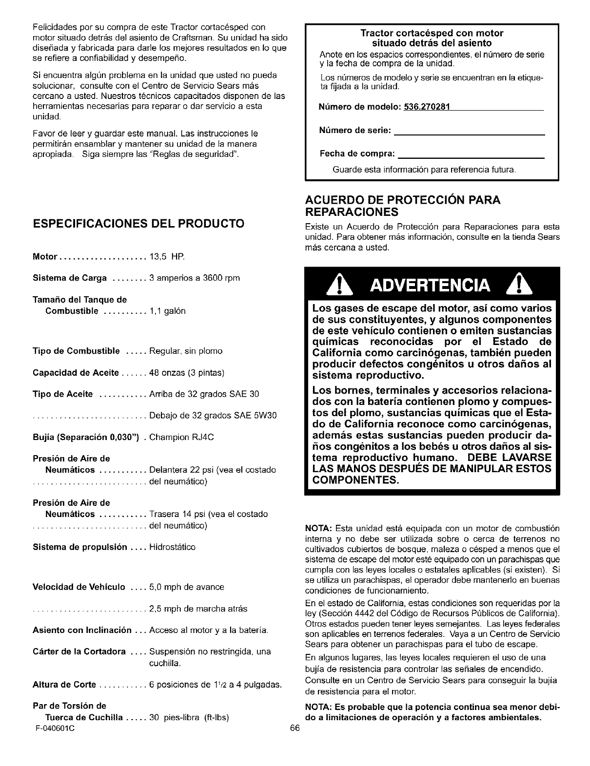
Felicidades por su compra de este Tractor cortac6sped con
motor situado detr_s del asiento de Craftsman. Su unidad ha sido
diseSada y fabricada para dade los mejores resultados en Io que
se refiere a confiabilidad y desempefio.
Si encuentra algQn problema en la unidad que usted no pueda
solucionar, consulte con el Centro de Servicio Sears m_s
cercano a usted. Nuestros tecnicos capacitados disponen de las
herramientas necesarias para reparar o dar servicio a esta
unidad.
Favor de leer y guardar este manual. Las instrucciones le
permitir_n ensamblar y mantener su unidad de la manera
apropiada. Siga siempre las "Reglas de seguridad".
Tractor cortacdsped con motor
situado detrbs del asiento
Anote en los espacioscorrespondientes,el nt_merode serie
y la fecha de compra de la unidad.
Los nQmeros de modelo y serie se encuentran en la etJque-
ta fijada a la unidad.
N_mero de modelo: 536.270281
N_mero de serie:
Fecha de compra:
Guarde esta informaci6n para referencia futura.
ESPECIFICACIONES DEL PRODUCTO
Motor .................... 13,5 HP.
Sistema de Carga ........ 3 amperios a 3666 rpm
Tamafio del Tanque de
Combustible .......... 1,1 gal6n
Tipo de Combustible ..... Regular, sin plomo
Capacidad de Aceite ...... 48 onzas (3 pintas)
Tipo de Aceite ........... Arriba de 32 grados SAE 30
.......................... Debajo de 32 grados SAE 5W30
Bujia (Separacibn 0,030") . Champion RJ4C
Presibn de Aire de
Neumaticos ........... Delantera 22 psi (vea el costado
.......................... del neum&tico)
Presibn de Aire de
Neumaticos ........... Trasera 14 psi (vea el costado
.......................... del neum&tico)
Sistema de propulsion .... Hidrost_tico
Velocidad de Vehicuto .... 5,0 mph de avance
.......................... 2,5 mph de marcha atras
Asiento con Inclinacibn... Acceso a] motor y a ]a bateria.
C_rter de ta Cortadora .... Suspensi6n no restringida, una
cuchilla,
Altura de Corte ........... 6 posiciones de 11/2a 4 pulgadas.
Par de Torsion de
Tuerca de CuchUla ..... 30 pies-libra (ftqbs)
F-040601C
ACUERDO DE PROTECCION PARA
REPARACIONES
Existe un Acuerdo de Protecci6n para Reparaciones para esta
unidad. Para obtener mas informaci6n, consulte en la tienda Sears
m_s cercana a usted.
Los gases de escape del motor, asi como varios
de sus constituyentes, y algunos componentes
de este vehiculo contienen o emiten sustancias
quimicas reconocidas por el Estado de
California como carcinbgenas, tambien pueden
producir defectos congenitos u otros dafios al
sistema reproductivo.
Los bornes, terminales y accesorios relaciona-
dos con la bateria contienen plomo y compues-
tos del plomo, sustancias quimicas que el Esta-
do de California reconoce como carcinbgenas,
adem_s estas sustancias pueden producir da-
fios cong,_nitos a los beb6s u otros dafios al sis-
tema reproductivo humano. DEBE LAVARSE
LAS MANOS DESPUI_S DE MANIPULAR ESTOS
COMPONENTES.
66
NOTA: Esta unidad esta equipada con un motor de combusti6n
interna y no debe ser utilizada sobre o cerca de terrenos no
cultivados cubiertos de bosque, maleza o c6sped a menos que el
sistema de escape del motor este equipado con un parachispas que
cumpla con las leyes locales o estatales aplicables (si existen). Si
se utiliza un parachispas, el operador debe mantenerlo en buenas
condiciones de funcionamiento.
En el estado de California, estas condiciones son requeridas por la
ley (Secci6n 4442 del C6digo de Recursos PQblicos de California).
Otros estados pueden tenet leyes semejantes. Las leyes federales
son aplicables en terrenos federales. Vaya a un Centro de Servicio
Sears para obtener un parachispas para el tubo de escape.
En algunos lugares, las leyes locales requieren el use de una
bujia de resistencia para controlar las sefiales de encendido.
Consulte en un Centro de Servicio Sears para conseguir la bujia
de resistencia para el motor.
NOTA: Es probable que la potencia continua sea menor debi-
do a timitaciones de operacion y a factores ambientales,
REGLAS DE SEGURIDAD
Practicas de operacion segura para vehiculos autoportados
Basadas en tas recomendaciones del tnstituto de Estbndares Nacionales de Estados Unidos de America
PRECAUCION: Esta mbquina cortadora es capaz de amputar manos y pies y de lanzar objetos con mucha fuerza. No
respetar las instrucciones de seguridad a continuacion podria resuttar en lesiones graves o ta muerte del operador o
de espectadores.
I. OPERACION GENERAL: 18.
1. Antes de comenzar el trabajo, lea, entienda y siga todas las
instrucciones que aparecen en el Manual de Instrucciones,
en la m_quina, en el motor yen cualquiera de los aditamen-
tos.
2. S61o permita que adultos responsables, familiarizados con
las instrucciones, utilicen la maquina.
3. Despeje el &rea de objetos tales come piedras, juguetes,
cables, etc., que podrian ser lanzados con fuerza por la cu-
chilla.
4. Antes de comenzar a co[tar el c6sped, asegt_rese de que no
haya ninguna persona en el _rea. Si alguien entra en el
area, pare de inmediato la m_quina.
5. Nunca Ileve pasajeros.
6. Antes de retroceder, desconecte la alimentaci6n al cortac6s-
ped o a cualquier aditamento que tenga instalado. No corte
el c6sped en reversa a menos que esto sea absolutamente
necesario. Siempre mire hacia abajo y hacia atr_s antes de
retroceder y mientras retrocede.
7. Este atento a la direcci6n de descarga de la hierba cortada.
No dirija la descarga hacia personas o hacia lugares donde
pudiera haber gente. No opere la unidad sin tener instalado
el recolector de hierba o el dispositivo de seguridad.
8. Aminore la velocidad antes de dar la vuelta.
9. Nunca deje una maquina desatendida mientras el motor esta
en march& Siempre desembrague la cuchilla(s), enganche
el freno de mano, pare el motor y retire la Ilave antes de ba-
jarse.
10. Desconecte la alimentaci6n a los aditamentos cuando no los
este utilizando o cuando transpo[te la unidad. Desembrague
la cuchilla(s) cuando no est6 cortando el c6sped.
Tenga mucho cuidado cuando deba remolcar cargas o cuan-
do utilice equipos pesados.
a. Utilice t_nicamente barras de enganche con puntos de
remolque aprobados.
b. Limite las cargas a aquellas que usted pueda controlar
con seguridad.
c. No gire el volante bruscamente. Tenga cuidado al retro-
ceder.
d. Utilice contrapesos o pesos en las ruedas cuando esto
sea recomendado en el Manual de Instrucciones.
19. No opere esta maquina si est_ tomando drogas u otras me-
dicinas que pudieran causar somnolencia o que pudieran
afectar su habilidad para operar esta m&quina.
20. No opere esta m_quina si su estado emocional o fisico no le
permite operada con seguridad.
21. Los datos recopilados indican que los operadores de 60
aSos o m&s, sufren un mayor nt_mero de accidentes y lesio-
nes relacionados con el manejo de m_quinas cortac6sped.
Estos operadores deben evaluar sus habilidades para mane-
jar de manera segura un tractor cortac6sped y evitar asi le-
siones graves que pudieran sufrir ellos u otras personas que
se encuentren presentes,
II. OPERACION EN CUESTAS:
Las cuestas y los terrenos accidentados son factores princi-
pales que se relacionan a accidentes causados por p_rdidas
de control o por vuelcos de la unidad y que pueden resultar
en lesiones graves o muerte. TODAS las cuestas requieren
que se tomen precauciones adicionales. Si no puede subir
ta cuesta usando el cambio de marcha atrbs, o si se siente
incbmodo en la cuesta, no la corte. Consulte la "Guia de
evaluacion de cuestas". Para obtener mayor informaci6n al
respecto, consulte esta guia que aparece al final de este ma-
nual.
11. Pare el motor antes de desmontar el recolector de hierba o
para desobtruir el conducto de descarga.
12. Corte el c6sped a la luz del dia o con buena luz artificial.
13. No opere la m_quina siesta bajo los efectos del alcohol o de
drogas, o siesta muy cansado.
14. Este atento al tr_fico cuando opere la maquina cerca de ca-
minos o si debe cruzados.
15. Si usa un remolque o camioneta para transpo[tar la unidad,
tenga mucho cuidado al cargar o descargar la unidad del
vehicalo.
RECOMENDACIONES
1. En las cuestas, corte el cesped ve[ticalmente (hacia arriba y
hacia abajo), y no en linea perpendicular (de lado a lado).
2. Quite todo obstaculo tal como piedras, ramas, etc.
3. Tenga cuidado con los hoyos, baches o resaltos. El terreno
disparejo puede hacer que la m&quina se vuelque. "La hier-
ba muy alta puede esconder obst_culos".
4. Maneje la unidad a baja velocidad. Seleccione una veloci-
dad suficientemente baja para que no tenga que parar o
cambiar de velocidad mientras esta en la cuesta.
16. Desenganche todos los embragues de los aditamentos y
coloque la palanca de cambios en la posici6n neutro antes
de arrancar el motor.
5. Respete y siga las recomendaciones del fabricante acerca
de pesos para las ruedas o contrapesos para mejorar la es-
tabilidad.
17. Siempre use gafas de protecci6n u algt_n tipo de protector
para los ojos cuando utilice la unidad, de esta manera prote-
ger& sus ojos de objetos que pudieran ser lanzados por la
m_quina. Este tipo de protecci6n ocular tambi6n debe usar-
Io cuando necesite hacer ajustes o reparaciones a la m_qui-
ha,
6. Tenga mucho cuidado cuando utilice el recolector de hierba
u otros aditamentos, estos afectan la estabilidad de la m_-
quina.
7. Procure que todos los movimientos en las cuestas sean len-
tos y graduales. No haga cambios bruscos de velocidad o
de direcci6n.
F-040601C 67
REGLAS DE SEGURIDAD
8. Evite tener que arrancar el motor o parado en una cuesta. 2.
Si los neum&ticos pierden traccidn, desembrague la cuchF
Ila(s) y contint_e despacio directamente hacia el pie de la 3.
cuesta.
PRECAUCIONES
1, No gire en las cuestas a menos que sea absolutamente Re*
cesario, si debe hacedo, gire lenta y gradualmente cuesta
abajo, si es posible,
2. No corte el c6sped cerca de precipicios, zanjas o terraple*
nes. Una rueda sobre un borde o el desprendimiento de un
borde podria causar un vuelco inesperado provocando lesio*
nes o la muerte.
3. No corte el cesped si est_ mojado. La reducida tracci6n
puede hacer que la m&quina resbale.
4. No trate de estabilizar la m&quina bajando su pie al suelo.
5. No utilice el recolector de hierba ni otro accesorio de remok
queen cuestas empinadas (de m&s de 10 grados).
III. NII_IOS:
Pueden ocurrir accidentes tragicos si el operador no est_
alerta a la presencia de Ri_os. A muchos nihos les atraen
las cortadoras autoportadas. NUNCA suponga que los ni-
hos permaneceran en el t_ltimo lugar donde los vib.
1. Mantenga a los ni_os fuera del _rea de trabajo y bajo el cuk
dado de un adulto que no sea el operador.
2. Mant6ngase alerta y pare el motor si entran nifios al area.
3. Antes y mientras retrocede, mire hacia atras y hacia abajo
por si hay niSos,
4. Nunca permita que niSos u otras personas vayan como "pa-
sajeros" en el cortacesped, ni siquiera cuando la cuchilla(s)
no est6 puesta. Ellos pueden caerse, lesionarse gravemem
te o pueden interferir con la operaci6n segura de la m_quina.
5. Nunca permita que nifios operen la m_quina. Ens6fieles a
los niSos los peligros de la maquina.
6. Tenga mucho cuidado cuando se aproxime a esquinas cie-
gas, arbustos, arboles u otros objetos que le impidan una
buena visibilidad.
4.
5.
6.
7.
8.
9.
10.
11.
Nunca arranque el motor ni Io deje en marcha dentro de un
recinto cerrado.
Mantenga todas las tuercas y pernos apretados, especial-
mente las tuercas de montaje de la cuchilla(s). Revise con
frecuencia la cuchilla(s) para ver siesta gastada o si tiene
algOn da_o tal como grietas o abolladuras. Una cuchilla tor*
cida o daSada debe ser reemplazada inmediatamente por
una cuchilla de repuesto original la cual puede obtener en un
centro de servicio autorizado. Para mayor seguridad, reem-
place la cuchilla cada dos a_os. Mantenga el equipo en
buenas condiciones.
Nunca trate de modificar los dispositivos de seguridad. Re-
viselos con frecuencia para cerciorarse de que trabajan
bien.
Para reducir los riesgos de incendio, mantenga la m_quina
libre de acumulaciones de hierba, hojas u otros desechos.
Limpie derrames de aceite o de combustible. Deje que la
m&quina se enfrie antes de guardarla.
Pare e inspeccione el equipo si choca contra algOn objeto.
Si es necesario, repare el equipo antes de hacedo arrancar
de nuevo.
Nunca realice ajustes o reparaciones con el motor en mar-
cha, El carburador puede ser ajustado mientras el motor
est_ en marcha, No cambie los ajustes del regulador del
motor ni sobrepase la velocidad de regimen del motor.
Los componentes del recolector de hierba est_n sujetos a
desgaste, daSo y deterioro, factores que pueden exponer las
partes mdviles o permitir que objetos sean lanzados por la
m&quina. AI guardar la unidad, asegOrese siempre de que el
recolector de hierba este vacio. Revise los componentes
peri6dicamente, y cuando sea necesario, reempl_celos con
piezas de repuesto recomendadas por el fabricante.
La cuchilla(s) de la cortadora es afilada y puede cortarle.
Envuelva la cuchilla(s) o utilice guantes y tome precauciones
cuando tenga que revisada o revisar el area del alojamiento
de la cuchilla.
Examine los frenos frecuentemente. AjQstelos y reviselos
segOn sea necesario.
Antes de comenzar a revJsar cualquier parte de la unidad,
espere a que todo movimiento se detenga.
IV. SERVICIO:
1. Tenga mucho cuando manipule gasolina y otros combustF
bles. Los combustibles son inflamables y los vapores son
explosivos.
a. Utilice Qnicamente un recipiente aprobado.
b. Nunca quite la tapa del tanque de gasolina ni a_ada corn*
bustible cuando el motor este en march& Deje que el motor
se enfrie durante varios minutos antes de Ilenar el tanque.
No fume cuando Ilene el tanque.
c. Nunca agregue combustible cuando la unidad se encuem
tra en un recinto cerrado.
d. Nunca guarde el cortac6sped con combustible en el tan-
que, o el recipiente de combustible en un recinto donde haya
alguna llama expuesta, tal como el piloto de un calentador
de agua.
RESPONSABILIDAD DEL PROPIETARIO
CONSIDERACI(_N AMBIENTAL
•No Ilene completamente el tanque de combustible.
• Saque el combustible de la m&quina al guardarla durante la
temporada de no uso.
• Use solamente gasolina sin plomo,
• Examine y limpie el filtro de aire regulamente.
• Cambie el aceite regularmente. Use aceite de 30W en el
verano.
• Ajuste el motor regularmente.
• Mantenga el equipo en buen estado de funcionamiento.
• Desh_gase debidamente del aceite de motor usado.
Fijese en este simbolo, _ste le indica precauciones de seguri-
dad importantes. Este simbolo significa: "Atencibn! Est_
alerta! Su seguridad esta en peligro".
F-040601C 68
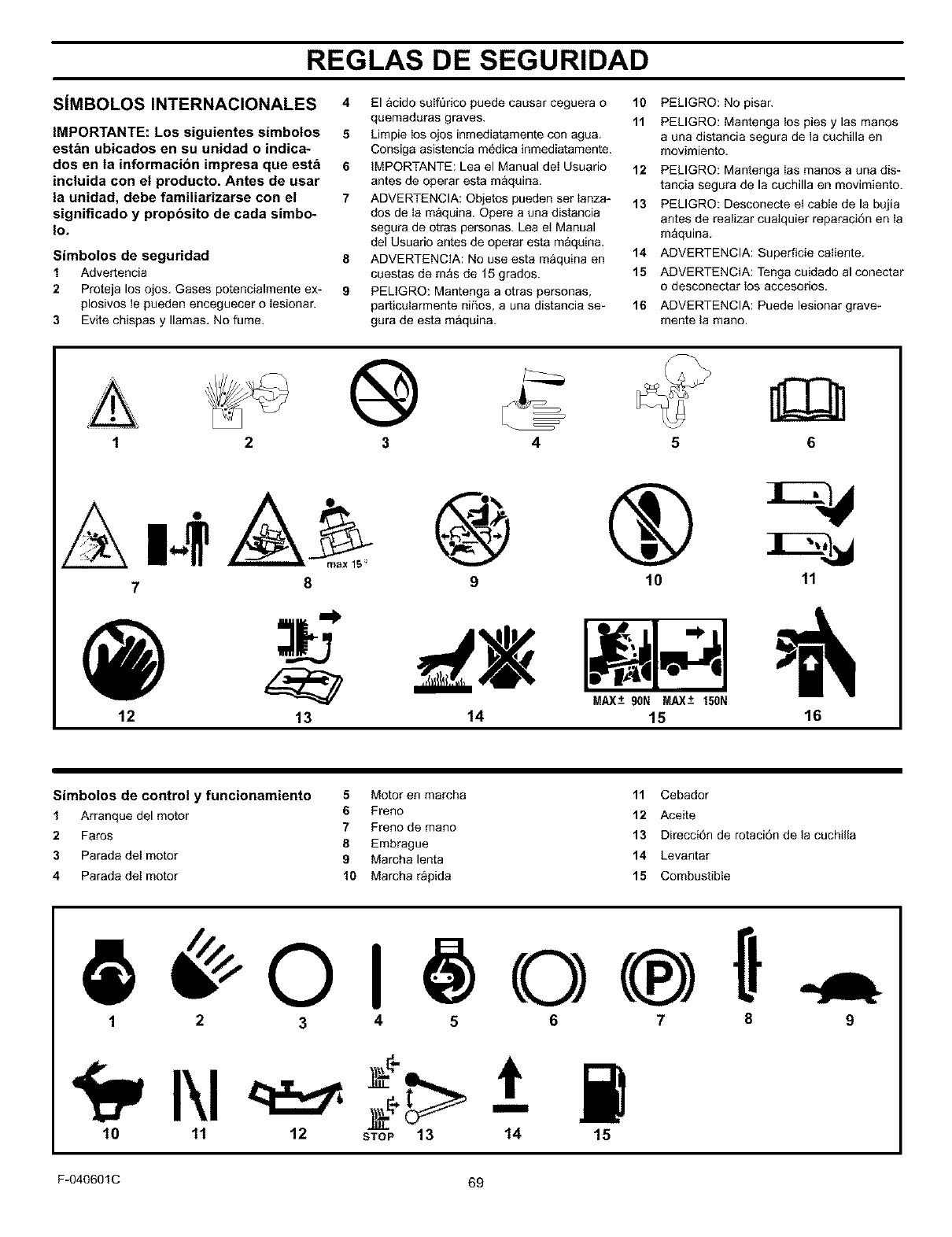
REGLAS DE SEGURIDAD
SIMBOLOS INTERNACIONALES
IMPORTANTE: Los siguientes simbo|os
estan ubicados en su unidad o indica-
dos en la informacion impresa que esta
incluida con el producto, Antes de usar
la unidad, debe familiarizarse con el
significado y propbsito de cada simbo-
Io.
Simbotos de seguridad
1Advertencia
2Proteja los ojos. Gases potencialmente ex-
plosivos le pueden enceguecer o Iesionar.
3Evite chispas y llamas. No fume.
4 El acido salf_rieo puede causar ceguera o 10
quemaduras graves. 11
5Limpie los ojos inmediatamente con agua.
Consiga asistencia m_dica inmediatamente.
6IMPORTANTE: Lea el Manual deI Usuario 12
antes de operar esta maquina.
7ADVERTENClA: Qbjetos pueden ser Ianza* 13
dos de Ia maquina. Opere a una distancia
segura de otras personas. Lea eI Manual
del Usuario antes de operar esta maquina.
8ADVERTENCIA: No use esta maquina en 14
cuestas de mas de 15 grades. 15
9 PELtGRO: Mantenga a otras personas,
particutarmente niSos, a una distancia se- 16
gura de esta maquina.
PELIGRO: No pisar.
PELIGRO: Mantenga los pies y las manes
a una distancia segura de la cuchilla en
movimiento.
PELIGRO: Mantenga Ias manos a una dis-
tancia segura de la cuchilla en movimiento.
PELIGRQ: Desconecte el cable de la bujia
antes de realizar cualquier reparaci6n en ta
maquina.
ADVERTENCIA: Superficie caliente.
ADVERTENCIA: Tenga cuidado al conectar
o desconectar los accesorios.
ADVERTENCIA: Puede lesionar grave-
mente la mano.
1®4 6
@
12
O® ®
910 11
I 1 ,1
13 14 15 16
Simbotos de control y funcionamiento 5Motor en marcha 11 Cebador
1Arranque del motor 6 Freno 12 Aceite
7Freno de mano
2 Fares 13 Direcci6n de retaci6n de la cuchilla
8 Embrague
3 Parada de! motor 9 Marcha lenta 14 Levantar
4 Parada del motor 10 Marcha rapida 15 Combustible
1 2 3 45 6 7 8
10 11 12 STOP 13 14 15
F-040601C 69
9
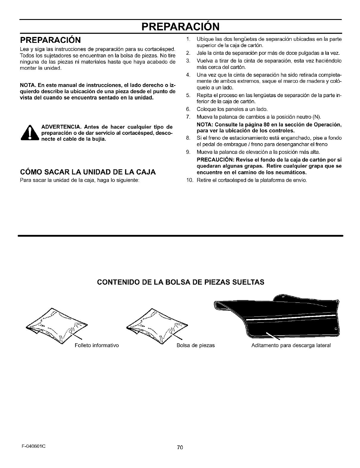
PREPARACION
PREPARACIC)N 1.
2,
3.
4.
Lea y siga las instrucciones de preparaci6n para su cortac6sped.
Todos los sujetadores se encuentran en la bolsa de piezas. No tire
ninguna de las piezas ni materiales hasta que haya acabado de
montar la unidad.
NOTA, En este manual de instrucciones, el lado derecho o iz-
quierdo describe la ubicacion de una pieza desde el punto de
vista del cuando se encuentra sentado en la unidad.
d_a_l=lb ADVERTENCIA. Antes de hacer cualquier tipo de
preparacibn o de dar servicio al cortacdsped, desco-
necte el cable de ta bujia.
COMO SACAR LA UNIDAD DE LA CAJA
5.
6,
7.
8.
9.
Ubique las dos lengOetas de separaci6n ubicadas en la parte
superior de la caja de cart6n.
Jale la cinta de separaci6n por mas de doce pulgadas a la vez.
Vuelva a tirar de la cinta de separaci6n, esta vez haciendolo
m_s cerca del cart6n.
Una vez que la cinta de separaci6n ha sido retirada completa*
mente de ambos extremos, saque el marco de madera y col6*
quelo a un lado.
Repita el proceso en las lengL_etasde separacidn de la parte in-
ferior de la caja de cart6n.
Coloque los paneles a un lado.
Mueva la palanca de cambios a la posici6n neutro (N).
NOTA: Consulte la pagina 80 en la seccion de Operacion,
para ver la ubicacibn de los controles.
Si el freno de estacionamiento est_ enganchado, pise a fondo
el pedal de embrague /freno para desenganchar el freno
Mueva la palanca de elevaci6n a la posici6n m&s alta.
PRECAUCION: Revise el fondo de la caja de carton por si
quedaran algunas grapas. Retire cualquier grapa que se
encuentre en el camino de los neumaticos.
Para sacar la unidad de la caja, haga Io siguiente: 10. Retire el cortac6sped de la plataforma de envio.
CONTENIDO DE LA BOLSA DE PIEZAS SUELTAS
Folleto informativo Bolsa de piezas Aditamento para descarga lateral
F-040601C 70
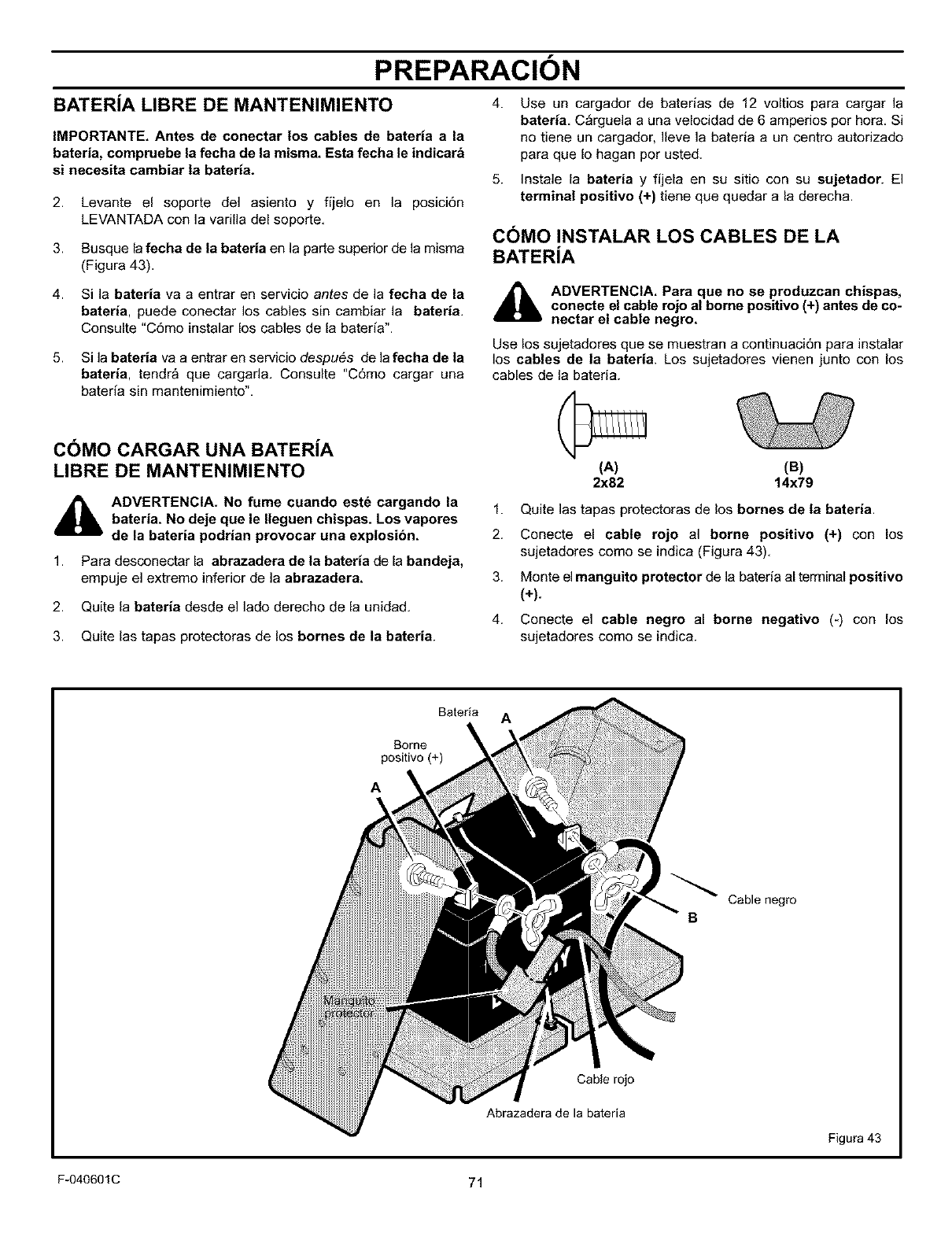
PREPARACION
BATERiA LIBRE DE MANTENIMIENTO 4.
IMPORTANTE. Antes de conectar los cables de bateria a la
bateria, compruebe la fecha de la misma. Esta fecha le indicara
si necesita cambiar ta bateria.
2. Levante el soporte del asiento y fijelo en la posici6n
LEVANTADA con la varilla del soporte,
3. Busque la fecha de la bateria en la parte superior de la misma
(Figura 43),
4. Si la bateria va a entrar en servicio antes de la fecha de la
bateria, puede conectar los cables sin cambiar la bateria,
Consulte "C6mo instalar los cables de la bateria".
5. Si la bateria va a entrar en servicio despu_s de la fecha de la
bateria, tendra que cargada, Consulte "C6mo cargar una
bateria sin mantenimiento",
C()MO CARGAR UNA BATERiA
LIBRE DE MANTENIMIENTO
_b ADVERTENCIA. No fume cuando estd cargando la
bateria. No deje que le Ileguen chispas. Los vapores
de la bateria podrian provocar una explosibn.
1. Para desconectar la abrazadera de la bateria de la bandeja,
empuje el extreme inferior de la abrazadera,
2. Quite la bateria desde el lade derecho de la unidad,
3. Quite las tapas protectoras de los bornes de ta bateria.
5.
Use un cargador de baterias de 12 voltios para cargar la
bateria, C_rguela a una velocidad de 6 amperios por hora, Si
no tiene un cargador, Ileve la bateria aun centro autorizado
para que Io hagan por usted,
Instale la bateria y fijela en su sitio con su sujetador. El
terminal positivo (+) tiene que quedar a la derecba.
C()MO INSTALAR LOS CABLES DE LA
BATERiA
4_lb ADVERTENCIA. Para que no se produzcan chispas,
conecte el cable rojo al borne positivo (+) antes de co-
nectar el cable negro.
Use los sujetadores que se muestran a continuaci6n para instalar
los cables de la bateria. Los sujetadores vienen junto con los
cables de la bated&
(A)
2x82 (B)
14x79
1. Quite las tapas protectoras de los bornes de ta bateria.
2. Conecte el cable rojo al borne positivo (+) con los
sujetadores como se indica (Figura 43),
3. Monte el manguito protector de la bateria al terminal positivo
(+).
4. Conecte el cable negro al borne negativo (_) con los
sujetadores como se indica.
Bateria A
Borne
positive (+)
A
Cable negro
B
Cable rojo
Abrazadera de la bateria
Figura 43
F-040601C 71
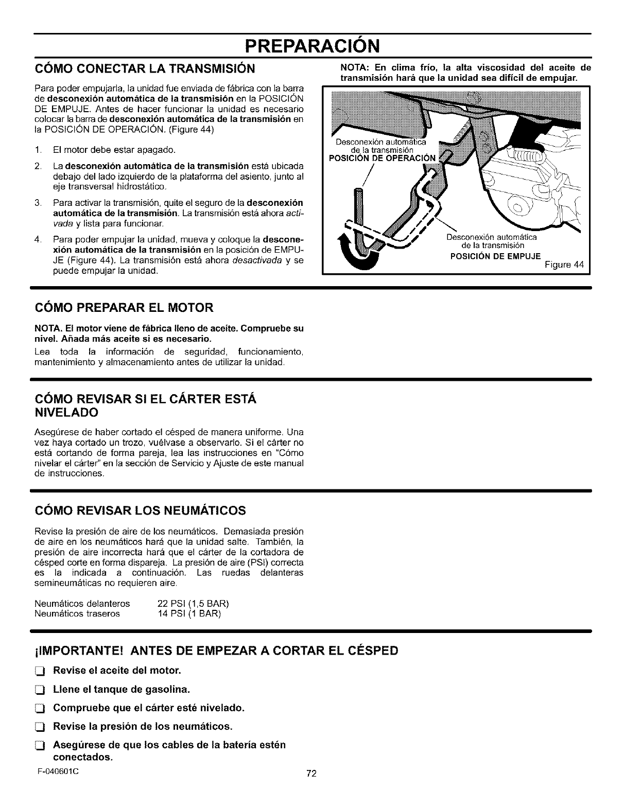
PREPARACION
C(_MO CONECTAR LA TRANSMISI(_N
Para poder empujada, la unidad fue enviada de fabrica con la barra
de desconexion automatica de la transmisibn en la POSICION
DE EMPUJE. Antes de hacer funcionar la unidad es necesario
colocar la barra de deeconexi6n autom_tica de la transmisi6n en
la POSlCION DE OPERACION. (Figure 44)
1.
2.
3.
4.
El motor debe estar apagado.
La desconexion automatica de la transmisi6n esta ubicada
debajo del lade izquierdo de la plataforma del asiento, junto al
eje transversal hidrostatico.
Para activar la transmisidn, quite el seguro de la desconexibn
autom_tica de la transmisi6n, La transmisi6n esta ahora acti-
vada y lista para funcionar.
Para poder empujar la unidad, mueva y coloque la descone-
xi6n automatica de la transmisi6n en la posici6n de EMPU-
JE (Figure 44). La transmisi6n est_ ahora desactivada y se
puede empujar la unidad.
NOTA: En cilia frio, la alta viscosidad del aceite de
transmisibn hara que ta unidad sea dificil de empujar.
Desconexi6n automatica
de Ia transmisi6n
POSICION DE OPERACI(_N
/
Desconexi6n automatica
de la transmisi6n
POSICION DE EMPUJE
Figure 44
C(_MO PREPARAR EL MOTOR
NOTA. El motor viene de fabrica Ileno de aceite. Compruebe su
nivel. Ahada m_s aceite si es necesario.
Lea toda la informaci6n de seguridad, funcionamiento,
mantenimiento y almacenamiento antes de utilizar la unidad.
COMO REVISAR SI EL CARTER ESTA
NIVELADO
AsegQrese de haber cortado el cesped de manera uniforme. Una
vez haya cortado un trozo, vu61vase a observarlo. Si el carter no
est_ cortando de forma pareja, lea las instrucciones en "C6mo
nivelar el c_rter" en la secci6n de Servicio y Ajuste de este manual
de instrucciones.
C(_MO REVISAR LOS NEUMATICOS
Revise la presi6n de aire de los neum_ticos. Demasiada presi6n
de aire en los neum_ticos har_ que la unidad salte. Tambien, la
presi6n de aire incorrecta har_ que el c_rter de la cortadora de
c6sped corte en forma dispareja. La presi6n de aire (PSI) correcta
es la indicada a continuaci6n. Las ruedas delanteras
semineum_ticas no requieren aire.
Neum&ticos delanteros
Neum_ticos traseros 22 PSI (1,5 BAR)
14 PSI (1 BAR)
ilMPORTANTE! ANTES DE EMPEZAR A CORTAR EL C#SPED
Revise el aceite del motor.
Llene el tanque de gasolina.
Compruebe que el c&rter este nivelado.
Revise la presibn de los neum&ticos.
Aseg_rese de que los cables de la bateria est_n
conectados.
F-040601C 72
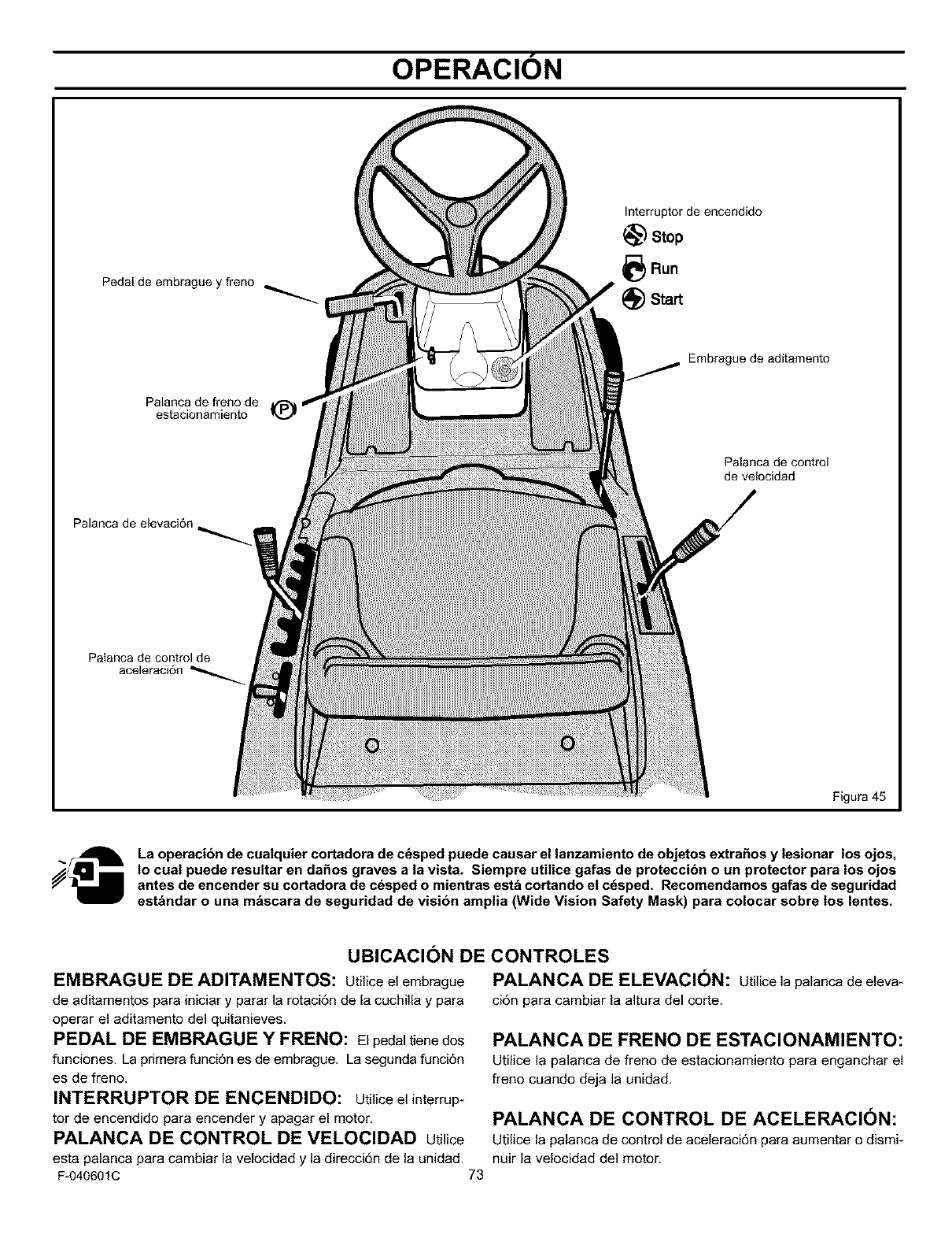
OPERACION
Pedal de embrague y freno
Interruptorde encendJdo
_) Stop
4_) Run
t_) Start
Embrague de aditamento
Palanca de freno de
estacionamiento
Palanca de control
de velocJdad
Palanca de elevaci6n
Palanca de control de
Figura 45
La operacion de cuatquier cortadora de c_sped puede causar el lanzamiento de objetos extrafios y lesionar los ojos,
to cual puede resultar en dafios graves a la vista. Siempre utilice gafas de proteccibn o un protector para los ojos
antes de encender su cortadora de c_sped o mientras est_ cortando el c_sped. Recomendamos gafas de seguridad
estandar o una m_scara de seguridad de vision amplia (Wide Vision Safety Mask) para colocar sobre los lentes.
UBICACION DE CONTROLES
EMBRAGUE DE ADITAMENTOS: Utilice el embrague
de aditamentos para iniciar y parar la rotaci6n de la cuchilla y para
operar el aditamento del quitanieves.
PEDAL DE EMBRAGUE Y FRENO: Elpedaltienedos
funciones. La primera funci6n es de embrague. La segunda funci6n
es de freno.
INTERRUPTOR DE ENCENDIDO: Utilice elinterrup-
tor de encendido para encender y apagar el motor,
PALANCA DE CONTROL DE VELOClDAD utilice
esta palanca para cambiar la velocidad y la direcci6n de la unidad.
F-040601C 73
PALANCA DE ELEVACI()N: Utilice la palanca de eleva-
cidn para cambiar la altura del corte.
PALANCA DE FRENO DE ESTACIONAMIENTO:
Utilice la palanca de freno de estacionamiento para enganchar el
freno cuando deja la unidad,
PALANCA DE CONTROL DE ACELERACION:
Utilice la palanca de control de aceleraci6n para aumentar o dismi-
nuir la velocidad del motor.
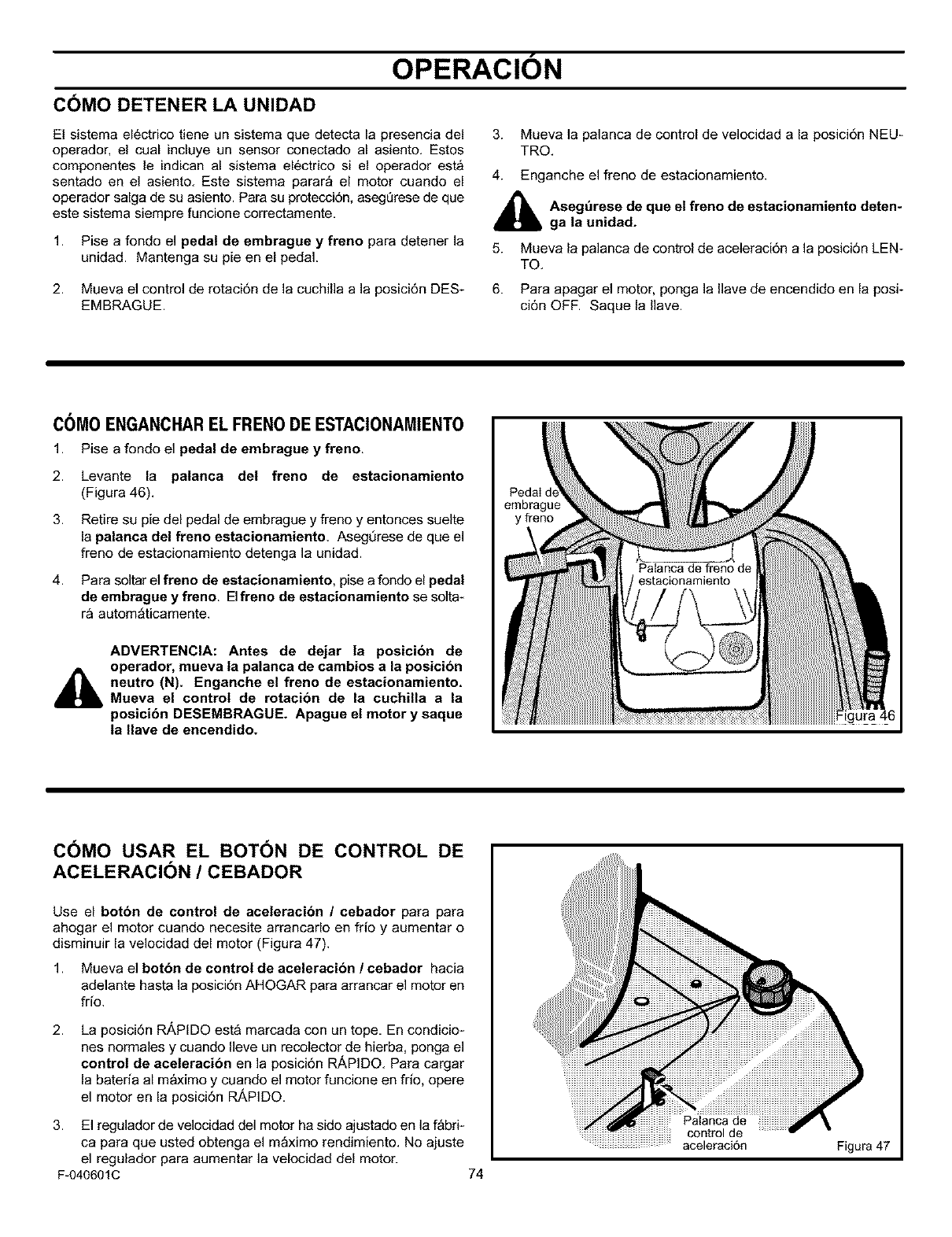
OPERACION
COMO DETENER LA UNIDAD
El sistema el_ctrico tiene un sistema que detecta la presencia del
operador, el cual incluye un sensor conectado al asiento. Estos
componentes le indican al sistema el_ctrico si el operador esta
sentado en el asiento. Este sistema parar_ el motor cuando el
operador salga de su asiento. Para su proteccidn, asegQrese de que
este sistema siempre funcione correctamente.
1. Pise a fondo el pedal de embrague y freno para detener la
unidad. Mantenga su pie en el pedal.
3. Mueva la palanca de control de velocidad a la posici6n NEU_
TRO.
4. Enganche el freno de estacionamiento.
_1= segurese de que el freno de estacionamiento deten-
ga la unidad.
5. Mueva la palanca de control de aceleraci6n a la posici6n LEN-
TO,
2. Mueva el control de rotaci6n de la cuchilla a la posici6n DES_ 6. Para apagar el motor, ponga la Ilave de encendido en la posi-
EMBRAGUE. ci6n OFF. Saque la Ilave.
C()M0 ENGANCHAREL FREN0 DE ESTACIONAMIENT0
1. Pise a fondo el pedal de embrague yfreno.
2. Levante la palanca del freno de estacionamiento
(Figura 46).
3. Retire su pie del pedal de embrague y freno y entonces suelte
la palanca del freno estacionamiento. Asegt]rese de que el
freno de estacionamiento detenga la unidad.
4. Para soltar el freno de estacionamiento, pise a fondo el pedal
de embrague y freno. EIfreno de estacionamiento se solta-
ra autom_ticamente.
ADVERTENCIA: Antes de dejar la posicion de
operador, mueva la palanca de cambios a la posicion
neutro (N). Enganche el freno de estacionamiento.
Mueva el control de rotacion de la cuchilla a la
posicibn DESEMBRAGUE. Apague et motor y saque
ta Ilave de encendido.
Peda
embrague
y freno
Figura 46
COMO USAR EL BOTON DE CONTROL DE
ACELERACION /CEBADOR
Use el boton de control de aceleracion Icebador para para
ahogar el motor cuando necesite arrancarlo en frio y aumentar o
disminuir la velocidad del motor (Figura 47).
1. Mueva el botbn de control de aceleracion /cebador hacia
adelante hasta la posici6n AHOGAR para arrancar el motor en
frio.
2. La posicidn R/_PIDO esta marcada con un tope. En condicio-
nes normales y cuando Ileve un recolector de hierba, ponga el
control de aceleracibn en la posici6n RAPIDO, Para cargar
la bateria al m_ximo y cuando el motor funcione en frio, opere
el motor en la posici6n RAPIDO,
3. El regulador de velocidad del motor ha sido ajustado en la f_bri*
ca para que usted obtenga el m_ximo rendimiento. No ajuste
el regulador para aumentar la velocidad del motor.
F-040601C 74
Patanca de
control de
aceleraci6n Figura 47
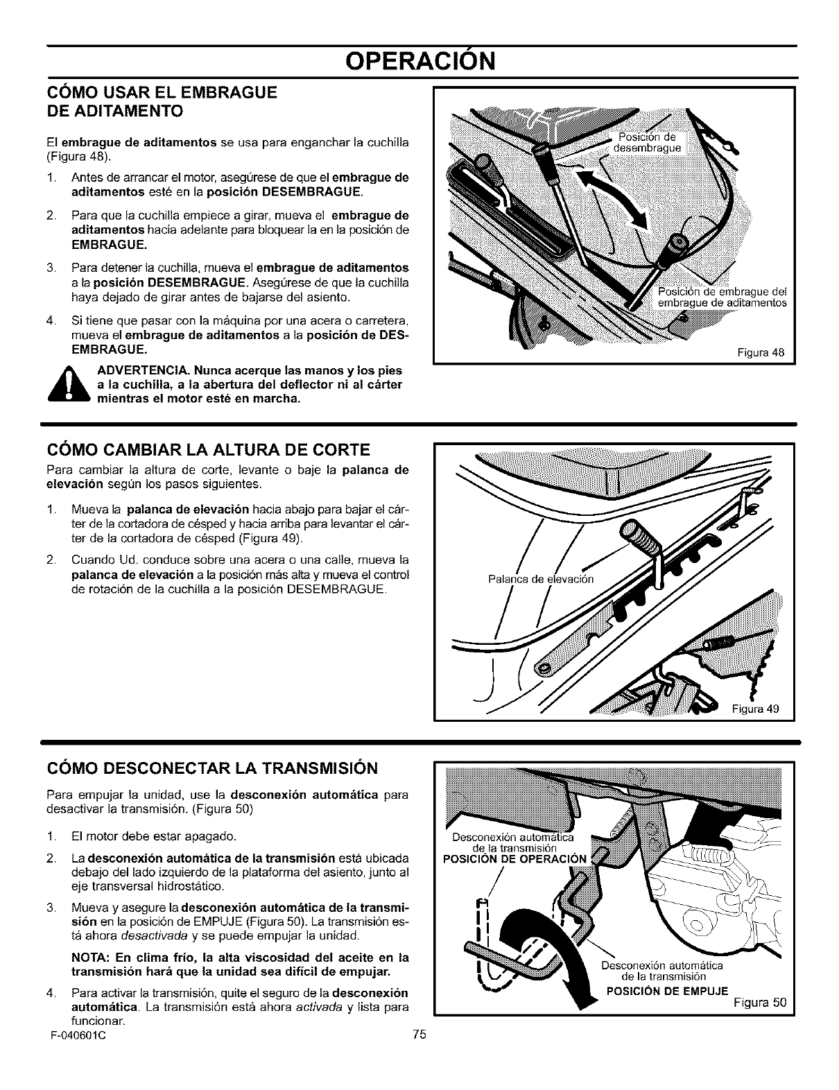
OPERACION
COMO USAR EL EMBRAGUE
DE ADITAMENTO
El embrague de aditamentos se usa para enganchar la cuchilla
(Figura 48).
1. Antes de arrancar el motor, aseg0rese de que el embrague de
aditamentos este en la posicibn DESEMBRAGUE
2. Para que la cuchilla empiece a girar, mueva el embrague de
aditamentos hacia adelante para bloquear la en la posici6n de
EMBRAGUE,
3.
4.
Para detener la cuchilla, mueva el embrague de aditamentos
a la posicibn DESEMBRAGUE Aseg0rese de que la cuchilla
haya dejado de girar antes de bajarse del asiento.
Si tiene que pasar con la m&quina por una acera o carretera,
mueva el embrague de aditamentos a la posicibn de DES-
EMBRAGUE.
_hlL ADVERTENCIA, Nunca acerque las manes y los pies
a la cuchilla, a la abertura del deflector ni al carter
mientras el motor est_ en marcha,
de embrague deI
embrague de aditamentos
Figura 48
COMO CAMBIAR LA ALTURA DE CORTE
Para cambiar la altura de corte, levante o baje la palanca de
elevacibn seg0n los pasos siguientes.
1.
2.
Mueva la patanca de elevacion hacia abajo para bajar el car-
ter de la cortadora de cesped y hacia arriba para levantar el c_r-
ter de la cortadora de c6sped (Figura 49).
Cuando Ud. conduce sobre una acera o una calle, mueva la
palanea de elevaeion a [a posici6n m_s alta y mueva el control
de rotaci6n de ]a cuchilla a la posici6n DESEMBRAGUE.
J
Palanca de elevaci6n
Figura 49
COMO DESCONECTAR LA TRANSMISION
Para empajar la unidad, use la desconexion automatica para
desactivar la transmisi6n. (Figura 50)
1. El motor debe estar apagado.
2. La desconexion automatica de la transmisibn esta ubicada
debajo del lado izquierdo de la plataforma del asiento, junto al
eje transversal hidrostatico.
3. Mueva y asegure la desconexibn autom_tica de la transmi-
si6n en la posici6n de EMPUJE (Figura 50). La transmisi6n es-
ta ahora desactivada y se puede empujar la unidad.
NOTA: En clima frio, la alta viscosidad del aceite en la
transmision hara que la unidad sea dificil de empujar.
4. Para activar la transmisi6n, quite el seguro de la desconexibn
autom_tica. La transmisi6n esta ahora activada y lista para
funcionar.
F-040601C 75
Desconexi6n automatica
de Ia transmisi6n
POSICION DE OPERACll
/
Desconexi6n automatica
de la transmisi6n
POSICION DE EMPUJE
Figura 50
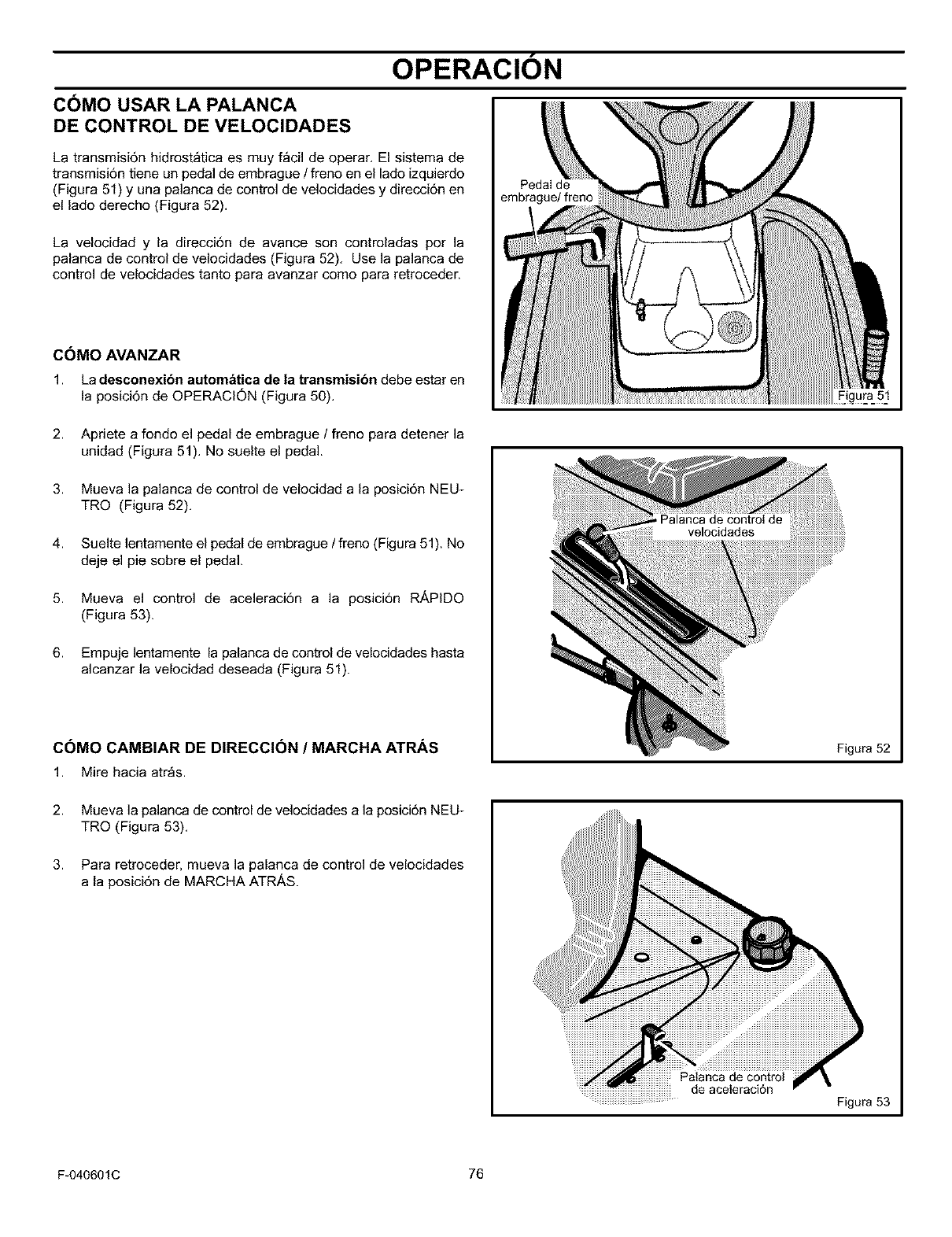
OPERACION
COMO USAR LA PALANCA
DE CONTROL DE VELOCIDADES
La transmisi6n hidrost_tica es muy f_cil de operar. El sistema de
transmisi6n tiene un pedal de embrague /freno en el lado izquierdo
(Figura 51) y una palanca de control de velocidades y direcci6n en
el lado derecho (Figura 52).
La velocidad y la direcci6n de avance son controladas por la
palanca de control de velocidades (Figura 52). Use la palanca de
control de velocidades tanto para avanzar como para retroceder.
COMO AVANZAR
1. La desconexibn automatica de la transmisibn debe estar en
la posici6n de OPERACION (Figura 50).
Pedal de
embrague/freno
2. Apriete a fondo el pedal de embrague /freno para detener la
unidad (Figura 51). No suelte el pedal.
3. Mueva la palanca de control de velocidad a la posici6n NEU-
TRO (Figura 52).
4. Suelte lentamente el pedal de embrague /freno (Figura 51). No
deje el pie sobre el pedal.
5. Mueva el control de aceleraci6n a la posici6n RikPIDO
(Figura 53).
6. Empuje lentamente la palanca de control de velocidades hasta
alcanzar la velocidad deseada (Figura 51).
COMO CAMBIAR DE DIRECCI6N /MARCHA ATlaS
1. Mire hacia atr_s.
Figura 51
Figura 52
2.
3.
Mueva la palanca de control de velocidades a la posici6n NEU_
TRO (Figura 53).
Para retroceder, mueva la palanca de control de velocidades
a la posici6n de MARCHA ATRAS.
Palanca de control
de aceleraci6n
Figura 53
F-040601C 76
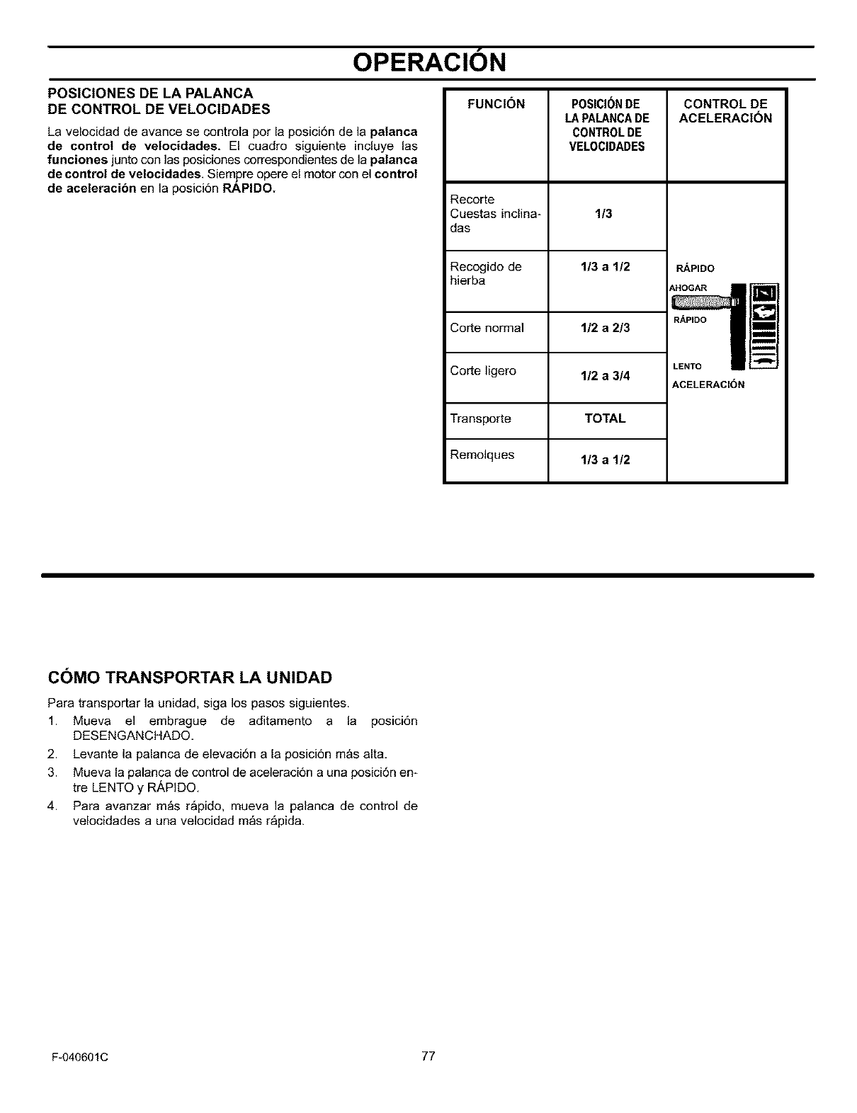
OPERACION
POSICIONES DE LA PALANCA
DE CONTROL DE VELOCIDADES
La velocidad de avance se controla por la posicidn de la palanca
de control de velocidades, El cuadro siguiente incluye las
funciones junto con las posiciones correspondientes de la palanca
de control de velocidades, Siemj0re opere el motor con el control
de aceleracibn en la posici6n RAPIDO.
FUNCION
Recorte
Cuestas inclina-
das
Recogido de
hierba
Corte normal
Corte ligero
Transporte
Remolques
POSICI(_NDE
LA PALANCADE
CONTROLDE
VELOCIDADES
1/3
1/3 a 1/2
CONTROLDE
ACELERACION
RAPIDO
AHOGAR
RAPIDO
1/2 a 2/3
1/2 a 3/4
TOTAL
1/3 a 1/2
LENTO
ACELERAClON
m
B
m
I
C()MO TRANSPORTAR LA UNIDAD
Para transportar la unidad, siga los pasos siguientes.
1. Mueva el embrague de aditamento a la posici6n
DESENGANCHADO,
2. Levante la palanca de elevaci6n a la posici6n mas alta,
3. Mueva la palanca de control de aceleraci6n a una posicidn en_
tre LENTO y R/kPIDO,
4. Para avanzar m_s r_pido, mueva la palanca de control de
velocidades a una velocidad m_s r_pida.
F-040601C 77
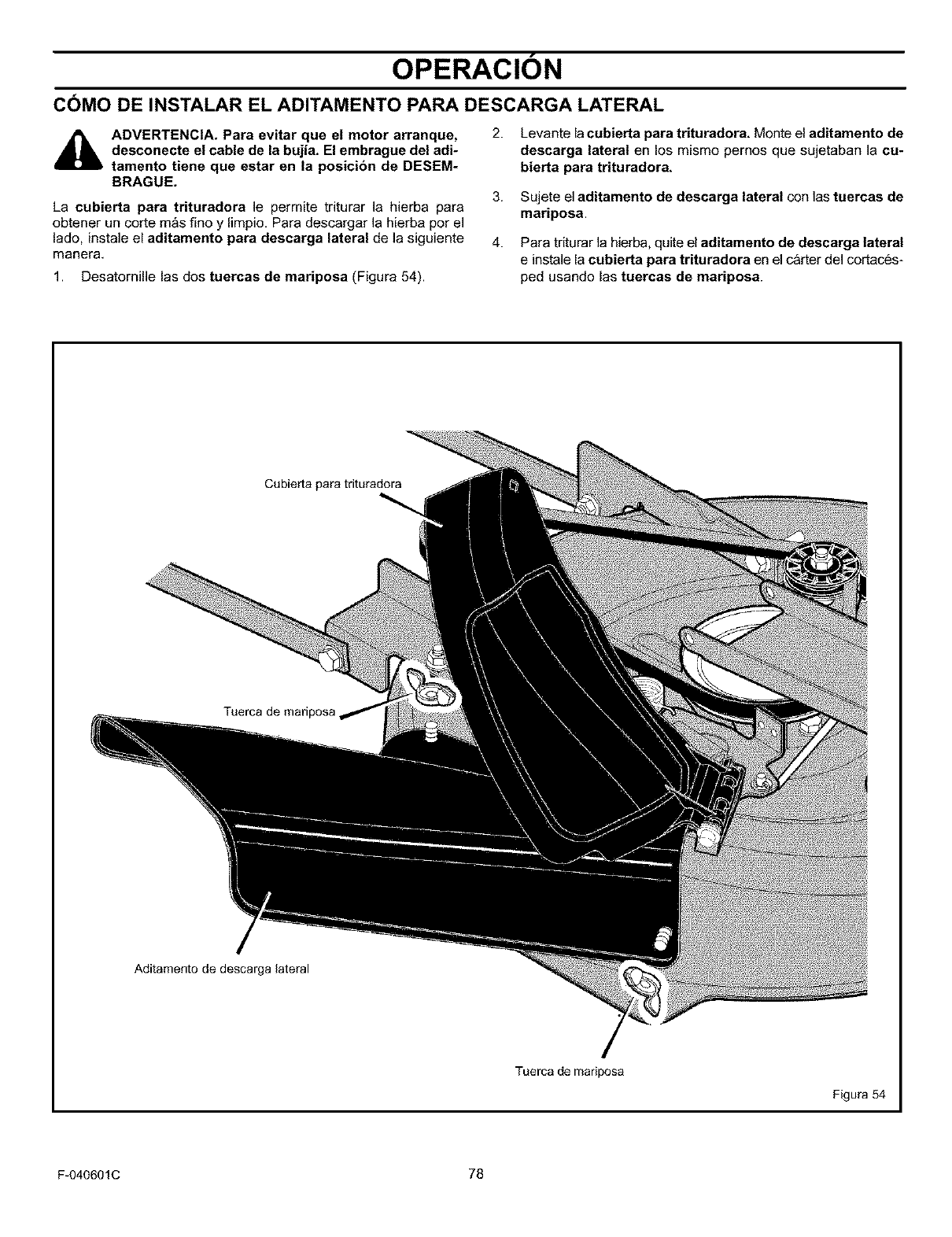
OPERACION
COMO DE INSTALAR EL ADITAMENTO PARA DESCARGA LATERAL
ADVERTENCIA. Para evitar que el motor arranque,
desconecte el cable de la bujia+ El embrague del adi-
tamento tiene que estar en la posicion de DESEM-
BRAGUE.
2.
3.
La cubierta para trituradora le permite triturar la hierba para
obtener un corte mas fino y limpio, Para descargar la hierba por el
lado+ instale el aditamento para descarga lateral de Jasiguiente 4.
manera+
1. Desatornille las dos tuercas de mariposa (Figura 54).
Levante lacubierta para trituradora, Monte el aditamento de
descarga lateral en los mismo pernos que sujetaban ]a cu-
bierta para trituradora,
Sujete el aditamento de descarga lateral con las tuercas de
mariposa.
Para triturar la hierba+quite el aditamento de descarga lateral
e instale la cubierta para trituradora en el carter del cortaces-
ped usando las tuercas de mariposa.
Cubierta para trituradora
Tuerca de mariposa,
Aditamento de descarga lateral
Tuerca de mariposa
Figura 54
F-040601C 78
OPERACION
ANTES DE ENCENDER EL MOTOR
REVISE EL ACEITE
NOTA: La unidad fue enviada desde la f_bdca con el motor Ileno
de aceite SAE, peso 30. Revise el nivel del aceite. Agregue
aceite, seg_n sea necesario.
1. AsegQrese de que la unidad est6 nivelada.
NOTA: No revise el nivel del aceite cuando el motor est_ en
marcha.
2. Limpie las partes alrededor de la varilla indicadora del nivel de
aceite. Retire la varilla indicadora. Limpie el aceite de la varilla.
3. Inserte la varilla indicadora dentro del tubo para agregar aceite.
Gire la varilla indicadora hacia la derecha basra que est6 apreta-
da. Retire la varilla indicadora y revise el nivel del aceite. El nivel
de aceite debe Ilegar hasta la marca LLENO en la varilla.
4. Si sea necesado, agregue aceite hasta que el aceite Ilegue hasta
la marca LLENO en la varilla indicadora. La cantidad de aceite
necesaria desde AGREGAR a LLENO se muestra en la varilla
indicadora. No agregue demasiado aceite.
AGREGUEGASOLINA
ADVERTENCIA: Utilice siempre un recipiente aproba-
do de gasolina. No fume mientras agrega gasolina al
tanque de combustible. No agregue gasolina cuando
est_ en un lugar cerrado. Antes de agregar gasolina, apague
el motor y d_jelo que se enfrie durante ratios minutos.
Llene el tanque de combustible Tanque de gasolina
con gasolina regular sin plomo. No (/*
utilice gasolina sin plomo de alto
octanaje. Aseg0rese de que la
gasolina sea fresca y limpia.
Gasolina con plomo aumentar&
depdsitos y acortar& la vida 0til de
las v_lvulas.
PRECAUCt(_N: Los combustibles mezclados con alcohol
(llamados gasohol o aqueUos que usan etanol o metanol),
pueden atraer humedad Io cual causa la separacibn y formacibn
de &cidos durante el almacenamiento de la unidad. La gasolina
que contiene &cidos puede dai_ar el sistema de combustible de
un motor mientras la unidad se encuentra almacenada.
Para evitar problemas con el sistema de alimentaci6n de
combustible, vacie _ste t31timoantes de guardar la unidad pot 30 dias
continuos o m_s, siguiendo los pasos siguientes.
1. Drene eltanque de combustible.
2. Encienda el motor. Deje que el motor funcione basra que las li-
neas de combustible y el carburador est6n vacios.
3. Despu6s de haber guardado la m&quina, asegQrese de utilizar
combustible fresco. Consulte las instrucciones de almacena-
miento para informaci6n adicionaL
4. Nunca utilice limpiador de motor o limpiador de carburador en el
sistema de alimentaci6n de combustible, ya que podrian ocurrir
da_os permanentes.
CARBURADOR
Los ajustes de f&brica para el carburador son para la mayoria de las
condiciones. Si el motor funciona bajo las condiciones siguientes,
puede ajustar la mezcla del carburador. Consulte "C6mo ajustar el
carburador" en la secci6n de Servicio y Ajuste.
1. El motor tiene una p6rdida de potencia o no funciona suavemen-
te.
2. Un cambio de operaci6n de verano a invierno.
3. Un cambio en la temperatura de operaci6n de m&s de 40 grados.
El carburador fue ajustado a 80 grados en la f&brica.
4. El motor funciona a una altura superior a 4.000 pies.
CC)MO ARRANCAR EL MOTOR
ADVERTENCIA: El sistema el_ctrico tiene un sistema
que detecta la presencia del operador, el cual incluye
un sensor conectado al asiento. Estos componentes
le indican al sistema el_ctrico si el operador est_ sentado en
el asiento. Este sistema parar& el motor cuando el operador
salga de su asiento. Para su proteccibn, asegOrese de que este
sistema siempre funcione correctamente.
NOTA: El motor no arrancar_ a menos que usted pise el pedal de
embrague y freno, o enganche el freno de estacionamiento y
mueva la palanca de embrague de aditamentos a la posici6n de
DESEMBRAGUE.
1. Si6ntese en el medio del asiento. Empuje el pedal de embrague
y freno completamente bacia adelante. Mantenga su pie sobre
el pedal.
2. Mueva la palanca de control de velocidades a la posici6n neutro
(N).
3. AsegQrese de que elembrague de cuchilla est6 enla posici6n
DESEMBRAGUE.
F-040601C 79
4.
5.
6.
7.
Empuje completamente hacia adelante la palanca de de control
de aceleraci6n hasta la posici6n AHOGAR o R_,PIDO. Algunos
modelos tienen una perilla de cebado del carburador separada.
Tire de la perilla completamente hasta que est6 en la posici6n
AHOGAR.
Gire la Ilave de encendido a la posici6n ARRANQUE. Suelte la
Ilave cuando el motor arranque.
NOTA: Si el motor no arranca despu_s de cuatro o cinco
intentos, mueva el acelerador a la posicibn RAPtDO. Intente
arrancar el motor otra vez. Si el motor no arranca, consulte
la TABLA DE LOCALIZACI(_N DE AVERiAS.
Mueva lentamente el control de aceleraci6n a la posici6n LEN-
TO. Si el modelo tiene un bot6n cebador separado, presione el
bot6n cebador.
Deje que un motor frio est6 en marcha durante varios minutos.
Comience a cortar el c_sped una vez que el motor se caliente.
Para arrancar un motor caliente, mueva el acelerador a una posi-
ci6n entre R_,PIDO y LENTO.
OPERACION
C()MO OPERAR, CON EL CARTER DE LA CORTADORA
ADVERTENCIA: La cubierta para trituradora es un
dispositivo de seguridad. No la quite. El deflector
fuerza el material cortado hacia la tierra. Mant_ngato
siempre en la posicion hacia abajo. Si el deflector es-
t_ dahado, reempl_celo con una pieza original obteni-
da en un Centro de Servicio Sears.
IMPORTANTE: Cuando opere con el carter del cortacdsped,
hagalo siempre con el control de aceleracibn colocado en la
posicibn RAPIDO.
1. Empuje el pedal de embrague y freno completamente hacia
adelante,
2.
3.
4.
5.
Arranque el motor,
Mueva la palanca de control de velocidades in la posici6n
NEUTRO,
Lentamente suelte el pedal de embrague y freno.
Mueva la palanca de elevaci6n a una posicidn de altura de cor*
te. Cuando la hierba est_ alta o densa, corte el c6sped en la
posici6n m_s alta primero y luego c6rtelo otra vez con el carter
del cortacesped en una posici6n m_s baja.
PRECAUCI(_N: No opere la unidad con el carter del
cortac_sped en la posicion de AJUSTE DE NIVEL. Si Io
hace, el carter y las cuchUlas del cortac6sped pueden
resultar da_ados.
6.
7.
Mueva el acelerador a la posici6n LENTO,
Mueva el embrague de aditamento a la posici6n de ENGAN-
CHADO,
8. Mueva la palanca de control de velocidades hacia adelante.
9.
10.
NOTA: Cuando corta en c_sped denso o con una bolsa
recogedora, opere ta unidad a una velocidad de avance
mas baja.
Mueva el control de aceleraci6n a la posici6n RAPIDO. Sine*
cesita ir mas r_pido o mas despacio, mueva la palanca de
control de velocidades hacia adelante o hacia atr_s.
AsegQrese de que el nivel de corte ajustado en la fabrica sea
correcto todavia. Despu6s de cortar una corta distancia, ob*
serve el _rea que ha sido cortada. Si el c_rter de la cortadora
no corta de forma pareja, consulte las instrucciones sobre "06_
mo nivelar el carter de la cortadora de cesped" en la secci6n
de Servicio y Ajuste.
_lb DVERTENCIA: Para un mejor control de la unidad,
seleccione siempre una velocidad segura.
COMO OPERAR LA UNIDAD EN CUESTAS
1.
2.
ADVERTENCIA: No suba ni baje cuestas que son de- 3.
masiado empinadas para poder retroceder en una li-
nea recta. Nunca maneje ta unidad a travds de una
cuesta. Consulte la "Guia para cuestas" al final de es-
te manual para obtener informacibn sobre cbmo eva-
luar las cuestas. 4.
Antes de manejar cuesta arriba o cuesta abajo, mueva la pa*
lanca de control de velocidades a una velocidad m_s baja.
No pare la unidad ni cambie las velocidades cuando se
encuentre en una cuesta. Si debe parar, empuje rapidamente
el pedal de embrague y freno hacia adelante y enganche el fre-
no de estacionamiento.
5.
Para arrancar de nuevo, asegt_rese de que la palanca de
control de velocidades este en una velocidad m_s baja. Mueva
el control de aceleraci6n a la posici6n LENTO. Y vaya soltando
lentamente el pedal.
Si debe parar o arrancar en una cuesta, tenga siempre sufi-
ciente espacio para que la unidad ruede cuando suelte el freno
y enganche el embrague.
Tenga mucho cuidado cuando cambia de direcci6n sobre una
cuesta. Cuando est_ en una cuesta o en una curva sobre la
cuesta, mueva el control de aceleraci6n a la posici6n LENTO
para evitar accidentes.
ADITAMENTOS
A esta unidad se le pueden instalar varios aditamentos. La unidad
puede tirar de aditamentos tales como una barredora, un aireador,
un esparcidor o un remolque peque_o. Esta unidad no puede usar
aditamentos que entrenen la tierra, tales como un arado, un
pulverizador con discos o un cultivador.
Para todos los aditamentos de arrastre o remolques, el peso bruto
no puede superar las 200 libras. El peso bruto es el peso del
aditamento remolque y de la carga que Ileve.
F-040601C 80
ADVERTENCIA: Para evitar la posibilidad de lesio-
nes graves, no debe cortar el c_sped en cuestas que
tengan mas de 15 grados de inclinacibn. Si se usa el
tractor con un aditamento de arrastre o de enganche
trasero, no opere la unidad en cuestas que tengan
mds de 10 grados de inclinacibn.
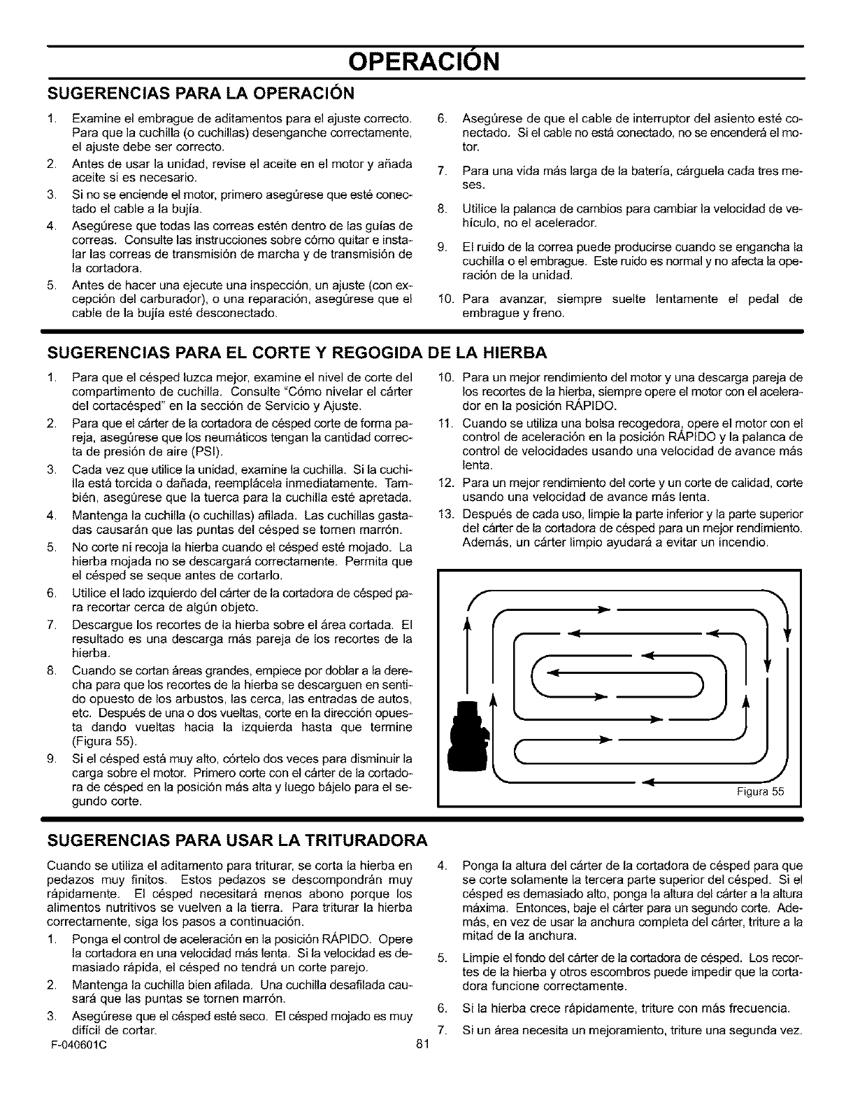
OPERACION
SUGERENCIAS PARA LA OPERACI()N
1.
2.
3.
4.
5.
Examine el embrague de aditamentos para el ajuste correcto.
Para que la cuchilla (o cuchillas) desenganche correctamente,
el ajuste debe ser correcto.
Antes de usar la unidad, revise el aceite en el motor y aSada
aceite si es necesario.
Si no se enciende el motor, primero asegQrese que est6 conec*
tado el cable a la bujia.
Asegt_rese que todas las correas est6n dentro de las guias de
correas. Consulte las instrucciones sobre c6mo quitar e insta*
lar las correas de transmisi6n de marcha y de transmisi6n de
la cortadora.
Antes de hacer una ejecute una inspecci6n, un ajuste (con ex*
cepci6n del carburador), o una reparaci6n, asegQrese que el
cable de la bujia este desconectado.
6.
7.
8.
9.
10.
AsegQrese de que el cable de interruptor del asiento est6 co*
nectado. Si el cable no esta conectado, no se encendera el mo-
tor.
Para una vida m_s larga de la bated& c_rguela cada tres me-
ses.
Utilice la palanca de cambios para cambiar la velocidad de ve*
hiculo, no el acelerador.
El ruido de la correa puede producirse cuando se engancha la
cuchilla o el embrague. Este ruido es normal y no afecta la ope-
raci6n de la unidad.
Para avanzar, siempre suelte lentamente el pedal de
embrague y freno.
SUGERENCIAS PARA EL CORTE Y REGOGIDA DE LA HIERBA
1. Para que el c6sped luzca meier, examine el nivel de corte del
compartimento de cuchilla. Consulte "C6mo nivelar el c_rter
del cortacesped" en la secci6n de Servicio y Ajuste.
2. Para que el c_rter de la cortadora de c6sped corte de forma pa*
reja, aseg_rese que los neumaticos tengan la cantidad correc*
ta de presi6n de aire (PSI).
3. Cada vez que utilice la unidad, examine la cuchilla. Si la cuchk
Ila esta torcida o da_ada, reempl_cela inmediatamente. Tam*
bi6n, aseg_rese que la tuerca para la cuchilla este apretada.
4. Mantenga la cuchilla (o cuchillas) afilada. Las cuchillas gasta*
das causar_n que las puntas del c6sped se tomen marr6n.
5. No corte ni recoja la hierba cuando el c6sped este mojado. La
hierba mojada no se descargar_ correctamente. Permita que
el c6sped se seque antes de cortado.
6. Utilice el lado izquierdo del c_rter de la cortadora de c6sped pa-
ra recortar cerca de algt]n objeto.
7. Descargue los recortes de la hierba sobre el _rea cortada. El
resultado es una descarga mas pareja de los recortes de la
hierba.
8.
9.
Cuando se cortan _reas grandes, empiece por doblar a la dere*
cha para que los recortes de la hierba se descarguen en sentk
do opuesto de los arbustos, las cerca, las entradas de autos,
etc. Despu6s de una o dos vueltas, corte en la direccidn opues*
ta dando vueltas hacia la izquierda hasta que termine
(Figura 55).
Si el cesped esta muy alto, c6rtelo dos veces para disminuir la
carga sobre el motor. Pdmero corte con el c_rter de la cortado*
ra de cesped en la posici6n m_s alta y luego b_jelo para el se_
gundo corte.
10. Para un mejor rendimiento del motor y una descarga pareja de
los recortes de la hierba, siempre opere el motor con el acelera-
dor en la posici6n RAPIDO.
11. Cuando se utiliza una bolsa recogedora_ opere el motor con el
control de aceleraci6n en la posici6n RAPIDO y la palanca de
control de velocidades usando una velocidad de avance m_s
lenta.
12.
13.
Para un mejor rendimiento del corte y un corte de calidad, corte
usando una velocidad de avance m_s lenta.
Despu6s de cada uso, limpie la parte inferior y la parte superior
del carter de la cortadora de cesped para un mejor rendimiento.
Adem_s, un c_rter limpio ayudar_ a evitar un incendio.
(, • •
Figura55
SUGERENCIAS PARA USAR LA TRITURADORA
Cuando se utiliza el aditamento para triturar, se corta la hierba en 4.
pedazos muy finitos. Estos pedazos se descompondran muy
r_pidamente. El c6sped necesitar_ menos abono porque los
alimentos nutritivos se vuelven a la tierra. Para triturar la hierba
correctamente, siga los pasos acontinuaci6n.
1. Ponga el control de aceleraci6n en la posici6n RAPIDO. Opere
la cortadora en una velocidad m_s lent& Si la velocidad es de- 5.
masiado r_pida, el c6sped no tendra un corte parejo.
2. Mantenga la cuchilla bien afilada. Una cucbilla desafilada cau-
sar_ que las puntas se tornen marr6n. 6.
3. Aseg_rese que el c6sped este seco. El cesped mojado es muy
dificil de cortar. 7.
F-040601C 81
Ponga la altura del c_rter de la cortadora de c6sped para que
se corte solamente la tercera parte superior del c6sped. Si el
c6sped es demasiado alto, ponga la altura del carter a la altura
m_xima. Entonces, baje el carter para un segundo corte. Ade-
re&s, en vez de usar la anchura completa del carter, triture a la
mitad de la anchura.
Limpie el fondo del carter de la cortadora de c6sped. Los recor-
tes de la hierba y otros escombros puede impedir que la corta-
dora funcione correctamente.
Si la hierba crece r&pidamente, triture con m&s frecuencia.
Si un _rea necesita un mejoramiento, triture una segunda vez.
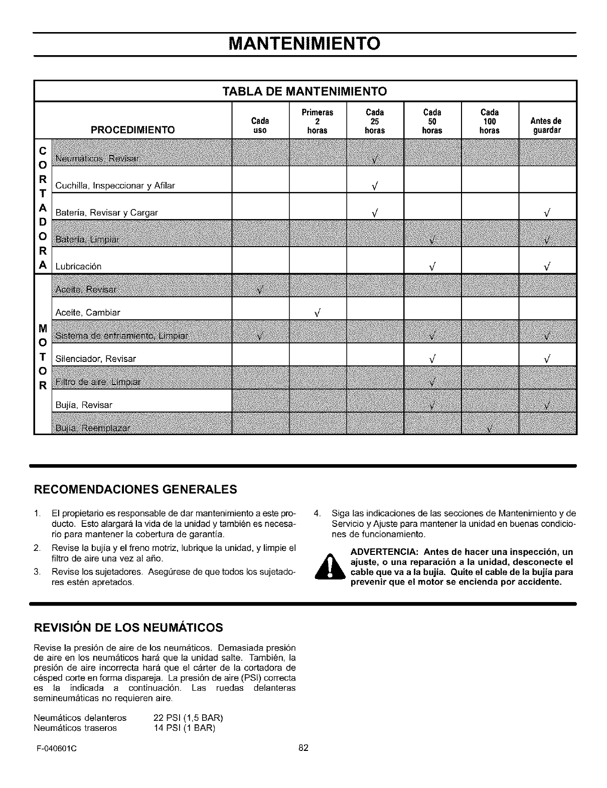
MANTENIMIENTO
TABLA DE MANTENIMIENTO
RI
TI
AI
OI
AI
MI
TI
Ol
RI
PROCEDIMIENTO
Cuchilla, Inspeccionar y Afilar
Bateria, Revisar y Cargar
Cada
uso
Primeras
2
h0ras
Cads
25
h0ras
Cads
50
horss
Cads
100
horss
Lubricaci6n
Aceite, Cambiar
Silenciador, Revisar
Antesde
guardar
RECOMENDACIONES GENERALES
1. El propietario es responsable de dar mantenimiento a este pro-
ducto. Esto alargar_ la vida de la unidad y tambi6n es necesa-
rio para mantener la cobertura de garantia.
2. Revise la bujia y el freno motriz, lubrique la unidad, y limpie el
filtro de aire una vez al aSo.
3. Revise los sujetadores. Asegt]rese de que todos los sujetado-
res esten apretados.
4. Siga las indicaciones de las secciones de Mantenimiento y de
Servicio y Ajuste para mantener la unidad en buenas condicio-
nes de funcionamiento.
ADVERTENCIA: Antes de hacer una inspeccion, un
ajuste, o una reparacibn a la unidad, desconecte el
cable que va a la bujia, Quite el cable de la bujia pars
prevenir que el motor se encienda pot accidente,
REVISION DE LOS NEUMATICOS
Revise la presi6n de aire de los neum_ticos. Demasiada presi6n
de aire en los neum_ticos har_ que la unidad salte. Tambien, la
presi6n de aire incorrecta har_ que el c_rter de la cortadora de
c6sped corte en forma dispareja. La presi6n de aire (PSI) correcta
es la indicada a continuaci6n. Las ruedas delanteras
semineum_ticas no requieren aire.
Neum&ticos delanteros
Neum&ticos traseros 22 PSI (1,5 BAR)
14 PSI (1 BAR)
F-040601C 82
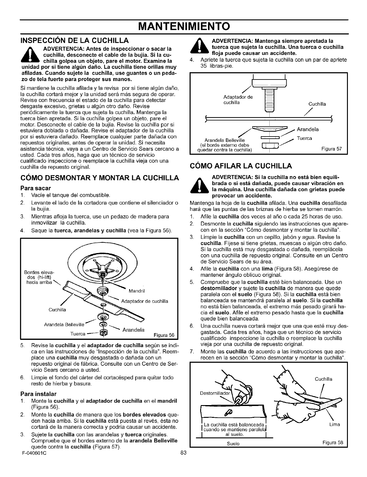
MANTENIMIENTO
INSPECCION DE LA CUCHILLA
_b DVERTENCIA: Antes de inspeccionar o sacar la
cuchilla, desconecte el cable de la bujia. Si la cu-
chilla golpea un objeto, pare el motor. Examine la
unidad por si tiene atgun da_o. La cuchilla tiene orillas muy
afiladas. Cuando sujete la cuchilla, use guantes o un peda-
zo de tela fuerte para proteger sus manos.
Si mantiene la cuchilla afilada y la revisa por si tiene algen daSo,
la cuchilla cortar_ mejor y la unidad ser& m&s segura de operar.
Revise con frecuencia el estado de la cuchilla para detectar
desgaste excesivo, grietas u algOn otro da6o. Revise
peri6dicamente la tuerca que sujeta la cuchilla. Mantenga la
tuerca bien apretada. Si la cuchilla golpea un objeto, pare el
motor. Desconecte el cable de la bujia. Revise la cuchilla por si
estuviera doblada o daSada. Revise el adaptador de la cuchilla
por si estuviera da6ado. Reemplace cualquier parte daSada con
repuestos originales, antes de operar la unidad. Si necesita
asistencia t6cnica, vaya a un Centro de Servicio Sears cercano a
usted. Cada tres aSos, haga queun t6cnico de servicio
cualificado inspeccione o reemplace la cuchilla vieja con una
cuchilla de repuesto original.
C()MO DESMONTAR Y MONTAR LA CUCHILLA
Para sacar
1. Vacie el tanque del combustible.
2. Levante el lado de la cortadora que contiene el silenciador o
la bujia.
3. Mientras afloja la tuerca, use un pedazo de madera para
inmovilizar la cuchilla.
4. Saque la tuerca, arandetas ycuchilla (vea la Figura 56).
Bordes eIeva-
dos (hi-lift)
hacia arriba
Cuchilla
Mandril
Adaptador de cuchilla
Arandeta BellevilIq Arandela
Tuerca _ Figura 56
5.
6.
Revise la cuchilla y el adaptador de cuchilla segOn se indF
ca en las instrucciones de "lnspecci6n de la cuchilla". Reem*
place una euchilla muy desgastada o da6ada con un
repuesto original de fabrica. Consulte con un Centro de Ser-
vicio Sears cercano a usted.
Limpie el fondo del carter del cortacesped para quitar todo
resto de hierba y basura.
Para instalar
1. Monte la cuchilla y el adaptador de cuchilla en el mandril
(Figura 56).
2. Monte la cuchilla de manera que los bordes elevados que *
den hacia arriba. Si la cuchilla est_ puesta al reves, esta no
cortar_ de la manera correcta y podria causar un accidente.
3. Sujete la cuchilla con las arandelas y tuerea originales.
Compruebe que el bordes externo de la arandela Belleville
quede contra la cuchUla (Figura 57).
F-040601C 83
_1 DVERTENCIA: Mantenga siempre apretada la
tuerca que sujeta la cuchilla. Una tuerca o cuchUla
floja puede causar un accidente.
4. Apriete la tuerca que sujeta la cucbilla con un par de apriete
35 libras-pie.
I I
AdcaP[l_d5e_ "-_J /Cuchilla
_./Arandela
Arandela BelIevilte _---_ /Tuerca
(el borde externo debe [Z_/
quedar contra ia cuchilla) I Figura 57
COMO AFILAR LA CUCHILLA
_1 DVERTENCIA: Si ta cuchilla no estb bien equili-
brada o si estb da_ada, puede causar vibracion en
la mbquina. Una cuchilla da_ada con grietas puede
provocar un accidente.
Mantenga la hoja de la cuchilla afilada. Una cuchilla desafilada
har_ que las puntas de las briznas de hierba se tornen marr6n.
1. Afile la cuchilla dos veces al aSo o cada 25 horas de uso.
2. Desmonte la cuchilla siguiendo las instrucciones que apare-
cen en la secci6n "C6mo desmontar y montar la cuchilla".
3. Limpie la cuchilla con un cepillo, jab6n y agua. Revise la
cuchilla, Fijese si tiene grietas, muescas o algt_n otro daSo.
Si la cuchilla esta muy desgastada o da6ada, reemplacela
con una cuchilla de repuesto original. Consulte en un Centro
de Servicio Sears de su _rea.
4. Afile la cuchilla con una lima (Figura 58). AsegQrese de
mantener _ngulo oblicuo original.
5. Compruebe que la cuchUla est6 bien balanceada. Use un
destornillador y sujete la cuchilla de manera que quede
paralela con el suelo (Figura 58). Si la cuchilla est_ bien
balanceada se mantendr_ paralela al suelo. Si la cuchilla
no esta bien balanceada, el extremo m&s pesado girar_ ha*
cia el suelo. Afile el extreme pesado hasta que la cuchilla
quede bien balanceada.
6. Una cuchilla nueva cortar_ mejor que una que est6 muy des-
gastada. Cada tres a6os, haga queun t6cnico de servicio
cualificado inspeccione la cuchilla o reemplace la cuchilla
vieja por una cuchilla de repuesto original.
7. Monte las cuchilla de acuerdo alas instrucciones que apa*
recen en la secci6n "C6mo desmontar y montar la cuchilla".
Destor_
! LaaC_Ch_Iea_mestratibala np_eaide_
I al suelo. I
Suelo Figura 58
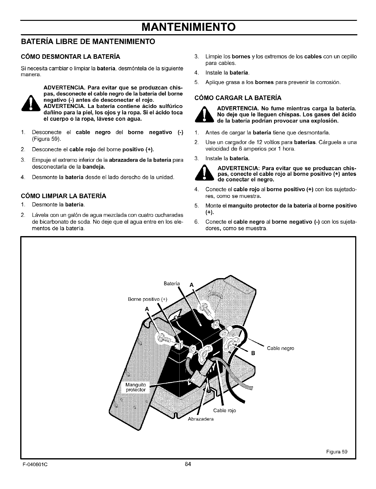
MANTENIMIENTO
BATERiA LIBRE DE MANTENIMIENTO
COMO DESMONTAR LA BATERiA
Si necesita cambiar o limpiar la bateria, desm6ntela de la siguiente
manera.
ADVERTENCIA. Para evitar que se produzcan chis-
pas, desconecte el cable negro de la bateria del borne
negativo (-) antes de desconectar el rojo.
ADVERTENCIA. La bateria contiene dcido sulft_rico
da_ino para la piel, los ojos y la ropa. Si el acido toca
el cuerpo o la ropa, tavese con agua.
1. Desconecte el cable negro del borne negativo (-)
(Figura 59).
2. Desconecte el cable rojo del borne positivo (+),
3. Empuje el extremo inferior de la abrazadera de la bateria para
desconectarla de la bandeja,
4. Desmonte la bateria desde el lado derecho de la unidad.
CC)MO LIMPIAR LA BATERiA
1. Desmonte la bateria.
2. L_vela con un galdn de agua mezclada con cuatro cucharadas
de bicarbonato de soda. No deje que el agua entre en los ele-
mentos de la bateria.
3,
4.
5.
Limpie los bornes y los extremos de los cables con un cepillo
para cables,
Instale la bateria,
Aplique grasa a los bornes para prevenir la corrosiSn.
C6MO CARGAR LA BATERiA
4_l=lb ADVERTENCIA. No fume mientras carga la bateria.
No deje que le Ileguen chispas. Los gases del dcido
de la bateria podrian provocar una explosibn.
1. Antes de cargar la bateria tiene que desmontada.
2. Use un cargador de 12 voltios para baterias. C_rguela a una
velocidad de 6 amperios por 1 hora.
3. Instale la bateria.
_1= ADVERTENCIA: Para evitar que se produzcan chis-
pas, conecte el cable rojo al borne positivo (+) antes
de conectar el negro.
4. Conecte el cable rojo al borne positivo (+) con los sujetado-
res, come se muestra,
5. Monte el manguito protector de la bateria al borne positivo
(+).
6. Conecte el cable negro al borne negativo (-) con los sujeta-
dores, come se muestra.
Bateria
Borne positivo (+)
A
Cable rojo
Abrazadera
BCable negro
Figura 59
F-040601C 84
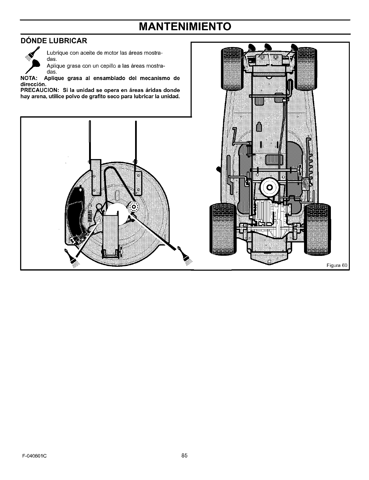
MANTENIMIENTO
DONDE LUBRICAR
Lubrique con aceite de motor las _reas mostra-
das,
Aplique grasa con un cepillo alas areas mostra*
das,
NOTA: Aplique grasa al ensamblado del mecanismo de
direccion.
PRECAUCION: Si la unidad se opera en _reas _ridas donde
hay arena, uti|ice potvo de grafito seco para lubricar la unidad,
Figura 60
F-040601C 85
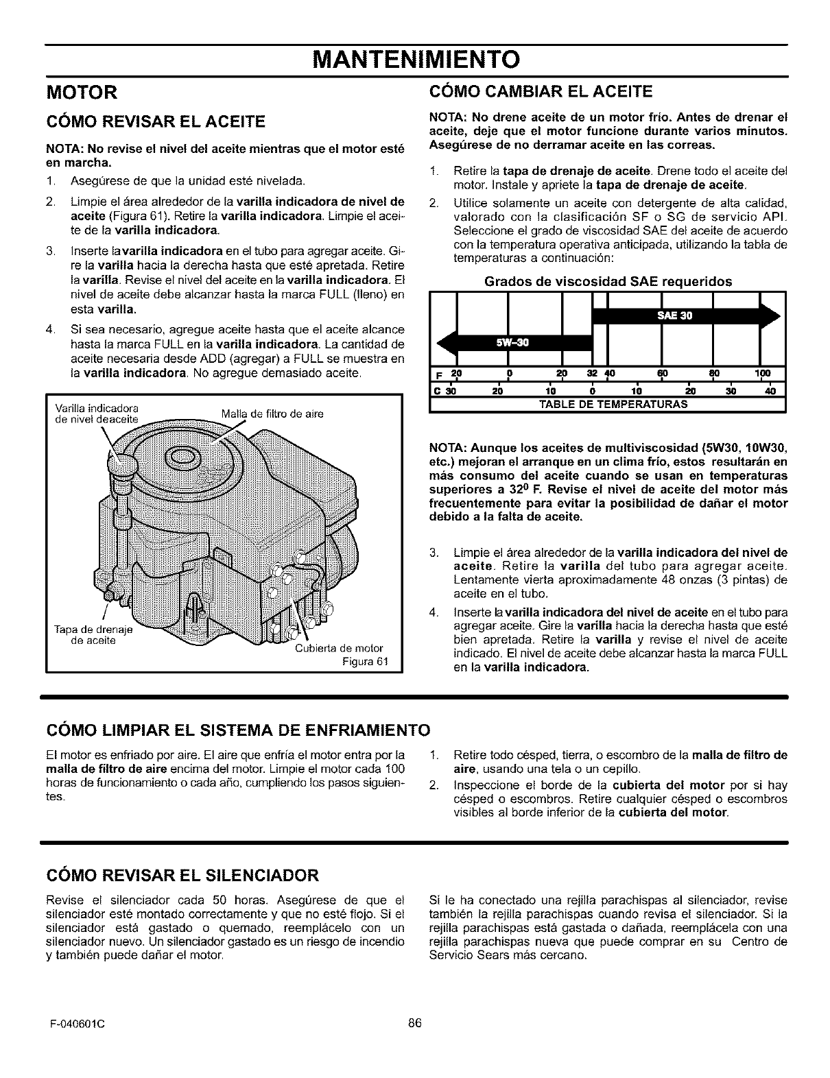
MANTENIMIENTO
MOTOR COMO CAMBIAR EL ACEITE
C()MO REVISAR EL ACEITE
NOTA: No revise el nive| del aceite mientras que el motor est_
en marcha.
1. AsegQrese de que la unidad est6 nivelada.
2. Limpie el _rea alrededor de la varilla indicadora de nivel de
aceite (Figura 61), Retire la varilla indicadora. Limpie el acek
te de la varilla indicadora.
3. Inserte lavarilla indicadora en el tubo para agregar aceite. Gi*
re la varilla hacia la derecha hasta que este apretada. Retire
la varilla. Revise el nivel del aceite en la varilla indicadora, El
nivel de aceite debe alcanzar hasta la marca FULL (lleno) en
esta varilla.
4. Si sea necesario, agregue aceite hasta que el aceite alcance
hasta la marca FULL en la varilla indicadora. La cantidad de
aceite necesaria desde ADD (agregar) a FULL se muestra en
la varUla indicadora. No agregue demasiado aceite.
Varitta indicadora
de nivet deaceite Matla de filtro de aire
/
Tapa de drenaje
de aceite Cubierta de motor
Figura 61
NOTA: No drene aceite de un motor frio. Antes de drenar el
aceite, deje que el motor funcione durante varios minutos.
Asegt_rese de no derramar aceite en tas correas,
1.
2.
Retire la tapa de drenaje de aceite. Drene todo el aceite del
motor. Instale y apriete la tapa de drenaje de aceite,
Utilice solamente un aceite con detergente de alta calidad,
valorado con la clasificaci6n SF o SG de servicio API.
Seleccione el grado de viscosidad SAE del aceite de acuerdo
con la temperatura operativa anticipada, utilizando la tabla de
temperaturas a continuaci6n:
Grados de viscosidad SAE requeridos
F =,0 ,o =p 3=1o ,6o ,8o 1,oo
C 30 20 1'0 (} 10 20 30 40
TABLE DE TEMPERATURAS
NOTA: Aunque los aceites de multiviscosidad (5W30, 10W30,
etc.) mejoran el arranque en un clima frio, estos resultar_n en
mas consumo del aceite cuando se usan en temperaturas
superiores a 32oF. Revise el nivel de aceite del motor mas
frecuentemente para evitar la posibUidad de dahar el motor
debido a la falta de aceite.
3.
4.
Limpie el area alrededor de la varilla indicadora del nivel de
aceite. Retire la varilla del tubo para agregar aceite.
Lentamente vierta aproximadamente 48 onzas (3 pintas) de
aceite en el tube.
Inserte lavarilla indicadora del nivel de aceite en el tubo para
agregar aceite. Gire la varilla hacia la derecha hasta que est6
bien apretada. Retire la varilla y revise el nivel de aceite
indicado. El nivel de aceite debe alcanzar hasta la marca FULL
en la varilla indicadora.
C()MO LIMPIAR EL SISTEMA DE ENFRIAMIENTO
El motor es enfriado por aire. El aire que enfria el motor entra por la
malla de filtro de aire encima del motor. Limpie el motor cada 100
horas de funcionamiento o cada aSo, cumpliendo los pasos siguien-
tes.
1. Retire todo cesped, tierra, o escombro de ]a malla de filtro de
aire, usando una tela o un cepillo.
2. Inspeccione el borde de la cubierta del motor por si hay
c6sped o escombros. Retire cualquier cesped o escombros
visibles a] borde inferior de la cubierta det motor.
C()MO REVISAR EL SILENCIADOR
Revise el silenciador cada 50 horas. Asegt_rese de que el
silenciador este montado correctamente y que no est6 flojo. Si el
silenciador esta gastado o quemado, reemplacelo con un
silenciador nuevo. Un silenciador gastado es un riesgo de incendio
y tambi6n puede daSar el motor.
Si le ha conectado una rejilla parachispas al silenciador, revise
tambi6n la rejilla parachispas cuando revisa el silenciador. Si la
rejilla parachispas esta gastada o da_ada, reempl_cela con una
rejilla parachispas nueva que puede comprar en su Centro de
Servicio Sears mas cercano.
F-040601C 86
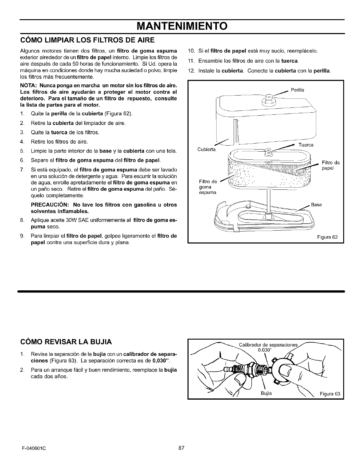
MANTENIMIENTO
COMO LIMPIAR LOS FILTROS DE AIRE
Algunos motores tienen dos filtros, un filtro de goma espuma
exterior alrededor de un filtro de papel interno, Limpie los fiJtros de
aire despues de cada 50 horas de funcionamiento, Si Ud, opera la
m&quina en condiciones donde hay mucha suciedad o polvo, limpie
los filtros mas frecuentemente,
NOTA: Nunca ponga en marcha un motor sin los filtros de aire.
Los filtros de aire ayudar_n a proteger el motor contra el
deterioro. Para el tamaSo de un filtro de repuesto, consulte
la tista de partes para el motor.
1. Quite la perilla de la cubierta (Figura 62).
2. Retire la cubierta del limpiador de aire.
3. Quite la tuerca de los filtros,
4. Retire los filtros de aire,
5.
6.
7.
8.
9.
Limpie la parte interior de la base y la cubierta con una tela,
Separe el filtro de goma espuma del filtro de papel.
Siesta equipado, el filtro de goma espuma debe ser lavado
en una soluci6n de detergente y agua. Para escurrir la soluci6n
de agua, enrolle apretadamente el filtro de goma espuma en
un paso seco, Retire el filtro de goma espuma del paso. $6_
quelo completamente.
PRECAUCION: No lave los filtros con gasotina u otros
solventes inflamabtes.
Aplique aceite 30W SAE uniformemente al filtro de goma es-
puma seco,
Para limpiar el filtro de papel, golpee ligeramente el fUtro de
papel contra una superficie dura y plana.
10, Si el filtro de papel est_ muy sucio, reemplacelo.
11, Ensamble los filtros de aire con la tuerea.
12. Instale Jacubierta. Conecte Jacubierta con la perUla.
Perilla
J
Cubierta
Filtro de /
goma
J
Filtro de
papel
Figura 62
COMO REVISAR LA BUJIA
1. Revise la separacidn de la bujia con un calibrador de separa-
clones (Figura 63), La separaci6n correcta es de 0,030",
2. Para un arranque f_cil y buen rendimiento, reemplace la bujia
cada dos aSos.
Bujla Figura 63
F-040601C 87
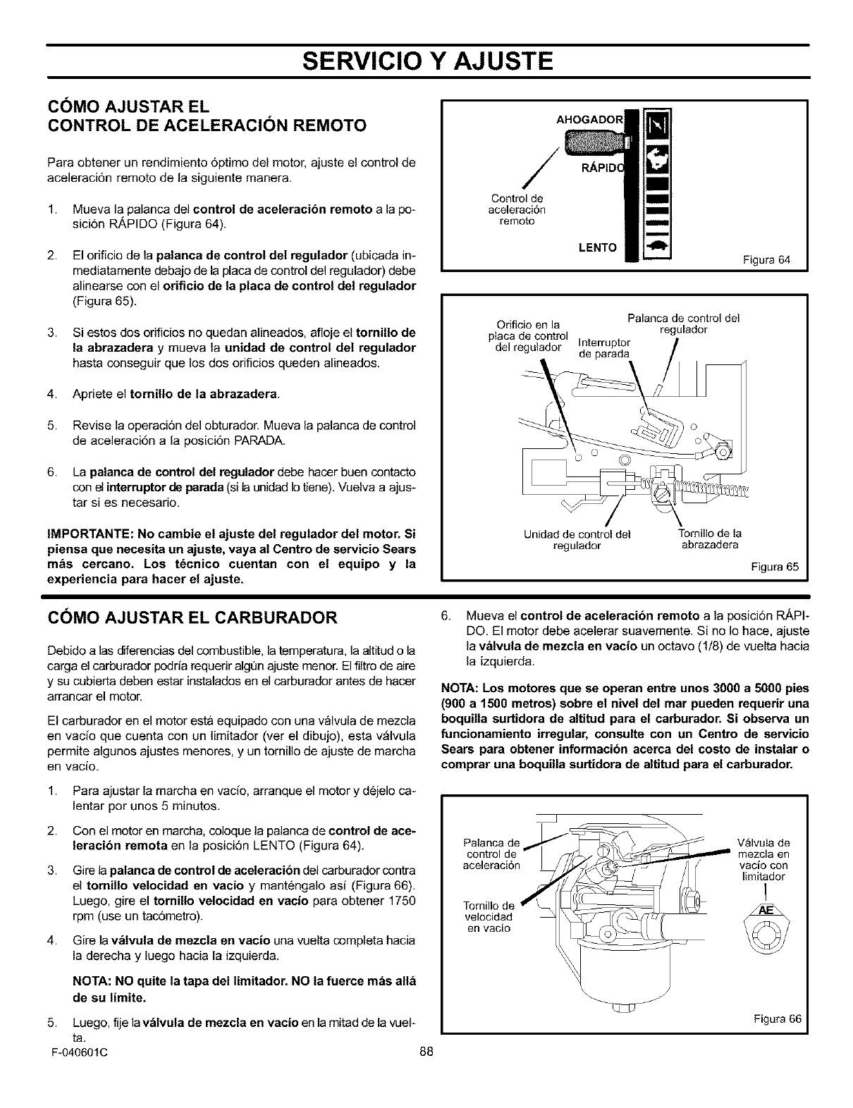
SERVICIO Y AJUSTE
COMO AJUSTAR EL
CONTROL DE ACELERACI()N REMOTO
Para obtener un rendimiento 6ptimo del motor, ajuste el control de
aceleraci6n remoto de la siguiente manera.
1. Mueva la palanca del control de aceleracibn remoto a la po_
sici6n IR/kPIDO (Figura 64).
2. El orificio de la palanca de control del regulador (ubicada im
mediatamente debajo de la placa de control del regulador) debe
alinearse con el orificio de la placa de control del regulador
(Figura 65).
3. Si estos dos orificios no quedan alineados, afloje el tornillo de
la abrazadera y mueva la unidad de control del regulador
hasta conseguir que los dos orificios queden alineados.
4. Apriete el tornillo de la abrazadera.
5. Revise la operaci6n del obturador. Mueva la palanca de control
de aceleracidn a la posici6n PARADA.
6. La palanca de control del regulador debe hacer buen contacto
con el interruptor de parada (si la unidad b tiene). Vuelva a ajus-
tar si es necesario.
IMPORTANTE: No cambie el ajuste del regutador del motor. Si
piensa que necesita un ajuste, vaya al Centro de servicio Sears
mas cercano. Los t_cnico cuentan con el equipo y la
experiencia para hacer et ajuste.
C()MO AJUSTAR EL CARBURADOR
Debido alas diferencias del combustible, la temperatura, la altitud o la
carga el carburador podria requerir algQn ajuste menor. El filtro de aire
y su cubierta deben estar instalados en el carburador antes de hacer
arrancar el motor.
El carburador en el motor esta equipado con una v_lvula de mezcla
en vacio que cuenta con un limitador (ver el dibujo), esta v_lvula
permite algunos ajustes menore& y un tornillo de ajuste de marcha
en vacio.
1. Para ajustar la marcha en vacio, arranque el motor y d6jelo ca-
lentar por unos 5 minutos.
2. Con el motor en march& coloque la palanca de control de ace-
leracion remota en la posici6n LENTO (Figura 64).
3. Gire la patanca de control de aceleracion del carburador contra
el tomillo velocidad en vacio y mant6ngalo asi (Figura 66).
Luego, gire el tomillo velocidad en vacio para obtener 1750
rpm (use un tac6metro).
4. Gire la v_tvula de mezcla en vacio una vuelta completa hacia
la derecha y luego hacia la izquierda.
NOTA: NO quite ta tapa del timitador. NO la fuerce mds all_
de su limite,
5. Luego, fije lav_tvula de mezcla en vacio en la mitad de la vuel_
ta.
F-040601C 88
/
Control de
aceleraci6n
remoto
LENTO
Figura 64
Palanca de control det
Orificio en la regulador
placa de control
del regulador Interruptor
de parada
Unidad de control det Tornilto de Ia
regulador abrazadera
Figura 65
6. Mueva el control de aceleracion remoto a la posici6n R/_PF
DO. El motor debe acelerar suavemente. Si no Io hace, ajuste
la valvula de mezcla en vacio un octavo (1/8) de vuelta hacia
la izquierda.
NOTA: Los motores que se operan entre unos 3000 a5000 pies
(900 a 1500 metros) sobre el nivel del mar pueden requerir una
boquilla surtidora de altitud para el carburador. Si observa un
funcionamiento irregular, consulte con un Centro de servicio
Sears para obtener informacion acerca del costo de instalar o
comprar una boquilla surtidora de altitud para el carburador.
Palanca de V_lvuIa de
control de mezcla en
aceleraci6n vacio con
limitador
1
Tomillo de
velocidad
erl vacio
Figura 66
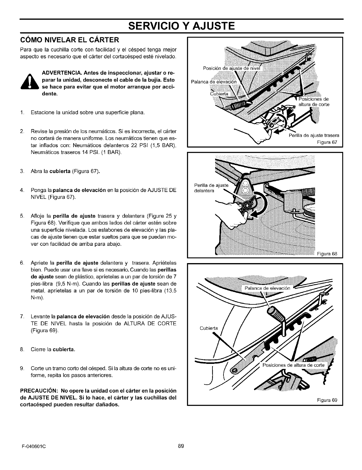
SERVICIO Y AJUSTE
COMO NIVELAR EL CARTER
Para que la cuchilla corte con facilidad y el c6sped tenga meier
aspecto es necesario que el carter del cortacesped este nivelado.
,a,ADVERTENCIA. Antes de inspeccionar, ajustar o re-
parar la unidad, desconecte el cable de la bujia. Esto
se hace para evitar que el motor arranque por acci-
dente.
1. Estacione la unidad sobre una superficie plan&
2. Revise la presi6n de los neumaticos. Si es incorrect& el c_rter
no cortara de manera uniforme. Los neum_ticos tienen que es-
tar inflados con: Neum_ticos delanteros 22 PSI (1,5 BAR),
Neum_ticos traseros 14 PSI. (1 BAR).
Posici6n de aiuste de nivel
Cubierta
altura de corte
Perilla de ajuste trasera
Figura 67
3. Abra la cubierta (Figura 67),
4. Ponga la palanca de elevacibn en la posici6n de AJUSTE DE
NIVEL (Figura 67).
5. Afloje la perilla de ajuste trasera y delantera (Figure 25 y
Figura 68), Verifique que ambos lados del c_rter esten sobre
una superficie nivelada. Los eslabones de elevacidn y las pla-
cas de ajuste tienen que estar sueltos para que se puedan mo-
ver con facilidad de arriba para abajo,
6. Apriete la perilla de ajuste delantera y trasera. Aprietelas
bien. Puede usar una llave si es necesario. Cuando las perillas
de ajuste sean de pl_stico, aprietelas a un par de torsi6n de 7
piesqibra (9,5 N-m). Cuando las perillas de ajuste sean de
metal, aprietelas a un par de torsidn de 10 pies-libra (13,5
N-m).
7. Levante la patanca de elevacibn desde la posicidn de AJUS-
TE DE NIVEL hasta la posicidn de ALTURA DE CORTE
(Figura 69).
8. Cierre la cubierta.
9. Corte un tramo corto del c6sped. Si la altura de corte no es unk
forme, repita los pasos anteriores.
PRECAUCION: No opere la unidad con el c_rter en la posicion
de AJUSTE DE NIVEL, Si Io hace, el carter y las cuchil|as del
cortac6sped pueden resaltar da_ados,
Perilla de ajuste
delantera
Cubierta
Figura 68
Figura 69
F-040601C 89
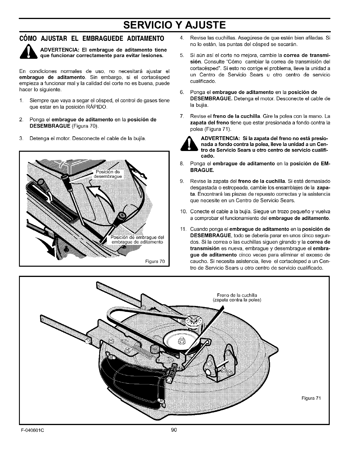
SERVICIO Y AJUSTE
C0M0 AJUSTAR EL EMBRAGUEDE ADITAMENT0 4. Reviselascuchillas.Aseg6resedequeest6nbienafiladas.Si
_b DVERTENCIA: El embrague de aditamento tiene
que funcionar correctamente para evitar lesiones,
En condiciones normales de uso, no necesitar_ ajustar el
embrague de aditamento. Sin embargo, si el cortac6sped
empieza a funcionar real y la calidad del corte no es buena, puede
hacer Io siguiente.
1. Siempre que vaya a segar el c6sped, el control de gases tiene
que estar en la posici6n R.&PIDO.
2. Ponga el embrague de aditamento en la posicibn de
DESEMBRAGUE (Figura 70),
3. Detenga el motor. Desconecte el cable de la bujia.
Posici6n de embrague det
embrague de aditamento
Figura 70
5.
no Io estan, las puntas del c6sped se secar&n.
Si at3n as[ el corte no mejora, cambie la correa de transmi-
si6n. Consulte "C6mo cambiar la correa de transmisi6n del
cortacesped". Si esto no corrige el problem& Ileve la unidad a
un Centro de Servido Sears u otro centro de servicio
cualificado.
6. Ponga el embrague de aditamento en la posicibn de
DESEMBRAGUE. Detenga el motor. Desconecte el cable de
la bujia.
7. Revise el freno de la cuchilla. Gire la polea con la mane. La
zapata del freno tiene que estar presionada a fondo contra la
polea (Figura 71).
_b ADVERTENCIA: Si la zapata del freno no est_ presio-
nada a fondo contra la polea, Ileve la unidad aun Cen-
tro de Servicio Sears u otro centro de servicio cualifi-
cado,
8. Ponga el embrague de aditamento en la posicibn de EM-
BRAGUE,
9.
10.
11.
Revise la zapata del freno de la cuchilla. Si est_ demasiado
desgastada o estropeada, cambie los ensamblajes de la zapa-
ta, Encontrar_ las piezas de repuesto correctas y la asistencia
que necesite en un Centro de Servicio Sears.
Conecte el cable a la bujia, Siegue un trozo peque_o y vuelva
a comprobar el funcionamiento del embrague de aditamento,
Cuando ponga el embrague de aditamento en la posicibn de
DESEMBRAGUE, todo se debeda parar en unos cinco segum
dos. Si la correa o las cuchillas siguen girando y la eorrea de
transmisibn es nueva, embrague y desembrague el embra-
gue de aditamento cinco veces para eliminar el exceso de
caucho. Si necesita asistencia, Ileve el cortacesped a un Cen-
tro de Servicio Sears u otro centro de servicio cualificado.
Freno de la cuchilta
(zapata contra la polea)
Figura 71
F-040601C 90
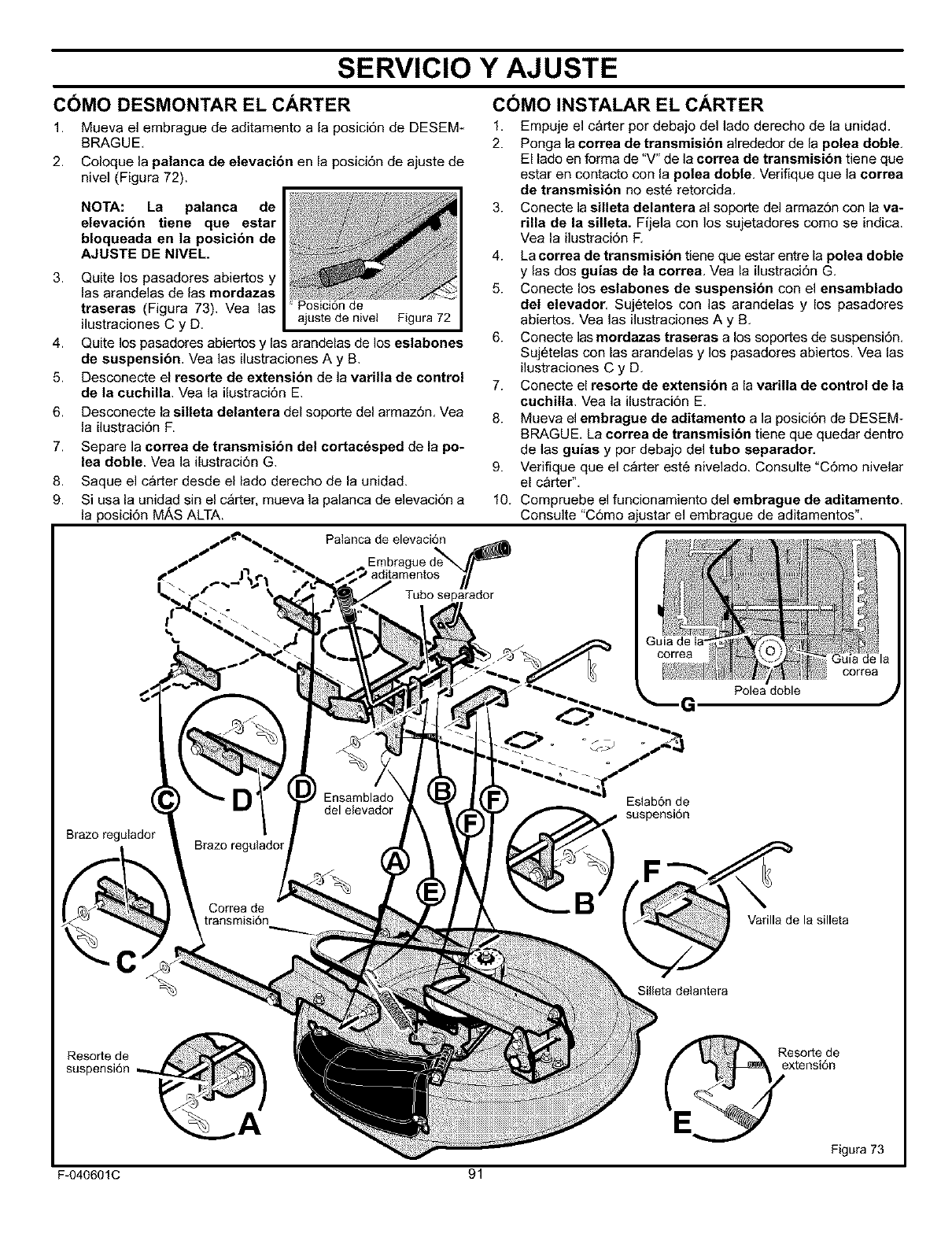
SERVICIO Y AJUSTE
CC)MO DESMONTAR EL CARTER C(_MO INSTALAR EL CARTER
1. Mueva el embrague de aditamento a la posici6n de DESEM*
BRAGUE,
2. Coloque la palanca de elevacion en la posici6n de ajuste de
nivel (Figura 72).
3.
4.
5.
6.
7.
8.
9.
NOTA: La palanca de
elevacion tiene que estar
bloqueada en la posicion de
AJUSTE DE NIVEL,
Quite los pasadores abiertos y
las arandelas de las mordazas
traseras (Figura 73). Vea las de
ilustraciones C y D. ajuste de nivet Figura 72
Quite los pasadores abiertos y las arandelas de los eslabones
de suspensibn. Yea las ilustraciones A y B.
Desconecte el resorte de extension de la varilla de control
de la cuchilla. Vea la ilustraci6n E.
Desconecte la silleta delantera del soporte del armaz6n, Vea
la ilustraci6n F.
Separe la correa de transmisi6n del cortac_sped de la po-
lea doble. Yea la ilustraci6n G.
Saque el carter desde el lado derecho de la unidad.
Si usa la unidad sin el c_rter, mueva la palanca de elevaci6n a
la posici6n MAS ALTA.
1,
2.
3.
4.
5.
6.
7.
8.
9.
10.
Palanca de elevaci6n
Embragued_
Tubo separador
Empuje el carter per debajo del lade derecho de la unidad.
Ponga la correa de transmisibn alrededor de la polea doble.
El lado en forma de "V" de la correa de transmisibn tiene que
estar en contacto con la polea doble. Verifique que la correa
de transmision no est6 retorcida.
Conecte la silleta delantera al soporte del armaz6n con la va-
rilla de la silleta. Fijela con los sujetadores como se indica.
Vea la ilustraci6n R
La correa de transmision tiene que estar entre la polea doble
y las dos guias de la correa, Vea la ilustraci6n G.
Conecte los eslabones de suspensibn con el ensamblado
del elevador. Sujetelos con las arandelas y los pasadores
abiertos. Vea las ilustraciones A y B.
Conecte las mordazas traseras a los soportes de suspensi6n.
Sujetelas con las arandelas y los pasadores abiertos. Vea las
ilustraciones C y D.
Conecte el resorte de extension a la varilla de control de ta
cuchilla. Vea la ilustraci6n E.
Mueva el embrague de aditamento a la posici6n de DESEM-
BRAGUE. La correa de transmisibn tiene que quedar dentro
de las guias y por debajo del tubo separador.
Verifique que el c_rter est6 nivelado. Consulte "C6mo nivelar
el carter".
Compruebe el funcionamiento del embrague de aditamento.
Consulte "C6mo ajustar el embrague de aditamentos".
_ Guia de la
_¢j__ correa
Polea doble
Brazo regulador
Eslab6n de
suspensi6n
C
a
Silleta detantera
Varilla de la silleta
Resole de
suspensi6n
F-040601C
Resole de
extensi6n
Figura 73
91
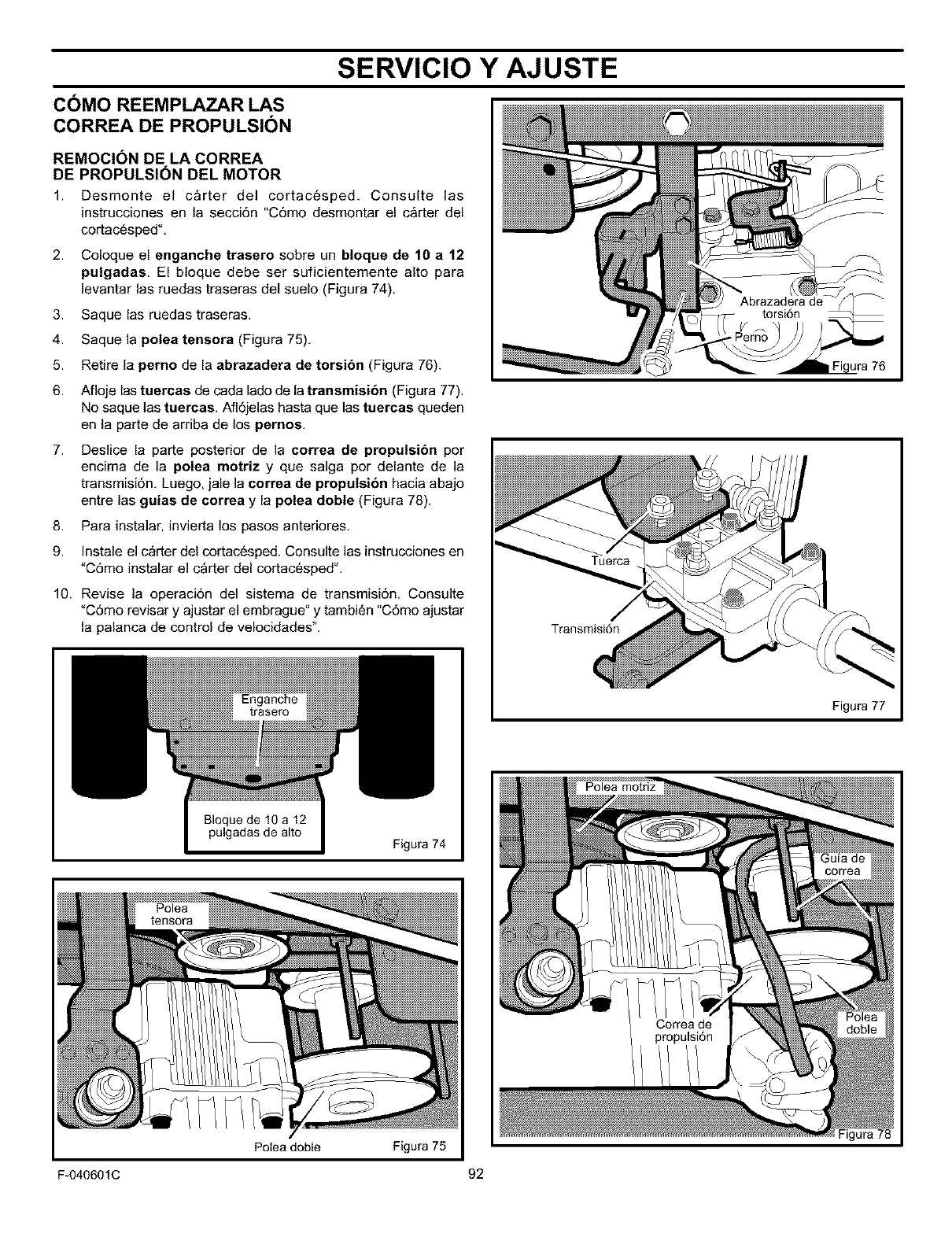
SERVICIO Y AJUSTE
COMO REEMPLAZAR LAS
CORREA DE PROPULSION
REMOCION DE LA CORREA
DE PROPULSION DEL MOTOR
1. Desmonte el carter del cortacesped. Consulte las
;nstrucciones en la secci6n "C6mo desmontar el carter del
cortacesped".
2. Coloque el enganehe trasero sobre un bloque de 10 a12
pulgadas. El bloque debe ser suficientemente alto para
levantar las ruedas traseras del suelo (Figura 74).
3. Saque las ruedas traseras.
4. Saque la polea tensora (Figura 75).
5. Retire la perno de la abrazadera de torsibn (Figura 76).
6. Afloje las tuercas de cada lado de la transmisibn (Figura 77).
No saque las tuereas. Afl6jelas hasta que las tuereas queden
en la parte de arriba de los pernos,
7. Deslice la parte posterior de la eorrea de propulsibn por
encima de la polea motriz y que salga por delante de la
transmisi6n. Luego, jale la eorrea de propulsion hacia abajo
entre las guias de correa y la polea doble (Figura 78).
8. Para insta]ar, JnvJertalos pasos anteriores.
9. Instale el c_rter del cortacesped. Consulte las instrucciones en
"C6mo instalar el carter del cortacesped".
10. Revise la operaci6n del sistema de transmisi6n. Consulte
"C6mo revisar y ajustar el embrague" y tambi6n "C6mo ajustar
la palanca de control de velocidades".
Figura 74
Polea doble
Figura 77
Figura 78
Figura 75
F-040601C 92
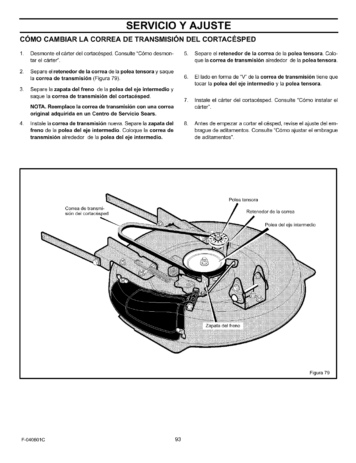
SERVICIO Y AJUSTE
COMO CAMBIAR LA CORREA DE TRANSMISION DEL CORTACI_SPED
1.
2.
3.
4.
Desmonte el carter del cortacesped, Consulte "C6mo desmom
tar el carter",
Separe el retenedor de la correa de la potea tensora y saque
la correa de transmisibn (Figura 79).
Separe la zapata de| freno de la polea de| eje intermedio y
saque la correa de transmision del cortacdsped.
NOTA. Reempiace la correa de transmision con una correa
original adquirida en un Centro de Servicio Sears.
Instale la correa de transmision nueva. Separe la zapata del
freno de la po|ea de| eje intermedio, Coloque la correa de
transmision alrededor de la polea del eje intermedio.
5. Separe el retenedor de la correa de la polea tensora. Colo-
que la correa de transmision alrededor de la polea tensora.
6. El lado en forma de "V" de la correa de transmisibn tiene que
tocar la polea del eje intermedio y la polea tensora.
7. Instale el c_rter del cortac6sped. Consulte "C6mo instalar el
c_rter",
8. Antes de empezar a cortar el cesped, revise el ajuste del em-
brague de aditamentos. Consulte "C6mo ajustar el embrague
de aditamentos".
Correa de transmi-
si6n del cortacesped
Polea tensora
Retenedor de la correa
Polea del eje intermedio
Figura 79
F-040601C 93
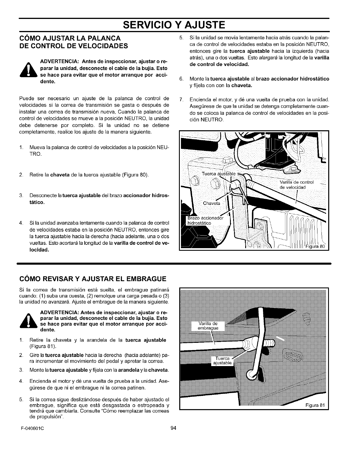
SERVICIO Y AJUSTE
5.
COMO AJUSTAR LA PALANCA
DE CONTROL DE VELOCIDADES
ADVERTENCIA: Antes de inspeccionar, ajustar o re-
parar la unidad, desconecte el cable de la bujia. Esto
se hace para evitar que el motor arranque por acci-
dente.
Si la unidad se movia lentamente hacia atr_s cuando la palan-
ca de control de velocidades estaba en la posicidn NEUTRO,
entonces gire la tuerca ajustable hacia la izquierda (hacia
atr_s), una o dos vueltas. Esto alargar# la Iongitud de la varilla
de control de velocidad.
6. Monte la tuerca ajustable al brazo accionador hidrostbtico
yfijela con con la chaveta.
Puede ser necesario un ajuste de la palanca de control de
velocidades si la correa de transmisi6n se gasta o despues de
instalar una correa de transmisi6n nueva, Cuando la palanca de
control de velocidades se mueve a la posicidn NEUTRO, la unidad
debe detenerse por completo. Si la unidad no se detiene
completamente, realice los ajuste de la manera siguiente.
7. Encienda el motor, y d6 una vuelta de prueba con la unidad.
AsegQrese de que la unidad se detenga completamente cuam
do se coloca la palanca de control de velocidades en la posi-
ci6n NEUTRO.
1. Mueva la palanca de control de velocidades a la posicidn NEU-
TRO.
2. Retire la chaveta de la tuerca ajustable (Figura 80).
3. Desconecte latuerca ajustable del brazo accionador hidros-
tdtico.
4. Si la unidad avanzaba lentamente cuando ]a palanca de control
de velocidades estaba en la posici6n NEUTRO, entonces gire
la tuerca ajustable hacia la derecha (hacia adelante, una o dos
vueltas. Esto acortar_ ]a Iongitud de la varilla de control de ve-
Iocidad.
COMO REVISAR Y AJUSTAR EL EMBRAGUE
Si la correa de transmisi6n est_ suelta, el embrague patinar_
cuando; (1) suba una cuesta, (2) remolque una carga pesada o (3)
la unidad no avanzar& Ajuste el embrague de la manera siguiente.
ADVERTENCIA: Antes de inspeccionar, ajustar o re-
parar la unidad, desconecte el cable de la bujia. Esto
se hace para evitar que el motor arranque pot acci-
dente.
1.
2.
3.
Retire la chaveta y la arandela de la tuerca ajustable
(Figura 81).
Gire la tuerca ajustable hacia la derecha (hacia adelante) pa*
ra incrementar el movimiento del pedal y apretar la correa.
Monte la tuerca ajustable y fijela con la arandela y la chaveta.
4. Encienda el motor y de una vuelta de prueba a la unidad. Ase*
gl3rese de que ni el embrague ni la correa patinen.
5. Si la correa sigue deslizandose despues de haber ajustado el
embrague, significa que esta desgastada o estropeada y
tendr& que cambiada. Consulte "C6mo reemplazar las correas
de propulsi6n".
Figura 81
F-040601C 94
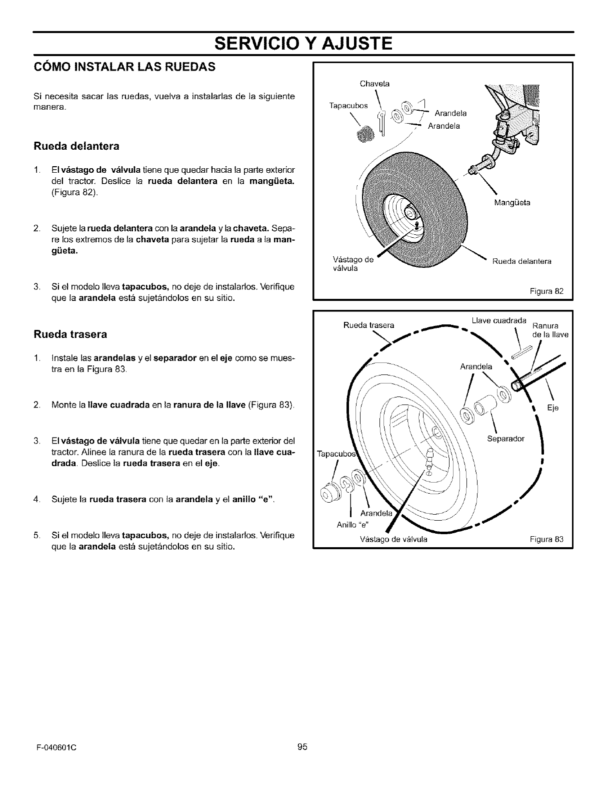
SERVICIO Y AJUSTE
COMO INSTALAR LAS RUEDAS
Si necesita sacar las ruedas, vuelva a instaladas de Ja siguiente
manera.
Rueda delantera
1. El v_stago de v_tvula tiene que quedar hacia la parte exterior
del tractor. Deslice la rueda delantera en la mangiJeta.
(Figura 82).
2. Sujete la rueda delantera con la arandela y lachaveta. Sepa-
re los extremes de la chaveta para sujetar ]a rueda ala man-
giJeta.
3. Si el modelo lleva tapacubos, no deje de instalarlos. Verifique
que la arandela est_ sujetandolos en su sitio.
Chaveta
Tapacubos \ _ Arandeta
_[_ j_ Arandela
Vastag
valvula
MangQeta
Rueda delantera
Figura 82
Rueda trasera
1. Instale las arandelas y el separador en el eje come se mues_
tra en la Figura 83.
2. Monte la tlave cuadrada en la ranura de ta tlave (Figura 83).
3. El v_etago de valvula tiene que quedar en la parte exterior del
tractor, Alinee la ranura de la rueda trasera con la Ilave cua-
drada. Deslice Ja rueda traeera en el eje.
4. Sujete la rueda traeera con la arandela y el anUlo "e".
5. Si el modelo Ileva tapaeubos, no deje de instalarlos. Verifique
que la arandela est_ sujetandolos en su sitio,
Llave cuadrada
Rueda trasera
Arandela
Ranura
de la Ilave
TapacuL
Anillo "e"
Vastago de valvula
I Eje
Separador /
!
/
Figura 83
F-040601C 95
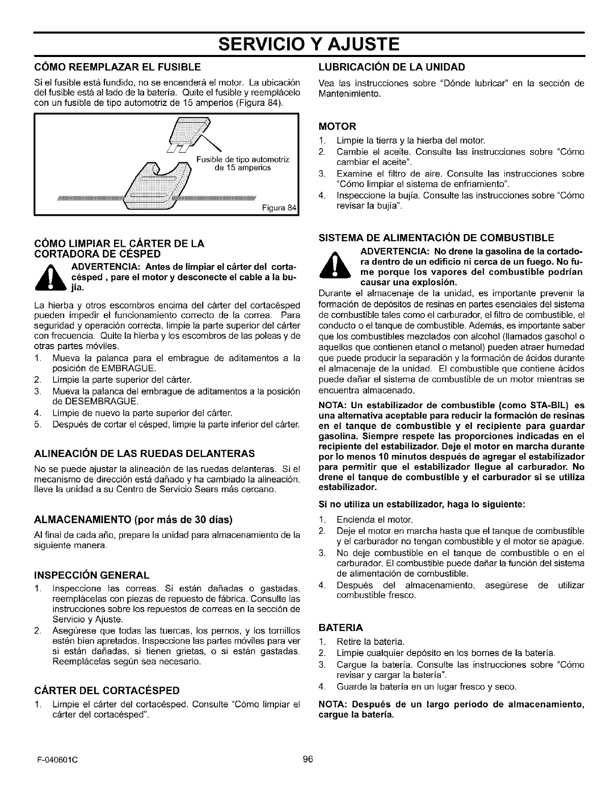
SERVICIO Y AJUSTE
COMO REEMPLAZAR EL FUSIBLE
Si el fusible esta fundido, no se encender& el motor. La ubicaci6n
del fusible esta al lado de la bateria. Quite el fusible y reemplacelo
con un fusible de tipo automotriz de 15 amperios (Figura 84).
LUBRICACION DE LA UNIDAD
Vea las instrucciones sobre "D6nde lubricar" en la secci6n de
Mantenimiento.
Fusible de tipo automotriz
Figura 84
MOTOR
1. Limpie la tierra y la hierba del motor.
2. Cambie el aceite. Consulte las instrucciones sobre "C6mo
cambiar el aceite'L
3. Examine el filtro de aire. Consulte las instrucciones sobre
"C6mo limpiar el sistema de enfriamiento".
4. Inspeccione la bujia. Consulte las instrucciones sobre "C6mo
revisar la bujia".
COMO LIMPIAR EL CARTER DE LA
CORTADORA DE CE_SPED
_hb ADVERTENCIA: Antes de limpiar el c&rter del corta-
c_sped, pare el motor y desconecte el cable a ta bu-
jia.
La hierba y otros escombros encima del carter del cortac6sped
pueden impedir el funcionamiento correcto de la correa. Para
seguridad y operaci6n correcta, limpie la parte superior del c_rter
con frecuencia. Quite la hierba y los escombros de las poleas y de
otras partes m6viles.
1. Mueva la palanca para el embrague de aditamentos a la
posici6n de EMBRAGUE.
2. Limpie la parte superior del c_rter.
3. Mueva la palanca del embrague de aditamentos a la posici6n
de DESEMBRAGUE.
4. Limpie de nuevo la parte superior del carter.
5. Despu6s de cortar el c6sped, limpie la parte inferior del carter.
ALINEACION DE LAS RUEDAS DELANTERAS
No se puede ajustar la alineaci6n de las ruedas delanteras. Si el
mecanismo de direcci6n est_ daSado y ha cambiado la alineacidn,
Ileve la unidad a su Centro de Servicio Sears mas cercano.
ALMACENAMIENTO (por m&s de 30 dias)
AI final de cada aSo, prepare la unidad para almacenamiento de la
siguiente manera.
INSPECCION GENERAL
1. Inspeccione las correas. Si est_n daSadas o gastadas,
reemplacelas con piezas de repuesto de f_brica. Consulte las
instrucciones sobre los repuestos de correas en la secci6n de
Servicio y Ajuste.
2. Aseg_rese que todas las tuercas, los pernos, y los tornillos
esten bien apretados. Inspeccione las partes m6viles para ver
si est_n daSadas, si tienen grietas, o si estan gastadas.
Reemplacelas seg_n sea necesario.
CARTER DEL CORTACESPED
1. Limpie el c_rter del cortac6sped. Consulte "C6mo limpiar el
c_rter del cortacesped".
SISTEMA DE ALIMENTACI(_N DE COMBUSTIBLE
ADVERTENCIA: No drene la gasolina de la cortado-
ra dentro de un edificio ni cerca de un fuego. No fu-
me porque los vapores del combustible podrian
causar una explosibn.
Durante el almacenaje de la unidad, es importante prevenir la
formaci6n de dep6sitos de resinas en partes esenciales del sistema
de combustible tales como el carburador, el filtro de combustible, el
conducto o el tanque de combustible. Adem_s, es importante saber
que los combustibles mezclados con alcohol (llamados gasohol o
aquellos que contienen etanol o metanol) pueden atraer humedad
que puede producir la separaci6n y la formaci6n de _cidos durante
el almacenaje de la unidad. El combustible que contiene acidos
puede da_ar el sistema de combustible de un motor mientras se
encuentra almacenado.
NOTA: Un estabilizador de combustible (come STA-BIL) es
una altemativa aceptable para reducir la formacion de resinas
en el tanque de combustible y el recipiente para guardar
gasolina. Siempre respete las proporciones indicadas en el
recipiente del estabilizador. Deje el motor en marcha durante
per Io menos 10 minutos despuds de agregar el estabilizador
para permitir que el estabilizador Ilegue al carburador. No
drene el tanque de combustible y el carburador si se utUiza
estabilizador.
Si no utiliza un estabilizador, haga Io siguiente:
1. Encienda el motor.
2. Deje el motor en marcha hasta que el tanque de combustible
y el carburador no tengan combustible y el motor se apague.
3. No deje combustible en el tanque de combustible o en el
carburador. El combustible puede da_ar la funci6n del sistema
de alimentaci6n de combustible.
4. Despu6s del almacenamiento, aseg_rese de utilizar
combustible fresco.
BATERIA
1. Retire la bateria.
2. Limpie cualquier dep6sito en los bornes de la bateria.
3. Cargue la bateria. Consulte las instrucciones sobre "C6mo
revisar y cargar la bateria".
4. Guarde la bateria en un lugar fresco y seco.
NOTA: Despu_s de un largo periodo de almacenamiento,
cargue la bateria,
F-040601C 96
TABLA DE LOCALIZACION DE AVERIAS
PROBLEMA: El motor no se enciende.
1. Siga los pasos de "C6mo encender el motor" en este manual.
2. Limpie los bomes de la bateria. Apriete los cables.
3. Revise si hay un cable flojo. Apriete los interruptores limitado-
res. (Vea el diagrama de cableado.)
4. Drene el tanque de combustible. Limpie la linea de combusti-
ble. Reemplace el filtro de combustible.
5. Quite la bujia(s). Mueva el acelerador a la posici6n LENTO.
Gire la Ilave de encendido a la posici6n ENCENDIDO. Intente
encender el motor varias veces. Instale la bujia.
6. Reemplace la bujia con un repuesto nuevo.
7. Ajuste el carburador.
PROBLEMA: El motor no da vueltas.
1. Siga los pasos de "C6mo Encender el Motor" en este libro.
2. Verifique el nivel de acido en la bateria. SI es necesario, agre-
gue agua. Cargue la bateria.
3. Reemplace el fusible con un respuesto nuevo.
4. Inspeccione el cableado preformado para ver si tiene alg0n da-
5o o una conexi6n floja. Repare todo cable daSado.
5. Modelos de Arranque Electrico: reemplace el solenoide con un
repuesto nuevo. Modelos de Arranque Manual: reemplace el
m6dulo.
PROBLEMA: El es dificil eneender el motor,
1. Ajuste el carburador.
2. Reemplace la bujia.
3. Reemplace elfiltro de combustible.
PROBLEMA: El motor no funciona suavemente otiene una
p_rdida de fuerza,
1. Revise el aceite.
2. Limpie elfiltro de aire.
3. Limpie la malla del filtro de aire.
4. Reemplace la bujia.
5. El motor esta funcionando demasiado fuerte. Utilice una veloci-
dad m&s baja.
6. Ajuste el carburador.
7. Reemplace elfiltro de combustible.
PROBLEMA: El motor no funciona suavemente a una
velocidad alta.
1. Reemplace la bujia.
2. Ajuste el acelerador.
3. Limpie elfiltro de aire.
4. Reemplace elfiltro de combustible.
PROBLEMA: El motor se apaga cuando se hacen funcionar las
cuchillas.
1. Revise el cableado preformado par ver si tiene alg_n dafio o
una conexi6n floja. Repare todo cable daSado.
PROBLEMA: Sobre cuestas, el motor se apaga.
1. En cuestas, corte el cesped en linea directa hacia arriba y ha-
cia abajo. Nunca corte el c6sped a traves de una cuesta.
PROBLEMA: El motor no funciona en vacio.
1. Reemplace la bujia.
2. Limpie elfiltro de aire.
3. Ajuste el carburador.
4. Ajuste el acelerador.
5. Drene el tanque de combustible. Limpie la linea de combusti-
ble. Reemplace el filtro de combustible.
PROBLEMA: Un motor caliente causa una disminucion de
fuerza.
1. Limpie la malla del filtro de aire.
2. Revise el aceite.
3. Ajuste el carburador.
4. Reemplace el filtro de combustible.
PROBLEMA: Vibracibn excesiva.
1. Reemplace la cuchilla.
2. Verifique si hay pernos del motor que estan flojos.
3. Disminuya la presi6n de aire en los neum_ticos.
4. Ajuste el carburador.
5. Verifique si existe una correa da_ada o una polea da_ada.
Reemplace las piezas da_adas.
PROBLEMA: El c_sped no se descarga correctamente.
1. Apague el motor. Limpie el carter de la cortadora.
2. Suba la altura de corte.
3. Reemplace o afile las cuchillas.
4. Mueva la palanca de cambios a una velocidad m_s baja.
5. Mueva el acelerador a la posici6n de RAPIDO.
6. Reemplace el resorte para la polea tensadora de cuchilla.
PROBLEMA: El c_rter de la cortadora no corta a nivel.
1. Revise la presi6n de aire en los neumaticos.
2. Ajuste el nivel del carter de la cortadora.
3. Revise el eje delantero. Si el eje delantero no gira libremente,
afloje los pernos del eje.
PROBLEMA: Las cuchillas de la cortadora no rotan.
1. Revise la correa de transmisi6n de la cortadora. Aseg_rese de
que la correa est6 instalada correctamente.
2. Reemplace la correa de transmisi6n de la cortadora.
PROBLEMA: La unidad no se mueve cuando se hace
funcionar el embrague.
1. Revise la correa de transmisi6n. AsegQrese de que la correa
est6 instalada correctamente.
2. Ajuste el embrague.
3. Reemplace la correa de transmisi6n.
PROBLEMA: La unidad se mueve mas despacio o se para
cuando se engancha el embrague.
1. Ajuste el embrague.
2. Reemplace la correa de transmisi6n.
PROBLEMA: Cuando se suelta el pedal de freno/embrague, se
puede oir ruido de correas.
1. Ruido temporario de las correas no afecta el funcionamiento
de la unidad. Si el ruido de las correas es continuo, examine
el enrutamiento de la correa. AsegQrese de que la correa est6
dentro de todas las guias de correas.
2. Si el ruido es continuo, ajuste el embrague.
PROBLEMA: Las ruedas traseras resbalan sobre terreno
desnivelado.
1. Revise el eje delantero. Si el eje delantero no gira libremente,
afloje los pernos del eje.
F-040601C 97
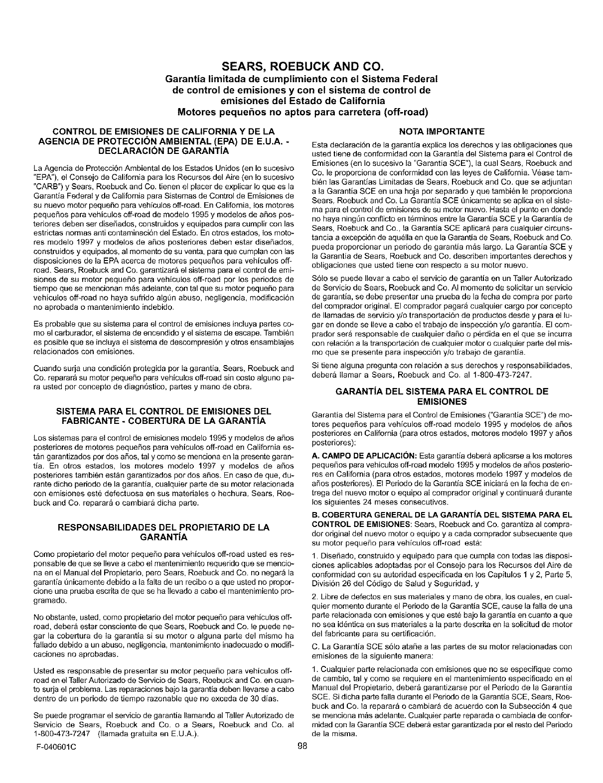
SEARS, ROEBUCK AND CO.
Garantia limitada de cumplimiento con el Sistema Federal
de control de emisiones y con el sistema de control de
emisiones del Estado de California
Motores pequehos no aptos para carretera (off=road)
CONTROL DE EMISIONES DE CALIFORNIA Y DE LA
AGENCIA DE PROTECCI(_N AMBIENTAL (EPA) DE E.U.A.
DECLARACION DE GARANTIA
La Agencia de Protecci6n Ambiental de los Estados Unidos (en Io sucesivo
"EPA"), et Consejo de California para los Recursos del Aire (en Io sucesivo
"CARB") y Sears, Roebuck and Co. tienen el placer de explicar Io que es la
Garantia Federal y de California para Sistemas de Control de Emisiones de
su nuevo motor pequeSo para vehiculos off-road. En California, los motores
pequeSos para vehiculos off-road de modelo 1995 y modeIos de aSos pos*
teriores deben set diseSados, construidos y equipados para complir con las
estrictas normas anti contaminaci6n del Estado. En otros estados, los moto-
res modelo 1997 y modelos de aSos posteriores deben estar diseSados,
construidos y equipados, at momento de su venta, para que cumplan con las
disposiciones de Ia EPA acerca de motores pequeSos para vehiculos off-
road. Sears, Roebuck and Co. garantizara el sistema para el control de emi*
siones de su motor peque5o para vehiculos off-road por los periodos de
tiempo qua se mencionan m_s adelante, con tat qua su motor pequeSo para
vehiculos off-road no haya sufrido alg6n abuso, negligencia, modificaci6n
no aprobada o mantenimiento indebido.
Es probable que su sistema para el control de emisiones incluya partes co-
mo el carburador, el sistema de encendido y el sistema de escape. Tambien
es posible que se incluya eI sistema de descompresi6n y otros ensambIajes
relacionados con emisiones.
Cuando surja una condici6n protegida por Ia garantia, Sears, Roebuck and
Co. reparara su motor pequeSo para vehicoIoa off-road sin costo atguao pa-
ra usted pot concepto de diagn6stico, partes y mano de obra.
SISTEMA PARA EL CONTROL DE EMISIONES DEL
FABRICANTE -COBERTURA DE LA GARANTiA
Los sistemas para eI controI de emisiones modelo 1995 y modeIos de a_os
posteriores de motores peque_os para vehicolos off-road en California es-
t&n garantizados pot dos a_os, ta! y como se menciona en Ia presente garan-
tia. En otros estados, los motores modeto 1997 y modelos de a_os
posteriores tambien estan garantizados pot dos a_os. En caso de qua, du-
rante dicho periodo de la garantia, coalquier parte de su motor relacionada
con emisiones este defectuosa en sus materiales o hechura, Sears, Roe-
buck and Co. reparar_ o cambiar& dicha parte.
RESPONSABILIDADES DEL PROPIETARIO DE LA
GARANTiA
Como propietario deI motor peque5o para vehicotos off-road usted es res*
ponsable de que se Ileve a cabo eI mantenimiento requerido que se mencio-
na en el ManuaI del Propietario, pero Sears, Roebuck and Co. no negara la
garantia Qnicamente debido a la falta de un recibo o a qua usted no propor*
clone una prueba escrita de qua se ha llevado a cabo eI mantenimiento pro-
gramado.
No obstante, usted, como propietario deI motor peque_o para vehicutos off-
road, debera estar consciente de qua Sears, Roebuck and Co. le puede he*
gar la cobertura de Ia garantia si su motor o alguna parte del mismo ha
fattado debido a un abuso, aegligencia, mantenimiento inadecuado o modifi-
caciones no aprobadas.
Usted es responsable de presentar su motor peque_o para vehiculos off-
road en e! Taller Autorizado de Servicio de Sears, Roebuck and Co. en coan-
to surja el problem& Las reparaciones bajo ta garantia deben Ilevarse a cabo
dentro de un periodo de tiempo razonable que no exceda de 30 dias.
Se puede programar el servicio de garantia IIamando at Taller Autorizado de
Servicio de Sears, Roebuck and Co. o a Sears, Roebuck and Co. al
1-890-473-7247 (ttamada gratuita en E.U.A.).
F-040601C 98
NOTA IMPORTANTE
Esta declaraci6n de la garantia explica los derechos y Ias obligaciones que
usted tiene de conformidad con Ia Garantia del Sistema para el Control de
Emisiones (en Io sucesivo Ia "Garantia SCE"), la cual Sears, Roebuck and
Co. le proporciona de conformidad con las leyes de California. Vease tam-
bi_n tas Garantlas Limitadas de Sears, Roebuck and Co. que se adjuntan
a la Garantia SCE en una hoja pot separado y que tambi6n le proporciona
Sears, Roebuck and Co. La Garantia SCE Qaicamente se aplica en el siste-
ma para el control de emisiones de su motor nuevo. Hasta el punto en donde
no haya ningQn conflicto en terminos entre la Garantia SCE y la Garantia de
Sears, Roebuck and Co., la Garantia SCE aplicara para cualquier circuns-
tancia a excepci6n de aqu_Ila en qua la Garantia de Sears, Roebuck and Co.
pueda proporcionar un periodo de garantia maa largo. La Garantla SCE y
la Garantia de Sears, Roebuck and Co. describen importantes derechos y
obligaciones qua usted tiene con respecto a su motor nuevo.
S6Io se puede Ilevar a cabo eI servicio de garantia en un Taller Autorizado
de Servicio de Sears, Roebuck and Co. Ai momento de solicitar un servicio
de garantia, se debe presentar una prueba de la fecha de compra pot pade
del comprador original. El comprador pagara cualquier cargo pot concepto
de Ilamadaa de servicio y/o transportaci6n de produclos desde y para el lu-
gar en donde se ileve a cabo el trabajo de inspecci6n y/o garantia. El com-
prador ser_ responsable de cuatquier daSo o p6rdida en et qua se incurra
con relaci6n a la transportaci6n de coaIquier motor o cualquier parte del mis-
mo qua se presente para inspecci6n y/o trabajo de garantia.
Si tiene alguna pregunta con relaci6n a sus derechos y responsabilidades,
debera llamar a Sears, Roebuck and Co. al 1-800-473-7247.
GARANTiA DEL SISTEMA PARA EL CONTROL DE
EMISIONES
Garantia del Sistema para el Control de Emisiones ("Garantia SCE") de too-
totes peque5os para vehiculos off-road modelo 1995 y modelos de aSos
posteriores en California (para otros estados, motores modelo 1997 y aSos
posteriores):
A. CAMPO BE APLICACION: Esta garantia debera aplicarse a los motores
pequefios para vehiculos off-road modelo 1995 y modelos de afios posterio-
res en California (para otros estados, motores mode!o 1997 y modetos de
aSos posteriores). El Periodo de la Garantia SCE iniciara en la fecha de en-
trega deI nuevo motor o equipo al comprador original y continuar_ durante
los siguientes 24 mesas consecutivos.
B. COBERTURA GENERAL DE LA GARANTiA DEL SISTEMA PARA EL
CONTROL DE EMISlONES: Sears, Roebuck and Co. garantiza al compra-
dot original del nuevo motor o equipo y a cada comprador subsecuente que
su motor peque_o para vehiculos off-road esta:
1. Dise5ado, construido y equipado para que cumpla con todas las disposi-
clones aplicables adoptadas pot el Consejo para los Recursos det Aire de
conformidad con su autoridad especificada en los Capitulos 1 y 2, Parte 5,
Divisi6n 26 del C6digo de Salud y Seguridad, y
2. Libre de defectos en sus materiales y mano de obra, los cuales, en coal-
quiet momento durante el Periodo de la Garantia SCE, cause la faIla de una
parte relacionada con emisiones y que est6 bajo la garantia en cuanto a que
no sea id_ntica en sus materiates a la parte descrita en Ia solicitud de motor
del fabricante para su certificaci6n.
C. La Garantia SCE s61o ataSe a tas partes de su motor retacionadas con
emiaiones de la siguiente manera:
1. Cualquier parte relacionada con emisiones que no se especifique como
de cambio, tal y como se requiere en e! mantenimiento especificado en el
ManuaI del Propietario, debera garantizarse pot e! Periodo de la Garantia
SCE. Si dicha parte falla durante el Periodo de la Garantia SCE, Sears, Roe-
buck and Co. la reparar_ o cambiar_ de acuerdo con la Subsecoi6n 4 qua
se menciona mas adeIante. Cualquier parte reparada o cambiada de confor-
midad con la Garantia SCE debera estar garantizada pot et resto det Periodo
de la misma,
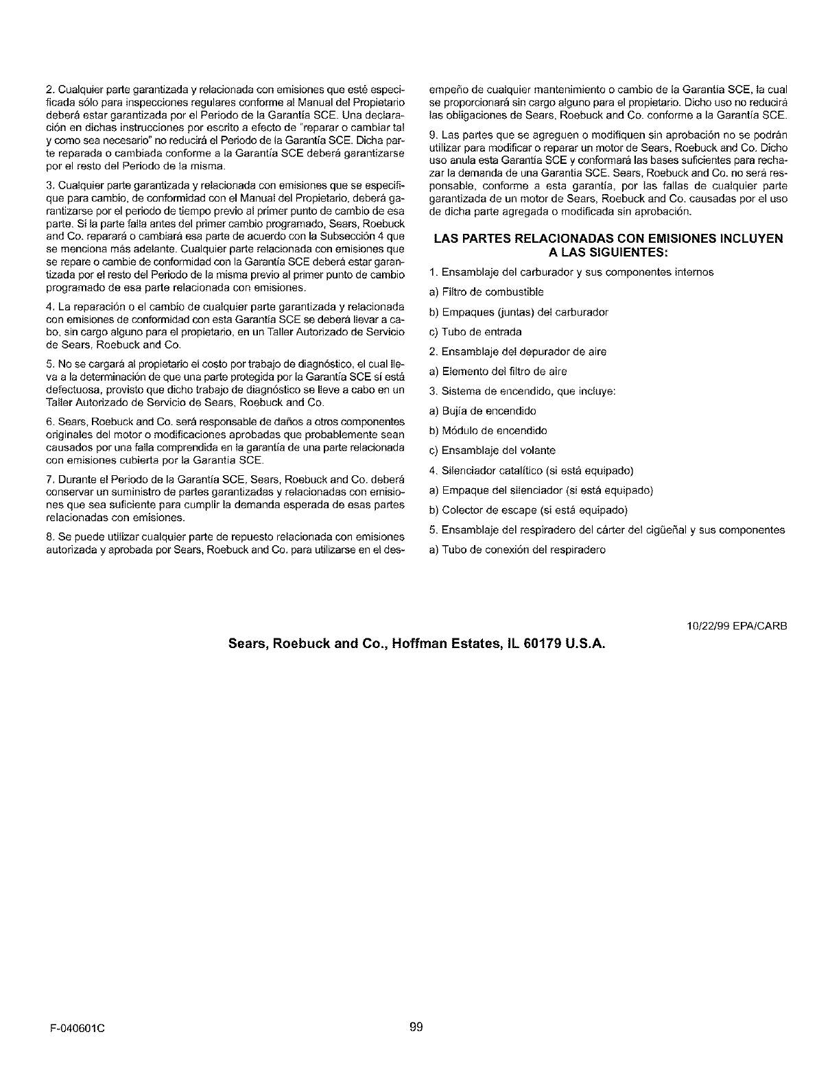
2.Cualquierpartegarantizadayrelacionadaconemisionesqueesteespeci-
ficadas61oparainspecoionesregularesconformealManualdelPropietario
deber_estargarantizadaporelPeriododelaGarantiaSCE.Unadedara*
ci6nendichasinstruccionesporescritoaefectode"repararocambiartal
ycomoseanecesario"noreduciraelPeriododelaGarantiaSCE.Dichapar-
tereparadaocambiadaconformealaGarantlaSCEdeberagarantizarse
porelrestodelPeriododetamisma.
3,CuaIquierpartegarantizadayreIacionadaconemisionesqueseespecifi-
queparacambio,deconformidadconelManuaIdelPropietario,deberaga-
rantizareeporelperiododetiempoprevioatprimerpuntodecambiodeeea
parte. Si ta parte faiIa antes del primer cambio programado, Sears, Roebuck
and Co. reparara o cambiar& eea parte de acoerdo con la Subeecci6n 4 que
se menciona m&s adelante. Cualquier parte relacionada con emisiones que
se repare o cambie de conformidad con la Garantia SCE debera estar garan-
tizada pot eI reeto del Periodo de la misma previo al primer punto de cambio
programado de eea parte relacionada con emisiones.
4, La reparaci6n o el cambio de cualquier parte garantizada y relacionada
con emisiones de conformidad con esta Garantia SCE se deber& Ilevar a ca-
bo, sin cargo alguno para el propietario, en un Taller Autorizado de Servicio
de Sears, Roebuck and Co.
5. No se cargara a! propietario el costo por trabajo de diagn6stico, el cual Ile-
va a la determinaci6n de que una parte protegida por la Garantia SCE siesta
defectuosa, provisto que dicho trabajo de diagn6stico se Ileve a cabo en un
Taller Autorizado de Servicio de Sears, Roebuck and Co.
6. Sears, Roebuck and Co. sera responsable de daSos a otros componentes
originates del motor o modificaciones aprobadas que probablemente sean
causados por una falla comprendida en Ia garantia de una parte relacionada
con emisiones cubierta por la Garantia SCE.
7. Durante et Periodo de la Garantia SCE, Sears, Roebuck and Co. debera
conservar un suministro de partes garantizadas y relacionadas con emisio*
nes que sea suficiente para cumplir la demanda esperada de esas partes
relacionadas con emisiones.
8. Se puede utilizar cualquier parte de repuesto retacionada con emisiones
autorizada y aprobada pot Sears, Roebuck and Co. para utilizarse en el des-
empeSo de coalquier mantenimiento o cambio de la Garantia SCE, Ia coal
se proporcionara sin cargo aiguno para el propietario. Dicho uso no reducira
las obligaciones de Sears, Roebuck and Co. conforme a la Garantia SCE.
9. Las partes que se agreguen o modifiquen sin aprobaci6n no se podr&n
utilizar para modificar o reparar un motor de Sears, Roebuck and Co. Dicho
uso anula esta Garantia SCE y conformara las bases suficientes para recha-
zar la demanda de una Garantia SCE. Sears, Roebuck and Co. no sera res-
ponsable, conforme a esta garantia, pot las fallas de cualquier parte
garantizada de un motor de Sears, Roebuck and Co. causadas por el uso
de dicha parte agregada o modificada sin aprobaci6n.
LAS PARTES RELACIONADAS CON EMISIONES INCLUYEN
A LAS SIGU|ENTES:
1. Ensamblaje del carburador y sus componentes intemos
a) Filtro de combustible
b) Empaques (juntas) deI carburador
c) Tubo de entrada
2. Ensamblaje deI depurador de aire
a) Elemento det filtro de aire
3. Sistema de encendido, que incluye:
a) Bujia de encendido
b) M6dulo de encendido
c) Ensamblaje del volante
4. Silenciador catalltico (siesta equipado)
a) Empaque del silenciador (si est_ equipado)
b) Colector de escape (si est_ equipado)
5. Ensamblaje del respiradero del c_rter del cigQeSal y sus componentes
a) Tubo de conexi6n del respiradero
Sears, Roebuck and Co., Hoffman Estates, IL 60179 U.S.A.
10/22/99 EPA/CARB
F-040601C 99

NOTAS
F-040601C 100
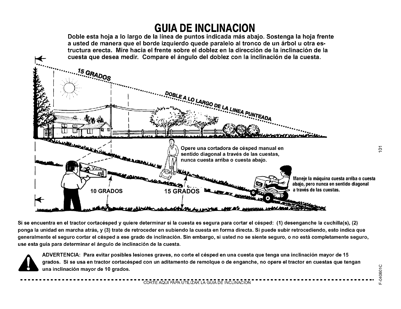
GUIADE INCLINACION
Doble esta hoja a Io largo de la linea de puntos indicada mas abajo. Sostenga la hoja frente
a usted de manera que el borde izquierdo quede paralelo al tronco de un arbol u otra es-
tructura erecta. Mire hacia el frente sobre el doblez en la direccibn de la inclinacibn de la
cuesta que desea medir. Compare el angulo del doblez con la inclinacibn de la cuesta.
....""i......
I ...................
•'' ....."..=._Lo.-
l i . u'':"
•,-: .... N_A _.
,,,,,. ,. "-Jo.N,T_DA
I* I°°lb_ t .oeo.es
10 GRADOS
Opere una cortadora de cdsped manual en
sentido diagonal a travds de las cuestas,
nunca cuesta arriba o cuesta abajo.
15 GRADOS
abajo,peronuncaen sentidodiagonal
a trav_sde las cuestas.
0
Si se encuentra en el tractor cortacdsped y quiere determinar si la cuesta es segura para cortar el cdsped: (1) desenganche la cuchilla(s), (2)
ponga la unidad en marcha atras, y (3) trate de retroceder en subiendo la cuesta en forma directa. Si puede subir retrocediendo, esto indica que
generalmente el seguro cortar el c_sped a ese grado de inclinacibn. Sin embargo, si usted no se siente seguro, o no est& completamente seguro,
use esta guia para determinar el &ngulo de inclinacibn de la cuesta.
A ADVERTENCIA: Para evitar posibles lesiones graves, no corte el c_sped en una cuesta que tenga una inclinacion mayor de 15
grados. Si se usa en tractor cortac_sped con un aditamento de remolque o de enganche, no opere el tractor en cuestas que tengan o
una inclinacibn mayor de 10 grados. CD
0
................................. C'O_E'A'Q5l'P%_A'U'T_I_R'L___l_5_ l__L%'A'C_'O_................................. o
LI,

NOTAS
F-040601C 102

INDICE
Inspecci6n, 83
A
Aceite
Cambiar, 86
Revisar, 79, 86
Tipo, 79
Aditamento para descarga lateral,
Instalar, 78
Aditamentos, 80
Ajustes
Carter, Nivelar, 89
Embrague, 94
Alineaci6n de ruedas, 96
AItura de corte
Ajustar, 89
Cambiar, 75
B
Bateria
Almacenamiento, 96
Cargar, 84
Desmontar, 84
Instalar, 71
Limpiar, 84
Revisar, 71
Bot6n de control de aceleraci6n,
Operaci6n, 74
Bujia, 87 C
Carter
Ajustar el niveL 89
Desmontar, 91
Instalar, 91
Carter de la cortador& Operaci6n, 80
Carter de la cortadora de c6sped,
Altura de corte, 75
Carter del cortac6sped, Limpiar, 96
Combustible, Tipo, 79
Control de velocidad, Ajustaq 94
Controles, Simbolos internacionales, 69
Correa
Correa de transmisi6n principal
Ajustar, 94
Transmisi6n
Ajustar, 94
Cambiar, 93
Correa de propulsion, Reemplazar, 92
Correa de transmisi6n
Ajustar, 94
Cambiar, 93
Correa de transmision principal
Ajustar, 94
Cubierta de la triturador& Retirar, 78
Cuchilla
Afilar, 83
Desmontar y montar, 83
D
Desconexi6n autom_tica, Operaci6n, 75
E
Embrague
Ajustar, 94
Revisar, 94
F
Filtro, Aire, 87
Freno de estacionamiento
Operaci6n, 74
Ubicaci6n, 73
Fusible, 96
G
Garantia, 65
Guia de inclinacion, 101
Interruptor de encendido, Ubicaci6n, 73
L
Lubricaci6n
Cortadora, 85
Motor, 86
M
Malla de filtro de aire, 86
Mantenimiento
Bateria
Cargar, 84
Limpiar, 84
Bujia, 87
C_rter
Desmontar, 91
Instalar, 91
Nivelar, 89
C_rter del cortacesped, Limpiar, 96
Correa, Transmisi6n, 93
Correa de propulsion, Reemplazar, 92
Cuchilla, 83
Embrague, 94
Filtro, Aire, 87
Fusible, 96
Instalar, Ruedas, 95
Lubricaci6n, 85
Silenciador, 86
Motor
Aceite, 72, 79, 86
Almacenamiento, 96
Arrancar, 79
Bot6n de control de aceleraci6n, 74
Combustible, 72, 79
Lubricaci6n, 86
Parachispas, 72
Preparaci6n, 72
Rejilla parachispas, 86
Silenciador, 86
Sistema de enfriamiento, 86
O
Operaci6n
Aditamentos, 80
Arrancar el motor, 79
Bot6n de control de aceleraci6n, 74
Carter de la cortadora, 80
C6mo transportar la unidad, 77
Corte y recogida de la hierba, 81
Desconexi6n autom&tica, 75
Parar la Unidad, 74
Freno de estacionamiento, 73, 74
Interruptor de encendido, 73
Operar en cuestas, 80
Palanca de cambios, 73
Palanca de control de aceleraci6n, 73
Palanca de elevaci6n, 73, 75
Pedal de control de velocidad, 76
Pedal de embrague y freno, 73
Trituradora, 81
Ubicaci6n de Controles, 73
P
Palanca de cambios, Ubicaci6n, 73
Palanca de control de aceleraci6n,
Ubicaci6n, 73
Palanca de elevaci6n
Operaci6n, 75
Ubicaci6n, 73
Parachispas, 72
Pedal de control de velocidad,
Operaci6n, 76
Pedal de embrague y freno, Ubicaci6n, 73
Presi6n de aire en los neum&ticos, 72, 82
R
Reglas de Seguridad, Instituto de
Estandares Nacionales de Estados
Unidos de Am6rica, 67-68
Rejilla parachispas, 86
S
Sensor de asiento, Operaci6n, 74, 79
Servicio y Ajuste, Carburador, 88
Silenciador, 86
Rejilla parachispas, 86
Simbolos intemacionales, 69
T
Tabla de Localizaci6n de Averias, 97
Tabla de Mantenimiento, 82
Trituradora, Operaci6n, 81
F-O20606L 103

Your Home
For repair-in your home-of all major brand appliances,
lawn and garden equipment, or heating and cooling systems,
no matter who made it, no matter who sold it!
For the replacement parts, accessories and
owner's manuals that you need to do-it-yourself.
For Sears professional installation of home appliances
and items like garage door openers and water heaters.
1-800-4-MY-HOME ® (1-800-469-4663)
Call anytime, day or night (U.S.A. and Canada)
www,sears,corn www.sears.ca
Our Home
For repair of carry-in items like vacuums, lawn equipment,
and electronics, call or go on-line for the location of your nearest
Sears Parts & Repair Center,
1-800-488-1222
Call anytime, day or night (U.S.A. only)
www.sears.com
To purchase a protection agreement on a product serviced by Sears:
1-800-827-6655 (U.S.A.) 1-800-361-6665 (Canada)
r>"
*_* Para pedir servicio de repa acJon
a domicilio, y para ordenar piezas:
1-888-SU-HOGAR sM
(1-888-784-6427)
Au Canada pour service en francais:
1-800-LE-FOYER _°
(1-800-533-6937)
® Registered Trademark /T_,4Trademark is_._Service Mark of Sears, Roebuck and Co.
® Marca Registrada /' Marca de F_brica, sMarca de Servicio de Sears, Hoebuck and Co.
M _,tD
S Marque de commerce /Marque d_pos_e de Sears, Roebuck and Co. ®)Sears, Roebuck and Co.
