Craftsman 536292524 User Manual CULTIVATOR Manuals And Guides L0407513
CRAFTSMAN Cultivator Manual L0407513 CRAFTSMAN Cultivator Owner's Manual, CRAFTSMAN Cultivator installation guides
User Manual: Craftsman 536292524 536292524 CRAFTSMAN CULTIVATOR - Manuals and Guides View the owners manual for your CRAFTSMAN CULTIVATOR #536292524. Home:Farm Equipment Parts:Craftsman Parts:Craftsman CULTIVATOR Manual
Open the PDF directly: View PDF ![]() .
.
Page Count: 56
Operator's Manual
Cultivator
2 Horsepower
2-cycle Engine
10 Inch Tines
Model 536.292524
CAUTION: Before using
this product, read this
manual and follow all of its
Safety Rules and
Operating Instructions,
CRRFTSMRN °
Manual del usario
Cultivador
2 caballos de fuerza (hp)
motor 2 tiempos
Aspas de 10 pulg.
Modelo 536.292524
PRECAUCION: Antes de usar este
producto, lea este manual y siga
todas las reglas de seguridad e
instrucciones de operaci6n,
Sears, Roebuck and Co., Hoffman Estates, IL 60179 U.S.A.
F-041324L www.sears.com/craftsman Made in USA
TABLE OF CONTENTS
WARRANTY STATEMENT ...... 2
SAFETY RULES ............... 3
INTERNATIONAL SYMBOLS .... 5
ASSEMBLY ................... 6
OPERATION .................. 8
MAINTENANCE ............... 13
SERVICE AND ADJUSTMENT... 16
TROUBLE SHOOTING CHART .. 19
REPAIR PARTS ................ 23
ENGINE REPAIR PARTS ........ 28
SPANISH (ESPAI_IOL) .......... 35
PARTS ORDERING/SERVICE ..
BACK COVER
WARRANTY STATEMENT
LIMITED ONE-YEAR WARRANTY ON CRAFTSMAN CULTIVATOR
For one year from the date of purchase, when this Craftsman Cultivator is maintained, lubri-
cated, and tuned up according to the operating and maintenance instructions in the owner's
manual, Sears will repair, free of charge, any defect in material or workmanship.
This warranty excludes tine(s), spark plug, and air cleaner which are expendable parts and
become worn during normal use.
If this Craftsman Cultivator is used for commercial or rental purposes, this warranty applies
for only 90 days from the date of purchase.
WARRANTY SERVICE IS AVAILABLE BY RETURNING THE CRAFTSMAN CULTIVA-
TOR TO THE NEAREST SEARS SERVICE CENTER IN THE UNITED STATES. THIS
WARRANTY APPLIES ONLY WHILE THIS PRODUCT IS IN USE IN THE UNITED
STATES.
This warranty gives you specific legal rights, and you may also have other rights which may
vary from state to state.
Sears, Roebuck and Co., D817WA, Hoftman Estates. IL 60179
Engine Exhaust, some of its constituents, and
certain vehicle components contain or emit
chemicals known to the State of California to
cause cancer and birth defects or other repro-
ductive harm.
Battery posts, terminals and related accessories
contain lead and lead compounds, chemicals
known to the State of California to cause cancer
and birth defects or other reproductive harm.
WASH HANDS AFTER HANDLING.
IMPORTANT: This unit is equipped with an internal combustion engine and must not be
used on or near any unimproved forest-covered, brush-covered or grass-covered land
unless the engine's exhaust system is equipped with a spark attester meeting
applicable local or state laws (if any). If a spark arrester is used, it must be maintained in
effective working order by the operator.
In the State of California the above is required by law (Section 4442 of the California
Public Resources Code). Other states may have similar laws. Federal laws apply on fed-
eral lands. See a Sears Authorized Service Center for a spark arrester for the muffler.
F 041324L 2
IMPORTANT
Safe Operation Practices for Cultivator
WARNING: Look for this symbol to point out important safety precautions.
It means: "Attention! Become Alert! Your Safety Is Involved."
_lb ARNING: To prevent acciden-
tal starting when setting-up,
transporting, adjusting or mak-
ing repairs, always disconnect spark
plug wire and put wire where it cannot
contact the spark plug.
IMPORTANT: Safety standards require opera-
tor presence controls to minimize the risk of in-
jury. Your cultivator is equipped with such
controls. Do not attempt to defeat the function
of the operator presence control under any cir-
cumstances.
Before Use
•Fill fuel tank outdoors with extreme care.
Do not smoke while refueling. Never fill fuel
tank indoors. Replace fuel tank cap se-
curely and wipe up spilled fuel.
• If fuel is spilled, do not attempt to start the
engine but move the machine away from
the area of spillage and avoid creating any
source of ignition until fuel vapors have dis-
sipated.
• Never remove the fuel tank cap or add fuel
to a running or hot engine.
• Never store fuel or cultivator with fuel in the
tank inside a building where fumes may
reach an open flame.
• Read the owner's manual carefully. Be
thoroughly familiar with the controls and
the proper use of the cultivator. Know how
to stop the cultivator and disengage the
controls quickly.
• Do not operate the cultivator without wear-
ing adequate outer garments. Wear foot-
wear that will improve footing on slippery
surfaces.
• Keep the area of operation clear of all per-
sons, particularly small children and pets.
• Thoroughly inspect the area where the cul-
tivator is to be used and remove all foreign
objects.
• Keep in mind that the operator or user is
responsible for accidents or hazards occur-
ring to other people, their property, and
themselves.
• Disengage all clutches and shift into neu- •
tral before starting the engine (motor).
Fuel Safety
• Handle fuel with care; it is highly flam-
mable.
• Use an approved container.
• Check fuel supply before each use, allow-
ing space for expansion as the heat of the
engine and/or sun can cause fuel to ex-
pand.
F 041324L
Operating Safety
• Never allow children or young teenagers to
operate the cultivator. Keep them away
while it is operating. Never allow adults to
operate the cultivator without proper in-
struction.
• Do not operate this machine if you are tak-
ing drugs or other medication which can
cause drowsiness or affect your ability to
operate this machine.
• Do not use this machine if you are mentally
or physically unable to operate this ma-
chine safely.
• Always wear safety glasses or eye shields
during operation or while performing an
adjustment or repair to protect your eyes
from foreign objects that may be thrown
from the cultivator.
Do not put hands or feet near or under ro-
tating parts.
Exercise extreme caution when operating
on or crossing gravel drives, walks, or
roads. Stay alert for hidden hazards or
traffic.
• Exercise caution to avoid slipping or falling.
• Never operate the cultivator without proper
guards, plates, or other safety protective
devices in place.
• Use only attachments and accessories ap-
proved by the manufacturer of the machine
IMPORTANT
(such as wheel weights, counterweights, •Never store the cultivator with fuel in the
and the like.
• Never operate the cultivator at high trans-
port speeds on hard or slippery surfaces.
Look behind and use care when backing.
• Never allow bystanders near the cultivator.
• Keep children and pets away while
operating.
• Never operate the cultivator without good
visibility or light.
• Be careful when tilling in hard ground. The
tines may catch in the ground and propel
the tiller forward. If this occurs, let go of the
handlebars and do not restrain the ma-
chine.
fuel tank inside a building where ignition
sources are present such as water and
space heaters, clothes dryers, and the like.
Allow the engine to cool before storing in
any enclosure.
If the fuel tank has to be drained, do this
outdoors.
Keep the cultivator in safe working condi-
tion. Check all fasteners at frequent inter-
vals for proper tightness.
Repair /Adjustments Safety
• Use extreme care when reversing or pull- •
ing the machine towards you.
• Do not change the engine governor set-
tings or overspeed the engine.
• Start the engine or switch on the motor
carefully according to instructions and with
feet well away from the tines.
• Never pick up or carry a machine while the •
engine is running.
• Do not run the engine indoors. The ex-
haust fumes are dangerous, containing
CARBON MONOXIDE, an ODORLESS •
and DEADLY GAS.
• Take all possible precautions when leaving
the cultivator unattended. Stop the engine,
and if equipped, remove the key.
• Do not overload the cultivator capacity by
attempting to till too deep at too fast a rate.
Safe Storage
• Always refer to the owner's manual instruc-
tions for important details if the cultivator is
to be stored for an extended period.
After striking a foreign object, stop the en-
gine. Remove the wire from the spark plug,
and keep the wire away from the plug to
prevent accidental starting. Thoroughly in-
spect the cultivator for any damage, and
repair the damage before restarting and
operating it.
If cultivator should start to vibrate abnor-
mally, stop engine and check immediately
for the cause. Vibration is generally a warn-
ing of trouble.
Stop the engine whenever you leave the
operating position. Also, disconnect the
spark plug wire before unclogging the tines
and when making any repairs, adjust-
ments, or inspections.
When cleaning, repairing, or inspecting,
shut off the engine and make certain all
moving parts have stopped.
Never attempt to make any adjustments
while the engine is running except when
specifically recommended by the manufac-
turer.
F 041324L 4

IMPORTANT
INTERNATIONAL SYMBOLS
IMPORTANT: Many of the following symbols are located on your unit or on literature sup-
plied with the product. Before you operate the unit, learn and understand the purpose for
each symbol.
ControlAnd Operating Symbols
Slow Fast Fuel Oil
Choke OFF A
Safety Warning Symbols
A
WARNING
Thrown Objects.
Keep Bystanders Away.
WARNING
Rotating Parts. Stop Engine.
Disconnect Spark Wire Before
Making Adjustments.
WARNING
IMPORTANT
Read Owner's Manual
Before Operating
This Machine.
WARNING
Wear Eye Protection STOP
F 041324L 5
ASSEMBLY ASSEMBLY
PARTS PACKED SEPARATELY
IN CARTON
1-Owner's Manual (not shown)
1 - 5.3 oz. 2-cycle Oi! 1 - 5.3 oz. 2-cycle Oil
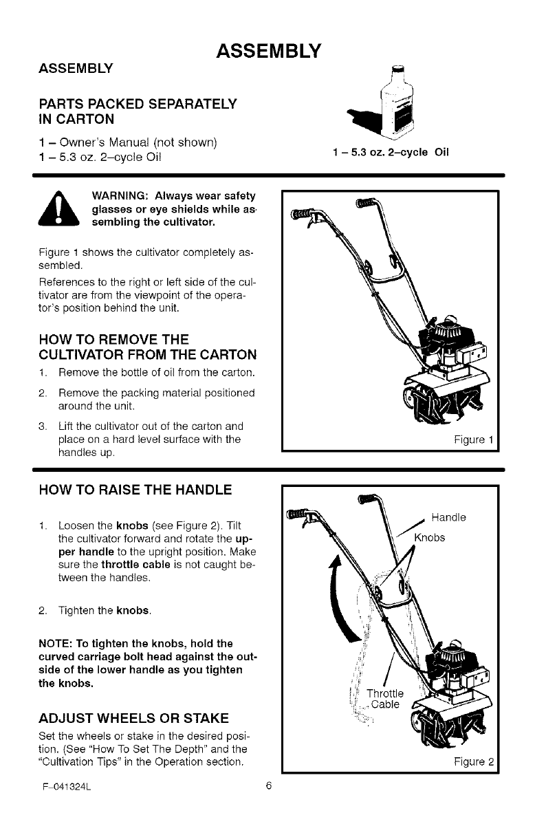
WARNING: Always wear safety
glasses or eye shields while as.
sembling the cultivator.
Figure 1 shows the cultivator completely as-
sembled.
References to the right or left side of the cul-
tivator are from the viewpoint of the opera-
tor's position behind the unit.
HOW TO REMOVE THE
CULTIVATOR FROM THE CARTON
1. Remove the bottle of oil from the carton.
2. Remove the packing material positioned
around the unit.
3. Lift the cultivator out of the carton and
place on a hard level surface with the
handles up.
Figure 1
HOW TO RAISE THE HANDLE
Loosen the knobs (see Figure 2). Tilt
the cultivator forward and rotate the up-
per handle to the upright position. Make
sure the throttle cable is not caught be-
tween the handles,
2. Tighten the knobs.
NOTE: To tighten the knobs, hold the
curved carriage bolt head against the out-
side of the lower handle as you tighten
the knobs.
ADJUST WHEELS OR STAKE
Set the wheels or stake in the desired posi-
tion. (See"How To Set The Depth" and the
"Cultivation Tips" in the Operation section.
._Kn Handle
obs
gure
F 041324L 6
ASSEMBLY
CHECKLIST
For the best performance and satisfaction
from this quality product, please review the
following checklist before you operate the
cultivator:
_' All assembly instructions have been
completed.
_' Check carton. Make sure no loose
parts remain in the carton.
_' All fasteners have been properly tight-
ened.
As you learn how to use the cultivator, pay
extra attention to the following important
items:
_'_' Fuel tank is filled with a fresh, clean,
oil and fuel mixture.
_'_' Become familiar and understand the
function of all controls. Before you
start the engine, operate all controls.
F 041324L 7
OPERATION
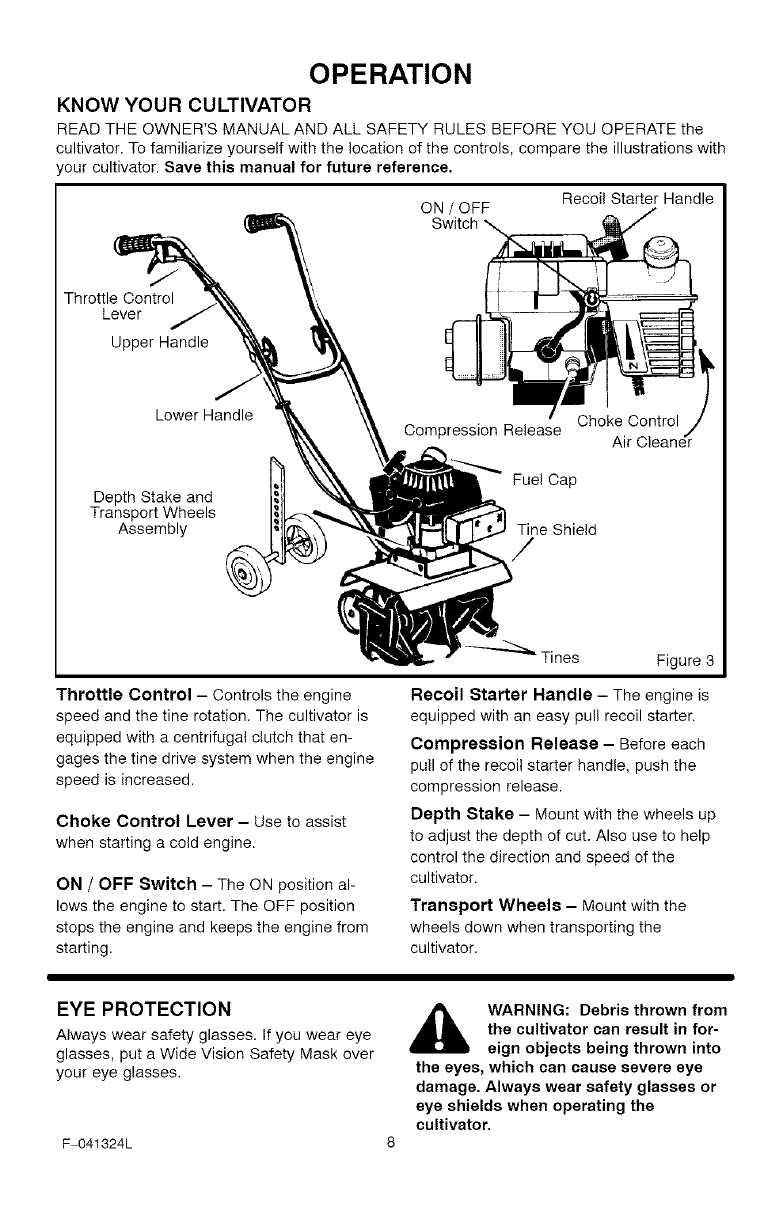
KNOW YOUR CULTIVATOR
READ THE OWNER'S MANUAL AND ALL SAFETY RULES BEFORE YOU OPERATE the
cultivator. To familiarize yourself with the location of the controls, compare the illustrations with
/our cultivator. Save this manual for future reference.
ON /OFF
Switch
Recoil Starter Handle
Throttle Control
Lever
Upper Handle
Lower Handle
Depth Stake and
Transport Wheels
Assembly
Choke Control
Air
Fuel Cap
Tine Shield
/
Tines Figure 3
Throttle Control - Controls the engine
speed and the tine rotation. The cultivator is
equipped with a centrifugal clutch that en-
gages the tine drive system when the engine
speed is increased.
Choke Control Lever - Use to assist
when starting a cold engine.
ON /OFF Switch - The ON position al-
lows the engine to start. The OFF position
stops the engine and keeps the engine from
starting.
Recoil Starter Handle - The engine is
equipped with an easy pull recoil starter.
Compression Release - Before each
pull of the recoil starter handle, push the
compression release.
Depth Stake - Mount with the wheels up
to adjust the depth of cut. Also use to help
control the direction and speed of the
cultivator.
Transport Wheels - Mount with the
wheels down when transporting the
cultivator.
EYE PROTECTION
Always wear safety glasses. If you wear eye
glasses, put a Wide Vision Safety Mask over
your eye glasses.
F 041324L
,_ WARNING: Debris thrown from
the cultivator can result in for-
eign objects being thrown into
the eyes, which can cause severe eye
damage. Always wear safety glasses or
eye shields when operating the
cultivator.
OPERATION
HOW TO USE THE CULTIVATOR
How To Stop The Cultivator
1. Release the throttle control to stop the
tines.
2. Move the ON/OFF switch, on the engine,
to the OFF position.
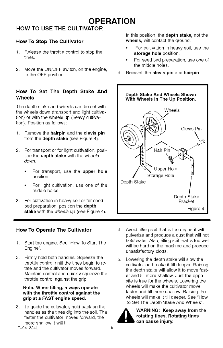
In this position, the depth stake, not the
wheels, will contact the ground.
For cultivation in heavy soil, use the
storage hole position.
For seed bed preparation, use one of
the middle holes.
4. Reinstall the clevis pin and hairpin.
How To Set The Depth Stake And
Wheels
The depth stake and wheels can be set with
the wheels down (transport and light cultiva-
tion) or with the wheels up (heavy cultiva-
tion). Position as follows:
1. Remove the hairpin and the clevis pin
from the depth stake (see Figure 4).
2. For transport or for light cultivation, posi-
tion the depth stake with the wheels
down.
For transport, use the upper hole
position.
For light cultivation, use one of the
middle holes.
3. For cultivation in heavy soil or for seed
bed preparation, position the depth
stake with the wheels up (see Figure 4).
Depth Stake And Wheels Shown
With Wheels In The Up Position.
_.._ Wheels
Clevis Pin
"_ _X_[_" Uppe _H_ole'_
Storage Hole
Depth Stake
Depth Stake
Bracket
Figure 4
How To Operate The Cultivator
1. Start the engine. See "How To Start The
Engine".
Firmly hold both handles. Squeeze the
throttle control until the tines begin to ro-
tate and the cultivator moves forward.
Maintain control and quickly squeeze the
throttle control against the grip.
Note: When tilling, always operate
with the throttle control against the
grip at a FAST engine speed.
3. To guide the cultivator, hold back on the
handles as the tines dig into the soil. The
faster the cultivator moves forward, the
more shallow it will till.
F 041324L
4. Avoid tilling soil that is too dry as it will
pulverize and produce a dust that will not
hold water. Also, tilling soil that is too wet
will be hard on the machine and produce
unsatisfactory clods.
5. Lowering the depth stake will slow the
cultivator and make it till deeper. Raising
the depth stake will allow it to move fast-
er and till more shallow. Just the oppo-
site is true for the wheels. Lowering the
wheels will make the cultivator move
faster and till more shallow. Raising the
wheels will make it till deeper. See "Row
To Set The Depth Stake And Wheels".
_ARNING: Keep away from the
rotating tines. Rotating tines
can cause injury.
OPERATION
BEFORE STARTING THE ENGINE
How To Prepare The Engine
,_ WARNING: Always use a safety
fuel container. Do not smoke
when adding the fuel mixture to
the engine. When inside an enclosure,
do not fill the fuel tank. Before you add
the fuel mixture, stop the engine. Let the
engine cool for several minutes.
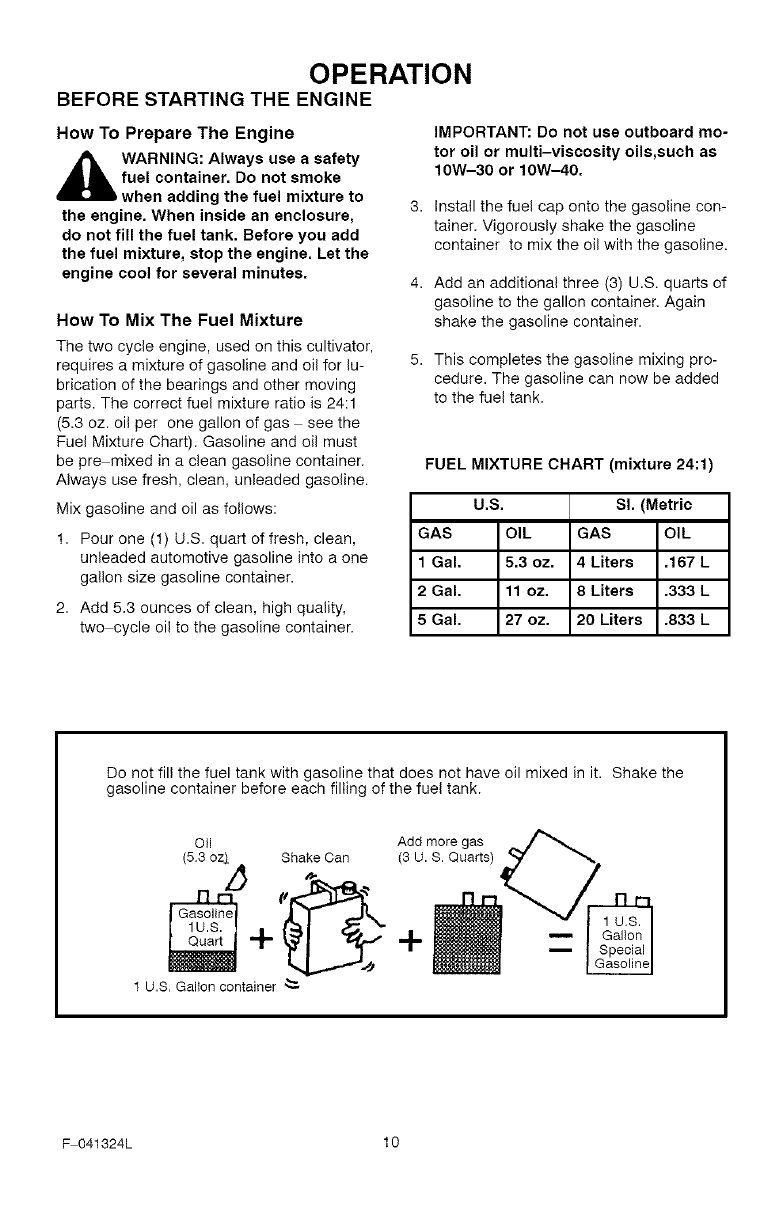
How To Mix The Fuel Mixture
The two cycle engine, used on this cultivator,
requires a mixture of gasoline and oil for lu-
brication of the bearings and other moving
parts. The correct fuel mixture ratio is 24:1
(5.3 oz. oil per one gallon of gas see the
Fuel Mixture Chart). Gasoline and oil must
be pre mixed in a clean gasoline container.
Always use fresh, clean, unleaded gasoline.
Mix gasoline and oil as follows:
1. Pour one (1) U.S. quart of fresh, clean,
unleaded automotive gasoline into a one
gallon size gasoline container.
2. Add 5.3 ounces of clean, high quality,
two cycle oil to the gasoline container.
IMPORTANT: Do not use outboard mo-
tor oil or multi-viscosity oils,such as
10W-30 or 10W-40.
Install the fuel cap onto the gasoline con-
tainer. Vigorously shake the gasoline
container to mix the oil with the gasoline.
Add an additional three (3) U.S. quarts of
gasoline to the gallon container. Again
shake the gasoline container.
This completes the gasoline mixing pro-
cedure. The gasoline can now be added
to the fuel tank.
FUEL MIXTURE CHART (mixture 24:1)
U.S. Sl. (Metric
GAS OIL GAS OIL
1 Gal. 5.3 oz. 4 Liters .167 L
2 Gal. 11 oz. 8 Liters .333 L
5 Gal. 27 oz. 20 Liters .833 L
Do not fill the fuel tank with gasoline that does not have oil mixed in it. Shake the
gasoline container before each filling of the fuel tank.
OII Add more gas
(5.3 oz[ Shake Can (3 U.S. Quarts)
V-_
1 U.$, Gallon container "-_
F 041324L 10
OPERATION
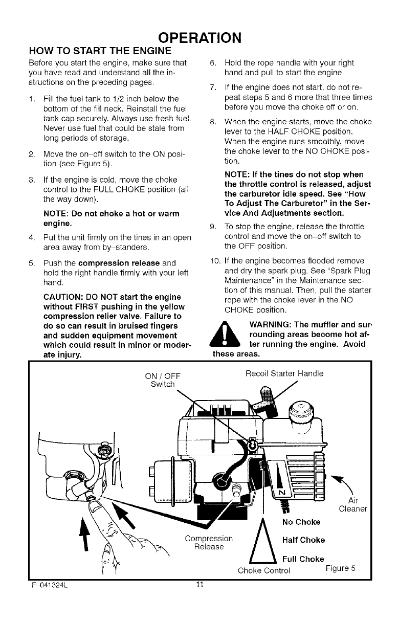
HOW TO START THE ENGINE
Before you start the engine, make sure that
you have read and understand all the in-
structions on the preceding pages.
Fill the fuel tank to 1/2 inch below the
bottom of the fill neck. Reinstall the fuel
tank cap securely. Always use fresh fuel.
Never use fuel that could be stale from
long periods of storage.
2. Move the on off switch to the ON posi-
tion (see Figure 5).
3. If the engine is cold, move the choke
control to the FULL CHOKE position (all
the way down).
NOTE: Do not choke a hot or warm
engine.
Put the unit firmly on the tines in an open
area away from by standers.
5. Push the compression release and
hold the right handle firmly with your left
hand.
CAUTION: DO NOT start the engine
without FIRST pushing in the yellow
compression relier valve. Failure to
do so can result in bruised fingers
and sudden equipment movement
which could result in minor or moder-
ate injury.
6. Hold the rope handle with your right
hand and pull to start the engine.
7. If the engine does not start, do not re-
peat steps 5 and 6 more that three times
before you move the choke off or on.
When the engine starts, move the choke
lever to the HALF CHOKE position.
When the engine runs smoothly, move
the choke lever to the NO CHOKE posi-
tion.
NOTE: if the tines do not stop when
the throttle control is released, adjust
the carburetor idle speed. See "How
To Adjust The Carburetor" in the Ser-
vice And Adjustments section.
To stop the engine, release the throttle
control and move the on off switch to
the OFF position.
10. If the engine becomes flooded remove
and dry the spark plug. See "Spark Plug
Maintenance" in the Maintenance sec-
tion of this manual. Then, pull the starter
rope with the choke lever in the NO
CHOKE position.
,_ WARNING: The muffler and sur.
rounding areas become hot af-
ter running the engine. Avoid
these areas.
ON /OFF
Switch
Recoil Starter Handle
Compression
Release
No Choke
Half Choke
Full Choke
Choke Control
Air
Cleaner
Figure 5
F 041324L 11
OPERATION
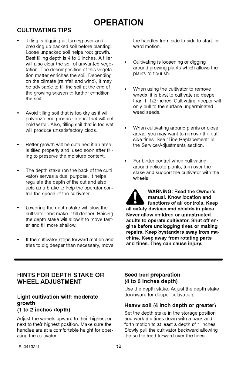
CULTIVATING TIPS
Tilling is digging in, turning over and
breaking up packed soil before planting.
Loose unpacked soil helps root growth.
Best tilling depth is 4 to 6 inches. A tiller
will also clear the soil of unwanted vege-
tation. The decomposition of this vegeta-
tion matter enriches the soil. Depending
on the climate (rainfall and wind), it may
be advisable to till the soil at the end of
the growing season to further condition
the soil.
Avoid tilling soil that is too dry as it will
pulverize and produce a dust that will not
hold water. Also, tilling soil that is too wet
will produce unsatisfactory clods.
Better growth will be obtained if an area
is tilled properly and used soon after till-
ing to preserve the moisture content.
The depth stake (on the back of the culti-
vator) serves a dual purpose. It helps
regulate the depth of the cut and also
acts as a brake to help the operator con-
trol the speed of the cultivator.
Lowering the depth stake will slow the
cultivator and make it till deeper. Raising
the depth stake will allow it to move fast-
er and till more shallow.
If the cultivator stops forward motion and
tries to dig deeper than necessary, move
the handles from side to side to start for-
ward motion.
Cultivating is loosening or digging
around growing plants which allows the
plants to flourish.
When using the cultivator to remove
weeds, it is best to cultivate no deeper
than 1 1/2 inches. Cultivating deeper will
only pull to the surface ungerminated
weed seeds.
When cultivating around plants or close
areas, you may want to remove the out-
side tines. See "Tine Replacement" in
the Service/Adjustments section.
For better control when cultivating
around delicate plants, turn over the
stake and support the cultivator with the
wheels.
,_ WARNING: Read the Owner's
manual. Know location and
functions of all controls. Keep
all safety devices and shields in place.
Never allow children or uninstructed
adults to operate cultivator. Shut off en-
gine before unclogging tines or making
repairs. Keep bystanders away from ma-
chine. Keep away from rotating parts
and tines. They can cause injury.
HINTS FOR DEPTH STAKE OR
WHEEL ADJUSTMENT
Light cultivation with moderate
growth
(1 to 2 inches depth)
Adjust the wheels upward to their highest or
next to their highest position. Make sure the
handles are at a comfortable height for oper-
ating the cultivator.
Seed bed preparation
(4 to 6 inches depth)
Use the depth stake. Adjust the depth stake
downward for deeper cultivation.
Heavy soil (4 inch depth or greater)
Set the depth stake in the storage position
and work the tines down with a back and
forth motion to at least a depth of 4 inches.
Slowly pull the cultivator backward allowing
the soil to feed forward over the tines.
F 041324L 12
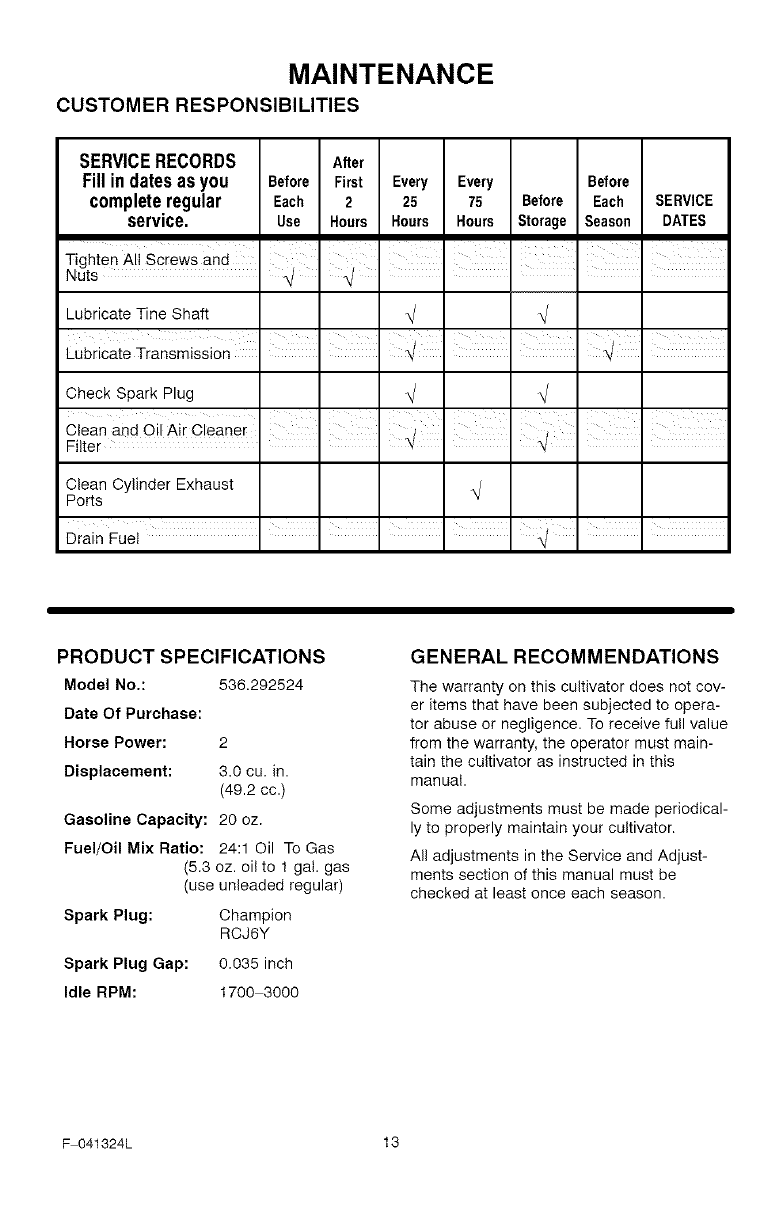
MAINTENANCE
CUSTOMER RESPONSIBILITIES
SERVICERECORDS After
Fillindatesasyou Before First Every Every Before
completeregular Each 2 25 75 Before Each SERVICE
service, use Hours Hours Hours Storage Season DATES
I I I I I I
Lubricate Tine Shaft
Lubricate Transmission I I I I I
Check Spark Plug
I I I
Clean and Oil Air Cleaner
Filter . .
Clean Cylinder Exhaust
Ports
PRODUCT SPECIFICATIONS
Model No.: 536.292524
Date Of Purchase:
Horse Power: 2
Displacement: 3.0 cu. in.
(49.2 cc.)
Gasoline Capacity: 20 oz.
Fuel/Oil Mix Ratio: 24:1 Oil To Gas
(5.3 oz. oil to 1 gal. gas
(use unleaded regular)
Spark Plug: Champion
RCJ6Y
Spark Plug Gap: 0.035 inch
Idle RPM: 1700 3000
GENERAL RECOMMENDATIONS
The warranty on this cultivator does not cov-
er items that have been subjected to opera-
tor abuse or negligence. To receive full value
from the warranty, the operator must main-
tain the cultivator as instructed in this
manual.
Some adjustments must be made periodical-
ly to properly maintain your cultivator.
All adjustments in the Service and Adjust-
ments section of this manual must be
checked at least once each season.
F 041324L 13
MAINTENANCE
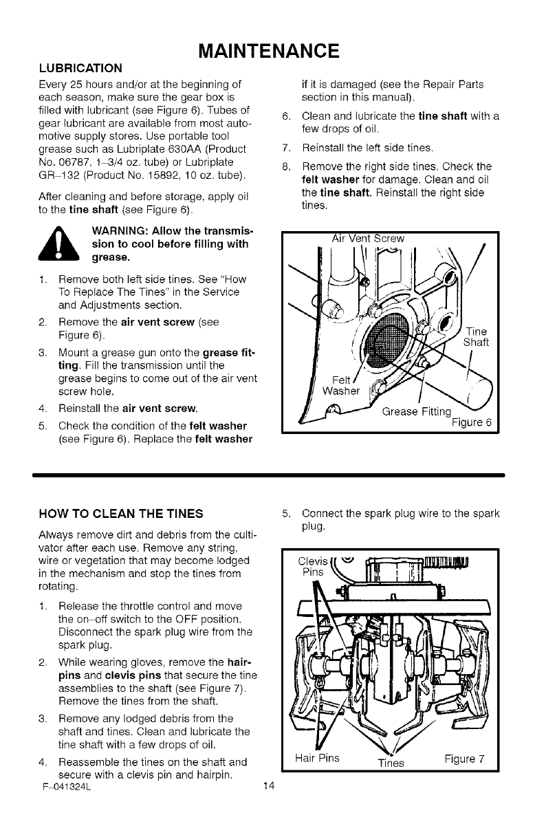
LUBRICATION
Every 25 hours and/or at the beginning of
each season, make sure the gear box is
filled with lubricant (see Figure 6). Tubes of
gear lubricant are available from most auto-
motive supply stores. Use portable tool
grease such as Lubriplate 630AA (Product
No. 06787, 1 3/4 oz. tube) or Lubriplate
GR 132 (Product No. 15892, 10 oz. tube).
After cleaning and before storage, apply oil
to the tine shaft (see Figure 6).
6,
7.
8.
if it is damaged (see the Repair Parts
section in this manual).
Clean and lubricate the tine shaft with a
few drops of oil.
Reinstall the left side tines.
Remove the right side tines. Check the
felt washer for damage. Clean and oil
the tine shaft, Reinstall the right side
tines.
_lb ARNING: Allow the transmis-
sion to cool before filling with
grease.
1. Remove both left side tines. See "How
To Replace The Tines" in the Service
and Adjustments section.
2. Remove the air vent screw (see
Figure 6).
3. Mount a grease gun onto the grease fit-
ting, Fill the transmission until the
grease begins to come out of the air vent
screw hole.
4. Reinstall the air vent screw.
5. Check the condition of the felt washer
(see Figure 6). Replace the felt washer
Air Vent Screw
Grease Fitting
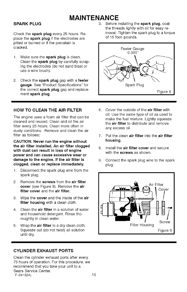
HOW TO CLEAN THE TINES
Always remove dirt and debris from the culti-
vator after each use. Remove any string,
wire or vegetation that may become lodged
in the mechanism and stop the tines from
rotating.
1. Release the throttle control and move
the on off switch to the OFF position.
Disconnect the spark plug wire from the
spark plug.
2. While wearing gloves, remove the hair-
pins and clevis pins that secure the tine
assemblies to the shaft (see Figure 7).
Remove the tines from the shaft.
3. Remove any lodged debris from the
shaft and tines. Clean and lubricate the
tine shaft with a few drops of oil.
4. Reassemble the tines on the shaft and
secure with a clevis pin and hairpin.
F 041324L 14
Connect the spark plug wire to the spark
plug.
Hair Pins Tines Figure 7
SPARK PLUG
Check the spark plug every 25 hours. Re-
place the spark plug if the electrodes are
pitted or burned or if the porcelain is
cracked.
MAINTENANCE
3. Before installing the spark plug, coat
the threads lightly with oil for easy re-
moval. Tighten the spark plug to a torque
of 15 fooFpounds.
Make sure the spark plug is clean.
Clean the spark plug by carefully scrap-
ing the electrodes (do not sand blast or
use a wire brush).
Check the spark plug gap with a feeler
gauge. See "Product Specifications" for
the correct spark plug gap and replace-
ment spark plug,
Feeler Gauge
0.035"
HOW TO CLEAN THE AIR FILTER 6.
The engine uses a foam air filter that can be
cleaned and reused. Clean and oil the air
filter every 25 hours, Clean more often in
dusty conditions. Remove and clean the air
filter as follows: 7,
CAUTION: Never run the engine without
the air filter installed. An air filter clogged 8.
with dust can result in loss of engine
power and can cause excessive wear or
damage to the engine. If the air filter is 9.
clogged, clean or replace immediately.
1. Disconnect the spark plug wire from the
spark plug.
2. Remove the screws from the air filter
cover (see Figure 9). Remove the air
filter cover and the air filter,
3. Wipe the cover and the inside of the air
filter housing with a clean cloth.
4. Clean the air filter in a solution of water
and household detergent. Rinse tho-
roughtly in clean water.
5. Wrap the air filter in a dry clean cloth,
Squeeze out (do not twist) all solution
until dry.
Cover the outside of the air filter with
oil. Use the same type of oil as used to
make the fuel mixture. Lightly squeeze
the air filter to distribute and remove
any excess oil,
Put the clean air filter into the air filter
housing.
Install the air filter cover and secure
with the screws as shown.
Connect the spark plug wire to the spark
plug.
Air Filter
Screw
Filter Housing
Figure 9
CYLINDER EXHAUST PORTS
Clean the cylinder exhaust ports after every
75 hours of operation. For this procedure, we
recommend that you take your unit to a
Sears Service Center.
F 041324L 15
SERVICE AND ADJUSTMENT
HOW TO REMOVE AND INSTALL THE TINES
References to the right or left side of the cul-
tivator are from the viewpoint of the opera-
tor's position behind the unit.
All four tines are different and cannot be in-
terchanged. The tines must be correctly
installed or the cultivator will not function
properly.
To till around plants or in small areas, the
outside tines can be removed to reduce the
tilling width to approximately 7 inches.
WARNING: The tines are self
sharpening and will become
quite sharp from use. Handle
carefully.
The tines will all wear evenly. If the tines are
being replaced because of wear, we recom-
mend that all four tines be replaced at the
same time. To replace the tines, do the fol-
lowing:
Tine Removal
1. Put the on off switch in the OFF posi-
tion.
2,
3.
Disconnect the spark plug wire from the
spark plug.
While wearing gloves, remove the hair-
pins and clevis pins that secure the tine
assemblies to the shaft (see Figure 10).
Remove the tines from one side of the
unit.
Hair Pins Tines Figure 10
F 041324L
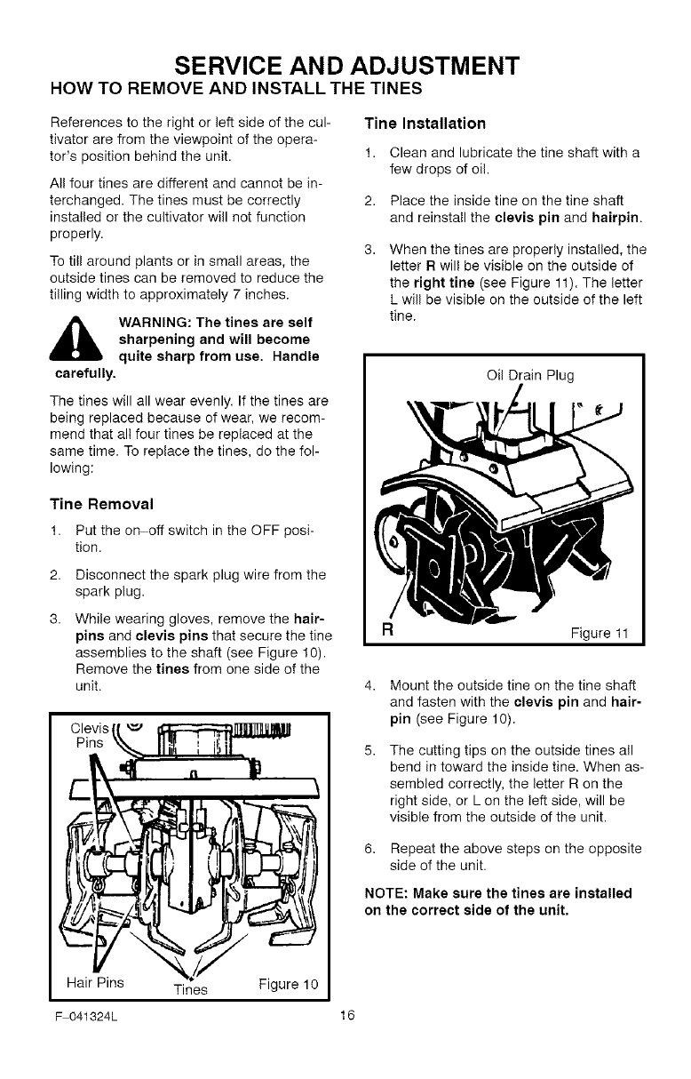
Tine Installation
1. Clean and lubricate the tine shaft with a
few drops of oil.
2. Place the inside tine on the tine shaft
and reinstall the clevis pin and hairpin.
When the tines are properly installed, the
letter R will be visible on the outside of
the right tins (see Figure 11). The letter
L will be visible on the outside of the left
tine.
Oil Drain Plug
Figure 11
4. Mount the outside tine on the tine shaft
and fasten with the clevis pin and hair-
pin (see Figure 10).
The cutting tips on the outside tines all
bend in toward the inside tine. When as-
sembled correctly, the letter R on the
right side, or L on the left side, will be
visible from the outside of the unit.
6. Repeat the above steps on the opposite
side of the unit.
NOTE: Make sure the tines are installed
on the correct side of the unit.
16
SERVICE AND ADJUSTMENT
HOW TO ADJUST THE CARBURETOR
A dirty air cleaner will cause the engine to
run improperly or to smoke excessively. Be-
fore adjusting the carburetor, make sure the
air cleaner is clean. Never make unneces-
sary adjustments to the carburetor. The car-
buretor was set at the factory to operate
efficiently under most applications. However,
if adjustments are required, we recommend
you contact your nearest Sears Service Cen-
ter. If you feel that you are competent to
make carburetor adjustment proceed as fol-
lows.
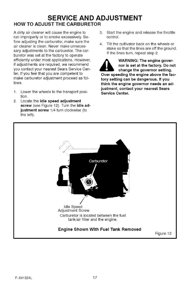
1,
2.
Lower the wheels to the transport posi-
tion.
Locate the idle speed adjustment
screw (see Figure 12). Turn the idle ad-
justment screw 1/4 turn clockwise (to
the left).
3. Start the engine and release the throttle
control.
4. Tilt the cultivator back on the wheels or
stake so that the tines are off the ground.
If the tines turn, repeat step 2.
WARNING: The engine gover-
nor is set at the factory. Do not
change the governor setting.
Over speeding the engine above the fac-
tory setting can be dangerous. If you
think the engine governor needs an ad-
justment, contact your nearest Sears
Service Center.
Idle Speed
Adjustment Screw
Carburetor is located between the fuel
tank/air filter and the engine.
Engine Shown With Fuel Tank Removed Figure 12
F 041324L 17
SERVICE AND ADJUSTMENT
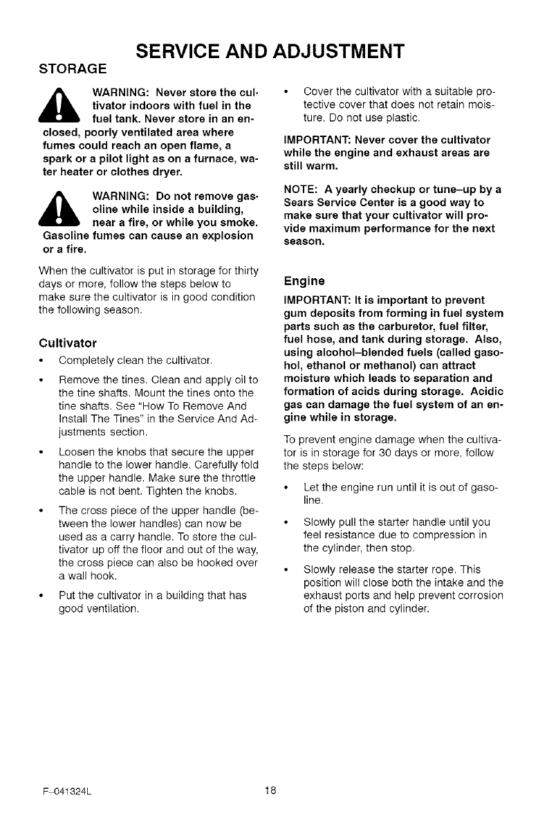
STORAGE
WARNING: Never store the cul-
tivator indoors with fuel in the
fuel tank. Never store in an en-
closed, poorly ventilated area where
fumes could reach an open flame, a
spark or a pilot light as on a furnace, wa-
ter heater or clothes dryer.
WARNING: Do not remove gas.
oline while inside a building,
near a fire, or while you smoke.
Gasoline fumes can cause an explosion
or a fire.
Cover the cultivator with a suitable pro-
tective cover that does not retain mois-
ture. Do not use plastic.
IMPORTANT: Never cover the cultivator
while the engine and exhaust areas are
still warm.
NOTE: A yearly checkup or tune-up by a
Sears Service Center is a good way to
make sure that your cultivator will pro-
vide maximum performance for the next
season.
When the cultivator is put in storage for thirty
days or more, follow the steps below to
make sure the cultivator is in good condition
the following season.
Cultivator
Completely clean the cultivator.
Remove the tines. Clean and apply oil to
the tine shafts. Mount the tines onto the
tine shafts. See "How To Remove And
Install The Tines" in the Service And Ad-
justments section.
Loosen the knobs that secure the upper
handle to the lower handle. Carefully fold
the upper handle. Make sure the throttle
cable is not bent. Tighten the knobs.
The cross piece of the upper handle (be-
tween the lower handles) can now be
used as a carry handle. To store the cul-
tivator up off the floor and out of the way,
the cross piece can also be hooked over
a wall hook.
Put the cultivator in a building that has
good ventilation.
Engine
IMPORTANT: It is important to prevent
gum deposits from forming in fuel system
parts such as the carburetor, fuel filter,
fuel hose, and tank during storage. Also,
using alcohol-blended fuels (called gaso-
hol, ethanol or methanol) can attract
moisture which leads to separation and
formation of acids during storage. Acidic
gas can damage the fuel system of an en-
gine while in storage.
To prevent engine damage when the cultiva-
tor is in storage for 30 days or more, follow
the steps below:
Let the engine run until it is out of gaso-
line.
Slowly pull the starter handle until you
feel resistance due to compression in
the cylinder, then stop.
Slowly release the starter rope. This
position will close both the intake and the
exhaust ports and help prevent corrosion
of the piston and cylinder.
F 041324L 18
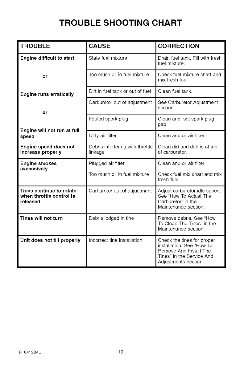
TROUBLE SHOOTING CHART
TROUBLE
Engine difficult to start
or
Engine runs erratically
or
Engine will not run at full
speed
Engine speed does not
increase properly
Engine smokes
excessively
Tines continue to rotate
when throttle control is
released
Tines will not turn
CAUSE
Stale fuel mixture
Too much oil in fuel mixture
Dirt in fuel tank or out of fuel
Carburetor out of adjustment
Fouled spark plug
Dirty air filter
Debris interfering with throttle
linkage
Plugged air filter
Too much oil in fuel mixture
Carburetor out of adjustment
Debris lodged in tine
Unit does not till properly Incorrect tine installation
CORRECTION
Drain fuel tank. Fill with fresh
fuel mixture.
Check fuel mixture chart and
mix fresh fuel.
Clean fuel tank,
See Carburetor Adjustment
section.
Clean and set spark plug
gap.
Clean and oil air filter,
Clean dirt and debris of top
of carburetor.
Clean and oil air filter.
Check fuel mix chart and mix
fresh fuel.
Adjust carburetor idle speed.
See "How To Adjust The
Carburetor" in the
Maintenance section.
Remove debris. See "How
To Clean The Tines" in the
Maintenance section.
Check the tines for proper
installation. See "How To
Remove And Install The
Tines" in the Service And
Adjustments section.
F 041324L 19

SEARS, ROEBUCK AND CO.
Federal and California Emission Control Systems Limited Warranty
Small Off-Road Engines
CALIFORNIA &US EPA EMISSION
CONTROL WARRANTY STATEMENT
The U. S. Environmental Protection Agency
("EPA"), the California Air Resources Board
("CARB") and Sears, Roebuck and Co. are
pleased to explain the Federal and California
Emission Control Systems Warranty on your
new small o_road engine. In California, new
1995 and later small off road engines must be
designed, built and equipped to meet the
State's stringent anti smog standards. In oth-
er states, new 1997 and later model year en-
gines must be designed, built and equipped, at
the time of sale, to meet the U.S. EPA regula-
tions for small non road engines. Sears, Roe-
buck and Co. will warrant the emission control
system on your small o_road engine for the
periods of time listed below, provided there
has been no abuse, neglect, unapproved mod-
ification, or improper maintenance of your
small off road engine.
Your emission control system may include
parts such as the carburetor, ignition system
and exhaust system. Also included may be the
compression release system and other emis-
sion related assemblies.
Where a warrantable condition exists, Sears,
Roebuck and Co. will repair your small oR
road engine at no cost to you for diagnosis,
parts and labor.
MANUFACTURER'S EMISSION
CONTROLSYSTEM WARRANTY
COVERAGE
Emission control systems on 1995 and later
model year California small off road engines
are warranted for two years as hereinafter
noted. In other states, 1997 and later model
year engines are also warranted for two years.
If, during such warranty period, any emission
related part on your engine is defective in ma-
terials or workmanship, the part will be
repaired or replaced by Sears, Roebuck and
Co.
OWNER'S WARRANTY
RESPONSIBILITIES
As the small o_road engine owner, you are
responsible for the performance of the re-
F 041324L
quired maintenance listed in your Owner's
Manual, but Sears, Roebuck and Co. will not
deny warranty solely due to the lack of receipts
or for your failure to provide written evidence
of the performance of all scheduled mainte-
nance.
As the small o_road engine owner, you
should, however, be aware that Sears, Roe-
buck and Co. may deny you warranty cover-
age if your small o_road engine or a part
thereof has failed due to abuse, neglect, im-
proper maintenance or unapproved modifica-
tions.
You are responsible for presenting your small
o_road engine to a Sears, Roebuck and Co.
Authorized Service Outlet as soon as a prob-
lem exists. The warranty repairs should be
completed in a reasonable amount of time, not
to exceed 30 days.
Warranty service can be arranged by contact-
ing either a Sears, Roebuck and Co. Autho-
rized Service Outlet, or by contacting Sears,
Roebuck and Co. at 1 800473 7247.
2O
IMPORTANT NOTE
This warranty statement explains your rights
and obligations under the Emission Control
System Warranty "(ECS Warranty") which is
provided to you by Sears, Roebuck and Co.
pursuant to California law. See also the Sears,
Roebuck and Co. Limited Warranties for
Sears, Roebuck and Co. which is enclosed
therewith on a separate sheet and also is pro-
vided to you by Sears, Roebuck and Co. The
ECS Warranty applies only to the emission
control system of your new engine. To the ex-
tent that there is any conflict in terms between
the ECS Warranty and the Sears, Roebuck
and Co. Warranty, the ECS Warranty shall ap-
ply except in any circumstances in which the
Sears, Roebuck and Co. Warranty may pro-
vide a longer warranty period. Both the ECS
Warranty and the Sears, Roebuck and Co.
Warranty describe important rights and obliga-
tions with respect to your new engine.
Warranty service can only be performed by a
Sears, Roebuck and Co. Authorized Service
Outlet. At the time of requesting warranty ser-
vice, evidence must be presented of the date
of sale to the original purchaser. The purchas-

ershallpayanychargesformakingservice
callsand/orfortransportingtheproductsto
andfromtheplacewheretheinspectionand/
orwarrantyworkisperformed.Thepurchaser
shallberesponsibleforanydamageorlossin-
curredinconnectionwiththetransportationof
anyengineoranypart(s)thereofsubmittedfor
inspectionand/orwarrantywork.
Ifyouhaveanyquestionsregardingyourwar-
rantyrightsandresponsibilities,youshould
contactSears,Roebuckand 0o. at
18004737247.
EMISSION CONTROL SYSTEM
WARRANTY
Emission Control System Warranty ("ECS
Warranty") for 1995 and later model year Cali-
fornia small o_road engines (for other states,
1997 and later model year engines):
A. APPLICABILITY: This warranty shall apply
to 1995 and later model year California small
o_road engines (for other states, 1997 and
later model year engines). The ECS Warranty
Period shall begin on the date the new engine
or equipment is delivered to its original, end
use purchaser, and shall continue for 24 con-
secutive months thereafter.
B, GENERAL EMISSIONS WARRANTY
COVERAGE: Sears, Roebuck and Co. war-
rants to the original, end use purchaser of the
new engine or equipment and to each subse-
quent purchaser that each of its small off road
engines is:
1. Designed, built and equipped so as to con-
form with all applicable regulations adopted by
the Air Resources Board pursuant to its au-
thority in Chapters 1 and 2, Part 5, Division 26
of the Health and Safety Code, and
2. Free from defects in materials and work-
manship which, at any time during the ECS
Warranty Period, will cause a warranted emis-
sions related part to fail to be identical in all
material respects to the part as described in
the engine manufacturer's application for certi-
fication.
O. The ECS Warranty only pertains to emis-
sions related parts on your engine, as follows:
1. Any warranted, emissions related parts
which are not scheduled for replacement as
required maintenance in the Owner's Manual
shall be warranted for the EOS Warranty Peri-
od. If any such part fails during the EOS War-
ranty Period, it shall be repaired or replaced by
F 041324L
Sears, Roebuck and Co. according to Subsec-
tion 4 below. Any such part repaired or re-
placed under the ECS Warranty shall be
warranted for any remainder of the ECS War-
ranty Period.
2. Any warranted, emissions related part
which is scheduled only for regular inspection
as specified in the Owner's Manual shall be
warranted for the EOS Warranty Period. A
statement in such written instructions to the ef-
fect of "repair or replace as necessary", shall
not reduce the EOS Warranty Period. Any
such part repaired or replaced under the EOS
Warranty shall be warranted for the remainder
of the ECS Warranty Period.
3. Any warranted, emissions related part
which is scheduled for replacement as re-
quired maintenance in the Owner's Manual,
shall be warranted for the period of time prior
to the first scheduled replacement point for
that part. If the part fails prior to the first sched-
uled replacement, the part shall be repaired or
replaced by Sears, Roebuck and Co. accord-
ing to Subsection 4 below. Any such emis-
sions related part repaired or replaced under
the ECS Warranty, shall be warranted for the
remainder of the EOS Warranty Period prior to
the first scheduled replacement point for such
emissions related part.
4. Repair or replacement of any warranted,
emissions related part under this ECS War-
ranty shall be performed at no charge to the
owner at a Sears, Roebuck and Co. Autho-
rized Service Outlet.
5. The owner shall not be charged for diagnos-
tic labor which leads to the determination that
a part covered by the ECS Warranty is in fact
defective, provided that such diagnostic work
is performed at a Sears, Roebuck and Co. Au-
thorized Service Outlet.
6. Sears, Roebuck and Co. shall be liable for
damages to other original engine components
or approved modifications proximately caused
by a failure under warranty of an emission re-
lated part covered by the EOS Warranty.
7. Throughout the ECS Warranty Period,
Sears, Roebuck and Co. shall maintain a sup-
ply of warranted emission related parts suffi-
cient to meet the expected demand for such
emission related parts.
8. Any Sears, Roebuck and Co. authorized
and approved emission related replacement
part may be used in the performance of any
EOS Warranty maintenance or repair and will
be provided without charge to the owner. Such
useshallnotreduceSears,RoebuckandCo.
ECSWarrantyobligations.
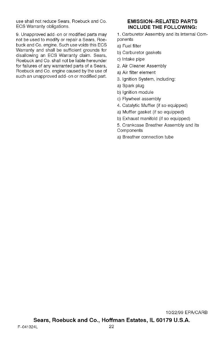
9.Unapprovedaddonormodifiedpartsmay
notbeusedtomodifyorrepairaSears,Roe-
buckandCo.engine.SuchusevoidsthisECS
Warrantyandshallbesufficientgroundsfor
disallowinganECSWarrantyclaim.Sears,
RoebuckandCo.shallnotbeliablehereunder
forfailuresofanywarrantedpartsofaSears,
RoebuckandCo.enginecausedbytheuseof
suchanunapprovedaddonormodifiedpart.
EMISSION-RELATED PARTS
INCLUDE THE FOLLOWING:
1. Carburetor Assembly and its Internal Com-
ponents
a) Fuel filter
b) Carburetor gaskets
c) Intake pipe
2. Air Cleaner Assembly
a) Air filter element
3. Ignition System, including:
a) Spark plug
b) Ignition module
c) Flywheel assembly
4. Catalytic Muffler (if so equipped)
a) Muffler gasket (if so equipped)
b) Exhaust manifold (if so equipped)
5. Crankcase Breather Assembly and its
Components
a) Breather connection tube
10/22/99 EPA/CARB
Sears, Roebuck and Co., Hoffman Estates, IL 60179 U.S.A.
F 041324L 22
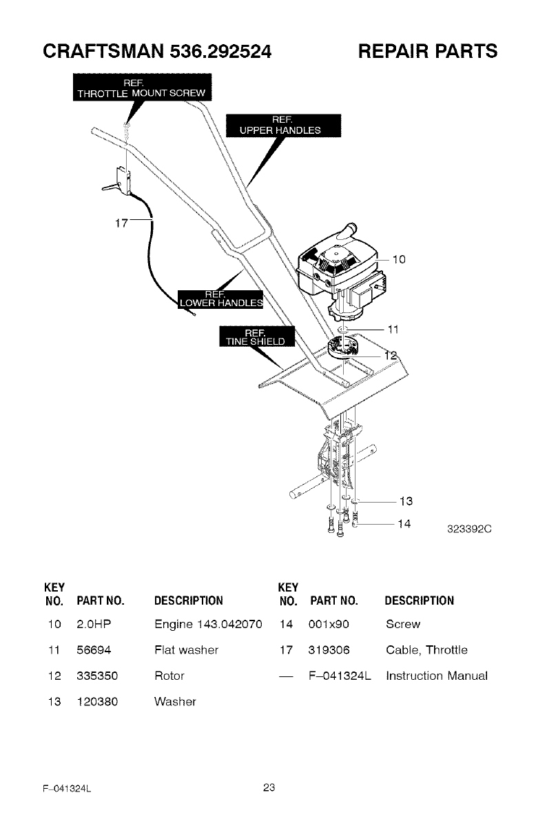
CRAFTSMAN 536.292524 REPAIR PARTS
17
11
13
14 323392C
KEY
NO. PART NO.
10 2.0HP
11 56694
12 335350
13 120380
KEY
DESCRIPTION NO. PARTNO. DESCRIPTION
Engine 143.042070 14 001x90 Screw
Flat washer 17 319306 Cable, Throttle
Rotor -- F-O41324L instruction Manual
Washer
F 041324L 23
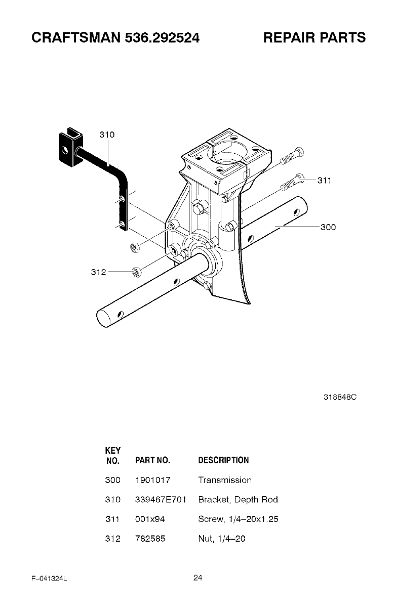
CRAFTSMAN 536.292524 REPAIR PARTS
310
300
3188480
KEY
NO. PART NO. DESCRIPTION
300 1901017 Transmission
310 339467E701 Bracket, Depth Rod
311 001x94 Screw, 1/4-20xl.25
312 782585 Nut, 1/4-20
F 041324L 24
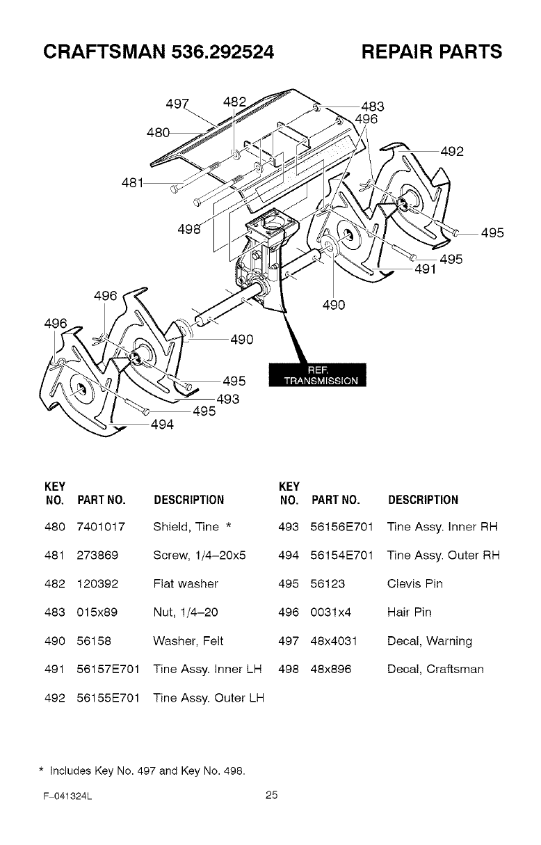
CRAFTSMAN 536.292524 REPAIR PARTS
497 482
481 _
496 49O
83
96
492
"--2
KEY
NO. PART NO. DESCRIPTION
480 7401017 Shield, Tine *
481 273869 Screw, 1/4-20x5
482 120392 Flat washer
483 015x89 Nut, 1/4-20
490 56158 Washer, Felt
KEY
NO. PART NO. DESCRIPTION
493 56156E701 Tine Assy. inner RH
494 56154E701 Tine Assy. Outer RH
495 56123 Clevis Pin
496 0031x4 Hair Pin
497 48x4031 Decal, Warning
Decal, Craftsman491 56157E701 Tine Assy. inner LH 498 48x896
492 56155E701 Tine Assy. Outer LH
*includes Key No. 497 and Key No. 498.
F 041324L 25
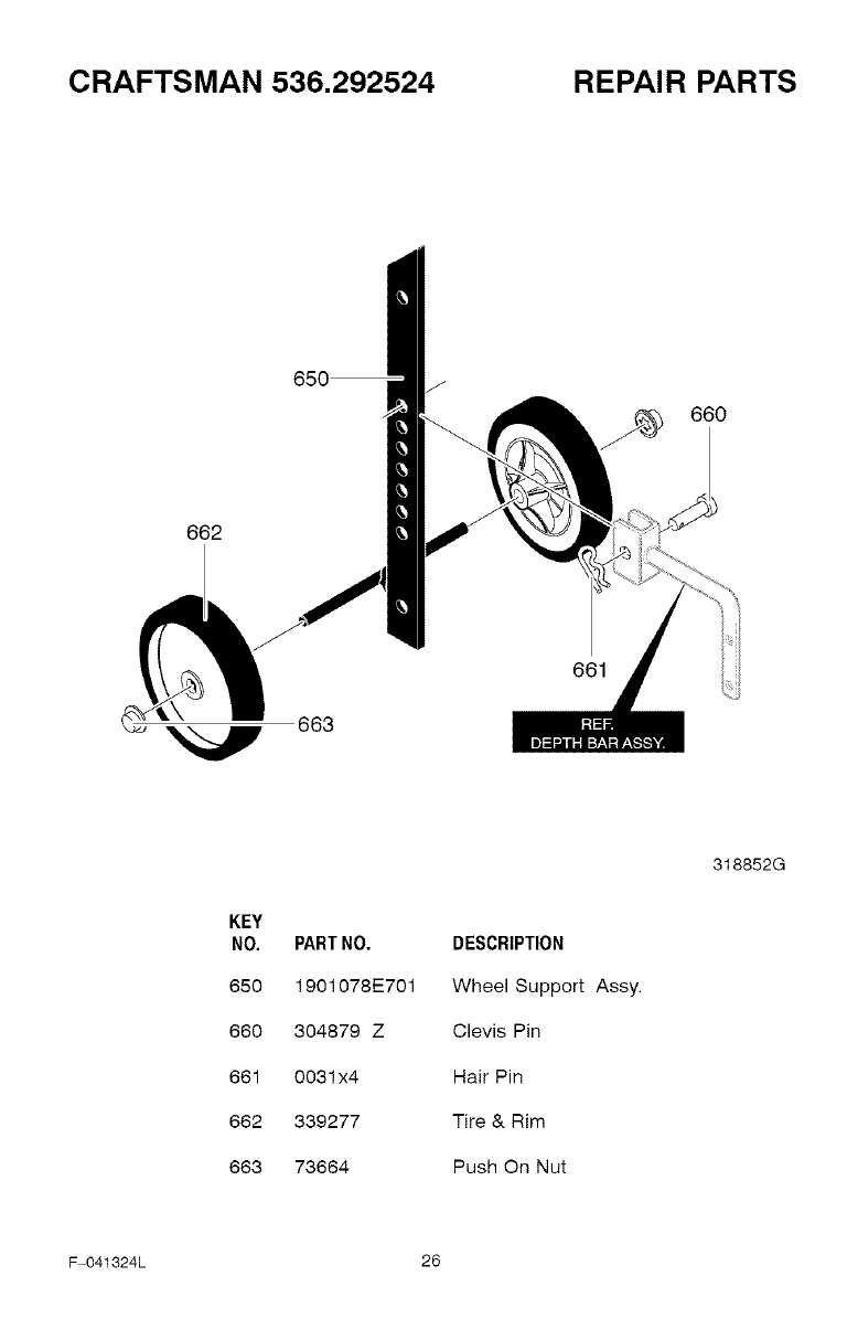
CRAFTSMAN 536.292524 REPAIR PARTS
662
650 J
660
663
661
KEY
NO.
650
660
661
662
663
PART NO.
1901078E701
304879 Z
0031x4
339277
73664
DESCRIPTION
Wheel Support Assy.
Clevis Pin
Hair Pin
Tire & Rim
Push On Nut
318852G
F 041324L 26
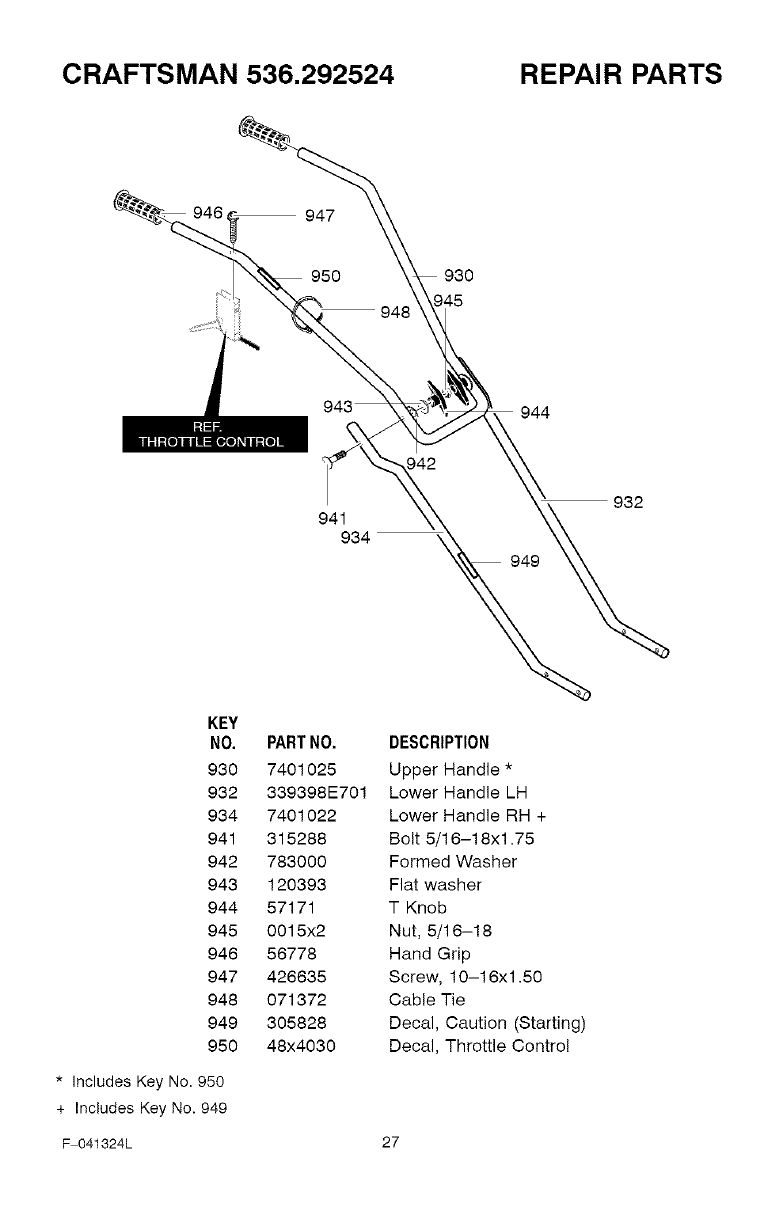
CRAFTSMAN 536.292524 REPAIR PARTS
947
950
941
934
930
944
949
932
KEY
NO. PART NO.
930 7401025
932 339398E701
934 7401022
941 315288
942 783000
943 120393
944 57171
945 0015x2
946 56778
947 426635
948 071372
949 305828
950 48x4030
* Includes Key No. 950
+ Includes Key No. 949
DESCRIPTION
Upper Handle *
Lower Handle LH
Lower Handle RH +
Bolt 5/16-18xl .75
Formed Washer
Flat washer
T Knob
Nut, 5/16-18
Hand Grip
Screw, 10-16xl .50
Cable Tie
Decal, Caution (Starting)
Decal, Throttle Control
F 041324L 27
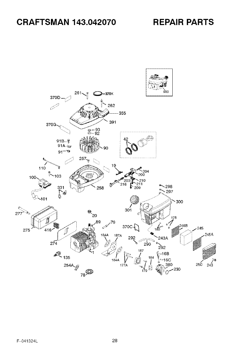
CRAFTSMAN 143.042070 REPAIR PARTS
184A
F 041324L 28
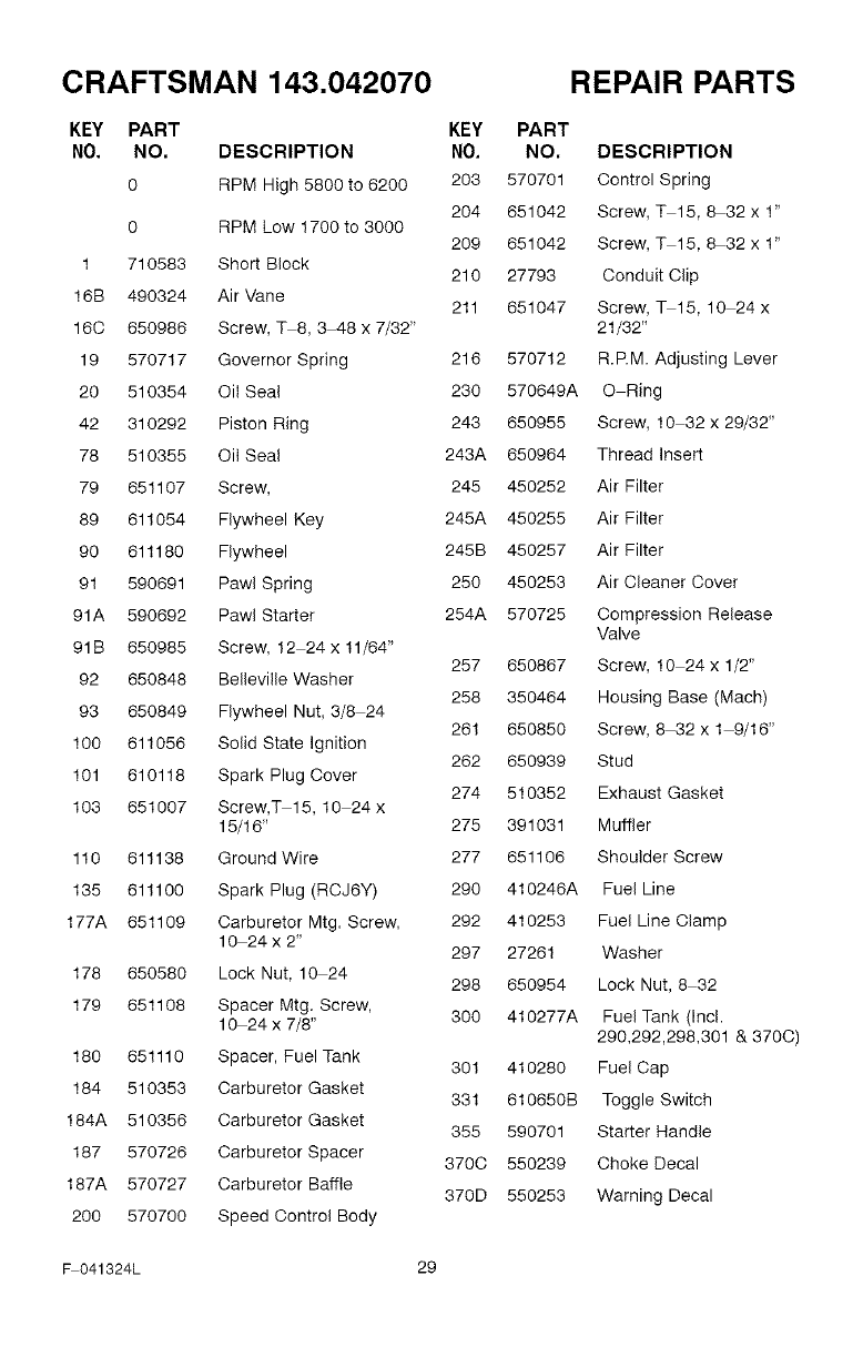
CRAFTSMAN 143.042070
KEY PART KEY PART
NO. NO, DESCRIPTION NO. NO,
0 RPM High 5800 to 6200 203 570701
204 651042
0 RPM Low 1700 to 3000 209 651042
1 710583 Short Block 210 27793
16B 490324 Air Vane 211 651047
160 650986 Screw, 3-8, 3 48 x 7/32"
19 570717 Governor Spring 216 570712
20 510354 Oil Seal 230 570649A
42 310292 Piston Ring 243 650955
78 510355 Oil Seal 243A 650964
79 651107 Screw, 245 450252
89 611054 Flywheel Key 245A 450255
90 611180 Flywheel 245B 450257
91 590691 Pawl Spring 250 450253
91A 590692 Pawl Starter 254A 570725
91B 650985 Screw, 12 24 x 11/64" 257 650867
92 650848 Beileville Washer 258 350464
93 650849 Flywheel Nut, 3/8 24 261 650850
100 611056 Solid State Ignition 262 650939
101 610118 Spark Plug Cover 274 510352
103 651007 Screw,3-15, 10 24 x
15/16" 275 391031
110 611138 Ground Wire 277 651106
135 611100 Spark Plug (RCJ6Y) 290 410246A
177A 651109 Carburetor Mtg. Screw, 292 410253
10 24 x 2" 297 27261
178 650580 Lock Nut, 10 24 298 650954
179 651108 Spacer Mtg. Screw,
10 24 x 7/8" 300 410277A
180 651110 Spacer, Fuel Tank 301 410280
184 510353 Carburetor Gasket 331 610650B
184A 510356 Carburetor Gasket 355 590701
187 570726 Carburetor Spacer 3700 550239
187A 570727 Carburetor Baffle 370D 550253
200 570700 Speed Control Body
REPAIR PARTS
DESCRIPTION
Control Spring
Screw, 3-15, 8-32 x 1"
Screw, 3-15, 8-32 x 1"
Conduit Clip
Screw, q- 15, 10 24 x
21/32"
R.P.M. Adjusting Lever
O Ring
Screw, 10 32 x 29/32"
Thread Insert
Air Filter
Air Filter
Air Filter
Air Cleaner Cover
Compression Release
Valve
Screw, 10 24 x 1/2"
Housing Base (Mach)
Screw, 8 32xl 9/16"
Stud
Exhaust Gasket
Muffler
Shoulder Screw
Fuel Line
Fuel Line Clamp
Washer
Lock Nut, 8 32
Fuel Tank (Incl.
290,292,298,301 & 3700)
Fuel Cap
Toggle Switch
Starter Handle
Choke Decal
Warning Decal
_041324L 29
CRAFTSMAN 143.042070
370G 550252 Instruction Decal
370K 36695 Starter Decal
370Q 550251 Emissions Decal
380 640347 Carburetor (Incl. 184)
380 640347 Carburetor (incl. 184)
391 590769 Recoil & Housing Assy.
REPAIR PARTS
416 390301A Spark Arrestor Kit
(Incl. 370V)
900 710583 Short Block
(order from 71 999)
900 710584 Engine Complete
(order from 71 999)
F 041324L 30
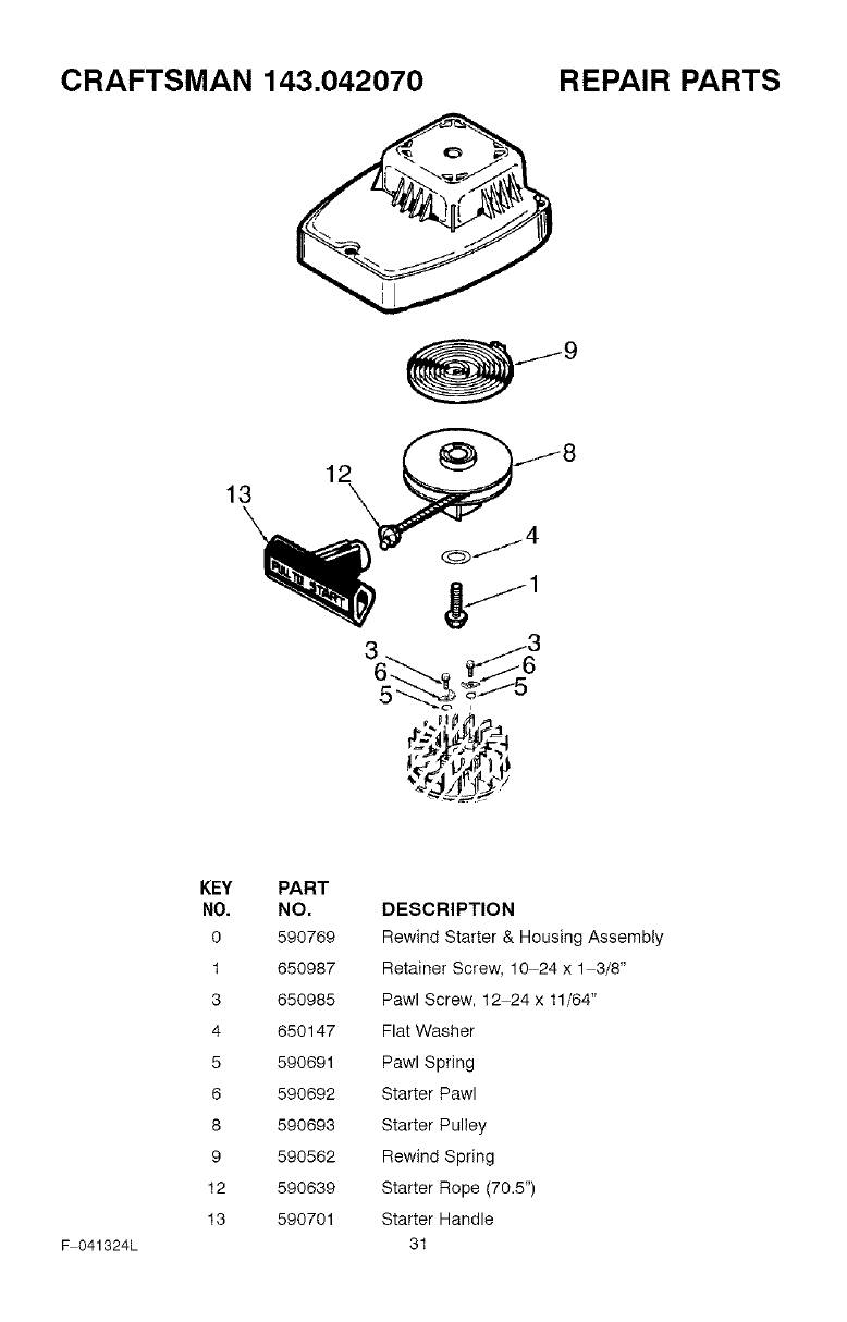
CRAFTSMAN 143.042070 REPAIR PARTS
12
13
_041324L
KEY
NO.
0
1
3
4
5
6
8
9
12
13
PART
NO. DESCRIPTION
590769 Rewind Starter & Housing Assembly
650987 Retainer Screw, 10 24 x 1 3/8"
650985 Pawl Screw, 12 24 x 11/64"
650147 Flat Washer
590691 Pawl Spring
590692 Starter Pawl
590693 Starter Pulley
590562 Rewind Spring
590639 Starter Rope (70.5")
590701 Starter Handle
31
CRAFTSMAN 143.042070 REPAIR PARTS
60
70
F 041324L 32
62
63
64
65
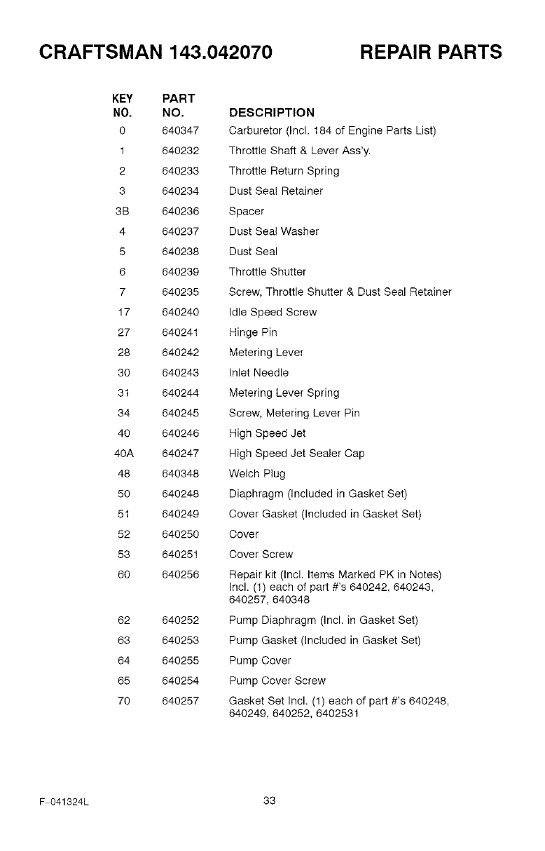
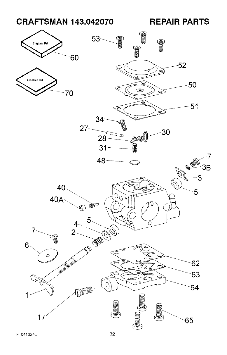
CRAFTSMAN 143.042070 REPAIR PARTS
KEY PART
NO. NO.
0 640347
1 640232
2 640233
3 640234
3B 640236
4 640237
5 640238
6 640239
7 640235
17 640240
27 640241
28 640242
30 640243
31 640244
34 640245
40 640246
40A 640247
48 640348
50 640248
51 640249
52 640250
53 640251
60 640256
62 640252
63 640253
64 640255
65 640254
70 640257
DESCRIPTION
Carburetor (Incl. 184 of Engine Parts List)
Throttle Shaft & Lever Ass'y.
Throttle Return Spring
Dust Seal Retainer
Spacer
Dust Seal Washer
Dust Seal
Throttle Shutter
Screw, Throttle Shutter & Dust Seal Retainer
Idle Speed Screw
Hinge Pin
Metering Lever
Inlet Needle
Metering Lever Spring
Screw, Metering Lever Pin
High Speed Jet
High Speed Jet Sealer Cap
Welch Plug
Diaphragm (included in Gasket Set)
Cover Gasket (Included in Gasket Set)
Cover
Cover Screw
Repair kit (Incl. Items Marked PK in Notes)
Incl. (1) each of part #'s 640242, 640243,
640257, 640348
Pump Diaphragm (Incl. in Gasket Set)
Pump Gasket (Included in Gasket Set)
Pump Cover
Pump Cover Screw
Gasket Set Incl. (1) each of part #'s 640248,
640249, 640252, 6402531
_041324L 33

NOTES
F 041324L 34
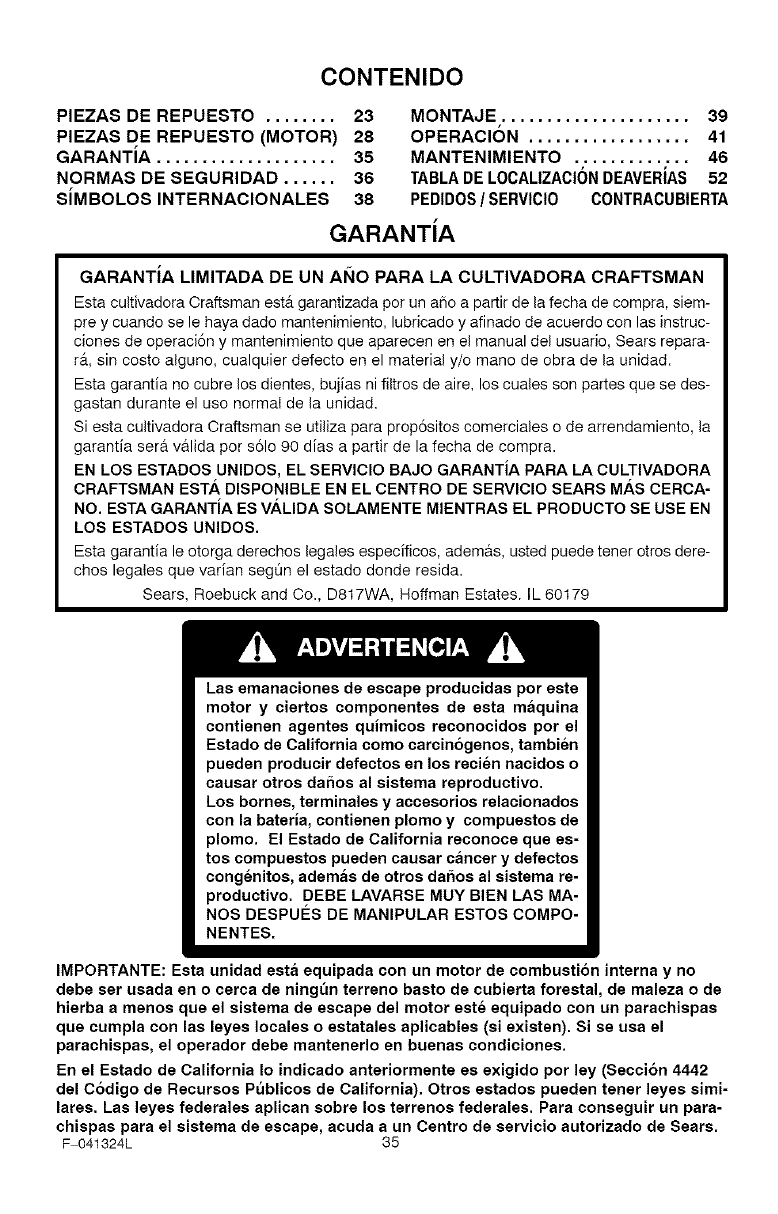
CONTENIDO
PIEZAS DE REPUESTO ........ 23 MONTAJE ..................... 39
PIEZAS DE REPUESTO (MOTOR) 28 OPERACI6N .................. 41
GARANTiA .................... 35 MANTENIMIENTO ............. 46
NORMAS DE SEGURIDAD ...... 36 TABLA DE LOCALIZACION DEAVERiAS 52
SiMBOLOS INTERNACIONALES 38 PEDIDOS/SERVICI0 CONTRACUBIERTA
GARANTiA
GARANTiA LIMITADA DE UN AI_IO PARA LA CULTIVADORA CRAFTSMAN
Esta cultivadora Craftsman est_ garantizada per un a_o a partir de la fecha de compra, siem-
prey cuando se le haya dado mantenimiento, lubricado y afinado de acuerdo con las instruc-
clones de operaci6n y mantenimiento que aparecen en el manual del usuario, Sears repara-
r&, sin costo alguno, cualquier defecto en el material y/o mane de obra de la unidad.
Esta garantia no cubre los dientes, bujias ni filtros de aire, los cuales son partes que se des-
gastan durante el use normal de la unidad.
Siesta cultivadora Craftsman se utiliza para prop6sitos comerciales o de arrendamiento, la
garantia ser& v&lida per s61o 90 dias a partir de la fecha de compra.
EN LOS ESTADOS UNIDOS, EL SERVICIO BAJO GARANTiA PARA LA CULTIVADORA
CRAFTSMAN ESTA DISPONIBLE EN EL CENTRO DE SERVlClO SEARS MAS CERCA-
NO. ESTA GARANTiA ES VALIDA SOLAMENTE MIENTRAS EL PRODUCTO SE USE EN
LOS ESTADOS UNIDOS.
Esta garantia le otorga derechos legales especificos, adem&s, usted puede tener otros dere-
chos legales que varian seg0n el estado deride resida.
Sears, Roebuck and Co., D817WA, Hoffman Estates. IL 60179
Las emanaciones de escape producidas pot este
motor y ciertos componentes de esta maquina
contienen agentes quimicos reconocidos pot el
Estado de California como carcin6genos, tambien
pueden producir defectos en los recien nacidos o
causar otros daSos al sistema reproductivo.
Los bomes, terminales y accesorios relacionados
con la bateria, contienen plomo y compuestos de
plomo. El Estado de California reconoce que es-
tos compuestos pueden causar cancer y defectos
congenitos, ademas de otros daSos al sistema re-
productivo. DEBE LAVARSE MUY BIEN LAS MA-
NOS DESPUI_S DE MANIPULAR ESTOS COMPO-
NENTES.
IMPORTANTE: Esta unidad esta equipada con un motor de combusti6n interna y no
debe set usada eno cerca de ningt_n terreno basto de cubierta forestal, de maleza o de
hierba a menos que el sistema de escape del motor este equipado con un parachispas
que cumpla con las leyes locales o estatales aplicables (si existen). Si se usa el
parachispas, el operador debe mantenerlo en buenas condiciones.
En el Estado de California Io indicado anteriormente es exigido por ley (Secci6n 4442
del C6digo de Recursos Publicos de California). Otros estados pueden tener leyes simi-
lares. Las leyes federales aplican sobre los terrenos federales. Para conseguir un para-
chispas para el sistema de escape, acuda a un Centro de servicio autorizado de Sears.
F 041324L 35
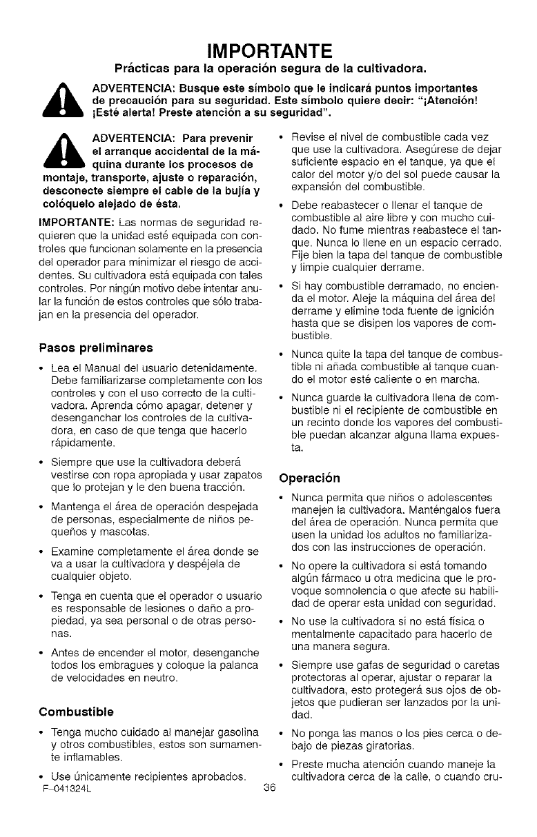
IMPORTANTE
Practicas para la operacion segura de la cultivadora.
ADVERTENCIA: Busque este simbolo que le indicara puntos importantes
de precaucibn para su seguridad. Este simbolo quiere decir: "iAtenci6nt
iEste alerta! Preste atenci6n a su seguridad".
_lb DVERTENCIA: Para prevenir
el arranque accidental de la ma-
quina durante los procesos de
montaje, transporte, ajuste o reparacion,
desconecte siempre el cable de la bujia y
col6quelo alejado de esta.
IMPORTANTE: Las normas de seguridad re-
quieren que la unidad est6 equipada con con-
troles que funcionan solamente en la presencia
del operador para minimizar el riesgo de acci-
dentes. Su cultivadora esta equipada con tales
controles. Por ningOn motivo debe intentar anu-
lar la funci6n de estos controles que s61otraba-
jan en la presencia del operador.
Pasos preliminares
•Lea el Manual del usuario detenidamente.
Debe familiarizarse completamente con los
controles y con el uso correcto de la culti-
vadora. Aprenda c6mo apagar, detener y
desenganchar los controles de la cultiva-
dora, en caso de que tenga que hacerlo
rapidamente.
• Siempre que use la cultivadora deberA
vestirse con ropa apropiada y usar zapatos
que Io protejan y le den buena tracci6n.
• Mantenga el Area de operaci6n despejada
de personas, especialmente de nihos pe-
quehos y mascotas.
• Examine completamente el Area donde se
va a usar la cultivadora y despejela de
cualquier objeto.
• Tenga en cuenta que el operador o usuario
es responsable de lesiones o dafio a pro-
piedad, ya sea personal o de otras perso-
nas.
• Antes de encender el motor, desenganche
todos los embragues y coloque la palanca
de velocidades en neutro.
• Revise el nive! de combustible cada vez
que use la cultivadora. AsegQrese de dejar
suficiente espacio en el tanque, ya que el
calor del motor y/o del sol puede causar la
expansi6n del combustible.
• Debe reabastecer o Ilenar el tanque de
combustible al aire libre y con mucho cui-
dado. No fume mientras reabastece el tan-
que. Nunca Io Ilene en un espacio cerrado.
Fije bien la tapa del tanque de combustible
y limpie cualquier derrame.
• Si hay combustible derramado, no encien-
da el motor. Aleje la maquina del Area del
derrame y elimine toda fuente de ignici6n
hasta que se disipen los vapores de com-
bustible.
Combustible
Nunca quite la tapa del tanque de combus-
tible ni afiada combustible al tanque cuan-
do el motor este caliente o en marcha.
Nunca guarde la cultivadora Ilena de com-
bustible ni el recipiente de combustible en
un recinto donde los vapores del combusti-
ble puedan alcanzar alguna llama expues-
ta.
Operacion
• Nunca permita que niSos o adolescentes
manejen la cultivadora. Mantengalos fuera
del &rea de operaci6n. Nunca permita que
usen la unidad los adultos no familiariza-
dos con las instrucciones de operaci6n.
• No opere la cultivadora si estA tomando
algQn f&rmaco u otra medicina que le pro-
voque somnolencia o que afecte su habili-
dad de operar esta unidad con seguridad.
• No use la cultivadora si no estA fisica o
mentalmente capacitado para hacerlo de
una manera segura.
• Siempre use gafas de seguridad o caretas
protectoras al operar, ajustar o reparar la
cultivadora, esto protegerA sus ojos de ob-
jetos que pudieran ser lanzados por la uni-
dad.
• Tenga mucho cuidado al manejar gasolina •
y otros combustibles, estos son sumamen-
te inflamables.
• Use t_nicamente recipientes aprobados.
F 041324L 36
No ponga las manos o los pies cerca o de-
bajo de piezas giratorias.
Preste mucha atenci6n cuando maneje la
cultivadora cerca de la calle, o cuando cru-
IMPORTANTE
ce por calzadas, calles o caminos de gra- • No exceda la capacidad de su cultivadora
va. Este alerta tanto del tr&fico como de al tratar de cultivar muy profundo a una ve-
problemas potenciales o imprevistos. Iocidad excesiva.
• Tenga cuidado para evitar caidas o resba-
Iones. Almacenamiento
• Nunca opere la cultivadora sin colocar en
su lugar los respectivos resguardos, placas
u otros aditamentos disehados para su
protecci6n y seguridad.
• Use s61o aditamentos y accesorios aproba-
dos por el fabricante de la maquina (como
por ejemplo pesos para las ruedas, contra-
pesos, etc.).
• Nunca opere la cultivadora a alta velocidad
en superficies duras o resbaladizas. Siem-
pre que retroceda mire hacia atrAs y hAga-
Io con cuidado.
• Nunca permita que haya personas cerca
de la cultivadora en marcha.
• Mantenga alejados a nifios y mascotas du-
rante la operaci6n de la maquina.
• Siempre opere el equipo a la luz del dfa o
con buena iluminaci6n artificial.
Cuando la cultivadora va a estar almace-
nada por un periodo largo de tiempo, con-
suite las instrucciones del manual del
usuario para obtener detalles importantes
al respecto.
Nunca guarde la cultivadora con combusti-
ble en el tanque, dentro de un recinto don-
de se encuentre alguna fuente de ignici6n,
tal como sistemas de calefacci6n, calenta-
dotes de agua, secadoras de ropa, etc.
Deje enfriar el motor antes de guardar la
unidad en un recinto cerrado.
Si es necesario vaciar e! tanque de com-
bustible, hAgalo al aire libre.
Mantenga la cultivadora en condiciones de
funcionamiento seguras. Revise con regu-
laridad todos los sujetadores para mante-
neflos debidamente apretados.
• Tenga cuidado al cultivar tierra compacta.
Los dientes pueden atorarse en el suelo y
propulsar la cultivadora hacia adelante. Si
esto ocurre, suelte los mangos y no intente
detener la mAquina.
• Tenga mucho cuidado al invertir la direc-
ci6n de la mAquina o al jalarla hacia usted.
• No haga ajustes al regulador de velocidad
del motor ni haga funcionar el motor a ve-
Iocidad excesiva.
• Encienda o arranque el motor con mucho
cuidado y segOn las instrucciones, y man-
tenga los pies alejados de los dientes.
• Nunca levante la mAquina cuando el motor
estA en marcha.
• Nunca ponga en marcha un motor dentro
de un recinto o de un Area cerrada. Los
vapores del sistema de escape son peli-
grosos, ya que contienen MONOXlDO DE
OARBONO, un GAS INODORO y MOR-
TAL.
• Tome todas las precauciones necesarias
cuando deje la cultivadora desatendida.
Apague el motor y saque la Ilave (si la
hay).
F 041324L
Reparacion /Ajustes
Si golpea un objeto con la unidad, apague
el motor. Desconecte el cable de la bujia y
mantengalo alejado de esta para evitar un
arranque accidental del motor. Inspeccione
la cultivadora cuidadosamente para vet si
esta sufri6 alg_n da_o. Siesta averiada,
debera repararla antes de hacerla funcio-
nat nuevamente.
Si la cultivadora comienza a vibrar de una
manera anormal, apague el motor. Revise
la unidad de inmediato para determinar la
causa. Generalmente la vibraci6n suele
indicar que existe alguna averia.
Apague el motor siempre que tenga que
dejar el equipo. Desconecte el cable de la
bujia antes de despejar los dientes y antes
de realizar cualquier reparaci6n, ajuste o
inspecci6n a la unidad.
Antes de limpiar, reparar o inspeccionar la
unidad, apague el motor y asegQrese de
que todas las partes o piezas en movi-
miento se hayan detenido.
• Nunca haga ajustes o reparaciones mien-
tras el motor este en marcha, a menos que
el fabricante Io indique especfficamente.
37
IMPORTANTE
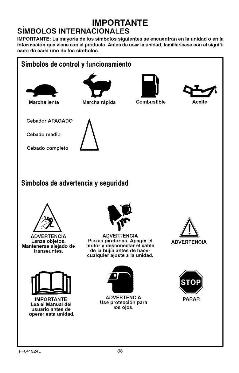
SiMBOLOS INTERNACIONALES
IMPORTANTE: La mayoria de los simbolos siguientes se encuentran en la unidad o en la
informaci6n que viene con el producto. Antes de usar la unidad, familiaricese con el signifi-
cado de cada uno de los simbolos.
Simbolos de control y funcionamiento
Marcha lenta Marcha rapida Combustible Aceite
Cebador APAGADO A
Cebado medio
Cebado completo
Simb010sde advertencia y seguridad
A
ADVERTENCIA
Lanza objetos.
Mantenerse alejado de
transe_ntes.
IMPORTANTE
Lea el Manual del
usuario antes de
operar esta unidad.
ADVERTENCIA
Piezas giratorias. Apagar el
motor y desconectar el cable
de la bujia antes de hacer
cualquier ajuste a la unidad.
ADVERTENCIA
Use proteccion para
los ojos.
ADVERTENCIA
PARAR
F 041324L 38
MONTAJ E MONTAJE
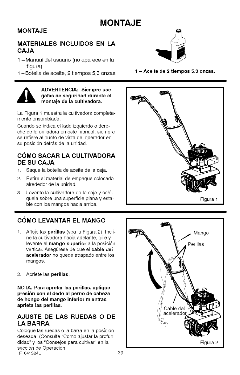
MATERIALES INCLUIDOS EN LA
CAJA
1 -Manual del usuario (no aparece en la
figura)
1 -Botella de aceite, 2 tiempos 5,3 onzas 1 - Aceite de 2 tiempos 5,3 onzas.
ADVERTENCIA: Siempre use
gafas de seguridad durante el
montaje de la cultivadora.
La Figura 1 muestra la cultivadora completa-
mente ensambiada.
Ouando se indica el lade izquierdo o dere-
cho de la orilladora en este manual, siempre
se refiere al punto de vista del operador en
su posici6n detr_s de la unidad.
COMO SACAR LA CULTIVADORA
DE SU CAJA
1. Saque la botella de aceite de la caja.
2. Retire el material de empaque colocado
alrededor de la unidad.
3. Levante la cultivadora de la caja y col6-
quela sobre una superficie plana y esta-
ble con los mangos hacia arriba. Figura 1
COMO LEVANTAR EL MANGO
Afloje las perillas (vea la Figura 2). Incli-
ne la cultivadora hacia adelante, gire y
levante el mango superior a la posici6n
vertical. Aseg6rese de que el cable del
acelerador no quede atrapado entre los
mangos.
2. Apriete las perillas.
NOTA: Para apretar las perillas, aplique
presi6n con el dedo al perno de cabeza
de hongo del mango inferior mientras
aprieta las perillas.
AJUSTE DE LAS RUEDAS O DE
LA BARRA
Ooloque las ruedas o la barra en la posici6n
deseada. (Consulte "Come ajustar la profun-
didad" y los "Consejos para cultivar" en la
secci6n de Operaci6n.
F 041324L 39
Mango
Perillas
Figura 2
MONTAJE
_" LISTA DE COMPROBACION
Para obtener un rendimiento 6ptimo y la ma-
yor satisfacci6n de este producto de alta ca-
lidad, favor de revisar la siguiente lista de
comprobaci6n antes de hacer funcionar su
cultivadora:
Se han completado todas las instruc-
clones de montaje.
Se ha revisado la caja de envio para
asegurar que no quede en 6sta ningu-
na pieza o parte.
Todos los sujetadores hart sido apre-
tados adecuadamente.
A medida que vaya aprendiendo a usar la
cultivadora, preste especial atenci6n a los
siguientes puntos importantes:
_'_' El tanque de combustible se debe Ile-
nar con una mezcla de combustible y
aceite fresca y limpia.
_'_' Debe familiarizarse y entender la fun-
ci6n de todos los controles. Antes de
hacer arrancar el motor, verifique el
funcionamiento de todos los contro-
les.
F 041324L 40
OPERACION
CONOZCA SU CULTIVADORA
ANTES DE HACER FUNOIONAR LA CULTIVADORA, LEA EL MANUAL DEL USUARIO Y
TODA LA INFORMACI6N SOBRE SEGURIDAD. Para familiarizarse con la ubicaci6n de los
controles, compare las siguientes ilustraciones con su cultivadora. Guarde este manual para
referencias futuras.
J
Palanca de control
del acelerador
Interruptor de
ENOENDIDO /
APAGADO
(ON /OFF)
Manija de arranque manual
Mango superior
Mango inferior
Con unto de barra Idl
de profundidad I._11
y ruedas lill.<'-.
de transport_
t
Descompresor OontrOlcebadorde/
Filtro de
aire
Tapa del tanque
de combustible
Cubierta protectora
de los dientes
'Dientes Figura 3
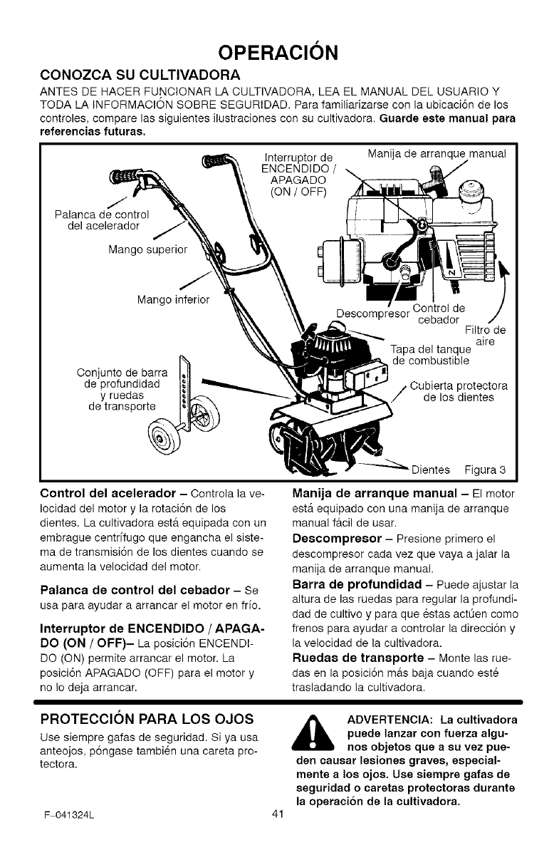
Control del acelerador - Controla la ve-
Iocidad del motor y la rotaci6n de los
dientes. La cultivadora est& equipada con un
embrague centdfugo que engancha el siste-
ma de transmisi6n de los dientes cuando se
aumenta la velocidad del motor.
Palanca de control del cebador - Se
usa para ayudar a arrancar el motor en fifo.
Interruptor de ENCENDIDO /APAGA-
DO (ON /OFF)- La posici6n ENCENDI-
DO (ON) permite arrancar el motor. La
posici6n APAGADO (OFF) para el motor y
no Io deja arrancar.
Manija de arranque manual - El motor
ester equipado con una manija de arranque
manual f&cil de usar.
Descompresor - Presione primero el
descompresor cada vez que vaya a jalar la
manija de arranque manual.
Barra de profundidad - Puede ajustar la
altura de las ruedas para regular la profundi-
dad de cultivo y para que 6stas actt_en como
frenos para ayudar a controlar la direcci6n y
la velocidad de la cultivadora.
Rueda8 de transporte - Monte las rue-
das en la posici6n m&s baja cuando est6
trasladando la cultivadora.
PROTECClON PARA LOS OJOS
use siempre gafas de seguridad. Si ya usa
anteojos, p6ngase tambi6n una careta pro-
tectora.
F 041324L
ADVERTENCIA: La cultivadora
puede lanzar con fuerza algu-
nos objetos que a su vez pue-
den causar lesiones graves, especial-
mente a los ojos. Use siempre gafas de
seguridad o caretas protectoras durante
la operaci6n de la cultivadora.
OPERACION
COMO USAR LA CULTIVADORA
Como parar la cultivadora
1. Suelte el control del acelerador para de-
tener la rotaci6n de los dientes.
2. Mueva el interruptor de ENCENDIDO !
APAGADO (ON/OFF), ubicado en el mo-
tor, a la posici6n APAGADO (OFF).
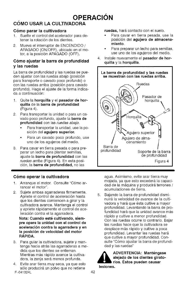
Como ajustar la barra de profundidad
y las ruedas
La barra de profundidad y las ruedas se pue-
den ajustar con las ruedas abajo (posici6n
para transporte o cavado poco profundo) o
con las ruedas arriba (posici6n para cavado
profundo). Haga el ajuste de la forma indica-
da a continuaci6n:
1. Quite la horquilla y el pasador de hor-
quilla de la barra de profundidad
(Figura 4).
2. Para transportar la unidad o para un ca-
vado poco profundo, ajuste la barra de
profundidad con las ruedas abajo.
Para transportar la unidad, use la po-
sici6n del agujsro superior.
Para un cavado poco profundo, use
uno de los agujeros del medio.
3. Para cavar en tierra pesada o para pre-
parar un lecho para plantar semillas,
ajuste la barra de profundidad con las
ruedas arriba (Figura 4). En esta posi-
ci6n, la barra de profundidad, no las
rusdas, har@.contacto con el suelo.
Para cavar en tierra pesada, use la
posici6n del agujero de almacena-
miento.
Para preparar un lecho para semillas,
use uno de los agujeros del medio.
Instale nuevamente el pasador de hor-
quilla y la horquilla.
La barra de profundidad y las ruedas
se muestran con las ruedas arriba.
Ruedas
Pasador de
horquilla _
Barra de
profundidad
Agujero de alma-
cenamiento /
Soporte de la barra
de profundidad
Figura 4
Como operar la cultivadora
1. Arranque el motor. Oonsulte "C6mo ar-
rancar el motor".
2. Sujete ambas agarraderas firmemente.
Apriete el control de aceleraci6n hasta
que los dientes comiencen a girar y la
cultivadora avance. Mantenga el control
y apriete r_.pidamente el control de ace-
leraci6n contra el la agarradera.
Nota: Cuando este cultivando, siem-
pre opere la unidad con el control de
aceleracion contra la agarradera y en
la posici6n de velocidad del motor
RAPIDA.
3. Para guiar la cultivadora, sujete y man-
tenga hacia atr_.s las agarraderas a me-
dida que los dientes se entierran.
Mientras mrs rapido avance la cultiva-
dora, la zanja ser_. menos profunda.
4. Evite arar tierra muy seca, ya que esto
s61o producir_, un polvo que no retiene
F 041324L 42
agua. Asimismo, evite arar tierra muy
mojada, ya que esto excedera la capaci-
dad de la m_.quina y producira terrones /
acumulaciones de tierra.
Bajando la barra de profundidad dismi-
nuir@,la velocidad de avarice de la culti-
vadora y har_. que 6sta cultive a mayor
profundidad. Levantando la barra de pro-
fundidad harm que la unidad avance m_.s
r_.pido y cultive a menor profundidad.
Con las ruedas ocurre Io contrario. Bajar
las ruedas hace que la cultivadora se
desplace mrs r_.pido y cultive a poca
profundidad. Levantar las ruedas har6.
que cultive a mayor profundidad. Con-
suite "C6mo ajustar la barra de profundi-
dad y las ruedas"
_hb DVERTENCIA: Mantengase
alejado de los dientes girato-
rios. I_stos pueden causar
lesiones.
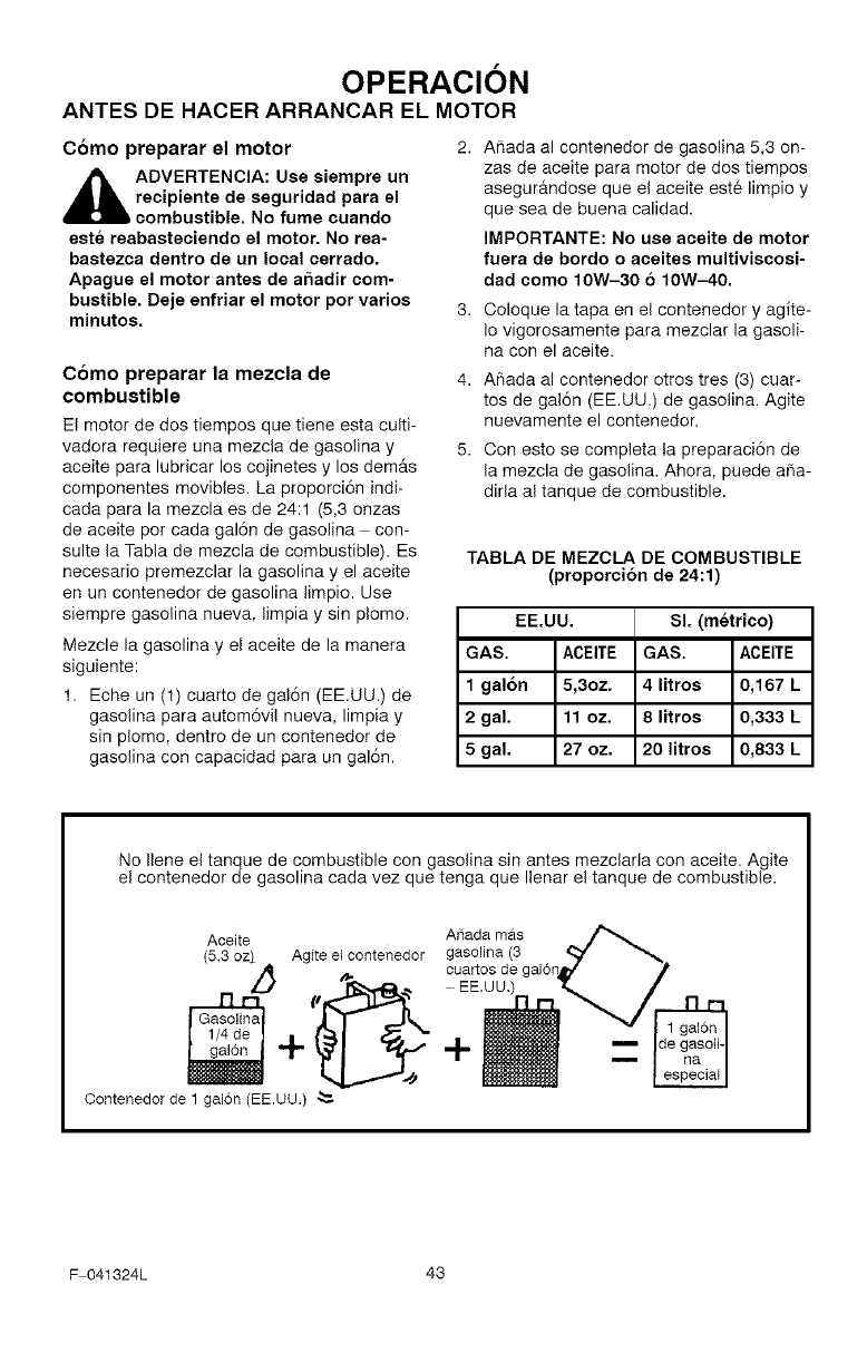
OPERACION
ANTES DEHACERARRANCAR EL MOTOR
Como preparar el motor 2.
,_ ADVERTENCIA: Use siempre un
recipiente de seguridad para el
bcombustible. No fume cuando
este reabasteciendo el motor. No rea-
bastezca dentro de un local cerrado.
Apague el motor antes de a5adir com-
bustible. Deje enfriar el motor por varios 3.
minutos.
Como preparar la mezcla de
combustible
El motor de dos tiempos que tiene esta culti-
vadora requiere una mezcla de gasolina y
aceite para lubricar los cojinetes y los demurs
componentes movibles. La proporci6n indi-
cada para la mezcla es de 24:1 (5,3 onzas
de aceite pot cada gal6n de gasolina con-
suite la Tabla de mezcla de combustible). Es
necesario premezclar la gasolina y el aceite
en un contenedor de gasolina limpio. Use
siempre gasolina nueva, limpia y sin plomo.
Mezcle la gasolina y el aceite de la manera
siguiente:
1. Eche un (1) cuarto de gal6n (EE.UU.) de
gasolina para autom6vil nueva, limpia y
sin plomo, dentro de un contenedor de
gasolina con capacidad para un gal6n.
Afiada al contenedor de gasolina 5,3 on-
zas de aceite para motor de dos tiempos
asegur&ndose que el aceite este limpio y
que sea de buena calidad.
IMPORTANTE: No use aceite de motor
fuera de bordo o aceites multiviscosi-
dad como 10W-30 610W-40.
Coloque la tapa en el contenedor y agite-
Io vigorosamente para mezclar la gasoli-
na con el aceite.
Aflada al contenedor otros tres (3) cuar-
tos de gal6n (EE.UU.) de gasolina. Agite
nuevamente el contenedor.
Con esto se completa la preparaci6n de
la mezcla de gasolina. Ahora, puede aria-
dirla al tanque de combustible.
TABLA DE MEZCLA DE COMBUSTIBLE
(proporci6n de 24:1)
EE.UU. SI. (metrico)
GAS. ACEITE GAS. ACEITE
1 galon 5,3oz. 4 litros 0,167 L
2 gal. 11 oz. 8 litros 0,333 L
5 gal. 27 oz. 20 litros 0,833 L
No Ilene el tanque de combustible con gasolina sin antes mezclarla con aceite. Agite
el contenedor de gasolina cada vez que tenga que Ilenar el tanque de combustible.
Aceite A_iadamas
(5,3 oz) Agiteel contenedor gasolina (3
oua osd ,
EE.UU
+
Contenedor de 1 galon (EE.UU,)
F 041324L 43
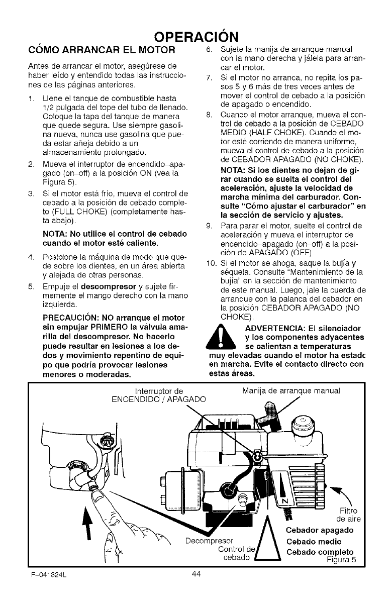
OPERACION
COMO ARRANCAR EL MOTOR 6, Sujete la manija de arranque manual
Antes de arrancar el motor, asegOrese de
haber leido y entendido todas las instruccio-
nes de las p&ginas anteriores.
1. Llene el tanque de combustible hasta
1/2 pulgada del tope del tube de Ilenado.
Coloque la tapa del tanque de manera
que quede segura. Use siempre gasoli-
na nueva, nunca use gasolina que pue-
da estar aSeja debido a un
almacenamiento prolongado.
2. Mueva el interrupter de encendido apa-
gado (on off) a la posici6n ON (vea la
Figura 5).
3. Si el motor est& frio, mueva e! control de
cebado a la posici6n de cebado comple-
to (FULL CHOKE) (completamente has-
ta abajo).
NOTA: No utilioe el control de cebado
cuando el motor este caliente.
4,
5.
Posicione la m&quina de modo que que-
de sobre los dientes, en un Area abierta
y alejada de otras personas.
Empuje el descompresor y sujete fir-
memente el mango derecho con la mane
izquierda.
PRECAUCION: NO arranque el motor
sin empujar PRIMERO la valvula ama-
rilla del descompresor. No hacerlo
puede reeultar en lesiones a Ice de-
doe y movimiento repentino de equi-
pc que podria provocar lesiones
menores o moderadas.
con la mane derecha y j_tlela para arran-
car el motor.
7. Si el motor no arranca, no repita los pa-
sos 5 y 6 mas de tres veces antes de
mover el control de cebado a la posici6n
de apagado o encendido.
8. Cuando el motor arranque, mueva el con-
trol de cebado a la posici6n de CEBADO
MEDIC (HALF CHOKE). Cuando el mo-
tor este corriendo de manera uniforme,
mueva el control de cebado a la posici6n
de CEBADOR APAGADO (NO CHOKE).
NOTA: Si los dientes no dejan de gi-
rat cuando se suelta el control del
aceleraci6n, ajuste la velocidad de
marcha minima del carburador. Con-
suite "C6mo ajustar el carburador" en
la secci6n de servicio y ajustes.
9. Para parar el motor, suelte el control de
aceleraci6n y mueva el interrupter de
encendido apagado (on off) a la posi-
ci6n de APAGADO (OFF)
10. Si el motor se ahoga, saque la bujia y
sequela. Consulte "Mantenimiento de la
bujia" en la secci6n de mantenimiento
de este manual. Luego, jale la cuerda de
arranque con la palanca del cebador en
la posici6n CEBADOR APAGADO (NO
CHOKE).
ADVERTENCIA: El silenciador
y los componentes adyacentes
se calientan a temperaturas
muy elevadas cuando el motor ha estadc
en marcha. Evite el contacto direoto con
estas areas.
Interrupter de
ENCENDIDO /APAGADO Manija de arranque manual
Decompresor
Control de
cebado
"k
Filtro
de aire
Cebador apagado
Cebado medic
Cebado completo
Figura 5
F 041324L 44
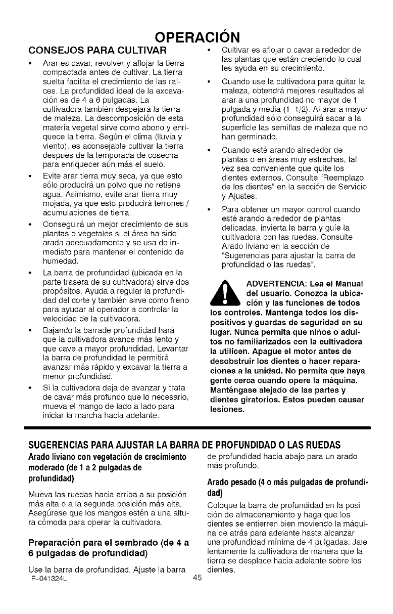
OPERACION
CONSEJOS PARA CULTIVAR
Arar es cavar, revolver y aflojar la tierra
compactada antes de cultivar. La tierra
suelta facilita el crecimiento de las rai-
ces. La profundidad ideal de la excava-
ci6n es de 4 a 6 pulgadas. La
cultivadora tambi6n despejar_, la tierra
de maleza. La descomposici6n de esta
materia vegetal sirve come abono y enri-
quece la tierra. Segt_n el clima (lluvia y
viento), es aconsejable cultivar la tierra
despues de la temporada de cosecha
para enriquecer at_n m_ts el suelo.
Evite arar tierra muy seca, ya que esto
s61o producir& un polvo que no retiene
agua. Asimismo, evite arar tierra muy
mojada, ya que esto producir& terrones /
acumulaciones de tierra.
Conseguir& un meier crecimiento de sus
plantas o vegetales si el _trea ha sido
arada adecuadamente y se usa de in-
mediate para mantener el contenido de
humedad.
La barra de profundidad (ubicada en la
parte trasera de su cultivadora) sirve dos
prop6sitos. Ayuda a regular la profundi-
dad del corte y tambi6n sirve como freno
para ayudar al operador a controlar la
velocidad de la cultivadora.
Bajando la barrade profundidad har_t
que la cultivadora avance m&s lento y
que cave a mayor profundidad. Levantar
la barra de profundidad le permitir&
avanzar m_ts r&pido y excavar la tierra a
menor profundidad.
Si la cultivadora deja de avanzar y trata
de cavar m_ts profundo que Io necesario,
mueva el mango de lado a lado para
iniciar la marcha hacia adelante.
Oultivar es aflojar o cavar alrededor de
las plantas que estAn creciendo Io cual
les ayuda en su crecimiento.
Ouando use la cultivadora para quitar la
maleza, obtendra mejores resultados al
arar a una profundidad no mayor de 1
pulgada y media (1 1/2). AI arar a mayor
profundidad s61o conseguir_ sacar a la
superficie las semillas de maleza que no
hart germinado.
Ouando est6 arando alrededor de
plantas o en areas muy estrechas, tal
vez sea conveniente que quite los
dientes externos. Consulte "Reemplazo
de los dientes" en la secci6n de Servicio
y Ajustes.
Para obtener un mayor control cuando
est6 arando alrededor de plantas
delicadas, invierta la barra y guie la
cultivadora con las ruedas. Consulte
Arado liviano en la secci6n de
"Sugerencias para ajustar la barra de
profundidad o las ruedas".
ADVERTENCIA: Lea el Manual
del usuario. Conozca la ubica-
cion y las funciones de todos
los controles. Mantenga todos los dis-
positivos y guardas de seguridad en su
lugar. Nunca permita que ni5os o adul-
tos no familiarizados con la cultivadora
la utilicen. Apague el motor antes de
desobstruir los dientes o hacer repara-
ciones a la unidad. No permita que haya
gente cerca cuando opere la maquina.
Mantengase alejado de las partes y
dientes giratorios. Estos pueden causar
lesiones.
SUGERENCIASPARAAJUSTARLABARRADEPROFUNDIDAD0 LASRUEDAS
Aradoliviano con vegetaci6nde crecimiento
moderado(de1 a 2 pulgadasde
profundidad)
Mueva las ruedas hacia arriba a su posici6n
m_s alta o a la segunda posici6n mas alta.
AsegOrese que los mangos est6n a una altu-
ra c6moda para operar la cultivadora.
Preparacion para el sembrado (de 4 a
6 pulgadas de profundidad)
Use la barra de profundidad. Ajuste la barra
F 041324L 45
de profundidad hacia abajo para un arado
m_s profundo.
Arado pesado (4 o mbs pulgadas de profundi-
dad)
Ooloque la barra de profundidad en la posi-
ci6n de almacenamiento y haga que los
dientes se entierren bien moviendo la maqui-
na de atr_s para adelante hasta alcanzar
una profundidad minima de 4 pulgadas. Jale
lentamente la cultivadora de manera que la
tierra se desplace hacia adelante sobre los
dientes.
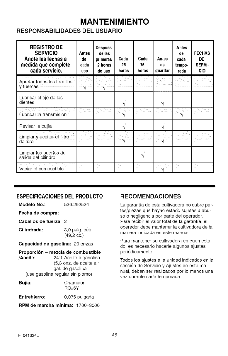
MANTENIMIENTO
RESPONSABILIDADES DEL USUARIO
REGISTRODE Despu_s Antes
SERVICIO Antes delas de FECHAS
Anotelasfechas a de primeras Cada Cada Antes cada DE
medidaquecomplete cada 2 horas 25 75 de tempo- SERVI-
cadaservicio, uso de uso horas horas guardar rada CIO
I I I I
Lubricar el eje de los
dientes
Lubricar la transmisi6n I I I ,
Revisar la bujia
Limpiar los puertos de
salida del cilindro
I I I I I I I
I I I I I ' I
Vaciar el combustible
ESPECIFICACIONESDELPRODUCTO
Modelo No,: 536.292524
Fecha de compra:
Caballos de fuerza: 2
Cilindrada: 3,0 pulg. c_b.
(49,2 cc.)
Capacidad de gasolina: 20 onzas
Proporci6n - mezcla de combustible
/Aceite: 24:1 Aceite a gasolina
(5,3 onz. de aceite a 1
gal. de gasolina
(use gasolina regular sin plomo)
Bujia: Champion
RCJ6Y
Entrehierro: 0,035 pulgada
RPM de marcha minima: 1700-3000
RECOMENDACIONES
La garantia de esta cultivadora no cubre par-
tes/piezas que hayan estado sujetas a abu-
so o negligencia pot parte del operador.
Para recibir el valor total de la garantia, el
operador debe mantener la cultivadora de la
manera indicada en este manual.
Para mantener su cultivadora en buen esta-
do, es necesario hacerle algunos ajustes
peri6dicamente.
Todos los ajustes a la unidad indicados en la
secci6n de Servicio y Ajustes de este ma-
nual, deben ser realizados pot Io menos una
vez durante cada temporada.
F 041324L 46
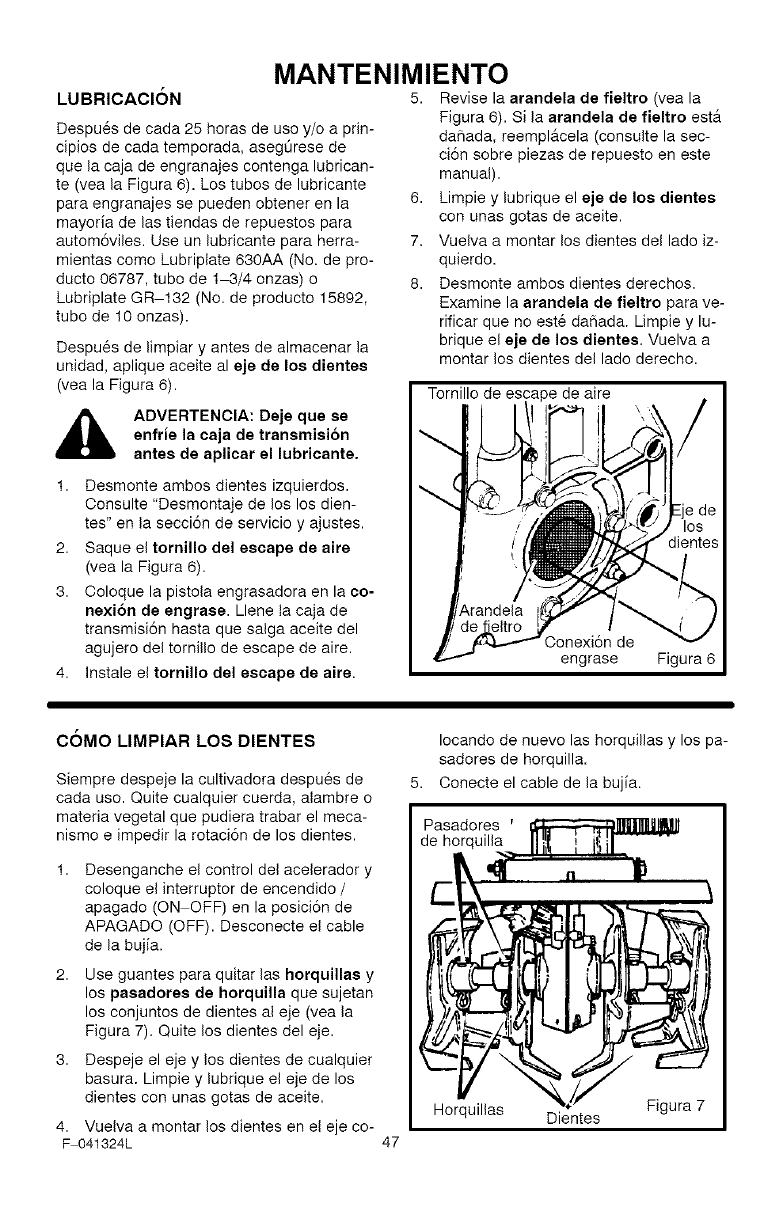
LUBRICACION
Despu6s de cada 25 horas de use y/o a prin-
ciples de cada temporada, asegOrese de
que la caja de engranajes contenga lubrican-
te (vea la Figura 6). Los tubes de lubricante
para engranajes se pueden obtener en la
mayoria de las tiendas de repuestos para
autom6viles. Use un lubricante para herra-
mientas come Lubriplate 630AA (No. de pro-
ducto 06787, tube de 1_3/4 onzas) o
Lubriplate GR 132 (No. de producto 15892,
tube de 10 onzas).
Despu6s de limpiar y antes de almacenar la
unidad, aplique aceite al eje de los dientes
(vea la Figura 6).
MANTENIMIENTO
5. Revise la arandela de fieltro (vea la
Figura 6). Si la arandela de fieltro est&
dahada, reempl&cela (consulte la sec-
ci6n sobre piezas de repuesto en este
manual).
6. Limpie y lubrique el eje de los dientes
con unas gotas de aceite.
7. Vuelva a montar los dientes del lade iz-
quierdo.
8. Desmonte ambos dientes derechos.
Examine la arandela de fieltro para ve-
rificar que no est6 daSada. Limpie y lu-
brique el eje de los dientee. Vuelva a
montar los dientes del lade derecho.
,_ ADVERTENCIA: Deje que se
enfrie la caja de transmisi6n
antes de aplicar el lubricante.
1. Desmonte ambos dientes izquierdos.
Oonsulte "Desmontaje de los los dien-
tes" en la secci6n de servicio y ajustes.
2. Saque el tornillo del escape de aire
(yea la Figura 6).
3. Coloque la pistola engrasadora en la co-
nexi6n de engrase. Llene ta caja de
transmisi6n hasta que salga aceite del
agujero del tornillo de escape de aire.
4. Instale el tornillo del escape de aire.
Tornillo de escape de aire
Oonexi6n de
engrase Figura 6
COMO LIMPIAR LOS DIENTES
Siempre despeje la cultivadora despu6s de
cada use. Quite cualquier cuerda, alambre o
materia vegetal que pudiera trabar el meca-
nismo e impedir la rotaci6n de los dientes.
Desenganche el control del acelerador y
coloque el interrupter de encendido /
apagado (ON OFF) en la posici6n de
APAGADO (OFF). Desconecte el cable
de la bujia.
Use guantes para quitar las horquillae y
los paeadores de horquilla que sujetan
los conjuntos de dientes al eje (vea la
Figura 7). Quite los dientes del eje.
3. Despeje el eje y los dientes de cualquier
basura. Limpie y lubrique el eje de los
dientes con unas gotas de aceite.
4. Vuelva a montar los dientes en el eje CO-
F 041324L
Iocando de nuevo las horquillas y los pa-
sadores de horquilla.
5. Conecte el cable de la bujia.
Pasadores
de horquilla
Horquillas
47
Dientes Figura 7
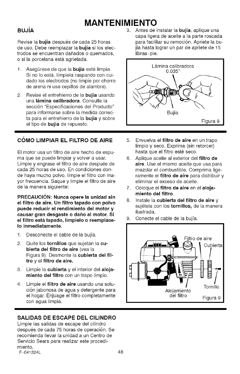
BUJiA
Revise la bujia despues de cada 25 horas
de use. Debe reemplazar la bujia si los elec-
trodos se encuentran dafiados o quemados,
o si la porcelana est& agrietada.
MANTENIMIENTO
3. Antes de instalar la bujia, aplique una
capa ligera de aceite a la parte roscada
para facilitar su remoci6n. Apriete la bu-
jia hasta Iograr un par de apriete de 15
libras pie.
AsegOrese de que la bujia este limpia.
Si no Io est&, limpiela raspando con cui-
dado los electrodes (no limpie pot chorro
de arena ni use cepillos de alambre).
Revise el entrehierro de la bujia usando
una lamina ealibradora. Consulte la
secci6n "Especificaciones del Producto"
para informarse sobre la medida correc-
ta para el entrehierro de la bujia y sobre
el tipo de bujia de repuesto.
L_tmina calibradora
0,035"
COMO LIMPIAR EL FILTRO DE AIRE
El motor usa un filtro de aire hecho de espu-
ma que se puede limpiar y volver a usar.
Limpie y engrase el filtro de aire despues de
cada 25 horas de use. En condiciones don-
de haya mucho polvo, limpie el filtro con ma-
yor frecuencia. Saque y limpie el filtro de aire
de la manera siguiente:
PRECAUCION: Nunca opere la unidad sin
el filtro de aire. Un filtro tapado con polvo
puede reducir el rendimiento del motor y
causar gran desgaste o da_o al motor. Si
el filtro esta tapado, limpielo o reemplace-
Io inmediatamente.
1. Desconecte el cable de la bujia.
2. Quite los tornilloe que sujetan la cu-
bierta del filtro de aire (vea la
Figura 9). Desmonte la cubierta del fil-
tro y el filtro de aire.
3. Limpie la cubierta y el interior del aloja-
miento del filtro con un trapo limpio.
4. Limpie el filtro de aire usando una solu-
ci6n jabonosa de agua y detergente para
el hogar. Enjuage el filtro completamente
con agua limpia.
5. Envuelva el filtro de aire en un trapo
limpio y seco. Exprima (sin retorcer)
hasta que el filtro este seco.
6. Aplique aceite al exterior del filtro de
aire. Use el mismo aceite que usa para
mezclar el combustible. Oomprima lige-
ramente el filtro de aire para distribuir y
eliminar el exceso de aceite.
7. Coioque el filtro de aire en el aloja-
miento del filtro.
8. Instale la cubierta del filtro de aire y
sujetela con los tornillos, de la manera
ilustrada.
9. Conecte el cable de la bujia.
Filtro de aire
Tornillo
Alojamiento
del filtro Figura 9
SALIDAS DE ESCAPE DEL CILINDRO
Limpie las salidas de escape del cilindro
despues de cada 75 horas de operaci6n. Se
recomienda Ilevar la unidad a un Centro de
Servicio Sears para realizar este procedi-
miento.
F 041324L 48
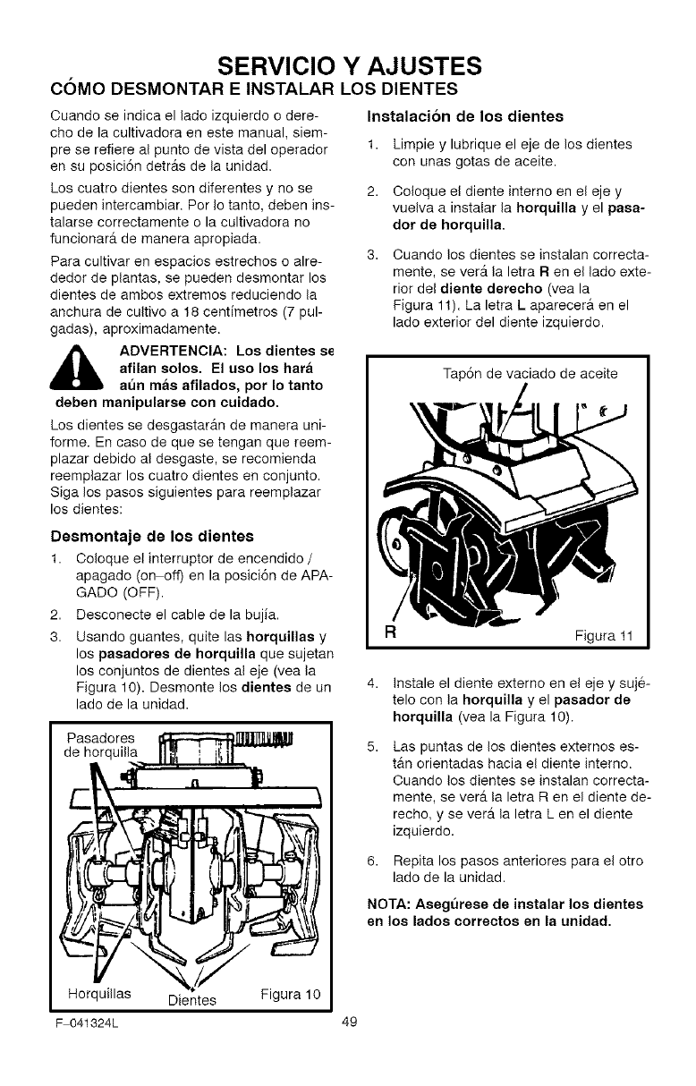
SERVICIO Y AJUSTES
C6MO DESMONTAR E INSTALAR LOS DIENTES
Ouando se indica el lado izquierdo o dere-
cho de la cultivadora en este manual, siem-
pre se refiere al punto de vista del operador
en su posici6n detrAs de la unidad.
Los cuatro dientes son diferentes y no se
pueden intercambiar. Per Io tanto, deben ins-
talarse correctamente o la cultivadora no
funcionar_t de manera apropiada.
Para cultivar en espacios estrechos o alre-
dedor de plantas, se pueden desmontar los
dientes de ambos extremes reduciendo la
anchura de cultivo a 18 cenfimetros (7 pul-
gadas), aproximadamente.
ADVERTENCIA: Los dientes s_
afilan solos. El uso los hara
at_n mas afilados, per Io tanto
deben manipularse con cuidado.
Los dientes se desgastar_n de manera uni-
forme. En case de que se tengan que reem-
plazar debido al desgaste, se recomienda
reemplazar los cuatro dientes en conjunto.
Siga los pasos siguientes para reemplazar
los dientes:
Desmontaje de los dientes
1. Ooloque el interrupter de encendido /
apagado (on off) en la posici6n de APA-
GADO (OFF).
2. Desconecte el cable de la bujia.
3. Usando guantes, quite las horquillas y
los pasadores de horquilla que sujetan
los conjuntos de dientes al eje (vea la
Figura 10). Desmonte los dientes de un
lade de la unidad.
Pasadores
de horquilla
Instalaci6n de los dientes
1. Limpie y lubrique el eje de los dientes
con unas gotas de aceite.
2. Coloque e! diente interno en el eje y
vuelva a instalar la horquilla y el pasa-
dot de horquilla.
Ouando los dientes se instalan correcta-
mente, se verA la letra R en el lado exte-
rior del diente derecho (vea la
Figura 11). La letra L aparecera en el
lade exterior del diente izquierdo.
Tap6n de vaciado de aceite
Figura 11
4. Instale el diente externo en el eje y suje-
telo con la horquilla y el paeador de
horquilla (vea la Figura 10).
Las puntas de los dientes externos es-
tan orientadas hacia el diente interno.
Ouando los dientes se instalan correcta-
mente, se verst la letra R en el diente de-
recho, y se verst la letra L en el diente
izquierdo.
6. Repita los pasos anteriores para el otro
lado de la unidad.
NOTA: Aseg_rese de instalar los dientes
en los lados correctos en la unidad.
Horquillas Dientes Figura 10
F 041324L 49
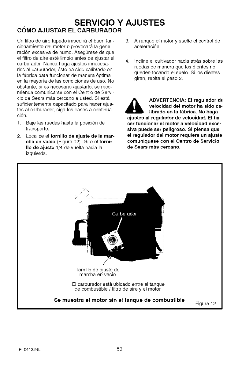
SERVICIO Y AJUSTES
C6MO AJUSTAR EL CARBURADOR
Un filtro de aire tapado impedirA el buen fun-
cionamiento del motor o provocara la gene-
raci6n excesiva de humo. AsegOrese de que
el filtro de aire est6 limpio antes de ajustar el
carburador. Nunca haga ajustes innecesa-
rios al carburador, este ha sido calibrado en
la fAbrica para funcionar de manera 6ptima
en la mayoda de las condiciones de uso. No
obstante, si es necesario ajustarlo, se reco-
mienda comunicarse con el Centro de Servi-
cio de Sears mas cercano a usted. Si ester
suficientemente capacitado para hacer ajus-
tes al carburador, siga los pasos a continua-
ci6n.
1. Baje las ruedas hasta la posici6n de
transporte.
2. Localice el tornillo de ajuste de la mar-
cha en vacio (Figura 12). Gire el torni-
Iio de ajuste 1/4 de vuelta hacia la
izquierda.
3. Arranque el motor y suelte el control de
aceleraci6n.
Incline el cultivador hacia atras sobre las
ruedas de manera que los dientes no
queden tocando el suelo. Si los dientes
giran, repita el paso 2.
,_ ADVERTENCIA: El regulador dc
velocidad del motor ha sido ca-
librado en la fabrica. No haga
ajustes al regulador de velocidad. El ha-
cer funcionar el motor a velocidad exce-
siva puede ser peligroso. Si piensa que
el regulador del motor requiere un ajuste
comuniquese con el Centro de Servicio
de Sears mas cercano.
Tornillo de ajuste de
marcha en vacio
El carburador estA ubicado entre el tanque
de combustible /filtro de aire y el motor.
Se muestra el motor sin el tanque de combustible Figura 12
F 041324L 50
SERVICIO Y AJUSTES
ALMACENAMIENTO
ADVERTENCIA: Nunca guarde
la cultivadora con combustible
en el tanque en un recinto ce-
rrado. Nunca la guarde en un area cerra-
da y con poca ventilaci6n, donde los va-
pores del combustible pudieran alcanzar
una llama expuesta, chispas o el piloto
de un sistema de calefacci6n, calentador
de agua o secadora de ropa.
ADVERTENCIA: No vacie el
tanque de combustible dentro
de un recinto cerrado, cerca de
fuego o de alguna llama expuesta, o
mientras este fumando. Los vapores de
la gasolina pueden causar una explosi6r
o un incendio.
Ouando es necesario almacenar la cultiva-
dora por treinta dias o mas, siga los pasos
indicados a continuaci6n para asegurar que
la cultivadora este en buenas condiciones de
uso para la siguiente temporada.
Cultivadora
Limpie bien la cultivadora.
Desmonte los dientes. Limpie y engrase
los ejes de los dientes. Monte los dien-
tes en los ejes respectivos. Consulte
"Desmontaje e instalaci6n de los dien-
tes" en la secci6n de servicio y ajustes,
Afloje las perillas que sujetan el mango
superior al mango inferior. Doble cuida-
dosamente el mango superior. AsegOre-
se de no doblar el cable del acelerador.
Apriete las perillas.
El travesa_o del mango superior (entre
el mango inferior) puede usarse como
un asa de transporte. Tambi6n puede
usarlo para colgar la cultivadora (en un
gancho de pared).
La cultivadora debe almacenarse en un
lugar que disponga de buena ventila-
ci6n.
Proteja la cultivadora con una cubierta
apropiada que no retenga humedad. No
use cubiertas de pl&stico.
IMPORTANTE: Nunca cubra la cultivadora
mientras el motor y las areas de escape
esten todavia calientes.
NOTA: Una revision o afinado anual he-
cha en un Centro de de Servicio de Sears
es una buena manera asegurar que su
cultivadora le brindara un rendimiento
optimo en la proxima temporada.
Motor
IMPORTANTE: Es importante evitar que
se formen residuos de gomorresina en
los componentes del sistema de combus-
ti6n tales como el carburador, filtro de
combustible, linea de combustible, y el
tanque durante el almacenamiento de la
unidad. Ademas, el uso de combustibles
mezclados con alcohol (llamados gaso-
hol, etanol o metanol) puede atraer hume-
dad Io cual Ileva a la separaci6n del
combustible y a la formaci6n de acidos
durante el almacenamiento de la unidad.
Los gases acidos que se forman pueden
dahar el sistema de combustion de un
motor.
Para prevenir el daSo al motor cuando la cul-
tivadora ester guardada por 30 dias o m_s,
siga los pasos siguientes:
Deje el motor en marcha hasta que se
termine la gasolina.
Jale lentamente la manija de arranque
manual hasta que sienta la resistencia
debido a la compresi6n del cilindro. En-
tonces det6ngase.
Suelte lentamente la cuerda de arranque
manual. En esta posici6n se cierran las
valvulas de entrada y salida, ayudando a
evitar la corrosi6n del pist6n y del cilin-
dro.
F 041324L 51
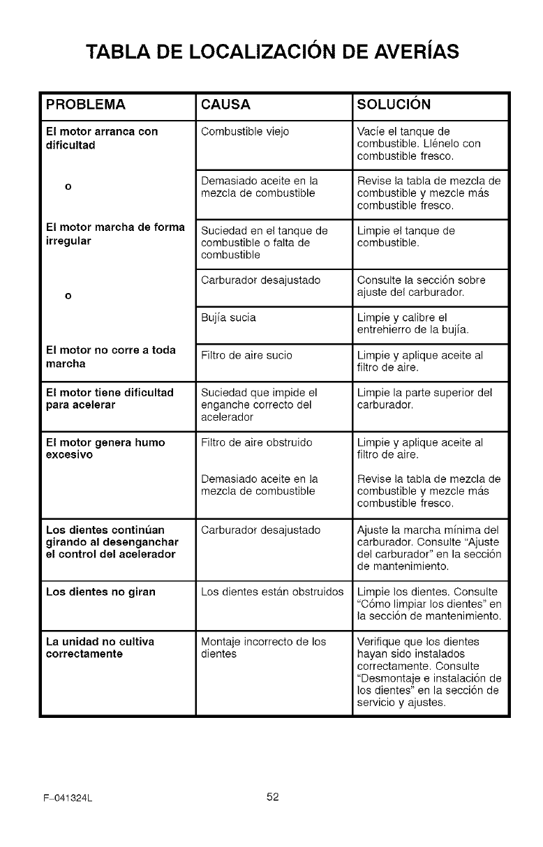
TABLA DE LOCALIZACION DE AVERiAS
PROBLEMA
El motor arranca con
dificultad
El motor marcha de forma
irregular
El motor no corre a toda
marcha
El motor tiene dificultad
para acelerar
El motor genera humo
excesivo
Los dientes contint_an
girando al desenganchar
el control del acelerador
Los dientes no giran
La unidad no cultiva
correctamente
CAUSA
Combustible viejo
Demasiado aceite en la
mezcla de combustible
Suciedad en el tanque de
combustible o falta de
combustible
Carburador desajustado Consulte la secci6n sobre
ajuste del carburador.
Bujia sucia Limpie y calibre el
entrehierro de la bujia.
Filtro de aire sucio Limpie y aplique aceite al
filtro de aire.
Suciedad que impide el
enganche correcto del
acelerador
Filtro de aire obstruido
Demasiado aceite en la
mezcla de combustible
Carburador desajustado
Los dientes est&n obstruidos
Montaje incorrecto de los
dientes
SOLUClON
Vacie el tanque de
combustible. Llenelo con
combustible fresco.
Revise la tabla de mezcla de
combustible y mezcle m&s
combustible fresco.
Limpie el tanque de
combustible.
Limpie la parte superior del
carburador.
Limpie y aplique aceite al
filtro de aire.
Revise la tabla de mezcla de
combustible y mezcle mAs
combustible fresco.
Ajuste la marcha minima del
carburador. Consulte "Ajuste
del carburador" en la secci6n
de mantenimiento.
Limpie los dientes. Consulte
"C6mo limpiar los dientes" en
la secci6n de mantenimiento.
Verifique que los dientes
hayan sido instalados
correctamente. Consulte
"Desmontaje e instalaci6n de
los dientes" en la secci6n de
servicio y ajustes.
F 041324L 52
SEARS, ROEBUCK AND CO.
Garantia limitada de cumplimiento con el Sistema Federal
de control de emisiones ycon el sistema de control de
emisiones del Estado de California
Motores pequeros para vehiculos todo terreno
CONTROL DE EMISIONES DE
CALIFORNIA Y DE LA AGENCIA DE
PROTECClON AMBIENTAL (EPA) DE
E.U.A.- DECLARACION DE LA
GARANTIA
La Agencia de Protecci6n Ambiental de los
Estados Unidos ("EPA"), el Consejo de Cali-
fornia para los Recursos del Aire ("OARB") y
Sears, Roebuck and Co. tienen el placer de
explicar Io que es la Garantia Federal y de Ca-
lifornia para Sistemas de Control de Emisio-
nes de su nuevo motor pequeflo para
vehiculos todo terreno. En California, los mo-
tores pequeflos para vehiculos todo terreno
de modelo 1995 y modelos de aries posterio-
res deben set disefiados, construidos y equi-
pados para cumplir con las estrictas normas
anti contaminaci6n del Estado. En otros esta-
dos, los motores modelo 1997 y modelos de
aries posteriores deben estar disefiados,
construidos y equipados, al momento de su
venta, para que cumplan con las disposicio-
nes de la EPA acerca de motores pequeflos
para vehiculos todo terreno. Sears, Roebuck
and Co., garantizar& el sistema para el control
de emisiones de su motor pequeflo para vehf-
culos todo terreno por los periodos de tiempo
que se mencionan m&s adelante, siempre y
cuando su motor pequefio para vehiculos todo
terreno no haya sufrido algt_n abuso, negligen-
cia, modificaci6n no aprobada o mantenimien-
to indebido.
Su sistema para el control de emisiones puede
incluir partes como el carburador, el sistema
de encendido y el sistema de escape. Tambi6n
puede incluir el sistema de descompresi6n y
otras unidades relacionadas con las emisio-
nes.
Cuando surja una condici6n protegida per la
garantia, Sears, Roebuck and Co., reparar_t
su motor pequeflo para vehiculos todo terreno
sin costo alguno para usted per concepto de
diagn6stico, partes y mane de obra.
SISTEMA PARA EL CONTROL DE
EMISIONES DEL FABRICANTE-
COBERTURA DE LA GARANTIA
Los sistemas para el control de emisiones del
modelo 1995 y modelos de arcs posteriores
de motores pequeros para vehicu!os todo te-
rreno en California est&n garantizados pot dos
aries, tal y como se menciona en la presente
garantia. En otros estados, los motores mode-
Io 1997 y modelos de ares posteriores tam-
bien est&n garantizados per dos ares. En
case de que, durante dicho periodo de la ga-
rantia, cualquier pieza del motor, relacionada
con emisiones este defectuosa en sus mate-
riales o mane de obra, Sears, Roebuck and
Co., reparar& o cambiar& dicha pieza.
RESPONSABILIDADES DEL
PROPIETARIO DE LA GARANTiA
Oomo propietario del motor pequefio para ve-
hiculos todo terreno usted es responsable de
que se Ileve a cabo el mantenimiento requeri-
do que se menciona en el Manual del usuario,
pete Sears, Roebuck and Co., no negar& la
garantia Onicamente debido a la falta de un re-
cibo o a que usted no proporcione una prueba
escrita de que se ha Ilevado a cabo el manteni-
miento programado.
No obstante, usted, come propietario del mo-
tor pequeflo para vehiculos todo terreno, de-
bet& estar consciente de que Sears, Roebuck
and Co., le puede negar la cobertura de la ga-
rantfa si su motor o alguna parte del mismo ha
fallado debido a abuso, negligencia, manteni-
miento inadecuado o modificaciones no apro-
badas.
Usted es responsable de presentar su motor
pequefio para vehiculos todo terreno en el Ta-
ller de Servicio Autorizado de Sears, Roebuck
and Co., en cuanto surja el problema. Las re-
paraciones bajo la garanfia deben Ilevarse a
cabo dentro de un periodo de tiempo razona-
ble que no exceda de 30 dias.
Se puede programar el servicio de garantia
Ilamando al Taller de Servicio Autorizado de
F 041324L 53
Sears, Roebuck and Co., o a Sears, Roebuck
and Co., al 1 800 473 7247 (llamada gratui-
ta en E.U.A.).
NOTA IMPORTANTE
Esta declaraci6n de garantia explica los dere-
chos y las obligaciones que usted tiene de
conformidad con la Garantia del Sistema para
el Control de Emisiones ("Garantia SCE"), la
cual Sears, Roebuck and Co., le proporciona
de conformidad con las leyes de California.
Consulte tambien las Garantias Limitadas de
Sears, Roebuck and Co., que se adjuntan a la
Garantia SCE en una hoja aparte y que tam-
bien le proporciona Sears, Roebuck and Co.,
La Garantia SCE 0nicamente se aplica en el
sistema para el control de emisiones de su
motor nuevo. Hasta el punto en donde no haya
ning_Onconflicto en t6rminos entre la Garantia
SCE y la Garantia de Sears, Roebuck and Co.,
la Garanfia SCE aplicarA para cualquier cir-
cunstancia a excepci6n de aquella en que la
Garantia de Sears, Roebuck and Co., pueda
proporcionar un periodo de garantia mAs lar-
go. La Garantia SCE y la Garantia de Sears,
Roebuck and Co., describen importantes de-
rechos y obligaciones que usted tiene con res-
pecto a su motor nuevo.
S61o se puede Ilevar a cabo el servicio de ga-
rantia en un Taller de Servicio Autorizado de
Sears, Roebuck and Co. At momento de solici-
tar un servicio de garantia, se debe presentar
una prueba de la fecha de compra per parte
del comprador original. El comprador pagara
cualquier cargo per concepto de Ilamadas de
servicio y/o transportaci6n de productos des-
de y para el lugar en donde se Ileve a cabo el
trabajo de inspecci6n y/o garantia. El compra-
dor sera responsable de cualquier dafio o p6r-
dida en el que se incurra con relaci6n a la
transportaci6n de cualquier motor o cualquier
parte del mismo que se presente para inspec-
ci6n y/o trabajo de garantia.
Si tiene alguna pregunta con relaci6n a sus de-
rechos y responsabilidades, debera Ilamar a
Sears, Roebuck and Co., al 1 800473 7247.
GARANTiA DEL SISTEMA PARA EL
CONTROL DE EMISIONES
Garantia del Sistema para el Control de Emi-
siones ("Garantia SOE") de motores peque-
ties para vehiculos todo terreno modelo 1995
y modelos de aries posteriores en California
(para otros estados, motores modelo 1997 y
aries posteriores):
F 041324L 54
A. CAMPO DE APLICACION: Esta garantia
deber_t aplicarse a los motores pequeflos para
vehfculos todo terreno modelo 1995 y mode-
los de afios posteriores en California (para
otros estados, motores modelo 1997 y mode-
los de aflos posteriores), El Periodo de la Ga-
rantia SCE se iniciarA en la fecha de entrega
del nuevo motor o equipo al comprador origi-
nal y continuara durante los siguientes 24 me-
ses consecutivos.
B. COBERTURA GENERAL DE LA GA-
RANTiA DEL SISTEMA PARA EL CON-
TROL DE EMISIONES: Sears, Roebuck and
Co. garantiza al comprador original del nuevo
motor o equipo y a cada comprador subse-
cuente que su motor pequeflo para vehiculos
todo terreno esta:
1. Diseflado, construido y equipado para que
cumpla con todas las disposiciones aplicables
adoptadas por el Consejo para los Recursos
del Aire de conformidad con su autoridad es-
pecificada en los Capitulos 1 y 2, Parte 5, Divi-
si6n 26 del C6digo de Salud y Seguridad, y
2. Libre de defectos en sus materiales y mane
de obra, Io cual cause en cualquier memento
durante el Periodo de la Garantia SCE, la falla
de una parte relacionada con emisiones y que
est6 bajo la garantia en cuanto a que no sea
identica en sus materiales a la parte descrita
en la solicitud de motor del fabricante para su
certificaci6n.
C. La Garantia SCE s61o atafle alas partes de
su motor relacionadas con emisiones de la si-
guiente manera:
1. Cualquier parte relacionada con emisiones
que no se especifique como de cambio, tal y
come se requiere en el mantenimiento especi-
ficado en el Manual del Propietario, deber_ ga-
rantizarse per el Periodo de la Garantia SCE.
Si dicha parte falla durante el Periodo de la Ga-
rantia SCE, Sears, Roebuck and Co. la repa-
rara o cambiarA de acuerdo con la Subsecci6n
4 que se menciona mas adelante. Cualquier
parte reparada o cambiada de conformidad
con la Garantfa SCE debera estar garantizada
per el resto del Periodo de la misma.
2. Cualquier parte garantizada y relacionada
con emisiones que este especificada s61o pa-
ra inspecciones regulares conforme al Manual
del Propietario debera estar garantizada per el
Periodo de la Garantia SCE. Una declaraci6n
en dichas instrucciones per escrito a efecto de
"reparar o cambiar tal y come sea necesario"
no reducira el Periodo de la Garantia SCE. Di-
cha parte reparada o cambiada conforme a la
GarantiaSOEdeberagarantizarseporelresto
delPeriododelamisma.
3.Oualquierpartegarantizadayrelacionada
conemisionesqueseespecifiqueparacam-
bio,deconformidadconelManualdelPropie-
tario,deberAgarantizarseporelperiodode
tiempoprevioalprimerpuntodecambiode
esaparte.Silapartefallaantesdelprimer
cambioprogramado,Sears,RoebuckandCo.
repararAocambiarAesaparedeacuerdocon
laSubsecci6n4quesemencionamAsadelan-
te.Cualquierparterelacionadaconemisiones
queserepareocambiedeconformidadconla
GarantiaSOEdeberaestargarantizadaperel
restodelPeriododelamismaprevioalprimer
puntodecambioprogramadodeesapartere-
lacionadaconemisiones.
4.Lareparaci6noelcambiodecualquierparte
garantizaday relacionadaconemisionesde
conformidadconestaGarantiaSCEsedebe-
rAIlevaracabo,sincargoalgunoparaelpro-
pietario,enunTallerAutorizadodeServiciode
Sears,RoebuckandCo.
5.Nosecargaraalpropietarioelcostoportra-
bajodediagn6stico,elcualIlevaaladetermi-
naci6ndequeunaparteprotegidaporla
GarantiaSOEsiestAdefectuosa,provistoque
dichotrabajodediagn6sticoseIleveacaboen
unTallerAutorizadodeServiciodeSears,
RoebuckandCo.
6.Sears,RoebuckandCo.seraresponsable
dedafiosaotroscomponentesoriginalesdel
motoromodificacionesaprobadasqueproba-
blementeseancausadosporunafallacom-
prendidaen la garantiade unaparte
relacionadaconemisionescubiertaporlaGa-
rantiaSOE.
7.DuranteelPeriododelaGarantiaSOE,
Sears,RoebuckandCo.deberaconservarun
suministrodepartesgarantizadasyrelaciona-
dasconemisionesqueseasuficientepara
cumplirlademandaesperadadeesaspartes
relacionadasconemisiones.
8.Sepuedeutilizarcualquierpartederepues-
to relacionadaconemisionesautorizaday
aprobadaporSears,RoebuckandOo.para
utilizarseeneldesempefiodecualquierman-
tenimientoocambiodelaGarantiaSOE,la
cualseproporcionarAsincargoalgunoparael
propietario.Dichousenoreduciralasobliga-
clonesdeSears,RoebuckandCo.conforme
alaGarantiaSCE.
9.Laspartesqueseagreguenomodifiquen
sinaprobaci6nnosepodrAnutilizarparamo-
dificarorepararunmotordeSears,Roebuck
andCo.DichouseanulaestaGarantiaSCEy
conformaralasbasessuficientespararecha-
zarlademandadeunaGarantiaSOE.Sears,
RoebuckandCo.noseraresponsable,con-
formeaestagarantia,perlasfallasdecual-
quierparegarantizadadeunmotordeSears,
RoebuckandCo.causadasporelusededi-
chaparteagregadaomodificadasinaproba-
ci6n.
LAS PARTES RELACIONADAS CON
EMISIONES INCLUYEN A LAS
SIGUIENTES"
1. Unidad del carburador y sus componentes
internes
a) Filtro de combustible
b) Empaques (juntas) del carburador
c) Tube de entrada
2. Unidad de filtro de aire
a) Elemento del filtro de aire
3. Sistema de encendido, que incluye:
a) Bujia de encendido
b) M6dulo de encendido
c) Ensamblaje del volante
4. Silenciador catalftico (siestA equipado)
a) Empaque del silenciador (si esta equipado)
b) Colector de escape (siestA equipado)
5. Ensamblaje del respiradero del carter del ci-
gOehal y sus componentes
a) Tubo de conexi6n del respiradero
10/22/99 EPA/CARB
Sears, Roebuck and Co., Hoffman Estates, IL 60179 U.S.A.
F 041324L 55

Your Home
For repair in your home of all major brand appliances,
lawn and garden equipment, or heating and cooling systems,
no matter who made it, no matter who sold it!
For the replacement parts, accessories and
owner s manuals that you need to do-it-yourself.
For Sears professional installation of home appliances
and items like garage door openers and water heaters.
1-800-4-MY-HOME fi Anytime, day or night
(1-800-469-4663) (U.S.A_ and Canada)
www.sears,com www.sears,ca
Our Home
For repair of carry-in products like vacuums, lawn equipment,
and electronics, call or go on-line for the nearest
Sears Parts and Repair Center.
1-800-488-1222 Anytime, day or night (U.S.A. only)
www.seats.com
To purchase a protection agreement on a product serviced by Sears:
1-800-827-6655 (U.S.A.) 1-800-361-6665 (Canada)
Para pedir servicio de reparaci n
a domicilio, y para ordenar piezas:
1-888_U-HOGAR sM
(1-888784-6427)
Au Canada pour service en fran ais:
1-800-LE-FOYER MC
(1@-533-6937)
www.sears,ca
' Sears, Roebuck and Co,
]M SM
fi Registered Trademark /Trademark /"_" Service Mark of Sears, Roebuck and Co.
TM SM
fi Marca Registrada /Marca de F/_rica /Marca de Servicio de Sears, Roebuck and Co_
MC MD
Marque de commerce /Marque dOposGe de Sears, Roebuck and Co.
