Craftsman 536773521 User Manual HIGHWHEEL WEEDTRIMMER Manuals And Guides L0104109
CRAFTSMAN Line Trimmers/Weedwackers, Gas Manual L0104109 CRAFTSMAN Line Trimmers/Weedwackers, Gas Owner's Manual, CRAFTSMAN Line Trimmers/Weedwackers, Gas installation guides
User Manual: Craftsman 536773521 536773521 CRAFTSMAN HIGHWHEEL WEEDTRIMMER - Manuals and Guides View the owners manual for your CRAFTSMAN HIGHWHEEL WEEDTRIMMER #536773521. Home:Lawn & Garden Parts:Craftsman Parts:536773521 Craftsman Grass trimmer (weed wacker) Manual
Open the PDF directly: View PDF ![]() .
.
Page Count: 38
m
6.5 Horsepower
MODEL NO.
536.773521
KEY START i
HIGHWHEEL WEEDTRIMMER
Caution:
Read and follow all Safety Rules
and Operating Instructions before
first use of this product,
SEARS,F_0O0211MROEBUCKAND CO., Hoffman Estates, IL 60179 U.S.A.. I
TABLE OF CONTENTS
WARRANTY STATEMENT ...... 2
SAFETY RULES ............... 3
INTERNATIONAL SYMBOLS .... 5
ASSEMBLY ................... 6
OPERATION .................. 9
MAINTENANCE ............... 13
SERVICE AND ADJUSTMENT.,, 16
TROUBLE SHOOTING CHART .. 21
SLOPE GUIDE ................. 23
REPAIR PARTS ................ 24
ENGINE REPAIR PARTS ........ 29
SPANISH (ESPA_IOL) .......... 38
PARTS ORDERING/SERVICE ... 64
WARRANTY STATEMENT
LIMITED TWO-YEAR WARRANTY ON CRAFTSMAN WEEDTRIMMER
For two yearn from the date of purchsse, when this Craftsman Weedtdmmer is maintained,
lubricated, and tuned up according to the operating and maintenance instructions in the
owner's manuat, Sears will repair, free of charge, any defect in matadal or workmanship.
If this Craftsman Weedtrimmer is used for commercial or rental purposes, this warranty ap-
plies for onty 90 days from the date of pumhase.
This warranty does not cover the following:
Expendableitems whichbecomewornduringnormaluse, such as sparkplugs,etc.
Repairnecessarybecauseofoperatorabuseornegligence,includingbentcrankshafts
and thefailure to maintainthe equipmentaccordingto the instructionscontainedinthe
owner'smanual.
WARRANTY SERVICE IS AVAILABLE BY RETURNING THE CRAFTSMAN WEED-
TRIMMER TO THE NEAREST SEARS SERVICE CENTER/DEPARTMENT IN THE
UNITED STATES.THIS WARRANTY APPUES ONLYWHILE THIS PRODUCTIS IN USE
IN THE UNITED STATES.
This warranty givesyouspecificlegaltights,andyoumay alsohaveotherfights which may
vary from state to state.
Sears, Roebuckand Co., D817WA, HoffmanEstates.IL 60179
IMPORTANT: This unit is equipped with an internal combustion engine and must not be
used on or near any unimproved forest-covered, brush-covered or grass-covered land
unless the engine's exhaust system is equipped with a spark arreeter meeting
applicable local or state laws (if any). If a spark arreatar is used, it must be maintained in
effective working order by the operator.
In the State of California the above is required by law (Section 4442 of the California
Public Resources Code). Other states may have similar laws. Federal laws apply on fed-
eral lands. See an Authorized Service Center for a spark arrester for the muffler.
F-O(]O211M 2
A
SAFETY RULES
Safe Operation Practices for Trimmer.
WARNING: Lookfor this symbol to point out importantsafety precautions.
It means: "Attention! Become Alertl Your Safety Is Involved,"
I. General Operation
1. Read, understand, and follow all instruc-
tions on the machine and in the manual(s).
Be thoroughly familiar with the contmle and
the proper use of the tdmmer before start-
ing.
2. Familiarize yourself with all of the safety
and operating decals on this equipment
and on any of its attachments or accesao-
rigs.
3. Do not put hands or feet near or under mtst-
ing parts.
4. Only allow responsible individuals, who are
familiar with the instructions,to operate the
trimmer.
5. Inspect the area where the tdmmer is to be
used. Your equipment can propel small ob-
jects at high speed causing personal injury
or property damage. Stay away from
breakable objects, such as house win-
dows, auto glass, greenhouses, etc.
6. Keep the area of operation clear of all per-
sons, perticolady small children, and pets.
7. Wear appropriate clothing such as a long-
sleeved shirt or jacket. ALsowear long trou-
sers or slacks. Do not wear shorts.
8. Do not wear loose clothing which could get
caught in this equipment.
9. Always wear safety goggles or safety
glasses with side shields when operating
tdmmer to protect your eyes from foreign
objects which can be thrown from the unit.
10. Always wear work gloves and sturdy feet-
wear. Leather work shoes or short boots
work well for moat people. These will pro-
tact the operator's ankles and shins from
small sticks, splinters, and other debds,
and improve traction.
11. It is advisable to wear protective headgear
to prevent the possibility of being struck by
small flying pertJcles, or being struck by low
hanging branches, twigs, or other objects
which may be unnoticed by the operator.
12. Do not operate the trimmer without proper
guards or other safety protective devices
in place.
13. Use this equipment for its intended pur-
pose only.
14. See manufacturer's instructions for proper
operation and instatiation of accessories.
F-OOO211M
Only usa accessories approved by the
manufacturer.
15. Operate only in daylight or good artificial
light.
16. Do not operate the trimmer while under the
influence of alcohol, drugs or other medica-
tion which can cause drowsiness or affect
your ability to operate this machine safely.
17. Never operate trimmer in wet grass. Al-
ways be sure of your footing; keep a firm
hold on the handle and walk; never run.
18. Before each use, inspect the throttle con-
trol lever and cable. Make sure that the
cable is free and that the lever is not dam-
aged. Also check the cable linkage running
to the carburetor for kinks, loose fittings,
and obstructions. Verify that the contra[
bail is working properly.
19. Stop the rotating trimmer bead when cross-
ing gravel ddves, walks, or roads. Wait for
the cutting lines to stop rotating.
20. Watch for traffic when operating near, or
when crossing roads.
21. Stop the engine (motor) whenever you
leave the equipment, before cleaning re-
pairing or inspecting the unit, be sure the
trimmer head and all moving parts have
stopped. Let the engine cool, disconnect
the spark plug wire and move it away from
the spark plug.
22. If the equipment should start to vibrate ab-
normally, stop the engine (motor), discon-
nect the spark plug wire and prevent it from
touching the spark plug. Check immediate-
ly for the cause. Vibration is generally a
warning of trouble.
23. After striking a foreign object, stop the en-
gine (motor). Remove the wire from the
spark plug. Inspect the tnmrner for dam-
age. If damaged, repair before starting and
operating the trimmer.
24. Never leave the trimmer unattended when
the engine is running. Remove the wire
from the spark plug.
25. Regutarly inspect the trimmer. Make sure
parts are not bent, damaged or loose.
li. Slope Operation
Slopes are a major factor related to slip and fail
accidents which can result in severe injury. All
SAFETY RULES
slopes require extra caution. If you feel uneasy
on e slope, do not trim it.
Dotdm across the face of slopes; never up end
down. Do not trim excessively steep slopes
(maximum 15 degrees) or areas where the
ground is very rough. See the "Guide" in the
back of this manual to check a slope. Exercise
extreme caution when changing direction on
slopes.
Do remove objects such as rocks, tree limbs,
etc.
Do watch for holes, ruts, or bumps. Ta]l grass
can hide obstacles.
Do nottrim near drep-offs, ditches, or embank-
mants. The operator could lose footing or bal-
ance.
Do nottrim excessively steep slopes.
Do not trim on wet grass. Reduced footing
could cause slipping.
III. Children
Tragic accidents can occur ifthe operator is not
alert to the presence of children. Children are
often attracted to the trimmer and the trimming
activity. Neverassume that children wilt remain
where you fast saw them.
1. Keap childran out of the tlimming area and
under the watchful care of a responsible
adult.
2. Be alert and turn trimmer off if children en-
ter the area.
3. Before and while moving backwards, look
behind and down for small children.
4. Never allow children to operate the trim-
me_
5. Use extra care when approaching blind
corners, shrube, trees, or other objects that
may obscure vision.
6. On electric start models, remove the igni-
tion key to prevent accidentst starting when
the trimmer is not is use.
IV. Service
1. Use extra care in handling gasoline and
other fuels. They are flammable and va-
pots are explosive.
a. Use only an approved container.
b. Never romove gas cap or add fuol with
the engine running. Allow engine to
cool before refueling. Do not smoke.
c. Never refuel the machine indoors.
d. Never store the machine or fuel con-
tainer inside where there is an open
flame, such as a water heater.
2. Never run an engine indoors or inside a
closed area.
3. Never make adjustments or repairs with
the engine (motor) running. D_sconnect the
spark plug wire, and keep the wire away
from the plug to prevent accidental starting
(remove the ignitionkey it equipped with an
electric start). Always wear eye protection
when you make adjustments or repairs.
4. Check the trimmer heed and engine
mounting bolts at frequent intervals for
proper tightness.
5. Keep all nuts and bolts tight and keep
equipment in good coediSon. Check
mounting hardware on thmmer head every
time you change trimmer line and plior to
each use.
6. Never tamper with safety devices. Check
their proper operation rngulady.
7. When servicing or repairing the trimmer, do
not tip the machine over or up unless ape-
cificelly instructed to do so in this Manual.
Service and repair procedures can be done
with the trimmer in an upright position.
Some procedures will be easier if the ma-
chine is lifted on a raised platform or work-
ing surface.
8. To reduce fire hazard, keep _mmer free of
grass, leaves, or other debris build-up.
Clean up oil or fuel spillage. Allow trimmer
to cool before storing.
9, Stop and inspect the equipment if you
strike an object. Repair, if necessary, be-
fore restarting.
10. Always disconnect spark plug wire before
cleaning, repainng, or adjusting.
11. Do not change the engine governor setting
or over-spasd the engine.
12. Clean and replace safety and instruction
decals as necessary.
13. To guard against engine over-hsating, al-
ways have engine debris filter mounted
and dean.
14. Inspect trimmer before storage.
15. Use only original equipment or authorized
replacement parts.
F_)OO211M 4

SAFETY RULES
INTERNATIONAL SYMBOLS
IMPORTANT:Many of the following symbols are located on your unit or on literature sup-
plied with the product. Before you operate the unit, learn and understand the purpose for
each symbol.
Slow Fast Fuel Oil
OOlO_ eOOGOOGOOO OOGO
WARNING
Thrown Objects.
Keep Bystanders Away.
WARNING
Rotating Parts. Stop Engine.
Disconnect Spark Wire Before
Making Adjustments.
A
WARNING
Q M
IMPORTANT WARNING
Read Owner's Manual Wear Eye Protection
Before Operating
This Machine.
STOP
@
WARNING
Never Operate Up Or
Down Slopes. Operate
Across Slopes.
F-(_:O211M 5
ASSEMBLY
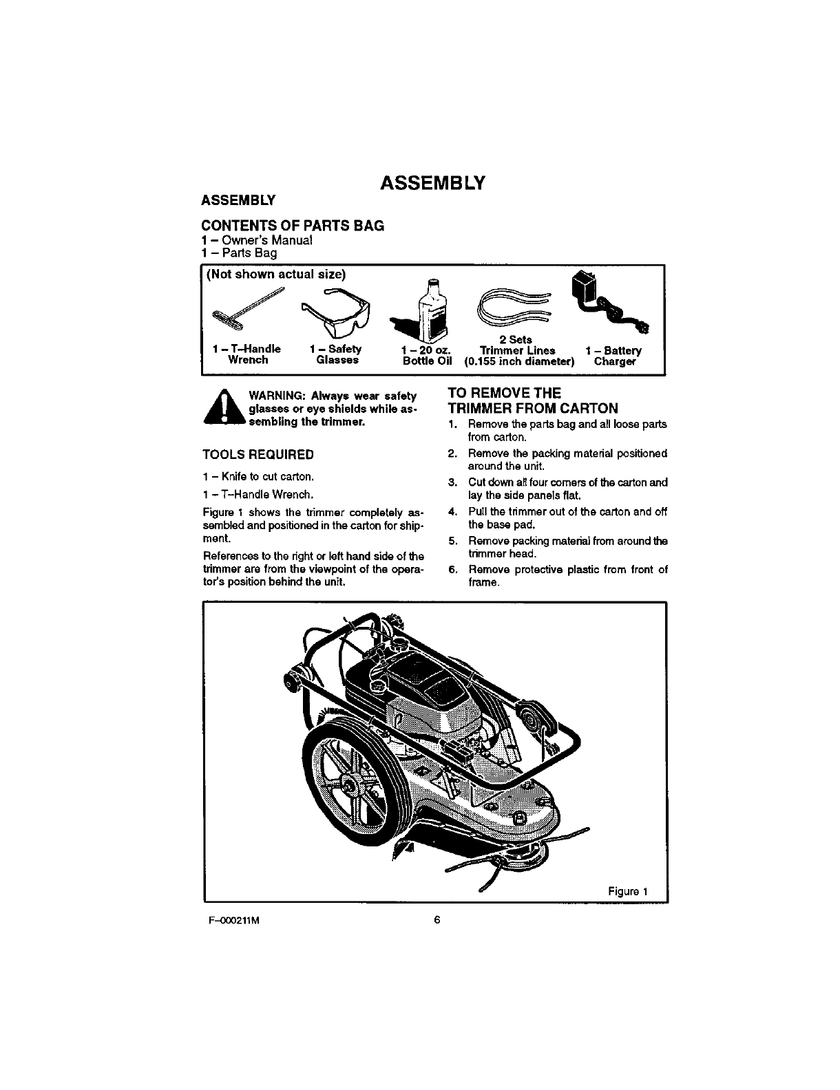
ASSEMBLY
CONTENTS OF PARTS BAG
1 Owner'sManual
- Parts Bag
Not shown actual size)
1 - T--Handle 1 - Safety 1- 20 oz.
Wrench Glasses Bottle Oil
2 Sets
Trimmer Lines 1 - Battery
(0.155 inch diameter) Charger
WARNING: Always wear safety
glasses or eye shields while as-
sembling the trimmer.
TOOLS REQUIRED
1 - Knife to cut carton.
1 - T-Handle Wrench.
Figure 1 shows the trimmer completely as-
sembled and positioned in the carton for ship*
ment.
References to the fight or left hand side of the
trimmer are from the viewpoint of the opera-
tor's position behind the unit.
TO REMOVE THE
TRIMMER FROM CARTON
1. Remove the parts bag and all loose parts
from carton.
2. Remove the packing material positioned
around the unit.
3. Cut down anfour comers of the carton and
lay the side panels flat.
4. Pull the trimmer out of the carton and off
the base pad.
5. Remove packing material from around the
trimmer head.
6. Remove protective plastic from front of
frame.
Figure 1
F-OOO211M 6
ASSEMBLY
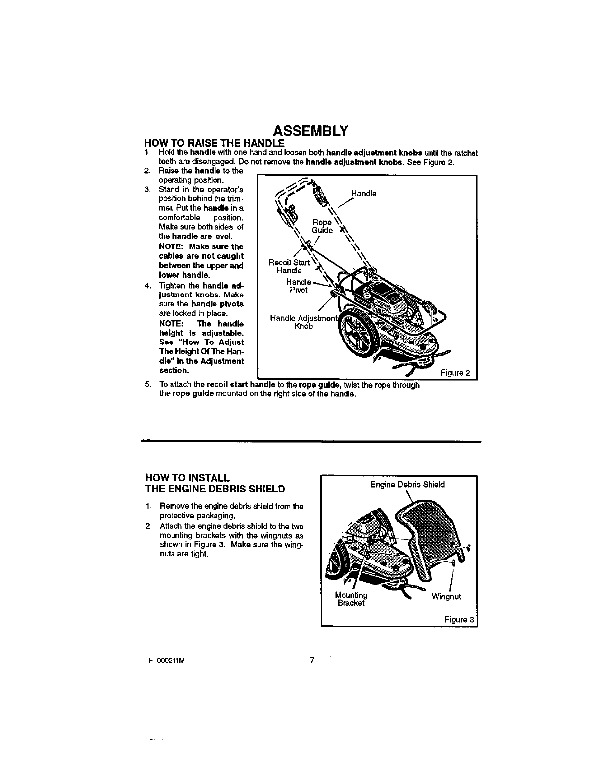
HOW TO RAISE THE HANDLE
t. Hold the handle with one hasd asd loosen both handle adjustment knobs untUthe ratchet
teeth are disengaged. Do not remove the handle adjustment knobs. See Figure 2.
2. Raise the handle to the
operating position.
3. Stand in the operator's
position behind the trim-
mer. Put the handle in a
comfortable position.
Make sure both sides of
the handle are level.
NOTE: Make sure the
cables are not caught
between the upper and
lower handle.
4. Tighten the handle ad-
justment knobs. Make
sure the handle pivots
are locked in place.
NOTE: The handle
height is adjustable.
See "How To Adjust
The Height Of The Han-
dle" in the Adjustment
section.
Handle
Rope \\
Guide
/\\\\ \\
Recoil
Handle
Pivot
5. To attach the recoil start handle to the rope guide, twist the rope through
the rope guide mounted on the right side of the handle.
Figure 2
HOW TO INSTALL
THE ENGINE DEBRIS SHIELD
1. Remove the engine debris shield from the
proteclJve packaging.
2. Attach the engine debris shield to the two
mounting brackets with the wingnuts as
shown in Figure 3. Make sure the wing°
nuts are tight.
Mounting
Bracket
Figure
F-O(X)211M
ASSEMBLY
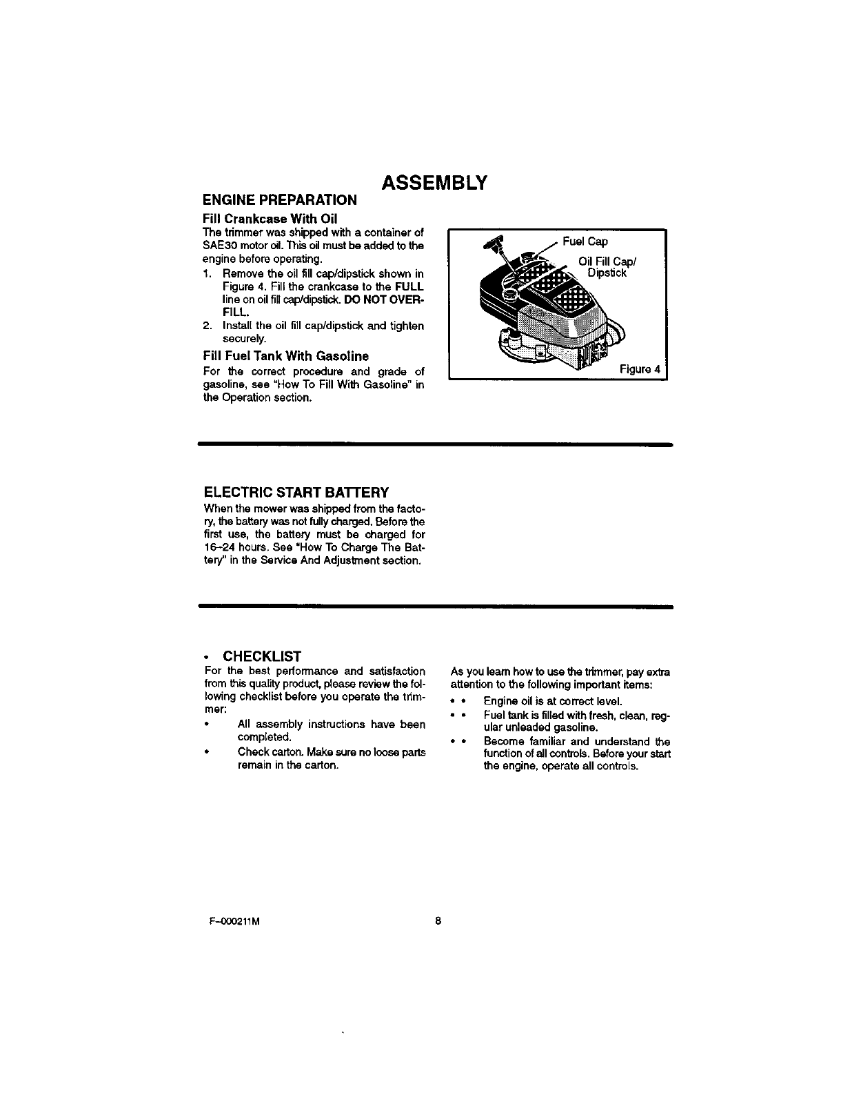
ENGINE PREPARATION
Fill Crankcase With Oil
The trimmer was shipped with a container of
SAE30 motor oil.This oil must be added to the
engine before operating.
1. Remove the oil fin cap/dipstick shown in
Figure 4. Fill the crankcase to the FULL
line on oil fillcap/dipstick. DO NOT OVER-
FILL.
2. Install the oil till cap/dipstick and tighten
securely.
Fill Fuel Tank With Gasoline
For the correct procedure and grade of
gasoline, see "How To Fill With Gasoline" in
the Operation section.
Cap
Oil Fill Cap/
Dipstick
Figure 4
ELECTRIC START BA'n'ERY
When the mower was shipped from the facto-
ry, the battery was notfully charged. Before the
first use, the battery must be charged for
16-24 hours. Bee "How To Charge The Bat-
tery" in the Service And Adjustment section.
•CHECKLIST
For the best performance and satisfaction
from this quality product, please review the fol-
lowing checklist before you operate the tnm-
mer:
All assembly instructions have been
completed.
Check carton. Make sure no looseparts
remain in the carton.
As you learn how to use the trimmer, pay extra
attention to the following important items:
••Engine oil is at correct level.
••Fuel tank is tilled with fresh, clean, reg-
ular unleaded gasoline.
••Become familiar and understand the
function of all controls. Before your start
the engine, operate all controls.
F-OOO211M 8
OPERATION
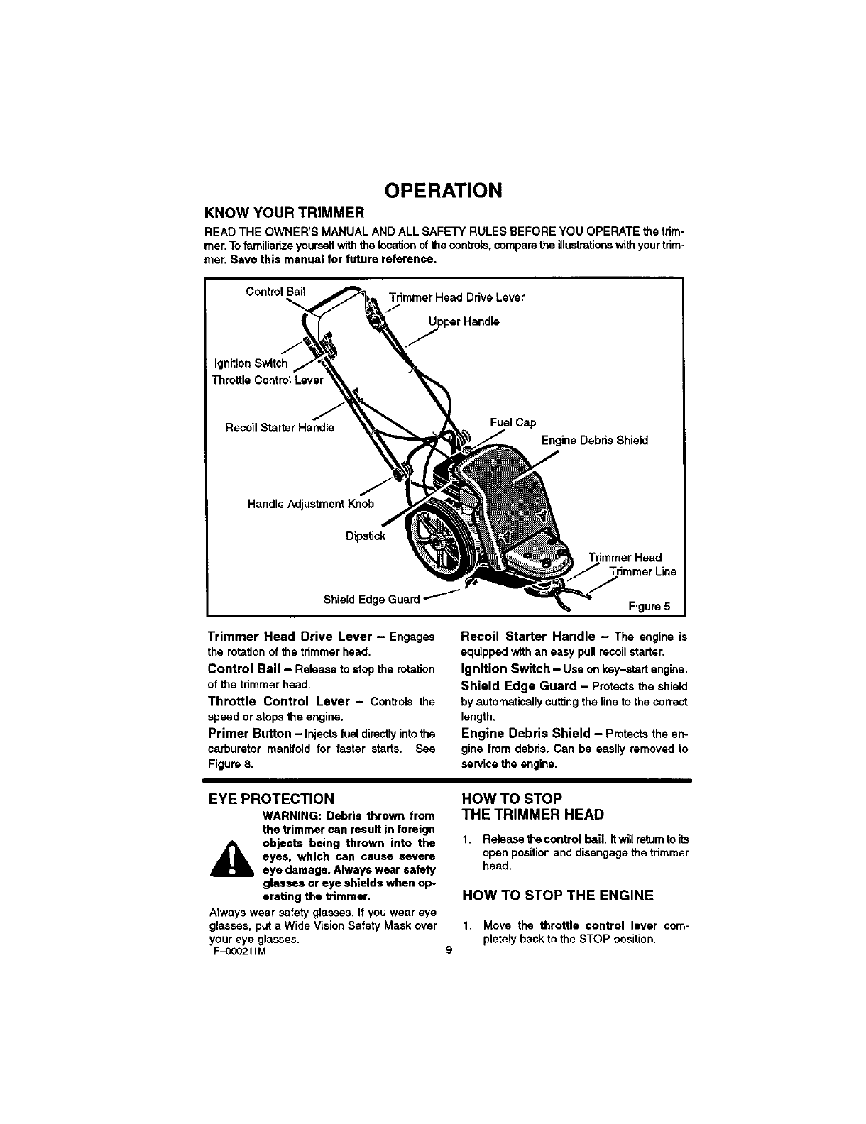
KNOW YOUR TRIMMER
READ THE OWNER'S MANUAL AND ALL SAFETY RULES BEFORE YOU OPERATE the trim-
mer. To familianze yourself with the location of the controls, compare the illustrationswith your trim-
mer. Save this manual for future reference.
Control Bail Tdmmer Head Drive Lever
/1
Ignition Switch
Throttle Control Lever
Recoil StarterHandle Fuel Cap
Engine Debris Shield
J
Handle Adjustment Knob
Dipstick
Trimmer Head
Shield Edge Figure 5
Trimmer Head Drive Lever - Engages
the rotation of the trimmer head.
Control Bail - Release to stop the rotation
of the trimmer head.
Throttle Control Lever - Controls the
speed or stops the engine.
Primer Button - Injects fuel directly into the
carburetor manifold for faster starts. See
Figure 8,
Recoil Starter Handle - The engine is
equippedwithan easy pullrecoilstarter.
Ignition Switch - Use on key-startengine.
Shield Edge Guard - Protectsthe shield
by automaticallycuttingthe lineto the correct
length,
Engine Debris Shield - Protectsthe en-
gine from debns.Can be easily removedto
sen/icetheengine.
EYE PROTECTION
WARNING: Debris thrown from
the trimmer can result in foreign
objects being thrown into the
eyes, which can cause severe
eye damage. Always wear safety
glasses or eye shields when op
erating the tHmmer,
Always wear safety glasses. If you wear eye
glasses, put a Wide Vision Safety Mask over
your eye glasses.
F-OOO211M
HOW TO STOP
THE TRIMMER HEAD
1. Release the control bail, Itwill re_um to its
open position and disengage the trimmer
head,
HOW TO STOP THE ENGINE
1. Move the throttle control lever com-
pletely back to the STOP position,
9
OPERATION
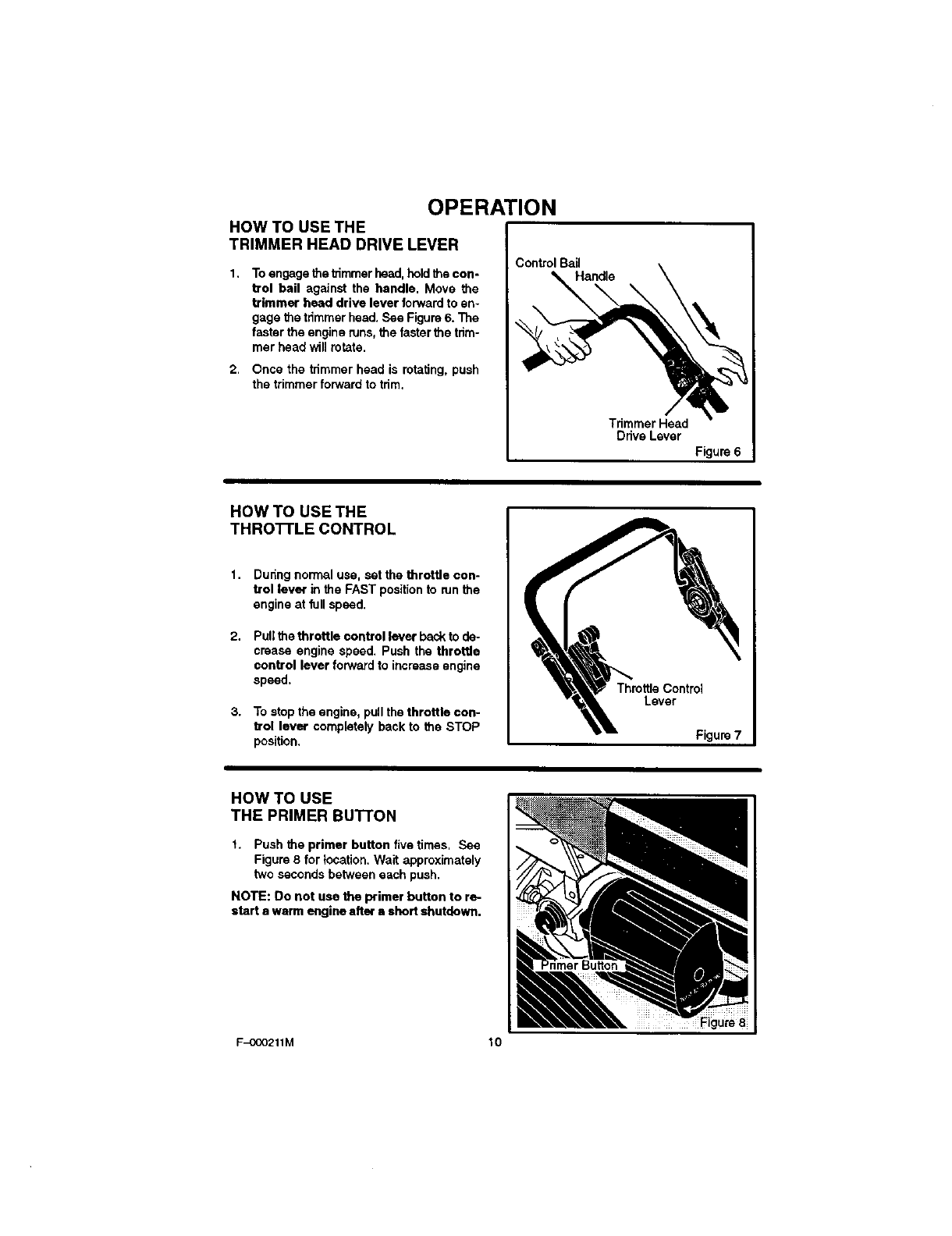
HOW TO USE THE
TRIMMER HEAD DRIVE LEVER
1, To engage the trimmer head, hold the con-
trol bail against the handle. Move the
trimmer heed drive lever forward to en-
gage the trimmer head. See Figure 6. The
faster the engine runs, the faster the trim-
mar head will rotate.
2. Once the tdmmer head is rotating, push
the trimmer forward to trim.
Control Bail
Handle
Trimmer Head
Drive Lever
Figure 6
!
HOW TO USE THE
THRO'I-rLE CONTROL
1. Duting normal use, set the throttle con-
trol lever in the FAST position to run the
engine at full speed.
2. Pull the throttle control lever back to de-
crease engine speed. Push the throttle
control lever forward to increase engine
speed.
3. To stop the engine, pull the throttle con-
trol lever completely back to the STOP
position,
ThrottleControl
Lever
Figure 7
HOW TO USE
THE PRIMER BUTTON
1. Push the primer button five times, See
Figure 8 for location. Wait approximately
two seconds between each push.
NOTE: Do not use the primer button to re-
start e warmengine after a shortshutdown.
F_OO211M 10
OPERATION
BEFORE STARTING THE ENGINE
Oil Recommendation
Only usehighqualitydetergentoil ratedwith
API serviceclassification SG. Selectthe oil's
SAE viscositygrade according to your ex-
pectedoperatingtemperature:
32.F
Colder _,_ _ _ B _ _,_ Warmer
I ;,E--; I
NOTE: Although multi-viscosity oils
(5W30, 10W30, etc.) improve starting in
cold weather, these multi-viscosity oils
will result in increased oil consumption
when used above 32-F. To avoid possible
engine damage from running low on oil,
frequently check your engine oil level.
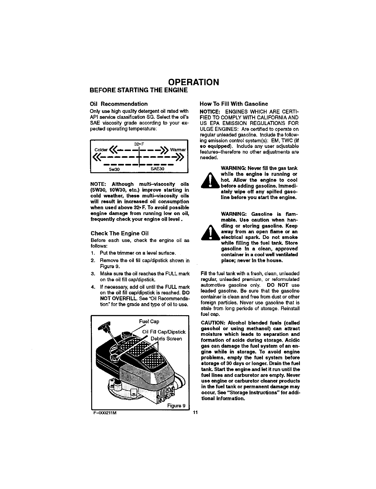
Check The Engine Oil
Before each use, check the engine oil as
follows:
1. Putthe trimmeron a level surface.
2. Remove the oil fillcap/dipstickshownin
Figure9.
3. Makesuretheoil reachestheFULLmark
onthe oil fill cap/dipstick.
4. If necessary,add oil untiltheFULL mark
onthe oil fill cap/dipstickis reached.DO
NOT OVERFILL. See 'Oil Recommenda-
tion"for thegrade and typeof oilto use.
FuelCap
Debds Screen
How To Fill With Gasoline
NOTICE: ENGINES WHICH ARE CERTI-
FIED TO COMPLY WITH CALIFORNIA AND
US EPA EMISSION REGULATIONS FOR
ULGE ENGINES: Are certified to operate on
regular unleaded gasoline. Include the follow-
ing emission control system(s): EM, TWC (if
=o equipped). Include any user adjustable
features-therefore no other adjustments are
needed.
WARNING: Never fill the gas tank
while the engine is running or
hoL Allow the engine to cool
before adding gasoline. Immedi-
ately wipe off any spilled gaso-
line before you start the engine.
WARNING: Gasoline is flam-
mable. Use caution when han-
dling or storing gasoline. Keep
away from an open flame or an
electrical spark. Do not smoke
while filling the fuel tank. Store
gasoline In a clean, approved
container in a cool well ventilated
place; never In the house.
Fill the fuel tank with afresh, clean, unleaded
regular, unleaded premium, or reformulated
automotive gasoline only. DO NOT use
leaded gasoline. Be sure that the gasoline
container is clean and free from dust or other
foreign particles. Never use gasoline that is
stale from long periods of storage. Reinstall
fuel cap.
CAUTION: Alcohol blended fuels (called
gesohol or using methanol) can attract
moisture which leads to separation and
formation of acids during storage. Acidic
gas can damage the fuel system of an en-
gine while in storage. To avoid engine
problems, empty the fuel system before
storage of 30 days or longer. Drain the fuel
tank. Start the engine and let it run until the
fuel lines and carburetor are empty. Never
use engine or carburetor cleaner products
in the fuel tank or permanent damage may
occur. See "Storage Instructions" for addi-
tional information.
Figure 9
F-OOO211M 11
OPERATION
HOW TO START THE ENGINE
NOTE: DONOT BE ALARMED, your engine
will smoke the first time it is started. It is
burning offthe protectivecoating that is on
the internal engine parts.
A ARNING: Never leave the trim-
mar unattended whil the engine
is runngin. Wait for the trimmer
lines to atop rotation.
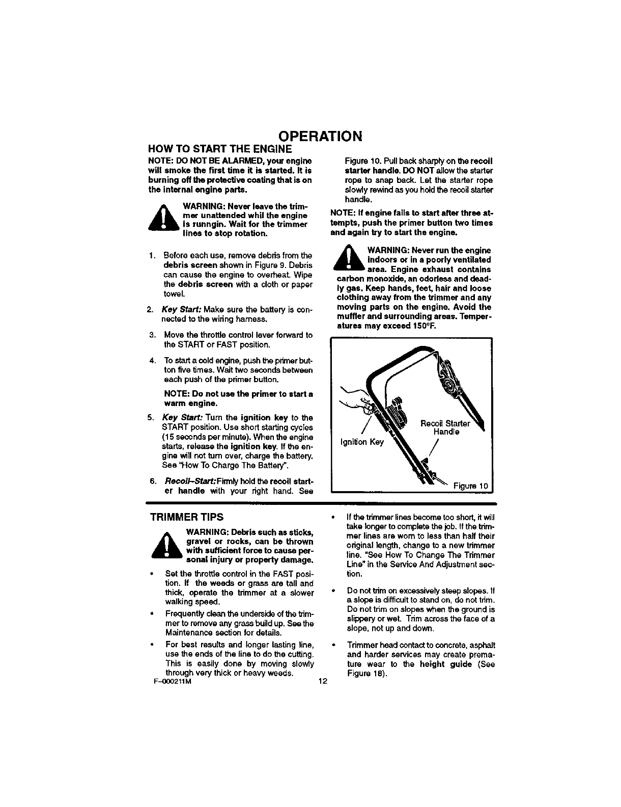
Figure10. Pullbacksharplyon therecoil
starter handle. DO NOTallowthestarter
rope to snap back. Let the starter rope
slowlyrewindasyouholdthe recoilstarter
handle.
NOTE: If engine fails to start after three at-
tempts, push the primer button two times
and again try to start the engine.
1. Before each use, remove debris from the
debris screen shown in Figure 9. Debris
can cause the engine to overheat. Wipe
the debris screen with a cloth or paper
towel.
2. Key Start: Make sure the battery is con-
nected to the wiring harness.
3. Move thethrottlecontrollever forward to
theSTART or FAST position,
4. To start a cold engine, push the prbnerbut-
ton five times. Wait two seconds between
each push of the primer button.
NOTE: Do not use the primer to start a
warm engine.
5. Key Start: Turn the ignition key to the
START position. Use short starting cycles
(15 seconds per minute). When the engine
starts, release the ignition key, If the en-
gine will not turn over, charge the battery,
See "How To Charge The Battery".
6. RecoiI-Start:FitTnlyholdtherecoil start-
er handle with your right hand. See
A WARNING: Never run the engine
indoors or in a poorly ventilated
area. Engine exhaust contains
carbon monoxide, an odorless and dead-
ly gas. Keep hands, feat, hair and loose
clothing away from the trimmer and any
moving parts on the engine. Avoid the
muffler and surrounding areas. Temper-
aturas may exceed 150°F.
IgniSon Key /
Figure 10
TRIMMER TIPS
A WARNING: Debris such as sticks,
gravel or rocks, can be thrown
with sufficient force to cause per-
sonel injury or property damage,
Set the throttle control in the FAST posi-
tion. If the weeds or grass are tall and
thick, operate the trimmer at a slower
walking speed.
Frequently clean the undemide of the trim-
mer to remove any grass build up. See the
Maintenance section for details,
For best rasults and longer lasting line,
use the ends of the line to do the cutting.
This is easily done by moving slowly
through very thick or heavy weeds.
F_)OO211M 12
If the trimmer lines become too short, itwill
take longer to complete the job. If the trim-
mar lines are worn to less than half their
original length, change to a new trimmer
line. "See How To Change The Trimmer
Line" in the Service And Adjustment sec-
tion.
Do not trim on excessively steep slopes, tf
aslope is difficult to stand on, do not tnm.
Do not trim on slopes when the ground is
slippery or wet. Trim across the face of a
slope, not up and down.
Trimmer head contact to concrete, asphalt
and harder services may create prema-
ture wear to the height guide (See
Figure tS).
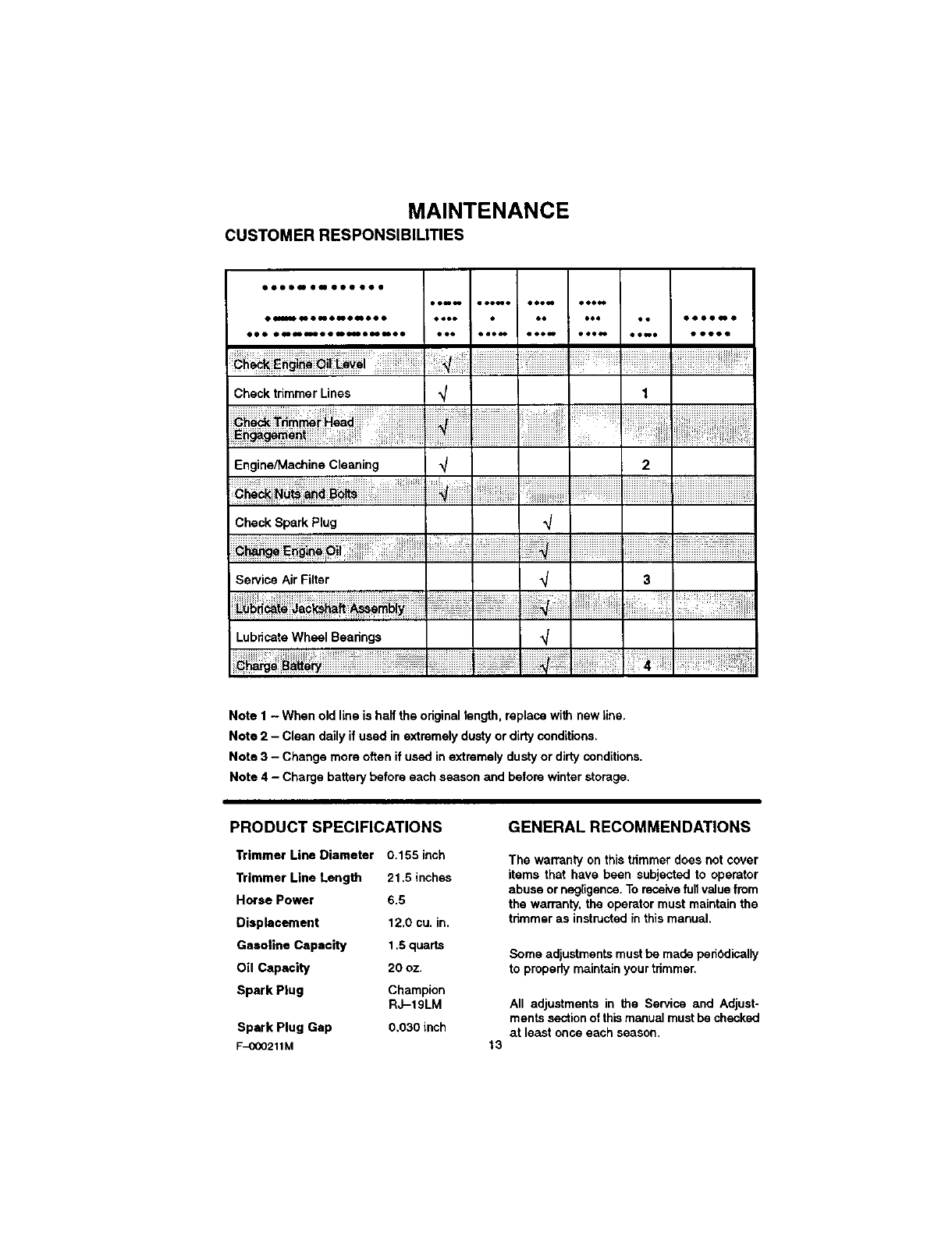
MAINTENANCE
CUSTOMER RESPONSIBILITIES
oooo_o_mooooeo
eom_ eooMo oooN oeeeo
OUmONO_O_mOO • eOOO eO eee
eee o qlll__ _ • • _ _ • Ill4' _ • • eee =oe_ eeew eee_
Check trimmer Lines
Engine/Machine Cleaning
eo oooo_o
ee_e ooooo
2
Check Spark Plug ,y
Service Air Filter
Lubricate Wheel Bearings _/
Note 1 - When old line is half the original length, replace with new line.
Note 2 - Clean daily if used in extremely dusty or dirty conditions.
Note 3 - Change more often if used in extremely dusty or dirty conditions.
Note 4 - Charge battery before each season and before winter storage.
PRODUCT SPECIFICATIONS
Trimmer Line Diameter 0.155 inch
Trimmer Line Length 21,5 inches
Horse Power 6.5
Displacement 12,0 cu. in.
Gasoline Capacity 1.5 quarts
Oil Capacity 20 oz.
Spark Plug Champion
RJ-19LM
Spark Plug Gap 0,030 inch
F_000211M
GENERAL RECOMMENDATIONS
The warranty on this trimmer does not cover
items that have been subjected to operator
abuse or negligence. To receive full value from
the warranty, the operator must maintain the
trimmer as instructed in this manual.
Some adjustments must be made periodically
to properly maintain your trimmer.
13
All adjustments in the Service and Adjust-
ments section of this manual must be checked
at least once each season.
LUBRICATION MAINTENANCE
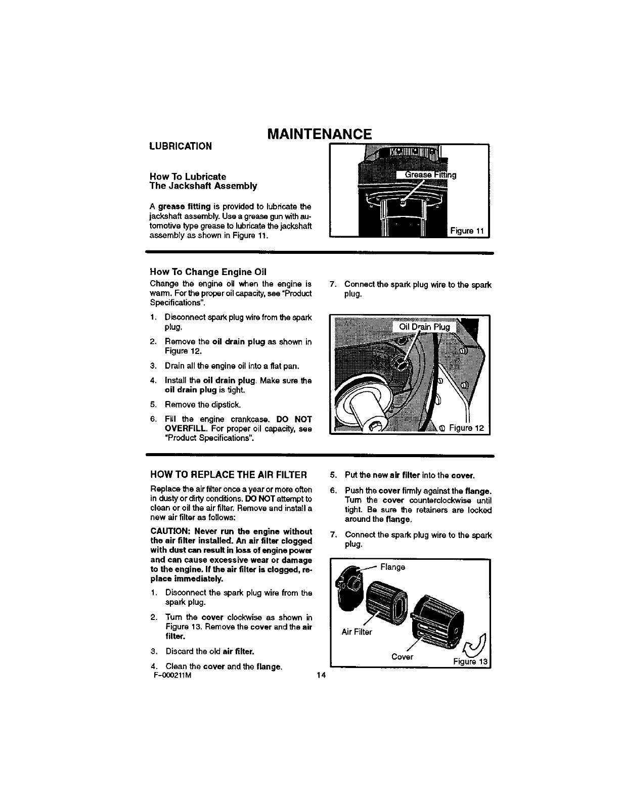
How To Lubricate
The Jackshaft Assembly
A grease fitting is provided to lubricate the
jaskehaft assembly. Use a grease gun with au-
tomotive type grease to lubricate the jackshaft
assembly as shown in Figure 11.
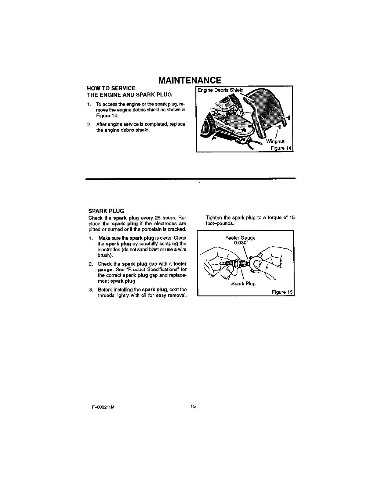
How To Change Engine Oil
Change the engine oil when the engine is
wam'l.Forthe properoilcapacity,see =Product
Specifications".
1. Disocnnect spark plug wirefrom the spark
plug.
2. Remove the oil drain plug as shown in
Figure 12.
3. Drain all theengine oilintoa fiatpan.
4. Install the oil drain plug. Make sure the
oil drain plug is tight.
5. Remove the dipstick.
6. Fill the engine crankcase. DO NOT
OVERFILL. For properoil capacity,see
"Product Specifications".
7. Connect the spark plug wire to the spark
plug.
Oil Drain
_,_ Figure 12
HOW TO REPLACE THE AIR FILTER
Replace the air filter once a year or more often
in dusty or dirty conditions. DO NOT attempt to
clean or oil the air filter. Remove and install a
new air filter as follows:
CAUTION: Never run the engine without
the air fitter installed. An air filter clogged
with dustcan result inloss of enginepower
and can cause excessive wear or damage
to the engine. If the air filter is clogged, re-
place immediately.
1, Disconnect the spark plug wire from the
spark plug.
2. Turn the cover clockwise as shown in
Figure 13. Remove the cover and the air
filter.
3. Discard the old air filter.
4. Clean the cover and the flange.
F-OOO211M 14
5. Putthe newair filter intothe cover.
6. Push the cover firmly against the flange.
Turn the cover counterclockwise until
tight. Be sure the retainers are locked
around the flange.
7. Connect the spark plug wire to the spark
plug.
Air Filter
Cover J
Figure 13
MAINTENANCE
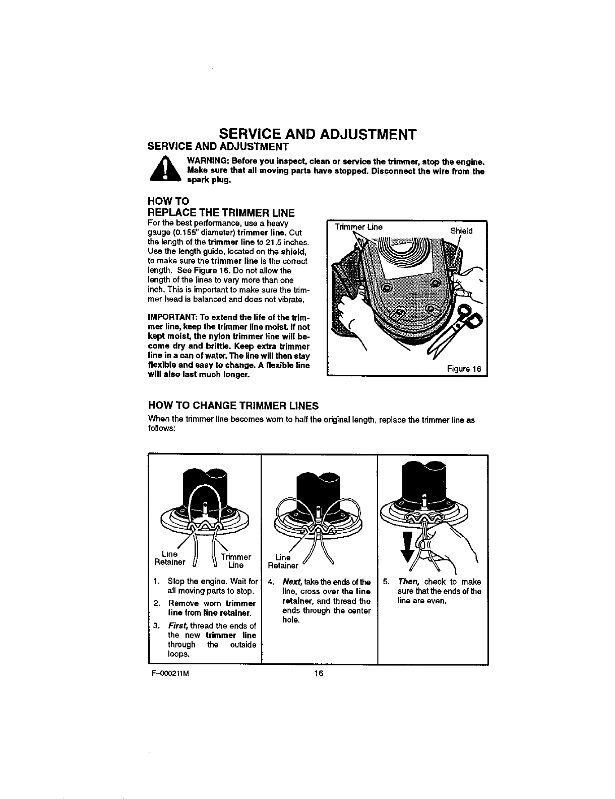
HOW TO SERVICE
THE ENGINE AND SPARK PLUG
1. To acsess the engine or the spark plug, re-
move the engine debds shield as shown in
Figure 14.
2. After engine service is completed, replace
the engine debris shield.
EngineDebrisShield
Wingnut
Figure14
SPARK PLUG
Check the spark plug every 25 hours. Re-
place the spark plug if the electrodesare
pittedorburnedor ifthe porcelainis cracked,
1. Makesurethe spark plug is clean,Clean
the spark plug by carefullyscrapingthe
electrodes(donotsandblastoruseawire
brush),
2. Check the spark plug gap with afeeler
gauge. See "Product Specifications" for
the correct spark plug gap and replace-
ment spark plug.
3. Before installing the spark plug, coat the
threads lightly with oil for easy removal.
Tightenthe spark plugto a torque of 15
fcot-pounds.
Feeler Gauge
0.030"
Spark Plug
Figure 1
F_)00211M 15
SERVICE AND ADJUSTMENT
SERVICE AND ADJUSTMENT
_IL WARNING: Before you inspect, clean or service the trimmer, stop the engine.
Make sure that all moving parts have stopped. Disconnect the wire from the
spark plug.
HOW TO
REPLACE THE TRIMMER LINE
For the best performance, use aheavy
gauge (0.155" diameter) trimmer line. Cut
the length of the trimmer line to 21.5 inches.
Use the length guide, located on the shield,
to make sure the trimmer line is the correct
length. See Figure 16. Do not allow the
length of the lines to vary more than one
inch. This is important to make sure the trim-
mer head is balanced and does not vibrate.
IMPORTANT: To extend the life of the trim-
mar line, keep the trimmer line moisL If not
kept moist, the nylon trimmer line will be-
come dry and brittle. Keep extra trimmer
line in a can of water. The line will then stay
flexible and easy to change. A flexible line
will also last much longer.
Tdmmer Line Shield
Figure 16
HOW TO CHANGE TRIMMER LINES
When the tdmmer line becomes worn to half the original length, replace the tdmmar line as
follows:
Line Trimmer
Retainer Line
1. Step the engine. Wait for
all moving parts to stop.
2. Remove worn trimmer
line from line retainer.
3. First, thread the ands of
the new trimmer line
through the outside
loops.
Line
Retainer
4. Next, take the ends of the
line, cross over the line
retainer, and thread the
ends through the center
hole.
I((
5. Then, check to make
surethatthe ends ofthe
lineare even.
F-C_0211M 16
SERVICE AND ADJUSTMENT
HOW TO ADJUST
THE HEIGHT OF THE HANDLE
Use the knobs, on each side of the handle, to
adjust the height of the handle.
1. Hold the handle withone hand and loosen
both knobs until the ratchet teeth are dis-
engaged. Do not remove the knobs. See
Figure 17.
2. Move the handle up or down to the de-
sired position, then align the ratchet
teeth. Make sure both sides of thehandle
are level.
3. Tighten the knobs.
Handle
Ratchet
Knob
Figure 17
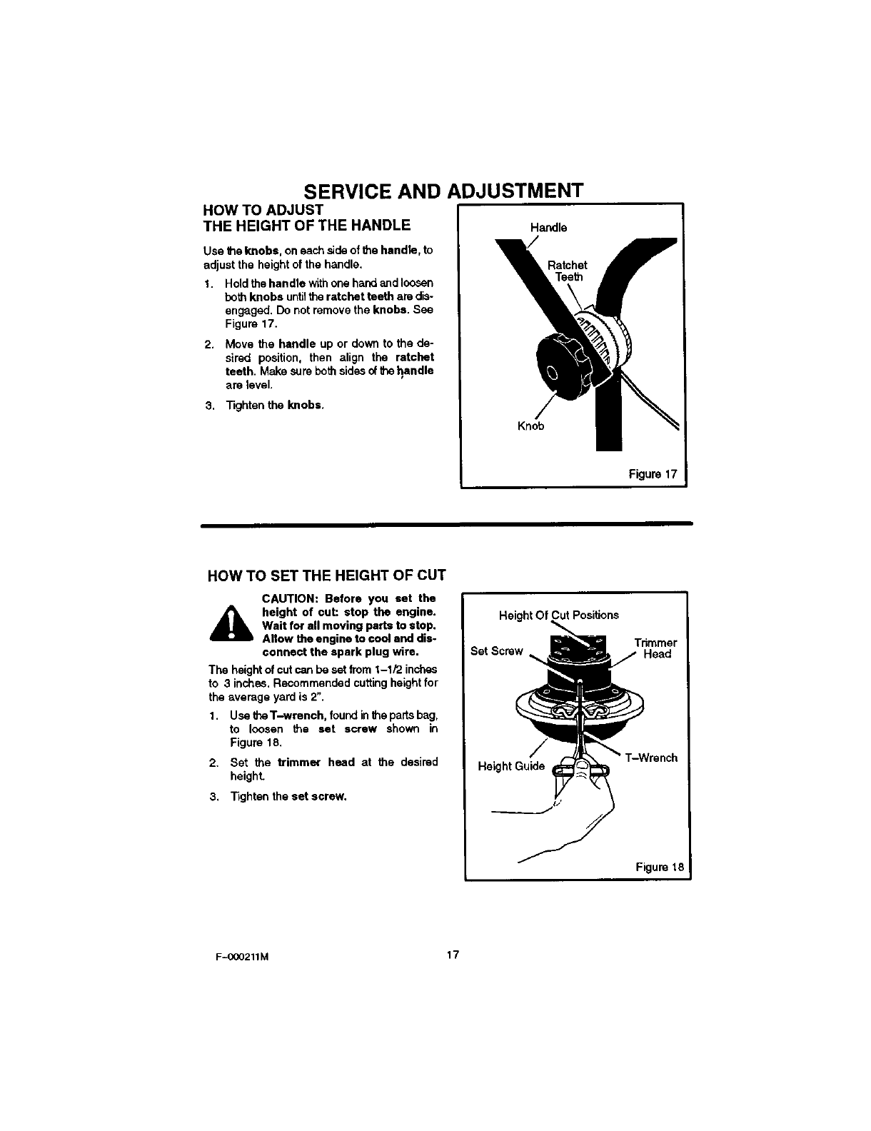
HOW TO SET THE HEIGHT OF CUT
CAUTION: Before you set the
_lb height of cut: stop the engine.
Wait for all moving parts to stop.
Allow the engine to cool and dis-
connect the spark plug wire.
The height of cut can be set from 1-1/2 inches
to 3 inches. Recommended cutting height for
the average yard is 2".
1. Use 61eT-wrench, found in the parts bag,
to loosen the set screw shown in
Figure 18.
2. Set the trimmer head at the desired
height
3. Tighten the set screw.
Height Of Cut Positions
Trimmer
Set Screw ._ Head
T-Wrench
HeightGuide
Figure 18
F-O00211M 17
SERVICE AND ADJUSTMENT
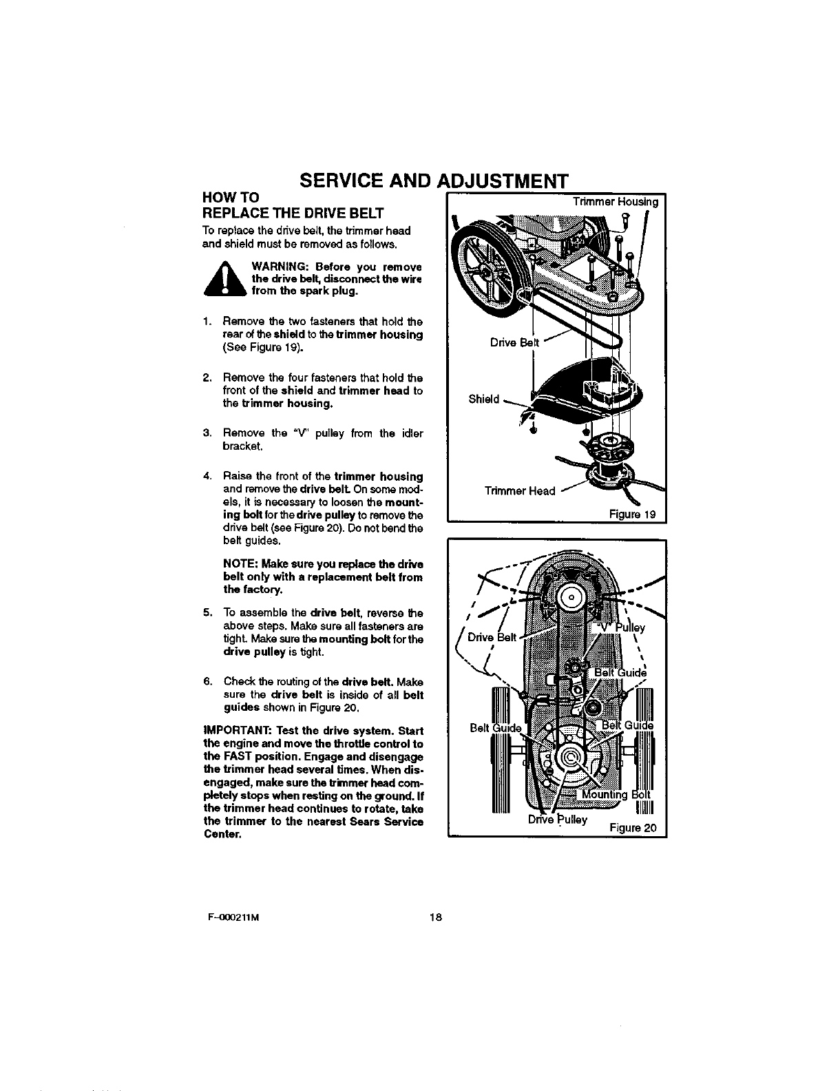
HOW TO
REPLACE THE DRIVE BELT
To reptase the dr_ve belt, the trimmer head
and shield must be mmovod as follows.
_IL WARNING: Before you remove
the drive belt, disconnect the wire
from the spark plug.
1. Remove the two fasteners that hold the
rear of the shield to the trimmer housing
(See Figure 19).
2. Remove the four fasteners that hold the
front of the shield and trimmer head to
the trimmer housing.
3. Remove the "V" pulley from the idler
bracket.
4. Raise the front of the trimmer housing
and remove the drive belL On some mod-
els, it is necessaP/to loosen the mount-
ing bolt for the drive pulley to remove the
drive belt (see Figure 20). Do not bend the
belt guides.
NOTE: Makesure youreplace the drive
belt only with e replacement belt from
the factory.
5. To assemble the drive belt, reverse the
above steps. Make sure all fasteners are
tight. Make sure the mounting bolt for the
drive pulley is _ght.
6. Check the routingof the drive belt. Make
sure the drive belt is inside of all belt
guides shown in Figure 20.
IMPORTANT: Test the drive system. Start
the engine and move the throffie control to
the FAST position. Engage and disengage
the trimmer head several times. When dis-
engaged, make sure the trimmer head com-
pletely stops when resting on the ground. If
the trimmer head continues to rotate, take
the trimmer to the nearest Sears Service
Center.
TrimmerHousing
Trimmer Head
Figure 19
_ulley Figure 20
F-OCO211M 18
SERVICE AND ADJUSTMENT
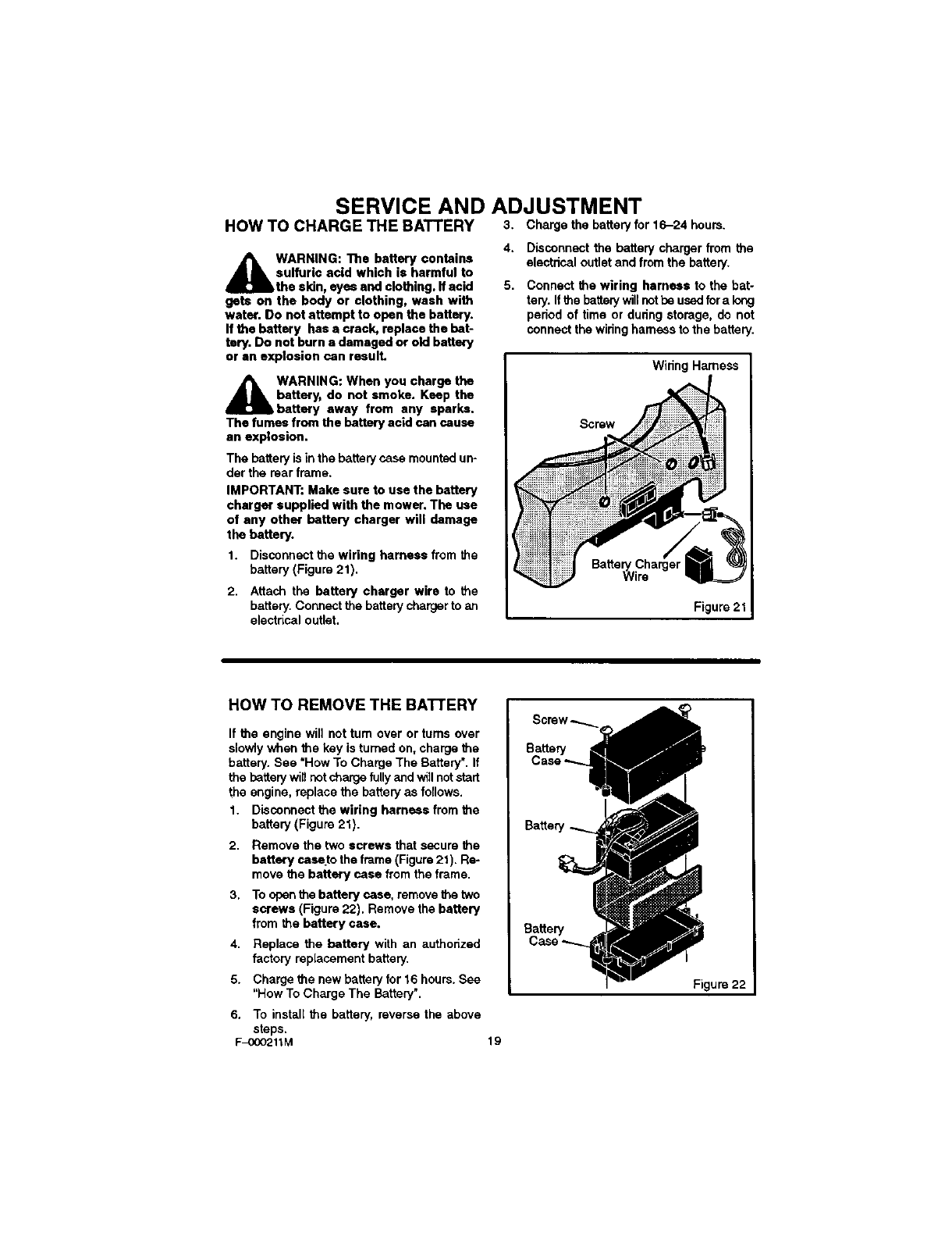
HOW TO CHARGE THE BATTERY 3, Charge the battery for 16-24 houm.
WARNING: The battery contains
sulfuric acid which is harmful to
the skin, eyes end clothing, ff acid
gets on the body or clothing, wash with
water. Do not attempt to open the battery.
If the battery has acrack, replace the bat-
tery. Do not burn adamaged or old battery
or an explosion can result.
A WARNING: When you charge the
battery, do not smoke. Keep the
battery away from any sparks.
The fumes from the battery acid can cause
an explosion.
The battery is in the battery case mounted un-
der the roar frame,
IMPORTANT; Make sure to use the battery
charger supplied with the mower. The use
of any other battery charger will damage
the battery.
1. Disconnect the wiring harness from the
battery (Figure 21).
2. Attach the battery charger wire to the
battery, Connect the battery charger to an
electrical outlet,
4, Disconnect the battery charger from the
electrical outlet and from the battery.
5. Connectthe wiring harness to the bat-
tery.If thebatterywillnotbe usedfora long
period of time or dunngstorage,do not
connectthewiringharnessto the battery.
Wiring Harness
Screw
Figure 21
HOW TO REMOVE THE BATTERY
If the engine will not tum over or tums over
slowly when the key is turned on, charge the
battery. See "How To Charge The Battery". If
the battery wig not charge fully and willnot start
the engine, replace the battery as follows.
1. Disconnect the wiring harness from the
battery (Figure 21).
2. Remove the two screws that secure the
battery case.to the frame (Figure 21). Re-
move the battery case from the frame.
3, To open the battery case, remove the two
screws (Figure 22), Remove the battery
from the battery case.
4. Replace the battery with an authorized
factory replacement battery.
5. Charge the new battery for 16 hours. See
"How To Charge The Battery".
6. To install the battery, reverse the above
steps,
F-0CO211M
Battery
Case
Battery
Battery
Case--_..
Figure 22
19
SERVICE AND ADJUSTMENT
STORAGE
AWARNING: Do not remove gaso-
line while inside a building, near
afire, or while you smoke. Gaso-
line fumes can cause an explo-
sion or a fire.
When the trimmer is put in storage for thirty
days or more, follow the steps below to
make sure the trimmer is in good condition
the following season.
Trimmer
Completelyclean the trimmer.
Putthetrimmerinabuildingthathas good
ventilation.
NOTE: A yearly checkup or tune-up at a
Sears authorized service center will make
sure that the trimmer will provide maxi.
mum performance for the next season.
Engine
iMPORTANT: It is important to prevent gum
deposits from forming in fuel system parts
such as the carburetor, fuel filter, fuel hose,
and tank during storage. Also, using alco-
hol-blended fuels (calisd gasohol, ethanol
or methanol) can attract moisture which
leads to separation and formation of acids
during storage. Acidic gas can damage the
fuel system of an engine while in storage.
To prevent engine damage when the trimmer
is in storage for 30 days or more, follow the
steps below:
Let the engine mn until it is out of gasoline.
Drain the oil from the warm engine. Fillthe
engine crankcase with new oil.
Removethesparkplugfromthe cylinder.
Pour one ounce of oil into the cylinder.
Slowlypullthe recoilstarterhandlesothat
theoilwillprotectthecylinder.Installa new
sparkplug inthe cylinder.
Clean dirt and debris from the cylinder
cooling fins and the engine housing.
If you do not want to remove gasoline, add
afuel stabilizer, such as Craftsman fuel
stabilizer No. 33500, to any gasoline left in
the tank. Craftsman fuel stalibizsr will
minimize the formation of gum deposits
and adds. If the tank Lsalmost empty, mix
Craftsman fuel stabilizer with fresh gaso-
line in asepam.te container and add the
mixture to the tank. Always follow the in-
structions on the stabilizer container. Run
the engine at least ten minutes after stabi-
lizer is added to allow the mixture to reach
the carburetor.
Battery
Charge the battery for 16-24 hours before
storage and again before use each season.
F-O(X)211M 20

TROUBLE SHOOTING CHART
TROUBLE CORRECTION
Engine does not start Connect spark plug wire.
Engine runs poorly.
CAUSE
Spark plug wire
disconnected.
Engine not primed.
Defective or incorrectly
gapped spark plug.
Fuel tank empty.
Dirty carburetor or fuel tine.
Dirty air filter.
Carburetor out of adjustment.
Prime engine.
Inspectorreplacespark
plug.
Add fuel,
Clean carburetororfuelline.
Replace airfilter.
For carburetoradjustment,
ake theunittoaSeare
ServiceCenter,
Engine flooded, iWait severalminutesbefore
starting.
Throttle control lever in Move throttle lever to FAST
incolTect position, or START position.
Stale gasoline. Drain old gasoline and add
fresh gasoline.
Defective throttle control Inspect lever and wire,
lever or wire. Replace if damaged or
defective.
Charge battery 16-24 hours,
Connect wiring harness.
Batteryis notfullycharged.
Wiringharnessnot
connectedto battery.
Sad sparkplug.
Dirtyairfilter.
Carburetoroutof adjustment.
Stale gasoline.
Engine cooling system
clogged,
Replace spark plug.
Replace air filter.
Adjust carburetor. Take the
unit to a Sears Service
Center.
Drain old gasoline, Add fresh
gasoline,
Clean engine screen and
cooling fins.
F-COO211M 21

TROUBLE SHOOTING CHART
Engine overheats.
Engine will not stop
running.
Poor trimming
pedormance.
Trimmer vibrates.
Trimmer head does not
retain line
Engine cooling system Clean debris screen and
,clogged, engine cooling fins.
Carburetor out of adjustment. Adjust carburetor. Take the
unit to a Sears Service
Center.
Oil level is low. Add oil.
Defective throttle contm!
lever or wire.
Throttle not adjusted
properly.
Trimmerline lengthis too
short.
Enginenot set at FAST
speed.
Set screw for trimmerhead
is loose,
Inspect and replace
damaged parts.
Movethrottleto thefullOFF
_osition.
Correctline lengthis 21.5
inches. When lessthan 1/2
this length,replacethe line.
Move engine throttle lever to
FAST position.
Tighten set screw with
T-handle wrench,
Trimmer line lengths are Adjust trimmer line to
substanlJally different, approximately equal lengths.
Loose nuts or bolts. Check all bolts and nuts,
including engine bolts.
Replace broken part.
Broken trimmer head.
Trimmer line not propedy
attached. Follow instructions on decal
or in the Service section of
the owner's manual.
Brokenline retainer. Replacetrimmerhead
assembly,
Trimmerline not correctsize, Use Craftsman0.155 inch
diameter trimmerline.
F-(XJO211M 22
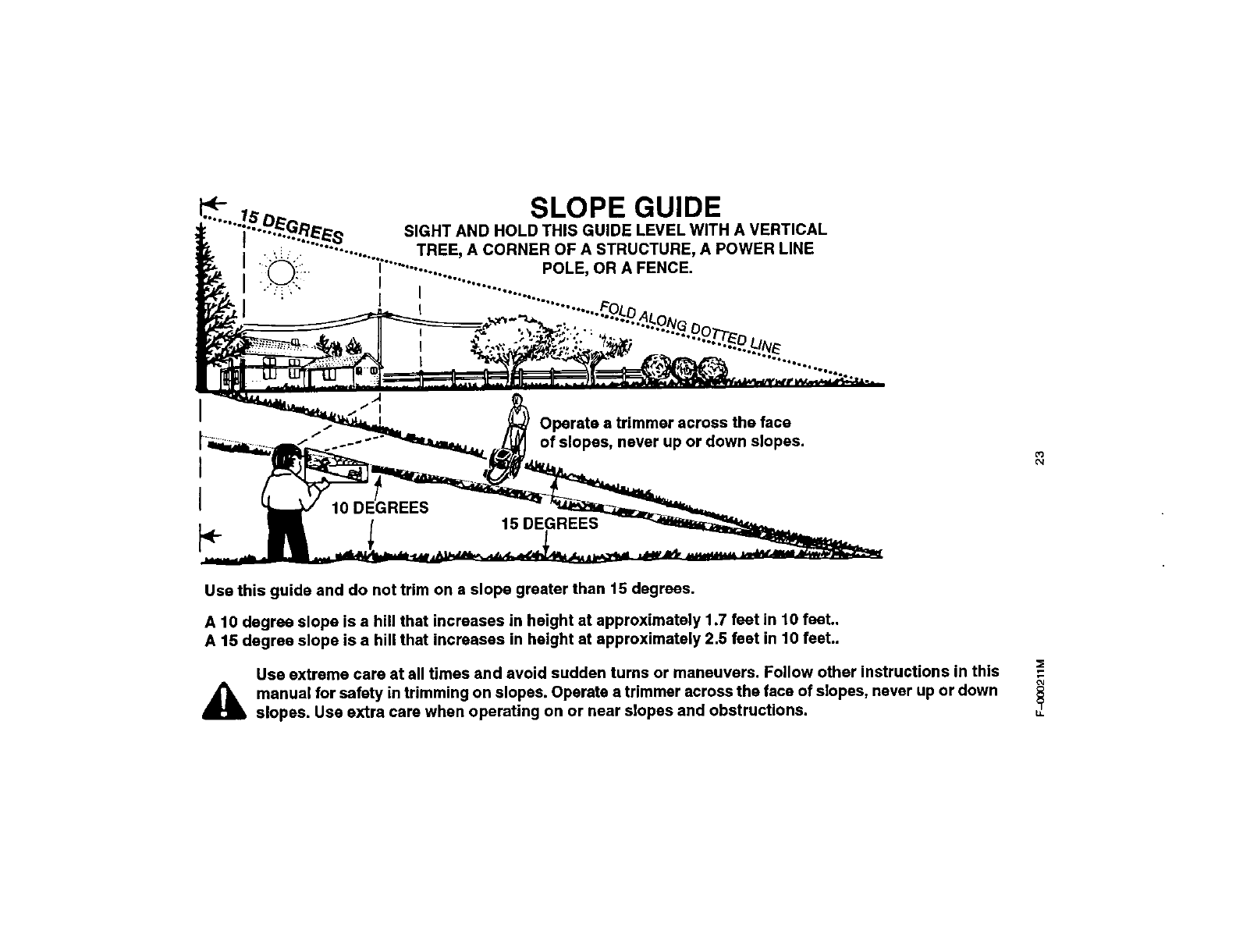
SLOPE GUIDE
SIGHT AND HOLD THIS GUIDE LEVEL WITH A VERTICAL
TREE, A CORNER OF A STRUCTURE, A POWER LINE
POLE, OR A FENCE.
Operate a trimmer across the face
of slopes, never up or down slopes. 03
_t
Use this guide and do not trim on a slope greater than 15 degrees.
A 10 degree slope is a hill that increases in height at approximately 1.7 feet in 10 feet..
A 15 degree slope is a hill that increases in height at approximately 2.5 feet in 10 feet..
Use extreme care at all times and avoid sudden turns or maneuvers. Follow other instructions in this
_manual for safety in trimming on slopes. Operate a trimmer across the face of slopes, never up or down
slopes. Use extra care when operating on or near slopes and obstructions.
oJ

CRAFTSMAN WEEDTRIMMER 536.773521
11
5
14 42
27
\
28_
2
33 34 36
38 40
\
39
F-OCO211M 24

CRAFTSMAN WEEDTRIMMER 536.773521
oee
• .• Description Port No.
1 Handle Assy. 740196-846
2 Lover, Control 740198-848
3 Bolt 323035
4 Strap, Tie 712267
5 Screw 712145
6 Washer 17x38 Z
7 Guide, Rope 672510
8 Cablo, Control Latching 740193
9 Key, Ignition 740228
10 Cable, Throttle w/ES 740225
11 Bolt 323034
12 Screw 710269
13 Cover, Batte W740218
14 Harness, Wiring 740221
15 Battery 740220
16 Holder, Battery 740222
17 Case, Battery 740219
18 Charger, Battery 740223
19 Knob, Handle 740202
20 Washer, Spring 711936
21 Pivot, Handle 740158
22 Bolt 711937
23 Handle, Lower 740195-846
24 Screw 710079
25 143.996512, See Engine Pages ENGINE
26 Hamess Clamp 740217
27 Nut 710140
28 Wheel and Tire 740185
29 Washer 710258
30 Spacer 740190
31 Bracket Assembly, Axle end 740188
32 Bolt, Carriage 711935
33 Bolt 48901
34 Nut 710203
35 Nut 710205
36 Shield, Trailing 740192
37 Bolt 710265
38 Frame 740216-848
39 Glasses, Safety 711890
40 Decal 712030
41 Spacer, PM .26x.5x.2 672292
42 Washer, Formed 783000
-- Manual, Owner's F-000211M
F-000211M 25
CRAFTSMAN WEEDTRIMMER 536.773521
1
2
3
25
26
11
31
38
/
22 23
F-OCO211M 26

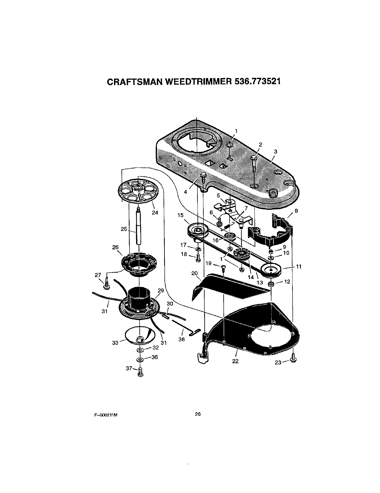
CRAFTSMAN WEEDTRIMMER 536.773521
Key
No. Description Pert No.
1 Nut 710140
2 Bolt 711978
3 Frame 740216-848
4 Screw 710272
5 Idler Assembly 740232
6 Bolt 710200
7 Spring 712403
6 Spacer, Jackshaft Housing 740292
9 Nut 712148
10 Washer 710083
11 Pulley, Cutting Head 740171
12 Spacer 740173
13 Belt 711933
14 Pulley, Idler 740244
15 Pulley, Engine 740179
16 Pulley, Idler 740183
17 Lockwasher 712147
18 Bolt 712146
19 Screw 712145
20 Flap, Debris 740167
22 Guard Assy, 770070
23 Screw 26x194
24 Jackshaft Housing Assembly 1001049
25 Shaft, Cutting Head 740246
26 Wrap, Upper Head 740163
27 Screw 712126
29 Cutting Disc Assembly 740175--848
30 Screw, Set 712127
31 Line, (Cutting Pack of 24) 79999
32 Flatwasher 712440
33 Guide, Height 740226
36 Lockwasher 120380
37 Bolt lx173
38 T-Wrench 712128
F-O00211M 27
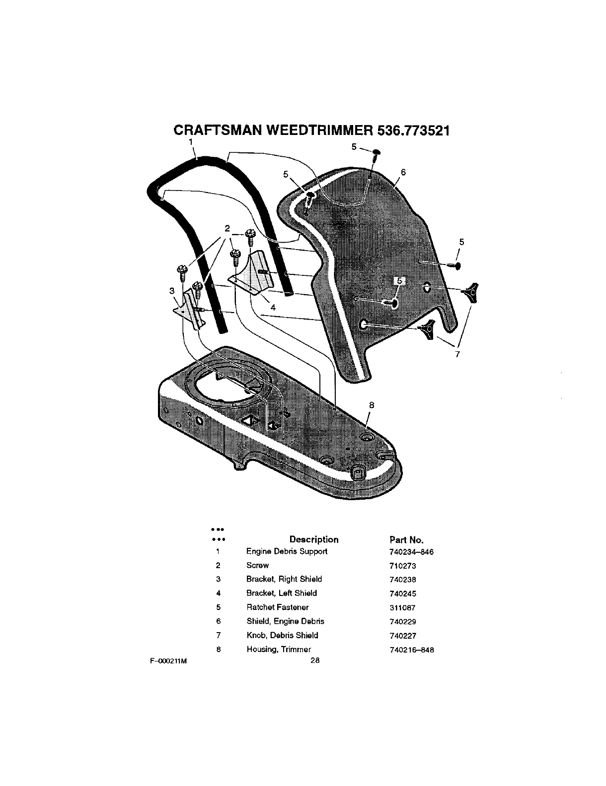
CRAFTSMAN WEEDTRIMMER 536.773521
1
5
/
F-OOO211M
oeo
•.. Description Part No.
1 Engine Debris Support 740234-846
2 Screw 710273
3 Bracket, Right Shield 740238
4 Bracket, Left Shield 740245
5 Ratchet Fastener 311087
6Shield, Engine Debris 740229
7Knob, Debris Shield 740227
8 Housing, Trimmer 740216-848
28

CRAFTSMAN ENGINE 143.996512
4OO 135
130
120
416 11g
F_XX)211M 29

CRAFTSMAN ENGINE 143.996512
• -- PART -.* PART
• . • NO. DESCRIPTION ... NO.
o RPM High 3450 to 3750 52 29914
0 RPM Low 2000 to 2300 69 35261
1 37266 Cylinder (Incl. 2,20 & 150) 70 34311E
2 26727 Dowel Pin 72 36083
6 33734 Breather Element 75 27897
7 36557 Breather Ass'y.
(IncL 6 & 12A) 80 30574A
12 36775 Breather Tube 81 30590A
12A 36558 Breather Cover & Tube 82 30591
(IncL 12B)
12B 36694 Breather Tube Elbow 83 30588A
14 28277 Washer 86 650488
15 30589 Govemor Rod (Incl. 14) 69 610961
16 34839A Governor Lever 90 611179
17 31335 Governor Lever Clamp 92 650815
18 651018 Screw, Torx T-15, 93 650816
8-32 x 19/64" 100 34443B
19 37329 Extension Spring 101 610118
20 32600 Oil Seal 103 651007
30 34570A Crankshaft
40 40027 Piston, Pin & Ring Set 110 36230
(Std.) 110A 34970
40 40028 Piston, Pin & Ring Set
(.010" OS) 11OC 35020
41 40025 Piston & Pin Ass'y. 119 36787
(Std.) (Incl. 43) 120 36825
41 40026 Piston & Pin Ass'y. 125 37288
(,010" OS) (Incl. 43)
42 40006 Ring Set (Std,) 126 37289
42 40007 Ring Set (.010" OS)
43 20381 Piston Pin Retaining Ring 130 6021A
45 36777 Connecting Rod Ass'y. 135 35395
(Incl. 46)
46 32610A Connecting Rod Bolt 150 31672
48 27241 Valve Lifter 151 31673
50 36778 Camshaft (MCR) 151A 40017
DESCRIPTION
Oil Pump Ass'y.
Mounting Flange Gasket
Mounting Flange
(Inol. 72 thru 83,306)
Oil Drain Plug
Oil Seal
Governor Shaft
Washer
Governor Gear Ass'y.
(Incl. 81)
Governor Spool
Screw, 1/4-20 x 1-1/4'
Flywheel Key
Flywheel
Believille Washer
Flywheel Nut
Solid State Ignition
Spark Plug Cover
Screw, Torx T-15,
10-24 x 15/16"
Ground Wire
Ground Wire
Ground Wire
Cylinder Head Gasket
Cylinder Head
Exhaust Valve (Std.)
(Incl. 151)
Intake Valve (Std.)
(Incl. 151)
Screw, 5/16-18 x 1-1/2"
Resistor Spark Plug
(RJ19LM)
Valve Spring
Valve Spring Cap
Intake Valve Seal
F-OOO211M 30

CRAFTSMAN ENGINE 143.996512
169 36783 Valve Cover Gasket 301 36246 Fuel Cap
172 36784 Valve Cover 305 35647 Oil Fill Tube
174 30200 Screw, 10--24 x9/16" 306 36996 "O"-Ring
178 29752 Nut & Lock Washer, 307 35499 "O"-Ring
1/4-28 309 650562 Screw, 10-32 x 3/8"
179 30593 Retainer Clip 310 35648 Dipstick
182 6201 Screw, 1/4-28 x 7/8" 313 34680 Spacer
184 26756 Carburetor To Intake Pipe
Gasket 314 650767 Screw, 8-32 x 27/64"
185 36785 Intake Pipe 315 34990 Alternator Coil
186 36255 Governor Link 322 35013 Connector Body
189 650831 Screw, 1/4-20 x 1/2" 324 33177 Terminal
200 37134 Control Bracket (Incl. 206) 325 37152 Spring Clip
206 610973 Terminal 347 651038 Screw, 10-32 x 27/32"
207 36200A Throttle Link 370A 36261 Lubrication Decal
209 30200 Screw, 10--24 x 9/16" 370C 37199 Pnmer Decal
223 650451 Screw, 1/4-20 x 1" 370E 34387 Air Cleaner Decal
224 36786 Intake Pipe Gasket 380 640069 Carburetor(Incl. 184)
238 650932 Screw, 10-32 x 49/64" 390 590739 Rewind Starter
239 34338 Air Cleaner Gasket (NOTE: This engine could
have been built with
241 36919 Air Cleaner Collar 590702 starter).
245 36905 Air Cleaner Filter 395 35707 Electric Starter Motor
250 36920 Air Cleaner Cover (12 VoR)
400 36792B Gasket Set (Incl. Items
260 36980 Blower Housing Marked PK in Notes)
261 30200 Screw, 10-24 x 9/16" Ind. Part #'s 26756 (1),
262 650831 Screw, 114-20 x 1/2" 28833 (1), 34338 (1),
36783 (1), 36786 (1),
263A 37198 Starter Grill 36787 (1), 36832 (1),
36996 (1), 37130 (1).
275 36790A Muffler 416 36085 Spark Arrestor Kit
277 660988 Screw, 1/4-20 x 2-9/32" (Incl. 417) (Optional)
285 350OOA Starter Cup 417 650821 Screw, 10-32 x 1/2"
287 650926 Screw, 8-32 x 21/64" (Optional)
290 29774 Fuel Line 900 0 Replacement Engine
NONE, order from 71-999
292 26460 Fuel Line Clamp 900 0 Replacement Short Block
298 28763 Screw, 10-32 x 35/64" 750812B,
300 36916 Fuel Tank (Incl. 292 & 301) order from 71-999
F_211M 31
CRAFTSMAN ENGINE 143.996512
_37
40
F-OOO211M 32

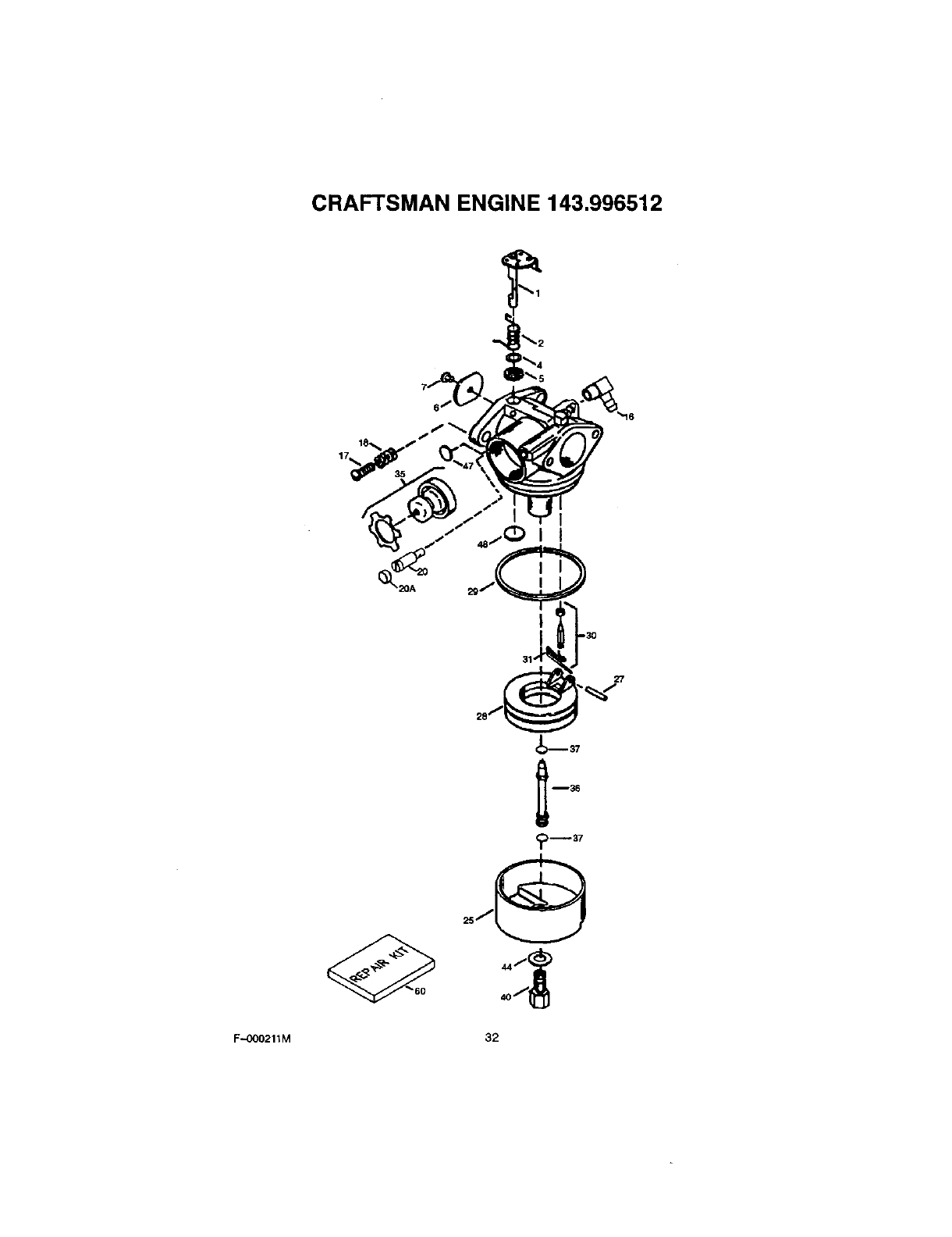
CRAFTSMAN ENGINE 143.996512
•,. PART
•••NO. DESCRIPTION
0 640069 Carburetor
(tncl, 184 of Engine Parts List
1 631615 Throttle Shaft & Lever Assembly
2 631767 Throttle Return Spring
4 631184 Dust Seel Washer
6 631183 Dust Seal (Throttle)
6 640070 Throttle Shutter
7 650506 Shutter Screw
16 631807 Fuel Fitting
17 651025 Throttle Crack Screw /Idle Speed
18 630766 Tension Spring
20 640027 Idle Restrictor Screw
20A 640053 Idle Restrictor Screw Cap
25 631867 Float Bowl
27 631024 Float Shaft
28 632019 Float
29 631028 Float Bowl "0" Ring
30 631021 Inlet Needle, Seat, & Clip (Incl. 31)
31 631022 Spring Clip
35 36045% Pnmer Bulb/Retainer Ring
36 632735 Main Nozzle Tube
37 632547 "0" Ring, Main Nozzle Tube
40 640030 High Speed Bowl Nut
44 27110A Bowl Nut Washer
47 630748 Welch Plug, Idle Mixture Well
48 631027 Welch Plug, Atmospheric Vent
60 632760 Repair kit
(Incl. Items Marked PK in Notes)
F-OOO211M 33
CRAFTSMAN ENGINE 143.996512
6\€
11C
_15 17
F-OOO211M 34

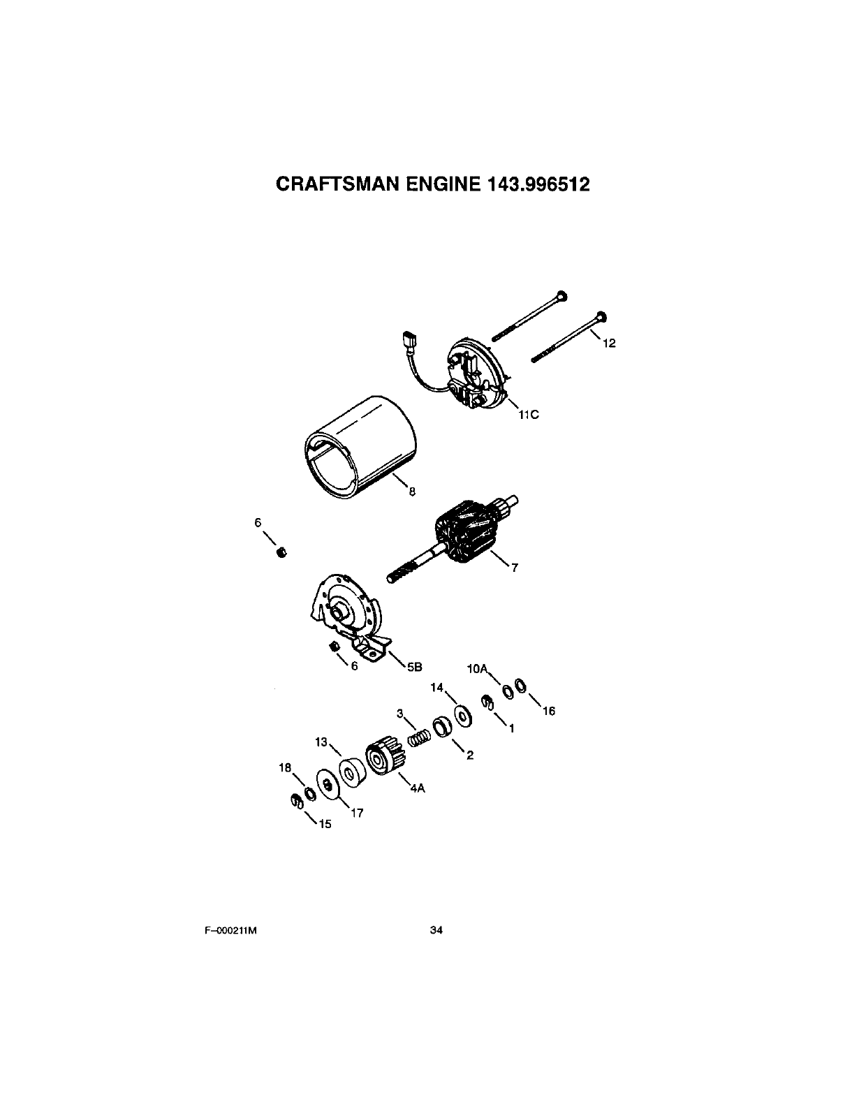
CRAFTSMAN ENGINE 143.996512
••• PART
•••NO. DESCRIPTION
0 35707 Electric Starter (12 Volt)
1 34955 Retainer Ring
2 34950 Spring Retainer
3 34954 Spring
4A 34949A Gear
5B 34953 Drive End Cap Ass'y.
633450 Lock Nut
7 34944 Armature
8 34945 Housing Ass'y.
10A 590500 Thrust Washer
11C 34942 Commutator End Cap Ass'y. (Incl. brushes)
12 34947 Bolt, 10-32 x 3-3/16"
13 34946 Pinion Dnver
14 34951 Cup Washer
15 34952 Retainer Ring
16 34948 Washer
17 34953 Drive Nut
18 590608 Washer
F-000211M 35
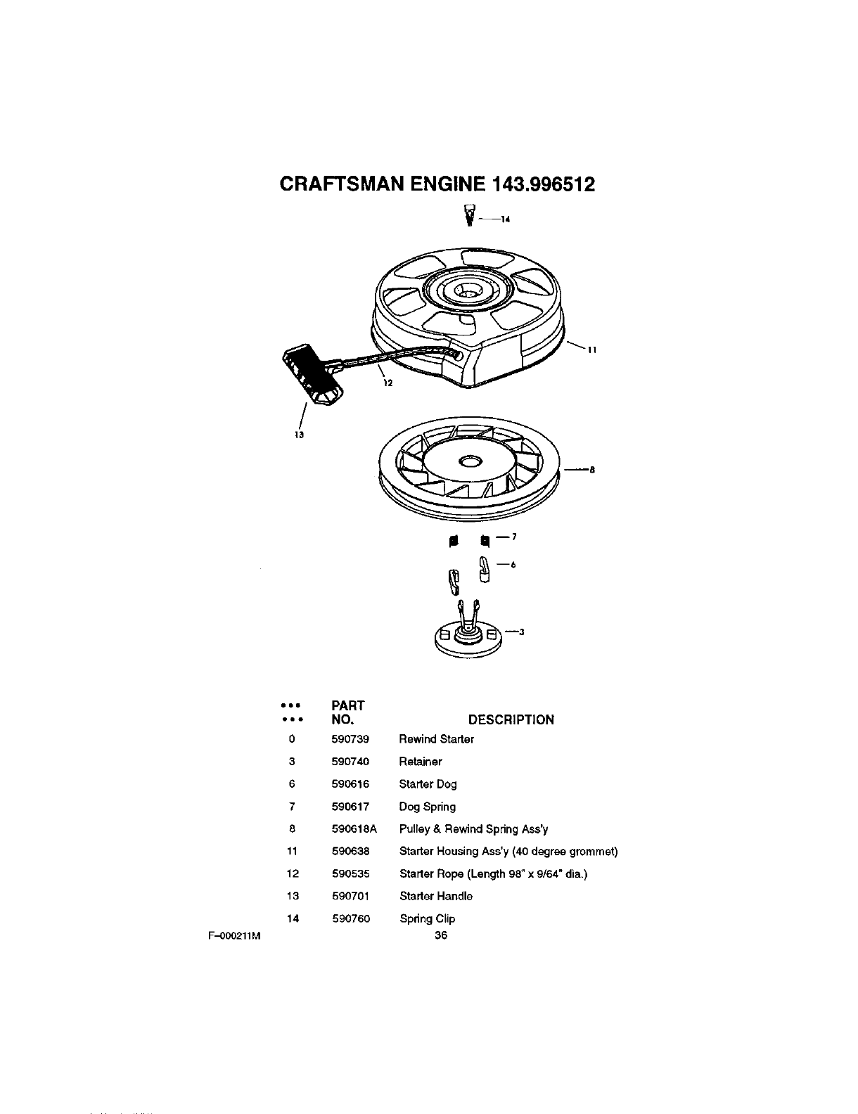
CRAFTSMAN ENGINE 143.996512
V--14
12
F-OOO211M
¢lou
eee
0
3
6
7
8
11
12
13
14
PART
NO,
590739
590740
590616
590617
590618A
590638
590535
590701
590760
DESCRIPTION
Rewind Starter
Retainer
Starter Dog
Dog Spring
Pulley & Rewind Spring Ass'y
Starter Housing Ass'y (40 degree grommet)
Starter Rope (Length 98" x 9/64" dia.)
Starter Handle
Spnng Clip
36

NOTES
F._OOO211M 37

For the repair or replacement parts you
need delivered directly to your home
Call 7am-7pm, 7days a week
1-800-366-PART
(1-800-366-7278)
Para ordenar piezas con entrega
a domicilio - 1-800-659-7084
For in-house major brand repair service
Call 24 hours a day, 7days a week
1-800-4-REPAIR
(1-800-473-7247)
Para pedir servicio de reparaci6n a
domicilio- 1-800-676-5811
For the location of a Sears Parts and
Repair Center in your area
Call 24 hours a day, 7days a week
1-800-488-1222
For information on purchasing a Sears
Maintenance agreement or to inquire
about an existing Agreement
Call 9am-5pm, Monday-Saturday
1-800-827-6655
When requesting service or ordering
pads, always provide the following infor-
mation:
•Product Type •Part Number
•Model Number •Part Description
,_et_aJs _epaifS_i_fsts Pdnted in U.S.A.
