Craftsman 536885213 User Manual SNOW THROWER Manuals And Guides L0108015
CRAFTSMAN Snowthrower, Gas Manual L0108015 CRAFTSMAN Snowthrower, Gas Owner's Manual, CRAFTSMAN Snowthrower, Gas installation guides
User Manual: Craftsman 536885213 536885213 CRAFTSMAN SNOW THROWER - Manuals and Guides View the owners manual for your CRAFTSMAN SNOW THROWER #536885213. Home:Lawn & Garden Parts:Craftsman Parts:Craftsman SNOW THROWER Manual
Open the PDF directly: View PDF ![]() .
.
Page Count: 65
Operator's Manual
Snow Thrower
5.0 Horsepower
Electric Start
21-inch Single Stage
Auger Propelled
Model 536.885213
CAUTION: Before using this product,
read this manual and follow all of its
Safety Rules and Operating Instructions.
CRRFTSMRN °
Manual del usario
Quitanieves
de 21 pulgadas
5.0 caballos de fuerza (hp)
Monoetapico
Arranque el_ctrico
Propulsado por barrena
Modelo 536.885213
PRECAUCION: Antes de usar este producto,
lea este manual y siga todas las reglas de
seguridad e instrucciones de operaci6n.
/
Sears, Roebuck and Co., Hoffman Estates, IL 60179 U.S.A.
F-011005M www.sears.com/craftsman
NnIL,'q:] !=l[o]d[_o_ _Innl=1_In_
WARRANTY STATEMENT ......
SAFETY RULES ...............
INTERNATIONAL SYMBOLS . ..
ASSEMBLY ...................
OPERATION ..................
MAINTENANCE ...............
SERVICE AND ADJUSTMENT ..
2 STORAGE .................... 20
2 TROUBLE SHOOTING CHART.. 21
4 REPAIR PARTS ............... 25
6
8 ENGINE REPAIR PARTS ....... 34
14 SPANISH (ESPAI_IOL) .......... 40
16 PARTS ORDERING/SERVICE .. 64
LIMITED TWO-YEAR WARRANTY ON CRAFTSMAN SNOW THROWER
For two years from the date of purchase, when this Craftsman Snow thrower is maintained,
lubricated, and tuned up according to the operating and maintenance instructions in the
owner's manual, Craftsman will repair, free of charge, any defect in material or workman-
ship.
If this Craftsman Snow thrower is used for commercial or rental purposes, this warranty ap-
plies for only 90 days from the date of purchase.
This warranty does not cover the following:
Items which become worn during normal use, such as spark plugs, drive belts and shear
pins.
Repair necessary because of operator abuse or negligence, including bent crankshafts
and the failure to maintain the equipment according to the instructions contained in the
owner's manual.
WARRANTY SERVICE IS AVAILABLE BY RETURNING THE CRAFTSMAN SNOW
THROWERTO THE NEAREST CRAFTSMAN SERVICE CENTER/DEPARTMENT IN
THE UNITED STATES. THIS WARRANTY APPLIES ONLY WHILE THIS PRODUCT IS
IN USE IN THE UNITED STATES.
This warranty gives you specific legal rights, and you may also have other rights which may
vary from state to state.
Sears, Roebuck and Co., D817WA, Hoffman Estates. IL 60179
_hb OOK FOR THIS SYMBOL TO POINT OUT IMPORTANT SAFETY PRECAUTIONS.
IT MEANS-- ATTENTION!!! BECOME ALERT!!! YOUR SAFETY IS INVOLVED.
Engine Exhaust, some of its constituents, and
certain vehicle components contain or emit
chemicals known to the State of California to
cause cancer and birth defects or other repro-
ductive harm.
Battery posts, terminals and related accessories
contain lead and lead compounds, chemicals
known to the State of California to cause cancer
and birth defects or other reproductive harm.
WASH HANDS AFTER HANDLING.
d_k WARNING: Always discon-
nect the spark plug wire
and place it where it cannot
make contact with spark plug to
prevent accidental starting during:
Preparation, Maintenance, or Stor-
age of your snow thrower.
IMPORTANT: Safety standards re-
quire operator presence controls to
minimize the risk of injury. Your snow
thrower is equipped with such controls.
Do not attempt to defeat the function of
the operator presence control under any
circumstances.
F-O11005M 2
TRAINING
1. Read the operating and service instruction
manual carefully. Be thoroughly familiar
with the controls and the proper use of the
equipment. Know how to stop the unit and
disengage the controls quickly.
2. Never allow children to operate the equip-
ment. Never allow adults to operate the
equipment without proper instruction.
3. Keep the area of operation clear of all per-
sons, particularly small children and pets.
4. Exercise caution to avoid slipping or falling
especially when operating in reverse.
PREPARATION
1. Thoroughly inspect the area where the
equipment is to be used and remove all
doormats, sleds, boards, wires, and other
foreign objects.
2. Disengage all clutches before starting the
engine (motor).
3. Do not operate the equipment without
wearing adequate winter outer garments.
Wear footwear that will improve footing on
slippery surfaces.
4. Handle fuel with care; it is highiy flam-
mable.
a. Use an approved fuel container.
b. Never remove fuel tank cap or add fuel
to a running engine (motor) or hot en-
gine (motor).
c. Fill fuel tank outdoors with extreme
care. Never fill fuel tank indoors.
d. Replace fuel cap securely and wipe up
spilled fuel.
e. Never store fuel or snow thrower with
fuel in the tank inside of a building
where fumes may reach an open flame
or spark.
f. Check fuel supply before each use, al-
lowing space for expansion as the heat
of the engine (motor) and/or sun can
cause fuel to expand.
5. For all units with electric starting motors
use electric starting extension cords certi-
fied CSA/UL Use only with a receptacle
that has been installed in accordance with
iocal inspection authorities.
6. Adjust the snow thrower height to clear
gravel or crushed rock surface.
7. Never attempt to make any adjustments
while the engine (motor) is running (except
when specifically recommended by manu-
facturer).
8. Let engine (motor) and snow thrower ad-
just to outdoor temperatures before starting
to clear snow.
F-011005M
Always wear safety glasses or eye shields
during operation or while performing an ad-
justment or repair to protect eyes from
foreign objects that may be thrown from the
snow thrower.
OPERATION
1. Do not operate this machine if you are tak-
ing drugs or other medication which can
cause drowsiness or affect your ability to
operate this machine.
2. Do not use this machine if you are mentally
or physically unable to operate this ma-
chine safely.
3. Do not put hands or feet near or under ro-
tating parts. Keep clear of the discharge
opening at all times.
4. Exercise extreme caution when operating
on or crossing gravel drives, walks or
roads. Stay alert for hidden hazards or
traffic.
5. After striking a foreign object, stop the en-
gine (motor), remove the wire from the
spark plug, thoroughly inspect snow
thrower for any damage, and repair the
damage before restarting and operating
the snow thrower.
6. If the unit should start to vibrate abnormal-
ly, stop the engine (motor) and check im-
mediately for the cause. Vibration is
generally a warning of trouble.
7. Stop the engine (motor) whenever you
leave the operating position, before un-
clogging the auger/impeller housing or dis-
charge chute and when making any
repairs, adjustments, or inspections.
8. When cleaning, repairing, or inspecting,
make certain the auger/impeller and all
moving parts have stopped and all controls
are disengaged. Disconnect the spark plug
wire and keep the wire away from the spark
plug to prevent accidental starting.
9. Take all possible precautions when leaving
the snow thrower unattended. Disengage
the auger/ impeller, stop engine (motor),
and remove key.
10. Do not run the engine (motor) indoors, ex-
cept when starting the engine (motor) and
for transporting the snow thrower in or out
of the building. Open the outside doors; ex-
haust fumes are dangerous (containing
CARBON MONOXIDE, an ODORLESS
and DEADLY GAS).
11. Do not clear snow across the face of
slopes. Exercise extreme caution when
changing direction on slopes. Do not at-
tempt to clear steep slopes.
12. Never operate the snow thrower without
proper guards, plates or other safety pro-
tective devices in place.
13.Neveroperatethesnowthrowernearen-
closures,automobiles,windowwells,
drop-offs,andthelikewithoutproperad-
justmentof thesnowdischargeangle.
Keepchildrenandpetsaway.
14.Donotoverloadthemachinecapacityby
attemptingtoclearsnowattoofastarate.
15.Neveroperatethemachineathightrans-
portspeedsonslipperysurfaces.Lookbe-
hindandusecarewhenbackingup.
16.Neverdirectdischargeatbystandersor
allowanyoneinfrontoftheunit.
17.Disengagepowertothecollector/impeller
whensnowthroweristransportedornotin
use.
18.Useonlyattachmentsandaccessoriesap-
provedbythemanufacturerofthesnow
thrower(suchastirechains,electricstart
kits,ect.).
19. Never operate the snow thrower without
good visibility or light. Always be sure of
your footing and keep a firm hold on the
handles. Walk;never run.
20. Do not over-reach. Keep proper footing
and balance at all times.
21. Do not attempt to use snow thrower on a
roof.
MAINTENANCE AND STORAGE
1. Check shear bolts and other bolts at fre-
quent intervals for proper tightness to be
sure the equipment is in safe working
condition.
2. Never store the snow thrower with fuel in
the tank inside a building where ignition
sources are present such as hot water and
space heaters, clothes dryers, and the like.
Allow the engine (motor) to cool before
storing in any enclosure.
3. Always refer to operator's guide instruc-
tions for important details if the snow
thrower is to be stored for an extended
period,
4. Maintain or replace safety and instruction
labels, as necessary.
5. Run the snow thrower a few minutes after
throwing snow to prevent freeze-up of the
auger/impeller.
_lb WARNING: This snow thrower isfor use on sidewalks, driveways
and other ground level surfaces.
Caution should be exercised while using on
steep sloping surfaces. DO NOT USE
SNOW THROWER ON SURFACES ABOVE
GROUND LEVEL such as roofs of resi-
dences, garages, porches or other such
structures or buildings.
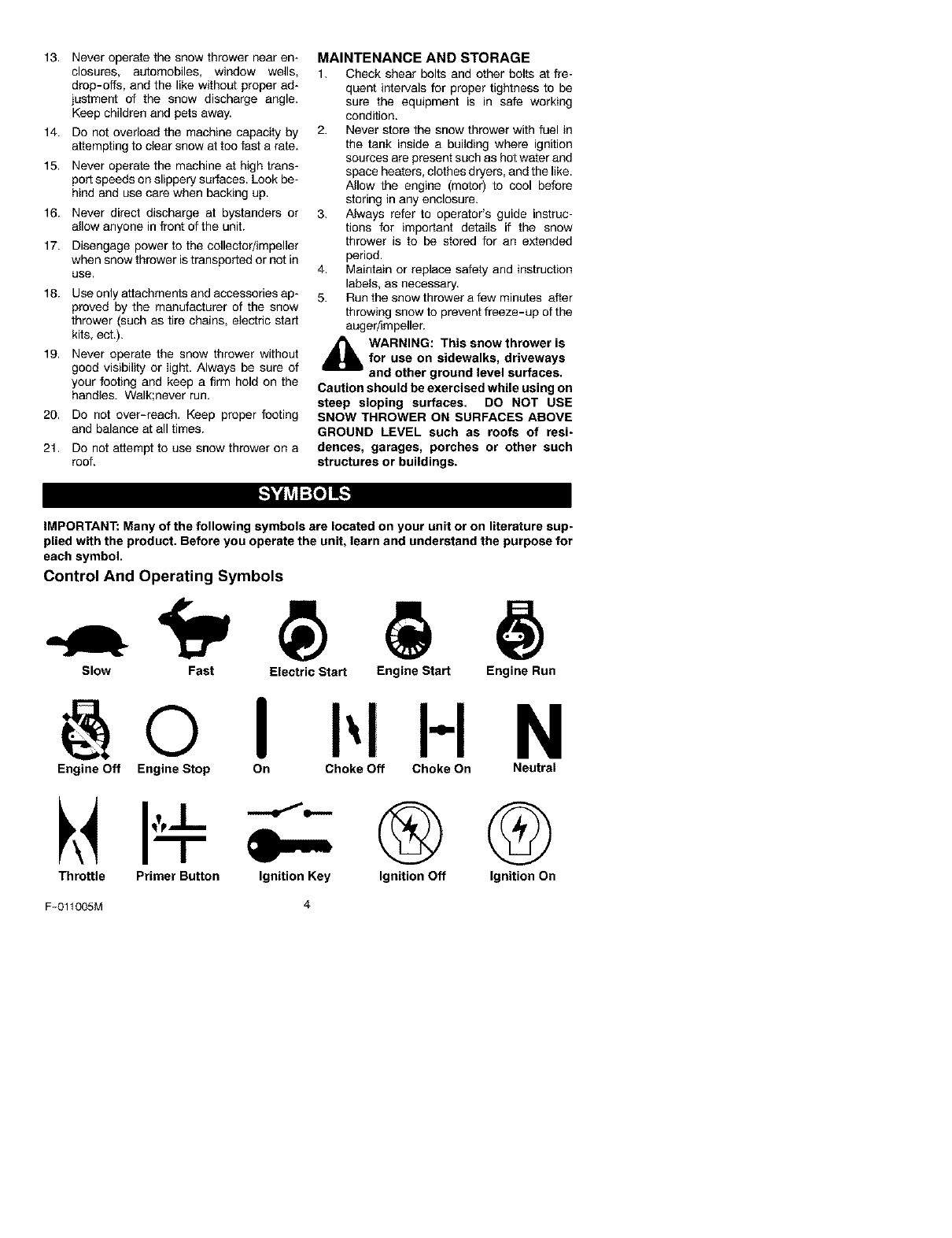
IMPORTANT:Many of the following symbols are located on your unit or on literature sup-
plied with the product. Before you operate the unit, learn and understand the purpose for
each symbol.
Control And Operating Symbols
Slow Fast Electric Start Engine Start Engine Run
H N
Engine Off Engine Stop On Choke Off Choke On Neutral
U
Throttle Primer Button
F-011005M
Ignition Key
4
®Q
Ignition Off Ignition On
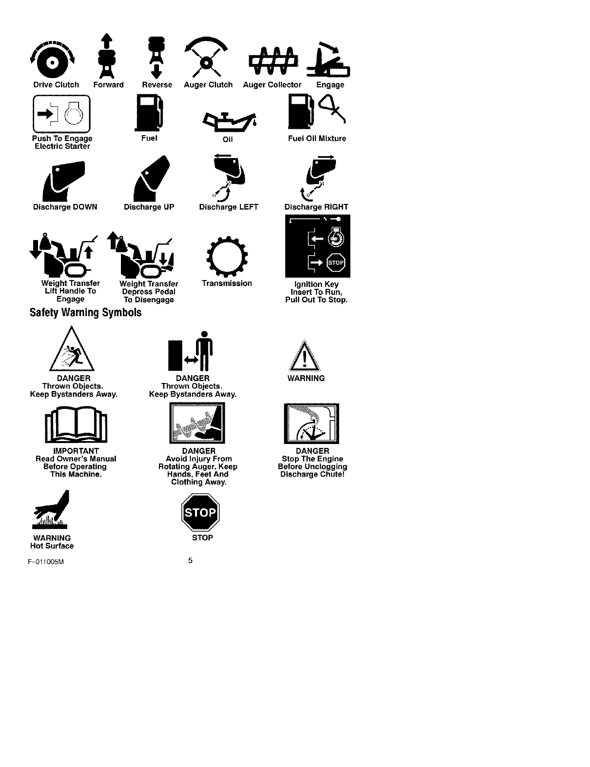
Drive Clutch Forward Reverse Auger Clutch Auger Collector Engage
Push To Engage
Electric Starter Fuel Oil FueI OilMixture
f
Discharge DOWN Discharge UP Discharge LEFT Discharge RIGHT
Weight Transfer Weight Transfer Transmission Ignition Key
Lift Handle To Depress Pedal Insert To Run,
Engage To Disengage Pull Out To Stop.
Safety Warning Symbols
DANGER
Thrown Objects.
Keep Bystanders Away.
IMPORTANT
Read Owner's Manual
Before Operating
This Machine.
DANGER
Thrown Objects.
Keep Bystanders Away.
DANGER
Avoid Injury From
Rotating Auger. Keep
Hands, Feet And
Clothing Away.
WARNING
DANGER
Stop The Engine
Before Unclogging
Discharge Chute!
WARNING
Hot Surface STOP
F-O11005M 5
Contents of Parts Bag
1 - Owner's Manual (not shown)
1 - Electric Starter Cord (not shown)
1- Container 3.2 ounce
d_lb WARNING: Always wear
safety glasses or eye shields
while assembling snow
thrower.
TOOLS REQUIRED
1 - Knife to cut carton
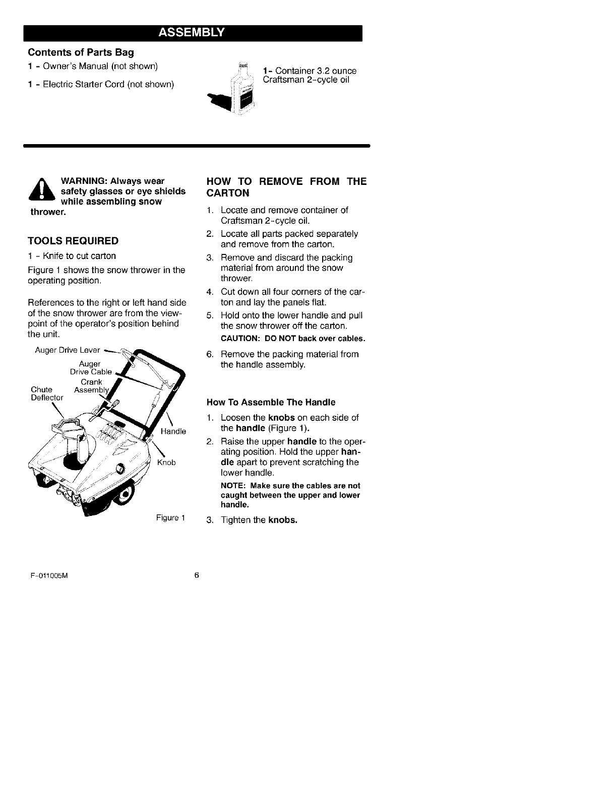
Figure 1 shows the snow thrower in the
operating position.
References to the right or left hand side
of the snow thrower are from the view-
point of the operator's position behind
the unit.
Auger Drive Lever ._.
Auger
Drive Cable
Crank
Chute
Deflector
\
Handle
Knob
Figure 1
HOW TO REMOVE FROM THE
CARTON
1. Locate and remove container of
Craftsman 2-cycle oil.
2. Locate all parts packed separately
and remove from the carton.
3. Remove and discard the packing
material from around the snow
thrower.
4. Cut down all four corners of the car-
ton and lay the panels flat.
5. Hold onto the lower handle and pull
the snow thrower off the carton.
CAUTION: DO NOT back over cables.
6. Remove the packing material from
the handle assembly.
How To Assemble The Handle
1,
2.
Loosen the knobs on each side of
the handle (Figure 1).
Raise the upper handle to the oper-
ating position. Hold the upper han-
dle apart to prevent scratching the
lower handle.
NOTE: Make sure the cables are not
caught between the upper and lower
handle.
3. Tighten the knobs.
F-011005M 6
_" CHECKLIST
Before you operate your new snow
thrower, to ensure that you receive the
best performance and satisfaction from
this quality product, please review the
following checklist:
_' All assembly instructions have been
completed.
_' The discharge chute rotates freely.
_' No remaining loose parts in carton.
While learning how to use your snow
thrower, pay extra attention to the fol-
lowing important items:
_' Make sure the fuel tank is filled with
the correct mixture (40:1 ratio) of gas-
oline and oil.
_' Become familiar with the location of
all controls and understand their
function.
v" Before starting the engine, make sure
all controls operate correctly.
PRODUCT SPECIFICATIONS
Horse Power: 5
Displacement: 8,46 cu. in.
Fuel Tank: 1,62 quart
Fuel/Oil Mixture: 40:1 Ratio
3,2 ounces of air
cooled engine
2-cycle oil speci-
fied for 40:1 per 1
gallon of gasoline.
Spark Plug: Champion RCJ8Y
or equivalent
(Gap 0.030)
NOTE: Engine horsepower ratings
may vary by engine adjustments,
manufacturing variances, altitude, at-
mospheric conditions, fuel and main-
tenance.
F-011005M 7
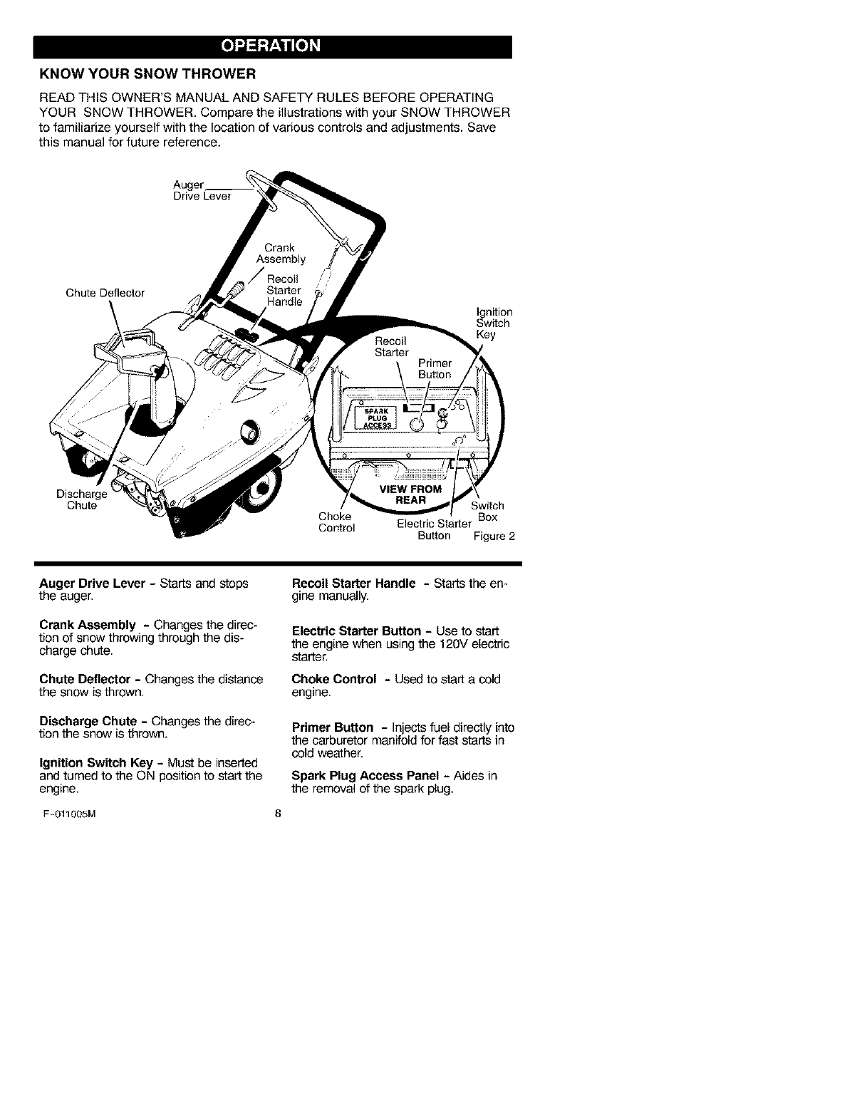
KNOW YOUR SNOW THROWER
READ THIS OWNER'S MANUAL AND SAFETY RULES BEFORE OPERATING
YOUR SNOW THROWER. Compare the illustrations with your SNOW THROWER
to familiarize yourself with the location of various controls and adjustments. Save
this manual for future reference.
Drive Lever
Chute Deflector
Ignition
Switch
Key
Discharge
Chute REAR Switch
Choke Box
Control Electric Starter
Button Figure 2
Auger Drive Lever - Starts and stops
the auger.
Crank Assembly - Changes the direc-
tion of snow throwing through the dis-
charge chute.
Chute Deflector - Changes the distance
the snow is thrown.
Discharge Chute -Changes the direc-
tion the snow is thrown.
Ignition Switch Key -Must be inserted
and turned to the ON position to start the
engine.
RecoilStarter Handle -Startsthe en-
gine manually.
Electric Starter Button - Use to start
the engine when using the 120V electric
starter.
Choke Control -Used to start a cold
engine.
Primer Button -Injects fuel directly into
the carburetor manifold for fast starts in
cold weather.
Spark Plug Access Panel - Aides in
the removal of the spark plug.
F-011005M 8
The operation of any snow thrower can
result in foreign objects being thrown
into the eyes, which can result in se-
vere eye damage. Always wear safety
glasses or eye shields while operating
the snow thrower.
We recommend standard safety
glasses or a wide vision safety mask for
over your glasses.
,_ WARNING: Read Owner's
Manual before operating
machine. Never direct dis-
charge toward bystanders stop the
engine before unclogging discharge
chute or auger housing and before
leaving the machine.
TO STOP YOUR
SNOW THROWER
1. To stop throwing snow, release the
auger drive lever. See Figure 2.
NOTE: If the snow thrower contin-
ues to slowly move forward, see
"How To Adjust The Auger Control
Cable" in the Service And Adjust-
ment Section.
2. To stop the engine, move the igni-
tion key to the off position.
TO CONTROL SNOW DISCHARGE
1. Turn the chute control rod to set the
direction of the snow throwing.
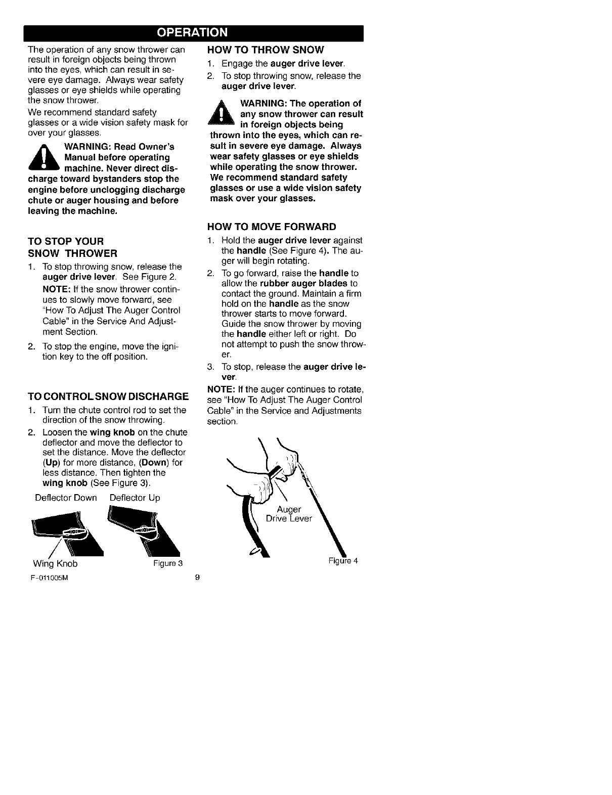
2. Loosen the wing knob on the chute
deflector and move the deflector to
set the distance. Move the deflector
(Up) for more distance, (Down) for
less distance. Then tighten the
wing knob (See Figure 3).
Deflector Down Deflector Up
HOW TO THROW SNOW
1. Engage the auger drive lever.
2. To stop throwing snow, release the
auger drive lever.
_bL ARNING: The operation of
any snow thrower can result
in foreign objects being
thrown into the eyes, which can re-
sult in severe eye damage. Always
wear safety glasses or eye shields
while operating the snow thrower.
We recommend standard safety
glasses or use a wide vision safety
mask over your glasses.
HOW TO MOVE FORWARD
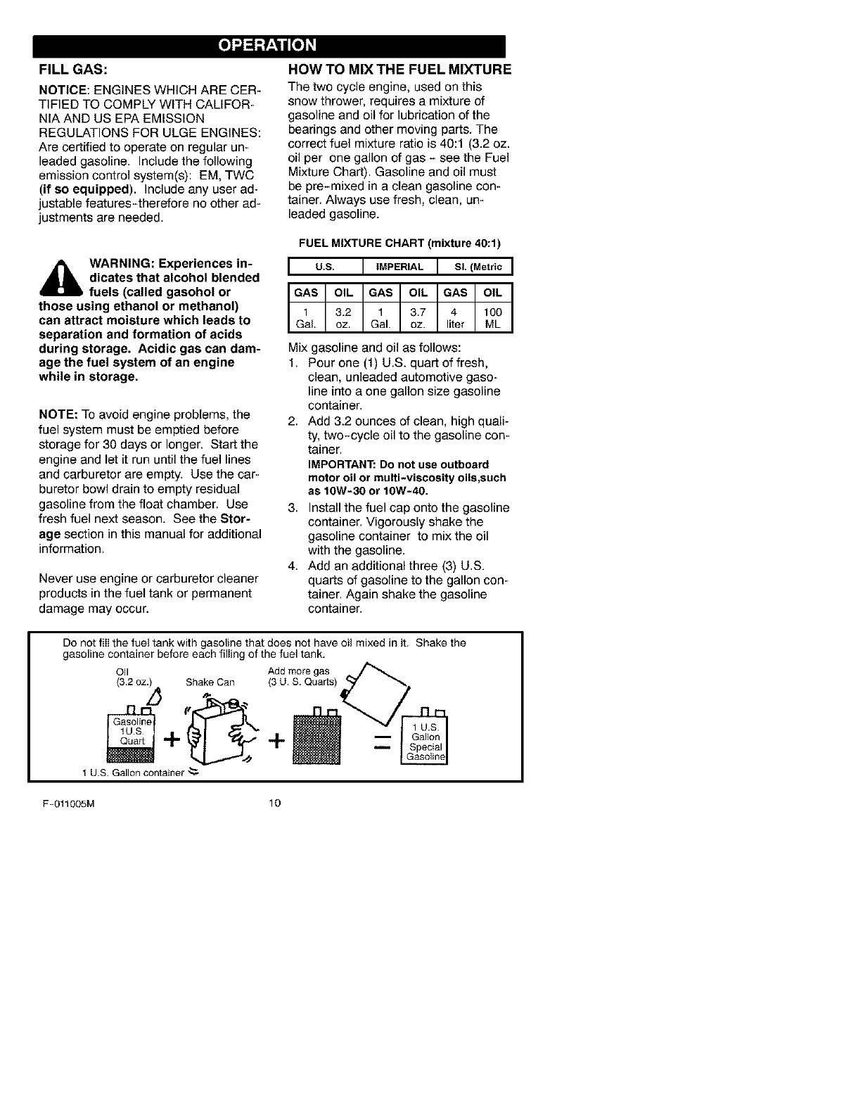
1,
2.
Hold the auger drive lever against
the handle (See Figure 4). The au-
ger will begin rotating.
To go forward, raise the handle to
allow the rubber auger blades to
contact the ground. Maintain a firm
hold on the handle as the snow
thrower starts to move forward.
Guide the snow thrower by moving
the handle either left or right. Do
not attempt to push the snow throw-
er.
3. To stop, release the auger drive le-
ver.
NOTE: If the auger continues to rotate,
see "How To Adjust The Auger Control
Cable" in the Service and Adjustments
section.
Auger
Wing Knob Figure 3
F-011005M 9
Figure 4
FILL GAS:
NOTICE: ENGINES WHICH ARE CER-
TIFIED TO COMPLY WITH CALIFOR-
NIA AND US EPA EMISSION
REGULATIONS FOR ULGE ENGINES:
Are certified to operate on regular un-
leaded gasoline. Includethe following
emission control system(s): EM, TWC
(if so equipped). Include any user ad-
justable features-therefore no other ad-
justments are needed.
_lb WARNING: Experiences in-
dicates that alcohol blended
fuels (called gasohol or
those using ethanol or methanol)
can attract moisture which leads to
separation and formation of acids
during storage. Acidic gas can dam-
age the fuel system of an engine
while in storage.
NOTE: To avoid engine problems, the
fuel system must be emptied before
storage for 30 days or longer. Start the
engine and let it run until the fuel lines
and carburetor are empty. Use the car-
buretor bowl drain to empty residual
gasoline from the float chamber. Use
fresh fuel next season. See the Stor-
age section in this manual for additional
information.
Never use engine or carburetor cleaner
products in the fuel tank or permanent
damage may occur.
HOW TO MIX THE FUEL MIXTURE
The two cycle engine, used on this
snow thrower, requires a mixture of
gasoline and oil for lubrication of the
bearings and other moving parts. The
correct fuel mixture ratio is 40:1 (3.2 oz.
oil per one gallon of gas - see the Fuel
Mixture Chart). Gasoline and oil must
be pre-mixed in a clean gasoline con-
tainer. Always use fresh, clean, un-
leaded gasoline.
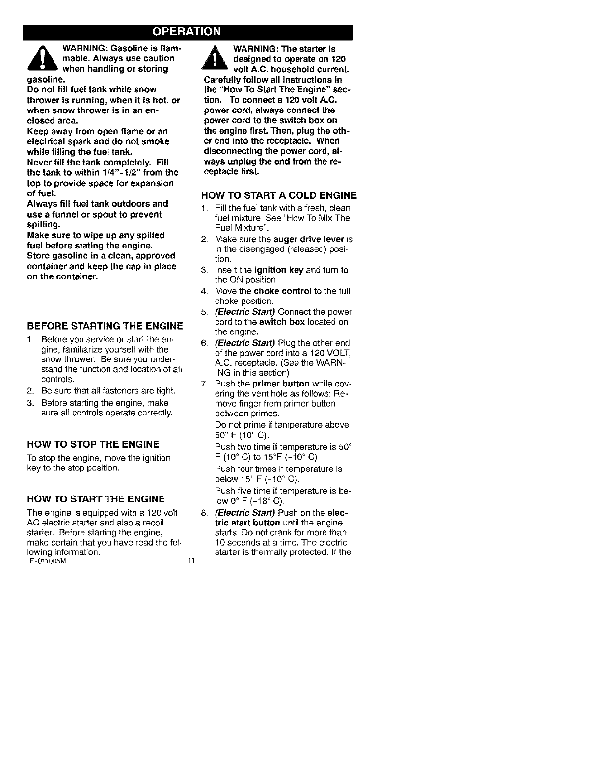
FUEL MIXTURE CHART (mixture 40:1)
Ios I'"PE"'ALIs,l.e,rtoI
Mix gasoline and oil as follows:
1. Pour one (1) U.S. quart of fresh,
clean, unleaded automotive gaso-
line into a one gallon size gasoline
container.
2. Add 3.2 ounces of clean, high quali-
ty, two-cycle oil to the gasoline con-
tainer.
IMPORTANT:Do not use outboard
motor oil or multi-viscosity oils,such
as 10W-30 or 10W-40.
3. Install the fuel cap onto the gasoline
container. Vigorously shake the
gasoline container to mix the oil
with the gasoline.
4. Add an additional three (3) U.S.
quarts of gasoline to the gallon con-
tainer. Again shake the gasoline
container.
Do nor fill the fuel tank with gasoline that does not have oil mixed in it. Shake the
gasoline container before each filling of the fuel tank.
OII Add more gas
(32 oz.) Shake Can (3 U. S. Quarts)
+
1 U.S Gallon container "_
F-011005M 10
_lb ARNING: Gasoline is flam-
mable. Always use caution
when handling or storing
gasoline.
Do not fill fuel tank while snow
thrower is running, when it is hot, or
when snow thrower is in an en-
closed area.
Keep away from open flame or an
electrical spark and do not smoke
while filling the fuel tank.
Never fill the tank completely. Fill
the tank to within 1/4"-1/2" from the
top to provide space for expansion
of fuel.
Always fill fuel tank outdoors and
use a funnel or spout to prevent
spilling.
Make sure to wipe up any spilled
fuel before stating the engine.
Store gasoline in a clean, approved
container and keep the cap in place
on the container.
BEFORE STARTING THE ENGINE
1. Before you service or start the en-
gine, familiarize yourself with the
snow thrower. Be sure you under-
stand the function and location of all
controls.
2. Be sure that all fasteners are tight.
3. Before starting the engine, make
sure all controls operate correctly.
HOW TO STOP THE ENGINE
To stop the engine, move the ignition
key to the stop position.
HOW TO START THE ENGINE
The engine is equipped with a 120 volt
AC electric starter and also a recoil
starter. Before starting the engine,
make certain that you have read the fol-
lowing information.
F-011005M
_h ARNING: The starter is
designed to operate on 120
volt A.C. household current.
Carefully follow all instructions in
the "How To Start The Engine" sec-
tion. To connect a 120 volt A.C.
power cord, always connect the
power cord to the switch box on
the engine first. Then, plug the oth-
er end into the receptacle. When
disconnecting the power cord, al-
ways unplug the end from the re-
ceptacle first.
11
HOW TO START A COLD ENGINE
1. Fill the fuel tank with a fresh, clean
fuel mixture. See "How To Mix The
Fuel Mixture".
2. Make sure the auger drive lever is
in the disengaged (released) posi-
tion.
3. Insert the ignition key and turn to
the ON position.
4. Move the choke control to the full
choke position.
5. (Electric Start) Connect the power
cord to the switch box located on
the engine.
6. (Electric Start) Plug the other end
of the power cord into a 120 VOLT,
A.C. receptacle. (See the WARN-
ING in this section).
7. Push the primer button while cov-
ering the vent hole as follows: Re-
move finger from primer button
between primes.
Do not prime if temperature above
50 ° F (10 ° C).
Push two time if temperature is 50 °
F (10 ° C) to 15°F (-10 ° C).
Push four times if temperature is
below 15° F (-10 ° C).
Push five time if temperature is be-
low 0° F (-18 ° C).
8. (Electric Start) Push on the elec-
tric start button until the engine
starts. Do not crank for more than
10 seconds at a time. The electric
starter is thermally protected. If the
electricstarteroverheates,itwillau-
tomaticallystopandcanonlybere-
startedwhenithascooledtoasafe
temperature.Awaitofabout5to10
minutesisrequiredtoallowthe
electricstartertocool.
9. (Recoil Start) Rapidly pull the re-
coil starter handle. Do not allow
the recoil starter handle to snap
back. Slowly return the recoil start-
er handle,
10. If the engine does not start in 5 or 6
tries, See the "Trouble Shooting
Chart" Instructions.
11. (Electric Start) When the engine
starts, release the electric start
button,
12. (Electric Start) First disconnect the
power cord from the receptacle.
Then, disconnect the power cord
from the switch box.
13. As the engine warms up, move the
choke control to 1/2 choke posi-
tion. When the engine runs smooth-
ly, move the choke control to the
off position.
NOTE: Allow the engine to warm up for
several minutes before blowing snow in
temperatures below 0°E
WARM START
If restarting a warm engine after a short
shutdown, leave choke at "OFF" and do
not push the primer button. If the en-
gine fails to start, follow the Cold Start
instructions.
_lb WARNING: Never run en-
gine indoors or in enclosed,
poorly ventilated areas. En-
gine exhaust contains CARBON
MONOXIDE, AN ODORLESS AND
DEADLY GAS. Keep hands, feet,
hair and loose clothing away from
any moving parts on engine and
snow thrower.
The temperature of muffler and
nearby areas may exceed 150°1=.
Avoid these areas.
DO NOT allow children or young
teenagers to operate or be near
snow thrower while it is operating.
_hb ARNING: Do not attempt
to remove any item that may
become lodged in auger
without taking the following precau-
tions:
• Release auger drive lever.
•Move the ignition lever to the
stop position to stop the engine.
•Disconnect spark plug wire.
Do not place your hands in the
auger or discharge chute. Use a
pry bar.
F-011005M 12
SNOW THROWING TIPS
1. When the handle is raised, the au-
ger blades will engage the ground
and the snow thrower will move for-
ward. When the auger drive lever is
released, the auger blades will stop.
If the blades do not stop, see "How
To Adjust The Auger Drive Cable" in
the Service And Adjustment section.
2. Most efficient snow throwing is ac-
complished when the snow is re-
moved immediately after if falls.
3. For complete snow removal, slightly
overlap each previous path.
4. Whenever possible, discharge the
snow down wind.
5. The distance the snow will be dis-
charged can be adjusted by moving
the discharge chute deflector. Raise
the deflector for more distance or
lower the deflector for less distance.
6. In windy conditions, lower the chute
deflector to direct the discharged
snow close to the ground where it is
less likely to blow into unwanted
areas.
7. For safety and to prevent damage
to the snow thrower, keep the area
to be cleared free of stones, toys
and other foreign objects.
8. Do not use the auger propelling fea-
ture when clearing gravel or
crushed rock driveways. Move the
handle down to slightly raise the au-
ger.
9. The forward speed of the snow
thrower is dependent on the depth
and weight of the snow. Experience
will establish the most effective
method of using the snow thrower
under different conditions.
10. After each snow throwing job, allow
the engine to run for a few minutes.
The snow and accumulated ice will
melt off the engine.
11. Clean the snow thrower after each
use.
12. Remove ice, snow and debris from
the entire snow thrower. Flush with
water to remove all salt or other
chemicals. Wipe snow thrower dry.
DRY AND AVERAGE SNOW
1. Snow up to eight inches deep can
be removed rapidly and easily by
walking at a moderate rate. For
snow or drifts of a greater
depth,slow your pace to allow the
discharge chute to dispose of the
snow as rapidly as the auger re-
ceives the snow.
2. Plan to have the snow discharged in
the direction the wind is blowing.
WET PACKED SNOW
Move slowly into wet, packed snow. If
the wet, packed snow causes the auger
to slow down or the discharge chute be-
gins to clog, back off and begin a series
of short back and forth jabs into the
snow. These short back and forth jabs,
four to six inches, will "belch" the snow
from the chute.
SNOW BANKS AND DRIFTS
In snow of greater depth than the unit,
use the same "jabbing" technique de-
scribed above. Turn the discharge
chute away from the snow bank. More
time will be required to remove snow of
this type than level snow.
F-011005M 13
CUSTOMER RESPONSIBILITIES
SERVICERECORDS
Fillindatesasyou Before Every Every Every
completeregular Each 5 10 25 Each Before SERVICE
service. Use Often Hours Hours Hours Season Storage DATES
iiiiii i
Tighten Atl Screws and ./ _/ .....
Nuts
Check Spark Plug _/ _/
,,,,,, ,
Lubricate Chute Control .....
Flange
Drain Fuel _/
Check Fuel _/ . I I I I I I
Check Auger Ddve
_able Ad ustment
See Cab e Ad ustment _/
GENERAL RECOMMENDATIONS
The warranty on this snow thrower
does not cover items that have been
subjected to operator abuse or negIF
gence. To receive full value from the
warranty, the operator must maintain
the snow thrower as instructed in this
manual.
Some adjustments will need to be
made periodically to properly maintain
your snow thrower.
All adjustments in the Service and Ad-
justments section of this manual
should be checked at least once each
season.
AFTER EACH USE
Check for any loose or damaged
parts.
Tighten any loose fasteners.
Check and maintain the auger.
Check controls to make sure they
are functioning properly.
If any parts are worn or damaged,
replace immediately.
Run the machine to clear the auger
of snow.
To prevent freezing of the auger or
controls, remove all snow and slush
from the snow thrower.
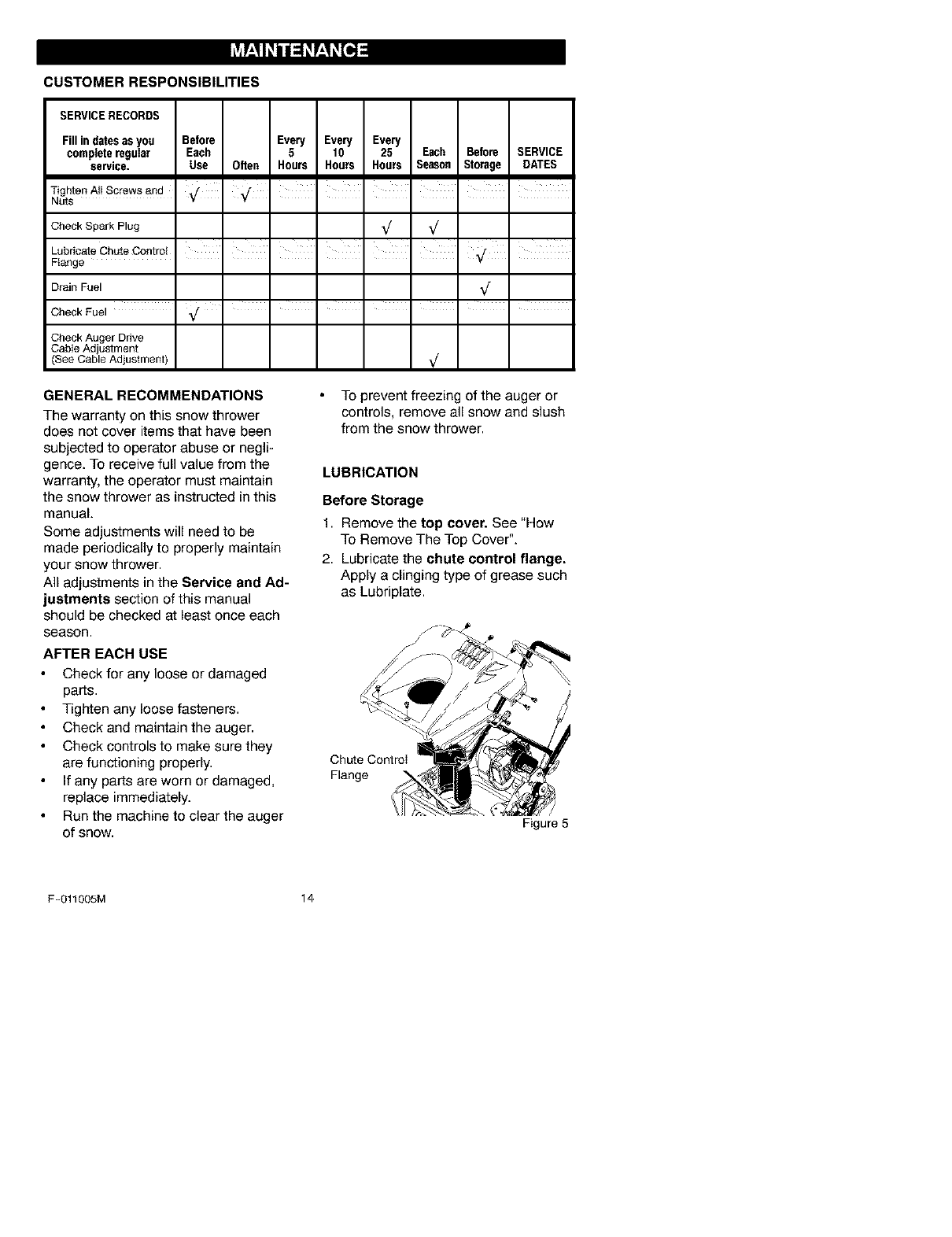
LUBRICATION
Before Storage
1. Remove the top cover. See "How
To Remove The Top Cover".
2. Lubricate the chute control flange.
Apply a clinging type of grease such
as Lubriplate.
Chute Controi
Flange
Figure 5
F-011005M 14
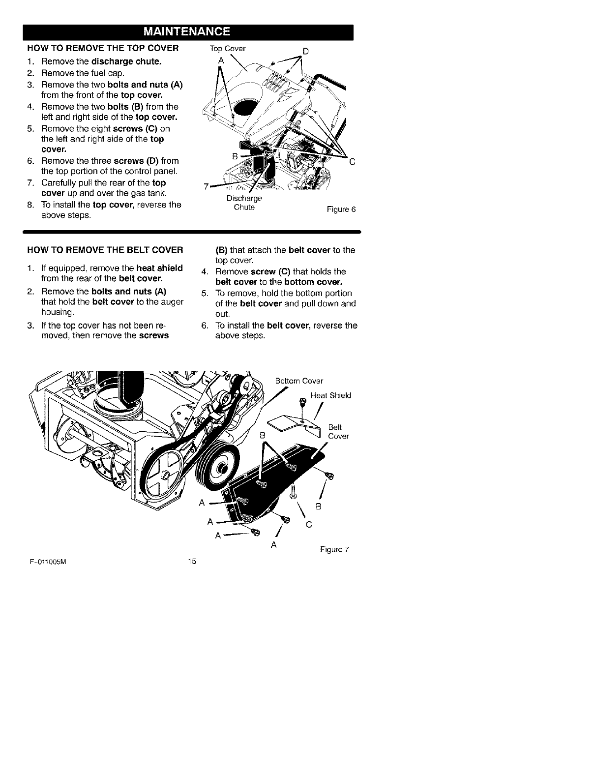
HOW TO REMOVE THE TOP COVER
1. Remove the discharge chute.
2. Remove the fuel cap.
3. Remove the two bolts and nuts (A)
from the front of the top cover.
4. Remove the two bolts (B) from the
left and right side of the top cover.
5. Remove the eight screws (C) on
the left and right side of the top
cover.
6. Remove the three screws (D) from
the top portion of the control panel.
7. Carefully pull the rear of the top
cover up and over the gas tank.
8. To install the top cover, reverse the
above steps.
TopCover
A
Discharge
Chute
D
Figure 6
HOW TO REMOVE THE BELT COVER
1. If equipped, remove the heat shield
from the rear of the belt cover.
2. Remove the bolts and nuts (A)
that hold the belt cover to the auger
housing.
3. If the top cover has not been re+
moved, then remove the screws
(B) that attach the belt cover to the
top cover.
4. Remove screw (C) that holds the
belt cover to the bottom cover.
5. To remove, hold the bottom portion
of the belt cover and pull down and
out.
6. To install the belt cover, reverse the
above steps.
Bottom Cover
Heat Shield
Belt
Cover
F-011005M 15
A
\
/c
A
B
Figure 7
_lb ARNING: To prevent acciden-
tal starting when making any
adjustments or repairs, always
disconnect the spark plug wire and place
it where it cannot make contact with the
spark plug.
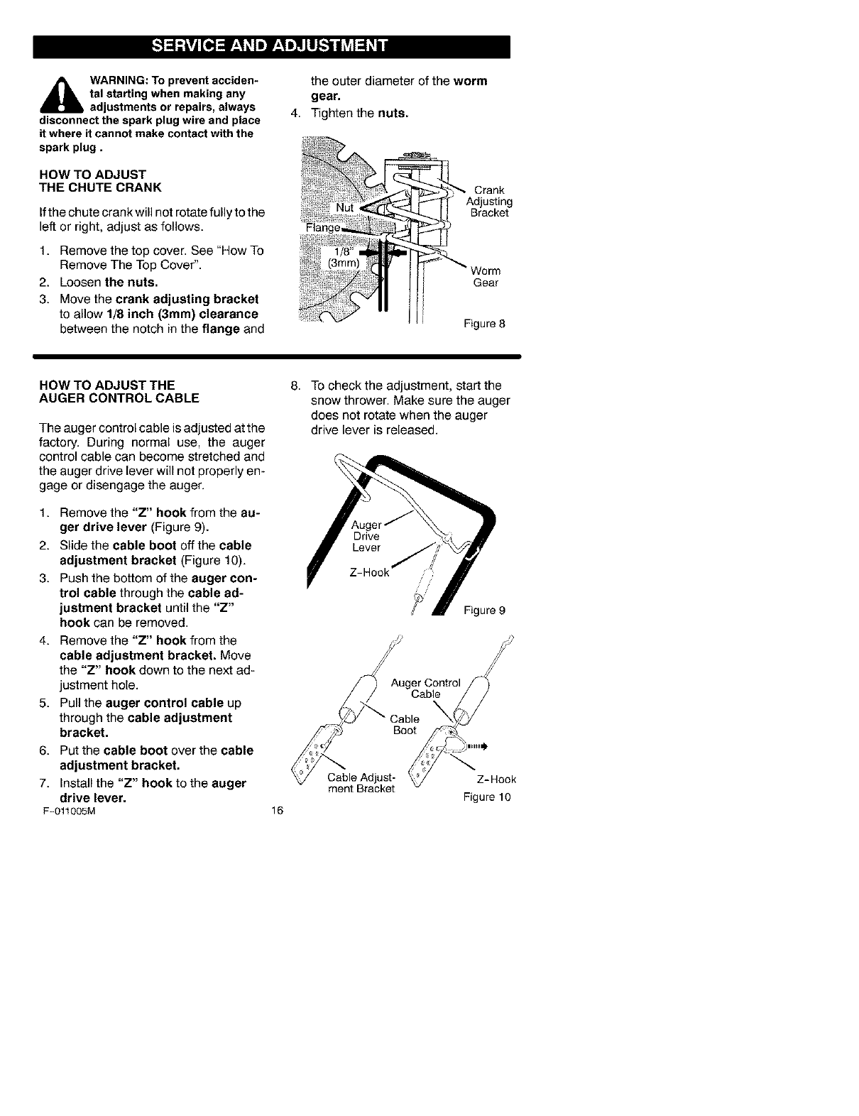
HOW TO ADJUST
THE CHUTECRANK
Ifthe chute crank will not rotate fuIly to the
left or right, adjust as follows.
1. Remove the top cover. See "How To
Remove The Top Cover".
2. Loosen the nuts.
3. Move the crank adjusting bracket
to allow 1/8 inch (3mm) clearance
between the notch in the flange and
the outer diameter of the worm
gear.
4. Tighten the nuts.
Worm
Gear
Figure 8
HOW TO ADJUST THE
AUGER CONTROL CABLE
The auger control cable is adjusted at the
factory. During normal use, the auger
control cable can become stretched and
the auger drive lever will not properly en-
gage or disengage the auger.
1. Remove the "Z" hook from the au-
ger drive lever (Figure 9).
2. Slide the cable boot offthe cable
adjustment bracket (Figure 10).
3. Push the bottom of the auger con-
trol cable through the cable ad-
justment bracket until the "Z"
hook can be removed.
4. Remove the "Z" hook from the
cable adjustment bracket. Move
the "Z" hook down to the next ad-
justment hole.
5. Pull the auger control cable up
through the cable adjustment
bracket.
6. Put the cable boot over the cable
adjustment bracket.
7. Install the "Z" hook to the auger
drive lever.
F-011005M
8. To check the adjustment, start the
snow thrower. Make sure the auger
does not rotate when the auger
drive lever is released.
Drive
Lever
Z-Hook
Auger Control
Cable
16
Cable Adjust-
ment Bracket Z-Hook
Figure 10
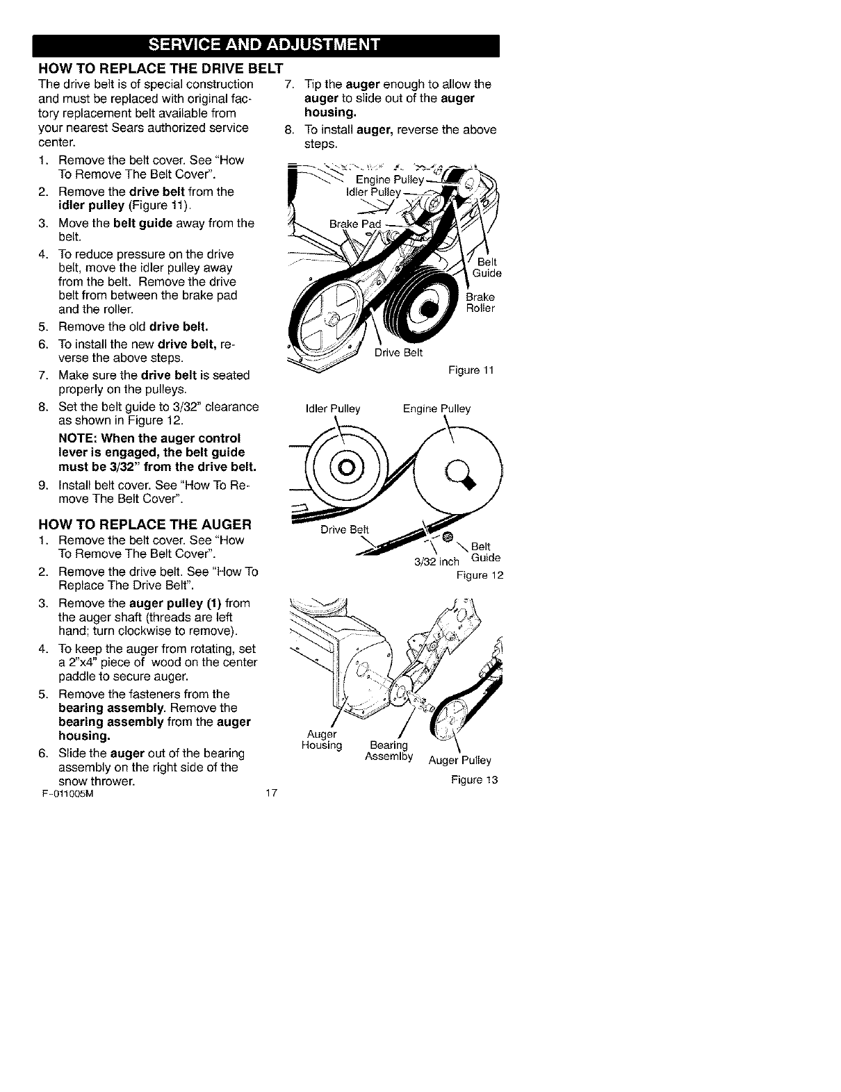
HOW TO REPLACE THE DRIVE BELT
The drive belt is of special construction
and must be replaced with original fac-
tory replacement belt available from
your nearest Sears authorized service
center.
1. Remove the belt cover. See "How
To Remove The Belt Cover".
2. Remove the drive belt from the
idler pulley (Figure 11).
3. Move the belt guide away from the
belt.
4. To reduce pressure on the drive
belt, move the idler pulley away
from the belt. Remove the drive
belt from between the brake pad
and the roller.
5. Remove the old drive belt.
6. To install the new drive belt, re-
verse the above steps.
7. Make sure the drive belt is seated
properly on the pulleys.
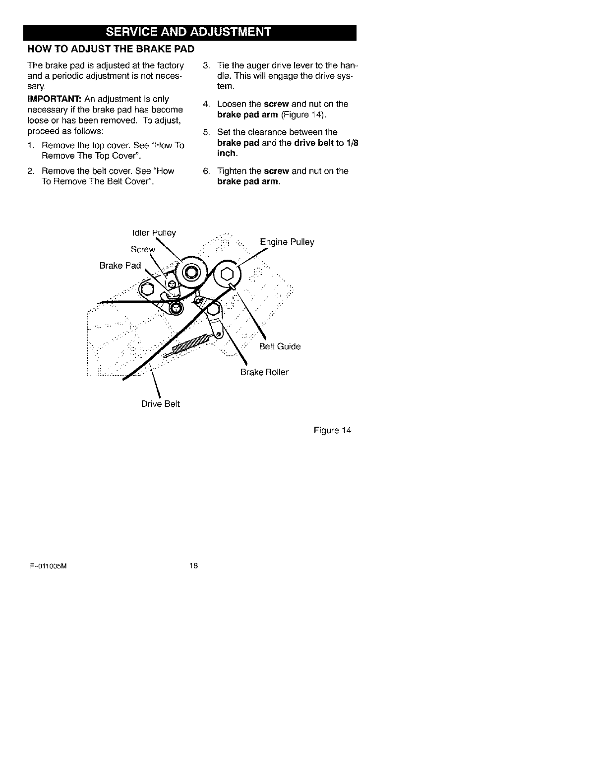
8. Set the belt guide to 3/32" clearance
as shown in Figure 12.
NOTE: When the auger control
lever is engaged, the belt guide
must be 3/32" from the drive belt.
9. Install belt cover. See "How To Re-
move The Belt Cover".
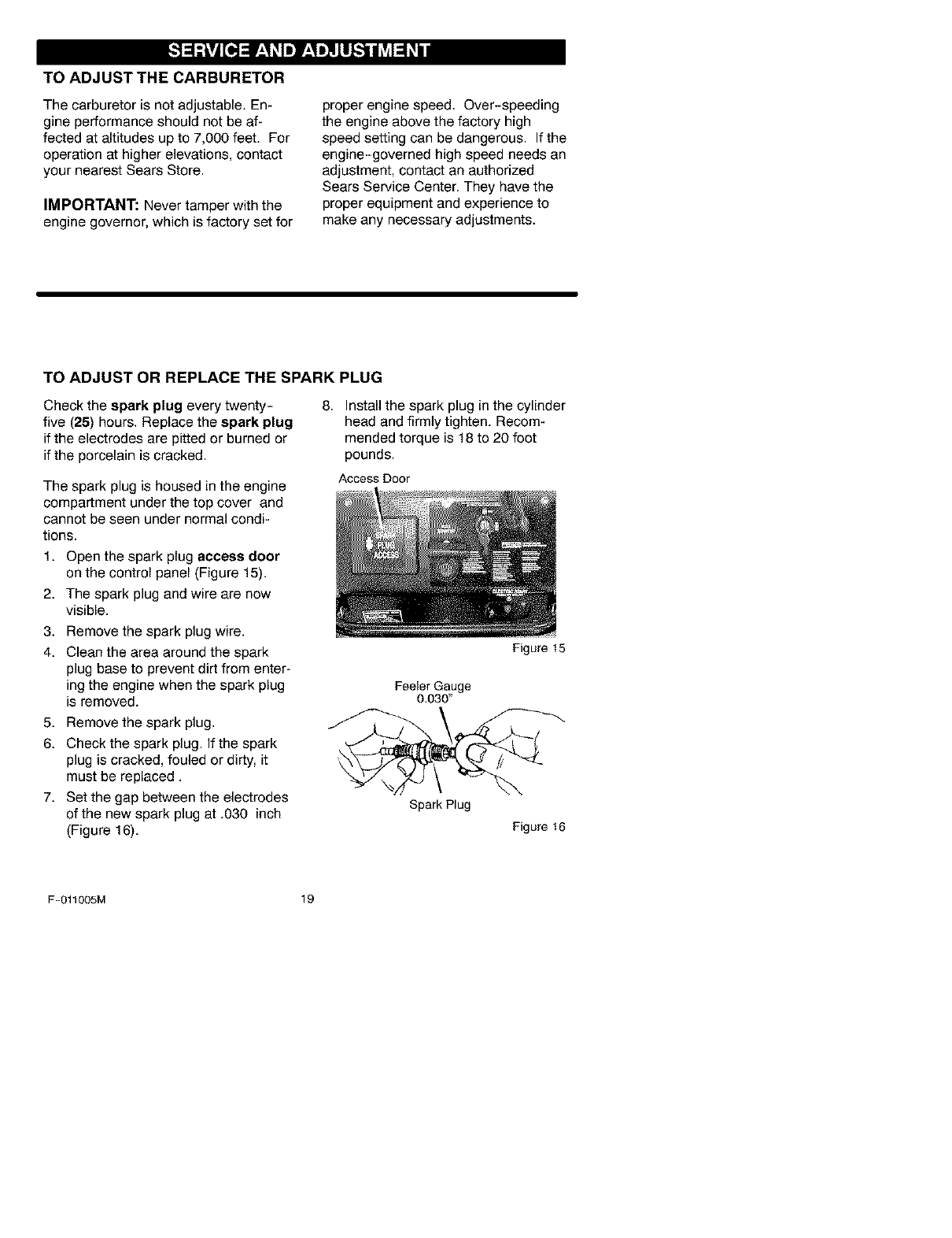
HOW TO REPLACE THE AUGER
t. Remove the belt cover. See "How
To Remove The Belt Cover".
2. Remove the drive belt. See "How To
Replace The Drive Belt".
3. Remove the auger pulley (1) from
the auger shaft (threads are left
hand; turn clockwise to remove).
4. To keep the auger from rotating, set
a 2"x4" piece of wood on the center
paddle to secure auger.
5. Remove the fasteners from the
bearing assembly. Remove the
bearing assembly from the auger
housing.
6. Slide the auger out of the bearing
assembly on the right side of the
snow thrower.
F-011005M
7. Tip the auger enough to allow the
auger to slide out of the auger
housing.
8. To install auger, reverse the above
steps.
Belt
Guide
Brake
Rolier
Drive Belt
Figure 11
17
Idler Pulley Engine Pulley
\Be,t
3/32 inch Guide
Figure 12
Auger
Housing Bearing
Assemlby Auger Puliey
Figure 13
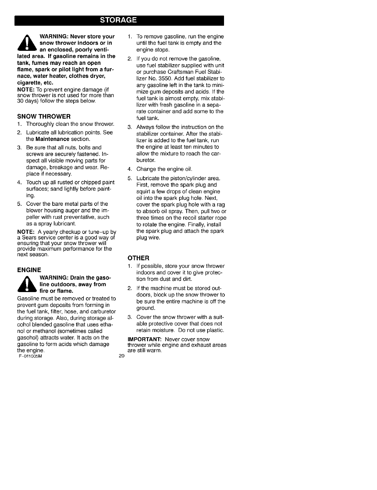
HOW TO ADJUST THE BRAKE PAD
The brake pad is adjusted at the factory
and a periodic adjustment is not neces-
sary.
IMPORTANT: An adjustment is only
necessary if the brake pad has become
loose or has been removed. To adjust,
proceed as follows:
1. Remove the top cover. See "How To
Remove The Top Cover".
2. Remove the belt cover. See "How
To Remove The Belt Cover".
3. Tie the auger drive lever to the han-
dle. This will engage the drive sys-
tem.
4,
5.
Loosen the screw and nut on the
brake pad arm (Figure 14).
Set the clearance between the
brake pad and the drive belt to 1/8
inch.
6. Tighten the screw and nut on the
brake pad arm.
Idler Pulley
Brake Pad
-:::_ :. Engine Pulley
::' Belt Guide
Brake Roller
Drive Belt
Figure 14
F-011005M 18
TO ADJUST THE CARBURETOR
The carburetor is not adjustable. En-
gine performance should not be af-
fected at altitudes up to 7,000 feet. For
operation at higher elevations, contact
your nearest Sears Store.
IMPORTANT: Never tamper with the
engine governor, which is factory set for
proper engine speed. Over-speeding
the engine above the factory high
speed setting can be dangerous. If the
engine-governed high speed needs an
adjustment, contact an authorized
Sears Service Center. They have the
proper equipment and experience to
make any necessary adjustments.
TO ADJUST OR REPLACE THE SPARK PLUG
Check the spark plug every twenty-
five (25) hours. Replace the spark plug
if the electrodes are pitted or burned or
if the porcelain is cracked.
The spark plug is housed in the engine
compartment under the top cover and
cannot be seen under normal condi-
tions.
1. Open the spark plug access door
on the control panel (Figure 15).
2. The spark plug and wire are now
visible.
3. Remove the spark plug wire.
4. Clean the area around the spark
plug base to prevent dirt from enter-
ing the engine when the spark plug
is removed.
5. Remove the spark plug.
6. Check the spark plug. Ifthespark
plug is cracked, fouled or dirty, it
must be replaced.
7. Set the gap between the electrodes
of the new spark plug at .030 inch
(Figure 16).
8. Install the spark plug in the cylinder
head and firmly tighten. Recom-
mended torque is 18 to 20 foot
pounds.
Access Door
FeeJerGauge
0.030"
Spark Plug
Figure 15
Figure 16
F-011005M 19
_[b ARNING: Never store your
snow thrower indoors or in
an enclosed, poorly venti-
lated area. If gasoline remains in the
tank, fumes may reach an open
flame, spark or pilot light from a fur-
nace, water heater, clothes dryer,
cigarette, etc.
NOTE: To prevent engine damage (if
snow thrower is not used for more than
30 days) follow the steps below.
SNOW THROWER
1. Thoroughly clean the snow thrower.
2. Lubricate all lubrication points. See
the Maintenance section.
3. Be sure that all nuts, bolts and
screws are securely fastened. In-
spect all visible moving parts for
damage, breakage and wear. Re-
place if necessary.
4. Touch up all rusted or chipped paint
surfaces; sand lightly before paint-
ing.
5. Cover the bare metal parts of the
blower housing auger and the im-
peller with rust preventative, such
as a spray lubricant.
NOTE: A yearly checkup or tune-up by
a Sears service center is a good way of
ensuring that your snow thrower will
provide maximum performance for the
next season.
ENGINE
_lb ARNING: Drain the gaso-
line outdoors, away from
fire or flame.
Gasoline must be removed or treated to
prevent gum deposits from forming in
the fuel tank, filter, hose, and carburetor
during storage. Also, during storage al-
cohol blended gasoline that uses etha-
nol or methanol (sometimes called
gasohol) attracts water. It acts on the
gasoline to form acids which damage
the engine.
F-011005M
1,
2.
3,
4,
5.
TO remove gasoline, run the engine
until the fuel tank is empty and the
engine stops.
If you do not remove the gasoline,
use fuel stabilizer supplied with unit
or purchase Craftsman Fuel Stabi-
lizer No. 3550. Add fuel stabilizer to
any gasoline left in the tank to mini-
mize gum deposits and acids. If the
fuel tank is almost empty, mix stabi-
lizer with fresh gasoline in a sepa-
rate container and add some to the
fuel tank.
Always follow the instruction on the
stabilizer container. After the stabi-
lizer is added to the fuel tank, run
the engine at least ten minutes to
allow the mixture to reach the car-
buretor.
Change the engine oil.
Lubricate the piston/cylinder area.
First, remove the spark plug and
squirt a few drops of clean engine
oil into the spark plug hole. Next,
cover the spark plug hole with a rag
to absorb oil spray. Then, pull two or
three times on the recoil starter rope
to rotate the engine. Finally, install
the spark plug and attach the spark
plug wire.
2O
OTHER
1. If possible, store your snow thrower
indoors and cover it to give protec-
tion from dust and dirt.
2, If the machine must be stored out-
doors, block up the snow thrower to
be sure the entire machine is off the
ground.
3. Cover the snow thrower with a suit-
able protective cover that does not
retain moisture. Do not use plastic.
IMPORTANT: Never cover snow
thrower while engine and exhaust areas
are still warm.
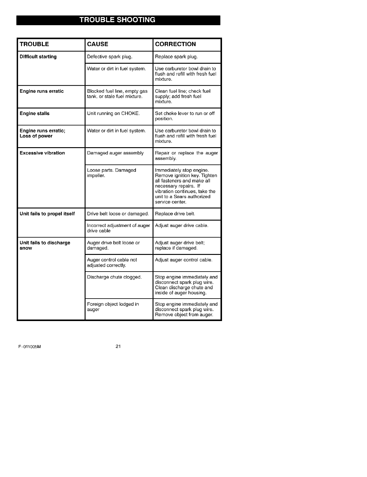
TROUBLE CORRECTION
Difficult starting Replace spark plug.
CAUSE
Defective spark plug.
Water or dirt in fuel system. Use carburetor bowl drain to
flush and refill with fresh fuel
mixture.
Engine runs erratic Blocked fuel line, empty gas Clean fuel line; check fuel
tank, or stale fuel mixture, supply; add fresh fuel
mixture.
Engine stalls Unit running on CHOKE. Set choke lever to run or off
position.
Engine runs erratic; Water or dirt in fuel system. Use carburetor bowl drain to
Loss of power flush and refill with fresh fuel
mixture.
Excessive vibration Damaged auger assembly Repair or replace the auger
assembly.
Unit fails to propel itself
Loose parts. Damaged
impeller.
Drive belt ioose or damaged.
Incorrect adjustment of auger
drive cable
Immediately stop engine.
Remove ignition key. Tighten
all fasteners and make all
necessary repairs. If
vibration continues, take the
unit to a Sears authorized
service center.
Unit fails to discharge
snow
Replace drive belt.
Adjust auger drive cable.
Auger drive belt loose or Adjust auger drive belt;
damaged, replace if damaged.
Auger control cable not Adjust auger control cable.
adjusted correctly.
Discharge chute clogged. Stop engine immediately and
disconnect spark plug wire.
Clean discharge chute and
inside of auger housing.
Foreign object Iodged in Stop engine immediately and
auger disconnect spark plug wire
Remove object from auger.
F-011005M 21
SEARS, ROEBUCK AND CO.
Federal and California Emission Control Systems Limited Warranty
Small Off-Road Engines
CALIFORNIA & US EPA EMISSION
CONTROL WARRANTY STATEMENT
The U. S. Environmental Protection Agency
("EPA"), the California Air Resources Board
("CARB") and Sears, Roebuck and Co. are
pleased to explain the Federal and California
Emission Control Systems Warranty on your
new small oft-road engine. In California, new
1995 and later smali oft-road engines must be
designed, built and equipped to meet the
State's stringent anti-smog standards. In oth-
er states, new 1997 and later model year en-
gines must be designed, built and equipped, at
the time of sale, to meet the U.S. EPA regula-
tions for small non-road engines. Sears, Roe-
buck and Co. will warrant the emission control
system on your small oft-road engine for the
periods of time listed below, provided there
has been no abuse, neglect, unapproved mod-
ification, or improper maintenance of your
small oft-road engine.
Your emission control system may include
parts such as the carburetor, ignition system
and exhaust system. Also included may be the
compression release system and other emis-
sion-related assemblies.
Where a warrantable condition exists, Sears,
Roebuck and Co. will repair your small off-
road engine at no cost to you for diagnosis,
parts and labor.
MANUFACTURER'S EMISSION
CONTROL SYSTEM WARRANTY
COVERAGE
Emission control systems on 1995 and later
model year California small oft-road engines
are warranted for two years as hereinafter
noted. In other states, 1997 and later model
year engines are also warranted for two years.
If, during such warranty period, any emission-
related part on your engine is defective in ma-
terials or workmanship, the part will be
repaired or replaced by Sears, Roebuck and
Co.
OWNER'S WARRANTY
RESPONSIBILITIES
As the small oft-road engine owner, you are
responsible for the performance of the re-
F-011005M
quired maintenance listed in your Owner's
Manual, but Sears, Roebuck and Co. will not
deny warranty solely due to the lack of receipts
or for your failure to provide written evidence
of the performance of all scheduled mainte-
nance.
As the small oft-road engine owner, you
should, however, be aware that Sears, Roe-
buck and Co. may deny you warranty cover-
age if your small oft-road engine or a part
thereof has failed due to abuse, neglect, im-
proper maintenance or unapproved modifica-
tions.
You are responsible for presenting your small
oft-road engine to a Sears, Roebuck and Co.
Authorized Service Outlet as soon as a prob-
lem exists. The warranty repairs should be
completed in a reasonable amount of time, not
to exceed 30 days.
Warranty service can be arranged by contact-
ing either a Sears, Roebuck and Co. Autho-
rized Service Outlet, or by contacting Sears,
Roebuck and Co. at 1-800-473-7247.
22
IMPORTANT NOTE
Esta This warranty statement explains your
rights and obligations under the Emission
Control System Warranty ("ECS Warranty")
which is provided to you by Sears, Roebuck
and Co. pursuant to California law. See also
the Sears, Roebuck and Co. Limited Warran-
ties for Sears, Roebuck and Co. which is en-
closed therewith on a separate sheet and also
is provided to you by Sears, Roebuck and Co.
The ECS Warranty applies only to the emis-
sion control system of your new engine. To the
extent that there is any conflict in terms be-
tween the ECS Warranty and the Sears, Roe-
buck and Co. Warranty, the ECS Warranty
shall apply except in any circumstances in
which the Sears, Roebuck and Co. Warranty
may provide a Iongerwarranty period. Both the
ECS Warranty and the Sears, Roebuck and
Co. Warranty describe important rights and
obligations with respect to your new engine.
Warranty service can only be performed by a
Sears, Roebuck and Co. Authorized Service
Outlet. At the time of requesting warranty ser-
vice, evidence must be presented of the date
of sale to the original purchaser. The purchas-
ershallpayanychargesformakingservice
callsand/orfortransportingtheproductsto
andfromtheplacewheretheinspectionand/
orwarrantyworkisperformed.Thepurchaser
shallberesponsibleforanydamageorlossin-
curredinconnectionwiththetransportationof
anyengineoranypart(s)thereofsubmittedfor
inspectionand/orwarrantywork.
Ifyouhaveanyquestionsregardingyourwar-
rantyrightsandresponsibilities,youshould
contactSears,Roebuckand Oo. at
1-800-473-7247.
EMISSION CONTROL SYSTEM
WARRANTY
Emission Control System Warranty ("ECS
Warranty") for 1995 and later model year Cali-
fornia small off-road engines (for other states,
1997 and later model year engines):
A. APPLICABILITY: This warranty shall apply
to 1995 and later model year California small
off-road engines (for other states, 1997 and
later model year engines). The ECS Warranty
Period shall begin on the date the new engine
or equipment is delivered to its original, end-
use purchaser, and shall continue for 24 con-
secutive months thereafter.
B. GENERAL EMISSIONS WARRANTY
COVERAGE: Sears, Roebuck and Co. war-
rants to the original, end-use purchaser of the
new engine or equipment and to each subse-
quent purchaser that each of its small off- road
engines is:
1. Designed, built and equipped so as to con-
form with all applicable regulations adopted by
the Air Resources Board pursuant to its au-
thority in Chapters 1 and 2, Part 5, Division 26
of the Health and Safety Code, and
2. Free from defects in materials and work-
manship which, at any time during the ECS
Warranty Period, will cause a warranted emis-
sions-related part to fail to be identical in all
material respects to the part as described in
the engine manufacturer's application forcer[i-
fication.
C. The ECS Warranty only pertains to emis-
sions-related parts on your engine, as follows:
1. Any warranted, emissions-related parts
which are not scheduled for replacement as
required maintenance in the Owner's Manual
shall be warranted for the ECS Warranty Peri-
od. If any such part fails during the ECS War-
ranty Period, it shall be repaired or replaced by
F-011005M 23
Sears, Roebuck and Co. according to Subsec-
tion 4 below. Any such part repaired or re-
placed under the ECS Warranty shall be
warranted for any remainder of the ECS War-
ranty Period.
2. Any warranted, emissions-related part
which is scheduled only for regular inspection
as specified in the Owner's Manual shall be
warranted for the ECS Warranty Period. A
statement in such written instructions to the ef-
fect of "repair or replace as necessary", shall
not reduce the ECS Warranty Period. Any
such part repaired or replaced under the ECS
Warranty shall be warranted for the remainder
of the ECS Warranty Period.
3. Any warranted, emissions-related part
which is scheduled for replacement as re-
quired maintenance in the Owner's Manual,
shall be warranted for the period of time prior
to the first scheduled replacement point for
that part. If the part fails prior to the first sched-
uled replacement, the part shall be repaired or
replaced by Sears, Roebuck and Co. accord-
ing to Subsection 4 below. Any such emis-
sions-related part repaired or replaced under
the ECS Warranty, shall be warranted for the
remainder of the ECS Warranty Period prior to
the first scheduled replacement point for such
emissions-related part.
4. Repair or replacement of any warranted,
emissions-related part under this ECS War-
ranty shall be performed at no charge to the
owner at a Sears, Roebuck and Co. Autho-
rized Service Outlet.
5. The owner shall not be charged for diagnos-
tic labor which leads to the determination that
a part covered by the ECS Warranty is in fact
defective, provided that such diagnostic work
is performed at a Sears, Roebuck and Co. Au-
thorized Service Outlet.
6. Sears, Roebuck and Co. shall be liable for
damages to other original engine components
or approved modifications proximately caused
by a failure under warranty of an emission- re-
lated part covered by the ECS Warranty.
7 Throughout the ECS Warranty Period,
Sears, Roebuck and Co. shall maintain a sup-
ply of warranted emission-related parts suffi-
cient to meet the expected demand for such
emission-related parts.
8. Any Sears, Roebuck and Co. authorized
and approved emission-related replacement
part may be used in the performance of any
ECS Warranty maintenance or repair and will
be provided without charge to the owner. Such
useshallnotreduceSears,RoebuckandCo.
ECSWarrantyobligations.
9.Unapprovedadd-onormodifiedpartsmay
notbeusedtomodifyorrepairaSears,Roe-
buckandCo.engine.SuchusevoidsthisECS
Warrantyandshallbesufficientgroundsfor
disallowinganECSWarrantyclaim.Sears,
RoebuckandCo.shallnotbeliablehereunder
forfailuresofanywarrantedpartsofaSears,
RoebuckandCo.enginecausedbytheuseof
suchanunapprovedadd-onormodifiedpart.
EMISSION-RELATED PARTS
INCLUDE THE FOLLOWING:
1. Carburetor Assembly and its Internal Com-
ponents
a) Fuel filter
b) Carburetor gaskets
c) Intake pipe
2. Air Cleaner Assembly
a) Air filter element
3. Ignition System, including:
a) Spark plug
b) Ignition module
c) Flywheel assembly
4. Catalytic Muffler (if so equipped)
a) Muffler gasket (if so equipped)
b) Exhaust manifold (if so equipped)
5. Crankcase Breather Assembly and its
Components
a) Breather connection tube
10/22/99 EPA/CARB
Sears, Roebuck and Co., Hoffman Estates, IL 60179 U.S.A.
F-011005M 24
GARANTiA ...................
REGLAS DE SEGURIDAD ......
SiMBOLOS INTERNACIONALES
MONTAJE ....................
OPERACI6N ..................
MANTENIMIENTO .............
40 SERV|CIO YAJUSTES ......... 55
40 ALMACENAMIENTO ........... 59
43 PIEZAS DE REPUESTO ........ 25
43
47 PIEZAS DE REPUESTO (MOTOR) 34
53 PEDIDO DE PIEZAS/SERVICIO . 64
GARANTiA LIMITADA DE DOS A_IOS PARA EL QUITANIEVES CRAFTSMAN
Durante dos argosa partir de la fecha de compra, siempre que a este quitanieves Craftsman se le
de mantenJmJento,lubricaci6n y afinamiento de acuerdo con Ins instruccJones de operacidn y man-
tenimiento presentadas en el manual de{ propietario, CRAFTSMAN reparar&, sin recargo a]guno,
cua]quJer defecto en material y mano de obra.
Si este quitanieves Craftsman es usado para prop6sitos comerciales o de arrendamJento, esta ga
rantia ser& v&lida so]amente por 90 dins a partJrde la fecha de compra.
Esta garantia no cubre ]o siguiente:
E]ementos fungJbies loscuales se gastan durante el uso normal, tales como bujias, correas de
transmisi6n y pasadores de seguridad.
Reparaciones necesarias debido a] abuso o negJJgenciadel operador, inc]uyendo eje de cig_Je-
5al dob]ado, y por no darle el mantenimiento necesario a la unidad segSn Io recomendado en
Ins Jnstrucciones contenidas en el manual del propJetarJo.
EL SERVIClO DE GARANTiA SE PUEDE OBTENER LLEVANDO EL QUlTANIEVES AL CEN-
TRO/DEPARTAMENTO DE SERVIClO CRAFTSMAN MAS CERCANO EN EUA. ESTA GARAN-
TIA ES Vb.LIDA SOLO CUANDO ESTE PRODUCTO ES USADO EN LOS ESTADOS UNIDOS.
Esta garantia le otorga derechos legales especificos, yes posible que tenga otros derechos los cua
les varian de estado a estado.
Sears, Roebuck and Co., D817WA, Hoffman Estates, IL 60179
PRESTE ATENCI(_N A ESTE SiMBOLO, LE INDICA PRECAUCiONES DE SEGU;
RIDAD IMPORTANTES. ESTE SIMBOLO SIGNIFICA--iiIATENCION!!! IiiESTE
ALERTA!H SE TRATA DE SU SEGURIDAD.
Las emanaciones de escape prodacidas pot este
motor y ciertos componentes de esta m_quina
contienen agentes quimicos reconocidos pot el
Estado de California como carcin6genos, tambien
pueden producir defectos en los recien nacidos o
caasar otros da_os al sistema reproductivo.
Los bornes, terminales y accesorios relacionados
con la bateria, contienen plomo y compuestos de
plomo. El Estado de California reconoce que es-
tos compuestos pueden causar c&ncer y defectos
congenitos, ademas de otros da_os al sistema re-
productivo. DEBE LAVARSE MUY BIEN LAS MA-
NOS DESPUES DE MANIPULAR ESTOS COMPO-
NENTES.
ADVERTENClA: Siem-pre desconecte el ca-
ble de la bujia, y col6-
quelo alejado de esta para pre-
venir un arranque accidental
durante la preparacibn, man-
tenimiento o almacenamiento
del quitanieves
IMPORTANTE: Para prevenir le-
siones, Ias normas de seguirdad
requieren controles en la unidad
que s61opuedan set manejados en
presencia del operador. Su quita-
nieves est_ equipado con dichos
controles. Por ningt_nmotivo inten-
te pasar per alto la funci6n del con-
trol en presencia del operador.
F-Ot1005M 25
CAPACITACION
1. Lea con atenci6n las instrucciones en el
manual de operaci6n y servicio. Familiari-
cese completamente con los controles y
el uso apropiado de la unidad. Aprenda a
detener la unidad y a desenganchar rApi-
damente los controles.
2. Nunca permita a niSos operar el quita-
nieves. Nunca permita que adultos operen
el quitanieves sin la instrucci6n apropia-
da.
3. Mantenga el Area libre de personas, espe-
cialmente niSos pequeflos y mascotas.
4. Tenga mucho cuidado para evitar resbalo-
nes o cafdas, especialmente cuando este
retrocediendo.
PREPARACION
1. Inspeccione completarnente el Area don-
de se usarA el quitanieves y retire todas
ias esteras, trineos, tableros, cabies, y
otros objetos extraSos.
2. Desenganche todos los embragues antes
de hater arrancar el motor.
3. No opere el quitanieves sin vestir prendas
de invierno adecuadas para trabajar a la
intemperie. Vista calzado que le de buena
tracci6n sobre superficies resbalosas.
4. Maneje el combustible con cuidado; @ste
es altamente inflamable.
(a) Use un contenedor aprobado para
combustible.
(b) Nunca quite la tapa del tanque de
combustible ni a_ada combustible a
un motor en marcha o a un motor ca-
liente.
(c) Llene el tanque de combustible al aire
libre y con mucho cuidado. Nunca lie-
ne ei tanque en un recinto cerrado.
(d) Vuelva a colocar la tapa del tanque de
combustible de manera segura, y lim-
pie el combustible derramado.
(e) Nunca almacene combustible o el qui-
tanieves con combustible en el tan-
que dentro de un edificio donde los
vapores pudiesen alcanzar alguna
llama abierta o chispas.
(f) Verifique que la unidad tenga suficien-
te combustible antes de cada uso, y
deje un espacio adicional en el tan-
que puesto que el calor del motor y/o
del sol hace que el combustible se
expanda.
5. Para todas las unidades con motores de
arranque electrico, use cables de exten-
F-011005M
si6n con certificaci6n CSA/UL Use sola-
mente tomacorrientes que hayan sido
instalados de acuerdo con los reglamen-
tos de inspecci6n locales.
6. Ajuste la altura del quitanieves para pasar
sobre superficies de grava o piedra tritura-
da.
7. JamAs intente efectuar ning_n ajuste
mientras el motor se encuentra en marcha
(excepto cuando el fabricante Io reco-
miende asf especfficamente).
8. Permita que el motor y el quitanieves se
ajusten a las temperaturas exteriores an-
tes de comenzar a despejar la nieve.
9. Siempre use gafas de seguridad o protec-
totes para los ojos durante la operaci6n o
mientras efectt3a alg_n ajuste o repara-
ci6n a la unidad, para proteger sus ojos
de objetos extraSos que pudiesen ser lan-
zados pot el quitanieves.
OPERACION
1. No opere esta mAquina siesta tomando
medicinas que puedan causar somnolen-
cia o afectar su habilidad para operar esta
unidad.
2. No opere esta unidad si por motivos emo-
cionales o fisicos se le dificulta operar Ia
unidad en forma segura.
3. No coloque Ias manos o los pies cerca o
debajo de piezas en movimiento Mant_n-
gase en todo momento a buena distancia
de la abertura dei tubo de descarga.
4. Tenga mucho cuidado al operar la unidad
en o a traves de entradas de autos, sen-
deros o caminos de grava. Mantengase
alerta de peligros ocultos o trAfico.
5.. Si goIpea un objeto extraSo, pare el mo-
tor, desconecte el cable de la bujfa, ins-
peccione meticulosamente el quitanieves
per si hubiera algt3n dafio, y repArelo an-
tes de arrancar el motor y operar et quita-
nieves nuevamente.
6. Si la unidad comienza a vibrar de manera
excesiva, pare el motor y revise la maqui-
na inmediatamente para encontrar la cau-
sa. Generalmente, la vibraci6n es una
advertencia de problema.
7. Pare el motor cuando deje la posici6n de
operaci6n, antes de desobstruir el aloja-
miento de la barrena/propulsor o el tubo
de descarga> y cuando efectt_e cualquier
reparaci6n, ajuste o inspecci6n a la uni-
dad.
8. Cuando limpie, repare o inspeccione la
unidad, asegSrese de que la barrena/pro-
pulsor y todas las partes m6viles se en-
cuentren detenidas, y que todos los
controles esten desenganchados. Desco-
necte el cable de de la bujfa y mant_ngalo
26
alejadodelabujiaparaevitarunarranque
accidental,
9. Tometodaslasprecaucionesposiblesal
dejarelquitanievesdesatendido.Desen-
gancheIabarrena!propulsor,pareelmo-
toryretirelaIlave.
10.Nohagaarrancarelmotorenrecintosce-
rrados,exceptoparaarrancarypara
transportarelquitanieveshaciaadentroo
haciaafueradelrecinto.Abralaspuertes
quedanalexterior;losvaporesdeesca-
pesonpeligrosos(contienenMONOXlDO
DECARBONO,unGASINODOROyLE-
TAL).
11.NouseelquitanievesparalimpiarAreas
deterrenoinclinadas(cuestas,pendien-
tes).Tengamuchocuidadocuandocam-
biededirecci6n.Nointentelimpiar
pendientesmuypronunciadas.
12.Nuncaopereelquitanievessinquelos
resguardos,placasuotrosdispositivosde
seguridadseencuentren en su lugar.
13. Nunca opere el quitanieves cerca de es-
caparates de vidrio, autom6viles, vidrie-
ras, sitios de carga/descarga, y similares,
sin el ajuste apropiado del angulo de des-
carga de la nieve. Mantenga a los ni_os y
Ias mascotas alejados del Area que esta
despejando.
14. No sobrecargue la capacidad de la maqui-
na al intentar limpiar la nieve a una vetoci-
dad demasiado rapida.
15. Nunca opere el quitanieves a altas veloci-
dades de transporte sobre superficies res-
balosas. Mire hacia arras y tenga ouidado
al retroceder.
16. Nunca descargue directamente hacia es-
pectadores ni permita a nadie frente al
quitanieves.
17. Desengancbe la fuerza motriz de Ia barre-
na/propulsor cuando el quitanieves sea
trasportado o no est@en uso.
18. Utilice t3nicamente aditamentos y acceso-
dos aprobados por el fabricante del quita-
nieves (tales como cadenas para las
ruedas, juegos de arranque eI6ctrico,
etc.).
19. Nunca opere el quitanieves sin tener bue-
na visibilidad o iluminaci6n. Asegt3rese
siempre que tiene buena estabilidad, y
sujete con firmeza el mango de la unidad.
Camine; nunoa corra.
20. No trate de alcanzar _reas dificiles, Man-
tenga le estabilidad y el balance en todo
momento.
21. No trate de usar et quitanieves para lim-
piar techos.
MANTENIMIENTO Y ALMACENA-
MIENTO
1. Revise los pernos con frecuencia para
asegurar que est6n bien apretados y que
la unidad est@en condiciones seguras de
funcionamiento.
2. Nunca guarde el quitanieves con combus-
tible en el tanque dentro de un recinto
donde hubieran fuentes de ignici6n tales
como calentadores de agua y estufas,
secadoras de ropa, y similares. Permita
que eI motor se enfrie antes de guardar ia
unidad en cualquier recinto.
3. Siva a almacenar el quitanieves por un
periodo prolongado, siempre consulte las
instrucciones del manual del operador
donde encontrara consejos importantes.
4. Mantenga o reemplace las etiquetas de
seguridad e instruociones, segt_n sea ne-
cesario.
5. Mantenga el quitanieves en marcha unos
cuantos minutos despues de despejar la
nieve, para evitar que se congete la barre-
na/propulsor.
_lb ADVERTENCIA: Este quitanieves
es para uso en aeeras, entradas
de auto y otras superficies de te-
rreno planas. Se debe tenet cuidado al
usar el quitanieves en superficies inelina-
das. NO USE EL QUITANIEVES EN SU-
PERFICIES SOBRE EL NIVEL DEL SUELO
tales eomo techos de residencias, de ga-
rages, porches u otras estructuras o
construceiones similares.
F-O11005M 27
B']]_I_t]Kt].']
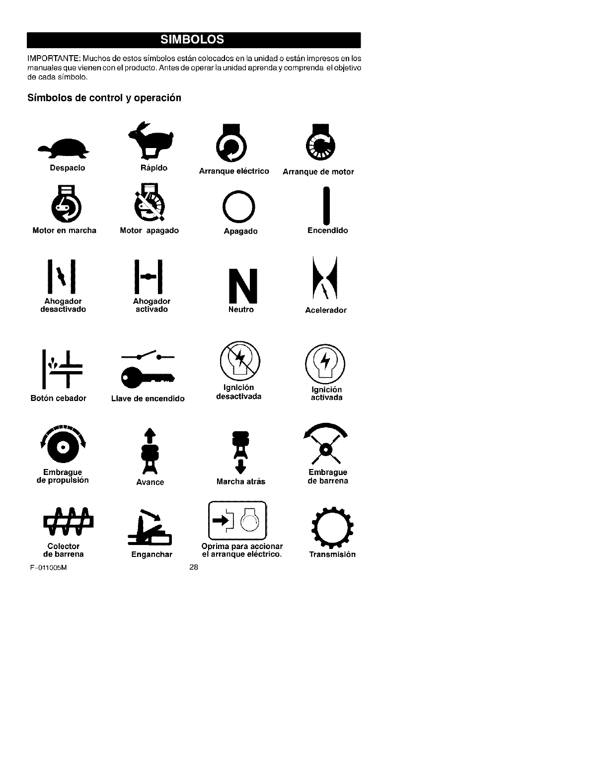
IMPORTANTE: Muchos de estos simbolos estAn colocados en la unidad o est_n impresos en los
manuales que vienen con el producto. Antes de operar Ia unidad aprenda y comprenda el objetivo
de cada simbolo.
Simbolos de control y operacion
Despacio Rapido Arranque electrico Arranque de motor
@oI
Motor en maroha Motor apagado Apagado Encendido
H N
Ahogador Ahogador
desactivado activado Neutro Acelerador
Boton cebador Llave de encendido
® @
Ignicion Ignicion
desactivada activada
Embrague
de propulsion
Colector
de barrena
F-011005M
Avance Marcha atras de barrena
"--_ O_onar 0
Enganchar el arranque el_ctrico. Transmision
28
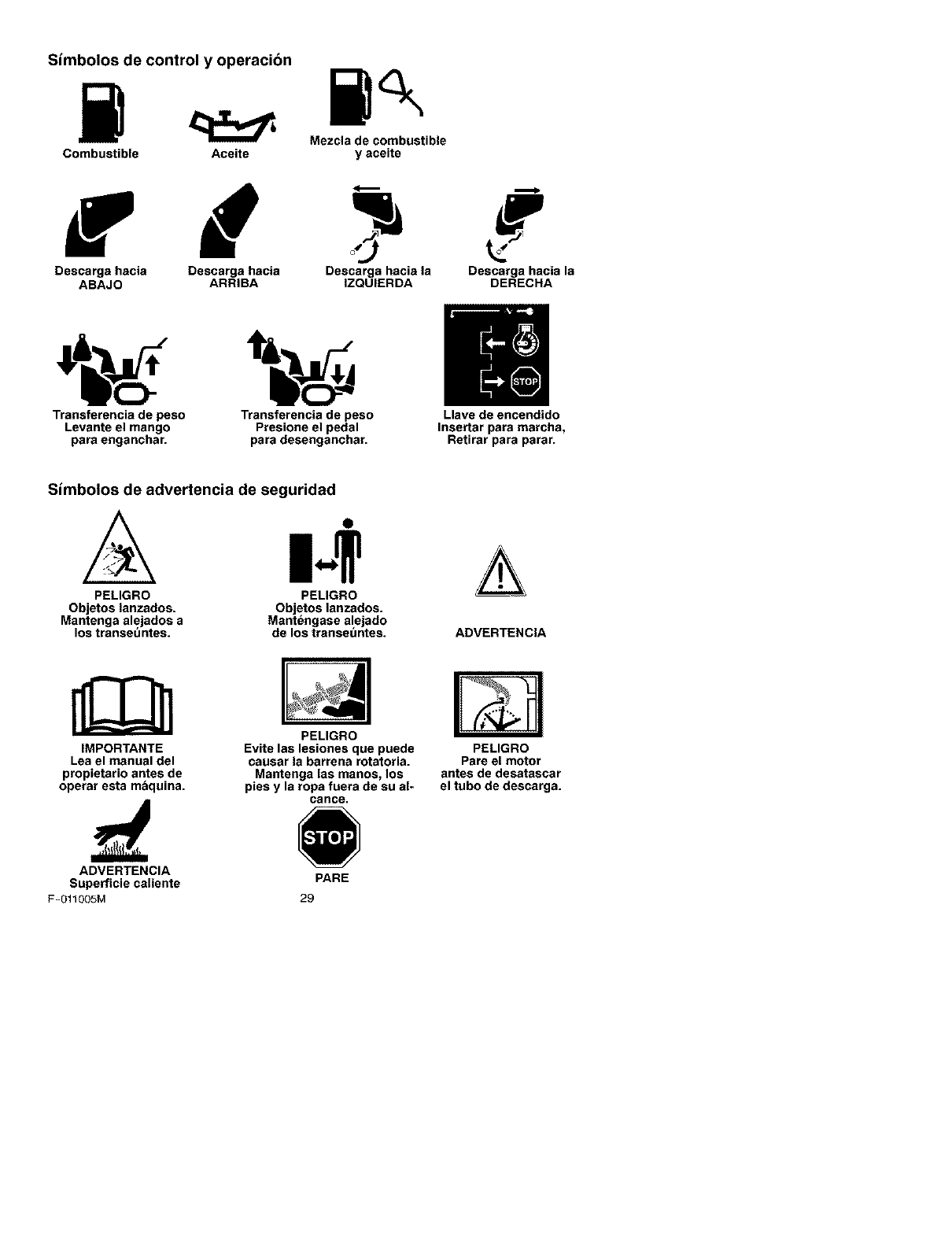
Simbolos de control y operacion
Mezcla de combustible
Combustible Aceite y aceite
Descarga hacia Descarga hacia Descarga hacia la Descarga hacia la
ABAJO ARRIBA IZQUIERDA DERECHA
i' o]
Transferencia de peso Transterencia de peso Llave de encendido
Levante el mango Presione el pedal Insertar para marcha,
para enganchar, para desenganchar. Retirar para parar.
Simbolos de advertencia de seguridad
PELIGRO
Objetos lanzados.
Mantenga alejados a
los transet_ntes.
PELIGRO
Objetos lanzados.
Mant_ngase alejado
de los transet_ntes. ADVERTENCIA
IMPORTANTE
Lea el manual del
propietario antes de
operar esta maquina.
PELIGRO
Evite las lesiones que puede
causar la barrena rotatoria.
Mantenga las manos, los
pies y la ropa fuera de su al-
cance.
PELIGRO
Pare el motor
antes de desatascar
el tubo de descarga.
ADVERTENCIA
Superficie caliente PARE
F-O11005M 29
I ::1_[.,',.__,'q_vtI=]IV_,IJ_l
Contenido de la bolsa con las partes
1-Manual del propietafio (no se muestra)
1 - Cable de arranque el_ctrico (no se
muestra) 1- Botella de 3,2 onzas de
aceite Craftsman de 2 tiem-
pos
_DVERTENClA: Use siempre
gafas protectoras o protectores
para los ojos, durante el ensam-
blaje del quitanieves.
HERRAMIENTAS NECESARIAS
1-Navaja para cortar cart6n
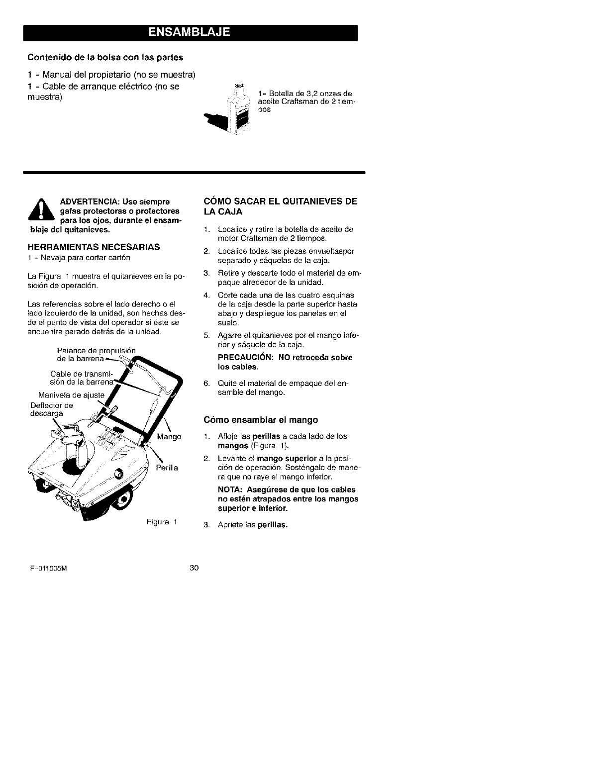
La Figura 1 muestra el quitanieves en Ia po-
sici6n de operaci6n.
Las referencias sobre el lado derecho o el
Iado izquierdo de la unidad, son hechas des-
de el punto de vista del operador si este se
encuentra parado detras de la unidad.
Palanca de propulsi6n
Cable de transmi-
Manivela de ajuste
Deflector de
descarga
Mango
Perilla
Figura 1
C6MO SACAR EL QUlTANIEVES DE
LA CAJA
1.
2.
3.
4.
Localice y retire la botetla de aceite de
motor Craftsman de 2 tiempos.
Localice todas las piezas envueltaspor
separado y sAquelas de la caja.
Retire y descarte todo el material de em-
paque alrededor de la unidad.
Corte cada una de las cuatro esquinas
de la caja desde la parte superior hasta
abajo y despliegue los paneIes en el
suelo.
Agarre el quitanieves pot el mango infe-
rior y saquelo de Ia caja.
PRECAUCION: NO retroceda sabre
Ios cables.
Quite el material de empaque del en-
samble det mango.
Como ensamblar el mango
1. Afloje las perillas a cada lado de los
mangos (Figura 1).
Levante el mango superior a la posi-
ciSn de operaciSn. SostengaIo de mane-
ra que no raye el mango inferior.
NOTA: Asegurese de qae los cables
no est_n atrapados entre los mangos
superior e inferior.
3. Apriete Ias perillas.
F-011005M 30

I ::1_[,'..__,'q_vjI:] IV_,IJ_l
_" LISTA DE REVISION
Antes de operar su nuevo quitanieves, y pa-
ra asegurar que obtenga el mejor rendimien-
to y la mayor satisfacci6n de este producto
de calidad, por favor haga un repaso de la
siguiente lista de revisi6n:
_' Se han completado todas las instruccio-
nes de ensamblado.
_' El tubo de descarga gira libremente.
_' No quedan piezas sueltas en la caja de
cart6n.
AI mismo tiempo que aprende a usar su qui-
tanieves, preste mucha atenci6n a los deta-
Iles siguientes:
_' AsegSrese de que ei tanque de combusti-
ble contenga la mezcla correcta de gasoli-
nay aceite (proporci6n 40:1),
_' Familiaricese con la ubicaci6n de todos
los controles y asegSrese de entender la
funci6n de cada uno.
_" Antesdeencenderelmotor, asegSresede
que todos los controles est6n funcionando
correctamente.
ESPECIFICACIONES DEL PRODUCTO
Caballos de fuerza: 5
Cilindrada: 8,46 puIgs, cu.
Tanque de combustible: 1,62 litros
Mezcla de gasolina/aceite: Proporci6n 40:1,3,2
onzas de aceite que
cumpla con las espe-
cificaciones para mo-
tores de 2 tiempos
enfriados por aire y
que sea aprobado pa-
ra una mezcla de
40:1 por 1 gal6n de
gasolina.
Bujia: Champion RCJ8Y
(Entrehierro 0,030)
NOTA: Los caballos de
fuerza del motor pueden
variar segun ajustes al mis-
mo, variantes del proceso
de fabricacion, altitud, con-
diciones atmosfericas,
combustible y manteni-
miento.
F-011005M 31
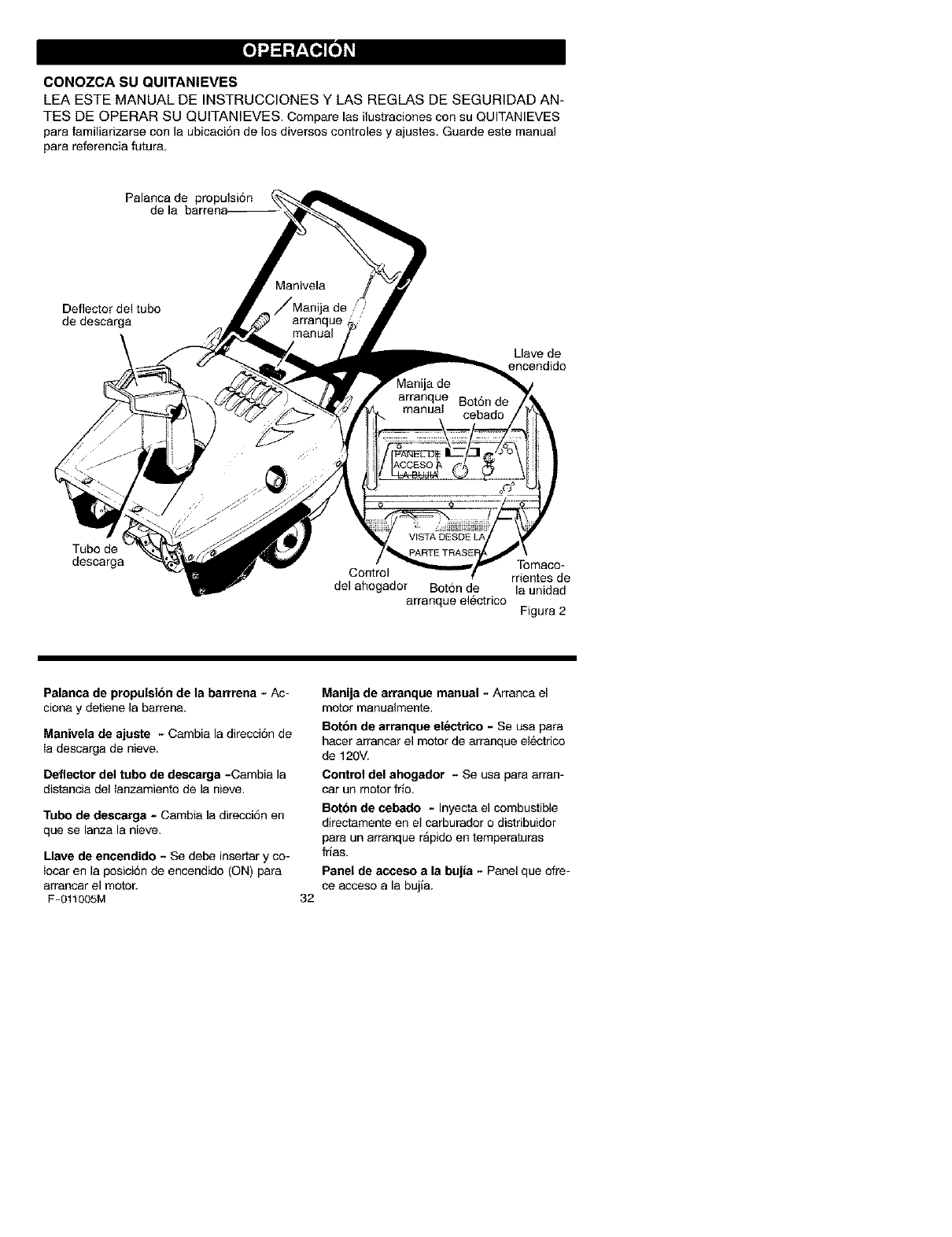
CONOZCA SU QUlTANIEVES
LEA ESTE MANUAL DE INSTRUCCIONES Y LAS REGLAS DE SEGURIDAD AN-
TES DE OPERAR SU QUITANIEVES. Compare las ilustraciones con su QUITANIEVES
para familiarizarse con la ubicaci6n de los diversos controles y ajustes. Guarde este manual
para referencia futura.
Palanca de propulsi6n
de
Deflector del tubo
de descarga
Llave de
encendido
Tubo de
descarga Tomaco-
Control rrientes de
del ahogador Bot6n de la unidad
arranque electrico Pigura 2
Palanca de propulsion de la barrrena - Ac-
ciona y detiene la barrena.
Manivela de ajuste - Cambia la direcci6n de
Ia descarga de nieve.
Deflector del tubo de descarga -Cambia la
distancia del Ianzamiento de la nieve.
Tubo de descarga - Cambia la direcci6n en
que se lanza la nieve.
Llave de encendido -Se debe insertar y co-
Iocar en la posici6n de encendido (ON) para
arrancar el motor.
F-011005M 32
Manija de arranque manual -Arranca el
motor manualmente.
Bntbn de arranque electrico - Se usa para
hacer arrancar el motor de arranque el6ctrico
de 120V,
Control del ahogador -Se usa para arran-
car un motor frio,
Betbn de cebado - Inyecta el combustible
directamente en el carburador o distribuidor
para un arranque rApido en tomperaturas
frias.
Panel de acceso a la bujia - Panel que ofre-
ce acceso a la bujia.
Laoperaci6ndecualquierquitanievespuede
provocarqueobjetosextraSosseaRlanza-
dosconfuerzahaciasusojos,Iocualpodria
resultarenlesionesgraves.Usesiempre
gafasdeseguridadoprotectoresparalos
ojoscuandoopereelquitanieves.
Serecomiendanlasgafasdeseguridades-
tandarolamascaradeseguridaddevisi6n
ampliaparausarlasobrelosanteojos.
_IL ADVERTENCIA: Lea el manual
del propietario antes de operar
la maquina. Nunca dirija la des-
carga hacia los transeuntes. Pare el mo-
tor antes de desobstroir el tubo de des-
carga o el alojamiento de la barrena, y
antes de dejar la maquina.
PARA PARAR LA DESCARGA DE
NIEVE
1. Para parar la descarga de nieve, suelte
la palanca de propulsion de la barrena.
Vea la Figura 2.
NOTA: Si la unidad continua avanzando
ientamente, consulte "C6mo ajustar el
cable de control de la barrena" en Ia
secci6n de Servicio y Ajustes.
2. Para parar el motor, mueva la Ilave de
ignici6n a Ia posici6n apagado (OFF).
PARA CONTROLAR LA
DESCARGA DE NIEVE
1. Gire la manivela de control del tubo de
descarga para determinar la direcci6n de
lanzamiento de ia nieve.
2. Afloje la tuerca de mariposa en et de-
flector del tubo de descarga y rnueva el
deflector para establecer la distancia.
Mueva el deflector hacia (ARRIBA) para
mayor distancia, hacia (ABAJO) para
una distancia menor. Luego apriete la
tuerca de mpariposa (yea la Figura 3).
Deflector Deflector arriba
abajo
Perilla de mariposa Figura 3
COMO LANZAR LA NIEVE
1. Enganche la palanca de propulsion de
la barrena.
F-011005M
2. Para detener la descarga de nieve, suet-
te la palanca de propulsion de la ba-
rrena.
_ADVERTENCIA: La operacibn
de cualquier quitanieves puede
provocar que objetos extraSos
seaR lanzados con faerza hacia sus
ojos, Io cual podria resoltar en lesiones
graves. Por Io tanto use siempre galas
de seguridad o protectores para los
ojos cuando tenga que operar el quita-
nieves. Le recomendamos gafas de
proteccion estAndar o una mascara de
proteccion de vision amplia para usar
sobre sus anteojos.
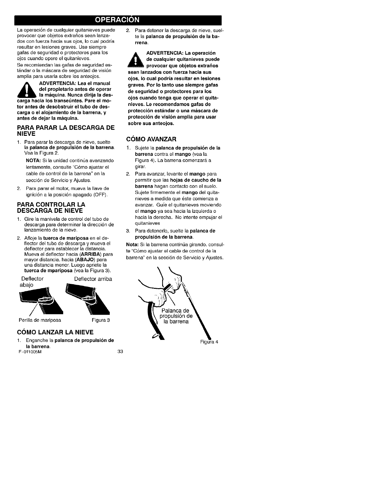
C(_MO AVANZAR
t. Sujete la palanca de propulsibn de la
barrena contra el mango (yea la
Figura 4). La barrena comenzarA a
girar.
2. Para avanzar, levante el mango para
permitir que las hojas de caucho de la
barrena hagan contacto con el suelo.
Sujete firmemente el mango del quita-
nieves a medida que 6ste comienza a
avanzar. Guie el quitanieves moviendo
el mango ya sea hacia la izquierda o
hacia la derecha. No intente empujar et
quitanieves
3. Para detenerlo, suelte la palanca de
propulsion de la barrena.
Nota: Si la barrena contint3a girando, consul-
te "C6mo ajustar el cable de control de la
barrena" en la secci6n de Servicio y Ajustes.
33
Figura 4
TIPO DE COMBUSTIBLE
AVISO: LOS MOTORES QUE EST_.N CER-
TIFICADOS PARA CUMPLIR CON LAS ES-
TIPULAClONES DE LAS NORMAS DE
EMISION EN EL ESTADO DE CALIFORNIA
Y DE LAS NORMAS FEDERALES DE EPA
DE EUA PARA MOTORES ULGE: Est_n
certiflcados par8 funcionar con gasolina re-
gular sin plomo. Esto incluye los siguientes
sistemas de control de emisi6n: EM, TWC
(para los motores que est6n equipados con
este sistema). Todas las caracteristicas
ajustables pot el usuario ya cumplen con Ins
normas, por la tanto no es neces8rio ningOn
otro ajuste.
_lb DVERTENCIA: La experiencia
indica que los combustibles
mezclados con alcohol (llama-
do gasohol o aquellos que usan etanol o
metanol) pueden atraer humedad la cual
conduce a la separacibn y formacion de
_cidos durante el almacenamiento. Los
gases acidicos pueden da_ar el sistema
de combustible de un motor mientras se
encuentra en almacenamiento.
NOTA: Para evitar problernas del motor, el
sistema de combustible debe vaciarse antes
de almacenar la unidad por 30 dias o mg=s.
Arrsnque el motor y dejelo en marcha hasta
que las linens de combustible y el carburs-
dor esten vacios. Use el escurridor de la ta-
za del carburador para vaciar la gasolina
residual de Ia cuba de nivel constante. Use
gasolina fresca la siguiente temporada. Para
obtener informaci6n adicional, consulte la
secci6n de "Almacenamiento" en este ma-
nual).
Nunca use productos de Iimpieza de motor o
carburador en el tanque de combustible, de
Io contrario podria causar daflo permanente
a la unidad.
C()MO PREPARAR LA MEZCLA
DE COMBUSTIBLE
El motor de dos tiempos de este quitanieves
requiere una mezcla de gasolina y aceite
par8 lubricar los cojinetes y los demg=s com-
ponentes m6viles. La mezcla indicada es
una relaci6n de 40:1 (3,2 onzas de aceite
por cada gal6n de gasolina - consulte la Ta-
bla de mezcla de combustible). Es necesario
premezclar la gasolina y el aceite en un con-
tenedor de gasolina limpio. Use siempre ga-
solina nueva, Iimpia y sin plomo.
TABLA DE MEZCLA DE COMBUSTIBLE
(relacion de 40:1)
La mezcla de gasolina y aceite se hace de la
manet8 siguiente:
1. Vierta un (1) cuarto de gal6n (EE.UU.) de
gasolina para autom6vil nueva, limpia y
sin plomo dentro de un contenedor de
gasolina con capacidad para un gal6n.
2. Armadaal contenedor con gasolina 3,2
onzas de aceite de dos tiempos, asegu-
rgmdose de que el aceite sea limpio y de
buena calidad.
IMPORTANTE: No use aceite de motor
fuera bordo o aceites multivisoosidad
como t0W-30 b10W-40.
3. Tape el contenedor de gasolina y agitelo
vigorosamente para mezclar la gasotina y
el aceite.
4. ASada al contenedor otros tres (3) cuar-
tos de gal6n (EE.UU,) de gasotina. Agite
nuevamente el contenedoit
No Ilene el tanque de combustible con gasolina sin antes mezclarla con aceite. Agite
el contenedor de combustible antes de Ilenar el tanque de combustible.
Aceite Agite el Afiada m_ts
(3,2onzas) contenedor gasolina
tr ,_ gal6n EE.UU
Contenedor - 1 gal6n (EE UU.)'_
F-O11005M 34
_1 ADVERTENCIA: La gasolina es
inflamable y debe tener mucho
cuidado al manipularla o alam*
cenarla.
No Ilene el tanque de combustible mien-
tras el quitanieves se encuentre en mar-
cha, cuando este caliente, o cuando el
quitanieves se encuentre en un area
cerrada.
Mantenga la unidad alejada de llamas
abiertas o chispas electricas y no fume
mientras Ilena el tanque de combustible.
Nunca Ilene el tanque completamente,
Llene el tanque hasta dejar entre 1/4-1/2
pulgada de la parte superior para
proporcionar espacio para la expansion
del combustible.
Siempre Ilene el tanque al aire libre y use
un embudo o boquilla para prevenir el
derrame.
Asegt_rese de limpiar cualquier combus-
tible derramado antes de arrancar el
motor.
Almacene la gasolina en un contendor,
limpio y aprobado, y mantenga la tapa
puesta y segura en el contenedor.
ANTES DE ARRANCAR EL
MOTOR
1. Antes de darle servicio o de hacer arran-
car el motor, familiaricese con el quita-
nieves. AsegSrese de entender la
funci6n y Ia ubicaci6n de todos los con-
troles.
2. AsegL_rese de que todos los sujetadores
esten apretados.
3. Antes de hacer arrancar el motor com-
pruebe que todos los controles funcio-
hen correctamente.
C()MO PARAR EL MOTOR
Paraparar et motor, rnueva la Ilavedeencen-
dido a la posici6n de parada (stop).
PARA ARRANCAR EL MOTOR
El motor est_ equipado con un sistema de
arranque electrico de 120 voltios de corrien-
te CA, ademAs de un sistema de arranque a
reacci6n. Antes de hacer arranoar eJmotor,
asegl3rese de haber leido Ia informaci6n si-
guiente:
F-011005M
_DVERTENCIA: El motor de
arranque esta diseSado para
funcionar con corriente domesti-
ca de 120 voltios de CA. Siga cuidado-
samente todas las instrucciones de la
section "Arranque del motor". Para co-
nectar el cable de alimentaci6n de 120
voltios de CA, conecte siempre el cable
al tomacorriente de la unidad del motor
primero. Luego, enchufe el otto extremo
en el tomacorriente. Cuando deeconec-
te el cable de alimentacion, desenchufe
siempre el extremo del tomacorriente
primero.
35
ARRANQUE DEL MOTOR
EN FRIO
1. Llene el tanque de combustible con una
mezcla de combustible nueva y limpia,
Consulte "C6mo mezclar el combustible"
en la secci6n de Ensamblaje.
2. Asegt_rese de que la palanca de propul-
sion de la bsrrena este desengancbada.
3. Inserte la Ilave de encendido mu6vala a
Ia posici6n de encendido (ON).
4, Mueva el control del estarter a la posi-
ci6n total.
5. (Arranque electrico) Conecte el cable
de alimentaci6n al tomacorrientes de Is
unidad ubicado en el motor.
6. (Arranque electrico) Enchufe el otro ex-
tremo del cable de alimentaci6n en el to-
macorrientes de 120 voltios de CA. (Lea
Ia ADVERTENCIA en esta secci6n).
7. Optima el boton cebador mientras cubre
el agujero de ventilaci6n de la manera
siguiente: Entre cebados, retire el dedo
del bot6n cebador.
No use la funci6n de cebado si la tempe-
ratura est_ sobre 50°F (10°C).
Oprima el bot6n dos veces si la tempera-
tufa estA entre 50°F (10°C) y 15°F
(-10°C).
Optima el bot6n cuatro veces si la tem-
peratura se encuentra por debajo de los
15°F (-10°C).
Optima el bot6n cinco veces si la tempe-
ratura se encuentra pot debajo de los 0°F
(-18°C).
8. (Arranque electrico) Optima el boron
de arranque el_ctrico hasta que el mo-
tor arranque No optima el boron de
arranque el_ctrico por mas de 10 se-
gundos cada vez. El arranque el_ctrico
tiene protecciSn termica. Si el arranque
electrico se recalienta, se parara y se
puede volver a activar s61o una vez que
se ha enfriado a una temperatura segura.
Se requiere una espera de 5 a 10 minu-
tos para permitir que el arranque electri-
co se enfrfe.
9. (Arranque amanual) Jale rapidamente
la manija del arranque manual. No
suelte la manija inmediatamente des-
pues de jalarla. Deje que la manija del
arranque manual se enrolle lentamente.
10.Si el motor no arranca a los 5 6 6 inten-
tos, lea las instrucciones en la "Tabla de
Iocalizaci6n y reparaci6n de avefias".
11, (Arranque electrica) Cuando el motor
arranque, suelte et boron de arranque
el_ctrico.
12. (Arranque electrico) Desconecte prime-
re el cable de alimentaci6n del tomaco-
rdente. Luego, desconecte el cable de
alimentaci6n deI tomacorrientes de la
unidad.
13. Mientras el motor se calienta, mueva el
control del estarter a la posici6n de 1/2
arranque. Cuando el motor este andando
de manera uniforme, mueva el control
del eetarter a la posici6n de apagado
(OFF).
NOTA: Deje que el motor se caliente per
algunos minutos antes de comenzar a remo-
very arrojar nieve en temperaturas inferiores
a los 0°F(-18°C).
ARRANQUEEN CALIENTE
Siesta arrancando un motor caliente des-
pues de haberlo apagado por un periodo
corto, deje el ahogador en "APAGADO"
(OFF) y no oprima el bot6n cebador.
_ADVERTENCIA: Nunca arran-
que el motor dentro de un re-
cinto cerrado o en areas con
poca ventilacibn. Los gases de escape
del motor contienen MONOXIDO DE
CARBONO, UN GAS INODORO Y MOR-
TAL. Mantenga las manos, los pies, el
pelo y la ropas sueltas alejadas de las
partes en movimiento tanto del motor
como del quitanieves. Latemperatura
del silenciador y de las piezas alrededor
del silenciador puede exceder los 150°F.
Evite tocar estas partes. No permita que
nifms ni adolescentes operen el quitanie-
ves ni que esten cerca cuando este esta
en funcionamiento.
i_ ADVERTENCIA: No intente re-
mover ning_3n objeto atascado
en la barrena sin tomar primero
las precauciones siguientes:
Suelte la palanca de propulsion de la
barrena.
Mueva la palanca de encendido a la
posicion stop para parar el motor.
Desconecte el cable de la bujia.
No coloque las manos en la barrena o
en el tubo de descarga. Use una barra
de apalancamiento.
F-011005M 36
SUGERENCIAS PARA EL
LANZAMIENTO DE NIEVE
1. Cuando se levanta el mango, las hojas
de caucho de la barrena entran en con-
tacto con el suelo y el quitanieves avan-
za. Cuando se suelta la palanca de
propulsi6n de la barren& las cuchillas
de la barrena se paran. Si las cuchillas
no paran, consulte "C6mo ajustar el ca-
ble de propulsi6n de la barrena" en la
secci6n de Servicio y Ajustes.
2. El lanzamiento de nieve mAs efectivo se
Iogra cuando la nieve se quita inmedia-
tamente despu6s de la nevada.
3. Para quitar completamente la nieve, so-
breponga ligeramente las pasadas del
quitanieves.
4. Cuando sea posible, descargue la nieve
a favor del viento.
5. Se puede ajustar la distancia a la que la
nieve sera lanzada, moviendo el deflec-
tor del tubo de descarga. Para mas dis-
tancia levante el deflector, para menos
distancia baje el deflector.
6. En condiciones de mucho viento, baje el
deflector del tubo de descarga para diri-
gir la nieve lanzada mas cerca deI suelo
para evitar que el viento la sople hacia
Areas no deseadas.
7. Para su seguridad y para prevenir el da-
5o aI quitanieves, mantenga el Area que
va a limpiar, libre de piedras, juguetes y
otros objetos extraSos.
8. No use la funci6n de propulsi6n de la
barrena cuando este pasando sobre en-
tradas de auto cubiertas con grava o to-
ca triturada. Mueva el mango hacia
abajo para Ievantar Iigeramente Ia barre-
na,
9. La velocidad de avance del quitanieves
depende de la profundidad y del peso de
Ia nieve. La manera mAs eficiente de
usar el quitanieves sera determinada pot
su experiencia bajo diversas condicio-
nes,
10. Despu6s de cada trabajo deje que el
motor funcione por unos minutos. Asi
se derretirA la nieve y el hielo acumula-
dos en el motor.
11. Limpie el quitanieves despu6s de cada
USO,
12. Quite el hielo, la nieve y los residuos de
todo el quitanieves, EnjuAguelo con
agua para quitarle toda la sal y otras
sustancias quimicas, Seque et quitanie-
yes.
NIEVE SECA Y DE
POCA PROFUNDIDAD
1. La nieve que se acumule hasta profundi-
dades de ocho puIgadas puede quitarse
rapida y facilmente, caminando a una
velocidad moderada con el quitanieves,
Para acumulaciones de nieve de mayor
profundidad, camine mas lento para per-
mitir la descarga uniforme de nieve tan
pronto sea recogida pot la barrena.
2. Intente descargar la nieve a favor del
viento,
NIEVE MOJADA Y COMPACTA
Avance lentamente para despejar la nieve
mojada y compacta. Si este tipo de nieve
hace que la barrena gire mas lento o empie-
za a atascar et tubo de descarga, retirese un
poco y empiece una serie de movimientos
cortos con el quitanieves, hacia adelante y
hacia arras. Estos movimientos cortos en la
nieve (de cuatro a seis pulgadas), ayudaran
a arrojar la nieve deI tubo de descarga.
BANCOS Y ACUMULACIONES
GRANDES DE NIEVE
Para despejar la nieve que se acumula a
una altura mayor que el quitanieves, use et
metodo descrito anteriormente (movimientos
cortos hacia adelante y hacia atrAs). Oriente
el tubo de descarga en direcci6n opuesta a
la del banco o acumulaci6n grande de nieve.
La remoci6n de este tipo de nieve tomarA
mas tiempo.
F-O11005M 37
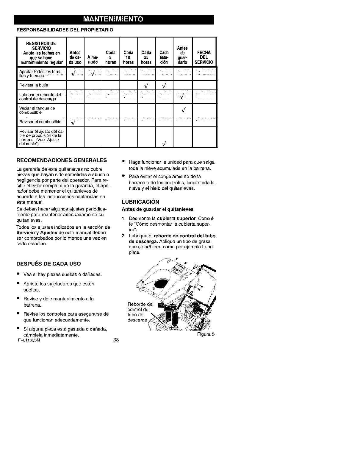
RESPONSABILIDADES DEL PROPIETARIO
REGISTROSDE
SERVICIO Antes
Anote las fechas en Antes Cada Cada Cada Ceda de FECHA
quese hace deca- A me- 5 10 25 esta- gear- DEL
mantenimientoregular da uso nudo horas horas horas ei6n darlo SERVICIO
Apretar todos _ostorni-' ,/ ',/ 'I I I I
Ilosy tee cas v v
Reviser la bujia _/ _/
Lo r,oa,o,robor ° o, I I I I I 'I
control de desca ga
Vaciar et tanque de _/
combustible
Reviser el combustible _/ .......
Reviser el ajuste del ca-
ble de propulsi6n de la
barrena (Vea "Ajuste
del cable") _/
RECOMENDACIONESGENERALES
La garanSa de este quitanieves no cubre
piezas que hayan sido sometidas a abuso o
negligencia pot parte del operador. Pare re-
cibir el valor compieto de la garantia, el ope-
rador debe mantener el quitanieves de
aouerdo a las instrucoiones oontenidas en
este manual,
Se deben hacer algunos ajustes peri6dica-
mente pare mantener adeouadamente su
quitanieves.
Todos los ajustes indicados en la secci6n de
Servicio y Ajustes de este manual deben
ser comprobados por io menos una vez en
cada estaci6n.
DESPUES DE CADA USO
• Yea si hay piezas sueltas o daSadas.
• Apriete los sujetadores que esten
sueltos.
• Revise y dele mantenimiento a la
barren&
• Revise los controles para asegurarse de
que funcionan adecuadamente.
• Si alguna pieza esta gastada o da_ada,
cAmbiela inmediatamente.
F-011005M
• Hags funcionar la unidad para que salga
toda la nieve acumulada en la barren&
• Para evitar el congelamiento de la
barrena o de los controles, limpie toda la
nieve y ei hielo del quitanieves.
LUBRICACION
Antes de guardar el quitsnieves
1. Desmonte la cubierta superior. Consui-
te "C6mo desmontar la cubierta super-
ior".
2. Lubrique el reborde de control del tubo
de descarga. Aplique un tipo de grass
que se adhiera, como pot ejemplo Lubri-
plate.
38
Reborde del
control del
tubo de
descarqa
Figura 5
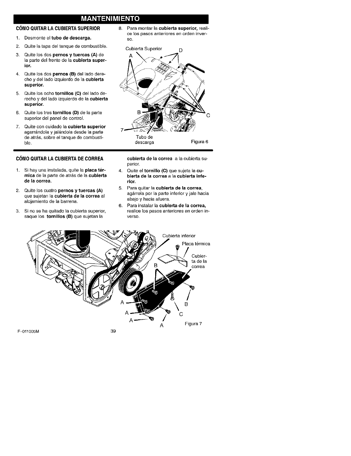
I_Vt!:I 1i i _111I_NI_11i lie1
C6MO QUITARLA CUBIERTASUPERIOR
1. Desmonte el tubo de desearga.
2. Quite Ia tapa del tanque de combustible.
3. Quite los dos pernos ytuercas (A) de
la parle del frente de la cubierta super-
ior.
4. Quite los dos pernos (B) del lado dere-
cho y del lado izquierdo de la eubierta
superior.
5. Quite los ocho tornillos (O) del lado de-
recho y del lado izquierdo de Ia cubierta
superior.
6. Quite los tres tornillos (D) de la parle
superior del panel de control.
7. Quite con cuidado la eubierta superior
agarrAndola y jalandola desde la parle
de atrAs, sobre el tanque de combusti-
ble.
Para montar la cubierta superior, reali-
ce los pasos anteriores en order inver-
so.
Cubierta Superior D
A
B
Tubo de
descarga Figura 6
C6MO QUITARLA CUBIERTADECORREA
1. Si hay una instalada, quite la placa ter-
mica de la parle de atras de la cubierta
de la correa.
2. Quite los cuatro pernos y tuereas (A)
que sujetan la cubierta de la correa al
alojamiento de la barrena.
3. Si no se ha quitado Ia cubierta superior,
saque los tornillos (B) que sujetan la
cubierta de Is correa a la cubierta su-
perior.
4. Quite el tornillo (O) que sujeta la cu-
bierta de Is eorrea a la eubierta infe-
rior.
5. Para quitar la eubierta de Is cortes,
agarrela pot la parle inferior y jale hacia
abajo y hacia afuera.
6. Para instalar la cubierta de Is correa,
realice los pasos anteriores en orden in-
verso.
Cubierta inferior
Placa termica
Cubier-
ta de la
oorrea
F-011005M 39
A
B
/c
A Figura 7

_hlL ADVERTENCIA: Para prevenir
el arranque accidental del mo-
tor, siempre desconecte el ca-
ble de la bujia y mantengalo alejado de
esta, mientras realiza ajustes o repara-
ciones a la unidad.
AJUSTE DE LA MANIVELA DEL
TUBO DE DESCARGA
Si la manivela de ajuste del tubo de descar-
ga no gira libremente hacia la izquierda o
hacia la derecha, realice los pasos siguien-
tes.
1. Quite la cubierta superior. Consulte"C6-
mo desmontar la cubierta superior".
2. Afloje las tuercas.
3. Mueva la placa de ajuste de la maniva-
la para permitir un espacio libre de 1/8
de pulgada (3mm) entre Ia muesca del
raborde yeI diametro exterior del torni-
Iio ainfin.
4, Apriete Ias taercas.
Reborde
de la ma-
nivela de
ajuste
pulg. Tomillo
sinfin
Figura 8
C6MO AJUSTAR EL CABLE DE
CONTROL DE LA BARRENA
El ajuste del cable de control de Ia barrena
se hace en la fabrica. Durante el uso normal
del quitanieves, este cable puede aflojarse
previniendo que la palanca del propulsor de
la barrena enganche o desenganche correc-
tamente.
1. Quite el gancho en "Z" de la palanca
del propulsor de la barrena (Figura
t2).
2. Deslice la funda del cable para que de-
je expuesto eI aoporte de ajuate del
cable (Figura 13).
3. Guie el extremo del cable de control de
la barrena a traves del soporta de
ajaste del cable hasta que se pueda
retirar el gancho en "Z".
4. Quite el gancho en "Z" del soporte de
ajuste del cable. Coloque el gancho en
"Z" en el pr6ximo agujero de ajuste
(mAs abajo).
5. Guie el cable de control de la barrena
a traves del soporte de ajuste del ca-
ble.
6. Instale de nuevo la funda del cable so-
bre el soporte de ajaste del cable.
7. Monte el gancho en "Z" a la palanca
del propulsor de la barrena.
F-011005M 4O
Para comprobar el ajuste, arranque el
quitanieves. AsegQrese de que la barre-
na no gire al soltar la palanoa de propul-
si6n.
la barrena
Gancho
en "Z"
Cable de
control de Ia
barrena
Funda del
Cable
Gancho
Sopo_e de en"Z'
_u_e del
cable Figura 10
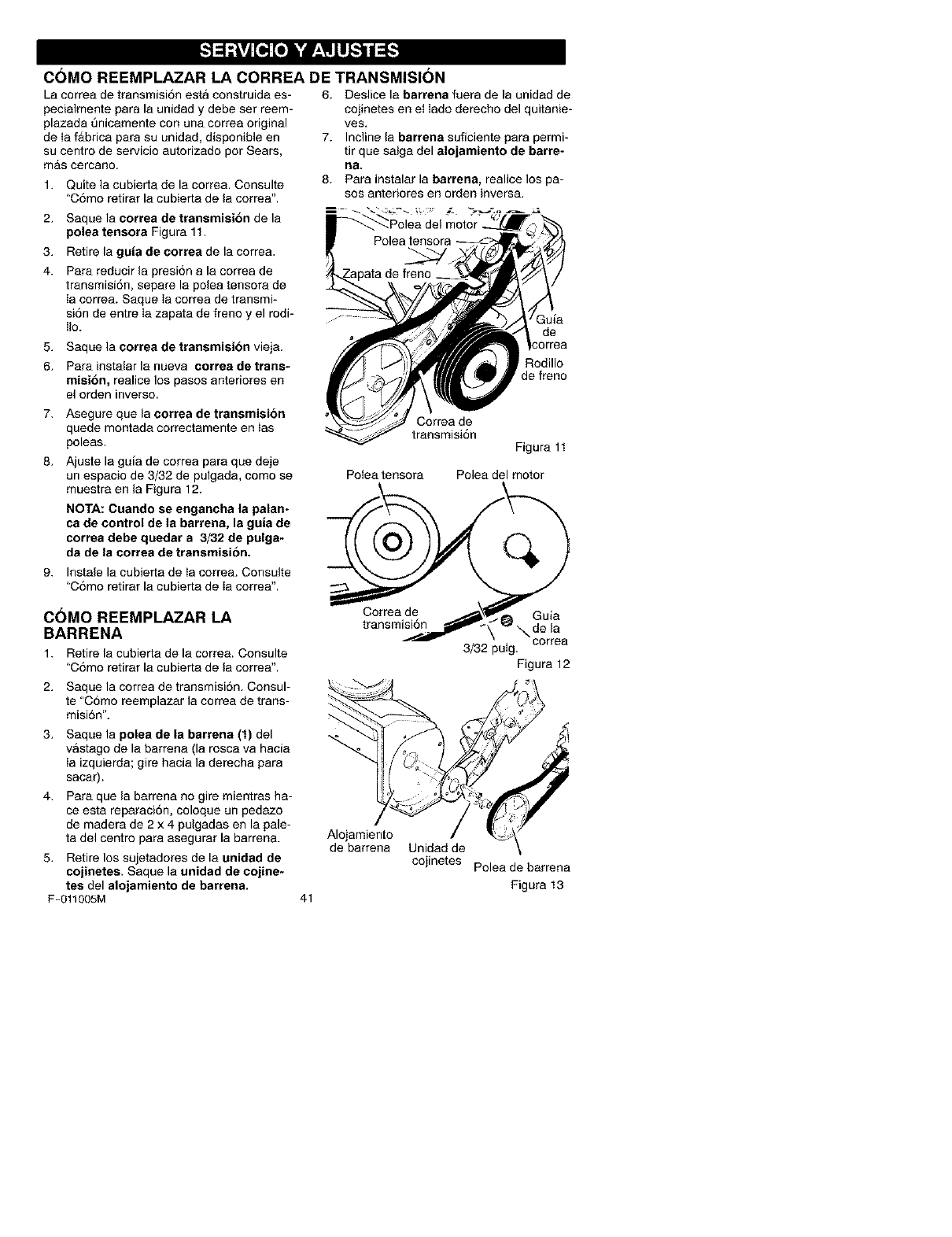
C(3MO REEMPLAZAR LA CORREA DE TRANSMISION
La correa de transmisi6n esta construida es-
pecialmente para la unidad y debe ser reem-
plazada t3nicamente con una correa original
de Ia fAbrica para su unidad, disponible en
su centro de servicio autorizado por Sears,
mas cercano.
1. Quite la cubierta de la correa. Consulte
"C6mo retirar la cubierta de la correa".
2. Saque la correa de transmisibn de la
polea tensora Figura 11.
3. Retire la guia de correa de la correa.
4. Para reducir la presi6n a la correa de
transmisi6n, separe la polea tensora de
Ia correa. Saque Ia correa de transmi-
si6n de entre Ia zapata de freno y el rodi-
Iio.
5. Saque la correa de transmisibn vieja.
6. Para instalar la nueva eorrea de trans-
rniei6n, realice los pasos anteriores en
el orden inverse.
6. Deslice la barrena fuera de la unidad de
cojinetes en et lade derecho del quitanie-
ves,
7. Incline la barrena suficiente para permi-
tir que salga del alojamiento de barre-
ha.
8. Para instalar la barrena, realice los pa-
sos anteriores en order inversa.
Guia
de
{odillo
de freno
7. Asegure que la correa de transmision
quede rnontada correctamente en ias
poleas.
8. Ajuste la guia de correa para que deje
un espacio de 3/32 de pulgada, como se
muestra en la Figura 12.
NOTA: Cuando se enganeha la palan-
ca de control de la barrena, la guia de
correa debe quedar a 3/32 de pulga-
da de la correa de transmision.
9. Instale la cubierta de Ia correa. Consulte
"C6mo retirar la cubierta de Ia correa".
C()MO REEMPLAZAR LA
BARRENA
1. Retire la cubierta de la correa. Consulte
"C6mo retirar la cubierta de la correa".
2. Saque la correa de transmisi6n. Consul-
te "C6mo reemplazar la correa de trans-
misi6n'L
3. Saque la polea de la barrena (1) del
vastago de la barrena (la rosca va hacia
Ia izquierda; gire hacia la derecha para
sacar).
4. Para que la barrena no gire mientras ha-
ce esta reparaci6n, coloque un pedazo
de madera de 2 x 4 pulgadas en la pale-
ta del centre para asegurar la barren&
5. Retire los sujetaderes de la unidad de
cojinetee. Saque la unidad de cojine-
tes del alojamiento de barrena.
F-011005M 41
Correa de
transmisi6n
Figura 11
Potea tensora Polea del motor
3/32 pulg.
Figura 12
Alojamiento /
de barrena Unidad de
cojinetes Polea de barrena
Figura 13
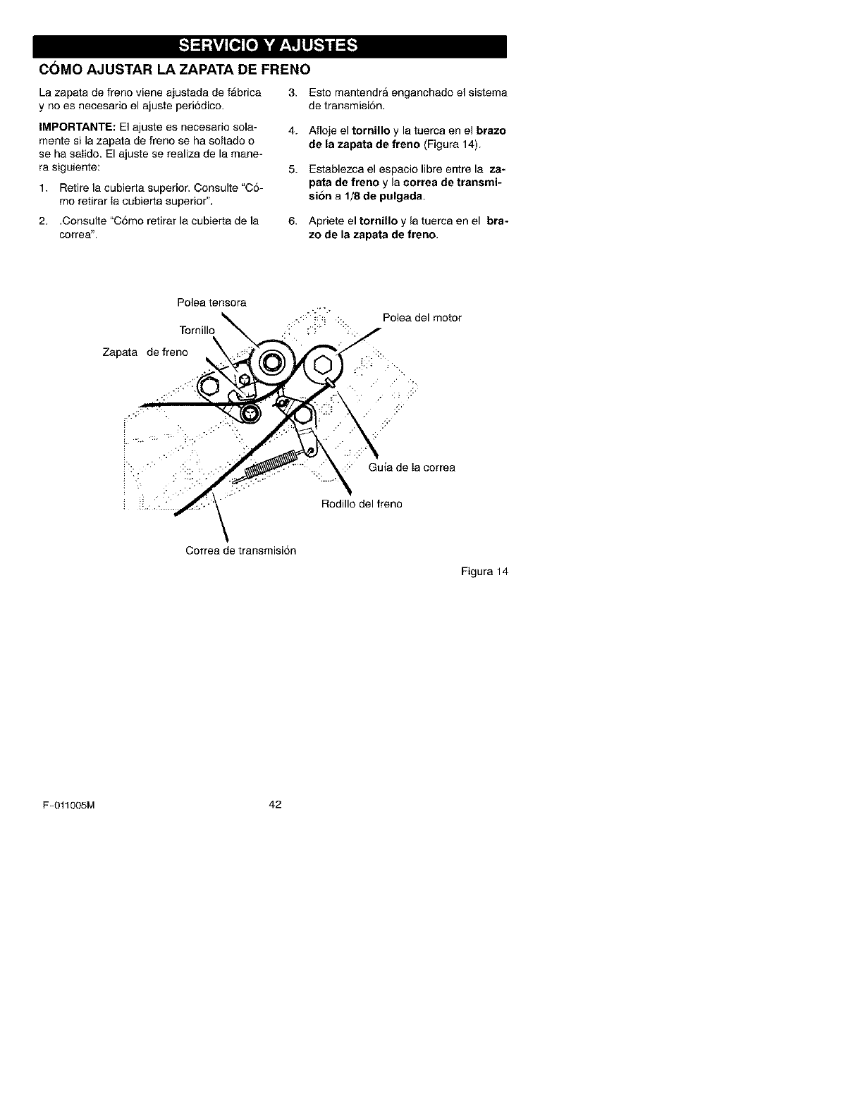
COMO AJUSTAR LA ZAPATA DE FRENO
La zapata de freno viene ajustada de fAbrica
y no es necesario el ajuste peri6dico.
IMPORTANTE: El ajuste es necesario sola-
mente si la zapata de freno se ha soltado o
se ha salido. El ajuste se realiza de la mane-
ra siguiente:
1. Retire la cubierta superior. Consulte "C6-
mo retirar Ia cubierta superior",
2. .Consulte "C6mo retirar la cubierta de la
correa".
3. Esto mantendra enganchado el sistema
de transmisi6n,
4. Afloje el tornillo y la tuerca en el brazo
de la zapata de freno (Figura 14).
5. Establezca el espacio libre entre la za-
pata de freno y la correa de transmi-
sion a 1/8 de pulgada.
6. Apriete el tornillo y la tuerca en el bra-
zo de la zapata de freno.
Polea tensora
Tornillo
Zapata de freno
Polea del motor
::: GuJa de Ia correa
Rodillo del freno
Correa de transmisi6n
Figura 14
F-011005M 42
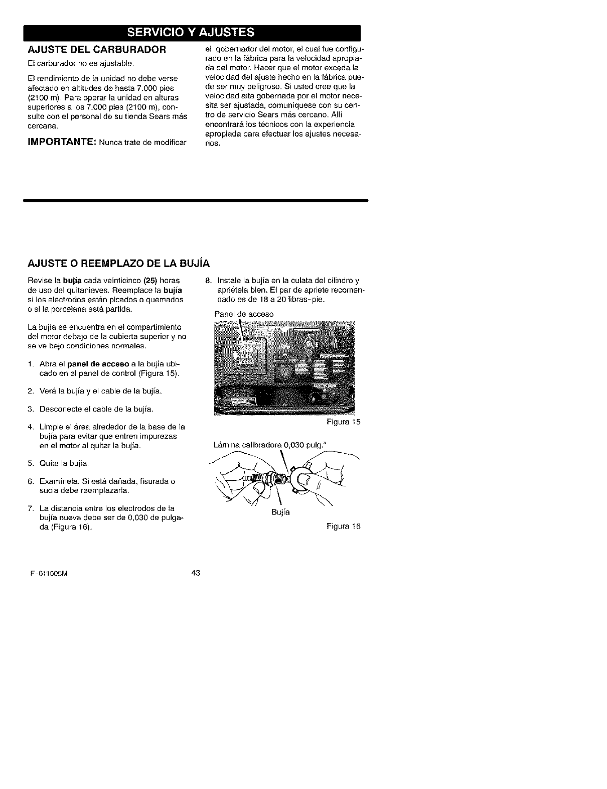
AJUSTE DEL CARBURADOR
El carburador no es ajustable.
El rendimiento de la unidad no debe verse
afectado en altitudes de hasta 7.000 pies
(2100 m). Para operar la unidad en alturas
superiores a los 7.000 pies (2100 m), con-
suite con el personal de su tienda Sears mAs
cercana.
IMPORTANTE: Nunca trate de modificar
el gobernador del motor, el cual fue configu-
rado en la fAbrica para la velocidad apropia-
da del motor. Hacer que el motor exceda la
velocidad del ajuste hecho en la fAbrica pue-
de set muy peligroso. Si usted cree que la
velocidad aIta gobemada por el motor nece-
sita set ajustada, comuniquese con su cen-
tro de servicio Sears mAs cercano. Alli
encontrarA los tecnicos con la experiencia
apropiada para efectuar los ajustes necesa-
rios.
AJUSTE OREEMPLAZO DE LA BUJiA
Revise la bujia cada veinticinco (25) horas
de uso del quitanieves. Reemplace Ia bujia
si los electrodos estan picados o quemados
o si la porcelana est_ partida.
La bujia se encuentra en el compartimiento
del motor debajo de la cubierta superior y no
se ve bajo condioiones normales.
8. Instale la bujla en la culata del cilindro y
aprietela bien. El par de apriete recomen-
dadoes de 18 a 20 libras-pie.
Panel de acceso
1. Abra el panel de acceso a la bujla ubi-
cado en el panel de control (Figura 15).
2. VerA la bujia y el cable de la bujia.
3. Desconecte el cable de la bujia.
4. Limpie el area alrededor de la base de la
bujia para evitar que entren impurezas
en el motor al quitar la bujla.
5. Quite la bujia.
Figura 15
LAmina calibradora 0,030 pulg."
6. Examinela. SiestA dafiada, fisurada o
sucia debe reemplazarla.
7. La distancia entre los electrodos de Ia
bujia nueva debe ser de 0,030 de pulga-
da (Figura 16).
Bujia
Figura 16
F-O11005M 43
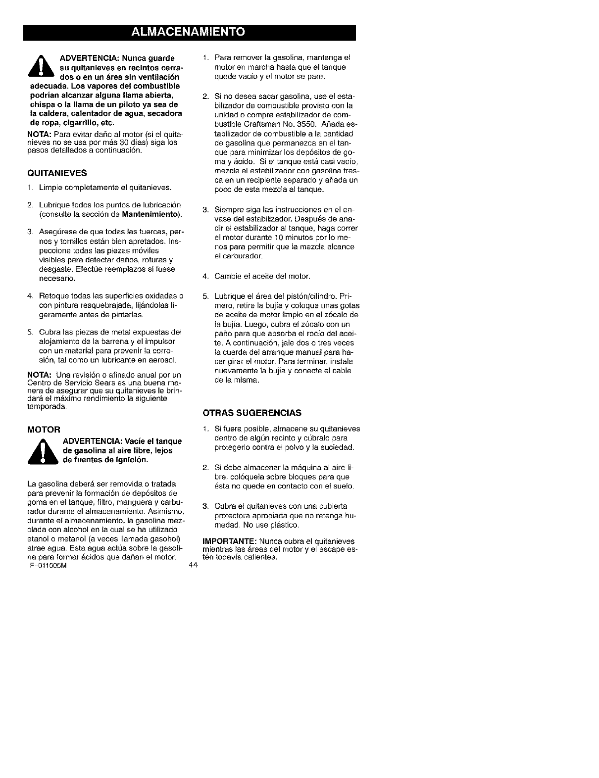
M ! _vjr;To]=1_r;1_vjII=1_il lie]
_IL DVERTENCIA: Nunca guarde
su quitanieves en recintos cerra-
dos o en un area sin ventilacibn
adecuada. Los vapores del combustible
podrian alcanzar alguna llama abierta,
chispa o la llama de un piloto ya sea de
la caldera, calentador de agua, secadora
de ropa, cigarrillo, etc.
NOTA: Para evitar dar_o al motor (si el quita-
nieves no se usa por mAs 30 dias) siga los
pasos detallados a continuaci6n.
QUlTANIEVES
1. Limpiecompletamente el quitanieves.
2. Lubrique todos los puntos de lubricaci6n
(consulte la secci6n de Mantenimiento).
3. Asegt3rese de que todas las tuercas, per-
nosy tornillos estan bien apretados. Ins-
peccione todas las piezas m6viles
visibles para detectar daSos, roturas y
desgaste. Efectt_e reemplazos si fuese
neoesario.
1. Para remover la gasolina, mantenga et
motor en marcha hasta que el tanque
quede vacio y el motor se pare.
2. Si no desea sacar gasolina, use el esta-
bilizador de combustible provisto con la
unidad o compre estabilizador de com-
bustible Craftsman No. 3550. ASada es-
tabilizador de combustible a la cantidad
de gasolina que permanezca en el tan-
que para minimizar los dep6sitos de go-
may acido. Si el tanque esta casi vacio,
mezcle el estabilizador con gasolina fres-
ca en un recipiente separado y aSada un
poco de esta mezcla al tanque.
Siempre siga las instrucciones en el en-
vase del estabilizador. Despues de ar_a-
dir el estabilizador al tanque, haga correr
el motor durante 10 minutos por Io me-
nos para permitir que ia mezcla alcance
el carburador.
4. Cambie el aceite del motor.
4. Retoque todas las superficies oxidadas o
con pintura resquebrajada, lijandolas li-
geramente antes de pintarlas.
5. Cubra las piezas de metal expuestas del
alojamiento de la barrena y el impulsor
con un material para prevenir Ia oorro-
si6n, tal como un lubricante en aerosol.
NOTA: Una revisi6n o afinado anual pot un
Centro de Servicio Sears es una buena ma-
nera de asegurar que su quitanieves le brin-
dara el m_iximo rendimiento la siguiente
temporada.
MOTOR
ADVERTENCIA: Vacie el tanque
de gasolina al sire libre, lejos
de fuentes de ignicion.
La gasolina deberA ser removida o tratada
para prevenir la formaci6n de dep6sitos de
goma en el tanque, filtro, manguera y carbu-
rador durante el almacenamiento. Asimismo,
durante el almacenamiento, la gasolina mez-
clada con alcohol en la cual se ha utilizado
etanol o metanol (a veces Ilamada gasohol)
atrae agua. Esta agua act_a sobre la gasoli-
na para formar Acidos que daSan el motor.
F-011005M
Lubrique el Area del pist6n/cilindro. Pri-
mero, retire la bujia y coloque unas gotas
de aceite de motor limpio en el z6calo de
Ia bujia. Luego, cubra et z6calo con un
paso para que absorba el rocio del acei-
te. A continuaci6n, jale dos o tres veces
ia cuerda del arranque manual para ha-
ter girar el motor. Para terminar, instale
nuevamente la bujia y conecte el cable
de la misma.
44
OTRAS SUGERENClAS
1. Si fuera posible, aimacene su quitanieves
dentro de algSn recinto y cSbralo para
protegerlo contra el potvo y la suciedad.
2. Si debe almacenar la maquina al aire li-
bre, col6quela sobre bloques para que
esta no quede en contacto con et sueto.
3. Cubra el quitanieves con una cubierta
protectora apropiada que no retenga hu-
medad. No use plastico.
IMPORTANTE: Nunca cubra el quitanieves
mientras las Areas del motor y el escape es-
ten todavia calientes.
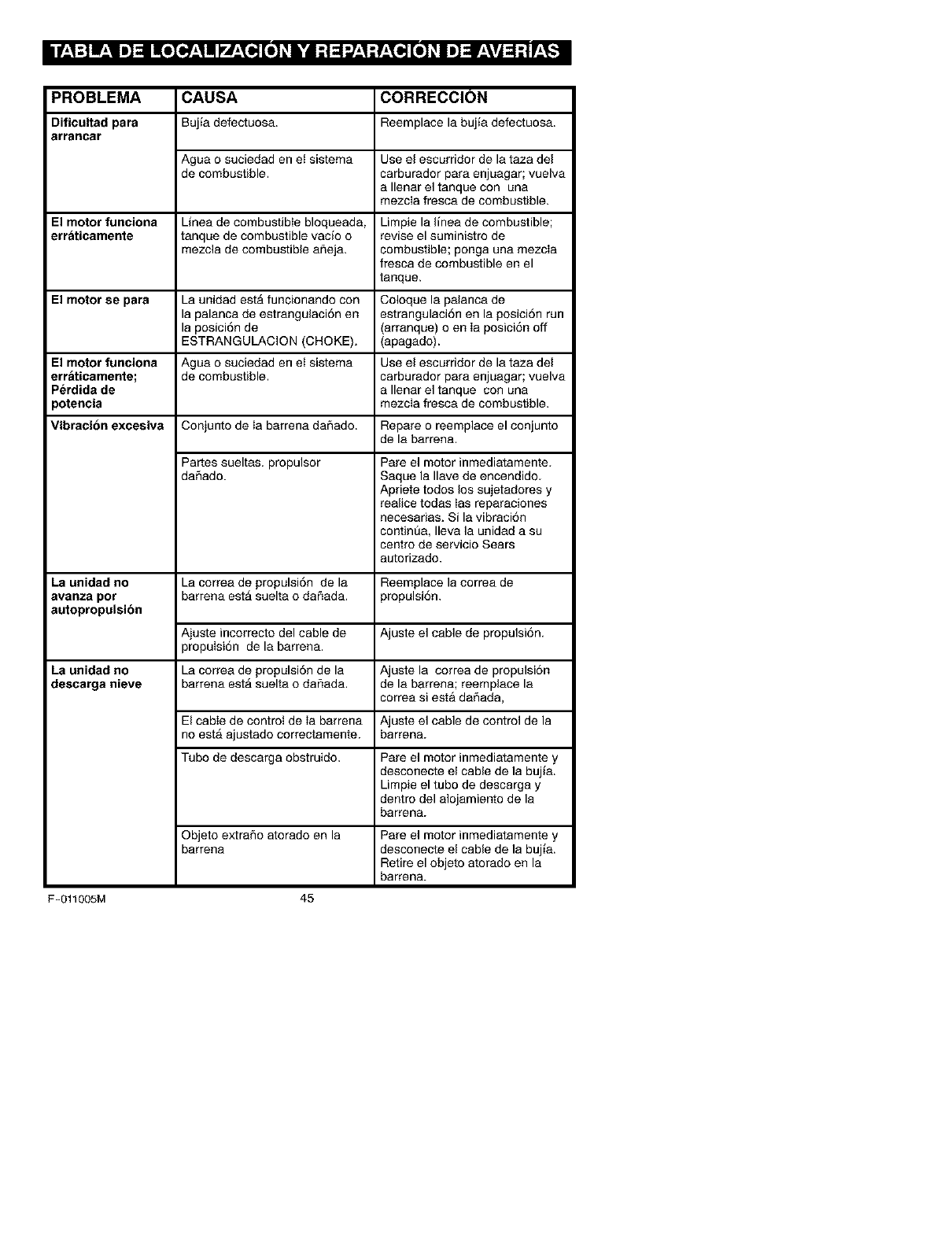
II f_,1:] mL,II _] :11m[o[o__,1mlVL,_o,][o] _h'dl :t :1-.J_,1:r±_ [o] _|_] _±\vj _ :t r±_
PROBLEMA CAUSA CORRECCION
Dificultad para Buj_a defectuosa. Reemplace la bujia defectuosa.
arrancar
Agua o suciedad en et sistema Use el escurridor de la taza del
de combustible, carburador para enjuagar; vuelva
a Ilenar el tanque con una
mezcla fresca de combustible.
El motor funoiona Linea de combustible bloqueada, Limpie la linea de combustible;
err_tioamente tanque de combustible vacio o revise el suministro de
mezcla de combustible ar_eja, combustible; ponga una mezcla
fresca de combustible en el
tanque.
El motor se para La unidad est_ funcionando con Coloque la palanca de
la palanca de estrangulaci6n en estrangulaci6n en la posici6n run
la posici6n de (arranque) o en Ia posici6n off
ESTRANGULACION (CHOKE). (apagado).
El motor funoiona Agua o suciedad en et sistema Use el escurridor de la taza del
erraticamente; de combustible, carburador para enjuagar; vuelva
Perdida de a Ilenar el tanque con una
)otencia mezcla fresca de combustible.
Vibracion excesiva Conjunto de Ia barrena dar_ado. Repare o reemplace el conjunto
de la barren&
Partes sueltas, propulsor Pare el motor inmediatamente.
dafiado. Saque la Ilave de encendido.
Apriete todos los sujetadores y
realice todas Ias reparaciones
necesarias. Si la vibraci6n
continua, Ileva la unidad a su
centro de servicio Sears
autorizado.
La unidad no La correa de propulsi6n de la Reemplace la correa de
avanza por barrena est_ suelta o daflada, propulsi6n.
autopropulsion
Ajuste incorrecto del cable de Ajuste el cable de propulsi6n.
propulsi6n de la barren&
La unidad no La correa de propulsi6n de la Ajuste la correa de propulsi6n
descarga nieve barrena est_ suelta o daflada, de la barrena; reemplace la
correa si esta dafiada,
El cable de control de Ia barrena Ajuste el cable de control de la
no est_ ajustado correctamente, barrena.
Tubo de descarga obstruido. Pare el motor inmediatamente y
desconecte el cable de la bujJa.
Limpie el tubo de descarga y
dentro del alojamiento de la
barrena.
Objeto extrafio atorado en la
barrena
Pare el motor inmediatamente y
desconecte el cable de la bujla.
Retire el objeto atorado en la
barren&
F-011005M 45
SEARS, ROEBUCK AND CO.
Garantia limitada de cumplimiento con el Sistema Federal
de control de emisiones y con el sistema de control de
emisiones del Estado de California
Motores pequehos no aptos para carretera (off-road)
CONTROL DE EMISIONES DE
CALIFORNIA Y DE LA AGENCIA DE
PROTECCI(_N AMBIENTAL (EPA) DE
E.U.A. -DECLARACI(_N DE LA
GARANTIA
La Agencia de Protecci6n Ambiental de los
Estados Unidos (en Io sucesivo "EPA"), el
Consejo de California para los Recursos del
Aire (en Io sucesivo "CARB") y Sears, Roe-
buck and Co. tienen el placer de explicar Io q ue
es la Garantla Federal y de California para Sis-
temas de Control de Emisiones de su nuevo
motor pequeSo para vehiculos off-road. En
California, los motores pequeflos paravehicu-
los off-road de modelo 1995 y modelos de
aSos posteriores deben set disefiados, cons-
truidos y equipados para cumplir con las es-
trictas normas anti contaminaci6n del Estado.
En otros estados, los motores modelo 1997 y
modelos de aflos posteriores deben estar di-
seflados, construidos y equipados, al momen-
to de su venta, para que cumpIan con las
disposiciones de la EPA acerca de motores
pequeSos para vehiculos off-road. Sears,
Roebuck and Co. garantizarA el sistema para
el control de emisiones de su motor pequefio
para vehiculos off-road por los periodos de
tiempo que se mencionan mas adelante, con
tal que su motor pequefio para vehiculos off-
road no haya sufrido algSn abuse, negligen-
cia, modificaci6n no aprobada o
mantenimiento indebido.
Es probable que su sistema para el control de
emisiones incluya partes como el carburador,
el sistema de encendido yel sistema de esca-
pe. Tambien es posible que se incluya el siste-
ma de descompresiSn y otros ensamblajes
relacionados con emisiones.
Cuando surja una condici6n protegida per la
garantia, Sears, Roebuck and Co. reparara su
motor pequeSo para vehiculos off-road sin
costo alguno para usted pot concepto de diag-
n6stico, partes y mano de obra.
SISTEMA PARA EL CONTROL DE
EMISIONES DEL FABRICANTE -
COBERTURA DE LA GARANTIA
Los sistemas para el control de emisiones mo-
delo 1995 y modelos de aflos posteriores de
motores pequeflos paravehfculos off-road en
California estAn garantizados per dos aSos, tal
y como se menciona en la presente garantia.
En otros estados, los motores modelo t 997 y
modelos de aflos posteriores tambien estan
garantizados pot dos a_os. En caso de que,
durante dicho periodo de la garantia, cualquier
parte de su motor relacionada con emisiones
este defectuosa en sus materiales o hechura,
Sears, Roebuck and Co. reparara o cambiarA
dicha parte.
RESPONSABILIDADES DEL
PROPIETARIO DE LA GARANTJA
Como propietario del motor pequeAo para ve-
hiculos off-road usted es responsable de que
se Ileve a cabo el mantenimiento requerido
que se menciona en el Manual del Propietario,
pero Sears, Roebuck and Co. no negara la ga-
rantia 5nicamente debido a la falta de un reci-
boo a que usted no proporcione una prueba
escrita de q ue se ha Ilevado a cabo el manteni-
miento programado.
No obstante, usted, como propietario del mo-
tor pequefio para vehiculos off-road, debera
estar consciente de que Sears, Roebuck and
Co. le puede negar la cobertura de la garantia
si su motor o alg u na parte del mismo ha fallado
debido a un abuso, negligencia, mantenimien-
to inadecuado o modificaciones no aproba-
das.
Usted es responsable de presentar su motor
pequeflo para vehiculos off-road en el Taller
Autorizado de Servicio de Sears, Roebuck
and Co. en cuanto surja el problema. Las repa-
raciones bajo la garantia deben Ilevarse a ca-
bo dentro de un periodo de tiempo razonable
que no exceda de 30 dias.
Se puede programar el servicio de garantia
Ilamando al Taller Autorizado de Servicio de
F-011005M 46
Sears, Roebuck and Co. o a Sears, Roebuck
and Co. al 1-800-473-7247 (llamada gratuita
en E.U.A.).
NOTA IMPORTANTE
Esta declaraci6n de la garantia explica los de-
rechos y las obligaciones que usted tiene de
conformidad con la Garantia del Sistema para
el Control de Emisiones (en Io sucesivo la"Ga-
rantia SCE"), la cual Sears, Roebuck and Co.
Ie proporciona de conformidad con las leyes
de California. V6ase tambien las Garantias Li-
mitadas de Sears, Roebuck and Co. que se
adjuntan a la Garantia SCE en una hoja por
separado y que tambien le proporciona Sears,
Roebuck and Co. La Garant[a SCE t_nicamen-
te se aplica en el sistema para el control de
emisiones de su motor nuevo. Hasta el punto
en donde no haya ning_n conflicto en terminos
entre la Garantia SCE y la Garantia de Sears,
Roebuck and Co., la Garantla SCE aplicar_
para cualquier circunstancia a excepci6n de
aquella en que la Garantia de Sears, Roebuck
and Co. pueda proporcionar un periodo de ga-
rantia mAs largo. La Garantia SCE y la Garan-
tim de Sears, Roebuck and Co. describen
importantes derechos y obligaciones que us-
ted tiene con respecto a su motor nuevo.
S61o se puede Ilevar a cabo el servicio de ga-
rantia en un Taller Autorizado de Servicio de
Sears, Roebuck and Co. AI momento de solici-
tar un servicio de garantia, se debe presentar
una prueba de la feche de compra por parte
del comprador original. El comprador pagarA
cualquier cargo pot concepto de Ilamadas de
servicio y/o transportaci6n de productos des-
de y para el lugar en donde se Ileve a cabo el
trabajo de inspecci6n y/o garantia. El compra-
dor sera responsable de cualquier da_o o per-
dida en el que se incurra con relaci6n a la
transportaci6n de cualquier motor o cualquier
parte del mismo que se presente para inspec-
ci6n y/o trabajo de garantia.
Si tiene alg una preg unta con relaci6n a sus de-
rechos y responsabilidades, debera Ilamar a
Sears, Roebuck and Co. al 1-800-473-7247.
GARANTiA DEL SISTEMA PARA EL
CONTROL DE EMISIONES
Garantia del Sistema para et Control de Emi-
siones ("Garantia SCE") de motores peque-
Los para vehiculos off-road modelo 1995 y
modelos de aSos posteriores en California
(para otros estados, motores modelo 1997 y
aflos posteriores):
F-011005M 47
A. CAMPO DE APLICAOION: Esta garantia
de berA aplicarse a los motores peq ue5os para
vehiculos off-road modelo 1995 y modelos de
aSos posteriores en California (para otros es-
tados, motores modelo 1997 y modelos de
aSos posteriores). El Periodo de la Garantia
SCE iniciarA en la fecha de entrega del nuevo
motor o equipo al comprador original y conti-
nuara durante ios siguientes 24 meses conse-
cutivos.
B. COBERTURA GENERAL DE LA GA-
RANTiA DEL SISTEMA PARA EL CON-
TROL DE EMISIONES: Sears, Roebuck and
Co. garantiza al comprador original del nuevo
motor o equipo y a cada comprador subse-
cuente que su motor pequeflo para vehiculos
off-road est.:
1. Dise_ado, construido y equipado para que
cumpla con todas las disposiciones aplicables
adoptadas por el Consejo para los Recursos
del Aire de conformidad con su autoridad es-
pecificada en los Cap[tulos 1 y 2, Parte 5, Divi-
si6n 28 del C6digo de Salud y Seguridad, y
2. Libre de defectos en sus materiales y mano
de obra, los cuales, en cualquier momento du-
rante el Periodo de la Garantla SCE, cause la
falla de una parte reIacionada con emisiones
y que est_ bajo la garantia en cuanto a que no
sea identica en sus materiales a la parte des-
crita en la solicitud de motor dei fabricante pa-
ra su certificaci6n.
C. La Garantia SCE s61oafafle alas partes de
su motor relacionadas con emisiones de la si-
guiente manera:
1. Cualquier parte relacionada con emisiones
que no se especifique como de cambio, tal y
como se requiere en el mantenimiento especi-
ficado en el Manual del Propietado, debera ga-
rantizarse pot el Periodo de la Garantia SCE.
Si dicha parte falla d urante el Periodo de la Ga-
rantia SCE, Sears, Roebuck and Co. la repa-
rata o cambiara de acuerdo con la Subsecci6n
4 que se menciona mas adelante. Cualquier
parte reparada o cambiada de conformidad
con la Garantia SCE deberA estar garantizada
pot el resto del Periodo de la misma.
2. Cualquier parte garantizada y relacionada
con emisiones que est_ especificada s61o pa-
ra inspecciones regulares conforme al Manual
de l Propietario deberA estar garantizada pot el
Periodo de la Garantia SCE. Una declaraci6n
en dichas instrucciones pot escrito a efecto de
"reparar o oambiar tal y como sea necesario"
no reducirA el Periodo de la Garantia SCE. Di-
cha parte reparada o cambiada conforme a la
GarantiaSCEdeberAgarantizarseperelresto
delPeriododelamisma.
3.CualquierpartegarantizadayreIacionada
conemisionesqueseespecifiqueparacam-
bio,deconformidadconelManualdelPropie-
tario,deber&garantizarseporelperiodode
tiempoprevioalprimerpuntodecambiode
esaparte.Silapartefallaantesdelprimer
cambioprogramado,Sears,RoebuckandCo.
repararAocambiaraesapartedeacuerdocon
laSubsecci6n4quesemencionamasadelan-
te.Cualquierparterelacionadaconemisiones
queserepareocambiedeconformidadconla
GarantiaSCEdeberAestargarantizadaporel
restodetPeriododelamismaprevioalprimer
puntodecambioprogramadodeesapartere-
iacionadaconemisiones.
4.Lareparaci6noelcambiodecualquierparte
garantizadayrelacionadaconemisionesde
conformidadconestaGarantlaSCEsedebe-
rAIlevaracabo,sincargoalgunoparaelpro-
pietario,enunTallerAutorizadodeServiciode
Sears,RoebuckandCo.
5.Nosecargaraalpropietarioelcostopertra-
bajodediagn6stico,elcualIlevaaladetermi-
naci6ndequeunaparteprotegidapotla
GarantiaSCEsiest_defectuosa,provistoque
dichotrabajodediagn6sticoseIleveacaboen
unTallerAutorizadodeServiciodeSears,
RoebuckandCo.
6.Sears,RoebuckandCo.seraresponsable
dedaSosaotroscomponentesoriginalesdel
motoromodificacionesaprobadasqueproba-
blementeseancausadospotunafallacom-
prendidaen la garantiade unaparte
relacionadaconemisionescubiertaporlaGa-
rantiaSCE.
7.DuranteelPeriododelaGarant[aSCE,
Sears,RoebuckandCo.deberAconservarun
suministrodepartesgarantizadasyrelaciona-
dasconemisionesqueseasuficientepara
cumplirlademandaesperadadeesaspartes
relaoionadasconemisiones.
8.Sepuedeutilizarcualquierpartederepues-
torelacionadaconemisionesautorizaday
aprobadaperSears,RoebuckandCo.para
utilizarseeneldesempeflodecualquierman-
tenimientoocambiodelaGarantiaSCE,la
cualseproporcionarAsincargoalgunoparael
propietario.DichousonoreducirAlasobliga-
cionesdeSears,RoebuckandCo.conforme
alaGarantiaSCE.
9.Laspartesqueseagreguenomodifiquen
sinaprobaci6nnosepodranutilizarparamo-
dificarorepararunmotordeSears,Roebuck
andCo.DichousoanulaestaGarant[aSCEy
conformar_lasbasessuficientespararecha-
zarlademandadeunaGarantiaSCE.Sears,
RoebuckandCo.noseraresponsable,con-
formeaestagarantla,porlasfallasdecual-
quierpartegarantizadadeunmotordeSears,
RoebuckandCo.causadaspotelusodedi-
chaparteagregadaomodificadasinaproba-
ci6n.
LAS PARTES RELACIONADAS CON
EMISIONES INCLUYEN A LAS
SIGUIENTES:
1. Ensamblaje deI carburador y sus compo-
nentes intemos
a) Filtro de combustible
b) Empaques (juntas) del carburador
c) Tubo de entrada
2. Ensamblaje del depurador de aire
a) Elemento del filtro de aire
3. Sistema de encendido, que incluye:
a) Buj_a de encendido
b) M6dulo de encendido
c) Ensamblaje del volante
4. Silenciador catalitico (si est_ equipado)
a) Empaque del silenciador (siesta equipado)
b) Colector de escape (siesta equipado)
5. Ensamblaje del respiradero del carter del ci-
gL_eSaly sus componentes
a) Tubo de conexi6n deI respiradero
10/22/99 EPA/CARB
Sears, Roebuck and Co., Hoffman Estates, Ib 60179 U.S.A.
F-011005M 48
For repair of major brand appliances in your own home.,.
no matter who made it, no matter who sold it! iiiiiiiiiii
1-800-4-MY-HOME SMAny,_medayor night
(,-800469-4663! iiiiiiiiiii
www.sears.com iiiiiiiiiii
TO bring in products such as vacuums,
lawn equipment and electronics for repair, call for
the location of your nearest Sears Parts & Repair Center.
1-800-488-1222 Anytime, day or night
www.sears.com
Fortherep,acementpa_s,accessoriesandownersmanuals
that you need to do-it-yourself, call Sears PartsDirectSM!
iiiiiiiiiii
1-800-366-PART 6a.m.-11p.m.CST,
(,.soo.306-72,s 7d ysaweek iiiiiiiiiii
www.sears.com/partsdirect
TO purchase or inquire about a Sears Service Agreement: iiiiiiiiiii
1-800-827-6655
iiiiiiiiiii
7 a.m.- 5 p.m. OST_ MOFL- Sa,.
® Registered Trademark /TM Trademark of Sears, Roebuck and Co,
TM
© Sears, Roebuck and Co ® Marca Registrada /Marca de Fabrica de Sears, Roebuck and Co
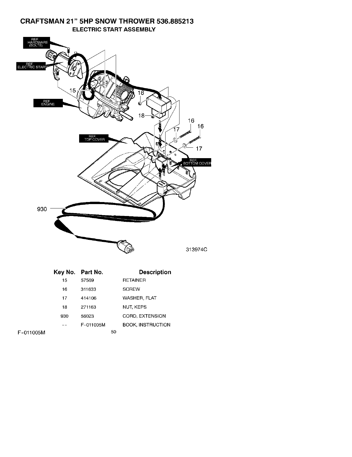
CRAFTSMAN 21" 5HP SNOW THROWER 536.885213
ELECTRIC START ASSEMBLY
16 16
17
930
313974C
F-011005M
Key No.
15
16
17
18
930
Part No.
57569
311633
414106
271163
56023
F-O11OO5M
Description
RETAINER
SCREW
WASHER, FLAT
NUT, KEPS
CORD, EXTENSION
BOOK, INSTRUCTION
5O
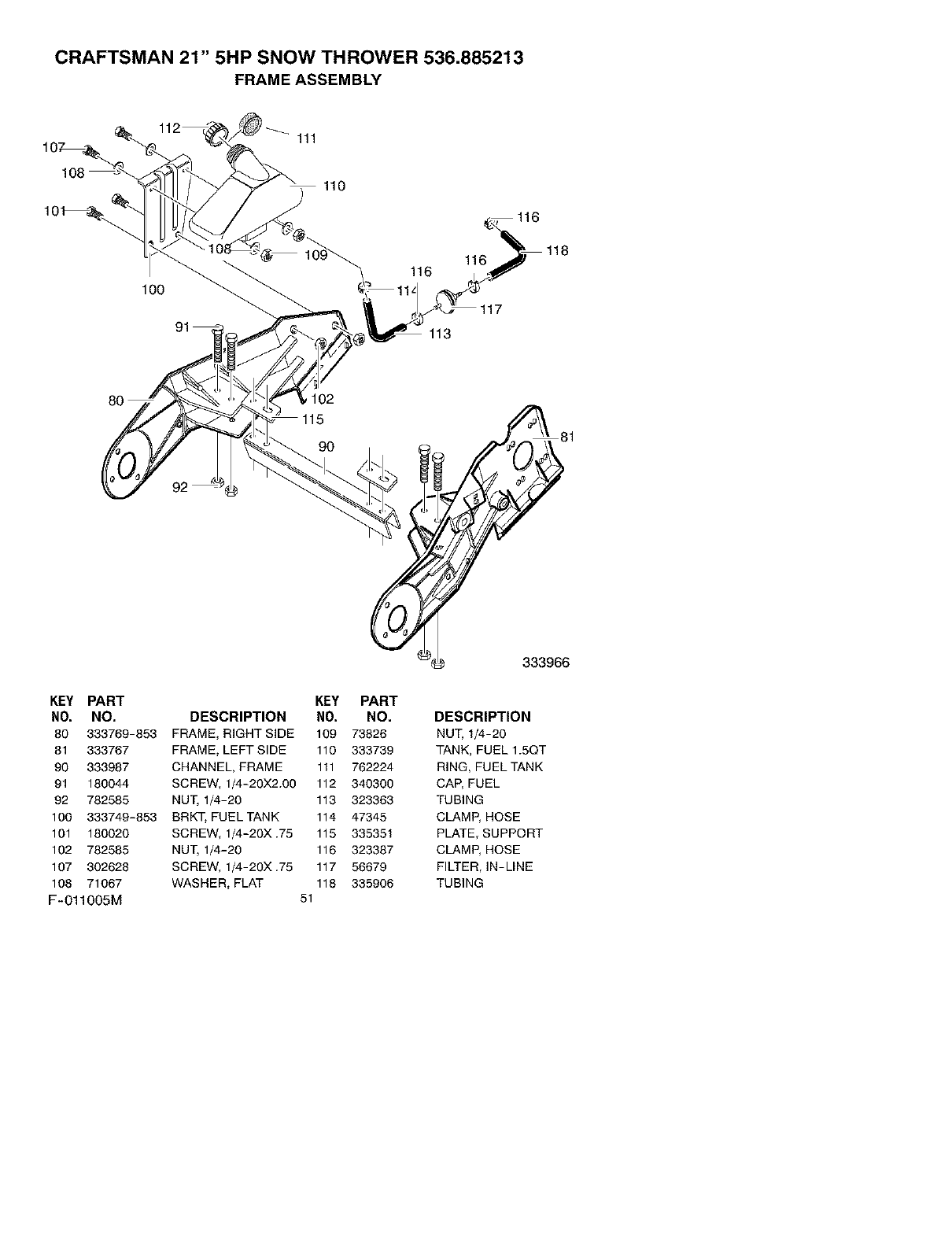
CRAFTSMAN 21" 5HP SNOW THROWER 536.885213
FRAME ASSEMBLY
111
110
100
116
113
116
117
i102
90
KEY PART KEY PART
NO. NO. DESCRIPTION NO. NO.
80 333769-853 FRAME, RIGHT SIDE 109 73826
81 333767 FRAME, LEFT SIDE 110 333739
90 333987 CHANNEL, FRAME 111 762224
91 180044 SCREW, 1/4-20X2.00 112 340300
92 782585 NUT, 1/4-20 113 323363
100 333749-853 BRKT, FUEL TANK 114 47345
101 180020 SCREW, 1/4-20X.75 115 335351
102 782585 NUT, 1/4-20 116 323387
107 302628 SCREW, 1/4-20X.75 117 56679
108 71067 WASHER, FLAT 118 335906
F-011OO5M 51
333966
DESCRIPTION
NUT, 1/4-20
TANK, FUEL 1.5QT
RING, FUEL TANK
CAP, FUEL
TUBING
CLAMP, HOSE
PLATE, SUPPORT
CLAMP, HOSE
FILTER, IN-LINE
TUBING
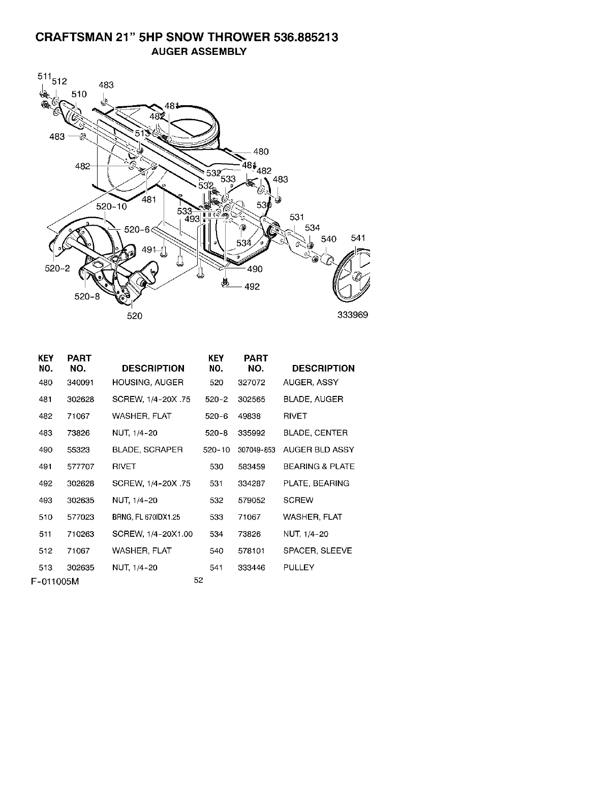
CRAFTSMAN 21" 5HP SNOW THROWER 536.885213
AUGER ASSEMBLY
511512 483
510
483
_8_482
483
520-2
520-8
520
492
531
534
540 541
333969
KEY PART
NO. NO.
480 340091
481 302628
482 71067
483 73826
490 55323
491 577707
492 302628
493 302635
510 577023
511 710263
512 71067
513 302635
F-011005M
KEY PART
DESCRIPTION NO. NO.
HOUS_NG_ AUGER 520 327072
SCREW, 1/4-20X.75 520-2 302565
WASHER, FLAT 520-6 49838
NU_ 1/4-20 520-8 335992
BLADE, SCRAPER 520-10 307049-853
RIVET 530 583459
SCREW, 1/4-20X.75 531 334287
NU_ 1/4-20 532 579052
8RNG, FL6701DXl.25 533 71067
SCREW, 1/4-20X1.00 534 73826
WASHER, FLAT 540 578101
NU_ 1/4-20 541 333446
52
DESCRIPTION
AUGER, ASSY
BLADE, AUGER
RIVET
BLADE, CENTER
AUGER BLD ASSY
BEARING & PLATE
PLATE, BEARING
SCREW
WASHER, FLAT
NUT, 1/4-20
SPACER, SLEEVE
PULLEY
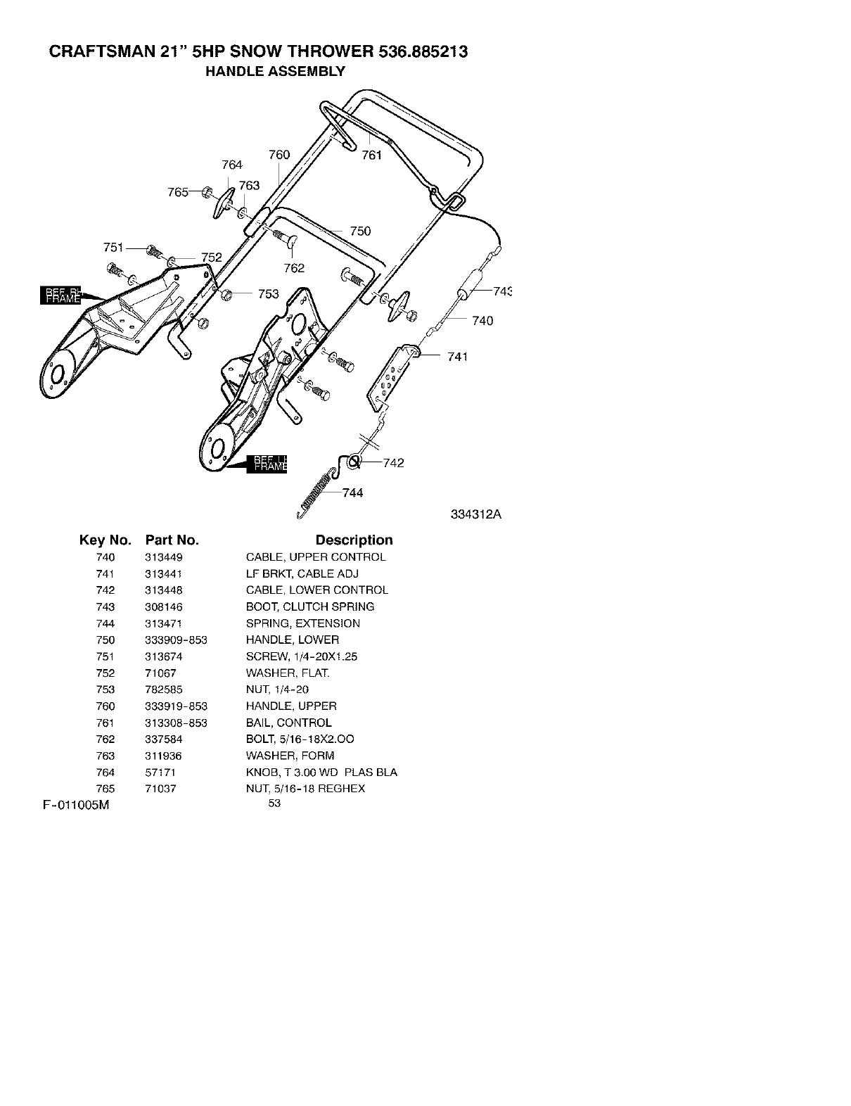
CRAFTSMAN 21" 5HP SNOW THROWER 536.885213
HANDLE ASSEMBLY
760
764
765_
751
Key No. Part No.
740 313449
741 313441
742 313448
743 308146
744 313471
750 333909-853
751 313674
752 71067
753 782585
760 333919-853
761 313308-853
762 337584
763 311936
764 57171
765 71037
F-011005M
Description
CABLE, UPPER CONTROL
LP BRKT, CABLE ADJ
CABLE, LOWER CONTROL
BOOT, CLUTCH SPRING
SPRING, EXTENSION
HANDLE, LOWER
SCREW, 1/4-20X1.25
WASHER, FLAT.
NUT, 1/4-20
HANDLE, UPPER
BAIL, CONTROL
BOLT, 5/16-18X2.OO
WASHER, FORM
KNOB, T 3.00 WD PLAS BLA
NUT, 5/16-18 REGHEX
53
334312A
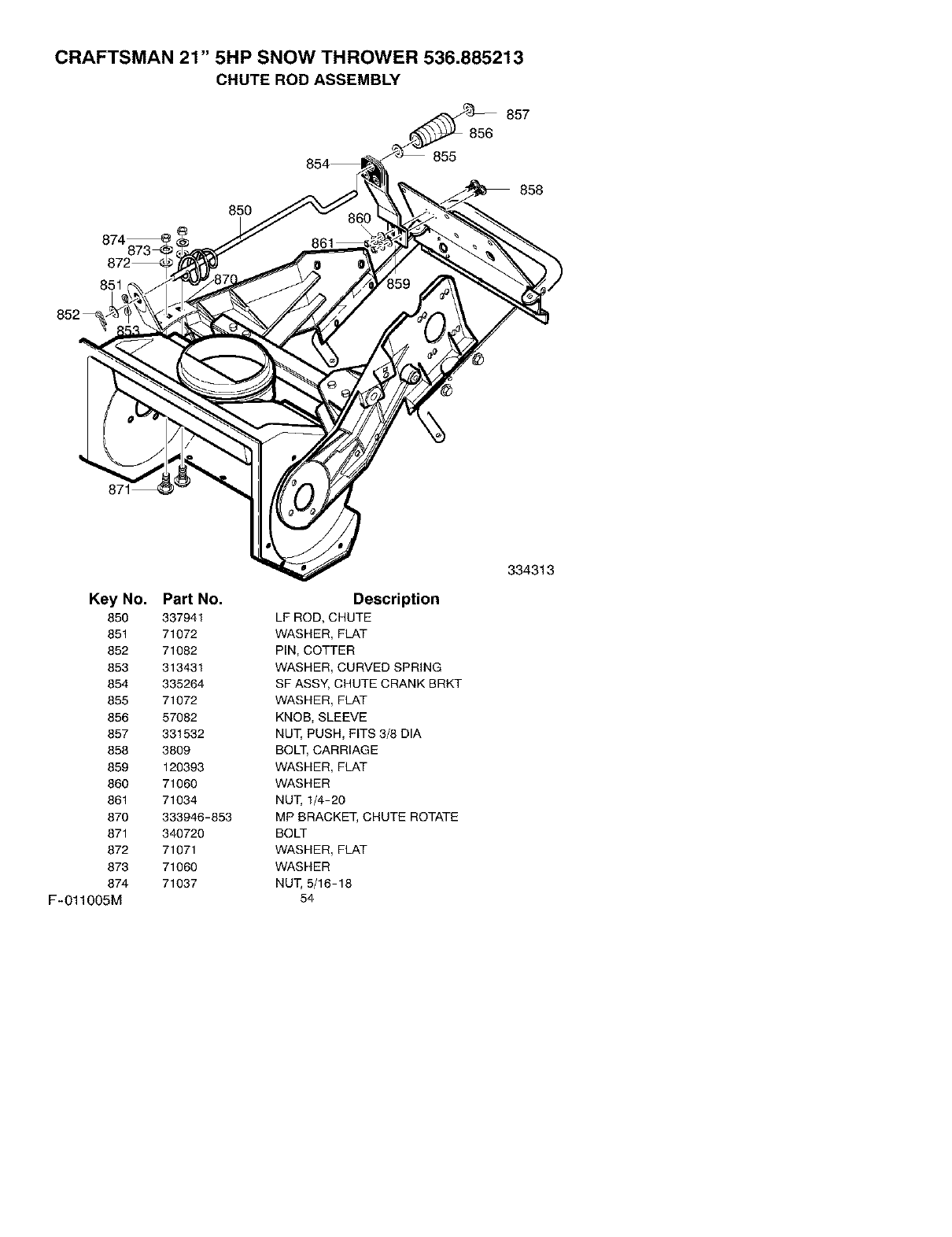
CRAFTSMAN 21" 5HP SNOW THROWER 536.885213
CHUTE ROD ASSEMBLY
857
856
855
858
850
874
851
Key No. Part No.
850 337941
851 71072
852 71082
853 313431
854 335264
855 71072
856 57082
857 331532
858 3809
859 120393
860 71060
861 71034
870 333946-853
871 340720
872 71071
873 71060
874 71037
F-O11005M
Description
LF ROD, CHUTE
WASHER, FLAT
PIN, COTTER
WASHER, CURVED SPRING
SF ASSY, CHUTE CRANK BRKT
WASHER, FLAT
KNOB, SLEEVE
NUT, PUSH, FITS 3/8 DIA
BOLT, CARRIAGE
WASHER, FLAT
WASHER
NUT, 1/4-20
MP BRACKET, CHUTE ROTATE
BOLT
WASHER, FLAT
WASHER
NUT, 5/16-18
54
334313
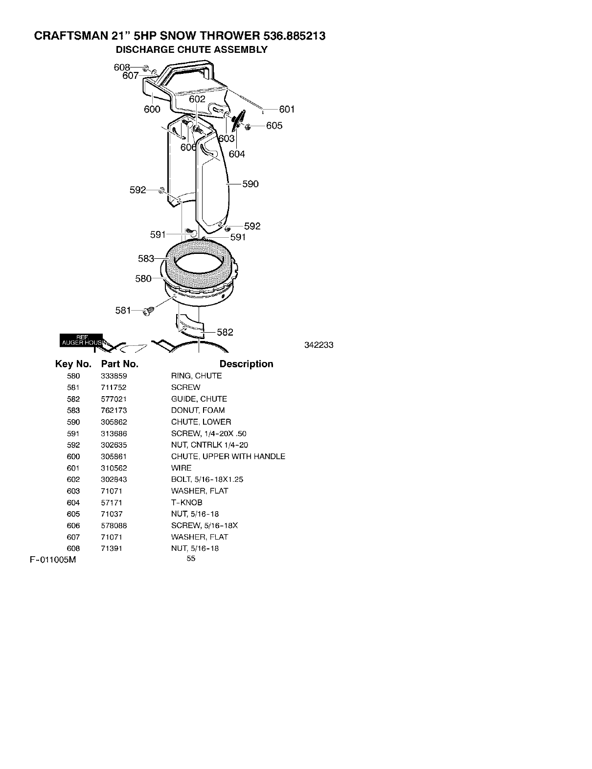
CRAFTSMAN 21" 5HP SNOW THROWER 536.885213
DISCHARGE CHUTE ASSEMBLY
6°go
60o692 _-. _'-
v_,,_ 582
__ _ _ 342233
Key No. Part No. Description
580 333859 RING, CHUTE
581 711752 SCREW
582 577021 GUIDE, CHUTE
583 762173 DONUT, FOAM
590 305862 CHUTE, LOWER
591 313686 SCREW, 1/4-20X .50
592 302635 NUT, CNTRLK 1/4-20
600 305861 CHUTE, UPPER WITH HANDLE
601 310562 WIRE
602 302843 BOLT, 5/16-18X1.25
603 71071 WASHER, FLAT
604 57171 T-KNOB
605 71037 NUT, 5/16-18
606 578088 SCREW, 5/16-18X
607 71071 WASHER, FLAT
608 71391 NUT, 5/16-18
F-011005M 55
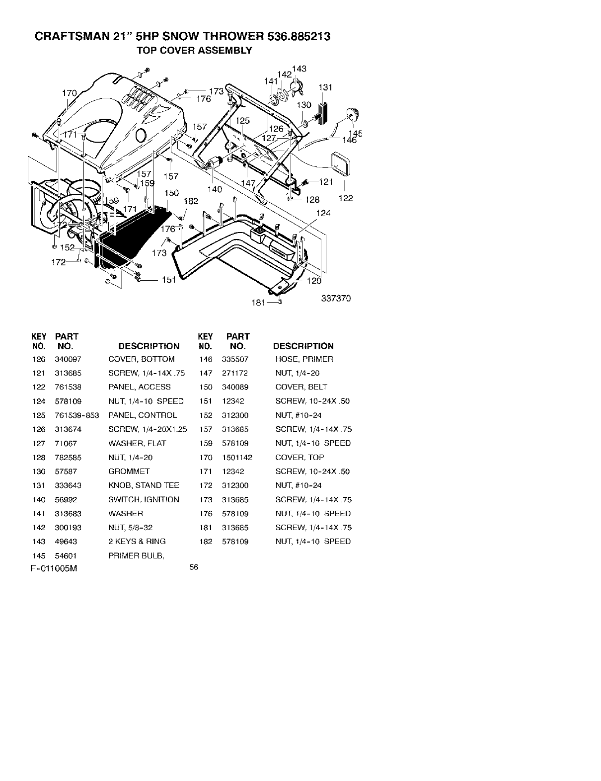
CRAFTSMAN 21" 5HP SNOW THROWER 536.885213
TOP COVER ASSEMBLY
'_ 142143
_ 141
173 _ 131
8 122
124
15
181_ 337370
KEY PART
NO. NO.
120 340097
121 313685
122 761538
124 578109
125 761539-853
126 313674
127 71067
128 782585
130 57587
131 333643
140 56992
141 313683
142 300193
143 49643
145 54601
F-011005M
KEY PART
DESCRIPTION NO. NO.
COVER, BOTTOM 146 335507
SCREW, 1/4-14X.75 147 271172
PANEL, ACCESS 150 340089
NUT, 1/4-10 SPEED 151 12342
PANEL, CONTROL 152 312300
SCREW, 1/4-20Xl.25 157 313685
WASHER, FLAT 159 578109
NUT, 1/4-20 170 1501142
GROMMET 171 12342
KNOB, STAND TEE 172 312300
SW_TCH, _GNIT_ON 173 313685
WASHER 176 578109
NUT, 5/8-32 181 313685
2 KEYS & RING 182 578109
PRIMER BULB,
56
DESCRIPTION
HOSE, PRIMER
NUT, 1/4-20
COVER, BELT
SCREW, 10-24X .50
NUT, #10-24
SCREW, 1/4-14X .75
NUT, 1/4-10 SPEED
COVER, TOP
SCREW, 10-24X .50
NUT, #10-24
SCREW, 1/4-14X .75
NUT, 1/4-10 SPEED
SCREW, 1/4-14X .75
NUT, 1/4-10 SPEED
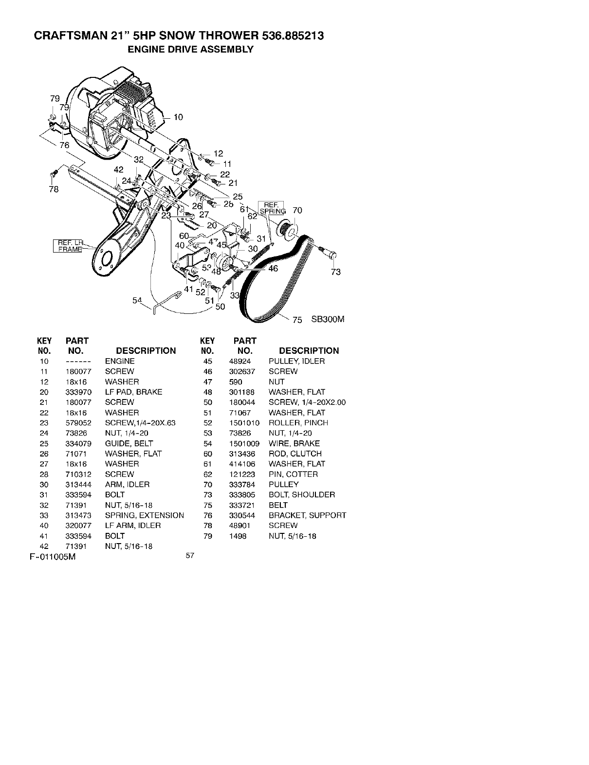
CRAFTSMAN 21" 5HP SNOW THROWER 536.885213
ENGINE DRIVE ASSEMBLY
7°7
_32 "_._ \_ _ 12
78
lh"d
60_ -, "_ L31
70
75 SB300M
KEY PART KEY PART
NO. NO. DESCRIPTION NO. NO. DESCRIPTION
10 ENGINE 45 48924 PULLEY, IDLER
11 180077 SCREW 46 302637 SCREW
12 18x16 WASHER 47 590 NUT
20 333970 LE PAD, BRAKE 48 301188 WASHER, FLAT
21 180077 SCREW 50 180044 SCREW, 1/4-20X2.00
22 18x16 WASHER 51 71067 WASHER, FLAT
23 579052 SCREW,1/4-2OX.63 52 1501010 ROLLER, PINCH
24 73826 NUT, 1/4-20 53 73826 NUT, 1/4-20
25 334079 GUIDE, BELT 54 1501009 WIRE, BRAKE
26 71071 WASHER, FLAT 60 313436 ROD, CLUTCH
27 18x16 WASHER 61 414106 WASHER, FLAT
28 710312 SCREW 62 121223 PIN, COTTER
30 313444 ARM, IDLER 70 333784 PULLEY
31 333594 BOLT 73 333805 BOLT, SHOULDER
32 71391 NUT, 5/16-18 75 333721 BELT
33 313473 SPRING, EXTENSION 76 330544 BRACKET, SUPPORT
40 320077 LF ARM, IDLER 78 48901 SCREW
41 333594 BOLT 79 1498 NUT, 5/16-18
42 71391 NUT, 5/16-18
F-011005M 57
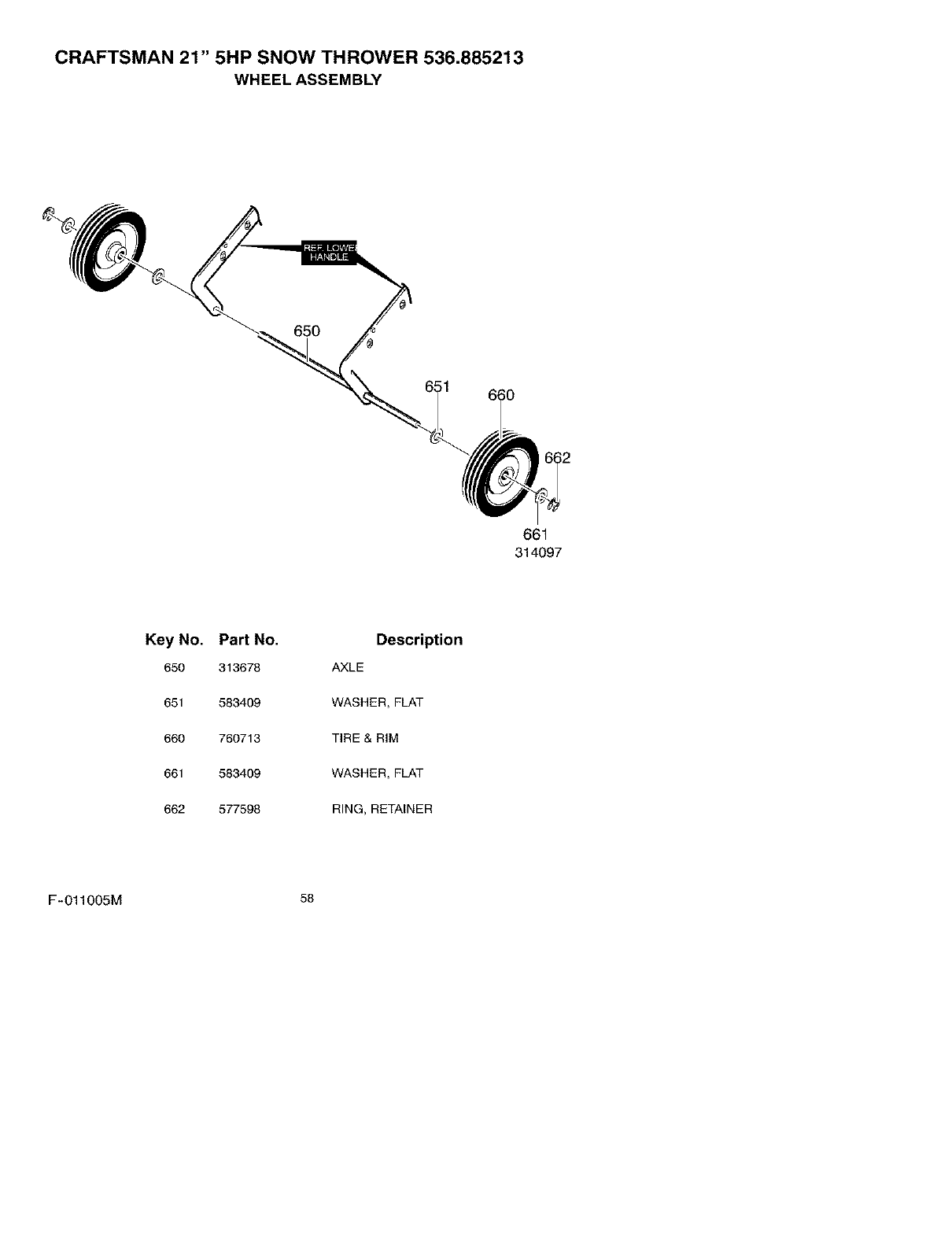
CRAFTSMAN 21" 5HP SNOW THROWER 536.885213
WHEEL ASSEMBLY
651
661
314097
Key No.
650
651
660
661
662
Part No.
313678
583409
760713
583409
577598
Description
AXLE
WASHER, FLAT
TIRE & RIM
WASHER, FLAT
RING, RETAINER
F-O11005M 56
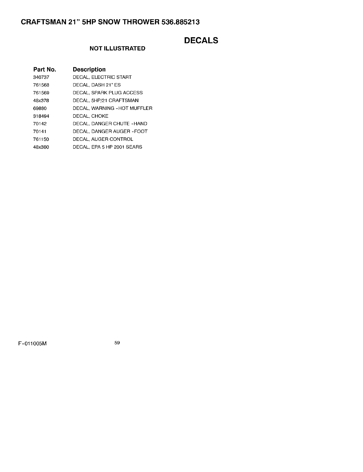
CRAFTSMAN 21" 5HP SNOW THROWER 536.885213
NOTILLUSTRATED DECALS
Part No.
340737
761568
761569
48x378
69880
318494
70142
70141
761150
48x380
Description
DECAL_ELECTRIC START
DECAL, DASH 21"ES
DECAL, SPARK PLUG ACCESS
DECAL, 5HP_I CRAFTSMAN
DECAL, WARNING-HOT MUFFLER
DECAL, CHOKE
DECAL, DANGER CHUTE -HAND
DECAL, DANGER AUGER -FOOT
DECAL, AUGER CONTROL
DECAL, EPA5 HP2001 SEARS
F-011005M 59
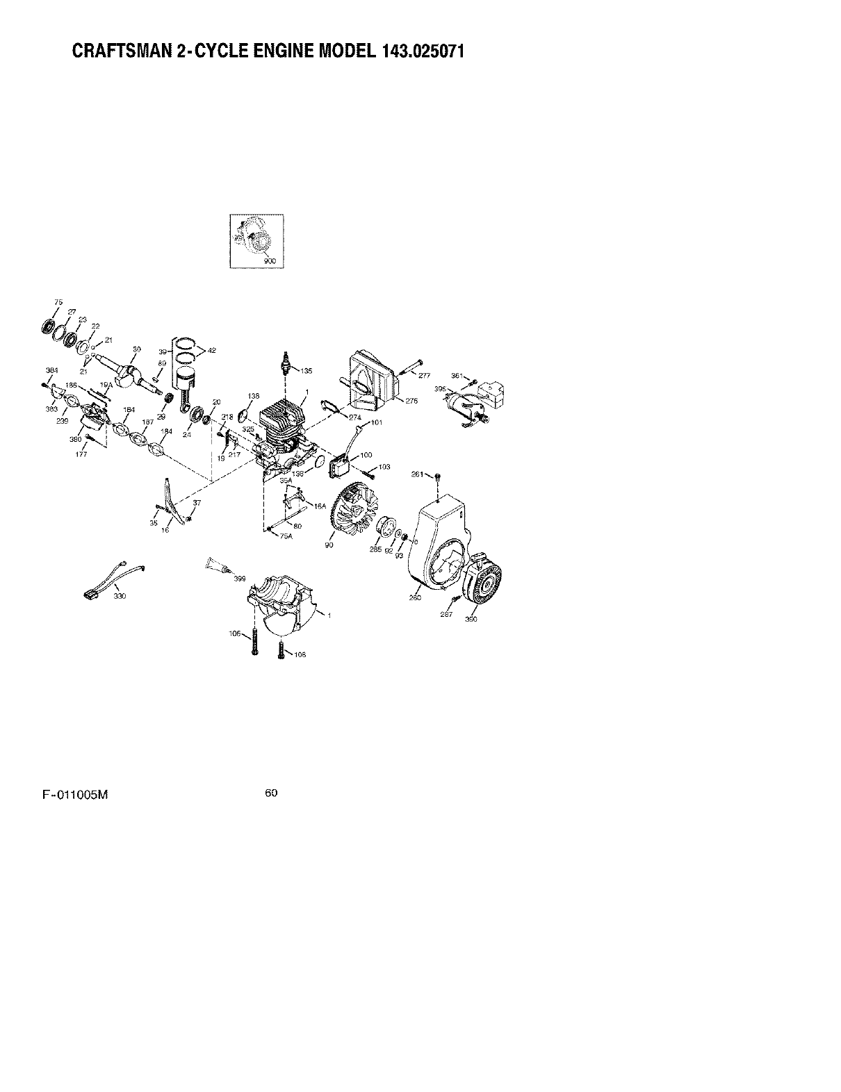
CRAFTSMAN2-CYCLE ENGINEMODEL 143.025071
75
/27 29
22
384 21
3O
138
285 9
287 /
390
F-O11005M 6o
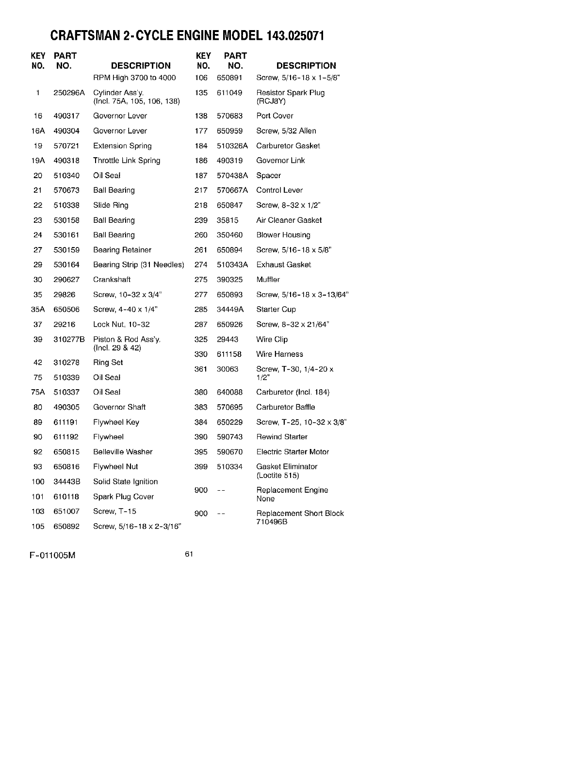
CRAFTSMAN2-CYCLE ENGINEMODEL 143.025071
KEY PART KEY PART
NO. NO. DESCRIPTION NO. NO. DESCRIPTION
RPM High 3700 to 4000 106 650891 Screw, 5/16-18 x 1-5/8"
1 250296A CylinderAss'y. 135 611049 Resistor Spark Plug
(Incl. 75A, 105, 106, 138) (RCJ8Y)
16 490317 Governor Lever 138 570683 Port Cover
16A 490304 Governor Lever 177 650959 Screw, 5/32 Allen
19 570721 Extension Spring 184 510326A Carburetor Gasket
19A 490318 Throttle Link Spring 186 490319 Governor Link
20 510340 Oil Seal 187 570438A Spacer
21 570673 Ball Bearing 217 570667A Control Lever
22 510338 Slide Ring 218 650847 Screw, 8-32 x 1/2"
23 530158 Ball Bearing 239 35815 Air Cleaner Gasket
24 530161 Ball Bearing 260 350460 Blower Housing
27 530159 Bearing Retainer 261 650894 Screw, 5/16-18 x 5/8"
29 530164 Bearing Strip (31 Needles) 274 510343A Exhaust Gasket
30 290627 Crankshaft 275 390325 Muffler
35 29826 Screw, 10-32 x 3/4" 277 650893 Screw, 5/16-18 x 3-13/64"
35A 650506 Screw, 4-40 x 1/4" 285 34449A Starter Cup
37 29216 Lock Nut, 10-32 287 650926 Screw, 8-32 x 21/64"
39 310277B Piston & Rod Ass'y. 325 29443 Wire Clip
(Incl. 29 & 42) 330 611158 Wire Harness
42 310278 Ring Set 361 30063 Screw, T-30, 1/4-20 x
75 510339 Oil Seal 1/2"
75A 510337 Oil Seal 380 640088 Carburetor (Incl. 184)
80 490305 Governor Shaft 383 570695 Carburetor Baffle
89 611191 Flywheel Key 384 650229 Screw, T-25, 10-32 x 3/8"
90 611192 Flywheel 390 590743 Rewind Starter
92 650815 Belleville Washer 395 590670 Electric Starter Motor
93 650816 Flywheel Nut 399 510334 Gasket Eliminator
(Loctite 515)
100 34443B Solid State Ignition
900 -- Replacement Engine
101 610118 Spark Plug Cover None
103 651007 Screw, T-15 900 -- Replacement Short BIock
710496B
105 650892 Screw, 5/16-18 x 2-3/16"
F-O11005M 61
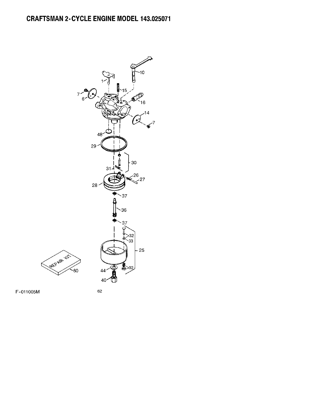
CRAFTSMAN2-CYCLE ENGINEMODEL 143.025071
F-O11005M 62
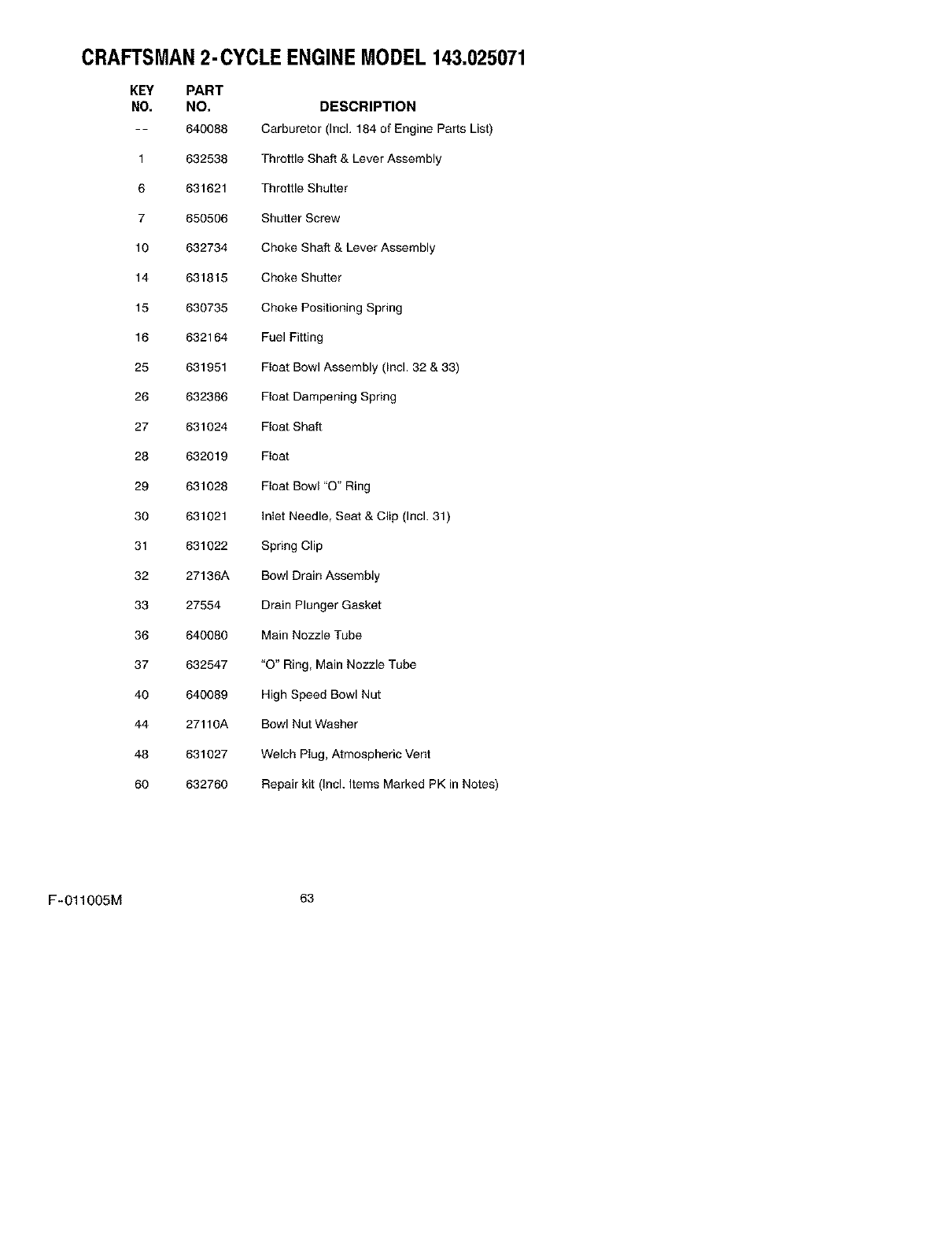
CRAFTSMAN2-CYCLE ENGINEMODEL 143.025071
KEY PART
NO. NO. DESCRIPTION
-- 640088 Carburetor (Incl. 184 of Engine Parts List)
1 632538 Throttle Shaft & Lever Assembly
6 631621 Throttle Shutter
7650506 Shutter Screw
10 632734 Choke Shaft & Lever Assembly
14 631815 Choke Shutter
15 630735 Choke Positioning Spring
16 632164 Fuel Fitting
25 631951 Float Bowl Assembly (Incl. 32 & 33)
26 632386 Float Dampening Spring
27 631024 Float Shaft
28 632019 Float
29 631028 Float Bowl "O" Ring
30 631021 Inlet Needle, Seat & Clip (Incl. 31)
31 631022 Spring Clip
32 27136A Bowl Drain Assembly
33 27554 Drain Plunger Gasket
36 640080 Main Nozzle Tube
37 632547 "O" Ring, Main Nozzle Tube
40 640089 High Speed Bowl Nut
44 27110A Bowl Nut Washer
48 631027 Welch Plug, Atmospheric Vent
60 632760 Repair kit (Incl. Items Marked PK in Notes)
F-011005M 63
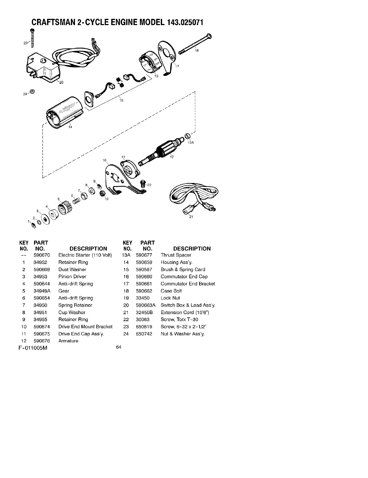
CRAFTSMAN2-CYCLE ENGINEMODEL 143.025071
7_ 8
KEY PART KEY PART
NO. NO, DESCRIPTION NO. NO. DESCRIPTION
-- 590670 Electric Starter (110 Volt) 13A 590677 Thrust Spacer
1 34952 Retainer Ring 14 590659 Housing Ass'y.
2 590608 Dust Washer 15 590587 Brush & Spring Card
3 34953 Pinion Driver 16 590660 Commutator End Cap
4 590644 Anti-drift Spring 17 590661 Commutator End Bracket
5 34949A Gear 18 590662 Case Bolt
6 590654 Anti-drift Spring 19 33450 Lock Nut
7 34950 Spring Retainer 20 590663A Switch Box & Lead Ass'y.
8 34951 Cup Washer 21 32450B Extension Cord (10'6")
9 34955 Retainer Ring 22 30063 Screw, Torx T-3O
t0 590674 Drive End Mount Bracket 23 650819 Screw, 6-32 x 2-1/2"
11 590675 Drive End Cap Ass'y. 24 650742 Nut & Washer Ass'y.
12 590676 Armature
F-011005M 64
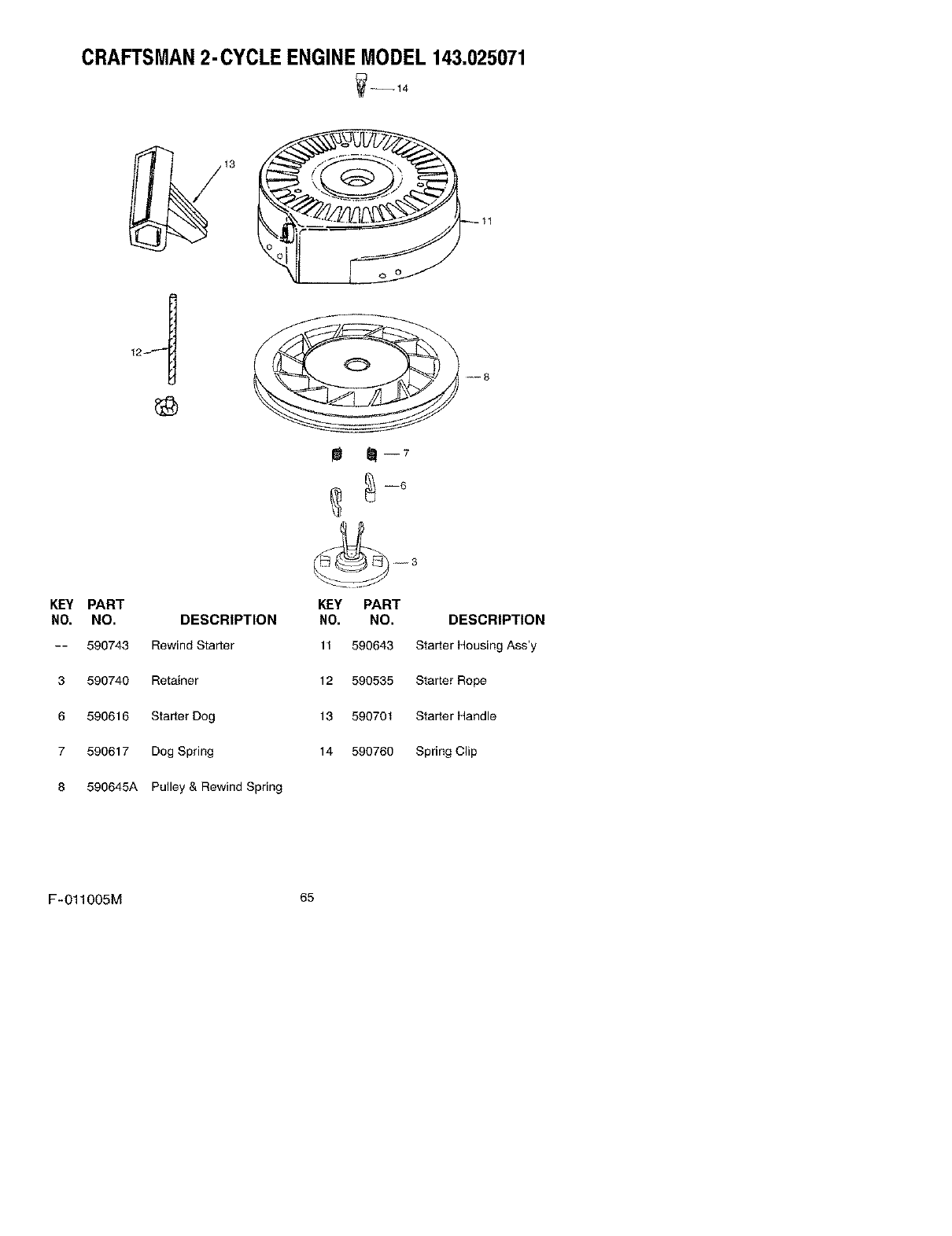
CRAFTSMAN2-CYCLE ENGINEMODEL 143.025071
_--14
m m-7
KEY PART KEY PART
NO. NO. DESCRIPTION NO. NO. DESCRIPTION
-- 590743 Rewind Starter 11 590643 Starter Housing Ass'y
3590740 Retainer 12 590535 Starter Rope
6590616 Starter Dog 13 590701 Starter Handle
7590617 Dog Spring 14 590760 Spring Clip
8 590645A Pulley & Rewind Spring
F-O11005M 65
