Craftsman 536885921 User Manual SNOW THROWER Manuals And Guides L0910368
CRAFTSMAN Snowthrower, Gas Manual L0910368 CRAFTSMAN Snowthrower, Gas Owner's Manual, CRAFTSMAN Snowthrower, Gas installation guides
User Manual: Craftsman 536885921 536885921 CRAFTSMAN SNOW THROWER - Manuals and Guides View the owners manual for your CRAFTSMAN SNOW THROWER #536885921. Home:Lawn & Garden Parts:Craftsman Parts:Craftsman SNOW THROWER Manual
Open the PDF directly: View PDF ![]() .
.
Page Count: 72
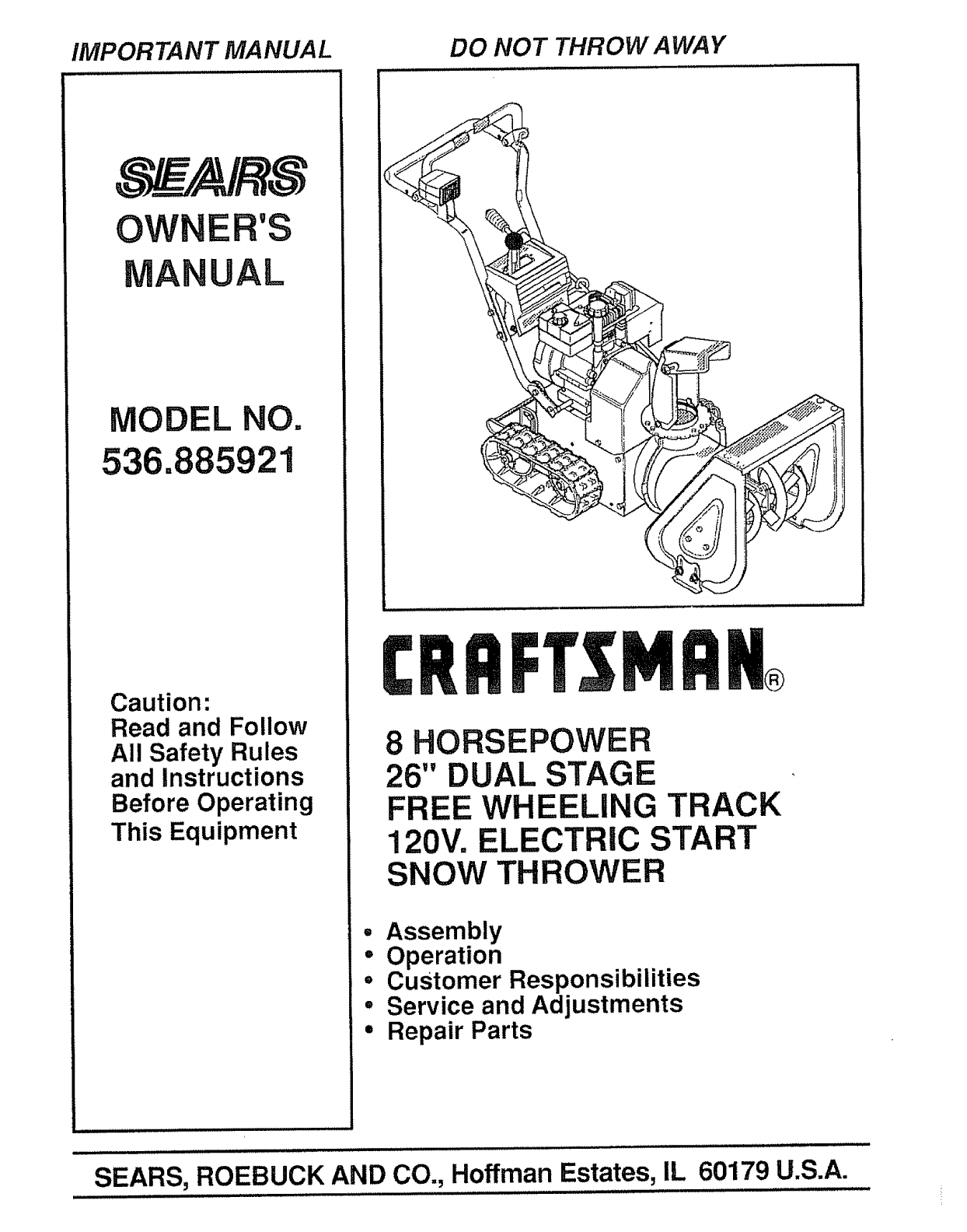
IMPORTANT MANUAL DO NOT THROW AWAY
OWNER'S
MANUAL
MODEL NO.
536.885921
Caution:
Read and Follow
All Safety Rules
and Instructions
Before Operating
This Equipment
8 HORSEPOWER
26" DUAL STAGE
FREE WHEELING TRACK
120V. ELECTRIC START
SNOW THROWER
° Assembly
• Operation
• Customer Responsibilities
° Service and Adjustments
• Repair Parts
SEARS, ROEBUCK AND CO., Hoffman Estates, IL 60179 U.S.A.
SAFETY RULES
CAUTION: ALWAYS DISCONNECT SPARK PLUG WIRE AND ._
PLACE WIRE WHERE IT CANNOT CONTACT SPARK PLUG A
TO PREVENT ACCIDENTAL STARTING WHEN SETTING-UP,
TRANSPORTING, ADJUSTING OR MAKING REPAIRS,
IMPORTANT
SAFETY STANDARDS REQUIRE OPERATOR PRESENCE CONTROLS TO MINIMIZE THE
RISK OF INJURY, YOUR SNOW THROWER IS EQUIPPED WITH SUCH CONTROLS. DO NOT
ATTEMPT TO DEFEAT THE FUNCTION OF THE OPERATOR PRESENCE CONTROL UNDER
ANY CIRCUMSTANCES
TRAINING
1o Read the operator's manual carefully. Be
thoroughly familiar with the controls and the
proper use of the snow thrower. Know how to
stop the snow thrower and disengage the
controls quickly.
2. Never allow children to operate the snowthrower
and keep them away while it is operating. Never
allow adults to operate the snow thrower without
proper instruction° Do not carry passengers.
3. Keep the area of operation clear of all persons,
particularly small children, and pets.
4. Exercise caution to avoid slipping or falling,
especially when operating in reverse.
PREPARATION
1. Thoroughly inspect the area where the snow
thrower is to be used and remove all doormats,
sleds, boards, wires, and other foreign objects.
2. Disengage all clutches and shift into neutral
before starting the engine (motor).
3o Do not operatethe snowthrowerwithout wearing
adequate winter outer' garments. Wear footwear
that will improve footing on slippery surfaces.
4_ Handle fuel with care; it is highly flammable_
(a) Use an approved fuel container.
(b) Never remove fuel tank cap or add fuel to a
running engine or hot engine.
(c) Fill fuel tank outdoors with extreme care.
Never fill fuel tank indoors.
=
(d) Replace fuel tank cap securely and wipe up
spilled fuel.
(e) Never store fuel or snow thrower with fuel in
the tank inside of a building where fumes may
reach an open flame or spark,
(f) Check fuel supply before each use, allowing
space for expansion as the heat of the engine
(motor) and/or sun can cause fuel to expand.
Use extension cords and receptacles as specified
by the manufacturer for all snow throwers with
electric drive motors or electric starting motors.
6, Adjust the snow thrower height to clear gravel or
crushed rock surfaces.
7. Never attempt to make any adjustments while the
engine (motor) is running (except when
specifically recommended by the manufacturer).
8. Let engine (motor) and snow thrower adjust to
outdoor temperatures before starting to clear
snow,
9. Always wear safety glasses or eye shields during
operation or while performing an adjustment or
repair to protect eyes from foreign objects that
may be thrown from the snow thrower.
OPERATION
1. Do not put hands or feet near or under rotating
parts. Keep clear of the discharge opening at all
times°
2, Exercise extreme caution when operating on or
crossing gravel drives, walks, or roads. Stay alert
for hidden hazards or traffic.
3_
4_
After striking a foreign object, stop the engine
(motor), remove the wire from the spark plug,
disconnect the cord on electric motors,
thoroughly inspect the snow thrower for any
damage, and repair the damage before restarting
and operating the snow thrower_
if the snow thrower should start to vibrate
abnormally, stop the (motor) and check
immediately for the cause. Vibration is generally
awarning of trouble.
5. Stop the engine (motor) whenever you leave the
operating position, before unclogging the auger!
impeller housing or discharge guide, and when
making any repairs, adjustments, or inspections.
6. When cleaning, repairing, or inspecting, make
certain the auger/impeller and all moving parts
have stopped° Disconnect the spark plug wire
and keep the wire away from the plug to prevent
accidental starting.
,Take all possible precautions when leaving the
snow thrower unattended. Disengage the auger/
impeller, shift to neutral, stop engine, and
remove key.
2
SAFETY RULES
.Do not run the engine indoors, except when starting
the engine and for transporting the snow thrower in
or out of the building. Open the outside doors;
exhaust fumes are dangerous (containing CARBON
MONOXIDE, an ODORLESS and DEADLY GAS).
9. Do not clear snow across the face of slopes.
Exercise caution when changing direction on
slopes. Do not attempt to clear steep slopes
10, Never operate the snow thrower without proper
guards, plates or other safety protective devices
in place.
11. Never operate the snow thrower near glass
enclosures, automobiles, window wells,
drop-offs, and the like without proper adjustment
of the snow discharge angle. Keep children and
pets away.
12. Do not overload the machine capacity by
attempting to clear snow at too fast arate°
13. Neveroperatethe snowthrowerat high transport
speeds on slippery surfaces° Look behind and
use care when backing.
14. Never direct discharge at bystanders or allow
anyone in front of the snow thrower.
15. Disengage power to the auger/impeller when
snow thrower is transported or not in use..
167 Use only attachments and accessories approved
by the manufacturer of the snow thrower (such
as tire chains, electric start kits, etc.)
17. Never operate the snow thrower without good
visibility or light. Always be sure of your footing,
and keep a firm hold on the handles. Walk; never
run.
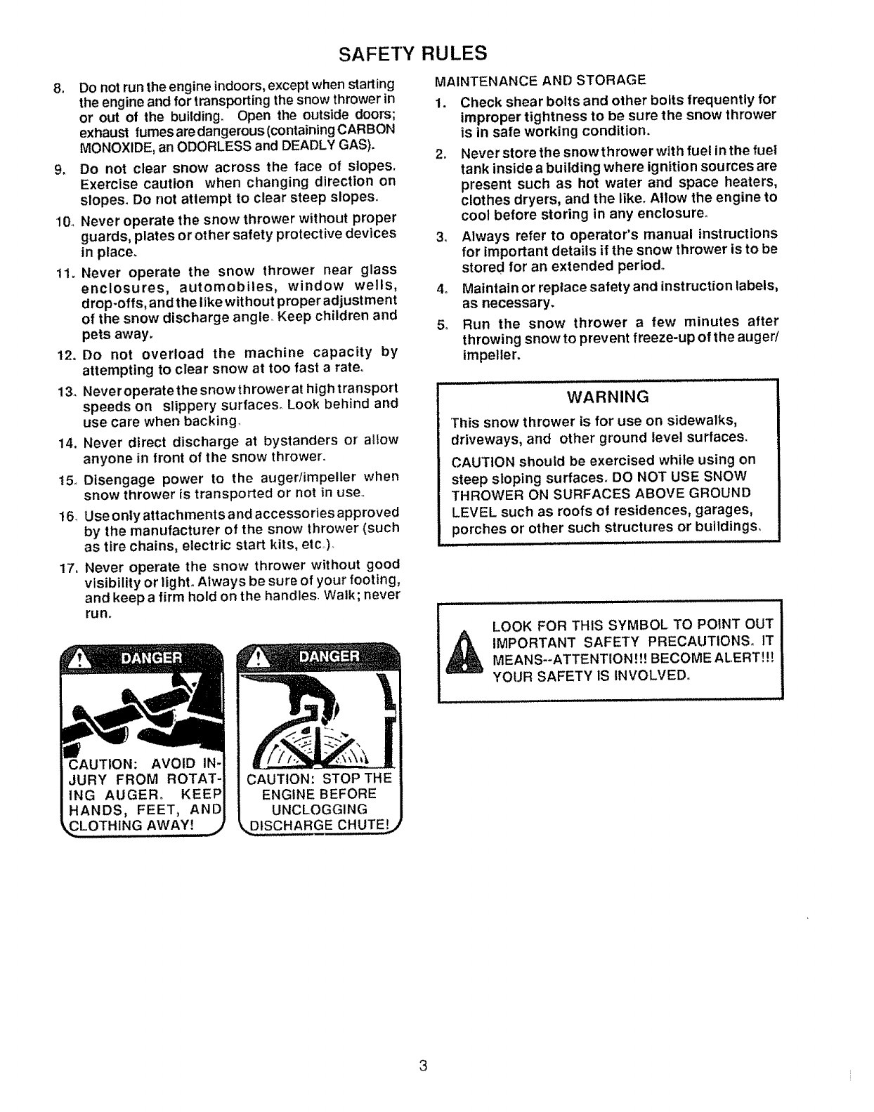
CAUTION: AVOID IN-
JURY FROM ROTAT-
ING AUGER° KEEP
HANDS, FEET, AND
AWAY! j
ENGINE BEFORE
UNCLOGGING
DISCHARGE CHUTE!
MAINTENANCE AND STORAGE
1. Check shear bolts and other bolts frequently for
improper tightness to be sure the snow thrower
is in safe working condition.
2. Never store the snow thrower with fuel in the fuel
tank inside a building where ignition sources are
present such as hot water and space heaters,
clothes dryers, and the like. Allow the engine to
cool before storing in any enclosure.
3. Always refer to operator's manual instructions
for important details if the snow thrower is to be
stored for an extended period.
4. Maintain or replace safety and instruction labels,
as necessary.
5. Run the snow thrower a few minutes after
throwing snow to prevent freeze-up of the auger/
impeller.
WARNING
This snow thrower is for use on sidewalks,
driveways, and other ground level surfaces.
CAUTION should be exercised while using on
steep sloping surfaces. DO NOT USE SNOW
THROWER ON SURFACES ABOVE GROUND
LEVEL such as roofs of residences, garages,
porches or other such structures or buildings,
LOOK FOR THIS SYMBOL TO POINT OUT
_ IMPORTANT SAFETY PRECAUTIONS. ITMEANS--ATTENTION.It! BECOME ALERT!{{
YOUR SAFETY IS INVOLVED.
3
CONGRATULATIONS on your purchase of a Sears
Craftsman Snow Thrower.. It has been designed, engi-
neered and manufactured to give you the best possible
dependability and performance..
Should you experience any problem you cannot easily
remedy, please contact your nearest Sears Service
Center!Department, Sears has competent, well-trained
technicians and the proper tools to service or repair this
unit
Please read and retain this manual. The instructions will
enable you to assemble and maintain your snow thrower
properly. Always observe the "SAFETY RULES.."
MODEL
NUMBER 536.885921
SERIAL
NUMBER
DATE OF
PURCHASE
THE MODEL AND SERIAL NUMBERS WILL BE
FOUND ON A DECAL ATTACHED TO THE REAR
OF THE SNOW THROWER HOUSING
YOU SHOULD RECORD BOTH SERIAL NUMBER
AND DATE OF PURCHASE AND KEEP 1NA SAFE
PLACE FOR FUTURE REFERENCE
, i,i
MAINTENANCE AG REEMENT
A Sears Maintenance Agreement is available on this
product Contact your nearest Sears Store for details
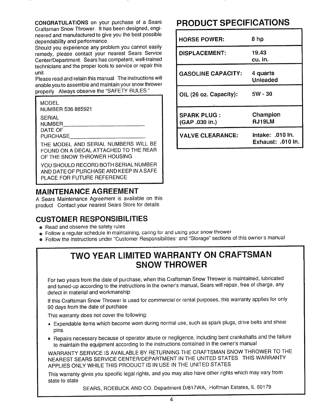
PRODUCT SPECIFICATIONS
HORSE POWER: 8 hp
DISPLACEMENT: 19.43
cu. in,
GASOLINE CAPACITY: 4 quarts
Unleaded
OIL (26 oz, Capacity): 5W - 30
SPARK PLUG : Champion
(GAP .030 in.) RJ19LM
VALVE CLEARANCE: intake: .010 in,
Exhaust: .010 in.
CUSTOMER RESPONSIBILITIES
e Read and observe the safety rules
e Follow a regular schedule in maintaining, caring for and using your snow thrower
® Follow the instructions under "Customer Responsibilities and "Storage" sections of this owners manual
TWO YEAR LIMITED WARRANTY ON CRAFTSMAN
SNOW THROWER
For two years from the date of purchase, when this Craftsman Snow Thrower is maintained, lubricated
and tuned-up according to the instructions in the owner's manual, Sears witl repair, free of charge, any
defect in material and workmanship
If this Craftsman Snow Thrower is used for commercial or rental purposes, this warranty applies for only
90 days from the date of purchase.
This warranty does not cover the following:
o Expendable items which become worn during normal use, such as spark plugs, drive belts and shear
pins..
o Repairs necessary because of operator abuse or negligence, including bent crankshafts and the tailure
to maintain the equipment according to lhe instructions contained in the owner's manual
WARRANTY SERVICE IS AVAILABLE BY RETURNING THE CRAFTSMAN SNOW THROWER TO THE
NEAREST SEARS SERVICE CENTERfDEPARTMENT IN THE UNITED STATES THIS WARRANTY
APPLIES ONLY WHILE THIS PRODUCT tS IN USE IN THE UNITED STATES.
This warranty gives you specific legal rights, and you may also have other rights which may vary from
state to state.
SEARS, ROEBUCK AND CO.. Deparlrnent Dt817WA, Hoffman Estates, IL 60179
4
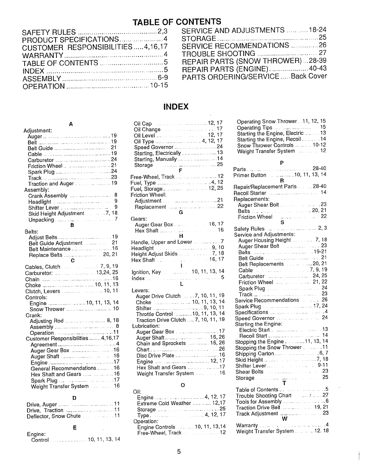
TABLE OF CONTENTS
SAFETY RULES .......................................................2,3
PRODUCT SPECIFICATIONS ..............................4
CUSTOMER RESPONSIBILITIES ..... 4,I6,17
WARRANTY .........................................................................4
TABLE OF CONTENTS ...........................................5
INDEX ...........................................................................5
ASSEMBLY .............................................................6-9
OPERATION ....................................................10-t5
SERVICE AND ADJUSTMENTS ...............18-24
STO RAGE ...................................................................25
SERVICE RECOMMENDATIONS ................ 26
TROUBLE SHOOTING .........................................27
REPAIR PARTS (SNOW THROWER) .....28-39
REPAIR PARTS (ENGINE) .........................40-43
PARTS ORDERING/SERVICE .......Back Cover
A
Adjustment:
Auger ........................................................19
Belt ............................................................19
Belt Guide ....................................................21
Cable .........................................................19
Carburetor .................................................24
Friction Wheel ........................................21
Spark Plug .................................... 24
Track .............................................. 23
Traction and Auger ......................... 19
Assembly:
Crank Assembty ................................. 8
Headlight ............................................. 9
Shifter Lever ...............................................9
Skid Height Adjustment ,7, 18
Unpacking .............................. 7
B
Belts:
Adjust Belts ........................................ 19
Belt Guide Adjustment .............. 21
Belt Maintenance ............................. 16
Replace Belts ............................ 20, 21
C
Cables, Clutch ............... 7, 9, !9
Carburetor: ...................... t 3,24, 25
Chain ................................................................!6
Choke ........................................t O, 11, 13
Clutch, Levers ..................... I0, 1I
Controls:
Engine .................................!0, 11, I3, 14
Snow Thrower ......................................I0
Crank:
Adjusting Rod .....................................8, 18
Assembly ........................................ 8
Operation ................................................11
Customer Responsibilities ...........4,16,17
Agreement ............................................4
Auger Gear Box ............................... t6
Auger Shaft ................................ t 6
Engine ................................................ 17
General Recommendations ........... 16
Hex Shaft and Gears ................... 16
Spark Plug ............................ 17
Weight Transfer System ............ 16
D
Drive, Auger ...........................................11
Drive, Traction ................................... 11
Deflector, Snow Chute .......... 11
E
Engine:
Control ............................1O, 1I, 13, 14
INDEX
Oil Cap .............................. I2, 17
Oil Change ................ 17
Oil Level ................... 12, 17
Oil Type .....................................4, 12, 17
Speed Governor ...............................24
Starting, Electrically ...............................13
Starting, Manually ...............................14
Storage ........................................25
F
Free-Wheel, Track ......................... I2
Fuel, Type .................................. 4, t2
Fuel, Storage ...................... !2, 25
Friction Wheel:
Adjustment ............................................2t
Replacement .................................... 22
G
Gears:
Auger Gear Box ..... t 6, 17
Hex Shaft ........................ 16
H
Handle, Upper and Lower ........................7
Headlight ......................... 9, 10
Height Adjust Skids ........... 7, 18
Hex Shaft ..... 16, 17
i
Ignition, Key ............ 10, 11, 13, 14
Index ............................ 5
L
Levers:
Auger Drive Clutch ........7, I0, 11, 19
Choke ......................... 10, II, t3, t4
Shifter .................................... 9, I0, l I
Throttle Control ....................i0, ti, t3, 14
Traction Drive Clutch ..... 7, 10, 11, 19
Lubrication:
Auger Gear Box ...................................17
Auger Shaft ......................... 16, 26
Chain and Sprockets ............. 16, 26
Chart ............................................... 26
Disc Drive Plate ....................................16
Engine ...............................................12, 17
Hex Shaft and Gears ........................17
Weight Transfer System .......... 16
O
Oil:
Engine ......................................4, 12, 17
Extreme Cold Weather .................12,17
Storage ..................................... 25
Type ........................ 4, 12, 17
Operation:
Engine Controls ........... 10, I1, 13,t4
Free-Wheel, Track ............ 12
Operating Snow Thrower. tt, 12, t5
Operating Tips ............................... 15
Starting the Engine, Electric ...........13
Starting the Engine, Recoil ............ 14
Snow Thrower Controls ............. !0-12
Weight Transfer System ............ 12
P
Parts ........................................ 28-40
Primer Button ............. 10, 1I, t3, 14
R
Repair/Replacement Parts ........ 28-40
Recoil Starter ...................................... 14
Replacements:
Auger Shear Bolt ................... 23
Belts .............................. 20, 2t
Friction Wheel ...................... 22
S
Safety Rules .................................... 2, 3
Service and Adjustments:
Auger Housing Height .......... 7, t8
Auger Shear Bolt ......................... 23
Belts ...................................... 19-21
Belt Guide ...................................... 2t
Belt Replacements .......... 20, 2t
Cable ...................... 7, 9, 19
Carburetor ............................. 24, 25
Friction Wheel ............... 21,22
Spark Plug ............................. 24
Track ......................................... 23
Service Recommendations ...... 26
Spark Plug .......................... 17, 24
Specifications .............................. 4
Speed Governor .......................... 24
Starting the Engine:
Electric Start ............................. 13
Recoil Start ........................................ 14
Stopping the Engine .................11, t3, 14
Stopping the Snow Thrower ........... 11
Shipping Carton .......................... 6. 7
Skid Height ......................... 7, I8
Shifter Lever .................... g-t 1
Shear Bolts ............................. 23
Storage ....................... 25
T
Table of Contents ...................... 5
Troubfe Shooting Chart ................. 27
Tools for Assembly ............................. 6
Traction Drive Belt ....................... !9, 21
Track Adjustment .............................. 23
W
Warranty .................................. 4
Weight Transfer System ......... 12. t8
5
ASSEMBLY
THIS SNOW THROWER HAS A TRACK DRIVE SYSTEM EQUIPPED TO GIVE
YOU FREE WHEELING CAPABILITY.
if your snow thrower must be moved without the aid of the engine, it will be easier to pull the snow thrower back-
ward by the handles, rather than pushing For details on how to use free wheeling, see the Track Drive/Free-Wheel
Feature paragraph in the Operation section of this manual.
On start up, the track drive system may be tight and will loosen up as the snow thrower' is used. After first use,
check the track for tension and adjust if necessary. See the Track Adjustment paragraph in the Service and Adjust-
ments section of this manual Check track adjustment and fasteners regularly.
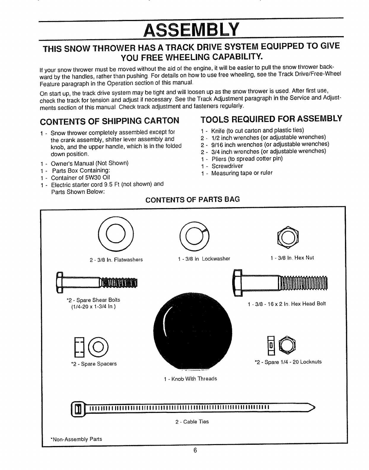
CONTENTS OF SHIPPING CARTON TOOLS REQUIRED FOR ASSEMBLY
! - Snow thrower completely assembled except for 1 -
the crank assembly, shifter lever assembly and 2 -
knob, and the upper handle, which is in the folded 2 -
down position. 2
1 - Owner's Manual (Not Shown) t -
1 - Parts Box Containing: 1 -
t - Container of 5W30 Oil 1 -
1 - Electric starter cord 9.5 Ft (not shown) and
Parts Shown Below:
CONTENTS OF PARTS BAG
Knife (to cut carton and plastic ties)
1/2 inch wrenches (or' adjustable wrenches)
9/t 6 inch wrenches (or adjustable wrenches)
3/4 inch wrenches (or adjustable wrenches)
Pliers (to spread cotter pin)
Screwdriver
Measuring tape or ruler
2 - 3/8 In..Flatwashers 1-3/8 in Lockwasher
©
1-3/8 In. Hex Nut
"2 - Spare Shear Bolts
(1/4-20 xt-3/4 In.)
*2 -Spare Spacers
! - 3t8 - 16 x 2 In, Hex Head Bolt
*2 - Spare 1/4 - 20 Locknuts
1 - Knob With Threads
_iiiiillilllliilllliilliilliliiiililiiiiiiiiillllilltllilllilllil'lll ..........._
2 - Cabte Ties
"Non-Assemb{y Parts
itiiiiu lll_ li,Hi, i i i lll i,i/ii, i,u,i.i H,i ,,it ,i i_tlll,l., 6
........................................................................ASSE....LY .......................
LowEnHANI LE..........
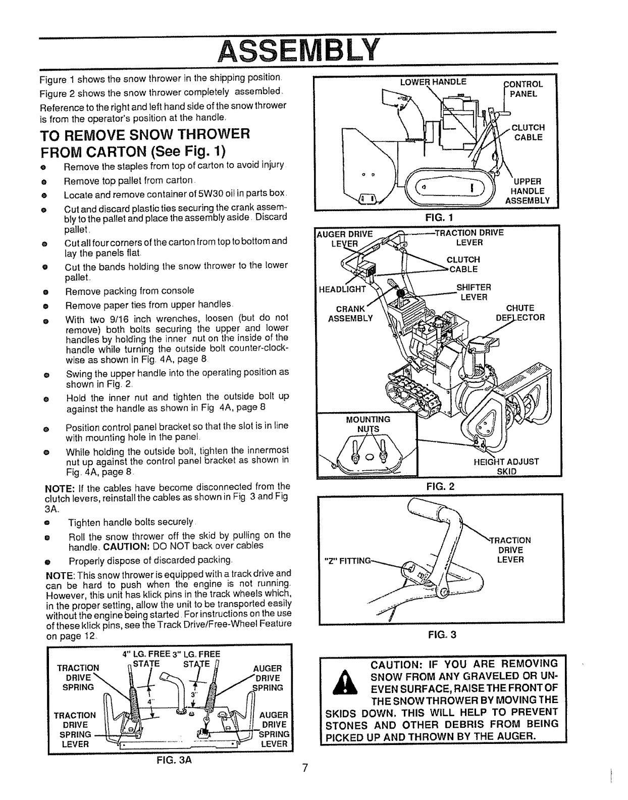
Figure 1 shows the snow thrower in the shipping position,
Figure 2 shows the snow thrower completely assembled,
Reference to the right and left hand side of the snow thrower
is from the operator's position at the handle,
TO REMOVE SNOW THROWER
FROM CARTON (See Fig. 1)
eRemove the staples from top of carton to avoid injury
eRemove top pallet from carton.
•Locate and remove container of 5W30 oil in parts box,
eCut and discard plastic ties securing the crank assem.
bly to the pallet and place the assembly aside. Discard
pallet,
eCut all fourcorners of the carton from top to bottom and
lay the panels flat,
•Cut the bands holding the snow thrower to the tower
pallet..
e Remove packing from console
•Remove paper ties from upper handles,
eWith two 9/!6 inch wrenches, _oosen (but do not
remove) both bolts securing the upper and lower
handles by holding the inner nut on the inside of the
handle wh}le turning the outside bolt counter-clock-
wise as shown in Fig 4A, page 8
eSwing the upper handle into the operating position as
shown in Fig, 2,
e Hold the inner nut and tighten the outside bolt up
against the handle as shown in Fig 4A, page 8
PANEL
CLUTCH
CABLE
AUGERD,iV .........
UPPER
HANDLE
ASSEMBLY
FIG. 1
DRIVE
LEVER
CLUTCH
HEADLIGHT SHIFTER
LEVER
CHUTE
ePosition control panel bracket so that the slot is in tine
with mounting hole in the panet.
eWhile holding the outside bo_t, tighten the innermost
nut up against the control panel bracket as shown in
Fig. 4A, page 8,
NOTE: If the cables have become disconnected from the
clutch levers, reinstall the cables as shown in Fig 3 and Fig
3A,,
o
O
Tighten handle bolts securely
Rol! the snow thrower off the skid by pulling on the
handle, CAUTION; DO NOT back over cables
eProperly dispose of discarded packing.
NOTE: This snow thrower is equipped with a track drive and
can be hard to push when the engine is not running,
However, this unit has kfick pins in the track wheels which,
in the proper setting, allow the unit to be transported easily
without the engine being started, For instructions on the use
of these klick pins. see the Track Drive/Free-Wheel Feature
on page I2,
4" LG, FREE 3" LG, FREE
TRACTION _STATE
DRIVE"-... /
SPR,.G
TRAOT,O.
DRWE II ///,_71_,
SPRING ---_
LEVEF_ _.
FIG. 3A
FIG. 2
,N
DRIVE
LEVER
FIG, 3
CAUTION: IF YOU ARE REMOVING
A SNOW FROM ANY GRAVELED OR UN-
EVEN SURFACE, RAISE THE FRONT OF
THE SNOWTHROWER BY MOVING THE
SKIDS DOWN. THIS WiLL HELP TO PREVENT
STONES AND OTHER DEBRIS FROM BEING
PICKED UP AND THROWN BY THE AUGER.
HOW TO SET UP YOUR SNOW
THROWER
Your snow thrower is equipped with height adjust
skids (See Fig. 2) on the outside of the auger
housing. To adjust the skid height, see To Adjust
Skid Height paragraph on page 18,.
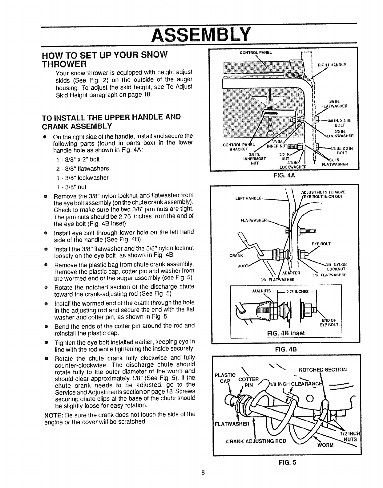
TO INSTALL THE UPPER HANDLE AND
CRANK ASSEMBLY
On the right side of the handle, installand secure the
following parts (found in parts box) in the lower
handle hole as shown in Fig 4A:
1 - 3/8" x 2" bolt
2 - 3/8" flatwashers
t - 3/8" lockwasher
t - 3/8" nut
®Remove the 318" nylon locknut and flatwasher from
the eye bolt assembly (on the chute crank assembly).
Check to make sure the two 3/8" jam nuts are tight,
The jam nuts should be 275 inches from the end of
the eye bolt (Fig. 4B inset)
e Install eye bolt through lower hole on the left hand
side of the handle (See Fig. 4B).
• Install the 3/8" flatwasher and the 3/8" nylon locknut
loosely on the eye bolt as shown in Fig 4B
e Remove the plastic bag from chute crank assembly
Remove the plastic cap, cotter pin and washer from
the wormed end of the auger assembly (see Fig 5),
® Rotate the notched section of the discharge chute
toward the crank-adjusting rod (See Fig 5).
einstall the wormed end of the crank fhrough the hole
in the adjusting rod and secure the end with the flat
washer and cotter pin, as shown in Fig 5
• Bend the ends of the cotter pin around the rod and
reinstall the plastic cap,,
e Tighten the eye bolt installed earlier, keeping eye in
line with the rod while tightening the inside securely
• Rotate the chute crank fully clockwise and fully
counter-clockwise. The discharge chute should
rotate fully to the outer diameter of the worm and
should clear approximately 1/8" (See Fig. 5).. If the
chute crank needs to be adjusted, go to the
Service and Adjustments section on page 18 Screws
securing chute clips at the base of the chute should
be slightly loose for easy rotation,.
NOTE: Be sure the crank does not touch the side of the
engine or the cover will be scratched,
BRACKET
3mlN, BOLT
INNERMOST NUT
NUT 3,"8 FLAT'WASHER
LOCKWASHER
FIG. 4A
ADJUST NUTS TO MOVE
EYE :BOLT IN OR OUT
CRANK
EYE BOLT
NYLON
3_/8 LOCKNUT
FLATWASHER
3/8 _ FLA"P#ASHER
JAM NUTS
2. 75 IN_
I END OF
EYE BOLT
FIG. 4B inset
i[ iL ,,,,,,,,,,,
FIG. 4B
"_" NOTCHED SECTION
PLASTIC % ,.
CAP COTTER
PIN /8 INCHCLEABANC
O
FLA
| _ _k\,, J//_".,,_ 1/2 INCH
8
FIG, 5
ASSEM LY
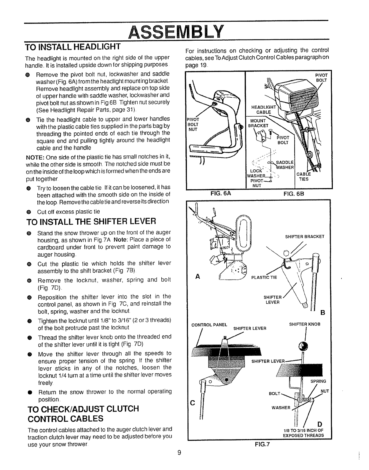
TO INSTALL HEADLIGHT
The headlight is mounted on the right side of the upper
handle., it is installed upside down for shipping purposes
® Remove the pivot bolt nut, lockwasher and saddle
washer (Fig. 6A) from the headlight mounting bracket
Remove headlight assembly and replace on top side
of upper handle with saddJe washer, Jockwasher and
pivot bolt nut as shown in Fig 6B Tighten nut securely
(See Headlight Repair Parts, page 31).
® Tie the headlight cable to upper and lower handles
with the plastic cable ties supplied in the parts bag by
threading the pointed ends of each tie through the
square end and putling tightly around the headlight
cable and the handle
NOTE: One side of the plastic tie has small notches in it,
while the other side is smooth. The notched side must be
on the inside o! the loop which is formed when the ends are
put together:
@ Try to loosen the cable tie If it can be loosened, it has
been attached with the smooth side on the inside of
the loop. Removethe cable tie and reverse its direction
@ Cut off excess plastic tie
TO INSTALL THE SHIFTER LEVER
O Stand the snow thrower up on the lronl of the auger
housing, as shown in Fig.7A Note: Place a piece of
cardboard under front to prevent paint damage to
auger housing.
• Cut the plastic tie which holds the shifter lever
assembly to the shift bracket (Fig 7B)
• Remove the iocknut, washer, spring and bolt
(Fig 7D)..
@ Reposition the shifter lever into the slot in the
control panel, as shown in Fig 7C, and reinstall the
bolt, spring, washer and the Iocknut
•Tighten the locknut until 1/8" to 3/t6" (2 or3 threads)
of the bolt protrude past the locknut
®Thread the shifter lever knob onto the threaded end
of the shifter lever until it is tight (Fig 7D)
•Move the shifter lever through all the speeds to
ensure proper tension of the spring If the shifter
lever sticks in any ol the notches, loosen the
locknut 1/4 turn at a time until the shifter lever moves
freely
•Return the snow thrower to the normal operating
position.
TO CHECK/ADJUST CLUTCH
CONTROL CABLES
The control cables attached to the auger clutch lever and
traction clutch fever may need to be adjusted before you
use your snow thrower
For instructions on checking or adjusting the control
cables, see To Adjust Clutch Control Cables paragraph on
page 19.
PIVOT
_'IVOT
BOLT
NUT
BOLT
TIES
FIG_ 6A FIG. 6B
SHIFTER
LEVER
CONTROLPANEL SHIFTER LEVER
SHIFTER
SHIFTER KNOB
/
SPRING
9
CWASHER
D
lib TO _t6 INCH OF
EXPOSEDTHREADS
FtG.7
OPERATION
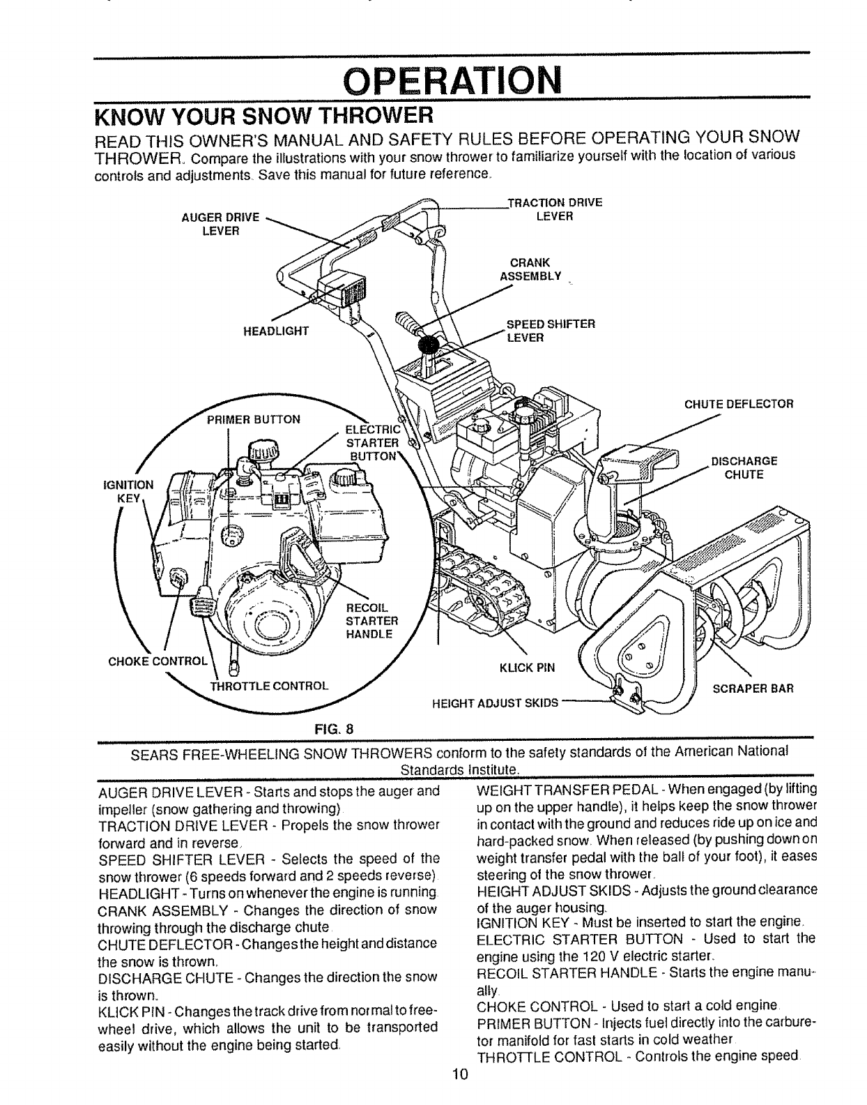
KNOW YOUR SNOW THROWER
READ THIS OWNER'S MANUAL AND SAFETY RULES BEFORE OPERATING YOUR SNOW
THROWER° Compare the illustrations with your snow thrower to familiarize yourself with the location of various
controls and adjustments, Save this manual for' future reference,,
AUGER DRIVE
LEVER
,TRACTION DRIVE
LEVER
CRANK
ASSEMBLY m
HEADLIGHT SPEED SHIFTER
TARTER
IGNITION
KEY
CHUTE DEFLECTOR
DISCHARGE
CHUTE
RECOIL
STARTER
HANDLE
CHOKECONTROL
THROTTLE CONTROL
KLICK PIN
HEIGHT ADJUST SKIDS
SCRAPER BAR
FIG. 8
SEARS FREE-WHEELING SNOW THROWERS conform to the safety standards of the American National
Standards Institute.
AUGER DRIVE LEVER - Starts and stops the auger and
impeller (snow gathering and throwing)
TRACTION DRIVE LEVER - Propels the snow thrower
forward and in reverse,
SPEED SHIFTER LEVER - Selects the speed of the
snow thrower (6 speeds forward and 2 speeds reverse)
HEADLIGHT -Turns on whenever the engine is running
CRANK ASSEMBLY -Changes the direction of snow
throwing through the discharge chute,
CHUTE DEFLECTOR - Changes the height and distance
the snow is thrown.
DISCHARGE CHUTE -Changes the direction the snow
is thrown.
KLICK PIN - Changes the track drive from normal to free-
wheel drive, which allows the unit to be transported
easily without the engine being started.
WEIGHT TRANSFER PEDAL- When engaged (by lifting
up on the upper handle), it hefps keep the snow thrower
in contact with the ground and reduces ride up on ice and
hard-packed snow When released (by pushing down on
weight transfer pedal with the ball of your foot), it eases
steering of the snow thrower.
HEIGHT ADJUST SKIDS - Adjusts the ground clearance
of the auger housing
IGNITION KEY - Must be inserted to start the engine
ELECTRIC STARTER BUTTON - Used to start the
engine using the 120 V electric starter,.
RECOIL STARTER HANDLE _Starts the engine manu_.
ally.
CHOKE CONTROL - Used to start a cold engine
PRIMER BUTTON - Injects fuel directly into the carbure-
tor manifold for fast starts in cold weather
THROTTLE CONTROL - ControLs the engine speed
10
The operation of any snow thrower can result in foreign objects being thrown into the
eyes, which can result in severe eye damage Always wear safety glasses or eye
shields while operating the snow thrower.
We recommend standard safety glasses or wide vision safety mask for over your
glasses avaRable at SEARS Retail or Catalog Stores..
iii.i....... i i i i i,,i :: iJ .......... ................ :
HOW TO USE YOUR SNOW
THROWER
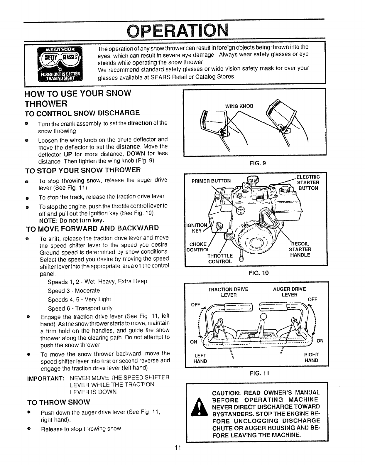
TO CONTROL SNOW DISCHARGE
oTurn the crank assembly to set the direction of the
snow throwing.
eLoosen the wing knob on the chute deflector and
move the deflector to set the distance Move the
deflector UP for more distance, DOWN for less
distance Then tighten the wing knob (Fig 9)
TO STOP YOUR SNOW THROWER
WING KNOB
FIGo9
eTo stop throwing snow, release the auger drive
lever (See Fig. 11)
•To stop the track, release the traction drive lever.
= To stop the engine, pushthe throttlecontrol lever to
off and pull out the ignition key (See Fig 10).
NOTE: Do not turn key.
TO MOVE FORWARD AND BACKWARD
iMPORTANT:
To shift, release the traction drive tever and move
the speed shifter lever to the speed you desire.
Ground speed is determined by snow conditions
Select the speed you desire by moving the speed
shifter lever into the appropriate area on the control
panel.
Speeds 1,2 - Wet, Heavy, Extra Deep
Speed 3 - Moderate
Speeds 4, 5 - Very Light
Speed 6 - Transport only
Engage the traction drive lever (See Fig 1I, left
hand) Asthe snowthrowerstarts to move, maintain
a firm hold on the handles, and guide the snow
thrower along the clearing path Do not attempt to
push the snow thrower
To move the snow thrower backward, move the
speed shifter lever into first or second reverse and
engage the traction drive lever (left hand)
NEVER MOVE THE SPEED SHIFTER
LEVER WHILE THE TRACTION
LEVER fS DOWN
TO THROW SNOW
o
o
Push down the auger drive lever (See Fig 1t,
right hand)..
Release to stop throwing snow..
CHOKE
CONTROL
THROTTLE
CONTROL
FIG. 10
Hi i =
TRACTION DRIVE
LEVER
HAND
A
STARTER
HANDLE
ii i,, .................
AUGER DRIVE
LEVER OFF
RIGHT
HAND
FIG. 11
CAUTION: READ OWNER'S MANUAL
BEFORE OPERATING MACHINE.
NEVER DIRECT DISCHARGE TOWARD
BYSTANDERS. STOP THE ENGINE BE-
FORE UNCLOGGING DISCHARGE
CHUTE OR AUGER HOUSING AND BE-
FORE LEAVING THE MACHINE_
1t
OPERAI=ION
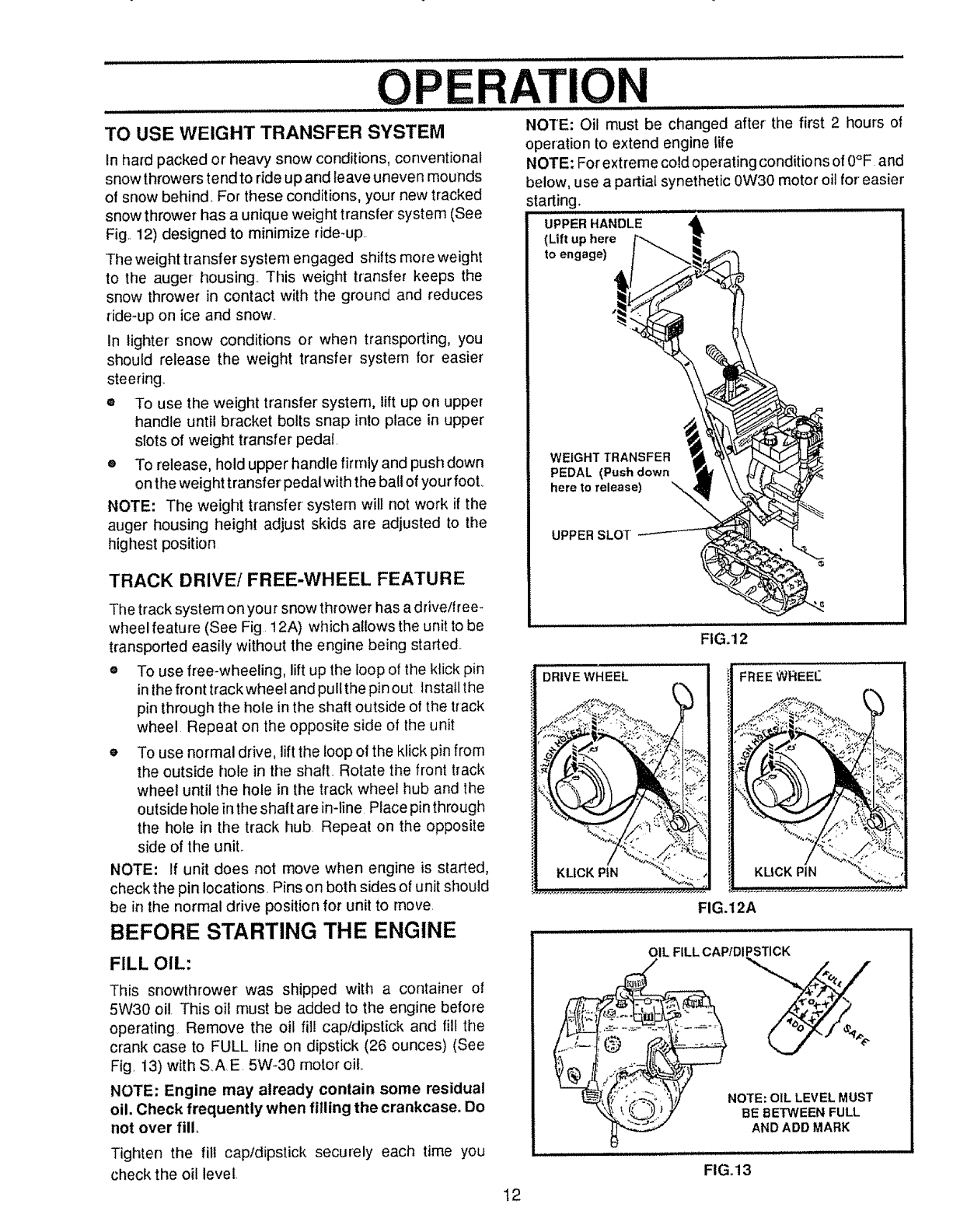
TO USE WEIGHT TRANSFER SYSTEM
In hard packed or heavy snow conditions, conventional
snow throwers tend to ride up and leave uneven mounds
of snow behind. For these conditions, your new tracked
snow thrower has a unique weight transfer system (See
Fig,, 12) designed to minimize dde-up,.
The weight transfer system engaged shifts more weight
to the auger housing. This weight transfer keeps the
snow thrower in contact with the ground and reduces
ride-up on ice and snow..
In lighter' snow conditions or when transporting, you
should release the weight transfer system for easier
steering.
®To use the weight transfer system, lift up on upper
handle until bracket bolts snap into place in upper
slots of weight transfer pedal.
eTo release, hold upper handle firmly and push down
on the weight transfer pedal with the ball of your fool
NOTE: The weight transfer system will not work if the
auger housing height adjust skids are adjusted to the
highest position
TRACK DRIVE/FREE-WHEEL FEATURE
The track system on your snow thrower has adrive/free_
wheel feature (See Fig, 12A) which allows the unit to be
transported easily without the engine being started..
®To use free-wheeling, lift up the loop of the kfick pin
in the front track wheel and pull the pin out Install the
pin through the hole in the shaft outside of the track
wheel Repeat on the opposite side of the unit
o To use normal drive, lift the loop of the klick pin from
the outside hole in the shaft.. Rotate the front track
wheel until the hole in the track wheel hub and the
outside hole in the shaft are in-line Place pin through
the hole in the track hub. Repeat on the opposite
side of the unit,.
NOTE: If unit does not move when engine is started,
check the pin locations, Pins on both sides of unit should
be in the normal drive position for unit to move,
BEFORE STARTING THE ENGINE
FILL OIL:
This snowthrower was shipped with a container of
5W30 oi!. This oil must be added to the engine before
operating Remove the oil fii! cap/dipstick and fill the
crank case to FULL line on dipstick (26 ounces) (See
Fig, 13) with SAE 5W-30 motor oil
NOTE: Engine may already contain some residual
oil. Check frequently when filling the crankcase. Do
not over fill.
Tighten the fill cap/dipstick securely each time you
check the oil level,
NOTE: Oil must be changed after the first 2 hours of
operation to extend engine life
NOTE: For extreme cold operating conditions of 0°F and
below, use a partial synethetic 0W30 motor oil for' easier
starting. ........................
UPPER HANDLE
(Lift up here
to engage)
WEIGHT TRANSFER
PEDAL (Push down
here to release)
UPPER SLOT
DRIVE WHEEL
FIG. 12
FREEWREEt_
KUCK PIN
FIG.12A
OIL FILL CAPtDIPSTICK
%
NOTE: OIL LEVEL MUST
BE BETWEEN FULL
AND ADD MARK
12
FIGo13
OPE ATIO
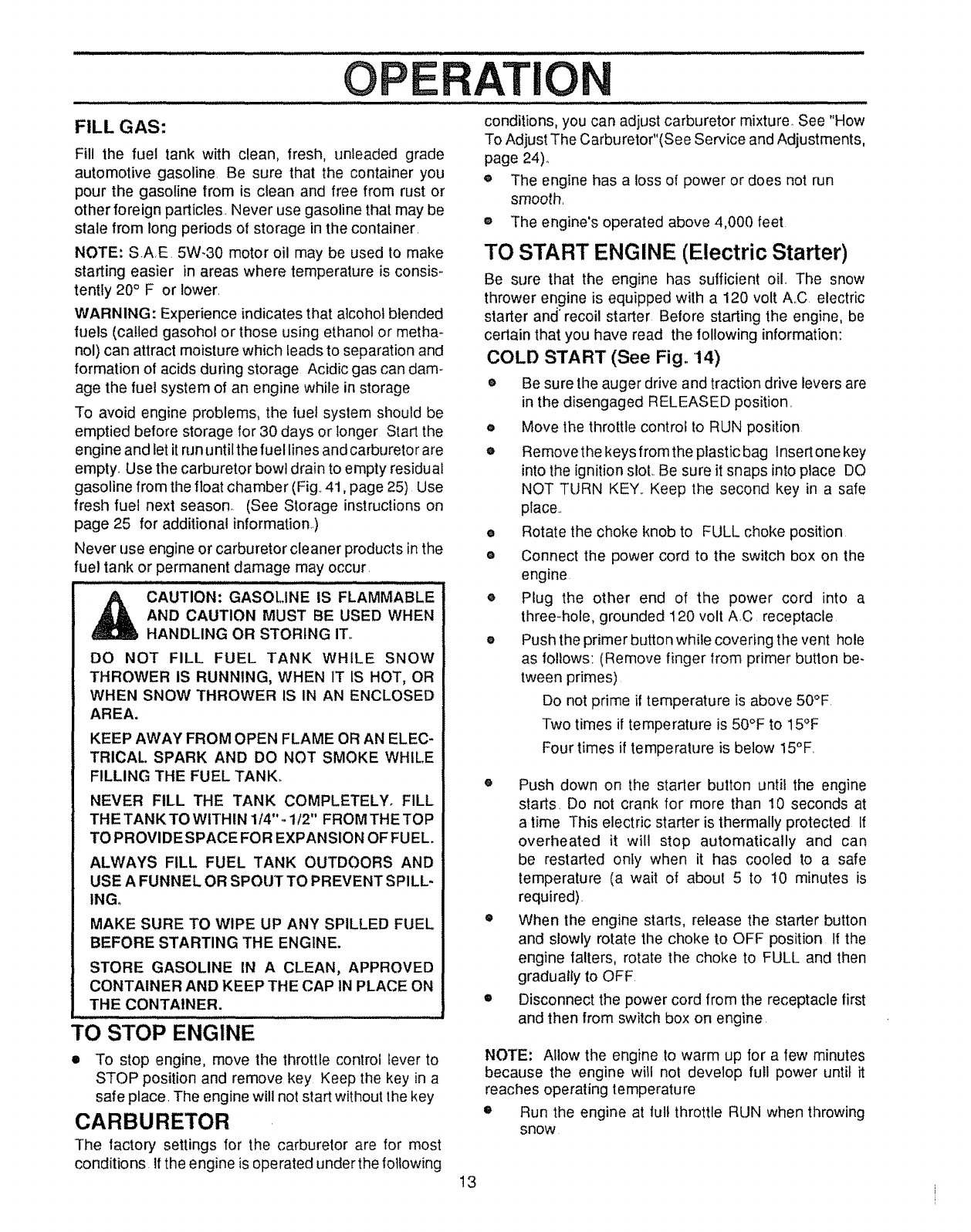
FILL GAS:
Fill the fuel tank with clean, fresh, unleaded grade
automotive gasoline. Be sure that the container you
pour the gasoline from is clean and free from rust or
other foreign particles. Never use gasoline that may be
stale from long periods of storage in the container.
NOTE: SAE. 5W-30 motor oil may be used to make
starting easier in areas where temperature is consis-
tentty 20° F or lower.
WARNING: Experience indicates that alcohol blended
fuels (called gasohol or those using ethanol or metha-
nol) can attract moisture which leads to separation and
formation of acids during storage Acidic gas can dam-
age the fuel system of an engine while in storage
To avoid engine problems, the fuel system should be
emptied before storage for 30 days or longer Start the
engine and let it run untilt he fuel lines and carbureto rare
empty. Use the carburetor bowl drain to empty residual
gasoline from the float chamber (Fig. 41, page 25) Use
fresh fuel next season. (See Storage instruclions on
page 25 for additional information)
Never use engine or carburetor cleaner products in the
fuel tank or permanent damage may occur.
_AUTION: GASOLINE IS FLAMMABLE
AND CAUTION MUST BE USED WHEN
HANDLING OR STORING IT,,
DO NOT FILL FUEL TANK WHILE SNOW
THROWER IS RUNNING, WHEN 1T IS HOT, OR
WHEN SNOW THROWER IS IN AN ENCLOSED
AREA.
KEEP AWAY FROM OPEN FLAME OR AN ELEC-
TRICAl. SPARK AND DO NOT SMOKE WHILE
FILLING THE FUEL TANK,.
NEVER FILL THE TANK COMPLETELY. FILL
THE TANKTOWlTHIN 1/4".- t12" FROMTHETOP
TO PROVIDE SPACE FO R EXPANSION OF FUEL.
ALWAYS FILL FUEL TANK OUTDOORS AND
USE A FUNNEL OR SPOUT TO PREVENT SPILL-
INGo
MAKE SURE TO WIPE UP ANY SPILLED FUEL
BEFORE STARTING THE ENGINE.
STORE GASOLINE IN A CLEAN, APPROVED
CONTAINER AND KEEP THE CAP IN PLACE ON
THE CONTAINER.
TO........STOP ENGINE .......................................
• To stop engine, move the throttle control lever to
STOP position and remove key Keep the key in a
safe place. The engine will not start without the key
CARBURETOR
The factory settings for the carburetor are for most
conditions. If the engine is operated under the following
conditions, you can adjust carburetor mixture See "How
To Adjust The Carburetor"(See Service and Adjustments,
page 24)_,
® The engine has a loss o{ power or does not run
smooth.
® The engine's operated above 4,000 feet
TO START ENGINE (Electric Starter)
Be sure that the engine has sufficient oil The snow
thrower engine is equipped with a 120 volt A.C electric
starter and" recoil starter Before starting the engine, be
certain that you have read the following information:
COLD START (See Fig. 14)
o Be sure the auger drive and traction drive levers are
in the disengaged RELEASED position.
oMove the throttle control to RUN position
® Removethe keys fromthe plastic bag Insert one key
into the ignition slot,. Be sure it snaps into place DO
NOT TURN KEY,. Keep the second key in a safe
place..
e Rotate the choke knob to FULL choke position
o Connect the power cord to the switch box on the
engine
o Plug the other end of the power cord into a
three-hole, grounded 120 volt A.C receptacle
o Push the primer button while covering the vent hole
as follows: (Remove finger from primer button be-
tween primes)
Do not prime il temperature is above 50°F
Two times if temperature is 50°F to 15°F
Four times if temperature is below 15°F.
o Push down on the starter button until the engine
starts. Do not crank for more than 10 seconds at
a time This electric starter is thermally protected If
overheated it will stop automatically and can
be restarted only when it has cooled to a safe
temperature (a wait of aboul 5 to 10 minutes is
required).
® When the engine starts, release the starter button
and slowly rotate the choke to OFF position If the
engine falters, rotate the choke to FULL and then
gradually to OFF.
eDisconnect the power cord from the receptacle lirst
and then from switch box on engine
NOTE: Allow the engine to warm up for a few minutes
because the engine will not develop full power until it
reaches operating temperature
•Run the engine at lull throttle RUN when throwing
snow
13
TI
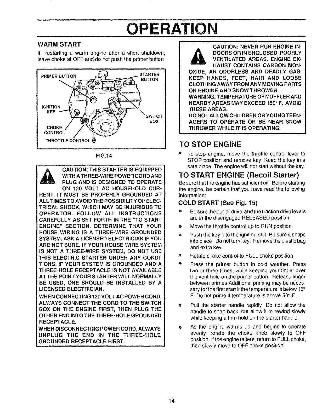
WARM S'rART
If restarting a warm engine after a short shutdown,
leave choke at OFF and do not push the primer button
CAUTION: NEVER RUN ENGINE IN-
DOORS OR IN ENCLOSED, POORLY
VENTILATED AREAS. ENGINE EX-
FIG.14
HAUST CONTAINS CARBON MON-
OXIDE, AN ODORLESS AND DEADLY GAS_
KEEP HANDS, FEET, HAIR AND LOOSE
CLOTHING AWAY FROM ANY MOVING PARTS
ON ENGINE AND SNOW THROWER.
WARNING: TEMPERATURE OF MUFFLERAND
NEARBY AREAS MAY EXCEED 150°F. AVOID
THESE AREAS.
DO NOT ALLOW CHILDREN OR YOUNG TEEN-
AGERS TO OPERATE OR BE NEAR SNOW
THROWER WHILE IT IS OPERATING.
TO STOP ENGINE
®To stop engine, move the throttle control lever to
STOP position and remove key Keep the key in a
CAUT,0NiTH,SSTARTER,SEaU,PPE0
W,THATHREE-WIREPOWERCORDAND
PLUG AND iS DESIGNED TO OPERATE
ON 120 VOLT AC HOUSEHOLD CUR-
BEN'[. IT MUST BE PROPERLY GROUNDED AT
ALL TIMES TO AVOID THE POSSIBILITY OF ELEC-
TRICAL SHOCK, WHICH MAY BE INJURIOUS TO
safe peace The engine will not start without the key
TO START ENGINE (Recoil Starter)
Be sure that the engine has sufficient oil Before starting
the engine, be certain that you have read the following
information:
COLD START (See Fig. 15)
OPERATOR_ FOLLOW ALL INSTRUCTIONS
CAREFULLY AS SET FORTH IN THE "TO START
ENGINE" SECTION. DETERMINE THAT YOUR
HOUSE WIRING IS A THREE*WIRE GROUNDED
SYSTEM. ASK A LICENSED ELECTRICIAN tF YOU
ARE NOT SURE. IF YOUR HOUSE WIRE SYSTEM
IS NOT A THREE-WIRE SYSTEM, DO NOT USE
THIS ELECTRIC STARTER UNDER ANY CONDI-
TIONS. IF YOUR SYSTEM IS GROUNDED AND A
THREEHOLE RECEPTACLE iS NOT AVAILABLE
AT THE POINT YOUR STARTER WILL NORMALLY
BE USED, ONE SHOULD BE INSTALLED BY A
LICENSED ELECTRICIAN.
WHEN CONNECTING 120 VOLT AC POWER CORD,
ALWAYS CONNECT THE CORD TO THE SWITCH
BOX ON THE ENGINE FIRST, THEN PLUG THE
OTHER END iNl"O THE THREE-HOLE GROUNDED
RECEPTACLE.
WHEN DISCONNECTING POWER CORD, ALWAYS
UNPLUG THE END IN THE THREE-HOLE
GROUNDED RECEPTACLE FIRST.
eBe sure the auger drive and the lraction drive levers
are in the disengaged RELEASED position
,=, Move the throttle control up to RUN position
ePush the key into the ignition slot Be sure it snaps
into place Do not turn key Remove the plastic bag
and extra key
•Rotate choke control to FULL choke position
®Press the primer button in cold weather Press
two or three times, while keeping your finger over
the vent hole on the primer button. Release finger
between primes Additional priming may be neces-
sary for the first start if the temperature is below 15°
F Do not prime if temperature is above 50°F
• Pull the starter handie rapidly Do not allow the
handle to snap back, but allow it to rewind slowly
while keeping a firm hold on the starter handle
e As the engine warms up and begins to operate
evenly, rotate the choke knob slowly to OFF
position _tf the engine falters, return to FULL choke,
then slowly move to OFF choke position
14
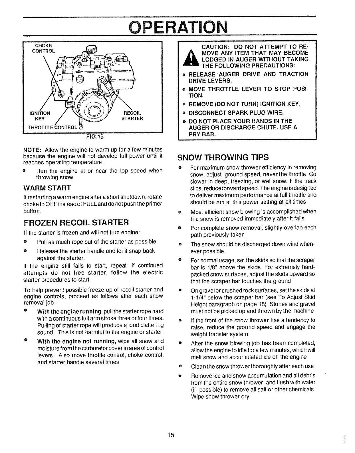
CHOKE
CONTROL
IGNITION RECOIL
KEY STARTER
THROTTLECONTROLI
FIG°15
O E TION
CAUTION: DO NOT ATTEMPT TO RE-
MOVE ANY ITEM THAT MAY BECOME
LODGED IN AUGER WITHOUT TAKING
THE FOLLOWING PRECAUTIONS:
eRELEASE'_AUGER DRIVE AND TRACTION
DRIVE LEVERS,
® MOVE THROTTLE LEVER TO STOP POSI-
TION,
•REMOVE (DO NOT TURN) IGNITION KEY.
•DISCONNECT SPARK PLUG WIRE.
®DO NOT PLACE YOUR HANDS IN THE
AUGER OR DISCHARGE CHUTE. USE A
PRY BAR.
NOTE: Allow the engine to warm up for a few minutes
because the engine will not develop full power until it
reaches operating temperature. SNOW THROWING TIPS
oRun the engine at or near the top speed when
throwing snow
WARM START
If restarting awarm engine after a short shutdown, rotate
choke to OFF instead of FULL and do not push the primer
button,
FROZEN RECOIL STARTER
If the starter is frozen and will not turn engine:
•Pull as much rope out of the starter as possible
eRelease the starter handle and let it snap back
against the starter
If the engine still fails to start, repeat If continued
attempts do not free starter, follow the electric
starter procedures to start.
To help prevent possible freeze-up of recoil starter and
engine controls, proceed as follows after each snow
removal job..
e With the engine running, pull the starter rope hard
with a continuous full arm stroke three or four times.
Pulling of starter rope will produce a loud clattering
sound Th{s is not harmful to the engine or starter_
e With the engine not running, wipe ali snow and
moisture from the carburetor cover in area of control
levers. Also move throttle control, choke control,
and starter handle several times
®For maximum snow thrower efficiency in removing
snow, adjust ground speed, never the throttle Go
slower in deep, freezing, or wet snow. If the track
slips, reduce forward speed. The engine is designed
to deliver maximum performance at full throttle and
should be run at this power setting at all times.
oMost efficient snow blowing is accomplished when
the snow is removed immediately after it falls
e For complete snow removal, slightly overlap each
path previously taken
oThe snow should be discharged down wind when-
ever possible.
e For normal usage, set the skids so that the scraper
bar is 1/8" above the skids For extremely hard-
packed snow surfaces, adjust the skids upward so
that the scraper bar touches the ground
o On gravel or crushed rock sutraces, set the skids at
t-!/4" below the scraper bar (see To Adjust Skid
Height paragraph on page 18) Stones and gravel
must not be picked up and thrown by the machine
eIf the front of the snow thrower has a tendency to
raise, reduce the ground speed and engage the
weight transfer system
o After the snow blowing job has been completed,
allow the engine to idle for a few minutes, which will
melt snow and accumulated ice off the engine.
•Clean the snow thrower thoroughly after each use
•Remove ice and snow accumulation and all debris
from the entire snow thrower, and flush with water
(if possible) to remove all salt or other chemicals
Wipe snow thrower dry
15 i_
CUSTOMER RESPONSIBILITIES
GENERAL RECOMMENDATIONS ..................
The warranty on this snow thrower does not cover items
that have been subjected to operator abuse or negli-
gence, To receive full value from the warranty, operator
must maintain snow thrower as instructed in this manual
Some adjustments will need to be made periodically to
properly maintain your snow thrower.
All adjustments in the Service and Adjustments section of
this manual should be checked at least once each
season.
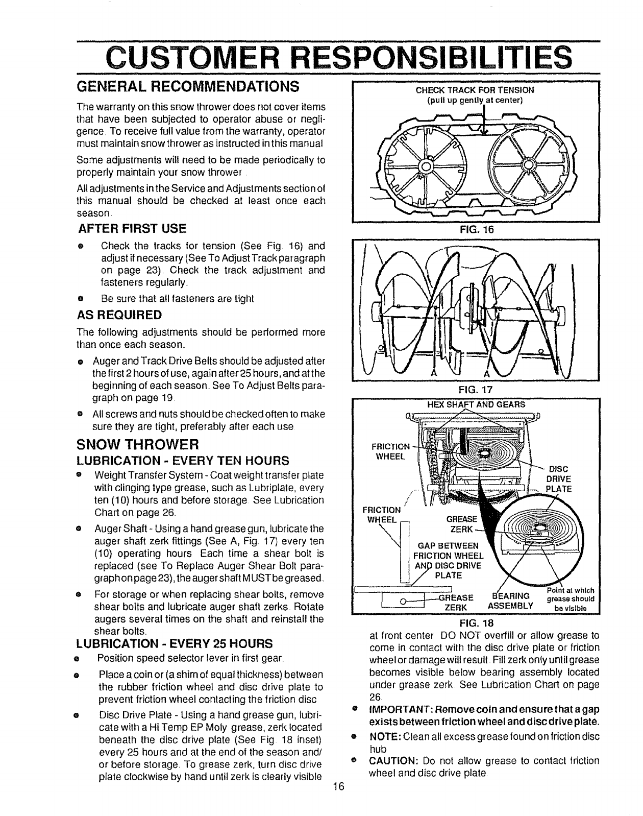
AFTER FIRST USE
eCheck the tracks for tension (See Fig. 16) and
adjust if necessary (See To Adjust Track paragraph
on page 23). Check the track adjustment and
fasteners regularly.
®Be sure that all fasteners are tight
AS REQUIRED
The following adjustments should be performed more
than once each season.
eAugerand Track Drive Belts should be adjusted after
the first 2 hours of use, again after25 hours, and atthe
beginning of each season See To Adjust Belts para-
graph on page 19.
®All screws and nuts should be checked often to make
sure they are tight, preferably after each use
SNOW THROWER
LUBRICATION - EVERY TEN HOURS
®Weight Transfer System- Coat weight transfer plate
with clinging type grease, such as Lubriplate, every
ten (10) hours and before storage See Lubrication
Chart on page 26
•Auger Shaft- Using a hand grease gun, lubricate the
auger shaft zerk fittings (See A, Fig.. 17) every ten
(10) operating hours Each time a shear bolt is
replaced (see To Replace Auger Shear Bolt para-
graph on page 23), the auger shaft MUST be greased..
®For storage or when replacing shear bolts, remove
shear bolts and lubricate auger shaft zerks Rotate
augers several times on the shaft and reinstall the
shear bolts_
LUBRICATION - EVERY 25 HOURS
ePosition speed selector lever in first gear.
ePlace a coin or (a shim of equal thickness) between
the rubber friction wheel and disc drive plate to
prevent friction wheel contacting the friction disc
eDisc Drive Plate - Using a hand grease gun, lubri-
cate with a Hi Temp EP Moly grease, zerk located
beneath the disc drive plate (See Fig 18 inset)
every 25 hours and at the end of the season and/
or before storage. To grease zerk, turn disc drive
plate clockwise by hand until zerk is clearly visible
H ii
CHECK TRACK FOR TENSION
(pull up gently at center_._)
FIG. 16
,i,, i iii ,Ll,,i llllll ,, ,_,,,_,, ,_,,
J/
A
FIG. 17
HEX SHAFT AND GEARS
WHEEL
!
FRICTION
WHEEL GREASE
DISC
DRIVE
PLATE
GAP BETWEEN
FRICTION WHEEL
16
o
o
®
tch
grease shoutd
ASSEMBLY be visible
.......... Ji ,, uu.,,,, l, ,i,i, ,u,,,u,
FIG, 18
at front center DO NOT overfill o_ allow grease to
come in contact with the disc drive plate or friction
wheel ordamage will result Fill zerk only until grease
becomes visible below bearing assembly located
under grease zerk See Lubrication Chart on page
26.
IMPORTANT: Remove coin and ensure that a gap
exists between friction wheel and disc drive plate.
NOTE: Clean all excess grease found on friction disc
hub
CAUTION: Do not allow grease to contact friction
wheel and disc drive plate.
CUSTOM SPO ILITIES
LUBRICATION
®Hex Shaft and Gears - Hex shaft and gears require
no lubrication. All bearings and bushings are lifetime
lubricated and require no maintenance (See Fig t8)..
NOTE: Any greasing or oiling o! the above components
can cause contamination of the friction wheel. Ifthe disc
drive plate or friction wheel come in contact with grease
or oil, damage to the friction wheel will result
Should grease or oil come in contact with the disc drive
plate or friction wheel, be sure to clean the plate and
wheel thoroughly_
NOTE: For storage, the hex shaft and gears should be
wiped with 5W-30 motor oil to prevent rusting (See Fig
• Auger Gear Box - The auger gear box has been
factory lubricated for life. If for some reason lubricant
should leak out, have the auger gear case checked
by a competent repairman.
ENGINE
LUBRICATION
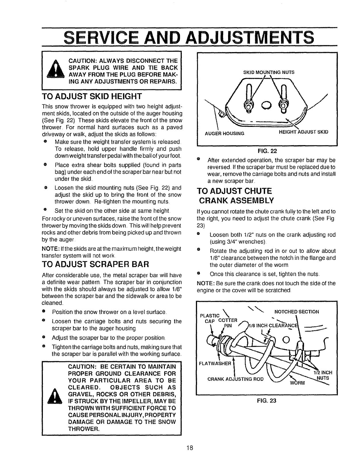
Check the crankcase oil level (See Fig t9) belore
starting the engine and after each five (5) hours of
continuous use_ Add S,AE. 5W-30 motor oil as needed..
Tighten fillcap/dipstick securely each time you check the
oil level.
OIL RECOMMENDATION
Only use high quality detergent oil rated with APt service
classification SG. Select the oil's viscosity grade accord-
ing to your expected operating temperature:
RECOMMENDED VISCOSITY GRADES
ICOLDER. 5W30 32°I SAE30"WARMER
NOTE: For extreme cold operating conditions of 0° F. and
below, use a partial synethetic 0W30 motor oil for easier
starting_
NOTE: Although multi-viscosity oils improve starting in
cold weather, these multi-viscosity oils will result in in-
creased oi! consumption when used above 32°F Check
your engine oil level more frequently to avoid possible
engine damage from running low on oil
e Position snow thrower so that the oil drain plug is
lowest point on the engine Remove oil drain plug
and oil fill cap/dipstick Drain oil into a suitable
container. Oil will drain more freely when warm
oReplace oil drain plug and tighten securely Refill
crankcase with SAE 5W-30 motor oi!
I7
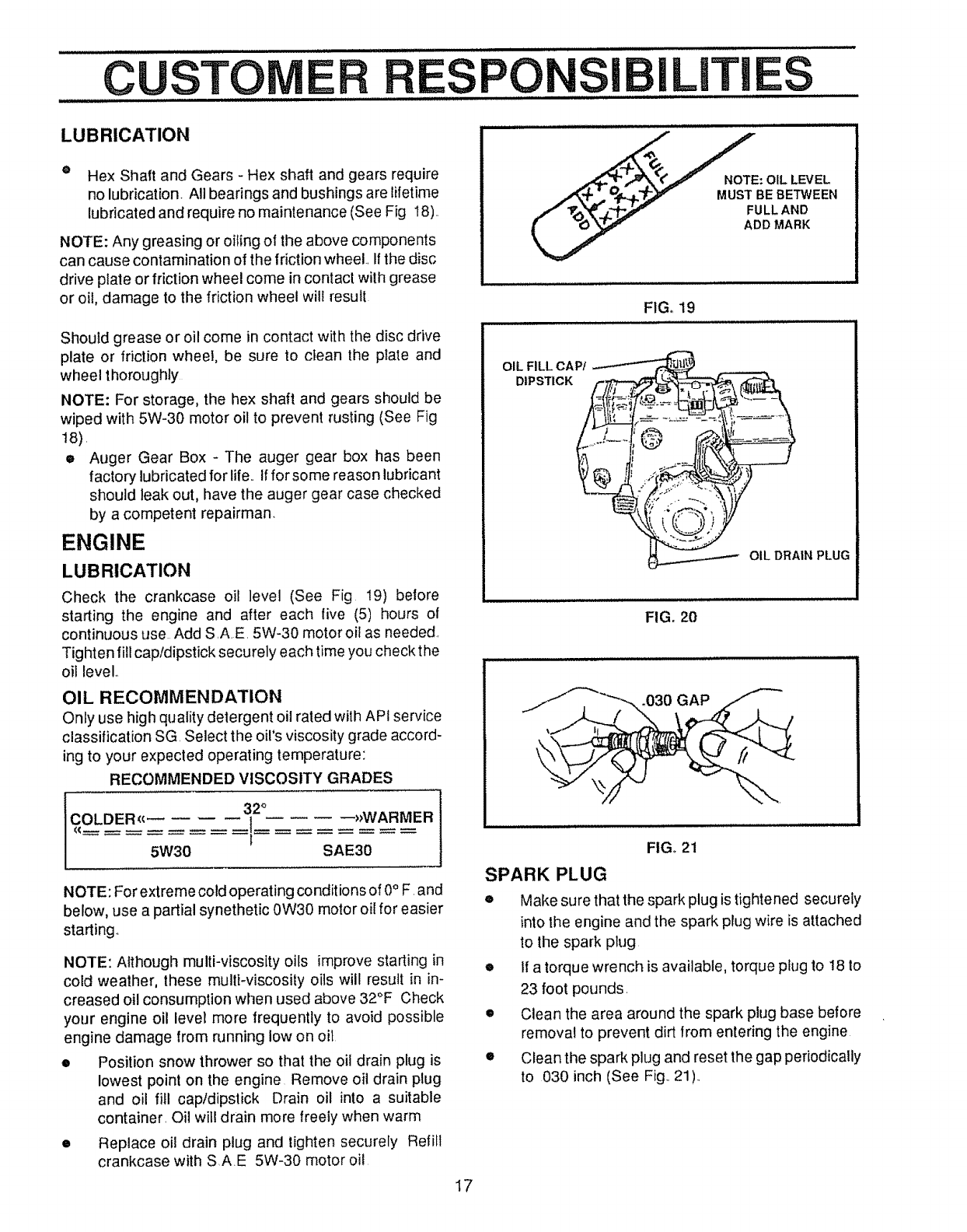
___NOTE: OIL LEVEL
.,,_,,p _ _.p..f,.T_]_v MUST BEBETWEEN
ADD MARK
FIG, 19
OIL FILL CAP/
DIPSTICK
OIL DRAIN PLUG
FIG, 20
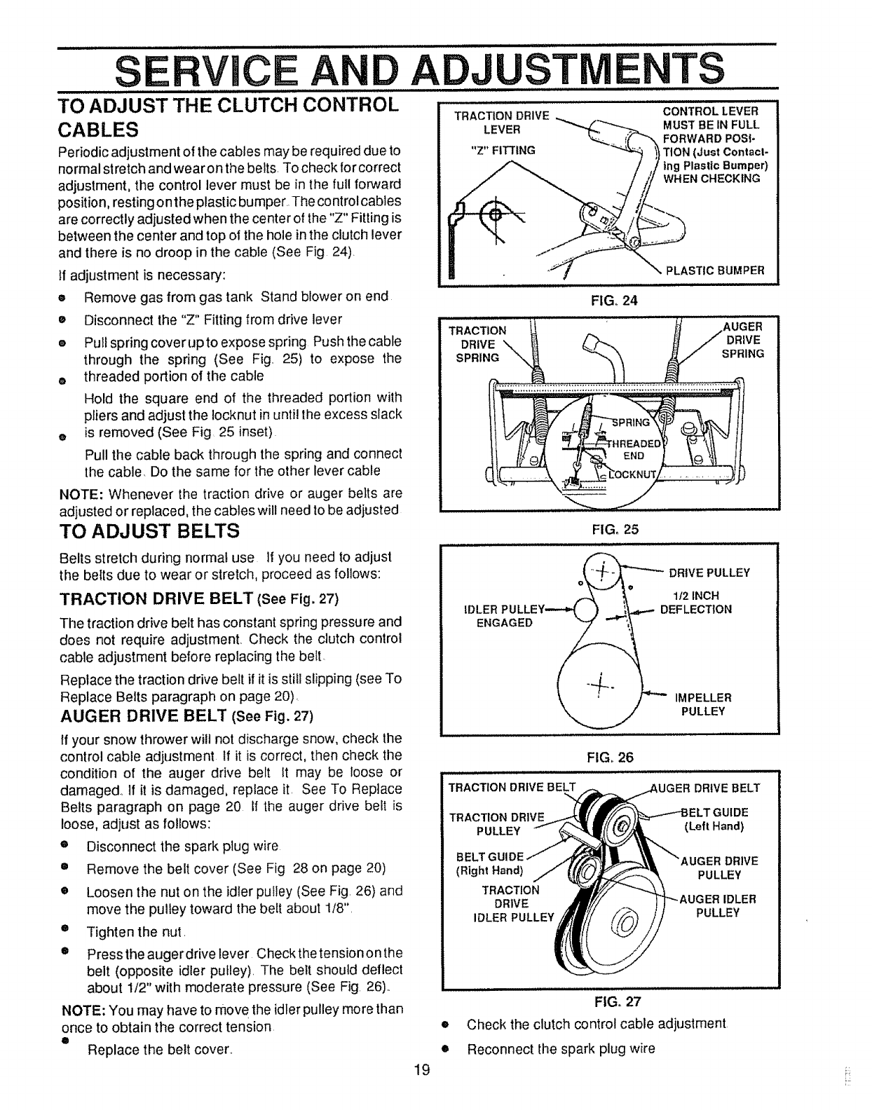
.030 GAP
FIGo 21
SPARK PLUG
eMake sure that the spark plug is tightened securely
into the engine and the spark plug wire is attached
to the spark plug
e It a torque wrench is available, torque plug to 18 to
23 foot pounds.
• Clean the area around the spark plug base before
removal to prevent dirt from entering the engine
• Clean the spark plug and reset the gap periodically
to 030 inch (See Fig.. 21)..
SERVICE AND ADJUSTMENTS
i= i ilUl,,i i, ................................... Jl, iii,i n i ill,ll ilU,,ll
CAUTION: ALWAYS DISCONNECT THE
SPARK PLUG WIRE AND TIE BACK
AWAY FROM THE PLUG BEFORE MAK-
ING ANY ADJUSTMENTS OR REPAIRS_
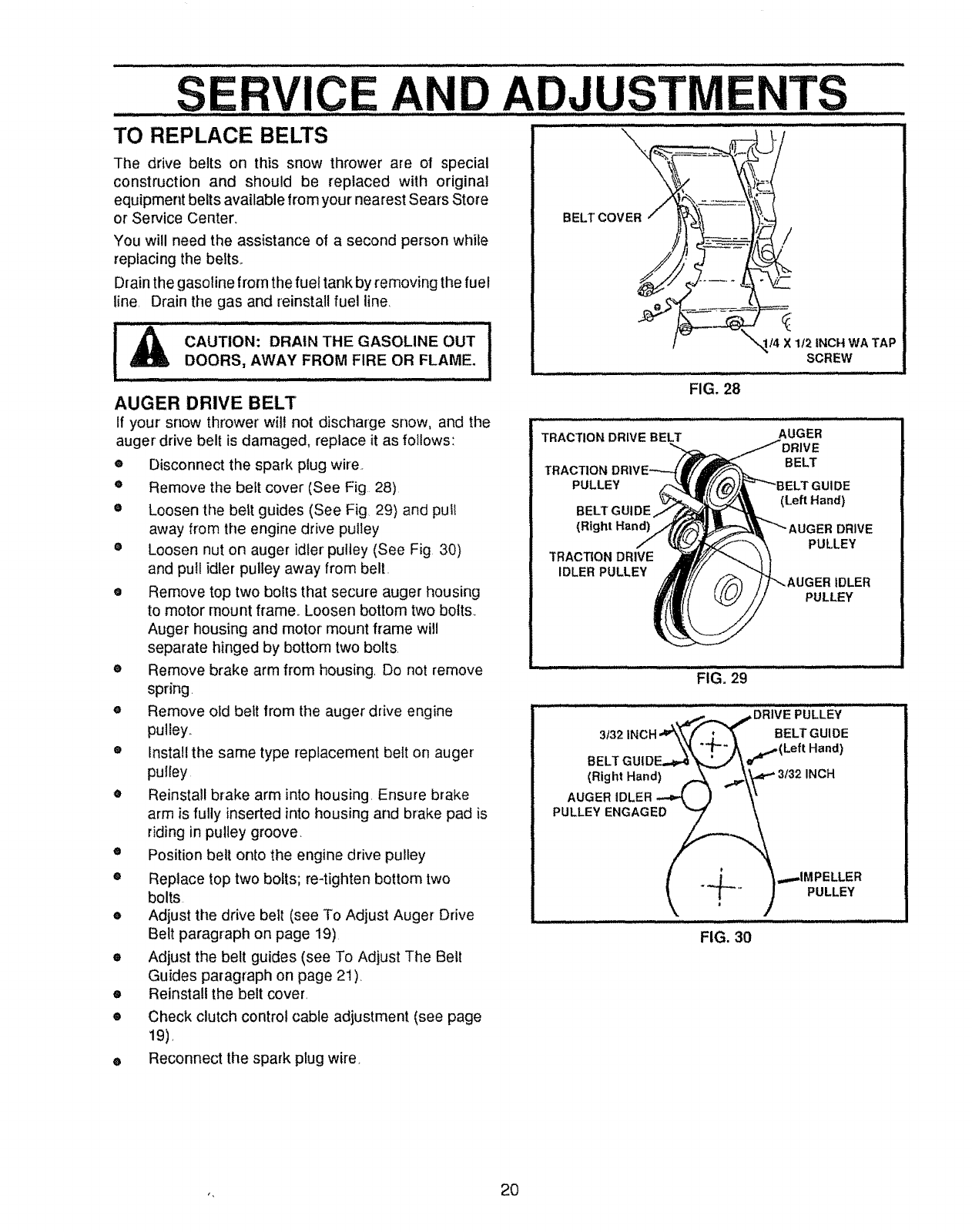
TO ADJUST SKID HEIGHT
This snow thrower is equipped with two height adjust-
ment skids, located on the outside of the auger housing
(See Fig 22) These skids elevate the front of the snow
thrower. For normal hard surfaces such as a paved
driveway or walk, adjust the skids as follows:
®Make sure the weight transfer system is released.
To release, hotd upper handle firmly and push
down weight transfer pedal with the ball of your foot.
®Place extra shear bolts supplied (found in parts
bag) under each end of the scraper bar near but not
under the skid.,
e Loosen the skid mounting nuts (See Fig. 22) and
adjust the skid up to bring the front of the snow
thrower down. Re-tighten the mounting nuts.
eSet the skid on the other side at same height.
For rocky or uneven surfaces, raise the front of the snow
thrower by moving the skids down, This will help prevent
rocks and other debris from being picked up and thrown
by the auger
NOTE: Ifthe skids are at the maximum height, the weight
transfer system will not work
TO ADJUST SCRAPER BAR
After considerable use, the metal scraper bar will have
a definite wear pattern The scraper bar in conjunction
with the skids should always be adjusted to allow 1t8"
between the scraper bar and the sidewalk or area to be
cleaned
•Position the snow thrower on a level sudace_
o
o
o
Loosen the carriage bolts and nuts securing the
scraper bar to the auger housing,
Adjust the scraper bar to the proper position,
Tighten the carriage bolts and nuts, making sure that
the scraper bar is parallel with the working surface.,
CAUTION: BE CERTAIN TO MAINTAIN
PROPER GROUND CLEARANCE FOR
YOUR PARTICULAR AREA TO BE
CLEARED. OBJECTS SUCH AS
GRAVEL, ROCKS OR OTHER DEBRIS,
IF STRUCK BY THE IMPELLER, MAY BE
THROWN WITH SUFFICIENT FORCE TO
CAUSE PERSONAL INJURY, PROPERTY
DAMAGEORDAMAGETOTHESNOW
THROWER.
SKID MOUNTING NUTS
AUGER HOUSING HEIGHT ADJ UST SKID
FIGo 22
eAfter extended operation, the scraper bar may be
reversed Ifthe scraper bar must be replaced due to
wear, remove the carriage bolts and nuts and install
a new scraper bar,
TO ADJUST CHUTE
CRANK ASSEMBLY
If you cannot rotate the chute crank fully to the left and to
the right, you need to adjust the chute crank (See Fig
23)
eLoosen both 1/2" nuts on the crank adjusting rod
(using 3/4" wrenches),
eRotate the adjusting rod in or out to allow about
1/8" clearance between the notch in the flange and
the outer diameter of the worm
= Once this clearance is set, tighten the nuts,
NOTE: Be sure the crank does not touch the side of the
engine or the cover will be scratched
\ .OTCHEDSECT,ON
PLASTIC ,%
CAP COTTER INCH CLEARANC
FLATWASHER 1
CRANK ADJUSTING ROD
1t2 INCH
FIG. 23
18
iiiii u,mlll ilul iJl i, ii iltllltl
S RViCE AN
TO ADJUST THE CLUTCH CONTROL
CABLES
Periodic adjustment of the cables may be required due to
normal stretch and wearon the belts, To check for correct
adjustment, the control lever must be in the full forward
position, resting o nthe plastic bumper+ The control cables
are correctly adjusted when the center of the "Z" Fitting is
between the center and top of the hole in the clutch lever
and there is no droop in the cable (See Fig 24)
If adjustment is necessary:
Remove gas from gas tank Stand blower on end
e
e
o
Disconnect the "Z" Fitting from drive lever
Pull spring cover upto expose spring Push the cable
through the spring (See Fig, 25) to expose the
o threaded portion of the cable
Hold the square end of the threaded portion with
pliers and adjust the Iocknut in until the excess slack
e is removed (See Fig, 25 inset).
Pull the cable back through the spring and connect
the cable Do the same for the other lever cable
NOTE: Whenever the traction drive or auger belts are
adjusted or replaced, the cables will need to be adjusted
TO ADJUST BELTS
Belts stretch during normal use If you need to adjust
the belts due to wear or stretch, proceed as follows:
TRACTION DRIVE BELT (See Fig. 27)
The traction drive belt has constant spring pressure and
does not require adjustment, Check the clutch control
cable adjustment before replacing the belt.
Replace the traction drive belt if it is still slipping (see To
Replace Belts paragraph on page 20)_
AUGER DRIVE BELT (See Fig. 27)
If your snow thrower will not discharge snow, check the
control cable adjustment If it is correct, then check the
condition of the auger drive belt It may be toose or
damaged., If it is damaged, replace it, See To Replace
Belts paragraph on page 20 If the auger drive belt is
loose, adjust as follows:
eDisconnect the spark plug wire
• Remove the belt cover (See Fig 28 on page 20)
•Loosen the nut on the idler pulley (See Fig, 26) and
move the pulley toward the bert about 1/8",
•Tighten the nut.
•Presstheaugerdrivelever Checkthetensiononthe
belt (opposite idler pulley), The bett should deflect
about 1/2" with moderate pressure (See Fig, 26)+
NOTE: You may have to move the idler pulley more than
once to obtain the correct tension.
oReplace the belt cover+
ADJUSTME TS
TRACTION DRIVE
LEVER
"Z" FITTING
CONTROL LEVER
MUST BE IN FULL
FORWARD POSI-
TION (Just Contact-
ing Plasllc Bumper)
WHEN CHECKING
TRACTION
DRIVE
SPRING
FIG.+24
PLASTIC BUMPER
DRIVE
SPRING
1
IDLER
ENGAGED
FIG, 25
DRIVE PULLEY
1/2 INCH
DEFLECTION
IMPELLER
PULLEY
FIG, 26
TRACTION DRIVE BELT UGER DRIVE BELT
TRACTION DRIVE "GUIDE
PULLEY (Left Hand)
BELT DRIVE
(Right Hand) PULLEY
TRACTION
DRIVE IDLER
IDLER PULLEY PULLEY
19
FIG, 27
• Check the clutch control cable adjustment
• Reconnect the spark plug wire
..............SERVICE,,,AN,D ADJUSTMENTS
TO REPLACE BELTS
The drive belts on this snow thrower are of special
construction and should be replaced with original
equipment belts available from your nearest Sears Store
or Service Center,
You will need the assistance of a second person while
replacing the belts.
Drain the gasoline from the fue! tank by removing the fuel
line Drain the gas and reinstall fuel line
IA....................I
CAUTION: DRAIN THE GASOLINE OUT
DOORS, AWAY FROM FIRE OR FLAME.
Jl,i ii,Jl,l,i, i iii iii H, i,,
AUGER DRIVE BELT
if your snow thrower will not discharge snow, and the
auger drive belt is damaged, replace it as follows:
®Disconnect the spark plug wire.
e Remove the belt cover (See Fig 28)
•Loosen the belt guides (See Fig 29) and pull
away from the engine drive pulley
®Loosen nut on auger idler pultey (See Fig 30)
and pull idler pulley away from belt
• Remove top two bolts that secure auger housing
to motor mount frame,, Loosen bottom two bolts,
Auger housing and motor mount frame will
separate hinged by bottom two bolts
eRemove brake arm from housing, Do not remove
spring
eRemove old belt from the auger drive engine
pulley,,
e install the same type replacement belt on auger
pulley
• Reinstall brake arm into housing, Ensure brake
arm is fully inserted into housing and brake pad is
riding in pulley groove,
® Position bell onto the engine drive pulley
®Replace top two bolts; re-tighten bottom two
bolts
e Adjust the drive bett (see To Adjust Auger Drive
Belt paragraph on page 19)
= Adjust the belt guides (see To Adjust The Belt
Guides paragraph on page 21)
o Reinstall the belt cover,
i i1,111I,L
/
/
IILLI, III I II III
FIG. 28
I4 X112 INCH WA TAP
SCREW
wn,,
TRACTION DRIVE BELT AUGER
TRACTION BELT
PULLEY 3E
(Left Hand)
BELT GUIDE
(Right Hand) DRIVE
PULLEY
TRACTION DRIVE
IDLER PULLEY IDLER
PULLEY
,,, i i,, i ii i ii ii
FIG. 29
,,,,
,,,_,,..._ ..sDRIVE PULLEY
3132INCH BELTGUIDE
BELT GUIDE..._ "'_'\ _ r''(Left Hand)
(Right Hand) A- ""_\_"_ 3/32 INCH
,...,,,IMPELLER
_ X-" )PULLEY
FIG. 30
Check clutch control cable adjustment (see page
19),
Reconnect the spark plug wire,
,, 20
SRVIC D ADJUSTME TS
TRACTION DRIVE BELT
If your snow thrower will not move forward, check the
traction drive belt for wear, If the traction drive belt
needs to be replaced, proceed as follows:
®Disconnect the spark plug wire,
•Remove the belt cover (See Fig, 28 on page 20)
eLoosen belt guides (See Fig 29) and pull belt
guides away from the engine drive pulley.
eLoosen nut on auger idler and pull auger idlerpulley
away from belto
®Remove auger drive belt from engine pulley,
ePull drive belt idler pulley away from ddve belt
®Remove drive belt
ePosition new drive belt onto traction pulley
®Pul! idler pulley away from belt, allowing beit to be
positioned onto engine pulley.
eReSease idJerpuJley Ensure _Jer puJJeyis properly
engaged with belt,
oReinstall auger drive belt,
•Adjust belt guides (see To Adjust The Belt Guides
paragraph below),
®Adjust idler on auger belt,
e Reinstall the belt cover
o Reconnect the spark plug wire,
"1"OADJUST THE BELT GUIDES
Alter you replace a track or auger drive belt, you need to
adjust one or both of the belt guides Proceed as lollows:
•Disconnect the spark plug wire.
e Remove the belt cover (See Fig 28 on page 20)
eEngage the auger drive clutch lever
•Measure the distance between the belt guides and
the belt (See Fig 30 on page 20) The distance
should be 3/32" for each guide
oit adiustment is necessary, loosen the belt guide
mounting bolts Move the belt guides to the correct
position., Tighten the mounting bolts
•Reinstall the belt cover,
•Reconnect the spark plug wire
FIG., 31
REMOVE BOLT,
LOOSEN BOLT,
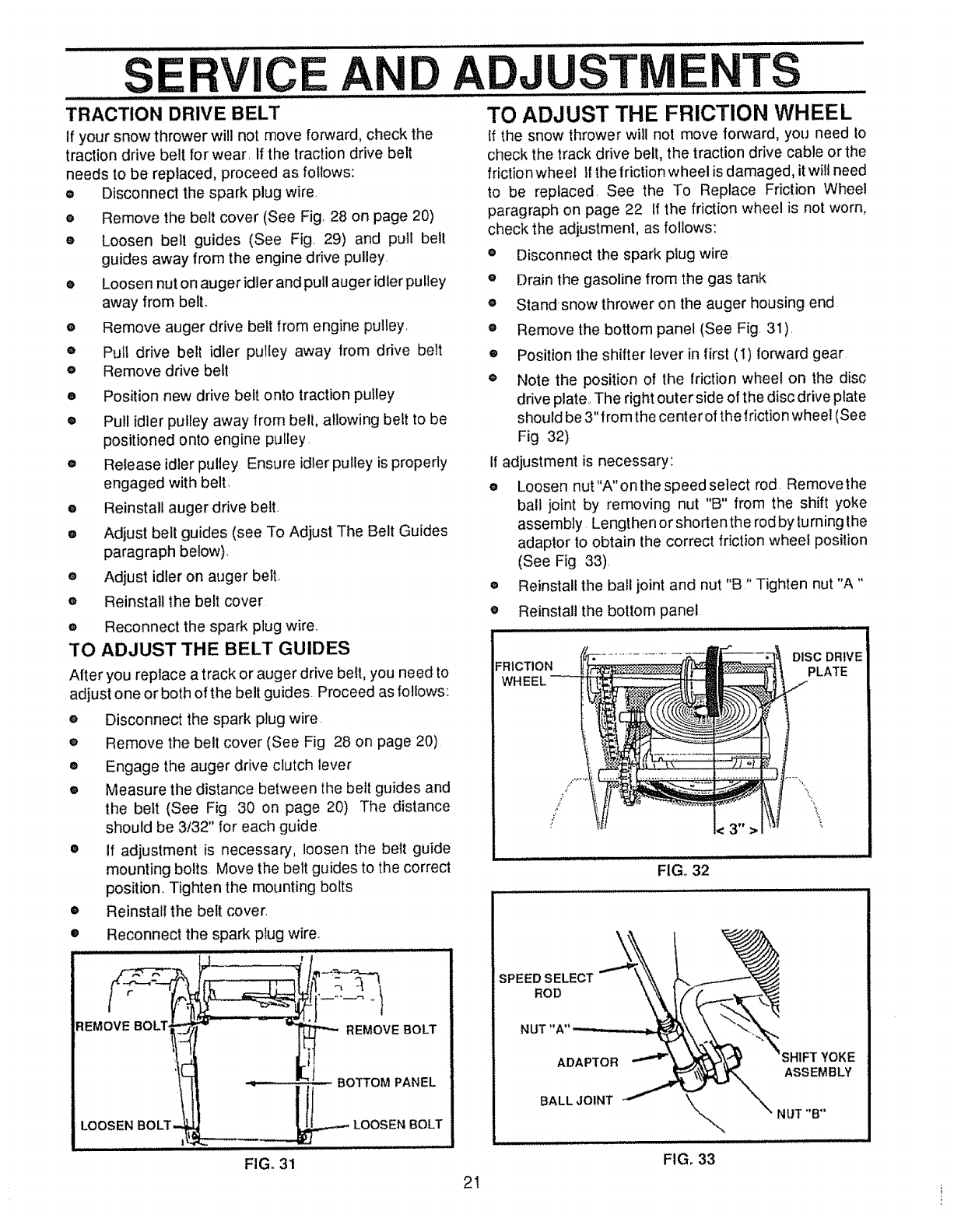
TO ADJUST THE FRICTION WHEEL
If the snow thrower will not move forward, you need to
check the track drive belt, the traction drive cable or the
friction wheel If the friction wheel is damaged, it will need
to be replaced, See the To Replace Friction Wheel
paragraph on page 22 If the friction wheel is not worn,
check the adjustment, as follows:
eDisconnect the spark plug wire,
eDrain the gasoline from the gas tank
®Standsnow thrower on the auger housing end
®Remove the bottom panel (See Fig. 31),
®Position the shifter lever in first (1) forward gear
eNote the position of the friction wheel on the disc
drive plate,, The right outer side of the disc drive plate
should be 3" from the center of the friction wheel (See
Fig 32)
;I adjustment is necessary:
eLoosen nut "A" on the speed select rod Removethe
ball joint by removing nut "B" from the shift yoke
assembly Lengthen or shortenthe rod by turning the
adaptor to obtain the correct friction wheel position
(See Fig 33),
eReinstall the ball joint and nut "B" Tighten nut "A"
•Reinstall the bottom panel
FRICTION DISC DRIVE
PLATE
FIG,, 32
21
SPEED SELECT
ROD
NUT"A"
ADAPTOR
BALL JOINT
FIG, 33
YOKE
ASSEMBLY
SERVICE AND ADJUSTMENTS ..............
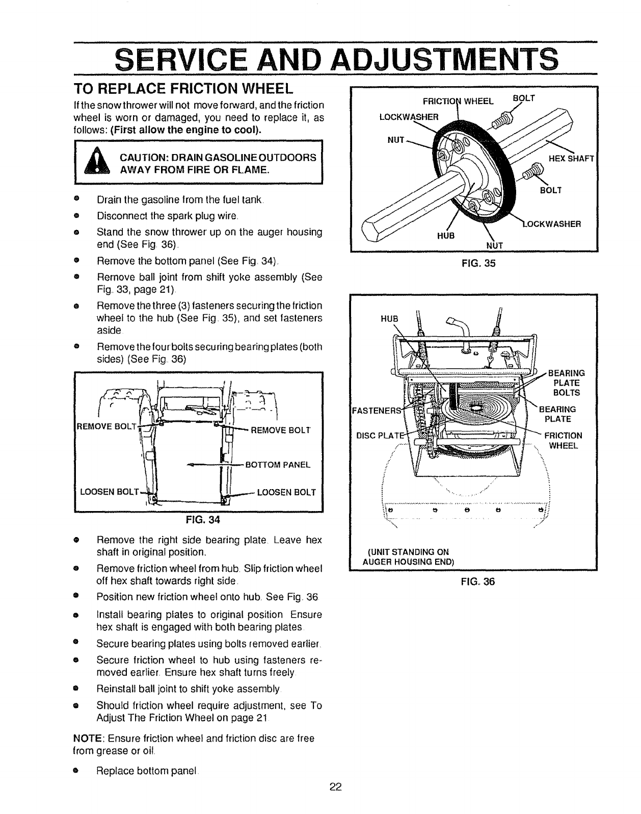
TO REPLACE FRICTION WHEEL
If the snow thrower will not move forward, and the frictio n
wheel is worn or damaged, you need to replace it, as
follows: (First allow the engine to cool).
CAUTION: DRAINGASOLINEOUTDOORS I
AWAY FROM FIRE OR FLAME.
® Drain the gasoline from the fuel tank.
• Disconnect the spark plug wire
eStand the snow thrower up on the auger housing
end (See Fig. 36).
• Remove the bottom panel (See Fig. 34)_
• Remove ball joint from shift yoke assembly (See
Fig., 33, page 2i).
•Remove the three (3) fasteners securing the friction
wheel to the hub (See Fig. 35), and set fasteners
aside
®Remove the four bofts securing bearing plates (both
sides) (See Fig. 36)
FIG. 34
®Remove the right side bearing plate Leave hex
shaft in original position.
eRemove friction wheel from hub. Slip friction wheel
off hex shaft towards right side.
•Position new friction wheel onto hub. See Fig 36
Install bearing pfates to original position Ensure
hex shaft is engaged with both bearing plates
•Secure bearing plates using bolts removed earlier.
•Secure friction wheel to hub using fasteners re-
moved earlier. Ensure hex shaft turns freely
= Reinstall ball joint to shift yoke assembly.
•Should friction wheel require adjustment, see To
Adjust The Friction Wheel on page 21
DISC
FRtCTtO WHEEL
LOCKWASHER
BOLT
HEX SHAFT
BOLT
HUB NUT
FIG. 35
HUB
PLATE
BOLTS
PLATE
FRICTION
.....,..,\. WHEEL
i
r i
(UNIT STANDING ON
AUGER HOUSING END)
FIG_ 36
NOTE: Ensure friction wheel and friction disc are free
from grease or oil.
eReplace bottom panel
22
S RVIC A
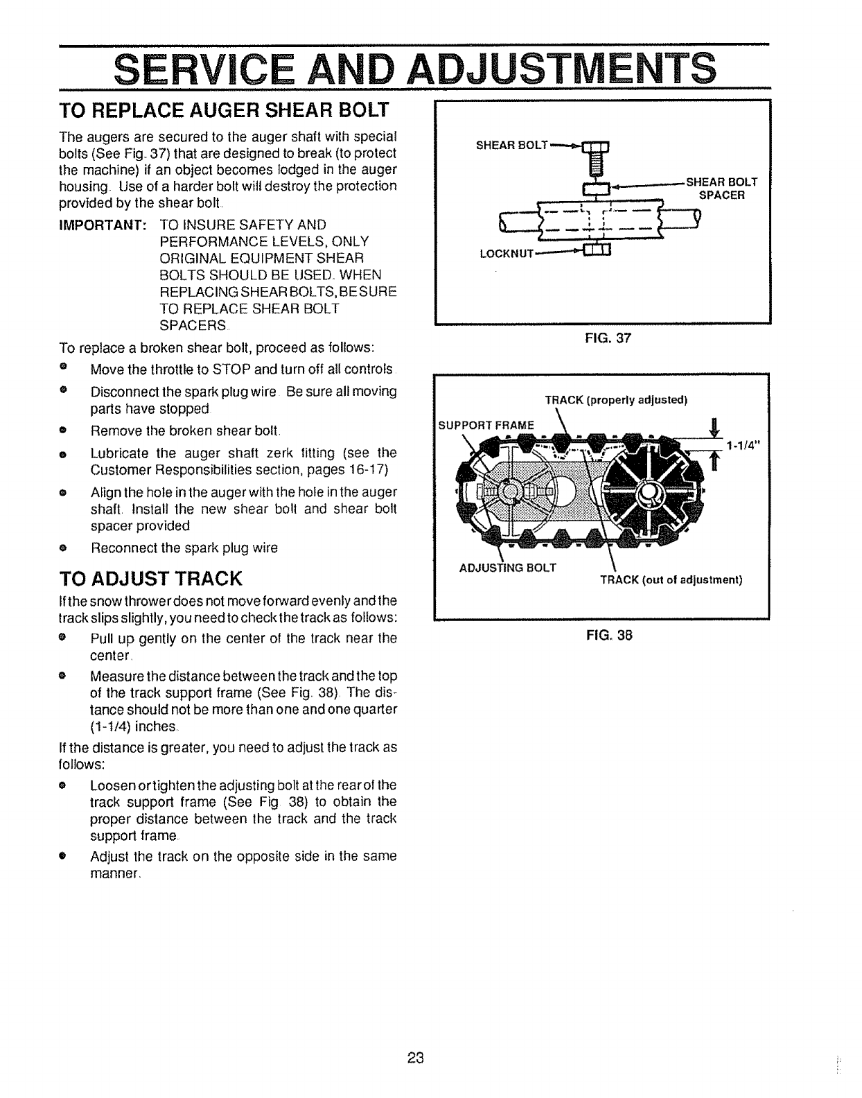
TO REPLACE AUGER SHEAR BOLT
The augers are secured to the auger shaft with special
bolts (See Fig..37) that are designed to break (to protect
the machine) if an object becomes lodged in the auger
housing Use of a harder bolt will destroy the protection
provided by the shear bolt.
IMPORTANT: TO INSURE SAFETY AND
PERFORMANCE LEVELS, ONLY
ORIGINAL EQUIPMENT SHEAR
BOLTS SHOULD BE USED_ WHEN
REPLACING SHEAR BOLTS, BESURE
TO REPLACE SHEAR BOLT
SPACERS.
To replace a broken shear bolt, proceed as follows:
Move the throttle to STOP and turn off all controls
Disconnect the spark plug wire Be sure all moving
parts have stopped
Remove the broken shear boil
Lubricate the auger shaft zerk fitting (see the
Customer Responsibilities section, pages 16-17)
Afign the hole in the auger with the hole in the auger
shaft, install the new shear bolt and shear bolt
spacer provided
Reconnect the spark plug wire
O
O
o
o
TO ADJUST TRACK
Ifthe snow throwerdoes not move forward evenly and the
track slips slightly, you need to check the track as follows:
®Pull up gently on the center of the track near the
center.
•Measure the distance between the track and the top
of the track support frame (See Fig.. 38). The dis-
tance should not be more than one and one quarter
(1-I/4) inches.
Ifthe distance is greater, you need to adjust the track as
follows:
eLoosen or tighten the adjusting bolt at the rear of the
track support frame (See Fig 38) to obtain the
proper distance between the track and the track
support frame.
•Adjust the track on the opposite side in the same
manner.
ADJUSTME TS
LOCKNUT_
FIG. 37
TRACK (properly adjusted)
SUPPORT FRAME
ADJUSTING BOLT
1-1/4"
TRACK (out of adjustment)
FIG. 38
23 i_
............SERVICE AND ADJUSTMENTS ......
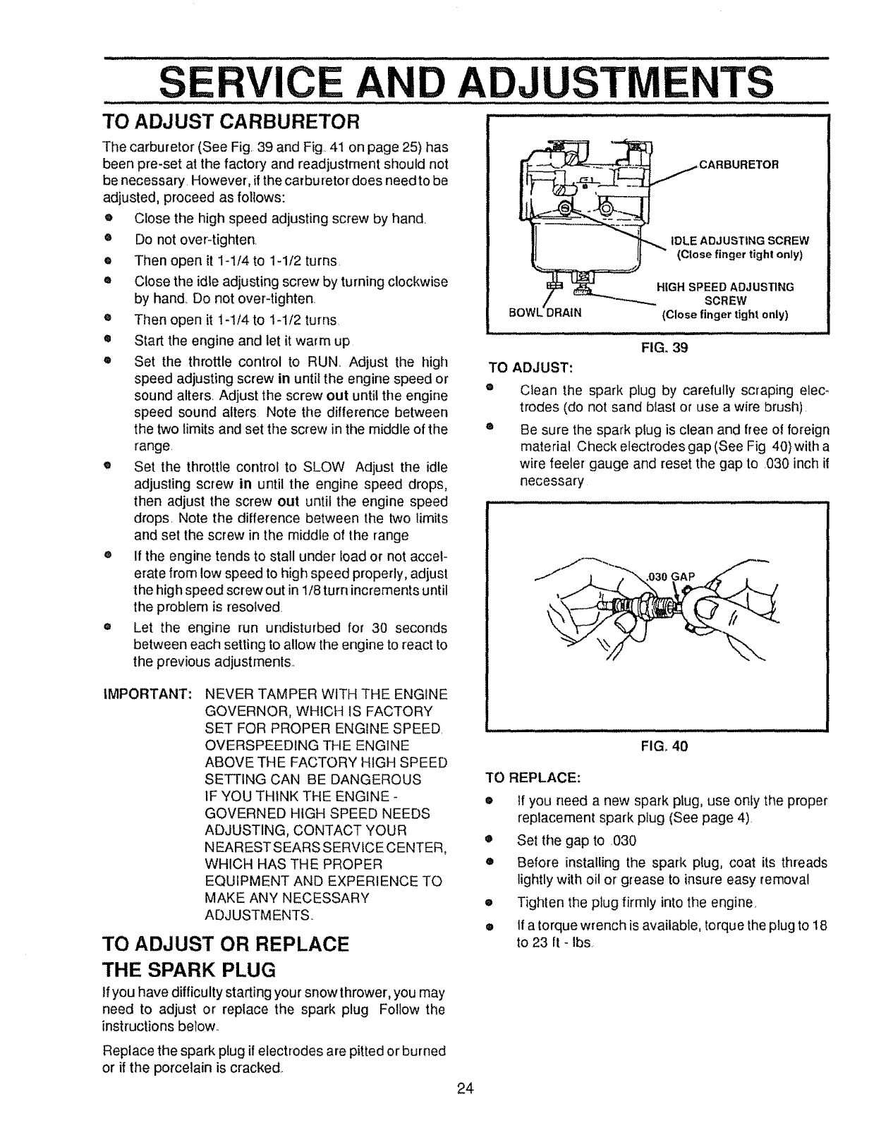
TO ADJUST CARBURETOR " .............
The carburetor (See Fig, 39 and Fig, 41 on page 25) has
been pre-set at the factory and readjustment should not
be necessary, However, if the carburetor does needto be
adjusted, proceed as follows:
eClose the high speed adjusting screw by hand
•Do not over-tighten,
eThen open it 1-1/4 to 1-1/2 turns•
®Close the idle adjusting screw by turning clockwise
by hand, Do not over-tighten,
eThen open it 1-1/4 to 1-1/2 turns
•Start the engine and let it warm up
eSet the throttle control to RUN Adjust the high
speed adjusting screw in until the engine speed or
sound alters, Adjust the screw out until the engine
speed sound alters Note the difference between
the two limits and set the screw in the middle of the
range
eSet the throttle control to SLOW Adjust the idle
adjusting screw in until the engine speed drops,
then adjust the screw out until the engine speed
drops_ Note the difference between the two limits
and set the screw in the middle of the range
®if the engine tends to stall under load or not accel-
erate from low speed to high speed properly, adjust
the high speed screw out in 1/8 turn increments until
the problem is resolved
eLet the engine run undisturbed for 30 seconds
between each setting to allow the engine to react to
the previous adjustments,,
IMPORTANT: NEVER TAMPER WITH THE ENGINE
GOVERNOR, WHICH IS FACTORY
SET FOR PROPER ENGINE SPEED,
OVERSPEEDING THE ENGINE
ABOVE THE FACTORY HIGH SPEED
SETTING CAN BE DANGEROUS
IF YOU THINK THE ENGINE-
GOVERNED HIGH SPEED NEEDS
ADJUSTING, CONTACT YOUR
NEARESTSEARS SERVICE CENTER,
WHICH HAS THE PROPER
EQUIPMENT AND EXPERIENCE TO
MAKE ANY NECESSARY
ADJUSTMENTS
TO ADJUST OR REPLACE
THE SPARK PLUG
If you have difficulty starting your snow thrower, you may
need to adjust or replace the spark plug Follow the
instructions below.,
Replace the spark plug if electrodes are pitted or burned
or if the porcelain is cracked,.
IDLE ADJ USTING SCREW
(Close finger tight only)
HIGH SPEED ADJUSTING
SCREW
(Close finger tight only)
i L, ill ,i, •
FIG. 39
TO ADJUST:
Q
Clean the spark plug by carefully scraping elec-
trodes (do not sand blast or use a wire brush),
Be sure the spark plug is clean and free of foreign
material Check electrodes gap (See Fig 40) witt_a
wire feeler gauge and reset the gap to .030 inch it
necessary
FIG, 40
TO REPLACE:
• if you need a new spark plug, use onfy the proper
replacement spark piug (See page 4),
eSet the gap to ,030
oBefore installing the spark plug, coat its threads
lightly with oil or grease to insure easy removal
•Tighten the plug firmly into the engine,
•If a torque wrench is available, torque the plug to 18
to 23 ft - Ibs,
24
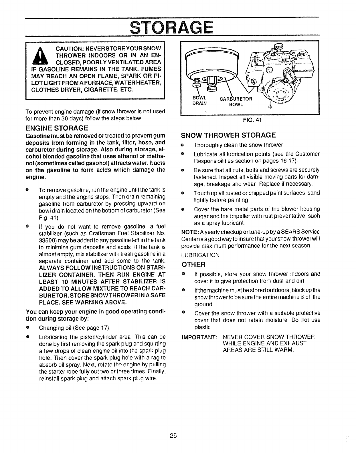
CAUTION : NEVER STORE YOUR SNOW
THROWER INDOORS OR IN AN EN-
CLOSED, POORLY VENTILATED AREA
IF GASOLINE REMAINS IN THE TANK. FUMES
MAY REACH AN OPEN FLAME, SPARK OR PI-
LOT LIGHT FROM AFURNACE, WATER H EATER,
CLOTHES DRYER, CIGARETTE, ETC,
To prevent engine damage (if snow thrower is not used
for more than 30 days) follow the steps below.
ENGINE STORAGE
Gasoline must be removed or treated to prevent gum
deposits from forming in the tank, filter, hose, and
carburetor during storage. Also during storage, al-
cohol blended gasoline that uses ethanol or metha-
nol (sometimes called gasohol) attracts water. It acts
on the gasoline to form acids which damage the
engine.
You
tion
®
O
To remove gasoline, run the engine until the tank is
empty and the engine stops Then drain remaining
gasoline from carburetor by pressing upward on
bowl drain located on the bottom of carburetor (See
Fig 41)
If you do not want to remove gasoline, a fuel
stabilizer (such as Craftsman Fuel Stabilizer No.
33500) may be added to any gasoline left inthe tank
to minimize gum deposits and acids. If the tank is
almost empty, mix stabilizer with fresh gasoline in a
separate container and add some to the tank..
ALWAYS FOLLOW INSTRUCTIONS ON STABI-
LIZER CONTAINER. THEN RUN ENGINE AT
LEAST 10 MINUTES AFTER STABILIZER IS
E
DRAIN
i i ,ll .l= i=,
BOWL
FIG. 41
SNOW THROWER STORAGE
eThoroughly clean the snow thrower
® Lubricate all lubrication points (see the Customer
Responsibilities section on pages 16-17),
o Be sure that all nuts, bolts and screws are securely
fastened Inspect all visible moving parts for dam-
age, breakage and wear Replace if necessary
• Touch up all rusted or chipped paint surfaces; sand
lightly before painting
e Cover the bare metal parts of the blower housing
auger and the impeller with rust preventative, such
as a spray lubricant
NOTE: A yearly checkup or tune-up by a SEARS Service
Center is a good way to insure that your snow throwerwi]l
provide maximum performance for the next season
LUBRICATION
OTHER
ADDED TO ALLOW MIXTURE TO REACH CAR-
BURETOR. STORE SNOWTHROWER IN A SAFE
PLACE. SEE WARNING ABOVE,
can keep your engine in good operating condi-
during storage by:
Changing oil (See page 17),
If possible, store your snow thrower indoors and
cover it to give protection from dust and dirt
Lubricating the piston/cylinder area This can be
done by first removing the spark plug and squirting
a few drops of clean engine oi! into the spark plug
hole. Then cover the spark plug hole with a rag to
absorb oil spray_.Next, rotate the engine by pulling
the starter rope fully out two or three times Finally,
reinstall spark plug and attach spark plug wire..
o Ifthe machine must be stored outdoors, block up the
snow thrower to be sure the entire machine is off the
ground
eCover the snow thrower with a suitable protective
cover that does not retain moisture. Do not use
plastic
NEVER COVER SNOW THROWER
WHILE ENGINE AND EXHAUST
AREAS ARE STILL WARM.
IMPORTANT:
25 i_
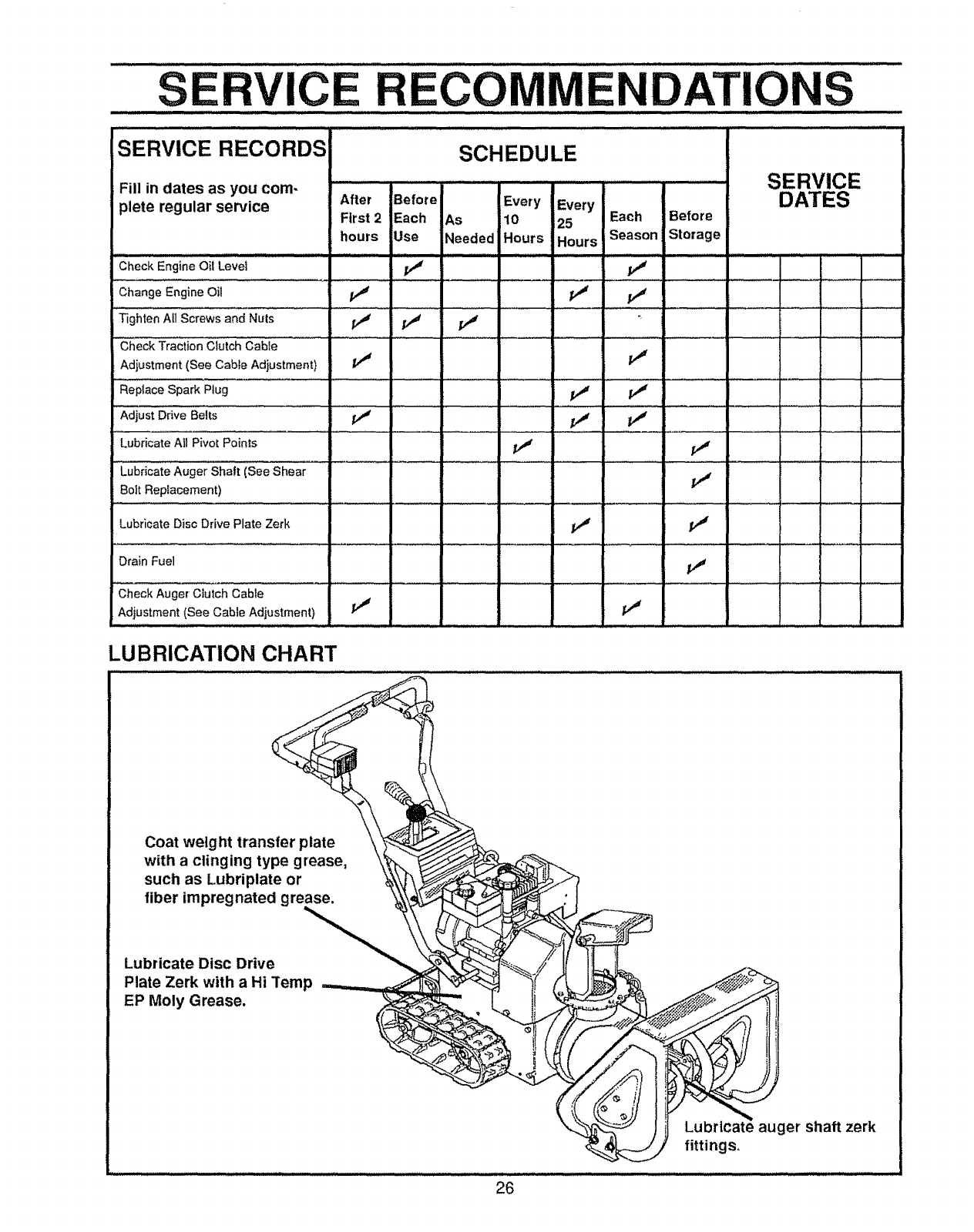
SE CE ECOMIVlENDATIONS
SERVICE RECORDS SCHEDULE
SERVICE
DATES
ii i ,i....
Fill in dates as you com-
plete regular service After Before Every Every
First 2 Each As [10 25 Each Before
hours Use Needed Hours Hours Season Storage
Check Engine Oil Level f,_
Change Engine Oil _ _,4 _t
Tighten All Screws and Nuts /,J f_ /
:'Check Traction clutch Cabie .......................
Adjustment (See Cable Adjustment} /_r f._
Replace Spark Plug ............ //_
:Adjustari,,ea_lts i," I," ..... v" ................
...... = ..... : •::a ................ :::
Lubricate All Pivot Points _ pj
LubriCate Auger Shall iSee Shear
Bolt Replacement) ............ I.......
Lubricate Disc Drive Plate Zerk
Drain Fuel
Check Auger Clutch Cable
Adjustment (See Cable Adjustment) i/' It
1,1 11
i,,"
LUBRICATION CHART
Coat weight transfer plate
with a clinging type grease,
such as Lubriplate or
fiber impregnated grease.
Lubricate Disc Drive
Plate Zerk with a Hi Temp
EP Moly Grease.
Lubricate auger shaft zerk
fittings,
26
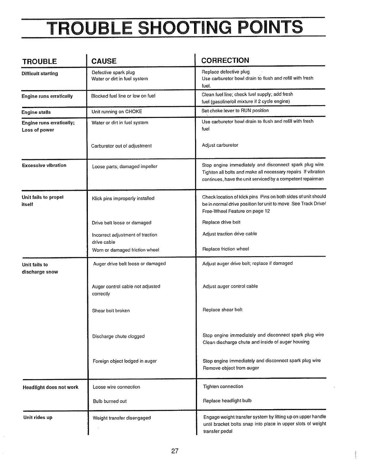
TROU LSOOTING POI J J i
TS
TROUBLE
Difflcull starting
Engine runs erratically
Engine stalls
Engine runs erratically;
Loss of power
Excessive vibration
Unit fails to propel
itself
Unit fails to
discharge snow
CAUSE
Defective spark plug
Water or dirt in fuel system
Blocked fuef line or low on fuel
Unit running on CHOKE
Water or dirt in fuel system
Carburetor out of adjustment
Loose parts; damaged impeller
Klick pins improperly installed
Drive belt loose or damaged
Incorrect adjustment of traction
drive cable
Worn or damaged triction wheel
Auger drive belt loose or damaged
Auger control cable not adjusted
CORRECTION
Replace defective plug
Use carburetor bowl drain to flush and refill with fresh
fuel,
Clean fuel line; check fuel supply; add fresh
fuel (gasolineloil mixture if 2 cycle engine)
Set choke lever to RUN position
Use carburetor bowl drain to flush and refill with fresh
fuel
Adjust carburetor
Stop engine immediately and disconnect spark plug wire
Tighten all bolts and make all necessary repairs If vibration
continues, have the unit serviced by a competent repairman
Check location of klick pins Pins on both sides of unit should
be in normal drive position for unit to move See Track Drivel
Free+Wheel Feature on page 12
Replace drive belt
Adjust traction drive cable
Replace friction wheel
Adjust auger drive belt; replace if damaged
Adjust auger control cable
correctly
Shear bolt broken
Discharge chute clogged
Replace shear bolt
Stop engine immediately and disconnect spark plug wire
CIean discharge chute and inside of auger housing
Headlight does not work
Unit rides up
Foreign object lodged in auger
Loose wire connection
Bulb burned out
Weight transfer disengaged
Stop engine immediately and disconnect spark plug wire
Remove object from auger
Tighten connection
Replace head+ight bulb
Engage weight transfer system by lilting up on upper handle
until bracket bolls snap into place in upper slots of weight
transler pedal
27 i:
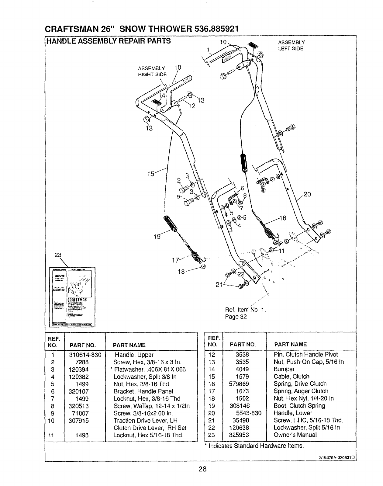
CRAFTSMAN 26" SNOW THROWER 536.885921
-IANDLE ASSEMBLY REPAIR PARTS 1o
1
ASSEMBLY
LEFT SIDE
ASSEMBLY 10
RIGHT SIDE /
23
-tI
PART NAME
\
Ref Item_lo 1,
Page 32
"EFII
NO. I
34
PART NO.
310614-830
7288
120394
120382
1499
320107
1499
320513
71007
307915
i498
Handle, Upper
Screw, Hex, 3/8-16 x 3 In
* Ftatwasher, 406X 81X066
Lockwasher, Split 3/8 In
Nut, Hex, 3/8-16 Thd
Bracket, Handle Panel
Locknut, Hex, 3/8-I6 Thd
Screw, WaTap, t2-14 x 1/21n
Screw, 3/8-16x2 00 In
Traction Drive Lever, LH
Clutch Drive Lever, RH Set
Locknut, Hex 5/16-18 Thd
REE
NO.
12
13
14
15
16
17
18
19
20
21
22
23
PART NOo
3538
3535
4049
1579
579869
1673
1502
308146
5543-830
35498
120638
325953
PART NAME
Pin, Clutch Handle Pivot
Nut, Push-On Cap, 5/16 In
Bumper
Cable, Clutch
Spring, Drive Clutch
Spring, Auger Clutch
Nut, Hex Nyt, 114-20 In
Boot, Clutch Spring
Handle, Lower
Screw, HHC, 5fl 6-18 Thd
Lockwasher, Split 5/16 in
Owner's Manual
Indicates Standard Hardware Items,
319376A-320637D
28
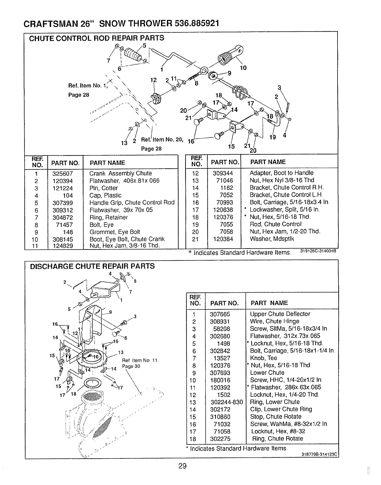
CRAFTSMAN 26" SNOW THROWER 536.885921
CHUTE CONTROL ROD REPAIR PARTS
REF.
NO, PART NO,
1 325607
2 120394
3 121224
4 104
5 307399
6 309312
7 304872
8 71457
9 148
10 308t 45
11 124829
7
6110
RefoltemNo,. 1_\ \. 12 2.. 8 3
p.go28 . 1- 18. =\,,
,"_ _ 17",, 17
13//2 ReflltemN° 20' 115 21 /
Page 28 20
............. REFo
PART NAME NO. PART NO.
Crank Assembly Chute
FIatwasher, .406>:.81x 066
Pin, Cotter
Cap, Plastic
Handle Grip, Chute Control Rod
Flatwasher, 39x70x 05
Ring, Retainer
Bolt, Eye
Grommet, Eye Bolt
Boot, Eye Bolt, Chute Crank
Nut, Hex Jam, 3/8-t6 Thd.
12 309344
13 71046
14 1162
15 7052
16 70993
17 120638
18 120376
19 7055
20 7058
21 120384
it
it
PART NAME
Adapter, Boot to Handle
Nut, Hex Nyl 3/8-16 Thd
Bracket, Chute Control R.H.
Bracket, Chute Control LH
Bolt, Carriage, 5/16-18x3,4 In
Lockwasher, Split, 5/16 In.
Nut, Hex, 5/16-18 Thd.
Rod, Chute Control
Nut, Hex Jam, 1/2-20 Thd.
Washer, Mdsptlk
'i<'i'ndicates s iandard Hardware items.. 319126c.314OO4B
DISCHARGE CHUTE REPAIR PARTS
4£X;r_,
Is_._ I" Re)I_mNo11,
_:J"_"-_ _.-,...._i _ ..... Page 30
\,
V. ......:.......7 \ ,:.......
....../";'.":>.':>': ...... T d_
;,,- 27,.-"
REF, 1
NO. t
*,J )
4 f
6 I
PART NO. PART NAME
307665
308931
58208
302680
1498
302842
13527
120376
307693
180016
120392
1502
302244-830
302172
310860
71032
71058
302275
8I
9I
10 I
11 I
12 I
13 1
14 I
15 I
16 I
17 I
18 I
Indicates Standard Hardware Items.
tipper Chute Deflector
Wire, Chute Hinge
Screw, SltMa, 5/16-18x3/4 In
Flatwasher, .312x,73xO65
* Locknut, Hex, 5/I6-18 Thd
Bolt, Carriage, 5/16-18xl-1/4 In.
Knob, Tee
* Nut, Hex, 5/16-18 Thd
Lower Chute
i Screw, HHC, 114-20xl/2 tn
i* Flalwasher, 286x.63xO65
Locknut, Hex, 1/4-20 Thd.
Ring, Lower Chute
Clip, Lower Chute Ring
Stop, Chute Rotate
Screw, WahMa, #8-32x112 In.
Locknut, Hex, #8-32
Ring, Chute Rotate
318779B-314123C
29
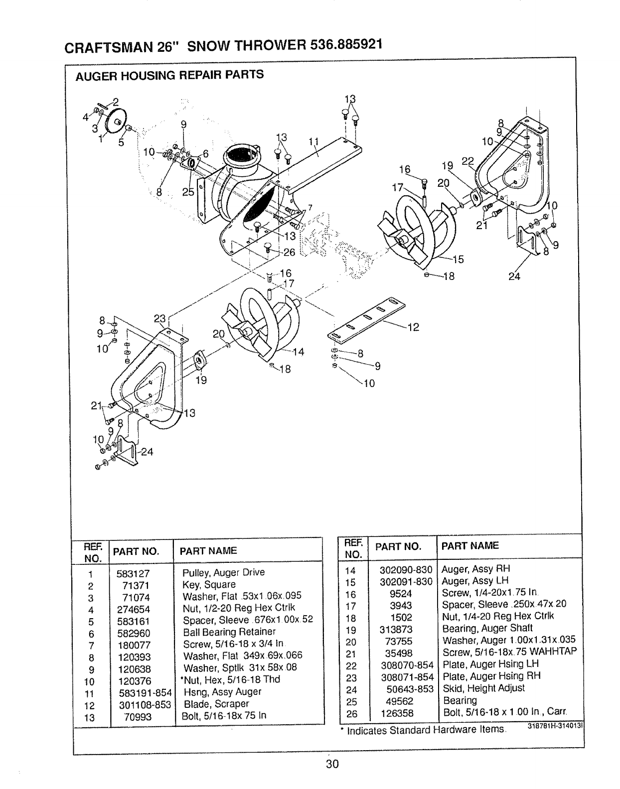
CRAFTSMAN 26" SNOW THROWER 536.885921
AUGER HOUSING REPAIR PARTS
9
10"]_
19 22/_/
e-"_l 8 24
10/e
3
REF.
NO.
I
2
3
4
5
6
7
8
9
10
11
12
13
PART NO. PART NAME
583127
71371
71074
274654
583161
582960
180077
120393
120638
120376
583191-854
301108-853
70993
Pulley, Auger Drive
Key, Square
Washer, Ffat .53xl .06x,095
Nut, 112-20 Reg Hex Ctrtk
Spacer, Sleeve. 676x 1 00x. 52
Ball Bearing Retainer
Screw, 5/16-18 x 3/4 In
Washer, Flat 349x.69x.066
Washer, Sptlk 31x 58x 08
*Nut, Hex, 5116-18 Thd
Hsng, Assy Auger
Blade, Scraper
Bolt, 5116-18x 75 In
14
15
t6
17
18
19
20
21
22
23
24
25
26
PART NO.
302090-830
302091-830
9524
3943
1502
313873
73755
35498
308070-854
308071-854
50643-853
49562
126358
PART NAME
Auger, Assy RH
Auger, Assy LH
Screw, 1/4-20xl.75 In.
Spacer', Sleeve. 250x 47x 20
Nut, 1/4-20 Reg Hex Ctrlk
Bearing, Auger Shaft
Washer, Auger 1.00xl .31x035
Screw, 5t16-18x. 75 WAHHTAP
Plate, Auger Hsing LH
Plate, Auger Hsing RH
Skid, Height Adjust
Bearing
Bolt, 5/16-18 x 1.00 in., Cart.
" Indicates Standard Hardware Items, 3t8781H.3t40!3!
30
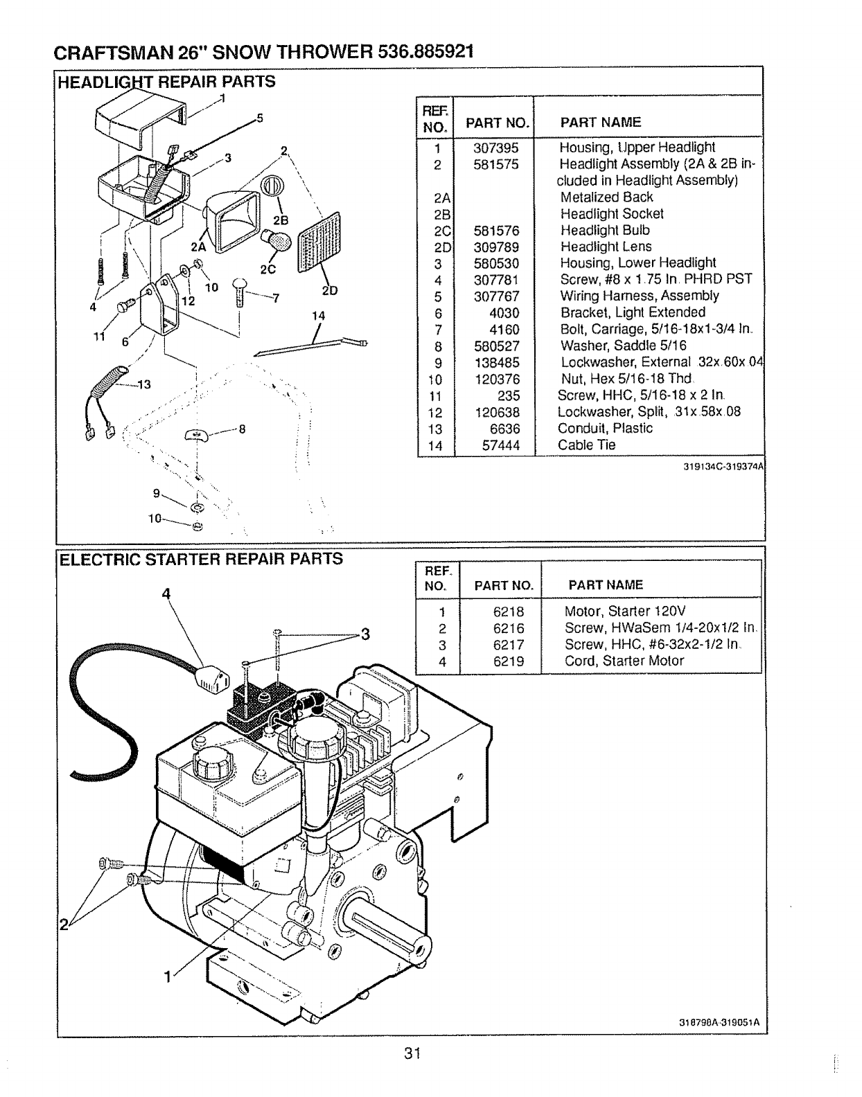
CRAFTSMAN 26" SNOW THROWER 536.885921
REPAIR PARTS
/1
14
: I
"9 !
2
2A
2B
20
2D
3
4
5
6
7
8
9
10
11
12
•13
14
PART NO.
307395
581575
581576
309789
580530
307781
307767
4030
4160
580527
138485
120376
235
120638
6636
57444
PART NAME
Housing, Upper Headlight
Headlight Assembly (2A & 2B in-
cluded in Headlight Assembly)
Metalized Back
Headlight Socket
Headlight Bulb
Headlight Lens
Housing, Lower Headlight
Screw, #8 x 1.75 In. PHRD PST
Wiring Harness, Assembly
Bracket, Light Extended
Bolt, Carriage, 5f16-18xl-3/4 In.
Washer, Saddle 5116
Lockwasher, External 32x,60x 04
Nut, Hex 5t16-I8 Thd
Screw, HHC, 5t16-18 x 2 In.
Lockwasher, Split, .3lx .58x.08
Conduit, Plastic
Cable Tie
319134C_319374A
ELECTRIC STARTER REPAIR PARTS
4PART NO.
6218
6216
6217
6219
PART NAME
Motor, Starter 120V
Screw, HWaSem I/4-20xtf2 In,
Screw, HHC, #6-32x2-1/2 In,
Cord, Starter Motor
318798A-319051A
31
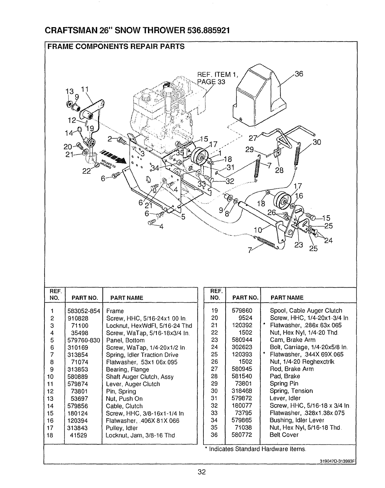
CRAFTSMAN 26" SNOW THROWER 536.885921
FRAME COMPONENTS REPAIR PARTS
13 11
6
REF,, ITEM 1,
_E 33
]
. # .,1
8
28
5
REF° !
NO. IPART NO.
583052-854
- ; 910828
rj I
4 I
F
6 I
8 1
9 I
10 I
11 |
12 I
13 !
14 I
15 1
16 I
17 I
18 I
71100
35498
579760-830
310169
313854
71074
313853
580889
579874
73801
53697
579856
180124
120394
313843
41529
PART NAME
Frame
Screw, HHC, 5/16-24xl 00 in.
Locknut, HexWdFl, 5/16-24 Thd
Screw, WaTap, 5/16-18x3/4 in
Panel, Bottom
Screw, WaTap, 1/4-20xl/2 In
Spring, Idler Traction Drive
Ftatwasher, 53xl 06x.095
Bearing, Flange
Shaft Auger Clutch, Assy
Lever, Auger Clutch
Pin, Spring
Nut, Push On
Cable, Clutch
Screw, HHC, 3/8-16x1-1/4 in
Flatwasher, 406X 81X 066
Pulley, Idler
Locknut, Jam, 3/8-16 Thd
" REF°
NO,
!9
20
21
22
23
24
25
26
27
28
29
3O
31
32
33
34
35
36
PART NO. PART NAME
579860
9524
120392
t502
580944
302623
120393
1502
580945
581540
73801
318468
579872
180077
73795
579865
71038
580772
Spool, Cable Auger Clutch
Screw, HHC, 1/4-20xl-3/4 In
Flatwasher, .286x ,63x, 065
Nut, Hex Nyt, 1/4-20 Thd,
Cam, Brake Arm
Bolt, Carriage, 1/4-20x5/8 in,.
Flatwasher, 344X 69X065
Nut, 1/4-20 Reghexctrlk
Rod, Brake Arm
Pad, Brake
Spring Pin
Spring, Tension
Lever, idler
Screw, HHC, 5/16-t8 x3/4 In
Flatwasher, .328x 1.38x .075
Bushing, Idler Lever
Nut, Hex Nyl, 5/16-18 Thd.
Belt Cover
Indicates Standard Hardware items
3190470-313993F
32
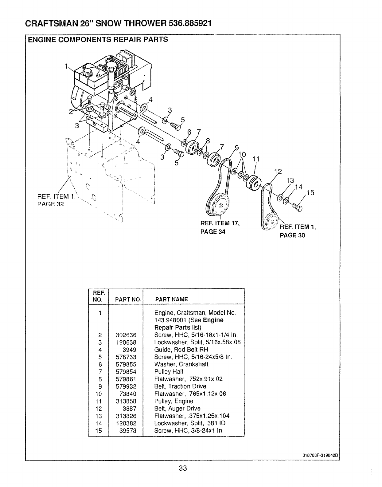
CRAFTSMAN 26" SNOW THROWER 536.885921
ENGINE COMPONENTS REPAIR PARTS
9
RER ITEM 17,
PAGE 34
11
12
/13
PAGE 30
1
2
3
4
5
6
7
8
9
10
'1!
12
13
14
15
PART NO_ PART NAME
302636
120638
3949
Engine, Craftsman, Model No.
!43.948001 (See Engine
Repair Parts list)
Screw, HHC, 5/16-18x1-1/4 In.
Lockwasher, Split, 5/16x58x,08
Guide, Rod Belt RH
578733
579855
579854
579861
579932
73840
313858
3887
313826
120382
39573
Screw, HHC, 5/16-24x5/8 In,.
Washer, Crankshaft
Pulley Half
Flatwasher, 752x 9 lx.02
Belt, Traction Drive
Flatwasher, 765x 1.12x, 06
Pulley, Engine
Belt, Auger Drive
Flatwasher, 375x 1.25x. 104
Lockwasher, Split, .381 ID
Screw, HHC, 3/8-24xt In.
31878BF-3"_90420
33 !:;
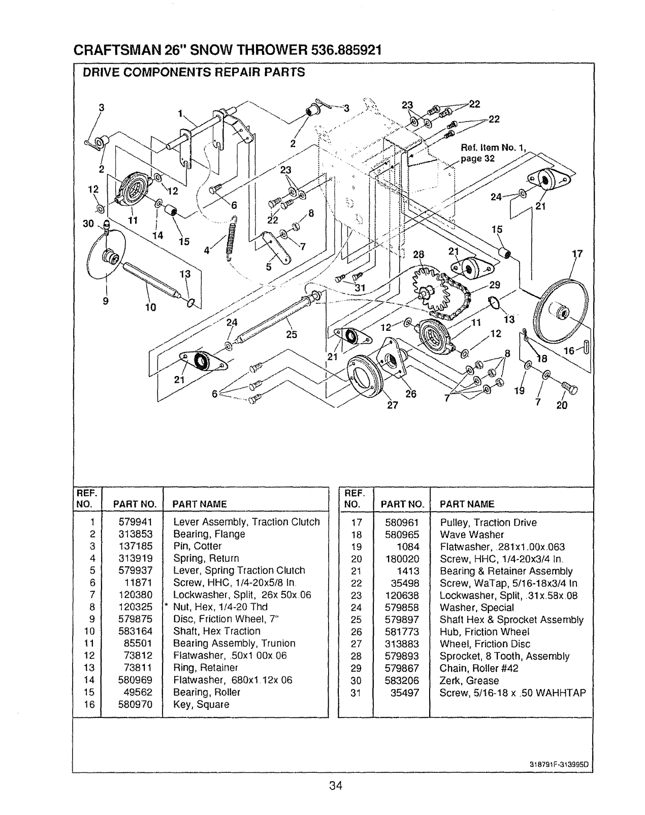
CRAFTSMAN 26" SNOW THROWER 536.885921
DRIVE COMPONENTS REPAIR PARTS
3
2
1\
10
415
28
Ref, Item No. 1,
32
15
21
27
1
7 20
REF.
NO.
1
2
3
4
5
6
7
8
9
10
11
12
13
14
15
16
PART NO. PART NAME
579941
313853
137185
313919
579937
11871
120380
120325
579875
583164
855O1
73812
73811
580969
49562
580970
Lever Assembly, Traction Clutch
Bearing, Flange
Pin, Cotter'
Spring, Return
Lever, Spring Traction Clutch
Screw, HHC, 1/4-20x5/8 In
Lockwasher, Split, 26x 50xO6
Nut, Hex, 1/4-20 Thd
Disc, Friction Wheel, 7"
Shaft, Hex Traction
Bearing Assembly, Trunion
Flatwasher, .50xl 00x 06
Ring, Retainer
Flatwasher, 680xl.12x 06
Bearing, Roller
Key, Square
'NO. I
4"7 I
18 I
19 i
20 I
2t 1
22 I
23 l
24 I
25 I
26 I
27 I
28 I
29 I
30 I
31 I
PART NO. PART NAME
580961
580965
1084
180020
1413
35498
120638
579858
579897
581773
313883
579893
579867
583206
35497
Pulley, Traction Drive
Wave Washer
Flatwasher,. 281 x t .00x.O63
Screw, HHC, t/4-20x3/4 In.
Bearing & Retainer Assembly
Screw, WaTap, 5/16-18x3/4 in
Lockwasher, Split, .31 x58x.08
Washer, Special
Shaft Hex & Sprocket Assembly
Hub, Friction Wheef
Wheel, Friction Disc
Sprocket, 8 Tooth, Assembly
Chain, Roller #42
Zerk, Grease
Screw, 5/16-18 x 50 WAHHTAP
318791 F-313995D
34
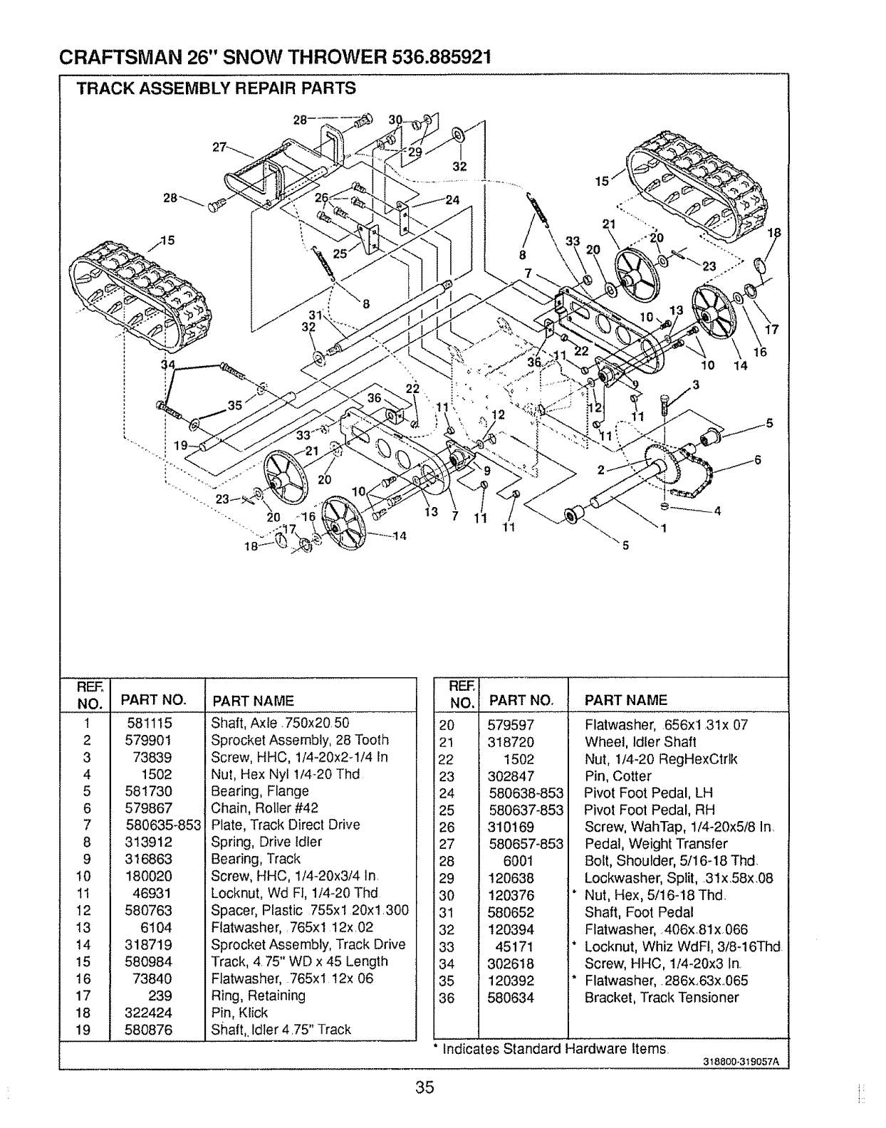
CRAFTSMAN 26" SNOW THROWER 536.885921
TRACK ASSEMBLY REPAIR PARTS
/15
20 "1
2O
22
32
10 14
3
REE
NO. PART NO.
1 581115
2 579901
3 73839
4 1502
5 581730
6 579867
7 580635_853
8 313912
9 316863
10 180020
I1 46931
12 580763
13 6104
14 318719
15 580984
16 73840
17 239
18 322424
19 580876
PART NAME
Shaft, Axie.750x20 50
Sprocket Assembly, 28 Tooth
Screw, HHC, 1/4-20x2-1/4 In
Nut, Hex Nyl 1/4-20 Thd
Bearing, Flange
Chain, Roller #42
Plate, Track Direct Drive
Spring, Drive Idler
Bearing, Track
Screw, HHC, 1f4-20x3/4 ln,
Locknut, Wd F], 1/4-20 Thd
Spacer, Plastic 755xl 20x1300
Ftatwasher,, 765xl 12x 02
Sprocket Assembly, Track Drive
Track, 4 75" WD x 45 Length
Flatwasher, 765xl 12x 06
Ring, Retaining
Pin, Klick
Shaft,, Idler 475" Track
REF.
NO. PART NO.
20 579597
21 318720
22 1502
23 302847
24 580638-853
25 580637-853
26 310169
27 580657-853
28 6001
29 120638
30 120376
31 580652
32 120394
33 45171
34 302618
35 120392
36 580634
I
PART NAME I
Flatwasher, 656xl 31x 07
Wheel, Idler Shaft
Nut, 1/4-20 RegHexCtrlk
Pin, Cotter
Pivot Foot Pedal, LH
Pivot Foot Pedal, RH
Screw, WahTap, 1/4-20x5/8 In.
Pedal, Weight Transfer
Bolt, Shoulder, 5/16-18 Thd.
Lockwasher, Split, 31x.58x.08
* Nut, Hex, 5/16-18Thd.
Shaft, Foot Pedal
Flatwasher, 406x81x,066
* Locknut, Whiz WdFt, 3/8-16Thd
Screw, HHC, 1/4-20x3 In
* Flatwasher, 286x63x 065
Bracket, Track Tensioner
Indicates standard Hardware iierns
318800-3t 9057A
35 i_
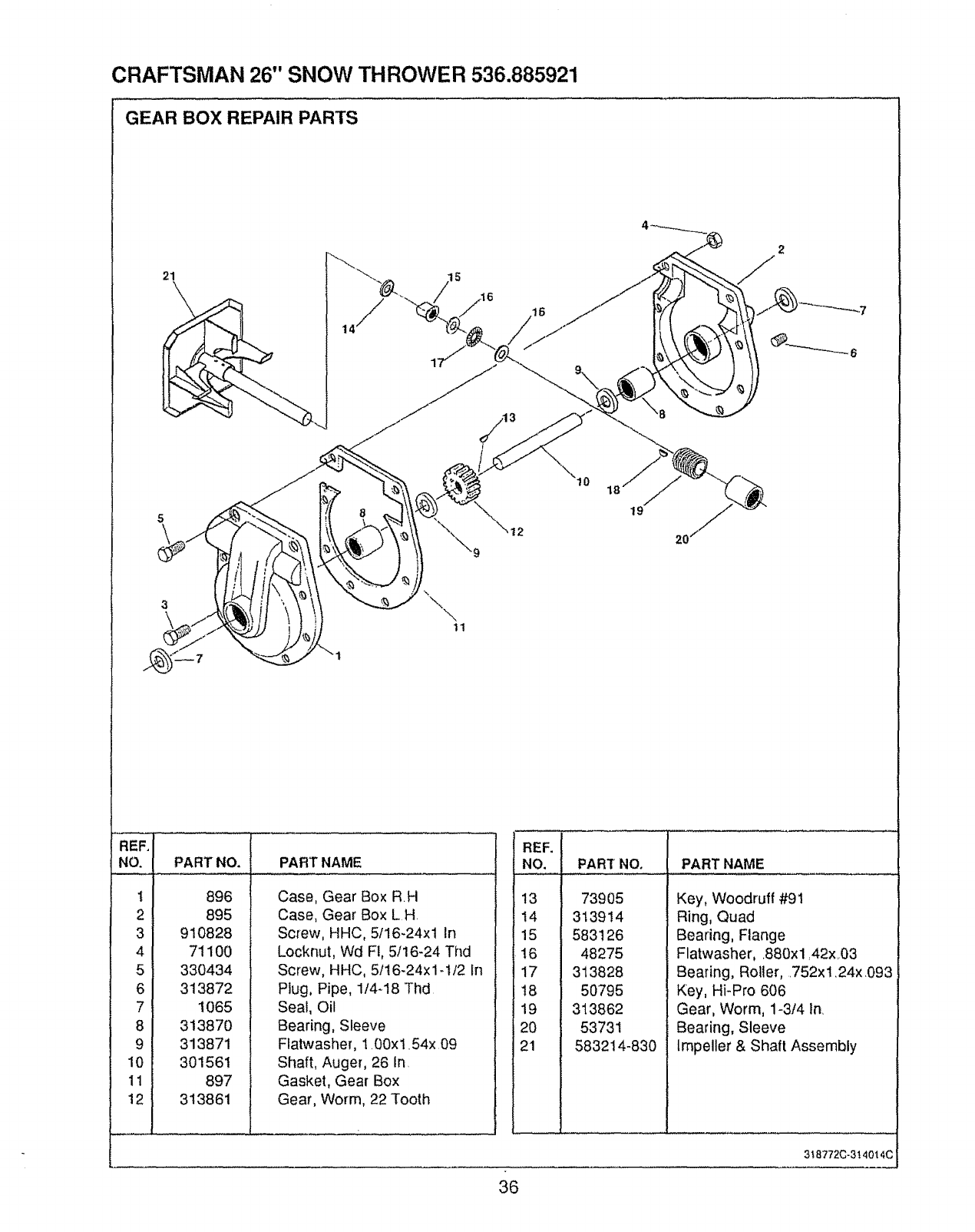
CRAFTSMAN 26" SNOW THROWER 536.885921
GEAR BOX REPAIR PARTS
21
\
19
20
REF.I
NO. i
.... .=,
21
31
41
v i
61
81
91
10I
111
121
PART NO. PART NAME
896
895
910828
71100
330434
313872
1065
313870
313871
301561
897
313861
Case, Gear Box RH
Case, Gear Box L H.
Screw, HHC, 5t16-24x! In
Locknut, Wd FI, 5t16-24 Thd
Screw, HHC, 5116-24x1-I/2 In
Plug, Pipe, 114q8 Thd
Seal, Oil
Bearing, Sleeve
Flatwasher, 1.00xl .54x 09
Shaft, Auger, 26 In.
Gasket, Gear Box
Gear, Worm, 22 Tooth
REF.
NO. PART NO. PART NAME
13
14
15
16
17
18
19
20
21
73905
313914
583126
48275
313828
50795
313862
53731
583214-830
Key, Woodruff #91
Ring, Quad
Bearing, Flange
Flatwasher, 880xl ,42x_.03
Bearing, Roller, .752xt24x093
Key, HFPro 606
Gear, Worm, 1-3f4 In.
Bearing, Sleeve
Impeller & Shaft Assembly
3t 8772C-3t 4014C
36
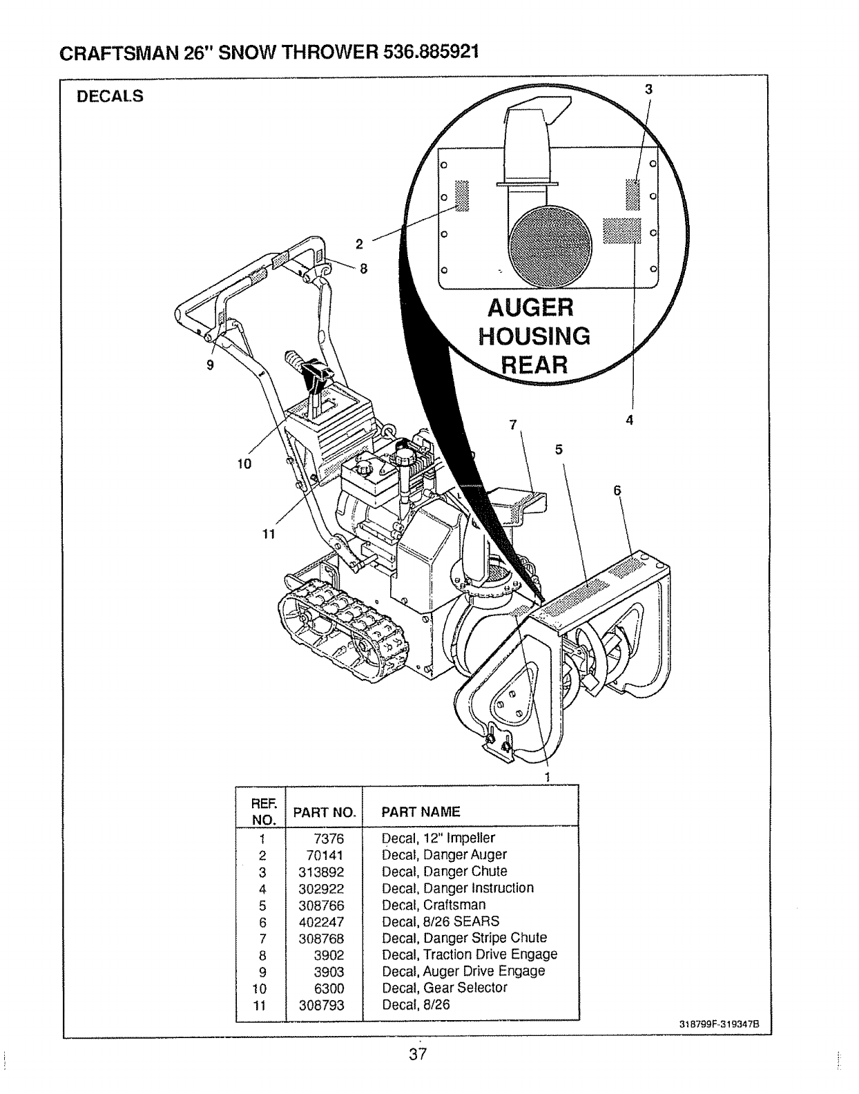
CRAFTSMAN 26" SNOW THROWER 536.885921
DECAt.S
AUGER
HOUSING
REAR
7 4
5
10
11
REE
1
2
3
4
5
6
i 7
8
9
i 1o
1
PART NO. PART NAME
7376
70141
313892
302922
308766
402247
308768
3902
3903
6300
308793
Decal, 12" Impeller
Decal, Danger Auger
Decal, Danger Chute
Decal, Danger instruction
Decal, Craftsman
Decal, 8126 SEARS
Decal, Danger Stripe Chute
Decal, Traction Drive Engage
Decal, Auger Drive Engage
Decal, Gear Selector
Decal, 8/26
37
3t 8799F.,319347B
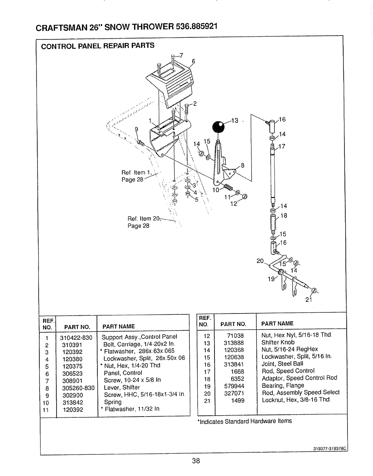
CRAFTSMAN 26" SNOW THROWER 536.885921
CONTROL PANEL REPAIR PARTS
6
,,_15
REFo
NO,
!
2
3
4
5
6
7
8
9
10
tl
PART NO, PART NAME
310422-830
310391
120392
120380
120375
306523
308901
305260-830
302900
313842
120392
Support Assy.Control Panel
Bolt, Carriage, 1/4-20x2 In..
*Flatwasher,. 286x, 63x,065
Lockwasher, Split, 26xS0x 06
* Nut, Hex, 1/4-20 Thd
Panel, Control
Screw, 10-24 x 5/8 In
Lever, Shifter
Screw, HHC, 5/16-18xl-3/4 In.
Spring
*Flatwasher, 1t/32 in
REFo
NO,
12
13
14
t5
16
17
18
19
20
21
PART NO,, PART NAME
71038
313888
120368
120638
313841
1668
6352
579944
327071
1499
Nut, Hex Nyl, 5t16-18 Thd,
Shifter Knob
Nut, 5/16-24 RegHex
Lockwasher, Split, 5/16 In,
Joint, Steel Ball
Rod, Speed Control
Adaptor, Speed Control Rod
Bearing, Flange
Rod, Assembly Speed Select
Locknut, Hex, 3/8-16 Thd.
*indicates Standard Hardware Items
38
319377-319378C
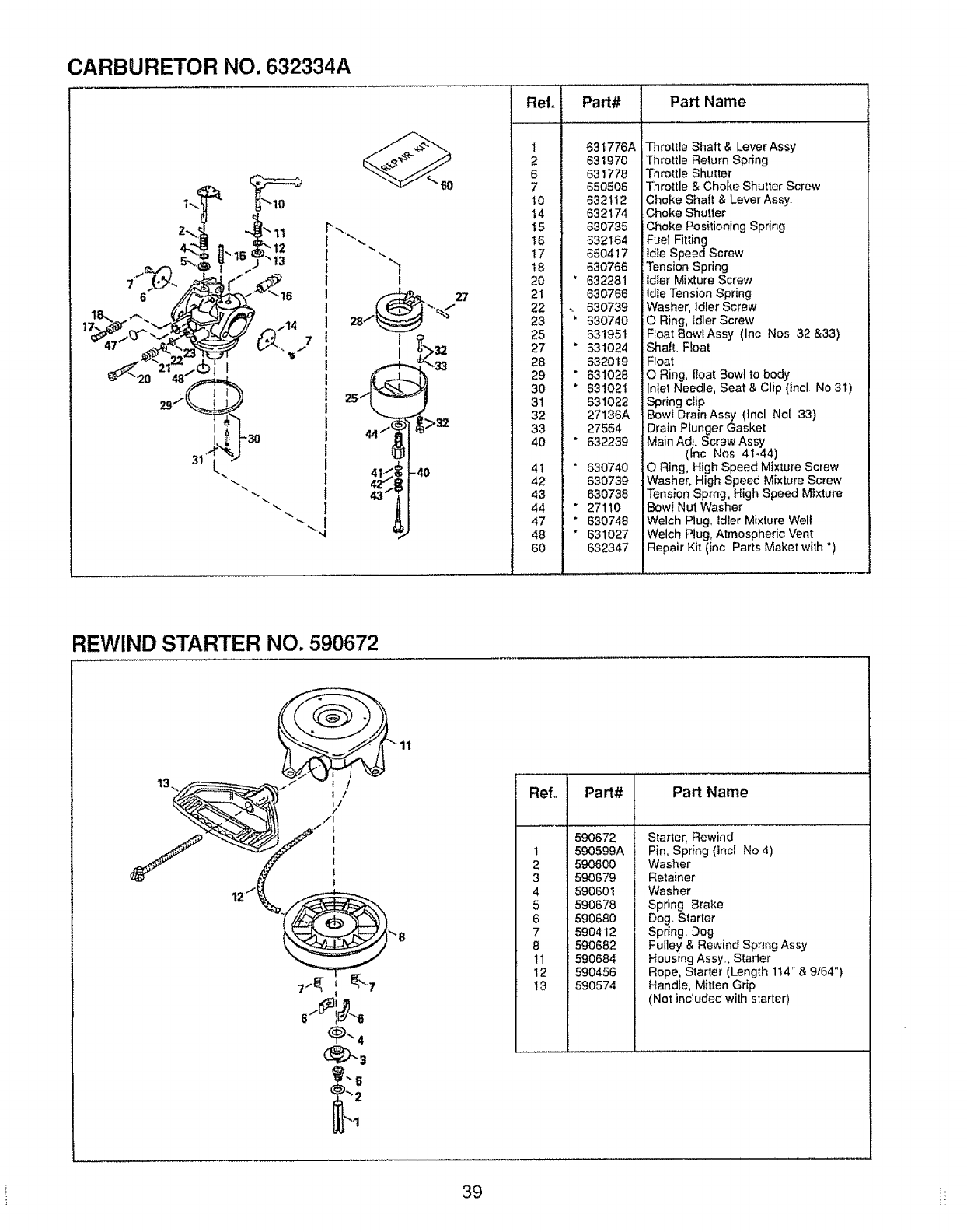
CARBURETOR NO. 632334A
i-30
12
"t3
I
25
32
-4O
Ref.
1
2
6
7
t0
14
15
16
17
18
20
21
22
23
25
27
28
29
3O
31
32
33
4O
41
42
43
44
47
48
60
Part# Part Name
631776A
631970
631778
650505
632112
632174
630735
632164
650417
630766
632281
630766
630739
630740
631951
631O24
632019
631028
631021
631022
27136A
27554
632239
63O740
630739
630738
27110
630748
631027
632347
Throttle Shaft & Lever Assy
Throttle Return Spring
Throttle Shutter
Throttle & Choke Shutter Screw
Choke Shaft & Lever Assy
:Choke Shutter
Choke Positioning Spring
Fuel Fitting
ldte Speed Screw
Tension Spring
ldter Mixture Screw
ldle Tension Spring
Washer, idler Screw
O Ring, Idler Screw
Float 8owlAssy (Inc Nos 32 &33)
Shaft. Ftoat
Float
ORing, float Bowl to body
Inlet Needle, Seat & Clip (lncl No 31)
Spring clip
Bowl DrainAssy (Incl No[ 33)
Drain Plunger Gasket
Main Adj. Screw Assy
(hc Nos 41-44)
ORing, High Speed Mixture Screw
Washer, High Speed Mixture Screw
Tension Sprng, High Speed Mixture
Bowl Nut Washer
Welch Plug, ldter Mixture Well
Welch Plug, Atmospheric Vent
Repair Kit (inc Parts Maket with °)
REWIND STARTER NO. 590672
11
..... i
Refo Part# Part Name
590672
t 590599A
2 590600
3 590679
4 590601
5 590678
6 59068O
7 59O412
8 590682
11 590684
12 590456
13 590574
Starter, Rewind
Pin, Spr}ng (Inc! No 4)
Washer
Retainer
Washer
Spring. Brake
Dog. Starter
Spring. Dog
Pulley & Rewind Spring Assy
Housing Assy, Starter
Rope, Starter (Length 114" & 9,'64")
Handle, Mitten Grip
(Not included with starter)
39 i:
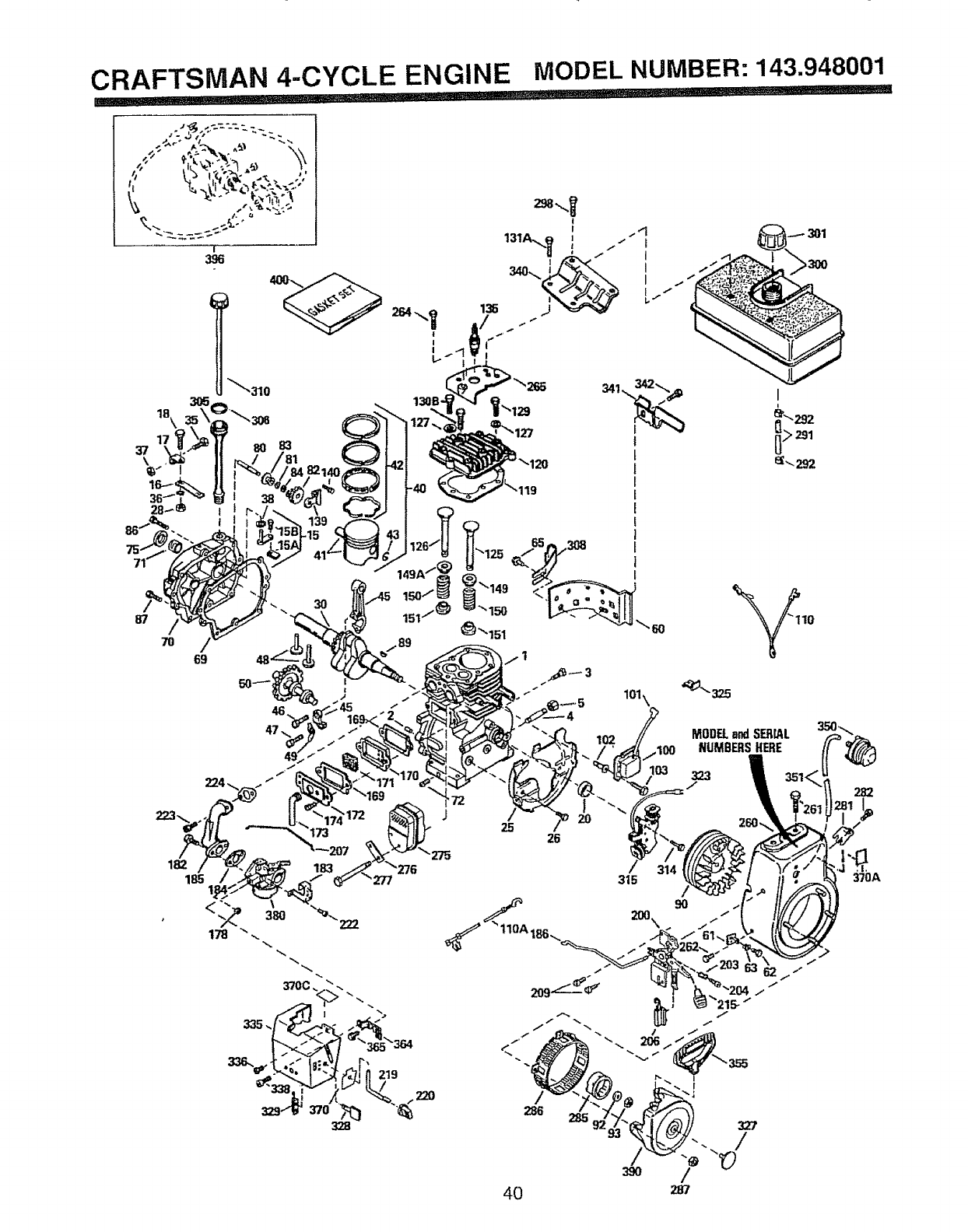
CRAFTSMAN 4-CYCLE ENGINE MODEL NUMBER: 143.948001
la\
17
37
\
/
69
J
223_. 173 25 26
182
185
/
286
4O
MODELandSERrAL
NUMBERSHERE
323
315 /
90
J
J
287
370A
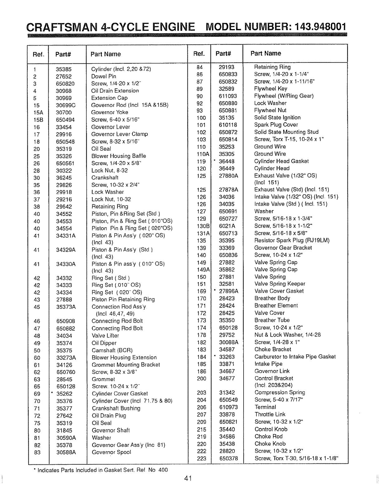
CRAFTSMAN 4-CYCLE ENGINE MODEL NUMBER: 143.948001
_!!!!!!!_, ! .i,,i,,...... ........................................................
Ref,
!
2
3
4
5
15
15A
15B
16
17
!8
20
25
26
28
30
35
36
37
38
4O
4O
4O
4t
4!
41
42
42
42
43
45
46
47
48
49
50
60
6t
62
63
65
69
70
7t
72
75
80
8t
82
83
Part# Part Name
35385
27652
65O82O
30968
3O969
30699C
3O700
65O494
33454
29916
650548
35319
35326
650561
30322
36245
29826
29918
29216
29642
34552
34553
34554
34331A
34329A
34330A
34332
34333
34334
27888
35373A
650908
650882
34034
35374
35375
33273A
34126
65076O
28545
650128
* 35262
35376
35377
27642
35319
31845
30590A
35378
30588A
Cylinder (IncL 2,20 &72)
Dowel Pin
Screw, 1/4-20 x t/2 °.
Oil Drain Extension
Extension Cap
Governor Rod (lncl 15A &15B)
Governor Yoke
Screw, 6-40 x 5/16"
Governor Lever
Governor Lever Clamp
Screw, 8-32 x 5/t6"
Oil Seat
Blower Housing Baffle
Screw, t/4-20 x 5/8"
Lock Nut, 8-32
Crankshaft
Screw, 10-32 x 2/4"
Lock Washer
Lock Nut, 10-32
Retaining Ring
Piston, Pin &Ring Set (Std)
Piston, Pin & Ring Set (010"OS)
Piston Pin & Ring Set (020"OS)
Piston &Pin Ass°y ( 020" OS)
(tnct 43)
Piston & Pin Ass'y (Std)
(Inc!. 43)
Piston & Pin ass'y ( 010" OS)
(tncl 43)
Ring Set (Sld)
Ring Set (.0t0" OS)
Ring Set ( 020- OS)
Piston Pin Retaining Ring
Connection Rod Ass'y
(lncl 46,47, 49)
Connecting Rod Bolt
Connecting Rod Bolt
Valve Lifter
Oil Dipper
Camshaft (BCR)
Blower Housing Extension
Grommel Mounting Bracket
Screw, 8-32 x 3/8'
Grommet
Screw. 10-24 x t/2"
Cylinder Cover Gasket
Cylinder Cover (tncl 7t.75 & 80)
Crankshall Bushing
Oil Drain Plug
Oil Seal
Governor Shaft
Washer
Governor Gear Ass'y (Inc 8I)
Governor Spool
*indicates Pads lncfuded in Gasket Sert. Ref No 400
Ref.
84
86
87
89
90
92
93
100
I0t
t 02
103
t10
!10A
I19
120
t 25
125
126
126
127
129
130B
13IA
135
139
140
149
149A
!50
151
I69
I70
I71
t72
t73
I74
I78
182
183
184
185
186
200
203
2O4
2O6
2O7
209
215
219
22O
222
223
4t
Part# Part Name
29193
650833
650832
32589
611093
650880
650881
35135
610118
650872
650814
35253
35305
* 36448
36449
27880A
27878A
34036
34035
65O691
65O727
6021A
650713
35395
33369
650836
27882
35862
27881
32581
* 27896A
28423
28424
28425
35350
650128
29752
30088A
34587
" 33263
33871
34667
34677
31342
650549
610973
33878
650821
35440
34586
35438
28820
650378
Retaining Ring
Screw, 1/4-20 x 1.1/4"
Screw, !/4-20 x I-1!/16"
Flywheel Key
Flywheel (WiRing Gear)
Lock Washer
Flywheel Nut
Solid State Ignition
Spark Plug Cover
Solid State Mounting Stud
Screw, Torx T-15, !0-24 x 1"
Ground Wire
Ground Wire
Cylinder Head Gasket
Cylinder Head
Exhaust Valve (1/32" OS)
(lncl 151)
Exhaust Valve (Std) (Incl. 151)
Intake Valve (1/32" OS) (Incl 151)
Intake Valve (Std) ( Incl. 151)
Washer
Screw, 5/16-!8 x 1-3/4"
Screw, 5/16-18 x 1-1t2"
Screw, 5/16-18 x 5/8"
Resistor Spark Plug (RJ19LM)
Governor Gear Bracket
Screw, 10°24 x 1/2"
Valve Spring Cap
Valve Spring Cap
Valve Spring
Valve Spring Keeper
Valve Cover Gasket
Breather Body
Breather Efement
Valve Cover
Breather Tube
Screw, 10-24 x 1/2"
Nut & Lock Washer, 1/4-28
Screw, 1/4-28 x t"
Choke Bracket
Carburetor to Intake Pipe Gasket
Intake Pipe
Governor Link
Control Bracket
(]nc! 203&204)
Compression Spring
Screw, 5-40 x 7!17"
Terminal
Throttle Link
Screw, 10-32 x t/2"
Control Knob
Choke Rod
Choke Knob
Screw, t0-32 x t/2"
Screw, Torx 7"-30, 5/16-18 x 1-1/8"
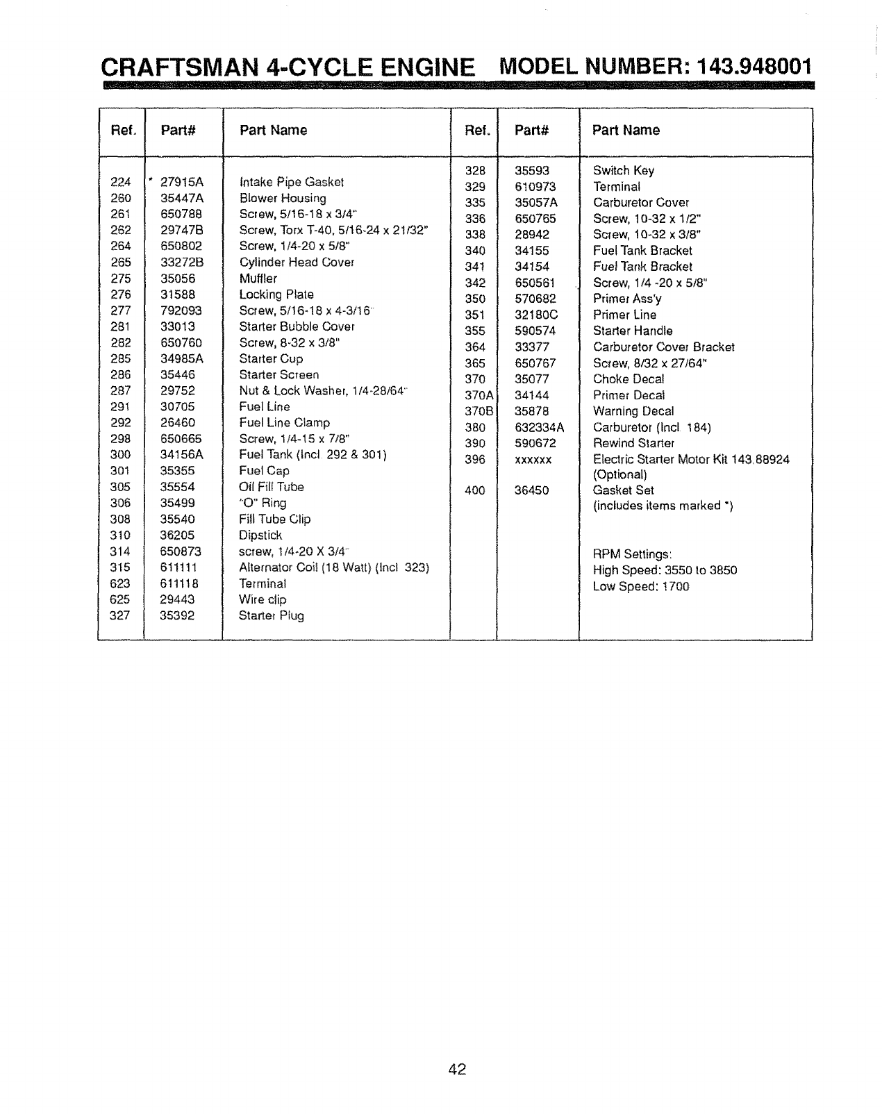
CRAFTSMAN 4-CYCLE ENGINE MODEL NUMBER: 143.948001
i_ .... ..........i.._........... ......... ...__.i...............,. _....i_i__ ..................... IIIIII ............... r =', II '1 I
Ref,
224
260
26t
262
264
265
275
276
277
281
282
285
286
287
291
292
298
300
301
3O5
306
3O8
3t0
314
3t5
623
625
327
Part#
27915A
35447A
650788
29747B
650802
33272B
35056
31588
792O93
33013
65O76O
34985A
35446
29752
30705
2646O
650665
34t56A
35355
35554
35499
3554O
36205
650873
611111
611118
29443
35392
Part Name
Intake Pipe Gasket
Blower Housing
Screw, 5/t 6-18 x 3/4++
Screw, Torx T-40, 5f16-24 x 21/32"
Screw, 1/4+20 x 5/8"
Cylinder Head Cover
Muffler
Locking Plate
Screw, 5/16-18 x 4-3/16"
Starter Bubble Cover
Screw, 8+32 x 3/8"
Starter Cup
Starter Screen
Nut & Lock Washer, 1/4+28/64"
Fuel Line
Fuel Line Clamp
Screw, 1/4-t5 x 7/8"
Fuet Tank (tnct 292 & 301)
Fuel Cap
Oil Fill Tube
"O" Ring
Fill Tube Clip
Dipstick
screw, 1t4+20 X 3/4"+
Alternator Coil (18 Watt) (lnc! 323)
Terminal
Wire ctip
Starter Plug
L"O'I
t
i ......
328
329
335
i 336
338
340
,34!
i 342
350
351
355
L 364
i 365
370 ,
370A
370B!
380 1
i 390
396
400
I
i
i
Part#
35593
61O973
35057A
65O765
28942
34155
34154
650561
57O682
32180C
590574
33377
650767
35O77
34144
35878
632334A
590672
XXXXXX
36450
Part Name
Switch Key
Terminal
Carburetor Cover
Screw, t0-32 x 1/2"
Screw, 10+32 x 3/8"
Fuel Tank Bracket
Fuel Tar+k Bracket
Screw, 1/4 -20 x 5/8"
Primer Ass'y
Primer Line
Starter Handle
Carburetor Cover Bracket
Screw, 8/32 x 27/64"
Choke Deca!
Primer Decal
Warning Decal
Carburetor (Incl t84)
Rewind Starter
Electric Starter Motor Kit 143, 88924
(Optional)
Gasket Set
(includes items marked ")
RPM Settings:
High Speed: 3550 to 3850
Low Speed: t700
42

[ NOTES
43
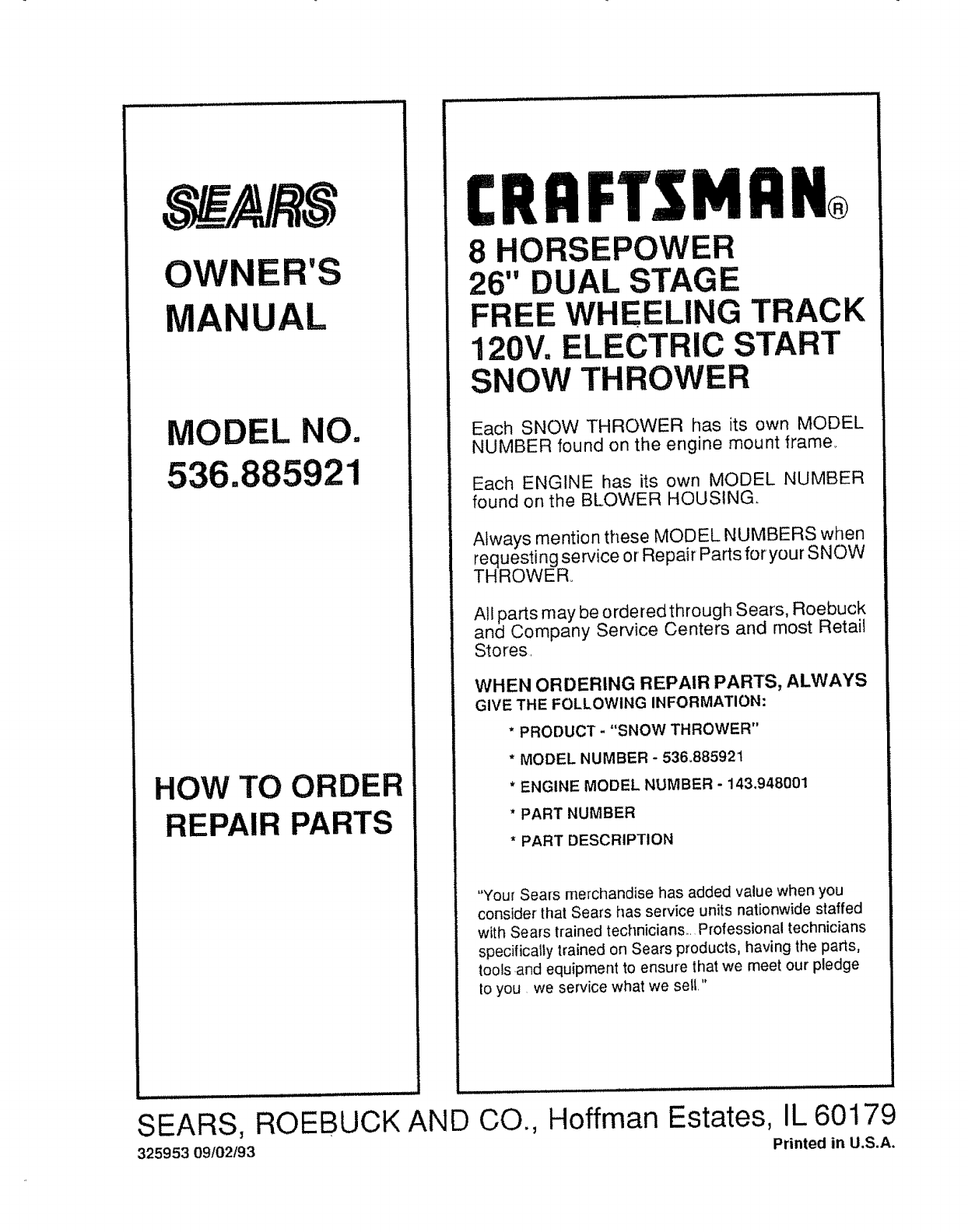
OWNER'S
MANUAL
MODEL NO.
536.885921
HOW TO ORDER
REPAIR PARTS
CRRFTSMRN®
8 HORSEPOWER
26" DUAL STAGE
FREE WHEELING TRACK
120V= ELECTRIC START
SNOW THROWER
Each SNOW THROWER has its own MODEL
NUMBER found on the engine mount frame.
Each ENGINE has its own MODEL NUMBER
found on the BLOWER HOUSING.
Always mention these MODEL NUMBERS when
requesting service or Repair Parts for your SNOW
THROWER°
All parts may be ordered through Sears, Roebuck
and Company Service Centers and most Retail
Stores.
WHEN ORDERING REPAIR PARTS, ALWAYS
GIVE THE FOLLOWING INFORMATION:
* PRODUCT -"SNOW THROWER"
*MODEL NUMBER - 536,88592t
* ENGINE MODEL NUMBER -143.948001
*PART NUMBER
* PART DESCRIPTION
"Your Sears merchandise has added value when you
consider that Sears has service units nationwide staffed
with Sears trained technicians.. Professional technicians
specifically trained on Sears products, having the parts,
tools =andequipment to ensure that we meet our pledge
to you we service what we sett."
SEARS, ROEBUCK AND CO.,
325953 09102193
....... ............. . .:. ..................... .....
Hoffman Estates, IL 60179
Printed in U.S.A,
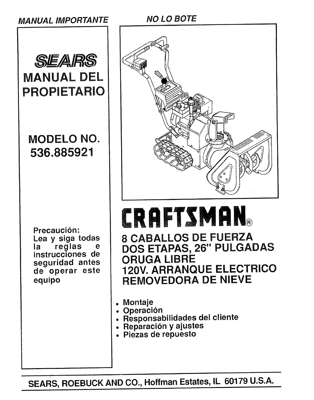
MANUAL IMPORTANTE NO LO BOTE
0
UAL EL
ETARIO
MODELO NO.
536.885921
Precaucion:
Lea y siga todas
ia reglas
instrucciones de
seguridad antes
de operar este
equipo
PrSNRN
8 CABALLOS DE FUERZA
DOS ETAPAS, 26" PULGADAS
ORUGA LIBRE
120V. ARRANQUE ELECTRICO
REMOVEDORA DE NIEVE
• Montaje
o Operacion
•Responsabilidades del cliente
= Reparacion y ajustes
o Piezas de repuesto
SEARS, ROEBUCK AND CO., Hoffman Estates, IL 60179 U.S.A.
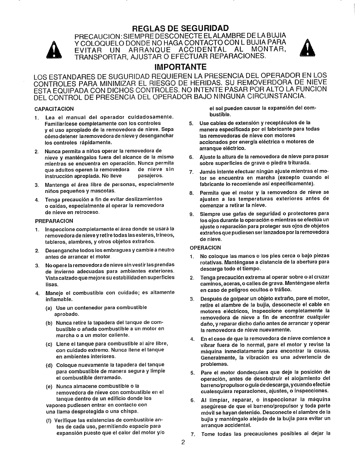
REGLAS DE SEGURIDAD
PRECAUCION" SIEMPRE DESCONECTE ELALAMBRE DE LA BUJIA
Y COLOQUELO DONDE NO HAGA CONTACTO CON L BUJIA PARA AI_
EVITAR UN ARRANQUE ACCIDENTAL AL MONTAR,
TRANSPORTARo AJUSTAR O EFECTUAR REPARACIONES,
IMPORTANTE
L©S ESTANDARES DE SUGURIDAD REQUIEREN LA PRESENCIA DE[_ OPERADOR EN LOS
CONTROLES PARA MINIMIZAR EL RIESGO DE HERIDAS. SU REMOVERDORA DE NIEVE
ESTA EQUIPADA CON DICHOS CONTROLES. NO INTENTE PASAR POR ALTO LA FUNCION
DEL CONTROL DE PRESENC1A DEL OPERADOR BAJO NINGUNA CIRCUNSTANCIA.
CAPACITACION
t,, Lea el manual del operador cuidadosamente.
Famlltaricese completamente con los controles
y el uso aproptado de la removedora de nieve_ Sepa
cbmo detener la removedora de nieve y desenganchar
los controles r_pidamente.
2. Nunca permita a ni#,os operar la removedora de
nieve y mantdngalos fuera del alcance de la misma
mlentras se encuentra en operact6n.. Nunca permita
que adultos operen la removedora de nieve sin
instruccibn apropiada. No Ileve pasajeros..
3.. Mantenga et drea libre de personas, especialmente
nirios peque_os y mascotaso
4. Tonga precaucibn a fin de evitar deslizamtentos
o cafdas, especialmente al operar la removedora
de nieve en retroceso.
PREPARACION
2_
3_
4_
Inspecclone completamente el brea donde se usara la
removedora de nieve y rot ire todas las esteras, trineos,
tableros, alambres, y otros objetos extrarios..
Desenganche todos los embragues y cambie aneutro
antes de arrancar el motor.
No opere la removedor ade nieve si n vest ir las prendas
de invietno adecuadas para ambientes exteriores..
Vista calzado que mejore su estabilidad en superficies
lisa&
Maneje et combustible con cuidado; es aitamente
inflamable.
(a) Use un contenedor para combustible
aprobado.
(b) Nunca retire la tapadera del tanque de corn*
bustible o afiada combustible a un motor en
marcha o a un motor caliente.
(c) Llene el tanque para combustible al &ire libre,
con culdado extremo. Nunca llene el tanque
en ambientes interiores.
(d) Coloque nuevamente la tapadera del tanque
para combustible de manera segura y |impie
el combustible derramadoo
(e) Nunca almacene combustible o la
removedora de nieve con combustible en el
tanque dentro de un edificio donde los
vapores pudiesen entrar en contacto con
una llama desprotegida o una chispa.
(f) Vertfique tas existencias de combustible an-
tes de cada uso, permitiendo espacio para
expansibn puesto que el calor del motor y!o
el sol pueden causar la expansi6n del com-
bustible.
5. Use cables de extensl6n y receptdculos de la
manera especiflcada pot el fabrtcante para todas
tas removedoras de nieve con motores
accionados pot energla el_ctrica omotores de
arranque eldctrico.
6. Ajuste la aitura de la removedora de nleve para pasar
sobre superficies de grava o p[edra triturada..
7. Jambs tntente efectuar ningt)n ajuste mtentras el mo-
tor se encuentra en marcha (excepto cuando et
fabricante io recomtende asf espectficamente)_
8_
9_
Permita que el motor yla removedora de nieve se
ajusten alas temperaturas exteriotes antes de
comenzar a retirar la nleve.
Siempre use galas de seguridad o protectores para
los ojos durante la operacf6n o mientras se efectt)a un
ajuste o reparacibn para proteger sus oJos de objetos
extra_os que pudiesen ser lanzados pot la removedora
de nlev&
OPERACION
1, No coloque las manos olos pies cerca o bajo piezas
rotatlvas. Mant_ngase adistancia de la abertura para
descarga todo el tiempo..
2. Tonga precauct6n extrema al operar sobre o al cruzar
caminos, aceras, o calles de grava.. Mantengase alerta
en caso de peltgros ocultos o tr_flcoo
3. Despues de golpear un objeto extrafio, pare el motor,
retire el alambre de la bujla, desconecte el cable en
motores el_ctricos, tnspeccione completamente la
removedora de nieve a fin de encontrar cuatquler
da_o, y reparar dicho da_o antes de arrancar y operar
la removedora de nieve nuevamente.
4. En el caso de que la removedora de nieve comience a
vibrar fuera de 1o normal, pare el motor y revise la
mbquina inmediatamente para encontrar ta causa.
Generalmente, la vibracion es una advertencia de
problemaso
5. Pare el motor dondequtera que deje la posici6n de
operacl6n, antes de desobstruir el alojamiento dot
barreno/propulsor o gula de descarga, y cuando efecttJe
cualesquiera reparaciones, ajustes, o inspecciones_
6. At tlmpiar, reparar, o inspeccionar la maquina
aseg0rese de que el barrenotpropulsor y toda parte
mSvil se hayan detenido.. Desconecte el alambre de la
bujla y mant_ngalo alejado de la bujla para evitar un
arranque accidental.
7o Tome todas las precauctones posibles al dejar la
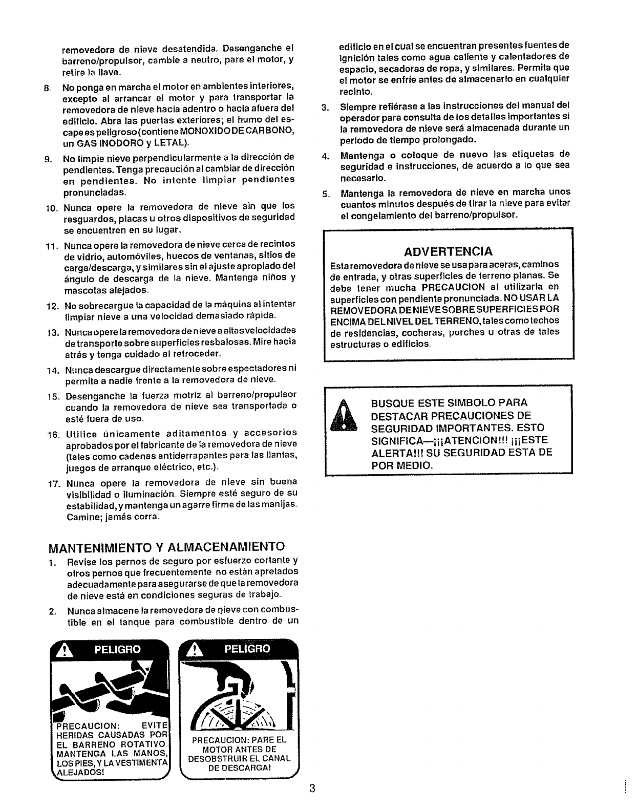
removedora de nieve desatendida.. Desenganche el
barreno/propulsor, cambie a neutro, pare el motor, y
retire la llave.
8o No ponga en marcha el motor en ambtentes interiores,
excepto al arrancar el motor y pare transportar la
removedora de nleve hacla adentro o hacla afuera del
edfficioo Abra |as puertas exteriores; el humo del es-
cape es pellgroso (contiene MONOXIDO DE CAR BONO,
un GAS INODORO y LETAL),.
9. No fimple nieve perpendicularmente ala dtreccibn de
pendientes° Tenga precauciSn al cambiar de direccI6n
en pendlentes. No lntente limplar pendientes
pronunciadas.
t0. Nunca opere la removedora de nieve sin que los
resguardos, placas u otros dispositivos de seguridad
se encuentren en su lugar.
11, Nunca opere la removedora de nieve cerca de recintos
de vidrio, autombviles, huecos de ventanas, s]tIos de
carga/descarga, y slmilares sin el ajuste apropiado del
_ngulo de descarga de la nieve.. Mantenga niRos y
mascotas alejados.,
12_ No sobrecargue |a capacidad de la maquina at intentar
timptar nieve a una velocidad demasiado rapida.
13. Nunca opere taremovedora de nieve a altasveiocidades
de transporte sobre superficies resbalosas. Mire hacia
atr_s y tenga cuidado al retroceder.
14. Nunca descargue dtrectamenle sobre espectadores ni
permita a nadie frente ata removedora de nieve..
15o Desenganche la fuerza motriz al barreno/propulsor
cuando la removedora de nieve sea transportada o
este fuera de uso_
"16. Uttllce flnicamente aditamentos y accesorlos
aprobados por el fabrlcante de la removedora de nleve
(tales como cadenas antiderrapantes para ias !tanlas,
juegos de arranque el_ctrico, etco).
t7. Nunca opere la removedora de nieve sin buena
vislbtltdad o ituminaci6n, Siempre este seguro de su
estabilidad, y mantenga un agarre firme de las ma nijas._
Camine; jam,_s corra_
edlflctoen el cue1se encuentran presentes fuentes de
1gnicibn tales como agua caliente y calentadores de
espaclo, secadoras de ropa, y similares. Permitaque
el motor se enfrle antes de atmacenar|o en cualquler
reclnto.
3. Siempre refidrase alas Instrucciones del manual del
operador para consulta de los detalles importantes si
ta removedora de nteve ser_ almacenada durante un
perlodo de tiempo proiongadoo
4. Mantenga o coloque de nuevo Jas etiquetas de
seguridad einstrucciones, de acuerdo a 1o que sea
necesarlo_
5. Mantenga la removedora de nieve en marcha unos
cuantos minutos despu_s de tirar la nieve para evltar
el congelamiento del barreno/propulsor.
ADVERTENCIA
Esta removedora de nteve se usa para aceras, camfnos
de entrada, y otras superficies de terreno planas. Se
debe tenet mucha PRECAUCION al utilizarla en
superficies con pendtente pronunctada_ NO USAR LA
REMOVEDORA DENIEVE SOBRESUPERFIC1ES POR
ENCIMA DELNtVEL DEL TERRENO, taIes como techos
de residencies, cocheras, porches u otras de tales
estructuras o ediflcios.
BUSQUE ESTE SIMBOLO PARA
DESTACAR PRECAUCIONES DE
SEGURIDAD tMPORTANTES. ESTO
SIGNIFICA_iiiATENCION !!! iiiESTE
ALERTA!!! SU SEGURIDAD ESTA DE
POR MEDIO_
MANTENIMIENTO YALMACENAMIENTO
1. Revise los pernos de seguro pot esfuerzo cortante y
otros pernos que frecuentemente no estan apretados
adecuadamente para asegura rse de que la removedora
de nieve est_ en condtciones seguras de trabajo.
2. Nunca almacene ta removedora de r_ieve con combus-
tible en el tanque pare combustible dentro de un
MOTOR ANTES DE
DE DESCARGA!
3i
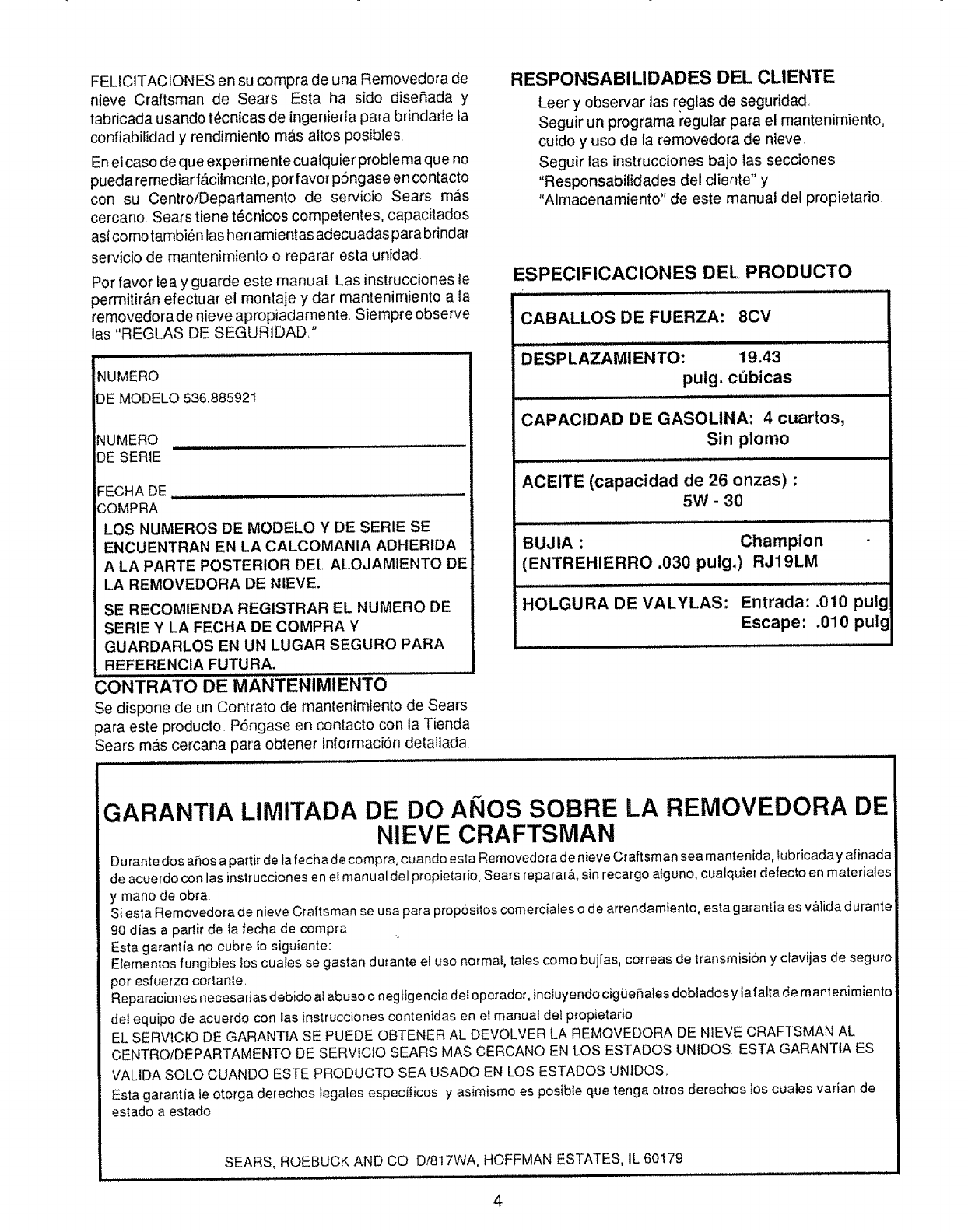
FELICJTAC_ONES en su com#ra de una Removedora de
nieve Craftsman de Sears. Esta ha sido diser_ada y
fabficada usando tecnicas de ingenieda para brindafle ta
confiab[_idad y rendimiento m_ls altos posibles
Enel caso de que expefimente cualquier problema que no
pueda remediar f_,citmente, pot favor p6ngase en contacto
con su Centro/Departamento de servicio Sears mas
cetcano, Sears tiene tecnicos competentes, capacitados
asicomo tambi6n las hertamientas adecuadas para brindat
setvicio de mantenimiento o reparar esta unfdad
Por favor iea y guarde este manual, Las instrucciones le
permitir_,n efectuar el montaje y dar mantenimiento a la
removedora de nieve apropiadame nte, Siempre observe
las "REGLAS DE SEGUR]DAD,"
NUMERO
DE MODELO 536.885921
NUMERO
DE SERIE
FECHA DE
COMPRA
LOS NUMEROS DE MODELO Y DE SERIE SE
ENCUENTRAN EN LA CALCOMANIA ADHERIDA
A LA PARTE POSTERIOR DEL ALOJAMIENTO DE
LA REMOVEDORA DE NIEVE.
SE RECOMIENDA REGISTRAR EL NUMERO DE
SERIE Y LA FECHA DE COMPRA Y
GUARDARLOS EN UN LUGAR SEGURO PARA
REFERENClA FUTURA.
CONTRATO DE MANTENIMIENTO
Se dispone de un Contrato de mantenimiento de Seats
para este producto.. P6ngase en contacto con la Tienda
Seats m,_s cercana para obtene_ informac[6n detallada
RESPONSABILIDADES DEL CLIENTE
Leer yobservar ]as reglas de seguridad
Seguir un programa regular para el mantenirniento,
cuido y uso de la removedora de nieve
Seguir las instrucciones bajo 1as secciones
"Responsabilidades del cliente" y
"Almacenamiento" de este manual del propietario.
ESPEClFICAClONES DEL PRODUCTO
CABALLOS DE FUERZA: 8CV
Illll IlllllllI,L ...................
DESPLAZAMIENTO: 19.43
pulg. cObicas
CAPACIDAD DE GASOLINA: 4cuartos,
Sin plomo
ACEITE (capacidad de 26 onzas) :
5W -30
BUJIA : Champion
(ENTREHIERRO .030 pulg,) RJ19LM
HOLGURA DE VALYLAS: Entrada: .010 pu!!
Escape: .010 pulg i
GARANTIA LIMITADA DE DO ANOS SOBRE LA REMOVEDORA DE
NIEVE CRAFTSMAN
Durante dos a_os a partir de la fecha de compra, cuando esta Removedor a de nieve Craftsman sea mantenida, _ubficada y afinada
de acuerdo con las instrucciones e n el manu al de l£ropietar o Sears reparar&, sin recargo alguno, cuatquier defecto en materiales
y mano de obra
S{esta Removedora de nieve Craftsman se usa para propssi_os comerciales o de arrendamiento, esta garantia es v&]ida durante
90 dias a partir de la fecha de compra
Esta garantia no cubre !o siguiente:
Elementos fungibles los cuaies se gastan dufante el uso normat, tates como buj[as, correas de transmisi6n y cfavijas de seguro
pot esfuerzo cortante.
Reparaciones necesarias debido al abuso o negtigencia deIoperadoL inctuyendocig{JeP, ales doblados y lafatta de mantenimiento
de_equipo de acuerdo con ias }nsttucciones contenidas en el manua_ del ptopietario
EL SERViCIO DE GARANTIA SE PUEDE OBTENER AL DEVOLVER LA REMOVEDORA DE NIEVE CRAFTSMAN AL
CENTRO/DEPARTAMENTO DE SERVICIO SEARS MAS CERCANO EN LOS ESTADOS UNIDOS ESTA GARANTIA ES
VALIDA SOLO CUANDO ESTE PRODUCTO SEA USADO EN LOS ESTADOS UNIDOS,
Esta garantia le otorga derechos tegates especificos, y asimismo es posib{e que tenga otros derechos los cuales varfan de
estado a estado
SEARS, ROEBUCK AND CO. Di817WA, HOFFMAN ESTATES, IL 60179
4
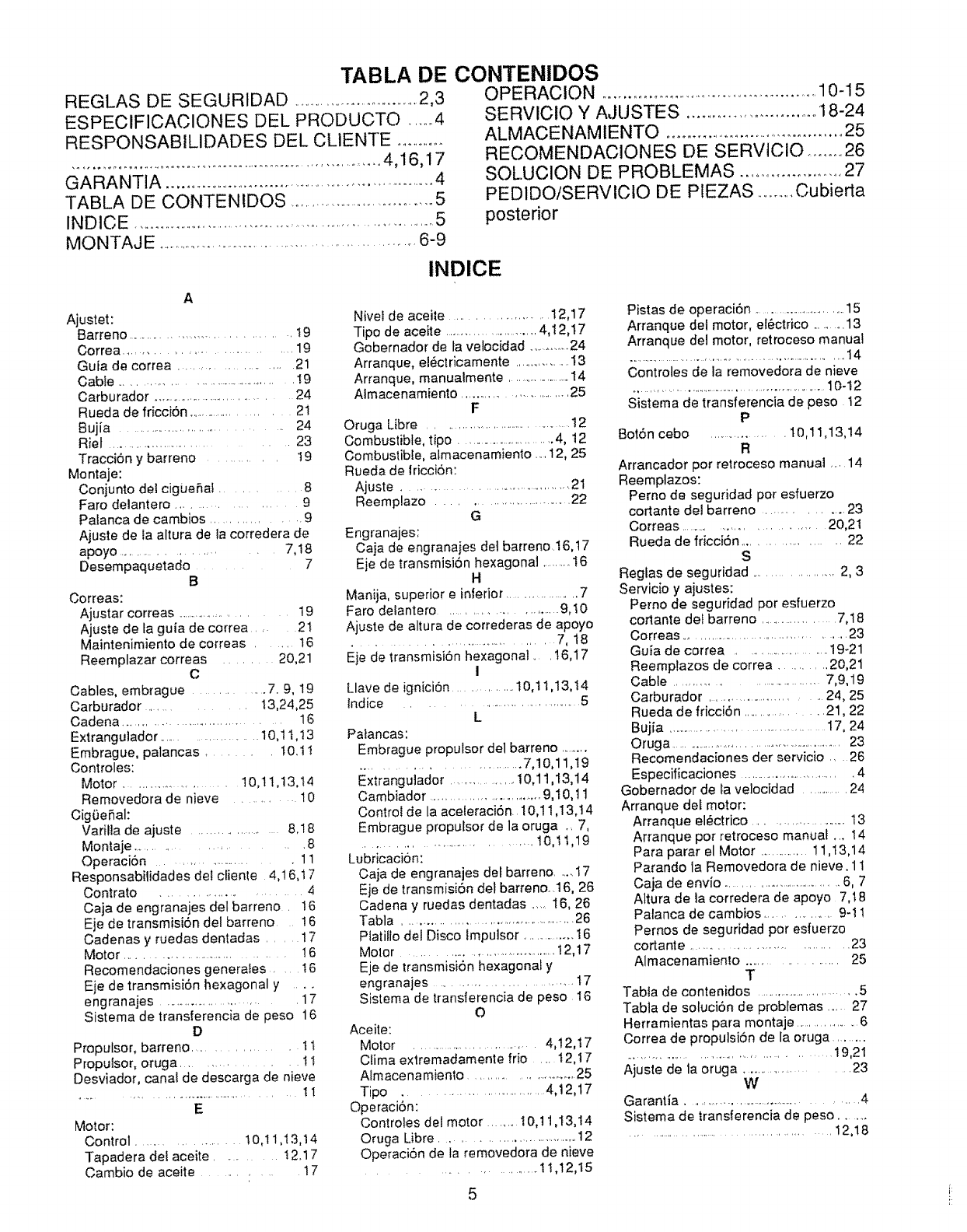
TABLA DE CONTENIDOS
REGLAS DE SEGURIDAD .....................................2,3
ESPECIFICACIONES DEL PRODUCTO ......4
RESPONSABILIDADES DEL CLIENTE ............
........................................................................4,16,17
GARANTIA ..................................................................4
TABLA DE CONTENIDOS .....................................5
INDtCE .........................................................................5
MONTAJE ..............................................................6-9
OPE RACION ................................................. 10-15
SERVICtO Y AJUSTES .............................. 18-24
ALMACE NAM lENTO .........................................25
RECOMENDACIQNES DE SERVICIO ........ 26
SQLUCIQN DE PROBLEMAS ....................... 27
PED1DO/SERVlCIO DE PIEZAS .............Cubierta
posterior
INDICE
Ajustet:
Barreno ..................................... 19
Correa ................................. 19
Guta de correa ........................ 21
Cable .............................................. ! 9
Carburador ................................... 24
Rueda de fricci6n ....................... 21
Bujia .................................. 24
Riel ................................ 23
TracciSn y barreno .......... t9
Montaje:
Conjunto det cigueRaf .......... 8
Faro delantero ..................... 9
Palanca de cambios ................. 9
Ajuste de la altura de la corredera de
apoyo .................... 7, t 8
Desempaquetado ....... 7
B
Correas:
Ajustar correas ....................... 19
Ajuste de ta guia de correa .... 21
Maintenimiento de correas .... 16
Reemplazar correas ........ 20,21
C
Cables, embrague ............... 7.9, 19
Carburador ............ 13,24,25
Cadena ..................................... 16
Extrangulador ....................... 10,1 t,!3
Embrague, palancas ........ t0.t I
Controles:
Motor .................... 10,11,13,!4
Removedora de nieve ............ 10
Cig0eRal:
Varilla de ajuste ....................... 8.18
Montaje ..................... 8
OperaciSn ........................... 11
Responsabilidades del clienle 4,16,t7
Contrato .......................... 4
Caja de engranajes det barreno . 16
Eje de transmisi6n del barreno 16
Cadenas y ruedas dentadas .... 17
Motor ................................... t 6
Recomendaciones generates .... I6
Eje de transmisi6n hexagonal y ....
engranajes ......................... 17
Sistema de transferencia de peso 16
D
Proputsor, barreno ................ 11
Proputsor, oruga ........... 11
Desviador, canal de descarga de nieve
....... ,.................................. !!
E
Motor:
Control .................... t0,11,13,t4
Tapadera def aceite ........... t 2.17
Cambio de aceite ............ 17
Nivet de aceite ..................... 12,17
Tipo de aceite ...........................4,I2,t7
Gobernador de la velocidad .............24
Arranque, el6ctricamente .................13
Arranque, manualmente .......................14
Almacenamiento ........................... 25
F
Oruga Libre ...................................... 12
Combustible, tipo ...............................4, 12
Combustible, almacenam}ento _..12, 25
Rueda de lricci6n:
Ajuste ......................................... 21
Reemplazo ............................... 22
G
Engranajes:
Caja de engranaies dei barreno.16,17
Eje de transmisi6n hexagonal ..........t6
H
Manija, superior einferior ................. 7
Faro deiantero .......................... 9,t0
Ajuste de altura de correderas de apoyo
.......................................... 7, 18
Eje de transmisiSn hexagonal .... 16,17
I
Llave de ignicion ............... t0,1 t,13,t4
Indice .................................. 5
L
Pafancas:
Embrague propulsor de] barreno ..........
........................... 7,10,11,19
Extrangulador .................. t0,11,13,14
Cambiador ............................. 9,10,11
Control de la aceleraciSn 10,11,13, t 4
Embrague proputsor de la oruga .. 7,
................................ 10,tt,19
Lubricacion:
Caja de engranajes dot barreno .... 17
Eje de transmisiOn del barreno_.16, 26
Cadena y ruedas dentadas ......16, 26
Tabla ............................................ 26
Ptatilio del Disco lmputsor ...............16
Motor ........................................ t 2,17
Eje de transmisiSn hexagonal y
engranajes .............................. 17
Sistema de transferencia de peso 16
O
Aceite:
Motor ............................. 4,12,t7
Clima extremadamente frio .... t2,17
Almace namiento ........................... 25
Tipo .................................. 4,12,17
Operaci6n:
Controles del motor .........I0,11 ,I3,14
Oruga Libre ................................. 12
Operaci6n de la removedora de nieve
.......................... 11,12,I5
Pistas de operaci6n ...............................15
Arranque del motor, el6ctrico ...........13
Arranque del motor, retroceso manual
....................................................................14
Controles de la removedora de nieve
................................................................10-12
Sistema de transferencia de peso t2
P
BotSn cebo .................... t0,11,13,14
R
Arrancador pot relroceso manual .....14
Reemplazos:
Perno de seguridad por esfuerzo
cortante del barreno ............... 23
Correas ............................. 20,21
Rueda de fricciSn .................... 22
S
Reglas de seguridad .................... 2, 3
Servicio y ajustes:
Perno de seguridad por esfuerzo
coJlante det barreno .................... 7,18
Correas ............................................ 23
Guia de correa ......................... 19-21
Reemplazos de correa .......... 20,21
Cable ................................ 7,9,19
Carburador ......................... 24, 25
Rueda de fricciSn ................ 21,22
Bujia .............................................17, 24
Oruga ..........................................................23
Recomendaciones der servicio .... 26
Especificaciones ............................... 4
Gobernador de la velocidad ..............24
Arranque del motor:
Arranque el_ctrico ........................ 13
Arranque pot retroceso manual ... 14
Para parar el Motor ...............11,13,14
Parando la Removedora de nieve. 11
Caja de envio ..................................6, 7
Altura de la corredera de apoyo 7,t8
Patanca de cambios ................. 9-t !
Pernos de seguridad por esfuerzo
cortante ................................. 23
Almacenamiento .................... 25
T
Tabla de contenidos ................................5
Tabla de soluciSn de problemas ..... 27
Herramientas para montaje ................. 6
Correa de propulsiSn de la oruga .........
.............................................. 19,21
Ajuste de ta oruga .......................... 23
W
Garantia ................................................. 4
Sistema de transierencia de peso ........
.............................................. 12,!8
5
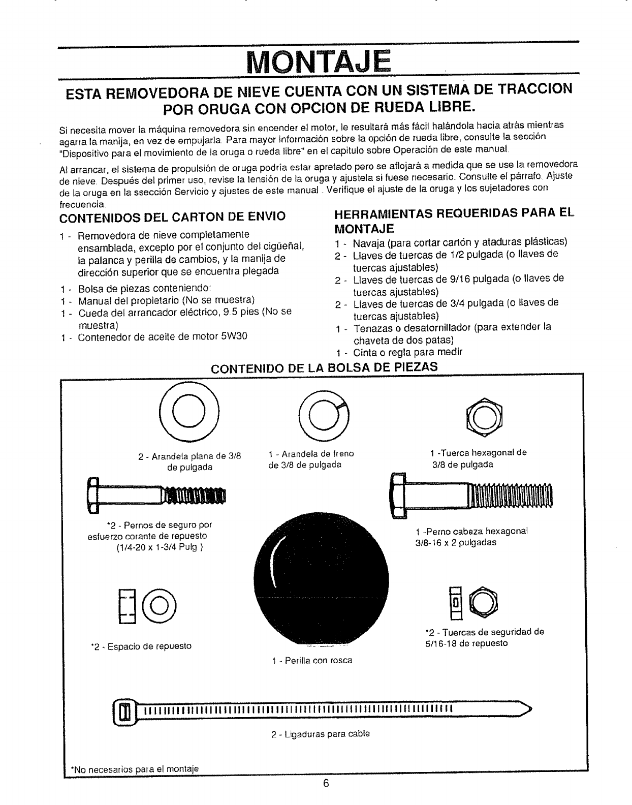
i,,i ii,,,,lll i nll,lnJ jl,, i,,, ill J ii i/ill.... ...........
MONTAJE
__ IH, ,,I,L J ut ................. _ ........
ESTA REMOVEDORA DE NIEVE CUENTA CON UN SISTEMA DE TRACCION
POR ORUGA CON OPCION DE RUEDA LIBRE.
Si necesita mover la m&quina removedora sin encender el motor, le resuttar& m&s f_.cil hat&ndola hacia atr&s mientras
agarra la manija, en vez de empujarla. Para mayor informaciSn sobre la opci6n de rueda libre, consulte la secci6n
"Disposkivo para el movimiento de la oruga o rueda fibre" en et capitufo sobre Operaci6n de este manual
AI arrancar, el sistema de propulsiSn de oruga podria estar apretado pero se aflojar& a medida que se use la temovedora
de nieve. Despu,_s del primer uso, revise la tensi6n de la oruga y ajustela si fuese necesario. Consutte el p&rrafo, Ajuste
de ia oruga en la sseccion Servicio y ajustes de este manual. Verifique e] ajuste de la oruga y los sujetadores con
frecuenci&
CONTENIDOS DEL CARTON DE ENVlO
1-Removedora de nieve completamente
ensambtada, excepto pot el conjunto de} cigOehal,
la palanca y perilla de cambios, y la manija de
direcci6n superior- que se encuentra ptegada
1 - Bolsa de piezas conteniendo:
1 - Manual del propietario (No se muestra)
I - Cueda del arrancador electrico, 95 pies (No se
muestra)
1 - Contenedor de aceite de motor 5W30
HERRAMIENTAS REQUERIDAS PARA EL,
MONTAJE
1 - Navaja (para cortar cation y ataduras pl_sticas)
2 - Ltaves de tuercas de 1/2 pulgada (o Ilaves de
tuercas ajustables)
2 - Llaves de tuercas de 9/16 pulgada (o llaves de
tuercas ajustables)
2 - Llaves de tuercas de 3/4 pulgada (o tfaves de
tuercas ajustables)
1 _ Tenazas o desatomillador (para extender la
chaveta de dos patas)
1 _ Cinta o regla para medir
CONTENIDO DE LA BOLSA DE PIEZAS
2 - Arandela p_ana de 3/8
de putgada
"2 - Pernos de seguro pot
esiuerzo corante de repuesto
(1f4-20 x 1-3t4 Pulg )
*2 - Espacio de repuesto
t - Arande_a de fteno
de 3/8 de pulgada
O
1 -Tuerca hexagonal de
318 de pulgada
t -Pemo cabeza hexagonal
3/8-16 x 2 pulgadas
"2 - Tuercas de seguridad de
5/16-18 de repuesto
1 - Perilla con rosca
2 - Ligaduras para cable
*No necesados para el montaje
6
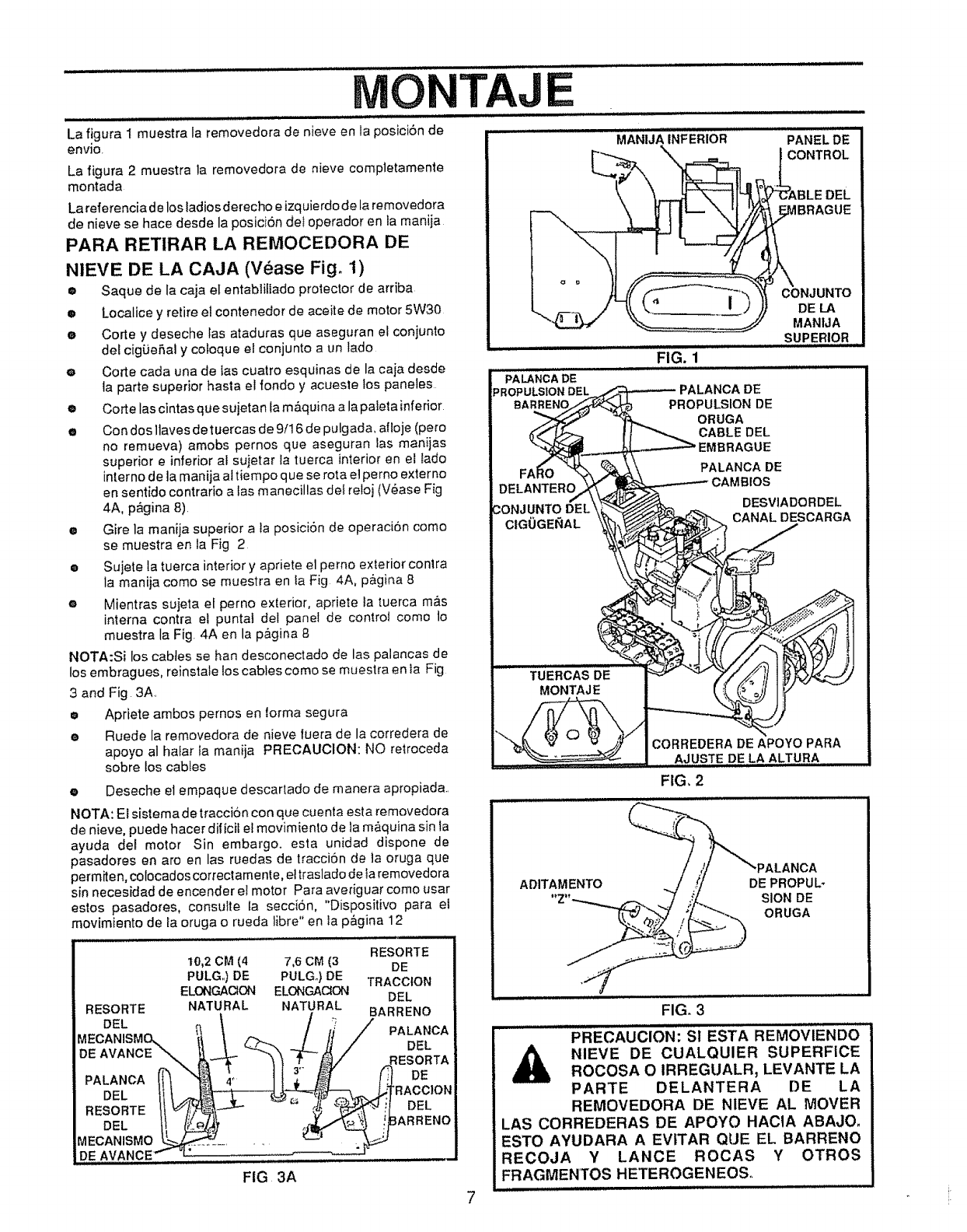
ONTAJ
La figura I muestra la removedora de nieve en la posici6n de
envJo.
La figura 2 muestra la removedora de nieve completamente
montada
La referenciadelosladiosderecho e izquierdode la removedora
de nieve se hace desde la posici6n del operador en la maniia
PARA RETIRAR LA REMOCEDORA DE
NIEVE DE LA CAJA (Vease Fig° 1)
• Saque de la caja el entabliliado protector de arriba
m Localice y retire el contenedor de aceite de motor 5W30
•Corte y deseche las ataduras que aseguran el conjunto
del cig0eSal y cotoque el conjunto aun lade
eCorte cada una de las cuatro esquinas de la caja desde
la parte superior hasta el rondo y acueste los paneles
e Corte las cintas que sujetan fa m_quina a la pateta inferior
• Con dos llaves de tuercas de 9/16 de pulgada, aftoje (pore
no remueva) amobs pernos que aseguran las manijas
superior einferior al sujetar la tuerca interior en ef tado
interne de la manija altiempo que se rota el perno externo
en sentido contrario a las manecillas del rolei (V_ase Fig
4A, pQgina 8)
•Gire la manija superior a la posici6n de operaci6n come
se muestra en la Fig 2
®Su]ete ta tuerca interior y apriete el perno exterior contra
la manija come se muestra en la Fig 4A, p_,.gina8
eMientras sujeta el perno exterior, apriete ta tuerca mrs
interna contra el puntal del panel de contro! come to
muestra la Fig 4A en la pagina 8
NOTA:Si los cables se ban desconectado de las palancas de
los embragues, reinstale los cables come se muestra en Ia Fig
3 and Fig 3A
oApriete ambos pernos en lorma segura
oRuede la removedora de nieve luera de la corredera de
apoyo al hafar Ia manija PRECAUClON: NO retroceda
sobre los cabtes
oDeseche el empaque descartado de manera apropiada.
NOTA: El sistema de tracci6n con que cuenta esla removedora
de nieve, puede hacer dilicit el movimiento de la m&quina sin fa
ayuda gel motor Sin embargo, esta unidad dispone de
pasadores en are en las ruedas de tracci6n de la oruga que
perm_en, colocados correclamente, et traslado de la removedora
sin necesidad de encender el motor Para averiguar come usar
esios pasadores, consulte ta secci6n, "Dispositivo parr el
movimiento de la oruga o rueda libre" en la p&gina 12
RESORTE
10,2 CM (4 7,6 CM (3 DE
PULG.) DE PULGo)DE TRACCtON
ELONGACION ELONGAC_ON DEL
RESORTE NATURAL NATURAL BARRENO
MECANISME__x._ __ ! 'PALANOA
DE AVANC DEL
PALANCA _"_t '_ RESORTADE
DEL lil RACCION
RESORTEIt' DEL
DEE ARRENO
MECANISMO_
DE AVANCE....
FIG 3A
MANIJAiNFERiOR ...... PANEL"DE
CONTROL
DEL
FIG. 1
PALANCA DE
PROPULSION DEL
CONJUNTO
DE LA
MANIJA
SUPERIOR i
DE
PROPULSION DE
ORUGA
CABLE DEL
EMBRAGUE
PALANCA DE
OS
DESVIADORDEL
CANAL DESCARGA
CORREDERA DE APOYO PARA
AJUSTE DE LA ALTURA
FIG, 2
ADITAMENTO DEPROPUL-
SION DE
ORUGA
FIG, 3
PRECAUCION: SI ESTA REMOVIENDO
NIEVE DE CUALQUlER SUPERFiCE
ROCOSA O IRREGUALR, LEVANTE LA
PARTE DELANTERA DE LA
REMOVEDORA DE NIEVE AL MOVER
LAS CORREDERAS DE APOYO HACtA ABAJO.
ESTO AYUDARA AEVITAR QUE EL BARRENO
RECOJA Y LANCE ROCAS Y OTROS
FRAGMENTOS HETEROGENEOS..
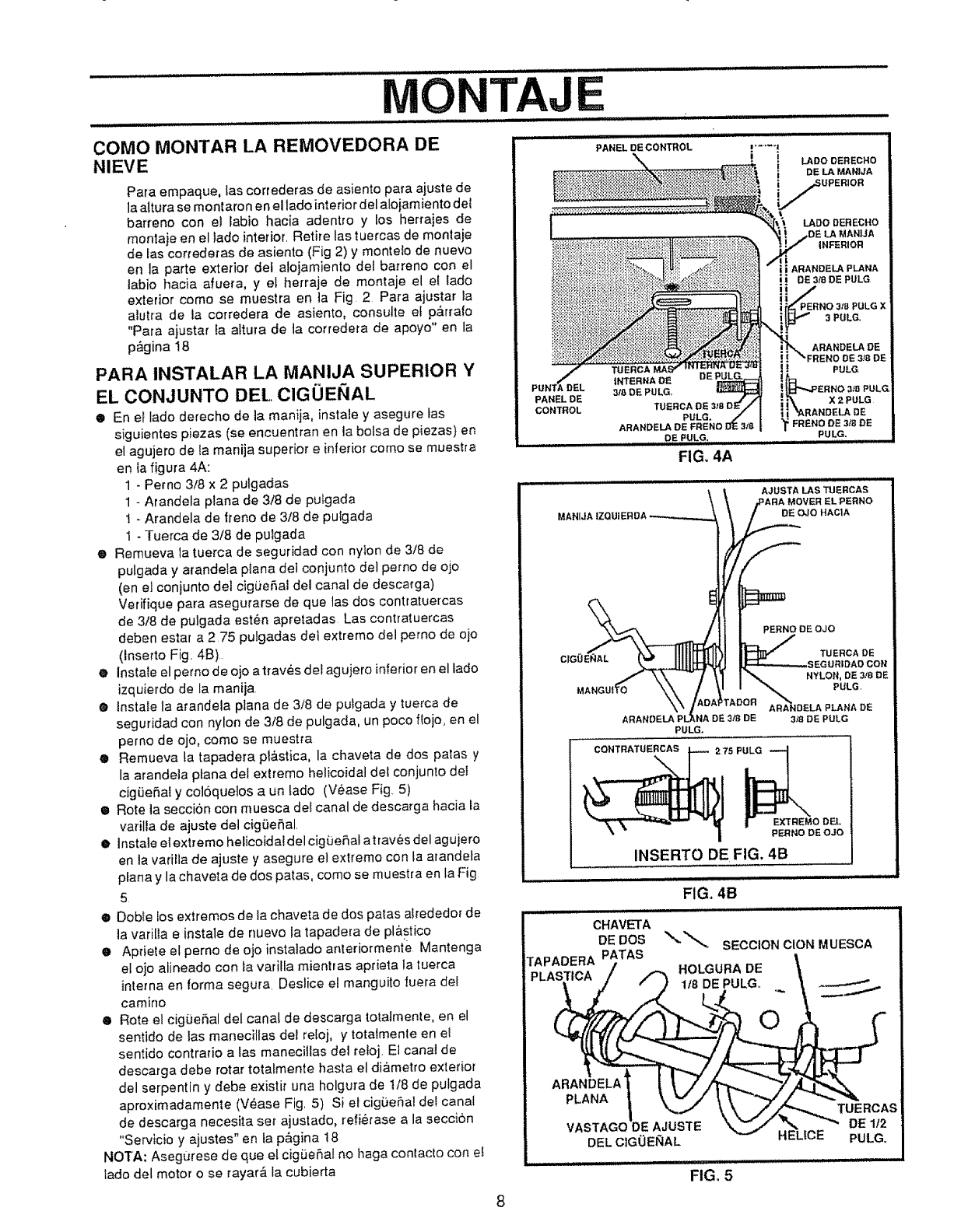
OE
PANEL DE CONTROL
COMe MONTAR LA REMOVEDORA DE
NIEVE
Para empaque, las correderas de asiento para ajuste de
la a(tura se montaron en el lade interior del a{o{amtento det
barreno con et labio hacia adentro y los herrajes de
montaje en el iado interior, Retire {astuercas de montaje
de tas correderas de asiento (Fig 2) y monteto de nuevo
en ta parte exterior det alojamiento del barreno con el
labio hacia afuera, y et herraje de montaje el el lade
exterior come se muestra en ta Fig 2 Pare ajustar la
alutra de la corredera de asiento, consutte el p,_.rrale
"Pare ajustar fa attura de ta corredera de apoyo" en la
p_gina I8
PARA INSTALAR LA MANIJA SUPERIOR Y
EL CONJUNTO DEL ClGOEI_IAL
•En el lade derecho de la manija, instate y asegure tas
siguientes piezas (se encuentran en ]a bolsa de piezas) en
el agujero de ta manija superior e inferior come se muestra
en ia figura 4A:
1-Perno 3/8 x 2 pulgadas
1-Arandela p/ana de 3t8 de pu/gada
t - Arandela de Irene de 3t8 de pulgada
1 - Tuerca de 3/8 de pulgada
eRemueva la tuerca de seguridad con nylon de 3/8 de
pulgada y a{andeta piana del conjunto del perno de ojo
(en e_conjunto del cigue,fai del canal de descarga)
Verifique para asegurarse de que tas dos contratuercas
de 3/8 de pulgada est_n apretadas Las contratuercas
deben estar a 2,75 pulgadas del extreme del perno de ojo
(Inserto Fig, 4B)
•lnstaie el perno de ojo a traves del agujero inferior en el lade
izquierdo de la maniia
®Instate ta arandela plana de 3/8 de pufgada y tuerca de
seguridad con nylon de 3/8 de pulgada, un poco floje, en el
perno de ojo, come se muestra
eRemueva ta tapadera pl&stica, la chaveta de dos paras y
la arandela plana del extreme helicoidal de! conjunto del
cigiJeSal y col6quelos aun tado (V_ase Fig. 5)
• Rote la seccion con muesca de! canal de descarga hacia la
varilla de ajuste dei cig(ie_al,
eInstale el extreme helicoidal del cigOeSal atraves del agujero
en ta vatilla de ajuste y asegure el extreme con la arandela
piano y la chaveta de dos patas, come se muestra en la Fig
5
•Doble los extremes de la chaveta de dos paras alrededor de
la varilia e instale de nuevo la tapadera de pl&stico
eApdele el perno de ojo instalado anteriormente Mantenga
el oje alineado con _avatilla mientras aprieta la tuerca
interna en forma segura Deslice el manguito fuera de!
camino
®Rote el cigOeRal del canal de descarga totatmente, en el
sentido de ias manecitlas del reloj, y totatmente en el
sentido contratio alas manecillas del retoj, Et canal de
descarga debe rotar totalmente hasta el diametro exterior
del serpentin y debe existi_' una holgura de 1/8 de pulgada
aproximadamente (V_ase Fig, 5) Si et cigLie_a! def canal
de descarga necesita set ajustado, refietase a la secci6n
"Servicio y ajustes" en ta p&gina 18
NOTA: AsegUrese de que el cig_eSal no haga contacto con el
lade del motor o se rayar_, la cubierta
II_ADODERECHO
[, DE LA MANJJA
iUPERIOR
LADe DERECttO
LA MANiJA
|NFERIOFI
il ARANDELA PLANA
DE 3/8 DE PULG
3t8 PULG X
E 318 DE
MANIJA IZQU
8
MAN_
PERNO DE OJO
TUERCA DE
SEGURIDAD CON
NYLON, DE3t8 DE
PULG
ARANDELAPULG.
IDELAPLANA DE
DE 318DEPULG
CONTRATUERCAS
2 75 P_
|EXTREMe DEL
PERNO DE OJO
INSERTO DE FIG. 4B
FIG, 4B
CHAVETA
DE DOS SECCION CION MUESCA
T^DAn_A PATAS t
....... L DE "
HO GURA
PLASTICA
1,'8_._._DEPULG_ . __
i ".,,-,/ _, , ./'_ TUERCAS
VASTAGODE AJUSTE '_ _,'_, ,..._._" DE 1/2
DELCIGOEglAL HELtCE PULG.
FIG. 5
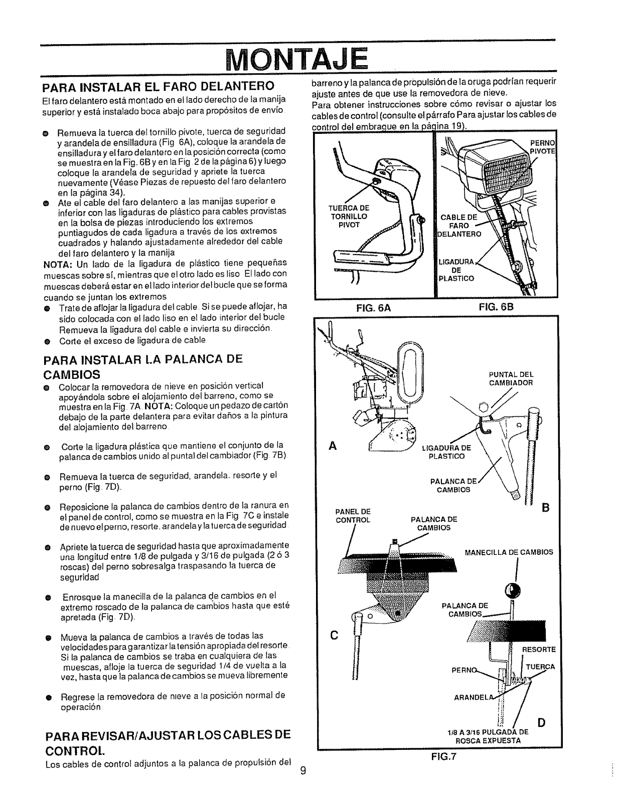
................... i/1//
MONTAJ
PARA INSTALAR EL FARO DELANTERO barrenoy lapatancadepropulsi6n de laoruga podrian requerir
El faro delantero esti_ montado en el lado derecho de ta manila ajuste antes de que use la removedora de nieve,
superior y estfi instalado boca abajo para propdsitos de env_o Para obtener instrucciones sobre cdmo revisar o ajustar los
cables de control (consulte el p_rrafo Para ajustar los cables de
del embrac
@ Remueva la tuerca de! tornillo pivote, tuerca de seguridad
y arandela de ensilladura (Fig 6A), coloque la arandela de
ensilladura y el faro delantero en la posiciSncorrecta (como
se muestra en la Fig..6B yen la Fig 2 de la p&gina 6) y tuego
coloque Ia arandela de seguridad y apriete la tuerca
nuevamente (V_ase Plazas de repuesto del faro detantero
en la p_gina 34).
®Ate et cable del faro delantero alas manijas superior e
inferior con las ligaduras de pl&stico para cables provistas
en la bolsa de piezas introduciendo los extremos
puntiagudos de cada ligadura a trav6s de tos extremos
cuadrados y hafando ajustadamente alrededor del cable
del faro delantero y la manija
NOTA: Un lado de la ligadura de pl&stico tiene peque_,as
muescas sobre sl, mientras que el otto lado es liso El lado con
muescas debar& estar en ei lado interior dot bucle que se forma
cuando se juntan los extremos
®Trate de aflojar la ligadura del cabie. Si se puede aflojar, ha
sido colocada con el lado liso en el lado interior def bucle
Remueva la ligadura det cable e invierta su direcci6n.
®Corte el exceso de ligadura de cable
PARA INSTALAR LA PALANCA DE
CAMBIOS
@ Colocar la removedora de nieve en posicion vertical
apoy&ndola sobre el alojamiento del barreno, como se
muestra en la Fig. 7A. NOTA: Coloque un pedazo de carton
debajo de la parte delantera para evitar daSos a la pintura
del atojamiento dei barreno
e Corte Ia tigadura pl&stica qua mantiene el coniunto de la
pafanca de cambios unido al puntaldot cambiador (Fig. 7B)
•Remueva la luerca de seguridad, arandela, resorte y el
perno (Fig. 7D)..
eReposicione la palanca de cambios dentro de ta ranura en
el panel de control, como se muestra en la Fig 7C einstale
de nuevo elperno, resorte, arandelaylatuerca deseguridad
Apt!ate la tuerca de seguridad hasta qua aproximadamente
una !ongitudentre 1/8 de pu]gada y 3/16 de pulgada (2 53
roscas) del perno sobresalga traspasando la tuerca de
seguridad
®
®Enrosque la manecilla de la palanca de cambios en el
extremo roscado de fa palanca de cambios hasta que est6
apretada (Fig. 7D)..
Mueva ta palanca de cambios a traves de todas las
ve!ocidadespara garantizartatensi6n apropiada delresorte.
Si ta patanca de cambios se traba en cualquiera de las
muescas, afloje Ia tuerca de seguddad 1t4 de vuelta a la
vez, hasta qua la palanca de cambios se mueva libremente
•Regrese la removedora de nleve a la posici6n normal de
operaciSn
9
PARA REVISAR/AJUSTAR LOS CABLES DE
CONTROt.
Los cabies de control adjuntos a la palanca de propuisi6n dei
DE
PLASTICO
FIG. 6A FIG. 6B
PLASTICO
PUNTALDEL
CAMBIADOR
A
PANELDE
CONTROL
PAl
CAM BIOS
PALANC A DE
CAMBIOS
B
MANECILLA DE CAMBtOS
/
C
RESORTE
iJi D
I/8 A 3/16 PULGADA DE
ROSCAEXPUESTA
.... :: w
FIG,7
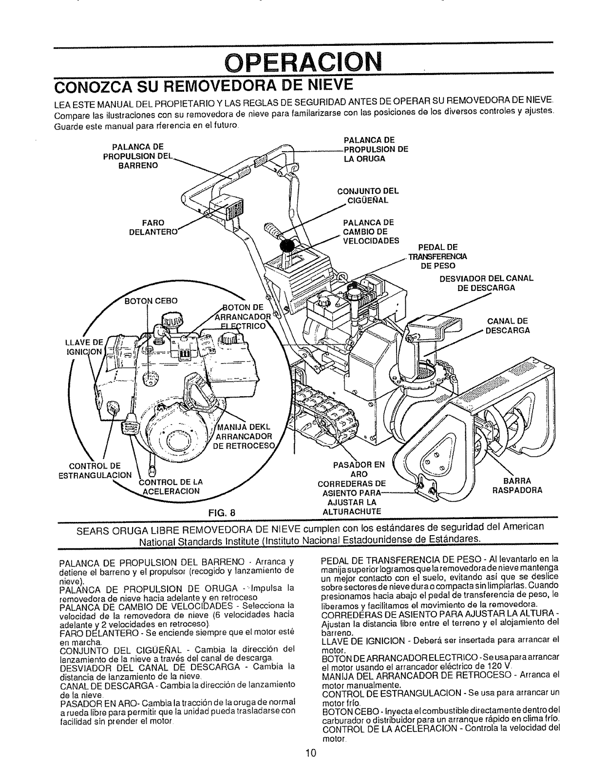
OP RAClO ,i,, J ll,l,lllt
C0N"OZCA SU REMOVEDORA DE NIEVE
LEA ESTE MANUAL DEL PROPIETARIO Y LAS REGLAS DE SEGURIDAD ANTES DE OPERAR SU REMOVEDORA DE NIEVE,
Compare las ilustraciones con su removedora de nieve para famitarizarse con ias posiciones de los diversos controles y ajustes..
Guarde este manual para rferencia en el futuro
PALANCA DE PALANCA DE
PROPULSION DE
BARRENO LAORUGA
CONJUNTO DEL
C|GOE_AL
FARO PALANCA DE
DELANTERO CAMBIO DE
VELOC|DADES
CEBO
PEDAL DE
TRN_FERENClA
DE PESO
DESVIADOR DELCANAL
DE DESCARGA
LLAVE DE
CANAL DE
DESCARGA
\
CONTROL DE
ESTRANGULACION CONTROL DELA
_ANIJA DEKL
ARRANCADOR
DE
PASADOR EN
ARO
CORREDERAS DE
ASIENTO
AJUSTAR LA
FIG. 8ALTURACHUTE
SEARS ORUGA LIBRE REMOVEDORA DE NtEVE cumpien con los est&ndares de seguridad del American
National Standards Institute Ilnstituto Nacional Estadounidense de Est&ndares,
BARRA
RASPADORA
PALANCA DE PROPULSION DEL BARRENO -Arranca y
detiene el barreno y el propulsor (recogido y lanzamiento de
nieve).
PALANCA DE PROPULSION DE ORUGA -_Impulsa la
removedora de nieve hacia adelante yen retroceso
PALANCA DE CAMBIO DE VELOCIDADES - Selecciona ta
veiocJdad de la removedora de nieve (6 velocJdades hacia
adelante y 2 velocidades en retroceso),
FARO DELANTERO - Se enciende siempre que el motor este
en marcha+
CONJUNTO DEL CIGOENAL - Cambia la direcciSn del
lanzamiento de ta nieve a trav_,s de_ canal de descarga
DESViADOR DEL CANAL DE DESCARGA - Cambia ta
distancia de tanzamiento de la nieve,
CANAL DE DESCARGA - Cambia ta direccion de lanzamiento
de ta nieve,
PASADOR EN ARO- Cambia la tracci6n de la oruga de normal
a rueda libre para permitir que ta unidad pueda trasladarse con
lacilidad sin prender el motor
PEDAL DE TRANSFERENCIA DE PESO- AI levantarlo en ta
manijasuperior [ogramos que la removedorade nieve mantenga
un mejor contacto con el suefo, evitando asi que se deslice
sobre sectores de nieve dura o compacta sin limpiarlas,, Cuando
presionamos hacia abaio el pedal de _ransferencia de peso, le
liberamos y facilitamos el movimiento de la removedora,
CORREDERAS DE ASIENTO PARA AJUSTAR LA ALTURA
Ajustan la distancia libre entre el terreno y el alojamiento del
barreno.
LLAVE DE IGNICION - Deber& ser insertada para arrancar el
motor.
BOTON DEARRANCADOR ELECTRICO -Se usapara arrancar
el motor usando el arrancador e16ctrico de 120 V,
MANfJA DEL ARRANCADOR DE RETROCESO - Arranca el
motor manualmente.
CONTROL DE ESTRANGULACION - Se usa para arrancar un
motor frlo,
BOTON CEBO- fnyecta el combustible directamente dentro del
carburador o distribuidor para un arranque r,_pido en clima frio,,
CONTROL DE LA ACELERACION - Controta la velocidad del
motor,
10
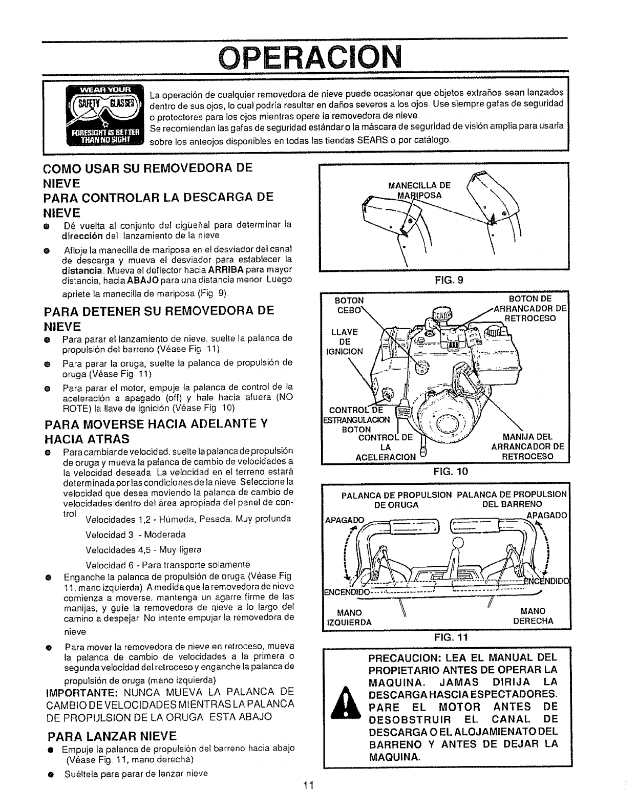
OPERACION
La operaci6n de cualquier removedora de nieve puede ocasionar que objetos extraSos sean lanzados
dentro de sus ojos, {ocuat podda resultar en daSos severos a los ojos Use siempre galas de seguridad
o protectores para los ojos mientras opere la removedora de nieve
Se recomiendan las galas de seguridad est&ndar o la m&scara de seguridad de visi6n amplia para usarla
sobre Ios anteojos disponibles en todas Jastiendas SEARS o pot cat&logo.
COMO USAR SU REMOVEDORA DE
NIEVE
PARA CONTROLAR LA DESCARGA DE
NIEVE
eD_ vuelta al conjunto del cigbe_al para determinar la
dtreccibn del lanzamiento de Ia nieve
0Afioje la manecilfa de mariposa en el desviador del canal
de descarga y mueva et desviador para establecer ia
distancia.. Mueva el deflector hac_a ARRIBA para mayor
distancia, hacia ABAJO para una distancia menor. Luego
apriete la manedlla de mariposa (Fig 9)
PARA DETENER SU REMOVEDORA DE
NIEVE
0Para parar el Ianzamiento de nieve_ suelte la palanca de
proputs_n del barreno (V6ase Fig 11)
0Para parar la oruga, suelte ta palanca de propulsbn de
oruga (V_ase Fig tt)
® Para parar el motor, empuje ta palanca de control de la
aceleraci6n a apagado (off) y hale hacia afuera (NO
ROTE) la !lave de ignici6n (V6ase F{g 10)
PARA MOVERSE HAClA ADELANTE Y
HAClA ATRAS
•Para cambiar de velocidad, sueIte la palanca de propulsiSn
de oruga y mueva la patanca de cambio de vefocidades a
la velocidad deseada La velocidad en el terreno estar&
determinada por tascondiciones de Ia nieve Seleccione la
velocidad que desea moviendo ia palanca de cambio de
vefocidades dentro del &rea apropiada del panel de con-
trol. Velocidades 1,2 - H0meda, Pesada, Muy profunda
VeIocidad 3 - Moderada
Velocidades 4,5 - Muy Iigera
O
Velocidad 6 -Para transporte solamen_e
Enganche Ia palanca de propulsion de oruga (Vease Fig
t t, mano izquierda) A medida que ta removedora de nieve
comienza a moverse, mantenga un agarre firme de fas
manijas, y guie la removedora de qieve a Io largo deI
camino a despeiar No intente empuiar Ia removedora de
nieve
•Para mover la removedora de nieve en retroceso, mueva
la palanca de cambio de velocidades a la primera o
segunda velocidad del retroceso y enganche la palanca de
propulsiSn de oruga (mano izquierda)
IMPORTANTE: NUNCA MUEVA LA PALANCA DE
CAMBIO DE VELOCIDADES MtENTRAS LA PALANCA
DE PROPULSION DE LA ORUGA ESTA ABAJO
PARA LANZAR NIEVE
•Empuje la palanca de propulsi6n del barreno hacia abajo
(V_ase Fig. 1i, mano derecha)
•SueIteta para parar de lanzar nieve
MANECILLA DE
,_.__.._MMA_POSA \ \\
FIG. 9
BOTON
LLAVE
DE
IGNIOION
BOTON DE
CADOR DE
RETROCESO
ESTRAt,_ULAClON
BOTON
CONTROL DE MANIJA DEL
LA ARRANCADOR DE
ACELERACION RETROCESO
FIG. 10
PALANCA DE PROPULSION PALANCA DE PROPULSION
DE ORUGA DEL BARRENO
APAGADO ._APAGADO
NC-ENDIDC
ENCEND1DO.............................. "_
MANO
|ZQUIER DA DERECHA
FIG_ 11
|| lllHll _,l
PRECAUClON: LEA EL MANUAL DEL
PROPIETARIO ANTES DE OPERAR LA
MAQUINAo JAMAS DIRIJA LA
DESCARGA HASClA ESPECTADORES.
PARE EL MOTOR ANTES DE
DESOBSTRUlR EL CANAL DE
DESCARGA O EL ALOJAMIENATO DEL
BARRENO Y ANTES DE DEJAR LA
MAQUINA.
1! r
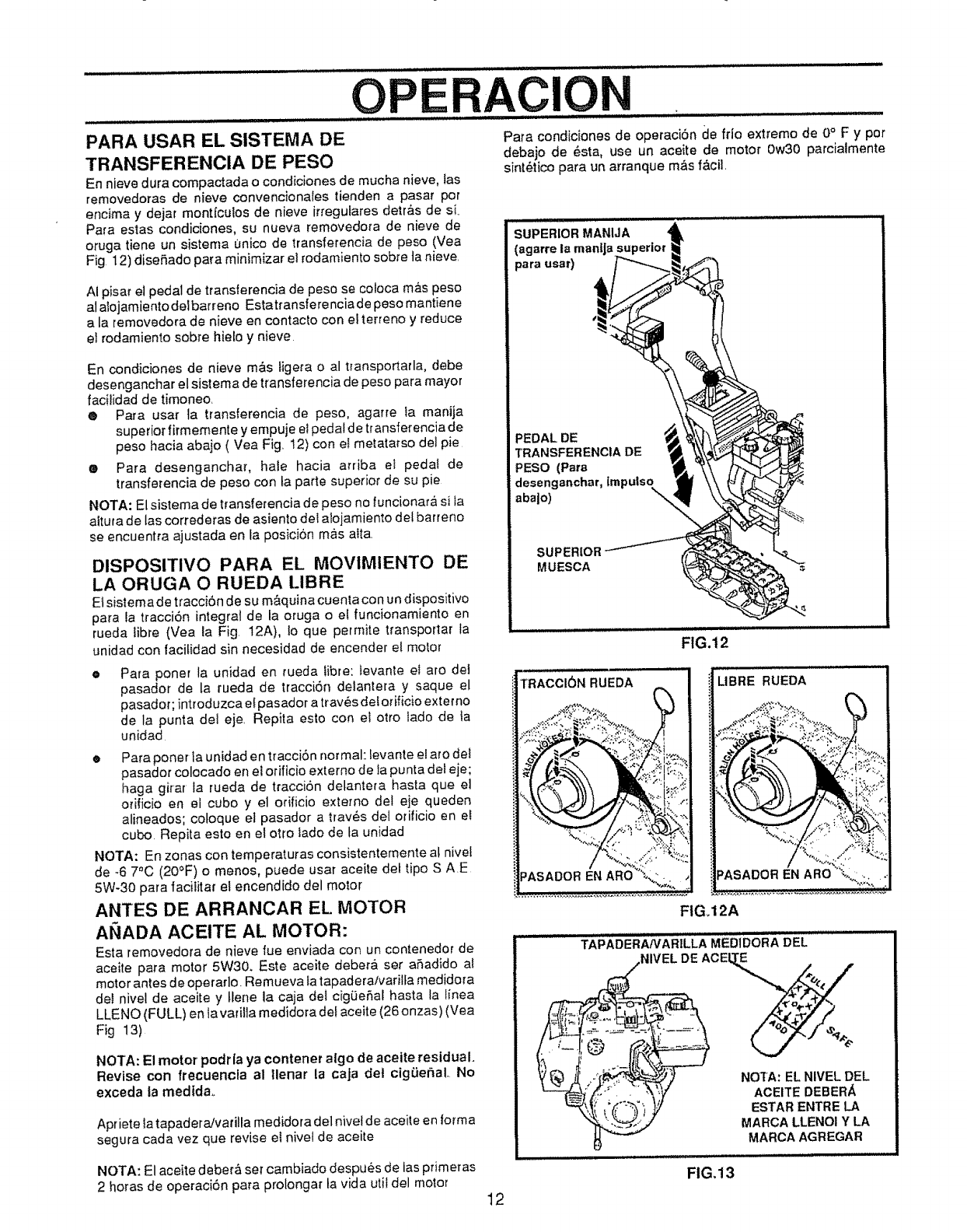
................................ ../ ................
PARA USAR EL SISTEMA DE
TRANSFERENCIA DE PESO
En nieve dura compactada o condiciones de mucha nieve, tas
removedoras de nieve convencionales tienden a pasar pot
encima y dejat mont{cutos de nieve irregulares detr_fis de si.
Para estas condiciones, su nueva removedora de nieve de
oruga tiene un sistema unico de transferencia de peso (Vea
Fig 12) diseSado para minimizar ei rodamiento sobre ta nieve.
........................,.,...............,........ ............
OPErtAC,ON
Para condiciones de operaci6n de frio extremo de 0°F y por
debajo de _sta, use un aceite de motor 0w30 parciaimente
sint_tico para un arranque mAs fAciL
AI pisar el pedal de transierencia de peso se coloca m_s peso
a] alojamiento delbarreno Estatransferenciade peso mantiene
a(a removedora de nieve en contacto con e{ terreno y reduce
eI rodamiento sobre hielo y nieve
En condiciones de nieve m&s ligera o al t_ansportarla, debe
desenganchar el sistema de transferencia de peso para mayor
facitidad de timoneo
®Para usaf {a transferencia de peso, agarre ia manija
superior firmemente y empuje eIpedal de transferencia de
peso hacia abaio ( Vea Fig 12) con et metatatso del pie
®Para desenganchar, hate hacia arriba el pedal de
transferencia de peso con la parte superior de su pie
NOTA: El sistema de transferencia de peso no funciona_&sila
aituta de las correderas de asiento del alojamiento de! barreno
se encuentra ajustada en [a posici6n mas alto
DISPOSITIVO PARA EL MOVIMIENTO DE
LA ORUGA O RUEDA I.IBRE
E1sistema de traccibn de su m_quina cuenla con un dispositivo
para la tracci6n integrat de la oruga o e! funcionamiento en
rueda tibre (Vea la Fig. 12A), to que permite transporlar la
unidad con t'aci[idadsin necesidad de encender el motor
Para poner la unidad en rueda fibre: tevante et aro del
pasador de la rueda de tracciSn defantera y saque el
pasador; introduzca el pasador a trav_s del orificio exter no
de la punta det eje Repita esto con eJ otto iado de Ia
unidad
o
ePara poner la unidad en tracciSn normal: levante el aro del
pasador colocado en el orificio externo de la punta def eje;
haga girar la rueda de traccion delantera hasta que el
orificio en el cubo y el orificio extemo del eje queden
alineados; cotoque el pasador a trav_s del ofificio en el
cubo. Repita esto en el otto lado de ta unidad
NOTA: En zonas con temperaturas consistentemente al nivel
de -6 70C (20°F) o menos, puede usar aceite det tipo S AE
5W-30 para facitita_ el encendido del motor
ANTES DE ARRANCAR EL MOTOR
ANADA ACEITE AL MOTOR:
Esta removedora de nieve rue enviada con un cont_enedor de
aceite para motor 5W30, Este aceite deber& ser aSadido at
motor antes d e operar]o. Remueva la tapadera/varilfa medidora
del nivel de aceite y llene la caja del ci9_eSal hasta la linea
LLENO (FULL) en la varilla medidora de! aceite (26 onzas) (Vea
Fig 13)
NOTA: El motor podrla ya contener algo de aceite residual•
Revise con frecuencla al |lenar la caja det cigLiehal. No
exceda ta medtda.
Apriete Ia tapadera!vatilla medidora del nivel de aceite en forma
segura cada vez que revise et nivel de aceite
NOTA: El aceite deber_ set cambiado despues de ias pfimeras
2 horas de operaci6n para prolongar la vida utit del motor
......... ,,, ,,,illill
SUPERIOR MANIJA
(agarre la manlja
para usar)
=EDAL DE
TRANSFERENCIA DE
PESO (Para
desenganchar, tmpulsoN,,,
abaio)
SUPERIOR
MUESCA
FIG.12
TRACCI(_N RUEDA
"t
FIG, 12A
LIBRE RUEDA
TAPADERANARILLA MEDIDORA DEL ......._ ....
NIVELDEACEL_
12
NOTA: EL NIVEL DEL
ACEITE DEBERA
ESTAR ENTRE LA
MARCA LLENOI Y LA
MARCA AGREGAR
:ll,,., i u ii..i
FIG,13
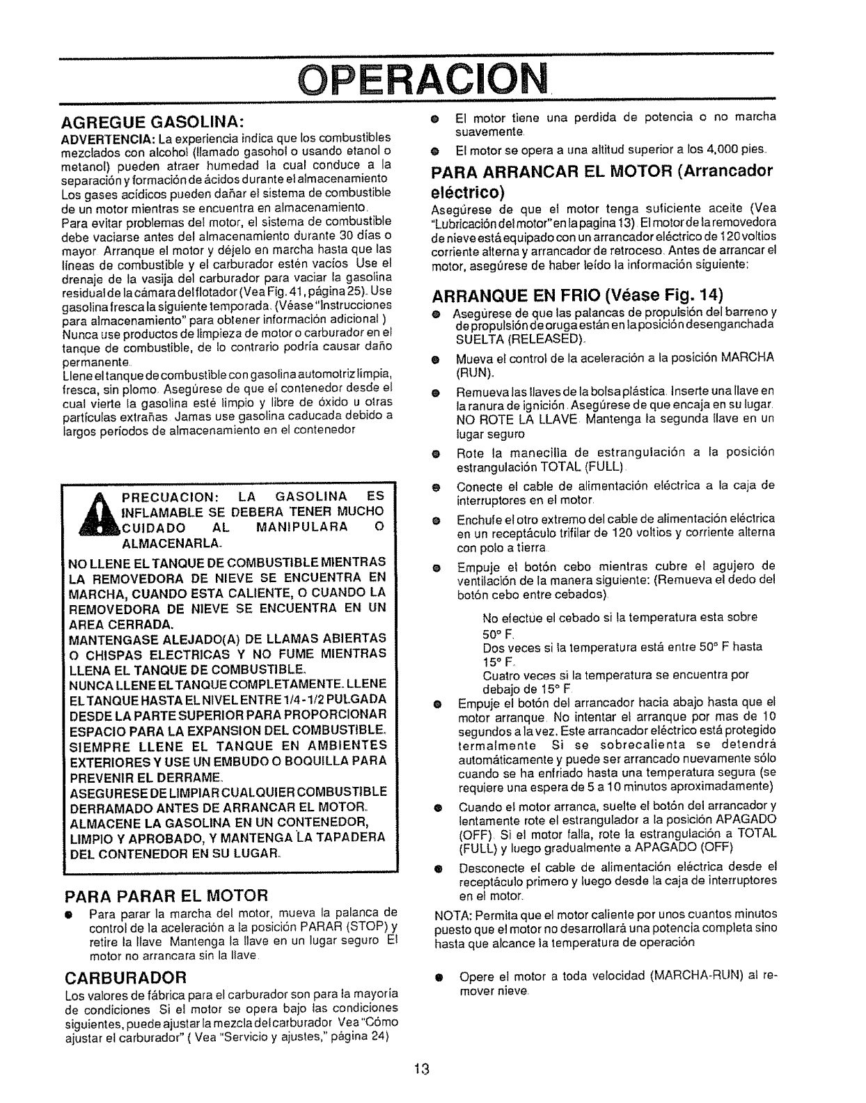
OPERACION
AGREGUE GASOLINA:
ADVERTENCIA: La experiencia indica que los combustibles
mezclados con alcohol (llamado gasohol o usando etanol o
metanol) pueden atraer humedad ta cual conduce a la
separaci6n y formaci6n de _,cidos d urante e! almacenamiento
Los gases acidicas pueden daSar el sistema de combustible
de un motor mientras se encuentra en almacenamiento.
Para evitar problemas del motor, el sistema de combustible
debe vaciarse antes de! almacenamiento durante 30 dias o
mayor Arranque el motor y dejelo en marcha hasta que las
lineas de combustible y el carburador est6n vacios Use el
drenaje de la vasija del carburador para vaciar la gasolina
residuatde lac&maradelflotador (Vea Fig. 41, p&gina25)..Use
gasolina fresca la siguiente temporada. (V6ase"instruccianes
para almacenamiento" para obtener informaci6n adicional )
Nunca use productos de limpieza de motor o carburador en el
tanque de combustible, de Io contrario podria causar daSo
permanente
Llene eltanque de combustible con gasolina automo|rizfimpfa,
tresca, sin plomo. AsegL_rese de que et contenedor desde el
cuaJ vierte {a gasolina est6 limpio y libre de 6xido u olras
partfculas extraSas Jamas use gasolina caducada debido a
largos periodos de almacenamiento en el contenedor
PRECUACION: LA GASOLINA ES
INFLAMABLE SE DEBERA TENER MUCHO
CUIDADO AL MANIPULARA O
ALMACENARLA_
NO LLEN E EL TANQUE DE COMBUSTIBLE M1ENTRAS
LA REMOVEDORA DE NIEVE SE ENCUENTRA EN
MARCHA, CUANDO ESTA CALIENTE, O CUANDO LA
REMOVEDORA DE NIEVE SE ENCUENTRA EN UN
AREA CERRADA,
MANTENGASE ALEJADO(A) DE LLAMAS ABIERTAS
O CHISPAS ELECTRICAS Y NO FUME MIENTRAS
LLENA EL TANQUE DE COMBUSTIBLE°
NUNCA LLENE ELTANQUE COMPLETAMENTE. LLENE
EL TANQUE HASTA EL N1VELENTRE 1/4 -1/2 PULGADA
DESDE LA PARTE SUPERIOR PARA PROPORCIONAR
ESPACIO PARA LA EXPANSION DEL COMBUSTIBLE°
S1EMPRE LLENE EL TANQUE EN AMBIENTES
EXTERtORES Y USE UN EMBUDO O BOQUILLA PARA
PREVENIR EL DERRAME.
ASEGURESE DE LIMPIA R CUALQUIER COMBUSTIBLE
DERRAMADO ANTES DE ARRANCAR EL MOTOR,.
_LMACENE LA GASOLINA EN UN CONTENEDOR,
LIMPIO Y APROBADO, Y MANTENGA 'LA TAPADERA
[:)EL CONTENEDOR EN SU LUGAR_
PARA PARAR EL MOTOR
•Para parar la marcha del motor, mueva la palanca de
control de la aceteraci6n a la posici6n PARAR (STOP) y
retire la lfave Mantenga la llave en un lugar seguro E!
motor no arrancara sin la Ilave
CARBURADOR
Los valores de f&brica para el carburador son para la mayoria
de condiciones Si et motor se opera bajo tas condiciones
siguientes, puede ajustar la mezcla delcarburador Vea"C6mo
ajustar ei carburador" ( Vea "Servicio y ajustes," p_gina 24)
e E1 motor tiene una perdida de potencia o no marcha
suavemente.
@ El motor se opera a una altitud superior a los 4,000 pies..
PARA ARRANCAR EL MOTOR (Arrancador
electrico)
Aseg,3rese de que et motor tenga suliciente aceite (Vea
"Lubricaci6n del motor"en lapagina 13) E1motorde la removedora
de nieve est& equipado con un arrancador el_,ctrico de I20 voltios
corriente alterna y arrancador de retroceso. Antes de arrancar el
motor, aseg_rese de haber leido la informaci6n siguiente:
ARRANQUE EN FRIO (Vease Fig. 14)
@Asegurese de que las patancas de propuisi6n del barreno y
de propulsi6n deorugaest&n en laposici6ndesenganchada
SUELTA (RELEASED).
® Mueva el control de la aceleraci6n a la posici6n MARCHA
(RUN).,
•Remueva las llaves de ta bolsa pl&stica, tnserte una llave en
la ranura de ignici6n, AsegLirese de que encaja en su lugar,
NO ROTE LA LLAVE Mantenga la segunda llave en un
lugar seguro
®Rote la maneciila de estrangulaci6n a la posici6n
estrangulaci6n TOTAL (FULL)
eConecte el cable de alimentaci6n el6ctrica a la caja de
interruptores en el motor.
eEnchufe et otro extremo del cable de alimentacion e!_clrica
en un recept&cuio trifilar de 120 vottios y corriente aiterna
con polo a tierra
eEmpuje ei bot6n cebo mientras cubre el agujero de
ventifaci6n de la manera siguiente: (Remueva el dedo del
bot6n cebo entre cebados)
No etectue el cebado si la temperatura esta sobre
50° F.
Dos veces si Ia temperatura est& entre 50° F hasta
t5 °F,.
Cuatro veces si la temperatura se encuentra por
debajo de 15° F
eEmpuje el bot6n del arrancador hacia abajo hasta que el
motor arranque No intentar el arranque pot mas de 10
segundos a la vez. Este arrancador e!6ctrico est& protegido
termalmente Si se sobrecalienta se detendr&
autom&ticamente y puede ser arrancado nuevamente s61o
cuando se ha enfriado hasta una temperatura segura (se
requiere una espera de 5 at0 minutos aproximadamente)
®Cuando el motor arranca, suelte el bot6n del arrancador y
lentamente rote el estrangulador a la posici6n APAGADO
(OFF), Si el motor falfa, rote la estrangulaci6n a TOTAL
(FULL) y luego gradualmente a APAGADO (OFF)
®Desconecte el cable de alimentaci6n el6ctrica desde el
recept&culo primero y luego desde la caja de interruptores
en el motor.
NOTA: Permita que el motor caliente por unos cuantos minutos
puesto que el motor no desarrollar& una potencia completa sino
hasta que alcance ta temperatura de operaci6n
•Opere el motor a toda velocidad (MARCHA-RLIN) al re-
mover nieve.
13
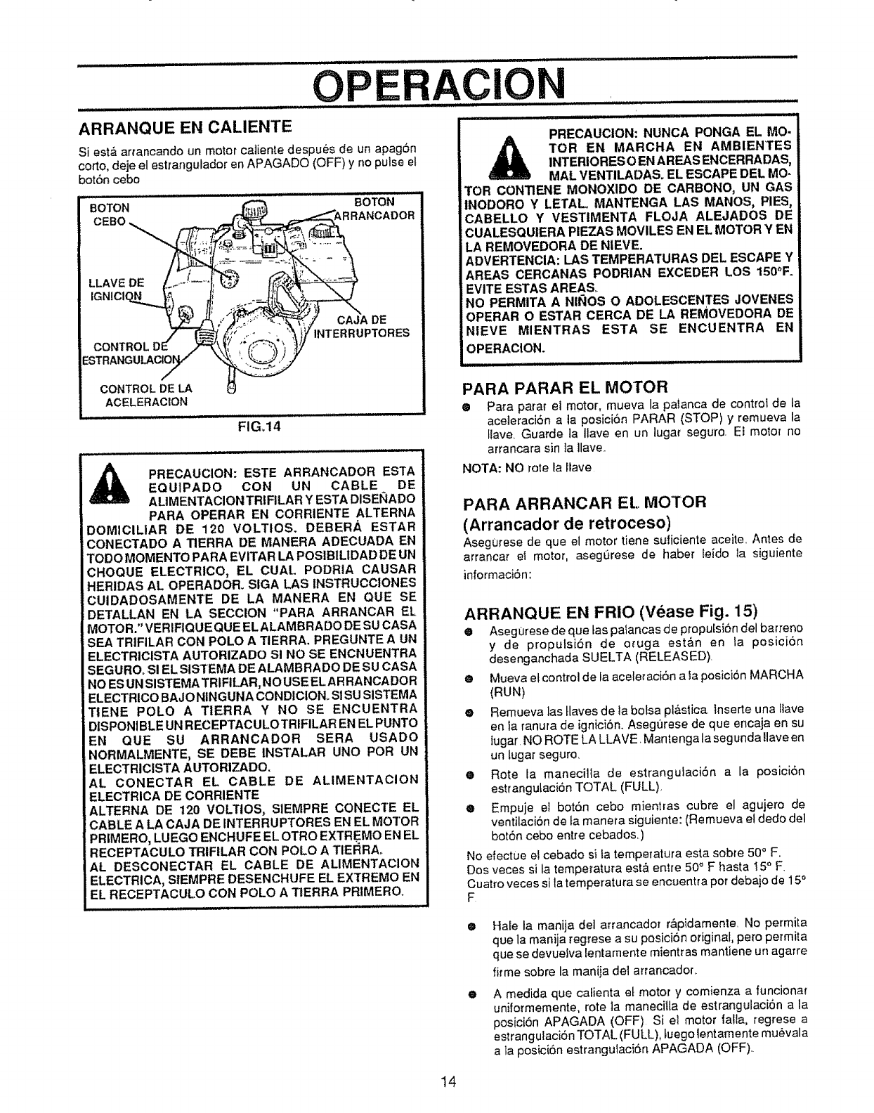
O RACION
.......................................... : ............. i iiilUll iiii ..... iii,ii.u,i ,,
ARRANQUE _N CALIENTE .........................................
Si est_ ar_'ancando un motor caliente despues de un apag6n
corto, deje el estrangulador en APAGADO (OFF) y no pulse et
bot6n cebo
BOTON 80TON
LLAVE DE
CAJA DE
INTERRUPTORES
CONTROL DE LA
ACELERACION
FIG,14
APRECAUCION: ESTE ARRANCADOR ES3"A
._ EQUIPADO CON UN CABLE DE
a==_,m= AL|MENTACION TRJFILAR Y ESTA DISENADO
PARA OPERAR EN CORRIENTE ALTERNA
DOMtCILIAR DE 120 VOLTtOS. DEBERA ESTAR
jCONECTADO A TIERRA DE MANERA ADECUADA EN
TODO MOMENTO PARA EVITAR LA POSIBILIDAD DE UN
CHOQUE ELECTRICO, EL CUAL PODRIA CAUSAR
HERIDAS AL OPERADOR. SIGA LAS INSTRUCCIONES
CUIDADOSAMENTE DE LA MANERA EN QUE SE
DETALLAN EN LA SECCION "PARA ARRANCAR EL
MOTOR." VERIFIQUEQUE ELALAMBRADO DE SU CASA
SEA TRIFILAR CON POLO A TIERRA. PREGUNTE A UN
ELECTRICISTA AUTORIZADO SI NO SE ENCNUENTRA
SEGUROo S! EL SISTEMA DE ALAMBRADO DE SU CASA
NO ESUN SISTEMA TRIFILAR,NO USE ELAR RANCADOR
ELECTRICO BAJO NINGUNA CONDICION. SI SU SISTEMA
TIENE POLO A TIERRA Y NO SE ENCUENTRA
DISPONIBLE UN RECEPTACULOTRIFILAR EN EL PUNTO
EN QUE SU ARRANCADOR SERA USADO
NORMALMENTE, SE DEBE INSTALAR UNO POR UN
ELECTRICISTA AUTORIZADO.
AL CONECTAR EL CABLE DE ALIMENTACION
ELECTRICA DE CORRIENTE
ALTERNA DE 120 VOLTIOS, SIEMPRE CONECTE EL
CABLE A LA CAJA DE INTERRUPTORES EN EL MOI"OR
PRIMERO, LUEGO ENCHUFE EL OTRO EXTREMO EN EL
RECEPTACULO TRIFILAR CON POLO A TIERRAo
AL DESCONECTAR EL CABLE DE ALIMENTACION
ELECTRICA, SIEMPRE DESENCHUFE EL EXTREMO EN
EL RECEPTACULO CON POLO A TIERRA PRIMERO.
PRECAUCION: NUNCA PONGA EL MO-
A TOR EN MARCHA EN AMBIENTES
INTERIORES O EN AREAS ENCERRADAS,
MAL VENTILADAS. EL ESCAPE DEL MO-
TOR CONTIENE MONOXlDO DE CARBONO, UN GAS
INODORO Y LETAL MANTENGA LAS MANOS, PIES,
CABELLO Y VESTIMENTA FLOJA ALEJADOS DE
CUALESQUIERA PIEZAS MOVILES EN EL MOTOR Y EN
LA REMOVEDORA DE NIEVE.
ADVERTENCIA: LAS TEMPERATURAS DEL ESCAPE Y
AREAS CERCANAS PODRIAN EXCEDER LOS 150°F.
EVITE ESTAS AREAS,
NO PERMITA A NII_OS O ADOLESCENTES JOVENES
OPERAR O ESTAR CERCA DE LA REMOVEDORA DE
NIEVE MIENTRAS ESTA SE ENCUENTRA EN
OPERACION.
PARA PARAR EL MOI"OR
•Para parar et motor, mueva la palanca de control de la
aceterac/6n a la posic{6n PARAR (STOP) y remueva la
tlave. Guarde la Ilave en un lugar seguro. Ei motor no
arrancara sin ta tlave.
NOTA: NO rote la liave
PARA ARRANCAR EL MOTOR
(Arrancador de retroceso)
Asegurese de que el motor tiene suticiente aceite. Antes de
arrancar el motor, asegurese de haber re,do la siguiente
informaci6n:
ARRANQUE EN FRIO (Vease Fig. 15)
®Asegurese de que tas pa_ancas de proputsibn del batreno
y de propulsi6n de o_uga est&n en la posicion
desenganchada SUELTA (RELEASED).
eMueva elcontrol de la aceleraci6n a fa posici6n MARCHA
(RUN)
eRemueva las tlaves de ta botsa pi&stica. Inserte una Iiave
en la ranura de igniciSn. AsegOrese de que encaja en su
{ugar NO ROTE LA LLAVE _Mantenga la segunda Ilave en
un lugar seguro.
•Rote ta manecilla de estrangulaci6n a la posiciSn
estranguLaciSn TOTAL (FULL).
®Empuje el bot6n cebo mientras cubre el agujero de
ventilaci6n de ta manera siguien!.e: (Remueva el dedo del
bot6n cebo entre cebados.)
No efectue e! cebado si la temperatura esta sobre 50° F.
Dos veces si la temperatura esl_ entre 50°F basra I5 °F.
Cuatro veces si la temperatura se encuentra pot debajo de 150
F
O
@
Hate la manija del arrancador rApidamente. No permita
que la manija regrese a su posici6n original, pero permita
que se devuelva {entarnente mientras mantJene un agarre
firme sobre la manJia del arrancador..
A medida que caiienta et motor y comienza a funcionar
uniformemente, rote la maneciila de estrangulaci6n a la
posici6n APAGADA (OFF) Si el motor falla, regrese a
estrangulaci6n TOTAL (FULL), Luegolentamente mu6vala
a la posici6n estrangulaci6n APAGADA (OFF)..
14
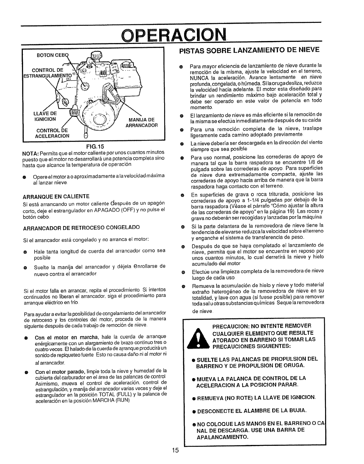
OPERACION
L i,,i, nmL :................ :
BOTON PISTAS SOBRE LANZAMIENTO DE NIEVE
FtG,,15
NOTA: Permita que el motor caliente pot unos cuantos minutos
puesto que el motor no desarrollar,& una potencia compJeta sino
hasta que aicance la temperatura de operacibn
eOpere el motor ao aproximadamente a la velocidad m&xima
al lanzar nieve
ARRANQUE EN CALIENTE
Si est& arrancando un motor caliente despu6s de un apagon
corto, deje el estranguiador en APAGADO (OFF) y no putse el
bot6n ceboo
ARRANCADOR DE RETROCESO CONGELADO
Si et arrancador esta congelado y no arranca el motor:
e Hale tanta iongitud de cuerda de! arrancador como sea
posible
oSuelte la manija de{ arrancador y d_jeia enro{larse de
nuevo contra el arrancador
@
Si el motor falia en arrancar, repita el procedimiento S[ intentos
continuados no liberan el arrancador, siga el procedimiento para
arranque e{6ctrico en fr[o.
Para ayudar a evitar la posibilidad de congelamiento del arrancador
de retroceso y los contro_es de! molor, proceda de la manera
siguiente despu_,s de cada trabajo de remocion de nieve
®
o
Con el motor en march& hale ta cuerda de arranque
en_rgicamente con un alargamienlo de brazo continuo tres o
cuatro veces. E1halado de fa cuerda de a[ranque producir& un
sonido de repiqueteo fuede Esto no causa da5o ni al motor ni
al arrancador,.
Con el motor parado, limpie toga _anieve y humedad de _a
cubierla de{ carburador en e{area de las pafancas de control
Asimismo, mueva el control de aceteraci6n, control de
estrangulaciSn, y manija del arrancador varias veces y deje el
estrangulador en la posiciSn TOTAL (FULL) y Ia palanca de
aceleraciSn en la posici6n MARCHA (RUN)
Para mayor eficiencia de lanzamiento de nieve durante la
remoci6n de ta m]sma, aiuste la velocidad en el terreno,
NUNCA la aceleraci6n.. Avance lentamente en nieve
profunda, congetada, o htJmeda..Si laoruga desliza, reduzca
la velocidad hacia adetante.. El motor esta diseRado para
bdndar un rendimiento m&ximo bajo aceleraci6n total y
debe ser operado en este valor de potencia en todo
momento.
eEl lanzamiento de nieve es m&s eficiente si la remoci_n de
la misma se efectLJainmediatam ente despu_s de su caida
• Para una remoci6n completa de ta nieve, trasJape
ligeramente cada camino adoptado previamente
O La nieve deber[a ser descargada en la direccion del viento
siempre que sea posible
• Para uso normal posicione Eascorrederas de apoyo de
manera tal que ta barra raspadora se encuentre 1/8 de
pulgada sobre las correderas de apoyo. Para supedicies
de nieve dura extremadamente compacta, ajuste las
correderas de apoyo hacia arriba de manera que [a barra
raspadora haga contacto cor_ e_terreno..
• En superficies de grava o roca triturada, posicione las
correderas de apoyo a 1-1/4 pulgadas por debajo de _a
barra raspadora (V6ase e[ p&rrafo "C6mo ajustar la attura
de las correderas de apoyo" en la p&gina 19) Las rocas y
grava no deber_n set recogidas y lanzadas pot la maquina
o Si _aparte delantera de la removedora de nieve tiene Ia
tendenciade elevarse reduzca la velocidad sobre elterreno
y enganche ef sistema de transferencia de peso..
e Despu_s de que se haya completado el lanzamiento de
nieve, permita que el motor se encuentre en reposo por
unos cuantos minutos, Io cual derretir#, la nieve y hieto
acumulado del motor
O
O
Efectue tma limpieza completa de ia removedora de nieve
tuego de cada uso
Remueva la acumulaciSn de hie!o y nieve y todo material
extrafio heterog6neo de la removedora de nieve en su
totalidad, y lave con agua (si fuese posible) para remover
toda sal u otras substancias quimicas Sequela removedora
de nieve
PRECAUCION: NO INTENTE REMOVER
CUALQUIER ELEMENTO QUE RESULTE
ATORADO EN BARRENO SI TOMAR LAS
PRECAUCIONES S1GUIENTES:
•SUELTE LAS PALANCAS DE PROPULSION DEL
BARRENO Y DE PROPULSION DE ORUGA,,
•MUEVA LA PALANCA DE CONTROL DE LA
ACELERAC|ON A LA POSICION PARAR.
•REMUEVA (NO ROTE) LA LLAVE DE |GNICION
•DESCONECTE EL ALAMBRE DE LA BUJtA.
® NO COLOQUE LAS MANOS EN EL BARRENO O CA
NAL DE DESCARGA, USE UNA BARRA DE
APALANCAMIENTO.
15
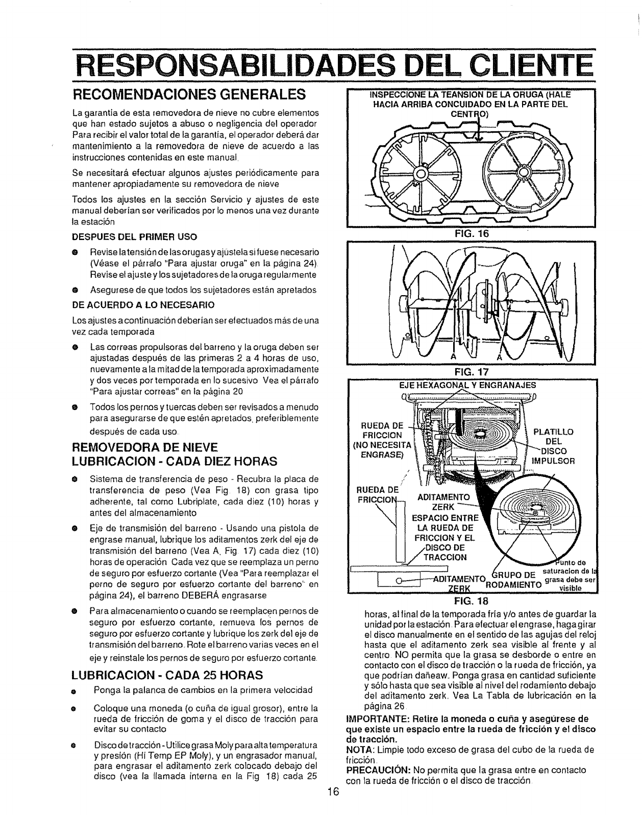
EL CLI
........................ ,, ,,,,w, i,, i i ulu,,,, lliH 11 J i llllllllll ii i,, i,llll . l lll n,i ,,
RECOMENDACIONES GENERALES INSPECCIONE LA TEANSIO_NDE LA ORUGA (HALE
La garantia de esta _emovedora de nieve no cubre eIementos
que han estado sujetos a abuse o negligencia del operador
Para recibir el valor total de la garantia, el operador deber& dar
mantenimiento a la removedora de nieve de acuerdo alas
instrucciones contenidas en este manual,
Se necesitar& efectuar algunos ajustes peri6dicamente para
mantener ap_opiadamente su removedora de nieve
Todos los ajustes en la secci6n Servicio y ajustes de este
manuat deberian set vedficados per Io menos una vez durante
la estaci6n
DESPUES DEL PRIMER USO FIG. 16
eRevise latensi6n detasorugas y aj'bstefa sifuese necesario
(V6ase el p&rra|o "Pare ajustar oruga" en la pagina 24)
Revise e! aiuste y los sujetadores de la oruga regularmente
eAsegurese de que todes los sujetadores est&n apretados
DE ACUERDO A LO NECESARIO
Los ajustes a contin uacion deberian set efectuados m&s de una
vez cada tempotada
e Las correas propulsoras det barreno y la oruga deben set
ajustadas despu6s de tas primeras 2 a 4 hotas de use,
nuevamente a la mitad de latemporada aproximadamente
y dos veces per temporada en lo sucesivo Vea el p&rrafo
"Para ajustar correas" en la p&gina 20
e Todos los pemosy tuercas deben set revisados a menudo
para asegurarse de que est_n apretados preferibiemente
despu6s de cada use
REMOVEDORA DE NIEVE
LUBRICAClON - CADA DIEZ HORAS
OSistema de transferencia de peso - Recubra la place de
transferencia de peso (Vea Fig 18) con grasa ripe
adherente, tal come Lubriplate, cada diez (10) horas y
antes del atrnacenamiento
eEje de ttansmisi6n del barreno - Usando una pistola de
engrase manual, lubrique los aditamentos zerk de! eje de
transmisiOn del ba[reno (Vea A, Fig t7) cada diez (10)
horas de operaci6n Cada vez que se reemplaza un pemo
de seguro per esfuerzo cortante (Vea "Para reemplazar el
pemo de seguro per esfuerzo cortante dei barreno'" en
p&gina 24), el batreno DEBERA engrasa_se
ePara ahnacenamiento o cuando se reemplacen pernos de
seguro per esfuerzo cortante, remueva lo.s pernos de
seguro per esfuerzo cortante y iubrique los zerk del eje de
transmisi6n del barreno. Rote ef barreno varias veces en et
eje y reinstale los pernos de seguro per esfuerzo cortante.
LUBRtCAClON - CADA 25 HORAS
e Ponga la palanca de cambios en la primera velocidad
Coloque una moneda (o cuba de iguat grosor), entre la
rueda de fficci6n de goma y el disco de tracci6n pera
evitar su contacto
Disco detraccion-Utilice grasa Mofy papa attatemperatura
ypresi6n (Hi Temp EP Moly), y un engrasador manual,
papa engrasar el aditamento zerk cotocado debajo del
disco (vea la ilamada interne en la Fig 18) cada 25
FIG. 17
EJE HEXAGONAL Y ENGRANAJES
RUEDA DE
FRICCION i
(NO NECESITA
ENGRASE)
/
RUEDA DE
FRICC|O_ ADITAMENTO
ZERK
ESPAClO ENTRE
LA RUEDA DE
FRICCION Y EL
PLAT1LLO
DEL
llSCO
IMPULSOR
16
FIG, 18
horas, al final de la temporada fria y/o antes de guardar la
unidad per la estaci6n, Para efectuar el engrase, haga gitar
el disco manuaimente en et sentido de las agujas del reloj
hasta que el aditamento zerk sea visible al frente y al
centre NO permita que la grasa se desborde o entre en
contacto con e! disco de tracci6n o la rueda de fricci6n, ya
que poddan daReawo Ponga grasa en cantidad suficiente
y s61ohaste que sea visible al nivel del todamiento debaio
del aditamento zerk, Vea La Tabla de iubricaci6n en la
p&gina 26
IMPORTANTE: Retire la moneda o curia y asegt_rese de
que existe un espacio entre la rueda de ft'iccion y el disco
de tracclbn.
NOTA: Limpie todo exceso de grasa del cubo de la rueda de
fricci6n.
PRECAUCI(_)N: No permita que la grasa entre en contacto
con la rueda de fficci6n o el disco de tracci6n
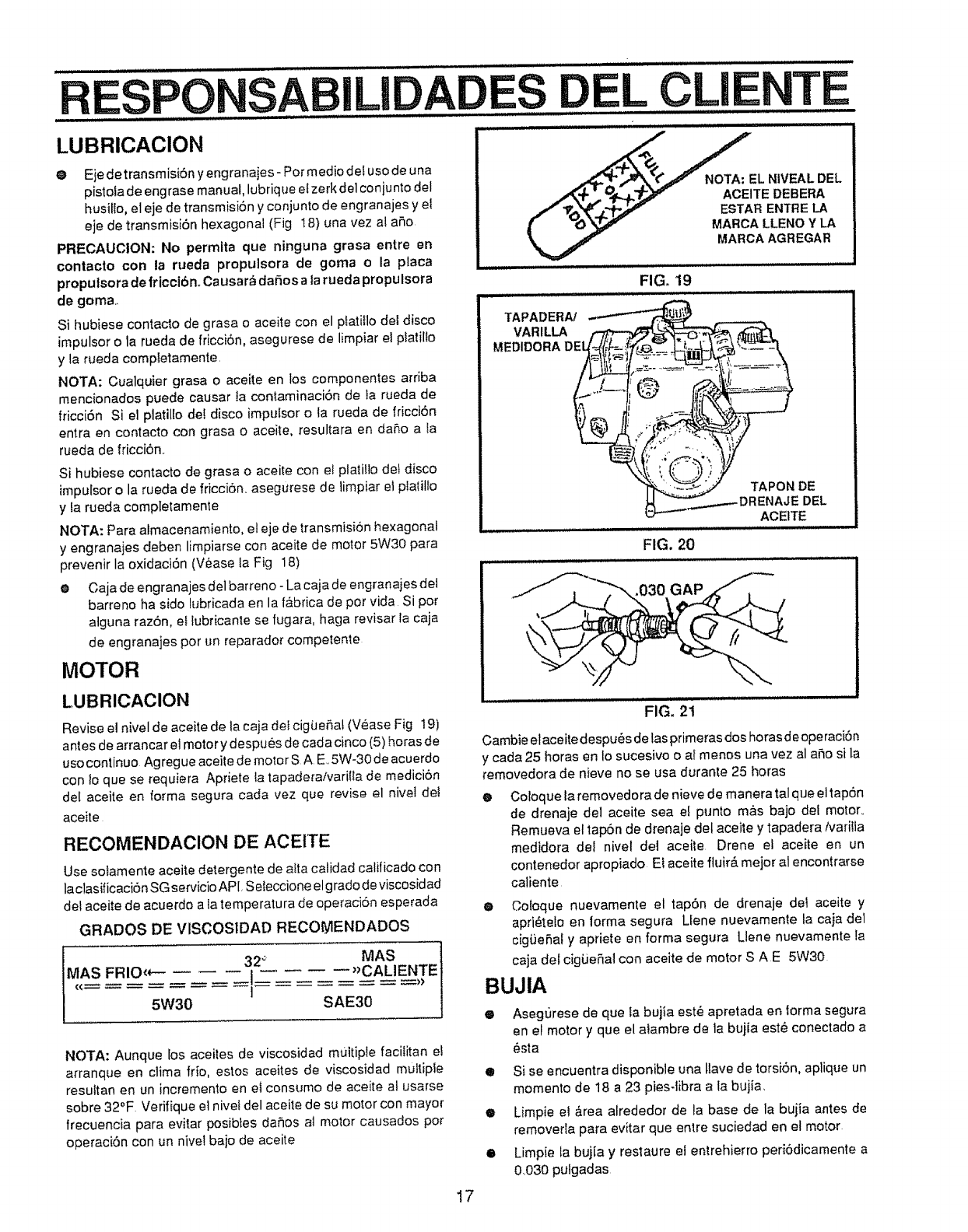
RESPONSABiLiDADES DEL CLIENTE
= HH.,I _ ,_,_.................j. I =.,,, .......................''IHH ....... ................. lIH
LUBRICACION
@ Eje detransmisi6n yengranaies - Par media de5usa de una
pistofa de engrase manual, lubrique efzerk del conjunto del
husiffo, el eje de transmisi6n y conjunto de engranajes y et
eje de transmisiSn hexagonal (Fig 18) una vez ai ar_o
PRECAUCtON: No perrnita que ninguna grasa entre en
conlacto con la rueda propulsora de goma ola placa
proputsora de friccibn_ Causar._daSos a tarueda propulsora
de goma,
Si hubiese contacto de grasa o aceite con el p_atitlo dei disco
impulsor o la rueda de fricci6n, asegurese de limpiar el platilto
y la rueda completamente.
NOTA: Cualquier grasa oaceite en los camponentes arriba
mencionados puede causar la contaminaci6n de ta rueda de
fricci6n Si el pJatil[o de! disco Jmpu[sor o {a rueda de fricci6n
entra en contacto con grasa o aceite, resultara en da_,o a la
rueda de fricci6n..
Si hubiese contacto de grasa o aceite con et ptatitlo det disco
impulsor o la rueda de fricci6n, asegurese de limpiar et pIatillo
y ta rueda completamente
NOTA: Para atmacenamiento, el eje de transmisi6n hexagonal
y engranajes deben limpiarse con aceite de motor 5W30 para
prevenir la oxidaci6n (V6ase la Fig 18)
e Caja de engranajes del barreno- La caja de engranaies det
barreno ha sido lubricada en la f&brica de par vida Si par
atguna razSn, el Iubficante se fugara, haga revisar la caja
de engranajes par un reparador competente
MOTOR
LUBRICACION
Revise e! nivel de aceite de la caja det cigue6at (Vease Fig 19)
antes de arrancar el motor y despu6s de cada cinco (5) horas de
usacontinua Agreg ueaceite de motors A E..5W-30 de acuerdo
con io que se requiera Apriete la tapaderaNarilta de medicion
de( aceite en forma segura cada vez que revise al nivel de!
aceite
RECOMENDACION DE ACEITE
Use solamente aceite detergente de alta calidad calificado con
la clasificaci6n SG servicio API Seteccione elg rado de viscosidad
det aceite de acuerdo a ta temperatura de operaci6n esperada
GRADOS DE VlSCOSIDAD RECOIYlENDADOS
MAS
MAS FRIO,*- __i 2_'_ "CALIENTE
/ == = -- = ="
NOTA: Aunque los aceJtes de viscosidad multiple facilitan el
arranque en clima frio, estos aceites de viscosidad m_ttipte
resultan en un incremento en el consumo de aceite al usarse
sabre 32°F Verifique el nivet del aceite de su motor con mayor
frecuencia para evitar posibles daSos at motor causados par
operaci6n con un nivel bajo de aceite
.,0._,__ZEL NIVEAL DEL
j,_+_ _.lkT_l v ACEITE DEBERA
/ '_'0__"3_._ vESTAR ENTRE LA
_" _O _ MARCA LLENO Y LA
_=_" MARCA AGREGAR
FIG, 19
i / i ......
TAPADERN
VARILLA
MEDIDORA
FIG. 20
TAPON DE
DEL
ACEITE
.030 GAP
FIG. 2t
Cambie el aceite despu_s de las primeras doshoras deoperacibn
ycada 25 horas en Io sucesivo o a! menos una vez al a_o si la
removedora de nieve no se usa durante 25 horas
0Coloque la removedora de nieve de manera tal que eltap6n
de drenaje del aceite sea e! punto m_fisbajo del motor.
Remueva el lap6n de drenaje det aceite y tapadera/varitla
medidora de/ nive/ del aceite Orene el aceite en un
contenedor apropiado Ei aceite fluir& mejor al encontrarse
caliente
@Cotoque nuevamente el tap6n de drenaje del aceite y
apri_te!o en lorma segura LIene nuevamente la caja de1
cig(JeSaf y apriete en farina segura Llene nuevamente [a
caja del cigLieSal con aceite de motor S A E 5W30
BUJIA
®Asegurese de que la bujia est_ apretada en forma segura
en et motor y que el alambre de la buiia est_ conectado a
_sta
•Si se encuentra disponibte una llave de torsi6n, aplique un
momenta de 18 a 23 pies-libra a la bujia_
• Limpie el &rea atrededor de _abase de la buiia antes de
removerla para evitar que entre suciedad en el motor
•Limpie la buj[a y restaure el entrehierro peri6dicamente a
0B30 pulgadas
17
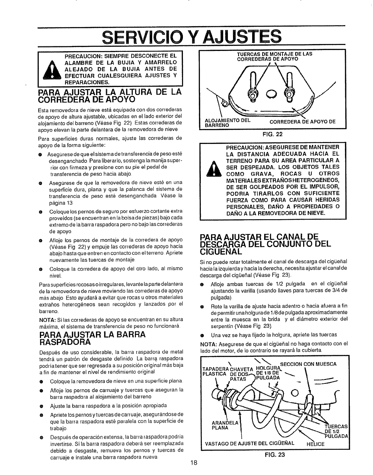
CIO Y AJUST
PRECAUCION: SiEMPRE DESCONECTE EL
_ALAMBRE DE LA BUJIA Y AMARRELO
ALEJADO DE LA BUJIA ANTES DE
EFECTUAR CUALESQUtERA AJUSTES Y
REPARACIONES.
PARA AJUSTAR LA ALTURA DE LA
CORREDERA DE APOYO
Esta removedora de nieve est& equipada con dos correderas
de apoyo de altura ajustable, ubicadas en el lade exterior del
alojamiento del barreno (V_ase Fig 22) Estas correderas de
apoyo eievan ta parle delantera de la temovedora de nieve
Para superficies duras normales, ajuste las correderas de
apoyo de la forma siguiente:
OAseg0rese de que elsistema detransferencia de peso este
desenganchado. Para tiberado, sostenga la manija super-
riot con firmeza y presione con su pie el pedal de
trans|erencia de peso hacia abajo.
@Asegt]rese de que fa removedora de nieve est6 en una
superficie dura, piana y que la palanca del sistema de
transferencia de peso este desenganchada Vease la
p,_gina !3
®Coloque los pernos de seguro per esfuerzo cortante extra
provetdos (se encuentran en la bolsade piezas) ba]o cada
extreme de la barra raspadora pero no baio las correderas
de apoyo
oAfloje los pernos de montaje de la corredera de apoyo
(V6ase Fig 22) y empuje las correderas de apoyo hacia
abajo hasta que entren en contacto con elterreno Apriete
nuevamente las tuercas de montaje
oCotoque la corredera de apoyo del otto lade, ai mismo
nivel,
Para superficies recosas o irregulares, levante taparte delantera
de la removedora de nieve moviendo las correderas de apoyo
m&s abajo Esto ayudar& a evitar que rocas u otros materiales
extrahos heterog6neos sean recogidos y lanzados per el
barreno,
NOTA: Si Ias correderas de apoyo se encuentran en su altura
m_.xima, ef sistema de transferencia de peso no funcionar&
PARA AJUSTAR LA BARRA
RASPADORA
Despues de uso considerable, la barra raspadora de metal
tendr& un patr6n de desgaste definido La barra raspadora
podria tener que ser regresada a su posicion original m&s baja
a fin de mantener el nivel de rendimiento original
®Coloque la removedora de nieve en una superficie plana
eAfloje los pernos de carruaje y tuercas que aseguran ia
barra raspadora al alojamiento del barreno
oAjuste ]a barra raspadora a la posicion apropiada
eApriete tos pemos ytuercas de carruaje, asegurandose de
que la barra raspadora est_ paralela con la superficie de
trabajo
@Despues de operaci6n extensa, la barra raspadora podria
invertirse,, Si la barra raspadora deber& set reemplazada
debido a desgaste, remueva los pernos y tuercas de
carruaje einstale una barra raspadora nueva 18
TI}ERCAS DE MONTAJE DE LAS
CORREDERAS DE APOYO
ALOJAMtENTO DEL CORREDERA DE APOYO DE
BARRENO
FIG, 22
PRECAUCION: ASEGURESE DE MANTENER
LA DISTANCIA ADECUADA HACfA EL
TERRENO PARA SU AREA PARTICULAR A
SER DESPEJADAo LOS OBJETOS TALES
COMe GRAVA, ROCAS U OTROS
MATERIALES EXTRAI_IOS HETEROGENEOS,
DE SER GOLPEADOS PeR EL IMPULSOR,
PODRIA TIRARLOS CON SUFICIENTE
FUERZA COMe PARA CAUSAR HERIDAS
PERSONALES, DA_IO A PROPIEDADES O
DANe A LA REMOVEDORA DE NIEVE.
PARA AJUSTAR EL CANAL DE
DESCARGA DEL CONJUNTO DEL
ClGUENAL
Si no puede rotar totalmente el canal de descarga del cigbeSal
hacia la izquierda y hacia la derecha, necesita ajust ar el canal de
descarga del cig0eSal (V6ase Fig 23),
•Afloje ambas tuercas de 1t2 puLgada en el cigiJeSai
ajustando la varilla (usando tlaves para tuercas de 3/4 de
pulgada)
•Rote la varilla de ajuste hacia adentro o hacia afuera a fin
de permitir una holgura de 1/8de pulgada aproxim adamente
entre la muesca en la brida y el di&melro exterior dei
serpentin (V_ase Fig 23).
®Una vez se haya tijado la holgura, apriete las tuercas
NOTA: Asegurese de que el cigiJeSal no haga contacto con el
lade del motor, de lo contrario se rayar& la cubierta,
\SECCION CON MUESCA
TAPADERA CHAVETA HOLGURA_
PLASTICA DE 1/8 DE _.
PULGADA
PLANA DE 112
VASTAGO DE AJUSTE DEL ClGUEI_IAL HEUCE
FIG. 23
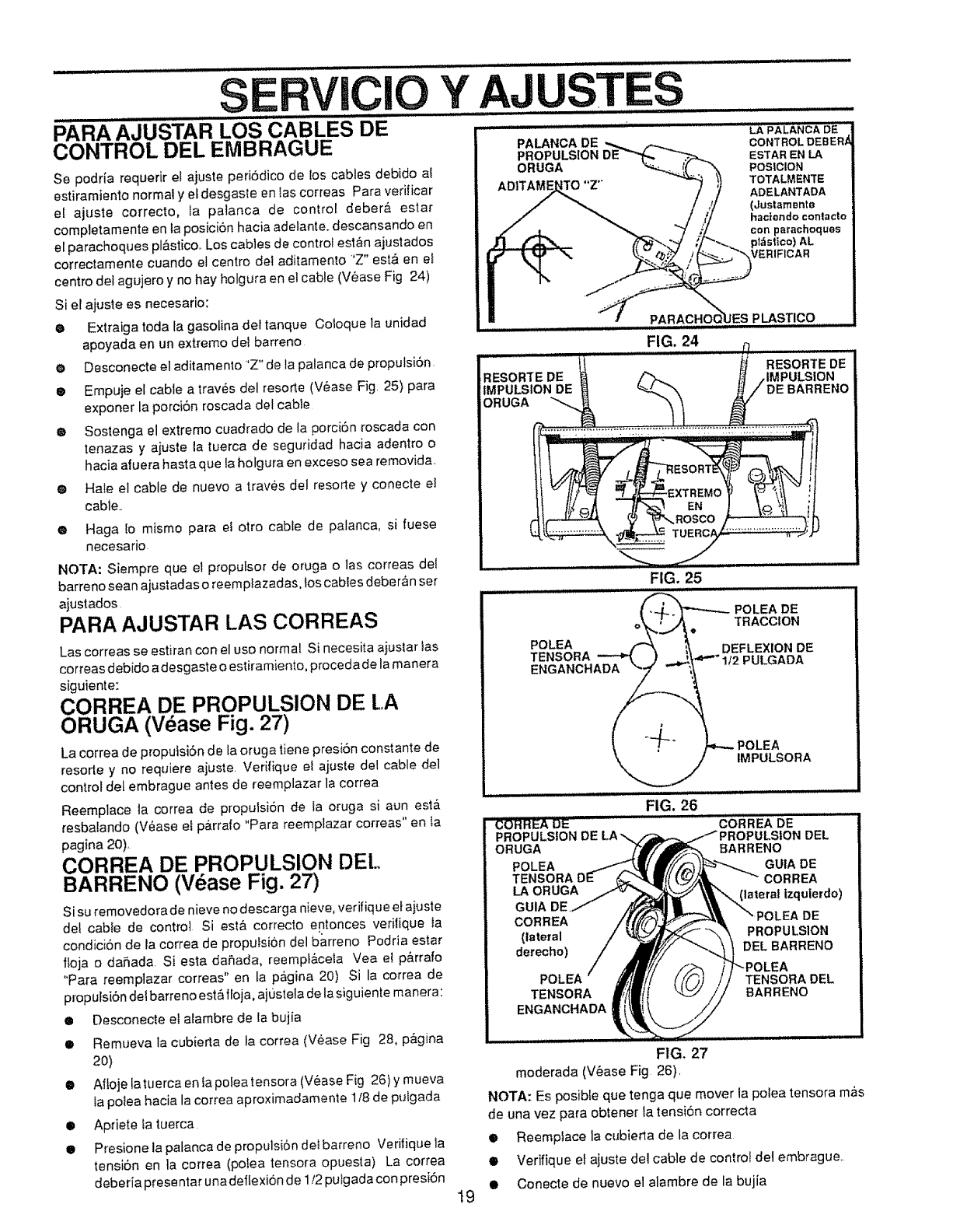
SERVIClO
PARA"AJUSTAR LOS CABLES DE ....
CONTROL DEE EMBRAGUE
Se podria requerir et ajuste peri6dico de los cables debido af
estiramiento normal y et desgaste en las correas Para verificar
el ajuste correcto, ta palanca de control deber& estar
completamente en la posiciOn hacia adelante, descansando en
el parachoques pl&sticoo Los cables de contro_ est&n ajustados
correctamente cuando el centro del aditamento 'Z" est& en et
centro de_agujero y no hay holgura en el cable (Vease Fig 24)
Si el ajuste es necesario:
o Extraiga toda fa gasolina del tanque Coloque la unidad
apoyada en un extremo de_ barreno
Y AJUSTES
PALANCA DE
PROPULSION
ORUGA
eDesconecte el aditamenlo"Z" de la palanca de propulsion.
®Empuje el cable a traves del resorte (V_ase Fig. 25) para
exponer la porci6n roscada del cable
®Sostenga el extremo cuadrado de la porci6n roscada con
tenazas y ajuste la tuerca de seguridad hacia adentro o
hacia afuera hasta que la holgura en exceso sea removida
RESORTEDE
IMPULSION DE
ORUGA
FiG.24....................
•Hate el cable de nuevo a traves del resorte y conecte el
cable..
..............LAPAL'_'NCAD_'_
CONTROL DEBER,_
ESTARENLA
POSICION
TOTALMENTE
ADELANTADA
(dusl'amente
haciondoconlacto
con parachoques
ptdsltco) AL
VER|FICAR
PLASTICQ ..........
®Haga {o mismo para ef otto cable de palanca, si fuese
necesario
NOTA: Siempre que el propulsor de oruga o las correas del
barreno sean ajustadas o reemplazadas, los cables deberan set
ajustados.
PARA AJUSTAR LAS CORREAS
Las correas se estiran con el uso normal Si necesita ajuslar ias
correas @ebidoadesgaste o estiramiento, proceda de la manera
siguiente:
CORREA DE PROPULSION DE LA
ORUGA (Vease Fig. 27)
La correa de proputsi6n de la oruga tiene presi6n constante de
resorte y no requiere ajuste. Verifique el ajuste del cable del
control del embrague antes de reemplazar la correa
Reemplace la correa de proputsi6n de la oruga si aun est,.
resbaiando (V,_ase el pkrralo "Para reemplazar correas" en la
pagina 20),
CORREA DE PROPULSION DEL
BARRENO (V_ase Fig. 27)
Si su removedorade nieve no descarga nieve, verifique ef aiuste
det cable de control Si esta correcto entonces veritique ta
condici6n de la correa de propulsion del b'arreno Podria estar
floja o dafada Siesta da5ada, reempt&ceta Vea el p&rrafo
"Para reemplazar correas" en la p&gina 20) Si la correa de
propulsion del barreno est_ floja, aj0stela de la siguiente manera:
o Desconecte ef alambre de ta bujia
II Remueva la cubierla de ta correa (Vease Fig 28, p&gina
2O)
•Aftoje latuerca en ta polea tensora (V6ase Fig 26) y mueva
Ia polea hacia la correa aproximadamente 1/8 de pu/gada
• Apt!ere la tuerca
• Presione la patanca de propulsi6n dot barreno Verifique la
tensi6n en la correa (polea tensora opuesta) La correa
deberia prose ntar una deflexion de 1/2 putgada con presi6n 19
POLEA
TENSORA
ENGANCHADA
FIG. 25
DEFLEXION DE
PULGADA
POLEA
IMPULSORA
FIG. 26
DE
TENSORA DEL
BARRENO
FIG. 27
moderada (V_ase Fig 26).
NOTA: Es posible que tenga que mover ia potea tensora m,_s
de una vez para obtenet' la tension correcla
$Reempface la cubiena de la correa
$Verifique el ajuste del cable de contro! del embrague.
It Conecte de nuevo el alambre de la bujia
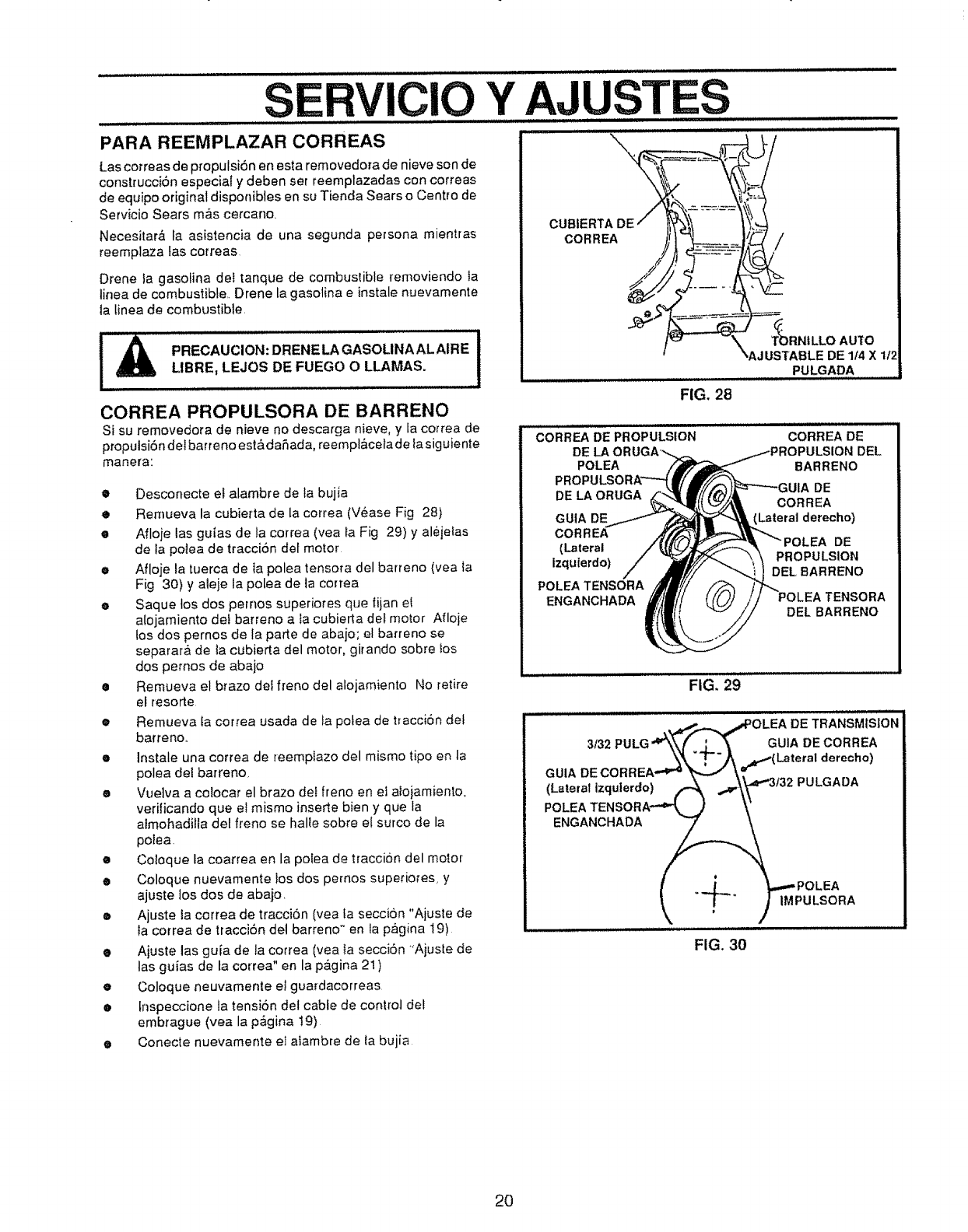
SERVIClO Y AJUSTES
PARA REEMPLAZAR CORREAS
Lascotreas de propulsi6n en esta removedora de nieve son de
construcciSn especial y deben ser reemplazadas con correas
de equipo original disponibles en su Tienda Sears o Centro de
Servicio Sears m&s cercano,
Necesitar& fa asistencia de una segunda persona mientras
reemplaza fas correas
Drene la gasolina det tanque de combustible removiendo Ia
linea de combustible,. Drene la gasolina e instale nuevamente
ta Linea de combustible,
PRECAUCION: DRENE LA GASOUNA AL AIRE 1LIBRE, LEJOS DE FUEGO OLLAMAS.
CORREA PROPULSORA DE BARRENO
Si su removedora de nieve no descarga nieve, y la correa de
propulsi6n dei barreno est&daSada, reempl&cela de la siguiente
manera:
•Desconecte et alambre de ta bujia
•Remueva la cubierta de la correa (Vease Fig 28)
•Afloje las guias de la correa (yea fa Fig 29) y al6jeias
de ta potea de tracci6n del motor
•Afloje la tuerca de la polea tensora del barreno (vea ta
Fig 30) y ateje la polea de ta correa
eSaque los dos pemos superiores que fijan el
aiojamiento det barreno a Ia cubierta det motor Afloje
los dos pernos de la parte de abajo; el barreno se
separar& de ia cubierta del motor, girando sobre tos
dos pemos de abajo
•Remueva el brazo det freno del alojamiento No retire
el resorte
•Remueva {a correa usada de {a potea de tracci6n det
barreno,.
eInstale una correa de reempiazo del mismo tipo en la
polea del barreno,
eVue]va a colocat el brazo del freno en et alojamiento,
verificando que eI mismo inserte bien y que la
almohadifla del freno se halle sobre el surco de la
polea,
•Co]oque la coarrea en la polea de traccion del motor
•Coloque nuevamente !os dos pernos superio_es, y
ajuste los dos de abajo
•Ajuste la correa de traccion (yea ia secci6n "Ajuste de
ia correa de tracci6n del barreno" en la pagina 19)
•Ajuste las guia de la correa (yea la secci6n "Ajuste de
las guias de la correa" en la p&gina 21)
eColoque neuvamente el guardacorreas
•[nspeccione la tensi6n del cable de control det
embrague (vea la p&gina 19)
•Conecte nuevamente e] aiambre de ta bujia
CUBIERTA DE
CORREA /
FIG. 28
T_)RN|LLO AUTO
_AJUSTABLE DE 114 X 1t,'
PULGADA
CORREA DE PROPULSION
DE
POLEA
DE LA ORUGA
GUIA DE
CORREA
(Lateral
izquterdo)
POLEA TENSORA
ENGANCHADA
CORREA DE
)ULSION DEL
BARRENO
DE
CORREA
(Lateral derecho)
DE
PROPULSION
DEL BARRENO
TENSORA
DEL BARRENO
................................FIG. 29_'
,_4'.,,,._ _*POLEA DE TRANSMISION
3/32 PULG "4_&_ j____---- _GUlA DE CORREA
_k _--)_ _.d_-*(Latm'al derecho)
GUIA DECORREA -'_'_ _ _.='
(Lateral Izqu,erdo) _ _,._"3t32 PULGADA
POLEA TENSORA-'="t_._ ..,/ \"
ENGANCHADA _
I. ,.-L_,, .. _.,.,_ POLEA
_ ! -/IMPULSORA
FIG. 30
20
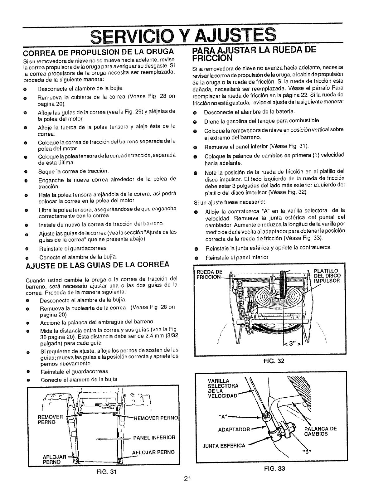
SERVICIO Y AJUSTES
u,,,,,,,,ll m i1,1 r :.... .................. .............
CORREA DE PROPULSION DE LA ORUGA PARA AJUSTAR LA RUEDA DE
Si su removedora de nieve no se mueve hacia adelante, revise FRICCION
la correa propulsora de [a oruga para averiguar su desgaste. Si
la correa propulsora de la oruga necesita ser reemplazada,
proceda de la siguiente manera:
G
G
0
0
0
®
0
®
0
@
0
0
O
0
Desconecte el alambre de la bujfa
Remt_eva _acubierta de la correa (Vease Fig 28 on
pagina 20).
Afloje las guias de la correa (yea la Fig 29) y al_jelas de
la poiea del motor.
Afloje ta tuerca de la polea tensora y aleje esta de ta
correa
Si la _'emovedora de nieve no avanza hacia adelante, necesita
revisar lacorrea de proputsi6n de lao rug a, elcable de propu fsi6n
de la oruga o la rueda de friccion Si la rueda de fricci6n esta
dafada, necesitar& ser reempiazada. V_ase el p&rrafo Para
reemplazar la rueda de fricci6n en ta p_gina 22. Si la rueda de
fricci6n no est& gastada, revise el ajuste de la siguiente manera:
Coloque ta correa de tracciSn del barreno separada de la
polea del motor
Coloquela poleatensorade lacorea detracciOn, separada
de esta ['Jttima
Saque la correa de tracci6n.
Enganche la nueva correa alrededor de fa potea de
tracciOn.
Hale ta polea tensora alej&ndola de la corera, asi podr&
colocar la correa en fa potea del motor
Libre la polea tensora, asegura, andose de que enganche
correctamente con la correa
lnstale de nuevo la correa de traccion del barreno
Ajuste fas gufas de la cerrea (yea la secciOn "Ajuste de tas
guias de la correa" que se presenla abajo)
Reinstale el guardacorreas
Conecte et alambre de la buiia
•Desconecte el alambre de la bateria.
O Drene la gasolina del tanque para combustible
@ Cotoque la removedora de nieve en posiciSn verticalsobre
el extremo del barreno,
@ Remueva et panel inferior (V_ase Fig 3!).
® Coloque la palanca de cambios en primera (1) velocidad
hacia adelante.
®Note la posiciSn de la rueda de fricciSn en el platiiIo del
disco impulsor, El lade izquierdo de la rueda de fricci6n
debe estar 3 pulgadas del lado m&s exterior izquierdo del
platillo del disco impulsor (V_ase Fig 32)
AJUSTE DE LAS GUIAS DE LA CORREA
Si un ajuste fuese necesario:
@ Afloje la contratuerca "A" en la varilla selectora de la
ve!ocidad Remueva ta junta esf_rica del puntal del
cambiador Aumente o reduzca la longitud de la varilta por
medio de darle vuelta al adaptador para obtener laposictSn
correcta de la rueda de fricci6n (V_ase Fig 33)
® Reinstate la junta esf_rica y apriete la contratuerca.
® Reinstale etpanef inferior
Cuando usted cambie la oruga o la correa de tracci6n del
barreno, set& necesario ajustar una o tas dos guias de la
correa Proceda de la manera siguiente:
• Desconecte el alambre de la bujia
eRemueva la cubiearta de la correa (Vease Fig 28 on
pagina 20)
•Accione ta palanca def embrague del barreno
• Mida la distancia entre la correa y sus guias (yea _aFig
30 pagina 20). Esta distancia debe ser de 2.4 mm (3/32
pulgada) para cada guia
eSi requieren de ajuste, afloje tos pernos de sost_n de las
guias; mueva tas guias a la posicl6n correcta y apriete los
pernos nuevamente
oReinstale el guardacorreas
• Conecte el atambre de la bujia
H,,i, ....
REMOVER __ '
FIG. 31
RUEDA DE PLATILLO
DEL DISCO
IMPULSOR
FIG. 32
VARILLA _'\'_\
SELECTORA \_\
DELA
w,oc,D O"-
ADAPTADOR
JUNTA ESFERtCA JDE
FIG, 33
21
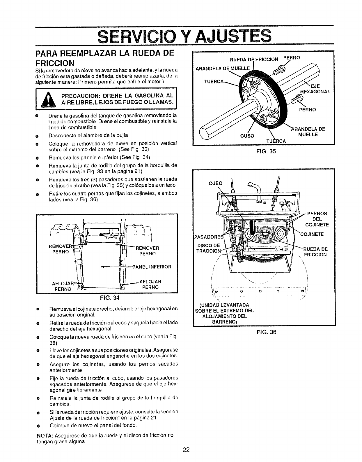
SERVICIO Y AJUSTES
PARA REEMPLAZAR LA RUEDA DE ...................
FRICCION
Si la removedor a de nieve no avanza hacia adeiante, y la nueda
de fricciSn esta gastada o daSada, debera reemplazaria, de la
siguiente manera: Primero permita qua enffie el motor)
PRECAUClON: DRENE LA GASOLINA ALi -
AIRE LIBRE, LEJOS DE FUEGO O LLAMAS. I
ODrene ta gasolina del tanque de gasolina removiando ta
linea de combustible Drene el combustible y reinstale la
tinea de combustible
eDesconecte el alambre de la bujia
eColoque la removedora de nieve en posicion vertica_
sobt'e el extremo del barrer_o (See Fig 36)
e Remueva los panete e inferior (See Fig 34)
•Remueva ta junta de rodilla del grupo de la horquilla de
cambios (vea ]a Fig._33 en la p&gina 21)
eRemueva los tres (3) pasadores qua sostienen ta rueda
de fricciSn ai cubo (yea la Fig 35) y coloquelos a un lado
•Retire los cuatro pernos qua fijan los cojinetes, a ambos
lados (yea la Fig 36)
REMOVE '---.-,
I°VE v REMOVER
P ..o j?
"_ ANEL INFERIOR
AFLOJAR .._--AFLOJAR
FtGo 34
e Remueva el cojinete drecho, dejando el eje hexagonal er_
su posici6n original.
e Retire la ruedade friccion del cubo y s&quela hacia el lado
derecho del eje hexagonal
•Coloque la nueva rueda de friccion en el cubo (yea la Fig
36)
•Lleve los cojinetes a sus posiciones originales Asegurese
de que el eje hexagonal enganche en los dos cojinetes
• Asegure los cojinetes, usando los pernos sacados
anteriormente.
e
o
e
Fije fa rueda de fricci6n aI cubo, usando {os pasadores
sqacados anteriormente Asegurese de qua el eje hex-
agonal gire libremente
Reinstale la junta de rodilta al grupo de la horquilla de
cambios
Si ta rueda de lricci6n l'equiere ajus_,e,consuile la secci6n
Ajuste de la rueda de fricci6n en la pagina 21
Cotoque de nuevo e] panel del rondo.
NOTA: Asegurese de qua ta rueda y el disco de fficciSn no
tengan grasa alguna
ARANDELA DE MUELLE
',FRICCION PERNO
,EJE
HEXAGONAL
PERNO
CUBO MUELLE
TUERCA
FIG, 35
DE
CUBO
PERNOS
DEL
COJfNETE
TR _UEDA DE
.. FRICC|ON
.J
/
,f _',
% .......................... .:.::''
(UNIDAD LEVANTADA
SOBRE EL EXTREMO DEL
ALOJAM1ENTODEL
8ARRENO)
FIG. 36
22
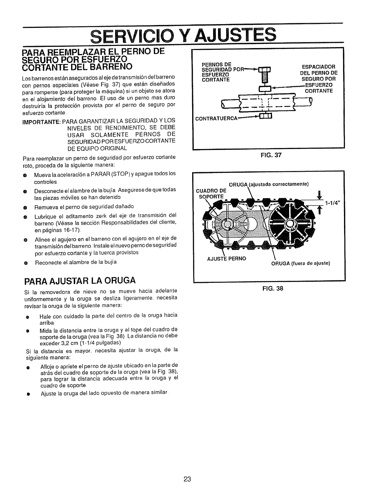
SERVICIO
PARA REEMPLAZAR......................................................EL PERNO DE
SEGURO POR ESFUERZO
CORTANTE DEL BARRENO
Los barrenos est&n asegurados al eje detransmisi6n defbarreno
con pernos especiales (V_ase Fig. 37) que est&n diseSados
para rornperse (para proteger ta m&quina) si un objeto se atora
en et atojamiento del barreno Et uso de un perno rnas duro
destruiria la proteccion provista pot el perno de seguro pot
esfuerzo cortante
IMPORTANTE: PARA GARANTIZAR LA SEGURIDAD Y LOS
NIVELES DE RENDIMIENTO, SE DEBE
USAR SOLAMENTE PERNOS DE
SEGURIDAD POR ESFUERZOCORTANTE
DE EQUfPO ORIGINAL
Para reempiazar un perno de seguridad pot esfuerzo cortante
roto, proceda de ta siguiente manera:
eMueva ta aceleracibn a PARAR (STOP) y apague todostos
controies.
•Desconecte el a_arnbrede la bujia Asegurese de que todas
{as piezas m6viles se han detenido
• Remueva el perno de seguridad dahado
O Lubrique e! aditamento zerk det eje de transmisi6n del
barreno (V§ase la secciSn Responsabilidades de! diente,
en p&ginas 16-I7).
e Aiinee el aguiero en e] barreno con e! agujero en e! eje de
transmisi6ndelbarreno Instale einuevopernodeseguridad
por esfuerzo cortante y la tuerca provistos
e Reconecte el alambre de la buiia
PARA AJUSTAR LA ORUGA
Si la rernovedora de nieve no se mueve hacia adelante
uniforrnemente y ta oruga se desliza ligerarnente, necesita
revisar ta oruga de la siguiente rnanera:
oHale con cuidado la parIe del centro de ia oruga hacia
arriba,
•Mida la distancia entre {a oruga y e! tope del cuadro de
soporte de la oruga (yea la Fig 38) La distancia no debe
exceder 3,2 cm (1-t/4 pulgadas)
Si ta distancia es mayor, necesita aiustar la oruga, de la
siguiente rnanera:
• Afloje o apriete el perno de ajuste ubicado en ta parte de
aires del cuadro de soporte de la oruga (yea la Fig 38),
para iograr la distancia adecuada entre ta oruga y el
cuadro de soporte
• Aiuste la oruga del tado opuesto de rnanera similar
Y AJUSTES :i ii, n,iH,,Uln ni .... n I1'1I
PERNOS DE
SEGURIDADPOR_ ESPACIADOR
ESFUERZO _DEL PERNO DE
CORTANTE _SEGURO POR
.._ESFUERZOCORTANTE
FIG. 37
CUADRO DE
SOPORTE
ORUGA (ajustada correctamente)
AJUSTE PERNO
ORUGA (fuera de ajuste)
FIG. 38
23
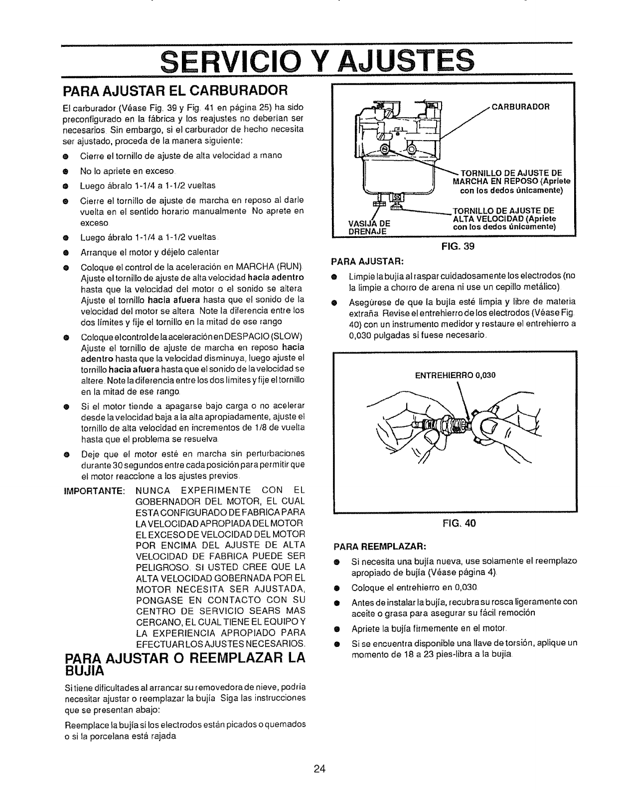
SERVICIO Y AJUSTES
PARA AJUSTAR EL CARBURADOR
EI carburador (V6ase Fig, 39 y Fig, 41 en p_gina 25) ha side
preconfigurado en la f&brica y los reajustes no deberian set
necesarios Sin embargo, si el carburador de becho necesita
set ajustado, proceda de la manera siguiente:
•Cier_e el tornillo de ajuste de alta velocidad a mane
® No lo apriete en exceso
eLuego Abralo 1-1/4 a t-i/2 vue!tas
® Cierre el tornillo de ajuste de marcha en repose al darle
vuelta en el sentido horario manuatmente No aprete en
exceso
®Luego Abralo 1-1/4 a 1-1/2 vueitas
• Artanque e! motor y d_jelo calenlar
•Coloque el control de la aceleracion en MARCHA (RUN)
Ajuste el tornilio de ajuste de alia velocidad hecla adentro
haste que la velocidad del motor o el sonido se aitera
Ajuste el tornil{o haole afuera haste que el sonido de ta
velocidad del motor se altera Note ia dife{encia entre los
dos lfmites y fije el tornilto en la mired de ese range
• Coloque elcontrolde laaceleracionen DESPACIO (SLOW)
Ajuste et tomiUo de ajuste de marcha en repose hacia
adentro haste que ta velocidad disminuya, luego ajuste el
tornillo hacia afuera haste que ei sonido de la velocidad se
altere, Note la diferencia entre los dos limites y fije el tornillo
en la mitad de ese tango,
®Si el motor tiende a apagarse bajo carga o no acelerar
desde Ia velocidad baja ala alia apropiadamente, ajuste et
tornillo de alia velocidad en incrementos de t/8 de vuelta
haste que el problema se resuefva
O Deje que e! motor est_ en marcha sin perturbaciones
d urante 30 segundos entre cada posici6n pare perm itir que
et motor reaccione a los ajustes previos,
IMPORTANTE: NUNCA EXPERIMENTE CON EL
GOBERNADOR DEL MOTOR, EL CUAL
ESTA CONFtGURAOO DE FABRfCA PARA
LA VELOCtDAD APROPIADA DEL MOTOR
EL EXGESO DE VELOCIDAD DEL MOTOR
PeR ENCIMA DEL AJUSTE DE ALTA
VELOCtDAD DE FABRICA PUEDE SER
PELIGROSO, St USTED CREE QUE LA
ALTA VELOCIDAD GOBERNADA PeR EL
MOTOR NECESITA SER AJUSTADA,
PONGASE EN CONTACTO CON SU
CENTRe DE SERVtCtO SEARS MAS
CERCANO, EL CUAL TtENE EL EQUIPO Y
LA EXPERIENCIA APROPIADO PARA
EFECTUAR LOS AJUSTES NECESARIOS,_
PARA AjUSTAR O REEMPLAZAR LA
BUJIA
DE AJUS3"E DE
MARCHA EN REPOSe (Apriete
con los dedos bnicamente)
TORN|LLO DE AJUSTE DE
ALTA VELOCIDAD (Apriete
DE con los dedos _nicamente)
DRENAJE
FIG. 39
PARA AJUSTAR:
®
e
Limpie la bujia al raspar cuidadosame nte los electrodes (no
la limpie a chorro de arena ni use un cepillo mete,lice)
Asegorese de que la bujta esle limpia y libre de materia
extraSa Revise el entrehierro de los electrodes (V_ase Fig,
40} con un instrumento medidor y restaure el entrehierro a
0,030 pulgadas si tuese necesario,
ENTREHIERRO 0,030
FIG, 40
PARA REEMPLAZAR:
®Si necesita una bujia nueva, use sotamente el reempiazo
apropiado de bujia (V_ase pagina 4),
•Coloque el entrehierro en 0,030
• Antes de instatar ta bujia, [ecubra su rosca ligeramente con
aceite o grasa para asegurar su f&cil remociSn
e Apriete la bujia fifmemente en el motor,
e si se encuentra disponible una Ilave de torsi6n, aptique un
memento de 18 a 23 pies-libra ala bujia
Si tiene dificuftades al arrancar su removedora de nieve, podtia
necesitar ajustar o reemplazar la bujia Siga las instrucciones
que se presentan abajo:
Reemplace la bujia si los electrodes estan picados o quemados
o si la porceiana est_ rajada
24
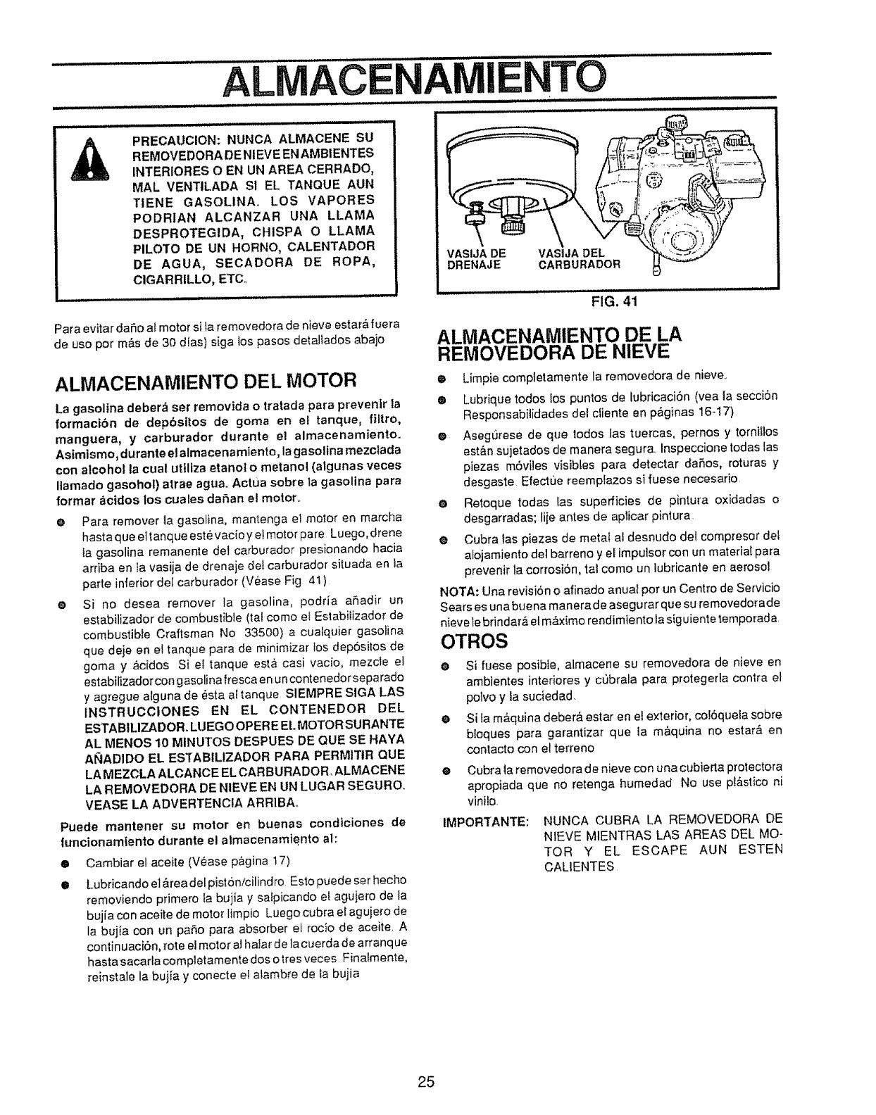
ALIVlACENAMIENTO
ll,ll,,,l,
PRECAUCION: NUNCA ALMACENE SU
REMOVEDORA DE NIEVE EN AMBIENTES
INTERIORES OEN UN AREA CERRADO,
MAL VENTILADA SI EL TANQUE AUN
TIENE GASOLINA, LOS VAPORES
PODR|AN ALCANZAR UNA LLAMA
DESPROTEGIDA, CHISPA O LLAMA
PILO'FO DE UN HORN@, CALENTADOR
DE AGUA, SECADORA DE ROPA,
CIGARRILLO, ETCo
Para evitar da_o al motor si ta removedora de nieve estara rue ra
de us@por m&s de 30 dlas) siga tospasos detaliados abaio
ALMACENAMIENTO DEL MOTOR
VASIJA DE VASIJA DEL
DRENAJE CARBURADOR
La gasolina deber_ set removida otratada para prey@nit la
formactbn de dep6sitos de goma en el tanque, filtro,
manguera, y carburador durante el almacenamiento.
Asirnismo, durante el almacenamIento, la ga solina mezc_ada
con alcohol la cuat utfliza etanol o metanol (algunas veces
Ilamado gasohol) atrae agua.. Actua sobre la gasolina para
formar acidos los cuales daSan el motor..
O
@
Para remover la gasolina, mantenga el molor en marcha
hasta que eltanque estevacioy et motor pare Luego, drene
fa gasolina remanente det carburador presionando hacia
arriba en la vasija de drenaje del carburador situada en la
part@inferior de! carburador (Vease Fig 4t)
Si no desea remover la gasolina, podria a_adir un
estabilizador de combustible (tal corn@ et Estabiiizador de
combustibte Craftsman No 33500) a cualquier gasolina
que deje en e{ tanque para de minimizar tos depositos de
goma y &cidos Si el tanque @st&casi vacio, mezcie el
estabilizador con gasolina fresca e nun conten edor separado
y agregue alguna de _sta aI tanque SIEMPRE SIGA LAS
tNSTRUCCIONES EN EL CONTENEDOFI DEL
ESTABILlZADOR.. LUEGOOPERE ELMOTOR SURANTE
AL MENOS 10 MINUTOS DESPUES DE QUE SE HAYA
AI_IADIDO EL ESTABILIZADOR PARA PERM|TIR QUE
LA MEZCLA ALCANCE EL CARBURADOR ALMACENE
LA REMOVEDORA DE NIEVE EN UN LUGAR SEGUROo
VEASE LA ADVERTENCIA ARRIBA,,
Puede mantener su motor en buenas condiciones de
funciorlamtento durarite el almacenamiento al:
@Cambiar el aceite (V_ase p,_gina !7)
@ Lubricando eiareadetpistbn/cilindro Estopuede set hecho
removiendo primer@ fa bujia y salpicando el agujero de la
buj{a con aceite de motor limpio Luego cubra eI agujero de
ta bujia con un paso para absorber et rocio de aceite A
contin uaciOn0rote el motor a!hafar de la cuerda de arranq ue
hasta sacarla completamente dos otres veces Finatmente,
reinstale la bujfa y conecte e_atambre de ta bujia
FIG. 41
ALMACENAMIENTO DE LA
REMOVEDORA DE NIEVE
@ Limpie completamente la removedora de nieve..
•Lubrique todos !os puntos de tubricaci6n (yea la secci6n
Responsabitidades del ciiente en p_ginas 16.-t7)
eAsegurese de que todos las tuercas, pernos y torni_los
est&n sujetados de manera segura. Inspeccione todas Ias
piezas m6viies visibles para detectar daSos, roturas y
desgaste Efectue reemplazos si fuese necesario
@ Retoque todas las superficies de pintura oxidadas o
desgarradas; liie antes de aplicar pintura
@Cubra las piezas de metal at desnudo del compresor det
alojamiento def barreno y el imputsor con un material para
prevenir la corrosi6n, tat como un lubricante en aerosol
NOTA: Una revisi6n o afinado anua[ por un Centro de Servicio
Sears es una buena manerade asegurar que su removedor ade
nieve lebrindar_ el m&×imo rendimie nto ta siguiente temporada
OTROS
eSi fuese posibie, almacene su removedora de nieve en
ambientes interiores y c_brala para protegerla contra et
polvo y la suciedad
eSi fa m&quina deber_. @star en e! exterior, coF6queia sobre
bloques para garantizar que {a m&quina no estar_ en
contact@ con el torten@
@Cubra ta removedora de nieve con una cubierta protectora
apropiada que no retenga humedad No use p!&sgco ni
vinilo,
IMPORTANTE: NUNCA CUBRA LA REMOVEDORA DE
NIEVE MIENTRAS LAS AREAS DEL MO-
TOR Y EL ESCAPE AUN ESTEN
CAL1ENTES
25
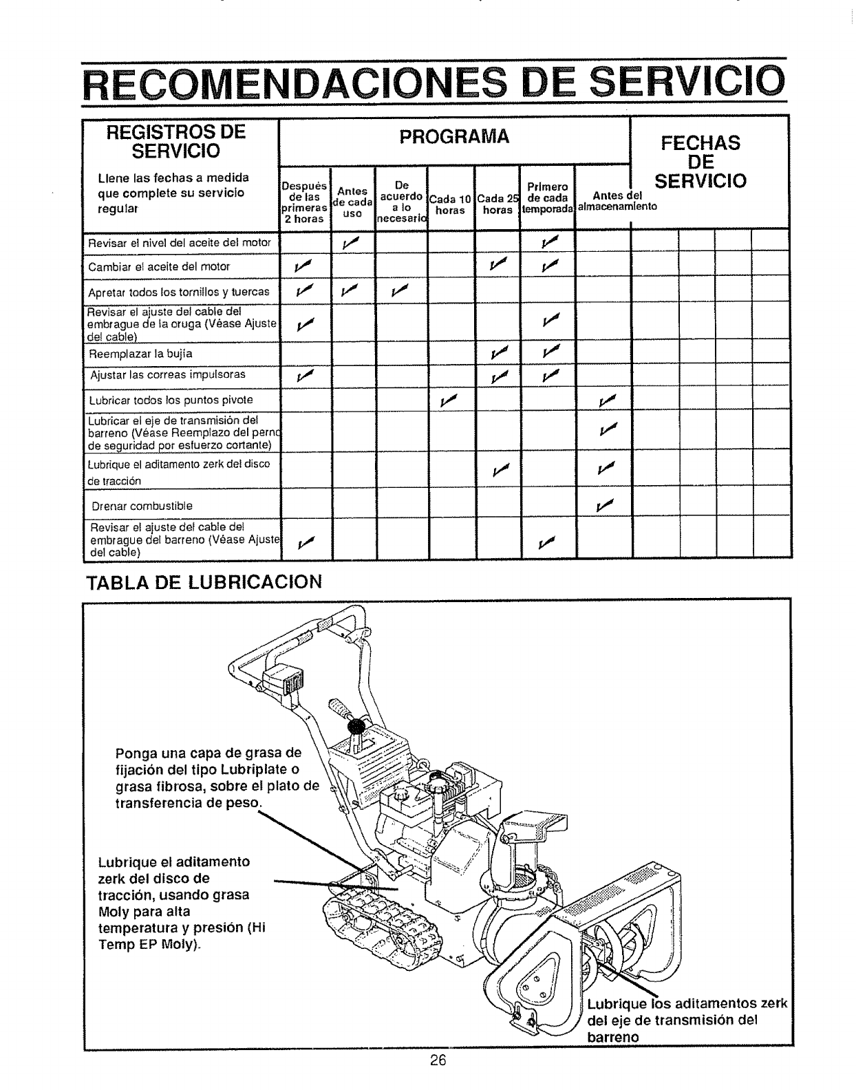
ECO DACIO S
.................REGiSTROS DE
SERVICIO
Llene las fechas a medida Despues
que complete su servicto de las
regular _rimeras
2 horas
Revisar el nive] del aceite de1 motor
Cambiar el aceite del motor V #
,, ,,,,..................
Apretar todos los torniHos y tuercas
Revisar el ajuste del cable del ..........
embrague de fa oruga (V_ase Ajuste
de{ cable) ...................
Reemplazar ]a bujia
.... _Ajust _r II'a'scorreas im'puis'or'as J
Lubricar todos los puntos pivote
PROGRAMA
De Prlmero
Antes acuerdo 3ada 10 Cada 25 decada Antesdel
de cada a io horas horas l_porad_ almacenamlento
use necesar|c
v" v"
ClO
FECHAS
DE
SERVlClO
............ =
Lubricar ei eie de transmisi6n det
barTeno (Vease Reemp_azo del pernc
de seguridad pot esfuerzo cortante) .....
Lubrique el aditamento zerk dei disco /_ /._
de tracci6n ..................
Drenar combustible
"Revisar el ajuste def cable det
embrague del barreno {V_ase Ajust_ j_
del cable) ..............................
TABLA DE LUBRICACION
Ponga una capa de grasa de
fijacibn del tipo Lubriplate o
grasa fibrosa, sobre el plato de
transferencia de peso.
Lubrique el aditamento
zerk del disco de
traccibn, usando grasa
Moty para alta
temperatura y presion (Hi
Temp EP Moly),
26
Lubrique los aditamentos zerk
dei eje de transmisibn del
barreno
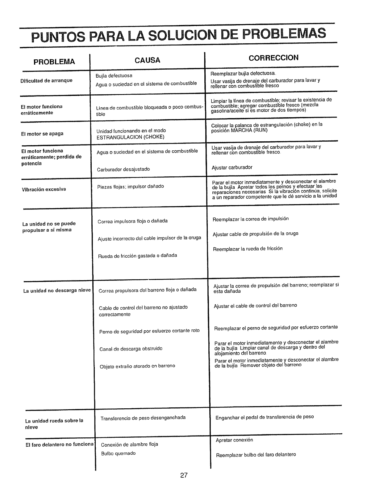
PUNTOS PARA LA SOLUCION DE PROBLEMAS
PROBLEMA
Dificultad de arranque
El motor funciona
err_ticamente
El motor seapaga
El motor funciona
errdticamente; perdida de
potencia
Vtbraci6n excesiva
La unidad no se puede
propulsar a si mlsma
La urtldad no descarga nteve
La unldad rueda sobre la
nieve
El faro delantero no furJcIona
CAUSA
Buiia defectuosa
Agua o suciedad en el sistema de combustible
Ltnea de combustible bloqueada o poco combus-
tible
Unidad funcionando en el mode
ESTRANGULACION (CHOKE)
Agua o suciedad en el sistema de combustible
Carburador desajustado
Piezas tlojas; impulsor da5ado
Correa impulsora floja o daSada
Ajuste incorrecto del cable impulsor de ta oruga
Rueda de fricci6n gas_ada o da_ada
Correa propuIsora del barreno floja o daSada
Cable de control del barreno no aiustado
correclamente
Perno de seguddad por esfuerzo cortante rote
Canal de descarga obslruido
Objeto e×trmfio atorado en barreno
Transferencia de peso desenganchada
Conexi6n de alambre floja
Bulbo quemado
CORRECClON
Reemptazar bujfa defectuosa,
Usar vasija de drenaje del carburador para lavar y
re!tenar con combustible fresco
Limpiar la linea de combustible; revisar la existencia de
combustible; agregar combustible fresco (mezcla
gasolina/aceite si es motor de dos tiempos)
. u i,i
Co!ocar la pafanca de estrangulacion (choke) en la
posici6n MARCHA (RUN)
Usar vasija de drenaje del carburador para lavar y
rellenar con combustible fresco
Ajustar carburador
Parar el motor inmediatamente y desconectar el alambre
de la bujia Apretar todos los pernos y efectuar las
reparaclones necesarias Sila vibraciSn continua, solicite
a un reparador competente que le de servicio a ta unidad
Reemplazar la correa de imputsi6n
Ajustar cable de propulsi6n de la oruga
Reemplazar ia rueda de fricci6n
Ajustar la correa de propulsiSn del barreno; reemplazar si
esta daiSada
Ajuslar el cable de control del barreno
Reempiazar el pemo de seguridad pot esfuerzo cortante
Parar el motor inmediatamente y desconectar el alambre
de ta bujia Limpiar canal de descarga ydentro del
alojamienfo del barreno
Parar e! motor inmediatamente y desconectar el atambre
de la bujia Remover objeto de! barreno
Enganchar el pedal de translerencia de peso
Apretar conexi6n
Reemplazar bulbo det faro delantero
27
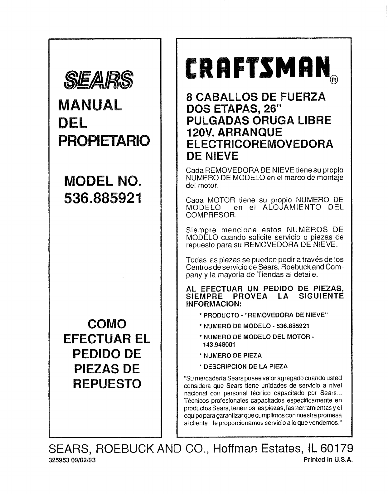
DEL
UAL
MODEL NO.
536. 1
COMO
EFECTUAR EL
PEDIDO DE
PIEZAS DE
REPUESTO
CRRFTSMRN
®
8 CABALLOS DE FUERZA
DOS ETAPAS, 26"
PULGADAS ORUGA LIBRE
120V. ARRANQUE
ELECTRICOREMOVEDORA
DE NIEVE
Cada REMOVEDORA DE NIEVE tiene su propio
NUMERO DE MODELO en el marco de montaje
del motor.
Cada MOTOR tiene su propio NUMERO DE
MODELO en el ALOJAMIENTO DEL
COMPRESOR
Siempre mencione estos NUMEROS DE
MODELO cuando solicite servicio o piezas de
repuesto para su REMOVEDORA DE NIEVE.
Todas las piezas se pueden pedir a trav_s de los
Centros de servicio de Sears, Roebuck and Com-
pany y la mayoria de Tiendas al detaile,,
AL EFECTUAR UN PEDIDO DE PIEZAS,
SlEMPRE PROVEA LA SlGUIENTE
INFORMAClON:
* PRODUCTO -"REMOVEDORA DE NIEVE"
*NUMERO DE MODELO - 536.885921
* NUMERO DE MODELO DEL MOTOR
14&94800t
* NUMERO DE PIEZA
* DESCRIPCiON DE LA PIEZA
"Su mercaderia Sears posee valor agregado cuando usted
considera que Sears tiene unidades de servicio a nivel
nacional con personal t_cnico capacitado por Sears ....
T6cnicos profesionales capacitados especificamente en
productos Sears, tene mos las piezas, las herramientas y el
equipo para garanlizarque curnplimos con nuestra promesa
al cliente,, le proporcionamos servicio a fo que vendemos?
SEARS, ROEBUCK AND CO., Hoffman Estates, tL 60179
325953 09102t93 Printed in U.S.A_
