Craftsman 536886120 User Manual 5HP 22 SNOW THROWER Manuals And Guides L0909323
CRAFTSMAN Snowthrower, Gas Manual L0909323 CRAFTSMAN Snowthrower, Gas Owner's Manual, CRAFTSMAN Snowthrower, Gas installation guides
User Manual: Craftsman 536886120 536886120 CRAFTSMAN 5HP 22 SNOW THROWER - Manuals and Guides View the owners manual for your CRAFTSMAN 5HP 22 SNOW THROWER #536886120. Home:Lawn & Garden Parts:Craftsman Parts:Craftsman 5HP 22 SNOW THROWER Manual
Open the PDF directly: View PDF ![]() .
.
Page Count: 72
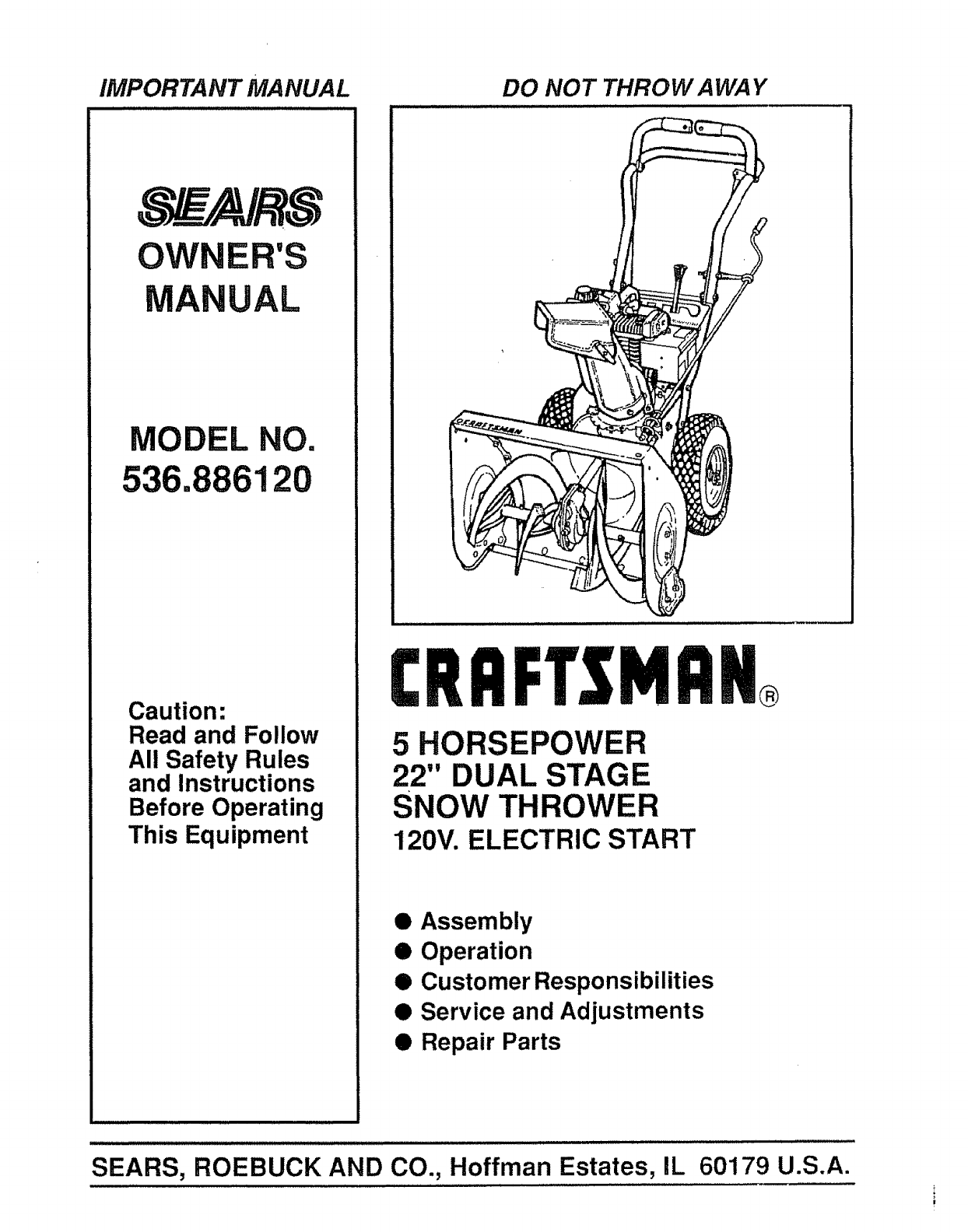
IMPORTANT MANUAL DO NOT THROW AWAY
OWNER'S
ANUAL
MODEL NO.
536.886120
Caution:
Read and Follow
All Safety Rules
and Instructions
Before Operating
This Equipment
CRI]FTSMnH
5 HORSEPOWER
22" DUAL STAGE
SNOW THROWER
120V. ELECTRIC START
• Assembly
• Operation
• Customer Responsibilities
• Service and Adjustments
• Repair Parts
SEARS, ROEBUCK AND CO., Hoffman Estates, IL
i,i i =i
60179 U.S.A.
SAFETY RULES
&CAUTION" ALWAYS DISCONNECT SPARK PLUG WIRE AND &
PLACE WIRE WHERE IT CANNOT CONTACT SPARK PLUG
TO PREVENT ACCIDENTAL STARTING WHEN SETTING-UP,
IMPORTANT
SAFETY STANDARDS REQUIRE OPERATOR PRESENCE CONTROLS TO MINIMIZE THE
RISK OF INJURY. YOUR SNOW THROWER IS EQUIPPED WITH SUCH CONTROLS. DO NOT
ATTEMPT TO DEFEAT THE FUNCTION OF THE OPERATOR PRESENCE CONTROL UNDER
ANY CIRCUMSTANCES.
TRAINING
1. Read the operator's manual carefully° Be
thoroughly familiar with the controls and the
proper use of the snow thrower. Know how to
stop the snow thrower and disengage the
controls quickly.
2. Never allow children to operate the snow thrower
and keep them away while it is operating. Never
allow adults to operate the snow thrower without
proper Instruction. Do not carry passengers.
3. Keep the area of operation clear of all persons,
partlculariy small children, and pets.
4. Exercise caution to avoid slipping or falling,
especially when operating in reverse..
PREPARATION
1. TfiOroughly inspect the area where the snow
thrower Is to be used and remove all doormats,
sleds, boards, wires, and other foreign objects,
2, Disengage all clutches and shift into neutral
before starting the engine (motor).
3. Do not operate the snow thrower without weartng
adequate winter outer garments. Wear footwear
that will Improve footing on slippery surfaces.
4. Handle fuel with care; tt is highly flammable.
(a) Use an approved fuel container.
(b) Never remove fuel tank cap or add fuel to a
running engine or hot engine.
(c) Fill fuel tank outdoors with extreme care.
Never flUfuel tank Indoors.
So
(d) Replace fuel tank cap securely and wipe up
spilled fuel.
(e) Never store fuel or snow thrower with fuel in
thetank inside of a building where fumes may
reach an open flame or spark.
(f) Check fuel supply before each use, allowing
space for expansion as the heat of the engine
(motor) and!or sun can cause fuel to expand.
Use extension cords and receptacles as specified
by the manufacturer for all snow throwers with
electric drive motors or electric starting motors.
6. Adjust the snow thrower height to clear gravel or
crushed rock surfaces.
7. Never attempt to make any adjustments while the
engine (motor) is running (except when
specifically recommended by the manufacturer).
8. Let engine (motor) and snow thrower' adjust to
outdoor temperatures before starting to clear
snow.
,Always wear safety glasses or eye shields during
operation or while performing an adjustment or
repair to protect eyes from foreign objects that
may be thrown from the snow thrower_
OPERATION
1. Do not put hands or feet near' or under rotating
parts. Keep clear of the discharge opening at all
times.
2. Exercise extreme caution when operating on or
crossing gravel drives, walks, or road& Stay alert
for hidden hazards or traffic.
3. After striking a foreign object, stop the engine
(motor), remove the wire from the spark plug,
disconnect the cord on electric motors,
thoroughly inspect the snow thrower for any
damage, and repair the damage before restarting
and operating the snow thrower.
4. if the snow thrower should start to vibrate
abnormally, stop the (motor) and check
immediately for the cause° Vibration Is generally
a warning of trouble.
5. Stop the engine (motor) whenever you leave the
operating position, before unclogging the auger/
impeller housing or discharge guide, and when
making any repairs, adjustments, or inspections_
6. When cleaning, repairing, or inspecting, make
certain the augerttmpeiler and all moving parts
have stopped. Disconnect the spark plug wire
and keep the wire away from the plug to prevent
accidental starting.
7. Take all possible precautions when leaving the
snow thrower unattended. Disengage the auger/
impeller, shift to neutral, stop engine, and
remove key.
SAFETY RULES
8. Do not run the engine indoors, except when starling
the engine and for transportingthe snow thrower In
orout of the building. Open the outside doors;
exhaust fumes aredangerous (containingCARBON
MONOXIDE, an ODORLESS and DEADLY GAS).
9. Do not clear snow across the face of slopes_
Exercise caution when changing direction on
slopes. Do not attempt to clear steep slopes.
10. Never operate the snow thrower without proper
guards, plates or other safety protective devices
In place.
11. Never operate the snow thrower near glass
enclosures, automobiles, window wells,
drop.ofts, and the llke without properadjustment
of the snow discharge angle. Keep children and
pets away.
12. Do not overload the machine capacity by
attempUng to clear snow at too fast a rate.
13. Neveroperatethe snow thrower at high transport
speeds on slippery surfaces. Look behind and
use care when backing.
14. Never direct discharge at bystanders or allow
anyone in front of the snow thrower.
15. Disengage power to the auger/Impeller when
snow thrower is transported or not in use.
16. Use onlyattachments and accessories approved
by the manufacturer of the snow thrower (such
as tire chains, electric start kits, etc.)o
17. Never operate the snow thrower without good
visibility or tlghtoAlways be sure of your footing,
and keep a firm hold on the handles. Walk; never
n.ln.
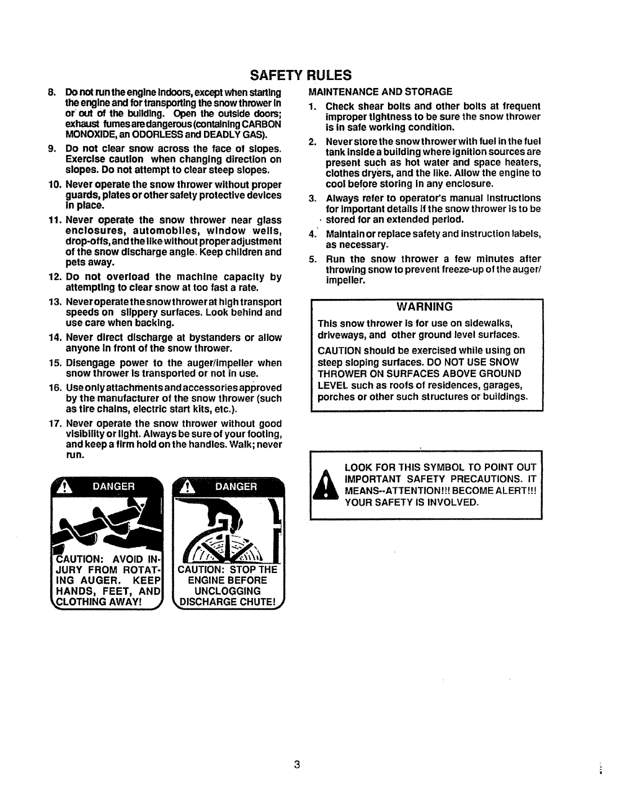
DISCHARGE CHUTE!
MAINTENANCEANDSTORAGE
1. Check shear bolts and other bolts at frequent
improper tightness to be sure the snow thrower
is in safe working condition.
2. Never store the snow thrower with fuel inthe fuel
tank inside a building where ignition sources are
present such as hot water and space heaters,
clothes dryers, and the like. Allow the engine to
cool before storing in any enclosure.
3_ Always refer to operator's manual Instructions
for Important details if the snow thrower is to be
,stored for an extended period.
4o Maintain or replace safety and instruction labels,
as necessary.
5_ Run the snow thrower a few minutes after
throwing snow to prevent freeze-up of the auger/
impeller.
WARNING
This snow thrower is for use on sidewalks,
driveways, and other ground level surfaces.
CAUTION should be exercised while using on
steep sloping surfaces_ DO NOT USE SNOW
THROWER ON SURFACES ABOVE GROUND
LEVEL such as roots of residences, garages,
porches or other such structures or buildings°
LOOK FOR THIS SYMBOL TO POINT OUT
iMPORTANT SAFETY PRECAUTIONS. IT
MEANS--ATTENTION!!! BECOME ALERT!!!
YOUR SAFETY IS INVOLVED.
3
CONGRATULATIONS on your purchase of a Sears
Craftsman Snow Thrower_ It has been designed, engi-
neered and manufactured to give you the best possible
dependability and performance.
Should you experience any problem you cannot easily
remedy, please contact your nearest Sears Service
Center/Department. Sears has competent, welHrained
technicians and the proper tools to service or repair this
unit.
Please read and retain this manual. The instructionswilt
enable youto assemble and maintainyour snow thrower
properly. Always observe the "SAFETY RULES"
/== =/=/=
MODEL
NUMBER 536.886120
SERIAL
NUMBER
DATE OF
PURCHASE
THE MODEL AND SERIAL NUMBERS WILL BE
FOUND ON A DECAL ATTACHED TO THE REAR
OF THE SNOW THROWER HOUSING.
YC)USHOULD RECORD BOTH SERIAL NUMBER
AND DATE OF PURCHASE AND KEEP IN A SAFE
PLACE FOR FUTURE REFERENCE.
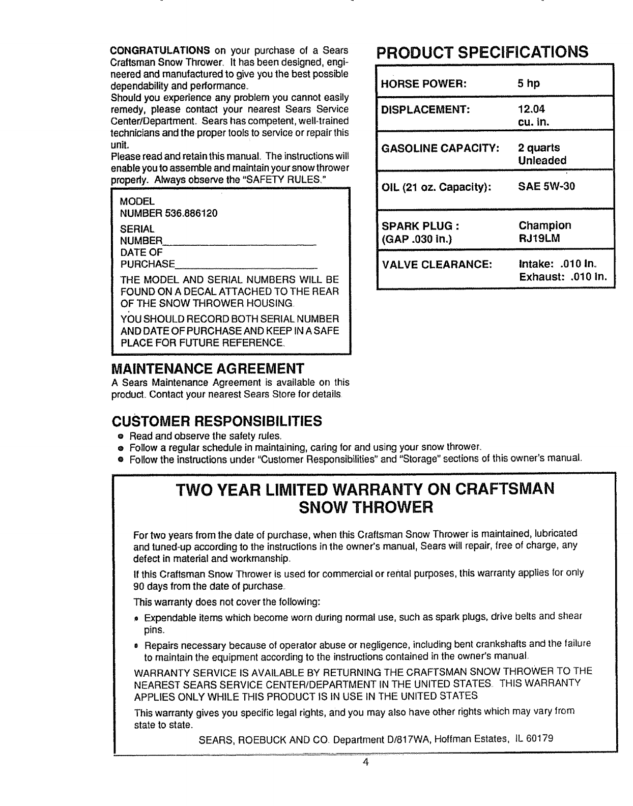
PRODUCT SPECIFICATIONS
HORSE POWER: 5 hp
i
DISPLACEMENT: 12.04
CU. in.
GASOLINE CAPACITY:
OIL (21 oz. Capacity):
2 quarts
Unleaded
SAE 5W-30
SPARK PLUG :
(GAP .030 in,)
VALVE CLEARANCE:
Champion
RJ19LM
Intake: .010 In.
Exhaust: .010 in.
MAINTENANCE AG REEMENT
ASears Maintenance Agreement is available on this
product.Contact your'nearest Sears Store for details.
CUSTOMER RESPONSIBILITIES
eRead and observe the safety rules_
® Follow a regular schedule in maintaining, caring for and using your snow thrower_
• Follow the instructions under "Customer Responsibilities" and "Storage" sections of this owner's manual
TWO YEAR LIMITED WARRANTY ON CRAFTSMAN
SNOW THROWER
For two years from the date of purchase, when this Craftsman Snow Thrower is maintained, lubricated
and tuned-up according to the instructions in the owner's manual, Sears will repair, free of charge, any
defect in material and workmanship
If this Craftsman Snow Thrower is used for commercial or rental purposes, thiswarranty applies for only
90 days from the date of purchase..
This warranty does not cover the following:
Expendable items which become worn during normal use, such as spark plugs, drive belts and shear
pins.
=Repairs necessary because of operator abuse or negligence, includingbent crankshafts and the failure
to maintain the equipment accordingto the instructionscontained in the owner's manuat_
WARRANTY SERVICE IS AVAILABLE BY RETURNING THE CRAFTSMAN SNOW THROWER TO THE
NEAREST SEARS SERVICE CENTER/DEPARTMENT IN THE UNITED STATES. THIS WARRANTY
APPLIES ONLY WHILE THIS PRODUCT IS IN USE IN THE UNITED STATES
This warranty gives you specific legal rights, and you may also have other rights which may vary from
state to state.
SEARS, ROEBUCK AND CO. Department D/817WA, Hoffman Estates, tL 60179
4
TABLE OF CONTENTS
SAFETY RULES ........................................ 2,3
PRODUCT SPECIFICATIONS ....................... 4
CUSTOMER RESPONSIBILITIES ..... 4,15-17
WARRANTY .................................................. 4
TABLE OF CONTENTS ... ............................. 5
INDEX .... ....................................................... 5
ASSEMBLY .............. ;................................ .6-9
OPERATION ........................................... 10-14
SERVICE AND ADJUSTMENTS ............ 18-24
STORAGE ................................................... 25
TROUBLE SHOOTING ............................... 26
REPAIR PARTS (SNOW THROWER)... 28-39
REPAIR PARTS (ENGINE) .................... 40-43
PARTS ORDERING/SERVICE ................... 44
A
Adjustment:
Belt ............................................. 19,20
Belt Guide ..........................................................2!
Cable ................................................ 19
Carburetor .........................................23
Friction Wheel ........................... 20,21
Spark Plug ..................................................23
Traction and Auger ..................................19,20
Assembly:
Crank Assembly ................................................8-9
Shifter Lever ........................................9
Skid Height Adjustment ...................7, 19
Unpacking .....................................................7
B
Belts:
Adjust Belts ................................ 19,20
Belt Guide Adjustment.....................21
Replace Belts .........................................20
C
Cables, Clutch........................... 7, 9, I9
Carburetor:. ........................................ 24
Choke .............................. 10, 11, 13,14
Clutch, Levers ...............................................10, t 1
Controls:
Engine .....................................10, 11, 13, 14
Snow Thrower ................................................10
Crank:
Assembly ...............................................................8
Operation .....................................................1t
Customer Responsibilities .........4,15-t7
Agreement ...........................................................4
Auger Gear Box ........................................17
Auger Shaft .......................................16
Engine ........................................... 17
General Recommendations ..................16
Hex Shaft and Gears .............................!7
D
Drive, Auger ..........................................................11
Drive, Traction .................................. 11
Deflector, Snow Chute ............................11
E
Engine:
Control ......................... 10, 11, !3, 14
Oil Cap ..........................................................12, 17
Oil Change ..............................................16
Oil Level ........................................12, 17
Oi! Type .................::...............4, 12, 17
Speed Governor .......................................26
Starling, Electrically ............................13
Starting, Manually ......................................14
Storage .................................................25
INDEX
F
Fuel, Type .............................................4, 12
Fuel, Storage.............................. 12, 25
Friction Wheel:
Adjustment...................................... 21
Replacement ................................. 22
G
Gears:
Auger Gear Box ......_..............................17
Hex Shaft ................................................................17
H
Handle_ Upper and Lower ................... 7
Height AdjustSkids ........................7, 18
Hex Shaft ......................................... 17
1
Ignition, Key ......................10, 11, 13, 14
Index o.;.........:..........................................................5
L
Levers:
Auger Drive Clutch .........7, "i0, 11, 19
Choke ......................................10, 11, 13, 14
Shifter .....................................................9, 10, 11
Throttle Control .................10, 11, 13, 14
Traction Drive Clutch......7, 10, 1 t, 19
Lubrication:
Auger Gear Box ............................. 17
Auger Shaft ..................................... 16
Disc Drive Plate .....................................16
Engine .................................. 12,17,25
Hex Shaft and Gears ..........................17
O
Oil:
Engine ................................. 4, 12, 17
Extreme Cold Weather ............. 12,17
Storage ............................................................25
Type ........................................4, 12, 17
Operation:
Engine Controls ..............10, 1I, 13,t4
Operating Snow Thrower.o. 11, 12, 15
Lockout Pin, Wheel .............................12
Operating Tips ................................. t4
Starting the Engine, Electric .......... !3
Starting the Engine, Recoi! ...............14
Snow Thrower Controls ................10.12
P
Parts.................................................................28-43
Primer Button ......................... I0, 11, 13
R
Repair/Replacement Parts .............28-42
Recoil Starter .................................................13
Replacements:
Auger Shear Bolt ......................................23
Belts .............................................................19,20
Friction Wheel ........................... 21,22
S
Safety Rules ..........................................2, 3
Service and Adjustments:
Auger Housing Height .....................7, 18
Auger Shear Bolt ...............................23
Belts .......................................................................19-20
Belt Guide ................................................21
Belt Replacements ...............................20
Cable ...............................................................7, 9, 19
Carburetor ......................................13,23, 25
Friction Wheel .....................................21, 22
Spark Plug ...................................................24
Service Recommendations ....................25
Spark Plug ...............................................17, 24
Specifications ...............................................4
Speed Governor ..................................................23
Starting the Engine:
Recoil Start ..o;........................................13
Stopping the Engine ......................13, 14
Stopping the Snow Thrower ...............11
Shipping Carton .........................................6, 7
Skid Height ............................................7, 18
Shifter Lever ............................................9-11
Shear Bolts .........................................................23
Storage ..............................................................25
T
Table of Contents ................................. 5
Trouble Shooting Chart ..............................26
Tools for Assembly ...................................6
Traction Drive Belt .............................19, 20
Tire Pressure .............................................18
W
Warranty ..................'.................................................4
Wheel, Lockout Pin......................................12
CONTENTS OF HARDWARE PACK
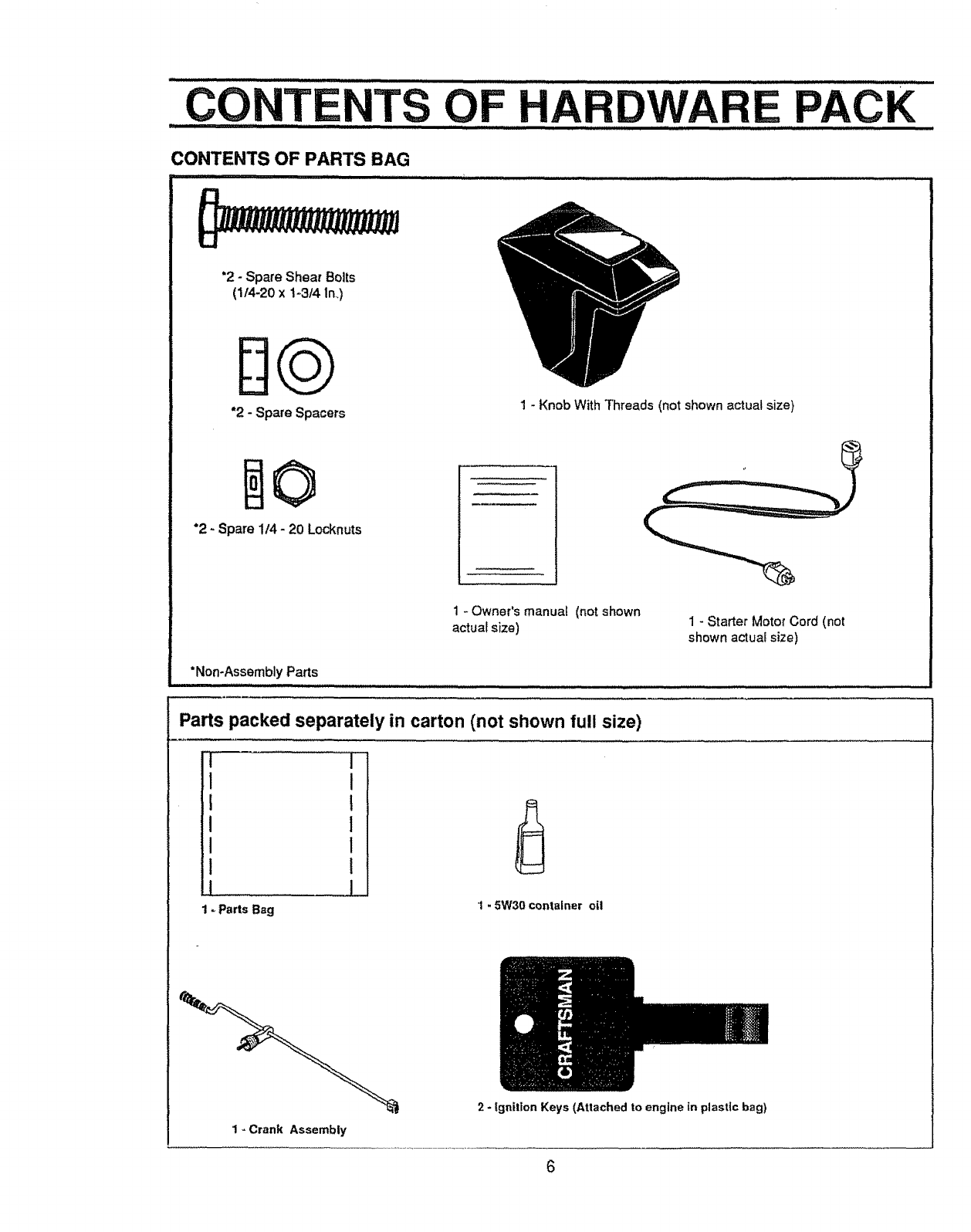
CONTENTS OF PARTS BAG
i ......................
'2 - Spare Shear Bolts
(1/4-20 xt-3/4 In.,)
"2 -Spare Spacers 1 - Knob With Threads (not shown actual size)
0
*2 - Spare 1/4 - 20 Locknuts
1 - Owner's manual (not shown
actual size) 1oStarter Motor Cord (not
shown actual size)
*Non-Assembly Parts
Parts packed separately in carton (not shown full size)
F,
I
!,
!1
!t................................
1_Parts Bag 1-5W30container oil
1-Crank Assembly
2 - Ignition Keys (Attached to engine tn plastic bag)
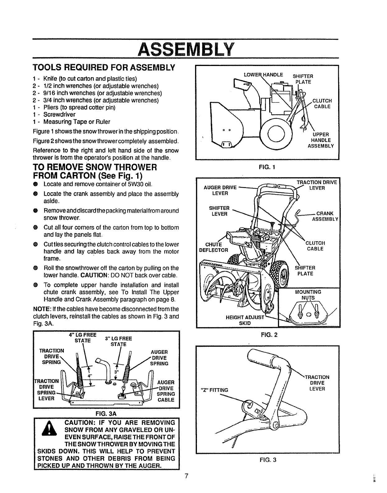
TOOLS REQUIRED FOR ASSEMBLY
1 - Knife (to cut carton and plasticties)
2 - 112inch wrenches (or adjustable wrenches)
2 - 9/16 inch wrenches (or adjustable wrenches)
2 - 3/4 inch wrenches (or adjustable wrenches)
1 - Pliers (to spread cotter pin)
1 _ Screwdriver
1 - Measuring Tape or Ruler
Figure 1shows the snowthrower in the shipping position.
Figure 2 showsthe snowthrower completely assembled°
Reference to the right and left hand side of the snow
thrower is from the operator's position at the handle.
TO REMOVE SNOW THROWER
FROM CARTON (See Fig. 1)
@ Locate and remove container of 5W30 oil.
0
o
®
®
®
®
Locate the crank assembly and place the assembly
aside,,
Remove and discardthe packing materialfrom around
snow thrower.,
Cut all four comers of the carton from top to bottom
and lay the panels flaL
Cut ties securing the clutch control cables to the lower
handle and lay cables back away from the motor
frame,
Roll the snowthrower oft the carton by pulling on the
lower handle,, CAUTION: DO NOT back over cable.
To complete upper handle installation and install
chute crank assembly, see To Install The Upper
Handle and Crank Assembly paragraph on page 8,,
NOTE: If the cables have become disconnected from the
clutch levers, reinstall the cables as shown in Fig 3and
Fig. 3A.
4;;LGF.eE 3"
STATE LG FREE
STATE
TRACTION
RACTION
•DRIVE
AUGER
SPRING
AUGER
SPRING
LEVER CABLE
FIG. 3A
iii J iii Jllll I ii1[[ iiijll ii ......................
CAUTION: IF YOU ARE REMOVING
SNOW FROM ANY GRAVELED OR UN-
EVEN SURFACE, RAISE THE FRONT OF
THE SNOWTHROWER BY MOVING THE
SKIDS DOWN. THIS WILL HELP TO PREVENT
STONES AND OTHER DEBRIS FROM BEING
PICKED UP AND THROWN BY THE AUGER.
FIG. I
HEIGHT
SKID
HANDLE SHIFTER
PLATE
LY
CLUTCH
CABLE
FIG, 2
"Z" FITTING
FIG,, 3
UPPER
HANDLE
ASSEMBLY
DRIVE
LEVER
7
LY
LIJ,/,/i
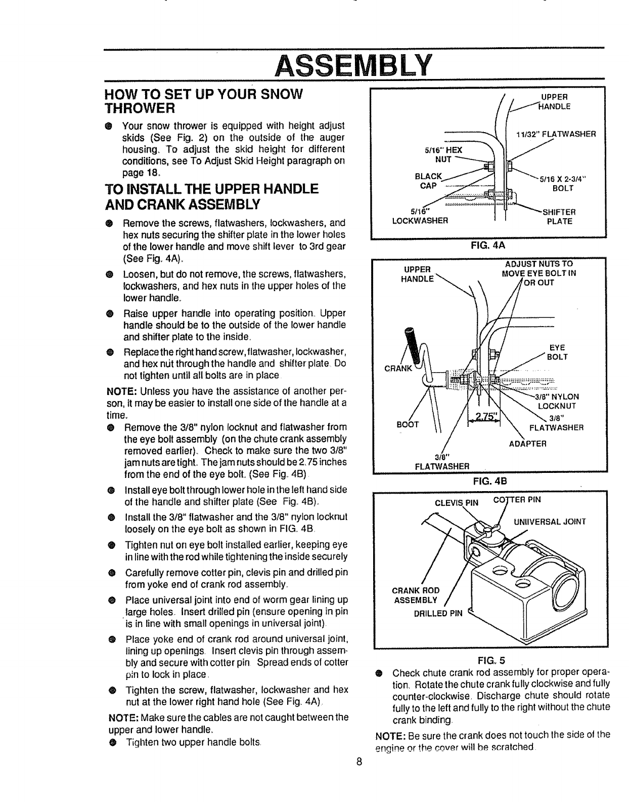
HOW TO SET UP YOUR SNOW
THROWER
® Your snow thrower is equipped with height adjust
skids (See Fig. 2) on the outside of the auger
housing. To adjust the skid height for different
conditions, see To Adjust Skid Height paragraph on
page 18.
TO INSTALL THE UPPER HANDLE
AND CRANK ASSEMBLY
® Remove the screws, flatwashers, lockwashers, and
hex nuts securing the shifter plate in the lower holes
of the lower handle and move shift lever to 3rd gear
(See Fig_ 4A)_
• Loosen, but do not remove, the screws, ftatwashers,
tockwashers, and hex nuts in the upper holes of the
lower' handle.
® Raise upper handle into operating position. Upper
handle should be to the outside of the lower' handle
and shifter plate to the inside°
® Replace the right hand screw, flatwasher, iockwasher,
and hex ndt through the handle and shifter plate Do
not tighten until all bolts are in place
NOTE: Unless you have the assistance of another per-
son, it may be easier to install one side of the handle at a
tirRe_
®Remove the 3/8" nylon locknut and flatwasher from
the eye bolt assembly (on the chute crank assembly
removed earlier). Check to make sure the two 3/8"
jam nuts aretighL The jam nuts shoutd be 2,75 inches
from the end of the eye bolt, (See Fig,,4B),
®Installeye boltthroughlower hole inthe left hand side
o! the handle and shifter plate (See Fig_4B),.
@ installthe 3/8" flatwasher and the 3/8" nylon Iocknut
loosely on the eye bolt as shown in FIG,,4B
®Tighten nut on eye bolt installed earlier, keeping eye
in line with the rod while tighte ning the insidesecurely
• Carefully remove cotter pin, clevis pin and drilled pin
from yoke end of crank rod assembty_
• Place universal joint into end of worm gear lining up
large holes, insert drilled pin (ensure opening in pin
is in line with small openings in universal joint).
e Place yoke end of crank rod around universal joint,
lining up openings insert clevis pin through assem-
bly and secure with cotter pin Spread ends of cotter
p_nto lock in place.
®Tighten the screw, flatwasher, Iockwasher and hex
nut at the lower right hand hole (See Fig. 4A).
NOTE: Make sure the cables are not caught between the
upper and lower handler
•Tighten two upper handle bolts.
UPPER
_DLE
5Ilt
NUT
BLACK
CAP
11132" FLATWASHER
BOLT
5tt6"
LOCKWASHER PLATE
FIG, 4A
ADJUST NUTS TO
MOVE EYE BOLT IN
UPPER
HANDLE'_
EYE
BOOT
3f8"
FLA"t3t#ASHER
CLEVIS PIN
NYLON
LOCKNUT
3t8"
FLATWASHER
ADAPTER
FIG. 4B
! PIN
UNIIVERSALJOINT
CRANK ROD
ASSEMBLY
DRILLED PIN
8
FIG_5
® Check chute crank rod assembly for proper opera-
tion. Rotate the chute crank fully clockwise and fully
counter-clockwise Discharge chute should rotate
fully to the left and fully to the right without the chute
crank binding.
NOTE: Be sure the crank does not touch the side ol the
engine or the cover will he scratched
ASSEMBLY
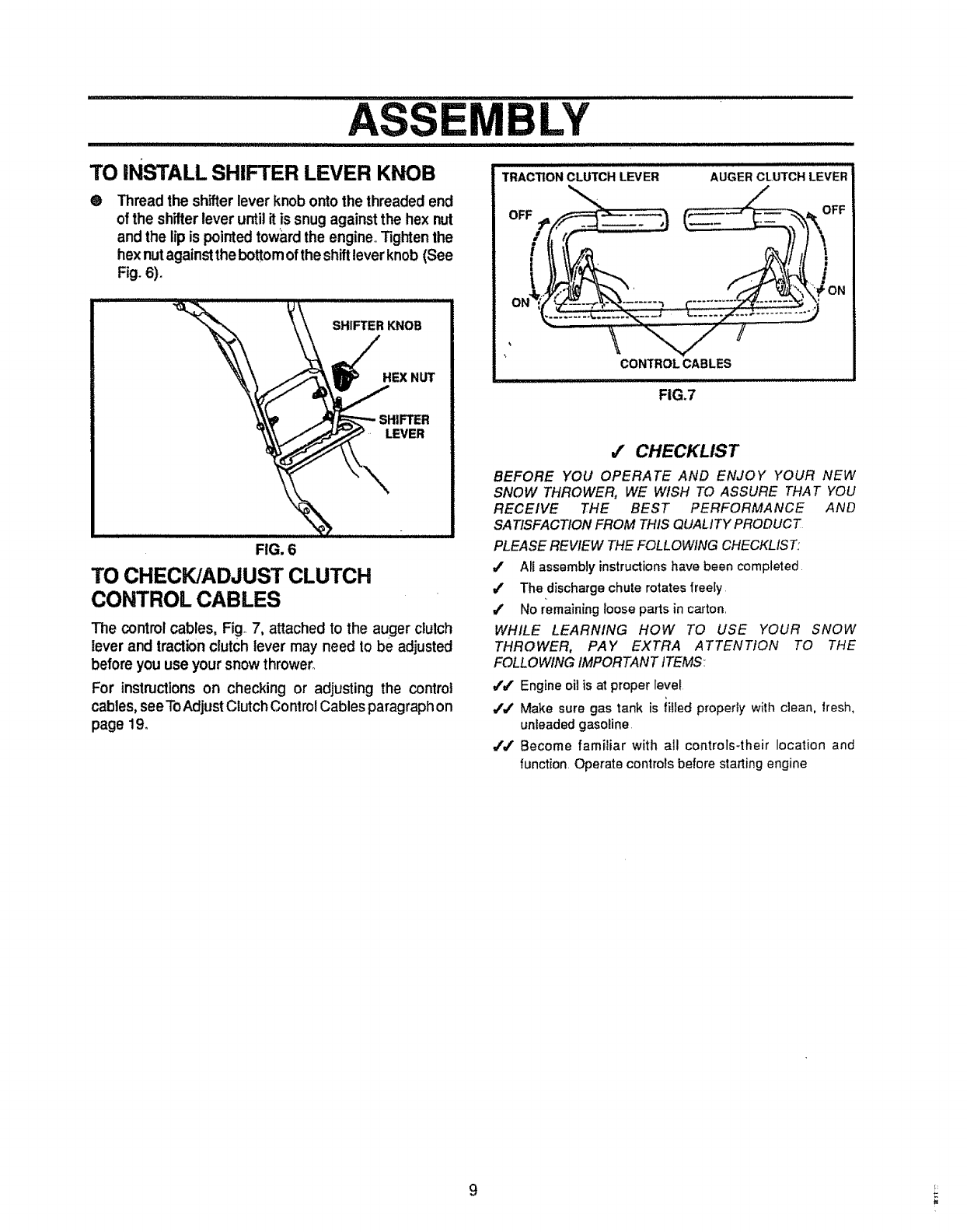
TO iNSTALL SHIFTER LEVER KNOB
®Thread the shifter lever knob onto the threaded end
of the shifterlever until it is snug againstthe hex nut
and the tip is pointed toward the engine..Tighten the
hex nut against the bottom of the shift lever knob (See
Fig. 6).
FIG. 6
TO CHECK/ADJUST CLUTCH
CONTROL CABLES
The control cables, Fig 7, attachedto the auger clutch
lever and tractionclutch lever may need to be adjusted
before you use your snow thrower_
For instructions on checking or adjusting the control
cables, see ToAdjust Clutch Control Cables paragraphon
page 19.
i llu ii i ,llllll,i llllIHN,lll
TRACTIONCLUTCHLEVER AUGERCLUTCHLEVER
OFF
CONTROLCABLES
FIG.7
,/ CHECKLIST
BEFORE YOU OPERATE AND ENJOY YOUR NEW
SNOW THROWER, WE WISH TO ASSURE THAT YOU
RECEIVE THE BEST PERFORMANCE AND
SATISFACTION FROM THIS QUALITY PRODUCT
PLEASE REVIEW THE FOLLOWING CHECKLIST:
/All assembly instructionshave been completed
J The discharge chute rotates freely
4' No remaining loose parts in carton,
WHILE LEARNING HOW TO USE YOUR SNOW
THROWER, PAY EXTRA ATTENTION TO THE
FOLLOWING IMPORTANT tTEMS:
,f=f Engine oil is at proper lever
/J Make sure gas tank is iiiled properIy with clean, lresh,
unleaded gasoline
_J Become familiar with all controls-their location and
function, Operate controls before starting engine
9
ORATIO
i i= ll=l i i ,i i,n i =l j==l
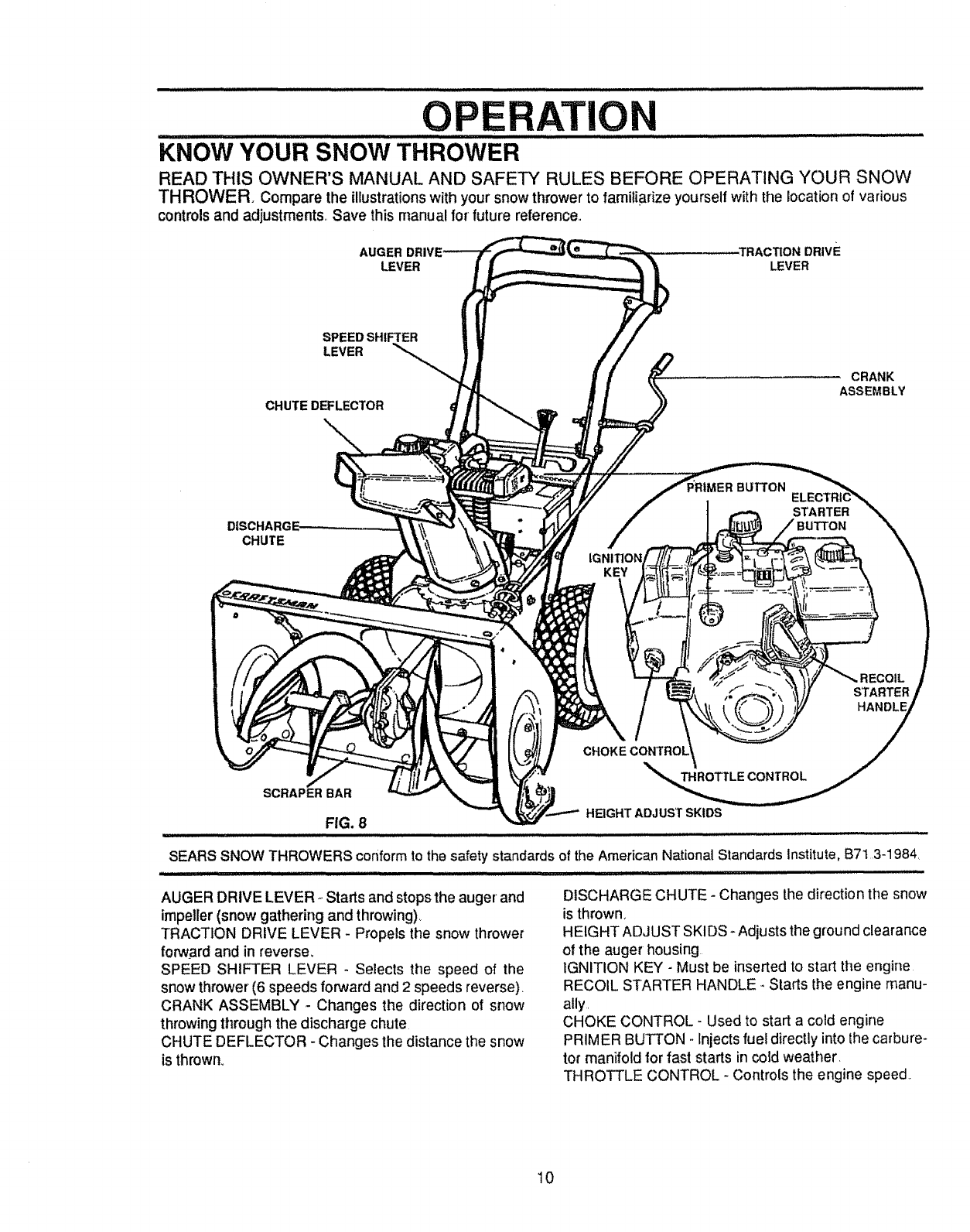
KNOW YOUR SNOW THROWER
READ THIS OWNER'S MANUAL AND SAFETY RULES BEFORE OPERATING YOUR SNOW
THROWER. Comparethe illustrationswith your snowthrower to familiarize yourselfwith the location of various
controlsand adjustments_ Save this manual for future reference.
AUG
LEVER LEVER
SPEED SHIFTER
LEVER
CHUTEDEFLECTOR
-\
CRANK
ASSEMBLY
CHUTE
_tMER BUTTON
STARTER
STARTER /
CHOKE CONTROL y
HEIGHT ADJUST SKIDS
of the American National Standards institute, B7t 3-1984_
AUGER DRIVE LEVER _.Starts and stops the auger and
impeller (snow gathering and throwing).,
TRACTION DRIVE LEVER - Propels the snow thrower
forward and in reverse,
SPEED SHIFTER LEVER -Selects the speed of the
snow thrower (6 speeds forward and 2 speeds reverse),
CRANK ASSEMBLY - Changes the direction of snow
throwing through the discharge chute
CHUTE DEFLECTOR -Changes the distance the snow
is thrown°
DISCHARGE CHUTE -Changes the direction the snow
is thrown,
HEIGHT ADJUST SKIDS - Adjusts the ground clearance
of the auger housing
IGNITION KEY -Must be inserted to start the engine
RECOIL STARTER HANDLE- Stads the engine manu-
ally,
CHOKE CONTROL- Used to start a cold engine
PRIMER BUTTON - Injects fuel directly into the carbure-
tor manifold for fast starts in cold weather.
THROTTLE CONTROL - Controls the engine speed.
10
OP T
The operationof any snow throwercan result inforeignobjectsbeing throwninto the
eyes, which can result in severe eye damage Always wear safety glasses or eye
shields while operating the snow thrower_
We recommend standard safety glasses available at SEARS Retail Stores or
Service Centers,
HOW TO USE YOUR SNOW
THROWER
TO STOP YOUR SNOW THROWER
®To stopthrowingsnow, releasethe augerdrive lever
(See Fig. 11).
•To stop the traction drive, release the traction drive
lever. (See Figure 11).
® To stop the engine, push the throttle control lever to
STOP and pull outthe ignitionkey (See Fig 10)
NOTE: DO NOT turn key.
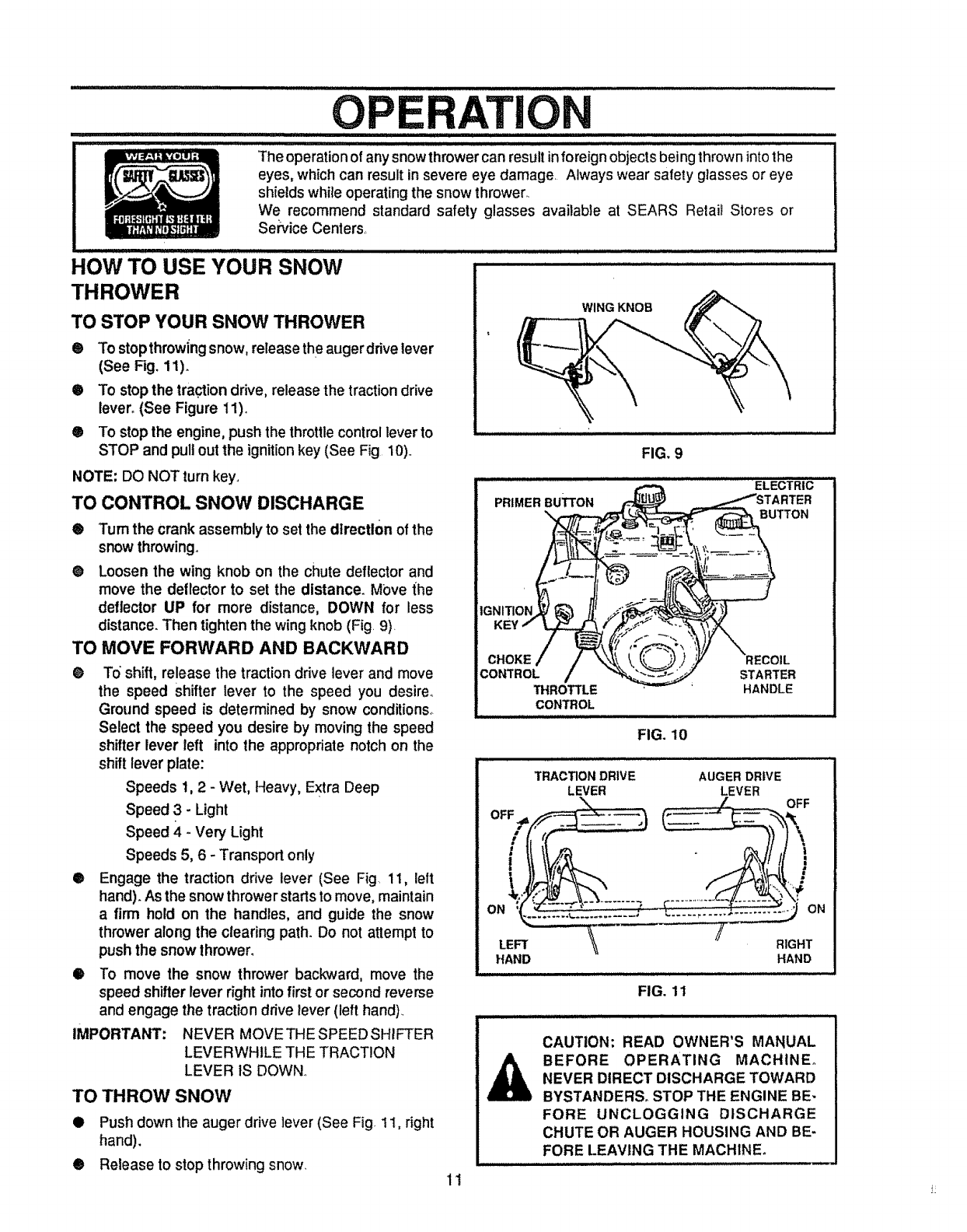
TO CONTROL SNOW DISCHARGE
® Turn the crank assembly to set the dtrectl0n of the
snow throwing,
@Loosen the wing knob on the chute deflector and
move the deflector to set the distance. Move the
deflector UP for more distance, DOWN for less
distance. Then tighten the wing knob (Fig 9)
TO MOVE FORWARD AND BACKWARD
@ To"shift, release the traction drive lever and move
the speed shifter lever to the speed you desirer
Ground speed is determined by snow conditions°
Select the speed you desire by moving the speed
shifter lever left into the appropriate notch on the
shift lever plate:
Speeds 1,2 - Wet, Heavy, Extra Deep
Speed 3 - Light
Speed 4 - Very Light
Speeds 5, 6 - Transport only
® Engage the traction drive lever (See Fig 11, lelt
hand). As the snow thrower starts to move, maintain
a firm hold on the handles, and guide the snow
thrower along the clearing path. Do not attempt to
push the snow lhrower.
•To move the snow thrower backward, move the
speed shifter lever right into first or second reverse
and engage the traction drive lever (left hand)
IMPORTANT: NEVER MOVE THE SPEED SHIFTER
LEVERWHILE THE TRACTION
LEVER tS DOWN.
TO THROW SNOW
•Push down the auger drive lever (See Fig 11, right
hand).
® Release to stop throwing snow
WING KNOB
FIG. 9
ELECTRIC
BUTTON
CHOKE
CONTROL
THROTTLE
CONTROL
STARTER
HANDLE
FIG. 10
TRACTION DRIVE AUGER DRIVE
LEVER LEVER
1!
LEFT _\ RIGHT
HAND HAND
FIG. 11
CAUTION: READ OWNER'S MANUAL
BEFORE OPERATING MACHINE°
NEVER DIRECT DISCHARGE TOWARD
BYSTANDERS, STOP THE ENGINE BE-
FORE UNCLOGGING DISCHARGE
CHUTE OR AUGER HOUSING AND BE-
FORE LEAVING THE MACHINE.
............... i1, iii iiiiii1, i i iiiiiii1, i i ,i ,i ii,Jll,,,J iii ii ii ii iii1,11 i i i,Jlll, i,
OPERATION
................. i i ill ......................................................................................................
mm i ll,ll im,i ii, i,i i, H,
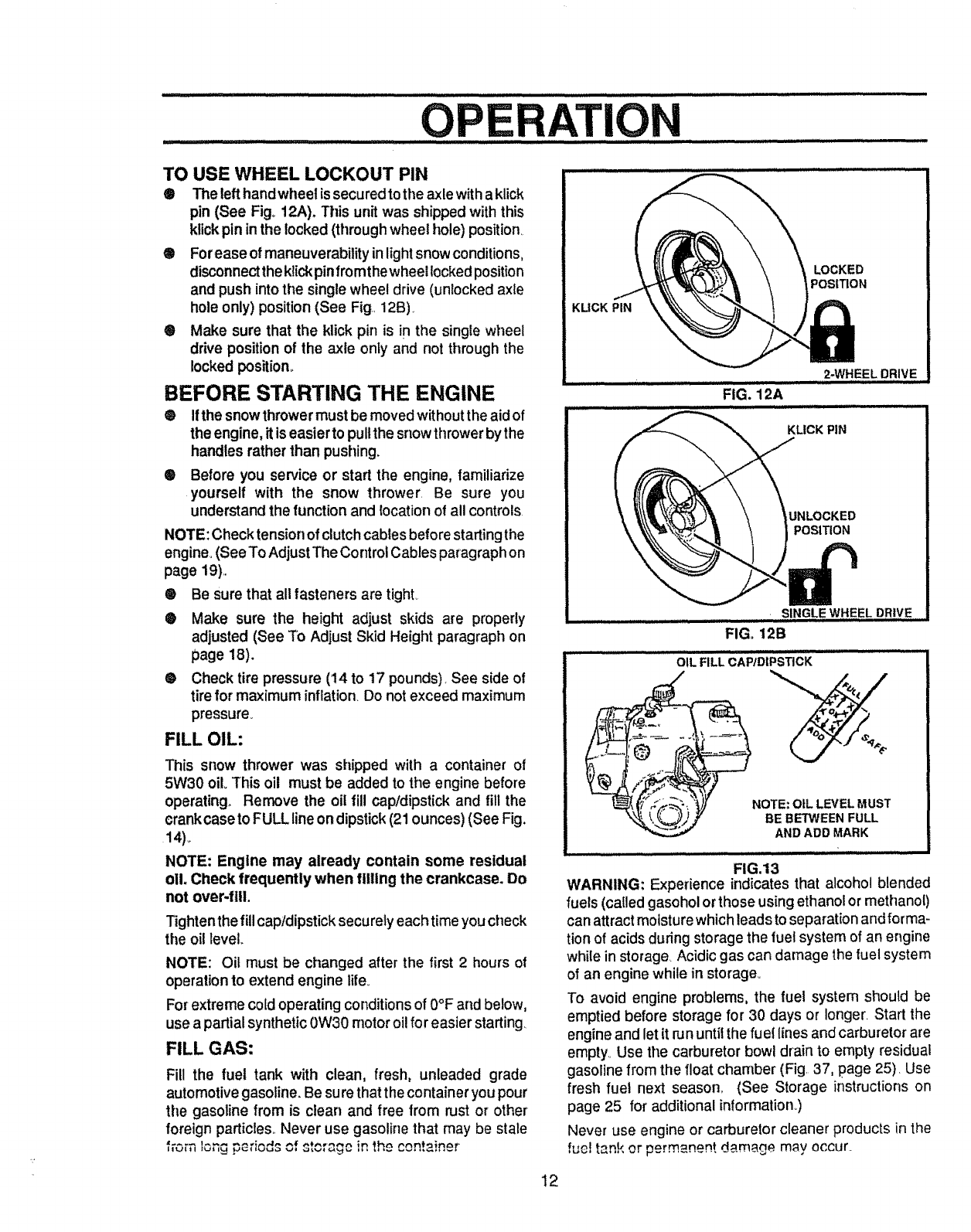
TO USE WHEEL LOCKOUT PIN
®The left handwheel is securedto the axle witha klick
pin (See Fig+ 12A). This unit was shipped with this
klickpin inthe locked (throughwheel hole) position
®Forease of maneuverabilityin lightsnowconditions,
disconnectthe klickpinfromthe wheel lockedposition
and push intothe singlewheel drive (unlocked axle
hole only) position(See Fig 12B),
®Make sure that the klick pin is in the single wheel
drive position of the axle only and not throughthe
locked position+
BEFORE STARTING THE ENGINE
Qlithe snowthrower must be movedwithoutthe aidof
the engine, itis easierto pullthe snowthrowerby the
handles rather than pushing.
®Before you service or start the engine, familiarize
yourself with the snow thrower, Be sure you
understand the function and {ocation of all controls.
NOTE: Checktensionof clutchcablesbefore starting the
engine°(See To Adjust The Control Cables paragraphon
page 19),,
®Be sure that all fasteners are tight..
®Make sure the height adjust skids are properly
adjusted (See To Adjust Skid Height paragraph on
page 18).
@ Check tire pressure (14 to 17 pounds). See side of
tire for maximum inflation. Do not exceed maximum
pressure+
FILL OIL:
This snow thrower was shipped with a container of
5W30 oil+ This oil must be added to the engine before
operating.+ Remove the oil fill cap/dipstick and fill the
crankcase to FULL line on dipstick (21ounces) (See Fig,
14)+
NOTE: Engine may already contain some residual
oli. Check frequently when filling the crankcase. Do
not over-fill.
Tightenthe fillcap/dipsticksecurelyeach time youcheck
the oil level+
NOTE: Oil must be changed after the first 2 hours of
operation to extend engine life+
For extreme cold operating conditions of 0°F and below,
use a partial synthetic 0W30 motoroil for easier starting.
FILL GAS:
Fill the fuel tank with clean, fresh, unleaded grade
automotive gasoline. Be su rethat the container you pour
the gasoline from is clean and free from rust or other
foreign particles,, Never use gasoline that may be stale
+e.... *
.u++, IOr_C+_Gt'iOdS of <+'++"_'+'+++' h_
+ + +_++-++++_+_+...+ +_n 't_ ,+ t"+'+n+Im+t_+_+++
KUCK PIN
LOCKED
POSITION
, , ......2-WHEEL DRIVE
FIG. 12A
............... /H / i i
KLICK PIN
UNLOCKED
POSITION
SINGLE WHEEL DRIVE
FIG. 12B
..................mLF, iCA¢;;IPS CK ..................
(_ NOTE: OIL LEVEL MUST
BE BETWEEN FULL
AND ADD MARK
FIG.13
WARNING: Experience indicates that alcohol blended
fuels (called gasoholorthose usingethanolor methanol)
can attractmoisturewhichleads toseparation andforma-
tion of acids during storage the fuel system of an engine
while in storage, Acidic gas can damage the fuel system
of an engine while in storage°
To avoid engine problems, the fuel system should be
emptied before storage for 30 days or Ionger_Start the
engineand let it run untilthe fuel lines and carburetorare
empty,,Use the carburetor bowl drain to empty residual
gasoline from the float chamber (Fig, 37, page 25)_ Use
fresh fuel next season,, (See Storage instructions on
page 25 for additional information,.)
Never use engine or carburetor cleaner products in the
fue_temk or permanent d.m+m+_gemay occur.
12
............ ii, Ill,I, IIl,III ................................................. ,......................................................
0 TION
II'I III I II] lJl,,,,: ....... .......: .............. l _LLJ
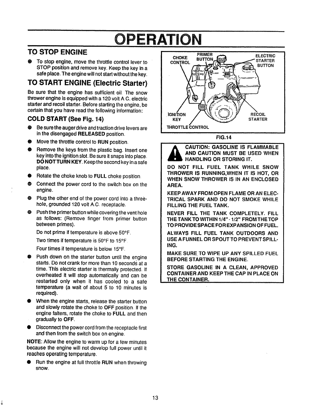
TO STOP ENGINE
®To stop engine, move the throttlecontrol lever to
STOP positionand remove key°Keep the key ina
safe place. The enginewill notstart withoutthe key°
TO START ENGINE (Electric Starter)
Be sure that the engine has sufficientoil The snow
thrower engine is equipped witha 120 voltA C. electric
starter and recoilstarter. Before startingthe engine, be
certain that you have read the following information:
COLD START (See Fig. 14)
•Be surethe auger drive and tractiondrive levers are
in the disengaged RELEASED position_
• Move the throttle control to RUN position°
• Remove the keys lrom the plastic bag,, Insert one
key into the ignition sloL Be sure it snaps into place.
DO NOT TURN KEY,,Keepthe second key in asate
place.
0
@
®
e
®
Rotate the choke knob to FULL choke position,
Connect the power cord to the switch box on the
engine,,
Plug the other end of the power cord into athree-
hole, grounded 120 volt A.C, receptacle_
Push the primer button while covering the vent hole
as follows: (Remove finger from primer button
between primes).
Do not prime if temperature is above 50°F=
Two times if temperature is 50°F to 15°F,
Four times if temperature is below 15°F.
Push down on the starter button until the engine
starts, Do notcrank for more than ! 0 seconds at a
time° This electric starter is thermally protected., If
overheated it will stop automatically and can be
restarted only when it has cooled to a safe
temperature (a wait of about 5 to 10 minutes is
required).
iil,lllll, ,lllll ill
PRIMER ELECTRIC
CHOKE BUTTON STARTER
CONTROL
BUTTON
iGNItION RECOIL
KEY STARTER
FIG.14
,H illlllllllllll Li ii ii illl ii ...........
CAUTION: GAsoLINE iS FLAMMABLE
AND CAUTION MUST BE USED WHEN
HANDLING OR STORING IT.
DO NOT FILL FUEL TANK WHILE SNOW
THROWER IS RUNNING,WHEN IT IS HOT, OR
WHEN SNOW THROWER IS IN AN ENCLOSED
AREA.
KEEP AWAY FROM OPEN FLAME OR AN ELEC-
TRICAL SPARK AND DO NOT SMOKE WHILE
FILLING THE FUEL TANK.
NEVER FILL THE TANK COMPLETELY. FILL
i
THE TANK TO WITHIN 114"_112" FROM THE TOP
TO PROVIDE SPACE FOR EXPANSION OF FUEL.
ALWAYS FILL FUEL TANK OUTDOORS AND
USE A FUNNEL OR SPOUT TO PREVENT SPILL-
ING.
MAKE SURE. TO WIPE UP ANY SPILLED FUEL
BEFORE STARTING THE ENGINE.
STORE GASOLINE IN A CLEAN, APPROVED
CONTAINER AND KEEP THE CAP IN PLACE ON
THE CONTAINER.
OWhen the engine starts, release the starter button
and slowly rotate the choke to OFF position. If the
engine falters, rotate the choke to FULL and then
gradually to OFF,
•Disconnect the power cord from the receptacle first
and then from the switch box on engine,,
NOTE: Allow the engine to warm up for a few minutes
because the engine will not develop full power until it
reaches operating temperature,
Q Run the engine at full throttle RUN when throwing
snow,_
13
OT
- ..............................................................." WARM START
CAUTION: NEVER RUN ENGINE
INDOORS OR IN ENCLOSED,
POORLY VENTILATED AREAS.
ENGINE EXHAUST CONTAINS
CARBON MONOXIDE, AN ODORLESS AND
DEADLY GAS. KEEP HANDS, FEET, HAIR AND
LOOSE CLOTHING AWAY FROM ANY MOVING
PARTS ON ENGINE AND SNOW THROWER.
WARNING: TEMPERATURE OF MUFFLER AND
NEARBY AREAS MAY EXCEED 150° F_ AVOID
THESE AREAS.
DO NOT ALLOW CHILDREN OR YOUNG TEEN-
AGERS TO OPERATE OR BE NEAR SNOW
THROWER WHILE IT IS OPERATING.
,,i, ii j
.... ........................ :L'l_ III Jill'
CAUTION: DO NOT ATTEMPT TO RE-
MOVE ANY ITEM THAT MAY BECOME
LODGED IN AUGER WITHOUT TAKING
THE FOLLOWING PRECAUTIONS:
e RELEASE AUGER DRIVE AND TRACTION
DRIVE LEVERS.
e MOVE THROTTLE LEVER TO STOP POSI-
TION.
• REMOVE (DO NOT TURN) IGNITION KEY.
e DISCONNECT SPARK PLUG WIRE.
• DO NOT PLACE YOUR HANDS IN THE
AUGER OR DISCHARGE CHUTE, USE A
PRY BAR.
/u,
TO START ENGINE (Recoil Starter)
Be sure that the engine has sufficient oilo Before starting
the engine, be certain that you have read the following
information:
COLD START (See Fig. 14)
•Be sure the auger drive and the traction drive levers
are in the disengaged RELEASED position.,
® Move the throttle control to RUN position,
® Pultthe starter handle rapidly Do not allow the handle
to snap back, but allow it to rewind slowly while
keeping a firm hold on the starter handle_
@As the engine warms up and begins to ope rate evenly,
rotate the choke knob slowly to OFF position, If the
engine falters, return to FULL choke, then slowly
move to OFF choke position..
NOTE: Allow the engine to warm up for a few minutes
because the engine will not develop full power until it
reaches operating temperature,.
®Runthe engine at or near the top speed when throwing
snow,
If restarting awarm engine after ashort shutdown, rotate
choke to OFF instead of FULL and do not push the
primer button.,
FROZEN STARTER
If the starter is frozen and will not turn engine:
® Pull as much rope out of the starter as possible
® Release the starter handle and let it snap back
against the starter_
If the engine still fails to start, push the primer button two
or three times again and repeat the two previous steps
until the engine starts Then continue with the directions
for cold start_
To help prevent possib!e freeze-up of recoil starter and
engine controls, proceed as follows after each snow
removal job.
•With the engine running, pull the starter rope hard
with a continuous full arm stroke three or four times.
Pulling of starter rope wilt produce a loud clattering
sound. This is not harmful to the engine or starter
® With the engine not runnlrlg, wipe all snow and
moisture from the carburetor cover in area of control
levers Also move throttle control, choke control, and
starter handle several times
SNOW THROWING TIPS
• For maximum snow thrower efficiency in removing
snow, adjust ground speed, NEVER the throttle, Go
slower in deep, freezing, or wet snow. If the track
slips, reduce forward speed. The engine is designed
to deliver maximum performance at full throttle and
should be run at this power setting at all times
® Most efficient snow throwing is accomplished when
the snow is removed immediately after it falls
O For complete snow removal, slightly overlap each
path previously taken.
® The snowshouldbedischargeddownwindwhenever
possible.
® For normal usage, set the skids so that the scraper
bar is 1/8" above the skids. For extremely hardpacked
snow surfaces, adjust the skids upward so that the
scraper bar touches the ground
® On gravel or crushed rock surfaces, set the skids at
1-1/4" below the scraper bar (see To Adjust Skid
Height paragraph on page 18). Stones and gravel
must not be picked up and thrown by the machine
® After the snow throwing job has been completed,
allow the engine to idle for a few minutes, which will
melt snow and accumulated ice off the engine
• Clean the snow thrower thoroughIy after each use
® Remove ice and snow accumulation and all debris
from the entire snow thrower, and flush with water (if
possible) to remove all salt or other chemicals Wipe
snow thrower dry
14
SERVICE RECORDS
IWlIIIIIH/IJ III
ES IL
,i,i, iw,i ..............................
wlwlw,L,Iii,,iu,,,,,,L,,I,,i,iii i,iii i i i i
Fill in dates as you complete
regular service
Check Engine Oil Level
ChangeEngineOil
TightenAllScrewsandNuts
LubricateAllPivotPoints
LubricateAugerShaft(SeeShear
BoltReplacement)
LubricateDiscDrivePlataZerk(See
CustomerResponsibilities)
CheckAugerClutchCable
Adjustment(SeeCableAdjustment)
CheckTractionClutchCable
Adjustment (Sea Cable Adjustment)
AdiustDriveBelts_
After Before
First 2 Each
hours Use
SCHEDULE
TiES
SERVICE
DATES
As Every Every Every Each Before
Needed 5 10 25 Season Storage
Hours Hours Hours
.... = .......
,....
= .......... = ..... .........
II v"
Ch=_Fuol
DrainFuel pj
ReplaceSparkPlug p,_ pJ
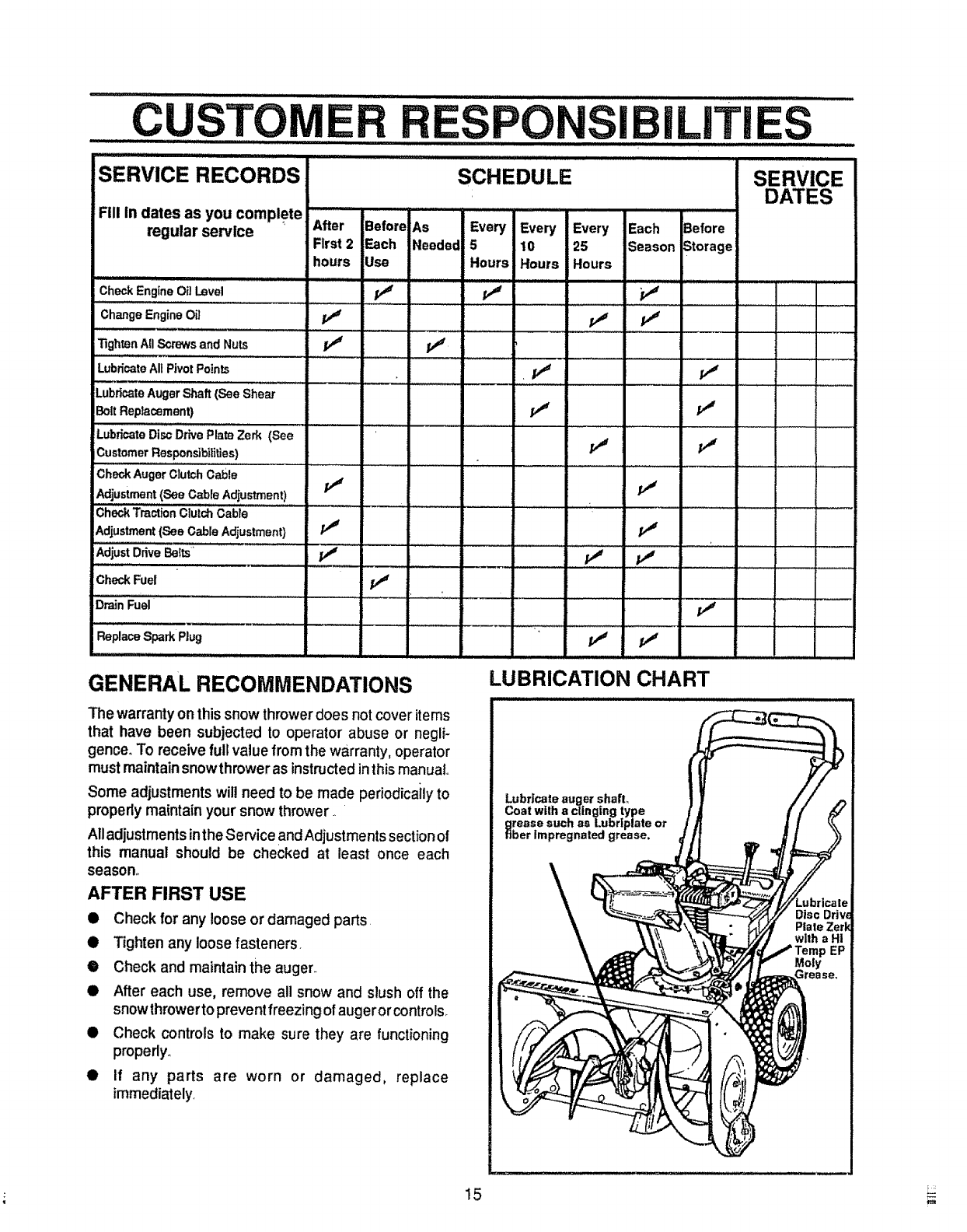
GENERAL RECOMMENDATIONS LUBRICATION CHART
The warranty onthis snow thrower does not cover items
that have been subjected to operator abuse or negli-
gence. To receive full value from the warranty, operator
must maintain snowthrower as instructedin this manual..
Some adjustments will need to be made periodicaily to
properly maintain your snow thrower.
All adjustments inthe Service and Adjustments section of
this manual should be checked at least once each
season°
AFTER FIRST USE
•Check for any loose or damaged parts.
•Tighten any loose fasteners.
•Check and maintain the auger.
• After each use, remove all snow and slush off the
snow throwerto preventfreezing of auger or controls_
• Check controls to make sure they are functioning
properly..
• If any parts are worn or damaged, replace
immediately
Lubr|cate auger shaft1,
Coat with aclinging type
grease such as Lubrtplate
fiber Impregnated grease. or
15 _
CUS rOMER RESPONSIBILITIES ..........
11 iiiiiiiiiii ii ii iiiiiiiiiii
SNOW THROWER
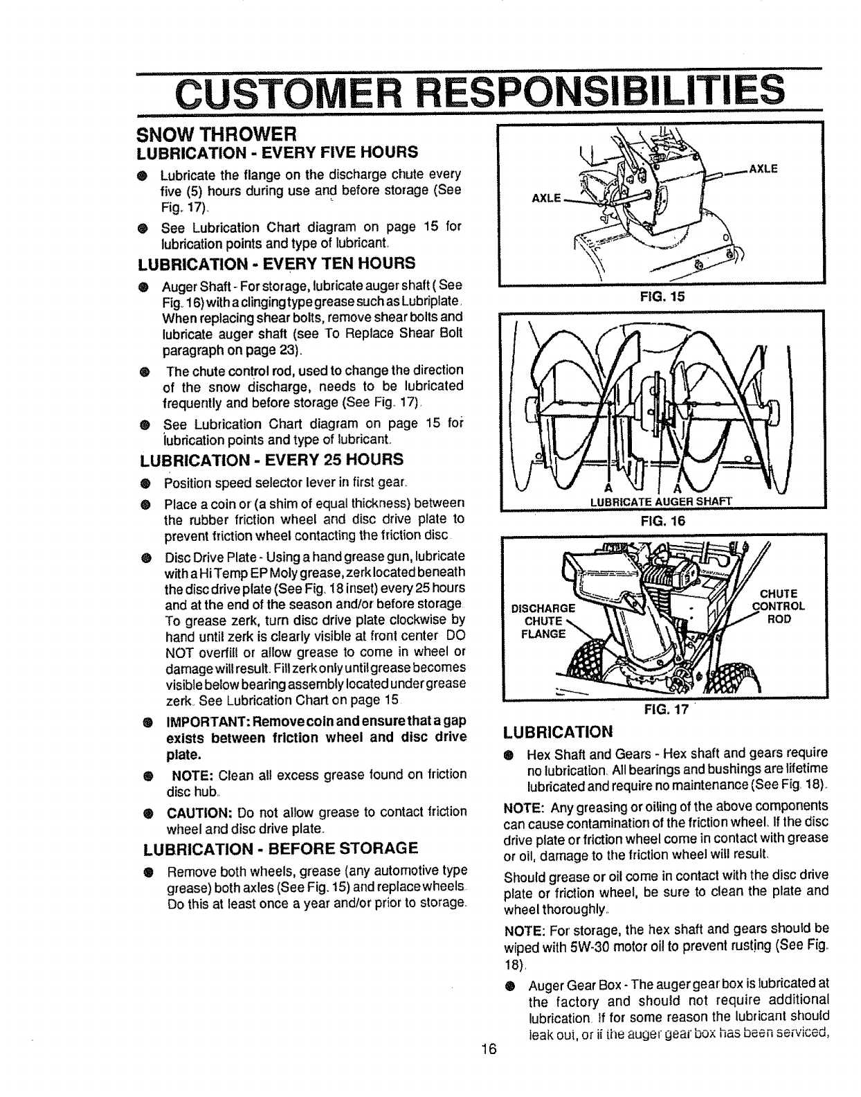
LUBRICATION - EVERY FIVE HOURS
•Lubricate the flange on tile discharge chute every
five (5) hours during use and before storage (See
Fig_ 17)_
® See Lubrication Chart diagram on page 15 for
lubrication points and type of lubricant..
LUBRICATION - EVERY TEN HOURS
®Auger Shaft-. For storage, lubricate auger shaft ( See
Fig. 16)with a clinging type grease such as Lubdplate.
When replacing shear bolts, remove shear bolts and
lubricate auger shaft (see To Reptace Shear Bolt
paragraph on page 23).
@ The chute control rod, used to change the direction
of the snow discharge, needs to be lubricated
frequently and before storage (See Fig.. 17).
® See Lubrication Chart diagram on page 15 fo_"
iubdcation points and type of lubricant.
LUBRICATION -EVERY 25 HOURS
®Position speed selector lever infirst gear,
®Place acoin or (a shim of equal thickness) between
the rubber friction wheel and disc drive plate to
prevent friction wheel contacting the friction disc
@DiscDrive Plate -Usinga hand grease gun, lubricate
witha HiTemp EP Motygrease, zerk locatedbeneath
the discdrive plate (See Fig, 18 inset)every 25 hours
and at the end of the season andlor before storage
To grease zerk, turn disc drive plate clockwise by
hand untilzerk is clearly visibleat front center DO
NOT overfil! or allow grease to come in wheel or
damage will resulLFitlzerk only untilgrease becomes
visible below bearing assembly located undergrease
zerk See Lubrication Chart on page 15
® IMPORTANT; Remove coin and ensure that a gap
exists between friction wheel and disc drive
plate.
@NOTE: Clean al! excess grease found on friction
disc hub..
•CAUTION: Do not allow grease to contact friction
wheel and disc drive plate,,
LUBRICATION - BEFORE STORAGE
®Remove both wheels, grease (any automotive type
grease) both axles (See Fig. 15) and replacewheels
Do this at least once a year andtor prior to storage
.................... .......................
__ _......AXLE
I II I/1/111111111111111 FIG. 15
LUBRICATE AUGER SHAFt'
FIG. 16
\
DISCHARGE
FLANGE
CHUTE
CONTROL
ROD
16
FiG, 17
LUBRICATION
® Hex Shaft and Gears - Hex shaft and gears require
no lubrication All bearings and bushings are lifetime
lubricated and require no maintenance (See Fig. 18)..
NOTE: Any greasing or oiling of the above components
can cause contamination of the friction wheel. If the disc
drive plate or friction wheel come in contact with grease
or oil, damage to the friction wheel will result.
Stlould grease or oil come in contact with the disc drive
plate or friction wheel, be sure to clean the plate and
wheel thoroughly,.
NOTE: For' storage, the hex shaft and gears should be
wiped with 5W-30 motor oil to prevent rusting (See Fig..
18).
®Auger Gear Box - The auger gearbox is lubricatedat
the factory and should not require additional
lubrication_ If for some reason the lubricant should
leak out, or ii ihe auger geaJ"box has been se[viced,
....CUSTO ......................... LITiE ...............
,,i IH,,,,HIII,'I'IIIIIIHI, IIII IIIIII II ] ................... ! ....................................... I III
GEARS
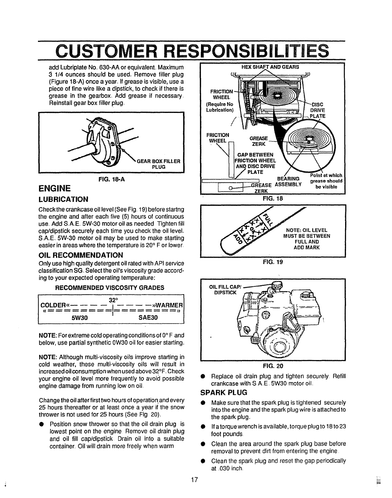
add Lubriplate No,,630-AA or equivalent,, Maximum
31/4 ounces should be used. Remove filler plug
(Figure 18-A) once a yearn if grease is visible, use a
piece of fine wire like a d!pstick, to check if there is
grease in the gearbox, Add grease if necessary,
Reinstall gear box filler plug.
ENGINE
LUBRICATION
FIG. 18.A
GEAR BOX FILLER
PLUG
Checkthe crankcaseoil level (See Fig, t9) before startng
the engine and after each five (5) hours of continuous
use., Add S,A.E, 5W-30 motor oil as needed Tighten fill
cap/dipstick securely each time you check the oil level.
S.A,,E_5W-30 motor oil may be used to make starting
easier in areas where the temperature is 20° F or lower,
OIL RECOMMENDATION
Only use high quality detergent oil rated with API service
classification SG. Select the oil's viscosity grade accord-
ing to your expected operating temperature:
RECOMMENDED VISCOSITY GRADES
32°
COLDER<€ ii >_WARMER
(( I_ >>
5W30 SAE30
NOTE: For extreme cold operating conditions of 0°F and
below, use partial synthetic 0W30 oil for easier starting.
NOTE: Although multi-viscosity oils improve starting in
cold weather, these multi-viscosity oils will result in
increased oilconsumption when used above 32°F.,Check
your engine oil level more frequently to avoid possible
engine damage from running low on oil_
Change the oil after first two hours of operation,and every
25 hours thereafter or at least once a year if the snow
thrower is not used for 25 hours (See Fig 20).
• Position snow thrower so that the oil drain plug is
lowest point on the engine, Remove oil drain plug
and oil fill cap/dipstick Drain oil into a suitable
container. Oil will drain more freely when warm
FRICTION
WHEEL
(Require No
Lubrication)
/
DRIVE
PLATE
FRICTION GRE/L,o_
IGAPBETWEEN
[[FRICTION WHEEL
iIANDDISCDRIVE
UJ PLATE
:: :'"'"'"': 'i_ BEARING
REASEASSEMBLY
................................ Z,,,ERK ......
FIG. 18
Point at which
grease should
be visible
_-l_._, _.TPj_ _" NOTE: OIL LEVEL
/_, _r.j.,p._v MUST BE BETWEEN
[v_ _ FULL AND
ADD MARK
..........-,/ ,...........
FIG. 19
OIL FILL CAP/
DIPSTICK
/,iL/I .....................
FIG. 20
• Replace oil drain ptug and tighten securely, Refill
crankcase with S A,E, 5W30 motor oil,
SPARK PLUG
D Make sure that the spark plug is tightened secureiy
into the engine and the spark plug wire is attached to
the spark plug.
!l! Ifatorque wrench is available, torque plug to 18to 23
foot pounds,
• Clean the area around the spark plug base before
removal to prevent dirt from entering the engine,
• Clean the spark plug and reset the gap periodically
at ,030 inch,
17 i_-_
...................... mmmlm I""
..........SERVICE AND ADJuS rMEN rs
CAUTION: ALWAYS DISCONNECT THE
SPARK PLUG WIRE AND TIE BACK
AWAY FROM THE PLUG BEFORE MAK-
ING ANY ADJUSTMENTS OR REPAIRS.
mHimmmmml mmmm,,_,,,,,,,_,_,,
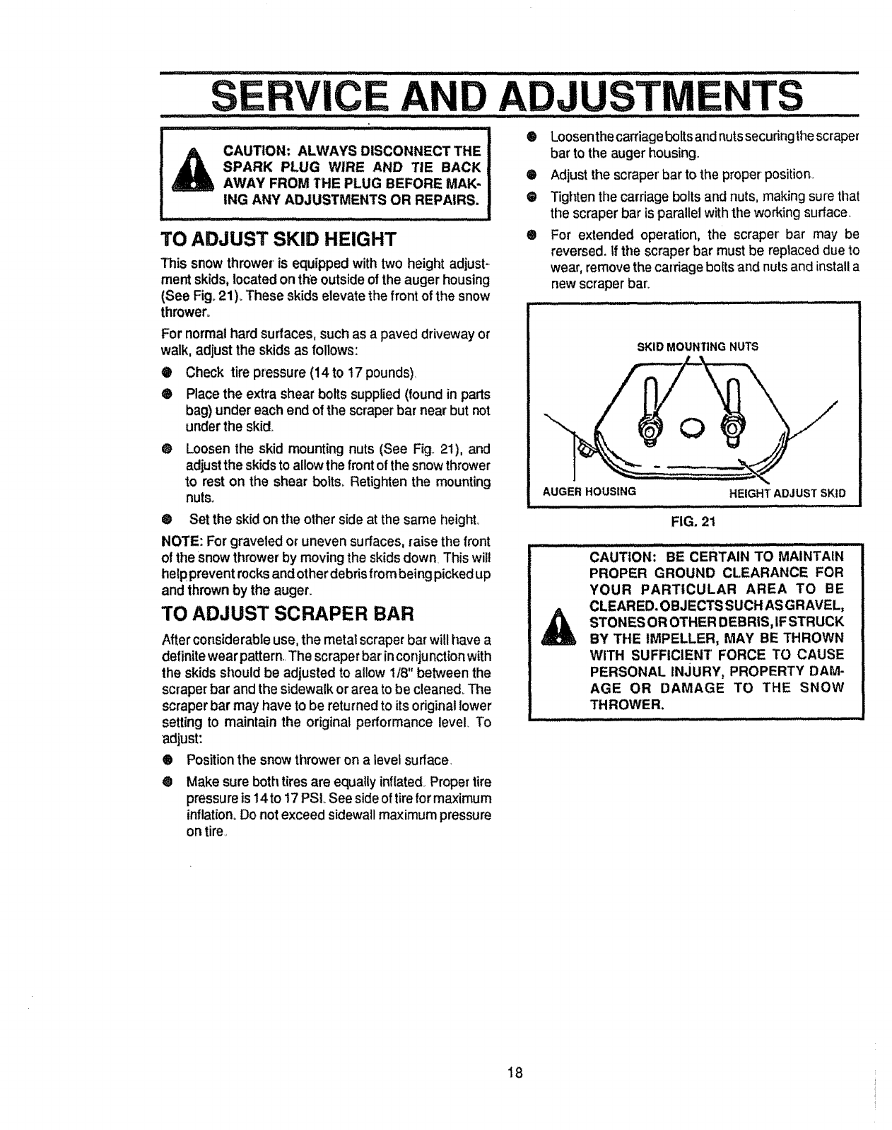
TO ADJUST SKID HEIGHT
This snow thrower is equipped with two height adjust -_
ment skids, located onthe outside of the auger housing
(See Fig, 21), These skids elevate the front of the snow
thrower,
For normalhard surfaces, such as a paved driveway or
walk, adjust the skids as follows:
Check tire pressure (14 to t7 pounds)
Place the extra shear bolts supplied (found in pads
bag) under each end of the scraper bar near but not
under the skid.
O
®
® Loosen the skid mounting nuts (See Fig. 21), and
adjust the skids to allow the front of the snow thrower
to rest on the shear bolts, Retighten the mounting
nuts°
®Set the skid on the other side at the same height°
NOTE: For graveled or uneven surfaces, raisethe front
of the snow thrower by moving the skids down This will
helpprevent rocks and other debrisfrom being picked up
and thrown by the auger.
TO ADJUST SCRAPER BAR
After considerable use, the metal scraper bar will have a
definite wear pattern. The scraper bar in conjunction with
the skids should be adjusted to allow 1/8" between the
scraper bar and the sidewalk or area to be cleaned_ The
scraper bar may have to be returned to itsoriginal lower
setting to maintain the original performance level. To
adjust:
®Positionthe snowthrower on a level surface,
®Make sure both tires are equally inflated. Propertire
pressure is 14to 17 PSL See side of tirefor maximum
inflation. Do not exceed sidewall maximum pressure
on tire,
®
®
Q
®
Loosenthecarriage bolts and nuts secudngthe scraper
bar to the auger housing_
Adjust the scraper' bar to the proper'position
Tighten ttle carriage bolts and nuts, making sure that
the scraper bar is parallel with the working surface
For extended operation, the scraper bar may be
reversed, if the scraper bar must be replaced due to
wear, remove the carriage bolts and nuts and install a
new scraper bar:
SKID MOUNTING NUTS
AUGER HOUSING HEIGHT ADJUST SKID
FIG. 21
...............CAUTi0N;' BE CERTAIN TO MAINTAIN
PROPER GROUND CLEARANCE FOR
YOURPARTICULARAREATo BE
CLEARED. OBJECTS SUCH AS GRAVEL,
STONESOROTHERDEBRIS,IFSTRUCK
BY THE IMPELLER, MAY BE THROWN
WITH SUFFICIENT FORCE TO CAUSE
PERSONAL INJURY, PROPERTY DAM-
AGE OR DAMAGE TO THE SNOW
THROWER.
18
S CE
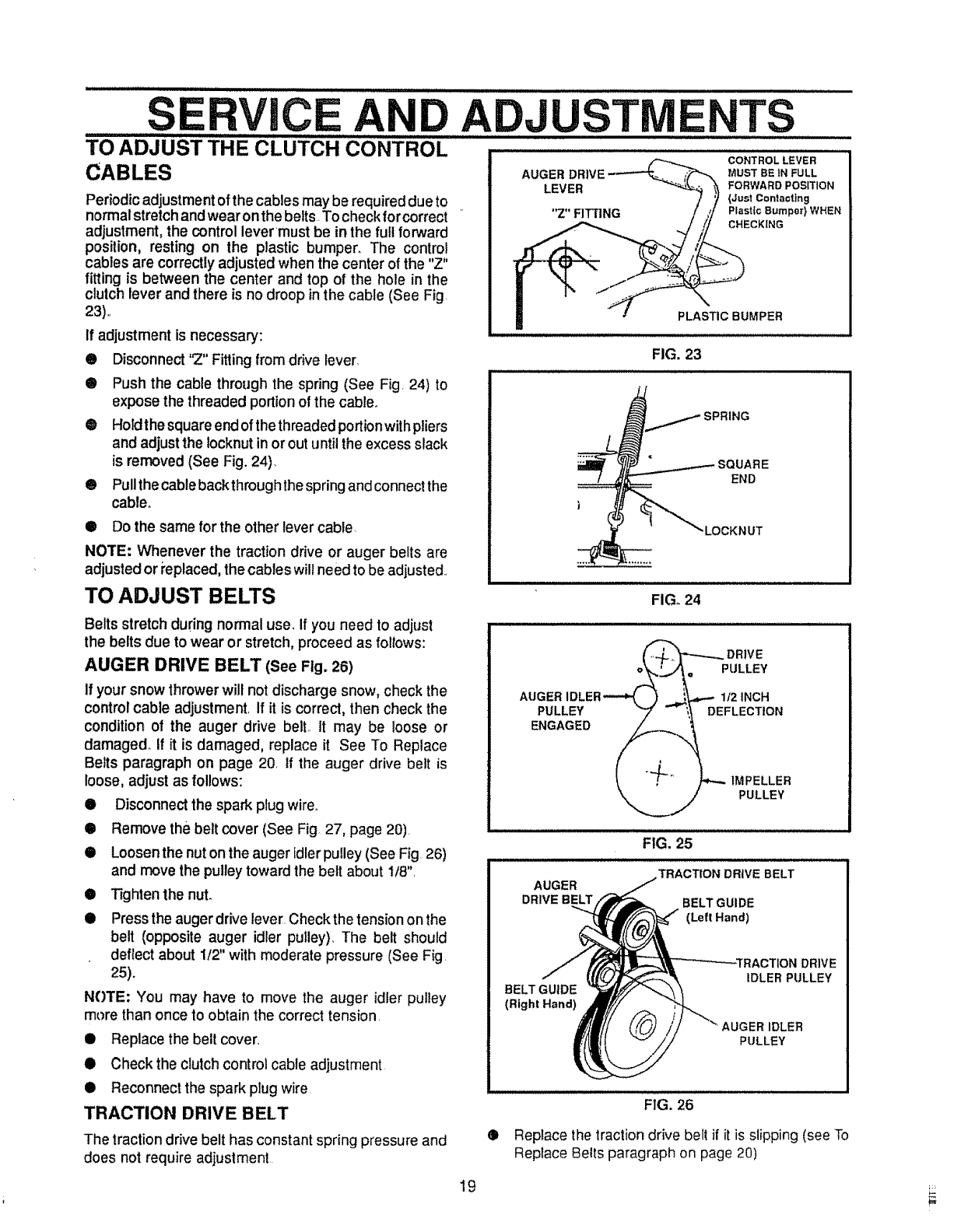
TO ADJUST THE CLUTCH€0NTR:oL ...........
CABLES
Periodic adjustment of the cables may be required due to
normal stretch and wear on the belts. To check for correct
adjustment, the control lever must be in the full forward
position, resting on the plastic bumper. The control
cables are correctly adjusted when the center of the "Z"
fitting is between the center and top of the hole in the
clutch lever and there is no droop in the cable (See Fig
23),,
If adjustment is necessary:
TS
® Disconnect "Z" Fitting from drive lever
•Push the cable through the spring (See Fig, 24) to
expose the threaded portion of the cable.
@Holdthe square end of the threaded portion with pliers
and adjust the locknut in or out until the excess slack
is removed (See Fig. 24).
• Pullthe cable backthrough thespring and connect the
cable.
CONTROL LEVER
AUGER MUST BE IN FULL
LEVER FORWARD POSITION
(Just Contacting
"Z" FITTING Plastic 8umpor} WHEN
CHECKING
PLASTIC BUMPER
,,_H.u,
FIG. 23
•Do the same for the other lever cable.
NOTE: Whenever the traction drive or auger belts are
adjusted or i'eplaced,the cables will need to be adjusted.,
TO ADJUST BELTS
END
,LOCKN UT
FIGo24
Belts stretch during normal use, If you need to adjust
the belts due to wear or stretch, proceed as follows:
AUGER DRIVE BELT (See Fig. 26)
If your snow throwerwill not discharge snow, check the
controlcable adjustment, If it is correct, then check the
condition o! the auger drive belt, It may be loose or
damaged. If it is damaged, replace it See To Replace
Belts paragraph on page 20 If the auger drive belt is
loose, adjust as Iol!ows:
•Disconnect the spark plug wire.,
•Remove the belt cover (See Fig. 27, page 20),
i Loosen the nut on the auger idler pulley (See Fig 26)
and move the pulley toward the belt about I!8",
Tighten the nut.
O
OPress the auger drive lever.Check the tensionon the
belt (opposite auger idler pulley). The belt should
deflect about 1/2" with moderate pressure (See Fig.
25).
NOTE: You may have to move the auger idler pulley
more than once to obtain the correct tension,
•Replace the belt cover,
•Check the clutch control cable adjustment
•Reconnect the spark plug wire
TRACTION DRIVE BELT
The traction drive belt has constant spring pressure and
does not require adjustment
(_+,'_---..._DRIVE
AUGER IDLER---_ ,) _..,_,--- 1/2 INCH
PULLEY "7 _ \_ DEFLECTION
t,_ " _ IMPELLER
"_.j PULLEY
FIG. 25
TRACTION DRIVE BELT
AUGER
DRIVE BELT BELT GUIDE
(Left Hand)
BELT GUIDE
(Right Hand)
DRIVE
iDLER PULLEY
AUGER IDLER
PULLEY
®
FIG. 26
Replace the tractiondrive belt if it is slipping (see To
Replace Belts paragraph on page 20)
19
.........S RVICEAND ADJU ............TS ........
iiiiiiii ii ,111111111 ......
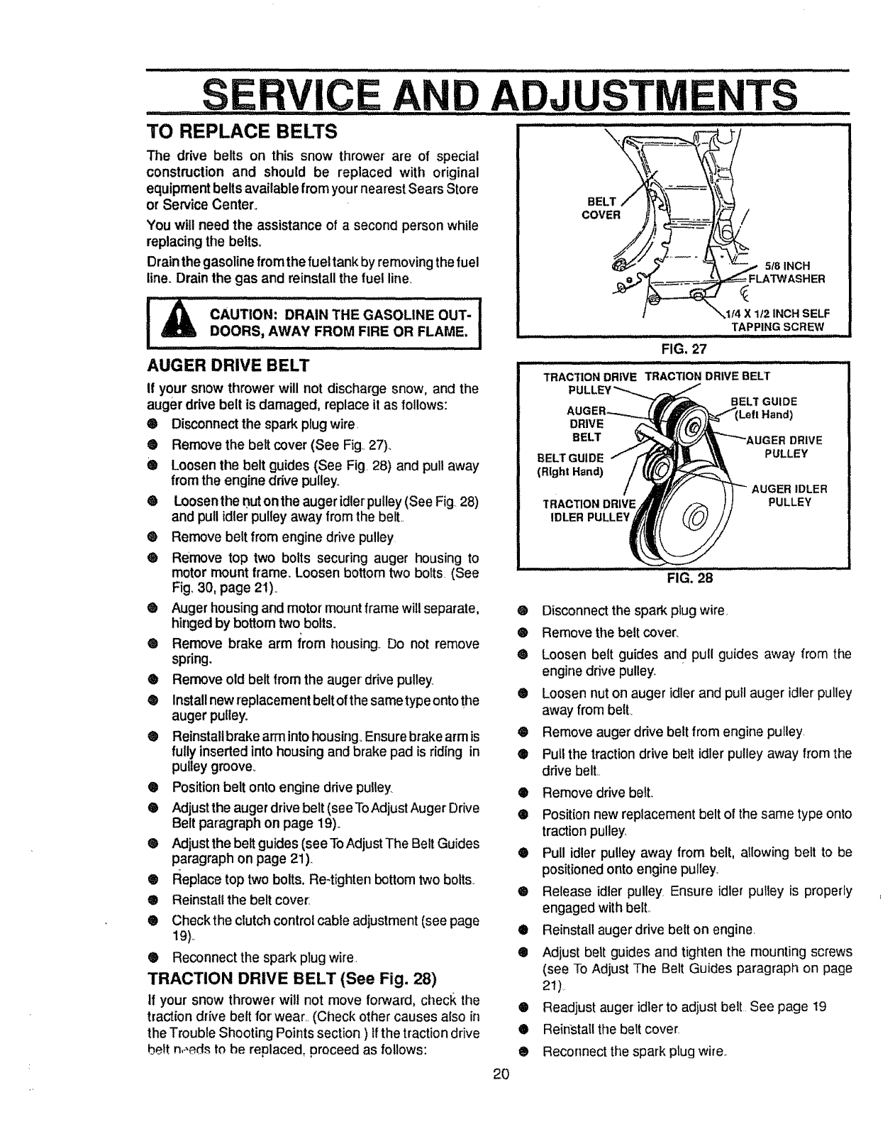
TO REPLACE BELTS \
The drive belts on this snow thrower are of special
construction and should be replaced with original
equipment beltsavailable from your nearest Sears Store
or Service Center.
You will need the assistance of a second person while
replacing the belts°
Drain the gasoline from the fuel tank by removing the fuel
line. Drain the gas and reinstall the fuel line
AUGER DRIVE BELT
If your snow thrower will not discharge snow, and the
auger drive belt is damaged, replace it as follows:
® Disconnect the spark plug wire.
® Remove the belt cover (See Fig..27)..
® Loosen tile belt guides (See Fig 28) and pullaway
from the engine drive pulley.
6 Loosen the nuton the auger idle['pulley (See Fig. 28)
and pull idler pulley away from the belt.
® Remove belt from engine ddve pulley
® Remove top two bolts securing auger housing to
motor mount frame, Loosen bottom two bolts. (See
Fig, 30, page 2!)._
® Auger housing and motor mount frame wiIl separate,
hinged by bottom two bolts.
® Remove brake arm irom housing. Do not remove
spring.
• Remove old belt from the auger drive pulley
® Installnewreplacementbeltofthesametypeontothe
auger pulley.
® Reinstall brake arm into housing° Ensure brake arm is
fully inserted into housing and brake pad is riding in
pulley groove_
• Position belt onto engine drive pulley
• Adjust the auger drive belt (see To Adjust Auger Drive
Belt paragraph on page 19).
® Adjust the belt guides (see ToAdjust The Belt Guides
paragraph on page 21).
• Replace top two bolts. Re-tighten bottom two bolts.
• Reinstall the belt covet:
® Checkthe clutch control cable adjustment (see page
19)_.
® Reconnect the spark plug wire
TRACTION DRIVE BELT (See Fig. 28)
If your snow thrower will not move forward, check the
traction drive belt for' wear.. (Check other causes also it]
the Trouble Shooting Points section ) tfthe traction drive
heft n_,eds to he replaced, proceed as follows:
BELT
COVER /
51
_,1/4 X 1t2 INCH SELF
TAPPING SCREW
FIG. 27
................................. ,, ,,, ,, ..... ,i
TRAC'T1ON DRIVE TRACTION DRIVE BELT
DRIVE
BELT
BELTGUIDE
(Right Hand)
TRACTION DRIVE
IDLER PULLEY
BELT GUIDE
Left Hand)
UGER DRIVE
PULLEY
AUGER IDLER
PULLEY
FIG. 28
® Disconnect the spark plug wire,
® Remove the belt cover.
® Loosen belt guides and pull guides away from the
engine ddve pulley,.
® Loosen nut on auger idler and pull auger idler pulley
away from belt..
® Remove auger drive belt from engine pulley.
® Pull the traction drive belt idler pulley away from the
drive belt..
® Remove drive belt.
® Position new replacement belt of the same type onto
traction pulley
• Pull idler pulley away from belt, allowing belt to be
positioned onto engine pulley.
® Release idler pulley Ensure idler pulley is propedy
engaged with belt..
tl Reinstall auger drive belt on engine.
Q Adjust bert guides and tighten the mounting screws
(see To Adjust The Belt Guides paragraph on page
21),.
® Readjust auger idler to adjust bell See page 19
• Reinstall the belt cover.
® Reconnect the spark plug wire..
2O
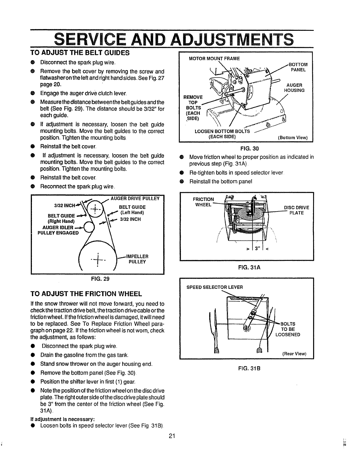
O
®
®
®
O
Disconnect the spark plug wire.
Remove the belt cover by removing the screw and
llatwasheron the left and right hand sides. See Fig. 27
page 20.
Engage the auger drive clutch lever..
Measurethe distance between the belt guides and the
belt (See Fig. 29)° The distance should be 3/32" for
each guide°
It adjustment is necessary, loosen the belt guide
mounting bolts_ Move the belt guides to the correct
position. Tighten the mounting bolts
OReinstall the belt cover.
®if adjustment is necessary, loosen the belt guide
mounting bolts. Move the bell guides to the correct
position° Tighten the mounting bolts.
@ Reinstallthe belt cover,
@Reconnect the spark plug wire.
•DRIVE: L:LEV
BELT GUIDE ,,"_\_I'_-"--..._\,f (Left Hand)
.__.L_ _._IMPELLER
_, F" )PULLEY
i. ,..i .iii
FIG. 29
TO ADJUST THE FRICTION WHEEL
If the snow thrower will not move forward, you need to
check the traction drive belt, the traction drive cable or the
friction wheel. Ifthe friction wheel isdamaged, it will need
to be replaced. See To Replace Friction Wheel para-
graph on page 22. If the friction wheel is not worn, check
the adjustment, as follows:
•Disconnect the spark plug wire_
•Drain the gasoline from the gas tank,
•Stand snow thrower on the auger housing end
•Remove the bottom panel (See Fig° 30)
•Position the shifter lever infirst (1) gear.
•Note the position of the frictionwheel on the disc drive
plate°The right outer side of the discdrive plate should
be 3" from the center of the friction wheel (See Fig.
3tA)
If adjustmentis necessary:
• Loosenbolts in speed selector lever (See Fig 31B)
ADJUSTM TS
FIG. 30
@ Move friction wheel to proper position as indicatedin
previousstep (Fig. 31A),
•Re-tighten bolts in speed selector lever
® Reinstall the bottom panel
FRICTION
DISC DRIVE
PLATE
>
FIG. 31A
SPEED SELECTOR LEVER
t
i
FIG. 31B
BOLTS
TO BE
/LOOSENED
(Rear View)
21
L_
...........SERVICE AND ADJUSTMENTS
...................... :_ :ill iill m ii ii i ,i ill i ii _1. i ill /i//i,,i,, ,,,,,,l, i
ii iiiii iiii i iii iiii II i i iiii, ..........
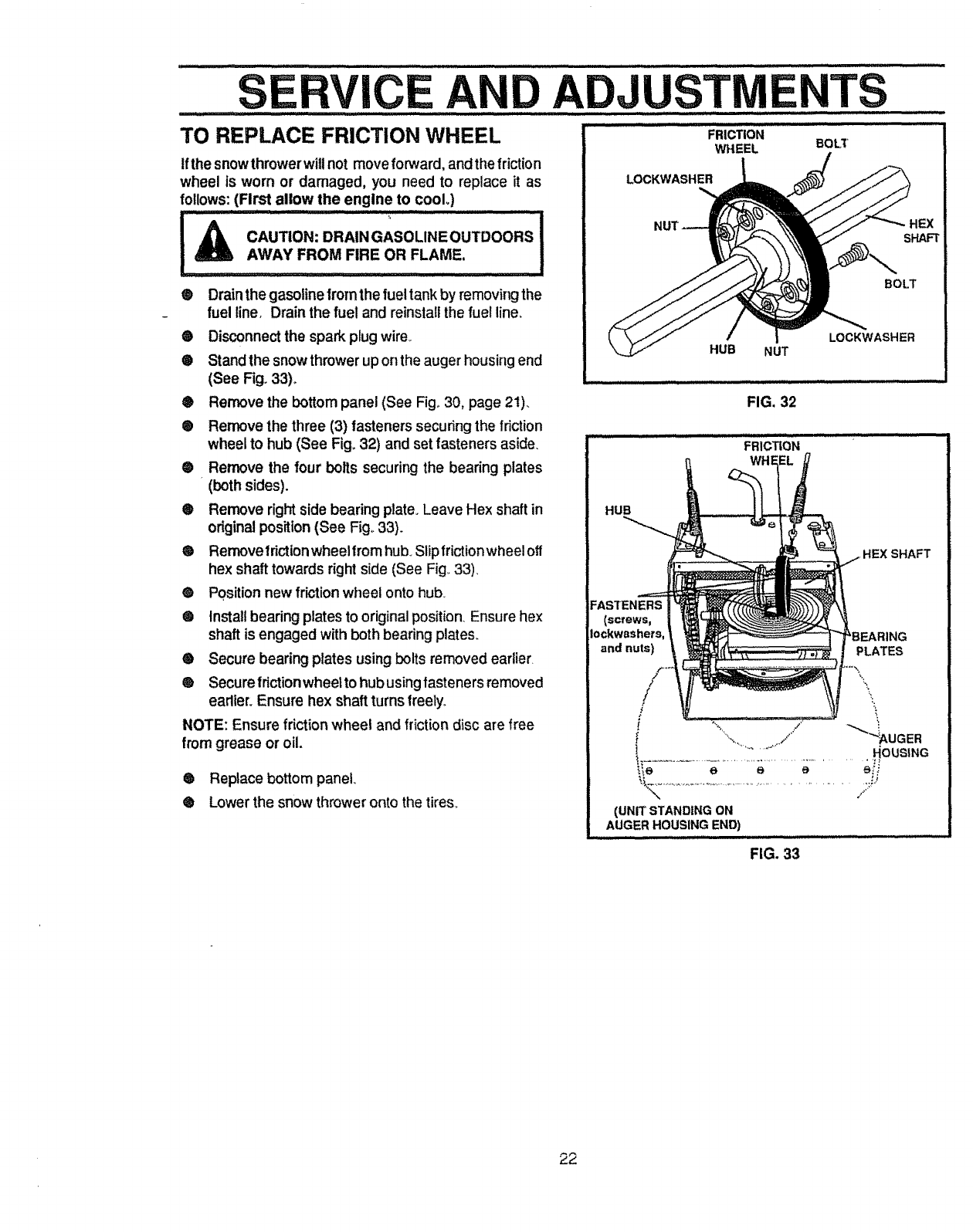
TO REPLACE FRICTION WHEEL FRICTIO.
WHEEL BOLT
tfthe snowthrowerwiltnot move forward, andthefriction
wheel is worn or damaged, you need to replace it as
follows:(First allow the engine to cooL)
-- +,
IACAUTION:DRA,,GAS0L,.EOUTDOORS
IAWAYF.OMF,"EO"FL-AME. II
@Drainthe gasolinefrom the fuel tank by removir_j the
fuel line. Drain the fuel and reinstall the fuel line.
®
®
Disconnectthe spark plugwire°
Standthe snow throwerup onthe auger housing end
(See Fig. 33)_
LOCKWASHER
HEX
SHAFT
BOLT
LOCKWASHER
HUB NUT
®Remove the bottom panel (See Fig° 30, page 2t)_ FIG. 32
® Remove the three (3) fasteners securing the friction
wheel to hub (See Fig=32) and set fasteners aside.
@ Remove the four bolts securing the bearing plates
(both sides).
® Remove right side bearing plate° Leave Hex shaft in
original position (See Fig° 33).
® Removefrictionwheelfromhub. Slipfrictionwheelofl
hex shaft towards right side (See Fig_33).
® Position new friction wheel onto hub_
® Install bearing plates to original position. Ensure hex
shaft is engaged with both bearing plates_
® Secure bearing plates using bolts removed earlier.
® Secure fdction wheel to hub using fasteners removed
eadier_Ensure hex shaft turns freely°
NOTE: Ensure friction wheel and fr{ction disc are free
from grease or oil.
® Replace bottom panel
® Lower the snow thrower onto the tires.
/
i .............. HOUSING
(UNIT STANDING ON
AUGER HOUSING END)
FIG. 33
22
SERVICE AND ADJUST TS
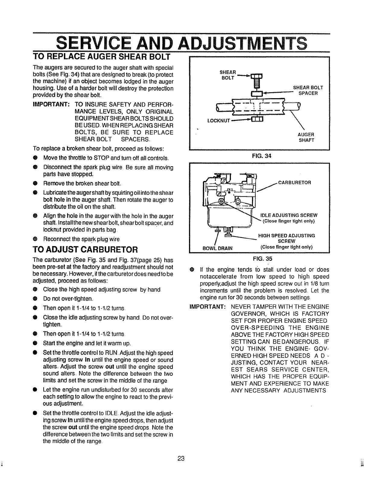
TO REPLACE A"UGER sHEAR BOLT
The augers are secured to the auger shaft with special
bolts (See Fig, 34) that are designed to break (to protect
the machine) if an object becomes lodged in the auger
housing, Use of a harder bolt will destroy the protection
provided by the shear bolt,.
IMPORTANT: TO INSURE SAFETY AND PERFOR-
MANCE LEVELS, ONLY ORIGINAL
EQUIPM ENT SHEAR BOLTS SHOULD
BE USED WHEN REPLACING SHEAR
BOLTS, BE SURE TO REPLACE
SHEAR BOLT SPACERS.
To replace a broken shear bolt, proceed as follows:
®Move the throttle to STOP and turn off all controls
O
O
o
®
Disconnect the spark plug wire. Be sure all moving
parts have stopped.
Remove the broken shear bolt,
Lubricate the auger shaft by squirting oil into the shear
bolt hole in the auger shaft..Then rotate the auger to
distribute the oil on the shaft.
Align the hole in the auger withthe hole in the auger
shall Installthe new shearbolt, shear bolt spacer, and
Iocknut provided in parts bag.
® Reconnect the spark plug wire
TO ADJUST CARBURETOR
The carburetor (See Fig, 35 and Fig_ 37(page 25) has
been pre-set at the factory and readjustment should not
be necessary. However, if the carburetor does needto be
adjusted, proceed as follows:
@ Close the high speed adjusting screw by hand.
®Do not over-tighten.
®Then open it 1-I/4 to 1-1/2 turns.
•Close the idle adjusting screw by hand. Do not over-
tighten,.
•Then open it 1-1/4 to 1-1/2 turns
•Start the engine and let it warm up.
•Set the throttle control to RUN. Adjust the high speed
adjusting screw In until the engine speed or sound
alters° Adjust the screw out until the engine speed
sound alters. Note the difference between the two
limits and set the screw inthe middle of the range
•Let the engine run undisturbed for 30 seconds after
each setting to allow the engine to react to the previ-
ous adjustment.
•Set the throttle control to IDLE. Adjust the idle adjust-
ingscrew In untilthe engine speed drops, then adjust
the screw out until the engine speed drops Note the
difference between the two lirnits and set the screw in
the middle of the range.
SHEAR
BOLT "_
_p SHEAR BOLT
SPACER
AUGER
SHAFT
FIG. 34
IDLE ADJUSTING SCREW
(Close finger light only)
BOWL DRAIN
HIGH SPEED ADJUSTING
SCREW
(Close finger tight only)
O
IMPORTANT:
FtG. 35
If the engine tends to stall under load or does
notaccelerate from low speed to high speed
properly,adjust the high speed screw out in 1/8 turn
increments until the problem is resolved. Let the
engine run for 30 seconds between settings.
NEVER TAMPER WITH THE ENGINE
GOVERNOR, WHICH IS FACTORY
SET FOR PROPER ENGINE SPEED
OVER-SPEEDING THE ENGINE
ABOVE THE FACTORY HIGH SPEED
SETTING CAN BE DANGEROUS. iF
YOU THINK THE ENGINE- GOV-
ERNED HIGH SPEED NEEDS A D *
JUSTING, CONTACT YOUR NEAR-
EST SEARS SERVICE CENTER,
WHICH HAS THE PROPER EQUIP-
MENT AND EXPERIENCE TO MAKE
ANY NECESSARY ADJUSTMENTS
23
.........SERVICE ANDADJUSTMENTS
, ,,! ................... : ..... : :.......... _=,,_ ...... _ I1' I! ,, ...................... i! I Ilil
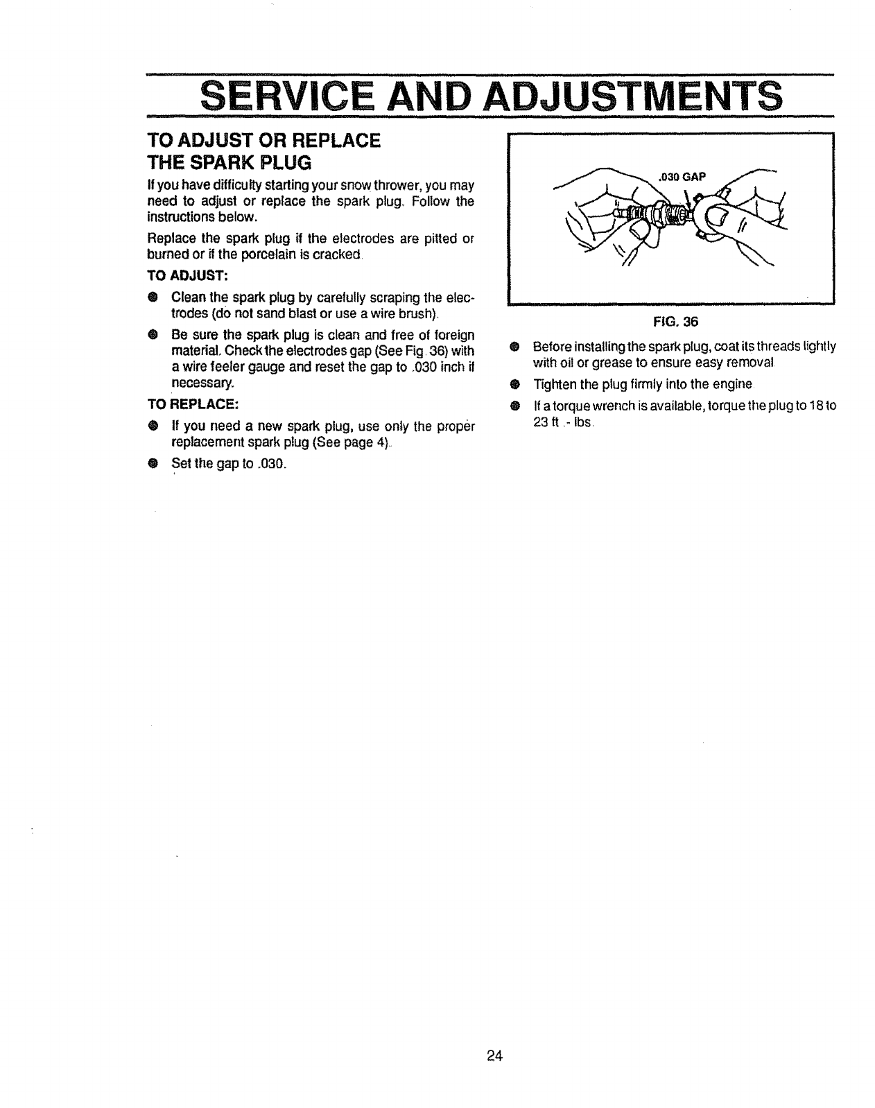
TO ADJUST OR REPLACE
THE SPARK PLUG
If you have difficultystarting your snow thrower, you may
need to adjust or replace the spark plug_ Follow the
instructions below,
Replace the spark plug if the electrodes are pitted or
burned or if the porcelain is cracked,
TO ADJUST:
O
®
Clean the spark plug by carefullyscraping the elec-
trodes (do not sand blast or use a wire bnJsh).
Be sure the spark plug is clean and free of foreign
material Check the electrodes gap (See Fig. 36) with
a wire feeler gauge and reset the gap to _030inch it
necessary.
TO REPLACE:
® If you need a new spark plug, use only the proper
replacement spark plug (See page 4)..
•Set the gap to .030.
,030 GAP
ml LI II, I1,11,, II lll l IHIII _ "
FIG. 36
®Before installingthe spark plug, coat itsthreads Lightly
with oil or grease to ensure easy removal
®Tighten the plug firmly into the engine
® Ifa torque wrench is available, torquethe plugto 18 to
23 ft _-Ibs.
24
STO E............................" ..............
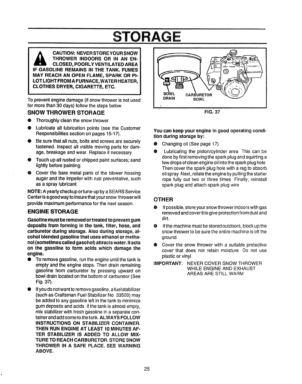
CAUTION: NEVERSTOREYOURSNOW
THROWER INDOORS OR IN AN EN-
CLOSED, POORLY VENTILATED AREA
IF GASOLINE REMAINS IN THE TANK. FUMES
MAY REACH AN OPEN FLAME, SPARK OR PI-
LOT LIGHT FROM A FURNACE, WATER HEATER,
CLOTHES DRYER, CIGARETTE, ETC.
To prevent engine damage (if snow thrower is not used
for more than 30 days) follow the steps below
SNOW THROWER STORAGE
CAR iURETOR
DRAIN BOWL
FIG. 37
®Thoroughly clean the snow thrower,
®Lubricate all lubrication points (see the Customer
Responsibilities section on pages 15-17).
®Be sure that all nuts, bolts and screws are securely
fastened. Inspect all visible moving parts for dam-
age, breakage and wear_,Replace if necessary,
® Touch up all rusted or chipped paint surfaces; sand
lightly before painting.
® Cover the bare metal parts of the blower housing
auger an_ the impeller with rust preventative, such
as a spray lubricant°
NOTE: A yearlycheckupor tune-up by aS EARS Service
Center is agoodwayto insurethat yoursnow throwerwill
provide maximum performance for the next season,
ENGINE STORAGE
Gasoline must be removed ortreated to prevent gum
deposits from forming in the tank, filter, hose, and
carburetor durtng storage. Also during storage, al-
cohol blended gasoline that uses ethanol or metha-
nol (sometimes called gasohol) attracts water. It acts
on the gasoline to form acids which damage the
engine.
•To remove gasoline, run the engine until the tank is
empty and the engine stops. Then drain remaining
gasoline from carburetor by pressing upward on
bowl drain located on the bottom of carburetor (See
Fig° 37).
•Ifyou do not want to remove gasoline, afuel stabilizer
(such as Craftsman Fuel Stabilizer No. 33500) may
be added to any gasoline left in the tank to minimize
gum deposits and acids If the tank is almost empty,
mix stabilizer with fresh gasoline in a separate con-
tainer and add some to the tank,,ALWAYS FOLLOW
INSTRUCTIONS ON STABILIZER CONTAINER.
THEN RUN ENGINE AT LEAST 10 MINUTES AF-
TER STABILIZER IS ADDED TO ALLOW MIX-
TURE TO REACH CAR BURETOR. STORE SNOW
THROWER IN A SAFE PLACE. SEE WARNING
ABOVE.
You can keep your engine in good operating condi-
tion during storage by:
®Changing oil (See page 17).
® Lubricating the piston/cylinder area This can be
done by first removing the spark plug and squirting a
few drops of clean engine oil into,the spark plug hole
Then cover Ihe spark plug hole with a rag to absorb
oi! spray Next, rotate the engine by pulling the starter
rope fully out two or three times Finally, reinstall
spark plug and attach spark plug wire
OTHER
@ If possible, store your snow throwerindoors with gas
removed and cover it to give protection from dust and
did,,
O
®
IMPORTANT:
Ifthe machine must be stored outdoors, block UPthe
snow throwerto be sure the entire machine is off the
ground,,
Cover the snow thrower with a suitable protective
cover that does not retain moisture Do not use
plastic or vinyl.,
NEVER COVER SNOW THROWER
WHILE ENGINE AND EXHAUST
AREAS ARE STILL WARM
25
L HOOTING POINTS .......
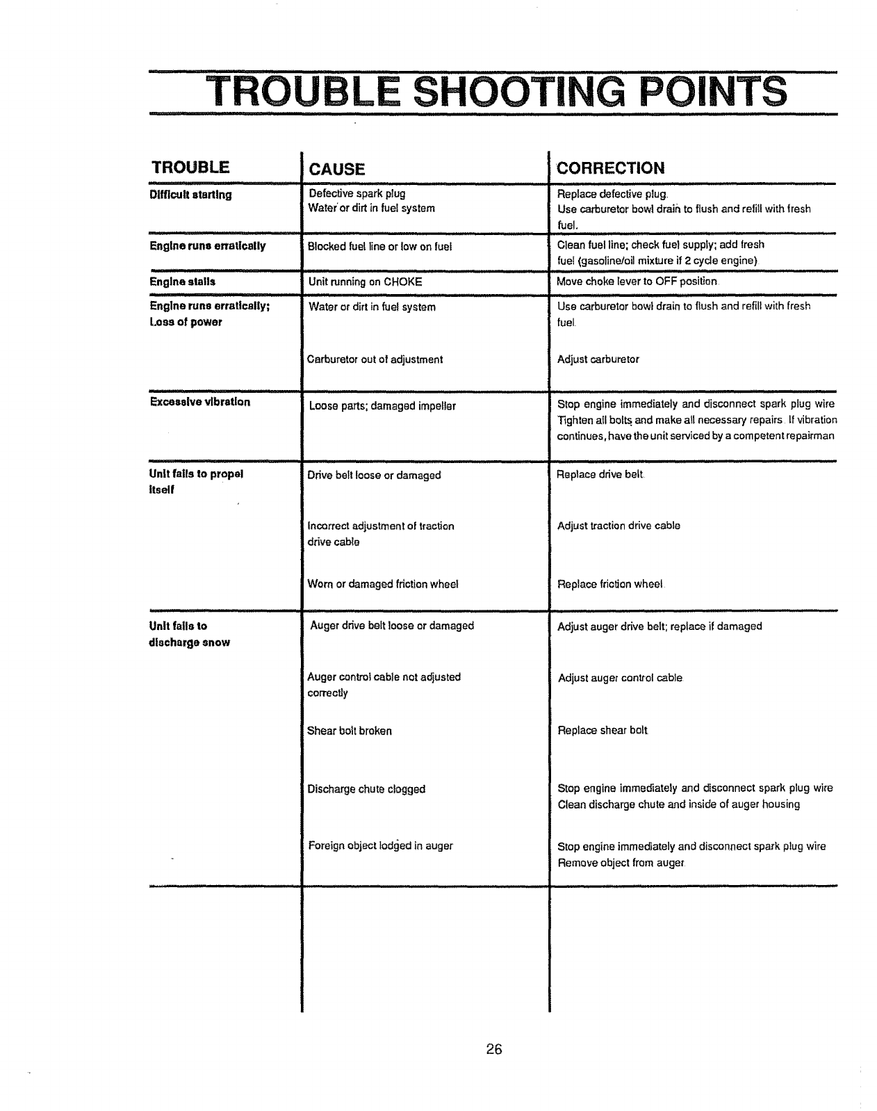
TROUBLE
Difficult starting
Englne runs erratlcally
Engine stalls
""L
Engine rune erratically;
Leas of power
Excessive vibration
Unit falls to propel
ltsel|
illlll
Unit fails to
discharge snow
CAUSE
...... ,.... , ,, ,, ,,,,
Defectivesparkplug
Water*or dirt in fuel system
Blocked fuel line or towon fuel
Carburetor out of adjustment
Loose parts; damaged impeller
............... 'L_L / I//L' J,,l•
Drive be_tloose or damaged
incorrect adjustment of traction
drive cable
Worn or damaged friction wheel
Auger drive belt loose ordamaged
Augercontrolcable not adjusted
correctly
Shear bolt broken
Discharge chute clogged
Foreign object lodged in auger
'CORRECTION
....... ,, ,,, ,,,,
Replace defective plug,,
Use carburetor bowl draih,to flush and refill with fresh
fuel.
Clean fuel line; check fuel supply;add fresh
fue! (gasolinetoi] mixture if 2 cycleengine)
i m, ........................
Move choke Iever to OFF position
Use carburetor bow_drain to flush and refill with fresh
fuel.
Adjust carburetor
..................... i ,JJl i i,i ,ll,i .......
Stop engine immediately and disconnect spark plug wire
Tighten all belts and make all necessary repairs tf vibration
continues, have the unit serviced bya competent repairman
Replace drive belt.
Adjust traction drive cable
Replace friction wheel
Adjust auger drive belt; replace if damaged
Adjust auger control cable
Replace shear bolt
Stop engine immediately and disconnect spark plug wire
Clean discharge chute and inside of auger housing
Step engine immediately and disconnect spark plug wire
Remove object from auger
26

NOTES
L,U,I
27
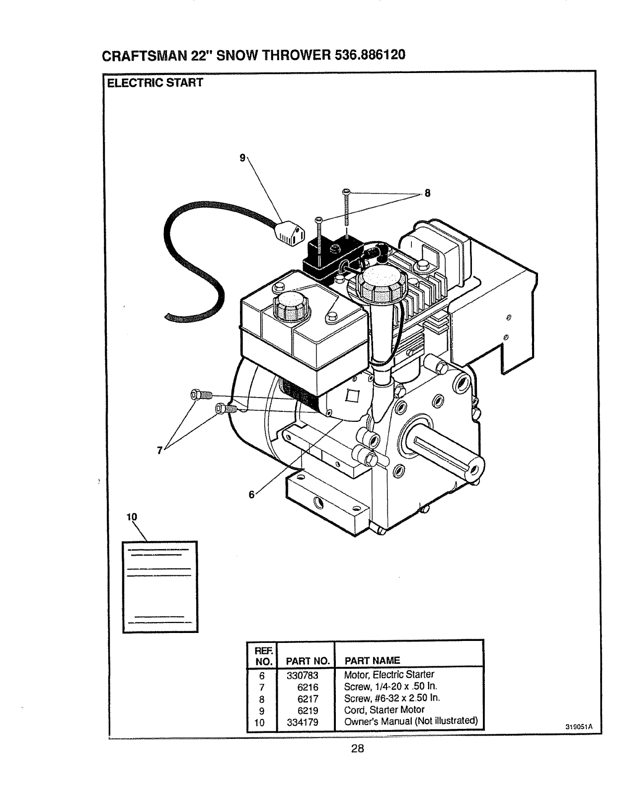
CRAFTSMAN 22" SNOW THROWER 536.886120
ELECTRIC START
®
®
10
RF.F.I
NO.
6
7
8
9
10
PART NAMEPART NO.
330783
6216
6217
6219
334179
Screw, 1/4-20 x ,50 1no
Screw, #6-32 x 2,50 In_
Cord, Starter' Motor
Owner's Manual (Not illustrated)
28
319051A
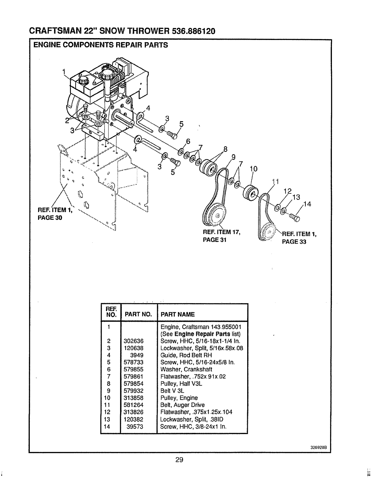
CRAFTSMAN 22" SNOW THROWER 536.886120
ENGINE COMPONENTS REPAIR PARTS
4
35
PAGE 30
35
REF_ITEM 17,
PAGE 31
0
12 314
ITEM !,
PAGE 33
REF.
NO, PART NO. PART NAME
1Engine, Craftsman 143.955001
2302636
3 120638
4 3949
5 578733
6579855
7 579861
8 579854
9 579932
10 313858
11 581264
12 313826
13 120382
14 39573
(See Engine Repair Parts list)
Screw, HHC, 5/16-18x1-1/4 Ino
Lockwasher, Split, 5/16xo58x08
Guide, Rod Belt RH
Screw, HHC, 5/16-24x5/8 In,
Washer, Crankshaft
Flatwasher, 752x91x02
Pulley, Half V3L
Belt V 3L
Pulley, Engine
Belt, Auger Drive
Flatwasher, 375xt 25xo104
Lockwasher, Split, 381D
Screw, HHC, 3/8-24xl In
ii ii i
29
326928B
i
CRAFTSMAN 22" SNOW THROWER 536.886120
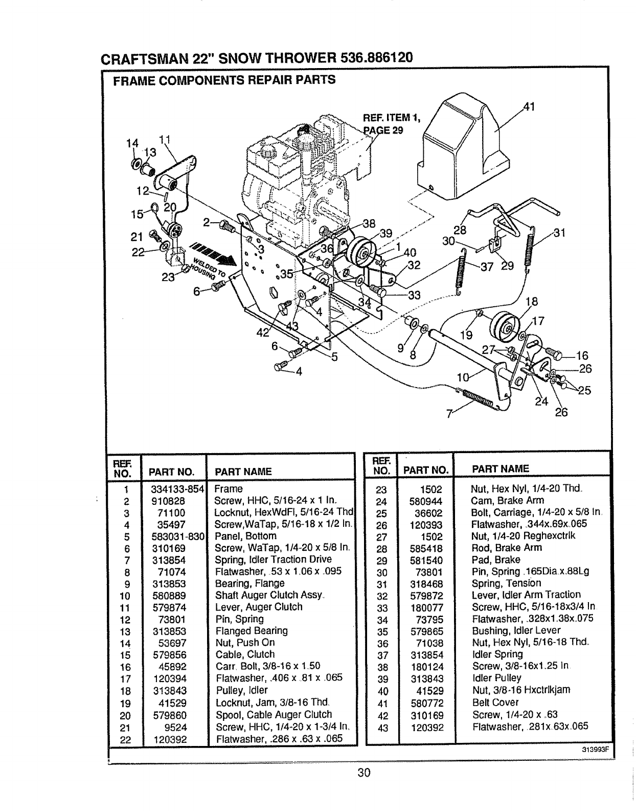
FRAME COMPONENTS REPAIR PARTS
._. REF. ITEM 1, //_--_ _\/,41
FIEF.
NO.
1
2
3
4
5
6
7
8
9
10
11
12
13
14
15
t6
17
18
19
20
21
22
i
PART NO.
334133-854
910828
71100
35497
583031-830
310169
313854
71074
NO. PART NO.PART NAME
iHi
Frame
Screw, HHC, 5/16-24 x 1In.
Locknut, HexWdFI, 5/16-24 Thd
Screw,WaTap, 5t16-18 x 1/2 in.
Panel, Bottom
Screw, WaTap, 114-20x 5t8 In.
Spring, Idter Traction Odve
Flatwasher, 53 x 1.06 x ..095
23
24
25
26
27
28
29
30
1502
580944
36602
120393
1502
585418
581540
73801
PART NAME
Nut, Hex Nyl, 1/4-20 Thd
Cam, Brake Arm
Bolt, Carriage, 1/4-20 x 5f8 In.
Flatwasher, ..344x.69x.065
Nut, 1/4-20 Reghexctrtk
Rod, Brake Arm
Pad, Brake
Pin, Spring .165Diax.88Lg
313853
580889
579874
73801
313853
53697
579856
45892
Bearing, Flange
Shaft Auger Clutch Assy.
Lever, Auger Clutch
Pin, Spring
Flanged Bearing
Nut, Push On
Cable, Clutch
Calf. Bolt, 318-16 x 150
31
32
33
34
35
36
37
38
318468
579872
180077
73795
579865
71038
313854
180124
Spring, Tension
Lever, Idler Arm Traction
Screw, HHC, 5t16-t8x3/4 In
Flatwasher, .328x1.38x_075
Bushing, Idler Lever
Nut, Hex Nyl, 5/16-18 Thd.
Idler Spring
Screw, 3/8-16x125 /n
120394
313843
41529
579860
9524
120392
Flatwasher, .406 x 81 x .065
Pulley, Idler
Locknut, Jam, 3/8-16 Thd.
Spool, Cable Auger Clutch
Screw, HHC, 1t4-20 x 1-3/4 Ino
Flatwasher, .286 x .63 x .065
42
43
39 313843
40 41529
41 580772
310169
120392
Idler Pulley
Nut, 3/8-16 Hxctrlkjam
Belt Cover
Screw, 1t4-20 x .63
Fiatwasher,. 281x.63x 065
313993F
3O
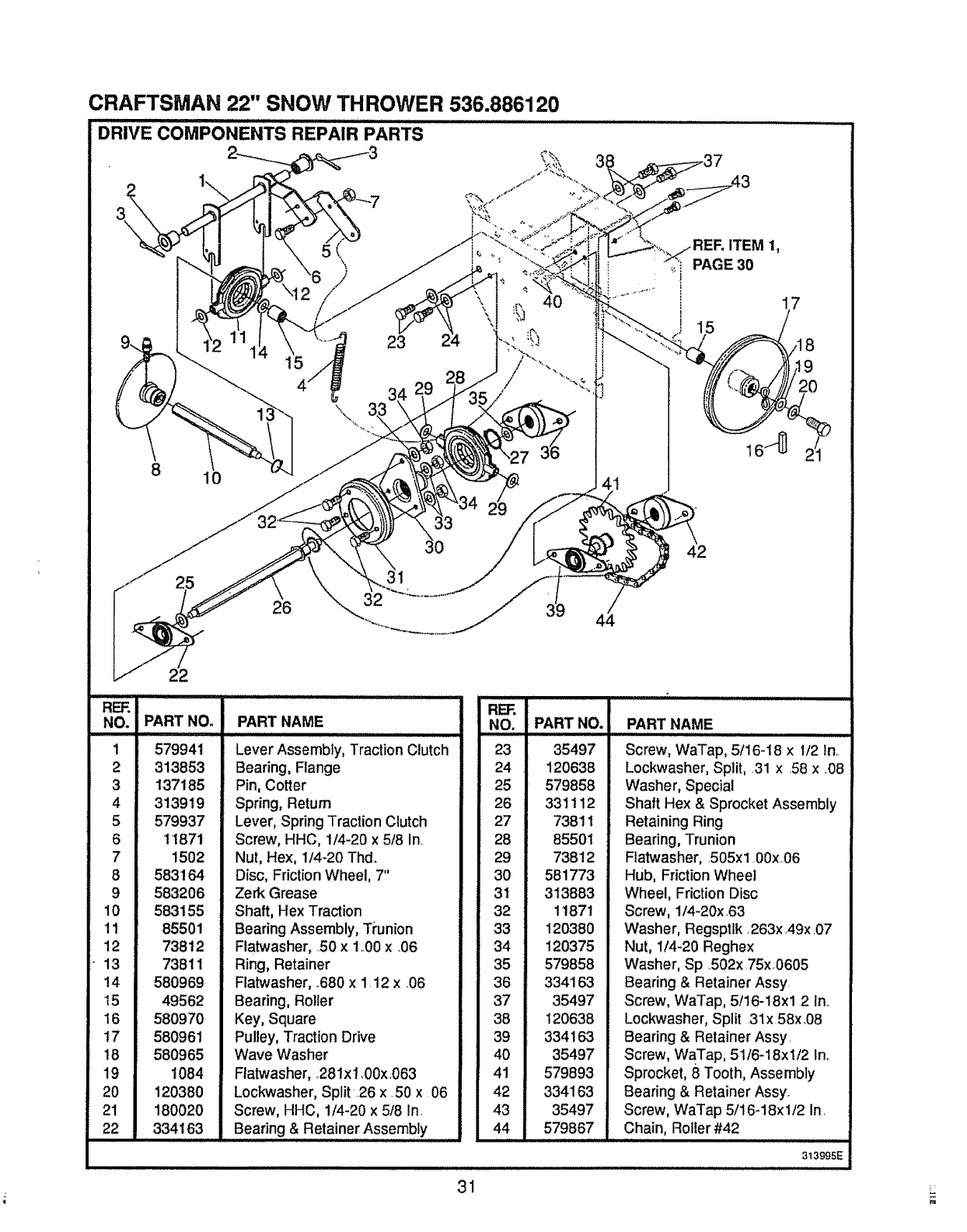
CRAFTSMAN 22" SNOW THROWER 536.886120
REF,
NO. PART NO.
PART NO.
1 579941
2 313853
3 137185
4 313919
5 579937
611871
7 1502
8583164
9 583206
10 583155
11 85501
12 73812
_ 13 73811
14 580969
I5 49562
16 580970
t7 580961
t8 580965
19 1084
20 120380
21 180020
22 334163
PART NAME
Lever Assembly, Traction Clutch
Bearing, Flange
Pin, Cotter
Spring, Return
Lever, Spring Traction Clutch
Screw, HHC, 1/4-20 x 5/8 In.
Nut, Hex, 1/4-20 Thd.
Disc, Friction Wheel, 7"
Zerk Grease
Shaft, Hex Traction
Bearing Assembly, Ti'union
Flatwasher, .50 x 1..00x _06
Ring, Retainer
Flatwasher, .680 x 1.12 x 706
Bearing, Roller
Key, Square
Pulley, Traction Drive
Wave Washer
Ftatwasher, 281x1.00x 063
Lockwasher, Split .26 x 50 x 06
Screw, HHC, 1/4-20 x 5/8 In.
Bearing & Retainer Assembly
..iRE] =,
, ,NO.
23
24
25
26
27
28
29
30
31
32
33
34
35
36
37
38
39
40
41
42
43
44
35497
120638
579858
331112
73811
85501
73812
581773
313883
11871
120380
120375
579858
334163
35497
120638
334163
35497
579893
334163
35497
579867
PART NAME
Screw, WaTap, 5/16-18 x 1/2 In..
Lockwasher, Split, ,31 x .58 x ..08
Washer, Special
Shaft Hex & Sprocket Assembly
Retaining Ring
Bearing, Trunion
Flatwasher, .505xl .00x06
Hub, Friction Wheel
Wheel, Friction Disc
Screw, 1/4-20x.63
Washer, Regsptlk .263x.49x.07
Nut, 1/4-20 Reghex
Washer, Sp ..502x75x.0605
Bearing & Retainer Assy.
Screw, WaTap, 5/16-18xl .2 In.
Lockwasher, Split 31x 58x.08
Bearing & Retainer Assy.
Screw, WaTap, 51/6-18xi/2 In.
Sprocket, 8 Tooth, Assembly
Bearing & Retainer Assy.
Screw, WaTap 5/16-18x 1/2 In.
Chain, Roller #42
313995E
31
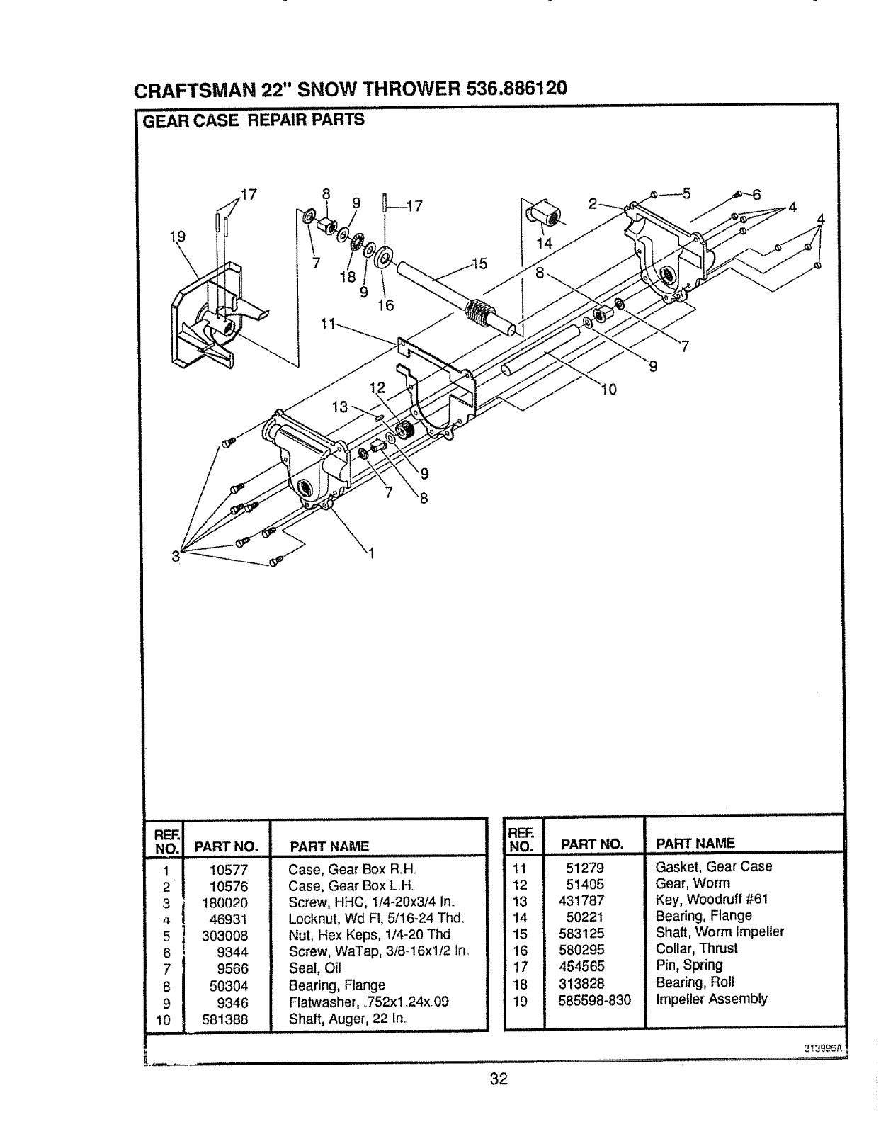
CRAFTSMAN 22" SNOW THROWER 536.886120
GEAR CASE REPAIR PARTS
8
t8 916
8
RF_
NO
1
2
3
4
5
6
7
8
9
10
PART NO.
10577
10576
180020
46931
303008
9344
9566
50304
9346
581388
PART NAME
/,J=, iii liHll, = = H=l =,ll=,,,,,,,
Case, Gear Box R.H.
Case, Gear Box L..H.
Screw, HHC, 1/4-20x3/4 in_
Locknut, Wd FI, 5/16-24 Thd.
Nut, Hex Keps, 1/4-20 Thd
Screw, WaTap, 3/8-16xl/2 in..
Seal, Oil
Bearing, Flange
Flatwasher, 752xl .24x.09
Shaft, Auger, 22 In.
llllllll ii i
iREF.
iNO.
ill
!12
13
i14
15
16
17
18
19
PART NO.
51279
51405
431787
50221
583125
580295
454565
313828
585598-830
PART NAME
Gasket, Gear Case
Gear, Worm
Key, Woodruff #61
Beadng, Flange
Shaft, Worm Impeller
Collar, Thrust
Pin, Spring
Bearing, Roll
Impeller Assembly
313_9_#.
32
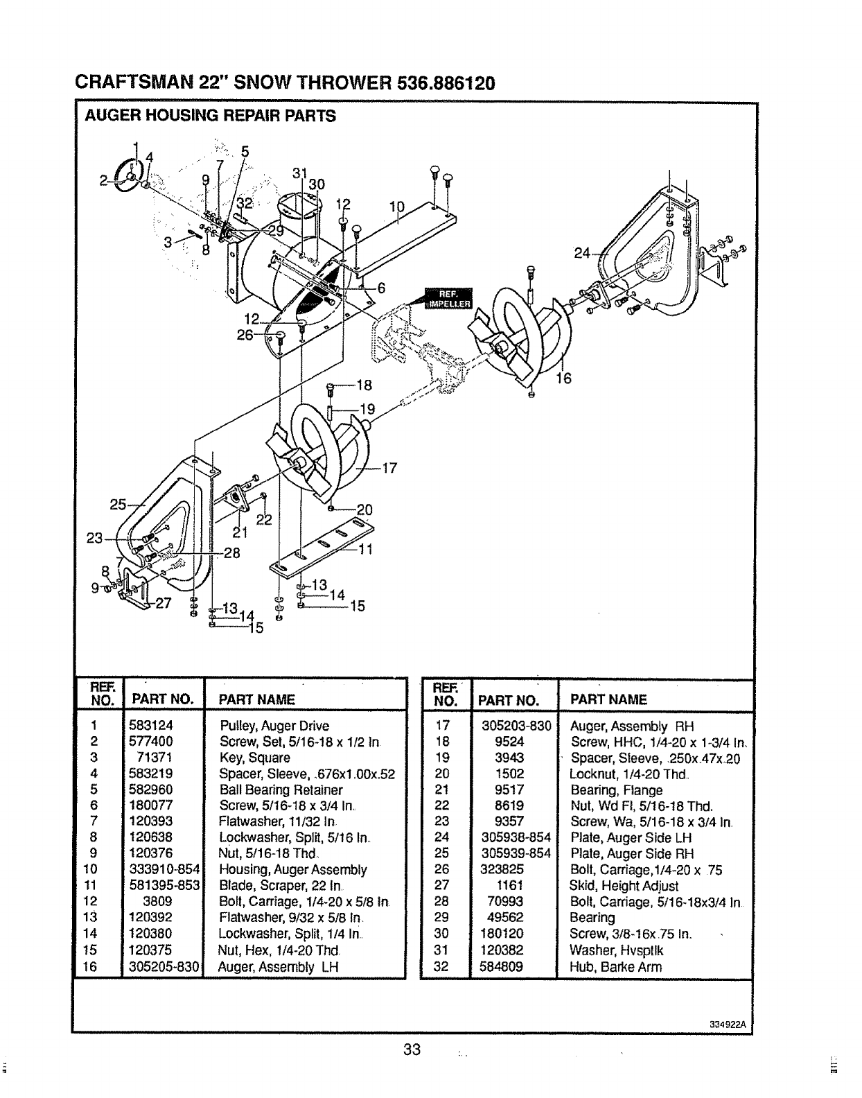
CRAFTSMAN 22" SNOW THROWER 536.886120
REF.
NO.
1
2
3
4
5
6
7
8
9
10
11
12
13
14
t5
16
PART NO. PART NAME
,,, ,,,,,,,,,,,,, ,,,,,, ,, , ,,,,
583124
577400
71371
583219
582960
180077
120393
120638
120376
333910-854
581395-853i
3809
120392
120380
120375
305205-830
Pulley, Auger Drive
Screw, Set, 5/16-!8 x 1/2 In
Key, Square
Spacer, Sleeve, °676x1,00x.52
Ball Bearing Retainer
Screw, 5/16-18 x 3/4 In..
Flatwasher, 11/32 In
L0ckwasher, Split, 5/t6 In_
Nut, 5116-18Thd.,
Housing, Auger Assembly
Blade, Scraper, 22 In.
Bolt, Carriage, 1/4-20 x 5/8 In.
Flatwasher, 9/32 x 5/8 In.
Lockwasher, Split, 1/4 In..
Nut, Hex, 1/4-20 Thd
Auger, Assembly LH
,11,,,,,H, ,I,L,,,,u,,,,l,,,lliJl,, ,u H liH
REF.'
NO.
17
18
19
2O
21
22
23
24
25
26
27
28
29
30
31
32
PART NO.
305203-830
9524
3948
1502
9517
8619
9357
305938-854
305939-854
323825
116'1
70993
49562
180120
120382
584809
PART NAME
Auger, Assembly RH
Screw, HHC, 1/4-20 x 1-3/4 In.
. Spacer, Sleeve, .250x.47x.20
Locknut, 1/4-20 Thd..
Bearing, Flange
Nut, Wd FI, 5/16-18 Thd.
Screw, Wa, 5/16-18 x 3/4 in,
Plate, Auger Side LH
Plate, Auger Side RH
Bolt, Carriage,I/4-20 x 75
Skid, Height Adjust
Bolt, Carriage, 5/16-18x3/4 In
Bearing
Screw, 3/8-16x.75 In.
Washer, Hvsptlk
Hub, Barke Arm
H,,,,I,,, ,, ,,, ,, ........................
33 _
334922A
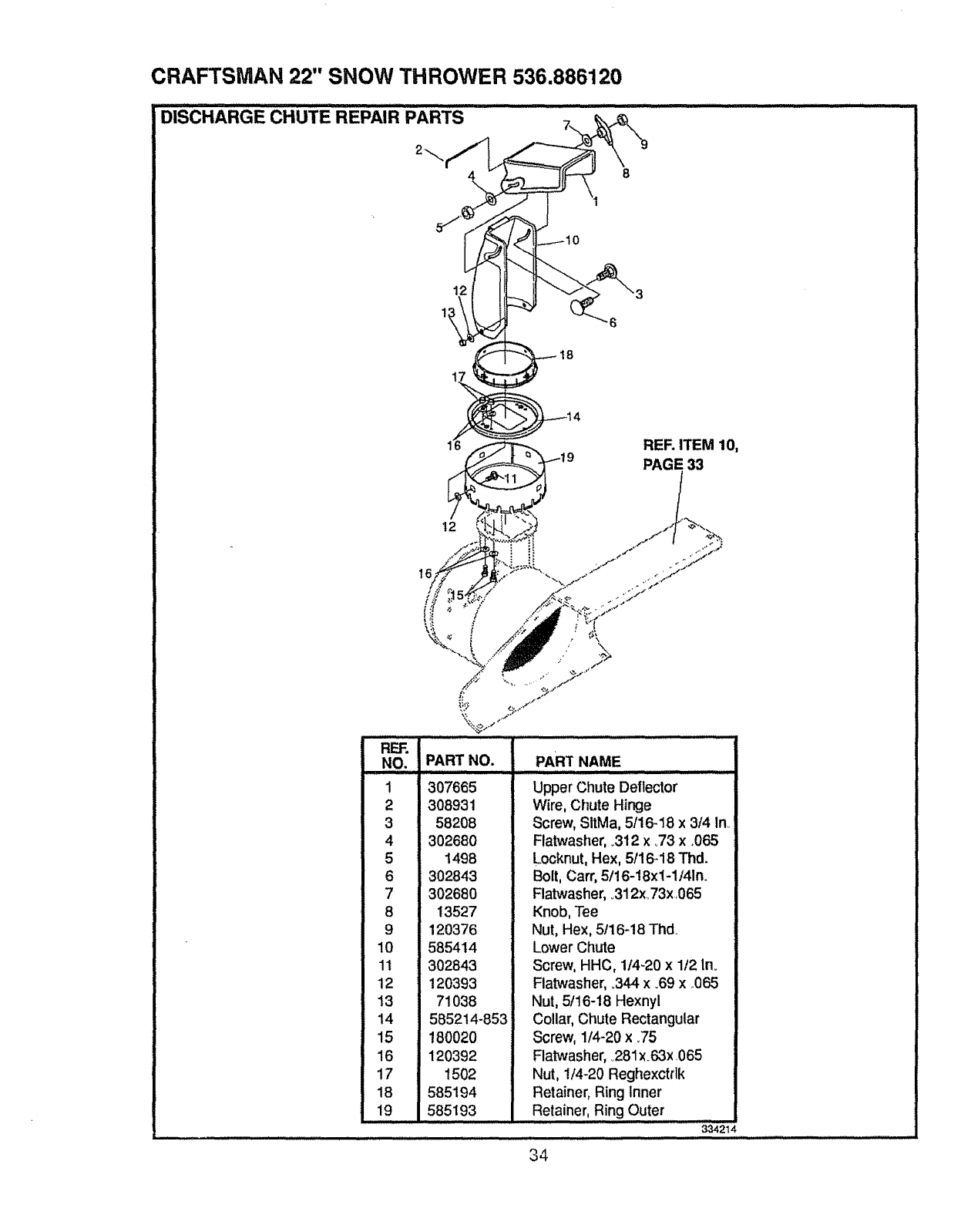
CRAFTSMAN 22" SNOW THROWER 536.886120
DISCHARGE CHUTE REPAIR PART's ' _ .....................
12
11
18
6
RER ITEM 10,
PAGE 33
16
t2
REF.
NO.
1
2
3
4
5
6
7
8
9
10
11
12
13
14
15
16
17
18
19
PART NO.
307665
308931
58208
302680
1498
302843
302680
13527
120376
585414
302843
120393
71038
585214-853
180020
120392
1502
585194
585193
PART NAME
Upper Chute Deflector
Wire, Chute Hinge
Screw, SItMa, 5/16-18 x 3/4 In..
Flatwasher, ..312x °73 x .065
Locknut, Hex, 5116-18Thd.
Bolt, Carr, 5/16-18xl-1!41n.
Flatwasher, o312x..73x065
Knob, Tee
Nut, Hex, 5/16-18 Thd
Lower Chute
Screw, HHC, 1t4-20 x 1t2 ln_
Flatwasher, .344 x .69 x .065
Nut, 5/16-18 Hexnyl
Collar, Chute Rectangular
Screw, 1/4-20 x _75
Flatwasher, 281x.63x .065
Nut, 1/4-20 Reghexctrlk
Retainer, Ring Inner
Retainer, Ring Outer
334214
34
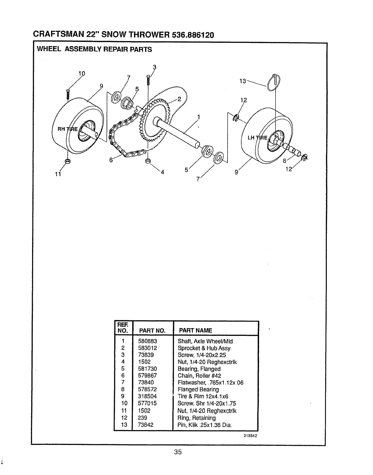
CRAFTSMAN 22" SNOW THROWER 536.886120
Ill II I ll',"N,III I , ,,, , , .................................................
WHEEL ASSEMBLY REPAIR PARTS
7
5
1
12
11 4 9
REF.
NO.
1
2
3
4
5
6
7
8
9
t0
11
12
13
PART NO,
580883
583012
73839
1502
581730
579867
73840
578572
318504
577015
!502
239
73842
PART NAME
Shaft, Axle Wheel/Mid
Sprocket & Hub Assy
Screw, 1/4-20x225
Nut, 1/4-20 Reghexclrtk
Bearing, Flanged
Chain, Roller #42
Flatwasher, .,765xl, 12x .06
Flanged Bearing
Tire & Rim 12x4Jx6
Screw, Shr 1/4-20xl.75
Nul, t/4-20 Reghexctdk
Ring, Retaining
Pin, Klik .25x1_.38Dia,
318542
35
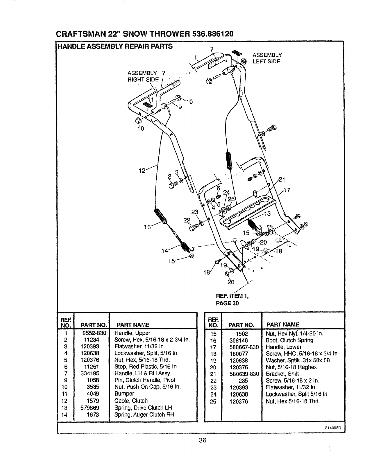
CRAFTSMAN 22" SNOW THROWER 536.886120
"hANDLE ASSEMBLY REPAIR PARTS 7............... ....
11 .., 1o
.9,,
121" ! ' "'""' e _ 21
7
PAGE 30
BEE'.
NO,
1
2
3
4
5
6
7
9
10
t!
12
13
14
PART NO.
9552-830
11234
120393
120638
120376
11261
334195
1058
3535
4049
i579
579869
1673
i ji ,
PART NAME
Handle, Upper
Screw, Hex, 5/16-18 x 2-3/4 In
Flatwasher, 11/32 In.
Lockwasher,Split,5/16 In.
Nut, Hex, 5/16-18 Thd..
Stop, Red Plastic, 5/16 In
Handle, LH & RH Assy
Pin, Clutch Handle, Pivot
Nut, Push On Cap, 5/16 In.
Bumper
Cable, Clutch
Spring, Drive Clutch LH
Spring, Auger Clutch RH
REF_
NO. PART NO.
15 1502
16 308146
17 580667-830
18 180077
19 120638
20 120376
21 580639-830
22 235
23 120393
24 120638
25 120376
PART NAME
Nut, HexNyl1114-20 ln_
Boot, Clutch Spdng
Handle, Lower
Screw, HHC, 5/16-18 x 3/4 In..
Washer, Spttk ,31x 58x.08
Nut, 5/16-18 Reghex
Bracket, Shift
Screw, 5/16-18 x 2 in,
Flatwasher, 11/32 in.
Lockwasher, Split 5/16 In
Nut, Hex 5/16-18 Thd
3140020
............. ............................... ''"4.
36
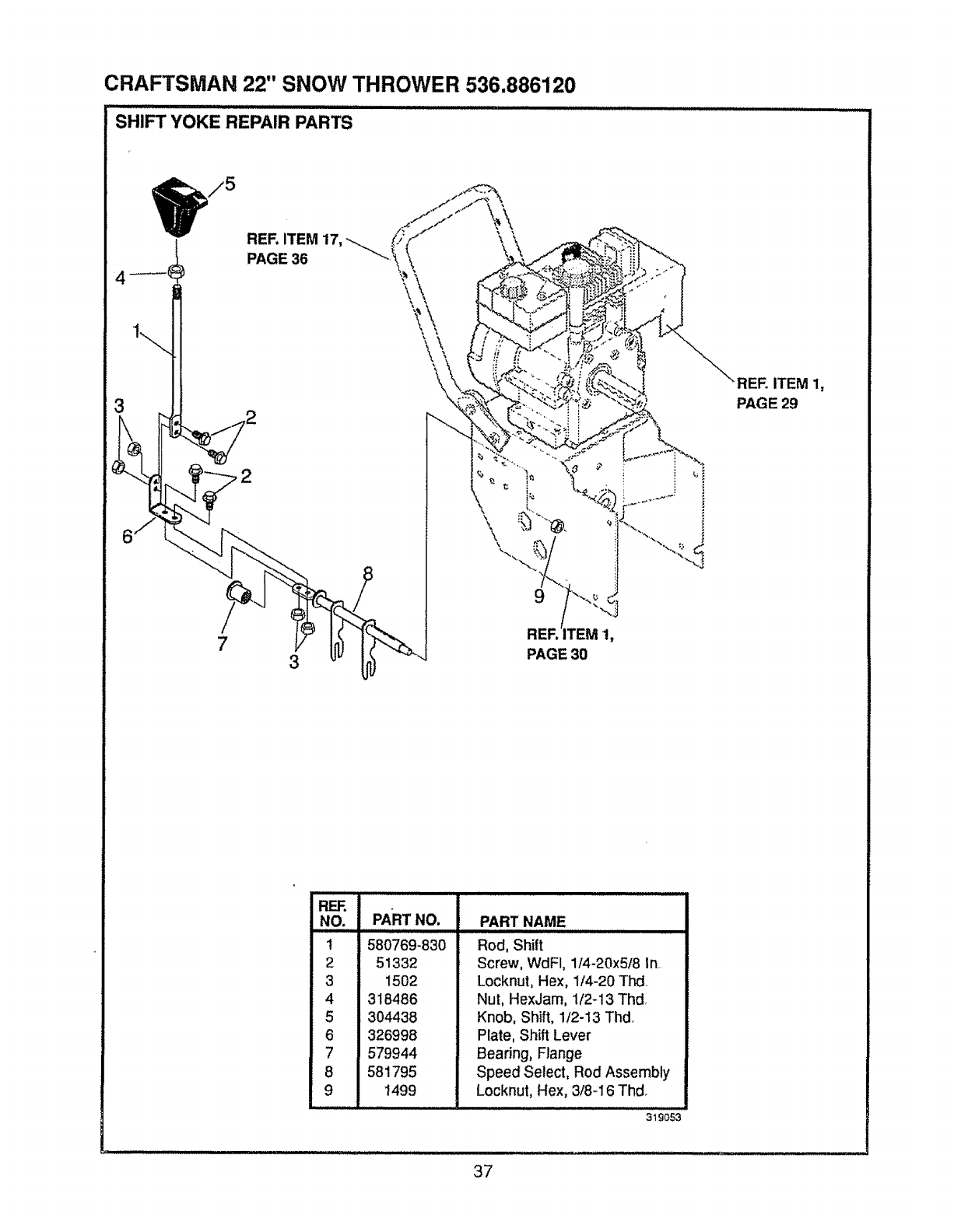
CRAFTSMAN 22" SNOW THROWER 536.886120
SHIFT YOKE REPAIR PARTS
73
\\\
9
1,
PAGE 30
RER ITEM 1,
PAGE 29
R_
NO. PART NO.
t
2
3
4
5
6
7
8
9
PART NAME
580769-830
51332
1502
318486
304438
326998
579944
581795
1499
ii ,llulnuulJU,,,,,,,,,,,,,,,,,,,,,,,,,,,,,,,,,, ,,
Rod, Shift
Screw, WdFi, 1t4-20x5f8 In.,
Locknut, Hex, 1/4-20 Thd,
Nut, HexJam, 1/2-13 Thd°
Knob, Shift, 1/2-13 Thdo
Plate, Shift Lever
Bearing, Flange
Speed Select, Rod Assembly
Locknut, Hex, 3/8-16 Thd,
319053
37
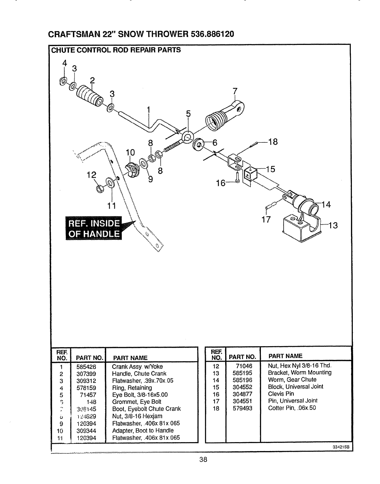
CRAFTSMAN 22" SNOW THROWER 536.886120
CHUTE CONTROL ROD REPAIR PARTS
4 3
5
_--18
NO. PART NO.
1 585426
2 307399
3 309312
4 578159
71457
148
.... 308145
9 120394
10 309344
1I !, 120394
PART NAME RE]'.
NO. PART NO. PART NAME
Crank Assy, w/Yoke
Handle, Chute Crank
Flatwasher, o39x,70x,05
Ring, Retaining
Eye Bolt, 3/8-16x&00
Grommet, Eye Bolt
Boot, Eyeboft Chute Crank
Nut, 3/8-16 Hexjam
Flatwasher, A06x 81x 065
Adapter, Boot to Handle
Ratwash,er,,,,,,,,,:,406x81x 065
t2 71046
!3 585195
14 585196
15 304552
16 304877
17 304551
18 579493
Nut, Hex Nyl 3/8-16 Thd,
Bracket, Worm Mounting
Worm, Gear Chute
Block, Universal Joint
Clevis Pin
Pin, Universal Joint
Cotter Pin, _06x,50
334215B
38
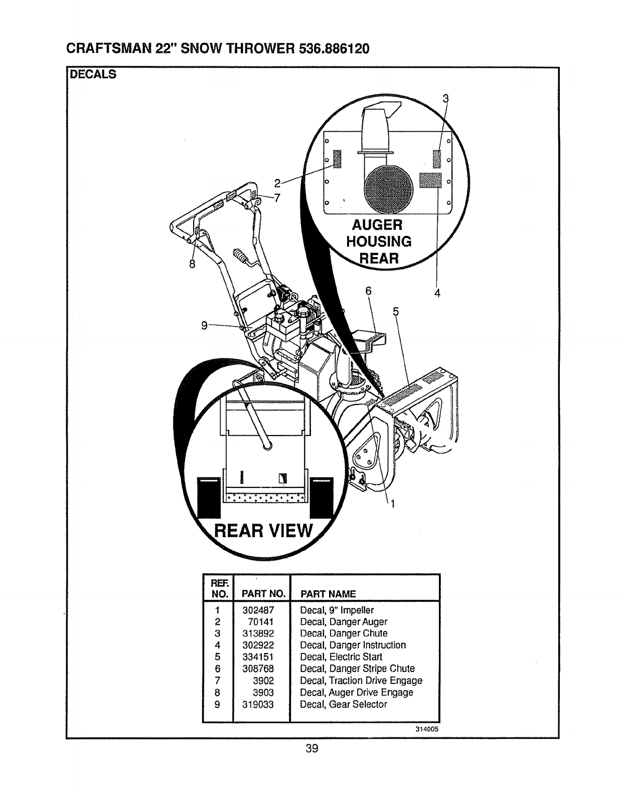
CRAFTSMAN 22" SNOW THROWER 536.886120
DECALS .....
8
AUGER
HOUSING
6 4
REAR VIEW
REF.
NO. PART NO. PART NAME
t302487
2 70141
3 313892
4 302922
5 334151
6 308768
7 3902
8 3903
9 319033
Decal, 9" tmpeller
Decal, Danger Auger
Decal, Danger Chute
Decal, Danger Instruction
Decal, Electdc Start
Decal, Danger Stripe Chute
Decal, Traction Drive Engage
Decal, Auger Drive Engage
Decal, Gear Selector
3t 4005
39
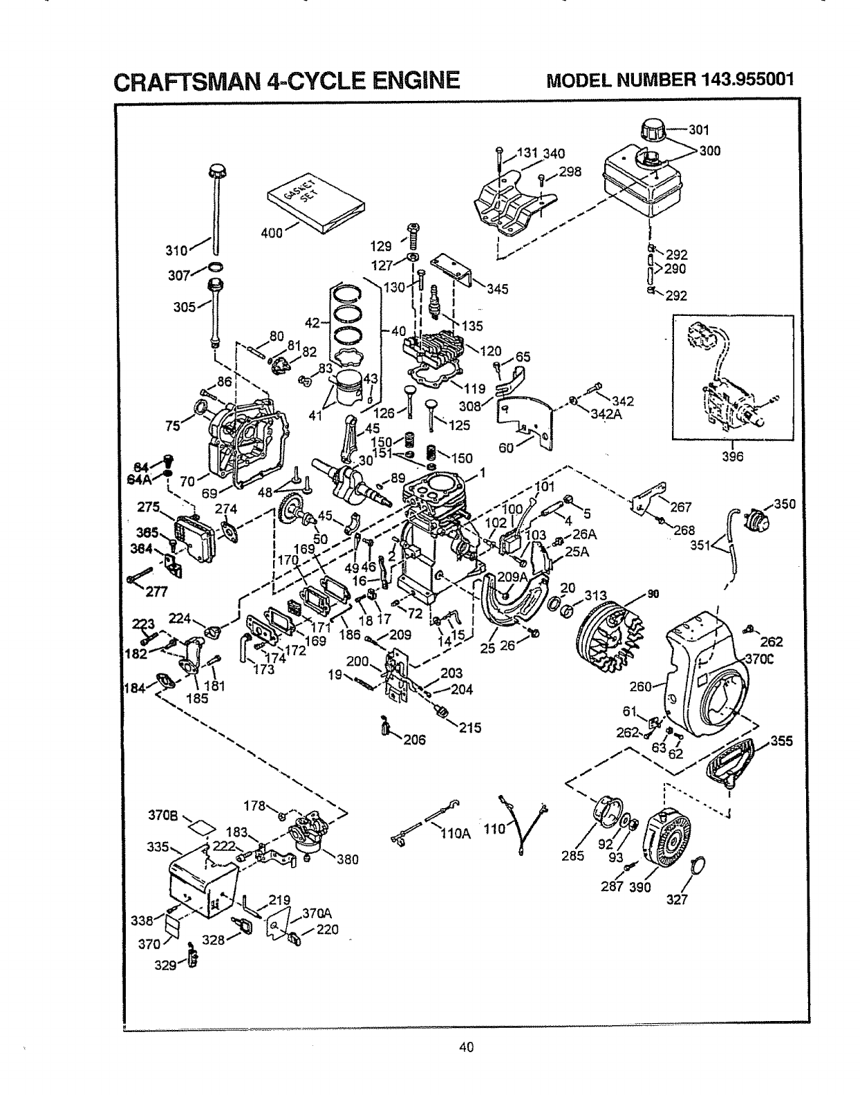
CRAFTSMAN 4-CYCLE ENGINE MODEL NUMBER 143.955001
.... ,, ,,,,,,,,,, iu , ,11111111 11 11,/1
69274
i
1
117
173
181
185
329
328
219
j131 340
;,,_'_/,298
!35
>
370A
285
93,.,/ /_
287 390 327
r".... : ,
4O
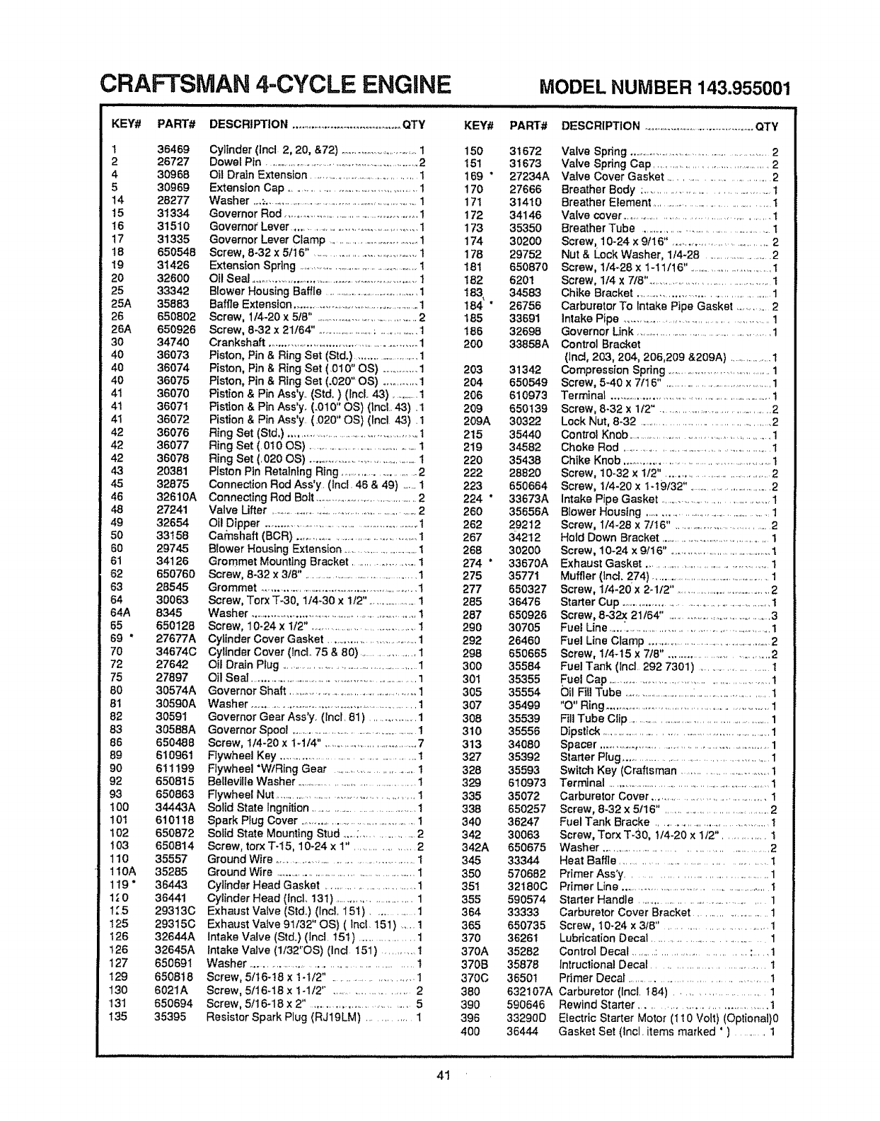
CRAFTSMAN 4-CYCLE ENGINE
KEY# PART# DESC R| _'=lO N....................................... QTY
136469
226727
4 30968
530969
t4 28277
15 31334
16 31510
17 31335
t8 650548
19 31426
20 32600
25 33342
25A 35883
26 650802
26A 650926
3O 34740
40 36073
40 36074
40 36075
41 36070
41 36071
41 36072
42 36076
42 36077
42 36078
43 20381
45 32875
46 32610A
48 27241
49 32654
50 33158
6O 29745
61 34126
62 650760
63 28545
64 30063
64A 8345
65 650128
69 *27677A
70 34674C
72 27642
75 27897
80 30574A
81 30590A
82 30591
83 30588A
86 650488
89 610961
90 611199
92 650815
93 650863
100 34443A
10t 610118
102 650872
103 650814
110 35557
110A 35285
119 *36443
1_ 0 36441
1.'.5 29313C
125 293t5C
126 32644A
126 32645A
127 650691
129 650818
130 6021A
131 650694
t35 35395
Cylinder (]ncl 2, 20, &72) ..............................1
Dowel Ptn ..................................................................2
Oil Drain Extension ....................................... 1
Extension Cap .......................................... I
Washer ,,_;................................................................1
Governor Rod ................................................ I
Governor Lever .......................................... 1
Governor Lever Clamp ............................... 1
Screw, 8-32 x 5116" ................................... 1
Extension Spring ......................................................1
Ofl Seal ..............................................................1
Blower Housing Baffle .........................................1
Baffle Extension ..................................................1
Screw, 1t4-20 x5/8", ................................... 2
Screw, 8-32 x 21164". .........................;..............1
Crankshaft ................................................... 1
Piston, Pin & Ring Set (Std.) ..........................1
Piston, Pin &Ring Set (.010" OS) .............1
Piston, Pin & Ring Set (.020" OS) ........... 1
Pistion & Pin Ass'y.. (Std,) (Incl. 43) ............1
Pistion & Pin Ass'y, (.0!0" OS) (incl.. 43) .1
Pistton & Pin Ass'y (.020" OS) (fncl 43). 1
Ring Set (Std,) ..................................................1
Ring Set (.010 OS) .........................................!
Ring Set (,020 OS) .............................................i
Piston Pin Retatntng Ring ........................... 2
Connection Rod Ass'y. (Inc!. 46 & 49) .......1
Connecting Rod Bolt .....................................2
Valve Uffer .............................................................2
Oil Dipper ....................................................... I
Carnshaft (BCR) .............................................1
Blower Housing Extension ...............................1
Grommet Mounting Bracket .................. 1
Screw, 8-32 x 3t8". .............................................1
Grommet ............................................................1
Screw, Torx T-30, 1/4-30 x 112". ....................1
Washer .............................................................1
Screw, 10-24 x1f2", .......................................1
Cylinder Cover Gasket .................................1
Cylinder Cover (tncL 75 & 80) .................... 1
Oil Dra}n Plug ......................................................1
Oil Seal ................................................................1
Governor Shaft .................................................1
Washer ..................................................................1
Governor Gear Ass'y. (incl. 81 ) ................ 1
Governor Spool .......................................................1
Screw, 114-20 x 1-1t4" _.................................7
Flywheel Key .....................................................1
Flywheel *WlRtng Gear ..................................t
Belleville Washer ..............................................1
Flywheel Nut ................................................. t
Solid State lngnition ............................................1
Spark Plug Cover ...........................................1
Solid State Mounting Stud .....;.................. 2
Screw, torx T-t5, 10-24 x 1". .................... 2
Ground Wire ...................................................1
Ground Wire ......................................................1
Cylinder Head Gasket ................................ t
Cylinder Head (IncL 13t) .......................... 1
Exhaust Valve (Std..) (lncl, 15t) ............. 1
Exhaust Valve 9t/32" OS) ( lnct. 151) .... 1
Intake Valve (Std.) (lncl. i51) ................... 1
Intake Valve (1132"OS) (Incl i51) .............1
Washer .................................................... t
Screw, 5/t6-!8 x t-t/2" .......................... 1
Screw, 5116-18 x t -1/2" ........................ 2
Screw, 5/16-18 x 2" .................................... 5
Resistor Spark Plug (RJ19LM) ............. 1
KEY#
150
t51
169 "
170
171
172
173
174
178
181
182
184 "
185
166
2O0
203
204
206
209
209A
215
219
220
222
223
224 °
260
262
267
268
274 "
275
277
285
287
290
292
298
3OO
301
305
307
308
310
313
327
328
329
335
338
340
342
342A
345
35O
351
355
364
365
370
370A
370B
370C
38O
390
396
4OO
MODEL NUMBER 143.955001
PART# DESCRIPTION ........................................... (_TY
31672
31673
27234A
27666
31410
34146
35350
30200
29752
650870
6201
34583
26756
33691
32698
33858A
31342
650549
610973
650139
30322
35440
34582
35438
28820
650664
33673A
35656A
29212
34212
30200
33670A
35771
650327
36476
650926
30705
26460
650665
35584
35355
35554
35499
35539
35556
34080
35392
35593
610973
35072
650257
36247
30063
650675
33344
570682
32180C
590574
33333
650735
36261
35282
35878
36501
632107A
590646
33290D
36444
Valve Spring ......................................................2
Valve Spring Cap ........................................ 2
Valve Cover Gasket .................................. 2
Breather Body ; ....................................... t
Breather Element ...................................... 1
Valve cover .................................................... t
Breather Tube ............................................... 1
Screw, 10-24 x 9tl 6". ................................. 2
Nut & Lock Washer, 1/4-28 ............................2
Screw, 1t4-28 x 1-11/16". .................................1
Screw, 1t4 x 7t8". ......................................... 1
Chike Bracket ............................................. 1
Carburetor To Intake Pipe Gasket .............2
Intake Pipe ................................................ 1
Governor Link ........................................................1
Control Bracket
(lnci, 203, 204, 206,209 &209A} ..................1
Compression Spring ...........................................1
Screw, 5-40 x 7116". ..........................................1
Terminal ................................................................!
Screw, 8-32 xI12". ........................................2
Lock Nut, 8-32 ............................................. 2
Control Knob ....................................................1
Choke Rod .......................................................1
Chike Knob ................................................ 1
Screw, 10-32 x t12". ..................................... 2
Screw, 1/4-20 x 1-t9/32". ................................2
Intake Pipe Gasket ....................................... 1
Blower Housing ...................................................1
Screw, 114-28 x 7/16". ...................................2
Hold Down Bracket .............................................1
Screw, 10-24 x 9/16" o........................................1
Exhaust Gasket ........................................ 1
Muffler (Ind. 274) ..................................................1
Screw, 1t4-20 x2-1t2". ......................................2
Starter Cup ..................................................... 1
Screw, 8-32x 21 t64" ......................................3
Fuel Line .....i.................................................. I
Fuel Line Clamp ..............................................2
Screw, 1t4-15 x 7/8". .................................. 2
Fuel Tank (lnci 292 7301) ...................... t
Fuel Cap ........................................................ t
Oil FIll Tube ..................................:.......................... 1
"O" Ring ............................................................1
Fill Tube Clip .........................................................1
Dipstick .............................................................1
Spacer ......................................................... 1
Starter Plug ................................................ 1
Switch Key (Craftsman ............................ 1
Terminal .......................................................................t
Carburetor Cover ..................................... 1
Screw, 8-32 x 5/16" .................................. 2
Fuel Tank Bracke .......................................... t
Screw, Torx T-30, t/4-20 x 1/2". ............. t
Wash er ............................................... 2
Heat Baffle ........................................... t
Primer Ass'y ........................................ 1
Primer Line ....................................................t
Starter Handle ........................................ 1
Carburetor Cover Bracket ........................ 1
Screw, 10-24 x 3/8" ........................... 1
Lubrication Decal ...................................... 1
ControlDecal .........:..........................:.....I
lntructional Decal .................................. 1
Primer Decal ............................................... 1
Carburetor (lncl. t84) ...................... 1
Rewind Starter .................................... 1
Electric Starter Motor (It0 Volt)(Optional}0
Gasket Set (Incl. items marked ' ) ..... t
41
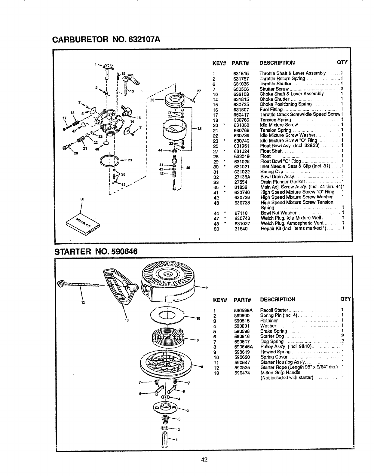
CARBURETOR NO. 632107A
6-TM
_ .. i '=, r
i? \. j,^././L.<3-#_"_---18
6),
_]l_._t 021 48 I
@-°
'A
.................. iii i IIIIIIIIH
STARTER NO. 590646
4t1
m
KEY# PART#
1631615
2 631767
6 631036
7 650506
10 632t 08
14 631815
15 630735
16 631807
17 65O417
18 630766
20 "631838
21 630766
22 630739
23 "630740
25 63195t
27 "631024
26 632019
29 *631028
30 *631021
31 631022
32 27136A
33 27554
40 " 31839
41 "630740
42 630739
43 630738
44 * 27110
47 "630746
48 "631027
60 31840
DESCRIPTION QTY
Throttle Shaft &Lever Assembly ....... 1
Throttle Return Spring ................ 1
ThrottleShutter............................I
ShutterScrew ........................................2
Choke Shaft &Lever Assembly ........ 1
Choke Shutter ....................................... 1
Choke Positioning Spdng ............. 1
Fuel Fitting .........................................1
Throttle Crack Scmwtldle Speed Screw 1
Tension Spring ....................... I
Idle Mixture Screw .................... t
TensionSpring ..............................I
Idle Mixture Screw Washer ............... 1
Idle Mixture Screw "O" Ring ........... 1
FToatBowl Asy ([ncl 32&33) ........ 1
Float Shaft ................................1
Float .............. ' ......... 1
Float Bowl "O" Ring ......................... I
Inlet Needle, Seat & Clip (Inct. 31) . . t
Spdng Clip ............................... t
Bowl Drain Assy ........................... 1
Drain Plunger Gasket ......................... 1
Main Adj Screw Ass'y.. (Incl. 41 thru 44)1
High Speed Mixture Screw "O" Ring 1
High Speed Mixture Screw Washer ..... 1
High Speed Mixture Screw Tension
Spring ....................................I
Bowl Nut Washer ................................... I
Welch Plug, Idle Mixture Well ....... !
Welch Plug, Atmospheric Vent .... 1
Repair Kit (inct items marked ") ..... t
12 \13
KEY# PART#
1590599A
2 590600
3590615
4590601
5590598
6 590616
7 590617
8 590645A
9590619
t0 590620
11 590647
12 590535
13 590474
DESCRIPTION QTY
Recoil Starter .......................... 1
Spring Pin (Inc 4) ............................ t
Retainer .......................................1
Washer ......................................... 1
Brake Spring ................................I
StarterDog ............................2
Dog Spring .....................................2
Putley Ass'y. (lncl 9&10) ....................... t
Rewind Spring ................................ t
Spring Cover ..................................... 1
Starter Housing Ass'y .......................... 1
Starter Rope (Length 98" x 9164" dia ). 1
Mitten Gri[p Handle
(Not included with starter) ............. t
42
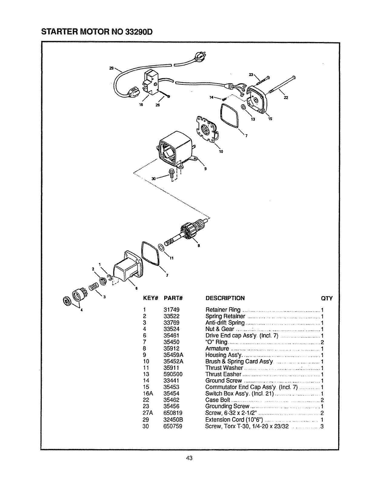
STARTER MOTOR NO 33290D
\lO
1
2
KEY# PART#
I31749
233522
3 33769
4 33524
6 35461
7 35450
8 35912
9 35459A
10 35452A
11 35911
13 590500
14 33441
t5 35453
16A 35454
22 35462
23 35456
27A 650819
29 32450B
30 650759
DESCRIPTION QTY
Retainer Ring ................................................................1
Spring Retainer ......................................................................1
Anti-drift Spring ............................................................1
Nut & Gear .............:.......................................................1
Drive End cap Ass'y. (Incl. 7) ..........................................1
"0" Ring ....................................................................................2
Armature ...........................................................................1
Housing Ass",/.................................................................. '1
Brush & Spring Card Ass'y ....................................1
ThrustWasher .............................................;........... 1
Thrust Easher .........................................................1
Ground Screw .......................................................I
Commutator End Cap Ass'y. (Incl. 7) ................t
Switch Box Ass'y,. (Incl, 21) .......................................1
Case Bolt ....................................................... 2
Grounding Screw ..................................................1
Screw, 6-32 x 2-1t2". ............................................2
Extension Cord (t0"6") .................................. 1
Screw, Torx "['-30, 1/4-20 x 23/32 .............. 3
43
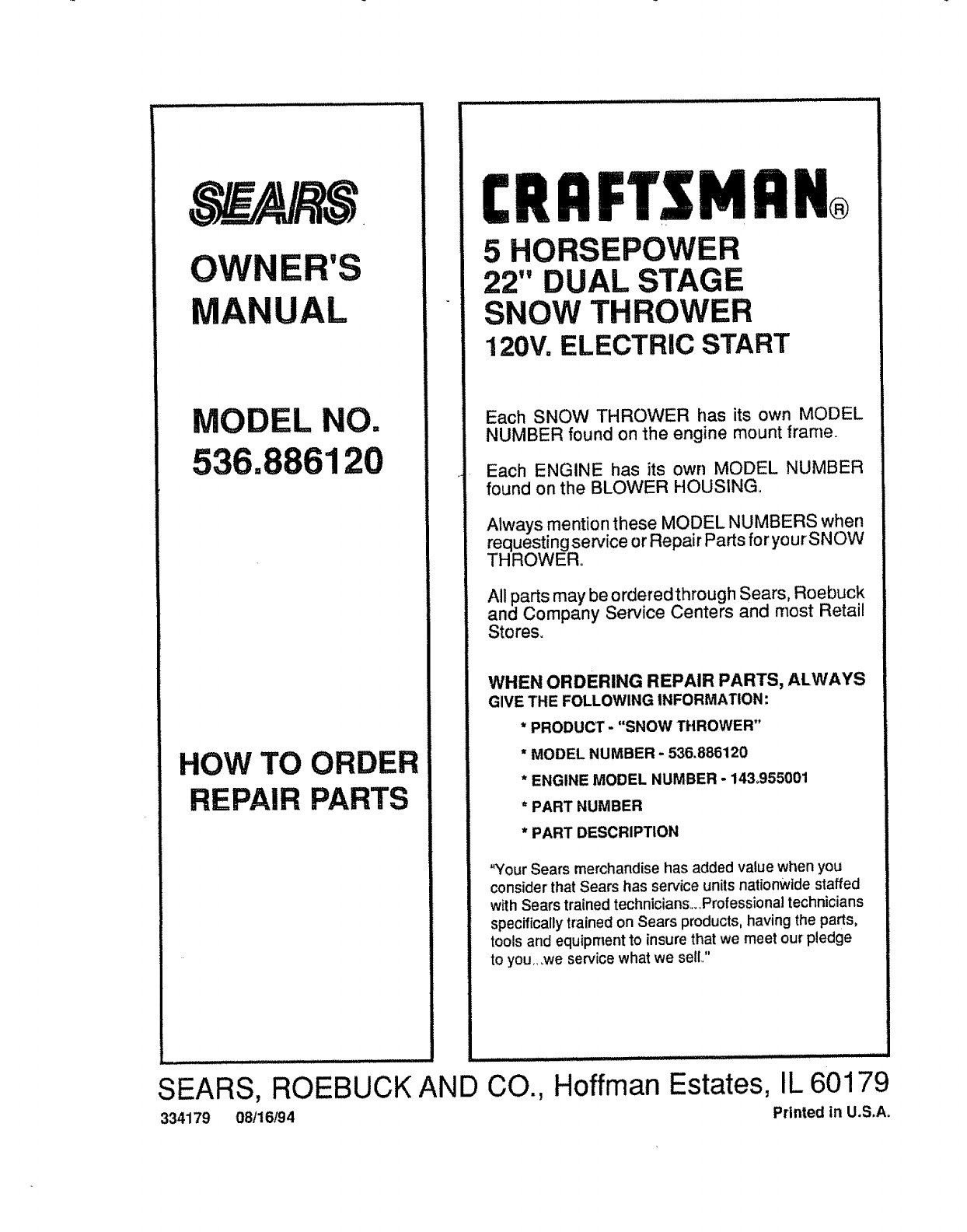
OWNER'S
MANUAL
MODEL NO.
HOW TO ORDER
REPAIR PARTS
SEARS, ROEBUCK AND CO.,
334179 08116194
CRRFTSMRN®
5 HORSEPOWER
22" DUAL STAGE
SNOW THROWER
120V, ELECTRIC START
Each SNOW THROWER has its own MODEL
NUMBER found on the engine mount frame.
Each ENGINE has its own MODEL NUMBER
found on the BLOWER HOUSING°
AIways mention these MODEL NUMBERS when
requesting service or Repair Parts foryourSNOW
THROWER°
All parts may be orderedthrough Sears, Roebuck
and Company Service Centers and most Retail
Stores.
WHEN ORDERING REPAIR PARTS, ALWAYS
GIVE THE FOLLOWING INFORMATION:
* PRODUCT -"SNOW THROWER"
* MODEL NUMBER - 536.886120
* ENGINE MODEL NUMBER - 143_955001
*PART NUMBER
*PART DESCRIPTION
"Your Sears merchandise has added value when you
consider that Sears has service units nationwide staffed
with Sears trained technicians_Professional technicians
specifically trained on Sears products, having the parts,
tools and equipment to insure that we meet our pledge
to you,, ,we service what we selL"
,, ,,
Hoffman Estates, IL 60179
Printed in U.S.A_
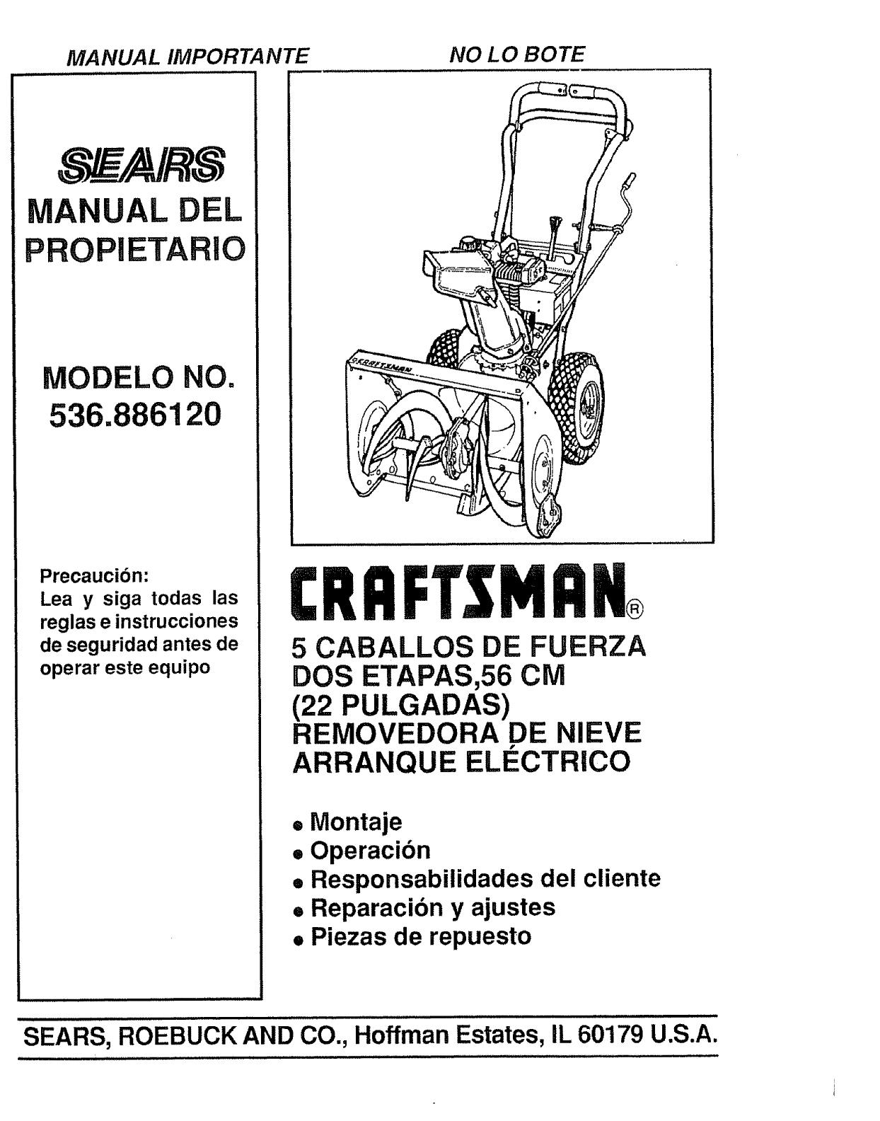
MANUAL IMPORTANTE
UAL DEL
PROPIETARIO
MODELO NO.
536.886120
Precaucion:
Lea y siga todas las
reglas e instrucciones
de seguridad antes de
operar este equipo
NO LO BOTE
CRAFTSMnN,
5 CABALLOS DE FUERZA
DOS ETAPAS,56 CM
(22 PULGADAS)
REMOVEDORA DE NIEVE
ARRANQUE ELECTRICO
•Montaje
• Operacion
• Responsabilidades del cliente
•Reparacion y ajustes
•Piezas de repuesto
SEARS, ROEBUCK AND CO., Hoffman Estates, IL 60179 U.S.A.
REGLAS DE SEGURIDAD
PRECAUCION: SIEMPRE DESCONECTE ELALAMBRE DE LA BUJIA
Y COLOQUELO DONDE NO HAGA CONTACTO CON L BUJ1A PARA A,
EVITAR UN ARRANQUE ACCIDENTAL AL MONTAR,
TRANSPORTAR, AJUSTAR O EFECTUAR REPARACIONES.
IMPORTANTE
LOS ESTANDARES DE SUGURIDAD REQUIEREN LA PRESENCIA DEL OPERADOR EN LOS
CONTROLES PARA MtNIMIZAR EL RIESGO DE HERIDAS, SU REMOVERDORA DE NIEVE
ESTA EQUIPADA CON DICHOS CONTROLES. NO INTENTE PASAR POR ALTO LA FUNCION
DEL CONTROL DE PRESENCIA DEL OPERADOR BAJO NINGUNA CIRCUNSTANCIA
CAPACITACION
1. Lea et manual de! operador culdadosamente.
Famlllaricese comptetamente con los controles
y et uso aproplado de la removedora de nleve. Sepa
c6mo detaner la rsmovedora de nieve y desenganchar
los controles rdpldamente.
2. Nunca permita a nlSos operar la removedora de
nlevs y mant6ngalos fuera del alcance de ta mtsma
mtentras se encuentra en operaclbn. Nunca permita
qua adultos operen la removedora de nteve sin
tnstrucci6n aproplada. No tleve pasajeros.
3. Mantenga el _rea libra de personas, especialmente
ni_os pequefios y mascotas.
4o Tenga preeaucl6n a fin de evltar destizamtentos
o caldas, especlalmente al operar la removedora
de nleve en retroceso.
PREPARACION
1o Inspecc!one completamente el drea donde seusard la
removedora de nleva y retire todas las esteras, trln eos,
tableros, alambres, y otros obJetos extra_os.
2. Desenganchetodos losembraguesycambieaneutro
antes de arrancarel mototo
3,, Nooperala removedoradentevestnvesttrlas prendas
de invlerno adecuadas para amblentes exterlores,
Vistacalzadoquamajors su establlidaden superficies
lisas,
4. Maneje el combustible con culdado; es altamente
tnflamable.
(a) Use un contenedor para combustible
aprobado.
(b) Nunca retire la tapadera del tanque de com-
bustible o afiada combustible aun motor en
marcha o a un motor callente.
(c) Liens el tanque para combustible a! airs lib're,
con cutdado extremoo Nunca liens el tanque
en ambientes interloreso
(d) Cotoque nuevamente la tapadera del tanque
para combustible de manera segura y llmpie
el combustible derramado.
(e) Nunca almacone combustible o la
removedora de nieve'con combustible en el
tanque dentro de un ediflcio donde los
vapores pudlesen entrar en contacto con
una llama desproteglda o una chispao
(f) Vertfique las exlstenclas de combustible an-
_s de cada u_, pcrmitiendo espacio par,_
expansl6n puesto que el calor del motet y/o
el sol pueden causar la expansl6n del com-
bustible.
5o Use cablesde extensl6ny recept_culosde la
manera especlflcada por el fabrIcante para todas
las removedorasde nleve con motores
acclonadospot energiaeidctrtca omotores de
arranqueeldctrleo.
6. AJustela alturade la removedora de nieveparapasar
sobre superficiesde grava o piedratrtturadao
7. Jam,_sIntents efectuarnlngBnaJustemlentras el mo-
tor se encuentra en marcha (excepto cuando el
fabrlcanteIo recomlendeasl especiflcamente).
B. Permita que el motor y la removedora de nieve se
ajusten alas temperaturas extertores antes de
comenzar a rat|rat la nleve.
9. Stempre use galas de segurldad o protectores para
los ojos durante la operaci6n o mlentras se efectda un
aJusteo reparacl6n para proteger sus ojos de ob|etos
extrafios que pudtesen ser lanzados por la removedor a
de nleve.
OPERACION
1. No coloque las manos o los pies cerca o bajo plazas
rotattvas. Mantdngase a dlstancia de la abertura para
descarga todo el ttempo.
2.. Tengaprecauclbnextremaal operarsobreo al cruzar
camlnos,aceras,o cariesde grava. Mant_ngasealerta
en caso de pellgrosocultoso tr_flco,
3. Despuds de gotpear un objeto extrafio, pare el motor,
retire el alambre de la bujla, desconecte et cable en
motores eldctrtcos, tnspecclone completamente la
removedora de nleve afin de encontrar cualquier
da_o, y reparar dlcho dar_o antes de arrancar y operar
la removedora de nleve nuevamente.
4_ En el caso de qua la removedora de nieve comlence a
vibrar fuera de io normal, pare el motor y revise la
m_quina tnmedlatamente para encontrar la cause°
Generalmente, la vibractbn es una advertencia de
problemas.
5. Pare el motor dondequlera que deje ta posici6n de
operacl6n, antes de desobstrulr el alojamlento del
barreno/propulsor o gula de descarga, ycuando efect0e
cuatesquiera reparactones, ajustes, o|nspecciones.
6. AI Ilmplar, reparar, o inspeccionar la m._quina
aseg_rese de qua el barrenofpropuisor y toda parts
m6vtl se hayan detenido,, Desconecte el alambre de la
bujla y mant_ngalo atejado de la bujla para evttar un
arranque _=cciden_-aL
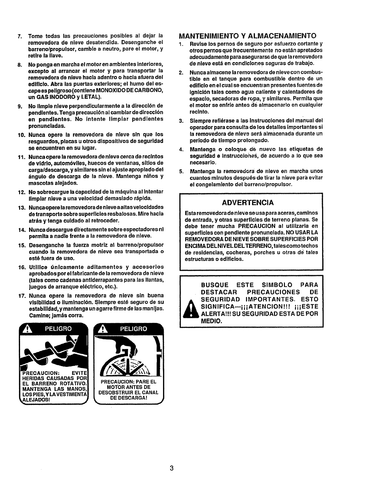
7. Tome todas las precauciones posibles al dejar la
removedora de nieve desatendida,. Desenganche el
barreno/propulsor, cambie a neutro, pare el motor, y
retire la ilave.
8. No ponga en marcha el motor en ambientes Interlores,
excepto al arrancar el motor y para transportar la
removedora de nleve hacla adentro o hacla efuera del
edtficto. Abra las puertas extertores; et humo del es-
cape es pellgroso (contlene MONOXIDO DE CARBONO,
un GAS INODORO y LETAL).
9. No iimple nleve perpendlcularmente ala direcclbn de
pendlentes. Tenga precauct6n al camblar de dlrecclbn
en pendlentes. No intents tlmptar pendlentes
pronuncladas.
10. Nunca opera la removedora de nleve sln qua los
resguardos, places u otros dlsposltlvos de segurldad
se encuentren en su tugar.
11. Nunca opera la removedora de nleve cerca de reclntos
de vidrlo, autom6viles, huecos de ventanas, sltlos de
carga/descarga, y slmllares sin el aJuste aproplado del
dngulo de descarga de la nleve. Mantenga nl_os y
mascotas aleJados.
12. No sobrecargue la Capacldad de la mdqulna al Intentar
Ilmplar nteve a una velocldad demastado rdptda.
13o Nunca operela removedera de ntevea altas vetocldades
detransporte sobre superficies resbalosaso Mire hacla
atrds y tenga cu]dado al retroceder.
14. Nunca descargue dlrectamente sobre espectadores nl
permlta a nadle frente ala removedora de nleve.
15_ Desenganche la fuerza motriz a! barreno/propulsor
cuando la removedora de nieve sea transportada o
est6 fuera de uso.
16o Utillce Onlcamente aditamentos y accesorios
aprobadospor el fabrlcante de la removedorade nteve
(tales comocadenasantiderrapantespara las ilantas,
Juegosde arranqueel_ctrico,etc.).
17. Nunca opere la removedora de nieve sin buena
vlslbllidado llumlnaclbn.Slempre est6 seguro de su
estabilldad,ymantenga unagarrefirmsdelasmanljaso
Camine;Jamdscorra.
DE DESCARGA!
MANTENIMIENTO Y ALMACENAMIENTO
1o Revise los pernos de seguro por esfuerzo cortante y
otros pernos que frecuentemente no estdn apretados
adecuadamente para asegurars_ de qua la removedora
de nleve estd en condlclone s seguras de trabajoo
2. Nunca almacene la removedora de nieve con combus-
tlble en el tanque para combustible dentro de un
edificio en el cual se encuentran presentes fuentes de
Ignlclbn tales como ague cattente y calentadores de
espacto, secadoras de ropa, y similares° Permlta qua
el motor se enfrle antes _le almacenarlo en cualquier
reclnto,,
3. Slempre refldrase alas Instrucclones del manual del
operador para consuP.a de tos detaltes tmportantes si
la removedora de nteve serd aimacenada durante un
per|odo de ttempo prolongado_
4. Mantenga o coloque de nuavo las ettquetas de
segurldad elnstrucciones, de acuerdo a Io qua sea
necasarlo.
5. Mantenga la removadora de ldeve en marcha unos
cuantos mtnutos despu6s de tirar la nieve para evitar
el congelamtento del barrer_o/propulsor,_
ADVERTENCIA
Esta removedora de nleve se usa para aceras, camlnos
de entrada, y otras superficies de terreno ptanas. Se
debe tener mucha PRECAUCION al ut|lizarla en
superficies con pendlente pronunclada. NO USAR LA
REMOVEDORA DE NIEVE SOBRE SUPERFICIES POR
ENCtMA DELNIVEL DELTERRENO, talescomo techos
de resldenclas, cocheras, porches u otras d_ tales
estructuras o edlficios.
BUSQUE ESTE SIMBOLO PARA
DESTACAR PRECAUCIONES DE
SEGURIDAD IMPORTANTES_ ESTO
SIGNIFICA--iIiATENCION!!! iiIESTE
ALERTA!!? SU SEGURIDAD ESTA DE POR
MEDIO,
3
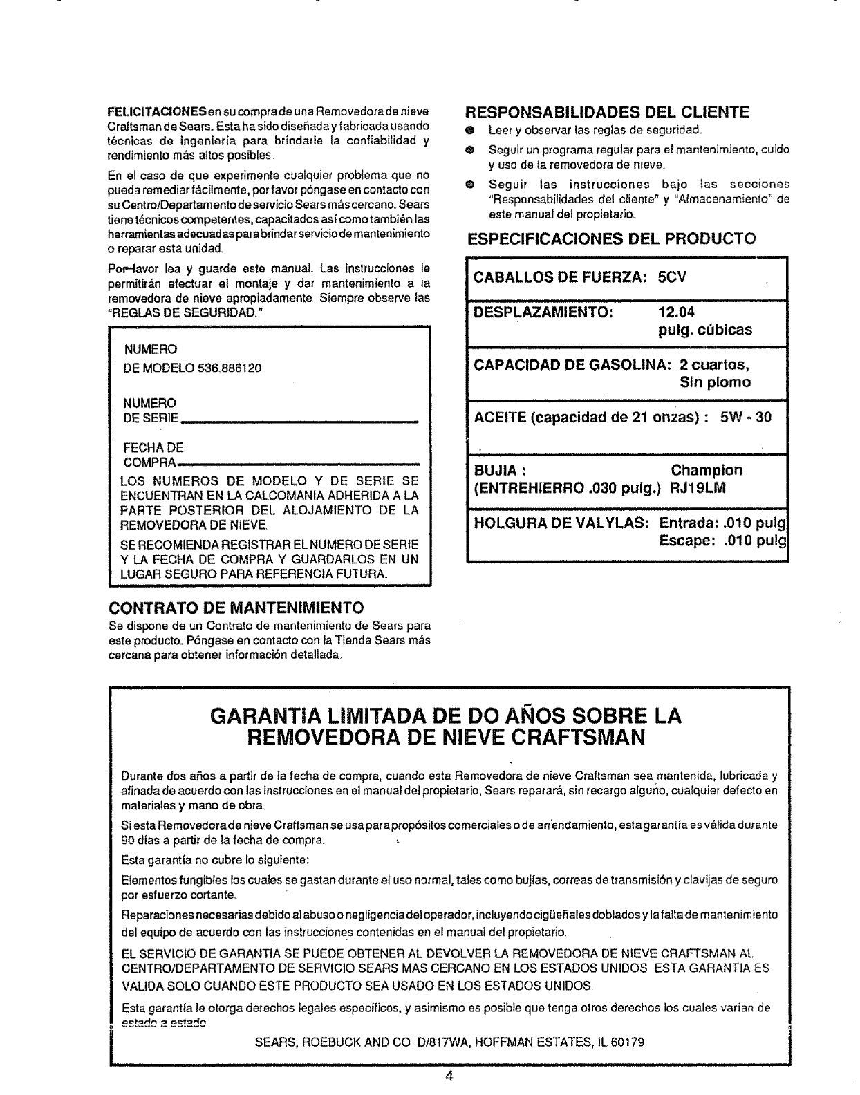
FELICITACIONES en su comprade una Removedora de nieve
Craftsman de Sears. Esta ha side diseSaday fabricada usando
t6cnicas de ingenierfa pare brindarle la confiabitidad y
rendimiento m_s altos posibles
En el case de qua experimente cualquier problema que no
pueda remediar f&cilmente, per favor p6ngase encontactocon
su Centro/Departamento de servicioSears m&scercano.Sears
fiene t6cnicoscompeter=tes,capacitados asfcome tambi6n las
herramientas adecuadas parabrindar serviciodemantenimiento
o reparar esta unidad_
Pod-favor tea y guarde este manual. Las instrucciones le
permitir&n efectuar et montaje ydar mantenimiento ala
removedora de nieve aproptadamente Siempre observe las
"REGLAS DE SEGURIDAD."
NUMERO
DE MODELO 536886120
NUMERO
DE SERIE,........
FECHA DE
COMPRA
LOS NUMEROS DE MODELO Y DE SERtE SE
ENCUENTRAN EN LA CALCOMANIA ADHERIDA A LA
PARTE POSTERIOR DEL ALOJAMIENTO DE LA
REMOVEDORA DE NIEVE.
SE RECOMIENDA REGISTRAR ELNUMERO DE SERtE
Y I_A FECHA DE COMPRA Y GUARDARLOS EN UN
LUGAR SEGURO PARA REFERENC1A FUTURA.
CONTRATO DE MANTENIMIENTO
Se dispone de un Contrato de mantenimiento de Sears pare
este producto P6ngase en contacto con la Tienda Sears m_s
cercana para obtener informaci6n detallada
RESPONSABILIDADES DEL CLIENTE
OLeer y observer las reg3as de seguridad.
® Seguir un programa regular pare el mantenimiento, cuido
yuse de la removedora de nieve.
o Seguir las instrucciones bajo las secciones
"Responsabilidades del ciiente" y "Atmacenamiento _'de
este manual del propietatio.
ESPEClFICACIONES DEL PRODUCTO
.,:l,
CABALLOS DE FUERZA: 5CV
DESPLAZAMIENTO: 12.04
puig. cdbicas
CAPACIDAD DE GASOLINA: 2 cuartos,
Sin plomo
ACEITE (capacidad de 21 onzas) : 5W - 30
BUJIA : Champion
(ENTREHIERRO .030 puig.) RJ19LM
HOLGURA DE VALYLAS: Entrada: .010 pulg
Escape: .010 pulg
GARANTIA LIMITADA DE DO ANOS SOBRE LA
REMOVEDORA DE NIEVE CRAFTSMAN
Durante dos aSos a partir de ta fecha de cempra, cuando esta Removedora de nieve Craftsman sea mantenida, lubricada y
afinada de acuerdo con las instrucciones en el manual del prepietario, Sears reparara, sin recargo alguno, cua{quier defecto en
materiales y mane de obra.
Siesta Removedora de nieve Craftsman se usa pareprop6sitos comerciales ode ar(endamiento, esta gar antia es v,_}idadurante
90 dlas a partir de la fecha de compra.
Esta garant[a no cubre Io siguiente:
Elementos fungibtes loscuales se gastan durante el use normal, tales coma bujtas, correas de transmisiSn y clavijas de seguro
per esfuerzo cortante._
Reparaciones necesarias debido al abuse o negligencia dei operador, incluyendocigOeSales doblados y lafalta de mantenimiento
del equipo de acuerdo con las instrucciones contenidas en el manual de_propietario,
EL SERVICIO DE GARANTIA SE PUEDE OBTENER AL DEVOLVER LA REMOVEDORA DE NtEVE CRAFTSMAN AL
CENTRO/DEPARTAMENTO DE SERVIC10 SEARS MAS CERCANO EN LOS ESTADOS UNIDOS ESTA GARANTIA ES
VALIDA SOLO CUANDO ESTE PRODUCTO SEA USADO EN LOS ESTADOS UNIDOS
Esta garantla le otorga derechos tegales especificos, y asimismo es posible qua tenga aires derechos los cuates varian de
SEARS, ROEBUCK AND CO. D!817WA, HOFFMAN ESTATES, IL 60179
4
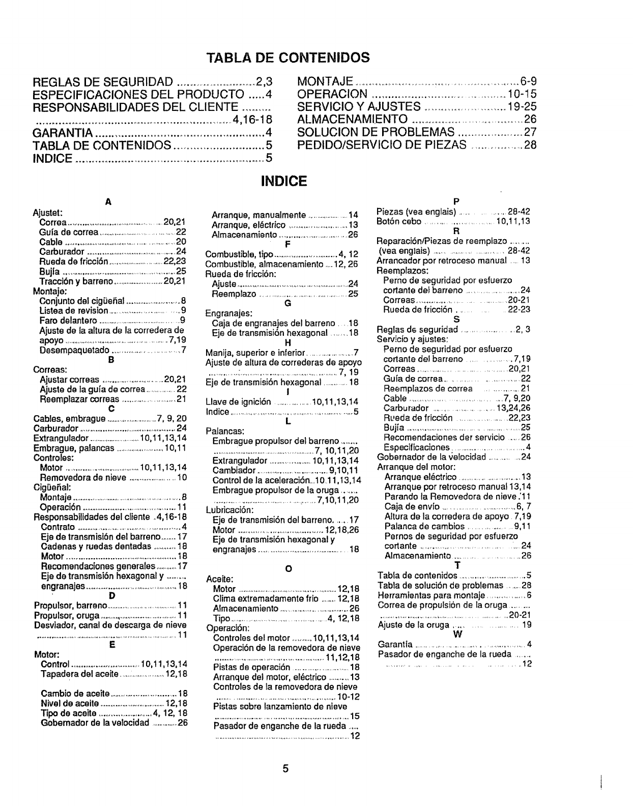
TABLA DE CONTENIDOS
REGLAS DE SEGURIDAD ..................................2,3
ESPECIFICACIONES DEL PRODUCTO ..... 4
RESPONSABILIDADES DEL CLIENTE .........
.................................................................. 4,t6-18
GARANTtA ...................................................... 4
TABLA DE CONTENtDOS ............................. 5
INDICE ............................................................ 5
MONTAJE .......................................................................6-9
OPERACION ............................................... 10-I 5
SERVICtO Y AJUSTES .......................... 19-25
ALMACENAMIENTO ................................................26
SOLUCION DE PROBLEMAS ........................ 27
PEDIDO/SERVICIO DE PIEZAS ................... 28
INDICE
A
Ajustet:
Correa .................................................2o,21
Gui'a de correa ...................................................22
Cable .......................................................20
Carburador ...........................................24
Rueda de fricciSn ....................................22,23
Bujla ..........................................................25
Traccibn y barreno ..............................20,21
Montaje:
Conjunto del cigDeSal..............................8
Listea de revision..................................9
Faro delantero .............................................9
Ajuste de la altura de la corredera de
apoyo ............................................................7,19
Desernpaquetado .............................. 7
B
Correas:
Ajustar correas ..................................20,21
Ajuste de la gu[a de correa ...................22
Reemplazar correas ............................21
C
Cables, embrague ................................7, 9, 20
Carburador .............................................24
Extrangulador .................................10,I1,13,14
Embrague, patancas ...........................10,11
Controles:
Motor ......................................10,11,13,14
Removedora de nieve .......................10
Cig{JeSal:
Montaje .................................................................8
OperaciSn .............................................11
Responsabilidades del cliente .4,16-18
Contrato ...................................................4
Eje de transmisibn del barreno ...... 17
Cadenas y ruedas dentadas ......... 18
Motor ................................................ t 8
Recomendaciones generales ..........17
Eje de transmisibn hexagonal y ........
engranajes ...............................................18
D
Propulsor, barreno ........................................11
Pmpulsor, oruga .......................................11
Desvtador, canal de descarga de nieve
.....................................................................................11
E
Motor:
Control .............................. 10,! t,13,14
Tapadera del aceBe .........................12,18
Cambio de aceite ..............................18
Nivel de aceite .....................................12,18
Tipo de aceite ............................4, 12, 18
Gobemador de la velocidad .............26
Arranque, manualmente .........................14
Arranque, el_ctrico ...........................13
Almacenamiento ....................................26
F
Combustible, tipo..............................4, 12
Combustible, almacenamiento .o..12, 26
Rueda de fricciSn:
Ajuste ........................................................24
Reemplazo ...................................................25
G
Engranajes:
Caja de engranajes del barreno ....18
Eje de transmisiSnhexagonal ....... 18
H
Manija, superior e inferior........................7
Ajuste de altura de correderas de apoyo
...............:.....................................................7, !9
Eje de transmisien hexagonal .............18
i
Llave de ignici6n .....................10,11,13,14
lndice ..............................................................5
L
Palancas:
Embrague propulsor del barreno .......
.........._........................................7, 10,11,20
Extrangulador ......................10,! 1,13,14
Cambiador.......................................9,10,11
Control de la aceleraciSn....10.11,13,14
Embrague propulsor de la oruga ........
...................................................7,10,11,20
Lubricacibn:
Eje de transmisiSn de! barreno ....... 17
Motor .................................... 12,18,26
Eje de transmisiSn hexagonal y
engranajes ........................................18
O
Aceite:
Motor ........................................................12,18
Clima extremadamente frio .........12,18
Aimacenamiento .......................................26
Tipo ...................................................4, !2,18
Operacibn:
Controles del motor ..........10,1 t ,13,14
Operacibn de la removedora de niave
............................................................t1,12,18
Pistas de operaciSn .....................................18
Arranque del motor, el_ctrico .........13
Controles de la removedora de nieve
........................................................10-12
Pistas sobre lanzamiento de nfeve
.......................................... , ...................... ,= ,.,, 15
Pasador de enganche de la rueda ......
............................................................. 2
P
Piezas (vea englais) ................ 28-42
Botbn cebo ............................ 10,11,13
R
ReparacibniPiezas de reemptazo ..........
(yea englais) ............................... 28_42
Arrancador por retroceso manual ......13
Reemplazos:
Perno de seguridad pot esfuerzo
cortante det barreno ...........................24
Correas ....................................... 20-2 t
Rueda de friccien ............ 22-23
S
Reglas de seguridad ..................... 2, 3
Servicio y ajustes:
Pemo de seguridad por esfuerzo
cortante del barreno ................. 7, t9
Correas ..............................................20,21
Gut'a de correa ............................... 22
Reemplazos de correa .............. 2t
Cable .................................. 7, 9,20
Carburador ............................13,24,26
RL,eda de fricciSn .......................22,23
Buj[a ........................................................25
Recomendaciones der servicio .....26
Especificaciones ...................................4
Gobernador de la velocidad ............. 24
Arranque del motor:
Arranque el_ctrico ..................................13
Arranque por retroceso manual 13,14
Parando ta Removedora de nieve ;11
Caja de envio .....................................6, 7
Altura de la corredera de apoyo 7,19
Patanca de cambios .................. 9,11
Pernos de seguridad por esfuerzo
cortante ............................................. 24
Almacenamiento ............................. 26
T
Tabla de contenidos ..............................5
Tabla de solucien de problemas ........28
Herramientas pare montaje ...................6
Correa de propulsien de [aoruga ...........
.................................................................20-21
Ajuste de la oruga ....................... 19
W
Garantta ...................................................4
Pasador de enganche de la rueda .........
....... ,,.......................... .12
5!
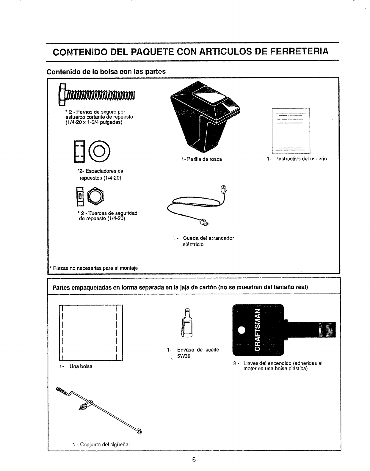
CONTENIDO DEL PAQUETE CON ARTICULOS DE FERRETERIA
Contenido de ia bolsa con las partes
" 2 - Pernos de seguro pot
esfuerzo cortante de repuesto
(1!4-20 x 1-3/4 pufgadas)
DQ
"2- Espaciadores de
repuestos (!/4-20)
* 2 - Tuercas de seguridad
de repuesto (1/4-20)
I- Perilla de rosca 1- Instructivo del usuario
1 - Cueda det arrancador
el_ctricio
" Piezas no necesarias para el montaje
Partes empaquetadas en forma separada en la jaja de cartbn (no se muestran del tamat_o real)
m
t
I
I
I
I
I
t 1
1- Unabolsa
Envase de aceite
5W30
2_ Ltaves del encendido (adheridas al
motor en una bolsa pt&stica)
1 - Conjunto det cig,3ehal
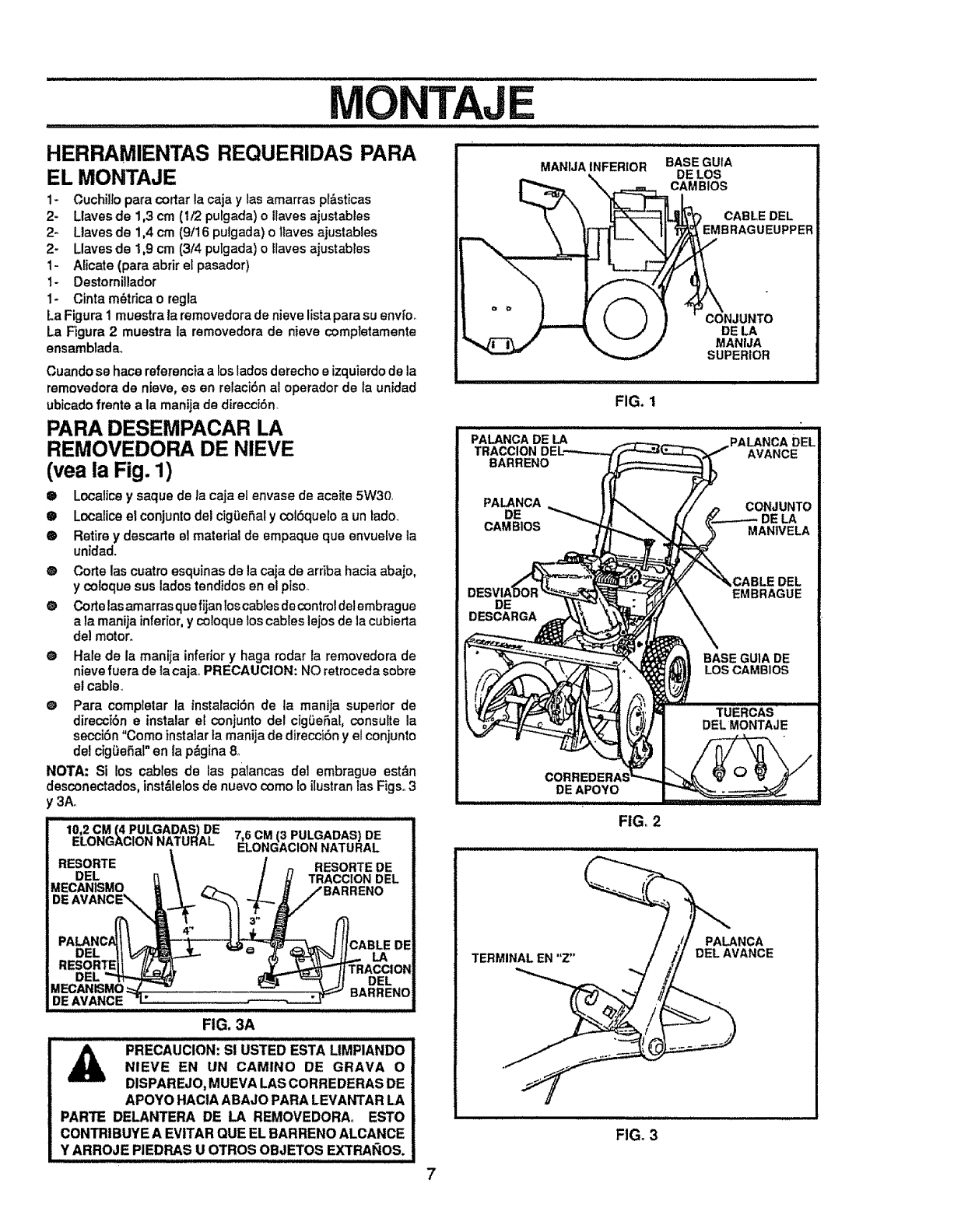
MONTAJE
HERRAMIENTAS REQUERIDAS PARA
EL MONTAJE
1- Cuchiltopara cortar la caja y las amarras pI_sticas
2* Llaves de 1,3 cm (I/2 pulgada) o Ilaves ajustables
2- Ltaves de 1,4 cm (9/16 pulgada) o tlaves ajustables
2_ Llaves de 1,9 cm (3/4 pulgada) o Itaves ajustabtes
1- Alicate (para abrir el pasador)
1- Destornillador
1- Cinta m_trica o regla
La Figura 1 muestra la removedorade nieve lista para su envi'o_
La Figura 2 muestra la removedora de nieve compfetamente
ensamblada_
Cuando se hace referencia alos lados derecho eizquierdode la
removedora de nieve, es en retacibn al operador de la unidad
ubicado frente a la manija de direccibn.
PARA DESEMPACAR LA
REMOVEDORA DE NIEVE
(vea la Fig. 1)
® Localice y saque de la caja el envase de aceite 5W3O,
•Localiceel conjuntodel cigiJeSal y cotSquelo a un lado.
® Retire y descarte el material de empaque qua envuelve la
unidad.
®Corte las cuatro esquinas de la caja de arriba hacia abajo,
ycoloque sus lados tendidos en el piso,.
O Corte lasamarras que fijanloscables de control delembrague
a la manija inferior,y coroque los cables lejos de la cubierta
del motor.
e Hale de la manija inferior y haga rodar la removedora de
nieve fuera de Ia caja,,PRECAUCION: NO retroceda sobre
et cable_
@ Para completar la instalaciSn de la manija superior de
direccibn e instalar et conjunto del cig_eSal, consulte la
secci6n "Como instatarfa manija de direcciSn y el conjunto
det cigSeSal" en la p&gina 8o
NOTA: Si los cables de las palancas de1 embrague est&n
desconectados, inst_lelos de nuevo como Io iIustran ias Figs. 3
y3A.
10,2 CM (4 PULGADAS) DE
ELONGACION NATURAL
RESORTE
DEL
MECANISMO
DE
7,6 CM (3 PULGADAS} DE
ELONGAClON NATURAL
RESORTE DE
TRACCION DEL
DEL CABLE DE
DEL
DE AVANCE
FIG. 3A
PRECAUCION: SI USTED ESTA LIMPIANDO
NIEVE EN UN CAMINO DE GRAVA 0
DISPAREJO, MUEVA LAS CORREDERAS DE
APOYO HACtA ABAJO PARA LEVANTAR LA
PARTE DELANTERA DE LA REMOVEDORA,, ESTO
CONTRIBUYE A EVITAR QUE EL BARRENO ALCANCE
Y ARROJE PIEDRAS U OTROS OBJETOS EXTRAI_OS.
MANIJAINFERIOR BASEGUIA
DE LOS
_RL_AMBIOS
L_-----_ IL.__"_ CABLE DEL
__,_MBRAGUEUPPER
ii ,ill ,i,,i,,i ,i, i,,lll,H, ii iHll i
FIG. 1
PALANCA DE LA
BARRENO
PALANCA
DE
CAMBIOS
DE
DESCARGA
DEAPOVO
FIG, 2
TERMINAL EN "Z"
PALANCA
DELAVANCE
FIG. 3
7
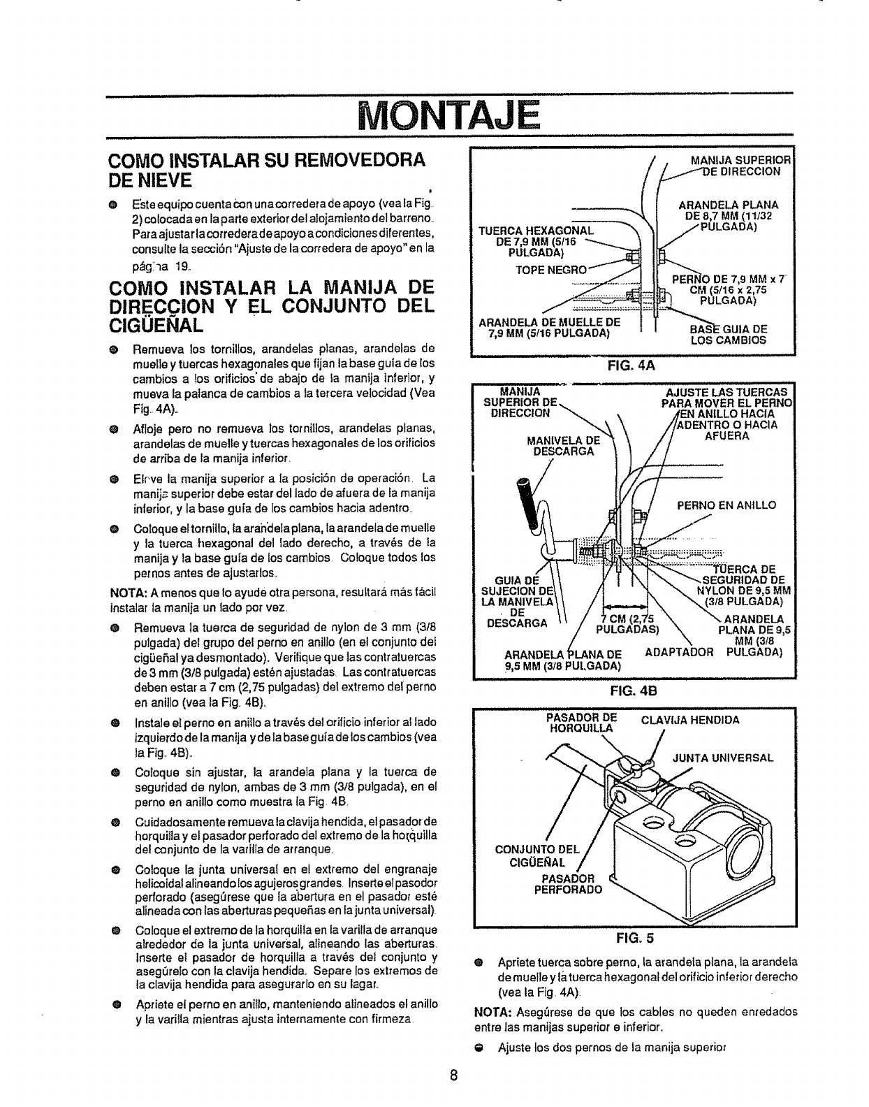
MONTAJE
COMe INSTALAR
DIRE.CCION Y EL
CIGUENAL
COMe INSTALAR SU REMOVEDORA
DE NIEVE t
OEsteequipocuenta conunacorredera de apoyo (vea la Fig.
2) colocada en laparte exterior del aloiamiento del barreno..
Paraajustar lacorrederade apoyo a condiciones diferentes,
consutte la secciSn "Ajuste de la corredera de apoyo" en la
pAg_la 19.
LA MANIJA DE
CONJUNTO DEL
@ Remueva los tornillos, arandelas planas, arandefas de
muelle y tuercas hexagonales que fijan la base guia de {os
cambios a !es orifieios" de abajo de fa manija inferior, y
mueva la palanca de cambios a ia tercera veJocidad (Vea
Fig..4A)°
@ Affoje pete no remueva los tornil]os, arandelas planes,
arandelas de muelle ytuercas hexagonales de los orificios
de arriba de la manija inferior_
@ El('ve la manija superior ala posiciSn de operaciSn. La
manij_,superior debe ester del lade de afuera de Eamanija
inferior, y la base gu[a de los cambios hacia adentro.
@ Coloque eltornitlo, la arahclelaplana, taarandela de muelle
y la tuerca hexagonal del lade derecho, a trav_s de ta
manija y Ia base guia de los cambios. Coloque redes los
pemos antes de ajustados_
NOTA: A menos que Ioayude etra persona, resuitarA m_s (Acil
instalar la manija un lade per vez
@ Remueva la tuerca de seguridad de nylon de 3 mm (3/8
pulgada) del grupo del perno en anillo fen el conjunto dei
cigDeSal ya desmontado). Verffique que las contratuercas
de3 mm (3!Spulgada)est_najustadas Lascontratuercas
deben estar a 7 cm (2,75 pulgadas) det extreme de{ pemo
en aniIlo (yea la Fig 4B).
@ Instale ef perno en anilloa trav_s del orificioinferior al lade
izquierdode la manija y de la base guta delos cambios (vea
la Fig..4B)..
@ Coloque sin ajustar, la arandela plana y la tuerca de
seguridad de nylon, ambas de 3 mm (3/8 pulgada), en el
perno en anillo come muestra fa Fig. 4B
@ Cuidadosamente remueva laciavija hendida, el pasadorde
horquitta y el pasador perforado del extreme de la ho[quille
del conjunto de la va_'iflade atranque_
@ Coloque la junta universal en el extreme del engranaje
helicoidal alineandolos agujeros grandes Inserteelpasodor
perforado (asegOrese que fa abertura en el pasadot est6
alineada con las aberturas pequeSas en lajuntauniversal)_
@ Coloque el extreme de la horquitia en la varilla de arranque
alrededor de la junta universal, alineando las aberturas.
lnserte el pasador de horquilla a tra;v_s det conjunto y
aseg,3reIocon la clavija hendida.. Separe los extremes de
la clavija hendida pare asegurarlo en su lagar._
@ Apriete el perno en anitlo, manteniendo alineados el anillo
y la varilla mientras ajusta intemamente con firmeza.
TUERCA HEXAGONAL
DE 7,9 MM (5/16
PULGADA)
TOPE
ARANDELA DE MUELLE DE
7,9 MM (5f16 PULGADA)
MANIJA SUPERIOR
ARANDELA PLANA
DE 8,7 MM (11/32
PERNO DE 7,9 MM x 7 _
CM (5/16 x 2,75
PULGADA)
LOS CAM BtOS
FIG. 4A
MANIJA
SUPERIORDE.,.
DIRECCION "_
UPSUAN_A
GUIA DE
SUJECION DE
LA MANIVELA
,DE
DESCARGA
AJUSTE LASTUERCAS
PARA MOVER EL PERNO
ANILLOHACIA
O HACIA
AFUERA
PERNO EN ANtLLO
ARANDELA DE
9,5 MM (3/8 PUt,GADA)
FIG, 4B
RCA DE
DE
NYLON DEg,5MM
FIG, 5
PLANA DE 9,5
MM (3/8
ADAPTADOR PULGADA)
CLAVIJA HENDI DA
CONJUNTO DEL
CIGOE_AL
PASADOR
PERFORADO
JUNTA UNIVERSAL
® Apriete tuerca sobre perno, la arande[a plane, la arandela
de muelle y l&tuerca hexagonal del orificio interiorderecho
(yea la Fig. 4A)
NO'FA: Aseg_rese de que los cables no queden eni'edados
entre las manijas superior e inferior_
O Ajuste los dos pernos de la manija superior
8
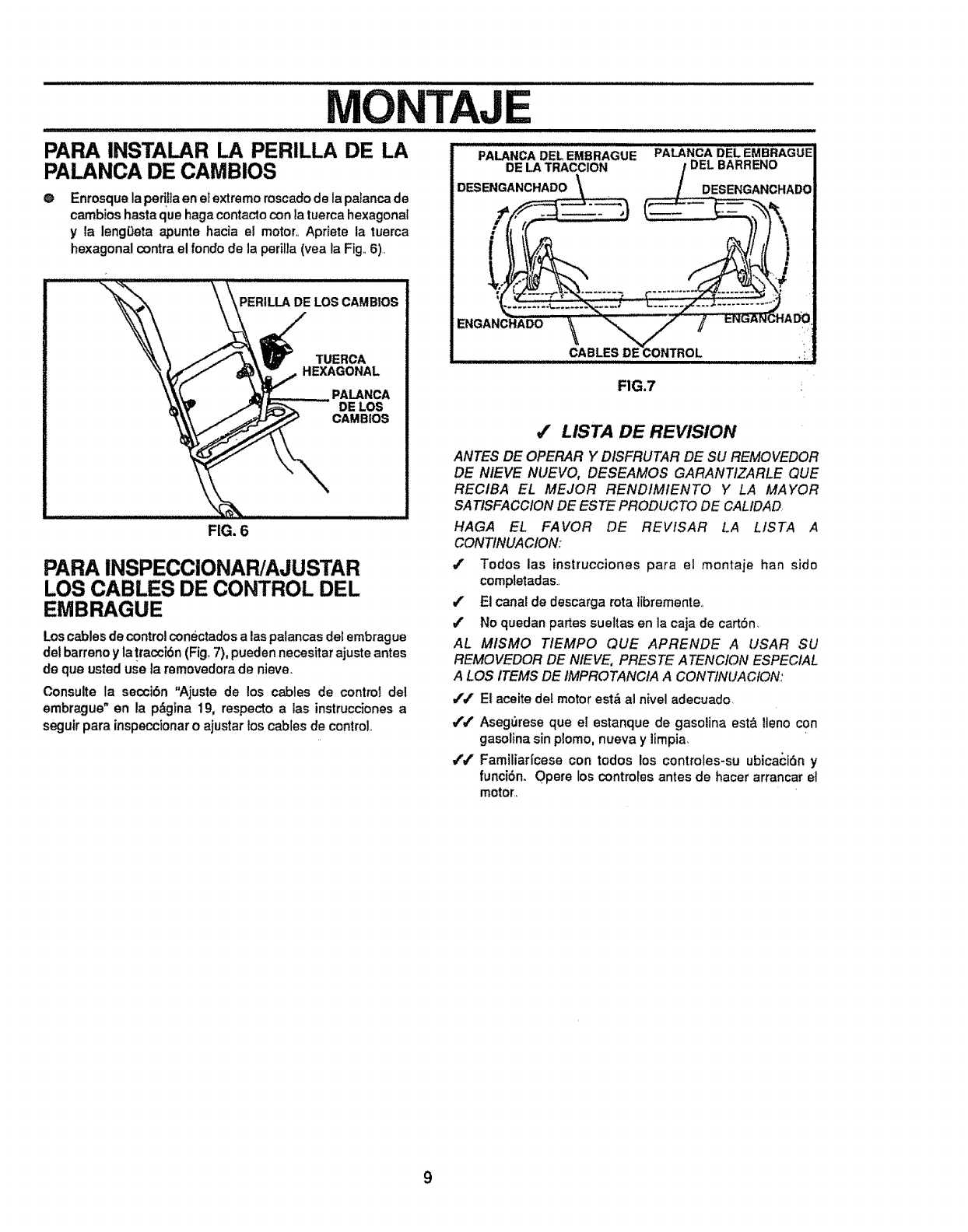
TAJE
PARA INSTALAR LA PERILLA DE LA
PALANCA DE CAMBIOS
@Enrosque la pedliaen elextremo mscado de la palancade
cambios hasta que haga contacto con la tuerca hexagonal
yla leng0eta apunte hacia el motor.. Apriete la tuerca
hexagonal contra el rondo de la perilia (yea la Fig..6).
PALANCA DEL EMBRAGUE PALANCA DEL EMBRAGUE
FIG.7
FIG. 6
PARA INSPECCIONAP,/AJUSTAR
LOS CABLES DE CONTROL DEL
EMBRAGUE
Los cablesde controlconbctados alas palancas del embrague
del barreno y la !raccibn (Fig,.7), pueden necesitar ajuste antes
de que usted use la removedora de nieve_
Consulte la secci6n "Ajuste de los cables de controt del
embrague" en la p_gina 19, respecto alas instrucciones a
seguir para inspeccionaro ajustar los cables de control,,
4' LISTA DE REVISION
ANTES DE OPERAR Y DISFRUTAR DE SU REMOVEDOR
DE NIEVE NUEVO, DESEAMOS GARANTIZARLE QUE
RECIBA EL MEJOR RENDIMIENTO Y LA MAYOR
SATISFACCION DE ES TE PRODUCTO DE CALIDAD,
HAGA EL FAVOR DE REVlSAR LA LISTA A
CONTINUACION:
t. Todos las instrucciones para el montaje han sido
completadas..
t. El canal de descarga rota ]ibremente.,
4' No quedan partes sueltas en la caja de cart6n•
AL MlSMO TIEMPO QUE APRENDE A USAR SU
REMOVEDOR DE NIEVE, PRESTE ATENCION ESPECIAL
A LOS ITEMS DE IMPROTANCIA A CONTINUACION:
Jt. El aceite deImotor est& at nivel adecuado.
,ft' Aseg_3rese que el estanque de gasolina est& lteno con
gasolina sin plomo, nueva y limpia,
4'/ FamiliarIcese con todos los controles-su ubicacidn y
funci6n. Opera los controtes antes de hacer arrancar el
motor.,
9
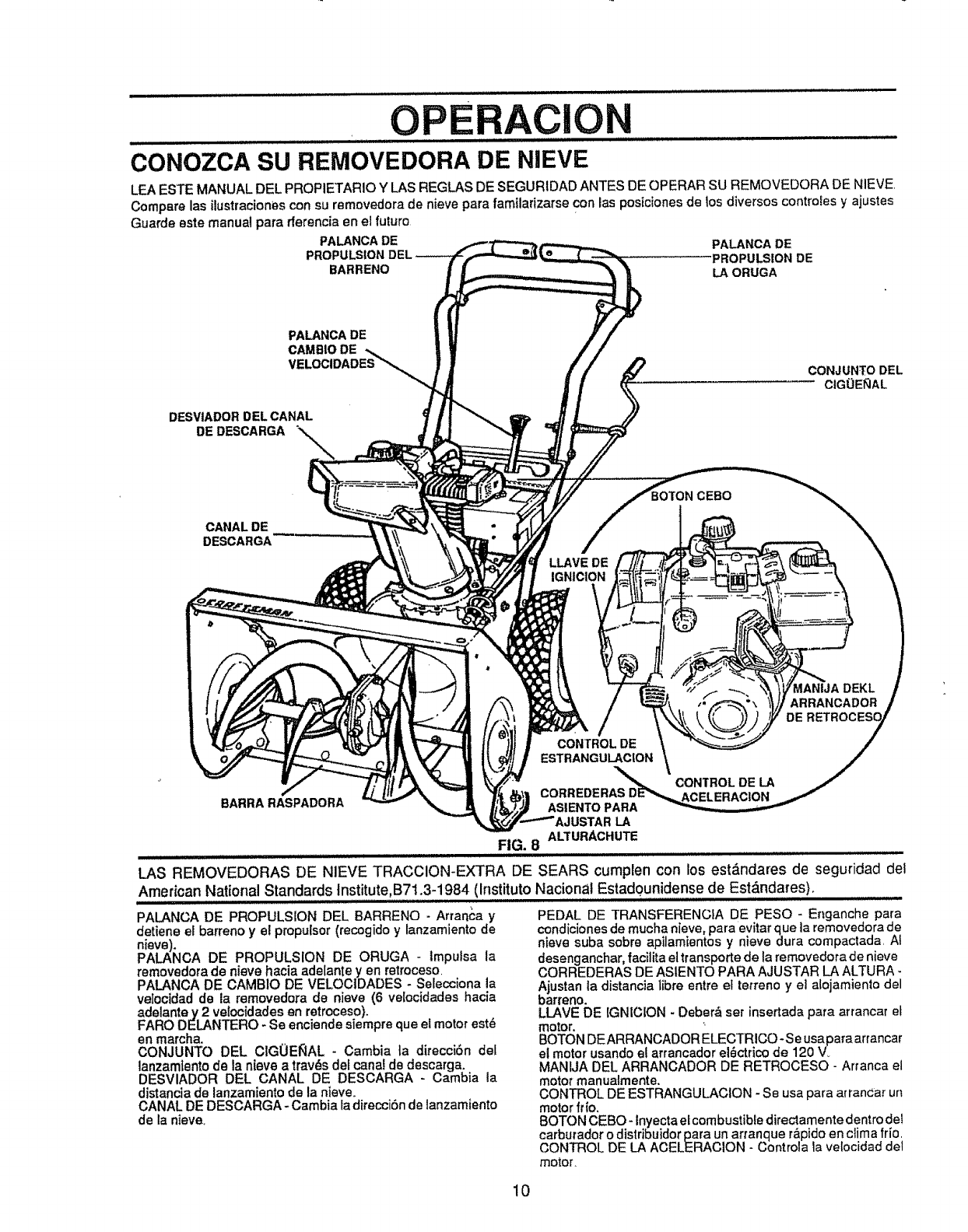
ii
CONOZCA SU REMOVEDORA DE NIEVE
LEA ESTE MANUAL DEL PROPIETARIO YLAS REGLAS DE SEGURIDAD ANTES DE OPERAR SU REMOVEDORA DE NIEVE
Compare las ilustraciones con su removedora de nieve para familarizarse con las posiciones de los diversos controles y ajustes
Guarde este manual pare rferencia en el futuro
PALANCADE PALANCADE
PROI PROPULSIONDE
BARRENO LA ORUGA
PALANCA DE
CAMBIO DE
VELOCI
DESVIADOR DEL CANAL
DE DESCARGA _'-\\._
CONJUNTO DEL
ClGOEIqAL
CANALDE
DESCARGA
LLAVE DE
IGNICION
CEBO
MANIJA DEKL
ARRANCADOR
CONTROL DE
ESTRANGULACION
CONTROL DE LA
CORREDERAS
BARRARASPADORA ASIENTO PARA
;LA
FIG. 8 ALTURACHUTE
iii iii i iiiiiiiiiiiiii ii iii iii iiiiii ...........
LAS REMOVEDORAS DE NIEVE TRACCION-EXTRA DE SEARS cumplen con los est&ndares de seguridad del
American National Standards Institute,B71.3-1984 (Instituto Nacional Estad0unidense de Est_ndares),
PALANCA DE PROPULSION DEL BARRENO - Arranca y
detiene el barreno y el propulsor (recogido y lanzamiento de
n{eve).
PALANCA DE PROPULSION DE ORUGA - lmputsa la
removedora de nieve hacia adelante y en retroceso.
PALANCA DE CAMBIO DE VELOCtDADES - Se_ecciona la
velocidad de la removedora de nieve (6 ve[ocidades hacia
adelanta y 2 veloc{dades en retroceso).
FARO DELANTERO - Se enciende siempre que el motor est_
en marcha.
CONJUNTO DEL CIGOEIr,_AL - Gamble ]a direccibn del
lanzamiento de la nieve a trav_s de_cane!de descarga.
DESVIADOR DEL CANAL DE DESCARGA - Cambia la
distancia de lanzamiento de la nieve.
CANAL DE DESCARGA-Cambia la direcciSn de lanzamiento
de la nieve.
PEDAL DE TRANSFERENCIA DE PESO - Enganche pare
condiciones de mucha nieve, para evitar qua la removedora de
nieve suba sobre apilamientos y nieve dura compactada AI
desenganchar, facilita el transporte de la removedora de nieve
CORREDERAS DE ASIENTO PARA AJUSTAR LA ALTURA -
bAjustania distancia libra entre et tetreno ye] alojamienlo del
arreno.
LLAVE DE [GNICION - Deber_ set insertada para arrancar e[
motor. '
BOTON DEARRANCADOR ELECTRICO-Se usapara arrancar
el motor usando el arrancador el_ctrico de 120 V_
MANIJA DEL ARRANCADOR DE RETROCESO - Arranca el
motor manualmente.
CONTROL DE ESTRANGULACION - Se usa para arrancar un
motor fr{o.
BOTON CEBO - Inyecta el combustible directamente dentro del
carburador o distribuidor para un arranque r&pido en clima frio.
CONTROL DE LA ACELERACION -Controta la velocidad del
motor_
10
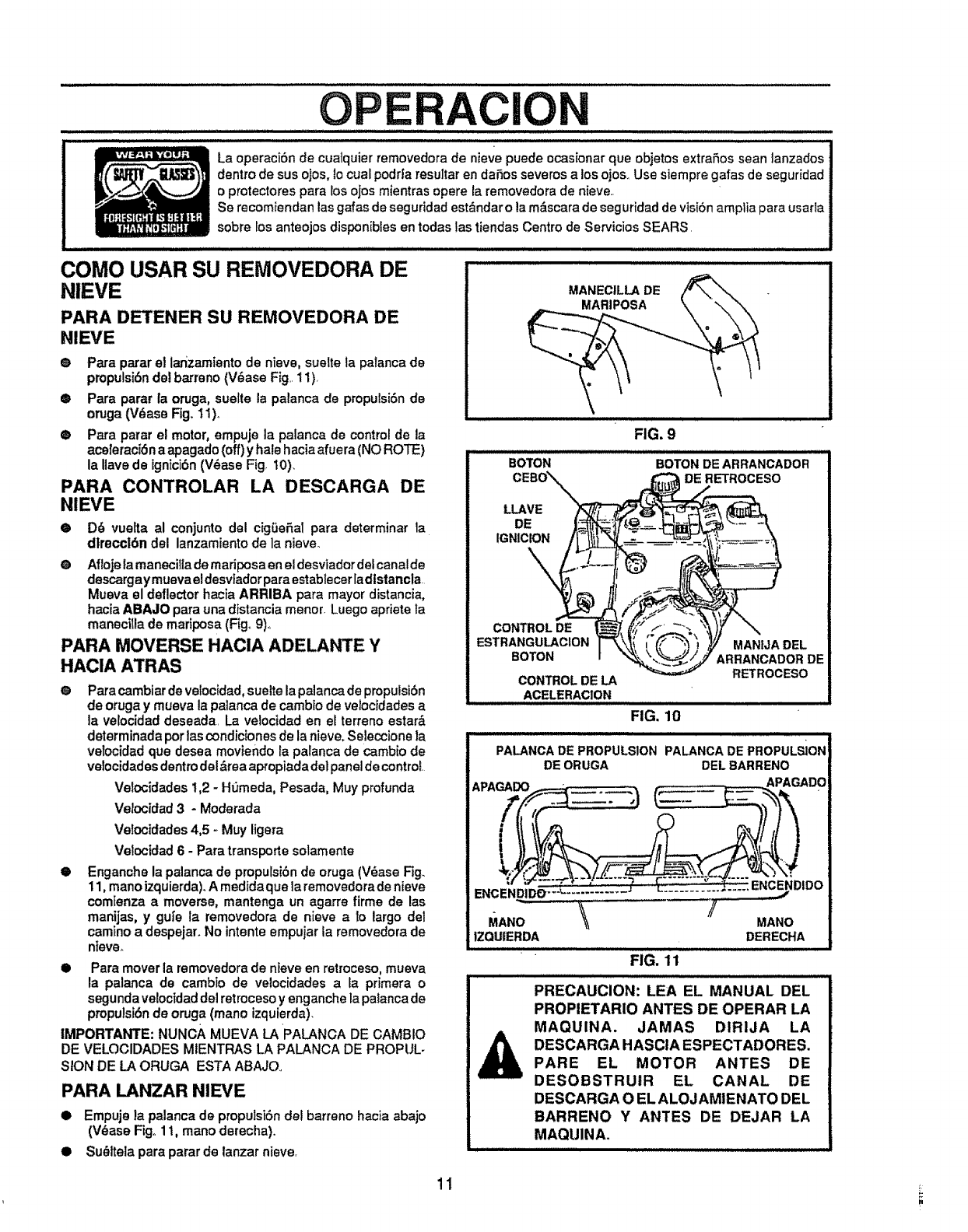
OPERACION
La operaciSn de cuatquier removedora de nieve puede ocasionarque objetos extrafios sean lanzados
dentro de sus ojos, 1ocual podr|a resultar en daSos severos a los ojos,. Use siempre galas de seguridad
o protectores para los ojos mientras opera la removedora de nieve.
Se recomiendan las gafas de seguridad est&ndar o la m_.scarade seguridad de visiSn amplia para usarla
sobre los anteojos disponibles en todas las tiendas Centre de Servicios SEARS.
...... i i iiii ii i i i i i ii ii iiiiiiii i ii iii i i
COMe USAR SU REMOVEDORA DE
NIEVE
PARA DETENER SU REMOVEDORA DE
NIEVE
® Para parar el lanzamiento de nieve, suelte la palanca de
pmpulsibndel barreno (V_ase Fig,, 11),
•Para parar la oruga, suelte la palanca de propulsi6nde
oruga (V_ase Fig, 11)o
• Para parar el motor, empuje la palanca de control de la
aceleraci6 na apagado (off)y hale haciaafuera (NO ROTE)
la Ilavede ignici6n(V_ase Fig, 10),
PARA CONTROLAR LA DESCARGA DE
NIEVE
•D6 vuelta al conjunto del cig[ieSal para determinar la
dlrecclbn del lanzamiento de la nieve.
O Afloje la manecilta de mariposa enel desviador del canal de
descarg aymueva el desviador para estab lecer ladtslancla.
Mueva el deflector hacia ARRIBA para mayor distancia,
hacia ABAJO para una distancia menor. Luego apriete la
manecitla de mariposa (Fig° 9)..
PARA MOVERSE HACIA ADELANTE Y
HACIA ATRAS
O
o
Para cambiar develocidad,sueite la palanca de propulsibn
de oruga y mueva la palanca de cambio de velocidades a
la velocidad deseada. La velocidad en el terreno estar&
determinada per las condiciones de la nieve, Seleccione la
velocidad qua desea moviendo la palanca de cambio de
velocidades dentrodel &tea apropiada del panel de control.
Velocidades 1,2 - HOmeda, Pesada, Muy profunda
Ve!ocidad 3-Moderada
Velocidades 4,5 -.Muy ligera
Velocldacl6 - Para transporte solamente
Engancha la palanca de propufsi6n de eruga (Vdase Fig.
11, mane izquierda). A medida qua la removedora de nieve
comienza a moverse, mantenga un agarre firme de las
manijas, y gute la removedora de nieve a Io largo del
camino a despejar. No intente empujar la removedora de
nieve_
lip Para mover la removedora de nieve en retroceso, mueva
la palanca de cambio de velociclades a la primera o
segundavelocidad del rat rocesoyenganche la palanca de
propulsi6n de oruga (mane izquierda).
IMPORTANTE: NuNcA MUEVA LA PALANCA DE CAMBIO
DE VELOCIDADES MIENTRAS LA PALANCA DE PROPUL-
SION DE LA ORUGA ESTA ABAJO.
PARA LANZAR NIEVE
•Empuje la palanca de propulsi6n del barreno hacia abajo
(Vt_ase Fig., 11, mane derecha).
• Su_itela para parar de tanzar nieve.
MANECILLADE
FIG. 9
BOTON
CEBO_ _
LLAVE
IGNI
CONTROL DE
ESTRANGULACION
BOTON
CONTROL DE LA
ACELERAClON
BOTON DE ARRANCADOR
DE RETROCESO
MANMA DEL
ARRANCADOR DE
RETROCESO
FIG. 10
•i
PALANCADE PROPULSION PALANCADEPROPULSIONI
DE ORUGA DEL BARRENO
__J
MANe '\ .................... /MANe
lZaUIE.DA DERECHA
,L....L..IU.I.LII,I.I,,Iill"
FIG. 11
PRECAUCION: LEA EL MANUAL DEL
PROPIETARIO ANTES DE OPERAR LA
MAQUINA. JAMAS DIRIJA LA
DESCARGA HASCtA ESPECTADORES.
PARE EL MOTOR ANTES DE
DESOBSTRUIR EL CANAL DE
DESCARGA O EL ALOJAMIENATO DEL
BARRENO Y ANTES DE DEJAR LA
MAQUINA.
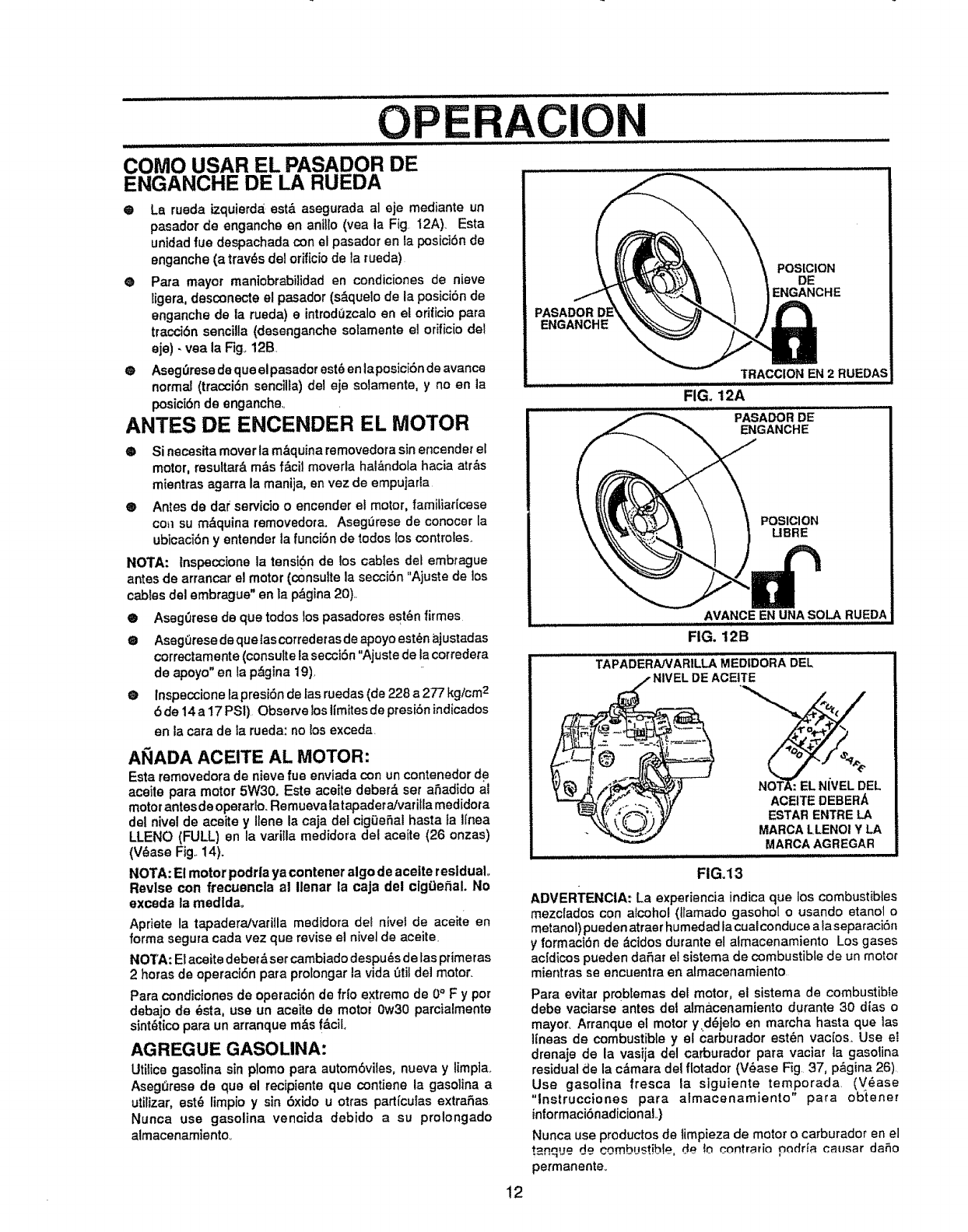
OPERACION
COMO USAR EL PASADOR DE
ENGANCHE DE LA RUEDA
@La rueda izquierda,est,. asegurada al eje mediante un
pasador de enganche en anillo (yea la Fig. 12A)_ Esta
unidad rue despachada con el pasador en la posici6nde
enganche (a tray, s del orificiode la rueda)
e Para mayor maniobrabilidad en condiciones de nieve
ligera, desconecte el pasador (s&quelo de la posici6nde
enganche de la rueda) e introdOzcaloen el orilicio para
tracci6n sencilla (desenganche solamente el orificio del
eje) -vea la F]g._12B.
@ AsegOresedequeelpasadorest6enlaposicibndeavance
normal (tracci6n sencilla) del eje solamente, y no en la
posicibn de engancheo
ANTES DE ENGENDER EL MOTOR
®Si necesita mover la m&quina removedorasin encender el
motor, resultar_, m_s f&cil moverla hal_ndola hacia atr&s
mientras agarra la manija, en vez de empujarla
® Antes de dar servicio o encender el motor, familiaHcese
con su m,_quina removedota. Asegerese de conocer la
ubicaci6n y entender la funci6n de todos los controles.
NOTA: tnspeccione la tensibn de los cables def embrague
antes de arrancar el motor (consulte la secci6n "Ajuste de los
cables del embrague" en la p&gina 20)..
@ AsegOrese de que todos los pasadores est6n firmes
@ Aseg_rese deque lascorredetas de apoyo est6n ajustadas
correctamente (consulte la secci6n "Ajustede la corredera
de apoyo" en la p&gina 19),
@ Inspeccione lapresi6n de las ruedas (de 228 a 277 kg/cmz
bde 14a 17 PS1) Observe los ltmites de presi6n indicados
en la cara de la rueda: nolos exceda.
At'_IADAACEITE AL MOTOR:
Esta removedora de nieve rue enviada con un contenedor d+e
aceite para motor 5W30. Este aceite deber_, ser aSadido al
motor antesdeoperarlo_ Remuevalatapadera/vatiflamedidota
del nivel de aceite y Ilene la caja del cigOeflal hasta la I[nea
LLENO (FULL) en la varilla medidora del aceite (26 onzas)
(V_ase Fig..14).
NOTA: El motor podrla ya contener algo de acelte residual°
Revise con frecuencla al Ilenar la caja del clg9e_al. No
exceda la medldao
Apriete la tapadera!varilla medidora del nivel de aceite en
forma segura cada vez que revise el nivel de aceite.
NOTA: Etaceite debetd set cambiadodespu_s de tas primeras
2 horas de operaci6n para prolongar la vida _til del motor.
Para condiciones de operaciSnde frio extremo de 0° F y por
debajo de _sta, use un aceite de motor 0w30 parcialmente
sint_ticopara un arranque m&s f&ciL
AGREGUE GASOLINA:
Utilice gasolina sin plomo para automdviles, nueva y limptao
Asegt_rese de que el recipiente que contiene la gasolina a
utilizar, est6 limpio y sin 6xido u otras partfculas extraSas
Nunca use gasolina vencida debido a su prolongado
almacenamiento..
ENGANCHE
POSICION
DE
ENGANCHE
TRACCIONEN 2 RUEDAS
FIG. 12A
PASADORDE
ENGANCHE
POSICION
UBRE
AVANCEEN UNASOLARUEDA
FIG. 12B
TAPADERANARILLAMEDfDORADEL
=-LDEACEtTE
_NOT"_:EL NiVEL DEL
i,_,:'" "'_.,_ ACEITE DEBERA
_ESTARENTRE LA
MARCALLENOI Y LA
MARCAAGREGAR
FIG.13
ADVERTENCIA: La experiencia indica que los combustibles
mezclados con alcohol (tlamado gasohol ousando etanol o
metanol) pueden atraer humedad Facual conduce ala separaci6n
y formaci6n de &cidos durante el almacenamiento Los gases
acldicos pueden daflar e! sistema de combustible de un motor
mientras se encuentra en almacenamiento
Para evitar probtemas del motor, el sistema de combustible
debe vaciarse antes det almacenamiento durante 30 dtas o
mayor. Arranque el motor y,d,_jelo en marcha hasta que las
lfneas de combustible y el carburador est_n vac[os. Use et
drenaje de la vasija del carburador para vaciar la gasolina
residual de la c&mara dei flotador (V6ase Fig. 37, p,figina 26)
Use gasolina fresca la siguiente temporada (V_ase
"lnstrucciones para atmacenamiento" para ob'iene_
informacibnadicionaL)
Nunca use productos de limpieza de motor o carburador en el
t_=nque de combustible, d_ Io contr_Ho podr_a catJsar daflo
permanente_
12
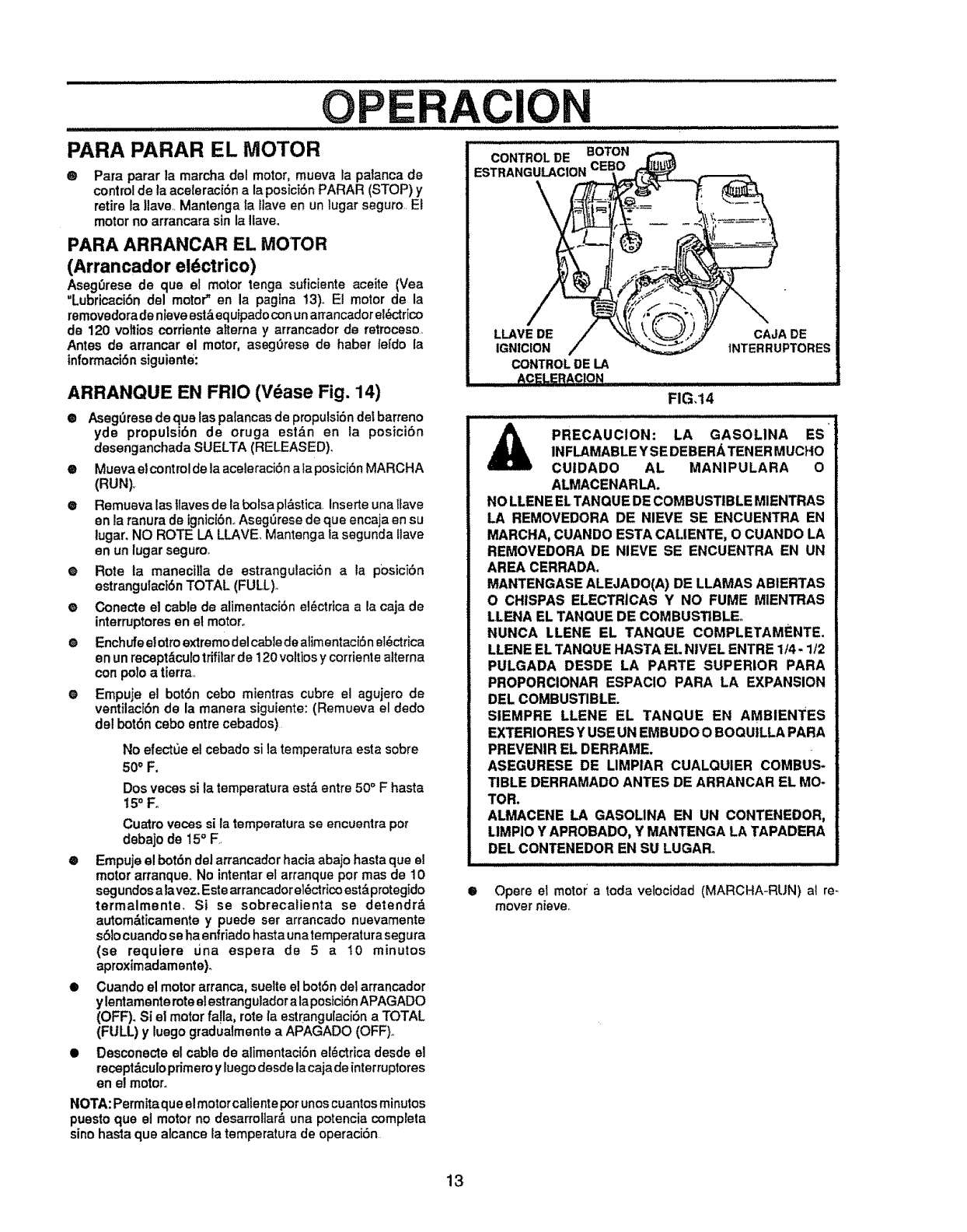
OPERACION
PARA PARAR EL MOTOR
®Pare parer la marcha del motor, mueva la patanca de
controlde ta aceleraci6n ala posiciSn PARAR (STOP) y
retire la llave.. Mantenga ta ftave en un lugar seguro El
motor no arrancara sin la Ilave.
PARA ARRANCAR EL MOTOR
(Arrancador el_ctrico)
Aseg(_rese de qua el motor tenga suficiente aceite (Yea
"Lubricaci6n del motor" en la pagina 13). El motor de la
removedorade nieve est,_.equipadoconun arrancador eh_:,'trico
de 120 voltios corriente atterna y arrancador de retroceso,
Antes de arrancar el motor, aseg0rese de haber lerclo la
informaci6n siguiante:
ARRANQUE EN FRIO (Vdase Fig. 14)
® Aseg(Jresedequetaspa[ancasdepropulsidndefbarreno
yde propulsidn de oruga est,_n en la posici6n
desenganchada SUELTA (RELEASED)..
®Mueva elcontrol de la aceleraci6n ala posici6n MARCHA
(RUN),
•Remueva las llaves de la bolsa pl&stica. Inserte una ltave
en la ranura de ignic[6n..Aseg_rese de qua encaja en su
lugar, NO ROTE LA LLAVE Mantenga la segunda ltave
en un lugar seguroo
®Rote ta manecil]a de estrangulaci6n ala p0sici6n
estrangulact6nTOTAL (FULL).
•Conecte el cable de alimentaci6n el_ctrica ala caja de
interruptores en el motor°
eEnchufe el ottoextremo del cable de atimentaciSn el_ctrica
en un recopt,_curotrifitar de 120 voltios y corfiente aiterna
con polo atierra..
• Empuje el bot6n cebo mientras cubre el agujero de
ventilacF6n de la manera siguiente: (Remueva el dedo
del bot6n cebo entre cebados)
No efectue el cebado si la temperatura esta sobre
50° F.
Dos veces si la temperatura est& entre 50°Fhaste
15° Fo
Cuatro veces si la temperature se encuentra pot
debajo de 15° F.
®Empuje el bot6n del atrancador hacia abajo haste qve el
motor arranqueo No intentar el arranque por mas de 10
segundos alavez. Este arrancador el_ctricoestbprotegido
termalmente. Si se sobrecalienta se detendrb
autom&ticamente y puede set arrancado nuevamente
s61ocuando se ha enfdado hasta unatemperatura segura
(se requiere dna espera de 5 a 10 minutos
aproximadamente).
• Cuando el motor arranca, suelte el bot6n del arrancador
y lentamente roteelestranguladora laposfcibn APAGADO
(OFF). St el motor fa!la, rote la estrangulacidn a TOTAL
(FULL) y luego gradualmente a APAGADO (OFF).
• Desconecte el cable de alimentaciSn el_ctrica desde el
recept&culoprimeroy luego desde la caja de interruptores
en e! motor.
0
BOTON
LLAVE DE CAJA DE
IGNICION tNTERRUPTORES
CONTROLDE LA
ACELERAClON .
FIG,14
I,H IWIUI_UHJI
A '
PRECAUCION: LA GASOLINA ES
INFLAMABLE YSE DEBERA TENER MUCHO
CUIDADO AL MANIPULARA 0
ALMACENARLA.
NO LLENE EL TANQUE DE COMBUSTIBLE MIENTRAS
LA REMOVEDORA DE NIEVE SE ENCUENTRA EN
MARCHA, CUANDO ESTA CALIENTE, 0 CUANDO LA
REMOVEDORA DE NIEVE SE ENCUENTRA EN UN
AREA CERRADA.
MANTENGASE ALEJADO(A) DE LLAMAS ABIERTAS
O CHISPAS ELECTRiCAS Y NO FUME MIENTRAS
LLENA EL TANQUE DE COMBUSTIBLE°
NUNCA LLENE EL TANQUE COMPLETAMENTE.
LLENE EL TANQUE HASTA EL NIVEL ENTRE 1/4- 1/2
PULGADA DESDE LA PARTE SUPERIOR PARA
PROPORCIONAR ESPACIO PARA LA EXPANSION
DEL COMBUSTIBLE.
SIEMPRE LLENE EL TANQUE EN AMBIENTES
EXTERIORESY USE UN EMBUDO O BOQUtLLA PARA
PREVENIR EL DERRAME.
ASEGURESE DE LIMPIAR CUALQUIER COMBUS-
TIBLE DERRAMADO ANTES DE ARRANCAR EL MO-
TOR.
ALMACENE LA GASOLINA EN UN CONTENEDOR,
LIMPIO Y APROBADO, Y MANTENGA LA TAPADERA
DEL CONTENEDOR EN SU LUGARo
..................... iiii II
Opera el motol: a toda velocidad (MARCHA-RUN) al re-
mover nieve_
NOTA: Permita qua elmotorcaliente por unos cuantos minutos
puesto qua el motor no desarroliar&una potencia completa
sino haste qua alcance la temperatura de operacidn
13
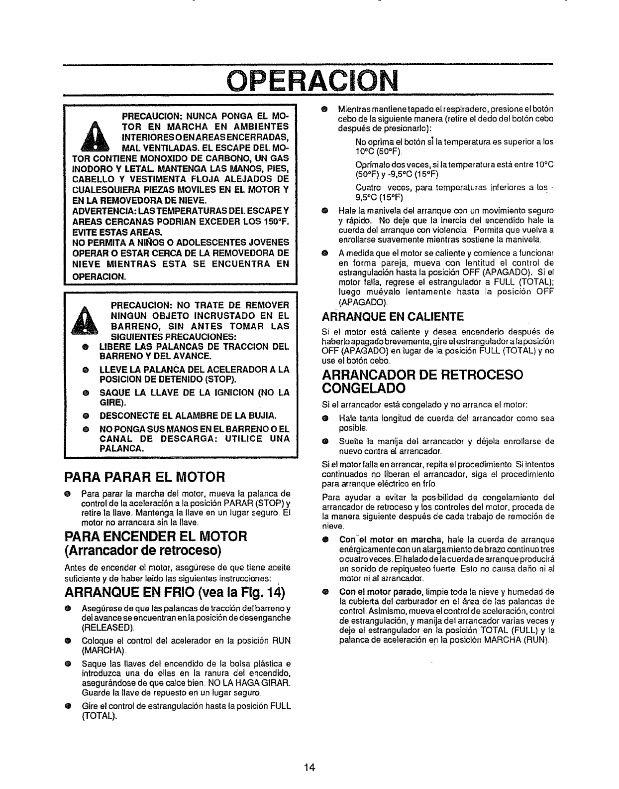
AClON
PRECAUCION: NUNCA PONGA EL MO-
,_ TOR EN MARCHA EN AMBIENTES
INTERIORESOENAREAS ENCERRADAS,
MAL VENTILADAS_ EL ESCAPE DEL MO.,
TOR CONI3ENE MONOXIDO DE CARBONO, UN GAS
INODORO Y LETAL MANTENGA LAS MANOS, PIES,
CABELLO Y VESTIMENTA FLOJA ALEJADOS DE
CUALESQUIERA PIEZAS MOVILES EN EL MOTOR Y
EN LA REMOVEDORA DE NIEVE_
ADVERTENCIA: LAS TEMPERATURAS DEL ESCAPE Y
AREAS CERCANAS PODRIAN EXCEDER LOS 150°F.
EVITE ESTAS AREAS.
NO PERMITA A NIt'_IOSO ADOLESCENTES JOVENES
OPERAR O ESTAR CERCA DE LA REMOVEDORA DE
NIEVE MIENTRAS ESTA SE ENCUENTRA EN
OPERAClON.
PRECAUCION: NO TRATE DE REMOVER
NINGUN OBJETO INCRUSTADO EN EL
BARRENO, SIN ANTES TOMAR LAS
SIGUIENTES PRECAUClONES:
®LIBERE LAS PALANCAS DE TRACCION DEL
BARRENO Y DEL AVANCE
®LLEVE LA PALANCA DEL ACELERADOR A LA
POSiClON DE DETENIDO (STOP).
e SAQUE LA LLAVE DE LA IGNICtON (NO LA
GIRE)o
oDESCONECTE EL ALAMBRE DE LA BUJIA.
oNO PONGA SUS MANOS EN EL BARRENO O EL
CANAL DE DESCARGA: UTILICE UNA
PALANCA.
PARA PARAR EL MOTOR
ePara parar la marcha dei motor, mueva la palanca de
control de la aceleraciSn a la posici6n PARAR (STOP) y
retirela llave. Mantenga la Ilave en un lugar seguro El
motor no arrancata sin la llave
PARA ENOENDER EL MOTOR
(Arrancadorde retroceso)
Antes de encender e_motor, aseg_rese de que tiene aceite
SLfficientey de haber leido las siguientes instrucciones:
ARRANQUE EN FRIO (vea la Fig. 14)
Q Aseg_lrese de que las palancas de tracci6n def barreno y
detavance se encuentran en laposici6n de desenganche
(RELEASED).
® Coloque et control del aceterador en ta posicibn RUN
(MARCHA)
® Saque las ilaves del encendido de ta bolsa pl&stica e
introduzca una de elias en la ranura del encendido,
asegur_,ndose de que calce bien. NO LA HAGA GIRAR.
Guarde la liave de repuesto en un lugar seguro.
Q Gire el control de estrangutaci6n hasta la posicibn FULL
(TOTAL)_
®Mientrasmantienetapado elrespiradero, presione elbot6n
cebo de la siguiente manera (retire et dedo del bot6n cebo
despu_s de presionado):
No oprima el bot6n s] la tempetatura es superior a los
10°C (50°F),
Oprtmato dos veces, si la temperatur a est& entre 10°C
(50°F) y -9,5°C (15°F)
Cuatro veces, para temperaturas inferiores a tos -
9,5oC (15OF)
@ Hale fa manivela del arranque con un movimiento seguro
yr_pido. No deje que la inercia det encendido hale la
cuerda del arranque con violencia Permita que vuelva a
enroUarse suavemente mienttas sostiene la manivela,
O A medida qua el motor se caliente y comience a funcionar
en forma pareja, mueva con lentitud el control de
estrangulaci6nhasta la posicidnOFF (APAGADO). Si et
motor falla, regrese el estrangulador a FULL (TOTAL);
luego mu_yalo lentamente hasta la posici6n OFF
(APAGADO).
ARRANQUE EN CALIENTE
Si el motor est& caiiente y desea encenderlo despu_s de
haberto apagado brevemente, gire el estrangulador a laposici6n
OFF (APAGADO) en lugar de la posiciSn FULL (TOTAL) y no
use el bot6n cebo..
ARRANCADOR DE RETROCESO
CONGELADO
Si el arrancador est& congelado y no arranca el motor:
O Hale tanta tongitud de cuerda del a=rancador como sea
posible.
® Suefte la manija deL arrancador y d_jela enroilarse de
nuevo contra el arrancaclor.
Si el motor falla en arrancar, repita el procedimiento Si intentos
continuados no liberan el arrancador, siga el procedimiento
para arranque et6ctrico en fr[o.
Para ayudar a evitar la posibiiidad de congelamiento def
arrancador de retroceso y los controles del motor, proceda de
Ia manera siguiente despu6s de cada trabajo de remoci6n de
nieve_
OCon'el motor en marcha, hale la cuerda de arranque
en_rgicamente con un atargamiento de brazo continuo tres
ocuatro veces. Elhalado de la cuerda de atranque producir&
un sonido de repiqueteo fuerte. Esto no causa da5o ni al
motor ni al artancador.
®Con el motor parado, limpie toda la nieve y humedad de
la cubierta del carburador en el &tea de las palancas de
control,Asimisma, mueva elcontrol de aceleraci6n, control
de estrangulaciSn, y manija del arrancador vadas veces y
deje el estrangulador en la posiciSn TOTAL (FULL) y la
palanca de aceleraci6n en ta posici6n MARCHA (RUN).
14
OPERAClO
PISTAS SOBRE LANZAMIENTO DE
NIEVE
@ Para mayor eficiencia de tanzamiento de nieve durante la
remociSn de la misma, ajuste la velocidad en e] terreno,
NUNCA la aceleraci6n. Avance lentamente en nieve
profunda, congelada, o hOmeclao Si la oruga desliza,
reduzca lavelocidad hacia adelante. El motor estadisefiado
para brindar un rendimiento m_imo bajo aceleraci6n total
y debe set operado en este valor de potencia en todo
momentoo
® El lanzamiento de nieve es m&seficiente sila remoci6n de
la mismase efectt_ainmediatamente despu_sde su calda_
® Para una remoci6n completa de la nieve, traslape
ligeramente coda camino adoptado previamente.,
® La nieve cteber|a serdescargada en la direcci6n del viento
siempre que sea posible
@ Para uso normal, posicione los correderas de apoyo de
manera tal que la barra raspadora se encuentre 1/8 de
pulgada sobre los correderas de apoyo_ Para superficies
de nieve dura extremadamente compacta, ajuste los
correderas de apoyo hacia arriba de manera que la barra
raspadora haga contacto con el terreno,.
O En superficies de grava o roca triturada, posicione las
correderas de apoyo a 1-1/4 pulgadas pot debajo de la
barra raspadora (V_ase el p&rra{o "C6mo ajustar la altura
de los correderas de apoyo" en la p&gina 18) Las rocas y
grava nodeber&n ser recogidas y lanzadas pot la m&quina.
@ Sila parle delantera de la removedora de nieve tiene la
tendenciade elevarse reduzca lavelocidad sobre el terreno
y enganche el sistema de transferencia de peso.
@ Despu_s de que se haya comptetado el lanzamiento de
nieve, permita que el motor se encuentre en r_poso por
unos cuantos minutos, 1ocual derretir_ la nieve y hielo
acumulado del motor.
@
O
EfectOe una limpieza completa de la removedora de nieve
luego de cada uso.,
Remueva la acumutaci6n de hielo y nieve y todo material
extrafio heterog_neo de la removedora de nieve en su
totalidad, y lave co n agua (si fuese posible) para remover
todasal uotrassubstancias quimicas Sequela removedora
de nieve..
15
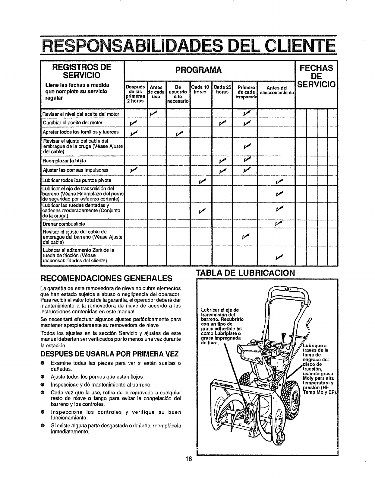
,, ,,,,, , ,,, , ,,, ,,,,,,i ii iiii iii ii iIL I I IIII II iI
ILl L CLI i
TE
REGISTROS DE
SERVICIO
Liens las fechas amedida
que complete su servlclo
regular
PROGRAMA
Despuds Antes De Cads 10 Cads25 Prlmero Antesdel
de las _ecadaiacuerde horas horas de cads almacenambnto
prlmeras use ato temporad=
2 horas necesarlo
FECHAS
DE
SERVICIO
Revisarel nivel del aceitedel motor _ _'_
,,,,,,,,,,,,,,,, - .... :- _
Cambiarel aceite del motor f,j _
Apretartodos lostornillosytuercas _
"Revis_ el _uste dd cable de! ........... _..................
en_rague de la oruga (V_ase Ajuste _'#
de!cable)
Reemplazar la bujla
_ustar ias=_sas Impulsoras p_' , p,# _'
"'" '" i: "
Lubricartodos los puntospivots
Lubricar etejs de transmisi6n del
barreno (V_ase Reemplazo del pernc
de segurtdadpot+esfuerzo cortante)....................
Lubrlcar las ruedas dentadas y
cadenasrnoderadamente (ConJunto p,#
de la oruga)
Drenar combustible
"Flevisarel ajuste del cable del
embrague del barreno (V_ase Ajuste
del cable)
LuMcar el adItamento Zerk de la
ruedade fricclSn(V_ase
responsabilidadesdel cliente)
v'
RECOMENDACIONES GENERALES
La garantfa de esta removedora de nieve no cubre elementos
que han estado sujetos a abuse o negligencia del opetador.
Para recibirel valor total de la garantfa+ el operador deber& dar
mantenimiento a la removedora de nieve de acuerdo alas
instrucciones contenidas en este manual
Se necesitar& efectuar algunos ajustes peri6dicamente pars
mantener apmpiadamente su removedora de nieve
Todos los ajustes en la secci6n Servicio y ajustes de este
manual deberran set verificados per 1omenos una vez durante
la estaci6n+
DESPUES DE USARLA PeR PRIMERA VEZ
® Examine todas las piezas para ver si est&n suettas o
dafiadas.
®Ajuste lodes los pernos que est_n ftojos
® Inspeccione y d6 mantenimiento al barreno.
® Cads vez que la use, retire de la removedora cualquier
resto de nieve o range para evitar la congelaci6n def
barreno y los controles+
® Inspeccione los controles y verifique su buen
funcionamiento.
® Si exists alguna parts desgastada o dafiada, reempt&ceta
inmediatamente+
TABLA DE LUBRICACION
Lubrlcar el eJede
transmisl6n del
barreno. Recubrlrlo
con un |lpo de
grass adhertble tal
come Lubrtplate o
grass impregnada
de fibra+ Lubrique a
tray,s de la
toma de
engrase del
.disco de
usando grass
Moly pars alta
temperatura y
presl6n (Ht-
Temp Moly EP).
illllllllllJllj i IIII
16
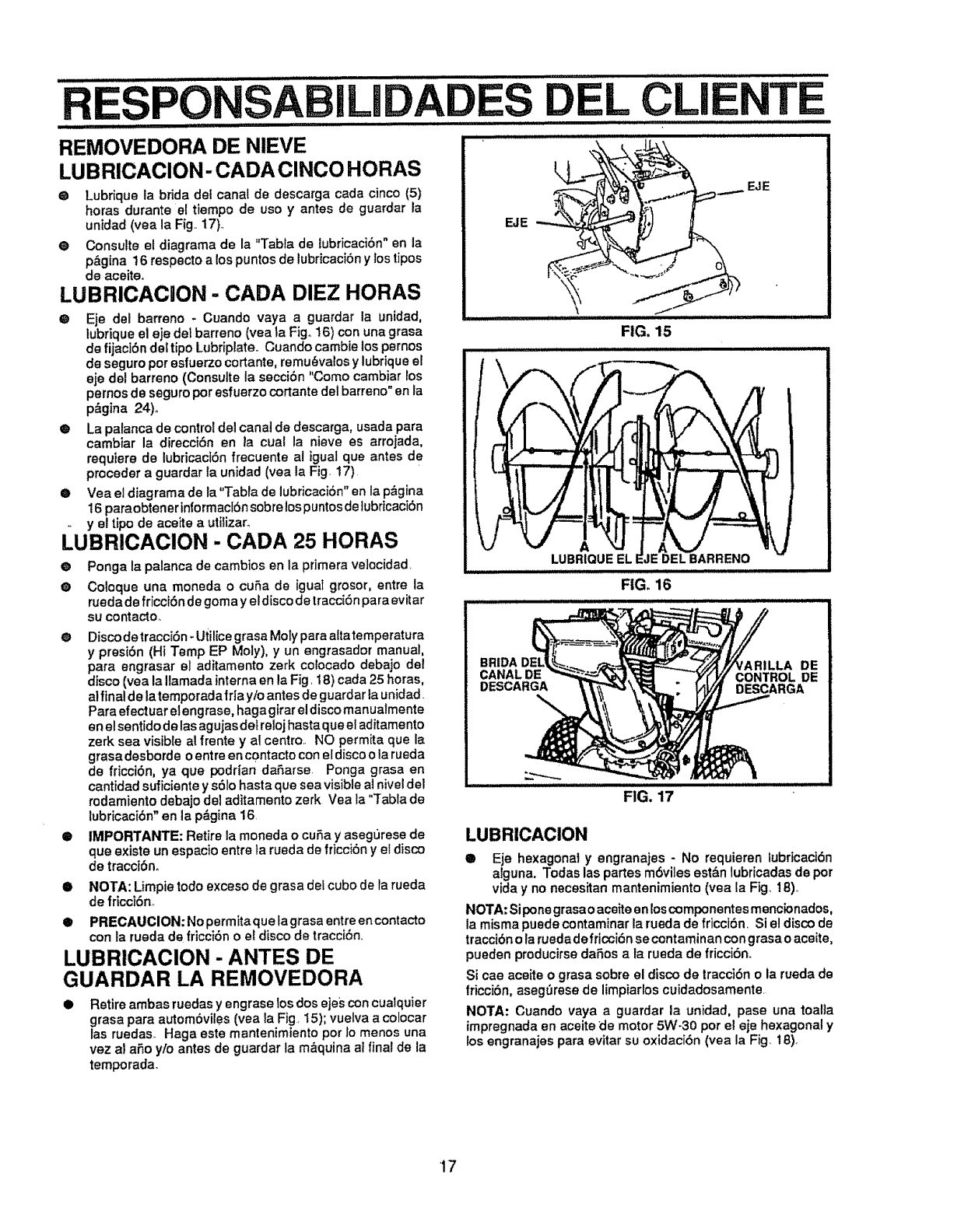
LEL CLI
.................... i,,i,i,i..................
i
ill LILI I I II
REMOVEDORA DE NIEVE
LUBRICACION- CADA CINCO HORAS
OLubrique la brida del canal de descarga cada cinco (5)
horas durante el tiempo de use y antes de guardar la
unidad (yea la Fig.. 17)..
@Consult@ el diagrama de la "Tabla de iubricaci6n" en la
p&gina 16 respecto alos puntos de lubricaci6n y los tipos
de aceite,
LUBRICACION - CADA DIEZ HORAS
@Eje del barreno - Cuando vaya a guardar la unidad,
lubrique el eje del barreno (yea la Fig.. 16) con una grasa
de fijaci6n dei tipo Lubriplate° Cuando cambie los pernos
de seguro per esfuerzo cortante, remu_valos y lubrique el
eje del barreno (Consulte la secci6n "Come cambiar los
pernos de seguro per esfuerzo cortante del barreno" en la
p&gina 24)°
@ La palanca de control del canal de descarga, usada para
cambiar la direcci6n en la cual la nieve es arrojada,
requiere de lubricaci6n frecuente al }gual que antes de
preceder a guardar la unidad (yea la Fig. 17)
@ Vea el diagrama de la"Tabfa de lubricaci6n" en la p&gina
16 paraobtener informacl6nsobre lospuntos delubricacibn
yel tipo de aceite a utitizar.
LUBRIOAOION - CADA 25 HORAS
® Ponga la palanca de cambios en la primera velecidad.
® Coloque una moneda o cuSa de iguat grosor, entre la
rueda de fricd6n de goma y eldisco de tracd6n para evitar
su contacto.
@ Disco de tracci6n -utitice grasa Moty para aita temperatura
y presi6n (Hi Temp EP Moly), y un engrasador manual,
para engrasar el aditamento zerk colocado debajo del
disco (yea la Ilamada interna en la Fig. 18) cada 25 horas,
al final de latemporada ffla y/o antes de guardar la unidad
Para efectuarelengrase, haga gfrar eldisco manualmente
en el sentido de las agujas det relojhasta que etaditamento
zerk sea visible al frente y al centre.. NO permita que la
grasa desborde o entre en contacto con el disco o la rueda
de fricci6n, ya qua podrian daSarse Ponga grasa en
cantidad suficiente y s61ohasta que sea visible al hive!del
redamiento debajo del aditamento zerk Vea la 'qrabla de
lubricaci6n" an la p&gina 16.
@ IMPORTANTE: Retire la moneda o cuSa y asegurese de
que exist@un espacio entre ta rueda de fricci6n y el disco
de tracci6n.
@ NOTA: Limpie todo exceso de grasa det cube de la rueda
de fricci6no
@PRECAUCION'Nopermitaque tagrasa entreencontacto
con la rueda de fricci6n o el disco de tracci6n,,
LUBRICAClON - ANTES DE
GUARDAR LA REMOVEDORA
@ Retire ambas ruedas y engrase los dos ejes con cualquier
grasa para autom6vites (vea la Fig. 15); vuelva a colocar
las ruedas. Haga este mantenimiento per Io menos una
vez al aSo y/o antes de guardar la m&quina ai final de la
temporada.
iillllll,i iiiill ill
EJE _:
\
FIG. 15
LUBRtOUE EL IE
FIG. 16
BRIDA 'ARILLA DE
CANALDE CONTROL DE
DESCARGA DESCARGA
FIG. 17
LUBRICACION
@Eje hexagonal yengranajes -No requieren lubricaci6n
alguna. Todas las partes m6viles est&n lubricadas de per
vida y no necesitan mantenimiento (yea la Fig, 18)°
NOTA: Sipone grasao aceite en los componentes mencionados,
la misma puede contaminar la rueda de fricci6n, Si el disco de
tracci6n o la rueda de fricci6n se contaminancon grasa o aceite,
pueden producirse daSos ala rueda de fricci6no
Si cae aceite o grasa sobre el disco de tracoi6n o la rueda de
fricci6n, asegSrese de limpiarlos cuidadosamente.
NOTA: Cuando vaya a guardar la unidad, pase una toalla
impregnada en aceite de motor 5W-30 per e! eje hexagonal y
los engranajes para evitar su oxidaci6n (yea la Fig 18).
17
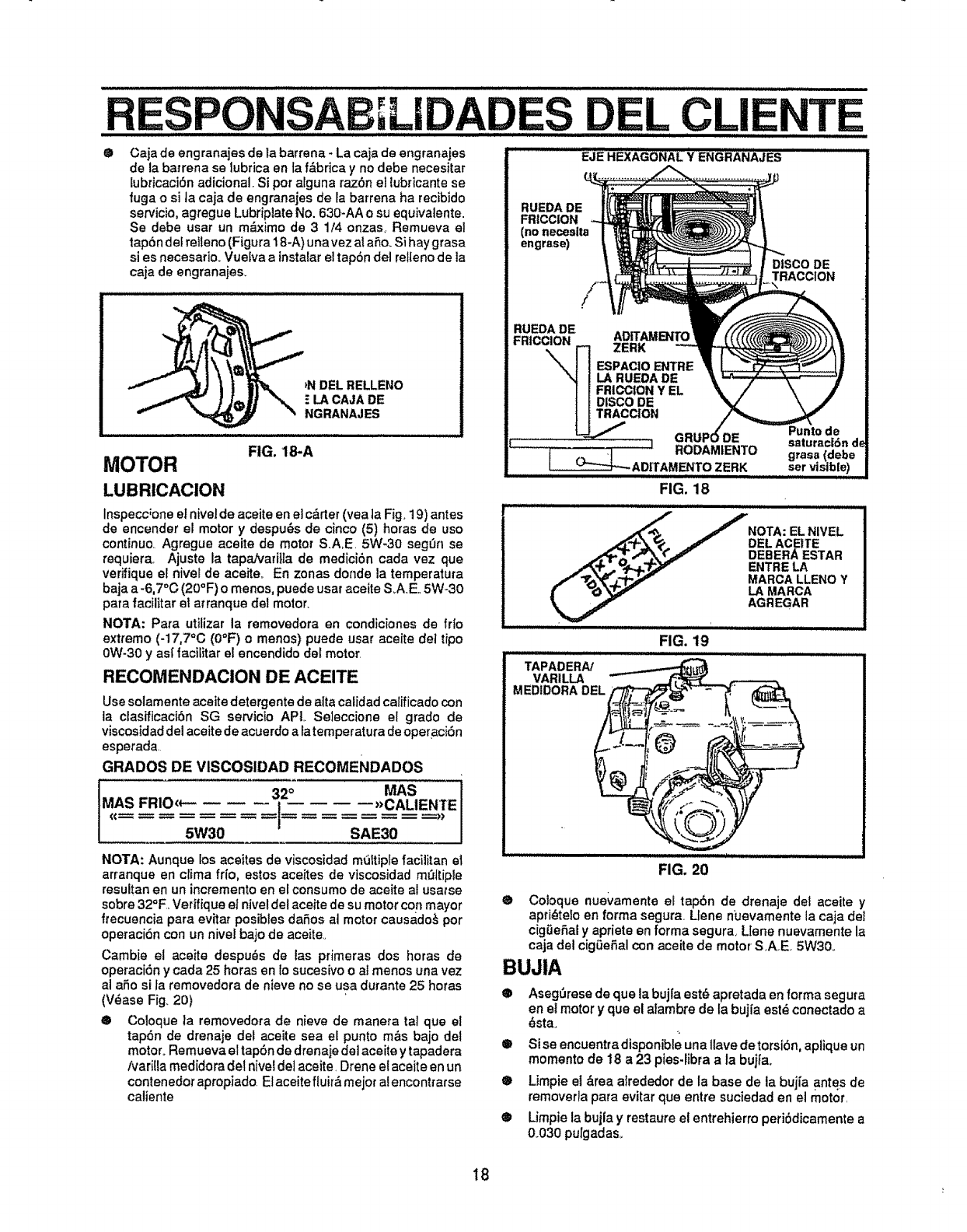
L
® Caja de engranajes de la barrena- La caja de engranajes
de la barrena se lubfica en fa f&brica y no debe necesitar
[ubficaci6n adicional. Si pot alguna razSn el lubricante se
fuga o si ]a caja de engranajes de rabarrena ha recibido
servicio, agregue Lubripiate No. 630-AA o su equivalente.
Se debe usar un m_ximo de 3 1/4 onzas, Remueva el
tap6n dei relleno (Figura 18-A) unavez at aSo. Si haygrasa
si es necesario. Vuelva a instalar el tapbn del retteno de la
caia de engranajes_
_NDEL RELLENO
ELA CAJA DE
NGRANAjES
FIG. 18-A
MOTOR
LUBRICACION
Inspecc;one et hive] de aceite en el c&rter(yea la Fig. 19) antes
de encender el motor y despu_s de cinco (5) horas de uso
continuo. Agregue aceite de motor S.A,E. 5W-30 seg_n se
requiera, Ajuste la tapahJari]la de medici6n cada vez que
verifique el nivel de aceite_ En zonas donde la temperatura
baja a-6,7°C (20°F) o menos, puede usar aceite S_AE., 5W-30
para facilitar el arranque del motor.
NOTA: Para utilizar la removedora en condiciones de frlo
extremo (-17,7°C (0°F) o menos) puede usar aceite de! tipo
0W-30 y as{ facilitar el encendido del motor.
RECOMENDAClON DE ACEITE
.................. EJE HEXAGONAL Y ENGRi_N'_,'JES
RUEDA DE
FRICCION
(no neceslta
engrase)
RUEDADE
FRICCION ADITAMEN'rC
ZERK
ESPACIOE_rI"RE
LA RUEDADE
FR|CClONY EL
DISCODE
TRACC|ON
............... _j
TE
DISCODE
TRACCION
Use solamente aceite detergente de attacalidad calificadocon
la clasificaci6n SG servicio APL Seleccione el grado de
viscosidadde!aceite de acuerdo a latemperatura deopeLaciSn
esperada
GRADOS DE VISCOSIDAD REOOMENDADOS
., i'°
S FRIO<_ _)CALIENTE
5W30 SAE30
NOTA: Aunque los aceites de viscosidad mti_tipfe facifitan el
arranque en clima fr{o, estos aceites de viscosidad mQftiple
resultan en un incremento en el consumo de aceite al usatse
sobre 32_F, Verifique el niveldel aceite de su motor con mayor
frecuencia para evitar posibles daSos al motor causado_ por
operaci6n con un nivel bajo de aceite.,
Cambie el aceite despu_s de ias pfimeras dos horas de
operaci6n y cada 25 horas en lo sucesivo o at menos una vez
al a_o si la removedora de nieve no se usa durante 25 horas
(V_ase Fig. 20)
® Coioque la removedora de nieve de manera tal que el
tapdn de drenaje del aceite sea el punto m&s bajo del
motor. Remueva el tapbn de drenaje de] aceite ytapadera
/vari!_ameal[dora de]nivei de] aceite. Drene el aceite en un
contenedor apropiado El aceite fiuir,_ mejor alencontrarse
caliente
FIG. 20
FIG. 19
lll,,HHillulllluHI_ _1_1_
TAPADERA/
VARILLA
MEDIDORADEL
® Coloque nuevamente el tapbn de drenaje del aceite y
apri_telo en forma segura, Llene n_Jevamentela caja de!
cig0eSai y apriete en forma segura, LIene nuevamente la
caja det cigQeSalcon aceite de motor SA,E 5W30,.
BUJIA
®AsegOresede que la buj{a est_ apretada en forma segura
en et motor y que el aiambre de la bujia est_ conectado a
_sta.
® Si se encuentra disponible una Ilave de torsibn, aplique un
momento de t8 a 23 pies-libra a la bujfao
® Limpie el &rea a_rededor de la base de la bujia antes de
removerla para evitar que entre suciedad en el motor,
® Limpie la bujla y restaure el entrehierro periSdicamente a
0.030 purgadas_
18
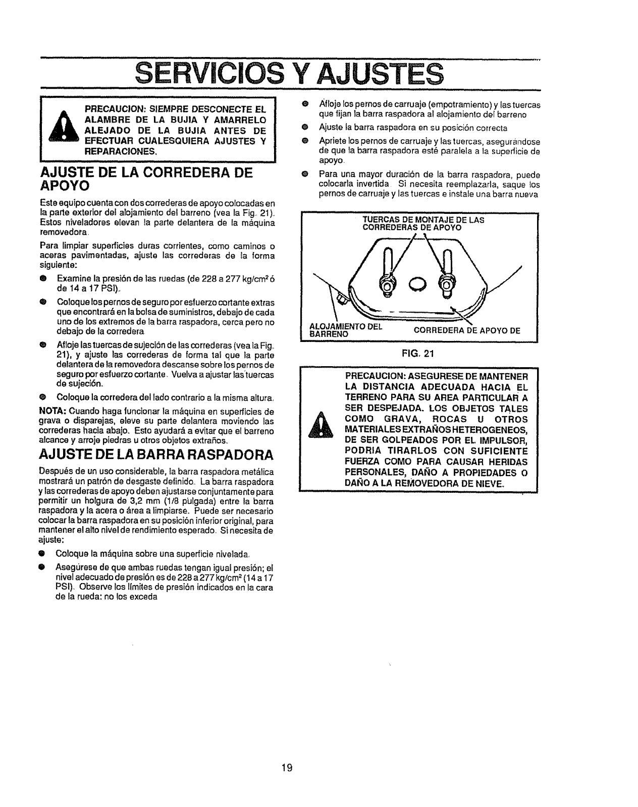
..... sERvlclos YAJUSTES ....
uIH/I ,11 i iiiiiiii
PRECAUCION: SIEMPRE DESCONECTE EL
ALAMBRE DE LA BUJIA Y AMARRELO
ALEJADO DE LA BUJIA ANTES DE
EFECTUAR CUALESQUIERA AJUSTES Y
REPARACIONES,
AJUSTE DE LA CORREDERA DE
APOYO
Este equipocuenta con dos correderas de apoyo colocadas en
la parle exterior del alojamiento del barreno (yea la Fig. 2t)_.
Estos niveladores elevan la parte delantera de la m&quina
removedora.
Para 5mpiar superficies duras corrientes, come caminos o
aceras pavimentadas, ajuste las correderas de la forma
siguiente:
O Examine la presibn de 1asruedas (de 228 a 277 kgicm_6
de 14 a!7 PS])._
® Cotoque los pernos de seguro per esfuerzo cortante extras
que encontrar& en la bolsa de suministros, debajo de cada
uno de los extremes de la barra raspadora, cerca pero no
debajo de la corredera
® Afloje lastuercasde sujeciSn de las correderas (veaia Fig..
21), y ajuste las correderas de forma tal que )a parte
delantera de la removedora descanse sobre los pernos de
seguro per esfuerzo cortante_ Vuelva a ajustar las'tuercas
de sujecJ6n.
e Coloque la corredera del lade contrario a la misma altura.
NOTA: Cuando haga funcionar la m&quina en superficies de
grava o disparejas, eleve su parte delantera moviendo las
correderas hacia abajo,. Esto ayudar,_ aevitar que el barreno
alcance y arroje piedras u otrosobjetos extraSos..
AJUSTE DE LA BARRA RASPADORA
Despu_s de un use considerable, la barra raspadora met_lica
mostrar& un patrSn de desgaste definido,. La barra raspadora
y lascorrederas de apoyo deben ajustarseconjuntamente para
permitir un holgura de 3,2 mm (1/8 putgada) entre la barra
raspadora y la acera o &rea a limpiarseoPuede set necesario
co]ocar la barra raspadora en su posiciSninferiororiginal, para
mantener e! alto nivel de rendimiento esperadoo Si necesita de
ajusts:
Q Coloque la m&quina sobre una superficie nivetada,
•Asegurese de que ambas ruedas tengan igual presi6n; el
nivel adecuado de presibnes de228 a 277 kg/cm2(14 a 17
PSI).. Observe los Ifmites de presi6n indicadosen la cara
de Earueda: no los exceda
eAfloje los pernosde carruaje (empotramiento) y las tuercas
que fijan la barra raspadora at alojamiento de[ barreno
@ Ajuste ta barra raspadora en su posiciSncorrecta
OApriete los pernos de carruaje y tas tuercas, asegurandose
de que la barra raspadora est_ paralela a la supedicie de
apoyo.
O Para una mayor duraciSn de la barra raspadera, puede
colocarla invertida S] necesita reemplazarla, sa.que tos
pernos de carruaje y las tuercas e instale una barra nueva
TUERCASDE MONTAJE DE LAS
CORREDERASDE APO¥O
O
ALOJAMIENTODEf. CORREDERADE APOYODE
BARRENO
FIG. 21
PRECAUCION: ASEGURESE DE MAN_rENER
LA DISTANCIA ADECUADA HACIA EL
TERRENO PARA SU AREA PARTICULAR A
SER DESPEJADA, LOS OBJETOS TALES
COMe GRAVA_ ROCAS U OTROS
MATERIALES EXTRAROS HETEROGENEOS,
DE SER GOLPEADOS PeR EL IMPULSOR,
PODRIA TIRARLOS CON SUFICIENTE
FUERZA COMe PARA CAUSAR HERIDAS
PERSONALES, DAi_O A PROPIEDADES O
DARe A LA REMOVEDORA DE NIEVE
19
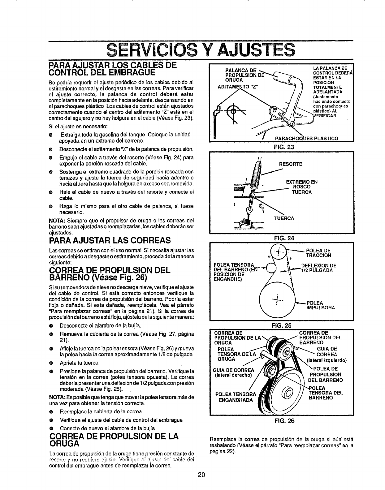
SE CIOS
CONTROL DEL EMBRAGUE
Se podfla requerir el ajuste peri6dico de los cables debido at
estiramiento normal y el desgaste en las correas., Para verificar
el ajuste correct®, la palanca de control deber_. ®star
completamente en la posici6n hacia adelante, descansando en
et parachoques pl&stico Los cables de control est&n ajustados
correctamente cuando el centro del aditamento "Z" est& en el
centro del agujero y no hay hoIgura en el cable (V_ase Fig. 23).
Si el ajuste es necesar{o:
® Extratga toda la gasolina del tanque, Cofoque la unidad
apoyada enun extremo del barren®,
e Desconecteel aditamento"Z" de la palancade propulsibn.
® Empuje el cable a trav6s del resorte (V_ase Fig. 24) para
exponer ta porci{_nroscada del cable.
OSostenga el extremo cuadrado de la porci6n roscada con
tenazas y ajuste la tuerca de seguridad hacia adentro o
hacia afuera hasta que la holgura en exceso sea removida.
®Hale el cable de nuevo a trav_s del resort® y conecte ei
cable.,
eHega i® mismo para el otro cable de pafanca, si fuese
necesafio.
NOTA: Siempre que el propulsor de oruga o las correas dei
barren®sean ajustadas oreemplazadas, loscables deberdn set
ajustados.
PARA AJUSTAR LAS CORREAS
Las correas se estiran conel us®normal Si necesita ajustar las
correas debido adesgaste o estiramiento, procedad_ la manera
siguiente:
CORREA DE PROPULSION DEL
BARREN® (Vease Fig. 26)
Si su temovedora de nieve nodescarga nieve, vefifiqueel ajuste
del cable de control. Si est& correct® entonces vefifique la
condiciSn de la correa de propulsk_n del barren®. Podria ®star
floja o daSada., Siesta daSada, reempl&ceta. Vea el p&rrafo
"Para reemplazar correas" en la p&gina 21). Si la correa de
propulsi6n del barren® est_ifloja, ajSstela de lasiguiente manera:
FIG. 23
RESORTE
EXTREMOEN
ROSCO
TUERCA
TUERCA
FIG. 24
_POLEA DE
o_,t_ eTRACCION
POLEATENSORA _ i_ DEFLEXIONDE
DELBARREN®(ER--"'k,..) .,._',._"'tt2 PULGADA
POSICIONDE -'7 _,_
!_POLEA
__ IMPULSORA
iilulllIHHI I I IHI Ill
®Desconecte el alambre de la bujla
®Remueva la cubierta de ia correa (V_ase Fig. 27, p&gina
21).
® Aflojelatuerca en lapoleatensora (V_ase Fig. 26) y mueva
la polea hacia la correa aproximadamente 1/8 de pulgada.
®Apriete fa tuerca_
•Preston® ta palanca de propulsi6n dei barren®. Verifique la
tensi6n en la correa (polea tensora opuesta). La correa
debert'apresentar una deflexidnde 1/2pulgada con presi6n
moderada (V_ase Fig_25).
NOTA: Es posibleque tenga que mover la potea tensora m&sde
una vez para obtener ia tensi{_n correcta.
•Reemplace la cubierta de la correa
®Verifique el ajuste dei cable de control del embrague
®Conecte de nuevo el afambre de ta bujia
CORREA DE PROPULSION DE LA
ORUGA
FIG, 25
CORREA DE CORREA DE
PROPULSIONDE LA_PROPULSIONDEL
ORUGA ._/_/"_. BARRENO
POLEA i_.,.k_lf_'///"_l_._. _GUIA DE
TENSORADELA ._>r_'_k,_t{(---_,_"_1,_ _CORREA
ORUGA f__k'_a terat izquierdo)
GUtA DECORREA /f[f/'___ "_POLEA DE
(lateralderecho) /_\_ PROPULSION
/NY/ ""_ DELBARRENO
/_I_H!// /_;;_, !/"'-POLEA
.O E, 1/1I/ tt oE .
ENGANCHADA _ =
FIG. 26
Lacorrea de propulsiSn de la oruga tiene presi6n constante de
resorie $,no requiere ajus[e, Verilique et ajus[e del caot_ cl_l
controldel embrague antes de reemplazar la correa
Reemplace la correa de proputsi6n de la oruga si a0rf est_
resbalando (V_ase el p&rrafo "Para reemplazar correas" en la
pagina 22)
2O
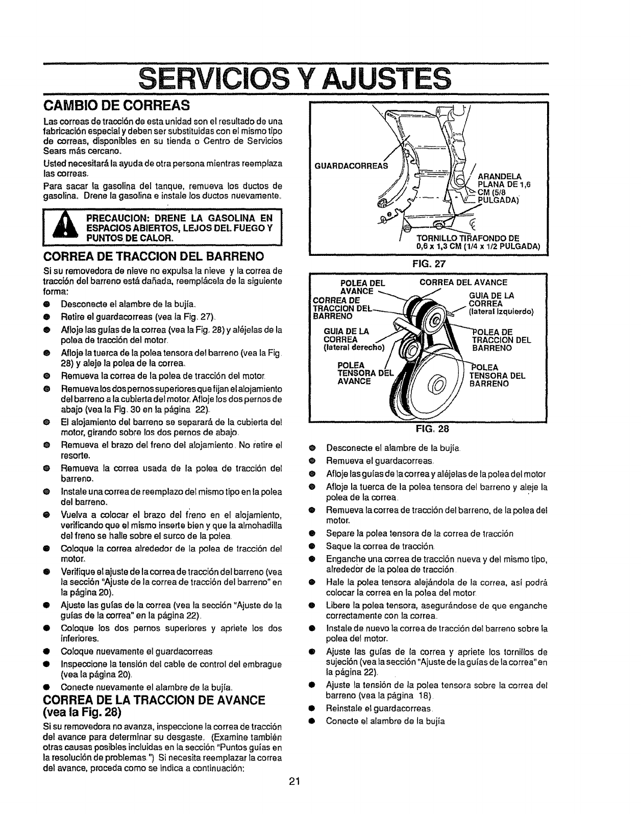
..... " SERVICIOS Y AJUST ..............................
iii1.1 i i iii. HII IIIII I I _'"' _............... _"_
CAMBIO DE CORREAS
Las correas de tracciSn de esta un[dad son el resultado de una
fabricaci6n especial y deben ser substituictas con el mismo tipo
de correas, disponibles en su tienda o Centre de Servicios
Sears m&s cercanoo
Usted necesitar&la ayuda de otra persona mientras reemp{aza
las correas.
Para sacar ta gasolina del tanque, remueva los ductos de
gasolinao Drene {agasolina e instate los ductos nuevamente..
I i, P.ECAucwo.:ORE.EL, aASOLii AE"I
ESPACIOSABIERTOS, LEJOS DEL FUEGO Y I
, pUNTOS DE CALEB. I
CORREA DE TRACClON DEL BARRENO
Si su removedora de nieve no expulsa la nieve yla correa de
traccibndel barreno est_ daSada, reempl_cela de la siguiente
forma:
•Desconecte el alambre de la bujta.
O Retire el guardacorreas (vea ta Fig. 27).
• Afioje las guias de la correa (yea la Fig..28) y ai6jelas de la
polea de tracci6n del motor.
® Aflojela tuerca de la polea tensora dei barreno (yea la Fig.
28) y aleje la polea de la correa_
O Remueva la correa de la potea de traccibn det motor.
O Remueva losdospernos superiores qua fijan el alojamiento
del barmno a la cubiertadel motor, Afloje los dos pernosde
abajo (yea la Ftg. 30 en la p&gina 22).
El aiojamiento del barreno se separar_, de la cubierta del
motor, girando sobre los dos pemos de abajo.
O
O
O
@ Remueva el braze del freno del alojamiento. No retire el
resorte.
® Remueva la correa usada de la polea de tracc{bndel
barreno,
@Instale una correa de reemplazo del mismo t{po an la po_ea
del barreno,
• Vuelva a colocar el braze de] freno en el alojamiento,
verfficando qua el mismo inserts bien y qua la atmohaditla
de] freno se halle sobre el surco de la poiea
Co]oque la correa alrededor de la polea de tracci6n del
motor.
/
GUARDACORREAS
,,,,,,,,,,,,,,,, ,,,,,,i ii i ii , ..........................
TORNILLOTIRAFONDODE
0,6x1,3 CM (lj4 x 112PULGADA)
....................... J ,i, HI i
FIG, 27
POLEA DEL CORREA DELAVANCE
AVANCE GUtA DE LA
CORREA DE CORREA
TRACCtON {lateral Izquterdo}
BARRENO
GU|A DE LA DE
CORREA TRACCION DEL
(lateral derecho) BARRENO
POLEA
TENSORA DEL TENSORA DEL
AVANCE 8ARRENO
FiGo 28
Verifique et ajuste de la correa de tracciSndel barreno (yea
]a secciSn "Ajuste de la correa de tracc}Sn del barreno" en
ta p_gina 20),.
O Ajuste las gu|as de la correa (vea la secc{Sn "Ajustede la
guias de la correa" an la p&gina22).
•Co!oque los dos pernos superiores y apriete los dos
inferioreso
• Coloque nuevamente el guardacorreas
• inspeccionela tensi6n del cable de control del embrague
(vea la p&gina 20),
• Conecte nuevamente el alambre de {a bujia..
CORREA DE LA TRACCION DE AVANCE
(vea la Fig. 28)
Si su removedora noavanza, inspeccione la correa de tracci6n
del avance para determinar su desgaste.. (Examine tambi_n
otras causas posibies incluidasan la secci6n "Puntos gu{as en
la resoiuci6nde problemas.") Si necesita reemplazar ta correa
det avance, proceda come se indica a continuaci6n:
21
@ Desconecte el alambre de la bujia
@Remueva elguardacorreasr
® Afloje lasgu{as de la correa y alSielas de [apolea del moto_
• Afloje la tuerca de la polea tensora del barreno y aleje la
polea de la correa.
® Remueva la correa de tracci6n del barreno, de la polea dei
motor°
• Separe la polea tensora de la correa de tracci6n
•Saque la correa de tracci6n.
® Enganche una correa de tracci6n nueva y del mismo ripe,
alrededor de ia polea de tracci6n
•Hale la polea tensora alej&ndola de la correa, asi podr&
colocar la correa an la polea dei motor
•Libere la potea tensora, asegur&ndose de qua enganche
correctamente con la correa..
•tnstate de nuevo la correa de tracc{Sn del barrene sobre ia
polea delmotor.
•Ajuste las gufas de {a correa y apriete los torniltos de
sujeci6n (vea la secci6n "Ajuste de la gu{as de la correa" en
la p&gina22).
•Ajuste la tensi6n de ]a polea tensora sobre la correa det
barreno (vea la p&gina 18).
•Reinstate etguardacorreas.
•Conecte el alambre de la bujia
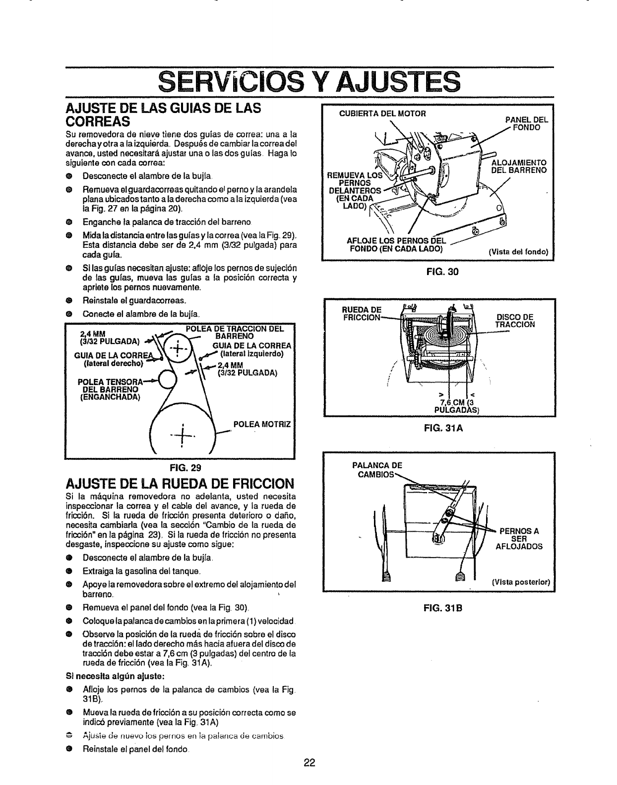
Y AJUSTES
AJUSTE DE LAS GUIAS DE LAS
CORREAS
Su removedora de nieve tiene dos guias de correa: una a ]a
derechay otra a fa izquierda, Despu_s de cambiar lacorrea del
avance, usted necesitar& ajustat una o las dos gulas. Haga lo
sigutente con cada correa:
e Desconecte el alambre de la bujfa
@ Remueva elguardacorreas quitando el perno y laarandela
plana ubicados tanto a la derecha come a la izquierda(yea
la F{go27 en la p&gina 20),,
O Enganche la palanca de tracciSn det barreno
® Mida la distancia entre las gufas y la cetrea (yea la Fig,.29).,
Esta distancia debe ser de 2,4 mm (3/32 pulgada) para
cada gufao
@ Si las gufas necesitan ajuste: afloje los pernos de sujedSn
de las guias, mueva las gufas a la posici6n cotrecta y
apriete los pemos nuevamente_
® Reinstale el guardacorreas.
® Conecte el alambre de la bujf&
................. POt.EADETRACCKONOEL
2,4 MM BARRENO
(3/32 PULGADA),,_._._._ GUIA DE LA CORREA
GUIA DE LACORRE._-_t.=_)j)n\ e,_ (lateral Izquierdo)
(lateralderecho) "- _ _._,,_ 2,4 MM
_("_ ._\\_ (3132PULGAOA)
POLEATENSO_A'"_ /V
DELBARRENO "7' \
i- _ . _ "_' POLEAMOTRIZ
CUBIERTADELMOTOR
\PANELDEL
_1 FONDO
_ _OJAMIENTO
R MU.VALOS 'J . A 0EL.A..E.O
PERNOS_ _/ t,l-_ /"
DELANTEROS"*'-_J-"_' .=._,_ ...J-"_'y
(ENCADA _/\ _/_'_ "\
AFLOJELOS PERNOSDEL ./
FONDO(EN CADA LADe) (Vistadel rondo)
FIGo30
RUEDA DE DISCO DE
TRACCION
/
> <
7,6CM
PULGADAS)
FIG, 31A
FIG. 29
AJUSTE DE LA RUEDA DE FRICCION
Si la m&quina removedora no adelanta, usted necesita
inspeccionar la correa yel cable del avance, y la rueda de
fricci6n. Si la rueda de fticci6n presenta deterioro odaSo,
necesita ca_mbiarla(yea la secci6n "Cambio de la rueda de
fricci6n" an ra p_gina 23)_ Si la ruedade fricci6n no presenta
desgaste, inspection®su ajuste come sigue:
@Desconecte el alambre de la bujfa.
® Extraiga la gasotina dei tanque+
® Apoye la removedora sobre el extreme det a!ojamiento del
barreno,
® Remueva el panel del fondo (yea fa Fig. 30).
® Coloque la palanca de cambiosen laprimera (1)velocidad
® Observe la posici6n de la rueda de fricci6n sebre el disco
de tracci6n: el lade derecho m&s hacia afuera del disco de
tracci6n debe estar a 7,6 cm (3 puigadas) det centre de la
rueda de fricci6n (yea la Fig. 31A).
St neceslta alg_3najuste:
® Afloje los pernos de la palanca de cambios (yea la Fig
31B),.
® Mueva la rueda de fricci6n a su posici6n cortecta come se
indic6 previamente (yea la Fig_31A)
_ju._te tJe ftuevo los perflos el! la pala_lca de cambios
® Reinstale elpaneldel rondo.
PALANCA DE
CAMBIOS_
I_ I "'" _/ AFLOJADOS
" (Vista posterior)
FIG. 31B
22
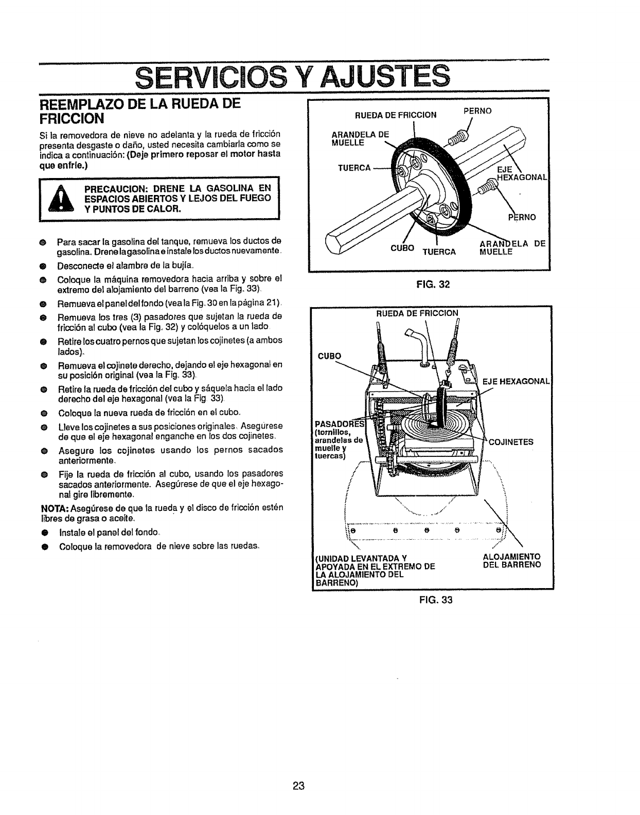
SERVICIOS
t...... tll LIU
REEMPLAZO DE LA RUEDA DE
FRICCION
Si la removedora de nieve no adetanta y la rueda de fricciSn
presenta desgaste o daSo, usted necesita cambiada como se
indica a continuaciSn:(Deje primero reposar el motor haste
qua enfrle.)
I A PRECAUCION: DRENE LA GASOLINA EN
ESPACIOS ABIERTOS Y LEJOS DEL FUEGO
Y PUNTOS DE CALOR,
tllllltl ................I,IH
•Pare sacar la gasolina del tanque, remueva los ductos de
gasolinaoDrene lagasotina e instals Iosductosnuevamente,
•Desconecte el alambre de la bujla,,
® COl_lUe la m&quina removedora hacia arriba y sobre el
extremo dei afojamiento del barreno (yea la Fig. 33),
ORemueva elpaneldelfondo (veala Fig.,30 en lap&gina 21),
O Remueva los tres (3) pasadotes qua sujetan la rueda de
friccibnal cubo (yea la Fig.,32) y coi6quelos a un redo,
O Retire los cuatro pernos que sujetan los cojinetes (a ambos
lados)o
@ Remueva el cojinetedarecho, dejando el eje hexagonal en
su posicibn original (yea la Fig,, 33),
@ Retire la rueda de fricc{Sn del cubo y s&quela hacia el lado
derecho del eje hexagonal (yea la Fig 33),
®Coloque ia nueva rueda de fricciSn en ei cuboo
eL!eve los cojinetes a sus posicionesoriginales_ Asegurese
de qua el eje hexagonal enganche en los dos cojinetes,
O Asegure los cojinetes usando tos pernos sacados
anteriormente,,
@ Fije la nJeda de |ricciSn al cubo, usando los pasadores
sacados anteriormente. Aseg0rese de qua el eje hexago-
nal gire libremente,
NOTA: AsegOrese de qua la rueda y el disco de friccibn est_n
tibres de grasa o aceiteo
• Instate el panel del fondo_
• Coloque la removedora de nieve sobre las ruedaso
Y
RUEDA DE FRICClON
ARANDELA DE
MUELLE
PERNO
EXAGONAL
CUBO TUERCA MUELLE DE
FIG, 32
RUEDA DE FRICCtON
CUBO
EJE HEXAGONAL
muelley
tuercas)
/
?
/
/
5
i
_'COJ1NETES
[\. /
\_ ,/ \
(UN|DADLEVANTADAY ALOJAMIENTO
APOYADAEN ELEXTREMO DE DEL BARRENO
LA ALOJAMIENTODEL
BARRENO)
FIG. 33
23
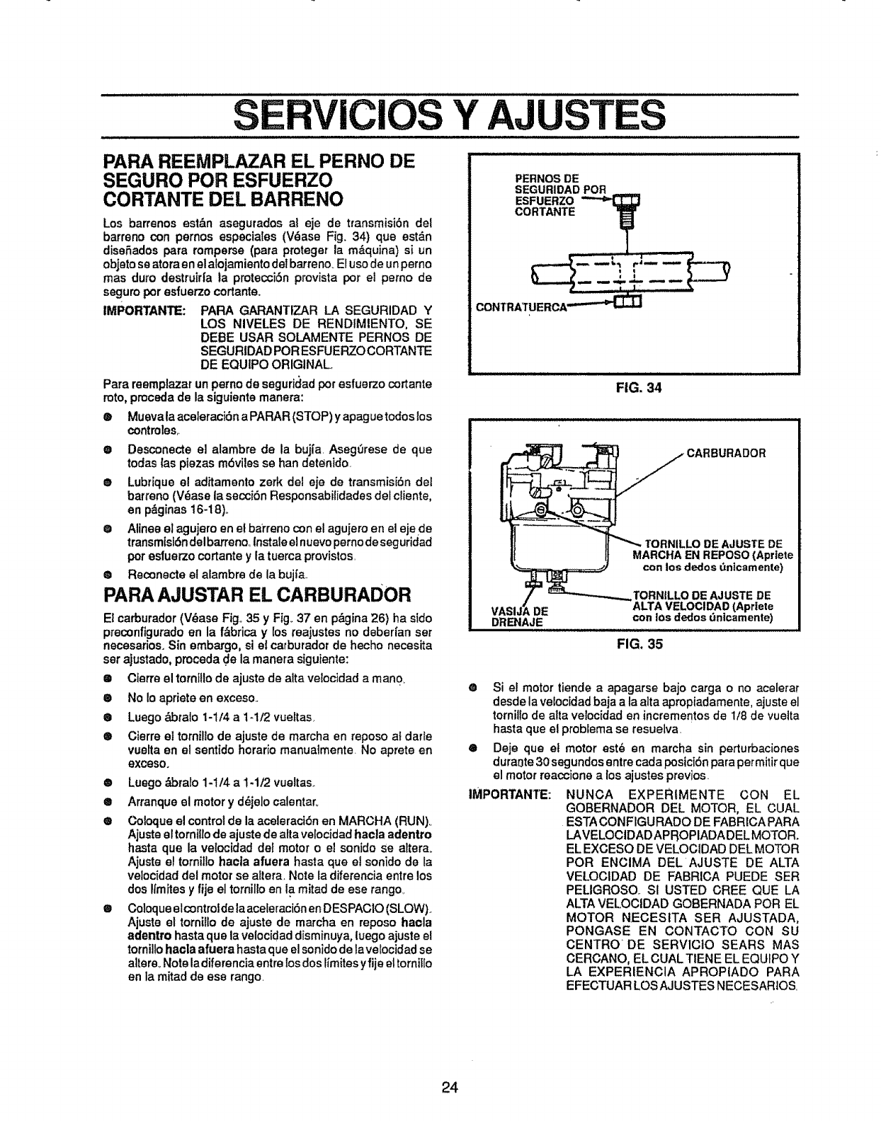
.............................................................S Y AJUSTES
PARA REEMPLAZAR EL PERNO DE
SEGURO POR ESFUERZO
CORTANTE DEL BARRENO
Los barrenos est&n asegurados al eje de transmisi6n del
barreno con pernos especia_es (V_ase Fig. 34) qua est&n
diseSados para romperse (pare proteger la m_quina) si un
objeto se atora anel alojamiento del barreno_El uso de unperno
mas duro destruir[a ta protecci6n provista por el perno de
seguro poresfuerzo cortante.
IMPORTANTE: PARA GARANTIZAR LA SEGURIDAD Y
LOS NIVELES DE RENDtMIENTO, SE
DEBE USAR SOLAMENTE PERNOS DE
SEGURtDAD POR ESFUERZOCORTANTE
DE EQUIPO ORIGINAL.,
Pare reemptazar un perno de seguridadpor esfuerzo cortante
roto, proceda de la siguiente manera:
e Muevala aceleraci6n a PARAR (STOP) yapague todoslos
contmles,.
• Desconecte el alambre de la bujfa. Aseg_rese de que
todas las piezas mdvtles se ban detenido.
•Lubtique el ad_tamenlo zerk del eje de transmisi6n det
barreno(V_ase la secciSn Responsabilidades del cliente,
en p_ginas 16-18).
e AUneeel agujero en el ba_'renocon el agujero en el ejede
transmisi6ndel barreno,,Instale elnuevopernode seguridad
poresfuerzo cortante y la tuerca provistos,
® Reconecte el alambre de la bujJ'a.
PARA AJUSTAR EL CARBURADOR
EZcarburador(V_ase Fig., 35 y Fig.,37 en p&gina 26) ha sido
preconfigurado en la f&brica y los reajustes no deberfan ser
necesarios. Sin embargo, si et carburador de hecho necesita
ser ajustado, proceda de la maneta siguiente:
•Oterre el tornJllode ajuste de alta velocidad a man0_
®No Io apriete en exceso..
•Luego _otalo 1-114a 1-1t2 vueltas,
® Cierre el tornillo de ajuste de marcha en reposo at darie
vuelta en el sentido horar[o manuaimente No aprete en
excesoo
®Luego &bralo 1-1/4 a 1-1/2 vueltas.
• Arranque el motor y d_jelo calentar..
•Coloque el controlde la aceleractdn en MARCHA (RUN)_
Ajuste el torni!lo de ajuste de alia velocidad hacla adentro
haste que la velocidad def motor o el sonido se attera_
Ajuste el tornitlo hacla afuera basra que el sonido de la
velocidad del motor se altera, Note la diferencia entre los
dos Ifmitesyfije el tornillo en la mitad de ese tango.
•Coloque elcontroldela aceleraci6n an DESPACIO (SLOW).
Ajuste el tornillo de ajuste de marcha en reposo hacla
aderdro haste qua la veloc[dad disminuya, luego ajuste el
tornillo hacla afuera haste que el sonido de la velocidad se
altere. Note ladiferencia entre los dos timites yfije et tornitlo
en la mitad de ese tango.
FIG, 34
DE
DRENAJE
TORNILLO DE AJUSTE DE
MARCHA EN REPOSO (Apriete
con los dedos dnicamente)
1"ORN|LLO DE AJUSTE DE
ALTA VELOCIDAD (Apriete
con los dedos dntcamente)
FIG. 35
@
O
IMPORTANTE:
Si el motor tiende a apagarse bajo carga o no aceFerar
desde la velocidad baja ala alta apropiadamente, ajuste el
tornillo de alta velocidad en incrementos de 1/8 de vuelta
hasta que el problema se resuelva.
Deje qua el motor est_ an marcha sin perturbaciones
dura0te 30 segundos entre cada posic[6n pare per mitir que
el motor reaccione a los ajustes previos.
NUNCA EXPERtMENTE CON EL
GOBERNADOR DEL MOTOR, EL CUAL
ESTA CONFIGURADO DE FABRICA PARA
LAVELOCIDADAPROPIADA DEL MOTOR°
EL EXCESO DE VELOCIDAD DEL MOTOR
POR ENCIMA DEL AJUSTE DE ALTA
VELOCIDAD DE FABRICA PUEDE SER
PELIGROSO.. SI USTED CREE QUE LA
ALTA VELOClDAD GOBERNADA POR EL
MOTOR NECESITA SER AJUSTADA,
PONGASE EN CONTACTO CON SU
CENTRO' DE SERV1CtO SEARS MAS
CERCANO, EL CUAL TIENE EL EQU_PO Y
LA EXPERIENClA APROPIADO PARA
EFECTUAR LOS AJUSTES NECESAR!OS
24
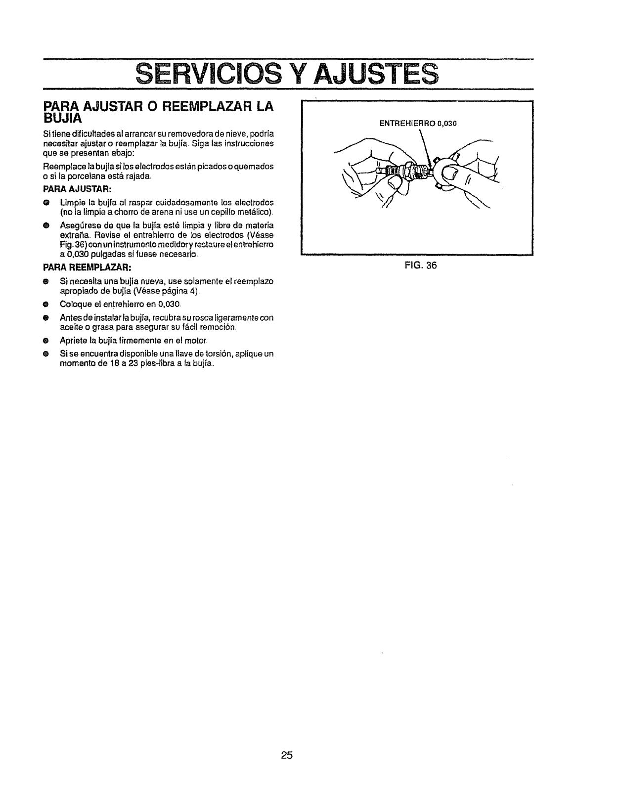
SERVICIOS Y
PARA AJUSTAR O REEMPLAZAR LA
BUJIA
Sitiene dificuttades al arrancar su removedora de nieve, podr{a
necesitar ajustar o reemplazar ]a bujfa. Siga tas instrucciones
que se presentan abajo:
Reempiace la buj|a si loselectrodosest&n picadoso quemados
o si Eaporcelana est& rajada_
PARA AJUSTAR:
@Limpie la buj|a al raspar cuidadosamente los electrodos
(no la limpie a chorro de arena ni use un cepillo met&lico).
@ Aseg_rese de que la bujia estO limpia y libre de materia
extrafa.. Revise el entrehierro de los electrodos (V&ase
Fig. 36) con uninstrumentomedldory restaureel entrehierro
a 0,030 pulgadas si fuese necesario,
PARA REEMPLAZAR:
• Si necesita una bujia nueva, use solamente el reemplazo
apropiado de bujta (V_ase p&gina 4)
0Coloque et entrehierro en 0,030,
e Antes de instalarla bujFa,recubra su rosca ligeramentecon
aceite o grasa para asegurar su f&cil remociOn.
•Apriete la bujfa firmemente en el motor
®Si se encuentra disponibleuna tlave de torsi6n, aplique un
momento de 18 a 23 pies-libra a la bujia.
ENTREHiER RO 0,030
FIG. 36
25
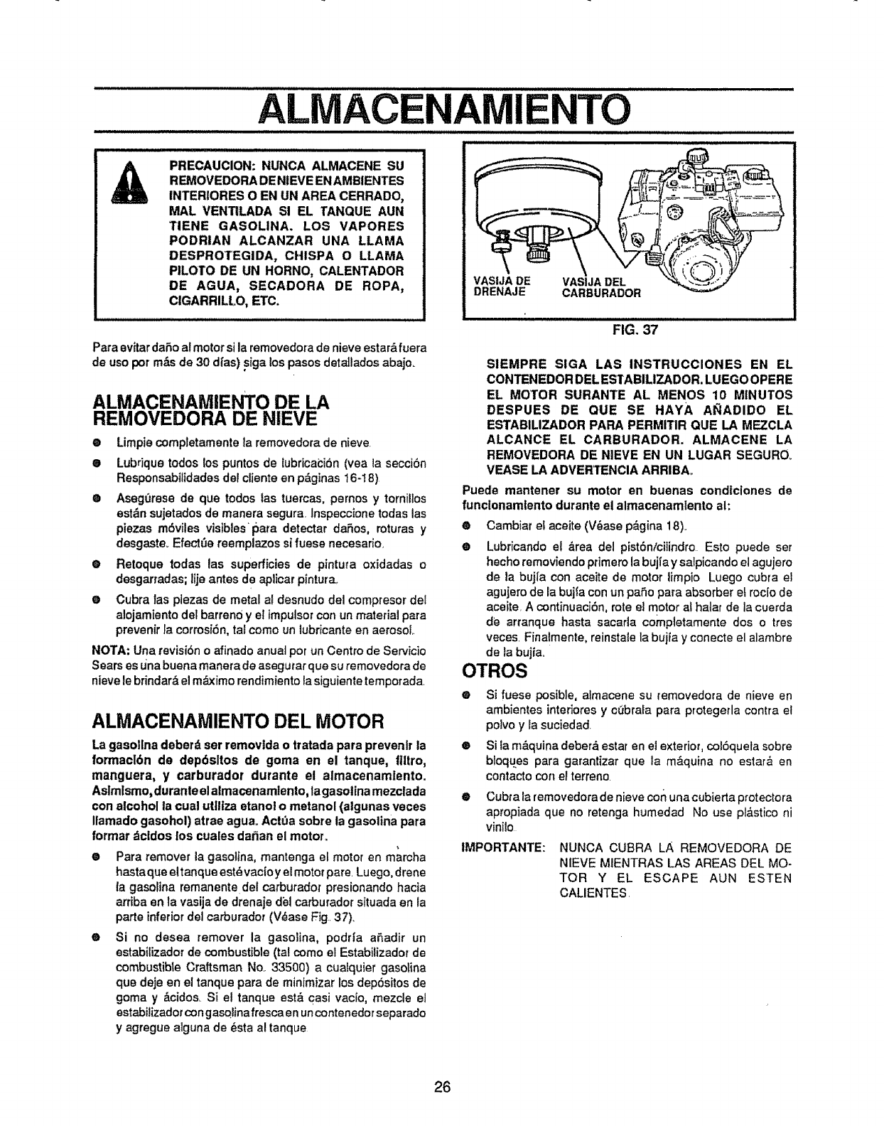
ALMACENAMIENTO
PRECAUCION: NUNCA ALMACENE SU
REMOVEDORA DE NIEVE ENAMBIENTES
INTERIORES O EN UN AREA CERRADO_
MAL VENTILADA SI EL TANQUE AUN
TIENE GASOLINA. LOS VAPORES
PODRIAN ALCANZAR UNA LLAMA
DESPROTEGIDA, CHISPA O LLAMA
PILOTO DE UN HORNO, CALENTADOR
DE AGUA, SECADORA DE ROPA,
CiGARRILLO, ETC.
Para avitar daSo ai motor si la removedora de nieve estar_,fuera
de uso por m,_sde 30 d/as) siga los pasos dete]lados abajo.
ALMACENAMIEFKO DE LA
REMOVEDORA DE NIEVE
®
®
O
Limpiecompletamente la removedora de nieve.
Lubdque todos los puntos de lubricai:i6n (yea ta secci6n
Responsabilidades dei cliente en p&ginas 16-18)
Aseg0rese de que todos las tuercas, pemos y torniilos
esl&n sujetados de manera segura, lnspeccione todas las
piezas m6viles visibles pare detectar da6os, roturas y
desgaste_ Efectt_e reemplazos si fuese necesario_
Retoque todas las superficies de pintura oxidadas o
desgarradas; lije antes de aplicar pintura_
Cubra tas plezas de metal af desnudo del compresor det
alojamiento del barren0 y el impulsorcon un material pare
prevenir la corrosi6n, tat como un lubricante en aerosol
@
®
NOTA: Una revisi6n o afinado anual por un Centro de Servicio
Sears es una buena manera de asegurar que su removedora de
nieve le brindar& el m_Jximorendimiento la siguiente temporada.
ALMACENAMIENTO DEL MOTOR
La gasollna deberd ser removtda o tratada pare prevenlr la
formacl6n de dep6sltos de goma en el tanque, flltro,
manguera, y carburador durante el almacenamlento.
Aslm Ismo, durante el almacenamtento, la gasolina mezclada
con alcohol la cual utlltza etanol o metanol (atgunas veces
Ilamado gasohol) atrae aguaoActda sobre ta gasolina para
format dcldos los cuales da_an el motor..
ePara remover la gasolina, mantenga el motor en marcha
hastaque eitanque est6 vacfo yel motor pare. Luego, drene
ta gasorina remanente del carburador presionando hacia
arriba en la vasija de drenaje del carburador situada en la
parte inferiordet carburador (V6ase Fig. 37).
® Si no desea remover la gasolina, podHa a6adir un
estabilizador de combustible(tal como el Estabilizadorde
combustible Craftsman No.. 33500) acualquier gasoline
que deje en el tanque pare de minimizar los dep6sitos de
goma y _.cidos. Si el tanque est& casi vacio, mezcle el
estabiiizador con gasolina fresca en un contenedor separado
y agregue alguna de 6sta al tanque
VASIJA DE VASIJA DEL
DRENAJE CARBURADOR
FIG. 37
SIEMPRE SIGA LAS INSTRUCCIONES EN EL
CONTENEDOR DEL ESTABILIZADOR. LUEGO OPERE
EL MOTOR SURANTE AL MENOS 10 MINUTOS
DESPUES DE QUE SE HAYA AI_ADIDO EL
ESTABILIZADOR PARA PERMITIR QUE LA MEZCLA
ALCANCE EL CARBURADOR. ALMACENE LA
REMOVEDORA DE NIEVE EN UN LUGAR SEGURO_
VEASE LA ADVERTENCIA ARRIBA_
Puede mantener su motor en buenas cond|ciones de
funclonamtento dutante el almacenamtento ah
®Cambiar ef aceite (V6ase p_gina 18)..
® Lubricando el _rea del pist6n/cilindro Esto puede set
heeho removiendo primero la buj|a y salpicando el agujero
de la bujfa con aceite de motor limpio Luego cubra el
agujero de la bujfa con un pa6o para absorber eLrocio de
aceite, A continuaci6n, rote el motor al hater de la cuerda
de arranque haste sacarla completamente dos o tres
veces. Finaimente, reinstaie la buita y conecte el alambre
de _abujia_
OTROS
IMPORTANTE:
eSi fuese posible, almacene su removedma de nieve en
ambientes intedores y cObrala para protegerla contra et
polvo y la suciedad
® Si la m&quina deber_ estar en el exterior, col6quela sobre
bloques para garantizar que la m_,quina no estar& en
contacto con el terreno
@ Cubta fa removedorade nieve con una cubierta protectora
apropiada que no retenga humedad No use pl&stico ni
vinilo
NUNCA CUBRA LA REMOVEDORA DE
NIEVE MIENTRAS LAS AREAS DEL MO-
TOR Y EL ESCAPE AUN ESTEN
CALIENTES.
26
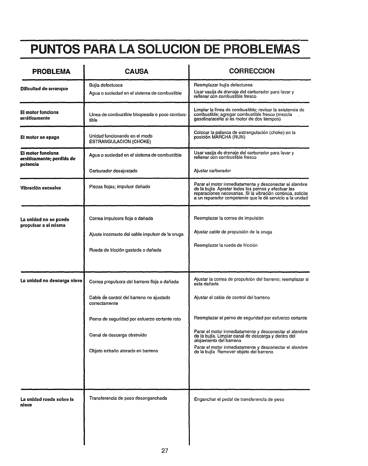
PUNTOS PARA LA SOLUCION DE PROBLEIVlAS
PROBLEMA
Diflcultad de arranque
.............. ,,,,
El motor funclona
errzttlcamente
El motor se apsgs
JIlLNil,I'll I I,II : H
El motor funclonn
errdticamente; perdtda de
potenela
HI _=_=/==,=u, i
V|brecl6n excesiva
1.3 unldad no se puede
propu|sBr asi mlsms
CAUSA
Bujia defectuosa
Agus o suc_edad en el sistema de combustible
Linea de combustible bfoqueada opoco combus-
Uble
La unldad no descorga nleve
La unldad rueda sobre la
nleve
Unidad funcionando en ef mode
ESTRANGULACION (CHOKE)
Agua o suciedsd en el sistema de combustible
Carburador desajustsdo
Piezas flojas; impulsor dafiado
Correa impulsora tloja 0 dafada
Ajuste incorrecto del cable impulsor de la oruga
Rueda de fricci6n gastada o daSads
Cortes propulsora del berreno ftoja o dat_ada
Cable de control del barrette no sjustado
correotamente
Pemo de seguridad per esfuerzo cortante rote
Canal de descarga obstruido
Objeto extraSo atorado en barreno
Transferenda de peso desenganchada
CORRECClON
Reemplazar bujia defectuosa
Usar vasijs de drenaie de1 carburador para tavar y
re{lenar con combustible fresco
Limpiar fa tinea de combustible; revisar la existencia de
combustible sgregar combustible fresco (mezcla .
gasot na/aceite si es motor de dos tiempos)
Cotocar Is palanca de estrangulaci6n (choke) en la
posici6n MARCHA (RUN)
................. ::::: ........... i,, L.IJul
Usar vasija de drenaje del carburader para lavar y
rellenar con combustible fresco
Ajustar carburador
............. Jlll.i , i
Psrar el motor inmedistamente y desconectar el alambre
de Is bujla. Apretar todos los pemos y efectuar las
reparaclones necesarias. Si la vibrac'bn continua, sorc'Le
a un reparador competente que le d6 servicio a la unidad
Reemplazar la correa de impulsi6n
Ajustar cable de propulsibn de la oruga
Reemptazar la rueda de fricci6n
.......... :- ii ,i HI,II II
Ajustar la correa de propulsi6n del barreno; reemplazar si
esta daSada
Ajustar et cable de control del barreno
Reemplazar el perno de seguddad per esfuerzo cortante
Parar el motor inmed]atamente y desconectar el alambre
de fa buj|a. Limpiar canat de descarga y dentro del
alojamiento del barrene
Parar el motor inmediatamente ydescoriectar el alambre
de le bujta Remover objeto del barreno
Enganchar el pedal de transferencis de peso
27
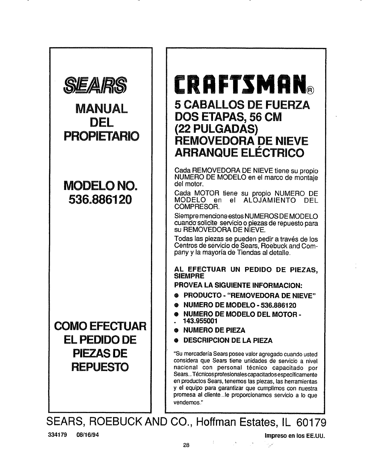
MANUAL
DEL
PROPIETARIO
MODELO NO.
536.886120
COMO EFECTUAR
EL PEDIDODE
PIEZASDE
REPUESTO
CRRFTSMFIN
5 CABALLOS DE FUERZA
DOS ETAPAS,56 CM
(22 PULGADAS)
REMOVEDORA DE NIEVE
ARRANQUE ELECTRICO
Cada REMOVEDORA DE NtEVE tiene su propio
NUMERO DE MODELO en el marco de rnontaje
del motor,
Cada MOTOR tiene su propio NUMERO DE
MODELO en el ALOJAMIENTO DEL
COMPRESOR
Siempre mendone estos NUMEROS DE MODELO
cuanda solicite servicio o piezas de repuesto para
su REMOVEDORA DE NIEVE.
Todas las piezas se pueden pedir a trav_s de los
Centros de servicio de Sears, Roebuck and Corn =
pany y la mayofia de Tiendas al detalle..
AL EFECTUAR UN PEDIDO DE PIEZAS,
SIEMPRE
PROVEA LA SIGUIENTE INFORMACION:
® PRODUCTO - "REMOVEDORA DE NIEVE"
®NUMERO DE MODELO - 536.886120
®NUMERO DE MODELO DEL MOTOR -
. 143.955001
® NUMERO DE PIEZA
® DESCRIPCION DE LA PIEZA
"Su mercaderia Sears posee valor agregado cuando usted
considera que Sears tiene unidades de servicio a nivel
nacional con personal t6cnico capacitado por
Searsoo.T_cnicosprofesionales capacitados especfficamente
en productos Sears, tenemos 1aspiezas, las herramientas
y el equipo para garantizar que cumplimos con nuestra
promesa at cliente.Je proporcionamos servicio a Eoque
vendemos ':
iiiiiiii ........
SEARS, ROEBUCK AND CO.,
334179 08/16194
28
I _/1/, ii1,11 I .................... ................
Hoffman Estates, IL 60179
Impresoenlos EE.UU.
