Craftsman 536886141 User Manual 5HP SNOW THROWER Manuals And Guides L0910464
CRAFTSMAN Snowthrower, Gas Manual L0910464 CRAFTSMAN Snowthrower, Gas Owner's Manual, CRAFTSMAN Snowthrower, Gas installation guides
User Manual: Craftsman 536886141 536886141 CRAFTSMAN 5HP SNOW THROWER - Manuals and Guides View the owners manual for your CRAFTSMAN 5HP SNOW THROWER #536886141. Home:Lawn & Garden Parts:Craftsman Parts:Craftsman 5HP SNOW THROWER Manual
Open the PDF directly: View PDF ![]() .
.
Page Count: 63
5.0 Horsepower
22 inch Dual Stage
120V. Electric Start
SNOW THROWER
MODEL NO.
536.886141
Caution:
Read and follow all Safety
Rules and Operating
Instructions before first use
of this product.
SEARS, ROEBUCK AND CO., Hoffman Estates, IL 60179 U.S.A.
761900 07/06/98
"Fable of Contents 2
Warranty 2
Safety Rules 2-4
Contents of Shipping Carton 4-5
Assembly 5-8
Operation 8-14
Maintenance 14-16
Service and Adjustments 17-21
Storage 22
Troubleshooting 23
Repair Parts 24-32
Engine Repair Parts 33-37
Spanish(Espafiot) 38-62
Parts Ordering/Service Back Cover
LIMITED TWO-YEAR WARRANTY ON CRAFTSMAN SNOW THROWER
For two years from the date of purchase, when this Craftsman Snow Thrower is maintained,
lubricated, and tuned up according to the operating and maintenance instructions in the
owner's manual, Craftsman will repair, free of charge, any defect in material or workmanship.
If this Craftsman Snow Thrower is used for commercial or rental purposes, this warranty
applies for only 90 days from the date of purchase_
This warranty does not cover the following:
oItems which become worn during normal use, such as spark plugs, drive belts and
shear pins°
°Repairs necessary because of operator abuse or negligence, including bent crank
shafts and the failure to maintain the equipment according to the instructions con-
tained in the owner's manual.
WARRANTY SERVICE IS AVAILABLE BY RETURNING THE CRAFTSMAN SNOW
THROWER TO THE NEAREST CRAFTSMAN SERVICE CENTER/DEPARTMENT IN THE
UNITED STATES. THIS WARRANTY APPLIES ONLY WHILE THIS PRODUCT IS IN USE
IN THE UNITED STATES.
This warranty gives you specific legal rights, and you may also have other rights which may
vary from state to state.
Sears, Roebuck and Co., D817WA, Hoffman Estates, IL 60'179
_CAUTION: Always disconnect spark
plug wire and place wire where it cannot
contact spark plug to prevent accidental
starting when setting-up, transporting,
adjusting or making repairs.
Look for this symbol to point out important safety precautions. It means--
ATTENTIONI!I Become alertl!! Your safety is involved,
TRAINING
IMPORTANT: Safety standards require
operator presence controlsto minimize the
risk of injury.Your snow throweris
equippedwithsuch controls.Do not attempt
to defeat the function of the operator
presencecontrolunder any circumstances,
iiii _ ....
_! California Proposition 65
WARNING: t.e
engine exhaust from this product
contains chemicals known to the
State of Califomia to cause cancer
birth defects or other reproductive
harm.
!, Read the operator's manual carefully.
Be thoroughly famihar with the controls
and the proper use of the snow thrower.
Know how to stop the snow thrower and
disengage the controls quickly.
2. Never allow children to operate the snow
thrower and keep them away while it is
operating. Never allow adults to operate
the snow thrower without proper instruc-
tion. Do not carry passengers.
3. Keep the area of operation clear of all
persons, particularly small children and
pets.
4. Exercise caution to avoid slipping or
falling, especially when operating in
_verse.
PREPARATION
14 Thoroughly inspect the area where the
snow thrower is to be used and remove
all doormats, sleds, boards, wires and
other foreign objects.
l
2. Disengage all clutches before starting
the engine (motor).
3. Do not operate the snow thrower
without wearing adequate winter outer
garments. Wear footwear that wilt
improve footing on slippery suffaces_
4. Handle fuel with care; it is highly
flammable.
(a) Use an approved fuel container.
(b) Never remove fuel tank cap or add
fuel to a running engine or hot
engine.
(¢) Fill fuel tank outdoors with
extreme care_ Never fill fuel tank
indoors.
(d) Replace fuel tank cap securely
and wipe up spilled fuelo
(e) Never store fuel or snow thrower
with fuel in the tank inside of a
building where fumes may reach
an open flame or spark,
(f) Check fuel supply before each
use, allowing space for expansion
as the heat of the engine (motor)
and/or sun can cause fuel to
expand.
5. Use extension cords and receptacles
as specified by the manufacturer for all
snow throwers with electric drive
motors or electric starting motors.
6. Adjust the snow thrower height to clear
gravel or crushed rock surfaces.
7. Never attempt to make any adjust-
ments while the engine (motor) is
running (except when specifically
recommended by the manufacturer).
8. Let engine (motor) and snow thrower
adjust to outdoor temperatures before
starting to clear snow.
9. Always wear safety glasses or eye
shields during operation or while
performing an adjustment or repair to
protect eyes from foreign objects that
may be thrown from the snow thrower,
OPERATION
Do not operate this machine if you are
taking drugs or other medication which
can cause drowsiness or affect your
ability to operate this machine.
2. Do not use this machine if you are
mentally or physically unable to
operate this machine safely.
3. Do not put hands or feet near or under
rotating parts. Keep clear of the
discharge opening at all times.
4. Exercise extreme caution when oper-
ating on or crossing gravel drives,
walks, or roads. Stay alert for hidden
hazards or traffic.
5. After striking a foreign object, stop the
engine (motor), remove the wire from
the spark plug, disconnect the cord on
electric motors, thoroughly inspect the
snow thrower for any damage, and
repair the damage before restarting
operating the snow thrower.
6. If the snow thrower should start to
vibrate abnormally, stop the (motor)
and check immediately for the cause.
Vibration is generally a warning of
trouble°
7. Stop the engine (motor) whenever you
leave the operating position, before
unclogging the auger/impeller housing
or discharge guide, and when making
any repairs, adjustments, or inspec-
tions.
8. When cleaning, repairing, or inspecting,
make certain the auger/impeller and all
moving parts have stopped. Disconnect
the spark plug wire and keep the wi:re
away from the plug to prevent acciden-
tal starting.
9. Take all possible precautions when
leaving the snow thrower unattended.
Disengage the auger/impeller, stop
engine, and remove key.
10. Do not run the engine indoors, except
when starting the engine and for
transporting the snow thrower in or out
of the building. Open the outside doors;
exhaust fumes are dangerous (contain_
ing CARBON MONOXIDE, an ODOR-
LESS and DEADLY GAS).
11. Do not clear snow across the face of
slopes. Exercise caution when changing
direction on slopes. Do not attempt to
clear steep slopes.
12. Never operate the snow thrower without
proper guards, plates or other safety
protective devices in place.
13. Never operate the snow thrower near
glass enclosures, automobiles, window
wells, drop-offs, and the like without
dProperadjustment of the snow
ischarge angle. Keep children and
pets away.
14o Do not overload the machine capacity
by attempting to clear snow at too fast
a rate.
15. Never operate the snow thrower at high
transport speeds on slippery surfaces_
Look behind and use care when
backing.
16. Never direct discharge at bystanders or
allow anyone in front of the snow
thrower.
17. Disengagepower to the auger/impeller
when snow thrower is transportedor
not in use.
18. Use only attachmentsand accessories
approvedby the manufacturerof the
snow thrower (such as tire chains,
electric _Jtartkits, etc,).
19. Never operate the snow thrower
without good visibili_ or light. Always
be sure of your footing,and keepa
firm hold on the handles.Walk; never
run.
MAINTENANCE AND STORAGE
Check shear bolts and other bolts
frequently for proper tightness to be
sure the snow thrower is in safe
working condition.
2. Never store the snow thrower with fuel
in the fuel tank inside a building where
ignition sources are present such as
hot water and space heaters, clothes
dryers, and the like. Allow the engine to
cool before storing in any enclosure.
3. Always refer to operator's manual
instnJctions for important details if the
snow thrower is to be stored for an
extended period_
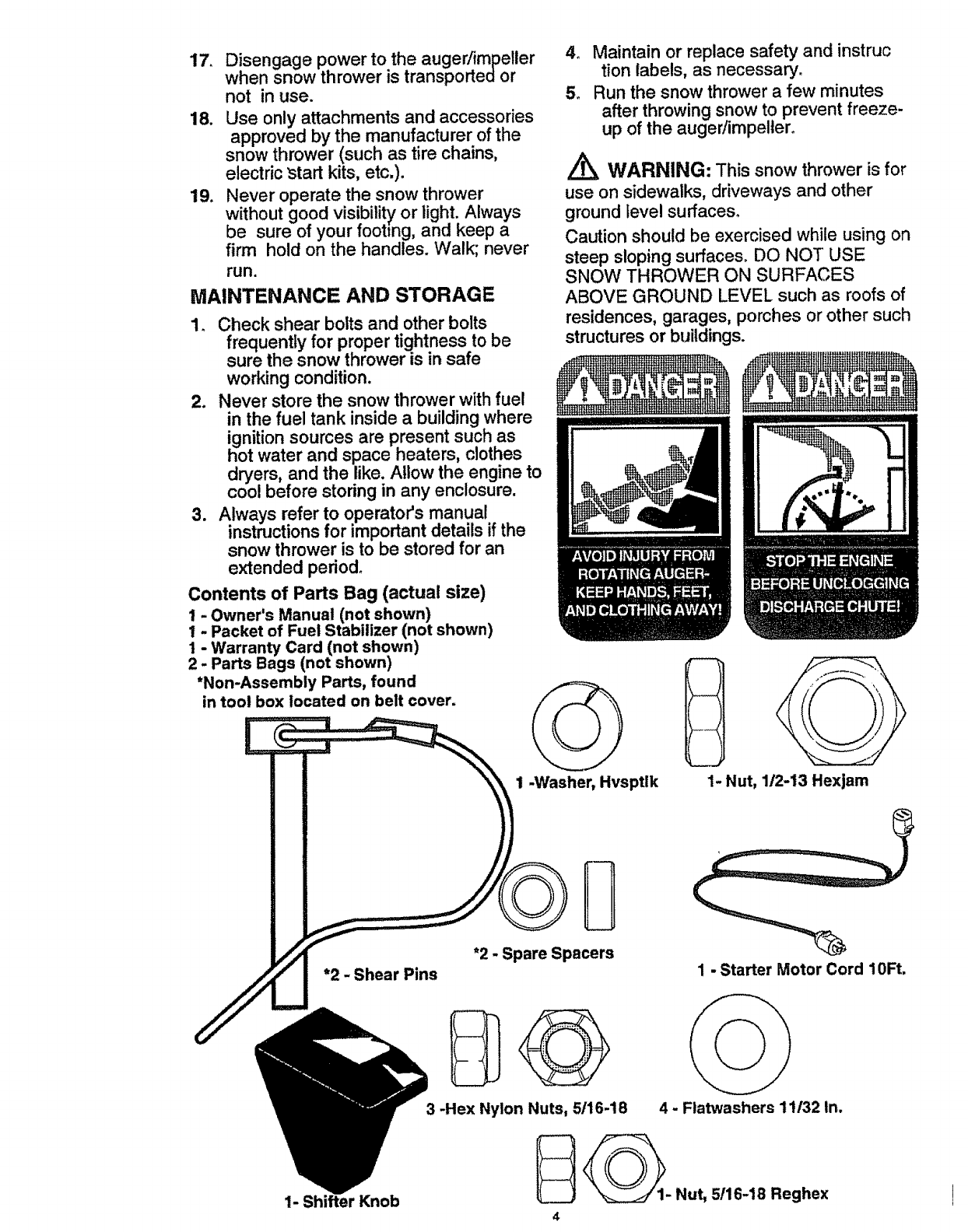
Contents of Parts Bag (actual size)
1- Owner's Manual (not shown)
1 - Packet of Fuel Stabilizer (not shown)
1 - Warranty Card (not shown)
2 - Parts Bags (not shown)
*Non-Assembly Parts, found
in tool box located on belt cover.
4o Maintain or replace safety and instruc
tion labels, as necessary.
5. Run the snow thrower a few minutes
afferthrowing snow to prevent freeze-
up of the augedimpelter.
AWARNING: This snow thrower is for
use on sidewalks, driveways and other
ground level surfaces°
Caution should be exercised while using on
steep sloping surfaces. DO NOT USE
SNOW THROWER ON SURFACES
ABOVE GROUND LEVEL such as roofs of
residences, garages, porches or other such
structures or buildings.
1-Washer, Hvsptlk D
1- Nut, 1/2-13 Hexjam
*2 - Shear Pins
*2 -Spare Spacers
3-Hex Nylon Nuts, 5/16-18
1-Starter Motor Cord 10Ft.
4-Flatwashers 11132In.
__1. Nut, 5116-18 Reghex
4
I
1- Shifter Knob
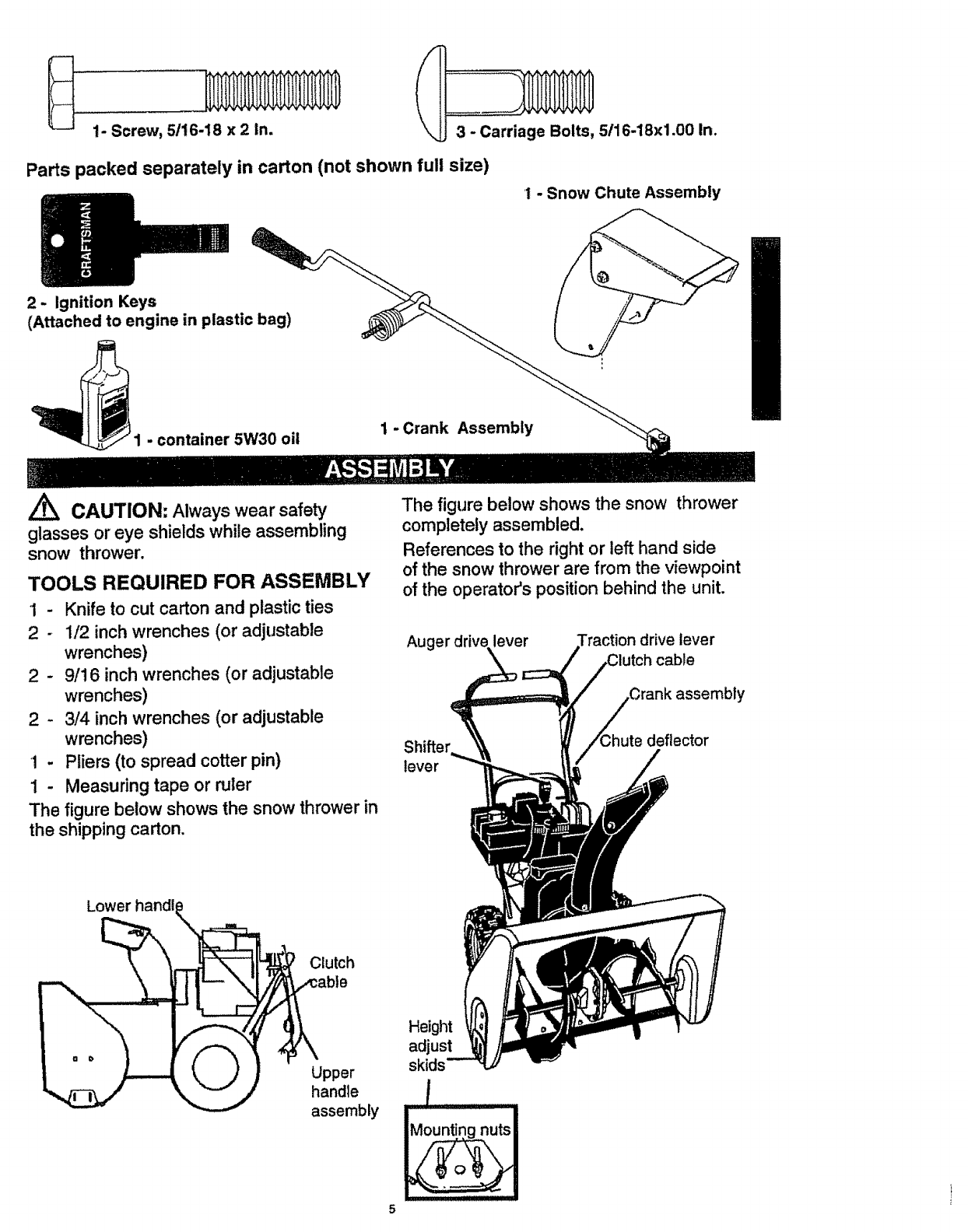
1- Screw, 5/16-18 x 2 In. 3-Carriage Bolts, 5116-18x1.00 In.
Parts packed separately in carton (not shown full size)
I-Snow Chute Assembly
2- Ignition Keys
(Attached to engine in plastic bag)
1-container 5W30 oil 1-Crank Assembly
CAUTION: Always wear safety
glasses or eye shields while assembling
snow thrower.
TOOLS REQUIRED FOR ASSEMBLY
1-Knife to cut carton and plastic ties
2-112 inch wrenches (or adjustable
wrenches)
2- 9/!6 inch wrenches (or adjustable
wrenches)
2 - 3/4 inch wrenches (or adjustable
wrenches)
1 - Pliers (to spread cotter pin)
1 - Measuring tape or ruler
The figure below shows the snow thrower in
the shipping carton.
The figure below shows the snow thrower
completely assembled.
References to the right or left hand side
of the snow thrower are from the viewpoint
of the operator's position behind the unit.
Auger driv_ lever drive lever
cable
assembly
Shifter
lever
Lower handl
Clutch
Upper
handle
assembly
Height
adjust
skids
5
TO REMOVE SNOW THROWER
FROM CARTON
•Locate and remove container of 5W30 oil.
° Locate all parts packed separately and
remove from the carton.
NOTE: Place fuel stabilizer in a safe place
until needed for storage.
o Remove and discard the packing material
from around the snow thrower°
oCut al! four corners of the carton from top
to bottom and lay the panels flat.
• Roll the snow thrower off the carton by
pulling on the lower handle. CAUTION:
DO NOT back over cables.
° Remove the packing material from
handle assembly and all plastic material
on unit.
o Cut ties securing the clutch control cables
to the lower handle and lay cables back
away from the motor frame.
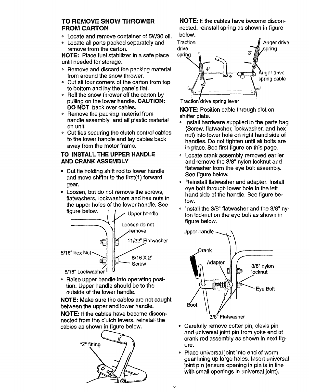
TO INSTALL THE UPPER HANDLE
AND CRANK ASSEMBLY
Cut tie holding shift rod to lower handle
and move shifter to the first(l) forward
gear.
Loosen, but do not remove the screws,
flatwashers, lockwashers and hex nuts in
the upper holes of the lower handle. See
figure below. ,_ Upper handle
.._\ Loosen do not
/ omo o
_ 11/32 Flatwasher
._=_.._5/16 X 2"
Screw
5/16" hex Nut
/
5/16" Lockwasher
°Raise upper handle into operating posi-
tion. Upper handle should be to the
outside of the lower handle.
NOTE' Make sure the cables are not caught
between the upper and lower handle.
NOTE: if the cables have become discon-
nected from the clutch levers, reinstall the
cables as shown in figure below.
"Z" fitting
NOTE: if the cables have become discon-
nected, reinstall spring as shown in figure
below.
Traction
drive
spri_,,__
¢
Traction
J Auger drive
3" _pring
4" uger ddve
Jrive springlever
NOTE: Position cable through slot on
shifter plate.
°Install hardware supplied in the parts bag
(Screw, flatwasher, loclo,r_asher, and hex
nut) into lower hole on right hand side of
handles. Do not tighten until all bolts are
in place. See first figure on this page.
° Locate crank assembly removed earlier
and remove the 3/8" nylon Iocknut and
flatwasher from the eye bolt assembly.
See figure below.
, Reinstall flatwasher and adapter. Install
eye bolt through lower hole in the left
hand side of the handle. See figure be-
low.
° Install the 3/8" flatwasher and the 3/8" ny-
lon Iocknut on the eye bolt as shown in
figure below_
Upper handle
3/8" nylon
locknut
Eye Bolt
Flatwasher
Carefully remove cotter pin, clevis pin
and universal joint pin from yoke end of
crank rod assembly as shown in next fig-
ure.
Place universal joint into end of worm
gear lining up large holes. Insert universal
joint pin (ensure opening in pin is in line
with small openings in universal joint).
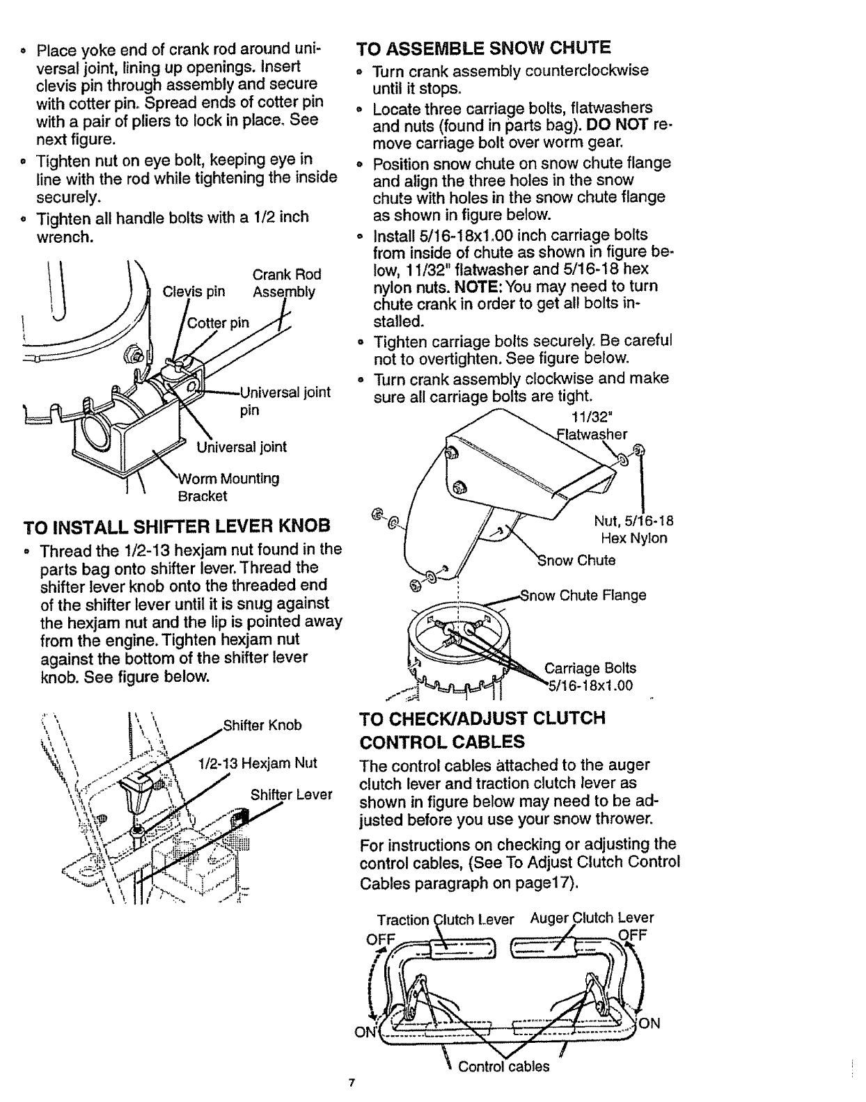
° Placeyoke end ofcrank rod arounduni-
versaljoint, lining up openings.Insert
clevis pin through assemblyand secure
with cotter pin,Spread ends of cotter pin
with a pair of pliers to lock inplace, See
next figure.
° Tighten nut on eye bolt, keepingeye in
line withthe rodwhile tighteningthe inside
securely.
• Tighten all handle boltswith a 112inch
wrench.
Crank Rod
Clevis pin Asse
pin
Universal joint
joint
TO ASSEMBLE SNOW CHUTE
o Turn crank assembly countercloclcwise
until it stops.
o Locate three carriage bolts, flat'washers
and nuts (found in parts bag). DO NOT re-
move carriage bolt over worm gear.
o Position snow chute on snow chute flange
and align the three holes in the snow
chute with holes in the snow chute flange
as shown in figure below.
o Install 5/16-18xl.00 inch carriage bolts
from inside of chute as shown in figure be-
low, 11/32" flatwasher and 5/16-18 hex
nylon nuts. NOTE: You may need to turn
chute crank in order to get all bolts in-
stalled.
= Tighten carriage bolts securely° Be careful
not to overtighten. See figure below.
= Turn crank assembly clockwise and make
sure all carriage bolts are tight.
Bracket
TO INSTALL SHIFTER LEVER KNOB
Thread the 1/2-13 hexjam nut found in the
parts bag onto shifter lever. Thread the
shifter lever knob onto the threaded end
of the shifter lever until it is snug against
the hexjam nut and the lip is pointed away
from the engine. Tighten hexjam nut
against the bottom of the shifter lever
knob. See figure below.
Nut, 5/16-18
Hex Nylon
Chute
_now Chute Flange
Carriage Bolts
...._ 116-18xl .00
TO CHECK/ADJUST CLUTCH
CONTROL CABLES
The control cables attached to the auger
clutch lever and traction clutch lever as
shown in figure below may need to be ad-
justed before you use your snow thrower.
For instructions on checking or adjusting the
control cables, (See To Adjust Clutch Control
Cables paragraph on page17).
Traction (_lutch Lever Auger Clutch Lever
OFF __ .....'_- r,----- _Z ....OFF
....._,Contro_llc_abIes
7
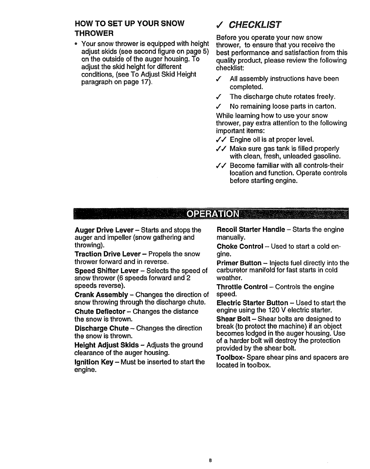
HOW TO SET UP YOUR SNOW
THROWER
Your snow thrower is equipped with height
adjust skids (see second figure on page 5)
on the outside of the auger housing. To
adjust the skid height for different
conditions, (see To Adjust Skid Height
paragraph on page 17).
,i CHECKLIST
Before you operate your new snow
thrower, to ensure that you receive the
best performance and satisfaction from this
quality product, please review the following
checklist:
,/" All assembly instructions have been
completed.
4" The discharge chute rotates freely.
,/" No remaining loose parts in carton.
While learning how to use your snow
thrower, pay extra attention to the following
important items:
,,,',/ Engine oil is at proper level.
,I,/ Make sure gas tank is filled properly
with clean, fresh, unleaded gasoline.
v"#' Become familiar with all controls-their
location and function. Operate controls
before starting engine.
Auger Drive Lever- Starts and stops the
auger and impeller (snow gathering and
throwing).
Traction Drive Lever- Propels the snow
thrower forward and in reverse°
Speed Shifter Lever - Selects the speed of
snow thrower (6 speeds forward and 2
speeds reverse).
Crank Assembly- Changes the direction of
snow throwing through the discharge chute.
Chute Deflector- Changes the distance
the snow is thrown.
Discharge Chute - Changes the direction
the snow is thrown.
Height Adjust Skids - Adjusts the ground
clearance of the auger housing.
Ignition Key - Must be inserted to start the
engine.
Recoil Starter Handle-- Starts the engine
manually.
Choke Control - Used to start a cold em
gine.
Primer Button - Injects fuel directly into the
carburetor manifold for fast starts in cold
weather.
Throttle Control - Controls the engine
speed.
Electric Starter Button - Used to start the
engine using the 120 Velectric starter.
Shear Bolt - Shear bolts are designed to
break (to protect the machine) if an object
becomes lodged in the auger housing. Use
of a harder bolt will destroy the protection
provided by the shear bolt.
Toolbox- Spare shear pins and spacers are
located in toolbox.
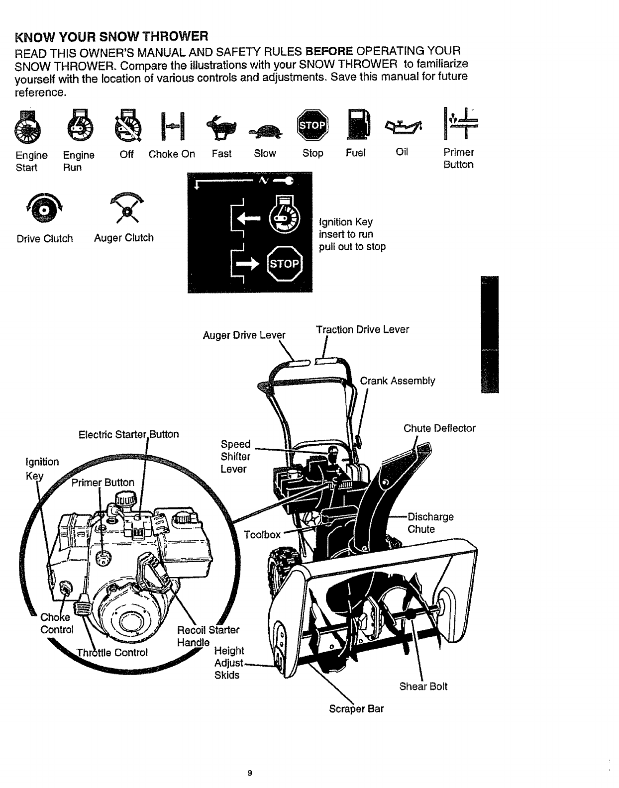
KNOW YOUR SNOW THROWER
READ THIS OWNER'S MANUAL AND SAFETY RULES BEFORE OPERATING YOUR
SNOW THROWER. Compare the illustrations with your SNOW THROWER to familiarize
yourself with the location of various controls and adjustments. Save this manual for future
reference.
Engine Engine Fast Slow Stop Fuel
Start Run
H
Off Choke On Oil Primer
Button
Drive Clutch Auger Clutch
Ignition Key
insert to run
pull out to stop
Auger Drive Lever Traction Drive Lever
Crank Assembly
Ignition
Electric Button
Speed
Shifter
Lever
Chute Deflector
Toolbox
'ge
Chute
Control Recoil Starter
Height
Adj
Skids
Bar
Shear Bolt
The operation of any snow thrower can re-
sult in foreign objects being thrown into the
eyes, which can result in severe eye dam-
age_ Always wear safety glasses or eye
shields while operating the snow thrower.
We recommend standard safety glasses or
a wide vision safety mask for over your
glasses, available at Craftsman Retail
Stores or Service Centers°
CAUTION: Read owner's manual
before operating machine. Never direct
discharge toward bystanders. Release the
auger control bar and stop the engine
before unclogging discharge chute or auger
housing and before leaving the machine.
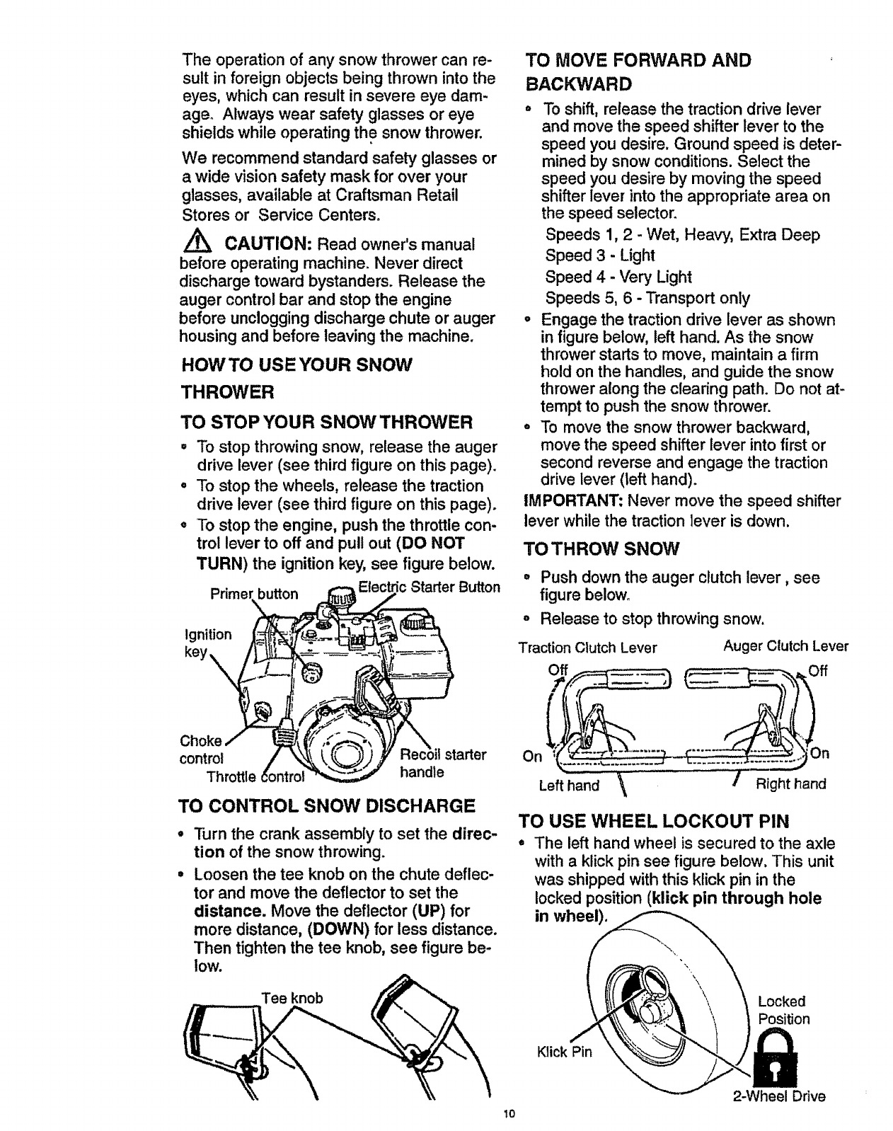
HOW TO USE YOUR SNOW
THROWER
TO STOP ;','OUR SNOW THROWER
•To stop throwing snow, release the auger
drive lever (see third figure on this page).
•To stop the wheels, release the traction
drive lever (see third figure on this page).
o To stop the engine, push the throttle con-
trol lever to off and pull out (DO NOT
TURN) the ignition key, see figure below.
Pdme! button Starter Button
Ignition
key\
Choke
control starter
Throttle handle
TO CONTROL SNOW DISCHARGE
Turn the crank assembly to set the direc-
tion of the snow throwing.
Loosen the tee knob on the chute deflec-
tor and move the deflector to set the
distance. Move the deflector (UP) for
more distance, (DOWN) for less distance.
Then tighten the tee knob, see figure be-
low.
Tee knob
TO MOVE FORWARD AND
BACKWARD
o To shift, release the traction drive lever
and move the speed shifter lever to the
speed you desire. Ground speed is deter-
mined by snow conditions. Select the
speed you desire by moving the speed
shifter lever into the appropriate area on
the speed selector.
Speeds 1, 2 - Wet, Heavy, Extra Deep
Speed 3 - Light
Speed 4 - Very Light
Speeds 5, 6 - Transport only
°Engage the traction drive lever as shown
in figure below, left hand. As the snow
thrower starts to move, maintain a firm
hold on the handles, and guide the snow
thrower along the clearing path. Do not at-
tempt to push the snow thrower.
= To move the snow thrower backward,
move the speed shifter lever into first or
second reverse and engage the traction
drive lever (left hand).
IMPORTANT: Never move the speed shifter
lever while the traction lever is down.
TO THROW SNOW
Push down the auger clutch lever, see
figure below.
Release to stop throwing snow.
Traction Clutch Lever
On
Lef hand \\
Auger Clutch Lever
Off ..... _ _ ....._,_Off
/Righthand
TO USE WHEEL LOCKOUT PIN
•The left hand wheel is secured to the axle
with a klick pin see figure below. This unit
was shipped with this klick pin in the
locked position (klick pin through hole
in wheel).
Klick Pin
Locked
Position
10
2-Wheel Drive
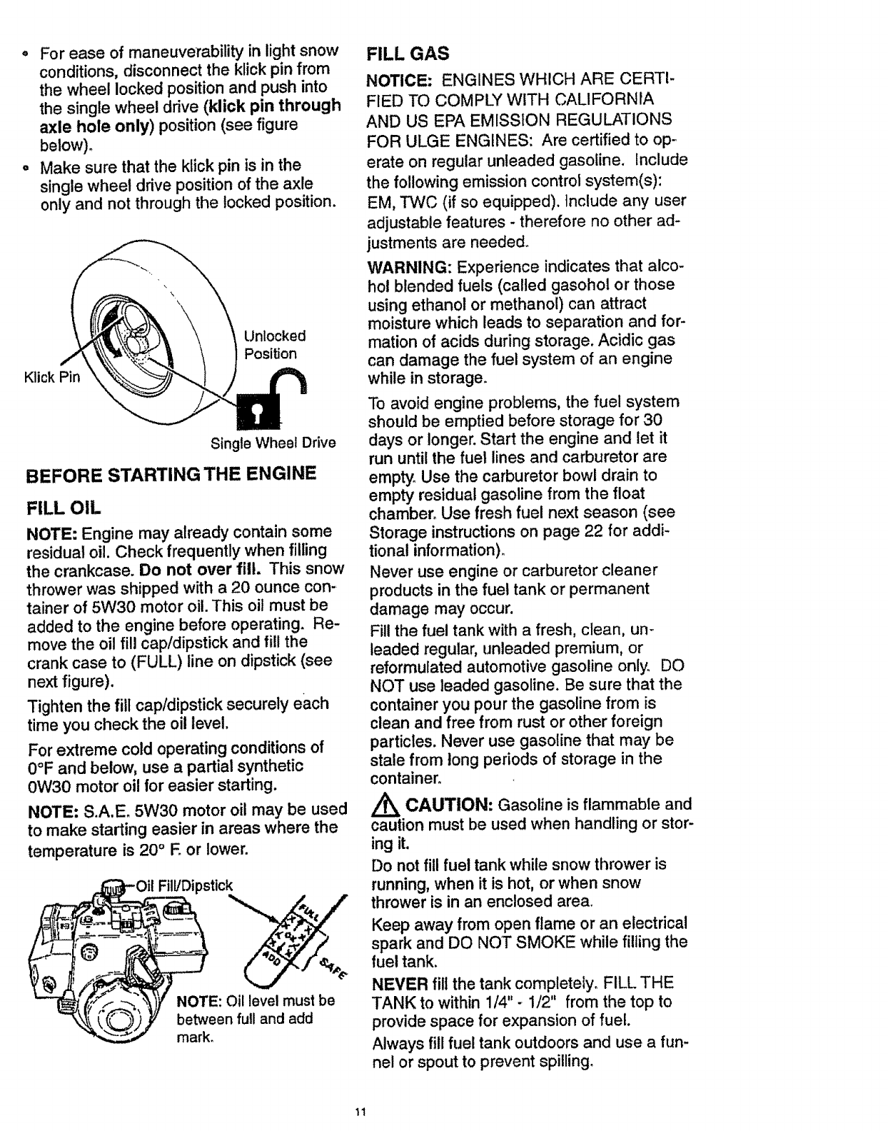
° For ease of maneuverability in light snow
conditions, disconnect the klick pin from
the wheel locked position and push into
the single wheel drive (klick pin through
axle hole only) position (see figure
below).
o Make sure that the klick pin is in the
single wheel drive position of the axle
only and not through the locked position.
KlickPin
Unlocked
Position
Single Wheel Drive
BEFORE STARTING THE ENGINE
FILL OIL
NOTE: Engine may already contain some
residual oil. Check frequently when filling
the crankcase. Do not over fill. This snow
thrower was shipped with a 20 ounce con-
tainer of 5W30 motor oil. This oil must be
added to the engine before operating. Re-
move the oil fill cap/dipstick and fill the
crank case to (FULL) line on dipstick (see
next figure).
Tighten the fill cap/dipstick securely each
time you check the oil level.
For extreme cold operating conditions of
0°F and below, use a partial synthetic
0W30 motor oil for easier starting.
NOTE: S.A.E. 5W30 motor oil may be used
to make starting easier in areas where the
temperature is 20 °E or lower.
.._Oit Fill/Dipstick
• __ _IF NOTE: Oil level must be
_),_y between fu,I and add
mark.
FILL GAS
NOTICE: ENGINES WHICH ARE CERTI-
FIED TO COMPLY WITH CALIFORNIA
AND US EPA EMISSION REGUL/_TIONS
FOR ULGE ENGINES: Are certified to op-
erate on regular unleaded gasoline. Include
the following emission control system(s):
EM, TWC (if so equipped). Include any user
adjustable features - therefore no other ad-
justments are needed.
WARNING: Experience indicates that alco-
hol blended fuels (called gasohol or those
using ethanol or methanol) can attract
moisture which leads to separation and for-
mation of acids during storage. Acidic gas
can damage the fuel system of an engine
while in storage.
To avoid engine problems, the fuel system
should be emptied before storage for 30
days or longer. Start the engine and let it
run until the fuel lines and carburetor are
empty° Use the carburetor bowl drain to
empty residual gasoline from the float
chamber. Use fresh fuel next season (see
Storage instructions on page 22 for addi-
tional information).
Never use engine or carburetor cleaner
products in the fuel tank or permanent
damage may occur.
Fill the fuel tank with a fresh, clean, un-
leaded regular, unleaded premium, or
reformulated automotive gasoline only. DO
NOT use leaded gasoline. Be sure that the
container you pour the gasoline from is
clean and free from rust or other foreign
particles. Never use gasoline that may be
stale from long periods of storage in the
container.
CAUTION: Gasoline is flammable and
caution must be used when handling or stor-
ing it.
Do not fill fuel tank while snow thrower is
running, when it is hot, or when snow
thrower is in an enclosed area.
Keep away from open flame or an electrical
spark and DO NOT SMOKE while filling the
fuel tank.
NEVER fill the tank completely. FILL THE
TANK to within 1/4" - 1/2" from the top to
provide space for expansion of fuel.
Always fill fuel tank outdoors and use afun-
nel or spout to prevent spilling°
11
Make sure to wipe up any spilled fuel be-
fore starting the engine.
Store gasoline in a clean, approved con-
tainer and keep the cap in place on the
container.
TO STOP ENGINE
oTo stop engine, move the throttle control
lever to Q (STOP) position and remove
key. Keep the key in a safe place. The
engine will not start without the key.
NOTE: DO NOT turn key_
TO START ENGINE (Electric Starter)
Be sure that the engine has sufficient oilo
The snow thrower engine is equipped with a
120 volt A.C. electric starter and recoil
starter. Before starting the engine, be cer-
tain that you have read the following infor-
mation:
COLD START
•Be sure the auger drive and traction drive
levers are in the disengaged (released)
position.
°Move the throttle control to ,_ (FAST)
position. See figure on page 9.
° Remove the keys from the plastic bag.
insert one key into the ignition slot. Be
sure it snaps into place. DO NOT TURN
KEY° Keep the second key in a safe
place.
•Rotate the choke knob clockwise to H
choke ON position. See figure on page 9.
• Connect the power cord to the switch box
on the engine.
,/_ CAUTION: This starter is equipped
with a three-wire power cord and plug
and is designed to operate on 120 volt AC
household current° tt must be properly
grounded at all times to avoid the possibility
of electrical shock, which may be injurious
to operator. Follow all instructions carefully
as set forth in the "To Start Engine" section.
Determine that your house wiring is a three-
wire grounded system. Ask alicensed elec-
trician if you are not sure. if your house wire
system is not a three-wire system, do not
use this electric starter under any condi-
tions. If your system is grounded and a
three-hole receptacle is not available at the
point your starter will normally be used, one
should be installed by a licensed electrician.
When connecting 120 volt AC power cord,
always connect the cord to the switch box
on the engine first, then plug the other end
into the three-hole grounded receptacle.
When disconnecting power cord, always
unplug the end in the three-hole grounded
receptacle first.
o Plug the other end of the power cord into
a three-hole, grounded 120 volt A.C,
receptacle,
° Push the primer button while covering the
vent hole as follows: (Remove finger
from primer button between primes).
See figure on page 9 for location.
Do not prime if temperature is above
50°F.
Two times if temperature is 50°F to 15°F.
Four times if temperature is below 15°Fo
° Push down on the starter button until the
engine starts. Do not crank for more than
10 seconds at a time. This electric starter
is thermally protected. If overheated it will
stop automatically and can be restarted
only when it has cooled to a safe tem-
perature (a wait of about 5 to 10 minutes
is required).
° When the engine starts, release the
starter button and move choke lever to
"1/2 choke" position. When engine runs
smoothly, move choke lever to "No
Choke" Position.
• Disconnect the power cord from the
receptacle first and then from the switch
box on engine.
NOTE: Allow the engine to warm up for sev-
eral minutes before blowing snow in tem-,
peratures below 0°F.
° Run the engine at full throttle ,_ (FAST)
when throwing snow.
TO STOP ENGINE
To stop engine, move the throttle control
lever to ID (STOP) position and remove
key. Keep the key in a safe place. The
engine will not start without the key.
NOTE: DO NOT turn key.
TO START ENGINE (Recoil Starter)
Be sure that the engine has sufficient oil.
The snow thrower engine is equipped with
arecoil starter. Before starting the engine,
be certain that you have read the following
information:
12
COLD START
o Be sure the auger drive and traction drive
levers are in the disengaged (released)
position.
• Move the throttle control to _ (FAST)
position. See figure on page 9 for Ioca o
tion.
° Remove the keys from the plastic bag° In-
sert one key into the ignition sloL Be sure
it snaps into place. DO NOT TURN KEY.
Keep the second key in a safe place.
• Rotate the choke knob clockwise to H
choke ON position. See figure on page 9,
• Push the primer button, see figure on
page 9, while covering the vent hole as
follows: (Remove finger from primer
button between primes)°
One time if temperature is above
50°E
Two times if temperature is 50°F to
15°E
Four times if temperature is below 15°F.
Pull the recoil starter handle rapidly. Do
not allow the handle to snap back, but al-
low it to rewind slowly while keeping a
firm hold on the starter handle.
As engine starts warms up move choke
lever to "1/2 choke" position. When engine
runs smoothly, move choke lever to "No
Choke" Position
NOTE: Allow the engine to warm up for sev-
eral minutes before blowing snow in
temperatures below 0°E
• Run the engine at full throttle ,_ (FAST)
when throwing snow.
WARM START
if restarting a warm engine after a short
shutdown, leave choke at (OFF) and do not
push the primer button. If the engine fails to
start, follow the Cold Start instructions
above.
FROZEN RECOIL STARTER
If the starter is frozen and will not turn
engine:
°Pull as much rope out of the starter as
possible.
°Release the starter handle and let it snap
back against the starter.
tf the starter still fails to turn engine, repeat
the two previous steps until the starter en-
gages. Then continue with the directions for
cold start°
To help prevent possible freeze-up of recoil
starter and engine controls, proceed as fol-
lows after each snow removal job.
•With the engine running, pull the
starter rope hard with a continuous full
arm stroke three or four times. Pulling of
starter rope will produce a loud clattering
sound. This is not harmful to the engine
or starter.
• With the engine not running, wipe all
snow and moisture from the carburetor
cover in area of control levers. Also move
throttle control, choke control, and starter
handle several times.
CAUTION: Never run engine indoors
or in enclosed, poorly ventilated areas.
Engine exhaust contains CARBON MON-
OXIDE, AN ODORLESS AND DEADLY
GAS. Keep hands, feet, hair and loose
clothing away from any moving parts on en-
gine and snow thrower.
WARNING: Temperature of muffler and
nearby areas may exceed 150° F_Avoid
these areas.
DO NOT allow children or young teenagers
to operate or be near snow thrower while it
is operating.
/_k CAUTION: Do no attempt to remove
any item that may become lodged in
auger without taking the following precau-
tions:
• Release auger drive and traction drive
levers.
• Move throttle lever to stop position.
° Remove (DO NOT TURN) ignition key.
° Disconnect spark plug wire.
° Do not place your hands in the auger or
discharge chute° Use a pry bar.
SNOW THROWING TIPS
For maximum snow thrower efficiency in
removing snow, adjust ground speed,
NEVER the throttle. Go slower in deep,
freezing, or wet snow. If the wheels slip,
reduce forward speed. The engine is de-
signed to deliver maximum performance
at full throttle and should be run at this
power setting at all times. Most efficient
13
snow blowing is accomplished when the
snow is removed immediately after it
falls.
o For complete snow removal, slightly over-
lap each path previously taken. Use
more overlap in deep snow to prevent
overloading.
o The snow should be discharged down
wind whenever possible, in windy condi-
tions, lower the chute deflector to direct
discharged snow close to the ground,
where it is less likely to blow into un-
wanted areas.
• For normal usage, set the skids so that
the scraper bar is t/8" above the skids_
For extremely hard-packed snow sur-
faces, adjust the skids upward so that the
scraper bar touches the ground°
• On gravel or crushed rock surfaces, set
the skids at 1-1/4" below the scraper bar
(See To Adjust Skids Height paragraph
on page 17). Stones and gravel must not
be picked up and thrown by the machine.
CUSTOMER RESPONSIBILITIES
After the snow throwing job has been
completed, allow the engine to idle for a
few minutes, which will melt snow and
accumulated ice off the engine.
Clean the snow thrower thoroughly after
each use.
Remove ice and snow accumulation and
all debris from the entire snow thrower,
and flush with water (if possible) to re-
move all salt or other chemicals. Wipe
snow thrower dry.
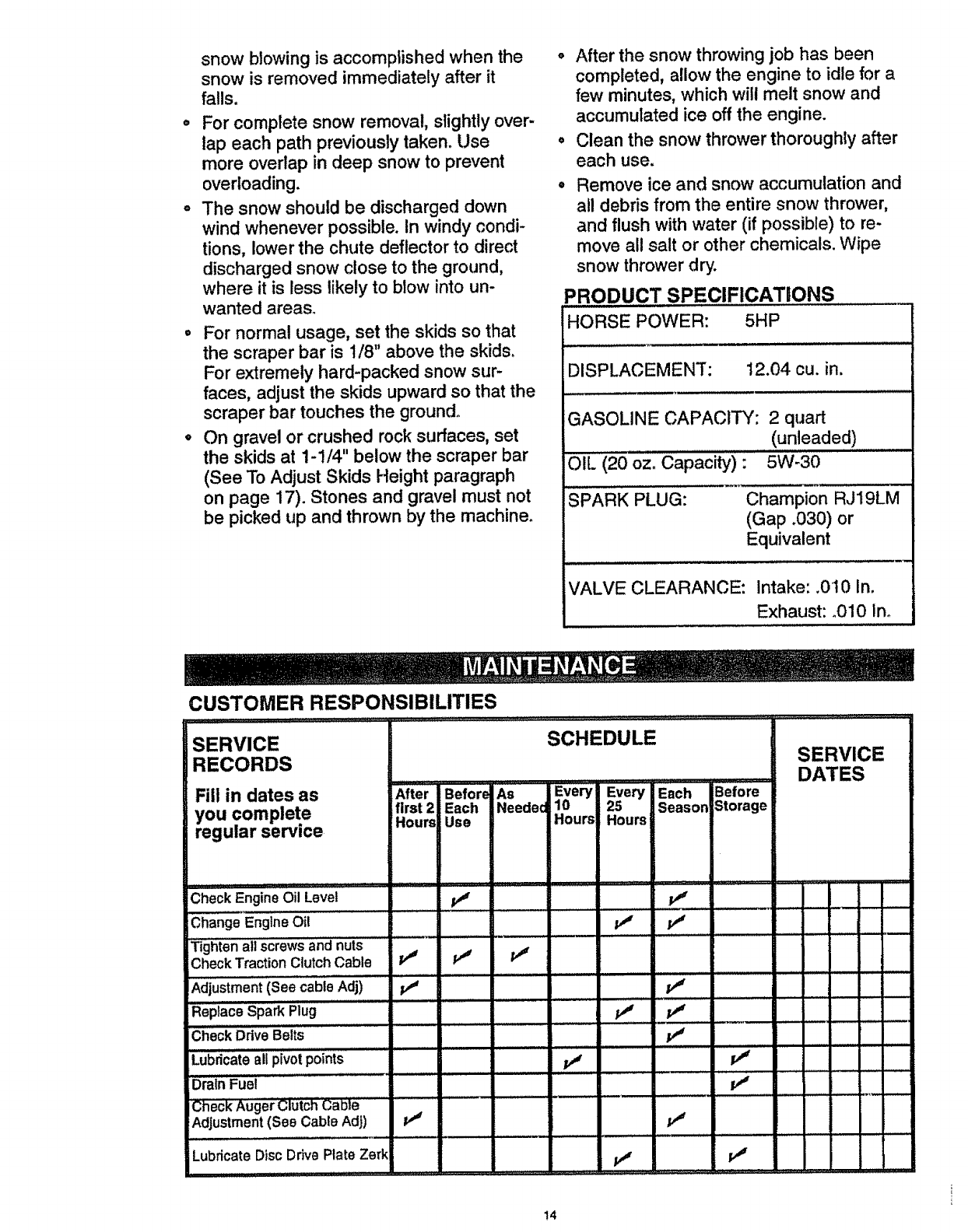
:JRODUCT SPECIFICATIONS
HORSE POWER: 5HP
DISPLACEMENT" 12.04 cu. in.
GASOLINE CAPACITY: 2 quart
(unleaded)
L L ,,, ,,
OIL (20 oz. Capacity)" 5W-30
SPARK PLUG: Champion RJ19LM
(Gap °030) or
Equivalent
VALVE CLEARANCE: Intake: .0I0 In.
Exhaust: .010 in.
SERVICE SCHEDULE
RECORDS SERVICE
DATES
Fill in dates as After Before As JEvery '""Every'"Each Before
first 2 Each Neede 10 25 Season Storage
you complete Hoursl Use Hours Hours
regular servme
, ,, .. = ........... :........
Check Engine Oil Level _ ......... _ _.
,,,, ,, ,,,,,,,,
Change EngineOil p_
Tighten all screws andnuts
CheckTractionClutch Cable _ P'_
A; ju tmentCSe; ; eAdj v" Ii'
......... ==................. _-
Replace Spark Plug jvJ
Check Ddve Belts p_'
Lubricateall pivot points jv_
DrainFuel ............. iv_
Adjustment (See Cable Adj) tJ t
LubricateDiscDrive Plate Zerk _r _r
!4
GENERAL RECOMMENDATIONS
The warranty on this snow thrower does not
cover items that have been subjected to op-
erator abuse or negligence. To receive full
value from the warranty, the operator must
maintain the snow thrower as instructed in
this manual. The maintenance chart is pro-
vided to assist the operator in properly
maintaining the snow thrower.
Some adjustments will need to be made pe-
riodically to properly maintain your snow
thrower.
AFTER FIRST USE
•Check for any loose or damaged parts.
•Tighten any loose fasteners.
°Check and maintain the auger.
•After each use, remove all snow and slush
off the snow thrower to prevent freezing of
auger or controls.
•Check controls to make sure they are
functioning properly.
°If any parts are worn or damaged, replace
immediately.
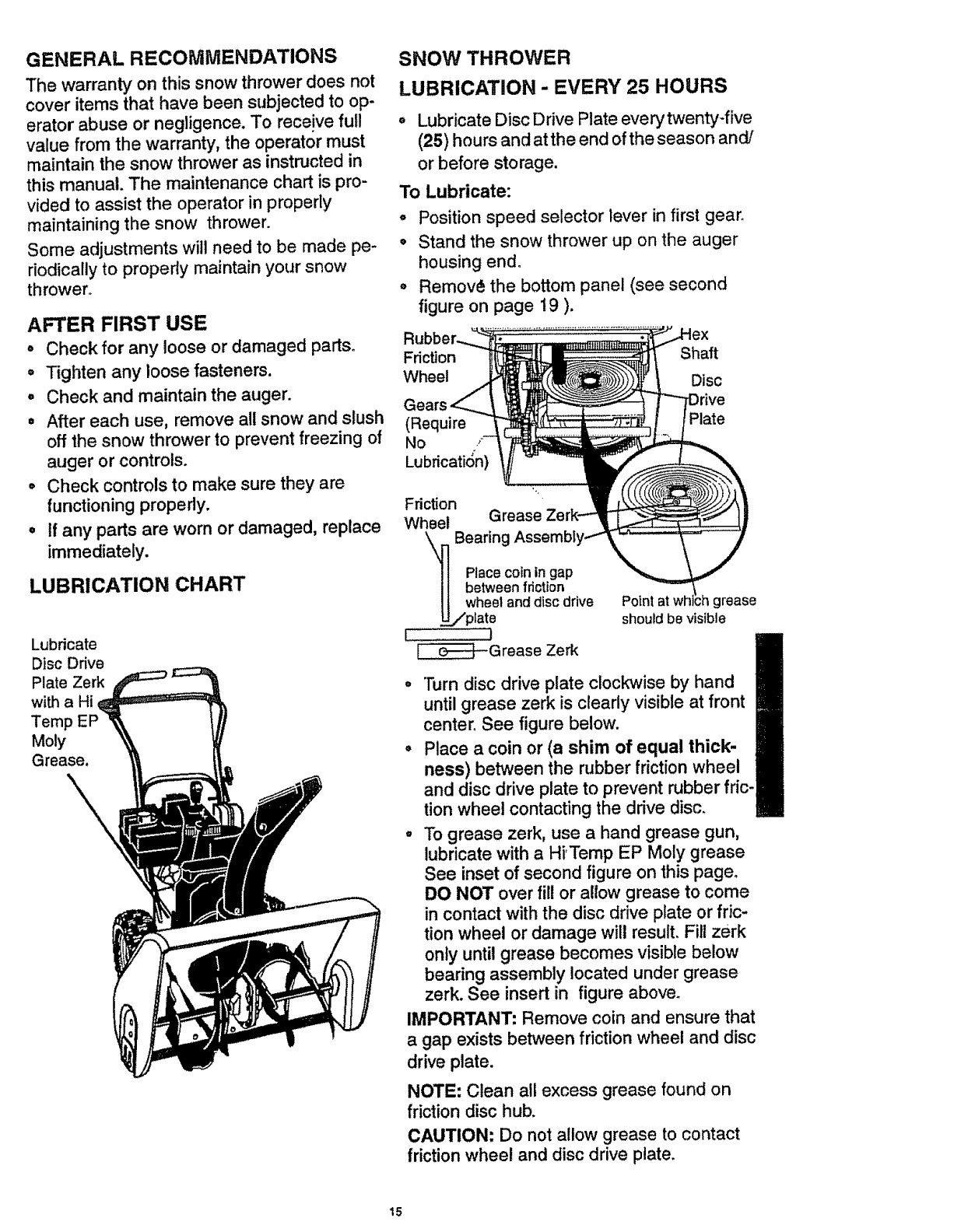
LUBRICATION CHART
Lubricate
Disc Drive
Plate Zerk
with a Hi
Temp
Moly
Grease,
SNOW THROWER
LUBRICATION - EVERY 25 HOURS
o Lubricate Disc Drive Plate every twenty-five
(25) hours and atthe end of the season and/
or before storage.
To Lubricate:
o Position speed selector lever in first gear.
• Stand the snow thrower up on the auger
housing end.
° Remov_ the bottom panel (see second
figure on page 19 ).
Fdction Shaft
Wheel Disc
(Require
No ,'
LubricatiOn)
Friction
Wheel Grease
\ Bearing
Place coin in gap
between fdction
wheel and disc drive
-/plate
I!
_Grease Zerk
Point at wh grease
shoutd be visible
°"]'urn disc drive plate clockwise by hand
until grease zerk is clearly visible at front
center. See figure below.
o Place a coin or (a shim of equal thick-
ness) between the rubber friction wheel
and disc drive plate to prevent rubber fric-
tion wheel contacting the drive disc.
•To grease zerk, use a hand grease gun,
lubricate with a Hi'Tamp EP Moly grease
See inset of second figure on this page.
DO NOT over fill or allow grease to come
in contact with the disc drive plate or fric-
tion wheel or damage will result, Fill zerk
only until grease becomes visible below
bearing assembly located under grease
zerk. See insert in figure above_
IMPORTANT" Remove coin and ensure that
a gap exists between friction wheel and disc
drive plate.
NOTE: Clean all excess grease found on
friction disc hub.
CAUTION: Do not allow grease to contact
friction wheel and disc drive plate.
15
LUBRICATION
-Hex Shaft and Gears - Hex shaft and
gears require no lubrication. All bearings
and bushings are lifetime lubricated and
require no maintenance.
NOTE: Arty' greasing or oiling of the above
components can cause contamination of
the friction wheel. If the disc drive plate or
friction wheel comes in contact with grease
or oil, damage to the friction wheel will re-
sult.
Should grease or oil come in contact with
the disc drive plate or friction wheel, be sure
to clean the plate and wheel thoroughly.
NOTE: For storage, the hex shaft and
gears should be wiped with 5W-30 motor oil
to prevent rusting. See second figure on
page 15.
• Auger Gear Box - The auger gear box
has been factory lubricated for life. If for
some reason lubricant should leak out,
have auger gear case checked by a com-
petent repairman.
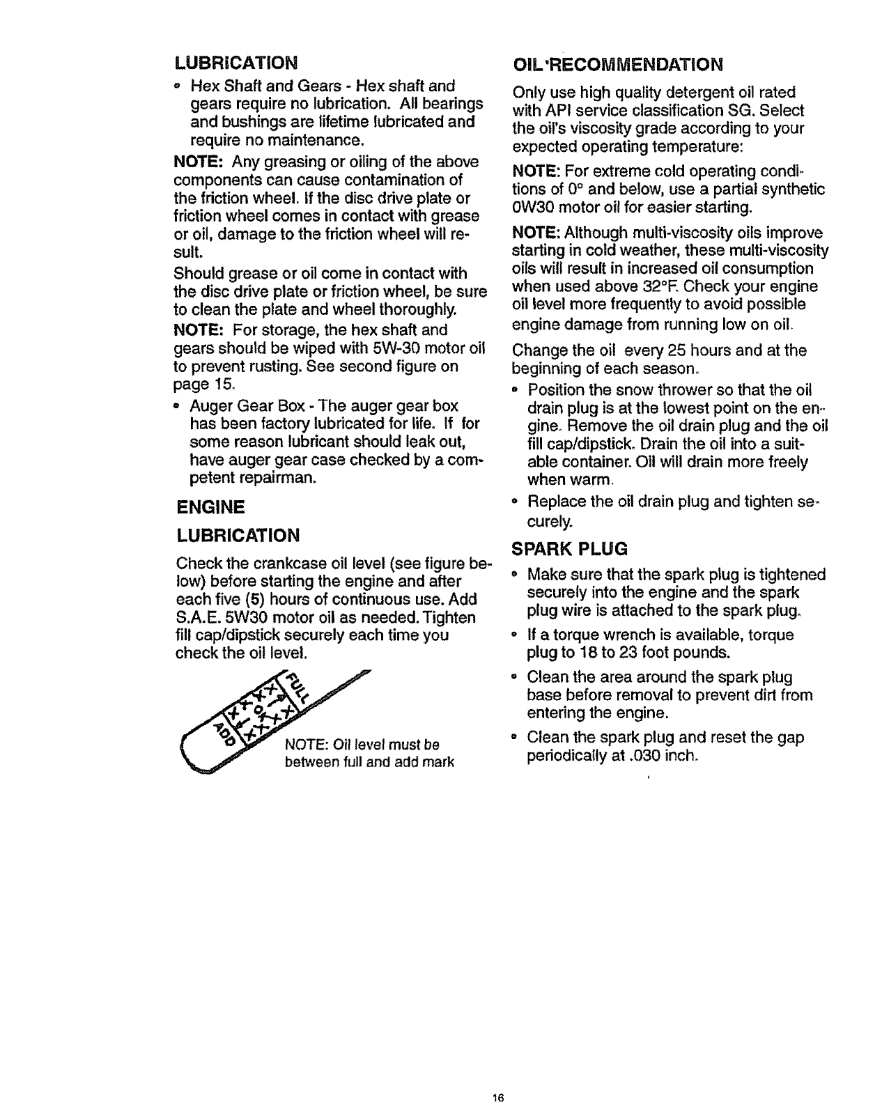
ENGINE
LUBRICATION
Check the crankcase oil level (see figure be-
low) before starting the engine and after
each five (5) hours of continuous use. Add
S.A.E. 5W30 motor oil as needed. Tighten
fill cap/dipstick securely each time you
check the oil level.
el must be
nd add mark
OIL'RECOMMENDATION
Only use high quality detergent oil rated
with APi service classification SG. Select
the oil's viscosity grade according to your
expected operating temperature:
NOTE: For extreme cold operating condi.,
tions of 0° and below, use a partial synthetic
0W30 motor oil for easier starting.
NOTE: Although multi-viscosity oils improve
starting in cold weather, these multi-viscosity
oils will result in increased oil consumption
when used above 32°E Check your engine
oil level more frequently to avoid possible
engine damage from running low on oil.
Change the oil every 25 hours and at the
beginning of each season°
•Position the snow thrower so that the oil
drain plug is at the lowest point on the en-
gine. Remove the oil drain plug and the oil
fill cap/dipstick. Drain the oil into a suit-
able container. Oil will drain more freely
when warm.
°Replace the oil drain plug and tighten se-
curely.
SPARK PLUG
°Make sure that the spark plug is tightened
securely into the engine and the spark
plug wire is attached to the spark plugo
°If a torque wrench is available, torque
plug to 18 to 23 foot pounds.
Clean the area around the spark plug
base before removal to prevent dirt from
entering the engine.
Clean the spark plug and reset the gap
periodically at .030 inch.
16
CAUTION: Always disconnect the
spark plug wire and tie back away from
the plug before making any adjustments
or repairs.
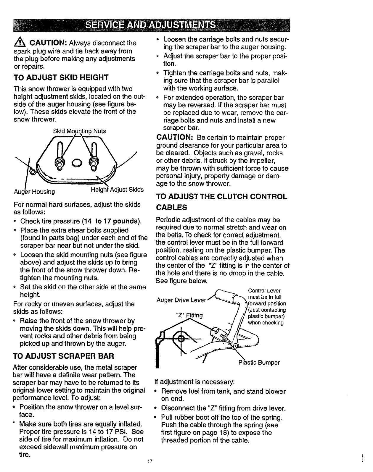
TO ADJUST SKID HEIGHT
This snow thrower is equipped with two
height adjustment skids, located on the out-
side of the auger housing (see figure be-
low). These skids elevate the front of the
snow thrower°
Skid Mo Nuts
Housing Height Adjust Skids
For normal hard surfaces, adjust the skids
as follows:
oCheck tire pressure (14 to 17 pounds).
oPlace the extra shear bolts supplied
(found in parts bag) under each end of the
scraper bar near but not under the skid.
o Loosen the skid mounting nuts (see figure
above) and adjust the skids up to bring
the front of the snow thrower down. Re-
tighten the mounting nuts.
• Set the skid on the other side at the same
height.
For rocky or uneven surfaces, adjust the
skids as follows:
Raise the front of the snow thrower by
moving the skids down. This will help pre-
vent rocks and other debris from being
picked up and thrown by the auger,
TO ADJUST SCRAPER BAR
After considerable use, the metal scraper
bar will have a definite wear pattern. The
scraper bar may have to be returned to its
original lower setting to maintain the original
performance level. To adjust:
, Position the snow thrower on alevel sur-
face.
Make sure both tires are equally inflated.
Proper tire pressure is 14 to 17 PSI. See
side of tire for maximum inflation_ Do not
exceed sidewall maximum pressure on
tire.
17
o Loosen the carriage bolts and nuts secur-
ing the scraper bar to the auger housing.
= Adjust the scraper bar to the proper posi-
tion.
• Tighten the carriage bolts and nuts, mak-
ing sure that the scraper bar is parallel
with the working surface.
° For extended operation, the scraper bar
may be reversed, tf the scraper bar must
be replaced due to wear, remove the car-
riage bolts and nuts and install a new
scraper bar.
CAUTION: Be certain to maintain proper
ground clearance for your particular area to
be cleared. Objects such as gravel, rocks
or other debris, if struck by the impeller,
may be thrown with sufficient force to cause
personal injury, property damage or dam_
age to the snow thrower°
TO ADJUST THE CLUTCH CONTROL
CABLES
Periodic adjustment of the cables may be
required due to normal stretch and wear on
the belts. To check for correct adjustment,
the control lever must be in the full forward
position, resting on the plastic bumper. The
control cables are correctly adjusted when
the center of the "Z" fitting is in the center of
the hole and there is no droop in the cable.
See figure below.
Auger Drive Leve
"Z" Fitting
Control Lever
must be Infutl
forwardposition
ring
plastfc bumper)
when checking
LicBumper
tf adjustment is necessary:
°Remove fuel from tank, and stand blower
on end.
°
°
Disconnect the "Z" fitting from drive lever.
Pull rubber boot off the top of the spring.
Push the cable through the spring (see
first figure on page 18) to expose the
threaded portion of the cable.
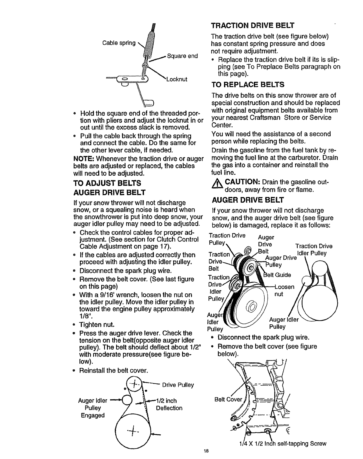
TRACTION DRIVE BELT
Cable spring \
o )cknut
end
The traction drive belt (see figure below)
has constant spring pressure and does
not require adjustment.
o Replace the traction drive belt if its is slip-
ping (see To Preplace Belts paragraph on
this page).
TO REPLACE BELTS
° Hold the square end of the threaded por-
tion with pliers and adjust the iocknut in or
out until the excess slack is removed.
•Pull the cable back through the spring
and connect the cable. Do the same for
the other lever cable, if needed.
NOTE: Whenever the traction drive or auger
belts are adjusted or replaced, the cables
will need to be adjusted.
TO ADJUST BELTS
AUGER DRIVE BELT
If your snow thrower wilt not discharge
snow, or a squealing noise is heard when
the snowthrower is put into deep snow, your
auger idler pulley may need to be adjusted°
o Check the control cables for proper ad-
justment. (See section for Clutch Control
Cable Adjustment on page 17).
•If the cables are adjusted correctly then
proceed with adjusting the idler pulley.
°Disconnect the spark plug wire.
• Remove the belt cover. (See last figure
on this page)
°With a 9/16' wrench, loosen the nut on
the idler pulley. Move the idler pulley in
toward the engine pulley approximately
1/8".
°Tighten nut.
, Press the auger drive lever. Check the
tension on the belt(opposite auger idler
The drive belts on this snow thrower are of
special construction and should be replaced
with original equipment belts available from
your nearest Craftsman Store or Service
Center.
You will need the assistance of a second
person while replacing the belts,
Drain the gasoline from the fuel tank by re-
moving the fuel line at the carburetor. Drain
the gas into a container and reinstall the
fuel line.
CAUTION: Drain the gasoline out-
doors, away from fire or flame.
AUGER DRIVE BELT
If your snow thrower will not discharge
snow, and the auger drive belt (see figure
below) is damaged, replace it as follows:
Traction Drive Auger
Pulle' Ddve Traction Drive
er Drive idter Pulley
Belt Pulley
Traction Guide
Idler nut
Au(
Idler Auger Idler
Pulley Pulley
=Disconnect the spark plug wire.
pulley). The belt should deflect about 1/2" °Remove the belt cover (see figure
with moderate pressure(see figure be- below).
low). .
Reinstall the belt cover.
Drive Pulley
Auger Idler "_ .,._._1/2 inch Belt
Pulley _eflection
Engaged _"_ _
1/4 X 1/2 Inch self-tapping Screw
18
* Loosen the belt guide (see third figure on
page !8) and pull away from the engine
drive pulley+
, Loosen nut on the auger idler pulley (see
third figure on'page 18) _nd pull idler pul-
ley away from the bell
o Remove top two bolts that secure auger
housing to motor mount frame. Loosen
bottom two bolts. Auger housing and mo-
tor mount frame will separate, hinged by
bottom two bolts_
° Remove old belt from the auger drive pul-
ley.
° install the original equipment replacement
belt in reverse order of removal.
°
o
Position drive belt onto the auger drive
pulley.
Adjust the belt guide (see To Adjust The
Belt Guides paragraph on this page).
Reinstall the belt cover.
Check clutch control cable adjustment,
see page 17.
Reconnect spark plug wire.
TRACTION DRIVE BELT
If your snow thrower wilt not move forward,
check the traction drive belt (see third fig-
ure on page 18) for wear (Check other
causes also in the Trouble Shooting Points
section), tf the traction drive belt needs to
be replaced, proceed as follows:
•Disconnect the spark plug wire.
• Remove the belt cover (see last figure on
page 18).
• Loosen the belt guide and pull away from
engine drive pulley (see third figure on
page 18).
•Loosen nut on auger idler and pull auger
idler pulley away from belt. Note location
of idler pulley for later re-installation.
° Remove auger drive belt from engine pul-
ley.
° Pull the idler pulley away from the drive
belt, allowing belt to be positioned onto
engine pulley.
,Release idler pulley. Ensure idler pulley is
properly engaged with belt.
° Reinstall auger drive belt+
o Adjust belt guide (see To Adjust The Belt
Guide paragraph ).
Adjust idler on auger belt.
Reinstall the belt cover.
o
o
oReconnect the spark plug wire.
19
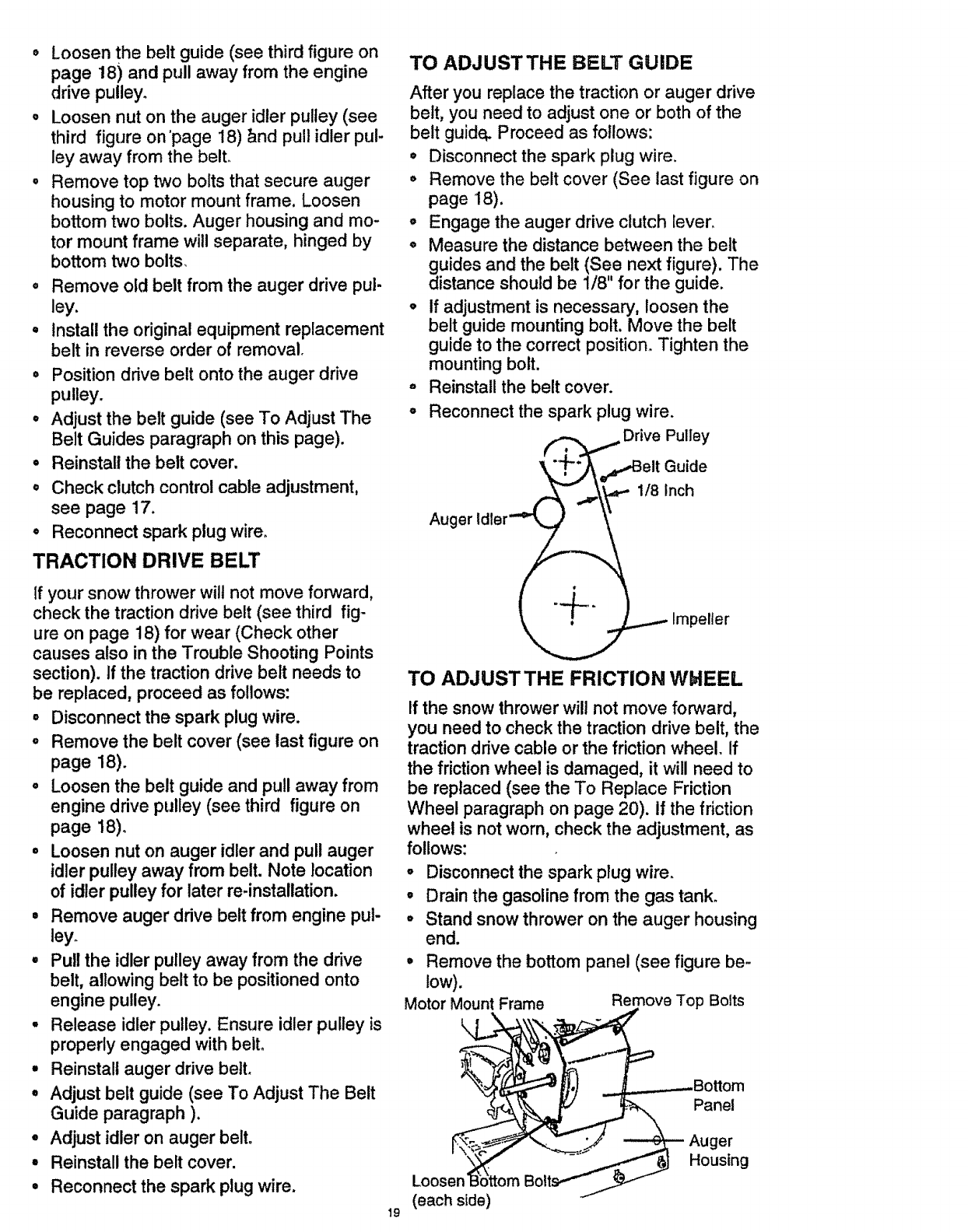
TO ADJUSTTHE BELT GUIDE
After you replace the traction or auger drive
belt, you need to adjust one or both of the
belt guide_ Proceed as follows:
• Disconnect the spark plug wire.
° Remove the belt cover (See last figure on
page 18).
o Engage the auger drive clutch lever.
o Measure the distance between the belt
guides and the belt (See next figure). The
distance should be 1/8" for the guide.
, If adjustment is necessary, loosen the
belt guide mounting bolt. Move the belt
guide to the correct position+ Tighten the
mounting bolt.
Reinstall the belt cover.
@
°Reconnect the spark plug wire.
(,._, ,_,_ Drive Pulley
']+
Auger Idter_._
_ Impeller
TO ADJUSTTHE FRICTION WblEEL
If the snow thrower will not move forward,
you need to check the traction drive belt, the
traction drive cable or the friction wheel. If
the friction wheel is damaged, it will need to
be replaced (see the To Replace Friction
Wheel paragraph on page 20). if the friction
wheel is not worn, check the adjustment, as
follows:
, Disconnect the spark plug wire.
•Drain the gasoline from the gas tank.
°Stand snow thrower on the auger housing
end.
Motor Mount Frame
k
Remove the bottom panel (see figure be-
low).
Remove Top Bolts
Loosen
(each side)
Panel
-- Auger
Housing
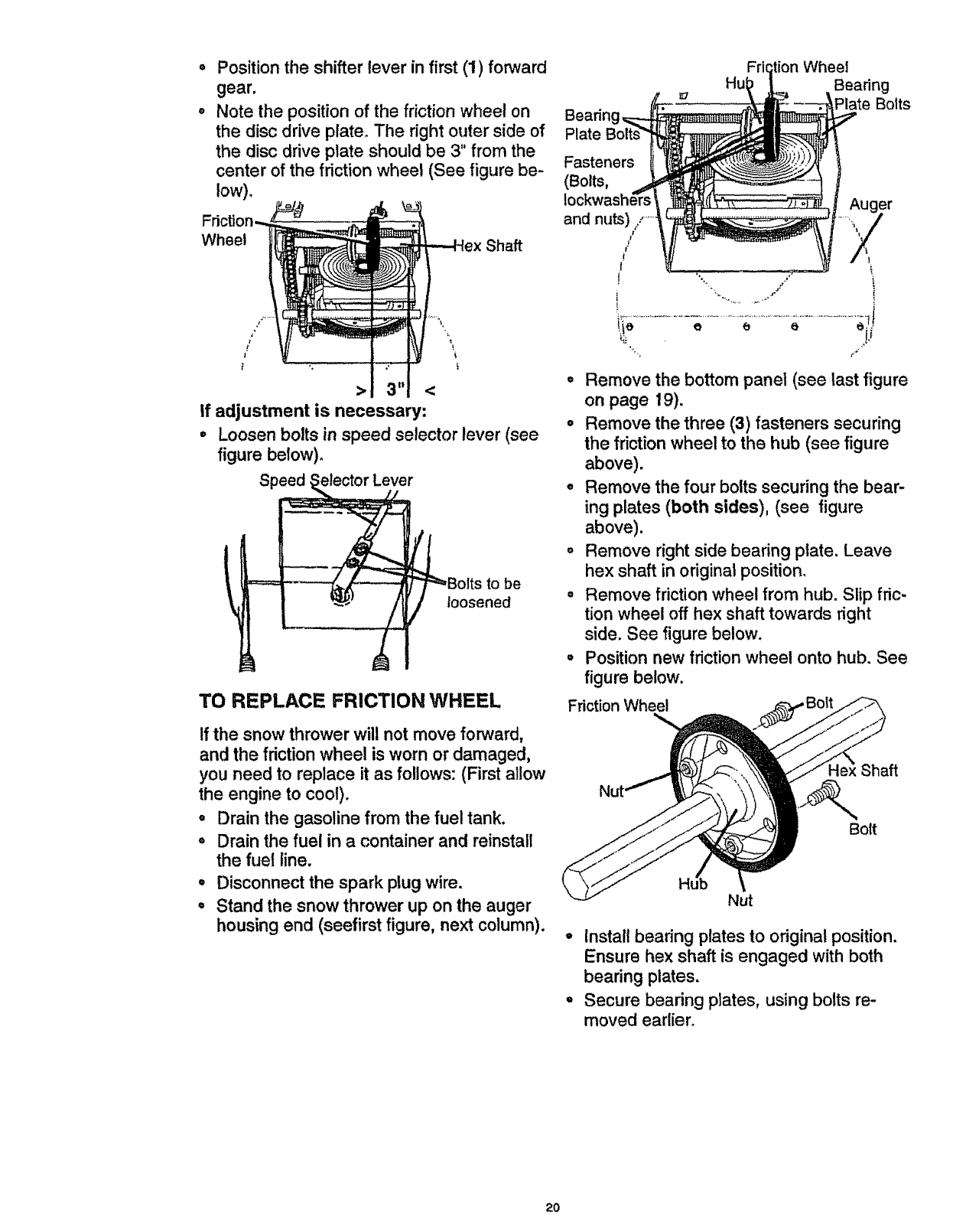
= Position the shifter lever in first (1) forward
gear.
o Note the position of the friction wheel on
the disc drive plate. The right outer side of
the disc drive plate should be 3" from the
center of the friction wheel (See figure be-
low)
Wheel _-- ----Hex Shaft
°i
>3" <
If adjustment is necessary:
° Loosen bolts in speed selector lever (see
figure below)°
Speed
TO REPLACE FRICTION WHEEL
tf the snow thrower will not move forward,
and the friction wheel is worn or damaged,
you need to replace it as follows: (First allow
the engine to cool).
oDrain the gasoline from the fuel tank.
oDrain the fuel in a container and reinstall
the fuel line.
°Disconnect the spark plug wire.
oStand the snow thrower up on the auger
housing end (seefirst figure, next column).
Bearin
Plate
Fasteners
Fri_
Hul Wheel
Bearing
Plate Bolts
.....Auger
/
o Remove the bottom panel (see last figure
on page 19).
° Remove the three (3) fasteners securing
the friction wheel to the hub (see figure
above).
• Remove the four bolts securing the bear-
ing plates (both sides), (see figure
above).
o Remove right side bearing plate. Leave
hex shaft in odginal position.
° Remove friction wheel from hub. Slip fric-
tion wheel off hex shaft towards right
side. See figure below.
- Position new friction wheel onto hub. See
figure below.
Friction Wheel
Shaft
Bolt
Nut
°Install bearing plates to original position.
Ensure hex shaft is engaged with both
bearing plates.
° Secure bearing plates, using bolts re-
moved earlier.
2O

TO REPLACE AUGER SHEAR BOLT
The augers are secured to the auger shaft
with special bolts (see figure below) that are
designed to break (to protect the machine) if
an object becomes lodged in the auger
housing, Use of a harder bolt will destroy the
protection provided by the shear bolt,
" ° Shear Pin
ar Bolt
tJJ Spacer
/! /
IMPORTANT: To ensure safety and perfor-
mance levels, only original equipment shear
bolts should be used. When replacing shear
bolts, be sure to replace shear bolt spacers.
To replace a broken shear bolt, proceed as
follows:
• Move the throttle to el (STOP) and turn
off all controls.
• Disconnect the spark plug wire. Be sure
all moving parts have stopped.
) Align the hole in the auger tube with the
hole in the auger shaft, Install the new
shear pin and shear bolt spacer found in
toolbox on top of belt cover.
NOTE: Spacer fits inside the larger hole in
the auger tube.
° Reconnect the spark plug wire.
TO ADJUST CARBURETOR
If you think your carburetor needs adjusting,
see your nearest Authorized Craftsman
Service Center. Engine performance should
not be affected at altitudes up to 7,000 feet.
For operation at higher elevations, contact
your Authorized Craftsman Service Center.
IMPORTANT: Never tamper with the engine
governor, which is factory set for proper en-
gine speed, Overspeeding the engine
above the factory high speed setting can be
dangerous. If you think the engine-governed
high speed needs adjusting, contact your
nearest Craftsman Service Center, which
has the proper equipment and experience to
make any necessary adjustments.
TO ADJUST OR REPLACE THE
SPARK PLUG
NOTICE: This spark ignition system meets
all requirements of the Canadian Interfer-
ence-Causing Equipment Regulations.
NOTICE: This engine complies with all cur-
rent Australian and New Zealand limitations
regarding electromagnetic interference. If
you have difficulty starting your snow
thrower, you may need to adjust or replace
the spark plug. Follow the instructions be-
low.
Replace the spark plug if the electrodes are
pitted or burned or if the porcelain is
cracked.
TO ADJUST:
Clean the spark plug by carefully scrap-
ing the electrodes (do not sand blast or
use a wire brush).
Be sure the spark plug is clean and free
of foreign material. Check the electrodes
gap (see figure below) with a wire feeler
gauge and reset the gap to ,030 inch if
necessary.
TO REPLACE:
° If you need a new spark plug, use only
the proper replacement spark plug (See
page 14)o
,, Set the gap to .030 inches.
•Before installing the spark plug, coat its
threads lightly with oil or grease to insure
easy removal.
° Tighten the plug firmly into the engine,
° if a torque wrench is available, torque the
plug to 18 to 23 ft. - Ibs.
21
Z_ CAUTION: Never store your snow
thrower indoors or in an enclosed, poorly
ventilated area if gasoline remains in the
tank. fumes may reach an open flame,
spark or pilot light from a furnace, water
heater, clothes dryer, cigarette, etc.
To prevent engine damage (if snow thrower rs
not used for more than 30 days) follow the
steps below°
SNOW THROWER STORAGE
,Thoroughly clean the snow thrower°
° Lubricate all lubrication points (See the
Maintenance section on pages ! 4-16).
° Be sure that all nuts, bolts and screws are
securely fastened, Inspect all visible mov-
ing parts for damage, breakage and wear.
Replace if necessary.
°Touch up all rusted or chipped paint sur-
faces; sand lightly before painting.
°Cover the bare metal parts of the blower
housing auger and the impeller with rust
preventative, such as aspray lubricant.
NOTE" A yearly checkup or tune-up by a
Craftsman Service Center is a good way to
insure that your snow thrower will provide
maximum performance for the next season.
ENGINE STORAGE
Gasoline must be removed or treated to pre-
vent gum deposits from forming in the tank,
filter, hose, and carburetor during storage.
Also during storage, alcohol blended gaso-
line that uses ethanol or methanol (some-
times called gasohol) attracts water. It acts
on the gasoline to form acids which damage
the engine.
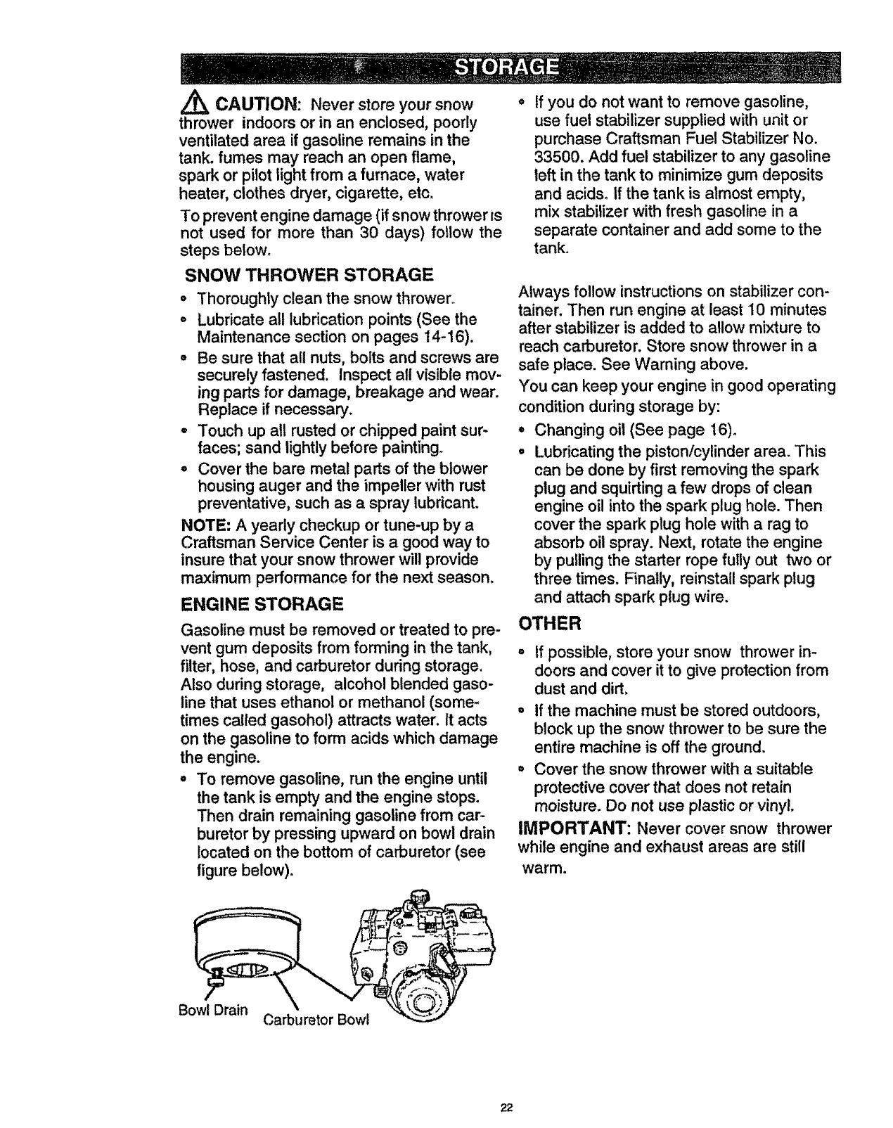
° To remove gasoline, run the engine until
the tank is empty and the engine stops.
Then drain remaining gasoline from car-
buretor by pressing upward on bowl drain
located on the bottom of carburetor (see
figure below).
If you do not want to remove gasoline,
use fuel stabilizer supplied with unit or
purchase Craftsman Fuel Stabilizer No.
33500. Add fuel stabilizer to any gasoline
left in the tank to minimize gum deposits
and acids. If the tank is almost empty,
mix stabilizer with fresh gasoline in a
separate container and add some to the
tank.
Always follow instructions on stabilizer con-
tainer. Then run engine at least 10 minutes
after stabilizer is added to allow mixture to
reach carburetor. Store snow thrower in a
safe place. See Warning above.
You can keep your engine in good operating
condition during storage by:
,, Changing oil (See page 16).
• Lubricating the piston/cylinder area. This
can be done by first removing the spark
plug and squirting a few drops of clean
engine oil into the spark plug hole. Then
cover the spark plug hole with a rag to
absorb oil spray. Next, rotate the engine
by pulling the starter rope fully out two or
three times. Fina!ly, reinstall spark plug
and attach spark plug wire.
OTHER
tf possible, store your snow thrower in-
doors and cover it to give protection from
dust and dirt,
oIf the machine must be stored outdoors,
block up the snow thrower to be sure the
entire machine is off the ground.
= Cover the snow thrower with a suitable
protective cover that does not retain
moisture. Do not use plastic or vinyl.
IMPORTANT: Never cover snow thrower
while engine and exhaust areas are still
warm.
Bowl Drain Carburetor Bowl
22
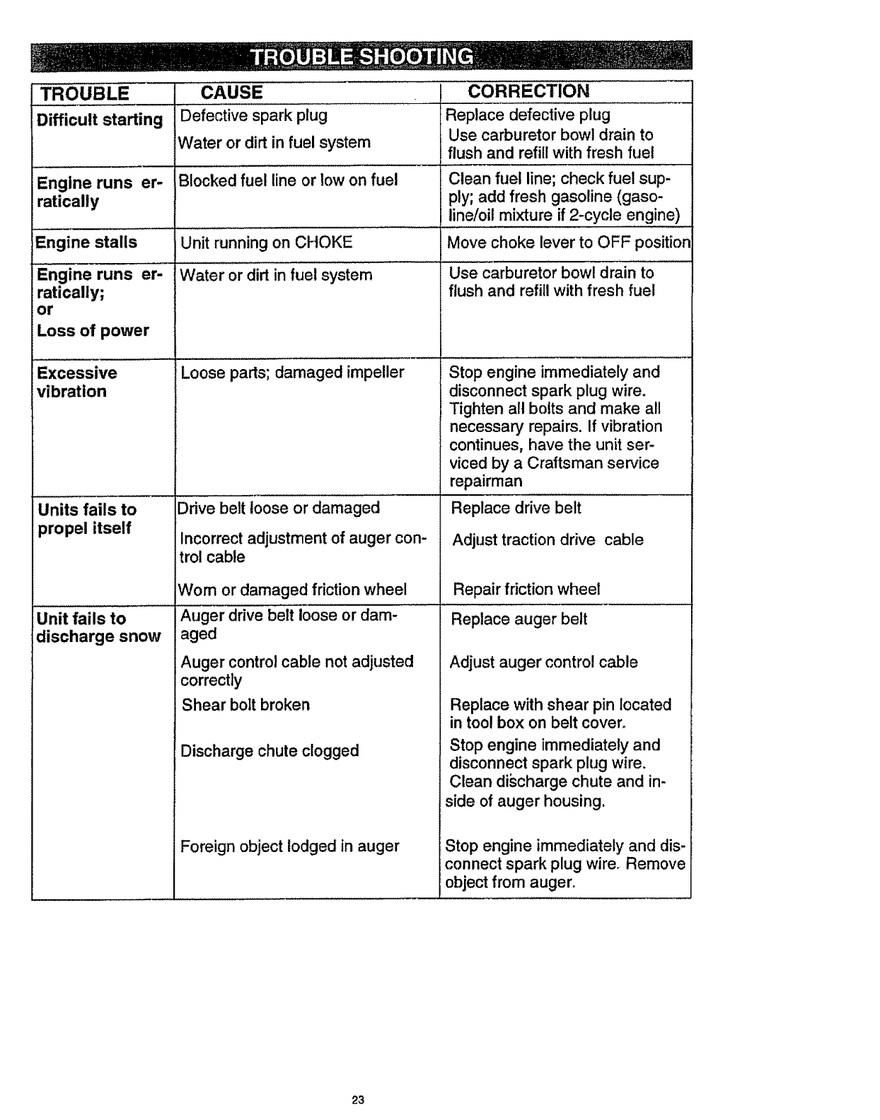
TROUBLE
Difficult starting
,, ,CAUSE . ..... • CORRECT!ON .................................................
Defective spark plug Replace defective plug
Water or dirt in fuel system
,, , ,,, , , ,, ,, , ,, ,,,
Blocked fuel line or low on fuel
Engine runs er-
ratically
Engine stalls
Engine runs er-
ratically;
or
Loss of power
Excessive
vibration
Units fails to
propel itself
iUnit fails to
discharge snow
Unit running on CHOKE
Water or dirt in fuel system
Loose parts; damaged impeller
Drive belt loose or damaged
Incorrect adjustment of auger con-
trol cable
Wom or damaged friction wheel
Auger drive belt loose or dam-
aged
Auger control cable not adjusted
correctly
Use carburetor bowl drain to
flush and refill with fresh fuel
....... ,, ,, ,,,,,,,, ,, , , ,
Clean fuel line; check fuel sup-
ply; add fresh gasoline (gaso-
line/oil mixture if 2-cycle engine)
Move choke lever to OFF position
Use carburetor bov¢l drain t0 ......
flush and refill with fresh fuel
Stop engine immediately and
disconnect spark plug wire.
Tighten all bolts and make all
necessary repairs. If vibration
continues, have the unit ser-
viced by a Craftsman service
repairman
Replace drive belt
Adjust traction drive cable
Repair friction wheel
Replace auger belt
Adjust auger control cable
Replace with shear pin located
in tool box on belt cover,
Stop engine immediately and
disconnect spark plug wire,
Clean discharge chute and in-
side of auger housing,
Stop engine immediately and dis-
connect spark plug wirer Remove
object from auger.
Shear bolt broken
Discharge chute clogged
Foreign object lodged in auger
23
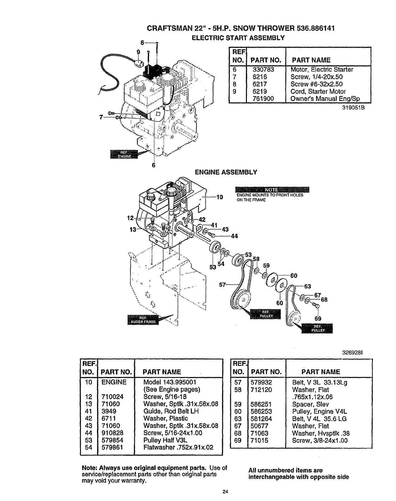
CRAFTSMAN 22" -5H.P. SNOW THROWER 536.886141
ELECTRIC START ASSEMBLY
NO.
6
7
6
9
PART NO. _ PART NAME
330783
6216
6217
6219
761900
Motor, Electric Starter
Screw, 1/4-20x.50
Screw #6-32x2.50
Cord, Starter Motor
Owner's Manual Eng/Sp
319051B
REF.
NO. PART NO.
10 ENGINE
12 710024
I3 7106O
41 3949
42 671i
_71060
9t0828
53 579854
579861
PART NAME
Model 143.995001
(See Engine pages)
Screw, 5/16-18
Washer, Spttk .31x.58x.08
Guide, Rod Belt LH
Washer, Plastic
Washer, Sptlk _31x.58x.08
Screw, 5/16-24x!_00
Pulley Half V3L
Flatwasher .752xo91x.02
REF,
NO.
57
58
3269281
PART NO.
579932
7'12120
59 586251
60 586253
63 581264
67 50677
68 71063
69 71015
PART NAME
Belt, V 3L 331i3Lg
Washer, Flat
.765xl .12x.06
Spacer, Slev
Pulley, Engine V4L
Belt, V 4L 35.6 LG
Washer, Flat
Washer, Hvsptlk °38
Screw, 3/8-24x1°00
Note: Always use original equipment parts, Use of
service/replacement parts other than original parts
may void your warranty.
24
All unnumbered items are
interchangeable with opposite side
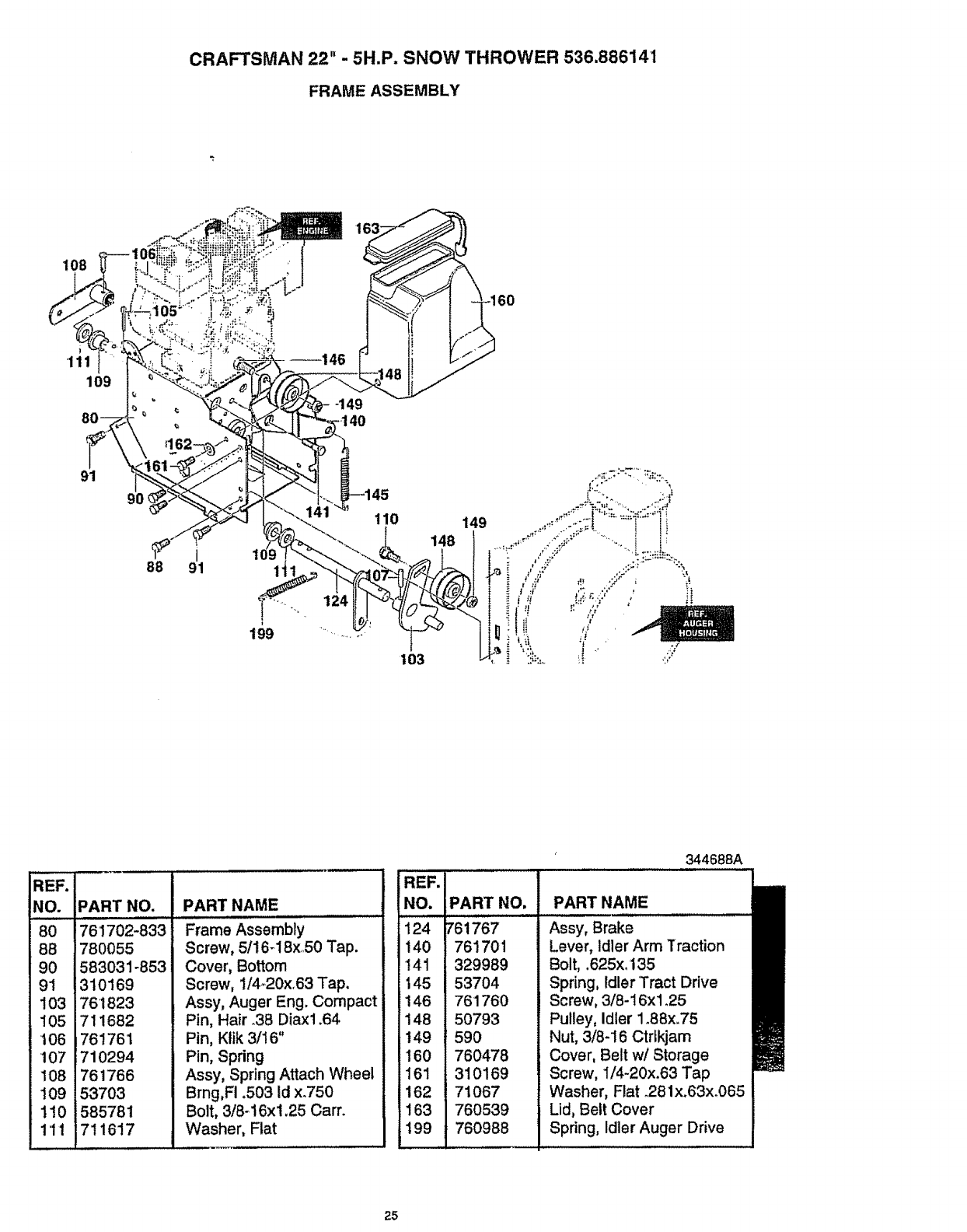
CRAFTSMAN 22" -5H.P. SNOW THROWER 536.886141
FRAME ASSEMBLY
108
'111
109
91
9O
88 91
124
110 149
,[,
REF.
NO.
80
88
90
9I
103
105
106
107
108
109
110
111
PART NO.
76 1702-833
780055
583031-853
310169
761823
711682
761761
710294
761766
53703
585781
711617
PARTNAME
Frame Assembly
Screw, 5116_18x..50 Tap.
Cover, Bottom
Screw, 1/4.20x_63 Tap,
Assy, Auger Eng. Compact
Pin, Hair .38 Diax1.64
Pin, Ktik 3/16"
Pin, Spring
Assy, Spring Attach Wheel
Bmg,Fi .503 Id x.750
Bolt, 3/8_16xl.25 Cam
Washer, Flat
IREF.
!NO.
12_4
1140
141
145
146
148
149
t60
I61
162
163
199
PART NO.
761767
761701
329989
53704
76'1760
50793
59O
760478
310169
71067
760539
760988
344688A
PART NAME
Assy, Brake
Lever, Idler Arm Traction
Bolt, .625x. 135
Spring, Idler Tract Drive
Screw, 3/8-16xl .25
Pulley, Idler 1.88x.75
Nut, 3/8-16 Ctrfkjam
Cover, Belt w/Storage
Screw, I/4-20x.63 Tap
Washer, Flat _281x.63x.065
Lid, Belt Cover
Spring, Idler Auger Drive
25
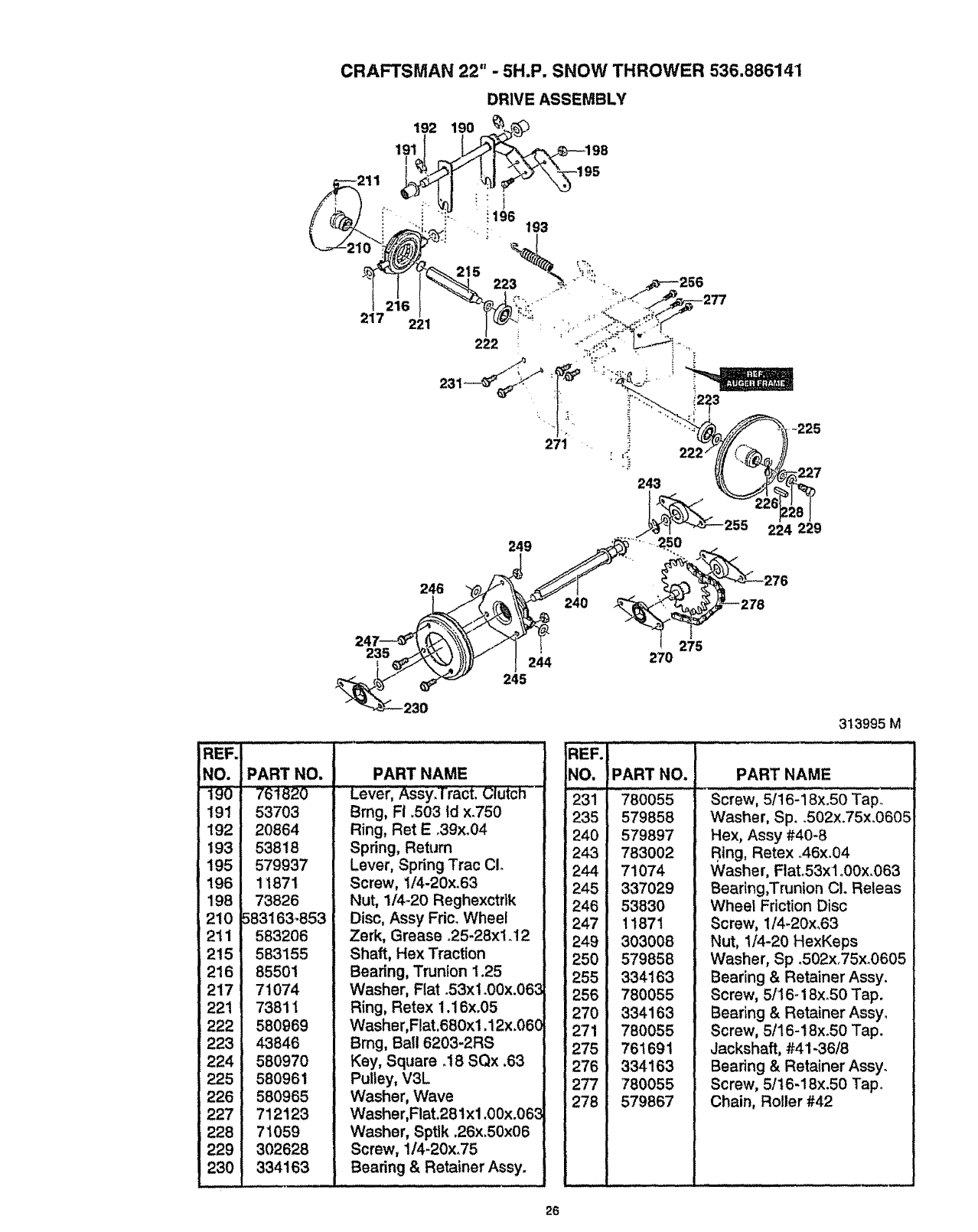
CRAFTSMAN 22" - 5H.P. SNOW THROWER 536,886141
DRIVE ASSEMBLY
217 221
REF.
NO.
190'
191
192
193
195
196
198
210
2il
215
216
217
221
222
223
224
225
226
227
228
229
230
249 ....
313995 M
PART NO.
"76_'"_20
53703
20864
53818
579937
11871
73826
583163_653
583206
583155
85501
71074
73811
580969
43846
580970
580961
580965
712123
71059
302628
334163
PART NAME
Lever, Assy.Tract, Clutch
Brng, Ft .503 td x.750
Ring, Ret E _39x.04
Spring, Return
Lever, Spring Trac CL
Screw, 1/4-20x.63
Nut, 1/4-20 Reghexctdk
Disc, Assy Fdc. Wheel
Zerk, Grease o25-28x1_12
Shaft, Hex Traction
Bearing, Trunton 1.25
Washer, Flat .53xl .00x.063
Ring, Retex 1.16x.05
Washer,Flat.680x1,12x.06C
Bmg, Ball 6203-2RS
Key, Square .18 SQx ,63
Pulley, V3L
Washer, Wave
Washer, Flat.281xl.00x.063
Washer, Sptlk ,26x.50x06
Screw, 114-20x.75
Bearing & Retainer Assy.
REF.
NO.
231
235
240
243
244
245
246
247
249
250
255
256
270
271
275
276
277
278
PART NO.
780055
579858
579897
783002
71074
337029
53830
11871
303008
579858
334163
780055
334163
780055
761691
334163
780055
579867
PART NAME
Screw, 5/16-18x.50 Tap°
Washer, Sp..502x.75x.0605
Hex, Assy #40-8
R,ing, Retex ..46x.04
Washer, Flato53xl.00x.063
Bearing,Trunion Cl. Releas
Wheel Friction Disc
Screw, 1/4-20x,63
Nut, 1/4-20 HexKeps
Washer, Sp o502x.75x.0605
Bearing & Retainer Assy.
Screw, 5/16-18x_50 Tap.
Bearing & Retainer Assy.
Screw, 5/16-18x.50 Tap.
Jackshaft, #41-36/8
Bearing & Retainer Assy.
Screw, 5/16-18x.50 Tap.
Chain, Roller #42
26
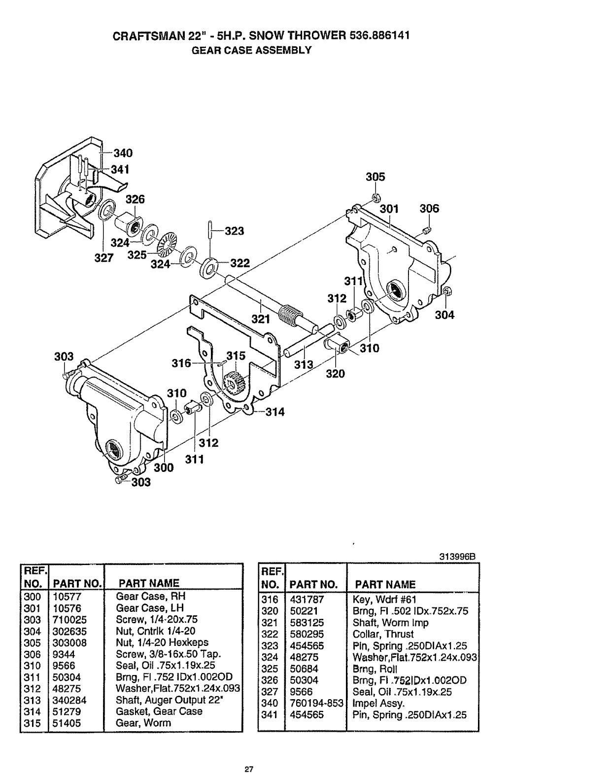
CRAFTSMAN 22" -5H.P. SNOW THROWER 536.886141
GEAR CASE ASSEMBLY
34O
326
305
301 306
327
321
311
312
304
303 315 310
320
312
311
303
REF.I
NO. !
3001
301 I
303 I
304 I
305 !
306 !
31o I
3!2 !48275
313 1340284
314 ! 51279
315 151405
PART NO.
10577
10576
710025
302635
303008
9344
9566
50304
PART NAME
Gear Case, RH
Gear Case, LH
Screw, 1/4-20x.75
Nut, Cntrlk 1/4-20
Nut, 1/4-20 Hexkeps
Screw, 3/8-16x.50 Tap.
Seat, Oil .75xl. 19x.25
Brng, FI .752 IDxl.002OD
Washer,Flat.752x1.24x.093
Shaft, Auger Output 22"
Gasket, Gear Case
Gear, Worm
313996B
REF.
NO. PART NO. PART NAME
316
320
321
322
323
324
325
326
327
340
341
431787
50221
583125
580295
454565
48275
50684
50304
9566
760194-853
454565
Key, Wdrf #61
Brng, R.502 IDx352x.75
Shaft, Worm Imp
Collar, Thrust
Ptn, Spdng o250DIAx1.25
Washer,Flat352x1_24x.093
Brag, Roll
Brag, Ft 3521Dxl _002OD
Seal, Oil .75x1.19x25
Impel Assy.
Pin, Spring .250DIAxl °25
27
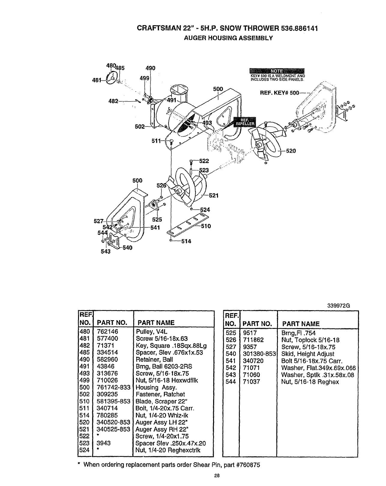
CRAFTSMAN 22" - 5H.P, SNOW THROWER 536.886141
AUGER HOUSING ASSEMBLY
480485
481_L !:
482
543
490
499
500
525
5OO
'---514
REF
NO. PART NO. PART NAME
480 762146
481 577400
482 71371
485 334514
490 582960
491 43846
493 313676
499 710026
500 761742-833
'502 309235
510 581395-853
511 340714
i514 780285
520 340520-853
521 340525-853
522 "
523 3943
524 *
Pulley, V4L
Screw 5/16-18x,63
Key, Square .18Sqx.88Lg
Spacer, Slev .676xlx,53
Retainer, Bal!
Brng, Ball 6203-2RS
Screw, 5/16-18x.75
Nut, 5/16-I 8 Hexwdfllk
Housing Assyo
Fastener, Ratchet
Blade, Scraper 22"
Bolt, 114-20x.75 Cam
Nut, 1/4-20 Whtzqk
Auger Assy LH 22"
Auger Assy RH 22"
Screw, 114-20xl.75
Spacer Slev .250xo47xo20
Nut, 1/4-20 Reghexctrik
REF.
NO.
525
526
527
54O
541
542
543
544
* When ordering replacement parts order Shear Pin, part #760875
339972G
PART NO.
9517
711862
9357
301380-853
34072O
71O71
71060
71037
PART NAME
Brng,Ft .754
Nut, Toplock 5/16-18
Screw, 5/16-18x.75
Skid, Height Adjust
Bolt 5/16-18x_75 Cam
Washer, Flat.349x.69x.066
Washer, Sptlk .,31x.58xo08
Nut, 5/16-t8 Reghex
28
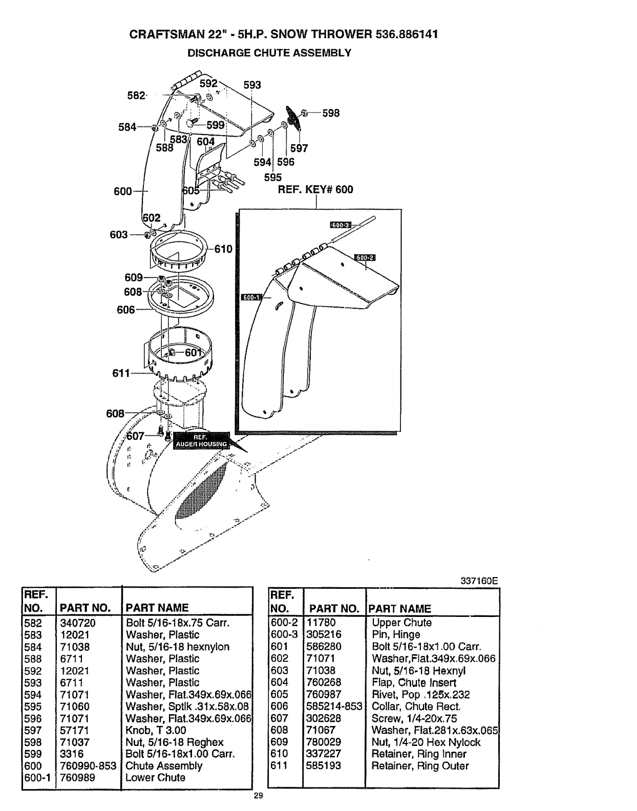
CRAFTSMAN 22" -5H.P. SNOW THROWER 536.886141
DISCHARGE CHUTE ASSEMBLY
582 593
597
594 596
595
REF. KEY# 600
!
REF.
NO.
582
583
584
588
592
593
594
595
596
597
598
599
600
600-1
PART NO.
340720
12021
71038
6711
12021
6711
71071
71060
71071
57171
7t 037
3316
760990-853
760989
29
PART NAME
Bolt 5/16-18x.75 Cart.
Washer, Plastic
Nut, 5/16-18 hexnyton
Washer, Plastic
Washer, Plastic
Washer, Plastic
Washer, Fiat.349x_69x.06_
Washer, Sptlk .31x.58x_08
Washer, FlaL349x°69x.06E
Knob, T 3.00
Nut, 5/16-18 Reghex
iBolt 5/16-18xl _00 Cam
;Chute Assembly
Lower Chute
REF.
NO.
600_2
600-3
601
602
603
604
605
606
607
608
609
610
611
PART NO,
11780
305216
586280
71071
71038
760268
760987
585214-853
302628
71067
780029
337227
585193
337160E
PART NAME
Upper Chute
Pin, Hinge
Bolt 5/16-18xl .00 Cam
Washer, Flat.349xo69x.066
Nut, 5/16-18 Hexnyl
Flap, Chute Insert
Rivet, Pop .125x.232
Collar, Chute Rect.
Screw, 1/4-20xo75
Washer, Flat.281x.63x,065
Nut, 1/4-20 Hex Nylock
Retainer, Ring Inner
Retainer, Ring Outer
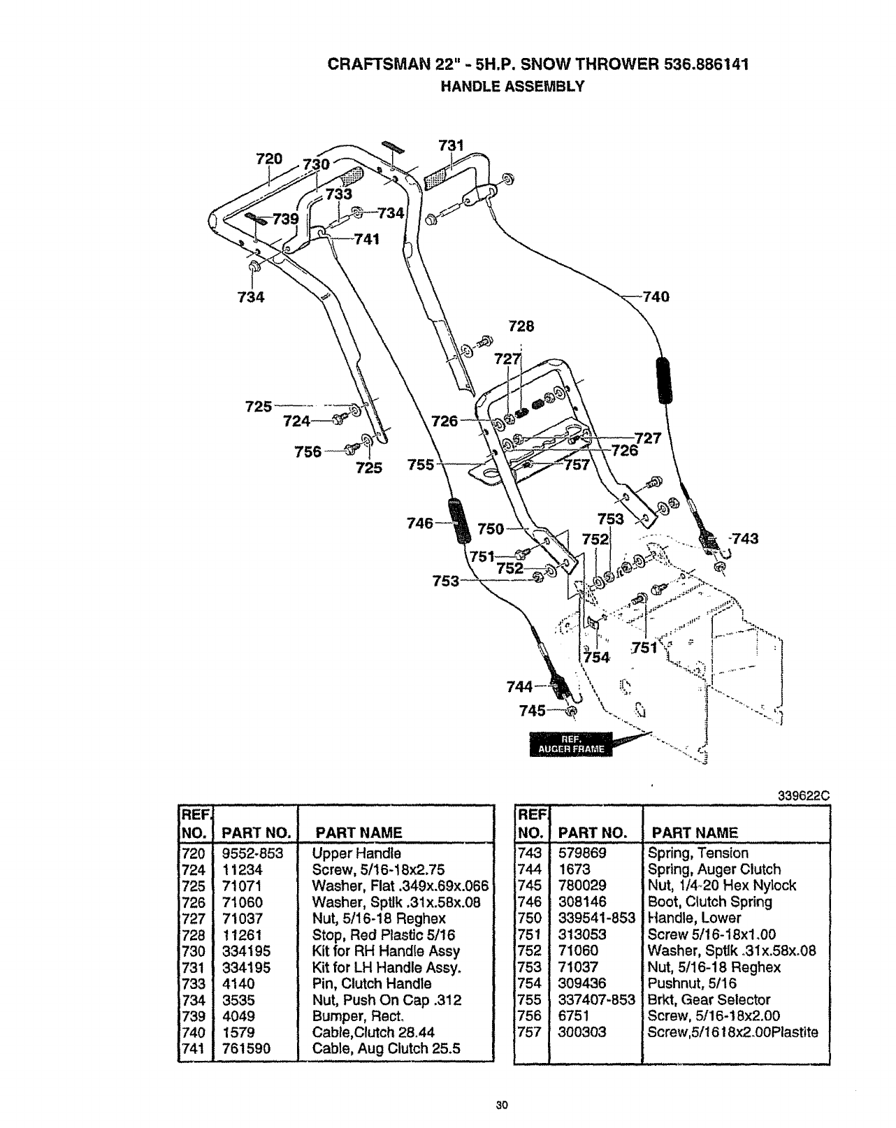
CRAFTSMAN 22" -5H.P. SNOW THROWER 536.886141
HANDLE ASSEMBLY
731
734
733
725 755
744--
REF.
NO.
?20
724
725
726
727
'728
730
731
733
734
1739
740
741
PART NO.
9552-853
11234
71071
71060
71037
11261
334195
334195
4140
3535
4049
1579
761590
PART NAME
Upper Handle
Screw, 5/16-18x2.75
Washer, Flat .349x.69x.066
Washer, Sptlk .31x.58x.08
Nut, 5/16-18 Reghex
Stop, Red Plastic 5116
Kit for RH Handle Assy
Kit for LH Handle Assy.
Pin, Clutch Handle
Nut, Push On Cap .312
Bumper, Rect.
Cable,Clutch 28.44
Cable, Aug Clutch 25.5
REF
NO.
743
744
i745
746
750
751
752
753
754
755
756
757
PART NO.
579869
1673
780029
308146
339541-853
313053
71060
71037
309436
337407-853
6751
300303
339622C
PART NAME
Spring, Tension
Spring, Auger Clutch
Nut, 1/4o20 Hex Nylock
Boot, Clutch Spring
Handle, Lower
Screw 5/16-18xl .00
Washer, Sptlk _31x.58x.08
Nut, 5/16-18 Reghex
Pushnut, 5/16
Brkt, Gear Selector
Screw, 5/16-18x2.00
Screw,5/1618x2.00Plastite
3O
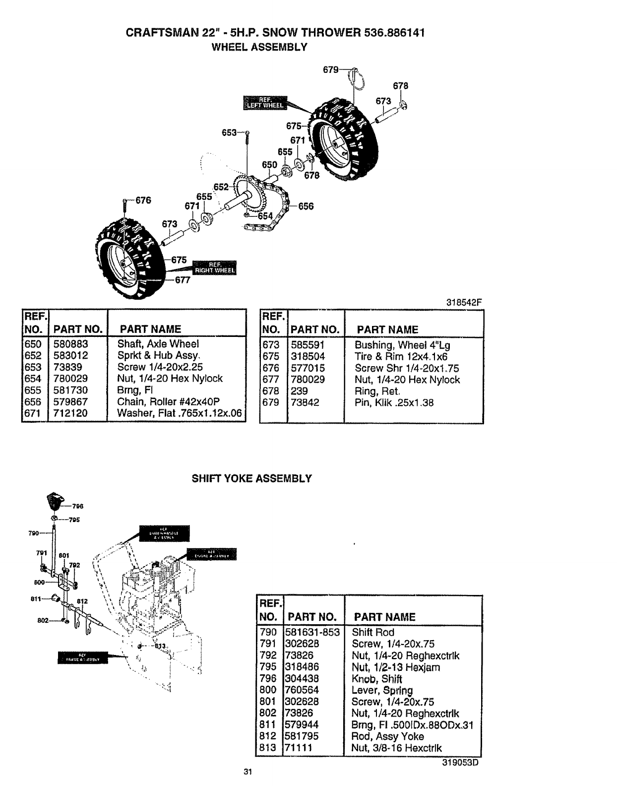
CRAFTSMAN 22" - 5H.P. SNOW THROWER 536.886141
WHEEL ASSEMBLY
679_ 678
673
671
655
655 "_
671
673
REF.
NO.
650
.652
E653
654
655
656
6z!i
PART NO.
580883
583012
73839
780029
581730
579867
712120
PART NAME
Shaft, Axle Wheel
Sprkt & Hub Assy.
Screw 1/4-20x2_25
Nut, 1/4-20 Hex Nylock
Brng, FI
Chain, Roller #42x40P
Washer, Fiat .765x1.12x.06
REF.
NO,
673
675
676
677
678
679
318542F
PART NO.
585591
318504
57"7015
780029
239
73842
PART NAME
Bushing, Wheel 4"Lg
Tire & Rim 12x4.1x6
Screw Shr 1/4-20xt .75
Nut, 1/4-20 Hex Nylock
Ring, ReL
Pin, Kltk .25xl .38
SHIFT YOKE ASSEMBLY
REF.
NO.
79o
791
792
795
796
800
801
8O2
811
812
8t3
PART NO.
II I
581631-853
302628
i73826
!318486
1304438
760564
!302628
73826
579944
581795
71111
PART NAME
Shift Boa .....................
Screw, 1/4-20x.75
Nut, 1/4-20 Reghexctdk
Nut, 1/2-!3 Hexjam
Knob, Shift
Lever, Spring
Screw, 1/4-20x.75
Nut, 1/4-20 Reghexctrlk
Brng, F! .500[Dx.88ODx°31
Rod, Assy Yoke
Nut, 3/8-16 Hexctrlk
319053D
31
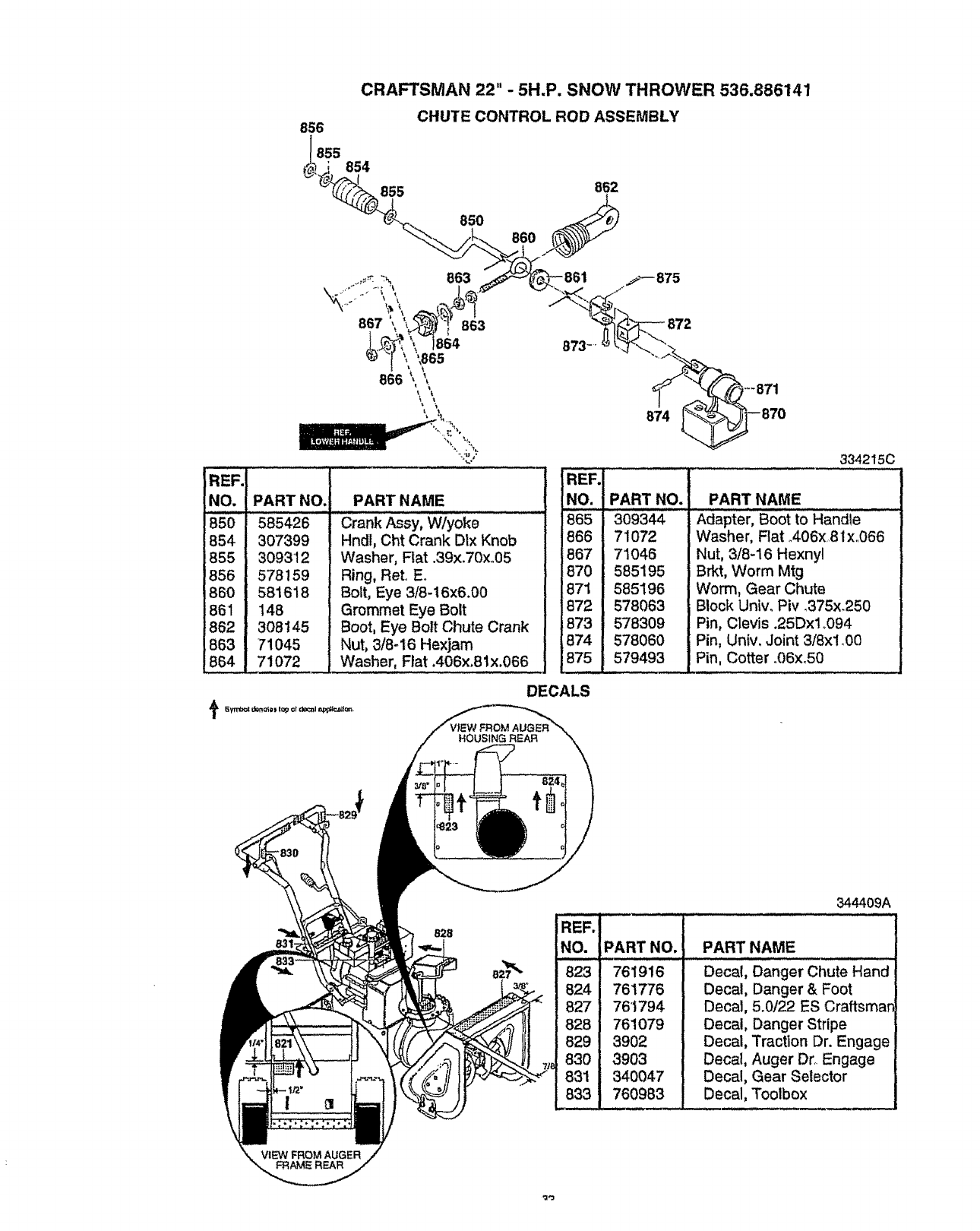
CRAFTSMAN 22" -5H.P. SNOW THROWER 536.886141
856
1_855 854
855
CHUTE CONTROL ROD ASSEMBLY
862
85O 860
REF'i
NO.
850
854
855
856
860
861
862
863
854
PART NO, PART NAME
585426 - Crank Assy, W/yoke
307399
309312
578159
581618
148
308145
71045
71072
Hndl, Cht Crank D1xKnob
Washer, Ftat .39x.70xo05
Ring, ReL E.
Bolt, Eye 3/8-16x6.00
Grommet Eye Bolt
Boot, Eye Bolt Chute Crank
Nut, 3/8-16 Hexjam
Washer, Flat .406x.81x.066
REF.
NO.
865
866
867
870
871
872
873
674
875
DECALS
HOUSING REAR
--871
874
3342150
PART NO. PART NAME
309344 - Adaptel:, BoOt to Halndie .....
71072
71046
585195
585196
578063
578309
578060
579493
Washer, Rat o406x,8 lx..066
Nut, 3/8-16 Hexnyl
Brkt, Worm Mtg
Worm, Gear Chute
Block Univ. Piv .375x_250
Pin, Clevis .25Dxlo094
Pin, Univ. Joint 3/8x! o00
Pin, Cotter .06x.50
828
344409A
PART NO. PART NAME
761916
761776
76'1794
761079
3902
3903
340047
760983
Decal, Danger Chute Hand
Decal, Danger & Foot
Decal, 5o0122 ES Craftsman
Decal, Danger Stripe
Decal, Traction Dr. Engage
Decal, Auger Dr. Engage
Decal, Gear Selector
Decal, Toolbox
VIEW FROM AUGER
FRAME REAR
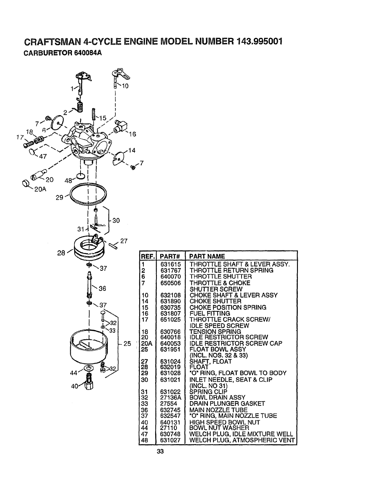
CRAFTSMAN 4.-CYCLE ENGINE MODEL NUMBER 143.995001
CARBURETOR 640084A
25
18
20
20A
25
27
26
29
30
31
32
i33
36
37
4O
44
47
48
PART#
i ,,,,
631615
631767
640070
650506
632108
631890
630735
631807
651025
630766
640018
640053
631951
631024
632019
631028
631021
631022
27136A
27554
632745
632547
640131
27110
630748
631027
PART NAME
THROTTLE SHAFT & LEVER AssY,
THROTTLE RETURN SPRING
THROTTLE SHUTTER
THROTTLE & CHOKE
SHUTTER SCREW
CHOKE SHAFT & LEVER ASSY
CHOKE SHUTTER
CHOKE POSITION SPRING
FUEL FITTING
THROTTLE CRACK SCREW/
IDLE SPEED SCREW
TENSION SPRING
IDLE RESTRICTOR SCREW
IDLE RESTRICTOR SCREW CAP
FLOAT BOWL ASSY
(INCL NOS. 32 & 33)
SHAFT, FLOAT
FLOAT
"O" RING, FLOAT BOWL TO BODY
INLET NEEDLE, SEAT & CLIP
NOL. NO 31)
PRING CLIP
BOWL DRAIN ASSY
DRAIN PLUNGER GASKET
MAIN NOZZLE TUBE
"O" RING, MAIN NOZZLE TUBE
HIGH SPEED BOWL NUT
BOWL NUT WASHER
WELCH PLUG, IDLE MIXTURE WELL
WELCH PLUG, ATMOSPHERIC VENT
33
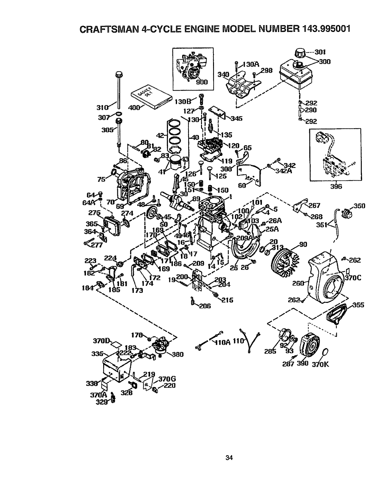
CRAFTSMAN 4-CYCLE ENGINE MODEL NUMBER 143.995001
>
!
34
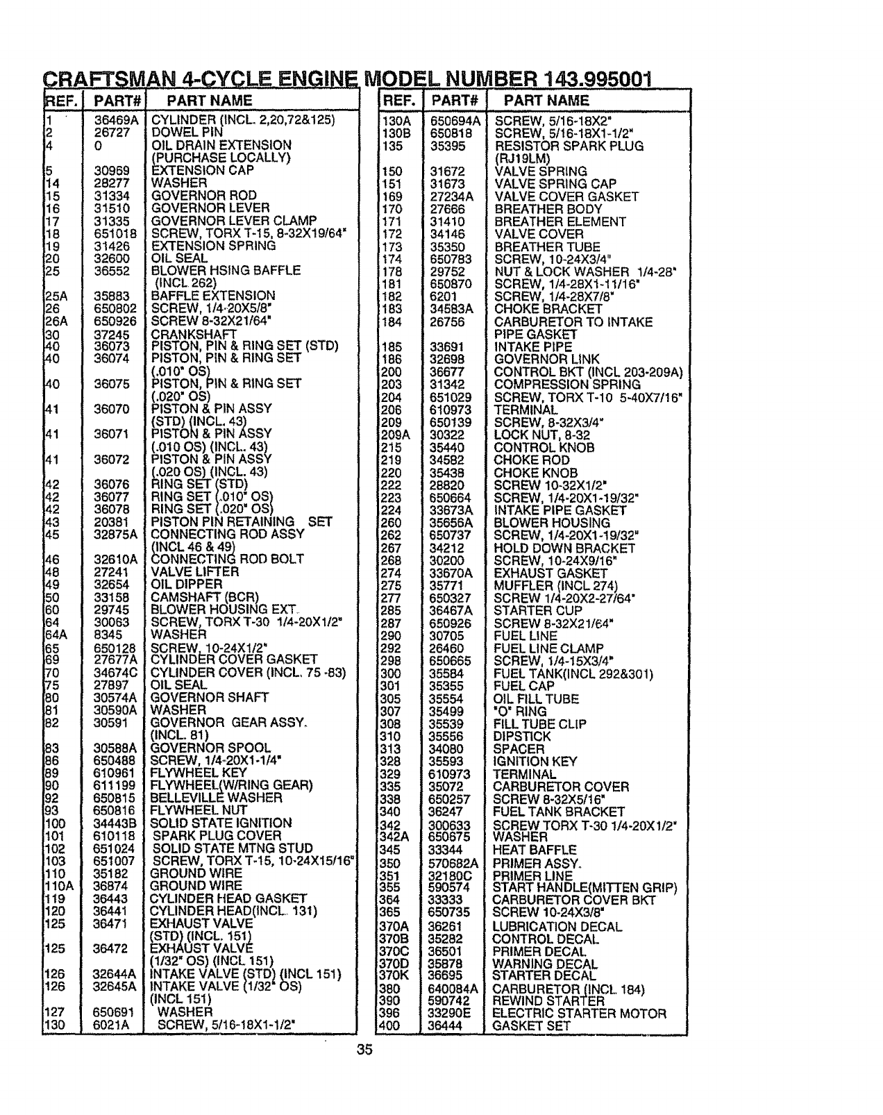
DR,A SM
REF. PART#
1 36469A
2 26727
4 0
5 30969
14 28277
15 31334
16 31510
17 31335
18 651018
19 31426
20 32600
25 36552
25A 35883
26 650802
26A 650926
30 37245
40 36073
40 36074
40 36075
41 36070
41 36071
41 36072
42 36076
42 36077
42 36078
43 20381
45 32875A
46 326t0A
48 27241
49 32654
50 33158
60 29745
64 30063
64A 8345
65 650128
69 27677A
70 34674C
75 27897
80 30574A
81 30590A
82 30591
83 30588A
86 650488
89 610961
90 611199
92 650815
93 650816
100 34443B
10t 610118
102 651024
103 651007
110 35182
110A 36874
t 19 36443
120 36441
125 36471
125 36472
126 32644A
t26 32645A
127 650691
130 6021A
AN 4-CYCLE_ENGINE
PART NAME
CYLINDER (INCL, 2,20,72&125)
DOWEL PIN
OIL DRAIN EXTENSION
RCHASE LOCALLY)
NSION CAP
WASHER
GOVERNOR ROD
GOVERNOR LEVER
GOVERNOR LEVER CLAMP
SCREW, TORX T-15, 8-32X19/64'
EXTENSION SPRING
OIL SEAL
BLOWER HSING BAFFLE
(INCL. 262)
BAFFLE EXTENSION
SCREW, 1/4-.20X5/8"
SCREW 8-32X21/64"
CRANKSHAFT
PISTON, PIN & RING SET (STD)
PISTON, PiN & RING SET
(.010"OS)
PISTON, PIN & RING SET
;O20"OS)
ISTON & PIN ASSY
{STD) {INCL. 43)
PISTON & PIN ASSY
(.010 OS) (INCL. 43)
PISTON & PIN ASSY
20 OS) (INCL. 43)
GSET (STD)
RING SET (.010" OS)
RING SET (.020" OS)
PISTON PIN RETAINING SET
CONNECTING ROD ASSY
NCL 46 & 49)
NNECTtNG ROD BOLT
VALVE LIFTER
OIL DIPPER
CAMSHAFT (BCR)
BLOWER HOUSING EXT
SCREW, TORX T-30 I14-20Xl/2"
WASHER
SCREW, 10-24X1/2 _
CYLINDER COVER GASKET
CYLINDER COVER (INCL 75 _83)
OIL SEAL
GOVERNOR SHAFT
WASHER
GOVERNOR GEAR ASSY.
(INCL. 81)
GOVERNOR SPOOL
SCREW, 1/4_20X1-1/4"
FLYWHEEL KEY
FLYWHEEL(W/RING GEAR)
BELLEVILLE WASHER
FLYWHEEL NUT
SOLID STATE IGNITION
SPARK PLUG COVER
SOLID STATE MTNG STUD
SCREW, TORX T-15, 10-24X15/16"
GROUND WIRE
GROUND WIRE
CYLINDER HEAD GASKET
CYLINDER HEAD(INCL 131)
EXHAUST VALVE
(STD) (INCL. 151)
EXHAUST VALVE
(1132" OS) (INCL 151)
INTAKE VALVE (STD 1 (INCL 151)
INTAKE VALVE (1/32 OS)
(INCL 151)
WASHER
SCREW, 5t16-18Xtq/2"
35
ODEL NUMBER 143.995001
REF. •PART# PART NAME ...............................
130A
130B
135
150
151
169
170
171
172
173
174
178
181
182
183
184
185
186
i200
Z03
2O4
206
209
209A
215
;219
i220
222
223
224
260
262
267
268
274
275
277
285
287
290
292
298
300
301
305
307
308
310
313
328
329
335
338
340
342
342A
345
350
351
355
364
365
370A
370B
370C
370D
370K
380
390
396
4O0
650694A
650818
35395
31672
31673
27234A
27666
31410
34146
35350
650783
29752
650870
6201
34583A
26756
33691
32698
36677
31342
651029
610973
650139
30322
35440
34582
35438
28820
650664
33673A
35656A
650737
34212
30200
33670A
35771
650327
36467A
650926
30705
26460
650665
35584
35355
35554
35499
35539
35556
34080
35593
610973
35072
650257
36247
300633
650675
33344
570682A
32180C
590574
33333
650735
36261
35282
36501
35878
36695
640084A
590742
33290E
36444
SCREW, 5/16-18X1q/2"
RESISTOR SPARK PLUG
(VRJ19LM) =
ALVE SPRING
VALVE SPRING CAP
VALVE COVER GASKET
BREATHER BODY
BREATHER ELEMENT
VALVE COVER
BREATHER TUBE
SCREW, 10-24X314"
NUT & LOCK WASHER 1/4-28"
SCREW, 1t4-28X1-11116"
SCREW, 1/4-28X7/8'
CHOKE BRACKET
CARBURETOR TO INTAKE
PIPE GASKET
INTAKE PIPE
GOVERNOR LINK
CONTROL BKT (INCL 203.209A)
COMPRESSION SPRING
SCREW, TORX T-10 5-40)(7/16"
TERMINAL
SCREW, 8-32X3/4"
LOCK NUT, 8-32
CONTROL KNOB
CHOKE ROD
CHOKE KNOB
SCREW 10-32Xl/2'
SCREW, 1/4-20)(1-19/32"
INTAKE PIPE GASKET
BLOWER HOUSING
SCREW, 114-20X1-19/32"
HOLD DOWN BRACKET
SCREW, 10-24X9116"
EXHAUST GASKET
MUFFLER (INCL 274) ,
SCREW 114-20X2-27/64
STARTER CUP
SCREW 8-32X21/64"
FUEL LINE
FUEL LINE CLAMP
SCREW, 1/4-15X3/4"
FUEL TANK(INCL 292&301)
FUEL CAP
OIL FILL TUBE
"O' RING
FILL TUBE CLIP
DIPSTICK
SPACER
IGNITION KEY
TERMINAL
CARBURETOR COVER
SCREW 8-32X51t6"
FUEL TANK BRACKET
SCREW TOP3( T-30 !/4-20X1/2'
WASHER
HEAT BAFFLE
PRIMER ASSY.
PRIMER UNE
START HANDLE{MITTEN GRIP)
CARBURETOR COVER BKT
SCREW 10-24X3/8"
LUBRICATION DECAL
CONTROL DECAL
PRIMER DECAL.
WARNING DECAL
STARTER DECAL
CARBURETOR(INCL 184)
REWIND STARTER
ELECTRIC STARTER MOTOR
GASKET SET
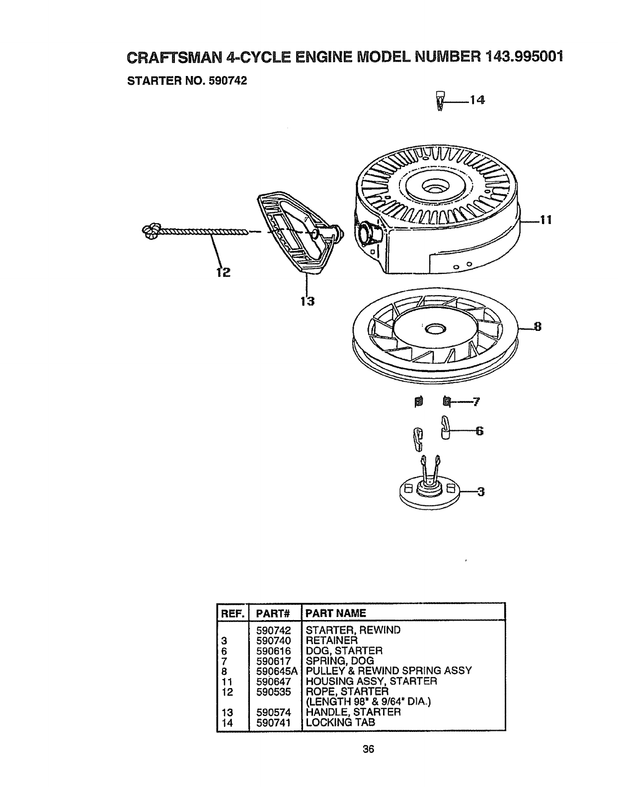
CRAFTSMAN _CYCLE ENGINE MODEL NUMBER 143.995001
STARTER NO. 590742
--14
REF. PART#
590742
3 590740
6 590616
7 590617
8 590645A
11 590647
12 590535
t3 590574
14 590741
i ii
PART NAME
i i i ii i i,,,i
STARTER, REWIND
RETAINER
DOG, STARTER
SPRING, DOG
PULLEY & REWIND SPRING ASSY
HOUSING ASSY, STARTER
ROPE, STARTER
(LENGTH 98" &9164" D1A_)
HANDLE, STARTER
LOCKING TAB
36
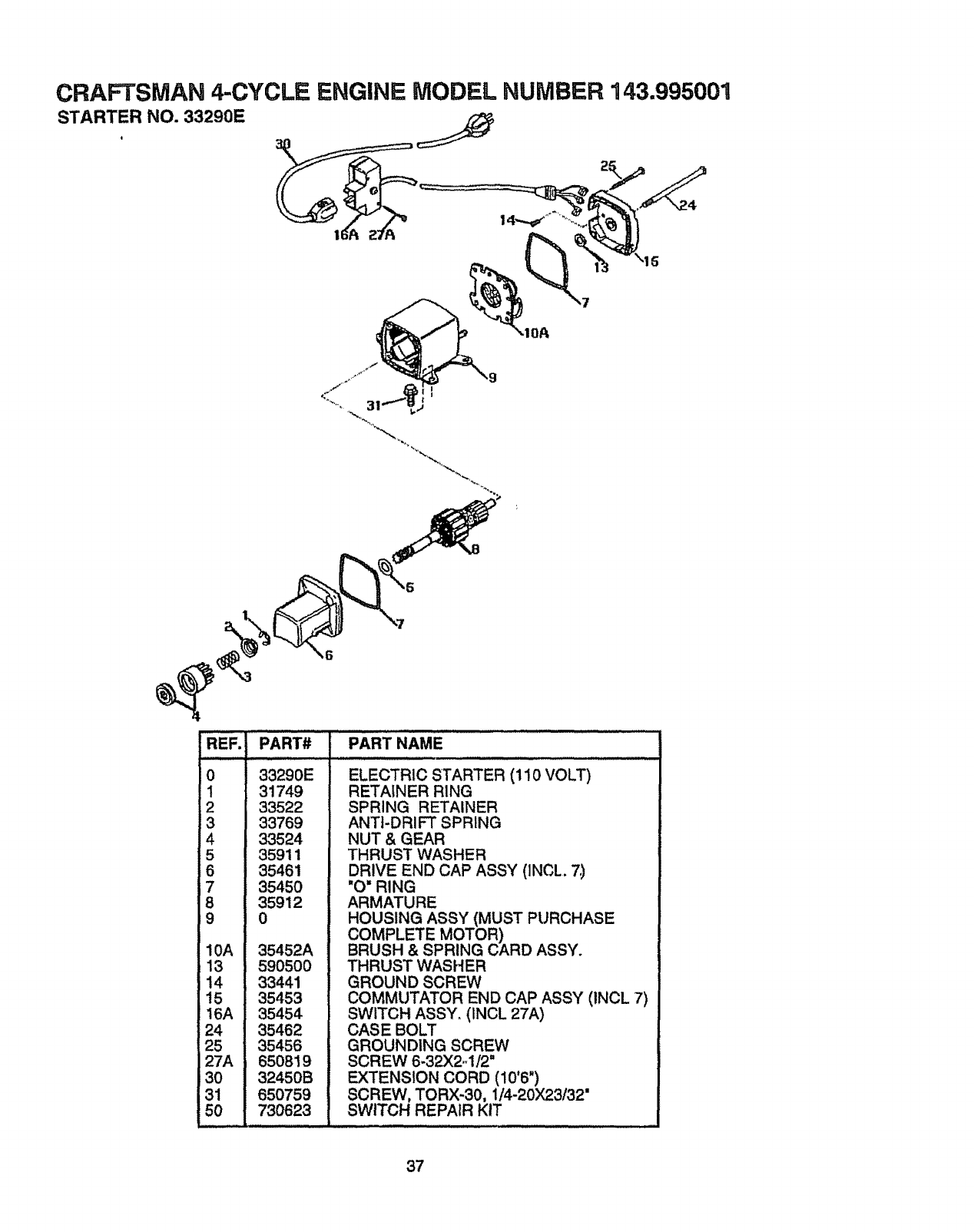
CRAFTSMAN 4-CYCLE ENGINE MODEL NUMBER 143.995001
STARTER NO. 33290E
PART#
33290E
31749
33522
33769
33524
35911
35461
35450
35912
0
PART NAME
35452A
5905o0
33441
35453
35454
35462
35456
650819
32450B
650759
730623
0
1
4
5
6
7
8
9
10A
13
14
15
16A
24
25
27A
30
31
50
ELECTRIC STARTER (110 VOLT)
RETAINER RING
SPRING RETAINER
ANTI-DRIFT SPRING
NUT & GEAR
THRUST WASHER
DRIVE END CAP ASS',( (INCL. 7,)
"O" RING
ARMATURE
HOUSING ASSY (MUST PURCHASE
COMPLETE MOTOR)
BRUSH & SPRING CARD ASSY.
THRUST WASHER
GROUND SCREW
COMMUTATOR END CAP ASSY (1NCL 7)
SWITCH ASSY. (INCL 27A)
CASE BOLT
GROUNDING SCREW
SCREW 6-32X2.-1/2"
EXTENSION CORD (10'6")
SCREW, TORX-30, 1/4-20X23!32"
SWITCH REPAIR KIT
37
REMOVEDORADENIEVE
Tabla de contenidos 38
Garantia 38
Reglas de seguridad 38-40
Contenido del paquete con articulos de
ferreteria 41
Montaje 42-45
Operacion 45-52
Mantemiento 52_54
Servicio y Ajustes 55-60
Almacenamiento 61
Solucion de problemas 62
Pedido/Servicio de Piezas 64
GARANTIA LIMITADA DOS ANOS SOBRE LA REMOVEDORA DE NIEVE
CRAFTSMAN
Durante dos aSos a partir de la fecha de compra, cuando esta Removedora de nieve
Craftsman sea mantenidad, lubricada y afinada de acuaredo con las instrucciones en el
manual det propietario, CRAFTSMAN reparard, sin recargo alguno, cualquier defecto en
matedales y mano de obra.
Si esta Removedora de nieve Craftsman se usa para prop6sitos comerciales o de
arrendamiento, esta garantia es vdlida durante 90 dfas a partir de la fecha de compra.
Esta garantfa no cubre Io siguiente:
•Elementos fungibles los cuales se gastan durante el uso normal, tales como bujfas,
correas de transmisi6n y clavijas de seguro por esfuerzo codante.
•Reparaciones necesarias debido al abuso o negligencia del operador, incluyendo
cigt_eSales doblados y ia falta de mantenimiento del equipo de acuerdo con las
instrucciones contenidas en el manual del propietario.
EL SERVICIO DE GARANTIA SE PUEDE OBTENER AL DEVOLVER LA REMOVEDORA
DE NIEVE CRAFTSMAN AL CENTRO/DEPARTAMENTO DE SERVlCIO CRAFTSMAN
MAS CERCANO EN LOS ESTADOS UNIDOS. ESTA GARANTIA ES VALIDA SOLO
CUANDO ESTE PRODUCTO SEA USADO EN LOS ESTADOS UNIDOS.
Esta garantfa le otorga derechos tegales especfficos, y asimismo es posible que tenga
otros derechos los cuales vart'an de estado a estado.
Sears Roebuck and Co. D817WA Hoffman IL 60179
el alambre de la bujia y coloquelo donde no
haga contacto contacto con el bujia para
evitar un arranque accidental al montar,
transportar, ajustar o efectuar reparaciones.
IMPORTANTE: Los estandares de sugridad
requieren la presencia del operador en los
controles para minimizar el riesgo de
heridas. Su removerdora de nieve esta
equipada con dichos controles. No intente
pasar por alto la funcion del control de
presencla del operador bajo ninguna
¢ircumstancia.
,_ Busque este simbolo para destacar precauclones de seguridad importantes.
Esto significa--llIATENClON!ll !IIESTEIll U seguridad esta de por medio.
PRECAUClON: Siempre desconecte J_r_ California Proposition65 '_r !
'" ADVERTENCIA: '
Las emanaciones de escape
producidas por este motor
contienen qu_mtcos reconoc_dos
por el Estado de California como
carcin6genos, tambi_n pueden
produeir defectos en los recidn
nacldos o causar otros daSos al
sistema reproductivo.
................ 'H ' ' "'"'"
CAPACITAClON
1. Lea et manual del operador
cuidadosamente° Familiaricese
completamente con los controles y el uso
apropiada.Sepa c6mo detener la
removedora de nieve y desenganchar los
controles rdpidamente.
38
2oNunca permita a nifios operar la
removedora de nieve y mant_ngalos
fuera del alcance de la misma mientras
se encuentra en operaci6n. Nunca
permita que adultos operen la
removedora de nieve sin instrucciSn
apropiadao No fleve pasajeros.
3. Mantenga el &rea iibre de personas,
especialmente niSos pequeSos y
mascotas.
4. Tenga precauci6n a fin de evitar
deslizamientos o cafdas, especialmente
al operar la removedora de nieve
enretroceso.
PREPARAClON
1. lnspeccione completamente el _rea
donde se usar& la removedora de nieve
y retire todas las esteras, trineos,
tableros, alambres, y otros objetos
extra5os.
2. Desenganche todos los embragues
antes de arrancar el motor°
3. No opere la removedora de nieve sin
vestir ias prendas de inviemo adecuadas
para ambientes exteriores. Vista calzado
que mejore su estabilidad en superficies
lisas.
4. Maneje el combustible con cuidado; es
altamente inflamable.
(a) Use un contenedor para combustible
aprobado.
(b) Nunca retire la tapadera del tanque
de combustible o a5ada combustible a
un motor en marcha o a un motor
caliente.
(c) Uene el tanque para combustible al
aire libre, con cuidado extremo. Nunca
Ilene el tanque en ambientes interiores.
(d) Coloque nuevamente la tapadera del
tanque para combustible de manera
segura y limpie el combustible
derramado.
(e) Nunca almacene combustible o la
removedora de nieve con combustible
en el tanque dentro de un edificio donde
los vapores pudiesen entrar en contacto
con una llama desprotegida o una
chispa.
(f) Vedfique las existencias de combus-
tible antes de cada uso, permitiendo
espacio para expansi6n puesto que el
calor del motor ylo el sol pueden causar
ta expansiSn del combustible.
5. Use cables de extensi6n yrecept&culos
de la manera especificada por el
fabricante para todas ias removedorasde
nieve con motores accionados pot
energfa el_ctrica o motores de arranque
el_ctrico.
6oAjuste la altura de la removedora de nieve
para pasar sobre superficies degrava o
piedra triturada.
7. Jam&s intente efectuar ning_n ajuste
mientras el motor se encuentra en marcha
(excepto cuando el fabricante Io
recomiende asf especificamente).
8. Permita que el motor y la removedora de
nieve se ajusten alas temperaturas
exteriores antes de comenzar a retirar la
nieve.
9. Siempre use gafas de seguridad o
protectores para los ojos durante la
operact'on o mientras se efectSa un ajuste
o reparaci6n para proteger sus ojos de
objetos extraSos que pudiesen ser
lanzados'por la removedora de nieveo
OPERACION
1. Prestare attenzione al traffico quando so
attraversano carreggiate o si usa il
trattorino in prossimit& di esse.
2oPrestare la massima attenzione quando si
carica o scafica la machina quando viene
usato un rimorchio o un camion per il
trasporto.
3. No coloque las manos o los pies cerca o
bajo piezas rotativas. Mant_ngase a
distancia de la abertura para descarga
todo el tiempo.
4. Tenga precauci6n extrema la operar
sobre o al cruzar caminos, aceras, o
calles de grava. Mant_ngase alerta en
caso de peligros ocultos o tr&fico.
5. Despu_s de golper un objeto extraSo,
pare el motor, retire el alambre de la bujra,
desconecte el cable en motores
el_ctricos, inspeccione completamente la
removedora de nieve a fin de encontrar
cualquier dafio, y reparar dicho daSo
antes de arrancar y operar la removedora
de nieve nuevamente.
6. En el caso de que ia removedora de nieve
comience a vibrar fuera de 1onormal, pare
el motor y revise la m&quina
inmediatamente para encontrar la causa.
Generalmente, la vibraci6n es una
advertencia de problemas.
7. Pare el motor dondequiera que deje ta
posici6n de operaciSn, antes de
desobstruir el alojamiento del barreno/
39
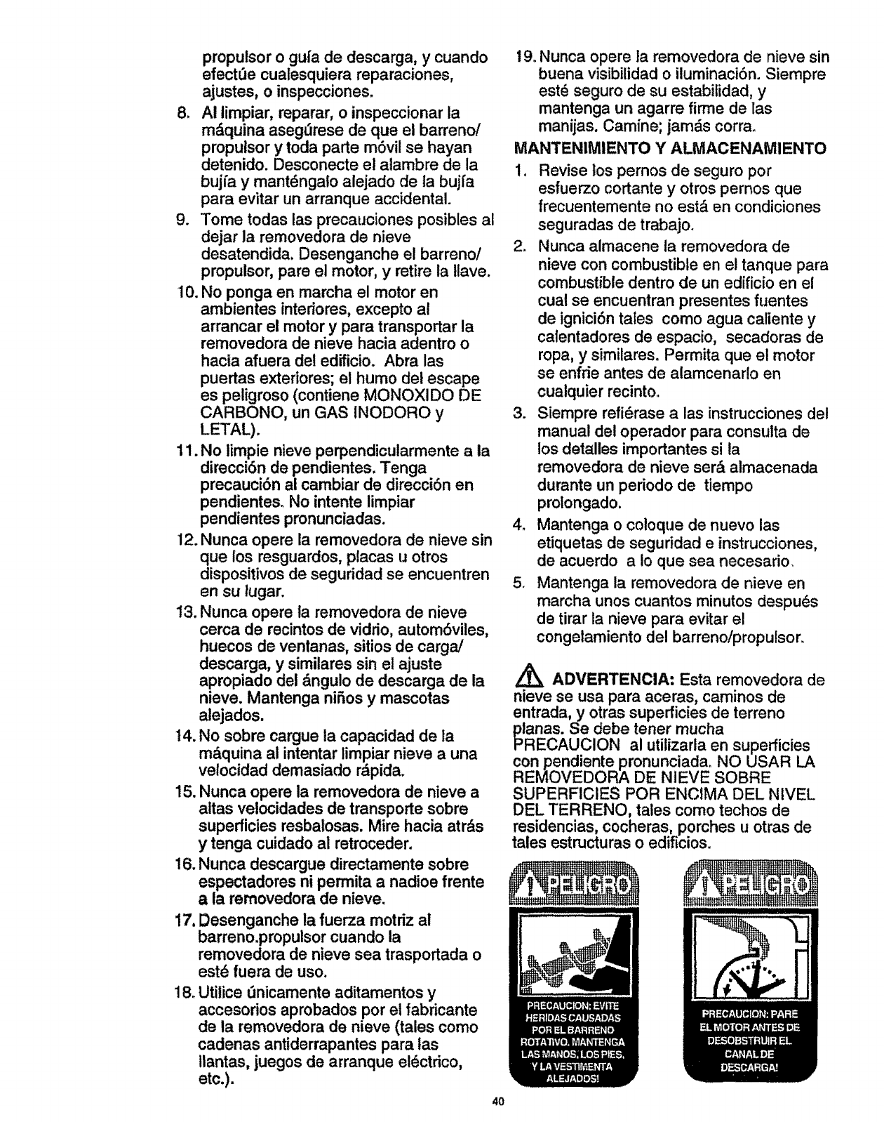
proputsor o gui'a de descarga, y cuando
efectL_e cualesquiera reparaciones,
ajustes, o inspecciones.
8. AI limpiar, reparar, o inspeccionar la
m_quina aseg_rese de que el barreno!
propulsor y toda parte mSvil se hayan
detenido. Desconecte el alambre de la
bujfa y mant_ngato alejado de la bujfa
para evitar un arranque accidental.
9. Tome todas las precauciones posibles al
dejar la removedora de nieve
desatendida. Desenganche el barreno/
propulsor, pare el motor, y retire ia tlave,
I0. No ponga en marcha el motor en
ambientes interiores, excepto al
arrancar el motor y para transportar la
removedora de nieve hacia adentro o
hacia afuera del edificio. Abra las
puertas exteriores; el humo del escape
es peligroso (contiene MONOXIDO DE
CARBONO, un GAS INODORO y
LETAL).
11. No limpie nieve perpendicularmente a la
direcciSn de pendientes. Tenga
precauci6n al cambiar de direcciSn en
pendienteso No intente limpiar
pendientes pronunciadas.
12. Nunca opere la removedora de nieve sin
que los resguardos, placas u otros
dispositivos de seguridad se encuentren
en su lugar.
13. Nunca opere la removedora de nieve
cerca de recintos de vidrio, automSviles,
huecos de ventanas, sitios de carga/
descarga, y similares sin el ajuste
apropiado del &ngulo de descarga de la
nieve. Mantenga nifios y mascotas
alejados.
14. No sobre cargue la capacidad de la
m&quina al intentar limpiar nieve a una
velocidad demasiado r_pida.
15. Nunca opere la removedora de nieve a
altas velocidades de transporte sobre
superficies resbalosas. Mire hacia atr&s
y tenga cuidado al retroceder.
16. Nunca descargue directamente sobre
espectadores ni permita a nadioe frente
ala removedora de nieve.
17. Desenganche la fuerza motriz al
barreno.propulsor cuando la
removedora de nieve sea trasportada o
estd fuera de uso.
18. Utitice dnicamente aditamentos y
accesodos aprobados por et fabricante
de la removedora de nieve (tales como
cadenas antiderrapantes para tas
tlantas, juegos de arranque eldctrico,
etc.).
4O
19. Nunca opere la removedora de nieve sin
buena visibilidad o iluminaciSn. Siempre
est6 seguro de su estabilidad, y
mantenga un agarre firme de las
manijas. Camine; jamds corra.
MANTENIMIENTO Y ALMACENAMIENTO
1, Revise los pernos de seguro por
esfuerzo cortante yotros pernos que
frecuentemente no estd en condiciones
seguradas de trabajo.
2. Nunca almacene la removedora de
nieve con combustible en el tanque para
combustible dentro de un edificio en el
cuat se encuentran presentes fuentes
de igniciSn tales como agua catiente y
ca{entadores de espacio, secadoras de
ropa, y similares. Permita que el motor
se enfrie antes de alamcenarlo en
cualquier recinto.
3. Siempre refi_rase alas instrucciones de!
manual del operador para consulta de
los detalles importantes si la
removedora de nieve ser& almacenada
durante un periodo de tiempo
prolongado.
4. Mantenga o coloque de nuevo las
etiquetas de seguddad e instrucciones,
de acuerdo a Io que sea necesario.
5. Mantenga la removedora de nieve en
marcha unos cuantos minutos despu6s
de tirar la nieve para evitar el
congelamiento del barreno!propulsor.
AADVERTENClA. Esta removedora de
nieve se usa para aceras, caminos de
entrada, y otras superficies de terreno
_lanas. Se debe tener rnucha
RECAUClON al utilizarla en superficies
con pendiente pronunciada. NO USAR LA
REMOVEDORA DE NIEVE SOBRE
SUPERFICIES POR ENCIMA DEL NIVEL
DEL TERRENO, tales como techos de
residencias, cocheras, porches uotras de
tales estructuras o edificios.
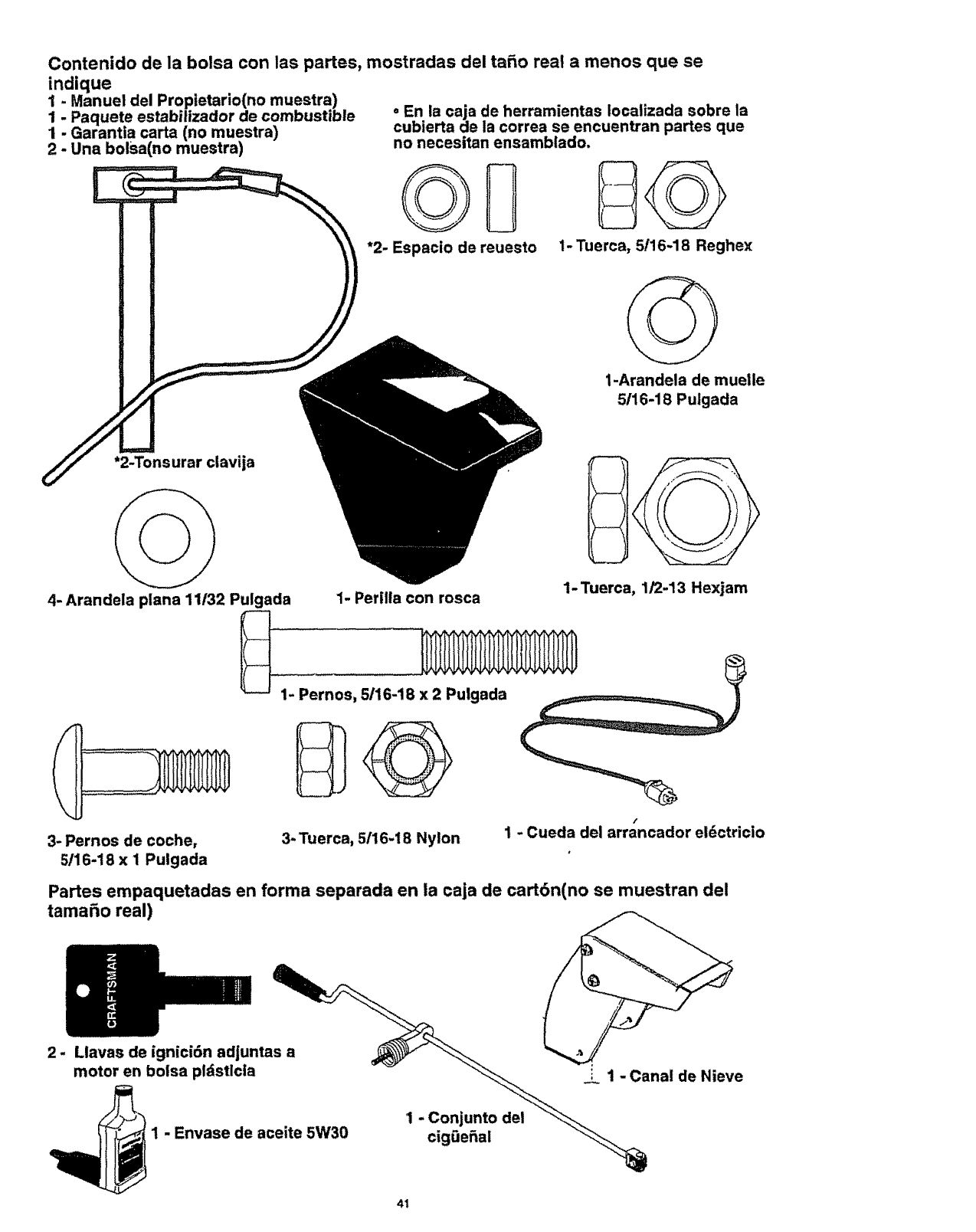
indique
1. Manuel del Proptetario(no muestra)
1 Paquete estabilizador de combustible
1 Garantia carta (no muestra)
2-Una bolsa(no muestra)
Contenido de la boisa con las partes, mostradas del taro real a menos que se
= En ia caja de herramientas Iocalizada sobre la
cubierta de la correa se encuentran partes que
no necesitan ensamblado.
%U
*2- Espacio de reuesto 1- Tuerca, 5/16-18 Reghex
*2-Tonsurar clavija
4- Arandela plana 11/32 Pulgada
3- Pernos de coche,
5/16-18 x 1 Pulgada
1-Arandela de muelle
5/16-18 Puigada
1- Tuerca, 1/2-13 Hexjam
1- Perilla con rosca
3- Tuerca, 5/16-18 Nylon
/
1-Cueda del arrancador eldctricio
Partes empaquetadas en forma separada en la caja de cart6n(no se muestran del
tamaSo real)
2- Llavas de ignici6n adjunta___-_..._
motor en bolsa pldsticla - "_ __ __ 1 - Canal de Nieve
_ ...... 1 - Conjunto del "_--_
__1 Envase de aceite 5W30 cigOe_al
41
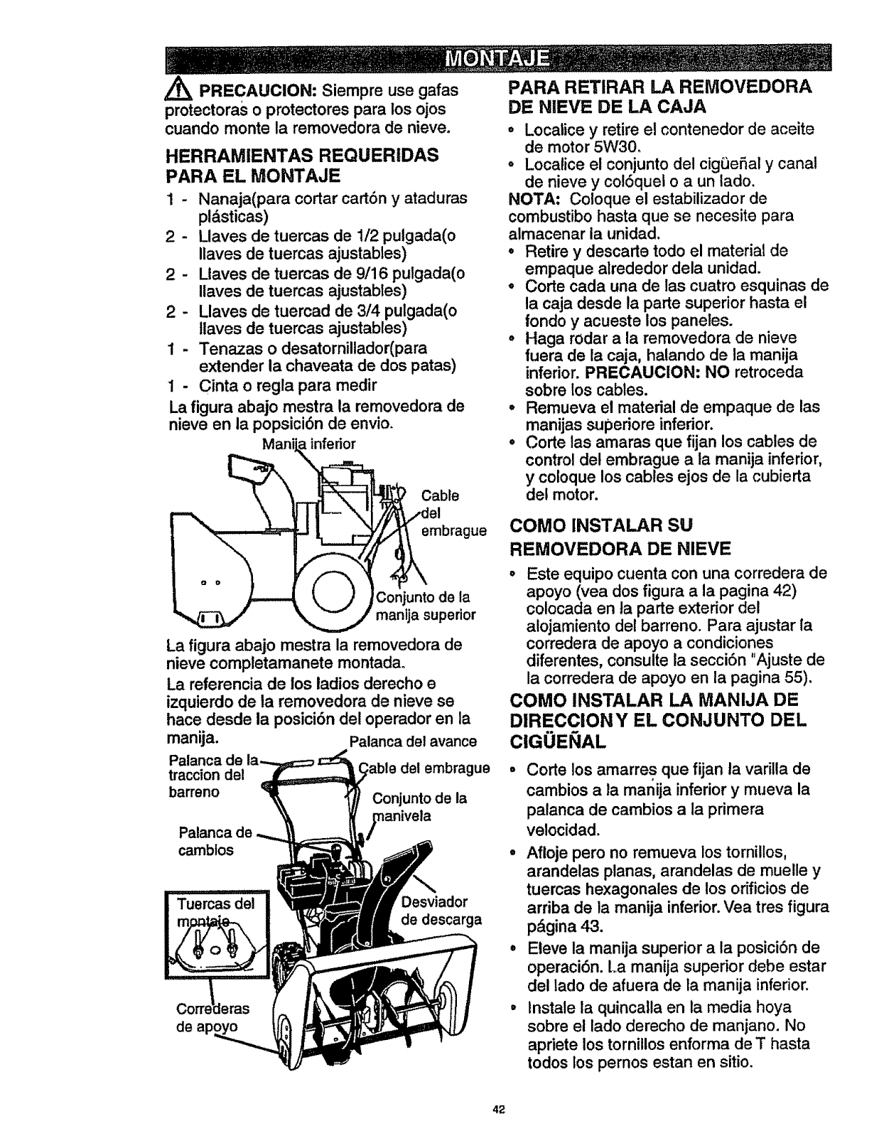
Z_ PRECAUClON: Siempre use gafas
protectoras o protectores para los ojos
cuando monte la removedora de nieve.
HERRAMIENTAS REQUERIDAS
PARA EL MONTAJE
1 - Nanaja(para cortar cart6n y ataduras
pl&sticas)
2 - Llaves de tuercas de 1/2 pulgada(o
Ilaves de tuercas ajustables)
2 - l_taves de tuercas de 9/16 pulgada(o
Ilaves de tuercas ajustables)
2-Llaves de tuercad de 3/4 pulgada(o
llaves de tuercas ajustables)
1-Tenazas o desatornillador(para
extender la chaveata de dos patas)
1- Cinta o regla para medir
La figura abajo mestra la removedora de
nieve en la popsici6n de envio.
'-'-._ ",, I!'-- ''d°l
--.. J e,'.bra .e
__ _manija superior
La figura abajo mestra la removedora de
nieve completamanete montada°
La referencia de los ladios derecho e
izquierdo de ia removedora de nieve se
hace desde la posici6n del operador en la
manija. Palanca del avance
Palanca de
traccion del del embrague
barreno Conjunto de la
Palanca
cambtos
Desviador
de descarga
de
PARA RETIRAR LA REMOVEDORA
DE NIEVE DE LA CAJA
oLocalice y retire el contenedor de aceite
de motor 5W30.
°Locatice el conjunto del cig0eSal y canal
de nieve y co!6quet o a un lado.
NOTA: Coloque el estabilizador de
combustibo hasta que se necesite para
almacenar la unidad.
°Retire y descarte todo el material de
empaque alrededor dela unidad.
•Corte cada una de las cuatro esquinas de
la caja desde la parte superior hasta el
fondo y acueste los paneles.
° Haga rodar a la removedora de nieve
fuera de la caja, halando de la manija
inferior. PRECAUClON: NO retroceda
sobre los cables.
°Remueva el material de empaque de las
manijas superiore inferior.
•Corte las amaras que fijan los cables de
control del embrague a la manija inferior,
y coloque los cables ejos de la cubierta
del motor.
COMO INSTALAR SU
REMOVEDORA DE NIEVE
o Este equipo cuenta con una corredera de
apoyo (yea dos figura a la pagina 42)
colocada en ta parte exterior del
alojamiento det barreno. Para ajustar la
corredera de apoyo a condiciones
diferentes, consulte ia secci6n "Ajuste de
la corredera de apoyo en la pagina 55).
COMO INSTALAR LA MANIJA DE
DIRECCIONY EL CONJUNTO DEL
ClGOEi_IAL
Corte los amarres que fijan ta varilla de
cambios ala manija inferior y mueva la
palanca de cambios a la primera
velocidad.
•Afloje pero no remueva los torniltos,
arandelas planas, arandelas de muelle y
tuercas hexagonales de los orificios de
arriba de la manija inferior. Vea tres figura
p&gina 43.
° Eleve la manija superior a la posici6n de
operaci6n. La manija superior debe estar
del lado de afuera de la manija inferior.
°Instale la quincalla en la media hoya
sobre el lado derecho de manjano. No
apriete los torniilos enforma de T hasta
todos los pemos estan en sitio.
42
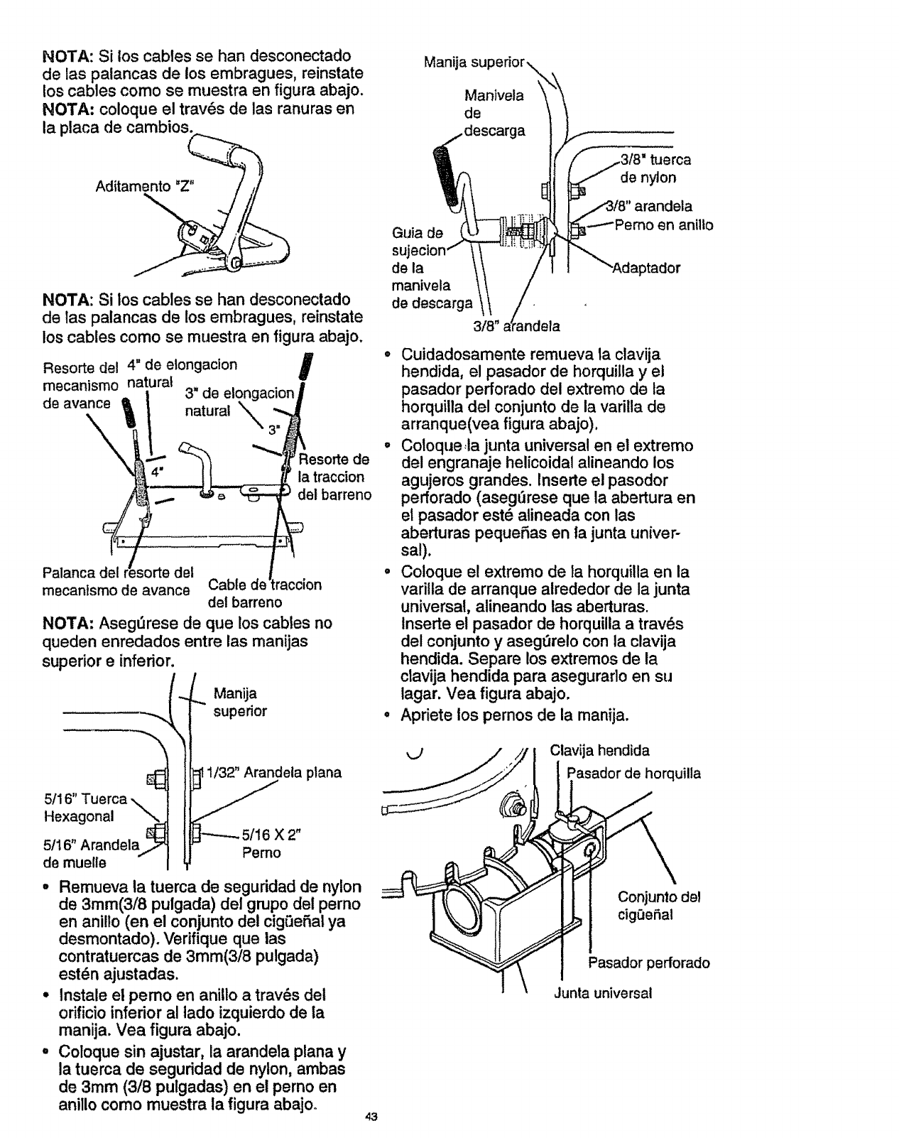
NOTA: Si los cables se han desconectado
de las palancas de los embragues, reinstate
los cables como se muestra en figura abajo.
NOTA" coloque el trav6s de las ranuras en
la placa de cambios_.....__._.
Aditamento "Z" _
NOTA: $i los cables se han desconectado
de las palancas de los embragues, reinstate
los cables como se muestra en figura abajo.
4" de etongacion I
Resorte del
mecanismo natural
de avance 3" de
Resorte de
ta traccion
del barreno
Palanca del
mecanIsmo de avance Cable
del barreno
NOTA: AsegvJrese de que los cables no
queden enredados entre las manijas
superior e inferior.
Manija
supedor
Maniveta
de
tuerca
de nylon
Guia de
suj,
de la
manivela
de descarga
3/8"
en anillo
• Cuidadosamente remueva la clavija
hendida, el pasador de horquilla y et
pasador perforado del extremo de ta
horquiila del conjunto de la varilla de
arranque(vea figura abajo),
° Coloque.,ia junta universal en el extremo
del engranaje helicoidal alineando los
agujeros grandes, tnserte el pasodor
pefforado (asegt'Jrese que la abertura en
el pasador est6 atineada con las
aberturas pequefas en la junta univer-
sal).
• Coloque el extremo de la horquilla en la
variila de arranque alrededor de la junta
universal, alineando las aberturas.
Inserte el pasador de horquilla a trav_s
del conjunto y asegt3relo con la clavija
hendida. Separe los extremos de la
clavija hendida para asegurarlo en su
iagar. Vea figura abajo.
o Apdete los pernos de la manija.
5/16" Tuerca
Hexagonal "'_,.
5/16" Arandela_
de muelte
1/32" Arandela plana
X 2"
Pemo
•Remueva la tuerca de seguddad de nylon
de 3mm(3/8 pulgada) del grupo del perno
en anillo (en el conjunto del cigi3eSal ya
desmontado). Verifique que ias
contratuercas de 3mm(3/8 pulgada)
est_n ajustadas.
° Instale el pemo en aniUo a trav_s del
orificio inferior al iado izquierdo de la
manija. Vea figura abajo.
° Coloque sin ajustar, la arandela plana y
la tuerca de seguridad de nylon, ambas
de 3mm (3/8 pulgadas) en el perno en
anillo como muestra la figura abajo° 43
Clavija hendida
Pasador de horquilla
Conjunto del
cigQeSal
Pasador perforado
Junta universal
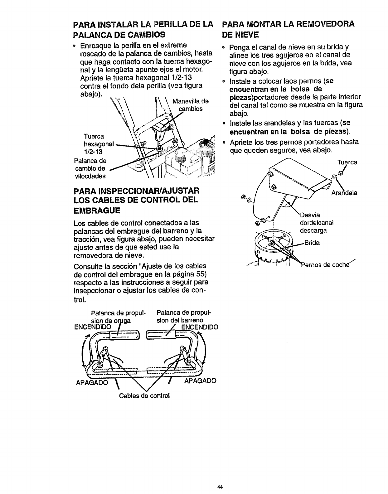
PARA INSTALAR LA PERILLA DE LA
PALANCA DE CAMBIOS
Enrosque la perilla en el extreme
roscado de la palanca de cambios, hasta
que haga contacto con la tuerca hexago-
nal y la lengeeta apunte ejos el motor.
Apriete la tuerca hexagonal 1/2-13
contra el fondo dela perilla (vea figura
abajo).
\ ,\ _ , Manevitla de
muerca
hexagonal
1/2-13
Palanca de
cambio de
vilocdades
PARA INSPECClONAR/AJUSTAR
LOS CABLES DE CONTROL DEL
EMBRAGUE
Los cables de control conectados alas
palancas del embrague del barreno y la
tracci6n, vea figura abajo, pueden necesitar
ajuste antes de que ested use la
removedora de nieve.
Consulte la seccibn "Ajuste de los cables
de control del embrague en la p&gina 55)
respecto a ias instrucciones a seguir para
insepccionar o ajustar los cables de con-
trol.
Palanca de propul- Patanca de propul-
sionde or,uga siondel barreno
ENCENDIDO !_.__.___ _/_ ENCENDIDO
.......\.._ /APAOADO
Cables de control
PARA MONTAR LA REMOVEDORA
DE NIEVE
o Ponga el canal de nieve en su brida y
alinee los tres agujeros en el canal de
nieve con los agujeros en la brida, vea
figura abajo.
• !nstale a coiocar laos pernos (se
encuentran en la bolsa de
plezas)portadores desde la parte interior
del canal tal como se muestra en la figura
abajo.
=Instale las arandelas y las tuercas (se
encuentran en la bolsa de piezas).
°Apriete los tres pernos portadores hasta
que queden seguros, yea abajo.
dordelcanal
descarga
de coche"""
44
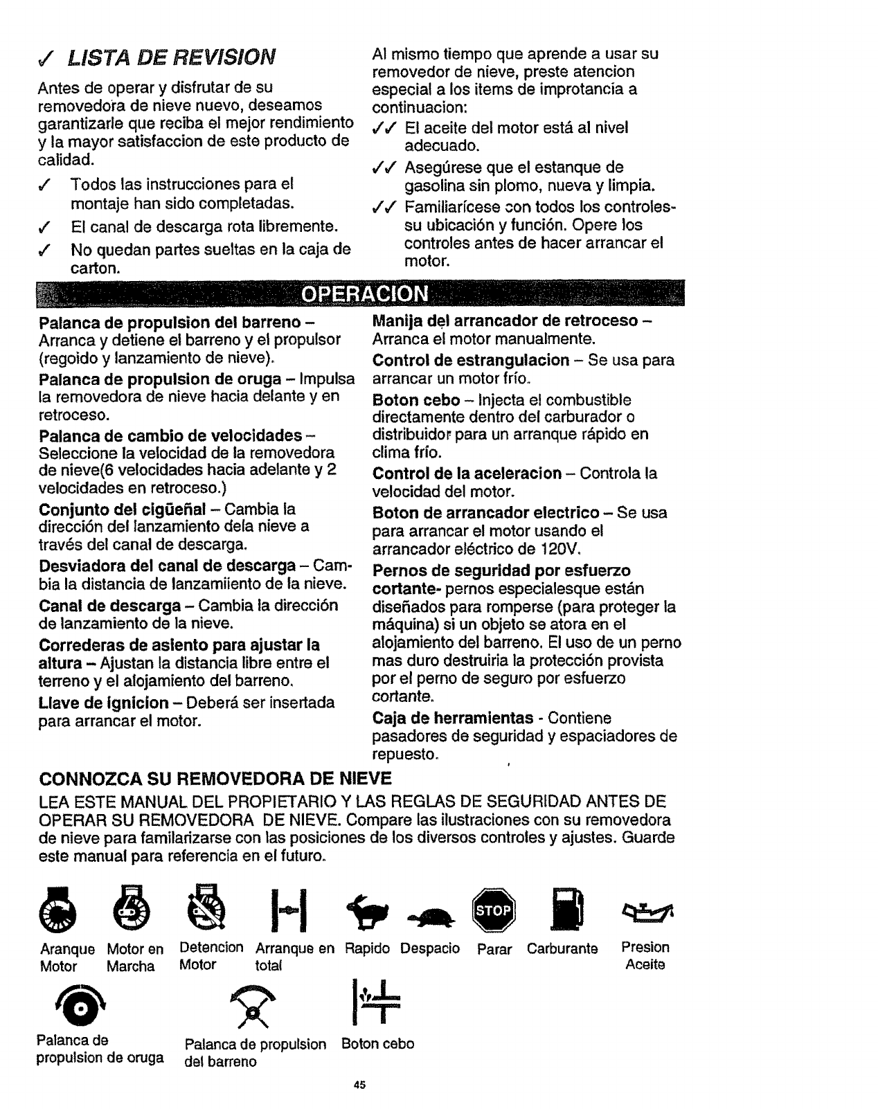
v" LISTA DE REViSiON
Antes de operar y disfrutar de su
removedora de nieve nuevo, deseamos
garantizarle que reciba el mejor rendimiento
y la mayor satisfaccion de este producto de
calidad.
JTodos las instrucciones para el
montaje han sido completadas.
€" Et canal de descarga rota libremente.
#" No quedan partes sueltas en la caja de
carton.
AI mismo tiempo que aprende a usar su
removedor de nieve, preste atencion
especial a los items de improtancia a
continuacion:
,/'#' E! aceite del motor est& al nivel
adecuado.
,,Iv" Aseg0rese que el estanque de
gasolina sin plomo, nueva y limpia.
#'_/ Familiar[cese con todos los controles-
su ubicaci6n y funci6n. Opere los
controles antes de hacer arrancar el
motor.
Palanca de propulsion del barreno -
Arranca y detiene et barreno y el propulsor
(regoido y lanzamiento de nieve)°
Palanca de propulsion de oruga - Impulsa
la removedora de nieve hacia delante yen
retroceso.
Palanca de cambio de velocidades -
Seleccione la veiocidad de la removedora
de nieve(6 velocidades hacia adelante y 2
velocidades en retroceso.)
Conjunto del cig0eiial- Cambia ia
direcci6n del lanzamiento dela nieve a
trav6s del canal de descarga.
Desviadora del canal de descarga - Cam-
bia la distancia de lanzamiiento de la nieve.
Canal de descarga - Cambia ta direcci6n
de lanzamiento de la nieve,
Correderas de aslento para ajustar la
altura - Ajustan ta distancialibre entre el
terreno y el alojamientodel barreno.
Llave de ignition - Deberd ser insertada
para arrancar el motor.
Manija del arrancador de retroceso -
Arranca el motor manualmente.
Control de estrangulacion - Se usa para
arrancar un motor fr{o.
Boton cebo - Injecta e! combustible
directamente dentro del carburador o
distribuidor para un arranque rdpido en
clima fr{o.
Control de la aceleracion - Controla la
velocidad del motor,
Boton de arrancador electrico - Se usa
para arrancar el motor usando el
arrancador el_ctdco de 120V,
Pernos de seguridad por esfuerzo
cortante- pernos especialesqueest&n
disefiadospara romperse(para proteger la
m&quina)si un objetose atora en el
alojamientodel barreno. El uso de un perno
mas duro destruiriala protecci6nprovista
por el pernode seguro por esfuerzo
cortante.
Caja de herramlentas - Contiene
pasadores de seguridad y espaciadores de
repuesto.
CONNOZCA SU REMOVEDORA DE NIEVE
LEA ESTE MANUAL DEL PROPIETARIO Y LAS REGLAS DE SEGURfDAD ANTES DE
OPERAR SU REMOVEDORA DE NIEVE. Compare las ilustraciones con su removedora
de nieve para familarizarse con las posiciones de los diversos controles y ajustes. Guarde
este manual para referencia en el futuro°
H
Aranque Motor en Detencion Arranqus en Rapido Despacio Parar Carburante Presion
Motor Marcha Motor total Aceite
Palanca de Palanca de propulsion Boton cebo
propulsion de oruga dsl barreno
45
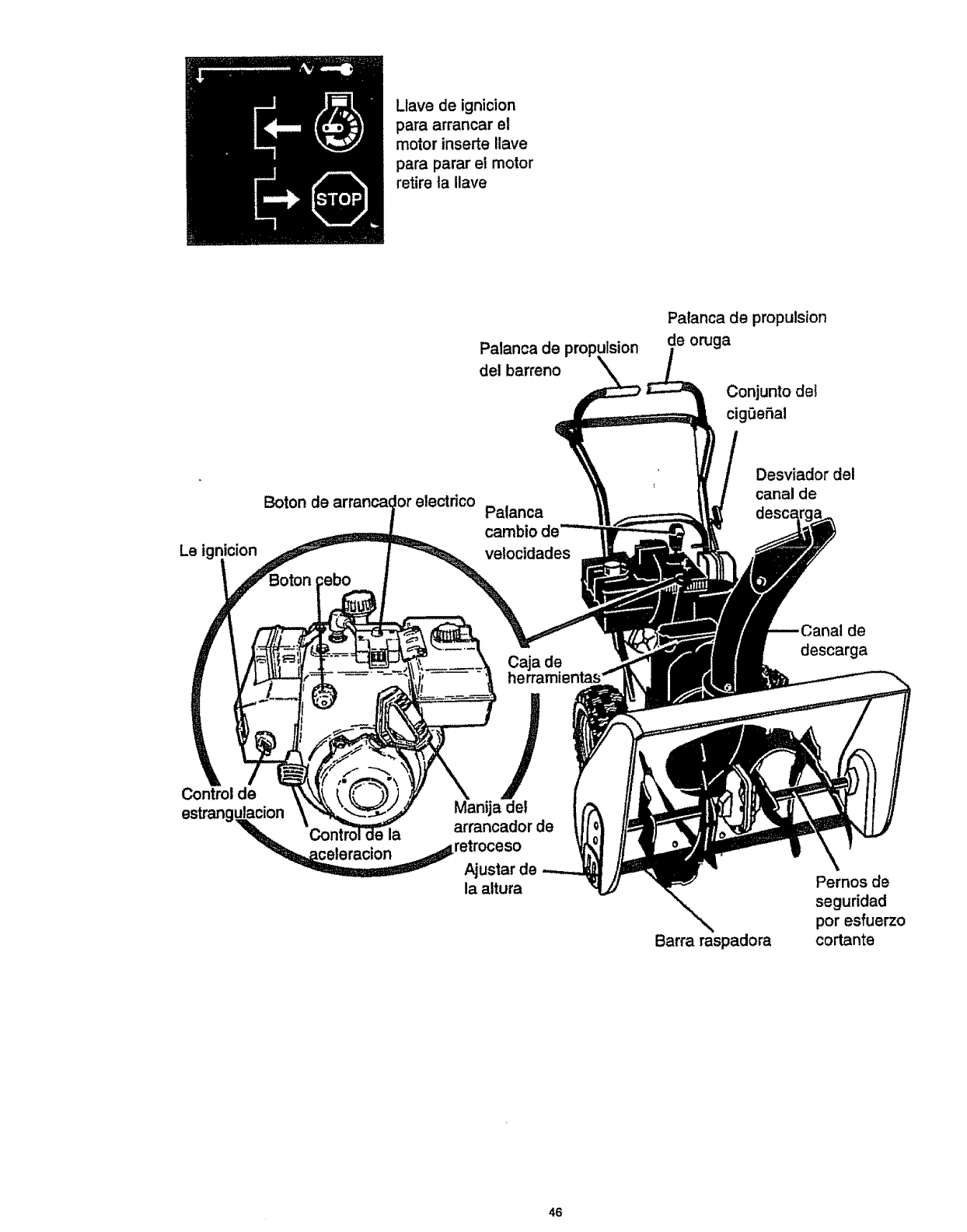
Llave de ignicion
para arrancar el
motor inserte Ilave
para parar el motor
retire ta Ilave
Palanca de propulsion
del barreno
Patanca de propulsion
de oruga
Conjunto del
cig0eSal
Le ignicion
Boron electdco Patanca
cambio
velocidades
Desviador del
canal de
Caja de
de
descarga
Control de
estrangulacion Manija de!
'_'_'_L la arrancador de
"_celeracion _=_retroceso
Ajustar de
la altura
Barra raspadora
Pernos de
seguridad
pot esfuerzo
cortante
46
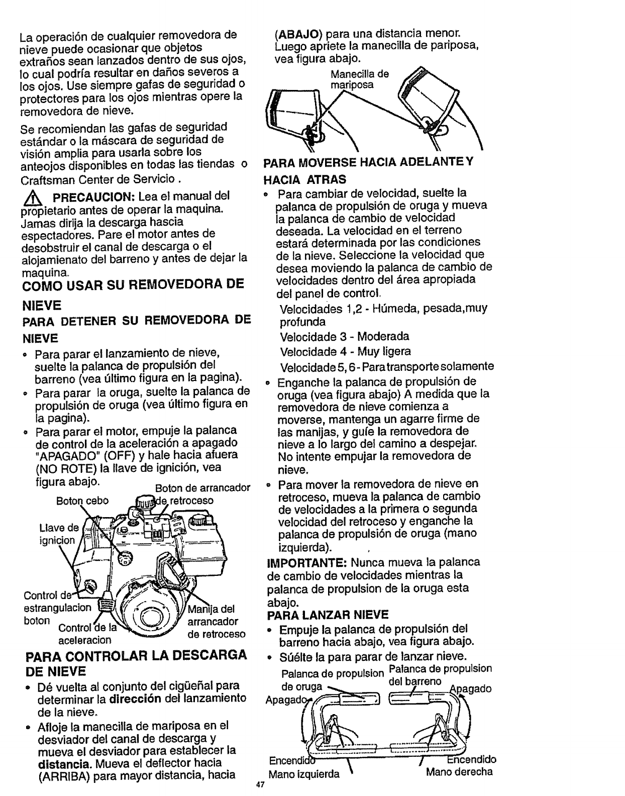
La operaciSn de cuatquier removedora de
nieve puede ocasionar que objetos
extrafios sean tanzados dentro de sus ojos,
Io cual podrfa resuttar en dafios severos a
los ojos. Use siempre gafas de seguridad o
protectores para los ojos mientras opere la
rernovedora de nieve.
Se recomiendan las gafas de seguridad
estS.ndar o la m_scara de seguridad de
visiSn amplia para usarla sobre los
anteojos disponibles en todas las tiendas o
Craftsman Center de Servicio.
Z_ PRECAUClON: Lea el manual del
propietario antes de operar la maquina.
Jamas dirija la descarga hascia
espectadores. Pare el motor antes de
desobstruir el canal de descarga o el
atojamienato del barreno y antes de dejar ia
maquina°
COMO USAR SU REMOVEDORA DE
NIEVE
PARA DETENER SU REMOVEDORA DE
NIEVE
•Para parar et ianzamiento de nieve,
suelte la palanca de propulsiSn del
barreno (yea t/itimo figura en la pagina).
° Para parar ta oruga, suelte la palanca de
propulsiSn de oruga (vea 51timo figura en
la pagina).
• Para parar el motor, empuje la palanca
de control de la aceleraciSn a apagado
"APAGADO" (OFF) y hale hacia afuera
(NO ROTE) la llave de igniciSn, vea
flgura abajo. Boton de arrancador
cebo retroceso
Llave de
ignk
Control
estrangulacion
boton arrancador
aceleracion de retroceso
PARA CONTROLAR LA DESCARGA
DE NIEVE
°D_ vuelta al conjunto del cig0eSat para
determinar la dlrecciSn del lanzamiento
de la nieve°
° Afloje la manecilla de mariposa en el
desviador del canal de descarga y
mueva el desviador para establecer la
distancia. Mueva el deflector hacia
(ARRIBA) para mayor distancia, hacia 47
(ABAJO) para una distancia menor.
Luego apriete la maneci!la de padposa,
yea figura abajo.
Manecillade
\
PARA MOVERSE HACIA ADELANTE Y
HACIA ATRAS
°Para cambiar de velocidad, suelte la
palanca de propulsiSn de oruga y mueva
la palanca de cambio de velocidad
deseada. La velocidad en el terreno
estard determinada por las condiciones
de la nieve. Seleccione la velocidad que
desea moviendo la patanca de cambio de
ve!ocidades dentro del drea apropiada
del panel de control.
Velocidades 1,2 -Hdmeda, pesada,muy
profunda
Velocidade 3 - Moderada
Velocidade 4 - Muy ligera
Velocidade 5, 6- Para transporte sotamente
• Enganche la palanca de propulsiSn de
oruga (yea figura abajo) A medida que la
removedora de nieve comienza a
moverse, mantenga un agarre firme de
tas manijas, y gufe la removedora de
nieve a Io largo del camino a despejar.
No intente empujar la removedora de
nieve.
= Para mover la removedora de nieve en
retroceso, mueva la palanca de cambio
de velocidades a la primera o segunda
velocidad del retroceso y enganche la
palanca de propulsiSn de oruga (mano
izquierda).
IMPORTANTE: Nunca mueva ]a palanca
de cambio de velocidades mientras la
palanca de propulsion de la oruga esta
abajo.
PARA LANZAR NIEVE
,Empuje la palanca de propulsiSn del
barreno hacia abajo, yea figura abajo.
°S_61te la para parar de lanzar nieve.
Palancade propulsionPatancade propulsion
agado
)
;endido
Mano derecha
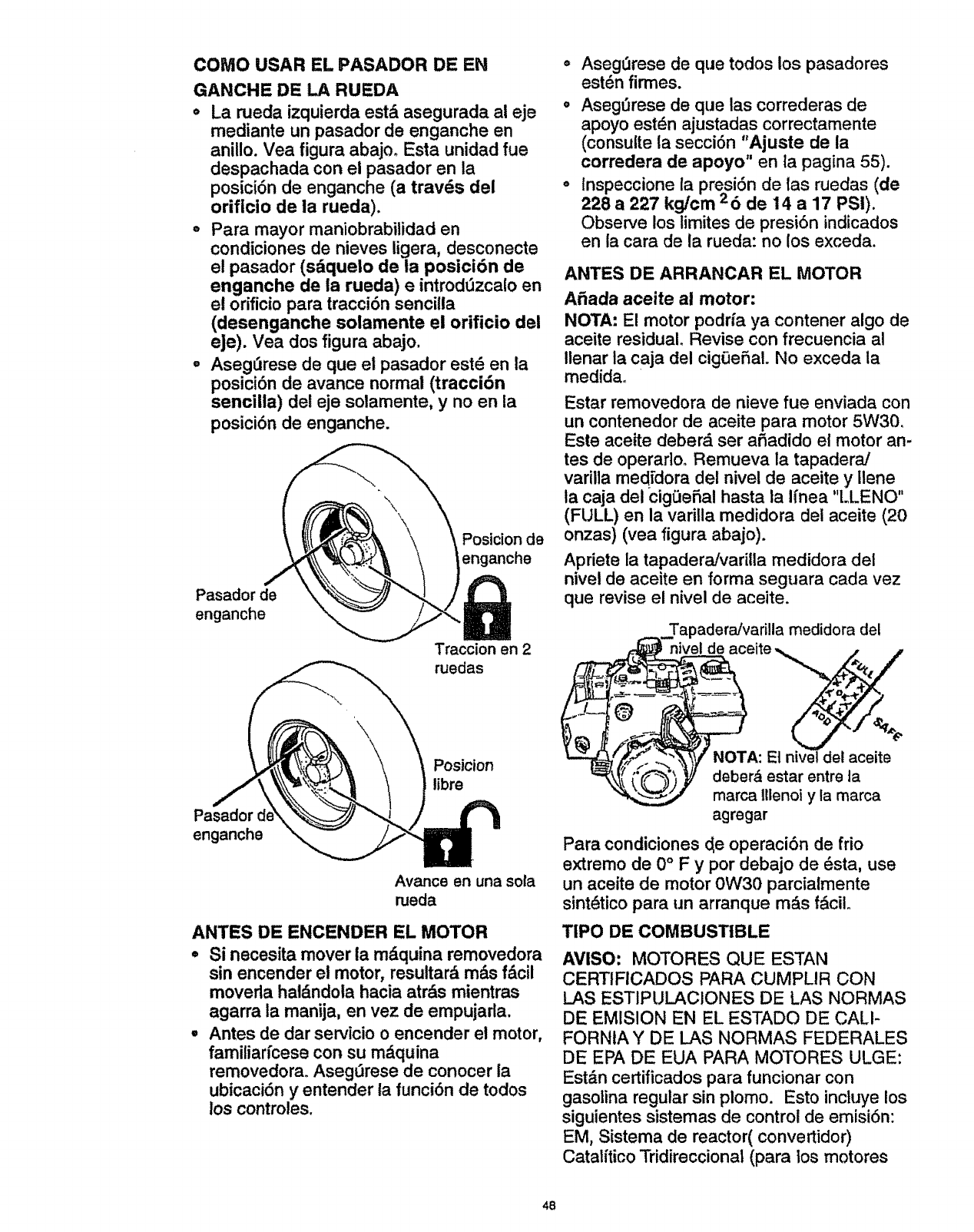
COMO USAR EL PASADOR DE EN
GANCHE DE LA RUEDA
o La rueda izquierda est_ asegurada al eje
mediante un pasador de enganche en
anillo. Vea figura abajm Esta unidad fue
despachada con el pasador en la
posici6n de enganche (a travds del
orificio de la rueda).
• Para mayor maniobrabilidad en
condiciones de nieves ligera, desconecte
el pasador (sdquelo de ia posici6n de
enganche de la rueda) e introd_zcalo en
el orificio para tracci6n sencilla
(desenganche solamente el orificio del
eJe). Vea dos figura abajo.
°Aseg6rese de que el pasador est6 en la
posici6n de avance normal (tracci6n
senciila) del eje solamente, y no en la
posici6n de enganche.
Pasador de
enganche
Postcion de
enganche
Traccion en 2
ruedas
Pasador
enganche
Posicion
libre
Avarice en una sola
rueda
ANTES DE ENCENDER EL MOTOR
°Si necesita mover la mdquina removedora
sin encender el motor, resultard m&s f&cil
moverla hal&ndola hacia atr&s mientras
agarra la manija, en vez de empujada.
° Antes de dar servicio o encender el motor,
familiarfcese con su m&quina
removedora. Asegt3rese de conocer la
ubicaci6n y entender la funci6n de todos
los controles.
° Asegt3rese de que todos los pasadores
est_n firmes.
o AsegOrese de que las correderas de
apoyo est_n ajustadas correctamente
(consuite la secci6n "Ajuste de la
corredera de apoyo" en la pagina 55).
olnspeccione la presi6n de tas ruedas (de
228 a 227 kg/cm 26de 14 a 17 PSi).
Observe los limites de presi6n indicados
en la cara de la rueda: no los exceda.
ANTES DE ARRANCAR EL MOTOR
A6ada aceite al motor:
NOTA: E! motor podrfa ya contener algo de
aceite residual, Revise con frecuencia al
Ilenar la caja del cigt3eSaL No exceda la
medida_
Estar removedora de nieve fue enviada con
un contenedor de aceite para motor 5W30.
Este aceite deber& set a6adido el motor an-
tes de operarto° Remueva la tapaderaJ
variila medidora del nivel de aceite y Ilene
ta caja del cigf_e_al hasta la Ifnea "LLENO"
(FULL) en la varilla medidora del aceite (20
onzas) (yea figura abajo).
Apriete la tapaderaffvadlla medidora dei
nivel de aceite en forma seguara cada vez
que revise el nivel de aceite.
Tapadera/varilla medidora del
eite
A: Et nivel det aceite
r&estar entreta
Illenoiy la marca
agregar
Para condiciones c_eoperaci6n de frio
extremo de 0°Fypor debajo de dsta, use
un aceite de motor 0W30 parcialmente
sint_tico para un arranque mds f&cil.
TIPO DE COMBUSTIBLE
AVISO: MOTORES QUE ESTAN
CERTIFICADOS PARA CUMPLIR CON
LAS ESTIPULACIONES DE LAS NORMAS
DE EMISION EN EL ESTADO DE CALI-
FORNIA Y DE LAS NORMAS FEDERALES
DE EPA DE EUA PARA MOTORES ULGE:
Est&n certificados para funcionar con
gasolina regular sin piomo. Esto inctuye los
siguientes sistemas de control de emisi6n:
EM, Sistema de reactor(convertidor)
Catatftico Tridireccional (para los motores
48
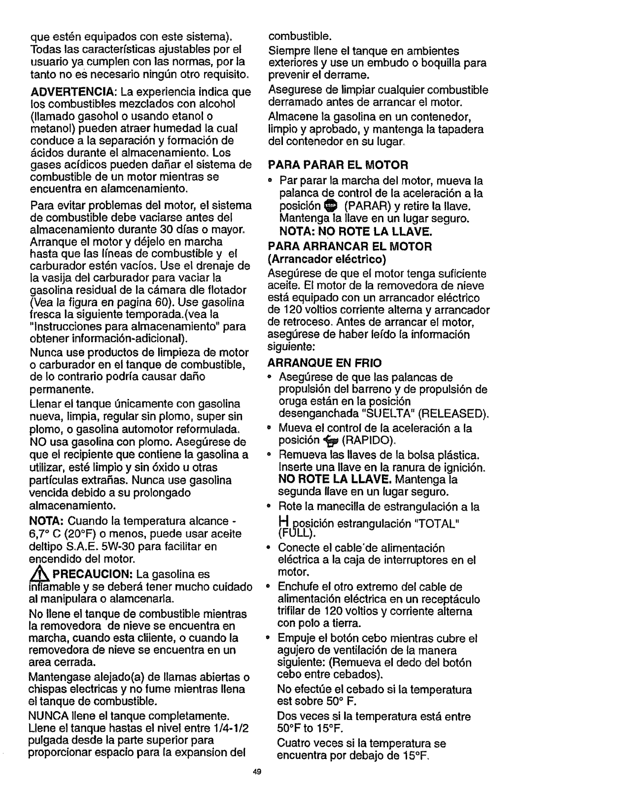
que est6n equipados con este sistema).
Todas las caracterfsticas ajustables por el
usuario ya cumpten con las normas, por la
tanto no es necesario ningSn otro requisito.
ADVERTENClA: La experiencia indica que
los combustibles mezclados con alcohol
(llamado gasohol o usando etanol o
metanol) pueden atraer humedad la cual
conduce a ia separaci6n y formaci6n de
&cidos durante el almacenamiento. Los
gases acfdicos pueden daSar el sistema de
combustible de un motor mientras se
encuentra en alamcenamiento.
Para evitar problemas del motor, el sistema
de combustible debe vaciarse antes del
almacenamiento durante 30 dfas o mayor.
Arranque el motor y d_jeto en marcha
hasta que las hneas de combustible y el
carburador est6n vacfos. Use el drenaje de
la vasija del carburador para vaciar la
gasotina residual de la c&mara dte flotador
(Vea la figura en pagina 60). Use gasotina
fresca la siguiente temporada.(vea la
"Instrucciones para almacenamiento" para
obtener informaciSn-adicional).
Nunca use productos de limpieza de motor
o carburador en el tanque de combustible,
de Io contrario podrfa causar daSo
permanente,
Llenar el tanque enicamente con gasolina
nueva, limpia, regular sin plomo, super sin
plomo, o gasolina automotor reformulada.
NO usa gasolina con p!omo. Aseg_rese de
que el recipiente que contiene la gasolina a
utilizar, est_ limpio y sin 6xido u otras
partfculas extraSas. Nunca use gasolina
vencida debido asu prolongado
almacenamiento.
NOTA: Cuando la temperatura alcance -
6,7 °C (20°F) o menos, puede usar aceite
deltipo S°A.E. 5W-30 para facilitar en
encendido del motor.
Z_ PRECAUTION: La gasolina es
inflamabte y se deber& tener mucho cuidado
al manipulara o alamcenarla.
No ilene el tanque de combustible mientras
ia removedora de nieve se encuentra en
marcha, cuando esta cliiente, o cuando la
removedora de nieve se encuentra en un
area cerrada.
Mantengase alejado(a) de llamas abiertas o
chispas electricas y no fume mientras llena
el tanque de combustible.
NUNCA Ilene el tanque completamente.
Llene el tanque hastas el nivel entre 1/4-1/2
pulgada desde la parte superior para
proporcionar espacio para la expansion del
49
combustible.
Siempre Ilene el tanque en ambientes
exteriores y use un embudo o boquilla para
prevenir el derrame.
Asegurese de limpiar cualquier combustible
derramado antes de arrancar el motor.
Almacene la gasolina en un contenedor,
limpio y aprobado, y mantenga la tapadera
del contenedor en su lugar.
PARA PARAR EL MOTOR
o Par parar la marcha del motor, mueva la
palanca de control de la aceleraci6n a la
posici6n IS) (PARAR) y retire la Ilave.
Mantenga la llave en un lugar seguro.
NOTA:,NO ROTE LA LLAVE.
PARA ARRANCAR EL MOTOR
(Arrancador el_ctrico)
Aseg_rese de que et motor tenga suficiente
aceite. El motor de la removedora de nieve
est_ equipado con un arrancador el_ctrico
de 120 voltios corriente alterna y arrancador
de retroceso. Antes de arrancar el motor,
aseg_rese de haber lefdo la informaciSn
siguiente:
ARRANQUE EN FRIO
o Aseg_rese de que tas palancas de
propulsiSn del barreno y de propulsi6n de
oruga est&n en la posici6n
desenganchada "SUELTA" (RELEASED).
• Mueva el control de la aceleraciSn a la
posici6n "_ (RAPIDO).
o Remueva las llaves de la bolsa pt&stica.
Inserte una Iiave en la ranura de igniciSn.
NO ROTE LA LLAVE, Mantenga la
segunda Ilave en un lugar seguro.
•Rote la manecilla de estrangulaci6n a la
HDosici6n estrangulaci6n "TOTAL"
(FULL).
o Conecte el cable'de alimentaciSn
el6ctrica a la caja de interruptores en el
motor.
• Enchufe el otro extremo del cable de
alimentaci6n el_ctdca en un recept_.culo
trifilar de 120 voitios y corriente alterna
con polo a tierra.
= Em.puje el bot6n cebo mientras cubre el
agujero de ventilaciSn de la manera
siguiente: (Remueva el dedo del bot6n
cebo entre cebados),
No efectt3e el cebado si la temperatura
est sobre 50 °F.
Dos veces si la temperatura estd entre
50°F to 15°F.
Cuatro veces si la temperatura se
encuentra por debajo de 15°F.
o Empujeel bot6n del arrancadorhacia
abajo hasta que el motorarranque.No
intentar el arranque por mas de 10
sergundos a la vez. Este arrancador
el6ctrico est,. protegidoterrnalmente.Si
se sobre calientase detendr&
autom_.ticamentey puede ser arrancado
nuevamentes61ocuandose ha enfriado
hastauna temperaturasegura (se
requiere una espera de 5 a 10 minutos
aproximadamente).
o Cuando el motor arranque, suette el
bot6n de arranque y ponga la palanca del
ahogador en la posici6n "1/2 ahogador"o
Cuando el motor est_ trabajando
uniformemente, meueva la palanca del
ahogador a la posici6n "no ahogador".
° Desconecte el cable de alimentaci6n
el6ctrica desde el recept&culo primero y
iuego desde la caja de interruptores en el
motor.
NOTA: deje que el motor se caliente por
algunos minutos antes de soplar nieve, en
temperaturas inferiores a - t8°C (0°F).
o Opere el motor atoda velocidad ,f_
(RAPIDO) al removerdora nieve.
ARRANQUE EN CALIENTE
Si estd arrancando un motor caliente despu6s
de un apag6n corto, deje el estrangulador en
"APAGADO" (OFF) y no pulse el bot6n cebo.
Z_ PRECAUC!ON: Este arrancador esta
equipado con un cable de alimentacion
trifilar y esta disefiado para operar en
cordente atterna domiciliar de 120 vottios.
Deberd estar conectado a tierra de manera
adecuada en todo momento para evitar ia
posibilidad de un choque electrico, el cual
podria causar heridas al operador. Siga las
instrucciones cuidadosamente de la manera
en que se detallan en la seccion "Para
arranca el motor." Verifique que el
alambrado de su casa sea trifilar con polo a
tierra. Pregunte a un electdcista autorizado
si no se encuentra seguro. Si el sistema de
atambrado de su casa no es un sistema
trifilar, no use e! arrancador electrico bajo
ninguna condition. Si su sistema tiene polo
a tierra y no se encuentra disponible un
receptaculo trifilar en et punto en que su
arrancador sera usado normalmente, se
debe instalar uno por un electricista
autorizado. AI conectar el cable de
alimentacion electrica de corriente aitema
de 120 voltios, siempre conecte el cable a la
caja de interruptores en el motor primero, 50
luego enchufe el otro extremo en el
receptaculo trifilar con polo a tierra. AI
desconectar el cable de alimentacion
electrica, siempre des enchufe el extremo
en el receptaculo con polo a tierra pfimero.
PARA PARAR EL MOTOR
Para parar la marcha del motor, mueva la
palanca de control de la aceleraci6n 1_!
(PARAR) y retire la Ilace. Mantenga la
llave en unlugar seguro. Elmotor no
arrancara sin la Ilave.
PARA ENCENDER EL MOTOR
(Retroceso Manual)
Cerci6rese de que el motor tiene suficiente
aceite. Antes de encender el motor,
aseg_rese de leer toda la informaci6n
siguiente:
ARRANQUE EN FRIO (Vea figura, pagina
44)
° Aseg_rese de que las palancas de
propulsi6n del barreno y de propulsi6n de
oruga estdn en la posici6n desenganche
"SU ELTA" (RELEASED).
°Mueva el control de la aceleraci6n a la
posici6n '_ (RAPIDO).
o Introduzca la Ilave en la ranura del
encendido y asergerese de que calce
bien. NO LA HAGA GIRAR. Coloque la
Ilave adicional proporcionada en un lugar
seguro,
o Rote la manecilla de estrangulaci6n a la
HDosici6n estrangulaci6n "TOTAL"
(FULL).
° Empuje el bot6n cebo mientras cubre e!
agujero de ventilaci6n de la manera
siguiente: (Remueva el dedo del bot6n
cebo entre cebados).
No efectee el cebado si la temperatura
esta sobre 50°F.
Dos veces si la temperatura est& entre
50°F hasta15°E
Cuatro veces si la temperatura se
encuentra por debajo de15°E
°Hale la manivela del arranque con un
movimiento seguro y rdpido. No deje que
la inercia del encendido hale la cuerda
del arranque con violencia. Permita que
vueiva a enrollarse suavemente mientras
sostiene la manivela.
Mientras el motor se va calentando,
mueva la palanca de ahogador a la
posici6n de "1/2 ahogador". Cuando el
motor est_ funcionando uniformemente,
mueva la palanca del ahogador a la
posici6n de "No ahogador".
NOTA: deje que el motor se caliente por
algunos minutos antes de soplar nieve, en
temperaturas infedores a. 18°C (0°F).
• Opere el motor a toda velocidad ,_
(RAPIDO) al remover nieve.
ARRANQUE EN CALIENTE
Si est& arrancando un motor catiente
despu_s de un apag6n corto, deje el
estrangulador en "APAGADO" (OFF) y no
pulse el bot6n cebo.
ARRANQUE CONGELADO
Si el arrancador estd congelado y no
arranca el motor:
°Hale tanta iongiatud de cuerda del
arrancador como sea posible.
oSuelte la manija del arrancador yd_jela
enrollarse de nuevo contra et arrancador.
Si el motor todavfa no arranca, repita estos
pasos hasta que logre encnederlo.
Para ayudar a evitar la posibilidad de
congelamiento del arrancador de retroceso
y los controles del motor, proceda de la
manera siguiente despu_s de cada trabajo
de remocibn de nieve.
°Con el motor en marcha, hale la cuerda
de arranque en6rgicamente con un
alargamiento de brazo continue tres o
cuatro veces. E! halado de la cuerda de
arranque producird un sonido de
repiqueteo fuerte. Esto no causa daSo ni
al motor ni al arrancador.
•Con el motor parado, limpie toda la
nieve y humedad de la cubierta del
carburador en el drea de las palancas de
control. Asimismo, mueve el control de
aceleraci6n, control de estrangulaci6n, y
manija del arrancador varias veces y deje
el estrangulador en ia posici6n, "TOTAl."
(FULL) y la palanca de aceleraci6n el la
posici6n (RAPIDO).
APRECAUClON: No intente remover
cualquier elemento que resulte atorado en
barreno si tomar las precauciones
siguientes:
° Suelte las palancas de propulsion del
barreno y de propulsion de oruga.
,, Mueva ta palanca de control de la
aceleracion a la position parar.
° Remueva (no rote) la Ilave de ignicion.
° Desconecte el alambre de la bujia.
•No coloque las manos en el barreno o
canal de descarga. Use una barra de
apalancamientoo
5!
PISTAS SOBRE LANZAiVilENTO DE
NIEVE
,, Para mayor eficiencia de lanzamiento de
nieve durante la remoci6n de la misma,
ajuste la velocidad en el terreno, NUNCA
la aceleraci6n. Avance lentamente en
nieve profunda, congelada, o h_meda. Si
la oruga desliza, reduzca ta velocidad
hacia adelanteo E! motor esta diseSado
para brindar un rendimiento mdximo bajo
aceleraci6n total y debe ser operado en
este valor de potencia en todo momento.
o El lanzamiento de nieve es mds efixcente
si la remoci6n de la misma se efect_a
inmediatamente despuds de su cafdao
° Para una remoci6n completa de la nieve,
traslape ligeramente cada camino
adoptado previamente. En nieve
profunda, superponga los barridos entre
si para evitar sobrecargar la m_.quina.
° La nieve deberfa ser descargada en la
direcci6n del viento siempre que sea
posible.
oPara uso normal, posicione las correderas
de apoyo de manera tai que la barra
raspadora se encuentre 1/8 de pulgada
sobre las correderas de apoyo. Para
superficies de nieve dura
extremadamente compacta, ajuste las
correderas de apoyo hacia arriba de
manera que la barra raspadora haga
contacto con el terreno.
°En superficies de grava o roca triturada,
posicione las correderas de apoyo a
1.114 pulgadas por debajo de la barra
raspadora (Vea el pdrrafo "Como ajustar
la altura de las correderas de apoyo" en
la p&g!na 55)° Las rocas y grava no
deberan ser recogidas y lanzadas por la
maquina.
°Si la parte delantera de la removedora
de nieve tiene la tendencia de elevarse
reduzca la velocidad sobre el terreno y
enganche el sistema de transferencia de
peso.
°Despuds de que se haya completad 0 el
lanzamlento de nieve, permita que el
motor se encuentre en reposo por unos
cuantos minutos, Io cual derretir_, la
nieve y hielo acumulado del motor.
°EfectSe una limpieza completa de la
removedora de nieve luego de cada uso.
°Remueva la acumulaci6n de hielo y
nieve y todo material extraSo
heterogdneo de la removedora de nieve
en su totalidad, y lave con agua (si fuese
posibte) para remover toda sal u otras
substancias qufmicas. Seque la
removedora de nieve.
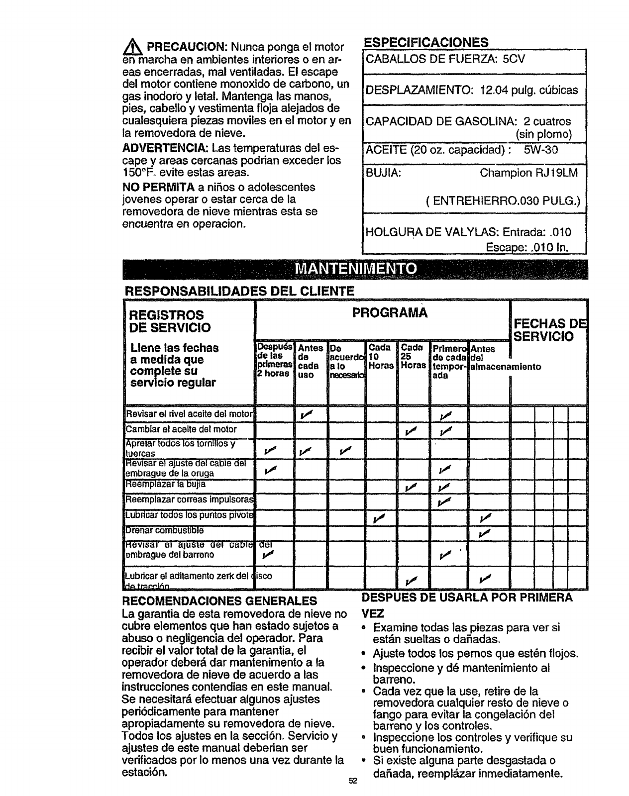
Z_ PRECAUCION: Nunca ponga el motor
en marcha en ambientes interiores o en ar-
eas encerradas, mal ventiladas. El escape
del motor contiene monoxido de carbono, un
gas inodoro y letal. Mantenga las manos,
pies, cabetlo y vestimenta floja alejados de
cualesquiera piezas moviles en el motor yen
la removedora de nieve.
ADVERTENCIA: Las temperaturas del es-
cape y areas cercanas podrian exceder los
150°F_ evite estas areas.
NO PERMITA a niSos oadolescentes
jovenes operar o estar cerca de la
removedora de nieve mientras esta se
encuentra en operacion.
RESPONSABILIDADES DEL CLIENTE
ESPEClFICACIONES
i ..... ....
CABALLOS DE FUERZA: 5CV
IH,. ....
DESPLAZAMIENTO: 12o04 pulg. c_bicas
CAPACIDAD DE GASOLINA: 2 cuatros
(sin plomo)
ACEITE (20 oz. capacidad)" 5W-30
,,,,,_,,,,_,,p,_i ,
BUJIA: Champion RJ 19LM
( ENTREHtERRO.030 PULG.)
HOLGURA DE VALYLAS: Entrada: .010
• Escape: .010 In.
REGISTROS
DE SERVIClO
Llene las fechas _pu_s Antes De
amedida que de las de acuerdc
ximeras cada a !o
complete su 2horae uso r_ces_
servicio regular
PROGRAMA FECHAS DE
........ SERVICIO
Cada Cada Prlme"roAntes
10 25 de cada de1
Horas Horas tempor- almacenamlento
ada
I
Reviser el dvelaceite det motor l,J P'_ I
Camblarel aceite de! motor tf
Apretartodos10Storntl|osy............................... '.......
tuercas P'_ P_ P_'
Revisar e} ajUste del ca'5'l'_'dei.........................
embrague de la oruga
ReemplaZar la"bujia .................. _' v" ........
Lubdcar todos los puntos plvot_ _ ......... t,j .....................
Drenat_mDiJ_;tiblb -'"" p# ....................
Hevisar'bl aluste oel came ael ....................................................
Brnbraguedel barreno tJ p,1 '
Lubrlcar el aditamentozerk del isco
RECOMENDACIONES GENERALES ..........DESPUES DE USA RLA POR PRIMERA
La garantia de esta removedora de nieve no
cubre elementos que han estado sujetos a
abuso o negligencia del operador. Para
recibir el valor total de la garantia, el
operador deber& dar mantenimento ata
removedora de nieve de acuerdo a las
instnucciones contendias en este manual.
Se necesitar& efectuar algunos ajustes
peri6dicamente para mantener
apropiadamente su removedora de nieve.
Todos los ajustes en la secci6no Servicio y
ajustes de este manual deberian ser
verificados por to menos una vez durante la
estaci6n. 52
VEZ
,, Examine todas las piezas para ver si
est&n sueltas o daSadas_
•Ajuste todos los pemos que est6n flojos.
.Inspeccione y dd mantenimiento al
barreno.
• Carla vez que la use, retire de la
removedora cualquier resto de nieve o
fango pare evitar la congelaci6n del
barreno y los controles.
° inspecclone los controles y verifique su
buen funcionamiento.
•Si exists alguna parts desgastada o
daSada, reempldzar inmediatamente.
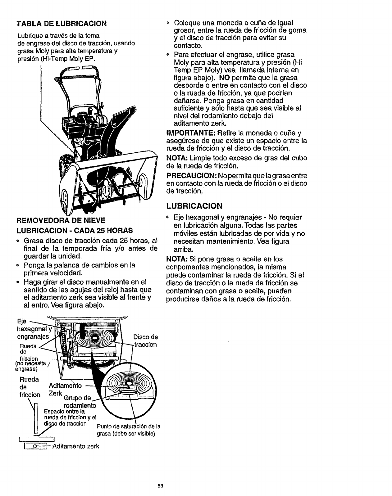
:I'ABLA DE LUBRICACION
Lubflque a travSs de la toma
de engrase del disco de tracci6n, usando
grasa Moly para alia temperatura y
presi6n (Hi-Temp Moly EP.
\
REMOVEDORA DE NIEVE
LUBRICAClON - CADA 25 HORAS
=Grasa disco de tracci6n cada 25 horas, al
final de la temporada frfa y/o antes de
guardar la unidad.
.Ponga la palanca de cambios en la
primera vetocidad°
• Haga girar et disco manualmente en el
sentido de las agujas del reloj hasta que
el aditamento zerk sea visible al frente y
ai entro. Vea figura abajoo
engranajes Disco de
Rueda _traccion
de
fdcclon .....
(no necesita/'
engrase)
Rueda
de Aditame'hto
fflccion Zerk Grupo de
rodamiento
Espacloentre la
rueda de friccion y el
o de traction Puntode satt de la
grasa (debe set visible)
;J
_Aditamento zerk
Coloque una moneda o cuSa de igual
grosor, entre la rueda de fricci6n de goma
y el disco de tracci6n para evitar su
contacto.
Para efectuar el engrase, utilice grasa
Moly para alta temperatura y presi6n (Hi
Temp EP Moly) vea Ilamada interna en
figura abajo). NO permita que la grasa
desborde o entre en contacto con el disco
o la rueda de fricci6n, ya que podrfan
daSarse. Ponga grasa en cantidad
suficiente y s61o hasta que sea visible at
nivel del rodamiento debajo del
aditamento zerk,
IMPORTANTE: Retire la moneda o curia y
asegt3rese de que existe un espacio entre la
rueda de fricci6n y el disco de tracci6n.
NOTA: Limpie todo exceso de gras del cubo
de la rueda de fricci6n.
PRECAUClON: No permita que la grasa entre
en contacto con la rueda de fricci6n o el disco
de tracci6n.
LUBRICAClON
Eje hexagonal y engranajes -No requier
en lubricaci6n alguna. Todas las partes
m6viles est&n lubricadas de por vida y no
necesitan mantenimiento. Vea figura
arriba,
NOTA; Si pone grasa o aceite en los
conpomentes mencionados, la misma
puede contaminar la rueda de fricci6n. Si el
disco de tracci6n o la rueda de fricci6n se
contaminan con grasa o aceite, pueden
producirse daSos a ia rueda de fricci6n.
53

Si cae aceite o grasa sobre el disco de
tracci6n o ia rueda de fricci6n, aseg_rese de
limpiarlos cuidadosamente,
NOTA: Cuando vaya a guardar la unidad,
pase una tolla impregnada en aceite de mo-
tor 5W30 por el eje hexagonal y los
engranajes para evitar su oxidaci6n.
o Caja de engranaje del barrena - La caja
de engranajes de la barrena se lubrica en
la f&brica y no debe necesitar tubricaci6n
adicional. Si por alguna raz6n el
lubricante se fuga o si la caja de
engranajes de la barrena ha recibido
servicio, agregue Lubriplate No. 630-AA o
su equivalente. Se debe usar un maximo
de 3-1/4 onzas. Remueva el tap6n del
relleno una vez al afio. Vea figura abajo.
Si hay grasa si es necesario. Vuelva a
instalar el tapSn del relleno de la caja de
engranajes.
MOTOR
LUBRICACION
Revise el nivei de aceite de la caja det
cigDeSal(vea figura abajo) antes de arrancar
el motor y despu6s de cada cinco (5) horas
de uso continuo. Agregue aceite de motor
SrA.E. 5W30 de acuerdo con Io que se
requiera. Apriete la tapadera/varilla de
m_dici6n del aceite en forma segura cada
vez que revise el nivel del aceite. Cuando la
temperatura baje a _6,7°C (20°F) o menos,
puede usar aceite del tipo S.A.E 5W30 para
facilitar el encendido del motor.
__.___NOTA: El ntvel del aceite
f _'o_'_ debera estar entre la marca
_=f_ llenoy la marca agregar
RECOMENDACION DE ACEITE
Use solamente aceite detergente de alta
calidad catificado con la clasificaci6n SSG
servicio API. Seleccione el grado de
viscosidad del aceite de acuerdo a la
temperatura de operaci6n esperada.
NOTA: En condicionesde fr{o extremo,
-17,7°C (0°F) omenos, use aceite de motor
parcialmentesint6tico0W30 para facilitar el
encendido.
NOTA: Aungue los aceites de visocosidad
mt_ltiple faciilitan el arranque en clima fifo,
estos aceites de viscosidad mt31tipte resultan
en un incremento en el comsumo de aceite
al usarse sobre 32°E Verifique el nivei del
aceite de su motor con mayor frecuencia
para evitar posibles daSos at motor
causados por operaci6n con un nivel bajo
de aceite.
Cambie et aceite despu_s de las primeras
dos horas de operaci6n y cada 25 horas en
Io sucesivo o al menos una vez al aSo si la
removedora de nieve no se usa durante 25
horas.
o Coloque la removedora de nieve de
manera tal que el tap6n de drenaje del
aceite sea el punto m&s bajo del motor.
Remueva el tap6n de drenaje del aceite y
tapadera/variUa medidora del nivel del
aceite. Drene el aceite en un contedor
apropiado. El aceite fluir& mejor al
encontrarse caliente.
° Coloque nuevamente el tap6n de drenaje
del aceite y apri_telo en forma segura.
Uene nuevamanete la caja del cigr3efial y
apriete en forrna segura. Llene
nuevamente la caja del cig_3eSatcon
aceite de motor S.A.E. 5W30o
BUJIA
° Asegt3rese de que ta bujia est_ apretada
en forma segura en el motor y que el
alambre la bujia est(_ conectado a 6sta.
o Si se encuentra disponible una Ilave de
torsi6n, aplique un momento de 18 a 23
pies-libra a _abujfa.
= Limpie el &tea alrededor de la base de la
bujia antes de removerla para evitar que
entre suciedad en el motor.
°Limpie la buji'a yrestaure el entrehierro
peri6dicamente a 0.030 pulgadas.
54
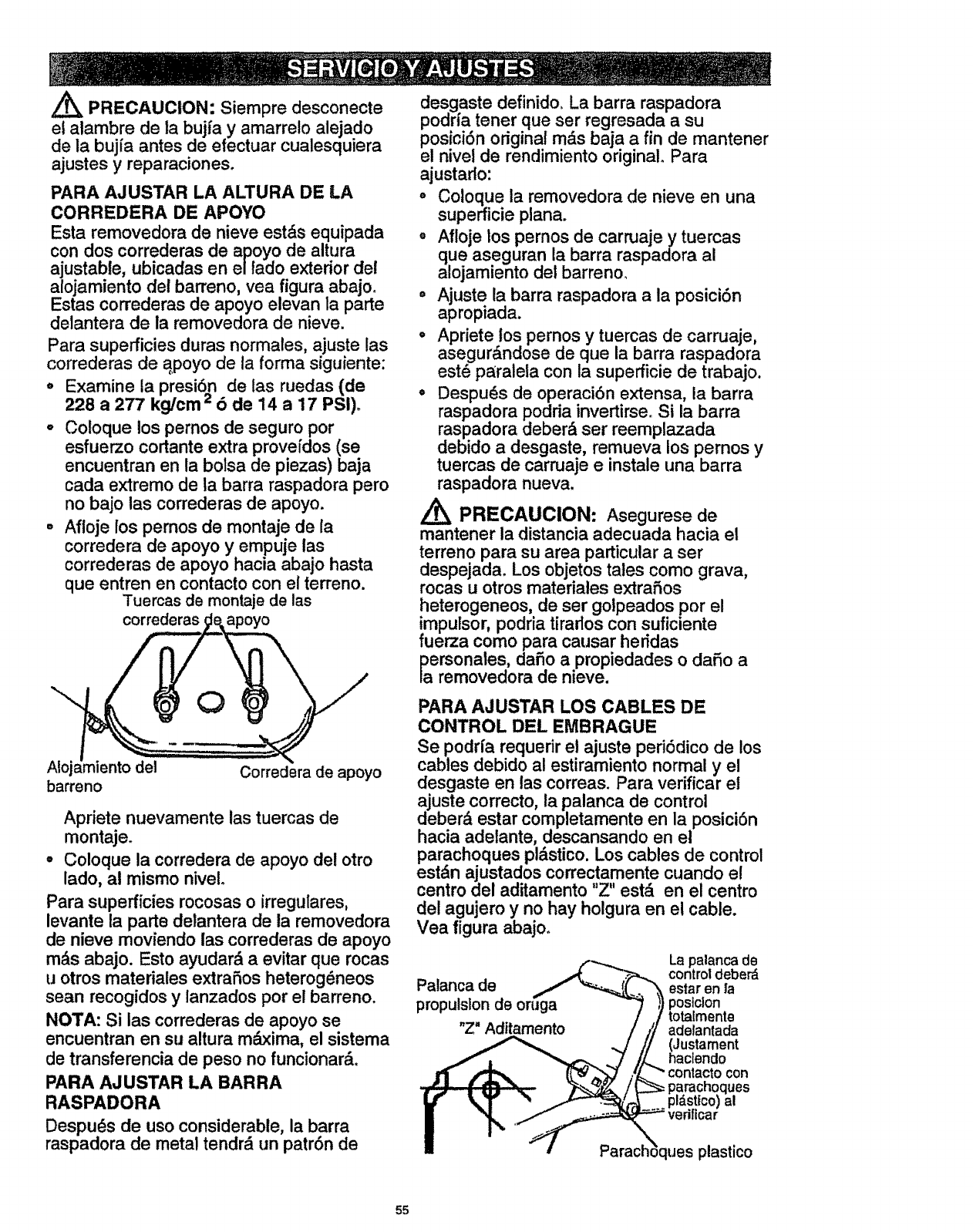
_PRECAUCION: Siempre desconecte
et atambre de la bujfa y amarrelo alejado
de la bujia antes de efectuar cualesquiera
ajustes y reparaciones.
PARA AJUSTAR LA ALTURA DE LA
CORREDERA DE APOYO
Esta removedora de nieve est&s equipada
con dos correderas de apoyo de altura
ajustable, ubicadas en eHado exterior del
alojamiento del barreno, vea figura abajo.
Estas correderas de apoyo elevan la parte
detantera de la removedora de nieve.
Para superficies duras normales, ajuste las
correderas de apoyo de la forma siguiente:
, Examine la presi6n de las ruedas (de
228 a 277 kg/cm '=o de 14 a 17 PSI),
°Coloque los pernos de seguro por
esfuerzo cortante extra prove[dos (se
encuentran en la bolsa de piezas) baja
cada extremo de la barra raspadora pero
no bajo las correderas de apoyo.
, Afloje los pernos de montaje de [a
corredera de apoyo y empuje las
correderas de apoyo hacia abajo hasta
que entren en contacto con el terreno.
Tuercas de montajede las
correderas apoyo
Aloj
barreno Corredera de apoyo
Apriete nuevamente las tuemas de
montaje.
• Coloque la corredera de apoyo del otro
lado, al mismo nivel.
Para superficies rocosas o irregulares,
levante la parte detantera de la removedora
de nieve moviendo las correderas de apoyo
m&s abajo. Esto ayudar& a evitar que rocas
u otros mater[ales extraSos heterog_neos
sean recogidos y lanzados por el barreno.
NOTA: Si las correderas de apoyo se
encuentran en su altura m_ima, el sistema
de transferencia de peso no funcionar&.
PARA AJUSTAR LA BARRA
RASPADORA
Despu_s de uso considerable, la barra
raspadora de metal tendr& un patr6n de
desgaste de[in[do. La barra raspadora
podna tener que ser regresada a su
posiciSn odginat m_.s baja a fin de mantener
el nivel de rendimiento original° Para
ajustarlo:
o Coloque la removedora de nieve en una
superficie plana.
o Afloje los pernos de carruaje y tuercas
que aseguran la barra raspadora al
alojamiento det barreno_
= Ajuste la barra raspadora a la posici6n
apropiada.
= Apriete los pernos y tuercas de carruaje,
asegur&ndose de que la barra raspadora
est6 paraleta con ta superficie de trabajo.
°Despu_s de operaci6n extensa, la barra
raspadora podria invertirse. Si la barra
raspadora deber& set reemplazada
debido a desgaste, remueva los pernos y
tuercas de carruaje e instale una barra
raspadora nueva.
PRECAUCION: Asegurese de
mantener la distancia adecuada hacia el
terreno para su area particular a ser
despejada. Los objetos tales como grava,
rocas u otros mater[ales extrafios
heterogeneos, de ser golpeados por el
mpulsor, podria tirados con suficiente
uerza como para causar heddas
personales, dafio a propiedades o daSo a
la removedora de nieve.
PARA AJUSTAR LOS CABLES DE
CONTROL DEL EMBRAGUE
Se podria requerir el ajuste peri0dico de los
cables debido al estiramiento normal y el
desgaste en las correas. Para verificar el
ajuste correcto, la palanca de control
deber& estar completamente en la posici6n
hacia adelante, descansando en el
parachoques pldstico. Los cables de control
estdn ajustados correctamente cuando el
centro del aditamento "Z" est,. en el centro
del agujero y no hay holgura en el cable.
Vea figura abajo.
Palanca de
propulslon de oruga
"Z" Aditamento
La palanca de
control deber_
estar en ta
postclon
totalmente
adelantada
hJUstament
aclendocon
ques
al
icar
lues plastico
55
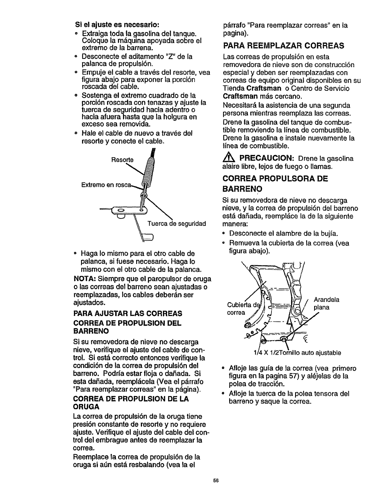
SI el ajuste es necesario:
oExtraiga toda la gasolina del tanque.
Coloque la m_.quina apoyada sobre el
extremo de la barrena.
oDesconecte el aditamento "Z" de la
palanca de propulsiSno
° Empuje el cable a traves del resorte, vea
figura abajo para exponer ia porci6n
roscada del cable.
,, Sostenga el extremo cuadrado de la
porci6n roscada con tenazas y ajuste la
tuerca de seguridad hacia adentro o
hacia afuera hasta que la holgura en
exceso sea removida.
,, Hale el cable de nuevo a tray,s del
resorts y conecte el cable°
Resorts
Extremo en
Tuerca de seguridad
• Haga io mismo para el otto cable de
palanca, si fuese necesario. Haga Io
mismo con el otro cable de la patancao
NOTA: Siempre que el paropulsor de oruga
o las correas del barreno sean ajustadas o
reemplazadas, los cables deber&n set
ajustados.
PARA AJUSTAR LAS CORREAS
CORREA DE PROPULSION DEL
BARRENO
Si su removedora de nieve no descarga
nieve, verifique el ajuste del cable de con-
trol. Si est& correcto entonces verifique la
condici6n de ta correa de propulsi6n del
barreno. Podrfa estar floja o daSada. Si
esta daSada, reempl&cela (Vea el p_.rrafo
"Para reemplazar correas" en la p_gina).
CORREA DE PROPULSION DE LA
ORUGA
La correa de propulsi6n de la oruga tiene
presi6n constante de resorte y no requiere
ajuste. Verifique el ajuste del cable del con-
trol del embrague antes de reemplazar la
correa.
Reemplace la correa de propulsi6n de la
oruga si a_n estd resbalando (vea la el
pdrrafo "Para reemplazar correas" en la
pagina).
PARA REEMPLAZAR CORREAS
Las correas de propulsi6n en esta
removedora de nieve son de construcci6n
especial y deben ser reemplazadas con
correas de equipo original disponibtes en su
Tienda Craftsman o Centro de Servicio
Craftsman mds cercano.
Necesitar& la asistencia de una segunda
persona mientras reemplaza las correas.
Drene la gasolina del tanque de combus-
tible removiendo la linea de combustible.
Drene la gasolina e instale nuevamente la
Ifnea de combustible.
PRECAUCION: Drene la gasolina
ataire libre, lejos de fuego ollama&
CORREA PROPULSORA DE
BARRENO
Si su removedora de nieve no descarga
nieve, y la correa de propulsi6n del barreno
estd da_ada, reempldce la de la siguiente
manera:
O
Q
Desconecte el alambre de la bujfa.
Remueva la cubierta de la correa (vea
figura abajo).
\
correa
Arandela
plana
X auto ajustable
°Afloje las gufa de la correa (vea pdmero
figura en la pagina 57) yai_jelas de la
polea de tracci6n.
°Afloje ta tuerca de la polea tensora clel
barreno ysaque la correa.
56
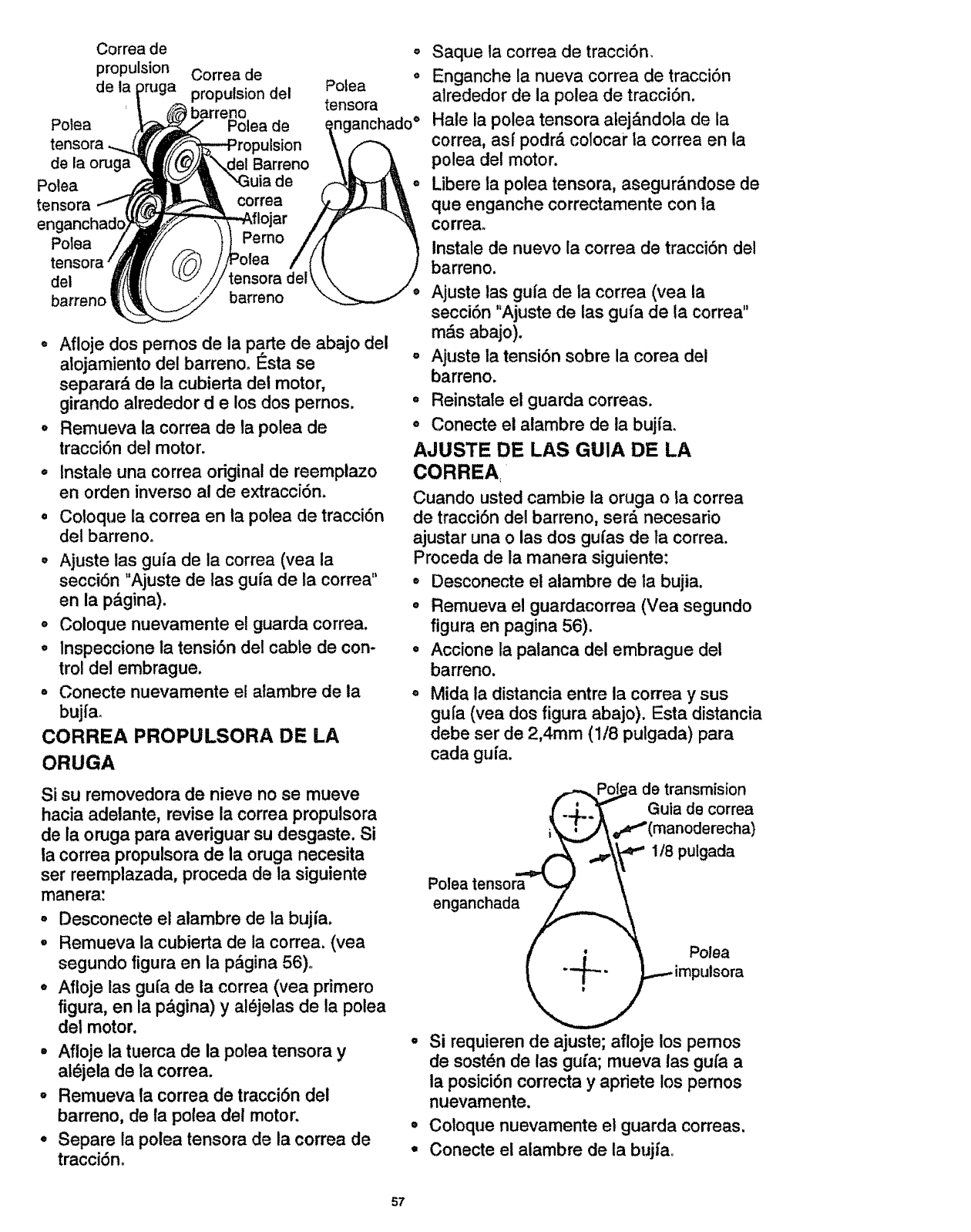
Correa de
propulsion Correa de
de ta _)ruga propulsion del Potea
| _ barreno
Polea _ .... Polea de
tensora .._!'_F_ _._rop uIsion
de la onJga "_{{ (_///_\.del Barreno
Polea _ _ _ ",Guia de
tensora -_('_ _ correa
enganchado_ __flojar
Po,o /,tt IF/ }I /
tensora/_'J ;/ (_/._] //Polea /
del l/ii'_t _//tensora del
0
@
tensora
nganchado °
• Afloje dos pemos de la parte de abajo del
alojamiento del barreno. Esta se
separar_, de la cubierta dei motor,
girando alrededor d e los dos pernos.
o Remueva la correa de la potea de
traccidn del motor.
° Instale una correa original de reemplazo
en orden inverso al de extracci6n.
Coloque la correa en la polea de traccidn
del barrenoo
,Ajuste tas guia de la correa (yea la
seccidn "Ajuste de las guia de la correa"
en la p&gina).
o Coloque nuevamente el guarda correa.
,lnspeccione la tensidn del cable de con-
trol del embrague.
- Conecte nuevamente el alambre de la
bujfa.
CORREA PROPULSORA DE LA
ORUGA
Saque la correa de tracci6n.
Enganche la nueva correa de traccibn
atrededor de la polea de tracci6n.
Hate la polea tensora atej&ndola de la
correa, asf podr_ colocar la correa en la
polea de! motor.
Libere la polea tensora, asegur&ndose de
que enganche correctamente con la
correa.
Instale de nuevo la correa de traccidn del
barreno.
Ajuste las guia de la correa (vea la
secci6n "Ajuste de las gufa de la correa"
m_,s abajo).
Ajuste la tensidn sobre la corea del
barreno.
°Reinstale el guarda correas.
o Conecte el alambre de la bujia.
AJUSTE DE LAS GUIA DE LA
CORREA
Cuando usted cambie la oruga o la correa
de tracci6n del barreno, ser_ necesario
ajustar una o las dos gufas de la correa.
Proceda de la manera siguiente:
° Desconecte el alambre de la bujia.
° Remueva el guardacorrea (Vea segundo
figura en pagina 56).
° Accione la palanca del embrague del
barreno.
Mida la distancia entre la correa y sus
gufa (yea dos figura abajo). Esta distancia
debe ser de 2,4mm (1/8 pulgada) para
cada guia.
Si su removedora de nieve no se mueve
hacia adelante, revise la correa propulsora
de ia oruga para averiguarsu desgaste. Si
la correa propulsorade la oruga necesita
ser reemplazada, proceda de la siguiente
manera:
° Desconecte el alambre de ia bujia.
-Remueva la cubierta de ia correa. (yea
segundo figura en la p_gina 56)_
o Afloje las gu{a de ia correa (vea primero
figura, en la p_igina) y al_jelas de la polea
dei motor.
°Afloje ia tuerca de la polea tensora y
al@jelade la correa.
°Remueva la correa de tracci6n del
barreno, de la polea del motor.
•Separe la polea tensora de la correa de
tracci6n.
f,-._Po_a de transmision
/..j..._ Guta de correa
_..,_ =_"(manode recha)
Polea tensora _"l
enganchada _
/' i _ Polea
_ _impulsora
Si requierende ajuste;aflojelospemos
de sost6nde lasgufa;mueva lasgui'aa
laposici6ncorrectay aprietelospemos
nuevamente.
•Coloque nuevamente el guarda correas.
•Conecte el alambre de la bujiao
57
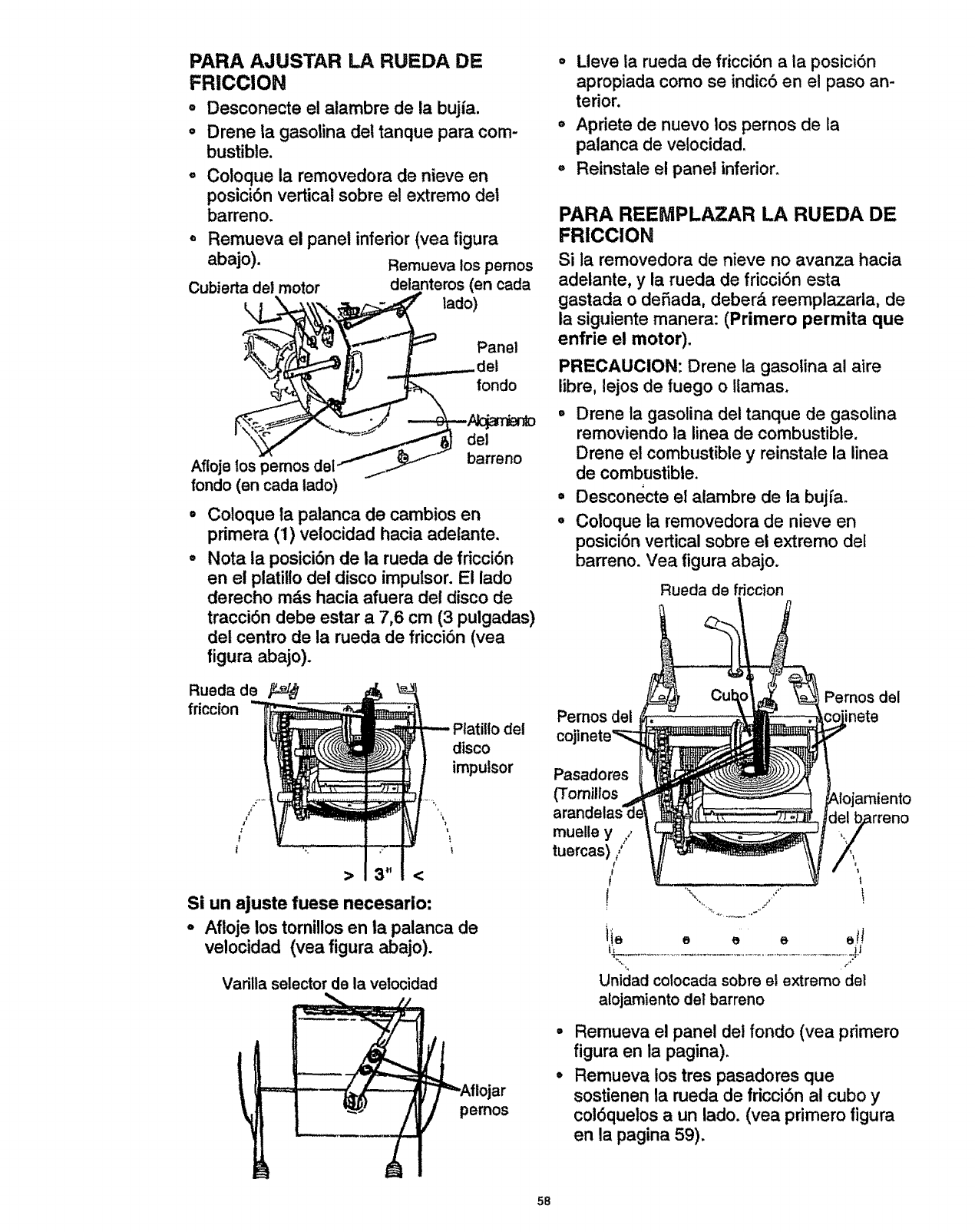
PARA AJUSTAR LA RUEDA DE
FRICCION
oDesconecte el alambre de la bujia.
oDrene ia gasolina del tanque para com-
bustible.
Coloque la removedora de nieve en
posici6n vertical sobre el extremo del
barreno.
o Remueva el panel inferior (vea figura
abajo). Remueva los pemos
Cubierta del motor delanteros (en cada
Panel
del
•
Afloje tos _emos del __ barreno
rondo (en cada lado)
Coloque la palanca de cambios en
primera (1) veiocidad hacia adetante.
Nota la posici6n de la rueda de fdcci6n
en el platillo del disco impulsor. El lado
derecho m_,s hacia afuera del disco de
tracci6n debe estar a 7,6 cm (3 pulgadas)
det centro de la rueda de fricci6n (vea
figura abajo).
Lleve la rueda de fricci6n a la posici6n
apropiada como se indic6 en el paso an-
terior.
o Apriete de nuevo los pernos de la
palanca de velocidad.
°Reinstale el panel inferior.
PARA REEMPLAZAR LA RUEDA DE
FRICCION
Si la removedora de nieve no avanza hacia
adelante, y la rueda de fricci6n esta
gastada o defiada, deber& reemplazarla, de
la siguiente manera: (Primero permita que
enfrie el motor).
PRECAUCION: Drene la gasotina al aire
libre, lejos de fuego o llamas.
•Drene la gasolina del tanque de gasolina
removiendo la linea de combustible.
Drene el combustible y reinstate la linea
de combustible.
° Desconecte el alambre de la bujfa.
° Coloque la removedora de nieve en
posici6n vertical sobre el extremo del
barreno. Vea figura abajo.
Rueda de fdccion
Rueda de
friccion
itlo del
disco
impulsor
Si un ajuste fuese necesario:
- Afloje los tomillos en ta palanca de
velocidad (vea figura abajo).
Varilla selectorde la velocidad
==== lojar
pemos
Pernos del
Pemos del inete
Pasadores
(Tomillos
muelle y
tuercas) t
f
d7 rren°
Unidad colocadasobre el extremo det
atojamientodel barreno
Remueva el panel del fondo (vea pdmero
figura en la pagina).
Remueva los tres pasadores que
sostienen la rueda de fricci6n al cubo y
col6quelos a un lado. (vea primero figura
en la pagina 59).
58
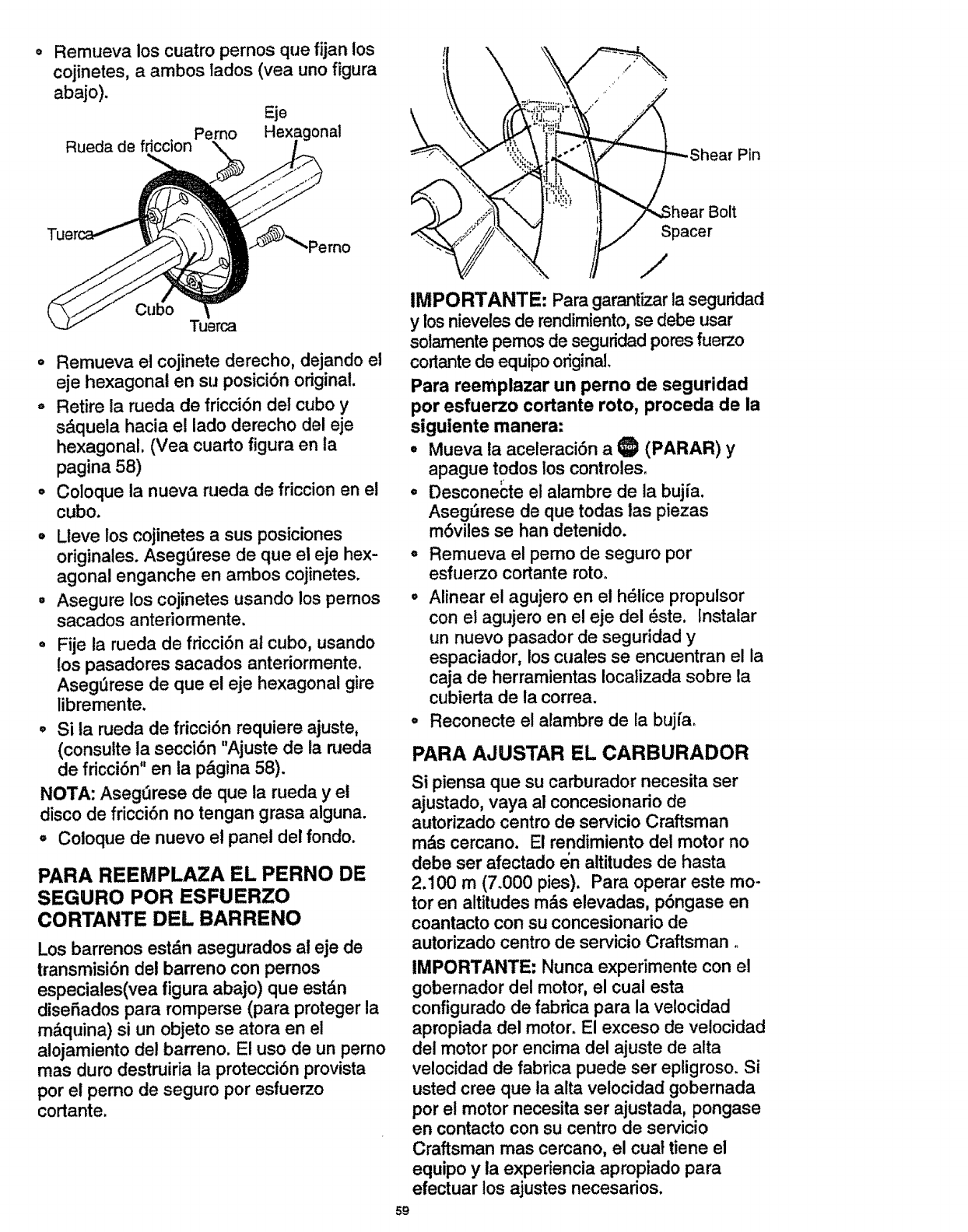
Remueva los cuatro pernos que fijan los
cojinetes, a ambos lades (yea uno figura
abajo). Eje
Rueda de friccion Perno Hexagonal ;at Pin
Tu
muerca
o Remueva el cojinete derecho, dejando el
eje hexagonal en su posici6n original.
° Retire la rueda de fricci6n del cube y
sdqueta hacia el lade derecho del eje
hexagonal. (Vea cuarto figura en la
pagina 58)
° Coloque la nueva rueda de friccion en el
cubo.
° Lieve los cojinetes a sus posiciones
originales. AsegtT=rese de que el eje hex-
agonal enganche en ambos cojinetes.
• Asegure los cojinetes usando los pemos
sacados anteriormente.
• Fije la rueda de fricci6n al cube, usando
los pasadores sacados anteriormente.
Aseg_rese de que el eje hexagonal gire
libremente.
° Si la rueda de fricci6n requiere ajuste,
(consuite la secci6n "Ajuste de la naeda
de fricci6n" en la pdgina 58).
NOTA: Aseg_3rese de que la rueda y el
disco de fricci6n no tengan grasa alguna.
° Coloque de nuevo el panel del fondo.
PARA REEMPLAZA EL PERNO DE
SEGURO POR ESFUERZO
CORTANTE DEL BARRENO
Los barrenos estdn asegurados al eje de
transmisi6n del barreno con pemos
especiales(vea figura abajo) que est_.n
dise5ados para romperse (para proteger la
mdquina) si un objeto se atora en el
alojamiento del barreno. El use de un perno
mas duro destruiria la protecci6n provista
per el perno de seguro per esfuerzo
cortante.
Bolt
Spacer
/
IMPORTANTE: Para garantizar la seguridad
ylos nieveles de rendimiento, se debe usar
solamente pemos de seguridad pores fuerzo
cortante de equipo original.
Para reemplazar un pemo de seguridad
per esfuerzo cortante rote, proceda de la
siguiente manera:
,Mueva la aceleraci6n a ID (PARAR) y
apague todos los controles,
oDesconecte el alambre de la bujfa.
Aseg_rese de que todas las piezas
m6viles se han detenido.
° Remueva el pemo de seguro per
esfuerzo cortante rotoo
•Alinear el agujero en el h61ice propulsor
con el agujero en el eje del 6ste. lnstalar
un nuevo pasador de seguridad y
espaciador, los cuales se encuentran el la
caja de herramientas localizada sobre la
cubierta de la correa.
° Reconecte el alambre de la bujfa.
PARA AJUSTAR EL CARBURADOR
Si piensa que su carburador necesita ser
ajustado, vaya al concesionario de
autorizado centre de servicio Craftsman
mi_s cercano. El rendimiento del motor no
debe ser afectado en altitudes de hasta
2.100 m (7.000 pies). Para operar este me-
tor en altitudes mAs elevadas, p6ngase en
coantacto con su concesionario de
autorizado centre de servicio Craftsman
IMPORTANTE: Nunca experimente con el
gobernador del motor, el cual esta
configurado de fabrica para la velocidad
apropiada del motor. El exceso de velocidad
del motor per encima del ajuste de alta
velocidad de fabrica puede ser epligroso. Si
usted cree que la alta velocidad gobernada
per et motor necesita ser ajustada, pongase
en contacto con su centre de servicio
Craftsman mas cercano, el cuat tiene el
equipo yla experiencia apropiado para
efectuar los ajustes necesados.
59
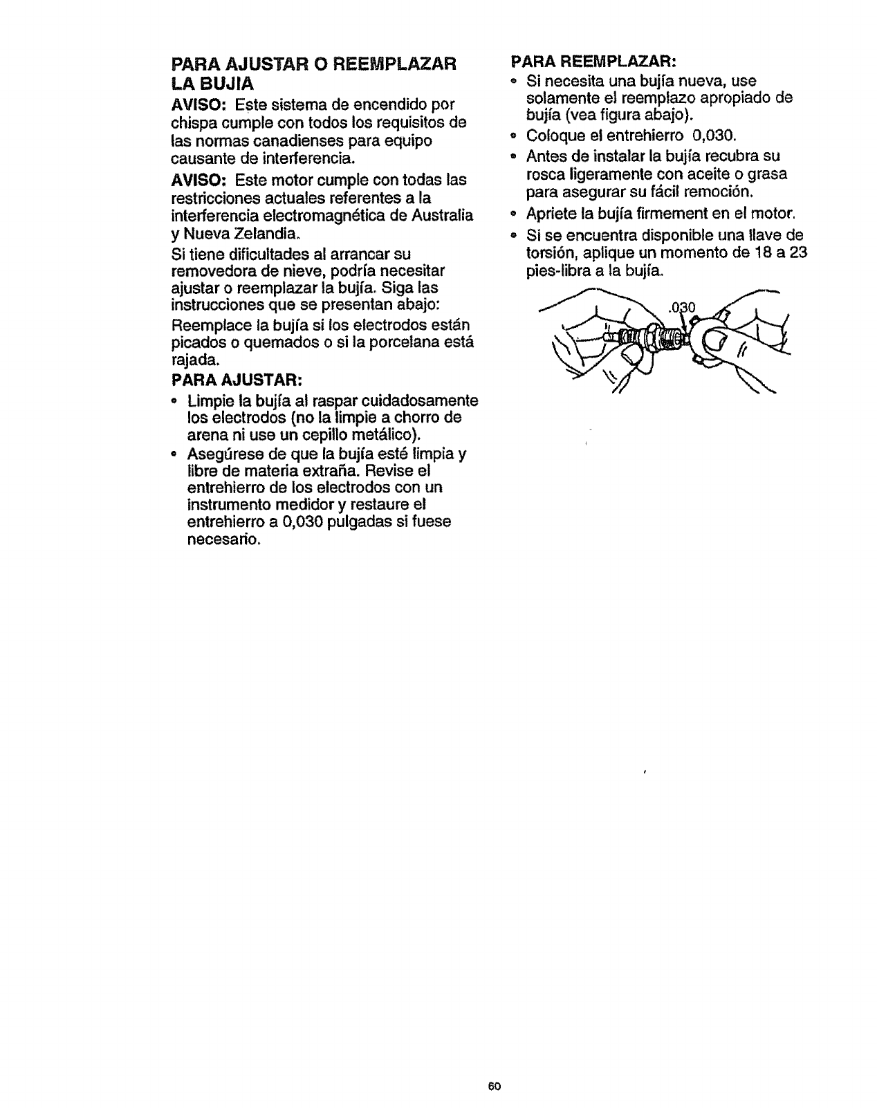
PARA AJUSTAR O REEMPLAZAR
LA BUJIA
AVISO: Este sistema de encendido pot
chispa cumple con todos los requisitos de
las normas canadienses para equipo
causante de interferencia.
AVISO: Este motor cumple con todas las
restricciones actuates referentes a la
interferencia electromagn_tica de Australia
y Nueva Zelandiao
Si tiene dificuitades al arrancar su
removedora de nieve, podrfa necesitar
ajustar o reemplazar la bujfa. Siga las
instrucciones que se presentan abajo:
Reemplace la bujfa si los electrodos estdn
pica(los o quemados o si la porcetana est&
rajada.
PARA AJUSTAR:
Limpie la bujfa al raspar cuidadosamente
los electrodos (no la limpie a chorro de
arena ni use un cepillo met&lico).
Aseg!Jrese de que la bujfa est6 limpia y
libre de materia extraSa. Revise el
entrehierro de los etectrodos con un
instrumento medidor y restaure el
entrehierro a0,030 pulgadas si fuese
necesario_
PARA REEMPLAZAR:
° Si necesita una buj[a nueva, use
solamente et reemplazo apropiado de
bujfa (vea figura abajo).
,Coloque el entrehierro 0,030.
= Antes de instalar la bujfa recubra su
rosca ligeramente con aceite o grasa
para asegurar su fdcil remoci6n.
•Apriete la bujfa firmement en el motor.
°Si se encuentra disponible una llave de
torsi6n, aplique un momento de 18 a 23
pies-libra a la bujfa.
60
PRECAUCION: Nunca almacene
su removedora de nieve en ambientes
interiores oen un area cerrado, real
ventilada si el tanque aun tiene gasolina.
Los vapores podrian alcanzar una llama
desprotegida, chispa o llama piloto de un
homo, calentador de agua, secadora de
ropa, cigarrillo, etc.
Para evitar da5o al motor (si la
removedora de nleve estar_ fuera de uso
por mds 30 dias) siga los pasos detallados
abajo.
ALMACENAMIENTO DE LA
REMOVEDORA DE NIEVE
oLimpie completamente la removedora de
nieve.
• Lubrique todos los puntos de lubricaci6n
(vea Mantenimiento del cliente en p&ginas
52-54).
°Aseg0rese de que todos las tuercas,
pemos y tomillos est&n sujetados de
manera segura, lnspeccione todas las
piezas m6viles visibles para detectar
daSos, roturas y desgaste. Efect_e
reemplazos si fuese necesario.
oRetoque todas las superficies de pintura
oxidadas o desgarradas; lije antes de
aplicar pintura.
°Cubra las piezas de metal al desnudo del
compresor dei alojamiento del barreno y.
el impuisor con un material para prevenlr
la corrosi6n, tal como un lubricante en
aersoL
NOTA: Una revisi6n o afinado anual por un
Centro de Servicio Craftsman es una buena
manera de asegurar que su removedora de
nieve le brindar& el mdximo rendimiento la
siguiente temporada.
ALAMCENAMIENTO DEL MOTOR
La gasolina deber& ser removida o tratada
para prevenir la formaci6n de dep6sitos de
goma en el tanque, filtro, manguera, y
carburador durante el almacenamiento.
Asimiso, durante el almacenamiento, la
gasolina mezclada con alcohol la cual utiliza
etanol o metanol (algunas veces llamado
gasohol) atrae agua. Acat0a sobre la
gasolina para formar &cidos los cuales
da_an el motor.
oPara remover la gasolina, mantenga el
motor en marcha hasta que el tanque
est6 vacfo y el.
°Si no quiere sacar gasolina, use et
estabilizador de combustible provisto con
la unidad o compre estabilizador de
combutstible Craftsman N_mo 33500.
ASada estabilizador de combustible a
cualquier gasolina que permanezca en el
tanque para minimizar los dep6sitos de
goma y _.cido. Si el tanque est,. casi
vacfo, mezcle el estabilizador con
gasolina nueva en un recipiente separado
y aSada un poco de esta mezcla al
tanque.
Siempre siga las instrucciones en el
contenedor det estabilizador. Luego opere el
motor surante at menos 10 minutos despues
de que se haya aSadido el estabilizador
para permitir que la mezcla alcance el
carburador. Almacene la removedora de
nieve en un _lugar seguro, Vease la
advertencia arriba. Vea Precaucion.
Puede mantener su motor en buenas
condiciones de funcionamiento durante el
almacenamiento ah
• Cambiar el aceite.
Lubricando et &rea del pist6n/citindro,
Esto puede ser hecho removiendo
primero la bujfa y salpicando el agujero
de ia bujfa con aceite de motor limpio.
Luego cubra el agujero de la bujta con un
paso para absorber el roc_ode aceite, A
continuaci6n, rote el motor al halar de la
cuerda de arranque hasta sacarla
completamente dos o tres veces.
Finalmente, reinstale la bujfa y conecte el
alambre de la bujfa.
OTROS
= Si fuese posible,'almacene su
removedora de nieve en ambientes
interfores y cebrala para protegerla contra
el polvo y la suciedad.
°Si la m&quina deber& estar en el exterior,
col6quela sobre bloques para garantizar
que la m&quina no estar& en contacto con
el terreno.
Cubra la removedora de nieve con una
cubierta protectora apropiada que no
retenga humedado No use pldstico ni
vinilo.
IMPORTANTE: Nunca cubra la
removedora de nieve mientras las areas del
motor y el escape aun esten calientes.
61
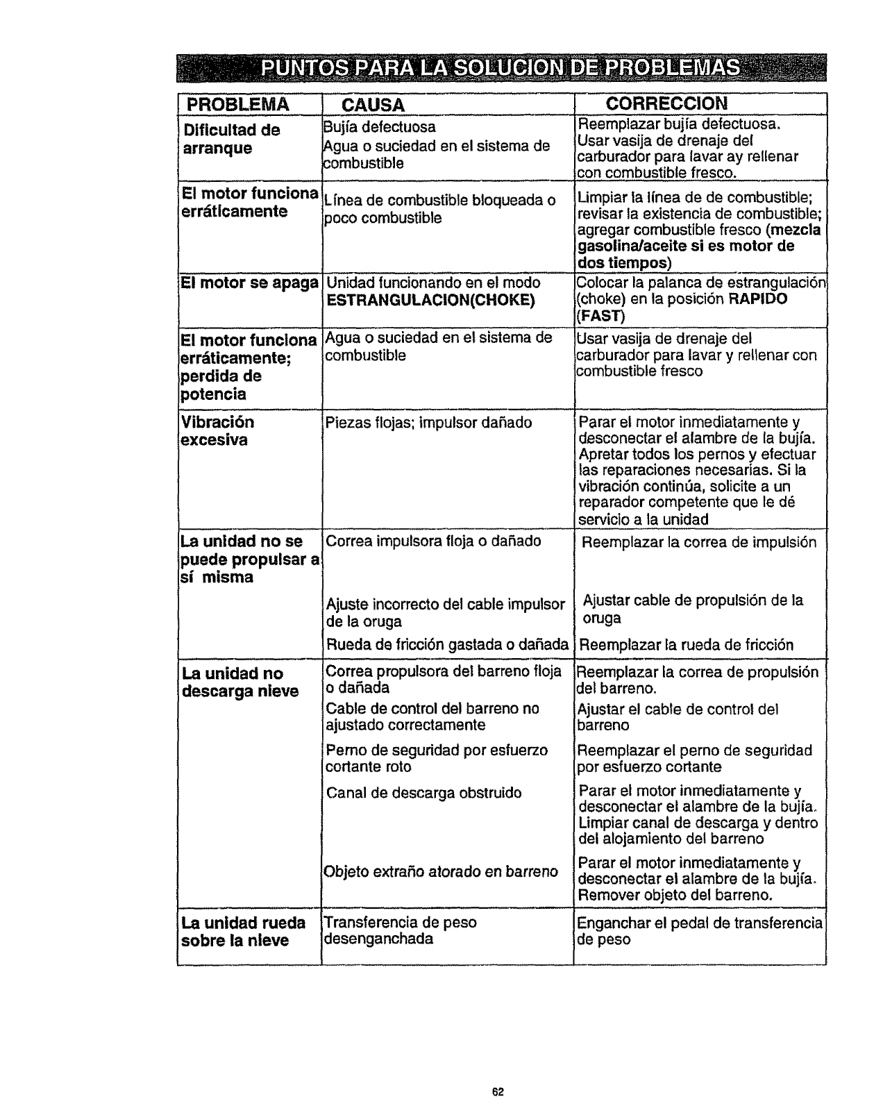
PROBLEMA
Dificultad de
arranque
El motor funciona
errdtlcamente
,:EImotor se apaga
El motor funclona
errdticamente;
_erdida de
_otencia
Vibracidn
excesiva
La unidad no se
puede propulsar a
Sl mlsma
iLa unidad no
descarga nieve
La unidad rueda
sobre la n|eve
CAUSA
Bujfa defectuosa
[Agua o suciedad en el sistema de
combustible
Lfnea de combustible bloqueada o
)oco combustible
Unidad funcionando en el modo
ESTRANGULACION(CHOKE)
Agua osuciedad en et sistema de
combustible
Piezas flojas; impulsor dafiado
Correa impulsora floja odafiado
Ajuste incorrecto del cable impulsor
de la oruga
Rueda de fdcci6n gastada odafiada
Correa propulsora del barreno fioja
odafiada
Cable de control del barreno no
ajustado correctamente
Pemo de seguridad por esfuerzo
cortante roto
Canal de descarga obstruido
Objeto extrafio atorado en barreno
Transferencia de peso
desenganchada
CORRECCION
Reemplazar bujia defectuosa,
Usar vasija de drenaje del
carburador para lavar ay reltenar
con combustible fresco.
Limpiar la ifnea de de combustible;
revisar la existencia de combustible;
agregar combustible fresco (mezcla
gasolina/aceite si es motor de
dos tiempos)
Colocar la palanca de estrangulaci6_
(choke) en la posici6n RAPIDO
(FAST)
Usar vasija de drenaje del
carburador para lavar y retlenar con
combustible fresco
Parar et motor inmediatamente y
desconectar el alambre de la bujfa.
Apretar todos los pernos y efectuar
las reparaciones necesarias. Si la
vibraci6n continua, solicite a un
reparador competente que le dd
servicio a la unidad
Reemplazar la correa de impulsi6n
Ajustar cable de propulsi6n de la
oruga
Reemplazar fa rueda de fdcci6n
Reemplazar la correa de propulsi6n
del barreno.
Ajustar el cable de control del
barreno
Reemplazar el perno de seguddad
_or esfuerzo cortante
:_arar el motor inmediatamente y
desconectar el alambre de la bujfao
Limpiar canal de descarga y dentro
del a!ojamiento del barreno
Parar el motor inmediatamente y
desconectar el alambre de ta bujfa.
Remover objeto del barreno.
Enganchar el pedal de transferencia
de peso
62
For the repair or replacement parts you
need delivered directly to your home
Call 7 am-'/' pro, 7 days a week
1-800=366=PART
(1-800-366-7278)
Para ordenar piezas con entrega
a domicilio -1-800-659-7084
For in-house major brand repair service
Call 24 hours a day, 7 days a week
1=800=4-REPAIR
(1-800-473-7247)
Para pedir servicio de reparaci6n a
domicilio - 1-800-676-5811
For the location of a Sears Parts and
Repair Center in your area
Call 24 hours a day, 7 days a week
1-800=488-1222
For information on purchasing a Sears
Maintenance Agreement or to inquire
about an existing Agreement
Call 9 am -Spm, Monday-Saturday
1-800=827-6655
When requesting service or ordering
parts, always provide the following
information:
• Product Type °Part Number
•Model Number °Part Description
Amef_'sRepairSpecialists Printed in U.S.A.
