Craftsman 536887752 User Manual SNOWTHROWER, GAS Manuals And Guides L0312024
CRAFTSMAN Snowthrower, Gas Manual L0312024 CRAFTSMAN Snowthrower, Gas Owner's Manual, CRAFTSMAN Snowthrower, Gas installation guides
User Manual: Craftsman 536887752 536887752 CRAFTSMAN SNOWTHROWER, GAS - Manuals and Guides View the owners manual for your CRAFTSMAN SNOWTHROWER, GAS #536887752. Home:Lawn & Garden Parts:Craftsman Parts:Craftsman SNOWTHROWER, GAS Manual
Open the PDF directly: View PDF ![]() .
.
Page Count: 104 [warning: Documents this large are best viewed by clicking the View PDF Link!]
]CRRFTSMRN 1
Operator's Manual
Snow Thrower
7.75 Horsepower
Electric Start
26-inch Dual Stage
Model 536.887752
CAUTION: Before using this product,
read this manual and follow all of its
Safety Rules and Operating Instructions.
Manual del usario
Quitanieves
de 26 pulgadas
7.75 caballos de fuerza (hp)
Biet&pico
Arranque el_ctrico
Modelo 536.887752
PRECAUCI6N: Antes de usar este producto,
lea este manual y siga todas las reglas de
seguridad e instrucciones de operaci6n.
Sears, Roebuck and Co., Hoffman Estates, IL 60179 U.S.A.
F-031027L www.sears.com/craftsman
WARRANTY STATEMENT ...... 2
SAFETY RULES ............... 2
INTERNATIONAL SYMBOLS .... 4
ASSEMBLY ................... 6
OPERATION .................. 12
MAINTENANCE ............... 19
SERVICE AND ADJUSTMENT .. 22
STORAGE .................... 33
TROUBLESHOOTING TABLE . .. 34
REPAIR PARTS ............... 38
ENGINE REPAIR PARTS ....... 58
SPANISH (ESPA_IOL) .......... 65
PARTS ORDERING/SERVICE ..
BACK COVER
LIMITED TWO-YEAR WARRANTY ON CRAFTSMAN SNOW THROWER
For two years from the date of purchase, when this Craftsman Snow thrower is maintained,
lubricated, and tuned up according to the operating and maintenance instructions in the
owner's manual, Sears will repair, free of charge, any defect in material or workmanship.
If this Craftsman Snow thrower is used for commercial or rental purposes, this warranty ap-
plies for only 90 days from the date of purchase.
This warranty does not cover the following:
Items which become wom during normal use, such as spark plugs, drive belts and shear
pins.
Repair necessary because of operator abuse or negligence, including bent crankshafts
and the failure to maintain the equipment according to the instructions contained in the
owner's manual.
WARRANTY SERVICE IS AVAILABLE BY RETURNING THE CRAFTSMAN SNOW
THROWER TO THE NEAREST SEARS SERVICE CENTER IN THE UNITED STATES.
THIS WARRANTY APPLIES ONLY WHILE THIS PRODUCT IS IN USE IN THE UNITED
STATES.
This warranty gives you specific legal rights, and you may also have other rights which may
vary from state to state.
Sears, Roebuck and Co., D817WA, Hoffman Estates. IL 60179
_lb OOK FOR THIS SYMBOL TO POINT OUT IMPORTANT SAFETY PRECAUTIONS.
IT MEANS-- ATTENTION!!! BECOME ALERT!!! YOUR SAFETY IS INVOLVED.
Engine Exhaust, some of its constituents, and
certain vehicle components contain or emit
chemicals known to the State of California to
cause cancer and birth defects or other repro-
ductive harm.
Battery posts, terminals and related accessories
contain lead and lead compounds, chemicals
known to the State of California to cause cancer
and birth defects or other reproductive harm.
WASH HANDS AFTER HANDLING.
WARNING: Always discon-
nect the spark plug wire
and place it where it cannot
make contact with spark plug to
prevent accidental starting during:
Preparation, Maintenance, or Stor-
age of your snow thrower.
IMPORTANT: Safety standards re-
quire operator presence controls to
minimize the risk of injury. Your snow
thrower is equipped with such controls.
Do not attempt to defeat the function of
the operator presence control under any
circumstances.
F-031027L 2
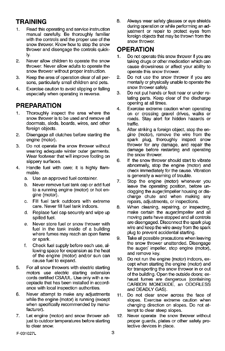
TRAINING
1. Read this operating and service instruction
manual carefully. Be thoroughly familiar
with the controls and the proper use of the
snow thrower. Know how to stop the snow
thrower and disengage the controls quick-
ly.
2. Never allow children to operate the snow
thrower. Never allow adults to operate the
snow thrower without proper instruction.
3. Keep the area of operation clear of all per-
sons, particularly small children end pets.
4. Exercise caution to avoid slipping or falling
especially when operating in reverse.
PREPARATION
1. Thoroughly inspect the area where the
snow thrower is to be used and remove all
doormats, sleds, boards, wires, and other
foreign objects.
2. Disengage all clutches before starting the
engine (motor).
3. Do not operate the snow thrower without
wearing adequate winter outer garments.
Wear footwear that will improve footing on
slippery surfaces.
4. Handle fuel with care; it is highly flam-
mable.
a. Use an approved fuel container.
b. Never remove fuel tank cap or add fuel
to a running engine (motor) or hot en-
gine (motor).
c. Fill fuel tank outdoors with extreme
care. Never fill fuel tank indoors.
d. Replace fuel cap securely and wipe up
spilled fuel.
e. Never store fuel or snow thrower with
fuel in the tank inside of a building
where fumes may reach an open flame
or spark.
f. Check fuel supply before each use, al-
lowing space for expansion as the heat
of the engine (motor) and/or sun can
cause fuel to expand.
5. For all snow throwers with electric starting
motors use electric starting extension
cords certified CSA/UL. Use only with a re-
ceptecle that has been installed in accord-
ance with local inspection authorities.
6. Never attempt to make any adjustments
while the engine (motor) is running (except
when specifically recommended by manu-
facturer).
7. Let engine (motor) and snow thrower ad-
just to outdoor temperatures before starting
to clear snow.
F-031027L
8_ Always wear safety glasses or eye shields
during operation or while performing an ad-
justment or repair to protect eyes from
foreign objects that may be thrown from the
snow thrower.
OPERATION
1. Do not operate this snow thrower ifyou are
taking drugs or other medication which can
cause drowsiness or affect your ability to
operate this snow thrower.
2. Do not use the snow thrower # you are
mentally or physically unable to operate the
snow thrower safely.
3. Do not put hands or feet near or under ro-
tating parts. Keep clear of the discharge
opening at all times.
4. Exercise extreme caution when operating
on or crossing gravel drives, walks or
roads. Stay alert for hidden hazards or
traffic.
5. After striking a foreign object, stop the en-
gine (motor), remove the wire from the
spark plug, thoroughly inspect snow
thrower for any damage, and repair the
damage before restarting and operating
the snow thrower.
6. If the snow thrower should start to vibrate
abnormally, stop the engine (motor) and
check immediately for the cause. Vibration
is generally a warning of trouble.
7. Stop the engine (motor) whenever you
leave the operating position, before un-
clogging the auger/impaller housing or dis-
charge chute and when making any
repairs, adjustments, or inspections.
8. When cleaning, repairing, or inspecting,
make certain the auger/impeller and all
moving parts have stopped and all controls
are disengaged. Disconnect the spark plug
wire and keep the wire away from the spark
plug to prevent accidental starting.
9. Take all possible precautions when leaving
the snow thrower unattended. Disengage
the auger/ impeller, stop engine (motor),
and remove key.
10. Do not run the engine (motor) indoors, ex-
cept when starting the engine (motor) and
for transporting the snow thrower in or out
of the building. Open the outside doors; ex-
haust fumes are dangerous (containing
CARBON MONOXIDE, an ODORLESS
and DEADLY GAS).
11. Do not clear snow across the face of
slopes. Exercise extreme caution when
changing direction on slopes. Do not at-
tempt to clear steep slopes.
12. Never operate the snow thrower without
proper guards, plates or other safety pro-
tective devices in place.
13.Neveroperatethesnowthrowernearen-
closures,automobiles,windowwells,drop-
offs,andt_e like without proper adjustment
of Me snow discharge angle. Keep children
and pets away.
14. Do not overload the snow thrower capacity
by attempting to clear snow at too fast a
rate.
15. Never operate the snow thrower at high
transport speeds on slippery surfaces.
Look behind and use care when backing
up.
16. Never direct discharge at bystanders or
allow anyone in front of the snow thrower.
17. Disengage powar to the collector/impeller
when snow thrower is transported or not in
use.
18. Use anly attachments and ascassorias ap-
proved by the manufacturer of the snow
thrower (such as tire chains, electric start
kits, ect.).
19. Never operate the snow thrower without
good visibility or light. Always be sure of
your footing and keep a firm hold on the
handles. Walk;never run.
20. Do not over-reach. Keep proper footing
and balance at all times.
21. Do not attempt to use snow thrower on a
roof.
MAINTENANCE AND STORAGE
1. Check shear bolts and other bolts at fre-
quent intervals for proper tightness to be
sure the snow thrower is in safe working
condition.
2. Never store the snow thrower with fuel in
the tank inside a building where ignition
sources are present such as hot water end
space heaters, clothes dryers, and Me like.
Allow the engine (motor) to cool before
storing in any enclosure.
3. Always refer to operator's guide instruc-
tions for important details if the snow
thrower is to be stored for an extended
period.
4. Maintain or replace safety and instruction
labels, as necessary.
5. Run the snow thrower a few minutes after
throwing snow to prevent freeze-up of the
augedimpeller.
_IL WARNING: This snow thrower isfor use on sidewalks, driveways
and other ground level surfaces.
Caution should be exercised while using on
steep sloping surfaces. DO NOT USE
SNOW THROWER ON SURFACES ABOVE
GROUND LEVEL such as roofs of resi-
dences, garages, porches or other such
structures or buildings.
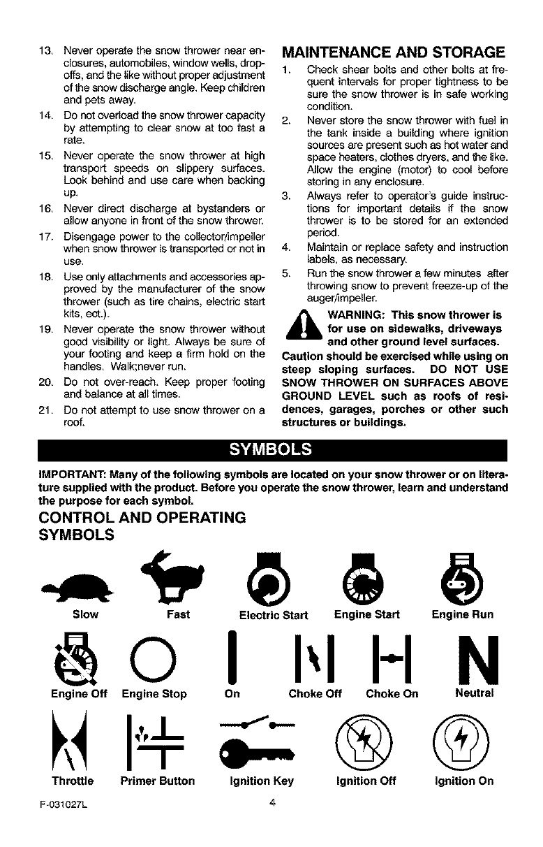
IMPORTANT: Many of the following symbols are located on your snow thrower or on litera-
ture supplied with the product. Before you operate the snow thrower, learn and understand
the purpose for each symbol.
CONTROL AND OPERATING
SYMBOLS
Slow Fast Electric Start Engine Start Engine Run
Engine Off Engine Stop
Throttle Primer Button
I I-I N
On Choke Off Choke On Neutral
®
Ignition Key Ignition Off Q
Ignition On
F-031027L
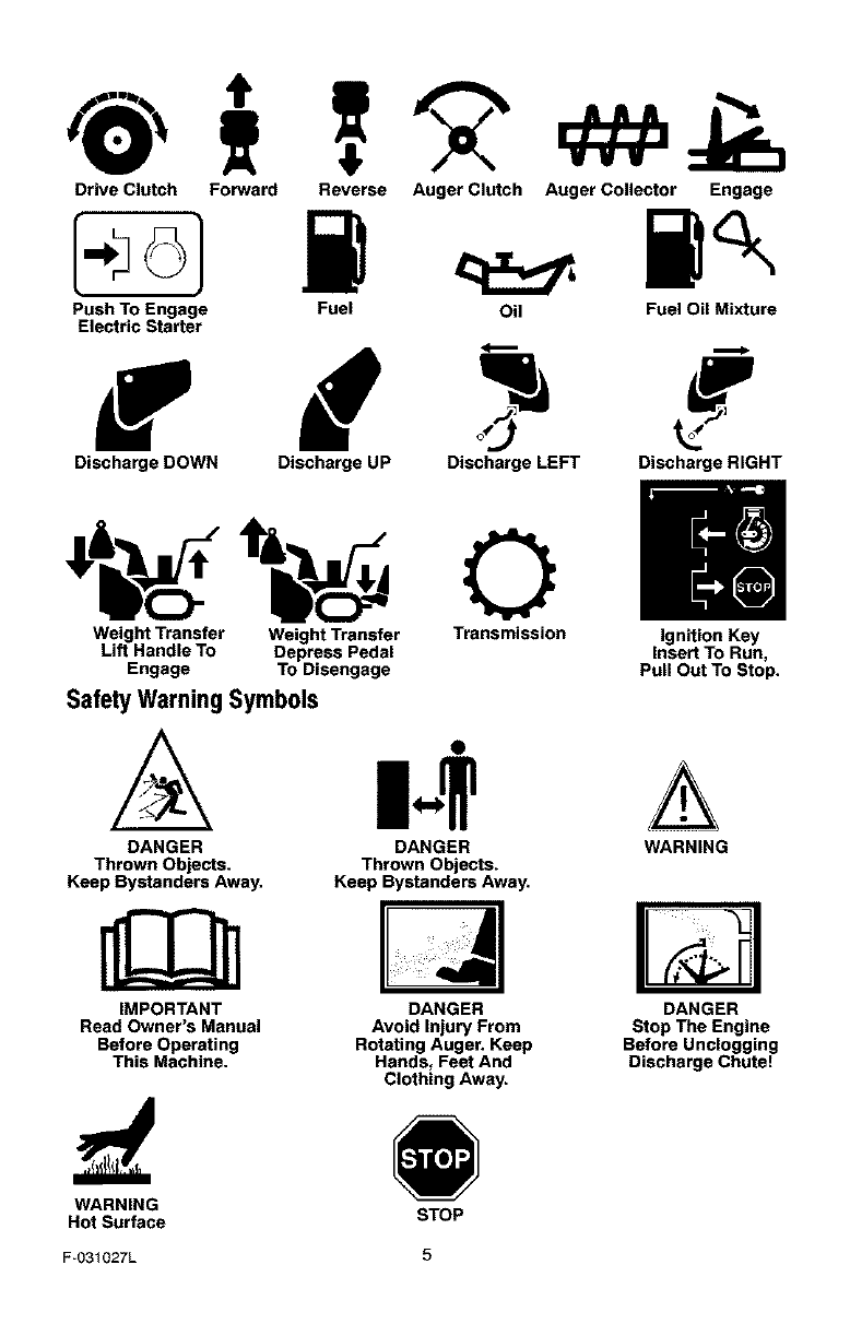
Drive Clutch Forward Reverse Auger Clutch Auger Collector Engage
Push To Engage Fuel Oil Fuel Oil Mixture
Electric Starter
Discharge DOWN Discharge UP Discharge LEFT Discharge RIGHT
Weight Transfer Weight Transfer Transmission Ignition Key
Lift Handle To Depress Pedal Insert To Run,
Engage To Disengage Pull Out To Stop.
Safety Warning Symbols
DANGER DANGER WARNING
Thrown Objects. Thrown Objects.
Keep Bystanders Away. Keep Bystanders Away.
IMPORTANT
Read Owner's Manual
Before Operating
This Machine.
DANGER
Avoid Injury From
Rotating Auger. Keep
Hands, Feet And
Clothing Away.
DANGER
Stop The Engine
Before Unclogging
Discharge Chute!
WARNING
Hot Surface STOP
F-O31027L 5
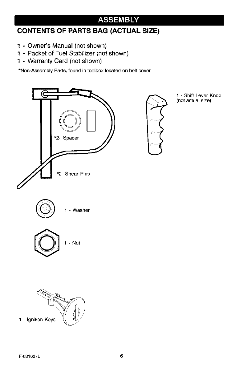
CONTENTS OF PARTS BAG (ACTUAL SIZE)
1-Owner's Manual (not shown)
1-Packet of Fuel Stabilizer (not shown)
1 - Warranty Card (not shown)
*Non-Assembly Parts,foundintoolboxlocatedonbeltcover
1 - Shift Lever Knob
(not actual size)
¢- I
1 - Washer
1 - Nut
1 - Igniti_
F-031027L 6
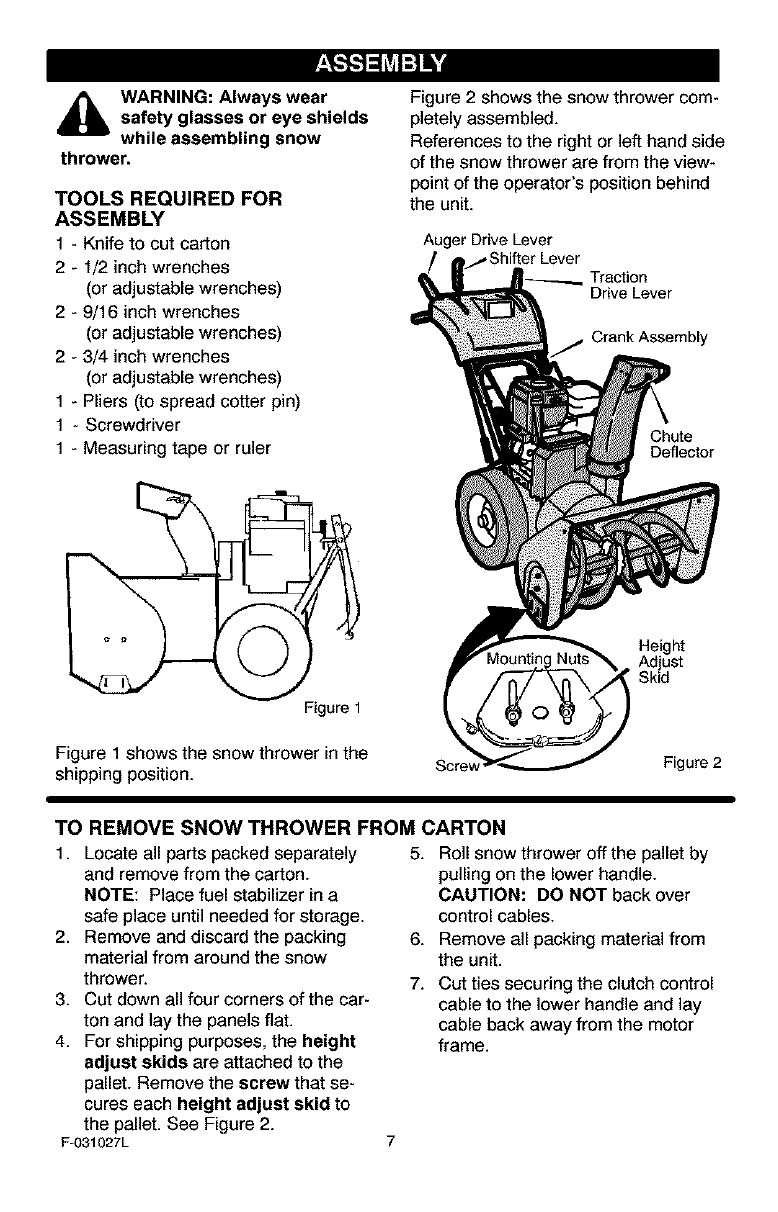
_lb ARNING: Always wear
safety glasses or eye shields
while assembling snow
thrower.
TOOLS REQUIRED FOR
ASSEMBLY
1 - Knife to cut carton
2- 1/2 inch wrenches
(or adjustable wrenches)
2-9/16 inch wrenches
(or adjustable wrenches)
2-3/4 inch wrenches
(or adjustable wrenches)
1 - Pliers (to spread cotter pin)
1- Screwdriver
1 - Measuring tape or ruler
Figure 1
Figure 1 shows the snow thrower in the
shipping position.
Figure 2 shows the snow thrower com-
pletely assembled.
References to the right or left hand side
of the snow thrower are from the view-
point of the operator's position behind
the unit.
Auger Drive Lever
Traction
Drive Lever
Crank Assembly
Chute
Deflector
Height
Adjust
Skid
Scre_ Figure 2
TO REMOVE SNOW THROWER FROM CARTON
1. Locate all parts packed separately
and remove from the carton.
NOTE: Place fuel stabilizer in a
safe place until needed for storage.
2. Remove and discard the packing
material from around the snow
thrower.
3. Cut down all four corners of the car-
ton and lay the panels flat.
4. For shipping purposes, the height
adjust skids are attached to the
pallet. Remove the screw that se-
cures each height adjust skid to
the pallet. See Figure 2.
F-031027L
5. Roll snow thrower off the pallet by
pulling on the lower handle.
CAUTION: DO NOT back over
control cables.
6. Remove all packing material from
the unit.
7. Cut ties securing the clutch control
cable to the lower handle and lay
cable back away from the motor
frame.
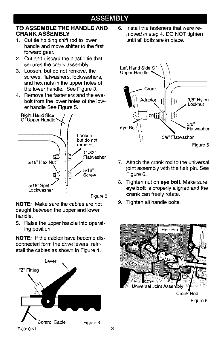
TO ASSEMBLE THE HANDLE AND
CRANK ASSEMBLY
1. Cut tie holding shift rod to lower
handle and move shifter to the first
forward gear.
2. Cut and discard the plastic tie that
secures the crank assembly.
3. Loosen, but do not remove, the
screws, flatwashers, Iockwashers,
and hex nuts in the upper holes of
the lower handle. See Figure 3.
4. Remove the fasteners and the eye-
bolt from the lower holes of the low-
er handle See Figure 5.
Right Hand Side
Of U
5/
5/16" Split j
Lockwasher
Loosen,
but do not
remove
11/32"
Flatwasher
5/16"
Screw
Figure 3
NOTE: Make sure the cables are not
caught between the upper and lower
handle.
5. Raise the upper handle into operat-
ing position.
NOTE: If the cables have become dis-
connected form the drive levers, rein-
stall the cables as shown in Figure 4.
Lever
"Z" Fitting
6. Install the fasteners that were re-
moved in step 4. DO NOT tighten
until all bolts are in place.
Left Hand Side Of \ \
Upper Handle _.._ __
f
_ 3/8" Nylon
' Locknut
EyeBolt _ _ _"Flatwasher
i, / 3/8" Flatwasher
Figure 5
7. Attach the crank rod to the universal
joint assembly with the hair pin. See
Figure 6.
8. Tighten nut on eye bolt. Make sure
eye bolt is properly aligned and the
crank can freely rotate.
9. Tighten all handle bolts.
Cran_ :_od
Figure 6
Control Cable Figure 4
F-031027L 8
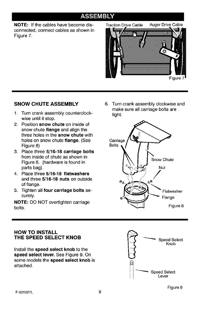
NOTE: If the cables have become dis-
connected, connect cables as shown in
Figure 7.
Traction Drive Cable Auger Drive Cable
SNOW CHUTE ASSEMBLY
1. Turn crank assembly counterclock-
wise until it stop.
2. Position snow chute on inside of
snow chute flange and align the
three holes in the snow chute with
holes on snow chute flange. (See
Figure 8)
3. Place three 5/16-18 carriage bolts
from inside of chute as shown in
Figure 8. (hardware is found in
parts bag).
4. Place three 5/16-18 flatwashers
and three 5/16-18 nuts on outside
of flange.
5. Tighten all four carriage bolts se-
curely.
NOTE: DO NOT overtighten carriage
bolts.
Figure 7
6. Turn crank assembly clockwise and
make sure all carriage bolts are
tight.
Carriage
Bolts
Snow Chute
Nut
/
__ Flatwasher
_ _ Flange
Figure 8
HOW TO INSTALL
THE SPEED SELECT KNOB
Install the speed select knob to the
speed select lever. See Figure 9. On
some models the speed select knob is
attached.
_ Speed Select
Knob
! i _ Speed Select
,, Lever
Figure 9
F-031027L 9
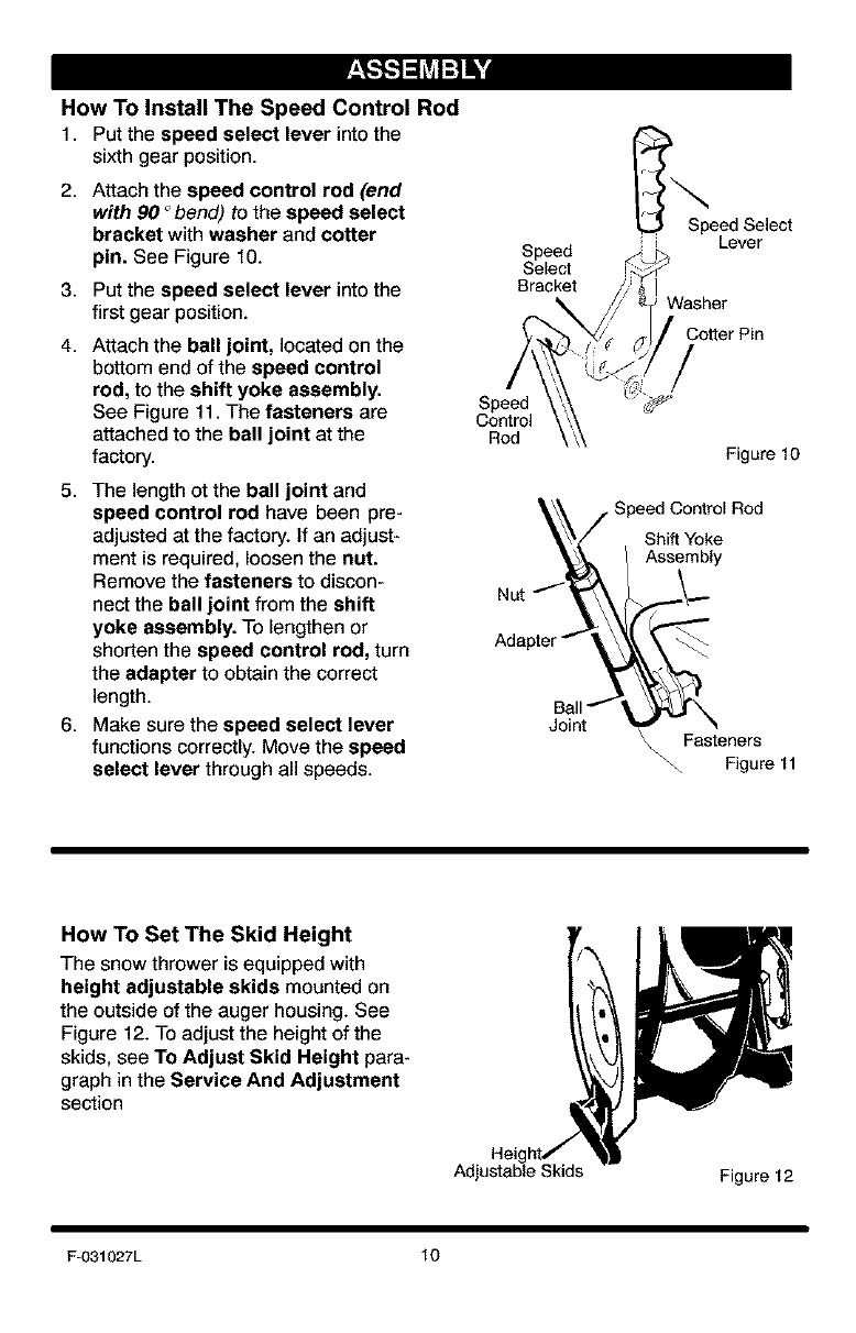
How To Install The Speed Control Rod
1. Put the speed select lever intothe
sixth gear position.
2. Attach the speed control rod (end
with 90 °bend) to the speed select
bracket with washer and cotter
pin. See Figure f0.
3. Put the speed select lever into the
first gear position.
4. Attach the ball joint, located on the
bottom end of the speed control
rod, to the shift yoke assembly.
See Figure 11. The fasteners are
attached to the ball joint at the
factory.
5. The length ot the ball joint and
speed control rod have been pre-
adjusted at the factory. If an adjust-
ment is required, loosen the nut.
Remove the fasteners to discon-
nect the ball joint from the shift
yoke assembly. To lengthen or
shorten the speed control rod, turn
the adapter to obtain the correct
length.
6. Make sure the speed select lever
functions correctly. Move the speed
select lever through all speeds.
Bracket
Speed
Control
Rod
Adapter
Joint
Speed Select
Lever
Cotter Pin
Figure 10
Shift Yoke
Assembly
Fasteners
Figure 11
How To Set The Skid Height
The snow thrower is equipped with
height adjustable skids mounted on
the outside of the auger housing. See
Figure 12. To adjust the height of the
skids, see To Adjust Skid Height para-
graph in the Service And Adjustment
section
Adjustable Skids Figure 12
F-O31027L 10
How To Set
The Length Of The Cables
The cables were adjusted at the factory
and no adjustments should be neces-
sary. However, after the handles are put
in the operating position, the cables can
be too tight or too loose. If an adjust-
ment is necessary, see "How To Check
And Adjust The Cables" in the Service
And Adjustment section.
_" CHECKLIST
Before you operate your new snow
thrower, to ensure that you receive the
best performance and satisfaction from
this quality product, please review the
following checklist:
_" All assembly instructions have been
completed.
_" The discharge chute rotates freely.
_" No remaining loose parts in carton.
_" Check the fasteners. Make sure all
fasteners are tight.
_" On electric start models, the unit was
shipped with the starter cord plugged
into the engine. Before operating, un-
plug the starter cord from the engine.
While learning how to use your snow
thrower, pay extra attention to the fol-
lowing important items:
_" Engine oil is at proper level.
_" Make sure gas tank is filled properly
with clean, fresh, unleaded gasoline.
_" Become familiar with all controls-
their location and function. Operate
controls before starting engine.
F-031027L 11
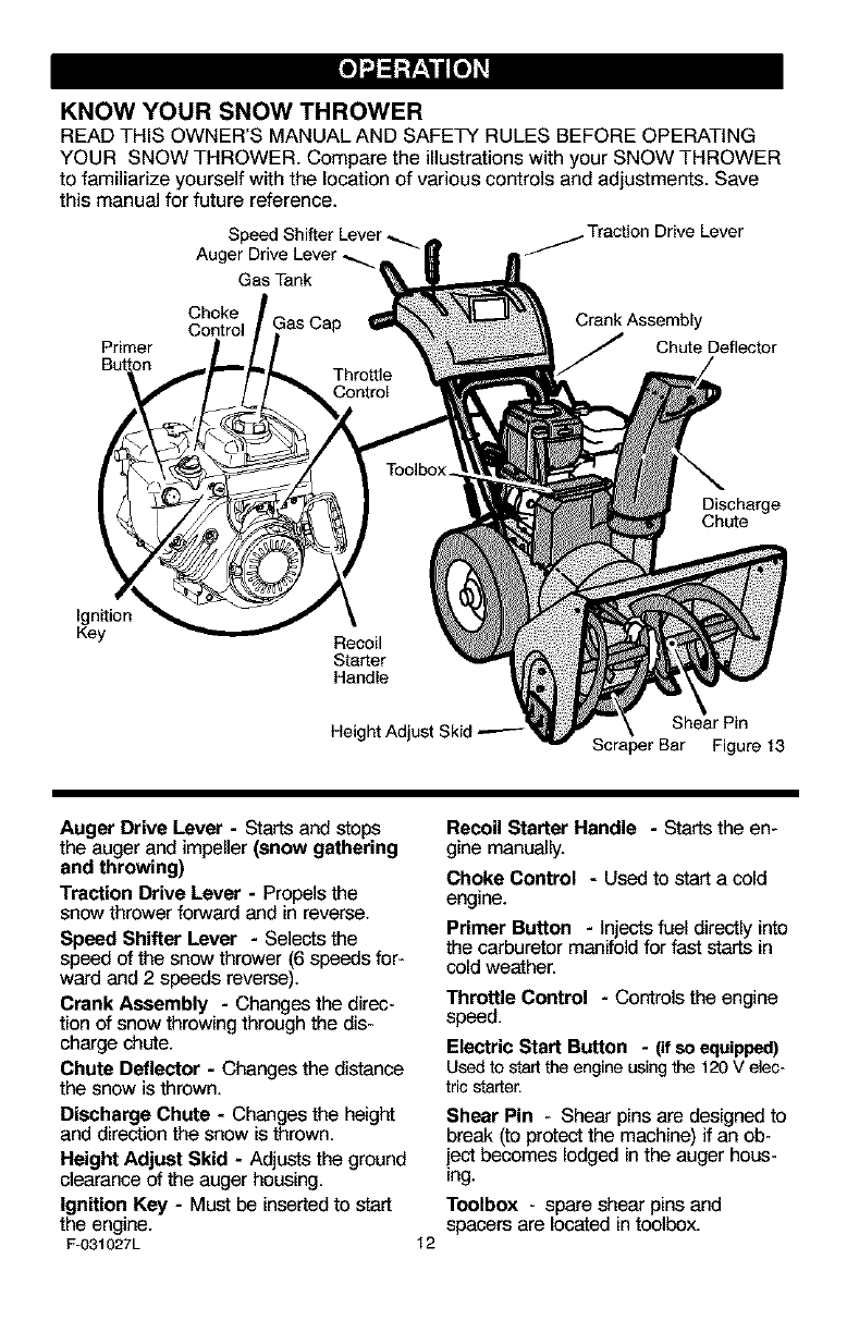
KNOW YOUR SNOW THROWER
READ THIS OWNER'S MANUAL AND SAFETY RULES BEFORE OPERATING
YOUR SNOW THROWER. Compare the illustrations with your SNOW THROWER
to familiarize yourself with the location of various controls and adjustments. Save
this manual for future reference.
Traction Drive Lever
Auger Drive Lever _,
Gas Tank
Primer
Button
Choke Crank Assembly
Control Chute Deflector
Discharge
Chute
Ignition
Key Recoil
Starter
Handle
Height Adjust Skid _-- [rPin
Scraper Bar Figure 13
Auger Drive Lever - Starts and stops
the auger and impeller (snow gathering
and throwing)
Traction Drive Lever - Propels the
snow thrower forward and in reverse.
Speed Shifter Lever - Selects t_e
speed of t_e snow thrower (6 speeds for-
ward and 2 speeds reverse).
Crank Assembly - Changes the direc-
tion of snow throwing through the dis-
charge chute.
Chute Deflector - Changes the distance
the snow is thrown.
Discharge Chute - Changes the height
and direction t_e snow is thrown.
Height Adjust Skid - Adjusts the ground
clearance of the auger housing.
Ignition Key - Must be inserted to start
the engine.
F-031027L 12
Recoil Starter Handle -Starts the en-
gine manually.
Choke Control - Used to start a cold
engine.
Primer Button -Injects fuel directly into
the carburetor manifold for fast starts in
cold weather.
Throttle Control -Controls the engine
speed.
Electric Start Button - (if so equipped)
Usedto start the engineusingthe 120 V elec-
tric starter.
Shear Pin - Shear pins are designed to
break (to protectthe machine) if an ob-
iect becomes lodged in the auger hous-
ing.
Toolbox - spare shear pins and
spacers are located in toolbox.
Theoperationofanysnowthrowercan
resultinforeignobjectsbeingthrown
intotheeyes,whichcanresultinse-
vereeyedamage.Alwayswearsafety
glassesoreyeshieldswhileoperating
thesnowthrower.
Werecommendstandardsafety
glassesorawidevisionsafetymaskfor
overyourglasses.
_lb ARNING: Read Owner's
Manual before operating
machine. Never direct dis-
charge toward bystanders. Stop the
engine before unclogging discharge
chute or auger housing and before
leaving the machine,
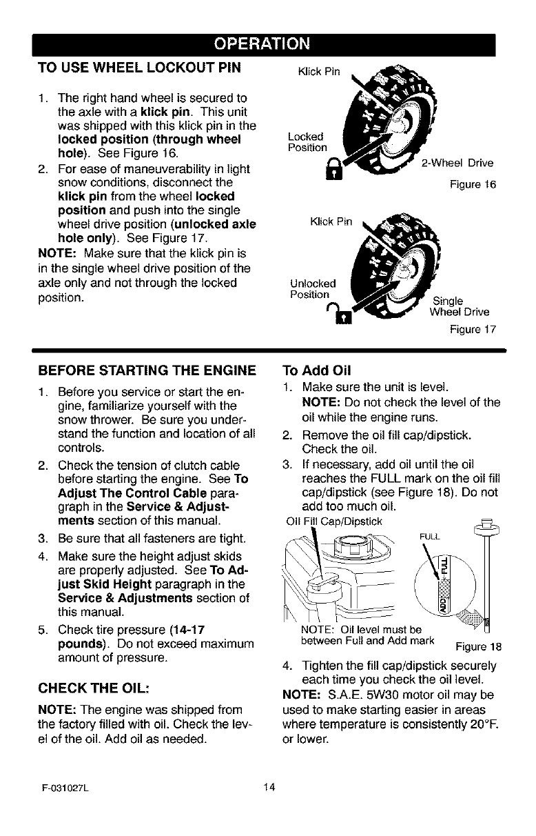
TO STOP YOUR
SNOW THROWER
1. To stop throwing snow, release the
auger drive lever. See Figure 14.
2. To stop the wheels, release the
traction drive lever.
3. To stop the engine, push the
throttle control lever to off and pull
out the ignition key.
Auger Drive Lever Traction Drive Lever
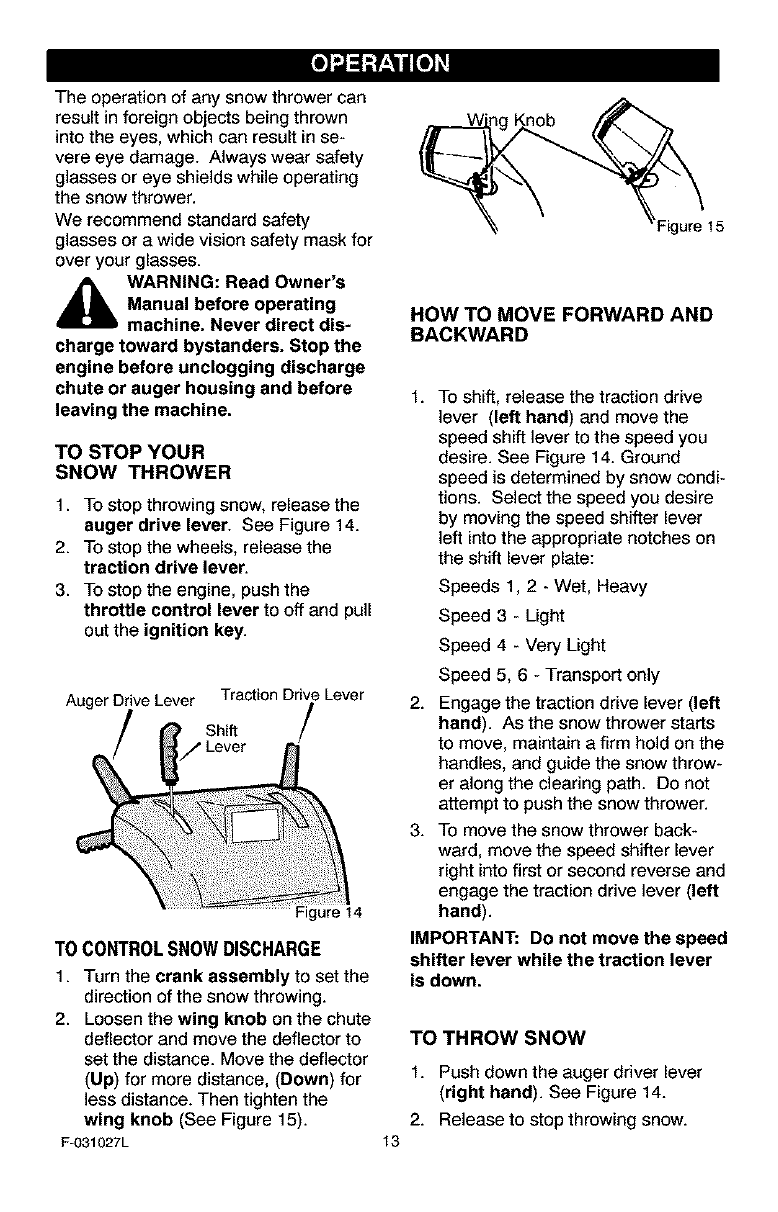
TO CONTROLSNOWDISCHARGE
1. Turn the crank assembly to set the
direction of the snow throwing.
2. Loosen the wing knob on the chute
deflector and move the deflector to
set the distance. Move the deflector
(Up) for more distance, (Down) for
less distance. Then tighten the
wing knob (See Figure 15).
F-031027L
HOW TO MOVE FORWARD AND
BACKWARD
t. To shift, release the traction drive
lever (left hand) and move the
speed shift lever to the speed you
desire. See Figure 14. Ground
speed is determined by snow condi-
tions. Select the speed you desire
by moving the speed shifter lever
left into the appropriate notches on
the shift lever plate:
Speeds 1, 2 - Wet, Heavy
Speed 3-Light
Speed 4 - Very Light
Speed 5, 6 - Transport only
2. Engage the traction drive lever (left
hand). As the snow thrower starts
to move, maintain a firm hold on the
handles, and guide the snow throw-
er along the clearing path. Do not
attempt to push the snow thrower.
3. To move the snow thrower back-
ward, move the speed shifter lever
right into first or second reverse and
engage the traction drive lever (left
hand).
IMPORTANT: Do not move the speed
shifter lever while the traction lever
is down.
13
TO THROW SNOW
1. Push down the auger driver lever
(right hand). See Figure 14.
2. Release to stop throwing snow.
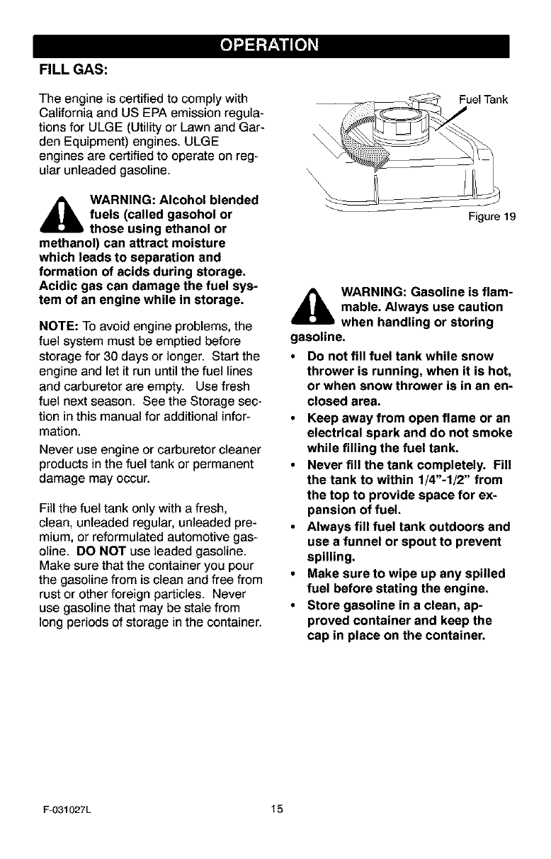
TO USE WHEEL LOCKOUT PIN
1. The right hand wheel is secured to
the axle with a klick pin. This unit
was shipped with this klick pin in the
locked position (through wheel
hole). See Figure 16.
2. For ease of maneuverability in light
snow conditions, disconnect the
klick pin from the wheel locked
position and push into the single
wheel drive position (unlocked axle
hole only). See Figure 17.
NOTE: Make sure that the kiick pin is
in the single wheel drive position of the
axle only and not through the locked
position.
Klick Pin
Locked
Position
KIickPin _,
Unlocked _
2-Wheel Drive
Figure 16
__nnec-'/_ Drive
Figure 17
BEFORE STARTING THE ENGINE
1. Before you service or start the en-
gine, familiarize yourself with the
snow thrower. Be sure you under-
stand the function and location of all
controls.
2. Check the tension of clutch cable
before starting the engine. See To
Adjust The Control Cable para-
graph in the Service &Adjust-
ments section of this manual.
3. Be sure that all fasteners are tight.
4. Make sure the height adjust skids
are properly adjusted. See To Ad-
just Skid Height paragraph in the
Service & Adjustments section of
this manual.
5. Check tire pressure (14-17
pounds). Do not exceed maximum
amount of pressure.
CHECK THE OIL:
NOTE: The engine was shipped from
the factory filled with oil. Check the lev-
el of the oil. Add oil as needed.
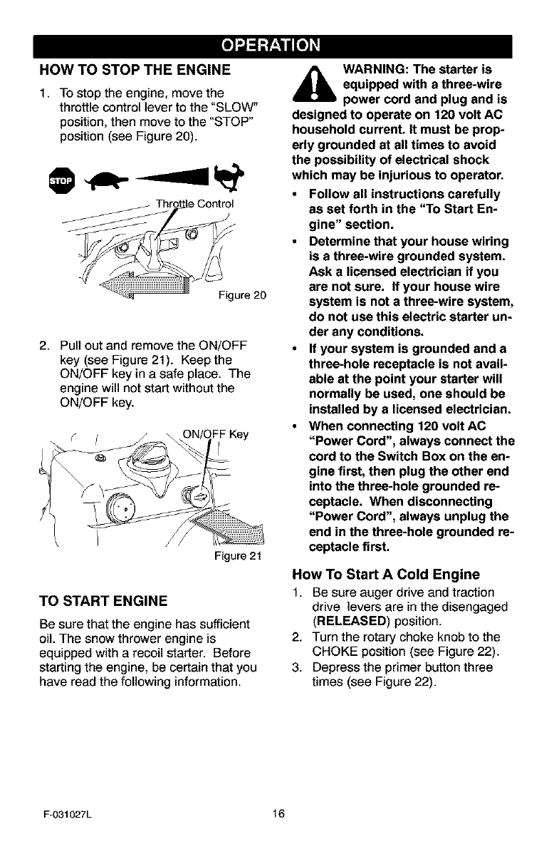
TO Add Oil
1. Make sure the unit islevel
NOTE: Do not check the level of the
oil while the engine runs.
2. Remove the oil fill cap/dipstick.
Check the oil.
3. If necessary, add oil until the oil
reaches the FULL mark on the oil fill
cap/dipstick (see Figure 18). Do not
add too much oil.
Oil FIll Cap/Dipstick
FULL
NOTE: Oil level must be
between Full and Add mark Figure 18
4. Tighten the fill cap/dipstick securely
each time you check the oil level.
NOTE: S.A.E. 5W30 motor oil may be
used to make starting easier in areas
where temperature is consistently 20°E
or lower.
F-031027L 14
FILL GAS:
The engine is certified to comply with
California and US EPA emission regula-
tions for ULGE (Utility or Lawn and Gar-
den Equipment) engines. ULGE
engines are certified to operate on reg-
ular unleaded gasoline.
_lb ARNING: Alcohol blended
fuels (called gasohol or
those using ethanol or
methanol) can attract moisture
which leads to separation and
formation of acids during storage.
Acidic gas can damage the fuel sys-
tem of an engine while in storage.
NOTE: To avoid engine problems, the
fuel system must be emptied before
storage for 30 days or longer. Start the
engine and let it run until the fuel lines
and carburetor are empty. Use fresh
fuel next season. See the Storage sec-
tion in this manual for additional infor-
mation.
Never use engine or carburetor cleaner
products in the fuel tank or permanent
damage may occur.
Fill the fuel tank only with a fresh,
clean, unleaded regular, unleaded pre-
mium, or reformulated automotive gas-
oline. DO NOT use leaded gasoline.
Make sure that the container you pour
the gasoline from is clean and free from
rust or other foreign particles. Never
use gasoline that may be stale from
long periods of storage in the container.
Fuel Tank
Figure 19
_lb ARNING: Gasoline is flam-
mable. Always use caution
when handling or storing
gasoline.
• Do not fill fuel tank while snow
thrower is running, when it is hot,
or when snow thrower is in an en-
closed area.
•Keep away from open flame or an
electrical spark and do not smoke
while filling the fuel tank.
•Never fill the tank completely. Fill
the tank to within 1/4"-1/2" from
the top to provide space for ex-
pansion of fuel.
•Always fill fuel tank outdoors and
use a funnel or spout to prevent
spilling.
•Make sure to wipe up any spilled
fuel before stating the engine.
•Store gasoline in a clean, ap-
proved container and keep the
cap in place on the container.
F-031027L 15
HOW TO STOP THE ENGINE
1. To stop the engine, move the
throttle control lever to the "SLOW"
position, then move to the "STOP"
position (see Figure 20).
Figure 20
2. Pull out and remove the ON/OFF
key (see Figure 21). Keep the
ON/OFF key in a safe place. The
engine will not start without the
ON/OFF key.
Figure 21
TO START ENGINE
Be sure that the engine has sufficient
oil. The snow thrower engine is
equipped with a recoil starter. Before
starting the engine, be certain that you
have read the following information.
4_lk WARNING: The starter is
equipped with a three-wire
power cord and plug and is
designed to operate on 120 volt AC
household current. It must be prop-
erly grounded at all times to avoid
the possibility of electrical shock
which may be injurious to operator.
• Follow all instructions carefully
as set forth in the "To Start En-
gine" section.
•Determine that your house wiring
is a three-wire grounded system.
Ask a licensed electrician if you
are not sure. If your house wire
system is not a three-wire system,
do not use this electric starter un-
der any conditions.
•If your system is grounded and a
three-hole receptacle is not avail-
able at the point your starter will
normally be used, one should be
installed by a licensed electrician.
•When connecting 120 volt AC
"Power Cord", always connect the
cord to the Switch Box on the en-
gine first, then plug the other end
into the three-hole grounded re-
ceptacle. When disconnecting
"Power Cord", always unplug the
end in the three-hole grounded re-
ceptacle first.
How TO Start A Cold Engine
1. Be sure auger drive and traction
drive levers are in the disengaged
(RELEASED) position.
2. Turn the rotary choke knob to the
CHOKE position (see Figure 22).
3. Depress the primer button three
times (see Figure 22).
Fu031027L 16
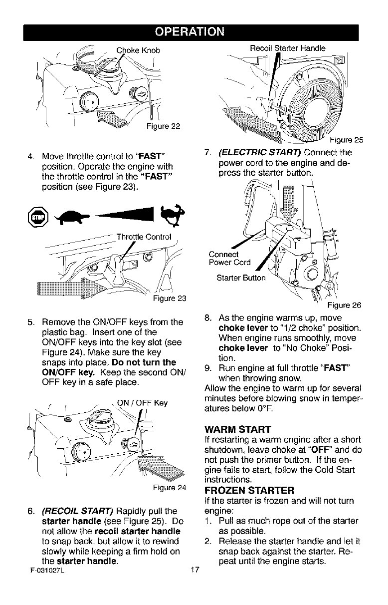
Recoil Starter Handle
4. Move throttle control to "FAST'
position. Operate the engine with
the throttle control in the "FAST"
position (see Figure 23).
Throttle Control
Figure 23
5. Remove the ON/OFF keys from the
plastic bag. Insert one of the
ON/OFF keys into the key slot (see
Figure 24). Make sure the key
snaps into place. Do not turn the
ON/OFF key. Keep the second ON/
OFF key in a safe place.
f(_ ON /OFF Key
Figure24
6. (RECOIL START) Rapidly pull the
starter handle (see Figure 25). Do
not allow the recoil starter handle
to snap back, but allow it to rewind
slowly while keeping a firm hold on
the starter handle.
F-031027L
gure 25
7. (ELECTRIC START) Connect the
power cord to the engine and de-
press the starter button.
Connect Jq
Power Cord /
Starter Button
17
Figure 26
8. AS the engine warms up, move
choke lever to "1/2 choke" position.
When engine runs smoothly, move
choke lever to "No Choke" Posi-
tion.
9. Run engine at full throttle "FAST"
when throwing snow.
Allow the engine to warm up for several
minutes before blowing snow in temper-
atures below 0°E
WARM START
If restarting a warm engine after a short
shutdown, leave choke at "OFF" and do
not push the primer button. If the en-
gine fails to start, follow the Cold Start
instructions.
FROZEN STARTER
If the starter is frozen and will not turn
engine:
1. Pull as much rope out of the starter
as possible.
2. Release the starter handle and let it
snap back against the starter. Re-
peat until the engine starts.
Tohelppreventpossiblefreeze-upof
recoilstarterandenginecontrols,pro-
ceedasfollowsaftereachsnowremov-
aljob.
1. Withtheenginerunning,pullthe
starterropehardwithacontinuous
fullarmstrokethreeorfourtimes.
Pullingofstarterropewillproducea
loudclatteringsound.Thisisnot
harmfultotheengineorstarter.
2. Withtheenginenotrunning,wipeall
snowandmoisturefromthecarbu-
retorcoverinareaofcontrollevers.
Alsomovethrottlecontrol,choke
control,andstarterhandleseveral
times.
d_lb WARNING: Never run en-
gine indoors or in enclosed,
poorly ventilated areas. En-
gine exhaust contains CARBON
MONOXIDE, AN ODORLESS AND
DEADLY GAS. Keep hands, feet,
hair and loose clothing away from
any moving parts on engine and
snow thrower.
• The temperature of muffler and
nearby areas may exceed 150°R
Avoid these areas.
•DO NOT allow children or young
teenagers to operate or be near
snow thrower while it is operat-
ing.
TO REMOVE SNOW FROM AUGER
_k WARNING: Do not attempt
to remove snow or debris
that may become lodged in
auger without taking the following
precautions:
A cleaning stick is attached to the top of
the auger housing. Use the cleaning
stick to remove snow from the auger
housing.
Release auger drive lever.
Move throttle lever to stop position.
Remove (do not turn) ignition key.
Disconnect spark plug wire.
Do not place your hands in the au-
ger or discharge chute. Use the
cleaning stick to remove snow.
SNOW THROWING TIPS
1. For maximum snow thrower efficien-
cy in removing snow, adjust ground
speed, NEVER the throttle. Go
slower in deep, freezing or wet
snow. Ifthe wheels slips, reduce
forward speed. The engine is de-
signed to deliver maximum perfor-
mance at full throttle and should be
run at this power setting at all times.
2. Most efficient snow throwing is ac-
complished when the snow is re-
moved immediately after if falls.
3. For complete snow removal, slightly
overlap each path previously taken.
4. The snow should be discharged
down wind whenever possible.
5. For normal usage, set the skids so
that the scraper bar is 1/8" above
the skids. For extremely hard-
packed snow surfaces, adjust the
F-031027L 18
6.
7.
8.
9.
skids upward so that the scraper
bar touches the ground.
On gravel or crushed rock surfaces,
set the skids at 1- 1/4" below the
scraper bar. See To Adjust Skid
Height paragraph in the Service &
Adjustments section of this manual.
Rocks and gravel must not be picked
up and thrown by the machine.
After the snow throwing job has
been completed, allow the engine to
idle for a few minutes, which will
melt snow and accumulated ice off
the engine.
Clean the snow thrower thoroughly
after each use.
Remove ice and SnOWaccumulation
and all debris from the entire snow
thrower, and flush with water (if pos-
sible) to remove all salt or other
chemicals. Wipe snow thrower dry.
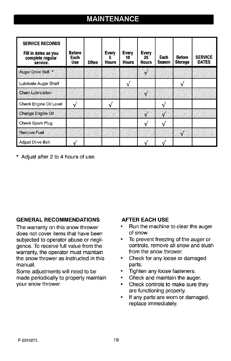
SERVICERECORDS
Fillindatesasyou Before Every Every Every
completeregular Each 5 10 25 Each Before SERVICE
service. Use Often Hours Hours Hours Season Stcrage DATES
Lubricate Auger Shaft _
Check Engine 0il Level _/ V V
Check Spark Plug _
vo
AdjustDrive Belt V V V
*Adjust after 2 to 4 hours of use.
GENERAL RECOMMENDATIONS
The warranty on this snow thrower
does not cover items that have been
subjected to operator abuse or negli-
gence. To receive full value from the
warranty, the operator must maintain
the snow thrower as instructed in this
manual.
Some adjustments will need to be
made periodically to properly maintain
your snow thrower.
AFTER EACH USE
Run the machine to clear the auger
of snow.
To prevent freezing of the auger or
controls, remove all snow and slush
from the snow thrower.
Check for any loose or damaged
parts.
_ghten any loose fasteners.
Check and maintain the auger.
Check controls to make sure they
are functioning properly.
If any parts are worn or damaged,
replace immediately.
F-O31027L 19
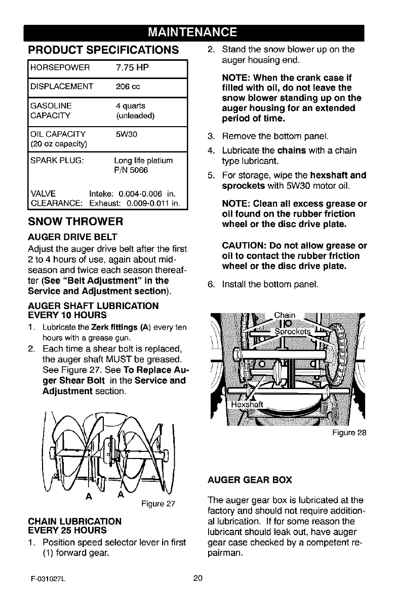
PRODUCT SPECIFICATIONS
HORSEPOWER 7.75 HP
DISPLACEMENT 206 cc
GASOLINE 4 quarts
CAPACITY (unleaded)
OIL CAPACITY 5W30
(20 oz capacity)
SPARK PLUG: Longlife platium
P/N 5066
VALVE Intake: 0.004-0.006 in.
CLEARANCE: Exhaust: 0.009-0.011 in.
SNOW THROWER
AUGER DRIVE BELT
Adjust the auger drive belt after the first
2 to 4 hours of use, again about mid-
season and twice each season thereaf-
ter (See "Belt Adjustment" in the
Service and Adjustment section).
AUGER SHAFT LUBRICATION
EVERY 10 HOURS
1. Lubricatethe Zerk fittings (A) everyten
hourswith a grease gun.
2. Each time a shear bolt is replaced,
the auger shaft MUST be greased.
See Figure 27. See To Replace Au-
ger Shear Bolt in the Service and
Adjustment section.
AFigure 27
CHAIN LUBRICATION
EVERY 25 HOURS
1. Position speed selector lever in first
(1) forward gear.
2. Stand the snow blower up on the
auger housing end.
NOTE: When the crank case if
filled with oil, do not leave the
snow blower standing up on the
auger housing for an extended
period of time.
3. Remove the bottom panel.
4. Lubricate the chains with a chain
type lubricant.
5. For storage, wipe the hexshaft and
sprockets with 5W30 motor oil
NOTE: Clean all excess grease or
oil found on the rubber friction
wheel or the disc drive plate.
CAUTION: Do not allow grease or
oil to contact the rubber friction
wheel or the disc drive plate.
6. Install the bottom panel.
Hexshaft
Figure 28
AUGER GEAR BOX
The auger gear box is lubricated at the
factory and should not require addition-
al lubrication. If for some reason the
lubricant should leak out, have auger
gear case checked by a competent re-
pairman.
F-031027L 20
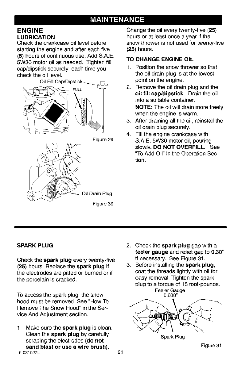
ENGINE
LUBRICATION
Check the crankcase oil level before
starting the engine and after each five
(5) hours of continuous use. Add S.A.E.
5W30 motor oil as needed. Tighten fill
cap/dipstick securely each time you
check the oil level.
Oil Fill Cap/Dipstick _
FULL
Figure 29
Change the oil every twenty-five (25)
hours or at least once a year if the
snow thrower is not used for twenty-five
(25) hours.
TO CHANGE ENGINE OIL
1. Position the snow thrower so that
the oil drain plug is at the lowest
point on the engine.
2. Remove the oil drain plug and the
oil fill cap/dipstick. Drain the oil
into a suitable container.
NOTE: The oil will drain more freely
when the engine is warm.
3. After draining all the oil, reinstall the
oil drain plug securely.
4. Fill the engine crankcase with
S.A.E. 5W30 motor oil, pouring
slowly. DO NOT OVERFILL. See
"To Add Oil" in the Operation Sec-
tion.
Oil Drain Plug
Figure 30
SPARK PLUG
Check the spark plug every twenty-five
(25) hours. Replace the spark plug if
the electrodes are pitted or burned or if
the porcelain is cracked.
To access the spark plug, the snow
hood must be removed. See "How To
Remove The Snow Hood" in the Ser-
vice And Adjustment section.
1. Make sure the spark plug is clean.
Clean the spark plug by carefully
scraping the electrodes (do not
sand blast or use awire brush).
F-031027L 21
2. Check the spark plug gap with a
feeler gauge and reset gap to 0.30"
if necessary. See Figure 31.
3. Before installing the spark plug,
coat the threads lightly with oil for
easy removal. Tighten the spark
plug to a torque of 15 foot-pounds.
Feeler Gauge
0.030"
Spark Plug
Figure 31
_lb ARNING: Always discon-
nect the spark plug wire and
place it where it cannot
make contact with spark plug to pre-
vent accidental starting when mak-
ing any adjustments or repairs.
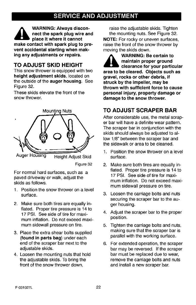
TO ADJUST SKID HEIGHT
This snow thrower is equipped with two
height adjustment skids, located on
the outside of the auger housing. See
Figure 32.
These skids elevate the front of the
snow thrower.
Nuts
O
Auger t- Height Adjust Skid
Figure 32
For normal hard surfaces, such as a
paved driveway or walk, adjust the
skids as follows.
1. Position the snow thrower on a level
surface.
2. Make sure both tires are equally in-
flated. Proper tire pressure is 14 to
17 PSI. See side of tire for maxi-
mum inflation. Do not exceed maxi-
mum sidewall pressure on tire.
3. Place the extra shear bolts supplied
(found in parts bag) under each
end of the scraper bar next to the
adjustable skids.
4. Loosen the mounting nuts that hold
the adjustable skids. To bring the
front of the snow thrower down,
raise the adjustable skids. Tighten
the mounting nuts. See Figure 32.
NOTE: For rocky or uneven surfaces,
raise the front of the snow thrower by
moving the skids down.
_lb ARNING: Be certain to
maintain proper ground
clearance for your particular
area to be cleared. Objects such as
gravel, rocks or other debris, if
struck by the impeller, may be
thrown with sufficient force to cause
personal injury, property damage or
damage to the snow thrower.
TO ADJUST SCRAPER BAR
After considerable use, the metal scrap-
er bar will have a definite wear pattern.
The scraper bar in conjunction with the
skids should always be adjusted to al-
low 1/8" between the scraper bar and
the sidewalk or area to be cleaned.
1. Position the snow thrower on a level
surface.
2.
3.
4.
5.
6.
Make sure both tires are equally in-
flated. Proper tire pressure is 14to
17 PSI. See side of tire for maxi-
mum inflation. Do not exceed maxi-
mum sidewall pressure on tire.
Loosen the carriage bolts and nuts
securing the scraper bar to the au-
ger housing.
Adjust the scraper bar to the proper
position.
Tighten the carriage bolts and nuts,
making sure that the scraper bar is
parallel with the working surface.
For extended operation, the scraper
bar may be reversed. If the scraper
bar must be replaced due to wear,
remove the carriage bolts and nuts
and install a new scraper bar.
F-031027L 22
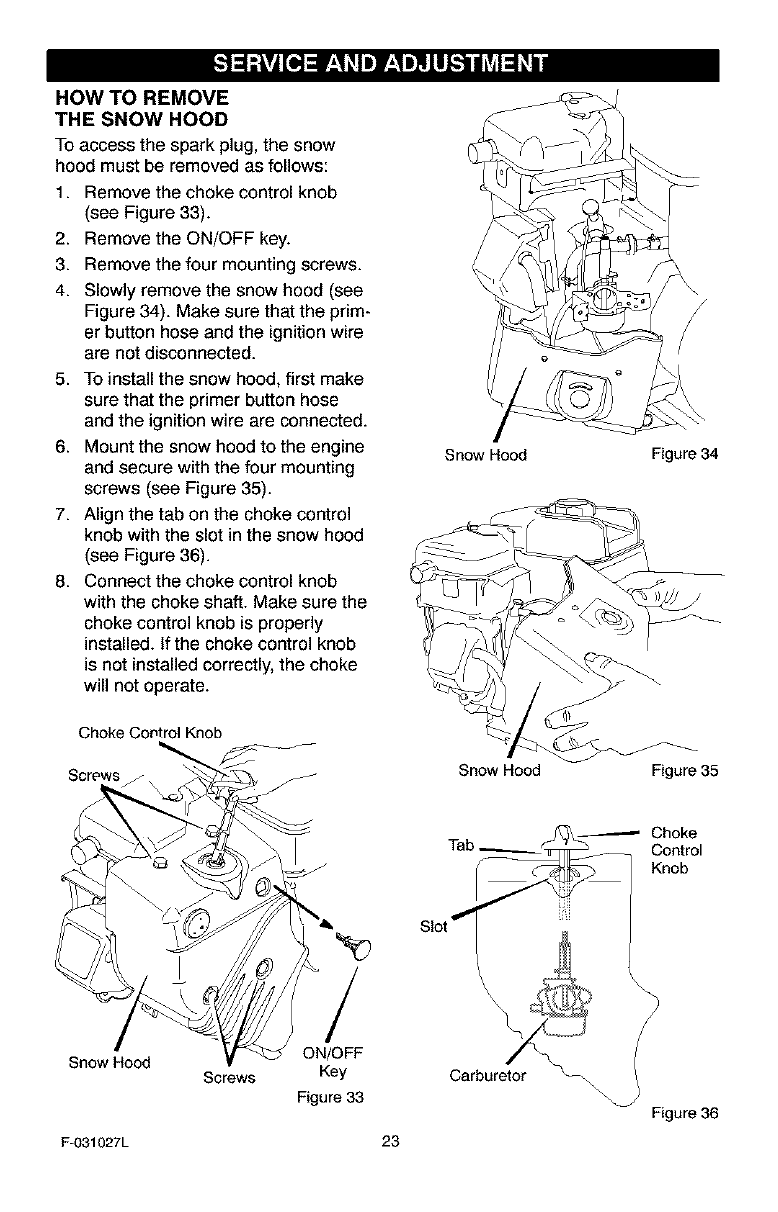
HOW TO REMOVE
THE SNOW HOOD
To access the spark plug, the snow
hood must be removed as follows:
1. Remove the choke control knob
(see Figure 33).
2. Remove the ON/OFF key.
3. Remove the four mounting screws.
4. Slowly remove the snow hood (see
Figure 34). Make sure that the prim-
er button hose and the ignition wire
are not disconnected.
5. To install the snow hood, first make
sure that the primer button hose
and the ignition wire are connected.
6. Mount the snow hood to the engine
and secure with the four mounting
screws (see Figure 35).
7. Align the tab on the choke control
knob with the slot in the snow hood
(see Figure 36).
8. Connect the choke control knob
with the choke shaft. Make sure the
choke control knob is properly
installed. If the choke control knob
is not installed correctly, the choke
will not operate.
Choke Control Knob
Screws
Snow Hood Screws
/
ON/OFF
Key
Figure 33
F-O31027L
\/
/
Snow Hood Figure 34
Snow Hood Figure 35
Tab__ Choke
Control
_j@.@ Knob
Slot _
23
\
Figure 36
BELT ADJUSTMENT
Traction Drive Belt
The traction drive belt has constant
spring pressure and does not require
an adjustment. If the traction drive belt
is slipping, replace the belt. See "How
To Replace The Belts" in the Service
And Adjustment section.
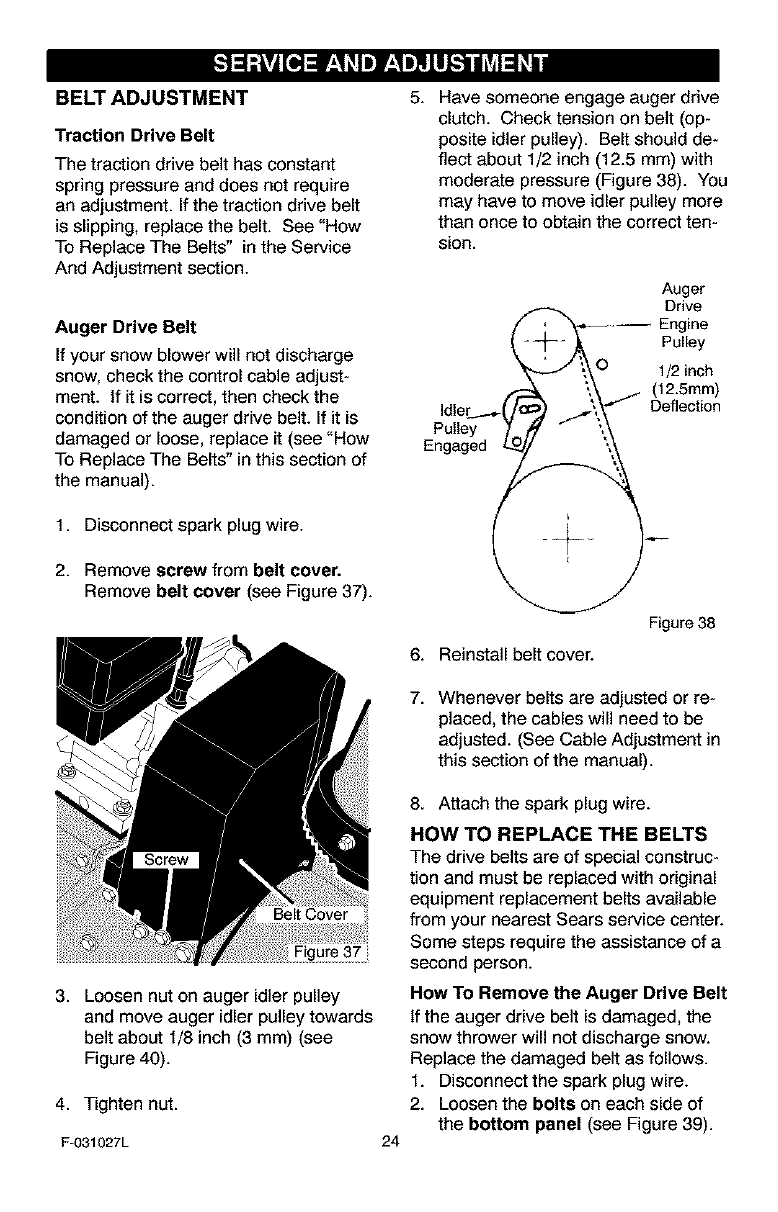
Auger Drive Belt
If your snow blower will not discharge
snow, check the control cable adjust-
ment. If it is correct, then check the
condition of the auger drive belt. If it is
damaged or loose, replace it (see "How
To Replace The Belts" in this section of
the manual).
1. Disconnect spark plug wire.
2. Remove screw from belt cover.
Remove belt cover (see Figure 37).
5. Have someone engage auger drive
clutch. Check tension on belt (op-
posite idler pulley). Belt should de-
flect about 1/2 inch (12.5 mm) with
moderate pressure (Figure 38). You
may have to move idler pulley more
than once to obtain the correct ten-
sJon.
Auger
( e
--j_ ,_ Pulley
J_O 1/2 inch
.-- \\ (12.5ram)
Idler __..,-('/€ .7\_ _'_/ Deflection
Pulleylo, °
Engaged L.._I_ _
Figure 38
6. Reinstall belt cover.
7. Whenever belts are adjusted or re-
placed, the cables will need to be
adjusted. (See Cable Adjustment in
this section of the manual).
3. Loosen nut on auger idler pulley
and move auger idler pulley towards
belt about 1/8 inch (3 mm) (see
Figure 40).
4. Tighten nut.
Fu031027L 24
8. Attach the spark plug wire.
HOW TO REPLACE THE BELTS
The drive belts are of special construc-
tion and must be replaced with original
equipment replacement belts available
from your nearest Sears service center.
Some steps require the assistance of a
second person.
How To Remove the Auger Drive Belt
If the auger drive belt is damaged, the
snow thrower will not discharge snow.
Replace the damaged belt as follows.
1. Disconnect the spark plug wire.
2. Loosen the bolts on each side of
the bottom panel (see Figure 39).
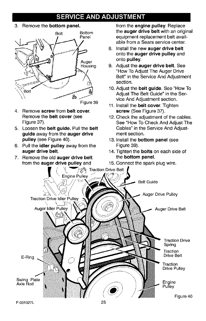
3. Remove the bottom panel,
Bolt Bottom
Panel
Auger
Housing
Bolt
Figure 39
4. Remove screw from belt cover.
Remove the belt cover (see
Figure 37).
5. Loosen the belt guide. Pull the belt
guide away from the auger drive
pulley (see Figure 40).
6. Pull the idler pulley away from the
auger drive belt.
7. Remove the old auger drive belt
from the auger drive pulley and
_ Traction Drive Be,t
Engine Pulley
from the engine pulley. Replace
the auger drive belt with an original
equipment replacement belt avail-
able from a Sears service center.
8. Install the new auger drive belt
onto the auger drive pulley and
onto pulley.
9. Adjust the auger drive belt. See
"How To Adjust The Auger Drive
Belt" in the Service And Adjustment
section.
10. Adjust the belt guide. See "How To
Adjust The Belt Guide" in the Ser-
vice And Adjustment section.
11. Install the belt cover. Tighten
screw (See Figure 37).
12. Check the adjustment of the cables.
See "How To Check And Adjust The
Cables" in the Service And Adjust-
ment section.
13. Install the bottom panel (see
Figure 39).
14. Tighten the bolts on each side of
the bottom panel.
15. Connect the spark plug wire.
Belt Guide
'\ WII _
Auger Idler Pulley
Auger Drive Pulley
Auger Drive Belt
E-Ring
Swing Plate
Axle Rod
Traction Drive
Spring
Traction
Drive Belt
Traction
Drive Pulley
Engine
Pulley
Figure 40
F-031027L 25
How To Remove
The Traction Drive Belt
If the snow thrower will not move for-
ward, check the traction drive belt for
wear or damage. If the traction drive
belt is worn or damaged, replace the
belt as follows.
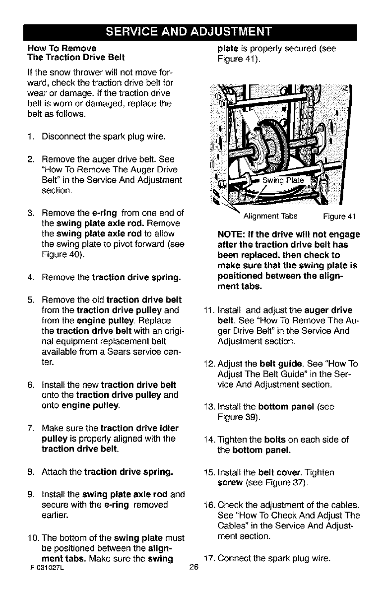
plate is properly secured (see
Figure 41).
1. Disconnect the spark plug wire.
2. Remove the auger drive belt. See
"How To Remove The Auger Drive
Belt" in the Service And Adjustment
section.
3. Remove the e-ring from one end of
the swing plate axle rod. Remove
the swing plate axle rod to allow
the swing plate to pivot forward (see
Figure 40).
4. Remove the traction drive spring.
5. Remove the old traction drive belt
from the traction drive pulley and
from the engine pulley. Replace
the traction drive belt with an origi-
nal equipment replacement belt
available from a Sears service cen-
ter.
6. Install the new traction drive belt
onto the traction drive pulley and
onto engine pulley.
7. Make sure the traction drive idler
pulley is properly aligned with the
traction drive belt.
Alignment Tabs Figure 41
NOTE: If the drive will not engage
after the traction drive belt has
been replaced, then check to
make sure that the swing plate is
positioned between the align-
ment tabs.
11. Install and adjust the auger drive
belt. See "How To Remove The Au-
ger Drive Belt" in the Service And
Adjustment section.
12. Adjust the belt guide. See "How To
Adjust The Belt Guide" in the Ser-
vice And Adjustment section.
13. Install the bottom panel (see
Figure 39).
14. Tighten the bolts on each side of
the bottom panel.
8. Attach the traction drive spring.
9. Install the swing plate axle rod and
secure with the e-ring removed
earlier.
10. The bottom of the swing plate must
be positioned between the align-
ment tabs. Make sure the swing
Fu031027L
15. Installthe belt cover. Tighten
screw (see Figure 37).
16. Check the adjustment of the cables.
See "How To Check And Adjust The
Cables" in the Service And Adjust-
ment section.
17. Connect the spark plug wire.
26
BELT GUIDE ADJUSTMENT
1. Remove spark plug wire.
2. Have someone engage auger drive.
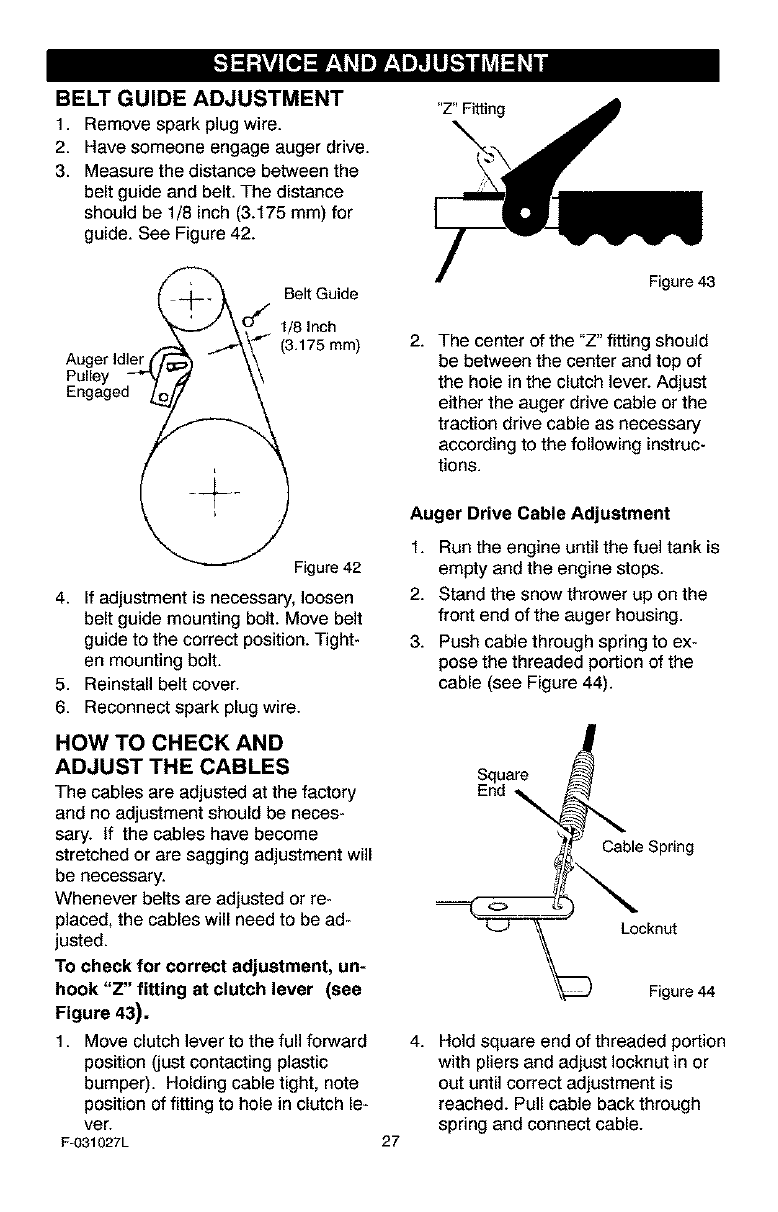
3. Measure the distance between the
belt guide and belt. The distance
should be 1/8 inch (3.175 mm) for
guide. See Figure 42.
"Z" Fitting
_'/_--_ BeltGuide
_'_' ,o_ 1/8,nch
Engaged ___
Figure 42
4. If adjustment is necessary, loosen
belt guide mounting bolt. Move belt
guide to the correct position. Tight-
en mounting bolt.
5. Reinstall belt cover.
6. Reconnect spark plug wire.
HOW TO CHECK AND
ADJUST THE CABLES
The cables are adjusted at the factory
and no adjustment should be neces-
sary. If the cables have become
stretched or are sagging adjustment will
be necessary.
Whenever belts are adjusted or re-
placed, the cables will need to be ad-
justed.
To check for correct adjustment, un-
hook "Z" fitting at clutch lever (see
Figure 43).
1. Move clutch lever to the full forward
position (just contacting plastic
bumper). Holding cable tight, note
position of fitting to hole in clutch le-
ver.
F-031027L
Figure 43
2. The center of the "Z" fitting should
be between the center and top of
the hole in the clutch lever. Adjust
either the auger drive cable or the
traction drive cable as necessary
according to the following instruc-
tions.
Auger Drive Cable Adjustment
1. Run the engine until the fuel tank is
empty and the engine stops.
2. Stand the snow thrower up on the
front end of the auger housing.
3. Push cable through spring to ex-
pose the threaded portion of the
cable (see Figure 44).
Square
End
Cable Spring
o
Locknut
Figure 44
27
4. Hold square end of threaded portion
with pliers and adjust Iocknut in or
out until correct adjustment is
reached. Pull cable back through
spring and connect cable.
TRACTION DRIVE CABLE ADJUSTMENT
1. Runthe engineuntilthe fueltank is 6. Puehthe bottomof the traction
empty and the engine stops.
2. Stand the snow thrower up on the
front end of the auger housing.
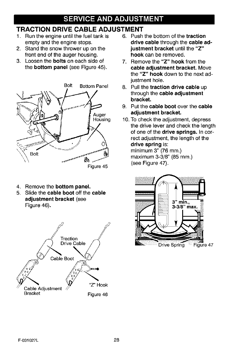
3. Loosen the bolts on each side of
the bottom panel (see Figure 45).
Bolt Bottom Panel
Auger
Housing
'\ \ Bolt _.._J
Figure 45
drive cable through the cable ad-
justment bracket until the "Z"
hook can be removed.
7. Remove the "Z" hook from the
cable adjustment bracket. Move
the "Z" hook down to the next ad-
justment hole.
8. Pull the traction drive cable up
through the cable adjustment
bracket.
9. Put the cable boot over the cable
adjustment bracket.
10. To check the adjustment, depress
the drive lever and check the length
of one of the drive springs. In cor-
rect adjustment, the length of the
drive spring is:
minimum 3" (76 mm.)
maximum 3-3/8" (85 mm.)
(see Figure 47).
4. Remove the bottom panel.
5. Slide the cable boot off the cable
adjustment bracket (see
Figure 46). 3-3/8" max. .....
mrriav(ti_nblef J_/_
Cable Boo
Cable Adjustment /_f Hook
Bracket Figure 46
F-031027L 28
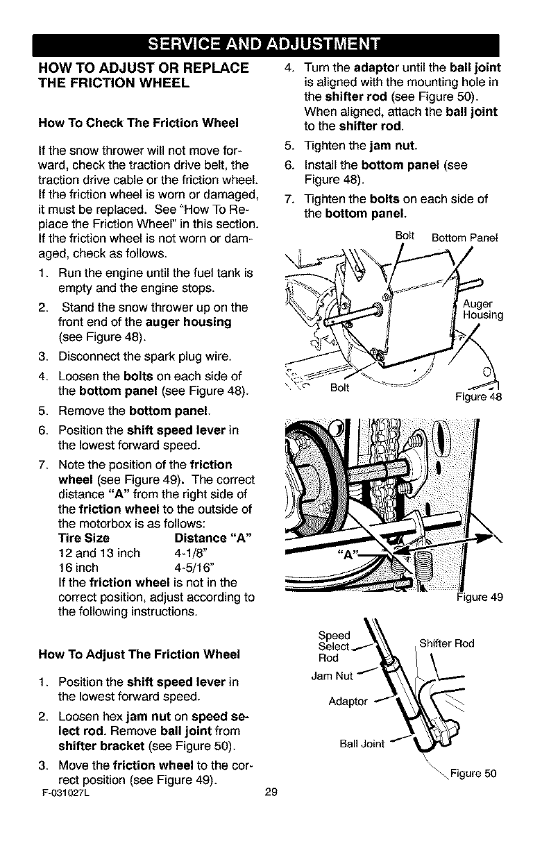
HOW TO ADJUST OR REPLACE
THE FRICTION WHEEL
How To Check The Friction Wheel
If the snow thrower will not move for-
ward, check the traction drive belt, the
traction drive cable or the friction wheel.
If the friction wheel is worn or damaged,
it must be replaced. See "How To Re-
place the Friction Wheel" in this section.
If the friction wheel is not worn or dam-
aged, check as follows.
1. Run the engine until the fuel tank is
empty and the engine stops.
2. Stand the snow thrower up on the
front end of the auger housing
(see Figure 48).
3. Disconnect the spark plug wire.
4. Loosen the bolts on each side of
the bottom panel (see Figure 48).
5. Remove the bottom panel.
6. Position the shift speed lever in
the lowest forward speed.
7. Note the position of the friction
wheel (see Figure 49). The correct
distance "A" from the right side of
the friction wheel to the outside of
the motorbox is as folows:
Tire Size Distance "A"
12 and 13 inch 4-1/8"
16 inch 4-5/16"
If the friction wheel is not in the
correct position, adjust according to
the following instructions.
4.
5.
6.
7.
Turn the adaptor until the ball joint
is aligned with the mounting hole in
the shifter rod (see Figure 50).
When aligned, attach the ball joint
to the shifter rod.
Tighten the jam nut.
Install the bottom panel (see
Figure 48).
Tighten the bolts on each side of
the bottom panel.
Bolt Bottom Panel
Auger
Housing
Figure 49
How To Adjust The Friction Wheel
1. Position the shift speed lever in
the lowest forward speed.
2. Loosen hexjam nut on speed se-
lect rod. Remove ball joint from
shifter bracket (see Figure 50).
3. Move the friction wheel to the cor-
rect position (see Figure 49).
F-031027L
Rod
Jam
Adaptor
Ball Joint
29
Shifter Rod
\_ Figure 50
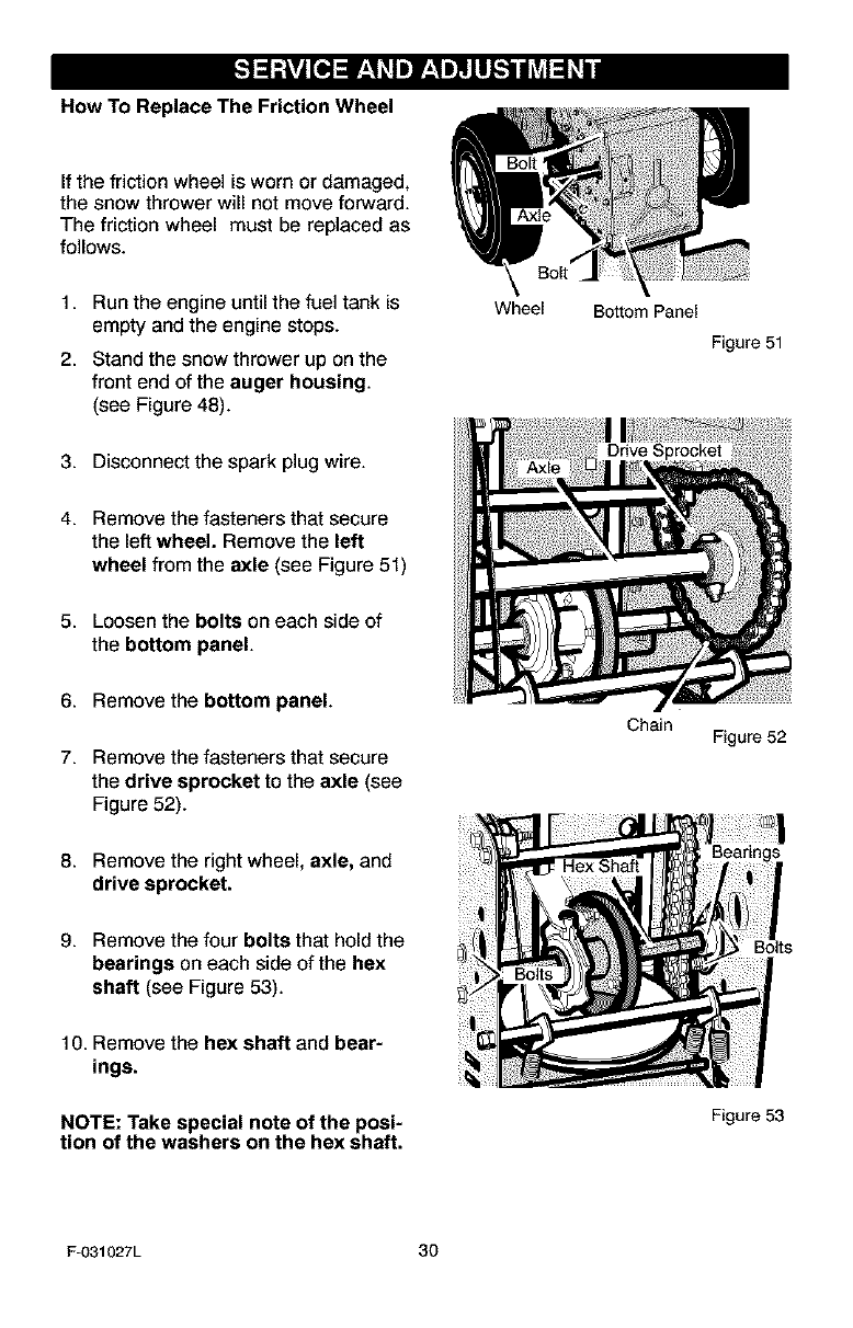
How To Replace The Friction Wheel
If the friction wheel is worn or damaged,
the snow thrower will not move forward.
The friction wheel must be replaced as
follows.
1. Run the engine until the fuel tank is
empty and the engine stops.
2. Stand the snow thrower up on the
front end of the auger housing.
(see Figure 48).
Wheel Bottom Panel
Figure 51
3. Disconnect the spark plug wire.
4. Remove the fasteners that secure
the left wheel. Remove the left
wheel from the axle (see Figure 51)
5. Loosen the bolts on each side of
the bottom panel.
6. Remove the bottom panel.
7. Remove the fasteners that secure
the drive sprocket to the axle (see
Figure 52).
Chain Figure 52
8. Remove the right wheel, axle, and
drive sprocket.
9. Remove the four bolts that hold the
bearings on each side of the hex
shaft (see Figure 53).
10. Remove the hax shaft and bear-
ings.
NOTE: Take special note of the posi-
tion of the washers on the hex shaft.
Bolts
Figure 53
Fu031027L 30
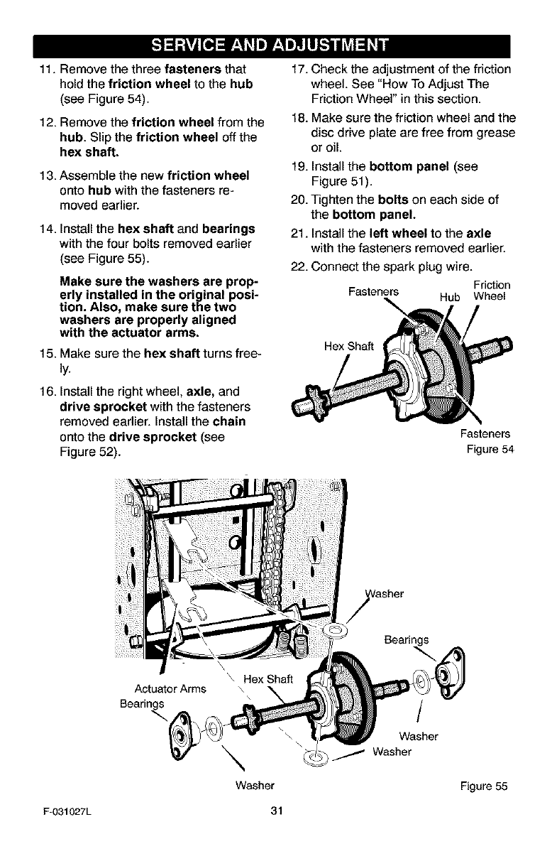
11. Remove the three fasteners that
hold the friction wheel to the hub
(see Figure 54).
12. Remove the friction wheel from the
hub. Slip the friction wheel off the
hex shaft.
13. Assemble the new friction wheel
onto hub with the fasteners re-
moved earlier.
14. Install the hex shaft and bearings
with the four bolts removed earlier
(see Figure 55).
Make sure the washers are prop-
erly installed in the original posi-
tion. Also, make sure the two
washers are properly aligned
with the actuator arms.
15. Make sure the hex shaft turns free-
16. Install the right wheel, axle, and
drive sprocket with the fasteners
removed earlier. Install the chain
onto the drive sprocket (see
Figure 52).
17. Check the adjustment of the friction
wheel. See "How To Adjust The
Friction Wheel" in this section.
18. Make sure the friction wheel and the
disc drive plate are free from grease
or oil.
19. Install the bottom panel (see
Figure 51).
20. Tighten the bolts on each side of
the bottom panel.
21. Install the left wheel to the axle
with the fasteners removed earlier.
22. Connect the spark plug wire.
Friction
Fasteners Hub Wheel
Hex Shaft
Fasteners
Figure 54
Actuator Arms
Bearings
\
Washer
Bearings
/
Washer
Washer
Figure 55
F-O31027L 31
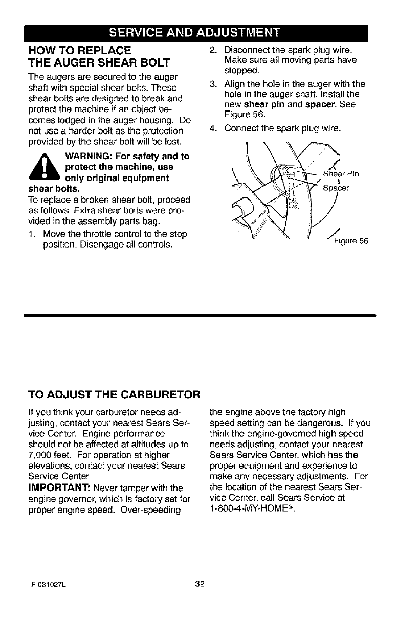
HOW TO REPLACE
THE AUGER SHEAR BOLT
The augers are secured to the auger
shaff with special shear bolts. These
shear bolts are designed to break and
protect the machine if an object be-
comes lodged in the auger housing. Do
not use a harder bolt as the protection
provided by the shear bolt will be lost.
,_ WARNING: For safety and to
protect the machine, use
only original equipment
shear bolts.
To replace a broken shear bolt, proceed
as follows. Extra shear bolts were pro-
vided in the assembly parts bag.
1. Move the throttle control to the stop
position. Disengage all controls.
2. Disconnect the spark plug wire.
Make sure all moving parts have
stopped.
3. Align the hole in the auger with the
hole in the auger shaft. Install the
new shear pin and spacer. See
Figure 56.
4. Connect the spark plug wire.
? X go,ea0
TO ADJUST THE CARBURETOR
If you think your carburetor needs ad-
justing, contact your nearest Sears Ser-
vice Center. Engine performance
should not be affected at altitudes up to
7,000 feet. For operation at higher
elevations, contact your nearest Sears
Service Center
IMPORTANT: Never tamper with the
engine governor, which is factory set for
proper engine speed. Over-speeding
the engine above the factory high
speed setting can be dangerous. If you
think the engine-governed high speed
needs adjusting, contact your nearest
Sears Service Center, which has the
proper equipment and experience to
make any necessary adjustments. For
the location of the nearest Sears Ser-
vice Center, call Sears Service at
1-800-4-MY-HOME®.
F-031027L 32
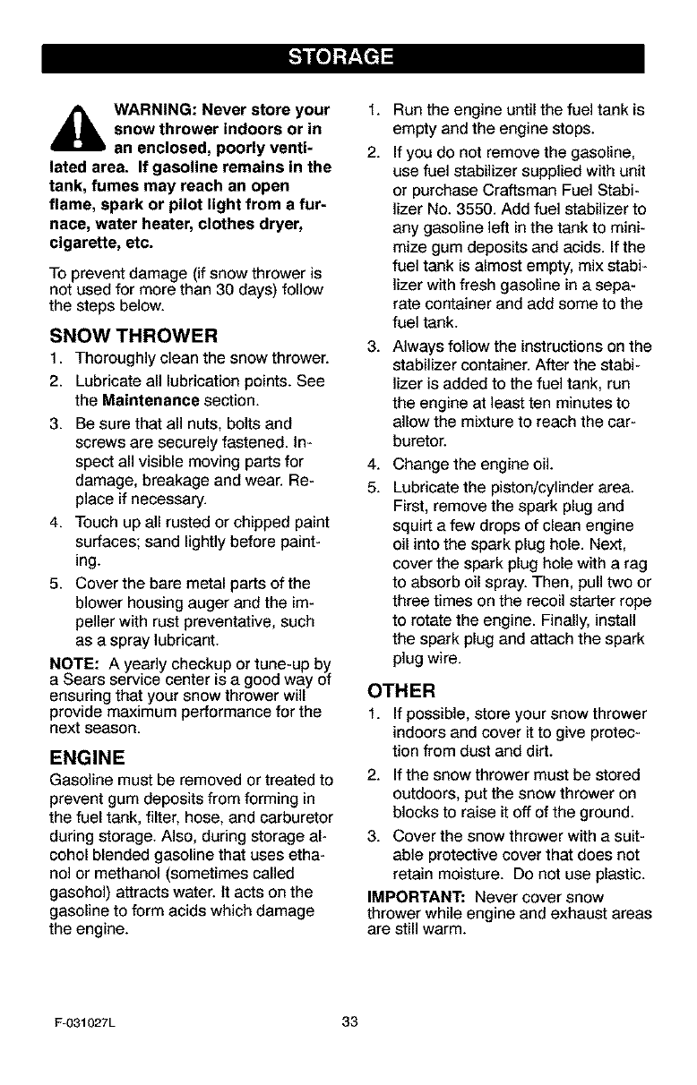
_lb ARNING: Never store your
snow thrower indoors or in
an enclosed, poorly venti-
lated area. If gasoline remains in the
tank, fumes may reach an open
flame, spark or pilot light from a fur-
nace, water heater, clothes dryer,
cigarette, etc.
To prevent damage (if snow thrower is
not used for more than 30 days) follow
the steps below.
SNOW THROWER
1. Thoroughly clean the snow thrower.
2. Lubricate all lubrication points. See
the Maintenance section.
3. Be sure that all nuts, bolts and
screws are securely fastened, in-
spect all visible moving parts for
damage, breakage and wear. Re-
place if necessary.
4. Touch up all rusted or chipped paint
surfaces; sand lightly before paint-
ing.
5. Cover the bare metal parts of the
blower housing auger and the im-
peller with rust preventative, such
as a spray lubricant.
NOTE: A yearly checkup or tune-up by
a Sears service center is a good way of
ensuring that your snow thrower will
provide maximum performance for the
next season.
ENGINE
Gasoline must be removed or treated to
prevent gum deposits from forming in
the fuel tank, filter, hose, and carburetor
during storage. Also, during storage al-
cohol blended gasoline that uses etha-
nol or methanol (sometimes called
gasohol) attracts water, it acts on the
gasoline to form acids which damage
the engine.
f,
2.
3,
4,
5.
Run the engine until the fuel tank is
empty and the engine stops.
If you do not remove the gasoline,
use fuel stabilizer supplied with unit
or purchase Craftsman Fuel Stabi-
lizer No. 3550. Add fuel stabilizer to
any gasoline left in the tank to mini-
mize gum deposits and acids. If the
fuel tank is almost empty, mix stabi-
lizer with fresh gasoline in a sepa-
rate container and add some to the
fuel tank.
Always follow the instructions on the
stabilizer container. After the stabi-
lizer is added to the fuel tank, run
the engine at least ten minutes to
allow the mixture to reach the car-
buretor.
Change the engine oil.
Lubricate the piston/cylinder area.
First, remove the spark plug and
squirt a few drops of clean engine
oil into the spark plug hole. Next,
cover the spark plug hole with a rag
to absorb oil spray. Then, pull two or
three times on the recoil starter rope
to rotate the engine. Finally, install
the spark plug and attach the spark
plug wire.
OTHER
1. If possible, store your snow thrower
indoors and cover it to give protec-
tion from dust and dirt.
2. If the snow thrower must be stored
outdoors, put the snow thrower on
blocks to raise it off of the ground.
3. Cover the snow thrower with a suit-
able protective cover that does not
retain moisture. Do not use plastic.
IMPORTANT: Never cover snow
thrower while engine and exhaust areas
are still warm.
Fu031027L 33
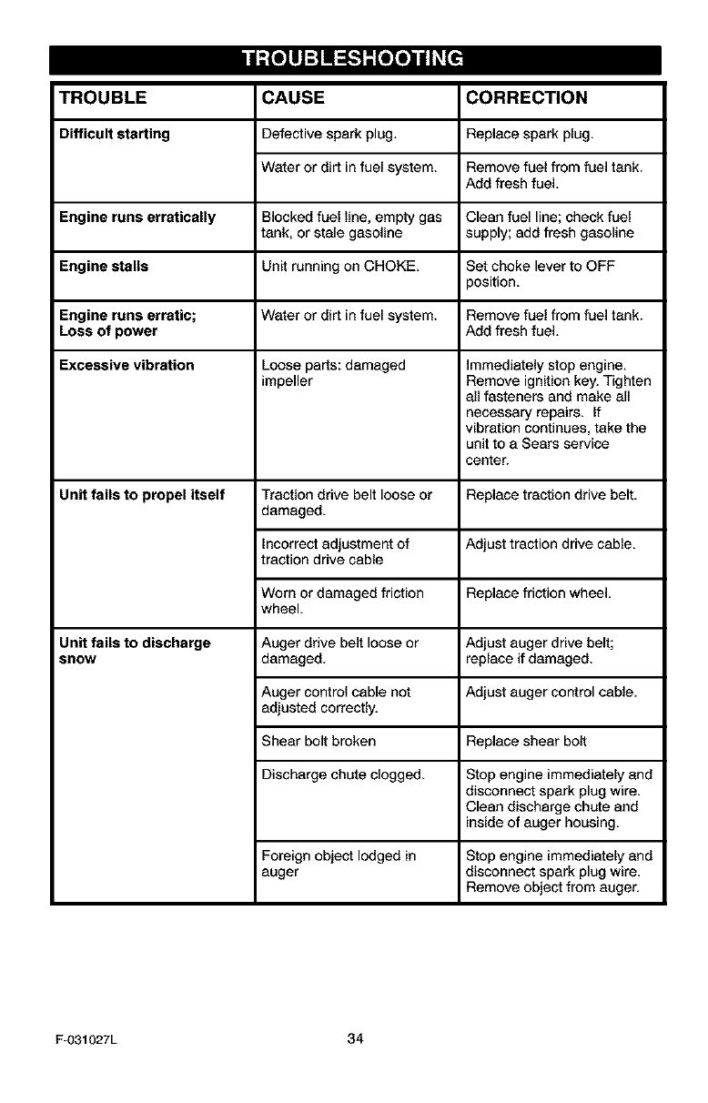
TROUBLE CORRECTION
Difficult starting
CAUSE
Defective spark plug,
Water or dirt in fuel system.
Replace spark plug.
Remove fuel from fuel tank.
Add fresh fuel.
Engine runs erratically Blocked fuel line, empty gas Clean fuel line; check fuel
tank, or stale gasoline supply; add fresh gasoline
Engine stalls Unit running on CHOKE. Set choke lever to OFF
position.
Engine runs erratic; Water or dirt in fuel system. Remove fuel from fuel tank.
Loss of power Add fresh fuel,
Excessive vibration Loose parts: damaged immediately stop engine,
impeller Remove ignition key, Tighten
all fasteners and make all
necessary repairs, if
vibration continues, take the
unit to a Sears service
center.
Unit fails to propel itself Traction drive belt loose or Replace traction drive belt.
damaged.
Incorrect adjustment of Adjust traction drive cable,
traction drive cable
Worn or damaged friction Replace friction wheel,
wheel,
Auger drive belt loose or
damaged. Adjust auger drive belt;
replace if damaged.
Auger control cable not Adjust auger control cable.
adjusted correctly.
Shear bolt broken Replace shear bolt
Discharge chute clogged. Stop engine immediately and
disconnect spark plug wire.
Clean discharge chute and
inside of auger housing.
Unit fails to discharge
SnOW
Foraigno_ectlodgedin
auger
Stop engine immediately and
disconnect spark plug wire.
Remove object from auger.
F-031027L 34
SEARS, ROEBUCK AND CO.
Federal and California Emission Control Systems Limited Warranty
Small Off-Road Engines
CALIFORNIA & US EPA EMISSION
CONTROL WARRANTY STATEMENT
The U. S. Environmental Protection Agency
("EPA"), the California Air Resources Board
("CARB'_ and Sears, Roebuck and Co. are
pleased to explain the Federal and California
Emission Control Systems Warranty on your
new small off-road engine. In California, new
1995 and later small off-road engines must be
designed, built and equipped to meet the
State's stringent anti-smog standards. In oth-
er states, new 1997 and later model year en-
gines must be designed, built and equipped, at
the time of sale, to meet the U.S. EPA regula-
tions for small non-rand engines. Sears, Roe-
buck and Co. will warrant the emission control
system on your small off-road engine for the
periods of time listed below, provided there
has been no abuse, neglect, unapproved mod-
ification, or improper maintenance of your
small off-road engine.
Your emission control system may include
parts such as the carburetor, ignition system
and exhaust system. Also included may be the
compression release system and other emis-
sion-related assemblies.
Where a warrantable condition exists, Sears,
Roebuck and Co. will repair your small off-
road engine at no cost to you for diagnosis,
parts end labor.
MANUFACTURER'S EMISSION
CONTROL SYSTEM WARRANTY
COVERAGE
Emission control systems on 1995 and later
model year California small off-road engines
are warranted for two years as hereinafter
noted. In other states, 1997 and later model
year engines are also warranted for two years.
If, dudng such warranty period, any emission-
related part on your engine is defective in ma-
terials or workmanship, the part will be
repaired or replaced by Sears, Roebuck and
Co.
OWNER'S WARRANTY
RESPONSIBILITIES
As the small off-road engine owner, you are
responsible for the performance of the ra-
F-031027L
quired maintenance listed in your Owner's
Manual, but Sears, Roebuck and Co. will not
deny warranty solely due to the lack of receipts
or for your failure to provide written evidence
of the performance of all scheduled mainte-
nance.
As the small off-road engine owner, you
should, however, be aware that Sears, Roe-
buck and Co. may deny you warranty cover-
age if your small off-road engine or a pert
thereof has failed due to abuse, neglect, im-
proper maintenance or unappraved modifica-
tions.
You are responsible for presenting your small
off-road engine to a Sears, Roebuck and Co.
Authorized Service Outlet as soon as a prob-
lem exists. The warranty repairs should be
completed in a reasonable amount of time, not
to exceed 30 days.
Warranty service can be arranged by contact-
ing either a Sears, Roebuck end Co. Autho-
rized Service Outlet, or by contacting Sears,
Roebuck and Co. at 1-900-473-7247.
35
IMPORTANT NOTE
This warranty statement explains your rights
and obligations under the Emission Control
System Warranty "(ECS Warranty") which is
provided to you by Sears, Roebuck and Co.
pursuant to California law. See also the Sears,
Roebuck and Co. Limited Warranties for
Sears, Roebuck and Co. which is enclosed
therewith on a separate sheet and also is pro-
vided to you by Sears, Roebuck and Co. The
ECS Warranty applies only to the emission
control system of your new engine. To the ex-
tent that there is any conflict in terms between
the ECS Warranty end the Sears, Roebuck
and Co. Warranty, the ECS Warranty shall ap-
ply except in any circumstances in which the
Sears, Roebuck and Co. Warranty may pro-
vide a longer warranty period. Both the ECS
Warranty and the Sears, Roebuck end Co.
Warranty describe important rights and obliga-
tions with respect to your new engine.
Warranty service can only be performed by a
Sears, Roebuck and Co. Authorized Service
Outlet. At the time of requesting warranty ser-
vice, evidence must be presented of the date
of sale to the original purchaser. The purchas-

ershallpayanychargesformakingservice
callsand/orfortransportingtheproductsto
andfromtheplacewheretheinspectionand/
orwarrantyworkisperformed.Thepurchaser
shallberasponsibleforanydamageorlossin-
curredinconnectionwiththetransportationof
anyengineoranypart(s)thereofsubmittedfor
inspectionand/orwarrantywork.
Ifyouhaveanyquestionsregardingyourwar-
rantyrightsandresponsibilities,youshould
contactSears,Roebuckand Co. at
1-800-473-7247.
EMISSION CONTROL SYSTEM
WARRANTY
Emisalon Control System Warranty ("ECS
Warranty") for 1995 and later model year Cali-
fornia small off-road engines (for other states,
1997 and later model year engines):
A, APPLICABILITY: This warranty shall apply
to 1995 and later model year California small
off-road engines (for other states, 1997 and
later model year engines). The ECS Warranty
Period shall begin on the date the new engine
or equipment is delivered to its original, end-
use purchaser, and shall continue for 24 con-
secutive months thereafter.
B. GENERAL EMISSIONS WARRANTY
COVERAGE: Sears, Roebuck and Co. war-
rants to the original, end-use purchaser of the
new engine or equipment and to each subse-
quent purchaser that each of its small off-road
engines is:
1. Designed, built and eqalppod so as to con-
form with all applicable regulations adopted by
the Air Resources Board pursuant to its au-
thority in Chapters 1 and 2, Part 5, Division 26
of the Health and Safety Code, and
2. Free from defects in materials and work-
manship which, at any time during the ECS
Warranty Period, will cause a warranted emis-
sions-related part to fail to be identical in all
material respects to the part as described in
the engine manufacturer's application for certi-
fication.
C. The ECS Warranty only pertains to emis-
sions-related parts on your engine, as follows:
1. Any warranted, emissions-related parts
which are net scheduled for replacement as
required maintenance in the Owner's Manual
shall be warranted for the ECS Warranty Peri-
od. If any such part fails during the ECS War-
ranty Period, it shall be rebeired or replaced by
F-031027L 36
Sears, Roebuck and Co. according to Subsec-
tion 4 below. Any such part repaired or re-
placed under the ECS Warranty shall be
warranted for any remainder of the ECS War-
ranty Period.
2. Any warranted, emissions-relatod part
which is scheduled only for regular inspection
as spacified in the Owner's Manual shall be
warranted for the ECS Warranty Period. A
statement in such wdtten instructions to the ef-
fect of "repair or replace as necessary", shall
not reduce the ECS Warranty Period. Any
such part repaired or replaced under the ECS
Warranty shall be warranted for the remainder
of the ECS Warranty Period.
3. Any warranted, emissions-relatod part
which is scheduled for replacement as re-
quired maintenance in the Owner's Manual,
shall be warranted for the period of time prior
to the first scheduled replacement point for
that part. If the part fails prior to the first sched-
uled replacement, the part shall be repaired or
replaced by Sears, Roebuck and Co. accord-
ing to Subsection 4 below. Any such emis-
sions-related part repaired or replaced under
the ECS Warranty, shall be warranted for the
remainder of the ECS Warranty Pedod prior to
the first scheduled replacement point for such
emissions-related part.
4. Repair or replacement of any warranted,
emissions-related part under this ECS War-
ranty shall be performed at no charge to the
owner at a Sears, Roebuck and Co. Autho-
rized Service Outlet.
5. The owner shall not be charged for diagnos-
tic labor which leads to the determinatiee that
a part covered by the ECS Warranty is in fact
defective, provided that such diagnostic work
is performed at a Sears, Roebuck and Co. Au-
thorized Service Outlet.
6. Sears, Roebuck and Co. shall be liable for
damages to other original engine components
or approved modifications proximately caused
by a failure under warranty of an emission-re-
lated part covered by the ECS Warranty.
7. Throughout the ECS Warranty Period,
Sears, Roebuck and Co. shall maintain a sup-
ply of warranted emission-related parts suffi-
cient to meet the expected demand for such
emission-relatod parts.
8. Any Sears, Roebuck and Co. anthorized
and approved emissiee-relatod replacement
part may be used in the performance of any
ECS Warranty maintenance or repair and will
be provided without charge to the owner. Such
useshallnotreduceSears.RoebuckendCo.
ECSWarrantyobligations.
9,Unapprovedadd-onormodifiedpartsmay
notbeusedtomodifyorrepairaSears,Roe-
buckandCo.engine,SuchusevoidsthisECS
Warrantyandshallbesufficientgroundsfor
disallowinganECSWarrantyclaim.Sears,
RoebuckendCo.shallnotbeliablehereunder
forfailuresofanywarrantedpartsofaSears,
RoebuckandCo.engine caused by the use of
such an unappraved add-on or modified part.
EMISSION-RELATED PARTS
INCLUDE THE FOLLOWING:
1. Carburetor Assembly and its Internal Com-
ponents
a) Fuel filter
b) Carburetor gaskets
c) Intake pipe
2, Air Cleaner Assembly
a) Air filter element
3, Ignition System, including:
a) Spark plug
b) Ignition module
c) Flywheel assembly
4, Catalytic Muffler (if so equipped)
a) Muffler gasket (if so equipped)
b) Exhaust manifold (if so equipped)
5, Crankcase Breather Assembly end its
Components
a) Breather connection tube
10/22/99 EPA!CARB
Sears, Roebuck and Co., Hoffman Estates, IL 60179 U.S.A.
F-031027L 37
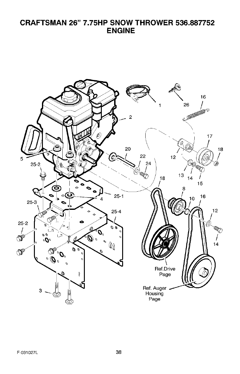
CRAFTSMAN 26" 7.75HP SNOW THROWER 536.887752
ENGINE
2
1
16
17
20 \
5 22 12
25-2
25-1
25-4
25-2
/
25-3
16
18
/
12
/
/
14
Ref,Drive
Page
Ref, Auger
Housing
Page
F-031027L 38
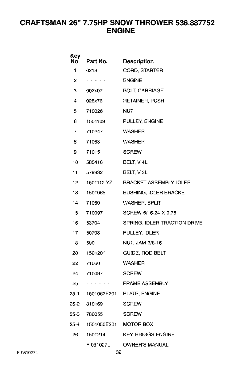
CRAFTSMAN 26" 7.75HP SNOW THROWER 536.887752
ENGINE
F-031027L
Key
No. Part No. Description
1 6219 CORD, STARTER
2 ENGINE
3 002x97 BOLT, CARRIAGE
4 028x76 RETAINER, PUSH
5 710026 NUT
6 1501109 PULLEY, ENGINE
7 710247 WASHER
8 71063 WASHER
9 71015 SCREW
10 585416 BELT, V 4L
11 579932 BELT, V 3L
12 1501112 YZ BRACKET ASSEMBLY, IDLER
13 1501065 BUSHING, IDLER BRACKET
14 71060 WASHER, SPLIT
15 710097 SCREW 5/16-24 X 0,75
16 53704 SPRING, _DLER TRACTION DRIVE
17 50793 PULLEY, IDLER
18 590 NUT, JAM 3/8-16
20 1501201 GUIDE, ROD BELT
22 71060 WASHER
24 710097 SCREW
25 FRAME ASSEMBLY
25-1 1501062E201 PLATE, ENGINE
25-2 310169 SCREW
25-3 780055 SCREW
25-4 1501050E201 MOTOR BOX
26 1501214 KEY, BRIGGS ENGINE
-- F-031027L OWNER'S MANUAL
39
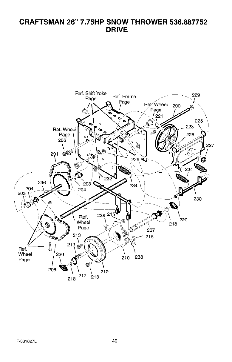
CRAFTSMAN 26" 7.75HP SNOW THROWER 536.887752
DRIVE
Ref, Shift Yoke
Page Ref, Frame _ _ _.229
200
Ref. Whee
Page
206
\
201
\
225 _/
\
227
/
236
230
Ref,
Wheel
Page \
208 212
217 213
218
207
215
\
210 238
220
218
F-031027L 40
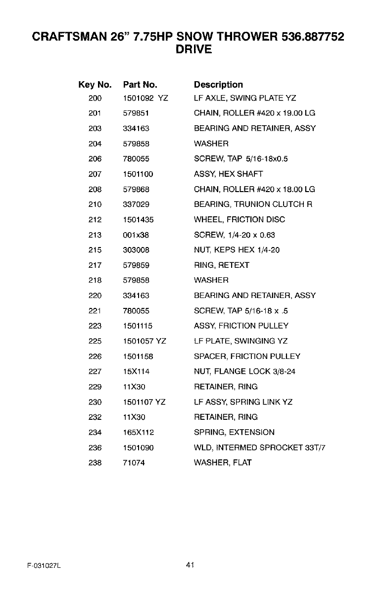
CRAFTSMAN 26" 7.75HP SNOW THROWER 536.887752
DRIVE
Key No. Part No.
200 1501092 YZ
201 579851
203 334163
204 579858
206 780055
207 1501100
208 579868
210 337029
212 1501435
213 001x38
215 303008
217 579859
218 579858
220 334163
221 780055
223 1501115
225 1501057 YZ
226 1501158
227 15X114
229 11X3O
230 1501107 YZ
232 11X3O
234 165Xl 12
236 1501090
238 71074
Description
LF AXLE, SWING PLATE YZ
CHAIN, ROLLER #420 x 19.00 LG
BEARING AND RETAINER, ASSY
WASHER
SCREW, TAP 5/16-18x0.5
ASSY, HEX SHAFT
CHAIN, ROLLER #420 x 18.00 LG
BEARING, TRUNION CLUTCH R
WHEEL, FRICTION DISC
SCREW, 1/4-20 x 0.63
NUT, KEPS HEX 1/4-20
RING, RETEXT
WASHER
BEARING AND RETAINER, ASSY
SCREW, TAP 5/16-18 x .5
ASS'/, FRICTION PULLEY
LF PLATE, SWINGING YZ
SPACER, FRICTION PULLEY
NUT, FLANGE LOCK 3/8-24
RETAINER, RING
LF ASSY, SPRING LINK YZ
RETAINER, RING
SPRING, EXTENSION
WLD, INTERMED SPROCKET 33T/7
WASHER, FLAT
F-031027L 41
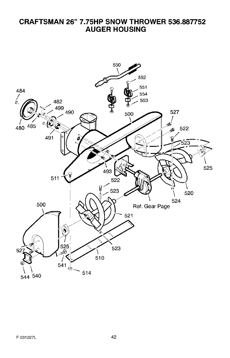
CRAFTSMAN 26" 7.75HP SNOW THROWER 536.887752
AUGER HOUSING
484
480
482 __iii
499 490 500
491
527
522
5OO
522
\ 520
524
Ref. Gear Page
521
525
\\
544 540
541
510
514
523
F-O31027L 42
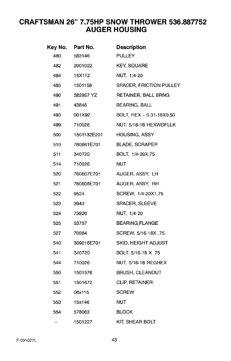
CRAFTSMAN 26" 7.75HP SNOW THROWER 536.887752
AUGER HOUSING
Key No. Part No. Description
480 583146 PULLEY
482 2001022 KEY, SQUARE
484 15Xl12 NUT, 1/4-20
485 1501158 SPACER, FRICTION PULLEY
490 582957 YZ RETAINER, BALL BRNG
491 43846 BEARING, BALL
493 001X92 BOLT, HEX - 0.31-18X0.50
499 710026 NUT, 5/16-18 HEXWDFLLK
500 1501132E201 HOUSING, ASSY
510 760661E701 BLADE, SCRAPER
511 340720 BOLT, 1/4-20X.75
514 710026 NUT
520 760607E701 AUGER, ASSY, LH
521 760608E701 AUGER, ASSY, RH
522 9524 SCREW, 1/4-20XI.75
523 3943 SPACER, SLEEVE
524 73826 NUT, 1/4-20
525 53757 BEARING,FLANGE
527 70984 SCREW, 5/16-18X .75
540 309016E701 SKID, HEIGHT ADJUST
541 340720 BOLT, 5/16-18 X .75
544 710026 NUT, 5/16-18 REGHEX
550 1501576 BRUSH, CLEANOUT
551 1501672 CLIP, RETAINER
552 06xl 15 SCREW
553 15xl 46 NUT
554 578063 BLOCK
-- 1501227 KIT, SHEAR BOLT
F-031027L 43
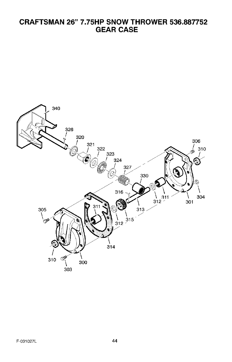
CRAFTSMAN 26" 7.75HP SNOW THROWER 536.887752
GEAR CASE
340
326
320
305
/
310 _ 300
303
301
306
310
304
F-O31027L 44
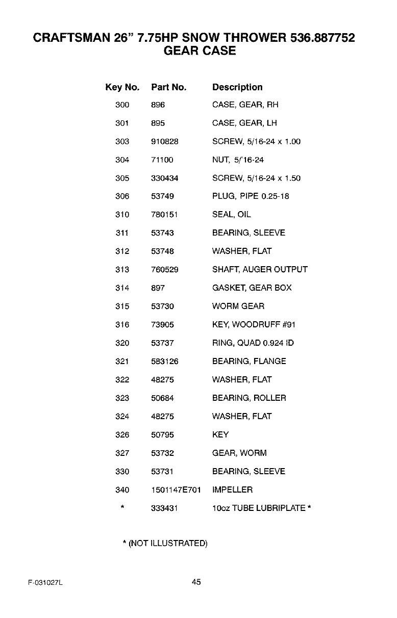
CRAFTSMAN 26" 7.75HP SNOW THROWER 536.887752
GEAR CASE
Key No. Part No. Description
300 896 CASE, GEAR, RH
301 895 CASE, GEAR, LH
303 910828 SCREW, 5/16-24 x 1.00
304 71100 NUT, 5/'16-24
305 330434 SCREW, 5/16-24 x 1.50
306 53749 PLUG, PiPE 0.25-18
310 780151 SEAL, OiL
311 53743 BEARING, SLEEVE
312 53748 WASHER, FLAT
313 760529 SHAFT, AUGER OUTPUT
314 897 GASKET, GEAR BOX
315 53730 WORM GEAR
316 73905 KEY, WOODRUFF #91
320 53737 RING, QUAD 0.924 ID
321 583126 BEARING, FLANGE
322 48275 WASHER, FLAT
323 50684 BEARING, ROLLER
324 48275 WASHER, FLAT
326 50795 KEY
327 53732 GEAR, WORM
330 53731 BEARING, SLEEVE
340 1501147E701 IMPELLER
333431 10oz TUBE LUBRIPLATE *
*(NOT iLLUSTRATED)
F-031027L 45
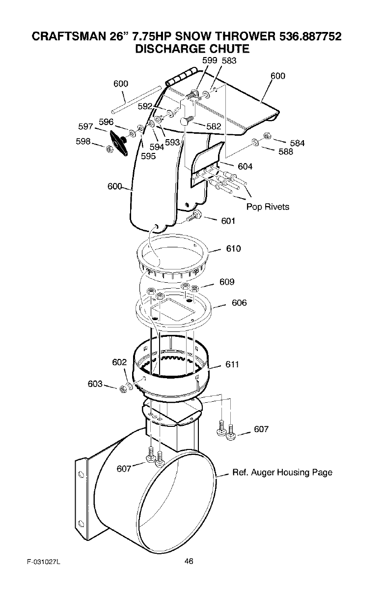
CRAFTSMAN 26" 7.75HP SNOW THROWER 536.887752
DISCHARGE CHUTE
599 583
600
600
609
606
602 611
Ref. Auger Housing Page
F-031027L 46
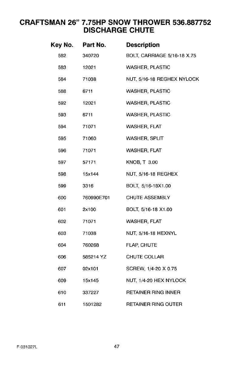
CRAFTSMAN 26" 7.75HP SNOW THROWER 536.887752
DISCHARGE CHUTE
Key No. Part No. Description
582 340720 HOLT, CARRIAGE 5/16-18 X.75
583 12021 WASHER, PLASTIC
584 71038 NUT, 5/16-18 REGHEX NYLOCK
588 6711 WASHER, PLASTIC
592 12021 WASHER, PLASTIC
593 6711 WASHER, PLASTIC
594 71071 WASHER, FLAT
595 71060 WASHER, SPLIT
596 71071 WASHER, FLAT
597 57171 KNOB, T 3.00
598 15x144 NUT, 5/16-18 REGHEX
599 3316 BOLT, 5/16-18XI.00
600 760990E701 CHUTE ASSEMBLY
601 2x100 BOLT, 5/16-18 XI.00
602 71071 WASHER, FLAT
603 71038 NUT, 5/16-18 HEXNYL
604 760268 FLAP, CHUTE
606 585214 YZ CHUTE COLLAR
607 02x101 SCREW, 1/4-20 X 0.75
609 15x145 NUT, 1/4-20 HEX NYLOCK
610 337227 RETAINER RING INNER
611 1501282 RETAINER RING OUTER
F-031027L 47
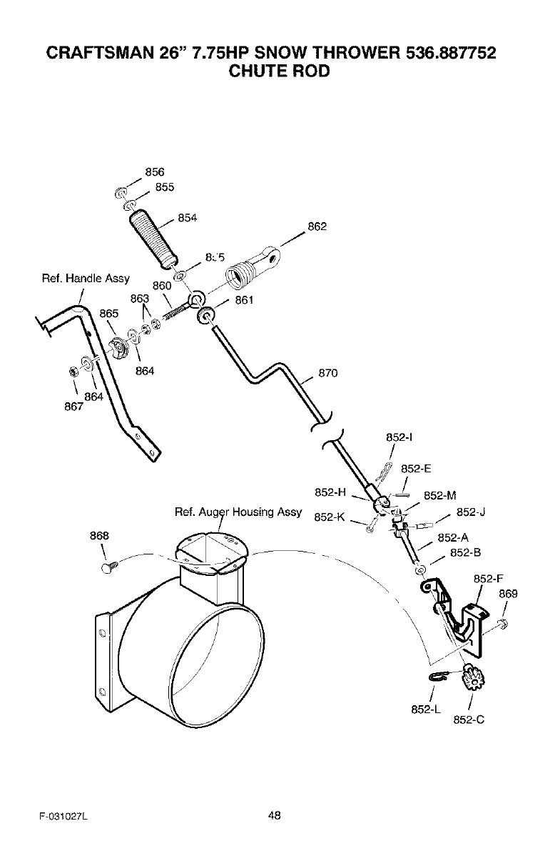
CRAFTSMAN 26" 7.75HP SNOW THROWER 536.887752
CHUTE ROD
856
/" 855
• 854 862
J
Ref, Handle Assy
861
\
867
868
\
864 870
852-H
r Housing Assy 852-K
852-E
852-M
852-J
852-A
j 852-B
852-F
869
\ \\ //
\\\
852-L t
852-C
F-031027L 48
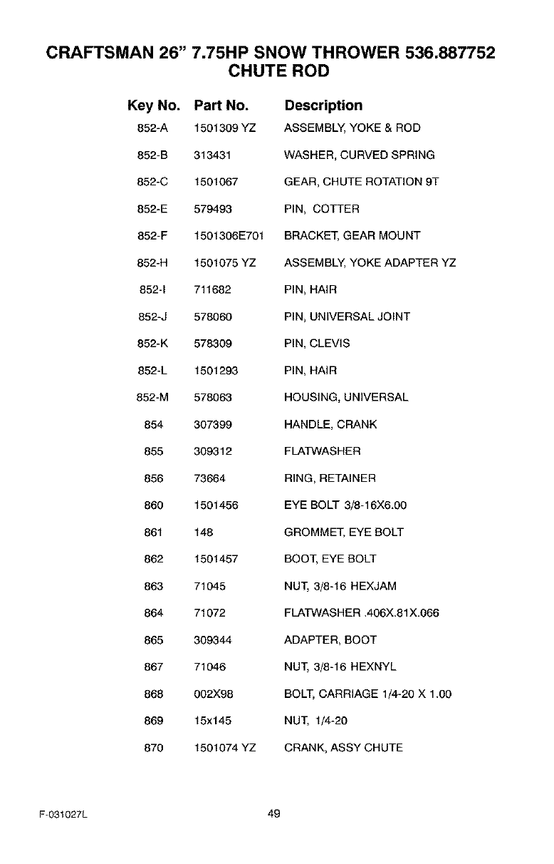
CRAFTSMAN 26" 7.75HP SNOW THROWER 536.887752
CHUTE ROD
Key No. Part No. Description
852-A 1501309 YZ ASSEMBLY, YOKE & ROD
852-B 313431 WASHER, CURVED SPRING
852-C 1501067 GEAR, CHUTE ROTATION 9T
852-E 579493 PIN, COTTER
852-F 1501306E701 BRACKET, GEAR MOUNT
852-H 1501075 YZ ASSEMBLY, YOKE ADAPTER YZ
852-1 711682 PIN, HAIR
852-J 578060 PIN, UNIVERSAL JOINT
852-K 578309 PIN, CLEVIS
852-L 1501293 PIN, HAIR
852-M 578063 HOUSING, UNIVERSAL
854 307399 HANDLE, CRANK
855 309312 FLATWASHER
856 73664 RING, RETAINER
860 1501456 EYE BOLT 3/8-16X6.00
861 148 GROMMET. EYE BOLT
862 1501457 BOOT. EYE BOLT
863 71045 NUT, 3/8-16 HEXJAM
864 71072 FLATWASH ER .406X.81X.066
865 309344 ADAPTER, BOOT
867 71046 NUT, 3/8-16 HEXNYL
868 002X98 BOLT, CARRIAGE 1/4-20 X 1.00
869 15x145 NUT, 1/4-20
870 1501074 YZ CRANK, ASSY CHUTE
F-031027L 49
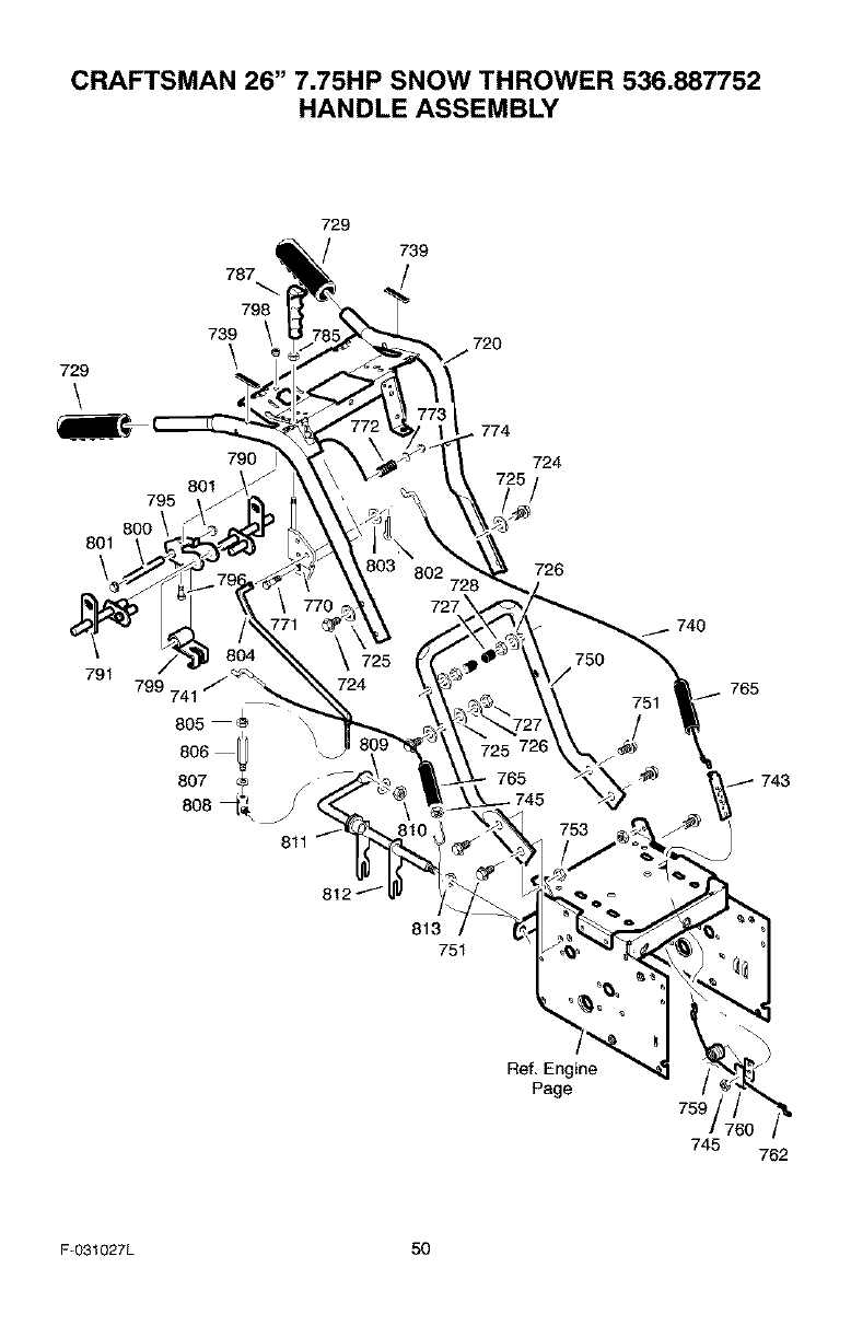
CRAFTSMAN 26" 7.75HP SNOW THROWER 536.887752
HANDLE ASSEMBLY
729
\
795
8OO
801
\
787
798
739
\
801
729
790 I
739
720
774
724
726
791 799 741
805
8O6
807
740
765
743
811
Ref, Engine
Page 759
745 762
F-O31027L 50
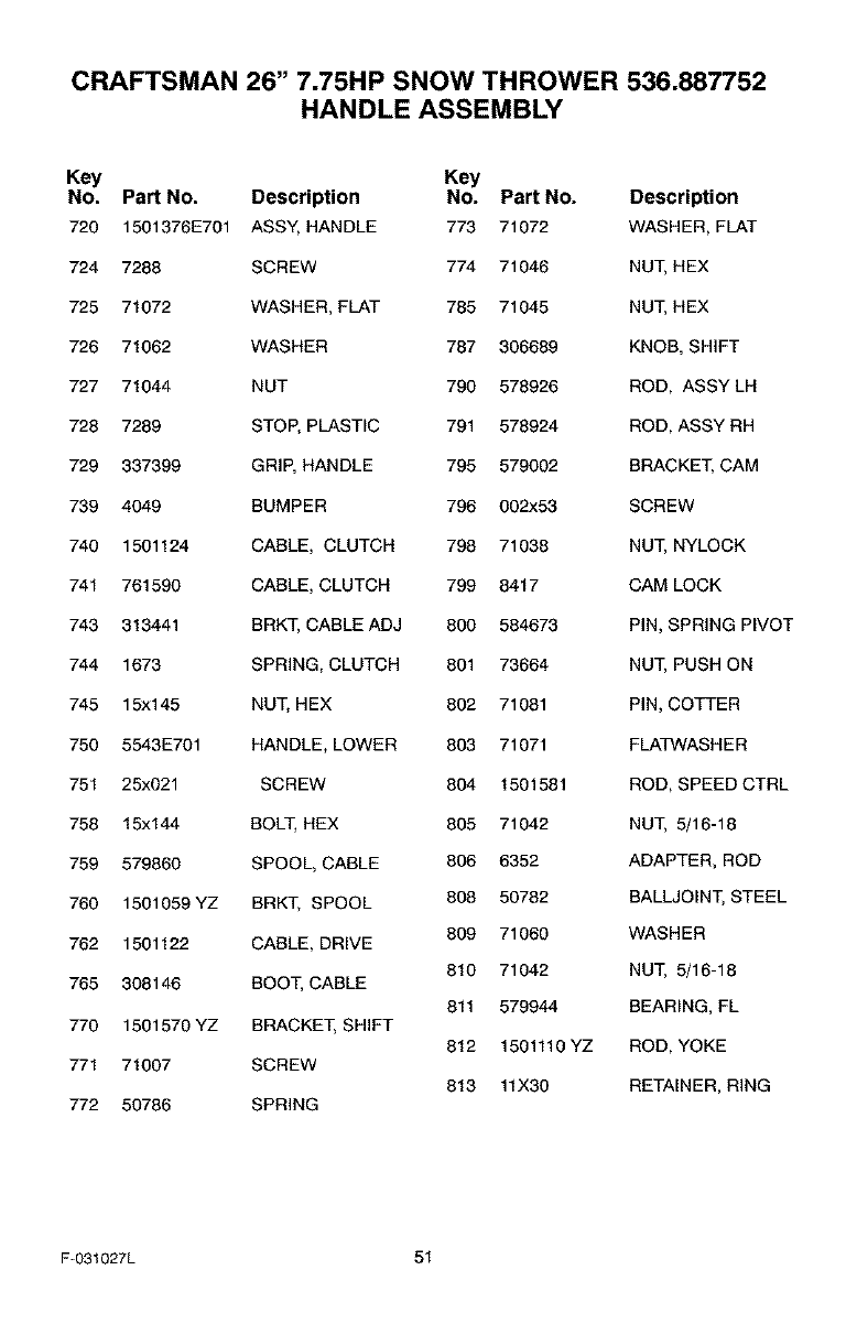
CRAFTSMAN 26" 7.75HP SNOW THROWER 536.887752
HANDLE ASSEMBLY
Key Key
NO. Part NO. Description NO. Part NO. Description
720 1501376E701 ASSY, HANDLE 773 71072 WASHER, FLAT
724 7288 SCREW 774 71046 NUT, HEX
725 71072 WASHER, FLAT 785 71045 NUT, HEX
726 71062 WASHER 787 306689 KNOB, SHIFT
727 71044 NUT 790 578926 ROD, ASSY LH
728 7289 STOP, PLASTIC 791 578924 ROD, ASSY RH
729 337399 GRIP, HANDLE 795 579002 BRACKET, CAM
739 4049 BUMPER 796 002x53 SCREW
740 1501124 CABLE, CLUTCH 798 71038 NUT, NYLOCK
741 761590 CABLE, CLUTCH 799 8417 CAM LOCK
743 313441 BRKT, CABLE ADJ 800 584673 PIN, SPRING PIVOT
744 1673 SPRING, CLUTCH 801 73664 NUT, PUSH ON
745 15x145 NUT, HEX 802 71081 PIN, COTTER
750 5543E701 HANDLE, LOWER 803 71071 FLATWASH ER
751 25x021 SCREW 804 1501581 ROD, SPEED CTRL
758 15x144 BOLT, HEX 805 71042 NUT, 5/16-18
759 579860 SPOOL, CABLE 806 6352 ADAPTER, ROD
760 1501059 YZ BRKT, SPOOL 808 50782 BALLJOINT, STEEL
762 1501122 CABLE, DRIVE 809 71060 WASHER
810 71042 NUT, 5/16-18
765 308146 BOOT, CABLE
811 579944 BEARING, FL
770 1501570 YZ BRACKET, SHIFT
812 1501110 YZ ROD, YOKE
771 71007 SCREW
813 11X30 RETAINER, RING
772 50786 SPRING
F-031027L 51
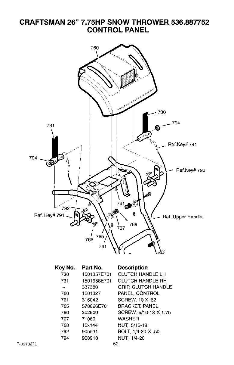
CRAFTSMAN 26" 7.75HP SNOW THROWER 536.887752
CONTROL PANEL
731 794
794
Ref, Key# 741
Ref.Key# 790
Ref, Key# 791 Ref, Upper Handle
766
761
F-031027L
Key No.
730
731
760
761
765
766
767
768
792
794
PaN No.
1501357E701
1501358E701
337380
1501327
316042
578866E701
302900
71060
15x144
905531
908913
Description
CLUTCH HANDLE LH
CLUTCH HANDLE RH
GRIP, CLUTCH HANDLE
PANEL, CONTROL
SCREW, 10 X .62
BRACKET, PANEL
SCREW, 5/16-18 X 1.75
WASHER
NUT, 5/16-18
BOLT, 1/4-20 X .50
NUT, 1/4-20
52
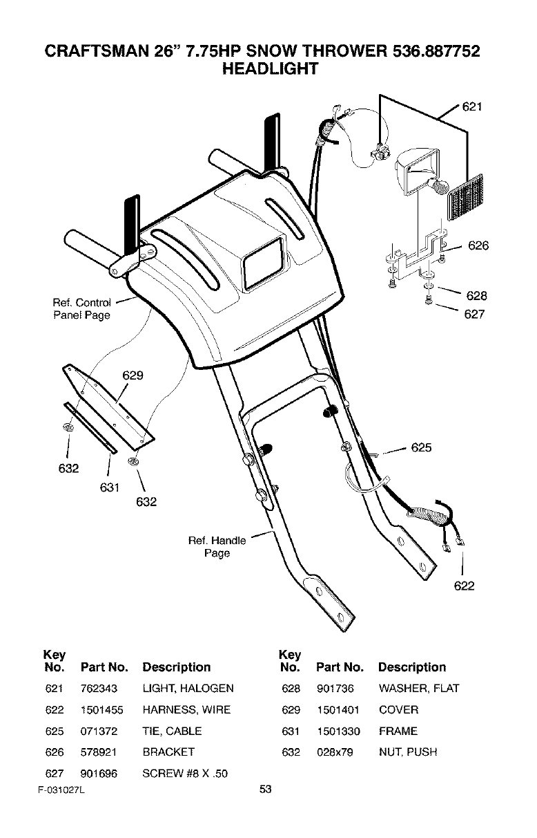
CRAFTSMAN 26" 7.75HP SNOW THROWER 536.887752
HEADLIGHT
626
Ref, Control 628
Panel Page 627
Ref, Handle
Page
625
A
622
Key
No. Part No. Description
621 762343 LIGHT, HALOGEN
622 1501455 HARNESS, WIRE
625 071372 TIE, CABLE
626 578921 BRACKET
627 901696 SCREW #8 X ,50
F-031027L
Key
No. Part No. Description
628 901736 WASHER, FLAT
629 1501401 COVER
631 1501330 FRAME
632 028x79 NUT, PUSH
53
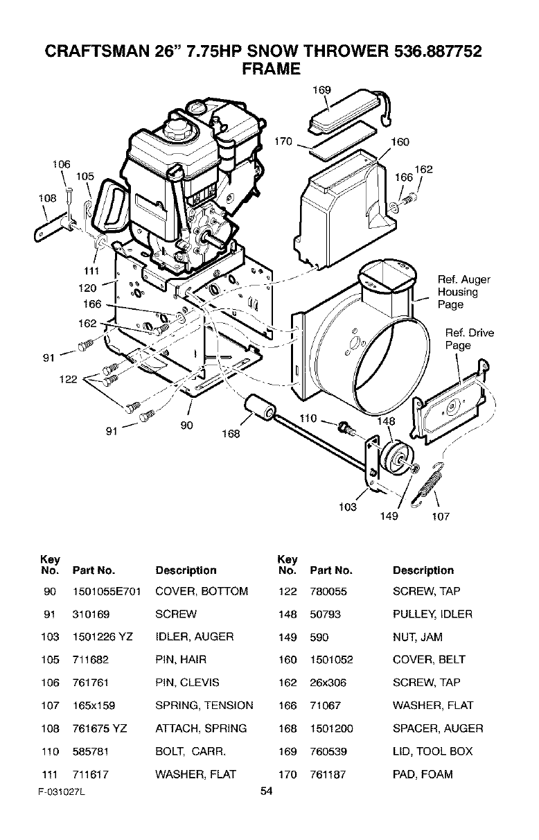
CRAFTSMAN 26" 7.75HP SNOW THROWER 536.887752
FRAME
106
\
106
111
120 q,
162
91
122
/
91 "_- 90 168
Ref, Auger
Housing
Page
Ref. Drive
Page
103 149 107
Key Key
No. Pert No. Description No. Pert No. Description
90 1501055E701 COVER, BOTTOM 122 780055 SCREW, TAP
91 310169 SCREW 148 50793 PULLEY, IDLER
103 1501226YZ IDLER, AUGER 149 590 NUT, JAM
105 711682 PIN, HAIR 160 1501052 COVER, BELT
106 761761 PIN, CLEVIS 162 26x306 SCREW, TAP
107 165x159 SPRING, TENSION 166 71067 WASHER, FLAT
108 761675 YZ ATTACH, SPRING 168 1501200 SPACER, AUGER
110 585781 BOLT, CARE 169 760539 LID, TOOL BOX
111 711617 WASHER, FLAT 170 761187 PAD, FOAM
F-031027L 54
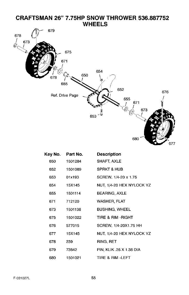
CRAFTSMAN 26" 7.75HP SNOW THROWER 536.887752
WHEELS
679
678
/
675
671
/
654
650 . _
655 /652 676
Ref. Drive Page 655 I
671
673
Key No. Pa_ No.
650 1501284
652 1501089
653 01x193
654 15X145
655 1501114
671 712120
673 1501138
675 1501022
676 577015
677 15X145
678 239
679 73842
680 1501021
68O
Description
SHAFT, AXLE
SPRKT & HUB
SCREW, 1/4-20 x 1.75
NUT, 1/4-20 HEX NYLOCK YZ
BEARING, AXLE
WASHER, FLAT
BUSHING, WHEEL
TIRE & RIM -RIGHT
SCREW, 1/4-20X1.75 HH
NUT, 1/4-20 HEX NYLOCK YZ
RING, RET
PIN, KLIK .25 X 1.38 DIA
TIRE & RIM -LEFT
677
F-031027L 55
CRAFTSMAN 26" 7,75HP SNOW THROWER 536.887752
DECALS
Pa_ No.
48x8036
48x2034
48x4055
761079
48x4054
48x388
48x358
760983
48x393
Description
DECAL, DANGER & FOOT *
DECAL, DANGER CHUTE -HAND *
DECAL, TRACT/ON DRIVE -ENGAGE (RED) *
DECAL, DANGER STRIPE *
DECAL, AUGER DRIVE -ENGAGE (RED) *
DECAL, 7,75/26 CRAFTSMAN (RED) *
NAMEPLATE, CRAFTSMAN *
DECAL, TOOL BOX -BELT COVER *
DECAL, SCH, (RED) *
*Not Illustrated
F-031027L 56

F-O31027L 57
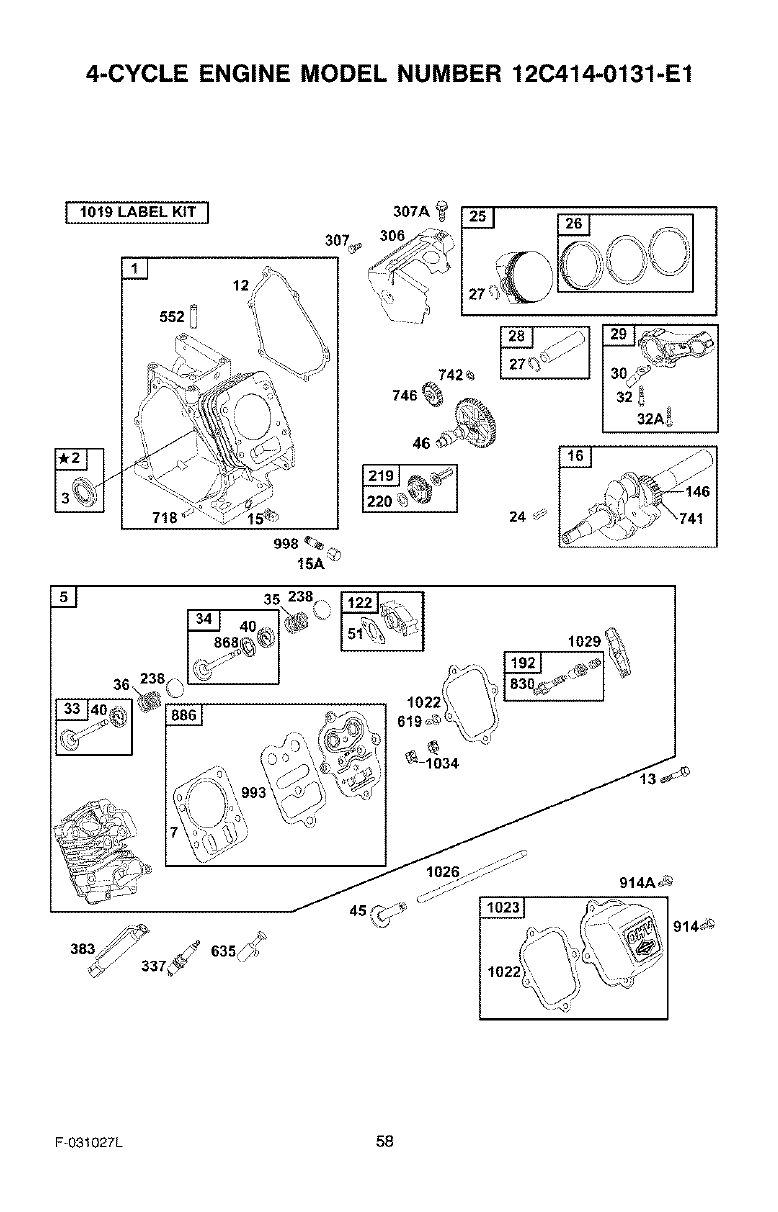
4-CYCLE ENGINE MODEL NUMBER 12C414-0131-E1
I1019 LABEL KIT I
3o_
552
12
15A_
742_
35
1029'
36\
_ ==,I °=°0;
F-O31027L 58
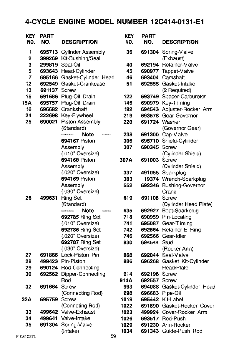
4-CYCLE ENGINE MODEL NUMBER 12C414-0131-E1
KEY PART KEY PART
NO, NO. DESCRIPTION NO, NO. DESCRIPTION
1 695713
2 399269
3 299819
5 693643
7 695166
12 692549
13 691137
15 691686
15A 695757
16 696682
24 222698
25 690021
26 499631
27 691866
28 499423
29 690124
30 692562
32 691664
32A 695759
33 499642
34 499641
35 691304
F-031027L
Cylinder Assembly 36 691304 Spring-V alve
Kit-Bushing/Seal (Exhaust)
Seal-Oil 40 692194 Retainer-V alve
Head-Cylinder 45 690977 Tappet-V alve
Gasket-Cylinder Head 46 693404 Camshaft
Gasket-Crankcase 51 692555 Gasket-Intake
Screw (2 Required)
Plug-Oil Drain 122 693749 Spacer-Carburetor
Plug-Oil Drain 146 690979 Key-Timing
Crankshaft 192 694543 Adjuster-Rocker Arm
Key-Flywheel 219 693576 Gear-Governor
Piston Assembly 220 691724 Washer
(Standard) (Governor Gear)
....... Note ..... 238 691300 Cap-V alve
694167 Piston 306 695710 Shield-Cylinder
Assembly 307 690345 Screw
(.010" Oversize) (Cylinder Shield)
694168 Piston 307A 691003 Screw
Assembly (Cylinder Shield)
(.020" Oversize) 337 491055 Sparkplug
694169 Piston 383 19374 Wrench-Sparkplug
Assembly 552 692346 Bushing-Governor
(.030" Oversize) Crank
Ring Set 619 691108 Screw
(Standard) (Cylinder Head Plate)
....... Note ..... 635 692927 Boot-Sparkplug
692765 Ring Set 718 690959 Pin-Locating
(.010" Oversize) 741 695087 Gear-T iming
692786 Ring Set 742 692564 Retainer-E Ring
(.020" Oversize) 746 692566 Gear-Idler
692787 Ring Set 830 694544 Stud
(.030" Oversize) (Rocker Arm)
Lock-Piston Pin 868 692044 Seal-Valve
Pin-Piston 886 696268 Gasket Kit-Cylinder
Rod-Connecting Head/Plate
Dipper-Connecting 914 692196 Screw
Rod 914A 692557 Screw
Screw 993 694066 Gasket-Cylinder Head
(Connecting Rod) 998 696683 Pipe-Oil
Screw 1019 695442 Kit-Label
(Conneting Rod) 1022 691690 Gasket-Rocker Cover
Valve-Exhaust 1023 499924 Cover-Rocker Arm
Valve-Intake 1026 693517 Rod-Push
Spring-Valve 1029 691230 Arm-Rocker
(Intake) 1034 691343 Guide-Push Rod
59
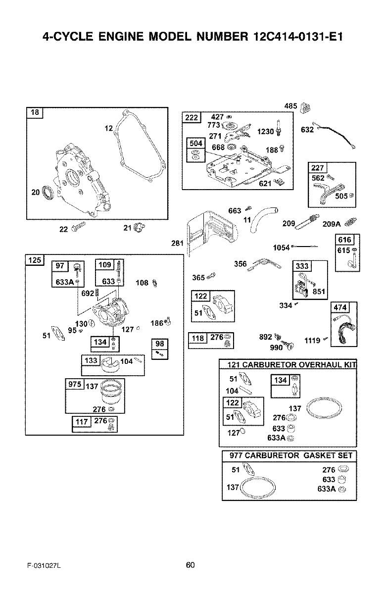
4-CYCLE ENGINE MODEL NUMBER 12C414-0131-E1
22
485
222_ 427 ® ,,
773_ _1230_ °32
8
i209_ 209A
1054"--
334 _"
892
990_ 1119 _
121 CARBURETOR OVERHAUL KIT
104%_
137276C_
127C3633 _-;
633A C_
977 CARBURETOR GASKET SET
276 _
633 _
633A _
F-O31027L 60
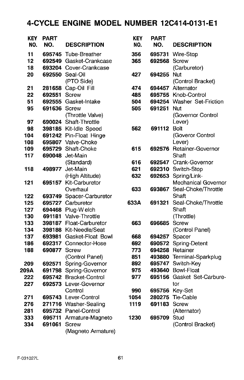
4-CYCLE ENGINE MODEL NUMBER 12C414-0131-E1
KEY PART KEY PART
NO, NO. DESCRIPTION NO, NO. DESCRIPTION
11 695745 Tube-Breather 356 695731 Wire-Stop
12 692549 Gasket-Crankcase 365 692568 Screw
18 693204 Cover-Crankcase (Carburetor)
20 692550 Seal-Oil 427 694255 Nut
(PTO Side) (Control Bracket)
21 281658 Cap-Oil Fill 474 694457 Alternator
22 692551 Screw 485 695755 Knob-Control
51 692555 Gasket-Intake 504 694254 Washer Set-Friction
95 691636 Screw 505 691251 Nut
(Throttle Valve) (Governor Control
97 690024 Shaft-Throttle Lever)
98 398185 Kit-Idle Speed 562 691112 Bolt
104 691242 Pin-Float Hinge (Goveror Control
108 695807 Valve-Choke Lever)
109 695729 Shaft-Choke 615 692576 Retainer-Governor
117 690048 Jet-Main Shaft
(Standard) 616 692547 Crank-Governor
116 498977 Jet-Main 621 692310 Switch-Stop
(High Altitude) 632 692653 Spring/Link-
121 695157 Kit-Carburetor Mechanical Governor
Overhaul 633 693867 Seal-Choke/Throttle
122 693749 Spacer-Carburetor Shaft
125 695727 Carburetor 633A 691321 Seal-Choke/Throttle
127 694468 Plug-Welch Shaft
130 691181 Valve-Throttle (Throttle)
133 396167 Float-Carburetor 663 696685 Screw
134 398188 Kit-Needle/Seat (Control Panel)
137 693981 Gasket-Float Bowl 666 694257 Spacer
166 692317 Connector-Hose 692 690572 Spring-Detent
166 690877 Screw 773 694256 Retainer
(Control Panel) 851 493880 TerminaI-Sparkplug
209 692571 Spring-Governor 892 695747 Switch-Key
209A 691798 Spring-Governor 975 493640 Bowl-Float
222 695742 Bracket-Control 977 695156 Gasket Set-Carbure-
227 692573 Lever-Governor tor
Control 990 695756 Key-Set
271 695743 Lever-Control 1054 260275 Tie-Cable
276 271716 Washer-Sealing 1119 691163 Screw
261 695732 Panel-Control (Alternator)
333 695711 Armature-Magneto 1230 695709 Stud
334 691061 Screw (Control Bracket)
(Magneto Armature)
F-031027L 61
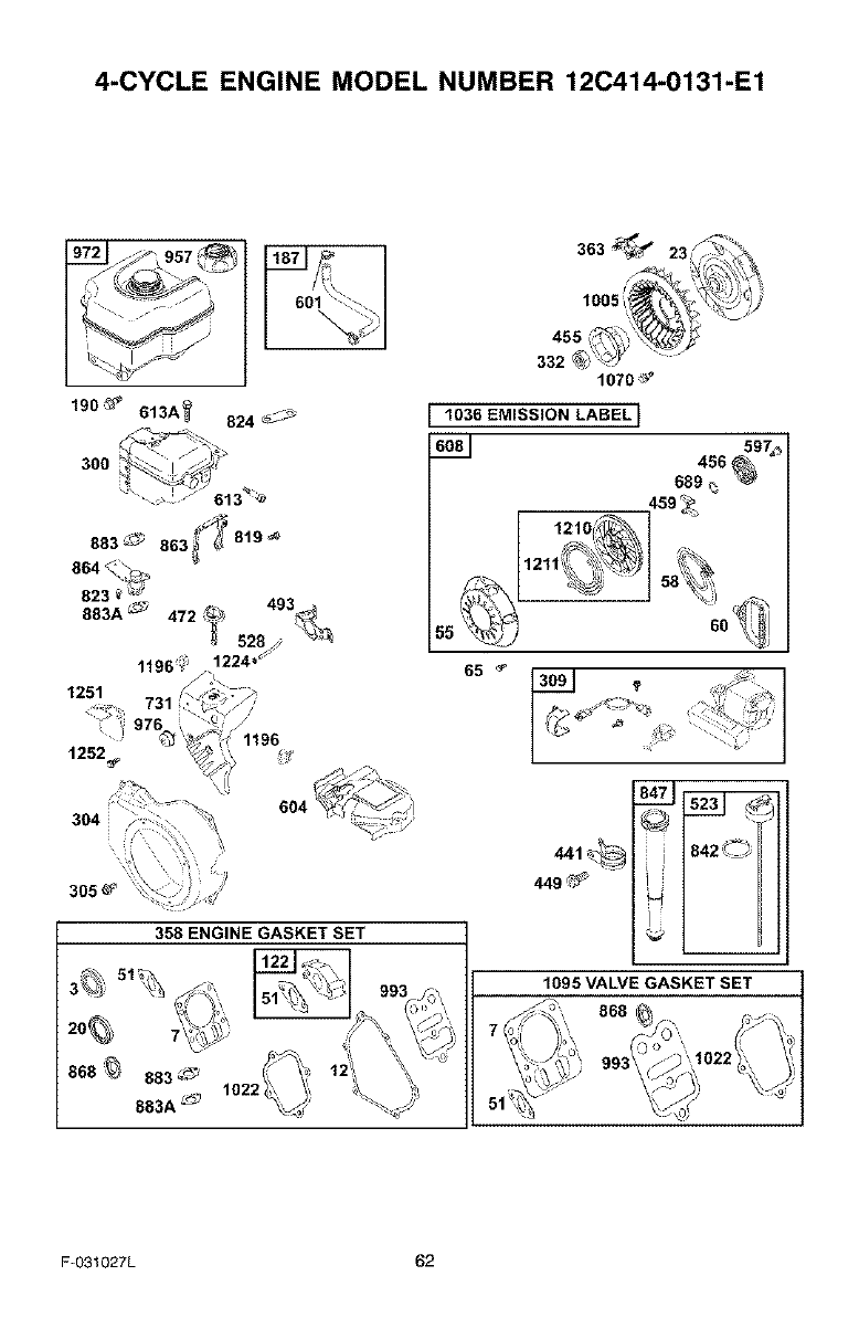
4-CYCLE ENGINE MODEL NUMBER 12C414-0131-E1
190 _'_ 613A_ 824 _-
300
305_
358 ENGINE GASKET SET
363 _23
1005
455
332 ' 1070 _"
1036 EMISSION LABEL 1
4s8 _97,_,
689 _
459 _
65 _
• J
.1_ i_ 9'2¸oI
449 <_;_
1095 VALVE GASKET SET
F-O31027L 62
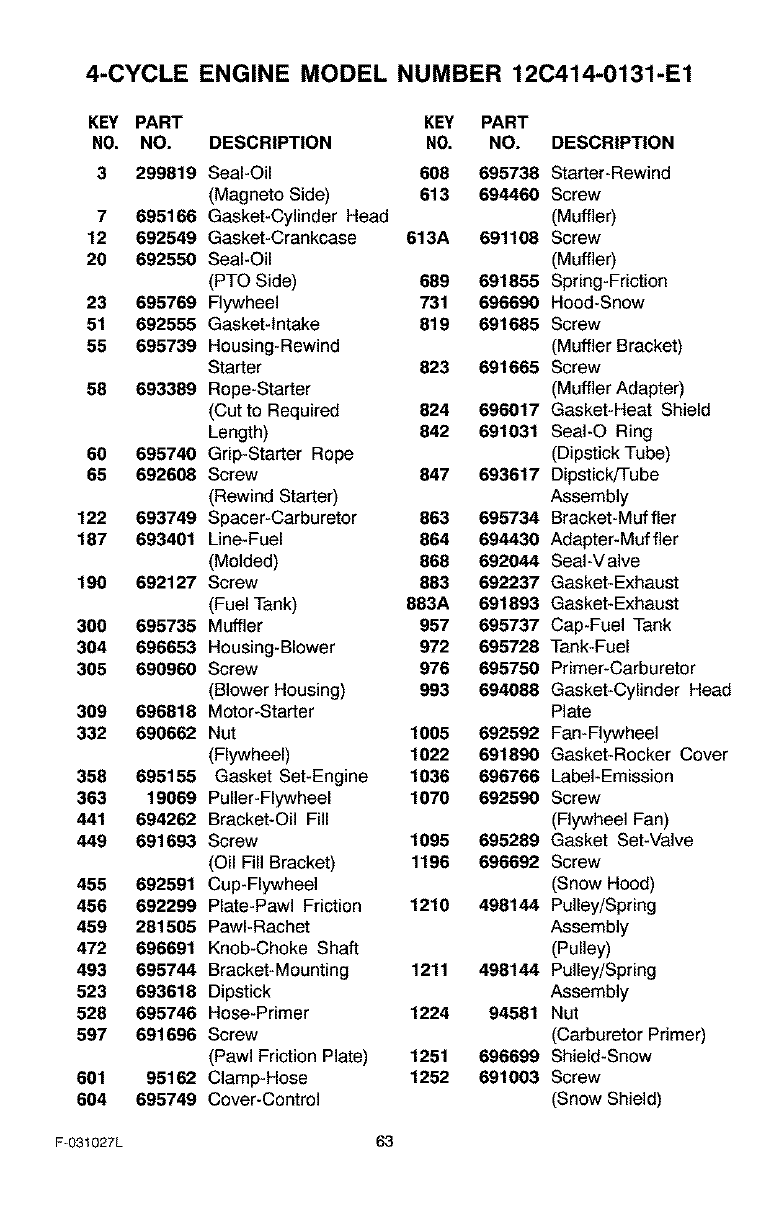
4-CYCLE ENGINE MODEL NUMBER 12C414-0131-E1
KEY PART KEY PART
NO, NO. DESCRIPTION NO, NO. DESCRIPTION
3 299819 Seal-Oil 608 695738 Starter-Rewind
(Magneto Side) 613 694460 Screw
7 695166 Gasket-Cylinder Head (Muffler)
12 692549 Gasket-Crankcase 613A 691108 Screw
20 692550 Seal-Oil (Muffler)
(PTO Side) 689 691855 Spring-Friction
23 695789 Flywheel 731 696690 Hood-Snow
51 692555 Gasket-Intake 819 691685 Screw
55 695739 Housing-Rewind (Muffler Bracket)
Starter 823 691665 Screw
58 693389 Rope-Starter (Muffler Adapter)
(Cut to Required 824 696017 Gasket-Heat Shield
Length) 842 691031 SeaI-O Ring
60 695740 Grip-Starter Rope (Dipstick Tube)
65 692608 Screw 847 693617 Dipstick!Tube
(Rewind Starter) Assembly
122 693749 Spacer-Carburetor 863 695734 Bracket-Muffler
187 693401 Line-Fuel 864 694430 Adapter-Muffler
(Molded) 868 692044 Seal-Valve
190 692127 Screw 883 692237 Gasket-Exhaust
(Fuel Tank) 883A 691893 Gasket-Exhaust
300 695735 Muffler 957 695737 Cap-Fuel Tank
304 696653 Housing-Blower 972 695728 Tank-Fuel
305 690960 Screw 976 695750 Primer-Carburetor
(Blower Housing) 993 694088 Gasket-Cylinder Head
309 696818 Motor-Starter Plate
332 690682 Nut 1005 692592 Fan-Flywheel
(Flywheel) 1022 691890 Gasket-Rocker Cover
358 695155 Gasket Set-Engine 1036 696766 Label-Emission
363 19069 Puller-Flywheel 1070 692590 Screw
441 694262 Bracket-Oil Fill (Flywheel Fan)
449 691693 Screw 1095 695289 Gasket Set-Valve
(Oil Fill Bracket) 1196 696692 Screw
455 692591 Cup-Flywheel (Snow Hood)
456 692299 Plate-Pawl Friction 1210 498144 Pulley/Spring
459 281505 PawI-Rachet Assembly
472 696691 Knob-Choke Shaft (Pulley)
493 695744 Bracket-Mounting 1211 498144 Pulley/Spring
523 693618 Dipstick Assembly
528 695746 Hose-Primer 1224 94581 Nut
597 691696 Screw (Carburetor Primer)
(Pawl Friction Plate) 1251 696699 Shield-Snow
601 95162 Clamp-Hose 1252 691003 Screw
604 695749 Cover-Control (Snow Shield)
F-031027L 63

F-O31027L 64
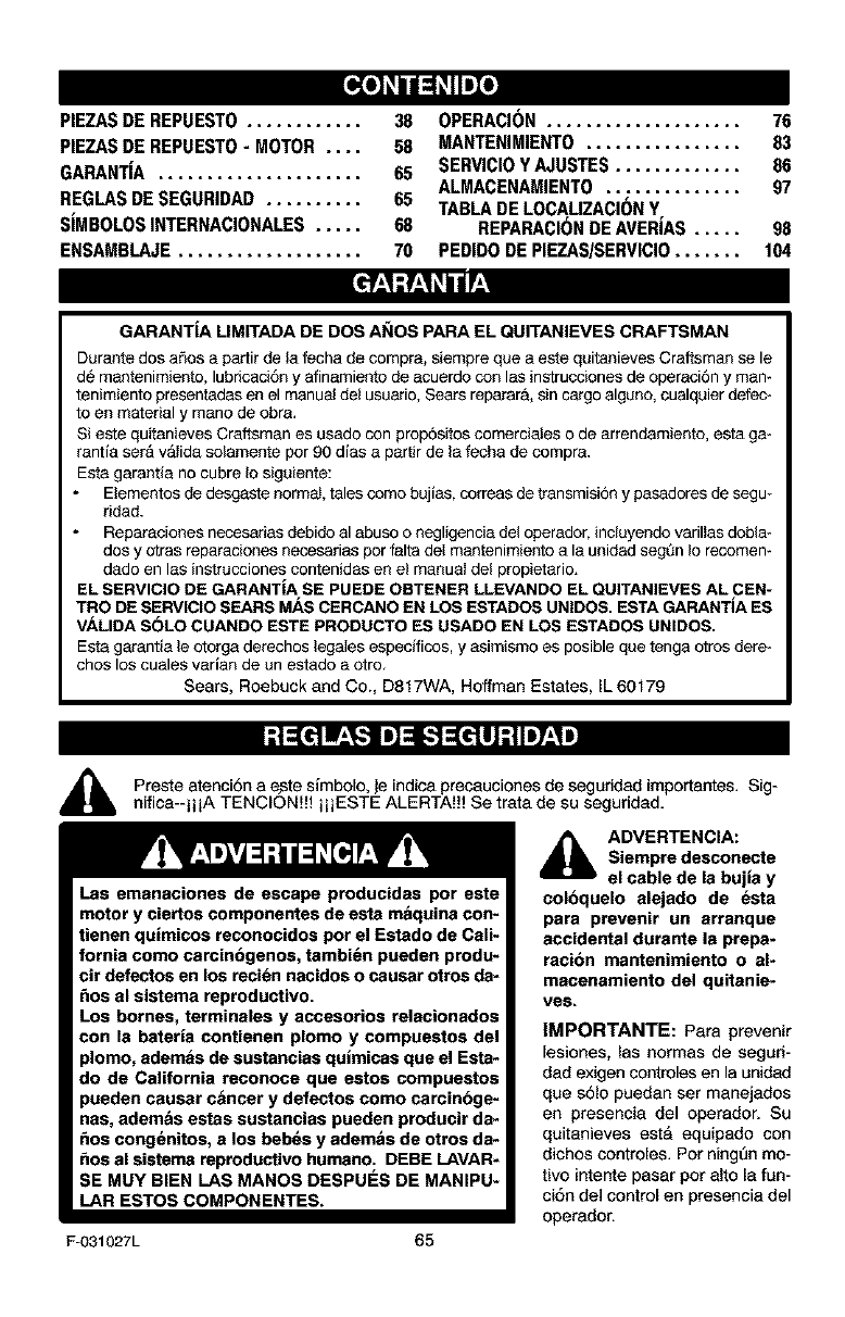
[_o] _I 1:1_IIm]_o]
PIEZASDE REPUEST0 ............ 38
PIEZASDE REPUEST0- MOTOR .... 58
GARANTIA ..................... 65
REGLASDESEGURIDAD .......... 65
SIMBOLOSINTERNACIONALES..... 68
ENSAMBLAJE................... 70
OPERACI(_N.................... 76
MANTENIMIENTO ................ 83
SERVICIOYAJUSTES............. 86
ALMACENAMIENTO.............. 97
TABLADELOCAUZACI(_NY
REPARACI(_NDEAVERIAS ..... 98
PEDIDODEPIEZAS/SERVICIO....... 104
GARANTiA LIMITADA DE DOS AI_IOS PARA EL QUITANIEVES CRAFTSMAN
Durante dos aSos a partir de la fecha de compra, siempre que a este quitanieves Craftsman se le
d6 mantenimiento, lubricaci6n y afinamiento de acuerdo con las instrucciones de operaci6n y man-
tenimiento presentadas en el manual del usuario, Sears reparar&, sin cargo algano, cualquier defec-
to an material y mano de obra.
Sieste quitanieves Craftsman es usado con prop6sitos comerciales o de arrsndamiento, esta ga-
rantia set& v_lida solamente pot 90 dias a partir de la fecha de compra.
Esta garantia no cubre Io siguiente:
Elementos de desgaste normal, tales como bujias, correas de transmisi6n y pasadorss de segu-
ridad.
Reparaciones necesarias debido al abuso o negligencia del opersdor, incluyendo varillas dobla-
dos y otras reparaciones necesarias par falta del mantenimiento a la unidad segQn Io recomem
dado en las instrucciones contenidas en el manual del propietario.
EL SERVICIO DE GARANTiA SE PUEDE OBTENER LLEVANDO EL QUITANIEVES AL CEN-
TRO DE SERVIClO SEARS MAS CERCANO EN LOS ESTADOS UNIDOS. ESTA GARANTiA ES
VALIDA SOLO CUANDO ESTE PRODUCTO ES USADO EN LOS ESTADOS UNIDOS.
Esta garantia le otorga derechos legales especificos, y asimismo es posible que tenga otros dere*
chos los cuales varian de un estado a otro.
Sears, Roebuck and Co., D817WA, Hoffman Estates, IL 60179
Preste atenci6n a e.ste simbolo, je indica preeauciones de seguddad importantes. Sig-
nifica--iii A TENCION!H i ii ESTE ALERTA!!! Se trata de su seguridad.
Las emanaciones de escape producidas por este
motor y ciertos componentes de esta maquina con-
tienen quimicos reconocidos pot el Estado de Cali-
fornia como carcinbgenos, tambi_n pueden produ-
cir detactos en los reci_n nacidos o causar otros da-
_os al sistema reproductivo.
Los homes, terminales y accesorios relacionados
con la bateria contienen plomo y compuestos del
plomo, ademas de sustancias qulmicas que el Esta-
do de California reconoce que estos compuestos
pueden causar c&ncer y defectos como carcinbge-
nas, adem&s estas sustancias pueden producir da-
_os cong_nitos, a los beb_s y adem&s de otros da-
_os al sistama reproducUvo humano. DEBE LAVAR-
SE MUY BIEN LAS MANOS DESPUES DE MANIPU-
LAR ESTOS COMPONENTES.
F-O31027L 65
_1_ DVERTENCIA:
Siempre desconecte
el cable de la bujia y
coloquelo alejado de esta
para prevenir un arranque
accidental durante la prepa*
racibn mantenimiento o al-
macenamiento del quitanie*
ves.
IMPORTANTE: Para prevenir
lesiones, las normas de seguri-
dad exigen controles en la unidad
que s61o puedan ser manejados
en presencia del operador. Su
quitanieves esta equipado con
dichos controles. Pot ning6n mo-
tivo intente pasar pot alto la fun-
ci6n del control en presencia del
operador.
CAPAClTACIbN
1. Lea con atenciAn [as instrucciones en el
manual de operaciAn y servicio. Familiari-
cese completamente con los controles y
el uso apropiado de] quitanieves. Apren-
da a detener el quitanieves y a desen-
ganchar rapidamente los controles.
2. Nunca permita ani_os operar el quita-
nieves. Nunca permita que adultos ape-
ten el quitanieves sin la instrucciAn
apropiada.
3. Mantenga el Area libre de personas, es-
pecielmente niAos pequeAos y mascotas.
4. Tenga mucho cuidado pare evitar resba-
lanes o caidas, especialmente cuando
est_ retrocediendo.
PREPARAClbN
1. Inspecciene compietamente e[ Area don-
de se usara el quitanieves y retire todas
las esteras, trineos, tableros, cables, y
otros objetos extraAos.
2. Desenganche todos los embragues antes
de hacer arrancar el motor.
3. No opere el quitanieves sin vestir pren-
das de inviemo adecuadas pare. trabajar
ala intemperie. Vista calzedo que le d_
buena tracciAn sobre superficies resbale-
sas,
4. Maneje el combustible cen cuidade; Aste
es altamente inflamable.
(a) Use un contenedor aprobado pare.
combustible.
(b) Nunca quite la tape del tanque de
combustible ni armadacombustible a
un motor en marcha o a un motor ca-
liente.
(c) Llene el tanque de combustible al el-
re libre y con mucho cuidado. Nunca
Ilene el tanque en un reeinto cerrado.
y/o del sol hace que el combustible
se expanda.
5. Para todos los quitanieves con motores
de arranque el_ctrico, use cables de ex-
tensiAn con certificaciAn CSA!UL Use
solamente tomacorrientes que hayan si-
do instalados de acuerdo con los regla-
mentos de inspecciAn locales.
6. JamAs intente efectuar ning_n ajuste
mientras el motor se encuentra en mar-
cha (excepto cuando el fabricante Io re-
comiende asi especificamente).
7. Permita que el motor y el quitanieves se
ajusten alas temperatures exteriores an-
tes de comenzar a despejar la nieve.
8. Siempre use gafas de seguridad o pro-
tectores pare los ojos durante la opera-
clan o mientras efectQa alg5n ajuste o
reparaciAn ala unidad, pare proteger sus
ojos de objetos extraAos que pudiesen
set lanzados par el quitanieves.
OPERACION
t, No epere este quitanieves si estA toman-
do medicinas que puedan causar somno-
lencia o afectar su habilidad para operar
el quitanieves.
2. No use el quitanieves si por motives
emocionales o fisicos se le dificulta ma-
nejarlo de forma segura.
3. No coloque las manos o los pies cerca o
debajo de piezas en movimiento. Men-
tAngase en todo momento a buena dis-
tancia de le abertura del tubo de
descarga.
4. Tenga mucho cuidado al operar el quite-
nieves en o a tray,s de entradas de au-
tos, senderos o caminos de grava.
MantAngase alerfa de peligros ocultos o
trafico.
5- Si golpea un objeto extra5o, pare el mo-
tor, desconecte el cable de la bujia, ins-
peccione meticulosamente el quitanieves
por si hubiera algQn daAo, y repArelo an-
tes de arrancar el motor y operar el quite-
nieves nuevamente.
Si el quitenieves comienza a vibrar de
manere excesiva, pare el motor y revise-
Io inmediatamente pare encontrar la cau-
se. Generalmente, la vibraciAn as una
advertencia de elgin problem&
7. Pare el motor cuando deje la posiciAn de
operaciAn, antes de desobstruir el aloja-
miento de la barrena/propulsor o el tubo
de descarga, y cuando efect5e cualquier
reparaciAn, ajuste o inspecciAn.
Cuando limpie, repare o inspeccione el
quitanieves, asegArese de que ]a barre-
(d) Vuelva a colocar la tape del tanque
de combustible de manera segura, y
limpie el combustible derramado. 6.
(e) Nunca almacene combustible o el
quitanieves con combustible en el
tanque dentro de un ediflcio donde
los vapores pudiesen alcanzar algu-
na llama abierta o chispas.
(f) Verifique que el quitanieves tenga
suficiente combustible antes de cede
uso, y deje un espacio adicional en el 8.
tanque puesto que el calor del motor
F-031027L 66
na/propulsorytodasInspartesm6viles
seencuentrendetenidas,yquetodoslos
controlesest_ndesenganchados.Desoo-
necteelcabledelabujiaymant_ngalo
alejadodelabujiapareevitarunarran-
queaccidental.
9. TometodasInsprecaucionesposiblesal
dejerelquitanievesdesatendido.Desen-
ganchelabarrena!propulsor,pareelmo-
toryretire18Ilave.
10.Nohagaarrancerelmotorenrecintos
cerrados,exceptoperaarrancerypare
trensportarelquitanieveshaciaedentroo
haciaafueradelrecinto.Abralaspuertas
quedenalexterior;losvaporesdeesca-
pesonpeligresos(contienenMONOXl-
DODECARBONO,unGASINODOROy
LETAL).
11.Nouseelquitanievesparelimpier&reas
deterrenoinclinadas(cuestas,pendien-
tes).Tengamuchocuidadocuandocam-
hiededirecci6n.Nointentelimpier
pendientesmuypronunciadas.
12.Nuncaopereelquitanievessinquelos
resguardos,placesuotrosdispositivos
deseguridadseencuentrenensuIugar.
13.Nuncaopereelquitanievescercadees-
caparetesdevidrio,eutom6viles,vidrie-
ras,sitiosdecerga/descarga,ysimilares,
sinelajusteapropiadodelangulodedes-
cargadelanieve.Mantengaalosnifiosy
lasmascotasalejadosdel&reequeest&
despejando.
14.Nosobrecarguelecapecidaddelquita-
nievesalintenterlimpiarlanieveauna
velocidaddemesiador&pida.
15.Nuncaopereelquitanievesaaltasveloci-
dadesdetransportesobresuperficies
resbalosas.Mirehaciaarrasytengacui-
dadoalretroceder.
16.Nuncadescarguedirectamentehaciaes-
pectadoresnipermitaanediefrenteal
quitanieves.
17.Desenganchelefuerzamotrizdelabe-
rrena/propulsorcuandoelquitanieves
seetrasportadoonoest6enuso.
18.Utilice8nicamenteadffamentosyacceso-
dosaprobadospotelfabricantedelquite-
nieves(talescomocadenasparelas
ruedas,juegosdearranqueel6ctrico,
etc.).
19.Nunceopereel quitanieves sin tener bue-
na visibilidad o iluminaci6n. Asegt_rese
siempre que tiene buena estabilidad, y
sujete con firmeza el mange. Camine;
nunca corl'e.
20. No trate de alcanzer &reas dificiles. Man-
tenga ]a estabilided yel balance en todo
momento.
21. No trete de user el quitenieves pare lim-
piar techos.
MANTENIMIENTO Y
ALMACENAMIENTO
1. Revise los pemos con frecuencia pera
asegurer que est6n bien epretados y que
el quitanieves est6 en condiciones segu-
ras de funcionamiento.
2. Nunce guerde el quitanieves con com-
bustible en el tanque dentro de un recinto
donde hubieran fuentes de ignici6n tales
como calentadores de ague y estufes,
secadoras de ropa, y similares. Permite
que el motor se enfrie antes de guarder
el quitanieves en cualquier recinto.
3. Siva a almacenar el quitanieves pot un
pedodo prolongado, siempre consulte las
instrucciones del manual del operador
donde encontrara consejos importantes.
4. Mantenga o reemplace las etiquetas de
seguridad e instrucciones, segQn sea ne-
cesario.
5. Mantenga el quitanieves en marcha unos
cuantos minutos despu_s de despeiar le
nieve, para ev_ar que se congele la be-
rrena/propulsor.
_IL ADVERTENCIA: Este quitanieves
es para use en aceras, entradas
de auto y otras superficies de te-
rreno planas. Se debe tener cuidado al
usar el quitanieves en superficies inclina-
das. NO USE EL QUITANIEVES EN SU-
PERFICIES SOBRE EL NWEL DEL SUELO
tales como techos de residencias, de ga-
rajes, porches u otras estrgcturas o cons-
trucciones similares.
F-031027L 67
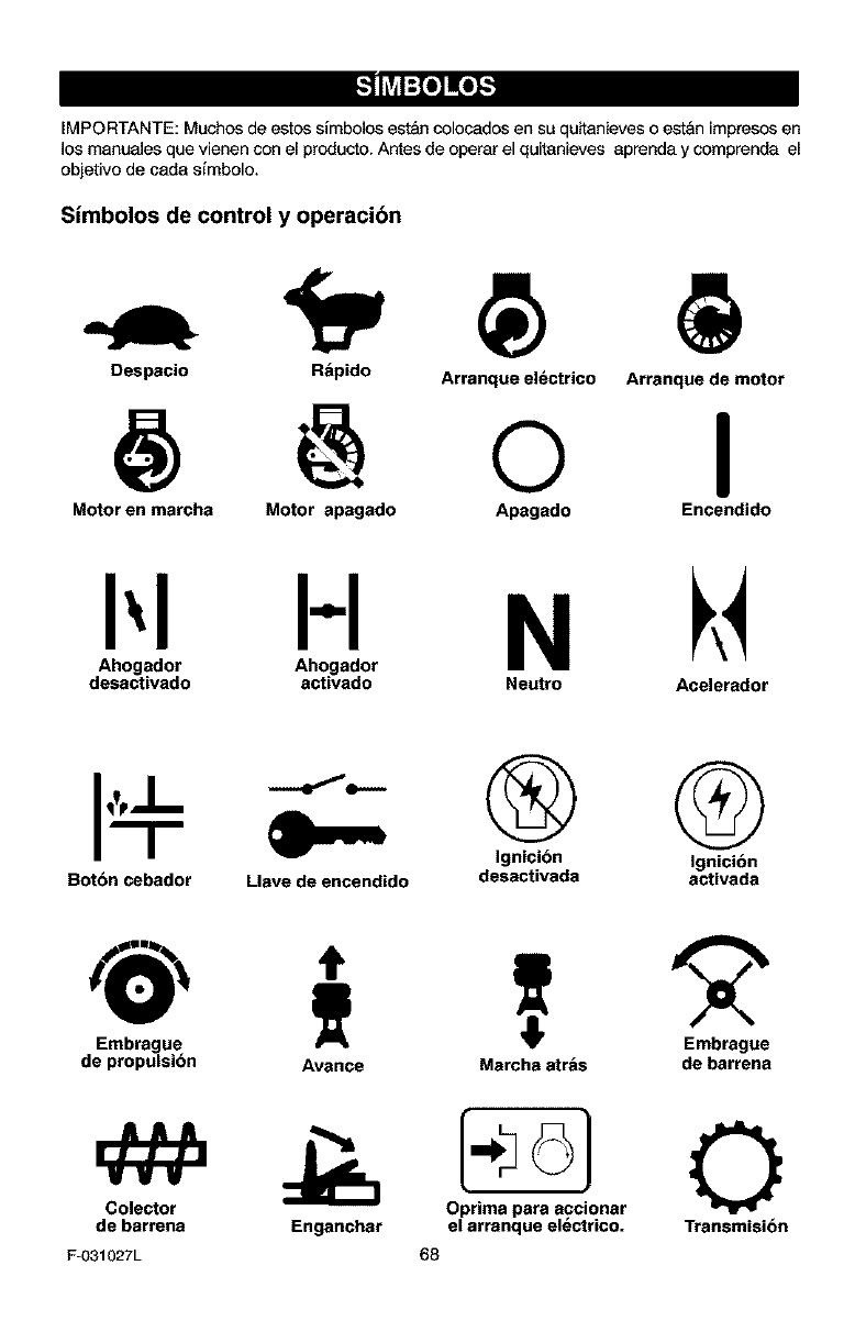
IMPORTANTE: Muchos de estos simbolos es_&ncolocados en su quitanieves o estan impresos en
los manuales que vienen con el producto. Antes de operar el quitanieves aprenda y comprenda el
objetivo de carla simbolo.
Simbolos de control y operacibn
Despacio R_pido Arranque el_ctrico
@ @ o Arranque de motor
I
Motoren marcha Motor apagado Apagado Encendido
HN
Ahogador Ahogador
desactivado activado Neutro Acelerador
Bot6n cebador Llave de encendido
@ @
Ignicibn Ignicibn
desactivada activada
@
Embrague
de propulsibn
Colector
de barrena
F-031027L
Avance Marcha atr&s de barrena
Oprima para accionar
Enganchar el arranque electrico. Transmisi6n
68
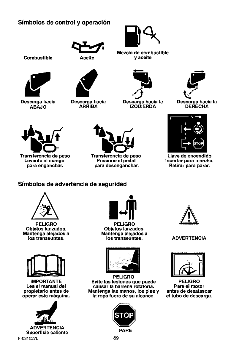
Simbolos de control y operacibn
Mezcla de combustible
Combustible Aceite y aceite
Descarga hacia Descarga hacia Descarga hacia la Descarga hacia la
ABAJO ARRIBA IZQUIERDA DERECHA
Transferencis de peso Transferencia de peso Llave de encendido
Levante el mango Presione el pedal Insertar para marcha,
para enganchar, para desenganchar. Retirar para parar.
Simbolos de advertencia de seguridad
PEMGRO PELIGRO
Objetos lanzados. Objetos lanzados.
Mantenga alejedos a Mantenga alejedos a
los transet_ntes, los transeuntes. ADVERTENClA
IMPORTANTE
Lea el manual del
propietario antes de
operar esta m_quina.
PELIGRO
Evite las lesiones que puede
causar la barrena rotatoria.
Mantenga las manos, los pies y
la ropa fuera de su alcance.
PELIGRO
Pare el motor
antes de desatascar
el tubo de descarga.
ADVERTENCIA
Superficie caliente PARE
F_O31027L 69
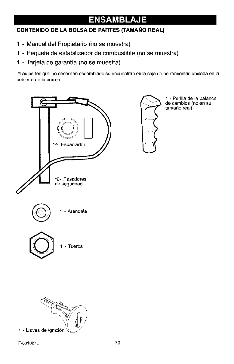
CONTENIDO DE LABOLSA DE PARTES_AMANO REAL)
1-Manual del Propietario (no se muestra)
1 - Paquete de estabitizador de combustible (no se muestra)
1 - Tarjeta de garantia (no se muestra)
*Las partesque no neces_tanensambladose encuentranenla cajade herramientasubicadaen la
cubierta de la correa.
I 1 - Perilla de ]a palanca
de cambios (no en su
tamar_o real)
1 - Arandela
1 - Tuerca
1 - Uaves de ignici6n _
Fu031027L 7O
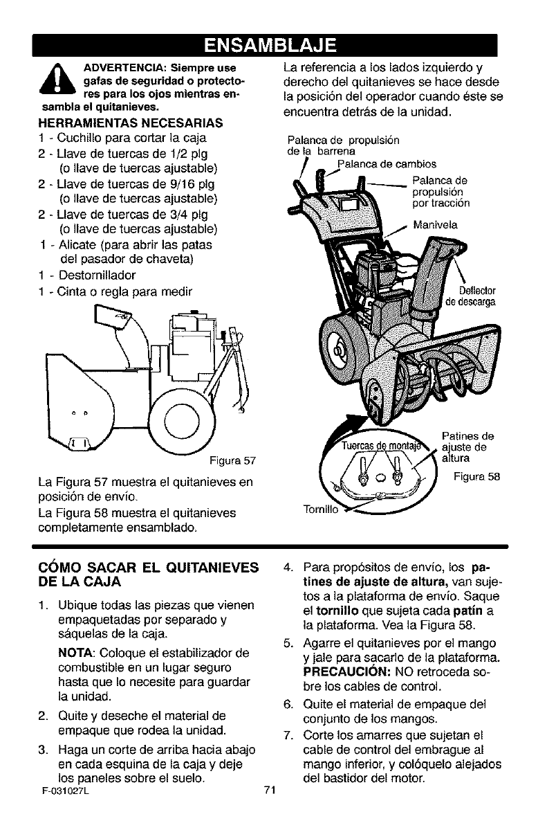
_lb DVERTENCIA: Siempre use
gafas de seguridad o protecto-
res para los ojos mientras en-
sambla el quitanieves.
HERRAMIENTAS NECESARIAS
1 - Cuchillo para cortar ]a caja
2 - Uave de tuercas de 1/2 pig
(o Ilave de tuercas ajustable)
2 - Uave de tuercas de 9/16 pig
(o Ilave de tuercas ajustable)
2 - Uave de tuercas de 3/4 pig
(o ]lave de tuercas ajustable)
1 - Alicate (para abrir las patas
del pasador de chaveta)
1 - Destornillador
1 - Cinta o regla para medir
Figura 57
La Figura 57 muestra el quitanieves en
posiciSn de envio.
La Figura 58 muestra el quitanieves
completamente ensamblado.
La referencia a los lados izquierdo y
derecho del quitanieves se hace desde
la posici6n del operador cuando este se
encuentra detr&s de la unidad.
Palanca de propulsi6n
de la barrena
Palanca de
propulsi6n
pot tracciSn
Manivel8
Deflector
_edescarga
Tornil]o
Patines de
• ajuste de
altura
Figura58
C_MO SACAR EL QUITANIEVES
DE LA CAJA
1. Ubique todas las piezas que vienen
empaquetadas per separado y
s&quelas de la caja.
NOTA: Co]oque el estabilizador de
combustible en un lugar seguro
hasta que Io necesite para guardar
]a unidad.
2. Quite y deseche el material de
empaque que rodea la unidad.
3. Haga un corte de arriba hacia abajo
en cada esquina de la caja y deje
los paneles sobre el suelo.
F-031027L 71
4. Para prop6sitos de envio, los pa-
tines de sjuste de alturs, van suje-
tos a la plataforma de envio. Saque
el tornillo que sujeta cada patin a
]a plataforma. Vea la Figura 58.
5. Agarre el quitanieves por el mango
y jale para sacar]o de la plataforma.
PRECAUCI(_N: NO retroceda so-
bre los cables de control.
6.
7.
Quite el material de empaque del
conjunto de los mangos.
Corte los amarres que sujetan el
cable de control del embrague al
mango inferior, y col6quelo alejados
del bastidor del motor.
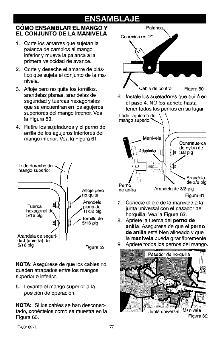
C6MO ENSAMBLAR EL MANGO Y
EL CONJUNTO DE LA MANIVELA
1. Corte los amarres que sujetan la
palanca de cambios al mango
inferior y mueva la palanca ala
primera velocidad de avance.
2. Corte y deseche el amarre de pl&s-
tico que sujeta el conjunto de la ma-
nivela.
3. Afioje pero no quite los tornillos,
arandelas planas, arandelas de
seguridad y tuercas hexagonales
que se encuentran en los agujeros
superiores del mango inferior. Vea
la Figure 59.
4. Retire los sujetadores y el perno de
anilla de los agujeros inferiores del
mango inferior. Vea la Figura 61.
mango superior
Tuerca
5/16 pig
Arandela de seguri<
dad aberta de
5/16 pig
Afloje pero
no quite
Arandela
•Tornillo de
5/16 pig
Figure 59
Conexi6n en "Z"
Cable de control Figure 60
6. Instale los sujetadores que quit6 en
el paso 4. NO los apriete haste
tener todos los pernos en su lugar.
Ladoizquierdo del
mango superio_
SContretuerca
[_ de nylonde
plg
Perno _ A_a_/_elpag
de anilla Arandele de 3/8 pig
Figure 61
7. Conecte el eje de la manivela ala
junta universal con el pasador de
horquilla. Vea la Figure 62.
8. Apriete la tuerca del perno de
anilla. Aseg_rese de que el perno
de anilla este bien alineado y que
la manivela pueda girar ]ibremente.
9. Apriete todos los pernos del mango.
NOTA: AsegQrese de que los cables no
queden atrapados entre los mangos
superior e inferior.
5. Levante el mango superior ala
posici6n de operaci6n.
NOTA: Si los cables se ban desconec-
tado, conectelos como se muestra en la
Figura 60.
F-031027L 72
Junta universal
Figure 62
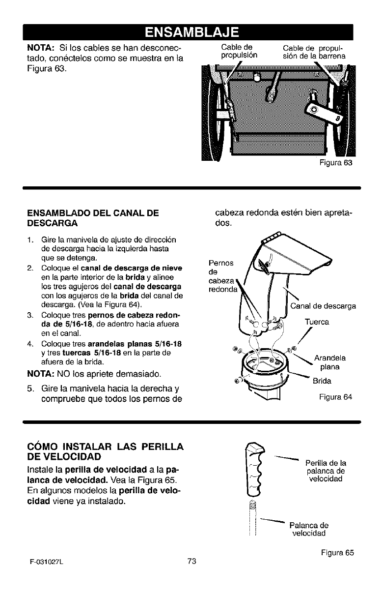
NOTA: Si los cables se hen desconec-
tado, conectelos como se muestra en la
Figura 63.
Cable de Cable de propul-
propulsi6n si6n de la barrena
ENSAMBLADO DEL CANAL DE
DESCARGA
1, Gire la manivela de ajuste de direcci6n
de descarga hacia la izquierda hasta
que se detenga.
2. Coloque el canal de descarga de nieve
en la perte interior de la brida y alinee
los tres agujeros del canal de dascarga
con los egujeros de la bride del canal de
descarga. (Vea la Figure 64),
3. Coloque tres pernos de eabeza redon-
da de 5/16-18, de adentre hacia afuera
en el cenaL
4, Coloque tres arandelas planas 5/16.18
y tres tuercas 5/16.18 en la parte de
afuere de la bride.
NOTA: NO los apriete demasiado.
5. Gire la manivela hacia la derecha y
compruebe que todos los pernos de
Figure 63
cabeza redonda esten bien apreta-
dos.
Pemos
de
cebeza
Canal de descarga
Tuerca
/
Arandela
plane
Figura 64
C6MO INSTALARLAS PERILLA
DEVELOClDAD
Instale la perilla de velocidad ala pa-
lanca de velocidad. Vea la Figure 65.
En algunos modelos la perilla de velo-
cidad viene ya instalado.
_ Perilla de la
palanca de
velocidad
i i _ Palanca de
': velocidad
Figure 65
F-031027L 73
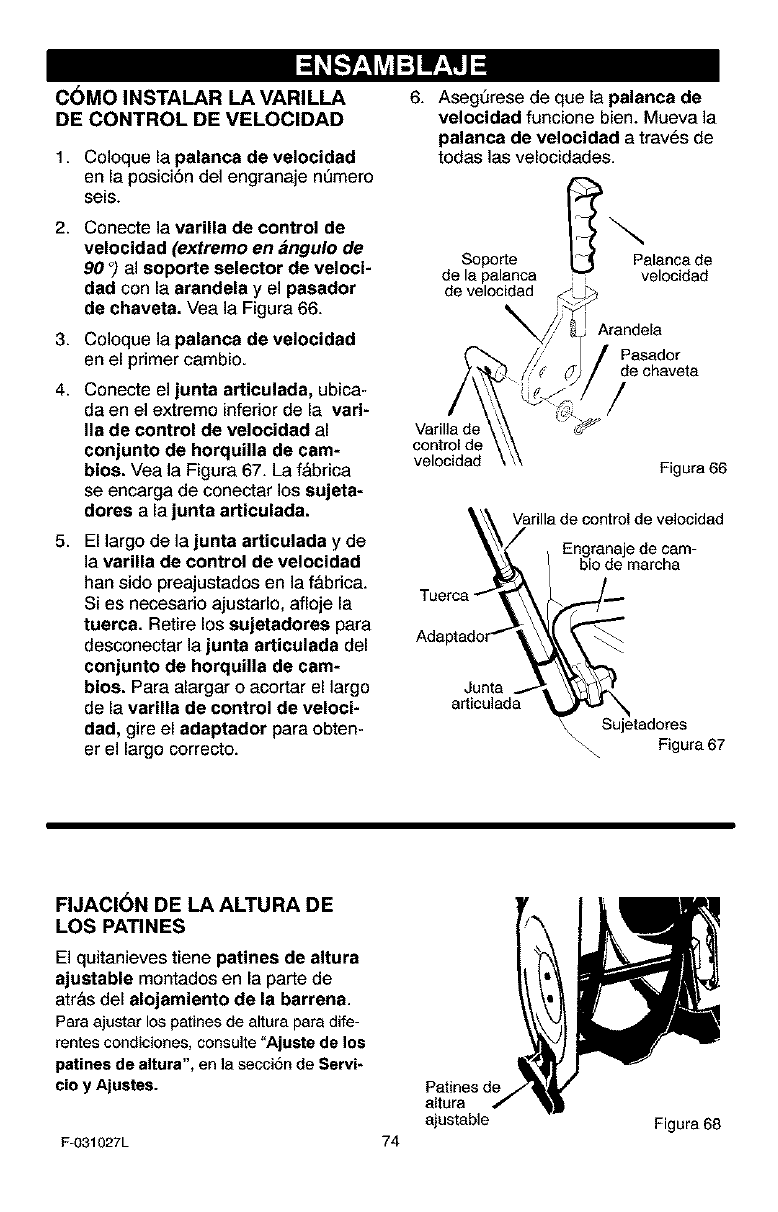
I::1 Lv4:] tr_,YlJ l
C6MO INSTALAR LA VARILLA
DE CONTROL DE VELOCIDAD
1. Coloque la palanca de velocidad
en la posici6n del engranaje nQmero
seis.
2. Coneete ]a varilla de control de
velocidad (extremo en angulo de
90 °) al soporte selector de veloci-
dad con la arandela y el pasador
de chaveta. Vea la Figura 66.
3. Coloque la palanca de velocidad
en el primer cambio.
4. Conecte el junta articulada, ubica-
da en el extremo inferior de la vari-
Ila de control de velocidad al
conjunto de horquilla de cam-
bios. Vea la Figura 67. La f&brica
se encarga de conectar los sujeta-
dores a la junta articulada.
5. El largo de la junta articulada y de
]a varilla de control de velocidad
ban sido preajustados en la f&brica.
Si es necesario ajustarlo, afloje la
tuerca. Retire los sujetadores para
desconectar la junta articulada del
conjunto de horquilla de cam-
bios. Para alargar o acortar el largo
de la varilla de control de veloci-
dad, gire el adaptsdor para obten-
er el largo correcto.
6. Aseg_rese de que la palanca de
velocidad funcione bien. Mueva la
palanca de velocidad a traves de
todas las velocidades.
Soporte Palanca de
de la palanca velocidad
de velocidad
Varilla de
control de
velocidad
_randela
Pasador
de chaveta
/
Figura66
k_ Varilla de control de velocldad
Junta .._ _
articulada
_Sujetadoras Figura 67
FIJACI6N DE LA ALTURA DE
LOS PATINES
El quitanieves tiene patines de altura
ajustable montados en la parte de
atr&s del alojamiento de Is barrena.
Para ajustar los patines de altura para dife-
rentes condiciones, consulte "Ajuste de los
patines de altura", en ]a secci6n de Servi-
cio y Ajustes.
F-O31027L
Patines de
altura
ajustable
74 Figura 68
C6MO AJUSTAR EL LARGO DE
LOS CABLES
Puesto que los cables fueron ajuetadoe
en la f&brica, no ee necesario que
usted los ajuste. Sin embargo, una vez
que se instalan los mangos en la posi-
ci6n de operaci6n, es posible que los
cables queden muy tirantes o muy rio-
jos. Si es necesario ajustados, consulte
la secci6n "C6mo revisar y ajustar los
cables" que aparece en la secci6n de
Servicios y Ajustes.
_" USTA DE REVISI6N
Antes de usar su nuevo quitanieves, y
para asegurar que obtenga el mejor
rendimiento y la mayor satisfacci6n de
este producto de calidad, por favor ha-
ga un repaso de la siguiente lista de re-
visi6n:
_" Se han completado todas las instruc-
clones de ensamblado.
_" El tubo de descarga gira libremente.
_" No quedan piezas sueltas en la caja
de cart6n.
_" Revise los sujetadores. Compruebe
que todos esten bien apretados.
_" En los modelos de arranque electri-
co, la unidad ha sido enviada con el
cable del sistema de arranque en-
chufado al motor. Antes de utilizar la
unidad, sirvase desenchufar el cable
de arranque del motor.
AI mismo tiempo que aprende a usar su
quitanieves, preste mucha atenci6n a
los detalles siguientes:
_" El aceite del motor est& al nivel ade-
cuado.
_" AsegQrese que el tanque de gasolina
este Ileno con gasolina limpia, fresca
y sin plomo.
Familiaricese con todos los contro-
les, su ubicaci6n y funci6n. Opere los
controles antes de hacer arrancar el
motor.
F-031027L 75
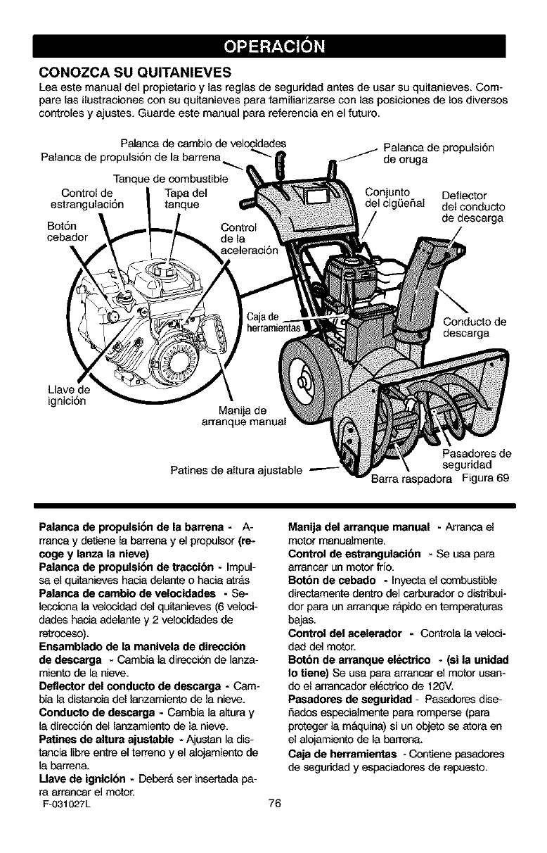
CONOZCA SU QUITANIEVES
Leaeste manual del propietario y las reglas de seguridad antes de usar su quitanieves. Com-
pare las ilustraciones con su quitanieves parafamiliarizarse con las posioionesde los diversos
controles y ajustes, Guarde este manual para referencia en el futuro.
Palanca de cambio de velcoidades
Palansa de propulsi6n de la barrena _-
Tanque de combustible
Control de Tapa del
estrangulaci6n tanque
Bot6n
cebader
_ Palanca de propulsi6n
de oruga
Coniunto Deflector
del cigQeSal del conducto
de descarga
Conducto de
descarga
Llave de
ignici6n Manila de
arranque manual
Patines de altura ajustable
Pasadores de
seguridad
3arra raspadera Figura 69
Palanca de propulsibn de la barrena - A-
rranca y detiene la barrena y el propulsor (re-
coge y lanza la nieve)
Palanca de propulsibn de tracoibn -Impul-
sa el quitanieves hacia delante ohacia arras
Palanca de cambio de velocidedes - Se-
]ecoiosa la velocidad de[ quitanieves (6 velcoi-
dades hecia adelante y 2 velcoidades de
retrcoeso).
Ensamblado de la manivela de direccibn
de descarga - Cambia la direcci6n de lanza-
miento de la aieve.
Deflector del conducto de dessarga - Cam-
bia la distancia del lanzamiento de la nieve.
Conducto de deecarga - Cambia la altura y
]a direcci6n del lanzamiento de la nieve.
Patines de altura ajustable - Ajustan la dis-
tancia libre entre el terreno y el alojamiento de
]a barrena.
Uave de igaici6n - DeberA ser insertada pa-
ra arrancar el motor.
F-031027L
Manila del arranque manual - Arransa el
motor manualmente,
Control de estrangulacibn - Se usa para
arrancar ua motor frio,
Botbn de cebado - Inyec_a el combustible
directamente dentro del sarburador o distdbui-
dor para un arranque r&pido en temperaturas
bajas.
Control del ecelerador - Controla la velcoi-
dad del motor.
Botbn de arranque elentrico -(si la uaided
Io tiene) Se usa para arransar el motor usan-
do el arransador el_,ctr_o de 120V.
Pasadores de segurided -Pasadores dise-
5ados especialmente para rompersa (para
proteger la m&quisa) si un objeto sa atora en
el alojamiento de la barren&
Caja de herramientas - Contiene pasadores
de seguridad yespaciadores de repuesto.
76
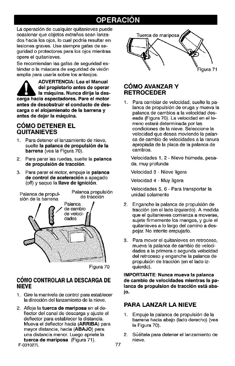
"J=1
La operaci6n de cualquier quitanieves puede
ocasionar que objetos extraSos sean ]anza-
dos hacia los ojos, Io cual podria resultsr en
]esiones grave& Use siempre galas de se-
guridad o protectores para los ojos mientras
opera e] quitanieve&
Se recomiendan las galas de seguridad es-
t&ndar o la m&scara de seguridad de visi6n
ampfia para usarla sobre los anteojos.
_IL ADVERTENCIA: Lea el Manual
del propietario antes de operar
la maquina. Nunca dirija la des-
carga hacia espectadores. Pare el motor
antes de desobstruir el conducto de des-
carga o el alojamienato de la barrens y
antes de dejar la m&quina.
C6MO DETENER EL
QUITANIEVES
1. Para detener el ]anzamiento de nieve,
suelte la palanca de propulsibn de la
barrena (yea Is Figura 70),
2. Pars parar las ruedss, suelte ]a palanca
de propulsibn de traccibn,
3. Pars parar el motor, empuje la palanca
de control de aceleraci6n a apagado
(off) y saque la Ilave de ignicibn,
Palanca de propul-
si6n de la barrena
Palanca propulsi6n
de tracci6n
Figura 70
COMOCONTROLARLADESCARGADE
NIEVE
1. Gire la manivela de control para establecer
la direcci6n del lanzamiento de la nieve.
2. Afloje la tuerca de mariposa en e] de-
flector del canal de descarga y ajuste el
deflector para establecer la distancia.
Mueva el deflector hacia (ARRIBA) pars
mayor distsncia, hacia (ABAJO) pars
una distancia menor. Luego apriete la
tuerca de mariposa (Figura 71).
F-031027L
Tuerca de mariposa
]gura 71
77
COMO AVANZAR Y
RETROCEDER
1, Pars cambiar de velocidad, suelte la pa-
lanca de propulsi6n de oruga y mueva la
palanca de cambios a la velocidad des-
eada (Figura 70). La velocidad en el te-
rreno estsrA determinada pot las
condiciones de la nieve. Seleccione la
velocidad que desea moviendo la palan-
ca de csmbio de velocidades a la ranura
apropiada de la placa de la palanca de
cambios.
Velocidades 1, 2 - Nieve h(_meda, pesa-
da, muy profunda
Velocidad 3 -Nieve ligera
Velocidad 4 - Muy ligera
Velocidades 5, 6 - Pars transportar la
unidad solamente
2,
3,
Enganche la palanca de propulsi6n de
trscci6n (en el lado izquierdo). A medida
que el quitanieves comienza a moverse,
sujete firmemente los mangos, y guie el
quitanieves a Io largo del camino a des-
pejar. No intente empujarlo.
Pars mover el quitanieves en retroceso,
mueva Is palanca de cambio de veloci-
dsdes a la primers o segunda velocidad
del retroceso y enganche la palanca de
propulsi6n de tracci6n (en el ]ado iz-
quierdo).
IMPORTANTE: Nunca mueva la palanca
de cambio de velocidades mientras la pa-
lanca de propulsion de traccion est& aba-
jo.
PARA LANZAR LA NIEVE
1, Empuje la palanca de propulsi6n de Is
barrena hacia abajo (]ado derecho) (yea
la Figura 70).
2. S561tela pars detener el lanzamiento de
nieve.
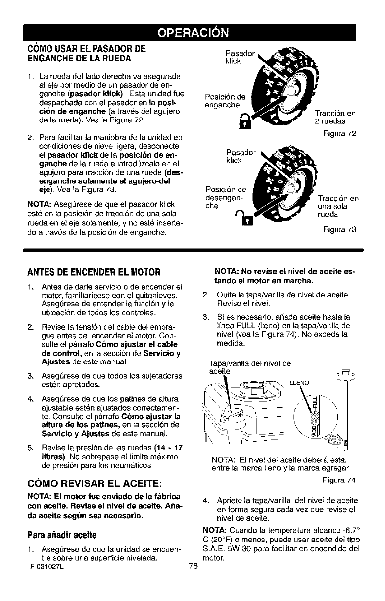
-.l=1
C(_MOUSARELPASADORDE
ENGANCHEDE LARUEDA
1. La rueda del lado derecha va asegureda
el eje per medic de un pesador de en-
ganche (paeedor klick). Esta unidad fue
despechada con el pasador en ]a poei-
cibn de enganche (a tray,s del agujero
de la rueda), Vea la Figure, 72,
2. Para feciliter la maniobra de la unidad en
condiciones de nieve ]igera, desconecte
el pasedor klick de la posicibn de en-
ganche de la ruede eintrod_zcalo en el
egujero pare tracci6n de una rueda (des-
engenche solemente el agujero<lel
eje). Vea la Figure 73.
NOTA: Aseg_rese de que el pasador klick
est6 en la posici6n de tracci6n de una sola
ruede en el eje solamente, y no est_ inserta-
do a tray,s de la posici6n de enganche.
Pasador
klick
Posici6n de
enganche Tracci6n en
2 reedas
Figure 72
Pasedor •
Pos_cion de
desengan- _P' _ Tracci6n en
che _v_"_ una sola
Figure 73
ANTESDE ENCENDEREL MOTOR
1. Antes de darle servicio o de encender el
motor, familiaricese con el quitanieves.
Aseg_rese de entender la funci6n y la
ubicaci6n de todos los controles.
2, Revise la tensi6n del cable del embra-
gue antes de encender el motor. Con-
suite el parrefo Como ajustar el cable
de control, en ]e seeei6n de Servicio y
Ajustes de este manual
3, Aseg_rese de que todos los sujetadores
est_n apretados.
4, Aseg_rese de que los patines de eltura
ajustable est6n ajustados correctamen-
te, Consulte el pArrafo Cbmo ajueter le
altura de los patines, en la secci6n de
Servicio y Ajustes de este manual.
5, Revise la presi6n de las ruedas (14 - 17
libres). No sobrepase el limite m#.ximo
de presi6n para los neumAticos
C6MO REVISAR EL ACEITE:
NOTA: El motor fue enviedo de la fabrica
con aceite. Revise el nivel de aceite. Ar_e-
de aceite seg_n sea necesario.
Paraa_adiraceite
1. Aseg_rese de que la unidad se encuen-
tre sobre una superficie nivelada.
F-031027L
NOTA: No revise el nivel de aceite es-
tendo el motor en marcha.
2, Quite la tapa/varifla de nivel de aceite.
Revise el nivel.
3, Si es necesario, aSada eceite hasta la
Ifnea FULL (lleno) en le tapa/varilla del
nivel (yea la Figura 74). No exceda la
medida.
Tapa/varilla del nivel de
aceite
LLENO
78
NOTA: El nivel del aceite debera ester
entre la marca Ileno y la marca agregar
Figure 74
4, Apriete la tapa!varilla del nivel de aceite
en forme segura cada vez que revise el
nivel de eceite,
NOTA: Cuando ]a temperatura alcence -6,7 °
C (20°F) o menos, puede user aceite del tipo
S.A.E. 5W-30 pare facilitar en encendido del
motor.
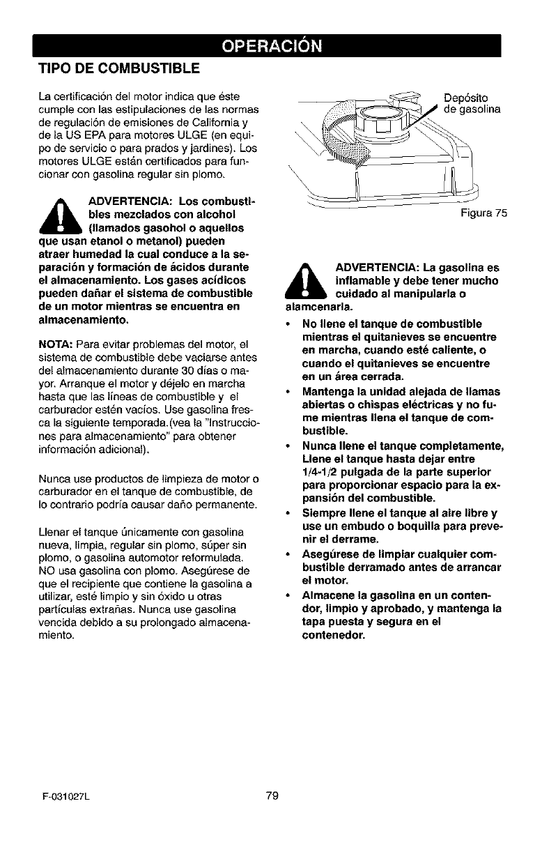
TIPO DE COMBUSTIBLE
La certificaci6n del motor indica que _ste
cumple con les estipulacienes de las normas
de regulaci6n de emisiones de California y
de la US EPA pera motores ULGE (en equi-
po de servicio o pare prades y jardines). Los
motores ULGE estan certificados pare fun-
cionar con gasoline regular sin plome.
_IL DVERTENCIA: Los combusti-
bles mezclados con alcohol
(llamados gasohol o aquellos
que usan etanol o metanol) pueden
atraer humedad la cual conduce a la se-
paracibn y formaci&n de acidos durante
el almacenamiento. Los gases acidicos
pueden da_ar el sistema de combustible
de un motor mientras se encuentra en
almacenamiento.
NOTA: Pare eviter problemas de] motor, e]
sistema de combustible debe vacierse antes
del almacenamiento durante 30 dies o ma-
yor. Arranque el motor y d6jelo an marcha
hasta que las lineas de combustible y el
carburador est_n vacfos. Use gasolina fres-
ca [e s{guiente temporada.(vee la "lnstruccio-
has para almacenamiente" pare obtener
informeciSn edicional).
Nunca use productos de limpieza de motor o
carburador en el tanque de combustible, de
]o contrarie podria causer da5o permanente.
Llenar el tanque 5nicamente cen gasolina
nueva, [impia, regular sin plemo, sSper sin
plemo, o gasolina autemotor reformulada.
NO usa gasoline con plomo. AsegSrese de
que el recipiente que contiene la gaseline a
utilizer, est_ limpio y sin 5xide u etras
perticulas extrar_as. Nunca use gase[ina
venc{da debido a su prolongade almecena-
miente.
\
Dep6s{to
de gasoline
Figure 75
ADVERTENCIA: La gasolina es
inflamable y debe tener touche
cuidado al manipularla o
alamcenarla.
No Ilene el tanque de combustible
mientras el quitanieves se encuentre
en marcha, cuando est6 caliente, o
cuando el quitanieves se encuentre
en un brea cerrada.
Mantenga la unidad alejada de llamas
abiertas o chispas el_ctricas y no fu-
me mientras Ilena el tanque de com-
bustible.
Nunca Ilene el tanque completamente,
Llene el tanque hasta dejar entre
1/4-1/2 pulgada de la parte superior
para proporcionar espacio para la ex-
pansibn del combustible.
Siempre Ilene el tanque al aire libre y
use un embudo o boquilla pare preve-
nit el derrame.
Aseg_rese de limpiar cualquier com-
bustible derramado antes de arrancar
el motor.
Almacene la gasolina en un conten-
dor, limpio y aprobado, y mantenga la
tapa puesta y segura en el
contenedor.
F-O31027L 79
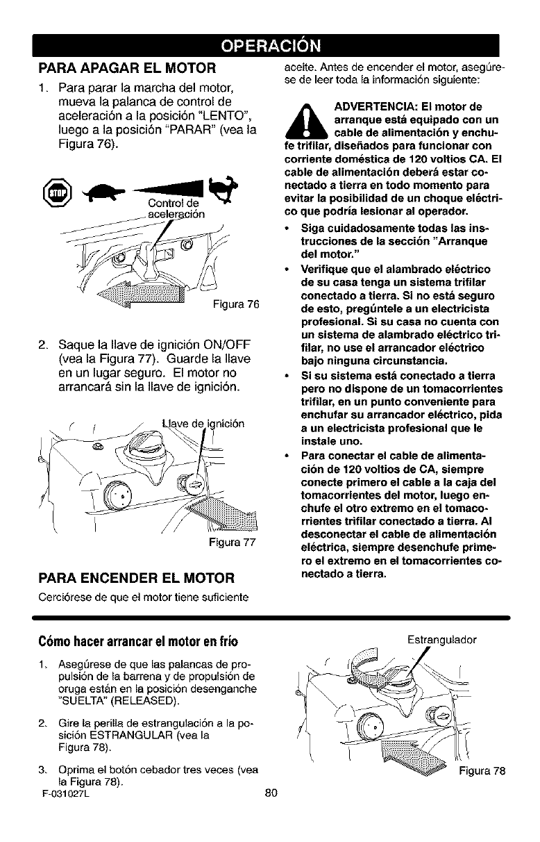
"J=1
PARA APAGAR EL MOTOR
1. Para parar la marcha del motor,
mueva la palanca de control de
aceleraci6n ala posici6n "LENTO",
luego ala posici6n "PARAR" (vea la
Figura 76).
Figure 76
2. Saquela Ilave de ignici6nON/OFF
(vea la Figura 77). Guarde la Ilave
en un lugar seguro. El motor no
arrancar& sin la Ilave de ignici6n.
Figure 77
PARA ENCENDER EL MOTOR
Cerci6rese de que el motor tiene suficiente
aceite, Antes de encender el motor, aseg_re-
se de leer toda le informeci6n siguiente:
_lb ADVERTENCIA: El motor de
arranque est& equipado con un
cable de alimentacibn y enchu-
fe trifilar, diser_ados para funcionar con
corriente domestica de 120 voltios CA. El
cable de alimentacibn deberb estar co*
nectado a tierra en todo momento para
evitar la posibilidad de un choque el_ctri-
co que podrla lesionar al operador.
Siga cuidadosamente todas las ins-
ttucciones de la seccibn "Arranque
del motor."
Verifique que el alambrado el_ctrico
de su case tenga un sistema trifilar
conectado a tierra. Si no estb seguro
de esto, pregt_ntele a un electdcista
profesional. Si su casa no cuenta con
un sistema de alambrado el_ctdco tri-
filar, no use el arrancador el_ctrico
bajo ninguna circunstancia.
Si su sistema est& conectado a tierra
pero no dispone de on tomacorrientes
ttitilar, en un punto conveniente para
enchutar su arrancador el_ctrico, pida
a un electricista protesional que le
instale uno.
Para conectar el cable de alimenta-
cibn de 120 voltios de CA, siempre
conecte primero el cable ala caja del
tomacorrientes del motor, luego en-
chufe el otto extremo en el tomaco-
rrientes trifilar conectado a tierra. AI
desconectar el cable de alimentacion
electrica, siempre desenchufe prime-
ro el extremo en el tomacorrientes co-
nectado a tierra.
C6mohacerarrancarel motoren fr|o
1, AsegOrese de que las pelancas de pro-
pulsi6n de la berrena y de propulsi6n de
oruga est&n en la posici6n desenganche
"S UELTA" (RELEASED),
2, Gire la perilla de estrangulaci6n a la po-
sioi6n ESTRANGULAR (yea la
Figure 78).
Estrangulador
/
3, Oprima el bot6n cebedor tres veces (vea
la Figure 78).
F-031027L 80
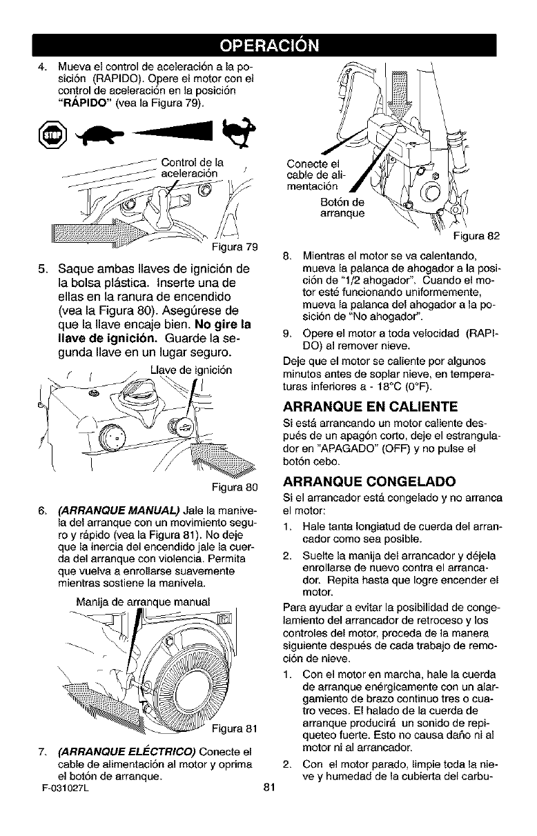
-.l=1
4, Mueva el control de aceleracJ6n a la po-
sici6n (RAPIDO). Opere el motor con el
control de aceleraci6n en la posici6n
"RAPIDO" (yea la Figure 79),
Control de la
_ aceleraci6n J
Figure 79
5. Saque ambas Ilaves de ignici6n de
]a boise pl&stica, lnserte una de
elias en la ranura de encendido
(vea la Figura 80). AsegQrese de
que la Ilave encaje bien. No gire la
Ilave de ignicibn. Guarde la se-
gunda Have en un lugar seguro.
Llavede ignici6n
r(
Figure 80
6, (ARRANQUE MANUAL) Jale la manive-
la del arranque con un movimiento segu-
re y r&pido (yea la Figure 81). No deje
que la inercia de] encendido jale la cuer-
da de] arranque con violencia. Permita
que vuelva a enrollarse suavemente
mientras sostiene le manivela.
Manijade a_ nque manual
Figura 81
7. (ARRANQUE ELECTRICO) Conecta el
cable de alimentaci6n al motor y eprima
al bot6n da arranque.
F-O31027L 81
Conecte el
cable de ali-
mentaci6n
Bot6n de
arranque
Figura 82
8. Mientres el motor se va calentando,
mueva la palanca de ahogador a la posi-
ci6n de "1/2 ahogador". Cuando el mo-
tor est_ funcionando uniformemente,
mueva la palanca del ahogador a la po-
sici6n de "No ahogador".
9. Opere el motor a toda velocidad (RAPI-
DO) al remover nieve.
Deje que el motor se caliente por algunos
minutes antes de soplar nieve, en tempera-
turas inferiores a - 18°C (0°F).
ARRANQUE EN CALIENTE
Si est8 errancando un motor caliente des-
pu_s de un apag6n corto, deje el estrangula-
dot en "APAGADO" (OFF) y no pulse el
bot6n cebo.
ARRANQUE CONGELADO
Si el arrencador esta congelado y no arranca
el motor:
1, Hale tante Iongiatud de cuerda del arran-
cador como sea posible.
2, Suelte la manila del arrancador y d6jela
enrollarse de nuevo contra el arrance-
dor. Repita haste que Iogre encender el
motor.
Pare ayudar a evitar la posibilidad de conge-
lamiento del arrancedor de retroceso y los
controles del motor, proceda de la manera
siguiente despu_s de cada trabajo de remo-
ci6n de nieve.
1, Con el motor en marcha, hale la cuerda
de arranque en_rgicamente con un alar-
gamiento de brazo continuo tres o cua-
tro veces. El halado de la cuerda de
arranque producirA un sonido de repi-
queteo fuerte, Esto no cause daSo ni al
motor ni al arrancador,
2, Con el motor parado, limpie tode la nie-
ve y humedad de la cubierta del carbu-
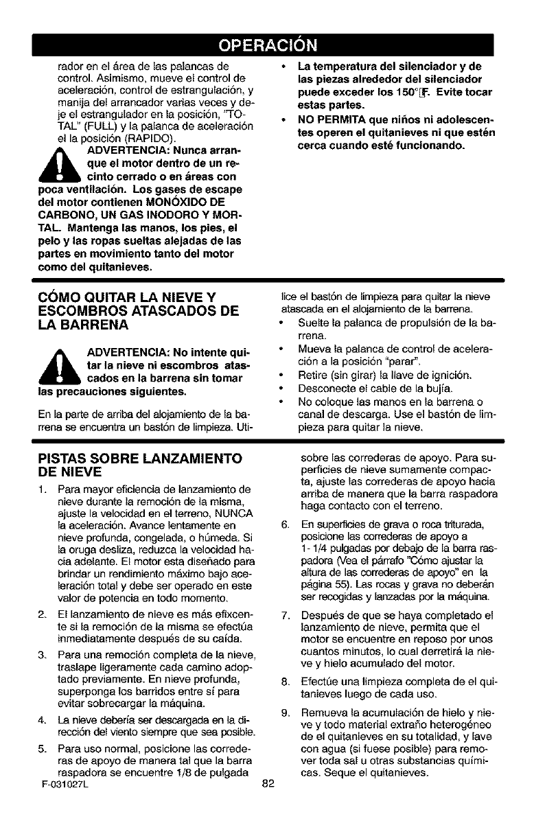
faderene[Areadelas pelances de
control. Asimismo, mueve el control de
aceieraciAn, control de estrangulaciAn, y
manija del arrancador varias veces y de-
je e[ estranguIador en Ja posiciAn, 'q-O-
TAL" (FULL) y la palanca de aceieraciAn
el la posiciAn (RAPIDO).
_IL ADVERTENCIA: Nunca arran-
que el motor dentro de un re-
cinto cerrado o en Areas con
poca ventilacion. Los gases de escape
del motor contienen MONOXIDO DE
CARBONO, UN GAS INODORO Y MOR-
TAL. Mantenga las manos, los pies, el
pelo y las ropas sueltas alejadas de las
partes en movimiento tanto del motor
como del quitanieves.
La temperatura del silenciador y de
las piezas alrededor del silenciador
puede exceder los 150°_ :. Evite tocar
estas partes.
NO PERMITA que ni_os ni adolescen-
tes operen el quitanieves ni que est_n
cerca cuando est_ funcionando.
CAMO QUITARLANIEVEY
ESCOMBROSATASCADOSDE
LABARRENA
_IL ADVERTENCIA: No intente qui-
tar la nieve ni escombros atas-
cados en la barrena sin tomar
las precauciones siguientes.
En ie perte de arriba del alojamiento de ie ba-
rrena se encuentra un bastAn de limpieza. Uti-
lice el bastAn de limpieza para quitar la nieve
atascada en e[ alojamiento de ie barrena.
Suelte la palanca de propuieiAn de la ba-
rrena.
Mueva la paIanca de control de aceiera-
clan ala posicidn "parar",
Retire (sin girar) la Ilave de ignieiAn.
Desconecte el cable de la bujia.
No coloque las manos en la barrena o
canal de descarga. Use el bastAn de [im-
pieza pare quitar la nieve.
PISTAS SOBRE LANZAMIENTO
DE NIEVE
1. Para mayor eficiencie de lanzamJento de
nJeve durante leremocJ6nde lamisma,
ajuste la velocidad en el terreno, NUNCA
la aceieraciAn. Avance lentemente en 6.
nieve profunde, congelada, o h_med& Si
le oruga desliza, reduzca la velocidad ha-
cia adeiente. El motor esta diseAade para
brinder un rendimiento m_:imo bajo ace-
leraciAntotal y debe ser operado en este
valor de potencia en todo momento.
2. Ellanzamiento de nieve es mas efixcen- 7.
te si la remociAn de la misma se efectt]a
inmediatamente despuAs de su ceida.
3. Pare una remociAn complete de la nieve,
traslape Iigeramente cada cemino adop-
tado previamente. En nieve profunda, 8.
superponga los barrides entre si pare
evitar sobrecargar la maquine. 9.
4. La nieve deberia ser descargada en la di-
recci6n del viento siempre que sea posibie.
5. Pare use normal, posiciene las correde-
ras de apoyo de manera tel que la barra
raspadora se encuentre 1/8 de pulgada
F-031027L 82
sobre las correderas de apoyo. Pare su-
perfieies de nieve sumamente compac-
ta, ajuste las correderas de apoyo hacia
arriba de manera que la barra raspadora
haga contacto con el terreno.
En superficies de grave o roca triturada,
posiciene las correderas de apoyo a
1- 1/4 pulgades per debajo de ie barra ras-
padora (Vea el parrafo "CAmo ajustar ie
altura de ies correderas de apeyo" en la
pAgina 55). Las rocas y grava no deberan
set recogidesy ienzadas pot la mAquina.
DespuAs de que se haya completedo el
lanzamiento de nieve, permita que el
motor se encuentre en reposo pot unos
cuantos minutos, Io cual derretirA la nie-
ve y hielo acumulado del motor.
Efect_e una limpieza completa de el qui-
tanieves luego de cede uso.
Remueva la acumulaciAn de hielo y nie-
ve y todo material extraAo heterogAneo
de el quitanieves en su totalidad, y lave
con agua (si fuese posible) pare remo-
ver toda sal u otras substancias quimi-
cas. Seque el quitanieves.

hV_r;! _ii _ _I hV_ll3_i I[e_
REGISTROSDE
SERVICIO
Anotelas fechasa me- Antes Cada Cada Cada Cada Antes FECHA
didaque completael de ca- A me- 5 10 25 tempo- de DEL
servicio da uso nudo horas horas horas rada guardar SERVICIO
Lubricaci6n de la
barren8 %/ %/
Revisar el nivel de acei-
te del motor %/ %/ %/
Revisar la bujla %/ %/
A ustar la correa de pro- %/ %/ %/
pus6n
*Ajustar despu_s de 2 a 4 horas de uso,
RECOMENDACIONES GENERALES
La garantia de este quitanieves no cubre
elementos que han estado sujetos a abuso o
negligencia por parte del operador. Para re-
cibir el valor total de la garantia, el operador
deber& dar mantenimiento al quitanieves de
acuerdo a las instrucciones contenidas en
este manual.
Sera necesario efectuar algunos ajustes pe-
ri6dicamente para mantener su quitanieves
en buenas oondiciones de funcionamiento.
DESPUleS DE CADA USO
• Haga funcionar la unidad para que satga
toda la nieve acumutada en la barren&
• Para evitar el congelamiento de la
barrena o de los controles, limpie toda la
nieve y el hielo del quitanieves.
• Revise ]a unidad por si tuviera alguna
pieza suelta o daSada.
• Apriete los sujetadores que est_n
sueltos.
• Revise y d6 mantenimiento a la barren&
• Revise los controles para asegurarse de
que funcionan correctamente.
• Si encuentra alguna pieza gastada o
da_ada, c&mbiela inmediatamente,
F-031027L 83
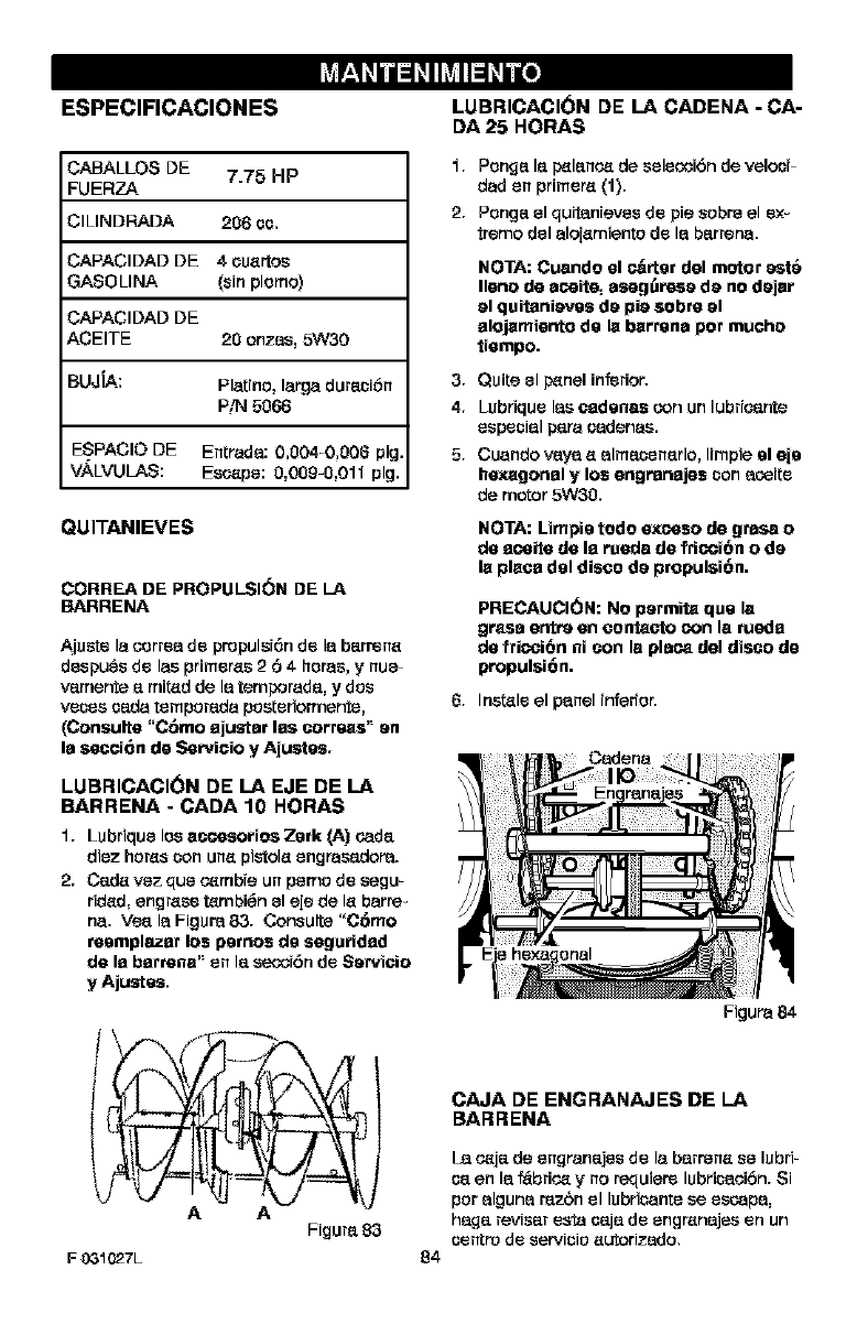
I_r_al_lnuld_ll_lld _lnu[o]
ESPECIFICACIONES
CABALLOS DE 7.75 HP
FUERZA
;ILINDRADA 206 co.
CAPACIDAD DE 4 ouartos
GASO LINA (sin plerno)
CAPACIDAD DE
ACEITE 20 onzes, 5W30
BUJiA: Platine, large duraci6n
P/N 5066
ESPACIO DE Entrada: 0,0040,006 pig.
V._./VULAS: Escape: O,0Og-O,011 pig.
QUITANIEVES
CORREA DE PROPULSI(_N DE LA
BARRENA
Ajuste la eerrea do propulsi6n do la barrena
despues do lee primeras 2 6 4 hares, ynue-
vamente amired de la temporada, y dos
races cada temperada peeterionnenfe,
(Conealte "C6mo ajaster las aortaes" an
le section de Servicio y Ajuetes.
LUBRICACION DE LA EJE DE LA
BARRENA -CADA 10 HORAS
1. Lubrique lee eeeesorioe Zerk (A) oada
diez hares con una pistola engrasadore.
2. Cede vez qua e_mbie un perne de segu-
tided, engrase tambi_n el ale de la barre-
ha. Vea la Figure 83. Consulte "C6mo
memplazar los pernos de seguridad
de la barmne" on la seooi6n do Sarvicio
y Ajustes.
AA
Figure 83
F 031027L
LUBRICACION DE LA CADENA -CA-
DA 25 HORAS
1. Ponga la p_lanee de seleooi6n de velocF
dad on primera (1).
2. Penga el quitanieves do pie sabre el ex-
treme del aloiamiente do la barrena.
NOTA: Cuendo el _rter dal motor est6
llano do e_eite, esag_resa da no dajer
al quitaniaves da pie sabre al
alojamianto de la barrene per touche
tiempo.
3. Quite el p_nel inferior.
4. Lubrique lee cadence con un lubrieante
especial pare cadenae.
5. Cuando vaya a alrnacenarlo, limpie el aje
hexagonal y los engrenajes con a_ite
de motor 5W30.
NOTA: Limpie todo excwasode gresa o
de aeeite de la reade de fricwai6no da
la place del disco da propulei6n.
PRECAUCI6N: No parmita qua le
greae antr_ en eootaeto eon le rueda
de fric_i6n ni con le ple_ dal disco de
propulsi6n.
6. Inertia el panel inferrer.
Cadena
Figure 84
84
CAJA DE ENGRANAJES DE LA
BARRENA
La e_ja de engranajes do la barrena so lubri-
ca en la _brie_ yno raquiere lubricaeibn. $i
per alguna rezbn el lubricante se escape,
haga reviser esta caja do engranajee on un
centro do servicio autorizado.
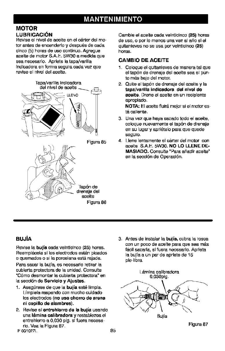
I_r_al_lnuld_ll_lld _lnu[o]
MOTOR
LUBRICACI(_N
Revise el nivel de aoeite en el o_rter del mo_
tor antes de encenderlo ydespues de cada
oinco _5} hor_s de uco oontinuo. Agre_ue
aseite de motor S.A.E. 5W30 a medida qua
sea necos_rio. Apriete la tap_arilla
indisadora en forma segure cada vez que
revise el nivel del acoite.
Tap_arilla indioadore
del nivel de aoerte
LLE_O
Figure 85
_=del
aseite
Figure 86
Cambie el aseite oada veintioinco (25) horas
de uso, opor Is manse una vez al afio s1el
quitanieves no se usa por veinticicoo (25)
horns.
CAMBIO DE ACEITE
1. Coloque el quitanievee de manere tel qua
el tapSn de drenaje del acoite sea el pun
to m&_ bajo del motor.
2. Quite el tap6n de drenaje del acoite y la
tapa_arilla indioadore dal nival de
aceite, Drone el aseite en un resipiente
apropiado,
NOTA: El aceite fluir_ meior si el motor es-
ta o_liente.
3. Una vez qua haya sasado todo el acoite,
soloque nuevamente el tap6n de drenaje
en su lugar yapri_telo pare qua quede
se£iuro.
4. Llano lentamente el s&rter del motor con
acoite S.A.E. 5W30. NO LO LLENE DE-
MASIADO. Consulte =Pare afiadir aseite"
en la secoi6n de Operaoi6n.
BUJiA
Revise la buj|a oada veintioinco _25) home.
Reempl&oela si log eleotrodos est_n pio_doe
o quemadco osi la porcolana esta rejada.
Pare easar la bujfa, es neoesarfo retirar la
oubierta protectore de la unidad. Coneulte
=C6mo desmontar la oubielta proteotora" en
la secoi6n de Servieie y Ajuates.
1. Asegl)rese de qua la buila est_ limpia.
Limpiela responds son mcoho coidado
los ele_trodco (no age cherts de arena
ni eapillo de alambres).
2. Revise el antrehiarro de la bujla usando
una I_mine ¢alibradora y reetablezoa el
entrehierro a 0,030 pig. si lucre necosa-
rio. Ve_ la Figure 87,
F03_027L
3. Antes de instalar la buji'e, oubra la fosse
son un poco de aoeita pare qua se_ m_s
f&oil s_sarla, si fuera neoesario. Aprieta
la bujfa aun par de apriete de 15
pie4ibre.
L_mina oalJbredore
0,030pig.
05
Bujia
Figure 87
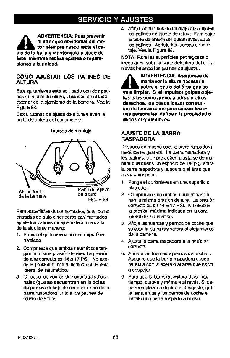
,_k ADVERTENCIA: Para p_venir
el arranque accidental del mo=
btot, siemp_ desconeete el ca-
ble de la bujfa y mant_ngalo alejado de
6_a mientras tealiza ajusles o rvapara-
ciones a la unidad.
COMO AJUSTAR LOS PATINES DE
ALTURA
Este qurtanieves est6 equipado con dos patF
nes de ajuste de altura, ubicados en el lado
exterior del alojamiento de la b_rrena. Ve_ la
Figura 88.
Estos p_tines de _iuste de altura elevan la
parte del_ntera del quit_nieves.
Tuerc_s de montaje
0
P_ra superficies duffs norm_les, tales oomo
entred_s de auto o senderos pavimentados
ajuste los p_tines de _iuste de altura de I_
de la siguiente manera:
1. Pong_ el quitanieves en una supe_cie
nivel_da.
2. Compruebe que ambos neum&Iicos ten=
gan I_ misma presi6n de aire. La presi6n
de aire _orreota es 14 a 17 PSI. No exe_
da I_ presJ6n mfixim_ indi_da en I_ _ar_
lateral del neumfitico.
3. Coloque los pernos de seguridad _dioio-
hales (ClUese encuentran en la bolsa
de partes) debejo de cade_extremo de le
barra mspadora junto _los patines de
ajuste de alture.
4. Afloje las tueroes de monteje que su[etan
los pe_tinesde e_justede _ltur_. Per_ baj_r
la perte delantere del quitenieves, sub_i
los petines. Apriete Ies tueroas de morn
taje. Vee la Figure 88.
NOTA: P_ra I_s superficies pedregos_s o
irregulares, suba le parte delantera del quite=
nieves bajando los p_tines de aiuste..
_DVERTENCIA: Asegl3ra_rve de
mantener la altura n_esaria
sobre el suelo del &tea que se
va a limpiar. Si el impulsor golpea obje-
tos tales como grava, piedras u ot_os
deseehos, los puede lanzar con $gfi-
ciente fuerza _omo para causar I_io-
nes personales, dafios a la propiedad o
da_os al quitanieves.
AJUSTE DE LA BARRA
RASPADORA
Despues de mu_ho uso, le barra raspedora
met_li_a se gaster&. Le barra raspedora y
los p_tines, siempre deben aju_rse de m_
nere que quede un espaoio de 1/8 pig. entre
le berre raspadora y le aoera o el _re_ que
se v_ _ despei_r.
1. Ponge el quitanieves en une supe_ie
nivelede.
2. Compruebe que _mbos neum_ticos tie
nen la misma presi6nde eke. Le presi6n
corr_ es de 14 a17 PSI. No exoeda
la presi6n m_b_ma indicada en la care
I_eral del neumfitioo.
3. Afloje I_s tueroas ypernos de _oche que
sujetan la barra resp_dore al _lojamiento
de I_ barrena.
4. A[uste le barra raspedora e_la posici6n
oorl%.ot_.
5. Apriete las tueroes y pernos de ooche..
Asegure que le barra respedora quede
paralele oon le acera o el firea que se va
ds_pei_r.
6. Pere que le b_rre respadore dure m_
tiempo, qui_ele y m6n_ele al rev_s. 8i de=
be reemplazerla debido al desgeste, qui
te les tueroas ylos pernos de coohe e
instele une berre raspadora nueve.
F03_027L 86
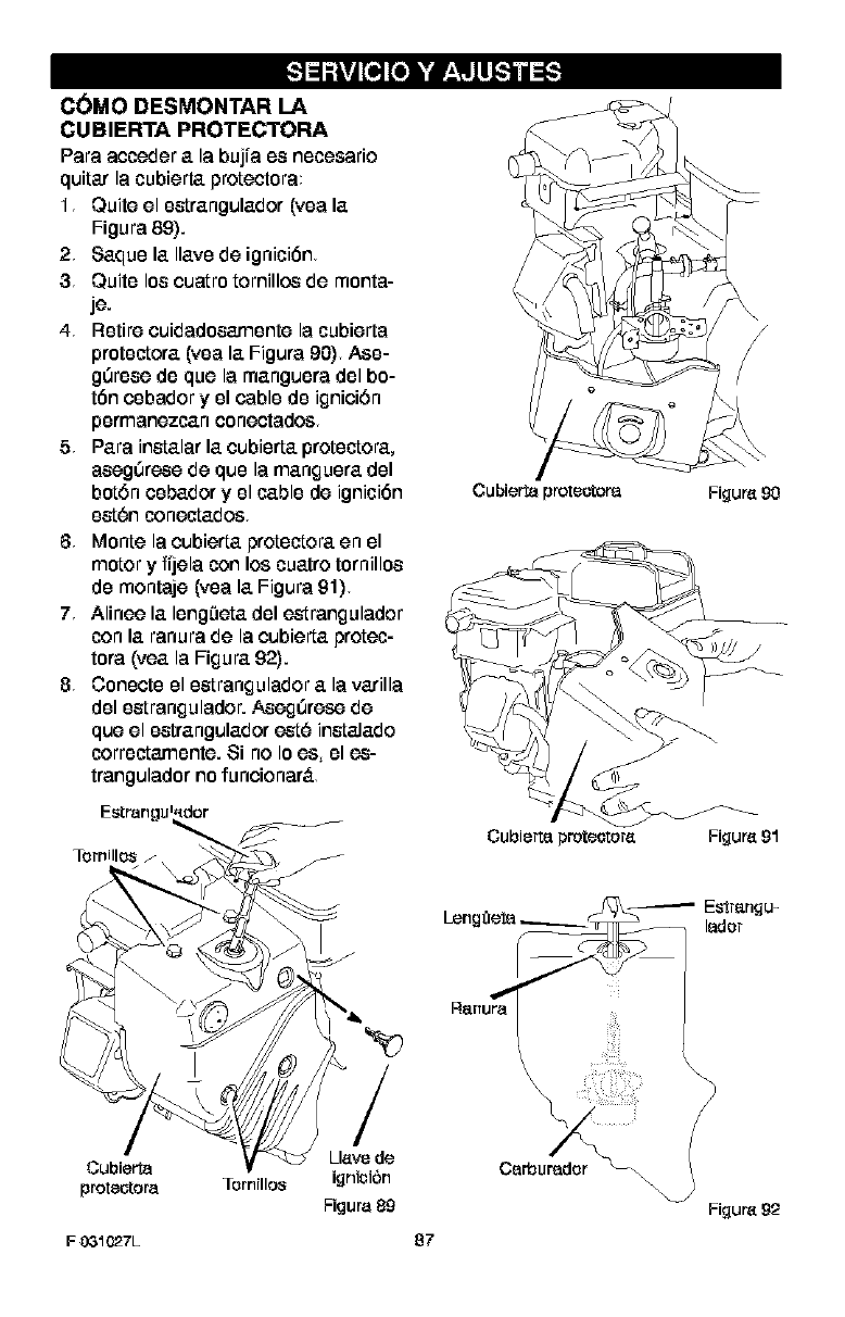
C(_MO DESMONTAR LA
CUBIERTA PROTECTORA
Para acceder a la bujra es necesario
quitar la cubierta protectora
1 Quite el estrangulador (yea la
Figura 89).
2Saque la Ilavede ignici6n
3Quite los cuatro tomillos de monta-
je.
4 Retire cuidadosamente la cubierta
protectora (yea la Figura 90) Ase-
g0rese de que la manguera del bo-
t6n cebador y el cable de ignici6n
permanezcan conectados
5Para instalar la cubierta protectora,
aseg0rese de que la manguera del
bot6n cebador y el cable de ignici6n
est6n conectados
6 Monte lacubiertaprotectora en el
motor yfi]ela con loscuatro tornillos
de montaje (yea la Figura 91)
7 Alinee la leng0eta del e-strangulador
con la ranurade lacubierta protec-
tora (yea la Figura 92).
8 Conecte el estrangulador a lavarilla
del estrangulador. Aseg0rese de
que el estrangulador est6 instalado
correctamente. 8i no Ioes el es-
trangulador nofuncionar_.
\/
/
Cubierta proteotora Figure 90
Cubierte proteotore Figure 91
Estrengu-
ledor
Cubierta
protectora ]ornnlos
F 031027L
/
Lleve de
ignicibn
Figura 89
87
\?
Carburador _\\\\ (
Figure 92
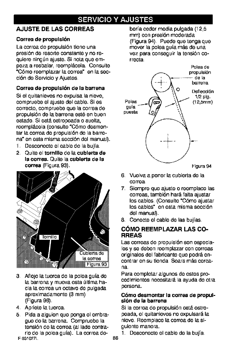
AJUSTE DE LAS CORREAS
Correa de propulsl6n
La correa,do propulsi6n tiono una
presiSn de reeorto constante y no re-
quioro ning_n ajuate. Si hate.que om-
peza.a resba.lar,reempl,.'_cola.Consulte
=CSmoroemplazar la.corroa" on la.sec-
cibn de Servicio y Ajuates
Correa de propulsl6n de la barrena
Si el quitanievos no oxpulsa, la nievo,
compruebe el ajuate del cable. Si es
correcto, compruebe que la correa de
propulsi6n de la.barrena eat6 en buen
eata.do Si eat& eatropoa.da o euelta.,
roompl_.cela (consulto =C6mo deemon-
tar la. eorroa, de propuleibn do la barre-
na" en eata misma, secci6n del manual).
1 Deeconecte el cable do la bujfa
2 Quite el tomlllo do la. eublerta de
la correa. Quite la cublerta de la
correa (Figure. 93).
3 Aflojola.tuorca do la polea guia,de
la.barrona,y mueva,oata E_ltima.ha-
cia la.correa un octavo de pulgada.
aproxima.da.mente(3 ram)
(Figura 96)
4Apriotela.tuerea.
5 Pida a a.lguienquo ponga el embra.-
guo do la.barrena..Compruebo la
tensi6n de la.correa.(a.Ilado contra.-
rio do la polea guia). La correa,cle-
F031C27L 88
berfa codermedia,pulgada (12,5
ram) conpresibn modora.da.
(Figura 94) Puode quo tonga quo
mover la polea guia.m,_sde una.
voz para conseguirla tensiSn co-
rrecta
Polea de
propulsibn
// "x_ -- de la
_ --,/_._ barrena
_/;,_O Deflec_i6n
.- \_ 1_'2plg.
Figure 94
6 Vuolva.a.porterla.cubierta do la
correa
"7 Siempre que a.juateoreemplace las
correae,tambi6n har,_falta ajuata.r
los cables (Coneulte=C6moajuata.r
losca.bles" on eata.miemaeocci6n
del manual).
8 Oonecte el cable de lee bujfas
COMO REEMPLAZAR LAS CO-
RREAS
I_ascorroasdo propulei6nsonespecia-
leey se debon roomplazarcon corroas
originalos del fabrieanto quo podr,_en-
contrar en su tionda Soars m,_ecerca.-
ha,
Para complota.ra.lgunosde oatoe pro-
eedimiontoe nocosita.rAla ayuda do atra.
persona..
Cbmo dosmontar la ¢orrea do propul-
slbn de la barrena
Si la corroa,do propulsi6neatS.oatro-
peada, el quitanievos nooxpulsar_ la.
niove Reomplace la.corroa,de la.ei-
guionte me.nora..
1 Deeeonocte el cabledo la bujfa
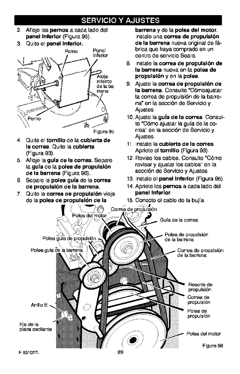
2 Afloje los pernos a cada lade del
panel Inferior (Figora 95)
3Quite el panel Inferior.
Perno P_nel
inferior
Perno
Figure 95
4Quite el tornlllo de la cublerta de
la cortes Quite la cublerla
(Figura 93)
5Afloje la gul'a de la cortes. 8epare
la gul'a de la poles de propulsl6n
de la barrena (Figura 96).
6 8epare la poles gul'a de la correa
de propulsl6n de la barrena.
7 Quite la correa de propulsl6n vieja
de la polea de propulsl6n de la
Pole_ del motor
barrens y de la polea del motor.
Ins[ale una correa de propulal6n
de la barrena nueva original de f_-
brits que hays comprado en un
centre de servicio 8ears.
8Inslale la correa de propulal6n de
la barrena nueva en la polea de
propulsl6n y en la poles
9Ajuste la correa de propulsl6n de
la barrena. Coneulte "C6moajustar
la correa de propulei6n de la barre-
ns" en la seeci6n de 8ervieio y
Ajusles
10 Ajusle la guia de la correa Consul-
te "C6mo ajuslar la guia de la co-
tree" en la eeeci6n de 8ervieio y
Ajusles
11 Inslale la cublerta de la cortes
Apriete el tornlllo (Figure 93)
12 Revise lee cables. Consulte "C6mo
reviser y ajuslar lee cables" en la
eeeci6n de 8ervieio y Ajusles
13 Inslale el panel Inferior (Figure 95)
14 Apriete los pernos a cads lade del
panel Inferior
15 Conecte el cable de la bujfa
Gufe de lecorre_
propulsi6n
de la berrene
propulsi6n
de la berrene
Anillo
ReserVe de
propulsi6n
Corre_ de
propulsi6n
Pole_ de
propulsi6n
Pole_ del motor
FJgura 96
F 03_027L 89
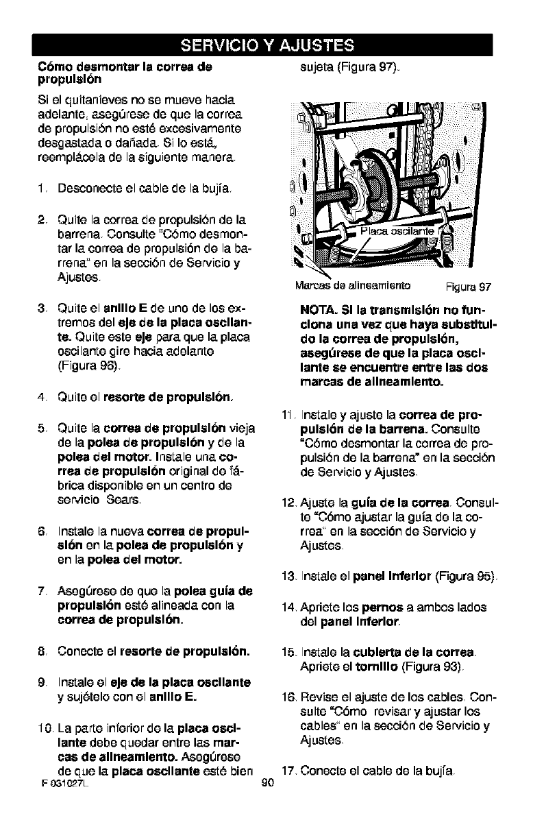
C6mo desmontar la correa de
propulsl6n
8i el quitanieves no se mueve hacia
adelante asegOrese de que la correa
de propulsi6n no est6 excesivamente
desga_ada o dafiada 8i Io est.,
reempl_.cela de la siguiente manera
1 Desconecte el cable de la bujia
2 Quite la correa de propulsi6n de la
barrena Consulte "C6mo desmon-
tar la correa de propulsibn de la ba-
rrena" en la secci6n de 8ervicio y
Ajustes
3 Quiteel anlllo E de uno de los ex-
tremes del eJede la place oscllan-
is. Quiteeste eJepare que la place
oscilante £ire hacia adelante
(Figure 96)
4 Quite el resorts de propulslbn,
5 Quite la correa de propulsl6n vieja
de la polea de propulsl6n y de la
polea del motor. Instals una eo-
rrea de propulsl6n original de f_-
brica disponible en un centre de
servicio 8ears
6 Instals la nueva correa de propul-
slbn en la polea de propulslbn y
en la polea del motor.
7Aseg0rese de que la poise gula de
propulsl6n est6 alineada con la
correa de propulslbn.
sujeta (Figure 97).
M_roas de alineemfento Figure 97
NOTA. SI la transmlsl6n no fun-
clona una vez que haya substltul-
do la correa de propulsl6n,
asegdrese de que laplaca oscl-
lante se encuentre entre las dos
marcas de allneamlento.
11, Instals y ajuste la correa de pro-
pulsl6n de la barrena. Consults
=C6mo desmontar la correa de pro-
pulsi6n de la barrena" en la secci6n
de 8ervicio y Ajustes
12. Ajuste la guia de la correa Consul-
te =C6mo ajustar la guia de la co-
rrea" en la secci6n de 8ervicio y
Ajustes
13 InstaJe el panel Inferior (Figura 95)
14 Apriete los pernos a ambos lades
del panel Inferior
8 Conecte el resorte de propulsl6n.
9 Instals el eJe de la place oscllante
y suj6telo con el anlllo E.
10 La parts inferior de laplaca oscl-
lante debe quedar entre las mar-
cas de allneamlento. Aseg0rese
de que la placa oscllante est6 bisn
F 031027L
15 Instals la cublerta de la correa
Aprieteel tornlllo (Figura 93)
16 Revise el ajuste de los cables Con-
suite =C6mo reviser y ajustar los
cables" en la secci6n de 8ervicio y
Ajustes
17, Conecte el cablede la bujra
9o
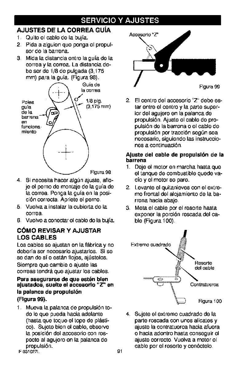
AJUSTES DE LA CORREA GUJA
1 Quite el cable de la bujia.
2 Pida a alguien que ponga el propul-
sot de la barren&
3Mida la distancia entre laguia de la
correa y la correa. La distancia de-
be esr de 1/8 de pulgada (3,175
ram) para la guia. (Figura 98).
Guiade
lacorrea
Pole_ 1/8 pig.
gufa (3,175 ram)
de la
FJgura98
4 8i necesita hater alg0n ajuste aflo-
je el perno de montaje de la gura de
la correa Ponga la gura en la pesi-
ci6n correcta Apriete el pemo
5Vuelva a instalar la cubierta de la
correa
6 Vuelve aconsctar el cable de la buji&
Figura 99
2El esntro del acessorio"Z" debe es-
tar entre el esntro y la parte super-
ior del agujero an la palanca de
propulsi6n Ajuste el cable de pro-
pulsi6nde la barrena oel cablede
propulsi6n por traccibn esg0n sea
neessario,siguiendo las instruccio-
nes a continuaci6n
AJustedel cable de propulslbn de la
barrena
1Dsje el motor en marcha basra que
el tanquede combustiblequede va-
tie y el motorse pare.
2 Levanteel quitanieves conel extre-
ms frontal del alojamientode la ba-
rrena hacia abajo
3 Meta el cableper el resorte hasta
exponer la porcibn rescada del ca-
ble (Figura 100)
C(_MO REVISAR Y AJUSTAR
LOS CABLES
Los cableses ajustanen la f_brica yno Extremo_uadrado
deberia ser neessario ajustarles. 8i es
se dan de si"oesteemflojes, aj0steles.
8iempre que cambieo ajustelas
correastendr_,queajustar loscables.
Para asegurarse de que est_n blen
aJustados,suelte el aeeesorlo "Z" en
la palanea de propulsl6n
(Figure 99).
1Muevala palancade propulsi6nto-
do Ioque pueda hacia adelante
(hasta quetoqueel tope de pl,_sti-
co). 8ujete bien el cable, observe
la pesici6n del accesorio con res-
pects al agujero en la palanca de
propulsi6n.
F031C27L _I
Resorte
del ¢._b le
Figura 100
4 8ujete el extreme cuadrado de la
parte rescada con unes alicates y
ajuste la contratuerca hacia afuera
o hacia adentro hasta conesguir el
ajuste correcto Vuelva a meter el
cable per el reesrte y con6ctelo
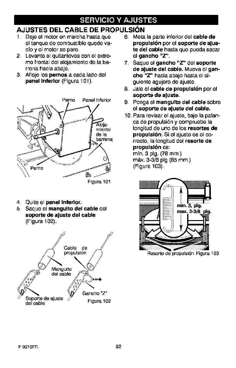
AJUSTES DEL CABLE DE PROPULSION
1 Deje el motoren marcha hasta que 6 Meta la parte inferiordel cable de
el tanque de combustible quede va-
tie y el motor ee pare
2Levante el quitanievee con el extre-
me frontal del alojamiento de la ba-
rrena hacia abajo.
3 Afloje los pemos acada lade del
panel Inferior (Figura 101)
Perno Panel inferior
mrente
de la
barr_na
Figure 101
4Quite el panel Inferior.
58aque el mangulto del cable del
aoporte de aJuste del cable
(Figura 102).
propulal6n per el soporte de aJua-
te del cable hasta que pueda eacar
el gancho "Z".
78aque el gancho "Z" del aoporte
de aJuate del cable. Mueva el gan-
cho "Z" hacia abajo hasta el si-
guiente agujero de ajuste
8 Jale el cable de propulal6n per el
aoporte de aJuste.
9 Ponga el mangulto del cable sobre
el soporte de aJuate del cable.
10 Para reviear el ajuste, baje la palan-
ca de propulsi6n y compruebe la
Iongitud de uno de los resortes de
propulal6n, 8i el ajuste ee el co-
rreeto, la Iongitud del resorte de
propulal6n ee:
mfn. 3 pig. (76 ram)
m&_. 3-3!8 pig (85 ram)
(Figura 108)
/ /
-4 Cable de .-A'
f ) pmpulsl6n /]
/"-_ 4/ /
20u,,°\¢:./
_' _ ,,,_3,,,,,_,
oo.o,o,,.-
// Soporte de a[uste // .....
del cable Hgur_ ]uz
Resorte de propulsi6n Figura 103
FO31027L £2
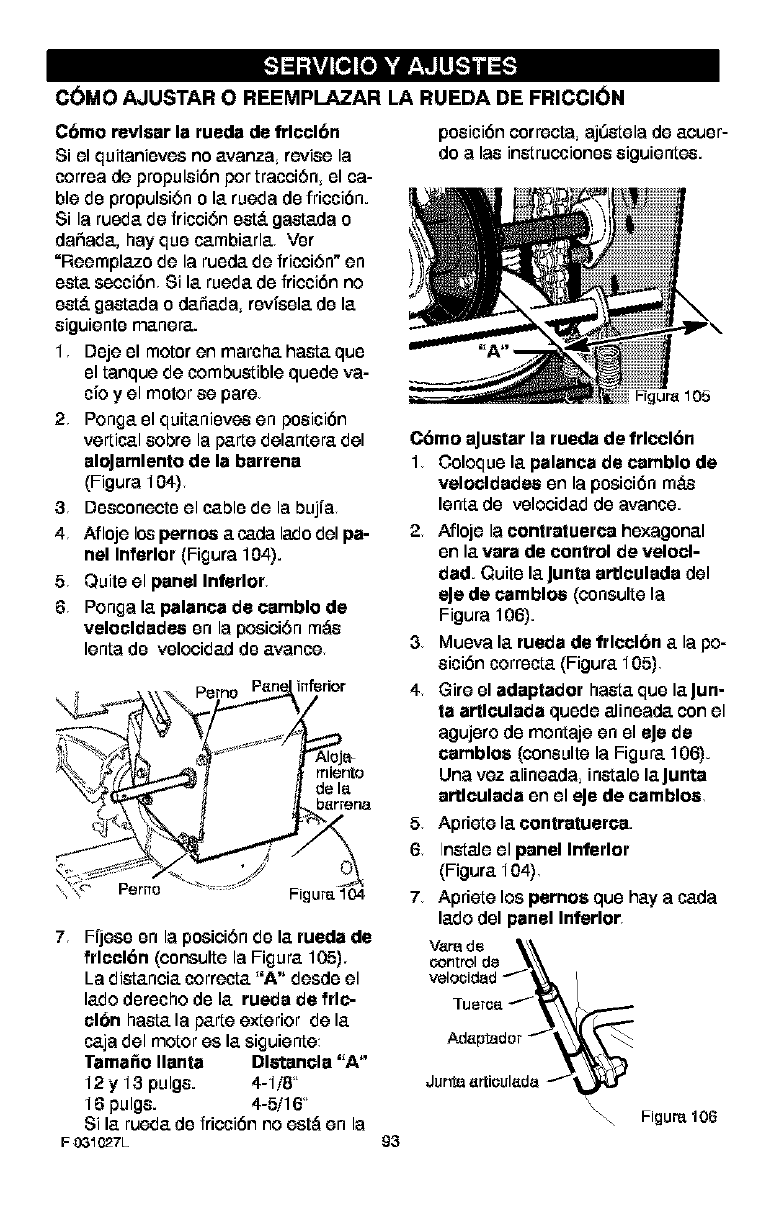
C(_MO AJUSTAR O REEMPLAZAR LA RUEDA DE FRICCION
Cbmo revlsar la rueda de frlcclbn
8i el quitanioves no avanza revise la
correa de propulsion pot tracciSn, el ca-
ble do propulsion o la rueda do friction.
8i la rueda de fricciSn est,. gastada o
dafiada, hay que cambiarla Vor
=Reemplazo de la ruoda de fricciOn" en
osta section 8i la rueda do friction no
est,. gastada o dafiada, revisela do la
siguiento manera.
1 Doje el motor en marcha hasta quo
el tanque de combustible quede va-
cio y el motor se pare
2 Ponga el quitaniovos en position
vertical sobre la parte delantera del
aloJamlento de la barrena
(Figura 104)
3Dosconecte el cable de la bujra
4 Afloje los pernos a ca£1alado del pa-
nel Inferior (Figura 104).
5Quite el panel Inferior
6Ponga la palanca de camblo de
velocldades on la position m,_s
lenta de velocidad de avance
inferior
miento
de I_
b_rrena
Perno Figure 104
7Fijeso on la posiciOn do la rueda de
frlcclOn (consulte la Figura 105),
La distancia correcta "A" desdo el
lado dorocho do la rueda de frlc-
elbn hasta la parte exterior de la
caja del motor es la siguiente
Tamale Ilanta Dlstancla "A"
12 y 13 pulgs. 4-1/8"
16 pu Igs. 4-5/16"
8i la rueda do friction no est,_ en la
F 031027L
position correcta,aj0stela de acuer-
do alas instruccionos siguientos.
93
Figure 105
C6mo aJustarla rueda de frlccl6n
1 Coloque la palanca de camblo de
velocldades on la position m&s
lentado volocidad do avarice.
2 Afloje lacontratuerca hexagonal
on la vara de control de velocl-
dad. Quite la Junta artlculada del
eJe de camblos (consulte la
Figura 106).
3Muova la rueda de frlcclbn a la po-
sicibn correcta (Figura 105)
4 Gire el adaptador hasta que la Jun-
ta artlculada quede alineada con el
agujero de montaje en el eJe de
camblos (consulte la Figura 106).
Una vez alineada instale laJunta
artlculada en el eJede camblos
5Aprietelacontratuerca.
6 Instale el panel Inferior
(Figura 104)
7 Apriete los pernos que hay a carla
lade del panel Inferior
verade\\\
control de _k\\
velocidad _"-_, /
Junta _rtieul_d_
_"-'_" ""_ Figure 106
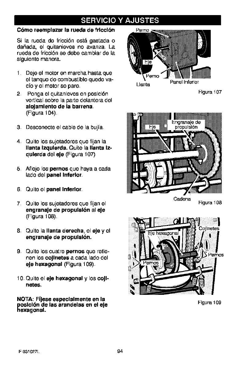
Cbmo reemplazar la rueda de frlcclbn
8i la ruoda de fricci6n est,_ gastada o
dafiada, el quitanievos no avanza La
rueda de fricei6n ee dobe cambiar de la
eiguiento manera.
1 Doje el motoren marcha hasta quo
el tanque de combustiblequede va-
tie y el motor se pare
2 Ponga el quitaniovoe en poeici6n
vertical sobre la parte delantera del
aloJamlentode la barrena
(Figura 104)
3Dosconeeto el cable de la bujra
4 Quite los sujetadores que fijan la
Ilanta Izqulerda. Quite la Ilanta Iz-
qulerda dol eJe (Figura 107)
5 Afloje lospernos que haya a carla
ladedol panel Inferior
6Quite el panel Inferior
7Quite los sujetadoreeque fijan el
engranaJede propulal6n al eJe
(Figura 108)
8Quite la Ilanta derecha, el eJeyel
engranaJede propulal6n.
9Quite los custro pernos que retie-
non los coJlnetes acada lade del
eJe hexagonal (Figura 109)
10 Quite el eJehexagonal y loscoJl-
nefes,
NOTA: Fl'Jese especlalmente en la
poslcl6n de las arandelaa en el eJe
hexagonal.
U_nt_ Panel inferior
Figura 107
Csdena Figura 108
Figura 109
FO31027L 94
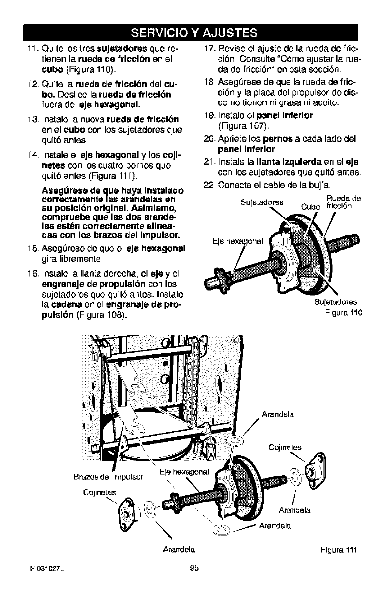
11 Quite los tros auJetadores que re-
tienen la rueda de frlcclbn en el
cube (Figura 110).
12 Quite la rueda de frlccl6n del cu-
be. Doslios la rueda de frlccl6n
fuera del eJe hexagonal.
13 Ins[ale la nueva rueda de frlccl6n
en el cube con los sujetadoros que
quit6 antes
14 Ins[ale el eJe hexagonal y los coJl-
netes con los cuatro pernos que
quit6 antes (Figura 111)
Asegdrose de que haya Iostalado
correctamente las arandelaa en
au poslcl6n original. Aslmlamo,
compruebe que las dos arande-
los est6n correc_amente allnea-
daa con los brazes del Impulsor.
15 Aseg0rose de que el eJe hexagonal
gira libremente
16 Ins[ale la Ilanta derecha, el eJey el
engranaJe de propulal6n con los
eujetadores que quit5 antes. Ins[ale
la cadena en el engranaJe de pro-
pulsl6n (Figura 108).
17 Revise el ajus[e de la rueda de fric-
cibn Consulte =C6mo ajus[ar la rue-
da de friecibn" en es[a eecei6n.
18 Aseg0rose de que la rueda de fric-
cibn yla placa del propuleor de dis-
co no tienen ni £rasa ni aosite.
19 Ins[ale el panel Inferior
(Figura 107)
20 Apriete los pernos acada lade del
panel Inferior
21 Ins[ale la Ilanta Izqulerda en el eJe
con los eujetadoros que quit6 antes
22 Conecte el cable de la bujra
Rued_ de
$u[etaderes Cube fricci6n
Suietadores
Figura 110
\\
\
Arandela
/
Arandela
Figur_ 111
F031027L 95
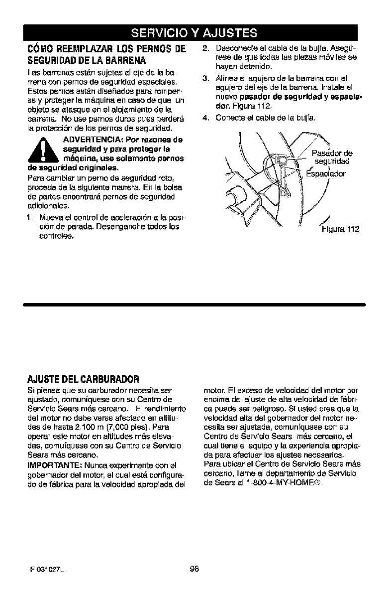
C(}MO REEMPLAZARLOS PER_IOSDE
SEGURIDADDE LA BARRE_IA
Les barrenes est_n sujetes al oje do la ba_
rrena con pornes de seguridad espeoiales.
Eotes percos est&n drsehados para romper
so y proteger la m_quina an ceso de qua un
objato so atesquo an el aloiamiento do la
barren8_, No usa pornos duros puos perdera
la protecoi6n de los pornes de seguridad.
_IL DVERTENCIA: Por rezonse da
seguridad y para protogar la
mfiquina, use solamante parnos
de seguridad odginalas,
Pare o_mbrar un perno do segurfdad roto,
proooda do la srguiente manere. En la bolsa
do partes enesotrer& pernoo do seguridad
adioionales.
1, Mueva el control do acoloresi6n a la posF
ci6n do parada. Desenganohe tadoo las
controles.
2. Desconeote el o_ble do la bujia. Asogg-
rose de quo todes los piez_s m6viles se
hayan dotenido.
3. Alinoe el agu[oro de la barrena con el
agujoro del eio de la barrena. Instale el
nuovo pesador de seguridad y espaoia-
dot. Figure 112.
4. Conecto el oable de la bujia.
_a%_s_dorde
_-- -- seguridad
E%esi dar
_Figure 112
AJUSTEDELCARBURADOR
Si pionsa qua su o_rburador neoesita ser
ajustado, comuniquese esn ou Centro de
Servicio Sears mils coro_no. El rendimiento
del motor no debe verso afeotado en altitu-
des do ha_ 2.100 m _7,000 pies). Pare
operer oste motor en altitudes mils olova-
des, esmufquese con ou Centro de Servioio
Sears mils oorsano.
IMPORTANTE: Nunca e×perimento con el
gobernador del motor, el oual est_ configure-
do do ffibrica para la velaoidad apropiada del
motor. El oxcoes do velaoidad del motor por
onoima del ajuote de alta velesidad de ffibrF
oa puede ser peligrosa. Si usted tree qua la
volooidad alta del gobernador del motor ne_
oeslta sor ajustada, oomuniquese con su
Contro do Servfoio Soars m_ corsano, el
oual tiene el oquipo yla oxperienoia apropia
da para efeotuar los ajustes neoesarfes.
Pare ubicor el Centro de Sorvioio Soars mils
ooro_no, llama al departameoto de Servicio
de Sears al 1-800-4-MY-HOME,%.
F03_027L 96
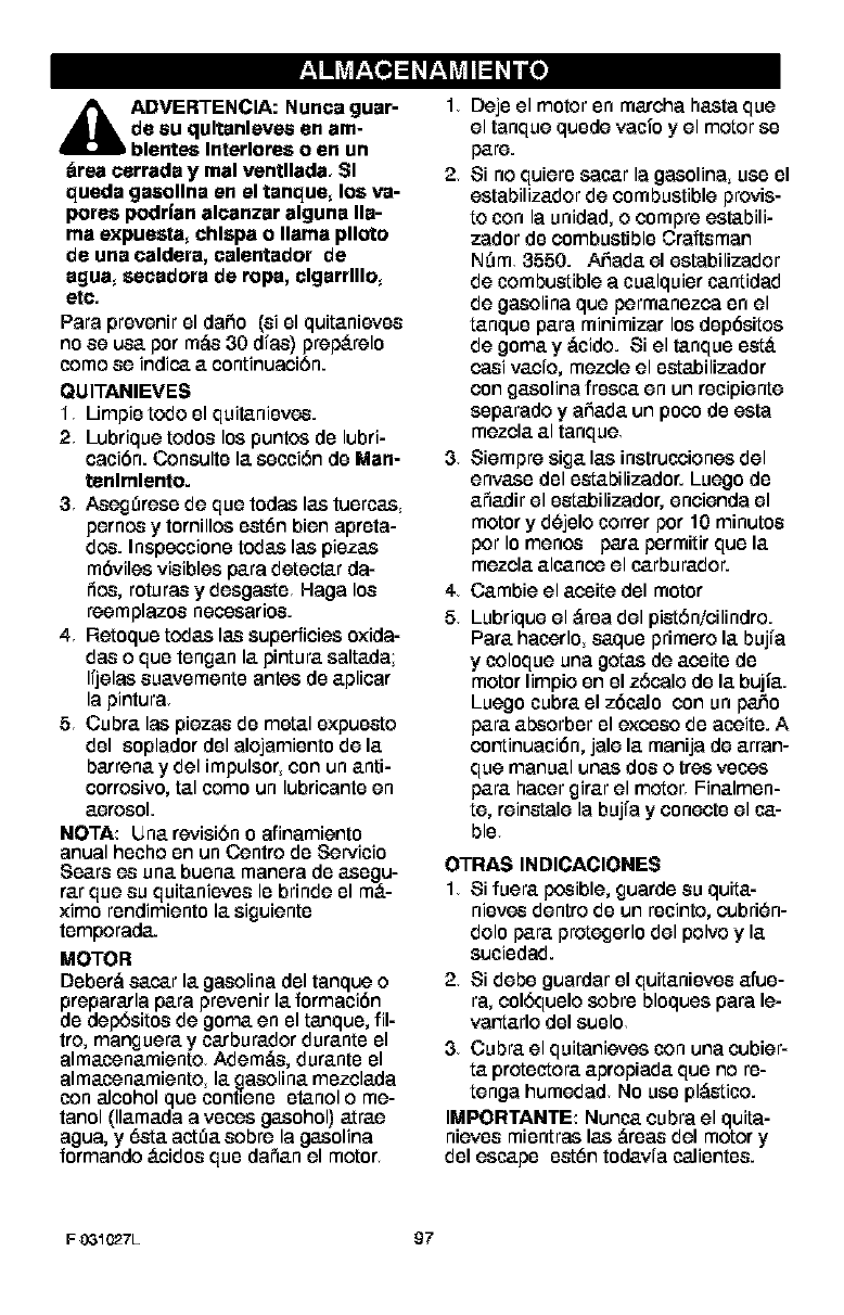
F_,_Inil_ r_,Te,]d _r_,q_IId _Inu_o]
_DVERTENCIA: Nunca guar-
de su qultanleves en am-
blentes Interlores o en un
_rea cerrada y rnal ventllada, SI
queda gasollna en el tanque, los va-
pores podrl'an alcanzar alguna lla-
ma expuesta, chlspa o llama plloto
de una caldera, calentador de
agua, secadora de ropa, clgarrlllo,
ere,
Para provenir el dafio (si el quitaniovos
no se usa por m,_s 30 dras) prep_.relo
come se indica a continuaciOn.
QUITANIEVES
1Limpio todo el quitaniovos.
2Lubrique todos los puntos do lubri-
caci6n. Consulto la section do Man-
tenlmlento.
3Aseg_roso de que todas las tuorcas
pernos y tomillos oetOn bien aprota-
dos. Inspocciono todas las piozas
m6vilos visiblos para detectar da-
rio,s, roturas y dosgaeto Haga los
reemplazos neossarios.
4 Retoquo todas las superficies oxida-
das o quo tongan la pintura saltada;
Irjelas suavomento antes do aplicar
la pintura
5 Cubra las piezas do metal oxpuoeto
dol soplador dol alojamionto de la
barrena y del impulsor, con un anti-
corrosivo, tal como un lubricanto en
aerosol.
NOTA: IJnarevisiOn o afinamiento
anual hocho on un Centre do Servicio
Sears os una buena manera de asegu-
rat que su quitaniovos Io brinde ol m_-
ximo rondimiento la siguiento
tomporada.
MOTOR
Dobor,_ sacar la gasolina dol tanque o
prepararla para provonir la formaci6n
do depOsitos de goma en el tanquo, ill-
ire, manguera y carburador duranto ol
almaosnamiento Adem,_s, duranto ol
almaosnamiento, la gasolina mozclada
con alcohol quo contieno otanol o me-
tanol (llamada a vooss gasohol) atrae
agua, y 6eta aetna sobre la gasolina
formando _.cidos quo dafian el motor
I, Dejo el motor on marcha hasta que
el tanque quode vacio y el motor so
pare.
2 Si no quiero sacar la gasolina, use el
eetabilizador de combustible provis-
to con la unidad, o compre ostabili-
zador do combustible Craftsman
N_m 3660. Afiada el eetabilizador
de combustible a cualquior cantidad
de gasolina que permanozca on el
tanquo para minimizar los dop6sitos
de gomay ,_cido. Si el tanquo oet_.
casi vacro, mezcle el oetabilizador
con gasolina frosca en un rocipiente
soparado y afiada un poco do eeta
mezcla al tanque
3Siempre siga las inetruccionos del
envaso dol oetabilizador. Luego do
afiadir el oetabilizador, encienda el
motor y d_jolo terror por 10 minutos
per Io menos para pormitir quo la
mezcla alcanos el carburador.
4 Cambie el aosite dol motor
5 Lubrique el ,_roa del pietOnicilindro.
Para haosrlo, saquo primoro la bujra
ycoloque una gotas de aosito do
motor limpio on el zOcalo do la bujia.
Luego cubra el z6calo con un patio
para absorber el excoso do aosito. A
continuaci6n, jale la manija de arran-
que manual unas dos o tros vooss
para haosr girar el motor Finalmon-
to, reinetale la bujra y conecto el ca-
ble
OTRAS INDICACIONES
I, Si fuera posible, guardo su quita-
niovos dentro do un rocinto, cubriOn-
dolo para protegorlo del polvo yla
suciedad.
2Si debe guardar el quitanievos afue-
ra, col6quelo sobre bloquos para le-
vantarlo dol suolo
3Cubra el quitanievos con una cubier-
ta protoctora apropiada quo no re-
tonga humedad No use pl,_etico.
IMPOR'rANTE: Nunca cubra el quita-
nievos miontras las ,_roas del motor y
dol escape oetOn todavra caliontos.
FO3_027L 97
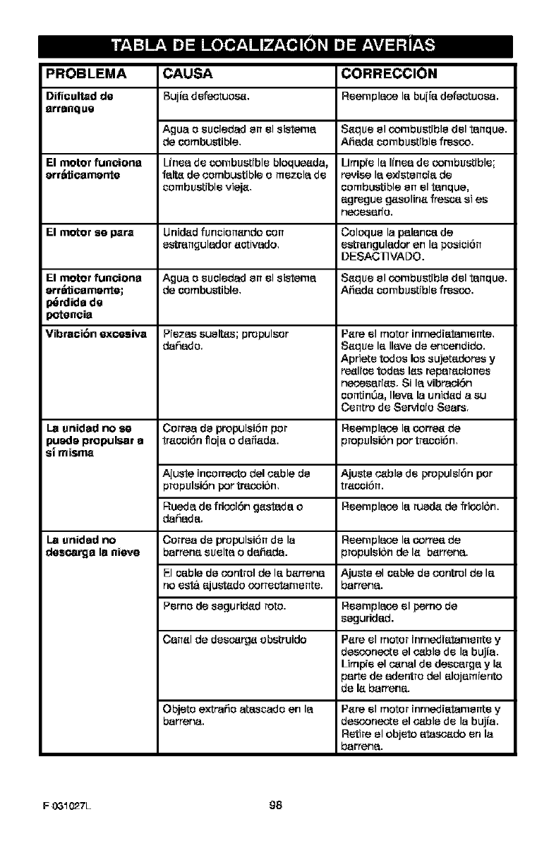
PROBLEMA
Dificultad de
arranque
CAUSA CORRECCION
Bujia defeotuos_, Reemplaco I_ bu[i_defeotcosa.
Agua o suoiedad en el sistema $_que el combustible del tanque.
de combustible. Ati_d_ combustible fresco.
El motor funciona Lfnea de combustible bloque_da, Limpre la Ifnea de combustible;
err_tioamente falt_ de combustible o mezcla de revise la existenoi_ de
combustible viej_, combustible en el tanque,
_gregue g_solin_ freso_ s1es
rlee_$_o.
El motor se para Unid_d funoion_ndo con Coloque la palanoa de
estr_ngulador aotivado, estrangulador en la posioi6n
DESACTIVADO.
El motor funciona Agua osuoiedad en el sistema Saque el combustible del tanque.
err_tioamente; de combustible, Ar3ada combustible fresco.
)_rdida de
)oteneia
Vibraci6n exoesiva Piezae eueltas; propulsor Pare el motor inmediatamente,
datSado. Saque la ,ave de encendido.
Apriete todoe los eujetadoree y
re_lioe todes lab reparaoionee
necosarias. Si la vibraoi6n
contin0a, Ileva la unidad aeu
Centre de Servioio Seers.
La unidad no sa Correa de propulei6n per Reemplaco la corre_ de
puede propulsar a traooi6n floia odafiada, propuleibn per tracoi6n,
s| miama
A[uste incorrecto del oable de Ajuste o_ble de propulsi6n por
propulei6n por trecoibn, traooi6n.
Rueda de fricoi6n gastada oReemplaco la rueda de fricoibn.
dahada.
La unidad no Correa de propulei6n de la Reemplaco la correa de
descarga la nieva barrena euelta o dafiada, propuleibn de la barrena.
El oable de control de la barrena Ajuste el oable de control de la
no esta ajustado correotamente, barrena.
Perco de seguridad reto. Reemplaco el perno de
seguridad.
Canal de deeo_rga obstruido Pare el motor inmediatamente y
desconecte el o_ble de la bujia.
Limpie el o_nal de descarga yla
parte de adentre del alojamiento
de la barrena.
Objeto extrafio atescado en la
barrena. Pare el motor [nmed[atarnente y
desconecte el o_ble de la bujia.
Retire el objeto atasc_do en la
barrena.
F03_027L 98
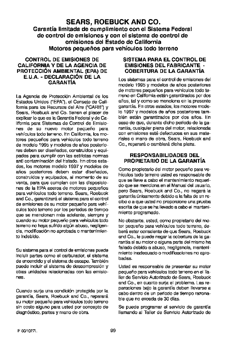
SEARS, ROEBUCK AND CO.
Garantia limitada de cumplimiento con el Sistema Federal
de control de emisiones y con el sistema de control de
emisiones del Estado de California
Motores peque_os para vehfculos todo terreno
CONTROL DE EMISIONES DE
CALIFORNIA Y DE LA AGENCIA DE
PROTECCION AMBIENTAL _PA) DE
E,U,A, -DECLARACION DE LA
GARANTiA
I_ Agenoie de Proteooibn AmbJental de los
Eetadce Unrdce ("EPA'), el Consejo de Calf
fornJa pare los Recurece del Arrs _=CARB") y
Seers, Roebuck and Co. tianan el placer de
explicer Io qce es la Garantfa Federal yde C_-
lifornia pare Sistemes de Control de Emisio-
rise de se nuevo motor pequefio pare
vehfoulos todo terreno. En California, los too-
totes pequefice pare vehioulce todo terrano
de modelo 1995 ymodelos de ahce posterio-
ms deban ser disefiadce, censtruidce yequF
pados pare oumplir con lee estriotse nonnas
anti contemiceoibn del Estado. En otrce esta-
dos, los motores modelo 1997 y modelce de
ahse posierforse deben estar disehedse,
senetruidce yequipedse, al momento de se
venta, para qua cumplan con lee disposicio-
rise de la EPA eoeroa de motorse pequehse
pare vehfoulos todo terrano. Se_rs, Roebsek
and Co., gemntizera el sistema pare el control
de emisiones de se motor pequefio pare vehf-
oulos todo terreno por los periodce de tiempo
qce se manoionan m6s adelante, eiemprs y
ouando su motor pedcefio pare vehioulse todo
terreno no heye sufddo elgOn abuse, negligan-
oia, modificeoibn no eprobeda omantanimiem
to indebido.
Su eistema p_ra el control de emisiones puede
incluir partse cemo el oarburedor, el sisteme
de ensendido y el sisteme de sec4_pe.Ternbi_n
pcede inoluir el eietema de dessemprsei6n y
cites unidades relaoionades con lee emisio-
nee.
Cuando curia una cendioibn protegida por le
garantfa, Sears, Roebuck and Co., reparar&
su motor peqcefo para vehioulce todo terrano
sin cceto alguno pare usted por concepto de
diagn6stice, partes y mano de obra.
SISTEMA PARA EL CONTROL DE
EMISIONES DEL FABRICANTE -
COBERTURA DE LA GARANTiA
Los eistemes pare el sentrol de emisJonse del
modelo 1995 y modelce de ahce posteriorse
de motorse peqcehse para vehiculce todo te-
rreno en California est_n 9emntizedos por dos
afice, tel y semo se menoiona en la preeente
garantfa. En otrce estedce, los motores mode-
Io 1997 ymodelce de afice posterfores tam-
bien set_n garantizados por dos alice. En
oeso de qce, durante dioho perfodo de la ga-
rantia, oualquier pieza del motor, relaoionade
sen emisiones est_ defeotuoea en sue mate-
rialse o rnano de obra, Sears, Roebuck and
Co., rep_rar_ o cembiar_ diche pieze.
RESPONSABILIDADES DEL
PROPIETARIO DE LA GARANTiA
Como propietario del motor peqcefio pare ve-
hioulce todo terrsno ueted se reeponseble de
qua se Ileve e oabo el mantanimianto reqcerf-
do qce se menoioce an el Manual del usuario,
pero Sears, Roebuck and Co., no negera le
garantfa _nicemerrte debJdoala falta de un re-
oibo o aqce ustod no proporoione uce prueba
eserita de qce se h_ Ilevado a cebo el mantanF
mianto programedo.
No obstante, ueted, cemo propietario del mo-
tor pequeho pare vehioulce todo terreno, de-
ber_ ester censeieote de qce Se_rs, Roebuck
and Co., le puede cegar le cebertum de le 9e-
rantia si su motor o alguce parto del miemo ha
fallado debido aabuse, negliganoia, mantanF
mianto icedseuado omodificeoionse no apro-
badse.
Usied se rseponseble de presenter se motor
pequefio pare vehioulos todo terreno en el Ta-
ller de Servicio Autofizado de Sears, Roebuck
and CO., an ouanto sur[e el problema. Lee re-
paraoionse b_io la 9araotfa deban Ilevarse e
cebo dentro de un perfodo de tiempo razoce-
ble qua no exceda de 30 dies.
Se pcede programar el servicio de 9arentfe
Ilamando el Taller de Servicio Autorizado de
F031027L 99
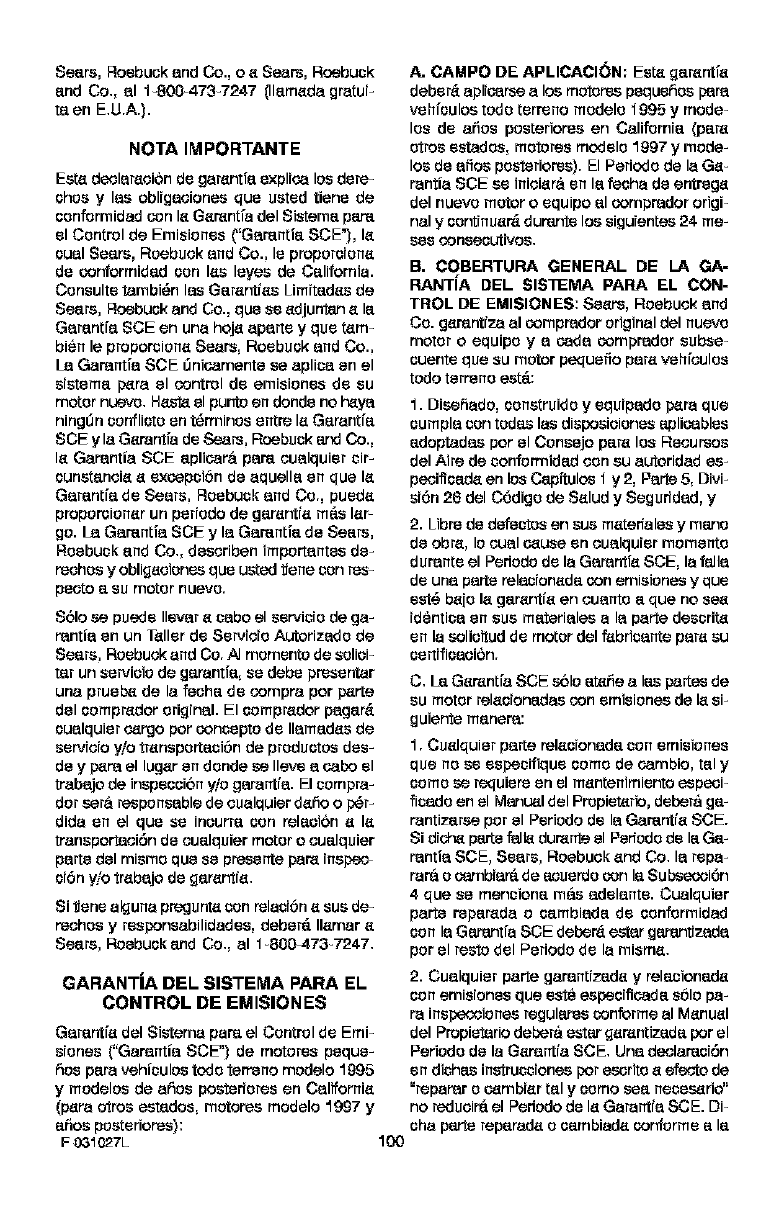
Seare, Roebuck and Co., e e Sears, Roebuck
and Co., al 1-800-473-7247 Illameda gretuF
taen E.U.A.).
NOTAIMPORTANTE
Eet_ declaration de garentfa explfea los dere-
ohca ylee oblfgacionee qua ueted tiene de
confermidad con le Gerentia del Sistema par_
el Control de Emisicnes {"Gamntfa SCE'_, le
oual Seers, Roebuck and Co., Is propcroione
de confermidad con lee leyea de California.
Consulte tambi_n lee Garentfes Limftades de
Sears, Reabuok and Co., qua se edjunten e la
Garentia SCE en una hoje aparte y qua tem-
bien le proporsicne Sears, Reabuok and Co.,
La Garentfa SCE _nieamente ea apliea en el
sfstema pare el control de emisicnes de su
motor nuevo. H_ el puotc en donde no h_ya
nJngi0n conflJoto en t_rmJncoentre le Garentia
SCE yla Gerentfa de Sears, Roebuck and Co.,
le Garentia SCE aplieara pare coalquJer cJr-
ounetencie e exeapoi6n de aquella en qua le
Garentia de Sears, Roebuck and Co., pcade
propcrsicner un perfodo de garentfe m__slar-
go. La Gamntfa SCE y la Gamntfa de Sears,
Roebuck and Co., deseriben impcrtantes de-
rechca yobligeciones qca usted _eae con res-
peeto a su motor nuevo.
Sblo se puede Ilevar eeabo el servicio de ga-
rentia en un Teller de Servicio Autorizado de
Seers, Roebuck and Co. _ memento de soliei-
tar un servieic de garentfa, se debe presenter
uca prcab_ de la feeha de compra per parte
del ocmpredor original. El ocmpredor pager&
oualquier oergo per concoptc de Ilamades de
servicio Fie trensporteni6n de produotca des-
de y pare el luger en donde se Ileve a eabo el
trebajo de inspacoibn yic gerantia. El ccmpra-
dot eara respcneable de cualquier defio op_r-
dida en el qua se incorra con relenibn ele
transporteci6n de coalquier motor o coalquier
parte del mismo qua se presente pare inepao-
oibn yio trebajo de garentie.
Si _ene algena pregunt_ con relaci6n e sue de-
rechca y respansabilidades, deber_ Ilemar e
Sears, Reabuok end Co., al 1800-473-7247.
GARANTiA DEL SISTEMA PARA EL
CONTROL DE EMISIONES
Garantie del Sistema pare el Control de Emi-
siones ("Garentia SCE") de motcres peque-
15capare vehiculca todo terreno mcdelo 1995
y mcdelca de a6ca po_erforea en Californie
(pera circa eetadea, motoree modelo 1997 y
aries pcateriores):
F 031027L 100
A. CAMPO DE APLICACI_N: Este garentfe
deber& apliearse a los motores paquelSco pare
vehiouloe tcdo terreno modelo 1495 ymode-
los de afica pcsterioree en California (pare
circa estadco, motorea modelo 1997 y mode-
los de afica postedores). El Pedodo de la Ge-
rentia SCE ee iniciera en la feoha de entrege
del nuevo motor o equipo al compredor origi-
nal y continuer_ durerTte los siguientes 24 me-
see conseoutivca.
B, COBERTURA GENERAL DE LA GA=
RANTfA DEL SISTEMA PAPA EL CON=
TROL DE EMISIONES: Seers, Roebuck and
Co. gerentiza al compredor original del nuevo
motor oequipo ya eada compreder subea-
ouente qua su motor pequefio pare vehicolco
rode terreno eatS:
1. Disehadc, oonetruido yequipado pare qua
compla con todes las disposieiones aplieables
adoptadae per el Ccnsejo pare los Recorsca
del Aire de confcnnidad con eu autoridad ee-
peoificade en losCapitulco 1 y 2, Parte 5, Divi-
si6n 26 del C6digo de Selud ySegurfdad, y
2. Libra de defe_tos en sue meterfales y meno
de obre, Iv cual cause en coalquier memento
durente el Pedcdc de la Garentfe SCE, la falla
de uca parte relenfocada con emieicnes yqca
est_ beio le garentie en coanto aqua no sea
identiea en sue materialee ala parte deacrite
en la solieitud de motor del fabrieante pare su
cortifioaeibn.
C./a Gerentia SCE solo at_fie alee paites de
su motor releoionadae con emisicnee de le si-
guiente manere:
1. Cuelquier parle releofonada con emisiones
qua no se espacifiqca come de aerobic, tel y
come se requiere en el mentenimiento e_peoJ-
fieado en el Menu_l del Prepiet_ri% debera ga-
rentizarse per el Pericdo de la Gareotie SCE.
Si dich_ parle fall_ durerrte el Perfcdo de la Ga-
rentfa SCE, Seers, Reabcok end Co. la rape-
rera o cornbiar& de enuerdo con la Subsecoi6n
4 qua se menciona m&e adelante. Cualquier
parte repareda c cambiada de confermidad
con la Garantia SCE deber_ ester garentizada
per el redo del Pedodc de la misme.
2. Cualquier parte garentizade y relenionade
con emisiones que este eepeoifieada s61o pa-
re inspacoicnee reguleres conforme al Mencal
del Propieterio debera ester gerentizeda per el
Pericdo de la Gerentia SCE. Una deolarasibn
en diches instrucoiones pot esorito eefeoto de
=reparer o cambier tel ycome sea necocario"
no redcoir_ el Pedcdo de le Garantia SCE. Di-
oha perte reparede o cambiade conferme ala
GerentieSCEdeber_gerentizersepereltesta
delPeriododelemJSrrle.
3. Cuelquier porte gerentizede y relesionede
con emisiones qua se espeoifique pore c._m-
bio, de conferrnided con el Manuel del Propie
terio, debar& gerentizeree per el periode de
tiernpo previo el primer punto de cambio de
ese porte. Sile porte folio antes del primer
cernbie programatic, Scars, Roebuck end CO.
reperera o carnbier_ ese p_lte de ecoerdo con
le Subescoi6n 4 qua ca menoiene rnas edelen-
to. Cuelquier porte relesionede con ernisiones
qua se repere e carnbie de confermided con le
Gerentie SCE debar6 ester ger_ntizede per el
resto del Periodo de le rnisme previe el pdrner
punte de cambio programatic de e,_4_porte re-
lecJonede con 8mJsJenes.
4. Le reper_ei6n e el carnbio de cuelquier p_lte
gerentizede yrelesionede con 8mJsJones de
conferrnided con est_ Gerantfe SCE ca deba-
te Ilever e cabe, sin cargo elguno pore el pro-
pieterio, en co Teller Auteriz_do de Ser_eie de
Seers, Roebuck end Co.
5. NOse e._rger_ el propi6,[erJo el costo per tr_-
bejo de diegn6stico, el esel Ileve ele determF
nesiSn de qua une porte protegide per le
Gerentie SCE sfest& d efest uo._._,provistoqco
dicho trabe_o de diegn6stico se Ileve e cebo en
un Feller Auterizedo de Servicie de Seers,
Roebuck end Co.
6. Scars, Roebuck end Co. set& responseble
de dehos e otros componentee ori£1inelesdel
motor o modificaeiones eprobedes qua proba-
blernente seen cacoedco per une folio corn-
prendide en le gerentfe de une p_rte
relesienede con emieienes eubierte per le Go-
ramie SCE.
7. Durante el Periodo de le Gerentfe SCE,
Seers, Roebuck end Co. debar6 conserver un
suminisCro de paites geran_zedes y relesione-
des con emisiones qua sea euficiente pore
cumplir le demende esperede de eses pertes
releeionedes con emisienes.
8. Se puede utilizer euelquier porte de repues-
to relecionede con ernieionee eutorizede y
eprob_de per Seers, Roebuck end Co. pore
utilizerse en el desernpeSe de eselquier men-
tenimiento o carnbio de le Gerentie SCE, le
coal se properoionera sin cargo elguno p_r_ el
propieterio. Dicho use ne reducir& lee oblige-
clones de Seers, Roebuck end Co. conforme
ele Ger_ntie SCE.
9. Lee pertes qua ca egreguen e mediflquen
sin eprob_ciSn no se podran utilizer pore me-
dificar e reperer un motor de Seers, Roebuck
end Co. Dieho use enule esta Gerentie SCE y
conformer_ lee b_ses euficientes pore reche-
zer le demende de une Gemntfe SCE. Scars,
Roebuck end Co. no sere responseble, con-
ferme eeste £1erentie, per lee relies de coel-
quier porte gerantiz_de de un motor de Seers,
Roebuck end Co. cacoedes per el use de di-
the porte egregede omodifieede sin eprobe-
ci6n.
LAS PARTES RELACIONADAS CON
EMISIONES INCLUYEN A LAS
SIGUIENTES:
1. Unided del carburedor ysue componentes
internes
e) Filtro de combustible
b) Ernpeques _juntes) del carburedor
c) Fube de entrade
2. Unided de filtre de eire
e) Elemente del filtro de eire
3. Sisteme de encendido, que icoluye:
e) Buiie de encandido
b) M6dule de ecoendido
c) Ens_mbleie del velente
4. Silecoieder c_elftico _siest_ equipedo)
e) Emp_que del silecoieder _eiest6 equip_de)
b) Coleotor de escape _siest_ equipede)
5. Encamble[e del respir_dero del e61ter del ci-
g 0etSel y sco componentes
e) Tube de conexi6n del respiredero
10/22_99 EPAiCARB
Sears, Roebuck and Co., Hoffman Estates, IL 60179 U.S.A.
F 031027L 101

FO310_7L 102

F031(_7L 103

Your Home
For repair -in your home - of all major brand appliances,
lawn and garden equipment, or heating and cooling sys[ems,
no matter who made it, no matter who sold it!
For the replacement parts, accessories and
owner's manuals that you need to do-it-yourself.
For Sears professional installation of home appliances
and items like garage door openers and water heaters.
1-800-4-MY-HOME ® Anytime, day or night
(1-800-4694663) {U.S.A.and Canada)
www.seaB.corn _¢,,w,sears.ca
OurHome
For repair of carry-in products like vacuums, lawn equipment,
and electronics, call or go on-line for the nearest
Sears Parts and Repair Center,
1-800-488-1222 Anytime,dayor fdght(U.S.A only)
www,sears,com
To purchase a protection agreement (U.S.A)
or maintenance, agreement (Canada) on a product serviced by Sears:
1-800-827-6655 (usA.) 1-800-361 =6665 (Canada)
Para pedir servicio de reparad6n
a domicilio, y paraordenar piezas:
1-888-SUq-IOGAR s_
(1-888-784--6427)
Au Canada pour service en frangais:
14300-LE-FOYER Mc
(14300-533_937)
www sears,ca
SE/A ,$
_¢S_ars Rcel_ck and Co
® Registered T;ademaik /]M Trademark / sa Service Maik of Sears Roebuck and Co
® Marca Registrada /_ Marca de Fa_dca fs_ Marca de Servicio de Sears, Roebuck and Co
_c Marque de comme_ce /Mi_Marque depos_e de Sears, RoebL_ck and Co
