Craftsman 580325650 User Manual AC GENERATOR Manuals And Guides L0707200
CRAFTSMAN Generator Manual L0707200 CRAFTSMAN Generator Owner's Manual, CRAFTSMAN Generator installation guides
User Manual: Craftsman 580325650 580325650 CRAFTSMAN AC GENERATOR - Manuals and Guides View the owners manual for your CRAFTSMAN AC GENERATOR #580325650. Home:Tool Parts:Craftsman Parts:Craftsman AC GENERATOR Manual
Open the PDF directly: View PDF ![]() .
.
Page Count: 60
Operator'sManual
®
ectricStart
ACGenerator
HOURS: Mnn. - Fri. 8 a.m. to 5 p.m. (CT)
WARNING
Before using this product, readthis
manual and follow all Safety Rules
add Operating Instructions.
ADVEBTENCIA
Antes de utilizar el producto, lea este
manual y siga todas las Reglasde
Seguridade Instrucciones de Uso.
Sears, Roebuckand Co., Roffrnan Estates,IL 60179 U.S.A.
Visit our Craftsman website:www.craftsman.com
Part No. 198712GS Draft E (06/19/2007)
,, Safety
• Assembly
• Operation
•Maintenance
,, Parts
,, Espafiol,p. 36
o3
WARRANTY.................................... 2
SAFETYRULES ............................... 3-5
FEATURESAND CONTROLS....................... 6
ASSEMBLY................................... 7-9
OPERATION................................ 10-14
SPECIFICATIONS............................... 15
MAINTENANCE.............................. 16-19
STORAGE .................................... 20
TROUBLESHOOTING............................ 21
SCHEMATIC/WIRINGDIAGRAM ................ 22-23
REPLACEMENTPARTS ....................... 24-32
NOTES....................................... 33
EMISSIONSSYSTEMWARRANTY............... 34-35
ESPANOL.................................. 36-59
HOWTO ORDERPARTS ................. BACKPAGE
One-YearFullWarrantyon CraftsmanGenerator
If this generator fails dueto a defect in material or workmanship within oneyear from the date of purchase, return it to any
Sears store, other Craftsman outlet, or Sears Parts & Repair Center in the United States for free repair (or replacement if
repair proves impossible).
AdditionalOne-YearLimited Warrantyon Craftsman Generator
For the second year from the date of purchase, if any part of this generator fails dueto a defect in material or workmanship, a
new part will be supplied free of charge. You must pay the labor cost if you wish to have it installed.
All warranty coverageapplies for only 90 days from date of purchase if this generator is used for commercial or rental
purposes. Oncea generator has experiencedcommercial or rental use, it shall thereafter be considered a commercial or rental
generator for the purpose of this warranty.
This warranty gives you specific legal rights, and you may also have other rights which vary from state to state.
Sears, Roebuckand Co., D/817WA, HoffmanEstates, IL 60179 U.S.A.
© Sears Brands, LLC
,_ This is the safetyalert symbol,it is used to alert youto potential personalinjuryhazards.
Obeyall safetymessagesthat follow this symbolto avoid possibleinjury ordeath.
[ _-!] Read thismanual carefully and become familiar
...................withyour generator. Knowits applications,its
limitations, and any hazardsinvolved.
The safety alert symbol (_1_)is used with a signal word
(DANGER,CAUTION,WARNING),a pictorial and/oFa safety
messageto alert you to hazards. DANGERindicates a hazard
which, if not avoided, will result in death or serious injury.
WARNINGindicates a hazardwhich, if not avoided, could
result in death or serious injury. CAUTIONindicates a hazard
which, if not avoided, might result in minor or moderate
injury. NOTICE,indicates a situation that could result in
equipment damage.Follow safety messagesto avoid or
reducethe risk of injury or death.
WARNING
The engine exhaustfrom this productcontains chemicals
known to the State of California to cause cancer, birth
defects, or other reproductive harm.
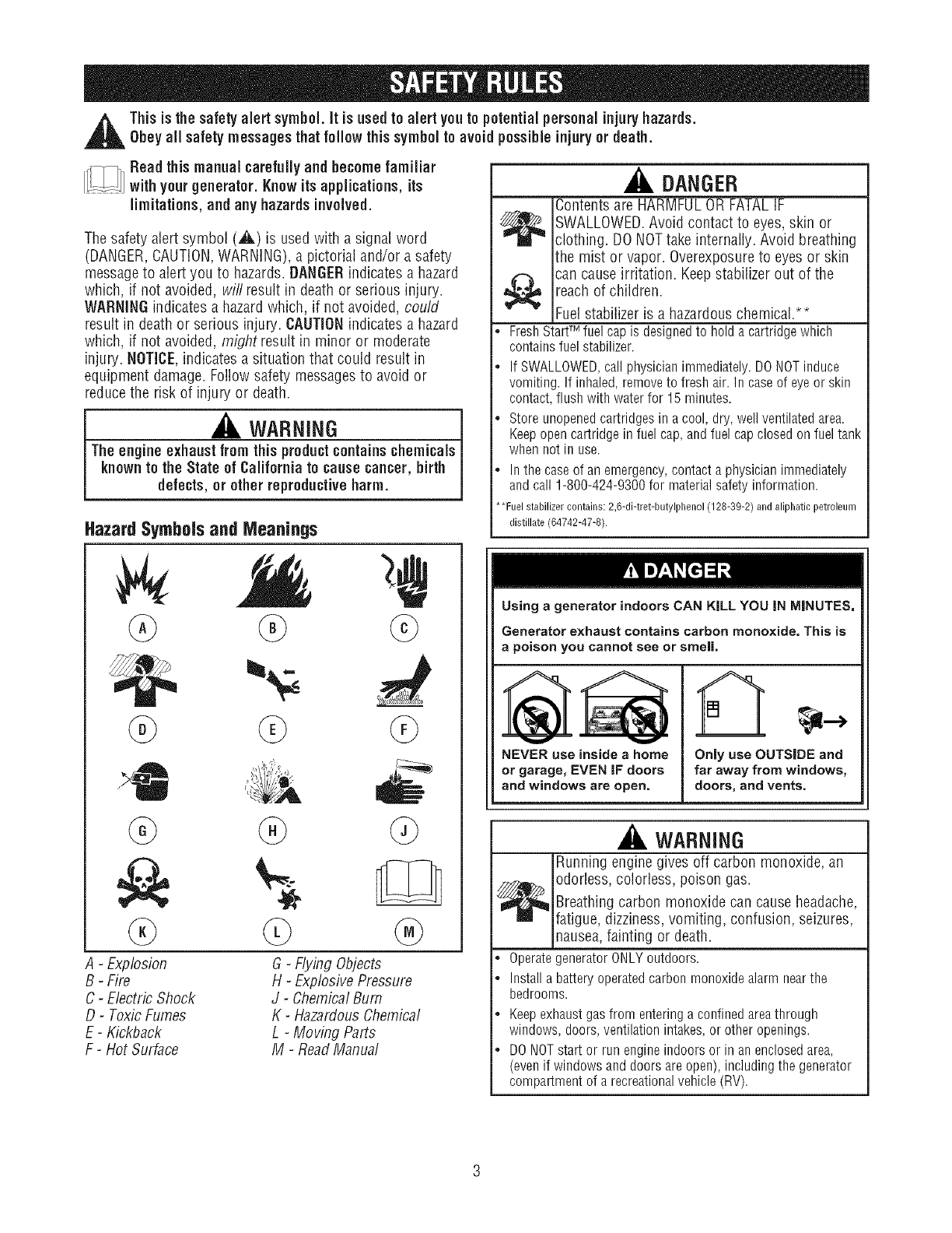
HazardSymbolsand Meanings
DANGER
Contentsare HARMFULOR FATALIF
SWALLOWED.Avoid contact to eyes, skin or
clothing. DONOTtake internally. Avoid breathing
the mist or vapor. Overexposureto eyes or skin
can cause irritation. Keepstabilizer out of the
reach of children.
Fuelstabilizer is a hazardouschemical.**
• FreshStartTM fuel capis designedto holdacartridgewhich
containsfuelstabilizer.
. IfSWALLOWED,callphysicianimmediately.DONOTinduce
vomiting.If inhaled,removeto freshair. In caseof eyeor skin
contact,flushwithwaterfor 15minutes.
• Storeunopenedcartridgesina cool,dry,wellventilatedarea.
Keepopencartridgeinfuel cap,andfuel capclosedonfueltank
whennotin use.
Inthe caseof anemergency,contacta physicianimmediately
andcall 1-808-424-9308for materialsafetyinformation.
• *Fuel stabilizer contaies: 2,6-di-tret-butylpheeol (128-39-2) and aliphatie petroleum
distillate (64742-47-8).
A-Explosion
B-Fire
C-Electric Shock
D-Toxic Fumes
E- Kickback
F-Hot Surface
®
G-Flying Objects
H-Explosive Pressure
J-ChemicalBum
K-HazardousChemical
L-Moving Parts
M-Read Manual
Using a generator indoors CAN KiLL YOU iN MINUTES,
Generator exhaust contains carbon monoxide. This is
a poison you cannot see or smell.
A,
NEVER use inside ahome
or garage,EVEN IF doors
and windows are open.
Only use OUTSIDE and
far away from windows,
doors, and vents.
WARNING
Running enginegives off carbon monoxide, an
odorless, colorless, poison gas.
_ reathing carbon monoxide can cause headache,
fatigue, dizziness,vomiting, confusion, seizures,
nausea,fainting or death.
• OperategeneratorONLYoutdoors.
Installabatteryoperatedcarbonmonoxidealarmnearthe
bedrooms.
Keepexhaustgasfromenteringa confinedareathrough
windows,doors,ventilationintakes,or otheropenings.
DONOTstartor runengineindoorsor in anenclosedarea,
(evenif windowsanddoorsareopen),includingthe generator
compartmentof arecreationalvehicle(RV).
WARNING
Generatorproduces hazardousvoltage.
_¢ Failureto isolate generator from power utility can
result in death or injury to electric utility workers
due to backfeed of electrical energy.
• When using generator for backuppower, notify utility company.
Use approvedtransfer equipment to isolate generator from
electric utility.
• Use a ground fault circuit interrupter (GFCI)in any damp or
highly conductive area, such as metal decking or steel work.
• DO NOTtouch barewires or receptacles.
. DO NOTuse generator with electrical cords which are worn,
frayed, bareor otherwise damaged.
DO NOToperate generator in the rain or wet weather.
• DO NOThandle generator or electrical cords while standing in
water, while barefoot, or while hands or feet are wet.
• DO NOTallow unqualified persons or children to operate or
service generator.
WARNING
_,,,_ ontact with muffler areacan result in serious
burns.
_ Exhaust heat/gases can ignite combustibles,
structures or damagefuel tank causing a fire.
DONOTtouch hot parts and AVOIDhot exhaustgases.
• Allow equipment to cool before touching.
• Keep at least 5 feet (1.5 m) of clearance on all sides of
generator including overhead.
• Codeof FederalRegulation (CFR) Title 36 Parks, Forests, and
Public Property require equipment powered by an internal
combustion engineto have a spark arrester, maintainedin
effective working order, complying to USDAForest service
standard 5100-1C or later revision. In the State of California a
spark arrester is required under section 4442 of the California
Public resourcescode. Otherstates may havesimilar laws.
WARNING
Starter and other rotating parts can entangle
hands, hair, clothing, or accessories.
• NEVERoperate generator without protective housing or covers.
. DO NOTwear loose clothing, jewelry or anything that may be
caught in the starter or other rotating parts.
. Tie up long hair and remove jewelry.
WARNING
Starter cord kickback (rapid retraction) can result
in bodily injury. Kickback will pull hand and arm
I1_< toward engine faster than you can let go.
Broken bones, fractures, bruises, or sprains
could result.
• When starting engine, pull cord slowly until resistanceis felt and
then pull rapidly to avoid kickback.
• NEVERstart or stop enginewith electrical devices plugged in
and turned on.
WARNING
Fueland its vapors are extremely flammable and
explosive.
Fire or explosion can cause severe burns ordeath.
WHEN ADDING OR DRAINING FUEL
. Turn generator OFFand let it cool at least2 minutes before
removing fuel cap. Loosen cap slowly to relieve pressure in
tank.
• Fill or drain fuel tank outdoors.
. DO NOToverfill tank. Allow space for fuel expansion.
• If fuel spills, wait until it evaporatesbefore starting engine.
. Keep fuel away from sparks, open flames, pilot lights, heat, and
other ignition sources.
• DONOTlight a cigarette or smoke.
WHEN STARTING EQUIPMENT
• Ensure spark plug, muffler, fuel cap, and air cleanerare in place.
. DO NOTcrank enginewith spark plug removed.
WHEN OPERATING EQUIPMENT
• DONOT tip engine or equipment at angle which causesfuel to
spill.
. This generator is not for usein mobile equipment or marine
applications.
WHEN TRANSPORTING OR REPAIRINGEQUIPMENT
• Transport/repair with fuel tank EMPTYor with fuel shutoff valve
OFF.
• Disconnect spark plug wire.
WHEN STORING FUEL OR EQUIPMENT WITH FUEL INTANK
• Store away from furnaces, stoves,water heaters, clothes dryers,
or other appliances that havepilot light or other ignition source
becausethey can ignite fuel vapors.
WARNING
This generator does not meetU. S. CoastGuard Regulation
33CFR-183and should not be used on marine applications.
Failure to use the appropriate U. S. Coast Guard approved
generator could result in death or serious injury and/or
property damage.
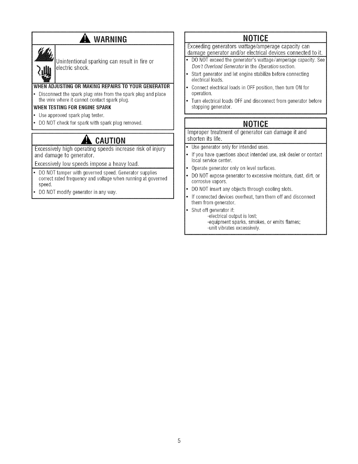
WARNING
_ Unintentional sparking can result in fire OF
_¢ electric shock.
WHENADJUSTINGOR MAKINGREPAIRSTOYOUR GENERATOR
. Disconnect the spark plug wire from the spark plug and place
the wire where it cannot contact spark plug.
WHENTESTINGFORENGINESPARK
• Use approved spark plug tester.
. DO NOTcheck for spark with spark plug removed.
CAUTION
Excessively high operating speeds increase risk of injury
and damage to generator.
Excessively low speeds impose a heavy load.
DO NOTtamper with governed speed.Generatorsupplies
correct rated frequency and voltage when running at governed
speed.
DO NOTmodify generator in anyway.
NOTICE
Exceeding generators wattage/amperage capacity can
damage generator and/or electrical devices connected to it.
DONOTexceedthe generator's wattage/amperage capacity. See
Don't OverloadGeneratorin the Operationsection.
Start generator and let engine stabilize before connecting
electrical loads.
Connect electrical loads in OFFposition, then turn ONfor
operation.
Turn electrical loads OFFand disconnect from generator before
stopping generator.
NOTICE
Improper treatment of generator can damage it and
shorten its life.
Use generator only for intended uses.
If you havequestions about intended use,ask dealeror contact
local service center.
Operategenerator only on level surfaces.
DONOTexpose generator to excessivemoisture, dust, dirt, or
corrosive vapors.
DONOTinsert any objects through cooling slots.
If connected devices overheat,turn them off and disconnect
them from generator.
Shut off generator if:
-electrical output is lost;
-equipment sparks, smokes, or emits flames;
-unit vibrates excessively.
KNOWYOUROEHERATOR
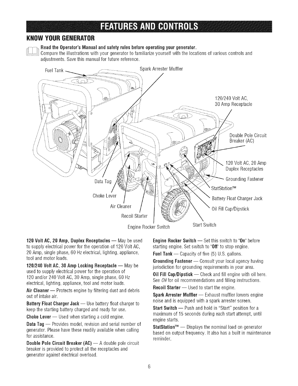
I!__-!i] Read the Operator'sManual and safety rules before operating your generator.
Comparethe illustrations with your generator to familiarize yourself with the locations of various controls and
adjustments. Savethis manual for future reference.
FuelTank Spark Arrestor Muffler
120/240 Volt AC,
/30 Amp Receptacle
/
Double PoleCircuit
Breaker (AC)
DataTag
120 Volt AC,20 Amp
Duplex Receptacles
Grounding Fastener
Choke Lever
Air Cleaner
Recoil Starter
Engine Rocker Switch
Battery Float ChargerJack
Oil Fill Cap/Dipstick
Start Switch
120 Volt AC,20 Amp, DuplexReceptacles -- May be used
to supply electrical power for the operation of 120 Volt AC,
20 Amp, single phase, 60 Hzelectrical, lighting, appliance,
tool and motor loads.
120/240 Volt AC, 30 Amp LockingReceptacle -- May be
usedto supply electrical power for the operation of
120 and/or 240 Volt AC,30 Amp, single phase,60 Hz
electrical, lighting, appliance,tool and motor loads.
Air Cleaner -- Protects engine by filtering dust and debris
out of intake air.
Battery Float Charger Jack-- Use battery float charger to
keep the starting battery charged and readyfor use.
Choke Lever-- Used when starting a cold engine.
Data Tag-- Provides model, revision and serial number of
generator. Pleasehave these readily availablewhen calling
for assistance.
Double Pole Circuit Breaker (AC)-- A double pole circuit
breaker is provided to protect all the receptaclesand
generator against electrical overload.
EngineRocker Switch -- Set this switch to "On"before
starting engine. Set switch to "Off"to stop engine.
Fuel Tank-- Capacityof five (5) U.S. gallons.
GroundingFastener-- Consult your local agencyhaving
jurisdiction for grounding requirements in your area.
Oil Fill Cap/Dipstick -- Checkand fill engine with oil here.
SeeOil for oil recommendations and filling instructions.
Recoil Starter -- Usedto start the engine.
Spark Arrestor Muffler -- Exhaustmuffler lowers engine
noise and is equipped with a spark arrester screen.
Start Switch -- Push and hold in "Start" position for a
maximum of 15 seconds during each start attempt, until
engine starts.
StatStationTM -- Displaysthe nominal load on generator
based on output frequency. It also has a built in maintenance
reminder.
Your Craftsman generator requires some assembly and is
ready for use only after it has beenproperly serviced with the
recommended oil and fuel.
If you have any problemswith the assembly of your
generator, please call the generator helpline at
1-800-222-3136.
Unpacking the Generator
f. Set the carton on a rigid fiat surface.
2. Removeeverything from carton except generator.
3. Opencarton completely by cutting each corner from top
to bottom.
4. Leavegenerator on carton to install wheel kit.
Carton Contents
Check all contents against those listed below:
• Main unit
• Engineoil
• Oil bottle funnel
• Operator's manual
• Wheel kit
• Adapter cord set
If any parts are missing or damaged,call the generator
helpline at 1-800-222-3135.
install WheelKit
NOTE:Wheel kit is not intended for over-the-road use. DO
NOTtow this unit with a motorized vehicle.
You will needthe following tools to install these
components:
• 13mm wrenches
• Socket wrench with a 13mm socket
• Pliers
Safety glasses
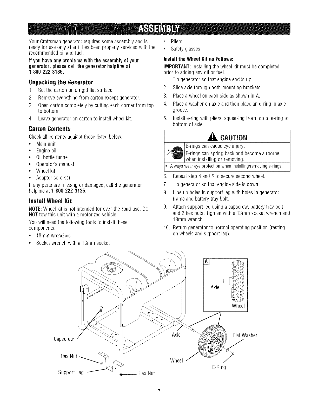
Install the Wheel Kit as Follows:
IMPORTANT: Installing the wheel kit must be completed
prior to adding any oil or fuel.
1. Tip generator so that engine end is up.
2. Slide axle through both mounting brackets.
3. Place a wheel on each side as shown in A.
4. Place a washer on axle and then place an e-ring in axle
groove.
5. Install e-ring with pliers, squeezingfrom top of e-ring to
bottom of axle.
CAUTION
E-tings can cause eye injury.
.,_ E-fings can spring back and become airborne
when installing or removing.
, Alwaysweareyeprotectionwheninstalling/removinge-rings.
6. Repeatstep 4 and 5 to securesecond wheel.
7. Tip generator so that engine side is down.
8. Line up holes in support leg with holes in generator
frame and battery tray bolt.
9. Attach support leg using a capscrew, battery tray bolt
and 2 hex nuts. Tighten with a 13mm socket wrench and
13mm wrench.
10. Return generator to normal operating position (resting
on wheels and support leg).
Axle
<>8
3
Wheel
Capscrew
Axle Flat Washer
Hex Nut
Support Leg _ Hex Nut
Wheel
E-Ring
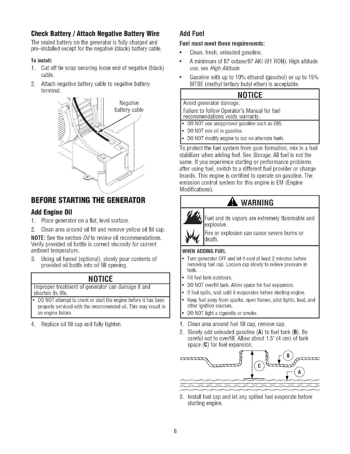
CheckBattery/Attach Negative BatteryWire
The sealed battery on the generator is fully charged and
pre-installed except for the negative(black) battery cable.
Toinstall:
1. Cut off tie wrap securing loose end of negative (black)
cable.
2. Attach negativebattery cable to negative battery
terminal.
Negative
battery cable
/,
J
'\\\ /J'/
BEFORESTARTINGTHEGENERATOR
AddEngineOil
1. Place generator on a flat, level surface.
2. Cleanarea around oil fill and remove yellow oil fill cap.
NOTE:Seethe section Oilto review oil recommendations.
Verify provided oil bottle is correct viscosity for current
ambient temperature.
3. Using oil funnel (optional), slowly pour contents of
provided oil bottle into oil fill opening.
NOTICE
Improper treatment of generator can damage it and
shorten its life.
DONOTattemptto crankor startthe enginebeforeit hasbeen
properlyservicedwiththe recommendedoil.Thismayresultin
anenginefailure.
4. Replaceoil fill cap and fully tighten.
Add Fuel
Fuel must meet these requirements:
*Clean,fresh, unleadedgasoline.
*A minimum of 87 octane/87 AKI (91 RON). High altitude
use, see High Altitude.
*Gasolinewith up to 10% ethanol (gasohol) or upto 15%
MTBE(methyl tertiary butyl ether) is acceptable.
NOTICE
Avoid generator damage.
Failureto follow Operator's Manual for fuel
recommendations voids warranty.
DONOTuseunapprovedgasolinesuchas E85.
DONOTmixoil in gasoline.
DONOTmodifyengineto runonalternatefuels.
To protect the fuel system from gum formation, mix in a fuel
stabilizer when adding fuel. See Storage.All fuel is not the
same. If you experiencestarting or performance problems
after using fuel, switch to a different fuel provider or change
brands. This engine is certified to operate on gasoline. The
emission control system for this engine is EM (Engine
Modifications).
WARNING
_fl_ Fueland its vapors are extremely flammable and
explosive.
Fireor explosion can cause severe burns ordeath.
WHEN ADDINGFUEL
•TurngeneratorOFFandlet it cool at least2 minutesbefore
removingfuel cap.Loosencapslowlyto relievepressurein
tank.
.Fillfueltankoutdoors.
•DONOToverfilltank.Allowspacefor fuel expansion.
.Iffuel spills,waituntil it evaporatesbeforestartingengine.
•Keepfuelawayfrom sparks,openflames,pilot lights,heat,and
otherignitionsources.
•DONOTlight acigaretteor smoke.
1. Cleanareaaround fuel fill cap, removecap.
2. Slowly add unleadedgasoline (A) to fuel tank (B). Be
careful not to overfill. Allow about 1.5" (4 cm) of tank
space (C) for fuel expansion.
3. Install fuel cap and let any spilled fuel evaporate before
starting engine.
Fresh StartTM Fuel Cap
Adding fuel preserver helps keepfuel fresh and carburetors
clean for easier starting, all season long. This new fuel cap
automatically drips concentrated fuel preserver into your fuel
tank.
DANGEB
Contentsare HARMFULOR FATALIF
_ WALLOWED.Avoid contact to eyes, skin or
clothing. DO NOTtake internally. Avoid breathing
the mist or vapor. Overexposureto eyesor skin
can cause irritation. Keepstabilizer out of the
reach of children.
Fuelstabilizer is a hazardouschemical.**
. If SWALLOWED,callphysicianimmediately.
• Inthe caseof anemergency,contacta physicianimmediately
andcall 1-808-424-9380for materialsafetyinformation.
• *Fuel stabilizer contains: 2,6-di-tret-butylphenol (128-39-2) and alipbatic petroleum
distillate (64742-47-8).
1. Place cartridge into fuel cap.
2. Push to "snap" cartridge into place.
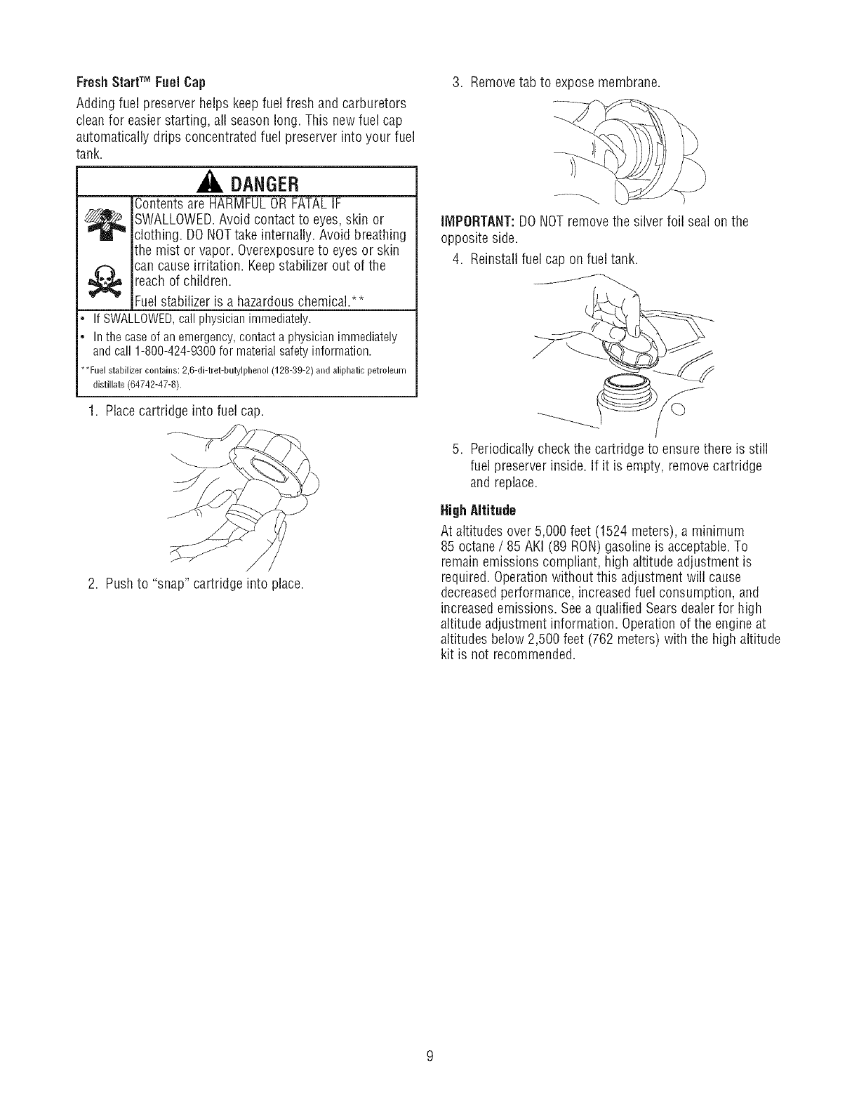
3. Removetab to expose membrane.
IMPORTANT:DONOTremove the silver foil seal on the
opposite side.
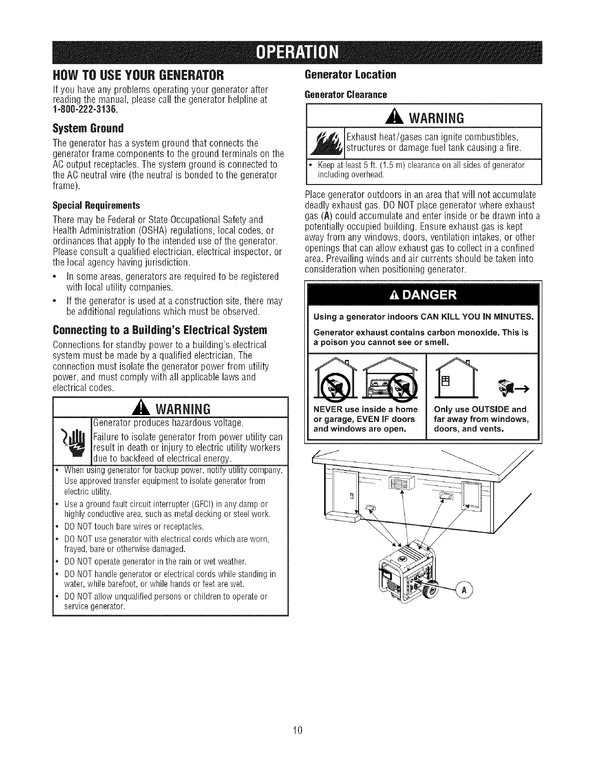
4. Reinstall fuel cap on fuel tank.
5. Periodically check the cartridge to ensure there is still
fuel preserver inside. If it is empty, removecartridge
and replace.
HighAltitude
At altitudes over 5,000 feet (1524 meters), a minimum
85 octane /85 AKI (89 RON)gasoline is acceptable.To
remain emissions compliant, high altitude adjustment is
required. Operationwithout this adjustment will cause
decreasedperformance, increasedfuel consumption, and
increasedemissions. Seea qualified Sears dealerfor high
altitude adjustment information. Operation of the engine at
altitudes below 2,500 feet (762 meters) with the high altitude
kit is not recommended.
HOWTO USEYOURGENERATOR Generator Location
If you haveany problems operating your generator after GeneratorClearance
readingthe manual, please call the generator heipline at
1-800-222-3136.
System Ground
The generator has a system ground that connects the
generator frame components to the ground terminals on the
AOoutput receptacles.The system ground is connected to
the AOneutral wire (the neutral is bonded to the generator
frame).
Special Requirements
There may be Federalor StateOccupational Safety and
HealthAdministration (OSHA)regulations, local codes, or
ordinancesthat apply to the intended use of the generator.
Pleaseconsult a qualified electrician, electrical inspector, or
the local agency having jurisdiction.
• Insome areas,generators are requiredto be registered
with local utility companies.
• If the generator is used at a construction site, there may
be additional regulations which must be observed.
Connecting to aBuilding's Electrical System
Oonnectionsfor standby power to a buiiding's electrical
system must be made by a qualified electrician. The
connection must isolatethe generator power from utility
power, and must comply with all applicable laws and
electrical codes.
WARNING
iGeneratorproduces hazardousvoltage.
_¢ Failureto isolate generator from power utility can
result in death or injury to electric utility workers
dueto backfeedof electrical energy.
•Whenusinggeneratorfor backuppower,notifyutilitycompany.
Useapprovedtransferequipmentto isolategeneratorfrom
electricutility.
•Useagroundfaultcircuit interrupter(GFCI)in anydampor
highlyconductivearea,suchasmetaldeckingor steelwork.
•DONOTtouchbarewiresor receptacles.
, DONOTusegeneratorwithelectricalcordswhichareworn,
frayed,bareor otherwisedamaged.
, DONOToperategeneratorinthe rainorwetweather.
•DONOThandlegeneratoror electricalcordswhilestandingin
water,whilebarefoot,or whilehandsorfeetarewet.
•DONOTallowunqualifiedpersonsor childrento operateor
servicegenerator.
WARNING
Exhaustheat/gases can ignite combustibles,
structures or damage fuel tank causing a fire.
Keepat least5 ft. (1.5 m)clearanceonall sidesof generator
includingoverhead.
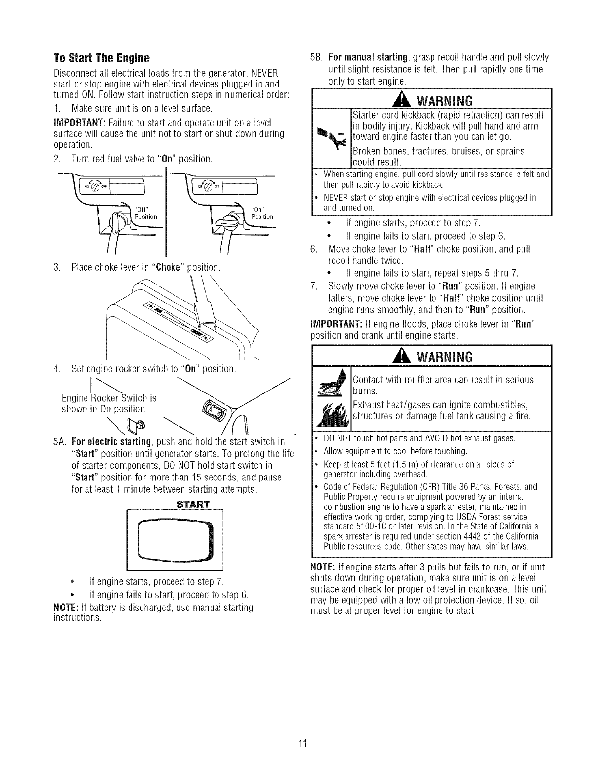
Placegenerator outdoors in an areathat wiil not accumulate
deadly exhaust gas. DO NOTplace generator where exhaust
gas (A) could accumulate and enter inside or be drawn into a
potentially occupied building. Ensure exhaust gas is kept
away from any windows, doors, ventilation intakes, or other
openings that can allow exhaust gas to collect in a confined
area. Prevailing winds and air currents should be taken into
consideration when positioning generator.
Using agenerator indoors CAN KiLL YOU iN MINUTES.
Generator exhaust contains carbon monoxide. This is
apoison you cannot see or smeJL
NEVERuse inside a home
or garage,EVEN IF doors
and windowsare open.
A
OnJy use OUTSIDE and
far away from windows,
doors, and vents.
10
To Start The Engine
Disconnectall electrical loads from the generator. NEVER
start or stop engine with electrical devices plugged in and
turned ON. Follow start instruction steps in numerical order:
1. Make sure unit is on a level surface.
IMPORTANT:Failureto start and operate unit on a level
surface will cause the unit not to start or shut down during
operation.
2. Turn red fuel valveto "On" position.
3. Place choke lever in "Choke" position.
4. Set engine rocker switch to "On" position.
EngineRockerSwitch is
shown in On position
5A. Far electric starting, push and hold the start switch in
"Start" position untilgenerator starts. To prolong the life
of starter components, DONOTholdstart switch in
"Start" position for more than 15 seconds, and pause
for at least 1 minute betweenstarting attempts.
START
• If engine starts, proceedto step 7.
• If engine fails to start, proceedto step 6.
NOTE:If battery is discharged, use manual starting
instructions.
5B. For manual starting, grasp recoil handleand pull slowly
until slight resistance is felt. Then pull rapidly one time
only to start engine.
WARNING
Startercord kickback (rapid retraction) can result
in bodily injury. Kickbackwill pull hand and arm
_< toward engine faster than you can let go.
T'- Broken bones, fractures, bruises, or sprains
could result.
•Whenstartingengine,pullcordslowlyuntil resistanceis feltand
thenpullrapidlyto avoidkickback.
, NEVERstartor stopenginewith electricaldevicespluggedin
andturnedon.
• If engine starts, proceed to step 7.
• If engine fails to start, proceed to step 6.
6. Move choke lever to "Half" choke position, and pull
recoil handletwice.
• If engine fails to start, repeatsteps 5 thru 7.
7. Slowly move choke lever to "Run" position. If engine
falters, movechoke lever to "Half" choke position until
engine runs smoothly, and then to "Run" position.
IMPORTANT:If engine floods, place choke lever in "Run"
)osition and crank until engine starts.
_i, WARNING
s_ Contactwith muffler areacan result in serious
burns.
_ Exhaust heat/gases can ignite combustibles,
structures or damage fuel tank causing a fire.
®
o
o
DONOTtouch hot parts and AVOIDhot exhaust gases.
Allow equipment to cool before touching.
Keep at least 5 feet (1.5 m) of clearanceon all sides of
generator including overhead.
Codeof FederalRegulation(CFR)Title 36 Parks, Forests, and
Public Property require equipment powered by an internal
combustion engineto have a spark arrester, maintained in
effective working order, complying to USDAForest service
standard 5100-1C or later revision. In the State of California a
spark arrester is required under section 4442 of the California
Public resources code. Otherstates may have similar laws.
NOTE:If engine starts after 3 pulls but fails to run, or if unit
shuts down during operation, makesure unit is on a level
surface and check for proper oil level in crankcase. This unit
may be equipped with a low oil protection device. If so, oil
must be at proper level for engine to start.
11
Connecting Electrical Loads
• Let the engine stabilize and warm up for a few minutes
after starting.
DONOTconnect240Voltloadsto 120Volt receptacles.
DO NOTconnect 3-phase loadsto the generator.
DO NOTconnect 50 Hz loadsto the generator.
Plug in andturn on the desired 120 Volt AC,single phase,
60 Hertz electrical loads.
• DO NOTOVERLOADTHEGENERATOR.SeeDon't
Overload Generator.
NOTICE
Exceedinggenerators wattage/amperagecapacitycan
damagegenerator and/or electrical devicesconnected to it.
DONOTexceedthe generator'swattage/amperagecapacity.See
Don'tOverloadGeneratorinthe Operationsection.
Startgeneratorandletenginestabilizebeforeconnecting
electricalloads.
ConnectelectricalloadsinOFFposition,thenturn ONfor
operation.
TurnelectricalloadsOFFanddisconnectfromgeneratorbefore
stoppinggenerator.
Stopping the Engine
1. Turnoff andunplugall electricalloadsfrom unit.NEVER
start or stop engine with electrical devices plugged in
and turned on.
2. Let engine run at no-load for two minutes to stabilize
unit's internal temperatures.
3. Move engine rocker switch to "Off" position.
WARNING
Backfire,fire or engine damagecould occur.
DONOTstopenginebymovingchokeleverto "Cheke"position.
4. Move fuel valve to "Off" position.
CORDSETSAND RECEPTACLES
Useonly high quality, well-insulated, grounded extension
cords with the generator's 120 Volt duplex receptacle.
Inspect extension cords before each use.
Checkthe ratings of all extension cords before you use them.
Extensioncord sets used should be rated for 125 Volt AC
loads at 20 Amps or greater for most electrical devices.
Some devices, however, may not requirethis type of
extension cord. Checkthe operator's manualsof those
devicesfor the manufacturer's recommendations.
Keepextension cords as short as possible to minimize
voltage drop.
WARNING
_ verloaded electrical cords can overheat, arc,
and burn resulting in death, bodily injury, and/or
property damage.
• ONLYusecordsratedfor your loads.
. Followallsafetieson electricalcords.
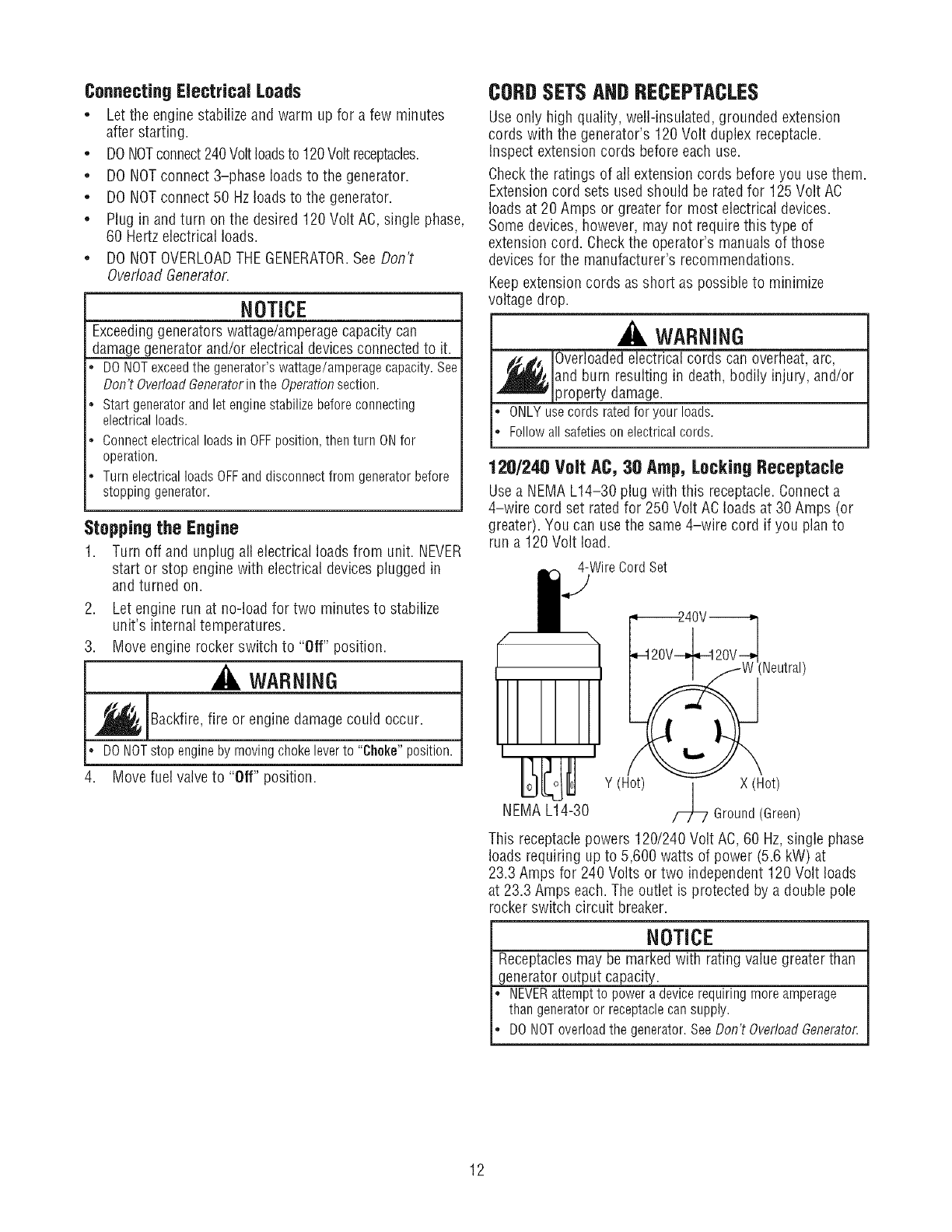
120/240 Volt AC, 30 Amp,LockingReceptacle
Usea NEMAL14-30 plug with this receptacle.Connect a
4-wire cord set rated for 250 Volt AC loads at 30 Amps (or
greater). You can use the same 4-wire cord if you plan to
run a 120 Volt load.
4-WireCordSet
:Neutral)
Y (Hot) | X (Hot)
NEMAL14-30 /-7L/ Ground(Green)
This receptacle powers 120/240 Volt AC,60 Hz,single phase
loads requiring up to 5,600 watts of power (5.6 kW) at
23.3 Amps for 240 Volts or two independent 120 Volt loads
at 23.3 Amps each.The outlet is protected by a double pole
rocker switch circuit breaker.
NOTICE
Receptaclesmay be marked with rating value greater than
generator output capacity.
NEVERattemptto poweradevicerequiringmoreamperage
thangeneratoror receptaclecansupply.
DONOToverloadthe generator.SeeDon'tOverloadGenerator.
12
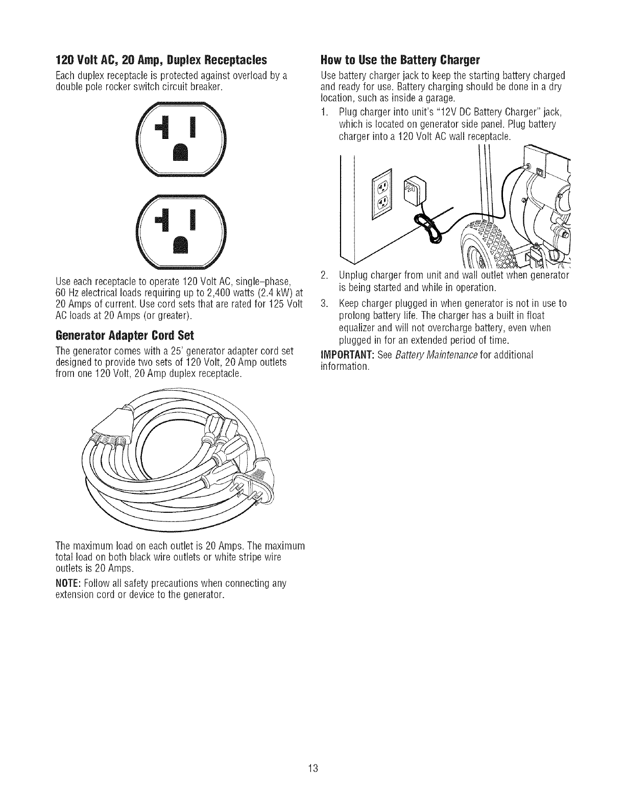
120 Volt AC, 20 Amp, Duplex Receptacles
Eachduplex receptacleis protected against overload by a
double pole rocker switch circuit breaker.
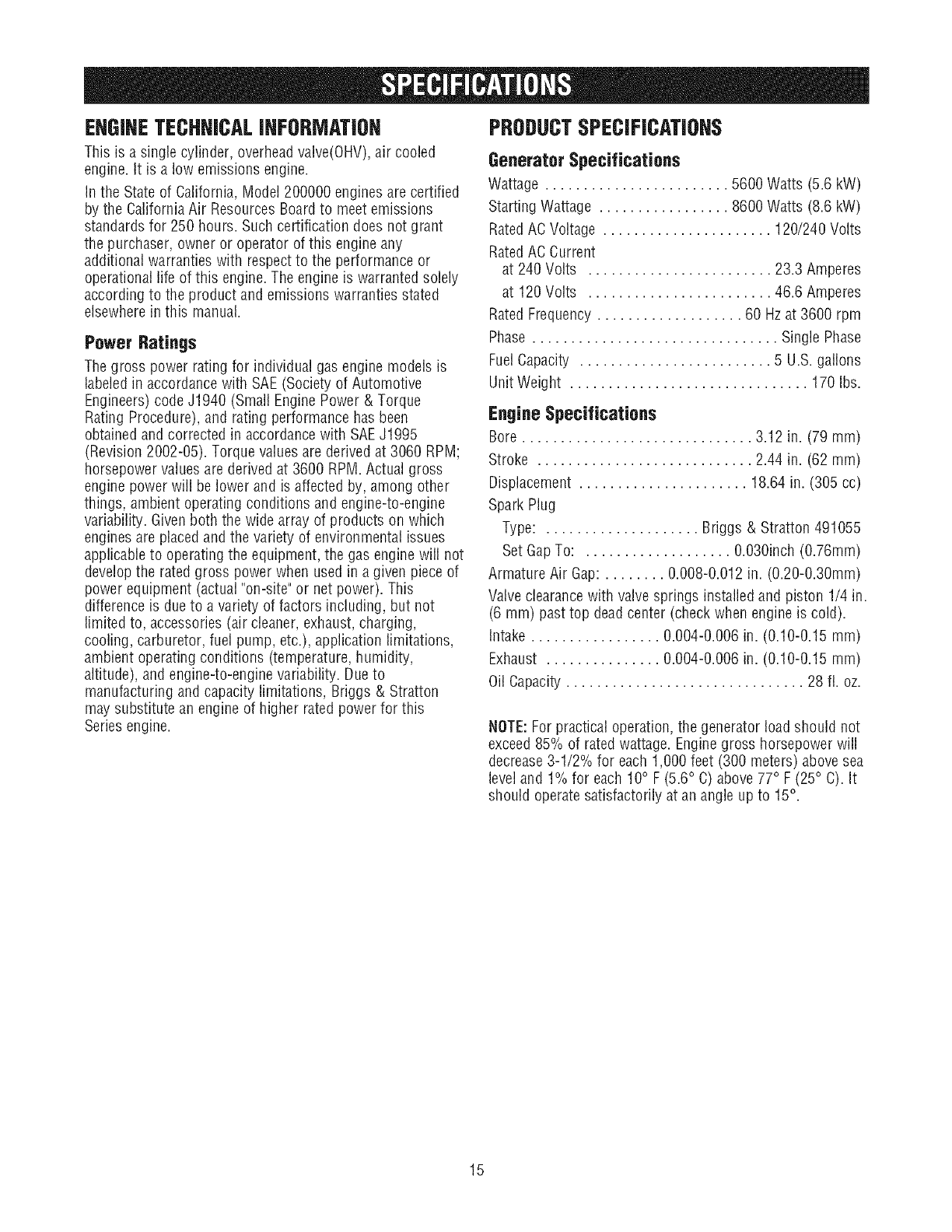
How to Use the Battery Charoer
Usebattery charger jack to keepthe starting battery charged
and ready for use. Battery charging should be done ina dry
location, such as inside a garage.
1. Plug charger into unit's "12V DO Battery Charger" jack,
which is located on generator side panel. Plug battery
charger into a 120 Volt AC wall receptacle.
Useeach receptacleto operate 120 Volt AO,single-phase,
60 Hzelectrical loads requiring up to 2,400 watts (2.4 kW) at
20 Amps of current. Usecord sets that are rated for 125 Volt
AOloads at 20 Amps (or greater).
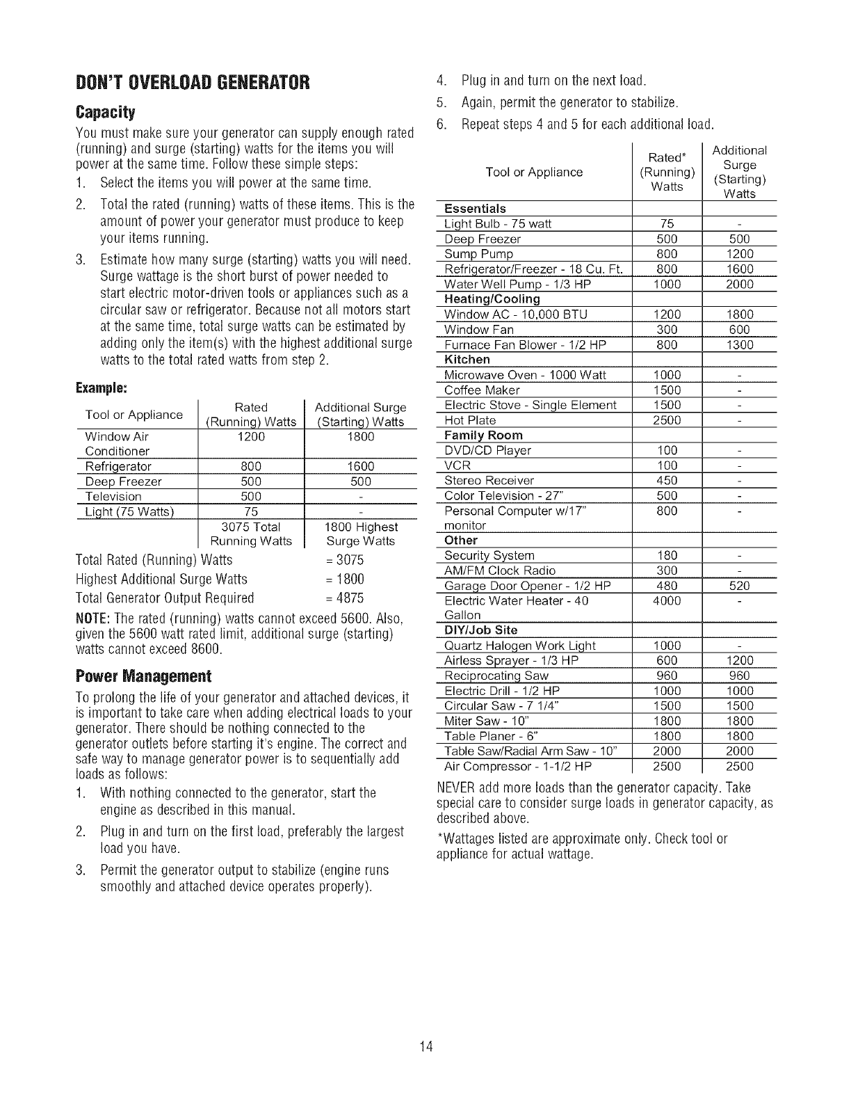
Generator Adapter Cord Set
The generator comes with a 25' generator adapter cord set
designed to provide two sets of 120 Volt, 20 Amp outlets
from one 120 Volt, 20 Amp duplex receptacle.
2. Unplug charger from unit and wall outlet when generator'
is being started and while in operation.
3. Keepcharger plugged in when generator is not in useto
prolong battery life. The charger has a built in float
equalizer and will not overcharge battery, even when
plugged in for an extendedperiod of time.
IMPORTANT:See Battery Maintenancefor additional
information.
The maximum load on each outlet is 20 Amps. The maximum
total load on both black wire outlets or white stripe wire
outlets is 20 Amps.
NOTE:Follow all safety precautions when connecting any
extension cord or deviceto the generator.
13
DOH'TOVERLOADGENERATOR
Capacity
You must make sure your generator can supply enough rated
(running) and surge (starting) watts for the itemsyou will
power at the sametime. Followthese simple steps:
1. Selectthe itemsyou will power at the same time.
2. Total the rated (running) watts of these items.This isthe
amount of power your generator must produce to keep
your items running.
3. Estimate how manysurge (starting) watts you will need.
Surge wattage is the short burst of power neededto
start electric motor-driven tools or appliancessuch as a
circular saw or refrigerator. Becausenot all motors start
at the sametime, total surge watts can be estimated by
adding only the item(s) with the highest additional surge
watts to the total rated watts from step 2.
Example:
Rated
(Running) Watts
1200
8OO
5OO
5OO
75
3075 Total
Running Watts
Tool or Appliance
Window Air
Conditioner
Refrigerator
Deep Freezer
Television
Light (75 Watts)
Total Rated(Running) Watts
HighestAdditional SurgeWatts
Total Generator Output Required
Additional Surge
(Starting) Watts
1800
1600
5OO
1800 Highest
Surge Watts
= 3075
= 1800
= 4875
NOTE:The rated (running) watts cannot exceed5600. Also,
given the 5600 watt rated limit, additional surge (starting)
watts cannot exceed8600.
Power Management
To prolong the life of your generator and attached devices, it
is important to take care when adding electrical loads to your
generator. There should be nothing connected to the
generator outlets before starting it's engine. The correct and
safe way to managegenerator power is to sequentially add
loads as follows:
1. With nothing connected to the generator, start the
engine as described in this manual.
2. Plug in and turn on the first load, preferablythe largest
load you have.
3. Permit the generator output to stabilize (engine runs
smoothly and attached deviceoperates properly).
4. Plug in and turn on the next load.
5. Again, permit the generator to stabilize.
6. Repeatsteps 4 and 5 for each additional load.
Tool or Appliance
Essentials
Light Bulb - 75 watt
Deep Freezer
Sump Pump
RefrigeratorlFreezer- 18 Cu. Ft.
Water Well Pump- 1/3 HP
Heating/Cooling
Window AC - 10,000 BTU
Window Fan
Furnace Fan Blower- I/2 HP
Kitchen
Microwave Oven - 1000 Watt
Coffee Maker
Electric Stove - Single Element
Hot Plate
Family Room
DVD/CD Player
VCR
Stereo Receiver
Color Television - 27"
Personal Computer w/17"
monitor
Other
Security System
AM/FM Clock Radio
Garage Door Opener - I/2 HP
Electric Water Heater - 40
Gallon
DIY/Job Site
Quartz Haloqen Work Light
Airless Sprayer- I/3 HP
Reciprocating Saw
Electric Drill- I/2 HP
Circular Saw - 7 1/4"
Miter Saw - 10"
Table Planer - 6"
Table Saw/Radial Arm Saw - 10"
Air Compressor - I-1/2 HP
Additional
Rated* Surge
(Running) (Starting)
Watts Watts
75
500 500
800 1200
800 1600
1000 2000
1200 1800
300 600
800 1300
1000
1500
1500
2500
100
100
45O
5OO
8OO
180
3OO
480 520
4000
1000
600 1200
960 960
1000 1000
1500 1500
1800 1800
1800 1800
2000 2000
2500 2500
NEVERadd more loads than the generator capacity. Take
special care to consider surge loads in generator capacity, as
describedabove.
*Wattageslisted are approximate only. Checktool or
appliance for actual wattage.
14
EHGINETECHNICALIHFORMATION
This is a single cylinder, overhead vaive(OHV),air coded
engine, it is alow emissions engine.
Inthe Stateof California, Model 200000 engines are certified
by the California Air Resources Boardto meet emissions
standards for 250 hours. Such certification does not grant
the purchaser, owner or operator of this engine any
additional warranties with respectto the performance or
operational life of this engine. The engine is warranted solely
according to the product and emissions warranties stated
elsewherein this manual.
Power Ratings
The gross power rating for individual gas engine models is
labeledin accordance with SAE(Society of Automotive
Engineers)code J1940 (Small Engine Power & Torque
Rating Procedure),and rating performance has been
obtained andcorrected in accordancewith SAEJ1995
(Revision 2002-05). Torque values are derived at 3060 RPM;
horsepower values are derived at 3600 RPM. Actual gross
engine power will be lower and is affected by, among other
things, ambient operating conditions and engine-to-engine
variability. Given both the wide array of products on which
engines are placed and the variety of environmental issues
applicable to operating the equipment, the gas engine will not
develop the rated gross power when used in a given piece of
power equipment (actual "on-site" or net power). This
difference is due to a variety of factors including, but not
limited to, accessories (air cleaner, exhaust,charging,
cooling, carburetor, fuel pump, etc.), application limitations,
ambient operating conditions (temperature,humidity,
altitude), and engine-to-engine variability. Due to
manufacturing and capacity limitations, Briggs & Stratton
maysubstitute an engine of higher rated power for this
Series engine.
PRODUCTSPECIFICATIOHS
Generator Specifications
Wattage ........................ 5600 Watts (5.6 kW)
Starting Wattage ................. 8600 Watts (8.6 kW)
RatedAC Voltage ...................... 120/240 Volts
RatedAC Current
at 240 Volts ........................ 23.3 Amperes
at 120 Volts ........................ 46.6 Amperes
RatedFrequency ................... 60 Hzat 3600 rpm
Phase ................................ Single Phase
FuelCapacity ......................... 5 U.S. gallons
Unit Weight ............................... 170 Ibs.
Engine Specifications
Bore .............................. 3.12 in. (79 mm)
Stroke ............................ 2.44 in. (62 mm)
Displacement ...................... 18.64 in. (305 cc)
Spark Plug
Type: .................... Briggs & Stratton 491055
Set GapTo: ................... O.030inch(0.76mm)
Armature Air Gap: ........ 0.008-0.012 in. (0.20-0.30mm)
Valve clearancewith valvesprings installed and piston 1/4 in.
(6 mm) past top dead center (check when engine is cold).
Intake ................. 0.004-0.006 in. (0.10-0.15 mm)
Exhaust ............... 0.004-0.006 in. (0.10-0.15 mm)
Oil Capacity ............................... 28 fl. oz.
NOTE:For practical operation, the generator load should not
exceed 85% of rated wattage. Enginegross horsepower will
decrease3-1/2% for each 1,000 feet (300 meters) above sea
level and 1% for each 10° F (5.6° C) above 77° F (25° C). It
should operate satisfactorily at an angle up to 15° .
15
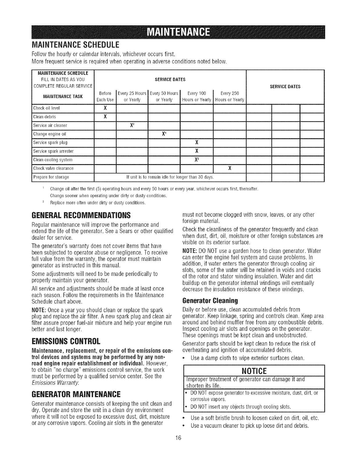
MAINTENANCESCHEDULE
Followthe hourly or calendar intervals, whichever occurs first.
More frequent service is required when operating in adverseconditions noted below.
MAINTENANCESCHEDULE
FILL IN DATESAS YOU
COMPLETEREGULARSERVICE SERVICEDATES
MAINTENANCETASK Every 25 Hours
or Yearly
Check oil level
Cleandebris
Service air cleaner
Change engine oil
Service spark plug
Service spark arrester
Cleancooling system
Check valve clearance
Prepare for storage
Before
Each Use
X
×
SERVICEDATES
Every 50 Hours Every 100 Every 250
or Yearly Hours or Yeary Hours or Yeary
X1
×
X
X_
×
If unit is to remain idle for longer than 30 days.
Change oil after the first (5) operating hours and every 50 hours or every year, whichever occurs first, thereafter.
Change sooner when operating under dirty or dusty conditions.
2 Replace more often under dirty or dusty conditions.
GENERALRECOMMENDATIONS
Regular maintenancewill improve the performance and
extendthe life of the generator. Seea Sears or other qualified
dealerfor service.
The generator's warranty does not cover items that have
been subjected to operator abuse or negligence.To receive
full value from the warranty, the operator must maintain
generator as instructed in this manual.
Some adjustments will needto be made periodically to
properly maintain your generator.
All service and adjustments should be made at least once
each season. Follow the requirements in the Maintenance
Schedule chart above.
NOTE:Oncea year you should clean or replace the spark
plug and replace the air filter. A new spark plug and clean air
filter assure proper fuel-air mixture and help your engine run
better and last longer.
EMiSSiONSCONTROL
[Vlaintellance, replacement, or repair of the emissions con-
trol devicesand systems may be performedby any non-
road engine repair establishment or individual. However,
to obtain "no charge" emissions control service,the work
must be performed by a qualified service center. Seethe
Emissions Warranty.
GENERATORMAINTENANCE
Generatormaintenanceconsists of keepingthe unit clean and
dry. Operateand store the unit in a clean dry environment
where it will not be exposedto excessive dust, dirt, moisture
or any corrosive vapors. Cooling air slots in the generator
must not becomeclogged with snow, leaves, or any other
foreign material.
Checkthe cleanliness of the generator frequently and clean
when dust, dirt, oil, moisture or other foreign substances are
visible on its exterior surface.
NOTE:DO NOTuse a garden hose to clean generator. Water
can enter the engine fuel system and causeproblems. In
addition, if water enters the generator through cooling air
slots, some of the water will be retained in voids and cracks
of the rotor and stator winding insulation. Water and dirt
buildup on the generator internal windings will eventually
decreasethe insulation resistance of these windings.
Generator Cleaning
Daily or before use,clean accumulated debris from
generator. Keeplinkage,spring and controls clean. Keeparea
around and behind muffler free from any combustible debris.
Inspect cooling air slots and openings on the generator.
Theseopenings must be kept clean and unobstructed.
Generator parts should be kept clean to reducethe risk of
overheating and ignition of accumulated debris.
• Usea damp cloth to wipe exterior surfaces clean.
NOTICE
Improper treatment of generator can damage it and
shorten its life.
DONOTexposegeneratorto excessivemoisture,dust,dirt, or
corrosivevapors.
DONOTinsertanyobjectsthroughcoolingslots.
,, Usea soft bristle brush to loosen caked on dirt, oil, etc.
• Usea vacuumcleanerto pick uploose dirt and debris.
16
BatteryMaintenance
Other than trickle charging, describedelsewhere, no
maintenanceis required for the battery. Keepthe battery and
terminals clean and dry.
IMPORTANT:Battery charging should be performed in a dry
location, such as inside a garage.
StatStation TM
The StatStationTM displays the nominal load on generator
based on output frequency. It also has a built in maintenance
reminder.
Wattage Monitor Operation
The display is two seven-segment LEDsthat provide an easy-
to-read indication of the amount of power being supplied by
the generator. The load monitor displays the generator's
output as a percentage.
As generator load increases,the display values will increase.
When the displayedvalues begin flashing, the user should
stop adding electrical loads to the generator.
If the power usage becomestoo high, the letters "OL" (for
Over Load)will flash on the display. The user should reduce
the amount of load attached to the generator.
Maintenance Reminder
The LEDwill displaycertain codesto alert you to check oil,
changeoil, check or replaceair filter and check or replace
spark plug. The following codes will display:
"C1" Check oil at 8 hour increments
"62" Changeoil at 50 hour increments
"63" Check or replaceair filter at 25 hour increments
"C4" Check or replacespark plug at 100 hour increments
To take advantage of the StatStation "maintenance reminder"
capabilities, the user must press the resetbutton after
completing the maintenancecalled for in the displayedcode
(Cl, C2, 03, or C4). This results in a display of "Co" or "CA",
depending on how long the button is pressed:
1) "Co" - Pressingthe reset button once quickly will display
"Co"(clearing to zero). This will clear any maintenance
codes that have elapsed up to that point and they will
begin timing again from zero.
2) "CA" - Pressing and holding the reset button for
2 seconds will display "CA"(clearing all). This clears all
maintenancecodes, even if they have not yet reached
their service point, and they will begin timing again from
ze re.
If nominal load and maintenancecodes appear
simultaneously, the LEDshall display, alternately, the
nominal load and code as follows:
The code will display for 3 seconds, then 1/2 second off. The
load will display for 6 seconds and then 1/2 second off.
ENGINEMAIHTENANCE
WARNING
_ Unintentional sparking can result in fire or
_¢ electric shock.
WHENADJUSTINGORMAKINGREPAIRSTOYOURGENERATOR
.Disconnectthe sparkplugwirefromthe sparkplugandplace
thewirewhereit cannotcontactsparkplug.
WHENTESTINGFORENGINESPARK
•Useapprovedsparkplugtester.
.DONOTcheckfor sparkwithsparkplugremoved.
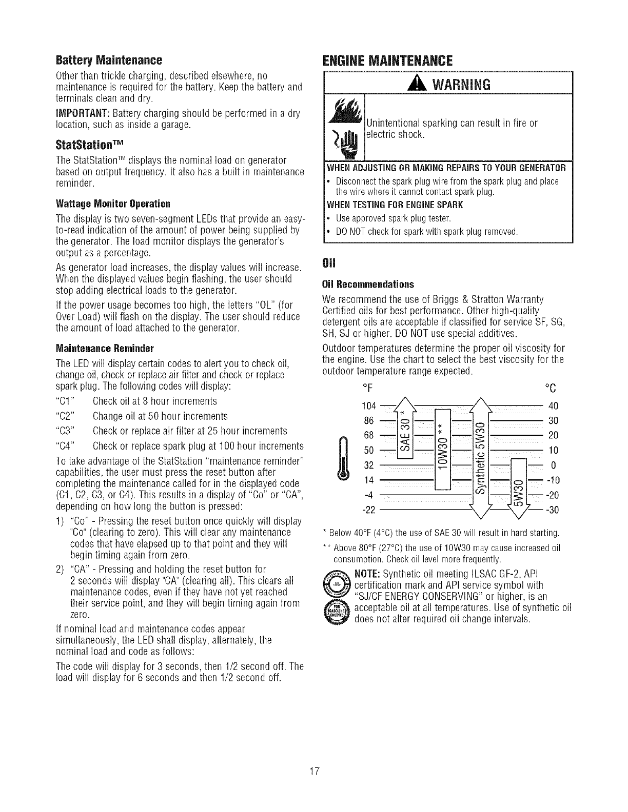
Oil
Oil Recommendations
We recommend the use of Briggs & Stratton Warranty
Certified oils for best performance. Other high-quality
detergentoils are acceptableif classified for service SF,SG,
SH,SJ or higher. DO NOTuse special additives.
Outdoor temperatures determinethe proper oil viscosity for
the engine. Usethe chart to select the best viscosity for the
outdoor temperature range expected.
oF
104 m _, __ ,
o6- I-.-
-22
°C
20
10
m 0
L-- o
2- --3o
* Below40°F(4%) the useof SAE30will resultinhardstarting.
** Above80°F(27°0)the useof 10W30maycauseincreasedoil
consumption.Checkoil levelmorefrequently.
@t0 OTE:Synthetic oil meeting ILSACGF-2,API
certification mark and API serv,!cesymbol with
"SJ/CF ENERGYCONSERVING or higher, is an
acceptableoil at all temperatures. Use of synthetic oil
does not alter required oil change intervals.
17
CheckingOil Level
Oil levelshould bechecked prior to each use or at leastevery
5 hours of operation.Keepoil level maintained.
1. Make sure generator is on a level surface.
2. Cleanarea around oil fill and remove oil fill cap.
3. Verify oil is at the point of overflowing at oil fill opening.
4. Replaceand tighten oil fill cap.
AddingEngineOil
1. Make sure generator is on a level surface.
2. Check oil level as described in Checking Oil Level
3. If needed, slowly pour oil into oil fill opening to the point
of overflowing at oil fill.
4. Replaceand tighten oil fill cap.
Service Air Cleaner
Your enginewill not run properly and may be damagedif you
run it with a dirty air cleaner.
Replacethe air cleaner every 25 hours of operation or once
each year, whichever comes first. Replacemore often if
operating under dirty or dusty conditions.
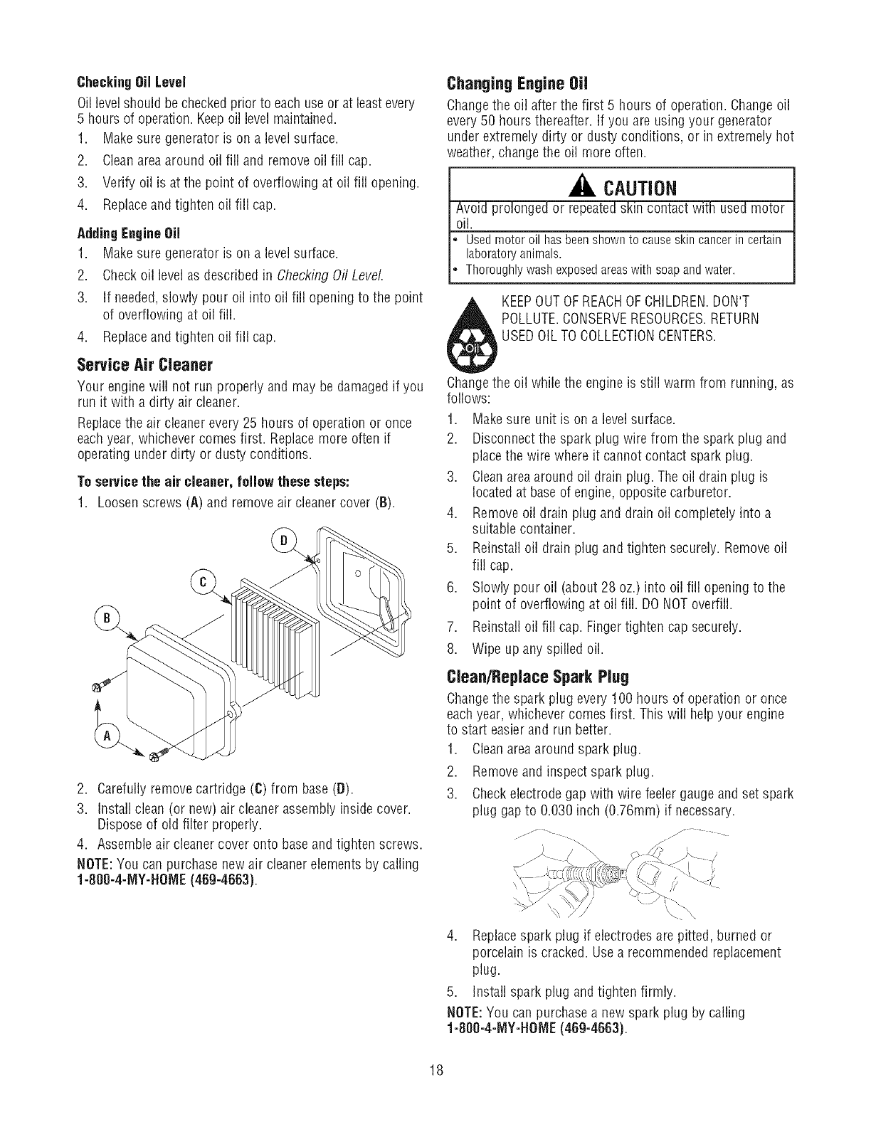
To servicethe air cleaner, folJew these steps:
1. Loosen screws (A) and removeair cleaner cover (B).
2. Carefully removecartridge (C) from base (D).
3. Install clean (or new) air cleaner assembly inside cover.
Dispose of old filter properly.
4. Assemble air cleaner cover onto base and tighten screws.
NOTE:You can purchase new air cleaner elements by calling
1-SOO-4-MY-HOME(46g-4663).
ChangingEngineOil
Changethe oil after the first 5 hours of operation. Changeoil
every 50 hours thereafter. If you are using your generator
under extremely dirty or dusty conditions, or in extremely hot
weather, change the oil more often.
CAUTION
Avoid prolonged or repeatedskin contact with used motor
oil.
Usedmotoroil hasbeenshownto causeskincancerin certain
laboratoryanimals.
Thoroughlywashexposedareaswith soapandwater.
KEEPOUTOF REACHOF CHILDREN.DON'T
POLLUTE.CONSERVERESOURCES.RETURN
USEDOIL TO COLLECTIONCENTERS.
Changethe oil while the engine is still warm from running, as
follows:
1. Makesure unit is on a level surface.
2. Disconnect the spark plug wire from the spark plug and
placethe wire where it cannot contact spark plug.
3. Cleanareaaround oil drain plug. The oil drain plug is
locatedat base of engine, opposite carburetor.
4. Remove oil drain plug and drain oil completely into a
suitable container.
5. Reinstall oil drain plug and tighten securely. Removeoil
fill cap.
6. Slowly pour oil (about 28 oz.) into oil fill opening to the
point of overflowing at oil fill. DONOToverfill.
7. Reinstall oil fill cap. Fingertighten cap securely.
8. Wipe up any spilled oil.
CleanlReplace Spark Plug
Changethe spark plug every 100 hours of operation or once
each year, whichever comes first. This will help your engine
to start easierand run better.
1. Cleanareaaround spark plug.
2. Removeand inspect spark plug.
3. Checkelectrode gap with wire feeler gauge and set spark
plug gap to 0.030 inch (0.76ram) if necessary.
jjJ -- -. f .....
4. Replacespark plug if electrodes are pitted, burned or
porcelain is cracked. Usea recommended replacement
plug.
5. install spark plug and tighten firmly.
NOTE:You can purchase a new spark plug by calling
1-800-4-NIY-HOME(469-4663).
18
Clean Spark Arrester Screen
The engine exhaust muffler has a spark arrester screen.
Inspectand clean the screen every 100 hours of operation or
once eachyear, whichever comes first.
NOTE:You can purchasea new spark arrester screen by
calling 1-800-4-MY-HOME (46g-4663).
If you useyour generator on any forest-covered, brush-
covered, or grass-coveredunimproved land, it must have a
spark arrester. The spark arrester must be maintainedin good
condition by the owner/operator.
WARNING
_ ontact with muffler areacan result in serious
burns.
_ Exhaust heat/gases can ignite combustibles,
structures or damagefuel tank causing a fire.
• DONOTtouch hot parts and AVOIDhot exhaustgases.
Allow equipment to cool before touching.
• Keep at least 5 feet (1.5 m) of clearance on all sides of
generator including overhead.
• Codeof FederalRegulation (CFR) Title 36 Parks, Forests, and
Public Property require equipment powered by an internal
combustion engineto have a spark arrester, maintainedin
effective working order, complying to USDAForest service
standard 5100-1C or later revision. In the State of California a
spark arrester is required under section 4442 of the California
Public resourcescode. Otherstates may havesimilar laws.
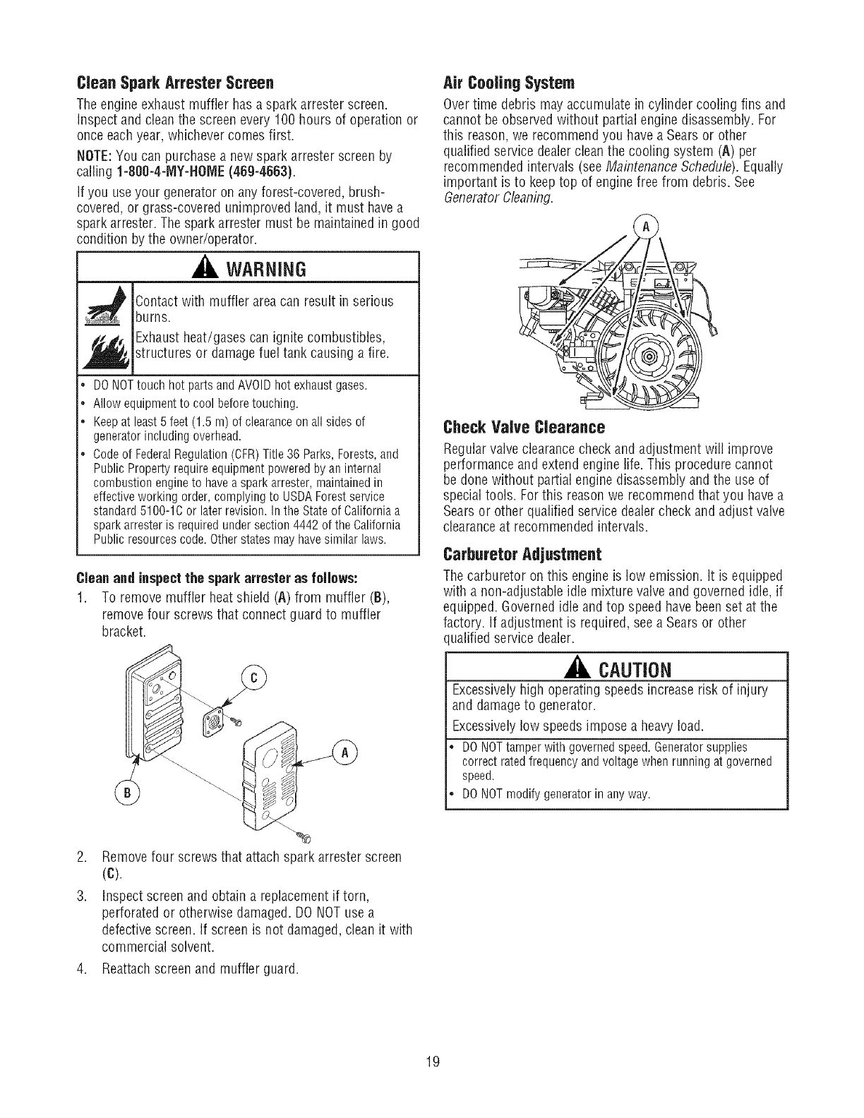
Clean and inspect the spark attester as follows:
1. To remove muffler heat shield (A) from muffler (B),
remove four screws that connect guard to muffler
bracket.
2. Remove four screws that attach spark arrester screen
(C).
3. Inspect screen and obtain a replacement if torn,
perforated or otherwise damaged. DO NOTuse a
defective screen. If screen is not damaged,clean it with
commercial solvent.
4. Reattachscreen and muffler guard.
Air Coofing System
Overtime debris may accumulate in cylinder cooling fins and
cannot be observed without partial engine disassembly. For
this reason,we recommend you have a Sears or other
qualified service dealerclean the cooling system (A) per
recommended intervals (see Maintenance Schedule).Equally
important is to keeptop of engine free from debris. See
Generator Cleaning.
Check VaJve Clearance
Regular valveclearancecheck and adjustment will improve
performance and extend engine life. This procedure cannot
be done without partial engine disassembly andthe use of
special tools. For this reason we recommend that you have a
Searsor other qualified service dealercheck and adjust valve
clearanceat recommended intervals.
Carburetor Adjustment
The carburetor on this engine is low emission, it is equipped
with a non-adjustable idle mixture valve and governed idle, if
equipped. Governedidle and top speed have beenset at the
factory. If adjustment is required, see a Sears or other
ualified service dealer.
CAUTION
Excessivelyhigh operating speeds increase risk of injury
and damageto generator.
Excessivelylow speeds impose a heavyload.
DONOTtamperwithgovernedspeed.Generatorsupplies
correctratedfrequencyandvoltagewhenrunningat governed
speed.
DONOTmodifygeneratorinanyway.
19
GENERAL
The generator should be started at least once every seven
days and allowed to run at least30 minutes, if this cannot be
done and you must store the unit for more than 30 days, use
the following information as a guide to prepare it for storage.
LongTerm Storage Instructions
It is important to prevent gum deposits from forming in
essential fuel system parts, such as the carburetor, fuel filter,
fuel hose or tank during storage. Also, experienceindicates
that alcohol-blended fuels (called gasoho], ethanol or
methanol) can attract moisture, which leads to separation
and formation of acids during storage. Acidic fuel can
damagethe fuel system of an engine while in storage.
WARNING
_Fuel and its are extremely flammable and
vapors
explosive.
_j_ ire or explosion can causesevere burns or
death.
WHEN STORINGFUELOR EQUIPMENTWITH FUELINTANK
• Storeawayfrom furnaces,stoves,waterheaters,clothesdryers
or otherappliancesthat havepilotlight or otherignitionsource
becausetheycanignitefuel vapors.
WHEN DRAININGFUEL
•TurngeneratorOFFandlet it coolat least2 minutesbefore
removingfuel cap.Loosencapslowlyto relievepressurein
tank.
. Drainfueltankoutdoors.
. Keepfuel awayfromsparks,openflames,pilot lights,heat,and
otherignitionsources.
• DONOTlighta cigaretteorsmoke.
Protect Fuel System
Fuel Preserver:
ChangeOil
While engine is still warm, drain oil from crankcase. Refill
with recommended grade.
Oil CylinderBore
* Removespark plug and pour about 1 ounce (30ml) of
clean engine oil into the cylinder.
. Install spark plug and crank slowly to distribute oil.
WARNING
_ Unintentional sparking can result in fire or
_¢ electric shock.
•NEVERcrankenginewith sparkplugremoved.
Generator
1. Cleangenerator as outlined in Generator Cleaning.
2. Checkthat cooling air slots and openings on generator
are openand unobstructed.
Other Storage Tips
1. DO NOTstore fuel from one seasonto another unless it
has beentreated as described in Protect Fuel System.
2. Replacefuel can if it starts to rust. Contaminatedfuel
will cause engine problems.
If possible, store unit indoors and cover it to give
protection from dust and dirt.
Coverunit with a suitable protective cover that does not
retain moisture.
WARNING
Storagecovers can be flammable.
Fillthe fuel tank with fresh fuel allowing at least 1.5"of tank
spacefor fuel expansion as shown on page8, when using a
fuel preserver cartridge with the fresh start fuel cap. If only
partially filled, air in the tank will promote fuel deterioration
during storage. Engineand fuel can be stored upto 6 months
with fuel preserver.
• Checklevel of fuel preserver cartridge. Fuelpreserver is
dark in color.
• If cartridge is almost empty or empty, replace with a new
fuel preserver cartridge following the instructions in Fresh
StarY Fuel Cap.
If fuel preserver is not used, remove all fuel from tank and
run engine until it stops from lack of fuel.
DONOTplace a storage cover over a hot generator.
Let equipment cool for a sufficient time before placing the cover
on the equipment.
Store generator in clean, dry area.
2O
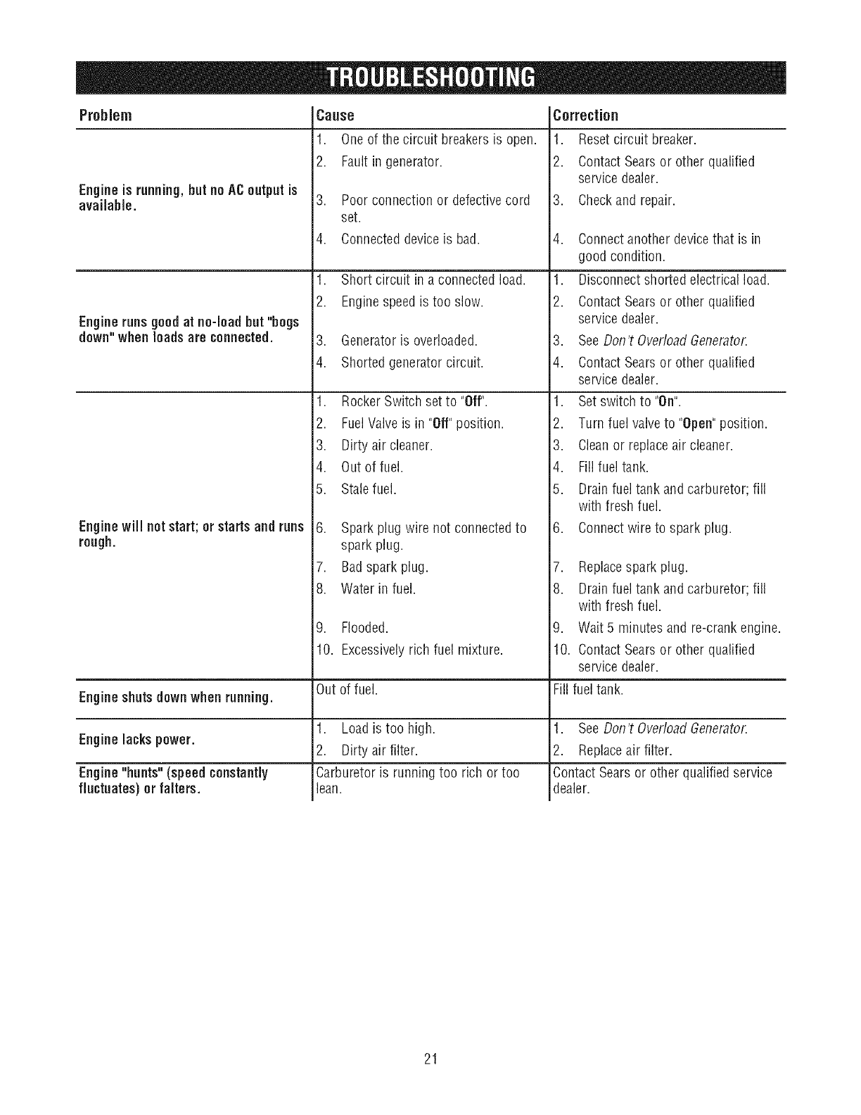
Problem
Engineis running,butno A€ outputis
available.
Engine runs goodat no-load hut "hogs
down" when loads are connected.
Engine will not start; orstarts and runs
Csuse
1. One of the circuit breakers is open.
2. Faultin generator.
3. Poor connection or defective cord
set.
4. Connected device is bad.
1. Short circuit in a connected load.
2. Enginespeed is too slow.
3. Generator is overloaded.
4. Shorted generator circuit.
1. Rocker Switch set to "Off".
2. FuelValve is in "Off" position.
3. Dirty air cleaner.
4. Out of fuel.
5. Stale fuel.
6. Spark plug wire not connected to
Cerreciien
1. Reset circuit breaker.
2. Contact Searsor other qualified
service dealer.
3. Checkand repair.
4. Connectanother device that is in
good condition.
1. Disconnect shorted electrical load.
2. Contact Searsor other qualified
service dealer.
3. SeeDon't OverloadGenerator.
4. Contact Searsor other qualified
service dealer.
1. Set switch to "On".
2. Turn fuel valveto "Open"position.
3. Cleanor replace air cleaner.
4. Fill fuel tank.
5. Drain fuel tank and carburetor; fill
with fresh fuel.
6. Connectwire to spark plug.
rough. spark plug.
7. Badspark plug.
8. Water in fuel.
9. Flooded.
7. Replacespark plug.
8. Drain fuel tank and carburetor; fill
with fresh fuel.
9. Wait 5 minutes and re-crank engine.
Engine shutsdown when running.
Engine lacks power.
Engine"hunts" (speed constantly
fluctuates) or falters.
10. Excessivelyrich fuel mixture.
Out of fuel.
1. Loadis too high.
2. Dirty air filter.
Carburetor is running too rich or too
lean.
10. Contact Searsor other qualified
service dealer.
Fill fuel tank.
1. SeeDon't OverloadGenerator.
2. Replaceair filter.
ContactSears or other qualified service
dealer.
21
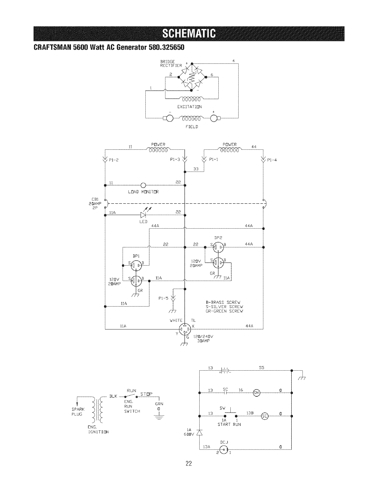
CRAFTSMAH5600 Watt AC Generator 580,325650
BRIDGE +
_RECTIFIER
EXCITATION
- +
FIELD
COl
20AMP
2P
PI-2
IIA
120V
20AMP
IIA
11 POWER
PI-3
0 22
LOAD MONITOR
/4/4 22
)4
LEB
44A
22
IIA
PI-5_
WHITE
F
POWER
lIP2
I20V
20AMP
G_ IIAI
B-BRASS SCREW
S-SILVER SCREW
GR-GREEN SCREW
TL
bX
t20/240V
30AMP
44
44A
44A
44A
PI-4
55
__
SPARK
PLUG
ENG,
IGNITION
RUN
ENG,
RUN
SWITCH
GRN
0
IA
600V
_7 l_ Q o
sw__
IA i
START RUN
DCJ
22
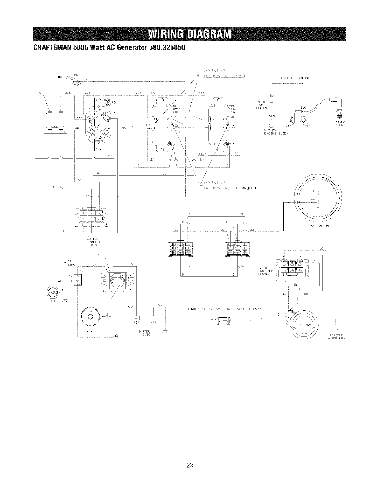
CRAFTSMAH5600 Watt AC Generator 580.325650
!IA
I3
\
13_ =
DCJ /X2
WARN NG
[rlCA/ED I_N EN(_;N£
_LK
GRN
o
NUT _N
ENGINE BL_CK
iAB NUSI NOI BE BROKEN
33
NE]TI P_]SI1 VEI :BRUSH IS CL_SESI [J BEARIN(
CUSTONER
GROUND LUG
23
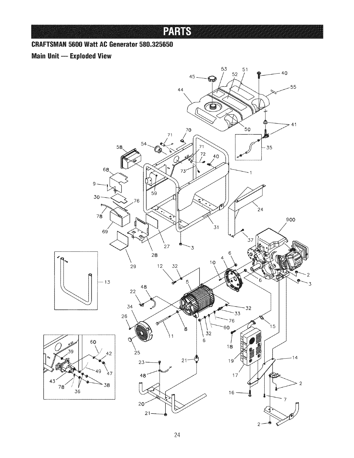
CRAFTSMAH5600 Watt AC Generator 580.325650
71
Main Unit -- Exploded View
44
7O
/
55 51
5O 41
58\
78
69
--1,3
36
6O
49 47
_ 38
27
28
29 12 32
48
22 \
54
26\
11
57
3
6
4
I0
17
24
900
24
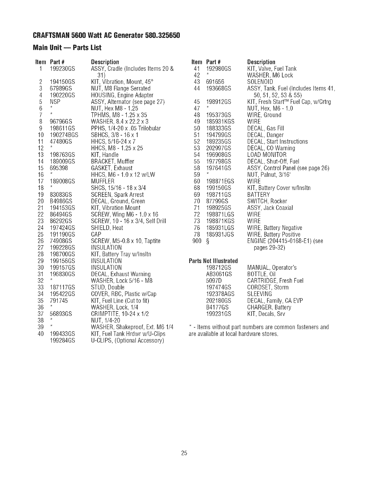
CRAFTSMAN5600 Watt ACGenerator500.325650
Main Unit -- Parts List
Item Part #
1 199230GS
2 194150GS
3 67989GS
4 190220GS
5 NSP
6 *
7 *
8 96796GS
9 198611GS
10 190274BGS
11 47480GS
12 *
13 198763GS
14 189009GS
15 695398
16 *
17 189008GS
18 *
19 83083GS
20 B4986GS
21 194153GS
22 86494GS
23 86292GS
24 197424GS
25 191190GS
26 74908GS
27 199228GS
28 198700GS
29 199156GS
30 199157GS
31 196830GS
32 *
33 187117GS
34 195422GS
35 791745
36 *
37 56893GS
38 *
39 *
40 199433GS
199284GS
Description
ASSY, Cradle(Includes Items 20 &
31)
KIT,Vibration, Mount, 45°
NUT,M8 FlangeSerrated
HOUSING,EngineAdapter
ASSY,Alternator (see page27)
NUT,HexM8 - 1.25
TPHMS, M8- 1.25 x 35
WASHER,8.4 x 22.2 x 3
PPHS,1/4-20 x .05 Trilobular
SBHCS,3/8- 16 x 1
HHCS,5/16-24 x 7
HHCS,M8- 1.25 x 25
KIT, Handle
BRACKET,Muffler
GASKET,Exhaust
HHCS,M6- 1.0 x 12 w/LW
MUFFLER
SHCS,15/16- 18 x 3/4
SCREEN,Spark Arrest
DECAL,Ground, Green
KIT,Vibration Mount
SCREW,Wing M6 - 1.0 x 16
SCREW,10- 16 x 3/4, Self Drill
SHIELD,Heat
CAP
SCREW,M5-0.8 x 10, Taptite
INSULATION
KIT, Battery Trayw/Insltn
INSULATION
INSULATION
DECAL,ExhaustWarning
WASHER,Lock 5/16- M8
STUD,Double
COVER,RBC,Plastic w/Cap
KIT, FuelLine (Cutto fit)
WASHER,Lock, 1/4
CRIMPTITE,10-24 x 1/2
NUT,1/4-20
WASHER,Shakeproof, Ext. M6 1/4
KIT, FuelTank Hrdwr w/U-Clips
U-CLIPS,(Optional Accessory)
Item Part#
41 192980GS
42 *
43 691656
44 193668GS
45 198912GS
47 *
48 195373GS
49 185931KGS
50 188333GS
51 194799GS
52 189235GS
53 202997GS
54 196908GS
55 197798GS
58 197641GS
59 *
60 198871EGS
68 199150GS
69 198711GS
70 87799GS
71 198925GS
72 198871LGS
73 198871KGS
76 185931LGS
78 185931JGS
900 §
Description
KIT, Valve,Fuel Tank
WASHER,M6 Lock
SOLENOID
ASSY, Tank, Fuel (Includes Items 41,
50, 51,52, 53 & 55)
KIT, FreshStartTM Fuel Cap,w/Crtrg
NUT,Hex, M6- 1.0
WIRE, Ground
WIRE
DECAL,Gas Fill
DECAL,Danger
DECAL,Start Instructions
DECAL,COWarning
LOADMONITOR
DECAL,Shut-Off, Fuel
ASSY, Control Panel(see page26)
NUT,Palnut, 3/16"
WIRE
KIT, Battery Coverw/Insltn
BATTERY
SWITCH,Rocker
ASSY, Jack Coaxial
WIRE
WIRE
WIRE, Battery Negative
WIRE, Battery Positive
ENGINE(204415-0168-E1) (see
pages29-32)
Parts Netlllustrated
198712GS
AB3061GS
5097D
197474GS
192378AGS
202180GS
B4177GS
199231GS
MANUAL,Operator's
BOTTLE,Oil
CARTRIDGE,Fresh Fuel
CORDSET,Storm
SLEEVING
DECAL,Family, CAEVP
CHARGER,Battery
KIT, Decals,Srv
* - Items without part numbers are common fasteners and
are available at local hardware stores.
25
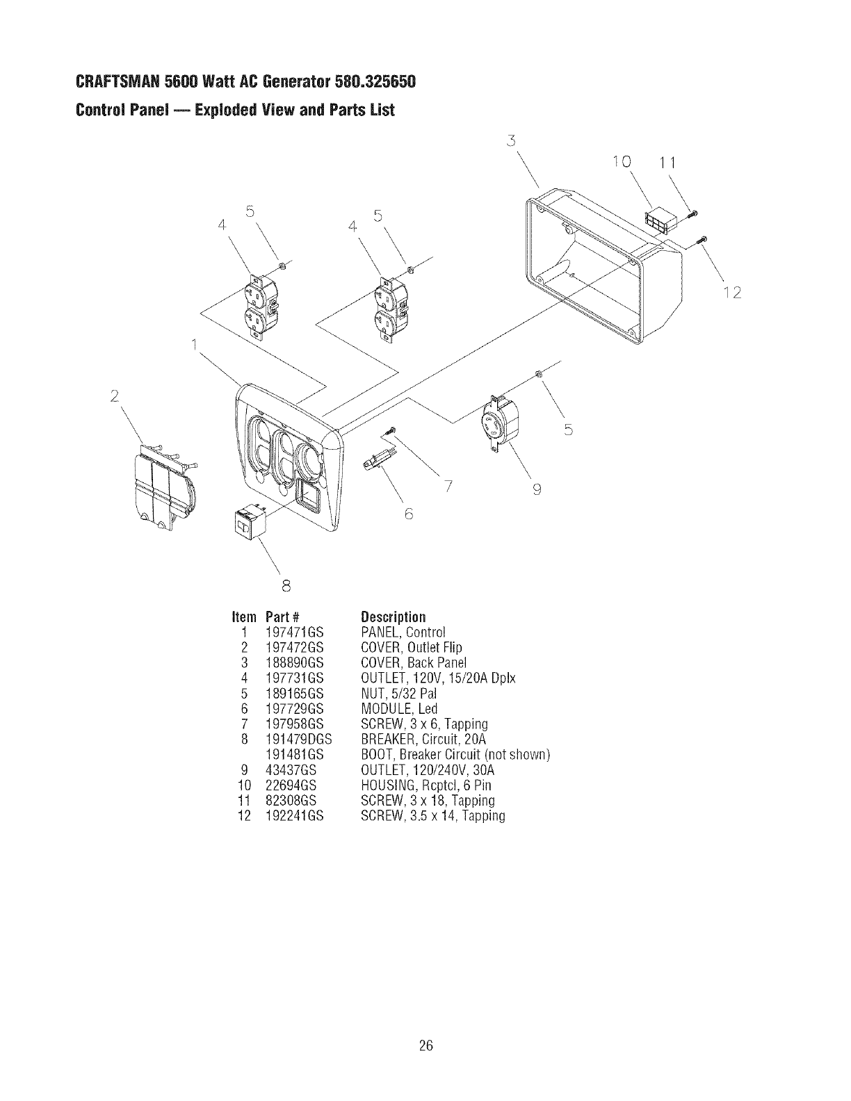
CRAFTSMAH5600 Watt AC Generator 500.325650
Control Panel -- Exploded View and Parts List
5
\\ \\\\\
2\
5
4 \
\\
8
5
\ 7 9
\
6
Item
1
2
3
4
5
6
7
8
9
10
11
12
Part #
197471GS
197472GS
188890GS
197731GS
189165GS
197729GS
197958GS
191479DGS
191481GS
43437GS
22694GS
82308GS
192241GS
Description
PANEL,Control
COVER,Outlet Flip
COVER,BackPanel
OUTLET,120V, 15/20A Dplx
NUT,5/32 Pal
MODULE,Led
SCREW,3 x 6, Tapping
BREAKER,Circuit, 20A
BOOT,BreakerCircuit (not shown)
OUTLET,120/240V, 30A
HOUSING,Rcptcl, 6 Pin
SCREW,3 x 18, Tapping
SCREW,3.5 x 14, Tapping
10 \11
\
12
26
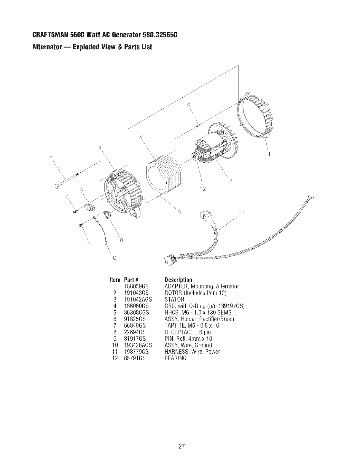
CRAFTSMAH5600 Watt AC Generator 580,325650
Alternator -- Exploded View & Parts List
5
\\\\\\\\
\
12
\2
\1
Item
1
2
3
4
5
6
7
8
9
10
11
12
Part #
186059GS
191043GS
191042AGS
186060GS
86308CGS
91825GS
66849GS
22694GS
81917GS
193428AGS
198779GS
65791GS
Description
ADAPTER,Mounting, Alternator
ROTOR(Includes Item 12)
STATOR
RBC,with O-Ring (p/n 189197GS)
HHCS,M6- 1.0 x 130 SEMS
ASSY, Holder, Rectifier/Brush
TAPTITE,M5 - 0.8 x 16
RECEPTACLE,6 pin
PIN, Roll, 4mm x 10
ASSY,Wire, Ground
HARNESS,Wire, Power
BEARING
27
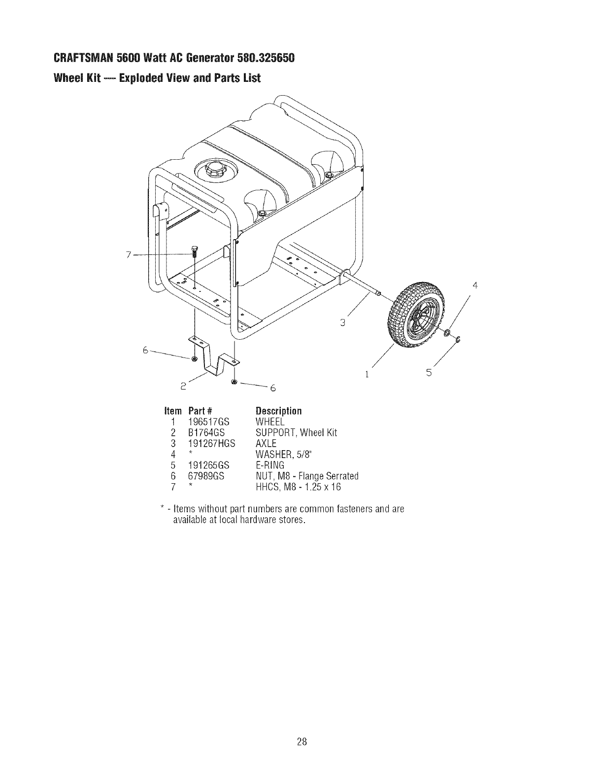
CRAFTSMAH5600 Watt AC Generator 580.325650
Wheel Kit -- Exploded View and Parts List
Item Part #Description
1 196517GS WHEEL
2 B1764GS SUPPORT,Wheel Kit
3 191267HGS AXLE
4*WASHER,5/8"
5 191265GS E-RING
6 67989GS NUT,MS- FlangeSerrated
7*HHCS,MS-1.25x16
* - Items without part numbers are common fasteners and are
available at local hardware stores.
28
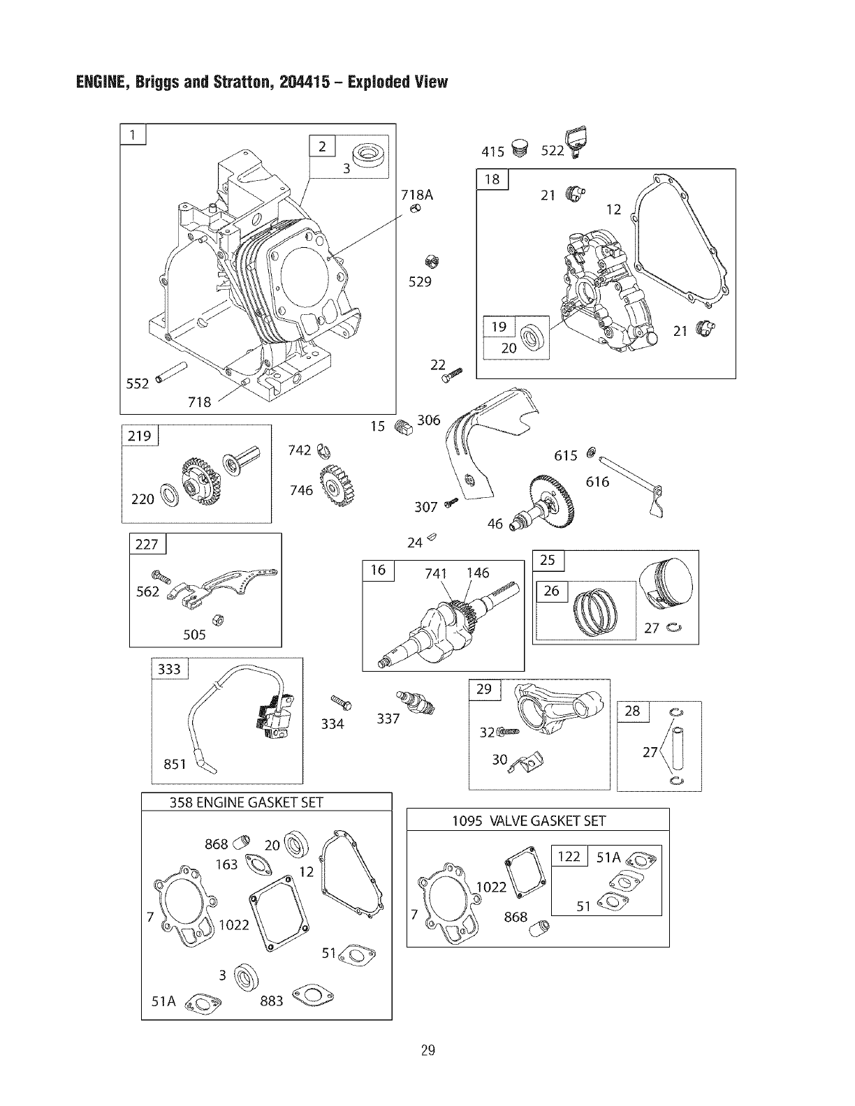
EHGIHE, BrBggsand Stratton, 204415 - Exploded View
@
505
742_
746_
851(
%
334
358 ENGINE GASKET SET
868_ 2o
163%
st@
3
51A _ 883
718A
@
529
415 _ 522_
181 21 12
15 _306
307 _
24 #
61 741 146 ©
27 _
337
1095 VALVEGASKET SET
._-_x1122151A_
7_ 868_ I 51
2g
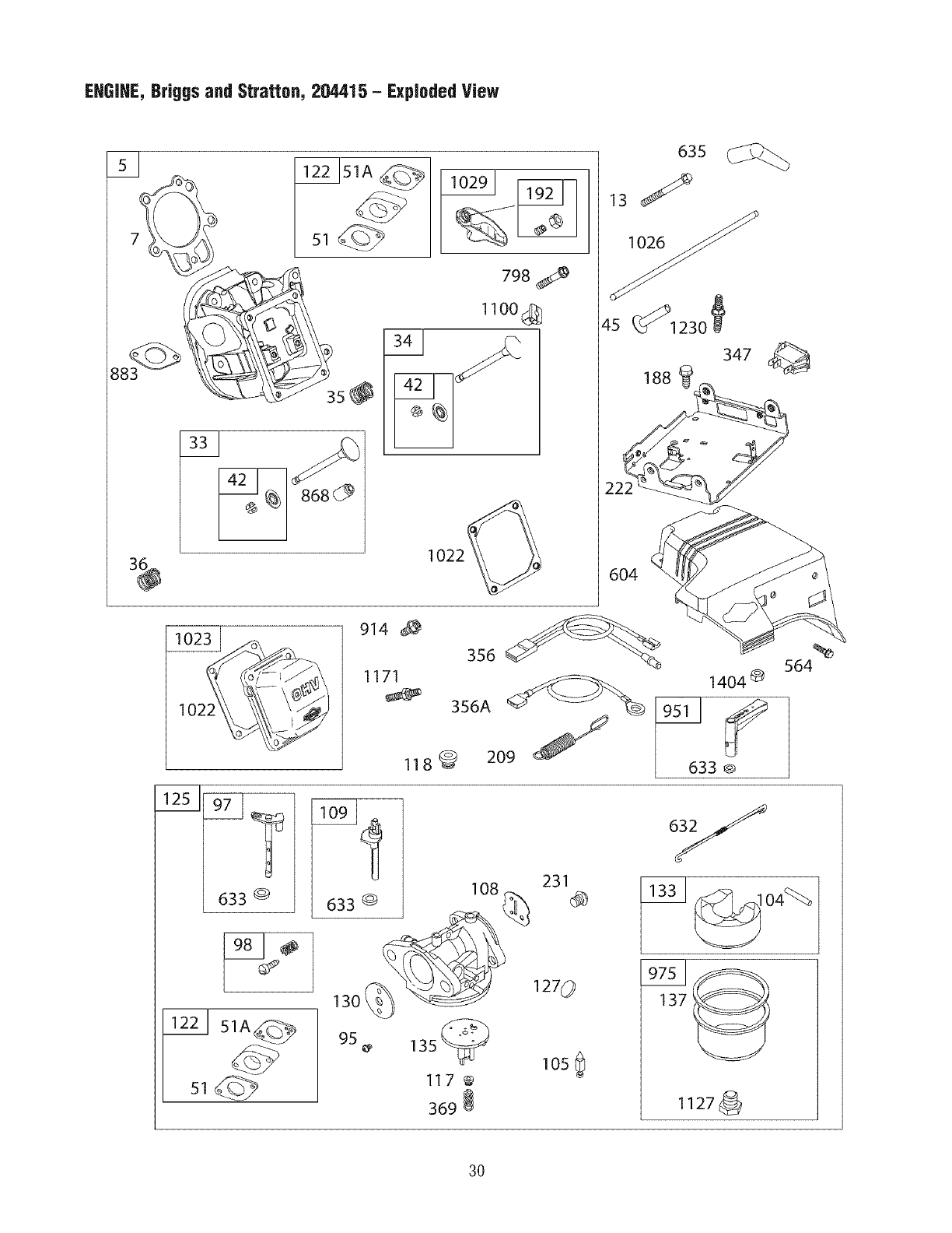
EHGIHE, Briggs and Stratton, 204415 - Exploded View
3_
798
1100_
1022_
102_/
914
1171
118_
635
13 _
_s_<1_o_
347
604
1404 ®
633 ®
%
564
633 @ 108
1301 __
231
127 0
95 13s_
117 @
369
105 0
oy
1331_o4_
137
!127_
3O
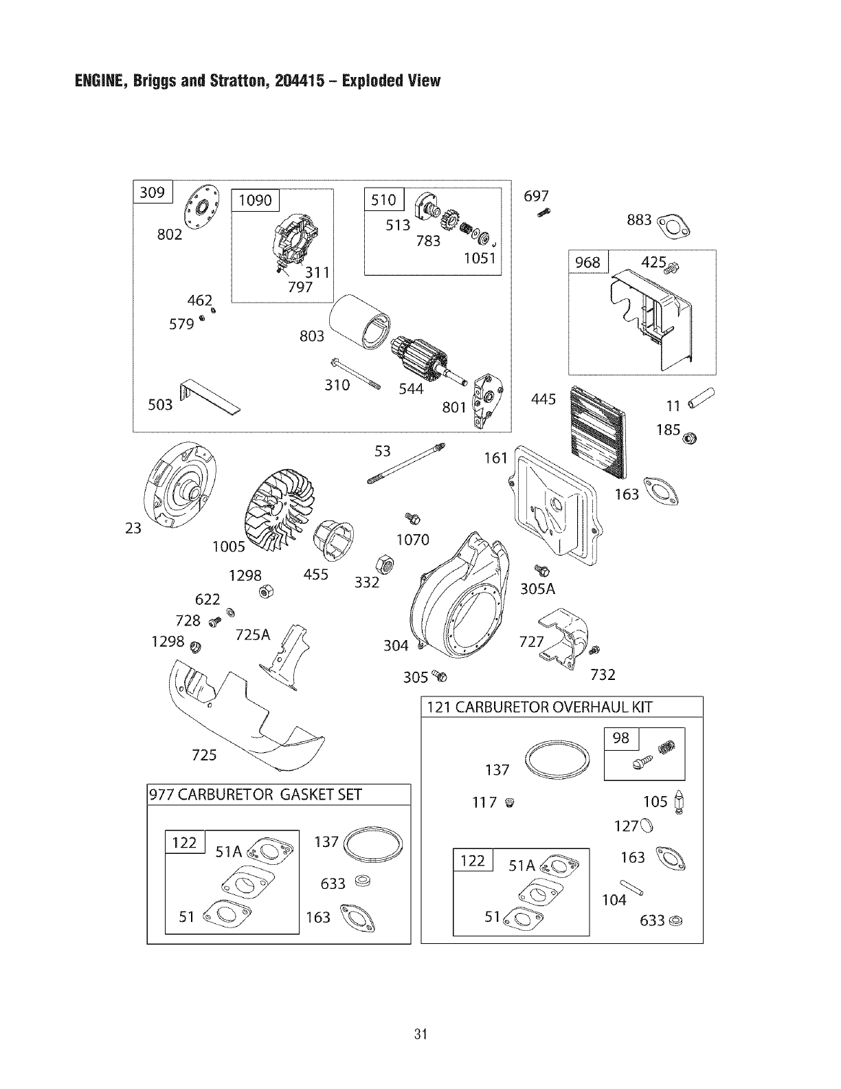
EHGIHE, BrBggsand Stratton, 204415 - Exploded View
8O2
462
579 _
503
797
783 _,,
1051
544
80!
1298
622 (_
728 725A
1298
455
Y
1070
@
332
304
161
305_
697
445
305A
727
732
185_D
163%
725
977 CARBURETOR GASKET SET
221 51A_ 137
633 G
163 %
121 CARBURETOR OVERHAUL KIT
137
117_ 105
127(_
163 %
104%_
633G
31
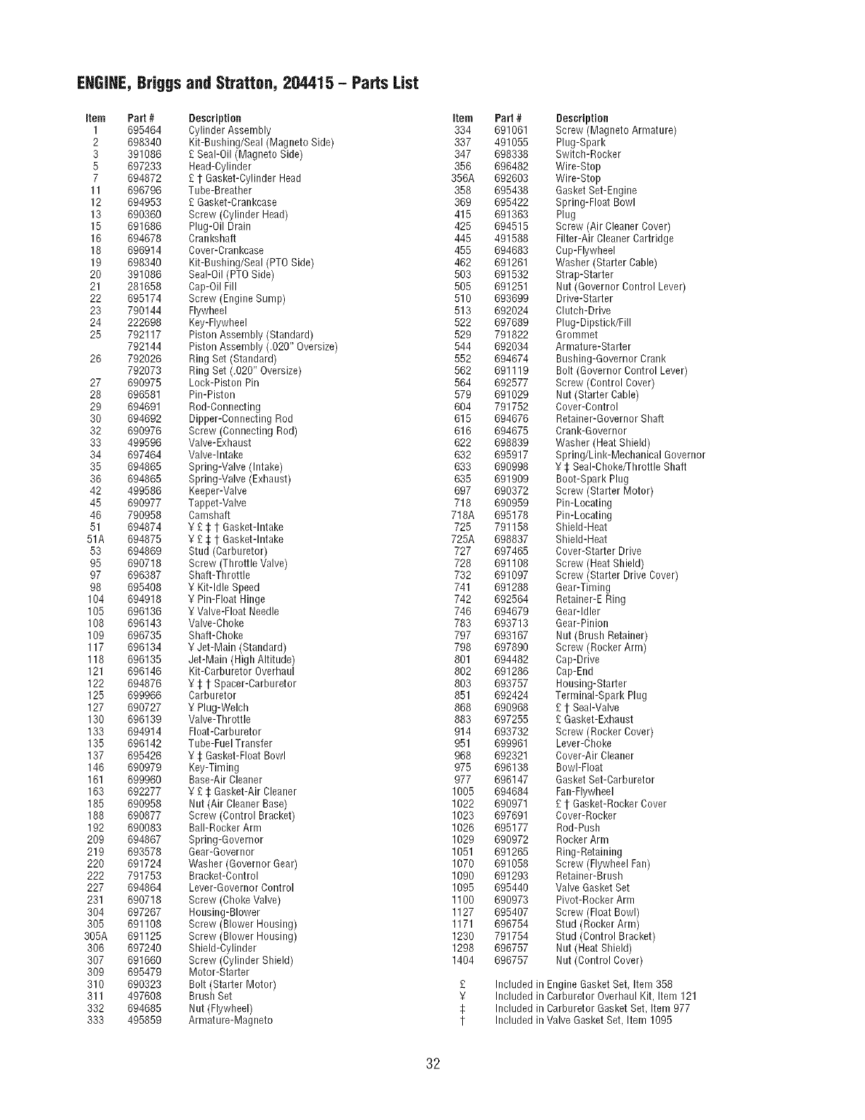
EHGIHE,Briggs and Stratton, 204415 - Parts List
item Part #Description
1 695464 Cylinder Assembly
2 698340 Kit-Bushing/Seal (Magneto Side)
3 391086 £ Seal-Oil (Magneto Side)
5 697233 Head-Cylinder
7 694872 £ 1 Gasket-Cylinder Head
11 696796 Tube-Breather
12 694953 £ Gasket-Crankcase
13 690360 Screw (Cylinder Head)
15 691686 Plug-Oil Drain
16 694678 Crankshaft
18 696914 Cover-Crankcase
19 698340 Kit-Bushing/Seal (PTO Side)
20 391086 Seal-Oil (PTO Side)
21 281658 Cap-Oil Fill
22 695174 Screw (Engine Sump)
23 790144 Flywheel
24 222698 Key-Flywheel
25 792117 Piston Assembly (Standard)
792144 Piston Assembly (.020" Oversize)
26 792026 Ring Set (Standard)
792073 Ring Set (.020" Oversize)
27 690975 Lock-Piston Pin
28 696581 Pin-Piston
29 694691 Rod-Connecting
30 694692 Dipper-Connecting Rod
32 690976 Screw (Connecting Rod)
33 499596 Valve-Exhaust
34 697464 Valve-Intake
35 694865 Spring-VaWe (intake)
36 694865 Spring-Valve (Exhaust)
42 499586 Keeper-Valve
45 690977 Tappet-Valve
46 790958 Camshaft
51 694874 Y £ :[:1 Gasket-Intake
51A 694875 ¥ £ :[:1"Gasket-Intake
53 694869 Stud (Carburetor)
95 690718 Screw (Throttle Valve)
97 696387 Shaft-Throttle
98 695408 ¥ KiNdle Speed
104 694918 ¥ Pin-Float Hinge
105 696136 ¥ Valve-Float Needle
108 696143 Valve-Choke
109 696735 Shaft-Choke
117 696134 ¥ Jet-Main (Standard)
118 696135 Jet-Main (High Altitude)
121 696146 Kit-Carburetor Overhaul
122 694876 ¥ 1:1"Spacer-Carburetor
125 699966 Carburetor
127 690727 ¥ Plug-Welch
130 696139 Valve-Throttle
133 694914 Float-Carburetor
135 696142 Tube-Fuel Transfer
137 695426 ¥ :I:Gasket-FloatBowl
146 690979 Key-Timing
161 699960 Base-Air Cleaner
163 692277 ¥ £ $Gasket-Air Cleaner
185 690958 Nut (Air Cleaner Base)
188 690877 Screw (Control Bracket)
192 690083 Bali-Rocker Arm
209 694867 Spring-Governor
219 693578 Gear-Governor
220 691724 Washer (Governor Gear)
222 791753 Bracket-Control
227 694864 Lever-Governor Control
231 690718 Screw (ChokeValve)
304 697267 Housing-Blower
305 691108 Screw (Blower Housing)
305A 691125 Screw (Blower Housing)
306 697240 Shield-Cylinder
307 691660 Screw (Cylinder Shield)
309 695479 Motor-Starter
310 690323 Bolt (Starter Motor)
311 497608 Brush Set
332 694685 Nut (Flywheel)
333 495859 Armature-Magneto
Item
334
337
347
356
356A
358
369
415
425
445
455
462
503
505
510
513
522
529
544
552
562
564
579
6O4
615
616
622
632
633
635
697
718
718A
725
725A
727
728
732
741
742
746
783
797
798
801
802
8O3
851
868
883
914
951
968
975
977
1005
1022
1023
1026
1029
1051
1070
1090
1095
1100
1127
1171
1230
1298
1404
£
¥
1:
t
Part #
691061
491055
698338
696482
692603
695438
695422
691363
694515
491588
694683
691261
691532
691251
693699
692024
697689
791822
692034
694674
691119
692577
691029
791752
694676
694675
698839
695917
690998
691909
690372
690959
695178
791158
698837
697465
691108
691097
691288
692564
694679
693713
693167
697890
694482
691286
693757
692424
690968
697255
693732
699961
692321
696138
696147
694684
690971
697691
695177
690972
691265
691058
691293
695440
690973
695407
696754
791754
696757
696757
Included in
Included in
Included in
Included in
Description
Screw (Magneto Armature)
Plug-Spark
Switch-Rocker
Wire-Stop
Wire-Stop
GasketSet-Engine
Spring-Float Bowl
Plug
Screw (Air Cleaner Cover)
Filter-Air Cleaner Cartridge
Cup-Flywheel
Washer (Starter Cable)
Strap-Starter
Nut (Governor Control Lever)
Drive-Starter
Clutch-Drive
Plug-Dipstick/Fill
Grommet
Armature-Starter
Bushing-Governor Crank
Bolt (Governor Control Lever)
Screw (Control Cover)
Nut (Starter Cable)
Cover-Control
Retainer-Governor Shaft
Crank-Governor
Washer (HeatShield)
Spring/Link-Mechanical Governor
¥ $ Seal-Choke/Throttle Shaft
Boot-Spark Plug
Screw (Starter Motor)
Pin-Locating
Pin-Locating
Shield-Heat
Shield-Heat
Cover-Starter Drive
Screw (Heat Shield)
Screw (Starter Drive Cover)
Gear-Timing
Retainer-E Ring
Gear-Idler
Gear-Pinion
Nut (Brush Retainer)
Screw (Rocker Arm)
Cap-Drive
Cap-End
Housing-Starter
Terminal-Spark Plug
£ 1"Seal-Valve
£ Gasket-Exhaust
Screw (Rocker Cover)
Lever-Choke
Cover-Air Cleaner
Bowl-Float
Gasket Set-Carburetor
Fan-Flywheel
£ 1 Gasket-Rocker Cover
Cover-Rocker
Rod-Push
Rocker Arm
Ring-Retaining
Screw (Flywheel Fan)
Retainer-Brush
Valve GasketSet
Pivot-Rocker Arm
Screw (Float Bowl)
Stud (Rocker Arm)
Stud (Control Bracket)
Nut (Heat Shield)
Nut (Control Cover)
Engine GasketSet, Item 358
Carburetor Overhaul Kit, Item 121
Carburetor Gasket Set, Item 977
Valve Gasket Set. Item 1095
32

33
Sears, Roebuckand Co., U.S.A. (Sears),the CaliforniaAir ResourcesBoard(CARD)and
the UnitedStates EnvironmentaJProtectionAgency(U.S.EPA}
EmissionsControlSystemWarrantyStatement
(Owner'sDefectWarrantyRightsand Obligations)
TheCalifornia Air Resources Board (CARB), U.S. EPAand Sears are
pleasedto explain the Emissions Control System Warranty on your
small offroad engine (SORE).In California, new small offroad
engines model year 2006 and later must be designed, built and
equipped to meet the State's stringent anti-smog standards.
Elsewherein the UnitedStates, new non-road,spark-ignition engines
certifiedfor model year 1997and later must meet similar standardsset
forth bythe U.S.EPA.Sears must warrant the emissions control
system on your enginefor the periodsof time listed below, provided
there has beenno abuse,neglector improper maintenanceof your
small off-road engine.
Your emissions control system includes parts such as the
carburetor, air cleaner, ignition system, fuel line, muffler and
catalytic converter. Also included may beconnectors and other
emissions related assemblies.
Where a warrantable condition exists, Sears will repair your small
off-road engine at no cost to you including diagnosis, parts and
labor.
Sears, Roebuck and Co, Emissinns Cnntrnl Defects Warranty
Coverage
Small off-road enginesare warranted relative to emissions control
parts defects for a period of two years, subject to provisions set
forth below. If any covered part on your engine is defective,the part
will be repaired or replaced by Sears.
Owner's Warranty Responsibilities
As the small off-road engine owner, you are responsible for the
performance of the required maintenance listed in your Operating
and Maintenance Instructions. Searsrecommends that you retain all
your receiptscovering maintenance on your small off-road engine,
but Searscannot deny warranty solely for the lack of receipts or for
your failure to ensurethe performance of all scheduled maintenance.
As the small off-road engine owner, you should however be aware
that Sears may deny you warranty coverage if your small off-road
engine or a part has failed due to abuse, neglect, improper
maintenanceor unapproved modifications.
You are responsible for presenting your small off-road engineto an
Authorized Sears Service Dealer as soon as a problem exists.
The undisputed warranty repairs should be completed in a
reasonable amount of time, not to exceed30 days.
If you have any questions regarding your warranty rights and
responsibilities, you should contact a Sears Service Representative
at 1-800-469-4663.
The emissions warranty is a defects warranty. Defects are judged
on normal engine performance. The warranty is not related to an in-
use emissions test.
Sears, Roebuck and Co, Emissinns Cnntrni Defects Warranty
Provisions
Thefollowing are specific provisions relativeto your Emissions
Control DefectsWarranty Coverage.It is in addition to the Sears
enginewarranty for non-regulated enginesfound in the Operatingand
MaintenanceInstructions.
1. Warranted Parts
Coverageunder this warranty extendsonly to the parts listed
below (the emissions control systems parts) to the extent these
parts were present on the enginepurchased.
a. Fuel Metering System
*Cold start enrichment system
*Carburetor and internal parts
*Fuel Pump
*Fuelline, fuel line fittings, clamps
.Fueltank, cap and tether
.Carbon canister
b. Air Induction System
*Air cleaner
.Intakemanifold
.Purge and vent line
c. Ignition System
.Spark plug(s)
.Magneto ignition system
d. Catalyst System
*Catalytic converter
.Exhaustmanifold
.Air injection system, Pulsevalve
e. Miscellaneous Items
.Vacuum, temperature, position, time sensitive valves and
switches
.Connectors and assemblies
2. Lengthof Coverage
Searswarrants to the initial owner and eachsubsequent
purchaser that the Warranted Parts shall befree from defects in
materials and workmanship which caused the failure of the
Warranted Parts for a period of two years from the date the
engineis deliveredto a retail purchaser.
3. NeCharge
Repair or replacementof any Warranted Part will be performed
at no charge to the owner, including diagnostic labor which
leads to the determination that a Warranted Part is defective if
the diagnostic work is performed at an Authorized Sears
Service Dealer.
4. Claims and Coverage Exclusions
Warranty claims shall befiled in accordance with the provisions
of the Sears Engine Warranty Policy. Warranty coverageshall
be excludedfor failures ofWarranted Parts which are not
original Searsparts or becauseof abuse, neglect or improper
maintenanceas set forth in the SearsEngineWarranty Policy.
Searsis not liable to cover failures of Warranted Parts caused
by the useof add-on, non-original, or modified parts.
5. Maintenance
Any Warranted Part which is not scheduled for replacementas
required maintenanceor which is scheduled only for regular
inspection to the effect of "repair or replaceas necessary"shall
bewarranted asto defectsfor the warranty period. Any
Warranted Part which is scheduledfor replacementas required
maintenanceshall be warranted as to defects only for the period
of time up to the first scheduled replacementfor that part. Any
replacementpartthat is equivalent in performance and
durabilitymay be used in the performance of any maintenanceor
repairs. The owner is responsible for the performance of all
required maintenance,as defined in the Sears Operatingand
MaintenanceInstructions.
6. Censequential Coverage
Coverage hereunder shall extend to the failure of any engine
components caused by the failure of any Warranted Part still
under warranty.
In the USAandCanada,a24-hourhotline,1-800-469-4663,hasa menuof pre-recordedmessagesofferingyou productmaintenance
information.
34
Emissions information
Enginesthat are certified to meetthe CaliforniaAir Resources
Board(CARB)Tier 2 Emission Standards must display
information regardingthe Emissions Durability Period and Air
Index. The engine manufacturer makesthis information
availableto the consumer on emission labels. The engine
emission label will indicate certification information.
The EmissionsDurabilityPeriod describes the number of
hours of actual running time for which the engine is certified
to beemissions compliant, assuming proper maintenancein
accordancewith the Operating & Maintenance Instructions.
The following categories are used:
Moderate: Engineis certified to be emission compliant for
125 hours of actual engine running time.
Intermediate: Engineis certified to beemission compliant
for 250 hours of actual engine running time.
Extended:Engineis certified to beemission compliant for
500 hours of actual engine running time.
Forexample, a typical walk-behind lawn mower is used 20 to
25 hours per year. Therefore, the EmissionsDurability
Period of an engine with an intermediate rating would
equateto 10to 12 years.
Certainengines will be certified to meetthe United States
Environmental Protection Agency (USEPA)Phase 2 emission
standards. For phase 2 certified engines, the Emissions
Compliance Period referred to on the Emissions Compliance
label indicates the number of operating hours for which the
engine has been shown to meet Federalemission
requirements.
For engines less than 225 cc displacement:
CategoryC = 125 hours
Category B = 250 hours
CategoryA = 500 hours
For engines of 225 cc or more:
CategoryC = 250 hours
Category B = 500 hours
CategoryA = 1000 hours
35
GARANTiA .................................... 36
REGLASDESEGURIDAD ...................... 37-39
CONOZCASU GENERADOR........................ 40
MONTAJE .................................. 41-43
FUNCiONAMiENTO........................... 44-48
ESPECIFiCACIONES............................. 49
MANTENIMIENTO ........................... 50-53
ALMACENAMIENTO............................. 54
REPARACIONDEAVERIAS ....................... 55
NOTAS ..................................... 56-57
GARANTIADEL SISTEMADECONTROL
DE EMiSIONES .............................. 58-59
COMOORDENARPARTES ............ ULTIMA PAGINA
Garantiacompietade an afio del generador Craftsman
Si el generador falla debido a defectos de materiales o mano de obra en el plazo de un afio a partir de la fecha de compra,
devu61valoa cualquier almac6n Sears,punto de venta de Craftsman o centro de reparaci6ny repuestos de Sears de los
Estados Unidos para su reparaci6n gratuita o, en caso de que 6sta no seaposible, parasu sustituci6n.
Garantialimitada de un ano adicional del generador Craftsman
Duranteel segundo a_o a partir de ia fechade compra, si cualquier pieza del generador faiia debido a defectos de materiales o
mano de obra, se suministrarA gratuitamente una nuevapieza. Si desea quese instale la pieza,deberApagar la mano de obra.
El periodo de garantia se reducirA a 90 dias desde la fecha de compra si el generadorse utiliza con fines comerciales o de
alquiler. Una vez que el generador se haya usado con fines comerciales o de alquiler, se considerarAcomo equipo de uso
comercial o alquiler a efectos de esta garantia.
Estagarantia le otorga determinados derechos legalesyes posible que tenga otros derechosque puedenvariar de un pais o
estado a otro.
Sears, Roebuckand Co., D/817WA, RoffmanEstates, IL 60179 U.S.A.
36
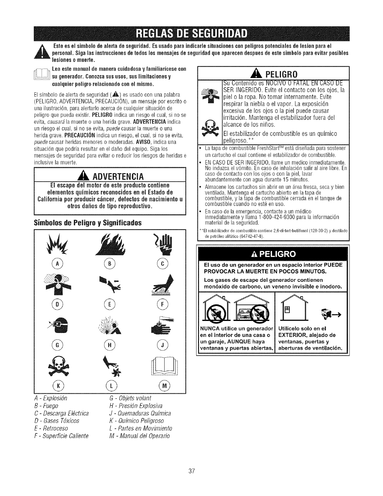
,_ Estees el simbeio de aierta de seguridad. Eeusado paraindicarie situacienescon peiigrospotenciaiesde lesionpara elpersonal. Siga las instruccionesde todos los mensajes de seguridad que aparecen despuesde estesimhoio para evitar posihies
lesionese muerte.
Lea eetemanual de manera cuidadoeay famiiiariceee con
....... su generader. Conozca sus uses, sue limitacioneey
cuaiquier peiigre reiacienado conel mismo.
El sirnbolo de alerta de seguridad (_l_) es usado con una palabra
(PELIGRO,ADVERTENCIA,PRECAUCION),un mensaje per escrito o
una ilustraciOn, para alertarlo acerca de cualquier situaci6n de
peligro que puedaexistir. PELIGROindica un riesgo el cual, si no se
evita, causar#la muerte o una herida grave. ADVERTENOIAindica
un riesgo el cual, si no se evita, puede causar la muerte o una
herida grave. PRECAUCI(iNindica un riesgo, el cual, si no se evita,
puede causar heridas menores o moderadas. AVISO, indica una
situaci6n que podria resultar en el da_o del equipo. Siga los
mensajes de seguridad paraevitar o reducir los riesgos de heridas e
inclusive la muerte.
ADVERTENCIA
El escapedel meter de este pr0ducte¢entiene
elementes quirnices rec0n0cides en el Estadede
California per preducirc_ncer, defectes de nacimiente u
0tres daff0sde tipe reproductive.
Simbolos de Peiigro y Significados
r.,qr,J=1! [_]_[o]
®
PELIGRO
Su Contenidoes NOCIVO0 F_
SERINGERIDO.Eviteel contacto con los ojos, la
piel o la ropa. No tomar internamente. Evite
respirar la niebla o el vapor. La exposici6n
excesivade los ojos o la piel puede causar
irritaci6n. Mantengael estabilizador fuera del
alcancede los ni_os.
El estabilizador de combustible es un quimico
peligroso.**
La tapa de combustible FreshStartTM est,. disefiadaparasostener
un cartucho el cualcontiene el estabilizadorde combustible.
ENCASODESER INGERIDO,Ilame un medico inmediatamente.
No induzcael v6mito. En case de inhalaci6nsalir al aire libre. En
case de contacto con los ojos o con la piel, lavar
abundantementecon aguadurante 15 minutes.
Almacene los cartuchos sin abrir en un Areafresca, seca y bien
ventilada. Mantenga el cartucho abierto en la tapa de
combustible, y la tapa de combustible cerradaen el tanque de
combustible cuando no est_ en use.
Encase de la emergencia,contacte a un m_dico
inmediatamentey llama 1-800-424-9300 para la informaci6n
material de la seguridad.
*El estabilizador de combustible contiene 2,6-di-tert-butilfenol (128-39-2) y destilado
de petr61eoalif_tico (64742-47-8).
El use de un generador en un espacio interior PUEDE
PROVOCAR LA MUERTE EN POCOS MINUTES.
Los gases de escape del generador contienen
rnon6xido de carbono, un veneno invisible e inodoro.
NUNCA utilice un generador
en el interior de una casa o
un garaje, AUNQUE haya
ventanas y puertas abiertas.
Utilicelo solo en e!
EXTERIOR, alejado de
ventanas, puertas y
aberturas de ventiJacibn.
A-Explosi6n
B-Fuego
C-DescargaEbctrica
D-Gases T6xicos
E- Retroceso
F- Superficie Caliente
G-Objets volant
H-Presi6n Explosiva
J-OuemadurasQufmica
K-Qufmico Peligroso
L-Partes en Movimiento
M-Manual del Operario
37
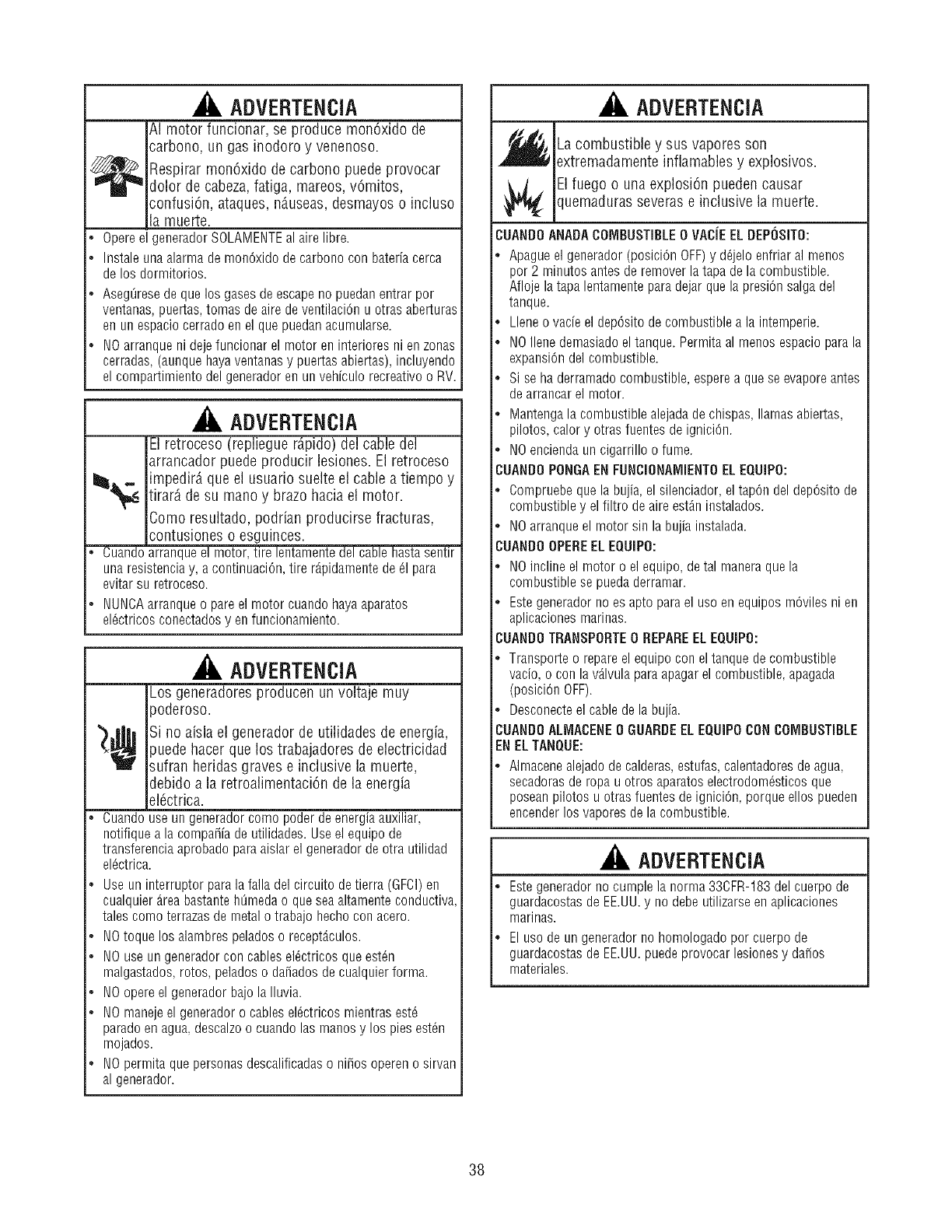
ADVERTENCIA
&l motor funcionar, se produce mon6xido de
sarbono, un gas inodoro y venenoso.
_ espirar mon6xido de carbono puede provocar
dolor de cabeza,fatiga, mareos, v6mitos,
sonfusi6n, ataques, n_useas,desmayos o incluso
jla muerte.
• OpereelgeneradorSOLAMENTEalairelibre.
, Instaleunaalarmademon6xidodecarbonocon bateriacerca
delos dormitorios.
Aseg_resedequelos gasesdeescapenopuedanentrarpor
ventanas,puertas,tomasdeairedeventilaci6nu otrasaberturas
enunespaciocerradoenel quepuedanacumularse.
• NOarranqueni dejefuncionarel motoreninterioresni enzonas
cerradas,(aunquehayaventanasy puertasabiertas),incluyendo
elcompartimientodelgeneradorenunvehiculorecreativoo RV.
• Cuando
®
ADVERTENCIA
El retroceso (repliegue r_pido) del cable del
arrancador puede producir lesiones. El retroceso
impedir_ que el usuario suelte el cable a tiempo y
tirarA de su mano y brazo hacia el motor.
Como resultado, podrian producirse fracturas,
contusiones o esguinces.
arranqueelmotor,tire lentamentedelcablehastasentir
unaresistenciay, acontinuaci6n,tire r_.pidamentede61para
evitarsu retroceso.
NUNCAarranqueo pareelmotorcuandohayaaparatos
el_ctricosconectadosyen funcionamiento.
ADVERTENCIA
iLos generadores producen un voltaje muy
poderoso.
_¢ Si no aisla el generador de utilidades de energia,
ipuedehacer que los trabajadores de electricidad
_ufran heridas graves e inclusive la muerte,
debido a la retroalimentaci6n de la energia
_16ctrica.
, Cuandouseungeneradorcomopoderdeenergiaauxiliar,
notifiqueala compa_iadeutilidades.Useelequipode
transferenciaaprobadoparaaislarelgeneradordeotra utilidad
el6ctrica.
• Useuninterruptorparalafalladelcircuitodetierra(GFCI)en
cualquierAreabastanteh[imedao queseaaltamenteconductiva,
talescomoterrazasdemetalo trabajohechoconacero.
, NOtoquelosalambrespeladoso recept_.culos.
• NOuseungeneradorconcablesel_ctricosqueest6n
malgastados,rotos,peladoso dafiadosdecualquierforma.
• NOopereel generadorbajolaIluvia.
, NOmanejeelgeneradoro cablesel_ctricosmientrasest6
paradoenagua,descalzoo cuandolasmanosy los piesest6n
mojados.
, NOpermitaquepersonasdescalificadaso ni_osopereno sirvan
algenerador.
ADVERTENCIA
La combustible y sus vapores son
extremadamente inflamables y explosivos.
El fuego o una explosi6n pueden causar
quemaduras severas e inclusive la muerte.
CUANDOANADACOMBUSTIBLE0 vACJEEL DEPOSIT0:
', Apague el generador (posici6nOFF)y d_jelo enfriar al menos
por 2 minutos antes de remover la tapa de la combustible.
Afloje la tapa lentamente para dejar que la presi6n salga del
tanque.
• Llene o vacieel dep6sito de combustible a la intemperie.
NOIlene demasiado eltanque. Permita al menos espacio parala
expansi6n del combustible.
Si se haderramado combustible, esperea que se evaporeantes
de arrancarel motor.
Mantenga la combustible alejadade chispas, llamas abiertas,
pilotos, calory otras fuentes de igniciOn.
NOencienda un cigarrillo o fume.
CUANDOPONGAENFUNCIONAMIENTOELEQUIPO:
, Compruebe que la bujia, el silenciador, el tap6n del dep6sito de
combustible y el filtro de aire est_n instalados.
, NO arranque el motor sin la bujia instalada.
CUANDOOPEREEL EQUIPO:
, NO incline el motor o el equipo, detal maneraque la
combustible se puedaderramar.
, Estegenerador no es apto parael uso en equipos m6viles ni en
aplicaciones marinas.
CUANDOTRANSPORTE0 REPAREELEQUIPO:
, Transporte o repareel equipo con el tanque de combustible
vacio, o con la v_lvula para apagarel combustible, apagada
(posici6n OFF).
• Desconecteel cable de la bujia.
CUANDOALIVIACENE0GUARDEELEQUIPOCONCOIVIBUSTIBLE
ENELTANQUE:
, Almacene alejado de calderas,estufas, calentadoresde agua,
secadorasde ropa u otros aparatos electrodom6sticos que
posean pilotos u otras fuentes de ignici6n, porque ellos pueden
encender los vapores de la combustible.
ADVERTENCIA
Estegenerador no cumple la norma 336FR-183 del cuerpo de
guardacostasde EE.UU.y no debe utilizarse en aplicaciones
marinas.
El uso de un generador no homologado por cuerpo de
guardacostasde EE.UU.puede provocar lesiones y da_os
materiales.
38
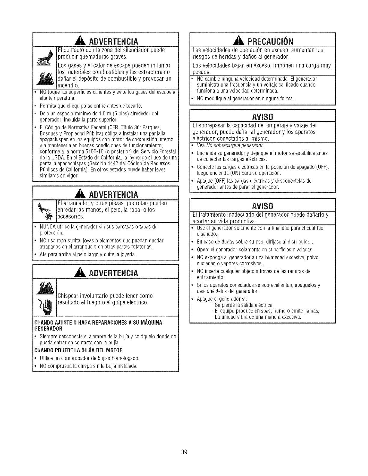
ADVERTENCIA
El contacto con la zona del silenciador puede
producir quemaduras graves.
Los gases y el calor de escape pueden inflamar
f_los materiales combustibles y las estructuras o
da_ar el dep6sito de combustible y provocar un
incendio.
•NOtoque las superficies calientes y evite los gases del escape a
altatemperatura.
•Permita que el equipo se enfrie antes de tocarlo.
Deje un espacio minimo de 1.5 m (5 pies) alrededor del
generador, incluida la parte superior.
El C6digo de Normativa Federal(CFR,Titulo 36: Parques,
Bosquesy Propiedad PQblica)obliga a instalar una pantalla
apagachispasen los equipos con motor de combusti6n interno
y a mantenerlaen buenascondiciones de funcionamiento,
conforme a la norma 5100-1C (o posterior) del Servicio Forestal
de la USDA. En el Estadode California, la ley exigeel uso de una
pantallaapagachispas (Secci6n4442 del C6digo de Recursos
P_blicos de California). En otros estados puede haber leyes
similares envigor.
ADVERTENCIA
_. l arrancador y otras piezas que rotan pueden
enredar las manos, el pelo, la ropa, o los
•_ accesorios.
•NUNCAutilice la generador sin sus carcasaso tapas de
protecci6n.
, NO use ropasuelta, joyas o elementos que puedan quedar
atrapados en el arranque o en otras partes rotatorias.
, Ate paraarriba el pelo largo y quite la joyeria.
ADVERTENCIA
Chispearinvoluntariopuede tener como
_¢ resultado el fuego o el golpe el6ctrico.
CUANDOAJOSTE0 HAGAREPARACIONESASUIVIAQUINA
GENERADOR
,Siempredesconecteel alambredela bujiay col6quelodondeno
puedaentrarencontactocon labujia.
CUANDOPRUEBELABUJJADELMOTOR
•Utiliceuncornprobadorde bujiashomologado.
, NOcompruebalachispasin labujiainstalada.
PRECAU€ION
Las velocidades de operaci6n en exceso, aumentan los
riesgos de heridas y da_ios al generador.
Las velocidades bajan en exceso, imponen una carga muy
}esada.
NOcambie ninguna velocidad determinada. El generador
suministra unafrecuencia y un voltaje calificado cuando
funciona a una velocidad determinada.
NOmodifique al generador en ninguna forma.
AViSO
El sobrepasar la capacidad del amperaje y vataje del
lenerador, puede da_ar al generador y los aparatos
el6ctricos conectados al mismo.
Yea No sobrecargue generador.
Enciendasu generadory deje que el motor se estabiliceantes
de conectar las cargasel_ctricas.
Conectelas cargasel_ctricas en la posici6n de apagado(OFF),
luego encienda (ON) parasu operaciOn.
Apague (OFF)las cargasel_ctricas y descon_ctelasdel
generador antes de parar el generador.
AViSO
El tratamiento inadecuado del generador puede da_arlo y
acortar su vida productiva.
Use el generador solamente con la finalidad para el cual fue
disefiado.
Encaso de dudas sobre su uso, dirijase al distribuidor.
Opereel generador solamente en superficies niveladas.
NOexponga al generador a una humedad excesiva,polvo,
suciedad o vapores corrosivos.
NOinserte cualquier objeto a trav_s de las ranuras de
enfriamiento.
Si los aparatosconectados se sobrecalientan, ap_guelosy
descon_ctelosdel generador.
Apague el generador si:
-Se pierde la salidael_ctrica;
-El equipo produce chispas, humo o emite llamas;
-La unidadvibra de una maneraexcesiva.
39
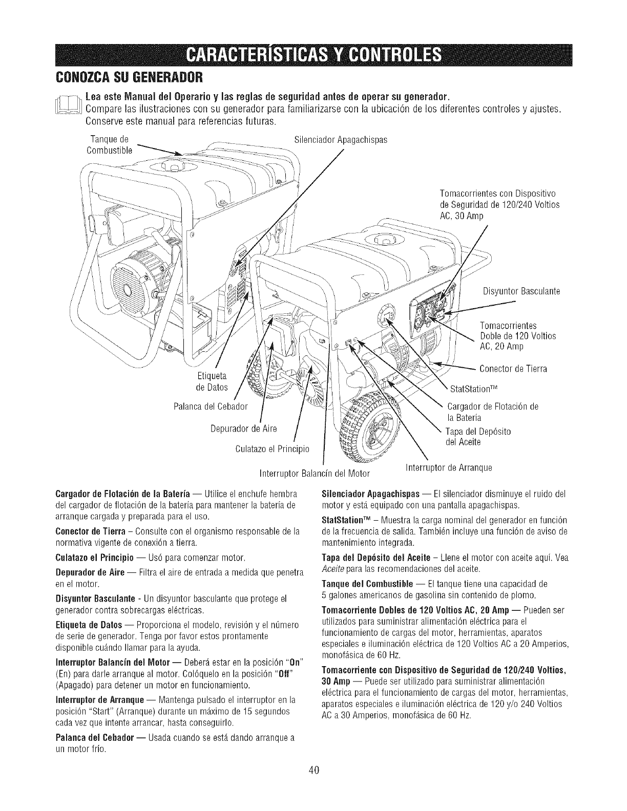
CONOZCASUGEHERADOR
_1 Lea este Manual del Operarioy las reglas de seguridadantes de operar su generador.
......... Compare las ilustracionescon su generadorpara familiarizarse con la ubicaci6n de losdiferentes controles yajustes.
Conserve este manual para referencias futuras.
Tanque de Silenciador Apagachispas
Combustible
Tomacorrientes con Dispositivo
de Seguridad de 120/240 Voltios
AC, 30 Amp
Disyuntor Basculante
Tomacorrientes
DoNede120Voltios
AC,20 Amp
ConectordeTierra
Etiqueta
de Dates
PalancadelCebador
DepuradordeAire
Culatazoel Principle
InterrupterBalancindel Motor
Cargador de Flotaci6n de
la Bateria
Tapa del Dep6sito
del Aceite
Interrupter de Arranque
Cargaderde Fleta¢i6n de la Bateria-- Utilice el enchufe hembra
del cargador de flotaci6n de la bateria para mantener la bateriade
arranque cargaday preparada para el use.
Cenecter de Tierra - Consulte con el organismo responsable de la
normativa vigente de conexi6n a tierra.
Cglatazo el Principle -- Us6 para comenzar motor.
Bepurader de Aire -- Filtra el aire de entrada a medida que penetra
en el motor.
Disyunler Basculante - Un disyuntor basculante que protege el
generador contra sobrecargas el_ctricas.
Etiqueta de Bates -- Proporciona el modelo, revisi6n y el n0mero
de serie de generador. Tenga per favor estos prontamente
disponible cdmdo Ilamar para la ayuda.
Interrupter Balancin del Meter -- Deber_estar en la posici6n "On"
(En) paradarle arranque al motor. Col6quelo en la posici6n "ofr'
(Apagado) para detener un motor enfuncionamiento.
Interrupter de Arranque -- Mantenga pulsado el interrupter en la
posiciOn"Start" (Arranque) durante un m_ximo de 15 segundos
cada vez que intente arrancar, hasta conseguirlo.
Palanca del Cebader -- Usadacuando se est,. dando arranque a
un motor frio.
Silenciader Apagachispas-- El silenciador disminuye el ruido del
motor y est,. equipado con una pantalla apagachispas.
StatStationTM - Muestra la carga nominal del generador en funci6n
de la frecuencia de salida. Tambi_n incluye una funci6n de aviso de
mantenimiento integrada.
Tapa del Dep6uito del Aueite - Llene el motor con aceite aqubVea
Aceite para las recomendaciones del aceite.
Tanque del Cembustible -- Eltanque tiene una capacidad de
5 galonesamericanos de gasolina sin contenido de pieing.
Ternacerriente Bebles de 120 Veltios AC, 20 Amp-- Puedenser
utilizados para suministrar alimentaci6n el6ctrica para el
funcionamiento de cargas del motor, herramientas, aparatos
especialese iluminaci6n el_ctrica de 120 Voltios AC a 20 Amperios,
monof_sica de 60 Hz.
Tomacorriente conDispesitivede Seguridad de 120/248 Velties,
30 Amp-- Puedeser utilizado para suministrar alimentaci6n
el_ctricapara el funcionamiento de cargas del motor, herramientas,
aparatos especialese iluminaci6n el_ctrica de 120 y/o 240 Voltios
AC a 30 Amperios, monof_.sicade 60 Hz.
4O
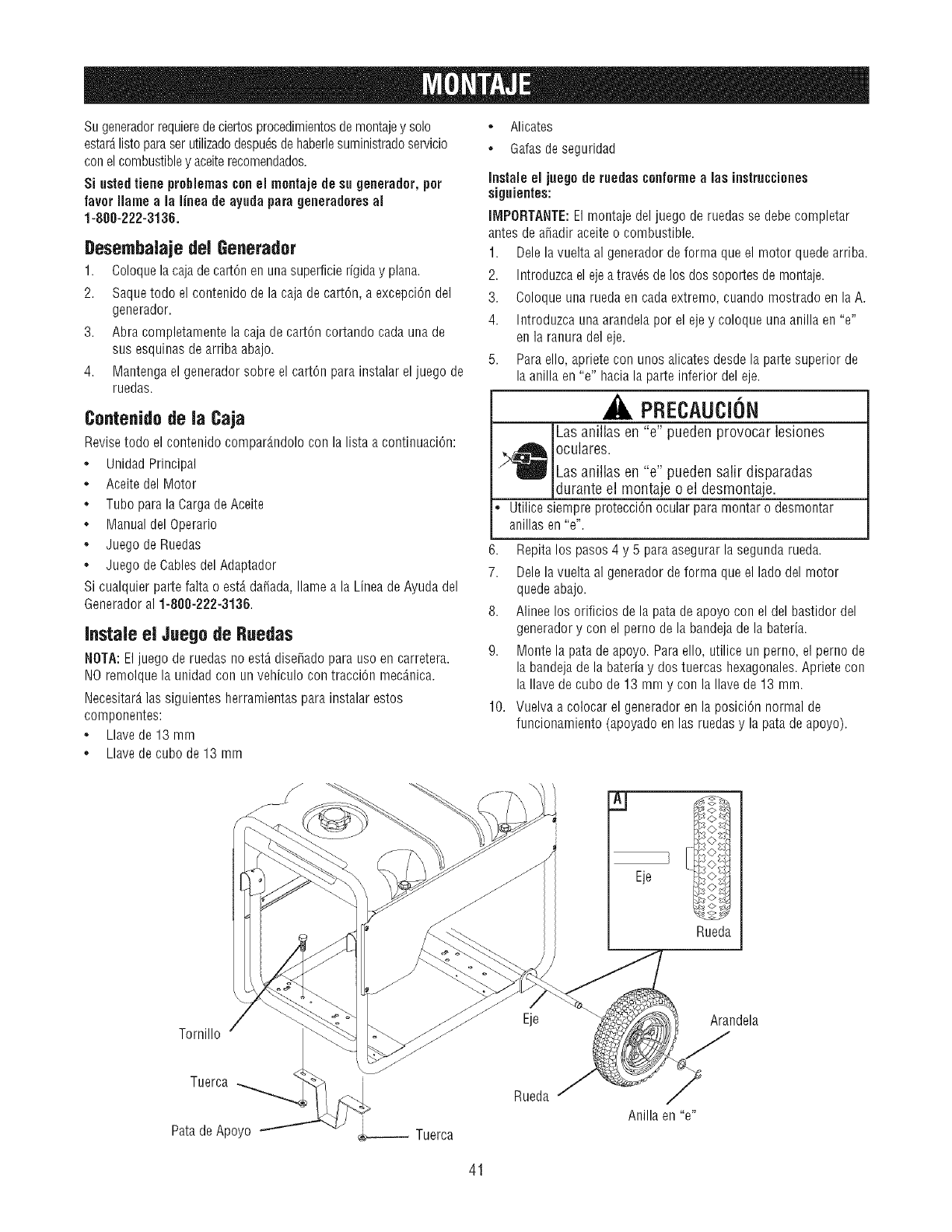
Su generadorrequierede ciertos procedimientosde montajey solo
estarAlisto paraserutilizadodespu_sdehaberlesuministradoservicio
conel combustibley aceiterecomendados.
Si usted tiene prohlemas conel mentaje de su generader, per
favor liame ala linea de aygda para generadoresal
1-800-222-3136.
gesembalaje del Generador
1. Coloquela caja de cart6n en unasuperficie rigida y plan&
2. Saquetodo el contenido de la caja de cart@, a excepci6n del
generador.
3. Abra completamente la caja de cart@ cortando cada una de
sus esquinas de arriba abajo.
4. Mantenga el generador sobre el cart@ para instalar el juego de
ruedas.
Contenido de la Caja
Revise todo el contenido compar_.ndolocon la lista a continuaci6n:
•Unidad Principal
° Aceite del Motor
°Tubo para la Carga de Aceite
° Manual del Operario
°Juego de Ruedas
°Juego de Cables del Adaptador
Si cualquier parte falta o est,. da_ada, Ilame a la Linea de Ayuda del
Generadoral 1-808-222-3136.
Instale el Juegode Ruedas
NOTA: Eljuego de ruedas no est_ dise_ado para uso en carretera.
NO remolque la unidad con un vehiculo con tracci6n me@.nica.
Necesitar_.las siguientes herramientas para instalar estos
componentes:
°Llave de 13 mm
° Llave de cubo de 13 mm
°Alicates
•Galasde seguridad
Instaleel juegoderuedasconformea lasinstrucciones
siguientes:
llVIPORTANTE:Elmontajedeljuegoderuedasse debecompletar
antesdea_adiraceiteo combustible.
1. Delelavueltaal generadordeformaqueel motorquedearriba.
2. Introduzcaelejeatrav_sdelosdossoportesdemontaje.
3. Coloqueunaruedaencadaextremo,cuandomostradoen laA.
4. Introduzcaunaarandelaporelejey coloqueunaanillaen"e"
enlaranuradeleje.
5. Paraello,aprieteconunosalicatesdesdelapartesuperiorde
laanillaen"e" haciala parteinferiordeleje.
PRECAUCION
Las anillas en "e" pueden provocar lesiones
oculares.
' Las anillas en "e" pueden salir disparadas
durante el montaje o el desmontaje.
° Utilice siempre protecci6n ocular para montar o desmontar
anillas en"e".
6. Repita los pasos 4 y 5 paraasegurar la segunda rued&
7. Dele lavuelta al generador de forma que el lado del motor
quedeabajo.
8. Alinee los orificios de la pata de apoyo con el del bastidor del
generador y con el perno de la bandeja de la bateria.
9. Monte la pata de apoyo. Para ello, utilice un perno, el perno de
la bandeja de la batefiay dos tuercas hexagonales. Apriete con
la Ilave de cubo de 13 mm y con la Ilavede 13 ram.
10. Vuelva a colocar el generador en la posici6n normal de
funcionamiento (apoyado en las ruedas y la pata de apoyo).
Eje <>s
o
Rueda
Tornillo Eje Arandela
Tuerca
PatadeApoyo Tuerca
Rueda
Anillaen"e"
41
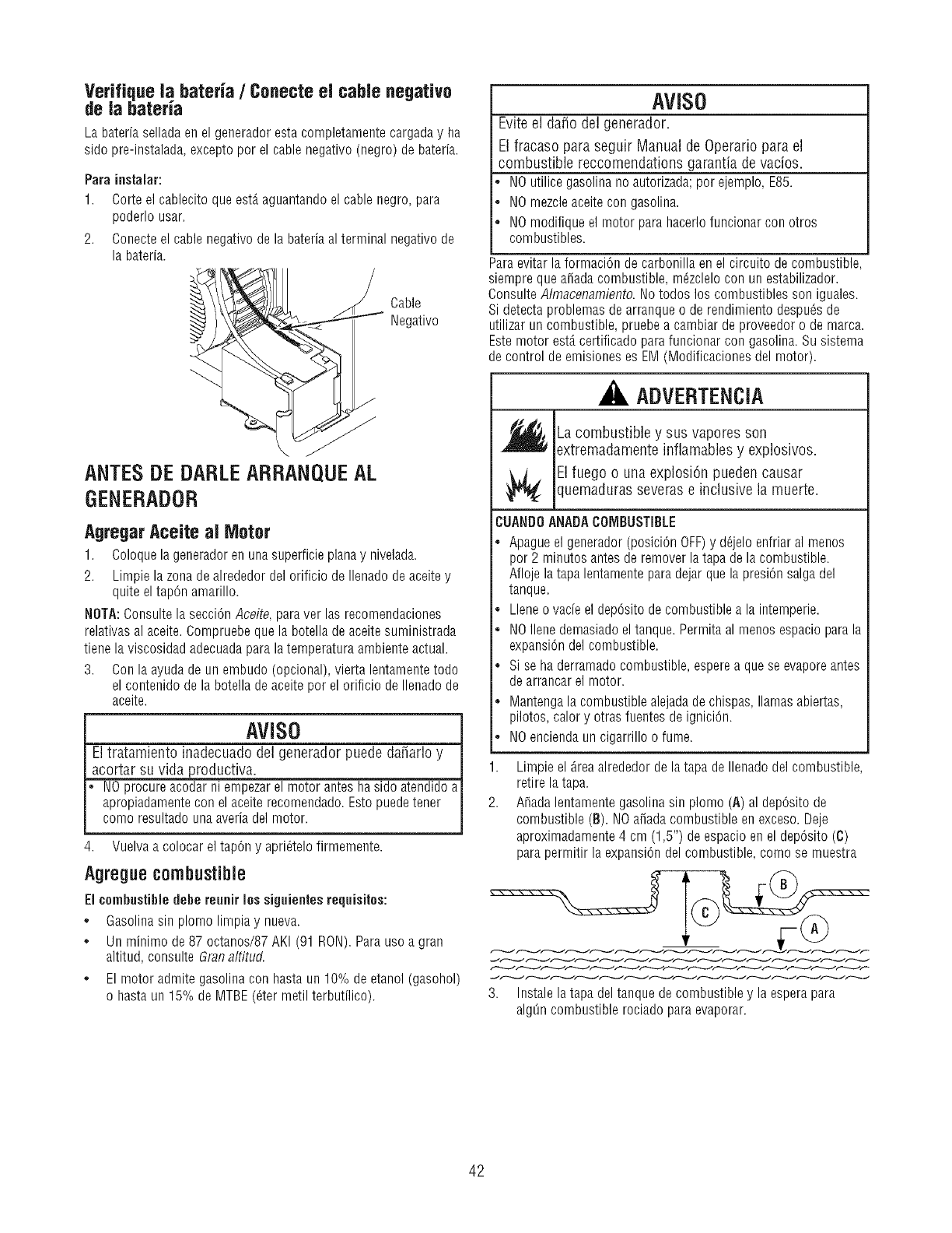
Verifique la bateria /Conecte el cable negatJvo
de la bateria
La bateria sellada en el generador esta completamente cargaday ha
sido pre-instalada, excepto por el cable negativo (negro) de bateria.
Para instalar:
1. Corte el cablecito que est,. aguantando el cable negro, para
poderlo usar.
2. Conecteel cable negativo de la bateria al terminal negativo de
la bateria.
Cable
Negativo
ANTESDEDARLEARRANQUEAL
GENERADOR
Agregar AceJte al Motor
1. Coloquela generadoren una superficie plana y nivelada.
2. Limpie la zona de alrededor del orificio de Ilenado de aceite y
quite el tap@ amarillo.
NOTA:Consulte la seccibn Aceite, paraver las recomendaciones
relativas al aceite. Compruebe que la botella de aceite suministrada
tiene la viscosidad adecuadapara la temperatura ambienteactual.
3. Con la ayuda de un embudo (opcional), vierta lentamente todo
el contenido de la botella de aceite por el orificio de Ilenado de
aceite.
AVISO
El tratamiento inadecuado del generador puede da_arlo y
acortar su vida productiva.
NO procure acodar ni empezarel motor antes ha sido atendido a
apropiadamentecon el aceite recomendado. Estopuede tenet
como resultado unaaveria del motor.
4. Vuelva a colocar el tap@ y apriOtelofirmemente.
Agregue combustible
El combustibledehe reunir los siguientee requisitos:
oGasolina sin plomo lirnpia y nueva.
o Un minimo de 87 octanos/87 AKI (91 RON). Para uso a gran
altitud, consulte 6ran altitud.
o El motor admite gasolina con hasta un 10% de etanol (gasohol)
o hasta un 15% de MTBE (_ter metil terbutflico).
AVISO
Evite el da_o del generador.
El fracaso para seguir Manual de Operatic para el
combustible reccomendations garantia de vacios.
NOutilice gasolina no autorizada; por ejemplo, E85.
NOmezcle aceite con gasolina.
NOmodifique el motor para hacerlofuncionar con otros
combustibles.
Paraevitar la formaciOn de carbonilla en el circuito de combustible,
siempre que a_adacombustible, m_zclelo con un estabilizador.
Consulte Almacenamiento. No todos los combustibles son iguales.
Si detecta problemas de arranque o de rendimiento despuOsde
utilizar un combustible, pruebe a cambiar de proveedor o de marca.
Estemotor est,. certificado para funcionar con gasolina. Su sistema
de control de emisiones es EM (Modificaciones del motor).
ADVERTENCIA
.,,_ La combustible y sus vapores son
extremadamente inflamables y explosivos.
El fuego o una explosion pueden causar
quemaduras severas e inclusive la muerte.
CUANDOANADACOMBUSTIBLE
*Apague el generador (posiciOn OFF)y d_jelo enfriar al menos
por 2 minutos antes de remover la tapa de la combustible.
Afloje la tapa lentamente para @jar que la presiOnsalga del
tanque.
*Llene o vacie el depOsitode combustible a la intemperie.
*NOIlene demasiado eltanque. Permita al menos espacio parala
expansion del combustible.
*Si se haderramado combustible, esperea que se evaporeantes
de arrancarel motor.
*Mantenga la combustible alejadade chispas, llamas abiertas,
pilotos, calory otras fuentes de igniciOn.
* NOencienda un cigarrillo o fume.
1. Limpie el _rea alrededor de la tapa de Ilenado del combustible,
retire la tapa.
2. A_ada lentamente gasolina sin plomo (A) al depOsitode
combustible (B). NOa_ada combustible en exceso. Deje
aproximadamente4 cm (1,5") de espacio en el depOsito(C)
para permitir la expansion del combustible, como se muestra
3. Instale la tapa del tanque de combustible y la espera para
al@n combustible rociado para evaporar.
42
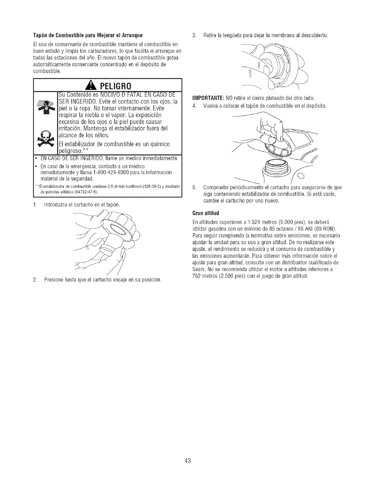
Tap6nde CombustibleparaMejerarel Arranque
Elusedeconservantedecombustiblemantieneelcombustibleen
buenestadoy limpialos carburadores,Io quefacilitaelarranqueen
todaslasestacionesdela_o.Elnuevotap6ndecombustiblegotea
automAticamenteconservanteconcentradoenel dep6sitode
combustible.
PELIGRO
-Su Contenido es NOCIVO0
SERINGERIDO.Eviteel contacto con los ojos, la
_ielo la ropa. No tomar intemamente. Evite
)irar la niebla o el vapor. La exposici6n
excesiva de los ojos o la piel puede causar
irritaci6n. Mantengael estabilizador fuera del
_jalcancede los ni_os.
IEIestabilizador de combustible es un quimico
peligroso.**
ENCASODESERINGERIDO,Ilameunmedicoinmediatamente.
Encasedelaemergencia,contactea unm_dico
inmediatamentey llama1-800-424-9300paralainformaci6n
materialdela seguridad.
*El estabilizador de combustible contiene 2 }-di-tert-butilfenol (128-39-2) y destilado
de petr61eoalif_tico (64742-47-8).
1. Introduzca el cartucho en el tapon.
2. Presionehastaqueel cartuchoencajeensu posiciOn.
3. Retirela lengiJetaparadejarla membranaaldescubierto.
ilVIPORTANTE:NOretireel cierreplateadodelotto lade.
4. Vuelvaa colocareltapOndecombustibleenel dep6sito.
5. Compruebeperi6dicamenteelcartuchoparaasegurarsedeque
sigaconteniendoestabilizadorde combustible.Siest_vacio,
cambieelcartuchoperunonuevo.
Granaltitud
Enaltitudes superiores a 1.524 metros (5.000 pies), se deberA
utilizar gasolina con un minimo de 85 octanes /85 AKI (89 RON).
Paraseguir cumpliendo la normativa sobre emisiones, es necesario
ajustar la unidad para su use a gran altitud. De no realizarseeste
ajuste, el rendimiento se reducirAy el consume de combustible y
las emisiones aumentar_m.Para obtener mAsinformaci6n sobre el
ajuste para gran altitud, consulte con un distribuidor cualificado de
Sears.No se recomienda utilizar el motor a altitudes inferiores a
762 metros (2.500 pies) con el juego de gran altitud.
43
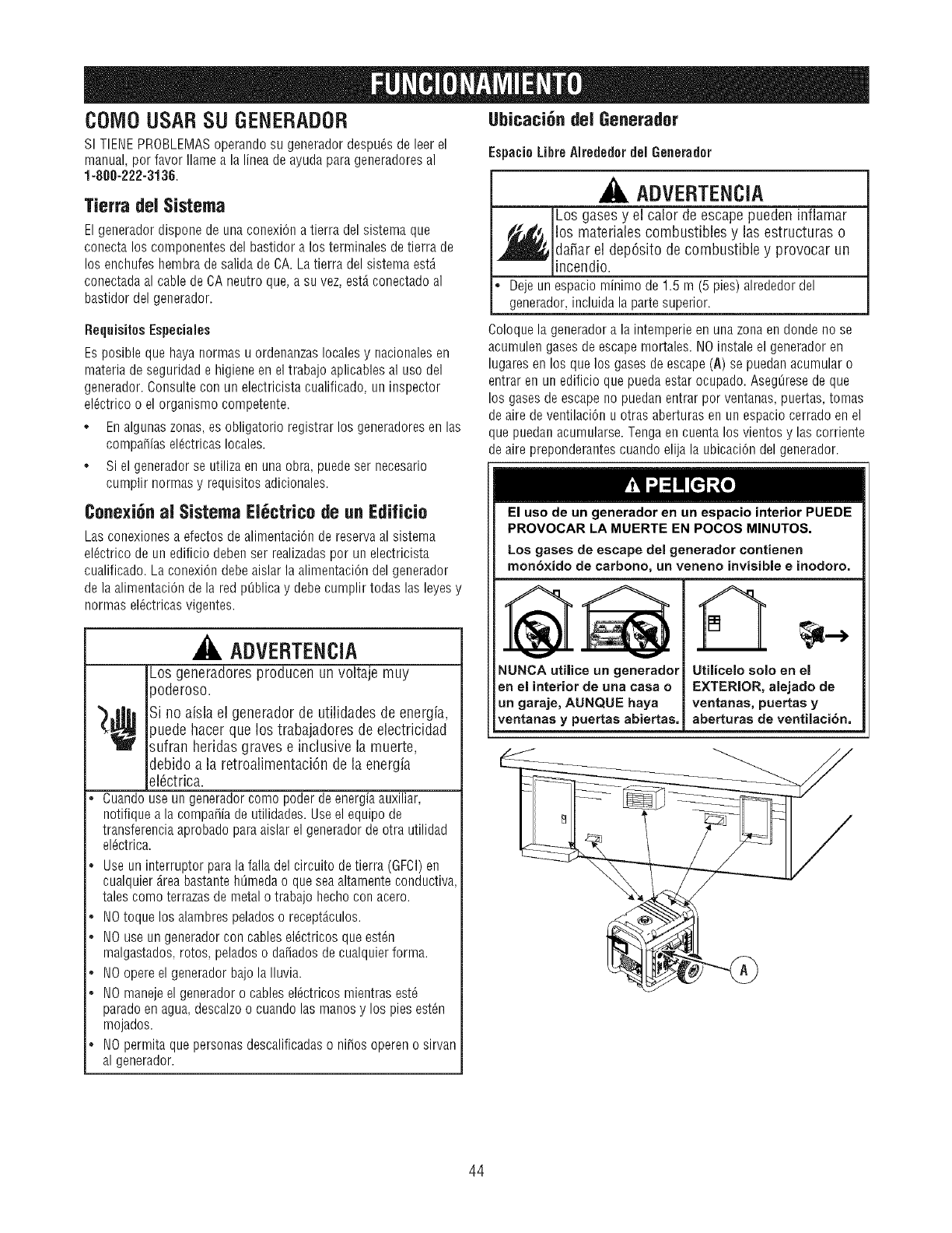
COM0USARSU GENERADOR
SI TIENEPROBLEMASoperandosu generadordespu_sdeleerel
manual,porfavorIlamea lalineadeayudaparageneradoresal
1-888-222-3136.
Tierra del Sistema
Elgeneradordisponedeunaconexi6natierradelsistemaque
conectalos componentesdelbastidoralos terminalesdetierra de
los enchufeshembradesalidadeCA.LatierradelsistemaestA
conectadaal cabledeCAneutroque,a suvez,est,.conectadoal
bastidordelgenerador.
Ubicaci_n del 6enerador
Es_aci0LibreAlrededordel Generador
ADVERTENCIA
Los gasesy el calor de escapepueden inflamar
,_los materiales combustibles y las estructuras o
da_arel dep6sito de combustible y provocar un
incendio.
• Dejeunespaciominimode1.5 m (5 pies)alrededordel
generador,incluidalapartesuperior.
RequisitesEspeciales
Esposiblequehayanormasu ordenanzaslocalesy nacionalesen
materiadeseguridade higieneeneltrabajoaplicablesal usodel
generador.Consultecon unelectricistacualificado,uninspector
el6ctricoo el organismocompetente.
* Enalgunaszonas,esobligatorioregistrarlosgeneradoresenlas
compa_iasel@tricaslocales.
° Si elgeneradorse utilizaenunaobra,puedeser necesario
cumplirnormasy requisitosadicionales.
Coloquelageneradorala intemperieenunazonaendondenose
acumulengasesdeescapemortales.NOinstaleel generadoren
lugaresenlos quelos gasesdeescape(A) sepuedanacumularo
entrarenun edificioquepuedaestarocupado.AsegOresede que
los gasesdeescapenopuedanentrarporventanas,puertas,tomas
deairedeventilaci6nuotrasaberturasenunespaciocerradoenel
quepuedanacumularse.Tengaencuentalos vientosy lascorriente
deairepreponderantescuandoelijala ubicaci6ndelgenerador.
Conexi_n al Sistema El_ctrico de un Edificio
Lasconexionesa efectosdealimentaci6ndereservaal sistema
el_ctricode unedificiodebenser realizadasporun electricista
cualificado.Laconexi6ndebeaislarlaalimentaci6ndelgenerador
delaalimentaci6ndela redpt]blicay debecumplirtodaslasleyesy
normasel_ctricasvigentes.
ADVERTENCIA
Los generadores producen un voltaje muy
iPoderoso.
_¢ Si no aisla el generador de utilidades de energia,
jpuedehacer que los trabajadores de electricidad
sufran heridas graves e inclusive la muerte,
debido a la retroalimentaci6n de la energia
_16ctrica.
°Cuandouseungeneradorcomopoderdeenergiaauxiliar,
notifiqueala compa_iadeutilidades.Useelequipode
transferenciaaprobadoparaaislarelgeneradordeotra utilidad
el6ctrica.
°Useuninterruptorparalafalladelcircuitodetierra(GFCI)en
cualquier_.reabastantehOmedao queseaaltamenteconductiva,
talescomoterrazasdemetalo trabajohechoconacero.
°NOtoquelosalambrespeladoso recept_.culos.
NOuseungeneradorconcablesel_ctricosqueest_n
malgastados,rotos,peladoso dafiadosdecualquierforma.
NOopereel generadorbajolaIluvia.
•NOmanejeelgeneradoro cablesel_ctricosmientrasest6
paradoenagua,descalzoo cuandolasmanosy los piesest_n
mojados.
.NOpermitaquepersonasdescalificadaso ni_osopereno sirvan
algenerador.
El uso de un generador en un espacio interior PUEDE
PROVOCAR LA MUERTE EN POCOS MINUTOS.
Los gases de escape del generador contienen
mon6xido de carbono, un veneno invisible einodoro.
oA A
NUNCAutiiice un generador
en el interiorde una casa o
un garaje, AUNQUEhaya
ventanasy puertas abiertas,
Utilicelo solo en el
EXTERIOR, alejado de
ventanas, puertas y
aberturas de ventilacibn,
44
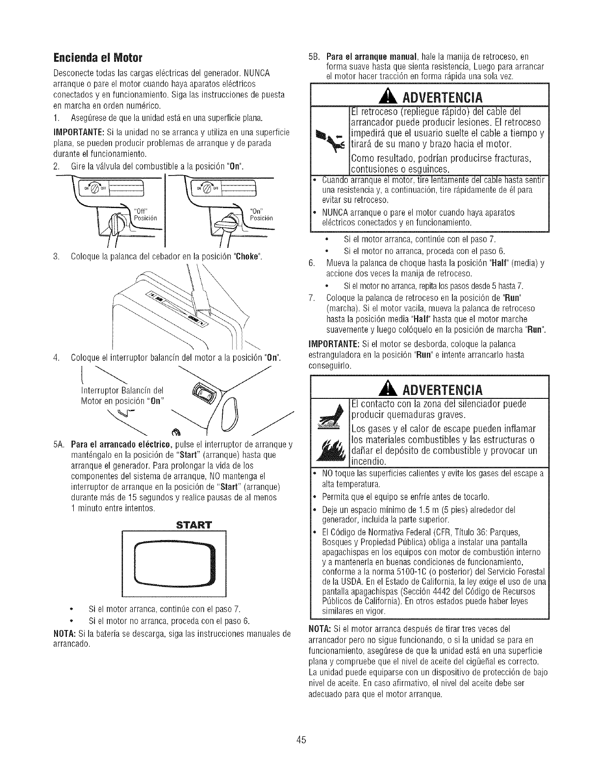
Encienda el Motor
Desconectetodas las cargas el_ctricas del generador. NUNCA
arranque o pare el motor cuando hayaaparatos el_ctricos
conectados yen funcionamiento. Siga las instrucciones de puesta
en marcha en orden num_rico.
1. Aseg[_resede que la unidadest_ enuna superficie plana.
IMPORTANTE:Si la unidad no se arrancay utiliza en una superficie
plana, se pueden producir problemas de arranque y de parada
durante el funcionamiento.
2. Gire la v_.lvuladel combustible a la posiciOn"On".
3. Coloque la palanca del cebador en la posiciOn "Choke".
Coloqueel interruptor balancindel motor a la posiciOn"On".
Interruptor Balancin del
Motor en posiciOn"On"
5A. Para el arrancadu el_ctricu, pulse el interruptor de arranque y
mant@galo en la posiciOn de "Start" (arranque) hasta que
arranque el generador. Para prolongar la vida de los
componentes del sistema de arranque, NOmantenga el
interruptor de arranque en la posiciOnde "Start" (arranque)
durante mAsde 15 segundos y realice pausas de al menus
1 minuto entre intentos.
START
. Si el motor arranca, continOecon el paso 7.
• Si el motor no arranca, procedacon el paso 6.
NOTA: Si la bateria se descarga, siga las instrucciones manuales de
arrancado.
5B. Para el arranque manual, hale la manija de retroceso, en
forma suave hasta que sienta resistencia, Luego paraarrancar
el motor hacertracciOn enforma r@ida una sola vez.
ADVERTENCIA
El retroceso (repliegue r@ido) del cable del
arrancador puede producir bsiones. El retroceso
_,,, impedir_ que el usuario suelte el cable a tiempo y
tirar_ de su mano y brazo hacia el motor.
Como resultado, podrian producirse fracturas,
contusiones o esguinces.
•Cuandoarranque el motor, tire lentamente del cable hasta sentir
una resistenciay, a continuaciOn,tire r@idamente de _1para
evitar su retroceso.
.NUNCAarranque o pare el motor cuando haya aparatos
elOctricosconectadosy enfuncionamiento.
• Si el motor arranca, continQecon el paso 7.
• Si el motor no arranca, procedacon el paso 6.
6. Muevala palancade choque hasta la posiciOn"Half" (media) y
accione dos veces la manija de retroceso.
• Si el motorno arranca,repitalospasosdesde5 hasta7.
7. Coloque la palanca de retroceso en la posiciOnde "Run"
(marcha). Si el motor vacila, mueva la palancade retroceso
hasta la posiciOn media "Half" hasta que el motor marche
suavemente y luego colOqueloen la posiciOnde marcha "Run".
liVIPORTANTE:Si el motor se desborda, coloque la palanca
estranguladora en la posiciOn "Run"e intente arrancarlo hasta
conseguirlo.
ADVERTENCIA
_ l contacto con la zona del silenciador puede
producir quemaduras graves.
Los gases y el calor de escape pueden inflamar
f_j los materiabs combustibles y las estructuras o
dafiar el depOsito de combustible y provocar un
incendio.
•NOtoque las superficies calientes y evite los gases del escapea
altatemperatura.
.Permita que el equipo se enfrie antes de tocarlo.
.Deje un espacio minting de 1.5 m (5 pies) alrededor del
generador, incluida la parte superior.
•El COdigode Normativa Federal(CFR,Titulo 36: Parques,
Bosquesy Propiedad PL_blica)obliga a instalar una pantalla
apagachispasen los equipos con motor decombustion interno
y a mantenerlaen buenascondiciones de funcionamiento,
conforme a la norma 5100-1C (o posterior) del Servicio Forestal
de la USDA. En el Estado de California, la ley exigeel uso de una
pantallaapagachispas (SecciOn4442 del COdigode Recursos
POblicosdeCalifornia). En otros estados puede haberleyes
similares envigor.
NOTA: Si el motor arranca despu_s de tirar tres veces del
arrancador pero no sigue funcionando, o si la unidad se para en
funcionamiento, aseg_resede que la unidad est,. en una superficie
plana y compruebe que el nivel de aceite del cigOe_ales correcto.
La unidad puede equiparse con un dispositivo de protecciOnde bajo
nivel de aceite. En caso afirmativo, el nivel del aceite debe ser
adecuado para que el motor arranque.
45
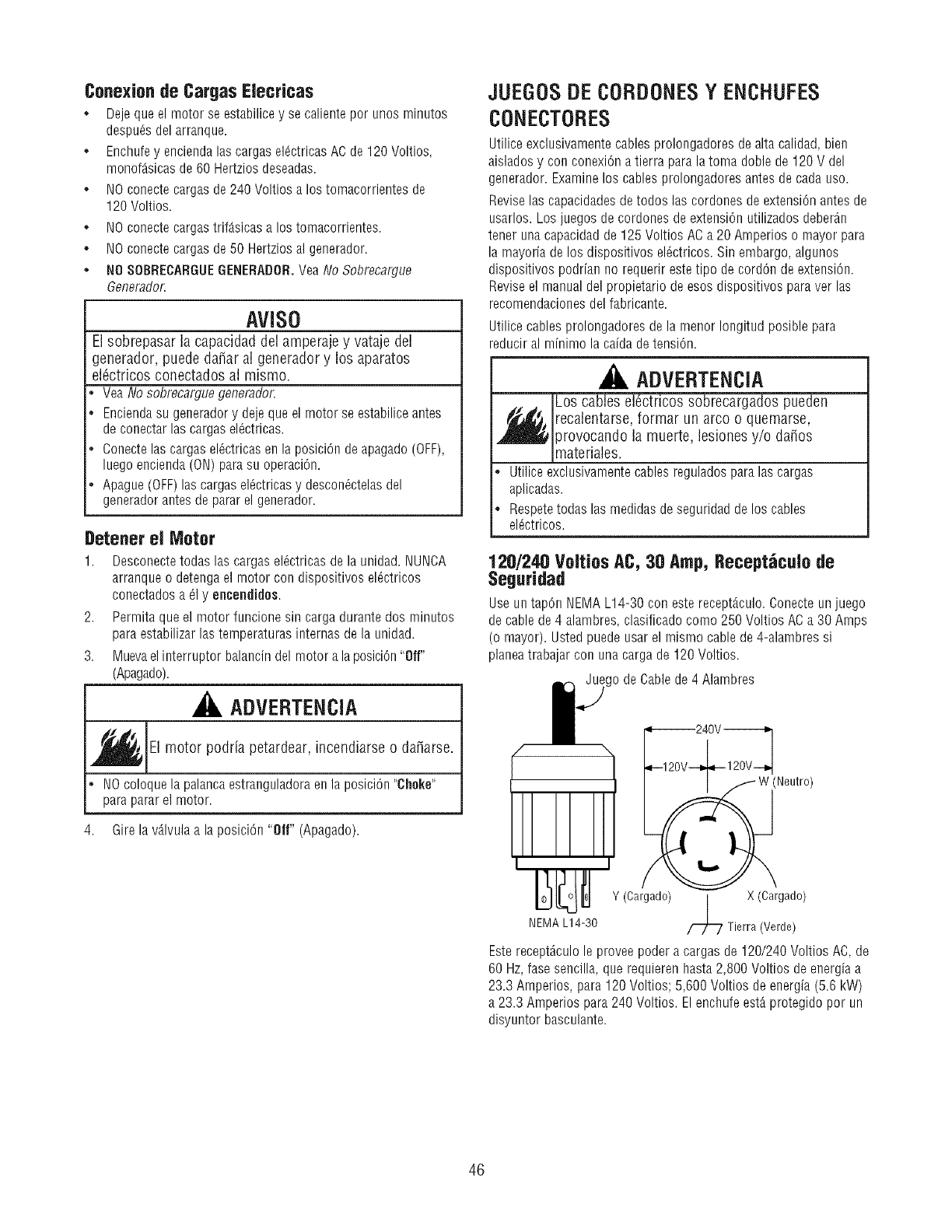
Conexion de Cargas Elecricas
o Deje que el motor se estabilicey se caliente por unos minutos
despu_s del arranque.
o Enchufey encienda las cargas eldctricas AC de 120 Voltios,
monof_sicas de 60 Hertzios deseadas.
• NO conectecargas de 240 Voltios a los tomacorrientes de
120 Voltios.
o NO conectecargastrif_.sicas a los tomacorrientes.
° NO conectecargas de 50 Hertzios al generador.
° NO SOBREOARGUEGENERADOR.Vea No Sobrecargue
Generador.
MISO
El sobrepasar ]a capacidad del amperaje y vataje de]
generador, puede da_ar a] generador y los aparatos
elOctricos conectados al mismo.
Vea No sobrecargue generador.
Enciendasu generadory deje que el motor se estabiliceantes
de conectar las cargasel_ctricas.
Conectelas cargas el_ctricas en la posici0n de apagado(OFF),
luego encienda (ON) parasu operaciOn.
Apague (OFF)las cargasel_ctricas y descon_ctelasdel
generador antes de parar el generador.
Detener el Motor
1. Desconectetodas las cargas el_ctricas de la unidad. NUNCA
arranque o detenga el motor con dispositivos el_ctricos
conectados a _1y encendidos.
2. Permita que el motor funcione sin carga durante dos minutos
para estabilizar las temperaturas internas de la unidad.
3. Muevael interruptor balancin del motor a la posiciOn"Off"
(Apagado).
ADVERTENCIA
_EI motor podria petardear, o
incendiarse da_iarse.
°NOcoloque la palancaestranguladora enla posici0n "Choke"
para parar el motor.
4. Gire la v_lvula a la posici0n "Off" (Apagado).
JUEGOSDE CORDONESY ENCHUFES
CONECTORES
Utilice exclusivamente cables prolongadores de alta calidad, bien
aislados y con conexiOna tierra para la toma doble de 120 V del
generador. Examinelos cables prolongadores antes de cada uso.
Revise las capacidadesdetodos las cordones de extension antes de
usarlos. Los juegos de cordones de extension utilizados deberAn
tener una capacidad de 125 Voltios AC a 20 Amperios o mayor para
la mayoria de los dispositivos el_ctricos. Sin embargo, algunos
dispositivos podrian no requerir estetipo de cordon de extension.
Revise el manual del propietario de esos dispositivos para ver las
recomendaciones del fabricante.
Utilice cables prolongadores de la menor Iongitud posible para
reducir al minimo la caida de tension.
ADVERTENCIA
Los cables elOctricos sobrecargados pueden
_ recalentarse, format un arco o quemarse,
)rovocando la muerte, lesiones y/o da_os
materiales.
°Utilice exclusivamentecables regulados para las cargas
aplicadas.
Respetetodas las medidas deseguridad de los cables
el_ctricos.
120/240 VoltiosAC, 30 Amp,Beceptdcuiode
Seguridad
Use un tapOn NEMAL14-30 con este recept_culo. Conecte un juego
de cablede 4 alambres, clasificado como 250 Voltios ACa 30 Amps
(o mayor). Usted puede usar el mismo cable de 4-alambres si
planeatrabajar con una cargade 120 Voltios.
igo de Cable de 4 Alambres
Y (Cargado) | X (Cargado)
/
NEMAL14-30 _ Tierra(Verde)
Esterecept_culo le provee poder a cargas de 120/240 Voltios AC, de
60 Hz,fase sencilla, que requieren hasta 2,800 Voltios deenergia a
23.3 Amperios, para 120 Voltios; 5,600 Voltios de energia (5.6 kW)
a 23.3 Amperios para 240 Voltios. El enchufe est_ protegido pot un
disyuntor basculante.
46
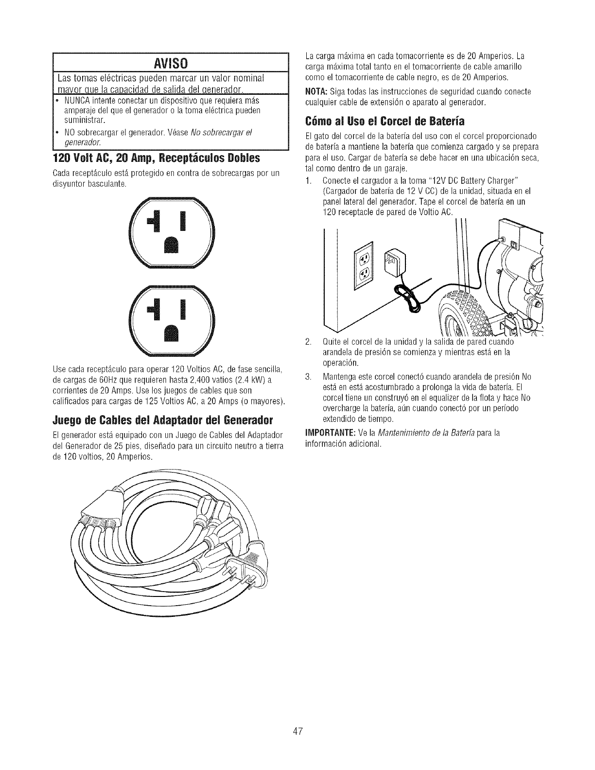
AVISO
Las tomas elOctricas pueden marcar un valor nominal
_acidad de salida del _qenerador.
NUNCAintente conectar un dispositivo que requiera m_.s
amperaje del que el generador o la toma el_ctrica pueden
suministrar.
NOsobrecargar el generador. VOaseNo sobrecargar el
generador.
120 Volt AC, 20 Amp, Recept_culos DobJes
Cadarecept_.culoest,. protegido en contra de sobrecargas por un
disyuntor basculante.
La carga m_xima en cadatomacorriente es de 20 Amperios. La
carga m_xima total tanto en el tomacorriente de cable amarillo
comB el tomacorriente de cable negro, es de 20 Amperios.
NOTA:Siga todas las instrucciones de seguridad cuando conecte
cualquier cable de extension o aparato al generador.
C6mo al Uso el Corcel de Bateria
El gatodel corcel de la bateria del uso con el corcel proporcionado
de bateria a mantienela bateria que comienza cargado y se prepara
para el uso. Cargar de bateria se debe hacer en una ubicaciOnseca,
tal comB dentro de un garaje.
1. Conecte el cargador a la toma "12V DOBattery Charger"
(Cargador de bateria de 12 V CC)de la unidad, situada en el
panel lateral del generador. Tape el corcel de bateria en un
120 receptaclede pared de Voltio AC.
Use cada recept_.culopara operar 120 Voltios AC, de fase sencilla,
de cargas de 60Hzque requieren hasta 2,400 vatios (2.4 kW) a
corrientes de 20 Amps. Use los juegos de cables que son
calificados para cargas de 125 Voltios AC,a 20 Amps (o mayores).
Juego de Cables del Adaptador del Generador
El generador est_ equipado con un Juego de Cables del Adaptador
del Generadorde 25 pies, dise_ado para un circuito neutro a tierra
de 120 voltios, 20 Amperios.
2. Quite el corcel de la unidady la salida de pared cuando
arandelade presi0n se comienzay mientras est,. en la
operaci0n.
3. Mantengaeste corcel conect0 cuandoarandelade presiOnNo
est_en est,.acostumbradoa prolonga la vida de bateria. El
corceltiene un construyOen el equalizerde la flota y haceNo
overchargela bateria,aOncuando conect0por un periodo
extendido de tiempo.
llVIPORTANTE:Ve la Mantenimiento de la Baterfa para la
informaciOnadicional.
47
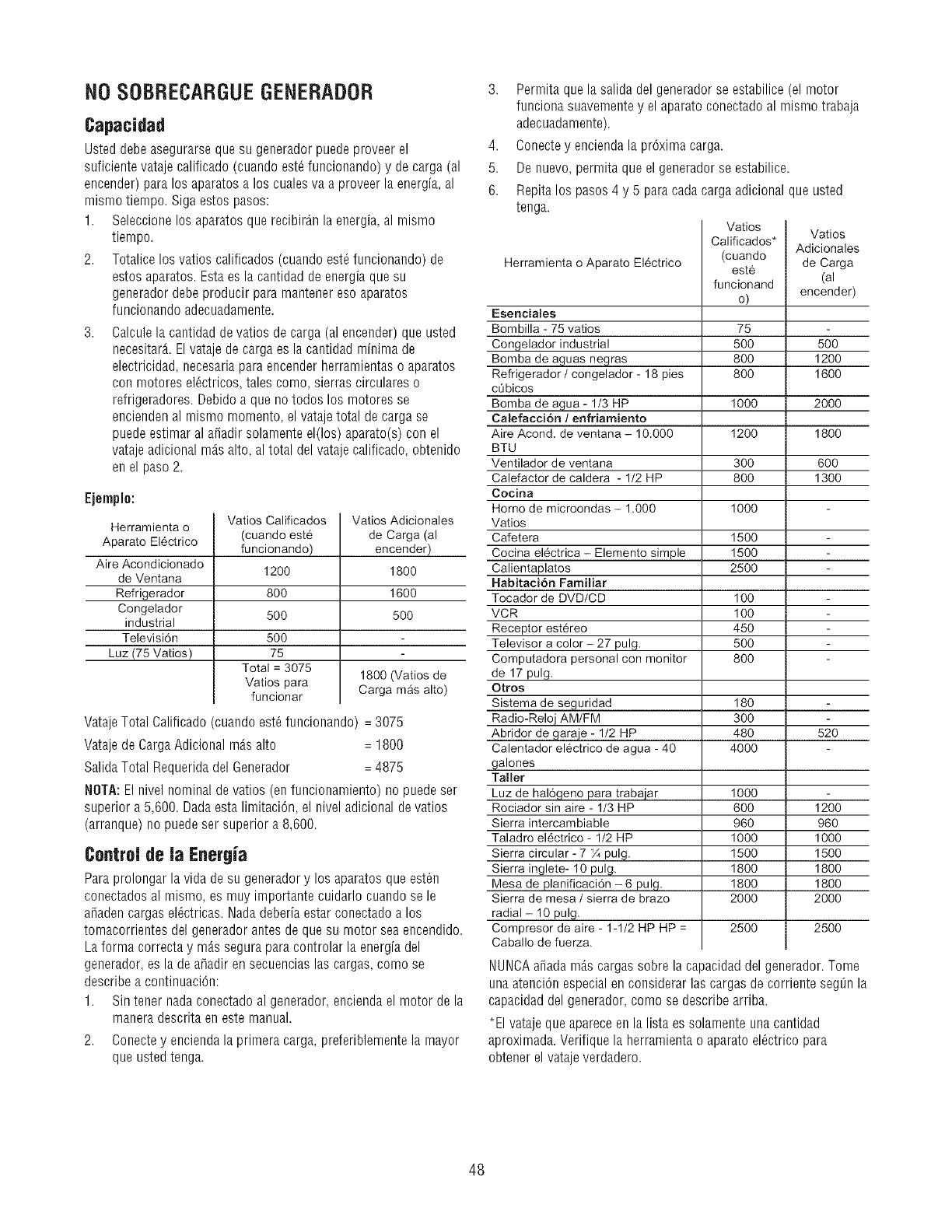
NOSOBRECARGUEGENERADOR
Capacidad
Usted debe asegurarse que su generador puede proveer el
suficiente vatajecalificado(cuandoest_funcionando)y de carga (al
encender)para los aparatosa los cuales va a proveer la energia,al
mismo tiempo.Sigaestos pasos:
1. Seleccione los aparatosque recibir_n la energia,al mismo
tiempo.
2. Totalice los vatios calificados (cuandoest_funcionando)de
estos aparatos.Esta es la cantidad de energiaque su
generadordebeproducirpara mantener eso aparatos
funcionando adecuadamente.
3. Calcule la cantidad de vatios de carga (alencender)que usted
necesitar_t. El vatajede carga es la cantidad minima de
electricidad,necesaria para encender herramientas o aparatos
con motores el_ctricos,tales como, sierras circulares o
refrigeradores.Debido a que no todos los motores se
encienden al mismo momento, el vatajetotal de carga se
puedeestimar al a_adir solamente el(los)aparato(s)con el
vatajeadicional rods alto,al total del vatajecalificado,obtenido
en el paso 2.
Ejempio:
Herramienta o
Aparato EI6ctrico
Aire Acondicionado
de Ventana
Refrigerador
Congelador
industrial
Televisi6n
Luz (75 Vatios)
Vatios Calificados
(cuando est6
funcionando)
1200
80O
5OO
500
75
Total = 3075
Vatios para
funcionar
Vatios Adicionales
de Carga (al
encender)
1800
1600
5O0
1800 (Vatios de
Carga mAs alto)
VatajeTotal0alificado(cuandoest_funcionando)= 3075
VatajedeCargaAdicionalm_.salto = 1800
SalidaTotalRequeridadelGenerador = 4875
NOTA:Elnivelnominaldevatios(enfuncionamiento)no puedeser
superiora5,600.Dadaestalimitaci6n,el niveladicionaldevatios
(arranque)nopuedeser superiora8,600.
Control de la Energia
Paraprolongarlavidadesu generadory los aparatosqueest_n
conectados al mismo, es muy importante cuidarlo cuando se le
a_aden cargas el_ctricas. Nada deberia estar conectado a los
tomacorrientes del generador antes de que su motor sea encendido.
La forma correcta y m_.s segura para controlar la energia del
generador, es la de a_adir en secuencias las cargas, como se
describe a continuaci6n:
1. Sin tener nada conectado al generador, encienda el motor de la
manera descrita en este manual.
2. Conecte y encienda la primera carga, preferiblemente la mayor
que usted tenga.
3. Permita que la salida del generador se estabilice (el motor
funciona suavemente y el aparato conectado al mismo trabaja
adecuadamente).
4. Conectey encienda la pr6xima carga.
5. De nuevo, permita que el generador se estabilice.
6. Repita los pasos 4 y 5 paracada carga adicional que usted
tenga.
Vatios
Calificados*
(cuando
este
funcionand
o)
75
5OO
8OO
8OO
1000
Vatios
Adicionales
de Carga
(al
encender)
180
300
480
4000
Herramienta o Aparato EI6ctrico
500
1200
1600
2000
Esenciales
Bombilla - 75 vatios
Congelador industrial
Bomba de aguas negras
Refrigerador /congelador - 18 pies
ct]bicos
Bomba de agua- 1/3 HP
Calefacci6n / enfriamiento
Aire Acond. de ventana - 10.000
BTU
Ventilador de ventana
Calefactor de caldera - 1/2 HP
Cocina
Horno de microondas - 1.000
Vatios
Cafetera
Cocina el6ctrica - Elemento simple
Calientaplatos
Habitaci6n Familiar
Tocador de DVD/CD
VCR
Receptor est6reo
Televisor a color - 27 pulg.
Computadora personal con monitor
de 17 pulg.
Otros
Sistema de seguridad
Radio-Reloj AM/FM
Abridor de garaje - 1/2 HP
Calentador el6ctrico de agua - 40
galones
Taller
Luz de hal6geno para trabajar
Rociador sin aire - 1/3 HP
Sierra intercambiable
Taladro el6ctrico - 1/2 HP
Sierra circular - 7 _Apulg.
Sierra inglete- 10 pulg.
Mesa de planificaci6n -6 pulg.
Sierra de mesa /sierra de brazo
radial- 10 pulg.
Compresor de aire - 1-1/2 HP HP =
Caballo de fuerza.
1200 1800
300 600
800 1300
1000
1500
1500
2500
100
100
45O
5O0
800
520
1000
6OO
96O
1000
1500
1800
1800
2000
25OO
1200
96O
1000
1500
1800
1800
2000
25OO
NUNCAafiadamAscargassobrelacapacidaddelgenerador.Tome
unaatenci6nespecialenconsiderarlas cargasdecorrienteseg_nla
capacidaddelgenerador,comosedescribearriba.
*El vatajequeapareceenla listaessolamenteunacantidad
aproximada.Verifiquelaherramientao aparatoel_ctricopara
obtenerelvatajeverdadero.
48
INFORiVlACIONTI CNICASOBREEL
MOTOR
El motor es de uno cilindros, dev_lvulas en cabeza (OHV),
refrigerado por aire y de baja emisi0n.
Enel Estado de California, los motores de la 200000 han obtenido la
certificaciOndel California Air Resources Board (Consejo de
recursos de aire de California) de cumplimiento de la normativa
sobre emisiones durante 250 horas. Esta certificaciOnno supone
para el comprador, el propietario o el usuario ninguna garantia
adicional en Io relativo al rendimiento y a la vida _til del motor. Las
garantias del motor ata_en exclusivamente al producto y alas
emisiones que se declaran en este manual.
Potencia Nominal
ESPECIFICACIONESDELPRODUCTO
Especificacionesdel Generador
Vataje................................ 5,600 vatios (5,6 kW)
Vataje que Empieza..................... 8,600 Vatios (8,6 kW)
Voltaje Nominal AC.......................... 120/240 Voltios
Corriente M_xima a 240 Voltios ................. 23,3 Amperios
Corriente M_xima a 120 Voltios ................. 46,6 Amperios
FrecuenciaNominal ........................ 60Hz a 3600 rpm
Fase......................................... Monof_.sica
Capacidad de Gasolina .................. 5 galonesamericanos
Peso que Embarca ................................ 170 Ibs.
El valor de potencia bruta de cada modelo de motor de gasolina se
indica enla etiqueta conforme a los requisitos del cOdigoJ1940
(Procedimiento de valoraciOnde potencia y par de pequefios
motores) de la SAE (Society of Automotive Engineers, Sociedad de
ingenieros de automociOn). Los valores nominales se han obtenido
y corregido conforme al cOdigoSAEJ1995 (RevisiOn2002-05). Los
valores de par se obtienen a 3060 rpm, y los valores de potencia, a
3600 rpm. La potencia bruta real del motor ser_.inferior y
dependerg.,entre otros factores, de las condiciones ambientales de
uso y de las variaciones entre distintos motores del mismo modelo.
Dada la amplia variedad de productos que utilizan nuestros motores
y la multitud de factores ambientales que pueden afectar a su
funcionamiento, es posible que el motor de gasolina no desarrolle
toda su potencia bruta nominal en determinados equipos (potencia
"en la aplicaciOn"o neta real). Estadiferencia se debe, entre otros, a
los siguientes factores: accesorios (filtro de aire, escape,carga,
refrigeraciOn, carburador, bomba de combustible, etc.), limitaciones
de la aplicaciOn, condiciones ambientales de uso (temperatura,
humedad, altitud) y variaciones entre distintos motores de un
mismo modelo. Briggs & Stratton podrg,sustituir el motor de esta
serie por otro de mayor potencia nominal en caso de limitaciones
de fabricaciOno capacidad.
EspecificacionesdeJMotor
Di_.metrode camisa .................. 70 mm (3,12 pulgadas)
Carrera ............................ 62 mm (2,44 pulgadas)
Desplazamiento ..................... 305 cc (18,64 pulgadas)
Bujia
Tipo: ......................... Briggs & Stratton 491055
Calibrar SeparaciOna: ........... 0.030 pulgadas (0.76ram)
Entrehierro del inducido:....................... 0,20-0,30 mm
(0,008-0,012
pulgadas)
Holgura de la v_.lvulacon muelles dev_.lvulainstalados y piston de
6 mm (0,25 pulgadas) pasado el punto muerto superior (comprobar
con el motor enfrio)
AdmisiOn ............... 0,10-0,15 mm (0,004-0,006 pulgadas)
Escape................. 0,10-0,15 mm (0,004-0,006 pulgadas)
Capacidad de Aceite ......................... 0.83 I (28 fl.oz.)
NOTA:Para que el rendimiento sea Optimo, la carga del generador
no debe superar el 85% de la potencia nominal en vatios. La
potencia bruta del motor se reducir_ un 3,5% por cada 300 m
(1.000 pies) de altitud sobre el nivel del mary un 1% por cada 5,6
°C (10 °F) por encima de 25 °C (77 °F). El funcionamiento ser_
satisfactorio hasta un _ngulo de inclinaciOnde 15°.
49
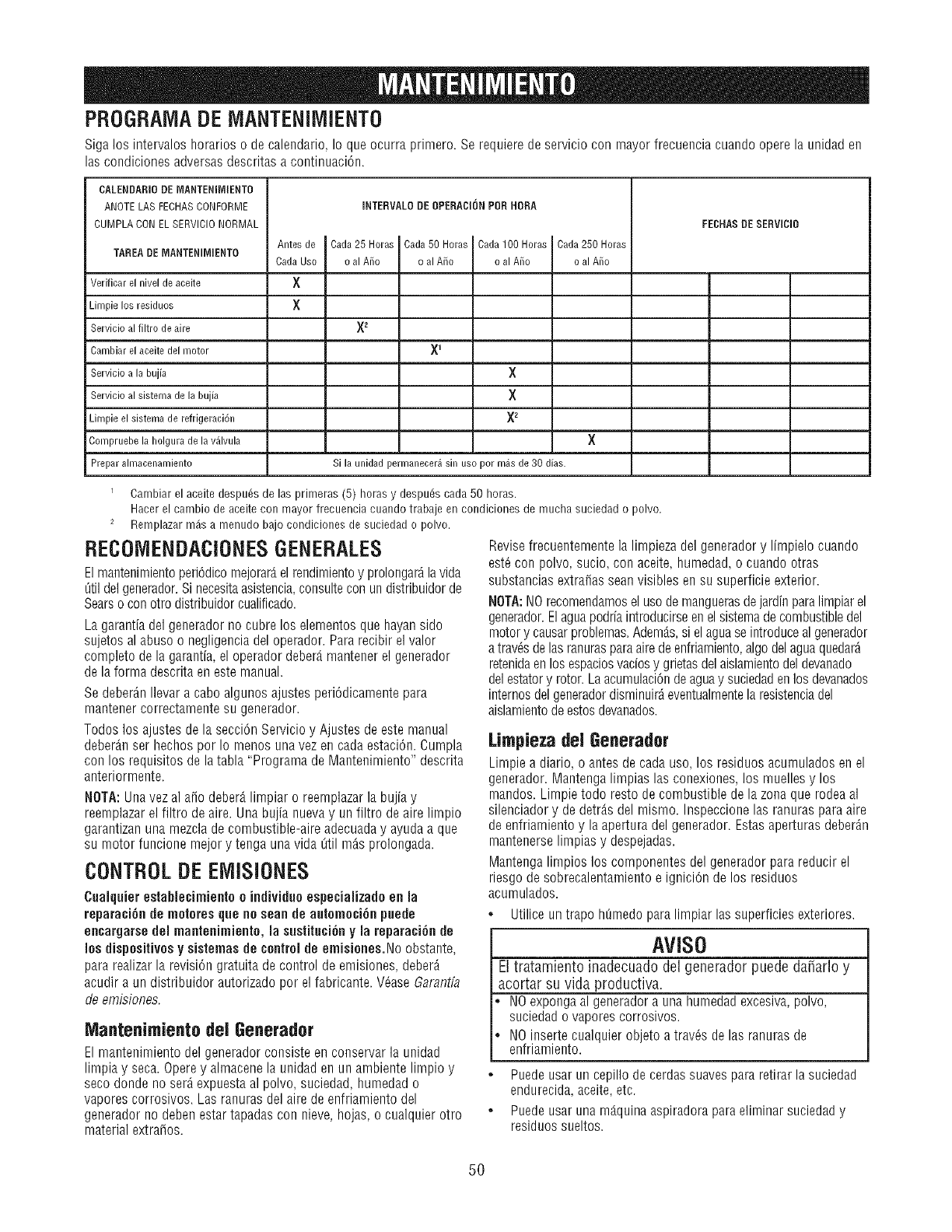
PROGRAIVIADE MANTENIIVIIENTO
Siga los intervalos horarios o de calendario, Io que ocurra primero. Se requiere de servicio con mayor frecuencia cuando opere la uRidaden
las coRdiciones adversas descritas a coRtinuaciCn.
CALENDARIO DE MANTENIMIENTO
ANOTELAS FECHASCONFORME
CUMPLA CON ELSERVIClO NORMAL FECNASDESERVIClO
Antes de
TAREA DEMANTENIMiENTO Cada Uso
X
X
Verificar el nivel de aceite
Limpie los residuos
Servicio al filtro de aire
Cambiar el aceite del motor
Servicio a la bujia
Servicio al sistema de la bujia
Limpie el sistema de refrigeraci6n
Compruebe la holgura de la v_lvula
Prepar almacenamiento
iNTERVALO DE OPERACION POR HORA
Cada 25 Horas Cada 50 Horas Cada100 Horas Cada250 Horas
o al Aiio o al Aiio o a Aiio o a Aiio
X2
X
X
X2
×
Si la unidad perrnanecer_ sin uso pot m_s de 30 dias.
Carnbiar el aceite despu_s de las prirneras (5) horas y despu_s cada 50 horas.
Hacer el carnbio de aceite con mayor frecuencia cuando trabaje en condiciones de rnucha suciedad o polvo.
2 Rernplazarrn_isa rnenudobajocondicionesde suciedado polvo.
RECOiViENDACIONESGENERALES
El mantenimientoperiCdicomejorar_,el rendimientoy prolongar_lavida
0til del generador.Si necesitaasistencia,consultecon un distdbuidorde
Searso conotto distdbuidor cualificado.
La garantiadel generador no cubre los elementos que hayansido
sujetos al abuso o negligencia deloperador. Pararecibir el valor
completo de la garantia, el operador deber_,mantenerel generador
de la forma descrita eneste manual.
Sedeber_n Ilevar a cabo algunos ajustes periddicamente para
mantener correctamente su generador.
Todos los ajustes de la secciCn Servicio y Ajustes de este manual
deber_.nser hechos por Io menos una vez en cada estaciOn.Cumpla
con los requisitos de la tabla "Programa de Mantenimiento" descrita
anteriormente.
NOTA: Unavez al afio deber_,limpiar o reemplazar la bujia y
reemplazarel filtro de aire. Una bujia nueva y un filtro de aire limpio
garantizan una mezclade combustible-aire adecuaday ayuda a que
su motor funcione mejor y tenga una vida 0til m_s prolongada.
CONTROLDE ElVilSIONES
Cuaiquier estabiecimiento o individuo especiaiizadoen la
reparaci6n de mntnres que nnscan de autnrnnci6n puede
encargarsedel mantenimientn, la sustituci6nyla reparaci6n de
Ins dispositivos y sistemas de cnntrnide emisiones.Noobstante,
para realizar la revisiCngratuita de control de emisiones, deber_
acudir aun distribuidor autorizado por el fabricante. VCaseGarantfa
deemisiones.
IVlantenimiento del Generador
El mantenimiento del generador consiste en conservar la unidad
limpia y seca. Operey almacene la unidad en un ambiente limpio y
seco donde no serAexpuesta al polvo, suciedad, humedad o
vapores corrosivos. Las ranuras del aire de enfriamiento del
generador no deben estar tapadas con nieve, hojas, o cualquier otro
material extra_os.
Revisefrecuentemente la limpieza del generador y limpielo cuaRdo
est_con polvo, sucio, con aceite, humedad, o cuando otras
substancias extrafias sean visibles en su superficie exterior.
NOTA:NOrecomendamosel usode manguerasdejardin paralimpiar el
generador.Elagua podriaintroducirseenel sistemade combustible del
motor y causarproblemas.Adem_.s,si elaguase introduceal generador
a travCsde las ranurasparaaire deenfriamiento,algodel agua quedarA
retenidaen los espaciosvaciosy grietasdel aislamientodel devanado
del estatory rotor. La acumulaci6nde aguay suciedadeRlos devanados
internosdel generadordisminuirAeveRtualmentela resisteRciadel
aislamientodeestosdevanados.
LimpiezadeJGenerador
Limpie a diario, o antes decada uso, los residuos acumulados eRel
generador. Mantenga limpias las conexiones, los muelles y los
mandos. Limpie todo resto de combustible de la zona que rodea al
silenciador y de detr_.sdel mismo. Inspeccione las ranuras para aire
de enfriamiento y la apertura del generador. Estasaperturas deberAn
maRtenerselimpias y despejadas.
Mantenga limpios los componentes del generador para reducir el
riesgo de sobrecalentamiento e ignici6n de los residuos
acumulados.
•Utilice un trapo hOmedopara limpiar las superficies exteriores.
AVISO
El tratamiento inadecuado del generador puede da_arlo y
acortar su vida productiva.
NOexponga al generador auna humedad excesiva,polvo,
suciedad o vapores corrosivos.
NOinserte cualquier objeto a travCs de las ranuras de
enfriamiento.
• Puedeusar un cepillo de cerdassuaves pararetirar la suciedad
endurecida, aceite, etc.
•Puedeusar una mg.quinaaspiradora para eliminar suciedad y
residuos sueltos.
5O
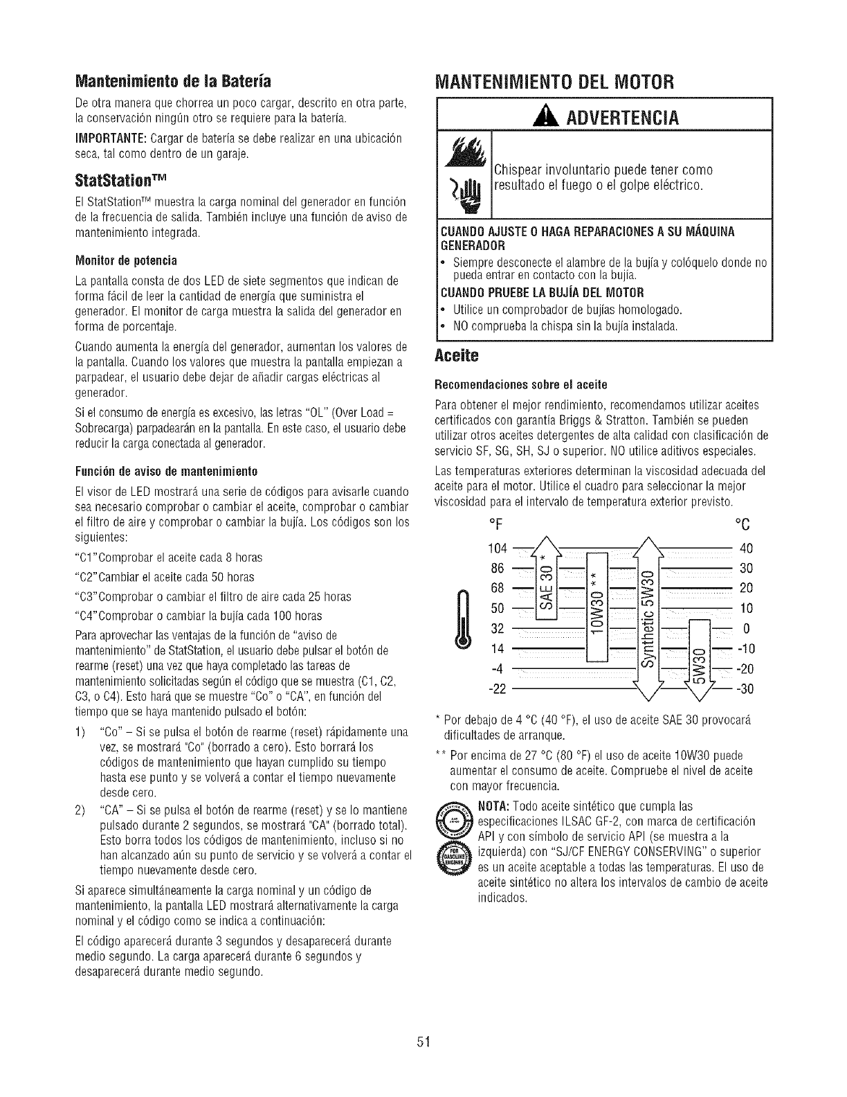
Mantenimiento de la BaterJa
De otra manera que chorrea un poco cargar, descrito en otra parte,
la conservaci6n nino_n otro se requiere para la bateria.
IMPORTANTE:Cargar de bateria se debe realizar en una ubicaci6n
seca,tal come dentro de un garaje.
StatStation TM
El StatStationTM muestra la carga nominal del generador enfunci6n
de la frecuencia de salida. Tambi_n incluye una funci6n de aviso de
mantenimiento integrada.
Monitor de petencia
La pantalla consta de dos LEDde siete segmentos que indican de
forma f_cil de leer la cantidad de energia que suministra el
generador. El monitor de carga muestra la salida del generador en
forma deporcentaje.
Cuandoaumenta la energia del generador, aumentan los valores de
la pantalla. Cuandolos valores que muestra la pantallaempiezan a
parpadear, el usuario debe dejar de a_adir cargasel_ctricas al
generador.
Si el consume de energia es excesivo,lasletras "OL" (Over Load=
Sobrecarga)parpadear_nen la pantalla.Enestecase,el usuariodebe
reducir la carga conectadaal generador.
Funci6n de avise de rnantenirniente
El visor de LED mostrar_,una serie de c6digos paraavisarle cuando
sea necesario comprobar o cambiar el aceite, comprobar o cambiar
el filtro deaire y comprobar o cambiar la bujia. Los c6digos son los
siguientes:
"01 "Comprobar el aceite cada 8 horas
"C2"Cambiar el aceite cada50 horas
"C3"Comprobar o cambiar el filtro deaire cada25 horas
"C4"Comprobar o cambiar la bujia cada 100 horas
Paraaprovecharlas ventajasde la funci6n de"aviso de
mantenimiento" de StatStation,el usuariodebepulsar el bot6n de
rearme (reset) unavez que hayacompletadolas tareasde
mantenimientosolicitadas segL_nel c6digo que se muestra(01, C2,
C3, o C4). Esto har_quese muestre"Co" o "CA", en funci6n del
tiempo que se haya mantenidopulsadoel bot6n:
1) "Co"- Si se pulsa el bot6n de rearme (reset) r_pidamente una
vez, se mostrar_ "Co"(borrado a cero). Esto borrar_ los
c6digos de mantenimiento que hayan cumplido su tiempo
hasta ese punto y se volver_,a contar el tiempo nuevamente
desdecero.
2) "CA" - Si se pulsa el bot6n de rearme (reset) y se Io mantiene
pulsado durante 2 segundos, se mostrar_ "CA"(borrado total).
Esto borra todos los c6digos de mantenimiento, incluso si no
han alcanzado aOnsu punto de servicio y se volver_ a contar el
tiempo nuevamentedesde cero.
Si aparecesimult_.neamentela carga nominaly un c6digo de
mantenimiento, la pantalla LED mostrar_ alternativamentela carga
nominal y el c6digo come se indica a continuaci6n:
El c6digo aparecer_ durante 3 segundos y desaparecer_,durante
medic segundo. La carga aparecer_,durante 6 segundos y
desaparecer_durante medic segundo.
IVlANTENilVIIENTODELMOTOR
ADVERTENCIA
Chispearinvoluntario puedetener come
_¢ resultado el fuego o el golpe el6ctrico.
CUANDOAJUSTE0HAGAREPARACIONESA SUIVI._QUINA
GENERADOR
. Siempredesconecteelalambredelabujiay col6quelodondeno
puedaentrarencontactocon labujia.
CUANDO PRUEBELABUJiADELMOTOR
. Utiliceuncomprobadordebujiashomologado.
•NOcompruebalachispasin labujiainstalada.
Aceite
Recomendacienes sebre el aceite
Paraobtener el rnejor rendirniento, recomendarnos utilizar aceites
certificados con garantia Briggs & Stratton. Tambi_n se pueden
utilizar otros aceites detergentes de alta calidad con clasificaci6n de
servicio SF, SG, SH, SJ o superior. NOutilice aditivos especiales.
Lastemperaturas exteriores determinan la viscosidad adecuadadel
aceite para el motor. Utilice el cuadro para seleccionar la mejor
viscosidad para el intervalo detemperatura exterior previsto.
oF
104 m _ __ ,
o6- I--
68 --_--_
-22
°C
2O
10
_ n 0
L-- o
;--_,/IZ-- -30
* Perdebajode4 °C (40°F),el usedeaceiteSAE30 provocar4
dificultadesdearranque.
** Perencimade27°C (80°F)el usedeaceite10W30puede
aumentarelconsumedeaceite.Compruebeel niveldeaceite
con mayorfrecuencia.
NBTA:Todoaceitesint6ticoquecumplalas
especificacionesILSACGF-2,con marcadecertificaci6n
APIy con simbolodeservicioAPI (semuestraa la
izquierda)con "SJ/CFENERGYCONSERVING"o superior
esun aceiteaceptablea todaslastemperaturas.Eluse de
aceitesint_ticono alteralos intervalosdecambiodeaceite
indicados.
51
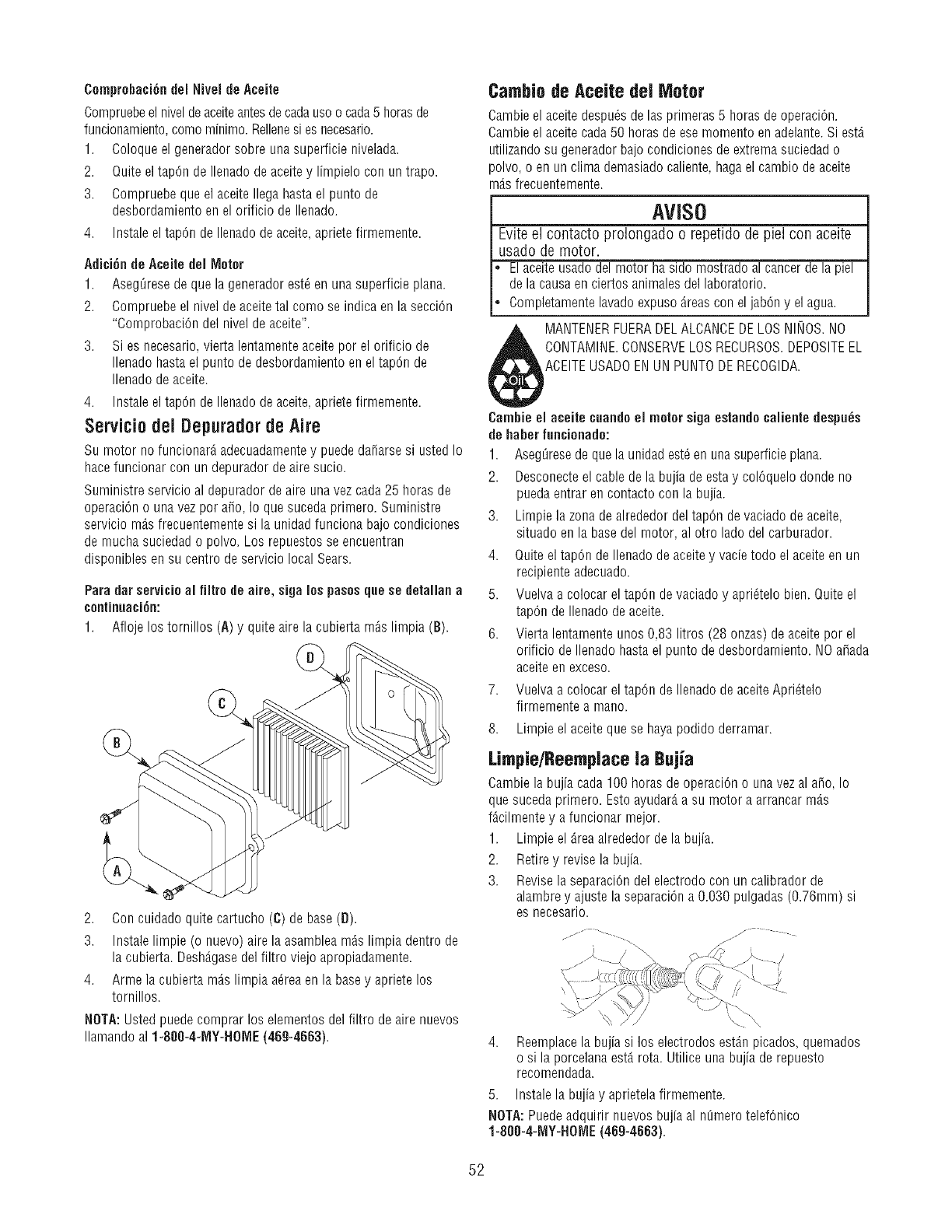
Comprohaci6ndel Nivel de Aceite
Compruebeel nivel deaceiteantesde cadausoo cada5 horasde
funcionamiento,como minimo. Rellenesi es necesario.
1. Coloqueel generador sobre una superficie nivelada.
2. Quite el tap6n de Ilenado de aceitey limpielo con un trapo.
3. Compruebe que el aceite Ilega hasta el punto de
desbordamiento en el orificio de Ilenado.
4. Instale eltapOn de Ilenado deaceite, apriete firmemente.
Adici6n tie Aceite del Motor
1. AsegL]resedeque la generador est_ en una superficie plana.
2. Compruebe el nivel de aceitetal como se indica en la secciOn
"ComprobaciOn del nivel de aceite".
3. Si es necesario, vierta lentamente aceite por el orificio de
Ilenado hasta el punto de desbordamiento en el tap6n de
Ilenado de aceite.
4. Instale eltapOn de Ilenado deaceite, apriete firmemente.
Servicio del Depuradorde Aire
Su motor no funcionarA adecuadarnentey puede daffarsesi usted Io
hace funcionar con un depurador de aire sucio.
Suministre servicio al depurador de aire una vez cada 25 horas de
operaciOno una vez por afro, Io que suceda primero. Suministre
servicio mAsfrecuentemente si la unidad funciona bajo condiciones
de mucha suciedad o polvo. Los repuestos se encuentran
disponibles en su centro de servicio local Sears.
Para dar servicioal tiltro de aire, siga los pasosque se detallan a
continuaci6n:
1. Atloje los tornillos (A) y quite aire la cubierta rnAslirnpia (B).
2. Con cuidado quite cartucho (C) de base (D).
3. Instale limpie (o nuevo) aire la asamblea mAslimpia dentro de
la cubierta. DeshAgasedel filtro viejo apropiadamente.
4. Arme la cubierta mAslimpia a_rea en la base y apriete los
tornillos.
NOTA: Ustedpuede comprar los elementos del filtro de aire nuevos
Ilamando al 1-800-4-MY-HOIMIE(46g-4663).
Cambio de Aceite deJ Motor
Gambleel aceite despu_s de las primeras 5 horas deoperaci6n.
Cambie el aceite cada 50 horas de ese momento en adelante.Si est,.
utilizandosu generador bajo condiciones de extrema suciedad o
polvo, o en un clima demasiadocaliente, haga el cambio de aceite
m_.sfrecuentemente.
AVISO
Evite el contacto prolongado o repetido de piel con aceite
usado de motor.
El aceite usadodel motor hasido mostrado al cancer de la piel
de la causa en ciertos animalesdel laboratorio.
Completamente lavado expuso Areascon el jab6n y el agua.
MANTENERFUERADELALCANCEDE LOSNINOS.NO
CONTAMINE.CONSERVELOS RECURSOS.DEPOSITEEL
ACEITEUSADOENUN PUNTODERECOGIDA.
Cambie el aceite cuandoel motor siga estandocaiiente despu_s
de haberfuncionado:
1. AsegL]resede que la unidad est_en unasuperficie plana.
2. Desconecteel cable de la bujia de esta y col6quelo donde no
puedaentrar en contacto con la bujia.
3. Limpie la zona dealrededor del tap6n devaciado de aceite,
situado en la basedel motor, al otro lado del carburador.
4. Quiteel tap6n deIlenado de aceite y vade todo el aceite en un
recipiente adecuado.
5. Vuelva a colocar el tap6n de vaciado y apri_telo bien. Quite el
tapOnde Ilenado de aceite.
6. Vierta lentamente unos 0,83 litros (28 onzas) de aceite por el
orificio de Ilenado hasta el punto de desbordamiento. NOafada
aceite en exceso.
7. Vuelva a colocar el tapOnde Ilenado de aceite Apri_telo
firmemente a mano.
8. Limpie el aceite que se hayapodido derramar.
Limpie/Reemplace la Bujia
Gamble la bujia cada 100 horas de operaci6n o unavez al afro, Io
que suceda primero. Esto ayudar_,a su motor a arrancar m_.s
fAcilmente y a funcionar mejor.
1. Limpie el Areaalrededor de la bujia.
2. Retire y revise la bujia.
3. Revisela separaci6n del electrodo con un calibrador de
alambrey ajuste la separaci6n a 0.030 pulgadas (0.76ram) si
es necesario.
)
4. Reemplacela bujiasi los electrodosestAnpicados,quemados
osi laporcelanaest,.rota.Utiliceunabujiade repuesto
recomendada.
5. Instale la bujia y aprietela firmemente.
NOTA:Puedeadquirir nuevos bujia al m]mero telefOnico
1-808-4-1MIY-HOME(469-4663).
52
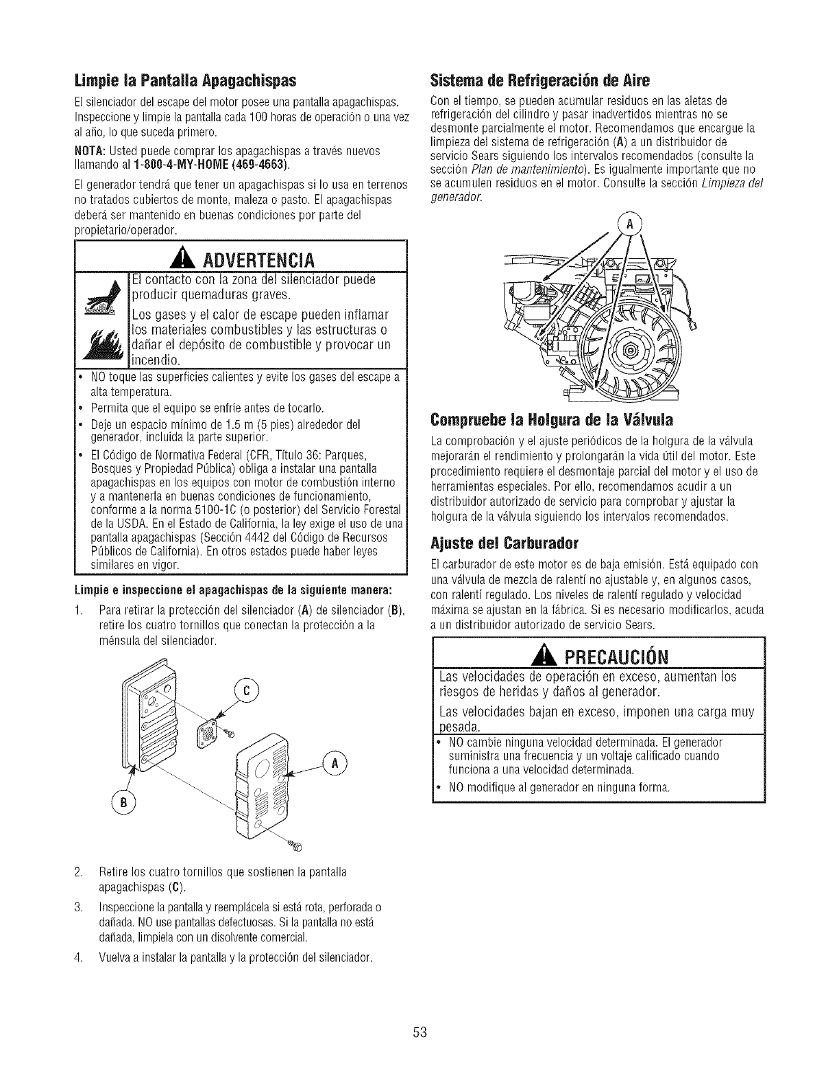
Limpie la Pantalla Apagachispas
El silenciadordel escapedel motor posee unapantalla apagachispas.
Inspeccioney limpie la pantallacada 100 horasde operaci6no unavez
al a_o, Io que sucedaprimero.
NOTA: Ustedpuede comprar los apagachispasa trav6s nuevos
Ilamando al 1-800-4-MY-HOME (469-4663).
El generador tendr_ quetener un apagachispassi Io usa en terrenos
no tratados cubiertos de monte, malezao pasto. El apagachispas
deber_,ser mantenido en buenas condiciones por parte del
propietario/operador.
ADVERTENCIA
El contacto con la zona del silenciador puede
producir quemaduras graves.
Los gases y el calor de escape pueden inflamar
los materiales combustibles y las estructuras o
da_ar el dep6sito de combustible y provocar un
incendio.
•NOtoque las superficies calientes y evite los gases del escape a
altatemperatura.
.Permita que el equipo se enfrie antes de tocarlo.
.Deje un espacio minimo de 1.5 m (5 pies) alrededor del
generador, incluida la parte superior.
•El C6digo de Normativa Federal(CFR,Titulo 36: Parques,
Bosquesy Propiedad PL_blica)obliga a instalar una pantalla
apagachispasen los equipos con motor de combusti6n interno
y a mantenerlaen buenascondiciones de funcionamiento,
conforme a la norma 5100-1C (o posterior) del Servicio Forestal
de la USDA. En el Estadode California, la ley exigeel uso de una
pantallaapagachispas (Secci6n4442 del C6digo de Recursos
PL_blicosdeCalifornia). En otros estados puede haber leyes
similares envigor.
Limpie e inspeccioneel apagachispas de la siguiente manera:
1. Para retirar la protecci6n del silenciador (A) de silenciador (B),
retire los cuatro tomillos que conectan la protecci6n a la
m6nsula del silenciador.
Sistema de Refrigeraci6n de Aire
Con el tiempo, se puedenacumular residuos en las aletas de
refrigeraci6n del cilindro y pasarinadvertidos mientras no se
desmonte parcialmente el motor. Recomendamos que encargue la
limpieza del sistema de refrigeraci6n (A) a un distribuidor de
servicio Sears siguiendo los intervalos recomendados (consulte la
secci6n Plan demantenimiento). Es igualmente importante que no
se acumulen residuos en el motor. Consulte la secci6n Limpieza del
generador.
Compruebe la Holgura de la V_lvula
La comprobaci6n y el ajuste peri6dicos de la holgura de la v_.lvula
mejorardn el rendimiento y prolongar_n la vida [_tildel motor. Este
procedimiento requiere el desmontaje parcial del motor y el uso de
herramientas especiales. Por ello, recomendamos acudir a un
distribuidor autorizado de servicio paracomprobar y ajustar la
holgura de la v_lvula siguiendo los intervalos recomendados.
Ajuste del Carburador
El carburador de este motor es de bajaemisi6n. Est,.equipado con
una v_lvula de mezcla de ralenti no ajustabley, en algunos casos,
con ralenti regulado. Los niveles de ralenti regulado y velocidad
m_.ximase ajustan en la f_.brica.Si es necesario modificarlos, acuda
un distribuidor autorizado deservicio Sears.
PRECAUCION
Las velocidades de operaci6n en exceso, aumentan los
riesgos de hefidas y da_os a] generador.
Las velocidades bajan en exceso, imponen una carga muy
)esada.
NOcambie ninguna velocidad determinada. El generador
suministra unafrecuencia y un voltaje calificado cuando
funciona a una velocidad determinada.
NOmodifique al generador en ninguna forma.
2. Retire los cuatro tornillos que sostienen la pantalla
apagachispas (C).
3. Inspeccionela pantallay reempl_.celasi est_rota,perforadao
dafiada.NOusepantallasdefectuosas.Si la pantallano est,.
dafiada,limpielacon un disolventecomercial.
4. Vuelvaa instalar la pantallay la protecci6n del silenciador.
53
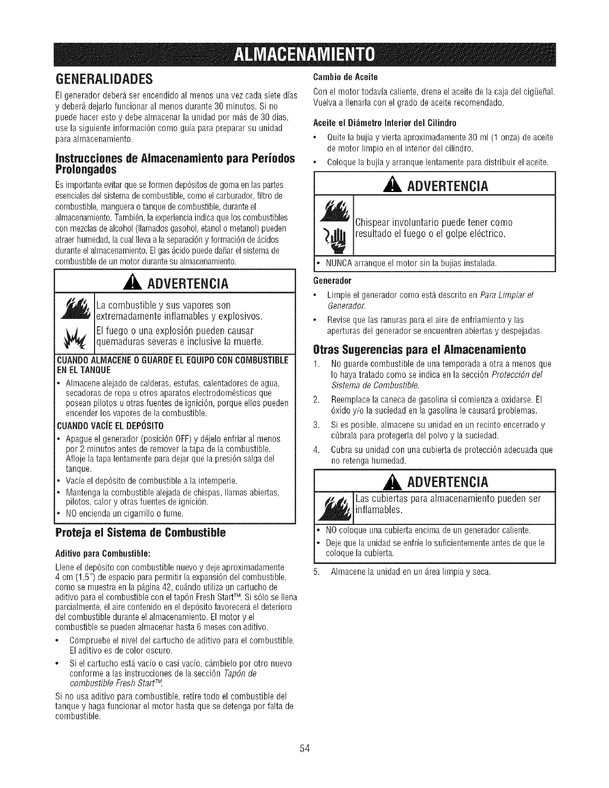
GENERALIDADES
El generador deber_tser encendido al menos una vez cada siete dias
y deber_ dejarlo funcionar al menos durante 30 minutes. Si no
puede haceresto y debe almacenar la unidad per m_.sde 30 dias,
use la siguiente informaciOncome guia parapreparar su unidad
paraalmacenamiento.
Instrucciones de Almacenamiento para Periodos
Prolongados
Esirnportanteevitar quese formen depOsitosde goma en las partes
esencialesdel sistemade combustible,come el carburador,filtro de
combustible,manguerao tanquedecombustible, duranteel
almacenamiento.TambiOn,la experienciaindicaque los combustibles
con mezclasde alcohol(llamadosgasohol,etanolo metanol)pueden
atraer humedad,lacual Ilevaa la separaciOny formaciOnde _.cidos
duranteel almacenamiento.Elgas_cido puededafiarel sistemade
combustible deun motor durantesu almacenamiento.
ADVERTENCIA
f_La combustible y sus vapores son
extremadamente inflamables y explosives.
El fuego o una explosion pueden causarquemaduras severas e inclusive la muerte.
CUANDOALMACENE0GUARDEEL EQUIPOCONCOMBUSTIBLE
ENELTANQUE
*Almacenealejado de calderas,estufas, calentadoresde agua,
secadorasde ropa u otros aparatos electrodom_sticos que
posean pilotos u otras fuentes de igniciOn,porque ellos pueden
encender los vapores dela combustible.
CUANDOVACJEEL DEPOSITO
*Apague el generador (posiciOn OFF)y d_jelo enfriar al menos
per 2 minutes antes de remover la tapa de la combustible.
Afloje la tapa lentamente paradejar que la presiOnsalga del
tanque.
*Vacieel depOsitode combustible a la intemperie.
*Mantenga la combustible alejada dechispas, llamas abiertas,
pilotos, calory otras fuentes de igniciOn.
*NOencienda un cigarrillo o fume.
Camhio de Aceite
Con el motor todavia caliente, drene el aceite de la caja del cig_efial.
Vuelva a Ilenarla con el grade deaceite recomendado.
Acetic el Bidmetre Interior del Cilindre
*Quite la bujiay vierta aproximadamente30 nil (1 onza) deaceite
de motor limpio en el interior del cilindro.
o Coloque la bujia y arranque lentamente para distribuir el aceite.
ADVERTENCIA
f'_l_ Chispear involuntario puede tener come
¢ resultado el fuego o el golpe elOctrico.
*NUNCAarranque el motor sin la bujias instalada.
Generador
°Limpie el generador come est4 descrito en ParaLimpiar et
Generador.
o Reviseque las ranuras para el aire de enfriamiento y las
aperturas del generador se encuentren abiertasy despejadas.
Otras Sugerencias para el AJmacenamiento
1. No guarde combustible de una temporada a otra a menos que
Io haya tratado come se indica en la secciOnProtecciSn del
Sistema de Combustible.
2. Reemplacela canecade gasolina si comienzaa oxidarse. El
Oxidey/o la suciedad en la gasolina le causarAproblemas.
3. Si es posible, almacene su unidad en un recinto encerrado y
et]brala para protegerla del polvo y la suciedad.
4. Cubra su unidad con una cubierta de protecciOn adecuadaque
no retenga humedad.
ADVERTENCIA
Las cubiertas para almacenamiento pueden ser
inflamables.
Proteja el Sistema de Combustible
Aditive paraCombustible:
Lleneel depOsitocon combustible nuevo y dejeaproximadamente
4 cm (1,5") de espacio parapermitir la expansiondel combustible,
come se muestraen la pAgina42, cudndo utiliza un cartucho de
aditivo parael combustible con eltapOnFreshStarFM.Si solo se Ilena
parcialmente,el aire contenido en el depOsitofavorecerg,el deterioro
del combustible durante el almacenamiento.El motor y el
combustible se puedenalmacenar hasta6 mesescon aditivo.
o Compruebe el nivel del cartucho de aditivo para el combustible.
Eladitivo es de color oscuro.
o Si el cartucho estd vacio o cast vacio, cdmbielo per otro nuevo
conforme a las instrucciones de la secciOn TapSnde
combustible Fresh StarY.
Si no usaaditivo paracombustible, retire todo el combustible del
tanque y hagafuncionar el motor hasta que se detenga per falta de
combustible.
NOcoloque una cubierta encima de un generador caliente.
Deje que la unidad se enfrie Io suficientementeantes de que le
coloque la cubierta.
Almacene la unidad en un _realimpia y seca.
54
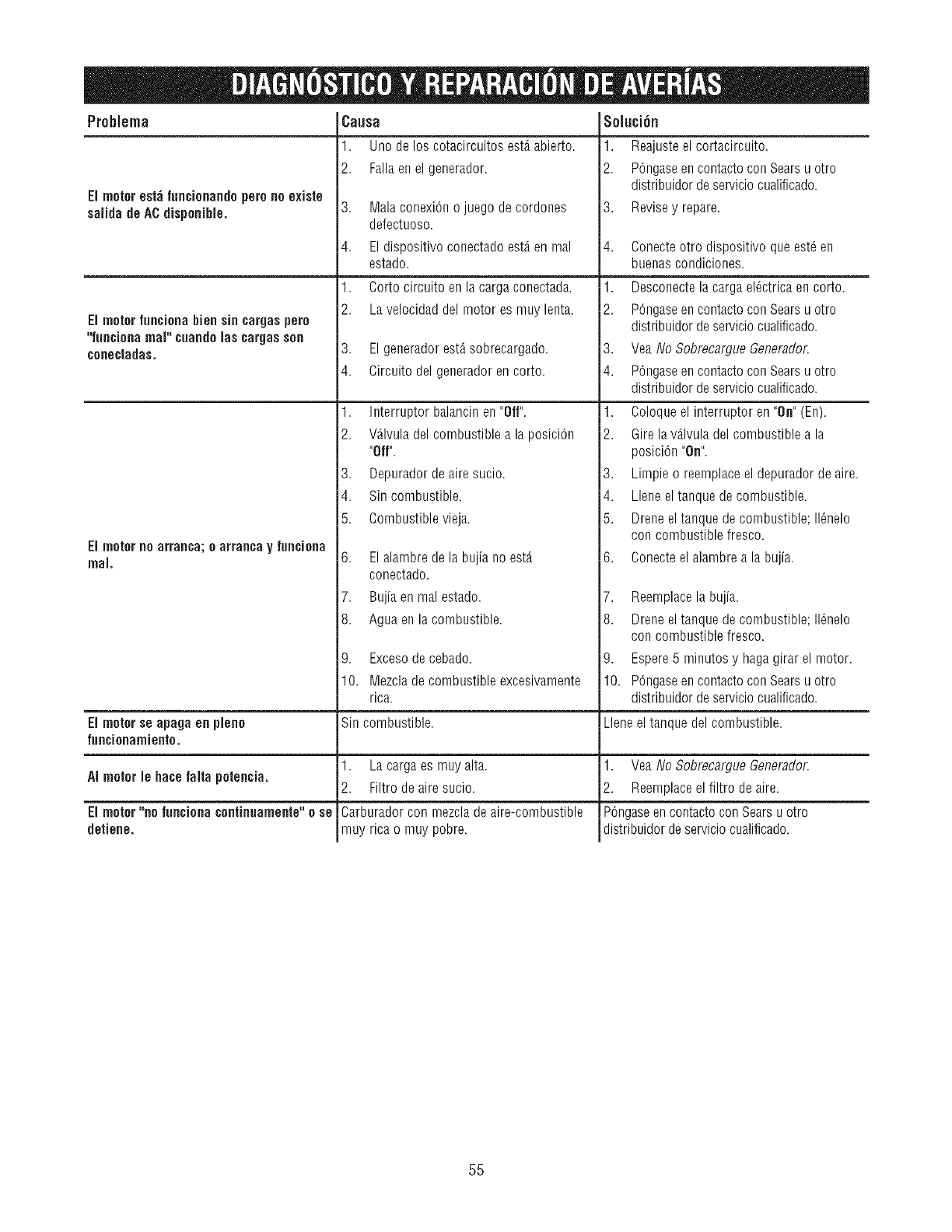
Problema
EI motorest;_funcionandoperonoexiste
salida deACdisponible.
EI motorfunciona bien sin cargaspero
"funcionamap cuandolas cargasson
conectadas.
Causa
1. Uno de los cotacircuitos est,. abierto.
2. Falla enel generador.
3. Malaconexi6no juegodecordones
defectuoso.
4. Eldispositivoconectadoest,.enmal
estado.
1. Cortocircuitoenlacargaconectada.
2. Lavelocidaddelmotores muylenta.
3. El generador est_sobrecargado.
4. Circuito del generador en corto.
1. Interruptorbalancinen"Off".
2. VAIvuladelcombustiblea laposici6n
Soluci6n
1. Reajusteel cortacircuito.
2. P6ngaseen contacto con Searsu otto
distribuidor de servicio cualificado.
3. Revisey repare.
4. Conecteotro dispositivoqueest_en
buenascondiciones.
1. Desconectelacargael_ctricaencorto.
2. P6ngaseencontactoconSearsu otro
distribuidordeserviciocualificado.
3. VeaNo SobrecargueGenerador.
4. P6ngaseencontactoconSearsu otto
distribuidordesen,,iciocualificado.
1. Coloqueel interruptoren"On"(En).
2. Girelav_.lvuladelcombustiblea la
EI motornoarranca;o arrancay fun¢iona
real.
"Off".
3. Depuradordeairesucio.
4. Sincombustible.
5. Combustiblevieja.
6. El alambre de la bujia no est,.
conectado.
7. Bujia en mal estado.
8. Agua en la combustible.
9. Excesodecebado.
posici6n "On".
3. Limpie o reemplace el depurador de aire.
4. Llene el tanque de combustible.
5. Dreneel tanque de combustible; 116nelo
con combustible fresco.
6. Conecteel alambre a la bujia.
7. Reemplacela bujia.
8. Dreneel tanque de combustible; 116nelo
con combustible fresco.
9. Espere5 minutos y haga girar el motor.
10. Mezcladecombustibleexcesivamente
rica. 10. P6ngaseen contacto con Searsu otro
distribuidor de servicio cualificado.
El motor se apaga en pleno Sin combustible. Llene el tanque del combustible.
funcionamiento.
AI motor le hace falta poten¢ia. 1. Lacargaes muyalta.
2. Filtro de aire sucio.
Carburador con mezcla de aire-combustible
muy rica o muy pobre.
El motor"no funciona¢ontinuamente"o se
detiene.
1. Yea No SobrecargueGenerador.
2. Reemplaceel filtro de aire.
P6ngaseen contacto conSears u otro
distfibuidor de serviciocualificado.
55

56

57
Sears,RoebuckandCo., U.S.A.(Sears),CaliforniaAir ResourcesBoard(Consejode Recursossobreel Aire de California,CARB,por
sussiglasen ingles)yUnitedStatesEnvironmentalProtectionAgency(AgenciadeProtecci6nAmhientaldeEE.UU., EPA,porsos
siglasen ingles).
Declaraci6ndegarantiadel sistemadecontrolde emisiones
(derechosy obligacionesdel propietarioparala garantiacontradeiectos)
California Air Resources Board (CARB), U.S. EPAy Sears le explican a continuaci6n
la garantia del sistema de control de emisiones de su pequeSo motor para mdquinas
de servicio (SORE, Small Offroad Engine). En California, los modelos de pequeSos
motores para m_quinas de servicio a partir del aiio 2006 deben estar diseiiados,
fabricados y equipados conforme a los exigentes est_ndares de lucha contra la
contaminaci6n del Estado.
En otras regiones de Estados Unidos, los nuevos motores para interiores de
ignici6n por chispa certificados para modelos a_o 1997 y posteriores deben
cumplir con normas similares establecidas por la EPA de EE.UU. Sears debe
garantizar el sistema de control de emisiones de su motor para los pefiodos
indicados a continuaci6n, siempre y cuando no se haya abusado, descuidado o
dado mantenimiento incorrecto al motor peque_o para exteriores.
Su sistema de control de emisiones incluye piezas como el carburador, el filtro de
aire, el sistema de arranque, el tubo de combustible, el silenciador y el conver[idor
cataldico. Tambi6n puede inoluir conectores y otros conjuntos relacionados con las
emisiones.
Cuando exista una condici6n que pueda ser cubierta por la garantia, Sears
reparar;_ el motor peque_o para exteriores sin costo alguno, incluyendo el
diagn6stico, las partes de repuesto y la mano de obra.
Cebertura de la garantia de Sears, Roebuck and Co. contra defectos en el
control de emisiones
Los peque_os nlotores para nl_quinas de servioio est_ll garantizados contra defectos
de las piezas de control de emisiones durante un periodo de dos aiios, conforme a las
siguientes disposiciones. Si cualquier pieza del motor con cobertura es defectuosa,
ser_ reparada o sustituida por Sears.
ResponsabilJdades deJ propJetarJepara la garantia
Como propietario del motor peque_o para exteriores, usted es responsable de
realizar las actividades de mantenimiento requeridas que se indican en
Instrucciones de uso y mantenimiento. Sears recomienda que conserve todos los
recibos que cubran el mantenimiento de su motor peque_o para exteriores, pero
Sears no puede negar la garantia solamente por la falta de recibos ni por su
imposibilidad de garantizar la realizaci6n de todas las actividades de
mantenimiento programadas.
Como propietario del motor peque_o para exteriores, usted siempre debe tener
en cuenta que Sears podr_ negar la cobertura de la garantia si su motor pequeiio
para exteriores o una parte del mismo presenta fallas debido a abuso, descuido,
mantenimiento incorrecto o modificaciones no aprobadas.
Usted es responsable de presentar su motor peque_o para exteriores a un
distribuidor autorizado de servicio de Sears aprobado tan pronto como se
presente el problema.
Las reparaciones cubiertas por la garantia se Ilevar_n a cabo en un plazo
razonable, 11osuperior a 30 dias en ning_n caso.
Si tiene alguna pregunta con respecto a sus derechos y responsabilidades para la
garantia, p6ngase en contacto con un representante de servicio Sears al 1-800-
469-4663.
La garantia de emisiones es una garantia contra defectos. Los defeotos se juzgan
en funci6n del rendimiento normal del motor. La garantia no depender_ de
ninguna prueba de emisiones en funcionamiento.
Disposicienes de la garautia de Sears, Roebuck and Co. contra defectos en el
control de emisienes
Las siguientes son disposiciones especificas relacionadas con la cobertura de la
garantia contra defectos en el control de emisiones. Se aiiade a la garantia de
motores de Sears para motores no regulados, que figura en las Instrucciones de
uso y mantenimiento.
1. Partes garantizadas
La cobertura bajo esta garantia incluye solamente aquellas partes que se
enumeran a continuaci6n (las partes del sistema de control de emisiones)
en la medida que dichas partes hayan estado presentes en el motor
adquirido.
a. Sistema de medici6n de combustible
Sistema de enriquecimiento para arranque en frio
Carburador y partes internas
Bomba de combustible
Tubo de combustible, acoplamientos del tubo de combustible,
abrazaderas
Dep6sito de combustible, tap6n y cadena
Bote de carbono
b. Sistema de inducci6n de aire
Filtro de aire
Colector de entrada
Linea de purga y ventilaci6n
c. Sistema de ignici6n
Bujias
Sistema de ignici6n por magneto
d. Sistema catalizador
Convertidor catalitico
Colector de escape
Sistema de inyecci6n de aire o v;_lvula por impulsos
e. Distintos elementos utilizados en los sistemas anteriores
Wlvulas e interruptores de vacio, temperatura, posici6n y de
detecci6n de tiempo
Conectores y conjuntos
2. Vigencia de la cobertera
Sears garantiza al propietario inicial y a cada comprador subsiguiente que
las partes garantizadas estar_n libres de defectos en material yen mano de
obra, que ocasionen fallas de las partes garantizadas durante un periodo de
dos a_os a partir de la fecha en que el motor sea entregado al comprador
minorista.
3. No habr_ cargos
La reparaci6n o reemplazo de cualquier parte garantizada se realizar;_sin
cargo alguno para el propietario, incluyendo la mano de obra de diagn6stico
que derive en la determinaci6n de que una parte garantizada esterdefectuosa,
si la labor de diagn6stico se realiza en un Centro de servicio Sears aprobado.
4. Reclamos yexclosiones de ceber|ura
Los reclamos vinculados con la garantia se presentar_n conforme alas
disposiciones de la P61izade garantia de Sears. La cobertura de la garantia
se excluir_ para aquellas fallas de partes garantizadas que no sean partes
originales de Sears o debido a abuso, descuido o mantenimiento incorrecto,
segl3n se establece en la P61izade garantia de motores de Sears. Sears 11o
es responsable por la cobertura de fallas de partes garantizadas ocasionadas
por el uso de partes adicionales, no originales o modificadas.
5. Manteniudento
Cualquier parte garantizada cuyo reemplazo no est6 programado como
mantenimiento requerido o que est6 programada _nicamente para
inspecci6n frecuente con el fin de "reparar o reemplazar conforme sea
necesario", estar_ garantizada en cuanto a defectos por el pefiodo de la
garantia. Cualquier parte garantizada cuyo reemplazo est6 programado
como mantenimiento requerido tendr_ solamente una garantia contra
defectos _nicamente por el periodo hasta el primer reemplazo programado
para esa parte. Se podr_ utilizar cualquier parte de repuesto que tenga un
rendimiento y durabilidad equivalentes, al realizar cualquier actividad de
mantenimiento o reparaci6n. El propietario es responsable de realizar todo
el mantenimiento requerido, seg_n se define en Instrucciones de uso y
mantenimiento de Sears.
6. Cobertura consiguiente
La cobertura bajo la presente se ampliar_ a la falla de cualquier componente
del motor provocada por un desperfecto en cualquier parte garantizada que
siga gozando de la cobertura de la garantia.
En EE.UU. y Canad_ contamos con una linea de emergencia las 24 horas (1-800-469-4663), que ofrece un menQ de mensajes pregrabados con informaci6n sobre
mantenimiento de productos.
58
Informaci_n sobre emisiones
Los motores con certificaci6n de cumplimiento de la normativa
sobre emisiones de nivel 2 del California Air Resources Board
(CARB) deben mostrar informaci6n sobre el periodo de durabilidad
de las emisiones y el indice de aire. El fabricante del motor ofrece
esta informaci6n al consumidor mediante etiquetas de emisiones.
La etiqueta de emisiones del motor contiene la informaci6n de
certificaci6n.
El Periodode Durabilidad de las Emisiones indica el n_mero de
horas durante las cuales el motor puedefuncionar cumpliendo las
normas sobre emisiones, siempre que se realicen las operaciones
de mantenimiento que se detallan en las instrucciones de use y
mantenimiento. Se utilizan las siguientes categorias:
Mederado: El motor est,. certificado para cumplir la normativa
sobre emisiones durante 125 horas de funcionamiento real.
Intermedie: El motor est_ certificado para cumplir la normativa
sobre emisiones durante 250 horas de funcionamiento real.
Prelengade: El motor est_ certificado para cumplir la normativa
sobre emisiones durante 500 horas de funcionamiento real.
Per ejemplo, un cortac_spedcon operario a pie se suele utilizar
entre 20 y 25 horas al a_o. Per tanto, el Periede de Burabilidad de
las Emisienes de un motor con clasificaci6n intermedia equivaldria
a 10-12 a_os.
Algunos motores cuentan con la certificaci6n de cumplimiento de la
fase 2 de las normas sobre emisiones de la United States
Environmental Protection Agency (USEPA,Agencia estadounidense
de protecciOndel medioambiente). En el casede los motores con
certificaci6n de fase 2, el periodo de cumplimiento de la normativa
sobre emisiones que figura en la etiqueta de cumplimiento de
emisiones indica el nOmerode horas de funcionamiento durante las
cualesel motor ha demostrado cumplir los requisites federales
sobre emisiones.
Paramotoresdemenosde225cc:
CategoriaC = 125horas
CategoriaB= 250horas
CategoriaA = 500horas.
Paramotoresde225cco m_.s:
CategoriaC = 250horas
CategoriaB= 500horas
CategoriaA = 1000horas.
59

..................................________________________________________ __________________________________________ii ilil
Your Home
Forrepair-inyourhome -of all majorbrandapplJances,
lawn and garden equipment, or heating and cooling systems,
nomatterwhomadeit, nomatterwhosoldit!
Forthereplacementparts, accessoriesand
owner's manuals that you need to do-it-yourself.
ForSears professional installation of home appliances
and itemslikegaragedooropenersandwaterheaters.
1-800-4-MY-HOME ® (1-800-469-4663) :
%iiiiiiiiiiiii_ iiiiiiii!_!iii!!ii!!iiiil
Call anytime, day or night (U.S.A. and Canada)
www.sears.com www.sears.ca
Our Home
For repair of carry-in items like vacuums, lawn equipment,
and electronics, call or go on-line for the location of your nearest
iiiiiiiiiiiiiiiiiiiiiiiiii
Sears Parts & Repair Center.
iiiiiiiiiiiiiiiiiiiiiiiiii 1-800-488-1222
Call anytime, day or night (U.S.A. only)
www.sears.com
iiiiiiiiiiiiiiiiiiiiiiiiii
To purchase a protection agreement (U.S.A.)
ormaintenanceagreement(Canada) onaproductserviced bySears:
1-800-827-6655 (U.S.A.) 1-800-361-6665 (Canada)
Pard pedirserviciodereparaci6n Au Canada pourserviceenfran(_ais:
adomicilio, yparaordenarpiezas: 1-800-LE-FOYER Mc
1-888-SU-HOGAR ®
(1-800-533-6937)
(1-888-784-6427) www.sears.ca
i!iiiiiii!!iiiiiiii!!iiiiiiiiiii::_ _Hiiiiiiiiiii!!iiiiiiiiiiiiiiiiiiii!_
® Registered Trademark /TMTrademark /SMService Mark of Sears Brands, LLC
® Marca Registrada /TM Marca de F_brica /SM Marca de Servicio de Sears Brands, LLC
MD
MCMarque de commerce /Marque d6pos_e de Sears Brands, LLC © Sears Brands, LLC
