Craftsman 580752090 User Manual PRESSURE WASHER Manuals And Guides L0705245
CRAFTSMAN Power Washer, Gas Manual L0705245 CRAFTSMAN Power Washer, Gas Owner's Manual, CRAFTSMAN Power Washer, Gas installation guides
User Manual: Craftsman 580752090 580752090 CRAFTSMAN PRESSURE WASHER - Manuals and Guides View the owners manual for your CRAFTSMAN PRESSURE WASHER #580752090. Home:Lawn & Garden Parts:Craftsman Parts:Craftsman PRESSURE WASHER Manual
Open the PDF directly: View PDF ![]() .
.
Page Count: 64
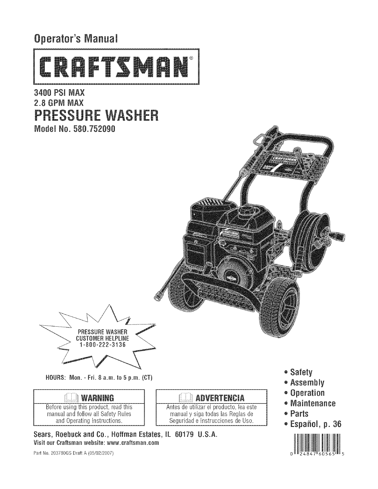
Operator'sManual
®
3408 PSi MAX
2.8 GPM MAX
Model No. 580.752090
PRESSUREWASHER
CUSTOMERHELPUNE
HOUriS: Non. - Fri. 8 a.m. to 5 p.m. (CT)
WARmeG
Before using this product, readthis
manual and follow atI Safety Rules
and Operating Instructions.
i ]
R, IADVERTENCJA
Antes de utiiizar el producto, iea este
manuai y siga todas ias Reglasde
Seguridade Instrucciones de Use.
Sears, Roebuck and Co., Hoffman Estates, [L 68179 U.S.A.
Visit our Craftsman website: www.craftsman.eom
Part No. 203780GS Draft A (05/02/2007)
®Safety
®Assembly
®Operation
+ Maintenance
++Parts
+Espa_oi, p. 36
0 4 } 5
WARRANTY.......................................... 2
SAFETYRULES...................................... 2-5
FEATURESANDCONTROLS.............................. 6
ASSEMBLY........................................ 7-11
OPERATION....................................... 12-16
SPECIFICATIONS..................................... 17
MAINTENANCE.................................... 18-22
STORAGE........................................... 23
TROUBLESHOOTING.................................. 24
NOTES ............................................. 25
REPLACEMENTPARTS.............................. 26-33
EMISSIONCONTROLWARRANTY..................... 34-35
ESPA_!OL......................................... 36-63
HOWTO ORDERPARTS ........................ BACK PAGE
If this pressurewasher faiis dueto a defect in materiai or workmanship within one year from the date of purchase, return it to
any Searsstore, other Craftsman outlet, or Sears Parts & Repair Centerin the UnitedStates or Canadafor free repair (or
replacementif repair proves impossible).
Ali warranty coverageapplies for only 90 days from date of purchaseif this pressure washer is ever used for commercial or
rentai purposes.
This warranty gives you specific legal rights, and you mayalso have other rights which vary from state to state.
Sears, Roebuck and Ce,, Heffman Estates, JL6e179
Sears Canada Jnc,, Terente, entarie, Canada MSB 2B8
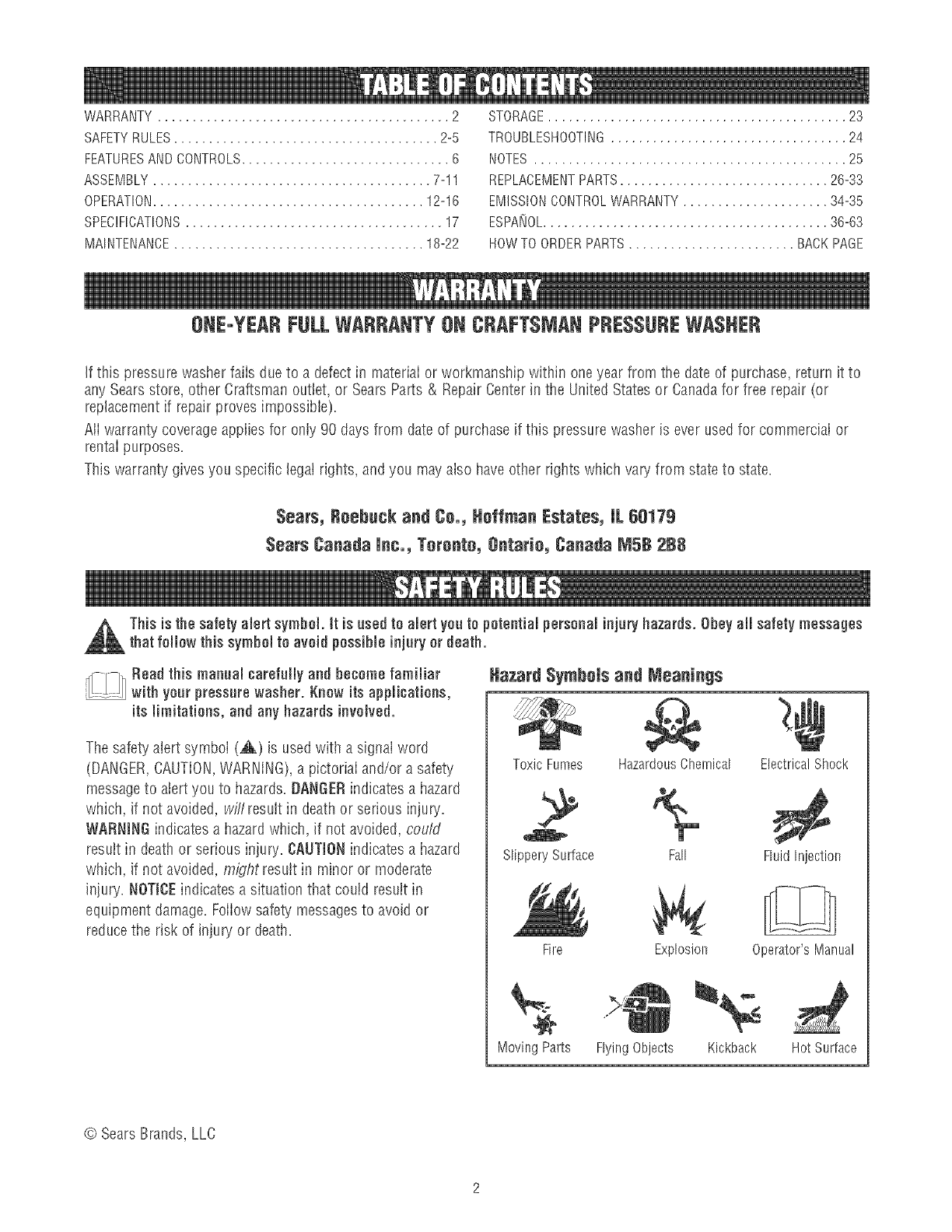
This is the safety alert symbol, tt is used to alert yea to potential persenaminjary hazards. Obey aH safety messages
that fellow this symbemto avoid pessiMe injury or death.
_Read this manual carefully and become familiar
..... with your pressurewasher. Knew its applications,
its limitations, and any hazardsinvolved.
The safety alert symbol (,_) is used with a signal word
(DANGER,CAUTION,WARNING),a pictorial and/or a safety
messageto alert you to hazards. BANGERindicates a hazard
which, if not avoided, wi/'/resuIt in death or serious injury.
WARNINGindicates a hazard which, if not avoided, cou/d
result in death or serious injury. CAUTIONindicates a hazard
which, if not avoided, might result in minor or moderate
injury. NOTIgEindicates a situation that could result in
equipment damage. Foiiow safety messagesto avoid or
reduce the risk of injury or death.
Hazard SymhoJsand Nteanings
ToxicFumes Hazardous Chemical
SlipperySurface
Fire
Electrical Shock
Moving Parts
Fall FluidInjection
Explosion Operator'sManual
Flying Objects Kickback Hot Surface
© Sears Brands, LLC
Contentsareharmfulorfatalif swailowed.Avoid
contacttoeyes,skinorclothing.DONOTtake
internaiiy.Avoidbreathingthemistorvapor.
Overexposuretoeyesorskincancauseirritation.
Keepstabilizeroutofthereachofchiidren.
Fueistabiiizerisahazardouschemical.**
", Fresh StartTM fuel cap is designed to hold a cartridge which
contains fuel stabilizer.
o If SWALLOWED,call physician immediately. DONOT induce
vomiting. If inhaled, remove to fresh air. hs caseof eye or skin
contact, flush with water for 15 minutes.
o Store unopened cartridges in a cool, dry, well ventilated area.
Keep open cartridge in fuel cap, and fuel cap c!osed on fuel tank
when not in use.
o hsthe caseof an emergency,contact a physician immediately
and call 1-800-424-9300 for material safety inforrnation.
**Fuel stabilizer contains: 2,6-di-tret-butylphenol (128-39-2) and aliphatic petroleum
distillate (64742-47-8),
WARNING
Running engine gives off carbon monoxide, an
odoriess, coloriess, poison gas.
Breathing carbon monoxide can cause headache,
fatigue, dizziness, vomiting, confusion, seizures,
nausea,fainting or death.
Some chemicais or detergents may be harmful if
inhaied or ingested, causing severe nausea,
fainting, or poisoning.
•OperatepressurewasherONLYoutdoors.
• Keepexhaustgasfromelsteringaconfinedareathrough
windows,doors,ventilationintakes,or otheropenings.
o DONOTsta!t or runengineindoorsor in anenclosedarea,
evenif windowsanddoorsareopen.
o Usea respiratoror rnaskwheneverthereis a chancethat
vaporsrnaybeinhaled.
• Readall instructionswith maskso you arecertainthe maskwill
providethe necessaryprotectionagainstinhalingharmful
vapors.
WARNING
Fuel and its vapors are extremely flammable and
explosive.
Fire or explosion can cause severe burns or
death.
WHEN ADDmNGORDRAiNiNG FUEL
• Turn pressure washer OFFand let it cool at least 2 minutes
before removing fuel cap. Loosen cap slowly' to relieve pressure
in tank.
• Fill or drain fuel tank outdoors.
o DONOToverfill tank. Allow space for fuel expansion.
• If fuel spills, wait until it evaporates before starting engine.
o Keep fuel away frorn sparks_ open flames, pilot lights_heat, and
other ignition sources.
o DONOTlight a cigarette or smoke.
WHENSTARTINGEQUmP_dENT
• Ensure spark plug, muffler, fuet cap, and air cleaner are in
place.
• DO NOTcrank enginewith spark plug removed.
WHEN OPERATINGEQUIPI_IENT
o DONOTtip engine or equipment at angle which causes fuel to
spill.
• DONOTspray flammable liquids.
WREN TRANSPORTmNGOR REPAiRmNGEQUiPI'_IENT
• Transport/repair with fuet tank EMPTYor with fuel shutoff valve
OFF.
• Disconnect spark plug wire.
WHEN STORmNGFUEL OR EQUiPIVlENTWiTH FUELmNTANK
o Store away from furnaces, stoves, water heaters,clothes
dryers, or other appliances that have pilot light or other ignition
source becausethey can ignite fuet vapors.
WARNING
Risk of electrocution=
Contact with power source can cause etectric
shock or burn,
• NEVERspray near power source.
WARNING
Starter cord kickback (rapid retraction) can result
in bodily injury. Kickback will pulI hand and arm
toward engine faster than you can Iet go.
Broken bones, fractures, bruises, or sprains
could result.
• NEVERpull starter cord without first relieving spray gun
pressure.
o When starting engine_pull cord slowly until resistance is felt
and then pull rapidly to avoid kickback.
o After eachstarting atternpt where enginefails to run, always
point spray gun in safe direction press red button and squeeze
spray gun trigger to releasehigh pressure.
o Firmly grasp spray gun with both hands when using high
pressure spray to avoid iniury when spray gun kicks back.
WARNING
Useof pressure washer can create puddles and
slippery surfaces,
Kickbackfrom spray gun can cause you to fall,
*Operatepressure washer frorn a stable surface.
o The cleaning area should haveadequate slopes and drainageto
reduce the possibility of a fall due to slippery surfaces.
o Be extremely careful if you rnust usethe pressure washer from
a ladder, scaffolding, or any other similar location.
o Firmly grasp spray gun with both hands when using high
pressure spray to avoid injury when spray gun kicks back.
WARNING
Contact with muffler area can result in serious
burns.
Exhaustheat/gases can ignite combustibles,
structures or damage fuel tank causing a fire.
*DO NOTtouch hot parts and AVOID hot exlsaustgases.
*Allow equipment to cool before touching.
o Keep at least 5 feet (152 crn) of clearance on all sides of
pressure washer including overhead.
o Codeof FederalRegulation (CFR)Title 36 Parks, Forests,and
Public Property require equipment powered by an internal
combustion engine to have a spark arrester, rnaintained in
effective working order, complying to USDAForest service
standard 5100-1C or later revision. In the State of California a
spark arrester is required under section 4442 of the California
Public resources code. Other states rnay havesimilar laws.
WARNING
The high pressure stream of water that thb
equipment produces can cut through skin and its
underlying tissues, ieading to serious injury and
_ossible amputation.
Spray gun traps high water pressure, even when
engine is stopped and water is disconnected,
which can cause injury.
• DONOT allow CHILDRENto operate pressure washer.
o NEVERrepair high pressure hose. Replaceit.
• NEVERrepair leaking connections with sealant of any kind
Replaceo-ring or seal
o NEVERconnect high pressure hoseto nozzle extension.
• Keep high pressure hose connected to purnp and spray gun
while system is pressurized.
• ALWAYS point spray gun in safe direction, press red button
and squeezespray gun trigger, to release high pressure, every
tirne you stop engine.
• NEVERaim spray gutsat people, animals, or plants.
o DO NOTsecure spray gun in open position.
• DO NOT leavespray gun unattended while rnacbine is running.
o NEVERusea spray gun wlsichdoes not have a trigger lock or
trigger guard in place and in working order.
• Always be certain spray gun, nozzbs and accessories are
correctly attached.
WARNING
Unintentional sparking can result in fire or
'_¢ electric shock.
WHENADJUSTmNGORMAKING REPAIRSTOYOUR PRESSURE
WASHER
• Disconnect the spark plug wire frorn the spark plug and place
the wire where it cannot contact spark plug.
WHENTESTmNGFORENGINESPARK
• Use approved spark plug tester.
o DONOTcheck for spark with spark plug removed.
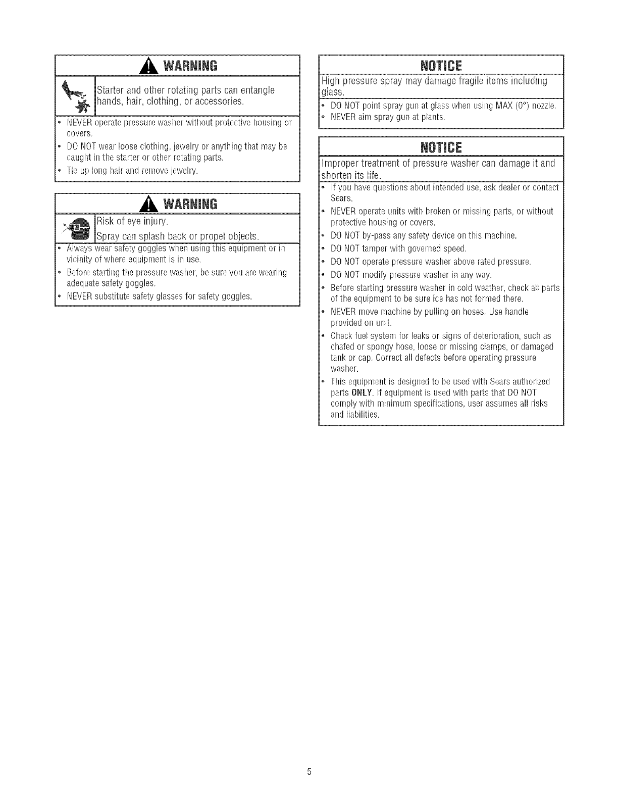
WARNING
Starter and other rotating parts can entangie
hands, hair, clothing, or accessories.
• NEVERoperatepressurewasherwithoutprotectivehousingor
covers.
• DONOTwea!looseclothing jewelryor anythingthat maybe
caughtinthe starteror other rotati_gparts.
o Tieup longhai!andrernovejewelry.
WARNING
IRisk of eye injury=
..L..__jSpray can splash back or propel objects.
Alwayswearsafetygoggleswhenusingthis equipmentor in
vicinityof whereequipmentis in use.
Beforestartingthe pressurewasher,besureyou arewearing
adequatesafetygoggles.
NEVERsubstitutesafetyglassesfor safetygoggles.
High pressure spray may damage fragiie items inciuding
lass.
DONOTpointspraygunat glasswhen usingMAX(0°) nozzle.
NEVERaim spraygunat plants.
Improper treatment of pressure washer can damage it and
shorten its iife.
Ifyou havequestionsaboutintendeduse,askdealeror contact
Sears.
NEVERoperateunitswith brokenor missingpa!rs,or without
protectivehousingor covers.
DONOTby-passanysafetydeviceonthis rnachine.
DONOTtamperwith governedspeed.
DONOToperatepressurewasheraboveratedpressure.
DONOTmodifypressurewasherinanyway.
Beforestartingpressurewasherincold weathercheckall parts
of the equiprner_tto besureice hasnot formedthere.
NEVERmovemachineby pullingon hoses.Usehandle
providedon unit.
Checkfuelsystemfor leaksor signsof deterioration,suchas
chafedor spongyhose,looseor missingclamps_or damaged
ta!_korcap.Correctalldefectsbeforeoperatingpressure
washer.
Thisequipmentis designedto beusedwith Searsauthorized
partsONLY.If equipmentis usedwith partsthatDONOT
complywith minimumspecifications,userassumesall risks
andliabilities.
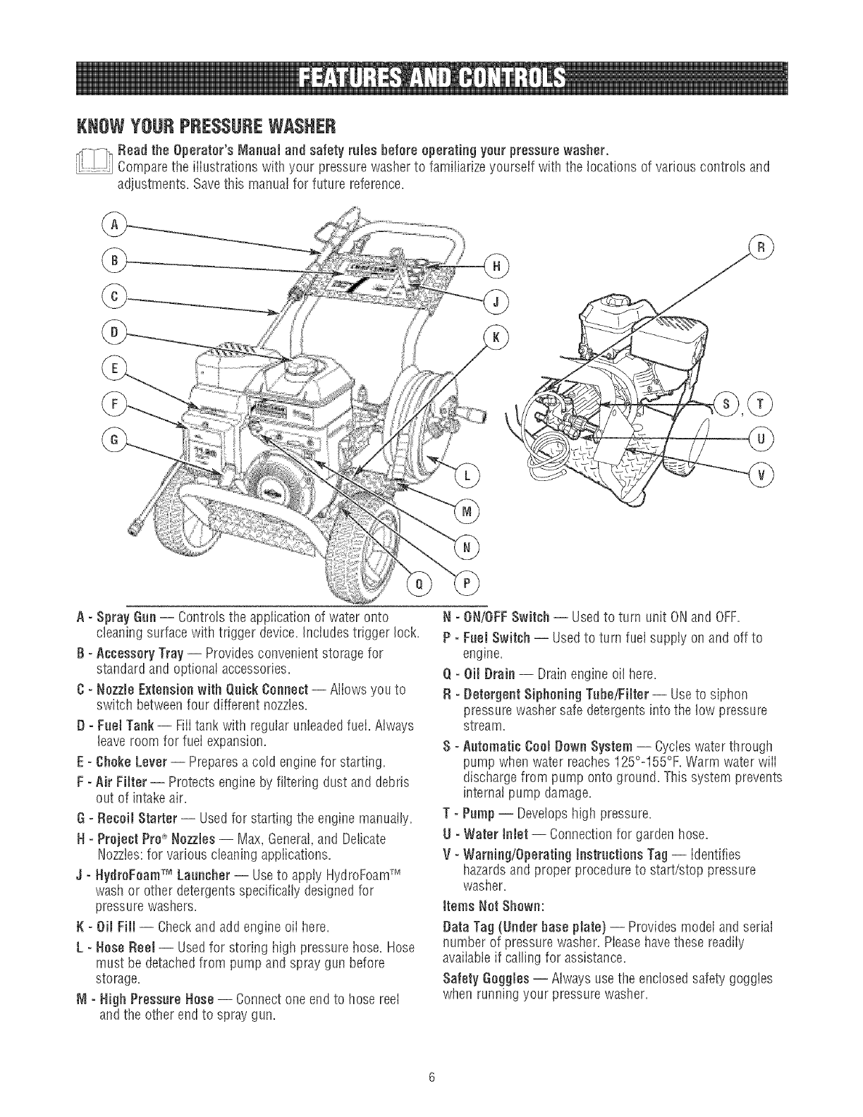
KNOWYOURPRESSUREWASHER
_Read the Operator'sManual and safety rules before operating your pressurewasher.
.... Comparethe iiiustrations with your pressurewasher to familiarize yourself with the locationsof various controls and
adjustments. Savethis manual for future reference.
A - Spray Can -- Controls the application of water onto
cleaning surface with trigger device. Inciudes trigger lock.
B - Accessory Tray -- Providesconvenient storage for
standard and optional accessories.
C =Nozzle Extensionwith Qaick Connect-- Allows you to
switch betweenfour different nozzles.
D =Fuel Tank-- Fill tank with regular unleadedfuel. Always
leave room for fuei expansion.
E=Choke Lever-- Preparesa coid engine for starting.
F - Air Filter -- Protects engine by filtering dust and debris
out of intake air.
G - Recoil Starter -- Used for starting the engine manually.
H =Project ProC_Nozzles -- Max, General,and Delicate
Nozztes:for various cleaning appiications.
J- HydroFoamTM Laancher -- Useto appiy HydroFoamTM
wash or other detergents specifically designed for
pressure washers.
K - Oil Fill -- Checkand add engine oil here.
L - Hose Reel -- Usedfor storing high pressure hose. Hose
must be detachedfrom pump and spray gun before
storage.
_1=High PressureHose -- Connect one end to hose reel
and the other end to spray gun.
N - ON/OFFSwitch -- Usedto turn unit ONand OFF.
P- Fael Switch -- Usedto turn fuel supply on and off to
engine,
Q =Oil Drain -- Drain engine oil here,
R =Detergent Siphoning Tahe/Filter -- Useto siphon
pressure washer safe detergents into the low pressure
stream,
S - Aatomatie Cool Down System -- Cycieswater through
pump when water reaches125°o155%. Warm water wiii
discharge from pump onto ground. This system prevents
internal pump damage,
T = Pump-- Developshigh pressure,
U - Water Inlet -- Connection for garden hose,
V=Warning/Operating tnetractions Tag -- Identifies
hazardsand proper procedure to start/stop pressure
washer.
ttems Not Shown:
Data Tag (Underbase plate) -- Provides model and serial
number of pressure washer. Piease havethese readiiy
avaiiabteif calling for assistance.
Safety Goggles -- Always use the enclosedsafety goggies
when running your pressure washer.
Your pressure washer requires some assembly and is ready
for use only after it has been properly serviced with the
recommended oil and fuel.
If you haveany problems with the assembly of your pressure
washer, pleasecatl the pressure washer helplineat
1o800o222o3136.
UNPACKPRESSUREWASHER
1. Remove everything from carton except pressure washer.
2. Opencarton completely by cutting each corner from top
to bottom.
3. Remove pressure washer from carton.
CARTONCONTENTS
CheckalI contents, if any parts are missing or damaged,calJ
the pressure washer hetpline at 1o808o222o3136.
*Main Unit
,Handle
, Accessory Tray
, High PressureHose
,Short High Pressure Hose
,Spray Gun
,NozzleExtensionwith Quick Connect Fitting
,HydroFoamTM Wash
. Oii Bottle
,HoseReel Kit
, Parts Bag (which inciudes the foiiowJng):
,Operator's Manual
,Owner's Registration Card
, Safety Goggles
, Bagcontaining 3 multi-colored ProjectPro_'Nozzies
, HydroFoamTM Launcher
,HydroFoamTM Launcher & Wash instruction Sheet
,FreshStart Fuel Cartridge
, HandieFastening HardwareKit (which includes):
, Wireform (I}
°Carriage Bolts (2)
,Plastic Knobs (3}
,Tree Ciips (4)
Becomefamiiiar with each piece before assembiing the
pressure washer, identify aii contents with the iiiustration on
page 6. if any parts are missing or damaged,caiJthe
pressure washer helpJineat 1-880-222-3t36.
ASSEMBLINGPRESSUREWASHER
Your Craftsman pressure washer will need assembly before
operation:
1. FilI out and send in registration card.
2. Attach handleand accessory tray.
3. Add oii to engine crankcase.
4. Attach hose reel.
5. Add fuel to fuel tank.
6. Connect high pressure hose to spray gun, hose reeland
pump.
7. Connectwater supply to pump.
8. Attach nozzleextension to spray gun.
9. Select/attachquick connect ProjectPro_ nozzleto nozzle
extension.
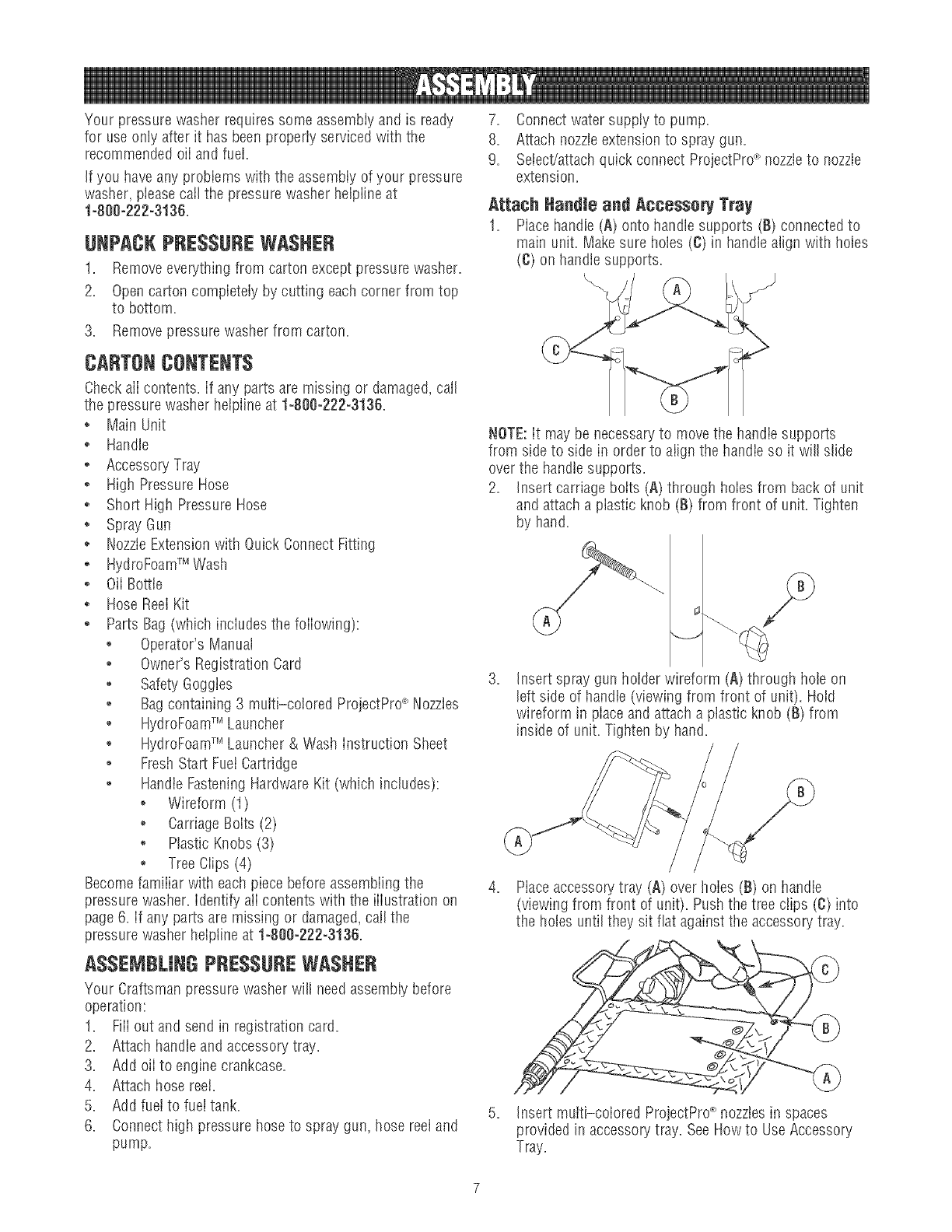
Attach ttandle and Accesso_ Tray
1. Placehandle (A) onto handlesupports (B) connected to
main unit. Make sure holes (C) in handlealign with holes
(C) on handle supports.
NOTE:it may be necessaryto move the handie supports
from side to side in order to align the handle so it will slide
over the handiesupports.
2. insert carriage bolts (A) througil holes from back of unit
and attach a plastic knob (B) from front of unit. Tighten
by hand.
Insert spray gun holder wireform (A} through hole on
left side of handle (viewing from front of unit). Hoid
wireform in piace and attach a plastic knob (B) from
inside of unit. Tighten by hand.
4. Placeaccessory tray (A) over isoles(B) on handle
(viewing from front of unit). Push the tree clips (C} into
the holes until they sit fiat againstthe accessory tray.
5. Insert multi-colored ProjectPro_ nozzlesin spaces
provided in accessorytray. See Howto UseAccessory
Tray.
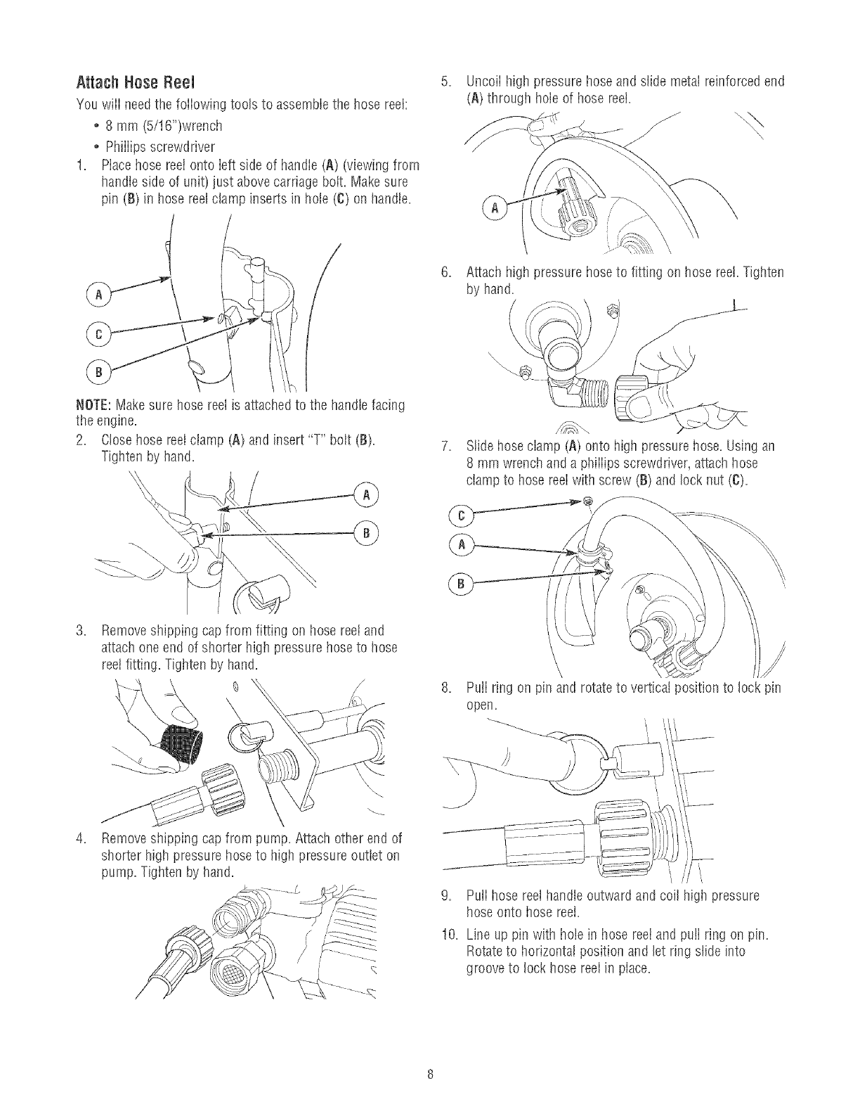
Attach Hose Reel
You wiii need the foiiowing tools to assemble the hose reel:
o 8 mm (5/16")wrench
o Phiiiips screwdriver
1, Place hose reeI onto Ieft side of handle (A) (viewing from
handle side of unit) just above carriage bolt. Make sure
pin (B)in hose reelclamp inserts in hole (C) on handle,
I
NOTE:Makesure hose reel is attached to the handle facing
the engine,
2, Close hose reeI ciamp (A) and insert "T" bolt (B),
Tighten by hand,
.Remove shipping cap from fitting on hose reet and
attach one end of shorter high pressure hose to hose
reel fitting. Tighten by hand,
.Remove shipping cap from pump. Attach other end of
shorter high pressure hose to high pressure outlet on
pump. Tighten by hand.
Uncoil high pressure hose and slide metal reinforced end
(A) through hole of hose reel.
6, Attach high pressure hose to fitting on hose reel. Tigilten
by hand.
7. Slidehose damp (A) onto high pressure hose. Using an
8 mm wrench and a phiiiips screwdriver, attach hose
clamp to hose reeiwith screw (B) and lock nut (C).
8. PulI ring on pin and rotate to vertical position to lock pin
open.
9, Puffhose reel handte outward and coil higil pressure
hose onto hose reei,
10, Line up pin with hote in hose reei and puii ring on pin,
Rotateto horizonta! position and let ring slide into
groove to lock hose reel in place,
Add Engine OiJ
1. Place pressure washer on a fiat, level surface.
2. Cleanarea around oii fiii and remove yeliow oii fiii cap.
NOTE:See Oil Recommendationsin Maintenancesection.
Verify provided oii bottie is the correct viscosity for current
ambient temperature.
3. Using oii funnel (optional), siowiy pour contents of
provided oil bottle into oil fill opening.
improper treatment of pressurewasher can damage it and
shorten its iife.
DONOTattemptto crankor startthe enginebeforeit hasbeen
properlyservicedwiththe recommendedoil. Thismayresultin
anenginefailure.
4. Replaceoil fill cap and fully tighten.
Add Fuel
Fuel must meet these requirements:
Clean,fresh, unleadedgasoline.
o A minimum of 87 octane/87 AKi (91 RON). Higil altitude
use, see High Altitude.
o Gasoiinewith upto 10% ethanol (gasohoi) or up to 15%
MTBE (methyl tertiary butyl ether) is acceptable.
NOTICE
Avoid pressure washer damage.
Faiiureto foiiow Operator's Manuai for fuel
recommendations voids warranty.
DONOTuseunapprovedgasolinesuchas E85.
DONOTmixoil in gasoline.
DONOTmodifyengineto runon alternatefuels.
To protect the fue! system from gum formation, mix in a fuel
stabiiizer when adding fuet. SeeStorage. Ali fuel is not the
same. if you experiencestarting or performance problems
after using fuel, switch to a different fuel provider or change
brands. This engine is certified to operate on gasoline. The
emission control system for this engine is EM (Engine
Modifications).
WARNING
FueIand its vapors are extremely fiammabb and
explosive.
_l_ ire or explosion can causesevere burns or
death.
WHENADDmNGFUEL
o TurnpressurewasherOFFandlet it coolat least2 minutes
beforeremovingfuelcap.Loosencapslowly'to relievepressure
in tank.
o Fillfuel tankoutdoors.
• DONOToverfilltank.Allowspacefor fue!expansion.
o Iffuel spills,waituntil it evaporatesbeforestartingengine.
• Keepfuelawayfromsparks,openflames,pilot lights,heat,and
otherignitionsources.
o DONOTlight a cigaretteorsmoke.
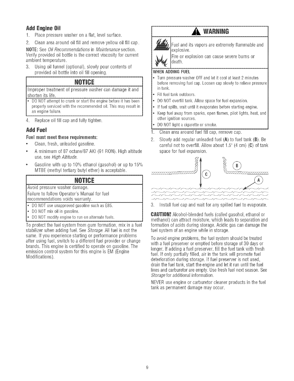
1. Cieanareaaround fuel fiii cap, removecap.
2. Siowiy add regular unleadedfuel (A) to fuei tank (B). Be
carefui not to overfiii. Aiiow about 15" (4 cm) (C) of tank
space for fuel expansion.
CAUTION! AIcohoI-blendedfuels (caiied gasoiloI, ethanoi or
methanol) can attract moisture, which leadsto separationand
formation of acids during storage. Acidic gas can damagethe
fuel system of an engine while in storage.
To avoid engineproblems,the fueIsystem should betreated
with a fuel preserveror emptiedbefore storageof 30 days or
longer, if adding a fuel preserver, fiii the fuei tank with fresh
fuel. if oniy partiaiiy filied, air in the tank wiii promote rue!
deterioration during storage, if fuet preserver is not used,
drainthe fuei tank, start the engineand iet it run untii the fuel
finesandcarburetorare empty. Usefreshfuel nextseason. See
Storagefor additionalinformation.
NEVERuseengine or carburetor cleaner products in the fuel
tank as permanent damage may occur.
Fred1$tatlFuelCap
Adding fuel preserver helps keepfuet fresh and carburetors
clean for easier starting, aii season iong. This new fuei cap
automatically drips concentrated fuel preserver into your fuel
tank.
, DANGER
Contentsare harmful or fatal if swallowed. Avoid
contact to eyes, skin or clothing. DONOTtake
internaiiy. Avoid breathing the mist or vapor.
Overexposureto eyesor skin can causeirritation.
KeepstabiIizerout of the reach of chiIdren.
Fuel stabilizer is a hazardouschemical.**
,* If SWALLOWED,callphysicianimmediately.
,, h_the caseof anemergency,contacta physicianimmediately
andcall1-800-424-9300for materialsafetyirffonnation.
**Fuel stabilizer contains: 2,6-di-tret-butylphenol (128-39-2) and aliphatic petroleum
distillate (64742-47-8),
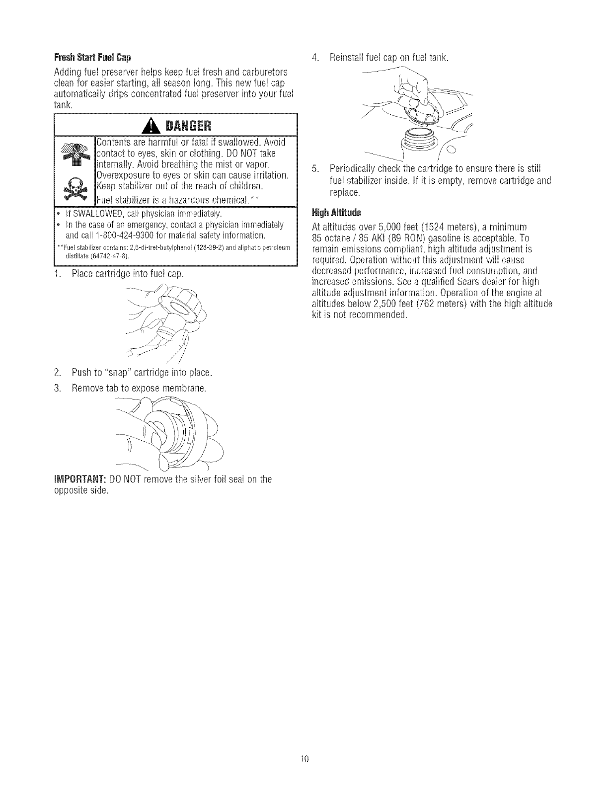
Place cartridge into fuel cap.
2. Push to "snap" cartridge into piace.
3. Removetab to expose membrane.
4. Reinstall fuel cap on fuettank.
J
Pedodicaiiy check the cartridge to ensure there is stiii
fuei stabilizer inside. If it is empty, removecartridge and
replace.
At aititudes over 5,000 feet (1524 meters), a minimum
85 octane /85 AKI (89 RON)gasoline is acceptable.To
remain emissions compiiant, higil aititude adjustment is
required. Operationwithout this adjustment wiii cause
decreasedperformance, increasedfueI consumption, and
increasedemissions. Seea qualified Sears deaierfor higil
altitude adjustment information. Operation of the engine at
altitudes below 2,500 feet (762 meters) with the high altitude
kit is not recommended.
IMPORTANT:DONOT removethe silver foil seal on the
opposite side.
10
Connect Hose and Water Supply to Pump
NOTE:Removeand discard the stlipping cap from the
pump's water inlet before attaching hoses.
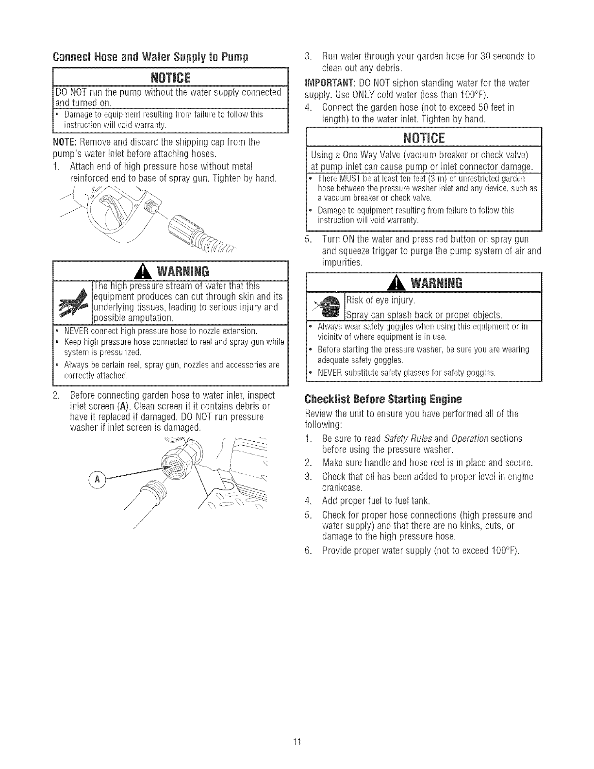
1. Attach end of higil pressure hose without metal
reinforced end to base of spray gun. Tighten by hand.
WARNING
The high pressure stream of water that this
_ quipment produces can cut through skin and its
underiying tissues, ieading to serious injury and
)ossibb amputation,
• NEVERconnect high pressure hoseto nozzleextension.
o Keep high pressure hose cormectedto reel and spray gun while
system is pressurized.
o Always be certain reel, spray gun, nozzlesand accessories are
correctly attached.
.Before connecting garden hose to water inlet, inspect
inlet screen (A). Cleanscreen if it contains debris or
have it replaced if damaged.DO NOTrun )ressure
washer if inlet screen is damaged.
/?
3. Run water through your garden hose for 30 seconds to
clean out any debris.
iMPORTANT:DO NOTsiphon standing water for the water
suppty. Use ONLYcoid water (less than I O0°F).
4. Connectthe garden hose (not to exceed50 feet in
bngth) to the water inlet. Tigistenby hand.
NOTICE
Using a OneWay Vaive (vacuum breaker or check vaive)
at pump inlet can cause pump or inlet connector damage.
ThereMUSTbeat leastten feet(3 m) of unrestrictedgarden
hosebetweenthe pressurewasherinletandan}/'device,suchas
avacuumbreakeror checkvalve.
Darnageto equipmentresultingfromfailureto followthis
instructionwill voidwarranty.
5. Turn ONthe water and press red button on spray gun
and squeezetrigger to purge the pump system of air and
impurities.
WARNING
,,_ Risk of eye injury.
_jSpraycan splash back or propel objects.
Alwayswearsafetygoggleswhen usingthis equipmentor in
vicinityof whereequipmentis in use.
Beforestartingthe pressurewasher,besureyouarewearing
adequatesafetygoggles.
NEVERsubstitutesafetyglassesfor safetygoggles.
Checklist Before Starting Engine
Reviewthe unit to ensure you have performed atl of the
foflowing:
1. Besure to read Safety Rubs and Operationsections
before using the pressure washer.
2. Makesure handle and hose reet is in place and secure.
3. Checkthat oii has beenadded to proper level in engine
crankcase.
4. Add proper fuei to fuei tank.
5. Checkfor proper hose connections (high pressure and
water supply) and that there are no kinks, cuts, or
damageto the high pressure hose.
6. Provide proper water supply (not to exceedIO0°F).
11
HOWTO USEYOURPRESSUREWASHER
If you haveany problems operating your pressure washer,
please calIthe pressure washer heipline at 1-800-222-3136.
Pressure Washer Location
WANNING
Exhaustheat/gases can ignite combustibbs,
structures or damage fuei tank causing a fire.
o Keepat least5ft. (152crn)clearanceonall sidesof pressure
washerincludingoverhead.
PressureWasherClearance
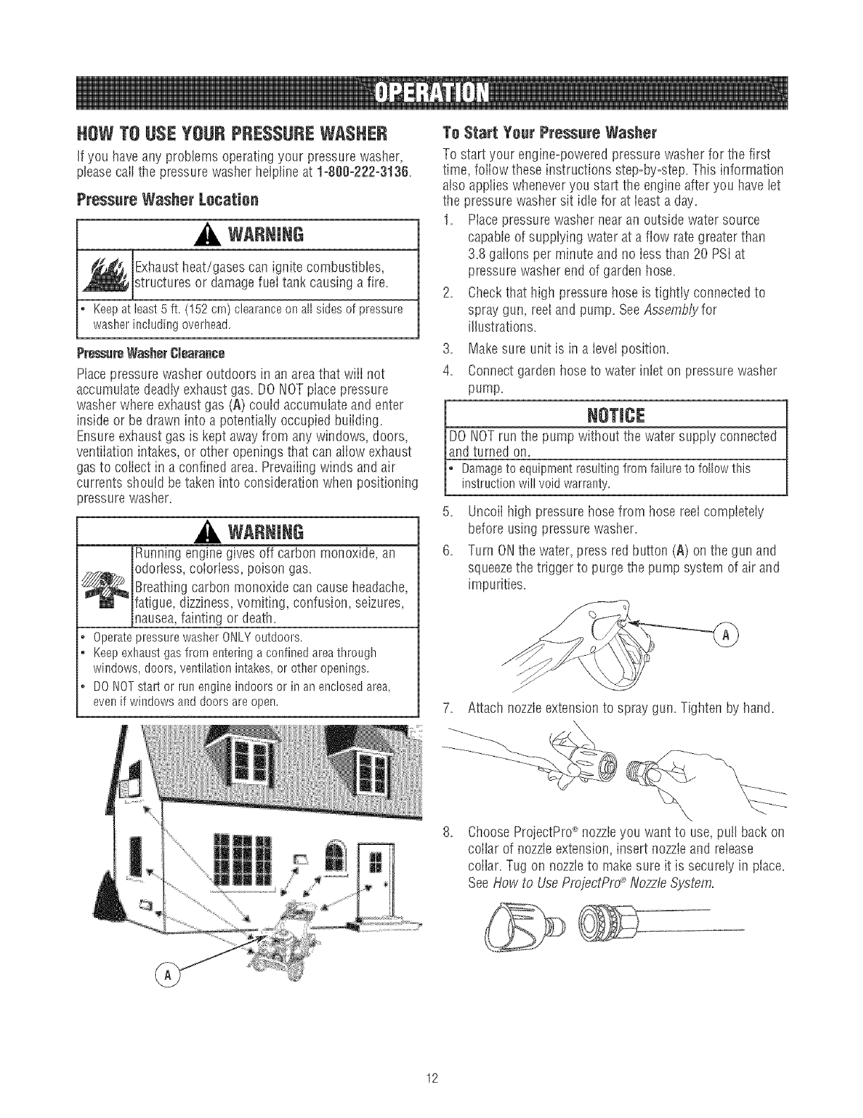
Macepressure wa@er outdoors in an areathat wiii not
accumulate deadiy exhaust gas. DO NOTpiace pressure
washer where exhaust gas (A) could accumulateand enter
inside or be drawn into a potentiaily occupied buiiding.
Ensureexhaust gas is kept awayfrom any windows, doors,
ventiiation intakes, or other openings that can aliow exhaust
gas to coiiect in a confined area. Prevaiiingwinds and air
currents should be taken into consideration when positioning
pressure washer.
WARNING
Running engine gives off carbon monoxide, an
odorless, coiorless, poison gas.
_ reathing carbon monoxide can causeheadache,
fatigue, dizziness, vomiting, confusion, seizures,
nausea,fainting or death.
*OperatepressurewasherONLYoutdoors.
o Keepexhaustgasfromenteringaconfinedareathrough
windows,doors,ventilationintakes,or otheropenings.
* DONOTeta1 or runengineindoorsor in anenclosedarea,
evenif windowsanddoorsareopen.
To Start Yeur Pressure Washer
To start your engine-powered pressurewasher for the first
time, foiiow these instructions step-by-step. This information
also applies wheneveryou start the engine after you have let
the pressure washer sit idle for at bast a day.
1. Piacepressure washer nearan outside water source
capable of supplying water at a flow rate greater than
3.8 gaiions per minute and no iess than 20 PSi at
pressurewasher end of garden hose.
2. Checkthat high pressure hose is tightiy connected to
spray gun, reel and pump. SeeAssemb_for
illustrations.
3. Makesure unit is in a ievei position.
4. Connectgarden hose to water intet on pressure washer
pump.
i NOTlC(
DO NOTrun the pump without the water supply connected
and turned on.
L amageto equipmentresultingfrom failureto followthis
instructionwill void warrasty
5. Uncoii high pressure hose from hose reelcompbteiy
before using pressure washer.
6. Turn ONthe water, press red button (A) on the gun and
squeezethe trigger to purge the pump system of air and
impurities.
Attach nozzleextension to spray gun. Tigllten by hand.
ChooseProjectPro_ nozzleyou want to use, pull back on
coilar of nozzleextension, insert nozzleand release
coiiar. Tug on nozzleto makesure it is securely in place.
SeeHow to UseProjectPro_Nozzle System.
12
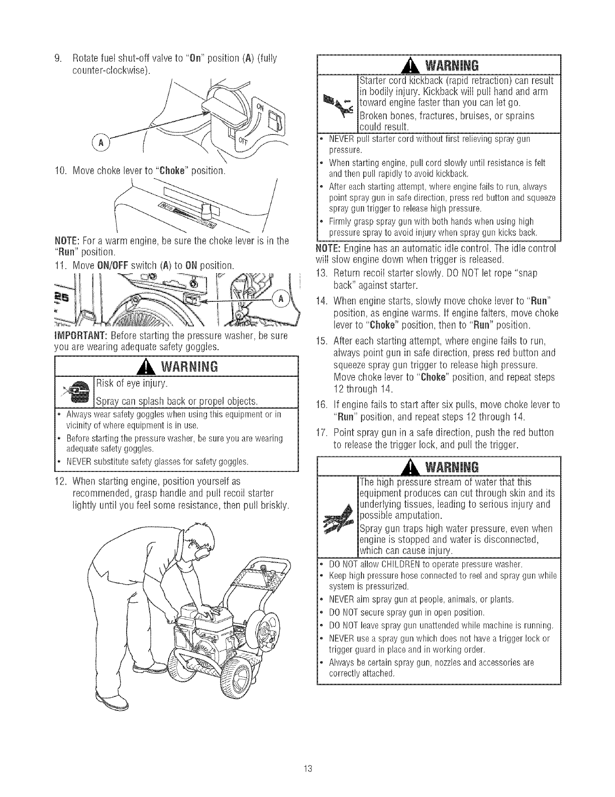
9. Rotatefueishut=offvalveto "On"position(A)(fully
counter=clockwise).
10.Movechokeleverto"Choke"position.
NOTE:For a warm engine, be sure the choke lever is in the
"Rue" position.
11. Move ON/OFFswitch (A) to ON position.
iMPORTANT:Before starting the pressure washer, be sure
/ou are wearing adequatesafety goggles.
WARNING
Risk of eye injury.
_Spray can sp ash back or propel objects.
Alwayswearsafetygoggleswhenusingthis equipmentor in
vicinityof whereequipmentisinuse.
Beforestartingthe pressurewasher,besureyou arewearing
adequatesafetygoggles.
NEVERsubstitutesafetyglassesfor safetygoggles.
12. When starting engine, position yourself as
recommended, grasp handle and puff recoii starter
lightly until you feel some resistance, then pulI briskly.
WARNING
Starter cord kickback (rapid retraction) can result
in bodily injury. Kickbackwill pu!I handand arm
toward enginefaster than you can iet go.
Broken bones, fractures, bruises, or sprains
could result.
• NEVERpullstartercord withoutfirst rdievingspraygun
pressure.
o Whenstartingengine,pullcord slowlyuntil resistanceis felt
andthen pullrapidlyto avoidkickback.
o Aftereachstartingattempt,whereenginefailsto run, always
pointspraygunin safedirection,pressredbuttonandsqueeze
sprayguntriggerto releasehighpressure.
o Firmlygraspspraygunwithboth handswhenusing high
pressuresprayto avoidiniurywhenspraygunkicksback.
NOTE:Enginehas an automatic idle controi. The idle control
wiii slow engine down when trigger is released.
13. Return recoii starter siowiy. DO NOTlet rope "snap
back" against starter.
14. When engine starts, siowiy movechoke iever to "Run"
position, as engine warms, if engine faiters, move choke
lever to "Choke" position, t!_ento "Rue" position.
15. After each starting attempt, w!_ereenginefaiis to run,
always point gun in safe direction, press red button and
squeezespray gun trigger to releasehigh pressure.
Move choke lever to "Choke" position, and repeat steps
12 through 14.
16. If enginefaiis to start after six puffs, movechoke iever to
"Run" position, and repeatsteps 12 througil 14.
17. Point spray gun in a safe direction, push the red button
to releasethe trigger lock, and pulI the trigger.
WARNING
The high pressurestream of water that this
equipment produces can cut through skin and its
_ nderlying tissues, ieadingto serious injury and
}ossibte amputation.
Spray gun traps high water pressure, even when
engine is stopped and water is disconnected,
which can cause injury.
• DONOTallowCHILDRENto operatepressurewasher.
o Keephighpressurehoseconnectedto reelandspraygunwhile
systemis pressurized.
o NEVERaim spraygunat people,animals,or plants.
• DONOTsecurespraygun inopenposition.
o DONOTleavespraygununattendedwhilernachineis running.
• NEVERusea spraygunwhichdoesnot haveatriggerlockor
triggerguardin placeandin workingorder.
o Alwaysbecertainspraygun,nozzlesandaccessoriesare
correctlyattached.
13
WARNING
Contact with muffler area can result in serious
burns.
Exhaustheat/gases can ignite combustibles,
structures or damage fuel tank causing a fire.
*DONOTtouchhot partsandAVOIDhot exhaustgases.
* Allowequipmentto cool beforetouching.
o Keepat least5feet (152crn) of clearanceonall sidesof
pressurewasherincludingoverhead.
, Codeof FederalRegulation(CFR)Title36 Parks,Forests,and
PublicPropertyrequireequipmentpoweredby aninternal
combustionengineto haveasparkarrester,rnaintainedin
effectiveworkingorder,complyingto USDAForestservice
standard5!00-1C or laterrevision.Itsthe Stateof Californiaa
sparkarresteris requiredundersection4442of the California
Publicresourcescode.Otherstatesrnayhavesimilarlaws.
How to Stop Your Pressure Washer
1. Reieasespray gun trigger and let engine idte for two
minutes.
2. Move ON/OFFswitch to OFFposition.
WARNING
Backfire,fire or engine damagecould occur.
*DONOTstopenginebymovingchokeleverto "Choke"position.
3. ALWAYSpoint spray gun in a safe direction, press red
button and squeezespray gun trigger to releaseretained
high water pressure.
WARNING
The high pressure stream of water that this
equipment produces can cut through skin and its
_ nderlying tissues, ieadingto serious injury and
)ossibbamputation.
Spray gun traps high water pressure, even when
engine is stopped and water is disconnected,
which can cause injury.
• Keephighpressurehoseconnectedto reelandspraygunwhile
systemis pressurized.
o ALWAYSpointspraygunin safedirection,pressredbutton
andsqueezesprayguntrigger,to rebasehighpressure,every
time youstopengine.
JNIPORTANT:Spray gun traps high water pressure, even
when engine is stopped and water is disconnected.
How to Use Accessory Tray
The unit is equipped with an accessorytray with piacesto
store your ProjectPro_ nozzles,HydroFoamTM iauncher, spray-
gun wireform to hold the spray gun and nozzteextension.
identify ali accessories with the iiiustration on page6.
NOTE:The extra hob in the tray is for storing a utiiity brush.
The extra clip in the tray is for storing a turbo nozzle. The
brush and turbo nozzleare NOTincluded with your pressure
washer. You can buy these items as optionai accessories.
1. Piacespray gun and nozzleextension into spray gun
holder wireform, as shown.
2. Coii high pressure hose onto hose reel.
3. Insert muiti-colored ProjectPro_ nozzles in spaces
provided in accessory tray.
4. Insert HydroFoamTM iauncher in spaceprovided in
accessory tray next to the multi-colored ProjectPro_
nozzles.
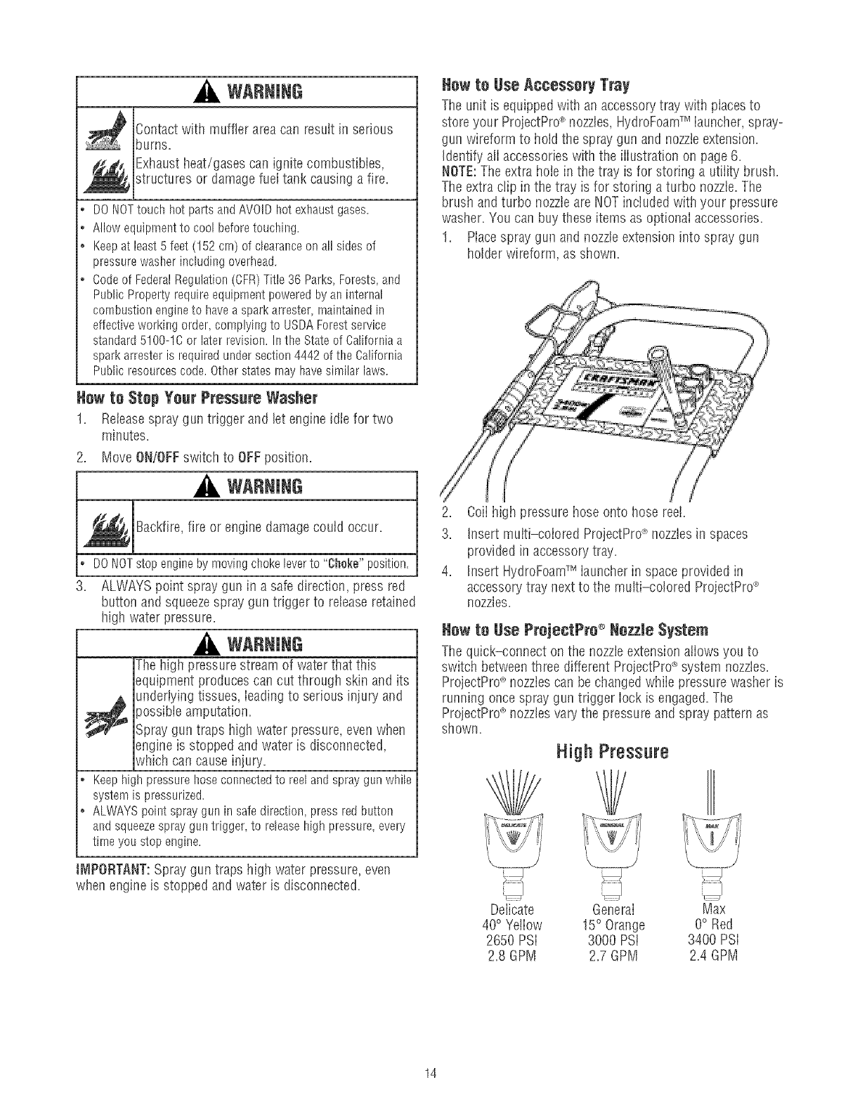
How to Hoe ProjectPro ® Hozzle System
The quick-connect on the nozzleextension atiows you to
switch betweenthree different ProjectPro_ system nozzles.
ProjectPrd_nozzles can be changed while pressure washer is
running once spray gun trigger Iock is engaged.The
ProjectPrd_nozzles vary the pressure and spray pattern as
shown.
High Pressure
Delicate General
40°Yeiiow 15° Orange
2650 PSi 3000 PSi
2.8 GPM 2.7 GPM
"--.i-.......l...J
Max
O° Red
3400 PSi
2.4 GPM
14
Fellowthese instructionsto shaegePrejestPro®nozzles:
1. PuiI back collar on quick-connect and pull current
ProjectPro_>nozzle off. Store ProjectPro_'nozzlesin
holder provided on the accessorytray.
WARNING
The high pressure stream of water that this
_ quipment produces can cut through skin and its
underiying tissues, ieadingto serious injury and
)ossibleamputation.
* NEVERexchangeProjectPro__nozzleswithoutlockingthe
trigger lockonthe spraygun.
o DONOTtwist ProjectPro<'nozzleswhile spraying.
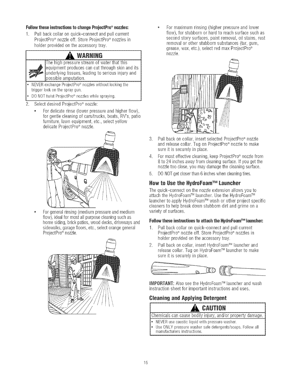
.Select desired ProjectPrd_nozzle:
o Fordelicate rinse (iower pressure and higher flow),
for genttecteaning of cars/trucks, boats, RV's, patio
furniture, iawn equipment, etc. select yellow
delicate ProjectPro_ nozzte.
For generalrinsing (medium pressureand medium
flow), idealfor most aiI purposecteaningsuch as
home siding,brick patios,wood decks,drivewaysand
sidewalks,garagefloors, etc.,selectorangegeneral
ProjectPro_>nozzte.
For maximum rinsing (higiler pressure and lower
flow), for stubborn or hard to reachsurface such as
second story surfaces, paint removal, eli stains, rust
removal or other stubborn substances (tar, gum,
grease, wax, etc.), select red max ProjectPro_'
nozzle,
3. Pull back on collar, insert selected ProjectPro_ nozzle
and releasecollar. Tug on ProjectPro_'nozzleto make
sure it is secureiy in piace.
4. For most effectivecleaning,keep ProjectPrd_nozzlefrom
8to 24 inchesawayfrom cleaningsurface. If you get the
nozzletoo close, you may damagethe cleaningsurface.
5. DONOTget closerthan 6 incheswhen cleaningtires.
Hew te 8se the HydreFeamTM Laancher
The quick-connect on the nozzleextension aliows you to
attach the HydroFoamTM iauncher. Usethe HydroFoamTM
launcher to appiy HydroFoamTM wash or other project specific
cteaners to heip break down stubborn dirt and grime on a
variety of surfaces.
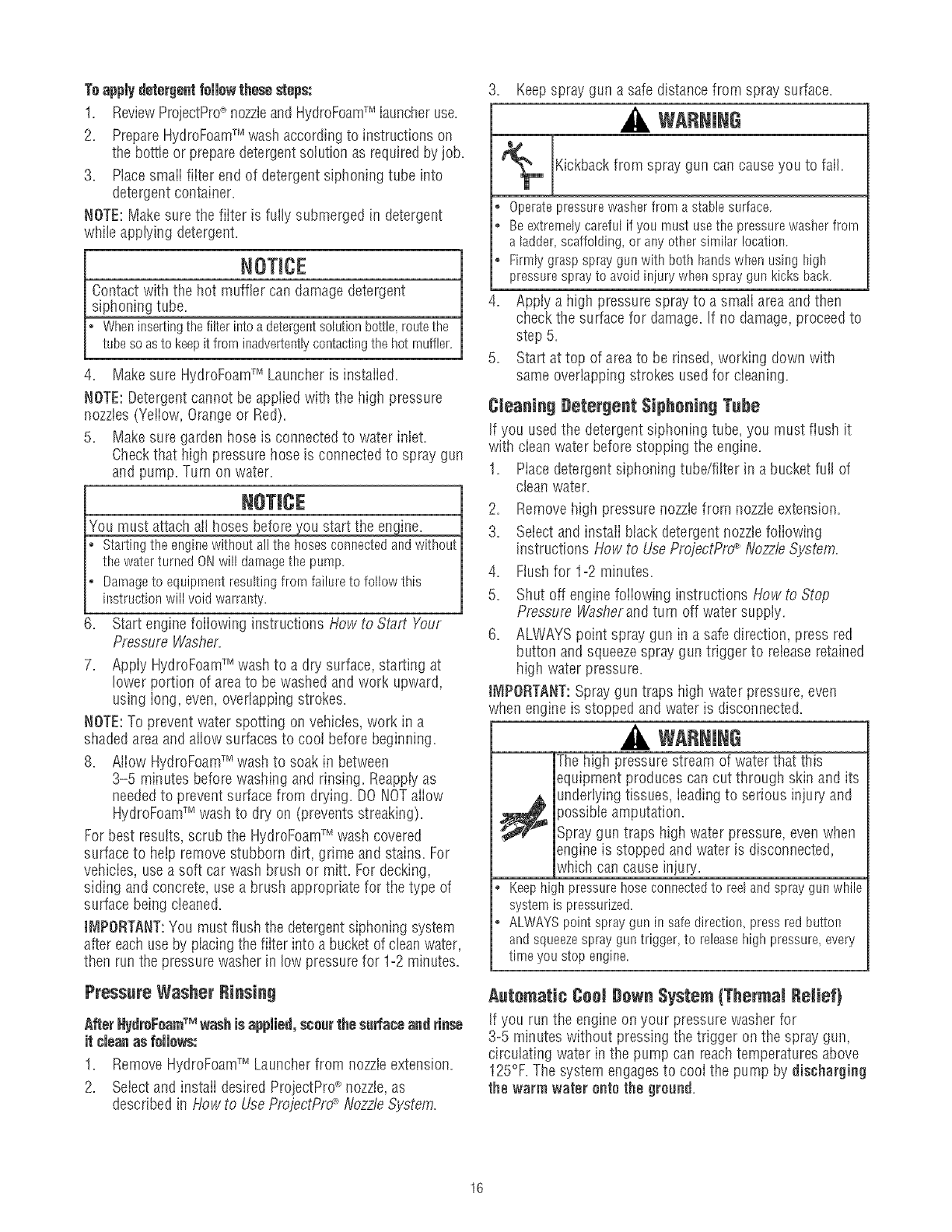
Followthese instructions to attash the HydreFearnTM lace€her:
1. Pull back collar on quick-connect and pull current
ProjectPrd_nozzleoff. Store ProjestPro_'nozzles in
holder provided on the accessopj tray,
2. Pull back on collar, insert HydroFoamTM launcher and
releasecollar. Tug on HydroFoamTM launcher to make
sure it is securely in place.
IMPORTANT:Also see the HydroFoamTM launcher and wash
instruction sheet for important instructions and uses.
Cteaning and Applying Detergent
A CAUTJe
Chemicalscan causebodily injupj, and/or property damage.
_ EVERusecausticliquidwithpressurewasher.
UseONLYpressurewashersafedetergents/soaps.Followall
rnanufacturersinstructions.
15
Toapply detergentfellow these steps:
1. ReviewProjectPro_'nozzleand HydroFoamTM launcheruse.
2. PrepareHydroFoamTM wash accordingto instructions on
the bottle or preparedetergentsolution as requiredby job.
3. Mace smaii fiiter end of detergent siphoning tube into
detergent container=
NOTE:Makesure the fiiter is fully submerged in detergent
while applying detergent=
NOTICE
Contact with the hot muffler can damage detergent
siphoning tube=
Wheninsertingthefilterintoadetergentsolutionbottle,routethe
tubesoasto keepitfrominadvertentlycontactingthehot rnuffler.
4. Make sure HydroFoamTM Launcher is installed.
NOTE:Detergentcannot be appiied with the high pressure
nozzles (Yeliow, Orange or Red).
5. Make sure garden hose is connected to water iniet.
Checkthat high pressure hose is connected to spray gun
and pump. Turn on water.
NOTICE
You must attach all hoses before you start the engine=
Startingthe enginewithoutallthe hosesconnectedandwithout
the waterturnedONwill damagetbe pump.
Darnageto equipmentresultingfrom failureto followthis
instructionwill void warranty.
6= Start engine foiiowing instructions How to Start Your
Pressure Washer=
7= Appiy HydroFoamTM wash to a dry surface, starting at
lower portion of areato be washed and work upward,
using iong, even, overlapping strokes=
NOTE:To prevent water spotting on vehicies,work in a
shaded areaand aliow surfacesto coot before beginning.
8= Aiiow HydroFoamTM wash to soak in between
3-5 minutes before washing and rinsing. Reappiyas
neededto prevent surface from drying. DO NOTaiiow
HydroFoamTM wash to dry on (prevents streaking).
For best results, scrub the HydroFoamTM wash covered
surface to help remove stubborn dirt, grime and stains. For
vehicies, use a soft car wash brush or mitt. For decking,
siding and concrete, use a brush appropriate for the type of
surface being cleaned=
J_IPORTANT:You must flush the detergentsiphoning system
after each use by piacingthe fiiter into a bucket of clean water,
then run the pressurewasherin low pressurefor 1-2 minutes.
Pressure Washer Rinsing
After NydroFoamTM washis applied, eceor the sorfaoeandrinoe
it cleanas fellows:
1. Remove HydroFoamTM Launcher from nozzleextension.
2. Seiectand instaii desired ProjectPro_ nozzle,as
described in How to UseProjeotPrd"__NozzleSystem.
3. Keepspray gun a safe distance from spray surface.
WARNING
Kickbackfrom spray gun can causeyou to fail=
o Operatepressurewasherfrom astablesurface.
o Beextremelycarefulif you mustusetbe pressurewasberfrom
a ladder,scaffolding,or anyotbersimilarlocation.
*Firmlygraspspraygunwithboth handswbenusing high
pressuresprayto avoidiniurywhenspraygunkicksback.
4= Appty a high pressure spray to a smati areaand then
check the surface for damage=If no damage,proceed to
step 5=
Start at top of areato be rinsed, working down with
same overlapping strokes used for cleaning=
Cteauiug getergeut $ipheuiug Tube
If you used the detergentsiphoning tube, you must flush it
with ciean water before stopping the engine.
1= Piacedetergent siphoning tube/filter in a bucket full of
clean water.
.
3=
,
5=
Remove high pressure nozziefrom nozzteextension.
Selectand instaii btack detergent nozzJefoiiowing
instructions How to UseProjectPrd_Nozzle System.
Ftushfor 1-2 minutes.
Shut off engine foiiowing instructions How to Stop
Pressure Washerand turn off water suppiy.
6= ALWAYS point spray gun in a safe direction, press red
button and squeezespray gun trigger to reiease retained
high water pressure=
iMPORTANT:Spray gun traps high water pressure, even
when engine is stopped and water is disconnected.
WARNING
The high pressurestream of water that this
equipment produces can cut through skin and its
underlying tissues, ieadingto serious injupj and
}ossibie amputation.
Spray gun traps high water pressure, even when
engine is stopped and water is disconnected,
which can cause injury.
o Keephighpressurehoseconnectedto reelandspraygunwhile
systemis pressurized.
• ALWAYSpointsprayguninsafedirection,pressredbutton
andsqueezesprayguntrigger,to releasehighpressure,every
timeyoustop engine.
Automatic Cool gewu System {Thermal lielief}
If you run the engine on your pressure washer for
3-5 minutes without pressing the trigger on the spray gun,
circuiating water in the pump can reach temperatures above
125%=The system engagesto cool the pump by discharging
the warm water onto the groond=
16
ENGINETECHNICALiNFORMATiON
This is a single cylinder, overhead valve (OHV),air cooled
engine, it is a iow emissions engine.
In the Stateof California, Model 150000 engines are certified
by the California Air Resources Boardto meet emissions
standards for 125 hours. Such certification does not grant
the purchaser, owner or operator of this engine any
additional warranties with respectto the performance or
operational iife of this engine. The engine is warranted solely
according to the product and emissions warranties stated
elsewherein this manual.
Power Ratings
The gross power rating for individual gas engine models is
labeledin accordance with SAE (Society of Automotive
Engineers)code J1940 (Small Engine Power & Torque
Rating Procedure),and rating performance has been
obtained andcorrected in accordancewith SAEJ1995
(Revision 2002=05).Torque values are derived at 3060 RPM;
horsepower values are derived at 3600 RPM. Actual gross
engine power wiii be lower and is affected by, among other
things, ambient operating conditions and engine-to-engine
variabiiity. Given both the wide array of products on which
engines are piaced and the variety of environmentai issues
appiicabb to operating the equipment, the gas engine wiii not
develop the rated gross power when used in a given piece of
power equipment (actual "on-site" or net power). This
difference is due to a variety of factors including, but not
limited to, accessories (air cleaner, exhaust,charging,
cooling, carburetor, fuel pump, etc.), appiication iimitations,
ambient operating conditions (temperature,humidity,
altitude), and engine-to-engine variabiiity. Due to
manufacturing and capacity iimitations, Briggs & Stratton
maysubstitute an engine of higher rated power for this
Series engine.
PRODUCTSPECiFiCATiONS
PressureWasherSpecifications
Max Outbt Pressure ....................... 3,400 PSi
Max Flow Rate............................. 2.8 GPM
Chemical Mix......................... Use as directed
Water Supply Temperature .......... Not to exceed IO0°F
Shipping Weight ............................. 93 Ibs.
EngineSpecifications
Bore ............................. £970 in. (75.44turn)
Stroke .............................. 2.200 in. (56ram)
Displacement ........................ 15.22 in. (249 cc)
SparkPlug
ResisterType: ............. Briggs & Stratton 491055S
Long Life Platinum: .......... Briggs & Stratton 5066D
SetGapTo: ...................... O.030inch(O.76mm)
ArrnatureAir Gap: ........... 0.010o0.014in.(O.25=O.36rnm)
Valveclearancewithvalvespringsinstalledand piston1/4in.
(6 rnrn)pasttop deadcenter(checkwhenengineis cold).
Intake .................... 0.004°0.006in.(0.10=0.15rnm)
Exhaust .................. 0.009o0.011in.(0.23=0.28rnrn)
Fue!Capacity............................... 1.6 Quarts
OilCapacity........................ 20 Ounces(0.6 liter)
NOTE:For practical operation, the engine ioad should not
exceed 85% of rated power. Enginepower wiii decrease
3-1/2% for each 1,000 feet (300 meters) above sea level and
1% for each 10° F (5.6° C) above 77° F (25° C). It should
operatesatisfactorily at an angle up to 15°.
17
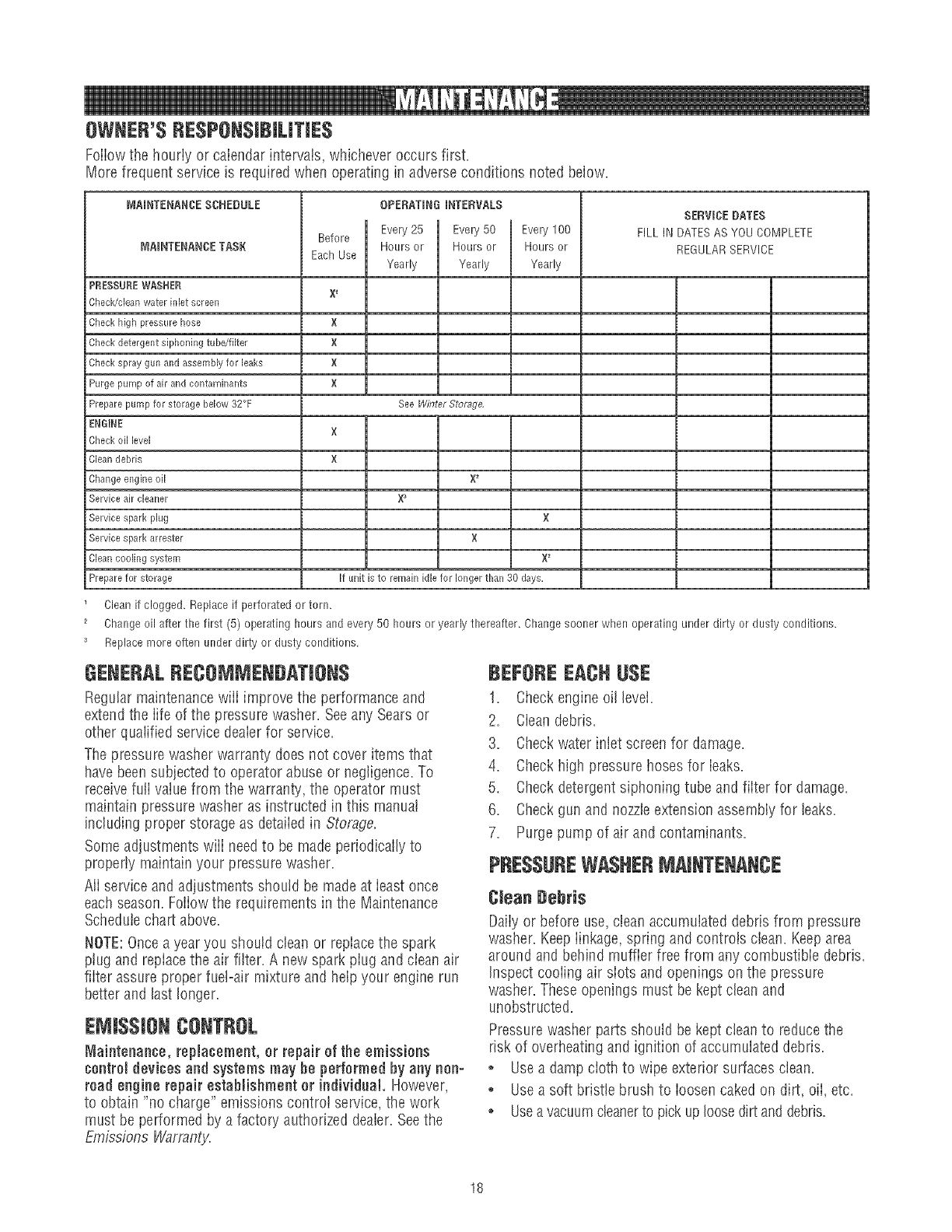
OWNER'SRESPONSiBiLiTiES
Foiiowthe hourly or calendar intervals, whichever occurs first.
More frequent service is required when operating in adverse conditions noted below.
MAINTENANCESCHEDULE
MNNTENANCETASK
PRESSURE W_,SHER
Check/clean water inlet screen
Check high pressure hose
Check detergent siphoning tube/filter
Check spray gun and assembly for leaks
Purge pump of air and contaminants
Prepare pump for storage below 32°F
ENGINE
Before
EachUse
X 1
X
×
X
X
OPERATINGINTERVALS
Every 25 Evel_/50
Hours or Hoursor
Yearly Yearly
See Winter Stof_ge,
Evel_,lO0
Hours or
Yearly
SERVICEeATES
FILL IN DATESAS YOU COMPLETE
REGULARSERVICE
Check oil level
Clean debris
Change engine oil
Service air cleaner
Service spark plug
Service spark arrestor
Clean cooling system
Prepare for storage
×
X
X_
X
×
if unit is to remain idle for longer than 30 days,
Cleanif clogged. Replace if perforated or tern.
Change oil after the first (5) operating hours and every 50 hours or yearly thereafter. Changesooner when operating under dirty or dusty conditions.
Replace more often under dirty or dusty conditions,
GENERALRECOMMENgATiON$
Regular maintenancewiii improve the performance and
extendthe iife of the pressure washer. Seeany Sears or
other quaiified service deaierfor service.
The pressure washer warranty does not cover items that
have been subjected to operator abuse or negligence.To
receivefuIi vatuefrom the warranty, the operator must
maintain pressure washer as instructed in this manual
including proper storage as detaiied in Storage.
Some adjustments wiii needto be made periodically to
properly maintain your pressure washer.
Ali service and adjustments should be made at ieast once
each season. Foliow the requirements in the Maintenance
Scheduie chart above.
NOTE:Oncea year you should clean or replace the spark
ptug and repiace the air filter. A new spark plug and ciean air
fiiter assure proper fuel-air mixture and help your engine run
better and last longer.
EJ J$$JONCONTROL
Maintenance, replacement, or repair of the emissions
¢ontromdevices and systemsmay he performedby any non-
road engine repairestablishment or individual. However,
to obtain "no charge" emissions controi service,the work
must be performed by a factory authorized dealer. Seethe
Emissions Warranty.
BEJ:OREEACHUSE
1. Checkengine oil level.
2. Cleandebris.
3. Checkwater inlet screen for damage.
4. Checkhigh pressure hoses for leaks.
5. Checkdetergent siphoning tube and filter for damage.
6. Checkgun and nozzleextension assembly for leaks.
7. Purge pump of air and contaminants.
PRESSUREWASHERMAINTENANCE
Clean Debris
Daily or before use,clean accumulated debris from pressure
washer. Keeplinkage, spring and controis clean. Keeparea
around and behind muffler free from any combustible debris.
inspect cooiing air siots and openings on the pressure
washer. Theseopenings must be kept clean and
unobstructed.
Pressurewasher parts should be kept ciean to reduce the
risk of overheating and ignition of accumulated debris.
o Use a damp cloth to wipe exterior surfaces clean.
° Usea soft bristle brush to ioosen caked on dirt, oii, etc.
° Usea vacuumcleanerto pick up loosedirt anddebris.
18
NOTICE
jImproper treatment of pressure washer can damage it and
W_orten _ ....
_tsq_fe,
L: DONOTinsertanyobjectsthroughcoolingslots.
Check and (}mean JnJet Screen
Examinegarden hose inlet screen. Clean if it is clogged or
replace if it is torn.
Check High Pressure Hnse
High pressure hoses can develop leaks from wear, kinking,
or abuse. Inspect hose before each use. Checkfor cuts,
leaks, abrasions, bulging of cover, or damage or movement
of couplings. If any of these conditions exist, replace hose
immediately.
WARNING
Pressurestream
t produces can cut through skin and its
g tissues, ieadingto serious injury and
_"" jpossibleamputation.
NEVERrepairhighpressurehose.Replaceit.
ReplacementhoseratingMUSTexceedrnaxirnurnpressure
ratingof unit.
Check Detergent Siphoning Tube
Examinethe fiiter on the detergent tube and clean if ctogged.
The tube should fit tightiy on the barbed fitting. Examinethe
tube for leaks or tears. Replacethe filter or tube if either is
damaged.
Check Gun and Nezzle Extensiun
Examinethe hose connection to the spray gun and make
sure it is secure. Test the trigger by pressing the red button
and making sure the trigger "springs back" into place when
you releaseit. You should not be able to press the trigger
without pressing the red button. Repiacespray gun
immediately if it fails any of these tests.
Nezzle Maintenance
A pulsing sensation felt whiie squeezingthe spray gun trigger
may becaused by excessive pump pressure. The principal
cause of excessive pump pressure is a nozzleclogged or
restricted with foreign materials, such as dirt, etc. To correct
the probiem, immediately clean the nozzlefollowing these
instructions:
,
2.
Shut off engine and turn off water supply.
ALWAYSpoint spray gun in a safe direction, press red
button and squeezespray gun trigger to releaseretained
high water pressure.
WARNING
The high pressure stream of water that this
equipment produces can cut through skin and its
_ nderlying tissues, ieading to serious injury and
)ossibie amputation.
Spray gun traps high water pressure, even when
engine is stopped and water is disconnected,
which can cause injury.
° Keephighpressurehoseconnectedto reelandspraygunwhile
systemis pressurized.
o ALWAYSpointspraygeminsafedirection,pressredbutton
andsqueezesprayguntrigger,to releasehighpressure,every
timeyoustop engine.
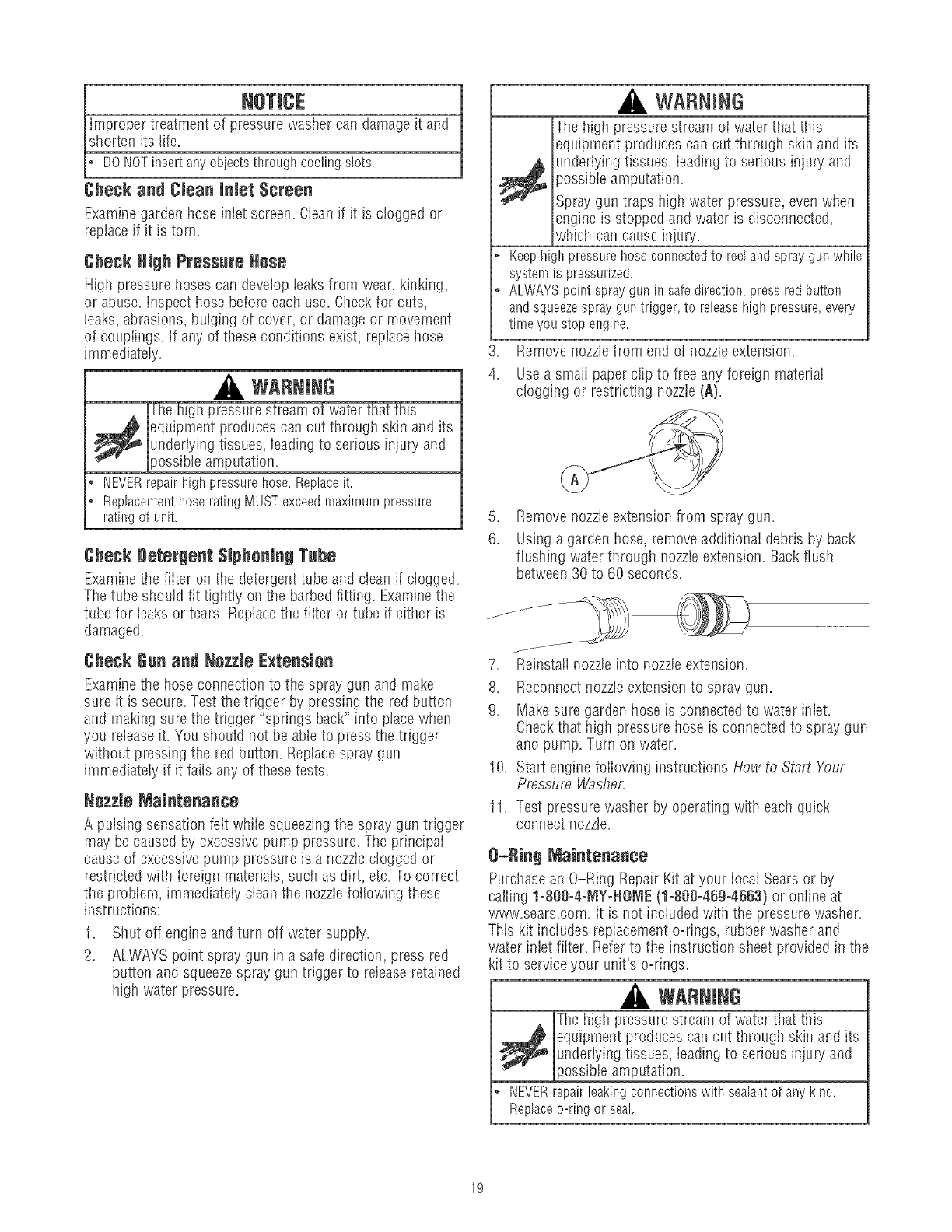
3= Remove nozzlefrom end of nozzleextension.
4. Usea smali paperclip to free any foreign material
clogging or restricting nozzle(A).
B,
6.
Remove nozzleextension from spray gun.
Using a garden hose, removeadditionai debris by back
flushing water through nozzleextension. Backflush
between30 to 60 seconds.
jJ
.
8.
9.
10.
11=
Reinstaii nozzleinto nozzleextension.
Reconnectnozzleextension to spray gun.
Makesure garden hose is connected to water inlet.
Checkthat high pressure hose is connected to spray gun
and pump. Turn on water.
Start engine foliowing instructions How to Start Your
Pressure Washe,_
Test pressure washer by operating with each quick
connect nozzle.
B-Ring Maintenance
Purchasean O-Ring Repair Kit at your iocaI Sears or by
caiiing 1-800-4-MY-NOME (1-800-469-4663) or oniine at
www=sears=com=it is not included with the pressure washer.
This kit includes repiacement o-rings, rubber washer and
water inlet fiiter. Referto the instruction sheet provided in the
kit to service your unit's o-rings=
WARNING
The high pressurestream of water that this
_ quipment produces can cut through skin and its
underlying tissues, ieadingto serious injury and
_ossibleamputation.
• NEVERrepairleakingconnectionswith sealantof anykind.
Replaceo-ringor seal.
19
Pump OiJMaintenance
DONOTattempt any oil maintenanceon this pump. This
model does not require any pump oii maintenance.The pump
is pre=iubricatedand sealed from the factory, requiring no
additional lubrication for the life of the pump.
ENGINEMAINTENANCE
WARNING
Unintentional sparking can result in fire or
_¢ electric shock.
WHENAD3USTmNGOR_IAKmNGREPAmRSTOYOURPRESSURE
WASHER
o Disconnectthe sparkplugwire fromthe sparkplugandplace
the wire whereit cannotcontactsparkplug.
WHENTESTINGFORENGINESPARK
*Useapprovedsparkplugtester.
. DONOTcheckfor sparkwith sparkplugremoved.
Oil
eli Becemmendatiens
We recommend tile use of Briggs & Stratton Warranty
Certified otis for best performance. Other high=quality
detergent oiis are acceptable if ciassified for service SF,SG,
SH, SJ or higher. DO NOTuse speciai additives.
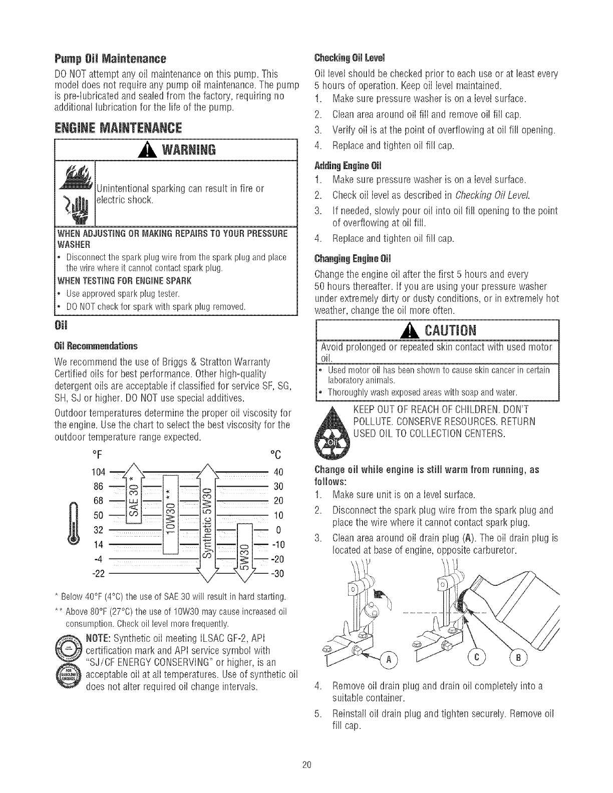
Outdoor temperatures determine the proper eli viscosity for
the engine. Usethe chart to select the best viscosity for the
outdoor temperature rangeexpected.
oF
104 ZIX'X
86 _
68
5o
32 _
14
-4
-22
oc
'X 4o
| 30
:_ 0
_m _0
- -lO
oh--j k-- o
* Below40°F(4°C)the useof SAE30 will resultin hardstarting.
** Above80%(27%) the useof 10W30maycauseincreasedoil
consumption.Checkoil levelmorefrequently.
NOTE:Synthetic eli meeting ILSACGF=2,API
certification mark and APi service symboi with
"SJ/CF ErIERGYCONSERVING"or higiler, is an
acceptabie eli at aii temperatures. Useof synthetic oil
does not alter required oil change intervals.
Checkingeli Level
Oil Ieveishould be checked prior to each use or at least every
5 hours of operation. Keepeli ieve! maintained.
1= Makesure pressure washer is on a ievei surface.
2= Cleanareaaround eli fiii and remove eli fiil cap=
3= Verify eli is at the point of overflowing at oil fill opening.
4. Replaceand tighten oil fill cap.
1, Makesure pressure washer is on a Ieveisurface.
2= Checkeli ievei as described in CheckLogOffLevel
3= If needed,slowly pour oil into oil fill openingto the point
of overflowing at eli fiii.
4= Replaceand tigilten oil fill cap=
Changethe engine oil after the first 5 hours and every
50 hours thereafter, if you are using your pressure washer
under extremely dirty or dusty conditions, or in extremely hot
weather, change the oil more often.
CAUTION
Avoid prolonged or repeatedskin contact with used motor
oil.
Usedmotoroil hasbeenshownto causeskincancerincertain
laboratoryanimals.
Thoroughlywashexposedareaswithsoapandwater.
KEEPOUTOF REACHOFCHILDREN.DON'T
POLLUTE.CONSERVERESOURCES.RETURN
USEDOIL TO COLLECTIONCENTERS.
Change oil while engine is still warm frem running,as
feiJows:
1. Makesure unit is on a ievei surface.
2. Disconnect the spark piug wire from the spark piug and
placethe wire where it cannot contact spark plug.
3. Cleanareaaround oil drain plug (A). The oil drain plug is
locatedat base of engine, opposite carburetor.
4. Remove eli drain piug and drain oil completely into a
suitable container.
5. Reinstall oil drain plug and tigilten securely. Removeoil
fill cap,
2O
6. Siowiy pour oii (about 20 oz.) into oil fiii opening (B) to
the point of overflowing (C) at oil fill cap.
7. Reinstali oii tiff cap. Finger tighten cap securely.
8. Wipe up any spilled oil.
Service Air Cleaner
Your enginewilI not run properly and may be damagedif you
run it with a dirty air cleaner.
Servicethe air cieaner once ever},25 hours of operation or
once eachyear, whichever comes first. Service more often if
operating under dirty or dusty conditions.
To service the air cleaner, fellew these steps:
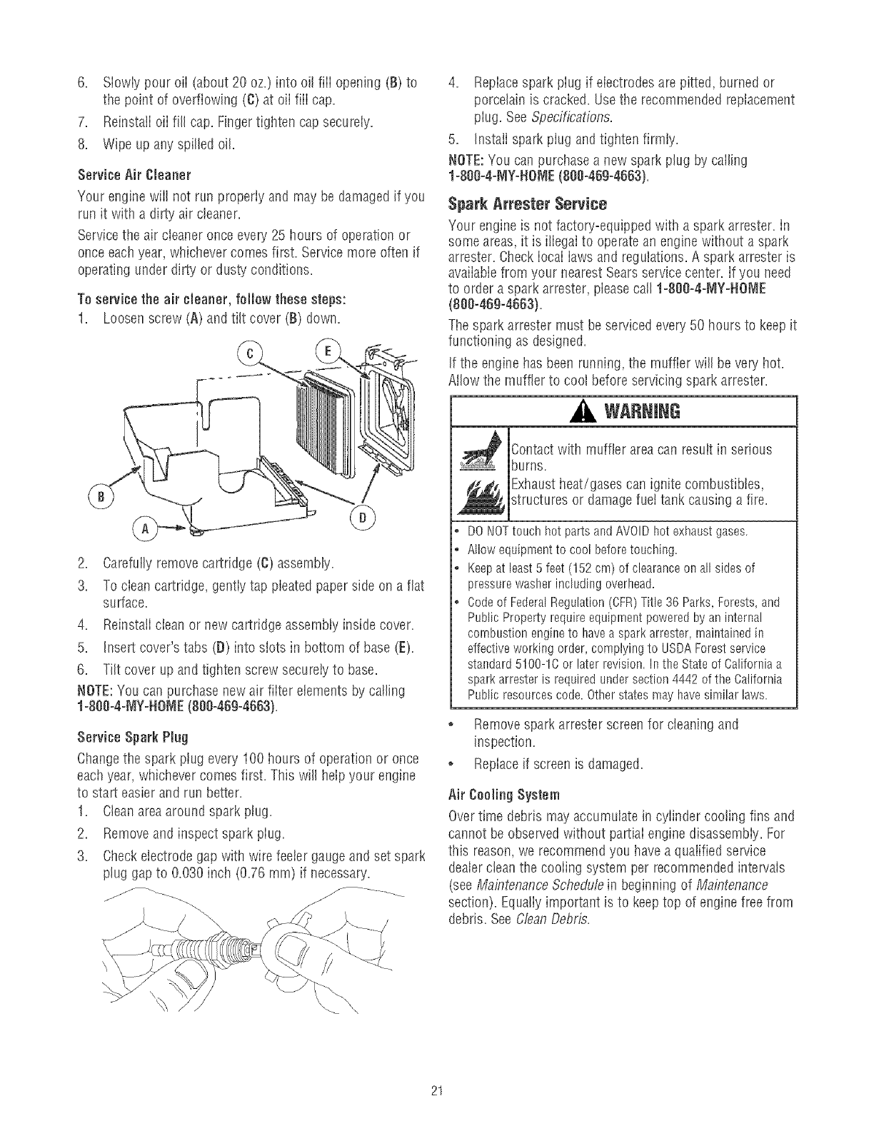
1. Loosen screw (A) and tilt cover (B) down.
2. Carefully removecartridge (C) assembly.
3. To ciean cartridge, gentiy tap pleated paper side on a flat
surface.
4. Reinstaii ciean or new cartridge assembly inside cover.
5. Insert cover's tabs (D) into siots in bottom of base (E).
6. Tilt cover up and tigilten screw secureiy to base.
NOTE:You can purchase new air fiiter elements by caifing
1-800o4-MY-NOME(800o469-4663}.
Service Spark Plug
Changethe spark plug every 100 hours of operation or once
each year, whichever comes first. This will help your engine
to start easier and run better.
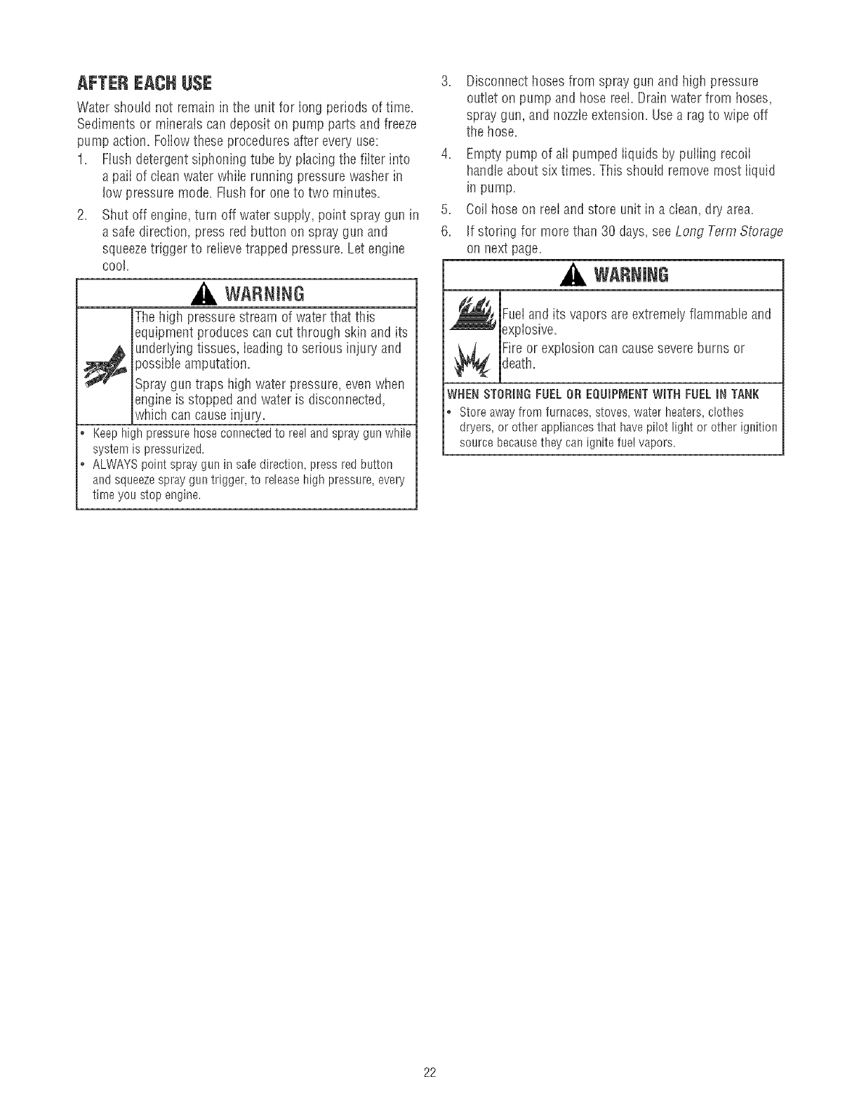
1. Cleanarea around spark plug.
2. Remove and inspect spark piug.
3. Checkelectrode gap with wire feeler gaugeand set spark
plug gap to 0.030 inch (0.76 ram) if necessary.
4. Repiacespark piug if eiectrodes are pitted, burned or
porcelain is cracked. Usethe recommended replacement
plug. See Specifications.
5. Instaii spark piug and tighten firmly.
NOTE:You can purchase a new spark plug by calling
1-800-4-MY-NO_,IE(800-469-4663).
Spark Attester Service
Your engine is not factory=equippedwith a spark arrester, in
some areas,it is iliegaI to operatean engine without a spark
arrester. Check iocai iaws and regulations. A spark arrester is
available from your nearest Sears service center. If you need
to order a spark arrester, please call 1-800o4-_IY-NOME
(8e0o469o4663).
The spark arrester must be serviced every50 hours to keep it
functioning as designed.
If the engine has been running, the muffler will be very hot.
Allow the muffler to cool before servicing spark attester.
WARNING
Contact with muffler area can result in serious
burns.
Exhaustheat/gases can ignite combustibles,
structures or damage fuet tank causing a fire.
®
o
o
DO NOTtouch hot parts and AVOIDhot exhaust gases.
Allow equipment to cool before touching.
Keep at least5 feet (152 cm) of clearance on all sides of
pressure washer including overhead.
Codeof FederalRegulation (CFR)Title 36 Parks, Forests, and
Public Property require equlprnent powered by an internal
combustion engineto have a spark arrester rnaintained in
effective working order, complying to USDAForest service
standard 5100-1C or later revision. In the State of California a
spark arrester is required under section 4442 of the California
Public resources code. Other states may have similar laws.
o Removespark arrester screen for cleaning and
inspection.
o Replaceif screen is damaged.
Air Cooling System
Overtime debris may accumulate in cylinder cooling fins and
cannot be observed without partiai engine disassembiy. For
this reason,we recommend you have a qualified service
dealerclean the cooiing system per recommended intervals
(see Ma_;_tenanceSchedu/'ein beginning of Maintenance
section). Equaliy important is to keeptop of engine free from
debris. See C!eanDebris.
21
AFTEREACHUSE
Water should not remain in the unit for long periods of time.
Sediments or minerals can deposit on pump parts and freeze
pump action. Foiiowthese procedures after every use:
1. Flush detergentsiphoning tube by piacing the fiiter into
a paii of clean water whiie running pressure washer in
low pressure mode. Flushfor oneto two minutes.
2. Shut off engine, turn off water suppiy, point spray gun in
a safe direction, press red button on spray gun and
squeezetrigger to relievetrapped pressure. Let engine
cool
WABNING
The high pressure stream of water that this
equipment produces can cut through skin and its
_ nderlying tissues, ieading to serious injury and
possible amputation.
Spray gun traps high water pressure, even when
engine is stopped and water is disconnected,
which can cause injury.
• Keephighpressurehoseconnectedto reelandspraygunwhile
systemls pressurized.
o ALWAYSpointspraygunin safedirection,pressredbutton
andsqueezesprayguntrigger,to releasehighpressure,every
thne youstopengine.
3. Disconnect hosesfrom spray gun and high pressure
outlet on pump and hose reel. Drain water from hoses,
spray gun, and nozzleextension. Usea rag to wipe off
the hose.
4. Empty pump of ali pumped iiquids by puiiing recoii
handle about six times. This should remove most iiquid
in pump.
5. Coil hose on reel and store unit in a clean, dry area.
6. If storing for more than 30 days, see Long Term Storage
on next page.
WARNING
Fuetand its vapors are extremely flammable and
expiosive.
Fire or explosion can cause severeburns or
death.
WHEN STORINGFUELOR EQUIP{VIENTWITH FUELINTANK
*Storeawayfromfurnaces,stoveswaterheaters,clothes
dryers or otherappliancesthathavepilot light or otherignition
sourcebecausetheycanignitefuelvapors.
22
WINTERSTORAGE
You must protect your unit from freezing temperatures.
Failureto do sowill permanentlydamageyour purnpand
renderyour unit inoperable.
Freezedarnageis not coveredunderwarranty.
To protectthe unit from freezing temperatures:
1. FoIiow steps 1=4in the previous section After Each Use.
2. Use pump saver, Model 6039, to treat pump. This
minimizes freeze damageand lubricates pistons and
seals.
3. If pump saver is not avaiiabb, connect a 3=footsection
of garden hose to water inlet adapter. Pour RV=antifreeze
(antifreeze without alcohol} into hose. PulI recoil handb
twice. Disconnect 3=foot hose.
4. Store unit in a clean, dry area.
LONGTERM STORAGE
If you do not plan to use the pressure washer for more than
30 days, you must prepare the engine and pump for long
term storage.
Protect Fuet System
FweiPreserver:
Fiiithe fuel tank with fresh fuel atiowing at bast 1.5"of tank
spacefor fuel expansion as shown on page9, when using a
fuei preserver cartridge with the fresh start fuel cap. if only
partiaiiy fiiied, air in the tank wiii promote fuei deterioration
during storage. Engineand fueI can be stored upto 6 months
with fuei preserver.
,Check level of fuet preserver cartridge. FueIpreserver is
dark in color.
, If cartridgeis atmostempty or empty, repiacewith a new
fuel preservercartridgefoiiowing the instructions in Fresh
StarffMFuelCapon page10.
If fuet preserver is not used, remove all fuel from tank and
run engine until it stops from lack of fuel.
ChangeEngineOil
While engine is still warm, drain oiI from crankcase. Refill
with recommended grade. See ChangingEngine Oii in Engine
Maintenance.
Oil CylinderBore
, Removespark piug and pour about 1/2 ounce (15 mt) of
clean engine oii into the cylinder.
* Instaii spark plug and pull starter handle slowly to
distribute oil.
Protectingthe Pump
To protect the pump from damage causedby minerai
deposits or freezing, use PumpSaver, Model 6039, to treat
pump. This prevents freezedamageand lubricates pistons
and seals.
You must protect your unit from freezing temperatures.
Failureto do so will permanentlydamageyour purnpand
renderyour unit inoperabb
Freezedamageisnot coveredunderwarranty.
NOTE:PumpSaveris avaiiabie as an optional accessory, it is
not included with the pressurewasher. Contact the nearest
authorized service center to purchase PumpSaver.
To use PumpSaver, makesure the pressurewasher is turned
off and disconnected from supply water. Readand foiiow aii
instructions and warnings given on the PumpSavercontainer.
Other Storage Tips
1. DO NOTstore fuel from one seasonto another unbss it
has beentreated as described in Protect Fuel System.
2. Repiacefuel container if it starts to rust. Rust and/or dirt
in fuel can cause probiems if it's used with this unit.
3. Coverunit with a suitable protective cover that does not
retain moisture.
WARNING
Storagecovers can be flammable.
•DONOTplacea storagecoveroverahot pressurewasher.
° Letequiprnentcoo[for a sufficienttime beforeplacingthe
coveronthe equiprnent.
4. Store unit in a clean and dry area.
23
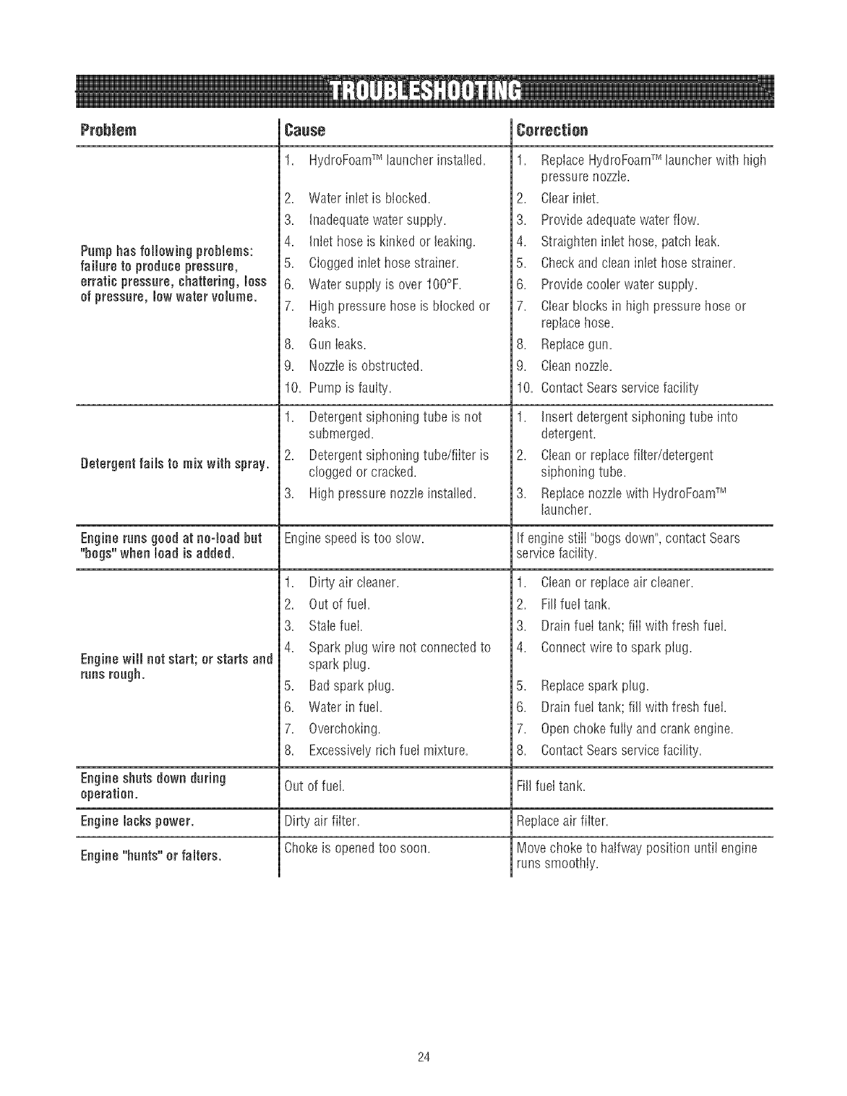
Pumphas followingproblems:
failure to producepressure,
erratic pressure, chattering,less
of pressure, Jewwater volume.
Detergent faiJsto mix with spray.
CauSe
1. HydroFoamTM launcherinstaIled.
2. Water inbt is blocked.
3. Inadequatewater suppiy.
4. Inlet hose is kinked or leaking.
5. Ciogged inbt hose strainer.
6. Water suppiy is over tOO°F.
7. High pressure hose is blocked or
1. ReplaceHydroFoamTM launcher with high
pressure nozzle.
2. Clearinlet.
3. Provide adequatewater flow.
4. Straighten inlet hose, patch ieak.
5. Checkand clean inlet hose strainer.
6. Provide cooier water suppiy.
7. Ciearblocks in high pressure hose or
leaks.
8. Gun leaks.
9. Nozzleis obstructed.
replace hose,
8, Replacegun,
9, Cleannozzle,
Pump is faulty. 10.
10,
1. Detergent siphoning tube is not
submerged.
2. Detergent siphoning tube/fiiter is
clogged or cracked.
3. High pressure nozzle installed.
ContactSears service facility
1. Insert detergent siphoning tube into
detergent.
2. Cleanor replace filter/detergent
siphoning tube.
3. Repiacenozzlewith HydroFoamTM
launcher.
Engineruns good at neolead hut Enginespeed is too slow. If engine stiii "bogs down", contact Sears
"hogs" when load is added, service facility.
EnginewHJnot start; orstarts and
runsrough.
1. Dirty air cleaner.
2. Out of fuel.
3. Stab fuel.
4. Spark ptug wire not connected to
spark ptug.
5. Bad spark plug.
6. Water in fuel.
7. Overchoking.
8. Excessivelyrich fuel mixture.
1. Cleanor replace air cleaner.
2. Fill fuel task=
3. Drain fuet tank; fiiI with fresh fuel.
4. Connectwire to spark plug.
5. Replacespark plug.
6. Drain fue! tank; fill with fresh fuei.
7. Openchoke fuily and crank engine.
8. ContactSears service facility.
Engine shuts down daring Out of fuel. Fill fuel tank.
operation.
EngineJackspower. Dirty air filter.
Chokeis openedtoo soon.
Engine"hunts" or falters.
Replaceair filter.
Move choke to halfway position until engine
runs smoothly.
24

25
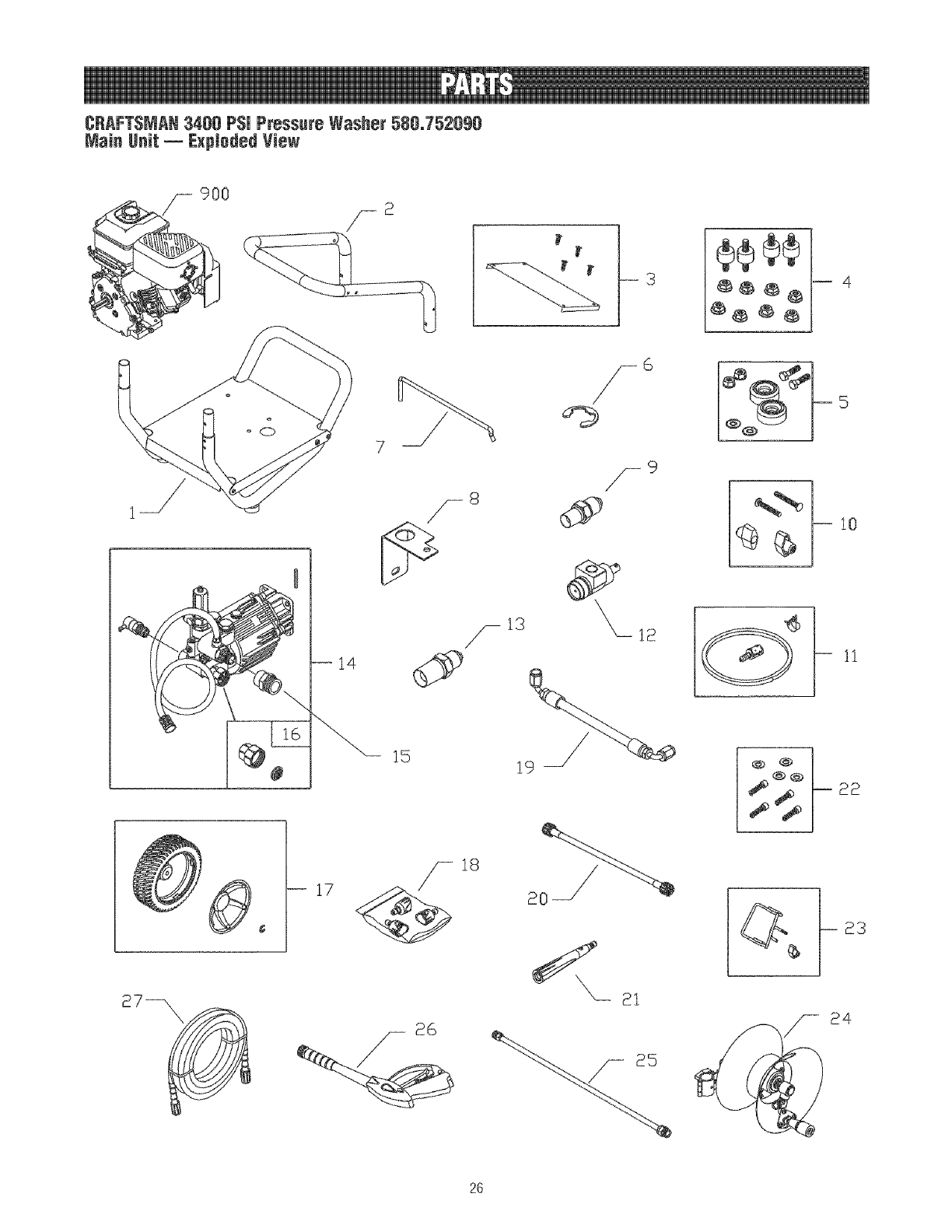
CRAFTSMAN3400 PSi Pressure Washer 580_752090
Main Unit _ExpJodedYJew
4
5
10
1!
15
18
19 °°!_ 22
24
2G
CRAFTSMAN3488 PSi Pressure Washer 58&752898
Main Unit _Parts List
item Part # Description
I 202966GS ASSY, Base
2 B201499GS HANDLE
3 202903GS KiT, Biiiboard
195964GS Clips, Tree
4 192134GS KiT, Engine Mounting Hrdwr
5 192553GS KiT, Vibration Mount
6 202351GS E-RING,Thrtt! Cntri
7 202873GS WIRE, Idle Control
8 B200973GS BRACKET,Idle Controi Mounting
9 202429GS FITTING,Hoseto ThrttI Cntrl
10 B2203GS KiT, Handie Fastening
11 192796GS KiT, Chem Hose&Fiiter
12 202352GS THROTTLECONTROL
13 202428GS FiTTiNG,Thrtti Cntri, Hoseto Pump
14 202005GS ASSY, Pump (see pages 28-29)
194298GS Valve,Thermal Relief
23139DGS Key
15 95457GS ADAPTER
16 194004GS KIT, inlet, Grdn Hose
17 202978GS KIT, Wheei
200517GS Hubcap
192050GS E-Ring
18 201758GS KiT, Nozzle
201580RGS Nozzle,QC,Project Pro, Yeilow
201580XGS Nozzle,QC,Project Pro, Orange
201580AAGS Nozzle,QC,ProjectPro, Red
19 202427GS ASSY, HoseSwivel, Thrtti Cntrl
20 202418GS HOSE,Whip
21 198423GS ASSY, Nozzle,Foaming
22 192131GS KIT, Pump Mounting Hrdwr
23 201661GS KiT, Gun HotderWeldment
24 202136GS ASSY, Hose Reet
203488GS Kit, Hrdwr, Hose Reel
25 193814GS EXTENSION,QC
26 199990GS GUN
27 202419GS HOSE
900 NSP ENGINE(150212-0119-E9) (see
pages 30-33)
items Not illustrated
Part # Description
203780GS MANUAL,Operator's
87815GS GOGGLES
30809GS GROMMET,Billboard
AB3061BGS OiL BOTTLE
201314GS AXLE
199462GS BOTTLE,Cncntrt, Hydro-Foam
203167GS KiT, Decais,Srv
194256GS KiT, Tag/Warning Srv
Optional Accessories Not illustrated
Part # Description
7175187GS GardenHose Quick Connect
7175197GS
7175124GS
7175122GS
7175116GS
7175129GS
7175121GS
7174402GS
6039
6092
6135
7174300GS
7174301GS
7174302GS
7174303GS
7174307GS
Accessory Quick Connect
Rotating Brush Kit
30' ReplacementHose
0 Ring Repair Kit
Turbo Nozzle
25' Extension Hose
Hose Reei
Pump Saver
WASH, HydroFoamTM
KiT, HydroFoamTM Launcher & Wash
HouseWash Concentrate (makes
4 gallons)
Deck Wash Concentrate(makes
2 gallons)
Vehicle/Boat Wash Concentrate
(makes 4 gatlons)
DegreaserConcentrate(makes
4 gallons)
Mold/Mildew Concentrate(makes
2 gallons)
27
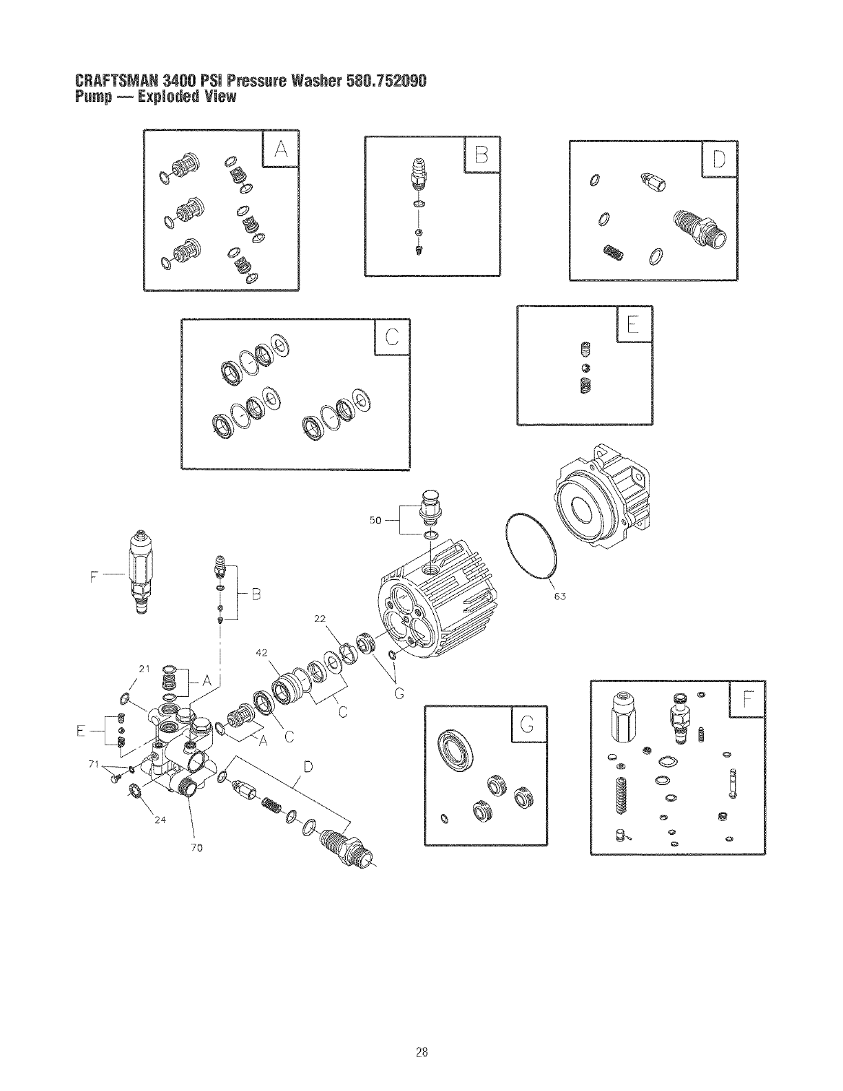
CRAFTSMAN3400 PSi PressureWasher5B0_752090
Pump-- ExplodedView
½
$
@
21
/
C
C
D
24
7O
m
@
65
OQ
Q
0
Q
Q
L
28
CRAFTSMAN3400 PSi Pressure Washer 580,752090
Pump _ Parts List
Item Part #
21 194434GS
22 190639GS
24 190640GS
42 190646GS
50 198160GS
63 194435GS
70 190654GS
71 190655GS
A 190657GS
B 192914GS
C 190660GS
D 194426GS
E 194427GS
F 193126GS
G 194425GS
Description
O=RiNG
SPACER
WASHER
PISTON,Guide
VENTCAP,with O=Ring
O-RiNG
PUMPHEAD
GRUBSCREW& WASHER
KIT, CHECKVALVE
KIT, CHEMICALiNJECT
KIT, SEALWATER
KIT, INJECTOR
KIT, BALL & SPRING
KIT, UNLOADER
KIT, SEALOIL
Items Not Illustrated
Part # Description
B2384GS FILTER,INLET
OptionaJAccessories Not illustrated
Part # Description
190656GS OiL BOTTLE
186452GS FILTER,INLET,BAGOF10
NOTE:Item letters A =Gare service kits and include aII parts shown within the box=
29
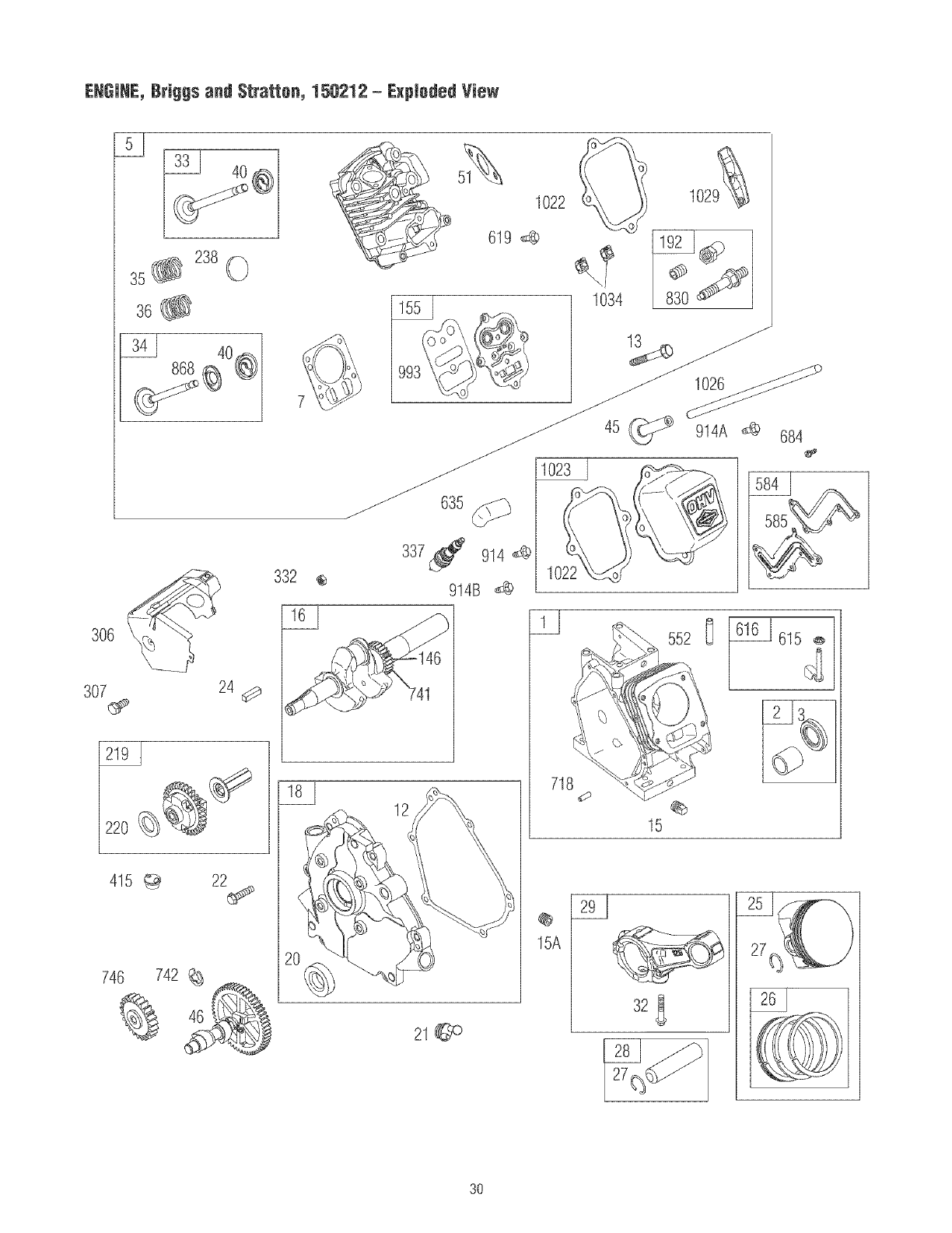
ENGINE, Briggs and Stratten, 150212 -Exploded View
_40
@
32® 2380
36
1022
619 _@
1034 830
307 24 d¢_
415 _ 22_
746 742
332
12
2!@D
7!8
@
15A
552 O 615
3O
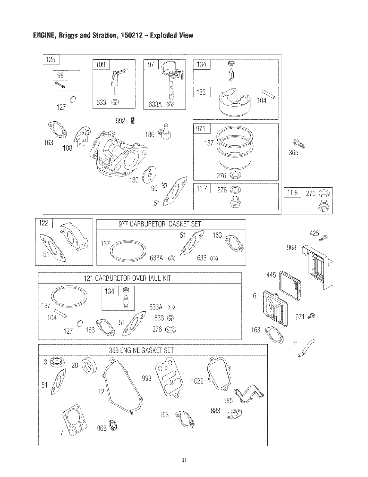
ENIINE, lri!ls and Stratton, 150212 - ExpJotet View
63
127
108
633 _ 633A 0
692 !
186
95 _
51
@
%
365
276
977CARBURETORGASKETSET
137 51¢__ 163 %
633A 0 633 ___
968
425_
137
127
121 CARBURETOROVERHAULKIT
0
633A @
633 @
276 @
2O
358 ENGINEGASKETSET
12
1022 0
163 883
585
445
161
971
31
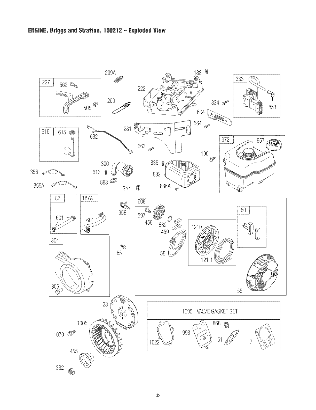
ENGINE, Briggs and Stratten, 150212 -Exploded View
356
356A
2271 562
6!50
209A 188
300
613 I_
883@;;
836 ¢¢
832
347 _ 836A
958
%
65
456 6890<_
58 @
55
lo9s_£vEGASKETSET
",_,_P@¢}5!/
32

EHGJNE,BrJggs and Stratton, 150212 -Parts List
_lem ?aft # Bescfiptioe
1 794188 Cylinder Assembly
2 399269 Kit-Bushing/Seal (Magneto Side)
3 299819S £ 0i} Seal (Magneto Side)
5 791720 Head-Cylinder
7 791716 £ 1 Gasket-Oylinder Head
11 692600 Tube-Breather
12 699485 £ Gasket-Orankcase
13 699482 Screw (Cylinder Head)
15 691686 Plug-Oil Drain
15A 691682 Plug@il Drain
16 792208 Crankshaft
18 699804 Cover-Crankcase
20 692550 £ Seal-Oil (PTO Side)
21 281658S Cap-Oil Fill
22 699478 Screw (Crankcase Cover)
23 699488 Flywheel
24 2226989 Key-Flywheel
25 791786 Piston Assembly (Standard)
791791 Piston Assembly (.020" Oversize)
26 791787 Ring Set (Standard)
791792 Ring Set (.020" Oversize)
27 690975 Lock-Piston Pin
28 690229 Pin-Piston
29 791783 Rod-Connecting
32 791784 Screw (Connecting Rod)
33 499642 Valve-Exhaust
34 499641 Valve-intake
35 691304 Spring-Valve (Intake)
36 691304 Spring-Valve (Exhaust)
40 692194 Retainer-Valve
45 690977 Tappet-Valve
46 791177 Camshaft
51 791718 ¥ £ $ t Gasket-intake
56 691422 t-lousing-Rewind Starter
58 693389 Rope-Starter
60 691915 Starter Rope Grip
66 699228 Screw (Re\_/indStarter)
95 691636 Screw (Throttle Valve)
97 690024 Throttle Shaft
98 398185 Kit-idle Speed
104 691242 ¥ Pin-Float Hinge
108 695807 Valve-Choke
109 690023 Shaft-Choke
117 690048 Jet-Main (Standard)
118 498976 Jet-Main (High Altitude)
121 792006 Kit-Carburetor Overhaul
122 791717 Spacer-Carburetor
125 792970 Carburetor
127 691739 ¥ Plug-Welch
130 691181 Valve-Throttle
133 398187 Float-Carburetor
134 398188 ¥ Valve-Float Needle
137 693981 ¥ :!: Gasket-Float Bowl
146 690979 Key-Timing
155 698214 Plate-Cylinder Head
161 699207 Base-Air Cleaner
163 696024 ¥ £ $ Gasket-Air Gleaner
186 692317 Connector-Hose
187 791766 Line-Fuel (Cut to Required Length)
187A 791867 Line-Fuel (Molded)
188 699479 Screw (Control Bracket)
190 699220 Screw (Fuel Tank)
192 694543 Bali-Rocker Arm
209 693710 Spring-Governor
209A 794364 Spring-Governor
219 693578 Gear-Governor
220 691724 Washer (Governor Gear)
222 794365 Bracket-Control
227 794367 Lever-Governor Control
238 691300 Cap-Valve
276 271716 ¥ Washer-Seali%
281 794366 Panel-Control
300 693593 Muffler
304 699598 Housing-Blower
305 699480 Screw (Blower Housing)
306 693610 Shield-Cylinder
item Part # Bescriptien
307 699483 Screw (Cylinder Shield)
332 792723 Nut (Flywheel)
333 695711 Armature-Magueto
334 699477 Screw (Magneto Armature)
337 491055S Plug-Spark
347 698338 Switch-Rocker
356 695630 Wire-Stop
356A 692602 Wire-Stop
358 791797 GasketBet-Engine
365 699484 Screw (Carburetor)
415 693463 Plug
425 699208 Screw (Air Cleaner Cover)
445 4915888 Filter-A/6 Cartridge
455 692591 Cup-Flywheel
456 692299 Plate-Pawl Friction
459 2815058 PawI-Ratchet
505 691251 Nut (Governor Control Lever)
552 692346 Bushing-Governor Crank
562 691112 Bolt (Governor Control Lever)
564 699854 Screw (Control Cover}
597 691696 Screw (Pawl Friction Plate)
584 791759 Cover-Breather Passage
585 791760 Gasket-Breather Passage
601 791850 Clamp-Hose
604 790473 Cover-Control
608 693394 Starter-Rewind
613 791972 Screw (Muffler)
615 692576 Retainer-Governor Shaft
616 692547 Crank-Governor
619 699480 Screw (Cylinder Head Plate)
632 693408 Spring/Link-Mechanical Governor
633 693867 ¥ $ Seal-Ohokeffhrottle Sbaft
633A 691321 ¥ $ Seal-Ohoke/fhrottle Shaft
635 692076 Boot-Spark Plug
663 699854 Screw (Control Panel)
684 793369 Screw (Breather PassageCover)
689 691855 Spring-Friction
692 690572 Spring-Detent
718 690959 Pin-Locating
741 695087 Gear-Timing
742 692564 Ring-Retaining
746 790278 Gear-Idler
839 694544 Stud (Rocker Arm}
832 693583 Guard-Muffler
836 699632 Screw (Muffler Guard)
836A 699203 Screw (Muffler Guard)
851 493880S Terminal-Spark Plug
868 692044 £ 1 Seal-Valve
883 691893 £ Gasket-Exhaust
914 699480 Screw (Rocker Cover) (Bottom)
914A 692557 Screw (Rocker Cover) (Top)
914B 697551 Screw (Rocker Cover) (Sides)
957 792647 Cap-FuelTank
958 698180 Valve-Fuel Shut Off
968 692584 Cover-Air Cleaner
971 690370 Screw (Air Cleaner Base)
972 694260 Tank-Fuel
975 790559 Bowl-Float
977 792007 GasketSet-Carburetor
993 694988 £ 1 Gasket-Cylinder Head Plate
1005 692592 Fan-Flywheel
1022 691890 £ 1-Gasket-Rocker Cover
1023 499924 Cover-Rocker
1026 790287 Rod-Push
1029 691230 Rocker Arm
1034 691343 Guide-Push Rod
1095 791798 Gasket Set-Valve
1070 699201 Screw (Flywheel)
1210 498144 Pulley/Spring Assembly (Pulley)
1211 498144 Pulley/Spring Assembly (Spring)
£ Included in Engine GasketSet, Item 358
¥ Included in Carburetor Overhaul Kit, Item 121
$ b-_cludedin Carburetor Gasket Set_Item 977
1" Included in Valve GasketSet, Item 1095
33
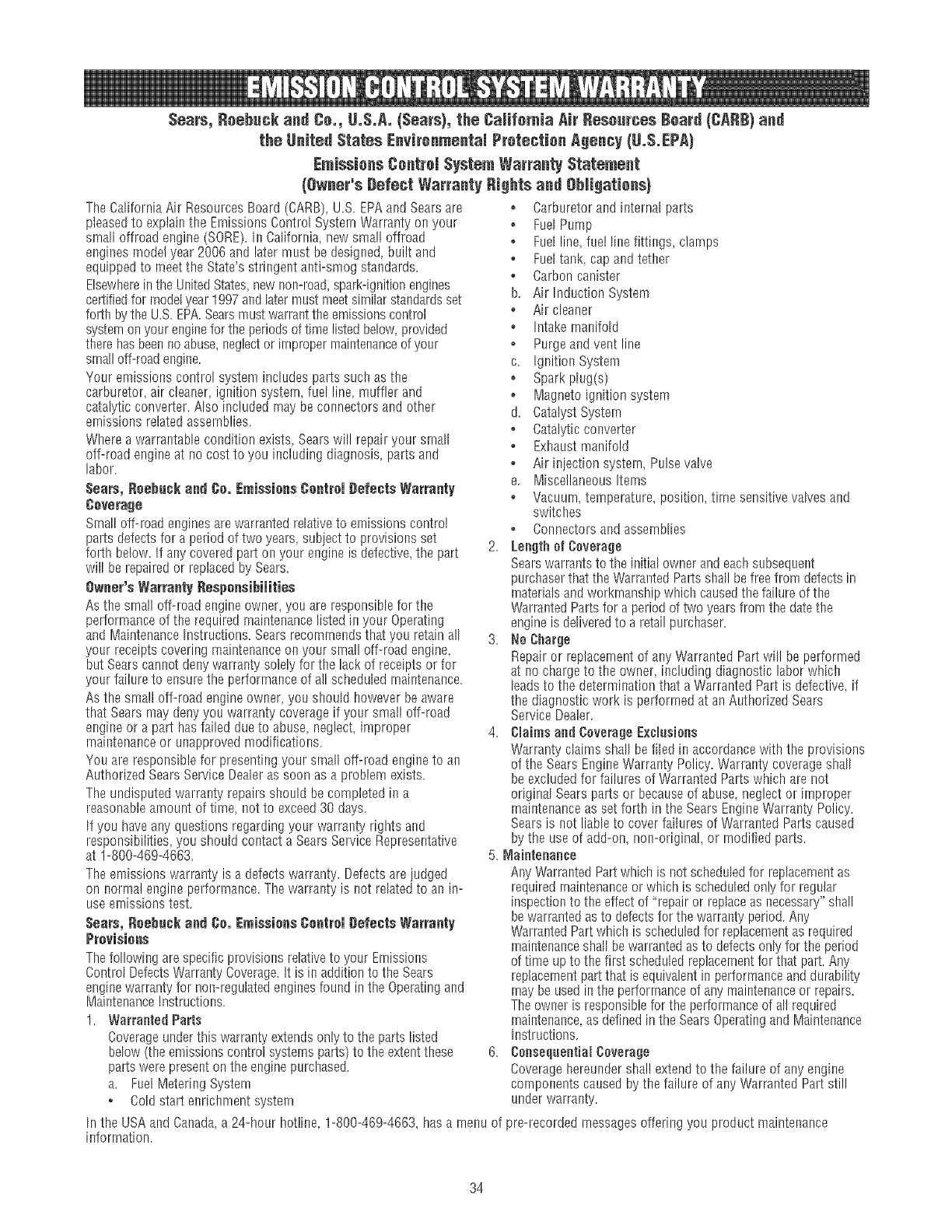
The California Air Resources Board (CARB), U.S. EPAand Sears are
pleasedto explain the Ernissions Control Systern Warranty on your
small offroad engine (SORE).br California, new small offroad
engines model year 2006 and later most be designed, built and
equipped to meet the State's stringent anti-smog standards.
Elsewherein the UnitedStates new non-road,spark-ignition engines
certifiedfor mode[year 1997 and latermust meet similar standardsset
forth bythe U.S. EPA.Searsmust warrant the emissions control
system on your engine for the periodsof time listed below, provided
there hasbeenno abuse,neglector impropermaintenanceof your
small off-road engine.
Your emissions control system includes parts such as the
carburetor air cleaner, ignition system, fuel line, muffler and
catalytic converter. Also included rnay beconnectors and other
emissions related assernblies.
Where a warrantable condition exists, Searswill repair your srnaH
off-road engine at no cost to you includingdiagnosis, parts and
labor.
Sears, neehuck aod Co. Emissions ¢ootromCefeots Warraoty
Coverage
Small off-road enginesare warranted relative to emissions control
parts defects for a period of two years, subiect to provisions set
forth below. If any covered part on your engine is defective,the part 2.
will be repaired or replaced by Sears.
Owner's Warranty Cesponeibiiities
As tire small off-road engine owner, you are responsible for tire
performance of the required rnaintenancelistedin your Operating
and MaintenanceInstructions. Searsrecommends that you retain all 3.
your receiptscovering maintenanceon your small off-road engine
but Sears cannot deny warranty solely for the lack of receipts or for
your failure to ensurethe performance of all scheduled rnaintenance.
As the small off-road engine owner, you should however be aware
that Sears may deny you warranty coverage if your small off-road
engine or a part has failed due to abuse neglect, improper 4.
rnaintenanceor unapproved modifications.
You are responsible for presenting your small off-road engineto an
Authorized Sears Service Dealeras soon as a problem exists.
The undisputed warranty repairs should becompleted ina
reasonable arnoont of tirne, not to exceed30 days.
If you have any questions regarding your warranty rights and
responsibilities, you should contact a Sears Service Representative
at 1-800-469-4663.
The emissions warranty is a defects warranty=Defects are judged
on normal engine perforrnance. The warranty is not related to an in-
use emissions test.
Sears, Coehock and Co. Emissions Control Cefeots Warranty
Previsions
Thefollowing are specific provisions relativeto your Emissions
Control DefectsWarranty Coverage.It is in addition to the Sears
enginewarranty for non-regulated enginesfound in the Operatingand
MaintenanceInstructions.
1. Warranted Parts
Coverageunder this warranty extendsonly to the parts listed
below (theemissions control systems parts) to the extent these 6.
parts were present on the enginepurchased.
a. Fuel Metering System
*Cold start enrichment system
In the USA and Canada,a 24-hour hot!ine, 1-800-469-4663, hasa rnenu of
information.
o Carburetor and internalparts
o Fuel Pump
o Fuel line, fue! line fittings, clarnps
o Fue[tank cap and tether
o Carbon canister
b. Air Induction System
, Air cleaner
o Intake rnan[foW
o Purge and vent line
c. Ignition System
o Spark plug(s)
o Magneto ignition system
d. Catalyst Systern
o Catalytic converter
o Exhaustmanifold
o Air injection systern, Pulsevalve
e. Miscellaneous Items
o Vacuurn, temperature, position, tirne sensitive valves and
switches
•Connectors and assemblies
Lengthof Coverage
Sears warrants to the initial owner and eachsubsequent
purchaser that the Warranted Parts shall befree from defects in
materials and workrnanship which caused the failure of tire
Warranted Parts for a period of two years from the date the
engineis deliveredto a retail purchaser=
No Charge
Repair or replacementof any Warranted Part will be performed
at no charge to the owner, includingdiagnostic labor which
leads to the determination that a Warranted Part is defective, if
the diagnostic work is perforrned at an Authorized Sears
Service Dealer.
CJaims and Coverage Exolnsiens
Warranty claims shah beflied inaccordance with the provisions
of the Sears EngineWarranty Policy. Warranty coverageshall
be excludedfor failures of Warranted Parts which are not
original Sears parts or becauseof abuse, neglector irnproper
rnaintenanceas set forth in the SearsEngine Warranty Policy.
Sears is not liable to cover failures of Warranted Parts caused
by the use of add-on, non-original, or rnodified parts.
5. Maintenance
Any Warranted Part which is not scheduled for rephcement as
required rnaintenanceor which is scheduled only for regular
inspection to the effect of "repair or replaceas necessary"shall
bewarranted asto defectsfor the warranty period. Any
Warranted Part which is scheduledfor replacementas required
rnaintenanceshall be warranted as to defects only for the period
of time up to tire first scheduled replacernentfor that part. Any
replacernentpart that is equivalent in performanceand durability
rnay be used in tire performance of any maintenanceor repairs.
Theowner is responsible for the performance of all required
rnaintenance as defined in the Sears Operatingand Maintenance
hrstructions.
Censeqnentiai Coverage
Coverage hereunder sha!l extendto the failure of any engine
cornponents caused by tire failure of any Warranted Part still
under warranty=
pro-recorded rnessagesoffering you product maintenance
34
EmJ_ion information
Enginesthat are certified to meetthe CaliforniaAir Resources
Board(CARB)Tier 2 Emission Standards must display
information regardingthe Emissions Durabiiity Period and Air
Index. The engine manufacturer makesthis information
avaiiabteto the consumer on emission iabeis, The engine
emission iabet wili indicate certification information,
The Emissions Durability Period describes the number of
hours of actual running time for which the engine is certified
to beemissions compliant, assuming proper maintenancein
accordancewith the Operating & Maintenance Instructions.
The following categories are used:
Moderate: Engineis certified to be emission compliant for
125 hours of actual engine running time.
Intermediate: Engineis certified to beemission compliant
for 250 hours of actual engine running time.
Extended: Engineis certified to beemission compiiant for
500 hours of actual engine running time.
Forexample, a typical walk-behind lawn mower is used 20 to
25 hours per year. Therefore, the Emissions Durability
Period of an engine with an intermediate rating would
equateto 10to 12 years.
Certainengines wiii be certified to meet the United States
Environmental Protection Agency (USEPA)Phase 2 emission
standards. For phase 2 certified engines, the Emissions
Compiiance Period referred to on the Emissions Compliance
label indicates the number of operating hours for which the
engine has been shown to meet Federalemission
requirements.
For engines iess than 225 cc displacement:
CategoryC = 125 hours
Category B = 250 hours
CategoryA = 500 hours.
For engines of 225 cc or more displacement:
CategoryC = 250 hours
Category B = 500 hours
CategoryA = 1000 hours.
35
GARANTIA.......................................... 36
REGLASDESEGURIDAD............................ 36-39
CARACTER{STICASYCONTROLES....................... 40
MOrITAJE........................................ 41-45
OPERAC!Orl....................................... 46-50
ESPECIFICAC!ONES................................... 51
IVlANTEI',IIIVlIENTO.................................. 52-56
ALMACENAMIENTO................................... 57
REPARAC!ONDEDAP-_IOSREPUESTOS.................... 58
NOTAS........................................... 59-61
GARANTIADELCONTROLDEEMISIONES............... 62-63
COMOORDENARPARTES............... PAGINAPOSTERIOR
Garant_a ¢empieta de un a_e de _a_impiadera a presi_n Craftsman
Sila Hmpiadoraa presi6n falla debido a defectos de materialeso rnano de obra ee el plazo de un afio a partir de la fecha de compra,
devu61valaa cualquier alrnacan Sears, punto de venta de Craftsman o centro de reparaci6e y repuestos de Searsde los Estados Unidos o
Canad_tparasu reparaciOngratuita o en caso de que 6sta no sea posiNe, parasu sustituci6n.
El periodo degaraetia se reducir_ a 90 dias desde la fecha de cornpra si la limpiadora a presi6n se utiliza en algt_nrnomento con flees
cornerciales o de alquiler.
Esta garantia le otorga deterrnieados derechos legales y es posible que tenga otros derechosque pueden variar de un pais o estado a otro.
Sears, Reebuek and Co,, #ept, 817 WA, Hoffman Estates, JL 68179
Sears Canada Jn¢,, Toronto, Ontario, Canada MSB 2B8
Este es eJsimboJo de aJerta de seguridad. Esusado paraindiearJe situa¢iones con peJigrospotenciaJes de Jesionpara e_
personal Siga masinstru¢ciunes de redes ruesmensajes de seguridad que aparecen despues de este simbomopara evitar pusiNes
Jeeiones o muerte,
=¢_[-1_Leaestemanuamminueiosamenteyeunezeaa rondomas
i_ [-JlJ.... partesyeJfun¢ionamientedesu m_quinaHmpiaduraa
presi6n.Conozcasusaplicaciones,susIhnitacieeesy los
peHgresievemacraaes.
Elsimbolodealertadeseguridad(_) es usadocon unapalabra
(PELIGRO,ADVERTEfICIA,PRECAUCION)ue mensajeperescritoo
unailustraci6n,paraalertadoacercadecualquiersituaci6nde
peligroquepuedaexJstir.PELI[_ROindicaunriesgoelcual,si nose
evita causardlarnuerteo u_saheridagrave.ADVERTENClAindicaun
riesgoelcua! si noseevita puedecausarlamuerteo unaherida
grave.PRECAUCm6Nindicaunriesgo,e! cual si noseevita puede
causarheridasrnenoreso moderadas.AVISOindicaunasituaci6e
quepodriaresultarenelda[iode!equipo.Sigalos mensajesde
seguridadparaevitaro reducirlos riesgosdehefidaseinclusivela
muerte.
DescargaEI6ctrica
SuperficiesResbalosas Caer Inyecci6n Lfquida
PartesenMovilniento ObjetosVoladores Superficie Caliente
Fuego Explosi6n Manual del Operario Contragolpe
36
ADVEBTENCIA
EJescape deJ motor de este producto centJene eJementos
quJmJ¢os re¢onocJdos en eJ Estado de CaJJfornJa
pot producJr ¢;_ncer, defectos de nacJmJento
uotros dafios de tJpo reprodu¢flvo,
PELJGRO
Su6ontenidoes NOClVO0 FATALENCASODESER
/_ INGERIDO. Evite el contacto con los ojos la pie! o la
ropa. No tomar internarnente. Evite respirarla niebla o
el vapor. La exposici6nexcesiva de los oioso la piel
)uede causar irritaciOn. Mantenga el estabilizador fuera
del aIcance de los nifios.
El estabilizador de combustible es un qufmico peligroso.**
, La tapa de combustible FreshStartTM est_diseflada parasostener un
cartucho el cual contiene el estabilizador de combustible.
, EI',JCASO DE SERINGERIDO,Ilame un medico inmediatamente. No
induzca el v6mito. En caso de inhalaciOnsalir al aire libre. En caso de
contacto con los ojos o con la piel, lavar abundantemente con agua
durante 15 minutos.
o Almacene los cartuchos sin abrir en un _rea fresca, seca y bien
ventilada. Mantenga el cartucho abierto en latapa de combustible, y la
tapa de combustible cerrada en el tanque de combustible cuando no
est_ en uso.
o En caso de la emergencia, contacte a un mSdico inmediatamente y llama
1-800-424-9300 para la informaci6n material de la seguridad.
**El estabillzadorde combustiblecontiene2,6-di-tert-butilfenol(128-39-2)y
destlladodepetr61eoallf_tlco(64742-47-8).
ABVERTENCiA
AI motorfuncionar,se producemon6xidodecarbono,
ungasinodoroy venenoso.
Respirarmon6xidodecarbonopuedeprovocardolor
de cabeza, fatiga, rnareos, vOrnitos, confusion,ataques n_useas, desmayos o incIuso la rnuerte.
Algunas sustancias quirnicas o los detergentes pueden
ser perjudicialessi inhalados o ingeridos,causando la
is_lJsea severa, desrnaya!sdo o para elwe!serlar.
, Opere el limpiadora a presi6n SOLAMENTEal aire libre.
, AsegOresede que los gases de escape no puedan entrar por ventanas,
puertas, tomas de aire de ventilaci6n u otras aberturas en un espacio
cerrado en el que puedan acumularse.
, I'_10arranque ni deje funcionar el motor en interiores ni en zonas
cerradas, aunque hayaventanas y puertas abiertas.
, Utilice un respirador o m_iscarasiempre que exista la posibilidad de
inhalar vapores.
, Lea todas las instrucciones de la m_scara para asegurarse de que le
brindar_ la protecci6n necesaria contra la inhalaciOn de vapores
nocivos,
ADVERTENCiA
Lagasolinay susvaporessonextrernadamente
inflamables y exp!osivos.
E[ fuego o una explosi6n pueden causar quernaduras
severas e inclusive la muerte.
CUANDO ANADA cor_IBUSTmBLE 0 VACiEELDEP6SmTO
Apague el limpiadora a presi(_n(posici6n OFF)y d_jelo enfriar al menos
por 2 minutos antes de remover la tapa de la combustible. Afloje la
tapa lentamente para dejar que la presi6n salga del tanque.
o Llene o vac[e el depOsito de combustible a la intemperie.
, NO Ilene demasiado el tanque. Permita al menos espacio para la
expansi6n del combustible.
, Si se ha derramado combustible, espere a que se evapore antes de
arrancar el motor.
, Mantenga la gasolina alejada de chispas, llamas abiertas, pilotos, calor
y otras fuentes de ignici6n.
, NO encienda un cigarrillo o fume.
CUANDO PONGA EN FUNCIONA{VIIENTO EL EQUBPO
o Compruebe que la bujfa el silenciador, el tap6n del dep6sito de
combustible y el filtro de aire est_n instalados.
o NO arranque el motor sin la buj[a instalada.
CUANDO OPEBEELEQUmPO
NO incline el motor o el equipo, de tal manera que la gasolina se pueda
derramar.
, NO rocie I[quidos inflamables.
CUANDO TRANSPORTE0 REPAREELEQUIPO
o Transporte o repare el equipo con el tanque de combustible vac[o, o
con la v_ilvulapara apagar el combustible, apagada (posici6n OFF).
, Desconecte el cable de la buj[a.
CUANDO ALMACE_iE0 GUARDE ELEQUmPOCON CO_vIBUSTmBLE
EN ELTANQUE
Almacene alejado de calderas, estufas, calentadores de agua, secadoras
de ropa u otros aparatos electrodom6sticos que posean pilotos u otras
fuentes de igniciOn, porque ellos puedenencender los vapores de la
combustible.
ADVEBTENCiA
_¢ [esgo de e]ectrocuci6n.
E! contacto con los cables eIactricos puedeprovocar
electrocuci6n y quernaduras.
, NUNCA rocie cerca de una fuente de energia el6ctrica.
37
ADVERTENCJA
El retroceso (repliegue r@ido) del cable del arrancador
puede producir bsiones El retroceso impedir_ que el
usuario sueIte e! cable a tiernpo y tirarA de su mano y
brazo Isacia el motor.
Corno resuItado, pod!ian producirse fracturas
contusiones o esguinces.
NUNCAtire del cable del arrancador sin elirninar previamente la presi6n
de la pistola rociadora.
Cuando arranque el motor, tire lentamente del cable hasta sentir una
resistencia y, a continuaciOn, tire r_pidamente de 81para evitar su
retroceso.
o Despu6s de cada intento de arranque, cuando el motor no consiga
arrancar, apunte con la pistola rociadora hacia una direcci6n segura,
pulse el bot6n rojo y apriete el gatillo para descargar la presi6n.
o Sujete firmemente la pistola rociadora con ambas manos cuando
aplique un rociado a alta presi6n paraevitar lesiones cuando se
produzca el retroceso de la pistola.
, ADVERTENCJA
Eluso delimpiadoraa presi@puedecrearlos@amos
y superficiesresba!osas.
Elretrocesodela pistolarociadorapuedeprovocar
caidas.
o Utilice la limpiadora a presi6n desde una superficie estable.
, El area de limpieza deber_itenet inclinaciones y drenajes adecuados
para disminuir la posibilidad de cafdas debido a superficies resbalosas.
o Extreme las precauciones si necesita utilizar la limpiadora a presi6n
des@ una escalera, un andamio u otro lugar similar.
o Sujete firmemente la pistola rociadora con ambas manos cuando
aplique un rociado a alta presi6n paraevitar lesiones cuando se
produzca el retroceso de la pistola.
, ADVERTENCJA
EIcontactocon lazonadelsibnciadorpuedeproducir
quemadurasgraves.
Losgasesy el calordeescapepuedeninfiamarlos
materialescombustibbsy lasestructuraso daiiarel
dep6sitodecombustibby provocarunincendio.
o NO toque las superficies calientes y EVITElos gases del escape a alta
temperatura.
,Permita que el equipo se enfrb antes de tocarlo.
Deje un espacio mfnimo de 152 cm (5 pies) alrededor del limpiadora a
presi6n, incluida la parts superior.
o El 66digo de Normativa Federal (6FR, Titulo 36: Parques, Bosquesy
Propiedad PSblica)obliga a instalar una pantalla apagachispas en los
equipos con motor de combustion interno y a mantenerla en buenas
condiciones de funcionamiento, conforme a la norma 5100-16 (o
posterior) del Servicio Forestalde la USDA. Enel Estado de California.
la leyexige el uso de una pantalla apagachispas (Secci6n 4442 del
C6digo de Recursos POblicosde California). En otros estados puede
haber byes similares en vigor.
ADVERTENCJA
El cborro de agua a alta presi6n que este equipo
produce puede atravesar la piel y los tejidos
_ ubcut_neos, provocando lesiones de gravedad que
)odrias dar lugar a la amputaci@ de un rniernbro.
La pistola rociadora contiene agua a aIta presi6n incluso
cots e! motor parado y el agua desconectada, que puede
causar la Iserida.
o NO permita en ningSn momento que NINOS operen la m_quina
limpiadora a presiOn.
o NUNOArepare la manguera de alta presi6n. Remplacela.
, NUNCA utilice ning8n tipo de sellador para reparar una fuga en una
conexi6n. Sustituya la junta t6rica o la junta.
, NUNCA conecte la manguera dealta presiOnal prolongador de la
boquilla.
, No desconecte la manguera de aita presi6n del carrete ni de la pistola
rociadora mientras haya presi6n en el circuito.
, SIEMPRE que pare el motor, apunte con la pistola rociadora hacia una
direcci6n segura, pulse el bot6n roio y apriete el gatillo para descargar
la presiOn.
, NUNCA apunte la pistola a la gente, animales o plantas.
o NO fiie la pistola rociadora en la posici6n abierta.
o NO abandone la pistola rociadora cuando la m_quina est6 en
funcionamiento.
, NUNCA utilice una pistola rociadora cuyo seguro o protecciOn para el
gatillo no est8 en perfecto estado de funcionamiento.
, AsegSreseen todo momento de conectar correctamente la pistola
rociadora, las boquillas y los accesorios.
ADVERTENCJA
6hispear involLmtariopuede tenet como resultado el
¢ fuego o el golpe el6ctrico.
CUANDOAJUSTE0 HAGA REPARACmONESA SU M,_QUmNA
UMPmADORAA PRESm()N
o Siempredesconecteelalambredela bujfay col6quelodonde11opueda
entrarencontactoconlabuj[a.
CUANDOPRUEBELA BUJJADEL MOTOR
, Utiliceun comprobadordebujBshomologado.
, NOcompruebalachispasin labujBinstalada.
38
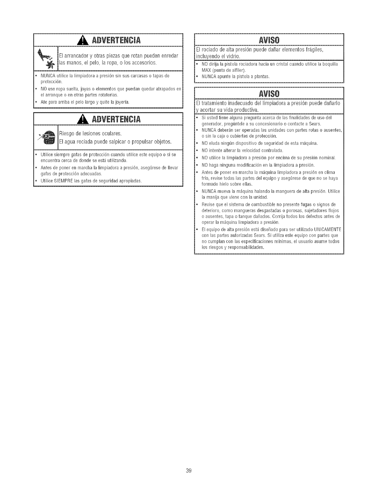
ADVERTENCJA
El arrancador y otras piezas que rotan pueden enredar
las manos, el pelo,la ropa, o los accesorios.
o NUNCA utilice la limpiadora a presi6n sin sus carcasas o tapas de
protecci6n.
o NO use ropa suelta, joyas o elementos qne puedan quedar atrapados en
el arranque o en otras partes rotatorias.
o Ate para arriba el pelo largo y quite la joyerfa.
ADVERTENCIA
Riesgo de lesiones oculares
E! agua rodada puedesalpicaro propulsarobjetos.
o Utilice siempre gafas de protecci6n cuando utilice este equipo o si se
encuentra cerca de donde se est_ utilizando.
o Antes de porter en marcha la limpiadora a presi6n, asegOresede Ilevar
gafas de protecci6n adecuadas.
o Utilice SIEMPRElas galas de segnridad apropiadas.
AVl$O
El rociado de alta presi6n puede da_ar elementos fr_giles,
incluyendoel vidrio.
NO dirija la pistola rociadora hacia un cristal cuando utilice la boquilla
MAX (punta de alfiler).
NUNCA apunte la pistola a plantas.
AVl$O
Eltratarnientoinadecuadodellimpiadoraapresi6npuededaiiado
acortarsuvida productiva.
Si usted tiene alguna pregunta acerca de las finalidades de uso del
generador, pregSntele a su concesionario o contacte a Sears.
NUNCA deber_inser operadas las unidades con partes rotas o ausentes
o sin la caja o cubiertas de protecci6n.
NO eluda ningOn dispositivo de seguridad de esta m_quina.
NO intente alterar la velocidad controlada.
NO utilice la limpiadora a presiOnpor encima de su presi6n nominal.
NO haga ninguna modificaci6n en la limpiadora a presi6n.
Antes de poner en marcha la m_iquina limpiadora a presi6n en clima
frfo, revise todas las partes del equipo y asegLSresede que no se haya
formado hielo sobre elias.
NUNCA mneva la m_quina halando la manguera de alta presi6n. Utilice
la manija que viene con la unidad.
Revise que el sistema de combustible no presente fugas o signos de
deterioro, como mangueras desgastadas o porosas, sujetadores flojos
o ausentes, tapa o tanque da_ados. Corrija todos los defectos antes de
operar la m_quina limpiadora a presi6n.
El equipo de alta presi6n est_ dise_iado para ser utilizado UNICAMENTE
con las partes autorizadas Sears. Si utiliza este equipo con partes que
no cumplan con las especificaciones m[nimas, el usuario asume todos
los riesgos y responsabilidades.
39
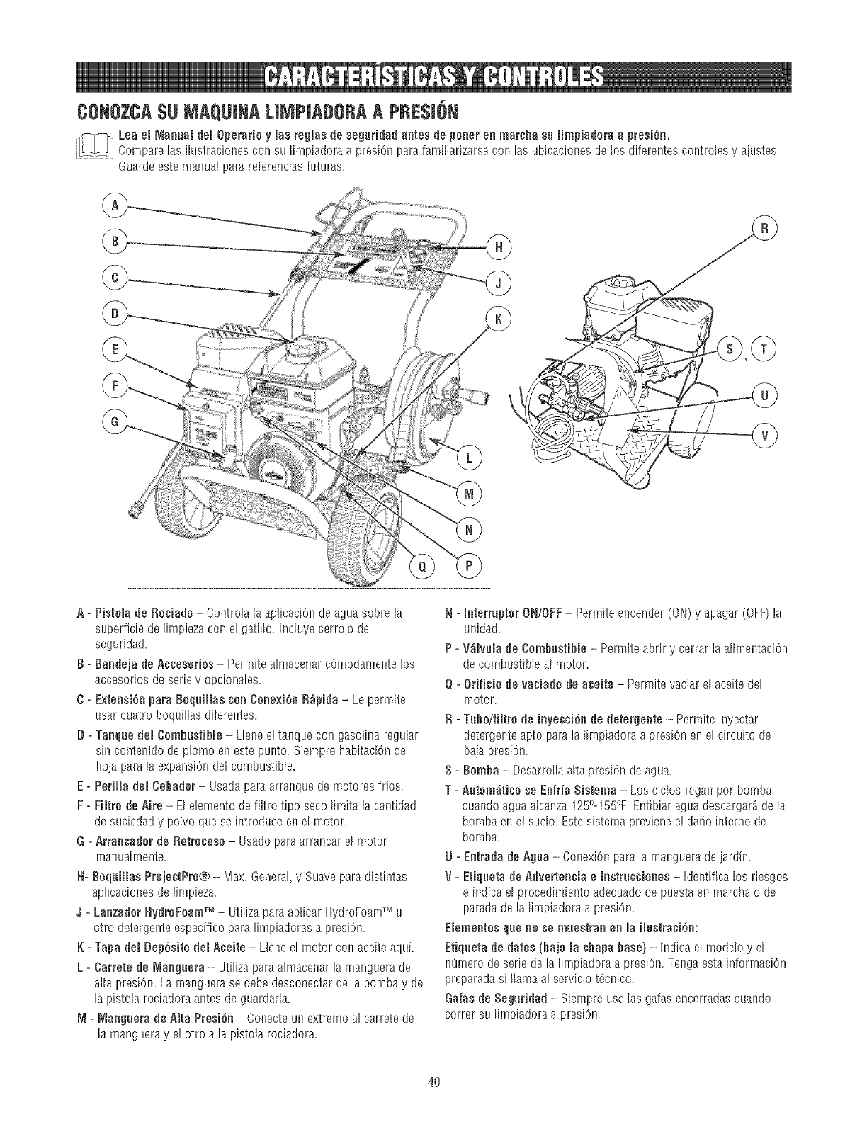
CONOZCA$UMAQUINALIMPIADORAA PRESm6N
Loo°,Mo.°o,de,operor,oy,osre ,o de eg°r,o°oo°,esdepo.°r°n,°orohoso,mpioOor°opr° i6n.
.....: Compare las ilustracioees con su lirnpiadora a presi6n parafamiliarizarse con las ubicaciooes de los dJferentescontroles y a]ustes.
Guarde este manual pare referencias futures.
\
A = Pistemade Reciade - Coetrola la aplicaci6n deague sobre la
superficie de limpieza con el gati%. Incluye cerrojo de
seguridad.
B = Baadeja de A¢ceseries - Permite almacenar cOrnodameetelos
accesorios de sede y opcionales.
C = ExteesiOepare BequiJJascee Ceee×iOeR0pida - Le permite
usar cuatro boqui!las difereetes.
D =Taeque deJCembBstiNe - Llene el taeque con gaso%a regular
sin contenido de plomo en este punto. Siempre habitaciOnde
hoja pare la expansion det combustible.
E = PeriJJadeJ Cebader- Usadapare arraeque de motores fries.
F=FiNre de Aire - El elemento de filtro ripe seco lirnita la cantidad
de suciedad y polvo que se introduce en el motor.
G=Arraecader de Retrecese -Usadopara arrancar e[ motor
rnaeuaheente.
H=BequHlas PrejectPre® - Max, General,y Suave pare distintas
aplicacioees de limpieza.
4=Laezader HydreFeamTM - Utilize pare aplicar HydroFoamTM u
otto detergente especifico para limpiadoras a presi6n.
K = Tapa del BepOsNedel Aceite - LJeneel motet con aceite aqui.
L =Carrete de [_,laeguera-Utiliza pare almacenar la rnanguera de
alta presi6n. La maeguerase debe desconectar de la bornba y de
la pistola rociadora antes de guardarla.
M=_laeguera de alta PresiOe- Coeecte un extreme al carretede
la mangueray e! otro a la pistola rociadora.
N=meterrupterON/OFF-Perrnite encender (ON) y apagar (OFF)la
uoidad.
P =V0mvumade OembustiNe - Permite abrir y cerrar la alirnentaciOn
de combustible al motor.
Q=ONficie de vaeiade de aeeNe -Permite vaciar el aceite deÁ
motor.
R = TubeifiNrede ieyeueiOede detergeete - Perrnite inyectar
detergente apto pare la lirnpiadora a presiOnen el circuito de
baja presiOn.
S = Bemba - Desarrolla alta presiOnde ague.
T =Autom0tice se Eefria Sistema -Los ciclos regae per bomba
cuaedo ague alcanza 125°-155%.Entibiar ague descargar_ de la
bornba en el sueD. Este sistema previene el da_o interne de
bornba.
U = Eetrada de Agua- CoeexiOnpare la rnaeguera de ]ardin.
V= Etiqueta de Advertee¢ia e lestrucuieees- Ideetifica los riesgos
e indica el procedimiento adecuado de puesta en rnarchao de
paradede la limpiadora a presiOn.
Elemeetes que ee ue muestrae ee la ilustraeiOe:
Etiqueta de dates (baje la ¢hapa base)- Indica el modeD y el
nOrnerode serie de la lirnpiadora a presiOn.Teega esta inforrnaciOn
preparadasi llama al servicio tOceico.
Galas de Seguridad - Siempre uselas galas encerradas cuando
correr su lirnpiadora a presiOn.
4O
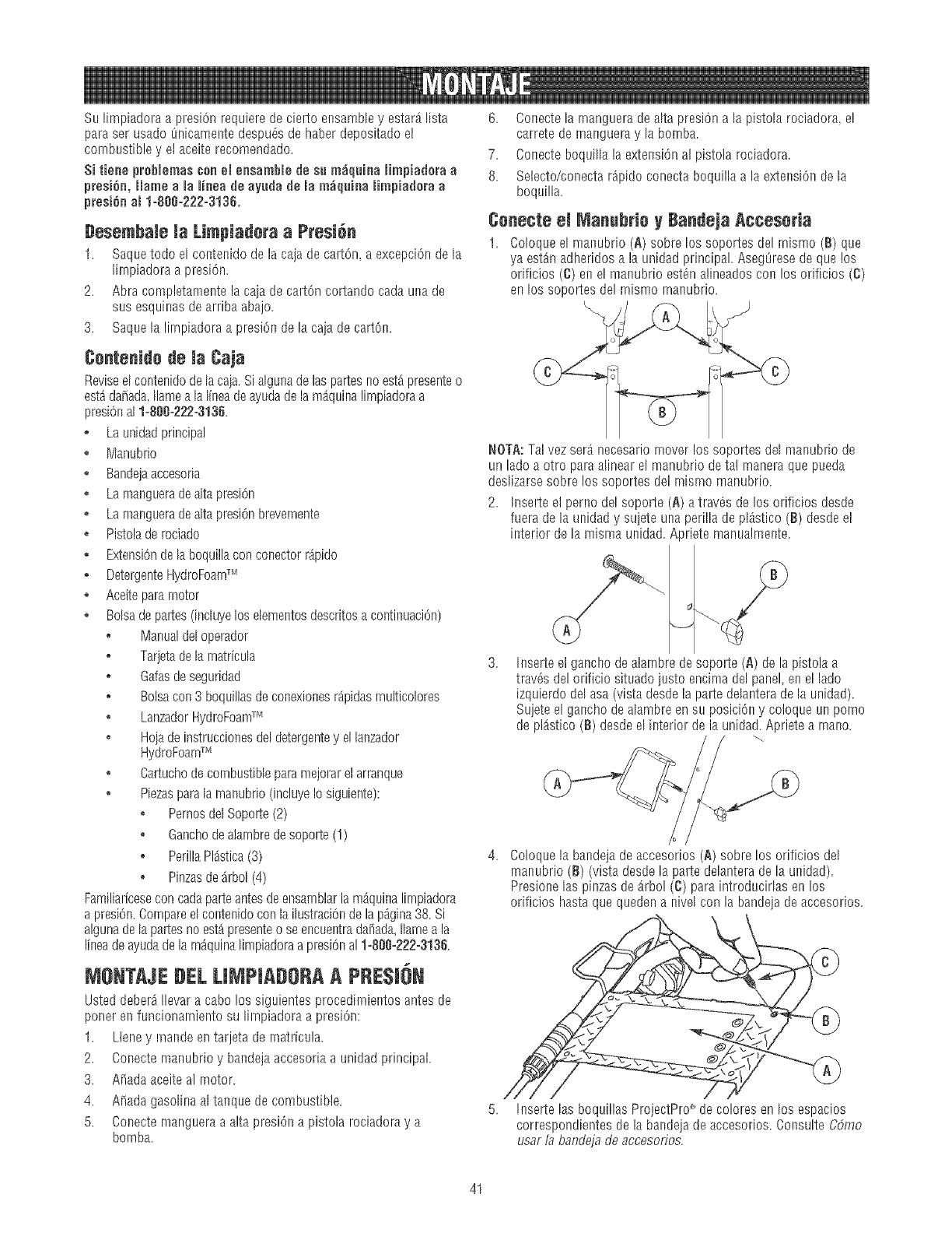
SulimpiadoraapresiOnrequieredeciertoensambleyestarAlista
parasetusadoOnicamentedespuOsdehaberdepositadoel
combustibleyelaceiterecomendado.
SitieneprobmemasconemensamhRedesu m_quinaHmpiaderaa
presiOn,Heinea ReRJneadeayudademam_quinaHmpiaderaa
presiOnam1=888=222=3136.
Besemhale Ja Limpiadera aPresi6n
1. Saquetodo el coetenidodelacajadecarton,aexcepciOndela
lirnpiadoraapresiOn.
2. Abracompletamentelacajadecartoncortandocadaunade
susesquinasdearribaabajo.
3. Saquelalirnpiadoraa presiOndela caindecarton.
Centenide de ta Caja
Reviseelcoeteeidodelacain.Sialgunadelaspartesnoest_presenteo
est_decade,Ilameala linendeayudadelam_quinalirnpiadoraa
presiOnal1=80U=222=3136
o Launidadprincipal
o Manubrio
, Bandejaaccesoria
o LamangueradealtapresiOn
o LamangueradealtapresiOnbrevernente
o Pistoladerociado
o ExtensiOndelaboquillaconconectorrApido
o DetergenteHydroFoarnTM
o Aceiteparemotor
o Bolsadepa!tes(induyelos elementosdescritosacontinuaciOn)
o Manualdeloperador
o Tarjetadelamatffcula
o Gafasdeseguridad
o Boisecon3 boquillasdeconexionesr_pidasrnulticolores
, LanzadorHydroFoamTM
o Hojadeinstruccionesdeldetergentey ellanzador
HydroFoarnTM
o Cartuchodecombustibleparemejorarelarranque
, Piezasparalarnaeubrio(incluyeIosiguiente):
, PernosdelSoporte(2)
o Ganchodealambredesopo!te(1)
o PerillaPldstica(3)
o Pinzasdearbol(4)
FamiliariceseconcadaparteantesdeensamblarlamAquinalirnpiadora
apresiOn.CompareelcontenidoconlailustraciOndelap_.gina38.Si
algunadelapartesnoest_presenteo seencueetradafiada,Ilameala
lineadeayudadelarn_quinalimpiadoraapresiOnal1=81_0=222-3136.
MeNTAJE BEL LIMPIADOBAA PRE$1!)N
Usteddeber_[[evaracabolos siguientesprocedirnientosantesde
ponerenfuncionarnientosulirnpiadoraa presiOn:
1. Lleney rnandeentarjetadematricela.
2. Conectemanubrioy bandejaaccesoriaa unidadprincipal.
3. A_adaaceiteal rnotor.
4. Made gasolinaal taequedecombustible.
5. Coeectemangueraaalta presiOna pistolarociadoray a
bomba.
6. Conecte la rnanguera de alta presiOna la pistola rociadora_el
carrete de rnangueray la bomba.
7. Conecte boquilla la extension al pistola rociadora,
8. Selecto/conectar_pido conecta boquilla ala extension de la
boquilla.
Cenecte el Manuhrie yBandeja Acceseria
1. Coloqueel manubrio(A) sobrelos soportesdelrnismo(El)que
ya est_nadheridosala unidadprincipal.AsegOresedequelos
orificios(C)enel manubdoestOnalineadoscon los orificios(C)
enlos soportesde!rnismornanubrio.
NOTA:Telvezser_necesariorneverlos soportesdelmanubriode
unladeaotro parea%earel manubriodeta! maneraquepueda
deslizarsesobrelossoportesdelrnismomanubrio.
2. Inserteelpernodelsoporte(A)atravasde losorificiosdesde
fueradela unidady sujeteunaperilladepl_stico(B)desdeel
interiordelamismaunidad.Aprietemanualmente.
hsserteelganchodealarnbredesopolte(A)dela pistolaa
travOsdelorificiosituadojestoencimadelpanelenellade
izquierdodelasa(vistadesdelapastedelanteradelaunidad).
Sujeteelganchodealambreensu posiciOny coloqueunporno
deplAstico(B)desdeel interiordela unidad.Aprietea rnano.
Coloquela bandejadeaccesorios(A) sobrelos orificiosdel
manubrio(El)(vistadesdela partedelanteradela unidad).
PresioneInspinzasdeArbo!(C) pareintroducirlasen los
orificioshastequequedena nivelconla bandejadeaccesorios.
5. h_serteInsboquillasProjectPro__decoloresenlos espacios
correspondientesde labandeiadeaccesorios.ConsulteCOme
userlabandejadeaccesofios.
41
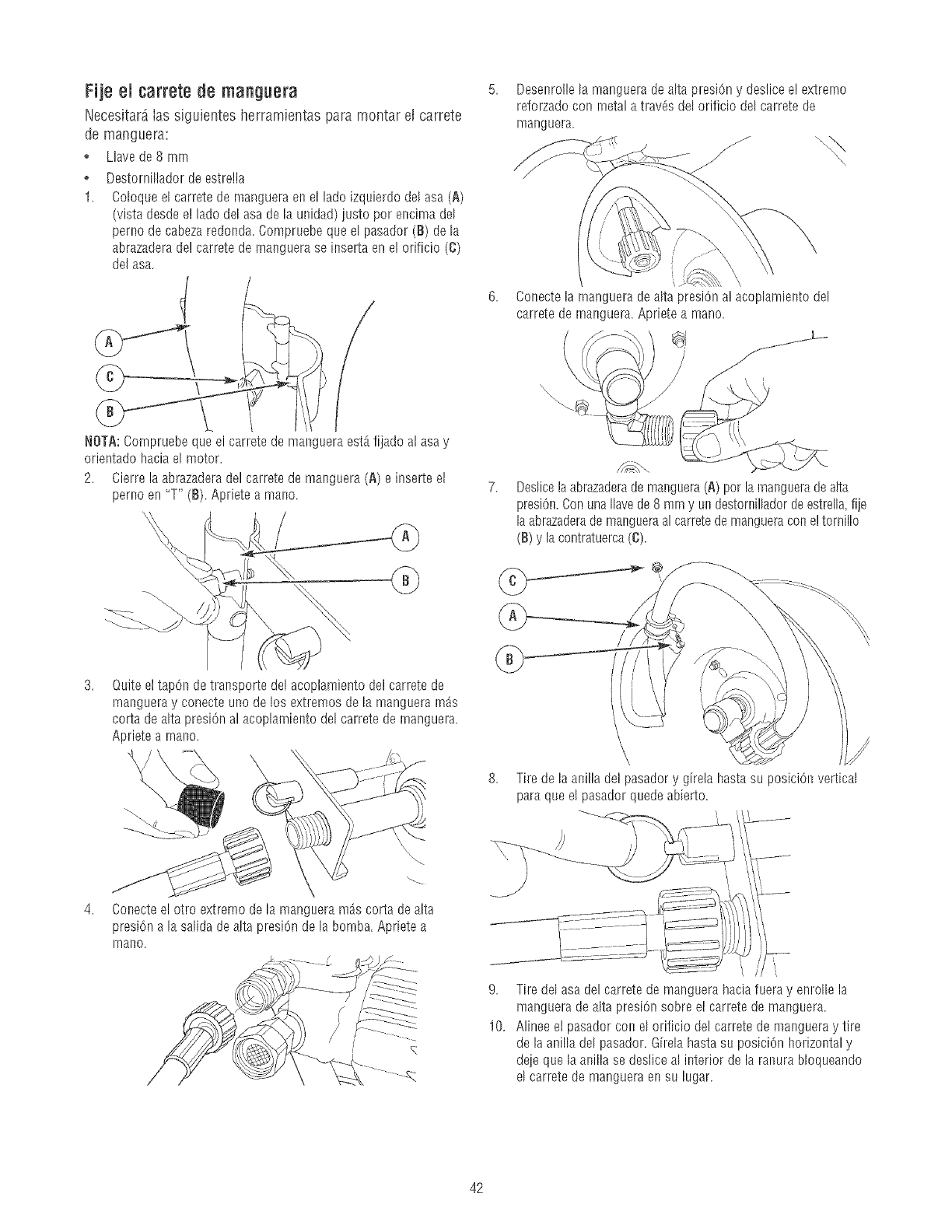
Fije el carrete de manguera
Necesitar_ ias sJguientes herramientas para montar eJcarrete
de manguera:
Llave de 8 rnrn
Destorni%dor de estrella
1. Coloqueel carrete de manguera en el lado izquJerdodel asa (A)
(vista desde e! lado del asa de la unidad) justo por encima del
perno de cabeza redonda.Compruebe que el pasador (B) de la
abrazaderade! carrete de rnanguera se inserta en el orificio (C)
del asa.
NOTA:Compruebe que el carrete de manguera est_fijado al asay
orientado hacia el motor,
2. Cierre la abrazaderadel carrete de manguera (A) e inserte el
perno en "T" (8). Apriete a mano.
Desenrolle la manguera de alta presiOny deslice e! extrerno
reforzado con metal a trav6s del orificio del carrete de
manguera.
ConectelarnangueradealtapresiOnalacoplamientodel
carretedernanguera.Aprietea mano.
\\\
Dedicela abrazaderade manguera(A) por la rnangueradealta
presi6n.Con una Ilavede 8 mm y un destorniiladorde estrella,fije
laabrazaderademangueraal carretede mangueracon e! tornillo
(B) y lacontratuerca(C).
Quite ettap6n de transporte del acoplamiento del carrete de
rnanguera y conecte uno de los extremos de la manguera m_s
corta de alta presi6n al acoplamiento del carrete de rnanguera.
Apriete a rnano,
Conecteel otro extremo de la manguera m_s corta de alta
presiOna la salida de alta presi6n de la bomba, Apriete a
inarlo.
9,
10.
Tire de la anilla del pasadory girela hasta su posiciOnvertical
para que el pasador quede abierto.
Tire del asa del carrete de manguera haciafuera y enrolle la
manguera dealta presiOnsobre el carrete de manguera,
AJineeel pasador con el orificio deJcarrete de mangueray tire
de la anilla del pasador. Girela hasta su posici6n horizontal y
deje que la anilla se deslice al interior de la ranura Uoqueando
el carrete de manguera en su lugar.
42
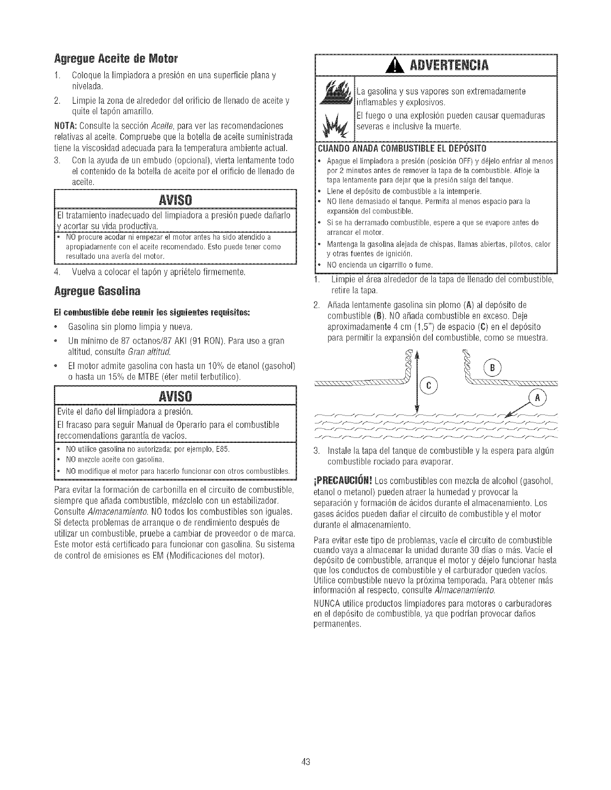
Agregue AceJte de Motor
1. Coloque la limpiadora a presiOnen una superficie plana y
nivelada.
2. Limpie la zona de ahededor del orificio de Ilenado deaceite y
quite el tap6n amari%.
NOTA:Consulte la secci6n Aceite, paraver las recomendaciones
relativas al aceite. CompFuebeque la botella de aceite suministrada
tiene la viscosidad adecuadapara la temperatura ambiente actual.
3. Con la ayuda de un embudo (opcional), vierta lentamente todo
el contenido de la botella de aceite poF el orificio de Ilenado de
aceite.
AVl$O
Eltratamiento inadecuado del lirnpiadora a presi6n puede daiiar!o
'acortar su vida productiva.
NOprocureacodarni empezarel motoranteshasidoatendidoa
apropiadamentecon elaceiterecomendado.Estopuedetenercomo
resultadounaaverfadel motor.
4. Vuelva a colocar el tap6n y apri_telo firmernente.
agregae GaseHaa
El ¢embustJbledebe reunJr lee sJ_luJentesrequisites:
. Gasolina sin plomo limpia y nueva.
. Un minirno de 87 octanos/87 AK! (91 RON). Para uso a gran
altitud, consulte Gran a/fitud.
o E! motor admite gasolina con hasta un 10% de etano! (gasohol)
o hasta un 15% de MTBE (ater metil terbutilico).
AVI$O
Eviteel da[io de! lirnpiadora a presiOn.
E! fracaso paraseguir Manual de Operario para el combustible
reccomendations garantia de vacios.
I'_10utilicegasolinano autorizada;por ejemplo,E85.
1/0mezcleaceitecon gasolina.
NOmodifiqueelmotor parahacerlofuncionarcon otroscombustibles.
Paraevitar la forrnaciOnde carbonilla en el circuito de combustible,
siempre que a_ada combustible, m_zclelo con un estabilizador.
Consulte Almacenamiento. r,lo todos los combustibles son iguales.
Si detecta problemas de arranque 0 de rendimiento despu_s de
utilizar un combustible, pruebe a cambiar de proveedor 0 de marca.
Este motor estAcertificado parafuncionar con gasolina. Su sistema
de control deemisiones es EM (Modificaciones del rnotor).
ADVERTENCJA
La gasolinay sus vapores son extFemadarnente
infiamables y explosivos.
_i_ l fuego o una explosi6n pueden causarquemaduras
severase inclusive la rnuerte.
CUANDO ANADA COI_IBUSTmBLEEL DEPOSITO
o Apagueellimpiadoraa presi6n(posici6nOFF)y d6jeloenfriaral r'nenos
por 2 minutosantesde removerlatapadela combustible.Afloje la
tapalentamenteparadejarquelapresi6nsalgadel tanque.
. Lleneeldep6sitodecombustiblea la intemperie.
o NOIlenedemasiadoeltanque.Permitaalmenosespacioparala
expansi6ndelcombustible.
o Sise haderramadocombustible,esperea queseevaporeantesde
arrancarel motor.
. Mantengala gasolinaalejadade chispas,llamasabiertas,pilotos,calor
y otrasfuentesdeignici6n.
. NOenciendaun cigarrilloo fume.
1. Lirnpie el area ahededor de la tapa de Ilenado del combustible,
retire la tapa.
2. A_adalentamente gaso%a sin plorno (g) al dep6sito de
combustible (B). 1/0 a_adacombustible en exceso. Deje
aproxJmadamente4 cm (1,5") de espacio (C) en el dep6sito
para perrnitir la expansi6n det combustible, corno se muestra.
3 Instale la tapa de!tanque de combustible y la espera para algtin
combustible rociado para evaporar.
iPRECAUCJ6N! Los combustibles con mezda dealcohol (gasohoL
etanol o metano!) pueden atraer la humedad y provocar la
separaci6ny formaciOn deAcidos durante el almacenamiento. Los
gases_cidos pueden daiiar el circuito de combustible y el motor
durante el almacenarniento.
Paraevitar estetipo de problemas vacie el circuito de combustible
cuando vayaa almacenar la unidad durante 30 dias o rnAs.Vacie el
dep6sito decombustible, arranque el motor y d_jelo funcionar hasta
que los conductos de combustible y e! carburador queden vacios.
Utilice combustible nuevo la pr6xima temporada. Paraobtener m_s
informaci6n a! respecto, consulte Almacenamiento.
r,IUNCA utilice productos limpiadores para motores o caFburadores
en e! dep6sito de combustible, ya que podrian provocar daiios
permanentes.
43
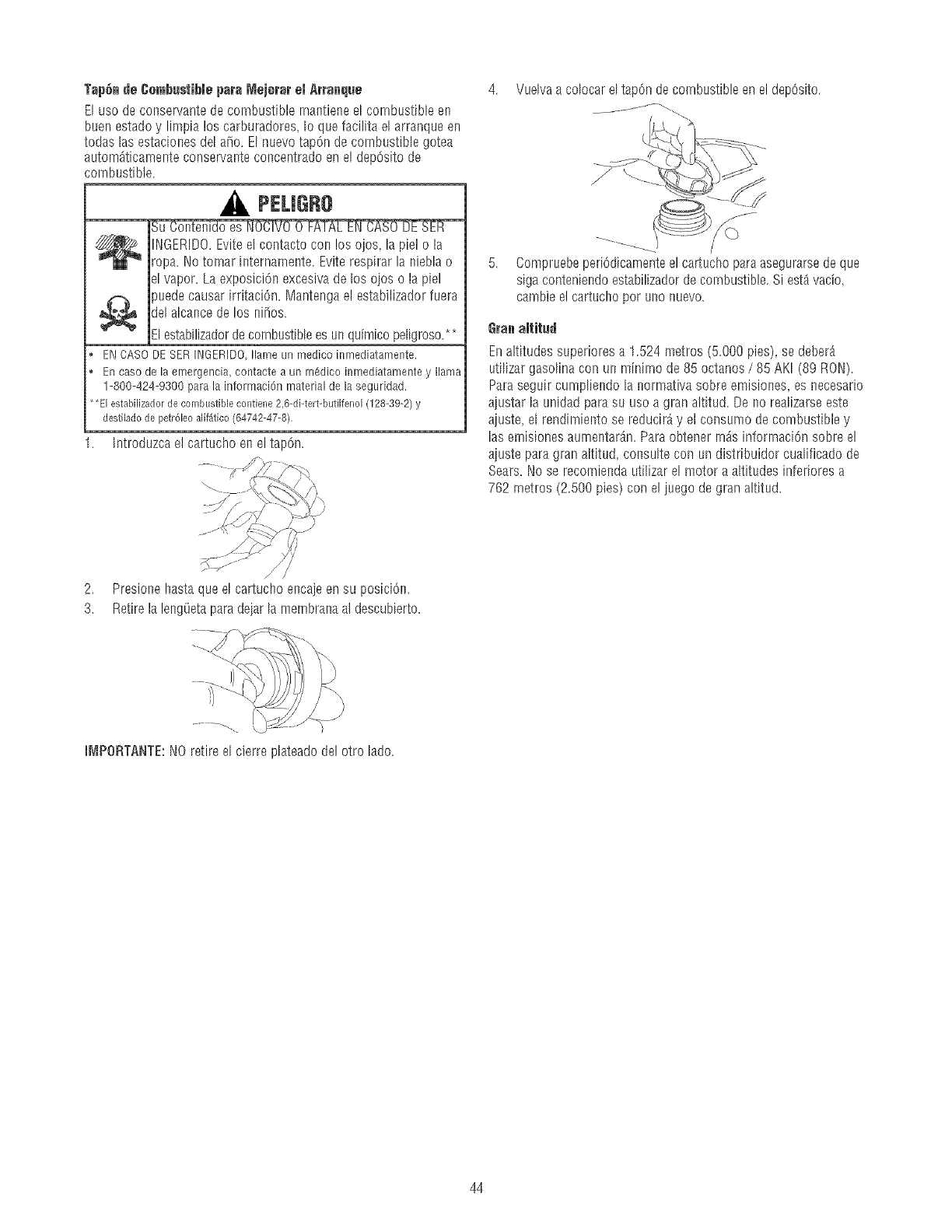
Tap6n de ¢ombustible para Mejorar el Arranque
El uso de conservante de combus%le mantiene el combustible en
buen estadoy limpia los carburadores_Io que facilita el arranque en
todas las estaciones del a_o. El nuevo tap6n de combustible gotea
autom_ticamente conservante concentrado en el depOsitode
cornbustible.
PELJGRO
,/////av//_ INGERDO. Eviteel contacto con los ojos, la pie! 0 la
ropa. No tomar internamente. Eviterespirar la nieUa 0
el vapor. La exposici6n excesivade los oios 0 la piel
puede causar irritaci6n. Mantenga el estabilizador fuera
del alcance de los ni_os.
Elestabilizadordecombustible es un quimico peligroso.**
ENCASODESERINGERiDOIlarneun medicoimnediatarnente.
Encasodelaernergencia,contactea un rnSdicoinrnediatarnentey llama
1-800-424-9300parala inforrnaci6nmaterialdelaseguridad.
*El estabilizador de combustible contiene 2,6-di-tert-butilfenol (128-39-2) y
destilado de petr61eo alif_tico (64742-47-8),
1. Introduzca el cartucho en el tapOn.
4. Vuelva a colocar eltap6n decombustible enel dep6sJto.
5. Compruebeperi6dicamente el cartucho para asegurarsede que
siga conteniendo estabilizador decombustible. SiestA vacio,
cambie e! cartucho pot uno nuevo.
Gran aliilud
Enaltitudes superiores a 1.524 metros (5.000 pies), se deber_
utilizar gaso%a con un minirno de 85 octanos /85 AKI (89 RON).
Paraseguir cumpliendo la normativa sobre emisiones_es necesario
aiustar la unidad para su uso a gran altitud. De no realizarseeste
aiuste_el rendirniento se reducir_y el consumo de combustible y
las emisiones aumentar_n. Para obtener rnds informaci6n sobre e!
aiuste para gran altitud, consulte con un distribuidor cualificado de
Sears.No se recomienda utilizar el motor a altitudes inferiores a
762 rnetros (2.500 pies) con e! juego de gran altitud.
2. Presionehastaqueel cartuchoencajeensu posici6n.
3. RetirelalengOetaparadeiarlamembranaal descubierto.
IMPGRTANTE:NOretireelcierreplateadode!otro lado.
44
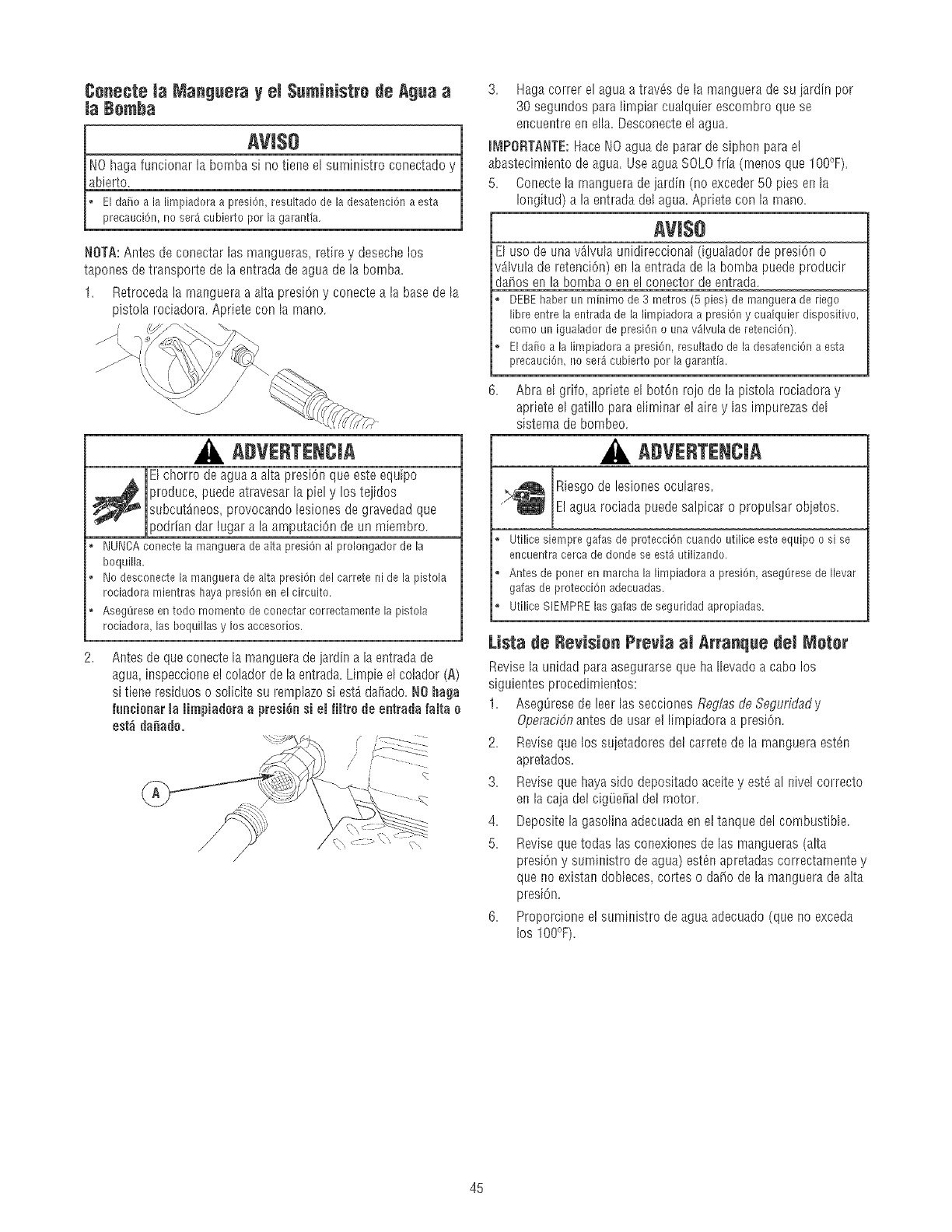
Conecte la Mangeera yeJ$eministre de Agea a
la Bomha
AVIS8
[ NO haga funcionar la bornba_e el suministro conectadoy
_bierto. __ _
I o Elda_oa lalimpiadoraa presi6n,resuitadodela desatenci6naesta
L precauei6n,noser_cubiertoperla garantia.
NOTA:Antes de conectar las mangueras, rethe y deseche los
tapones de transporte de la entrada de agua de la bornba.
1. Retroeeda la rnanguera a aIta presi6n y conectea la base de la
pistola rociadora. Apriete con la rnano.
/
, ADVERTENCiA
El chorro deagua a alta presi6n que este equipo
_ roduce, puede atravesar la piel y los tejidos
subcut_neos, provocando lesiones de gravedad que
podrian dar lugar a la amputaci6n de un miembro.
o NUNCAconectela mangueradealta presiOnal prolongadorde la
boquilla.
o Nodesconectelamanguerade altapresi6ndelcarretenidela pistola
rociadoramientrashayapresi6nenelcircuito.
o AsegOreseentodo mementodeconectarcorrectamentela pistola
rociadora,lasboquillasy losaccesorios.
Antes de que conecte[amanguerade jardin a la entrada de
agua inspeccione e! colador de la entrada.Limpie el colador (A)
si tiene residues o solicite su remplazosi est_dai_ado.NOhaga
fun¢ionar la Jimpiadoraapresi6nsi el fiJtre de entradafaJta o
est_ danado.
[_ :_2222:_22;
/
3. Hagacorrer elagua a trav6s de la manguera de su iardin per
30 segundos para limpiar cualquier escombro que se
encuentre en ella. Desconecteel agua.
mI_tPORTANTE:Hace NOagua de parar de siphon parael
abastecimiento de agua. Use agua SOLOfria (rnenos que 100°F).
5. Conecte la rnanguera de jardin (no exceder 50 pies en la
Iongitud) a la entrada del agua.Apriete con la rnano.
AVlSe
E[ uso de una%lvuIa unidireccional (igua[ador de presi6n o
%lvula de retenciOn)en la entrada de la bornbapuede producir
da_os en la bornba0 en e! conector de entrada.
DEBEhaberunminimode3 metros(5 pies)de mangueraderiego
libreentreiaentradadela limpiadoraa presi6ny cualquierdispositivo,
comeunigualadorde presi6no unav_lvuladeretenci6n).
Eldaiio a lalimpiadoraa presi6n resuitadodela desatenci6naesta
precauci6n,no ser_eubiertoper lagarant[a.
6. Abra el grifo, apriete el bot6n rojo de la pistola rociadora y
apriete el gatillo para dirninar el aire y las impurezas dd
sistema de bombeo.
A#VERTENCIA
Riesgo de lesiones oculares.
El agua rociada puede salpicar 0 propulsar objetos.
, Utilicesiempregafasdeprotecci6ncuandoutiliceesteequipoo si se
encuentracercadederideseest_utilizando.
o Antesdeponeren marchalalimpiadoraa presi6n,asegL_resedeIlevar
gafasdeprotecci6nadecuadas.
o UtiliceSlEMPRElasgalasdeseguridadapropiadas.
Lista de Revisien Previa al Arranque del Meter
Revise [a unidad para asegurarse que haIlevado a cabo los
siguientes procedirnientos:
1. AsegOresede leer las secciones Reglas de Seguridady
Operaci6nantes de usar el lirnpiadora a presi6n.
2. Revise que los suietadores del carrete de la manguera est_n
apretados.
3. Revise que haya side depositado aceitey est_ al nivel correcto
en la caja del cig(_efialdel rnotor.
4. Deposite la gasoIinaadecuadaen el tanque del combustible.
5. Revise quetodas las conexiones de las mangueras (alta
presiOny suministro de agua) est_n apretadas correctamente y
que no existan doNeces, cortes o damede la manguera de alta
pres[On.
6. Proporcione e! suministro de agua adecuado (que no exceda
los 100°F).
45
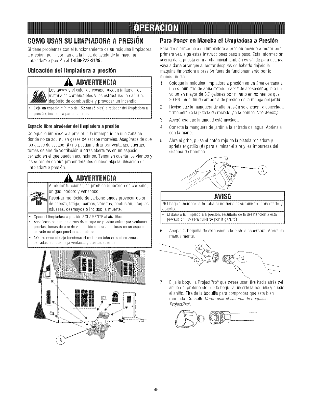
COMOUSARSU LJMPJADORAAPRESJ6N
Si tiene prob[emas con el funcionamiento de su mAqui_a lirnpiadora
a presiOn,por favor !lame a la Iflseade ayudade la rnAquina
Iimpiadora a presiOnal 1-888-222-3136.
Ubicaci6n dei limpiadera a presi6n
ADVERTENCIA
Los gases y e[ ca[or de escape puedeninflamar!os
rnatefia[es combustibles y las estructuras 0 da_ar el
depOsitodecombustible y provocar ur) incendio.
, Dejeunespaciominimode 152cm (5 pies)alrededordel limpiadoraa
presi6n,incluidala partesuperior.
Espacie libre alrededer del limpiadora a presi6n
Co]oque [a [impiadora a presiCma la intemperieen una zona en
donde no se acurnulen gases de escape mortales. Aseg_resede que
los gases de escape (A) no pueda!_entrar por ventanas, pueltas,
tornas de aire de ventilaciOnu otras aberturas en un espacio
cerrado en el que puedan acurnu[arse.Tenga en cuenta losvientos y
las corriente de aire preponderantes cuando elija la ubicaci(}n del
limpiadora a presi6n.
ADVERTENCIA
AI motor funcionar, se produce mon6xido de carbono,
un gas inodoro y venenoso.
Respirar rnon6x[do de carbono puede provocar dolor
de cabeza, fatiga, mareos, v6mitos, confusi6n, ataques,
n_useas, desmayos o incluso la muerte.
Opere el limpiadora a presi6n SOLAMENTEal aire libre.
o Aseg8rese de que los gases de escape no puedan entrar por ventanas,
puertas, tomas de aire de ventiiaci6n u otras aberturas en un espacio
cerrado en el que puedarl acumuiarse,
o NO arranque ni deje funcionar el motor en interiores ni en zonas
cerradas, aunque hayaventanas y puertas abiertas.
Para Pener en _larcha el Limpiadera aPresi_n
Paradar[e arranque a su limpiadora a presiOnmovido a motor por
primera vez siga estas instrucciones paso a paso. Esta informaciOn
acerca de [a puestaen rnarcha inicial tambi6n es %]ida para cuando
vaya a dade arranque al rnotor despu6s de haberlo dejado [a
rn_quina lirnpiadora a presi6n fuera de funcionarniento por Io
rner_osun dia.
1. Coloque la rn_quina limpiadora a presi6n en un area cercana a
ur)asuministro de agua exterior capaz de abasteceragua a un
volumen mayor de 3.7 ga!ones por minuto en no menos que
20 PSI er_el fin de arandelade presiOnde la manga de! jardin.
2. Reviseque la malsguerade a[ta presiOnse encuentre conectada
firmemente a la pistola de rociado y a la bomba. Vea Montaje.
3. AsegOreseque la unidad est6 nivelada.
4. Conecte la rnanguera de jardin a la entrada del agua. Apfieteta
COr) la mar)o,
5. Abra el grifo, pulse el botOn rojo de [apistola rociadora y
apriete e[ gatillo (A) para eliminar el aire y las impurezasdel
sistema de bombeo.
6,
manualmente.
Acople la boquflla de extensi6n a la pistola aspersora. Apri_tela
E[iia la boqui[[a ProiectPro" que desee usar, tire hacia atrdsde[
anillo del prolongador de la boqui[[a, inserte la boquil[a y suelte
el ani[[o. Tire de la boquil[a para comprobar que estA bien
montada. Consulte CSmo usar d sistema de boquillas
ProjectPm.
46
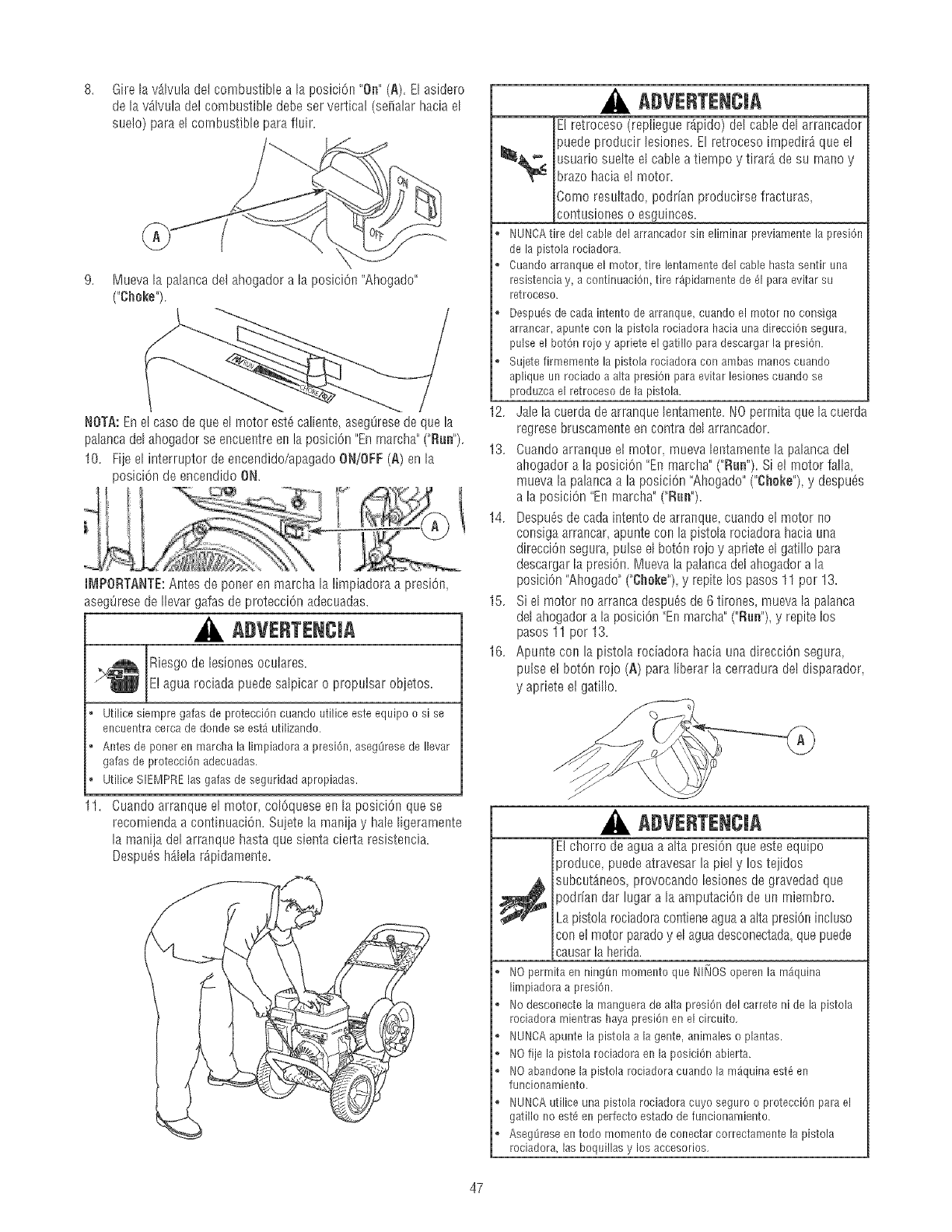
8. GirelavAIvuladelcombustiblealaposiciCn"On"(A).Elasidern
delavAIvLfladelcombustibledebeservertical(sefialarhaciael
sueto)paraelcombustibleparafluir.
9. MuevalapalaecadotahogadnralapnsiciOn"Ahngado"
("Choke").
NOTA:En el caso de que el motor est6 caliente,asegOresede que la
paiancadel ahogador se eneuentreBe la posici6n "Enrnarcha" ("Roe").
10. Fije el interruptor de encendido/apagado ON/OFF(A) en la
posiciOnde encendido ON.
IMPORTANTE: Antes de porter en marcha la limpiadora a presi0n,
aseg0rese de Ilevar galas de protecciOn adecuadas.
ADVERTENCIA
Riesgo de lesiones oculares.
E! agua rodada puedesalpicaro propulsarobjetos.
o Utilice siempre gafae de protecciCn cuando utilice este equipo osi se
encuentra cerca de donde se est_ utilizando.
o Antes de porter en marcha la limpiadora a presiCn,aeeg(_resede Ilevar
gafae de protecciCn adecuadas.
o Utilice SIEMPRElas galas de seguridad apropiadae.
11. Cuando arranque el ranter, colCquese en la pnsiciCn que se
recornienda a cnntinuaciOn. Sujetela maniiay hale ligeramente
la manija del arranque hasta que sienta cierta resisteecia.
Despu_s hAlela r_pidamente.
ADVERTENCiA
El retrocesn (repliegue rApido) del cable del arrancador
puede producir lesiones. El retrocesn irnpedir_ que el
usuario suelte el cable a tiernpn y tirar_ de su rnano y
brazn hacia el mntnr.
Comoresultado,pndrianproducirsefracturas_
contusiones n esguinces.
, NUNCAtire del cable del arrancador sin eliminar previamente la presiOn
de la pistola rociadora.
, Cuando arranque el motor, tire lentamente del cable hastasentir una
resistencia y, a continuaciOn, tire r_pidamente de _1para evitar su
retroceso.
o DespuSsde cada intento de arranque, cuando el motor no consiga
arrancar, apunte con la pistola rociadora hacia una direcciOn segura,
pulse el botch rojo y apriete el gatillo para descargar la presiOn.
o Sujete firmemente la pistola rociadora con ambas manos cuando
aplique un rociado a alta presiOn para evitar lesiones cuando se
produzca el retroceso de la pistola.
12. Jalelacuerdadearranquelentamente.NOpermitaquelacuerda
regresebruscamenteencontradelarrancador.
13. Cuandoarranqueel motor_muevaleetamentela palancadel
ahogadora la posiciCn"Eemarcha"("Rue").Siel rnotorfalla_
muevalapalaecaa laposiciOn"Ahogado"("Choke"),y despu_s
ala posiciOn"Enmarcha"("Rue").
14. Despu_sdecadaintentndearranque_cuandoelmotorno
consigaarrancarapunteconlapistnlarociadnrahaciauna
direcciOnsegura,pulseelbotchrojoy aprieteelgatillnpara
descargar la presiOn. Mueva la palanca del ahngador a la
posiciCn"Ahogado"("Choke")yrepitelos pasos 11 por 13.
15. Si el motor no arranca despu_sde 6 tirones,mueva la palanca
del ahogadora la posiciOn"En marcha" ("Rue"),y repiteIns
pasos 11 per 13.
16. Apunte con la pistola rociadnra hacia una direcciOn segnra,
pulseel bntCn rojn(A) para liberar la cerradura dot disparador,
y apriete el gatilln.
ADVERTENCiA
El chorrn de agua a alta presiCn que este equipo
produce puedeatravesar la piel y los tejidos
_ ubcutAneos, provncando lesiones de gravedad que
)odriandar lugar a la amputaciCe de un miembro.
Lapistola rnciadoracnntieneaguaa alta presiCnincluso
coo e! motor parado y el agua desconectada_quepuede
causarla herida.
NOpermitaenning_nmomentoqueNINOSoperenlarn_quina
limpiadoraa presiOn.
o Nodesconectelamanguerade altapresiCndelcarreteni de la pistola
rociadoramientrashayapresiCnen elcircuito.
o NUNCAapuntela pistolaa lagente,animaleso plantas.
NOfije lapistolarociadoraenlaposiciCnabierta.
o NOabandonelapistolarociadoracuandolam_quinaest6en
funcionamiento.
o NUNCAutiliceunapistolarociadoracuyoseguroo protecciOnparael
gatillonoest6enperfectoestadodefuncionamiento.
o Aseg8reseentodo momentodeconectarcorrectamentela pistola
rociadora,lasboquillasy los accesorios.
47
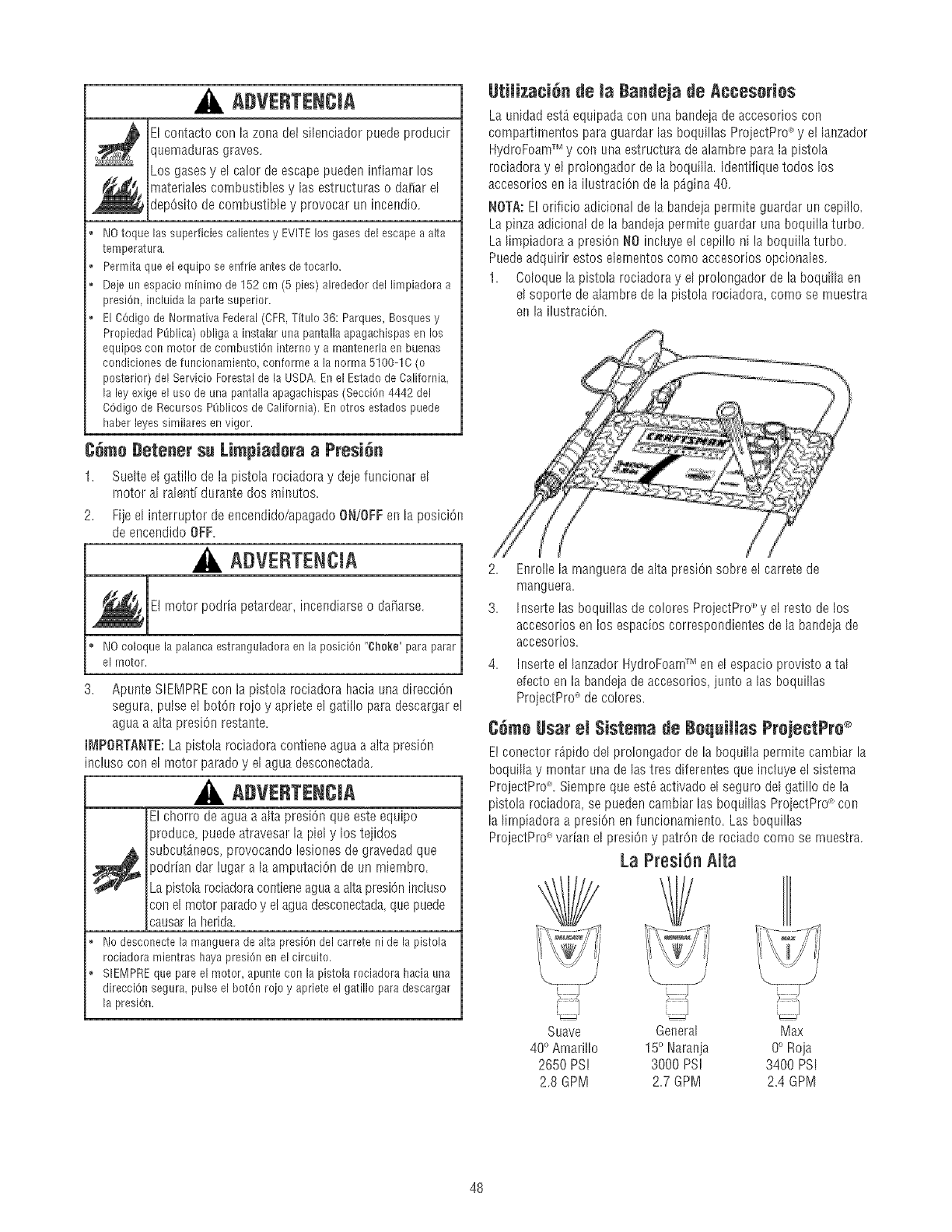
ADVERTENCJA
EIcontacto con la zona del silenciador puede producir
quemaduras graves.
Los gasesy el calor de escape puedeninfiamar los
materialescombustibles y las estructuras 0 daiiar el
depOsitode combustible y provocar un incendio.
o NOtoquelassuperficiescalientesy EVITElosgasesdelescapea alta
temperatura.
o Permitaqueel equipose enfrfeantesdetocarlo.
, Dejeunespaciominimode 152cm (5 pies)alrededordel limpiadoraa
presiOn,incluidala partesuperior.
, ElCOdigode NormativaFederal(CFR,Titulo36: Parques,Bosquesy
PropiedadP_blica)obligaa instalaruuapantallaapagachispasenlos
equiposconmotorde combustioninterney a mantenerlaenbuenas
condicionesdefuncionamiento,conformea la norma5100-1C(o
posterior)del ServicioForestaldela USDA.Enel EstadodeCalifornia.
la leyexigeel usedeunapantallaapagachispas(SecciOn4442del
COdigode RecursosP[iblicosdeCalifornia).Enotros estadospuede
haberleyessimilaresenvigor.
C_me Detener su Limpiadera aPresi_n
1. SuelteelgatillodelapistoIarociadoray dejefuncionarel
rnotoral ralentidura_stedos minutos,
Fijeel interruptordeencendido/apagadoON/OFFenla posiciOn
deencendidoOFF.
ADVEBTENCiA
E! rnotor podria petardear, incmsdiarseo da[iarse.
NOcoloquela palancaestranguladoraenlaposiciOn"ghoke"paraparar
el motor.
3. Apunte SIEMPREcon la pistola rociadora hacia una direcci6n
segura pulse el botOn roio y apriete el gatillo para descargar e!
aguaa alta presiOnrestante.
IMPORTANTE:La pistola rociadora contiene agLlaa alta presiOn
incluso con el motor paradoy el agua desconectada.
ADVERTENCJA
El chorro deagua a aIta presi6n que este equipo
produce puedeatravesar la piel y los tejidos
subcut_r_eos,provocando lesiolsesde gravedad que
podrian dar lugar a la amputaciOnde un rniernbro.
Lapistota rociadoracor_tieneaguaa alta presiOnincluso
cotsel motor paradoy el aguadesconectada,que puede
causarla Iserida.
o Nodesconectelamanguerade altapresiOndelcarretenidela pistola
rociadoramientrashayapresiOnenelcircuito.
o SIEMPREquepareel motor,apunteconla pistolarociadorahaciauna
direcciOnsegura,pulseel botOnroley aprieteel gatilloparadescargar
la presiOn.
UtiliTaciOn de Ja Bandeja de Acceseries
La unidad est_ equipadacon una bandejade accesorios con
compartimentos para guardar las boquillas ProiectPro_ y el lanzador
HydroFoamTM y con Lmaestructura de alambre para la pistola
rociadora y el prolongador de la boqui% Identifique todos los
accesorios en la ilustraciOn de la p_gi_sa40.
NOTA:EI orificio adicional de la balsdejaperrnite guardar un cepillo.
La pinzaadicional de la bandeja perrnite guardar una boqLdllaturbo.
La limpiadora a presiOnNO incIuye el cepillo ni la boqLdllaturbo.
Puedeadquirir estos elernelstoscorno accesorios opcionales.
1. Coloque la pistola rociadora y el prolongador de la boquiIIa en
el soporte deaIambre de la pistola rociadora_como se rnuestra
e_sla ilustraci6n.
2. E_srollela manguera de alta presi6n sobre el carrete de
marlguera.
3. Inserte las boquillas de co!ores ProjectPro _'y el resto de los
accesorios en los espacios correspondientes de la bandeja de
accesorios.
4. Inserte el lalszadorHydroFoamTM en el espacio provisto a tal
efectoen la bandeia de accesorios, jmsto alas boquillas
ProjectPro" de colores.
COmeUsar el $istema de Boquiilas PrejectPre ®
E! conector r_pido del prolongador de la boquilla permite cambiar la
boquiIIa y rnontar una de las tres diferentes que incluye e] sistema
ProjectPro_. Siernpreque esta activado el seguro del gatillo de la
pistola rociadora, se pueden cambiar las boquiIIas ProjectPrd con
la lirnpiadora a presi6n enfuncionarnier_to.Las boquillas
ProjectPro_ var%s el presiOny patron de rociado corno se rnuestra.
La Presi6n Alta
Suave General Max
400Amarillo 150 rlarania 0° Roja
2650 PS! 3000 PS! 3400 PSI
2.8 GPM 2.7 GPM 2.4 GPM
48
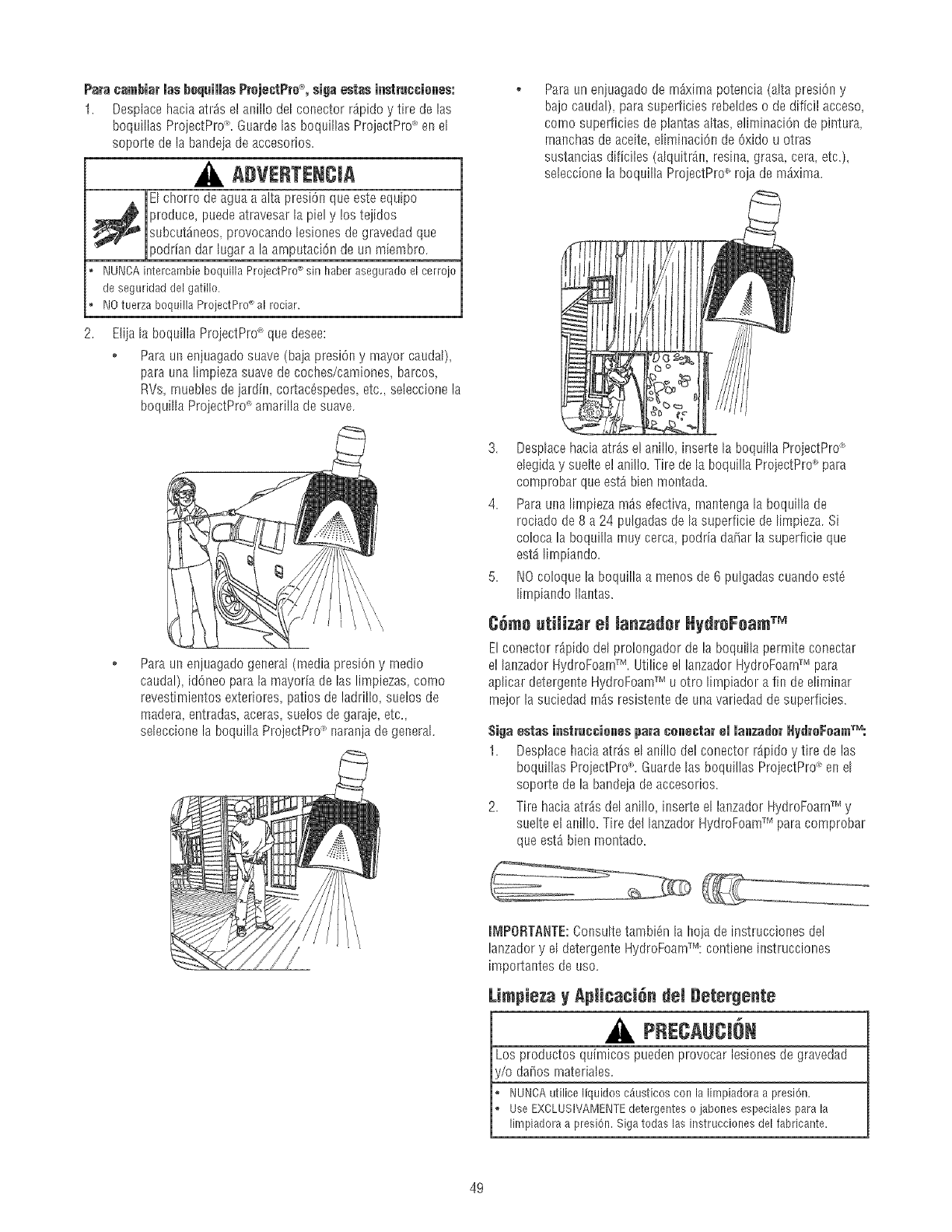
Paracambiarlasb+quiiiasPr+jectPro+_,sivaestasinstru¢¢iones:
1. Desptacehaciaatr_sel anillodelconectorr_pidoy tire delas
boquillasProjectPro_'.Guardelas boquillasProjectPro_'enel
soportede labandeiadeaccesorios.
ADVERTENCiA
El chorro deagua a alta presiOnque este equipo
,_ produce, puedeatravesar la piel y !os tejidos
subcut_neos, provocando lesiones de gravedad que
podrian dar lugar a la amputaci6n de un miembro.
, NUNCAintercambieboquillaProjectPro+'sin haberaseguradoel cerrojo
deseguridaddelgatillo.
* NOtuerzaboquillaProjectPro_'al rociar.
Eliiala boquillaProjectPrd_quedesee:
+ Paraunenjuagadosuave(bajapresiOny mayorcaudal),
paraunalimpiezasuavedecoches/camiones,barcos,
RVs,rnueblesdejardin,cortac_spedes,etc..se]eccionela
boqufllaProiectPro"amarflladesuave.
Para un enjuagado general (media presi6n y medio
caudal) id6neo para la mayoria de las limpiezas, como
revestimientos exteriores, patios de ladrillo, suelos de
madera entradas aceras, suetos de garaie etc,
seleccione la boquilla ProjectPro+'rlaranja de general.
Paraun enjuagado de rn_xirnapotencia (alta presiOny
bajo caudal), para superficies rebeldes o de dificil acceso,
como superficies de plantas aItas eliminaci6n de pintura,
mar_chasde aceite, eliminaciOnde 6xido u otras
sustanciasdificiles (aIquitr_n, resina grasa, cera, etc.),
se]eccionela boquilla ProjectPro<+_roja de maxima.
3. DespIacehaciaatrAselanillo,insertelaboquiIlaProiectPrd+_
eIegiday suelteelaniflo.Tiredela boquillaProiectPro<+_para
comprobarqueest_bienmontada.
4. Paraunalimpiezam_sefectivamantengalaboquiIIade
rociadode8 a 24 pulgadasdelasuperficiedelimpieza.Si
colocala boquillarnuycerca,podriada[iarlasuperficieque
est_lirnpiando.
5. NOco]oquelaboquillaa menosde6 pulgadascuandoest6
lirnpiandoIlantas.
C_me utiii_,ar eJ lanzader HydreFeam TM
El conector r_pido del pro!ongador de la boquiIIa permite conectar
e! lanzador HydroFoamTM. Utilice el lanzador HydroFoaWmpara
apIicar detergente HydroFoamTM u otro lirnpiador a fin dediminar
rnejor la suciedad rn_s resistente de unavariedad de superficies.
Siva estas instre¢¢ienespara cenectar el lanzader l_ydr+FeamrM:
1. Desptacehacia atr_s el ani]lo del conector r_.pidoy tire de las
boquillas ProjectPro_+_.Guarde las boquillas ProjectPro_'en el
soporte de la bandejade accesorios.
2. Tire haciaatr_s del anillo, inserte el lanzador HydroFoamTM y
suelte el alsi!lo. Tire del lanzador HydroFoamTM para comprobar
que est_ bien montado.
mMPORTANTE:Consulte tambi6n la hoja de instrucciones del
lanzador y el detergente HydroFoarnT_":contiene instrucciones
importantes de uso.
Limpieza y Apiicaci_n dei Detergente
A, PRECAUCI6m
Los productos quim[cos pueden provocar les[ones de gravedad
i/o da_os rnateriales.
NUNCAutiliceliquidosc_iusticosconla limpiadoraa presi6n.
UseEXCLUSIVAMENTEdetergenteso jabonesespecialesparala
limpiadoraa presiOn.Sigatodaslas instruccionesdelfabricante.
49
Para apJJcareJdeter_ente, siva J+ssi_uientes pas+s:
1. Repase el uso de la boquHla ProjectPro<'y de] lanzador
HydroFoarnTM.
2. Prepare el detergente HydroFoamTM conforme a las
instrucciones en la botella.
3. Coloqueel pequefio extrerno final del filtro del tubo de
inyecci6n de! detergente dentro de! contenedor del detergente.
NOTA:AsegOresede que et filtro est6totalmente surnergido
mientras se aplica el detergente.
AVISO
El contacto con e[ silenciador a a[ta temperatura puede producir
dafios en el tubo de inyecciOnde detergente.
Cuandocoloqueel filtro enlabotelladeldetergente,coloqueeltubo de
maneraquenoentreencontactoaccidentalmenteconelsilenciador
caliente.
4. AsegOresedeque e! lanzador HydroFoamTM estA[nstalado.
NOTA: NOse puede apIicar detergente con las boquillas dealta
presiOn(Arnarilla, Naranjay Roja).
5. AsegOresedeque la mangueradel jardin estAconectadaa la
entrada de agua.Cornpruebe que la rnanguera de alta presiOn
estAconectadaa la pistola rociadora y a la bomba. Abra la
alimentaci6n de agua.
AriSe
Usted deberb_conectar todas las manguerasantes de darle
arranque a! motor.
Arrancarel motorsintenertodaslas manguerasconectadasy sin el
suministrode aguaABIERTO(ON)causar_eldaflode la bomba.
Eldafioa lalimpiadoraa presi6n,resultadodela desatenci6naesta
precauciOn,noser_cubiertoporla garantia.
6. Marcha el rnotor siguiendo las instrucciones de la secci6n
Cdmo poner en fundonamiento Is firnpiadora a presi6n.
7. ApIique HydroFoamTM detergente a una superficie seca.
Empiece por la parte inferior y suba haciendo rnovirnientos
largos, uniformes y repetitivos.
NOTA: Paraevitar la formaciOn de mamas de gotas de agua en
vehicu!os, trabaje en una zona de sombra y deje enfriar las
superficies antes de ernpezar.
8. Deje que el HydroFoamTM detergente empape la superficie
durante 3-5 minutos antes de lavar y acIarar.VueIva a aplicar
la SOILIciOrlcuando sea necesario para evitar que [a superficie
se seque. Evite que e! HydroFoamTM detergente se seque
(impide la formaci6n de vetas).
Para un mejor resultado, friegue la superficie recubierta con
HydroFoamTM detergente para eIiminar mAsfAcilmente la suciedad y
las rnanchasmAs resistentes. Para [irnpiarvehiculos, utilice un
cepillo o una manopla suave para coches. Para limpiar terrazas,
revestimientos exteriores y hormigOn, utilice un cepillo adecuado
para la cada superficie.
Enjuage de la M_quina Limpia_JeraaPresi_n
[lespu_s de imber aplicado el deter_ente, refrie_Jue la superficie
yenjuageia de la si_luientemanera:
1. Quite el lanzador HydroFoamTM del pro[ongador de [aboquilla.
2. Seleccionee instale la boquilla de aita presiOndeseada
conforme alas instrucciones de la secciOnC6mo Usar et
Sistema de Boquillas ProjectPro _.
3. Mantenga la pistola de rociado a una distancia segura del area
que planea rociar.
ADVERTENCIA
El retroceso de la pistola rociadora puede provocar
caidas.
, Utilicelalimpiadoraa presi6ndesdeunasuperficieestable.
o Extremelasprecaucionessi necesitautilizarlalimpiadoraapresi6n
desdeunaescalera,un andamiou otro lugarsimilar.
o Sujetefirmementela pistolarociadoraconambasmanoscuando
apliqueun rociadoaaltapresiOnparaevitarlesionescuandose
produzcael retrocesodela pistola.
4. Apliqueunrociadodealtapresi6na unapequefiazonay Ioego
compruebesi sehaproducidoalgOntipo dedafio.Sino
apreciadaiios,continOeene!paso5.
5. Comienceenla partesuperiordelareaqueva a eniuagar,
dirigi6ndosehaciaabajocon los rnismosmovirnientos
superpuestosqueutiliz6parala lirnpieza.
Limpieza del tube de inyecci_n de detergente
Si usted us6 el tubo, usted debelavado con agua lirnpia antes de
parar el rnotor.
1. Co[oque el filtro y la inyecciOndetergente en un balde Ileno de
agualimpia.
2. Quite [a boqu[% de alta presiOndel pro!ongador de la boquiIIa.
3. Sdeccionee instaIela boquiItanegra (detergente)siguiendolas
instruccionesdela secciOnCdmoUsar /as BoquillasProjgctPrd-_.
Lave de 1 a 2 rninutos.4,
5. Pareel motor sigLfiendolas instruccionesde la secciOnCdmo
detenerla limpiadora a presi6ny cierre la alirnentaci6nde agua.
6. Apunte SIEMPREcon la pistola rociadora hacia una direcci6n
segura, pulse e! boron rojo y apriete el gatillo para descargar el
aguaa alta presiOn restante.
m[vIPORTANTE:La pistola rociadora contiene agua a alta presi6n
incluso con el rnotor parado y el agua deeconectada.
ADVERTE CiA
El chorro de aguaa a[ta pres[Onque este equipo
produce puedeatravesar la piel y los tejidos
_ ubcutAneos, provocando lesiones de gravedad que
)odrian dar lugar a la amputaciOnde un rniembro.
Lapistola rociadoracontieneaguaa aIta presi6nincluso
con e! motor parado y el agua desconectada,quepuede
causarla herida.
No desconecte la manguera de alta presi6n del carrete ni de la pistola
rociadora mientras haya presi6n en el circuito.
o SIEMPRE que pare el motor, apunte con la pistola rociadora hacia una
direcci6n segura, pulse el botOn rojo y apriete el gatillo para descargar
la presiOn.
Sistema de Enfriamiente A_temdtice
{Alivie T rmice)
E]agua que circuIa dentro de la bomba puede alcanzartemperaturas
entre los !25°-155°F s[ hacefuncionar el motor de su mAquina
limpiadora a presiOnde 3 a 5 minutos sin oprimir el gatiIIo de [a
pistola de rociado. E[ sistema deenfriamiento automAtico se activa a
estatemperatura y enfria la bomba descargando agua caliente en el
piso, evitando asi el daiio [nterno de la bomba.
5O
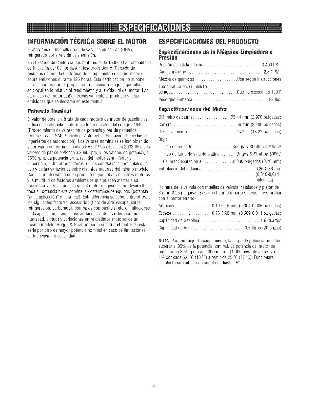
JNFORMACI6NTECNmCA$OBREELMOTOR
El motor es de uno cilindros, devA[vulasen cabeza(OHV),
refrigerado por aire y de baja emisiOn.
Enel Estadode California, los motores de la 150000 ban obtenido la
certificaciOndel California Air Resources Board (Conseio de
recursos de aire de California) de cumpIimiento de la normativa
sobre emisiones durante 125 horas. Esta certificaciOnno supone
para el comprador, el propietario o e! LIsuarioninguna garantia
adicional en !o relativo a] rendimiento y a la vida t_til del motor. Las
garantias de! motor ata_en exclusivamente al producto y a las
emisiones que se declaran en este manual.
Petencia Neminal
El valor de potencia bruta de cada mode[o de rnotor de gasolina se
indica enla etiqueta conforme a los requisitos del cOdigoJ1940
(Procedimiento de vaIoraciOnde potencia y par de pequeiios
motores) de la SAE (Society of Automotive Engineers, Sociedad de
ingenieros de automociOn). Los valores norninales se han obtenido
y corregido conforme al cOdigoSAEJ!995 (RevisiOn2002-B5). Los
valores de par se obtienen a 3060 rpm, y los va!ores de potencia, a
3600 rpm. La potencia bruta real de[ motor serAinferior y
dependerA,entre otros factores, de las condiciones ambientales de
uso y de [as variaciones entre distintos rnotores del mismo mode[o.
Dada la amplia variedad de productos que utilizan nuestros motores
y la multitud de factores arnbientales que pueden afectar a su
funcionamiento, es posibIe que e[ motor de gasolina no desarrolle
toda su potencia bruta nominal en determinados equipos (potencia
"en la aplicaciOn"o neta real). Estadiferencia se debe, entre otros, a
los siguientes factores: accesorios (filtro de aire, escape,carga,
refr[geraciOn,carburador, bomba de combustible etc.), I[mitaciones
de la aplicaciOn, condiciones ambientales de uso (temperatura,
humedad, altitud) y variaciones entre distintos motores de un
mismo modelo. Briggs & Stratton podrA sustituir e! rnotor de esta
serie por otro de mayor potencia nomina! en caso de limitaciones
de fabricaci6n o capacidad.
ESPECJFJCACJONE$DELPRODUCTO
Especificacienes de _aM_quina Limpiadora a
Presi6n
PresiOndesalida m_xima 3,400 PS]
Caudal rn_x[rno .................................. 2.8 GPM
Mezclade quimicos .................. UsesegOninstrucciones
Temperatura del surninistro
deagua ............................ Queno excedalos IO0°F
Peso que Embarca ................................. 93 Ibs.
Especificacienes del Meter
DiAmetro de camisa ................ 75.44 mrn (2,970 pulgadas)
Carrera ............................ 56 mrn (2,200 pulgadas)
Desplazamiento ...................... 249 cc (15,22 pulgadas)
Buiia
Tipo de reOstato:................. Briggs & Stratton 491055S
Tipo de larga de vida de platino: ....... Briggs & Stratton 5066D
Cal[brar SeparaciOna: ............. 0.030 pulgadas (0.76 mm)
EntreMerrodel inducido: ....................... 0,25-0,36 rnm
(0,010-0,014
pulgadas)
Holgura de la vAIvulacon muelles devAIvula instalados y piston de
6 mm (0,25 pulgadas) pasado el punto rnuerto superior (cornprobar
con el rnotor en fdo)
Admis[On ............... 0,10-0,15 rnm (O,O04-O,OO6pulgadas)
Escape ................. 0,23-0,28 rnrn (0,009-0,011 pulgadas)
Capacidad de Gasolina .......................... 1.6 Cuartos
Capacidad deAceite ...................... 0.6 litros (20 onzas)
NOTA:Paraunrneiorfuncionamiento,lacargadepotencianodebe
superarel85%de lapotencianominal.Lapotenciadelmotorse
reducir_un3,5% porcada300metros(1.BOOpies)dealtitudy un
1%pot cada56 °C(10°F)a partirde25°C(77°C).FuncionarA
satisfactoriamenteenunAngulodehasta15°.
51
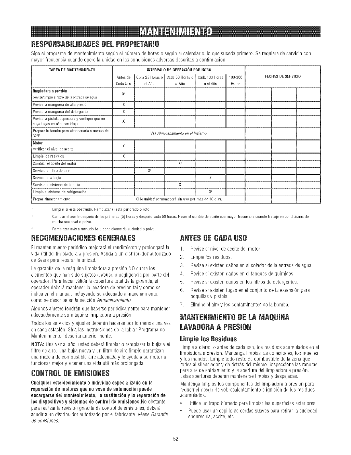
RESPONSABJLJDADE$#EL PRSPJETARJO
Sigael programade mantenimientoseg@el ROmerode horaso seg8nelcalendario,[oquesucedapr[mero.Serequ[eredeserviciocon
mayorfrecuenciacuandooperelams[dadenlascondicionesadversasdescritasa continuaciOn.
TAREA DE MANTENIMUENTO
Ihnpiadera a preei6n
Revisdlimpie el fiitro de la entradade agua
Revise la manguera de aita presi6n
Revise la manguera del detergente
Revise la pistoia aspersora y verifique que no
haya fugas en el ensamNaie
Prepare la bomba parr almacenaria a meres de
Antes de
Cada Uso
X
X
X
INTERVALO DEOPERAOUONPOR HORA
Cada 25 Horas o Cada 50 Horas o Cada100 Horas
al A_o al A_o o al Ai_o
Yea Almacenamiento en el Inviemo,
100-300Horas
FEOHAS DESERVUCIO
32°F
WJoter
Verificar el nivel de aceite
Limpie los residuos
Cambiar el aeeite del motor
Servicio al filtro de aire
Servicio a la buj[a
Servicio al sistema de la buj[a
Limpie el sistema de refrigeraci6n
Prepar almacenamiento
×
×
×2
X
×
X_
Si la unidad permanecer_ sin uso por m4s de 30 dire,
Limpiar si est_ obstmido, Remplazar si est_ perforado o roto,
Cambiar el aceite despu_s de las primeras (5) horas y despues erda 50 horas, Hacer el eambio de aceite con mayor frecuencia cuando trabaje en condiciones de
mucha suciedad o polvo,
Remplazar m_s a menudo bajo condiciones de suciedad o polvo,
RECSNEN#ACIONE$GENERALE$ ANTES#E CA#A [J$0
E[ maRtenimiento peri6dico meiorard e[ rend[rniento y prolongar_ la
vida 8til del I[rnp[adora a pres[On.Acuda a un distribuidor autodzado
de Sears para repararla unidad.
La garantia de la m_quina [impiadoraa presiOnNOcubre los
elementos que hart sido suietos a abuso o neg[[geRciapor parte dd
operador. Para hacervA[idala cobertura total de la garantia el
operador deberd rnantener la lavadora de presiOnta[ y como se
indica ene[ manual, incluyendo su adecuadoa[macenamiento,
corno se describe en la secci6n Almacenambnto.
A[gunos aiustes tendr_n que hacerse periOd[camentepara rnantener
adecuadamentesu rn_quina I[rnp[adoraa presi6n.
Todos los servicios y ajustes deberdn hacerse por Io menos unavez
en cada estaciOn.Siga las instrucciones de la taNa "Programa de
Mantenimiento" descdta aRteriormente.
NOTA: Unavez al aiio, usted deberA limpiar o remplazar la bujiay el
%ro de aire. Una buiia nuevay un %ro de aire I[rnpio garantizan
una mezcta decombustiNe-aire adecuaday le ayuda a su motor a
funcionar meior y a tener unavida Otilmds prolongada.
CSNTRSLBE EMI$1ONE$
CuaJquJerestabJechnJefltoo JfldJvJduoespecJaHzadoeft Ja
repara¢i6n de motores que Resear de automo¢i6n puede
encargarse dei mantenimiento, la sastitu¢i6n y la reparaci6n de
Josdispositivus ysistemas de ¢oatreJde emisienes.No obstante,
para realizarla revision gratuita de control deemisiones, deberA
acudir a un distribuidor autorizado por el fabricante. V6ase Garantia
deemisiones.
1. Reviseel nivel de aceite del motor.
2. Lirnpie los residuos.
3. Revises[ existen da_os en el colador de la entrada de agua.
4. Revises[ existen da_os en el tanques de quirnicos.
5. Revises[ existen da_os en los filtros de detergeRtes.
6. Revisesi existen fugas eRel conjunto de la extensi(_nparr
boquillas y pistola.
7. Bimine el aire y los contaminantes de la bomb&
MANTENIMIENT8 BE LA MAQUJNA
LAVA#SRAAPRE$tSN
Limpie tos Residues
Limp[e a diario, o antes decada uso los res[duos acurnu[ados en el
limpiadora a presi0n. Mantenga limp[as las conexiones, los muelles
ylos mandos. Limpie todo resto de combustible de la zona que
rodea al silenciador y de detr_s del rnismo. [nspeccionelas ranuras
paraaire de enfriamiento y [aapertura dei limpiadora a presi6n.
Estasaperturasdeber_n rnantenerselimp[as y despeiadas.
Nantenga [impioslos cornponentes de] [[mpiadoraa pres[Onpara
reducir el riesgo de sobrecalentam[ento e igniciOn de los residuos
acurnulados.
• Utilice un trapo h[_medopara Ihnp[ar las superficies exter[ores.
o Puede usar un cepillo de cerdas suaves para retirar la suciedad
endurecida,aceite, etc.
52
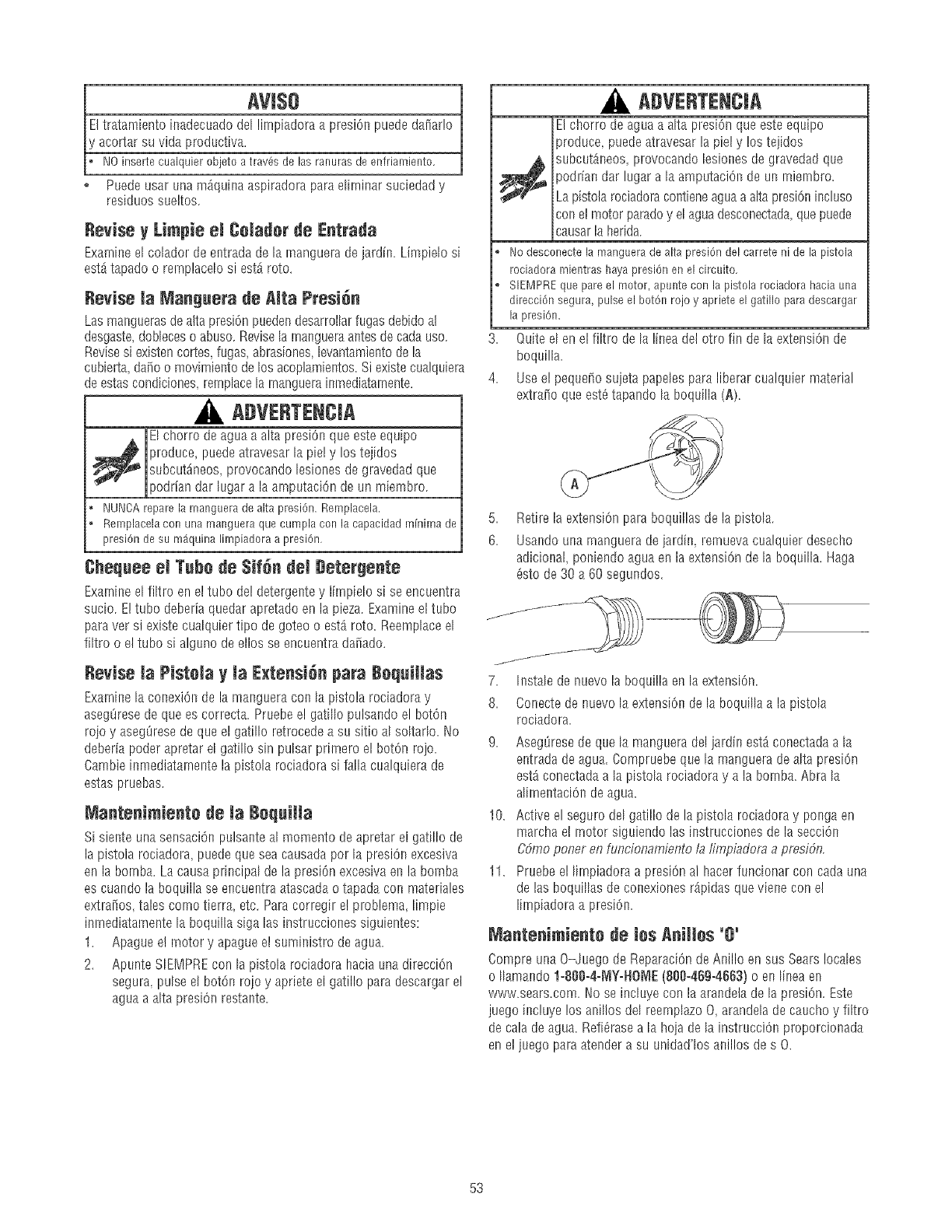
AVI$O
Eltratamiento inadecuado del lirnpiadoraa presi6n puede dafiar!o
'acortar su vida productiva.
NOinsertecualquierobjetoa tray,s de lasranurasdeenfriamiento.
Puede usar una mAquina aspiradora para elirninar suciedad y
residuos sueltos.
Revise y LimpieemCeladerde Entrada
Examineel colador de entrada de la rnanguerade jardn. Limpielo si
est_ tapado o rernplacelo si est_ roto.
Revise Manguera de alta Presi6n
Las mar_guerasdealta presi6n puedendesarrollar fugas debido ai
desgaste,dobIeceso abuso. Revisela rnangueraantes de cadauso.
Revisesi existen cortes,fugas, abrasiones,levantamientode la
cubierta da_o o movimielstode los acoplamier_tos.Si existe cualquiera
de estascondiciones,remplace la rnanguerainrnediatarnente.
ADVERTENCJA
El chorro deagua a alta presiOnque este equipo
produce, puedeatravesar la pie! y los tejidos
subcut_neos provocando lesiones de gravedad que
podfian dar klgar a la arnputaci6n de un miembro.
, I',JUI',JOAreparela manguerade altapresi6n.Remplaeela.
o Remplacelaconunamangueraquecumplaconlacapacidadminimade
presi6ndesu m_quinalimpiadoraa presi6n.
Chequeeel TubedeSirendel Detergente
Examineel fiItro en el tubo de! deterger_tey limpielo si se encuentra
sucio. E!tubo deberia quedar apretado en la pieza. Examineel tubo
para ver si existe cualquier %o de goteo o est_ roto. Reemplaceel
filtro o el tubo si alguno de ellos se encuentra da_ado.
Revise _a Pistela y la ExtensiOnpa_ RequiHas
Examinela conexiOnde la manguera con la pistola rociadora y
asegOresedeque es correcta. Pruebe e! gatiIIo pulsalsdoel bot6n
rojo y asegOresede que el gati% retrocede a su sitio al soItarlo. No
deberia poder apretar el ga%o sin pulsar primero el bot6n rojo.
Cambie inmediatarnente la pistola rociadora si falla cualquiera de
estas pruebas.
aantenimiente de la RequiHa
Si siente una sensaci6n pulsante a[ momento deapretar el gati% de
la pistola rociadora puede que sea causadapot [a presiOnexcesiva
en la bomba. La causa prhscipa[de la presi6n excesivaels la bomba
es cuando la boquilla se encuentra atascadao tapada con materiales
extraiios tales corno tierra, etc. Para corregh e! problema limpie
inrnediatarnentela boquilla siga las instrucciones siguientes:
1. Apague e! motor y apague el sumi_sistrode agua.
2. Apunte SIEMPREcon la pistoIa rociadora hacia una direcciOn
segura pulse el bot61sroio y apriete el gatillo para descargar el
aguaa alta presiOnrestante.
3,
4.
ADVERTENCJA
El chorro de agua a alta presi6n que este equipo
produce puedeatravesar la piel y los tejidos
1_ subcut_lseos,provocando lesiones de gravedad que
)odria!_dar lugar a la amputaciOnde un rniernbro.
Lapistola rociadoracontieneaguaa aIta presi6nincluso
con e! motor parado y el agua desconectada,quepuede
causarla herida.
o Nodesconectelamanguerade altapresi6ndelcarreteni dela pistola
rociadoramientrashayapresi6nenelcircuito.
o SIEMPREquepareel motor,apunteconla pistolarociadorahaciauna
direcci6nsegura,pulseel bot6nrojoy aprieteel gatilloparadescargar
la presiOn.
Quite el en el filtro dela linea det otro fin de la extension de
boquilla.
Useel pequdio sujeta papeIes para liberar cualquier material
extraiio que est_ tapando la boquilla (A).
5,
6.
Retirela extensionparaboquillasdela pistola.
Usalsdounarnangueradejardin, remuevacualquierdesecho
adicional,porfiendoaguaenlaextensionde laboquilla.Haga
6stode30a 60segundos.
7. Instale de nuevo la boquilla en la extensi6n.
8. Conecte de nuevo la extension de la boquilla a la pistola
rociadora.
9. Aseg8rese de que la manguera del jardin estAconectada a la
e_stradade agua. Compruebe que la manguera de alta presi6n
est,. conectadaa la pistola rociadora y a la bomba. Abra la
alirnentaci6n de agua.
10. Active el seguro del gatillo de la pistola rociadora y ponga en
marcha el motor siguiendo las instrucciones de la secciOn
C6mo poner en funcionamiento la Iimpiadora a presidn.
11. Pruebe el limpiadora a presi6n al hacerfuncionar con cada una
de las boquiIIas de conexiones rApidas queviene con el
lirnpiadora a presiOn.
aantenimiente de ies AniHes'e'
Compre una O-Juego de Reparac[6ndeAIsillo en sus Sears !ocales
o Ilama_sdoI=SOB-4-_Y=HO_IE(8eB=469-4663)o en linea en
www.sears.com. 1/ose incluye con la arandela de la presiOn. Este
juego incluye los anillos del reemplazoO, arandeIa de caucho y filtro
de cala de agua. Refiarasea la hoia de la instrucciOn proporcionada
en e! juego para atender a su unidad'los a_sillosde s O.
53
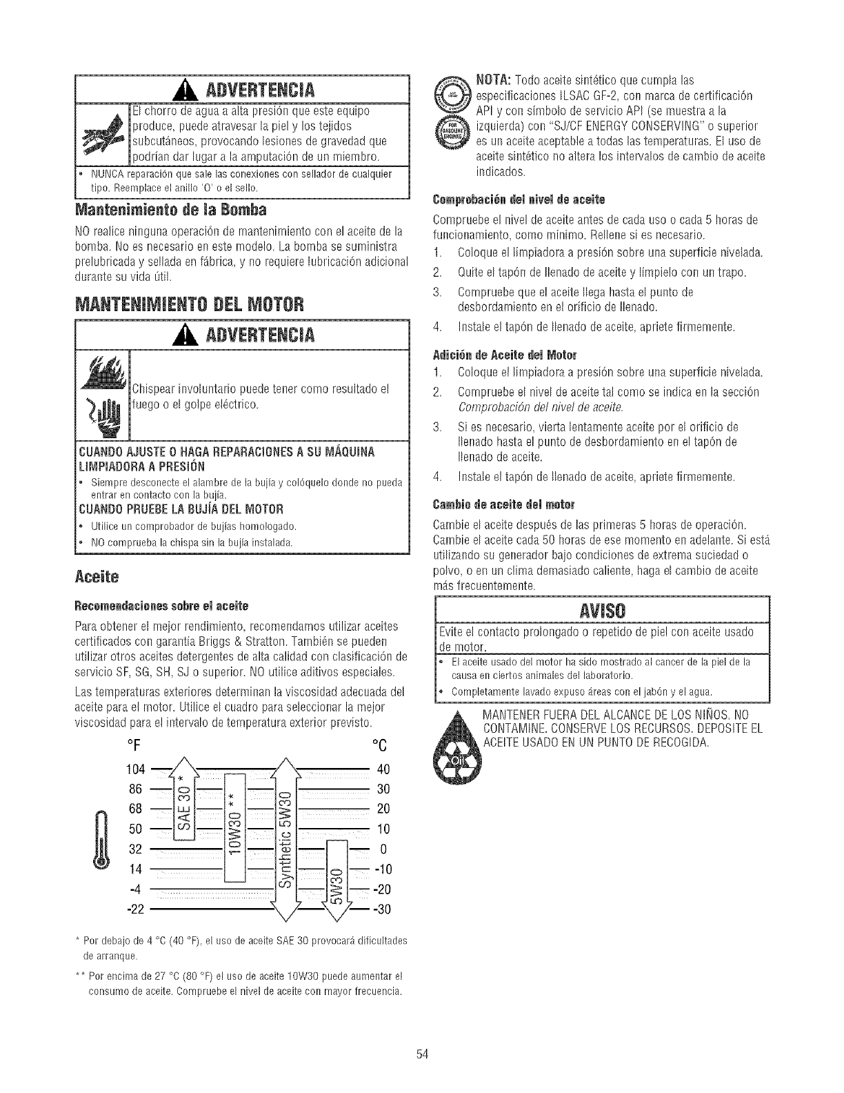
ADVERTENCIA
El chorro deagua a alta presi6n que este equipo
_ roduce, puedeatravesar la piel y los tejidossubcut_neos, provocando lesiones de gravedad que
podrian dar lugar ala arnputaci6n de un miembro.
NUNCAreparaci6nquesalelasconexionescon selladordecualquier
tipo. Reemplaceel anillo'0' o elsello.
Mantenimiento de la Bemha
NO realice n[nguna operaci6n de rnanten[miento con el aceite de la
bomba. No es necesario en este rnodelo. La bornba se suministra
prelubricada y sdIada en f_brica, y no requiere lubricaci6n adicional
durante su vida _til.
i ANTENINitENTO #EL i OTOR
ADVERTENCiA
Ch[spear [nvduntarb puedetener como resultado el
¢ fuego o el golpe el6ctrico.
CUANDOAJUSTE0 HAGAREPARACtONESA SU MAQUINA
LI_'IPmADORAA PRESli_N
, Siempredesconecteelalambredela bujiay col6quelodon@no pueda
entrarencontactoconiabujia.
CUANDOPRUEBELA BUJiA DEL MOTOR
Utiliceun comprobadordebujiashomologado.
o NOcompruebalachispasin labujiainstalada.
Aedte
l_ecemendacienes sd_re el eceile
Pareobtener e[ meior rendimiento recomendamos utilizar aceites
certificados con garantia Briggs & Stratton. Tambi_n se pueden
utilizer otros aceites detergentes de aita calidad con clasificaciOnde
servicio SF, SG, SH, SJ o superior. NO utilice aditivos especiales.
Las temperaturas exteriores determinan laviscosidad adecuadadd
aceite para el rnotor. Utilice el cuadro paresebccionar la mejor
viscosidad para el [ntervalo de temperatura exterior previsto.
OF °C
104___ _ %_ 40
86 _ _| 30
>o1__20
068 51-- o
32 __ _m -- 0
14 _l--_-]_-10
-4 f_ L_ _ L---20
* Perdebajo de 4 °C (40 °F), el use de aceite SAE30 provocar_ dificultades
de arranque,
** Per encima do 27 °C (80 °F) el uso de aceite 10W30 puede aumentar el
consumo do aceite, Compruebe el nivel de aceite con mayor frecuencia.
NOTA:Todo aceite sint6tico que curnAlas
especificaeiones ILSACGF-2,con rnarca de certificaci6n
API y con simbdo de servicio API (se muestra ala
izquierda) con "SJ/CF ENERGYCONSERVING"o sLiperior
es un aceiteaceptable a todas las temperaturas. EI uso de
aceite sint_tico no altera los intervalos de camb{o de aceite
indicados.
Cemprd_ad_n del nieel de eceile
Compruebe el nivel de aceite antes de cada uso o cada 5 horas de
funcionamiento, como minirno. Rdbne s[ es necesario.
1. Cdoque el Bnpiadora a presi6n sobre una superficie n[vdada.
2. Quite el tap@ de Ilenadode aceite y limpielo con un trapo.
3. Compruebe que e! aceite IIega haste el punto de
desbordamiento en el orificio de Ilenado.
4. Instab el tap@ de Ibnado de aceite, apriete firmemente.
Adi¢i6m_de ._cdie dd lVider
1. Cdoque el I[mpiadora a presi6n sobre una superficie n[vdada.
2. Compruebe el nivel de aceite tel como se indica en la secci6n
Comprobacidn de/nivel de aceite.
3. Si es necesario,vierta bntamente aceite por el orificio de
Ibnado hasta e! punto de desbordamiento en el tap@ de
Ibnado deaceite.
4. Instab el tap@ de Ibnado de aceite, apriete firmemente.
Cembiede aceile del ruder
Cambie el aceite despu_s de las primeras 5 horas de operaciOn.
Cambie el aceite cada 50 horas de ese momento en adelante. Si estA
utilizando su generador bajo condiciones de extrema suciedad o
poIvo, o en un clime dernasiadocaliente, haga el cambio de aceite
rnAsfrecuentemente.
AVlS8
Eviteel contacto prdongado o repetido de pie!con aceite usa@
de motor.
Elaceiteusadodel motor hasido mostradoal cancerde lapielde la
causaen ciertosanimaiesdel laboratorio.
Completamentelava@expuso£eas coneljab@y el ague.
MANTENERFUERADELALCANCEDELOSNli_fOS.NO
CONTAMINE.CONSERVELOSRECURSOS.DEPOSITEEL
ACEITEUSADOENUN PUNTODERECOGDA.
54
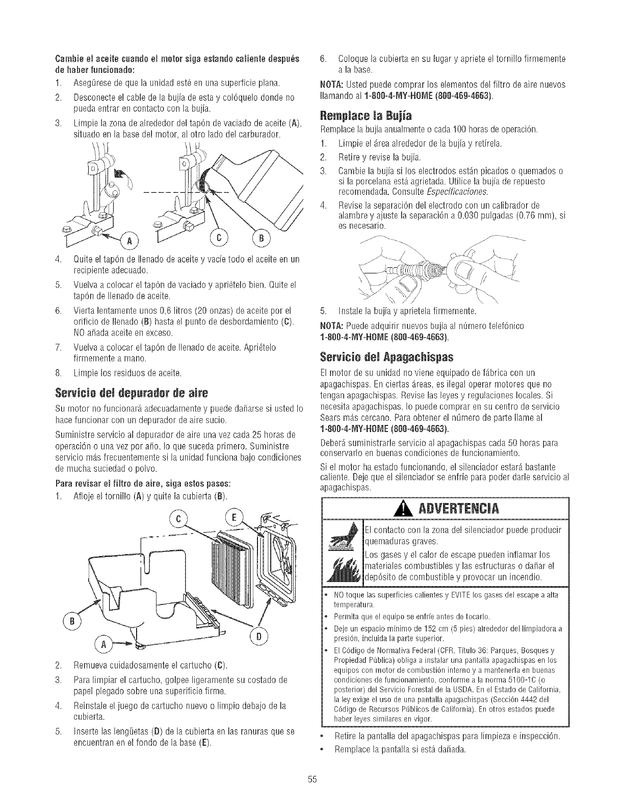
Cambieemaceitecuandoemmotorsiga estandocaHeetedespu_e
deheberfue¢ieeedo:
1. Asegtiresedequela ueidadest6enunasuperficieplane.
2. Desconectee!cabledela buiiadeestay colgque!oderideno
puedaentrarencontactocon la buiia.
3. Limpielazoeadealrededordeltapgndevaciadodeaceite(A),
situadoenlabasede!motor,alotro ladede!carburador.
4. Quite et tapOn de Iler_adode aceitey vacie todo e! aceite en un
recipiente adecuado.
5. Vuelva a colocar el tapOnde vaciado y aprigtelo bien. Quite el
tapOnde Ileeado de aceite.
6. Vierta lentamente unos 06 litros (20 onzas) de aceite per el
orificio de !lenado (B) haste el punto de desbordamieeto (C).
1t0 ariada aceite ee exceso.
7. Vuelva a colocar e! tapOnde Ilenado deaceite. Apri_telo
firrnernente a mane.
8. Limpie los residues de aceite.
Servicie del depurader de aire
Su motor no funcionar_ adecuadamentey puede da#arsesi usted Io
hace funcionar con un depurador de aire sucio.
Suministre servicio al depurador de aire una vez cada 25 bores de
operacign o una vez per ago, !o que suceda prirnero. Suministre
servicio mAsfrecuentemeete si la unidad funciona bajo condiciones
de touche suciedad o polvo.
Pare reviser el fHtre de aire, siga estes pesos:
1. Afloje el toreillo (A) y quite la cubierta (B).
2. Rernuevacuidadosarnenteelcartucho(C).
3. Parelirnpiarel cartucho golpeeligerarnentesu costadode
papelplegadosobreueasuperificiefirrne.
4. Reinstaleeliuegodeca!tuchonuevoo limpiodebaiodela
cubierta.
5. Insertelas lengiJetas(D) delacubiertaenlas ranurasquese
encuentranenelrondodela base(E).
6. Coloque la cubierta en su lugary apriete el toreillo firmernente
ala base.
NOTA:Usted puede comprar los elementos de! filtro de aire nuevos
Ilamandoal I=seg=4=_IY=HO_IE(8eg=46g=4663).
Rempiace la Bujga
Remplacela bujiaanualrneeteo cada 100 horasde operacign.
1. Limpie el area alrededor de la buiia y retirela.
2. Retire y revise la bujia.
3. Cambie la buiia si los electrodes est_n picados o quemados o
sila porcelanaest_ agrietada. Utilice la bujia de repuesto
recornendada.Coesulte Especificaciones.
4. Revise la separaciOndel electrode con un calibrador de
alambrey ajuste la separacige a 0.030 pulgadas (0.76 rnm), si
es r!ecesario.
}
'\
5. k_stalelabujiay aprietelafirmemeete.
NOTA:Puedeadquirirnuevosbujiaal nSmerotelefgnico
l=80g=4=[vIY=HOME(sgg=469=4663).
Servicie dei Apagachispas
El motor desu unidad no viene equipado de f_brica con un
apagachispas. En ciertas _reas_es ilegal operar motores que no
tengan apagachispas. Revise las leyes y regulacioees locales. Si
necesitaapagachispas_Io puede comprar ee su centre de servicio
Searsm_s cercano. Pare obteeer el nSrnerode parte Ilame al
l=80g=4=MY=HOME(OgO=469=4663).
Deber_sumieistrarle servicio al apagacbispas cada 50 horas pare
conservado en buenascoediciones de funcioeamiento.
Si el motor ha estado fuecionando, e! silenciador estar_ bastaete
caliente. Dejeque el sileeciador se enfrie para poder darle servicio al
apagachispas.
ADVERTENCJA
s_ E! contacto con la zone del sileeciador puede producir
quernaduras graves.
Los gasesy el calor de escape pueden inflamar los
_ ateriales combustibles y las estructuras o dafiar el
depOsitode combustible y provocar un iecendJo.
®
®
®
®
NOtoque las superficies calientes y EVITElos gases del escape a alta
temperatura,
Permita que el equipo se enfr[e antes de tocarlo.
Deje un espacio m[nimo de 152 cm (5 pies) alrededor del limpiadora a
presign, incluida la parte superior.
El COdigode Normative Federal (CFR,TittJlo 36: Parques, Bosquesy
Propiedad PL3blica)obliga a instalar una pantalla apagachiepas en los
equipos con motor de combustign interne y a mantenerla en buenas
condiciones de funcionamiento, conforme ala norma 5100-16 (o
posterior) del Servicio Forestalde la USDA. En el Estado de California,
la leyexige el use de una pantalla apagachispas (Seccign 4442 del
Cgdigo de Recursos R_blicos de California), En otros estados puede
haber leyes similares en vigor.
,, Retire la pantalla de!apagachispas pare lirnpiezae iespeccige.
° Rernplacela paetalla siestA da#ada.
55
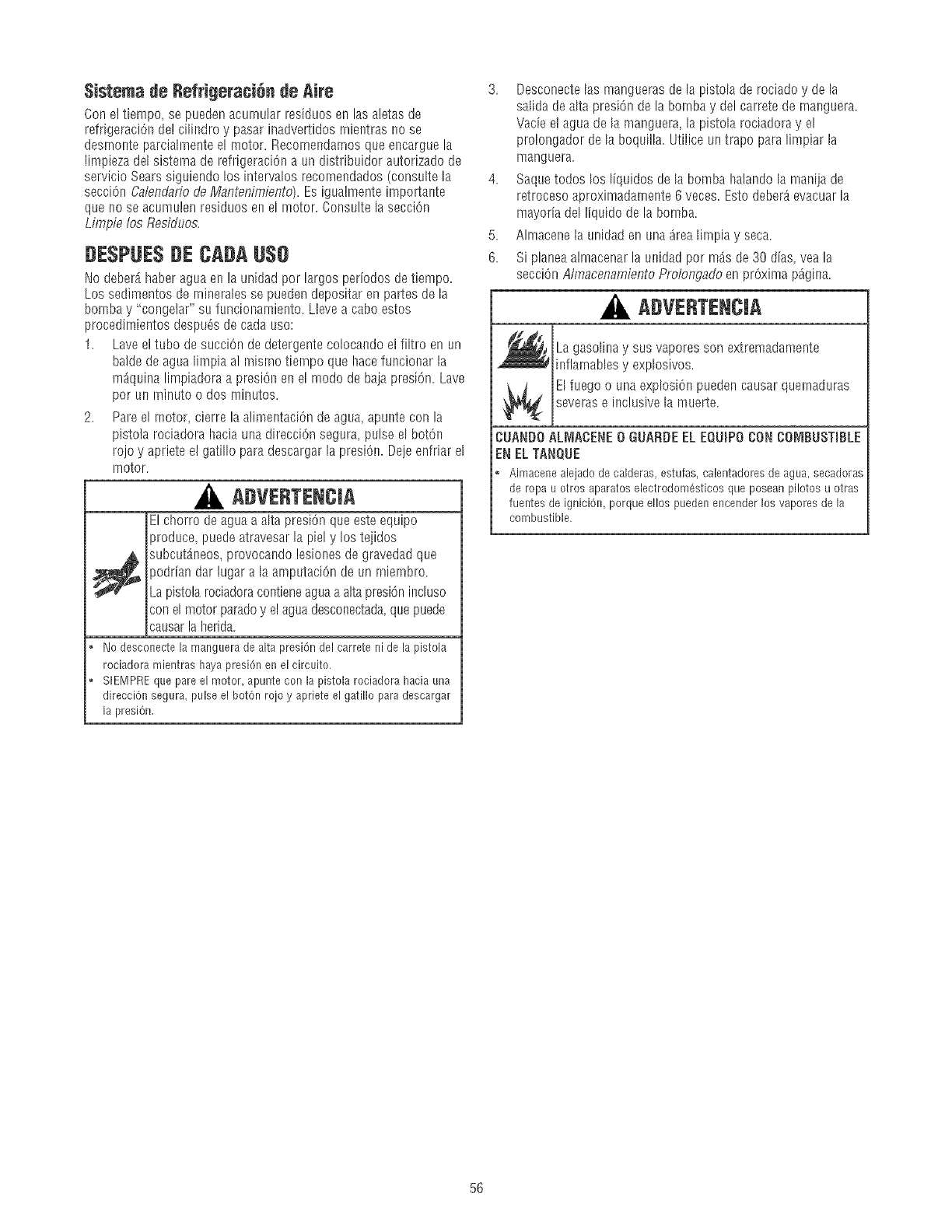
$istema de RefrJgeraci_n de AJre
Con e! %mpo, se pueden acurnu[ar res[duos en las aletas de
refrigeraci6n de! ciIindro y pasar inadvertidos rnientras no se
desmonte parciaIrnenteel motor. Recomendamos que er_carguela
limpieza del sistema de refrigeraci6n a un distribuidor autorizado de
servicio Sears siguiendo los intervaIos recornendados (consuIte la
secci6n Calendano de Mantenimiento). Es igualmente importante
que no se acumulen residuos en el motor. Consulte la secciOn
Limpie los Residuos.
DESPUE$DECADAU$0
No deberAhaber agua er_la un[dad por largosperiodos de tiempo.
Los sedimentos de rnineraIes se pueden depositar en partes de la
bomba y "congelar" su funcionamiento. L]eve a cabo estos
procedimientos despu6s decada uso:
1. Lave el tubo de succiOnde detergente colocando el filtro en un
baide de agua limpia al misrno tiernpo que hacefuncionar la
rn_quina limpiadora a presiOnen el modo de baja presi6n. Lave
por un rninuto o dos minutos.
2. Pare el motor, cierre la alimentaci6n de agua, apunte con la
pistola rociadora hacia una direcci6n segura, pulse el bot6n
rojo y apriete el gati% para descargar la presiOn.Deje enfrlar el
rnotor.
ADVENTENCIA
El chorro deagua a a[ta presi6n que este equipo
produce puedeatravesar la piel y los teiidos
_ ubcutAneos, provocando lesiones de gravedad que
podrian dar lugar a la amputaci6n de un rniembro.
Lapistola rociadoracontieneaguaa alta presi6ninduso
con el motor paradoy el aguadesconec,tada, que puede
causarla herida.
Nodesconectelamanguerade altapresi6ndelcarretenidela pistola
rociadoramientrashayapresi6nenelcircuito.
, SIEMPREquepareel motor,apunteconla pistolarociadorahaciauna
direcciOnsegura,pulseel botOnrojoy aprieteel gatilloparadescargar
la presi6n.
3. Desconecte[as manguerasde la pisto[a de rociado y de la
saIida de alta presi6n de la bornbay del carrete de manguera.
Vacie e! agua de la manguera la pistola rociadora y el
proIongador de la boquilla. Utilice untrapo para limpiar la
manguera.
4. Saquetodos los liquidos de la bomba ha]andola manija de
retroceso aproximadamente 6 veces. Esto deber_ evacuar la
mayofia del liquido de la bomba.
5. Almacene la unidad en una arealimpia y seca.
6. Si pIaneaalmacenar la unidad pot m_s de 30 dias, vea la
secciOnAlmacenambnto Prolondado en pr6xJmap_g[na.
ADVERTENCIA
La gasolinay sus vapores son extremadamente
lnflamablesy exp[osivos.
El fuego o una explosi6n pueden causar quemaduras
severase inclusive la muerte.
CUANDOALMACENE0 GUARDEELEQUmPOCON CO|_IBUSTmBLE
EN ELTANQUE
, Aimaceneaiejadode calderas,estufas,calentadoresdeagua,secadoras
deropau otrosaparatoselectrodom_stieosqueposeanpilotesu otras
fuentesde igniei6n,porqueellos puedenencenderlosvaporesdela
combustible.
56
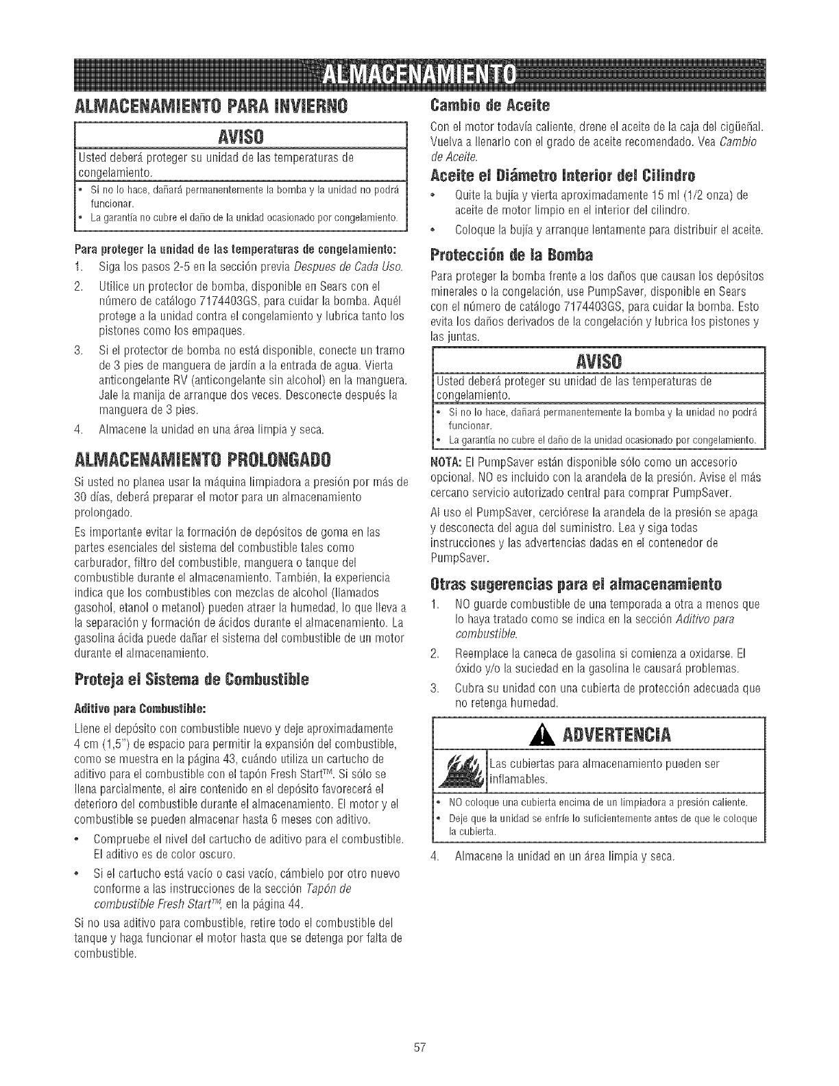
ALMACENAMJENTOPARAJNVJERNO
AVI$O
Usted deberb_proteger su unidad de las temperaturas de
congelamiento.
si no Iohace,da_ar_iperrnanenternentela bombayla unidadno podr_
funcionar.
Lagarantfanocubreelda_odelaunidadocasionadoporcongelarniento.
ParaprotegerJaunidadde Jastemperaturasde ¢onge_amiente:
1. Sigalos pasos2-5 enlasecciOnpreviaOespuesdeCadaUse.
2. Uti]iceunprotectordebomba,disponibleelsSearsconel
nOrnerodecat,logo7174403GSparacuidarlabomba.Aqu_]
protegea la u_sidadcontraelcongelamientoy lubricatantolos
pistonescomolos empaques.
3. Si elprotectordebombanoest_disponibIe,conecteuntramo
de3 piesdemangueradejardina laentradadeagua.Vierta
alsticongelanteRV(anticongelantesin alcohol)enla rnalsguera.
Jalela maniiadearranquedosveces.DesconectedespaOsla
rnalsguerade3 pies.
4. Almacenela unidadenunaarealirnpiay seca.
ALMACENAJ JENTOPROLONGADO
Si usted no pla_ea usar la m_quina lirnpiadora a presiOnpor rn_s de
30 dias deberdpreparar el rnotor para un aknacenamiento
prolongado.
Es importa!_teevitar la forrnaciOn de depOsitosde goma en las
partes esencialesdel sistema del combustible tales como
carburador, filtro del combustible, manguera o tanque del
combustible durante el almacenarniento.Tambi_n, la experiencia
indica que los combustibles con mezdas de alcohol (lIamados
gasohol, etanol o metanol) pueden atraer la humedad, Io que IIevaa
la separaciOny forrnaciOnde Acidos durante el ahnace!_amiento.La
gasolina dcida puede dai_arel sisterna del combustible de un motor
durante e! ahnacenamiento.
Preteja el $istema de Cembastible
,_dilivo para Combusiil_le:
Llene el depOsitocon combustible nuevoy deie aproximadamente
4 cm (1,5") de espacio para permitir la expansion del combustible,
como se muestra en la p_.gina43, cu;_ndoutiliza un cartucho de
aditivo parael cornbustible con el tapOn Fresh StartTM, Si solo se
Ilena parciahnente,el aire contenido en el depOsitofavorecerAel
deterioro de! cornbustible durante el almacenamiento. EI motor y e!
combustible se puedenalmacenar hasta 6 rnesescon aditivo.
Compruebe el nive! de! cartucho deaditivo para el combustible.
E! aditivo es de color oscuro.
o Si el ca!tucho estdvacio o casivacio c_.mbielopot otro nuevo
conforme alas instrucciones de la secciOnTapdn de
combustible Fresh StarT, en la p_gina 44.
Si no usa aditivo para combustible, retire todo el combustible del
ta_que y haga funcior_arel motor hasta que se detenga pot falta de
cornbustible.
Camhie de Aceite
Con el motor todavia caliente drene el aceite de la caja del cigi_e_al.
Vuelva a !le!_adocon el grado de aceite recomendado. Yea Cambio
deAce/re.
Aceite el Di_metre J_te_ier dei Citindre
oQuite [a buiia y vierta aproximadamente 15 m[ (1/2 onza) de
aceite de rnotor lirnp[o en el interior de! cilindro.
oColoquela bujia y arranque lentamente para distribuir el aceite.
Pretecei_ de _a Be_a
Paraproteger la bomba frente a los da[_osque causa!_los depOsitos
rninerales o la congelaciOn,use PumpSaver, disponible en Sears
con el nOmerode cat,logo 7174403GS para caidar la bornba. Esto
evita los daiios derivados de la congelaciOny lubrica los pistones y
las juntas.
Arise
Usted deber_ proteger su unidad de las temperaturas de
congelamiento.
si no Io hace,da[iar_permanentementela bornbay launidadno podr_i
funcionar.
Lagarant[anocubreeldai_ode launidadocasionadoporcongelarniento.
NOTA:EI PumpSaver est_n disponible solo corno un accesorio
opcional. NO es incIuido con la arandela de la presiOn.Avise el m_s
cercano servicio autorizado central para comprar PumpSaver.
AI uso el PumpSaver, cerciOresela arandelade la presiOnse apaga
y desconectadel agua del suministro. Leay siga todas
instrucciones y las advertencias dadas en el contenedor de
PumpSaver.
etras s_gerencias para eJ al_aeenamie_te
1. 1t0 guarde combustible de una temporada a otra a menos que
Io hayatratado como se indica en la secciOnAditivo para
combustible.
2. Reemplacela caneca de gasolina si comienza a oxidarse. El
Oxidoy/o la suciedad en la gasolina le causarAproblemas.
3. Cubra su unidad co_ una cubierta de protecciOn adecuadaque
no retenga hurnedad.
A VERTENCJA
Las cubiertas paraah_nacer_amientopueden ser
infiamables.
NOcoloqueunacubiertaencirnadeunlirnpiadoraa presiOncaliente.
Dejequelaunidadseenfr[eIo suficientementeantesdequelecoloque
lacubierta.
4. Almacene la unidad en un _rea lirnpia y seca.
57
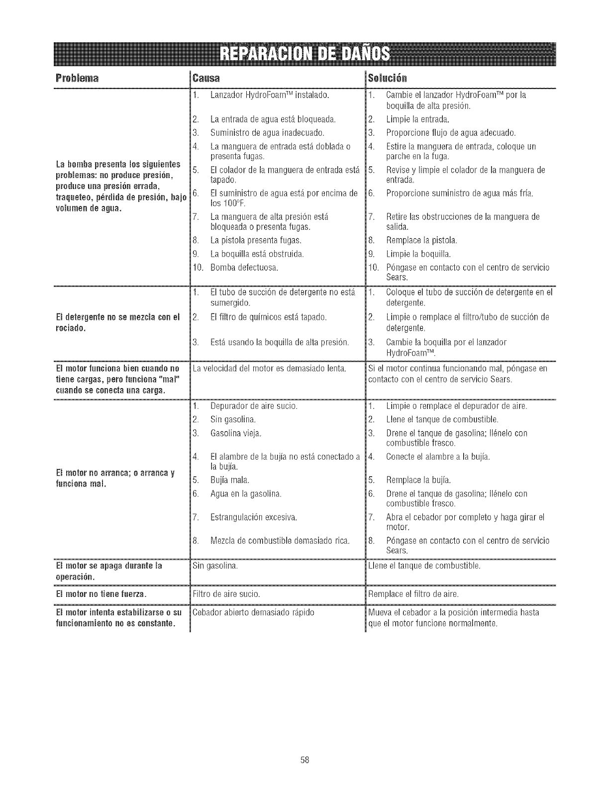
Prebmema
La bombapresentamossiguientes
problemas:noproducepre$i6n,
produceunapresi6nerrada,
traqueteo,p_rdidadepresi6n,bajo
voiumendeagua,
EIdetergenteno se mezcmaconem
rociado,
Causa
1. LanzadorHydroFoamTMinstaladO.
2. La entrada de agua est_ bloqueada.
3. Suministro de agua inadecuado.
4. La manguera de entrada est_ doblada o
presenta fugas.
5. El colador de la manguera de entrada est_
tapado.
6. El suministro deagua est_ por encirna de
los IO0°F.
7. La manguera de alta presiOnest_
bloqueada o presenta fugas.
8. La pistola presenta fugas.
9. La boquilla est_ obstruida.
10. Bomba defectuosa.
1. Eltubo desucciOndedetergentenoestb,
surnergido.
2. Elfiltro dequirnicosest_tapado.
3. Est_ usando la boqui% de alta presi6n.
Emmotor funciona Bien euundu nu La velocidad det rnotor es demasiado lenta.
tiene eurgus, peru funeiunu "mum"
cuunduse cunectuunu curgu.
D motur no arran€u; u atruncu y
funeiunu real.
1. Depurador de aire sucio.
2. Sin gaso%a.
3. Gasolina vieia.
4. El alambre de la bujia no estd conectadoa
$eiuci6n
1. Cambie el lanzador HydroFoamTM pot la
boquilla de alta presi6n.
2. Limpie la entrada.
3. Proporcione flujo de agua adecuado.
4. Estire la rnanguera de entrada, coloque un
parche en la fuga.
5. Revisey limpie el colador de la rnanguera de
entrada.
6. Proporcione suministro de agua m_s fria.
7. Retirelasobstruccionesdela rnanguerade
salida.
8. Rernplacela pistola.
9, Limpiela boquilla.
10. P6ngaseencontactoconel centrodeservicio
Sears.
1. Coloqueeltubo desucci6ndedetergenteenel
detergente.
2. Limpieo remplaceelfiltro/tubodesucciOnde
detergente.
3. Carnbielaboquillaporellanzador
HydroFoamTM.
Siel motorcontinuafuncionandomal_pOngaseen
contactoconel centrodeservicioSears.
1. Limpie o remplace el depurador de aire.
2. Llene el tanque de combustible.
3. Droneel tanque de gasolina; 118ne!ocon
combustible fresco.
4. Conecte el alambre a la buiia.
la bujia.
5. Buiiarnala.
6. Aguaenlagasolina.
7. Estrangulaci6n excesiva.
5. Remplacela bujia.
6. Dreneel tanque de gasolina; 116ne!ocon
combustible fresco.
Abra e! cebador por completo y haga girar el
rnotor.
8. P6ngaseencontactoconel centrodeservicio
Sears.
El muter se apaga durante la Llene el tanque de combustible.
uperaci6n.
El mutor no tiene fuerza.
8. Mezcladecombustibledemasiadorica.
Singasolina.
Filtrodeairesucio.
Cebadorabiertodemasiador_pido
B mutor intenta estabiHzarse osu
funeionamientu nu es eunstante.
Remplaceel filtro de aire.
Muevael cebador a la posici6n intermedia hasta
que el motor funcione norrnahnente.
58

59

60

61
California Air Resources Board (CARB) U.S. EPAy Sears le explican a continuaci6n
la garantia del sistema de control de emisiones de su pequ@o motor para mdquinas
de servicio (SORE, Small Offroad Engine). En California, los modelos de peque_os
motores para m_quinas de servicio a partir del a_o 2006 @ben estar dise_ados,
fabricados y equipados conforme a los exigentes est_ndares de lucha centre la
contaminaci6n del Estado.
En otras regiones de Estados Unidos, los nuevos motores para interiores de
ignici6n per chispa certificados para modelos a_o !997 y posteriores deben
cumplir con normas similares establecidas per la EPA de EE.UU. Sears debe
garantizar el sistema de control de emisiones de su motor para los per[odes
indicados a continuaci6n, siempre y cuando no se haya abusado, descuidado o
dado mantenimiento incorrecto al motor peque_o para exteriores
Su sistema de control de emisiones incluye plazas come el carburador, el filtro de
aire, el sistema de arranque, el tube de combustible el silenciador y el convertidor
catal[tico, Tambi@ puede incluir conectores y otros coquntos relacionados con las
emisiones,
Cuando exista una condici6n qua pueda ser cubierta per la garantia, Sears
reparar_ el motor peque_o para exteriores sin costo alguno, incluyendo el
diagnCstico, las partes de repuesto y la mane de obra
gobertura de la garantia de Sears, Ree_u_k and ge. centre ddectes en el
central de emisienee
Los pequ@os motores para m_quinas de sep,4cioestdn garantizados centre defectos
de las piezas de control de emisiones durante un per[ode de dos aSos, conforme a las
siguientes disposiciones, Si cualquier plaza del motor con cobertura es defectuosa,
ser_ reparada o sustituida per Sears.
Respensabilidadns del prepietarin pare la garantia
Come propietario del motor peque_o para exteriores, usted es responsable de
realizar las actividades de mantenimiento requeridas qua se indican en
Instrucciones de use y mantenimiento Sears recomienda qua conserve todos los
recibos qua cubran el mantenimiento de su motor peque_o para exteriores, pare
Sears no puede negar la garant[a solamente per la falta de recibos ni per su
imposibilidad de garantizar la realizaciCn de todas las actividades de
mantenimbnto programadas.
Come propietario del motor peque_o para exteriores, usted siempre debe tener
en cuenta qua Sears podr_ negar la cobertura de la garant[a si su motor peque_o
para exteriores o una parte del misrno presenta fallas debido a abuse, descuido,
mantenimiento incorrecto o modificaciones no aprobadas
Usted es responsabb de presentar su motor pequeiio para exteriores a un
distribuidor autorizado de servicio de Sears aprobado tan pronto come se
presente el probbma,
Las reparaciones cubiertas per la garanth se Ilevar_n a cabo en un plazo
razonable, no superior a 30 dias en ning0n case.
Si tiene alguna pregunta con respecto a sus derechos y responsabilidades para la
garant[a, pCngase en contacto con un representante de servicio Sears al 1-800-
469-4663
La garant[a de emisiones es una garantia contra defectos, Los defectos se iuzgan
en funciCn del rendimiento normal del motor. La garantia no depender_ de
ninguna prueba de emisiones en funcionamiento.
I}iepnsicienee de la garantia de Seers, Ree_eck and Ca. _entra defectes en el
ennlrel de ernisienee
Las siguientes son disposiciones espedficas relacionadas con la cobertura de la
garanfia contra defectos en el control de emisiones. Se a_ade a la garanfia de
motores de Sears para motores no regulados, qua figura en las Instrucciones de
use y mantenimiento,
1 Partes garantizadas
La cobertura bqo esta garant[a incluye solamente aquellas partes qua se
enumeran a continuaci6n (las partes del sistema de control de emisiones)
en la medida qua dichas partes hayan estado presentes en el motor
adquirido.
a. Sistema de medici6n de combustible
Sistema de enriquecimiento pare arranque en fr[o
Carburador y partes internas
Bomba de combustible
Tube de combustible, acoplamientos del tube de combustible,
abrazaderas
Dep6sito de combustible, tap6n y cadena
Beta de carbono
b Sistema de inducci6n de aire
Filtro de aire
Colector de entrada
Linea de purga y ventilaci6n
c. Sistema de ignici6n
BujBs
Sistema de ignici6n per magneto
d, Sbtema catalizador
Convertidor cataBtico
Colector de escape
Sistema de inyecciCn de aire o v_lvula per impulses
e. Distintos elementos utilizados en los sistemas antedores
V_lvulas e interruptores de vado temperature posici6n y de
detecci6n de tiempo
Conectores y conjuntos
2. Vigencia de ia _ebertnra
Sears garantiza al propietario inicial y a cada comprador subsiguiente qua
las partes garantizadas estar_n libres de defectos en material yen mane de
obra, qua ocasionen fallas de las partes garantizadas durante un periodo de
dos aSos a partir de la fecha en qua el motor sea entregado al comprador
minorista,
3. Ne habr_ cargee
La reparaciCn o reemplazo de cualquier parte garantizada se realizard sin
cargo alguno pare el propietario, incluyendo la mane de obra de diagnCstico
qua derive en la determinaciCn de qua una parte garantizada est_ defectuosa,
si la labor de diagnCstico se realiza en un Centre de servicio Sears aprobado.
4. Reclamne y exelesienes de cebertnra
Los reclamos vinculados con la garant[a se presentanJn conforme alas
disposiciones de la PCliza de garant[a de Sears. La cobertura de la garanth
se excluir_ para aquellas fallas de partes garantizadas qua no sean partes
originabs de Sears o debido a abuse, descuido o mantenimiento incorrecto,
sag@ se estabbce en la PClizade garanth de motores de Sears. Sears no
es responsabb per la cobertura de fallas de partes garantizadas ocasionadas
per el use de partes adicionales, no originabs o modificadas.
5. Ntantenirainnte
Cualquier parte garantizada cuyo reemplazo no est6 programado come
mantenimiento requerido o qua est_ programada 0nicamente para
inspecciCn frecuente con el fin de "reparar o reemplazar conforme sea
necesario", estard garantizada en cuanto a defectos per el per[ode de la
garant[a. Cualquier parte garantizada cuyo reemplazo est6 programado
come mantenimiento requerido tendr_ solamente una garanth centre
defectos _nicamente per el per[ode hasta el primer reemplazo programado
para esa parte Se podr_ utilizar cualquier parte de repuesto qua tenga un
rendimiento y durabilidad equivabntes, al realizar cualquier actividad de
mantenimiento o reparaciCn El propietario es responsable de realizar todo
el mantenimiento requerido, segSn se define en Instrucciones de use y
mantenimiento de Sears,
6. Cnbertera _ensignienle
La cobertura bajo [a presente se ampliar_ a [a falla de cualqubr componente
de[ motor provocada per un desperfecto en cualquier parte garantizada qua
siga gozando de la cobertura de [a garant[a.
En EE,UU. y Canadd contamos con una Bnea de emergencia las 24 horas (1-800-469-466% qua ofrece un men8 de mensajes pregrabados con informaciCn sobre
mantenimiento de productos,
62
[nfermac[6n sehre emisiones
Los motores con certificacl6n de cumplhnieeto de la normativa
sobre emisioees de nivel 2 del California Air Resources Board
(CARB) debee mostrar informaciOe sobre el periodo de durabilidad
de las emisiones y e! hsdicede aire. El fabricante del motor ofrece
esta informaciOn al consumidor rnedianteetiquetas de emisiones.
La etiqueta de emisiones de] rnotor contieee la informaciOn de
certificaci6e.
E[ Periede de Durabilidad de lee Emisieees[ndicael mirnero de
horas duraete las cuales e! motor peedefencionar cempliendo [as
normas sobre emisiones siernpre que se realicen las operaciones
de maeteeimiento que se detaIIaeen las instrucciones de use y
manteeimiento. Seuti[[zan [ass[guientes categorias:
Mederade: EI motor est_ certificado para cumpIir la norrnativa
sobre emisioees durante 125 horas de funcioeamieeto real.
Intermedie: El motor est_ certificado para cumplir la normativa
sobre emisioees durante 250 horas de funcioeamieeto real.
Preleegade: El rnotor est_ certificado para cumplir la normativa
sobre emisioees durante 500 horas de funcioeamiento real.
Per ejemplo un cortac_sped con operario a pie se suele utilizar
entre 20 y 25 horas al a[io. Per taeto, el Periede de Burabilidad de
las Emisieees de un motor con cias[ficaciOeietermedia equivaldria
a 10-12 a_os.
Algunos rnotores cuentan con la certificaciOn de curnplimiento de la
fase 2 de las normas sobre emisioees de la United States
Environmental Protection Agency (USEPA Ageecia estadourfideese
de protecciOndel medioambiente ). En el case de los motores con
certificaciOnde fase 2, el periodo de cumplimiento de la normativa
sobre emisiones que figura en la etiqueta de cumplimiento de
emisiones indica el n8mero de betas de funcionamiento durante las
cuaIesel rnotor ha demostrado cumplir los requisites federales
sobre emisiones.
Pararnotoresderneeosde225cc:
CategoriaC = 125horas
CategoriaB= 250horas
CategoriaA = 500horas.
Pararnotoresde225cco rn_s:
Categoria6 = 250horas
CategoriaB= 500horas
CategoriaA = 1000horas.
63

iiiiiiiiiiiiiiiiiiii
iiiiiiiiiiiiiii''_
iiiiiiiiiiiiiii
iiiiiiiiiiiiiii
iiiiiiiiiiiiiii
iiiiiiiiiiiiiii
iiiiiiiiiiiiiii
iiiiiiiiiiiiiii
iiiiiiiiiiiiiii
iiiiiiiiiiiiiii
iiiiiiiiiiiiiii
iiiiiiiiiiiiiii
iiiiiiiiiiiiiii
iiiiiiiiiiiiiii
iiiiiiiiiiiiiii
iiiiiiiiiiiiiii
iiiiiiiiiiiiiii
iiiiiiiiiiiiiii
© Sears Brands, LLC
® Registered Trademark /TMTrademark /SMService Mark of Sears Brands, LLC
® Marca Registrada /TM Marca de Fabrica /SM Marca de Servicio de Sears Brands, LLC
MCMarque de commerce /MDMarque depos6e de Sears Brands, LLC
