Craftsman 69522302 User Manual MITER SAW STAND Manuals And Guides L0905161
CRAFTSMAN Tool Base Manual L0905161 CRAFTSMAN Tool Base Owner's Manual, CRAFTSMAN Tool Base installation guides
User Manual: Craftsman 69522302 69522302 CRAFTSMAN MITER SAW STAND - Manuals and Guides View the owners manual for your CRAFTSMAN MITER SAW STAND #69522302. Home:Tool Parts:Craftsman Parts:Craftsman MITER SAW STAND Manual
Open the PDF directly: View PDF ![]() .
.
Page Count: 36

Owner's ManuaU
Model No.
695.22302
WARNING: Read, understand and follow all rules and
instructions in this manual BEFORE using this product,.
Failure to do so can result in serious personal injury.
Sears, Roebuck and Co.,
Hoffman Estates,
IL 60179 U.S.A.
_,WARRANTY
SAFETY
eASSEMBLY
eFEATURES
=STORAGE
REPAIR PARTS

Warrant-j......................................................... ,.
Safety Instructions.._...................... ,........... ....
Description, Specifications ...............................
Unpacking, Carton Contents ........................... .
Assembly ..........................:................................
Miter Saw Compatibility ....................................
Mounting Other Tools .......................................
Usage...............................................................
Page
Pages
Page
pages
Pages
Page
Page
Page
Storage.., .......................................................... Pages
Repair Parts ...................................................... Pages
3-'5
7-9
10-27
28
29
30- 32
33
34- 35
ONE-YEAR FULL WARRANTY ON CRAFTSMAN PROFESSIONAL
UNIVERSAL MITER SAW STAND
If this CRAFTSMAN PROFESSIONAL product fails due to adefect in
material or workmanship wthin one year from the date of purchase,
RETURN IT TO ANY SEARS STORE OR OTHER CRAFTSMAN
OUTLET IN THE UNITED STATES FOR FREE REPLACEMENT.
This warranty gives you specific legal rights, and you may also
have other rights which vary from state to state.
Sears, Roebuck and Co., Depto 817WA, Hoffman Estates, IL 60179
2

1. DO NOT standor climb on miter saw stand, it couldtip over
causing serious injury.
2. BE SURE all locking pins are in the set-up position holes BEFORE
using your miter saw and miter Saw stand.
3. ALWAYS firmly attach miter saw. DO NOT attempt to use your miter
saw stadd until the miter saw is fastened firmly to the boards.
4, ONLY use your miter saw stand on a hard, dry, flat, and level surface.
5. BE SURE that any bench top tool used with this stand is firmly
attached to the boards.
6. BE SURE the board clamps are tightly clamped to the stand when the
bench top tool is in use.
7. ALWAYS keep all guards in place. BE SURE all power tool guards
are in good working order and are in proper adjustment
8. ALWAYS keep your hands away from the cutting area.
9. DO NOT mount a table saw onto this stand. The direction of feed on a
table saw iS counter to the axis of best stability on this stand.
Aggressive feeding Ofsheet materials into a table saw could cause the
stand to tip.
10. ALWAYS use clamps or a vise to hold work when practical. Using
clamps or a vise to hold work is safer than using your hand. Italso
frees both hands to operate the saw.
BE SURE to read and understand all instructions in
this manual and the miter saw's operating manual before using it on the
stand. Failure to follow all instructions can result in electric shock, fire
and/or serious persona! injury.
WORK AREA SAFETY
1. ALWAYS keep your work area clean and well lit. Cluttered benches
and dark areas invite acciderits.
2. DO NOT operate power tools in explosive atmospheres, such as in
the presence of flammable liquids, gases, or dust. Power tools
create sparks that may ignite the dust or _umes.
3. ALWAYS keep bystanders, children, and visitors away while
operating a power tool. Distractions can cause you to lose control.
3

ELECTRICAL SAFETY
1. Double insulated tools are equipped with a polarized plug (one blade
is wider than the other). This plug will fit in a polarized outlet only
one way. if the plug does not fit fully into the outlet, reverse the plug.
if it still does not fit, contact a qualified electrician to install a
polarized outlet. DO NOT change or alter the plug in any way.
2. Double insulation eliminates the need for the three-wire grounded power
cord and grounded power supply system. Applicable only to Class tl
(double insulated) tools.
3. Before plugging in the tool, BE SURE that the outlet voltage supplied is
within the voltage marked on the tool's data plate. DO NOT use "AC only"
rated tools with a DC power supply.
4. ALWAYS avoid body contact with grounded surfaces, such as pipes,
radiators, ranges and refrigerators. There is an increased risk of electric
shock if your body is grounded.
5. if operating the power tool in damp locations is unavoidable, ALWAYS
use a Ground Fault Circuit Interrupter to supply power to your tool.
ALWAYS wear electrician's rubber gloves and footwear in damp
conditions.
6. DO NOT expose power tools to rain or wet conditions. Water entering a
power tookwill increase the risk of electric shock°
7. DO NOT abuse the cord. NEVER use the cord to carry the tools or pull
the plug from the outlet. Keep cord away from heat, oil, sharp edges or
moving parts. Replace damaged cords immediately. Damaged cords
increase the risk of electric shock.
8. When operating a power toot outside, ALWAYS use an outdoor extension
cord marked '"W-A" or "W'. These cords are rated for outdoor use and
reduce the risk of electric shock.
NOTE: The extension cord must have adequate wire size AWG
(American Wire Gauge) for safe, efficient use. Smaller gauge wires, have
greater capacity (16 gauge wire has more capacity than 18 gauge wire).
PERSONAL SAFETY
1. ALWAYS stay alert, watch wha, you are doing, and use common sense
when operating apower tool. DO NOT use tool while tired or under the
influence of drugs, alcohol or medication. Amoment of inattention while
operating power too_s may result in serious persona! injury.
2. ALWAYS dress properly. DO NOT wear loose clothing or jewelry.
Pull back long ha=r. Keep your hair, clothing, and gloves away from
moving parts. Loose clothing, jewelry, or long hair can be caught in
moving parts°
3. ALWAYS avoid accidental starting. BE SURE switch is in the "Off"
position before plugging in. Do not carry tools with your finger on
the switch. Carrying tools with your finger on the switch or plugging in
tools that have the switch in the "On" position invites accidents.
4
PERSONAL SAFETY (cont.)
4. ALWAYS remove adjusting keys or wrenches before turning the
tooJ on. A wrench or a key that is left attached to a rotating part of the
tool may result in personal injury,
5. DO NOT overreach. ALWAYS keep proper footing and balance _it all
times. Proper footing and balance enables better control of the tool in
unexpected situations.
6. ALW'AYS use safety equipment. Always wear eye protection. Dust
mask, non-skid safety shoes, hard hat, or hearing protection must,be
used for appropriate conditions
SAFE TOOL USE AND CARE
1. ALWAYS use clamps or other practical ways to secure and support
the workplece to a stable platform. Holding the work by hand or against
your body is unstable and may lead to loss of control,
2. DO NOT force the tool. Use the correct tool for your application.
The correct too! will do the job better and safer at the rate for which it is
designed.
3. DO NOT use the tool if the Switch does not turn it "On" or "Off". Any
tool that cannot be controlled with the switch is dangerous and must
be repaired.
4. ALWAYS disconnect the plug from the power source before making
any adjustments, changing, accessories, or storing the tool. Such
preventive safety measures reduce the risk of starting the tool
accidentally.
5. ALWAYS store idle tools out of the reach of children and other
untrained persons. Tools are dangerous in the hands of untrained users.
6. ALWAYS maintain tools with care. Keep cutting tools sharp and :
clean. Properly maintained tools with sharp cutting edges are less likely
to bind and are easier to control
7. ALWAYS check for misalignment or binding of moving parts,
breakage of parts, and any other condition that may affectthe
tool's operation, if damaged, have the tool serviced before using.
Many accidents are caused by poorly maintained tools. •........
4'
USE OF ACCESSORIES THAT ARE NOT
RECOMMENDED FOR USE WITH YOUR TOOL MAY CREATE A
HAZARDOUS CONDITION.
8. ALWAYS use only accessories that are recommended for your tool.
Accessories that may be suitable for one tool can become hazardous
when used on another tool.
5
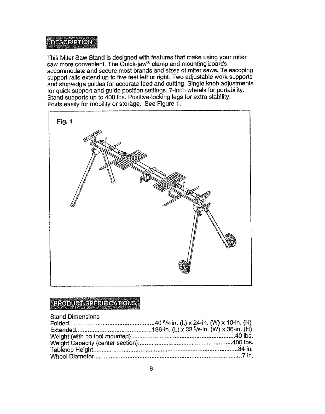
This Miter Saw Standis designedwith features that make usingyour miter
saw moreconvenient.The Quick-jaw_ clamp and mounting boards
accommodateand secure most brands and sizes of miter saws. Telescoping
support rails extend upto five feet left or right. Two adjustablework supports
and stop/edge guidesfor accuratefeed and cutting. Single knob adjustments
for quick support and guide position settings. 7-inch wheels for portability,
Stand supports up to 400 Ibs. Positive-locking legs for extra Stability.
Folds easily for mobility or storage. See Figure 1.
Fig. 1
Stand Dimensions
Folded .............. :.................................... 40 s/8-in. (L)x 24-in. (W)x 10-in: (H)
Extended ......... ..................................... 136-in. (L) x 33 5/8-in. (W) x 36-in. (H)
Weight (with no tool mounted) ............................................................ _.40 Ibs,
Weight Capacity (center section) ........................................................ 400 ibs.
Tabletop Height ......................................................................... :........i...... 34 in.
Wheel Diameter ........................... 1........................................................ ,,..7 in.
6

UNPACKING
Unpack all parts and carefully separate parts from packing materials.
Check each part with the parts illustration and list on pages 7, 8 and 9,
BE SURE that all parts are accounted for before discarding any packing
materials° To make assembly easier, keep the contents of the box together.
Wipe parts thoroughly with a clean, dry cloth,,
PACKAGE CONTENTS AND HARDWARE (Figure 2)
Item
A
B
C
D
E
F
_Li_
G
H
Fig. 2
Description Quantity
Frame Assembly, including legs 1
Wheel Assembly 2
Mounting Board 2
Carrying Handle
Work Support Assembly, Right
Work Support Assembly, Left
Clamp Assembly
Edge Guide Assembly
1
1
2
A
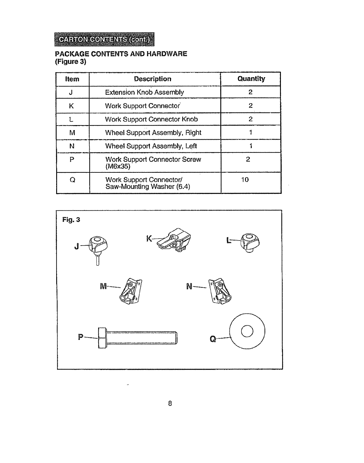
PACKAGE CONTENTS AND HARDWARE
(Figure 3)
Item De_scr_ption Quantity
J
K
L
M
N
P
Q
Extension Knob Assembly
Work Support Connector
Work Support Connector Knob
Wheel Supp0rt Assembly, Right
Wheel Support Assembly, Left
Work Support Connector Screw
(M6x35)
Work Support Connector/
Saw-Mounting Washer (6.4)
2
2
2
1
1
2
, ,,L ,,,,uL , ,,,,,,
10
Fig. 3
8
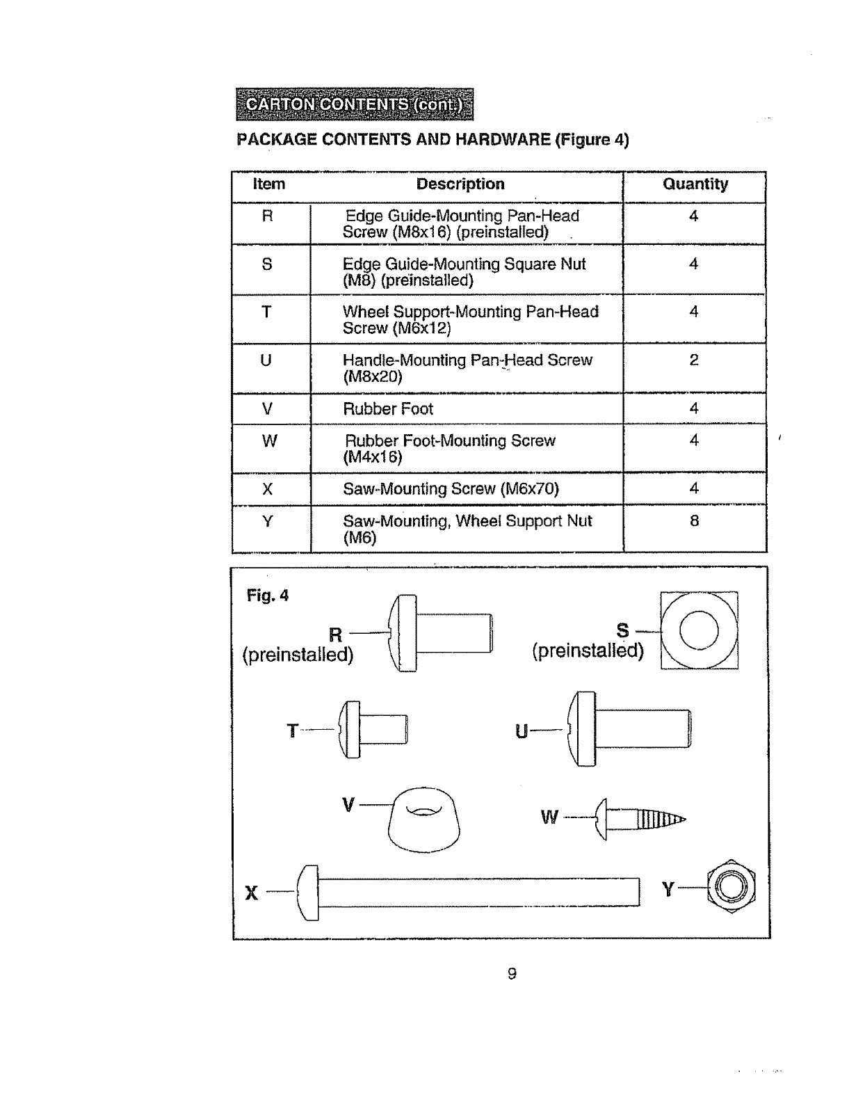
PACKAGE CONTENTS AND HARDWARE (Figure 4)
Item Description " "Quantity
R Edge Guide-Mounting Pan-Head 4
Screw (M8x16) (preinstalled) •
S Edge Guide-Mounting Square Nut
(MS) (weinstatled)
Wheel Support*Mounting Pan-Head 4
Screw (M6x12)
U Handle-Mounting Pan,-Head Screw 2
(M8x20)
V Rubber Foot 4
W Rubber Foot-Mounting Screw 4
(M4x16)
X Saw.Mounting Screw (M6x70) 4
Y Saw-Mounting, Wheel Support Nut 8
(M6)
Fig. 4
R-- tl
(preinstalted) '___! (prelnstalled) _,._-__,/'1
°-I[j !
_
9
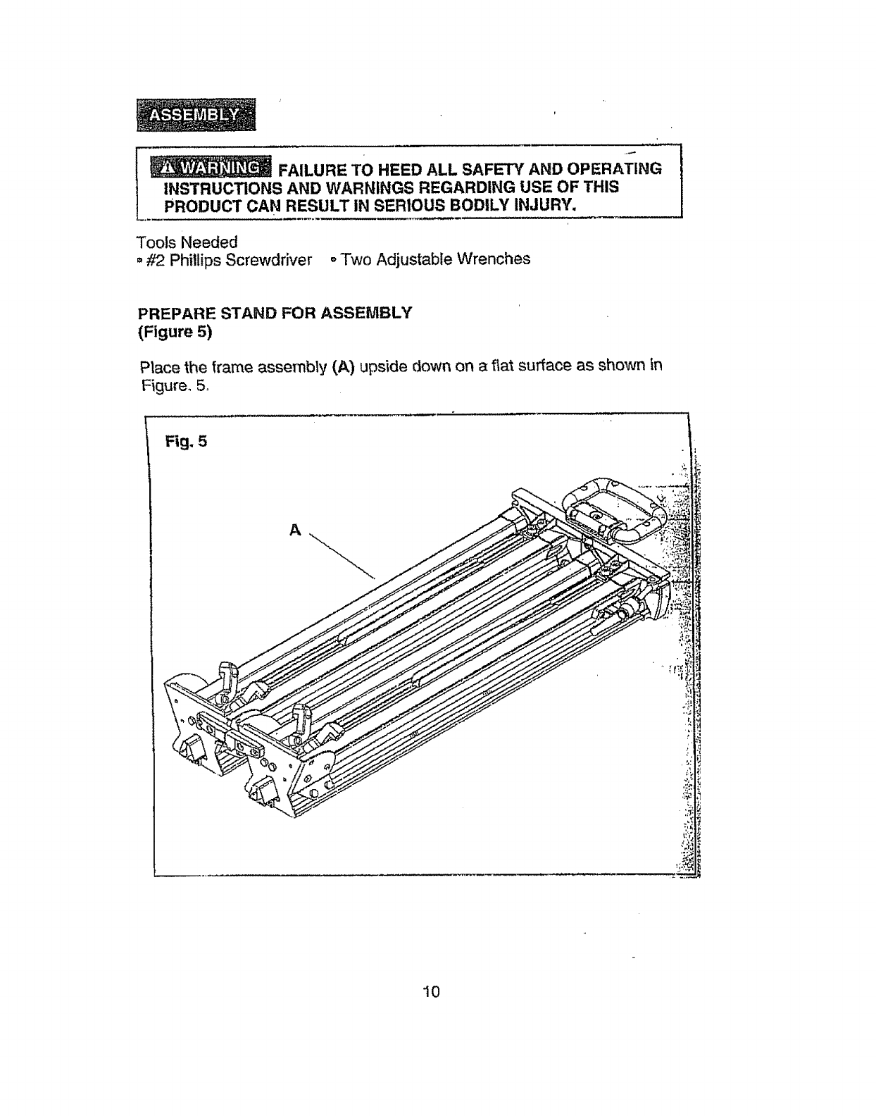
FAILURE TO HEED ALL SAFETY AND OPERATING
INSTRUCTIONS AND WARNINGS REGARDING USE OF THIS
PRODUCT CAN RESULT IN SERIOUS BODILY INJURY,
Tools Needed
,#2 Phillips Screwdriver oTwo Adjustable Wrenches
PREPARE STAND FOR ASSEMBLY
(Figure 5)
Place the frame assembly (A) upside down on a flat surface as shown in
Figure. 5_
Fig, 5
A
10
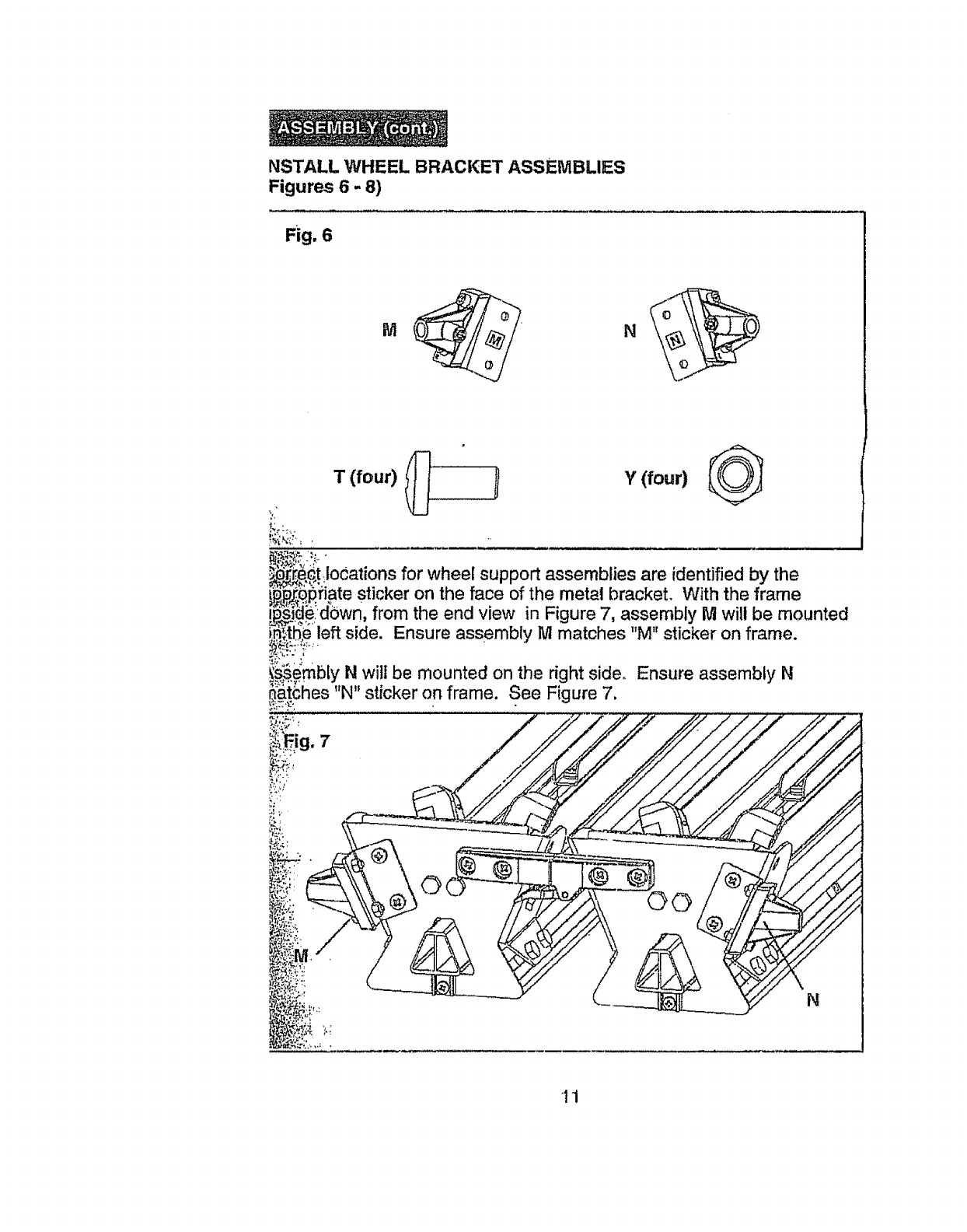
NSTALL WHEEL BRACKET ASSEMBLIES
Figures 6 - 8)
Fig. 6
M
,_r_[_ct locations for wheel support assembhes are fdentJfied by the
_,,p_._)iate sticker on the face of the metal bracket. With the frame
'_'_°:_'"-_eldi3wn,from the end view in Figure 7, assembly M will be mounted
'_ _"" • 1t Tit "
i_:tt_e left side. Ensure assembly Mmatches M st cker on frame.
_embly N wit| be mounted on the nght sldeo Ensure assembly N
_:_;_hes "N" sticker on frame. See Figure 7,
g. 7
N
11
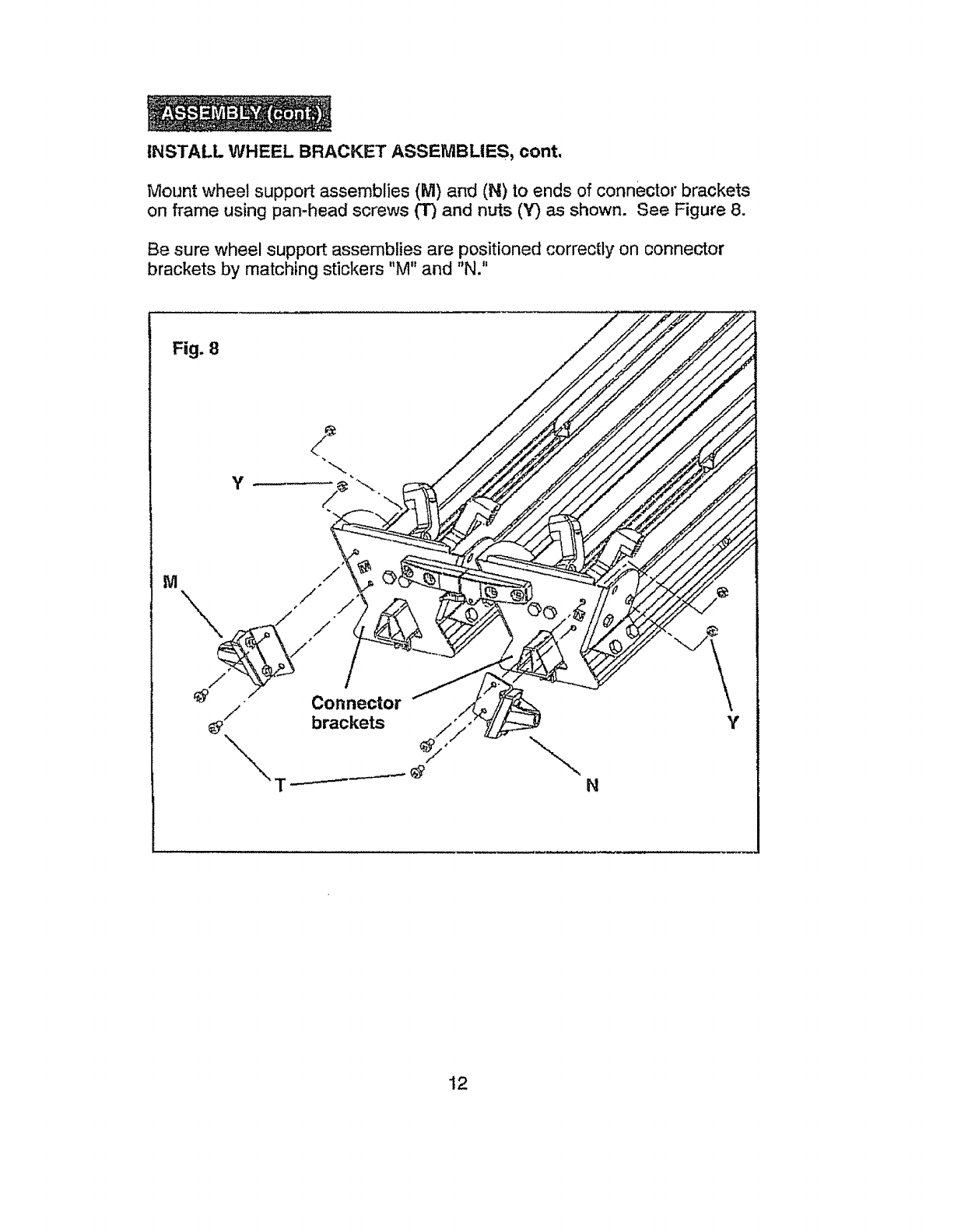
INSTALL WHEEL BRACKET ASSEMBLIES, cont.
Mount wheel support assemblies (M) and (N) to ends of connector brackets
on frame using pan-head screws (3") and nuts (Y) as shown. See Figure 8.
Be sure wheel support assemblies are positioned correctly on connector
brackets by matching stickers "M" and "N."
Fig. 8
M,/
Connector
/brackets \N
12
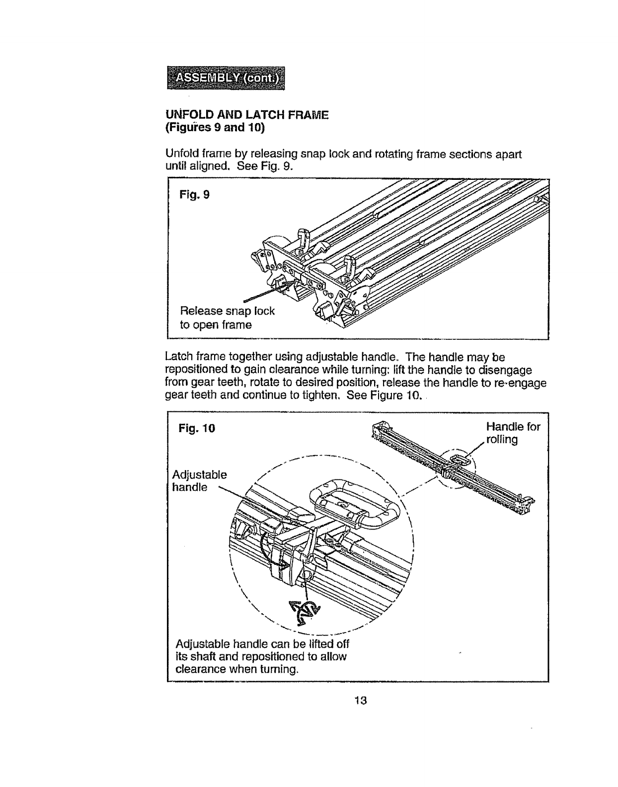
UNFOLD AND LATCH FRAME
(Figures 9 and 10)
Unfold frame by releasing snap lock and rotating frame sections apart
until aligned. See Fig. 9.
Fig. 9
Release snap lock
to open frame
Latch frame together using adjustable handle. The handle may be
repositioned to gain clearance while turning: lift the handle to disengage
from gear teeth, rotate to desired position, release the handle to re-engage
gear teeth and continue to tighten. See Figure 10.
Fig. 10 Handle for
rolling
.,f
Adjustable /,°
\
Adjustable handle can be lifted off
its shaft and repositioned to allow
clearance when turning.
13
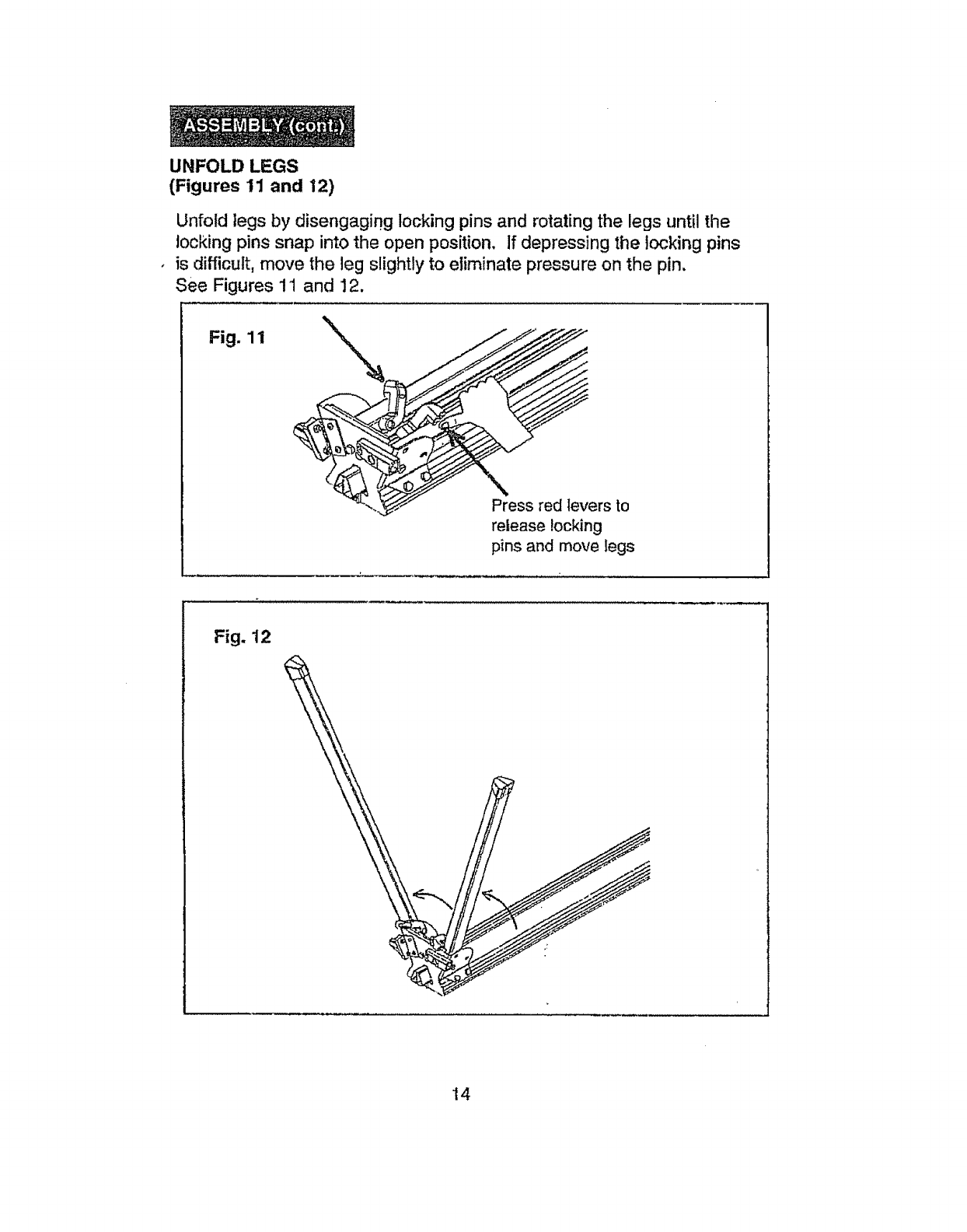
UNFOLD LEGS
(Figures 11 and 12)
Unfold legs by disengaging locking pins and rotating the legs until the
locking pins snap into the open position, If depressing the locking pins
is difficult, move the leg slightly to eliminate pressure on the pin,
See Figures 11 and 12.
Fig. 11
Press red levers to
release locking
pins and move legs
Fig. 12
t4
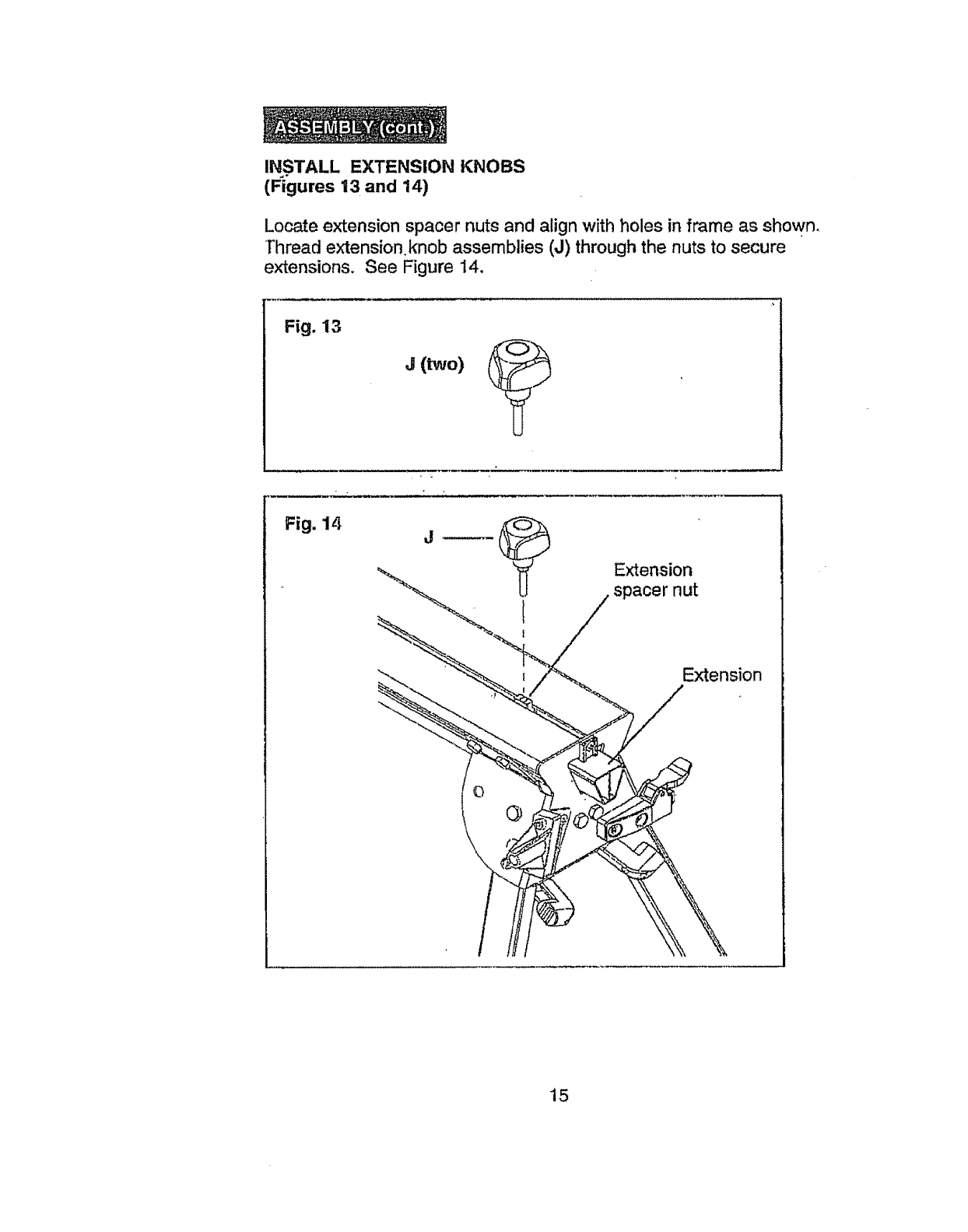
INSTALL EXTENSION KNOBS
(Fi'gures 13 and 14)
Locate extension spacer nuts and align with holes in frame as shown.
Thread extensionknob assemblies (J) through the nuts to secure
extensions. See Figure 14.
Fig. 13
j(two)
\
Extension
spacer nut
Extension
15
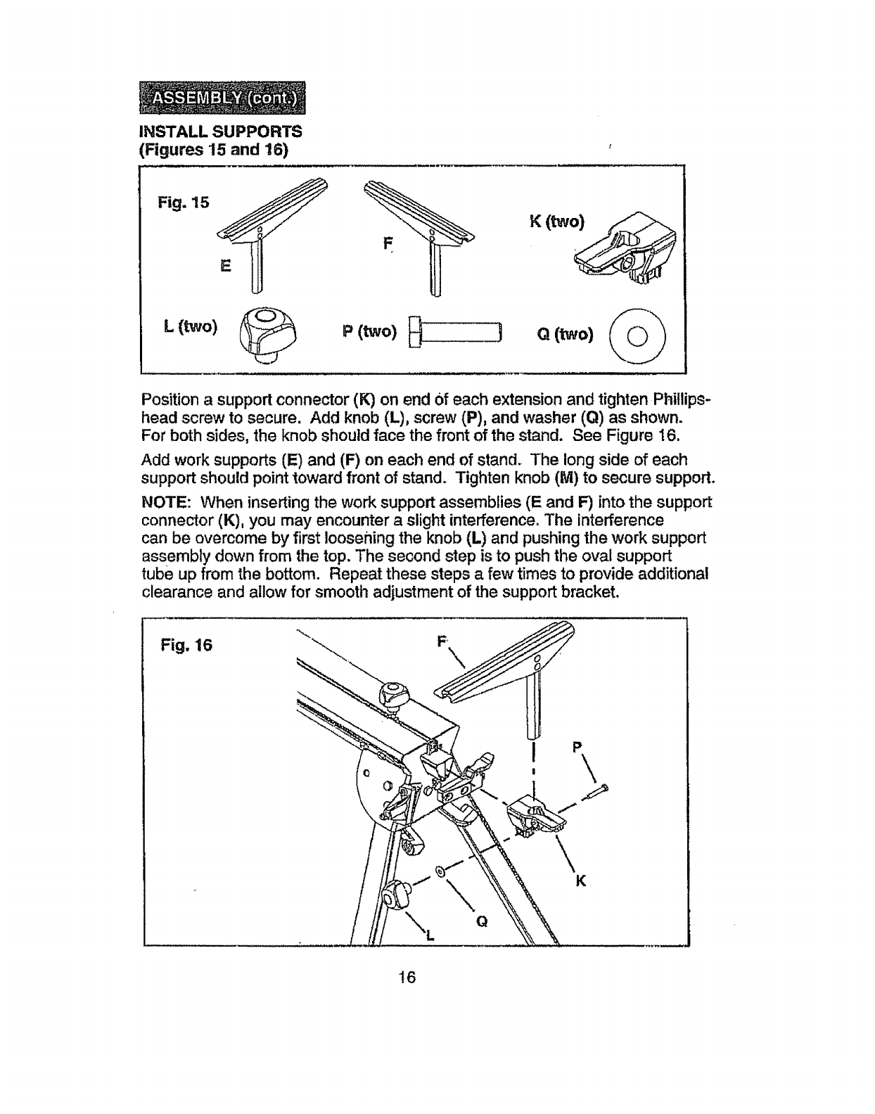
INSTALL SUPPORTS
(Figures 15 and 16)
Fig. 15
L (two)
t
Position asupport connector (K) on end Of each extension and tighten Phillips-
head screw to secure. Add knob (L), screw (P), and washer (Q) as shown.
For both sides, the knob should face the front of the stand. See Figure 16.
Add work supports (E) and (F) on each end of stand. The long side of each
support should point toward front of stand. Tighten knob (M) to secure support.
NOTE: When inserting the work support assemblies (E and F) into the support
connector (K), you may encounter aslight interference. The interference
can be overcome by first loosening the knob (L) and pushing the work support
assembly down from the top. The second step is to push the oval support
tube up from the bottom. Repeat these steps a few times to provide additional
clearance and allow for smooth adjustment of the support bracket.
Fig, 16
\Q
\
K
16
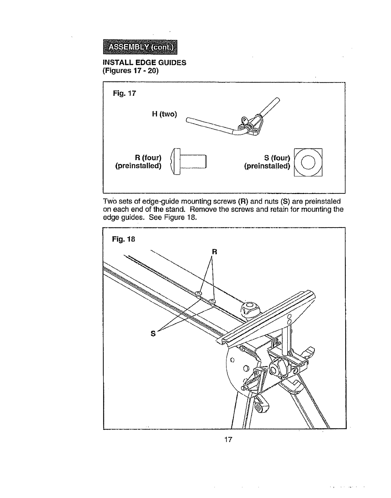
INSTALL EDGE GUIDES
(Figures 17 - 20)
Fig. 17
H(two)
(preinstalled) (preinsta!led)
Two sets of edge-guide mounting screws (R) and nuts (S) are preinstaled
on each end of the stand. Remove the screws and retain for mounting the
edge guides. See Figure 18.
Fig. 18
R
S
17
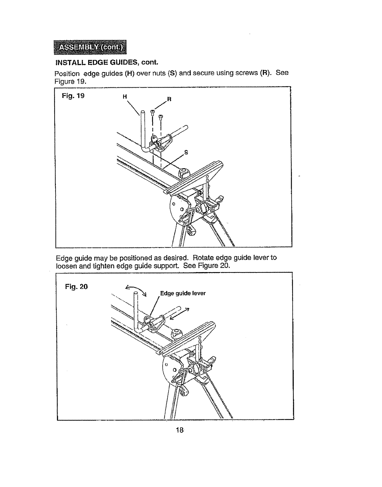
INSTALL EDGE GUIDES, cont.
Position edge guides (H) over nuts (S) and secure using screws (R).
Figure 19,
Fig. 19
See
S
Edge guide may be positioned as desired, Rotate edge guide lever to
oosen and tighten edge guide supporL See Figure 20.
Fig. 20 Edge guide lever
18
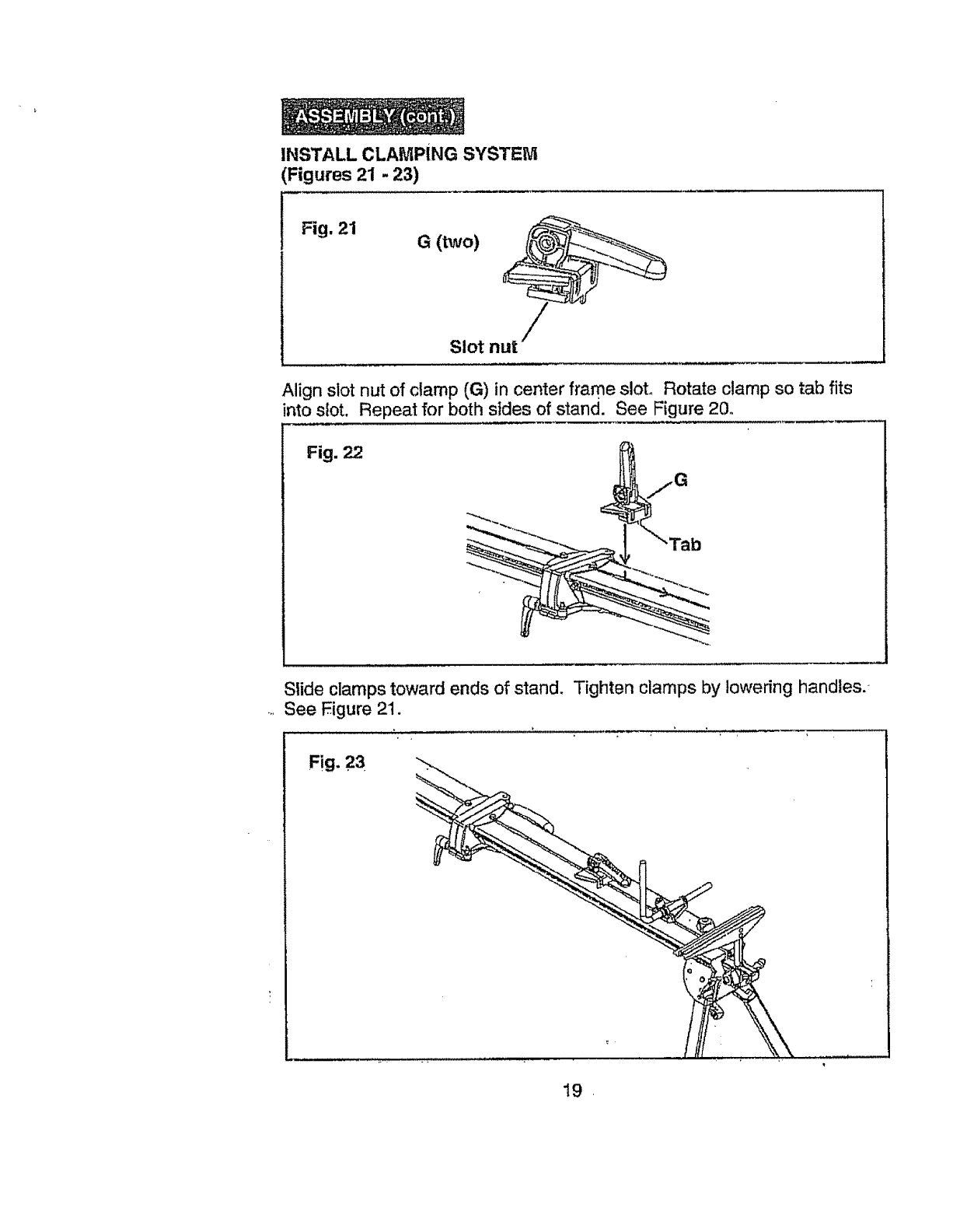
INSTALL CLAMPING SYSTEM
Figures 21 - 23)
Fig, 21
G(two)
Slot n
Align slot nut of clamp (G) in center frame slot. Rotate clamp so tab fits
into slot. Repeat for both sides of stand. See Figure 20.
Fig. 22
Stide clamps toward ends of stand. Tighten clamps by lowering handles.
See Eigure 21.
Fig. 23
19.
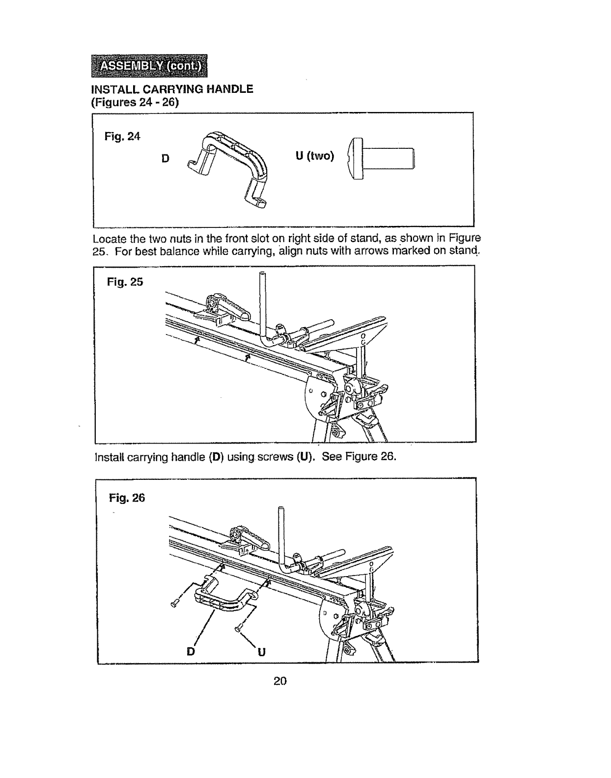
INSTALL CARRYING HANDLE
(Figures 24 -26)
Fig. 24
DU (two)
Locate the two nuts in the front slot on right side of stand, as shown in Figure
25. For best balance while carrying, align nuts with arrows marked on stand.
Fig. 25
lnstatl carrying handle (D) using screws (U), See Figure 26.
Fig. 26
D
2O
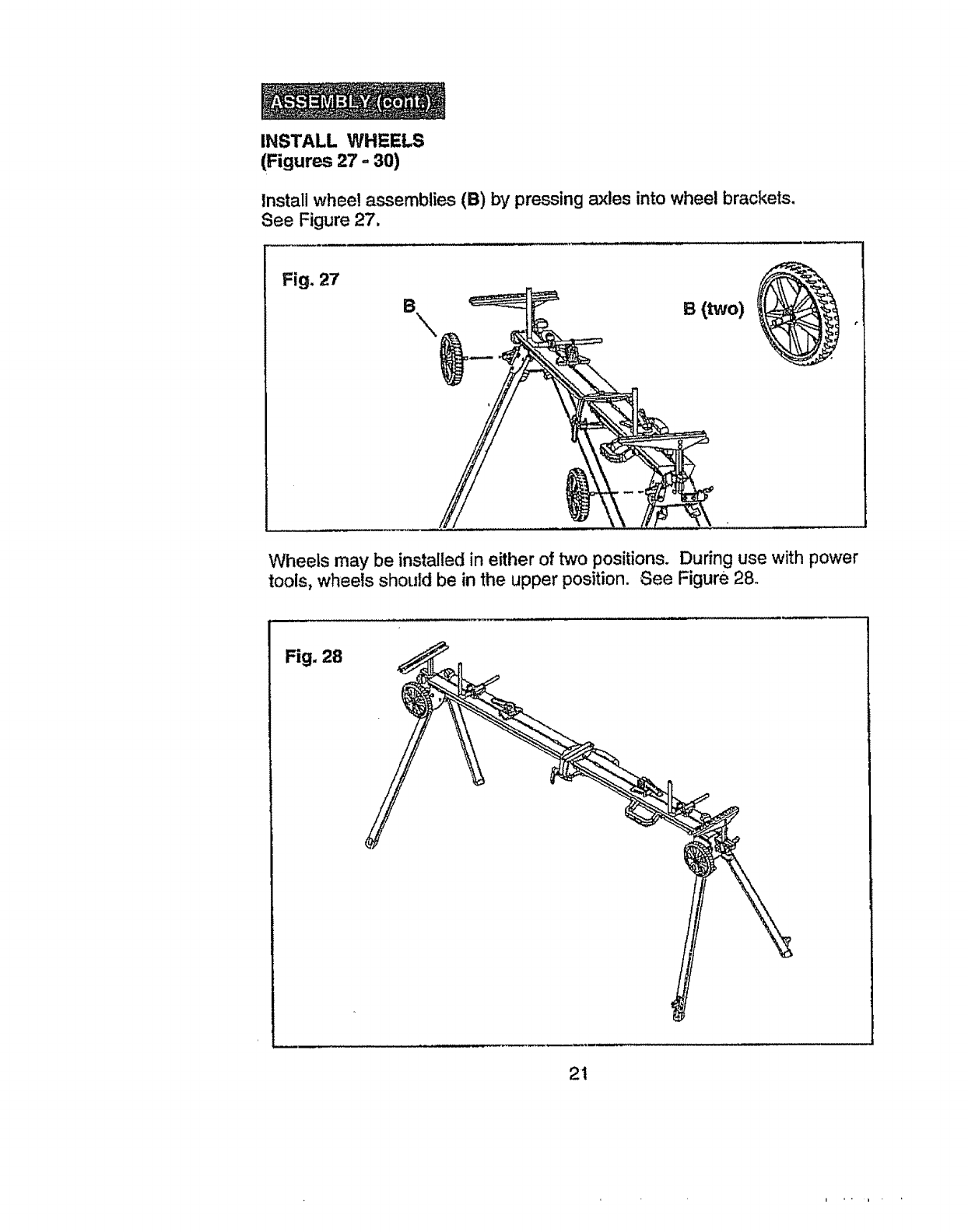
INSTALL WHEELS
(Figures 27 =30)
Install whee! assemblies (B) by pressing axles into wheel brackets.
See Figure 27.
Fig. 27
Wheels may be installed in either of two positions. During use with power
tools, wheels should be in the upper position. See Figure 28.
Fig. 28
21
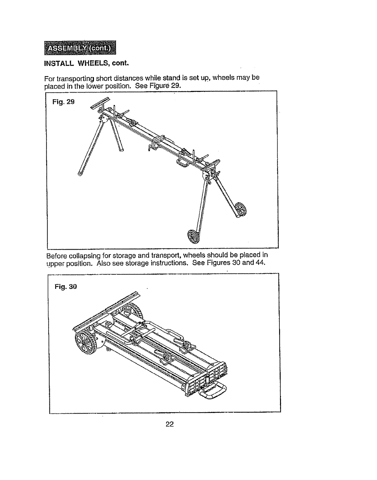
iNSTALL WHEELS, cont.
For transporting short distances while stand is set up, wheels may be
:_laced in the lower position. See Figure 29.
Fig. 29
Before collapsing for storage and transport, wheels should be placed in
upper position. Also see storage instructions. See Figures 30 and 44.
Fig. 3O
22
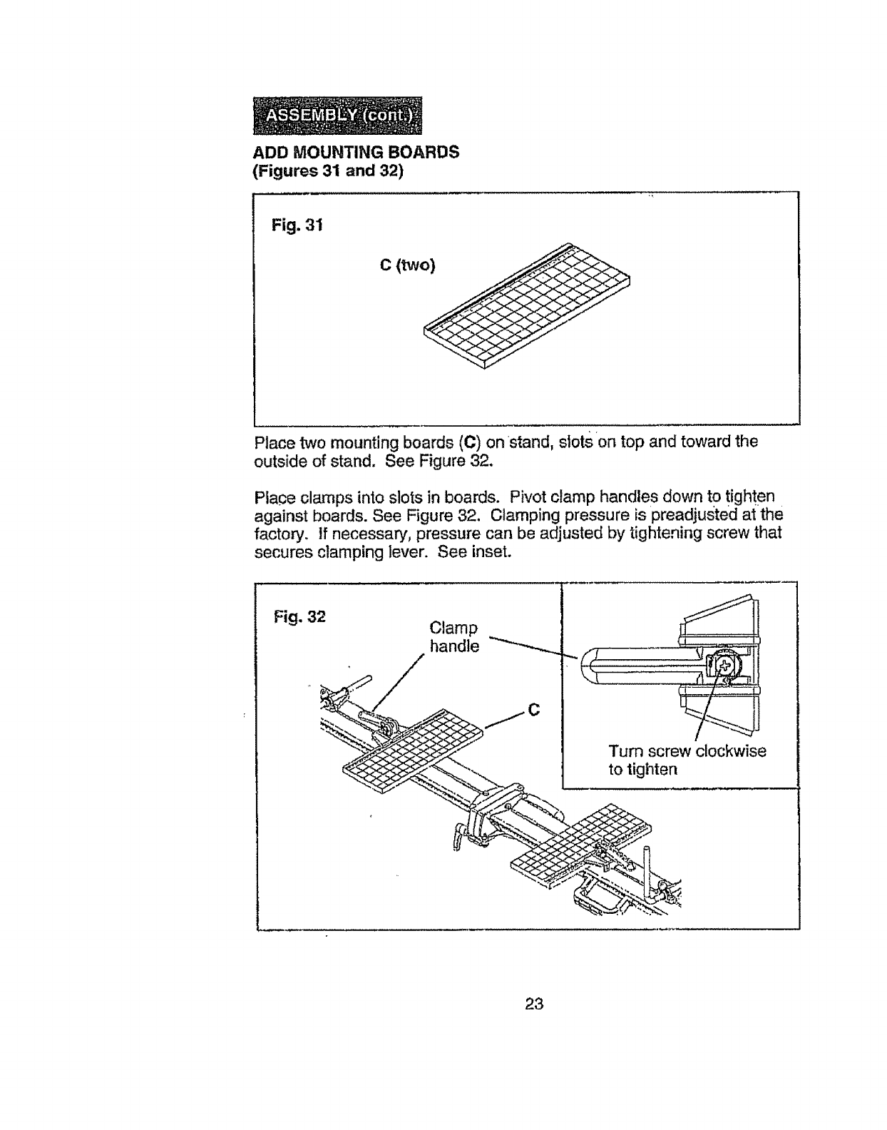
ADD MOUNTING BOARDS
(Figures 31 and 32)
Fig. 31
c (two)
Place two mounting boards (C) on stand, slots on top and toward the
outside of stand. See Figure 32.
Place clamps into slots in boards. Pivot clamp handles down to tighten
against boards. See Figure 32. Clamping pressure is preadjusted at the
factor,/. If necessary, pressure can be adjusted by tightening screw that
secures clamping lever. See inset.
Fig. 32 Clamp
handle
Turn screw clockwise
to tighten
23
MOUNT THE MITER SAW
(Figures 33 - 38)
MOUNTING THE MITER SAW TO'THE BOARDS
Secure boards to frame of miter saw stand as explained in "ADD
MOUNTING BOARDS" on page 23. Loosen clamps slightly and position
boards to be slightly wider than the base of the miter saw to be mounted.
To square boards, align grid on boards with the frame of the miter saw
stand.
Position miter saw on boards with fence of saw in line with center of
clamps. Saw base should be approximately 1" from front edge of
boards and 1/2" from slot in boards. See Figure 34.
NOTE: Position saw and boards so mounting bolts will not interfere with
frame of miter saw stand.
Be sure to position your saw and boards for maximum
stability.
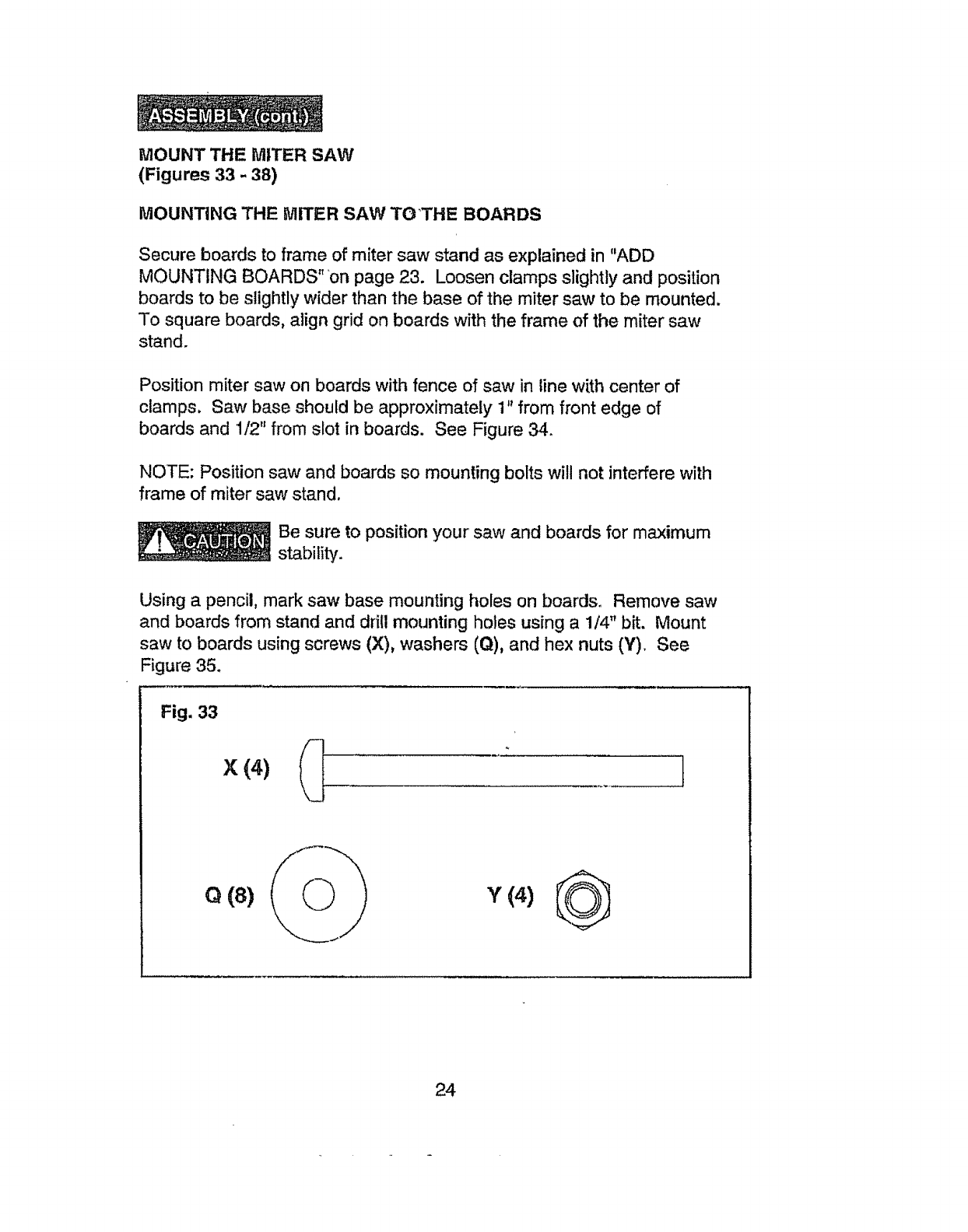
Using a pencil, mark saw base mounting holes on boards. Remove saw
and boards from stand and drill mounting holes using a 1/4" bit. Mount
saw to boards using screws (X), washers (Q), and hex nuts (Y). See
Figure 35.
Fig. 33
Q(8)
24
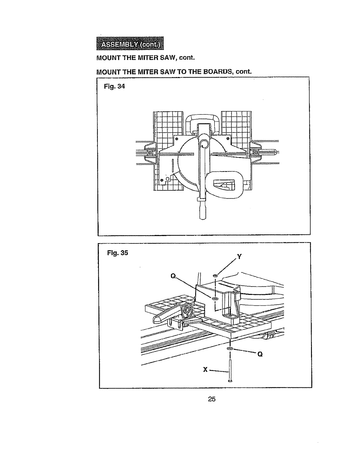
MOUNT THE MITER SAW, cont.
MOUNT THE MITER SAW TO THE BOARDS, cont.
Fig. 34
Fig. 35
25
MOUNTTHE MITERSAW, cont.
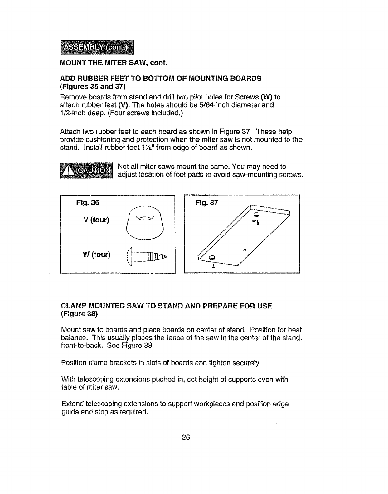
ADD RUBBER FEETTO BOTTOM OF MOUNTING BOARDS
(Figures 36 and 37)
Remove boards from stand and drill two pilot holes for Screws (W) to
attach rubber feet (V). The holes should be 5/64-inch diameter and
1/2=inch deep. (Four screws included.)
Attach two rubber feet to each board as shown in Figure 37. These help
provide cushioning and protection when the miter saw is not mounted to the
stand. Install rubber feet IY2" from edge of board as shown.
Not all miter saws mount the same. You may need to
adjust location of foot pads to avoid saw-mounting screws,
Fig. 36
w(four)
Fig. 37
CLAMP MOUNTED SAW TO STAND AND PREPARE FOR USE
(Figure 38}
Mount saw to boards and place boards on center of stand. Position for best
balance° This usually places the fence of the saw in the center of the stand,
front-to-back, See Ffgure 3&
Position clamp brackets in slots of boards and tighten securely,
With telescoping extensions pushed in, set height of supports even with
table of miter saw.
Extend telescoping extensions to support workpieces and position edge
guide and stop as required.
26
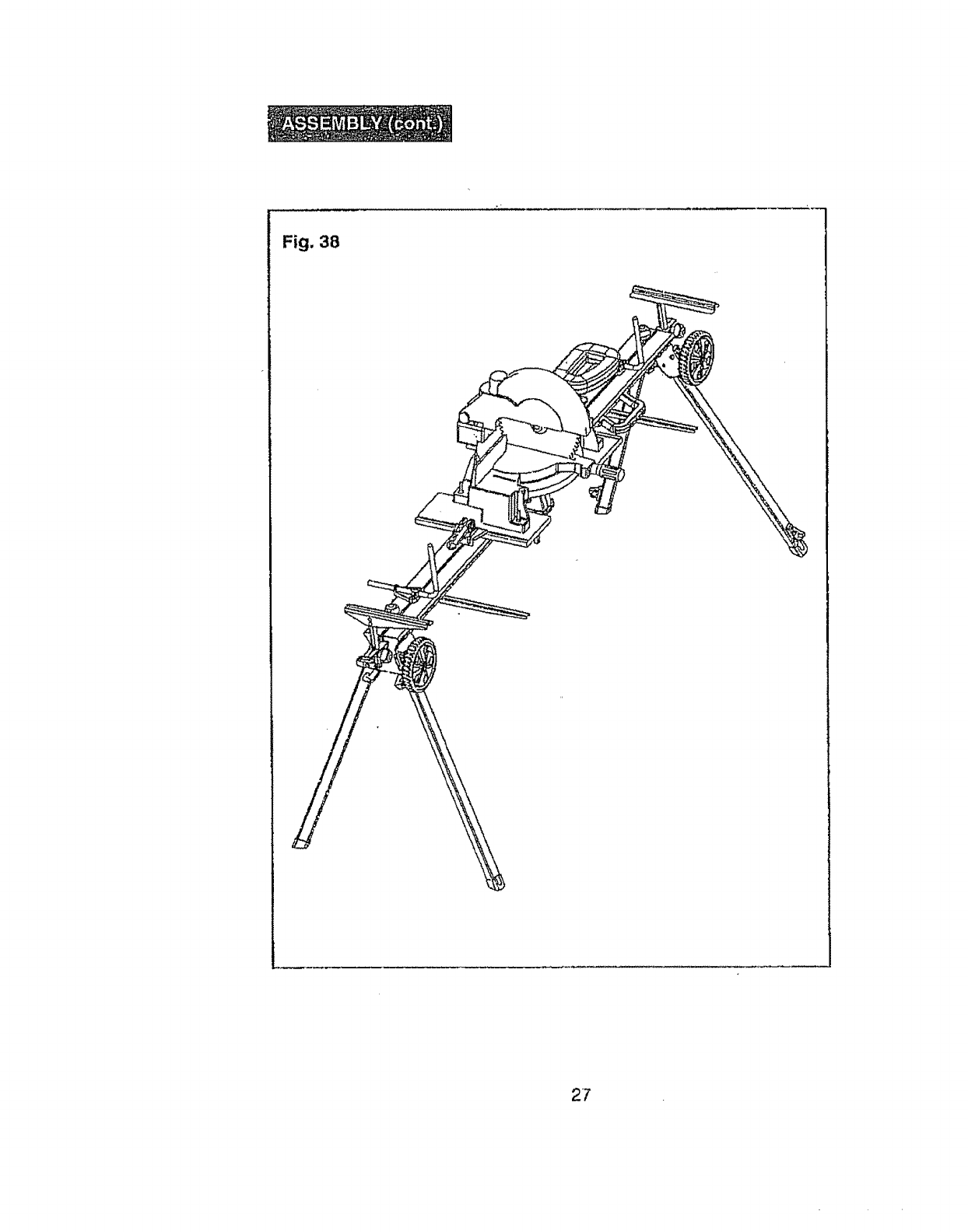
Fig. 38
27

This workstand is designedfor use with Craftsman and most
otherbrands of miterand compound miter saws. The saw will
mountdirectly to the boards provided with the stand. Itwill also
accommodatesaws with unusual mounting hole patterns.Simply
followthe precedinginstructions.
The followingmodelswill mountdirectly to the boardsprovided
withthe stand
BRAND
Craftsman
Delta
MODEL NUMBER
21211
21218
21222
21230
2'1240
21292
24315
36-04O
36-070
36-075
36-225
36-235
36-240
DeWalt 703
705
706
708
Hitachi C10FCD
C10FM
C15FB
Makita BLS712
BLS820SFK
LS711DWBEK
LSS00DWB
LS1013
LS071 tZ
LS1212
LS 1220
BRAND MODEL NUMBER
Milwaukee 6496
6490
6494
Porter-Cable 3802
3807
Pro-Tech 7107
7207
7208
72121
Rigid
Ryobi
SkiI-Bosch
MS1050
MS1250
TS1301DX
3810
3912
3915
3924
Tool Shop JIZ-ZP-305
28

Mounting Non-Standard Miter Saws and Other Tools To The Boards •
(Figures 39 and_O)" ';_ '_ "'_'! _' ,
NOT_0UNT ATAB.LS SA,W ON THIS, STAND.
The direction of feed on @_,tabilb:_sawis perpendicular tO the axis
of best stability on this S_Od_ Aggressiv_ fee_=ng of sheet
materials into a table ._aw _0iJla_ cause the Stand to tip over.
This Miter Saw Stand nlay also be used With other bench'top tools, such as
chop saws, grinders, drill presses, sanders, joiners, scroll saws and band
saws. (see Figure 39.)
Fig. 39
For additional tools and other miter saws with non-standard mounting holes,
plywood or other boards may be used for mounting tools for use on this
stand. The plywood used should be approximately 3/4 in. thick.
Cut plywood or boards to f'rtmounting hole pattern for tool to be used with
the stand. The wood must clear center hinge area of stand and extend 1
inch in all directions beyond the bottom edge of the tool base for proper
clamping to the Stand. (See Figure 40.)
Fig. 40 NOTE: _nnen using mounting boards
other than those included with this stand,
slots matching those on the odginal
mounting boards Should be cut using a
router or table saw. These slots should
be 3/8" wide, 3/32 deep, and 3/8" from
the edge of the boards.
Mount your tool to the plywood or boards following the directions
in the Mounting Miter Saw section of this manual.
29
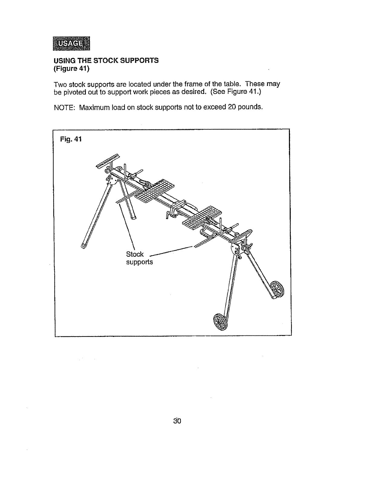
USING THE STOCK SUPPORTS
(Figure 41)
Two stock supports are located under the frame of the table. These may
be pivoted out to support work pieces as desired. (See Figure 41 .)
NOTE: Maximum load on stock supports not to exceed 20 pounds.
Fig. 41
Stock
supports
3O
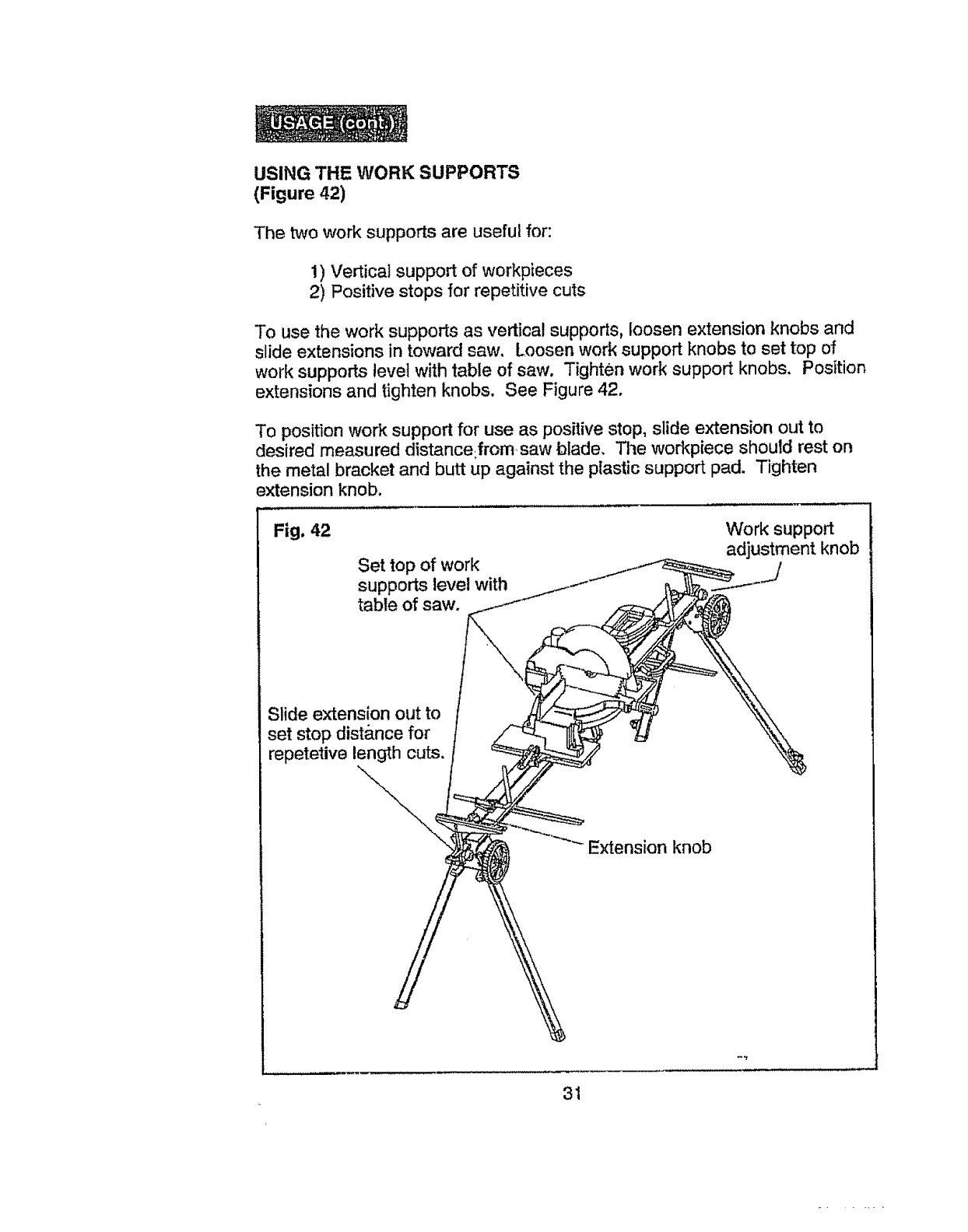
USING THE WORK SUPPORTS
(Figure 42)
The two work supports are useful for:
!) Vertical support of workpieces
2) Positive stops for repetitive cuts
To use the work supports as vertical supports, loosen extension knobs and
slide extensions in toward saw. Loosen work support knobs to set top of
work supports level with table of saw. Tighten work support knobs. Position
extensions and tighten knobs. See Figure 42.
To position work support for use as positive stop, slide extension out to
desired measured distance from saw blade. Tile workpiece should rest on
the metal bracket and butt up against the plastic support pad. Tighten
extension knob.
Fig. 42
Set top of work
supports level with
table of saw.
Work support
adjustment knob
Slide extension out to
set stop dist&nce for
repetetive length cuts.
Extension knob
31
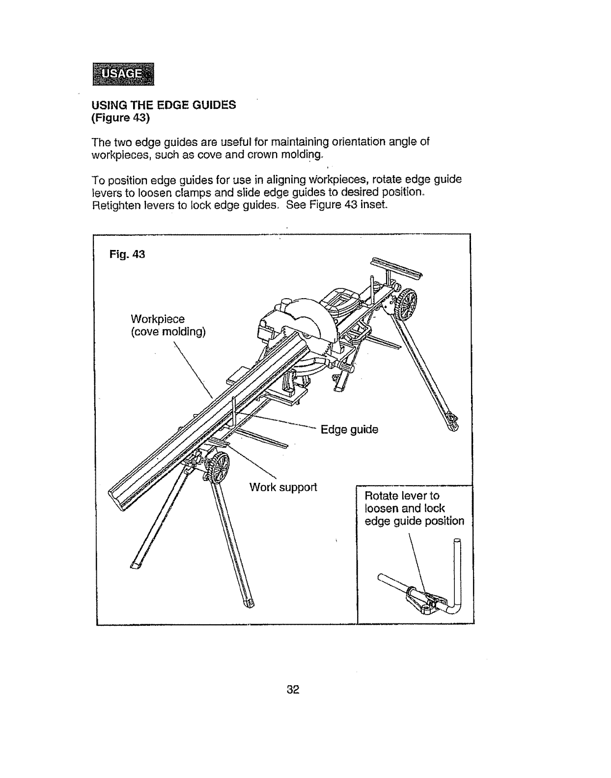
USING THE EDGE GUIDES
(Figure 4-3)
The two edge guides are useful for maintaining orientation angle of
workpieces, such as cove and crown molding.
To position edge guides for use in aligning v_orkpieces, rotate edge guide
levers to loosen clamps and slide edge guides to desired position.
Retighten levers to lock edge guides. See Figure 43 inset.
Fig. 43
Workpiece
(cove molding)
Edge guide
Work support Rotate lever to
loosen and lock
edge guide position
32
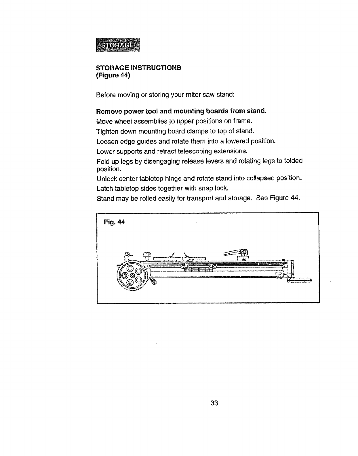
STORAGE INSTRUCTIONS
(Figure 44)
Before moving or storing your miter saw stand:
Remove power tool and mounting boards from stand.
Move wheel assemblie s to upper positions on frame.
Tighten down mounting board clamps to top of stand.
Loosen edge guides and rotate them into a lowered position.
Lower supports and retract telescoping extensions
Fold up legs by disengaging release levers and rotating legs to folded
position.
Unlock center tabletop hinge and rotate stand into collapsed position.
Latch tabletop sides together with snap lock.
Stand may be rolled easily for transport and storage. See Figure 44,
Fig. 44
33
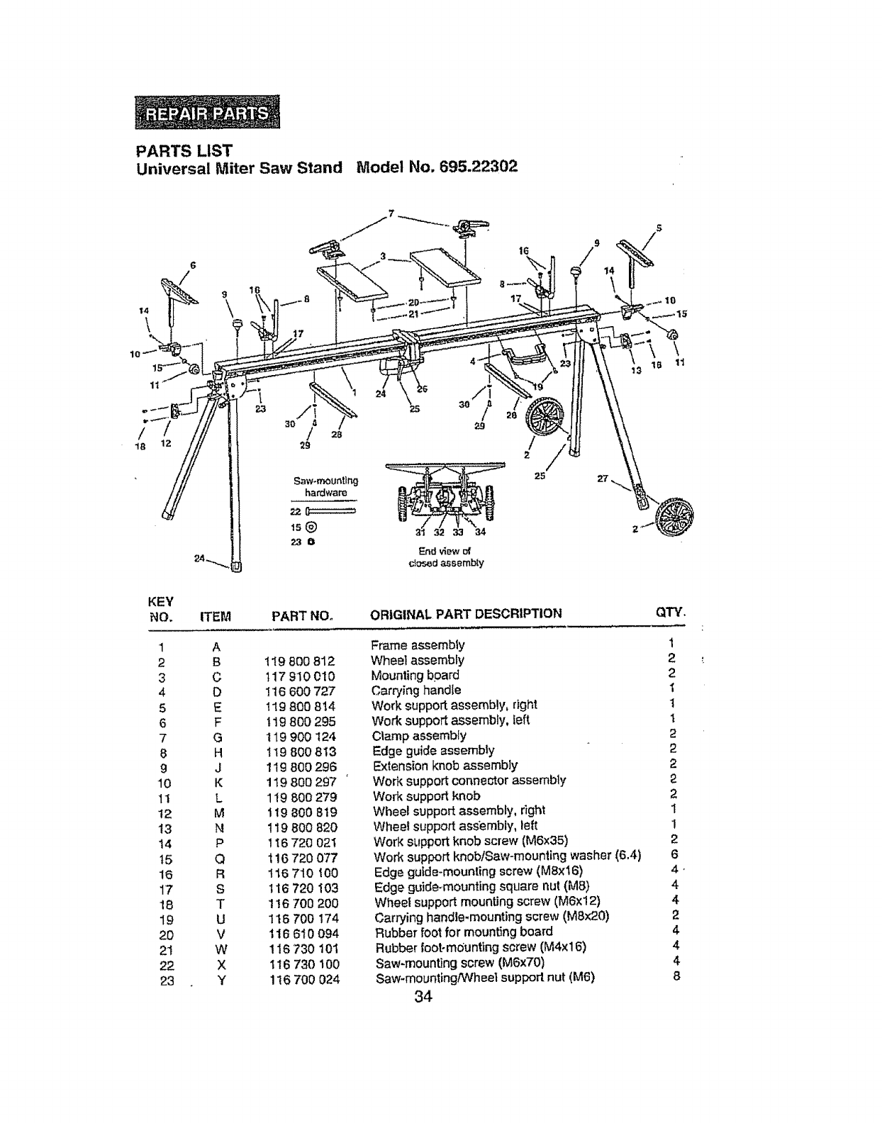
PARTS LIST
Universal Miter Saw Stand Model No. 695.22302
Saw-mounting
hardware
16
17
25
S
10
KEY
NO, ITEM PART NO.
1 A
2 B t19 8O0 812
3C 117 910 010
4 D !16 600727
5 E I19 800 8t4
6 F t19 800 295
7 G 119 900 124
8H 119 800 813
9J 119 800 296
10 K 119 800 297
11 L 119 800279
t2 M 119 800 8t9
t3 N 119 800 820
14 P 116 720 02t
15 Q 1!6 720 0'77
16 R 116 710 100
17 S 116 720 103
18 T 1t6 700 200
I9 U 1t6 700174
20 V 116 610 094
21 W 116 730 101
22 X 116 730 100
23 Y 116700 024
ORIGINAL PART DESCRIPTION
Frame assembly
Wheet assembly
Mounting bpard
Carrying handle
Work support assembly, right
Work support assembly, left
Clamp assembly
Edge guide assembly
Extens{on knob assembly
Work support connector assembly
Work support knob
Wheel support essembly, dght
Wheel support assembly, left
Work support knob screw (M6x35)
Work support knob/Saw-mounting washer (6.4)
Edge gufde-moun{ing screw (M8x16)
Edge guide-mounting square nut (M8)
Wheel support mounting screw (MTx12)
Carrying handle-mounting screw (MSx20)
Rubber foot for mounting board
Rubber foot-m_unting screw (M4xl 6)
Saw-mounting screw (M6x70)
Saw-mounting/Wheel support nut (M6)
34
QTY.
1
2
2
1
t
2
2
2
2
2
1
1
2
6
4,
4
4
2
4
4
4
8

PARTS LIST
Universal Professional Miter Saw Stand Model No. 695.22302
KEY
NO. PART NO. REPLACEMENT PARTS DESCRIPTION
2119 800 812 Wheel assembly
3117 910 010 Mounting board
4 116 600 727
19 116 700 f74 Carrying handte
Carrying handle-mounting screw (M8x20)
5119 800 814
6 1t9 80O 295
10 1t9 8OO297
11 119 800 279
14 1t6 720 02'1
15 116 720 077
119 900 124
Work support assembly, right
Work support assembty, left
Wo_ support conhectorassembly
Work support knob
Work supportknob screw (M6x35)
Work support knob washer (64)
Clamp assembly
8 119 8O08+13
16 116 710 100
17 116 720 !03
£119 800 296
Edge guide assembly
Edge gulde-mounting screw (Max16)
Edge guide-mounting sqt_arenut (MS)
Extension knob assembly
20 1!6 610 094
21 !16 730 101 Rubber foot for mounting board
Rubber foot-mduntingscrew (M4xt6)
22 116 730 100
15 116 720 077
23 116700 024
Saw-mountingscrew (M6x70)
Saw+mounting washer (6+4)
Saw-mounting nut (M6)
12 119 800 819
13 '11g 800820
18 116 700 200
23 116 700 024
24 119 800269
Wheel support assembly, dghl .
Wheel support assembly, left
Wheel support assembly mounting screw (M6xt2) +
Whee! support assembly-mounting nut (M6)
Swivel handle assembly (red)
25 116 610 228.
26 1i6 710 050 Adjustable handle for latching frame together
Adjustable handle washer (10.4)
27 116 600 662 Foot
28 117 0103O1
29 116730069
30 116 700 026
31 t19 8O0278
32 116 60073O
++3-3 146700 091
34 116 700 024
Stock support
Stock support screw (M6xl 6)
Stock support washer !6;4)
Carrying Lock, Rigf_t.Hated
Carrying Lock, Left Hand
Carrying Lock Mounting Screw (M6x2.0)
Carrying Lock Mounting Nut (M6))
QTY.
1
2
1
1
1
t
1
1
t
2
2
4
4
4
8
4
1
1
1
1
1
1
1
1
1
1
t
4
4
35

i
:!;
_J,_ _ 1_' i_" "; ,_ * i_, _ ;- : "-'_:_ '
':• _ "" _ ••.,_ i• ',:_,,'_'_, ;: _ _._ i
Your Home '-,_::_,"_::
For repair in your home of alll major brand appliances, :;..
lawn and garden equipment, or heating and cooling system, :,i.:i_
no matter who made it, no matter who sold itl : '""
For the replacement parts, accessories and _:;?;_.;_
owner's manuals that you need to do-it-yourselL ,:._i__''
For Sears professional installation of home appliances :':_._.
_.:._'_i_,
and the items like garage door openers and water heaters. ,._":_,_._
1-800-4-MY-HOME _ Anytime, day or night _,";:'_'_
(l-800-469-4663) (U.S,A, and Canada) "_:"_
www, sears°com www.sears.com _;;_,i,_
Our Home ,.__;_
For repair of carry*in products like vacuums, lawn equipment, _",_-_.:;:_,_
and electronic, call or go on-line for the nearest " ....
'- Sears Parts and Repair Center.
1-800-488-1222 Anytime, day or night (US.A.)
To purchase a protection agreement (U_S,A.) or maintenance .-,--,,_
agreement (Canada) on a product serviced by Sea's: '_":
1-800-827-6655 ,(US_.) 1-800-361-6665 (Canada) ''_'_
Para pedir ser,,_ciode reparaciSn Au Canada pour service en fran_-_is: ;",'."
a domicil_o,ypara ordenar pie_s: 1-800-LE-FOYER _ ,'_i::it._'
1-888-SU-HOGAR s_ (_-_oo-_3_7)
(
©Sears, F_ebuck ar_ Co.
® Ragistered Trademark l"rMTrademark /s_ Service Mark of Sea_, Roebuck and Co.
® Marca Reglstrada 1_r_ Mama de F,.bfioa Is_ Mama de Servieio de Sears, Roebuck and Co
_',cMarque de commerce l'_ Marque d_pos_e de Sea_s. Roebuck and Co
