Craftsman 695657960 User Manual WORKBENCH Manuals And Guides L0809503
CRAFTSMAN Workbench / Project Manual L0809503 CRAFTSMAN Workbench / Project Owner's Manual, CRAFTSMAN Workbench / Project installation guides
User Manual: Craftsman 695657960 695657960 CRAFTSMAN WORKBENCH - Manuals and Guides View the owners manual for your CRAFTSMAN WORKBENCH #695657960. Home:Tool Parts:Craftsman Parts:Craftsman WORKBENCH Manual
Open the PDF directly: View PDF ![]() .
.
Page Count: 10
Owner's Manual
Manual del Usuario
I1!'1I
CRRFTS.R. !
HEIGHT ADJUSTABLE CLAMPING TABLE
BANCO DE TRABAJO DE FIJACION R/_PIDA
Model No. 695.65796
Modelo N-°695.65796
CAUTION:
Before using thls
product, read this
manual and
follow all its Safety Rules
and Operating .
Instructions.
PRECAUCION:
Antes de usar este
producto, lea este manual
y slga todas las
instrucclones de
seguridad y de maneJo.
• Safety Instructions • Instrucciones de
• Assembly segurldad
• Operation •Montaje
•Repair Parts =Manejo
• Lista de plezas
Sears, Roebuck and Co., Hoffman Estates, IL 60179 U.S,A,
WARRANTY ............................................................... 2:
SAFETY INSTRUCTION8 ......................................... 8
INTRODUCTION ........................................................ 4
ASSEMBLY ................................................................ 4
Full One Year Warranty
OPERATION .............................................................. 5
_PE(31FI{3AT[O_J_ ..................................................... 8
UN-PACKING AND CHECKING ........................... ,..... 9
ESPAI_IOL................................................................ 11
If this ORAFTSMAN _ Olamplng Table fails to give
complete satisfaction wlthtn one year from the date
of purchase, return It to (or contact) the nearest
8ears Service Center In the United States, and
Sears wilt repair It, free of charge.
This warranty gives you specific legal rights and you
may also have other rights which vary from state to
state.
Sear=, Roebuck and Co.,
D/817WA_ Hoffman Estates, IL 60179
DO NOT attempt to assemble or operate your
CRAFTSMAN_ Height Adjustable Clamping Tdble until
you have read the safety instructions tnthis section.
Safety Items throughout this manual are labeled with
WARNING or CAUTION,
Means that faltura to fot!ow this
safety statement may result tn
extanelvsproduct damage, serious personal Injury or
death.
Means that failure to fellow thls
safety statement may result In mtnor or
moderate personal In]ury, property or equipment
damage.
DO NOT use this too[ for
scaffolding or as a ladder, Make sure to
fully tighten handles when in use. Maxlmum capacity
380 Ibs,
Read all Instructions.
@DO NOT load clamplng table withmore than SSolbs.
@DO NOT apply an unbalanced load which could
result tn the shop stand tippingover.
DO NOT attempt to use your portable
workbench unless the Jaw Is securely
looked in position.
When operating a stationary power tool
such as a Mitre Saw, on your Olamplng
Table, be sure the tool is securely bolted to a separate
piece of plywood and the plywood Is securely clamped
to the work table. DO NOT clamp or mount stationary
power tool directly to tabletop, This could cause serious
bodily damage.
When operating aportabte power tool
such as a drill, router_ sander or planer:
Always be sure that the workplace Is securely ¢le_'nped
to your Clamping Table, This will avoid kickback which
couldcause serious bodily injury. '
1"o prevent persona[ Injury while
opening or closing your workbench,
always avoid positioning hands or fingers where they
couldget pinched,
®DO NOT stand or climb on the shop stand. It could
fall or_p over causing serious Injury,
®Be sure the shop stsnd's leg set frame assembly Is
in the fuliy opened position before using.
®Dress for safety. DO NOT wear loose clothing,
gloves, necktles or Jewelry (rings, watches); they
can get caught and draw you Into moving parts_
ALWAYS wear non-aIlp footwear; tie back hair.
@
@
DO NOT store a_hopstand outdoors or
{nadamp location,
ALWAYS keep your work area clean, uncluttered
and well lit. DO NOT work o.n or place shop stand
legs on floor surfaces theft are slrppery from
sawdust, oil, water or wax
Keep visitors or ohlldren a sadiedistance away from
the work area, especially when you're operating a
power tool, Visitors should wear the same safety
equipment as the operator,
@SAVE THESE INSTRUCTIONS.
2
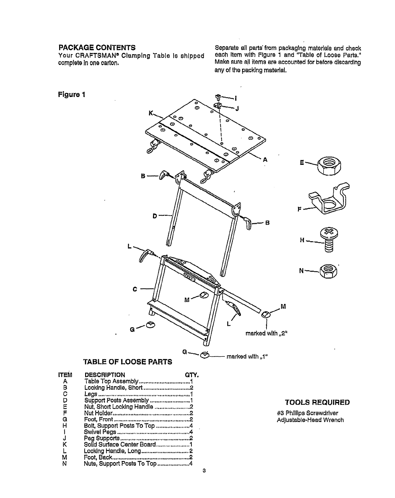
PACKAGE CONTENTS
Your CRAFTSMAN °Clamping Table is shipped
completeinonecarton,
Separate ell parts'from packaging materials and check
each Item with Figure 1and "Table of Loose Parts."
Make sure a!l items are accounted for before dlscardlng
any of the packing material.
Figure I
!
|
1
1
1
B
A
D
iTEM
A
B
C
D
E
F
Q
H
l
J
K
L
M
N
TABLE OF LOOSE PARTS G,--.,,. _ marked wlth ,1"
DESCRIPTION QTY.
Table Top Assembly................................ !
LooklngHandle, Short .............................2
Legs .........................................................1
SupportPostsAssembly.........................I
Nut,ShortLocklngHandle.......................2
NutHolder................................................2
Foot, Front ..................................................2
Bolt, Support Posts To Top ..................... 4
b-_IvelPegs .............................................A
Peg Supports ........................................... 2
Solid Surface Center Board ..................... 1
Looldng Handle, Long..............................2
Foot, Back................................................ 2
Nuts_Support Posts To Top ....................4
TOOLS REQUIRED
#3 PhillipsScrewdriver
Adjustable-Head Wrench

TheCRAFTSMAN eClamplng Table provides a work
surface of up to 40-3/4 '_.It features a largo 30" x20-1/2"
ti(ting top made of durable _B/4-1nchthlak MDF (Medium
Denslty Fiber). Its steel frame supports up to 330 Ibs,,
and thero ]s a convenient storage rack with slots for
table pegs, parts and for hand toofs, such as
screwdrivers and chisels. Jaw Is adjustable up to 9
degrees for holding Irregularly-shaped workpleoes.
A step bar provldes additional support and stability,
The major components of your dRAFTSMAN ®
Clamping Table have been assembled at 1he factory.
This lnctudes the table top, the support posts, and tho
legs, You need to complete _he shop stand by assem-
bling the following components to each other."
= table top to support posts
= short locking handles to support posts
= feet to Iegs
•longlocking handles to Ieg_
=table top/support posts to logs
For these proaedures, you need a #3 Phillips
screwdriver and an adjustable-head wrench.
Table Top to Support Posts
1. Place stand top (A) upside.down on a smooth
surface. (See Ftgura 2,)
Figure 2
2. With vlangular-shapod tilt brackets on Inside of rail
and pivoted toward rear of table, attach _upport
postsassembly (D) with 4 bolts (H) and 4nuts (N),
2on each side,
3. Tighten with Phillips screwdriver and adjustable-
head wrench.
Looklng Handles to Support Posts
1, Move support posts assembly (D) to most
advanced position (small tabs Ilmlt movement).
(See Figure 2.)
2. Maintaining a_embly In most advanced posltlon
with your shoulder, place tabs of nut holder (F)
(over nut [I_]) and Into slots. White holding nut
holder In slot with nut, use other hand to thread
short looking handle (B) Into nut
3. Repeat for other side.
To tighten: Turn handles clockwise.
To loosen: Turn handles counterclockwise.
B
D
N
F
DF
H
A
4
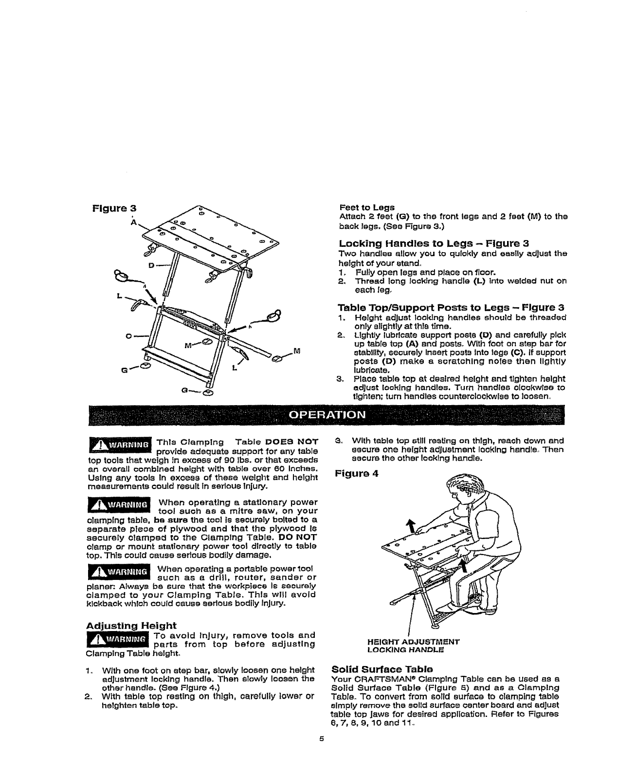
Figure 3
h
Feet to Legs
Attach 2 feet (G) to :he front legs and 2 feet (M) to the
back legs, (See Figure 3,)
Locking Handles to Legs -Figure 3
Two handles allow you to qulckly and esstly adjust the
height of your stand.
1. Futiy open legs and place on floor.
2. Thread long Jooktng handle (L) into welded nut on
each Ieg_
Table Top/Support Posts to Legs - Figure 3
1. Height adjust looPJng handles should be threaded
only slightly at thls time.
2. Lightly lubricate support posts (O) and carefully pick
up labia top (A) and posts. With foot on step bar for
stability, securely Insert posts Into legs (C)o if support
posts (D) make a scratching notes then lightly
lubricate.
3o Place table top at desired height and lighten height
adjust rooking handles. Turn handles olookwise to
tighten; turn handles oounterclootcwlee to loosen,
This Clamping Table DOE8 NOT
provide adequate support for any table
top tools that weigh tn excess of 90 Ibs. or that exceeds
an overall combined height with table over 60 Inches,
Using any tools in excess of these weight and height
measurements could result In sedous injury.
When operating astationary power
tool euoh as a mitre e_w, on your
clamping table, be aura the tool ts securely bolted to a
separate pleoe of ptywood and that the plywood Is
securely elarnped to the Clamping Table. DO NOT
clamp or mount stationary power toot directly to table
top. This could cause serious bodily damage,
When operating a portable power _ooI
such as a drill, router, sander or
planer: Always bs sure that the workpiece Is securely
clamped to your Cramping Table, This will avoid
kickback whloh could cause serious bodily Injury.
Ad |ng Height
To avoid Injury, remove tools and
parts from top before adjusting
Clamping Table height.
1o With one foot on step bar, slowly loosen one height
adjustment locking handle. Then slowly loosen the
other handle°(See Figure 4,)
2_ With table top resting on thigh, carefully lower or
heighten tabletop.
3. With table top still resting on thlgh, reach down and
secure one height adjustment looking handle., Then
secure the otherIooklng handle.
Figure 4
HEIGHT ADJUSTMENT
LOCKING HANDL_
Solid Surface Table
Your CRAFTSMAN e Clamping Table can be used as a
Solid Surface Table (Figure 5) and as a Cl_mplng
Table,. To convert from solid surface to olamptng table
simply remove the solid surface center board and adjust
table top Jaws for desired application. Refer to Figures
6, 7, 8, 9, 10 and 11.
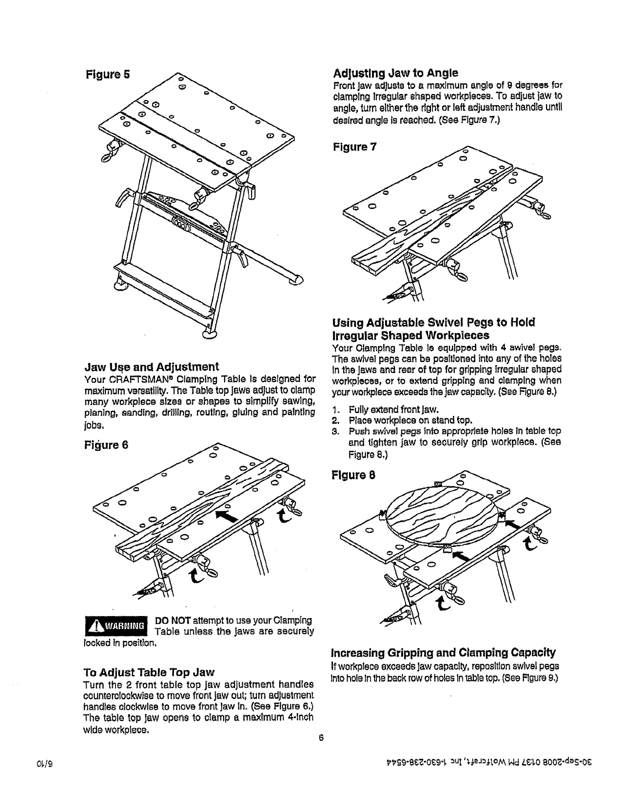
Figure 5 Adjusting Jaw to Angle
FrontJaw adjusts to a maximum angle of 9 degrees for
olamplng Irregular shaped workplsces. To adjust jaw to
angle, turn either the rightor left adjustment handleuntil
desired angle is reached. (See Figure 7.)
Figure 7
Jaw Use and Adjustment
Your CRAFTSMAN ®Clamping Table ls designed for
maximum versatility.The Tabte topjaws adjust to clamp
many workplace sizes or shapes to simplify sawing,
planing, sanding, drilling, routing, gluing and painting
jobs,
Fi_lure 6
DO NOT attempt to use your Olamping
Table unless the Jaws are securely
locked in position,
To Adjust Table Top Jaw
Turn the 2 front table top jaw adjustment handles
counterotockwiseto move front jaw out;turn adjustment
handles clockwise to move front Jaw In_(See Figure 6.)
The table top Jaw opens to clamp a maximum 4-1nob
wide workpfece.
Using Adjustable Swivel Pegs to Hold
Irregular Shaped Workpieoes
Your Olamplng Table Is equipped with 4 swivel pegs.
The swivelpegs can be posltloned into any of the holes
In theJaws and rear of top for gripping frregular shaped
workpleces, or to extend gripping and clamping when
your workplaceexceeds _hajaw capacity, (see F3gure8.)
1. Fullyextend fmntJaw.
2. Place workplace on standtop.
3. Push sw]ve]pegs into appropr]ate holes tn table top
and tighten jaw to securely grip workplace. (See
Figure8.)
Figure 8
Increasing Gripping and Clamping Capacity
If workplaceexceedsJawcapacity,reposltlonswivel pegs
Intohole Inthe back row of holes tn tabletop.(See Rgure9.)
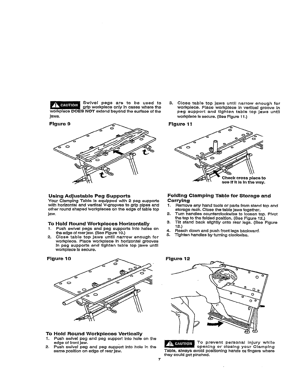
Swlve! pegs are to be used to
grip workplace only In cases where the
workplace DOLES NOT extend beyond the surface of the
Jaws.
Figure g =, _:_
3+ Close table top Jaws until narrow enough for
workplace, Place workpleoe In vertloal groove in
peg support and tighter table top jaws until
workplace Is secure. (Sea F3gum 11.)
Flgure 11
Check cross piece tO
see If It Is In the way.
Using Adjustable Peg Supports
Your Clamping Table Is equipped with 2 peg eupportm
with horizontal and vertlcal V-gropves to grip pipes and
other round shaped _vorkplecee on the edge of table top
JEW+,
To Hold Round Workpleces Horizontally
1= Push swivel pegs and peg supports Into holes on
the edge of rear Jaw. (See Figure 10.)
2. Close table top Jaws untll narrow enough for
worl<pteoe, Place workplace In horizontal grooves
in peg supports and tighten table top Jaws until
workple_e Is secure,
Figure 10
To Hold Round tNorkpieoee Vertically
1. Push swivel peg and peg support Into hole on the
edge of front Jaw,
2. Push swivel peg and peg support into hole in the
same position on edge of rear Jaw.
Folding Clamping Tabl e for Storage and
Carrying
1, Remove any hand tools or parts from stand top and
storage rack, Close the table Jaws together,
2, Turn handles countemlockwlse to loosen top. Pivot
the top to the forded posit]on, (See Figure 12.)
3+ Tilt stand back slightly onto rear Jags. (See Figure
mJ
4. Reach down and push front legs backward
5. Tighten handles by turning clockwlse.
Figure 12
To prevent personal injury while
open]ng or cloBing your Clamping
Table, always avoid po0itionlng hands o_ fingers where
they coulcl get plnohed.
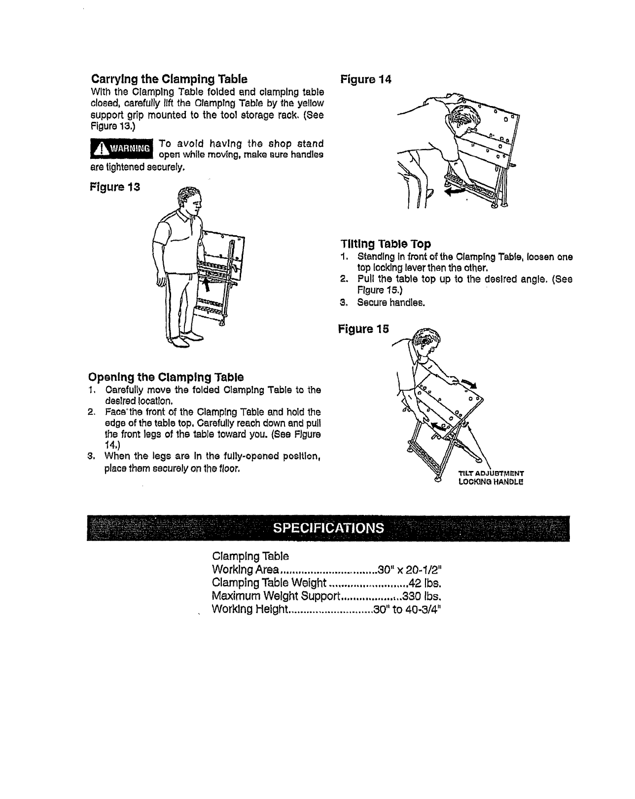
Carrying the Clamping Table
With the Clamping Table folded end clamping table
o!osed, carefully !Ift the Olamplng Tabre by the yellow
support grip mounted to the tool storage rack. (See
Figure !3.)
To avoid havlng the shop stand
open while moving, make aura handles
are tightenedsecurely.
Figure 13
Figure 14
Tilting Table Top
I. Standing infront of the ClampingTable, loosen one
top looking lever then the other,
2, Pull the table top up to the desired angle. (See
Figure 15.)
3o Secure handles.
Figure 1B
Opening the Clamping Table
1. Oarefully move the folded Olamplng Table to the
desired location,
2. Fats'the front of the Clamping Table and hold the
edge of the table top, Carefully reach down and pull
the front legs of the table toward you. (See Figure
_4,)
3, When the legs are in the fully-opened position,
place them securely on the floor. TiLT ADJUBTME;NT
LOOKING HANDLE
Clamping Table
V¢orklngArea ................................. 30" x 20-1/2"
Clamping Table Weight .......................... 42 lbs.
Maximum Weight Support ................. ,,,330 Ibs,
Working Height ............................ 30" to 40-3/4"
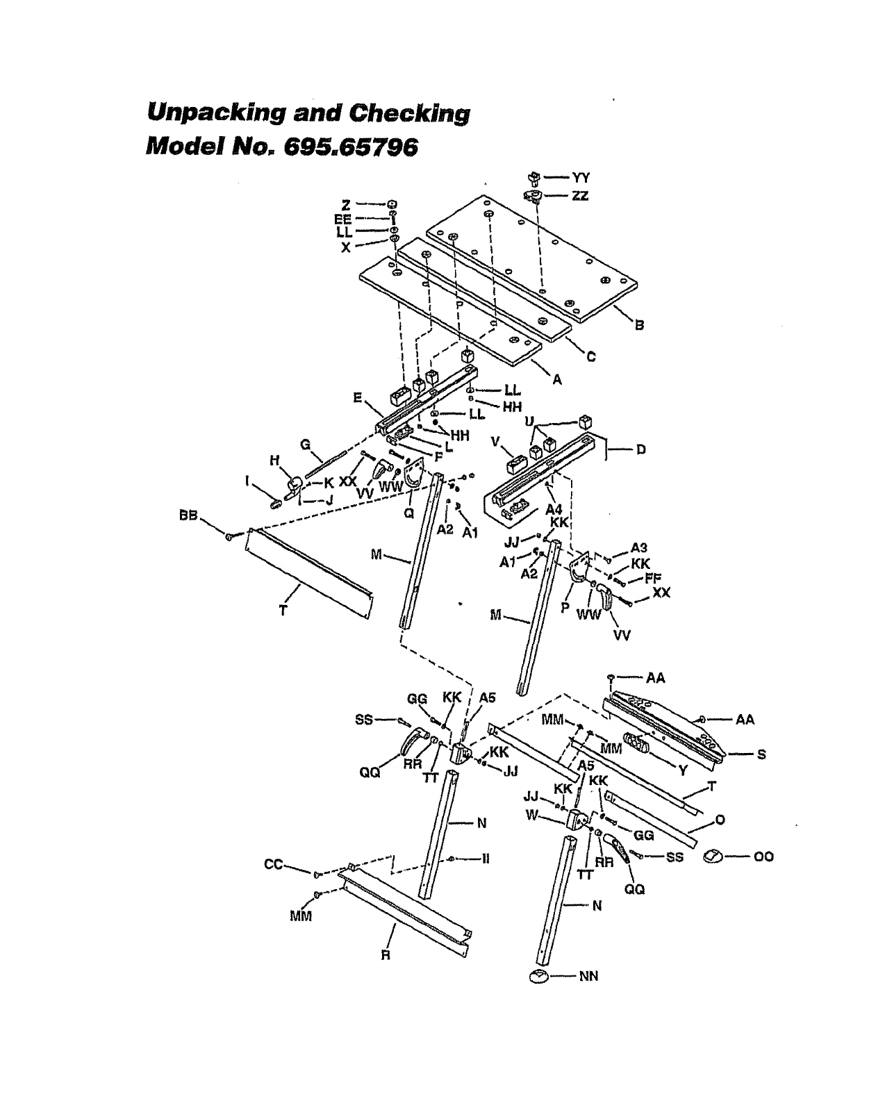
Unpacking and Checking
Model No. 695.65796
G
H \
II
!I
1
!
|
T
I
!||
I
v\
A5
A2
B
A3
_-FF
XX
?_AA
S
/
R
N\
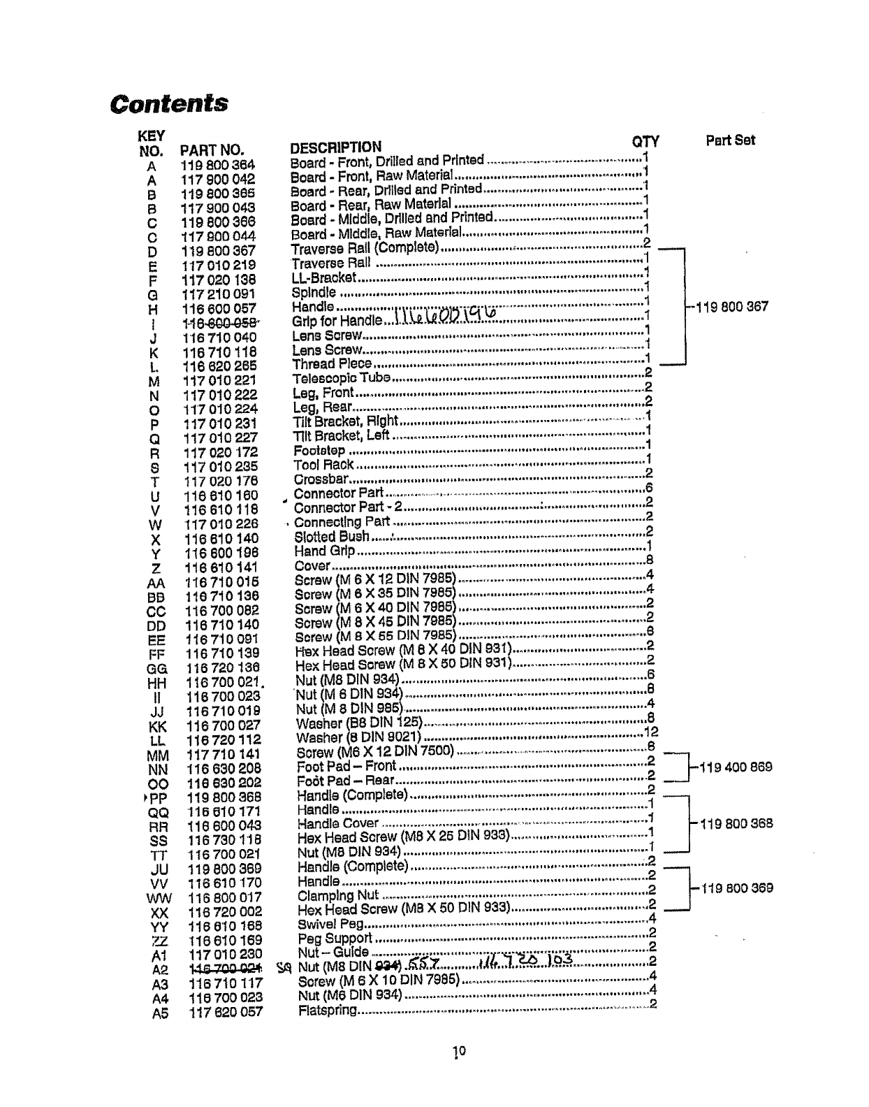
Contents
KEY
NO. PART NO.
A 119 800 364
AI17 900 042
B119 800 385
B117 900 04.3
C119 800 388
O117 O00 044
D 1!9 800 367
E117010219
F 117020 138
O 117210091
H 116 600 057
J118 710 O40
K 116 710 118
L 116 820 285
M 117010221
N 117 010 222
O117 010 224
P 117 010 231
Q 117010227
R 117020 172
81i7 010 235
T117 020 176
U 118810180
V118 610 118
W117 010 228
X 116 610 140
Y1t6 600196
Z t16 610 141
AA 116710016
BB 118 710 138
CC 116700082
DD 116710140
EE t 16 710 091
FF 116710139
GG 116720136
HH 1187O0021.
11 116 70O 023
JJ 116710019
KK 116700027
LL 116720 1t2
MM 117710 141
NN 116 630 206
O0 116 630 202
PP 1!9800368
QQ 116010171
RR 118 800 043
SS 116 730 118
TT 116 700 021
JU 119 800 369
VV 116 610 170
W'W 116 800 017
XX 116720OO2
YY t16 0't0 168
ZZ 118810169
A1 117 010 23O
A2
A3 1167t0 117
A4 118 700 023
A5 117 620 057
DESCRIPTION
Board - Front, Drilled and Printed...............................................1
Board -Front, Raw Matedal .................................................... 1
Board -Rear, Ddlted and Printed ............................................ 1
Board-Rear, Raw Materlal .................................................... 1
Board -Middle, Drllledand Printed ......................................... 1
Board - Mlddle, Raw Material .................................................. 1
Travame Rall (Complete) ....................,.....................................2
Traverse Ral_ ........................................................................... 1
LL-Braoket ................................................................................ !
Spindle .................................................................................... 1
Handle ................................................................................... 1
Grip for Handle,.,_.._,_._._.._.._.'_. ........................................ 1
Lena Screw .............................................................................. 1
Lens Screw.................................................................................I
Thread Piece ........................................................................... 1
Telescopic Tube ...................................................................... 2
Leg, Front................................................................................ 2
Leg, Rear ................................................................................. 2
3ilt Bracket, Right..........................................................................1
Tilt Bracket, Left ...................................................................... 1
FootBlep.................................................................................. 1
Tool Rack ................................................................................ 1
Crossbar................................................................................... 2
Connector Part ...............................................................................6
"Corms=or Part -2...................................... :............................ 2
.Connecting Part ...................................................................... 2
Slotted Bush.....:...................................................................... 2
Hand Gdp ................................................................................ 1
Cover....................................................................................... 8
Screw (M 6X12 DIN 7985) .................................................... 4
Screw {_ 6 X 35 DIN 7985) .................................................... 4
Screw 6 X 40 DIN 7986) .................................................... 2
Screw 8 X 45 DIN 7985_\ .................................................... 2
screw (M 8 X 65 DIN 7985) .................................................... 6
Hex Head Screw (M 8 X 40 DIN 931)......................................2
Hex Hea_l Screw (M BX 50 DIN 931)..................................... 2
Nut (Me DIN 934) .................................................................... 6
'Nut (M 6 DIN 934) ................................................................... 8
Nut (M 8 DIN 985).................................................................... 4
Washer (68 DIN !25) .............................................................. 8
Washer (6 DIN 9021) ............................................................. 12
Screw (Me X 12 DIN 7500) ..........................................................8
Foot Pad- Front..................................................................... 2
Fo0t Pad- Rear...................................................................... 2
Handle (Comp]ste) .................................................................. 2
Handle ...................................................................................... 1
Handle Cover .............................................................................1
He)<Head Screw(M8 X 26 DiN 933) .......................................1
Nut (MB DIN 934) .................................................................... I
Handle (Comptete) ................................................................ ;.2
Handle ..................................................................................... 2
ClamplngNut...........................................................................2
Hex Head Screw (M6 X 50 DIN 933)......................................2
Swivel Peg................................................................................ 4
Peg Support ............................................................................. 2
Nut- Guide ........................................................................... 2
Nut (M8 DIN _.._,_,.7:. ...........f.4_,.._,.,,,_......).q.$...................... 2
Screw (M 6 X 10 DIN 7985) .................................................... 4
Nut (Me DIN 934) .................................................................... 4
Ratspdng.........................................................................................2
OTY Part Set
-119 800 367
--_119 400869
_'-119 8OO366
19 800389
t0
