Craftsman 706323180 User Manual TOOL CABINET Manuals And Guides 1311199L
User Manual: Craftsman 706323180 706323180 CRAFTSMAN TOOL CABINET - Manuals and Guides View the owners manual for your CRAFTSMAN TOOL CABINET #706323180. Home:Tool Parts:Craftsman Parts:Craftsman TOOL CABINET Manual
Open the PDF directly: View PDF ![]() .
.
Page Count: 8
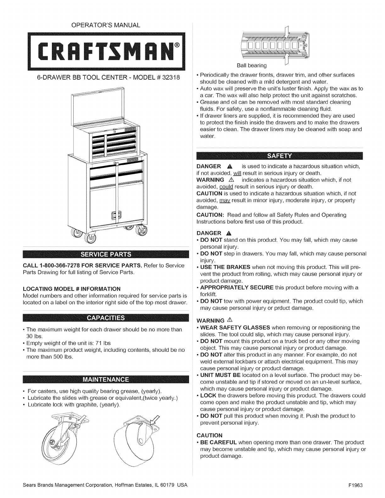
OPERATOR'S MANUAL
T°
6-DRAWER BB TOOL CENTER - MODEL # 32318
CALL 1-800-366-7278 FOR SERVICE PARTS. Refer to Service
Parts Drawing for full listing of Service Parts.
LOCATING MODEL # INFORMATION
Model numbers and other information required for service parts is
located on a label on the interior right side of the top most drawer.
•The maximum weight for each drawer should be no more than
30 Ibs.
•Empty weight of the unit is: 71 Ibs
•The maximum product weight, including contents, should be no
more than 500 Ibs.
•For casters, use high quality bearing grease, (yearly).
•Lubricate the slides with grease or equivalent,(twice yearly.)
•Lubricate lock with graphite, (yearly).
Ball bearing
•Periodically the drawer fronts, drawer trim, and other surfaces
should be cleaned with a mild detergent and water.
•Auto wax will preserve the unit's luster finish. Apply the wax as to
a car. The wax will also help protect the unit against scratches.
•Grease and oil can be removed with most standard cleaning
fluids. For safety, use a nonflammable cleaning fluid.
•If drawer liners are supplied, it is recommended they are used
to protect the finish inside the drawers and to make the drawers
easier to clean. The drawer liners may be cleaned with soap and
water.
DANGER _, is used to indicate a hazardous situation which,
if not avoided, will result in serious injury or death.
WARNING z_ indicates a hazardous situation which, if not
avoided, could result in serious injury or death.
CAUTION is used to indicate a hazardous situation which, if not
avoided, may. result in minor injury, moderate injury, or property
damage.
CAUTION: Read and follow all Safety Rules and Operating
Instructions before first use of this product.
DANGER
•DO NOT
pe_onal
•DO NOT
i_ury.
A
stand on this product. You may fall, which may cause
injury.
step in drawers. You may fall, which may cause personal
•USE THE BRAKES when not moving this product. This will pre-
vent the product from rolling, which may cause personal injury or
product damage.
•APPROPRIATELY SECURE this product before moving with a
forklift.
•DO NOT tow with power equipment. The product could tip, which
may cause personal injury or prduct damage.
WARNING z_
•WEAR SAFETY GLASSES when removing or repositioning the
slides. The tool could slip, which may cause personal injury.
•DO NOT mount this product on a truck bed or any other moving
object. This may cause personal injury or product damage.
•DO NOT alter this product in any manner. For example, do not
weld external Iockbars or attach electrical equipment. This may
cause personal injury or product damage.
•UNIT MUST BE located on a level surface. The product may be-
come unstable and tip if stored or moved on an un-level surface,
which may cause personal injury or product damage.
•LOCK the drawers before moving this product. The drawers could
come open and make the product unstable and tip, which may
cause personal injury or product damage.
•DO NOT pull this product when moving it. Push the product to
prevent personal injury.
CAUTION
•BE CAREFUL when opening more than one drawer. The product
may become unstable and tip, which may cause personal injury or
product damage.
Sears Brands Management Corporation, Hoffman Estates, IL 60179 USA F1963
TOOLS REQUIRED:
Flat-tip Screwdriver
3/8-in Wrench
HARDWARE REQUIRED:
1/4-20 Hex Nut (Qty: 16)
1/4-20 x .438-in Screw (Qty: 16)
1/4-14 x 5/8 Sheet Metat Screw
(Qty: 4)
Chest:
Literature
Cabinet:
Literature
Hardware bag
Caster pack
Caster pack
& ,$ T
REMOVE CHEST FROM ROLL-AWAY
The unit comes with the chest secured to the inside of
the rotbaway by either two or four 1/4-14 x 5/8 screws.
Lay the rolbaway down on its back. Use packaging
material to protect the paint finish.
Remove the securing screws from the underside of the
roll-away. Save the screws for mounting the chest to the
roll-away.
Remove the chest.
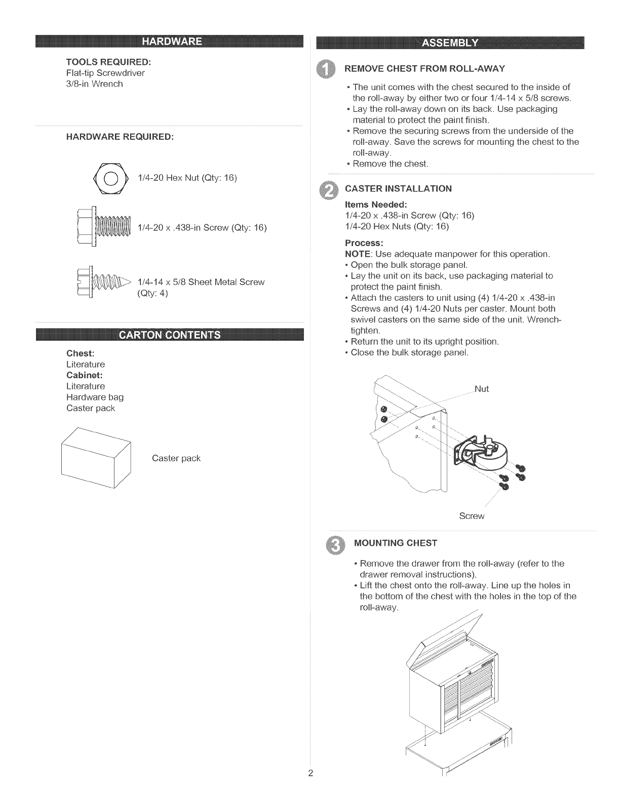
_ CASTER INSTALLATION
Items Needed:
1/4-20 x A38qn Screw (Qty: 16)
1/4-20 Hex Nuts (Qty: 16)
Process:
NOTE: Use adequate manpower for this operation.
-Open the bulk storage panel.
Lay the unit on its back, use packaging material to
protect the paint finish.
Attach the casters to unit using (4) 1/4-20 x .438-in
Screws and (4) 1/4-20 Nuts per caster. Mount both
swivel casters on the same side of the unit. Wrench-
tighten.
Return the unit to its upright position.
Close the bulk storage panel.
Nut
Screw
MOUNTING CHEST
Remove the drawer from the roll-away (refer to the
drawer removal instructions).
Lift the chest onto the rolbaway. Line up the holes in
the bottom of the chest with the holes in the top of the
roll-away.
Attachthechestusingtwo1/4-14x5/8screwsthatwere
usedtosecurethechesttothebottomoftheroll-away.
Wrenchtightenallscrews.
Replacethedrawer(refertothedrawerinstaJtationinstruc-
tions).
Toremovethechest,reversetheprocedure.
@LABELS (iF APPLICABLE)
PrOCeSS:
- Apply a Jight film of glass cJeaner to the surface where
the label is to be applied.
- PeeJ the JabeJfrom the backing and place the label in
position.
- Check aJignment of the Jabel and adjust accordingly.
- Hold the Jabet in position and squeegee off excess Jiquid
with a towel, working from the center toward each end of
the Jabet.
- Suggested label location is shown.
0 _ _± 0 7
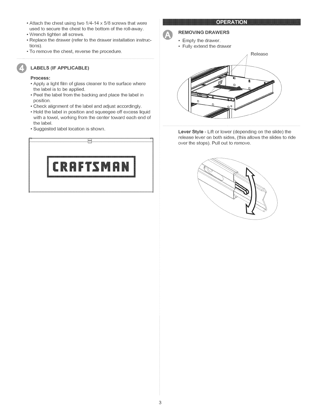
REMOVING DRAWERS
Empty the drawer.
FutJy extend the drawer
_, Release
/
Lever Style - Lift or lower (depending on the slide) the
release lever on both sides, (this allows the stides to ride
over the stops). Putt out to remove.
\\\ \
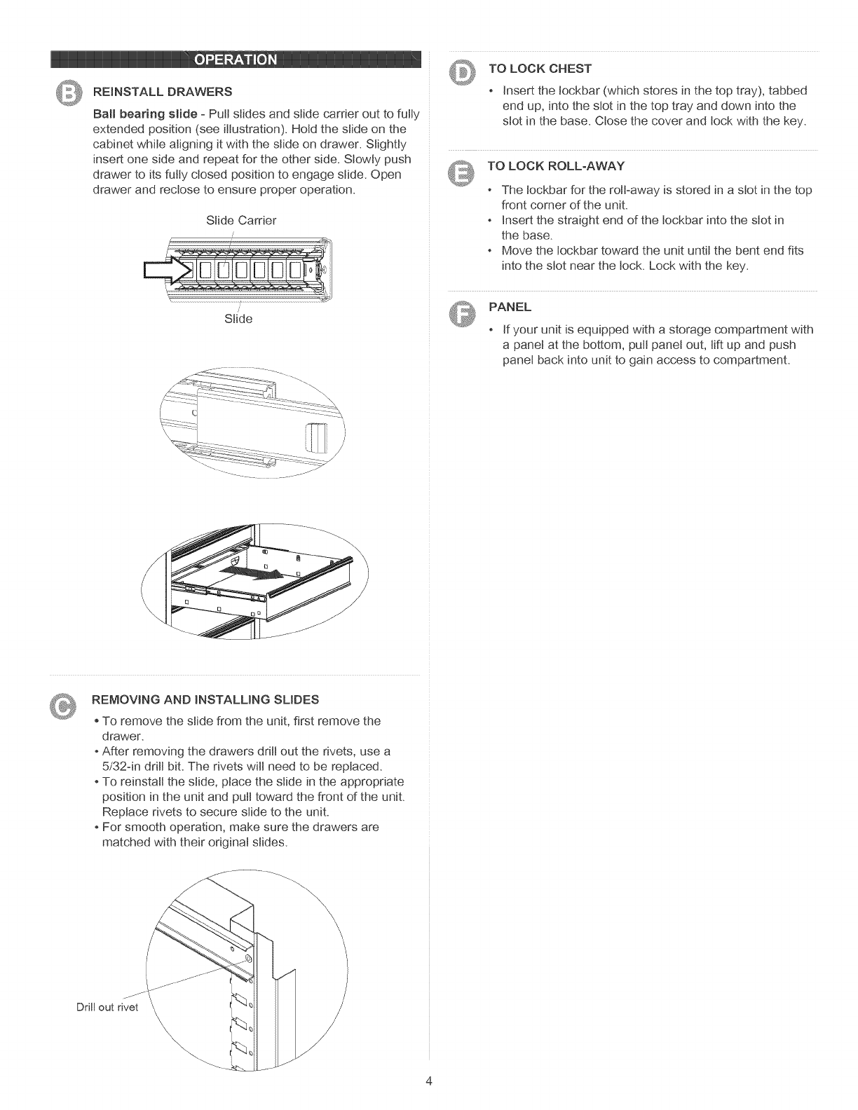
©REINSTALL DRAWERS
Ball bearing slide - Putt slides and slide carrier out to fully
extended position (see illustration). Hold the slide on the
cabinet while aligning it with the slide on drawer. Slightly
insert one side and repeat for the other side. Slowly push
drawer to its fully closed position to engage slide. Open
drawer and rectose to ensure proper operation.
Slide Carrier
Slide
TO LOCK CHEST
Insert the tockbar (which stores in the top tray), tabbed
end up, into the slot in the top tray and down into the
slot in the base. Close the cover and lock with the key.
TO LOCK ROLL-AWAY
The tockbar for the roJFaway is stored in a slot in the top
front corner of the unit.
Insert the straight end of the tockbar into the slot in
the base.
Move the tockbar toward the unit until the bent end fits
into the slot near the lock. Lock with the key.
PANEL
If your unit is equipped with a storage compartment with
a panel at the bottom, putt panel out, lift up and push
panel back into unit to gain access to compartment.
REMOVING AND INSTALLING SLIDES
, To remove the slide from the unit, first remove the
drawer.
After removing the drawers drill out the rivets, use a
5/32-in drill bit. The rivets will need to be replaced.
To reinstall the slide, place the slide in the appropriate
position in the unit and pull toward the front of the unit.
Replace rivets to secure slide to the unit.
For smooth operation, make sure the drawers are
matched with their original slides.
\
\\\ \\\
Drill out rivet
MANUAL DE USUARIO
®
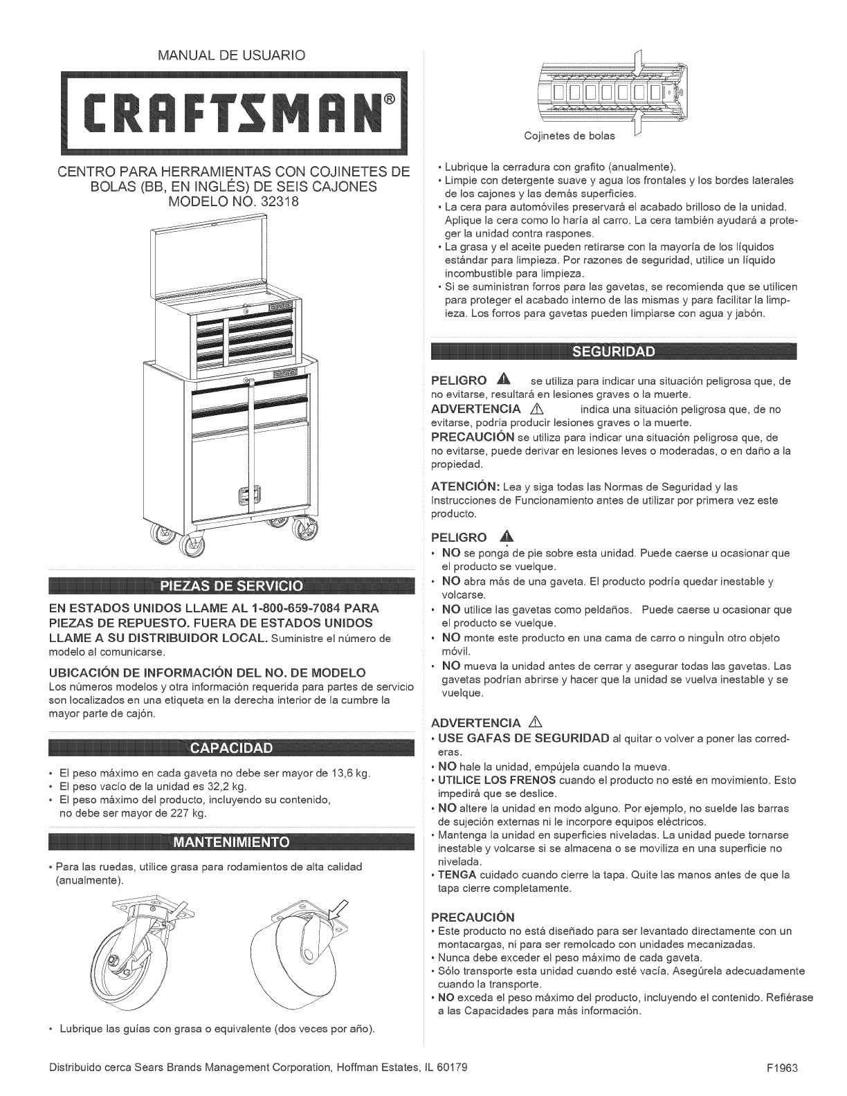
CENTRO PARA HERRAMENTAS CON COJRNETES DE
BOLAS (BB, EN INGL[_S) DE SEIS CA JONES
MODELO NO. 32318
iilI_
HH,_, 0 IIIIIIII
EN ESTADOS UNIDOS LLAME AL 1o800o659o7084 PARA
PIEZAS DE REPUESTO. FUERA DE ESTADOS UNIDOS
LLAME A SU DISTRtBUIDOR LOCAL. Suministre el nOmero de
modelo al comunicarse.
UBICACI6N DE MNFORMACt6N DEL NO. DE MODELO
Los nOmeros modelos y otra informaci6n requerida para partes de servicio
son Iocalizados en una etiqueta en la derecha interior de la cumbre la
mayor parte de caj6n.
• El peso m_ximo en cada gaveta no debe ser mayor de 13,6 kg.
• El peso vacio de la unidad es 32,2 kg.
• El peso mSximo del producto, incluyendo su contenido,
no debe ser mayor de 227 kg.
Para las ruedas, utilice grasa para rodamientos de alta calidad
(anualmente).
• Lubrique las guias con grasa o equivalente (dos veces por a_o).
• Lubrique la cerradura con grafito (anualmente).
• Limpie con detergente suave y agua los frontales y los bordes laterales
de los cajones y las demSs superficies.
• La cera para autom6viles preservar8 el acabado brilloso de la unidad.
Aplique la cera como Io haria al carro. La cera tambi6n ayudar8 a proteo
ger la unidad contra raspones.
• La grasa y el aceite pueden retirarse con la mayoria de los liquidos
est_ndar para limpieza. Por razones de seguridad, utilice un liquido
incombustible para limpieza.
• Si se suministran forros para las gavetas, se recomienda que se utilicen
para proteger el acabado interno de las mismas y para facilitar la limpo
ieza. Los forros para gavetas pueden limpiarse con agua y jab6n.
PELIGRO _ se utiliza para indicar una situaci6n peligrosa que, de
no evitarse, resultar_ en lesiones graves o la muerte.
ADVERTENCIA Z_ indica una situaci6n peligrosa que, de no
evitarse, podria producir lesiones graves o la muerte.
PREOAUOI6N se utiliza para indicar una situaci6n peligrosa que, de
no evitarse, puede derivar en lesiones leves o moderadas, o en da_o a la
propiedad.
ATENOI6N: Lea y siga todas las Normas de Seguridad y las
Instrucciones de Funcionamiento antes de utilizar por primera vez este
producto.
PEUGRO
NO se ponga de pie sobre esta unidad. Puede caerse u ocasionar que
el producto se vuelque.
NO abra mSs de una gaveta. El producto podria quedar inestable y
volcarse.
NO utilice las gavetas como pelda_os. Puede caerse u ocasionar que
el producto se vuelque.
NO monte este producto en una cama de carro o ninguin otro objeto
m6viL
NO mueva la unidad antes de cerrar y asegurar todas las gavetas. Las
gavetas podrian abrirse y hacer que la unidad se vuelva inestable y se
vuelque.
ADVERTENClA
USE GAFAS DE SEGURIDAD al quitar o volver a poner las corredo
eras.
• NO hale la unidad, empOjela cuando la mueva.
• UTILICE LOS FRENOS cuando el producto no est8 en movimiento. Esto
impedir_ que se deslice.
• NO altere la unidad en modo alguno. Por ejemplo, no suelde las barras
de sujeci6n externas ni le incorpore equipos el¢ctricos.
• Mantenga la unidad en superficies niveladas. La unidad puede tornarse
inestable y volcarse si se almacena o se moviliza en una superficie no
nivelada.
• TENGA cuidado cuando cierre la tapa. Quite las manos antes de que la
tapa cierre completamente.
PRECAUCI6N
Este producto no est_ dise_ado para ser levantado directamente con un
montacargas, ni para ser remolcado con unidades mecanizadas.
Nunca debe exceder el peso mSximo de cada gaveta.
$61o transporte esta unidad cuando est6 vacia. AsegOrela adecuadamente
cuando la transporte.
NO exceda el peso mSximo del producto, incluyendo el contenido. Refi6rase
alas Capacidades para m_s informaci6n.
Distribuido cerca Sears Brands Management Corporation, Hoffman Estates IL 60179 F1963
HERRAMIENTASNECESARIAS:
Destornillador,puntadecruz
LlaveInglesade8mm
PIEZASINCLUJDAS:
TuercaHexagonalde1/4o20(Cant:16)
Tornillo1/4o20xA38dn (Cant:16)
Tornillo 1/4o14 x 5/8 (Cant:4)
QUJTAR EL BAUL DE LA PIEZA DESLIZANTE
• La unidad tiene un baQl fijado por dentro a una pieza deslio
zante ya sea por dos o cuatro tornillos 1/4o14 x 5/8.
Acuesta la pieza deslizante boca arriba. Usa el material del
empaque para proteger el acabado de la pintura.
Quita los tornillos de fijaci6n en el fondo de la pieza deslizante.
Guarda los tornillos para montar el baQl sobre la pieza anterior.
Quita el baQk
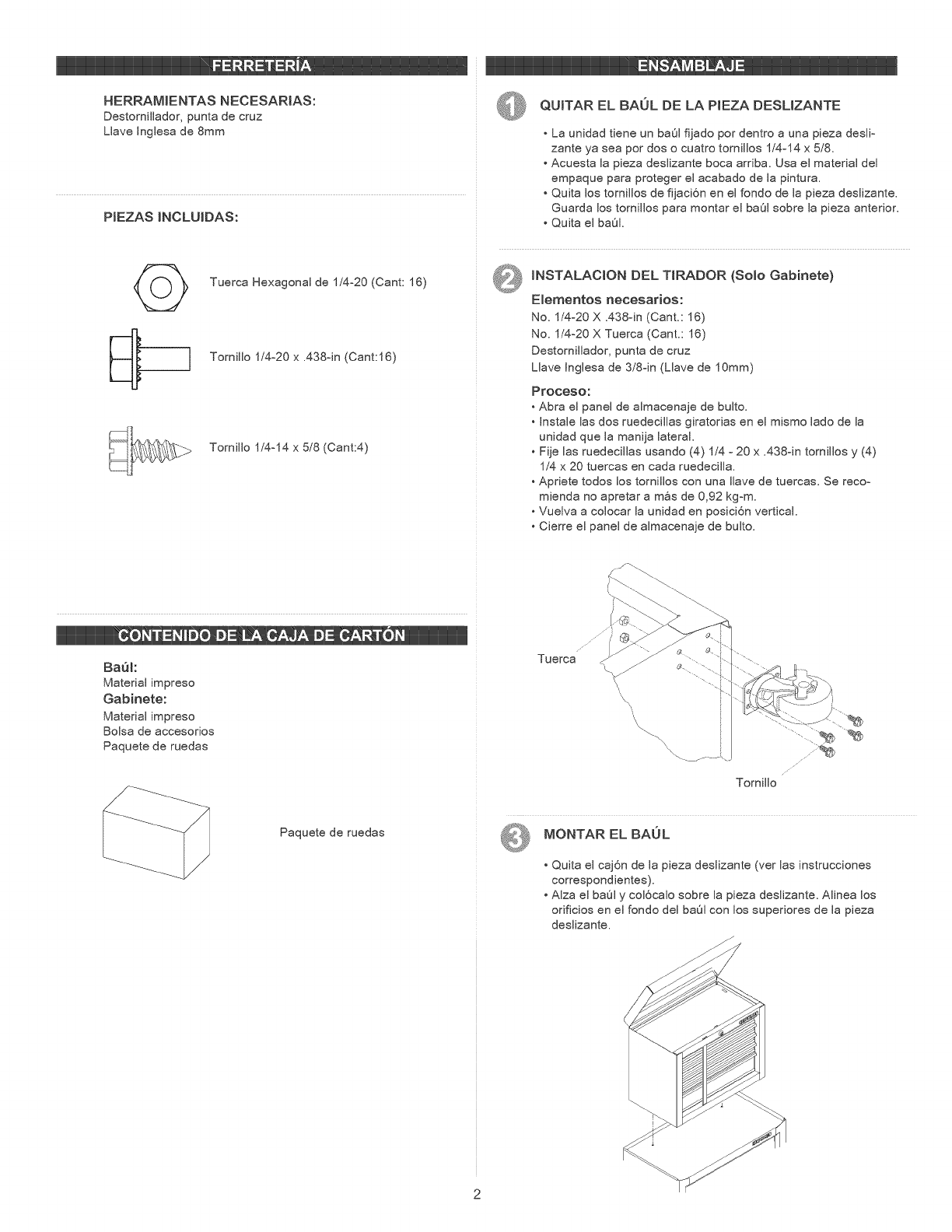
@MNSTALACION DEL TIRADOR (Solo Gabinete)
E_ementos necesarios:
No. 1/4-20 X A38oin (Cant.: 16)
No. 1/4o20 X Tuerca (Cant.: 16)
Destornillador, punta de cruz
Llave Jnglesa de 3/8dn (Llave de 10mm)
Proceso:
Abra el panel de almacenaje de bulto.
• Jnstale las dos ruedecillas giratorias en el mismo lado de la
unidad que la manija lateral.
Fije las ruedecillas usando (4) 1/4 o 20 x .438dn tornillos y (4)
1/'4x 20 tuercas en cada ruedecilla.
Apriete todos los tornillos con una Ilave de tuercas. Se recoo
mienda no apretar a m_s de 0,92 kgom.
Vuelva a colocar la unidad en posici6n vertical.
Cierre el panel de almacena e de bulto.
BaQI:
Material impreso
Gabinete:
Material impreso
Bolsa de accesorios
Paquete de ruedas
Paquete de ruedas
Tuerca ....
TorniJJo
MONTAR EL BAUL
• Quita el caj6n de la pieza deslizante (ver las instrucciones
correspondientes).
• AJza el ba@ly coJ6caJo sobre Japieza desJizante. AJinea los
orificios en el fondo deJ baQl con los superiores de Japieza
desJizante.
FijaelbaQIconlosdostornillos1/4-14x5/8usadosparaunirel
baQIalrondodelapiezamencionada.
AprietatodoslostornillosconunaIlave.
Vuelveamontarelcaj6n(verlasinstruccionescorrespondientes).
ParaquitarelbaQl,invierteelproceso.
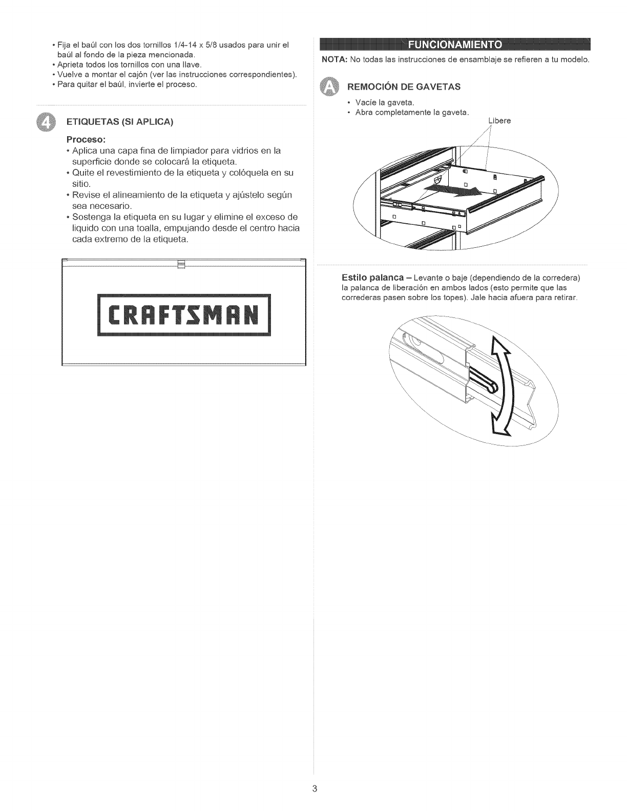
ETIQUETAS(SlAPLICA)
Proceso:
- Aptica una capa fina de timpiador para vidrios en ta
superficie donde se colocar_ la etiqueta.
- Quite el revestimiento de ta etiqueta y cotOqueta en su
sitio.
Revise el alineamiento de ta etiqueta y ajQsteto segQn
sea necesado.
Sostenga la etiqueta en su lugar y elimine el exceso de
tiquido con una toaHa, empujando desde el centro hacia
cada extreme de ta etiqueta.
NOTA: No todas las instrucciones de ensamblaje se refieren a tu modelo.
QREMOCION DE GAVETAS
• Vac{e la gaveta,
Abra completamente la gaveta. Libere
Esti_o pa_anca - Levante o baje (dependiendo de la corredera)
la palanca de liberaci6n en ambos lados (esto permite que las
correderas pasen sobre los topes). Jale hacia afuera para retirar.
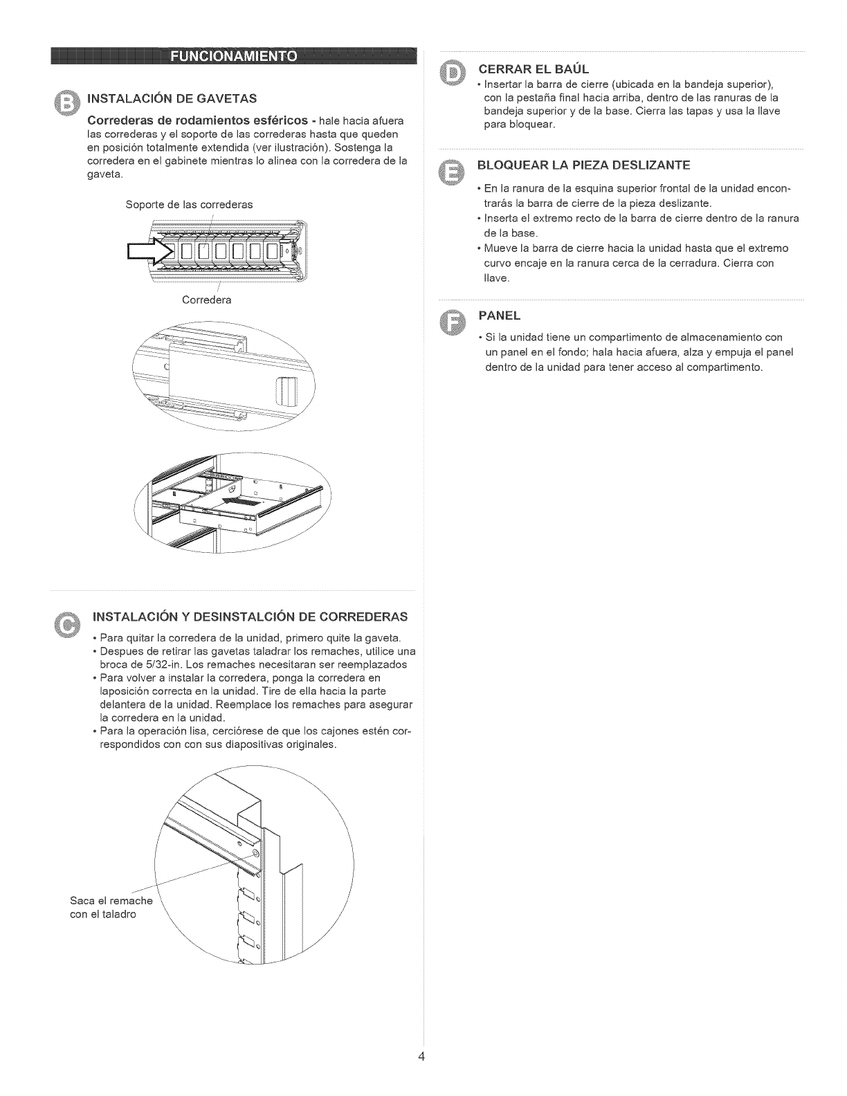
Q INSTALACIONDEGAVETAS
Correderasderodamientosesfericos - hale hacia afuera
ias correderas y ei soporte de ias correderas hasta que queden
en posici6n totaimente extendida (ver iiustraci6n), Sostenga ia
corredera en ei gabinete mientras io aiinea con ia corredera de ia
gaveta.
Soporte de las correderas
/: %
Corredera
CERRAR EL BAUL
• Insertar ia barra de cierre (ubicada en ia bandeja superior),
con ia pestaSa final hacia arriba, dentro de ias ranuras de ia
bandeja superior y de ia base. Cierra ias tapas y usa ia iiave
para bioquear.
BLOQUEAR LA PIEZA DESLIZANTE
En la ranura de la esquina superior frontal de la unidad encon-
trarSs la barra de cierre de la pieza deslizante.
Inserta el extremo recto de la barra de cierre dentro de la ranura
de la base.
Mueve la barra de cierre hacia la unidad hasta que el extremo
curvo encaje en la ranura cerca de la cerradura. Cierra con
Ilave,
PANEL
Si la unidad tiene un compartimento de almacenamiento con
un panel en el fondo; hala hacia afuera, alza y empuja el panel
dentro de la unidad para tener acceso al compartimento.
INSTALACtON Y DESlNSTALCION DE CORREDERAS
Para quitar la corredera de la unidad, primero quite la gaveta.
Despues de retirar las gavetas taladrar los remaches, utilice una
broca de 5/32-in. Los remaches necesitaran ser reemplazados
Para volver a instalar la corredera, ponga la corredera en
laposici6n correcta en la unidad. Tire de ella hacia la parte
delantera de la unidad. Reemplace los remaches para asegurar
la corredera en la unidad.
Para la operaci6n lisa, cerci6rese de que los cajones est6n cor-
respondidos con con sus diapositivas originales.
\\\\\
jfJ
Saca el remache \
con el taladro \
\\\ \
