Craftsman 706404420 User Manual TOOL CHEST Manuals And Guides 1409280L
User Manual: Craftsman 706404420 706404420 CRAFTSMAN TOOL CHEST - Manuals and Guides View the owners manual for your CRAFTSMAN TOOL CHEST #706404420. Home:Tool Parts:Craftsman Parts:Craftsman TOOL CHEST Manual
Open the PDF directly: View PDF ![]() .
.
Page Count: 8
OPERATOR'S MANUAL
s -
®
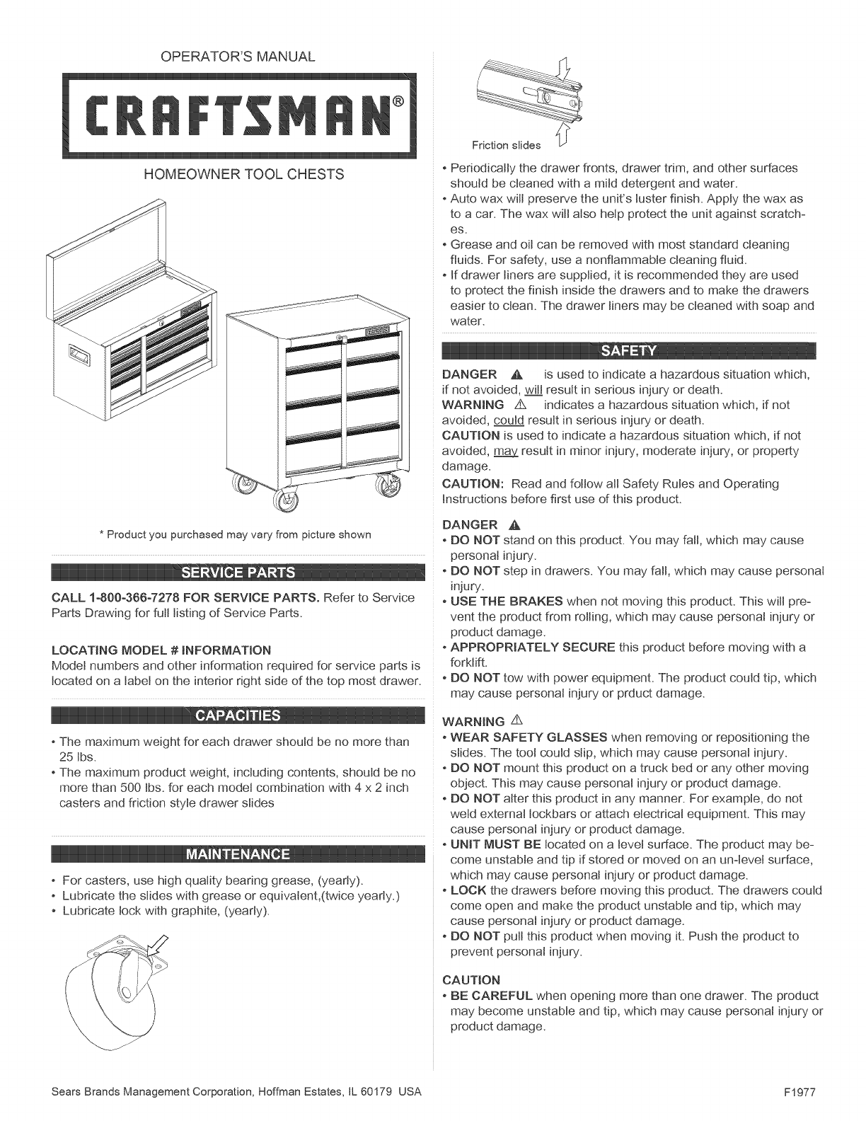
Friction slides
HOMEOWNER TOOL CHESTS oPeriodically the drawer fronts, drawer trim, and other surfaces
should be cleaned with a mild detergent and water.
Auto wax wilt preserve the unit's luster finish. Apply the wax as
to a car. The wax wilt also help protect the unit against scratch-
es.
Grease and oil can be removed with most standard cleaning
fluids. For safety, use a nonflammable cleaning fluid.
If drawer liners are supplied, it is recommended they are used
to protect the finish inside the drawers and to make the drawers
easier to clean. The drawer liners may be cleaned with soap and
water.
.q
DANGER _, is used to indicate a hazardous situation which,
if not avoided, wit_[result in serious injury or death.
WARNING z_ indicates a hazardous situation which, if not
avoided, could result in serious injury or death.
CAUTION is used to indicate a hazardous situation which, if not
avoided, _ result in minor injury, moderate injury, or property
damage.
CAUTION: Read and follow all Safety Rules and Operating
Instructions before first use of this product.
* Product you purchased may vary from picture shown
CALL 1-800-388-7278 FOR SERVICE PARTS. Refer to Service
Parts Drawing for full listing of Service Parts.
LOCATING MODEL # INFORMATION
Model numbers and other information required for service parts is
located on a label on the interior right side of the top most drawer.
The maximum weight for each drawer should be no more than
25 Ibs.
The maximum product weight, including contents, should be no
more than 500 tbs. for each model combination with 4 x 2 inch
casters and friction style drawer slides
For casters, use high quality bearing grease, (yearly).
Lubricate the slides with grease or equivatent,(twice yearly.)
Lubricate lock with graphite, (yearly).
v H i
DANGER A
DO NOT stand on this product. You may fall, which may cause
personal injury.
DO NOT step in drawers. You may fall, which may cause personal
injury.
USE THE DRAKES when not moving this product. This will pre-
vent the product from rolling, which may cause personal injury or
product damage.
APPROPRIATELY SECURE this product before moving with a
forklift.
•DO NOT tow with power equipment. The product could tip, which
may cause personal injury or prduct damage.
WARNING Z_
WEAR SAFETY GLASSES when removing or repositioning the
slides. The tool could slip, which may cause personal injury.
DO NOT mount this product on a truck bed or any other moving
object. This may cause personal injury or product damage.
DO NOT alter this product in any manner. For example, do not
weld external lockbars or attach electrical equipment. This may
cause personal injury or product damage.
UNIT MUST BE located on a level surface. The product may be-
come unstable and tip if stored or moved on an unqevet surface,
which may cause personal injury or product damage.
LOCK the drawers before moving this product. The drawers could
come open and make the product unstable and tip, which may
cause personal injury or product damage.
DO NOT pull this product when moving it. Push the product to
prevent personal injury.
CAUTION
DE CAREFUL when opening more than one drawer. The product
may become unstable and tip, which may cause personal injury or
product damage.
Sears Brands Management Corporation, Hoffman Estates, IL 60179 USA F1977
TOOLS REQUIRED:
Ftat4ip Screwdriver
3/8-in Wrench
7/16-in Wrench
5/16-in Drill Bit
HARDWARE REQUIRED:
MIDDLE CHEST
@
1/4 - 20 x 5/8" (Qty: 4)
1/4 - 20 Nut (Qty: 4)
HARDWARE REQUIRED:
CABINET
@
1/4 - 20 x 5/8" (Qty: 16)
1/4 - 20 Nut (Qty: 16)
Chest:
Literature
Cabinet:
Literature
Hardware bag
Caster pack
Caster pack
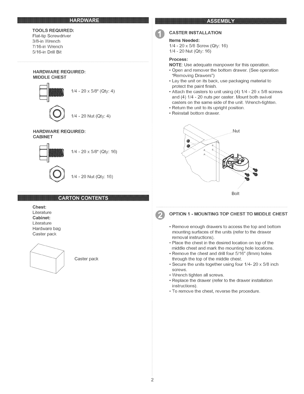
CASTER INSTALLATION
Items Needed:
1/4 - 20 x 5/8 Screw (Qty: 16)
1/4 - 20 Nut (Qty: 16)
Process:
NOTE: Use adequate manpower for this operation.
Open and remover the bottom drawer. (See operation
"Removing Drawers")
Lay the unit on its back, use packaging material to
protect the paint finish.
Attach the casters to unit using (4) 1/4 - 20 x 5/8 screws
and (4) 1/4 - 20 nuts per caster. Mount both swivel
casters on the same side of the unit. Wrench4ighten.
Return the unit to its upright position.
Reinstall bottom drawer.
Nut
.........._
Bolt
OPTION I o MOUNTING TOP CHEST TO MIDDLE CHEST
Remove enough drawers to access the top and bottom
mounting surfaces of the units (refer to the drawer
removal instructions).
Place the chest in the desired location on top of the
middle chest and mark the mounting hole locations.
Remove the chest and drill four 5/16" (8mm) holes
through the top of the middle chest.
Secure the units together using four 1/4- 20 x 5/8 inch
screws.
-Wrench tighten att screws.
-Replace the drawer (refer to the drawer installation
instructions).
-To remove the chest, reverse the procedure.
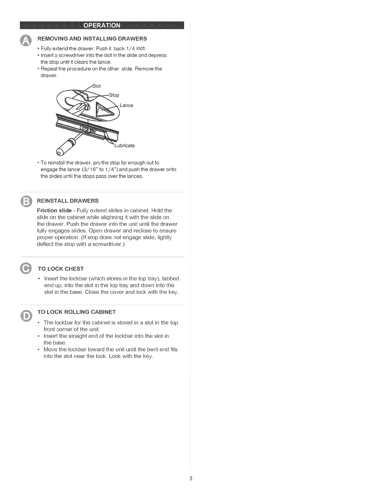
REMOVINGANDiNSTALLiNGDRAWERS
Fullyextend the drawer. Push it back 1/4 inch.
Insert a screwdriver into the slot in the slide and depress
the stop until it clears the lance.
Repeat the procedure on the other slide. Remove the
drawer.
Jbricate
To reinstall the drawer, prythe stop far enough out to
engage the lance (3/16" to 1/4") and push the drawer onto
the slides until the stops pass over the lances.
REINSTALL DRAWERS
Friction stide = Fully extend slides in cabinet. Hold the
slide on the cabinet while alighning it with the slide on
the drawer. Push the drawer into the unit until the drawer
fully engages slides. Open drawer and rectose to ensure
proper operation. (If stop does not engage slide, lightly
deflect the stop with a screwdriver.)
TO LOCK CHEST
Insert the tockbar (which stores in the top tray), tabbed
end up, into the slot in the top tray and down into the
slot in the base. Close the cover and lock with the key.
TO LOCK ROLLING CABINET
The tockbar for the cabinet is stored in a slot in the top
front corner of the unit.
Insert the straight end of the tockbar into the slot in
the base.
Move the tockbar toward the unit until the bent end fits
into the slot near the lock. Lock with the key.

MANUAL DE USUARIO
®
CAJAS DE HERRAMENTAS DOMESTICAS
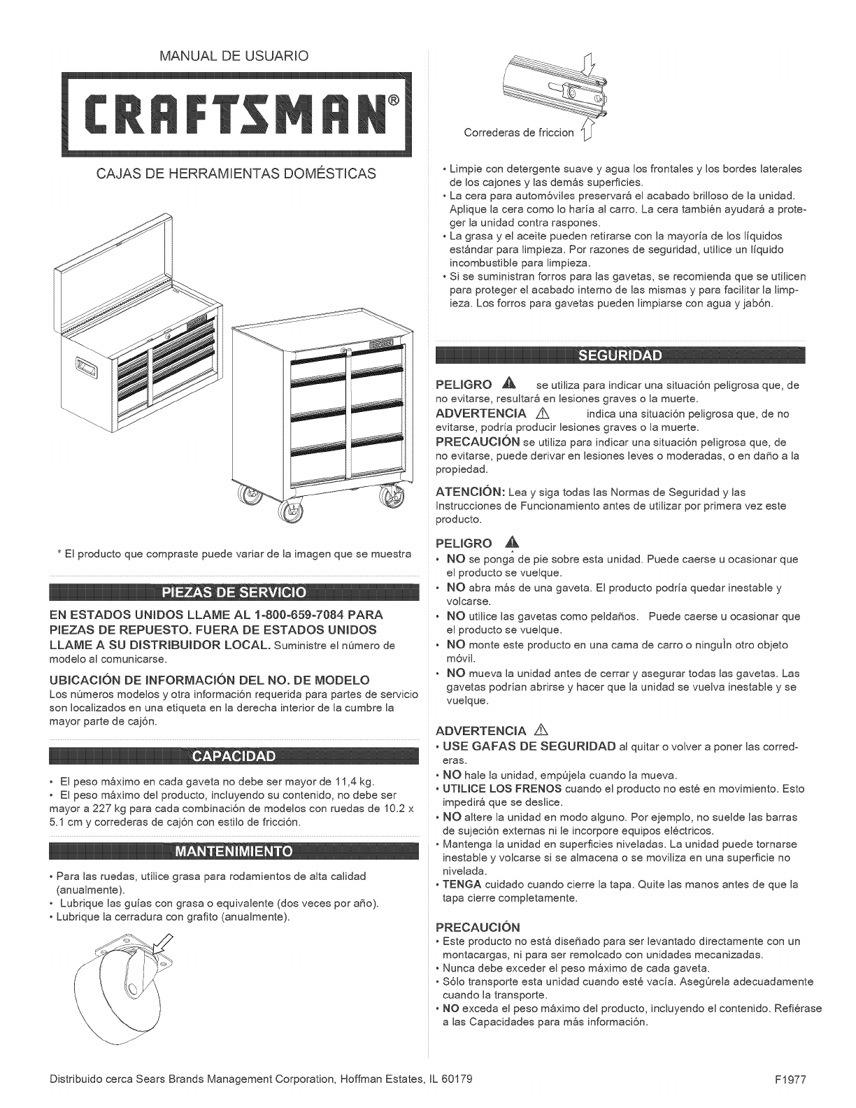
Correderas de friccion q/?
p_
Limpie con detergente suave y agua los frontales y los bordes laterales
de los cajones y las demSs superficies.
La cera para autom6viles preserva@ el acabado brilloso de la unidad.
Aplique la cera como Io haria al carro. La cera tambi6n ayudar8 a proteo
ger la unidad contra raspones.
La grasa y el aceite pueden retirarse con la mayoria de los liquidos
est_ndar para limpieza. Por razones de seguridad, utilice un liquido
incombustible para limpieza.
Si se suministran forros para las gavetas, se recomienda que se utilicen
para proteger el acabado interno de las mismas y para facilitar la limpo
ieza. Los forros para gavetas pueden limpiarse con agua y jab6n.
* El producto que compraste puede variar de la imagen que se muestra
iilI_
HH,_, 0 IIIIIIII
EN ESTADOS UNIDOS LLAME AL 1o800o659o7084 PARA
PIEZAS DE REPUESTO. FUERA DE ESTADOS UNIDOS
LLAME A SU DISTRtBUIDOR LOCAL. Suministre el nOmero de
modelo al comunicarse.
UBICACI6N DE MNFORMACt6N DEL NO. DE MODELO
Los nOmeros modelos y otra informaci6n requerida para partes de servicio
son Iocalizados en una etiqueta en la derecha interior de la cumbre la
mayor parte de caj6n.
• El peso mSximo en cada gaveta no debe ser mayor de 11,4 kg.
• El peso mSximo del producto, incluyendo su contenido, no debe ser
mayor a 227 kg para cada combinaci6n de modelos con ruedas de 10.2 x
5.1 cm y correderas de caj6n con estilo de fricci6n.
Para las ruedas, utilice grasa para rodamientos de alta calidad
(anualmente).
Lubrique las guias con grasa o equivalente (dos veces por a_o).
Lubrique la cerradura con grafito (anualmente).
PEUGRO _ se utiliza para indicar una situaci6n peligrosa que, de
no evitarse, resultar_ en lesiones graves o la muerte.
ADVERTENCIA Z_ indica una situaci6n peligrosa que, de no
evitarse, podria producir lesiones graves o la muerte.
PREOAUOI6N se utiliza para indicar una situaci6n peligrosa que, de
no evitarse, puede derivar en lesiones leves o moderadas, o en da_o a la
propiedad.
ATENOI6N: Lea y siga todas las Normas de Seguridad y las
Instrucciones de Funcionamiento antes de utilizar por primera vez este
producto.
PEUGRO
NO se ponga de pie sobre esta unidad. Puede caerse u ocasionar que
el producto se vuelque.
NO abra mSs de una gaveta. El producto podria quedar inestable y
volcarse.
NO utilice las gavetas como pelda_os. Puede caerse u ocasionar que
el producto se vuelque.
NO monte este producto en una cama de carro o ninguin otro objeto
m6viL
NO mueva la unidad antes de cerrar y asegurar todas las gavetas. Las
gavetas podrian abrirse y hacer que la unidad se vuelva inestable y se
vuelque.
ADVERTENClA
USE GAFAS DE SEGURIDAD al quitar o volver a poner las corredo
eras.
• NO hale la unidad, empOjela cuando la mueva.
• UTILICE LOS FRENOS cuando el producto no est8 en movimiento. Esto
impedir_ que se deslice.
• NO altere la unidad en modo alguno. Por ejemplo, no suelde las barras
de sujeci6n externas ni le incorpore equipos el¢ctricos.
• Mantenga la unidad en superficies niveladas. La unidad puede tornarse
inestable y volcarse si se almacena o se moviliza en una superficie no
nivelada.
• TENGA cuidado cuando cierre la tapa. Quite las manos antes de que la
tapa cierre completamente.
PRECAUCI6N
Este producto no est_ dise_ado para ser levantado directamente con un
montacargas, ni para ser remolcado con unidades mecanizadas.
Nunca debe exceder el peso mSximo de cada gaveta.
$61o transporte esta unidad cuando est6 vacia. AsegOrela adecuadamente
cuando la transporte.
NO exceda el peso mSximo del producto, incluyendo el contenido. Refi6rase
alas Capacidades para m_s informaci6n.
Distribuido cerca Sears Brands Management Corporation, Hoffman Estates IL 60179 F1977
HERRAMIENTASNECESARIAS:
Destornillador,puntadecruz
LlaveInglesade8mm
Llavede7/16pig
Brocadetaladrode5/16pig
PIEZASINCLUIDAS:
CAJADEHERRAMIENTASINTERMEDtA
Tornillo1/4o20x5/8oin(Cant:4)
@Tuerca Hexagonal de 1/4o20
(Cant: 4)
PIEZAS INCLUIDAS:
GABJNETE
©
Tornillo 1/4o20 x 5/8oin (Cant:16)
Tuerca Hexagonal de 1/4o20
(Cant: 16)
BaQJ:
Material impreso
Bolsa de accesorios
Gabinete:
Material impreso
Bolsa de accesorios
Paquete de ruedas
Paquete de ruedas
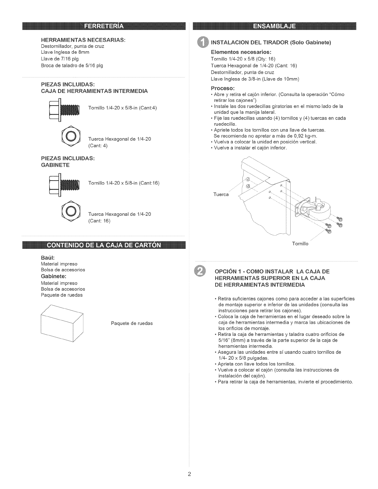
@INSTALACION DEL TIRADOR (Solo Gabinete)
E_ementos necesarios:
Tornillo 1/4o20 x 518 (Qty: 16)
Tuerca Hexagonal de 1/4o20 (Cant: 16)
Destornillador, punta de cruz
Llave Inglesa de 3/8oin (Llave de 10mm)
Proceso:
• Abre y refira el caj6n inferior. (Consulta la operaci6n "C6mo
retirar los cajones")
• Instale las dos ruedecillas giratorias en el mismo lado de la
unidad que la manija lateral.
• Fije las ruedecillas usando (4) tornillos y (4) tuercas en cada
ruedecilla.
• Apriete todos los tornillos con una Ilave de tuercas.
Se recomienda no apretar a m_s de 0,92 kgom.
• Vuelva a colocar la unidad en posici6n vertical.
• Vuelve a instalar el caj6n inferior.
//
Tuerca
\\ '\
Tornillo
OPCtON I oCOMO INSTALAR LA CAJA DE
HERRAMIENTAS SUPERtOR EN LA CAJA
DE HERRAMIENTAS INTERMEDtA
• Retira suficientes cajones como para acceder alas superficies
de montaje superior e inferior de las unidades (consulta las
instrucciones para refirar los cajones).
• Coloca la caja de herramientas en el lugar deseado sobre la
caja de herramientas intermedia y marca las ubicaciones de
los orificios de montaje.
• Retira la caja de herramientas y taladra cuatro orificios de
5/16" (8mm) a trav6s de la parte superior de la caja de
herramientas intermedia.
• Asegura las unidades entre si usando cuatro tornillos de
1/4o 20 x 5/8 pulgadas.
• Aprieta con Ilave todos los tornillos.
• Vuelve a colocar el caj6n (consulta las instrucciones de
instalaci6n del caj6n).
• Para retirar la caja de herramientas, invierte el procedimiento.
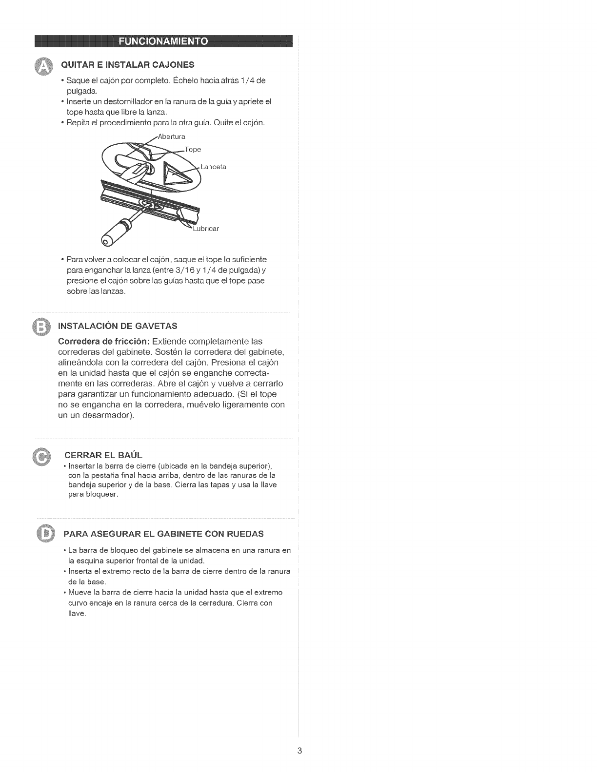
@QUITAR EINSTALAR CAJONES
Saque el cajon por complete. Echelo hacia atrb.s 1/4 de
pulgada.
Inserte un destorniJJador en la ranura de la guia y apriete el
tope hasta que libre la lanza.
Repita el procedimiento para Jaotra guia. Quite el caj6n.
,Lanceta
'Lubricar
Para volver a colocar el cajon, saque el tope Io suficiente
para enganchar la Janza (entre 3/16 y 1/4 de pulgada) y
presione el cajon sobre las guias hasta que el tope pase
sobre las lanzas.
INSTALACION DE GAVETAS
Corredera de fricci6n: Extiende completamente Jas
correderas det gabinete. Sost6n ta corredera det gabinete,
aJine_ndoJa con Jacorredera det cajOn. Presiona eJ cajOn
en Jaunidad hasta que et cajOn se enganche correcta-
mente en tas correderas. Abre eJ cajOn y vueJve a cerrarto
para garantizar un funcionamiento adecuado. (Si eJ tope
no se engancha en Ja corredera, mu6veto tigeramente con
un un desarmador).
CERRAR EL BAUL
• Jnsertar la barra de cierre (ubicada en la bandeja superior),
con la pesta_a final hacia arriba, dentro de Jas ranuras de la
bandeja superior y de la base. Cierra las tapas y usa la Ilave
para bloquear.
PARA ASEGURAR EL GABJNETE CON RUEDAS
• La barra de bloqueo del gabinete se almacena en una ranura en
la esquina superior frontal de la unidad.
Jnserta el extremo recto de la barra de cierre dentro de la ranura
de la base.
Mueve la barra de cierre hacia la unidad hasta que el extremo
curvo encaje en la ranura cerca de la cerradura. Cierra con
Ilave.