Craftsman 706452580 User Manual TOOL CHEST Manuals And Guides 1409282L
User Manual: Craftsman 706452580 706452580 CRAFTSMAN TOOL CHEST - Manuals and Guides View the owners manual for your CRAFTSMAN TOOL CHEST #706452580. Home:Tool Parts:Craftsman Parts:Craftsman TOOL CHEST Manual
Open the PDF directly: View PDF ![]() .
.
Page Count: 8
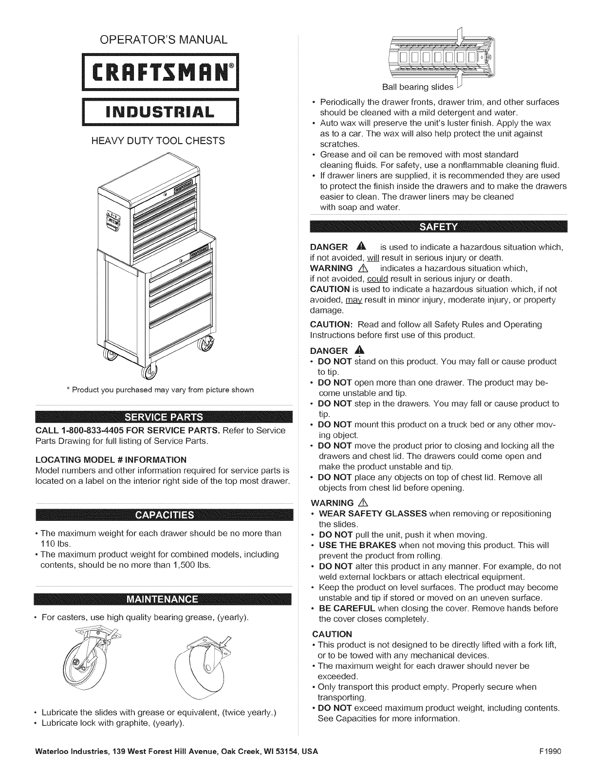
OPERATOR'S MANUAL
HEAVY DUTY TOOL CHESTS
* Product you purchased may vary from picture shown
CALL 1-800-833-4405 FOR SERVICE PARTS. Refer to Service
Parts Drawing for full listing of Service Parts.
LOCATING MODEL #iNFORMATiON
Model numbers and other information required for service parts is
located on a label on the interior right side of the top most drawer.
• The maximum weight for each drawer should be no more than
110 Ibs.
• The maximum product weight for combined models, including
contents, should be no more than 1,500 Ibs.
• For casters, use high quality bearing grease, (yearly).
• Lubricate the slides with grease or equivalent, (twice yearly.)
• Lubricate lock with graphite, (yearly).
• Periodically the drawer fronts, drawer trim, and other surfaces
should be cleaned with a mild detergent and water.
• Auto wax will preserve the unit's luster finish. Apply the wax
as to a car. The wax will also help protect the unit against
scratches.
• Grease and oil can be removed with most standard
cleaning fluids. For safety, use a nonflammable cleaning fluid.
• If drawer liners are supplied, it is recommended they are used
to protect the finish inside the drawers and to make the drawers
easier to clean. The drawer liners may be cleaned
with soap and water.
DANGER _1_ is used to indicate a hazardous situation which,
if not avoided, wil___Jresult in serious injury or death.
WARNING Z_ indicates a hazardous situation which,
if not avoided, could result in serious injury or death.
CAUTION is used to indicate a hazardous situation which, if not
avoided, _ result in minor injury, moderate injury, or property
damage.
CAUTION: Read and follow all Safety Rules and Operating
Instructions before first use of this product.
DANGER _,
• DO NOT s;cand on this product. You may fall or cause product
to tip.
• DO NOT open more than one drawer. The product may be-
come unstable and tip.
• DO NOT step in the drawers. You may fall or cause product to
tip.
• DO NOT mount this product on a truck bed or any other mov-
ing object.
• DO NOT move the product prior to closing and locking all the
drawers and chest lid. The drawers could come open and
make the product unstable and tip.
• DO NOT place any objects on top of chest lid. Remove all
objects from chest lid before opening.
WARNING z_
• WEAR SAFETY GLASSES when removing or repositioning
the slides.
• DO NOT pull the unit, push it when moving.
• USE THE BRAKES when not moving this product. This will
prevent the product from rolling.
• DO NOT alter this product in any manner. For example, do not
weld external Iockbars or attach electrical equipment.
• Keep the product on level surfaces. The product may become
unstable and tip if stored or moved on an uneven surface.
• BE CAREFUL when closing the cover. Remove hands before
the cover closes completely.
CAUTION
• This product is not designed to be directly lifted with a fork lift,
or to be towed with any mechanical devices.
• The maximum weight for each drawer should never be
exceeded.
• Only transport this product empty. Properly secure when
transporting.
• DO NOT exceed maximum product weight, including contents.
See Capacities for more information.
Waterloo Industries, 139 West Forest Hill Avenue, Oak Creek, WI 53154, USA F1990
TOOLS REQUIRED:
1/2-in. Wrench
Cross4ip Screwdriver
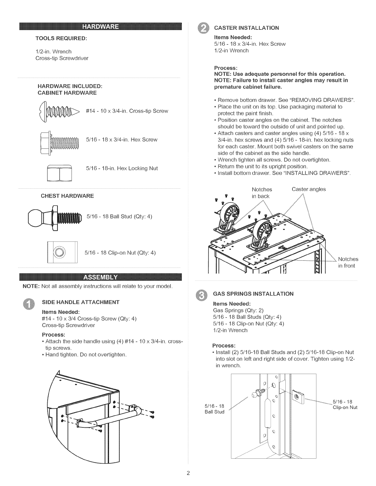
HARDWARE INCLUDED:
CABINET HARDWARE
#14 - 10 x 3/4-in. Cross4ip Screw
5/16 - 18 x 3/4-in. Hex Screw
5/16 - 18-in. Hex Locking Nut
CHEST HARDWARE
5/16 - 18 Ball Stud (Qty: 4)
5/16 - 18 Clip-on Nut (Qty: 4)
NOTE: Not aJJassembly instructions wilt relate to your model
SIDE HANDLE ATTACHMENT
Items Needed:
#14 - 10 x 3/4 Cross-tip Screw (Qty: 4)
Cross-tip Screwdriver
Process:
-Attach the side handle using (4) #14 - 10 x 3/4-in. cross-
tip screws.
- Hand tighten. Do not overtighten.
CASTER INSTALLATION
Items Needed:
5/16 - 18 x 3/4-in. Hex Screw
1!2-in Wrench
Process:
NOTE: Use adequate personnel for this operation.
NOTE: Failure to install easter angles may result in
premature cabinet failure.
Remove bottom drawer. See "REMOVING DRAWERS".
Place the unit on its top. Use packaging material to
protect the paint finish.
Position caster angles on the cabinet. The notches
should be toward the outside of unit and pointed up.
Attach casters and caster angles using (4) 5/16 - 18 x
3/4-in. hex screws and (4) 5/16 - 18-in. hex locking nuts
for each caster. Mount both swivel casters on the same
side of the cabinet as the side handle.
Wrench tighten all screws. Do not overtighten.
Return the unit to its upright position.
Install bottom drawer. See "INSTALLING DRAWERS".
Notches Caster angles
in back
Notches
in front
GAS SPRINGS INSTALLATION
Items Needed:
Gas Springs (Qty: 2)
5/16 - 18 Ball Studs (Qty: 4)
5/16 - 18 Clip-on Nut (Qty: 4)
1!2-in Wrench
Process:
-Install (2) 5/16-18 Ball Studs and (2) 5/16-18 Clip-on Nut
into slot on left and right side of cover. Tighten using 1!2-
in wrench.
5/16- 18
Ball Stud
..............................5/16 - 18
Clip-on Nut
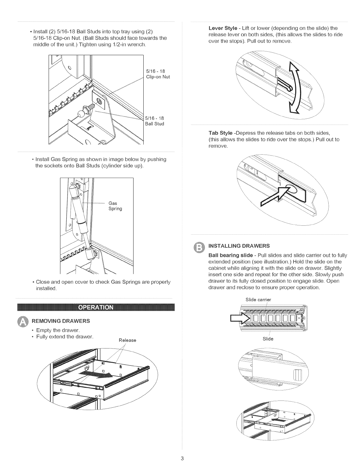
Install (2) 5/16-18 Batt Studs into top tray using (2)
5/16-18 Ctip-on Nut. (Bali Studs should face towards the
middle of the unit.) Tighten using 1!2-in wrench.
Lever Style -Lift or lower (depending on the slide) the
release lever on both sides, (this allows the slides to ride
over the stops). Putt out to remove.
5/16 -18
Clip-on Nut
5/16- 18
Ball Stud
Instatl Gas Spring as shown in image below by pushing
the sockets onto Batt Studs (cylinder side up).
)
/
Tab Style -Depress the release tabs on both sides,
(this allows the slides to ride over the stops.) Putt out to
remove.
Gas
Spring
Close and open cover to check Gas Springs are properly
installed.
Q REMOVING DRAWERS
Empty the drawer.
Fully extend the drawer. Release
_ iNSTALLiNG DRAWERS
Ba_ bearing slide - Putt slides and slide carrier out to futty
extended position (see illustration.) Hotd the stide on the
cabinet white aligning it with the slide on drawer. Slightly
insert one side and repeat for the other side. Slowly push
drawer to its futty closed position to engage slide. Open
drawer and rectose to ensure proper operation.
Slide carrier
Slide
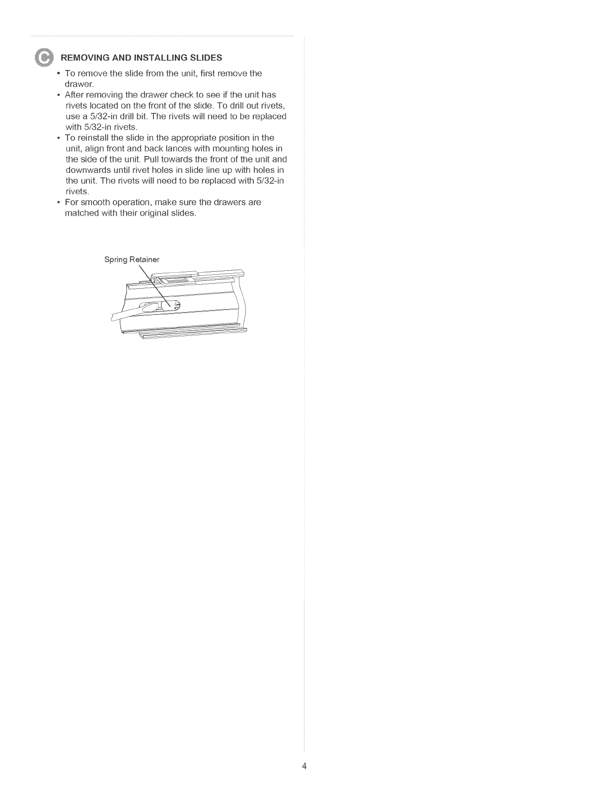
REMOVING AND iNSTALLiNG SLIDES
To remove the slide from the unit, first remove the
drawer.
After removing the drawer check to see if the unit has
rivets located on the front of the slide. To drill out rivets,
use a 5/324n drill bit. The rivets wilt need to be replaced
with 5/324n rivets.
To reinstall the slide in the appropriate position in the
unit, align front and back lances with mounting holes in
the side of the unit. Putt towards the front of the unit and
downwards until rivet holes in slide line up with holes in
the unit. The rivets wilt need to be replaced with 5/324n
rivets.
-For smooth operation, make sure the drawers are
matched with their original slides.
Spring Retainer
MANUAL DE USUARIO
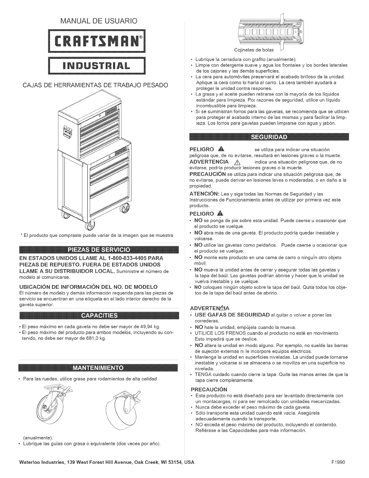
CAJAS DE HERRAMIENTAS DE TRABAJO PESADO
* El producto que compraste puede variar de la imagen que se muestra
EN ESTADOS UMDOS LLAME AL 1o800-833-4405 PARA
PIEZAS DE REPUESTO. FUERA DE ESTADOS UNIOOS
LLAME A SU DJSTRIBUJDOR LOCAL. Suministre eJnQmero de
modeJo aJ comunicarse.
UBICACI6N DE JNFORMACI6N DEL NO. DE MODELO
El nQmero de modelo y demos informaci6n requerida para Jas piezas de
servicio se encuentran en una etiqueta en el lado interior derecho de la
gaveta superior.
• El peso mSximo en cada gaveta no debe ser mayor de 49,94 kg.
• El peso mSximo del producto para ambos modelos, incluyendo su con°
tenido, no debe ser mayor de 681,0 kg.
• Para las ruedas, utilice grasa para rodamientos de alta calidad
(anualmente).
• Lubrique las guias con grasa o equivalente (dos veces por a_o).
• Lubrique la cerradura con grafito (anualmente).
• Limpie con detergente suave y agua los frontales y los bordes laterales
de los cajones y las demos superficies.
• La cera para autom6viles preservar_ el acabado brilloso de la unidad.
Aplique la cera como Io harla al carro. La cera tambi6n ayudar8 a
proteger la unidad contra raspones.
• La grasa y el aceite pueden retirarse con la mayorla de los Ilquidos
est_ndar para limpieza. Por razones de seguridad, utilice un Ilquido
incombustible para limpieza.
• Si se suministran forros para las gavetas, se recomienda que se utilicen
para proteger el acabado interno de las mismas y para facilitar la limpo
ieza. Los forros para gavetas pueden limpiarse con agua y jab6n.
PELIGRO ,_k se utiliza para indicar una situaci6n
peligrosa que, de no evitarse, resultar_ en lesiones graves o la muerte.
ADVERTENOIA A indica una situaci6n peligrosa que, de no
evitarse, podrla producir lesiones graves o la muerte.
PREOAUOI6N se utiliza para indicar una situaci6n peligrosa que, de
no evitarse, puede derivar en lesiones leves o moderadas, o en da_o a la
propiedad.
ATENOION: Lea y siga todas las Normas de Seguridad y las
Instrucciones de Funcionamiento antes de utilizar por primera vez este
producto.
PEUGRO _,
• NO se ponga de pie sobre esta unidad. Puede caerse u ocasionar que
el producto se vuelque.
• NO abra m_s de una gaveta. El producto podrla quedar inestable y
voJcarse.
• NO utilice las gavetas como pelda_os, Puede caerse u ocasionar que
el producto se vuelque,
• NO monte este producto en una cama de carro o ninguin otro objeto
m6vil,
• NO mueva Jaunidad antes de cerrar y asegurar todas Jasgavetas y
Jatapa deJ baOL Las gavetas podrian abrirse y hacer que Jaunidad se
vueJva inestabJe y se vueJque,
NO coJoques ningOn objeto sobre Jatapa deJ baOL Quita todos los objeo
tos de Jatapa deJ baOJantes de abrido,
ADVERTENL_A
• USE GAFAS DE SEGURIDAD al quitar o volver a poner las
corredera&
• NO hale Jaunidad, empQjeJa cuando Jamuev&
• UTILICE LOS FRENOS cuando el producto no est6 en movimiento.
Esto impedir8 que se desJice.
• NO aJtere la unidad en modo aJguno. Por ejempJo, no sueJde Jas barras
de sujeci6n externas ni Jeincorpore equipos eJ6ctricos.
• Mantenga Jaunidad en superficies niveJadas. La unidad puede tornarse
inestabJe y voJcarse si se aJmacena o se moviJiza en una superficie no
niveJada.
• TENGA cuidado cuando cierre Ja tapa. Quite Jas manos antes de que Ja
tapa cierre compJetamente.
PRECAUCK)N
• Este producto no est_ diseSado para ser Jevantado directamente con
un montacargas, ni para ser remoJcado con unidades mecanizadas,
• Nunca debe exceder el peso mSximo de cada gaveta,
• S6Jo transporte esta unidad cuando est6 vacia, AsegOreJa
adecuadamente cuando Jatransporte,
• NO exceda el peso m_ximo deJ producto, incJuyendo el contenido,
Refi6rase a Jas Capacidades para m_s informaci6n,
Waterloo Industries, 139 West Forest Hill Avenue, Oak Creek, WI 53184, USA F1990
HERRAMIENTAS NECESARIAS:
Llave Inglesa de 1/2 inch
Destomittador de Punta en Cruz
PIEZAS INCLUIDAS:
GABJNETE DE HARDWARE
Tuerca Phillips de No. 14 -10 x 3/4
(Cant: 4)
TorniHo Hexagonal de 5/16 -
18 x 3/4 pig
Contratuerca Hexagonal de 5/16 -
18 pig
BAUL DE HARDWARE
Pemo Esf6rico de 5/16 - 18
(Cant: 4)
Tuerca de Abrazadera de 5/16 -
18 (Cant: 4)
=l_J:
NOTA: No todas tas instrucciones de ensambtaje se refieren a tu
modeto.
INSTALACION DE LA MANIJA LATERAL
E_ementos necesarios:
Tornillos Phillips de No. 14 -10 x 3/4 (Cant.: 4)
DestorniHador de Punta en Cruz
Proceso:
• Fije ta manija lateral usando 4 torniHos de Punta en Cruz
de No. 14 -10 x 3/4.
• Apriete a mano. No apriete demasiado.
INSTALACION DEL TtRADOR
Elementos necesarios:
TorniHo Hexagonal de 5/16 - 18 x 3/4 ptg
Uave Inglesa de 1/2 inch
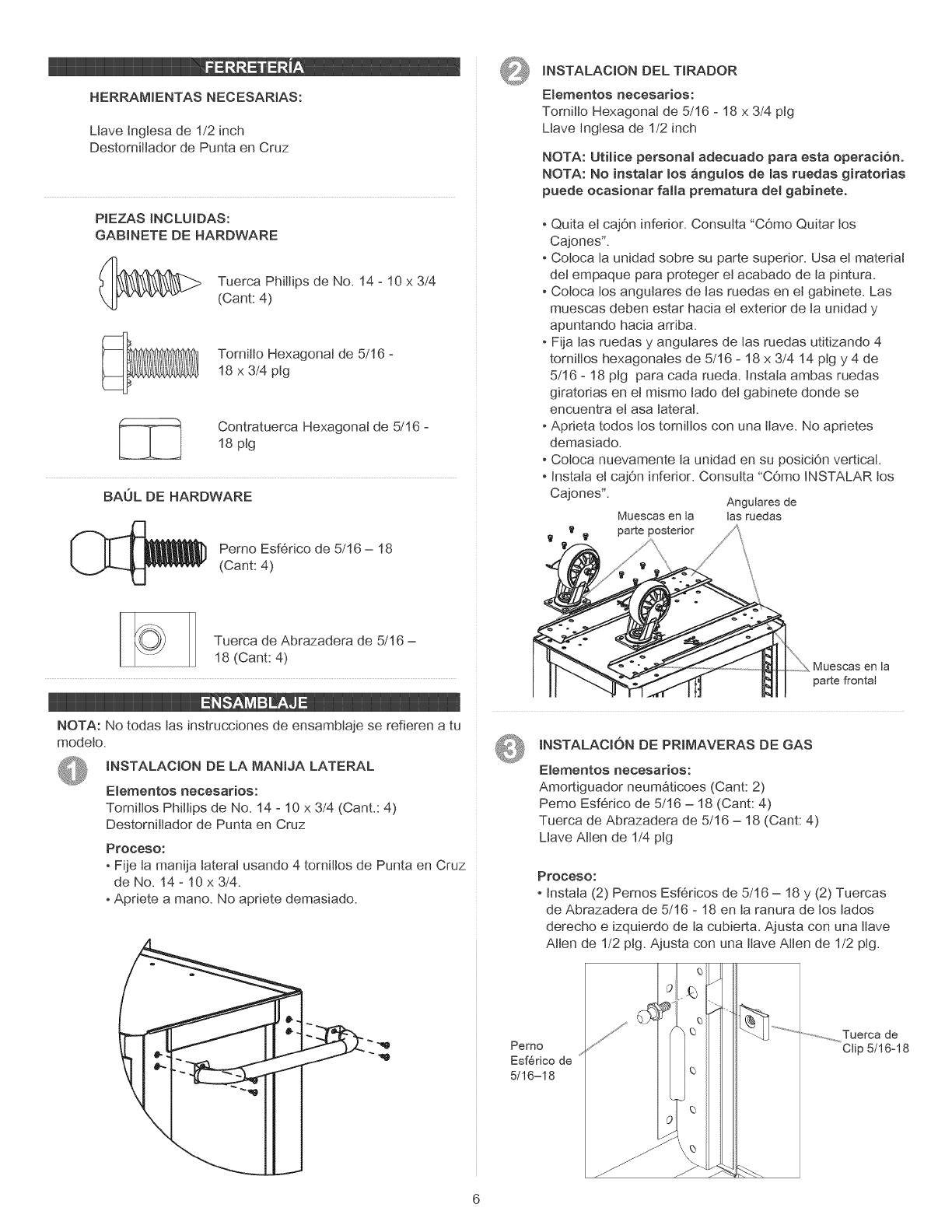
NOTA: UtiHce personal adecuado para esta operaci6n.
NOTA: No instalar Los angulos de _as ruedas giratorias
puede ocasionar faHa prematura de_ gabinete.
- Quita el cajOn inferior. Consutta "COmo Quitar los
Cajones".
Coloca ta unidad sobre su parte superior. Usa el matedat
det empaque para proteger et acabado de ta pintura.
Coloca tos angulares de tas ruedas en el gabinete. Las
muescas deben estar hacia et exterior de ta unidad y
apuntando hacia arriba.
Fija tas ruedas y angutares de tas ruedas utitizando 4
torniIIos hexagonales de 5/16 -18 x 3/4 14 plg y 4 de
5/16 -18 pig para cada rued& Instala ambas ruedas
giratorias en el mismo tado det gabinete donde se
encuentra el asa taterat.
Aprieta todos tos tomittos con una ttave. No aprietes
demasiado.
Coloca nuevamente ta unidad en su posiciOn vertical.
Instala et cajOn inferior. Consutta "COmo INSTALAR tos
Cajones". Angulares de
las ruedasMuescas en la
parte posterior
\\\
Muescasenla
parte frontal
INSTALACION DE PRIMAVERAS DE GAS
Elementos necesarios:
Amortiguador neum_ticoes (Cant: 2)
Pemo Esf6rico de 5/16 =18 (Cant: 4)
Tuerca de Abrazadera de 5/16 =18 (Cant: 4)
Ltave Alien de 1/4 ptg
Perno
Esf6rico de
5/16-18
Proceso:
Instala (2) Pemos Esf6ricos de 5/16 -18 y (2) Tuercas
de Abrazadera de 5/16 -18 en ta ranura de los lados
derecho e izquierdo de ta cubierta. Ajusta con una ttave
Alien de 1/2 ptg. Ajusta con una ttave Alien de 1/2 pig.
i Q
÷,y
..............................Tuerca de
Clip 5/16-18
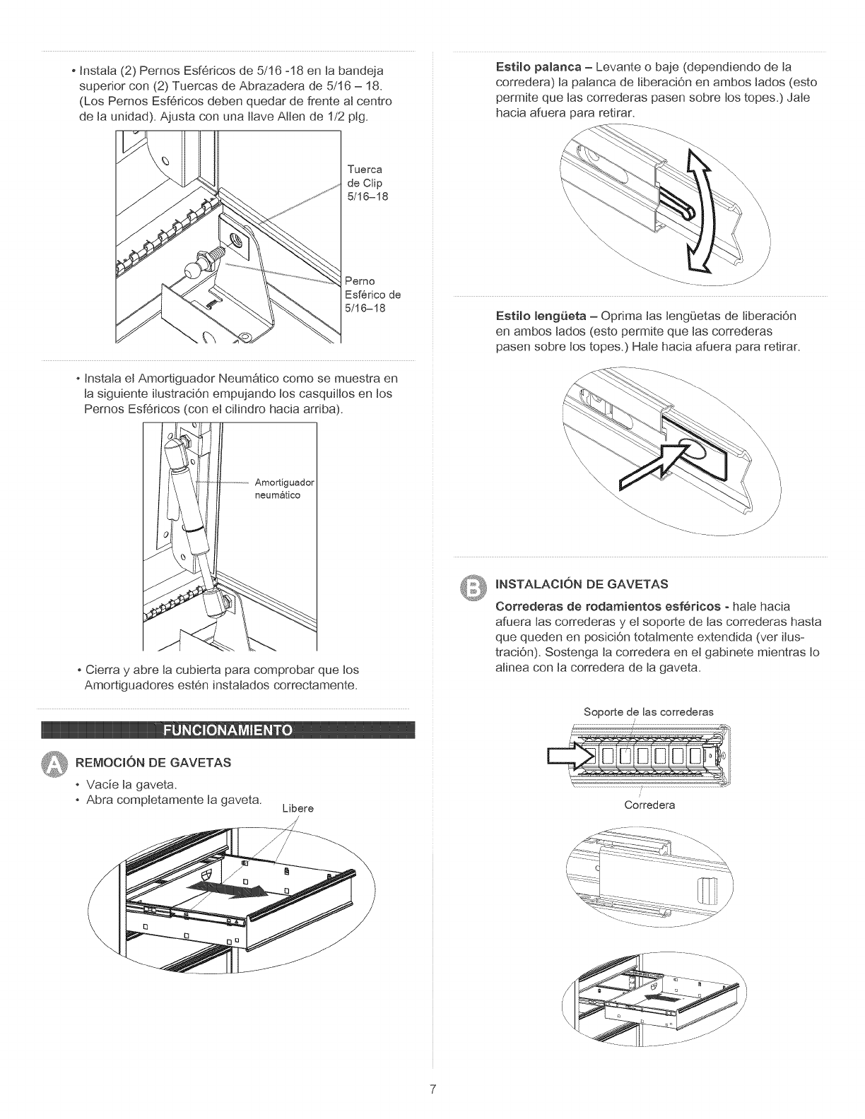
Instala (2) Pernos Esf6ricos de 5/16 -18 en la bande]a
superior con (2) Tuercas de Abrazadera de 5/16 - 18.
(Los Pemos Esf6ricos deben quedar de frente at centro
de ta unidad). Ajusta con una ttave Alien de 1/2 pig.
Estilo palanca - Levante o bale (dependiendo de la
corredera) ta patanca de NberaciOn en ambos lados (esto
permite que las correderas pasen sobre los topes.) JaJe
hacia afuera para retirar.
Tuerca
de Clip
5/16-18
Perno
Esf@ico de
5/16-18
Instala et Amortiguador Neum_tico como se muestra en
ta siguiente itustraciOn empujando los casquitJos en tos
Pemos Esf6dcos (con eJciNndro hacia ardba).
Estilo leng_eta - Optima tas teng_'_etasde tiberaciOn
en ambos lados (esto permite que las correderas
pasen sobre los topes.) HaJe hacia afuera para retirar.
Amortiguador
neumatico
Cierra y abre la cubierta para comprobar que tos
Amortiguadores est6n instaJados correctamente.
REMOOJON DE GAVETAS
Vacie ta gaveta.
Abra comptetamente ta gaveta. Libere
INSTALACION DE GAVETAS
Correderas de rodamientos esfericos - hale hacia
afuera tas correderas y et soporte de las correderas hasta
que queden en posiciOn totalmente extendida (vet itus-
traciOn). Sostenga ta corredera en et gabinete mientras to
atinea con ta corredera de ta gaveta.
Soporte de las correderas
i
Corredera
G Y DECORREDERAS
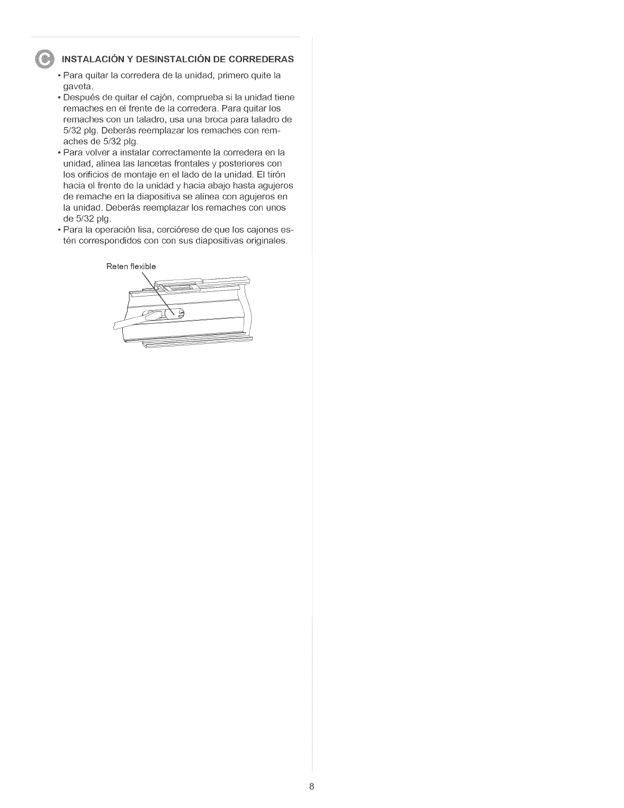
INSTALAClONDESlNSTALClON
Paraquitartacorrederadetaunidad,primeroquiteta
gaveta.
Despu6sdequitarelcajOn,compruebasitaunidadtiene
remachesenetfrentedelacorredera.Paraquitarlos
remachesconuntaladro,usaunabrocaparatatadrode
5/32pig.Deber_sreemptazarlosremachesconrem-
achesde5/32plg.
Paravolverainstatarcorrectamentetacorrederaenla
unidad,atinealaslancetasfrontalesy postedorescon
losorificiosdemontajeenettadodetaunidad.Ettir0n
haciaelfrentedelaunidady haciaabajohastaagujeros
deremacheentadiapositivasealineaconagujerosen
taunidad.Deber_sreemptazarlosremachesconunos
de5/32plg.
ParataoperaciOnlisa,cerciOresedequeloscajoneses-
t6ncorrespondidosconconsusdiapositivasoriginates.
Reten flexible
8
