Craftsman 706655250 User Manual 2 DRAWER WORKBENCH Manuals And Guides L0711359
CRAFTSMAN Workbench / Project Manual L0711359 CRAFTSMAN Workbench / Project Owner's Manual, CRAFTSMAN Workbench / Project installation guides
User Manual: Craftsman 706655250 706655250 CRAFTSMAN 2 DRAWER WORKBENCH - Manuals and Guides View the owners manual for your CRAFTSMAN 2 DRAWER WORKBENCH #706655250. Home:Tool Parts:Craftsman Parts:Craftsman 2 DRAWER WORKBENCH Manual
Open the PDF directly: View PDF ![]() .
.
Page Count: 8
CRRFT$1dI:IN
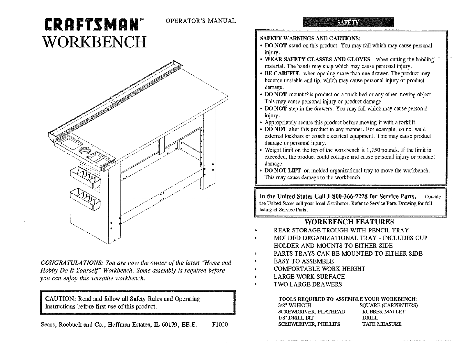
WORKBENCH
OPERATOR'S MANUAL
CONGRATULATIONS: You are now the mt,_ter of the latest "Home and
Hobby Do It Yourself" Workbench. Some assembly is required before
you czzn enjoy this versatile workbenck.
CAUTION: Read and follow all Safety Rules and Operating
Instructions before first use of this product.
Sears, Roebuck and Co., Hoffman Estates, IL 60179, EE. E. F1020
SAFETY WARNINGS AND CAUTIONS:
-DO NOT stand on this product. You may fall which may cause personal
injury.
.WEAR SAFETY GLASSES AND GLOVES when cutting the banding
material. The bands may snap which may cause personal injury.
• BE CAREFUL when opening more than one drawer. The product may
bccome trustable and tip, which may cause personal injury, or product
dmnage.
-DO NOT mount this product on a truck bed or any other moving object.
This may cause personal injury or product d,-a'nage.
•DO NOT step in the drawers. You may fall which may cause personal
injury,
• Appropriately secure this product before moving it with a forklift.
•DO NOT alter this product in any manner. For example, do not weld
external lockbars or attach eieeWical equipment. This may cause product
damage _r personal injury.
• Weight limit on the top of the workbench is i ,750 pounds. If the limit is
exceeded, the product could collapse and cause personal injmy or product
damage.
• DO NOT LIFT oil molded organizational Way to move the workbench.
This may cause damage to the workbench.
In the United States Call 1-800-366-7278 for Service Paris. outside
the United St_es call your loe_ distributor. Refer to Service Parts l)nm:dng for full
listhag _" Service Parts.
WORKBENCH FEATURES
oREAR STORAGE TROUGH WITH PENCIL TRAY
• MOLDED ORGANIZATIONAL TRAY - INCLUDES CUP
HOLDER AND MOUNTS TO EITHER SIDE
•PARTS TRAYS CAN BE MOUNTED TO EITHER SIDE
° EASY TO ASSEMBLE
• COMFORTABLE WORK HEIGHT
• LARGE WORK SURFACE
•TWO LARGE DRAWERS
TOOLS REQUIRED TO ASSEMBLE YOUR WORKBENCH:
3/g" WRENCH SQUARE (CARPENTERS)
SL,1LEWDR1VER, FLA_ RUBBER MAILEI"
1/8" DRILl, BIT DRILL
SCREWDRIVER, PHKL,IPS TAPE MEASURE
7 ...............
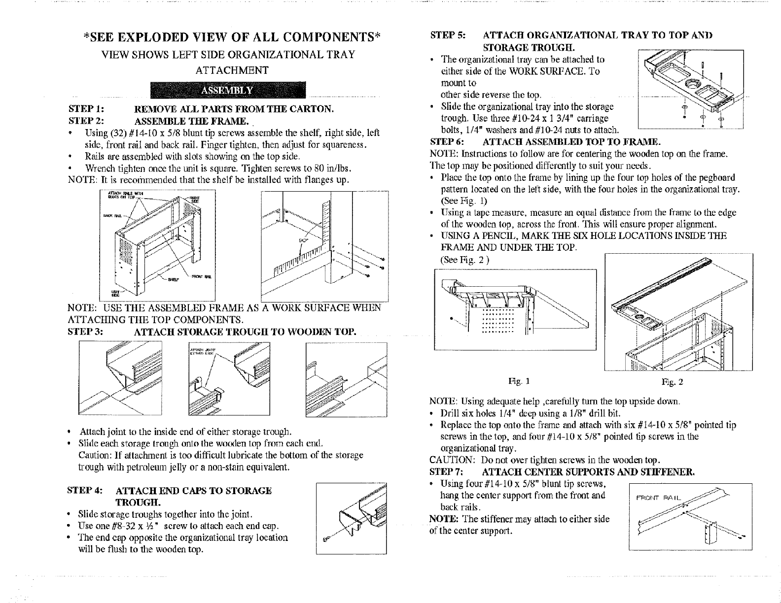
*SEE EXPLODED VIEW OF ALL COMPONENTS*
VIEW SHOWS LEFT SIDE ORGANIZATIONAL TRAY
ATTACHMENT
STEP 1: REMOVE ALL PARTS FROM THE CARTON.
STEP 2: ASSEMBLE TilE FRAME.
• Using (32) #14-10 x5/8 blunt tip screws _ssemble the shelf, right side, left
side, front rail and back rail. Finger tighten, then adjust for squareness.
•Rails are assembled with slots showing on the top side.
• Wrench tighten once the unit is squm'e. Tighteaa screws to 80 in/lbs.
NOTE: It is recommended that the shelf be installed with flanges up.
.... ;._ illlLg vd_l ..........
NOTE: USE THE ASSEMBLED FRAME AS A WORK SURFACE WHEN
ATI'ACHING Tim TOP COMPONENTS.
STEP 3: ATTACH STORAGE TROUGH_ TO WOODEN TOP.
!"%N
Attach joint to the inside end of either storage trough.
Slide each storage trough onto the wo(._lentop from each end.
Caution: If attachment is too difficult lubricate the bottom of the storage
trough with petroleum jelly or a nomstain equivalent.
STEP 4: ATTACH END CAPS TO STORAGE
TROUGH.
• Slide storage troughs together into the joint.
• Use one #8-32 x _A" screw to attach each end cap.
• The end cap opposite the org_lizational tray location
will be flush to the wooden top.
STEP 5:
STORAGE TROUGH.
• The organizational tray can be attached to
either side of the WORK SURFACE. To
mount to
other side reverse the top.
• Slide the organizational tray into the storage
trough. Use three #10-24 x 1 3/4" carriage
bolts, 114" washers and #10-24 nuts to attach.
ATTACH ORGANIZATIONAL TRAY TO TOP AND
STEP 6: ATTACH ASSEMBLED TOP TO FRAME.
NOTE: Instructions to follow are for centering the wooden top on the flame.
The top may be positioned differently to suit your needs.
•Place the top onto the frame by lining up the four top holes of the pegboard
pattern located on the left side, with the four holes in the organizational tray.
(See Fig. 1)
• Using a tape measure, measure an equal distance from the frame to the edge
of the wooden top, across the fi'ont. This will ensure proper alignment.
• USING A PENCIL, MARK 21-1ESIX HOLE LOCNIlONS INSIDE THE
FRAME AND UNDER THE TOP.
(See Fig. 2 )
Fig. 1 Eg. 2
NOTE: Using adequate help ,carefully tam the top upside down.
• Drill sixholes 114" deep using a 1/8" drill bit.
• Replace the top onto the fi'ame and attach with six #14-10 x 5/8" pointed tip
screws in the top, _uadfour #t4-10 x 5/8" pointed tip screws in the
organizational tray,
CAUTION: Do not over tighten screws in the wooden top.
STEP 7: ATTACH CENTER SUPPORTS AND STIFFENER.
•Using four #14-10 x 5/8" blunt tip screws,
hang the center support from the front and _o_,n- _ IL
back rails.
NOTE: The stiffener may attachto either side
of the center support.
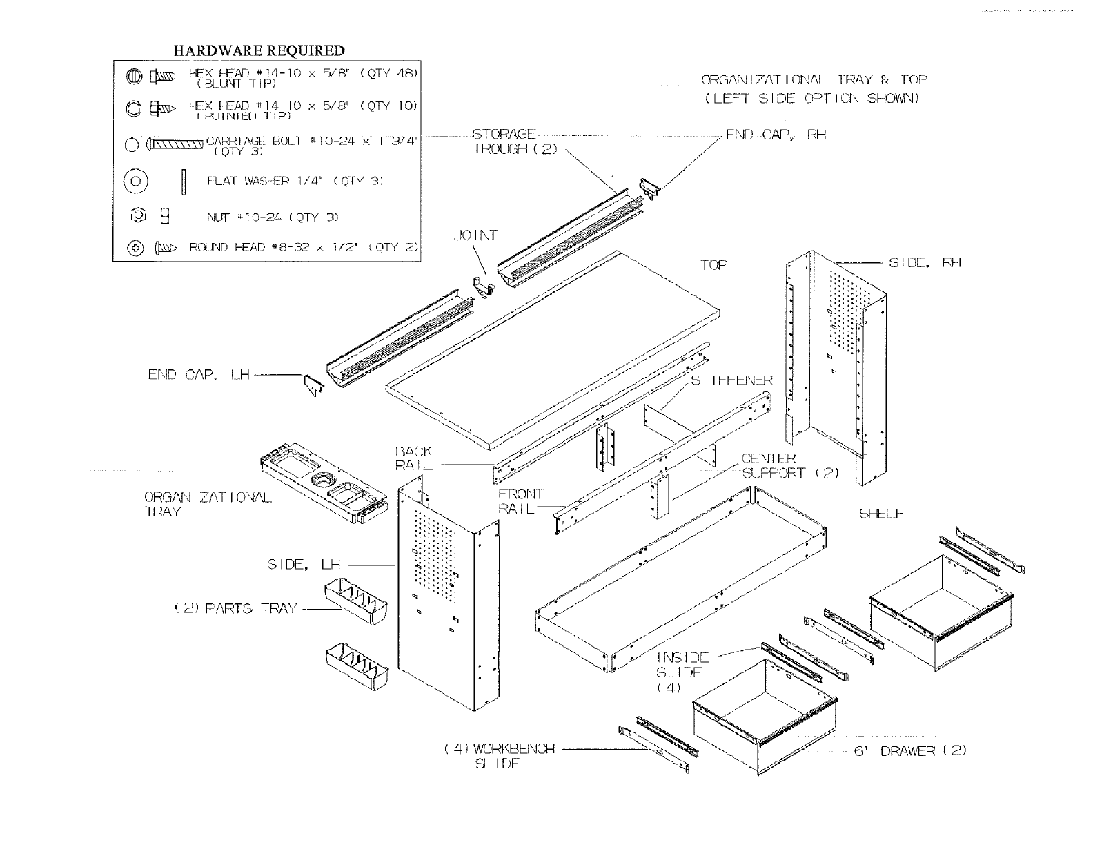
HARDWAREREQUIRED
@ E_ HEX ,LEAD #14-10 x 5,."8" (QTY 48)
( BLUNT ] IP)
0 _;_> I-EX HEAD :_14-10 × 5/8" (QTY 10)
(F_IItTED TIP)
0 _CARRIAGE BOLT t;lO 24 £ 1 374"
_OTY a_
B FlAT WASFER 1/4 ° (QTY 3)
I_ B NLrF _I0-24 (QTY 3)
(_) @2_> ROLND lEAD _8-32 x ]/2' (QTY 2)
ORGAN IZATI OI",IAL TRAY 8, TOP
(LEFT SIDE OP]-ION SHOWN)
STORAGE _ END CAP, RH
TROUGH (2) /
f-
/
/
JO INT
\
ST I FFENER
S IDE, LH
(2) PARTS TRAY "--.IL,J
%
BACK
RAIL
FRONT
(4) WORKBENCH
SLIDE
CENTER
6" DRAV6R (2)
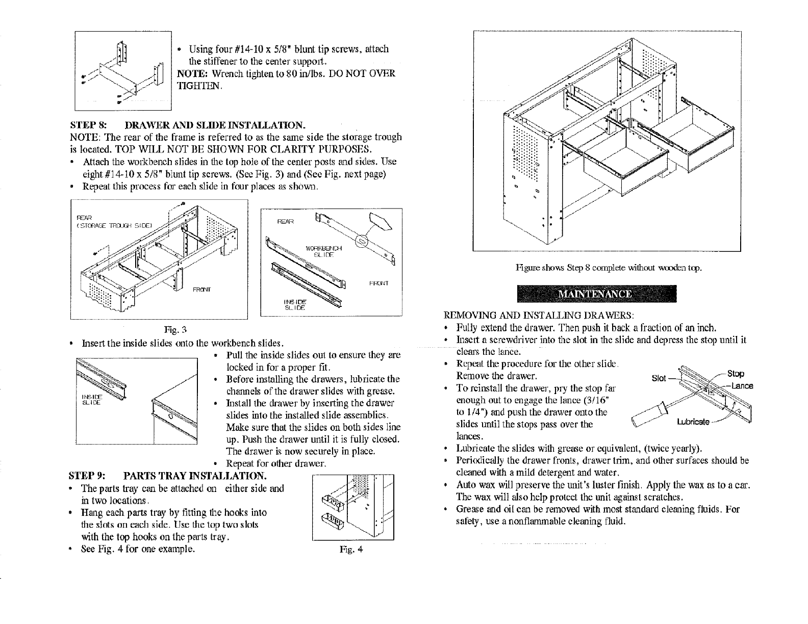
- Using four #14-10 x 5/8" blunt tip screws, attach
the stiffener to the center support.
NOTE: Wrench tighten to 80 inilbs. DO NOT OVER
TIGHTEN.
STEP 8: DRAWER AND SLIDE INSTALLAIION.
NOTE: The rear of the frame is referred to as the same side the storage trough
is located. TOP WILL NOT BE SHOWN FOR CLARITY PURPOSES.
• Attach the workbench slides in the top hole of the center posts and sides. Use
eight #14-10 x 5/8" blunt tip screws. (See Fig. 3) _ad (See Fig. next page)
•Repeat this process for each slide in four places as shown.
FRI_
"...._.. /-.--,
Fig. 3
lnse11 the inside slides onto the workbench slides.
li'_d S
,2t_I DE
STEP 9: PARTS TRAY INSTALLATION.
•The p,_'ts tray can be attached on either side and
in two locations.
° Hang each part,_ tray by fitting the hooks into
the slots on each side. Use the top two slot_
with the top hooks on the parts tray.
• See Fig. 4 for one example.
•Pull the inside slides out to ensure they are
locked in for a proper fit.
•Before installing the drawers, lubricate the
chalmels of the drawer slides with grease.
• Install the drawer by inserthag the drawer
slides into the installed slide assemblies.
Make sure that the slides on both sides line
up. Push the drawer until it is fully closed.
The drawer is now securely in place.
•Repeat for other drawer.
l:fig. 4
lqgure sl',ov,_ Step 8 complete without waxlen tcp.
REMO_vqNG AND INSTALLING DRAWERS:
, Fully extend the drawer. Then push it back afraction of an inch.
•It_sert a screwdriver into the slot in the slide and depress the stop until it
ele_us the lance.
• Repot the procedure for the other slide.
Remove the drawer. ._St_
•To reinstall the drawer, pry the stop far
euough out to engage the lance (3/16"
to 1/4") and push the drawer onto the
slides until the stops pass over the I-ubrieat¢
lances.
• Lubricate the slides with grease or equivalent, (twice yearly).
• Perk_ically the drawer fronts, drawer trim, and other surfaces should be
cleaned with a mild detergent and water.
° Auto wax will preserve the fruit's lmter finiZ Apply the wax as to a ca'.
The wax will also help protect the unit against scratches.
•Grease and oil c_a be reanoved with most standard cleaning fluids. For
safety, use a nonflarmnable cleaning fluid.
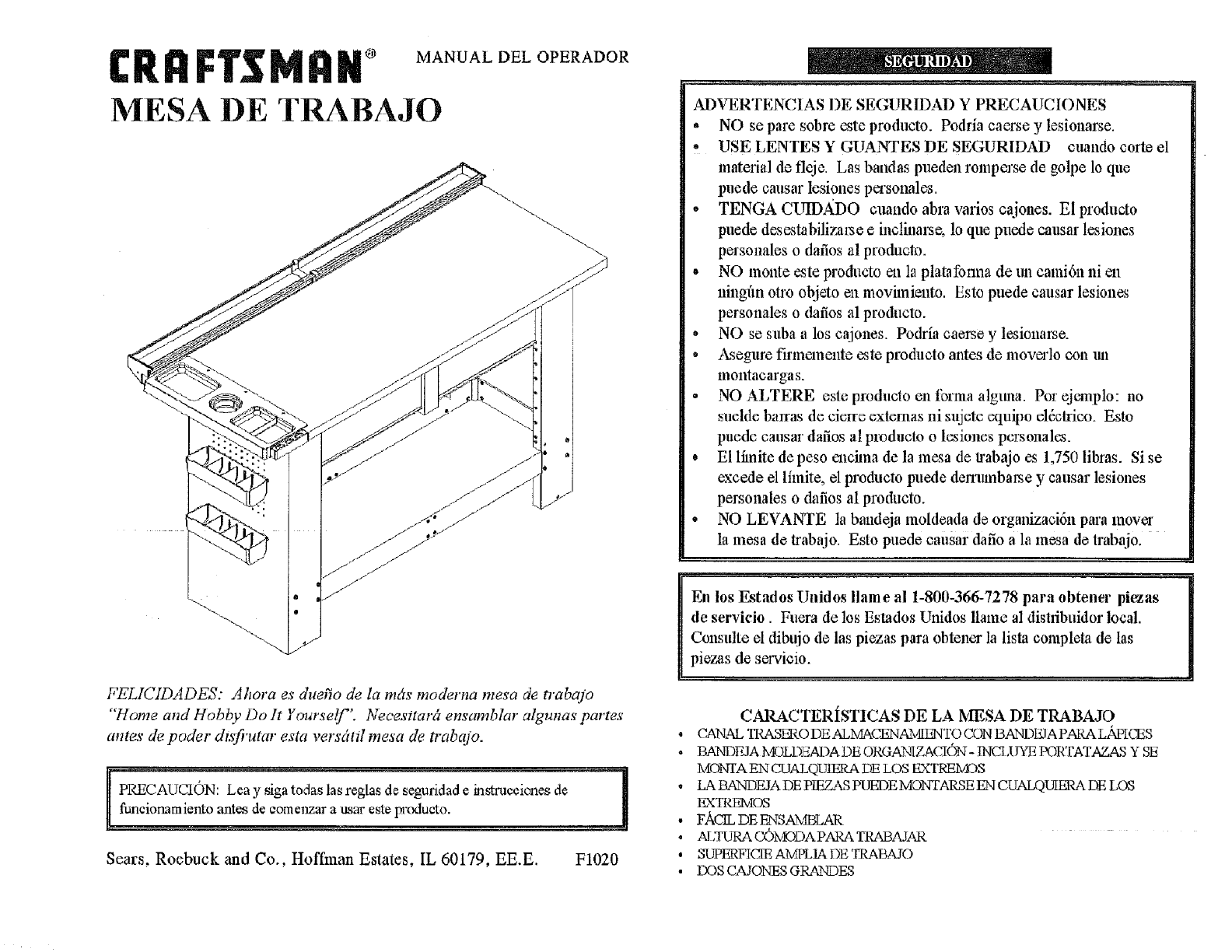
® MANUAL DEL OPERADOR
MESA DE TRABAJO
FELICIDADES: Ahora es duerio de la rods moderna mesa de tT'abajo
"'Home and Hobby Do It Yore'self". Necesitar[z ensamblar alguna._ partes'
ames de poder dtsfi'utar esta versdtd mesa de trab_qo.
AUCION: Lea y siga todas las reglas de seguridad e instrueeienes de
namiento antes de eomenz_x a usar este I_xxtucto.
Sears, Roebuck and Co., Hoffman Estates, IL 60179, EE.E. F1020
ADVERTENCIAS I)E SEGUR1DAD Y PRECAUCIONES
,NO se pare sobre este produeto. Podria caerse y lesional;e.
• USE LENTES Y GUANTES DE SEGURIDAD euando corte el
material de fleje. Las bandas pueden tempo'so de golpe lo que
puede cattsar lesiones persotmlos.
• TENGA CUIDADO cuando abra varies ca jones. El producto
puede desestabilizal_e e inctinal_e, 1oque puede causar l_iones
persouales o dafios al produclo.
° NO monte este producto en la platafonna de un eami6n ni en
ninghn otto objeto ea movimiento. Estc puede causar lesiones
personales o dafios al produeto.
° NO se suba a los cajones. Podria caerse y l_sienarse.
• Asegure finnemente este produeto antes de moverlo con m_
montaeargas.
° NO ALTERE este produclo cn lbrma alguna. Per ejcmplo: no
suelde balras de cierre exlemas ni sujelc equilm el&trice. Esto
puede causar dafios al pmduclo o lesiones personalt,'s.
• El limite de peso calcima de la mesa de trabajo es 1,750 libras. Si se
exeede el lfinite, el produeto puede dem_mbarse y causar lesiones
personales o dafios al producto.
• NO LEVANTE la bandeja moldeada de organizaoidn para move,
la mesa de trabajo. Esto puede eausar dafio a la mesa de trabajo.
En los Estados Unidos Ilame al 1-800-366-7278 para obtener pietas
de servicio. Fuera de los Estados Unidos llame al dishibuidor local.
Consldte el dibujo de las piezas para obtener la lista completa de las
piezas de servieio.
CARACTERISTICAS DE LA MESA DE TRABAJO
° CAN._d.TRASERODEALMACENAMIF_TOCONBANDI_APARALz_PICES
, BANDEJA h_.gLD>;ADA DE ORGANIZACION- INCt,UYE F'ORTATAZAS Y BE
MONTA EN CUALQLqERA DE LOS EXTREMES
• LA BANDEJA DE PIEZAS PUEDE MONTARSE EN CUALQ_ DE LOS
_ TRt_q'vIOS
•FACILDE ENSAMBLAR
, AI,T_ COMODAPARA TRABAJAR
. SUPERFICIE AMPLIAI)E'rRABAIO
• DOSCAJONF_SGRANDES
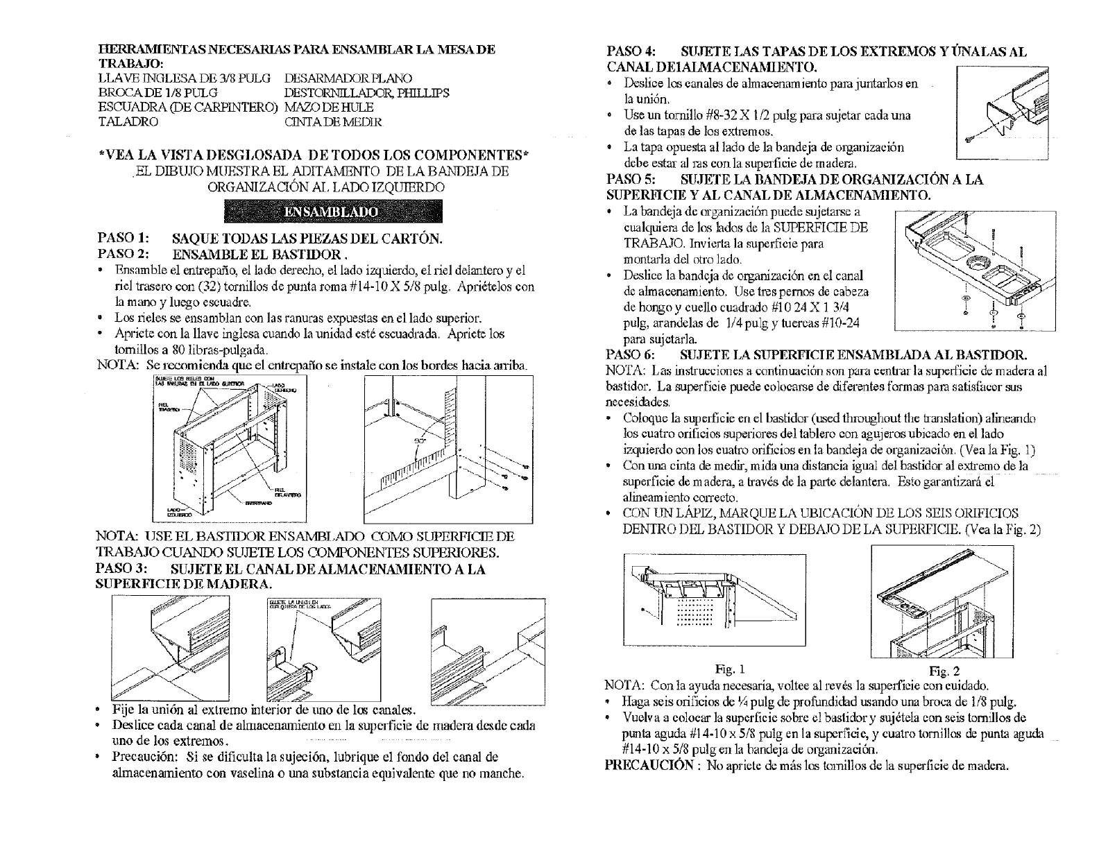
HERRA_MIENTAS NECESARIAS PARA ENSAMBLAR LA MESADE
TRABAJO:
LLAVE INGLESA DE 3/8 PULG DESARMADORPLANO
BROCA DE 1/8 PULG DESTORN1LLADOR, PHILLIPS
ESCUADRA (DE CARPINTERO) MAZO DE HULE
T.ALADRO CINTA DE MEDIR
*VEA LA VISTA DESGLOSADA DE TODOS LOS COMPONENTES*
EL DIBUJO MUESTRA EL ADITAMENTO DE LA BANDEJA DE
ORGANIZACION AI, LADO IZQUIERDO
PASO 1: SAQUE TODAS LAS PIEZAS DEL CARTON.
PASO 2: ENSAMBLE EL BASTIDOR.
• Ensamble el entrepafio, el lado dereeho, el lado izquierdo, el riel delanteroy el
rM txasero con (32) tornillos de punta rema #14-10X 5/8 pulg. Apfi_tclos con
la mano y lu_o eseuadre.
•Los rMes se ensamblan con las ranuras expuestas en el lado superior.
• Apricte con la llave inglcsa cuando la unidad est_ escuadrada. Apriete los
tomitlos a 80 libras-pulgada.
NOTA: Se rtxmmienda que el cnlrc baflose inslale con los hordes haeia an'iba_
_= i.o_ rml_ cou
, ;,i<L
NOTA: USE EL BASTIDOR ENSAMBI.ADO COMO SUPERFICIE DE
TRAB?dO CUANDO SUJETE LOS COMPONENrI'ES SUPERIORES.
PASO 3: SUJETE EL CANAL DE ALMACKNAMIENTO ALA
SUPERFICIE DE MADERA.
Fije la uni6n al extremo interior de tmo de los ean'Aes.
Desfice cada canal de almacenamiento en la superficie de rnadera desde carla
uno de los extremos.
Preeauci6n: Si se dificulta la suieci6n, lubrique el fondo del canal de
almaeenamiento con vaselina o una substancia equivalente que no manehe.
PASO 4:
CANAL DEIAIAIACENAMIENTO.
• Desliee los eanales de almaeenamientopare juntarlos en
la uni6n.
• Use un tornillo #8-32 X l/2 pulg para sujetar eada una
de las tapas de los extremos.
oLa tapa opuesta al lado de la bandeja de olganizaei6n
debe estar al ras con la superfieie de madeva.
SU,IETE LAS TAPAS DE LOS EXTREMOS Y I'INALASAL
PASO 5: SIrJETE LA BANDEJA DE ORGANIZACION A LA
SUPERFICIE Y AL CANAL DE ALMACENAMIENTO.
La bandeja de _:ganiz_aei6npuede sujetz_e a
cualquiemde lea lades & la SUPERFICIE DE
TRABAJO. Invierta la superfieie para
montada dd otro lado.
Desliee la bandeja de organizaeidn cnd canal
de atmaeenamiento. Use h'e_pemos de eabeza
de hongo y euello cuadrado #10 24 X 1 3/4
pulg, arandelas de l!4pu]g y tuercas #10-24
para sujetarla.
/1
r
PASO 6: SUJETE LA SUPERFICIE ENSAMBLADA AL BASTIDOR.
NOTA: Las hlstrucciones a confinuaeidn son lxaraeenlxar la superficie de madera al
bastidor. La superfieie puede eolocame de diferentes tbrmas pare satisthcer sus
necesidades.
• Coloque la superfieie en el bastidor (used throughout file translation) alineando
los euatro orifieios superieres del lablero con agujeros ubieado en el lado
izquierdo con los euatro orifieios en la bandeja de organizaei6n. (Vea la Fig. 1)
• Con una cinta de medir, mida una distancia igual del bastidor al ex_u'emode la
superficie de madera, a tray,s de la pat_e delanlera. Esto garantizarfi el
alineamiento eorreeto.
° CON UN Lii_PIZ,MARQUE LA UBICACION DE LOS SEIS ORIFICIOS
DENIRO DEL BASTIDOR Y DEBAJO DE LA SUPERFICIE. (Vea la Fig. 2)
I r_ L
[i_ i :_
Fig. 1 Fig. 2
NOTA: Con la ayuda neeesaria, voltee al rev_s la superfide con euidado.
• Haga seis orificios de _Apulg de profundidad ttsando una broea de 1/8 pulg.
• Vuelva a eoloear la superfieie soN'e el bastidory sujdtela con seis tomillos de
punta agucka#14-10 × 5/8 pulg en la superf'ide, y cuatro tornillos de punta aguda
#14-10 x 5/8 pulg en la bandeja de organizad6n.
PRECAUCION : No apriete de mils los tomillos de la superfieie de madera.
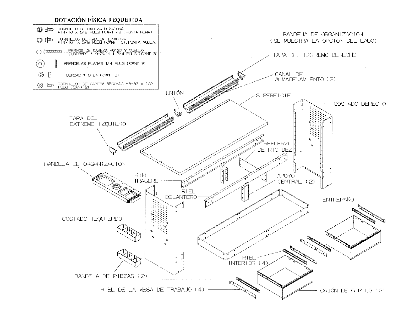
TAPA DEL
EXTREMO i ZCSJI ERO
\\
COS1 ADO I ZQUIEIRDO
%".::::::_
BANDEJA DE P IEZAS (2)
Lb41ON
\\
BANDEJA DE ORGAN IZAC tor,l
(SE MUESTRA hA OPCION DEL LADO)
_.,_ TAPA DEL EXTRE]vlO DERECI40
CANAL DE
t"_" ALMACENAM IEF_O i 2 )
RI EL
DELANTERO
DE RIGIDEZ
j J'_
APOYO
CENTRAL (2)
RIEI.
INTERI OR ( 41
COSTADO DEREC1 I0
RIEL DE LA MESA DE TRABAJO (4) -- CAJOrq DE 6 PULG (2)
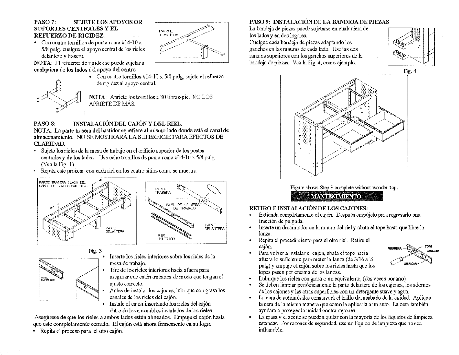
PASO 7: SUJETE LOS APOYOS OR
SOPORT£S CENTRALES Y EL
REFUERZO DE RIGIDEZ.
•Con euah'o tornil!os de punta roma #14-10 x
5/8 pulg, cuelgue el apwo central de los rides
ddanlcro y trasero,
NOTA: E1refuerzo de rigidez se puede sujetar a
etu'dquiera de los lados del apoyo del centro.
• Con cuitro tomillos #14-10 x 5/8 pulg, sujete el refuerzo
de rigidez al apoyo central.
NOTA: Apriete ios tornillos a 80 libras-pie. NO LOS
APRIETE DE Mfi.S.
PASO 9: LNSTALACION DE LA B_NDEJA DE HEZAS
La bandeja de piezas puede s_jetarse en eualquiera de
los ladosy endos lugmes.
Cuelgue cada bandeja de piezas adaptando los
ganchos en las ranuras de cada lado. Use las dos
ranuras supefiores con los ganehos superiores de la
bandeja de piezas. Vea la Fig. 4, eomo ejempb.
t tA
I_g. 4
PASO 8: INSTALACION DEL CAJON Y DEL RIEL.
NOTA: La prate trasera del basfidor se refiem al rnismo lado dome _tfi el canal de
almacenamiento. NO SE 1VIOSTR_M_ LA SUPERFICIE PARA _CTOS DE
CLARIDAD.
• Sujetc los rides do la mesa de laabajo en el orificio superior de los postes
eentrales y de los lados, Use ocho torrtillos de pun/a roma #14-10 x 5/8 pulg,
(Yea la Fig. 1)
• Repita e_e proceso con eada riel en los euatm sitios como se muestra,
PNRIE
DFk Pl\rFFt:_A
Fig, 3
o
o
1
insertc los deles interiores sobr_ los rides & la
mesa de trabajo.
Ti_e de los rides interiores haeia afuera para
a_egurar que estdn tmlrados de modo que tengan el
ajuste correeto.
Antes de imtalar los cajones, tubriquc con grasa los
canales de los rides del caj6rL
Instale el eaj6n insertando los rides del eaj6n
dntro de los ensambles instalados de los rides.
Aseggu'ese de que los deles a ambos lados est&l alineados. Empuje el c_aj6nhasta
que est_ completamente cen'ado. El eaj6n esk4 aJmra fmnemente en su lugea'.
, Repita el pmcem para el otro caj6n.
Figure sho_s Step 8 cc_npletevdthout wooden top.
RETIRO E INSTALACION DE LOS CA,IONF.S:
• Exlienda completamente el eaj6r_ Despu_s emp_ido para regresado una
fmeei6n de pulgada.
. Inserte un desarmador en la ranura del rid y abata el lope hasta que fibre la
lar,.za.
• Repita el proeedimiento para el ota'oriet Relire el
ca.lon.
• Paxa volvcr a instalar el caj6n, abata el tope hacia
afu_ra 1osuficiente para meter la lanza (de 3/16 a V_
pulg) y empuje el eaj6n sobre los rides hasta que los
topes pasen pot eneima de las lanzas.
• Lubfique los rides con grasa o un equiva!vmte, (dos veees por afio),
• Se deben limpiar peri6dieamente la parte delantera de los eajones, los adornos
de los cajones y las otrassuperficies con un detergente suave y agua.
• La cera de autom6viles eonservara el britlo del aeabado de la unidad. Aplique
la eera de la misma manera que eomo la apiiearia a un auto. La eera tambi_n
aN_dar_ a proteger la unidad contra rayones.
• La grasa y el aeeite se pueden quitar con lam ayoria de los liquidos de limpieza
estimdm-. Pot razones de seguridad, use un liquido de limpieza clueno sea
inflamable.
