Craftsman 917250051 User Manual GARDEN TRACTORS Manuals And Guides L0803600
CRAFTSMAN Lawn, Tractor Manual L0803600 CRAFTSMAN Lawn, Tractor Owner's Manual, CRAFTSMAN Lawn, Tractor installation guides
User Manual: Craftsman 917250051 917250051 CRAFTSMAN GARDEN TRACTORS - Manuals and Guides View the owners manual for your CRAFTSMAN GARDEN TRACTORS #917250051. Home:Lawn & Garden Parts:Craftsman Parts:Craftsman GARDEN TRACTORS Manual
Open the PDF directly: View PDF ![]() .
.
Page Count: 52
®
MODEL NUMBER 917.250051 OWNER'SMANUAL
Assembly
Operation
Customer
Responsibilities
Service
Adjustments
Repair Parts
aution:
cad and Follow
I Safety Rules
_d Instructions
efore Operating
his Equipment
SAFETY RULES &
Safe Operation Practices for Ride-On Mowers
IMPORTANT: THIS CUTTING MACHINE IS CAPABLE OFAMPUTATING HANDS AND FEET AND THROWING OBJECTS.
FAILURE TO OBSERVE THE FOLLOWING SAFETY INSTRUCTIONS COULD RESULT IN SERIOUS INJURY OR DEATH.
I. GENERAL OPERATION
•Read, understand, and follow all instructions in the manual
and on the machine before starting.
•Only allow responsible adults, who are familiar with the
instructions, to operate the machine.
•Clear the area of objects such as rocks, toys, wire, etc,
which could be picked up and thrown by the blade.
•Be sure the area isclear of otherpeople before mowing. Stop
machine if anyone enters the area.
• Never carry passengers.
• Do not mow in reverse unless absolutely necessary. Always
leek down and behind before and while backing.
,, Be aware of the mower discharge direction and do not point
it at anyone. Do not operate the mower without either the
entire grass catcher or the guard in place.
° Slow down before turning.
•Never leave a running machine unattended. Nways turn off
blades, set parking brake, stop engine, and remove keys
before dismounting.
• Turn off blades when not mowing.
° Stop engine before removing grass catcher or unclogging
chute.
• Mow only in daylight or good artificial light.
° Do not operate the machine while under the influence of
aicoho! or drugs.
° Watch for traffic when operating near or crossing roadways.
•Use extra care when loading or unloading the machine into
atrai_er or truck.
U, SLOPE OPERATION
Slopes are a major factor related to toss-of=control and tipover
accidents, which can result in severe injury or death. AHslopes
require extra caution. Ifyou cann ot back up the slope orifyou feel
uneasy on it, do not mow it.
DO:
•Mow up and down slopes, not across.
•Remove obstacles such as rocks, tree limbs, etc.
° Watch for holes, ruts, or bumps. Uneven terrain could
overturn the machine. Tall grass can hide obstacles.
• Use slow speed. Cheese a low gear so that you wilf not have
to stop or shift while on the slope.
• Follow the manufacturer's recommendations for wheel
weights or counterweights to improve stability.
= Use extra care with grass catchers or other attachments.
These can change the stability of the machine.
•Keep all movement on the slopes slow and gradual Do not
make sudden changes in speed or direction.
° Avoid starting or stopping on a slope. If tires lose traction,
disengage the blades and proceed slowly straightdewn the
slope.
DO NOT:
•Do not turn on slopes unless necessary, and then, turn slowly
and gradually downhill, if possible.
.Do notmow near drop-offs, ditches, or embankments. The
mower could suddenly turn over if a wheel is over the edge
of a cliff or ditch, or if an edge caves in.
•Do not mow on wet grass. Reduced traction could cause
sliding.
•Do not try to stabilize the machine by putting your foot on the
ground.
•Do not use grass catcher on steep slopes.
ill. CHILDREN
Tragic accidents can occur if the operator is not afert to the
presence ofchildren. Children are often attracted to the machine
and the mowing activity. Neverassume that children will remain
where you last saw them.
• Keep children out of the mowing area and underthe watchful
care of another responsible adult.
•Be alert and tum machine off ifchildren enter the area.
• Before and when backing, look behind and down for small
children.
= Never carry children. They may fall off and be seriously
injured or interfere with safe machine operation.
• Never allow children to operate the machine.
•Use extra care when approaching blind corners, shrubs,
trees, or other objects that may obscure vision.
IV. SERVICE
•Use extra care inhandling gasoline and otherfuels. They are
flammable and vapors are explosive.
Use only an approved container.
Never remove gas cap or add fue! with the engine
running. Allow engine to cool before refueling. Do not
smoke.
Never refuel the machine indoors.
Never store the machine or fuel container inside where
there is an open flame, such as a water heater.
. Never run a machine inside a closed area.
, Keep nuts and bolts, especially blade attachment bolts, tight
and keep equipment in good condition.
=Never tamper with safety devices. Check their proper
operation regularly.
•Keep machine free of grass, leaves, or other debris build-up.
Clean oil or fuel spillage. Allow machine to cool before
storing.
o Stop and inspect the equipment if you strike an object.
Repair, if necessary, before restarting.
• Never make adjustments or repairs with the engine running.
° Grasscatchercomponentsaresubjecttowear, damage,and
deterioration, which could expose moving parts or allow
objects to be thrown. Frequently check components and
replace with manufacturer's recommended parts, when nec-
essary,
, Mower blades are sharp and can cuL Wrap the blade(s) or
wear gloves, and use extra caution when servicing them.
o Check brake operation frequently. Adjust and service as
required,
_r this symbol to_
fety precautions, It means !
N!II BECOME ALERT!!! YOUR i
IS INVOLVED, J
CAUTION: Always disconnect spark
plug wire and place wire where it cannot
contact spark plug in order to prevent
accidental starting when setting up,
transporting, adlusting or making
repairs.
CONGRATULATIONS on your purchase of a Sears
tractor. It has been designed, engineered and manufac-
tured to give you the best possible dependability and
performance.
Should you experience any problem you cannot easily
remedy, please contact your nearest Sears Service
CentedDepartment. We have competent, welt-trained
technicians and the proper tools to service or repair this
tractor.
Please read and retain this manual. The instructions will
enable you to assemble and maintain your tractor prop-
erly. Always observe the "SAFETY RULES".
MODEL
NUMBER 917.250051
SERIAL
NUMBER
DATE OF PURCHASE
THE MODELAND SERIAL NUMBERSWILL BE FOUND
ON A PLATE UNDER THE SEAT.
YOU SHOULD RECORD BOTH SERIAL NUMBER AND
DATE OF PURCHASE AND KEEP tN A SAFE PLACE
FOR FUTURE REFERENCE.
MAINTENANCE AGREEMENT
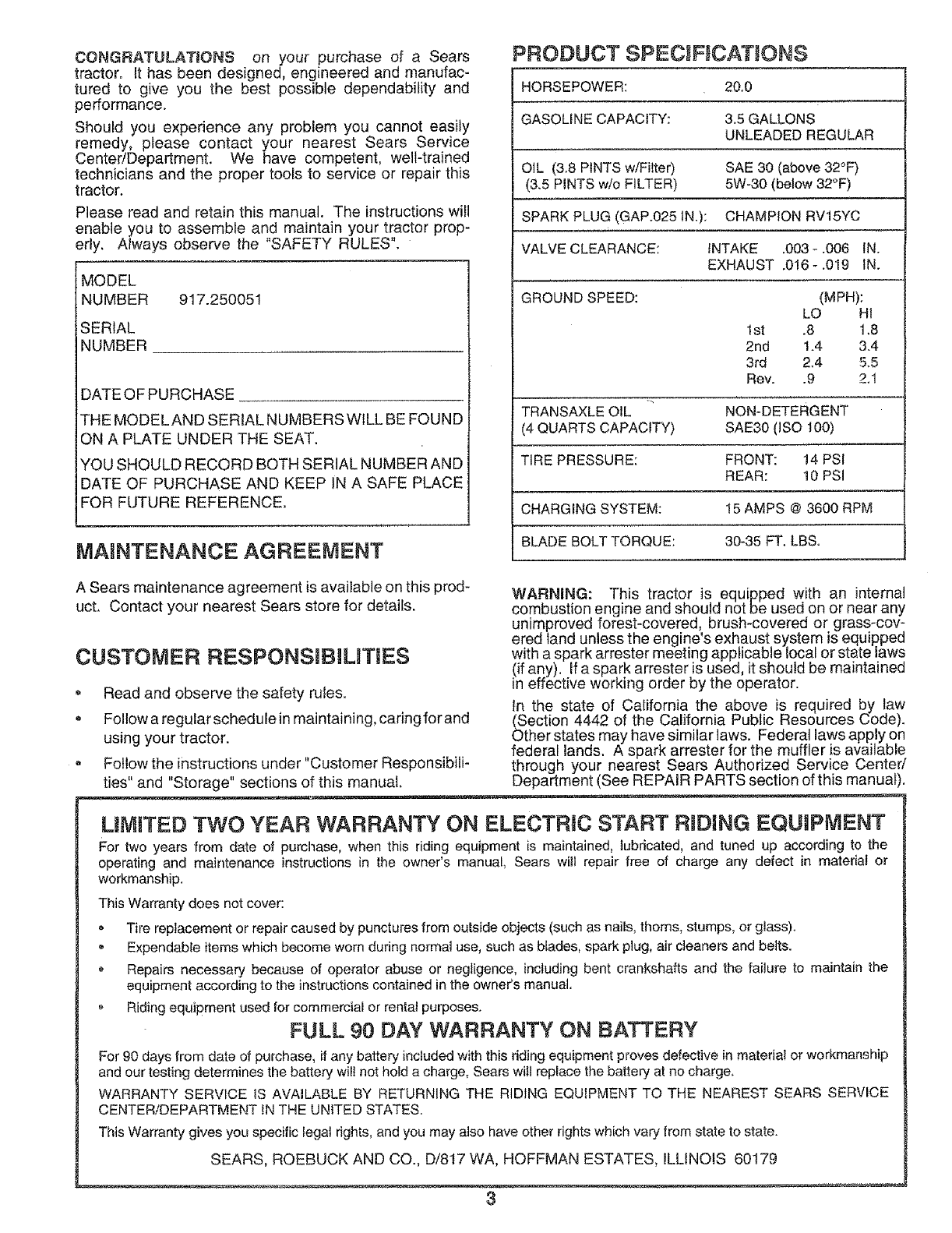
PRODUCT SPECiFiCATiONS
HORSEPOWER: 20.0
GASOLINE CAPACITY: 3.5 GALLONS
UNLEADED REGULAR
OIL (3.8 PINTS w/Fitter) SAE 30 (above 32°F)
(3.5 PINTS w/o FILTER) 5W-30 (below 32°F)
SPARK PLUG (GAP.025tN.): CHAMPION RV15YC
VALVE CLEARANCE: INTAKE .003- .006 IN.
EXHAUST .016-.019 IN.
GROUND SPEED: (MPH):
LO HI
1st .8 1.8
2rid 1.4 3.4
3rd 2.4 5.5
Rev. .9 2.1
TRANSAXLE OIL NON-DETERGENT
(4 QUARTS CAPACITY) SAE30 (ISO 100)
TIRE PRESSURE: FRONT: 14 PSI
REAR: 10 PSi
CHARGING SYSTEM: 15 AMPS @ 3600 RPM
BLADE BOLT TORQUE: 30-35 FT. LBS.
A Sears maintenance agreement is available on this prod-
ucL Contact your nearest Sears store for details.
CUSTOMER RESPONSlBILnT ES
Read and observe the safety rules.
, Follow a regular schedule in maintaining, caring for and
using your tractor.
Follow the instructions under "Customer Responsibili-
ties" and "Storage" sections of this manual,
WARNING: This tractor is equipped with an internal
combustion engine and should not be used on or near any
unimproved forest-covered, brush-covered or grass-cov-
ered land unless the engine's exhaust system is equipped
with a spark arrester meeting applicable local or state laws
lif any). Ifa spark arrester is used, it should be maintained
neffective working order by the operator.
In the state of California the above is required by taw
(Section 4442 of the California Public Resources Code).
Other states may have similar laws. Federal laws apply on
federal lands. A spark arrester for the muffler is available
through your nearest Sears Authorized Service Center/
Department (See REPAIR PARTS section of this manual
LIMITED TWO YEAR WARRANTY ON ELECTRIC START RIDING EQUtPiVIENT
For two years from date of purcl_ase, when this riding equipment is maintained, iubricated, and tuned up according to the
operating and maintenance instructions in the owner's manual, Sears will repair free of charge any defect in material or
workmanship.
This Warranty does net cover:
* Tire replacement or repair caused by punctures from outside objects (such as nails, thorns, stumps, or glass).
,Expendable items which become worn during normal use, such as blades, spark plug, air cleaners and belts.
* Repairs necessary because of operator abuse or negligence, including bent crankshafts and the failure to maintain the
equipment according to the instructionscontained in the owner's manual.
Riding equipment used for commercial or rentat purposes.
FULL 90 DAY WARRANTY ON BATTERY
For 90 days from date of purchase, if any battery included with this riding equipment proves defective in material or workmanship
and our testing determines the battery will net hold a charge, Sears wilt replace the battery at no charge.
WARRANTY SERVICE iS AVAILABLE BY RETURNING THE RIDING EQUIPMENT TO THE NEAREST SEARS SERVICE
CENTER/DEPARTMENT IN THE UNITED STATES.
This Warranty gives you specific legal rights, and you may also have other rights which ,vary from state to state.
SEARS, ROEBUCK AND CO., D/8t7 WA, HOFFMAN ESTATES, ILLINOIS 60179
TABLE OF CONTENTS
SAFETY RULES ............................................................ 2
PRODUCT SPECIFICAT!ONS .................................... :_3
CUSTOMER RESPONSIBiLiTiES ..................... 3, 13-1{}
WARRANTY .................. _,................................................ 3
TABLE OF CONTENTS ................................................. 4
iNDEX ............................................................................ .4
TRACTOR ACCESSORIES ........................................... 5
ASSEMBLY ................................................................ 7-9
OPE RATION ........................................................... 10-t 2
MAINTENANCE SCHEDULE ...................................... 13
SERVICE AND ADJUSTMENTS ............................ 17-20
STORAGE .................................................................... 2t
TRO UBLESHOOTtNG ............................................ 22=23
REPAIR PARTS -TRACTOR ................... :............. 25-38
REPAIR PARTS -ENGINE ..................................... 40-49
PARTS ORDERING/SERViCE ................... BACK PAGE
iNDEX
A
Accessories ............................................ 5
Adjustments:
Brake ........................................... 17
Carburetor ................................... 20
Clutch .............................. i ........... 17
Throttle Control Cable ................. 20
Toeqn .......................................... 18
Air Filter, Engine ................................. 16
Air Screen, Engine .............................. 15
Assembly ........................................... 7-9
8
Battery:
Charging ........................................ 8
Cleaning ...................................... t 4
installation ..................................... 9
Levels ....................................... 8,!4
Preparation .................................... 8
Starting with Weak Battery .......... 19
Storage ........................................ 21
Terminals .................................... 14
Be_t:
Motion Drive
Removal/Replacement ........... 18
Brake Adjustment ............................... 17
C
Carburetor Adjustment ....................... 20
Clutch Adjustment. ............................ !7
Controls, Tractor ................................. 10
Customer Responsibilities .......... 3,13-16
Engine:
Air Filter ................................... 16
.Air Filter Foam Pre-Cieaner .... 16
Air Screen, Engine .................. 15
Battery ..................................... 14
Cooling Fins, Engine ............... 15
Engine Oil ................................ 15
Fuel Filter ................................ 16
Spark Plugs ............................. 16
Tractor:
Lubrication Chart ..................... 13
Maintenance Schedule ............ t 3
Tire Care .............................. 8,19
E
Electrical:
Interlocks and Relays .................. 19
Schematic ................................... 24
Wiring Diagram ............................ 26
Engine:
Air Filter ....................................... 16
Air Filter Foam Pre-Cleaner ........ 16
Air Screen ................................... 15
Cooling Fins, Engine ................... 15
Oil Change .................................. 15
Oi! Level ................................... 8,14
Oil Type ....................................... 15
Preparation .................................. 12
Repair Parts ........................... 40-49
Starting ........................................ 12
Storage ........................................ 21
F
Filter:
Air Filter ....................................... 16
Air Filter Foam Pre-Cieaner ........ 16
Fuel ............................................. 16
Oil ................................................ 16
Fuel:
Type ............................................ 12
Storage ........................................ 21
Fuse .................................................... 19
H
Hood Remova!/Installation .................. 20
L
Lubrication Chart ..................... _.......... 13
M
Maintenance Schedule ....................... 13
Muffler ................................................ 16
Spark Arrester .......................... 3,30
O
O_l:
Cold Weather Conditions ....... t2,15
Fi_ter ............................................ 16
Engine ......................................... t 5
Storage ........................................ 21
Transaxle .................................... t 4
Operation ...................................... 10-12
Options:
Accessories ................................... 5
Spark Arrester .......................... 3,30
P
Parking Brake ................................ 10-11
Parts Bag ................ .............................. 6
Parts, Replacement/Repair ........... 25-38
Product Specifications ........................... 3
R
Repair Parts .................................. 25-37
S
Safety Rules ......................................... 2
Seat ...................................................... 8
Service and Adjustments ............... 17-20
Carburetor ................................... 20
Clutch .......................................... 17
Fuse ............................................ 1g
Hood Removal/installation .......... 20
Motion Drive Belt
Removal/Replacement ........... 18
Tire Care ................................... 8,t9
Toeqn .......................................... 18
Slope Guide Sheet ............................. 51
Spark Plugs. ....................................... 16
Specifications ....................................... 3
Starting the Engine ............................. 12
Steering Wh eel ................................ 7,18
Stopping the Tractor ........................... 11
Storage ............................................... 21
T
Throttle Control Cable
Adjustment .................................. 20
Tires ................................................... 8,19
Trouble Shooting Chart .................. 22-23
Transaxle:
Oil Level ...................................... 14
Repair Parts ........................... 36-37
W
Warranty ............................................... 3
Wiring Diagram ................................... 26
Wiring Schematic ................................ 24
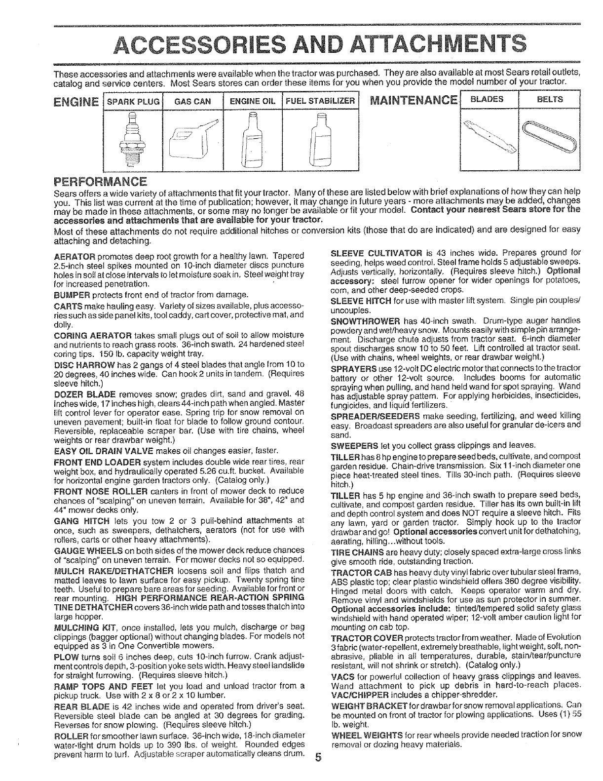
ACCESSORmES AN ATTACHMENTS
These accessories and attachments were available when the tractor was purchased. They are also available at most Sears retail outlets,
catalog and service centers. Most Sears stores can order these items for you when you provide the model number of your tractor.
ENGINE SPARK PLUG GAS CAN ENGINE OiL FUEL STABILIZER MAINTENANCE
PERFORMANCE
Sears offers a wide variety of attachments that fit your tractor. Many of these are listed below with brief explanations of how they can help
you. This list was current at the time of publication however, it may change in future years - more attachments may be added, changes
may be made in these attachments, or some may no longer be available or fit your mode. Contact your nearest Sears store for the
accessories and _ttachments that are available for your tractor.
Most of these attachments do not require additional hitches or conversion kits (those that do are indicated) and are designed for easy
attaching and detaching.
AERATOR promotes deep root growth for a healthy lawn, Tapered
2,5qnch steel spikes mounted on 10-inch diameter discs puncture
holes in soil at c_ose intervals to let moisture soak in. Steet weight tray
for increased penetration.
BUMPER protects front end of tractor from damage.
CARTS make hauling easy. Variety of sizes available, plus accesso-
ries such as side panel kits, tool caddy, cart cover, protective mat, and
dolly,
CORING AERATOR takes small plugs out of soil to allow moisture
and nutrients to reach grass roots. 36-inch swath. 24 hardened steel
coring tips, 150 Ib, capacity weight tray.
DISC HARROW has 2 gangs of 4 steel b_ades that angle from 10 to
20 degrees, 40 inches wide. Can hook2 units in tandem. (Requires
sleeve hitch.)
DOZER BLADE removes snow; grades dirt, sand an(] gravel, 48
inches wide, 17 inches high, clears 444nch path when angled. Master
lift control lever for operator ease. Spring trip for snow removal on
uneven pavement; built-in float for blade to follow ground contour.
Reversible, replaceable scraper bar. (Use with tire chains, wheel
weights or rear drawbar weight.)
EASY OIL DRAIN VALVE makes oiJ changes easier, faster.
FRONT END LOADER system includes double wide rear tires, rear
weight box, and hydraulically operated 5.26 cu.ft, bucket, Available
for horizontal engine garden tractors only. (Catalog onty,)
FRONT NOSE ROLLER canters in front of mower deck to reduce
chances of "scalping" on uneven terrain. Available for 38", 42" and
44" mower decks only.
GANG HITCH lets you tow 2 or 3 puiFbehind attachments at
once, such as sweepers, dethatchers, aerators (not for use with
rollers, carts or other heavy attachments).
GAUGE WHEELS on both sides of the mower deck reduce chances
of "scalping" on uneven terrain. For mower decks not so equipped.
MULCH RAKF_JDETHATCHER loosens soi_ and flips thatch and
matted leaves to lawn surface for easy pickup. Twenty spring tine
teeth. Useful to prepare bare areas for seeding. Available for front or
rear mounting. HiGH PERFORMANCE REAR-ACTION SPRING
TIN E DETHATCHER covers 36-inch wide path and tosses thatch into
large hopper.
MULCHING K_T, once installed, lets you mutch, discharge or bag
clippings (bagger optional) without changing blades. For models not
equipped as 3 in One Convertible mowers.
PLOW turns soil 6 inches deep, cuts 10-inch furrow. Crank adjust-
ment controls depth, 3-position yoke sets width_ Heavy steel landslide
for straight furrowing. (Requires sleeve hitch.)
RAMP TOPS AND FEET let you toad and unload tractor from a
pickup truck, Use with 2 x 8 or 2 x 10 lumber.
REAR BLADE is 42 inches wide and operated from driver's seat.
Reversible steel blade can be angled at 30 degrees for grading.
Reverses for snow plowing. (Requires sleeve hitch.)
ROLLER for smoother lawn surface. 36-inch wide, 18-inch diameter
waterqight drum holds up to 390 Ibs, of weight. Rounded edges
prevent harm to turf. Adjustable scraper automatically cleans drum. 5
SLEEVE CULTIVATOR is 43 inches wide. Prepares ground for
seeding, helps weed control Steel frame holds 5 adjustable sweeps.
Adiusts venticalty, horizontally. (Requires sleeve hitch.) Optional
accessory: steel furrow opener for wider openings for potatoes,
corn, and other deep-seeded crops.
SLEEVE HITCH for use with master lift system. Single pin couples/
uncouples.
SNOWTHROWER has 40-inch swath. Drum-type auger handles
powdery and wet/heavy snow. Mounts easily with simple pin arrange-
ment. Discharge chute adjusts from tractor seat. 6-inch diameter
spout discharges snow 10 to 50 feet. Lift controlled at tractor seat.
(Use with chains, wheel weights, or rear drawbar weight,)
SPRAYERS use 12-volt DC electric motor that connects to the tractor
battery or other 12-volt source, Includes booms for automatic
spraying when pulling, and hand held wand for spot spraying, Wand
has adjustable spray pattern. For applying herbicides, insecticides,
fungicides, and liquid fertilizers.
SPREADER/SEEDERS make seeding, fertilizing, and weed killing
easy. Broadcast spreaders are also useful for granular de-icers and
sand.
SWEEPERS let you collect grass clippings and leaves,
TILLER has 8 hp engine to prepare seed beds, cultivate, and corn post
garden residue. Chain-drive transmission. Six 1 l-inch diameter one
piece heat-treated steel tines. Tills 30cinch path. (Requires sleeve
hitch.)
TILLER has 5 hp engine and 36-inch swath to prepare seed beds,
cultivate, and compost garden residue. Tiller has its own built-in lift
and depth control system and does NOT require a sleeve hitch. Fits
any lawn, yard or garden tractor. Simply hook up to the tractor
drawbar and go! Optional accessories convert unit for dethatching,
aerating, hi_ting...without tools.
TIRE CHAINS are heavy duty; closely spaced extra-large cross links
give smooth ride, outstanding traction.
TRACTOR CAB has heavy duty vinyl fabric over tubular steel frame,
ABS plastic top; clear plastic windshield offers 360 degree visibility.
Hinged metal doors with catch. Keeps operator warm and dry.
Remove vinyl and windshields for use as sun protector in summer.
Optional accessories include: tinted/tempered sotid safety glass
windshield with hand operated wiper; 12-vott amber caution light for
mounting on cab top.
TRACTOR COVER protects tractor from weather. Made of Evolution
3 fabric (water-repellent, extremely breathable, light weight, soft, non-
abrasive, pliable in all temperatures, durable, stain/tear/puncture
resistant, will not shrink or stretch). (Catalog only.)
VACS for powerful collection of heavy grass clippings and leaves.
Wand attachment to pick up debris in hardoto-reach places.
VAClCHtPPER includes a chipper-shredder,
WEIGHT BRACKET for drawbar for snow removal applications, Can
be mounted on front of tractor for plowing applications. Uses (1) 55
Ib. weight.
WHEEL WEIIGHTS for rear wheels provide needed traction for snow
removal or dozing heavy materials.
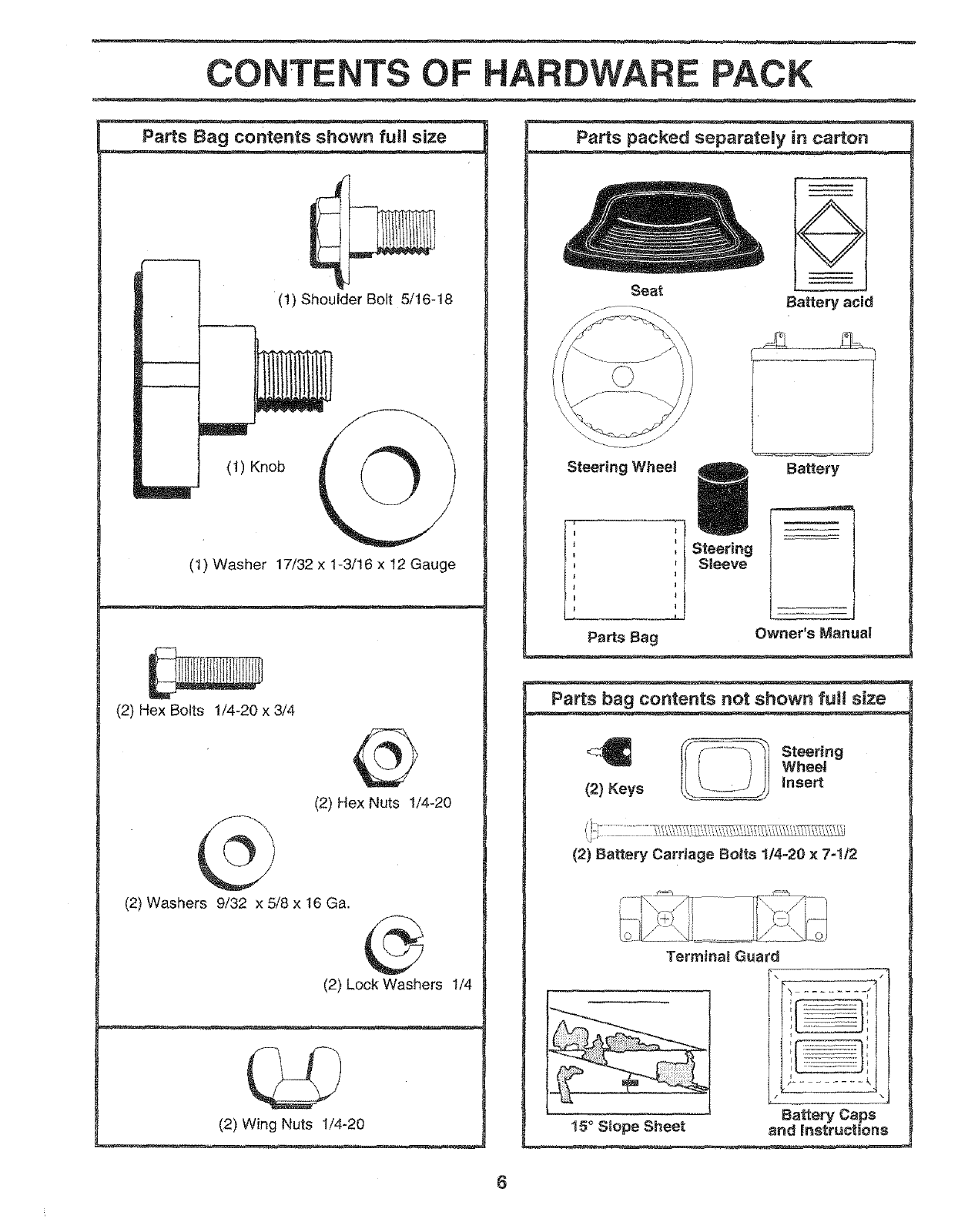
CONTENTS OF DWARE PAC
Parts Bag contents shown full size
(1) Shoulder Bolt 5/16q8
(1) Knob
(1) Washer 17/32 x 1-3/16 x 12 Gauge
(2) Hex Bolts t/4-20 x 3/4
(2) Hex Nuts 1/4-20
(2) Washers 9/32 x 5/8 x 16 Ga.
(2) Lock Washers 1/4
(2) Wing Nuts 1/4-20
Parts packed separately in carton
Seat
÷
8artery acid
Steering Wheet Bakery
Steering
Sleeve
Parts bag contents not shown ful! size
(2) Keys _! teering
Wheel
Insert
(2) Battery Carriage Bo|ts 1/4-20 × 7-1/2
Terminal Guard
15° Stope Sheet
L q
I................
"1
Battery Caps
and Instructions
Yournewtractorhasbeenassembledatthefactorywiththeexception of those parts left unassembled for shipping purposes.
To ensure safe and proper operation of your tractor, all parts and hardware you assemble must be tightened securely. Use
the correct tools as necessary to insure their proper tightness.
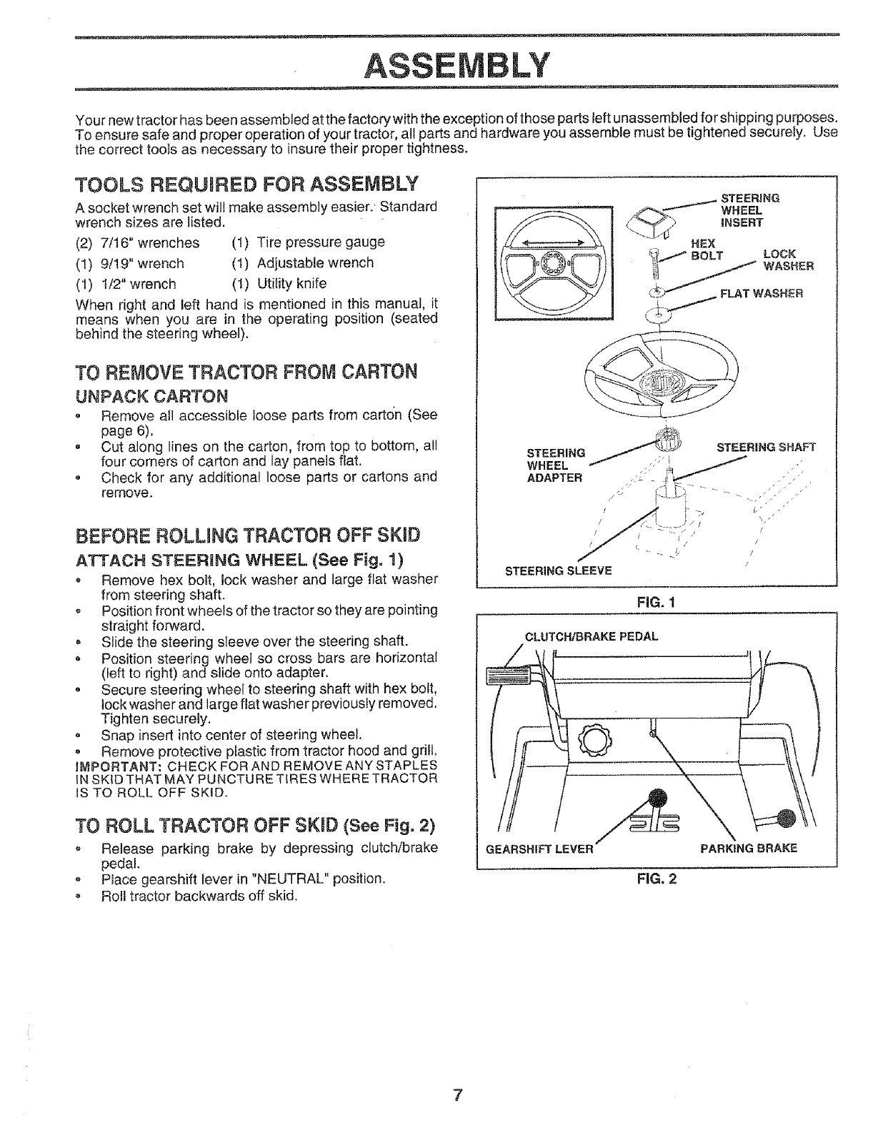
TOOLS REQUmRED FOR ASSEMBLY
A socket wrench set will make assembly easier. Standard
wrench sizes are listed.
(2) 7/16" wrenches (1) Tire pressure gauge
(1) 9/19" wrench (t) Adjustable wrench
(1) 1/2" wrench (1) Utility knife
When right and left hand is mentioned in this manual, it
means when you are in the operating position (seated
behind the steering wheel).
TO REMOVETRACTOR FROMCARTON
UNPACK CARTON
• Remove aH accessible loose parts from carton (See
page 6),
• Cut along lines on the carton, from top to bottom, all
four corners of carton and lay panels flat.
• Check for any additional loose parts or cartons and
remove,
BEFORE ROLMNG TRACTOR OFF SKiD
ATTACH $TEERRNG WHEEL (See Fig. t)
oRemove hex bolt, lock washer and large flat washer
from steering shaft.
, Position front wheels of the tractor so they are pointing
straight forward,
, Slide the steering sleeve over the steering shaft.
oPosition steering wheel so cross bars are horizontal
(left to right) and slide onto adapter.
= Secure steering wheel to steering shaft with hex bolt,
lock washer and large flat washer previously removed.
Tighten securely.
= Snap insert into center of steering wheel.
, Remove protective plastic from tractor hood and grill.
IMPORTANT: CHECK FOR AND REMOVE ANY STAPLES
IN SKID THAT MAY PUNCTURE TfRES WHERE TRACTOR
IS TO ROLL OFF SKID.
TO ROLL TRACTOR OFF SKRD(See Fig, 2)
Release parking brake by depressing clutch/brake
pedal.
o Place gearshift lever in "NEUTRAL" position.
Roll tractor backwards off skid.
._ / STEERING
INSERT
_:i/BOLT _LOCK
i;! // WASHER
(_f'_ _FLAT WASHER
STEERING
WHEEL
ADAPTER
STEERING SHAFT
STEERING SLEEVE
FiG. 1
CLUTCH/BRAKE PEDAL
?°
GEARSHIFT LEVER PARKING BRAKE
FIG. 2
7
ASS
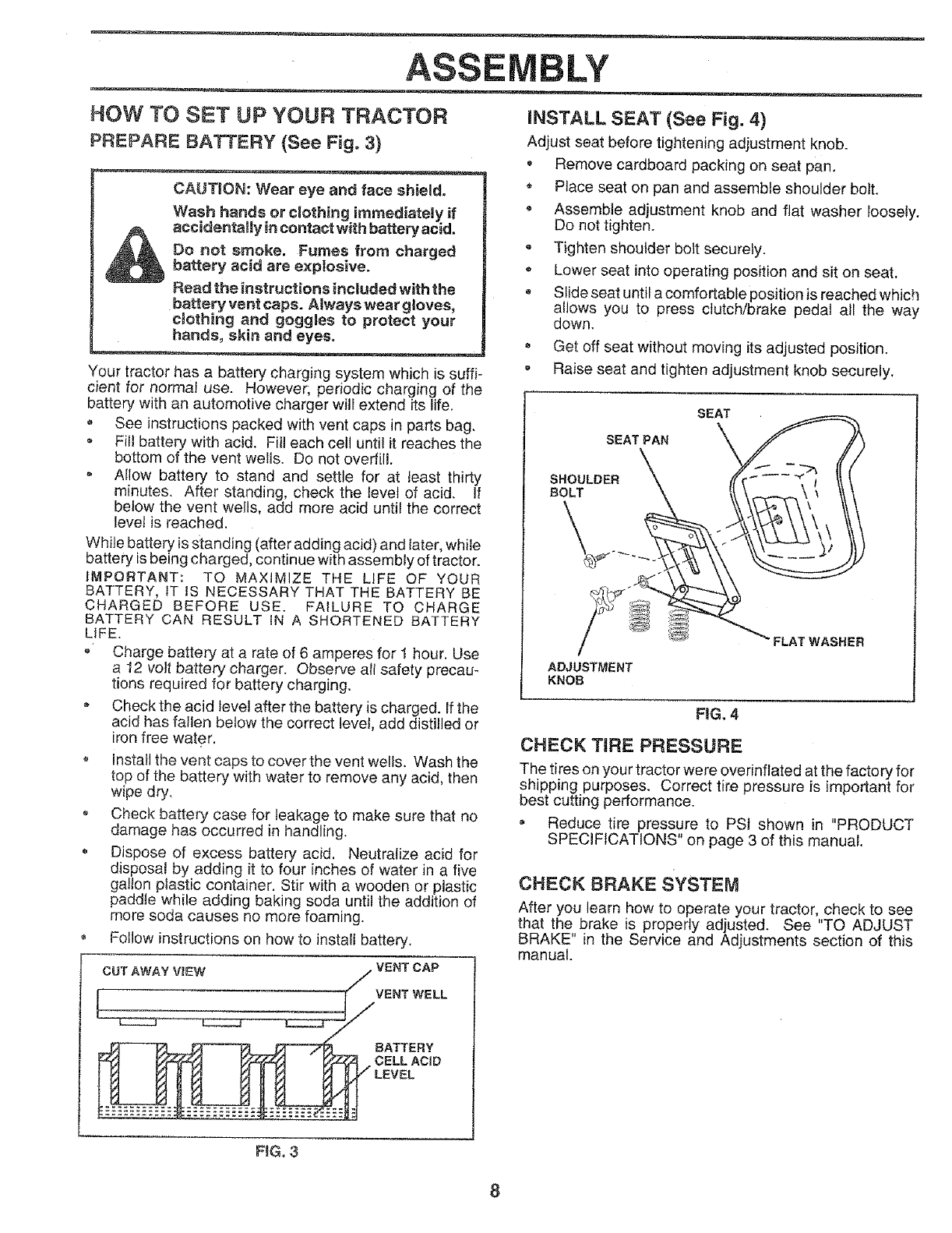
HOW TO SET UP YOUR TRACTOR
PREPARE BATTERY (See Fig. 3)
CAUTION: Wear eye and face shield.
Wash hands or clothing immediately ff
_ accidentallyincontactwithbatteryacid.
Oo not smoke. Fumes from charged
battery acid are explosive.
Read the instructions included with the
battery vent caps. Always wear gloves,
c_othing and goggles to protect your
hands, skin and eyes.
Your tractor has a battery charging system which is suffi-
cient for normal use. However; periodic charging of the
battery with an automotive charger will extend its life.
See instructions packed with vent caps in parts bag.
o Fill battery with acid. Fitl each cell until it reaches the
bottom of the vent wells. Do not overfill.
Allow battery to stand and settle for at least thirty
minutes. After standing, check the level of acid. If
below the vent wells, add more acid until the correct
level is reached.
While battery is standing (after adding acid) and later, while
battery is being charged, continue with assembly of tractor.
ItV'iPORTANT: TO MAXiMiZE THE LIFE OF YOUR
BATTERY, IT IS NECESSARY THAT THE BATTERY BE
CHARGED BEFORE USE. FAILURE TO CHARGE
BATTERY CAN RESULT tN A SHORTENED BATTERY
LIFE.
o Charge battery at a rate of 6 amperes for 1 hour. Use
a 12 volt battery charger. Observe all safety precau-
tions required for battery charging.
*Check the acid level after the battery is charged. If the
acid has fallen below the correct level, add distilled or
iron free water,
o Install the vent caps to cover the vent wells. Wash the
top of the battery with water to remove any acid, then
wipe dry.
, Check battery case for leakage to make sure that no
damage has occurred in handling.
o Dispose of excess battery acid. Neutralize acid for
disposal by adding it to four inches of water in a five
gallon ptastic container. Stir with a wooden or plastic
paddle while adding baking soda until the addition of
more soda causes no more foaming.
Follow instructions on how to install battery_
VENT CAP
VENT WELL
BATTERY
CELL ACiD
LY
iNSTALL SEAT (See Fig. 4)
Adjust seat before tightening adjustment knob.
•Remove cardboard packing on seat pan.
• Place seat on pan and assemble shoulder bolt.
• Assemble adjustment knob and fiat washer loosely.
Do not tighten.
Tighten shoulder bolt securely.
•Lower seat into operating position and sit on seat.
,Slide seat until a comfortable position is reached which
allows you to press clutch/brake pedal all the way
down.
Get off seat without moving its adjusted position.
Raise seat and tighten adjustment knob securely.
SEAT PAN
SHOULDER
BOLT
ADJUSTMENT
KNOB
SEAT
FLAT WASHER
FIG. 4
CHECK TiRE PRESSURE
The tires on your tractor were overinflated at the factory for
shipping purposes. Correct tire pressure is important for
best cutting performance.
, Reduce tire pressure to PSI shown in "PRODUCT
SPECIFICATIONS" on page 3 of this manual.
CHECK BRAKE SYSTEM
After you learn how to operate your tractor, check to see
that the brake is properly adjusted. See "TO ADJUST
BRAKE" in the Service and Adjustments section of this
manual.
FiG, 3
8
ASSEMBLY
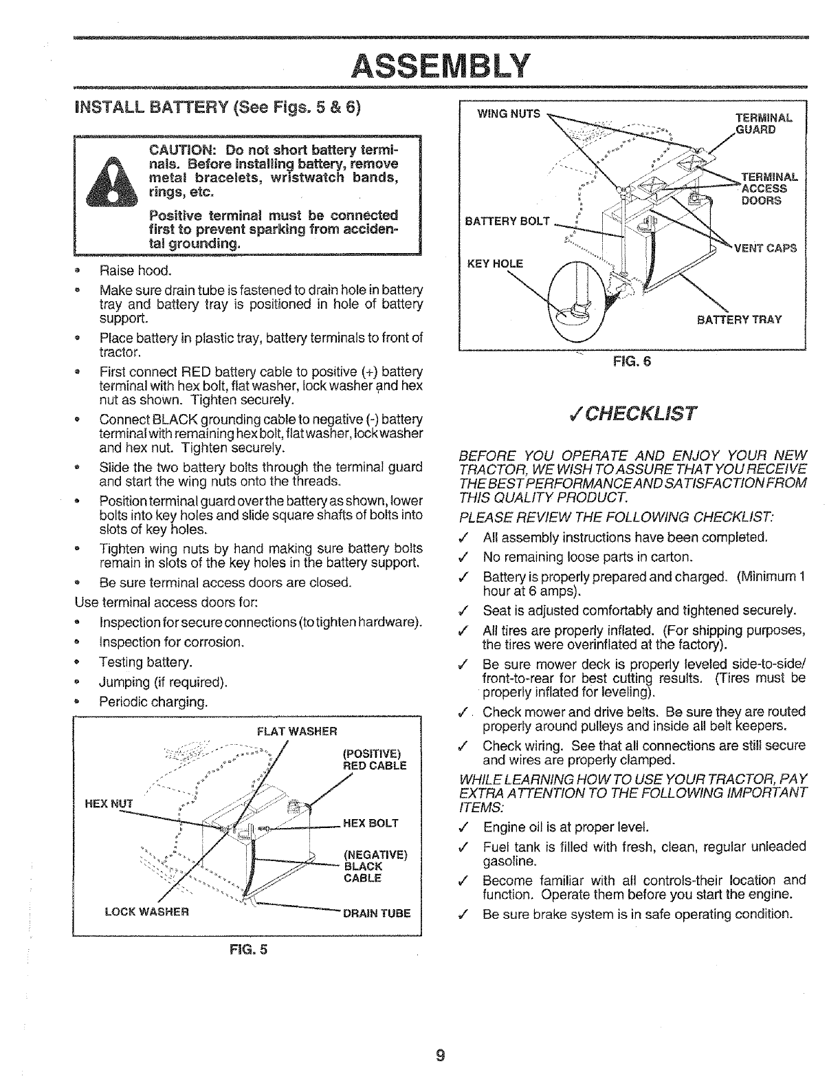
HNSTALL BATTERY {See Figs, 5 & 6)
CAUT1ON: Do not short battery termi-
nals. Before installing battery, remove
metal bracelets, wristwatch bands,
rings, etc.
Positive terminal must be connected
first to prevent sparking from acciden-
ts! grounding.
,Raise hood.
,Make sure drain tube is fastened to drain hole in battery
tray and battery tray is positioned in hole of battery
support.
o Place battery in plastic tray, battery terminals to front of
tractor.
• First connect RED battery cable to positive (+) battery
terminal with hex bolt, flat washer, lock washer and hex
nut as shown. Tighten securely.
Connect BLACK grounding cable to negative (-) battery
terminal with remaining hex bolt, fiat washer, Iock washer
and hex nut. Tighten securely.
Slide the two battery bolts through the terminal guard
and start the wing nuts onto the threads.
• Position terminal guard over the battery as shown, lower
bolts into key holes and slide square shafts of bolts into
slots of key holes.
Tighten wing nuts by hand making sure battery bolts
remain in slots of the key holes in the battery support.
Be sure terminal access doors are closed.
Use terminal access doors for:
Inspection for secure connections (to tighten hardware).
Inspection for corrosion.
• Testing battery.
Jumping (if required).
® Periodic charging.
FLAT WASHER
(POSITtVE)
RED CABLE
HEXBOLT
(NEGATIVE)
CABLE
LOCK WASHER DRA|N TUBE
WING NUTS
BATTERY BOLT
KEY HOLE
DOORS
CAPS
BATTERY TRAY
RG. 6
JCHECKLIST
BEFORE YOU OPERATE AND ENJOY YOUR NEW
TRACTOR, WE WISH TO ASSURE THAT YOU RECEIVE
THE BEESTPERFORMANCE AhID SATISFACTION FROM
THIS QUALITY PRODUCT.
PLEASE REVIEW THE FOLLOWING CHECKLIST:
,/ All assembly instructions have been completed.
,/ No remaining loose parts in carton.
¢" Battery is properly prepared and charged. (Minimum 1
hour at 6 amps).
,/ Seat is adjusted comfortably and tightened securely.
¢" Al! tires are properly inflated. (For shipping purposes,
the tires were overinflated at the factory).
,/ Be sure mower deck is properly leveled side-to-side!
front-to-rear for best cutting results. (Tires must be
properly inflated for leveling).
•/Check mower and drive belts. Be sure they are routed
properly around pulleys and inside all belt keepers.
¢" Check wiring. Sse that all connections are stilf secure
and wires are properly clamped.
WHILE LEARNING HOW TO USE YOUR TRACTOR, PAY
EXTRA A TTENTION TO THE FOLLOWING IMPORTANT
ITEMS:
¢Engine oil is at proper level.
¢Fuel tank is filled with fresh, clean, regular unleaded
gasoline.
¢ Become familiar with all controls-their location and
function. Operate them before you start the engine.
_' Be sure brake system is in safe operating condition.
FiG. 5
9
OPERATIC
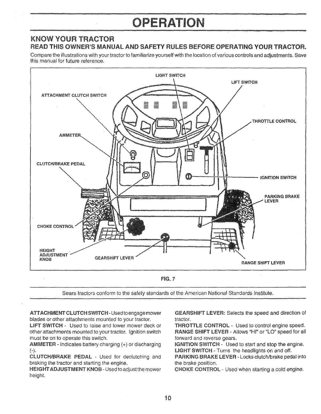
KNOW YOUR TRACTOR
READ THIS OWNER'S MANUAL AND SAFETY RULES BEFORE OPERATING YOUR TRACTOR,
Compare the illustrations with your tractor to fami/iarize yourself with the location of various controls and adjustments. Save
this manual for future reference.
LIGHT SWITCH
ATTACHMENT CLUTCH SWITCH
THROTTLE CONTROL
CLUTCH/BRAKEPEDAL
iGNITION SWITCH
PARKING BRAKE
LEVER
HEIGHT
ADJUSTMENT
KNOB GEARSHJFTLEVER RANGE SHIFT LEVER
FiG° 7
Sears tractors conform to the safety standards of the American National Standards Institute.
ATTACHMENT CLUTCH SWITCH- Used to engage mower
blades or other attachments mounted to your tractor.
LIFT SW_TCH - Used to raise and lower mower deck or
other attachments mounted to your tractor. Ignition switch
must be on to operate this switch.
AMMETER - Indicates battery charging (+) or discharging
(-).
CLUTCH/BRAKE PEDAL -Used for declutching and
braking the tractor and starting the engine,
HEMGHTADJUSTMENT KNOB - Used to adjust the mower
height,
GEARSHIFT LEVER: Selects the speed and direction of
tractor.
THROTTLE CONTROL - Used to control engine speed.
RANGE SHIFT LEVER - Allows "Hi" or "LO" speed for all
forward and reverse gears.
iGNITiON SWITCH - Used to start and stop the engine.
LIGHT SW_TCH - Turns the headlights on and off.
PARKING BRAKE LEVER - Locks clutch/brake pedaJ into
the brake position.
CHOKE CONTROL - Used when starting a cold engine.
10
OPERATION
l_ The operation of any tractor can result in foreign objects thrown into the eyes, which can result in 1
severe eye damage. Always wear safety glasses or eye shietds before starting your tractor and while I
maving. We recomme,d wide visien safety mesk for overthe ,pectaeles._or_s!_
HOW TO USE YOUR TRACTOR
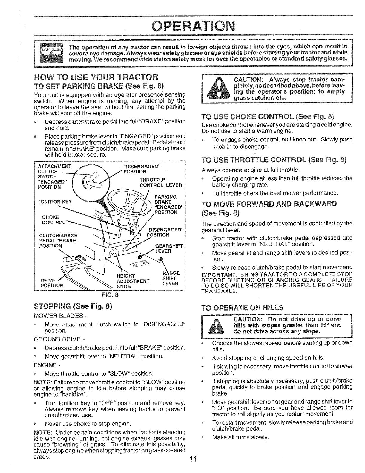
TO SET PARKING BRAKE (See Fig. 8)
Your unit is equipped with an operator presence sensing
switch. When engine is running, any attempt by the
operator to leave the seat without first setting the parking
brake will shut off the engine.
*Depress clutch/brake pedal into full "BRAKE" position
and hold.
oPlace parking brake lever in "ENGAGED" position and
release pressu re from clutch/brake pedal. Pedal should
remain in "BRAKE" position. Make sure parking brake
wilt hold tractor secure.
ATTACHMENT
CLUTCH
SWITCH
"ENGAGED"
POSiTiON
iGNE|ON KEY
CHOKE
CLUTCH/BRAKE
PEDAL"BRAKE"
HEIGHT
ADJUSTMENT
KNOB
FiG. 8
THROTTLE
CONTROL LEVER
_PARKING
POSIT_ON
_'_'DiSENGAGED"
POStTION
J
GEARSHIFT
VER
RANGE
SHIFT
LEVER
TO USE CHOKE CONTROL (See Fig= 8)
Use choke control whenever you are starting a cold engine.
Do not use to start a warm engine.
- To engage choke control, pull knob out. Slowly push
knob in to disengage.
TO USE THROTTLE CONTROL (See Fig. 8}
Always operate engine at full throttle.
.Operating engine at less than fuji throttle reduces the
battery charging rate,
.Full throttle offers the best mower performance.
TO MOVE FORWARD AND BACKWARD
(See Fig. 8)
The direction and speed of movement is controlled by the
gearshift lever.
*Start tractor with clutch/brake pedal depressed and
gearshift tever in "NEUTRAL" position,
o Move gearshift and range shift levers to desired posi-
tion.
-Slowly release clutch/brake pedal to start movement.
iMPORTANT: BRING TRACTOR TO A COMPLETE STOP
BEFORE SHiFTiNG OR CHANGING GEARS, FAILURE
TO DO SO WiLL SHORTEN THE USEFUL LiFE OF YOUR
TRANSAXLE.
STOPPING (See Fig. 8)
MOWER BLADES -
o Move attachment clutch switch to "DISENGAGED"
position.
GROUND DRIVE
o Depress clutch/brake pedal into full "BRAKE" position.
Move gearshift lever to "NEUTRAL" position.
ENGINE -
Move throttle control to "SLOW" position.
NOTE: Faiture to move throttle control to "SLOW" position
or allowing, engine to idle before stopping may cause
engine to backfire.
o Turn ignition key to "OFF" position and remove key.
Always remove key when leaving tractor to prevent
unauthorized use.
o Never use choke to stop engine.
NOTE: Under certain conditions when tractor is standing
idle with engine running, hot engine exhaust gasses may
cause "browning _'of gras& To eliminate this possibility,
always stop engine when stopping tractor on grass covered
areas.
TO OPERATE ON HILLS
Choose the slowest speed before starting up or down
hitls.
o Avoid stopping or changing speed on hills.
if slowing is necessary, move throttle control to slower
position.
If stopping is absoluteiy necessary, push clutch!brake
pedal quickly to brake position and engage parking
brake.
o Move gearshift lever to 1st gear and range shift lever to
"LO" position. Be sure you have allowed room for
tractor to roll slightly as you restart movemenL
o To restart movement, slowly release parking brake and
clutch/brake pedal.
o Make all turns slowly.
11
OPERATION
TO TRANSPORT
,Raise attachment lift to highest position with liftcontrol.
, When pushing or towing your unit, be sure gearshift
lever is in "NEUTRAL" position.
•Do not push or tow unit at more than five (5) MPH.
NOTE: To protect hood from damage when transporting
you rtractor on a truck or a trailer, be sure hood is closed and
securedtotractor. Use an appropriate means of tying hood
to tractor (rope, cord, etc.).
BEFORE STARTING THE ENGINE
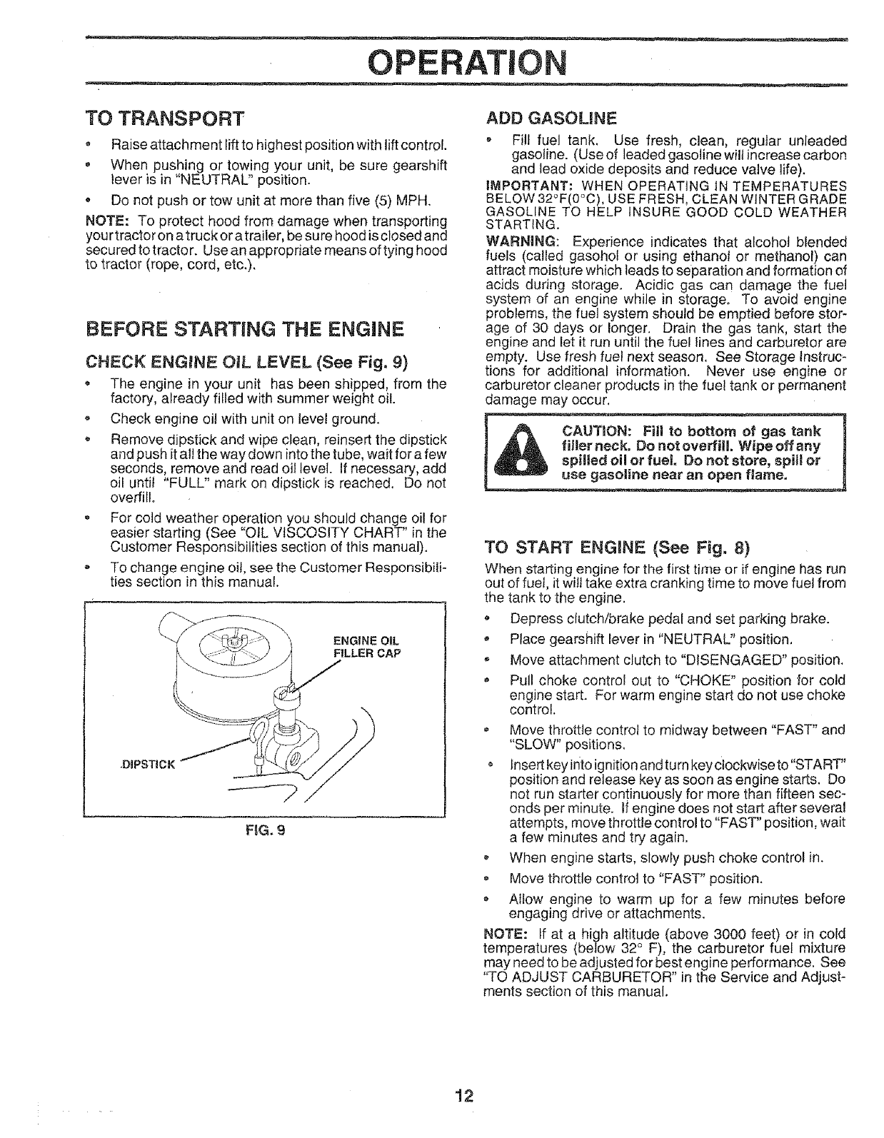
CHECK ENGINE OIL LEVEL (See Fig. 9)
, The engine in your unit has been shipped, from the
factory, already filled with summer weight oil
Check engine oil with unit on level ground.
•Remove dipstick and wipe clean, reinsert the dipstick
and push it at! the way down into the tube, wait for afew
seconds, remove and read oil level. If necessary, add
oil untit "FULL" mark on dipstick is reached. Do not
overfill.
For cold weather operation you should change oil for
easier starting (See "OIL VISCOSITY CHART" in the
Customer Responsibilities section of this manual).
o To change engine oil, see the Customer Responsibili-
ties section in this manual.
ENGINE OIL
FILLER CAP
FiG. 9
ADD GASOL|NE
• Fi!f fuel tank. Use fresh, clean, regular unleaded
gasoline. (Use of leaded gasoline wilt increase carbon
and lead oxide deposits and reduce valve life).
IMPORTANT: WHENOPERAT]NG1NTEMPERATURES
BELOW 32°F(0°C), USE FRESH, CLEAN WINTER GRADE
GASOLINE TO HELP iNSURE GOOD COLD WEATHER
STARTING.
WARNING: Experience indicates that alcohot blended
fuels (called gasoho_ or using ethanot or methanol) can
attract moisture which leads to separation and formation of
acids during storage. Acidic gas can damage the fuel
system of an engine while in storage. To avoid engine
problems, the fuel system should be emptied before stor-
age of 30 days or longer. Drain the gas tank, start the
engine and let it run until the fuel lines and carburetor are
empty. Use fresh fuel next season. See Storage Instruc-
tions for additional information. Never use engine or
carburetor cleaner products in the fuel tank or permanent
damage may occur,
CAUTION: Fill to bottom of gas tank
filler neck. Do not overfill. Wipe off any
spilled oil or fuel Do not store, spill or
use g_ine near an open flame.
TO START ENGINE (See Fig. 8)
When starting engine for the firsL time or if engine has run
out of fuel, itwitt take extra cranking time to move fuel from
the tank to the engine.
- Depress clutch/brake pedal and set parking brake.
*Place gearshift lever in "NEUTRAL" position,
Move attachment clutch to "DISENGAGED" position.
Pull choke control out to "CHOKE" position for cold
engine start. For warm engine start do not use choke
control.
*Move throttle control to midway between "FAST" and
"SLOW" positions.
Insert key into ignition and turn key clockwise to"START"
position and release key as soon as engine starts. Do
not run starter continuously for more than fifteen sec-
onds per minute, if engine does not start after several
attempts, move throttle control to "FAST" position, wait
a few minutes and try again.
When engine starts, slowly push choke control in.
. Move throttle control to "FAST" position.
Atlow engine to warm up for a few minutes before
engaging drive or attachments.
NOTE: tf at a high altitude (above 3000 feet) or in cold
temperatures (below 32 ° F), the carburetor fuel mixture
may need to be adjusted for best engine performance. See
"TO ADJUST CARBURETOR" in the Service and Adjust-
ments section of this manual.
12
CUSTOM BmL ES
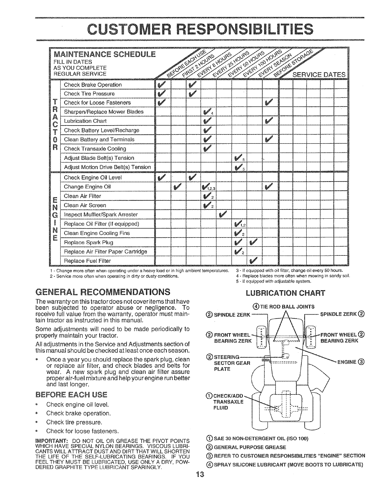
MAINTENANCE SCHEDULE
FILL iN DATES
AS YOU COMPLETE
REGULAR SERVICE SERVICE DATES
Check Brake Operation
Check for Loose Fasteners G##
Sharpen!Replace Mower Blades
Lubrication Chart
Check Battery Level/Recharge
Clean Battery and Terminals
Check Transaxfe Cooling
Adjust Blade Belt(s) Tension
Adjust Motion Drive Belt(s) Tension
Check Engine Oil Level
Change Engine Oil
Clean Air Filter
Clean Air Screen
inspect Muffler/spark Attester
Iv'
V',
v"
v"
v"
v" v"
V'2
V'2i
Replace Oil Filter (If equipped)
Clean Engine Cooling Fins
Replace Spark Plug
Replace Air Filter Paper Cartridge
Replace Fuel Filter
J
V'5
V'5
v"
1 - Change more often when operating under a heavy load or in high ambient temperatureS.
2 - Service more often when operating in dirty on dusty conditions.
JI-
V" .......I-
V"
V" l-
v" v"
v'i B I l_1 _
3 - If equipped with oil filter, change oil every 50 hours,
4 - Replace biades more often when mewing in sandy soil.
GENERAL RECOMMENDATIONS
The warranty on this tractor does not cover items that have
been subjected to operator abuse or negligence. To
receive full value from the warranty, operator must main-
tain tractor as instructed in this manual.
Some adjustments wilt need to be made periodically to
properly maintain your tractor.
All adjustments in the Service and Adjustments section of
this manual should be checked at least once each season.
Once a year you should replace the spark plug, clean
or replace air filter, and check blades and belts for
wear. A new spark plug and clean air filter assure
proper air-fuel mixture and helpyour engine run better
and last longer.
BEFORE EACH USE
Check engine oil level.
,Check brake operation.
Check tire pressure.
o Check for loose fasteners.
IMPORTANT: DO NOT OIL OR GREASE THE PIVOT POINTS
WHICH HAVE SPECIAL NYLON BEARINGS. VISCOUS LUBRI-
CANTS WILL ATTRACT DUST AND DIRT THAT WiLL SHORTEN
THE LIFE OF THE SELF-LUBRICATING BEARINGS, IF YOU
FEEL THEY MUST BE LUBRICATED, USE ONLY A DRY, POW-
DERED GRAPHITE TYPE LUBRICANT SPARINGLY.
5 - fl equipped with adiustable system.
LUBRICATION CHART
(_TIE ROD BALL JOINTS
(_) SPINDLE ZERK
(_) FRONT WHEEL (_)
BEARING ZERK BEARING ZERK
®SECTOR GEAR ENGINE (_)
PLATE
CTRANSAXLE
FLUID
13
(_ SAE 30 NON-DETERGENT OiL (ISO 100)
(_ GENERAL PURPOSE GREASE
(_) REFER TO CUSTOMER RESPONSIBIUTtES "ENGINE" SECTION
(_) SPRAY StMCONE LUBRICANT (MOVE BOOTS TO LUBRICATE)
CUSTOM ILITIES
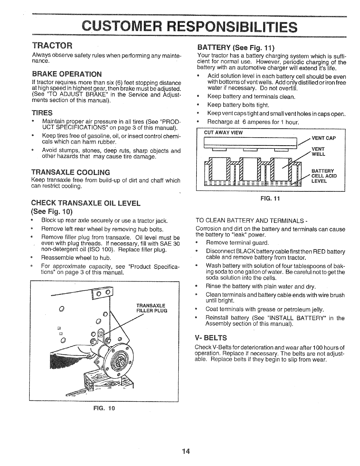
TRACTOR
Always observe safety rules when performing any mainte-
nance.
BRAKE OPERATION
If tractor requires more than six (6) feet stopping distance
at high speed in highest gear, then brake must be adjusted.
(See "TO ADJUST BRAKE" in the Service and Adjust-
ments section of this manual).
TIRES
° Maintain proper air pressure in all tires (See "PROD-
UCT SPECIFICATIONS" on page 3 of this manual).
Keep tires free of gasoline, oil, or insect control chemi-
cals which can harm rubber.
• Avoid stumps, stones, deep ruts, sharp objects and
other hazards that may cause tire damage.
TRANSAXLE COOUNG
Keep transaxte free from build-up of dirt and chaff which
can restrict cooling_
CHECK TRANSAXLE ORL LEVEL
(See Fig. 10)
Block up rear axle securely or use a tractor jack.
Remove left rear wheel by removing hub bolts.
, Remove filler plug from transaxle. Oil level must be
even with plug threads. If necessary, fill with SAE 30
non-detergent oil (ISO 100). Replace filler plug.
,Reassemble wheel to hub.
• For approximate capacity, see "Product Specifica-
tions" on page 3 of this manual.
TRANSAXLE
OFILLER PLUG
©
BATTERY (See Fig. 11)
Your tractor has a battery charging system which is suffi-
cient for normal use. However, periodic charging of the
battery with an automotive charger will extend it's life.
• Acid solution level in each battery cell should be even
with bottoms of vent wells. Add only distilled or iron free
water if necessary. Do not overfill.
• Keep battery and terminals clean.
-Keep battery bolts tight.
• Keep vent caps tight and small vent holes incaps open.
• Recharge at 6 amperes for 1 hour_
CUT AWAY VIEW
VENT
BATTERY
CELL ACID
LEVEL
FIG. 1t
TO CLEAN BATTERY AND TERMINALS -
Corrosion and dirt on the battery and terminals can cause
the battery to "leak" power.
Remove terminal guard.
*Disconnect BLACK battery cable first then RED battery
cable and remove battery from tractor.
Wash battery with solution of four tablespoons of bak-
ing sodato one gatton of water. Be careful notto getthe
soda solution into the cells.
Rinse the battery with plain water and dry.
Clean terminals and battery cable ends with wire brush
until bright.
Coat termir_als with grease or petroleum jelly.
, Reinstall battery (See "INSTALL BATTERY" in the
Assembly section of this manual).
V- BELTS
check V-Belts for deterioration and wear after 100 hours of
operation. Replace if necessary. The belts are not adjust-
able. Replace belts if they begin to slip from wear.
FIG. 10
14
CUSTOMER FIESPONSIBmLITIES
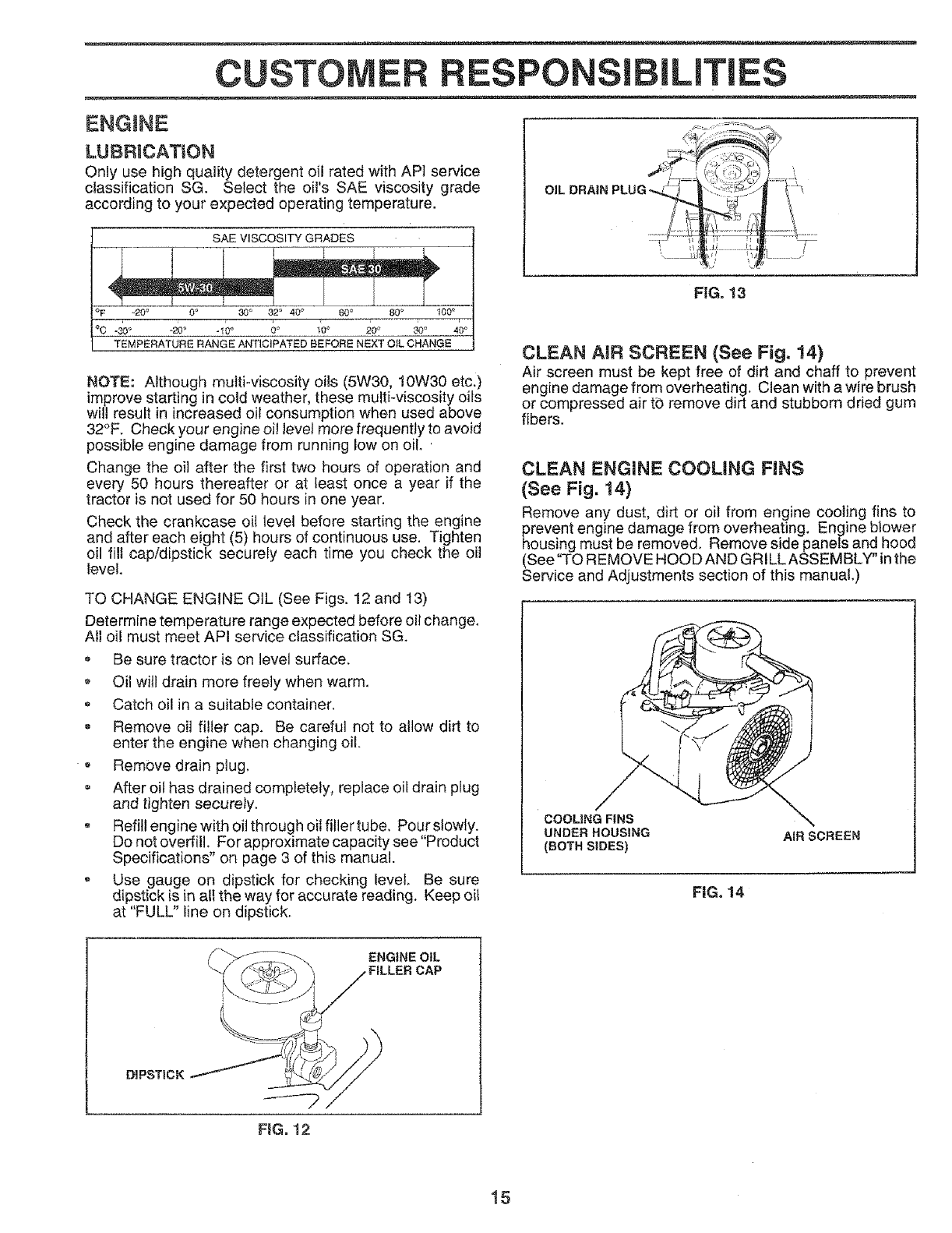
ENGINE
LUBRICATION
Only use high quality detergent oil rated with API service
classification SG. Select the oil's SAE viscosity grade
according to your expected operating temperature.
SAEVISCOSITYGRADES
°F -20 _ 0o 30_ 32_ 40_ 60 ° 80 _ 100 °
TEMPERATURE RANGE ANTICIPATED BEFORE NEXT OIL CHANGE
NOTE: Although mu{ti-viscosity oils (5W30, 10W30 etc.)
improve starting in cold weather, these multkviscosity oils
will result in increased oil consumption when used above
32°F. Check your engine oil levet more frequently to avoid
possible engine damage from running low on oil..
Change the oil after the first two hours of operation and
every 50 hours thereafter or at least once a year if the
tractor is not used for 50 hours in one year.
Check the crankcase oi] level before starting the engine
and after each eight (5) hours of continuous use. Tighten
oil fill cap/dipstick securely each time you check the oil
level.
TO CHANGE ENGINE OIL (See Figs. 12 and t3)
Determine temperature range expected before oil change.
All oil must meet API service classification SG.
Be sure tractor is on level surface.
,Oil witl drain more freely when warm.
Catch oil in a suitable container.
• Remove oil filler cap. Be careful not to allow dirt to
enter the engine when changing oil.
Remove drain plug.
After oil has drained completely, replace oil drain plug
and tighten securely.
, Refitl engine with oil through oil filler tube, Pour slowty.
Do not overfill° For approximate capacity see "Product
Specifications" on page 3 of this manua!.
o Use gauge on dipstick for checking level. Be sure
dipstick is in all the way for accurate reading. Keep oit
at "FULL" line on dipstick.
o
FIG. 13
CLEAN AIR SCREEN (See Fig. 14)
Air screen must be kept free of dirt and chaff to prevent
engine damage from overheating. Clean with a wire brush
or compressed air tb remove dirt and stubborn dried gum
fibers.
CLEAN ENGINE COOLING FINS
(See Fig. 14}
Remove any dust, dirt or oil from engine cooling fins to
prevent engine damage from overheating. Engine blower
housing must be removed. Remove side panels and hood
sSee"TO REMOVE HOOD AND GRILL ASSEMBLY" inthe
ervice and Adjustments section of this manual.)
/
COOLING FINS \
UNDER HOUSING AiR SCREEN
(BOTH SIDES)
FiG. 14
ENGINE OIL
FILLER CAP
DIPSTICK
FiG. 12
15
CUSTOMER RESPONSiBiLITIES
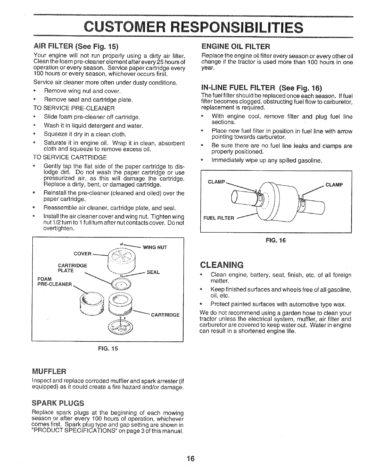
AiR FILTER (See Fig. 15)
Your engine will not run properly using a dirty air filter.
Clean the foam pre-cleaner element after every 25 hours of
operation or every season. Service paper cartridge every
!00 hours or every season, whichever occurs first.
Service air cleaner more often under dusty conditions.
*Remove wing nut and cover.
o Remove seal and cartridge plate.
TO SERVICE PRE-CLEANER
Slide foam pre-cleaner off cartridge.
Wash it in liquid detergent and water.
Squeeze it dry in a clean cloth.
- Saturate it in engine oil. Wrap it in clean, absorbent
cloth and squeeze to remove excess oil.
TO SERVICE CARTRIDGE
. Gentry tap the flat side of the paper cartridge to dis-
lodge dirt. Do not wash the paper cartridge or use
pressurized air, as this will damage the cartridge.
Replace a dirty, bent, or damaged cartridge,
. Reinstall the pre-cleaner (cleaned and oiled) over the
paper cartridge,
. Reassemble air cleaner, cartridge plate, and seal.
, Install the air cleaner cover and wing nut. Tighten wing
nut 1/2 turn to 1 full turn after nut contacts cover. Do not
overtighten.
ENG1NE OtL FILTER
Replace the engine oil filter every season or every other oil
change if the tractor is used more than 100 hours in one
year.
IN-LINE FUEL FILTER (See Fig. 16)
The fuel fllter should be replaced once each season. If fuel
filter becomes clogged, obstructing fuel flow to carburetor,
replacement is required.
*With engine cool, remove filter and plug fuel line
sections.
• Place new fuel filter in position in fuel line with arrow
pointing towards carburetor.
• Be sure there are no fuel line leaks and ciamps are
properly positioned,
o Immediately wipe up any spiIled gasoline.
CLAMP _ j CLAMP
COVER
WING NUT
CARTRIDGE
PLATE
FOAM
PRE-CLEANER __ SEAL
__ CARTRIDGE
FIG. 16
CLEANING
o Clean engine, battery, seat, finish, etc. of all foreign
matter.
oKeep finished surfaces and wheels free of atl gasoline,
oil, etc.
• Protect painted surfaces with automotive type wax.
We do not recommend using a garden hose to clean your
tractor unless the electrical system, muffler, air filter and
carburetor are covered to keep water out. Water in engine
can result in a shortened engine life.
FIG. 15
MUFFLER
Inspect and replace corroded muffler and spark arrester (if
equipped) as it could create a fire hazard and/or damage.
SPARK PLUGS
Replace spark plugs at the beginning of each mowing
season or after every 100 hours of operation, whichever
comes first. Spark pIug type and gap setting are shown in
"PRODUCT SPECIFICATIONS" on page 3 of this manual.
!6
SERVICE ADJUSTMENTS
CAUTION: BEFORE PERFORMING ANY SERVICE OR ADJUSTtVlENTS:
Depress clutch/brake pedal fully and set parking brake.
_ lace gearshift lever in 'NEUTRAL'position.
Place attachment clutch in "DISENGAGED position,
®Turn ignition key "OFF" and remove key.
Make sure the blades and all moving parts have completely stopped.
*Disconnect spark plug wire from spark plug and place wire where it cannot come in contact with
plug.
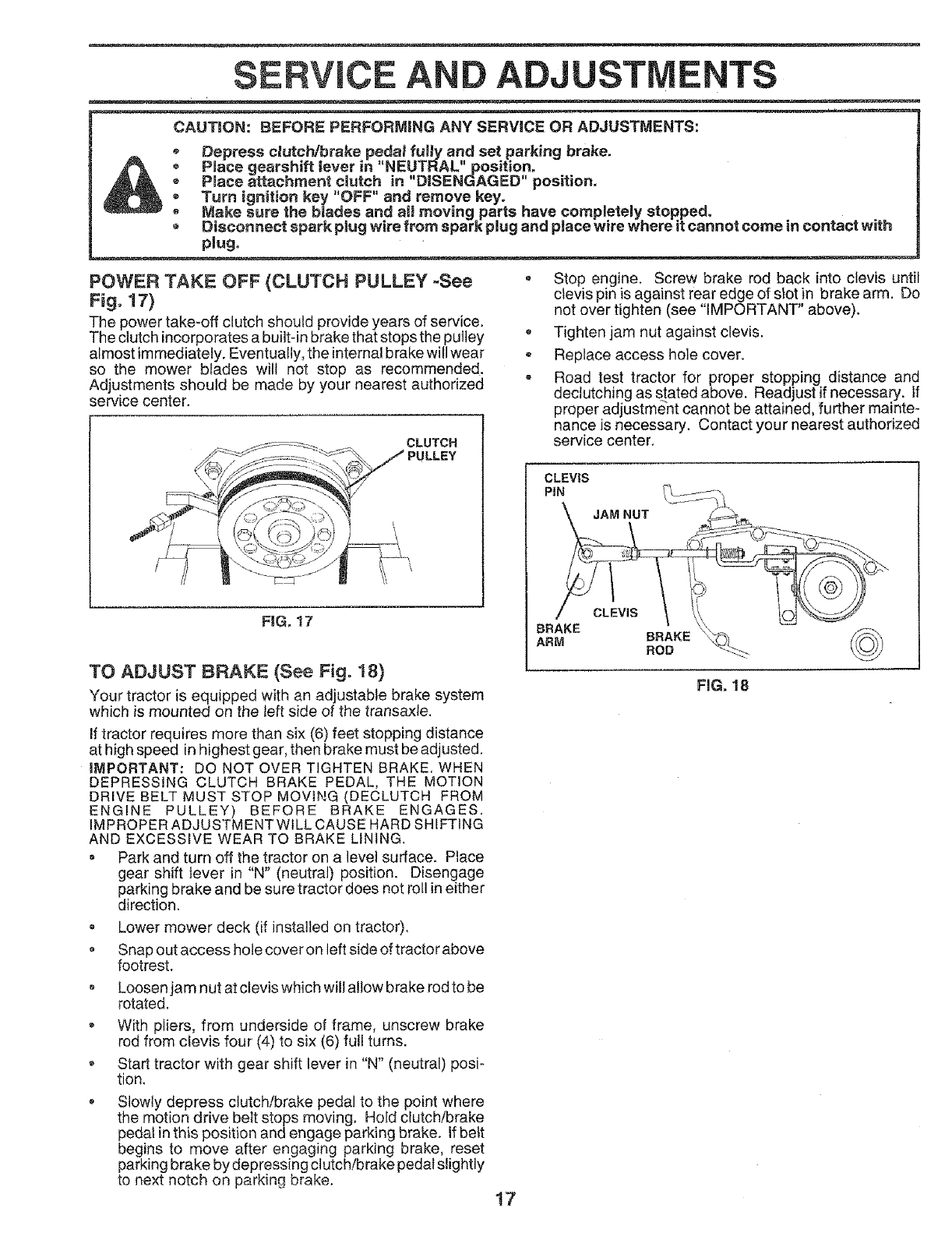
POWER TAKE OFF (CLUTCH PULLEY -See
Fig, 17)
The power take-off clutch should provide years of service.
The clutch incorporates a built-in brake that stops the pulley
almost immediately. Eventually, the internal brake will wear
so the mower blades wilt not stop as recommended.
Adjustments should be made by your nearest authorized
service center.
ss--._. CLUTCH
_Jf_- ....... ':_=._. J PULLEY
FIG, t7
TO ADJUST BRAKE (See Fig. 18)
Your tractor is equipped with an adjustable brake system
which is mounted on the left side of the transaxle,
If tractor requires more than six (6) feet stopping distance
at high speed inhighest gear, then brake must be adjusted.
iMPORTANT: DO NOT OVER TIGHTEN BRAKE, WHEN
DEPRESSING CLUTCH BRAKE PEDAL, THE MOTION
DRIVE BELT MUST STOP MOVING (DECLUTCH FROM
ENGINE PULLEY) BEFORE BRAKE ENGAGES.
IMPROPER ADJUSTMENT WILL CAUSE HARD SHIFTING
AND EXCESSIVE WEAR TO BRAKE LINING.
= Park and turn off the tractor on a level surface. Place
gear shift lever in "N" (neutral) position. Disengage
parking brake and be sure tractor does not roll in either
direction.
Lower mower deck (if installed on tractor).
Snap out access hole cover on left side of tractor above
footrest.
o Loosen jam nut at clevis which will allow brake rod to be
rotated.
With pliers, from underside of frame, unscrew brake
rod from clevis four (4) to six (6) full turns.
o Start tractor with gear shift lever in "N" (neutral) posi-
tion.
Stop engine. Screw brake rod back into clevis until
clevis pin is against rear edge of stot in brake arm. Do
not over tighten (see "IMPORTANT" above).
Tighten jam nut against clevis.
Replace access hole cover.
o Road test tractor for proper stopping distance and
dectutching as stated above. Readjust if necessary, if
proper adjustment cannot be attained, further mainte-
nance is necessary. Contact your nearest authorized
service center,
CLEVIS
PIN _,_,
,
\ JAM NUT _/___._
Ir
r_n_r,_ BRAKE ' '_ :>'
ARM ROD _'_>
FIG. 18
Slowly depress clutch/brake pedal to the point where
the motion drive belt stops moving, Hold clutch/brake
pedal in this position and engage parking brake. If belt
begins to move after engaging parking brake, reset
parking brake by depressing clutch/brake pedal slightly
to next notch on parking brake. 17
SERVICE AND ADJUSTMENTS
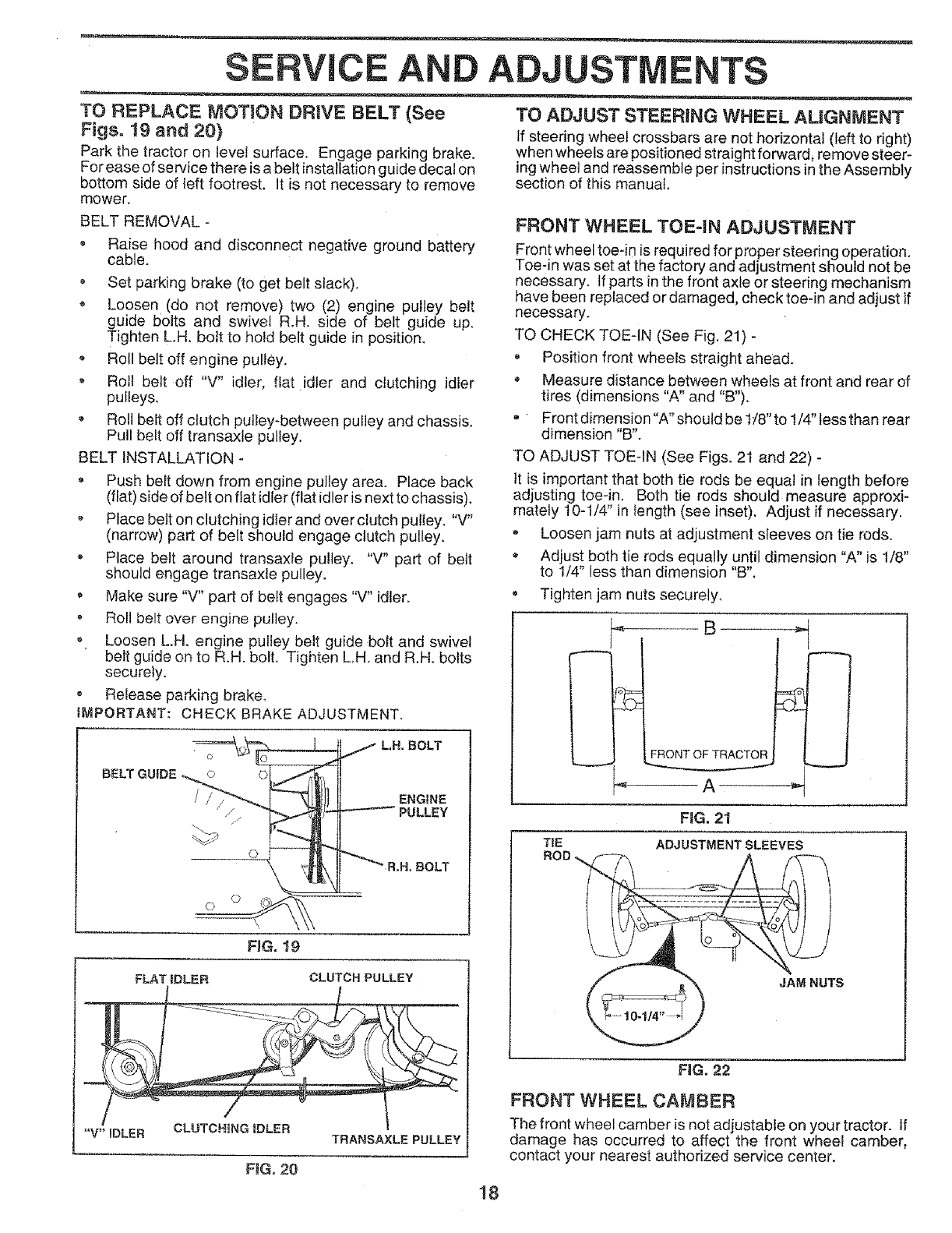
TO REPLACE MOTION DRIVE BELT (See
Figs. 19 and 20)
Park the tractor on level surface. Engage parking brake.
For ease of service there is a belt installation guide decal On
bottom side of left footrest. It is not necessary to remove
mower.
BELT REMOVAL -
, Raise hood and disconnect negative ground battery
cable.
Set parking brake (to get belt slack).
Loosen (do not remove) two (2) engine pulley belt
guide bolts and swivel R.H. side of belt guide up.
Tighten L.H. bolt to hold belt guide in position.
o Roll belt off engine pulley.
,Roll belt off "V" idler, flat idler and ciutching idfer
pulleys,
• Roll belt off clutch pulley-between pulley and chassis.
Pull belt off transaxte pulley.
BELT INSTALLATION -
• Push belt down from engine pulley area. Place back
(flat) side of belt on flat idler(flat idler is next to chassis).
•Place belt on clutching idler and over clutch pulley. "V"
(narrow) part of belt should engage clutch pulley.
• Place belt around transaxle pulley. "V" part of belt
should engage transaxle pulley.
•Make sure "V" part of belt engages "V" idter_
-Roll belt over engine pulley.
• Loosen L.H. engine pulley belt guide bolt and swivel
belt guide on to R.H. bolt. Tighten LH, and R.H, bolts
securely.
® Release parking brake,
IMPORTANT: CHECK BRAKE ADJUSTMENT,
LH, BOLT
ENGINE
PULLEY
.BOLT
FroG.19
FLAT iDLER
"'V" iDLER CLUTCH{NG IDLER TRANSAXLE PULLEY
CLUTCH PULLEY
FiG. 20
TO ADJUST STEERING WHEEL ALIGNMENT
If steering wheel crossbars are not horizontal (left to right)
when wheels are positioned straight forward, remove steer-
ing wheel and reassemble per instructions in the Assembly
section of this manual.
FRONT WHEEL TOE4N ADJUSTMENT
Front wheel toeqn is required for proper steering operation.
Toe-in was set at the factory and adjustment should not be
necessary, If parts in the front axle or steering mechanism
have been replaced or damaged, check toe-in and adjust if
necessary.
TO CHECK TOE-IN (See Fig. 21) -
Position front wheels straight ahead.
*Measure distance between wheels at front and rear of
tires (dimensions "A" and "B").
Front dimension "A" should be tt8" to t/4" less than rear
dimension "B".
TO ADJUST TOE-IN (See Figs. 2I and 22) -
It is important that both tie rods be equal in length before
adjusting toe-in. Both tie rods should measure approxi-
mately 10-1/4" in tength (see inset). Adjust if necessary.
, Loosen jam nuts at adjustment sleeves on tie rods.
* Adjust both tie rods equally until dimension "A" is 1/8"
to 1/4" less than dimension "B".
o Tighten jam nuts securely,
B
FRONT OF TRACTOR
A _"
FBG.21
ADJUSTMENT SLEEVES
TIE
ROD
JAM NUTS
FIG. 22
FRONT WHEEL CAMBER
The front wheel camber is not adjustable on your tractor. If
damage has occurred to affect the front wheel camber,
contact your nearest authorized service center.
!8
SERVICE AND ADJUSTMENTS
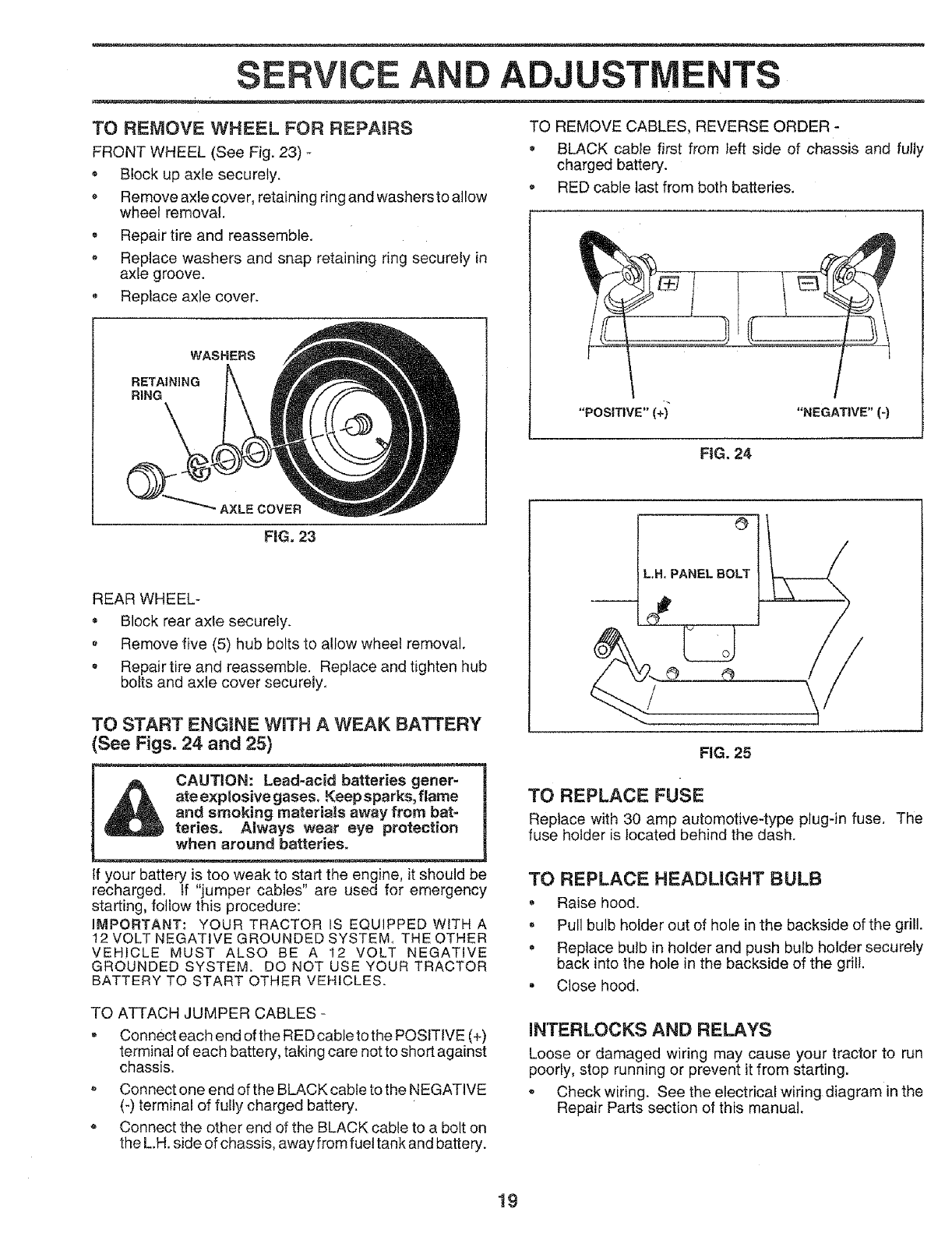
TO REMOVE WHEEL FOR REPAIRS
FRONT WHEEL (See Fig. 23) -
• Block up axle securely.
o Remove axle cover, retaining ring and washersto allow
wheel removal.
. Repair tire and reassemble.
•Replace washers and snap retaining ring securely in
axle groove.
® Replace axle cover.
WASHERS
RETAINING
RtNG
AXLE COVER
FIG. 23
REAR WHEEL-
BlOCk rear axle securely.
Remove five (5) hub bolts to allow wheel removal.
•Repair tire and reassemble. Replace and tighten hub
bolts and axle cover securely.
TO START ENGINE WITH A WEAK BATTERY
See Figs. 24 and 25)
_. j_ ate e_ses, Keep sparks, flame i
and _eHats away from bat-
ter'_ eye protection
a,oo ba,e,o,. .............................1
If your battery is too weak to start the engine, it should be
recharged, tf "jumper cables" are used for emergency
starting, follow this procedure:
IMPORTANT: YOUR TRACTOR IS EQUIPPED WITH A
12 VOLT NEGATIVE GROUNDED SYSTEM, THE OTHER
VEHICLE MUST ALSO BE A t2 VOLT NEGATIVE
GROUNDED SYSTEM. DO NOT USE YOUR TRACTOR
BATTERY TO START OTHER VEHICLES.
TO ATTACH JUMPER CABLES -
• Connect each end of the RED cable to the POSITIVE (+)
terminal of each battery, taking care not to short against
chassis.
Connect one end of the BLACK cable to the NEGATIVE
(-) terminal of fully charged battery.
Connect the other end of the BLACK cable to a bolt on
the L.H. side of chassis, away from fuel tank and battery.
TO REMOVE CABLES, REVERSE ORDER -
• BLACK cable first from left side of chassis and fully
charged battery.
RED cable last from both batteries.
L.H,PANEL BOLT
O/
FIG. 25
TO REPLACE FUSE
Replace with 30 amp automotive-type plug-in fuse, The
fuse holder is located behind the dash.
TO REPLACE HEADLIGHT BULB
. Raise hood.
= Pull bulb holder out of hole in the backside of the grill.
• Replace bulb in holder and push bulb holder securely
back into the hole in the backside of the grill.
. Close hood.
iNTERLOCKS AND RELAYS
Loose or damaged wiring may cause your tractor to run
poorly, stop running or prevent it from starting.
Check wiring. See the electrical wiring diagram in the
Repair Parts section of this manual.
19
SERVICE A
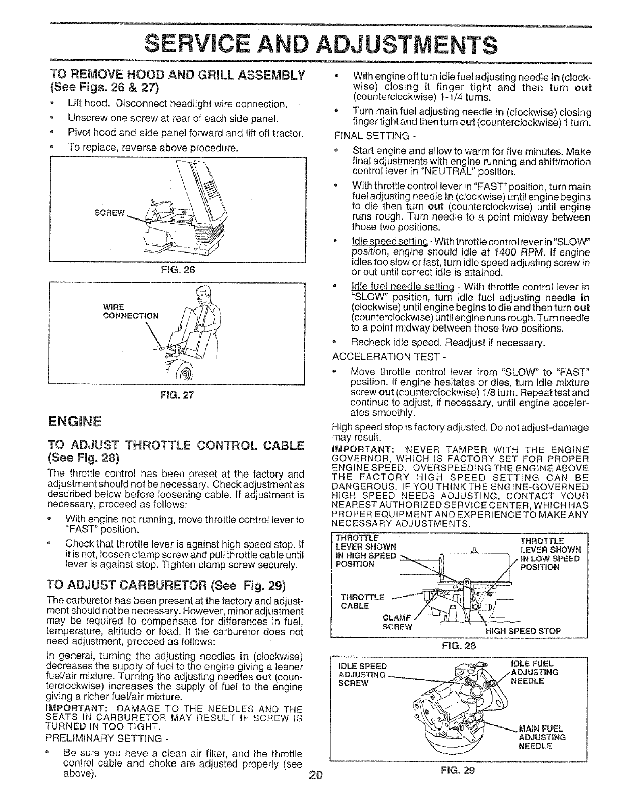
TO REMOVE HOOD AND GRILL ASSEMBLY
(See Figs. 26 & 27)
• Lift hood. Disconnect headlight wire connection.
oUnscrew one screw at rear of each side panel.
•Pivot hood and side panel forward and lift off tractor.
, To replace, reverse above procedure.
FiG. 26
WiRE
CONNECTION
\
FiG. 27
ENGINE
TO ADJUST THROTTLE CONTROL CABLE
(See Fig. 28)
The throttle control has been preset at the factory and
adjustment should not be necessary. Check adjustment as
described below before loosening cable, if adjustment is
necessary, proceed as follows:
o With engine not running, move throttle control lever to
"FAST" position.
o Check that throttle lever is against high speed stop. If
it is not, loosen clamp screw and pull throttle cable until
lever is against stop. Tighten clamp screw securely.
TO ADJUST CARBURETOR (See Fig. 29)
The carburetor has been present at the factory and adjust-
ment should not be necessary. However, minor adjustment
may be required to compensate for differences in fuel,
temperature, altitude or load. If the carburetor does not
need adjustment, proceed as follows:
in general, turning the adjusting needles in (clockwise)
decreases the supply of fuel to the engine giving a leaner
fuel/air mixture. Turning the adjusting needles out (coun-
terclockwise) increases the supply of fuel to the engine
giving a richer fuet/air mixture.
IMPORTANT: DAMAGE TO THE NEEDLES AND THE
SEATS tN CARBURETOR MAY RESULT IF SCREW IS
TURNED IN TOO TIGHT.
PRELIMINARY SETTING -
• Be sure you have a clean air filter, and the throttle
control cable and choke are adjusted properly (see
above).
ADJUSTMENTS
With engine off turn idle fuel adjusting needle in (clock-
wise) closing it finger tight and then turn out
(counterclockwise) 1-1/4 turns.
* Turn main fuel adjusting needle in (clockwise) closing
finger tight and then turn out (counterclockwise) 1 turn.
FINAL SETTING -
*Start engine and allow to warm for five minutes. Make
final adjustments with engine running and shift/motion
control lever in "NEUTRAL" position.
With throttle control lever in "FAST" position, turn main
fuel adjusting needle in (clockwise) until engine begins
to die then turn out (counterclockwise) until engine
runs rough. Turn needle to a point midway between
those two positions.
Idle speed setting- With throttle control lever in"SLOW"
position, engine should idle at 1400 RPM. If engine
idles too stow or fast, turn idle speed adjusting screw in
or out until correct idle is attained.
- Idle fue! needle setting - With throttle control lever in
"SLOW" position, turn idle fuel adjusting needle in
(clockwise) until engine begins to die and then turn out
(counterclockwise) until engine runs rough. Turn needle
to a point midway between those two positions,
*Recheck idle speed. Readjust if necessary.
ACCELERATION TEST -
- Move throttle control lever from "SLOW" to "FAST"
position. If engine hesitates or dies, turn idle mixture
screw out (counterclockwise) 1/8 turn. Repeat test and
continue to adjust, if necessary, until engine acceler-
ates smoothly.
High speed stop is factory adjusted. Do not adjust-damage
may result.
IMPORTANT: NEVER TAMPER WITH THE ENGINE
GOVERNOR, WHICH IS FACTORY SET FOR PROPER
ENGINE SPEED. QVERSPEEDING THE ENGINE ABOVE
THE FACTORY HIGH SPEED SETTING CAN BE
DANGEROUS. IFYOUTHINKTHE ENGINE-GOVERNED
HIGH SPEED NEEDS ADJUSTING, CONTACT YOUR
NEAREST AUTHORIZED SERVICE CENTER, WHICH HAS
PROPER EQUIPMENT AND EXPERIENCE TO MAKE ANY
NECESSARY ADJUSTMENTS.
THROTTLE THROTTLE
: LEVER SHOWN Z& LEVER SHOWN
{N HIGH SPEED _ q .|N LOW SPEED
POS|TtON _ POSmON
THROTTLE /I _I [_,.,_'/?'_
CABLE
CLAMP /_'___-
SCREW H|GH SPEED STOP
FroG°28
IDLE SPEED iDLE FUEL
SCREW NEEDLE
MAmNFUEL
ADJUSTING
NEEDLE
20 FIG. 29
STORAG
Immediately prepare your tractor for storage at the end of
the season or if the tractor will not be used for 30 days or
more.
N_-Neverstore the tractor wit_'_*"-'---'--_
n the tank inside a building
i _ where fumes may reach an open flame
J_ or spark. AI!ow the engine to cool
in.,y .o'osu,e.
TRACTOR
Remove mower from tractor for winter storage. When
mower is to be stored for a period of time, clean it thor-
oughly, remove all dirt, grease, leaves, etc. Store in a
clean, dry area.
o Clean entire tractor (See"CLEANING" in the Customer
Responsibilities section of this manual).
o inspect and replace belts, if necessary (See belt re-
placement instructions in the Service and Adjustments
section of this manual).
Lubricate as shown in the Customer Responsibilities
section of this manual.
Be sure that all nuts, bolts and screws are securely
fastened. Inspect moving parts for damage, breakage
and wear. Replace if necessary.
* Touch up all rusted or chipped paint surfaces; sand
lightly before painting,
BATTERY
Fully charge the battery for storage,
-After a period of time in storage, battery may require
recharging,
, To help prevent corrosion and power leakage during
long periods of storage, battery cables should be
disconnected and battery cleaned thoroughly (see "TO
CLEAN BATTERY AND TERMINALS" in the Cus-
tomer Responsibilities section of this manual).
After cleaning, leave cables disconnected and place
cables where they cannot come in contact with battery
terminals.
Be sure battery drain tube is securely attached,
If battery is removed from tractor for storage, do not
store battery directly on concrete or damp surfaces,
ENGINE
FUEL SYSTEM
!MPORTANT: IT IS IMPORTANT TO PREVENT GUM
DEPOSITS FROM FORMING IN ESSENTIAL FUEL
SYSTEM PARTS SUCH AS CARBURETOR, FUEL FILTER,
FUEL HOSE, OR TANK DURING STORAGE. ALSO,
EXPERIENCE INDICATES THAT ALCOHOL BLENDED
FUELS (CALLED GASOHOL OR USING ETHANOL OR
METHANOL) CAN ATTRACT MOISTURE WHICH LEADS
TO SEPARATION AND FORMATION OF ACIDS DURING
STORAGE. ACIDIC GAS CAN DAMAGE THE FUEL
SYSTEM OF AN ENGINE WHILE IN STORAGE.
*Drain the fuel tank.
, Start the engine and let it run until the fuel lines and
carburetor are empty,
,Never use engirte or carburetor cleaner products in the
fuel tank or permanent damage may occur.
, Use fresh fuel next season.
NOTE: Fuel stabilizer is an acceptable alternative in
minimizing the formation of fuel gum deposits during stor-
age. Add stabilizer to gasoline in fuel tank or storage
container, Always follow the mix ratio found on stabilizer
container. Run engine at least 10 minutes after adding
stabilizer to allow the stabilizer to reach the carbu rotor. Do
not drain the gas tank and carburetor if using fuel stabilizer.
ENGINE OiL
Drain oil (with engine warm) and replace with clean engine
oil. (See "ENGINE" in the Customer Responsibilities
section of this manual),
CYLINDERS
•Remove spark plug(s).
•Pour one ounce of oil through spark plug hole(s) into
cylinder(s).
• Turn ignition key to"START" position for a few seconds
to distribute oil.
= Replace with new spark plug(s).
OTHER
Do not store gasoline from one season to another.
• Replace your gasoline can if your can starts to rust.
Rust and/or dirt in your gasoline will cause problems.
•If possible, store your tractor indoors and cover it to
give protection from dust and dirt.
•Cover your tractor with a suitable protective cover that
does not retain moisture. Do not use plastic. Plastic
cannot breathe which allows condensation to form and
witl cause your tractor to rust.
IMPORTANT: NEVER COVER TRACTOR WHILE ENGINE
AND EXHAUST AREAS ARE STILL WARM,
21
"FRO LESHOOTING
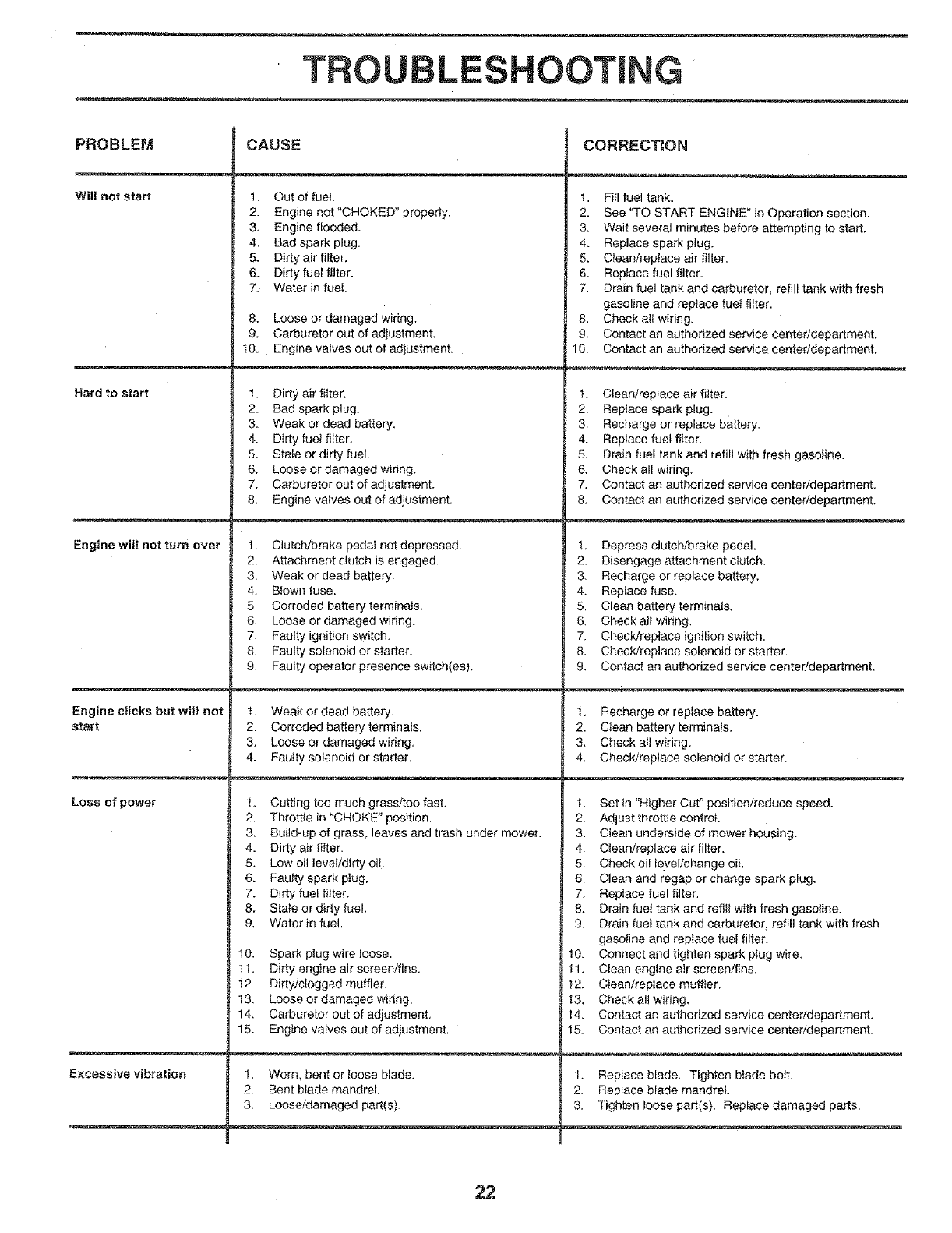
PROBLEM
Wil! not start
Hard to start
Engine will not turn over
Engine clicks but wilt not
start
Loss of power
Excessive vibration
CAUSE
1. Out of fuel.
2. Engine not "CHOKED" properly,
3. Engine flooded.
4. Bad spark plug,
5. Dirtyair filter.
6. Dirty fuel filter.
7. Water in fuel
8, Loose or damaged wiring,
9. Carburetor out of adjustment,
10. Engine valves out of adiustment.
CORRECTION
t, Fill fuel tank.
2, See "TO START ENGINE" in Operation section.
3. Wait several minutes before attempting to start,
4. Replace spark pJug.
5, Clean/replace air filter,
6. Replace fuel filter.
7. Drain fuel tank and carburetor, refill tank with fresh
gasoline and replace fuel filter.
8. Check all wiring.
9. Contact an authorized service center/department.
t0. Contact an authorized service centeddepartment,
1. Dirty air filter.
2. Bad spark plug.
3. Weak or dead battery,
4. Dirty fuel filter,
5, Stale or dirty fuel.
6. Loose or damaged wiring,
7. Carburetor out of adjustment.
8, Engine valves out of adjustment,
1. Clutch!brake pedal not depressed.
2. Attachment dutch is engaged.
3. Weak or dead battery.
4. Blown fuse.
5. Corroded battery terminals,
6, Loose or damaged wiring.
7, Faulty ignition switch,
8, Faulty solenoid or starter.
9. Fauity operator presence switch(es).
t, Weak or dead battery.
2. Corroded battery terminals.
3. Loose or damaged wiring,
4. Fautty solenoid or starter.
!, Clean/replace air filter.
2, Replace spark plug.
3, Recharge or replace batteiy.
4. Replace fuel filter,
5, Drain fuel tank and refill with fresh gasoline.
6, Check all wiring,
7. Contact an authorized service center/department,
8, Contact an authorized service center/department,
1. Cutting too much grass/too fast.
2. Throttle in "CHOKE" position,
3. Build-up of grass, leaves and trash under mower.
l, Depress clutch/brake pedal.
2. Disengage attachment ctutch,
3- Recharge or replace battery.
4. Replace fuse.
5, Clean battery terminals.
6, Check ali wiring,
7. Check/replace ignition switch.
8. Check/replace solenoid or starter.
9. Contact an authorized service center/depadment.
4. Dirty air filter.
5, Low oil level/dirty oil,
6, Faulty spark ptug,
7. Dirty fuel filter.
8. State or dirty fuel,
9. Water in fuel.
10. Spark plug wire loose.
11. Dirty engine air screen/fins.
t2. Dirty/clogged muffler,
!3. Loose or damaged wiring,
14. Carburetor out of adiustment,
15. Engine valves out of adiustment.
1. Worn, bent or loose blade.
2. Bent blade mandrel,
3, Looseldamaged part(s).
1. Recharge or replace battery.
2, Clean battery terminals.
3. Check all wiring.
4, Check/replace solenoid or starter,
t. Set in "Higher Cut" position/reduce speed.
2, Adjust throttle control
3, Clean underside of mower housing,
4. Clean/replace air filter.
5. Check oi! level/change oil.
6, Clean and regap or change spark plug.
7. Replace fuel filter.
8. Drain fuel tank and refill with fresh gasoline.
9, Drain fuel tank and carburetor, refill tank with fresh
gasoline and replace fuel filter,
10. Connect and tighten spark plug wire,
11, Clean engine air screen/fins,
t2. Clean/replace muffler.
t3, Check all wiring,
14. Contact an authorized service centeddepartment.
15. Contact an authorized service center/department.
1. Replace blade, Tighten blade bott.
2. Replace blade mandrel.
3, Tighten loose part(s), Replace damaged parts.
22
TROUBLESHOOTING
.......... _._m.
PROBLEM
Engine continues to run
when operator leaves seat
with attachment clutch
engaged
Poor cut - Uneven
Mower blades witl not
rotate
Poor grass discharge
Headlight(s) not working
(if so equipped)
Battery will not charge
Engine "backfireS"
when turning engine
"OFF"
CAUSE
1. Faulty operator-safety presence control system.
1. Worn, bent or loose blade.
2. Mower deck not level.
3. Buitdup of grass, leaves, and trash under mower.
4. Bent blade mandrel.
1. Obstruction in clutch mechanism.
2. Mower drive belt out of adjustment.
3. Worn!damaged mower drive belt.
4. Frozen idler puliey.
5. Frozen blade mandrel
1,
2.
3.
4.
5.
6.
7.
8.
9.
10.
Engine speed too siow.
Travel speed too fast.
Wet grass.
Mower deck not level
Low/uneven tire air pressure.
Worn. bent or loose blade.
Buildup of grass, leaves and trash under mower.
Mower drive bett worn or out of adjustment.
Blades improperly installed.
Improper blades used.
1. Switch is "OFF".
2. Bulb(s) burned out.
3. Faulty light switch.
4. Loose or damaged wiring.
5. Blown fuse.
1. Bad battery cell(s).
2. Poor cable connections.
3. Faulty regulator (if so equipped).
4. Faulty alternator.
1. Engine throttle control not set at "SLOW"
position for 30 seconds before stopping engine.
CORRECTION
1. Check wiring, switches and connections. If not
corrected, contact an authorized service cented
department.
1. Replace blade. Tighten blade bolt.
2. Level mower deck.
3. Clean underside of mower housing-
4. Replace blade mandrel.
t. Remove obstruction.
2. Adjust mower drive belt_
3. Replace mower drive belt.
4. Replace idler pulley.
5. Replace blade mandrel.
1. Place throttle control in "FAST" position.
2. Shift to slower speed.
3. Allow grass to dry before mowing.
4. Level mower deck.
5. Check tires for proper air pressure.
6. Replace/sharpen blade. Tighten blade bolt.
7. Clean underside of mower housing.
8. Replace/adjust mower drive belt.
g. Reinstall blades sharp edge down.
10. Replace with blades listed in this manual.
1. Turn switch "ON".
2. Replace bulb(s).
3. Check/replace light switch.
4. Check wiring and connections.
5. Replace fuse.
l. Replace battery.
2, Check/clean all connections.
3. Reptace regulator.
4. Replace alternator.
1. Move throttle control to "SLOW" position and allow
to idie for 30 seconds before stepping engine.
23
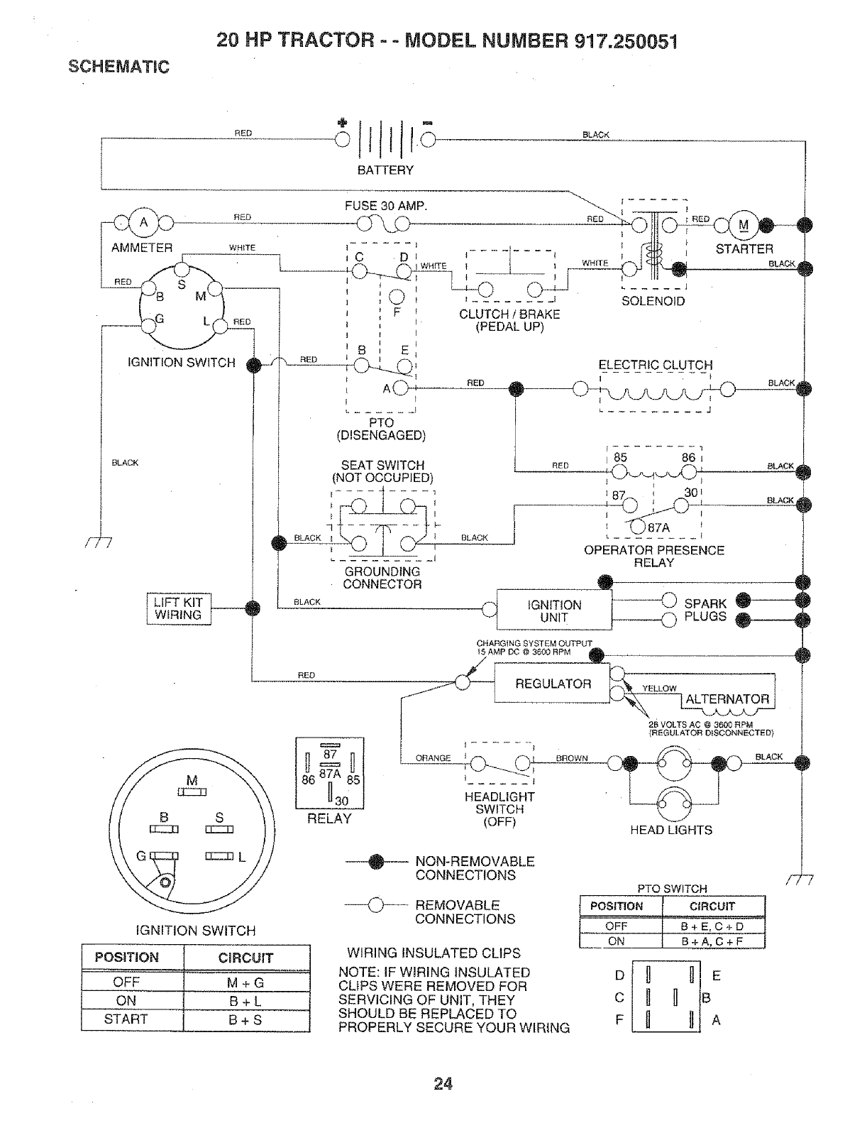
SCHEMATIC
20 HP TRACTOR - o MODEL NUMBER 917,250051
RED
RED
WHITE
RED
NED
BLACK
LIFT KIT ___
WIRING ]
L
BATTERY
RED
FUSE 30 AMP,
U",.D
_C DI *...... t
_ C) _
J F _
]I
_ B E_
RgD
_ A _
F _
PTO
(DISENGAGED)
CLUTCH /BRAKE
(PEDAL UP)
SEAT SWITCH
(NOT OCCUPIED)
I BLACK _ 1
GROUNDING
CONNECTOR
BLACK
BLACK
BLACK
IGNITION SWITCH
POSITIONSTARTOFFON - i CIRCUITMBB+L++SG
WHITE
1 STARTER
BLACK
ELECTRIC CLUTCH
BLACK
I ........ 1
I85 86
,87_: _o,
OPERATOR PRESENCE
RELAY
IGNITION SPARK
UNIT PLUGS _
RED
CHARGING SYSTEM OUTPUT
_5 AMP DC @ 3600 RPM ,_
RED __ __REGULATOR__
86 . 851 _
_30 HEADLIGHT
SWITCH
RELAY (OFF)
NON-REMOVABLE
CONNECTIONS
REMOVABLE
CONNECTIONS
WIRING INSULATED CUPS
NOTE: IF WIRING INSULATED
CLIPS WERE REMOVED FOR
SERVICING OF UNIT, THEY
SHOULD BE REPLACED TO
PROPERLY SECURE YOUR WIRING
ELLOW
26 VOLTS AC @ 3600 RPM
(REGULATOR DISCONNECTED}
HEAD LIGHTS
PTO SWITCH
POSITION ] CIRCUIT 1
OFF
oN I B_D 4
B+A,C+F |
D _ _B E
c B H
F _ _ A
/7
_P
24
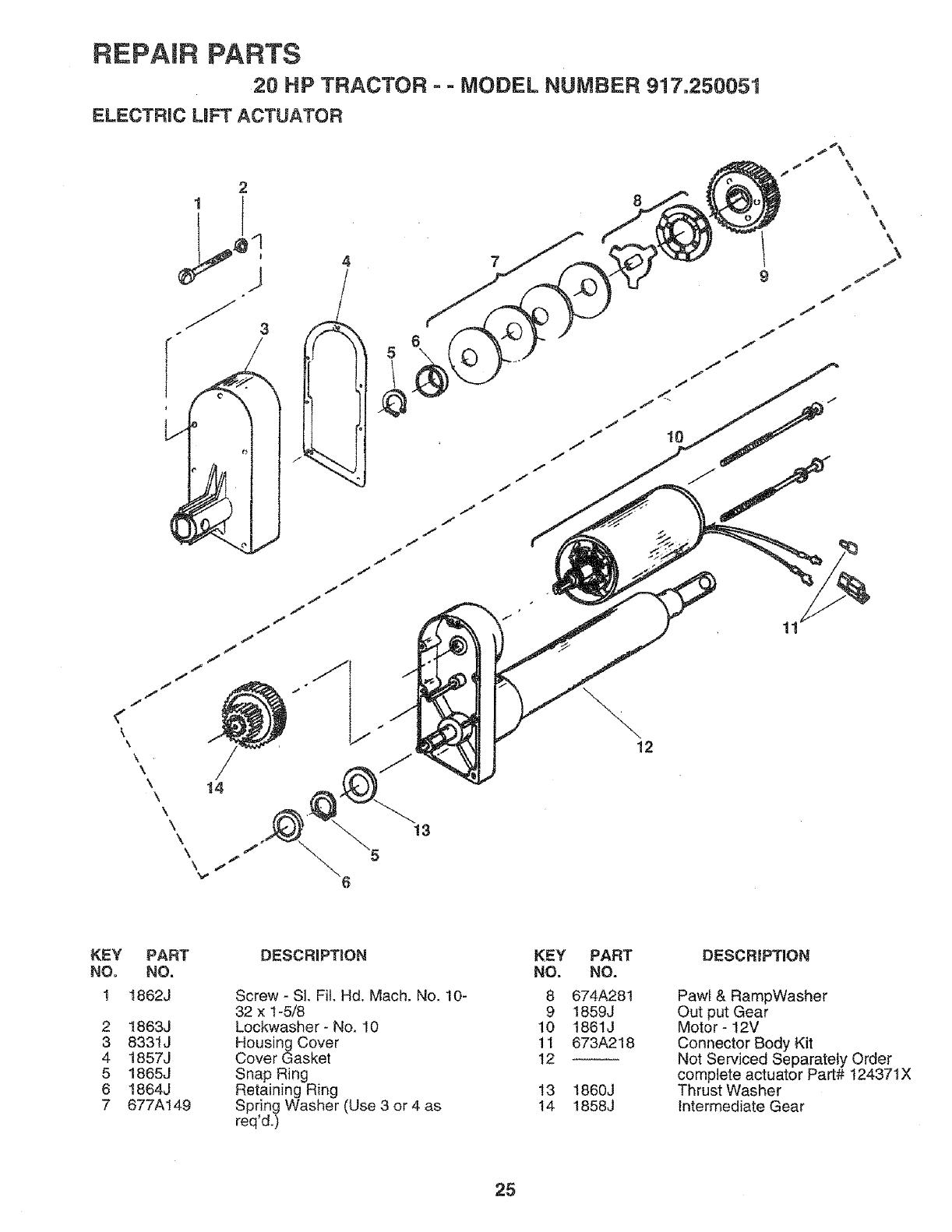
REPAIR PARTS
20 HP TRACTOR - - MODEL NUMBER 917.250051
ELECTRIC LiFT ACTUATOR
<-
\
\\\\\\\f
\ I
14
13
7
12
i
11
\\\\\\
f
KEY
NO.
1
2
3
4
5
6
7
PART
NO.
I862J
1863J
8331J
1857J
1865J
1864J
877A149
DESCRIPTION
Screw - Sl. Fil. Hd. Mach. No, 10-
32 x 1-5/8
Lockwasher - No, 10
Housing Cover
Cover Gasket
Snap Ring
Retaining Ring
Spring Washer (Use 3 or 4 as
req'd.)
KEY
NO.
8
9
10
11
12
13
t4
PART
NO.
674A281
1859J
1861J
673A218
1860J
1858J
DESCRIPTION
Pawl & RampWasher
Out put Gear
Motor- 12V
Connector Body Kit
Not Serviced Separately Order
complete actuator Part# 124371X
Thrust Washer
intermediate Gear
25
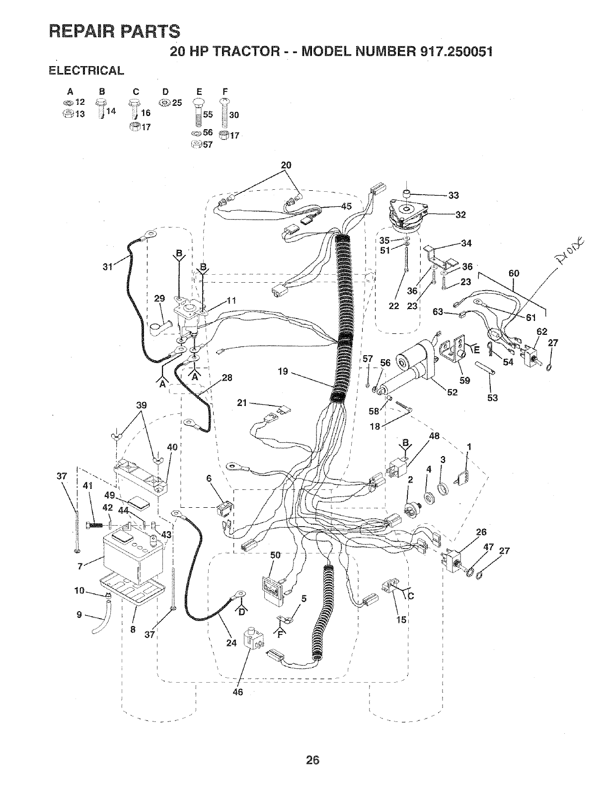
REPAIR PARTS
20 HP TRACTOR - - MODEL NUMBER 917.250051
ELECTRICAL
A8 C D E F
_!:_57
2O
37
\
3g
29
19
\
5O 27
26
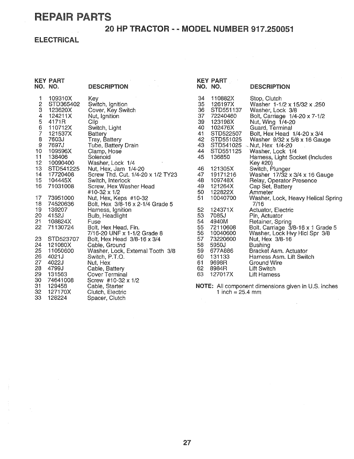
REPAIR PARTS
20 HP TRACTOR - MODEL NUMBER 917.25005!
ELECTRICAL
KEY PART KEY PART
NO. NO. DESCRIPTION NO. NO. DESCRIPTION
1 109310X Key 34 110882X
2 STD365402 Switch, Ignition 35 126197X
3 123620X Cover, Key Switch 36 STD551137
4 124211X Nut, Ignition 37 72240460
5 417tR Clip 39 123198X
6 1t0712X Switch, Light 40 102476X
7 t21537X Battery 41 STD522507
8 7603J Tray, Battery 42 STD551025
97697J Tube, Battery Drain 43 STD541025
10 109596X Clamp, Hose 44 STD55t125
tl 138406 Solenoid 45 136850
t2 10090400 Washer, Lock t/4
13 STD541225 Nut, Flex, Jam 1/4-20 46 12t305X
14 17720408 ScrewThd. Cut. 1/4_20 x 1/2 TY23 47 19171216
15 104445X Switch, Interlock 48 109748X
16 71031008 Screw, Hex Washer Head 49 121264X
#10-32 x 1/2 50 I22822X
17 73951000 Nut, Hex, Keps #10-32 51 10040700
18 74520636 Bolt, Hex 3/8-16 x 2-1/4 Grade 5
19 139207 Flamess, Ignition 52 t24371X
20 4152J Bulb, Headlight 53 7085J
21 108824X Fuse 54 4940M
22 71130724 Bolt, Hex Head, Fin. 55 72110608
7/16-20 UNF x 1-1/2 Grade 8 56 10040600
23 STD523707 Bolt, Hex Head 3/8-16 x 3/4 57 73220600
24 !21080X Cable, Ground 58 5950J
25 1!050600 Washer, Lock, External Tooth 3/8 59 677A886
26 4021J Switch, P.T.O. 60 131133
27 4022J Nut, Hex 61 9698R
28 4799J Cable, Battery 62 8984R
29 131563 CoverTerminal 63 !27017X
30 74641008 Screw #10-32 x 1/2
31 129458 Cable, Starter
32 127170X Clutch, Electric
33 128224 Spacer, Clutch
Stop, Clutch
Washer 1-1/2 x 15/32 x .250
Washer, Lock 3/8
Bolt, Carriage 1/4-20 x 7-1/2
Nut, Wing t/4-20
Guard, Terminal
Bott, Hex Head 1/4-20 x 3/4
Washer 9/32 x 5/8 x 16 Gauge
Nut, Hex 1/4-20
Washer, Lock 1/4
Harness, Light Socket (includes
Key #20)
Switch, Plunger
Washer 17/32 x 3/4 x 16 Gauge
Relay, Operator Presence
Cap Set, Battery
Ammeter
Washer, Lock, Heavy Helical Spring
7/16
Actuator, Electric
Pin, Actuator
Retainer, Spring
Bolt, Carriage 3/8-16 x I Grade 5
Washer, Lock Hvy Hlct Spr 3/8
Nut, Hex 3/8-16
Bushing
Bracket Asmo Actuator
Harness Asm. Lift Switch
Ground Wire
Lift Switch
Lift Harness
NOTE: All component dimensions given in U.S. inches
1 inch = 25.4 mm
27
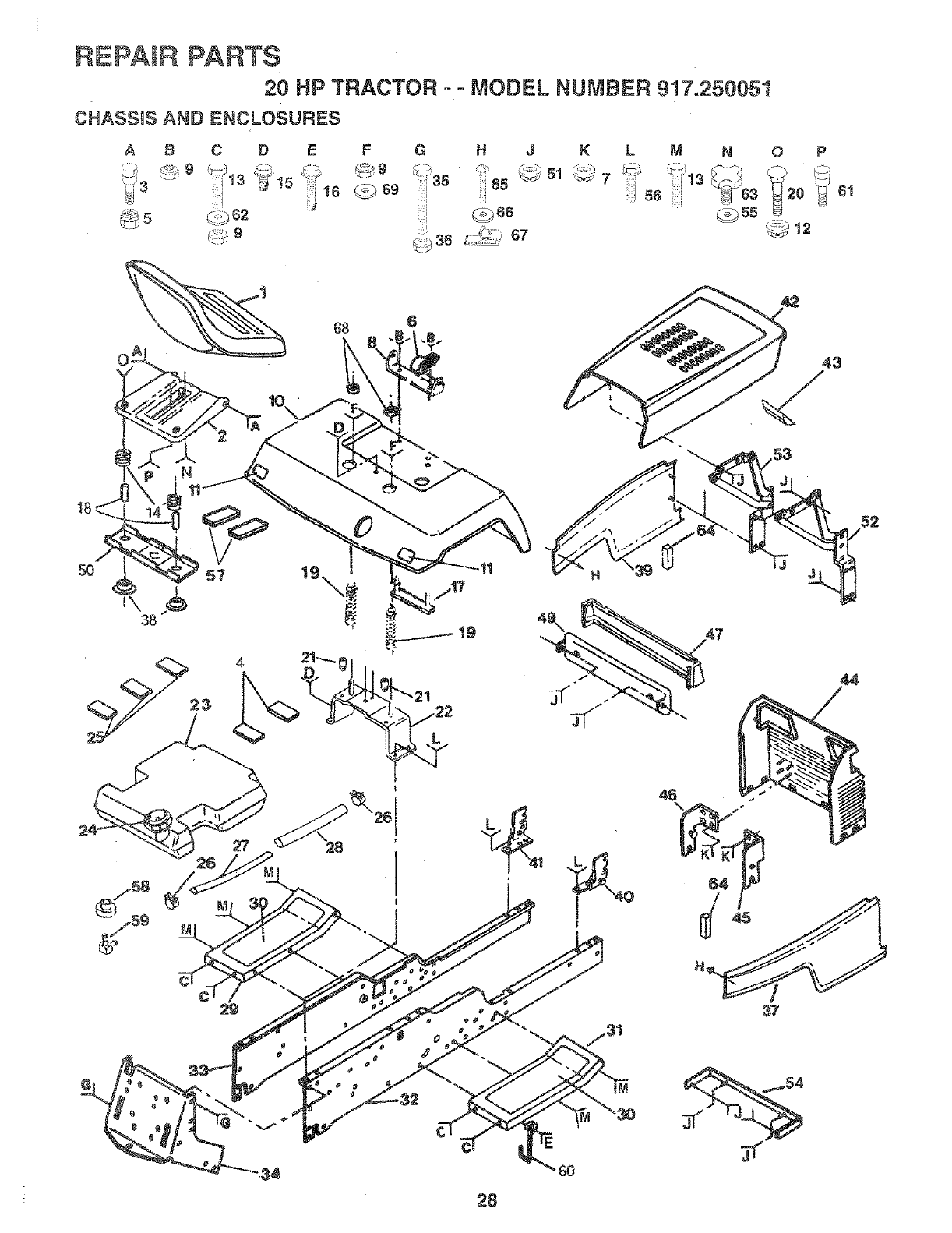
REPAIR PARTS
20 HP TRACTOR - = MODEL NUMBER 917=250051
CHASS_SAND ENCLOSURES
A 8 C D EF
@ 5 (::,_62
6
LM N
";f 13
56 :
0P
61
43
5? ,/17
53
H
44
: 28
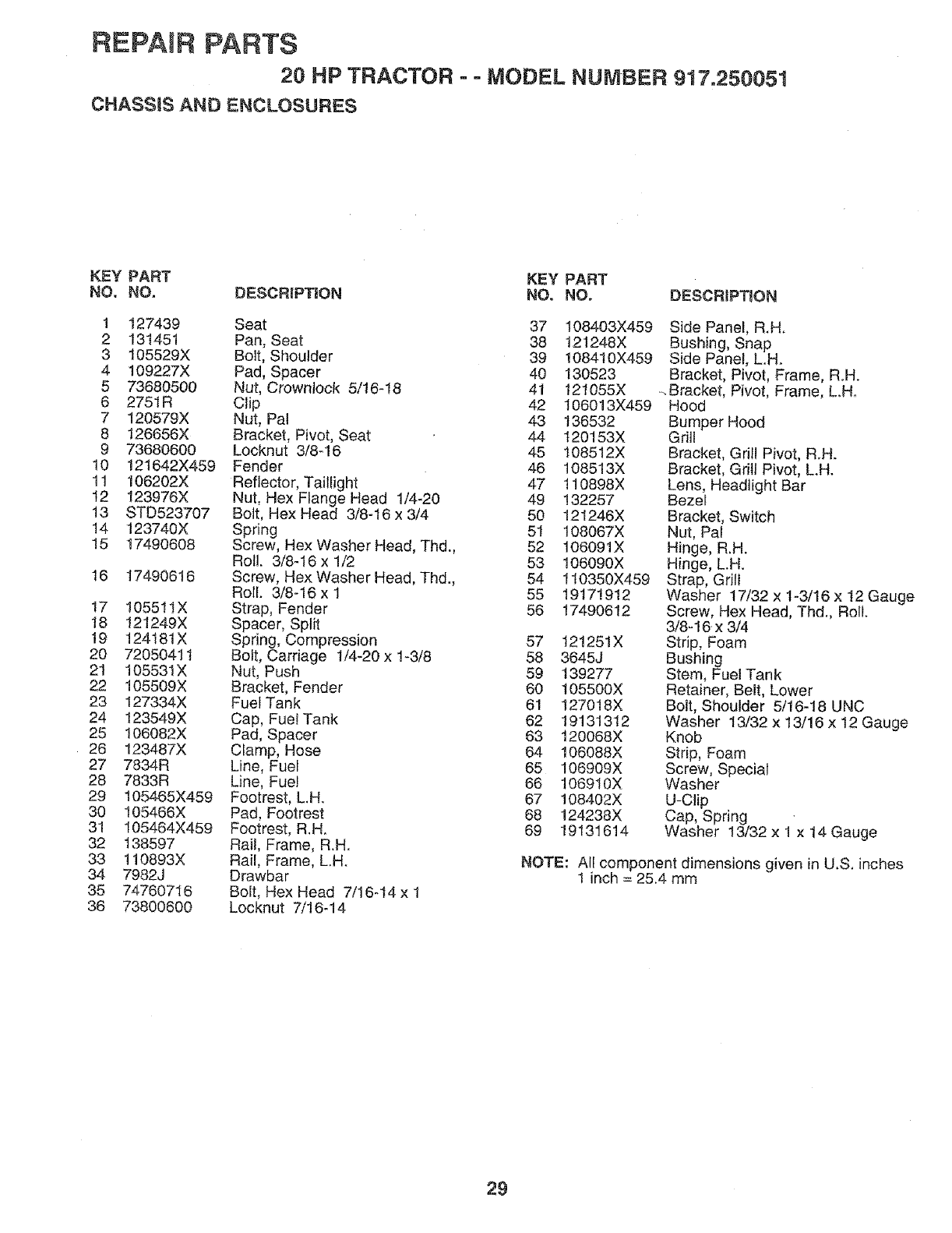
REPAIR PARTS
20 HP TRACTOR - = MODEL NUMBER 917.250051
CHASSIS AND ENCLOSURES
KEY PART KEY PART
NO. NO. DESCRiPTiON NO. NO. DESCRiPTiON
1 127439 Seat 37 108403X459
2 131451 Pan, Seat 38 121248X
3 105529X Bolt, Shoulder 39 108410X459
4 109227X Pad, Spacer 40 130523
5 73680500 Nut, Crownlock 5/16q8 41 121055X
6 275IR Clip 42 106013X459
7 120579X Nut, Pal 43 136532
8 126656X Bracket, Pivot, Seat 44 120153X
9 73680600 Locknut 3/8-16 45 108512X
10 12t642X459 Fender 46 108513X
11 106202X Reflector, Taillight 47 1!0898X
12 123976X Nut, Hex Flange Head 1/4-20 49 132257
13 STD523707 Bolt, Hex Head 3/8-16 x 3/4 50 121246X
14 123740X Spring 51 108067X
15 17490608 Screw, Hex Washer Head, Thd., 52 106091X
Roll. 3/8-16 x 1/2 53 106090X
16 17490616 Screw, Hex Washer Head, Thd., 54 110350X459
Roll. 3/8-16xl 55 19171912
17 105511X Strap, Fender 56 17490612
18 121249X Spacer, Split
t9 124181X Spring, Compression 57
20 7205041 t Bolt, Carriage 1/4-20 x 1-3/8 58
21 105531X Nut, Push 59
22 105509X Bracket, Fender 60
23 127334X Fuel Tank 61
24 t23549X Cap, FuelTank 62
25 106082X Pad, Spacer 63
26 123487X Clamp, Hose 64
27 7834R Line, Fuel 65
28 7833R Line, Fue! 66
29 105465X459 Footrest, LH. 67
30 105466X Pad, Footrest 68
31 105464X459 Footrest, R.H. 69
32 t38597 Rail, Frame, R.H.
33 110893X Rail, Frame, LH.
34 7982J Drawbar
35 74760716 Bolt, Hex Head 7/16_14 x 1
36 73800600 Locknut 7/16-14
Side Panel, R.H.
Bushing, Snap
Side Panel, L.H.
Bracket, Pivot, Frame, R.H.
-.Bracket, Pivot, Frame, L.Ho
Hood
Bumper Hood
Grill
Bracket, Grill Pivot, R.H.
Bracket, Grill Pivot, LH.
Lens, Headlight Bar
Bezel
Bracket, Switch
Nut, Pal
Hinge, R,H.
Hinge, L.H.
Strap, Grill
Washer 17/32 x t-3/16 x t2 Gauge
Screw, Hex Head, Thd., Roll.
3/8 _16x 3/4
121251X Strip, Foam
3645J Bushing
139277 Stem, Fuel Tank
105500X Retainer, Belt, Lower
127018X Bolt, Shoulder 5/16-18 UNC
19131312 Washer 13/32 x 13/16 x 12 Gauge
120068X Knob
106088X Strip, Foam
106909X Screw, Special
106910X Washer
108402X U-Clip
124238X Cap, Spring
19131614 Washer 13/32 x 1 x 14 Gauge
NOTE: All component dimensions given in U.S. inches
1 inch = 25.4 mm
29
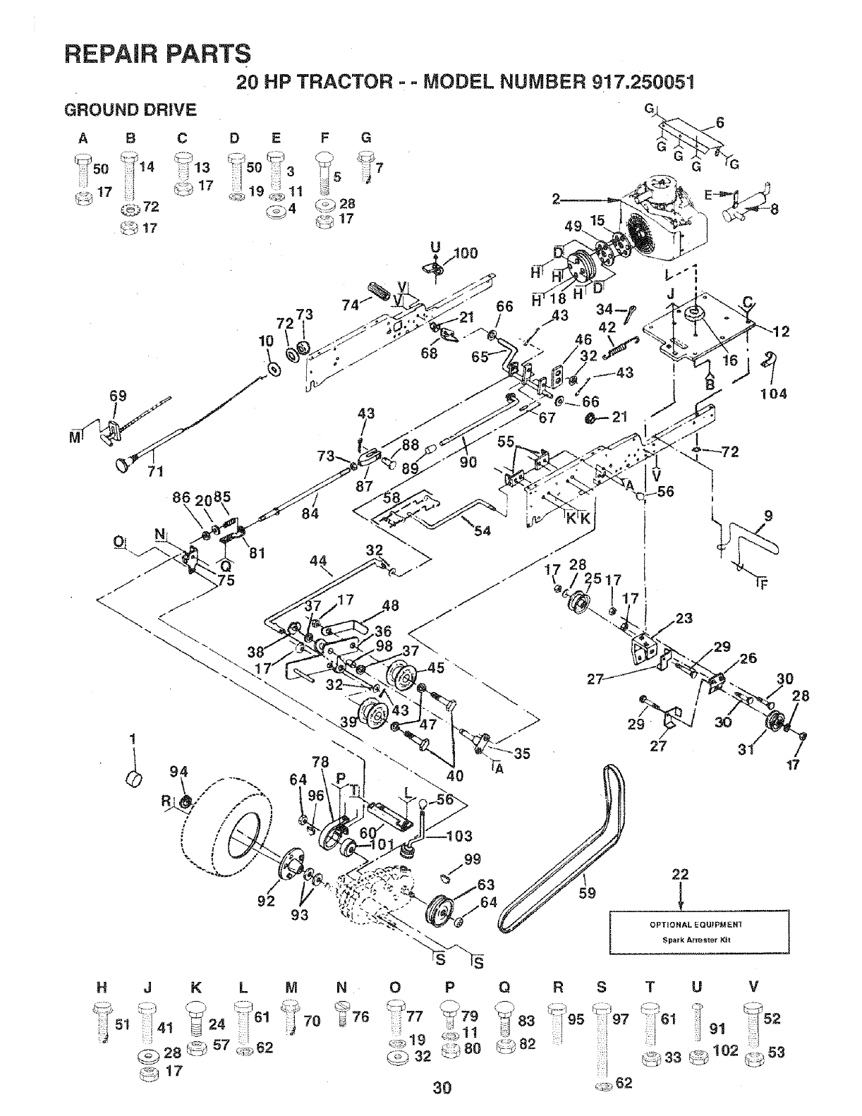
REPAIR PARTS
GROUND DRIVE 20 HP TRACTOR --MODEL NUMBER 917.,?.50051
ABC D E
Q._72 _4
_ t 7
FG
28
G
G
104
71 90
86, 85 87 V
\/L 9
1
M N
":i'70 _76
O P QR S TU
30 _,_ 62
V
HJKL
_.3" 1
28 57 ;
17
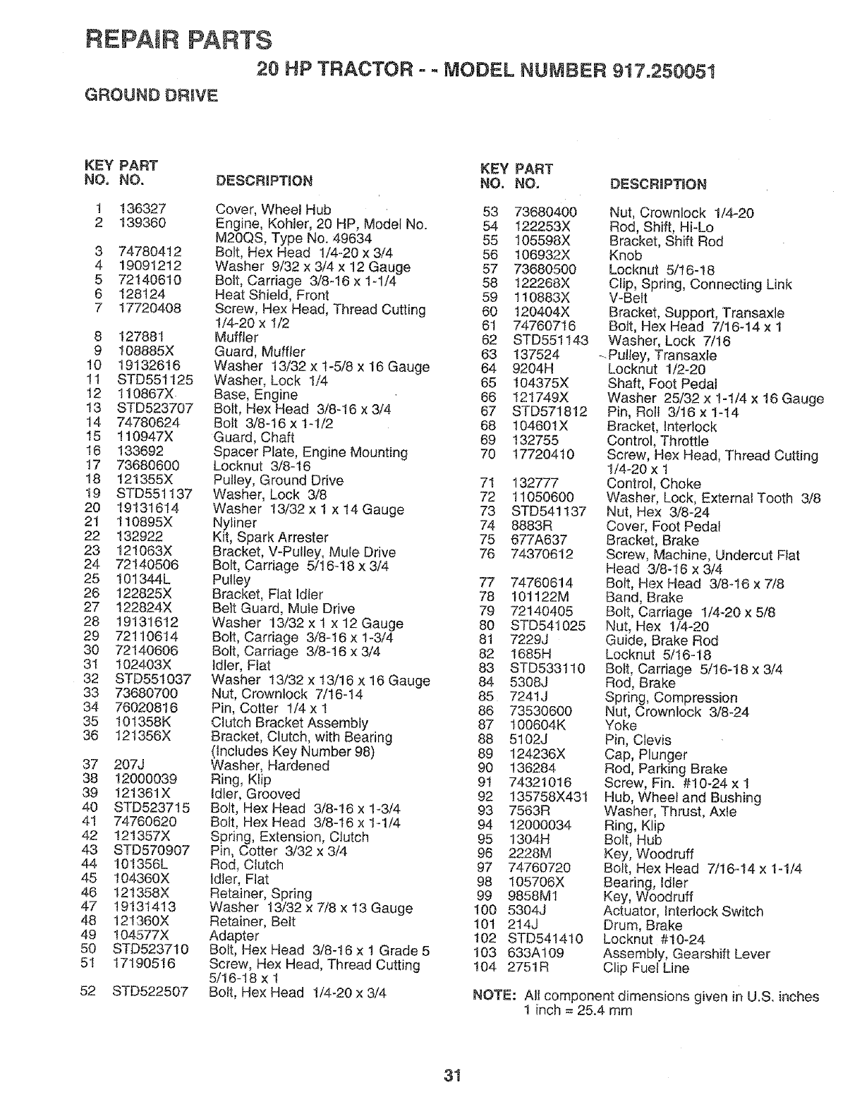
REPAIR PARTS
20 HP TRACTOR - - MODEL NUMBER 917.25005t
GROUNO DRIVE
KEY PART KEY PART
NO, NO. DESCRIPTION NO. NO, DESCRIPTION
1 136327
2 139360
3 74780412
4 19091212
5 72140610
6 128124
7 17720408
8 127881
9 108885X
10 19132616
11 STD55t125
12 110867X
13 STD523707
14 74780624
15 110947X
16 133692
17 73680600
18 121355X
19 STD55t137
20 19131614
21 110895X
22 132922
23 121063X
24 72140506
25 I01344L
26 122825X
27 122824X
28 19131612
29 72110614
30 72140606
3I 102403X
32 STD55t037
33 73680700
34 76020816
35 101358K
36 12t356X
37 207J
38 12000039
39 I21361X
40 STD5237t5
41 74760620
42 t21357X
43 STD570907
44 101356L
45 104360X
46 121358X
47 19131413
48 12!360X
49 !04577X
50 STD5237t0
51 17190516
52 STD522507
Cover, Wheel Hub 53 73680400
Engine, Kohler, 20 HP, Modei No. 54 122253X
M20QS, Type No. 49634 55 105598X
Bolt, Hex Head 1/4o20 x 3/4 56 I06932X
Washer 9/32 x 3/4 x 12 Gauge 57 73680500
Bolt, Carriage 3/8-16 x 1-1/4 58 122268X
Heat Shield, Front 59 110883X
Screw, Hex Head, Thread Cutting 60 120404X
1/4-20 x I/2 6t 74760716
Muffler 62 STD551143
Guard, Muffler 63 137524
Washer 13/32 x 1-5/8 x 16 Gauge 64 9204H
Washer, Lock 1/4 65 104375X
Base, Engine 66 121749X
Bolt, Hex Head 3/8-16 x 3/4 67 STD571812
Bolt 3/8-t6 x 1-1/2 68 104601X
Guard, Chart 69 132755
Spacer Plate, Engine Mounting 70 17720410
Locknut 3/8-16
Pulley, Ground Drive 7I 132777
Washer, Lock 3/8 72 11050600
Washer 13/32 x 1 x 14 Gauge 73 STD541137
Nytiner 74 8883R
Kit, Spark Arrester 75 677A637
Bracket, V-Pulley, Mule Drive 76 74370612
Bolt, Carriage 5/16-18 x 3/4
Pulley 77
Bracket, Flat Idler 78
Belt Guard, Mule Drive 79
Washer 13/32 x 1 x 12 Gauge 80
Bolt, Carriage 3/8-16 x t-3/4 81
Bolt, Carriage 3/8-16 x 3/4 82
_dler, Fiat 83
Washer 13/32 x 13/16 x 16 Gauge 84
Nut, Crowntock 7/I6-14 85
Pin, Cotter t/4 x 1 86
Clutch Bracket Assembly 87
Bracket, Clutch, with Bearing 88
(_nctudes Key Number 98) 89
Washer, Hardened 90
Ring, Klip 9t
Idler, Grooved 92
Bolt, Hex Head 3/8-16 x 1-3/4 93
Bolt, Hex Head 3/8-16 x 1-1/4 94
Spdng, Extension, Clutch 95
Pin, Cotter 3/32 x 3/4 96
Rod, Clutch 97
Idler, Flat 98
Retainer, Spring 99
Washer 13/32 x 7/8 x 13 Gauge 100
Retainer, Belt 101
Adapter t02
Bolt, Hex Head 3/8-16 x 1 Grade 5 103
Screw, Hex Head, Thread Cutting 104
5/16-18 x !
Bolt, Hex Head 1/4-20 x 3/4
74760614
101122M
72140405
STD541025
7229j
1685H
STD533110
5308J
7241j
73530600
t00604K
5102J
124236X
136284
74321016
135758X431
7563R
12000034
1304H
2228M
74760720
105706X
9858M1
5304J
2t4J
STD541410
633Al09
2751R
Nut, Crownlock 1/4-20
Rod, Shift, Hi-Lo
Bracket, Shift Rod
Knob
Locknut 5/I6q 8
Clip, Spring, Connecting Link
V-Belt
Bracket, Support, Transaxle
BoJt, Hex Head 7/16-14 x 1
Washer, Lock 7/16
- Pulley, Transaxle
Locknut 1/2-20
Shaft, Foot Pedal
Washer 25/32 x 1-1/4 x 16 Gauge
Pin, Roll 3/16 x t-14
Bracket, Interlock
Control, Throttle
Screw, Hex Head, Thread Cutting
t/4-20 x 1
Control, Choke
Washer, Lock, External Tooth 3/8
Nut, Hex 3/8-24
Cover, Foot Pedal
Bracket, Brake
Screw, Machine, Undercut Flat
Head 3/8-16 x 3/4
Bolt, Hex Head 3/8-16 x 7/8
Band, Brake
Bolt, Carriage 1/4-20 x 5/8
Nut, Hex 1/4-20
Guide, Brake Rod
Locknut 5/16-18
Bolt, Carriage 5/16-18 x 3/4
Rod, Brake
Spring, Compression
Nut, Crownlock 3/8-24
Yoke
Pin, Clevis
Cap, Plunger
Rod, Parking Brake
Screw, Fin. #!0-24 x 1
Hub, Wheel and Bushing
Washer, Thrust, Axle
Ring, Klip
Bolt, Hub
Key, Woodruff
Bolt, Hex }-lead 7/16-I4 x 1-1/4
Bearing, Idler
Key, Woodruff
Actuator, Interlock Switch
Drum, Brake
Locknut #10-24
Assembly, Gearshift Lever
Clip Fuel Line
NOTE: Alt component dimensions given in U.S. inches
1 inch = 25.4 mm
31
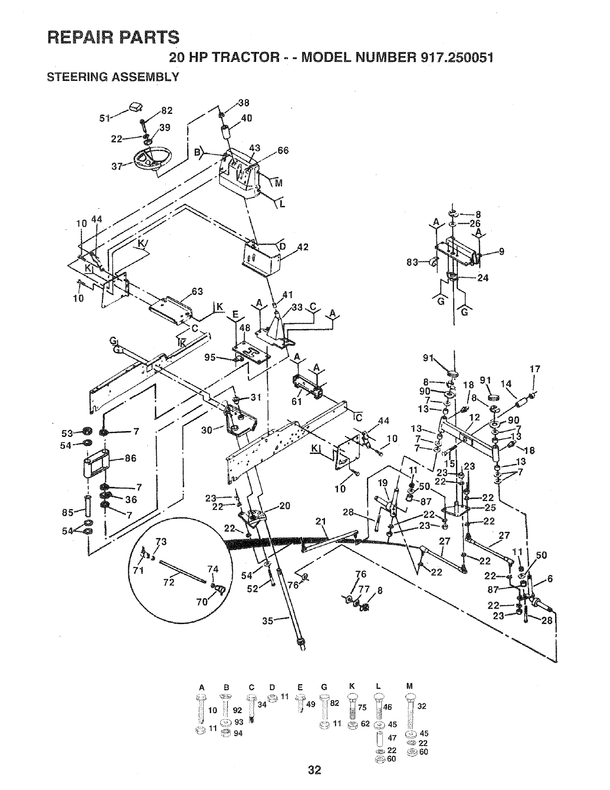
REPAIR PARTS
20 HP TRACTOR -- MODEL NUMBER 917.250051
STEERING ASSEMBLY
/66
1{) ._..
10
A
72
61 7_
13--_
17
/
21
27 27
I
50
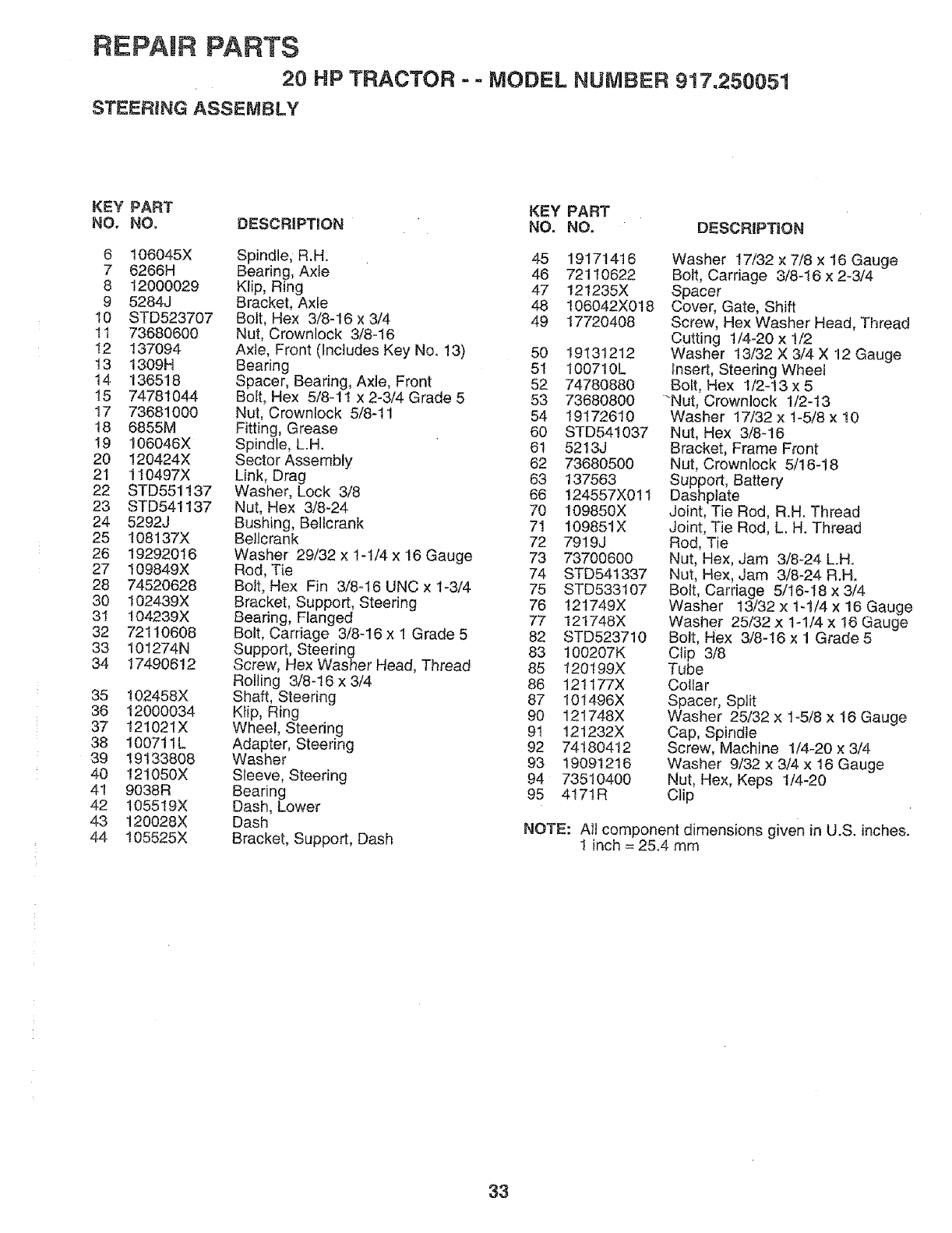
REPAIR PARTS
20 HP TRACTOR --MODEL NUMBER 917.250051
STEERING ASSEMBLY
KEY PART KEY PART
NO, NO. DESCRIPTION NO. NO. DESCRIPTION
6 106045X Spindle, R.H. 45 19171416
7 6266H Bearing, Axle 46 72110622
8 12000029 Ktip, Ring 47 121235X
9 5284J Bracket, Axle 48 106042X0t8
t0 STD523707 Bolt, Hex 3/8-16 x 3/4 49 17720408
tl 73680600 Nut, Crownlock 3/8-16
I2 137094 Axle, Front (Includes Key No. !3) 50 19131212
t3 1309H Bearing 51 100710L
!4 136518 Spacer, Bearing, Axle, Front 52 74780880
15 74781044 Bolt, Hex 5/8-1t x 2-3/4 Grade 5 53 73680800
17 73681000 Nut, Crownlock 5/8-I1 54 19172610
18 6855M Fitting, Grease 60 STD541037
19 106048X Spindle, L.H. 61 5213J
20 120424X Sector Assembly 62 73680500
21 110497X Link, Drag 63 137563
22 STD551137 Washer, Lock 3/8 66 124557X01 t
23 STD541137 Nut, Hex 3/8-24 70 109850X
24 5292J Bushing, Bellcrank 71 109851X
25 !08!37X Belicrank 72 7919J
26 19292016 Washer 29/32 x 1-1/4 x 16 Gauge 73 73700600
27 109849X Rod, Tie 74 STD541337
28 74520628 Bo_t, Hex Fin 3/8-16 UNC x 1-3/4 75 STD533t07
30 102439X Bracket, Support, Steering 76 12!749X
31 !04239X Bearing, Flanged 77 121748X
32 72110608 Bolt, Carriage 3/8-16 x 1 Grade 5 82 STD523710
33 101274N Support, Steering 83 100207K
34 17490612 Screw, Hex Washer Head, Thread 85 120199X
Rolling 3/8-16 x 3/4 86 121177X
35 t02458X Shaft, Steering 87 101496X
36 12000034 Ktip, Ring 90 121748X
37 121021X Wheel, Steering 9! 121232X
38 100711L Adapter, Steering 92 74180412
39 19133808 Washer 93 19091216
40 121050X Sleeve, Steering 94 73510400
41 9038R Bearing 95 4171R
42 105519X Dash, Lower
43 120028X Dash
44 105525X Bracket, Support, Dash
Washer 17/32 x 7/8 x 16 Gauge
Bolt, Carriage 3/8-16 x 2-3/4
Spacer
Cover, Gate, Shift
Screw, Hex Washer Head, Thread
Cutting t/4-20 x 1/2
Washer 13/32 X 3/4 X 12 Gauge
Insert, Steering Wheel
Bott, Hex 1/2-13 x 5
"Nut, Crownlock t/2-13
Washer 17/32 x 1-5/8 x 10
Nut, Hex 3/8-!6
Bracket, Frame Front
Nut, Crownlock 5/16-18
Support, Battery
Dashplate
Joint, Tie Rod, R.H. Thread
Joint, Tie Rod, L. H. Thread
Rod, Tie
Nut, Hex, Jam 3/8-24 LH.
Nut, Hex, Jam 3/8-24 R.H.
Bolt, Carriage 5/16-I8 x 3/4
Washer 13/32 x 1-1/4 x 16 Gauge
Washer 25/32 x 1-1/4 x 16 Gauge
Bolt, Hex 3/8-16 x 1 Grade 5
Clip 3/8
Tube
Collar
Spacer, Split
Washer 25/32 x 1_5/8 x t6 Gauge
Cap, Spindle
Screw, Machine 1/4_20 x 3/4
Washer 9/32 x 3/4 x 16 Gauge
Nut, Hex, Keps 1/4-20
Clip
NOTE: AIt component dimensions given in U.S. inches.
1 inch = 25.4 mrs
33
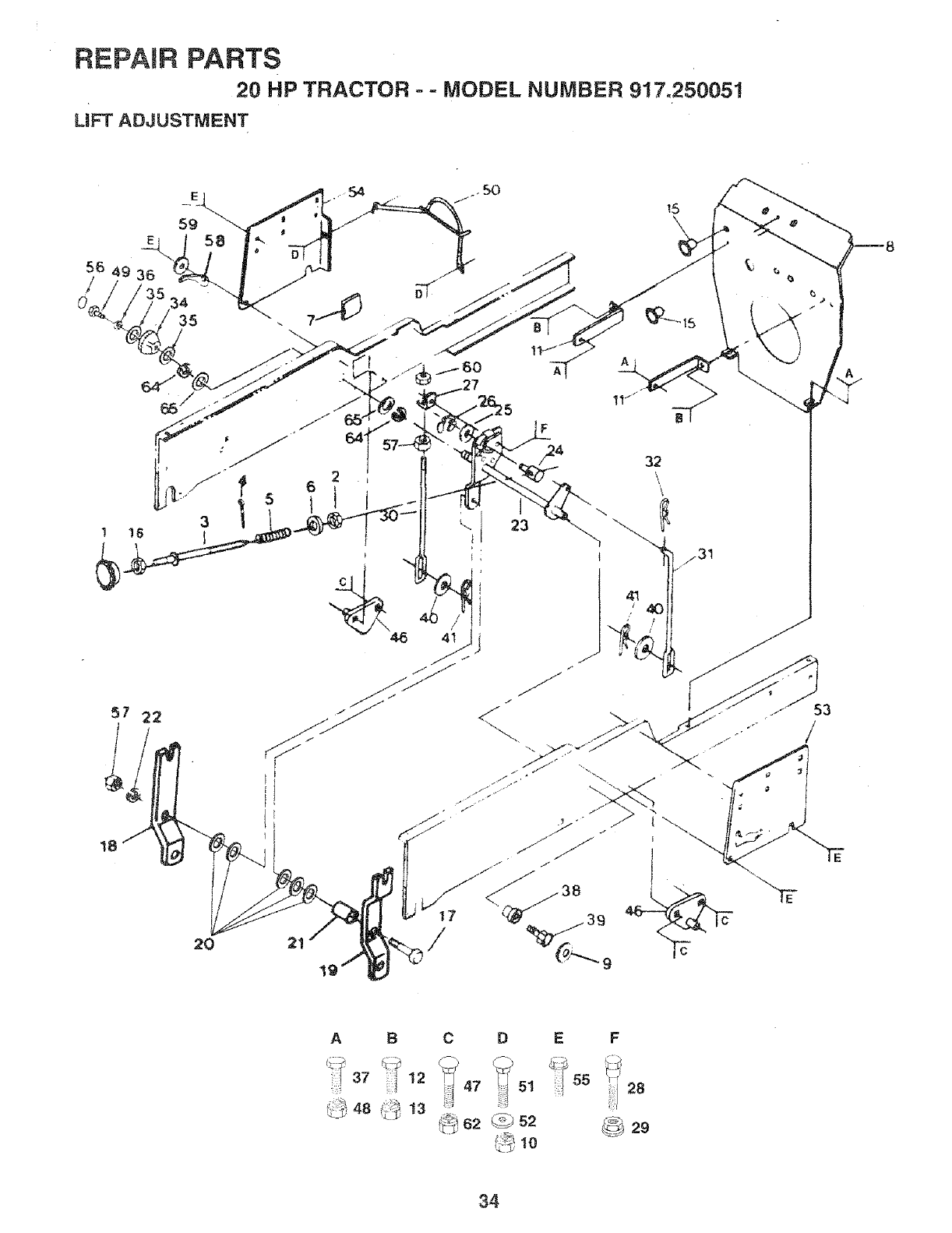
REPAIR PARTS
20 HP TRACTOR --MODEL NUMBER 917.250051
LiFT ADJUSTMENT
3
57 22
18
3839
_/31
I53
/
AB
37 12
_C_:48 ...._ 13
CD
47 5t
_ 62 @ s2
i :i) t0
E F
_29
34
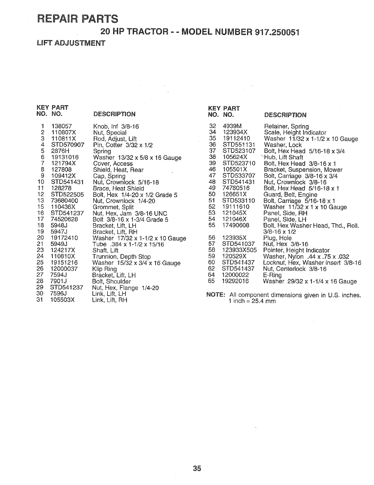
REPAIR PARTS
20 HP TRACTOR -= MODEL NUMBER 917.250051
UFT ADJUSTMENT
KEY PART KEY PART
NO. NO. DESCRIPTION NO. NO. DESCRIPTION
1 138O57
2 1t0807X
3 1t0811X
4 STD570907
5 2876H
6 19131016
7 121794X
8 127808
9 109412X
10 STD541431
11 128278
12 STD522505
13 73680400
15 110436X
16 STD541237
t7 74520628
18 5948J
19 5947J
20 19172410
21 5949J
23 124217X
24 110810X
25 19151218
26 12000037
27 7594J
28 7901J
29 STD541237
30 7596J
31 105503X
Knob, lnf 3/8-16 32
Nut, Special 34
Rod, Adjust, Lift 35
Pin, Cotter 3/32 x 1/2 36
Spring 37
Washer 13/32 x 5/8 x 16 Gauge 38
Cover, Access 39
Shield, Heat, Rear 46
Cap, Spring 47
Nut, Crown{ock 5/!6-18 48
8race, Heat Shield 49
Bolt, Hex 1/4-20 x 1/2 Grade 5 50
Nut, Crownlock 1/4-20 51
Grommet, Split 52
Nut, Hex, Jam 3/8-16 UNC 53
Bolt 3/8-16 x 1-3/4 Grade 5 54
Bracket, Lift, LH 55
Bracket, Lift, RH
Washer 17/32 x 1-I/2 x !0 Gauge 56
Tube .384 x 1-1/2 x t5/16 57
Shaft, Lift 58
Trunnion, Depth Stop 59
Washer 15/32 x 3/4 x 16 Gauge 60
Klip Ring 62
Bracket, Lift, LH 64
Bolt, Shoulder 65
Nut, Hex, Flange 1/4-20
Link, Lift, LH
Link, Lift, RH
4939M
123934X
19112410
STD551131
STD523107
105624X
STD523710
105501X
STD533707
STD541431
74780516
126651X
STD533110
19111810
121045X
!21046X
17490608
123935X
STD541037
I23933X505
120529X
STD541437
STD541437
12000022
19292016
Retainer, Spring
Scale, Height Indicator
Washer 11/32 x 1-1/2 x 10 Gauge
Washer, Lock
Bolt, Hex Head 5/16-18 x 3/4
"Hub, Lift Shaft
Bolt, Hex Head 3/8-16 x t
Bracket, Suspension, Mower
Bolt, Carriage 3/8-16 x 3/4
Nut, Crownlock 3/8-16
Bolt, Hex Head 5/16-18 x 1
Guard, Belt, Engine
Bolt, Carriage 5/16-18 x 1
Washer 11/32 x I x 10 Gauge
Panel, Side, RH
Panel, Side, LH
Bolt, Hex Washer Head, Thd., Roll.
3/8-16 x 1/2
Plug, Hole
Nut, Hex 3/8-16
Pointer, Height Indicator
Washer, Nylon .44 x .75 x .032
Locknut, Hex, Washer insert 3/8-16
Nut, Centerlock 3/8-16
E-Ring
Washer 29/32 x 1-1/4 x 16 Gauge
NOTE: Ali component dimensions given in U.So inches.
1 inch = 25.4 mm
35
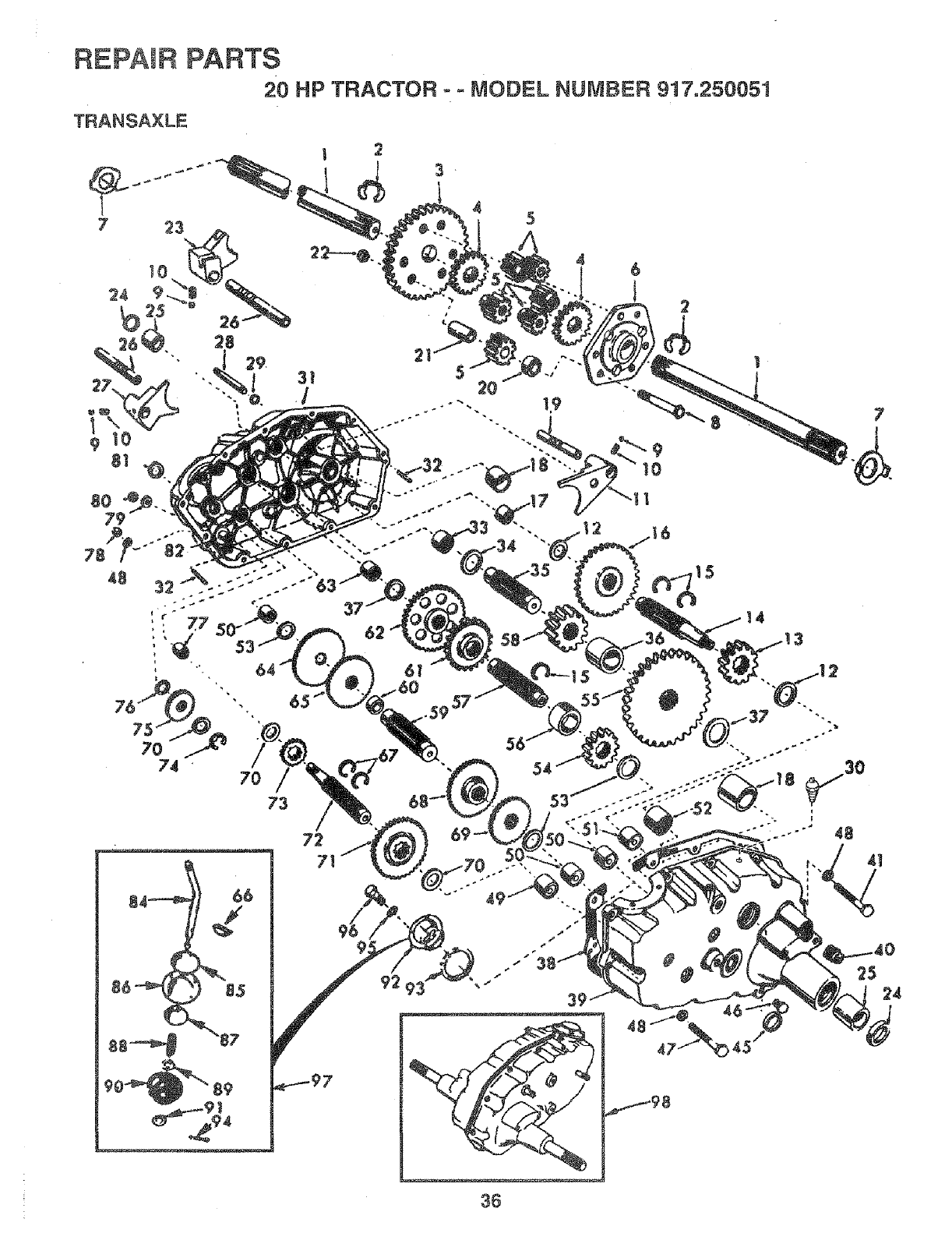
REPAtR PARTS
20 HP TRACTOR- - MODEL NUMBER 917.250051
TRANSA×LE
73
62
61
160 +.59 53
#
#
36
7
4t
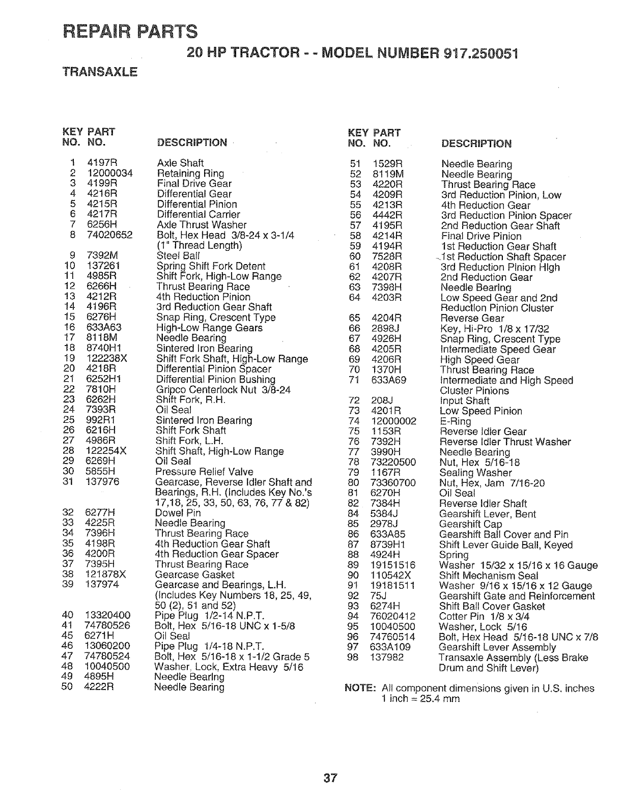
REPAWF PARTS
20 HP TRACTOR ==MODEL NUMBER 917.250051
TRANSAXLE
KEY PART KEY PART
NO. NO. DESCRmPTION NO. NO. DESCRIPTION
1 4197R Axte Shaft 51 1529R
2 12000034 Retaining Ring 52 8119M
3 4199R Final Drive Gear 53 4220R
4 42t6R Differential Gear 54 4209R
5 4215R Differential Pinion 55 42t3R
6 4217R Differential Carrier 56 4442R
7 6256H Axle Thrust Washer 57 4t95R
8 74020652 Bolt, Hex Head 3/8-24x 3-t/4 58 42t4R
(1" Thread Length) 59 4194R
9 7392M Steel Ball 60 7528R
10 137261 Spring Shift Fork Detent 61 4208R
11 4985R Shift Fork, High-Low Range 62 4207R
12 6266H Thrust Bearing Race 63 7398H
13 4212R 4th Reduction Pinion 64 4203R
14 4196R 3rd Reduction Gear Shaft
15 6276H Snap Ring, Crescent Type 65 4204R
16 633A63 High-Low Range Gears 66 2898J
17 8118M Needle Bearing 67 4926H
18 8740H1 Sintered Iron Bearing 68 4205R
19 122238X Shift Fork Shaft, High-Low Range 69 4206R
20 4218R Differential Pinion Spacer 70 1370H
21 6252H1 Differential Pinion Bushing 71 633A69
22 78!0H Gripco Centerlock Nut 3/8-24
23 6262H Shift Fork, R.H. 72 208J
24 7393R Oil Seal 73 4201R
25 992R1 Sintered Iron Bearing 74 12000002
26 6216H Shift Fork Shaft 75 1t53R
27 4986R Shift Fork, L.H. 76 7392H
28 122254X Shift Shaft, High-Low Range 77 3990H
29 6269H Oil Seal 78 73220500
30 5855H Pressure Relief Valve 79 1167R
31 137976 Gearcase, Reverse Idler Shaft and 80 73360700
Bearings, R.H. (Includes Key No.'s 81 6270H
17,18, 25, 33, 50, 63, 76, 77 & 82) 82 7384H
32 6277H Dowel Pin 84 5384J
33 4225R Needle Bearing 85 2978J
34 7396H Thrust Bearing Race 86 633A85
35 4198R 4th Reduction Gear Shaft 87 8739H1
36 4200R 4th Reduction Gear Spacer 88 4924H
37 7395H Thrust Bearing Race 89 19151516
38 t21878X Gearcase Gasket 90 110542X
39 137974 Gearcase and Bearings, L.H. 91 19181511
(Includes Key Numbers 18, 25, 49, 92 75J
50 (2), 51 and 52) 93 6274H
40 13320400 Pipe Plug 1/2-14 N.P.T. 94 76020412
4t 74780526 Bolt, Hex 5/16o18 UNC x 1-5/8 95 10040500
45 6271H Oil Seal 96 74760514
46 13060200 Pipe Plug 1/4-18 N.P.T. 97 633A109
47 74780524 Bolt, Hex 5/16-18 x 1-1/2 Grade 5 98 137982
48 10040500 Washer, Lock, Extra Heavy 5/16
49 4895H Needle Bearing
50 4222R Needle Bearing
Needle Bearing
Needle Bearing
Thrust Bearing Race
3rd Reduction Pinion, Low
4th Reduction Gear
3rd Reduction Pinion Spacer
2nd Reduction Gear Shaft
Final Drive Pinion
1st Reduction Gear Shaft
.1 st Reduction Shaft Spacer
3rd Reduction Pinion High
2nd Reduction Gear
Needle Bearing
Low Speed Gear and 2nd
Reduction Pinion Cluster
Reverse Gear
Key, Hi-Pro t/8 x 17/32
Snap Ring, Crescent Type
Intermediate Speed Gear
High Speed Gear
Thrust Bearing Race
Intermediate and High Speed
Cluster Pinions
input Shaft
Low Speed Pinion
E-Ring
Reverse Idler Gear
Reverse Idler Thrust Washer
Needle Bearing
Nut, Hex 5/16_18
Sealing Washer
Nut, Hex, Jam 7/16-20
Oi! Seal
Reverse Idler Shaft
Gearshift Lever, Bent
Gearshift Cap
Gearshift Ball Cover and Pin
Shift Lever Guide Ball, Keyed
Spring
Washer 15/32 x 15/16 x !6 Gauge
Shift Mechanism Seal
Washer 9/16 x 15/16 x 12 Gauge
Gearshift Gate and Reinforcement
Shift Bail Cover Gasket
Cotter Pin !/8 x 3/4
Washer, Lock 5/16
Bolt, Hex Head 5/16-!8 UNC x 7/8
Gearshift Lever Assembly
Transaxfe Assembly (Less Brake
Drum and Shift Lever)
NOTE: All component dimensions given in U.S. inches
1 inch = 25.4 mm
37
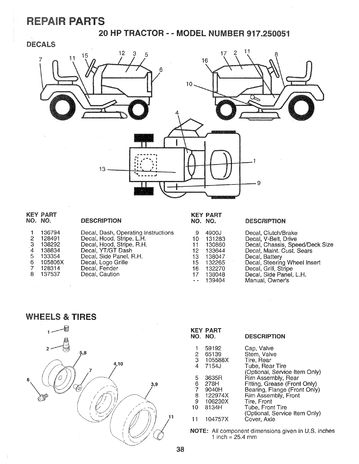
REPAER PARTS
20 HP TRACTOR --MODEL NUMBER 917.250051
DECALS
7 1! I5 12 3 5 17 2 11 8
16
6
10
13
KEY PART KEY PART
NO. NO. DESCRIPTION NO. NO. DESCRIPTION
1 t36794
2 12849!
3 138292
4 138834
5 133354
6 105806X
7 128314
8 t37537
Decal, Dash, Operating Instructions 9 4900J
Decal, Hood, Stripe, L.H. 10 131283
Decal, Hood, Stripe, R.H. 1l 130860
Decal, YTiGT Dash 12 133644
Decal, Side Panel, R.H. 13 138047
Decal, Logo Grille 15 132265
Decal, Fender 16 132270
Decal, Caution 17 138048
- - 139404
Decal, Clutch/Brake
Decal, V-Belt, Drive
Decal, Chassis, Speed/Deck Size
Decal, Maint. Cust. Sears
Decal, Battery
Decal, Steering Wheel Insert
Decal, Grill, Stripe
Decal, Side Panel, L.H.
Manual, Owner's
WHEELS & TIRES
1.t4)
7
6
,10
KEY PART
NO. NO. DESCRIPTION
1
2
3
4
5
6
7
8
9
10
11
59192
65139
105588X
7154J
3635R
278H
9040H
122974X
106230X
8134H
104757X
Cap, Valve
Stem, Valve
Tire, Rear
Tube, Rear Tire
(Optional, Service Item Only)
Rim Assembly, Rear
Fitting, Grease (Front Only)
Bearing, Flange (Front Only)
Rim Assembly, Front
Tire, Front
Tube, Front Tire
(Optional, Service item Only)
Cover, Axle
NOTE: All component dimensions given in U.S. inches
t inch = 25.4 mm
38

SERVICE NOTES
39
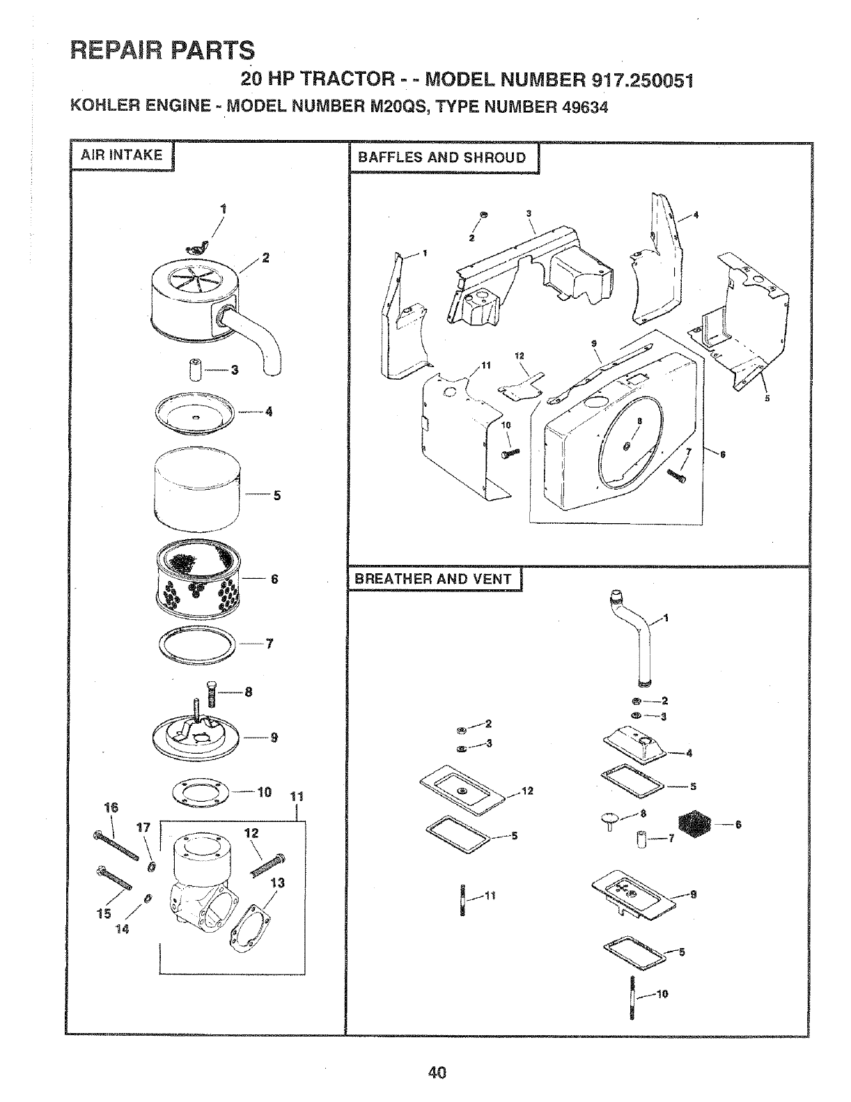
REPAIR PARTS
20 HP TRACTOR o- MODEL NUMBER 917.250051
KOHLER ENGINE -MODEL NUMBER M20QS, TYPE NUMBER 49634
16
12
11
:3
\
9
\
BREATHER AND VENT I
jti J9
< >io
l j10
4O
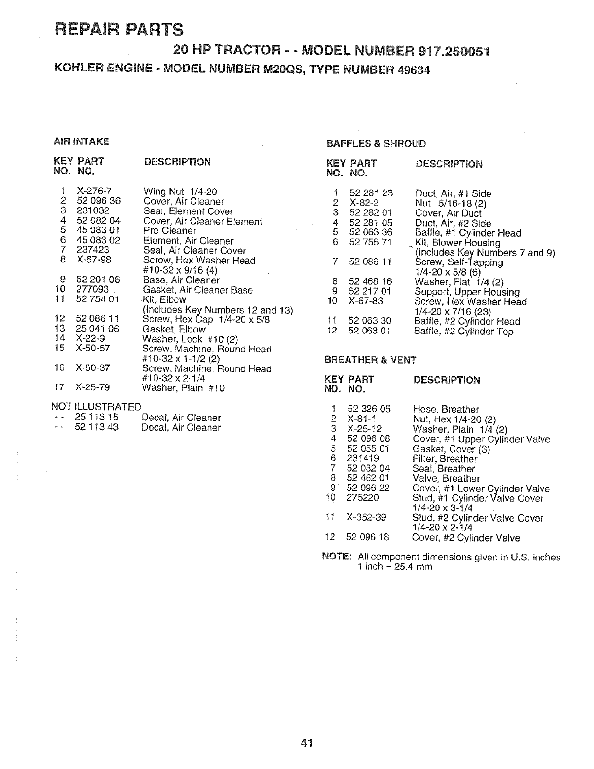
REPAIR PARTS
20 HP TRACTOR == MODEL NUMBER 917.250051
KOHLER ENGINE - MODEL NUMBER M20QS, TYPE NUMBER 49634
AiR |NTAKE BAFFLES & SHROUD
KEY PART DESCRIPTION KEY PART
NO. NO, NO. NO.
1 X-276-7
2 52 096 36
3 231032
4 52 082 04
5 45 083 01
6 45 083 02
7237423
8 X-67-98
9 52 201 06
10 277093
11 52 754 01
!2 52 086 11
t3 25 041 06
14 X-22-9
15 X-50-57
16 X-50-37
Wing Nut 1/4-20 1 52 281 23
Cover, Air Cleaner 2 X-82_2
Seal, Element Cover 3 52 282 01
Cover, Air Cleaner Element 4 52 28! 05
Pre-Cleaner 5 52 063 36
Element, Air Cleaner 6 52 755 71
Seal, Air Cleaner Cover
Screw, Hex Washer Head 7 52 086 11
#10-32 x 9/16 (4)
Base, Air Cleaner 8 52 468 16
Gasket, Air Cleaner Base 9 52 217 01
Kit, Elbow 10 X-67-83
(Includes Key Numbers 12 and 13)
Screw, Hex Cap I/4-20 x 5/8 1I
Gasket, Elbow 12
Washer, Lock #10 (2)
Screw, Machine, Round Head
#10-32 x 1-1/2 (2)
Screw, Machine, Round Head
#10-32 x 2-I/4 KEY PART
Washer, Plain #10 NO. NO,17 X-25-79
NOT ILLUSTRATED
- - 25 113 15 Decal, Air Cleaner
- - 52 1t3 43 Decal, Air Cleaner
DESCRIPTION
52 063 30
52 063 01
Duct, Air, #1 Side
Nut 5/16-t8 (2)
Cover, Air Duct
Duct, Air, #2 Side
Baffle, #1 Cylinder Head
. Kit, Blower Housing
(Includes Key Numbers 7 and 9)
Screw, Self-Tapping
1/4-20 x 5/8 (6)
Washer, Flat 1/4 (2)
Support, Upper Housing
Screw, Hex Washer Head
I/4-20 x 7/t6 (23)
Baffle, #2 Cylinder Head
Baffle, #2 Cylinder Top
BREATHER & VENT
DESCRIPTmON
1 52 326 05
2 X-81-1
3 X-25-12
4 52 096 08
5 52 055 01
6 231419
7 52 032 04
8 52 462 01
9 52 096 22
10 275220
11 X-352-39
12 52 O96 18
Hose, Breather
Nut, Hex 1!4-20 (2)
Washer, Plain 1/4 (2)
Cover, #1 Upper Cylinder Valve
Gasket, Cover (3)
Filter, Breather
Seal, Breather
_!atve, Breather
Cover, #1 Lower Cylinder Valve
Stud, #1 Cylinder Valve Cover
1/4-20 x 3-I/4
Stud, #2 Cylinder Valve Cover
1/4-20 x 2-1/4
Cover, #2 Cylinder Valve
NOTE: All component dimensions given in U.S. inches
1 inch = 25.4 mm
41
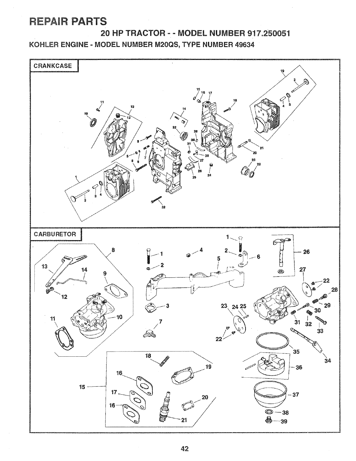
REPAIR PARTS
20 HP TRACTOR - - MODEL NUMBER 917.250051
KOHLER ENGINE - MODEL NUMBER M20QS, TYPE NUMBER 49634
_s_i _j
17
/
"15 -" 17
42
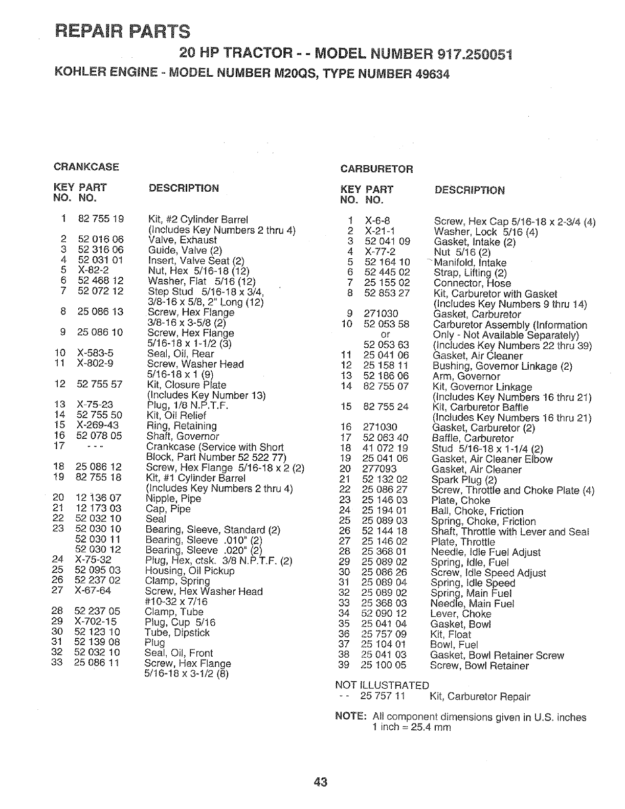
REPAIR PARTS
20 HP TRACTOR - = MODEL NUMBER 917.250051
KOHLER ENGINE -MODEL NUMBER M20QS, TYPE NUMBER 49634
CRANKCASE CARBURETOR
KEY PART DESCRIPTBON KEY PART DESCRIPTION
NO, NO. NO. NO,
13 X_75-23
14 52 755 50
15 X-269-43
16 52 078 05
17 ---
18 25 086 12
19 82 755 18
20 12 136 07
21 12 173 03
22 52 032 10
23 52 030 10
52 030 11
52 030 !2
24 X-75-32
25 52 095 03
26 52 237 02
27 X_67-64
28 52 237 05
29 X-702-15
30 52 t23 10
31 52 t39 08
32 52 032 10
33 25 086 11
1 82 755 19 Kit, #2 Cylinder Barrel 1 X_6-8
(Includes Key Numbers 2 thru 4) 2 X-21-1
2 52 016 06 Valve, Exhaust 3 52 041 09
3 52 316 06 Guide, Valve (2) 4 X_77-2
4 52 03t 01 Insert, Valve Seat (2) 5 52 164 t0
5 X-82-2 Nut, Hex 5/16-18 (12) 6 52 445 02
6 52 468 12 Washer, Flat 5/16 (12) 7 25 155 02
7 5207212 StepStud 5/16-t8x3/4, 8 5285327
3/8-16 x 5/8, 2" Long (12)
8 25 086 13 Screw, Hex Flange 9 271030
3/8-16 x 3-5/8 (2) 10 52 053 58
9 25 086 t0 Screw, Hex Flange or
5/16-18 x 1-1/2 (3) 52 053 63
10 X-583_5 Seal, Oil, Rear 11 25 041 06
11 X-802-9 Screw, Washer Head 12 25 158 tl
5/16-18x1(9) 13 5218606
12 52 755 57 Kit, Closure Plate 14 82 755 07
(Includes Key Number 13)
Plug, 1/8 N.P.T.F. 15
Kit, Oi! Relief
Ring, Retaining t6 271030
Shaft, Governor 17 52 063 40
Crankcase (Service with Short 18 41 072 19
Block, Part Number 52 522 77) 19 25 041 06
Screw, Hex Flange 5/16-18 x 2 (2) 20 277093
Kit, #1 Cylinder Barrel 21 52 132 02
(Includes Key Numbers 2 thru 4) 22 25 086 27
Nipple, Pipe 23 25 146 03
Cap, Pipe 24 25 194 01
Seal 25 25 089 03
Bearing, Sleeve, Standard (2) 26 52 !44 t8
Bearing, Sleeve .010" (2) 27 25 146 02
Bearing, Sleeve .020" (2) 28 25 368 01
Plug, Hex, ctsk. 3/8 N.P.T.F. (2) 29 25 089 02
Housing, Oil Pickup 30 25 086 26
Clamp, Spring 31 25 089 04
Screw, Hex Washer Head 32 25 089 02
#10-32 x 7/16 33 25 368 03
Clamp, Tube 34 52 090 12
Plug, Cup 5/16 35 25 041 04
Tube, Dipstick 36 25 757 09
Plug 37 25 104 01
Seal, Oil, Front 38 25 041 03
Screw, Hex Flange 39 25 100 05
5/16-18 x 3-1/2 (8)
82 755 24
Screw, Hex Cap 5/16-18 x 2-3/4 (4)
Washer, Lock 5/16 (4)
Gasket, Intake (2)
Nut 5/16 (2)
"Manifold, Intake
Strap, Lifting (2)
Connector, Hose
Kit, Carburetor with Gasket
(Includes Key Numbers 9 thru 14)
Gasket, Carburetor
Carburetor Assembly (Information
Only - Not Available Separately)
(includes Key Numbers 22 thru 39)
Gasket, Air Cleaner
Bushing, Governor Linkage (2)
Arm, Governor
Kit, Governor Linkage
(includes Key Numbers 16 thru 2I)
Kit, Carburetor Baffle
(Includes Key Numbers 16 thru 21)
Gasket, Carburetor (2)
Baffle, Carburetor
Stud 5/16-18 x 1-1/4 (2)
Gasket, Air Cleaner Elbow
Gasket, Air Cleaner
Spark Plug (2)
Screw, Throttle and Choke Plate (4)
Plate, Choke
Ball, Choke, Friction
Spring, Choke, Friction
Shaft, Throttle with Lever and Seai
Plate, Throttle
Needle, Idle Fuel Adjust
Spring, idle, Fuel
Screw, Idle Speed Adjust
Spring, Idle Speed
Spring, Main Fuel
Needle, Main Fuel
Lever, Choke
Gasket, Bowl
Kit, Float
Bowl, Fuel
Gasket, Bowl Retainer Screw
Screw, Bowl Retainer
NOT ILLUSTRATED
- - 25 757 tl Kit, Carburetor Repair
NOTE: All component dimensions given in U.S. inches
1 inch = 25.4 mm
43
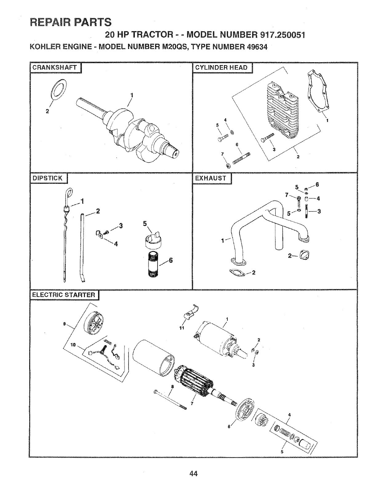
REPAIR PARTS
20 HP TRACTOR ==MODEL NUMBER 917.250051
KOHLER ENGINE = MODEL NUMBER M20QS, TYPE NUMBER 49634
/
2
jl
L
\
4 \\
°\ \ _,,,_ %. ,_ \1
2-@
STARTER J
3
44
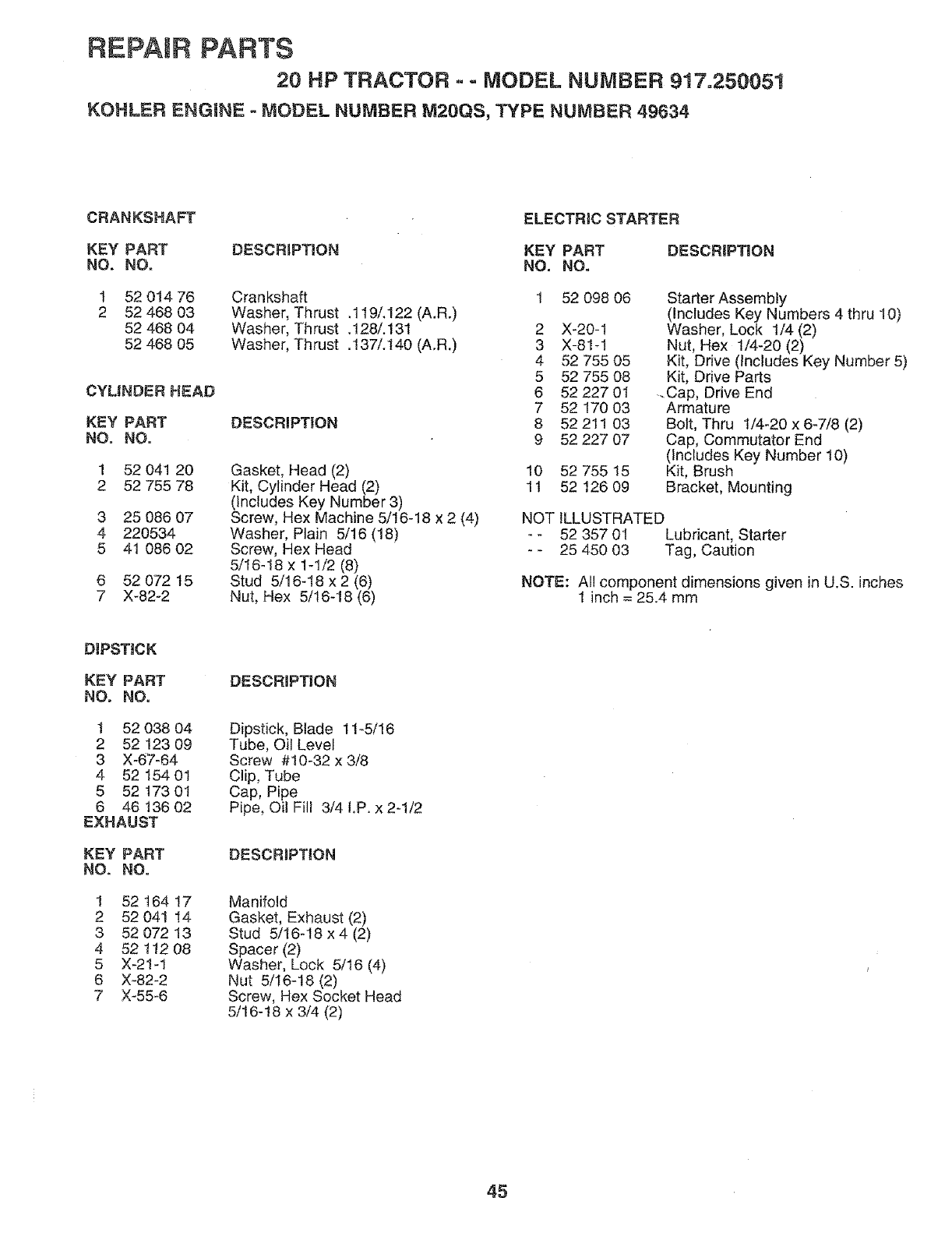
REPAIR PARTS
20 HP TRACTOR -- MODEL NUMBER 917=250051
KOHLER ENGINE - MODEL NUMBER M20QS, TYPE NUMBER 49634
CRANKSHAFT ELECTRIC STARTER
KEY PART DESCRIPTION KEY PART
NO. NO. NO. NO.
1 52 014 76
2 52 468 03
52 468 04
52 468 05
CYLINDER HEAD
KEY PART
NO. NO.
1 52 041 20
2 52 755 78
3 25 086 07
4 220534
5 41 086 02
Crankshaft
Washer, Thrust .119/,122 (A.R.)
Washer, Th rust .!28/. 13t
Washer, Thrust .137/.140 (A.R.)
DESCRIPTION
Gasket, Head (2)
Kit, Cylinder Head (2)
(includes Key Number 3)
Screw, Hex Machine 5/16-18 x 2 (4)
Washer, Plain 5/16 (18)
Screw, Hex Head
5/16-18 x 1-1/2 (8)
Stud 5/16-18 x 2 (6)
Nut, Hex 5/16-18 (6)
6 52 072 t5
7 X-82-2
DESCRIPTION
1 52 098 06
2 X-20-1
3 X-81-1
4 52 755 05
5 52 755 08
6 52 227 01
7 52 170 03
8 52 211 03
9 52 227 07
10 52 755 15
1t 52 126 09
Starter Assembly
(Includes Key Numbers 4 thru 10)
Washer, Lock 1/4 (2)
Nut, Hex 1/4-20 (2)
Kit, Drive (Includes Key Number 5)
Kit, Drive Parts
.Cap, Drive End
Armature
Bolt, Thru 1/4-20 x 6-7/8 (2)
Cap, Commutator End
(Includes Key Number 10)
Kit, Brush
Bracket, Mounting
NOT ILLUSTRATED
-- 52 357 01 Lubricant, Starter
-- 25 450 03 Tag, Caution
NOTE: Al! component dimensions given in U.S. inches
1 inch = 25.4 mm
D1PSTiCK
1 52 038 04
2 52 !23 09
3 X-67-64
4 52 154 01
5 52 t73 0t
6 46 t36 02
EXHAUST
KEY PART
NO. NO.
1 52 t64 17
2 52 041 !4
3 52 072 13
4 52 112 08
5 X-2!-1
6 X-82-2
7 X-55-6
DESCRIPTION
Dipstick, Blade 11-5/16
Tube, Oil Level
Screw #10-32 x 3/8
Clip, Tube
Cap, Pipe
Pipe, Oil Fill 3/4 !.P. x 2-1/2
DESCR_PTION
Manifold
Gasket, Exhaust (2)
Stud 5/16-18 x 4 (2)
Spacer (2)
Washer, Lock 5/16 (4)
Nut 5/I6-18 (2)
Screw, Hex Socket Head
5/16-!8 x 3/4 (2)
45
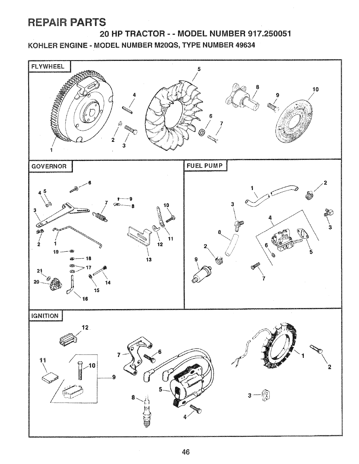
REPAIR PARTS
20 HP TRACTOR =- MODEL NUMBER 917.250051
KOHLER ENGINE - MODEL NUMBER M20QS, TYPE NUMBER 49634
FLYWHEEL 5
/
J
12
\
13
10
11
2\
3
// /
/ /
7
_2
2
46
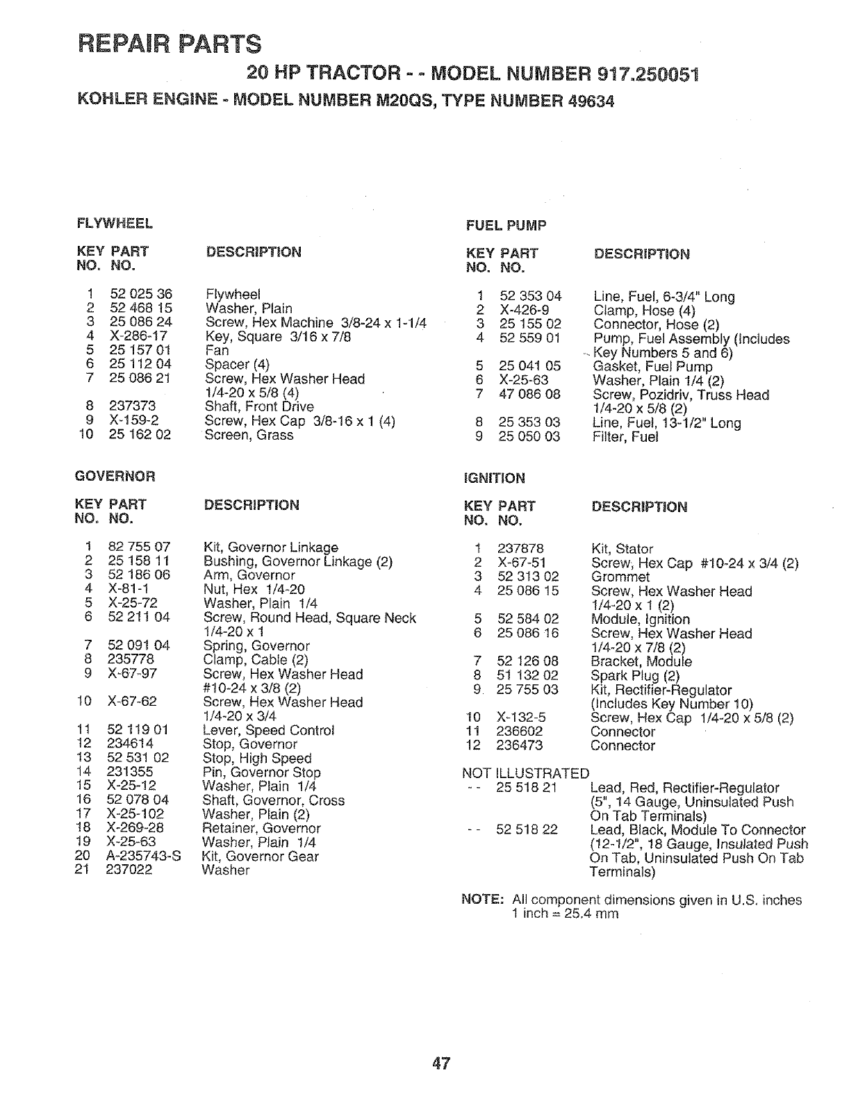
REPAIR PARTS
20 HP TRACTOR o - MODEL NUMBER 9t7.250051
KOHLER ENGINE - MODEL NUMBER M20QS, TYPE NUMBER 49634
FLYWHEEL FUEL PUMP
KEY PART DESCRIPTION KEY PART DESCRIPTION
NO. NO. NO. NO.
1 52 025 36 Flywheel 1 52 353 04
2 52 468 15 Washer, Plain 2 X-426-9
3 25 086 24 Screw, Hex Machine 3/8-24 x 1-1/4 3 25 155 02
4 X-286o17 Key, Square 3/16 x 7/8 4 52 559 01
5 25 157 0t Fan
6 2511204 Spacer (4) 5 25 041 05
7 25 086 21 Screw, Hex Washer Head 6 X-25-63
1/4-20 x 5/8 (4) 7 47 086 08
8 237373 Shaft, Front Drive
9 X-159-2 Screw, Hex Cap 3/8-16 x 1 (4) 8 25 353 03
10 25 162 02 Screen, Grass 9 25 050 03
Line, Fuel, 6-3/4" Long
Clamp, Hose (4)
Connector, Hose (2)
Pump, Fuel Assembly (Includes
_-Key Numbers 5 and 6)
Gasket, Fuel Pump
Washer, Plain t/4 (2)
Screw, Pozidriv, Truss Head
1/4-20 x 5/8 (2)
Line, Fuel, 13-1/2" Long
Filter, Fuel
GOVERNOR IGNfTiON
KEY PART DESCRIPTION KEY PART
NO. NO. NO. NO.
1 82 755 07 Kit, Governor Linkage t 237878
2 25 158 1! Bushing, Governor Linkage (2) 2 X-67-51
3 52 186 06 Arm, Governor 3 52 313 02
4 X-81-1 Nut, Hex !/4_20 4 25 086 15
5 X-25-72 Washer, Plain 1/4
6 52 211 04 Screw, Round Head, Square Neck 5 52 584 02
1/4-20xl 6 25 08616
7 52 091 04 Spring, Governor
8 235778 Clamp, Cable (2) 7 52 126 08
9 X-67_97 Screw, Hex Washer Head 8 51 132 02
#10-24 x 3/8 (2) 9 25 755 03
10 X-67-62 Screw, Hex Washer Head
1/4-20 x 3/4 10 X_132-5
tl 52 119 01 Lever, Speed Control 1! 236602
t2 234614 Stop, Governor 12 236473
t3 52 531 02 Stop, High Speed
14 231355 Pin, Governor Stop
15 X-25-12 Washer, Plain !/4
16 52 078 04 Shaft, Governor, Cross
17 X-25-102 Washer, Plain (2)
18 X-269-28 Retainer, Governor
19 X-25_63 Washer, P_ain 1/4
20 A-235743-S Kit, Governor Gear
2I 237022 Washer
DESCREPTJON
Kit, Stator
Screw, Hex Cap #10-24 x 3/4 (2)
Grommet
Screw, Hex Washer Head
1/4-20 x 1 (2)
Module, Ignition
Screw, Hex Washer Head
1/4-20 x 7/8 (2)
Bracket, Module
Spark Plug (2)
Kit, Rectifier-Regulator
(Includes Key Number 10)
Screw, Hex Cap 1/4-20 x 5/8 (2)
Connector
Connector
NOT ILLUSTRATED
-- 25 518 21 Lead, Red, Rectifier-Regulator
(5", 14 Gauge, Uninsutated Push
On Tab Terminals)
-- 52 518 22 Lead, Black, Module To Connector
(12-1/2", 18 Gauge, Insulated Push
On Tab, Uninsulated Push On Tab
Terminals)
NOTE: All component dimensions given in U.S. inches
1 inch = 25.4 mm
47
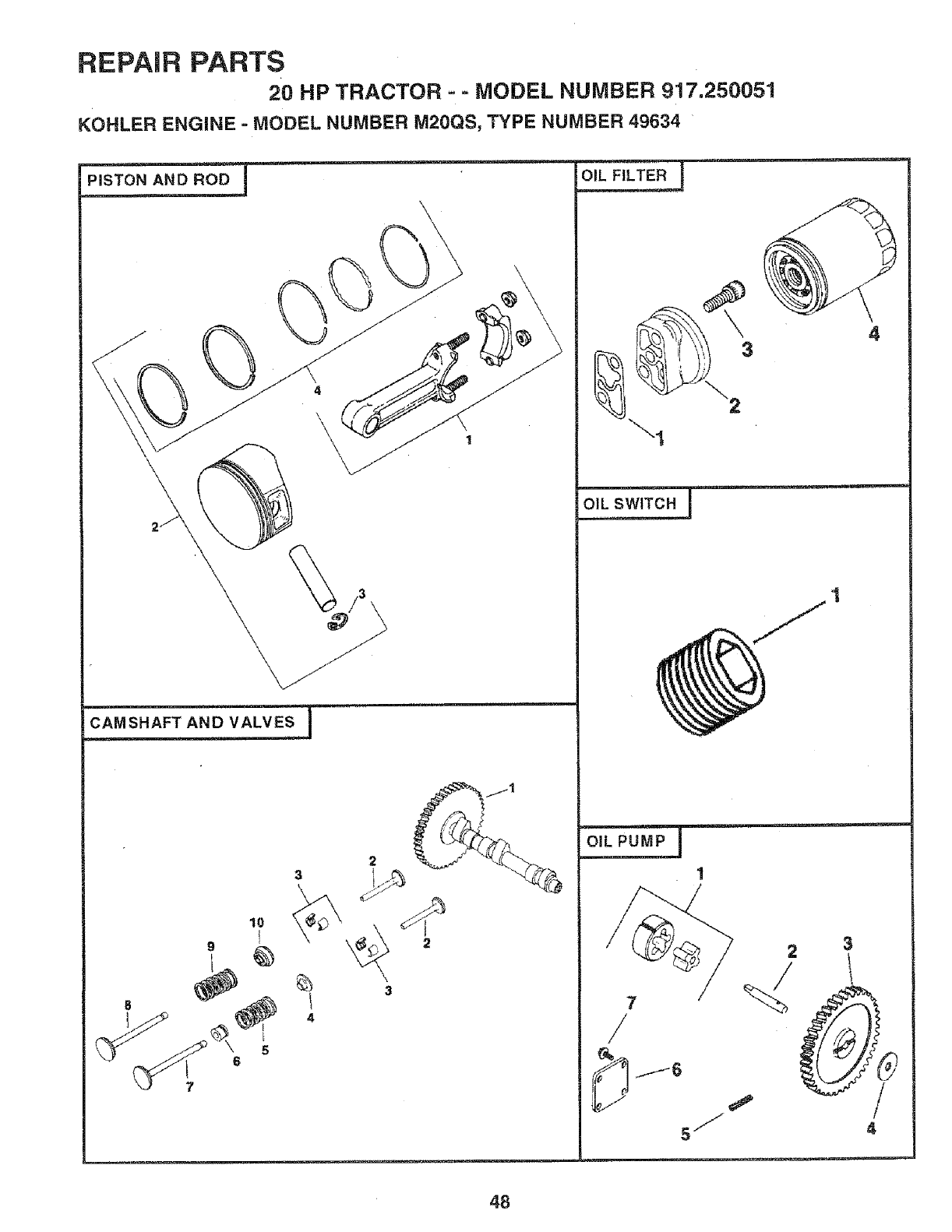
REPAIR PARTS
20 HP TRACTOR -- MODEL NUMBER 917.250051
KOHLER ENGINE = MODEL NUMBER M20QS, TYPE NUMBER 49634
4
3
\
4
OIL SW_
1
48
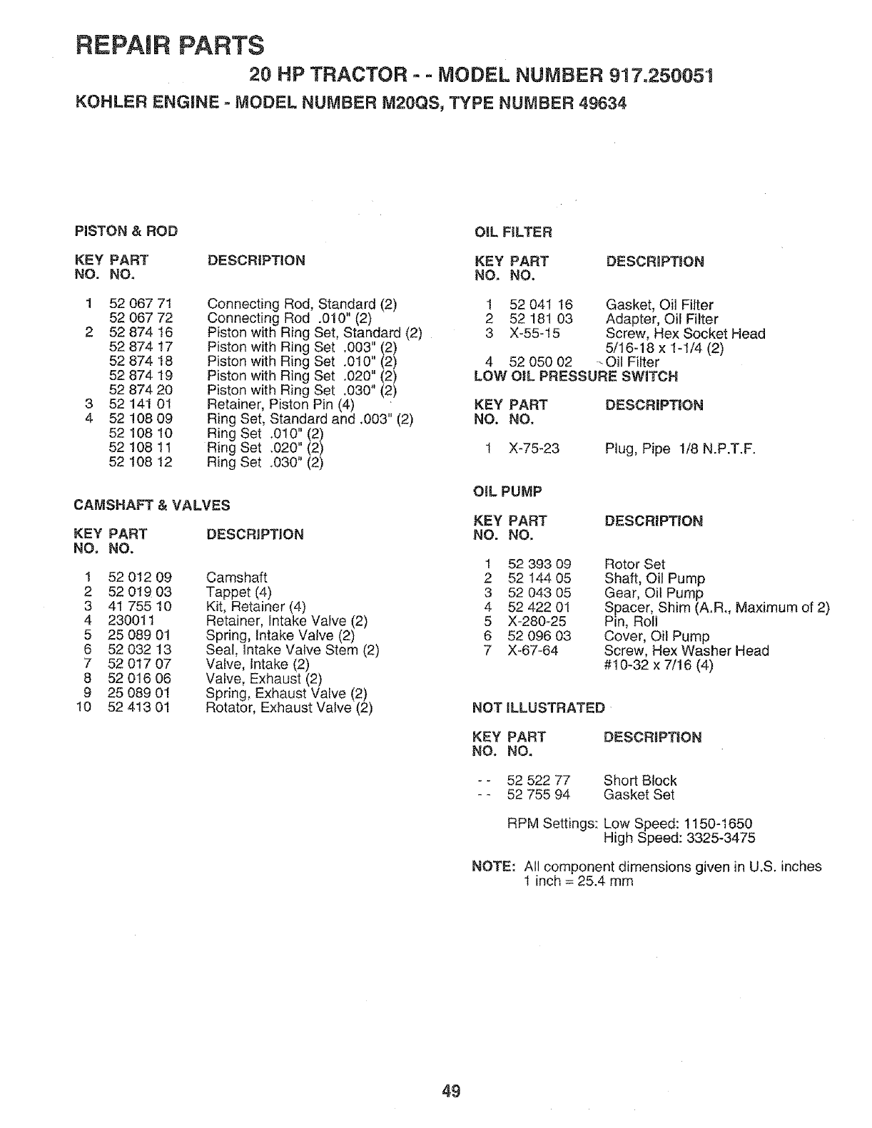
REPAmRPARTS
20 HP TRACTOR - -MODEL NUMBER 9!7.250051
KOHLER ENGINE - MODEL NUMBER M20QS, TYPE NUMBER 49834
PISTON &ROD OIL FILTER
KEY PART DESCRiPTiON KEY PART DESCRiPTiON
NO. NO. NO. NO.
1 52 067 71
52 067 72
2 52 874 16
52 874 17
52 874 18
52 874 19
52 874 20
3 52 141 01
4 52 !08 09
52 108 10
52 108 11
52 108 12
CAMSHAFT
KEY PART
NOo NO.
Connecting Rod, Standard (2)
Connecting Rod .010" (2)
Piston with Ring Set, Standard (2)
Piston with Ring Set ,003" (2)
Piston with Ring Set .010" (2)
Piston with Ring Set .020" (2)
Piston with Ring Set .030" (2)
Retainer, Piston Pin (4)
Ring Set, Standard and ,003" (2)
Ring Set .0t0" (2)
Ring Set .020" (2)
Ring Set .030" (2)
&VALVES
DESCRiPTiON
Camshaft
Tappet (4)
Kit, Retainer (4)
Retainer, Intake Valve (2)
Spring, Intake Valve (2)
Seal, intake Valve Stem (2)
Valve, intake (2)
Valve, Exhaust (2)
Spring, Exhaust Valve (2)
Rotator, Exhaust Valve (2)
1 52 012 09
2 52 0!9 03
3 41 755 10
4 230011
5 25 089 01
6 52 032 13
7 52 0t7 07
8 52 016 06
9 25 089 01
!0 52 413 01
1 52 041 16 Gasket, Oil Filter
2 52 181 03 Adapter, Oil Filter
3 X-55-t5 Screw, Hex Socket Head
5/16-18 x I-1/4 (2)
4 52 050 02 -Oil Filter
LOW OiL PRESSURE SW_TCH
KEY PART DESCRiPTiON
NO. NO.
1 X-75-23 Plug, Pipe 1/8 N.P.T.F.
OIL PUMP
KEY PART DESCRIPTION
NO. NO.
1 52 393 09
2 52 144 05
3 52 043 05
4 52 422 01
5 X-280-25
6 52 096 03
7 X-67-64
Rotor Set
Shaft, Oil Pump
Gear, Oil Pump
Spacer, Shim (A.R., Maximum of 2)
Pin, Roll
Cover, Oil Pump
Screw, Hex Washer Head
#10-32 x 7/16 (4)
NOTILLUSTRATED
KEY PART
NO. NO. DESCRIPTIION
- - 52 522 77
- - 52 755 94 Short Block
Gasket Set
RPM Settings: Low Speed: 1150-1650
High Speed: 3325-3475
NOTE: All component dimensions given in U.S. inches
! inch = 25.4 mm
49

CE NOTES
5O
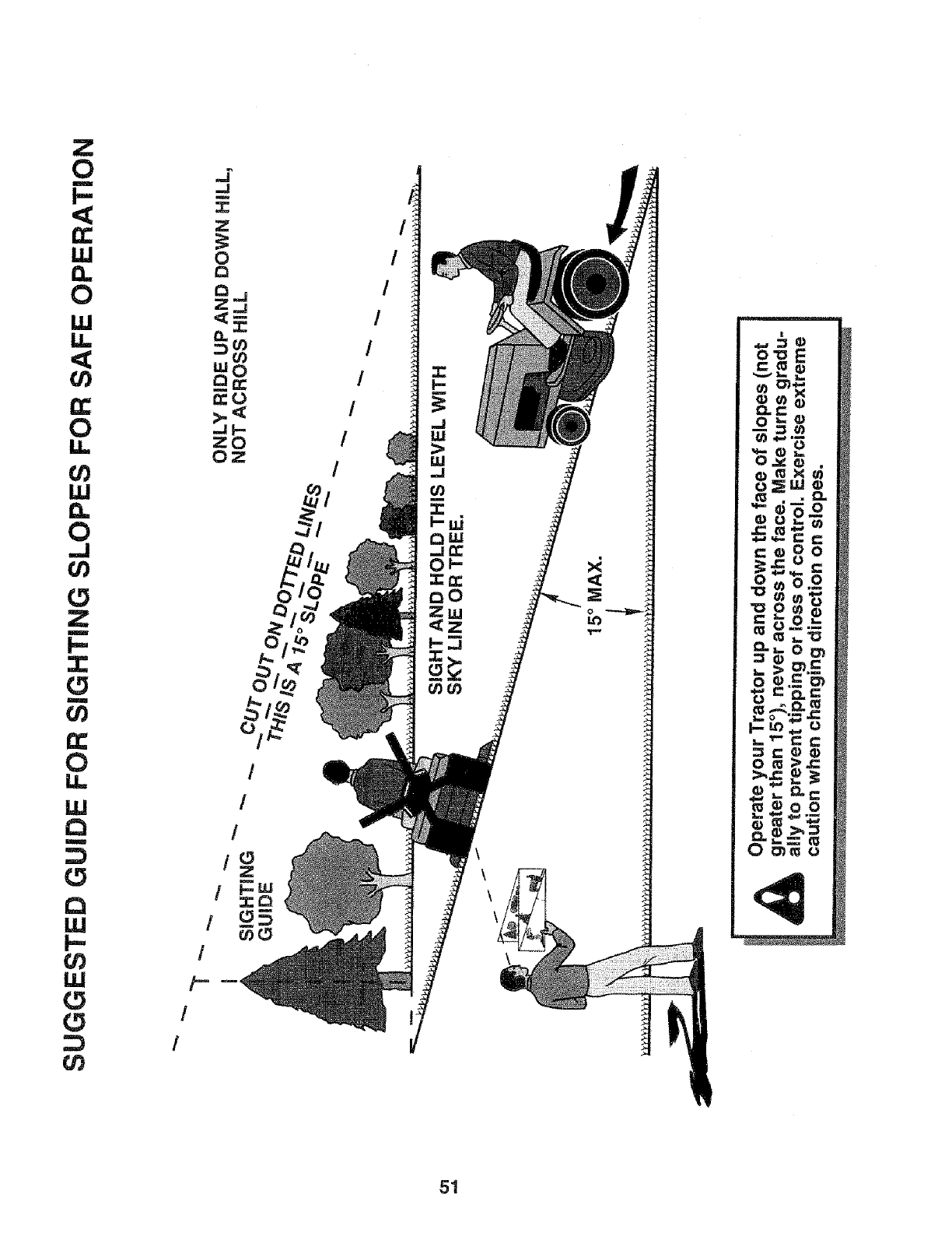
Z
O
LU
CL
O
LU
Li.
n-
O
0_
LU
13.
O
,-!
U)
O
Z
B
3:
O
LL
LU
{3
LU
t--
IJJ
O
J
..J
m
3Z
;Z
O
D.
COO
zO
/
/
/
/
/
/
/
1
1o
Z
oN
!
/
/
/
/
/
/
/!---
I.LI
>
o
LO
!
9__E
e_ e
{z=
Oh.e
_O_o
o 0_c'N
0 m _),,=:
UO'_m o
51
S/EA/,qS
OWNER'S
MANUAL
MODEL NO.
917.250051
HOW TO ORDER
REPAIR PARTS
20.0 HP TWIN CYLINDER
ELECTRIC START
6 SPEED TRANSAXLE
GARDEN TRACTOR
®
Each tractor has its own model number. Each engine has
its own model number.
The model number for your tractor will be found on the
model plate located under the seat.
The model number for your engine will be found on the
blower housing of the engine.
AIt parts listed herein may be ordered from any Sears,
Roebuck and Co. Service Center/Department and most
Retail Stores.
WHEN ORDERING REPAIR PARTS, ALWAYS GIVE THE
FOLLOWING INFORMATION:
•PRODUCT - GARDEN TRACTOR
, MODEL NUMBER- 917.250051
•ENGINE MODEL NO. -M20QS-49634
•PART NUMBER
°PART DESCRIPTION
Your Sears merchandise has added value when you
consider Sears has service units nationwide staffed with
Sears trained technicians.., professional technicians
specifically trained to insure that we meet our pledge to
you, we service what we sell.
139404 1.27.93 Printed in U.S.A.
II IIIIII IIIIIIIIIIIIIIIIIIIIII
