Craftsman 917254220 User Manual 36 RIDING LAWN TRACTOR Manuals And Guides L0707059
CRAFTSMAN Lawn, Tractor Manual L0707059 CRAFTSMAN Lawn, Tractor Owner's Manual, CRAFTSMAN Lawn, Tractor installation guides
User Manual: Craftsman 917254220 917254220 CRAFTSMAN 36 RIDING LAWN TRACTOR - Manuals and Guides View the owners manual for your CRAFTSMAN 36 RIDING LAWN TRACTOR #917254220. Home:Lawn & Garden Parts:Craftsman Parts:Craftsman 36 RIDING LAWN TRACTOR Manual
Open the PDF directly: View PDF ![]() .
.
Page Count: 48
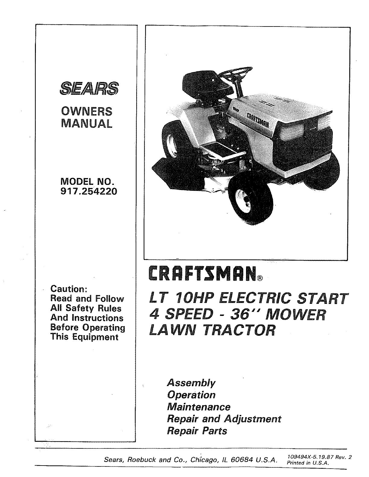
MODEL NO.
917.254220
Caution:
Read and Follow
All Safety Rules
And instructions
Before Operating
This Equipment
CRRFTSMRN®
I. T 10HP ELECTRIC START
4SPEED -36 "" MOWER
I..A CTOR
Assembly
Operation
Maintenance
Repair and Adjustment
Repair Parts
Sears, Roebuck and Co., i60684 109494x-5.19.87 Rev. 2
Ch cago, IL U.S.A. Printed in U,S.A.
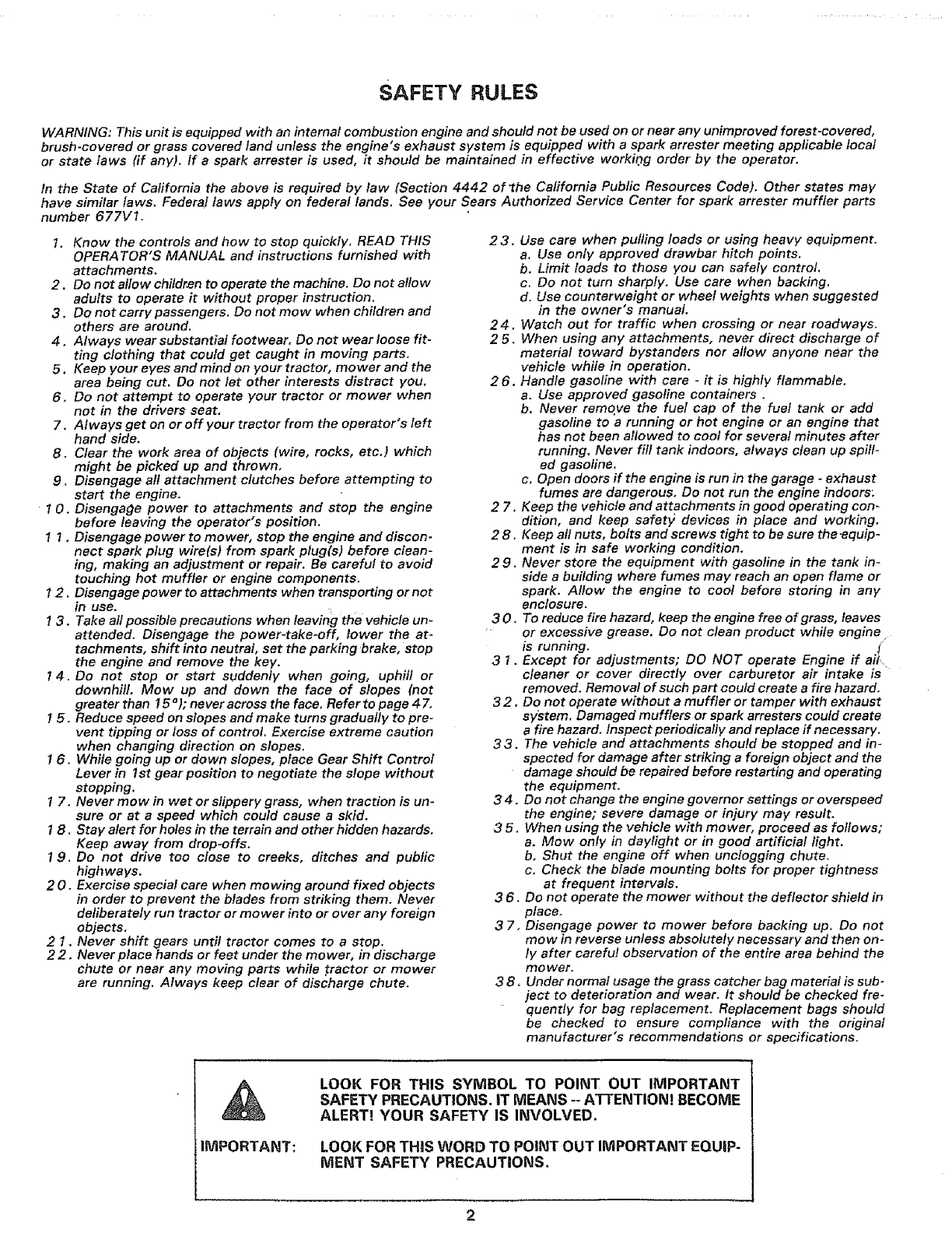
SAFETY RULES
WARNING: This unit is equipped with an internal combustion engine and should not be used on or near any unimproved forest-covered,
brush-covered or grass covered land unless the engine's exhaust system is equipped with a spark arrester meeting applicable local
or state laws fif any), If a spark arrester is used, it should be maintained in effective working order by the operator.
In the State of California the above is required by law (Section 4442 of"the Cafifornia Public Resources Code). Other states may
have similar laws. Federal laws apply on federal lands. See your Sears Authorized Service Center for spark arrester muffler parts
number 677V1.
1. Know the controls and how to stop quickly, READ THIS
OPERATOR'S MANUAL and instructions furnished with
attachments,
2. Do not allow children to operate the machine. Do not allow
adults to operate it without proper instruction.
3. Do not carry passengers. Do not mow when children and
others are around.
4, Always wear substantial footwear, Do not wear loose fit-
ting clothing that could get caught in moving parts,
5. Keep your eyes and mind on your tractor, mower and the
area being cut, Do not let other interests distract you.
6, Do not attempt to operate your tractor or mower when
not in the drivers seat.
7, Always get on or off your tractor from the operator's left
hand side,
8. Clear the work area of objects (wire, rocks, etc,) which
might be picked up and thrown,
9. Disengage aft attachment clutches before attempting to
start the engine.
10. Disengage power to attachments and stop the engine
before leaving the operator's position,
1 1. Disengage power to mower, stop the engine and discon-
nect spark plug wire(s) from spark plug(s) before clean-
ing, making an adjustment or repair. Be careful to avoid
touching hot muffler or engine components.
12. Disengage power to attachments when transporting or not
in use.
13. Take all possible precautions when leaving the vehicle un-
attended. Disengage the power-take-off, lower the at-
tachments, shift into neutral, set the parking brake, stop
the engine and remove the key.
14. Do not stop or start suddenly when going, uphill or
downhill. Mow up and down the face of slopes (not
greater than ! 5 o); never across the face, Refer to page 47,
15, Reduce speed on slopes and make turns gradually to pre-
vent tipping or loss of control. Exercise extreme caution
when changing direction on slopes,
16. While going up or down slopes, place Gear Shift Control
Lever in 1st gear position to negotiate the slope without
stopping.
1 7. Never mow in wet or slippery grass, when traction is un-
sure or at a speed which could cause a skid,
1 B. Stay alert for holes in the terrain and other hidden hazards.
Keep away from drop-offs.
19. Do not drive too close to creeks, ditches and public
highways.
20, Exercise special care when mowing around fixed objects
in order to prevent the blades from striking them. Never
deliberately run tractor or mower into or over any foreign
objects,
2 1, Never shift gears until tractor comes to a stop.
22, Never place hands or feet under the mower, in discharge
chute or near any moving parts while tractor or mower
are running. Always keep clear of discharge chute.
23. Use care when pulling loads or using heavy equipment.
a. Use only approved drawbar hitch points.
b. Limit loads to those you can safely control.
c. Do not turn sharply, Use care when backing.
d. Use counterweight or wheel weights when suggested
in the owner's manual.
24. Watch out for traffic when crossing or near roadways.
2 5, When using any attachments, never direct discharge of
material toward bystanders nor allow anyone near the
vehicle while in operation.
2 6. Handle gasoline with care -it is highly flammable.
a. Use approved gasoline containers.
b. Never remove the fuel cap of the fuel tank or add
gasoline to a running or hot engine or an engine that
has not been allowed to coot for several minutes after
running. Never fi/f tank indoors, always clean up spill-
ed gasoline.
c. Open doors if the engine is run in the garage -exhaust
fumes are dangerous_ Do not run the engine indoors;
27. Keep the vehicle and attachments in good operating con-
dillon, and keep safety devices in place and working.
2 8. Keep all nuts, bolts and screws tight to be sure the_quip-
ment is in safe working condition,
29. Never store the equipment with gasoline in the tank in-
side a building where fumes may reach an open flame or
spark. Allow the engine to cool before storing in any
enclosure,
30. To reduce fire hazard, keep the engine free of grass, leaves
•or excessive grease. Do not clean product while engine
is running, j"
3 1, Except for adjustments; DO NOT operate Engine if ati,
cleaner or cover directly over carburetor air intake is
removed. Removal of such part could create a fire hazard,
32. Do not operate without a muffler or tamper with exhaust
sy/stem. Damaged mufflers or spark arresters could create
a fire hazard. Inspect periodically and replace if necessary.
33. The vehicle and attachments should be stopped and in-
spected for damage after striking a foreign object and the
damage should be repaired before restarting and operating
the equipment.
34. Do not change the engine governor settings or overspeed
the engine; severe damage or injury may result.
3 5. When using the vehicle with mower, proceed as follows;
a. Mow only in daylight or in good artificial light.
b, Shut the engine off when unclogging chute.
c. Check the blade mounting bolts for proper tightness
at frequent intervals.
3 6. Do not operate the mower without the deflectorshield in
place,
3 7, Disengage power to mower before backing up. Do not
mow in reverse unless absolutely necessary and then on-
ly after careful observation of the entire area behind the
mo wer.
3 8, Under normal usage the grass catcher bag material is sub-
ject to deterioration and wear. It should be checked fre-
quently for bag replacement. Replacement bags should
be checked to ensure compliance with the original
manufacturer's recommendations or specifications,
IMPORTANT:
LOOK FOR THIS SYMBOL TO POINT OUT IMPORTANT
SAFETY PRECAUTIONS. IT MEANS --ATTENTION! BECOME
ALERT! YOUR SAFETY IS INVOLVED.
LOOK FOR THiS WORD TO POINT OUT IMPORTANT EQUiP-
MENT SAFETY PRECAUTIONS.
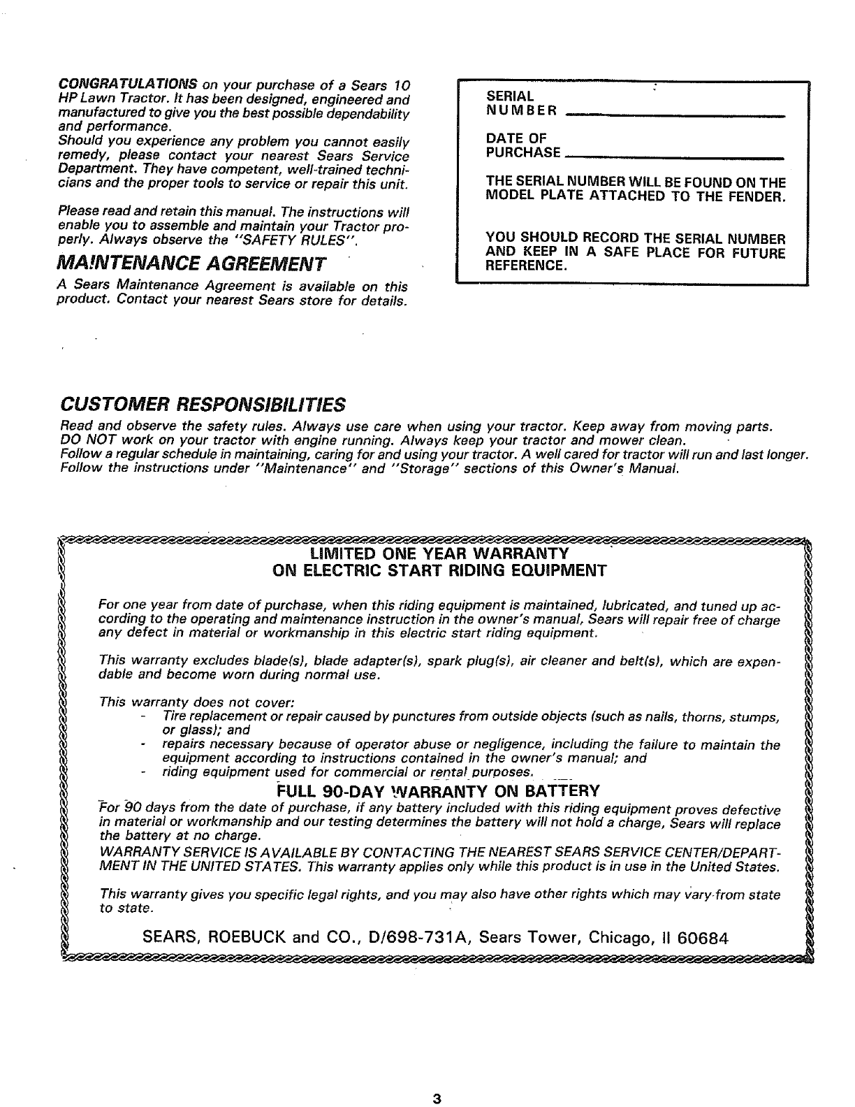
CONGRATULATIONS on your purchase of a Sears 10
HP Lawn Tractor. It has been designed, engineered and
manufactured to give you the best possible dependability
and performance.
Should you experience any problem you cannot easily
remedy, please contact your nearest Sears Service
Department. They have competent, weft-trained techni-
cians and the proper tools to service or repair this unit.
Please read and retain this manual. The instructions will
enable you to assemble and maintain your Tractor pro-
perly. Always observe the "'SAFETY RULES".
MA,gNTENANCE AGREEMENT
ASears Maintenance Agreement is available on this
product. Contact your nearest Sears store for details.
SERIAL
NUMBER
DATE OF
PURCHASE
THE SERIAL NUMBER WILL BE FOUND ON THE
MODEL PLATE ATTACHED TO THE FENDER.
YOU SHOULD RECORD THE SERIAL NUMBER
AND KEEP IN A SAFE PLACE FOR FUTURE
REFERENCE.
CUSTOMER RESPONSIBILITIES
Read and observe the safety rules. Always use care when using your tractor. Keep away from moving parts.
DO NOT work on your tractor with engine running. Always keep your tractor and mower clean.
Follow a regular schedule in maintaining, caring for and using your tractor. A well cared for tractor will run and last longer.
Follow the instructions under "'Maintenance" and "'Storage" sections of this Owner's Manual.
LIMITED ONE YEAR WARRANTY
ON ELECTRIC START RIDING EQUIPMENT
For one year from date of purchase, when this riding equipment is maintained, lubricated, and tuned up ac-
cording to the operating and maintenance instruction in the owner's manual, Sears will repair free of charge
any defect in material or workmanship in this electric start riding equipment.
This warranty excludes blade(s), blade adapter(s), spark plug(s), air cleaner and belt(s), which are expen-
dable and become worn during normal use.
This warranty does not cover:
Tire replacement or repair caused by punctures from outside objects (such as nails, thorns, stumps,
or glass); and
repairs necessary because of operator abuse or negligence, including the failure to maintain the
equipment according to instructions contained in the owner's manual; and
riding equipment used for commercial or r entalDurposes.
FULL 90-DAY WARRANTY ON BATTERY
-For 90 days from the date of purchase, if any battery included with this riding equipment proves defective
in material or workmanship and our testing determines the battery wil! not hold a charge, Sears will replace
the battery at no charge.
WARRANTY SERVICE IS AVAILABLE BY CONTACTING THE NEAREST SEARS SERVICE CENTER/DEPART-
MENT IN THE UNITED STATES. This warranty applies only while this product is in use in the United States.
This warranty gives you specific legal rights, and you may also have other rights which may vary.from state
to state.
SEARS, ROEBUCK and CO., D/698-731A, Sears Tower, Chicago, It 60684
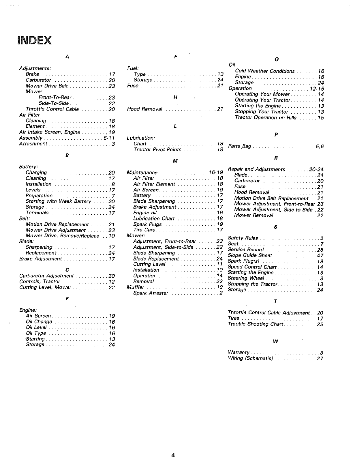
iNDEX
Adjustments:
Brake ..................... 17
Carburetor .................. 20
Mower Drive Belt ............. 23
Mower
Front-To-Rear ............ 23
Side- To-Side ............. 22
Throttle Control Cable ......... 20
Air Filter
Cleaning .................... 1B
Element ..................... 18
Air Intake Screen, Engine ........ 19
Assembly ................... 5-11
Attachment ................... 3
Battery:
Charging .................... 20
Cleaning .................... 17
Installation ................... 8
Levels ...................... 17
Preparation ................... 7
Starting with Weak Battery ..... 20
Storage ..................... 24
Terminals .................. 17
Belt:
Motion Drive Replacement ...... 21
Mower Drive Adjustment ....... 23
Mower Drive, Remove/Replace .. 10
Blade:
Sharpening ................. 17
Replacement ................ 24
Brake Adjustment ............... 17
C
Carburetor Adjustment ........... 20
Controls, Tractor ............... 12
Cutting Level, Mower ............ 22
Engine:
Air Screen .................... 19
Oil Change .................. 16
Oil Level .................... 16
Oil Type ................... 16
"Starting ..................... 13
Storage ..................... 24
Fuel:
Type ....................... !3
Storage ..................... 24
Fuse ......................... 21
H
Hood Removal ................. 21
Lubrication:
Chart .................... 18
Tractor Pivot Points ......... 18
M
Maintenance ................ !6-19
Air Filter .................... 18
Air Filter Element ............. 18
Air Screen ................... 19
Battery ..................... 17
Blade Sharpening ............. 17
Brake Adjustment ............. 17
Engine oil ................... 16
Lubrication Chart ............. 18
Spark Plugs ................. 19
Tire Care .................... 17
Mo wet:
Adjustment, Front-to-Rear ...... 23
Adjustment, Side -to-Side ....... 22
Blade Sharpening ............ 17
Blade Replacement ............ 24
Cutting Level ................ 11
Installation .................. 10
Operation ................... 14
Removal .................... 22
Muffler ....................... 19
Spark Arrester ................ 2
0
Oil
Cold Weather Conditions ....... 16
Engine ...................... 16
Storage ..................... 24
Operation ................... 12-15
Operating Your Mower ......... 14
Operating Your Tractor ......... 14
Starting the Engine ............ 13
Stopping Your Tractor ......... 13
Tractor Operation on Hills ...... 15
P
Parts .Bag ..................... 5, 6
R
Repair and Adjustments ....... 20-24
Blade ....................... 24
Carburetor .................. 20
Fuse ....................... 21
Hood Removal ............... 21
Motion Drive Belt Replacement .. 21
Mower Adjustment, Front-to-Rear 23
Mower Adjustment, Side-to-Side ,22
Mower Removal .............. 22
S
Safety Rules .................... 2
Seat .......................... 7
Service Record ................. 28
Slope Guide Sheet .............. 47
Spark Plugls) .................. 19
Speed Control Chart ............. 14
Starting the Engine .............. 13
Steering Wheel .................. 8
Stopping the Tractor ............. !3
Storage ....................... 24
T
Throttle Control Cable Adjustment., 20
Tires ......................... 17
Trouble Shooting Chart ........... 25
W
Warranty ....................... 3
Wiring (Schematic) .............. 27
4
Know Your Tractor ASSEMBL Y
READ THIS OWNER'S MANUAL BEFORE OPERATING YOUR LAWN TRACTOR. If you understand the machine and
its operation, you will achieve efficient and peak performance, While reading the manual, compare the illustrations with
your Lawn Tractor to familiarize yourself with the location of various controls and adjustments, Study the operating
instructions and safety precautions thoroughly to insure proper functioning of your Lawn Tractor and to prevent injury
to yourself and others. Be sure to pay strict attention to aft notes and cautions; they are included for your safety. Save
this manual for future reference.
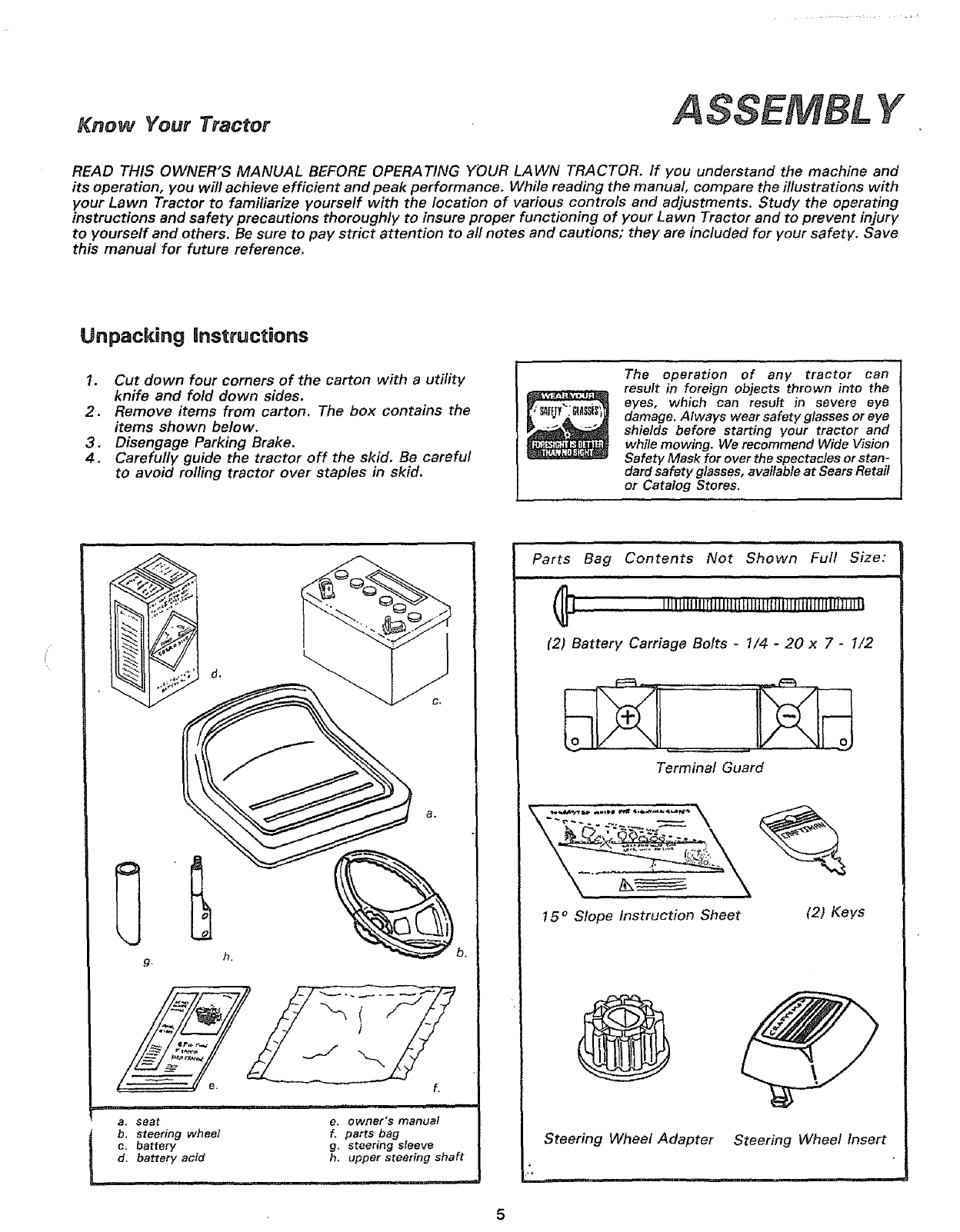
Unpacking instructions
1. Cut down four corners of the carton with a utility
knife and fold down sides.
2. Remove items from carton. The box contains the
items shown below.
3. Disengage Parking Brake.
4. Carefully guide the tractor off the skid. Be careful
to avoid rolling tractor over staples in skid.
The operation of any tractor can
result in foreign objects thrown into the
eyes, which can result in severe eye
damage. Always wear safety glasses or eye
shields before starting your tractor and
while mowing. We recommend Wide Vision
Safety Mask for ever the spectacles or stan-
dard safety glasses, available at Sears Retail
or Catalog Stores,
b.
e.
a. seat
b, steering wheel
c, battery
d, battery acid
i
i1,,i,i lU i1,1,1,, i j,,ll
e, owner's manual
f. parts bag
g. steering sleeve
h, upper steering shaft
Parts Bag Contents Not Shown Full Size:
,ll
..... IIlll'l"['t"tlllllIIIIII IIItl 1111111111I11IIIfi'i'_l'l'llll
(2) Battery Carriage Bolts -1/4 -20 x 7 -1/2
Terminal Guard
15 ° Slope Instruction Sheet (2) Keys
Steering Wheel Adapter Steering Wheel Insert
•ASSEMBL Y
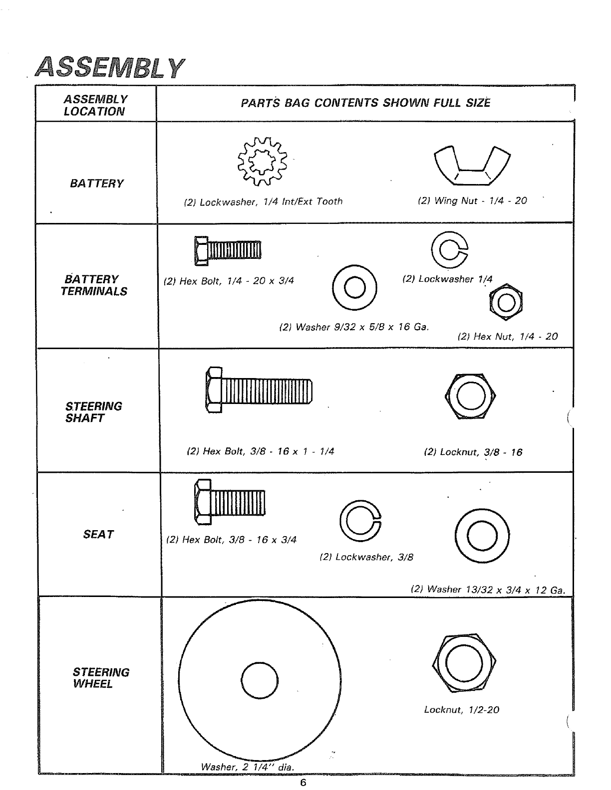
A SSEMBL Y
LOCA TION
BA TTERY
BATTERY
TERMINALS
STEERING
SHAFT
SEAT
STEERING
WHEEL
IF
PARTS BAG CONTENTS SHOWN FULL SIZE
i i i,ll m l ,Hll
(2) Lockwasher, 7/4 int/Ext Tooth (2} Wing Nut -1/4 -20
m
d
(2) Hex Bolt, 1/4 -20 x 3/4
©
(2) Lockwasher 1/4
(2) Washer 9/32 x 5/8 x 16 Ga,
_ i1111111t1111111111111}
(2) Hex Bolt, 3/8- 16 x 1 -1/4
,,,,,,, u u, ,,i,,,,,,.,,.,,
llillliliillL
L...
(2) Hex Bolt, 3/8 -16 x 3/4
(2) Hex Nut, 1/4 -20
,,, ,Ill m,,u, I,
(2) Locknut, 3/8 -!6
p,i
® G
(2) Lockwasher, 3/8
(2) Washer 13/32 x 3/4 x 12 Ga,
Locknut, 1/2-20
Washer, 2 1/4 d_a. " J
tt ,,_. • --
6
To assemble your tractor you will need:
t ___ (2) 7/16" wrenches Tire Pressure Gauge
(2) 9/16" wrenches Utility Knife
(1) 3/4" wrench
NOTE: RIGHT HAND (R.H.) AND LEFT HAND (L.H.) ARE
DETERMINED FROM OPERATOR'S POSITION WHILE
SEATED ON THE TRACTOR.
WEAR EYE AND FACE SHIELD,
WASH HANDS OR CLOTHING IM-
MEDIATELY IF ACCIDENTALLY IN
CONTACT WITH BATTERY ACID.
DO NOT SMOKE, FUMES FROM
CHARGED BATTERY ACID ARE
EXPLOSIVE.
READ THE INSTRUCTIONS INCLUD-
ED WITH THE BATTERY ACID CON-
TAINER. ALWAYS WEAR GLOVES,
CLOTHING AND GOGGLES TO PRO-
TECT YOUR HANDS, SKIN AND
EYES.
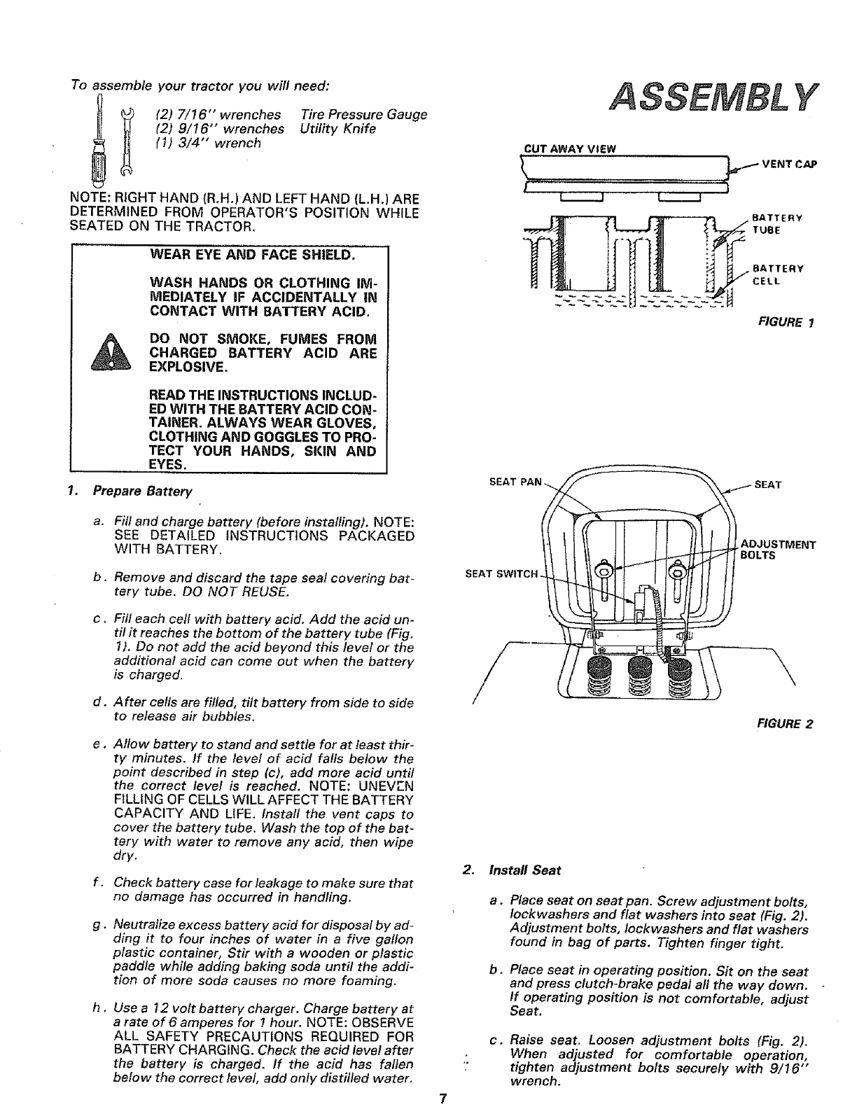
1. Prepare Battery SEAT
ASSEMBL Y
k__.___l
BATTERY
CELL
FIGURE I
a.
b.
Fill and charge battery (before installing). NOTE:
SEE DETAILED INSTRUCTIONS PACKAGED
WITH BATTERY.
Remove and discard the tape seal covering bat-
tery tube. DO NOT REUSE.
SEAT SWITCH
.ADJUSTMENT
BOLTS
C,
d.
e,
f.
g.
h,
Fill each cell wffh battery acid. Add the acid un-
til it reaches the bottom of the battery tube (Fig,
1). Do not add the acid beyond this level or the
additional acid can come out when the battery
is charged.
After cells are filled, tilt battery from side to side
to release air bubbles.
Allow battery to stand and settle for at least thir-
ty minutes. If the level of acid falls below the
point described in step (c), add more acid until
the correct level is reached. NOTE: UNEVEN
FILLING OF CELLS WILL AFFECT THE BATTERY
CAPACITY AND LIFE. instafl the vent caps to
cover the battery tube. Wash the top of the bat-
tery with water to remove any acid, then wipe
dry.
Check battery case for leakage to make sure that
no damage has occurred in handling.
Neutralize excess battery acid for disposal by ad-
ding it to four inches of water in a five gallon
plastic container, Stir with a wooden or plastic
paddle while adding baking soda until the addi-
tion of more soda causes no more foaming.
Use a 12 volt battery charger. Charge battery at
a rate of 6 amperes for I hour. NOTE: OBSERVE
ALL SAFETY PRECAUTIONS REQUIRED FOR
BATTERY CHARGING. Check the acid level after
the battery is charged. If the acid has fallen
below the correct level, add only distilled water.
2.
7
\
FIGURE 2
Install Seat
a.Place seat on seat pan. Screw adjustment bolts,
Iockwashers and flat washers into seat (Fig. 2).
Adjustment bolts, Iockwashers and flat washers
found in bag of parts. Tighten finger tight.
b. Place seat in operating position. Sit on the seat
and press clutch-brake pedal all the way down.
If operating position is not comfortable, adjust
Seat.
c. Raise seat. Loosen adjustment bolts (Fig. 2).
When adjusted for comfortable operation,
tighten adjustment bolts securely with 9/16""
wrench.
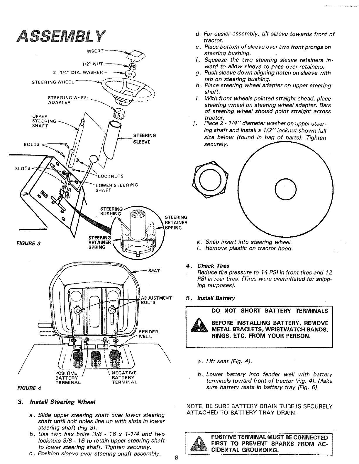
ASSEMBL Y
_NSE RT
1/2" NUT
2-1/4- OlA. WASHER
STEERING WHEEL
STEERING WHEEL_
UPPER ADAPTER ------_
STEERING
SHAFT
BOLTS
STEERING
SLEEVE
SLOTS
iTS
LOWER STEERING
SHAFT
FIGURE 3 STEERING
RETAINER
SPRING
STEERING
RETAINER
SPRING
d,
e_
f.
g.
j.
h.
i.
For easier assembly, tilt sleeve towards front of
tractor,
Place bottom of sleeve over two front prongs on
steering bushing.
Squeeze the two steering sleeve retainers in-
ward to allow sleeve to pass over retainers.
Push sleeve down aligning notch on sleeve with
tab on steering bushing.
Place steering wheel adapter on upper steering
shaft.
With front wheels pointed straight ahead, place
steering wheel on steering wheel adapter. Bars
of steering wheel should point straight across
tractor.
Place 2 -1/4" diameter washer on upper steer-
ing shaft and instafl a 1/2"" Iocknut shown furl
size below (found in bag of parts). Tighten
securely.
k. Snap insert into steering wheel.
I. Remove plastic on tractor hood.
ADJUSTMENT
BOLTS
FENDER
.... _ WELL
POSITIVE NEGATIVE
BATTERY BATTERY
TERMINAL TERMINAL
FIGURE 4
3. Install Steering Wheel
a. Slide upper steering shaft over lower steering
shaft until bolt holes line up with slots in lower
steering shaft (Fig 3).
b. Use two hex bolts 3/8 -16 x 1-1/4 and two
Iocknuts 3/8 -16 to retain upper steering shaft
to lower steering shaft. Tighten securely.
c. Position sleeve over steering shaft assembly.
4_ Check Tires
Reduce tire pressure to 14 PSI in front tires and 12
PSI in rear tires. (Tires were overinflated for shipp-
ing purposes).
5. Install Battery
DO NOT SHORT BATTERY TERMINALS
_i BEFORE INSTALLING BATTERY, REMOVE
METAL BRACLETS, WRISTWATCH BANDS,
RINGS, ETC. FROM YOUR PERSON.
a. Lift seat (Fig. 4).
b.. Lower battery into fender well with battery
terminals toward front of tractor (Fig, 4), Make
sure battery rests in battery tray (Fig. 6).
NOTE: BE SURE BATTERY DRAIN TUBE tS SECURELY
ATTACHED TO BATTERY TRAY DRAIN.
_POSITIVE TERMINAL MUST BECONNECTED
FIRST TO PREVENT SPARKS FROM AC-
CIDENTAL GROUNDING.
cASSEMBL Y
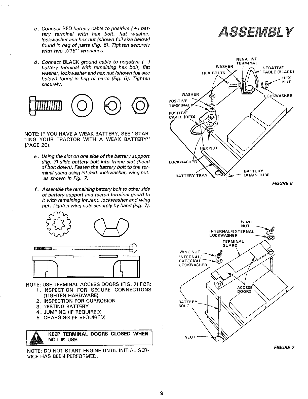
Connect RED battery cable to positive (+) bat-
tery terminal with hex bolt, flat washer,
Iockwasher and hex nut (shown full size below)
found in bag of parts (Fig. 6). Tighten securely
with two 7/16" wrenches.
d, Connect BLACK ground cable to negative (-)
battery terminal with remaining hex bolt, flat
washer, Iockwasher and hex nut (shown full size
below) found in bag of parts (Fig. 6). Tighten
securely.
NOTE: IF YOU HAVE A WEAK BATTERY, SEE "STAR-
TING YOUR TRACTOR WITH A WEAK BATTERY"
(PAGE 20).
e. Using the slot on one side of the battery support
(Fig. 7) slide battery bolt into frame slot (head
of bolt down). Fasten the battery bolt to the ter-
minal guard using int./ext. Iockwasher, wing nut.
as shown in Fig. 7.
Assemble the remaining battery bolt to other side
of battery support and fasten terminal guard to
it with remaining int./ext. Iockwasher and wing
nut. Tighten wing nuts securely by hand (Fig. 7).
NOTE: USE TERMINAL ACCESS DOORS (FIG. 7) FOR:
1. INSPECTION FOR SECURE CONNECTIONS
(TIGHTEN HARDWARE)
2. INSPECTION FOR CORROSION
3. TESTING BATTERY
4. JUMPING (IF REQUIRED)
5. CHARGING (IF REQUIRED)
I_ NoTKEEPTERMINAL DOORS CLOSED WHENIIN USE.
NOTE: DO NOT START ENGINE UNTIL INITIAL SER-
VICE HAS BEEN PERFORMED.
WASHER
/
POSITIVE
£ABLE (RED)
LOCK
HE
WASHER
NEGATIVE
TERMINAL
NEGATIVE
CABLE (BLACK)
.HEX
NUT
LOCKWASHER
BATTERY TRAY
I I
BATTERY
TUBE
FIGURE 6
WING
NUT _,_,,j_
INTERNAL/EXTERNAL _
LOCKWASHER _
TERMINAL
GUARD
WING NUT_.._,..._
INTERNAL/
EXTEI
LOCKWASHER
BATTERY
BOLT \
SLOT
FIGURE 7
A
ATTACHMENT_
CLUTCH LEVER...._._.
"DISENGAGED
.OS,T,O.__
FIGURE 8
Y
FIGURE 9
RETAINER LIFT
SPRING /BRACKET
TRUNNION
FIGURE 10
LIFT LEVER
LIFT
LEVER
CLUTCH PARALLEL RETAINER
ROD RETAINER LINK FRONT SPRINGS
SPRING AXLE
j
FRONT
H]NGE
PIN
HtNGE
PiN
CLUTCH
CLUTCH ...._ /\ j_"_,
SUSPENSION \
ARM RETAINER
SPRING
10
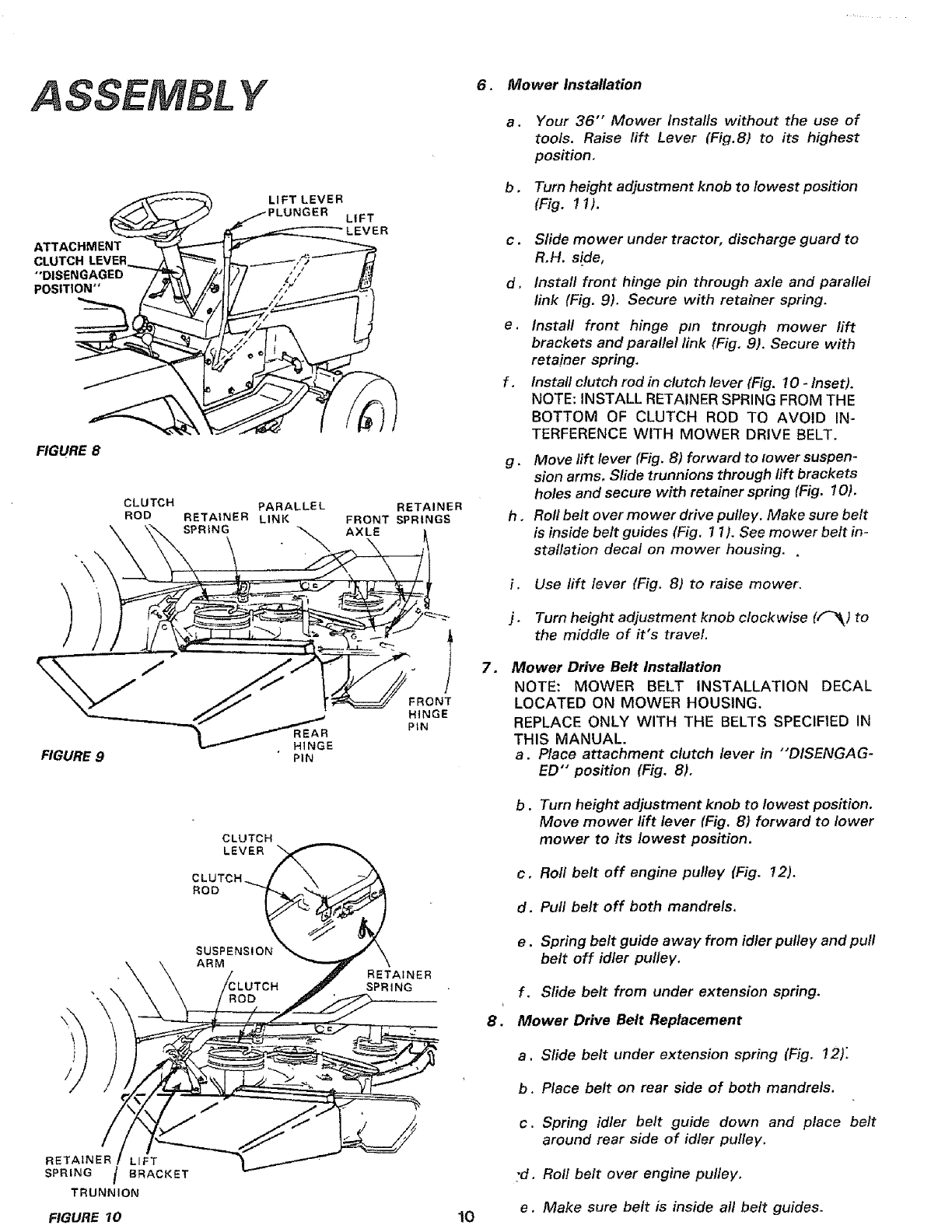
6. Mower Installation
a.
b.
Your 36" Mower Installs without the use of
tools. Raise lift Lever (Fig.8) to its highest
position,
Turn height adjustment knob to lowest position
(Fig. 11).
c. Sfide mower under tractor, discharge guard to
R,H. side,
d, Install front hinge pin through axle and parallel
link (Fig. 9). Secure with retainer spring.
e.
f,
Install front hinge pin through mower lift
brackets and parallel link (Fig. 9), Secure with
retainer spring,
Install clutch rod in clutch lever (Fig. 10 -Inset).
NOTE: INSTALL RETAINER SPRING FROM THE
BOTTOM OF CLUTCH ROD TO AVOID IN-
TERFERENCE WITH MOWER DRIVE BELT.
g.Move lift lever (Fig. 8) forward to lower suspen-
sion arms, Slide trunnions through rift brackets
holes and secure with retainer spring (Fig. I0).
h . Roll belt over mower drive pulley. Make sure belt
is inside belt guides (Fig, 11). See mower belt in-
stallation decal on mower housing..
i. Use lift lever (Fig. 81 to raise mower.
j. Turn height adjustment knob clockwise (f_k) to
the middle of it's travel,
=Mower Drive Belt Installation
NOTE: MOWER BELT INSTALLATION DECAL
LOCATED ON MOWER HOUSING,
REPLACE ONLY WITH THE BELTS SPECIFIED IN
THIS MANUAL.
a. Place attachment clutch lever in "'DISENGAG-
ED" position (Fig. 8),
b.Turn height adjustment knob to lowest position.
Move mower lift lever (Fig. 8) forward to lower
mower to its lowest position.
c, Roll belt off engine pulley (Fig. 12),
d. Pull belt off both mandrels,
e.Spring belt guide away from idler pulley and pull
belt off idler pulley.
f. Slide belt from under extension spring,
8. Mower Drive Belt Replacement
a. Slide belt under extension spring (Fig, 12):
b. Place belt on rear side of both mandrels.
c. Spring idler belt guide down and place belt
around rear side of idler pulley,
:d. Roll belt over engine pulley.
e. Make sure belt is inside all belt guides.
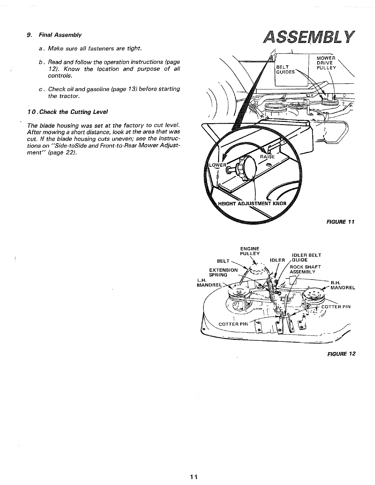
,Final Assembly
a, Make sure aft fasteners are tight.
b, Read and follow the operation instructions (page
12). Know the location and purpose of all
controls.
c . Check oil and gasoline (page 13) before starting
the tractor.
10. Check the Cutting Level
The blade housing was set at the factory to cut level.
After mowing a short distance, look at the area that was
cut, If the blade housing cuts uneven; see the instruc-
tions on "'Side-toSide and Front-to-Rear Mower Adjust-
ment" (page 22).
\
FIGURE 11
ENGINE
PULLEY
BELT _,_ _k__
EXTENSION
SPRING
L.H.
MANDREL
IDLER
IDLER BELT
GUIDE
K SHAFT
ASSEMBLY
R,H.
MANDREL
COTTER PiN
Y
'FIGURE 12
11
OPERA TION
KNOW YOUR TRACTOR
READ THIS OWNER'S MANUAL BEFORE OPERATING YOUR LAWN TRACTOR. If you understand the machine and
its operation, you will achieve efficient and peak performance. While reading the manual, compare the illustrations with
your Lawn Tractor to familiarize yourself with the location of various controls and adjustments. Study the operating
instructions and safety precautions thoroughly to insure proper functioning of your Lawn Tractor and to prevent injury
to yourself and others. Be sure to pay strict attention to all notes and cautions; they are included for your safety. Save
this manual for future reference.
Light
Throttle
Clutch/Brake Pedal
Height
Adjustment
Knob
Gear Shift Lever
Attachment
Lever
Lift Lever
Clutch
Parkmg Brake
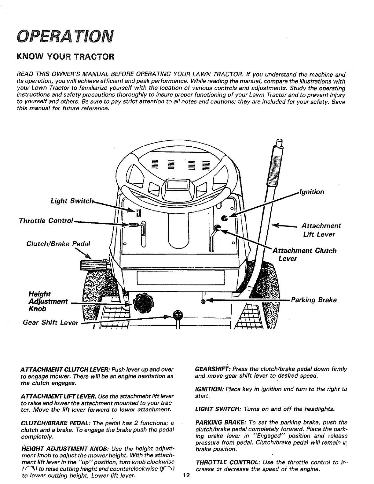
ATTACHMENT CLUTCH LEVER: Push lever up and over
to engage mower. There will be an engine hesitation as
the clutch engages.
ATTACHMENT LIFT LEVER: Use the attachmeht rift lever
to raise and lower the attachment mounted to your trac-
tor, Move the rift lever forward to lower attachment.
CLUTCH/BRAKE PEDAL: The pe'dal has 2 functions; a
clutch and a brake. To engage the brake push the pedal
completely.
HEIGHT ADJUSTMENT KNOB: Use the height adjust-
ment knob to adjust the mower height, With the attach-
ment lift lever in the "up" position, turn knob clockwise
( F-_k) to raise cutting height and counterclockwise (_)
to lower cutting height. Lower lift lever.
GEARSHIFT: Press the clutch/brake pedal down firmly
and move gear shift lever to desired speed.
IGNITION: Place key in Lgnition and turn to the right to
Start.
LIGHT SWITCH: Turns on and off the headlights,
PARKING BRAKE: To set the parking brake, push the
clutch/brake pedal completely forward. Place the park-
ing brake lever in "Engaged" position and release
pressure from pedal. Clutch/brake pedal will remain ir
brake position.
THROTTLE CONTROL: Use the throttle control to in-
crease or decrease the speed of the engine.
12
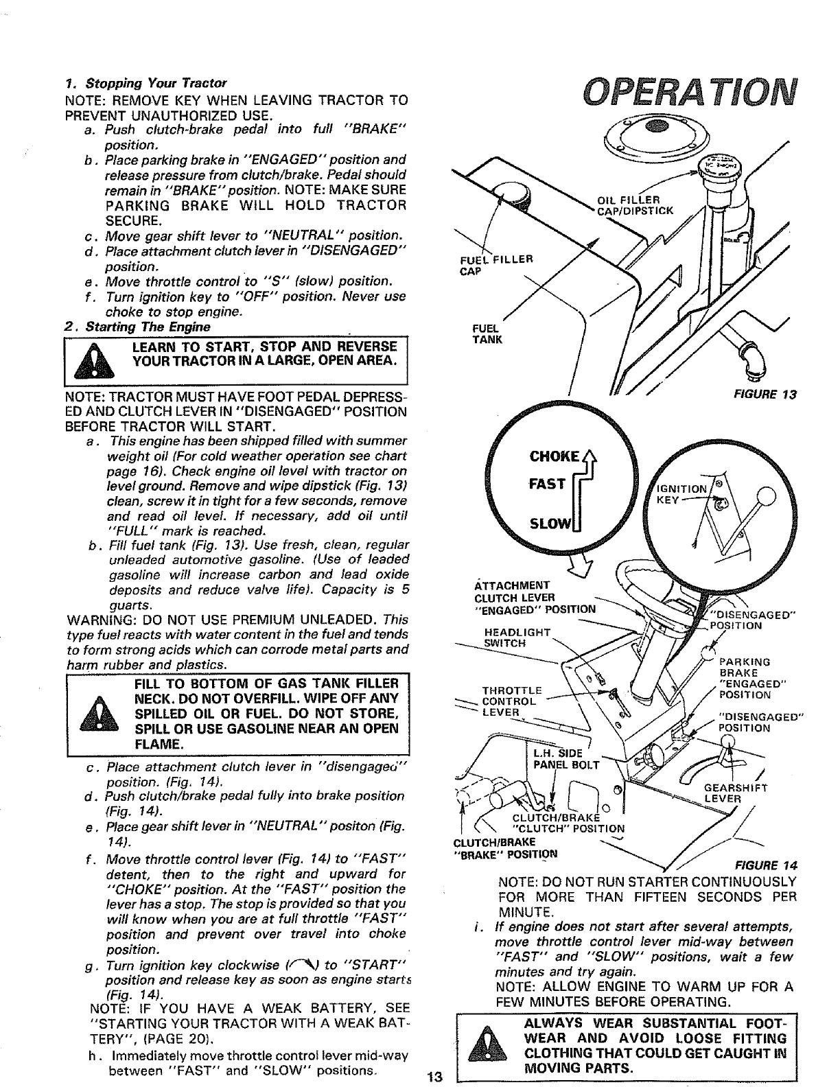
1. Stopping Your Tractor
NOTE: REMOVE KEY WHEN LEAVING TRACTOR TO
PREVENT UNAUTHORIZED USE.
a. Push clutch-brake pedal into full "BRAKE"
position,
b . Place parking brake in "'ENGAGED" position and
release pressure from clutch/brake. Pedal should
remain in "'BRAKE"position. NOTE: MAKE SURE
PARKING BRAKE WILL HOLD TRACTOR
SECURE.
c. Move gear shift lever to "'NEUTRAL'" position.
d, Place attachment clutch lever in "'DISENGAGED"
position,
e. Move throttle control to "S'" (slow) position.
f. Turn ignition key to "'OFF" position. Never use
choke to stop engine.
2. Starting The Engine
I_ LEARN TO START, STOP AND REVERSE J
H
YOUR TRACTOR IN A LARGE, OPEN AREA. I
NOTE: TRACTOR MUST HAVE FOOT PEDAL DEPRESS-
ED AND CLUTCH LEVER IN "DISENGAGED" POSITION
BEFORE TRACTOR WILL START.
a.This engine has been shipped filled with summer
weight oil (For cold weather operation see chart
page t6). Check engine off level with tractor on
/evel ground. Remove and wipe dipstick (Fig, 13)
clean, screw it in tight for a few seconds, remove
and read oil level. If necessary, add oil until
"FULL" mark is reached.
b. Fill fuel tank (Fig, 13). Use fresh, clean, regular
unleaded automotive gasoline. (Use of leaded
gasoline will increase carbon and lead oxide
deposits and reduce valve life). Capacity is 5
guarts.
WARNING: DO NOT USE PREMIUM UNLEADED. This
type fuel reacts with water content in the fuel and tends
to form strong acids which can corrode metal parts and
harm rubber and plastics.
FILL TO BOTTOM OF GAS TANK FILLER
NECK. DO NOT OVERFILL. WIPE OFF ANY
SPILLED OIL OR FUEL. DO NOT STORE,
SPILL OR USE GASOLINE NEAR AN OPEN
FLAME.
c. Place attachment clutch lever in "'disengaged'"
position. (Fig, 14).
d. Push clutch/brake pedal fully into brake position
(Fig. t4).
e. Place gear shift lever in "'NEUTRAL'" positon (Fig.
14),
f. Move throttle control lever (Fig. 14) to "'FAST"
detent, then to the right and upward for
•'CHOKE'" position. At the "FAST" position the
lever has a stop. The stop is provided so that you
will know when you are at full throttle "'FAST"
position and prevent over travel into choke
posfion,
g, Turn ignition key clockwise (F_k) tO "'START"
position and release key as soon as engine start_
(Fig. 14),
NOTE: IF YOU HAVE A WEAK BATTERY, SEE
"STARTING YOUR TRACTOR WITH A WEAK BAT-
TERY", (PAGE 20}.
h. Immediately move throttle control lever mid-way
between "FAST" and "SLOW" positions, 13
OPERA ON
FUEL FILLER
CAP
FUEL
TANK
FIGURE 13
LTi_A_G;D_vNETRoS|T!ON_
HEADLIGHT
SWI TCH "_
THROTTLE
CONTROL
/ILH. SIDE
,/ IPANELBOLT
.I I
I \ \"CLUTCH'* POSITION
CLUTCH/BRAKE
"BRAKE" POSITION FIGURE14
NOTE: DO NOT RUN STARTER CONTINUOUSLY
FOR MORE THAN FIFTEEN SECONDS PER
MINUTE.
i. If engine does not start after several attempts,
move throttle control lever mid-way between
"'FAST" and "SLOW" positions, wait a few
minutes and try again.
NOTE: ALLOW ENGINE TO WARM UP FOR A
FEW MINUTES BEFORE OPERATING.
ALWAYS WEAR SUBSTANTIAL FOOT-
AWEAR AND AVOID LOOSE FITTING
CLOTHING THAT COULD GET CAUGHT IN
MOVING PARTS.
OPERA TlOIV
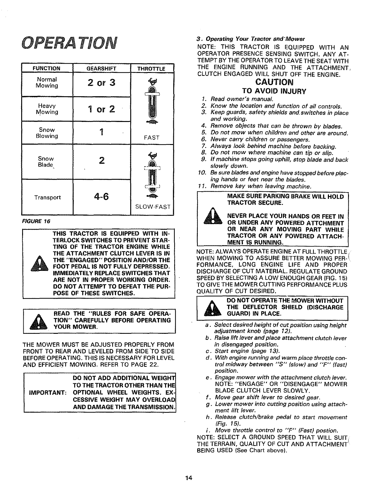
FUNCTION GEARSHIFT THROTTLE
=ill im ,,,,,,,,,,,ll
Normal
Mowing
Heavy
Mowing
Snow
Blowing
Snow
Blade.
Transport
2or3
1or2
2
4-6
FAST
SLOW-FAST
FIGURE 16
THIS TRACTOR IS EQUIPPED WITH IN-
TERLOCK SWITCHES TO PREVENT STAR-
TING OF THE TRACTOR ENGINE WHILE
THE ATTACHMENT CLUTCH LEVER IS IN
THE "ENGAGED" POSITION AND!OR THE
FOOT PEDAL IS NOT FULLY DEPRESSED.
IMMEDIATELY REPLACE SWITCHES THAT
ARE NOT IN PROPER WORKING ORDER.
DO NOT ATTEMPT TO DEFEAT THE PUR-
POSE OF THESE SWITCHES.
READ THE "RULES FOR SAFE OPERA-
TION'" CAREFULLY BEFORE OPERATING
YOUR MOWER.
THE MOWER MUST BE ADJUSTED PROPERLY FROM
FRONT TO REAR AND LEVELED FROM SIDE "TO SIDE
BEFORE OPERATING. THIS IS NECESSARY FOR LEVEL
AND EFFICIENT MOWING. REFER TO PAGE 22.
IMPORTANT:
DO NOT ADD ADDITIONAL WEIGHTI
TO THE TRACTOR OTHER THAN THEI
OPTIONAL WHEEL WEIGHTS. EX-_
CESSIVE WEIGHT MAY OVERLOAD I
AND DAMAGE THE TRANSMISS!ON. I
3, Operating Your Tractor and'Mower
NOTE: THIS TRACTOR IS EQUIPPED WITH AN
OPERATOR PRESENCE SENSING SWITCH. ANY AT=
TEMPT BY THE OPERATOR TO LEAVE THE SEAT WITH
THE ENGINE RUNNING AND THE ATTACHMENT,
CLUTCH ENGAGED WILL SHUT OFF THE ENGINE.
CAUTION
TO AVOID INJURY
1. Read owner's manual.
2, Know the location and function of all controls,
3. Keep guards, safety shields and switches in place
and working.
4. Remove objects that can be thrown by blades.
6. Do not mow when children and other are around,
6. Never carry children or passengers,
7. Always look behind machine before backing.
B. Do not mow where machine can tip or slip.
9. If machine stops going uphill, stop blade and back
slowly down.
10. Be sure blades and engine have stopped before Plac-
ing hands or feet near the blades.
I. Remove key when leaving machine,
MAKE SURE PARKING BRAKE WILL HOLD
TRACTOR SECURE.
NEVER PLACE HANDS OR FEET IN
YOUR
OR UNDER ANY POWERED ATTCHMENT
OR NEAR ANY MOVING PART WHILE
TRACTOR OR ANY POWERED ATTACH-
.........MENT IS RUNNING.
NOTE: ALWAYS OPERATE ENGINE AT FULLTHROTTLE
WHEN MOW NG TO ASSURE BETTER MOWING PER-t
FORMANCE, LONG ENGINE LIFE AND PROPER
DfSCHARGE OFCUT MATERIAL, REGULATE GROUND
SPEED BY SELECTING ALOW ENOUGH GEAR (FIG, 15)
TO GIVE THE MOWER CUTTING PERFORMANCE PLUS
QUALITY OF CUT DESIRED.
THE DEFLECTOR SHIELD (DISCHARGE
GUARD) IN PLACE.
a.Se/ect desired height of cut position using height
adjustment knob (page 12).
b. Raise lift lever and place attachment clutch lever
in disengaged position.
c. Start engine (page 13).
d, With engine running and warm place throttle con-
trol midway between "'S'" (slow) and "'F'" (fast)
position,
e. Engage mower with the attachment clutch lever.
NOTE: "ENGAGE" OR "'DISENGAGE" MOWER
BLADE CLUTCH LEVER SLOWLY.
f. Move gear shift lever to desired gear.
g, Lower mower into cutting position using attach-
ment rift lever.
h. Release clutch/brake pedal to start movement
(Fig. 15).
i. Move throttle control to "'F'" (Fast) postion.
NOTE: SELECT A GROUND SPEED THAT WILL SUIT
THE TERRAIN, QUALITY OF CUT AND ATTACHMENT
BEING USED (See Chart above).
14

4. Mowing Tips
NOTE: TIRE CHAINS CANNOT BE USED WITH THE
MOWER ATTACHED.
READ THE "SAFETY RULES" CAREFULLY
BEFORE OPERATING YOUR MOWER.
REFER TO PAGE 2.
a. Use the runner on the R.H. side as a guide; the blade
cuts approximately an inch outside the runner (Fig.
17).
b, Drive so that clippings are discharged onto the area
that has been cut, Have the cut area to the right of
the machine, This will result in a more even, distribu-
tion of clippings and more uniform cutting.
C. When mowing large areas (Fig. 18), start by turning
to the right so that the clippings will discharge away
from shrubs, fences, driveways, etc. After two or
three rounds, mow in the opposite direction making
left hand turns until finished.
d. if grass is extremely tall, it should be mowed twice.
The first time relatively high. The second time to the
desired height.
e. The left hand side of mower should be used for
trimming.
5, Operating The Tractor On Hills
a. Move gear shift lever to '" 1ST" gear before starting
up or down hills.
b. AVOID STOPPING OR SHIFTING ON HILLS.
c, If slowing is necessary, move throttle control lever
to slower position.
LEAVE ENOUGH ROOM WHEN STOP-
PING AND STARTING TO ALLOW SLIGHT
TRACTOR ROLL DOWNHILL AS CLUTCH-
BRAKEPEDAL MOVES THROUGH CLUTCH
POSITION.
d. If stopping is absolutely necessary, push clutch-brake
pedal quickly to brake position and engage parking
brake.
e. To restart tractor movement, make sure tractor is in
the lowest speed range (" 1ST'" Gear) and that you
have allowed room to roll slightly downhil!. Depress
clutch-brake fully. Disengaged parking brake and
release clutch-brake pedal SLOWLY to start tractor
movement.
f. Make all turns gradually.
HEIGHT
ADJUSTMENT
KNOB
OPERA TION
ATTACHMENT CLUTCH
LEVER "DISENGAGED"
POSITION ATTACHMENT CLUTCH
LEVER "ENGAGED"
POSITION
LIFT LEVER
LIFT
LEVER
RUNNER
GUARD
FIGURE 17
.
ii illl
FIGURE 18
6. Flip-Up Discharge Guard,
Your mower has a flip-up discharge guard (Fig. 17) for
door or gate clearance when held in raised position.
15
MAKE SURE ATTACHMENT CLUTCH
LEVER IS 1N "DISENGAGED" POSITION
AND BLADES HAVE STOPPED BEFORE
RAISING DISCHARGE GUARD (DEFLEC-
TOR). NEVER OPERATE MOWER
WITHOUT DISCHARGE GUARD IN
OpERATiNG POSITION,
INTENANCE First 2 Hours (Two Mowings)
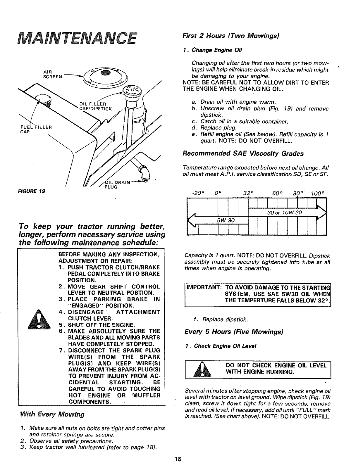
7, Change Engine Oil
AIR
SCREEN
Changing oil after the first two hours (or two mow-
ings) will help eliminate break-in residue which might
be damaging to your engine,
NOTE: BE CAREFUL NOT TO ALLOW DIRT TO ENTER
THE ENGINE WHEN CHANGING OIL.
a. Drain off with engine warm.
b. Unscrew oil drain plug (Fig. 19) and remove
dipstick.
c. Catch oil in a suitable container.
d. Replace plug,
e. Refill engine off (See below). Refill capacity is 1
quart. NOTE: DO NOT OVERFILL.
Recommended SAE Viscosity Grades
FIGURE 19
jOIL DRAIN
PLUG
To keep your tractor running better,
longer, perform necessary service using
the following maintenance schedule:
BEFORE MAKING ANY INSPECTION,
ADJUSTMENT OR REPAIR:
t. PUSH TRACTOR CLUTCH/BRAKE
PEDAL COMPLETELY INTO BRAKE
POSITION.
MOVE GEAR SHIFT CONTROL
LEVER TO NEUTRAL POSTION.
PLACE PARKING BRAKE IN
"ENGAGED" POSITION.
DISENGAGE " ATTACHMENT
CLUTCH LEVER,
SHUT OFF THE ENGINE.
MAKE ABSOLUTELY SURE THE
BLADES AND ALL MOVING PARTS
HAVE COMPLETELY STOPPED,
7. DISCONNECT THE SPARK PLUG
WIRE(S) FROM THE SPARK
PLUG(S) AND KEEP WIRE(S)
AWAY FROM THE SPARK PLUG(S)
TO PREVENT INJURY FROM AC-
CIDENTAL STARTING. BE
CAREFUL TO AVOID TOUCHING
HOT ENGINE OR MUFFLER
COMPONENTS.
,
3.
5.
6.
With Every Mowing
Temperature range expected before next oil change. All
oil must meet A.P.I. service classification SD, SE or SF.
.20 ° 0 ° 32 °t60 ° 80 °100 °
LJilL
30 or 10W-30 J
Capacity is 1 quart. NOTE: DO NOT OVERFILL. Dipstick
assembly must be securely tightened into tube at all
times when engine is operating.
iIMPORTANT: TO AVOID DAMAGE TO THE STARTING I
SYSTEM, USE SAE 5W30 OIL WHEN I
THE TEMPERTURE FALLS BELOW 32 °.t
f. Replace dipstick,
Every 5 Hours (Five Mowings)
1, Check Engine Oil Level
DO NOT CHECK ENGINE OIL LEVEL
WITH ENGINE RUNNING.
Several minutes after stopping engine, check engine oil
level with tractor on level ground, Wipe dipstick (Fig. 19)
clean, screw it down tight for a few seconds, remove
and read oil level. If necessary, add oil until "'FULL" mark
is reached. (See chart above), NOTE: DO NOT OVERFILL,
1. Make sure all nuts on bolts are tight and cotter pins
and retainer springs are secure,
2. Observe all safety precautions.
3. Keep tractor well lubricated (refer to page 18).
16
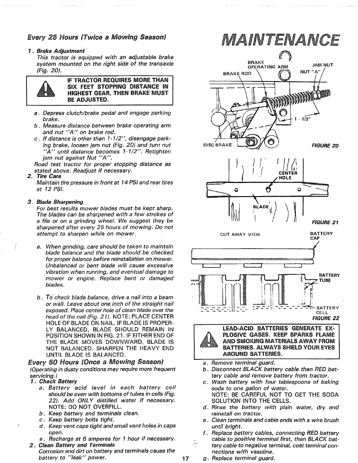
Every 25 Hours (Twice a Mowing Season)
I, Brake Adjustment
This tractor is equipped with an adjustable brake
system mounted on the right side of the transaxle
(Fig. 20).
IF TRACTOR REQUIRES MORE THAN
SIX FEET STOPPING DISTANCE IN
HIGHEST GEAR, THEN BRAKE MUST
BE ADJUSTED.
o
a. Depress clutch/brake pedal and engage parking
brake.
b. Measure distance between brake operating arm
and nut "A'" on brake rod.
c. tf distance is other than 1-1/2", disengage park-
ing brake, loosen jam nut (Fig. 20) and turn nut
"A'" until distance becomes 1-1/2"'. Retighten
jam nut against Nut "'A'.
Road test tractor for proper stopping distance as
stated above. Readjust if necessary.
Tire Care
Maintain tire pressure in front at 14 PSi and rear tires
at 12 PSI.
.Blade Sharpening
For best results mower blades must be kept sharp.
The blades can be sharpened with a few strokes of
afile or on a grinding wheel, We suggest they be
sharpened after every 25 hours of mowing. Do not
attempt to sharpen while on mower.
a. When grinding, care should be taken to maintain
blade balance and the blade should be checked
for proper balance before reinstallation on mower.
Unbalanced or bent blade will cause excessive
vibration when running, and eventual damage to
mower or engine, Replace bent or damaged
blades.
b, To check blade balance, drive a nail into a beam
or wall. Leave about one inch of the straight nail
exposed. Place center hole of clean blade over the
head of the nail (Fig. 21). NOTE: PLACE CENTER
HOLE OF BLADE ON NAIL. IF BLADE IS PROPER-
LY BALANCED, BLADE SHOULD REMAIN IN
POSITION SHOWN IN FIG, 21, IF EITHER END OF
THE BLADE MOVES DOWNWARD, BLADE IS
NOT BALANCED, SHARPEN THE HEAVY END
UNTIL BLADE IS BALANCED,
Every 50 Hours(Once a Mowing Season)
(Operating in dusty conditions may require more frequent
servicing. )
1. Check Battery
a. Battery acid level in each battery cell
should be even with bottoms of tubes in cells (Fig.
22). Add ONLY distilled water if necessary,
NOTE: DO NOT OVERFILL.
b. Keep battery and terminals clean,
c. Keep battery bolts tight.
d.Keep vent caps tight and small vent holes in caps
open.
e. Recharge at 6 amperes for 1 hour if necessary.
2. Clean Battery and Terminals
Corrosion and dirt on battery and terminals cause the
battery to "'leak'" power. 17
MAINTENANCE
BRAKE
OPERATING ARM JAM NUT
BRAKE ROD NUT "'A'"
DISC BRAKE FIGURE 20
I/ "OLE I
_'" I \
IFIGURE 21
CUT AWAY VIEW BATTERY
CAP
BATTERY
a.
b.
c.
d.
e.
f.
g_
LEAD-ACID BATTERIES GENERATE EX-
PLOSIVE GASES. KEEP SPARKS FLAME
AND SMOKING MATERIALS AWAY FROM
BATTERIES. ALWAYS SHSELD YOUR EYES
AROUND BATTERIES.
Remove terminal guard.
Disconnect BLACK battery cable then RED bat-
tery cable and remove battery from tractor.
Wash battery with four tablespoons of baking
soda to one gallon of water.
NOTE: BE CAREFUL NOT TO GET THE SODA
SOLUTION INTO THE CELLS.
Rinse the battery with plain water, dry and
reinstall on tractor.
Clean terminals and cable ends with a wire brush
until bright.
Replace battery cables, connecting RED battery
cable to positive terminal first, then BLACK bat-
tery cable to negative terminal, coat terminal con-
nections with vasoline.
Replace terminal guard.
MAINTENANCE
ENGINE OIL AIR CLEANE
FILLER CAP COVER
AND DIPSTICK
AIR
FOAM
ELEMENT
AIR
CLEANER
BODY
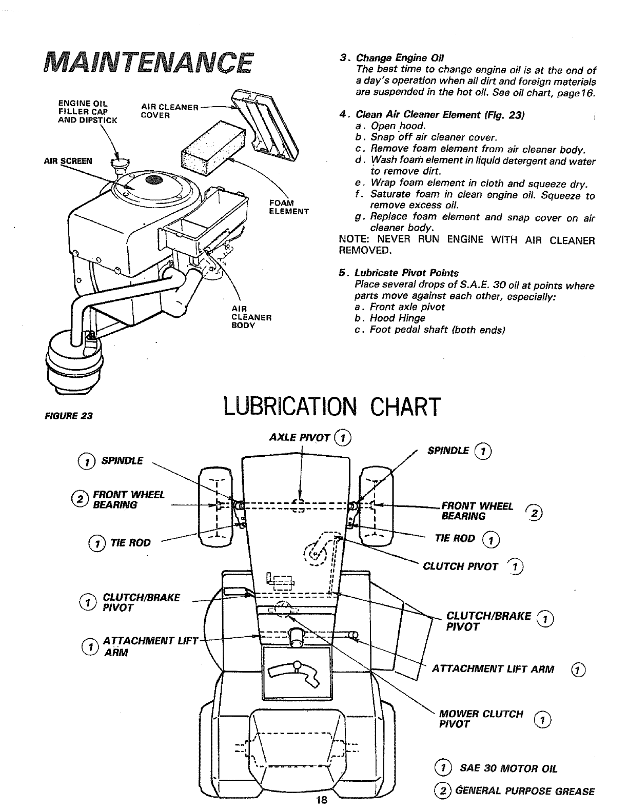
.Change Engine Oil
The best time to change engine oil is at the end of
a day's operation when all dirt and foreign materials
are suspended in the hot off. See oil chart, page 16.
4. Clean Air Cleaner Element (Fig. 23)
a, Open .hood.
b. Snap off air cleaner cover.
c, Remove foam element from air cleaner body.
d. Wash foam element in liquid detergent and water
to remove dirt.
e. Wrap foam element in cloth and squeeze dry.
f. Saturate foam in clean engine oil. Squeeze to
remove excess off.
g, Replace foam element and snap cover on air
cleaner body.
NOTE: NEVER RUN ENGINE WITH AIR CLEANER
REMOVED,
5. Lubricate Pivot Points
Place several drops of S.A.E. 30 oil at points where
parts move against each other, especially:
a. Front axle pivot
b. Hood Hinge
c. Foot pedal shaft (both ends)
FIGURE 23
_SPINDLE
LUBRICATION
AXLE PIVOT
CHART
SPINDLE
_FRONT WHEEL
BEARING
QTIE ROD
_CLUTCH/BRAKE
PIVOT
_ATTACHMENT
ARM
WHEEL
BEARING
TIE ROD
CLUTCH PIVOT
CLUTCH/BRAKE
PIVOT
ATTACHMENT LIFT ARM
MOWER CLUTCH
PIVOT
18
SAE 30 MOTOR OIL
_GENERAL PURPOSE GREASE
6. Clean Air Screen
Air screen (Fig. 23) must be kept free of dirt and chaff
to prevent engine damage from overheating.
7. Check Muffler
Inspect and replace damaged muffler as it could
create a fire hazard and/or damage.
DO NOT TOUCH HOT MUFFLER,
CYLINDER OR FINS AS CONTACT MAY
CAUSE BURNS.
Every 100 Hours (Every Two Years)
DISCONNECT SPARK PLUG WIRE(S) TO
PREVENT ACClDENTIAL STARTING
BEFORE MAKING ANY INSPECTION, AD-
JUSTMENT OR REPAIR (EXCEPT CAR-
BURETOR). BE CAREFUL TO AVOID
TOUCHING HOT ENGINE OR MUFFLER
COMPONENTS.
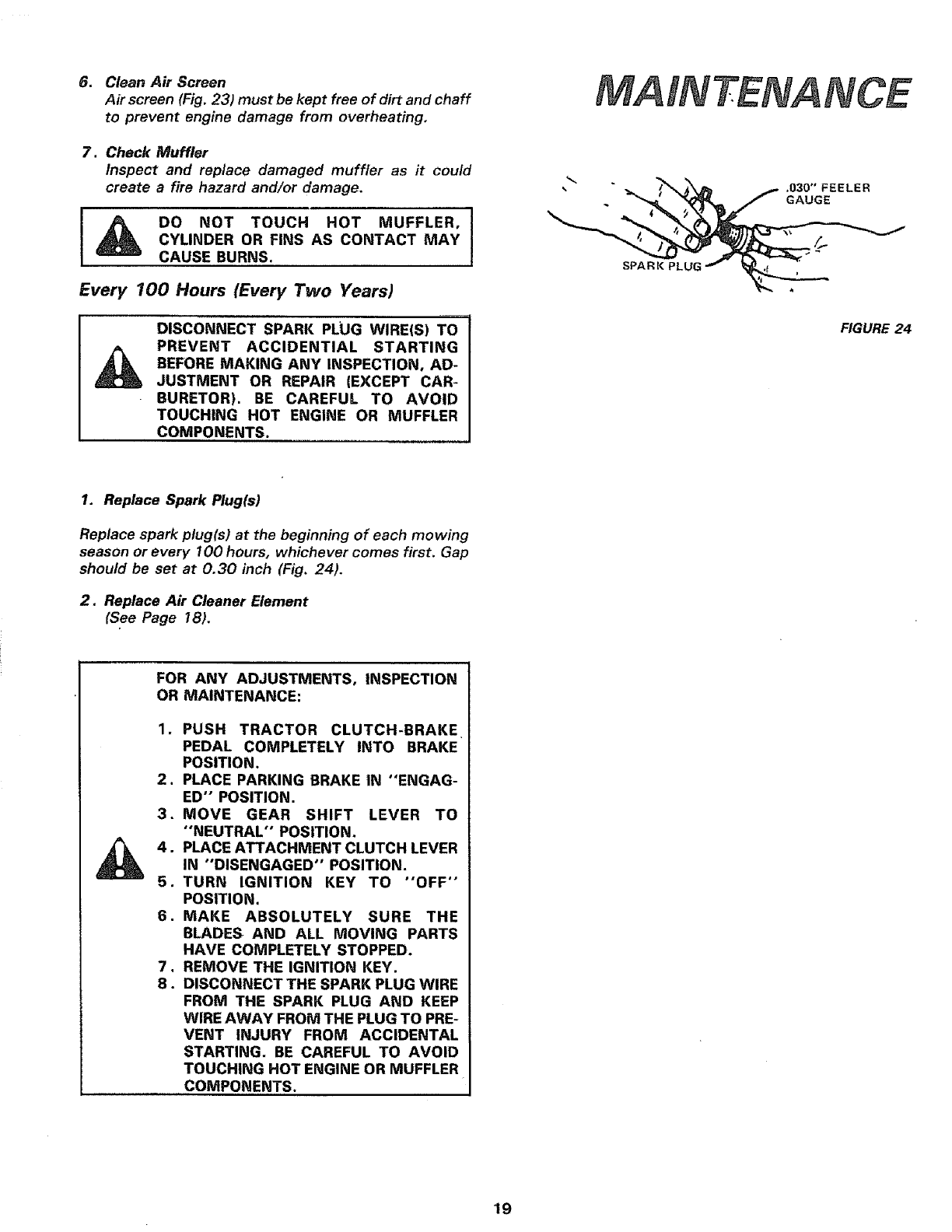
MAINTENANCE
,030" FEELER
GAUGE
SPARK
FIGURE 24
1. Replace Spark Plug(s)
Replace spark plug(s) at the beginning of each mowing
season or every 100 hours, whichever comes first. Gap
should be set at 0.30 inch (Fig. 24).
2. Replace Air Cleaner Element
(See Page 18).
FOR ANY ADJUSTMENTS, INSPECTION
OR MAINTENANCE:
1. PUSH TRACTOR CLUTCH-BRAKE
PEDAL COMPLETELY INTO BRAKE
POSITION.
2. PLACE PARKING BRAKE IN "ENGAG-
ED" POSITION.
3. MOVE GEAR SHIFT LEVER TO
"NEUTRAL" POSITION,
4. PLACE ATTACHMENT CLUTCH LEVER
IN "DISENGAGED" POSITION.
5. TURN IGNITION KEY TO "OFF'"
POSITION.
6. MAKE ABSOLUTELY SURE THE
BLADES AND ALL MOVING PARTS
HAVE COMPLETELY STOPPED.
7, REMOVE THE IGNITION KEY,
8. DISCONNECT THE SPARK PLUG WIRE
FROM THE SPARK PLUG AND KEEP
WIRE AWAY FROM THE PLUG TO PRE-
VENT INJURY FROM ACCIDENTAL
STARTING. BE CAREFUL TO AVOID
TOUCHING HOT ENGINE OR MUFFLER
COMPONENTS.
19
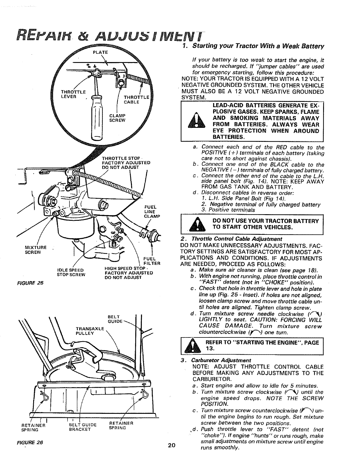
MIXTURE
SCREW
FIGURE 25
IDLE SPEED
STOP SCREW
RETAINER
SPRING
FIGURE 26
AUJU i M Ni
7. Starting your Tractor With a Weak Battery
TRANSAXLE
PULLEY
BELT GUIDE
BRACKET
THROTTLE STOP
FACTORY ADJUSTED
DO NOT ADJUST
FUEL
LINE
CLAMP
FUEL
FILTER
HIGH SPEED STOP -
FACTORY ADJUSTED
DO NOT ADJUST
BELT
RETAINER
SPRING
2O
if your battery is too weak to start the engine, it
should be recharged. If "jumper cables" are used
for emergency starting, follow this procedure:
NOTE: YOUR TRACTOR IS EQUIPPED WITH A 12 VOLT
NEGATIVE GROUNDED SYSTEM. THE OTHER VEHICLE
MUST ALSO BE A 12 VOLT NEGATIVE GROUNDED
SYSTEM,
LEAD-ACID BATTERIES GENERATE EX- j
PLOSIVE GASES. KEEP SPARKS, FLAME J
AND SMOKING MATERIALS AWAY
FROM BATTERIES. ALWAYS WEAR
EYE PROTECTION WHEN AROUND
BATTERIES,
a. Connect each end of the RED cable to the
POSITIVE (+) terminals of each battery (taking
care not to short against chassis).
b. Connect one end of the BLACK cable to the
NEGATtVE (-) terminals of fully charged battery.
c. Connect the other end of the cable to the L.H.
side panel bolt (Fig. 14). NOTE: KEEP AWAY
FROM GAS TANK AND BATTERY.
d, Disconnect cables in reverse order:
1. L,H. Side Panel Bolt (Fig 14).
2. Negative terminal of fufly charged battery
3. Posit[re terminals
iA oo.o,os oo. 1
•TO START OTHER VEHICLES.
2. Throttle Control Cable Adjustment
DO NOT MAKE UNNECESSARY ADJUSTMENTS. FAC-
TORY SETTINGS ARE SATISFACTORY FOR MOST AP-
PLICATIONS AND CONDITIONS. IF ADJUSTMENTS
ARE NEEDED, PROCEED AS FOLLOWS:
aoMake sure air cleaner is clean (see page 18).
b. With engine not running, place throttle control in
"FAST" detent (not in "'CHOKE" position).
c . Check that hole in throttle lever and hole in plate
line up (Fig. 25 -Inset). If holes are not aligned,
loosen clamp screw and move throttle cable un-
til holes are aligned. Tighten clamp screw.
d. Turn mixture screw needle clockwise (F_)
LIGHTLY to seat, CAUTION: FORCING WILL
CAUSE DAMAGE. Turn mixture screw
clounterclockwise (_) one turn,
IAI
3. Carburetor Adjustment
NOTE: ADJUST THROTTLE CONTROL CABLE
BEFORE MAKING ANY ADJUSTMENTS TO THE
CARBURETOR.
a. Start engine and allow to idle for 5 minutes.
b. Turn mixture screw clockwise (F_ until the
engine speed drops. NOTE THE SCREW
POSITION.
c. Turn mixture screw counterclockwise (jf-_) un-
til the engine begins to run rough. Set mixture
screw between the two positions.
_d. Push throttle lever to "'FAST" detent (not
"'choke"). If engine "'hunts" or runs rough, make
small adjustments on mixture screw until engine
runs smoothly.
e. If engine idles too fast or too slow, adjust idle
with idle speed stop screw.
f . High speed is factory adjusted. DO NOT ADJUST
DAMAGE MAY RESULT.
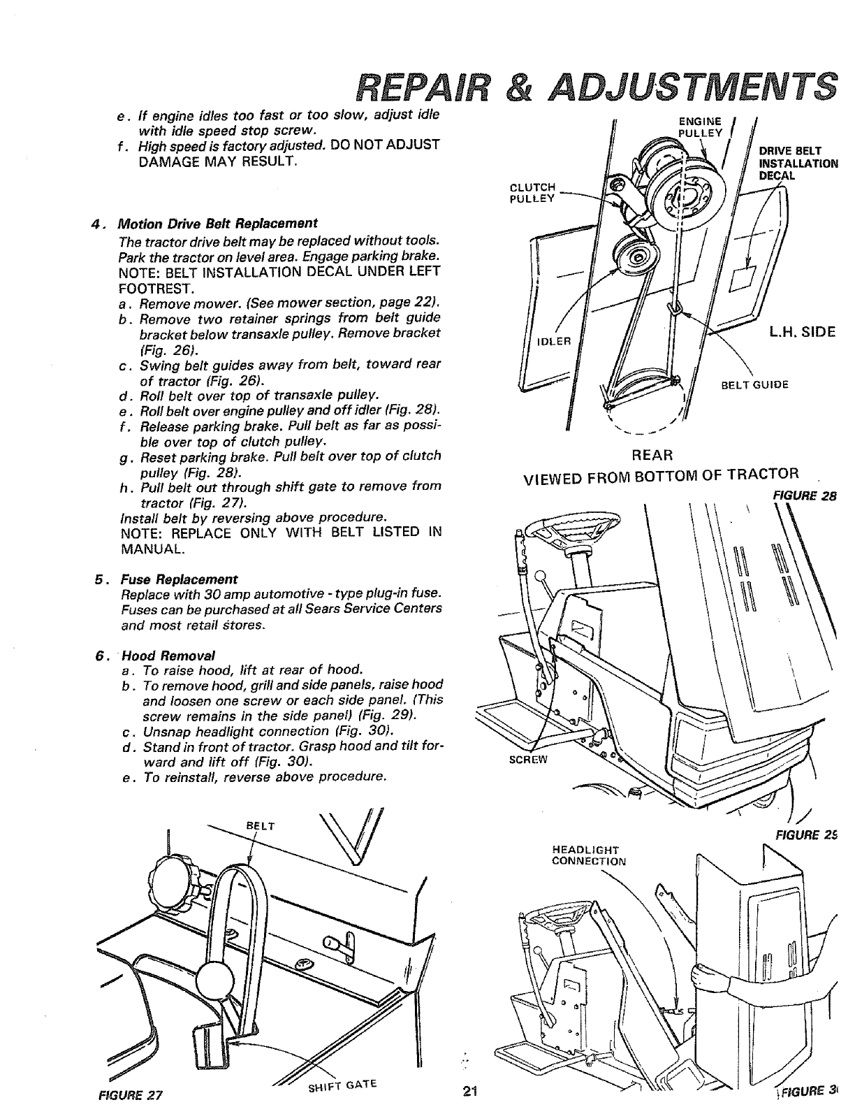
,Motion Drive Belt Replacement
The tractor drive belt may be replaced without tools.
Park the tractor on level area, Engage parking brake.
NOTE: BELT INSTALLATION DECAL UNDER LEFT
FOOTREST.
a. Remove mower. (See mower section, page 22).
b. Remove two retainer springs from belt guide
bracket below transaxle pulley. Remove bracket
(Fig. 26).
c. Swing belt guides away from belt, toward rear
of tractor (Fig. 26).
d. Roll belt over top of transaxle pulley.
e, Roll beit over engine pul/ey and off idler (Fig. 28).
f . Release parking brake. Pull belt as far as possi-
ble over top of clutch pulley.
g. Reset parking brake. Pull belt over top of clutch
pulley (Fig. 28).
h. Pull belt out through shift gate to remove from
tractor (Fig. 27).
Install belt by reversing above procedure.
NOTE: REPLACE ONLY WITH BELT LISTED IN
MANUAL.
5, Fuse Replacement
Replace with 30 amp automotive -type plug-in fuse.
Fuses can be purchased at all Sears Service Centers
and most retail stores,
6. Hood Removal
a. To raise hood, lift at rear of hood.
b.To remove hood, grill and side panels, raise hood
and loosen one screw or each side panel. (This
screw remains in the side panel) (Fig. 29).
c. Unsnap headlight connection (Fig. 30).
d. Stand in front of tractor. Grasp hood and tilt for-
ward and lift off (Fig. 30).
e. To reinstall, reverse above procedure.
BELT
FIGURE 27 sHIFT GATE 21
ADJUSTMENTS
ENGINE
PULLEY /
DRIVE BELT
INSTALLATION
DECAL
CLUTCH
PULLEY
L.H, SIDE
BELT GUIDE
REAR
VIEWED FROM BOTTOM OF TRACTOR
FIGURE 28
\
\\
SCREW
/
FIGURE 2_
HEADLIGHT
CONNECTION
REPAIR & ADJUSTMENT
REAR
SUSPENSION
TRUNNIONS
FIGURE 31
R.H.
SUSPENSION
RETAINER ARM
SPRING
LIFT
BRACKET
RETAINER
HINGE
PENS
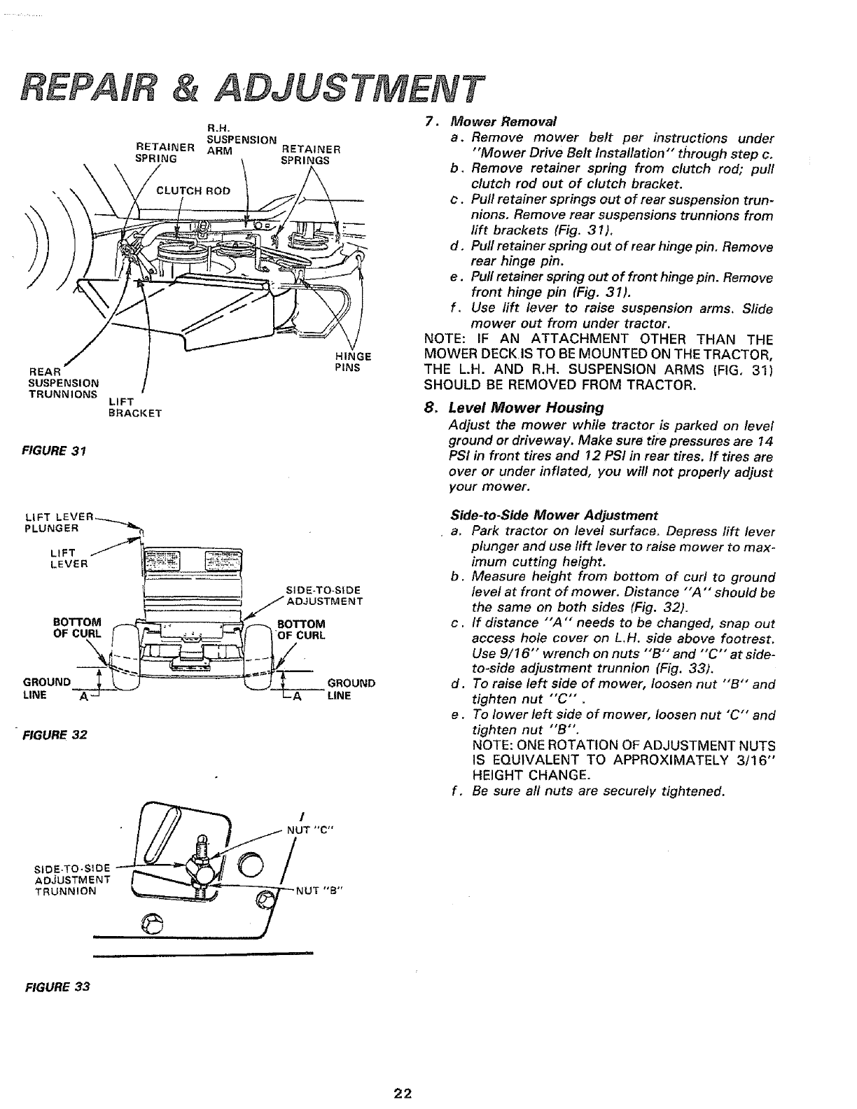
7. Mower Removal
a. Remove mower belt per instructions under
"Mower Drive Belt Installation'" through step c.
b+ Remove retainer spring from clutch rod; pull
clutch rod out of clutch bracket.
c. Pull retainer springs out of rear suspension trun-
nions, Remove rear suspensions trunnions from
rift brackets (Fig. 31).
d, Pull retainer spring out of rear hinge pin. Remove
rear hinge pin.
e. Pull retainer spring out of front hinge pin, Remove
front hinge pin (Fig. 3 I).
f. Use lift lever to raise suspension arms. Slide
mower out from under tractor.
NOTE: IF AN ATTACHMENT OTHER THAN THE
MOWER DECK IS TO BE MOUNTED ON THE TRACTOR,
THE L.H. AND R.H. SUSPENSION ARMS {FIG, 31)
SHOULD BE REMOVED FROM TRACTOR.
8. Level Mower Housing
Adjust the mower while tractor is parked on level
ground or driveway. Make sure tire pressures are 14
PSl in front tires and 12 PSI in rear tires, If tires are
over or under inflated, you will not properly adjust
your mower.
LIFT LE VE R ._..._
PLUNGER
LIFT
LEVER
BOTTOM
OF CURL l
GROUND _""
LINE
SIDE-TO-SIDE
.J ADJUSTMENT
FIGURE 32
TRUNNION _==_=_-- _7--- NUT "B '
Side-to-Side Mower Adjustment
a. Park tractor on level surface. Depress lift lever
plunger and use lift lever to raise mower to max-
imum cutting height.
b. Measure height from bottom of curl to ground
level at front of mower. Distance "'A "' should be
the same on both sides (Fig. 32).
c. If distance "'A "" needs to be changed, snap out
access hole cover on L.H. side above footrest.
Use 9/16"" wrench on nuts "'B'" and "'C'" at side-
to-side adjustment trunnion (Fig. 33).
d. To raise left side of mower, loosen nut "'B'" and
tighten nut "'C'",
e. To lower left side of mower, loosen nut "C'" and
tighten nut "B".
NOTE: ONE ROTATION OF ADJUSTMENT NUTS
IS EQUIVALENT TO APPROXIMATELY 3/16"
HEIGHT CHANGE.
f. Be sure all nuts are securely tightened.
FIGURE 33
22
REPAIR
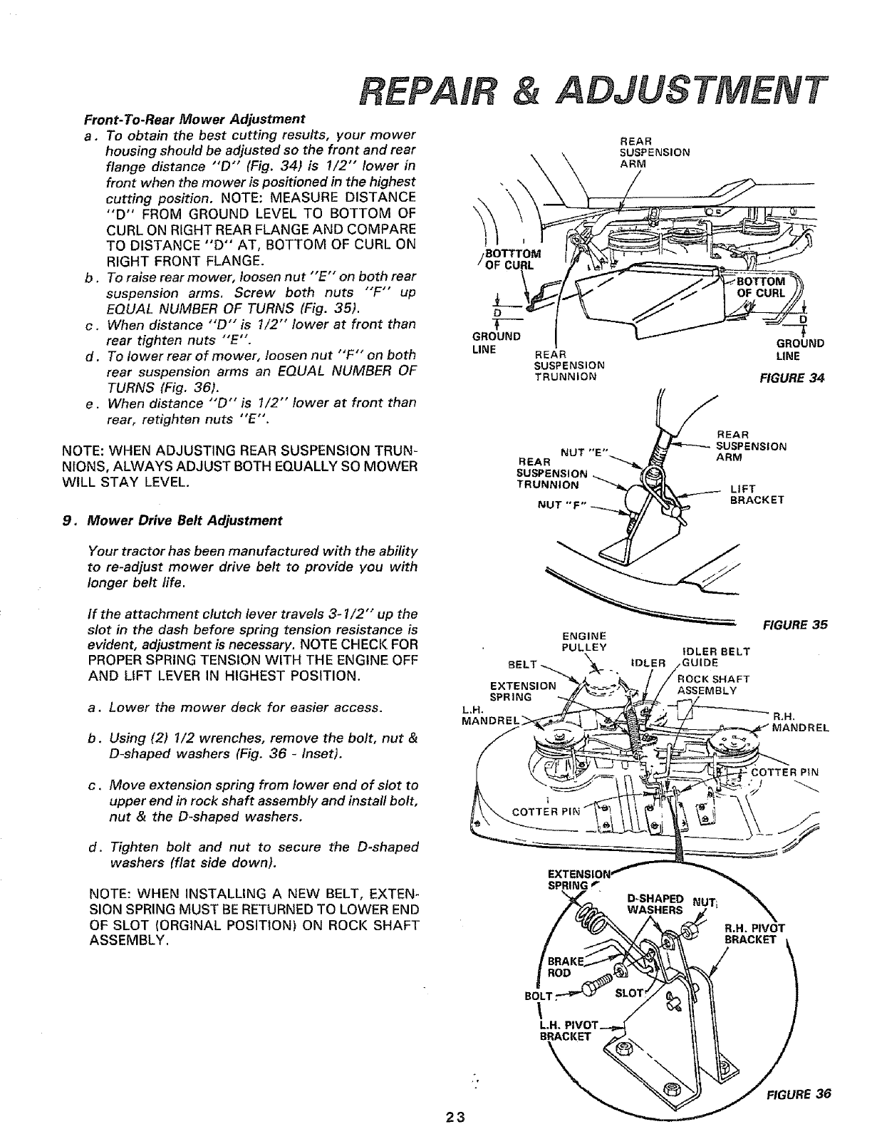
Front-To-Rear Mower Adjustment
a. To obtain the best cutting results, your mower
housing should be adjusted so the front and rear
flange distance "'D" (Fig. 34) is 1/2" lower in
front when the mower is positioned in the highest
cutting position. NOTE: MEASURE DISTANCE
"D" FROM GROUND LEVEL TO BOTTOM OF
CURL ON RIGHT REAR FLANGE AND COMPARE
TO DISTANCE "D" AT, BOTTOM OF CURL ON
RIGHT FRONT FLANGE.
b.To raise rear mower, loosen nut "'E'" on both rear
suspension arms. Screw both nuts "'F" up
EQUAL NUMBER OF TURNS (Fig. 35).
c. When distance "'D'" is 1/2" lower at front than
rear tighten nuts "'E".
d. To lower rear of mower, loosen nut "'F'" on both
rear suspension arms an EQUAL NUMBER OF
TURNS (Fig. 36).
e. When distance "D" is 1/2" lower at front than
rear, retighten nuts "E'.
NOTE: WHEN ADJUSTING REAR SUSPENSION TRUN-
NIONS, ALWAYS ADJUST BOTH EQUALLY SO MOWER
WILL STAY LEVEL.
9. Mower Drive Belt Adjustment
Your tractor has been manufactured with the ability
to re-adjust mower drive belt to provide you with
longer belt life.
&ADJUSTMENT
REAR
SUSPENSION
ARM
J
BOTTTOM
OF CURL
D
T--'-
GROUND
LINE REAR
SUSPENSION
TRUNNION
D
GROUND
LINE
FIGURE 34
_P'_!R E A R
NUT "F" -_//_ BRACKET
3/ J-
If the attachment clutch lever travels 3- I/2" up the
slot in the dash before spring tension resistance is
evident, adjustment is necessary. NOTE CHECK FOR
PROPER SPRING TENSION WITH THE ENGINE OFF
AND LIFT LEVER IN HIGHEST POSITION.
a, Lower the mower deck for easier access.
b. Using (2) I/2 wrenches, remove the bolt, nut &
D-shaped washers (Fig. 36 -Inset).
c. Move extension spring from lower end of slot to
upper end in rock shaft assembly and install bolt,
nut & the D-shaped washers,
EXTENSION
SPRING
L.H.
MANDREL
ENGINE
PULLEY iDLER BELT
IDLER ;GUIDE
;HAFT
ASSEMBLY
FIGURE 35
R.N.
MANDREL
d, Tighten bolt and nut to secure the D-shaped
washers (flat side down).
NOTE: WHEN INSTALLING A NEW BELT, EXTEN-
SION SPRING MUST BERETURNED TO LOWER END
OF SLOT (ORGINAL POSITION) ON ROCK SHAFT
ASSEMBLY.
SPRING r
\
R.H. PIVOT
BRACKET
BOLT,
\L.H,
BRACKET
23
FIGURE 36
REPAIR &ADJUSTMENT
11. Storage
Remove mower from tractor for winter storage. When
mower is to be stored for a period of time, clean it
thoroughly, remove all dirt, grease, leaves, etc. Give
blades and underside of housing a good coat of grease
MANDREL or rust preventative. Store in a clean dry area.
ASSEMBLY A. Fuel System
FLANGES
I
BLADE
WASHE
LOCKWASHER
HEX BOLT GR, 5
FIGURE 37
NOTE: GASOLINE STORAGE STABILIZER (SUCH AS
STA-BIL) MUST BE ADDED TO GASOLINE WHEN STOR-
ING UNIT. SUCH AN ADDITIVE WILL MINIMIZE FUEL
GUM DEPOSITS PREVENTING A CLOGGED FUEL
SYSTEM. FOLLOW DIRECTIONS PACKAGED WITH
STA-BIL.
Run engine 10 minutes after adding STA-BIL to gasoline
to allow additive to reach carburetor.
B. Engine Oil
Drain (with engine warm) and replace with clean
engine oil, (See chart page 16).
C, Cylinder(s)
1, Remove spark plug(s).
2. Pour one ounce of oil through spark plug hole(s)
into cylinder(s).
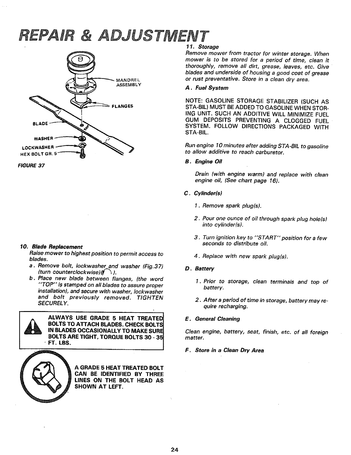
10. Blade Replacement
Raise mower to highest position to permit access to
blades.
a. Remove bolt, Iockwasher and washer (Fig.37)
{turn counterclockwise) (F_ ).
b. Place new blade between flanges, (the word
"'TOP'" is stamped on all blades to assure proper
installation), and secure with washer,/ockwasher
and bolt previously removed. TIGHTEN
SECURELY.
!
ALWAYS USE GRADE 5 HEAT TREATEDI
BOLTS TO ATTACH BLADES. CHECK BOLTS_
IN BLADES OCCASIONALLY TO MAKE SUREI
BOLTS ARE TIGHT, TORQUE BOLTS 30 -35 I
•FT. LBS. /
3. Turn ignition key to "'START" position for a few
seconds to distribute oil,
4, Replace with new spark plug(s).
D, Battery
1. Prior to storage, clean terminals and top of
battery.
2. After a period of time in storage, battery may re-
quire recharging.
E. General Cleaning
Clean engine, battery, seat, finish, etco of all foreign
matter•
F. Store in a Clean Dry Area
A GRADE 5 HEAT TREATED BOLT
CAN BE IDENTIFIED BY THREE
LINES ON THE BOLT HEAD AS
SHOWN AT LEFT.
24
TROUBLESHOOTING
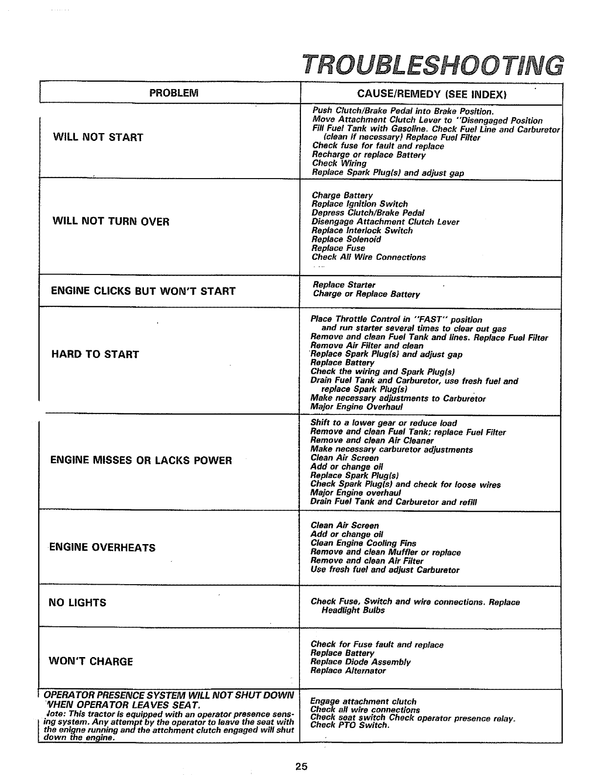
WILL NOT START
PROBLEM CAUSE/REMEDY (SEE INDEX)
WILL NOT TURN OVER
Push Clutch/Brake Pedal into Brake Position.
Move Attachment Clutch Lever to "Disengaged Position
Fill Fuel Tank with Gasoline. Check Fuel Line and Carburetor
(clean if necessary) Replace Fuel Filter
Check fuse for fault and replace
Recharge or replace Battery
Check Wiring
Replace Spark Plug(s) and adjust gap
Charge Battery
Replace Ignition Switch
Depress Clutch/Brake Pedal
Disengage Attachment Clutch Lever
Replace Interlock Switch
Replace Solenoid
Replace Fuse
Check All Wire Connections
Replace Starter
ENGINE CLICKS BUT WON'T START Charge or Replace Battery
HARD TO START
ENGINE MISSES OR LACKS POWER
ENGINE OVERHEATS
NO LIGHTS
WON'T CHARGE
OPERA TOR PRESENCE SYSTEM WILL NOT SHUT DOWN
_HEN OPERATOR LEA VES SEA 7",
Jote: This tractor is equipped with an operator presence sens-
ing system. Any attempt by the operator to leave the seat with
the enigne running and the attchment clutch engaged will shut
down the engine.
Place Throttle Control in "FAST" position
and run starter several times to clear out gas
Remove and clean Fuel Tank and lines. Replace Fuel Filter
Remove Air Filter and clean
Replace Spark Plug(s) and adjust gap
Replace Battery
Check the wiring and Spark Plug(s)
Drain Fuel Tank and Carburetor, use fresh fuel and
replace Spark Plug(s)
Make necessary adjustments to Carburetor
Major Engine Overhaul
Shift to a lower gear or reduce load
Remove and clean Fuel Tank; replace Fuel Filter
Remove and clean Air Cleaner
Make necessary carburetor adjustments
Clean Air Screen
Add or change oil
Replace Spark Plug(s)
Check Spark Plug/s) and check for loose wires
Major Engine overhaul
Drain Fuel Tank and Carburetor and refill
Clean Air Screen
Add or change off
Clean Engine Cooling Fins
Remove and clean Muffler or replace
Remove and clean Air Filter
Use fresh fuel and adjust Carburetor
Check Fuse, Switch and wire connections. Replace
Headlight Bulbs
Check for Fuse fault and replace
Replace Battery
Replace Diode Assembly
Replace Alternator
Engage attachment clutch
Check all wire connections
Check seat switch Check operator presence relay.
Check PTO Switch.
25
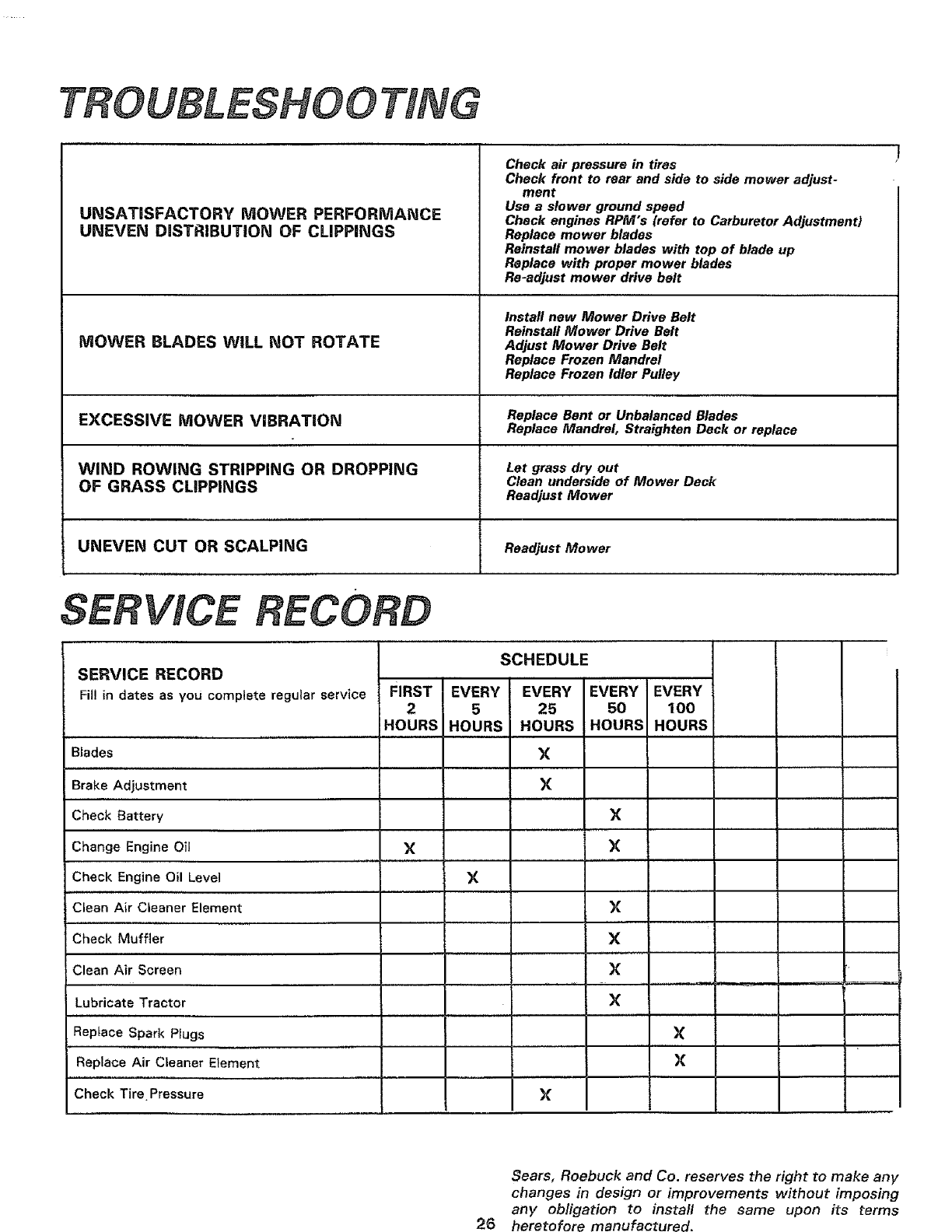
TROUBLESHOOTING
UNSATISFACTORY MOWER PERFORMANCE
UNEVEN DISTRIBUTION OF CLIPPINGS
MOWER BLADES WILL NOT ROTATE
Check air pressure in tiros
Chock front to rear and side to side mower adjust-
ment
Use a slower ground speed
Check engines RPM's {refer to Carburetor Adjustment)
Replace mower blades
Reinstall mower blades with top of blade up
Replace with proper mower blades
Re-adjust mower drive belt
Install new Mower Drive Belt
Reinstall Mower Drive Belt
Adjust Mower Drive Belt
Replace Frozen Mandrel
Replace Frozen Idler Pulley
EXCESSIVE MOWER ViBRATiON Replace Bent or UnbalancedBlades
Replace Mandrel, Straighten Deck or replace
WIND ROWING STRIPPING OR DROPPING Let grass dry out
Clean underside of Mower Deck
OF GRASS CLIPPINGS ReadjustMower
UNEVEN CUT OR SCALPING ReadjustMower
SERVICE RECORD
SCHEDULE
SERVICE RECORD
Fil! in dates as you complete regular service FIRST
2
HOURS
,,,, , ,,,,,...................
B_ades
Brake Adjustment
Check Battery
Change Engine Oil X
Check Engine Oil Level
Clean Air Cleaner Element
Check Muffler
Clean Air Screen
Lubricate Tractor
, ,,,,,,,,,,
Replace Spark Plugs
,,,,,,, ,,,
Replace Air Cteaner Element
............ ,,, , ,
Check Tire Pressure
EVERY
5
HOURS
X
EVERY EVERY EVERY
25 50 100
HOURS HOURS HOURS
X
×
×
×
×
X
X
X
X
X
I
X
L
26
Sears, Roebuck and Co. reserves the right to make any
changes in design or improvements without imposing
any obligation to install the same upon its terms
heretofore manufactured.
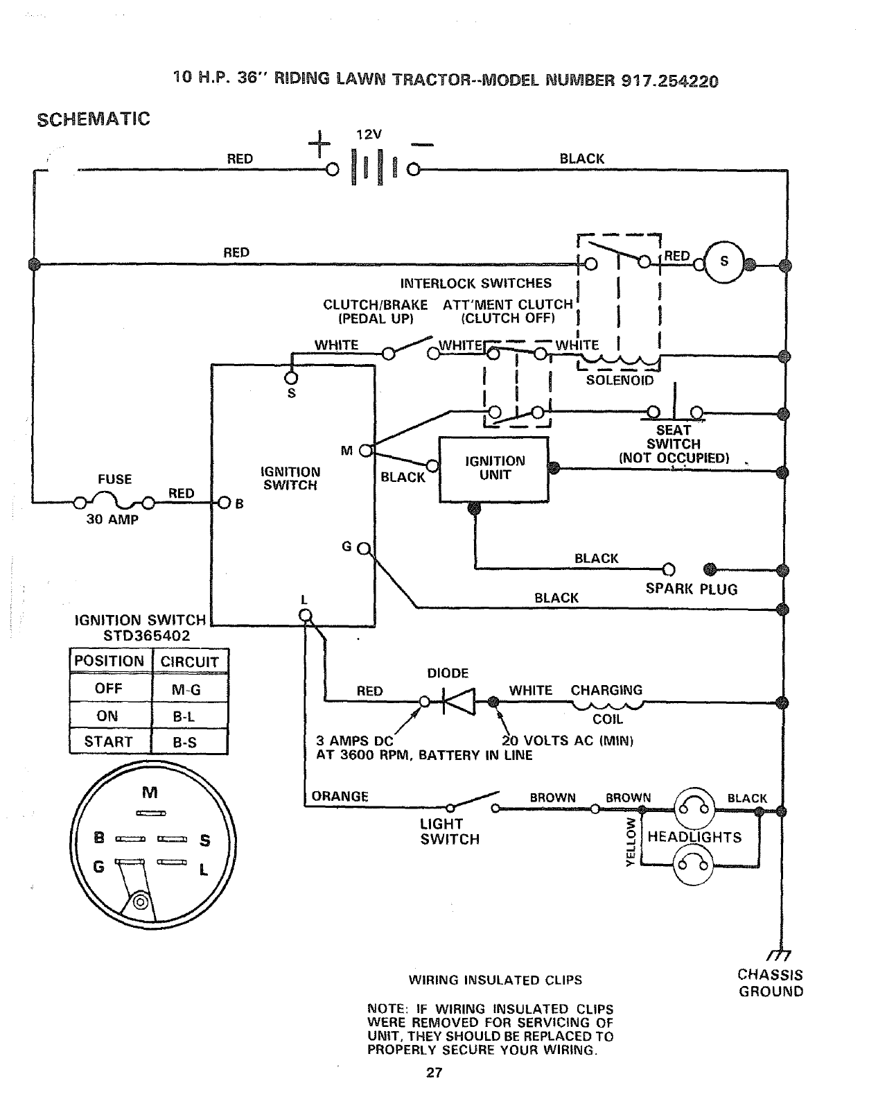
10 H.P. 36" RIDBNG LAWN TRACTOR--MODEL NUMBER 917.254220
SCHEMATIC
. IIH,,'
12V
"_° o[l[lo ....0LAC,,_
FUSE
__a"_ RED
30 AMP
RED
IGNITION SWITCH
STD365402
POSITION CIRCUIT
OFF M-G
ON B-L
START B-S
OB
S
INTERLOCK SWITCHES I
CLUTCH/BRAKE ATT'MENT CLUTCH'
[PEDAL UP) (CLUTCH OFF)
WHITE
IGNITION
SWITCH
RED
COIL
\
3 AMPS DC :;}0 VOLTS AC (MIN)
AT 3600 RPM, BATTERY IN LINE
ORANGE
r-_ ---1 _-,..
)..........L,GHTSW,TOH BROWN
WIRING INSULATED CLIPS
NOTE: IF WIRING INSULATED CLIPS
WERE REMOVED FOR SERVICING OF
UNIT, THEY SHOULD BE REPLACED TO
PROPERLY SECURE YOUR WIRING,
/3
CHASSIS
GROUND
27
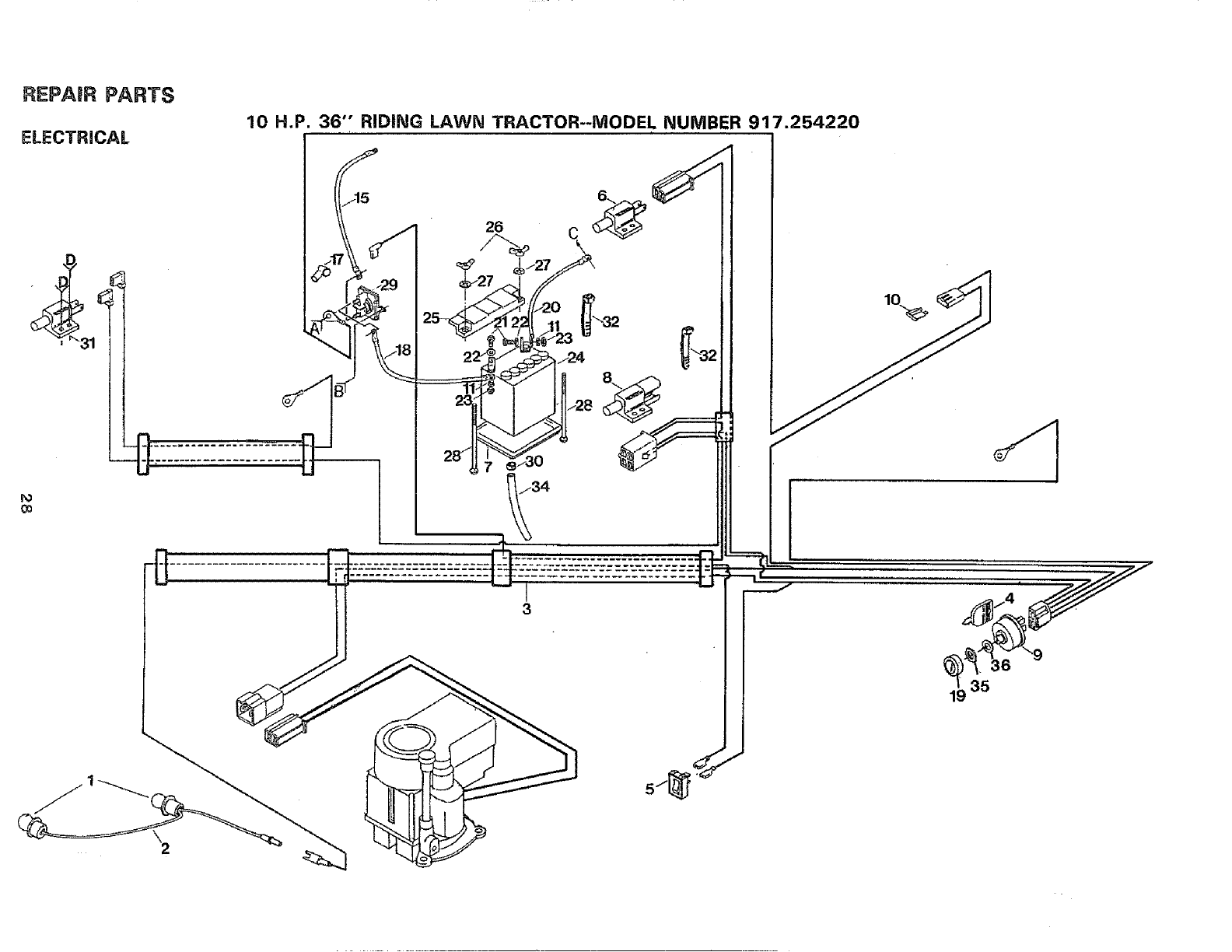
REPAIR PARTS
ELECTRICAL
I'o
0o
10 H.P. 36'" RIDING LAWN TRACTOR--MODEL NUMBER 917.254220
r
19 35
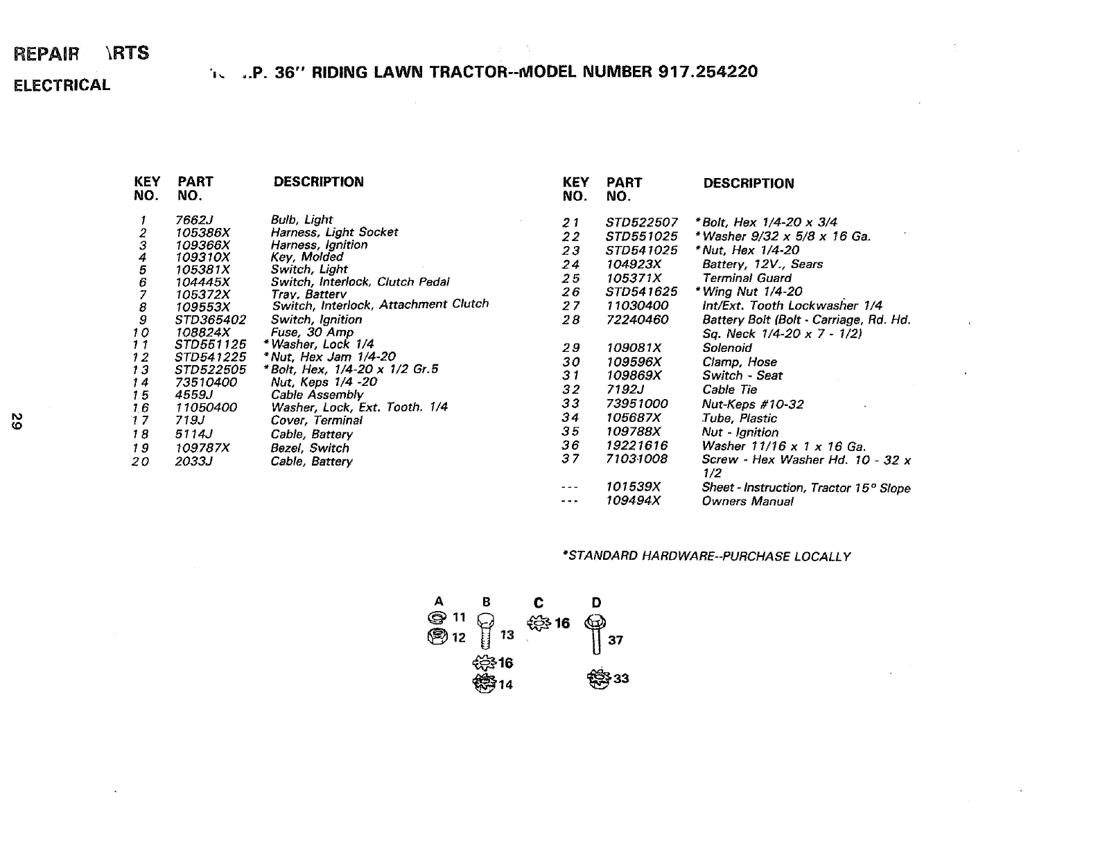
REPAIR \RTS
ELECTRICAL ',,. ,.P. 36"' RIDING LAWN TRACTOR"MODEL NUMBER 917.254220
KEY
NO.
1
2
3
4
5
6
7
8
9
10
!1
!2
13
14
15
7_6
17
18
19
20
PART
NO.
7662J
105386X
109366X
109310X
!05381X
104445X
105372X
109553X
STD365402
!08824X
STD551125
STD541225
STD522505
73510400
4559J
1105040O
719J
5114J
109787X
2033J
DESCRIPTION KEY PART DESCRIPTION
NO. NO.
Bulb, Light 21STD522507
Harness, Light Socket 22 STD551025
Harness, Ignition 2 3 STD541025
Key, Molded
Switch, Light 2 4 104923X
Switch, Interlock, Clutch Pedal 25 105371X
Tray, Battery 2 6 STD541625
Switch, Interlock, Attachment Clutch 2 7 11030400
Switch, Ignition 2 8 72240460
Fuse, 30 Amp
*Washer, Lock 1/4 29 109081X
*Nut, Hex Jam 1/4-20 30 109596X
*Bolt, Hex, I/4-20x 1/2 Gr.5
Nut, Keps I/4-20 3 1 109869X
Cable Assembly 3 2 7192J
Washer, Lock, Ext. Tooth. 1/4 33 73951000
Cover, Terminal 34 105687X
Cable, Battery 3 5 109788X
Bezel, Switch 36 19221616
Cable, Battery 37 71034008
101539X
109494X
*Bolt, Hex I/4-20 x 3/4
*Washer 9/32 x 5/8 x 16 Ga.
*Nut, Flex 1/4-20
Battery, 12V., Sears
Terminal Guard
*Wing Nut 1/4-20
Int/Ext. Tooth Lockwas!Ter 1/4
Battery Bolt (Bolt -Carriage, Rd. lid.
Sq. Neck I/4-20 x 7- 1/2)
Solenoid
Clamp, Hose
Switch _Seat
Cable Tie
Nut-Keps #10-32
.Tube, Plastic
Nut -Ignition
Washer 11/16x 1 x 16 Ga.
Screw -Hex Washer Hd. 10 -32 x
1/2
Sheet -Instruction, Tractor 15 oSlope
Owners Manual
*STANDARD HARDWARE--PURCHASE LOCALLY
A B
12 13
C D
®'°
, 33
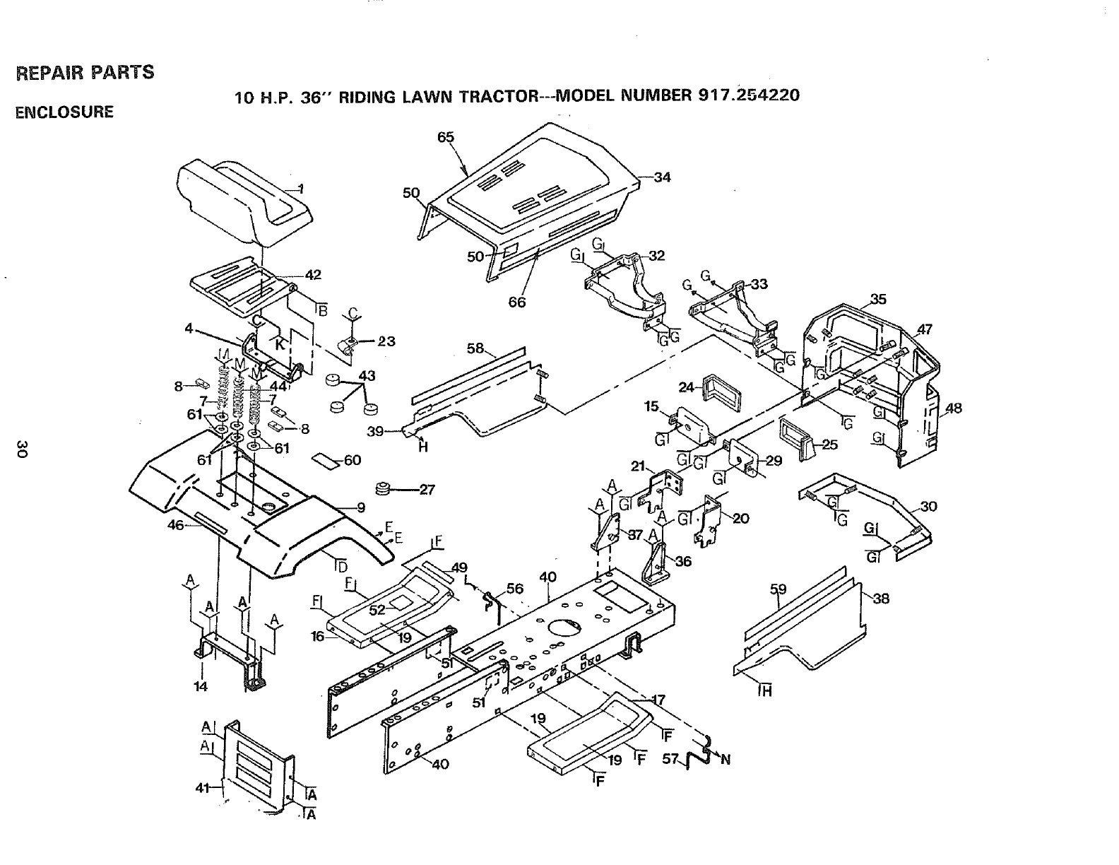
REPAIR PARTS
ENCLOSURE
10 H.P. 36" RIDING LAWN TRACTOR---MODEL NUMBER 917.254220
65
\
50\
0
/
66
39---_H
_-6o
t
14
A
51
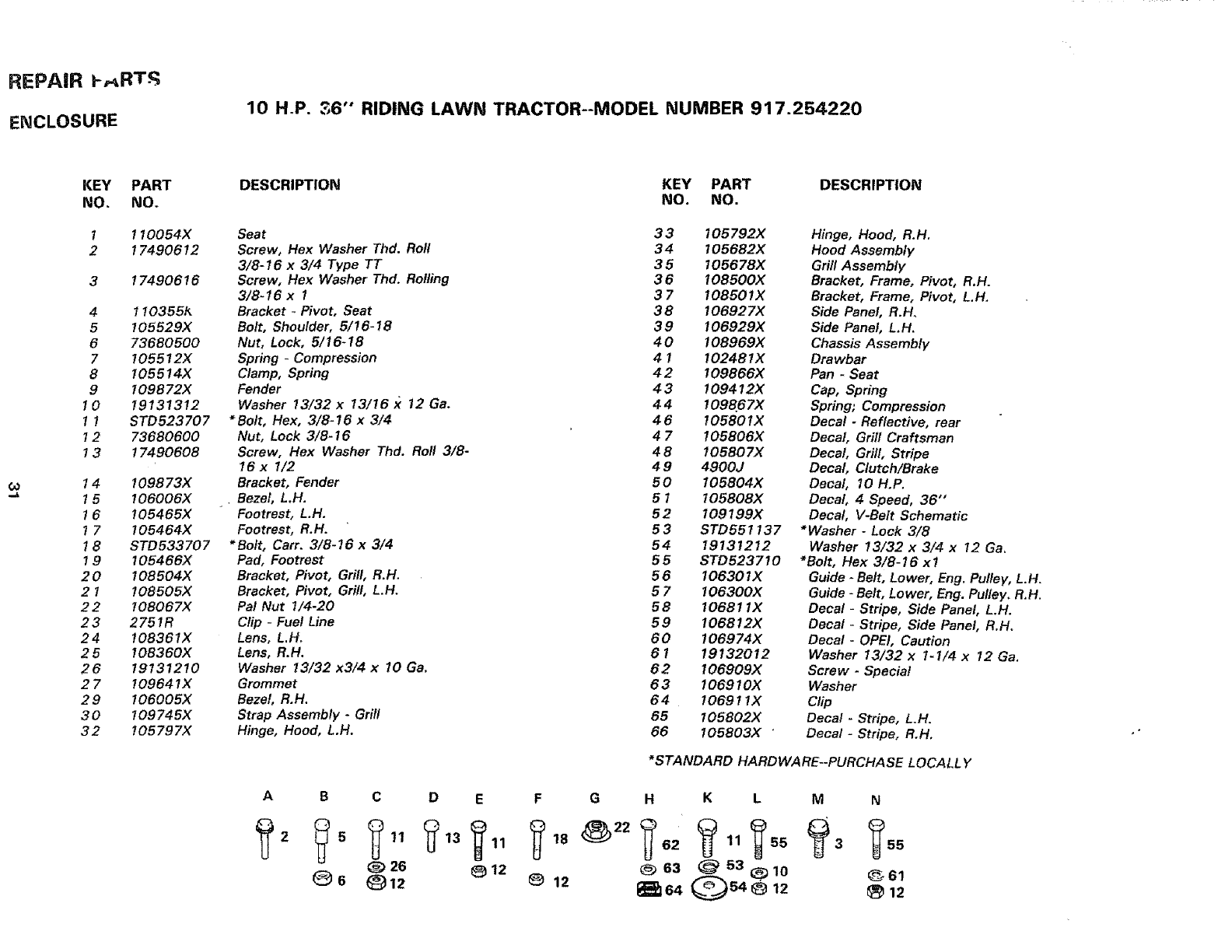
REPAIR p,_RT-_.
ENCLOSURE
10 H.P. 36'" RIDING LAWN TRACTOR--MODEL NUMBER 917.254.220
co
KEY PART
NO. NO.
1 1 I0054X
2 17490612
317490616
4 1103561_
5_05529X
673680500
7I05512X
8105514X
9109672X
1 0 19131312
1 1 STD523707
12 73680600
13 17490608
14 109873X
15106006X
1 6 105465X
1 7 I05464X
1 8 STD533707
1 9 105466X
2 0 108504X
2 1 108505X
2 2 108067X
23 2751R
24 108361X
2 5 108360X
26 19131210
2 7 10964 lX
29 106005X
30 109745X
32 105797X
DESCRIPTION KEY PART
NO. NO.
Seat 3 3
Screw, Hex Washer Thd. Roll 34
3/8-16 x3/4 Type TT 35
Screw, Hex Washer Thd. Rolling 3 6
3/8-t6 x 737
Bracket - Pivot, Seat 38
Belt, Shoulder, 5/!6-18 39
Nut, Lock, 5/16-18 40
Spring -Compression 4 1
Clamp, Spring 4 2
Fender 4 3
Washer 13/32 x13/16 :_ 12 Ga. 44
*Bolt, Flex, 3/8-16 x 3/4 4 6
Nut, Lock 3/8-16 4 7
Screw, Hex Washer Thd. Roll 3/8- 4 8
16 x I/2 49
Bracket, Fender 50
Bezel, L.H. 51
Footrest, L.H. 52
Footrest, R.H. 53
*Bolt, Cart. 3/8-16 x 3/4 54
Pad, Footrest 5 5
Bracket, Pivot, Gdll, R.H. 56
Bracket, Pivot, Grill, L.H. 5 7
Pal Nut 1/4-20 56
Clip -Fuel Line 59
Lens, L.H, 60
Lens, R.H. 61
Washer 13/32 x3/4 x 10 Ga. 62
Grommet 6 3
Bezel, R.H. 64
Strap Assembly -Grill 65
Hinge, Hood, L.H, 66
A B C D E F
26 _12
6 (_12 _12
DESCRIPTION
105792X Hinge, Hood, R.H.
105682X Hood Assembly
105678X Grill Assembly
108500X Bracket, Frame, Pivot, R.H.
108501X Bracket, Frame, Pivot, L.H,
106927X Side Panel, R.H.
106929X Side Panel, L.H.
106969X Chassis Assembly
10248 l X Drawbar
109866X Pan -Seat
109412X Cap, Spring
109867X Spring; Compression
105801X Decal -Reflective, rear
105606X Decal, Grill Craftsman
105607X Decal, Grill, Stripe
4900J Decal, Clutch/Brake
I05804X Decal, 10 H.P.
105808X Decal, 4 Speed, 36"
109196X Decal, V-Belt Schematic
STD551137 *Washer -Lock 3/8
19131212 Washer 13/32 x 3/4 x 12 Ga,
STD523710 *Bolt, Hex 3/6-16 x!
10630 IX Guide -Belt, Lower, Eng. Pulley, L.H.
106300X Guide -Belt, Lower, Eng. Pulley. R.H.
10681 tX Decal -Stripe, Side Panel, L.H.
106812X Decal -Stripe, Side Panel, R.H.
106974X Decal- OPEl, Caution
19132012 Washer 13/32 x 1-I/4 x 12 Ga,
106909X Screw -Special
1069 IOX Washer
10691 l X Clip
I05602X Decal- Stripe, L.H.
105803X " Decal -Stripe, R,H.
*STANDARD HARDWARE--PURCHASE LOCALLY
G H K L M N
63 (_ 53 _10 661
_64 Q54_ 12 _ 12
23
32 Spark
OPTIONAL EQUIPMENT
Arrester Screen Assembly 677Vl
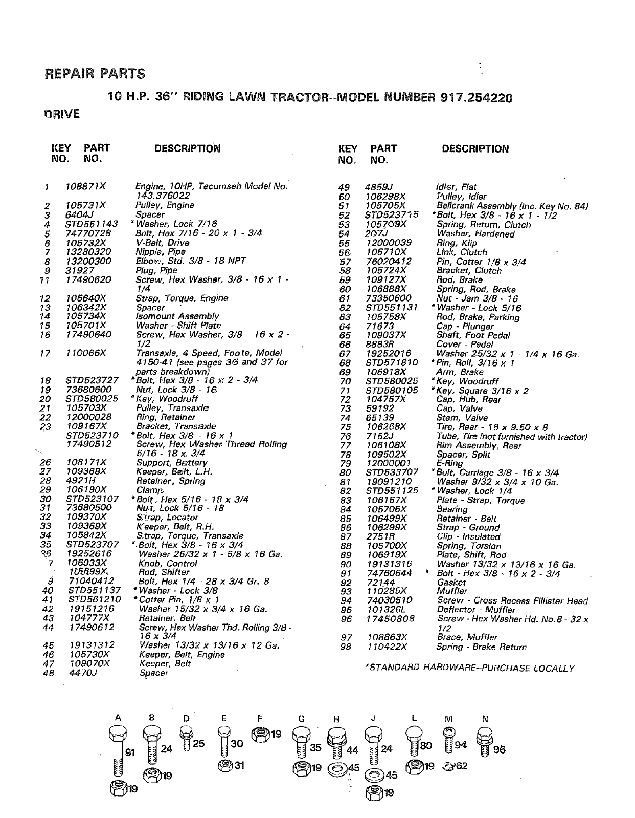
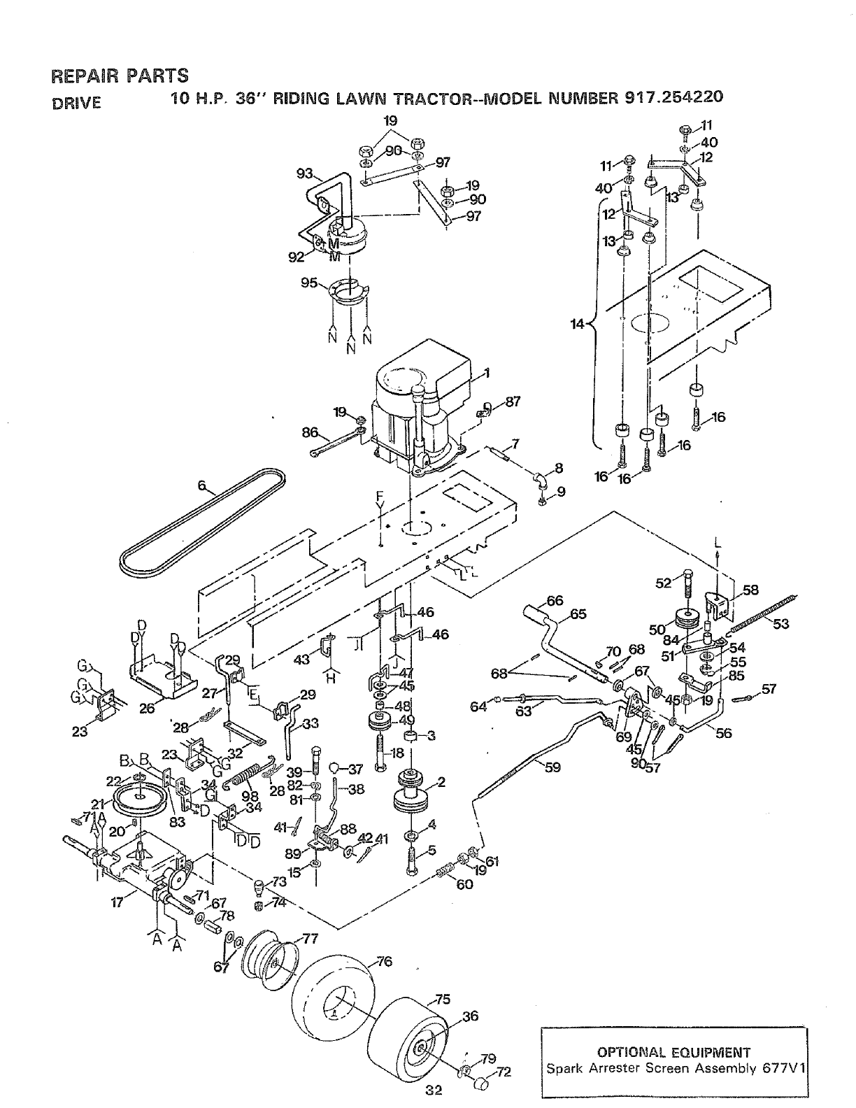
REPAUR PARTS
10 H.P. 36" RIDeNG LAWN TRACTOR--MODEL NUMBER 917.254220
_3RIVE
KEY PART DESCRIPTION KEY PART DESCRIPTION
NO. NO. NO o NO,
! 108871X
2 105731X
3 6404J
4 STD551143
5 7477O728
6 !05732X
7 13280320
8 13200300
9 31927
11 17490620
12 105640X
13 t06342X
14 105734X
15 I05701X
16 17490640
17 110066X
18 STD523727
19 73680600
20 STD580025
21 105703X
22 12000028
23 109167X
STD523710
17490512
26 108171X
27 109368X
28 4921H
29 106190X
30 STD523107
3I 73680500
32 109370X
33 109369X
34 105842X
35 STD523707
_19252616
7106933X
1_J_99X,
9 71040412
40 STD551137
41 STD561210
42 19151216
43 104777X
44 17490612
45 19131312
46 105730X
47 109070X
48 4470J
Engine, IOHP, Tecumseh Model No. 49 4859J
143.376022 50 106298X
Pulley, Engine 51 106706X
Spacer 52 STD5237"_5
*Washer, Lock 7/16 53 105zogx
Bolt, Hex 7/16- 20 x 1 -3/4 54 2_'lJ
V-Belt, Drive 55 12000039
Nipple, Pipe 56, 105710X
Elbow, Std. 3/8- 18 NPT 57 76020412
Plug, Pipe 58 105724)(
Screw, Hex Washer, 3/8 -16 x 1 -59 109127X
1/4 60 106888X
Strap, Torque, Engine 61 73350600
Spacer 62 STD551131
Isomount Assembly. 63 I05758X
Washer -Shift Plate 64 71673
Screw, Flex Washer, 3/8 _16 x 2 -65 109037X
I/2 66 8883R
Transaxle, 4 Speed, Foote, Model 67 19252016
4150-41 (see pages 3_ and 37 for 68 STD571810
parts breakdown) 69 106918)(
*Bolt, Flex 3/8 -16 x. 2 -3/4 70 STD580025
Nut, Lock 3/8 -16 7! STD580105
*Key, Woodruff 72 I04757X
Pulley, Transaxl_ 73 59192
Ring, Retainer 74 65139
Bracket, Trans_xle 75 106268X
*Bolt, Hex 3/8 -16 x 1 76 7152J
Screw, Hex VVasher Thread Rolling 77 106108X
5/16 -!8 x. 3/4 78 I09502X
Support, B_ttery 79 12000001
Keeper, B_Jlt, L.H. 80 STD533707
Retainer, Spring 81 19091210
Clam£, 82 STD551125
*Bolt, Hex 5/16 -18 x 3/4 83 106157X
Nu_t, Lock 5/16- 18 84 105706X
Sotrap, Locator 85 106499X
IL'eeper, Belt, R.H. 86 106299X
S.trap, Torque, Transaxle 87 2751R
*Bolt, Hex 3/8 -16 x 3/4 88 105700X
Washer 25/32 x 1 -5/8 x 16 Ga. 89 106919X
Knob, Control 90 19131316
Rod, Shifter 91 74760644
Bolt, Hex I/4 -28 x 3/4 Gr. 8 92 721.44
*Washer -Lock 3/8 93 110285X
*Cotter Pin, 1/8 x 194 74030510
Washer 15/32 x 3/4 x t6 Ga. 95 101326L
Retainer, Belt 96 17450808
Screw, Hex Washer Thd. Rolling 3/8 -
16 x 3/4 .97 I08863X
Washer 13/32 x 13/16 x 12 Ga. 98 110422X
Keeper, Belt, Engine
Keeper, Belt
Spacer
Idler, Flat
Pulley, Idler
Bellcrank Assembly (Inc. Key No. 84)
"Bolt, Hex 3/8- 16 x 1 -1/2
Spring, Return, Clutch
Washer, Hardened
Ring, Klip
Link, Clutch
Pin, Cotter 1/8 x 3/4
Bracket, Clutch
Rod, Brake
Spring, Rod, Brake
Nut -Jam 3/8 -16
*Washer - Lock 5/16
Rod, Brake, Parking
Cap -Plunger
Shaft, Foot Pedal
Cover - Pedal
Washer 25/32 x 1 -1/4 x 16 Ga.
*Pin, Roll, 3/16 x 1
Arm, Brake
*Key, Woodruff
*Key, Square 3/16 x 2
Cap, Hub, Rear
Cap, Valve
Stem, Valve
Tire, Rear -18 x 9. 50 x 8
Tube, Tire (not furnished with tractor)
Rim Assembly, Rear
Spacer, Split
E-Ring
*Bolt, Carriage 3/8- 16 x 3/4
Washer 9/32 x 3/4 x I0 Ga.
*Washer, Lock 1/4
Plate -Strap, Torque
Bearing
Retainer -Belt
Strap -Ground
Clip -Insulated
Spring, Torsion
Plate, Shift, Rod
Washer 13/32 x t3/16 x 16 Ga.
Bolt -Hex 3/8 -!6 x 2 -3/4
Gasket
Muffler
Screw -Cross Recess Fillister Head
Deflector -Muffler
Screw -Hex Washer Hd. No.8 -32 x
!/2
Brace, Muffler
Spring -Brake Return
*STANDARD HARDWARE-_PURCHASE LOCALL Y
A B D' E F
®19 ®31
GH J LM N
°_t9
_EPA_IR PARTS
23
28
29
32
:FF
36
50
55 60
62
68
55 _,
34
63
61 +65
67
REPAIR PARTS
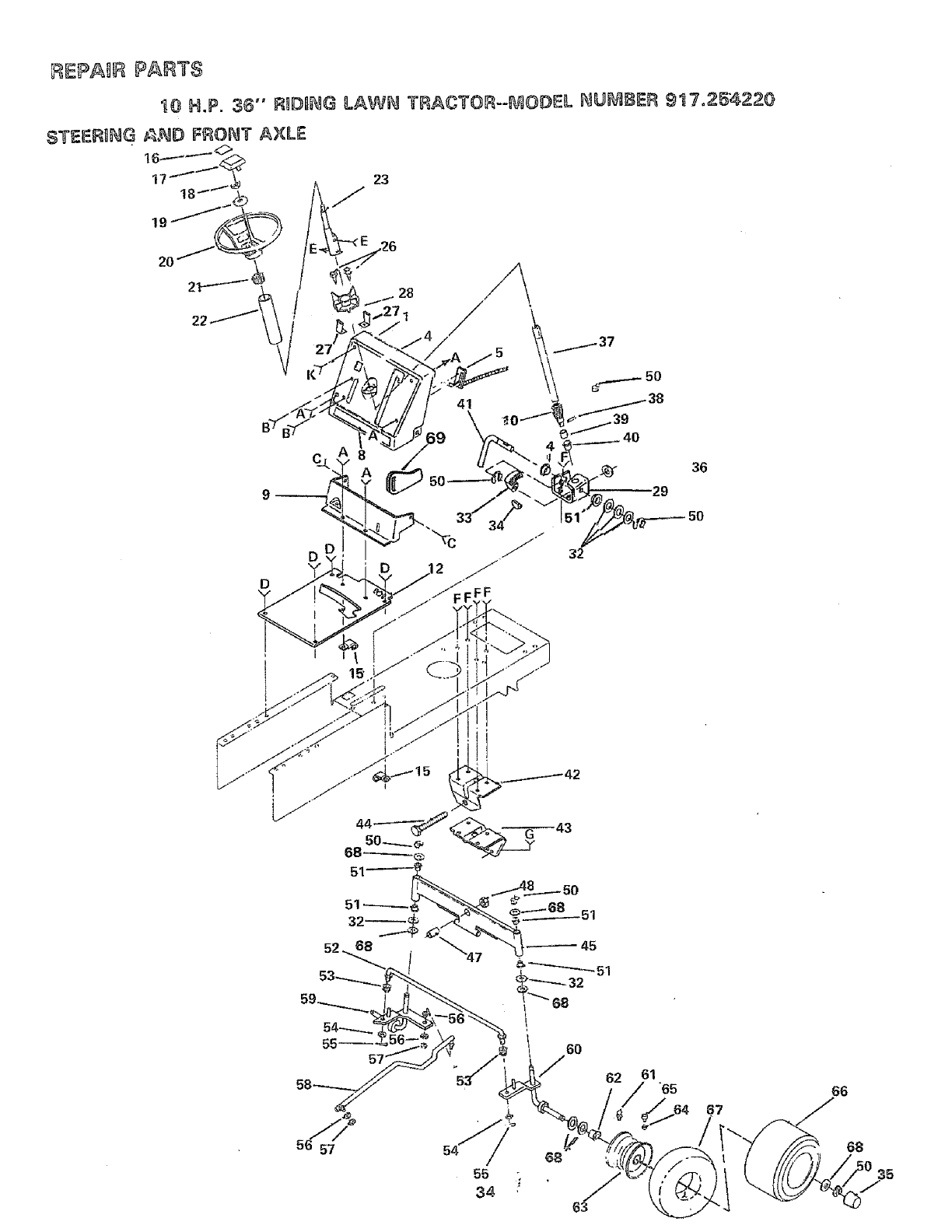
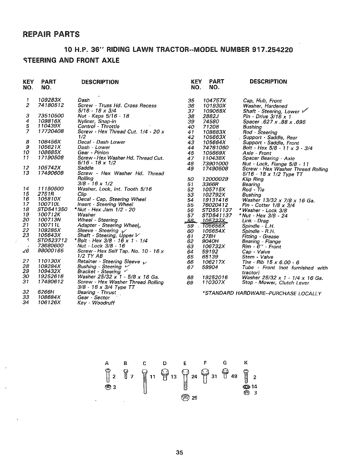
10 H.P. 36" RIDING LAWN TRACTOR--MODEL NUMBER 917.254220
_TEERING AND FRONT AXLE
KEY PART DESCRIPTION KEY PART DESCRIPTION
NO. NO. NO. NO.
1109283X Dash 35 1047-_7X
2 74180512 Screw -Truss Hd, Cross Recess 36 101930X
5/16 _18 x 3/4 37 109068X
3 73510500 Nut -Keps 5/16 -18 38 2882J
4 109816X Nyliner, Snap-In 39 74580
5 110439X Control -Throttle 40 71208
7 17720408 Screw -Hex Thread Cut. 1/4 -20 x 41 !08683X
!/2 42 I05663X
8 !08456X Decal -Dash Lower 43 I05664X
9105621X Dash -Lower 44 74761060
10 108685X Gear -Pinion 45 105669X
11 17190508 Screw -Hex Washer Hd. Thread Cut. 47 1 I0438X
5/16- 18 x I/2 48 73901000
12 105742X Saddle 49 17490508
13 17490608 Screw - Hex Washer Hd. Thread
14 11150500
15 2751R
!6 105810X
17 100710L
18 STD541350
19 I00712K
20 100713N
21 100711L
22 109285X
23 105643X
tSTD523712
,73680600
16 98000165
27 1!0130X
28 109284X
29 109432X
30 19252616
37 17490612
32 6266H
33 108684X
34 I06126X
Rolling 50 12000029
3/8- 16 x 1/2 51 3366R
Washer, Lock, Int. Tooth 5/16 52 105715X
Clip 53 102792X
Decal -Cap, Steering Wheel 54 19131416
Insert -Steering Wheel 55 76020412
*Nut -Hex Jam 1/2 -20 56 STD551137
Washer 57 STD541137
Wheel -Steering _
Adapter -Steering Wheel_ 59 .I05656X
Sleeve -Steering J 60 I05654X
Shaft -Steering, Upper _/" 61 278H
*Bolt - Hex 3/8 _I6 x 1 -I/4 62 9040H
Nut -Lock 3/8 - 16 63 106732X
Screw-HexSelfTap. No. 10- 16x 64 59192
I/2 TY AB 65 65139
Retainer -Steering Sleeve v 66 106217X
Bushing -Steering "-_ 67 59904
Bracket -Steering _"
Washer 25/32 x 1 -5/8 x 16 Ga, 68 19252016
Screw -Hex Washer Thread Rolling 69 110307X
3/8 -16 x 3/4 Type TT
Bearing -Thrust .
Gear -Sector
Key- Woodruff
Cap, Hub, Front
Washer, Hardened
Shaft -Steering, Lower _/
Pin _Drive 3/16 x 1
Spacer. 62 7 x .88 x. 695
Bushing
Rod- Steering
• Support -Saddle, Rear
Support -Saddle, Front
Bolt -Hex 5/8 -1 t x 3 -3/4
Axle -Front
Spacer Bearing -Axle
Nut -Lock, Flange 5/8 -11
Screw -Hex Washer Thread Rolling
5/16 - 18 x1/2 Type TT
Klip Ring
Bearing
Rod - .Tie
Bushing
Washer 13/32 x 7/8 x 16 Ga.
Pin - Cotter 1/8 x 3/4
* Washer -Lock 3/8
*Nut - Hex 3/8 -24
Link -Drag
Spindle -L.H.
Spindle - R.H.
Fitting -Grease
Bearing -Flange
Rim -6" -Front
Cap -Valve
Stem -Valve
Tire -Rib 15 x 6.00 -6
Tube -Front (not furnished with
tractor)
Washer 26/32 x 1 -1/4 x 16 Ga.
Stop -Mower, Clutch Lever
*STANDARD HARDWARE--PURCHASE LOCALLY
A B C D E F G
(_2 _7 I 11 _13 _24 _31 _t49
25
K
@ 14
@ 3
35
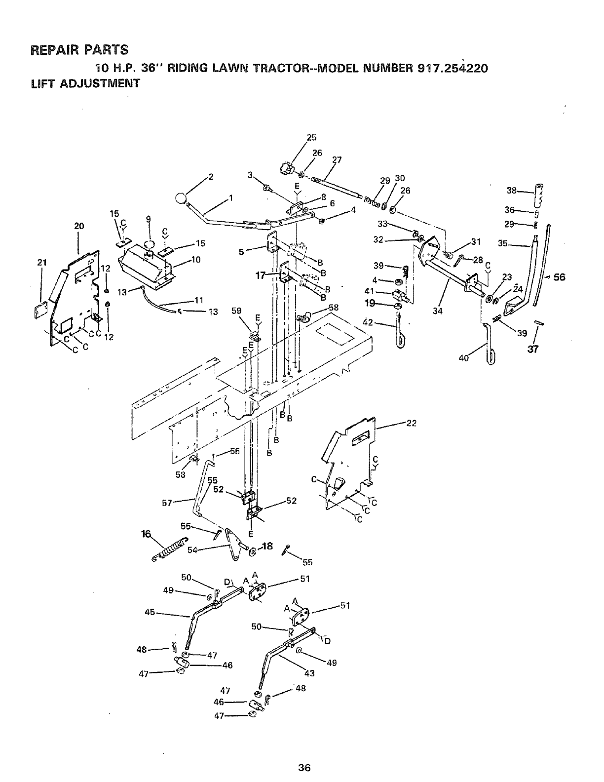
REPAIR PARTS
10 H.P. 36" RIDING LAWN TRACTOR--MODEL NUMBER 917.25,$220
LIFT ADJUSTMENT
25
26
20
58
29 30
32
/
37
56
36
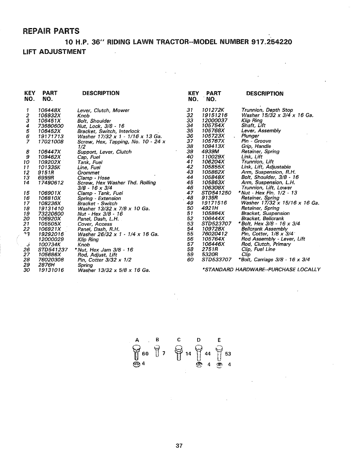
REPAIR PARTS
10 H.P. 36" RiDiNG LAWN TRACTOR--MODEL NUMBER 917.254220
LiFT ADJUSTMENT
KEY PART DESCRIPTION KEY PART DESCRIPTION
NO. NO. NO. "NO.
1
2
3
4
5
6
7
8
9
10
11
12
13
14
15
16
17
18
19
20
21
22
J
26
27
28
29
3O
I06448X Lever, Clutch, Mower 31 I01272K
106932X Knob 32 19151216
106451X Bolt, Shoulder 33 12000037
73680600 Nut, Lock, 3/8- 16 34 I05754X
106452X Bracket, Switch, Interlock 35 t05768X
19171713 Washer 17/32 x 1- 1/16 x 13 Ga. 36 I05723X
17021008 Screw, Hex, Tapping, No. 10- 24 x 37 t05767X
I/2 38 109413X
I06447X Support, Lever, Clutch 39 4939M
109462X Cap, Fuel 40 110029)(
109202X Tank, Fuel 41 t06204X
I01335K Line, Fuel 42 t05855X
9151R Grommet 43 I05862X
6999R Clamp -Hose 44 t05848X
17490612 Screw, Flex Washer Thd. Rolling 45 t05863X
3/8 -16 x 3/4 46 t06308X
106901X Clamp -Tank, Fuel 47 STD541250
I06810X Spring -Extension 48 9t35R
I08236X Bracket -Switch 49 19171516
19131410 Washer 13/32 x 7/8 x !0 Ga. 50 4921H
73220600 Nut -Hex 3/8 -16 51 105864X
t06920X Panel, Dash, L.H. 52 106444)(
105505X Cover, Access 53 STD523707
106921X Panel, Dash, R.H. 54 109728X
19292016 Washer 26/32 x 1 -1/4 x 16 Ga. 55 76020412
12000029 Klip Ring 56 105764X
100734K Knob 57 I06446X
STD541237 *Nut, Hex Jam 3/8 -16 58 275tR
105686X Rod, Adjust, Lift 59 5320R
76020308 Pin, Cotter 3/32 x 1/2 60 STD533707
28761-/ Spring
19131016 Washer 13/32 x 5/8 x 16 Ga.
Trunnion, Depth Stop
Washer 15/32 x 3/4 x 16 Ga.
Klip Ring
Shaft, Lift
Lever, Assembly
Plunger
Pin -Groove
Grip, Handle
Retainer, Spring
Link, Lift
Trunnion, Lift
Link, Lift, Adjustable
Arm, Suspension, R.H.
Bolt, Shoulder, 3/8- 16
Arm, Suspension, L.H.
Trunnion, Lift, Lower
*Nut -Hex Fin. 1/2 -13
Retainer, Spring
Washer 17/32 x 15/16 x 16 Ga.
Retainer, Spring
Bracket, Suspension
Bracket, Bellcrank
*Bolt, Hex 3/8 -I6 x 3/4
Beficrank Assembly
Pin, Cotter, 1/8 x 3/4
Rod Assembly -Lever, Lift
Rod, Clutch, Primary
Clip, Fuel Line
Clip
*Bolt, Carriage 3/8- 16 x 3/4
*STANDARD HARDWARE--PURCHASE LOCALLY
A B C D E
37
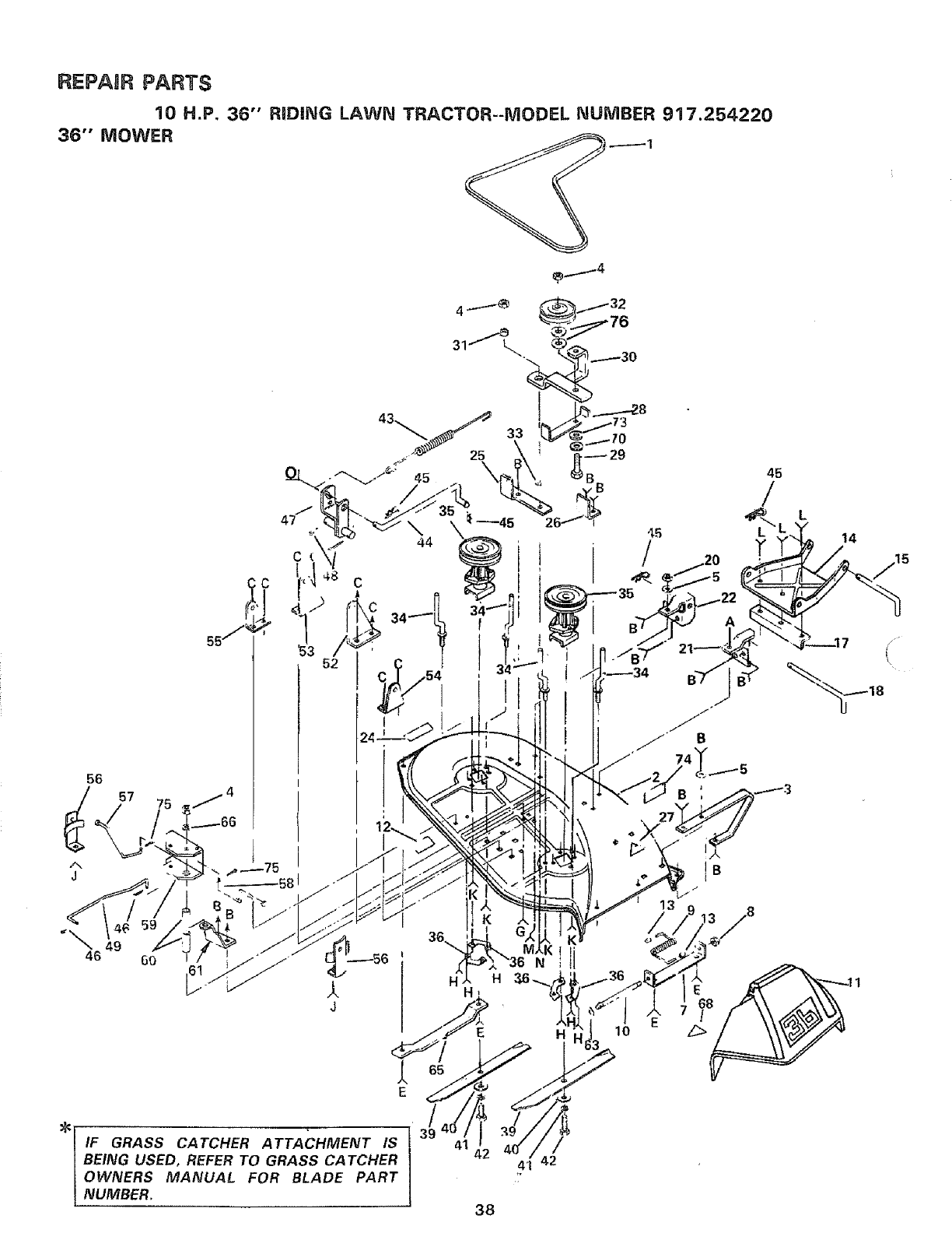
REPAIR PARTS
10 H.P, 36" RiDiNG LAWN TRACTOR--MODEL NUMBER 917.254220
36" MOWER .---- 1
56
J
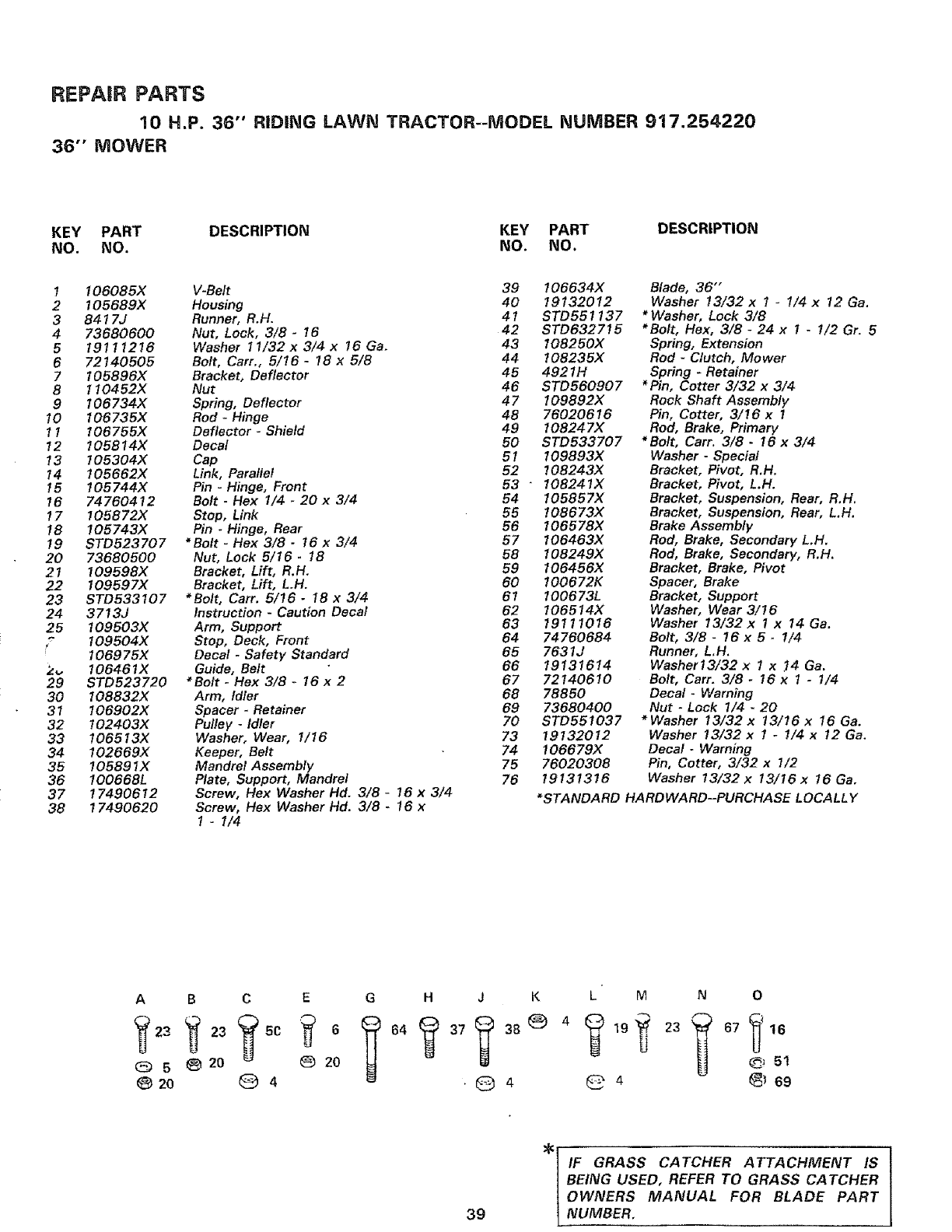
REPAIR PARTS
10 H.P. 36" RIDING LAWN TRACTOR--MODEL NUMBER 917.254220
36" MOWER
KEY PART DESCRIPTION KEY PART DESCRIPTION
NO. NO. NO. NO.
I 106085X V-Belt 39 I06634X
2105689X Housing 40 19132012
3 8417J Runner, R.H. 41 STD551137
4 73680600 Nut, Lock, 3/8- 16 42 STD632715
5 19111216 Washer 11/32 x 3/4 x 16 Ga. 43 108250X
6 72140505 Bolt, Carr., 5/16 -18 x 5/8 44 108235X
7 105896X Bracket, Deflector 45 4921H
8 110452X Nut 46 STD560907
9 106734X Spring, Deflector 47 109892X
10 106735X Rod -Hinge 48 76020616
11 106755X Deflector -Shield 49 !08247X
12 105814X Decal 50 STD533707
13 105304X Cap 51 109893X
14 I05662X Link, Parallel 52 !08243X
15 I05744X Pin -Hinge, Front 53 " I08241X
16 74760412 Bolt -Hex I/4 -20 x 3/4 54 105857X
17 I05872X Stop, Link 55 108673X
18 105743X Pin - Hinge, Rear 56 106578X
19 STD523707 *Bolt -Hex 3/8 -16 x 3/4 57 106463X
20 73680500 Nut, Lock 5/16 -18 58 !08249X
21 109598X Bracket, Lift, R.H. 59 106456X
22 I09597X Bracket, Lift, LH. 60 100672K
23 STD533107 *Bolt, Cart. 5/16 -18 x 3/4 61 100673L
24 3713J Instruction -Caution Decal 62 106514X
25 109503X Arm, Support 63 19! 1!016
109504X Stop, Deck, Front 64 74760684
f106975X Decal -Safety Standard 65 7631J
2,, I06461X Guide, Belt 66 19131614
29 STD523720 *Bolt - Hex 3/8 -16 x 2 67 72140610
30 I08832X Arm, Idler 68 78850
31 106902X Spacer -Retainer 69 73680400
32 102403X Pulley -Idler 70 STD551037
33 106513X Washer, Wear, 1/16 73 19132012
34 102669X Keeper, Belt 74 106679X
35 105891X Mandrel Assembly 75 76020308
36 100668L Plate, Support, Mandrel 76 19131316
37 17490612 Screw, Hex Washer Hd. 3/8 -16 x 3/4
38 17490620 Screw, Hex Washer Hd. 3/8 -16 x
1-I/4
Blade, 36"
Washer 13/32 x 1 -1/4 x 12 Ga.
*Washer, Lock 3/8
*Bolt, Flex, 3/8- 24 x 1-i/2 Gr. 5
Spring, Extension
Rod -Clutch, Mower
Spring -Retainer
*Pin, Cotter 3/32 x 3/4
Rock Shaft Assembly
Pin, Cotter, 3/!6 x 1
Rod, Brake, Primary
*Bolt, Cart'. 3/8 -16 x 3/4
Washer -Special
Bracket, Pivot, R.H.
Bracket, Pivot, L.H.
Bracket, Suspension, Rear, R.H_
Bracket, Suspension, Rear, L.H.
Brake Assembly
Rod, Brake, Secondary LH.
Rod, Brake, Secondary, R.H.
Bracket, Brake, Pivot
Spacer, Brake
Bracket, Support
Washer, Wear 3/16
Washer 13/32 x ! x 14 Ga.
Bolt, 3/8 -16 x 5 - 1/4
Runner, L.H.
Washer13/32 x 1 x !4 Ga.
Bolt, Carr. 3/8- 16 x 1 -1/4
Decal- Warning
Nut -Lock 1/4.20
*Washer 13/32 x 13/16 x t6 Ga.
Washer !3/32 x t- 1/4 x !2 Ga.
Decal -Warning
Pin, Cotter, 3/32 x 1/2
Washer 13/32 x 13/16 x t6 Ga.
*STANDARD HARDWARD--PURCHASE LOCALLY
A B C E G H J K L M N 0
05_ 20 0 20 _51
20 Q4.Q 4 _ 4 _ 69
39
_ [ IF GRASS CATCHER ATTACHMENT IS
BEING USED, REFER TO GRASS CA TCHER
OWNERS MANUAL FOR BLADE PART
NUMBER,
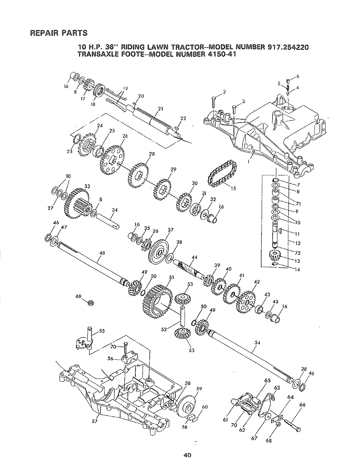
REPAUR PARTS
t0 H.P. 36" RIDmNG LAWN TRACTOR--MODEL NUMBER 937.254220
TRANSAXLE FOOTE--iVlODEL NUMBER 4150-43
48
29
36 37
38
69
49 50
15
31
32
39 40
50 :9
41
\
1._ ' 13
42
43
45
!6
\
57
53
58
59
6O
61
70 62
54
67
65
68
63
64
/
/
38 46
66
/
40
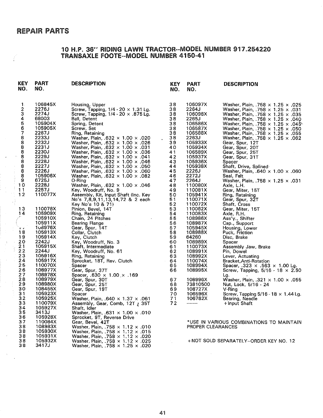
REPAIR PARTS
10 H.P. 36" RIDH_G LAWi_ TRACTOR--MODEL NUMBER 917.254220
TRANSA×LE FOOTE--MODEL NUMBER 4150-41
KEY PART
NO. NO. DESCRIPTION KEY PART DESCRIPTION
NO. NO,
1 106845X
2 2276J
3 2274J
468003
5105904X
6105905X
7 2267J
8 2233J
8 2232J
8 2231J
8 223OJ
8 2229J
8 2228J
8 2227J
8 2226J
8 105906X
9 6725J
1 0 2228J
11 2257J
12 110077X
13
14
!
19
20
21
22
23
24
25
26
27
28
29
30
31
32
33
34
35
36
37
38
38
38
38
38
110078X
105909X
105910X
105911X
108976X
105913X
105914X
2242J
105915X
2244J
105916X
1059!7X
110070X
108977X
!08978X
108979X
108980X
108455X
105923X
105925X
110079X
105927X
3413J
105928X
110084X
108983X
105930X
105931X
105932X
3417J
Housing, Upper 3 8
Screw, Tapping, 1/4 - 20 × 1.31 Lg. 3 8
Screw, Tapping, 114 - 20 × .875 Lg. 3 8
Ball, Detent 3 8
Spring, Detent 3 8
Screw, Set 3 8
Ring, Retaining 3 8
Washer, Plain, .632 x 1.00 × .020 38
Washer, Plain, .632 x1.00 × .026 39
Washer, Plain, .632 × 1.00 x .031 40
Washer, Plain, .632 x 1.00 x .036 41
Washer, Plain, .632 x 1.00 x .041 42
Washier, Plain, .632 x 1.00 x .046 43
Washer, Plain, .632 x 1.00 x .050 44
Washer, Plain, .632 x 1.00 x .060 4 5
Washer, Plain, .632 x 1.00 × .082 46
O-Ring 4 7
Washer, Plain, .632 × 1.00 x .046 48
Key, Woodruff, No. 9 4 9
Assembly, Kit, Input Shaft (Inc. Key 50
No's 7,8,9,11,13,14,72 & 2 each 51
Key No's t0 & 71) 52
Pinion, Bevel, 14T 5 3
Ring, Retaining 5 4
Chain, 24 Pitches 5 5
Bearing Flange 5 6
Gear, Spur, 14T 5 7
Collar, Clutch 58
Key, Clutch 5 9
Key, Woodruff, No. 3 60
Shaft, Intermediate 6 1
Key, Woodruff, No. 61 62
Ring, Retaining 6 3
Sprocket, 18T, Rev. Clutch 64
•Spacer 6 5
Gear, Spur, 37T 6 6
Spacer, .630 x 1.00 x .169
Gear, Spur, 30T 6 7
Gear, Spur, 25T 68
Gear, Spur, 19T 6 9
Spacer 7 0
Washer, Plain, .640 x 1.37 x .061 7 1
Assembly, Gear, Comb, 12T _. 35T 7 2
Shaft, Idler
Washer, Plain, .631 × 1.00 x .O10
Sprocket, 9T, Reverse Drive
Gear, Bevel, 42T
Washer, Plain, .758 x 1.12 x .010
Washer, Plain, .758 × 1.12 × .015
Washer, Plain, .758 × t,t2 × .020
Washer, Plain, .758 × 1.12 x .025
Washer, PIain, .758 × 1.25 x .020
106097X
2264J
106098X
2265J
106586X
106587X
106588X
2263J
105933X
105934X
106589X
105937X
105936X
105938X
2226J
2272J
2264J
110080X
110081X
105941X
110071X
110072X
110082X
110083X
108986X
108987X
105945X
108988X
64260
108989X
!10073X
108991X
t08992X
110074X
108994X
108995X
108996X
73810500
108727X
106596X
106782X
Washer, Ptain, .758 x 1.25 x .025
Washer, Ptain, .758 ×1.25 × .O3!
Washer, Piain, .758 x 1.25 × .035
Washer, Plain, .758 × 1.25 x .040
Washer, Plain, .758 x 1.25 x .045 _
Washer, Plain, .758 x 1.25 x ,050
Washer, Plain, .758 x 1,25 x .055
Washer, Plain, .758 × 1.25 x .062
Gear, Spur, 12T
Gear, Spur, 20T
Gear, Spur, 25T
Gear, Spur, 31T
Spacer
Shaft, Drive, Splined
Washer, Plain, .640 x 1.OO × .O60
Seal, Felt
Washer, Plain, .758 x 1.25 x .031
Axle, L.H.
Gear, Miter, 15T
Ring, Retaining
Gear, Spur, 32T
Shaft, Cross
Gear, Miter, 15T
Axle, R.H.
Ass'y., Shifter
Cap., Support
Housing, Lower
Puck, Friction
Disc, Brake
Spacer
Assembly Jaw, Brake
Pin, Dowel
Lever, Actuating
Bracket,Anti-Rotation
Spacer, .323 × .563 x 1.00 Lg.
Screw, Tapping, 5t16 - 18 x 2.50
Lg.
Washer, Plain, .32! × 1.00 x .055
Nut, Lock, 5/16 - 24
V-Ring
Screw, Tapping 5/16 - 18 x t .44 Lg.
Bearing, Needle
+ Input Shaft
*USE IN VARIOUS COMBINATIONS TO MAINTAIN
PROPER CLEARANCES
+NOT SOLD SEPARATELY--ORDER KEY NO, 12
41
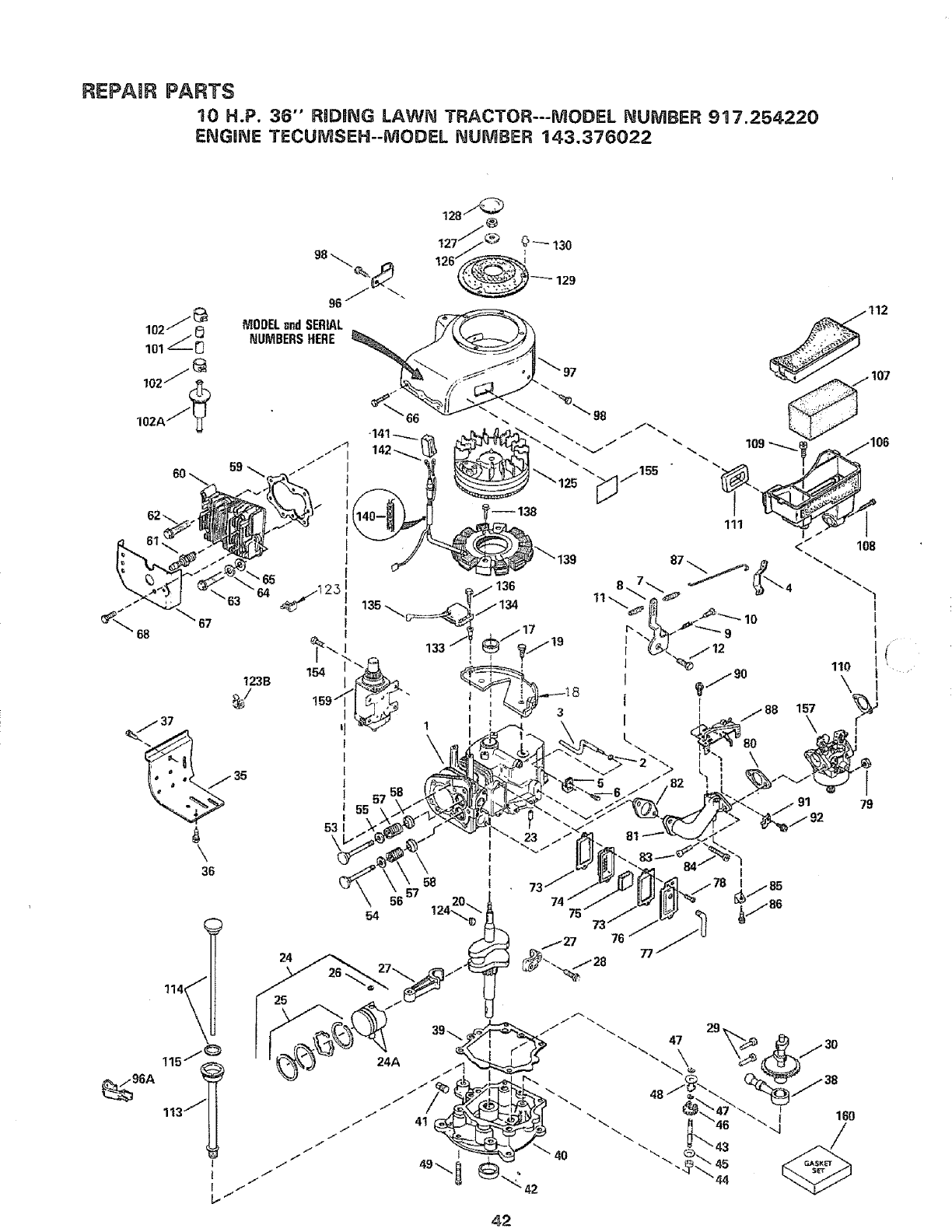
REPAUR PARTS
10 H.P. 36" RiDiNG LAWN TRACTOR---MODEL I'_UiVIBER 917.254220
ENGnNE TECUMSEH--MODEL NUMBER 143.376022
68
96A
98 "..._.
MODEL Bnd SERIAL
NUMBERS HERE
128/'_
127"_ _ 0_130
126r___129
123B
35
\
36
79
,$2
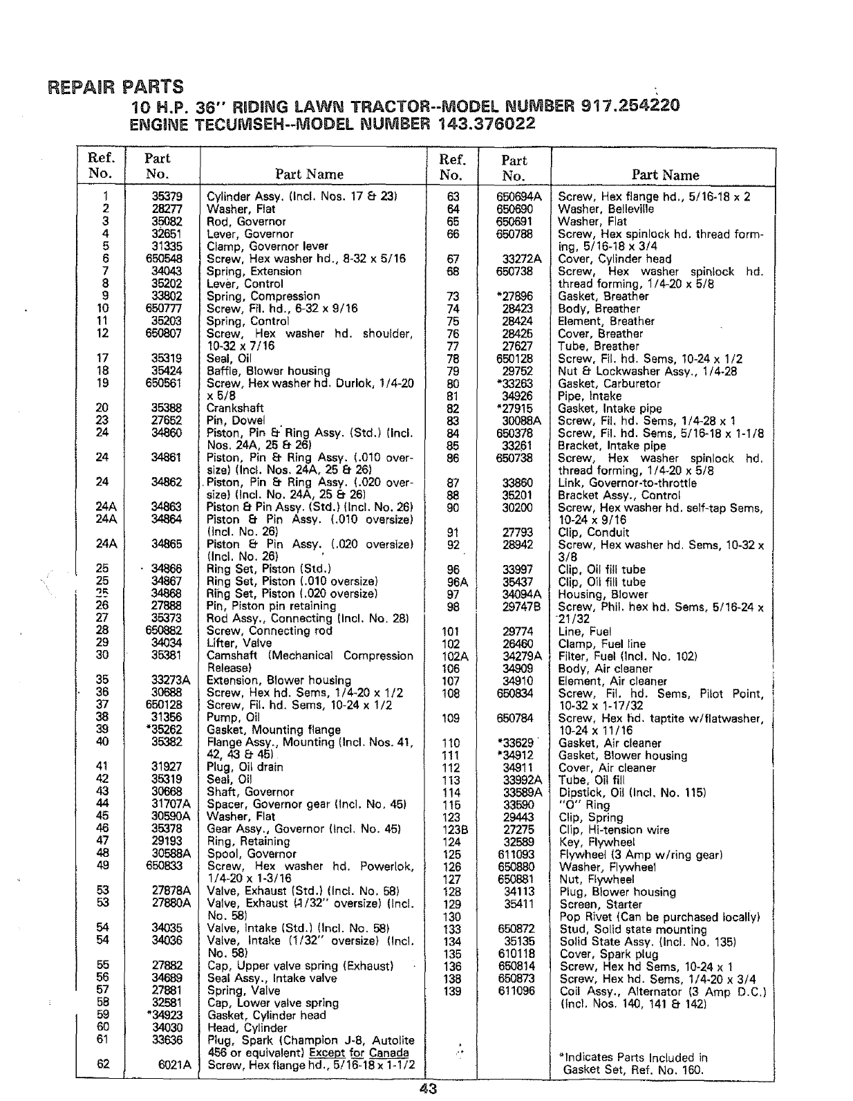
REPAgR PARTS -,
10 H.P. 36" RiDiNG LAWN TRACTOR--MODEL NUMBER 917.254220
ENGINE TECUMSEH--MODEL I_UMBER 143.376022
Ref.
No.
1
2
3
4
5
6
7
8
9
10
11
12
17
18
19
2O
23
24
24
24
24A
24A
24A
25
25
25
26
27
28
29
3O
35
36
37
38
39
4O
41
42
43
44
45
46
47
46
49
53
53
54
54
55
56
57
58
61
P_t
No. P_tName
35379
28277
35O82
32651
31335
650548
34O43
35202
338O2
65O777
35203
650807
35319
35424
650561
35388
27652
3486O
34861
34862
34863
34864
34865
- 34866
34867
34868
27888
35373
65O882
34034
35,381
33273A
30688
650128
31356
*35262
35382
31927
35319
30668
31707A
30590A
35378
29193
30568A
65O833
27878A
27880A
34035
34036
27882
34689
27881
32581
_34923
34030
33636
6021A
Cylinder Assy. (Incl. Nos. 17 8 23)
Washer, Rat
Rod, Governor
Lever, Governor
Clamp, Governor lever
Screw, Hex washer hd, 8-32 x 5/16
Spring, Extension
Lever, Control
Spring, Compression
Screw, Fil. hd,, 6-32 x 9/16
Spring, Control
Screw, Hex washer hd. shoulder,
t0_32 x 7/16
Seal, Oil
Baffle, Blower housing
Screw, Hex washer hd. Duriok, 1/4-20
x 6/8
Crankshaft
Pin, Dowel
Piston, Pin El" Ring Assy. (Std,) (Incl.
Nos, 24A, 25 8- 26)
Piston, Pin _f Ring Assy. (.010 over-
size} (Incl. Nos. 24A, 25 8- 26)
Piston, Pin El- Ring Assy. (.020 over-
size) (Incl. No. 24A, 25 8 26)
Piston 8 Pin Assy. (Std.} (Incl. No. 26)
Piston e Pin Assy. (.0t0 oversize)
(incl. No. 26)
Piston 8- Pin Assy. (.020 oversize)
(Incl. No. 26)
Ring Set, Piston (Std.)
Ring Set, Piston (.010 oversize)
Rihg Set, Piston (.020 oversize)
Pin, Piston pin retaining
Rod Assy., Connecting (Incl. No. 28)
Screw, Connecting rod
Lifter, Valve
Camshaft (Mechanical Compression
Release}
Extension, Blower housing
Screw, Hex hd. Seres, 1/4-20 x 1/2
Screw, Fit. hd. Seres, 10-24 x 1/2
Pump, Oil
Gasket, Mounting flange
Flange Ass,/,, Mounting (Incl, Nos, 4t,
42, 43 _ 45)
Plug, Oil drain
Seal, Oil
Shaft, Governor
Spacer, Governor gear (incl. No. 45)
Washer, Flat
Gear Assy., Governor (tnct, No. 45)
Ring, Retaining
Spool, Governor
Screw, Hex washer hd. Powerlok,
1/4-20 x 1-3/!6
Valve, Exhaust {Std.) (Incl. No. 58)
Valve, Exhaust (-1/32'" oversize) (Incl.
No. 58)
VaLve, tntake (Std.) (lncl. No. 58)
Valve, Intake (1/32" oversize) (incl.
No. 58)
Cap, Upper valve spring (Exhaust)
Seal Assy., Intake valve
Spring, Valve
Cap, Lower valve spring
Gasket, Cylinder head
Head, Cylinder
Plug, Spark (Champion J-8, Autolite
456 or equivalent) Exc_.x£__[for
Screw, Hex flange hd., 5/16-18 x 1-1/2
43-
IR,e
i No.
63
64
65
66
67
68
73
74
75
76
77
78
79
80
81
82
83
84
85
86
87
88
9O
91
92
96
96,
97
98
101
102
102A
106
107
108
109
110
111
112
113
114
115
123
t23B
124
125
126
127
128
129
130
133
134
135
136
138
139
L
Part
No.
650K94A
650_
650691
6507_
33_2A
650738
*278.96
28423
28424
28425
27627
650128
29752
*33263
34926
"27915
30088A
650378
33261
650738
3386O
35201
30200
27793
28942
33997
35437
34094A
29747B
29774
26460
34279A
34809
34910
650834
6507_
*33629 '
*34912
34911
33992A
33589A
3359O
29443
27275
32589
611093
65O88O
650881
34113
35411
650872
35135
610118
650814
650873
611096
P_tName
Screw, Hex flange hd., 5/16-18 x 2
Washer, Belleville
Washer, Flat
Screw, Hex spinlock hd. thread form-
ing, 5/t6-18 x 3/4
Cover, Cylinder head
Screw, Hex washer spinlock hd.
thread forming, 1/4-20 x 5/8
Gasket, Breather
Body, Breather
Element, Breather
Cover, Breather
Tube, Breather
Screw, Fil, hd. Sems, 10-24 x 1/2
Nut 8- Lockwasher Assy., I/4-28
Gasket, Carburetor
Pipe, Intake
Gasket, Intake pipe
Screw, Fil. hd. Sems, 1/4-28 x 1
Screw, Fil. hd. Sems, 5/16-18 x 1-1/8
Bracket, Intake pipe
Screw, Hex washer spinlock hd.
thread formlng, 1/4-20 x 5/8
Link, Governor-to-throttle
Bracket Assy., Controt
Screw, Hex washer hd. self-tap Sems,
10-24 x 9/16
Clip, Conduit
Screw, Hex washer hd. Sems, 10-32 x
3/8
Clip, Oil fill tube
Clip, Oit fill tube
Housing, Blower
Screw, Phil, hex hd, Sems, 5/16-24 x
21/32
Line, Fuel
Clamp, Fuel line
Filter, Fuel (Incl. No, 102)
Body, Air cleaner
Element, Air cleaner
Screw, FiL hd. Sems, Pilot Point,
10-32 x 1-17/32
Screw, Hex hd. taptite w/fiatwasher, '
10-24 x 11/!6
Gasket, Air cleaner
Gasket, Blower housing
Cover, Air cleaner
Tube, Oil fill
Dipstick, Oil (Inc!, No. 115)
"O" Ring
Clip, Spring
Clip, Hi-tension wire
Key, Flywheel
Flywheel (3 Amp w/ring gear)
Washer, Flywheel
Nut, Flywheel
Plug, Blower housing
Screen, Starter
Pop Rivet (Can be purchased locally)
Stud, Solid state mounting
Solid State Assy. (Incl, No, 135)
Cover, Spark plug
Screw, Hex hd Sems, 10-24 x 1
Screw, Hex hd, Sems, 1/4-20 x 3/4
Coil Assy., Alternator (3 Amp D.C,)
(incl, Nos. 140, 141 8- !42)
"Indicates Parts Included tn
Gasket Set, Ref. No. 1_).
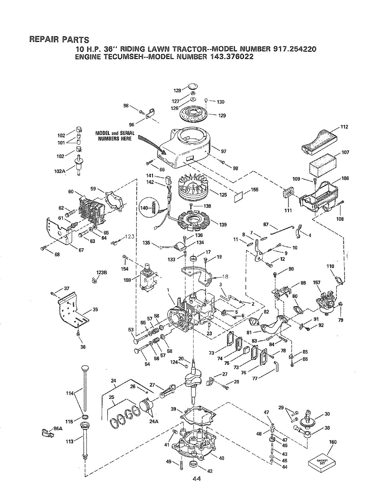
d
\
_s/_
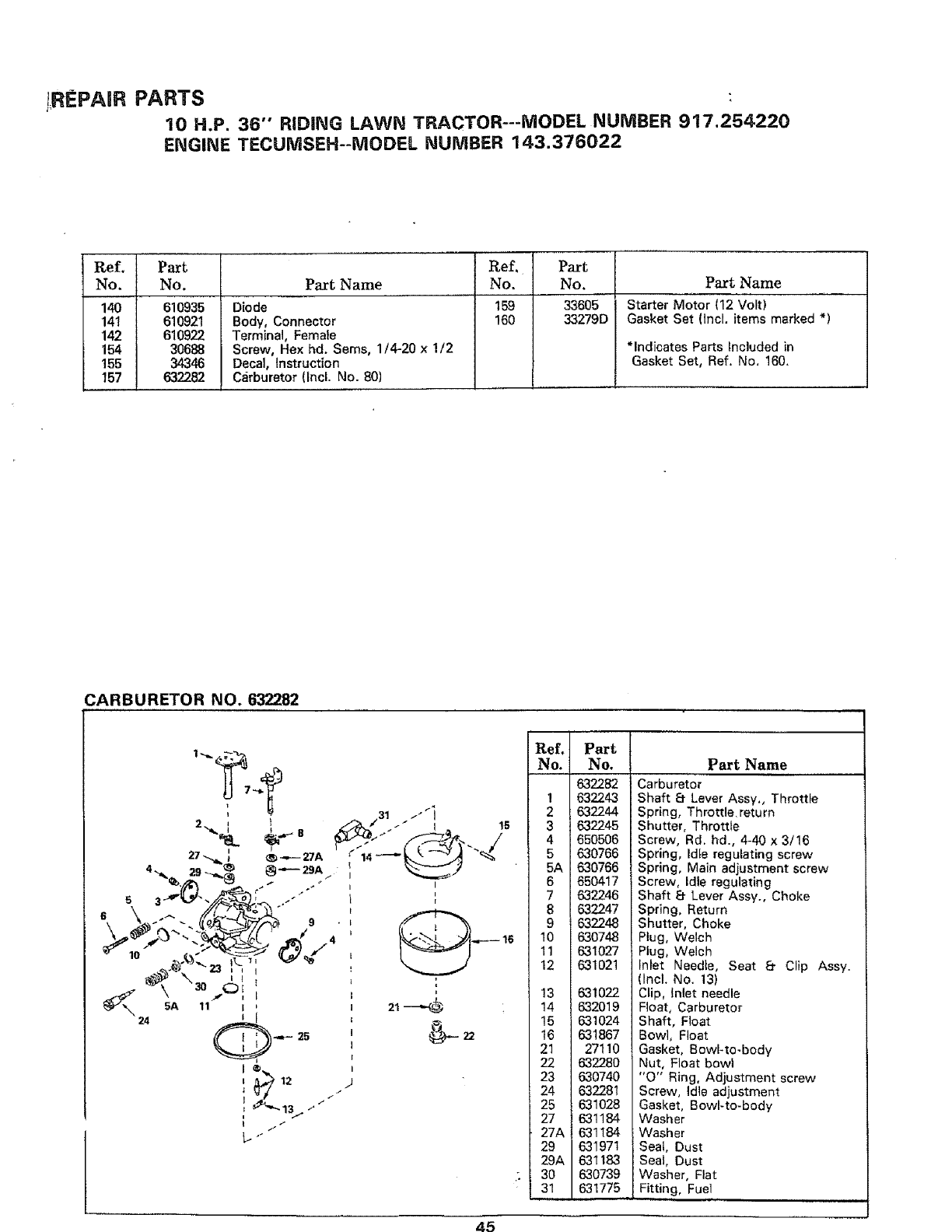
!REPAIR PARTS
10 H.P. 36" RIDING LAWN TRACTOR---MODEL NUMBER 917.254220
ENGINE TECUMSEH--MODEL NUMBER 143.376022
Ref. Part
No. No.
140 610935
14t 610921
142 610922
154 30688
155 34346
157 632282
PartName
Diode
Body, Connector
Terminal, Female
Screw, Hex hd. Seres, 1/4-20 x!/2
Decal, Instruction
Carburetor (lncL No. 80)
Ref. Part
No. No.
159 33605
160 33279D
Part Name
Starter Motor (12 Volt)
Gasket Set (lncl. items marked *)
*Indicates Parts Included in
Gasket Set, Ref. No. 160,
CARBURETOR NO. 632282
Ref.
No.
1
2
3
4
5
5A
6
7
8
9
10
11
12
13
14
15
16
21
22
23
24
25
27
.27A
29
29A
30
31
Part [
No, 1
632282
6322431
6322_ I
632245 l
650505I
630766
630766 1
650417
632246 1
632247 1
i 632248
63o7481
6310271
631021
631022
632019
631024
631867
27110
632280
630740
63228 I
631028
631184
631184
631971
631183
630739
631775
Part Name
Carburetor
Shaft t_ Lever Assy., Throttle
Spring, Throttle return
Shutter, Throttle
Screw, Rd. hd., 4-40 x 3/16
Spring, ldte regulating screw
Spring, Main adjustment screw
Screw, Idle regulating
Shaft 8 Lever Assy., Choke
Spring, Return
Shutter, Choke
Plug, Welch
Plug, Welch
Inlet Needle, Seat _ Clip Assy.
Incl. No. 13)
Clip, Inlet needle
Float, Carburetor
Shaft, Float
Bowl, Float
Gasket, Bowl-to.body
Nut, Float bowl
"O" Ring, Adjustment screw
Screw, Idle adjustment
Gasket, Bowl-to-body
Washer
Washer
Seat, Dust
Seal, Dust
Washer, Flat
Fitting, Fuel
45
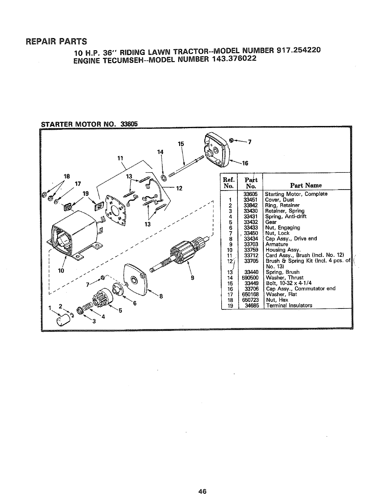
REPAIR PARTS
10 H.P. 36" RiDiNG LAWN TRACTOR--MODEL NUMBER 917.254220
ENGINE TECUNISEH--MODEL NUMBER 143.376022
STARTER MOTOR NO. 33_5
14
11
18
17
19 1
2
3
4
5
6
7
8
9
10
11,
t2i,
]
13
14
15
16
17
18
19
No.
336O5
33451
33842
33430
33431
33432
33433
,33450
33434
33703
33759
33712
33705
33440
59O500
33449
33706
650168
650723
34685
Part Name
Starting Motor, Comp|ete
Cover, Dust
Ring, Retainer
Retainer, Spring
Spring, Anti-drift
Gear
Nut, Engaging
Nut, Lock
Cap Assy., Drive end
Armature
Housing Assy.
Card Assy., Brush (Incl. No. 12)
Brush Er Spring Kit (incl. 4 pcs. of
No. 13)
Spring, Brush
Washer, Thrust
Bolt, 10-32 x 4-1/4
Cap Assy., Commutator end
Washer, Flat
Nut, Hex
Terminal Insulators
46

SUGGESTED GUIDE FOR SIGHTL__ SLOPES FOR SAFE OPERATION
Operate your Tractor up and down the face of slopes (not
greater than 15 °); never across the face. Make turns
gradually to prevent tipping or loss of control. Exercise
extreme caution when changing direction on slopes.
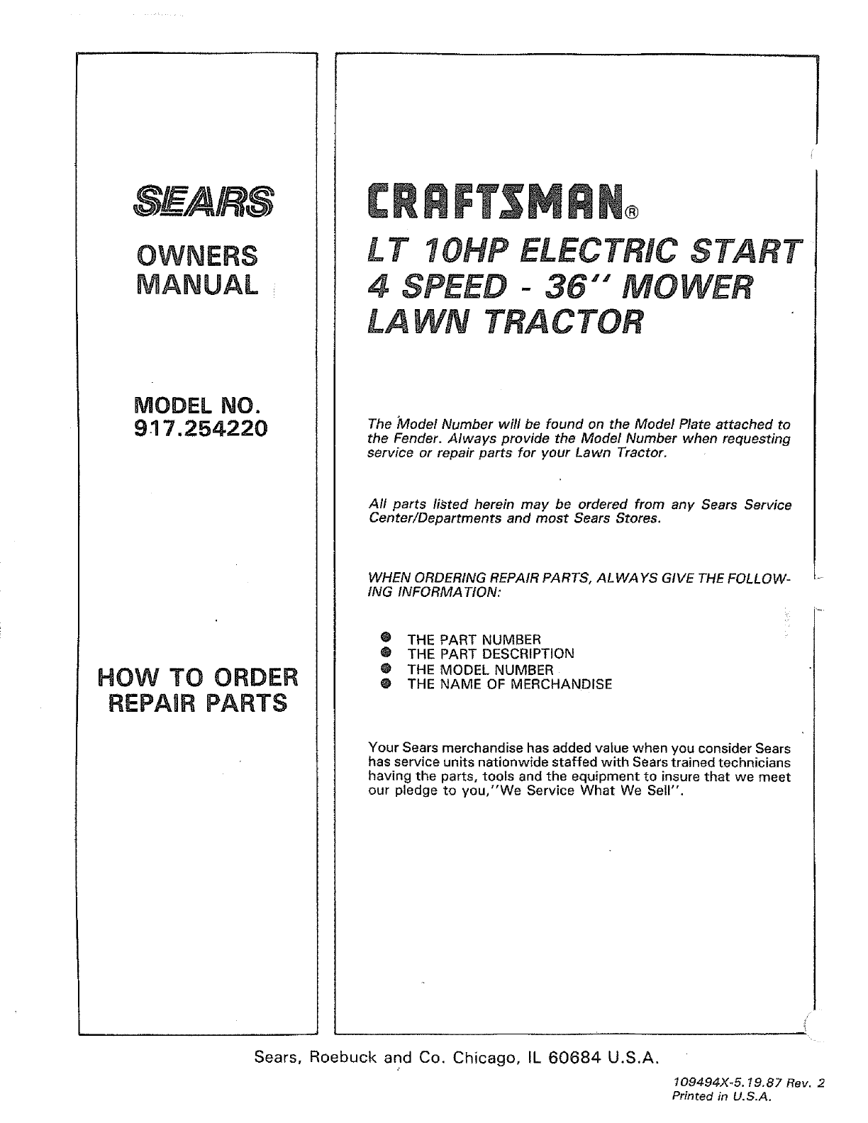
SEA/RS
MODEL NO.
917.254220
HOW TO ORDER
REPAnR PARTS
LT_OHP
4SPEED
LA
N®
ELECTRIC
-36""
TRACTOR
START
The "Model Number will be found on the Model Plate attached to
the Fender. Always provide the Model Number when requesting
service or repair parts for your Lawn Tractor.
All parts listed herein may be ordered from any Sears Service
Center/Departments and most Sears Stores.
WHEN ORDERING REPAIR PARTS, ALWAYS GIVE THE FOLLOW-
ING INFORMATION:
• THE PART NUMBER
0 THE PART DESCRIPTION
@ THE MODEL NUMBER
0 THE NAME OF MERCHANDISE
Your Sears merchandise has added value when you consider Sears
has service units nationwide staffed with Sears trained technicians
having the parts, tools and the equipment to insure that we meet
our pledge to you,"We Service What We Sell".
Sears, Roebuck and Co. Chicago, IL 60684 U.S.A.
109494X-5. 19.87 Rev. 2
Printed in U.S.A.
