Craftsman 917254244 User Manual 38 MOWER LAWN TRACTOR Manuals And Guides L0807631
CRAFTSMAN Lawn, Tractor Manual L0807631 CRAFTSMAN Lawn, Tractor Owner's Manual, CRAFTSMAN Lawn, Tractor installation guides
User Manual: Craftsman 917254244 917254244 CRAFTSMAN 38 MOWER LAWN TRACTOR - Manuals and Guides View the owners manual for your CRAFTSMAN 38 MOWER LAWN TRACTOR #917254244. Home:Lawn & Garden Parts:Craftsman Parts:Craftsman 38 MOWER LAWN TRACTOR Manual
Open the PDF directly: View PDF ![]() .
.
Page Count: 48
,, , ,,,,.
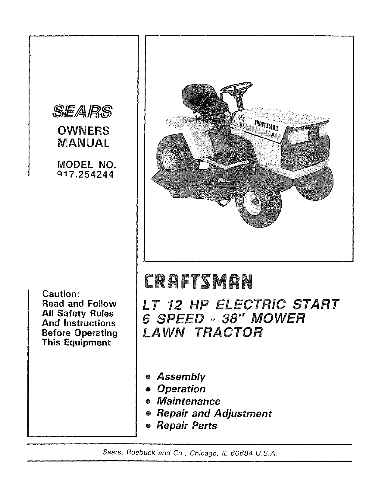
OWNERS
MANUAL
MODEL NO.
q17.254244
Caution:
Read and Follow
All Safety Rules
And instructions
Before Operating
This Equipment
LT 12 HP ELECTRIC START
6 SPEED -38" MOWER
LA WN TRA CTOR
®Assembly
®Operation
eMaintenance
®Repair and Adjustment
®Repair Parts
Sears, Roebuck and Co, Chicago, IL 60684 USA
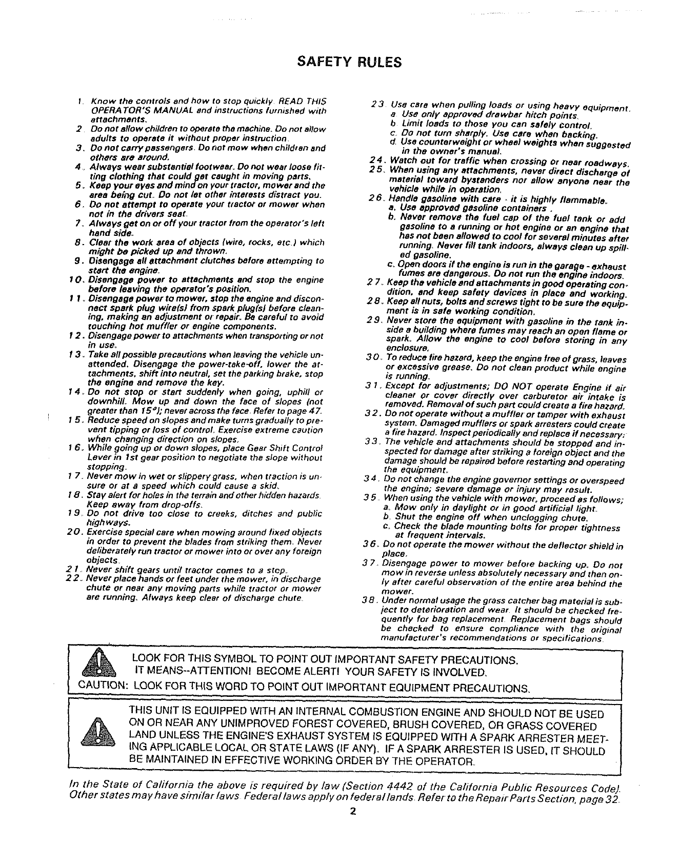
SAFETY RULES
I Know the controls and how to stop quickly READ THIS
OPERA TOR'5 MANUAL end instructions furnished with
attachments,
2 Do not allow children to operate the machine. Do not allow
adults to operate it without proper instruction.
3_ Do not carry passengera Do not mow when childran and
others #tie around.
4oAlways waarsubstantialfootweer_ Donot waarloose fit-
tlng clothing that could get caught in moving parts,
5. Keep your ayes and mind on your tractor, mower and the
area being cut, Do not let other interests distract you.
6. Do not attempt to operate your tractor or mower when
not in the drivers seaL.
7_ Always get on or off your tractor from the operator's left
hand side°
8. Cleat the work area of objects (wire, rocks, etc3 which
might be picked up and thrown,
g. Disengage all attachment clutches before attempting to
start the engine°
100 Disengage power to attachments and stop the engine
before leaving the operator's position.
! I oDisengage power to mower, atop the engine and discon-
nect spark plug wire(s/from spark plug(s) before clean-
ing, making an adjustment or repair° Be careful to avoid
touching hot muffler or engine components.
12. Disengage power to attachments when transporting or not
in use.
13. Take all possible precautions when leaving the vehicle un.
attended. Disengage the power-take-off, lower the at-
tachments, shift into neutral, set the parking brake, stop
the engine and remove the key.
14 oDo not stop or start suddenly when going, uphill or
downhill Mow up and down the face of slopes (not
greater than 15 el; never across the face. Refer to page 47.
15_ Reduce speed on slopes and make turns gradually to pre-
vent tipping or loss of control Exercise extreme caution
when changing direction on slopes_
16, While going up or down slopes, place Gear Shift Control
Lever ln Ist gear posltion to negotiate the slope without
stopping.
17 o Never mow in wet or slippery grass, when traction is Uno
sure or at e speed which could cause a skid_
t8. Stay alert for holes in the terrain and other hidden hazards.
Keep away from drop-offs_
19, Do not drive too close to creeks, ditches and public
highways.
20. Exercise special care when mowing around fixed objects
in order to prevent the blades from striking them Never
deliberately run tractor or mower into or over any foreign
objects
2 t Never shift gears until tractor comes to astop.
22 Never place hands or feet under the mower, in discharge
chute or near any moving parts while tractor or mower
are running, Always keep clear of discharge chute
23 Use care when pulling loads or using heavy equipment.
aUse only approved drawbar hitch points,
b Limit loads to those you can safely control
e, Do not turn sharply. Use care when backing.
d Use counterweight or wheel weights when suggested
in the owner's manual.
24. Watch out for traffic when crossing or near roadways.
25, When using any attachments, never direct discharge of
material toward bystanders nor allow anyone near the
vehicle while in operation.
26_ Handle gasoline with care -it is highly flammable°
a. Use approved gasoline containers o
b. Never remove the fuel cap of the fuel tank or add
gasoline to a running or hot engine or an engine that
has not been allowed to cool for several minutes after
running, Never fill tank indoors, always clean up spill-
ed gasoline.
c. Open doors ff the engine is run in the garage -exhaust
fumes ere dangerous° Do not run the engine indoors.
27° Keep the vehicle and attachments in good operating con*
dillon, and keep safety devices in place and working,
2 8° Keep all nuts, bolts and screws tight to be sure the equip*
ment is in safe working condition,
29. Never store the equipment with gasoline in the tank in.
side a building where fumes may reach an open flame or
spark° Allow the engine to cool before storing in any
enclosure,
30_ To reduce.fire hazard, keep the engine free of grass, leaves
or excessive grease. Do not clean product while engine
is running=
3 I, Except for adjustments; DO NOT operate Engine if air
cleaner or cover directly over carburetor air intake is
removed. Removal of such part could create a fire hazard°
32. Do not operate without a muffler or tamper with exhaust
system_ Damaged mufflers or spark arresters could create
afire hazard. Inspect periodically and replace ff necessary:
33 The vehicle and attachments should be stopped and in-
spected for damage after striking a foreign object and the
damage should be repaired before restarting and operating
the equipment°
34 Do not change the engine governor settings or overspeed
the engine; severe damage or injury may result.
35 When using the vehicle with mower; proceed as follows;
aMow only in daylight or in good artificial light,
bShut the engine off when unclogging chute.
c_ Check the blade mounting bolts for proper tightness
at frequent intervals.
36. Do not operate the mower without the deflector shield in
place,
37, Disengage power to mower before backing up. Do not
me w in reverse unless absolutely necessary and then on-
ly after careful observation of the entire area behind the
mower.
38. Under normal usage the grass catcher bag material is sub:
ject to deterioration and wear It should be checked fre-
quently for bag replacement Replacement bags should
be checked to ensure compliance with the original
manufacturer's recommendations or specifications
LOOK FOR THIS SYMBOL TO PO NT OUT IMPORTANT SAFETY PRECAUTIONS.
T MEANS--ATTENTIONI BECOME ALERTI YOUR SAFETY IS INVOLVED_
CAUTION: LOOK FOR THIS WORD TO POINT OUT IMPORTANT EQUIPMENT PRECAUTIONS.
',, , ' ,,,
THIS UNIT IS EQUIPPED WITH AN INTERNAL COMBUSTION ENGINE AND SHOULD NOT BE USED
ON OR NEAR ANY UNIMPROVED FOREST COVERED, BRUSH COVERED. OR GRASS COVERED
LAND UNLESS THE ENGINE'S EXHAUST SYSTEM IS EQUIPPED WITH A SPARK ARRESTER MEET-
ING APPLICABLE LOCAL OR STATE LAWS (IF ANY). IF A SPARK ARRESTER IS USED, IT SHOULD
BE MAINTAINED IN EFFECTIVE WORKING ORDER BY THE OPERATOR
In the State of Cafifornia the above is required by law (Section 4442 of the Cafifornia Public Resources Code)
Other states may have st)77t'iarfaws Fedet al laws app/y on federal lands Refet to the Repair Parts Section. page32
2
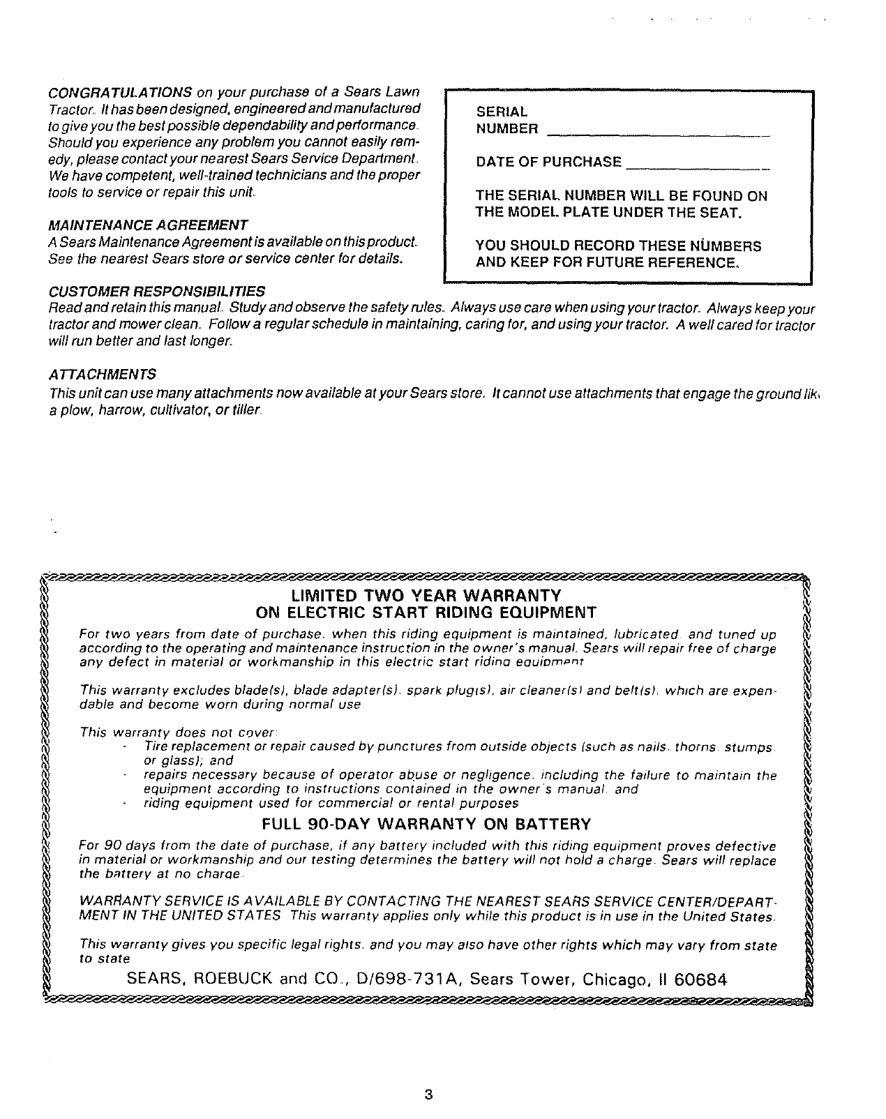
CONGRATULATIONS on your purchase of a Sears Lawn
Tractor It has been designed, engineered and manufactured
to give you the best possible dependability and performance.
Should you experience any problem you cannot easily rem-
edy, please contact your nearest Sears Service Department
We have competent, well-trained technicians and the proper
tools to service or repair this uniL
MAINTENANCE AGREEMENT
A Sears Maintenance Agreement is available on this product.
See the nearest Sears store or service center for details.
SERIAL
NUMBER
DATE OF PURCHASE
THE SERIAL NUMBER WILL BE FOUND ON
THE MODEL PLATE UNDER THE SEAT.
YOU SHOULD RECORD THESE NLIMBERS
AND KEEP FOR FUTURE REFERENCE.
CUSTOMER RESPONSIBILITIES
Read and retain this manual Study and observe the safety rules. Always use care when using your tractor. Always keep your
tractor and mower clean_ Follow a regular schedule in maintaining, caring for, and using your tractor. A well cared for tractor
will run better and last longer.
A TTA CHMEN TS
This unit can use many attachments now available at your Sears store. It cannot use attachments that engage the ground lik,
a plow, harrow, cultivator, or tiller
LIMITED TWO YEAR WARRANTY
ON ELECTRIC START RIDING EQUIPMENT
For two years from date of purchase, when this riding equipment is maintained, lubricated and tuned up
according to the operating and maintenance instruction in the owner's manual, Sears will repair free of charge
any defect in material or workmanship in this electric start ridino eouiom_m
This warranty excludes blade(s), blade adapterls), spark pluglsl, air cleanerlsl and beltlel which are expen-
dable and become worn during normal use
This warranty does not cover:
Tire replacement or repair caused by punctures from outside objects tauch as nails, thorns, stumps
or glass); and
repairs necessary because of operator at]use or negligence, including the failure to maintain the
equipment according to instructions contained in the owner's manual and
riding equipment used for commercial or rental purposes
FULL 90-DAY WARRANTY ON BATTERY
For 90 days from the date of purchase, if any battery included with this riding equipment proves defective
in material or workmanship and our testing determines the battery will not hold a charge. Sears will replace
the battery at no charcle
WARRANTY SERVICE IS AVAILABLE BY CONTACTING THE NEAREST SEARS SERVICE CENTER/DEPART-
MENT IN THE UNITED STATES This warranty applies only while this product is in use in the United States
This warranty gives you specific legal rights, and you may also have other rights which may vary from state
to state
SEARS, ROEBUCK and CO, D/698-731A, Sears Tower, Chicago, !1 60684
3
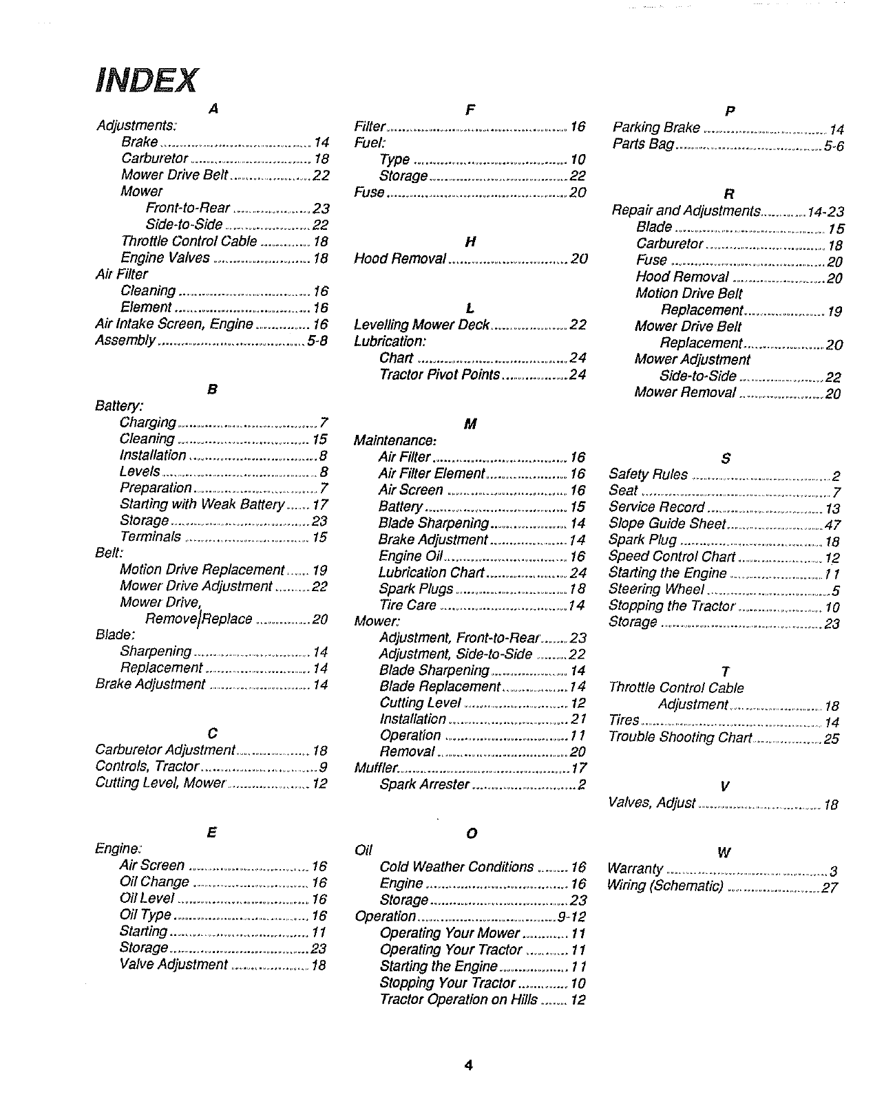
INDEX
A
Adjustments:
Brake ...............................................14
Carburetor ................................... 18
Mower Drive Belt ........................22
Mower
Front-to-Rear .......................23
Side-to-Side ....................... 22
Throttle Control Cable .............. 18
Engine Valves ......................... 18
Ak Filter
Cleaning ...................................... 16
Element .................................... 16
Air Intake Screen, Engine ............... 16
Assembly ........................................ 5-8
B
Battery:
Charging ...................................... 7
Cleaning .................................. 15
Installation .................................. 8
Levels ................................................8
Preparation ........................................7
Staffing with Weak Battery ....... 17
Storage .........................................23
Terminals ...........................................15
Belt:
Motion Drive Replacement ....... 19
Mower Drive Adjustment ...........22
Mower Drive,
Remove]Replace .................20
Blade:
Sharpening ...........................................14
Replacement .................................14
Brake Adjustment ..................................14
C
Carburetor Adjustment .......................18
Controls, Tractor. ................................ 9
Cutting Level, Mower ...................... 12
E
Engine:
Air Screen .....................................16
Oil Change ......................................16
OilLevel ..................................... 16
Oil Type .........................................16
Staffing ............................................11
Storage ........................................ 23
Valve Adjustment .......................18
F
Filter ..................................................... 16
Fuel:
Type ......................................... 10
Storage ..................................... 22
Fuse ............................................... 20
H
Hood Removal ............................... 20
L
Levelling Mower Deck .................... 22
Lubrication:
Chaff ........................................ 24
Tractor Pivot Points ................... 24
M
Maintenance:
Air Filter ................................... 16
Air Filter Element ....................... 16
Air Screen ....................................16
Battery ...................................... 15
Blade Sharpening ..................... 14
Brake Adjustment .......................14
Engine Oil ................................. 16
Lubrication Chaff ....................... 24
Spark Plugs ................................ 18
Tire Care .................................. 14
Mower:
Adjustment, Front-to-Rear ........23
Adjustment, Side-to-Side .........22
Blade Sharpening ........................14
Blade Replacement ................... 14
Cutting Level .............................. 12
Installation .................................. 21
Operation .................................. 11
Removal .................................... 20
Muffler. ............................................... 17
Spark Arrester ............................ 2
0
Oil
Cold Weather Conditions ........ 16
Engine ..................................... 16
Storage ...................................... 23
Operation ....................................... 9-12
Operating Your Mower ............. 11
Operating Your Tractor ........... 11
Staffing the Engine .................. 11
Stopping Your Tractor ............... 10
Tractor Operation on Hills ....... 12
P
Parking Brake .............................................14
Paffs Bag ....................................................5-6
R
Repa# and Adjustments ...............14-23
Blade ..................................................15
Carburetor .......................................18
Fuse .................................................20
Hood Removal ..............................20
Motion Drive Belt
Replacement .........................19
Mower Drive Belt
Replacement ..........................20
Mower Adjustment
Side4o-Side .........................22
Mower Removal ........................ 20
S
Safety Rules ................................................2
Seat ...............................................................7
Service Record ........................................13
Slope Guide Sheet ......................................47
Spark Plug ...........................................18
Speed Control Chaff ...........................12
Staffing the Engine ..............................11
Steering Wheel ........................................5
Stopping the Tractor ...............................10
Storage ...........................................................23
T
Throttle Control Cable
Adjustment .......................................18
Tires ..................................................................14
Trouble Shooting Chaff .........................25
V
Valves, Adjust ..............................................18
w
Warranty .....................................................3
Wiring (Schematic) ..............................27
4
,Y
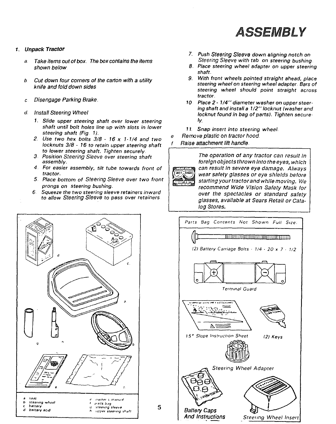
1. Unpack Tractor
a Take items out of box, The box contains the items
shown below
b Cut down four corners of the carton with a utility
knife and fold down sides
c Disengage Parking Brake
dInstall Steering Wheel
1, Slide upper steering shaft over lower steering
shaft until bolt holes line up with slots in lower
steering shaft (Fig 11_
2 Use two hex bolts 3/8- 16 x 1-1/4 and two
Iocknuts 3/8 -16 to retain upper steering shaft
to lower steering shaft. Tighten securely
3 Position Steering Sleeve over steering shaft
assembly_
4 For easier assembly, tilt tube towards front of
tractor.,
5 Place bottom of Steering Sleeve over two front
prongs on steering bushing,
6Squeeze the two steering sleeve retainers inward
to allow Steering Sleeve to pass over retainers
b5reefing wh_l
Cbaffory
db_flel¥ Bctd
tj_ It t$ 1),1_ 5
7. Push Steering Sleeve down aligning notch on
Steering Sleeve with tab on steering bushing
8, Place steering wheel adapter on upper steering
shaft.
9_ With front wheels pointed straight ahead, place
steering wheel on steering wheel adapter Bars of
steering wheel should point straight across
tractor
10 Place 2 -1/4" diameter washer on upper steer-
ing shaft and install a1/2" Iocknut (washer and
Iocknut found in bag of parts). Tighten secure
ly.
11, Snap insert into steering wheel
e Remove plastic On tractor hood
f Raise attachment lift handle,
The operation of any tractor can result In
foreign objects thrown Into the eyes, which
can result In severe eye damage. Always
wear safety glasses or eye shields before
startlng yourtractor andwhlle movlng° We
recommend Wide Vision Safety Mask for
over the spectacles or standard safety
glasses, available at Sears Retail or Cata-
log Stores.
Parrs Bag Contents Nor Shown Full Size:
....... Iilll!lt!lilJ._illlllll!littlllIIHIjlIIjH_
12l Battery Carriage Bolls 1/4 -20 x7•t/2
Terrmnal Guard
15 °Slope Insrrucfron 5heel
@
ring
Battery Caps
And Instructions
12l Keys
Wheel Adapter
Steering Wheel Inset!l
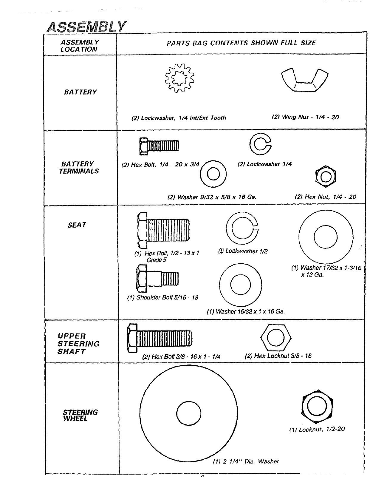
ASSEMBLY
ASSEMBLY PARTS BAG CONTENTS SHOWN FULL SIZE
LOCATION
BA T TER Y
BA TTER Y
TERMINALS
SEAT
UPPER
STEERING
SHAFT
STEERING
WHEEL
©
(21 Lockwasher, I/4 Int/Ext Tooth (2) Wing Nut _1/4 -20
m
(2) Hex Bolt, I/4 -20 x 3/4 /P_
©
(2) Lockwasher 1/4
(2) Washer 9/32 x 5/8 x 16 Ga,
©
(2) Hex Nut, 1/4 --20
(1) Hex Bolt, 1/2 -13 x1
Grade5
(1) Shoulder Bolt S/16- 18
Q
(J) Lockwashet 1/2
(I) Washer 15/32x 1x16 Ga.
(1) Washer 17/32x I-3/16
x12 Ga.
(2) Hex Bolt 3/8 -16x 1 -I/4 ©
(2) Flex Locknut 3/8 -16
"" Dia. Washer
(1) Locknut, 1/2-20
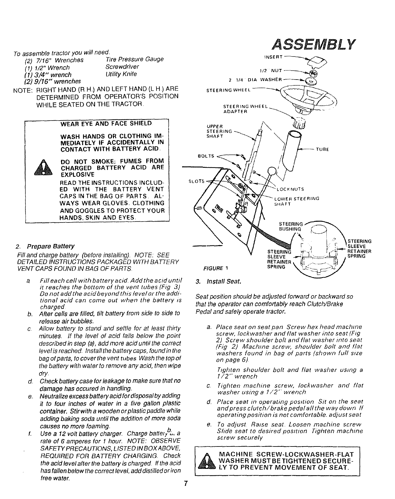
Toassembletractoryouwillneed:
(2) 7/16"Wrenches TirePressureGauge
(1)1/2"Wrench Screwdriver
(I) 3/4" wrench Utility Knife
(2) 9/16" wrenches
NOTE: RIGHT HAND (RH) AND LEFT HAND (L H) ARE
DETERMINED FROM OPERATOR'S POSITION
WHILE SEATED ON THE TRACTOR
WEAR EYE AND FACE SHIELD
WASH HANDS OR CLOTHING IM-
MEDIATELY IF ACCIDENTALLY IN
CONTACT WITH BATTERY ACID
DO NOT SMOKE; FUMES FROM
CHARGED BATTERY ACID ARE
EXPLOSIVE
READ THE INSTRUCTIONS INCLUD-
ED WITH THE BATTERY VENT
CAPS IN THE BAG OF PARTS AL-
WAYS WEAR GLOVES, CLOTHING
AND GOGGLES TO PROTECT YOUR
HANDS, SKIN AND EYES
2 1/4 DIA
STEERING WHEEL
ASSEMBLY
INSERT
1/2
STEERING WHEEL
UPPER ADAPTER
STE
SHAFT
_CK NUTS
STEER}NG
SHAFT
STEERIN(
BUSHING
2, Prepare Battery
Fill and charge battery (before installing) NOTE: SEE
DETAILED INSTRUCTIONS PACKAGED WITH BATTERY
VENT CAPS FOUND IN BAG OF PARTS
a Fill each cell with battery acid Add the acid until 3.
it reaches the bottom of the vent tubes (Fig 3)
Do not add the acid beyond this /eve/ or the addi-
tional acid can come out when the battery is
charged
b After cells are rifled, tilt battery from side to side to
release air bubbles.,
c Allow battery to stand and settle for at least thirty a_
minutes If the level of acid falls below the point
described in step (a), add more acid until the correct
level is reached Instafl the battery caps, found in the
bag of parts, to cover the vent tubes Wash the top of
the battery with water to remove any acid, then wipe
dry
dCheck battery case for leakage to make sure that no
damage has occured in handling, c
e. Neutralize excess battery acid for disposal by adding
it to four inches of water in a five gallon plastic d,
container. Stir with a wooden or plastie paddle while
adding baking soda until the addition of more soda
causes no more foaming _, e
L Use a 12 volt battery charger Charge batteo,"=, a
rate of 6 amperes for 1 hour, NOTE: OBSERVE
SAFETYPRECAUTIONS. LISTEDINBOXABOVE. [_
REQUIRED FOR BATTERY CHARGING Check
the acid level after the battery is charged If the acid
has fallen below the correct level, add distilled or iron
free water, 7
FIGURE 1
Install Seat.
STEERING
SLEEVE
RETAINER k
SPRING
STEERING
SPRING
Seat position should be adjusted forward or backward so
that the operator can comfortably reach Clutch/Brake
Pedal and safely operate tractor.
Place seat on seat pan Screw hex head machine
screw, Iockwasher and flat washer into seat (Fig
2) Screw shoulder bolt and flat washer into seat
(Fig 2) Machine screw, shoulder bolt and flat
washers found in bag of parts (shown full size
on page 6)
Tighten shoulder bolt and flat washer using a
1/2"" wrench
Tighten machine screw, [ockwasher and flat
washer using a 1/2'" wrench
Place seat in operating position Sit on the seat
andpress clutch/brake pedal all the way down If
operating position is not comfortable, adjust seat
To adjust Raise seat Loosen machine screw
Shde seat to desired position Tighten machine
screw securely
MACHINE SCR EW-LOCKWASH ER-FLAT
WASHER MUST BETIGHTENED SECURE-
LY TO PREVENT MOVEMENT OF SEAT. I
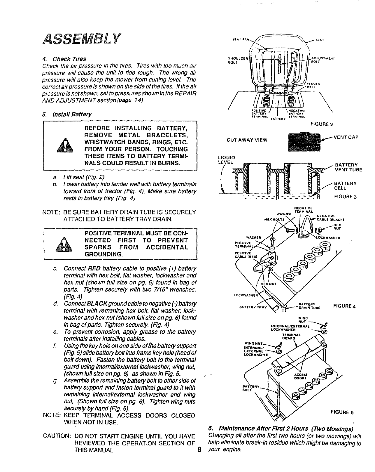
ASSEMBL Y
4. Check Tires
Check the air pressure in the t#es. Tires with too much air
pressure will cause the unit to ride rough. The wrong air
pressure will also keep the mower from cutting level. The
coFect air pressum is shown on the side of the timso ff the ait
pf _ssure is not shown, set to pressures shown in the REPAIR
AND ADJUSTMENT sectionlpage 14).
5o Install Battery
a_
bo
BEFORE INSTALLING BATTERY,
REMOVE METAL BRACELETS,
WRISTWATCH BANDS, RINGS, ETC.
FROM YOUR PERSON. TOUCHING
THESE ITEMS TO BATTERY TERMI-
NALS COULD RESULT IN BURNS.
Lift seat (Fig. 2)_
Lower battery into fender well with battery terminals
toward front of tractor (Fig° 4), Make sure battery
rests in battery tray (Fig 4)
NOTE: BE SURE BATTERY DRAIN TUBE IS SECURELY
ATTACHED TO BATTERY TRAY DRAIN,
NOTE:
POSITIVETERMiNALMUSTBEcON-7
NECTEDFIRSTTO PREVENT/
SPARKS FROM ACCIDENTAL |
GROUNDING J
Connect RED battery cable to positive (+) battery
terminal with hex bolt, flat washer, Iockwasher and
hex nut (shown full size on pg. 6) found in bag of
parts. Tighten securely with two 7/16" wrenches.
(Fig. 4)
d. Connect BLACKground cable to negative (-) battery
terminal with remaning hex bolt, flat washer, lock-
washer and hex nut (shown full size on pg. 6) found
in bag of parts. Tighten securely. (Fig. 4)
e To prevent corrosion, apply grease to the battery
terminals after installing cables.
L Usingthekeyholeononesideof_ebatterysupport
(Fig=5) slide battery boll into frame key hole (head of
boll down). Fasten the battery bolt to the terminal
guard using internal/external Iockwasher, wing nut,
(shown full size on pg. 6) as shown in F_g.5.
g. Assemble the remaining battery boll to other side of
battery support and fasten terminal guard to it with
remaining internal/external Iockwasher and wing
nut, (Shown full size on pg_ 6). Tighten wing nuts
securely by hand (Fig. 5).
KEEP TERMINAL ACCESS DOORS CLOSED
WHEN NOT IN USE.
CAUTION: DO NOT START ENGINE UNTIL YOU HAVE
REVIEWED THE OPERATION SECTION OF
THIS MANUAL 8
SHOULOER AOJUSTM_Nt
6QLT _OLT
T_RMINA_ T_RM_NAL
UAT £RV
F|GURE 2
CU'f AWAY VIEW
VENT CAP
LIQUID
LE/VEL _ _ f BATTERY
g_ _ _J _ R _ /BATTERY
_" ." {1 ._'..~- ~-"_-"_1 FIGURE 3
WASHER
P_t_VE
TERMINAlf
POSITIVE
CABLE(RED_
\
WASHER
NEGATIVE
TERMINAL
NEGATtVE
BATTERy
BATTERY TRAY FIGURE4
FIGURE 5
6. Maintenance After First 2 Hours (Two Mowlngs)
Changing oil alter the first two hours (or two mowings) will
help eliminate break-in residue which might be damaging to
your engine_
KNOW YOUR TRACTOR
OPERATION
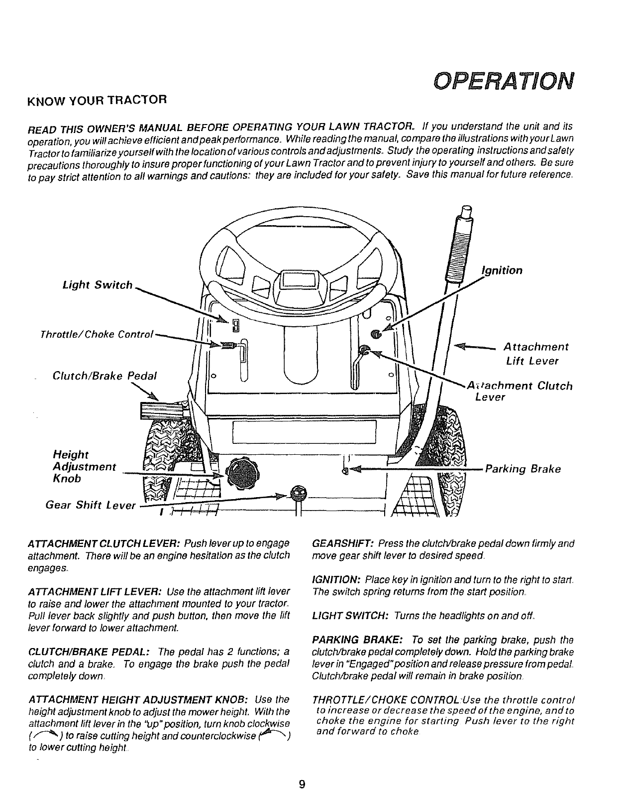
READ THIS OWNER'S MANUAL BEFORE OPERATING YOUR LAWN TRACTOR. If you understand the unit and its
operation, youwillachieveefficientandpeakpedormance, Whilereadingthemanual, comparetheillustrationswithyourLawn
Tractor to familiarize yourself with the location of various controls and adjustments,, Study the operating instructions and safety
precauti_ns th_r_ugh_y t_ insure pr_per functi_ning _f y_ur Lawn Tract_r and t_ prevent injury t_ y_urse_f and _thers. Be sure
to pay strict attention to all warnings and cautions: they are included for your safety,, Save this manual for future reference+
Light Switch
Throttle/Choke
Clutch/Brake Pedal :hment Clutch
Lever
Height
Adjustment
Knob
Gear Shift
J
Parking Brake
ATEA CHMENT CLUTCH LEVER: Push lever up to engage
attachment. There will be an engine hesitation as the clutch
engages.
ATTACHMENT LIFT LEVER: Use the attachment lift lever
to raise and lower the attachment mounted to your tractor,
Pull lever back slightly and push button, then move the rift
lever forward to lower attachment+
CLUTCH/BRAKE PEDAL: The pedal has 2 functions; a
clutch and a brake To engage the brake push the pedal
completely down
ATTACHMENT HEIGHT ADJUSTMENT KNOB: Use the
height adjustment knob to adjust the mower heighL With the
attachment lift lever in the 'tJp" positiono turn knob clockwise
(F-_ ) to raise cutting height and counterclockwise ('_'-_ )
to lower cutting height
GEARSHIFT: Press the clutclVbrake pedal down firmly and
move gear shift lever to desired speed
IGNITION: Place key in ignition and turn to the right to starL
The switch spring returns from the start position,,
LIGHT SWITCH: Turns the headlights on and ofL
PARKING BRAKE: To set the parking brake, push the
clutclVbrake pedal completely down. Hold the parking brake
lever in "Engaged"position and release pressure from pedal,
Clutch/brake pedal will remain in brake position
THROTTLE/CHOKE CONTROL Use the throttle control
to increase or decrease the speed of the engine, and to
choke the engine for starting Push lever to the right
and forward to choke
9
OPERATION
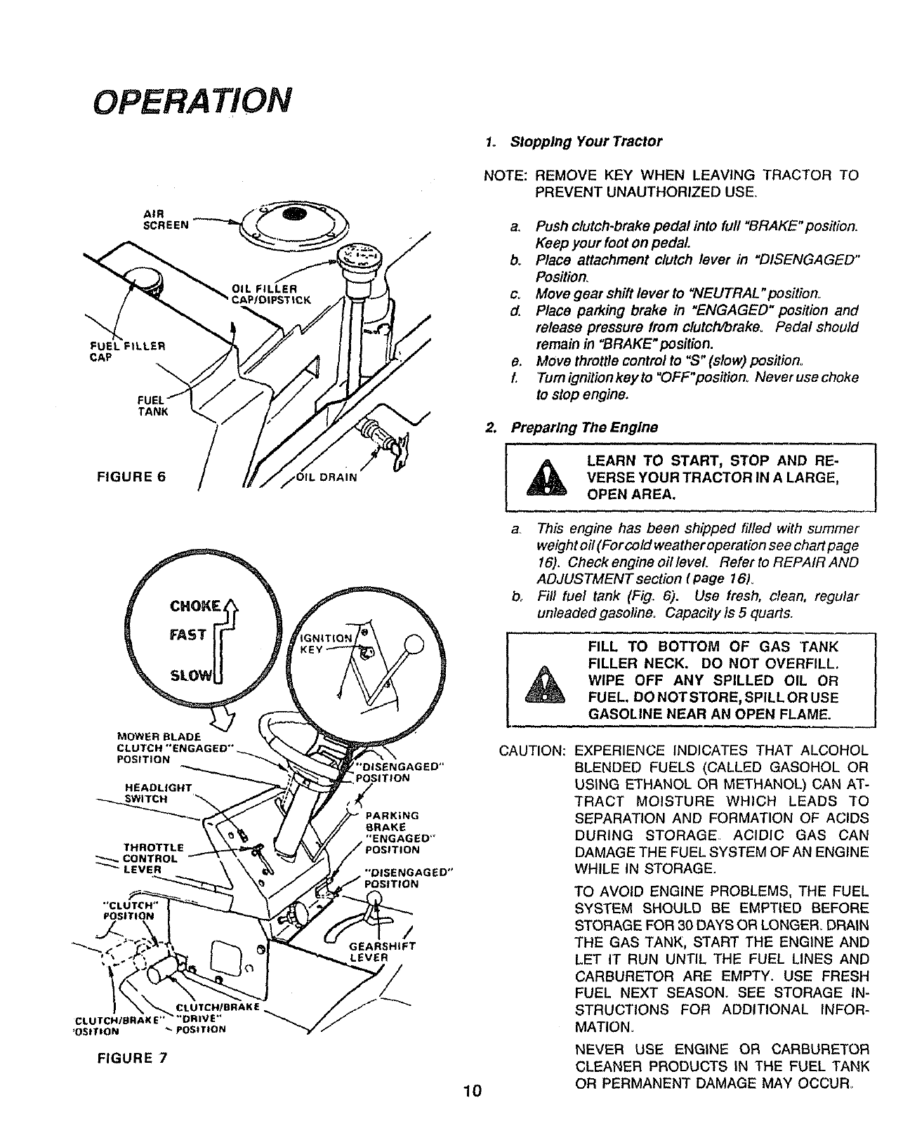
1o Stopping Your Tractor
AIR
SCREEN
FUEL FILLER
CAP
TANK
FIGURE 6
MOWER BLADE
POSITION
HEADLIGHT
_.,_WITCH
"CLUTCW'
POSITION
FIGURE 7
DRAIN
_"DISENGAGED"
POSITION
PARKING
BRAKE
"ENGAGED"
/
GEARSHIFT
LEVER
NOTE:
a,
b.
c_
2.
10
REMOVE KEY WHEN LEAVING TRACTOR TO
PREVENT UNAUTHORIZED USE
d.
e.
f.
Push clutch-brake pedal into full "BRAKE"position,
Keep your foot on pedal.
Place attachment clutch lever in "DISENGAGED"
Position,
Move gear shift lever to "NEUTRAL " position_
Place parking brake in "ENGAGED" position and
release pressure from clutch/brakeo Pedal should
remain in "BRAKE"position.
Move throttle control to "S" (slow) position°
Turn ignition key to "OFF"position, Never use choke
to stop engine.
Preparing The Engine
, , .... ,
_LEARN TO START, STOP AND RE-
VERSE YOUR TRACTOR IN A LARGE,
OPEN AREA.
a Tills engine has been shipped filled with summer
weight oil (For cold weather operation see chart page
16). Check engine oil level Refer to REPAIR AND
ADJUSTMENT section (page 161o
b, Fill fuel tank (Fig. 6). Use fresh, clean, regular
unleaded gasoline. Capacity is 5quarts.
FILL TO BOTTOM OF GAS TANK
FILLER NECK. DO NOT OVERFILL.
WIPE OFF ANY SPILLED OIL OR
FUEL. DO NOT STORE, SPILL OR USE
GASOLINE NEAR AN OPEN FLAME.
CAUTION: EXPERIENCE INDICATES THAT ALCOHOL
BLENDED FUELS (CALLED GASOHOL OR
USING ETHANOL OR METHANOL) CAN AT-
TRACT MOISTURE WHICH LEADS TO
SEPARATION AND FORMATION OF ACIDS
DURING STORAGE ACIDIC GAS CAN
DAMAGE THE FUEL SYSTEM OF AN ENGINE
WHILE IN STORAGE.
TO AVOID ENGINE PROBLEMS, THE FUEL
SYSTEM SHOULD BE EMPTIED BEFORE
STORAGE FOR 30 DAYS OR LONGER, DRAIN
THE GAS TANK, START THE ENGINE AND
LET IT RUN UNTIL THE FUEL LINES AND
CARBURETOR ARE EMPTY. USE FRESH
FUEL NEXT SEASON. SEE STORAGE IN-
STRUCTIONS FOR ADDITIONAL INFOR-
MATION
NEVER USE ENGINE OR CARBURETOR
CLEANER PRODUCTS IN THE FUEL TANK
OR PERMANENT DAMAGE MAY OCCUR
3. StaRing The Engine
a,. Move throttle control lever (Fig., 7) past "FAST"to the
"CHOKE" position.
b. Tumignitionkeyto "START"andreleasekeyassoon
as engine starts.
CAUTION: DO NOT RUN STARTER CONTINUOUSLY
FOR MORE THAN FIFTEEN SECONDS PER
MINUTE,.
c, If engine does not start after four or five tries, move
throttle control lever to "FAST" position, wait a few
minutes and try again,, If the engine does not start
after four or five more tries, see the TROU-
BLESHOOTING Chart (page 25),
d After the engine starts move throttle control lever
slowly to the "SLOW"position
e To start a hot engine move the throttle control lever
to a position between "FAST" and "SLOW"
READ THE "RULES FOR SAFE J
OPERATION" CAREFULLY BEFORE
OPERATING YOUR MOWER.
OPERATION
ATTACHMENT CLUTCH
LEVER "DISENGAGED*'
POSITION
HEIGHT ATTACHMENT CLUTCH
ADJUSTMENT LEVER "ENGAGED"
KNOB POSIT!ON
LIFT LEVER
;R LIFT LEVER
'OSITION
LIFT LEVEF
POSITION
RUNNER
GUARD
CAUTION: DO NOT ADD ADDITIONAL WEIGHT TO THE
TRACTOR OTHER THAN THE OPTIONAL
WHEEL WEIGHTS. EXCESSIVE WEIGHT
MAY OVERLOAD AND DAMAGE THE
TRANSMISSION
l _ ALWAYS WEAR SUBSTAN]IAL FOOT-
WEAR AND AVOID LOOSE FITTING
CLOTHING THAT COULD GET CAUGHT
IN MOVING PARTS
CAUTION
TO AVOID INJURY
1 Read owner's manual
2 Know location and function of all controls
3 Keep guards, safety shield and switches in place
and working
4 Remove objects that can be thrown by blades
5, Do not mow when children and others are around
6 Never carry children or passengers
7 Always look behind machine before backing
8 Do not mow where machine can tip or slip
9 If machine stops going uphill, stop blades and back
slowly clown
10 Be sure blades and engine have stopped before
placing hands or feet near the blades
1I Remove key when leaving machine
MAKE SURE PARKING BRAKE WILL HOLD
TRACTOR SECURE.
NEVER PLACE YOUR HANDS OR FEET IN
OR UNDER ANY POWERED ATTACHMENT
OR NEAR ANY MOVING PART WHILE
TRACTOR OR ANY POWERED ATTACH-
MENT IS RUNNING. 11
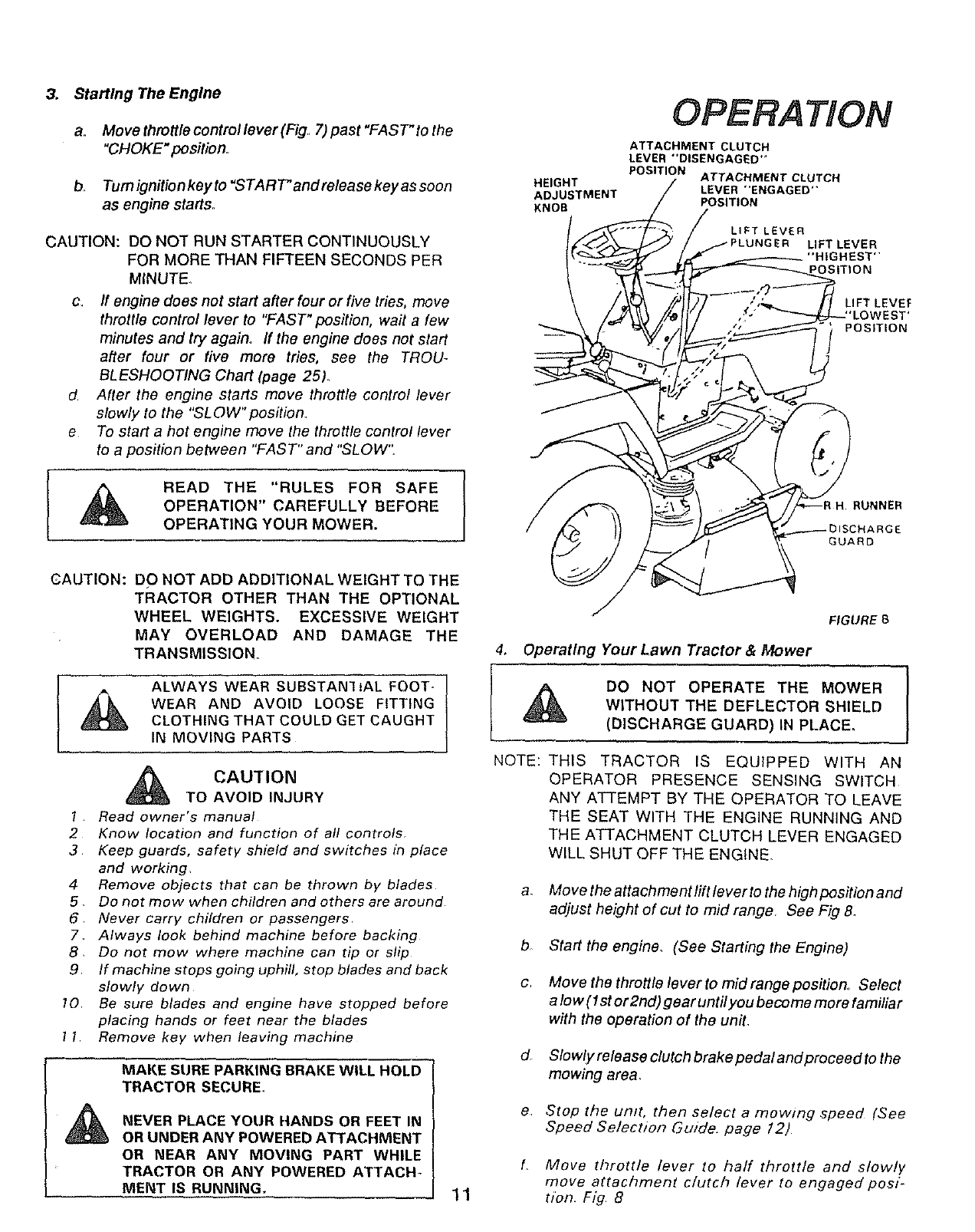
FIGURE8
4. Operating Your Lawn Tractor & Mower
DO NOT OPERATE THE MOWER
WITHOUT THE DEFLECTOR SHIELD
(DISCHARGE GUARD) IN PLACE,
NOTE: THIS TRACTOR IS EQUIPPED WITH AN
OPERATOR PRESENCE SENSING SWITCH
ANY ATTEMPT BY THE OPERATOR TO LEAVE
THE SEAT WITH THE ENGINE RUNNING AND
THE ATTACHMENT CLUTCH LEVER ENGAGED
WILL SHUT OFF THE ENGINE
a, Move the attachment lift leverto the high position and
adjust height of cut to mid range See Fig 8.
b Start the engine, (See Starting the Engine)
c Move the throttle lever to mid range position, Select
a low (1st or2nd) gear untilyou become more familiar
with the operation of the unit,
d_ Slowly release clutch brake pedal and proceed to the
mowing area,
e Stop the umt, then select a mowing speed (See
Speed Selection Guide. page 12)
f Move throttle lever to half throttle and slowly
move attachment clutch lever to engaged pos/-
(ton. Fig 8
OPERATION
g. Slowly release clutch brake pedal
h, Move throttle lever to fast position,
L05serve height of Cut and readjust as desired
CAUTION: BEFORE YOU MOVE THE GEAR SHIFT
LEVER, COME TO A COMPLETE STOP. FAIL-
URE TO DO SO CAN RESULT IN GEAR BOX
DAMAGE.
f
T
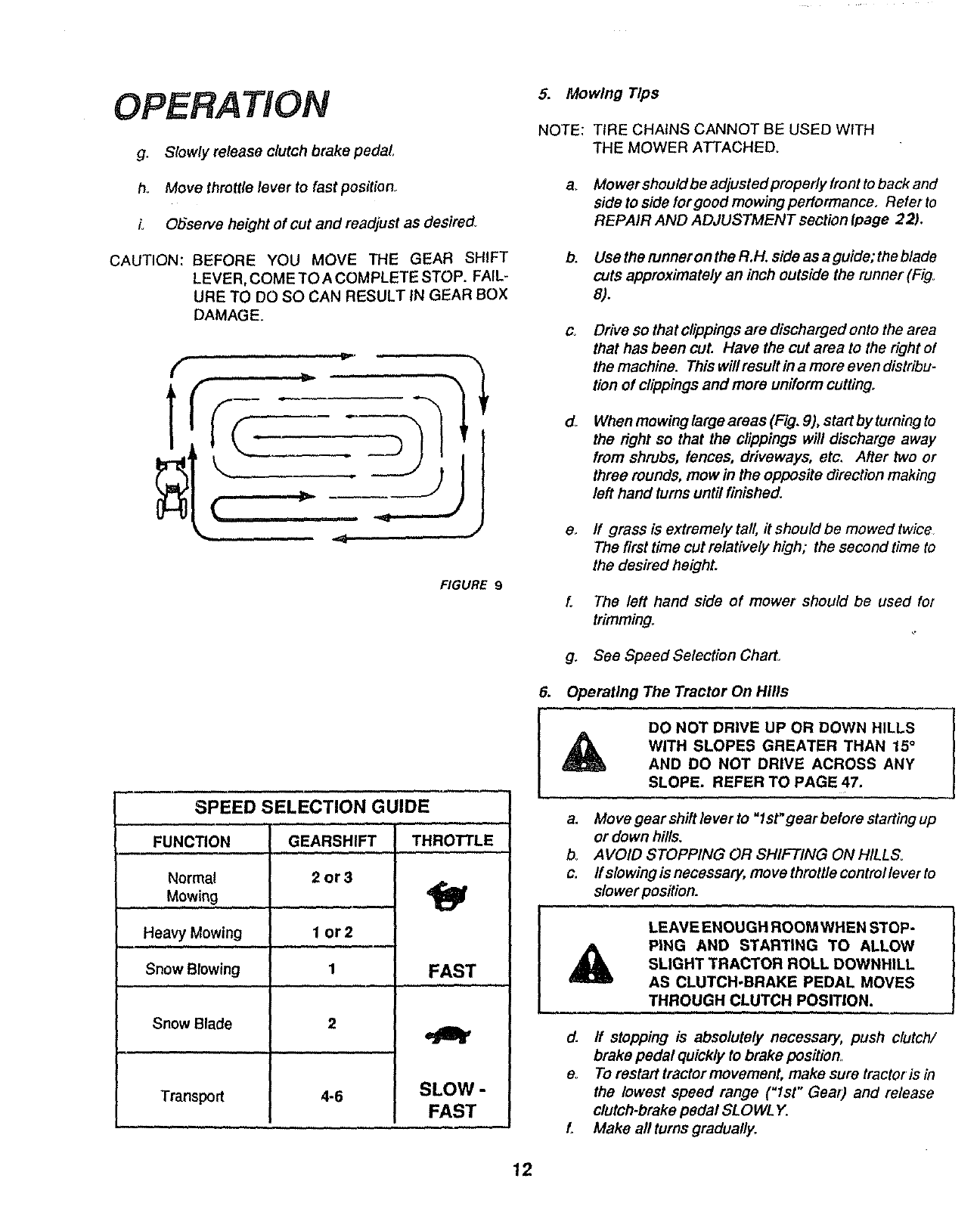
FIGURE 9
SPEED SELECTION GUIDE
FUNCTION
Normal
Mowing ........
Heavy Mowing
,,,,,,
Snow Blowing
Snow Blade
Transport
GEARSHIFT
2or3
I or2
1
2
4-6
THROTTLE
FAST
SLOW-
FAST
5. Mowing Tips
NOTE: TIRE CHAINS CANNOT BE USED WITH
THE MOWER ATTACHED.
a, Mowershouldbe adjustedpropedy front to back and
side to side for good mowing performance, Referto
REPAIR AND ADJUSTMENT section Ipage 22).
b. Use the runner on the R.H. side as aguide; the blade
cuts approximately an inch outside the runner (Fig.
8).
C_ Drive so that clippings ate discharged onto the area
that has been cut. Have the cut area to the right of
themachine. Thiswillresultinamoreevendistribu-
tion of clippings and more uniform cutting.
d_ When mowing large areas (Fig. 9), start by turning to
the right so that the clippings will discharge away
from shrubs, fences, driveways, etc. After two or
three rounds, mow in the opposite direction making
left hand turns until finished.
e. ff grass is extremely tall it should be mowed twice
The first time cut relatively high; the second time to
the desired height.
f. The left hand side of mower should be used for
trimming.
g. See Speed Selection CharL
6. Operating The Tractor On Hills
DO NOT DRIVE UP OR DOWN HILLS
WITH SLOPES GREATER THAN 15°
AND DO NOT DRIVE ACROSS ANY
SLOPE. REFER TO PAGE 47.
a,
b
c,
A
d.
e_
f_
Move gear shift lever to "1st" gear before starting up
or down hills.
AVOID STOPPING OR SHIFTING ON HILLS.
ff slowing is necessary, move throttle control lever to
slower position. |
LEAVE ENOUGH ROOM WHEN STOP-
PING AND STARTING TO ALLOW/
SLIGHT TRACTOR ROLL DOWNHILL
J
AS CLUTCH-BRAKE PEDAL MOVES
THROUGH CLUTCH POSITION.
If stopping is absolutely necessary, push clutch/
brake pedal quickly to brake position.
To restart tractor movement, make sure tractor is in
the lowest speed range ("Ist" Gear) and release
clutch-brake pedal SLOWLY.
Make all turns gradually.
12
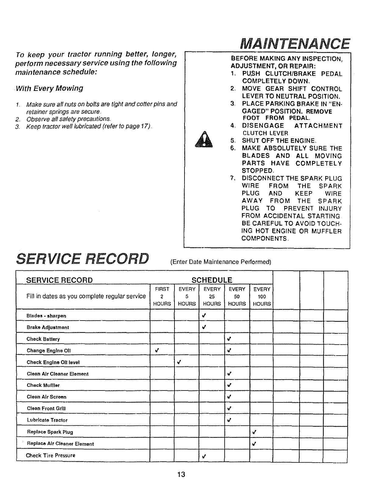
To keep your tractor running better, longer,
perform necessary service using the folio wing
maintenance schedule:
With Every Mowing
1 Make sure all nuts on bolts are tight and cotter pins and
retainer springs are secure
2 Observe all safety precautions,
3. Keep tractor well lubricated (refer to page 17)
MAINTENANCE
BEFORE MAKING ANY INSPECTION,
ADJUSTMENT, OR REPAIR:
1. PUSH CLUTCH/BRAKE PEDAL
COMPLETELY DOWN,
2. MOVE GEAR SHIFT CONTROL
LEVER TO NEUTRAL POSITION.
3. PLACE PARKING BRAKE IN "EN-
GAGED" POSITION. REMOVE
FOOT FROM PEDAL.
4. DISENGAGE ATTACHMENT
CLUTCH LEVER
5. SHUT OFF THE ENGINE.
6. MAKE ABSOLUTELY SURE THE
BLADES AND ALL MOVING
PARTS HAVE COMPLETELY
STOPPED_
7. DISCONNECT THE SPARK PLUG
WIRE FROM THE SPARK
PLUG AND KEEP WIRE
AWAY FROM THE SPARK
PLUG TO PREVENT INJURY
FROM ACCIDENTAL STARTING
BE CAREFUL TO AVOID TOUCH-
ING HOT ENGINE OR MUFFLER
COMPONENTS
SERVICE RECORD (Enter Date Maintenance Performed)
.... SERVICE RECORD
Fill in dates as you complete regular service
FIRST
2
HOURS
SCHEDULE
EVERY EVERY EVERY EVERY
5 25 50 100
HOURS HOURS HOURS HOURS
Blades -sharpen
Brake Adlustment
Check Battery
Change Engine OII
Check Engine OII level
Clean Air Cleaner Element
v"
€
e"
€
v"
v'
v"
Check Muffler v"
Clean Air Screen
Clean Front Grill
Lubricate Tractor
€
v"
tt
Replace Spark Plug
Replace Air Cleaner Element
CheckTire Pressure €
v"
v"
13
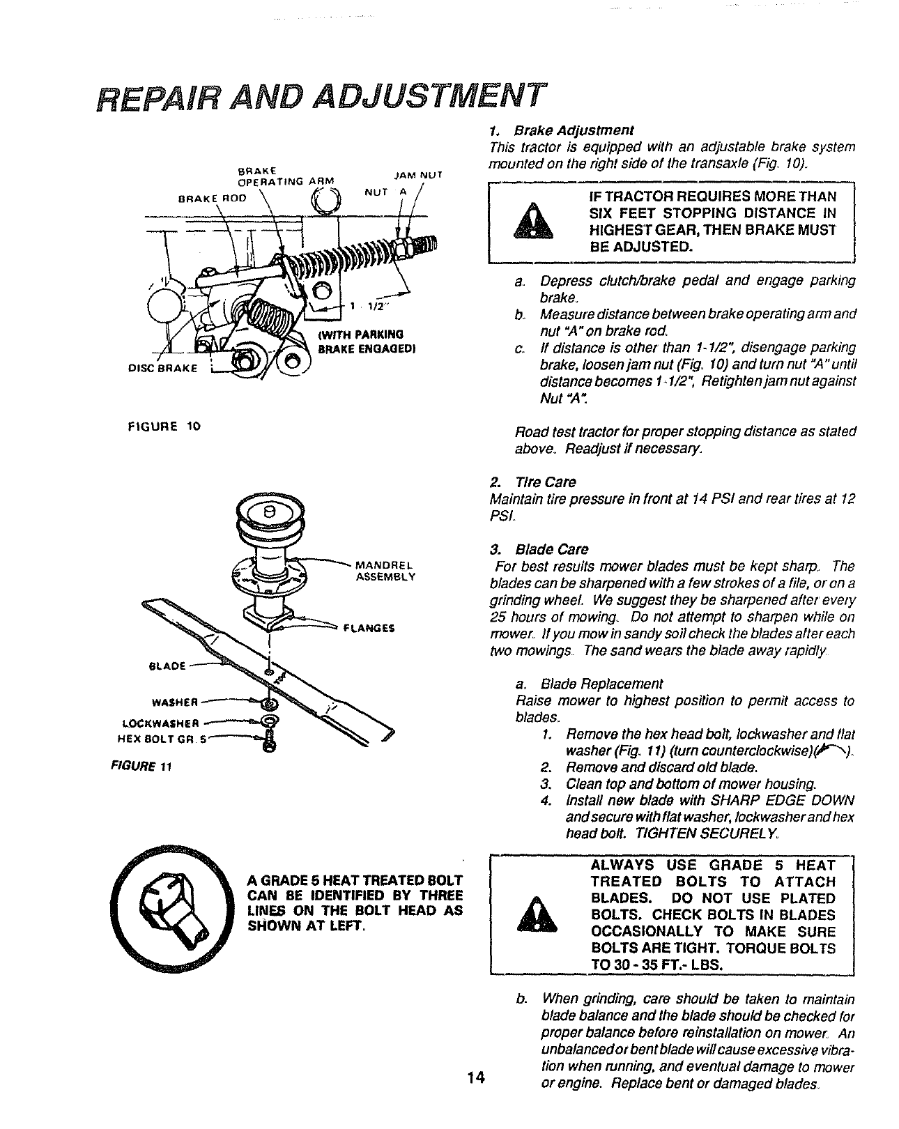
FtEPAIR AND ADJUSTMENT
BRAKE JAM NUT
OPERATING ARM NUT A
BRAKE ROD
1. Brake Adjustment
This tractor is equipped with an adjustable brake system
mounted on the right side of the transaxle (Fig. 10)_
IF TRACTOR REQUIRES MORE THAN
SIX FEET STOPPING DISTANCE IN
HIGHEST GEAR, THEN BRAKE MUST
BE ADJUSTED.
DISC BRAKE
1112"
)WITH PARKING
BRAKE ENGAGED)
a. Depress clutch/brake pedal and engage parking
brake°
bo Measure distance between brake operating arm and
nut "A"on brake rod,
c. ff distance is other than 1.1/2", disengage parking
brake, loosen jam nut (Fig. 10) and turn nut "A" until
distance becomes t. 1/2", Retighte njam nut against
Nut ",4".
FIGURE 10 Road test tractor for proper stopping distance as stated
above. Readjust if necessary.
2. Tire Care
Maintain tire preSsure in front at 14 PSI and rear tires at 12
PSL
3. Blade Care
For best results mower blades must be kept sharp. The
blades can be sharpenedwith a few strokes of a file, or on a
grinding wheel, We suggest they be sharpened after every
25 hours of mowing. Do not attempt to sharpen while on
mower If you mow in sandy soil check the blades after each
two mowings The sand wears the blade away rapidly
A GRADE 5 HEAT TREATED BOLT
CAN BE IDENTIFIED BY THREE
LINF._ ON THE BOLT HEAD AS
SHOWN AT LEFT°
a. Blade Replacement
Raise mower to highest position to permit access to
blades..
1. Remove the hex head bolt, Iockwasher and l/at
washer (Fig. 11) (turn counterclockwise)_r_)
2. Remove and discard old blade.
3, Clean top and bottom of mower housing_
4. Install new blade with SHARP EDGE DOWN
and secure with flat washer, lockwasher and hex
head bolt. TIGHTEN SECUREL Y.
A
ALWAYS" USE GRADE 5 HEAT
TREATED BOLTS TO ATTACH
BLADES. DO NOT USE PLATED
BOLTS. CHECK BOLTS IN BLADES
OCCASIONALLY TO MAKE SURE
BOLTS ARE TIGHT. TORQUE BOLTS
TO 30 -35 FT.- LBS.
14
b. When grinding, care should be taken to maintain
blade balance and the blade should be checked for
proper balance before reinstallation on mower An
unbalanced or bent blade will cause excessive vibra-
tion when running, and eventual damage to mower
or engine° Replace bent or damaged blades,
REPAIR AND ADJUSTMENT
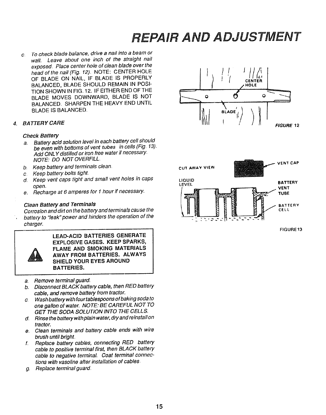
C, To check blade balance, drive a nail into a beam or
wall., Leave about one inch of the straight nail
exposed, Place center hole of clean blade overthe
head of the nail(Fig. 12) NOTE: CENTER HOLE
OF BLADE ON NAIL, IF BLADE IS PROPERLY
BALANCED, BLADE SHOULD REMAIN IN POSI-
TION SHOWN IN FIG 12. IF EITHER END OF THE
BLADE MOVES DOWNWARD, BLADE IS NOT
BALANCED SHARPEN THE HEAVY END UNTIL
BLADE IS BALANCED
4_ BATTERY CARE
Check Battery
&Battery acid solution level in each battery cell should
be even with bottoms of vent tubes in cells (Fig 13)
Add ONLY distilled or iron free water if necessary,
NOTE: DO NOT OVERFILL.
b_ Keep battery and terminals clean
c Keep battery bolts tighL
d. Keep vent caps tight and small vent holes in caps
open_
e,. Recharge at 6 amperes for 1hour ff necessary.
Clean Battery and Terminals
Corrosion and dirt on the battery and terminals cause the
battery to "leak" power and hinders the operation of the
charger,
LEAD-ACID BATTERIES GENERATE
EXPLOSIVE GASES. KEEP SPARKS,
FLAME AND SMOKING MATERIALS
AWAY FROM BATTERIES. ALWAYS
SHIELD YOUR EYES AROUND
BATTERIES.
a., Remove terminal guard,
b. Disconnect BLACK battery cable, then RED battery
cable, and remove battery from tractor,
c Wash battery with fourtablespoons of baking soda to
one gallon of water NOTE: BE CAREFUL NOT TO
GET THE SODA SOLUTION INTO THE CELLS,,
d. Rinsethebatterywithpfainwater, dryandreinstaflon
tractor.
eo Clean terminals and battery cable ends with wire
brush until bright.
L Replace battery cables, connecting RED battery
cable to positive terminal first, then BLACK battery
cable to negative terminal Coat terminal connec-
tions with vasoline after installation of cables
g, Replace terminal guard
o,,,,,f............
tFIGURE 12
CU't AWAY VtEW VENT CAP
LIQUID
LEVEL BATTERY
CELL
FIGURE13
15
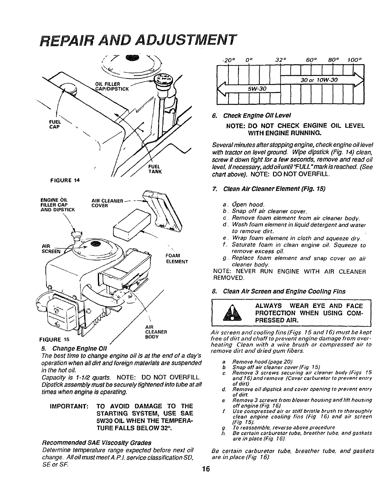
REPAIR AND ADJUSTMENT
CAP
FIGURE 14
ENGINE (}IL
FILLERCAP
AND DIPSTICK
\
AIR
SCREEN
COVER
FOAM
ELEMENT
_20 °0° 32 ° 60 ° 80 ° 100 _
6. Check Engine 011Level
NOTE: DO NOT CHECK ENGINE OIL LEVEL
WITH ENGINE RUNNING,
Several minutes after stopping engine, check engine oil level
with tractor on level ground, Wipe dipstick (Fig° 14) clean,
screw it down tight for a few seconds, remove and read oil
level ff necessaty, add oit untit "FULL "mark is reached. (See
chart above). NOTE: DO NOT OVERFILL.
7. Clean Air Cleaner Element (Fig. 15)
a. Open hood
b, Snap off air cleaner covet,
c, Remove foam element from air cleaner body,
d. Wash foam element in liquid detetgent and water
to remove dirt.
e. Wrap foam element in cloth and squeeze dry,
f. Saturate foam in clean engine oil Squeeze to
remove excess oil.
g. Replace foam element and snap cover on air
cleaner body,
NOTE: NEVER RUN ENGINE WITH AIR CLEANER
REMOVED
AIR R
FIGURE 15 /BODY
5. Change Engine 011
The best time to change engine air is at the end of a day's
operation when all dirt and foreign materials are suspended
in the hot oil.
Capacity is 1-1/2 quarts. NOTE: DO NOT OVERFILL,
Dipstick assembly must be securely tightened into tube at all
times when engine is operating.
IMPORTANT: TO AVOID DAMAGE TO THE
STARTING SYSTEM, USE SAE
5W30 OIL WHEN THE TEMPERA-
TURE FALLS BELOW 32°.
Recommended SAE Viscosity Grades
Determine temperature range expected before next oil
change_ A// oil must meet A,PJ. service classification SD,
SE or SF_
8. Clean Air Screen and Engine Cooling Fins
I_ALWAYS WEAR EYE AND FACE
PROTECTION WHEN USING COM-
PRESSED AIR.
Air screen and cooling fins (Figs 15 and 16) must be kept
free of dirt and chaff to prevent engine damage from over-
heating Clean with a wire brush or compressed air to
remove dirt and dried gum fibers
a Remove hood (page 20)
bSnapoHaircleanetcoverlFig 151
c, Remove 3screws securing air cleaner body IF/gs 15
and 16) and remove (Cover carburetor to prevent entry
of dirt)
dRemove oil dipstick and cover opening to prevent entry
of dirt
e Remove 3 screws from blower housing andlift housing
off engine (Fig. 16)
fUse compressed air or stiff bristle brush to thoroughly
clean engine cooling fins (Fig 16) and air screen
(Fig 15)
g To reassemble, reverse above procedure
h, Be certain carburetor tube. breather tube, and gaskets
are in place (Fig l e).
Be certain carburetor tube, breather tube,, and gaskets
are in place (Fig 16)
16
REPAIR AND ADJUSTMENT
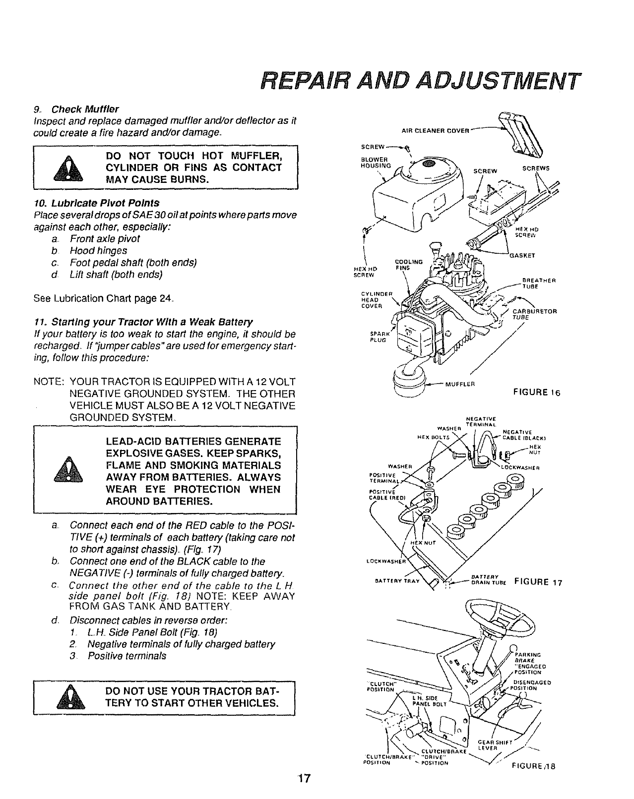
9.. Check Muffler
Inspect and replace damaged muffler and/or deflector as it
could create a fire hazard and/or damage.
DO NOT TOUCH HOT MUFFLER, 1
CYLINDER OR FINS AS CONTACT
MAY CAUSE BURNS.
10. Lubricate Pivot Points
Place several drops of SAE 30 oil at points where parts move
against each other, especially:
a Front axle pivot
b Hood hinges
c_ Foot pedal shaft (both ends)
d Lift shaft (both ends)
See Lubrication Chart page 24,
11. Starting ,your Tractor With a Weak Battery
If your battery is too weak to start the engine, it should be
recharged, If ']umper cables" are used for emergency start.
ing, follow this procedure:
NOTE: YOUR TRACTORIS EQUIPPED WITH A12VOLT
NEGATIVE GROUNDED SYSTEM. THE OTHER
VEHICLE MUST ALSO BE A12VOLTNEGATIVE
GROUNDED SYSTEM,
LEAD-ACID BATTERIES GENERATE
EXPLOSlVEGASES. KEEPSPARKS,
FLAME AND SMOKING MATERIALS
AWAY FROM BATTERIES. ALWAYS
WEAR EYE PROTECTION WHEN
AROUND BATTERIES.
a Connect each end of the RED cable to the POSI-
TIVE (+) terminals of each battery (taking care not
to short against chassis). (Fig, 17)
b, Connect one end of the BLACK cable to the
NEGATIVE (-) terminals of fully charged battery,
c Connect the other end of the cable to the L H
side panel bolt (Fig. 18) NOTE: KEEP AWAY
FROM GAS TANK AND BATTERY
d, Disconnect cables in reverse order:
1. LH, Side Panel Bolt (Fig. 18)
2 Negative terminals of fully charged battery
3 Positive terminals
CyLiNDER
HEAO _
COVER
PLUG
_OOLtNG
FINS
TUBE
/
/
FIGURE 16
NEGATI_/E
TERMINAL
WASHER NEGATIVE
HEX BOLT s CAnL_ IBt, A_KI
HE×
NUT
WASHER LDCKWASHE R
PI_ITJVE
TERMiN_
_tTEVE
CABLE IflE[ll
I.OCKWASHE R
E7ER'' 17
_'r _v _AY "_,_;_;_'_b BE FIGUR
,A !
DO NOT USE YOUR TRACTOR BAT-
TERYTO START OTHERVEHICLES. I
17
REPAIR AND ADJUSTMENT
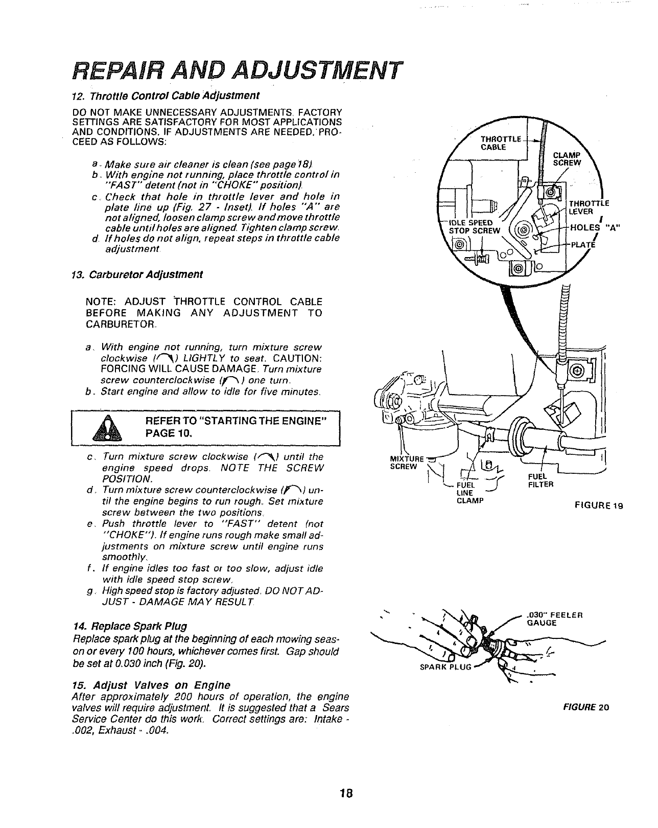
12. Throttle Control Cable Adjustment
DO NOT MAKE UNNECESSARY ADJUSTMENTS. FACTORY
SETTINGS ARE SATISFACTORY FOR MOST APPLICATIONS
AND CONDITIONS. IF ADJUSTMENTS ARE NEEDED,PRO-
CEED AS FOLLOWS:
a. Make sure air cleaner is clean (see page _8)
b. With engine not running, place throttle control in
"FAST" detent (not in ""CHOKE" position}
c, Check that hole in throttle lever and hole in
plate line up (Fig, 27 -Inset), If holes "',4""are
not aligned, loosen clamp screw and move throttle
cable until holes are aligned Tighten clamp screw
dIf holes do not align, repeat steps in throttle cable
adjustment
13. Carburetor Adjustment
NOTE: ADJUST THROTTLE CONTROL CABLE
BEFORE MAKING ANY ADJUSTMENT TO
CARBURETOR.
a, With engine not running, turn mixture screw
clockwise l[-_) LIGHTLY to seat. CAUTION:
FORCING WILL CAUSE DAMAGE, Turn mixture
screw counterclockwise (_'_ ) one turn.
b. Start engine and allow to idle for five minutes.
REFER 'TO "STARTING THE ENGINE"
PAGE 10_
c, Turn mixture screw clockwise ("_k) until the
engine speed drops NOTE THE SCREW
POSITION,
d, Turn mixture screw counterclockwise (Ir_) un-
til the engine begins to run rough. Set mixture
screw between the two positions
e, Push throttle lever to "'FAST" detent (not
"CHOKE"). If engine runs rough make small ad-
justments on mixture screw until engine runs
smoothly,
f. If engine idles too fast or too slow, adjust idle
with idle speed stop screw.
g High speed stop is factory adjusted. DO NOTAD.
JUST -DAMAGE MAY RESULT
14. Replace Spark Plug
Replace spark plug at the beginning of each mowing seas-
on or every lOO hours, whichever comes first. Gap should
be set at &030 inch (Fig. 20).
MIXTURE"
SCREW
15, Adjust Valves on Engine
After approximately 200 hours of operation, the engine
valves will require adjustmenL It is suggested that a Sears
Service Center do this work: Correct settings are: Intake -
,002, Exhaust-.004,
_- FUEL
LINE
CLAMP
THROTi"LE
LEVER I
'HOLES "A"
/
=PLATE
/
FUEL
FILTER
FIGURE 19
.S30"FEELER
GAUGE
FIGURE 20
18
FtEPAIR AND ADJUSTMENT
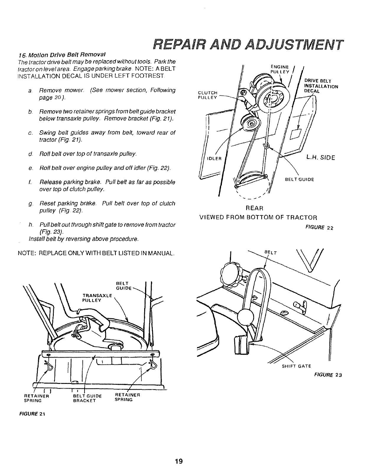
16. Motion Drive Belt Removal
The tractor drive belt may be replaced without tools Park the
tractoronlevelarea Engageparkingbrake NOTE: ABELT
INSTALLATION DECAL IS UNDER LEFT FOOTREST
a Remove mower (See mower section, Following
page 2o). CLUTCH
PUL
ENGINE
PULLEY /
DRIVE BELT
INSTALLATION
DECAL
b Remove two retainersprings frombeltguide bracket
below transaxle pulley. Remove bracket (Fig, 21).
c. Swing belt guides away from belt, toward rear of
tractor (Fig. 21)_
d. Roll belt over top of transaxle pulley.
e Roll belt over engine pulley and off idler (Fig. 22)
fRelease parking brake. Pull belt as far as possible
over top of clutch pulley.
g Reset parking brake. Pull belt over top of clutch
pulley (Fig 22)
h Pullbelt out through shift gate to remove from tractor
(Fig, 23)
Install belt by reversing above procedure,
BELT GUIDE
REAR
VIEWED FROM BOTTOM OF TRACTOR
FIGURE 22
NOTE: REPLACE ONLY WITH BELT LISTED IN MANUAL°
BELT
GUIDE_
TRANSAXLE
PULLEY
BELT
SHIFT GATE
FIGURE 23
I
RETAINER BELT GUIDE RETAINER
SPRING BRACKET SPRING
FIGURE 21
19
REPAIR AND ADJUSTMENT
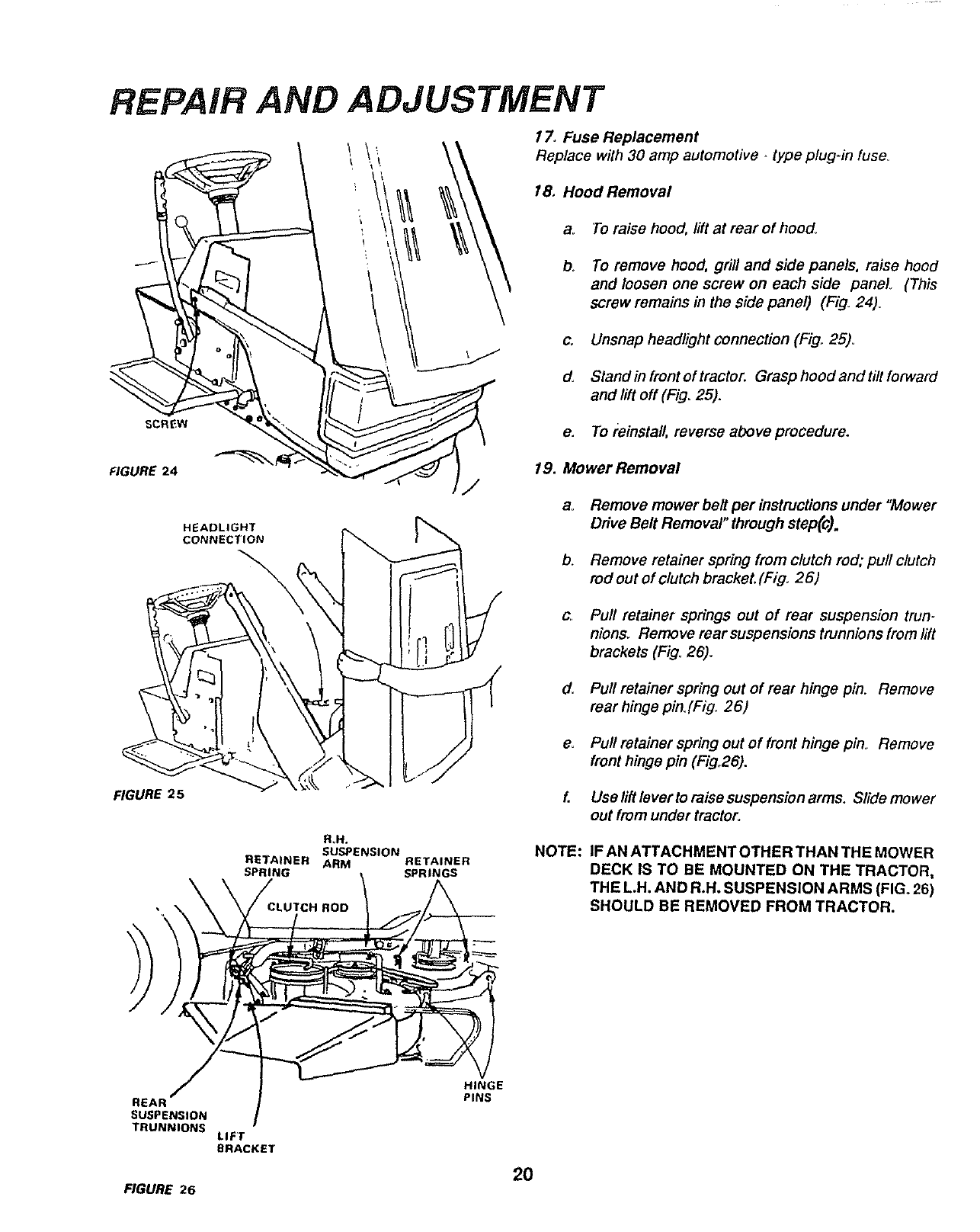
17. Fuse Replacement
Replace with 30 amp automotive -type plug-in fuse_
18, Hood Removal
a. To raise hood, lift at rear of hood,.
b. To remove hood, grill and side panels, raise hood
and loosen one screw on each side panel (This
screw remains in the side panel) (Fig. 24).
FIGURE 24
HEADLIGHT
CONNECTION
/
c. Unsnap headlight connection (Fig. 25)_
d. Stand in front of tractor. Grasp hood and tilt forward
and lift off (Fig. 25).
e. To reinstall, reverse above procedure.
19. Mower Removal
ao Remove mower belt per instructions under "Mower
Drive Belt Removal" through step(c).
b. Remove retainer spring from clutch rod; pull clutch
rod out of clutch brackeL(Fig. 26)
cPuff retainer springs out of fear suspension trun-
nions. Remove rear suspensions trunnions from lift
brackets (Fig. 26).
d, Pull retainer spring out of rear hinge pin, Remove
rear hinge pin.(Fig, 26)
e. Pull retainer spring out of front hinge pin_ Remove
front hinge pin (Figo26).
_GURE 25
R_N.
SUSPENSION
RE'JAINER ARM RETAINER
SPRING SPRINGS
/
E
LIFT
BRACKET
FIGURE 26
f.
NOTE:
2O
Use lift lever to raise suspension arms. Slide mower
out from under tractor.
IF AN ATTACHMENTOTHER THAN THE MOWER
DECK IS TO BE MOUNTED ON THE TRACTOR,
THE L.H. AND R.H. SUSPENSION ARMS (FIG. 26)
SHOULD BE REMOVED FROM TRACTOR.
REPAIR AND ADJUSTMENT
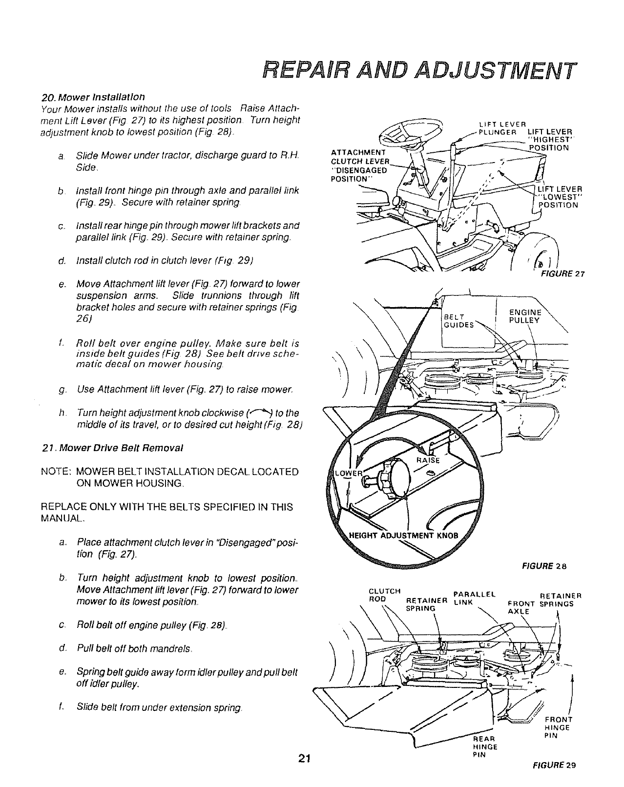
20. Mower Installation
Your Mower instafls without the use of tools Raise Attach-
ment Lift Lever (Fig 27) to its highest position Turn height
adjustment knob to lowest position (Fig 28)
aSlide Mower under tractor, discharge guard to RH
Side
b Install front hinge pin through axle and parallel link
(Fig 29). Secure with retainer spring
c Installrear hinge pin through mower lift brackets and
parallel link (Fig 29) Secure with retainer spring.
d Install clutch rod in clutch lever (Fig 29)
e_ Move Attachment lift lever (Fig 27) forward to lower
suspension arms Slide trunnions through lift
bracket holes and secure with retainer springs (Fig
26.1
f Roll belt over engine pulley, Make sure belt is
inside belt guides (Fig 28) See belt drive sche-
matl_ decal on mower housing
g Use Attachment lift lever (Fig. 27) to raise mower.
h Turn height adjustment knob clockwise (._ to the
middle of its travel, or to desired cut height (Fig 28)
\\
LIFT LEVER
PLUNGER LIFT LEVER
POSITION
FIGURE 2 7
ENGINE_
IELT PULLEY
2 I, Mower Drive Belt Removal
NOTE: MOWER BELT INSTALLATION DECAL LOCATED
ON MOWER HOUSING.
REPLACE ONLY WITH THE BELTS SPECIFIED IN THIS
MANUAL.
C,
d.
Place attachment clutch lever in "Disengaged"posi-
tion (Fig, 27),,
Turn height adjustment knob to lowest position,
Move Attachment lift lever (Fig_ 27) forward to lower
mower to its Iowest position,
Roll belt off engine pulley (Fig 28),
Pull belt off both mandrels,
Spring belt guide away form idler pulley and pull belt
off idler pulley.
f, Slide belt from under extension spring
21
CLUTCH
ROD
FIGURE 2 8
PARALLEL RETAINER
RETAINER LINK FRONT _PRtNGS
SPRING _ AXLE
REAR
HINGE
PIN
J
FRONT
HINGE
PIN
FIGURE 29
REPAIR AND ADJUSTMENT
ROLT_
\L.H.
BRACKET
FIGURE 30
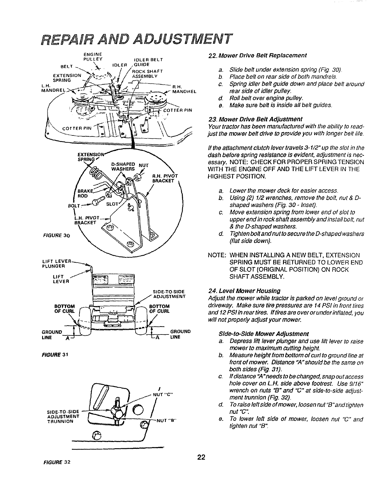
22. Mower Drive Belt Replacement
a. Slide belt under extension spring (Fig 30)
b. Place belt on rear side of both mandrels.
c. Spring idler belt guide down and place belt around
rear side of idler pulley°
d. Rofl belt over engine pulley.
e,, Make sure belt is inside all belt guides_
23. Mower Drive Belt Adjustment
Your tractor has been manufactured with the ability to read-
just the mower belt drive to provide you with longer bell fife
ff the attachment clutch lever travels 3- I/2" up the slot in the
dash before spring resistance is evident, adjustment is nec.
essaty. NOTE: CHECK FOR PROPER SPRINGTENSION
WITH THE ENGINE OFF AND THE LIFT LEVER IN THE
HIGHEST POSITION,
ao Lower the mower deck for easier access_
b. Using (2) 1/2 wrenches, remove the bolt, nut &D.
shaped washers (Fig. 30 ÷Inset).
c. Move extension spring from lower end of slot to
upper end in rock shaft assembly and install bolt, nut
& the D-shaped washers.
d. TightenboltandnuttosecuretheD-shapedwashers
(flat side down).
LIFT
PLUNGER
LIFT
LEVER
BOTTOM
OF CURL
SIDE-TO SIDE
BOTTOM
CURL
NOTE: WHEN INSTALLING A NEW BELT, EXTENSION
SPRING MUST BE RETURNED TO LOWER END
OF SLOT (ORIGINAL POSITION) ON ROCK
SHAFT ASSEMBLY.
24. Level Mower Housing
Adjust the mower while tractor is parked on level ground or
driveway. Make sure tire pressures are 14 PSI in front tires
and 12 PSI in rear tires. If tires are over or under inflated, you
will not properly adjust your mower.
GROUND
LINE
FIGURE 31
SIDE-TO.SIDE
ADJUSTMENT
TRUNNION
GROUND Side-to.Side Mower Adjustment
a. Depress lift lever plunger and use lift lever to raise
mower to maximum cutting heighL
bo Measure height frem bottom of curl to ground line at
front of mower. Distance "A" should be the same on
both sides (Fig. 31)_
c_ ffdistance"A"needstobechanged, snapoutaccess
hole cover on L.H. side above footresL Use 9/16"
wrench on nuts "B"and "C" at side-to-side adjust-
ment trunnion (Fig. 32).
do To raise left side of mower; loosen nut "B"and tighten
nut "C"
e. To lower left side of mower; loosen nut "C" and
tighten nut "B't
22
_GURE 32
REPAIR AND ADJUSTMENT
NOTE: ONE ROTATION OF ADJUSTMENT NUTS IS
EQUIVALENT TO APPROXIMATELY 3/16"
HEIGHT CHANGE
f Be sure all nuts are securely tightened
g Replace cover
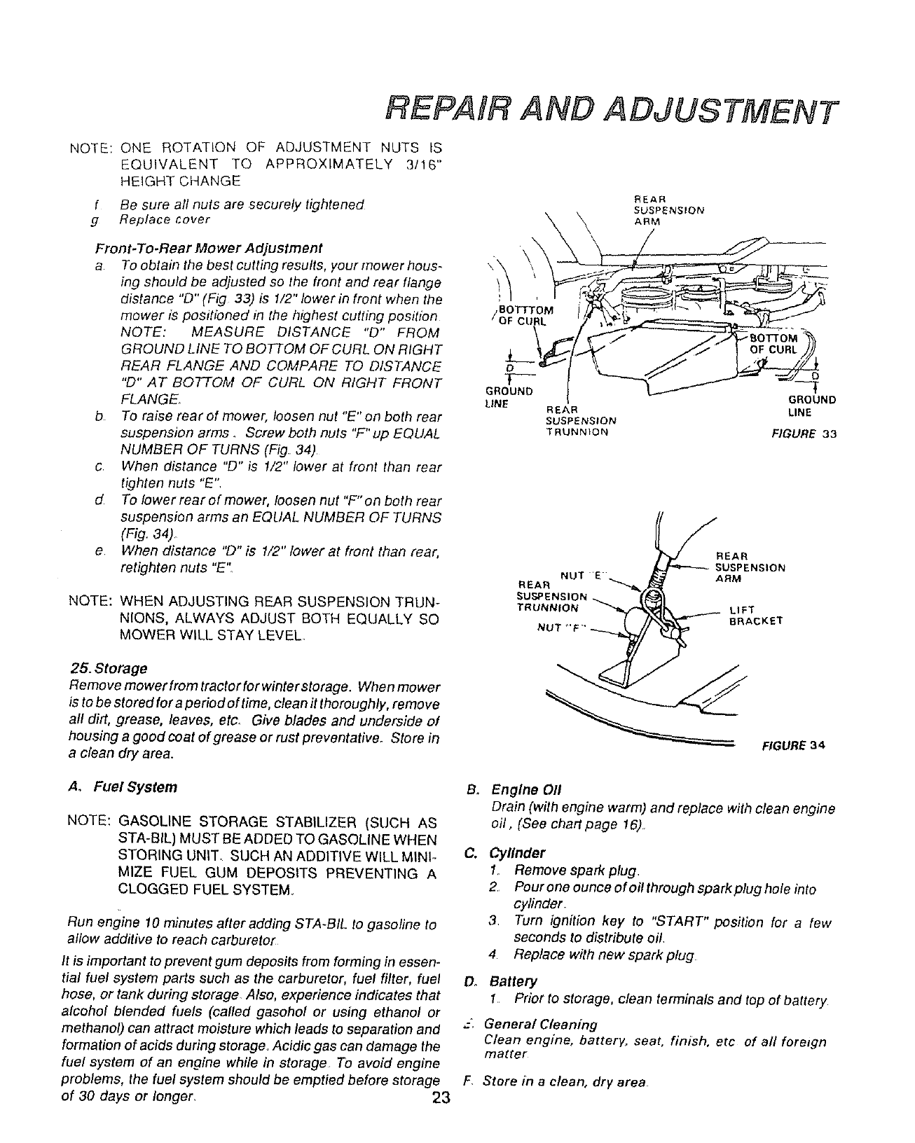
Front-To-Rear Mower Adjustment
a To obtain the best cutting results, your mower hous-
ing should be adjusted so the front and rear flange
distance "D" (Fig 33) is 1/2" lower in front when the
mower is positioned in the highest cutting position
NOTE: MEASURE DISTANCE "D" FROM
GROUND LINE TO BOTTOM OF CURL ON RIGHT
REAR FLANGE AND COMPARE TO DISTANCE
"D" AT BOTTOM OF CURL ON RIGHT FRONT
FLANGE
b To raise rear of mower, loosen nut "E" on both rear
suspension arms .Screw both nuls "F" up EQLJAL
NUMBER OF TURNS (Fig 34)
cWhen distance "D" is 1/2" lower at front than rear
tighten nuts "E",
dTo Iowerrearofmower, loosen nut "F"on both rear
suspension arms an EQLIAL NUMBER OF TURNS
(Fig. 34)_
e When distance "D" is 1/2" lower at front than rear,
retighten nuts "E'"
NOTE: WHEN ADJUSTING REAR SUSPENSION TRUN-
NIONS, ALWAYS ADJUST BOTH EQUALLY SO
MOWER WILL STAY LEVEL.
25. Storage
Removemowerfromtractorforwinterstorage. Whenmower
is to be stored for a period of time, clean it thoroughly, remove
all dirt, grease, leaves, etc. Give blades and underside of
housing a good coat of grease or rust preventativeo Store in
a clean dry area.
o
T----
GROUND
LINE
REAR
SUSPENSION
'_ ARM
OF CURL
REAR
SUSPENSION
TRUNNION
.,.....,__!EAR SUSPENSION
REAR NUT 'E RM
SU,_ENSION_
TRUNNION LIFT
NUT_,F. 'BRACKET
GROUND
LINE
_GURE 33
RGURE 34
A. Fuel System
NOTE: GASOLINE STORAGE STABILIZER (SUCH AS
STA-BIL) MUST BE ADDED TO GASOLINE WHEN
STORING UNIT. SUCH AN ADDITIVE WILL MINI-
MIZE FUEL GUM DEPOSITS PREVENTING A
CLOGGED FUEL SYSTEM.
Run engine 10 minutes after adding STA-BIL to gasoline to
allow additive to reach carburetor
It is important to prevent gum deposits from forming in essen-
tial fuel system parts such as the carburetor, fuel filter, fuel
hose, or tank during storage. Also, experience indicates that
alcohol blended fuels (called gasohol or using ethanol or
methanol) can attract moisture which leads to separation and
formation of acids during storage, Acidic gas can damage the
fuel system of an engine while in storage To avoid engine
problems, the fuel system should be emptied before storage
of 30 days or longer, 23
B_
C,
On
Engine 011
Drain (with engine warm) and replace with clean engine
oil, (See chart page 16)
Cylinder
1_ Remove spark plug.
2, Pour one ounce of oil through spark plug hole into
cylinder
3, Turn ignition key to "START" position for a few
seconds to distribute oil.
4 Replace with new spark plug
Battery
1Prior to storage, clean terminals and top of battery
General Cleaning
Clean engine, battery, seat, finish, etc of all foreign
matter
F. Store in a clean, dry area
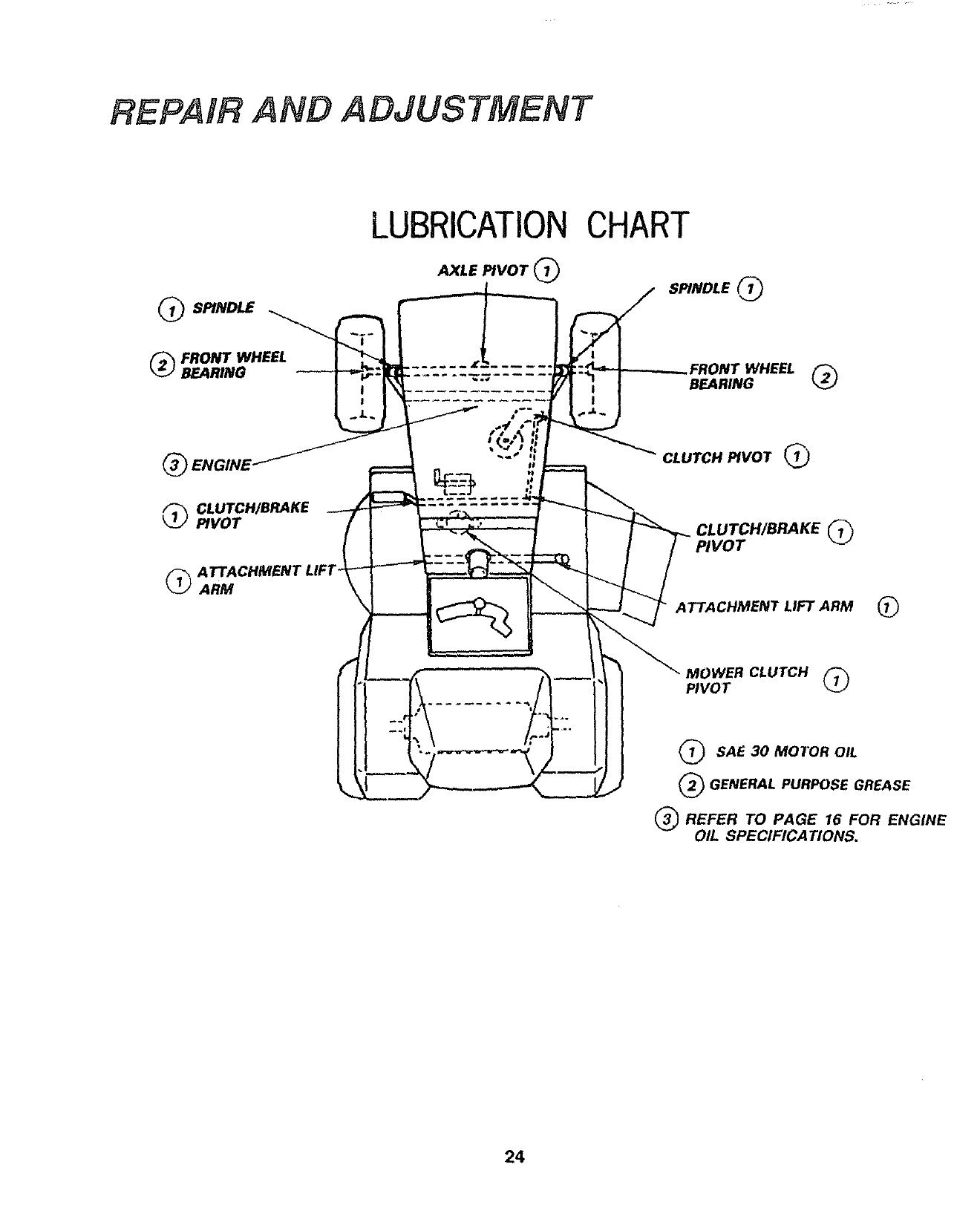
REPAIR AND ADJUSTMENT
LUBRICATIONCHART
SPINDLE
_FRONT WHEEL
BEARING
®
CLUTCH/BRAKE
PIVOT
_-_ ATTACHMENT LIFT_
_J ARM \
AXLE PIVOT;
!
SPINDLE _1_
_FRONT WHEEL
BEARING
CLUTCH PIVOT _)
@
@
ATTACHMENT LIFT ARM @
MOWER CLUTCH
PIVOT @
SAE 30 MOTOR OIL
(_ GENERAL PURPOSE GREASE
REFER TO PAGE 16 FOR ENGINE
OIL SPECIFICATIONS.
24
TROUBLESHOOTING
WILL NOT START
WILL NOT TURN OVER
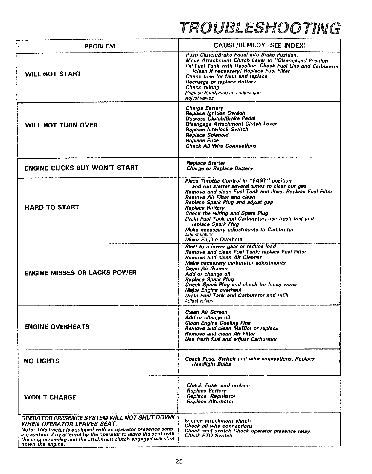
PROBLEM CAUSE/REMEDY (SEE INDEX)
Push Clutch/Brake Pedal into Brake Position.
Move Attachment Clutch Lever to "Disengaged Position
Fill Fuel Tank with Gasollna, Check Fuel Line and Carburetor
(clean If necessary) Replace Fuel Filter
Check fuse for fault and replace
Recharge or replace Battery
Check Wiring
Replace Spark Plug and adjust gap
Adjust valves.
Charge Battery
Replace Ignition Switch
Depress Clutch/Brake Pedal
Disengage Attachment Clutch Lever
Replace Interlock Switch
Replace Solenoid
Replace Fuse
Check All Wire Connections
Replace Starter
ENGINE CLICKS BUT WON'T START Chargeor Replace Battery
HARD TO START
ENGINE MISSES OR LACKS POWER
ENGINE OVERHEATS
NO LIGHTS
WON'T CHARGE
OPERA TOR PRESENCE SYSTEM WILL NOT SHUT DOWN
WHEN OPERA TOR LEA VES SEA T_
Note: This tractor is equipped with an operator presence sens-
ing syetem_ Any attempt by the operator to leave the seat with
the enigne running and the attchment clutch engaged will shut
down the engine.
Piece Throttle Control in "FAST" position
and run starter several times to clear out gas
Remove and clean Fuel Tank and lines,, Replace Fuel Filler
Remove Air Filter and clean
Replace Spark Plug and adjust gap
Replace Battery
Check the wiring and Spark Plug
Drain Fuel Tank and Carburetor, use fresh fuel and
replace Spark Plug
Make necessary adjustments to Carburetor
Adjust valves
Major Engine Overhaul
Shift to a lower gear or reduce load
Remove and clean Fuel Tank; replace Fuel Filter
Remove and clean Air Cleaner
Make necessary carburetor adjustments
Clean Air Screen
Add or change oil
Replace Spark Plug
Check Spark Plug and check for loose wires
Major Engine overhaul
Drain Fuel Tank and Carburetor and refill
Adjust valves
Clean Air Screen
Add or change oil
Clean Engine Cooling Fine
Remove and clean Muffler or replace
Remove and clean Air Filter
Use fresh fuel and adjust Carburetor
Check Fuse, Switch and wire connections. Replace
Headlight Bulbs
Check Fuse and replace
Replace Battery
Replace Regulator
Replace Alternator
Engage attachment clutch
Check aft wire connections
Check seat switch Check operator presence relay
Check PTO Switch
25
TROUBLESHOOTING
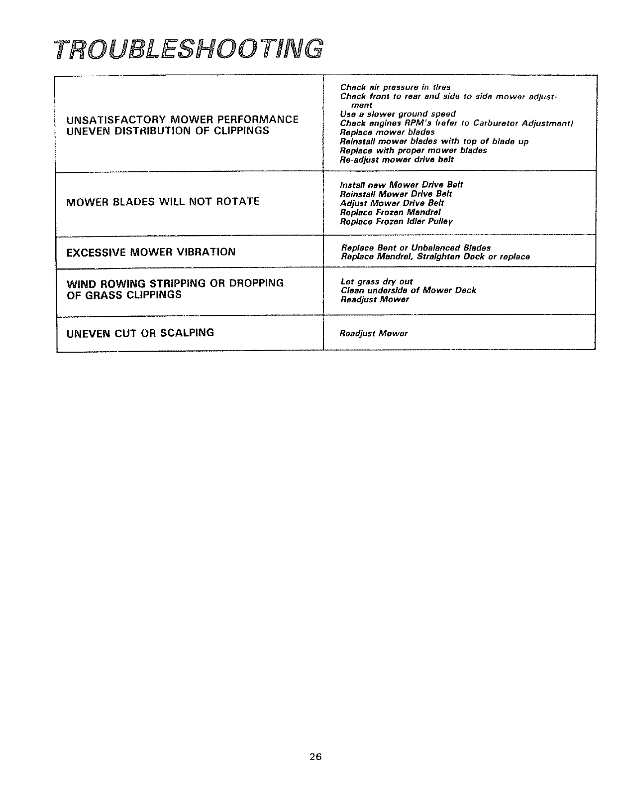
UNSATISFACTORY MOWER PERFORMANCE
UNEVEN DISTRIBUTION OF CLIPPINGS
Chock air pressure in tires
Chock front to roar and side to side mower adjust-
ment
Use a slower ground speed
Check engines RPM's (refer to Carburetor Adjustment)
Replace mower blades
Relnstafl mower blades with top of blade up
Replace with proper mower blades
Re-adjust mower drive belt
Install new Mower Drive Belt
Reinstall Mower DHve Belt
MOWER BLADES WILL NOT ROTATE Adjust Mower Drive Belt
Replace Frozen Mandrel
Replace Frozen Idler Pufloy
Replace Bent or Unbalanced Blades
EXCESSIVE MOWER VIBRATION Replace Mandrel. Straighten Deck or replace
WIND ROWING STRIPPING OR DROPPING Let grass dry out
Clean underside of Mower Deck
OF GRASS CLIPPINGS ReadjustMower
UNEVEN CUT OR SCALPING Readjust Mower
i
26
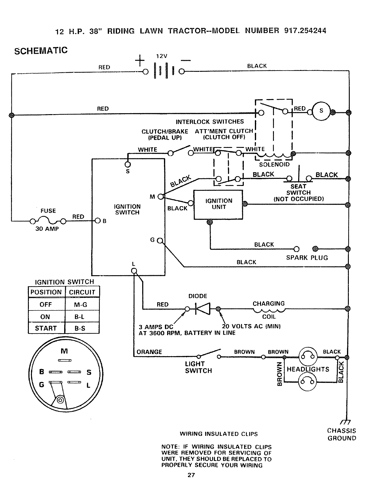
12 H.P. 38" RIDING LAWN TRACTOR--MODEL NUMBER 917.254244
SCHEMATIC
RED BLACK
FUSE
30 AMP
OB
E
IGNITION SWITCH
POSITION CIRCUIT
OFF M-G
ON B-L
START B-S
S
MC
IGNITION
RED
SWITCH
INTERLOCKSW,TCHESI II
CLUTCH/BRAKE ATT'MENT CLUTCH."
{PEDAL UP) (CLUTCH OFF) I I I
WH,TE__ s
BLACK |
SEAT
,_ tSWITCH
_._J IGNITION L (NOT OCCUPIED)
BLACK_ UNIT , F
BLACK
GO
•\
( _I RED
BLACK O O
BLACK SPARK PLUG
DIODE
__2 CHARGING
COIL
03 AMPS DC VOLTS AC (MINI
AT 3600 RPM. BATTERY IN LINE
ORANGE
LIGHT Z I _Iv
SW,TCH _olHEA_HTSI_
WIRING INSULATED CLIPS
NOTE: IF WIRING INSULATED CLIPS
WERE REMOVED FOR SERVICING OF
UNIT, THEY SHOULD BE REPLACED TO
PROPERLY SECURE YOUR WIRING
/;
CHASSIS
GROUND
27
T"
n-
LLI
rn
Z
...I
ILl
I
|
Q:
0
i-..
D=
I"
..J
z
.wl
n-
co
n"
:3=
qp.m
I--
\
\
IJJ LU
...i
_" IlL 28
\
t_
T_ \
/
E
i
W
m
..I
ttl
o
I-
0
F-
--I
m
-J
l-
¢J
W
.J
W
Z
o
O
h-
_0
o.Z
Z
o.
O:
U
w
D
wO
_Z
a= -
wO
vz
× _8 TM
_ X_O_
_m_mm_moo
XxXXX '_ x__ 8 8
_ o_O_ LO _ _'_ X
o _'_-_ _'_'_
2g
a. €_
w z
ft., w 30
(/)
D.
<
iii
iii
Z
.J
I-
0
<
F-
z
<
/
z
CO
LU
I£
0
...J
_J
z
iii
F-
Q.
E:
W
_d
•
°
D.
LU
F-
<
D*
>-
_z
0
31
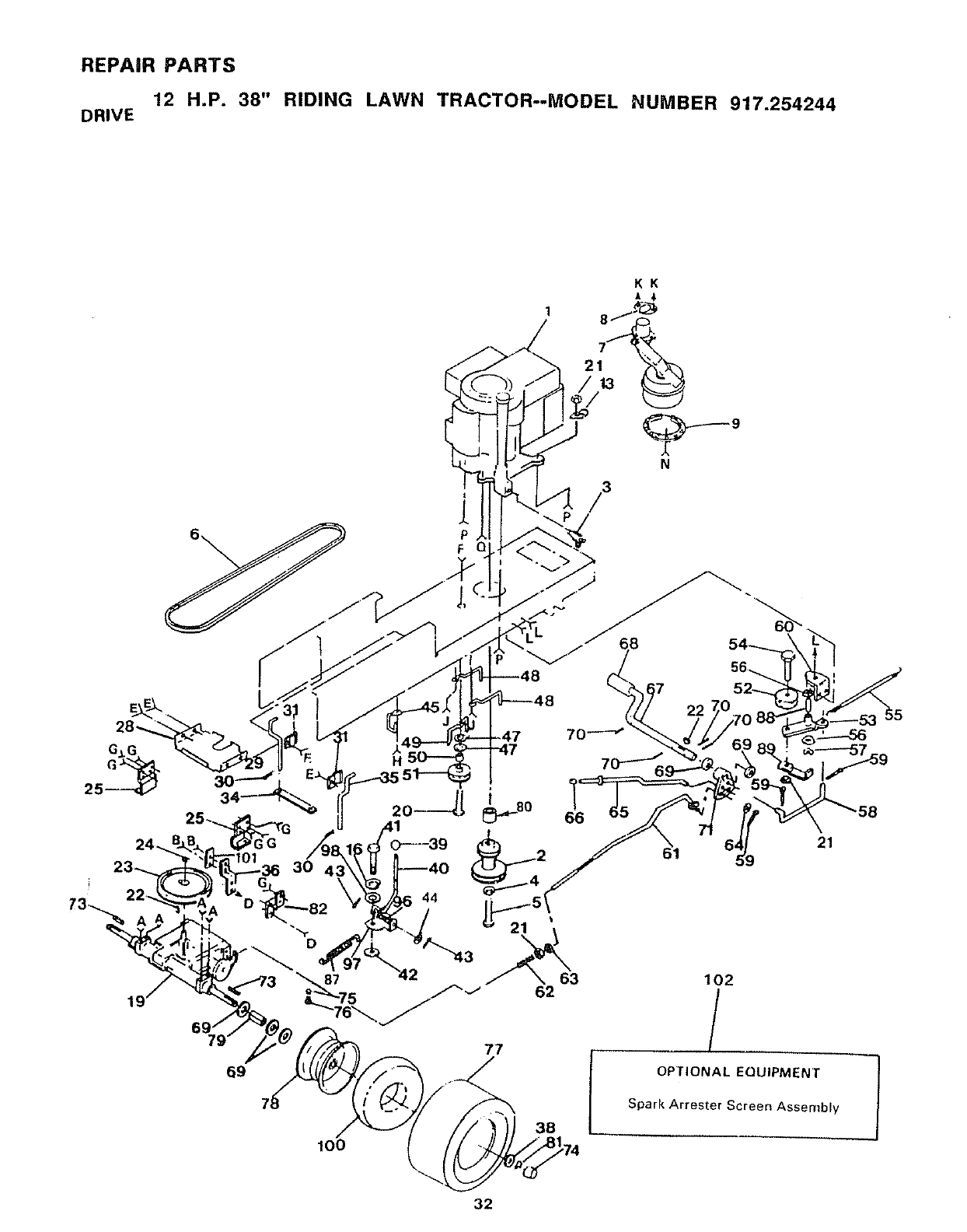
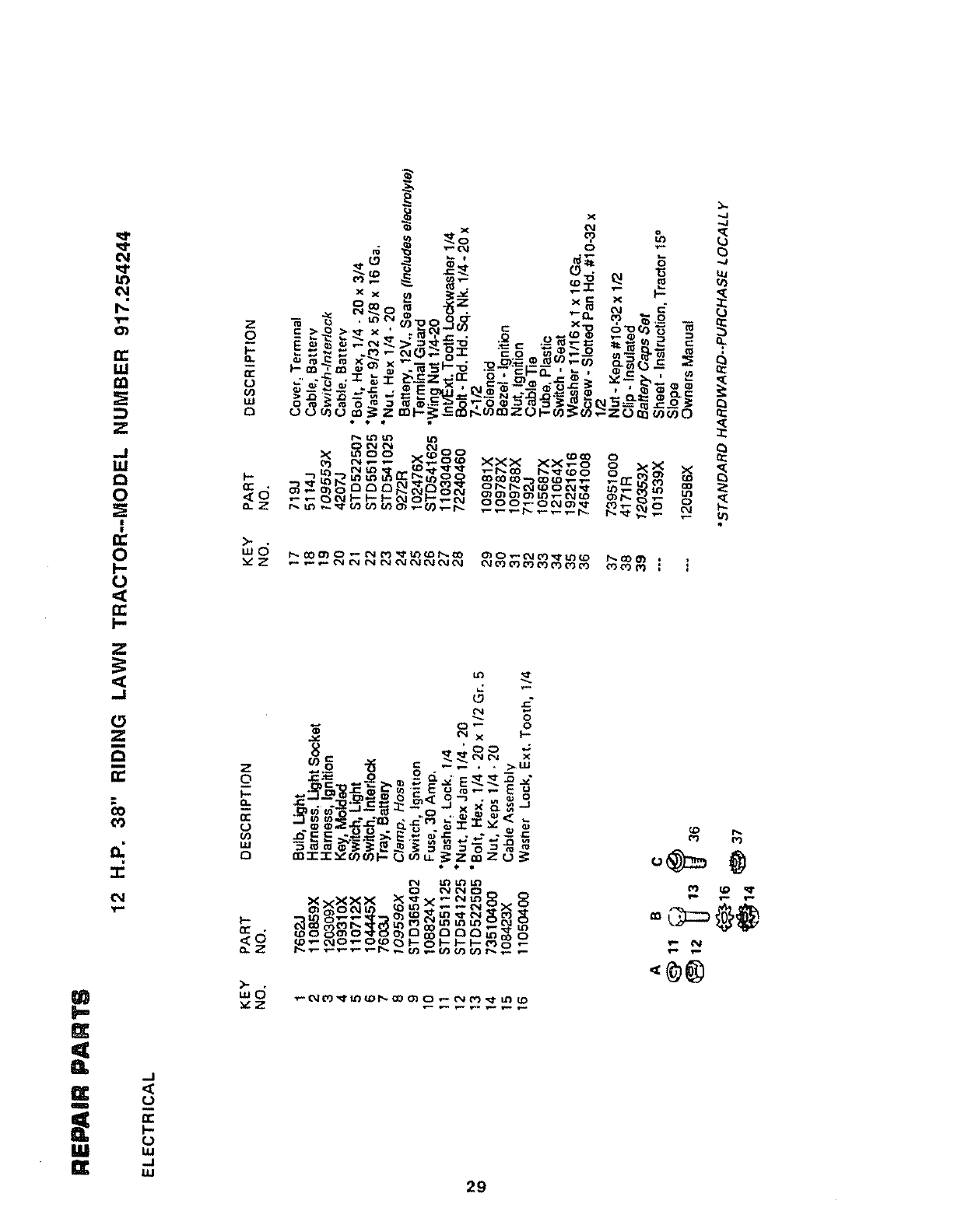
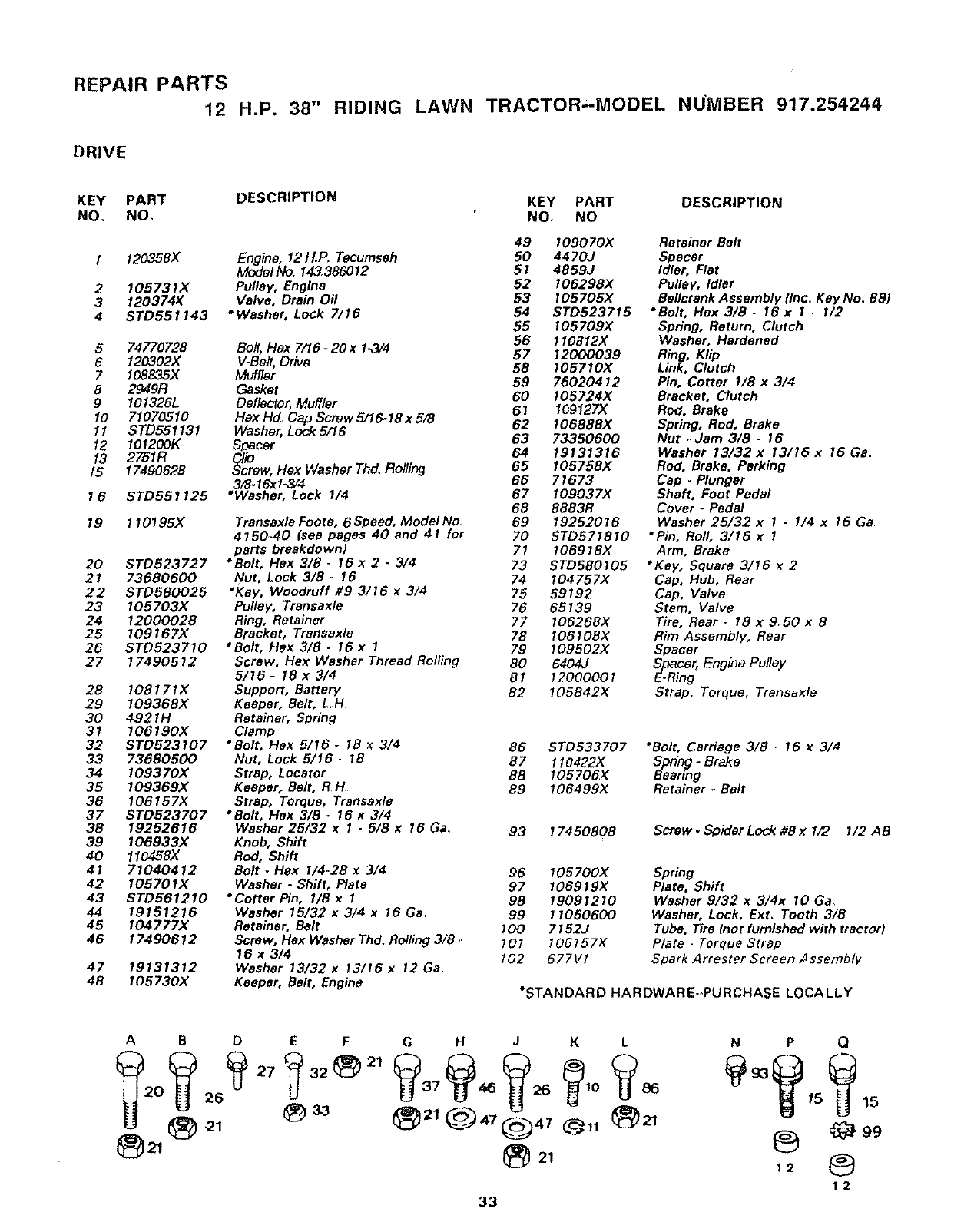
REPAaR PARTS
12 H.P. 38" RIDING LAWN TRACTOR--MODEL NUMBER 917.254244
DRIVE
P
F Q
KK
N
/3
32
22
21
102
/
OPTIONAL EQUIPMENT
Spark Arrester Screen Assembly
REPAIR PARTS
12 H.P. 38" RIDING LAWN TRACTOR,-MODEL NUMBER 917.254244
DRIVE
KEY PART DESCRIPTION KEY PART DESCRIPTION
NO. NO, NO, NO
2
3
4
12O358X
105731X
120374K
STD551143
Engine, 12 H.P. Tecumseh
Model No. 143386012
Pulley, Engine
Valve, Drain Oil
"Washer, Lock 7/16
5 74770728 Bolt, Hex7/16-20x1.3/4
6 120302X V-Be#, Drive
710BB35X Muffler
8 2949R Gasket
9 I01326L Deflector, Muffler
10 71070510 Hax Hd Cap Screw 5/16.18 x S/8
11 STD551131 Washer, Lock5/16
12 101200K Sr_acer
13 2751R ClliiD
15 17490628 _crew, Hex Washer Thd Rolling
3/8-16xl-3/4
16STD551125 •Washer, Lock 1/4
19 110195X
20 STD523727
21 73680600
22 STD580025
23 105703X
24 12000028
25 109167)(
26 STD523710
27 17490512
28 108171X
29 I09368X
30 4921H
31 106190)(
32 STD523107
33 73680500
34 109370X
35 109369X
36 106157X
37 STD523707
38 19252616
39 I06933X
40 110458X
41 71040412
42 105701X
43 STD561210
44 19151216
45 I04777X
46 17490612
47 19131312
48 I05730X
Transaxle Foote, 6Speed, Model No.
4150_40 (see pages 40 and 41 for
parts breakdown)
*Bolt, Flex 3/8 -16 x 2 -3/4
Nut, Lock 3/8 -16
•Key, Woodruff #9 3/16 x3/4
Pulley, Transaxle
Ring, Retainer
Bracket, Transaxle
•Bolt, Hex 3/8 -16 x I
Screw, Flex Washer Thread Rolling
5/16 -18 x 3/4
Support, Battery
Keeper, Belt, L H
Retainer, Spring
Clamp
"Bolt, Hex 5/16 -18 x3/4
Nut, Lock 5/16 -18
Strap, Locator
Keeper, Belt, R.H
Strap, Torque, Transaxle
"Bolt, Flex 3/8 -16 x3/4
Washer 25/32 x1-5/8 x16 Ga.
Knob, Shift
Rod, Shift
Bolt -Flex I/4-28 x 3/4
Washer -Shift, Plate
•Cotter Pin, I/B x I
Washer 15/32 x 3/4 x 16 Ga
Retainer, Belt
Screw, Hex Washer Thd. Rolling 3/8
16 x 3/4
Washer 13/32 x 13/16 x 12 Ga
Keeper, Belt, Engine
49 109070X Retainer Belt
50 4470J Spacer
5f4859J Idler, Flat
52 106298X Pulley, Idler
53 t05705X Bellcrank Assembly (inc. Key No. 88)
54 STD523715 "Bolt, Hex 3/8 -16 x!_I/2
55 I05709X Spring, Return, Clutch
56 1I0812X Washer, Hardened
57 12000039 Ring, Klip
58 I05710X Link, Clutch
59 76020412 Pin, Cotter 1/8 x 3/4
60 105724)( Bracket, Clutch
61 109127X Rod, Brake
62 106888X Spring, Rod, Brake
63 73350600 Nut • Jam 3/8 - 16
64 19131316 Washer 13/32x 13/16x 16 Ga.
65 I05758X Rod, Brake, Parking
66 71673 Cap _Plunger
67 109037X Shaft, Foot Pedal
6B 8883R Cover -Pedal
69 19252016 Washer 25/32 x 1 - 1/4 x 16 Ga
70 5TD571810 "Pin, Roll, 3/16 x 1
71 106916X Arm, Brake
73 STD580705 •Key, Square 3/16 x 2
74 I04757X Cap, Hub, Rear
75 59192 Cap, Valve
76 65139 Stem, Valve
77 106268)( Tire, Rear -18 x 950 x 8
78 I06108X Rim Assembly, Rear
79 I09502X Spacer
80 6404J Spacer, Engine Pulley
81 12000001 E-Ring
82 105842X Strap, Torque, Transaxle
86 STD533707 *Bolt, Carriage 3/8 -16 x3/4
87 110422X Sf_r_ -Brake
88 105706X Beanng
B9 I06499X Retainer *Belt
93 17450808 Screw -Spider Lock #8 x1/2 1/2 AB
96 I05700X
97 I06919X
98 19091210
99 11050600
100 7152J
101 106157X
102 677V1
Spring
Plate. Shift
Washer 9/32 x 3/4x 10 Ga,
Washer, Lock, Ext, Tooth 3/8
Tube. Tire (not furnished with tractor)
Plate -Torque Strap
Spark Arrester Screen Assembly
"STANDARD HARDWARE-oPURCHASE LOCALLY
A B D
27
E F G H J K L
33
N P Q
12
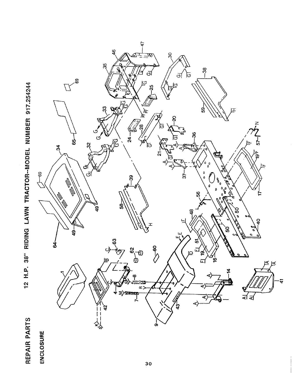
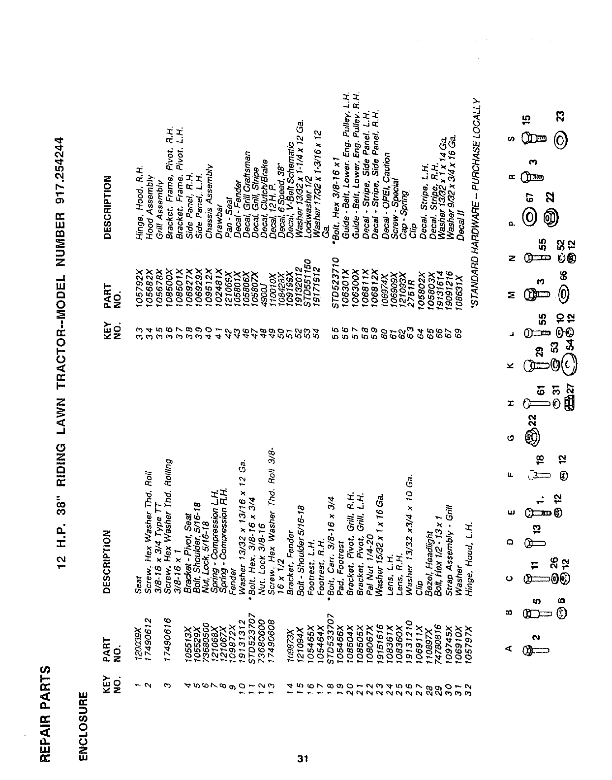
REPAIR PARTS
12 H.P. 38" RIDING LAWN TRACTOR--MODEL NUMBER 917.254244
I
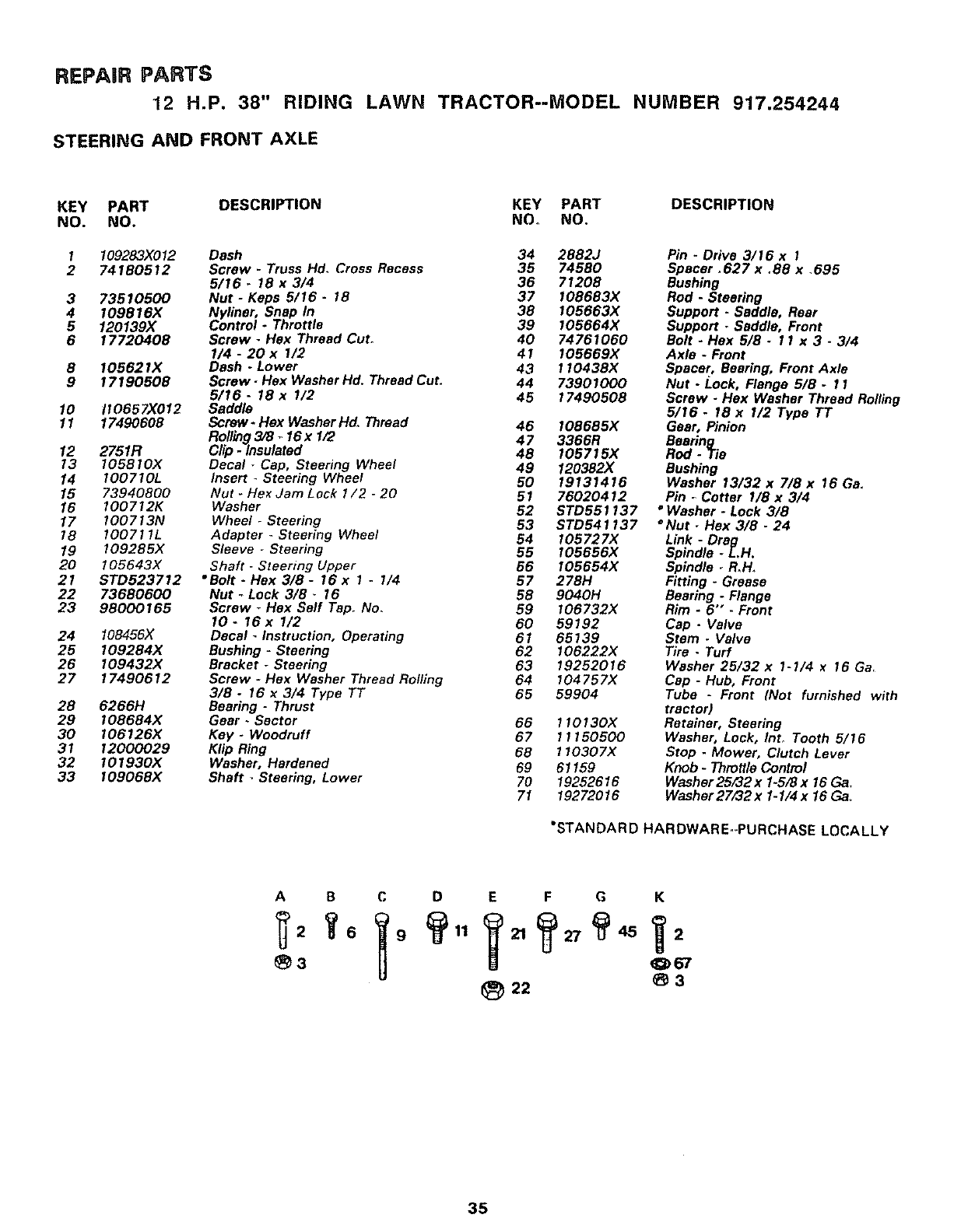
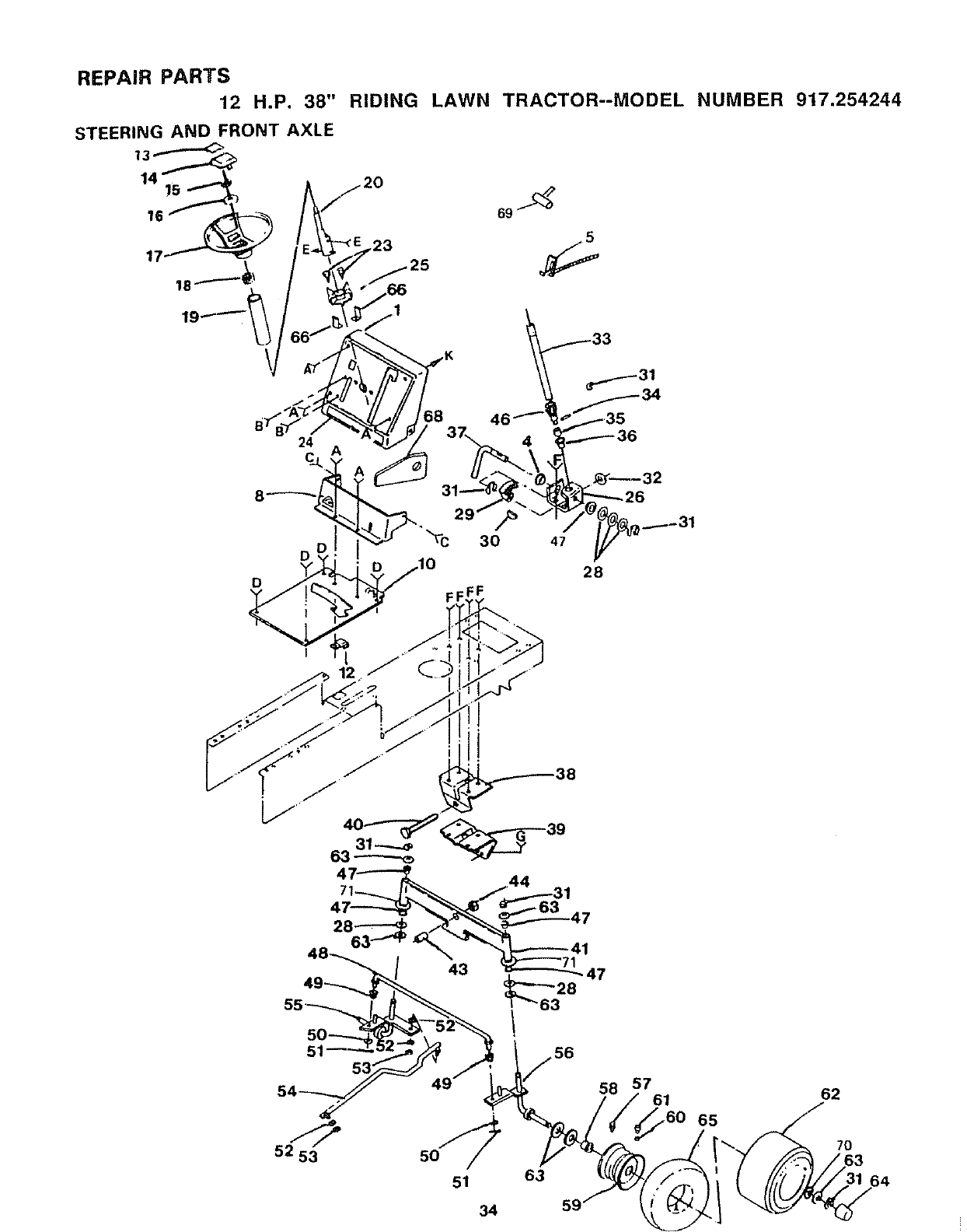
REPAIR PARTS
12 H.P. 38" RIDING LAWN TRACTOR--MODEL NUMBER 917.254244
STEERING AND FRONT AXLE
KEY PART DESCRIPTION KEY PART DESCRIPTION
NO. NO, NO. NO,
1
2
3
4
5
6
8
9
109283X012
74180512
73510500
109816X
120139X
17720408
I05621X
17190508
lO 110657)(012
11 17490608
12 2751R
13 105870X
14 I00710L
15 73940800
16 100712K
17 100713N
18 100711L
19 109285X
20 105643X
21 STD523712
22 73680600
23 98000165
24 108456X
25 109284X
26 I09432X
27 17490612
28 62661-1
29 108684X
30 106126)(
31 12000029
32 101930X
33 109068X
Dash
Screw - Truss Hd. Cross Recess
5/16. 18 x 3/4
Nut - Keps 5/16 - 18
Nyliner, Snap In
Control *Throttle
Screw -Hex Thread Cut_
1/4 -20 xI/2
Dash -Lower
Screw - Hex Washer Hd. Thread Cut.
5/16- 18 x I/2
Saddle
Screw- Hex Washer lid. Thread
Ro11_9 3/8 .16 x 1/2
Clip -Insulated
Decal -Cap, Steering Wheel
Insert - Steering Wheel
Nut -Hex Jam Lock 1/2 -20
Washer
Wheel -Steering
Adapter -Steering Wheel
Sleeve -Steering
Shaft -Steermg Upper
"Bolt -Hex 3/8 -16 x 1 -I/4
Nut _Lock 3/8 _I5
Screw TFlex Self Tap. No.
10- 16 x 1/2
Decal -Instruction, Operating
Bushing -Steering
Bracket -Steering
Screw -Hex Washer Thread Rolling
3/8 -16 x3/4 Type TT
Bearing - Thrust
Gear -Sector
Key -Woodruff
Klip Ring
Washer, Hardened
Shaft _Steering, Lower
34 2882J
35 74580
36 71208
37 I08683X
38 105663X
39 I05664X
40 74761060
41 105669X
43 11043BX
44 73901000
45 17490508
46 I08685X
47 3366R
48 105715X
49 120382X
50 19131416
51 76020412
52 STD551137
53 STD541137
54 I05727X
55 I05656X
56 105654X
57 278H
58 9040H
59 I06732X
60 59192
61 65139
62 I06222X
63 19252016
64 104757X
65 59904
66 110130X
67 71150500
68 110307X
69 61159
70 19252616
71 19272016
Pin .Drive 3/16 x 1
Spacer .627 x.88 x.695
Bushing
Rod. Steering
Support -Saddle, Rear
Support. Saddle, Front
Bolt - Flex 5/8 -11 x 3.3/4
Axle *Front
Spacer, Bearing, Front Axle
Nut - Lock, Flange 5/8 -11
Screw -Hex Washer Thread Rolling
5/16 -18 x I/2 Type TT
Gear, Pinion
Bearing
Red. Tie
Bushing
Washer 13/32 x 7/8 x 16 Ga,
Pin _Cotter I/8 x 3/4
"Washer - Lock 3/8
°Nut. Hex 3/8 - 24
Link - Drag
Spindle -L,H,
Spindle. R,H.
Fitting. Grease
Bearing - Flange
Rim - 6" - Front
Cap. Valve
Stem .Valve
Tire -Turf
Washer 25/32 x 1-1/4 x16 Ga
Cap - Hub, Front
Tube -Front (Not furnished with
tractor)
Retainer, Steering
Washer, Lock, Into Tooth 5/16
Stop -Mower, Clutch Lever
Knob - Throttle Control
Washer 25,,'32x 1-5/8 x 16 Ga,
Washer 27/32 x 1-1/4x 16 Ga,.
'STANDARD HARDWARE-PURCHASE LOCALLY
ABC D
_3
E F G K
22 _3
35
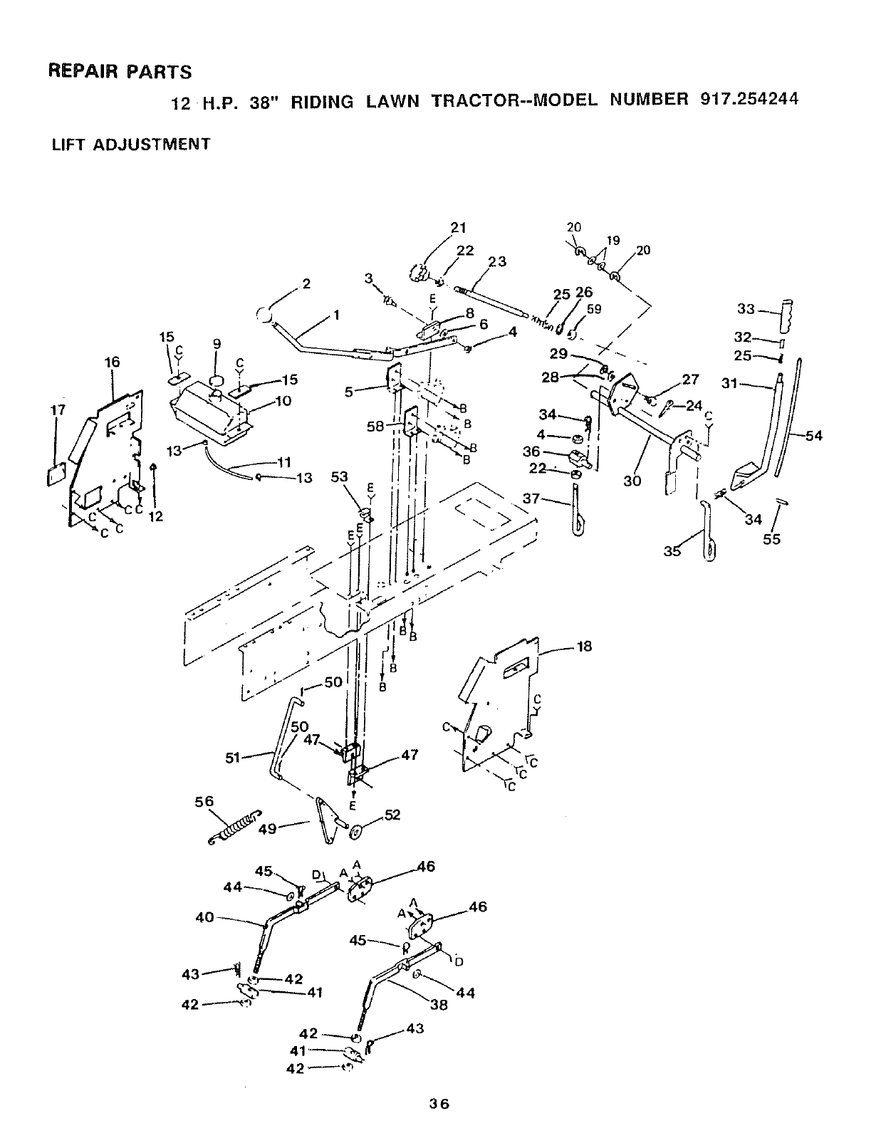
REPAIR PARTS
12 H.P. 38" RIDING LAWN TRACTOR--MODEL NUMBER 917.254244
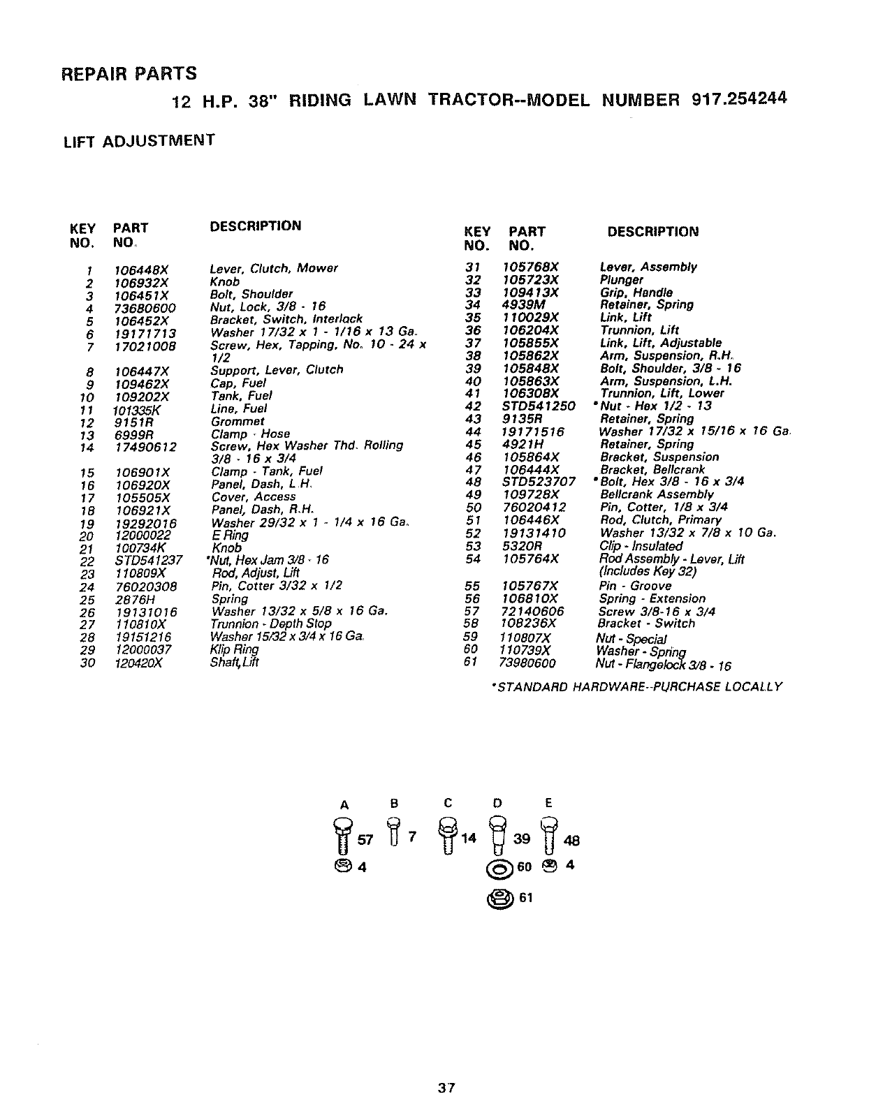
LIFT ADJUSTMENT
16
53 3O
IB
B
C
36
REPAIR PARTS
12 H.P. 38" RIDING LAWN TRACTOR--MODEL NUMBER 917.254244
LIFT ADJUSTMENT
KEY PART DESCRIPTION KEY PART DESCRIPTION
NO, NO_ NO. NO.
I
2
3
4
5
6
7
8
9
10
11
12
13
14
15
16
17
18
19
20
21
22
23
24
25
26
27
28
29
30
I06448X Lever, Clutch, Mower 31 105768X
I06932X Knob 32 I05723X
106451X Bolt, Shoulder 33 I09413X
73680600 Nut, Lock, 3/8 -16 34 4939M
I06452X Bracket, Switch, InterlQck 35 110029X
19171713 Washer 17/32x I .1/16x 13Ga. 36 I06204X
17021008 Screw, Hex, Tapping, No. 10.24 x 37 I05855X
I/2 38 I05862X
106447X Support, Lever, Clutch 39 105848X
109462)( Cap, Fuel 40 105863X
I09202X Tank, Fuel 41 106308X
101335K Line, Fuel 42 STD541250
9151R Grommet 43 9135R
6999R Clamp -Hose 44 19171516
17490612 Screw, Hex Washer Thd. Rolling 45 4921H
3/6 -16 x 3/4 46 105864X
I06901X Clamp - Tank, Fuel 47 I06444X
106920X Panel, Dash, L H, 48 STD523707
I05505X Cover, Access 49 10972BX
106921X Panel, Dash, R.H. 50 76020412
19292016 Washer 29/32 x 1 .. 1/4x 16 Ga. 51 I06446X
12000022 ERing 52 19131410
100734K Knob 53 6320R
STD541237 *Nut, Flex Jam 3/8 -16 54 105764X
1I0809X Red, Adjust, Lift
76020308 Pin, Cotter 3/32 x 1/2 55 I05767X
2876H Spring 56 I06810X
19131016 Washer 13/32 x 5/8 x 16 Ga. 57 72140606
110810X Trunnion. Depth Stop 58 I08236X
19151216 Washer15/32x3/4x16Ga. 59 110807)(
12000037 Klip Ring 60 110739)(
120420X Shaft, Lift 61 73980600
Lever, Assembly
Plunger
Grip, Handle
Retainer, Spring
Link, Lift
Trunnion, Lift
Link, Lift, Adjustable
Arm, Suspension, RoH.
Bolt, Shoulder, 3/8- 16
Arm, Suspension, L.H.
Trunnion, Lift, Lower
*Nut *Flex I/2- 13
Retainer, Spring
Washer 17/32x 15/16 x 16 Ga.
Retainer, Spring
Bracket, Suspension
Bracket, Bellcrank
• Bolt, Hex 3/8 -16 x 3/4
Bellcrank Assembly
Pin, Cotter, 1/8 x 3/4
Rod, Clutch, Primary
Washer 13/32 x 7/8 x 10 Ga.
Clip - Insulated
Red Assembly -Lever, Lift
(Includes Key 32)
Pin -Groove
Spring -Extension
Screw 3/8-16 x3/4
Bracket -Switch
Nut -Special
Washer- Spdng
Nut -Flangolock 3/8.16
"STANDARD HARDWARE--PURCHASE LOCALLY
AB C D E
_60 _4
61
37
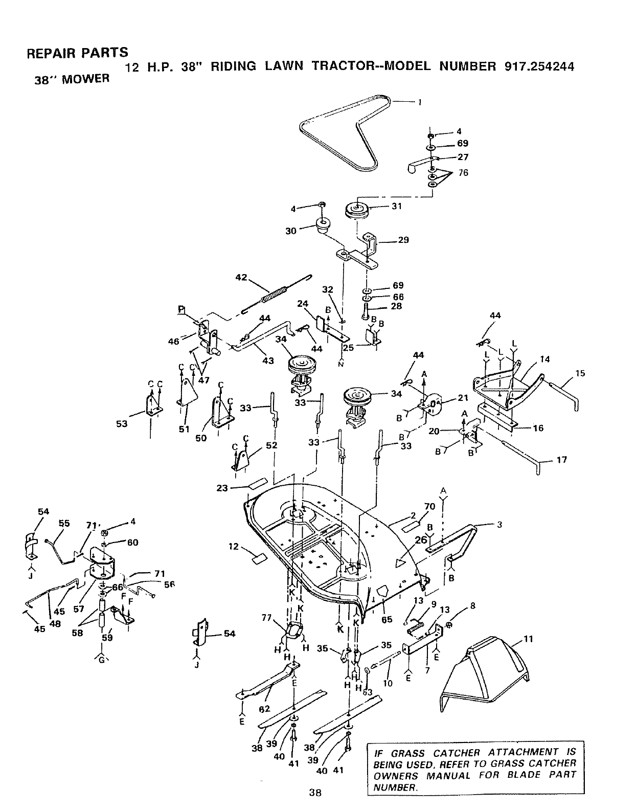
REPAIR PARTS
12
38" MOWER
H.P. 38" RIDING LAWN TRACTOR--MODEL NUMBER 917.254244
1
CC
53 I
_45 48 58 59 I
51 5O
33
38
t
IF GRASS CATCHER ATTACHMENT IS I
BEING USED. REFER TO GRASS CATCHER I
OWNERS MANUAL FOR BLADE PART
NUMBER.
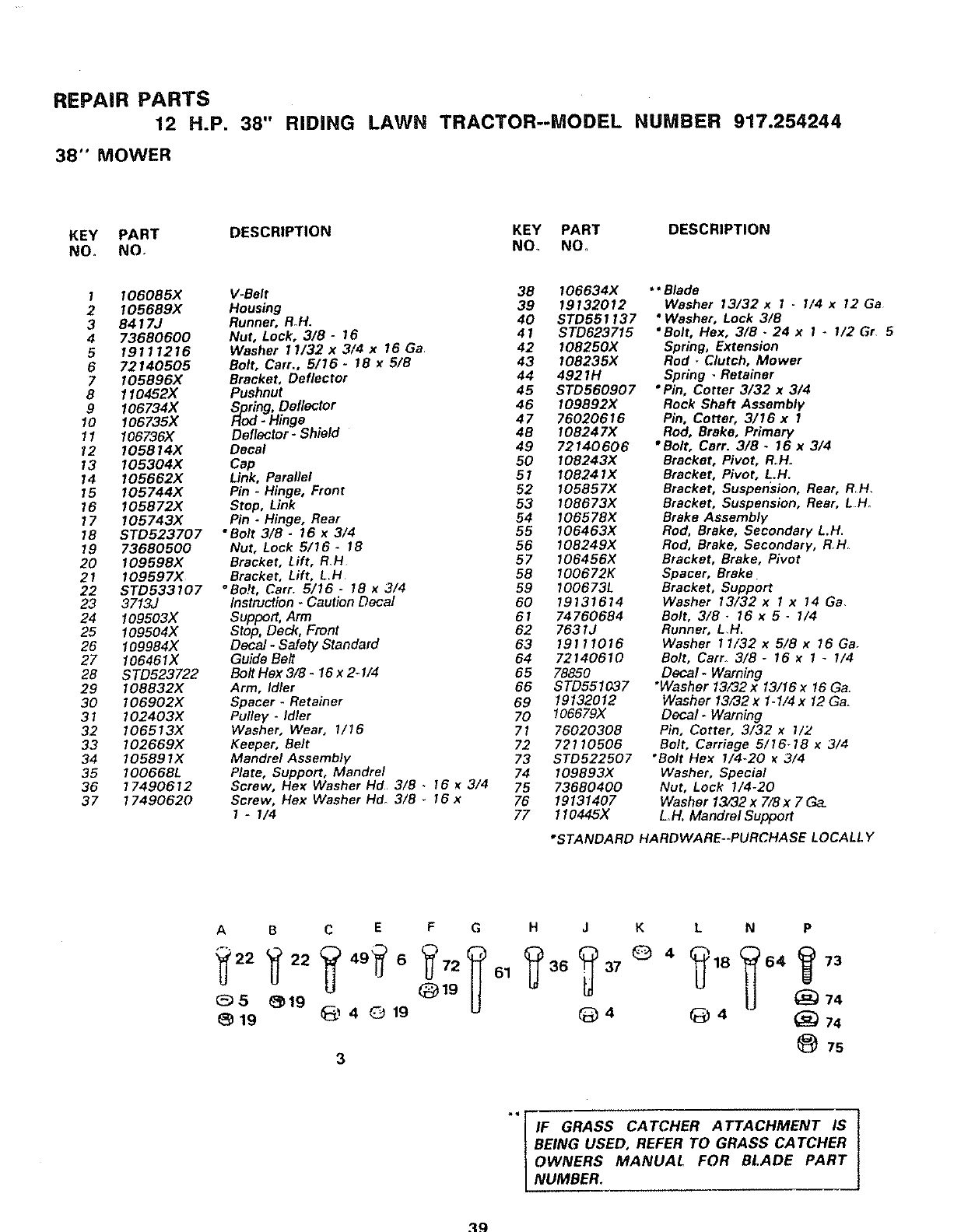
REPAIR PARTS
12 H.P. 38" RIDING LAWN TRACTOR--MODEL NUMBER 917.254244
38" MOWER
KEY PART DESCRIPTION KEY PART DESCRIPTION
NO. NO. NO NO_
1 I06085X V.Belt 38 106634X
2 105689X Housing 39 19132012
3 8417J Runner, RoH. 40 STD551137
4 73680600 Nut, Lock, 3/8 -16 41 STD623715
5 19111216 Washer 11/32x3/4x 16Ga 42 I08250X
6 72140505 Bolt, Cart., 5/16 - 18 x 5/8 43 108235X
7 105896)( Bracket, Deflector 44 4921H
8 110452X Pushnut 45 STD560907
9 106734X Spring, Deflector 46 I09892X
10 106735X Rod-Hinge 47 76020616
11 106736X Deflector-Shield 48 108247)(
12 I05814X Decal 49 72140606
13 105304X Cap 50 I08243X
14 I05662X Link, Parallel 51 I08241X
15 I05744X Pin -Hinge, Front 52 105857X
16 I05872X Stop, Link 53 108673X
17 105743X Pin. Hinge, Rear 54 I06578X
18 8TD523707 "Bolt 3/8 -16 x3/4 55 I06463X
19 73680500 Nut, Lock 5/16 -18 56 108249X
20 109598X Bracket, Lift, R,H 57 106456X
21 I09597X Bracket, Lift, L.H 58 100672K
22 STD533107 °Be!t, Carr. 5/16 - 18 x3/4 59 100673L
23 3713J Instruction-CautionDecal 60 19131614
24 109503X Support, Arm 61 74760684
25 109504X Stop, Deck, Front 62 7631J
26 109984X Decal -Safety Standard 63 19 t11016
27 106461X Guide Belt 64 72140610
28 STD523722 Bolt Hex 3/8 -16 x 2-I/4 65 78850
29 108832X Arm, Idler 66 STD551037
30 106902X Spacer -Retainer 69 19132012
31 102403X Pulley -Idler 70 106679X
32 106513X Washer, Wear, 1/16 71 76020308
33 102669X Keeper, Belt 72 72110506
34 10589 IX Mandrel Assembly 73 STD522507
35 I00668L Plate, Support, Mandrel 74 I09893X
36 17490612 Screw, Hex Washer Hd 3/8 . 16 x3/4 75 73680400
37 17490620 Screw, Flex Washer Hd_ 3/8 .16 x 76 19131407
I - I/4 77 110445X
** Blade
Washer 13/32x I - I/4 x12Ga
•Washer, Lock 3/8
• Bolt, Hex, 3/8 -24 x 1- 1/2 Gr 5
Spring, Extension
Rod *Clutch, Mower
Spring -Retainer
•Pin, Cotter 3/32 x 3/4
Reck Shaft Assembly
Pin, Cotter, 3/16 x 1
Rod, Brake, Primary
"Bolt, Cart. 3/8- 16 x 3/4
Bracket, Pivot, RoH.
Bracket, Pivot, L.H,
Bracket, Suspension, Rear, R,H,
Bracket, Suspension, Rear, L H.
Brake Assembly
Rod, Brake, Secondary L.H.
Rod, Brake, Secondary, RH
Bracket, Brake, Pivot
Spacer, Brake
Bracket, Support
Washer 13/32 xIx14 Ga,
Bolt, 3/8 _16 x 5 -1/4
Runner, L,H.
Washer 11/32 x 5/8 x 16 Ga.
Bolt, Carro 3/8 -16 x 1 _1/4
Decal- Warning
"Washer 13/32x 13/16 x16 Ga_
Washer 13732 x1-1/4 x 12 Ga.
Decal- Warning
Pin, Cotter, 3/32 x 1/:z
Bolt, Carriage 5/16-18 x3/4
"Bolt Hex I/4-20 x3/4
Washer, Special
Nut, Lock I/4-20
Washer 13/32 x 7/8 x 7 Ga.
L,H. Mandrel Support
*STANDARD HARDWARE.-PURCHASE LOCALLY
ABCEFG
05 _19 Q19
19 _) 4019
3
HJK L NP
61 36 37 64 73
@ 74
_)4 _4 _74
7s
*'FIF GRASS CATCHER ATTACHMENT IS
|BEING USED, REFER TO GRASS CATCHER
|OWNERS MANUAL FOR BLADE PART
LNUMBER.
39
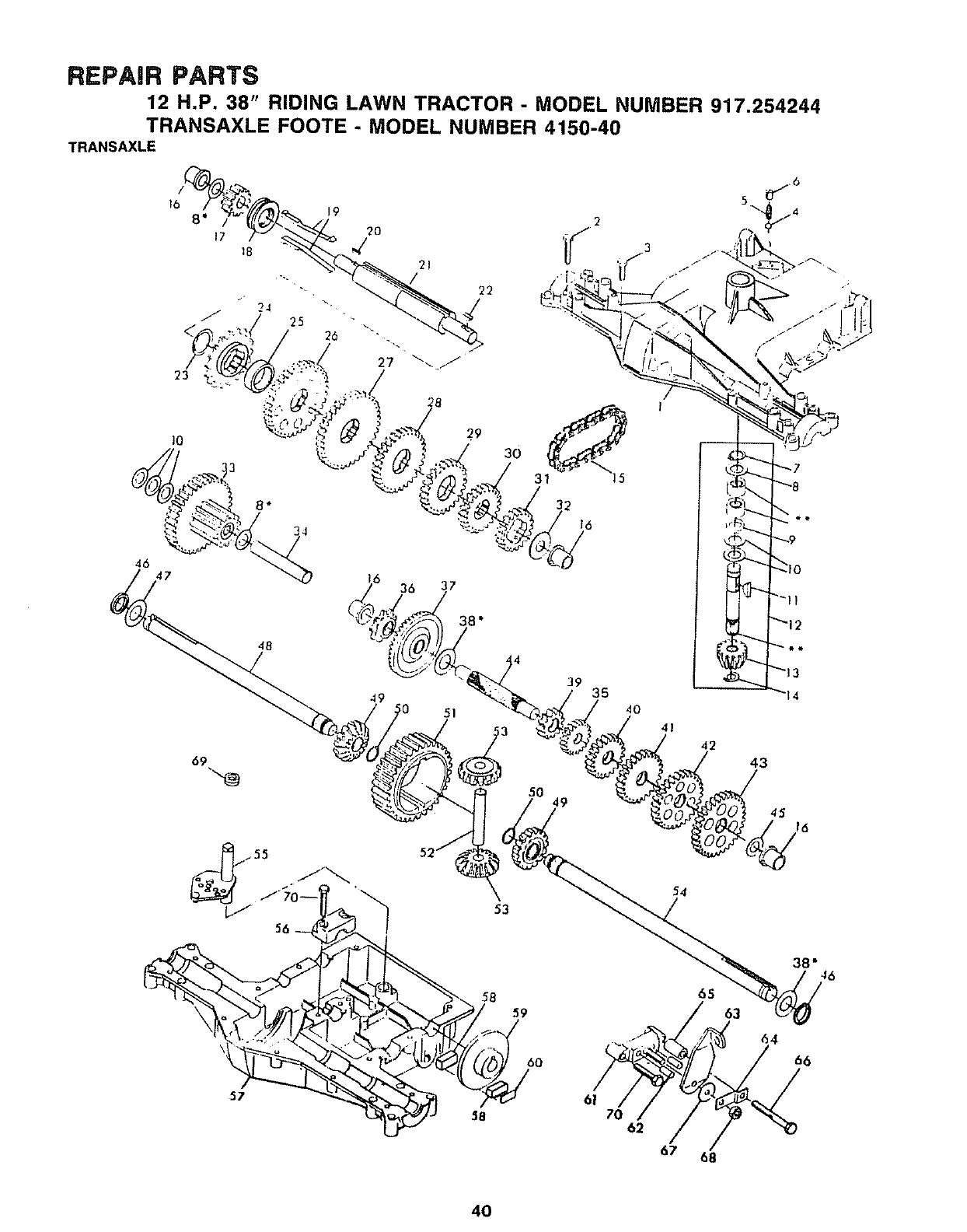
REPAIR PARTS
12 H.P. 38" RIDING LAWN TRACTOR -MODEL NUMBER 917.254244
TRANSAXLE FOOTE - MODEL NUMBER 4150-40
TRANSAXLE
5O 49
53
54
58 59
60
38" 46
65
63 64
66
67 68
40
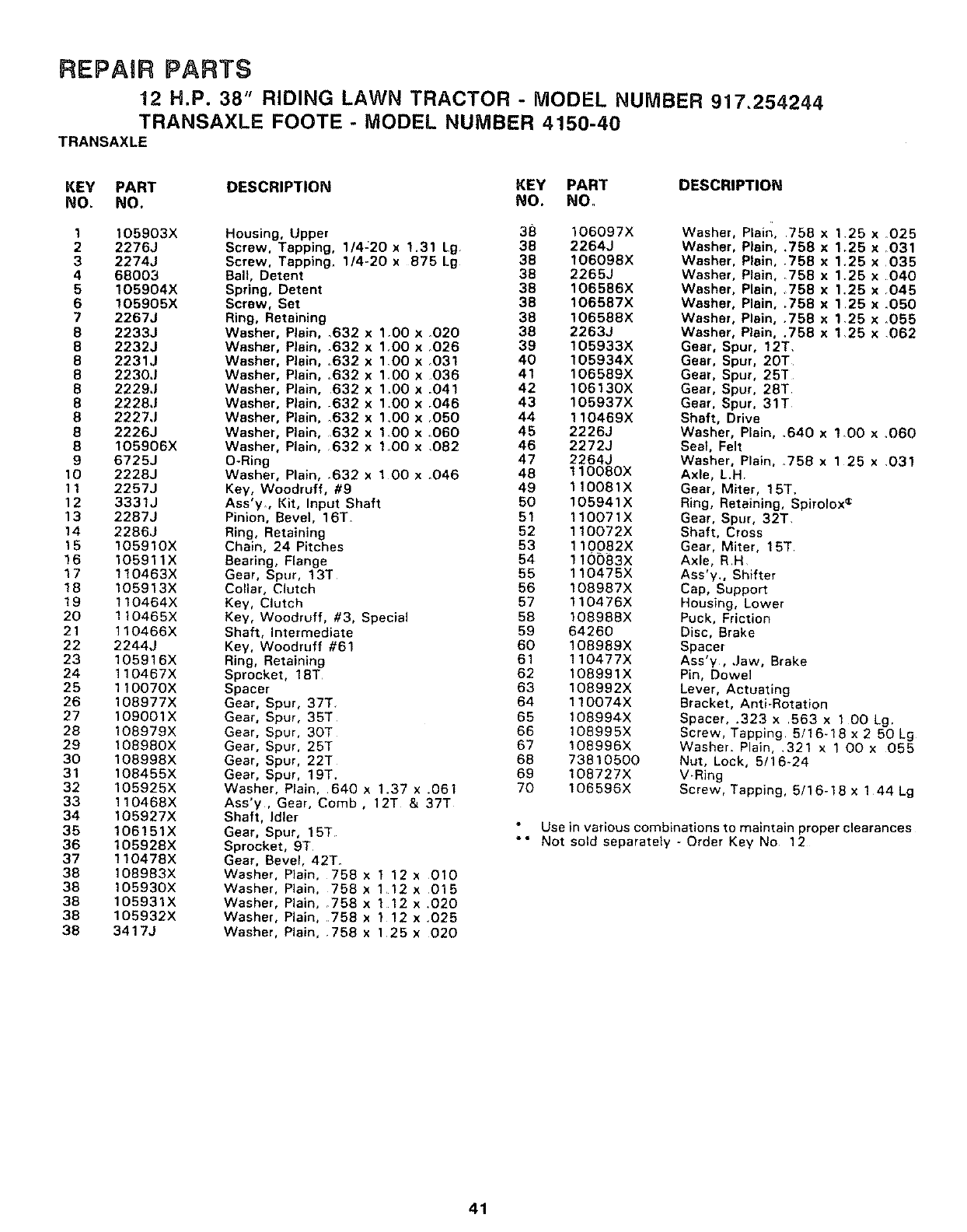
REPAIR PARTS
12 H.P. 38" RIDING LAWN TRACTOR - MODEL NUMBER 917,254244
TRANSAXLE FOOTE - MODEL NUMBER 4150-40
TRANSAXLE
KEY PART DESCRIPTION KEY PART DESCRIPTION
NO. NO. NO. NO.
1105903X Housing, Upper 38 106097X
2 2276J Screw. Tapping, 1/4:20 x 1.31 Lg 38 2264J
3 2274J Screw, Tapping, 1/4-20 x 875 Lg 38 106098X
4 68003 Ball, Detent 38 2265J
5 105904X Spring, Detent 38 106586X
6 !O5905X Screw, Set 38 106587X
7 22673 Ring, Retaining 38 106588X
6 2233J Washer, Plain, ,632 x 1,00 x _O20 38 2263J
8 2232J Washer, Plain, .632 x 1,O0 x 026 39 105933X
8 2231J Washer, Plain, ,632 x 100 x ,031 40 105934X
8 2230J Washer, Plain, ,632 x 1,00x 036 41 106589X
8 22293 Washer, Plain, 632 x 1,00 x .041 42 106130X
8 22283 Washer, Plain, .632 x 1.00 x r046 43 105937X
822273 Washer, Plain, _632 x 1.O0 x ,050 44 110469X
8 2226J Washer, Plain, 632 x 1.00 x _060 45 2226J
6 I05906X Washer, Plain, 632 x 1_00 x .082 46 2272J
9 6725J O-Ring 47 2264J
10 2228J Washer, Plain, ,632 x 1 00 x .046 48 110080X
11 2257J Key, Woodruff, #9 49 110081X
12 3331J Ass'y, Kit, Input Shaft 50 105941X
13 2287J Pinion, Bevel, 16T. 51 110071X
14 2286J Ring, Retaining 52 110072X
15 105910X Chain, 24 Pitches 53 110082X
16 105911X Bearing, Flange 54 110083X
17 110463X Gear, Spur, 13T 55 110475X
18 105913X Collar, Clutch 56 108987X
19 110464X Key, Clutch 57 110476X
20 110465X Key, Woodruff, #3, Special 58 108955X
21 110466X Shaft, Intermediate 59 64260
22 2244J Key, Woodruff #61 60 108989X
23 105916X Ring, Retaining 61 110477X
24 110467X Sprocket, 18T 62 108991X
25 110070X Spacer 63 108992X
26 108977X Gear, Spur, 37T. 64 110074X
27 109001X Gear, Spur, 35T 65 108994X
28 108979X Gear, Spur, 30T 66 108995X
29 10898OX Gear, Spur, 25T 67 108996X
30 108998X Gear, Spur, 22T 68 73810500
31 108455X Gear, Spur, 19T, 69 108727X
32 105925X Washer, Plain, 640 x1.37 x .061 70 106596X
33 110468X Ass'y, Gear, Comb, 12T & 37T
34 105927X Shaft, Idler
35 106151X Gear, Spur, 15T Use
36 105928X Sprocket, 9T *° Not
37 110478X Gear, Bevel, 42T.
38 108983X Washer, Plain, 758 x 1 12 x 010
38 105930X Washer, Plain, 758 x 1 12 x 015
38 105931X Washer, Plain, _758 x 1 12 x .020
38 105932X Washer, Plain, 758 x t 12 x.025
38 3417J Washer, Plain, .758 x 125 x 020
Washer, Plain, 758 x1,25 x 025
Washer, Plain, .758 x 1.25 x rO31
Washer, Plain, 758 x 1,25 x 035
Washer, Plain, 758 x 1.25 x 040
Washer, Plain, ,758 x 1.25 x ,045
Washer, Plain..758 x 125 x ,050
Washer, Plain, .758 x 1,25 x .055
Washer, Plain, .758 x 1,25 x ,062
Gear, Spur, 12T,
Gear, Spur, 20T
Gear. Spur, 253"
Gear, Spur, 28T
Gear, Spur. 31T
Shaft, Drive
Washer, Plain, ,640 x 1D0 x _060
Seal, Felt
Washer, Plain, _758 x 125 x .031
Axle, L,H.
Gear, Miter, 15T.
Ring, Retaining, Spirolox •
Gear, Spur, 32T.
Shaft, Cross
Gear, Miter, 15T
Axle, RH
Ass'y,, Shifter
Cap, Support
Housing, Lower
Puck, Friction
Disc, Brake
Spacer
Ass'y, .Jaw, Brake
Pin, Dowel
Lever, Actuating
Bracket, Anti-Rotation
Spacer, .323 x 563 x 1 O0 Lg,
Screw, Tapping. 5/16_18 x 2 50 Lg
Washer. Plain, .321 x 1 O0 x 055
Nut, Lock, 5/16-24
V-Ring
Screw, Tapping, 5/16-18 x 144 Lg
in various combinations to maintain proper clearances
sold separately -Order Key No 12
41
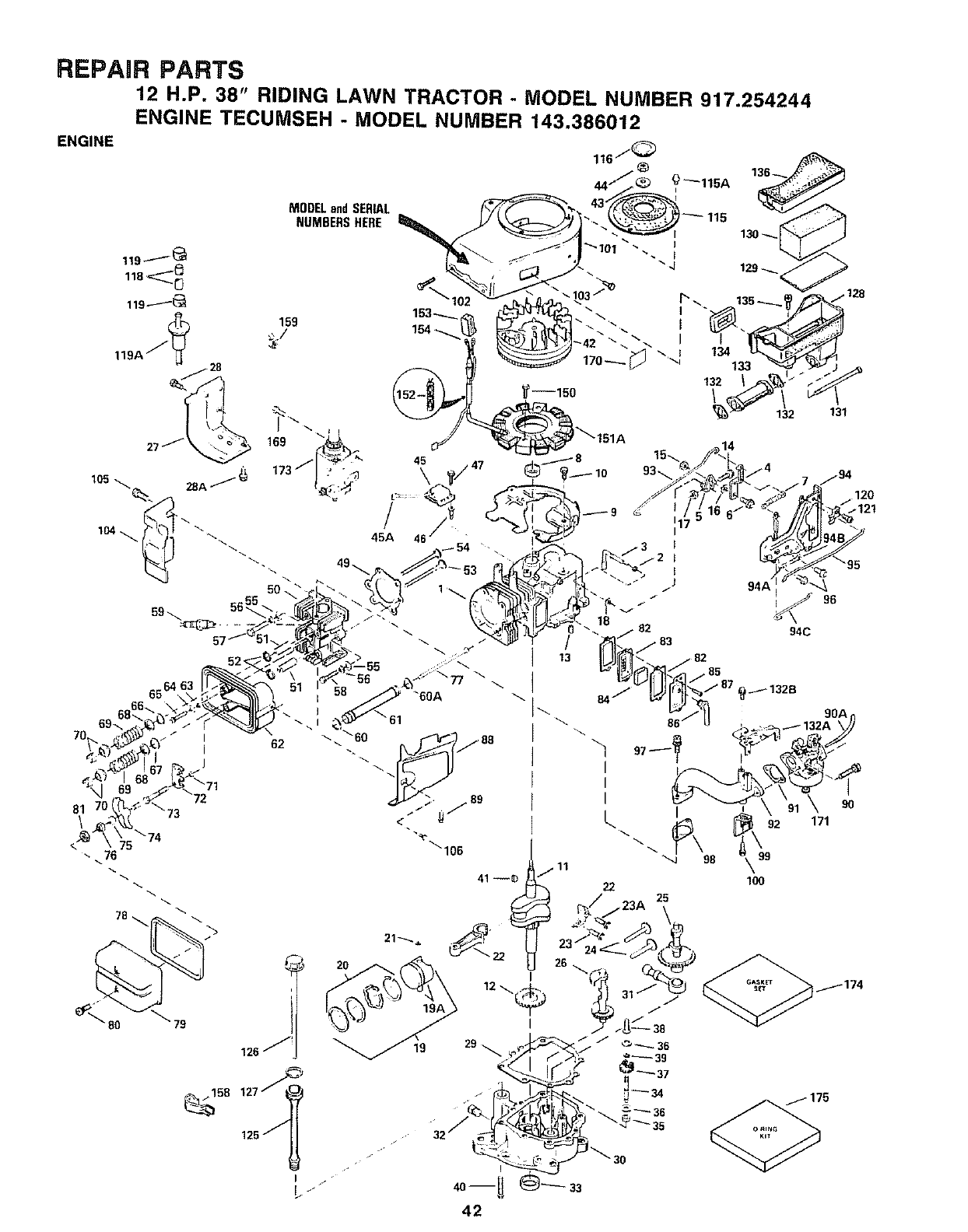
REPAIR PARTS
ENGINE
12 H.P. 38" RIDING LAWN TRACTOR - MODEL NUMBER 917.254244
ENGINE TECUMSEH -MODEL NUMBER 143.386012
MODEL and SERIAL )-_- 115
NUMBERS HERE
13
6564,
81 70'
\_74
"- 76
134133
132 131
_121
_! 20
19A
I
126 _19
/
42
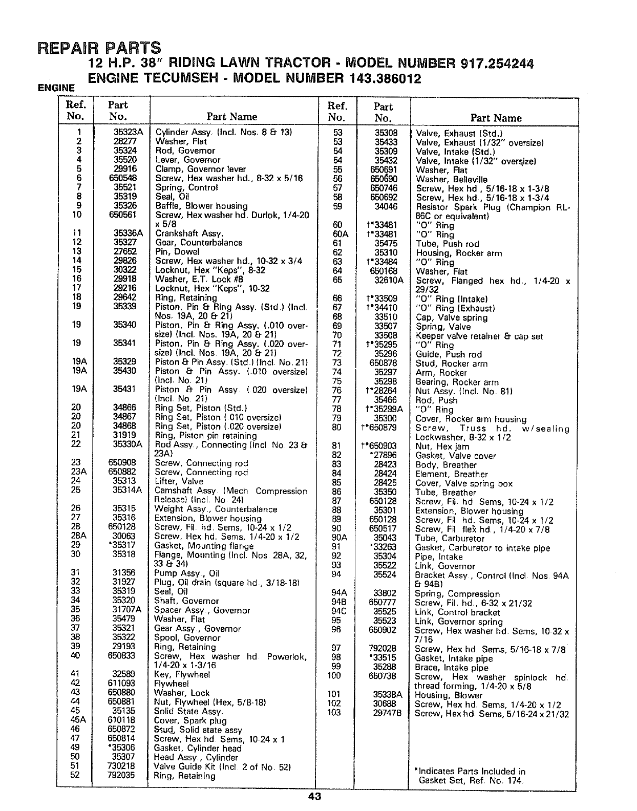
REPAUR PARTS
12 H.P. 38" RIDING LAWN TRACTOR - MODEL NUMBER 917,254244
ENGINE TECUiViSEH -MODEL NUMBER 143.386012
ENGINE
Ref.
No.
1
2
3
4
6
6
7
8
9
10
11
12
13
14
15
16
17
18
19
19
19
19A
19A
19A
20
20
20
21
22
23
23A
24
25
26
27
28
28A
29
30
31
32
33
34
35
36
37
38
39
40
41
42
43
44
45
45A
46
47
49
50
51
52
Part
No.
35323A
28277
35324
35520
29916
650548
35521
35319
35326
65O561
35336A
35327
27652
29826
3O322
29918
29216
29642
35339
3534O
35341
35329
35430
35431
34866
34867
34868
31919
35330A
650908
650882
35313
35314A
35315
35316
650128
30063
"35317
35318
31356
31927
35319
35320
31707A
35479
35321
35322
29193
650833
32589
611093
650880
650881
35135
610118
650872
650814
"35306
35307
730218
792035
P_tName
Cylinder Assy, (IncL Nos 88- 13)
Washer, Flat
Rod, Governor
Lever, Governor
Clamp, Governor lever
Screw, Hex washer hd, 8-32 x 5/16
Spring, Control
Seal, Oil
Baffle, Blower housing
Screw, Hex washer hd. Durlok, 1/4-20
x 5/8
Crankshaft Assy.
Gear, Counterbalance
Pin, Dowel
Screw, Hex washer hd, 10-32 x 3/4
Locknut, Hex "Keps", 8-32
Washer, E.T. Lock #8
Locknut, Hex "Keps", 10-32
Ring, Retaining
Piston, Pin 8. Ring Assy. (Std) (Incl.
Nos. 19A, 20 8. 21)
Piston, Pin 8 Ring Assy, (.010 over-
size) (IncL Nos. 19A, 20 8. 21)
Piston, Pin 8. Ring Assy. (.O3Oover-
size) (Incl. Nos 19A, 20 8- 21)
Piston 8. Pin Assy (Std) (Incl. No, 21)
Piston 8. P_n Assy. (_010 oversize)
(Incl, No 21)
Piston 8. Pin Assy (020 oversize)
(Incl No 21)
Ring Set, Piston (Std.)
Ring Set, Piston (010 oversize)
Ring Set, Piston (020 oversize)
Ring, Piston pin retaining
Rod Assy, Connecting (Incl No 23 8-
23A)
Screw, Connecting rod
Screw, Connecting rod
Lifter, Valve
Camshaft Assy (Mech Compression
Release) (Incl No 24)
Weight Assy, Counterbalance
Extension, Blower housing
Screw, Fil hd Seres, 10-24 x 1/2
Screw, Hex hd Sems, 1/4-20 x 1/2
Gasket, Mounting flange
Flange, Mounting (Incl Nos 28A, 32,
33 8. 34)
Pump Assy., Oil
Plug, Oil drain (square hd, 3/18-18)
Seal, Oil
Shaft, Governor
Spacer Assy, Governor
Washer, Fiat
Gear Assy, Governor
Spool, Governor
Ring, Retaining
Screw, Hex washer hd Powerlok,
1/4-20 x 1-3/16
Key, Flywheel
Flywheel
Washer, Lock
Nut, Flywheel (Hex, 5/8-18)
Solid State Assy.
Cover, Spark plug
Stud., Solid state assy
Screw, Hex hd Sems, 10-24 x 1
Gasket, Cylinder head
Head Assy, Cylinder
Valve Guide Kit (Inc! 2 of No. 52)
Ring, Retaining
Ref.
No.
53
53
54
54
55
56
57
58
59
6O
6OA
61
62
63
64
65
66
67
68
69
70
71
72
73
74
75
76
77
79
79
8O
43
81
82
83
84
85
86
87
88
89
90
90A
91
92
93
94
94A
94B
94C
95
96
97
98
99
100
101
102
103
Part
No.
35308
35433
35309
35432
650691
650_3O
650746
65O692
34046
t'33481
1"'33481
35475
35310
t'33484
650168
32610A
t'336o9
t'34410
33510
33507
33508
t'35295
35296
650878
35297
35298
t'28264
35466
t*35299A
35300
t'650879
t'650903
*27896
28423
28424
28425
35350
650128
35301
650128
650517
35043
*33263
35304
35522
35524
33802
650777
35525
35523
650902
792028
"33515
35288
650738
35338A
30688
29747B
P_tName
Valve, Exhaust (Std.)
Valve, Exhaust (1/32" oversize)
Valve, Intake (Std.)
Valve, Intake ( 1/32" over._ize)
Washer, Flat
Washer, Beneville
Screw, Hex hal, 5/16-19 x 1-3/8
Screw, Hex hd., 5/16-18 x 1-3/4
Resistor Spark Plug (Champion RL-
86C or equivalent)
"0" Ring
"0" Ring
Tube, Push rod
Housing, Rocker arm
"O" Ring
Washer, Flat
Screw, Flanged hex hd, 1/4-20 x
29/32
"O" Ring {Intake)
"O" Ring (Exhaust)
Cap, Valve spring
Spring, Valve
Keeper valve retainer 8. cap set
"0" Ring
Guide, Push rod
Stud, Rocker arm
Arm, Rocker
Bearing, Rocker arm
Nut Assy. (Encl No 81)
Rod, Push
"0" Ring
Cover, Rocker arm housing
Screw, Truss hd. w/sealing
Loekwasher, 8-32 x 1/2
Nut, Hex jam
Gasket, Valve cover
Body, Breather
Element, Breather
Cover, Valve spring box
Tube, Breather
Screw, Fil hd Sems, 10-24 x 1/2
Extension, BIower housing
Screw, Fil hd. Sems, 10-24 x I/2
Screw, Fil fle_ hd, 1/4-20 x 7/8
Tube, Carburetor
Gasket, Carburetor to intake pipe
Pipe, Intake
Link, Governor
Bracket Assy, Control {Incl Nos 94A
8. 94B)
Spring, Compression
Screw, Fil hd, 6-32 x 21/32
Link, Control bracket
Link, Governor spring
Screw, Hex washer hd. Sems, 10-32 x
7/16
Screw, Hex hd Seres, 5/16-18 x 7/8
Gasket, Intake plpe
Brace, Intake pipe
Screw, Hex washer spinlock hd
thread forming, 1/4-20 x 5/8
Housing, Blower
Screw, Hex hd Sems, 1/4-20 x 1/2
Screw, Hexhd Sems, 5/16-24x21/32
*indicates Parts Included in
Gasket Set, Ref. No. 174
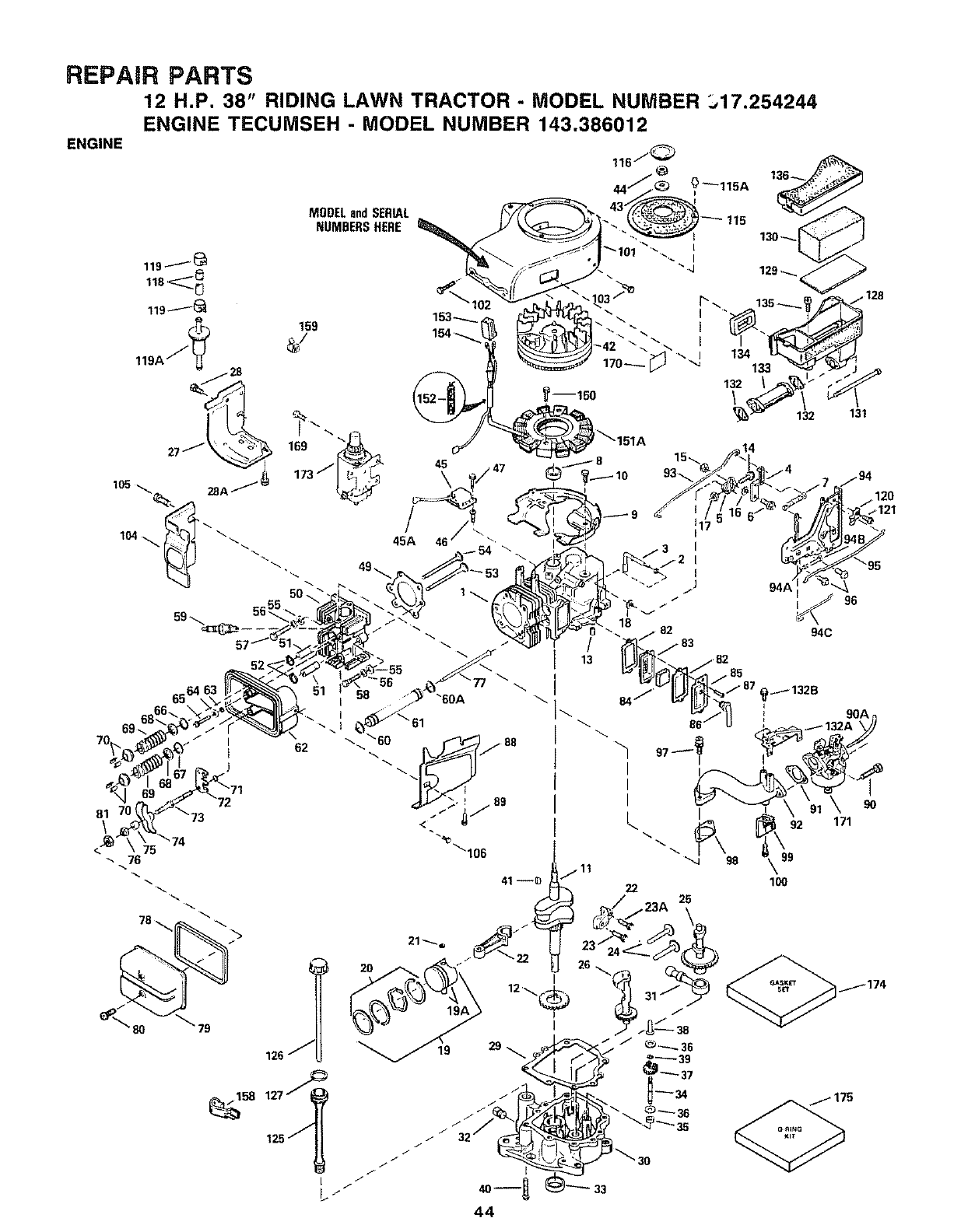
REPAIR PARTS
12 H.P. 38" RIDING LAWN TRACTOR - MODEL NUMBER 317.254244
ENGINE TECUMSEH - MODEL NUMBER 143.386012
ENGINE
81
\
MODELandSERIAL
NUMBERSHERE
51 -ooA \1\
18
13
I
1132B
33
44
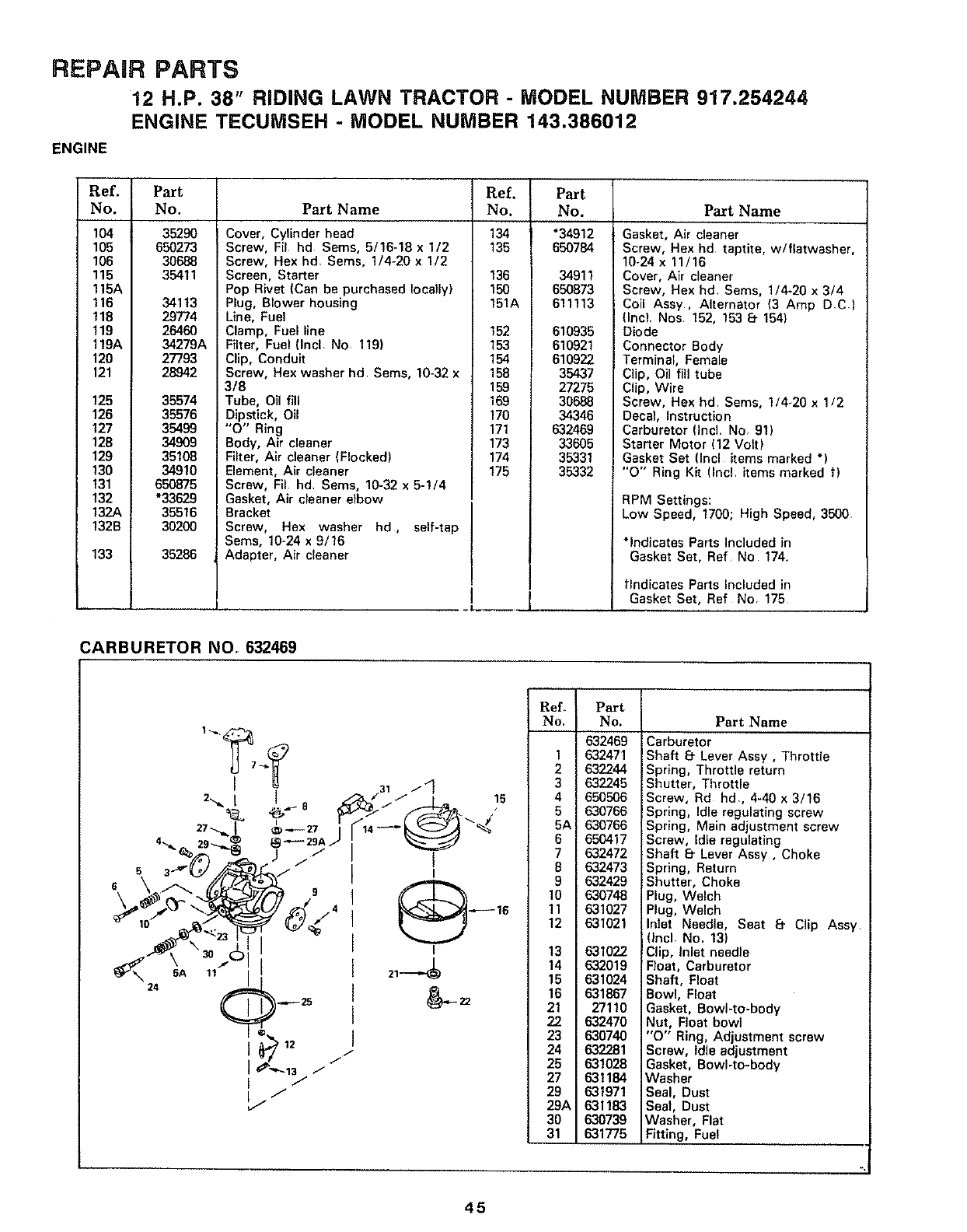
REPAaR PARTS
12 H.P. 38" RiDiNG LAWN TRACTOR - MODEL NUMBER 917.254244
ENGINE TECUMSEH - MODEL NUMBER 143.386012
ENGINE
Ref. Part
No. No.
104 35290
105 650273
106 30688
115 35411
115A
116 34113
118 29774
119 26460
119A 34279A
120 27793
121 28942
125 35574
126 35576
127 35499
128 34909
129 35106
130 34910
t31 650875
132 *33629
132 35516
132B 30200
133 35286
Part Name
Cover, Cylinder head
Screw, Fil hd Seres, 5/16-18 x 1/2
Screw, Hex hd, Sems, 1/4-20 x 1/2
Screen, Starter
Pop Rivet (Can be purchased locally)
Plug, Blower housing
Line, Fuel
Clamp, Fuel llne
Filter, Fuel (Incl No 119)
Clip, Conduit
Screw, Hex washer hd Sems, 10-32 x
3/8
Tube, Oil fill
Dipstick, Oil
"0" Ring
Body, Air cleaner
Filter, Air cleaner (Flocked)
Element, Air cleaner
Screw, FIL hd Sems, 10-32 x 5-1/4
Gasket, Air cleaner elbow
Bracket
Screw, Hex washer hd, self-tap
Sems, 10-24 x 9/16
Adapter, Air cleaner
!
Ref.
No.
134
135
Part
No.
*34912
650784
136 34911
150 650873
151A 611113
152 610935
153 610921
154 610922
158 35437
159 27275
169 30688
170 34346
171 632469
173 33605
174 35331
175 35332
P_tName
Gasket, Air cleaner
Screw, Hex hd taptite, w/flatwasher,
10-24 x 11/16
Cover, Air cleaner
Screw, Hex hd, Sems, 1/4-20 x 3/4
Coil Assy, Alternator (3 Amp D,C)
(IncL Nos 152, 153 8. 154)
Diode
Connector Body
Terminal, Female
Clip, Oil fill tube
Clip, Wire
Screw, Hex hd Sems, 1/4-20 x 1/2
Decal, instruction
Carburetor (Incl. NOr 91)
Starter Motor (12 Volt)
Gasket Set (Incl items marked *)
"O" Ring Kit (Incl, items marked t)
RPM Settings:
Low Speed, 1700; High Speed, 3500,
*Indicates Parts Included in
Gasket Set, Ref No 174.
tlndicates Parts Included in
Gasket Set, Ref NOr 175
CARBURETOR NO. 632469
31 /4
/--/ 15
_\ SA 11 21---,._
/-
J
ReL Part
No. No. Part Name
1
2
3
4
5
5A
6
7
8
9
10
11
12
13
14
15
16
21
22
23
24
25
27
29
29A
30
31
632469
632471
632244
632245
650506
630766
630766
650417
632472
632473
632429
630748
631027
631021
631022
632019
631024
631867
27110
632470
630740
632281
631028
631184
631971
631183
630739
631775
Carburetor
Shaft 8- Lever Assy, Throttle
Spring, Throttle return
Shutter, Throttle
Screw, Rd hd., 4-40 x 3/16
Spring, Idle regulating screw
Spring, Main adjustment screw
Screw, Idle regulating
Shaft 8. Lever Assy, Choke
Spring, Return
Shutter, Choke
Plug, Welch
Plug, Welch
Inlet Needle, Seat 8. Clip Assy
Incl, No. 13)
Clip, Inlet needle
Float, Carburetor
Shaft, Float
Bowl, Float
Gasket, Bowl-to-body
Nut, Float bowl
"O'" Ring, Adjustment screw
Screw, Idle adjustment
Gasket, Bowl-to-body
Washer
Seal, Dust
Seal, Dust
Washer, Flat
Fitting, Fuel
45
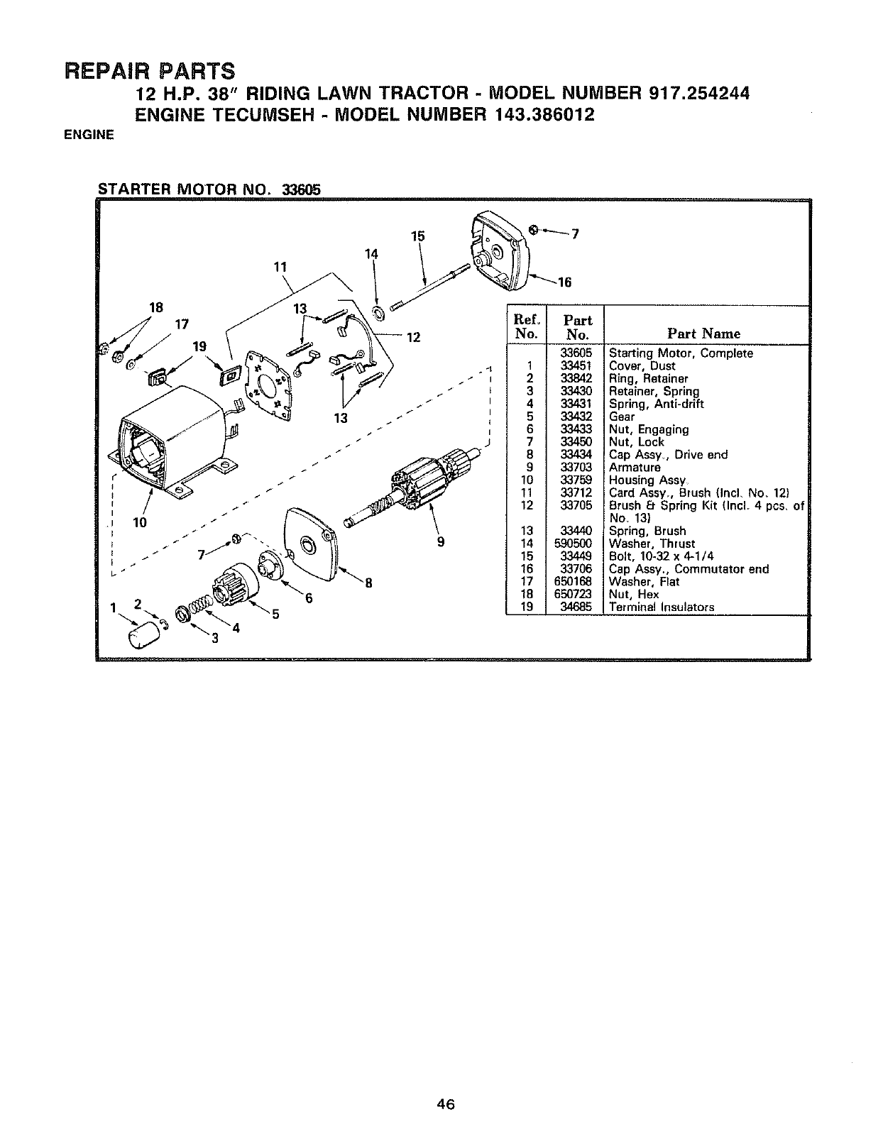
REPAIR PARTS
12 H.P. 38" RIDING LAWN TRACTOR - MODEL NUMBER 917.254244
ENGINE TECUMSEH - MODEL NUMBER 143.386012
ENGINE
STARTER MOTOR NO. 33605
14
11
18
17
19 33605
. _ 1 33451
I233842
3 33430
i 4 33431
5 33432
t6 33433
7 33450
8 33434
9 33703
10 33759
11 33712
12 33705
13 33440
14 590500
15 3,3449
16 33706
17 650168
18 650723
19 34685
Part Name
Starting Motor, Complete
Cover, Dust
Ring, Retainer
Retainer, Spring
Spring, Anti-drift
Gear
Nut, Engaging
Nut, Lock
Cap Assy. Drive end
Armature
Housing Assy
Card Assy,, Brush (Incl, No. 12)
Brush 8- Spring Kit (Incl. 4 pcs, of
No 13)
Spring, Brush
Washer, Thrust
Bolt, 10-32 x 4-1/4
Cap Assy., Commutator end
Washer, Flat
Nut, Hex
Terminal Insulators
46

SUGGESTED GUIDE FOR SBGHTDNG SLOPES FOR SAFE OPERATnON
SIGHTING GUIDE
(_0/11
ONLY RIDE UP AND DOWN HILL
NOT ACROSS HILL
)
SIGHT AND HOLD THIS LEVEL WITH
SKY LiNE OR TREE
15 ° MAX.
Operale your Tractor ul) awJ down the faoe of slopes (no{
greater than 15°)_ never across lh_ face. Make tu_r_s g_adLJ-
alIV to prevent tlpp_f1(J or toss ol control. ExercLse _xtref'nu
caullon when chan(jlng (.Jifect_on On Slopes.
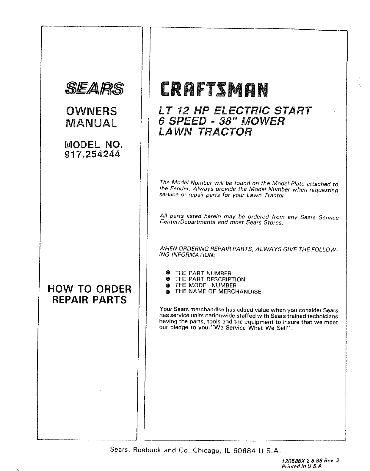
OWNERS
MANUAL
MODEL NO.
917.254244
HOW TO ORDER
REPAIR PARTS
L T 12 HP ELECTRIC START
6SPEED - 38" MOWER
LAWN TRACTOR
The Model Number will be found on the Model Plate attached to
the Fender. Always provide the Model Number when requesting
service or repair parts for your Lawn Tractor
All parts listed herein may be ordered from any Sears Service
Center/Departments and most Sears Stores.
WHEN ORDERING REPAIR PARTS, ALWAYS GIVE THE FOLLOW-
ING INFORMA TION:
@ THE PART NUMBER
0 THE PART DESCRIPTION
@ THE MODEL NUMBER
• THE NAME OF MERCHANDISE
Your Sears merchandise has added value when you consider Seers
has service units nationwide staffed with Sears trained technicians
having the parts, tools and the equipment to insure that we meet
our pledge to you,"We Service What We Sell"_
Sears, Roebuck and Co. Chicago, IL 60684 U S_A..
120586x 2 8.88 Rev 2
Printed in U S A
