Craftsman 917254531 User Manual MOWER DECK SCALPS GROUND ON TURNS TRACTORS Manuals And Guides L0706374
CRAFTSMAN Lawn, Tractor Manual L0706374 CRAFTSMAN Lawn, Tractor Owner's Manual, CRAFTSMAN Lawn, Tractor installation guides
User Manual: Craftsman 917254531 917254531 CRAFTSMAN MOWER DECK SCALPS GROUND ON TURNS-TRACTORS - Manuals and Guides View the owners manual for your CRAFTSMAN MOWER DECK SCALPS GROUND ON TURNS-TRACTORS #917254531. Home:Lawn & Garden Parts:Craftsman Parts:Craftsman MOWER DECK SCALPS GROUND ON TURNS-TRACTORS Manual
Open the PDF directly: View PDF ![]() .
.
Page Count: 52
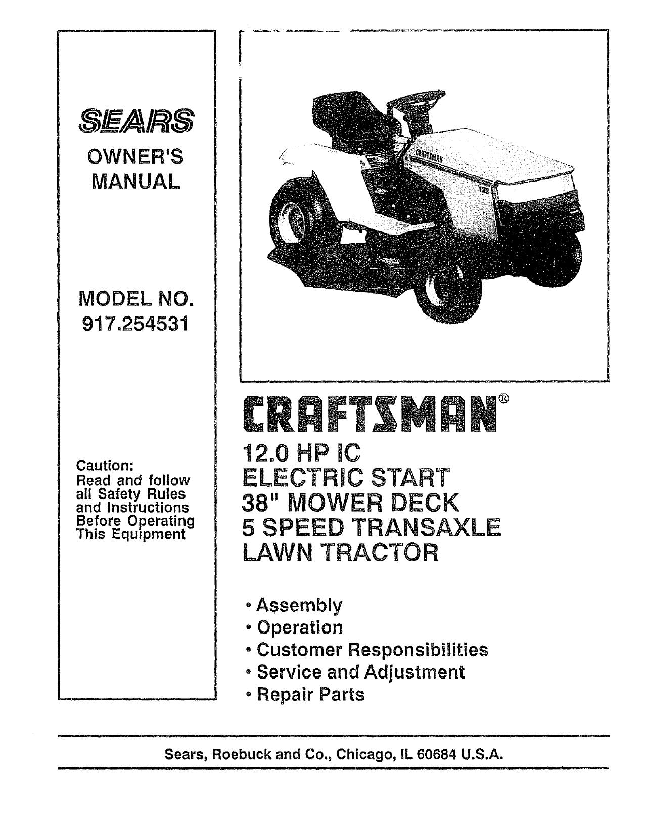
OWNER'S
MANUAL
MODEL NO.
917.254531
Caution:
Read and follow
all Safety Rules
and Instructions
Before Operating
This Equipment
®
12.0 HP IC
ELECTRIC START
38" OWER DECK
5SPEED TRANSAXLE
LAWN TRACTOR
oAssembly
•Operation
• Customer Responsibilities
• Service and Adjustment
° Repair Parts
............ , ,, ,, ,,,, ,,,.,,,, •
Sears, Roebuck and Co., Chicago, IL 60684 U.S.A.
SAFETY RULES &
Safe Operation Practices for Ride-On Mowers
IMPORTANT; THIS CUTTING MACHINE IS CAPABLE OF AMPUTATING HANDS AND FEETAND THROWING OBJECTS,
FAILURE TO OBSERVE THE FOLLOWING SAFETY INSTRUCTIONS COULD RESULT IN SERIOUS INJURY OR DEATH
I. GENERAL OPERATION
* Read, understand, and follow all instructions in the manual
and on the machine before starting.
Only allow responsible adults, who are familiar with the
instructions, to operate the machine.
, Cteartheareaofobjects suchas rocks, toys, wire, etc., which
could be picked up and thrown by the blade.
Be sure the area isclear of other people before mowing. Stop
machine if anyone enters the area.
, Never carry passengers.
Do not mow in reverse unless absolutely necessary., AIways
look down and behind before and while backing.
Be aware of the mower discharge direction and do not point
it at anyone. Do not operate the mower without either the
entire grass catcher or the guard in place..
Slow down before turning.
Never leave a running machine unattended Always turn off
blades, set parking brake, stop engine, and remove keys
before dismounting
*Turn off blades when not mowing.
• Stop engine before removing grass catcher or unclogging
chute
Mow only in daylight or good artificial light.
Do not operate the machine while under the influence of
alcohol or drugs.
Watch for traffic when operating near or crossing roadways.
. Use extra care when loading or unloading the machine into a
trailer or truck.
I1, SLOPE OPERATION
Slopes are a major factor related to toss-of-contro! and tipover
accidents, which can resuit in severe injury or death.. All slopes
require extra caution, If you cannot back up the slope or ff you feet
uneasy on it, do not mow ito
DO:
• Mow up and down slopes, not across.
Remove obstacles such as rocks, tree limbs, eta.,
• Watch for holes, ruts, or bumps. Uneven terrain could
overturn the machine Tall grass can hide obstacfe&
Use slow speed Choose a low gear so that you will not have
to stop or shift while on the slope°
Followthe manufacturer's recommendations forwheel weights
or counterweights to improve stability.
• Use ex_a care with grass catchers or other attachments.
These can change the stability of the machine.
Keep all movement on the slopes slowand gradual Do not
make sudden changes in speed or direction.
Avoid starting or stopping on a slope If tires lose traction,
disengage the blades and proceed slowly straight down the
slope
DO NOT:
Do not turn on slopes unless necessary, and then turn slowly
and gradually downhi , if possible.
Do notmow near drop-offs, ditches, or embankments The
mower could suddenly turn over if a wheel is over the edge of
a cliff or ditch, or if an edge caves in,
•Do not mow on wet grass Reduced traction could cause
sliding,
Do not try to stabilize the machine by putting your foot on the
ground.
•Do not use grass catcher on steep slopes.
IlL CHILDREN
Tragic accidents can occur if the operator is not alert to the
presence of children, Children are often attracted to the machine
and the mowing activity. Neverassume that children will remain
where you last saw them,
• Keep children out of the mowing area and under the watchful
care of another responsible adult.
• Be alert and turn machine off if children enter the area.
, Before and when backfng, look behind and down for small
children.
• Never carry children.. They may fall off and be seriously
injured or interfere with the safe machine operatiom
• Never allow children to operate the machlne_
• Use extra care when approaching blind comers, shrubs,
trees, or other objects that may obscure vision.
IV. SERVICE
•Use extra care In handling gasoline and other fuels. They
are flammable and vapors are explosive.
Use only an approved container.
Never remove gas cap or add fuel with the engine
running Allow engine to cool before refueling, Do not
smoke
Never refuel the machine indoors.
Never store the machine or fuel container inside where
there is an open flame, such as a water heater
• Never run a machine inside a closed area.
• Keep nuts and bolts, especially blade attachment bolts, tight
and keep equipment in good condition.
•Never tamper with safety devices Check their proper
operation regularly.
• Keep machine free of grass, leaves, or other debris build-up
Clean otl or fuel spillage. Allow machine to cool before
stodng.
• Stop and inspect the equipment If you strike an object.
Repair, if necessary, before restarting.
• Never make adjustments or repairs with the engine running.
• Grass catcher components are subject to wear, damage,
and deterioration, which could expose moving parts or allow
objects to be thrown. Frequently check components and
replace with manufacturer's recommended parts, when nec-
essary.
• Mower blades are sharp and can cut. Wrap the blade(s) or
wear gloves, and use extra caution when servicing them.
• Check brake operation frequently Adjust and service as
required.
2
Look for this symbol to point out impor- !
tant safety precautions. It means |
CAUTION!!! BECOMEALERTH! YOUR [
.... SAFE ,SINVOL,'ED. I
CAUTION: Always disconnect spark
plug wire and place wire where it cannot
contact spark plug in order to prevent
accidental starting when setting up,
transporting, adjusting or making
repairs.
CONGRATULATIONS on your purchase of a Sears
Tractor, It has been designed, engineered and manu-
factured to give you the best possible dependability and
performance.
.Should you experience any problem you cannot easily
remedy, please contact your nearest Sears Service
Center/Department. We have competent, well-trained
technicians and the proper tools to service or repair this
unit,
Please read and retain this manual° The instructions will
enable you to assemble and maintain y.our unit properly.
Always observe the 'SAFETY RULES.
_ODEL
NUMBER 917254531
SERIAL
NUMBER
DATE OF PURCHASE
THE MODELAND SERIALNUMBERSWILLBE FOUND
ON A PLATE UNDER THE SEAT.
YOU SHOULD RECORD BOTH SERIALNUMBER AND
DATE OF PURCHASE AND KEEP IN A SAFE PLACE
FOR FUTURE REFERENCE,
MAINTENANCE AGREEMENT
A Sears Maintenance Agreement is available on this prod_
ucL Contact your nearest Sears store for details°
CUSTOMER RESPONSIBILITIES
•Read and observe the safety rules_
, Follow a regular schedulein maintaining, caring for and
using your unit.
•Follow the instructions under "Customer Responsibili-
ties" and "Storage" sections of this owner's manual.
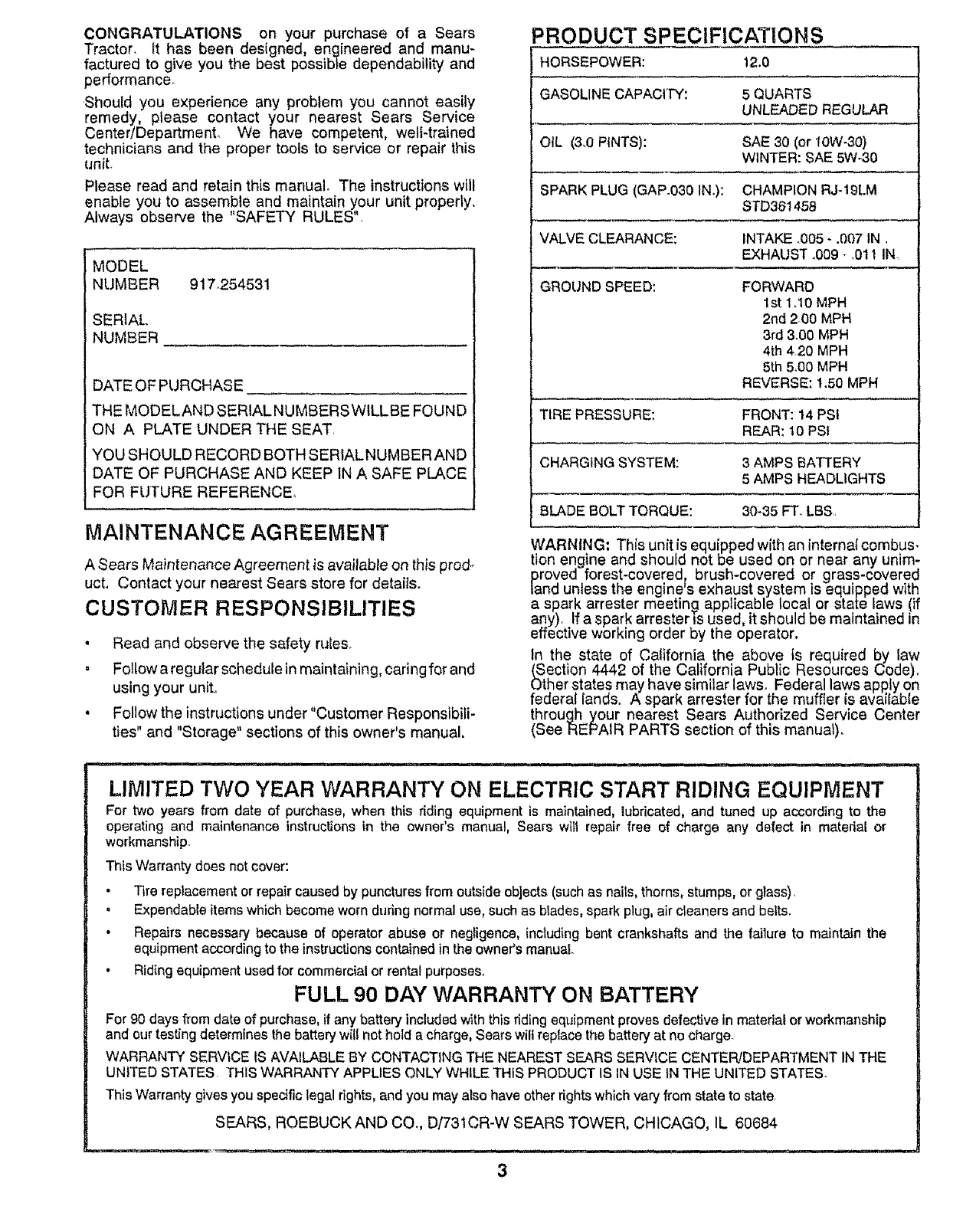
PRODUCT SPECIFICATIONS
HORSEPOWER: t2.0
GASOLINE CAPACITY: 5 QUARTS
UNLEADED REGULAR
OiL (3.0 PINTS): SAE 30 (or 10W-30)
WINTER: SAE 5W-30
SPARK PLUG (GAP°030 IN.): CHAMPION RJ-19LM
STD361458
VALVE CLEARANCE: INTAKE .005 - .007 IN
EXHAUST .009 -o0t I IN
GROUND SPEED: FORWARD
1st 1.t0 MPH
2nd 2.00 MPH
3rd 3,00 MPH
4th 4.20 MPH
5th 5.00 MPH
REVERSE: 130 MPH
TIRE PRESSURE: FRONT: 14 PSI
REAR: 10 PSI
CHARGING SYSTEM: 3 AMPS BATTERY
5 AMPS HEADLIGHTS
BLADE BOLT TORQUE: 30-35 FT. LBS
WARNING: This unit is equipped w!th an internal combus-
tion engine and should not be used on or near any unim-
proved forest-covered, brush-covered or grass-eoverea
land unless the engine's exhaust system is equipped with
a spark arrester meeting applicable local or state laws (if
any). If aspark arrester ts used, it should be maintained in
effective working order by the operator,
In the state of California the above is required by law
(Section 4442 of the California Public Resources Code).
Other states may have similar laws. Federal laws apply on
federal lands. A spark arrester for the muffler is available
through your nearest Sears Authorized Service Center
(See REPAIR PARTS section of this manual).
LIMITED TWO YEAR WARRANTY ON ELECTRIC START RIDING EQUIPMENT
For two years from date of purchase, when this tiding equipment is maintained, lubricated,and tuned up according to the
operating and maintenance instructions in the owner's manual, Sears will repair free of charge any defect in material or
workmanship.
This Warranty does not cover:
•Tire replacement or repair caused by punctures from outside objects (suchas naits, thorns, stumps, or glass).
°Expendable items which become worn during normal use, such as blades, spark plug, air cleaners and belts.
• Repairs necessary because of operator abuse or negligence, includingbent crankshafts and the failure to maintain the
equipment according to the instructions contained in the owner's manual.
•Riding equipment used for commercial or rentalpurposes.
FULL 90 DAY WARRANTY ON BATTERY
For 90 days from date of purchase, ff any battery included with this riding equlpment proves defective in material or workmanship
and our testing determines the battery wif{ not hold a charge, Sears wilt replace the battery at no charge.
WARRANTY SERVICE IS AVAILABLE BY CONTACTING THE NEAREST SEARS SERVICE CENTEPjDEPARTMENT IN THE
UNITED STATES THIS WARRANTY APPLIES ONLY WHILE THIS PRODUCT IS IN USE IN THE UNITED STATES°
This Warranty gives you specific legal rights, and you may also have other rightswhich vary from state to stater
SEARS, ROEBUCK AND CO,, D/'731CR-W SEARS TOWER, CHICAGO, IL 60684
3
TABLE OF CONTENTS
SAFETY RULES ............................................................ 2
PRODUCT SPECIFICATIONS ....................................... 3
CUSTOMER RESPONSIBIMTIES ..................... 3, 14-17
WARRANTY ................................................................... 3
TABLE OF CONTENTS ................................................. 4
INDEX ...................................... ;...................................... 4
TRACTOR ACCESSORIES ........................................... 5
ASSEMBLY ................................................................ 7-9
OPERATION ........................................................... 10-13
MAINTENANCE SCHEDULE ...................................... 14
SERVICE AND ADJUSTMENTS ............................ 18-23
STO RAG E.................................................................... 24
TROUBLESHOOTING ............................................ 25-26
REPAIR PARTS - TRACTOR ................................. 28-43
REPAIR PARTS - ENGINE ..................................... 44-48
PARTS ORDERING/SERVICE ................... BACK PAGE
INDEX
A
Accessories ................................................ 5
Adjustments:
Brake ............................................. 20
Carburetor .................................... 23
Mower
Front-To-Back ......................... 19
Side-To-Side ........................... 19
Throttle Control Cable ................... 23
Air Filter, Engine .................................... 17
Air Screen, Engine .....................................17
Assembly ....................................................7-9
B
Battery:
Charging ............................................ 8
Cleaning ............................................16
Installation ....................................... 9
Levels ......................................... 8,16
Preparation ....................................... 8
Starting with Weak Battery ........... 21
Storage ........................................... 24
Terminals ...................................... 16
Belt:
Motion Drive
Removal!Replacement .............20
Mower Blade Drive
Removal/Replacement ........... 20
Blade:
Sharpening ..................................... 15
Replacement .............................. 15
Brake Adjustment .................................. 20
C
Carburetor Adjustment ............................24
Controls, Tractor ................................. 10
Customer Responsibilities ............. 14-17
Engine:
Air Filter ....................................... 17
Air Filter Foam Pre-Cleaner o_o17
Air Screen, Engine .................... 17
Battery ........................................ t 6
Cooling Fins, Engine ............... 17
Engine Oil ................................. 16
Fuel Filter ................................ 17
Spark Plugs ................................. t 7
Tractor:
Blade .......................................... ! 5
Lubrication Chad ....................... 14
Maintenance Schedule ............ 14
Tire Care ........................... 8,15,21
Cutting Height, Mower ........................... 11
E
Electrical:
interlocks and Relays .................... 22
Schematic ...................................... 27
Wiring Diagram .............................. 28
Engine:
Air Filter ....................................... 17
Air Filter Foam Pre.Cleaner ......... 17
Air Screen ....................................... 17
Cooling Fins, Engine ..................... 17
Oil Change ........................................16
Oil Level ................................... 12,16
Oil Type ............................................16
Preparation ................................... 12
Repair Parts .............................. 44-48
Starting ............................................ 13
Storage ...............................................24
F
Filter:
Air Filter .............................................17
Air Filter Foam Pre-Cfeaner ........ 17
Fuel .............................................. 17
Fuel:
Type .....................................................12
Storage .................................................24
Fuse ...........................................................22
H
Hood Remova!/Installation ................... 22
L
Leveling Mower Deck .......................... 19
Lubrication:
Chart ..................................................14
M
Maintenance Schedule ...........................14
Mower:
Adjustment, Front-to-Back ............ 19
Adjustment, Side4o-Side ...............19
Blade Sharpening ............................15
Blade Replacement ...................... 15
Cutting Height ................................ 1t
Installation ...................................... 18
Operation ............................................12
Removal ........................................ 18
Mowing Tips ........................................... 13
Muffler ................................................... 17
Spark Arrester ............................ 3,38
O
Oil:
Cold Weather Conditions .........12,16
Engine ......................................... 16
Storage .......................................... 24
Operation ......................................... 10-13
Operating Mower ................................ 12
Options:
Accessories ................................... 5
Spark Arrester ........................... 3,38
P
Parking Brake ................................ 10-11
Parts Bag ............................................... 6
Parts, ReplacementJRepalr ........... 28-43
Product Specifications ...............................3
R
Repair Parts ........................................28-43
S
Safety Rules ............................................ 2
Seat ......................................................... 8
Service and Adjustments ............... !8-23
Carburetor ..................................... 23
Fuse .............................................. 22
Hood Removal/Installation ............22
Motion Drive Belt
Removal/Replacement ............ 20
Mower Blade Drive Belt
Removal/Replacement ........... 20
Mower Adjustment
Front- to-Back .......................... lg
Side-to-Side ............................. 1g
Mower Removal .................................18
Tire Care ............................... 8,15,21
Slope Guide Sheet ..................................51
Spark Plugs ......................................... 17
Specifications ........................................ 3
Starting the Engine ......................... 12-13
Steering Wheel ................................. 7,21
Stopping the Tractor ........................... 11
Storage ................................................ 24
T
Throttle Control Cable
Adjustment ................................... 23
Tires......................................................8,15,21
Trouble Shooting Chad .................. 25-26
Transaxle:
Repair Parts .............................. 42-43
W
Warranty .................................................... 3
Wiring Diagram ....................................... 28
Wiring Schematic .................................. 28
4
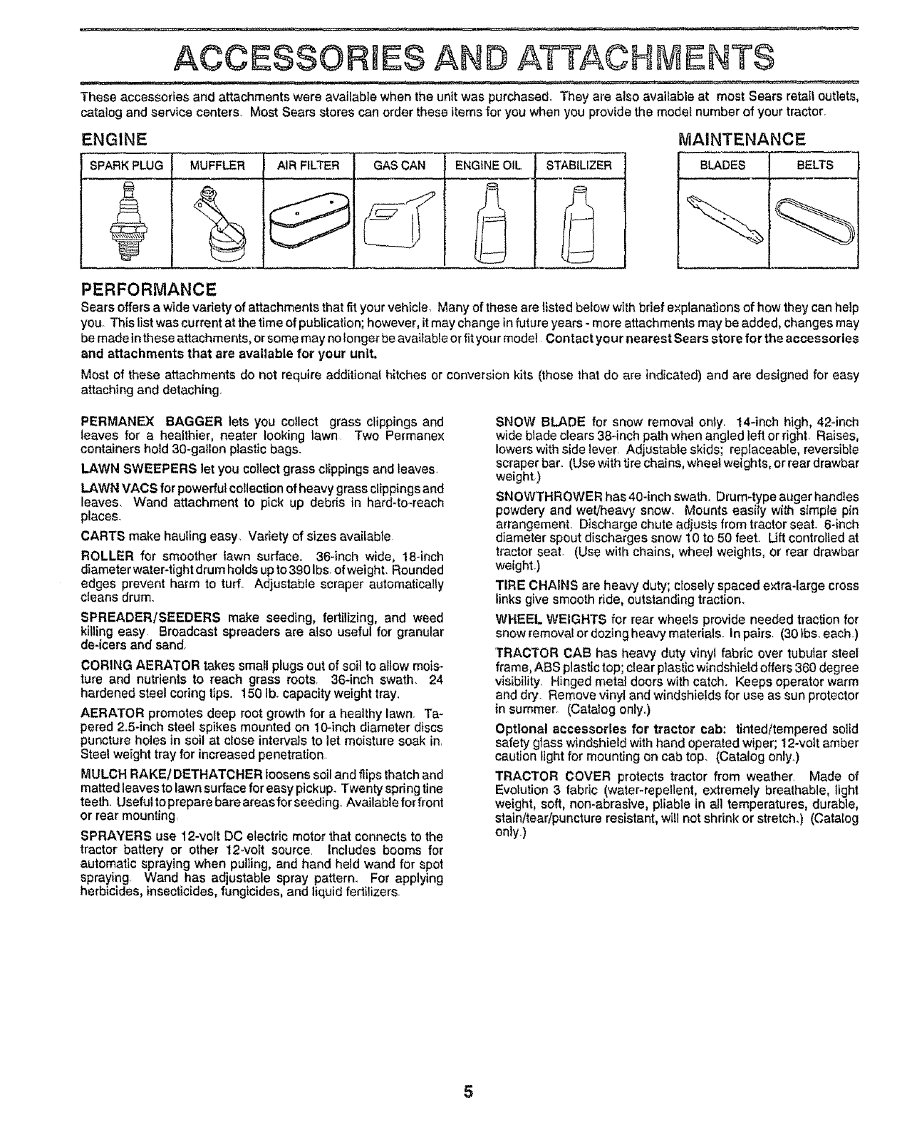
ACCESSORIES AND ATTACHMENTS
These accessories and attachments werg available when the unit was purchased. They are also available at most Sears retail outlets,
catalog and service centers_ Most Sears stores can order these items for you when you provide the model number of your tractor_
ENGINE MAINTENANCE
SPARK PLUG MUFFLER AIR FILTER GAS CAN ENGtNE OIL STABiLiZER BLADES BELTS
PERFORMANCE
Sears offers a wide variety of attachments that fit your vehicle_ Many of those are listed below with brief explanations of how they can help
you. This list was current at the time of publication; however, it may change in future years - more attachments may be added, changes may
be made in these attachments, or some may no longer be available or fit your model Contact your nearest Sears store for the accessories
and attachments that are available for your unit.
Most of these attachments do not require additional hitches or conversion kits (those that do are indicated) and are designed for easy
attaching and detaching.
PERMANEX BAGGER lets you collect grass clippings and
leaves for a healthier, neater looking lawn Two Permanex
containers hold 30-gallon plastic bags.
LAWN SWEEPERS let you collect grass clippings and leaves,
LAWN VAtS for powerful collection of heavy grass clippings and
leaves. Wand attachment to pick up debris in hard4o-reach
pfaces_
CARTS make hauling easy Variety of sizes available
ROLLER for smoother lawn surface. 36-inch wide, 18-inch
diameter water-tight drum holds up to 390 Ibs_ofweight. Rounded
edges prevent harm to tuff. Adjustable scraper automatically
cleans drum_
$PREADERISEEDER$ make seeding, fertilizing, and weed
killing easy Broadcast spreaders are also useful for granular
de-icers and sand.
CORING AERATOR takes small plugs out of soil to allow mois-
ture and nutrients to reach grass roots. 36-inch swath. 24
hardened steelcoring tips, 1501b. capacity weight tray,
AERATOR promotes deep root growth for a healthy lawn. Ta-
pered 2.5-inch steel spikes mounted on lO-inch diameter discs
puncture holes in soil at close intervals to let moisture soak in.
Steel weight tray for increased penetration
P_IULCHRAKE/DETHATOHER loosens soil and flips thatch and
matted leaves to lawn surface for easy pickup. Twenty spring tine
teeth. Useful to prepare bare areas for seeding. Available for front
or rear mounting,
SPRAYERS use 12-volt DC electric motor that connects to the
tractor battery or other 12-volt source. Includes booms for
automatic spraying when pulling, and hand held wand for spot
spraying Wand has adjustable spray pattern. For applying
herbicides, insecticides, fungicides, and liquid ferlilizers.
SNOW BLADE for snow removal only 14-inch high, 42-inch
wide blade clears 38-inch path when angled left or right. Raises,
lowers with side lever. Adjustable skids; replaceable, reversible
scraper bar. (Use with tire chains, wheet weights, or rear drawbar
weight.)
SNOWTHROWER has40-inch swath_ Drum-type auger hand!es
powdery and wet/heavy snow. Mounts easily with simple pin
arrangement, Discharge chute adjusts from tractor seal 6-inch
diameter spout discharges snow 10 to 50 feet. Lift controlled at
tractor seat. (Use with chains, wheel weights, or rear drawbar
weight.)
TIRE CHAINS are heavy duty; ctosely spaced extra-large cross
links give smooth ride, outstanding traction_
WHEEL WEIGHTS for rear wheets provide needed traction for
snow t'emoval or dozing heavy materials_ In pairs. (30 tbs. each.)
TRACTOR CAB has heavy duty vinyl fabric over tubular steel
frame, ABS plastic top; clear plastic windshield offers 360 degree
visibility. Hinged metal doors with catch. Keeps operator warm
and dry. Remove vinyl and windshields for use as sun protector
in summer_ (Catalog onlyo)
Optional accessories for tractor cab: tinted/tempered solid
safety glass windshield with hand operated wiper; 12-vott amber
caution light for mounting on cab top. (Catalog only.)
TRACTOR COVER protects tractor from weather. Made of
Evolution 3 fabric (water-repallent, extremely breathable, light
weight, soft, non-abrasive, pliable in all temperatures, durable,
stain/tear/puncture resistant, will not shrink or stretch.) (Catalog
onlyo)
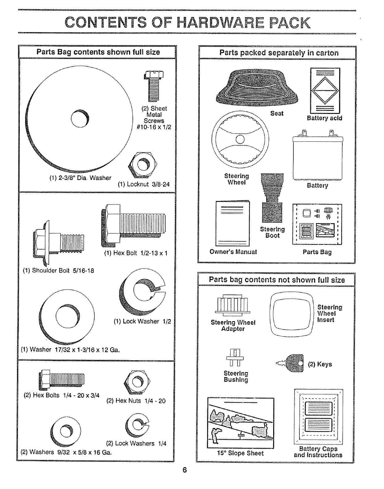
Parts Bag contents shown full size
(2) Sheet
Metal
Screws
#10-16 x 1/2
(1) Hex Bolt t/2-13 x I
(I) Shoutder Bolt 5/16-18
@C
(1) Lock Washer 1/2
(1) Washer 17/32 x 1-3/16 x 12 Ga.
(2) Hex Bolts 1/4 - 20 x 3/4 (2) Hex Nuts 1/4 - 20
G
(2) Lock Washers 1/4
(2) Washers 9/32 x 5/8 x 16 Ga.
Parts packed separately in carton
Seat
O
Battery acid
Steering
Wheel
Steering
Boot
Owner's Manual
,i ,, i,,,
L..............l
Battery
.............. •............. ,,,,,,_,,,= ................. , ........... , ,
Parts bag contents not shown full size
__/___ Steering
i Wheel
Steering Wheel Insert
Adapter
6
Steering
Bushing
_1_ (2) Keys
I
i
f
Battery Caps
15° Slope Sheet and Snstructions
ASSEMBLY
TOOLS REQUIRED FOR ASSEMBLY
A socket wrench set will make assembly easier. Standard
wrench sizes are listed.
(1) 5/16" wrench
(2) 7/t6" wrenches
(1) 1/2" wrench
(t) 9/t6" wrench
Tire pressure gauge
Screwdriver
Utility knife
When right and left hand is mentioned in this manual, it
means when you are in the operating position (seated
behind the steering wheel).
TO REMOVE UNIT FROM CARTON
UNPACK CARTON
, Remove all accessible loose parts and parts cartons
from carton (See page 6)°
• Cut along dotted lines on carton, from top to bottom, all
four corners of carton and lay panels flat.
° Check for any additional loose parts or cartons and
remove.
BEFORE ROLLING UNIT OFF SKID
ATTACH STEERING WHEEL (See Fig. 1)
• Slide the steering bushing over the steering shaft,
_' Raise steering shaft forward until screw holes in dash
line up with steering bushing. Install two (2) sheet
metal screws and tighten securely,
• Position steering boot over steering shaft.
°Place tabs of steering boot over slots in dash and push
down to secure,
o Slide steering wheel adapter onto upper steering shaft,
• Position front wheels of the tractor so they are pointing
straight forward,
. Position steering wheel so cross bars are horizontal
(left to right) and slide onto adapter,
• Assemble large flat washer and 3/8-24 hex locknut and
tighten securely,
. Snap insert into center of steering wheel.
o Remove protective plastic from tractor hood and grill.
IMPORTANT: CHECK FOR AND REMOVE ANY
STAPLES IN SKI D THAT MAY PUNCTURE T_RES WHERE
UNIT IS TO ROLL OFF SKID.
(See Fig. 6)
o Raise attachment lift lever to its highest position.
, Release parking brake by depressing clutch/brake
pedal.
, Ptace gearshift lever in "NEUTRAL" position,
, Roll unit backwards off skid.
, Remove banding holding discharge guard up against
tractor.
INSERT
3/8-24 HEX LOCKNUT
2-3/8"
STEERING
STEERING
BUSHING
_STEERING
WHEEL
ADAPTER
STEERING
BOOT
STEERING SHAFT
(ASSEMBLY POSITION)
STEERING SHAFT
pSHIPPtNG
OSITtON)
FIG. !
7
ASSEMBLY
HOW TO SET UP YOUR TRACTOR
PREPARE BATTERY (See Fig. 2)
CAUTION: Wear eye and face shield.
Wash hands or clothing Immediately If
accidentally In contact wlth battery acid.
Do not smoke. Fumes from charged
battery acid are explosive.
Read the Instructions Included with the
batteryvent caps. Alwayswear gloves,
clothing and goggles to protect your
hands, skin and eyes.
Your unit has a battery charging system which is sufficient
for normal use. However, periodic charging of the battery
with an automotive charger will extend its life.
•See instructions packed with vent caps in parts bag_
. Fill battery with acid. Fill each celt until it reaches the
bottom of the vent wells. Do not overfill.
• Allow battery to stand and settle for at least thirty
minutes, After standing, check the level of acid. if
below the vent wells, add more acid until the correct
level is reached,
While battery is standing (after adding acid) and later, while
battery is being charged, continue with assembly of unit.
IMPORTANT: TO MAXIMIZE THE LIFE OF YOUR
BATTERY, IT tS NECESSARY THAT THE BATTERY BE
CHARGED BEFORE USE, FAILURE TO CHARGE
BATTERY CAN RESULT IN A SHORTENED BATTERY
LIFE.
o Charge battery at a rate of 6 amperes for 1 hour. Use
a 12volt battery charger° Observe all safety precautions
required for battery charging.
o Check the acid level after the battery is charged, if the
acid has fallen below the correct level, add distilled or
iron free water.
• Install the vent caps to cover the vent wells. Wash the
top of the battery with water to remove any acid, then
wipe dry°
. Check battery case for leakage to make sure that no
damage has occurred in handling°
o Dispose of excess battery acid. Neutralize acid for
disposal by adding it to four inches of water in a five
gallon plastic container. Stir with a wooden or plastic
paddle while adding baking soda until the addition of
more soda causes no more foaming
• Follow instructions on how to install battery.
CUT AWAY VIEW _VENT CAP
/VENT WELL
E ,H;I LEv,-
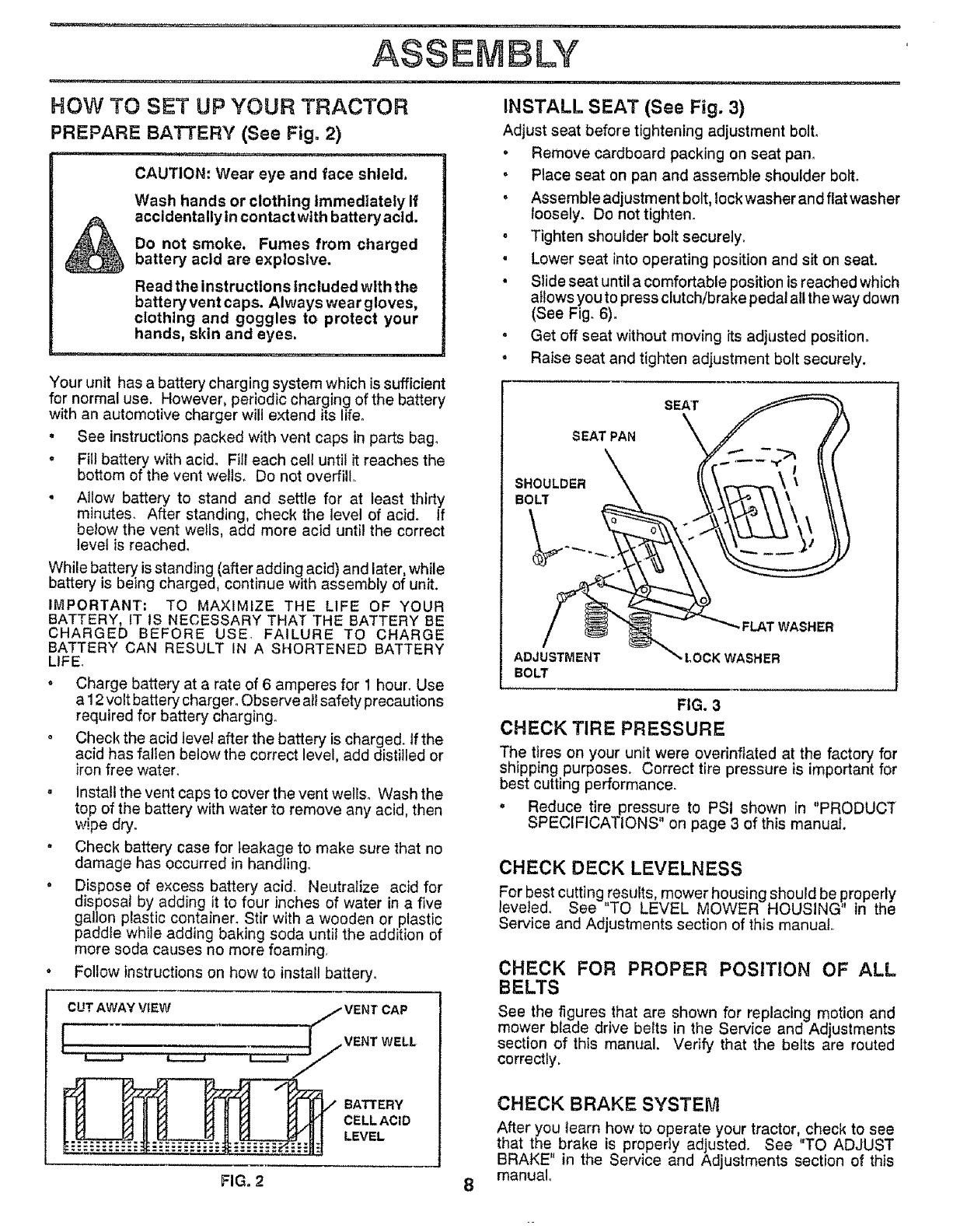
INSTALL SEAT (See Fig. 3)
Adjust seat before tightening adjustment bolto
• Remove cardboard packing on seat pan.
° Place seat on pan and assemble shoulder bolt.
• Assemble adjustment bolt, lock washer and flat washer
loosely. Do not tighten_
o Tighten shoulder bolt securely.
•Lower seat into operating position and sit on seat.
•Slide seat until a comfortable position isreached which
allows you to press clutch/brake pedal all the way down
(See Fig. 6).
. Get off seat without moving its adjusted position.
• Raise seat and tighten adjustment bolt securely.
SEAT
SEATPAN
SHOULDER
BOLT
- FLAT WASHER
ADJUSTMENT LOCK WASHER
BOLT
FIG. 3
CHECK TIRE PRESSURE
The tires on your unit were overinflated at the factory for
shipping purposes. Correct tire pressure is important for
best cutting performance.
. Reduce tire pressure to PSI shown in "PRODUCT
SPECIFICATIONS" on page 3 of this manual.
CHECK DECK LEVELNESS
For best cutting resuRs, mower housing should be ,properly
leveled. See TO LEVEL MOWER HOUSING' in the
Service and Adjustments section of this manual.
CHECK FOR PROPER POSITION OF ALL
BELTS
See the figures that are shown for replacing motion and
mower blade drive belts in the Service and Adjustments
section of this manual. Verify that the belts are routed
correctly.
CHECK BRAKE SYSTEM
After you learn how to operate your tractor, check to see
that the brake is propedy adjusted. See "TO ADJUST
BRAKE" in the Service and Adjustments section of this
manual°
FIG= 2 8
ASSEMBLY
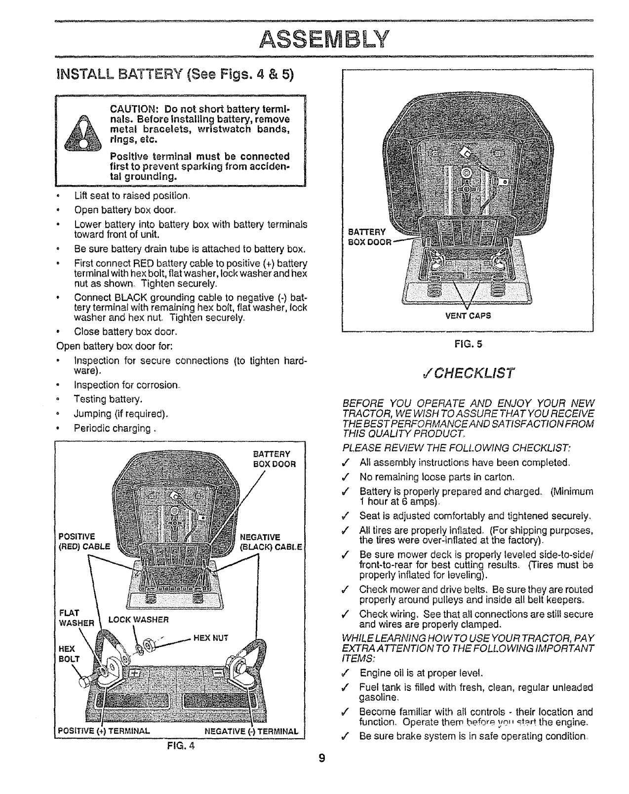
INSTALL BATTERY (See Figs. 4 & 5)
CAUTION: Do not short battery terml.
nals. Before Installing battery, remove
metal bracelets, wristwatch bands,
rings, etc,
Positive terminal must be connected
first to prevent sparking from acclden=
tat grounding.
• Lift seat to raised position,
=Open battery box door.
= Lower battery into battery box with battery terminals
toward front of unit.
. Be sure battery drain tube is attached to battery box.
•First connect RED battery cable to positive (+) battery
terminal with hex bolt, flat washer, lock washer and hex
nut as shown. Tighten securely.
. Connect BLACK grounding cable to negative (-) bat-
tery terminal with remain{ng hex bolt, flat washer, lock
washer and hex nut. Tighten securely°
- Close battery box door.
Open battery box door for:
. Inspection for secure connections (to tighten hard-
ware).
o Inspection for corrosion.
° Testing battery.
. Jumping (if required).
•Periodic charging o
BATTERY
BOX DOOR
POSlTIVE NEGATIVE
(RED) CABLE (BLACK) CABLE
FLAT
WASHER
\
HEX
BO_
LOCK WASHER
HEX NUT
I
POSITIVE (+) TERMINAL NEGATIVE (-) TERMINAL
FIG. 4
BATTERY
BO_
VENT CAPS
FIG. 5
,!'CHECKLIST
BEFORE YOU OPERATE AND ENJOY YOUR NEW
TRACTOR, WE WISH TO ASSURE THAT YOU RECEIVE
THE BEST PERFORMANCE AND SATISFACTION FROM
THIS QUALITY PRODUCT,
PLEASE REVIEW THE FOLLOWING CHECKLIST:
/" All assembly instructions have been completed.
,/ No remaining loose parts in carton_
/Batteryis properly prepared and charged. (Minimum
1 hour at 6 amps).
v" Seat is adjusted comfortably and tightened securely°
/Alttires are properly inflated, (For shipping purposes,
the tires were over-inflated at the factory).
/" Be sure mower deck is properly leveled side-to-side/
front4o-rear for best cutting results. (Tires must be
prcpedy inflated for leveling).
/Check mower and drive belts, Be sure they are routed
properly around pulleys and inside all belt keepers_
v" Check wiring, See that all connections are stilt secure
and wires are property clampe&
WHILE LEARNING HOWTO USE YOUR TRACTOR, PAY
EXTRA ATTENTION TO THE FOLLOWING IMPORTANT
ITEMS:
#" Engine oil is at proper level
,/ Fuel tank is fifted with fresh, clean, regular unleaded
gasoline,
,I Become familiar with all controls - their location and
function. Operate them before yo_t _t?_ the engine.
v" Be sure brake system is in safe operating condition,
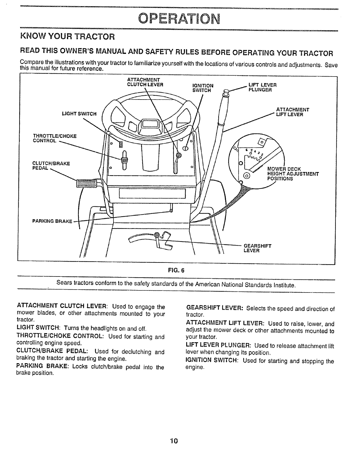
OPERATnON
KNOW YOUR TRACTOR
READ THIS OWNER'S MANUAL AND SAFETY RULES BEFORE OPERATING YOUR TRACTOR
Compare the illustrations with your tractor to familiarize yourself with the locations of various controls and adjustments, Save
this manual for future reference_
ATTACHMENT
CLUTCH LEVER IGNITION LIFT LEVER
SWITCH PLUNGER
LIGHT SWITCH
\\
THROTTLE/CHOKE
CONTROL
ATTACHMENT
LIFT LEVER
CLUTCH!BRAKE
[ J
MOWER DECK
HEIGHT ADJUSTMENT
POSITIONS
GEARSHIFT
LEVER
FIG, 6
Sears tractors conform to the safety standards of the American National Standards Institute_
ATTACHMENT CLUTCH LEVER: Used to engage the
mower blades, or other attachments mounted to your
tractor.
LIGHT SWITCH: Turns the headlights on and off.
THROTTLE/CHOKE CONTROL; Used for starting and
controlling engine speed.
CLUTCH/BRAKE PEDAL: Used for declutching and
braking the tractor and starting the engine.
PARKING BRAKE: Locks clutch/brake pedat into the
brake position.
GEARSHIFT LEVER: Selects the speed and direction of
tractor.
ATTACHI'_IENT LIFT LEVER: Used to raise, lower, and
adjust the mower deck or other attachments mounted to
your tractor.
LIFT LEVER PLUNGER: Used to release attachment lift
lever when changing its position.
IGNITION SWITCH: Used for starting and stopping the
engine.
10
OPERATION
The operation of any tractor can result in foreign objects thrown into the eyes, which can
result in severe eye damage, Always wear safety g|asses or eye shields while operating
your tractor or performing any adjustments or repairs. We recommend wide vision safety
mask for over the spectacles or standard safety glasses, available at Sears Retail or
Catalog stores.
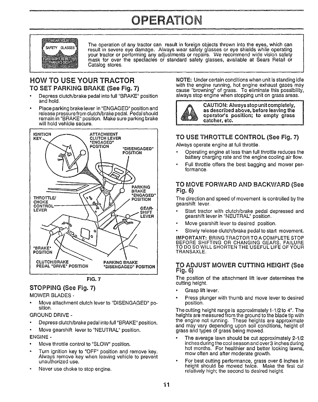
HOW TO USE YOUR TRACTOR
TO SET PARKING BRAKE (See Fig. 7)
• Depress clutch/brake pedal into full "BRAKE" position
and hold.
• Place parking brake lever in "ENGAGED" position and
release pressurefrom clutch/brake pedal. Pedal should
remain in "BRAKE" position. Make sure parking brake
will hold vehicle secure.
IGNITION ATTACHMENT
KEY ,, CLUTCH LEVER
"ENGAGED"
POSITION "DISENGAGED"
POSITION
_ROTTL_
CHOKE
CONTROL'
LEVER
PARKING
BRAKE
"ENGAGED"
GEAR-
LEVER
"BRAKE'
POSITION
CLUTCHtBRAKE
PEDAL "DRIVE" POSITION PARKING BRAKE
'DISENGAGED" POSITION
FIG. 7
STOPPING (See Fig. 7)
MOWER BLADES -
oMove attachment clutch lever to "DISENGAGED" po-
sition,
GROUND DRIVE -
• Depress clutch/brake pedal into full "BRAKE" position.
o Move gearshift lever to "NEUTRAL" position.
ENGINE -
• Move throttle control to"SLOW" position°
o Turn ignition key to "OFF" position and remove key.
Always remove key when leaving vehicle to prevent
unauthorized use.
o Never use choke to stop engine,
NOTE: Under certain conditions when unit is standing idle
with the engine running, hot engine exhaust gases may
cause "browning" of Brass. To eliminate this possibility,
always stop engine wnen stopping unit on grass areas.
---CAUTIO N_p unit cornpletely,-
a_ov,be efore leaving the
_. poIstol _n' to empty grass
TO USE THROTTLE CONTROL (See Fig. 7)
Always operate engine at full throttle,
o Operating engine at less than full throttle reduces the
battery charging rate and the engine cooling air flow,
• Full throttle offers the best bagging and mower per-
formance,
TO MOVE FORWARD AND BACKWARD (See
F g.6)
The direction and speed of movement is controlled by the
gearshift lever,
•Start tractor with clutch/brake pedal depressed and
gearshift lever in "NEUTRAL position,
• Move gearshift lever to desired position,
.Slowly release clutch/brake pedal to start movement,
IMPORTANT; BRING TRACTOR TO A COMPLETE STOP
BEFORE SHIFTING OR CHANGING GEARS. FAILURE
TO DO SO WILL SHORTEN THE USEFUL LIFE OF YOUR
TRANSAXLE,
TO ADJUST MOWER CUTTING HEIGHT (See
Fig. 6)
The position of the attachment lift lever determines the
cutting height,
•Grasp lift lever.
, Press plunger with thumb and move lever to desired
position,
The cutting height range is approximately 1..1/2to 4'L The
heights are measured from the ground to the blade tip with
the engine not running. These heights are approximate
and may vary depending upon soil conditions, height of
grass and types of grass being mowed.
° The average lawn should be cut approximately 2-1/2
inches during the cool season and over 3 inches during
hot month& For healthier and better looking lawns,
mow often and after moderate growths
o For best cutting performance grass over 6 inches in
heght should be mowed twice, Make the first cuf
relatively high; the second to desired height.
11
OPERATION
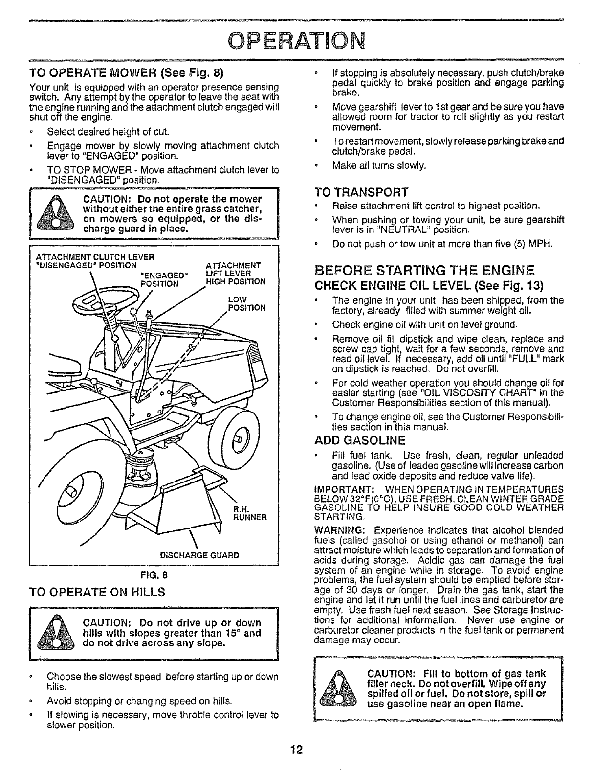
TO OPERATE MOWER (See Fig. 8)
Your unit is equipped with an operator presence sensing
switch° Any attempt by the operator to leave the seat with
the engine running and the attachment clutch engaged will
shut off the engine,
• Select desired height of cut.
• Engagemower by slowly moving attachment clutch
lever to ENGAGED' position.
° TO STOP MOWER _ Move attachment clutch lever to
"DISENGAGED" po__sition;...........
CAUTION: Do not operate the mower
without either the entire grass catcher,
on mowers so equipped, or the dis-
charge guard in place,
ATTACHMENT
LIFT LEVER
HIGH POSITION
LOW
POSITION
R,N°
RUNNER
DISCHARGE GUARD
ATTACHMENTCLUTCHLEVER
=DISENGAGED=POSITION
.ENGAGED =
POSI_ON
FIG. 8
TO OPERATE ON HILLS
CAUTION; Do not drive up or down
hills with slopes greater than 15° and
do not drive across any slope.
*Choose the slowest speed before starting up or down
hitis.
o Avoid stopping or changing speed on hills_
.If slowing is necessary, move throttle control lever to
slower position.
= If stopping is absolutely necessary, push clutch/brake
pedal quickly to brake position and engage parking
brake.
o Move gearshift lever to 1st gear and be sure you have
allowed room for tractor to roll slightly as you restart
movement.
• To restart movement, slowly release parking brake and
clutch/brake pedal.
. Make all turns slowly.
TO TRANSPORT
oRaise attachment lift control to highest position°
. When pushing or towing your unit, be sure gearshift
lever is in "NEUTRAL" position_
. Do not push or tow unit at more than five (5) MPH.
BEFORE STARTING THE ENGINE
CHECK ENGINE OIL LEVEL (See Fig. 13)
• The engine in your unit has been shipped, from the
factory, already filled with summer weight oil.
o Check engine oil with unit on level ground,
o Remove oil fill dipstick and wipe clean, replace and
screw cap tight, wait for a few seconds, remove and
read oil level. If necessary, add oil until "FULL" mark
on dipstick is reached_ Do not overfill.
o For cold weather operation you should change oil for
easier starting (see "OIL VISCOSITY CHART" in the
Customer Responsibilities section of this manual)_
° To change engine oil, see the Customer Responsibili-
ties section in this manual.
ADD GASOLINE
• Fill fuel tank. Use fresh, clean, regular unleaded
gasoline. (Use of leaded gasoline willincrease carbon
and lead oxide deposits and reduce valve life).
IMPORTANT: WHEN OPERATING IN TEMPERATURES
BELOW 32°F(0°C), USE FRESH, CLEAN WINTER GRADE
GASOLINE TO HELP INSURE GOOD COLD WEATHER
STARTING.
WARNING: Experience indicates that alcohol blended
fuels (called gasohol or using ethanol or methanol) can
attract moisture which leads to separation and formation of
acids during storage. Acidic gas can damage the fuel
system of an engine while in storage. To avoid engine
problems, the fuel system should be emptied before stor-
age of 30 days or longer. Drain the gas tank, start the
engine and let it run until the fuel lines and carburetor are
empty. Use fresh fuel next season. See Storage Instruc-
tions for additional information. Never use engine or
carburetor cleaner products in the fuel tank or permanent
damage may occur.
: _.,,,,,,,_ ,,, ., ,....... I
,_ CAUTION: Fill to bottom of gas tank !
._ filler neck. Do not overfill. Wipeoffany I
spilled oil or fuel, Do not store, spill or |
12
OPERATION
TO START ENGINE (See Fig, 7)
When starting engine for the first time or if engine has
run out of fuel, it will take extra cranking time to move
fuel from the tank to the engine,
• Depress the clutch/brake pedal and set the parking
brake.
• Place gearshift lever in "NEUTRAL" position°
• Move attachment clutch to "DISENGAGED" position.
• Move throttle control lever to "CHOKE" position for
cold engine start. For warm engine start, move
throttle control to "FAST" position.
° Turn ignition key clockwise to "START" position and
release key as soon as engine starts. Do not run
starter continuously for more than fifteen seconds
per minute If engine does not start after several
attempts, move throttle control to "FAST" position,
wait a few minutes and try again.
• When engine starts, move throttle control to desired
position.
• Allow engine to warm up for a few minutes before
engaging drive or attachment clutch.
NOTE: tf at a high altitude (above 3000 feet) or in cold
temperatures (below 32° F), the carburetor fuel mixture
may need to be adjusted for best engine performance,
See TO ADJUST CARBURETOR' in the Service and
Adjustments section of this manual.
MOWING TIPS
•Tire chains cannot be used when the mower hous-
ing is attached to unit°
•Mower should be properly leveled for best mowing
performance, See TO LEVEL MOWER HOUSING
in the Service and Adjustments section of this
manual°
,Use the runner on the right hand side of mower as
a guide. The blade cuts approximately an inch
outside the runner (See Fig. 8)_
• The left hand side of mower should be used for trim-
ming.
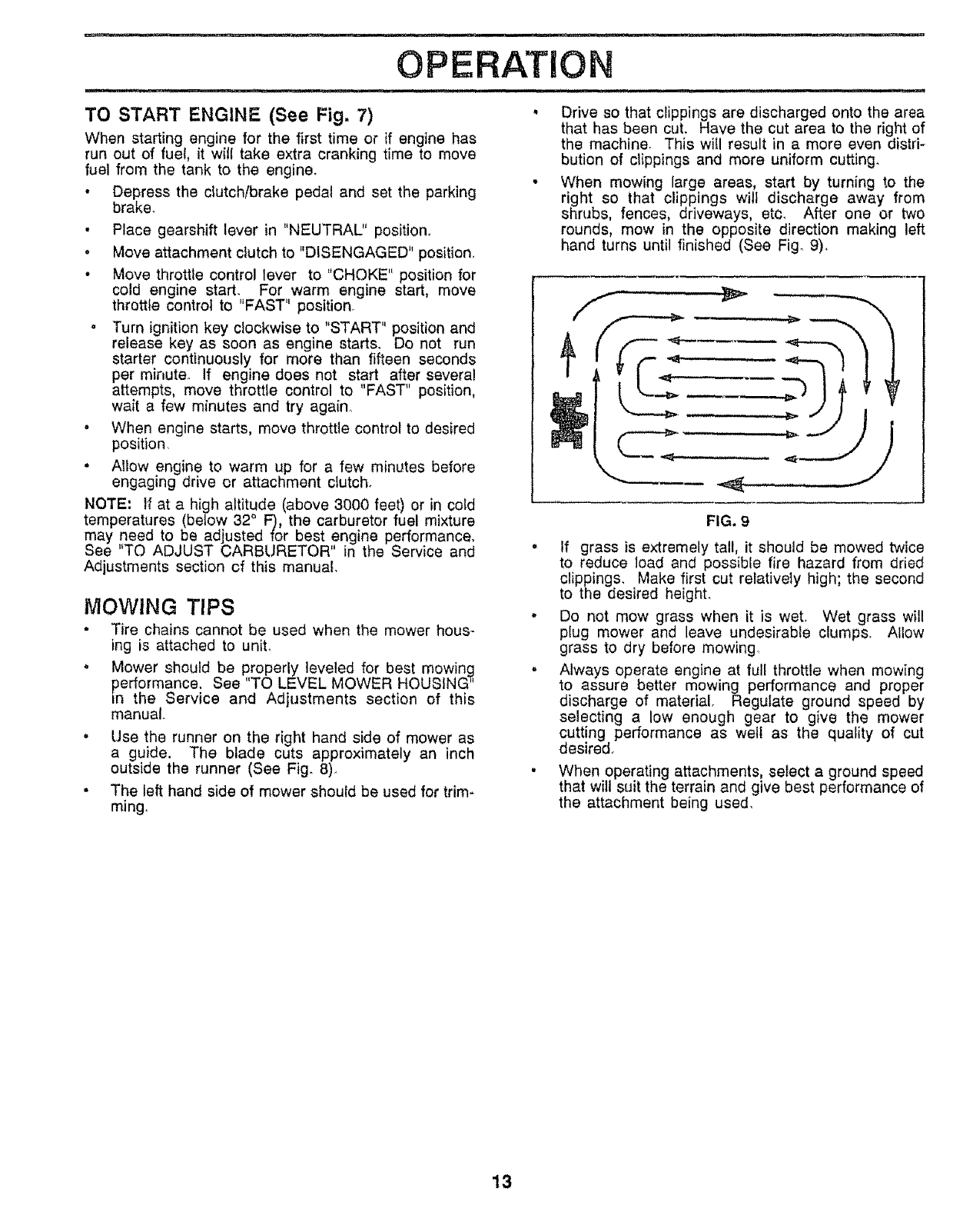
Drive so that clippings are discharged onto the area
that has been cut. Have the cut area to the right of
the machine. This will result in a more even distri-
bution of clippings and more uniform cutting.
When mowing large areas, start by turning to the
right so that clippings wilt discharge away from
shrubs, fences, driveways, etc, After one or two
rounds, mow in the opposite direction making left
hand turns until finished (See Fig° 9),
FIG. 9
• If grass is extremely tall, it should be mowed twice
to reduce load and possible fire hazard from dried
clippings. Make first cut relatively high; the second
to the desired heighL
,Do not mow grass when it is wet. Wet grass will
plug mower and leave undesirable clumps. Allow
grass to dry before mowing°
,Always operate engine at full throttle when mowing
to assure better mowing performance and proper
discharge of material. Regulate ground speed by
selecting a low enough gear to give the mower
cutting performance as well as the quality of cut
desired.
•When operating attachments, select a ground speed
that will suit the terrain and give best performance of
the attachment being used.
13
..... ii ¸ lu-ill iii1,, iiii, ,, ,u ....
CUSTOMER RESPONS BILFRES
nunl i, i]_, i,, ,,, i, lU,,, .......
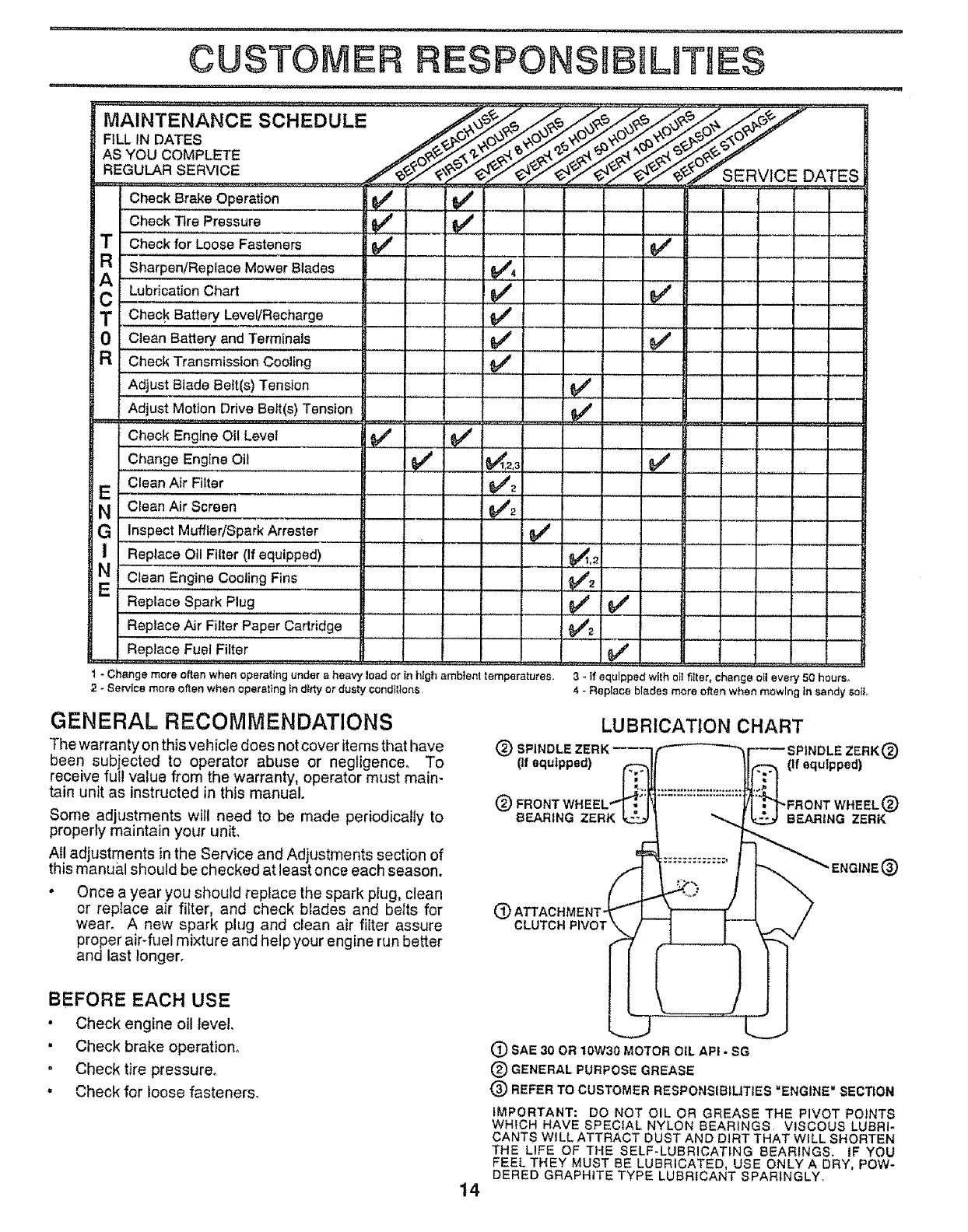
MAINTENANCE SCHEDULE
FILL IN DATES
AS YOU COMPLETE
REGULAR SERVICE
Check Br,a,ke Ope,ra!!on
Check T_rePressure 6#4'
Check for Loose Fasteners ...... _44
RSharpen!Replace Mower Blades
_A LubricationChart
C Check Battery LeveVRecharge
0 Clean Battery and Terminals
R Check Transmission Cooling
Adjust Blade Belt(s) Tension
Adjust Motion Drive Be_t(s)Tension
Check Engine Oil Level
Change Engine Oil
Clean Air Filter
E
NClean AirScreen
G InsPect Muffler/SparkArrester
IReplace Otl Filter (If equipped)
EN "Clean En,,g,i,ne,,,c,ooling ........
Fins
Replace Spark Plug
Replace Air Filter Paper Cartridge
Replace Fuel Filter
v'
v'
v',
v'
v'
J__U L
1 - Change mere often when operating under a heavy toad or tn high ambient temperatures.
2 - Service mere often when operatIng In dirty or dusty conditions
e/
SERVICE DATES
...... ,, i, ,,
....... v'v'
v'
3_If equipped with ot! fitter,change oll every 50 hours+
4 - Re#ace btadee more oftenwhen mowing Fnsandy soIL
GENERAL RECOMMENDATIONS
The warranty on this vehicle does not cover items that have @
been subjected to operator abuse or negligence° To (Ifequipped)
receive ful! value from the warranty, operator must main-
tain unit as instructed in this manual.
Some adjustments will need to be made periodically to
properly maintain your unit.
All adjustments in the Service and Adjustments section of
this manual should be checked at least once each season.
, Once a year you should replace the spark plug, clean
or repIace air filter, and check blades and belts for @
wear, A new spark plug and clean air filter assure
proper air4uel mixture and help your engine run better
and last tonger°
LUBRICATION CHART
(If equipped)
@ FRONT WHE _)
BEARING ZERK BEARING ZERK
CLUTCH PIVOT
ENGINE@
BEFORE EACH USE
•Check engine oil level,
• Check brake operation,
"Check tire pressure°
•Check for loose fasteners,
14
(_) SAE 30 OR 10W30 MOTOR OIL API - BG
(_) GENERAL PURPOSE GREASE
@REFER TO CUSTOMER RESPONSIBILITIES =ENGINE" SECTION
IMPORTANT: DO NOT OIL OR GREASE THE PIVOT PO)NTS
WHICH HAVE SPECIAL NYLON BEARINGS, VISCOUS LUBRI*
CANTS WILL ATTRACT DUST AND DIRT THAT WILL SHORTEN
THE LIFE OF THE SELF-LUBRICATING BEARINGS. tF YOU
FEEL THEY MUST BE LUBRICATED, USE ONLY A DRY, POW-
DERED GRAPHITE TYPE LUBRICANT SPARINGLY.
TRACTOR
Always observe safety rules when performing any mainte-
nance_
CUSTOMER ESPONSIBILITmES
BRAKE OPERATION
If unit requires more than six (6) feet stopping distance at
high speed in highest gear,,!han brake must be adjusted,
(See 'TO ADJUST BRAKE in Service and AdjLJstments
section of this manual),
TIRES
-Maintain proper air pressure in all tires (See "PROD ,_
UCT SPECIFICATIONS" on page 3 of this manual),
. Keep tires free of gasoline, oil, or insect control chemi-
cals which can harm rubber.
"Avoid stumps, stones, deep ruts, sharp objects and
other hazards that may cause tire damage.
BLADE CARE
For best results mower blades must be kept sharp. The
blades can be sharpened with a file or on a grinding wheel.
We suggest they be sharpened or replaced after every 25
hours of mowing. Check biades more often if mowing in
sandy conditions.
- Do not attempt to sharpen blades while they are on the
mower_
o Replace bent or damaged blades.
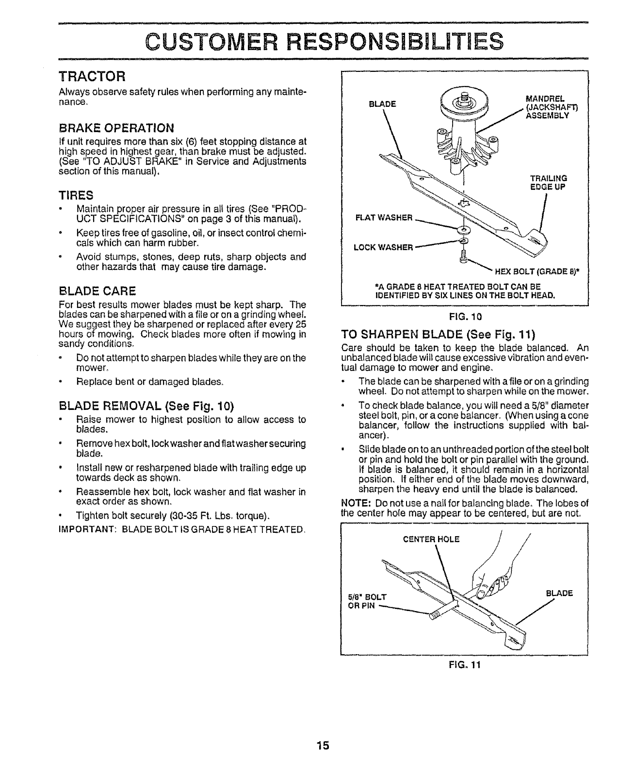
BLADE REMOVAL (See Fig. 10)
o Raise mower to highest position to allow access to
blades,
• Remove hex bott, lock washer and flat washer securing
blade,
° Install new or resharpened blade with trailing edge up
towards deck as shown,
- Reassemble hex bolt, lock washer and flat washer in
exact order as shown,
•Tighten bolt securely (30-35 Ft. Lbs. torque).
IMPORTANT: BLADE BOLT IS GRADE 8 HEAT TREATED.
DE f'_ _" "_ MANDREL
_'A GRADE 8 HEAT TREATED BOLT CAN BE
IDENTIFIEDBYSIXLINESONTHEBOLTHEAD.
FIG. 10
TO SHARPEN BLADE (See Fig. 11)
Care should be taken to keep the blade balanced. An
unbalanced blade will cause excessive vibration and even-
tual damage to mower and engine.
• The blade can be sharpened with a file or on a grinding
wheel. Do not attempt to sharpen while on the mower.
° To check blade balance, you will need a 5/8" diameter
steel bolt, pin, or a cone balancero (When using a cone
balancer, follow the instructions supplied with bat-
ancer).
, Slide blade on to an unthreaded portion of the steel bolt
or pin and hold the bolt or pin parallel with the ground.
If blade is balanced, it should remain in a horizontal
position, If either end of the blade moves downward,
sharpen the heavy end until the blade is balanced.
NOTE: Do not use a nail for balancing blade, The lobes of
the center hole may appear to be centered, but are not.
CENTER HOLE
5/8 _ BOLT BLADE
OR PIN J
FIG. 11
15
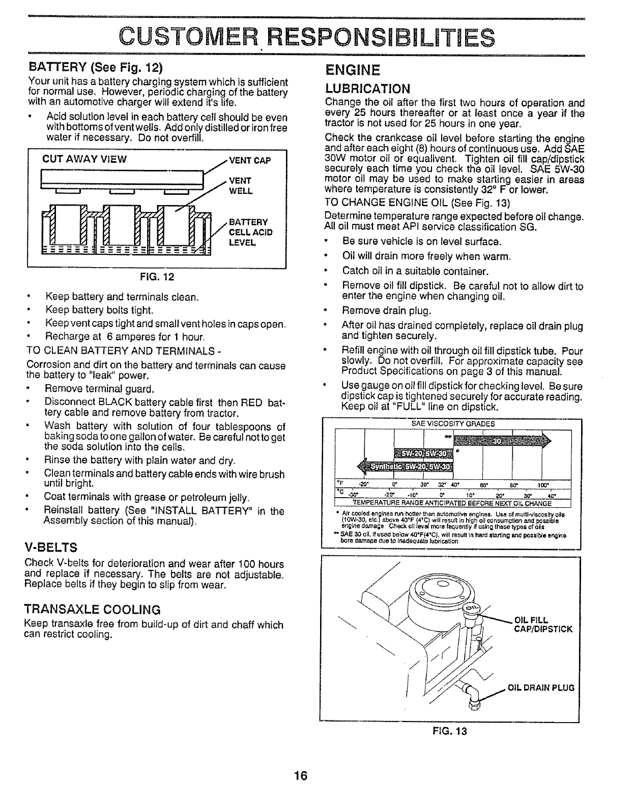
BATTERY (See Fig. 12)
Your unit has a battery charging system which is sufficient
for normal use. However periodic charg,ing of the battery
wth an automotive charger will extend its life.
• Acid solution level in each battery cell should be even
with bottoms of vent wells. Add only distilled or iron free
water if necessary. Do not overfill.
iiiiii i,
RESPONSiBILiTIES
CUT AWAY VIEW CAP
WELL
CELL ACID
LEVEL
FIG. 12
°Keep battery and terminals clean.
.Keep battery bolts tight.
•Keep vent caps tight and small vent holes in caps open.
-Recharge at 6 amperes for I hour.
TO CLEAN BATTERY AND TERMINALS -
Corrosion and dirt on the battery and terminals can cause
the battery to "leak" power.
, Remove terminal guard.
.Disconnect BLACK battery cable first then RED bat-
tery cable and remove battery from tractor.
•Wash battery with solution of four tablespoons of
baking soda to one galton of water. Becarefulnottoget
the soda solution into the cells,
• Rinse the battery with plain water and dry,
• Clean terminals and battery cable ends with wire brush
until bright.
• Coat terminals with grease or petroleum jeI¥
° Reinstall battery (See "INSTALL BATTERY" in the
Assembly section of this manual)°
V-BELTS
Check V-belts for deterioration and wear after 100 hours
and replace if necessary. The belts are not adjustable°
Replace belts if they begin to slip from wear,
TRANSAXLE COOLING
Keep transaxle free from build-up of dirt and chaff which
can restrict cooling.
ENGINE
LUBRICATION
Change the oil after the first two hours of operation and
every 25 hours thereafter or at least once a year ff the
tractor is not used for 25 hours in one year°
Check the crankcase oil level before starting the engine
and after each eight (8) hours of continuous use. Add SAE
30W motor oil or equalivento Tighten oil fill cap/dipstick
securely each time you check the oil level. SAE 5W-30
motor oil may be used to make starting easier in areas
where temperature is consistently 32° F or lower.
TO CHANGE ENGINE OIL (See Fig° 13)
Determine temperature range expected before oil change.
All oil must meet APt service classification SG.
•Be sure vehicle is on level surface.
, Oil will drain more freely when warm.
, Catch oil in a suitable container.
" Remove oil fill dipstick_ Be careful not to allow dirt to
enter the engine when changing oil.
,Remove drain pJug.
,After oil has drained completely, replace oil drain plug
and tighten securely.
-Refill engine with oil through oil fill dipstick tube. Pour
slowly. Do not overfill For approximate capacity see
Product Specifications on page 3 of this manual.
° Use gauge on oit fill dipstick for checking levet. Be sure
dipstick cap is tightened securely for accurate reading.
Keep oil at "FULL" line on dipstick.
SAE VISCOSITY GRADES
,OIL DRAIN PLUG
FIG. 13
16
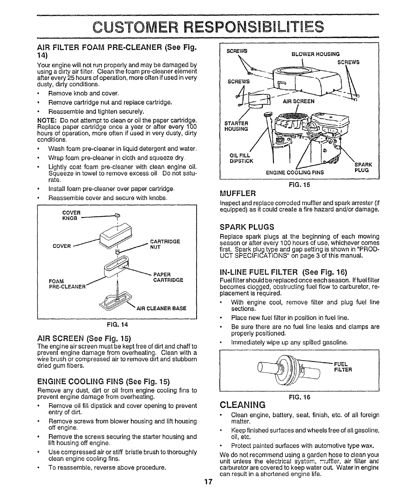
AIR FILTER FOAM PRE-CLEANER (See Fig,
14)
Your engine will not run properly and may be damaged by
using a dirty air filter_ Clean the foam pro-cleaner element
after every 25 hours of operation, more often if used in very
dusty, dirty conditions.
• Remove knob and cover.
• Remove cartridge nut and replace cartridge.
, Reassemble and tighten securely,
NOTE: Do not a_empt to clean or oil the paper cartridge.
Replace paper cartridge once a year or after every 100
hours of operation, more often if used in very dusty, dirty
condition&
• Wash foam pre-cleaner in liquid detergent and water.
• Wrap foam pro-cleaner in c_oth and squeeze dry_
• Lightly coat foam pre-cleaner with clean engine oil.
Squeeze in towel to remove excess oil. Do not satu-
rate_
o Install foam pro-cleaner over paper cartridge.
• Reassemble cover and secure with knobs.
COVER
KNOB
=CARTRIDGE
COVER _NUT
_"'_PAPER
FOAM _ _ CARTRIDGE
FRE-CLE ANERI'- _ _
__R CLEANER BASE
FIG. 14
AIR SCREEN (See Fig, 15)
The engine air screen must be kept free of dirt and chaff to
prevent engine damage from overheating. Clean with a
wire brush or compressed air to remove dirt and stubborn
dried gum fibers.
ENGINE COOLING FINS (See Fig. 15)
Remove any dust, dirt or oil from engine cooling fins to
prevent engine damage from overheating_
• Remove oil fill dipstick and cover opening to prevent
entry of dirt.
o Remove screws from blower housing and lift housing
off engine.
. Remove the screws securing the starter housing and
lift housing off engine.
o Use compressed air or stiff bristle brush to thoroughly
ctean engine cooling fins,
. To reassemble, reverse above procedure°
SCREWS BLOWER HOUSING
STARTER
HOUSING
17
OIL FILL
DIPSTICK 1SPARK
ENGINE COOLINGFINS PLUG
FIG. 15
MUFFLER
Inspect and replace corroded muffler and spark arrester (if
equipped) as it coutd create a fire hazard and/or damage.
SPARK PLUGS
Replace spark plugs at the beginning of each mowing
season or after every t00 hours of use, whichever comes
first, Spark plug type and gap setting is shown in "PROD-
UCT SPECIFICATIONS on page 3 of this manual.
IN-LINE FUEL FILTER (See Fig, 16)
Fuel filter should be replaced once each season. Iffuel filter
becomes clogged, obstructing fuel flow to carburetor, re-
placement is required.
• With engine cool, remove filter and plug fuel line
sections.
° Place new fuel filter in position in fuel line.
• Be sure there are no fuel line leaks and clamps are
properly positioned.
•Immediately wipe up any spilled gasoline°
'-_ FUEL
FILTER
FIG. 16
CLEANING
• Clean engine, battery, seat, finish, etc_ of all foreign
matter.
oKeep finished surfaces and wheels free of all gasoline,
oil, etc,
"Protect painted surfaces with automotive type wax.
We do not recommend using a garden hose to clean youl
unit unless the electrical system, muffler, air filter and
carburetor are covered to keep water out Water in engine
can result in a shortened engine life.
SERVSCE AND ADJUSTMENTS
i,, i i i,ii1,1,,,,11,,,i i ! ii i
CAUTION: BEFORE PERFORMING ANY SERVICE OR ADJUSTMENTS:
• Depress clutch/brake pedal fully and set parking brake.
•Place gearshift lever in "NEUTRAL" position,
,Place attachment clutch in "DISENGAGED" position.
oTurn ignition key "OFF" and remove key.
• Make sure the blades and all moving parts have completely stopped,
. Disconnect spark plug wire from spark plug and place wire where it cannot come in contact with
plug.
ii,l,,,i ii i1,1 i ir..... ,lll,,i ii, ii, i i ,, _ i i, i _................. 111111i,i , ii
TRACTOR {
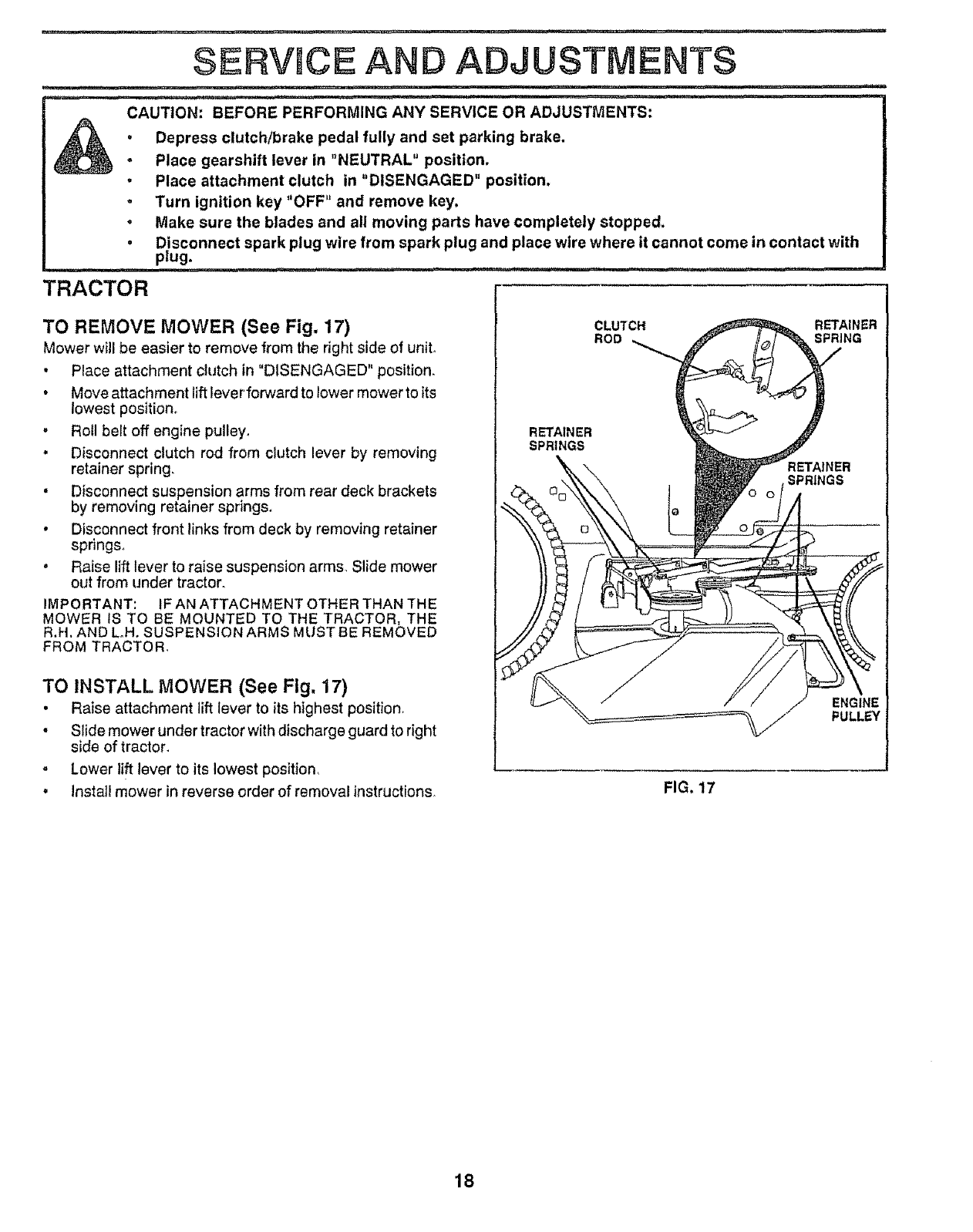
TO REMOVE MOWER (See Fig. 17)
Mower will be easier to remove from the right side of unit.
•Place attachment clutch in "DISENGAGED" position_
•Move attachment lift lever'forward to lower mower to its
lowest position,
• Roll belt off engine pulley,
•Disconnect clutch rod from clutch lever by removing
retainer spring,
•Disconnect suspension arms from rear deck brackets
by removing retainer springs_
•Disconnect front links from deck by removing retainer
springs,
•Raise lift lever to raise suspension arms Slide mower
out from under tractor,
IMPORTANT: IF AN ATTACHMENT OTHER THAN THE
MOWER tS TO BE MOUNTED TO THE TRACTOR, THE
R.H. AND Loll. SUSPENSION ARMS MUST BE REMOVED
FROM TRACTOR,
TO INSTALL MOWER (See Fig. 17)
°Raise attachment lift lever to its highest position,
. Slide mower under tractor with discharge guard to right
side of tractor.
=Lower tift tever to its lowest position_
•lnsta]l mower in reverse order of removal instructions_
CLUTCH RETAINER
ROD SPRING
RETAINER
SPRINGS
ENGINE
PULLEY
FIG. 17
18
ii ii,i, ,i , ..............
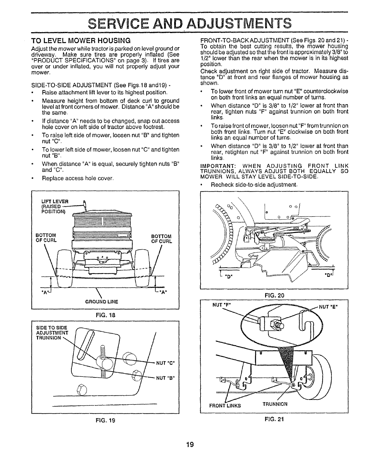
TO LEVEL MOWER HOUSING
Adjust the mower whifetractor is parked on tevet ground or
dfiveway_ Make sure tires are properly inflated (See
PRODUCT SPECIFICATIONS' on page 3) If tires are
over or under inflated, you will not properly adjust your
mower.
SIDE-TO-SIDE ADJUSTMENT (See Figs_18 and19) -
• Raise attachment lift lever to its highest position.
• Measure height from bottom of deck curl to ground
level at front corners of mower, Distance "A" should be
the same
. If distance "A" needs to be changed, snap out access
hole cover on left side of tractor above footrest°
•To raise teft side of mower, loosen nut "B" and tighten
nut "C".
•To lower left side of mower, loosen nut "C" and tighten
nut "B".
. When distance "A" is equal, securely tighten nuts "B"
and "C".
• Replace access hole cover.
FRONT-TO-BACK ADJUSTMENT (See Figs 20 and 21) -
To obtain the best cutting results, the mower housing
should be adjusted so that the front is approximately 3/8" to
1/2" lower than the rear when the mower is in its highest
position_
Check adjustment on right side of tractor° Measure dis-
tance "D" at front and rear flanges of mower housing as
shown,
• To lower front of mower turn nut"E" counterclockwise
on both front links an equal number of turns.
• When distance "D" is 3/8" to 1/2" lower at front than
rear, tighten nuts "F" against trunnion on both front
links
o To raise front of mower, loosen nut"F" from trunnion on
both front links Turn nut "E" clockwise on both front
links an equal number of turns.
. When distance "D" is 3/8" to 1/2" lower at front than
rear, retighten nut "F" against trunnion on both front
links,
IMPORTANT: WHEN ADJUSTING FRONT LINK
TRUNNIONS, ALWAYS ADJUST BOTH EQUALLY SO
MOWER WILL STAY LEVEL SIDE-TO-SIDE.
• Recheck side-to-side adjustment,
LIFT LEVER
(RAISED
POSITION)
BOTTOM BOTTOM
OF CURL OF CURL
\
GROUNDLINE
FIG. 18
SIDE TO SIDE
ADJUSTMENT _ [)) _/
TRUNNION_NUT "C'
NUT"B"
FIG. 20
NUT "F" .E•
FRONT LINKS TRUNNION
FIG. 19 FIG. 21
19
_111 ....... i.......
SERVICE AN
=:n,l,ll, ii, ii ,
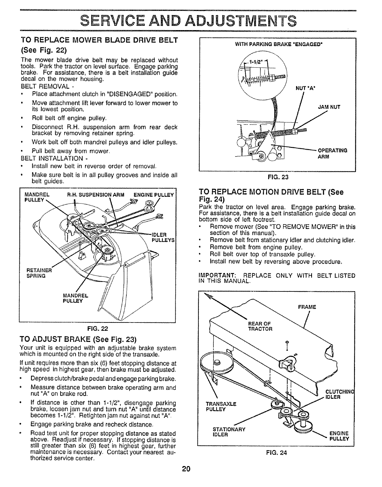
TO REPLACE MOWER BLADE DRIVE BELT
(See Fig, 22)
The mower blade drive belt may be replaced without
tools. Park the tractor on level surface. Engage parking
brake. For assistance, there is a belt installation guide
decal on the mower housing_
BELT REMOVAL
•Place attachment clutch in "DISENGAGED" position.
• Move attachment lift lever forward to lower mower to
its lowest position,
•Roll belt off engine pulley°
•Disconnect R.Ho suspension arm from rear deck
bracket by removing retainer spring.
• Work belt off both mandrel pulleys and idler pulleys.
• Pull belt away from mower.
BELT INSTALLATION -
•Install new belt in reverse order of removal.
• Make sure belt is in all pulley grooves and inside all
belt guides°
MANDREL R,H. SUSPENSION ARM ENGINE PULLEY
PULLEY
PULLEY
ADJUSTMENTS
WITH PARKING BRAKE "ENGAGED'
RETAINER
SPRING
MANDREL
PULLEY
FIG. 23
NUT "A"
JAM NUT
OPERATING
ARM
TO REPLACE MOTION DRIVE BELT (See
Fig. 24)
Park the tractor on level area° Engage parking brake.
For assistance, there is a belt installation guide decal on
bottom side of left footrest.
•Remove mower (See "TO REMOVE MOWER" in this
section of this manual)°
• Remove belt from stationary idler and clutching idler.
•Remove belt from engine pulley.
•Roll belt over top of transaxle pulley.
•Install new belt by reversing above procedure°
ONLY WITH BELT LISTED
FRAME
IMPORTANT: REPLACE
IN THtS MANUAL.
FIG. 22
TO ADJUST BRAKE (See Fig. 23)
Your unit is equipped with an adjustable brake system
which is mounted on the right side of the transaxle.
If unit requires more than six (6) feet stopping distance at
high speed in highest gear, then brake must be adjusted.
• Depress clutch/brake pedal and engage parking brake.
•Measure distance between brake operating arm and
nut "A" on brake rod°
•If distance is other than 1-1/2", disengage parking
brake, loosen jam nut and turn nut "A" until distance
becomes 1-1/2'L Retighten jam nut against nut "A".
•Engage parking brake and recheck distance.
o Road test unit for proper stopping distance as stated
above, Readjust if necessary, If stopping distance is
still greater than six (6) feet in highest gear, further
maintenance is necessary. Contact your nearest au-
thorized service center.
20
PULLEY
STATIONARY
IDLER
FIG. 24
CLUTCHING
IDLER
ENGINE
PULLEY
SERVICE AN
TO ADJUST STEERING WHEEL ALIGNMENT
if steering wheel crossbars are not horizontal (left to right)
when wheels are positioned straight forward, remove steer..
ing wheel and reassemble per instructions in the Assembly
section of this manual.
FRONT WHEEL TOE-IN/CAMBER
The front wheel toeqn and camber are not adjustable on
ADJUSTMENTS
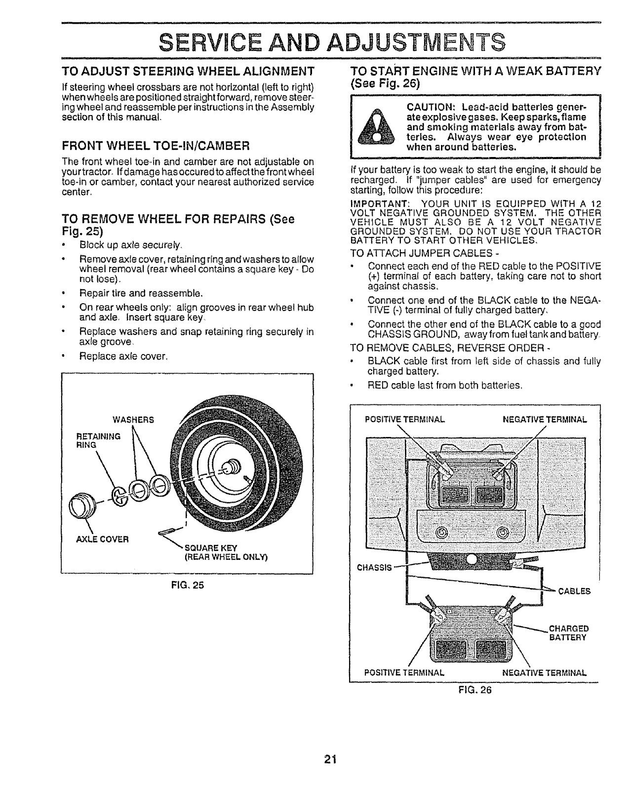
TO START ENGINE WITH A WEAK BATTERY
(See Fig, 26)
_CAUTION: Lead-acid batteries goner-
|_'-_, ate explostve gases, Keepsparks, flame
| _ and smoking materials away from bat-
_ terles. Always wear eye protection
! --_, When around batteries,
your tractor_ if damage has occured to affect the front wheel
toe-in or camber, contact your nearest authorized service
center,
TO REMOVE WHEEL FOR REPAIRS (See
Fig, 25)
•Block up axle securely.
•Remove axle cover, retaining ring and washers to allow
wheel removal (rear wheel contains a square key- Do
not Iose)o
•Repair tire and reassemble.
•On rear wheels only: align grooves in rear wheel hub
and axle. Insert square key
•Replace washers and snap retaining ring securely in
axle groove.
• Replace axle cover.
If your battery is too weak to start the engine, it should be
recharged, tf "jumper cables" are used for emergency
starting, follow this procedure:
IMPORTANT: YOUR UNIT tS EQUIPPED WITH A 12
VOLT NEGATIVE GROUNDED SYSTEM, THE OTHER
VEHICLE MUST ALSO BE A 12 VOLT NEGATIVE
GROUNDED SYSTEM. DO NOT USE YOUR TRACTOR
BATTERY TO START OTHER VEHiCLES_
TO ATTACH JUMPER CABLES -
,Connect each end of the RED cable to the POSITIVE
(+) terminal of each battery, taking care not to short
against chassis,.
• Connect one end of the BLACK cable to the NEGA-
TiVE (-) terminal of fully charged battery,
. Connect the other end of the BLACK cable to a good
CHASSIS GROUND, away from fuel tank and battery,
TO REMOVE CABLES, REVERSE ORDER -
• BLACK cable first from left side of chassis and fully
charged battery.
•RED cable tast from both batteries.
WASHERS
RETAINING
RING
AXLECOVER
!
"_ SQUARE KEY
(REARWHEELONLY)
FIG, 25
POSITIVETERMINAL NEGATIVE TERMINAL
CHARGED
BATTERY
POSITIVE TERMINAL NEGATIVE TERMINAL
FIG, 26
21
SERVICE AN
,, ,i
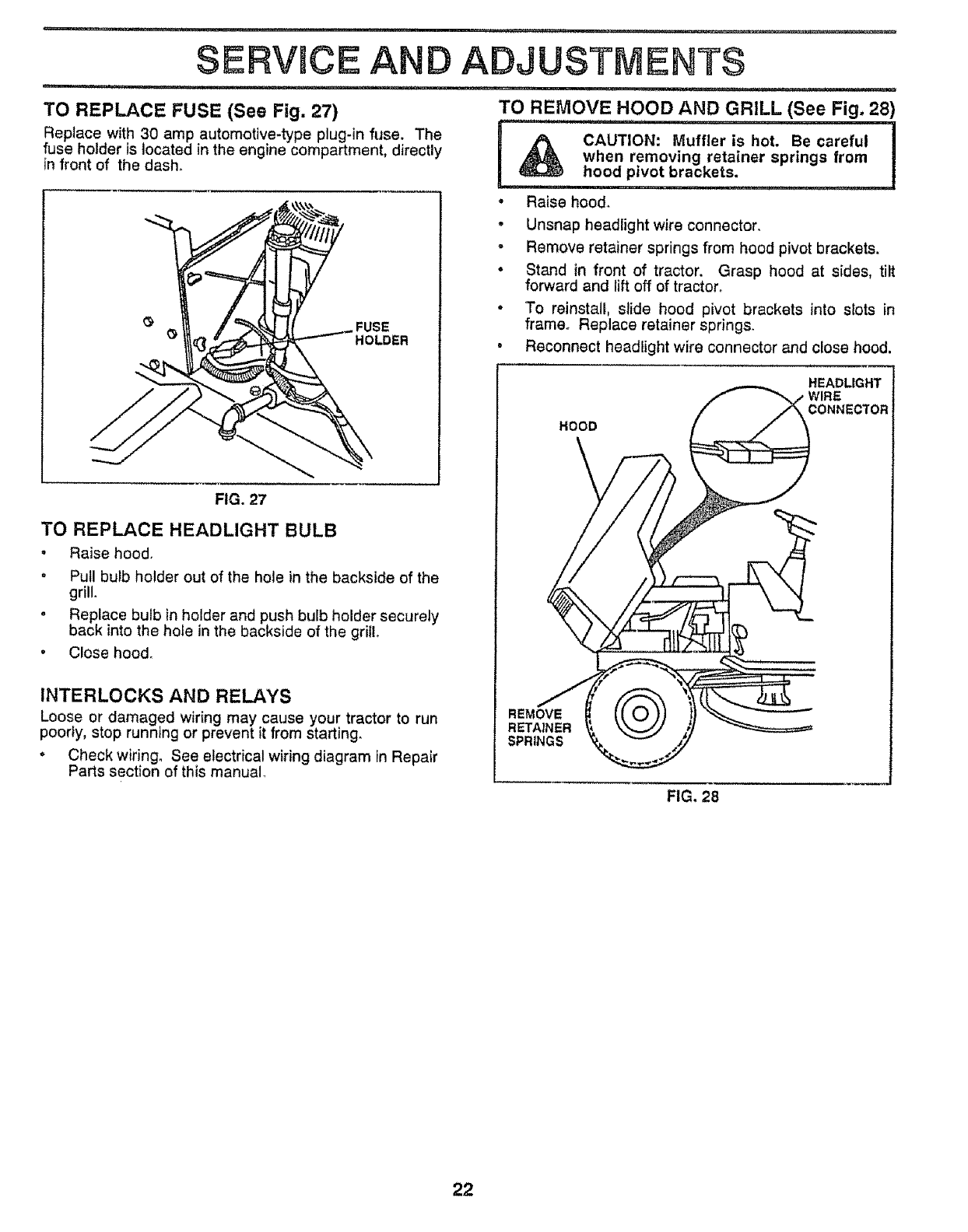
TO REPLACE FUSE (See Fig. 27)
Replace with 30 amp automotive-type plug-in fuse. The
fuse holder is located in the engine compartment, directly
in front of the dash.
ADJUSTMENTS
i,i ,i ,,111,,111,,, iii i, ,i ii, / i i [
TO REMOVE HOOD AND GRILL (See Fig. 28)
...........
CAUTION: Muffler is hot. Be careful I
when removing retainer springs from
hood pivot brackets. ,,,, ............... ]
FUSE
_' HOLDER
FIG. 27
TO REPLACE HEADLIGHT BULB
. Raise hood.
" Pull bulb holder out of the hole in the backside of the
grill.
°Replace bulb in holder and push bulb holder securely
back into the hole in the backside of the grill
• Close hood°
INTERLOCKS AND RELAYS
Loose or damaged wiring may cause your tractor to run
poorly, stop running or prevent it from starting.
•Check wiring, See electrical wiring diagram in Repair
Parts section of this manual.
,Raise hood_
.Unsnap headright wire connector.
o Remove retainer springs from hood pivot brackets.
°Stand in front of tractor. Grasp hood at sides, tilt
forward and lift off of tractor°
*'To reinstall, slide hood pivot brackets into slots in
frame° Replace retainer springs.
.Reconnect headlight wire connector and close hood,
HOOD
HEADLIGHT
WIRE
CONNECTOR
REMOVE
RETAINER
SPRINGS
FIG. 28
22
SERVICE AN
,1 , ill = , = i i, M,,, =,H.,,.I,
ENGINE
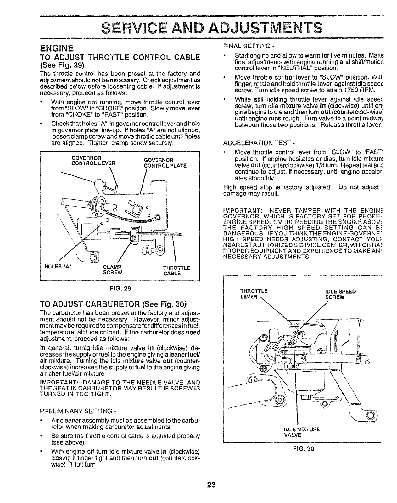
TO ADJUST THROTTLE CONTROL CABLE
(See Fig. 29)
The throttle control has been preset at the factory and
adjustment should not be necessary. Check adjustment as
described below before loosening cable, If adjustment is
necessary, proceed as follows:
• With engine not running, move throttle control lever
from "SLOW" to "CHOKE" position° Slowly move lever
from "CHOKE" to "FAST" position_
• Check that holes"A" in governor control lever and hole
in governor plate line-up_ if holes "A" are not aligned,
loosen clamp screw and move throttle cable until holes
are aligned. Tighten clamp screw securely.
GOVERNOR
CONTROL LEVER GOVERNOR
CONTROL PLATE
HOLES "A" CLAMP
SCREW
............................... j_ =l ..... m
ADJUSTMENTS
i,, i, ,,i i,, 11, i, i i, _L,,u,_,,
FINAL SET'f'tNG -
• Start engine and allow to warm for five minutes. Make
final adjustments with engine running and shiftj'motion
control lever in "NEUTRAL position.
• Move throttle control lever to "SLOW" position. With
finger, rotate and hold throttle lever against idle spee_
screw_ Turn idle speed screw to attain t750 RPM.
. While still holding throttle lever against idle speed
screw, turn idle mixture valve in (clockwise) until en-
gine begins to die and then turn out (counterclockwisel
until engine runs rough. Turn valve to a point midway
between those two positions° Release throttle lever.
ACCELERATION TEST -
•Move throttle control lever from "SLOW" to "FAST'
position. If engine hesitates or dies, turn idie mixture
valve out (counterclockwise) 1/8 turn. Repeat test anc
continue to adjust, if necessary, until engine acceler
ates smoothly.
High speed stop is factory adjusted_ Do not adjust
damage may result°
IMPORTANT; NEVER TAMPER WtTH THE ENGINE
GOVERNOR, WHICH iS FACTORY SET FOR PROPEF
ENGINE SPEED, OVERSPEEDING THE ENG1NEABOVE
THE FACTORY HIGH SPEED SETTING CAN BI!
DANGEROUS. IF YOU THINK THE ENG1NE-GOVERNE[
HIGH SPEED NEEDS ADJUSTING, CONTACT YOUF
NEAREST AUTHORfZED SERVICE CENTER, WHICH HA.c
PROPER EQUIPMENT AND EXPERIENCE TO MAKE AN _
NECESSARY ADJUSTMENTS
FIG. 29
TO ADJUST CARBURETOR (See Fig. 30)
The carburetor has been preset at the factory and adjust-
ment should not be necessary. However, minor adjust-
ment may be required to compensate for differences infuel,
temperature, altitude or load If the carburetor does need
adjustment, proceed as follows:
In general, turnig idle mixture valve In (clockwise) de-
creases the supply of fuel to the engine giving a leaner fuel/
air mixture, Turning the idle mixture valve out (counter.
clockwise) increases the supply of fuel to the engine giving
a richer fuel/air mixture.
IMPORTANT" DAMAGE TO THE NEEDLE VALVE AND
THE SEAT tN CARBURETOR MAY RESULT tF SCREW tS
TURNED IN TOO TIGHTo
PRELIMINARY SETTING -
• Air cleaner assembly must be assembled to the carbu-
retor when making carburetor adjustments,
• Be sure the throttle control cable is adjusted properly
(see above).
• With engine off turn idle mixture valve In (clockwise)
closing it finger tight and then turn out (counterclock-
wise) 1 full turn.
THROTTLE IDLE SPEED
LEVER SCREW
IDLE MIXTURE
VALVE
FIG. 30
23
.......................... , ,, ...................... _ --
STORAGE
Immediately prepare your tractor for storage at the end of
the season or if the unit will not be used for 30 days or more.
CAUTION: Never store the tractor with
gasoline In the tank Inside abuilding
where fumes may reach an open flame
or spark. Allow the engine to cool
before storing In any enclosure.
TRACTOR
Remove mower from tractor for winter storage° When
mower is to be stored for a period of time, clean it thor.
oughly, remove all dirt, grease, leaves, etc. Store in a
clean, dry area.
•Clean entire tractor (See "CLEANING" in the Customer
Responsibilities section of this manual)°
• Inspect and replace belts, if necessary (See belt re-
placement instructions in the Service and Adjustments
section of this manual),
•Lubricate as shown in the Customer Responsibilities
section of this manual.
oBe sure that all nuts, bolts and screws are securely
fastened. Inspect moving parts for damage, breakage
and wear. Replace if necessary,
. Touch up all rusted or chipped paint surfaces; sand
Iightly before painting.
BATTERY
°Fully charge the battery for storage.
* After a period of time in storage, battery may require
recharging_
° To help prevent corrosion and power leakage during
long periods of storage, battery cables should be
disconnected and battery cteaned thoroughly (see "TO
CLEAN BATTERY AND TERMINALS" in the Cus-
tomer Responsibilities section of this manual)_
. After cleaning, leave cables disconnected and place
cables where they cannot come in contact with battery
terminals_
.Be sure battery drain tube is securely attached°
ENGINE
FUEL SYSTEM
IMPORTANT: IT IS IMPORTANT TO PREVENT GUM
DEPOSITS FROM FORMING IN ESSENTIAL FUEL
SYSTEM PARTS SUCH AS CARBURETOR, FUEL FILTER,
FUEL HOSE, OR TANK DURING STORAGE, ALSO,
EXPERIENCE INDICATES THAT ALCOHOL BLENDED
FUELS (CALLED GASOHOL OR USING ETHANOL OR
METHANOL) CAN ATTRACT MOISTURE WHICH LEADS
TO SEPARATION AND FORMATION OF ACIDS DURING
STORAGE, ACIDIC GAS CAN DAMAGE THE FUEL
SYSTEM OF AN ENGINE WHILE IN STORAGE.
o Drain the fuel tank°
° Start the engine and let it run until the fuel lines and
carburetor are empty°
. Never use engine or carburetor cleaner products in the
fuel tank or permanent damage may occur.
•Use fresh fuel next season.
NOTE; Fuel stabilizer is an acceptable alternative in
minimizing the formation of fuel gum deposits during stor-
age. Add stabilizer to gasoline in fuel tank or storage
container. Always foliow the mix ratio found on stabilizer
container. Run engine at least 10 minutes after adding
stabilizer to allow the stabilizer to reach the carburetor. Do
not drain the gas tank and carburetor if using fuel stabilizer°
ENGINE OIL
Drain oil (with engine warm) and replace with clean engine
oil. (See "ENGINE" in the Customer Responsib'hTes
section of this manual),
CYLINDERS
°Remove spark plug(s)_
.Pour one ounce of oil through spark plug hole(s) into
cylinder(s).
. Turn ignition key to"START" position fora few seconds
to distribute oil.
oReplace with new spark plug(s),
OTHER
° Do not store gasoline from one season to another.
oReplace your gasoline can if your can starts to rust.
Rust and/or dirt in your gasoline will cause problems.
•tf possible, store your unit indoors and cover it to give
protection from dust and dirL
. Cover your unit with asuitable protective cover that
does not retain moisture. Do not use plastic. Plastic
cannot breathe which allows condensation to form and
witl cause your unit to rust.
IMPORTANT: NEVER COVER TRACTOR WHILE ENGINE
AND EXHAUST AREAS ARE STILL WARM.
24

TROU LESHOOTING POINTS
,i,, ,,i, ],11 illl , Ulll ............................. : ............ • _:,_ ......................
PROBLEM
ill IUU'U. ii
Will not start
Hard to 8tart
Engine will not turn over
Engine clicks but wltl not
start
i,i i i i, n l
Lose of power
Exceastve vibration
CAUSE
1, Out of fuel.
2, Engine not "CHOKED" properly,
3Engine flooded,
4. Bad spark piug.
5. Dirty eJrfilter.
6. Dirty fuet filter.
7. Water In fuel
8. Loose or damaged wNng.
9o Carburetor out of adjustment.
10 Engine valves out of adjustment.
1Dirty air fiitar..
2. Bad spark plug
& Weak or dead battery
4 Dirty fuel filter.
5. Stale or dirty fuel,
6. Loose or damaged wiring.
7. Carburetor out of adjustment.
8. Engine valves out of edjustmanL
t. Clutch!brake pedal not depressed°
2. Attachment clutch is engaged.
3. Spark plug wire Is disconnected.
4 Weak er dead battery.
5 BIown fuse.
6. Corroded battery terminals.
7 Loose or damaged wiring.
8. Faulty Ignition switch.
9. Faulty solenoid or starter.
10. Faulty operator presence switch(es).
1: Weaker dead battery.
2Corroded battery terminals.
3Loose or damaged wtdng
4. Faulty solenoid or statler,
1. Cutting too much grass/too fasL
2_ ThrotlJe tn "CHOKE" position.
3 Build-up of grass, leaves and trash under mower
4. Dlrty air filter.
5. Low ell level/dirty oil
6. Faulty spark plug,
7DLrtyfuel filter.
8. State or dirty fuel.
9 Water in fuel.
10. Spark plug wire loose.
11. Dirty engine alr screen/fins
t2. Dirty/slogged muffler
13 Loose or damaged wiring.
14. Carburetor out of adjustment
t5 Engine valves out of adjustmenL
I. Worn, bent or loose blade
2. Bent blade mandrel
3. Loose/damaged part(s).
CORRECTION
1 Flit fuel tank.
2o See TO START ENGINE in Operation section.
3, Wait several minutes before attempting to start.
4. Replace spark pTug
5. Clean/replace air filter.
6, Replace fuel filter,
7o Drain fuel tank and carburetor, refill tank with fresh
gasoline and repfaca fuel fitter.
8 Check aU wEdng,
9, Contact Sears Service DepartmenL
10. Contact Sears Service Department.
1. Clean/replace air fi_ter.
2. Replace spark plug.
3. Recharge or replace battery.
4. Replace fuel filter
5. Drain fuel tank and refill with fresh gasoline.
6o Check el{ wiring.
7 Contact Seats Service DepaP, mant
8. Contact Se&rs Service Department.
1. Depress clutch/brake pedal.
2, Disengage attachment clutch,
3 Connect wire to spark plug.
4, Recharge or replace battery
5, Replace fuse.
6 Clean batterytermtnais,
7. Cheek all wiring
8Check/replace Ignition switch.
9, Check/repeats solenoid or starter.
l& ContaCt Sears Service DepartmenL
.................................................... ,i
1, Recharge or replace battery
2Clean battery terminals.
3. Check nit wiring.
4r CheckJreplaee solenoid or statler.
........... H U:H,,"I'IH,
1Set tn =Higher Cut" position/reduce speed.
2. Adjust throttle control.
3, Clean underside of mower housing.
4. Clean/repines a_rfilter.
5_ Check oil level./change oil.
6. Clean and regap or change spark plug.
7 Replace fuel filler.
8. Drain fuel tank end refill with fresh gasoline.
9 Drain fuel tank and carburetor, refill tank with fresh
gasoline and replace fuel filter
10. Connect and tighten sp_k plugwfre.
11, Clean englne air screen/fins.
12. Clean/replace muffler
13. Check allwidng.
14. Contact Sears Service Department
15, Contact Sears Service DepartmenL
1. Replace blade Tighten blade boll
2. Replace blade mandrel.
3. Tighten loose part(s). Replace damaged parts.
25
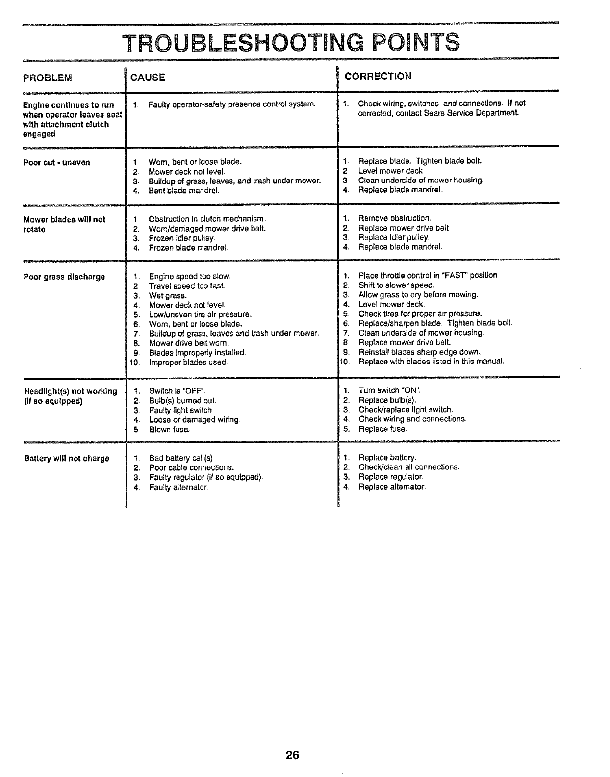
i,l_,_J,J,i,J,i,
PROBLEM
Engine continues to run
when operator leaves seat
with attachment clutch
engaged
Poor cut - uneven
Mower blades wl]l not
rotate
Poor grass discharge
Headlight(s) not working
(If so equipped)
Battery will not charge
..... ii, , ,ir,, /i '1 ....... i' ,11,,
TROUBLESHOOTING POINTS
,i,i ...... _ ,,, i,ii i
CAUSE
1 Fauity operator-safety presence central system,
t. Worn, bentor _oosebiade_
2Mower decknotlevel
3_ Buildupof grass, _eaves,and trashundermowe_,
4. Bentblade mandrel,
1, Obstruction tn clutch mechanism
2, Worn/damaged mower ddve belt.
3 Frozen idler pulley
4r Frozen blade mandrel
1, Enginespeedtoo stow.
2. Travel speedtoo fasL
3 Wet grass.
4, Mowerdecknot level
5, Low/uneventire air pressure
6, Worn, bent or {easeblade,
7, Buiidup of grass, {eavesand trash under mower.
8o Mower drive belt worn,
9, Blades improperlyinstalled.
10, improperblades used,
1, Switch _s"OFF",
2 Bulb(s) burned out°
3 Faulty tight switch.
4, Loose or damaged wiring.
5 Blown fuse,
1, Bad battery ce_I(s),
2. Poor cabte connections,
3. Faulty regulator (if so equlppsd).
4, Faulty alternator,
CORRECTION
, ,1 ,,1,1 ii
1, Check wiring, switches and connections, If not
corrected, contact Sears Service Department,
I, Rep{ace blade. Tighten blade boll
2, Leve_ mower deck.
3Clean undersideofmower housing,
4. Replace blade mandrel
1, Remove obstruction.
2. Replace mower ddve bell
3, Replace idler pu]leyo
4, Replace blade mandrel.
1, Place throttle control in "FAST" position°
2, Shift to slower speed,
3, At_ow grass to dry before mowing,
4, Level mower deck,
5 Check tires for proper air pressure,
6, Replace/sharpen blade, Tighten blade boll
7. Clean underside of mower housing,
8 Replace mower drive bell
9 Retnsta{I bfades sharp edge dowm
t0. Replace with blades listed In Lhis manual
1, "rum switch "ON"r
2_ RepJace bulb(s),
3. Check]replace light switch,
4, Check wiring and connections,
5o Replace fuse.
1_ Replace battery.
2, Check/clean aJl connections,
3,, Replace regulator.
4, Replace altemator
26
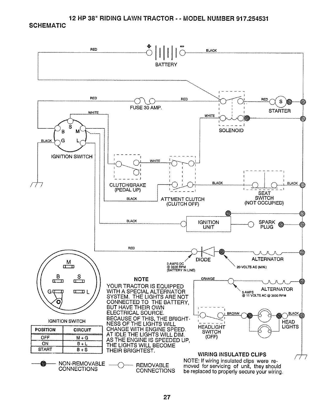
12 HP 38" RIDING LAWN TRACTOR - - MODEL NUMBER 917.254531
SCHEMATIC
RED
BATTERY
BLACK
F
RED
BLACK
WHITE
IGNITION SWITCH
1i".-.-.-.-.-.-._313CZ33
IGNITION8WITCH
POSITION CIRCUIT 7
NON-REMOVABLE
CONNECTIONS
FUSE 30 AMP.
I
'O1
I{,._1
...... J
CLUTCH/BRAKE
(PEDAL UP)
BLACK
BLACK
RED
....... 1
WHITE __.._"_T'-
1 I I
t I !
t t
NOTE
YOUR TRACTOR IS EQUIPPED
WITH A SPECIAL ALTERNATOR
SYSTEM THE LIGHTS ARE NOT
CONNECTED TO THE BATTERY,
BUT HAVE THEIR OWN
ELECTRICAL SOURCE.
BECAUSE OF THIS, THE BRIGHT-
NESS OF THE LIGHTS WILL
CHANGE WITH ENGINE SPEED.
AT IDLE THE LIGHTS WILL DIM.
AS THE ENGINE tS SPEEDED UP,
THE LIGHTS WILL BECOME
THEIR BRIGHTEST.
ATT'MENT CLUTCH
(CLUTCH OFF)
I i l
-- I_
J
SOLENOID
STARTER
(
BLACK
I- I
}I
SEAT
SWITCH
(NOT OCCUPIED)
,oN,T,oNSPARKUNIT PLUG
3AMPSOC/" DIODE '%,..... ALTERNATOR
@3600 RPM " 20 VOLTS AC (MfN)
(BATTERY _N LINE)
5 AMPS ALTERNATOR
@11voLTSAc@_ _PM
I...... I
(OFF)
F7
--(-_--- REMOVABLE
CONNECTIONS
WIRING INSULATED CLIPS
NOTE: If wiring insulated clips were re-
moved for servicing of unit, they should
be replaced to properly secure your wlring_
27
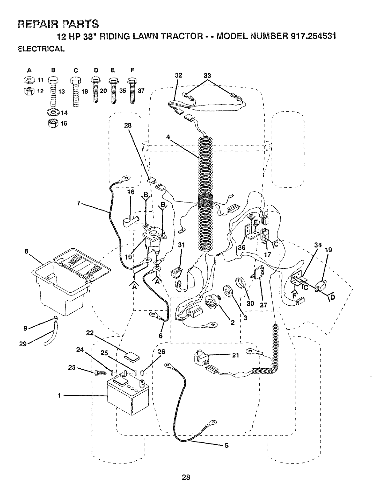
REPAnR PARTS
12 HP 38" RIDING LAWN TRACTOR ° .. MODEL NUMBER 917.254531
ELECTRICAL
A B C
12 13 18
8\
28
I
4
32 33
31 34 19
28
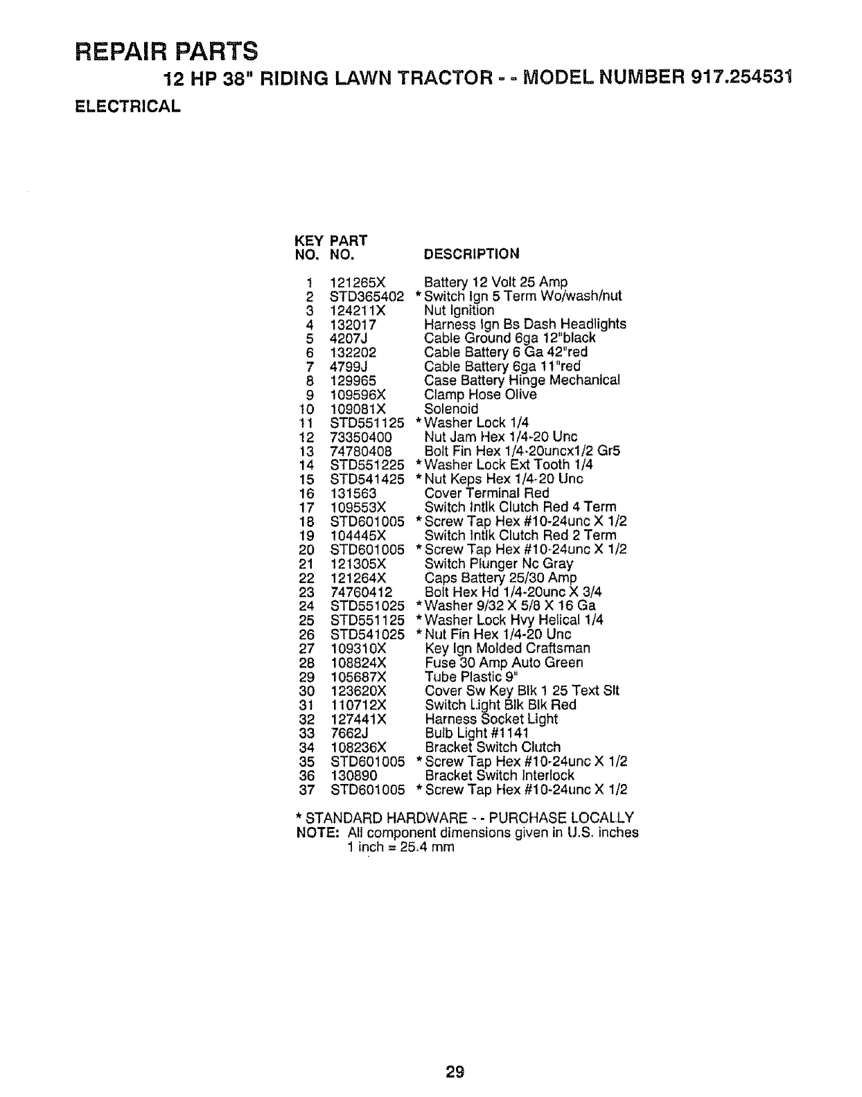
REPAIR PARTS
12 HP 38" RIDING LAWN TRACTOR., oMODEL NUMBER 917,254531
ELECTRICAL
KEY PART
NO. NO. DESCRIPTION
t 121265X
2 STD365402
3 124211X
4 132017
54207J
6132202
7 4799J
8 129965
9 t09596X
t0 !09081X
tt STD551125
12 73350400
13 74780408
14 STD551225
15 STD541425
16 131563
17 109553X
18 STD601005
19 104445X
2O STD601005
21 12t305X
22 121264X
23 74760412
24 STD55t025
25 STD55!125
26 STD541025
27 109310X
28 108824X
29 105687X
30 123620X
31 1t0712X
32 127441X
33 7662J
34 108236X
35 STD601005
36 130890
37 STD601005
Battery 12 Volt 25 Amp
* Switch Ign 5 Term Woiwash/nut
Nut Ignition
Harness tgn Bs Dash Headlights
Cable Ground 6ga 12' black
Cable Battery 6 Ga 42"red
Cable Battery 6ga 11"red
Case Battery Hinge Mechanical
Clamp Hose Olive
Solenoid
*Washer Lock 1/4
Nut Jam Hex 1/4-20 Unc
Bolt Fin Hex 1/4-20uncxl/2 Gr5
*Washer Lock Ext Tooth 1/4
*Nut Keps Hex 1/4_20 Unc
Cover Terminal Red
Switch lntlk Clutch Red 4 Term
* Screw Tap Hex #10-24unc X 1/2
Switch lntlk Clutch Red 2 Term
*Screw Tap Hex #10,24unc X 1/2
Switch Plunger Nc Gray
Caps Battery 25/30 Amp.
Bolt Hex Hd 1/4-20unc X 3/4
*Washer 9/32 X 5/8 X 16 Ga
*Washer Lock Hvy Helical 1/4
*Nut Fin Hex 1/4-20 Unc
Key Ign Molded Craftsman
Fuse 30 Amp Auto Green
Tube Plast c
Cover Sw Key BIk I 25 Text Sit
Switch Light Blk BIk Red
Harness Socket Light
Bulb Light #1141
Bracket Switch Clutch
* Screw Tap Hex #10-24unc X 1/2
Bracket Switch Interlock
*Screw Tap Hex #10-24unc X 1/2
*STANDARD HARDWARE _- PURCHASE LOCALLY
NOTE: All component dimensions given in U,S, inches
1 inch = 25,4 mm
29
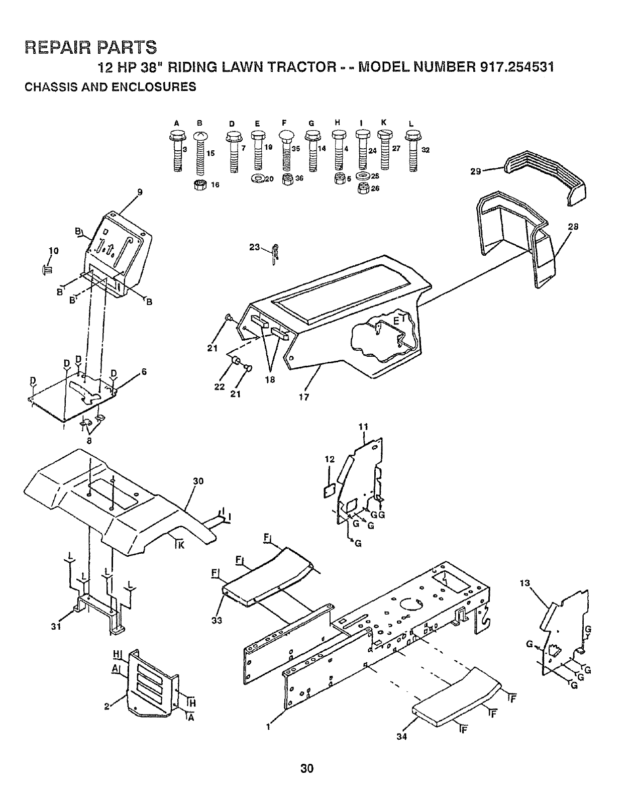
REPAUR PARTS
12 HP 38" RIDING LAWN TRACTOR ° = MODEL NUMBER 917,254531
CHASSIS AND ENCLOSURES
9
10
6
31
AB D E F G H ! K L
_2s
23_._
21 "o
21 t7
3O
33
11
13
A
2F
34
3O
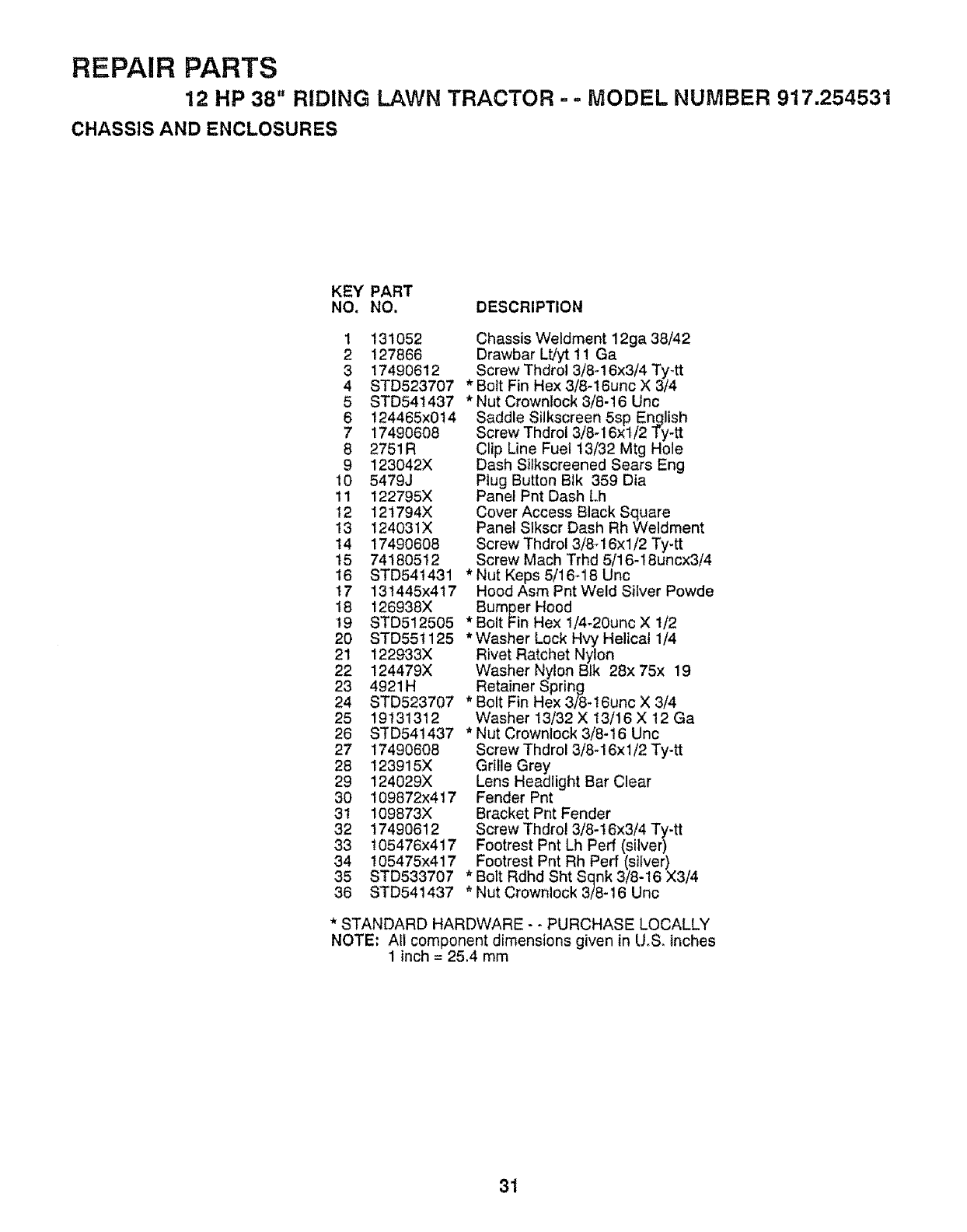
REPAIR PARTS
12 HP 38" RIDING LAWN TRACTOR ,-,- MODEL NUMBER 917.254531
CHASSIS AND ENCLOSURES
KEY PART
NO. NO. DESCRIPTION
1 131052
2 127866
3 17490612
4 STD523707
5STD541437
6 124465x0t4
7 17490608
8 2751R
9 123042X
10 5479J
11 122795X
12 12t794X
13 124031X
14 17490608
15 74180512
16 STD541431
17 13t445x417
18 126938X
t9 STD512505
20 8TD551125
21 122933X
22 124479X
23 4921H
24 STD523707
25 19131312
26 STD541437
27 17490608
28 123915X
29 124029X
30 109872x417
31 109873X
32 17490612
33 105476x417
34 105475x417
36 STD533707 *
36 STD541437 *
Chassis Weldment 12ga 38/42
Drawbar Lt/yt 11 Ga
Screw Thdrol 3/8-16x3/4 Ty4t
*Bolt Fin Hex 3/8-16unc X 3/4
* Nut Crowntock 3/8-16 Unc
Saddle Silkscreen 5sp English
Screw Thdrol 3/8-16xl/2 Ty-tt
Clip Line Fuel t3/32 Mtg Hole
Dash Siikscreened Sears Eng
Plug Button Blk 359 Dia
Panel Pnt Dash Lh
Cover Access Black Square
Panel Slkscr Dash Rh Weldment
Screw Thdrol 3/8q 6xl/2 Ty-tt
Screw Mach Trhd 5/16-18uncx3/4
* Nut Keps 5/'16-,18 Unc
Hood Asm Pnt Weld Silver Powde
Bumper Hood
* Bolt Fin Hex 1/4-20unc X 1/2
*Washer Lock Hvy Helical 1/4
Rivet Ratchet Nylon
Washer Nylon Blk 28x 75x 19
Retainer Spring
* Bolt Fin Hex 3/8-t6unc X 3/4
Washer 13/32 X 13/16 X 12 Ga
* Nut Crownlock 3/8-16 Unc
Screw Thdrcl 3/8-16xl/2 Ty-tt
Grille Grey
Lens Headlight Bar Clear
Fender Pnt
Bracket Pnt Fender
Screw Thdro! 3/8-16x3/4 Ty-tt
Footrest Pnt Lh Perf (silver)
Footrest Pnt Rh Perf (silver)
Bolt Rdhd Sht Sqnk 3/'8-16 X3/4
Nut Crownleck 3/8-16 Unc
* STANDARD HARDWARE - - PURCHASE LOCALLY
NOTE; All component dimensions given in U,S. inches
1inch = 25.4 mm
31
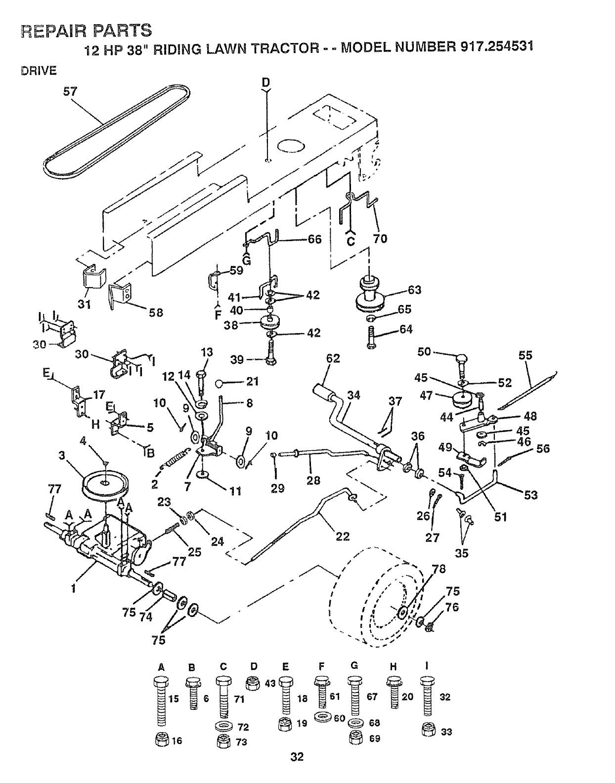
REPAIR PARTS
12 HP 38" RIDING LAWN TRACTOR - - MODEL NUMBER 917.254531
DRIVE
57 D
30 _! 13 39 -_,
E_L _1 _1 12 14
-17 \ 0----21
E 10 8 34 37
A B C D E F G H I
15 618 1 67 0 32
72 _ 19_o_ 68
32

REPARR PARTS
12 HP 38" RIDING LAWN TRACTOR - - MODEL NUMBER 917.254531
DRIVE
KEY PART KEY PART
NO. NOn DESCRIPTION NO. NO. DESCRIPTION
120897X
1t0422X
123666X
12000028
121520X
17490512
1069t9X
12446tX
19151216
Transaxle 5sp Std Dana
Spring Return Brake T/a Zinc
Pulley Transaxte Alum
Ring Retainer # 5100-62
Strap Pnt Torque 30 Deg Blk
Screw Thdrol 5/t6-18 X 3/4 Tyt
Plate Pnt Rod Shift T/a (btk)
Rod Shifter Blk (dana)
Washer t5/32 X 3/4 X 16ga
1
2
3
4
5
6
7
8
9
10 STD5612t0 * Pin Cotter t/8 X 1 Cad
11 105701X Washer Plate Shf 388 Sq Hole
12 19091210 Washer 9/32 X 3/4 X 10 Ga
13 71040412 Bolt Fin Hex 1/4,28unfx3/4 Gr8
14 STD551t25 *Washer Lock Hvy Helical 1/4
15 STD523727 *Bott Fin Hex 3/8-t6unc X 2-3/4
!6 STD541437 *Nut Crownlock 3/8-16 Unc
17 121520X Strap PntTorque 30 Deg Blk
18 STD523707 * Bolt Fin Hex 3/8-16unc X 3/4
19 STD54t437 *Nut Crownlock 3/8-16 Unc
20 17490512 Screw Thdrot 5/t6q8 X 3/4 Tyt
21 106933X Knob Rd 1/2,,13 Ptstc Thds BIk
22 131867 Rod Brake Lt
23 STD541437 * Nut Lock Hex W/wsh 3/8-16unc
24 STD541237 * Nut Hex Jam 3/8-16 Unc
25 106888X Spring Rod Brake 2 00 Zinc
26 STD551037 *Washer 13/32X 13/16X 16Ga
27 STD561210 * Pin Cotter l/S X 3/4 Cad
28 128904 Rod Brake Parking Lt
29 124236X Cap Parking Brake Red
30 109167X Bracket Transmission
31 127275X Keeper Belt Lh Lt 14 Ga
32 STD523707 * Bolt Fin Hex 3/8,16unc X 3/4
33 STD541437 * Nut Crownlock 3/8-16 Unc
34 122424X Shaft Asm Pedal Foot I 930
35 120t83X Bearing Nylon Blk 629 Id
36 STD551062 *Washer 21/32 X 1 X 16 Ga
37 STD57t8t0 *Pin Roll 3/16 X 1"
38 123674X Pulley tdter Flat
39 STD523727 * Bolt Fin Hex 3/8-t6unc X 2-3/4
40 4470J Spacer Split 395 X 59 Bzp
41 !09070X Keeper Belt Retainer
42 19131312
43 STD541437
44 105706X
45 1108t2X
46 12000039
47 127783
48 123789X
49 123205X
50 STD523715
51 STD54t437
52 STD55t037
53 t05710X
54 STD5612t0
55 t05709X
56 STD56t210
57 125907X
58 127274X
59 104777X
60 19131312
61 17490612
62 8883R
63 131002
64 7t'130720
65 STD55t143
66 129921
67 STD523710
68 19131312
69 STD541437
70 131402
71 STD523710
72 19132012
73 STD541437
74 t09502X
75 I21749X
76 STD581075
77 123583X
78 t21748X
Washer 13/32 X 13/16 X 12 Ga
*Nut Crownlock 3/8q6 Unc
Bearing Nyl 503 X 628 X 1 25
Washer Hardened
Ring KIip #t5304-50
Pulley Idler V Groove Plastic
Beflcrank Asm
Retainer Belt Style Spring
* Bolt Hex Hd 3/8-16unc X t-1/2
* Nut Crownlock 3/8-16 Unc
*Washer 13/32 X 13/16 X 16 Ga
Link Clutch 7 66
* Pin Cotter 1/8 X 3/4 Cad
Spring Return Clutch 6 75
* Pin Cotter 1/8 X 3/4 Cad
V-belt Ground Drive 90 00
Keeper Belt Rh Lt Pnt!zinc 16g
Retainer Belt Chassis Lh Zinc
Washer 13/32 X 13/16 X 12 Ga
Screw Thdrol 3/8-16x3/4 Ty-tt
Cover Pedal BIk Std
Pulley Engine
Bolt Finhex 7/16-20unfx1-1/4g8
*Washer Lock HW Hlcl Spr 7/16
Keeper Belt Engine Lh Lt
* Bolt Fin Hex 3/8-16unc X 1
Washer 't3/32 X 13/16 X t2 Ga
* Nut Crownlock 3/8-16 Unc
Guide Belt Dr Mower Rh
* Bolt Fin Hex 3/8-16unc X 1
Washer 13/32 X 1-!/4 X 12 Ga
* Nut Crownlock 3/8-16 Unc
Spacer Split 80xl 94 Cad/zinc
Washer 25/32 X 1 1/4 X t6 Ga
* Ring E #5133-75
Key Square 2 0 X 1845/1865
Washer 25/32 X t 5/8 X 16ga
*STANDARD HARDWARE - _ PURCHASE LOCALLY
NOTE: All component dimensions given in Uo& inches
'I inch = 25.4 mm
33
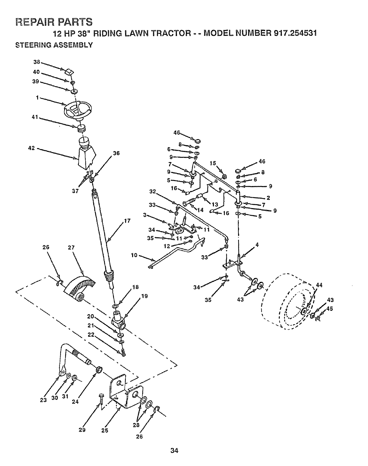
I
/ !," }_J_I._
tl I t 2"_ i q!,l_,lii.
I _o ,,+ s#'-'_
\,, t \ ".,tp

REPAIR PARTS
12 HP 38" RIDING LAWN TRACTOR - - MODEL NUMBER 917.254531
STEERING ASSEMBLY
KEY PART
NO. NO. DESCRIPTION
1 t00713N
2 105669X
3130460
4 130459
5 6266H
6 121748X
7 19272016
8 12000029
9 3366R
10 130468
11 STD551137
12 73610600
13 110438X
!4 74011056
15 73601000
16 132624
17 132614
18 57079
19 124035X
20 !26684X
21 STD551125
22 71070410
23 127501
24 109816X
25 124036X
26 12000029
27 !24034X
28 6266H
29 17490612
30 STD551137
31 73610600
32 130465
33 120754X
34
35
36
37
38
39
4O
41
42
43
44
45
46
Wheel Steering Std Black
Axle Asm Front
Spindle Asm Lh
Spindle Asm Rh
Bearing Race Thrust Harden
Washer 25/32 X 1 5/8 X 16ga
Washer 27/32 X 1 1/4 X 16 Ga
Ring Klip #t5304-75
Bearing Col Strg Blk
Link Drag Sol Ball Jt 20 064
*Washer Lock Hvy Hfct Spr 3/8
Nut Fin Hex 3/8-24 Unf
Spacer Bearing Axle Front
Bolt Hex 5/8-11 Uric X 3-1/2
Nut Hex Jam Lk W/wh 5/8-11 Unc
Pin Axle 5/8 X 1 55/1 54 Lg
Shaft Asm Strg 5/8 X 15 19 Lt
Washer Thrust 515x 750x 033
Support Shaft
Washer Shim 1/4 X 5/8 X 062
* Washer Lock HW Helical 1/4
Screw Hex Socket 1/4-20 X 5/8
Shaft Asm Pittman
Nyliner Snap tn
Bracket Steering
Ring Klip #t5304-75
Gear Sector
BearingRace Thrust Harden
Screw'rhdrol 3/8-16x3/4 Ty-tt
*Washer Lock HW Hlcl Spr 3/8
Nut Fin Hex 3/8-24 Unf
Rod Tie Wire Form 19 75 Mech
Bushing Rod Tie BIk Lt
19131416 Washer 13/32 X 7/8X 16ga
STD561210 * Pin Cotter 1/8 X 3/4 Cad
132196 Bushing Strg 5/8 ld Dash
STD611005 * Screw Slftp #10d 6 X 1/2 Ty-b
100710L Insert Cap Strg Wheel Std BIk
!9133808 Washer t3/32 X 2-3/8 X 8 Ga
STD54t537 * Nut Lock Center 3/8-24unf
104820X Adaptor Wheel Strg 640/635id
124417X Boot Shaft Steering
121749X Washer 25/32 X 1 !/4 X 16 Ga
12t748X Washer 25/32 X 1 5/8 X 16ga
12000029 Ring Klip #t5304-75
!21232X Cap Spindle Fr Top Blk
* STANDARD HARDWARE - - PURCHASE LOCALLY
NOTE; All component dimensions given in UoS. inches
1 inch = 25,4 mm
35
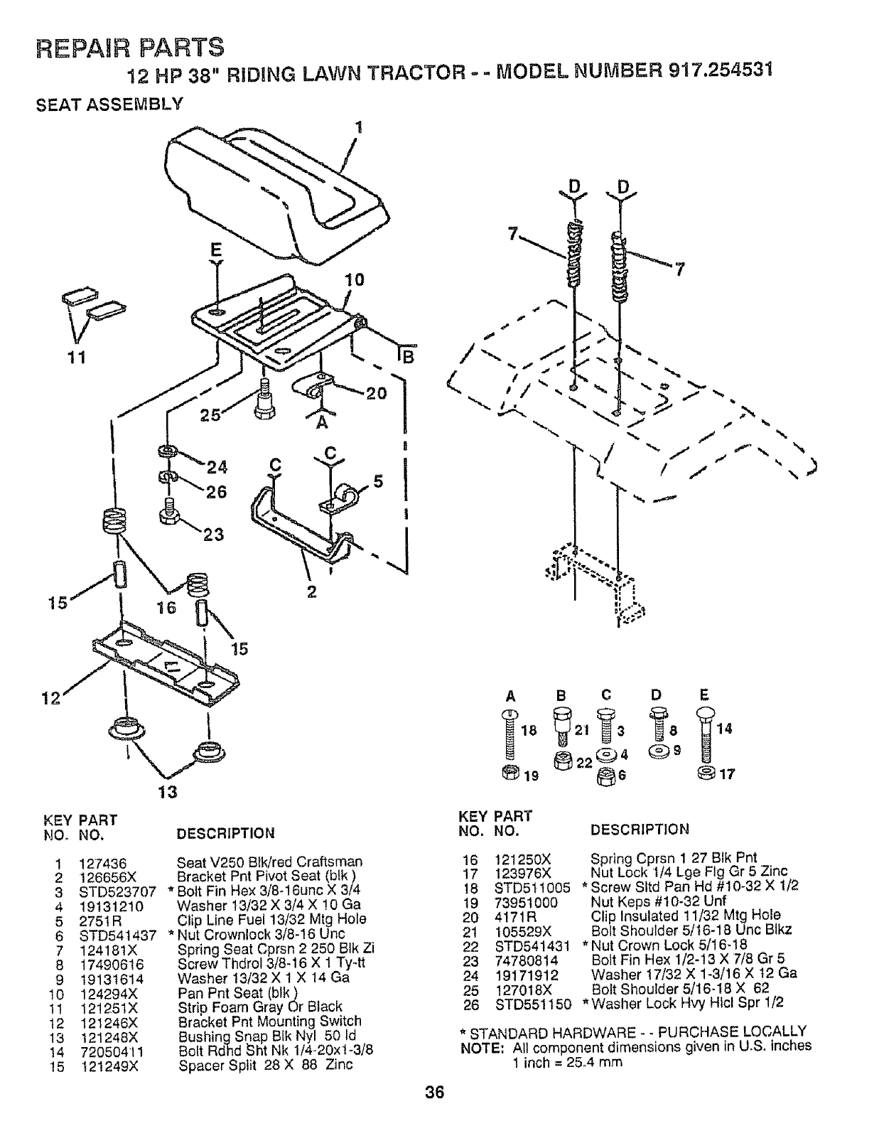
REPAIR PARTS
12 HP 38" RBDING LAWN TRACTOR o - MODEL NUMBER 917.254531
SEAT ASSEMBLY
16
8
C
!
2
|'..,,
•, ,)
12
KEY PART
NO. NO.
1 127436
2 126656X
3 STD523707
4 19131210
5 275tR
6 STD54t437
712418tX
8 17490616
9 19131614
t0 124294X
11 12!26tX
!2 121246X
13 121248X
14 72050411
f5 t2t249X
13
DESCRIPTION
Seat V250 BIk/red Craftsman
Bracket Pnt Pivot Seat (blk)
* Bolt Fin Hex 3/8-16unc X 3/4
Washer 13/32 X 3/4 X !0 Ga
Clip Line Fuel 13/32 Mtg Hole
* Nut Crownlock 3/8-16 Unc
Spring Seat Cprsn 2 250 BIk Zi
Screw Thdrol 3/8-16 X 1 Ty4t
Washer 13/32 X 1 X 14 Ga
Pan Pnt Seat (blk)
Strio Foam Gray Or Black
Bracket Pnt Mounting Switch
Bushing Soap Blk Nyl 50 ld
Bolt Rdhd Sht Nk t/4-20xl-3/8
Spacer Split 28 X 88 Zinc
ABCDE
_19 _22_ 4 (_)8 _)17
KEY PART
NO. NO. DESCRIPTION
16 t21250X
17 123976X
!8 8TD51t005
19 73951000
20 4171R
21 105529X
22 8TD541431
23 74780814
24 19171912
25 127018X
26
Spring Cprsn 1 27 BIk Pnt
Nut Lock t/4 Lge Fig Gr 5 Zinc
* Screw Sltd Pan Hd #10-32 X 1/2
Nut Keps #t0-32 Unf
Clip Insulated 11/32 Mtg Hole
Bolt Shoulder 5/16-18 Unc Blkz
* Nu! Crown Lock 5/16-18
Bolt Fin Hex 1/2-13 X 7/8 Gr5
Washer 17/32 X 1-3/16 X t2 Ga
Bolt Shoulder 5/16-18 X 62
STD551t50 *Washer Lock Hvy Htcl Spr 1/2
* STANDARD HARDWARE - - PURCHASE LOCALLY
NOTE: All component dimensions given in UoSoinches
! inch =25°4 mm
36
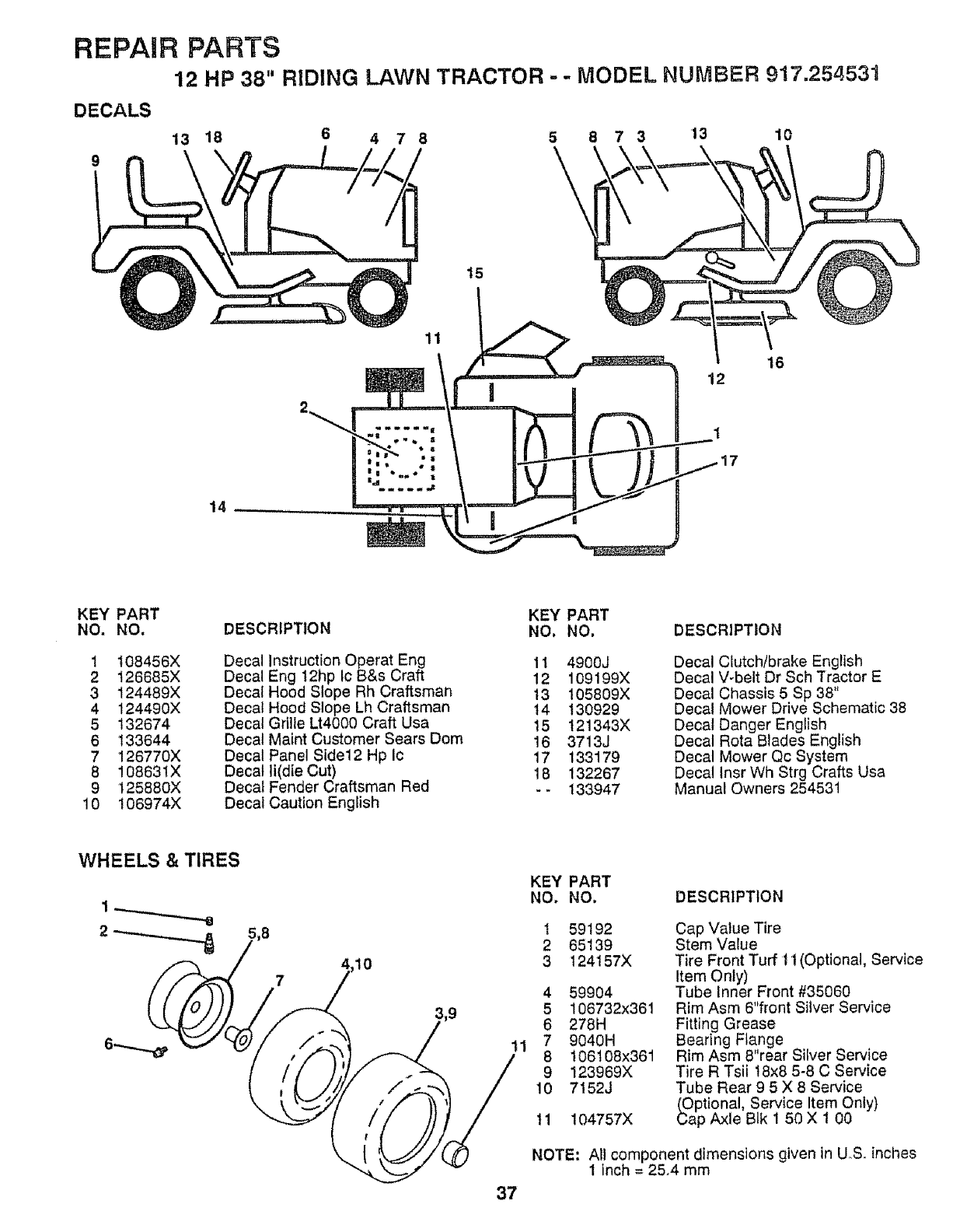
REPAIR PARTS
12 HP 38" RIDING LAWN TRACTOR., - MODEL NUMBER 917.254531
DECALS
9
13 18 6 47 8 5 8 7 3 13 10
t5
11
16
12
1
KEY PART
NO, NO.
1 t08456X
2 126685X
3 124489X
4 124490X
5 132674
6 133644
7 126770X
8 10863tX
9 125880X
10 106974X
DESCRIPTION
Decal
Decal
Decal
Decal
Decal
Decal
Decal
Decal
Decal
Decal
Instruction Operat Eng
Eng 12hp Ic B&s Craft
Hood Slope Rh Craftsman
Hood Slope Lh Craftsman
Grille Lt4000 Craft Usa
Maint Customer Sears Dom
Panel Side12 Hp Ic
li(dfe Cut)
Fender Craftsman Red
Caution English
KEY PART
NO. NO.
11 4900J
12 109199X
13 105809X
14 130929
15 121343X
16 3713J
17 133179
18 132267
-- 133947
DESCRIPTION
Decal Clutch/brake English
Decal V-belt Dr Sch Tractor E
Decal Chassis 5 Sp 38"
Decal Mower Drive Schematic 38
Decal Danger English
Decal Rota Blades English
Decal Mower Qc System
Decal Insr Wh Strg Crafts Usa
Manual Owners 254531
WHEELS & TIRES
10
37
KEY PART
NO, NO. DESCRIPTION
t
2
3
59192
65139
t24157X
4 59904
5 106732x361
6 278H
7 9040H
8 t06108x361
9 123969X
10 7152J
tl t04757X
Cap Value Tire
Stem Value
Tire Front Turf t t (Optional, Service
Item Only)
Tube Inner Front #35060
Rim Asm 6"front Silver Service
Fitting Grease
Bearing F_ange
Rim Asm 8"rear Silver Service
Tire R Tsii t8x8 5-8 C Service
Tube Rear 9 5 X 8 Service
_Optional, Service Item Only)
ap Axle Blk 1 50 X 1 00
NOTE: All component dimensions given in U_S. inches
1inch = 25.4 mm
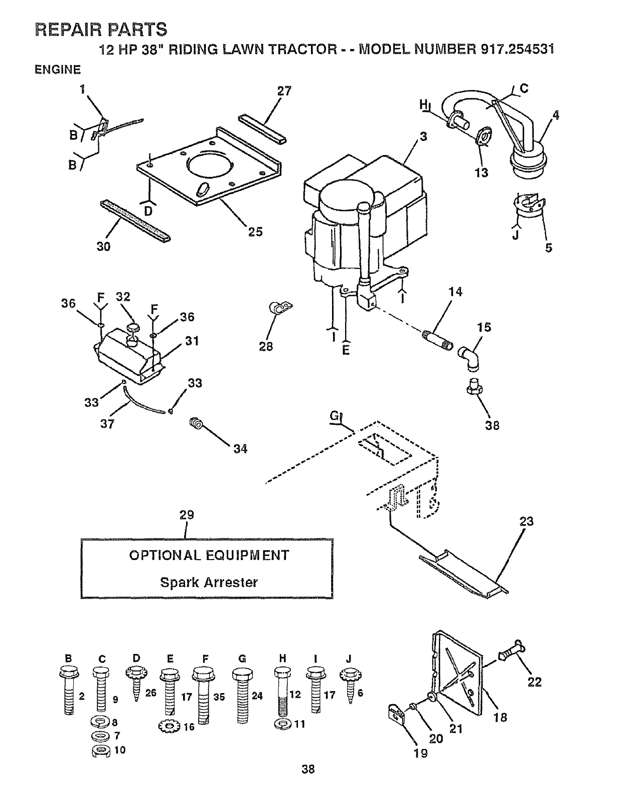
REPAIR PARTS
12 HP 38" RIDING LAWN TRACTOR - -MODEL NUMBER 917.254531
ENGINE
127
30
B
34
38
36 F3236
33
25
29
/
OPTIONAL EQU IPM ENT
Spark Arrestet
II /23
C D E F G H I J
9615427
_8 _16 _ _)11
_7
_10 lg
38
REPAIR PARTS
12 HP 38" RIDING LAWN TRACTOR ==MODEL NUMBER 917.254531
ENGINE
KEY PART
NO. NO. DESCRIPTION
1 132759
2 17720410
3131951
4 1256t0X
5 101326L
6 17030808
7 STD55t025
8 STD55t125
9 STD522510
10 73220500
11 STD551t31
!2 71070510
13 125593X
14 13280324
t5 13200300
16 STD551237
'17 17490620
t8 105736X
t9 !05839X
20 105838X
21 STD55t025
22 123650X
23 128953
24 STD60t005
25 124027X
26 17030808
27 105037X
28 2751R
29 t21851X
30 127057X
31 t09202X
32 123549X
33 123487X
34 t24028X
35 17490412
36 19091416
37 101335K
38 ---
Control Throt Rh Blk Pdl 15 t0
Screw Hex Thd Cut 1/4-20x5/8 T
Engine B&s 12hp I/c Dual 1 Vt
Muffler Exhaust B&s Lt Std
Deflector Muffler # 222573
Screw Spiderloc Hexhd#8xt/2 Ab
*Washer 9/32 X 5/8 X 16 Ga
*Washer Lock Hvy Helicat 1/4
*Bolt Fin Hex 1/4-20 UncX 1
Nut Fin Hex 5/16-18 Unc
*Washer Lock Hvy H/cl Spr 5/16
Screw Hexhd Cap 5/16-18x5/8
Gasket t 313 ld Tin Plated
Nipple Pipe 3/8 Npt X 3"
Elbow Std 90 Degree 3/8-!8 Npt
*Washer Lock Ext Tooth 3/8
Screw Thdrol 3/8-16xl -1/4 Tytt
Shield Pnt Heat
Receptacle 1/4 Turn Dacrotized
Retainer 1/4 Turn 365odx 222id
*Washer 9/32 X 5/8 X 16 Ga
Stud 1/4 Turn (replaces 105751
Shield Pnt Heat Browning Grass
* Screw Tap Hex #10-24unc X 1/2
Shield Pnt Heat Hood Lt
Screw Spiderloc Hexhd#8xl/2 Ab
Strip Foam 18"
Clip Line Fuel 13/32 Mtg Hole
Arrestor Spark
Strap Hood
Tank Fuel 1 25 Fr
Cap Asm Fuel W/sym Vented
Clamp Hose Blk
Bushing Snap Nyl BIk Fuel Une
Screw Hexwsh Thdrol 1/4-20x3/4
Washer 9/32 X 7/8 X 16ga
Line Fuel 950"
Plug Oil Drain (Order From Engine
Manufacturer)
* STANDARD HARDWARE -- PURCHASE LOCALLY
NOTE: All component dimensions given in U_S, inches
1 inch = 25.4 mm
39
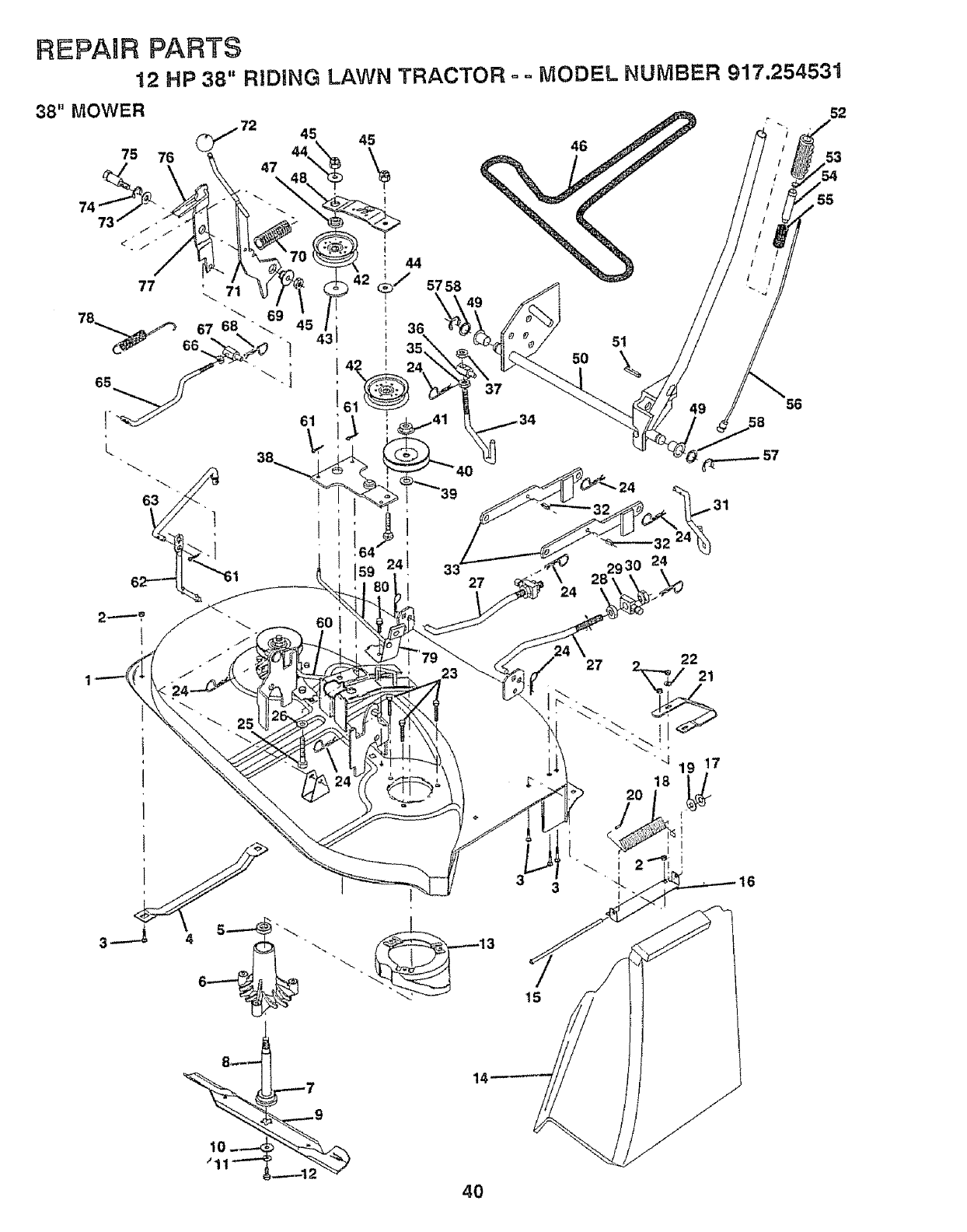
REPAIR PARTS
12 HP 38" RIDING LAWN TRACTOR = ,. MODEL NUMBER 917.254531
38" MOWER
45 45
44
77 71 _'/ 57 58
C
L
63 1
51
50
37
24
56
57
52
53
55
15
27 o 22
"J 19 17
10-.---
_'11"-""
14'
4O
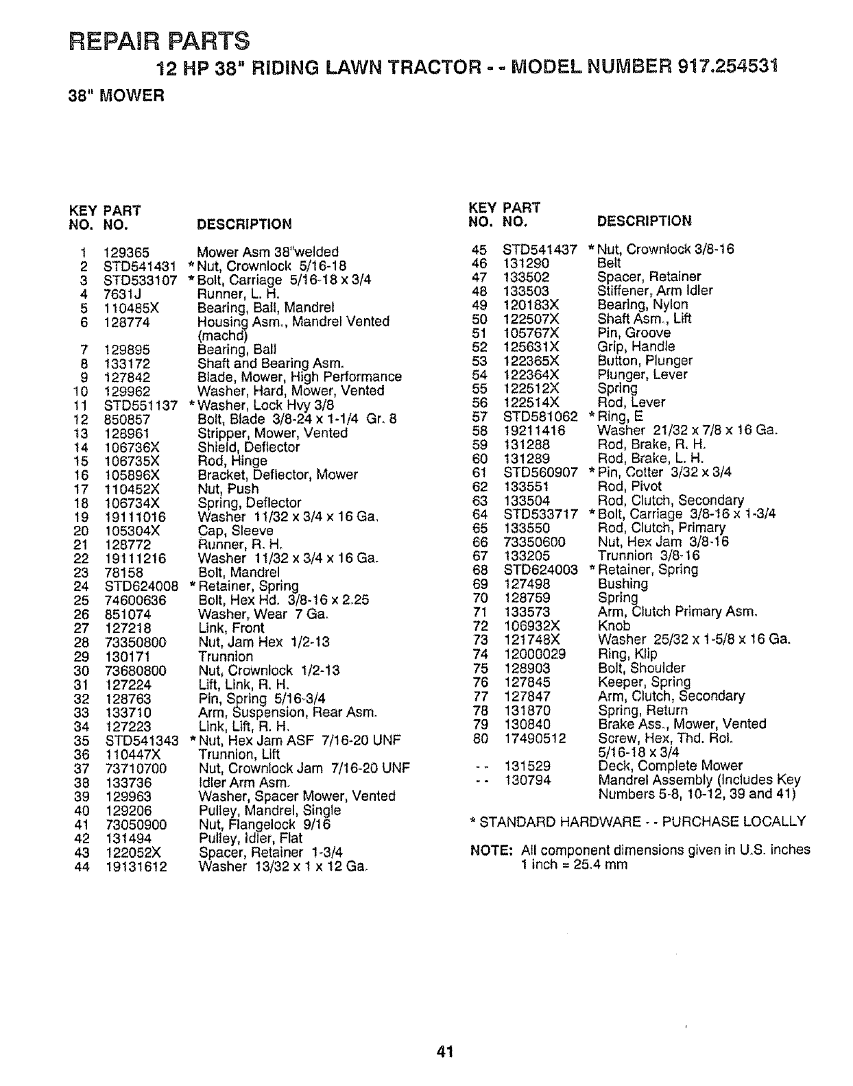
REPAIR PARTS
12 HP 38" RIDING LAWN TRACTOR - = MODEL NUMBER 917.254531
38" MOWER
KEY PART KEY PART
NO. NO. DESCRIPTION NO, NO. DESCRIPTION
1
2
3
4
5
6
7
8
9
10
11
12
t3
t4
15
16
17
18
19
20
21
22
23
24
25
26
27
28
29
3O
31
32
33
34
35
36
37
38
39
4O
41
42
43
44
129365
STD54t431
STD533107
7631J
110485X
128774
Mower Asm 38"welded
* Nut, Crownlock 5/16-18
*Bolt, Carriage 5/16.18 x 3/4
Runner, L. H.
Bearing, Ball, Mandrel
Housing Asmo, Mandrel Vented
(machd)
t29895 Bearing, Bali
t33172 Shaft and Bearing Asm_
127842 Blade, Mower, High Performance
129962 Washer, Hard, Mower, Vented
STD551137 * Washer, Lock Hvy 3/8
850857 Bolt, Blade 3/8-24 x 1-1/4 Gr. 8
128961
106736X
106735X
I05896X
110452X
106734X
19111016
105304X
128772
19111216
78158
STD624008
74600636
851074
127218
73350800
130171
73680800
127224
128763
133710
127223
STD541343
t10447X
73710700
133736
129963
129206
73050900
131494
!22052X
19131612
Stripper, Mower, Vented
Shield, Deflector
Rod, Hinge
Bracket, Deflector, Mower
Nut, Push
Spring, Deflector
Washer 11/32 x 3/4 x 16 Ca.
Cap, Sleeve
Runner, R. H.
Washer 11/32 x 3/4 x 16 Ca.
Bolt, Mandrel
* Retainer, Spring
Bolt, Hex Hd. 3/8-t6 x 2_25
Washer, Wear 7 Ga.
Link, Front
Nut, Jam Hex t/2-t3
Trunnion
Nut, Crownlock 1/2-13
Lift, Link, Ro H_
Pin Spring 5/16_3/4
Arm, Suspens on, Rear Asm.
Link, Lift, R. H.
* Nut, Hex Jam ASF 7/t6-20 UNF
Trunnion, Lift
Nut, Crownlock Jam 7/16-20 UNF
Idler Arm Asm.
Washer, Spacer Mower, Vented
Pulley, Mandrel, Single
Nut, Flangelock 9/16
Pulley, Idler, Flat
Spacer, Retainer 1-3/4
Washer 13/32 x I x 12 Ca°
45 STD541437 *Nut, Crownlock 3/8-16
46 131290 Belt
47 133502 Spacer, Retainer
48 !33503 Stiffener, Arm Idler
49 120183X Bearing, Nylon
50 122507X Shaft Asmo, Lift
51 105767X Pin, Groove
52 125631X Grip, Handle
53 122365X Button, Plunger
54 122364X Ptunger, Lever
55 122512X Spring
56 122514X Rod, Lever
57 STD581062 *Ring, E
58 19211416 Washer 21/32x7/Sx16Ga.
59 131288 Rod, Brake, R. H.
60 131289 Rod, Brake, L. H.
61 STD560907 *Pin, Cotter 3/32 × 3/4
62 133551 Rod, Pivot
63 133504 Rod, Clutch, Secondary
64 STD533717 *Bolt, Carriage 3/8-16 × t-3/4
65 133550 Red, Clutch, Primary
66 73350600 Nut, He× Jam 3/8-t6
67 133205 Trunnion 3/8q6
68 STD624003 *Retainer, Spring
69 127498 Bushing
70 !28759 Spring
71 133573 Arm, Clutch PrimaryAsmo
72 106932X Knob
73 12t748X Washer 25/32 × 1-5/8 x 16 Ca.
74 12000029 Ring, Ktip
75 128903 Bott, Shoulder
76 127845 Keeper, Spring
77 127847 Arm, Clutch, Secondary
78 131870 Spring, Return
79 130840 Brake Ass., Mower, Vented
80 17490512 Screw, Hex, Thd. RoL
5/16-18 x 3/4
-- 131529 Deck, Complete Mower
-- 130794 Mandrel Assembly (Includes Key
Numbers 5-8, 10-12, 39 and 41)
* STANDARD HARDWARE -- PURCHASE LOCALLY
NOTE; All component dimensions given in U.S. inches
1 inch = 2&4 mm
41
FIEPAnFI PARTS
12 HP 38 '=RIDING LAWN TRACTOR - - MODEL NUMBER 917.254531
45
54
46
56 47
57 4B
__'- 49
59
16
-17
58 6O
19
43_52
61
42
62
74
_5
63 64 73
7O
68
ri 72
REPAgR PARTS
12 HP 38" RIDING LAWN TRACTOR o- MODEL NUMBER 917,254531
FOOTE/DANA TRANSAXLE- MODEL NUMBER 143.4360-06
KEY PART KEY PART
NO, NO. DESCRIPTION NO, NO. DESCRIPTION
1 120458X Housing, Upper 41 105928X
2 2274J Screw, Tapping, Large 42 110084X
1/4-20 x .734 43 108983X
3 68003 Bali, Detent 105930X
4 105904X Spring, Detent 10593tX
5 105905X Screw, Set 105932X
6 120460X Shifter Assembly 3417J
7 120461X O-Ring 106097X
8 120462X *Washer, Plain .505 x °942 x -006 2264J
120463X * Washer, Plain ,505 x .942 x .010 106098X
120464X * Washer, Plain .505 x .942 x .015 2265J
120465X * Washer, Plain .505 x .942 x °020 106586X
t20466X * Washer, Plain _505 x .942 x °026 106587X
838t8 * Washer, Plain °505 x °942 x °030 106588X
120467X * Washer, Plain 505 x 942 x .040 2263J
9 2286J Ring, Retaining 44 120473X
!0 2267J Ring, Retaining 45 !05933X
11 3413J * Washer, Plain ,632 x 1_00 x _0t0 46 120407X
2233J * Washer, Plain ,632 x 1.00 x .020 47 106589X
2232J * Washer, Plain °632 x 1.00 x .026 48 120408X
2231J *Washer, Plain .632 x 1_00 x 031 49 105937X
2230J *Washer, Plain .632 x 1o00 x .036 50 105936X
2229J *Washer, Plain .632 x 1.00 x .041 51 2226J
2228J *Washer, Plain _632x !.00 x .046 52 2227J
2227J *Washer, Plain .632 x 1.00 x .050 53 2263J
2226J *Washer, Plain °632 x 1o00 x _060 54 120474X
105906X * Washer, Plain .632 x I _00 x _082 55 110081X
12 6725J O-Ring 56 105941X
13 120415X Washer, Plain .632× 1.38 ×.046 57 110071X
I4 2257J Key, Woodruff, #9 58 120952X
15 110077X Kit, Input Shaft Assembly 59 110082X
16 t10078X Pinion, Bevel, 14 Teeth 60 120475X
17 105909X Ring, Retaining 61 t20476X
18 105910X Chain, 24 Pitches 62 120961X
19 10591 IX Bearing, Flange 63 7294J
20 108976X Gear, Spur, 14 Teeth 64 108989
21 1059t3X Collar, Clutch 65 120953X
22 120468X Key, Clutch 66 120954X
23 2242J Key, Woodruff, #3 67 120955X
24 !20469X Shaft, Intermediate
25 2244J Key, Woodruff, #6t 68 108992X
26 105916X Ring, Retaining 69 108996X
27 120470X Sprocket, 18Teeth 70 120956X
28 1t0070X Spacer 71 73810500
29 108977X Gear, Spur, 37 Teeth 72 106596X
30 120405X Gear, Spur, 30 Teeth
31 108980X Gear, Spur, 25 Teeth 73 120993X
32 120406X Gear, Spur, 22 Teeth 74 120951X
33 t08455X Gear, Spur, t9 Teeth 75 !20416X
34 t05923X Spacer 1.133 x 1.50 x.375
35 I05825X Washer, Plain .640 x 1.37 x .06t
36 2232J Washer, Plain .632 x 1.00 x .026
37 108978X Spacer .630 x 1.00 x.169
38 110079X Assembly, Gear, Combination of _ Order Key Number t5
12 Teeth and 35 Teeth
39 120471X Shaft, Idler
40 120472X Spacer ,635 x .875 x .755
Sprocket, 9 Teeth
Gear, Bevel, 42 Teeth
*Washer, Plain ,758 x 1_12×_010
*Washer, Plain ,758 x 1o12x o015
*Washer, Plain _758x 1o12× °020
*Washer, Plain °758 x t.12 x .025
*Washer, Plain .758 x t_25 ×.020
*Washer, Plain .758 x 1.25 × .025
*Washer, Plain .1758× 1.25 x .031
*Washer, Plain .758 × 1.25 x _035
* Washer, Plain 758 ×1.25 x .040
* Washer, Plain .'758 x 1.25 × .045
* Washer, Plain °758 x 1_25× .050
*Washer, Plain .758 × 1.25 × .055
*Washer, Plain .758 x 1.25 × .062
Shaft, Drive
Gear, Spur, 12 Teeth
Gear, Spur, 20 Teeth
Gear, Spur, 25 Teeth
Gear, Spur, 28 Teeth
Gear, Spur, 31 Teeth
Spacer .781 x 1,00 x .375
Washer, Plain °632 x t .00 x .060
Seal, Felt
Washer, Plain .758 ×1o25 × _062
Axle, Left Hand
Gear, Miter, 15 Teeth
Ring, Retaining
Gear, Spur, 32 Teeth
Shaft, Cross
Gear, Miter, 15 Teeth
Axle, Right Hand
Housing, Lower
Puck, Friction
Disc, Brake
Spacer
Jaw, Brake
Pin, Dowel
Screw, Tapping, Large
5/16-18 x 2.25
Lever, Actuating
Washer, Plain .321 × t .00 × .055
Bracket, Anti-Rotation
Locknut 5/16.24
Screw, Tapping, Large
5/t 6-18 x 1_44
Washer, Plain ,343 × 81 x .059
Puck, Friction
Grease
* Use in Various Combinations To Maintain Proper
Clearances
NOTE; All component dimensions given in U.S. inches
1inch = 25.4 mm
43
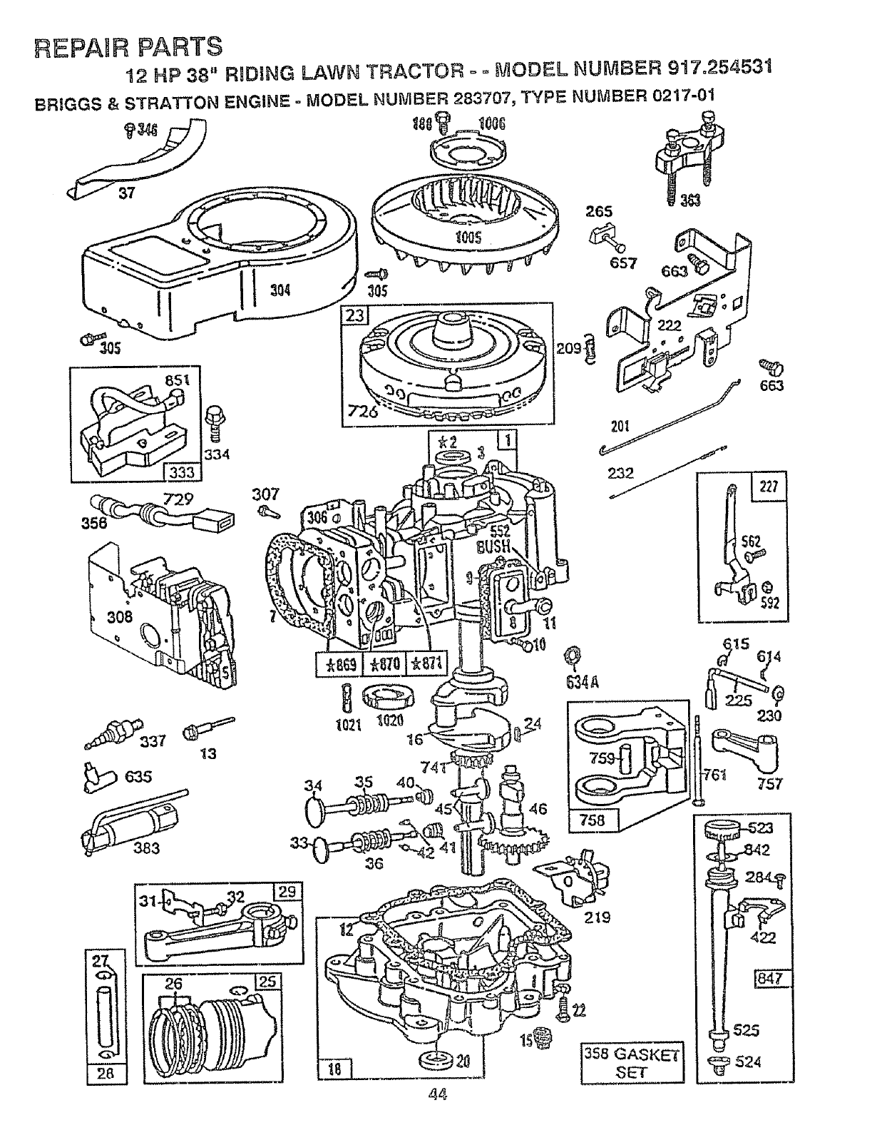
REPAURPARTS
12 HP 38" R_DHNG LAWN TRACTOR o o MODEL NUMBER 917.254531
BRIGGS & STRATTON ENGINE - MODEL NUMBER 283707, TYPE NUMBER 0217-01
334
307
13
11
44
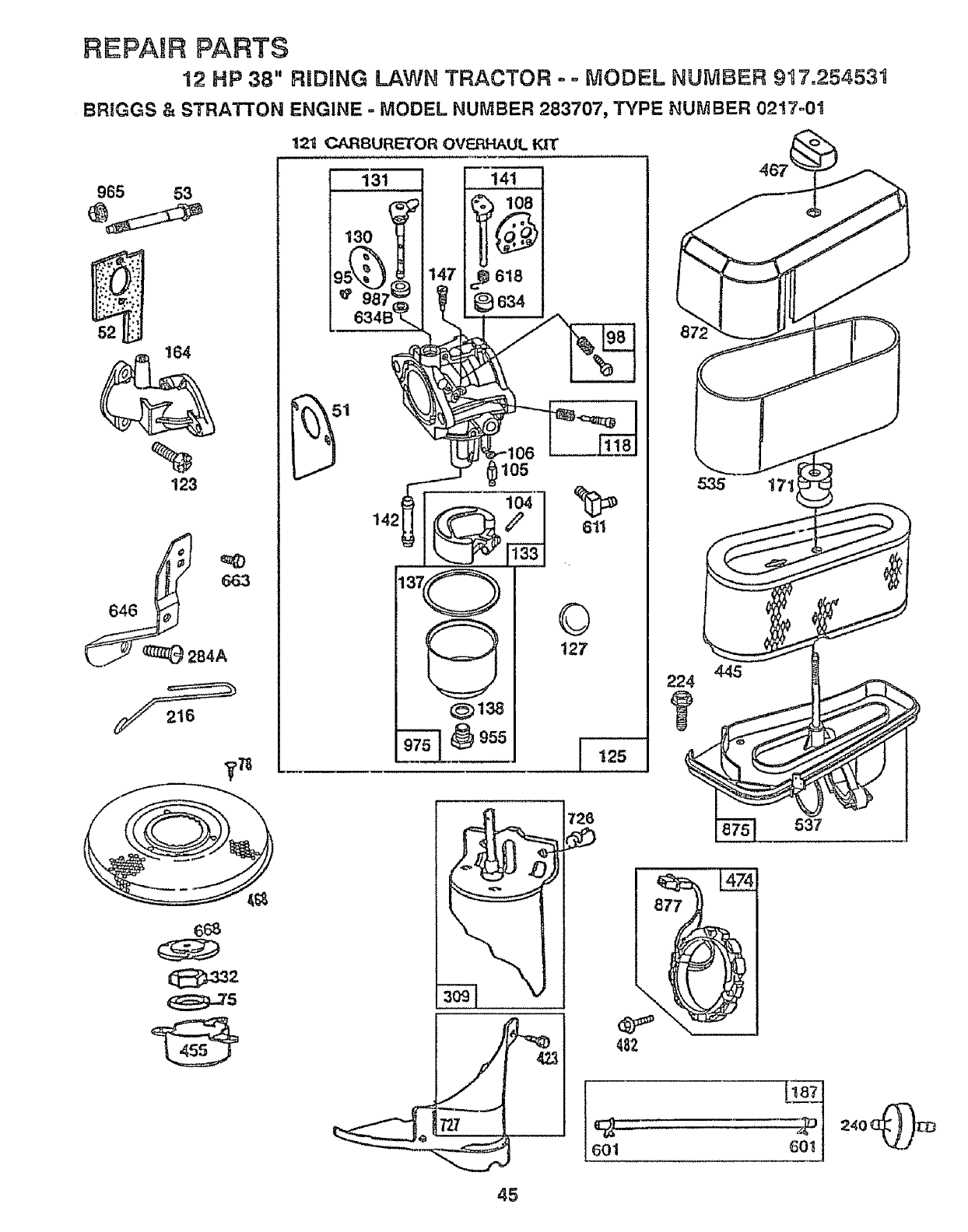
REPAIR PARTS
12 HP 38" RRDING LAWN TRACTOR - ° MODEL NUMBER 917.25453!
BRIGGS & STRATTON ENGINE =MODEL NUMBER 283707, TYPE NUMBER 0217o01
965 53
52
164
84A
._,78
6_
12t CARBURETOR OV_UL KIT
131 14t
_ lo8
987,= _ ®634
©
127
I125
535 17'
,,,,, ,,,,,
601 601 I
45
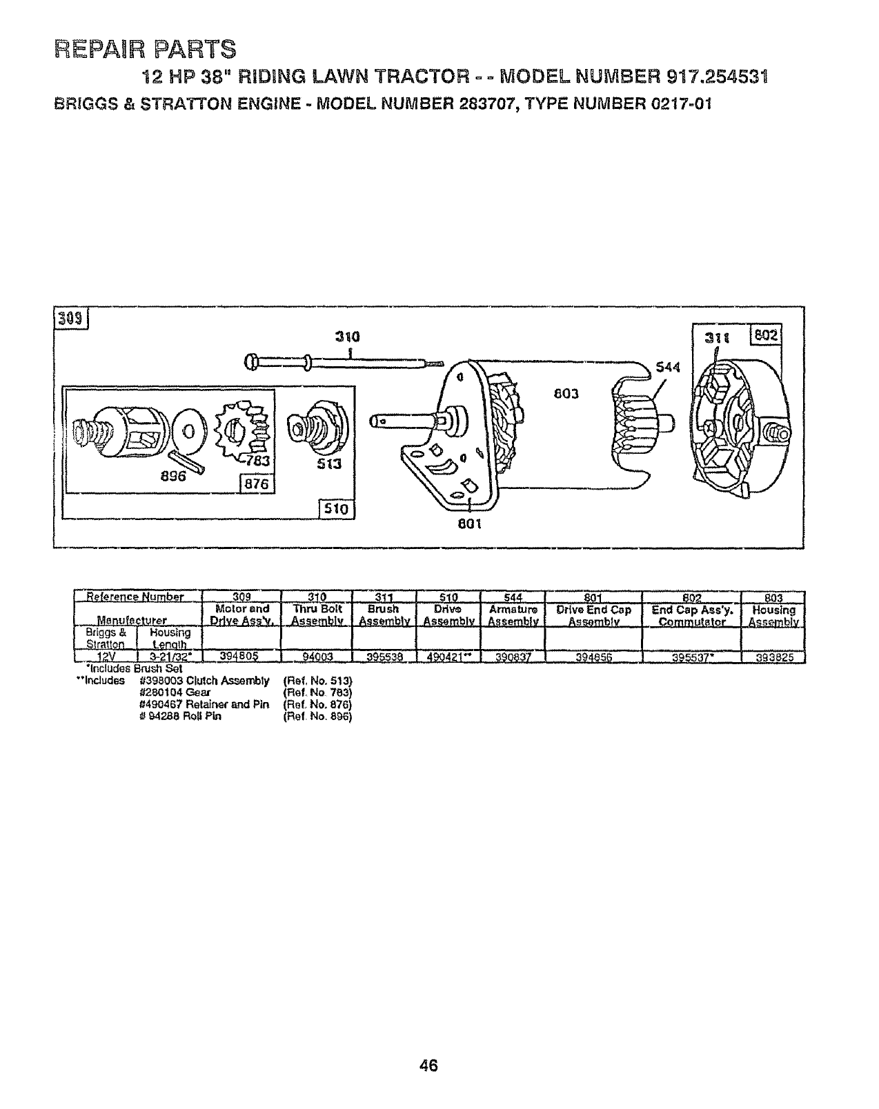
EPA R PARTS
12 HP 38" RiDiNG LAWN TRACTOR = ° MODEL NUMBER 917.254531
BRIGGS & STRATTON ENGINE -MODEL NUMBER 283707, TYPE NUMBER 0217-01
3tO
801
803
.F{eference Number | 309 1310 ......|i "311 I51Q
Motor and I_Bolt I Brush I Drive
.__._urer I Drive Ass__.,_L_,I Assembtv I Assembly
Br=ggs& jHousing tJJ J
. izv 1 3-__ Ii_ _9480_ _I L_40_3_ l__39ss;_O.1 4904Zl*"
"IncludesBrush Set
"lncludGs #398003 Clutch As,s_mbly (Ref, No. 513)
#280104 Ge_ (Ref., No 783)
#490467 Retainer and Pin (Ref, No. 876)
#94288 RO_ Pin (Ref No, 896)
544
Armature
Assembtv i
39_37
sol I eo_ .T so3 l
13rtveEndC_p j End Cap Ass y. IH0using j
46
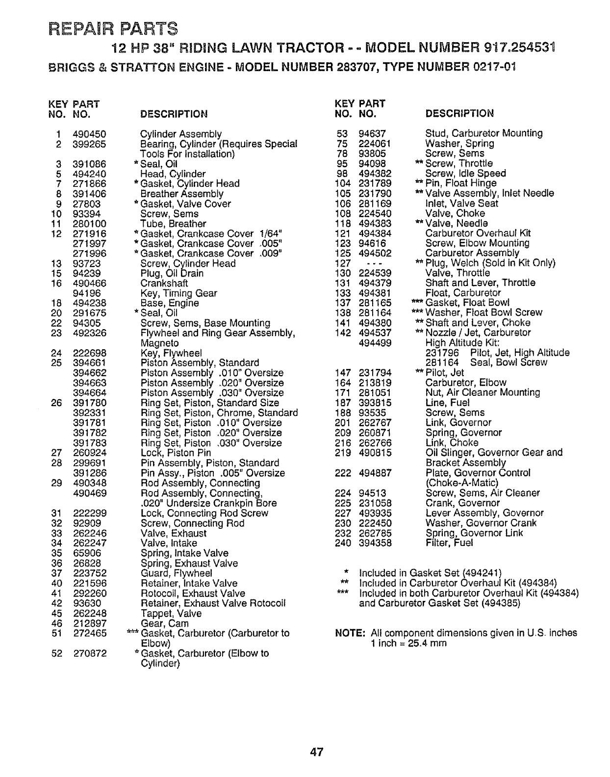
REPAUR PARTS
12 HP 38" RIDBNG LAWN TRACTOR ==MODEL NUMBER 917o25453t
BRIGGS & STRATTON ENGINE -MODEL NUMBER 283707_ TYPE NUMBER 0217-01
KEY PART KEY PART
NO. NO. DESCRIPTION NO, NO, DESCRIPTION
1 490450
2 399265
3 391086
5 494240
7 271866
8 391406
9 27803
I0 93394
tt 280100
12 271916
271997
271996
13 93723
15 94239
16 490466
94196
18 494238
20 291675
22 94305
23 492326
24 222698
25 394661
394662
394663
394664
26 391780
392331
391781
391782
391783
27 260924
28 299691
391286
29 490348
490469
31 222299
32 92909
33 262246
34 262247
35 65906
36 26828
37 223752
40 221596
41 292260
42 93630
45 262248
46 212897
51 272465
52 270872
Cylinder Assembly 53 94637
Bearing, Cylinder (Requires Special 75 22406I
Tools For installation) 78 93805
* Seal, Oil 95 94098
Head, Cylinder 98 494382
* Gasket, Cylinder Head 104 231789
Breather Assembly 105 231790
* Gasket, Valve Cover 106 281169
Screw, Sems 108 224540
Tube, Breather 118 494383
* Gasket, Crankcase Cover 1/64" 121 494384
* Gasket, Crankcase Cover .005" 123 94616
* Gasket, Crankcase Cover .009" 125 494502
Screw, Cylinder Head 127 - - -
Plug, Oil Drain 130 224539
Crankshaft 131 494379
Key, Timing Gear 133 494381
Base, Engine 137 281165
*Seal, Oil 138 281164
Screw, Seres, Base Mounting 141 494380
Flywheel and Ring Gear Assembly, 142 494537
Magneto 494499
Key, Flywheel
Piston Assembly, Standard
Piston Assembly .010" Oversize 147 231794
PistonAssembiy .020"Oversize 164 213819
Piston Assembly .030" Oversize 171 281051
Ring Set, Piston, Standard Size 187 393815
Ring Set, Piston, Chrome, Standard 188 93535
Ring Set, Piston .010 Oversize 201 262767
Ring Set, Piston .020' Oversize 209 260871
Ring Set, Piston 4030" Oversize 216 262766
Lock, Piston Pin 219 490815
Pin Assembly, Piston, Standard
Pin Assyo, Piston .005" Oversize 222 494887
Rod Assembly, Connecting
Rod Assembly, Connecting, 224 94513
.020" Undersize Crankpin Bore 225 231058
Lock, Connecting Rod Screw 227 493935
Screw, Connecting Rod 230 222450
Valve, Exhaust 232 262785
Valve, intake 240 394358
Spring, intake Valve
Spring, Exhaust Valve
Guard, Flywheel
Retainer, Intake Valve
Rotocoil, Exhaust Valve
Retainer, Exhaust Valve Rotocoit
Tappet, Valve
Gear, Cam
Gasket, Carburetor (Carburetor to
Elbow)
'_Gasket, Carburetor (Elbow to
Cylinder)
Stud, Carburetor Mounting
Washer, Spring
Screw, Sems
** Screw, Throttle
Screw, Idle Speed
** Pin, Float Hinge
Valve Assembly, Inlet Needle
Inlet, Valve Seat
Valve, Choke
*_ Valve, Needle
Carburetor Overhaul Kit
Screw, Elbow Mounting
Carburetor Assembly
'_ Plug, Wetch (Sold in Kit Only)
Valve, Throttle
Shaft and Lever, Throttle
Float, Carburetor
Gasket, Float Bowl
_* Washer, Float Bowl Screw
** Shaft and Lgver, Choke
Nozzle /Jet, Carburetor
High Altitude Kit:
231796 Pilot, Jet, High Altitude
281164 Seal, Bowl Screw
** Pilot, Jet
Carburetor, Etbow
Nut, Air Cleaner Mounting
line, Fuel
Screw, Sems
Link, Governor
Spring, Governor
Unk, Choke
Oil Slinger, Governor Gear and
Bracket Assembly
Plate, Governor Control
(Choke-A-Matic)
Screw, Sems, Air Cleaner
Crank, Governor
Lever Assembly, Governor
Washer, Governor Crank
Spring, Governor Unk
Filter, Fuel
* Included in Gasket Set (494241)
** Included in Carburetor Overhaul Kit (494384)
*** Included in both Carburetor Overhaul Kit (494384)
and Carburetor Gasket Set (494385)
NOTE: All component dimensions given in US inches
1 inch = 25°4 mm
47
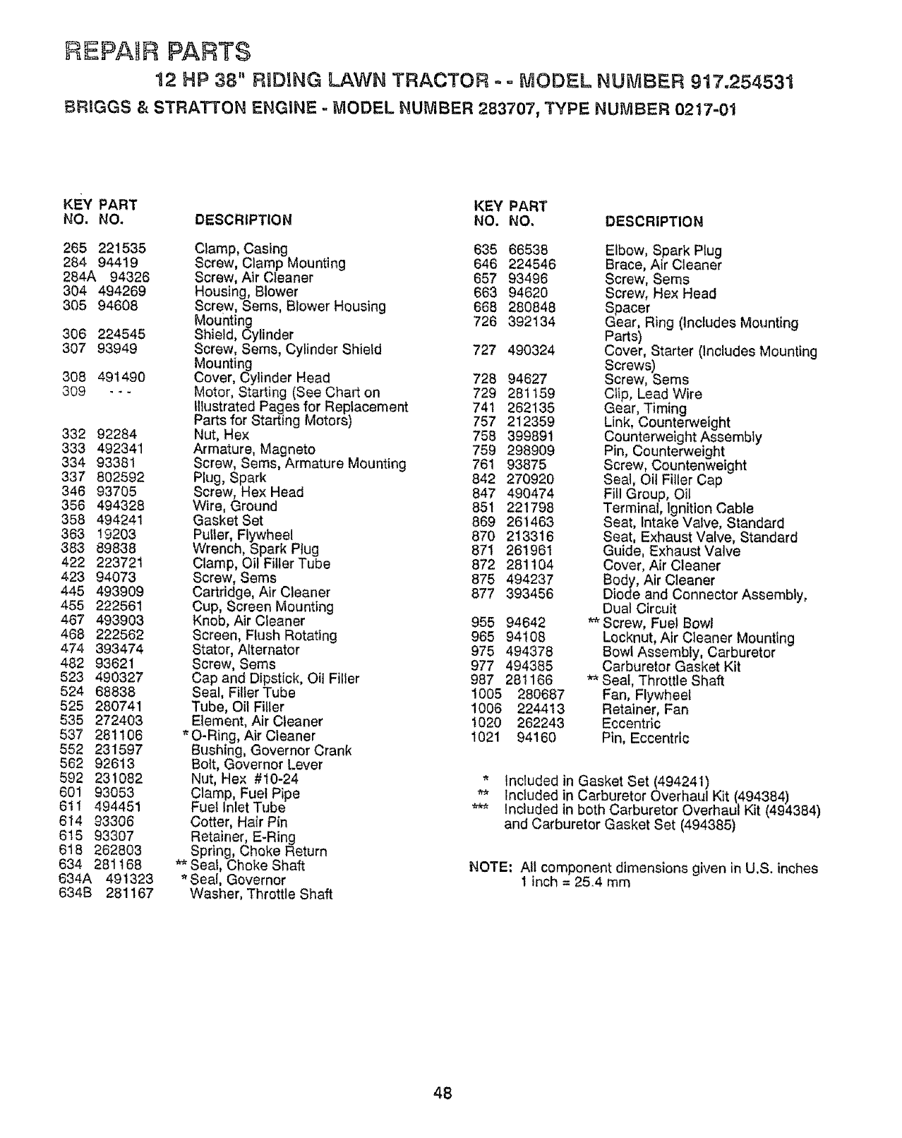
REPAIR PARTS
12 HP 38" R D[NG LAWN TRACTOR o o MODEL NUMBER 917.254531
BRIGGS & STRATTON ENGINE - MODEL NUMBER 283707, TYPE NUMBER 02t7-01
KEY PART KEY PART
NO, NO. DESCRIPTION NO. NO, DESCRIPTION
265 221535
284 94419
284A 94326
304 494269
305 94608
306 224545
307 93949
308 491490
309 ---
332 92284
333 492341
334 93381
337 802592
346 93705
356 494328
358 494241
363 19203
383 89838
422 223721
423 94073
445 493909
455 222561
467 493903
468 222562
474 393474
482 93621
523 490327
524 68838
525 280741
535 272403
537 281106
552 231597
562 92613
592 231082
601 93053
6tl 494451
614 93306
615 93307
618 262803
634 281168
634A 491323
634B 281167
Clamp, Casing 635 66538
Screw, Clamp Mounting 646 224546
Screw, Air Cleaner 657 93496
Housing, Blower 663 94620
Screw, Seres, Blower Housing 668 280848
Mounting 726 392t 34
Shield, Cylinder
Screw, Sems, Cylinder Shield 727 490324
Mounting
Cover, Cylinder Head 728 94627
Motor, Starting (See Chart on 729 281159
Illustrated Pages for Replacement 741 262135
Parts for Starting Motors) 757 212359
Nut, Hex 758 399891
Armature, Magneto 759 298909
Screw, Sems, Armature Mounting 761 93875
Plug, Spark 842 270920
Screw, Hex Head 847 490474
Wire, Ground 851 221798
Gasket Set 869 261463
Puller, Flywheel 870 213316
Wrench, Spark Plug 87I 261961
Clamp, Oil Filler Tube 872 281104
Screw, Seres 875 494237
Cartridge, Air Cleaner 877 393456
Cup, Screen Mountlng
Knob, Air Cleaner 955 94642
Screen, Flush Rotating 965 94108
Stator, Alternator 975 494378
Screw, Sems 977 494385
Cap and Dipstick, Oil Filler 987 281166
Seal, FillerTube 1005 280687
Tube, Oil Filler 1006 224413
Element, Air Cleaner t020 262243
*O-Ring, Air Cleaner 1021 94160
Bushing, Governor Crank
Bolt, Governor Lever
Nut, Hex #10-24
Clamp, Fuel Pipe
Fuel Inlet Tube
Cotter, Hair Pin
Retainer, E-Ring
Spring, Choke Return
** Seal, Choke Shaft
* Seal, Governor
Washer, Throttle Shaft
Elbow, Spark Plug
Brace, Air Cleaner
Screw, Seres
Screw, Hex Head
Spacer
Gear, Ring (includes Mounting
Parts)
Cover, Starter (Includes Mounting
Screws)
Screw, Seres
Clip, Lead Wire
Gear, Timing
Link, Counterweight
Counterweight Assembly
Pin, Counterweight
Screw, Countenweight
Seat, Oil Filler Cap
Fill Group, Oil
Terminal, lgnitlon Cable
Seat, Intake Valve, Standard
Beat, Exhaust Valve, Standard
Guide, Exhaust Valve
Cover, Air Cleaner
Body, Air Cleaner
Diode and Connector Assembly,
Dual Circuit
** Screw, Fuel Bowl
Locknut, Air Cleaner Mounting
Bow_ Assembly, Carburetor
Carburetor Gasket Kit
** Seat, Throttle Shaft
Fan, Flywheel
Retainer, Fan
Eccentric
Pin, Eccentric
* Included in Gasket Set (494241)
** Included in Carburetor Overhaul Kit (494384)
_** Included in both Carburetor Overhaul Kit (494384)
and Carburetor Gasket Set (494385)
NOTE; All component dimensions given in U.S. inches
1 inch = 25.4 mm
48

SERVICE: NOTES
49

5O

SUGGESTED GUIDE FOR S_GHTING SLOPES FOB SAFE OPERATION
SIGHTING
GUIDE
ONLY RIDE UP AND DOWN HILL,
NOT ACROSS HILL
SIGHT AND HOLD THIS LEVEL WITH
SKY LiNE OR TREE.
15 °MAX.
Operate your Tractor up and down the face of slopes (not
greater than !5°), never across the face. Make turns gradu
ally to prevent tipping or Joss of corntrel. Exercise extreme
caution when changing direction en siopes.
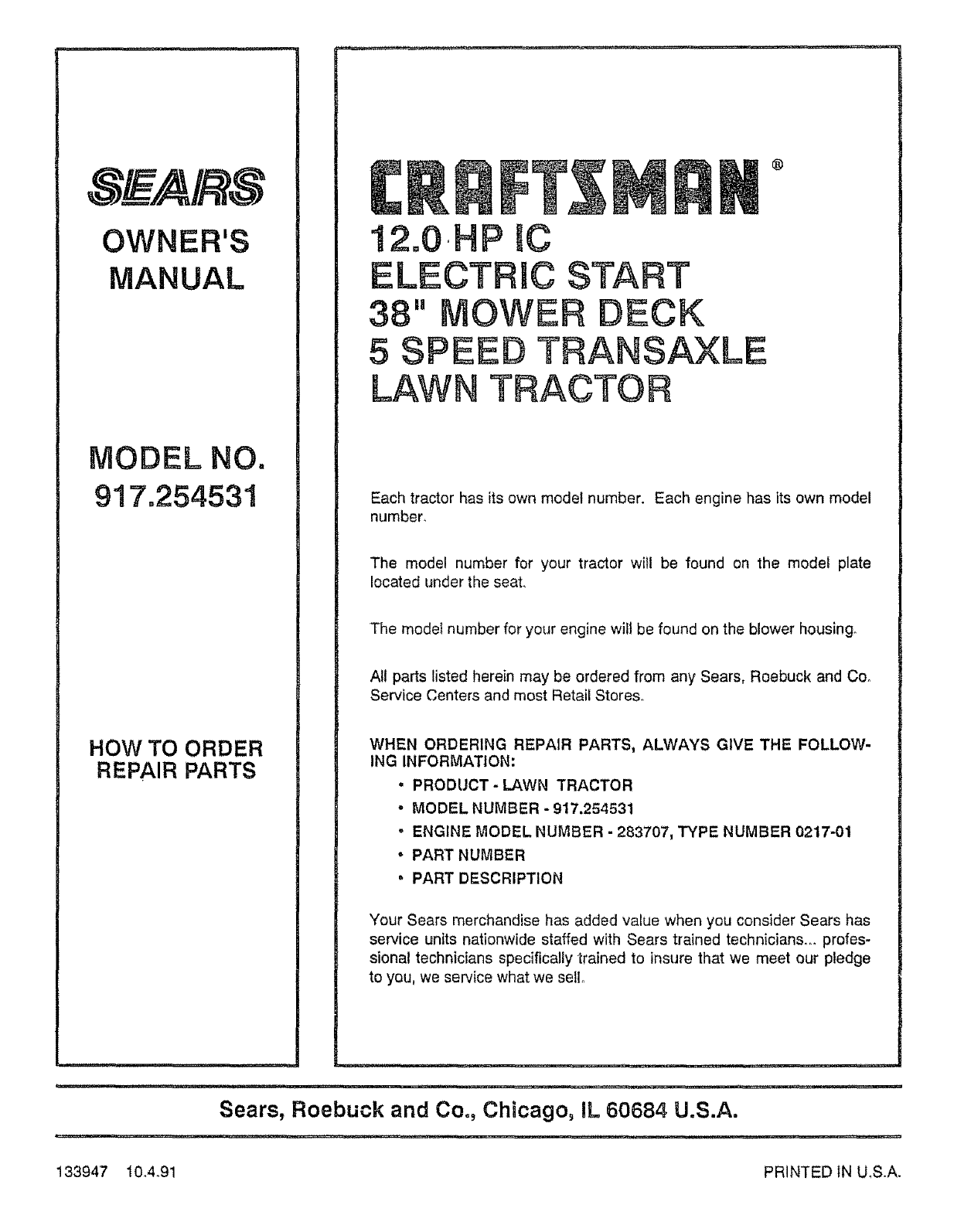
OWNER'S
MANUAL
MODEL NO.
917.254531
HOW TO ORDER
REPAIR PARTS
qllrl,
®
12.0,HP IC
ELECTRIC START
38" MOWER DECK
5 SPEED TRANSAXLE
LAWN TRACTOR
Each tractor has its own model number. Each engine has its own model
number.
The model number for your tractor will be found on the model plate
located under the seat.
The model number for your engine wilt be found on the blower housing.
All parts listed herein may be ordered from any Sears, Roebuck and Co.
Service Centers and most Retail Stores..
WHEN ORDERING REPAIR PARTS, ALWAYS GIVE THE FOLLOW-
ING INFORMATION:
• PRODUCT-LAWN TRACTOR
.MODEL NUMBER - 917.254531
-ENGINE MODEL NUMBER - 283707, TYPE NUMBER 0217-01
. PART NUMBER
oPART DESCRIPTION
Your Sears merchandise has added value when you consider Sears has
service units nationwide staffed with Sears trained technician&_ profes-
sional technicians specifically trained to insure that we meet our pledge
to you, we service what we sello
r
Sears, Roebuck and Co., Chicago, IL 60684 U.S.A.
i,,h,U, ................... ' ' hi" I' _ ......
133947 10A_91 PRINTED IN U,S,A.
