Craftsman 917254750 User Manual Lawn, Tractor Manuals And Guides L0707406
CRAFTSMAN Lawn, Tractor Manual L0707406 CRAFTSMAN Lawn, Tractor Owner's Manual, CRAFTSMAN Lawn, Tractor installation guides
User Manual: Craftsman 917254750 917254750 CRAFTSMAN Lawn, Tractor - Manuals and Guides View the owners manual for your CRAFTSMAN Lawn, Tractor #917254750. Home:Lawn & Garden Parts:Craftsman Parts:Craftsman Lawn, Tractor Manual
Open the PDF directly: View PDF ![]() .
.
Page Count: 52
SEAl, S
OWNER'S
MANUAL
MODEL NO.
917.254750
Caution:
Read and follow
all Safety Rules
and Instructmns
Before Operating
This Equipment
®
12.5 HP OHV
ELECTRIC START
38" MOWER DECK
5SPEED TRANSAXLE
LAWN TRACTOR
. Assembly
•Operation
-Customer Responsibilities
oService and Adjustment
•Repair Parts
Sears, Roebuck and Co., Chicago, IL 60684 U.S.A.
J,,,p l l,,iM i,ll ,J, u ii H, 1, i i lll,ll
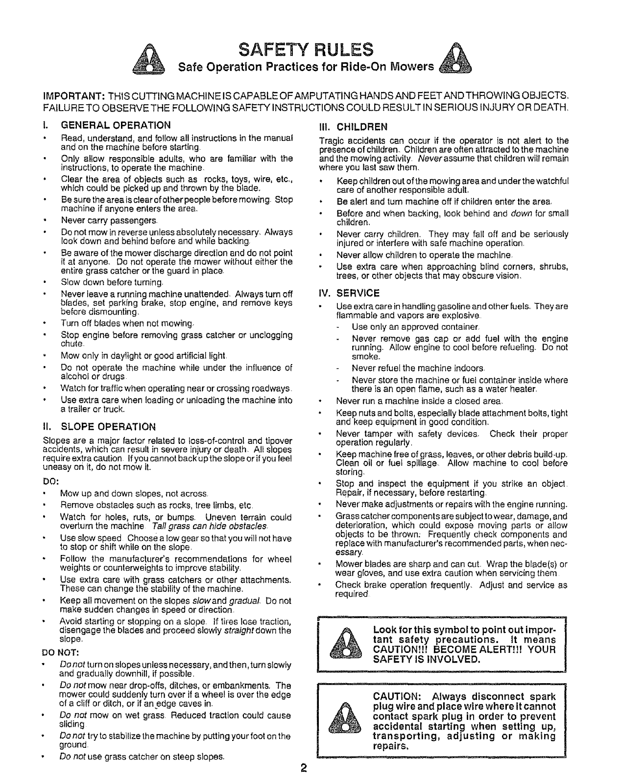
SAFETY RULES
Safe Operation Practices for Ride-On Mowers
IMPORTANT: THIS CUTTING MACHINE IS CAPABLE OFAMPUTATING HANDS AND FEETAND THROWING OBJECTS,
FAILURE TO OBSERVE THE FOLLOWING SAFETY INSTRUCTIONS COULD RESULT IN SERIOUS INJURY OR DEATH,
1. GENERAL OPERATION
•Read, understand, and follow all instructions in the manual
and on the machine before starting
Only allow responsible adults, who are familiar with the
instructions, to operate the machine.
, Clear the area of ob ects such as rocks, toys, wire, etc.
wh{ch could be picked up and thrown by the b ode+
• Be sure the area is clear of other people before mowing+ Stop
machine if anyone enters the area°
Never carry passengers
Do not mow in reverse unless absolutely necessary. Always
took down and behind before and while backing
Be aware of the mower discharge direction and do not point
it at anyone. Do not operate the mower without either the
entire grass catcher or the guard in place
•Slow down before turning.
Never leave arunning machine unattended_ Always turn off
blades, set parking brake, stop engine, and remove keys
before dismounting+
Turn off blades when not mowing
Stop engine before removing grass catcher or unclogging
chute
Mow only in daylight or good artificial light.
Do not operate the machine while under the influence of
alcohol or drugs
•Watch for traffic when operating near or crossing roadways
•Use extra care when loading or unloading the machine into
a trailer or truck..
II. SLOPE OPERATION
Slopes are a major factor related to toss-of-control and tipover
accidents, which can result in severe injury or death+ Air slopes
requlre extra caution. If you cannot back up the slope or ifyou feel
uneasy on it, do not mow it+
DO:
• Mow up and down slopes, not across.
Remove obstacles such as rocks, tree limbs, etc.
Watch for holes, ruts, or bumps+ Uneven terrain could
overturn the machine Tall grass can hide obstacles+
Use slow speed Choose a low gear so that you will not have
to stop or shift while on the slope.
Follow the manufacturer's recommendations for wheel
weights or counterweights to improve stability.
• Use extra care with grass catchers or other attachments.
These can change the stability of the machine..
•Keep all movement on the slopes slowand gradual Do not
make sudden changes in speed or direction
• Avoid starting or stopping on a slope+ ff tires lose traction,
disengage the bSades and proceed slowly stralghtdown the
slope.
DO NOT:
Do not turn on slopes untess necessary, and then, turn slowly
and gradualfy downhill, if possible.
•Do not mow near drop-offs, ditches, or embankments+ The
mower could suddenty turn over if a wheel is over the edge
of acliff or ditch, or if anedge caves in.
Do not mow on wet grass Reduced traction could cause
sliding
Do not try to stabilize the machine by putting your foot on the
ground.
•Do not use grass catcher on steep slopes.
III. CHILDREN
Tragic accidents can occur if the operator is net alert to the
presence of children. Children are often attracted to the machine
and the mowing activity Neverassume that children will remain
where you last saw them.
• Keep children out of the mowing area and under the watchful
care of another responsible adulL
• Be alert and turn machine off if children enter the area.
• Before and when backing, iook behind and down for small
children.
,Never carry children+ They may fall off and be seriously
injured or interfere with safe machine operation+
Never allow children to operate the machine.
Use extra care when approaching blind corners, shrubs,
trees, or other objects that may obscure vision.
IV. SERVICE
Use extra care Jnhandting gasoline and other fuels.. They are
flammable and vapors are explosive
Use only an approved container
Never remove gas cap or add fuel with the engine
running+ Allow engine to cool before refue+ing+ Do not
smoke.
Never refuel the machine indoors+
Never store the machine or fuel container inside where
there is an open flame, such as a water heater.
•Never run a machine inside a closed area.
•Keep nuts and boits, especially blade attachment bolts, tight
and keep equipment in good condition..
Never tamper with safety devices. Check their proper
operation regularly.
Keep machine free of grass, leaves, or other debris build+up.
Clean oil or fuel spillage+ Allow machine to cool before
storing.
•Stop and inspect the equipment if you strike an object
Repair, if necessary, before restarting
• Never make adjustments or repairs with the engine running.
Grass catcher components are subject to wear, damage, and
deterioration, which coufd expose moving parts or allow
objects to be thrown: Frequently check components and
repIace with manufacturer's recommended parts, when nec+
essary.
.Mower blades are sharp and can cut+ Wrap the blade(s) or
wear gloves, and use extra caution when servicing them
•Check brake operation frequently. Adjust and service as
required
I t_, Look for this symbol to point out impor-
tant safety precautions, tt means
CAUTION!!t BECOME ALERT!!! YOUR
SAFETY IS INVOLVED.
CAUTION: Always disconnect spark
_plug wire and place wire where it cannot
contact spark plug in order to prevent
accidental starting when setting up,
transporting, adjusting or making
repairs,
mH ,=,u ....... ,

CONGRATULATIONS on your purchase of a Sears
tractor. It has been designed, engineered and manufac-
tured to give you the best possible dependability and
performance.
Should you experience any problem you cannot easily
remedy, please contact your nearest Sears Service
Center/Department. We have competent, well-trained
technicians and the proper tools to service or repair this
tractor,
Please read and retain this manual. The instructions wilt
enable you to assemble and maintain your tractor prop-
erly. Always observe the SAFETY RULES',
MODEL
NUMBER 917254750
SERIAL
NUMBER
DATE OF PURCHASE
THE MODELAND SERIAL NUMBERS WILL BE FOUND
ON A PLATE UNDER THE SEAT,
YOU SHOULD RECORD BOTH SERIAL NUMBER AND
DATE OF PURCHASE AND KEEP IN A SAFE PLACE
FOR FUTURE REFERENCE
MAINTENANCE AGREEMENT
A Sears maintenance agreement is available on this prod-
uct. Contact your nearest Sears store for details,
CUSTOMER RESPONSIBILITIES
Read and observe the safety rules.
Follow a regular schedule in maintaining, caring for and
using your tractor
Follow the instructions under "Customer Responsibili-
ties" and "Storage" sections of this manual.
PRODUCT SPECIFICATIONS
HORSEPOWER: t 2,5
GASOLINE CAPACITY: 5 QUARTS
UNLE.ADEDREGULAR
OIL (3,0 PINT CAPACITY): SAE 30 (Above 32°F)
5W-30 (Below 32°F)
SPARK PLUG (GAP.030 IN.): CHAMPION RJ-19LM
STD361458
VALVE CLEARANCE: INTAKE: .005 - °007 IN.
EXHAUST: .00g - ,011 IN.
GROUND SPEED: FORWARD:
1st 1.10 MPH
2nd 200 MPH
3rd 3.00 MPH
4th 4.2O MPH
5th 5OO MPH
REVERSE: 1.50 MPH
TIRE PRESSURE: FlUeNT: 14 PSI
REAR: 10 PSI
CHARGING SYSTEM: 5 AMPS @ 3600 RPM
BLADE BOLT TORQUE: 30-35 FT. LBS.
WARNING: This tractor is equipped with an internal
combustion engine and should not be used on or near any
unimproved forest-covered, brush-covered or grass-cov-
ered land unless the engine's exhaust system is equipped
with a spark arrester meeting applicable local or state laws
(if any). If a spark arrestor is used it should be maintained
in effect ve working order by the operator.
tn the state of California the above is required by law
(Section 4442 of the California Public Resources Code)_
Other states may have similar laws Federal laws apply on
federal lands. A spark arrestor for the muffler is available
through your nearest authorized service center (See the
REPAIR PARTS section of this manual).
LIMITED TWO YEAR WARRANTY ON ELECTRIC START RIDING EQUIPMENT
For two (2) years from the date of purchase, if thisriding equipment is maintained, lubricated and tuned up according to the
instructions in the owner's manual, Sears will repair or replace, free of charge, any parts found to be defective in material or
workmanship
This Warranty does not cover:
• Expendable items which become worn during normal use, such as blades, spark plugs, air cleaners and belts.
Tire replacement or repair caused by punctures from outside objects, such as nails,thorns, stumps, or glass_
, Repairs necessary because of operator abuse, negligence,improper storage or accident or the failure to maintain the
equipment according to the instructions containedin the owner's manual.
, Riding equipment used for commercial or rental purposes,
LIMITED 90 DAY WARRANTY ON BATTERY
For 90 days from date of purchase, if any battery included with this riding equipment proves defective in material or workmanship
and our testing determines the battery will not hold a charge, Sears will replace the battery at no charge,
WARRANTY SERVICE IS AVAILABLE BY RETURNING THE RIDING EQUIPMENT TO THE NEAREST SEARS SERVICE
CENTER/DEPARTMENT IN THE UNITED STATES,
This Warranty gives you specific legal rights, and you may also have other rights which may vary from state to state
SEARS, ROEBUCK AND CO., Di731CR-W, SEARS TOWER, CHICAGO, iLLINOiS 60684
into i,,, in,i i i, ii ',H,H I'll11 ,I HH I lU,, I ' '"
3
TABLE OF CONTENTS
SAFETY RULES ............................................................ 2
PRODUCT SPECIFICATIONS ....................................... 3
CUSTOMER RESPONSIBILITIES ..................... 3, 14-17
WARRANTY ................................................................... 3
TABLE OF CONTENTS ................................................. 4
INDEX ............................................................................. 4
TRACTOR ACCESSORIES ........................................... 5
ASSEMBLY ................................................................ 7-9
OPERATION ........................................................... 10-13
MAINTENANCE SCHEDULE ...................................... 14
SERVICE AND ADJUSTMENTS ............................ 18-23
STORAGE .................................................................... 24
TROUBLESHOOTING ............................................ 25-26
REPAIR PARTS -TRACTOR ................................. 28-43
REPAIR PARTS - ENGINE ..................................... 44-48
PARTS ORDERING/SERVICE ................... BACK PAGE
INDEX
A
Accessories ...................................... 5
Adjustments;
Brake .................................... 20
Carburetor .................................. 23
Mower
Front-To-Back ................. 19
Side-To-Side .......................... 19
Throttle Control Cable ................ 23
Air Filter, Engine ............................ 17
Air Screen, Engine .............................. 17
Assembly ................................. 7-9
B
Battery:
Charging ....................... 8
Cleaning ......................... t6
Installation .............................. 9
Levels .................................. 8,16
Preparation ............................. 8
Starting with Weak Battery ........ 21
Storage .............................. 24
Terminals ...................... 1 6
Belt:
Motion Drive
Removal!Replacement ........... 20
Mower Blade Drive
Removal/Replacement .......... 20
Blade:
Sharpening ....................... 15
Replacement ................... 15
Brake Adjustment ................... 20
C
Carburetor Adjustment ..................... 23
Controls, Tractor ..................... 10
Customer Responsibilities .......... t 4-17
Engine:
Air Filter ................................ 17
Air Filter Foam Pro-Cleaner .... 17
Air Screen, Engine ................ 17
Battery .......................... 16
Cooling Fins, Engine .......... '17
Engine Oil .................. 16
Fuel Filter ...................... 17
Spark Plugs ........................... 17
Tractor:
Blade ................................ 15
Lubrication Chart .............. 14
Maintenance Schedule .......... 14
Tire Care .................... 8,15,21
Cutting Height, Mower ...................... 11
E
Electrical:
Interlocks and Relays ................. 22
Schematic ................................. 27
Wiring Diagram ........................... 28
Engine:
Air Filter ................................... 17
Air Filter Foam Pre-Cleaner .........17
Air Screen ............................. 17
Cooling Fins, Engine .................. 17
Oil Change ................................. 16
Oil Level .............................. 12,16
Oil Type .................................. 16
Preparation ................................ 12
Repair Parts ....................... 44-48
Starting .............................. 13
Storage ................................ 24
F
Filter:
Air Filter ........................... 17
Air Filter Foam Pre-Cleaner ....... t7
Fuel........................................ 17
Fuel:
Type ..................................... 12
Storage ................................... 24
Fuse ............................................ 22
H
Hood Removal/Installation ................. 22
L
Leveling Mower Deck .................. 19
Lubrication:
Chart ........................... 14
M
Maintenance Schedule ................... 14
Mower;
Adjustment, Front-to-Back ......... t 9
Adjustment, Side-to-Side .......... 19
Blade Sharpening .................... 15
Blade Replacement .................. 15
Cutting Height ............................ 11
Installation .......................... 18
Operation ................................. 12
Removal ............................ 18
Mowing Tips ................................... 13
Muffler ........................................... 17
Spark Arrestor ....................... 3,38
O
Oil:
Cold Weather Conditions ...... 12,16
Engine .............................. 16
Storage ................................... 24
Operation ....................................... 10-13
Operating Mower ........... .................... 12
Options:
Accessories ................................. 5
Spark Arrestor ....................... 3,38
P
Parking Brake .............................. 10-11
Parts Bag ............................................... 6
Parts, Replacement/Repair ........... 28-43
Product Specifications ........................... 3
R
Repair Parts ......................... 28-43
S
Safety Rules ..................................... 2
Seat .................................................. 8
Service and Adjustments ............ 18-23
Brake ...................................... 20
Carburetor ............................... 23
Fuse .................................. 22
Hood Remova!/Installation ....... 22
Motion Drive Belt
Removat/Repiacement ........ 20
Mower Blade Drive Belt
Removal/Replacement ......... 20
Mower Adjustment
Front- to-Back ..................... 19
Side-to-Side ...................... 19
Mower Removal ....................... 18
Tire Care ............................8,15,21
Slope Guide Sheet ..................... 51
Spark Plugs .................................... 17
Specifications ................................ 3
Starting the Engine .....................12-13
Steering Wheel ................................ 7,2'I
Stopping the Tractor ....................... 11
Storage ...................................... 24
T
Throttle Control Cable
Adjustment ............................23
Tires ............................................ 8,I 5,21
Trouble Shooting Chart ............. 25-26
Transaxle:
Repair Parts ....................... 42-43
W
Warranty .......................................... 3
Wiring Diagram ................................ 28
Wiring Schematic ........................ 27
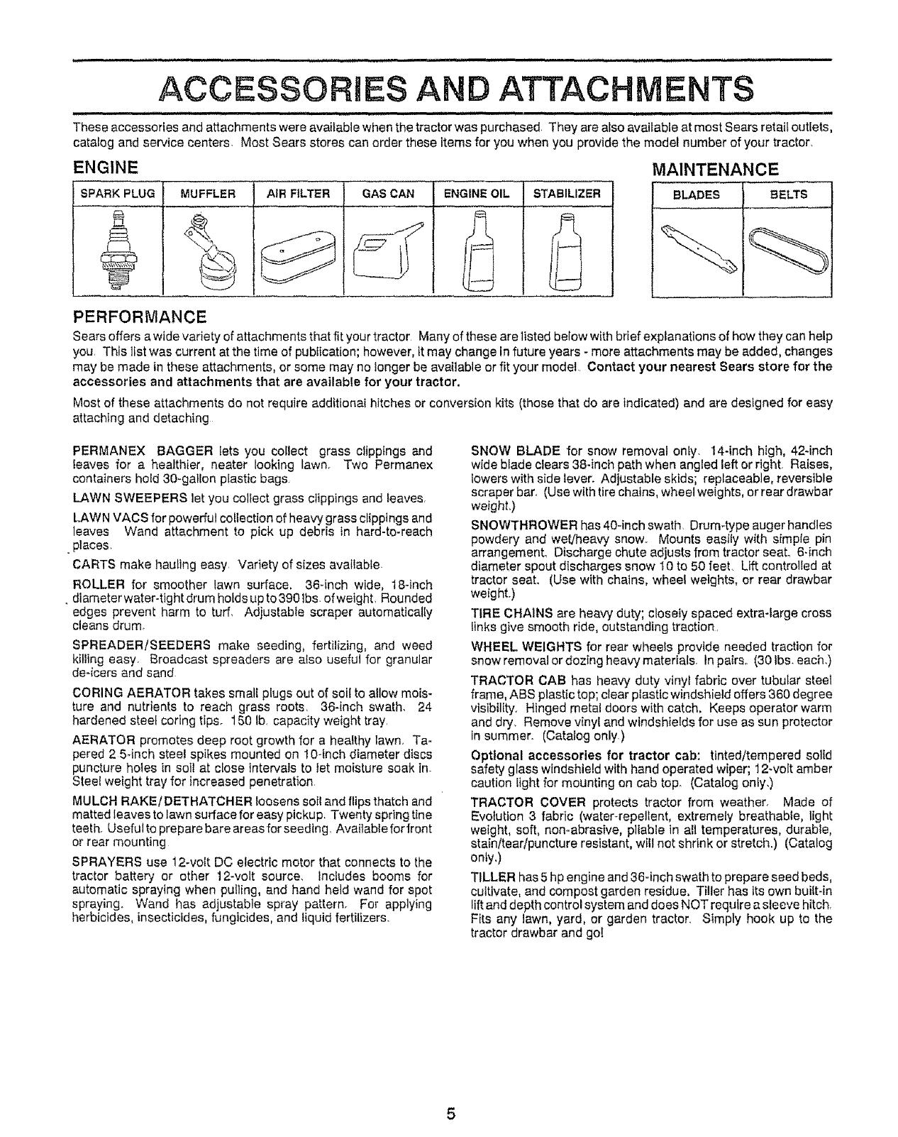
ACCESSORIES AN ATTACHMENTS
These accessories and attachments were available when the tractor was purchased, They are also available at most Sears retait outlets,
catalog and service centers. Most Sears stores can order these items for you when you provide the model number of your tractor,
ENGINE MAINTENANCE
SPARK PLUG MUFFLER AIR FILTER GAS CAN ENGINE OIL STABILIZER BLADES BELTS
PERFORMANCE
Sears offers a wide variety of attachments that fit your tractor Many of these are listed below with brief explanations of how they can help
you, This list was current at the time of publication; however, itmay change in future years - more attachments may be added, changes
may be made in these attachments, or some may no longer be available or fit your model Contact your nearest Sears store for the
accessories and attachments that are available for your tractor.
Most of these attachments do not require additional hitches or conversion kits (those that do are indicated) and are designed for easy
attaching and detaching
PERMANEX BAGGER fets you collect grass clippings and
leaves for a healthier, neater looking lawn. Two Permanex
containers hotd 30-gallon plastic bags
LAWN SWEEPERS ]el you collect grass clippings and feaves,
LAWN VACS for powerful collection of heavy grass clippings and
leaves Wand attachment to pick up debris in hard-to-reach
•places.
CARTS make hauling easy Variety of sizes available
ROLLER for smoother fawn surface. 36-inch wide, 18-inch
, diameterwater-tightdrum holdsupto3g01bs, ofwetght, Rounded
edges prevent harm to turf, Adjustable scraper automatically
cleans drum,
SPREADERiSEEDERS make seeding, fertilizing, and weed
killing easy. Broadcast spreaders are also useful for granular
deqcers and sand
CORING AERATOR takes small plugs out of soil to allow mois-
ture and nutrients to reach grass roots, 36-inch swath, 24
hardened steel coring tips. 150 lb. capacity weight tray.
AERATOR promotes deep root growth for a healthy lawn, Ta-
pered 2 5-inch steel spikes mounted on 10-fnch diameter discs
puncture holes in soil at close intervals to tet moisture soak in-
Steel weight tray for increased penetration
MULCH RAKE/DETHATCHER loosens soil and flips thatch and
matted leaves to lawn surface for easy pickup, Twenty spring tine
teeth. Useful to prepare bare areas for seeding. Available for front
or rear mounting
SPRAYERS use 12-volt DC electric motor that connects to the
tractor battery or other 12wolt source, includes booms for
automatic spraying when pulling, and hand heir wand for spot
spraying. Wand has adjustable spray pattern. For applying
herbicides, insecticides, fungicides, and liquid fertilizers.
SNOW BLADE for snow removal only. !4-inch high, 424nch
wide blade clears 38-inch path when angled left or right. Raises,
lowers with side lever. Adjustable skids; replaceable, reversible
scraper bar. (Use with tire chains, wheel weights, or rear drawbar
weighL)
SNOWTHROWER has 40-inch swath, Drum4ype auger handles
powdery and wet/heavy snow. Mounts easily with simple pin
arrangement_ Discharge chute adjusts from tractor seat. 6-inch
diameter spout discharges snow 10 te 50 feet, Lift controlled at
tractor seat. (Use with chains, wheel weights, or rear drawbar
weight.)
TIRE CHAINS are henW duty; closely spaced extra-large cross
Iinks give smooth ride, outstanding tractionr
WHEEL WEIGHTS for rear wheels provide needed traction for
snow removal or dozing heavy materials In pairs. (30 Ibs. each.)
TRACTOR CAB has heavy duty vinyl fabric over tubular steel
frame, ABS plastic top; clear plastic windshield offers 360 degree
visibility, Hinged metal doors with catch, Keeps operator warm
and dry. Remove vinyl and windshields for use as sun protector
in summer. (Catalog only)
Optional accessories for tractor cab: tinted/tempered solid
safety glass windshield with hand operated wiper; 12-volt amber
caution light for mounting on cab top. (Catatog only,)
TRACTOR COVER protects tractor from weather, Made of
Evolution 3 fabric (water-repellent, extremely breathable, light
weight, soft, non-abrasive, pliable in all temperatures, durable,
stain/tear/puncture resistant, will not shrink or stretch.) (Catalog
only.)
TILLER has 5 hp engine and 36-inch swath to prepare seed beds,
cultivate, and compost garden residue. Titler has its own built-in
lift and depth control system and does NOT require a sleeve hitch.
Fits any lawn, yard, or garden tractor. Simply hook up to the
tractor drawbar and go[
5
i,i ,,IH, II
CONTENTS OF
_,L...,,. ,.,..
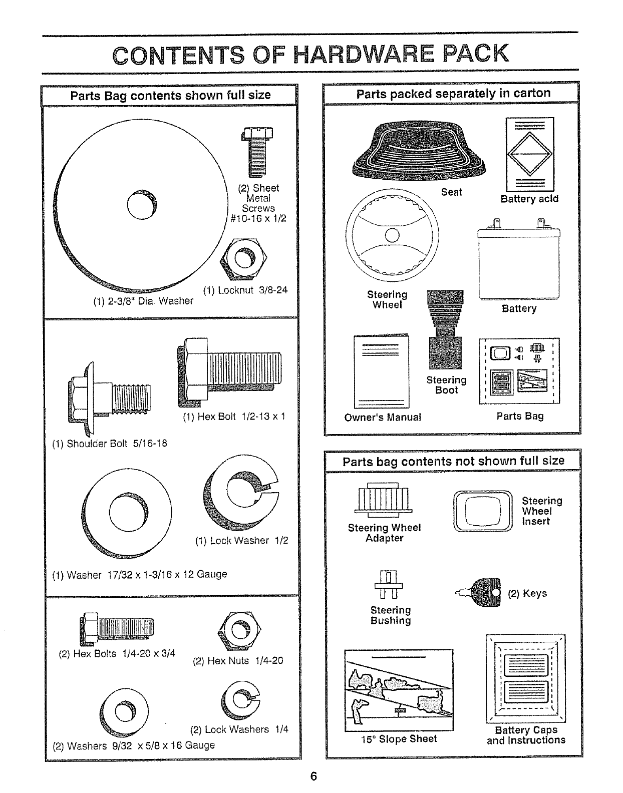
Parts Bag contents shown full size
,, ,,,,,,,,,,,,
©(2) Sheet
Metal
Screws
#10-16 x 1/2
(1) Locknut 3/8-24
(1) 2-3/8" Dia_ Washer
(1) Hex Bolt I/2-13 x t
(1) Shoulder Bolt 5/I6-18
(1) Lock Washer 1/2
('t) Washer 17/32 x 1-3/16 x 12 Gauge
(2) Hex Bolts 1/4-20 x 3/4 4b
(2) Hex Nuts 1/4-20
(2) Lock Washers '!/4
(2) Washers 9/32 x 5/8 x 16 Gauge
............... , .......... ,,,,, , ........... , .... , ,,_
i,i ,,i
HARDWARE PACK
,i, ii1,1
, ,,, ................ =1 ,,i,1,,i
Parts packed separately in carton
i,, ,i,, I, ,i,, i,i,
Seat
Q
Battery acid
Steering
Wheel =,=_===
Steering
Boot
Battery
Owner's Manual
II,,,H,
z
|: L_J-,, _,
|
1
t
. I
Parts Bag
,,,J ..............
Parts bag contents not shown full size
........ ,. ii..... ..... ................
{o 1'teo 'o,
L-------.J ' Wheel
Steering Wheel Insert
Adapter
_,_ (2) Keys
%,
'l____=q
i
Battery Caps
and Instructions
....... .i.
Steering
Bushing
15° Slope Sheet
. . .._m...
6
When right and left hand is mentioned in this manual, it
means when you are in the operating position (seated
behind the steering wheel).
TO REMOVE TRACTOR FROM CARTON
UNPACK CARTON
Remove att accessible loose parts and parts cartons
from carton (See page 6)
Cut along dotted lines on carton, from top to bottom, all
four corners of carton and hay panels flat.
• Check for any additional loose parts or cartons and
remove
BEFORE ROLLING TRACTOR OFF SKID
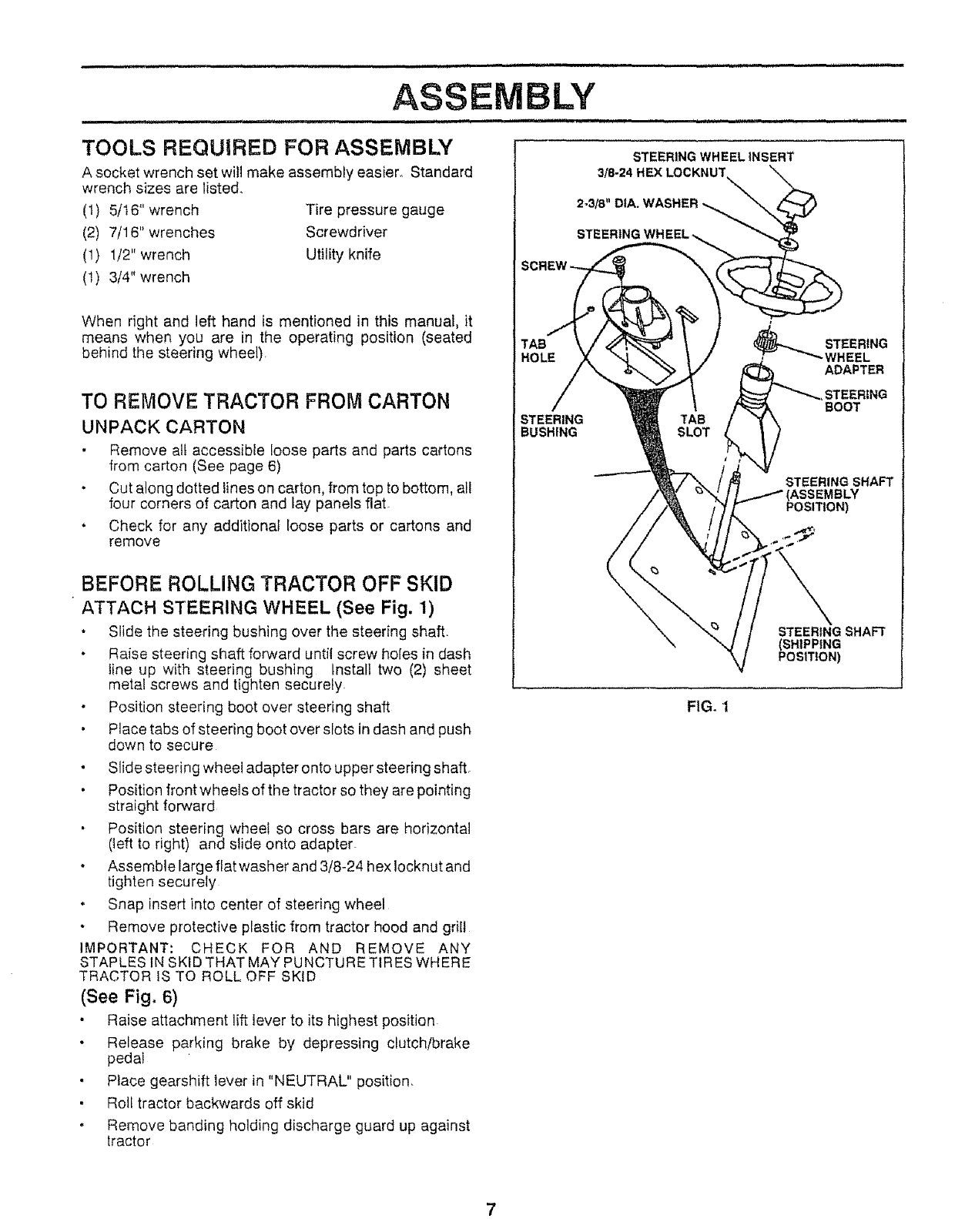
ATTACH STEERING WHEEL (See Fig. 1)
Slide the steering bushing over the steering shaft.
• Raise steering shaft forward until screw holes in dash
line up with steering bushing install two (2) sheet
metal screws and tighten securely
Position steering boot over steering shaft
• Place tabs of steering boot over slots in dash and push
down to secure
. Slide steering wheel adapter onto upper steering shaft.
Position front wheels of the tractor so they are pointing
straight forward
Position steering wheel so cross bars are horizontal
(heftto right) and slide onto adapter.
.Assemblelarge flat washer and 3/8_24 hex Iocknut and
tighten securely
Snap insert into center of steering wheel
Remove protective plastic from tractor hood and grill
IMPORTANT: CHECK FOR AND REMOVE ANY
STAPLES IN SKID THAT MAY PUNCTURE TIRES WHERE
TRACTOR IS TO ROLL OFF SKID
(See Fig, 6)
Raise attachment lift lever to its highest position
Release parking brake by depressing clutch!brake
pedal
• Place gearshift lever in "NEUTRAL" position,
• Roll tractor backwards off skid
Remove banding holding discharge guard up against
tractor
STEERING TAB
BUSHING SLOT
FIG, 1
STEERING
BOOT
STEERING SHAFT
POSITION)
•,p
STEERING SHAFT
(SHIPPING
POSITION)
HOW TO SET UP YOUR TRACTOR
PREPARE BATTERY (See Fig. 2)
,iiill i
CAUTION: Wear eye and face shield°
Wash hands or clothing immediately if
accidentallyin contact with battery acid.
Do not smoke, Fumes from charged
battery acid are explosive,
Read the instructions Included with the
battery vent caps, Always wear gloves,
clothing and goggles to protect your
hands, skin and eyes,
................................... ll, m ....
Your tractor has a battery charging system which is suffi-
cient for normal use However, periodic charging of the
battery with an automotive charger will extend its life_
See instructions packed with vent caps in parts bag.
Fill battery with acid. Fill each celt until it reaches the
bottom of the vent wells Do not overfill
• Allow battery to stand and settle for at least thirty
minutes After standing, check the level of acid. If
below the vent wells, add more acid until the correct
levet is reached.
While battery is standing (after adding acid) and later, while
battery is being charged, continue with assembly of tractor
iMPORTANT: TO MAXIMIZE THE LIFE OF YOUR
BATTERY, tT iS NECESSARY THAT THE BATTERY BE
CHARGED BEFORE USE FAILURE TO CHARGE
BATTERY CAN RESULT IN A SHORTENED BATTERY
LIFE
• Charge battery at a rate of 6 amperes for 1 hour. Use
a 12 volt battery charger. Observe atl safety precautions
required for battery charging.
• Check the acid level after the battery is charged, If the
acid has fallen below the correct level, add distilled or
iron free water.
• Install the vent caps to cover the vent wells Wash the
top of the battery with water to remove any acid, then
wipe dry
Check battery case for leakage to make sure that no
damage has occurred in handling.
Dispose of excess battery acid Neutralize acid for
disposal by adding it to four inches of water in a five
gallon plastic container, Stir with a wooden or plastic
paddle while adding baking soda until the addition of
more soda causes no more foaming
• Fellow instructions on how to install battery.
cu'r AWAY ViEW rCAP
VENT WELL
BA'r-£ERY
CELLACID
LEVEL
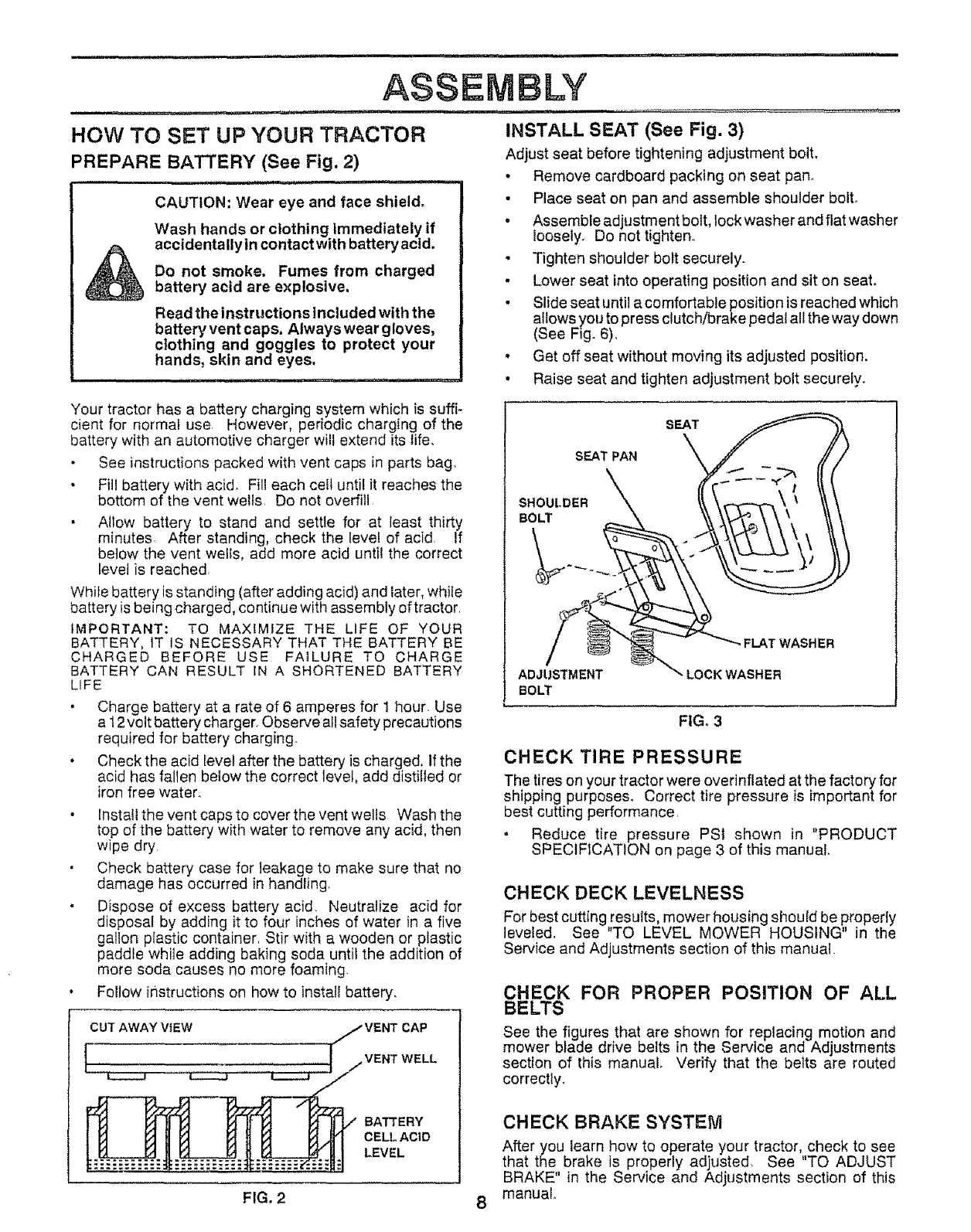
INSTALL SEAT (See Fig. 3)
Adjust seat before tightening adjustment bolt.
• Remove cardboard packing on seat pan..
• Place seat on pan and assemble shoulder bolt.
•Assemble adjustment bolt, lock washer and flat washer
Ioosely_ Do not tighten°
• Tighten shoulder bolt securely.
.Lower seat into operating position and sit on seat.
• Slide seat until a comfortable position is reached which
allows you to press clutch/brake pedal all the way down
(See Fig° 6),
• Get off seat without moving its adjusted position.
• Raise seat and tighten adjustment bolt securely.
SEAT
SEAT PAN
SHOULDER
BOLT
ADJUSTMENT
BOLT
i,.
•FLAT WASHER
"- LOCK WASHER
FIG, 3
CHECK TIRE PRESSURE
The tires on your tractor were overinflated at the factory for
shipping purposes. Correct tire pressure is important for
best cutting performance,
. Reduce tire pressure PSi shown in "PRODUCT
SPECIFICATION on page 3 of this manual.
CHECK DECK LEVELNESS
For best cutting _esufts, mower housing should be properly
leveled. See TO LEVEL MOWER HOUSING in the
Service and Adjustments section of this manual
CHECK FOR PROPER POSITION OF ALL
BELTS
See the figures that are shown for replacing motion and
mower blade drive belts in the Service and Adjustments
section of this manual Verify that the belts are routed
correctly.
CHECK BRAKE SYSTEM
After you learn how to operate your tractor, check to see
that the brake is properly adjusted. See "TO ADJUST
BRAKE" in the Service and Adjustments section of this
manual.
FIG, 28
i i,,,, ,, i i i iii1,11 .........................
ASSEMBLY
illUi..... iiiii i ii i,r ,i ,i,, ,,,NI iiii ii
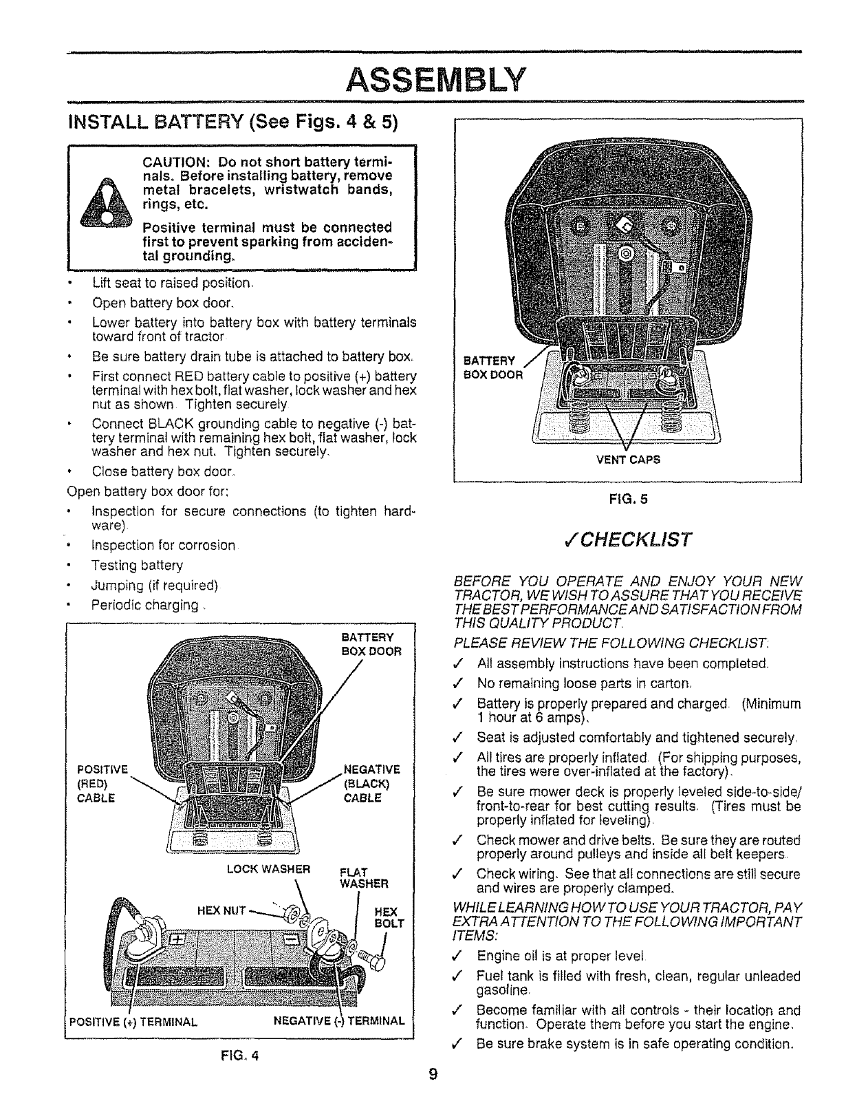
INSTALL BATTERY (See Figs. 4 & 5)
illl, ,i i,,, ii,lll,,i,l,i ill
CAUTION: Do not short batter]/termi-
nalso Before installing battery, remove
metal bracelets, wristwatch bands,
rings, etc.
Positive terminal must be connected
first to prevent sparking from acciden-
tal grounding.
ii i
Lift seat to raised position.
• Open battery box door.
Lower battery into battery box with battery terminals
toward front of tractor
• Be sure battery drain tube is attached to battery box,
• First connect RED battery cable to positive (+) battery
terminal with hex bolt, flat washer, lock washer and hex
nut as shown Tighten securely
• Connect BLACK grounding cable to negative (-) bat-
tery terminal with remaining hex bolt, flat washer, lock
washer and hex nut. Tighten securely.
• Close battery box door.
Open battery box door for:
Inspection for secure connections (to tighten hard-
ware)
• Inspection for corrosion
Testing battery
•Jumping (if required)
Periodic charging.
BATTERY
BOX DOOR
POSITIVE NEGATIVE
(RED) "_. BLACK)
CABLE CABLE
LOCK WASHER FLAT
WASHER
HEX
BOLT
POSITIVE (+) TERMINAL NEGATIVE TERMINAL
FIG. 4
VENT CAPS
BATTERY
BOX DOOR
9
FIG, 5
/CHECKLIST
BEFORE YOU OPERATE AND ENJOY YOUR NEW
TRACTOR, WE WISH TO ASSURE THAT YOU RECEIVE
THE BEST PERFORMANCE AND SA TISFACTION FROM
THIS QUALITY PRODUCT.
PLEASE REVIEW THE FOLLOWING CHECKLIST.
•/All assembly instructions have been completed.
,/ No remaining loose pars in carton,
,/" Battery is properly prepared and charged. (Minimum
1 hour at 6 amps).
V" Seat is adjusted comfortably and tightened securely,
/All tires are properly inflated. (For shipping purposes,
the tires were over-inflated at the factory).
¢" Be sure mower deck is properly leveled side*to-side/
front-to-rear for best cutting results, (Tires must be
properly inflated for leveling),
,,I Check mower and drive belts. Be sure they are routed
properly around pulleys and inside all belt keepers.
,/ Check wiring. See that al! connections are still secure
and wires are properly clamped.
WHILE LEARNING HOW TO USE YOUR TRACTOR, PAY
EXTRA A TTENTtON TO THE FOLLOWING IMPORTANT
ITEMS:
,/ Engine oil is at proper level
¢" Fuel tank is filled with fresh, clean, regular unleaded
gasoline,
,/ Become familiar with all controls - their location and
function. Operate them before you start the engine.
,/ Be sure brake system is in safe operating condition.
KNOW YOUR TRACTOR
READ THIS OWNER'S MANUAL AND SAFETY RULES BEFORE OPERATING YOUR TRACTOR
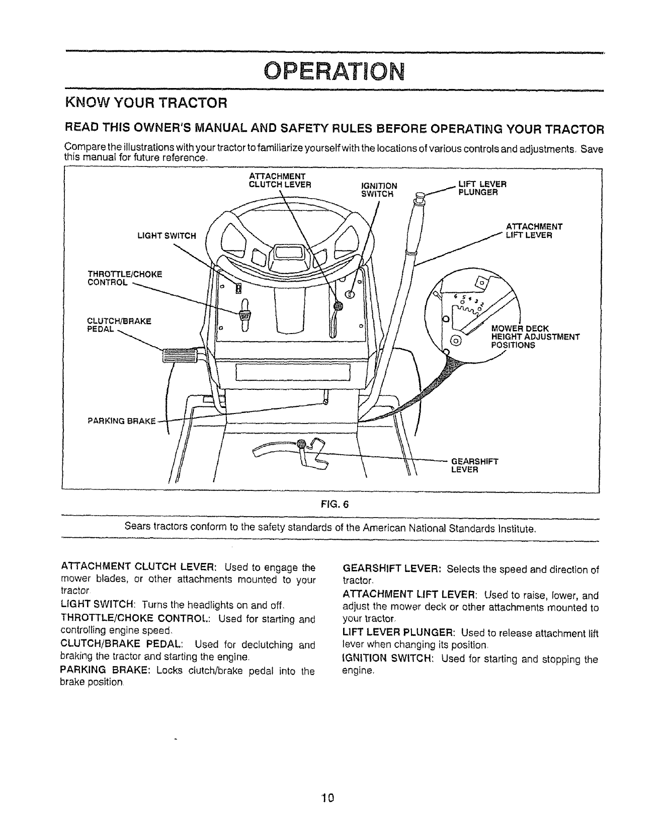
Compare the illustrations with your tractor to familiarize yourselfwith the locations of various controls and adjustments, Save
this manual for future reference°
ATTACHMENT
CLUTCH LEVER IGNITION LIFt'LEVER
SWIXCH PLUNGER
LIGHT SWITCH ATTACHMENT
LIFT LEVER
THROTTLE/CHOKE
CONTROL
CLUTCH/BRAKE
]
MOWER DECK
HEIGHT ADJUSTMENT
POSITIONS
EARSHIFT
LEVER
F|G. 6
Sears tractors conform to the safety standards of the American National Standards Institute.
ATTACHMENT CLUTCH LEVER: Used to engage the
mower blades, or other attachments mounted to your
tractor
LIGHT SWITCH: Turns the headlights on and off.
THROTTLE/CHOKE CONTROl..: Used for starting and
controlling engine speed.
CLUTCH/BRAKE PEDAL: Used for dec[utching and
braking the tractor and starting the engine
PARKING BRAKE: Locks clutch/brake pedal into the
brake position.
GEARSHIFT LEVER: Selects the speed and direction of
tractor.
ATTACHMENT LIFT LEVER: Used to raise, lower, and
adjust the mower deck or other attachments mounted to
your tractor
LIFT LEVER PLUNGER: Used to release attachment lift
lever when changing its position
iGNITION SWITCH: Used for starting and stopping the
engine,
10

The operation of any tractor can result in foreign objects thrown into the eyes, which can
result in severe eye damage. Always wear safety glasses or eye shields while operating
your tractor or performing any adjustments or repairs. We recommend wide vision safety
mask for over the spectacles or standard safety glasses, available at Sears Retaii or
Catalog stores.
HOW TO USE YOUR TRACTOR
TO SET PARKING BRAKE (See Fig. 7)
•Depress clutch/brake pedal into full "BRAKE" position
and hold
• Place parking brake lever in "ENGAGED" position and
release pressure from clutch/brake pedal. Pedal should
remain in "BRAKE" position° Make sure parking brake
will hold tractor secure..
IGNITION ATTACHMENT
KEY. CLUTCH LEVER
='ENGAGED"
POSITION "DISENGAGED"
POSITION
THROTTL_
CHOKE
CONTROL
LEVER
PARKING
BRAKE
"ENGAGED"
GF.AR-
LEVER
CLUTCH/BRAKE
PEDAL "DRIVE" POSITION PARKING BRAKE
"DISENGAGED" POSITION
FIG, 7
STOPPING (See Fig. 7)
MOWER BLADES -
• Move attachment clutch lever to "DISENGAGED" po-
sition
GROUND DRIVE -
, Depress clutch/brake pedal into full "BRAKE" position.
• Move gearshift lever to "NEUTRAL" position.
ENGINE -
• Move throttle control to "SLOW" position
• Turn ignition key to "OFF" position and remove key,
Always remove key when leaving tractor to prevent
unauthorized use
• Never use choke to stop engine,
NOTE: Under certain conditions when tractor is standing
idle with the engine running, hot engine exhaust gases may
cause "browning" of grass. To eliminate this possibility,
always stop engine when stopping tractor on grass areas
CAUTION: Always stop tractor com-
pletely, as described above, before leav-
ing the operator's position; to empty
grass catcher, etc. ..............
TO USE THRO'Fi'LE CONTROL (See Fig. 7)
Always operate engine at full throttle
• Operating engine at less than full throttle reduces the
battery charging rate and the engine cooling air flow.
• Full throttle offers the best bagging and mower per-
formance
TO MOVE FORWARD AND BACKWARD (See
Fig. 6)
The direction and speed of movement is controlled by the
gearshift lever.
• Start tractor with clutch/brake pedal depressed and
gearshift lever in "NEUTRAL" position.
•Move gearshift lever to desired position
, Slowly release clutch/brake pedal to start movement.
IMPORTANT: BRING TRACTOR TO A COMPLETE STOP
BEFORE SHIFTING OR CHANGING GEARS, FAILURE
TO DO SO WiLL SHORTEN THE USEFUL LIFE OF YOUR
TRANSAXLE,
TO ADJUST MOWER CUTTING HEIGHT (See
Fig. 6)
The position of the attachment lift lever determines the
cutting height,
• Grasp lift lever
• Press plunger with thumb and move lever to desired
position.
The cutting height range is approximately 1-1/2to 4"° The
heights are measured from the ground to the blade tip with
the engine not running. These heights are approximate
and may vary depending upon soil conditions, height of
grass and types of grass being mowed.
. The average lawn should be cut approximately 2-1/2
inches during the cool season and over3 inches during
hot months For healthier and better looking lawns,
mow often and after moderate growth.
• For best cutting performance, grass over 6 inches in
height should be mowed twice, Make the first cut
relatively high; the second to desired height.
11
OPERATIC
=, = =ul,i ,,,,, i,,,-
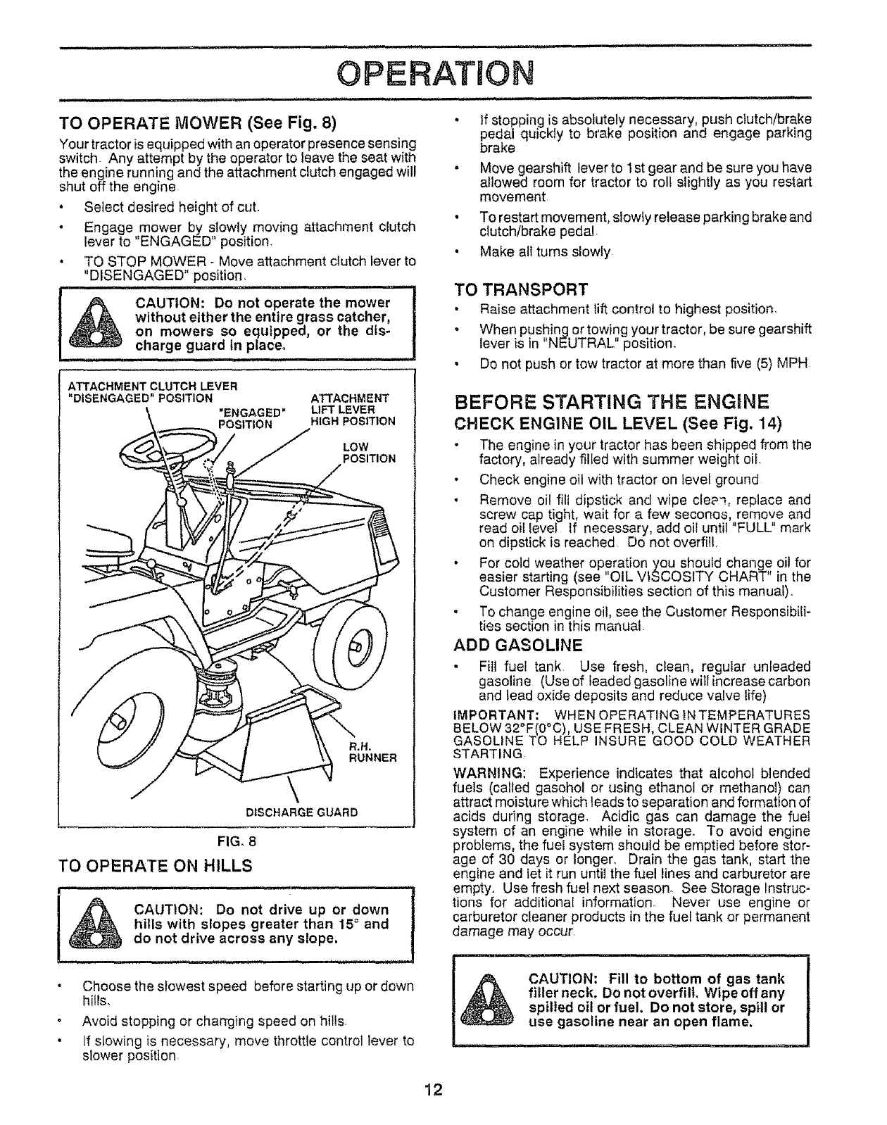
TO OPERATE MOWER (See Fig. 8)
Your tractor is equipped with an operator presence sensing
switch. Any attempt by the operator to _eave the seat with
the engine running and the attachment clutch engaged will
shut off the engine
• Select desired height of cut,
• Engagemower by slowly moving attachment clutch
lever to ENGAGED" position
. TO STOP MOWER *Move attachment clutch lever to
"DISENGAGED" position.
l& CAUTION: Do not operate the mower
without either the entire grass catcher,
on mowers so equipped, or the dis-
charge guard In place°
............ ill 1,
• If stopping is absolutely necessary, push clutch/brake
pedal quickIy to brake position and engage parking
brake
• Move gearshift lever to 1st gear and be sure you have
allowed room for tractor to roll slightly as you restart
movement
• To restart movement, slowly release parking brakeand
clutch/brake pedal
• Make all turns slowly
TO TRANSPORT
• Raise attachment lift control to highest position
o When pushing or towing your tractor, be sure gearshift
lever is in ' NEUTRAL" position,
• Do not push or tow tractor at more than five (5) MPH
ATTACHMENT CLUTCH LEVER
"DISENGAGED"POSITION
"ENGAGED"
POSITION
ATTACHMENT
LIFT LEVER
HIGH POSITION
LOW
POSITION
R,H,
RUNNER
DISCHARGE GUARD
FIG. 8
TO OPERATE ON HILLS
CAUTION: Do not drive up or down
hills with slopes greater than 15° and
do not drive across any slope,
.Choose the slowest speed before starting up or down
hills.
Avoid stopping or changing speed on hills
• If slowing is necessary, move throttle control lever to
slower position
BEFORE STARTING THE ENGINE
CHECK ENGINE OIL LEVEL (See Fig, 14)
•The engine in your tractor has been shipped from the
factory, already filied with summer weight oil,
• Check engine oil with tractor on ievel ground
• Remove oil fill dipstick and wipe cle_q, replace and
screw cap tight, wait for a few secones, remove and
read oil ievel tf necessary, add oil until "FULL" mark
on dipstick is reached Do not overfill.
• For cold weather operation you shouid change oil for
easier starting (see "OIL VISCOSITY CHART" in the
Customer Responsibilities section of this manual).
• To change engine oil, see the Customer ResponsibiIF
ties section in this manual
ADD GASOLINE
• Fill fuel tank Use fresh, clean, regular unleaded
gasoline (Use of leaded gasoiine will increase carbon
and lead oxide deposits and reduce valve life)
iMPORTANT; WHEN OPERATING iN TEMPERATURES
BELOW 32°F(0°C), USE FRESH, CLEAN WINTER GRADE
GASOLINE TO HELP INSURE GOOD COLD WEATHER
STARTING
WARNING: Experience indicates that alcohol blended
fuels (called gasohol or using ethanol or methanol) can
attract moisture which leads to separation and formation of
acids during storage. Acidic gas can damage the fuel
system of an engine while in storage. To avoid engine
problems, the fuel system should be emptied before stor-
age of 30 days or longer, Drain the gas tank, start the
engine and let it run until the fuel lines and carburetor are
empty, Use fresh fuel next season. See Storage Instruc-
tions for additional information Never use engine or
carburetor cleaner products in the fuel tank or permanent
damage may occur,
CAUTION: Fill to bottom of gas tank
filler neck. Do not overfill Wipe off any
spilled oil or fuel. Do not store, spill or
use gasoline near an open flame.
12
................................ i,ill ill ,i.,,, !H,I,,I llll
OPERATmON
i,i i,,iii H, ..................... ,,., i,ll.ill i ii i1,11_ H . ,ll,m ,rr ,IH i....
TO START ENGINE (See Fig. 7)
When starting engine for the first time or if engine has
run out of fuel, it will take extra cranking time to move
fuel from the tank to the engine°
, Depress the clutch/brake pedal and set the parking
brake
•Place gearshift lever in "NEUTRAL" position.
• Move attachment clutch to "DISENGAGED" positiono
•Move throttle control lever to "CHOKE" position for
cold engine startr For warm engine start, move
throttle control to "FAST" position_
,Turn ignition key clockwise to "START" position and
release key as soon as engine starts. Do not run
starter continuously for more than fifteen seconds
per minute. If engine does not start after several
attempts, move throttle control to "FAST" position,
wait a few minutes and try again..
When engine starts, move throttle control to desired
position.
Allow engine to warm up for a few minutes before
engaging drive or attachment clutch.
NOTE: tf at a high altitude (above 3000 feet) or in cold
temperatures (below 32° F), the carburetor fuel mixture
may need to be adjusted for best engine performance.
See TO ADJUST CARBURETOR in the Service and
Adjustments section of this manual.
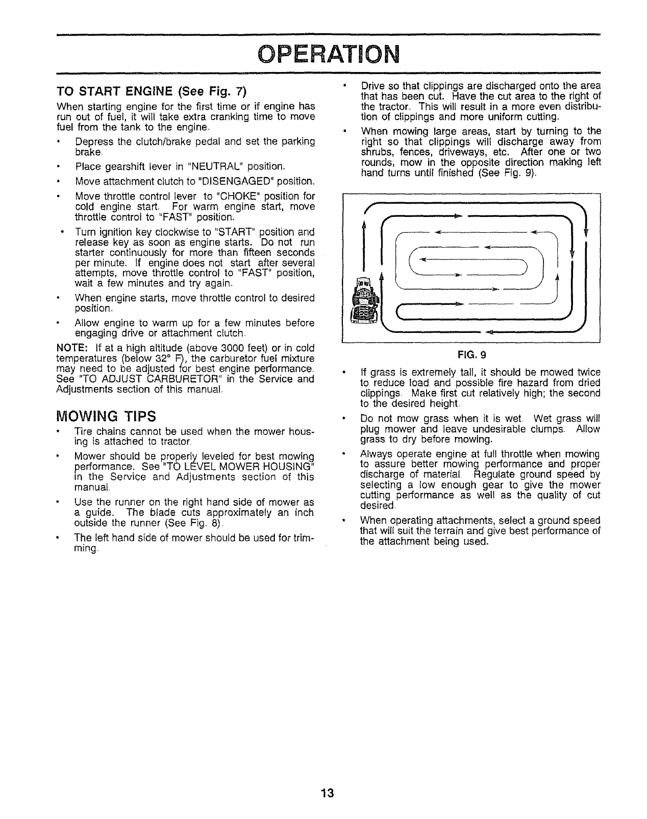
• Drive so that clippings are discharged onto the area
that has been cut. Have the cut area to the right of
the tractor. This will result in a more even distribu-
tion of clippings and more uniform cutting.
• When mowing large areas, start by turning to the
right so that clippings will discharge away from
shrubs, fences, driveways, etc, After one or two
rounds, mow in the opposite direction making left
hand turns until finished (See Fig_ 9).
MOWING TIPS
Tire chains cannot be used when the mower hous-
ing is attached to tractor.
• Mower should be properiy leveled for best mowing
performance. See "TO LEVEL MOWER HOUSING"
in the Service and Adjustments section of this
manual.
•Use the runner on the right hand side of mower as
a guide, The biade cuts approximately an inch
outside the runner (See Fig, 8).
• The left hand side of mower should be used for trim-
ming.
'HH ' 'lpl I HH I,'lJ "1 '" _'_
FIG, 9
• If grass is extremely tall, it should be mowed twice
to reduce load and possible fire hazard from dried
clippings, Make first cut relatively high; the second
to the desired height.
• Do not mow grass when it is wet Wet grass will
plug mower and leave undesirable clumps. Allow
grass to dry before mowing.
, Always operate engine at full throttle when mowing
to assure better mowing performance and proper
discharge of material. Regulate ground speed by
selecting a low enough gear to give the mower
cutting performance as well as the quality of cut
desired-
, When operating attachments, select a ground speed
that will suit the terrain and give best performance of
the attachment being used.
13
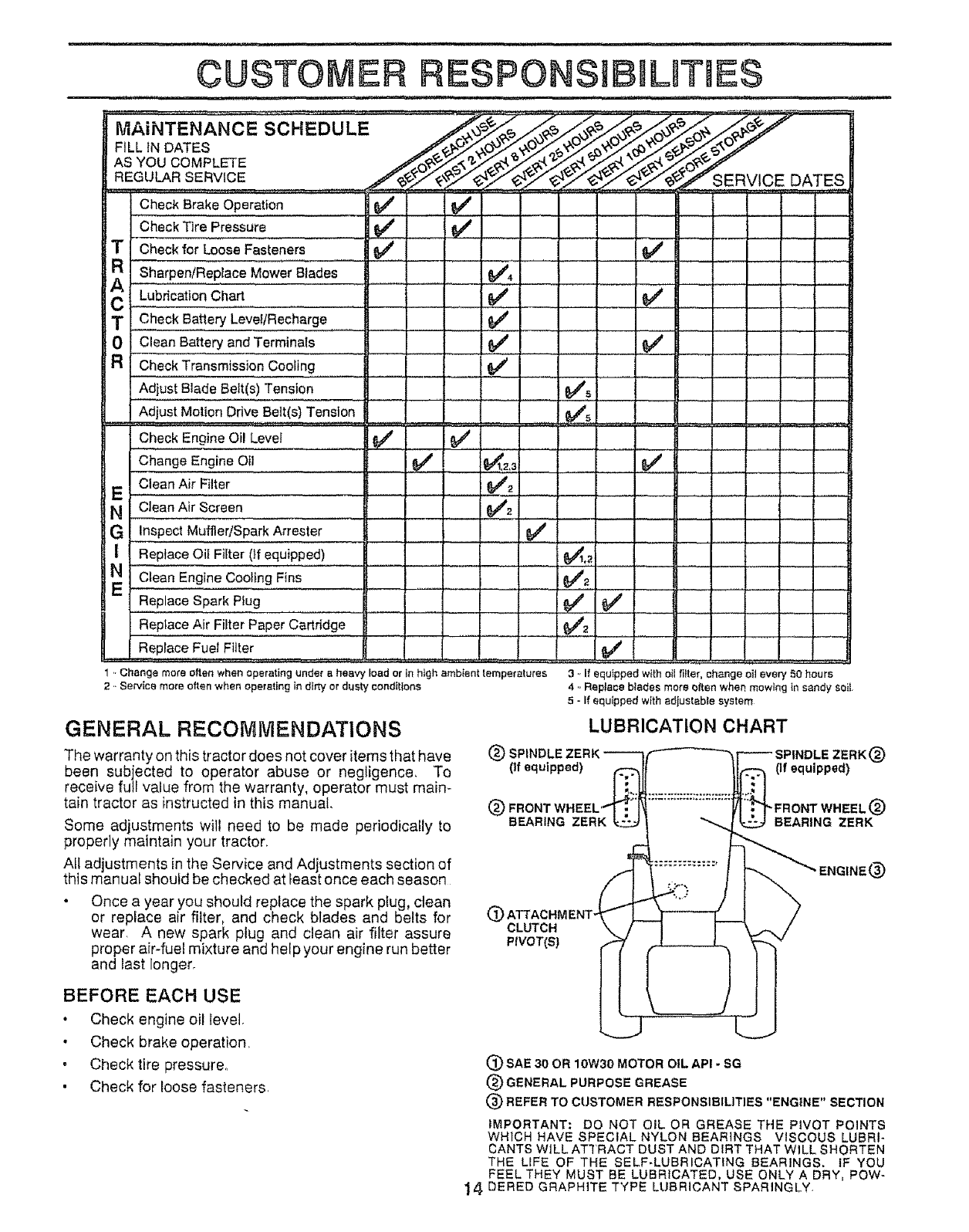
MAINTENANCE SCHEDULE
FILL iN DATES
AS YOU COMPLETE
REGULAR SERVICE SERVICE DATES
Check Brake......Operation ........i
Check Tire Pressure
TCheckfor Loose Fasteners
AR ........... .............
Sha!l_en/ReplaceMower Blades
C Lubrication Cha.rt..............
mCheck Battery Level/Recharge
0 Clean Battery andTerminaIs
a Check Transmission Cooling
Adjust Blade Belt(s) Tension
Adjust Motion Drive Bett(s) Tension
====#, ......
Check Engine Oil Level ...... 0/#
Change Engine Oit
Clean Air Filter
E
NCleanAir Screen
G Inspect Muffler/Spark Arrester
!ReplaceOil Filter 0f equipped)
N Clean Engine Cooling Fins
Replace Spark PIug
RepfaceAir Filter Paper Cartridge
H=
ReplaceFuel Filter
v',
V" !v'.......
.6/
e,'
1,.Change more often when operating under a heavy load or in high ambient femperatutes
2 ,. Service more often when operating in dirty or dusty eondltlons
L ......
V'_
!$4_'...................
_2._ .................e" ........
Iv'=
I_ _
3., If equipped with oil fi_far, change oil every 50 hours
4 ,. Replace btades more often when mowing _n sandy soil
5-If equipped with adjusfable system
GENERAL RECOMIV1ENDATIONS
The warranty on this tractor does not cover items that have
been subjected to operator abuse or negligence, To
receive full value from the warranty, operator must main-
rain tractor as instructed in this manual.
Some adjustments will need to be made periodically to
properly maintain your tractor.
All ad ustments in the Service and Adjustments section of
th s manual shou d be checked at east once each season
• Once a year you should replace the spark plug, clean
or replace air filter, and check blades and belts for
wear. A new spark plug and clean air filter assure
proper air-fuel mixture and help your engine run better
and last longer.
LUBRICATION CHART
(_) SPINDLE ZERK ----'-If'-----'-_F-_ SPINDLE ZERK (_)
(If equipped) _..,.,,.,,,,,.....,....._ (If equipped)
® FRONTWHEEL4_'_ ...............i/I".._PRONTWHEEL®
B_,R,.GZERK_1 "-.. [-_ BEAR,NGZERK
t
®CLUTCH
PIVOT(S)
BEFORE EACH USE
• Check engine oil Ievel.
• Check brake operation.
, Check tire pressure..
, Check for loose fasteners.
(_) SAE 30 OR 10W30 MOTOR OIL API - SG
®GENERAL PURPOSE GREASE
(_) REFER TO CUSTOMER RESPONSIBILITIES "ENGINE" SECTION
IMPORTANT: DO NOT OILER GREASE THE PIVOT POINTS
WHICH HAVE SPECIAL NYLON BEARINGS VISCOUS LUBRI*
CANTS WILL AT'IRACT DUST AND DIRT THAT WILL SHORTEN
THE L_FE OF THE SELF-LUBRiCATING BEARINGS. IF YOU
FEEL THEY MUST BE LUBRICATED, USE ONLY A DRY, Pew-
14 DERED GRAPHITE TYPE LUBRICANT SPARINGLY_
BRAKE OPERATION
If tractor requires more than six (6) feet stopping distance
at high speed inhighest gear_than brake must be adjusted.
(See TO ADJUST BRAKE in the Service and Adjust-
merits section of this manual)
TIRES
o
4=
Maintain proper air pressure in all tires (See "PROD-
UCT SPECIFICATIONS on page 3 of this manual).
Keep tires free of gasoline, oil, or insect control chemi-
cals which can harm rubber
Avoid stumps, stones, deep ruts, sharp objects and
other hazards that may cause tire damage
BLADE CARE
For best results mower blades must be kept sharp The
blades can be sharpened with a file or on a grinding wheel,
We suggest they be sharpened or replaced after every 25
hours of mowing Check blades more often if mowing in
sandy conditions
. Do not attempt to sharpen blades while they are on the
mower
• Replace bent or damaged blades
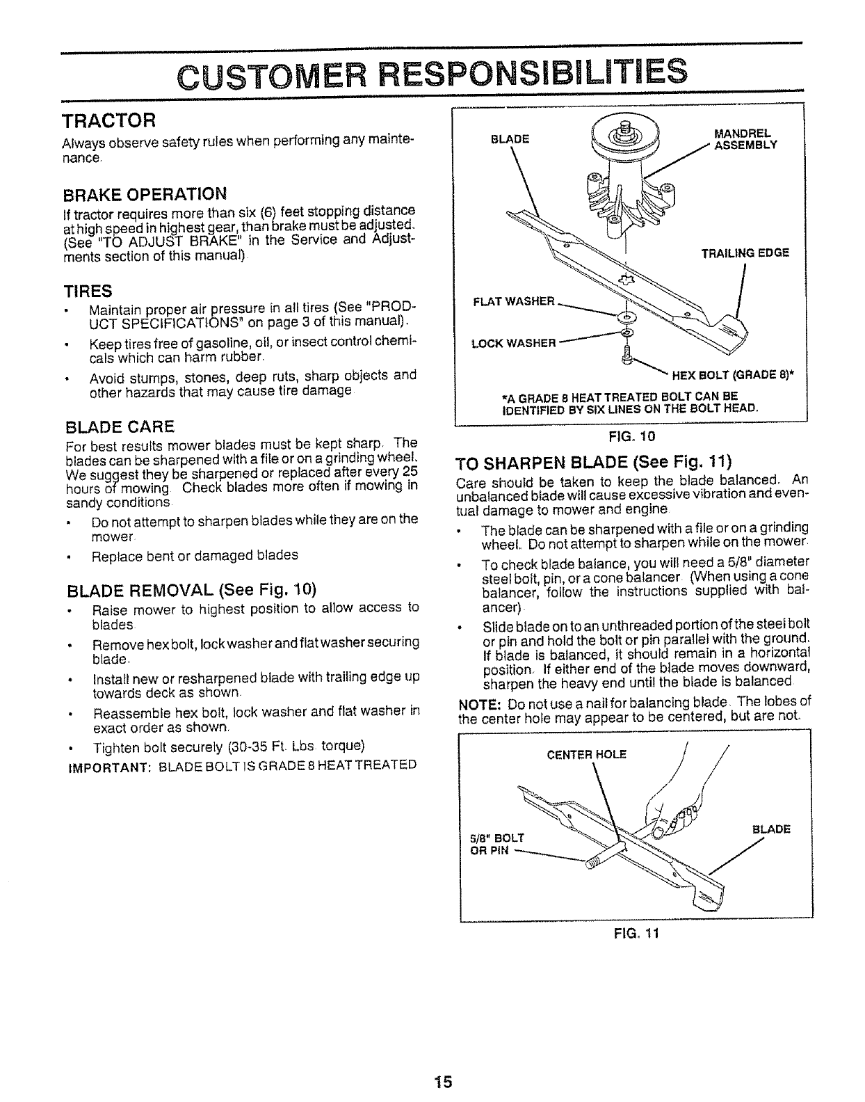
BLADE REMOVAL (See Fig. 10)
• Raise mower to highest position to allow access to
blades
• Remove hex bolt, lock washer and fiat washer securing
blade.
• Install new or resharpened blade with trailing edge up
towards deck as shown.
Reassemble hex boit, lock washer and flat washer in
exact order as shown
• Tighten boft securely (30-35 FL Lbs torque)
IMPORTANT: BLADE BOLT 1SGRADE 8 HEAT TREATED
LOCK WASHER
_MANDREL
ASSEMBLY
TRAILING EDGE
)°
_" HEX BOLT (GRADE 8)*
_A GRADE 8HEAT TREATED BOLT CAN BE
IDENTIFIED BY SIX LINES ON THE BOLT HEAD,
FIG. 10
TO SHARPEN BLADE (See Fig. 11)
Care should be taken to keep the blade balanced. An
unbalanced blade will cause excessive vibration and even-
tual damage to mower and engine
• The blade can be sharpened with a file or on a grinding
wheel. Do not attempt to sharpen while on the mower
• To check blade balance, you wil{ need a 5/8" diameter
steel bo_t,pin, ora cone baiancer (When using a cone
balancer, follow the instructions supplied with baF
ancer)
• Slide blade on to an unth readed portion of the steel bolt
or pin and hold the bolt or pin parallel with the ground.
If blade is balanced, it should remain in a horizontal
position_ If either end of the b_ade moves downward,
sharpen the heavy end until the biade is balanced
NOTE; Do not use a nail for balancing blade The lobes of
the center hole may appear to be centered, but are not.
CENTER HOLE
S/8" BOLT
OR PiN
BLADE
FIG. 11
15
CUSTO RESPONSi mLmT ES
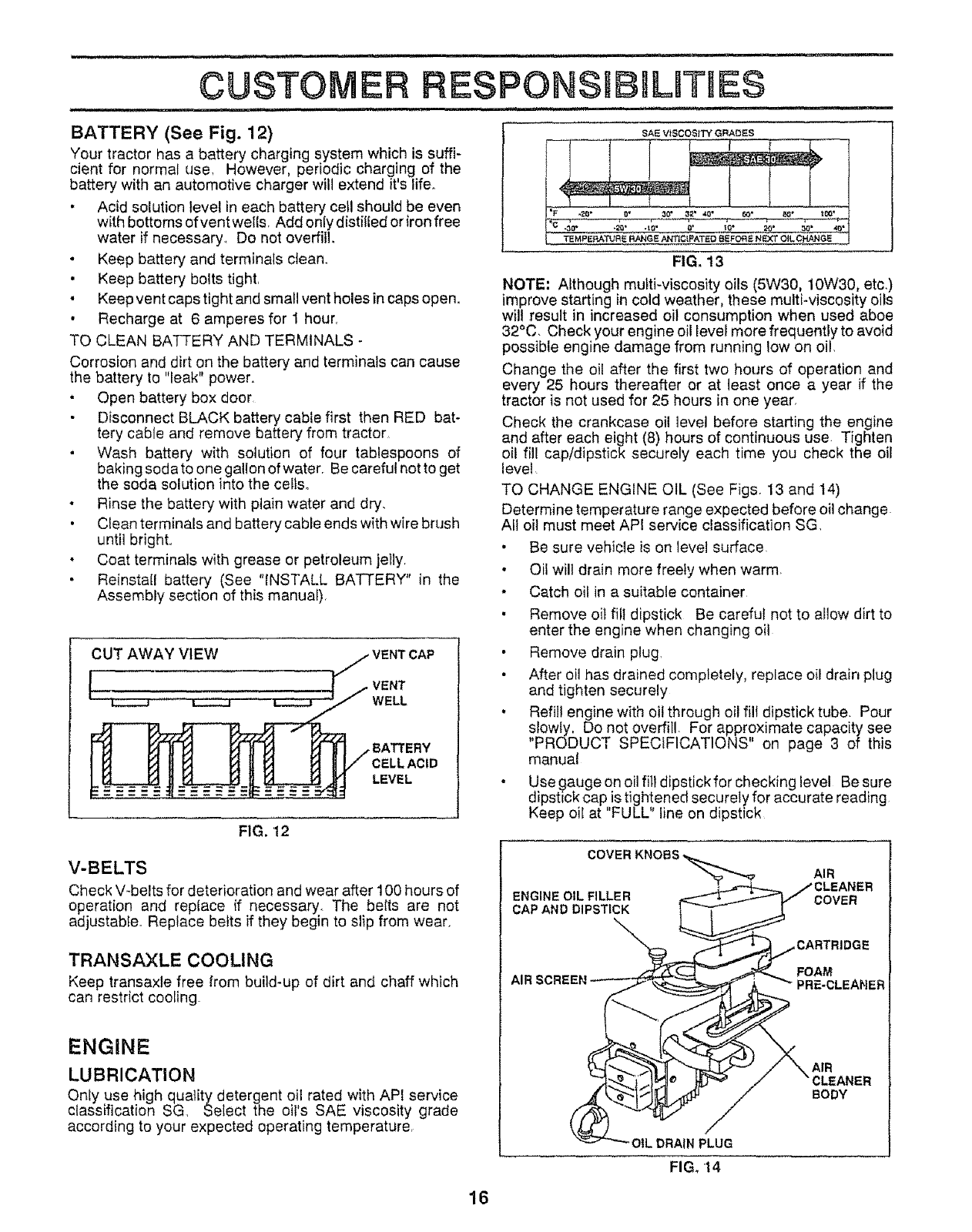
BATTERY (See Fig. 12)
Your tractor has a battery charging system which is suffi-
cient for normat use. However, periodic charging of the
battery with an automotive charger will extend it'slife.
• Acid solution level in each battery ceil should be even
with bottoms of vent wel{s. Add only distilled or iron free
water if necessary. Do not overfill.
• Keep battery and terminals clean.
• Keep battery bolts tight,
• Keep vent caps tight and small vent holes in caps open.
• Recharge at 6 amperes for 1 hour.
TO CLEAN BATTERY AND TERMINALS -
Corrosion and dirt on the battery and terminals can cause
the battery to "leak" power.
• Open battery box door
Disconnect BLACK battery cable first then RED bat-
tery cable and remove battery from tractor
• Wash battery with solution of four tablespoons of
baking soda to one gallon of water. Be careful not to get
the soda solution into the cells.
• Rinse the battery with plain water and dry.
• Clean terminals and battery cable ends with wire brush
until bright..
• Coat terminals with grease or petroleum jelly.
• Reinstall battery (See "INSTALL BATTERY" in the
Assembly section of this manual).
CUT AWAY VIEW
VENT
WELL
BATTERY
LEVEL
FIG. 12
V-BELTS
Check V-belts for deterioration and wear after I00 hours of
operation and rep{ace if necessary. The be{ts are not
adjustable_ Replace belts if they begin to slip from wear.
TRANSAXLE COOLING
Keep transaxle free from build-up of dirt and chaff which
can restrict cooling.
ENGINE
LUBRICATION
Only use high quality detergent o!1 rated with API service
classification SG Select the oils SAE viscosity grade
according to your expected operating temperature,
SAE VISCOSITY GRADES
FIG. 13
NOTE; Although muLti-viscosity oils (5W30, 10W30, etc.)
improve starting in cold weather, these multi-viscosity oils
will result in increased oil consumption when used aboe
32°C. Check your engine oil level more frequently to avoid
possible engine damage from running low on oil,
Change the oil after the first two hours of operation and
every 25 hours thereafter or at least once a year if the
tractor is not used for 25 hours in one year,
Check the crankcase oil level before starting the engine
and after each eight (8) hours of continuous use. Tighten
oil fill cap/dipstick securely each time you check the oil
level
TO CHANGE ENGINE OIL (See Figs. 13 and 14)
Determine temperature range expected before oil change
All oil must meet AP! service classification SG.
• Be sure vehicle is on level surface.
• Oil will drain more freely when warm
- Catch oil in a suitable container
• Remove oil fill dipstick Be careful not to aNow dirt to
enter the engine when changing oil
• Remove drain plug.
• After oil has drained completely, replace oi! drain plug
and tighten securely
• Refill engine with oil through oil fill dipstick tube Pour
slowly, Do not overfill. For approximate capacity see
'PRODUCT SPECIFICATIONS" on page 3 of this
manual
•Use gauge on oil fill dipstick for checking level Be sure
dipstick cap is tightened securely for accurate reading
Keep oil at "FULL" line on dipstick
COVER KN(
ENGINE OIL FILLER
CAP AND DIPSTICK
AIR
AIR SCRE!
AIR
CLEANER
BODY
OIL DRAIN PLUG
FIG. 14
16
CUSTO ERESPONSUBHLITtES
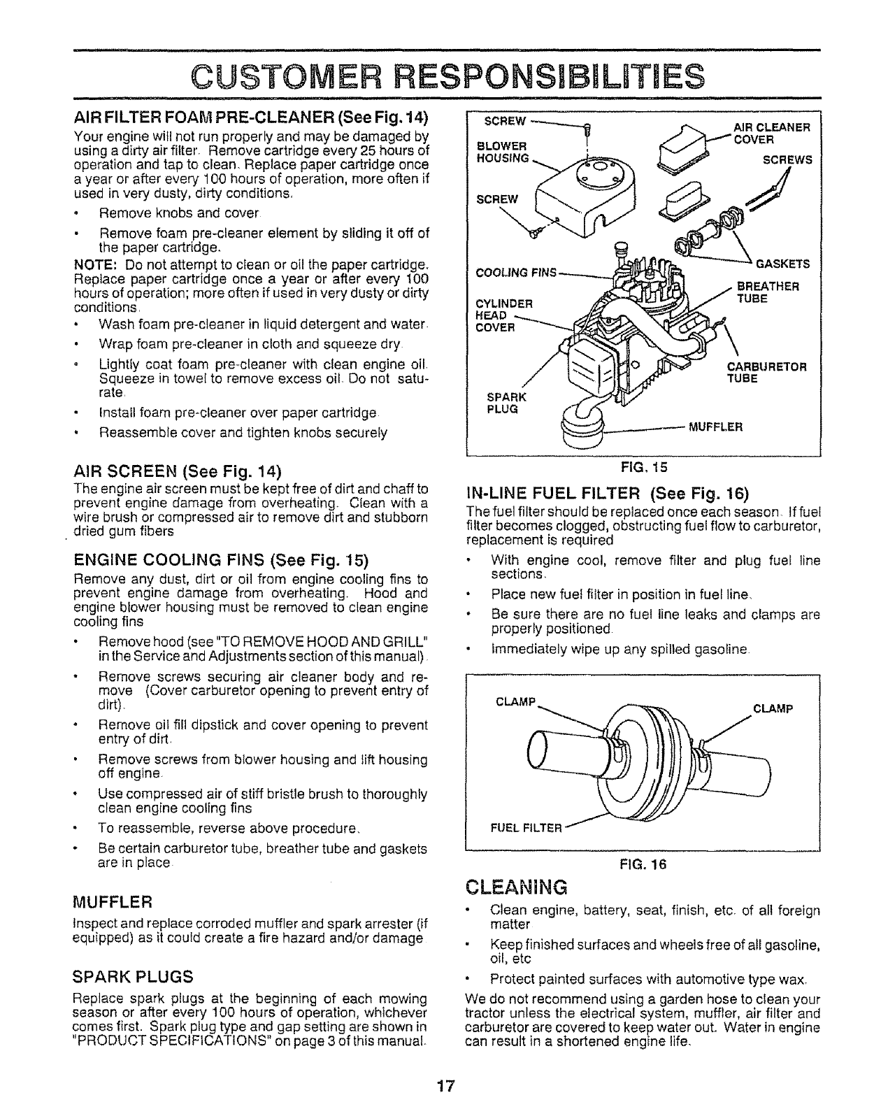
AIR FILTER FOAM PRE-CLEANER (See Fig, 14)
Your engine will not run properly and may be damaged by
using a dirty air filter, Remove cartridge every 25 hours of
operation and tap to clean, Replace paper cartridge once
a year or after every 100 hours of operation, more often if
used in very dusty, dirty conditions,
. Remove knobs and cover
• Remove foam pre-cleaner etement by sliding it off of
the paper cartridge.
NOTE'. Do not attempt to clean or oil the paper cartridge,
Replace paper cartridge once a year or after every 100
hours of operation; more often if used in very dusty or dirty
conditions,
• Wash foam pre-cteaner in liquid detergent and water
• Wrap foam pro-cleaner in cloth and squeeze dry
° Lightly coat foam pre-cleaner with clean engine oil,
Squeeze in towel to remove excess oil Do not satu-
rate.
install foam pre*cleaner over paper cartridge
• Reassemble cover and tighten knobs securely
SCREW -'_'_1 _ AIR CLEANER
_COVER
BLOWER _ SCREWS
HOUSING ,_ J
SCREW
CYLINDER
HEAD
COVER
SPARK
PLUG
3ASKETS
BREATHER
TUBE
CARBURETOR
TUBE
AIR SCREEN (See Fig. 14)
The engine air screen must be kept free of dirt and chaff to
prevent engine damage from overheating. Clean with a
wire brush or compressed air to remove dirt and stubborn
dried gum fibers
ENGINE COOLING FINS (See Fig. 15)
Remove any dust, dirt or oil from engine cooling fins to
prevent engine damage from overheating. Hood and
engine b!ower housing must be removed to clean engine
cooling fins
• Remove hood (see "TO REMOVE HOOD AND GRILL"
in the Service and Adjustments section of this manual)
• Remove screws securing air cleaner body and re-
move (Cover carburetor opening to prevent entry of
dirt).
oRemove oil fill dipstick and cover opening to prevent
entry of dirt,
Remove screws from blower housing and lift housing
off engine
•Use compressed air of stiff bristle brush to thoroughly
clean engine cooling fins
• To reassemble, reverse above procedure.
Be certain carburetor tube, breather tube and gaskets
are in place
MUFFLER
Inspect and replace corroded muffler and spark arrester (if
equipped) as it coufd create a fire hazard and!or damage
SPARK PLUGS
Replace spark plugs at the beginning of each mowing
season or after every 100 hours of operation, whichever
comes first. Spark plug type and gap setting are shown in
"PRODUCT SPECIFICATIONS" on page 3 of this manual
FIG. 15
IN-LINE FUEL FILTER (See Fig. 16)
The fuel filter should be replaced once each season. If fuel
filter becomes clogged, obstructing fuel flow to carburetor,
replacement is required
• With engine cool, remove filter and plug fuel line
sections.
• Place new fuel filter in position in fuel line.
• Be sure there are no fuel line leaks and clamps are
properly positioned
• Immediately wipe up any spilled gasoline.
CLAMP CLAMP
FUEL F_
FIG. 16
CLEANING
• Clean engine, battery, seat, finish, etc. of all foreign
matter
• Keep finished surfaces and wheels free of all gasoline,
oil, etc
• Protect painted surfaces with automotive type wax.
We do not recommend using a garden hose to clean your
tractor unless the electrical system, muffler, air filter and
carburetor are covered to keep water out. Water in engine
can result in a shortened engine life.
17
= =,,, ...... :::-w-: . =,, .............. , = .....................,., H,,=, ......................
SERVICE AND ADJUSTMENTS
CAUTION: BEFORE PERFORMING ANY SERVICE OR ADJUSTMENTS:
_ w
Q
m
TRACTOR
Depress clutch/brake pedal fully and set parking brakes
Place gearshift lever in "NEUTRAL" position,
Place attachment clutch in "DISENGAGED" position.
Turn ignition key "OFF" and remove key.
Make sure the blades and all moving parts have completely stopped.
Disconnect spark plug wire from spark plug and place wire where it can not come in contact with
plugo
,,,, -=,,=, , ,,,re,r, H,, m=,, ,,,,,,, ,,H,
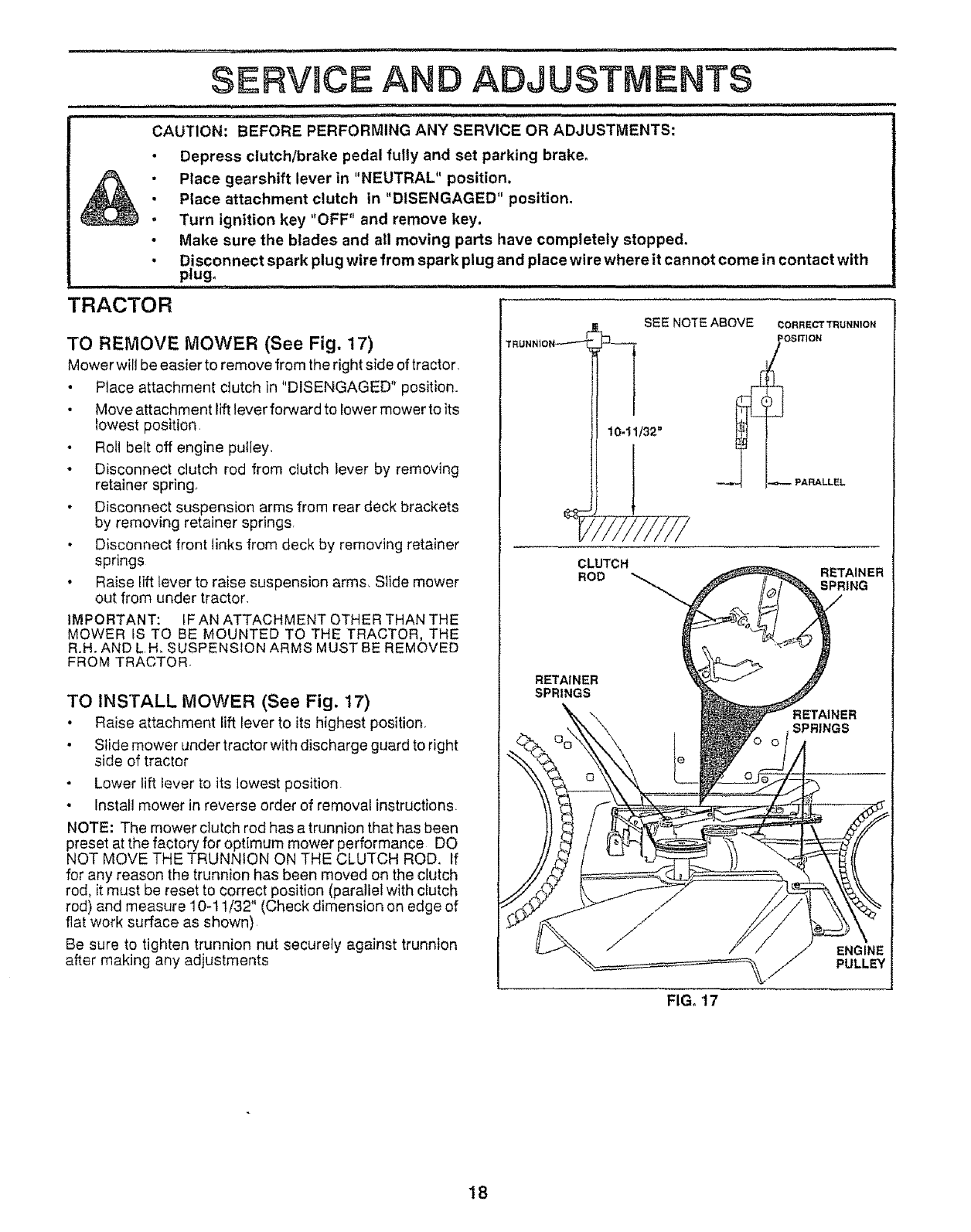
TO REMOVE MOWER (See Fig. 17)
Mower wiil be easier to remove from the right side of tractor,
•Place attachment clutch in "DISENGAGED" position.
•Move attachment lift lever forward to lower mower to its
lowest position.
.Roll belt off engine pulley,
• Disconnect clutch rod from clutch lever by removing
retainer spring
• Disconnect suspension arms from rear deck brackets
by removing retainer springs,
• Disconnect front links from deck by removing retainer
springs
• Raise lift lever to raise suspension arms, Slide mower
out from under tractor,
IMPORTANT: tF AN ATTACHMENT OTHER THAN THE
MOWER tS TO BE MOUNTED TO THE TRACTOR, THE
R,H. AND L H, SUSPENSION ARMS MUST BE REMOVED
FROM TRACTOR,
TO INSTALL MOWER (See Fig. 17)
• Raise attachment lift lever to its highest position,
• Slide mower under tractor with discharge guard to right
side of tractor
Lower lift lever to its lowest position.
• Install mower in reverse order of removal instructions,
NOTE: The mower clutch rod has a trunnion that has been
preset at the factory for optimum mower performance DO
NOT MOVE THE TRUNNION ON THE CLUTCH ROD. If
for any reason the trunnion has been moved on the clutch
rod, it must be reset to correct position (parallel with clutch
rod) and measure 10-t 1/32" (Check dimension on edge of
flat work surface as shown)
Be sure to tighten trunnion nut securely against trunnion
after making any adjustments
_J_ SEE NOTE ABOVE CORRECT TRUNN1ON
OSIT1ON
PARALLEL
CLUTCH
ROD RETAINER
SPRING
RETAINER
SPRINGS
IER
SPRINGS
FIG, 17
18
SERVMCE AND ADJUSTMENTS
,i lU.i ............... , .................... ,i,,,i i.. . ........
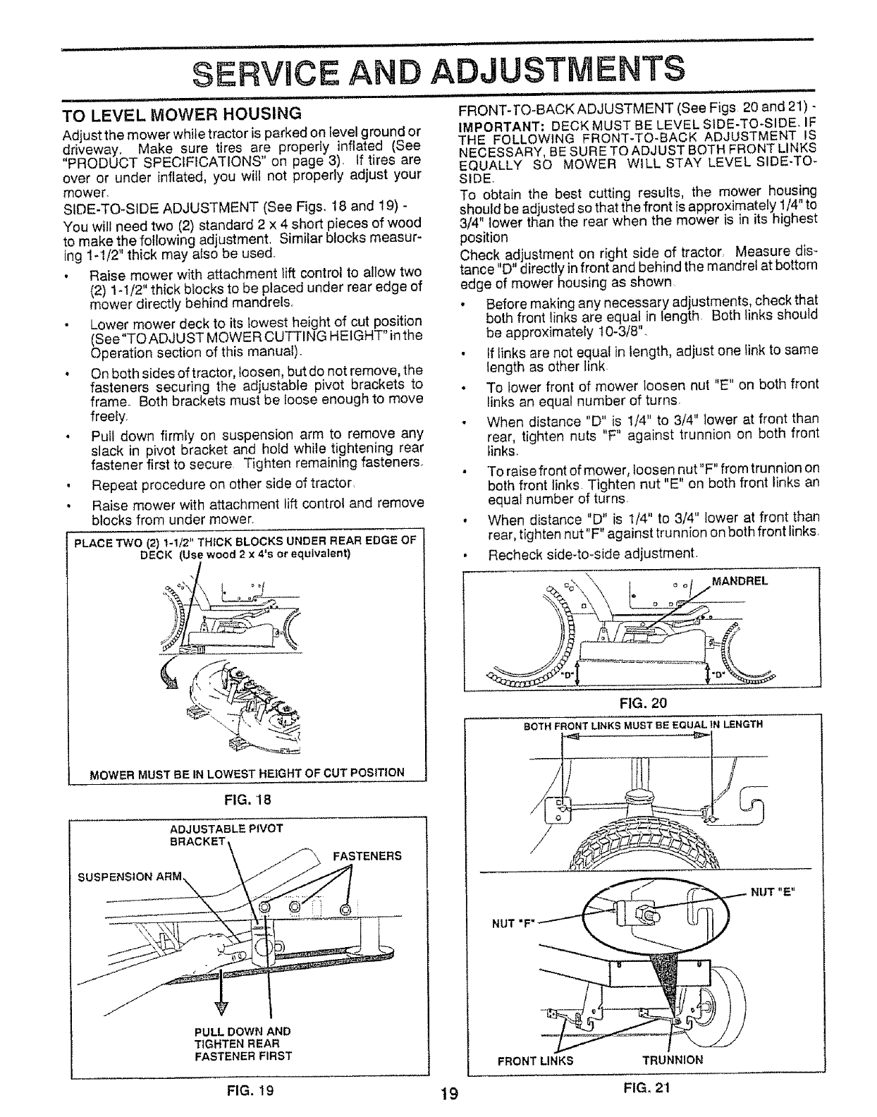
TO LEVEL MOWER HOUSING FRONT-TO-BACKADJUSTMENT (See Figs 20 and 21)-
Adjust the mower while tractor is parked on level ground or IMPORTANT= DECK MUST BE LEVEL S1DE-TO-SIDEo IF
THE FOLLOWING FRONT-TO-BACK ADJUSTMENT IS
driveway. Make sure tires are propedy inflated (See
PRODUCT SPECIFICATIONS' on page 3), If tires are NECESSARY, BE SURE TO ADJUST BOTH FRONT LINKS
EQUALLY SO MOWER WILL STAY LEVEL SIDE-TO-
over or under inflated, you wilt not properly adjust your SIDE.
mower. To obtain the best cutting results, the mower housing
SIDE-TO-SIDE ADJUSTMENT (See Figs. 18 and 19) - should be adjusted so that the front is approximately 1/4" to
You will need two (2) standard 2 x 4 short pieces of wood 3/4" lower than the rear when the mower is in its highest
to make the following adjustment, Similar blocks measur- position
ing 1-1/2" thick may also be used. Check adjustment on right side of tractor Measure dis-
, Raise mower with attachment lift control to allow two tance "D" directly in front and behind the mandrel at bottom
(2) 1-1/2" thick biocks to be placed under rear edge of edge of mower housing as shown
mower directly behind mandrel& • Before making any necessary adjustments, check that
• Lower mower deck to its lowest height of cut position both front links are equal in length Both links should
(See"TOADJUST MOWER CUTTING HEIGHT" inthe be approximately 10_3/8".
Operation section of this manual). • If links are not equal in length, adjust one link to same
• On both sides of tractor, loosen, but do not remove, the length as other link
fasteners securing the adjustable pivot brackets to • To lower front of mower loosen nut "E" on both front
frame° Both brackets must be loose enough to move links an equal number of turns.
freely. • When distance "D" is 1/4" to 3/4" lower at front than
• Pull down firmiy on suspension arm to remove any rear, tighten nuts "F" against trunnion on both front
slack in pivot bracket and hold while tightening rear links.
fastener first to secure Tighten remaining fasteners.
, Repeat procedure on other side of tractor
•Raise mower with attachment _iftcontrol and remove
blocks from under mower.
PLACE TWO (2) 1-1/2" THICK BLOCKS UNDER REAR EDGE OF
DECK (Use wood 2 x 4's or equivalent)
/
_._,_
MOWERMUSTBE INLOWEST HEIGHT OF CUTPOSITION
FIG, 18
ADJUSTABLE PIVOT
BRACKET\
\ j_ FASTENERS
SUSPENSION ARM\ _.j __
PULL DOWN AND
TIGHTEN REAR
FASTENER FIRST
e
To raise front of mower, loosen nut"F" from trunnion on
both front links Tighten nut "E" on both front links an
equal number of turns
When distance "D" is 1/4" to 3/4" lower at front than
rear, tighten nut"F" against trunnion on both front links,
Recheck side-to-side adjustment.
MANDREL
FIG. 20
BOTH FRONT LINKS MUST BE EQUAL tN LENGTH
NUT "E"
FRONT LINKS TRUNNION
FIG. 19 19 FIG, 21
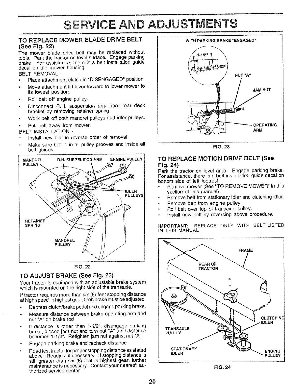
TO REPLACE MOWER BLADE DRIVE BELT
(See Fig. 22)
The mower blade drive belt may be replaced without
tools. Park the tractor on level surface. Engage parking
brake, For assistance, there is a belt installation guide
decal on the mower housing.
BELT REMOVAL -
• Place attachment dutch in "DISENGAGED" position.
• Move attachment lift Iever forward to lower mower to
its lowest position.
• Roll belt off engine pulley,
• Disconnect R.H, suspension arm from rear deck
bracket by removing retainer spring.
• Work belt off both mandrel pulleys and idler pulleys°
• Pull belt away from mower,,
BELT INSTALLATION -
•Install new belt in reverse order of removal
•Make sure belt is in all pultey grooves and inside atl
belt guides°
MANDREL Roll. SUSPENSION ARM ENGINE PULLEY
PULLEYS
RETAINER
SPRING
/
MANDREL
PULLEY
NUT•A"
FIGo 23
TO REPLACE MOTION DRIVE BELT (See
Fig. 24)
Park the tractor on level area, Engage parking brake.
For assistance, there is abelt installation guide decal on
bottom side of left footrest°
• Remove mower (See "TO REMOVE MOWER" in this
section of this manual).
• Remove belt from stationary idler and clutching idler.
• Remove belt from engine pulley,
•Roll be_t over top of transaxle puJley_
.Install new belt by reversing above procedure.
IMPORTANT: REPLACE ONLY WITH BELT LISTED
IN THIS MANUAL.
FRAME
FIG. 22
TO ADJUST BRAKE (See Fig. 23)
Your tractor is equipped with an adjustable brake system
which is mounted on the right side of the transaxleo
tf tractor requires more than six (6) feet stopping distance
at high speed in highest gear, then brake must be adjusted.
•Depress ctutch/brake pedal and engage parking brake_
Measure distance between brake operating arm and
nut "A" on brake rod,
•if distance is other than 1-1/2", disengage parking
brake, loosen jam nut and turn nut "A" until distance
becomes 1-1/2'L Retighten jam nut against nut "A",
• Engage parking brake and recheck distance,
• Road test tractor for proper stopping distance as stated
above., Readjust if necessary. If stopping distance is
still greater than six (6) feet in highest gear, further
maintenance is necessary. Contact your nearest au-
thorized service center.
PULLEY
STATIONARY
IDLER
FIG. 24
CLUTCHINC
ENGINE
PULLEY
2O
_:---'--:- = = ,,, ,,,,,,,== i ,,,n,,,",,,,,, ,, H"H," ¸'
SERVICE AN ADJUSTMENTS
............. ............................................. _ ,1, 11 = ,,uJ = 1, ........................................... ,1 = ,
TO ADJUST STEERING WHEEL ALIGNMENT TO START ENGINE WITH A WEAK BA'rTERY
(See Fig. 26)
If steering wheel crossbars are not horizontal (left to right)
when wheels are positioned straight forward, remove steer-
ing wheel and reassemble per instructions in the Assembiy
section of this manual.
FRONT WHEEL TOE-IN/CAMBER
The front wheel toe-in and camber are not adjustable on
your tractor If damage has occurred to affect the front
wheel toe-in or camber, contact your nearest authorized
service center.
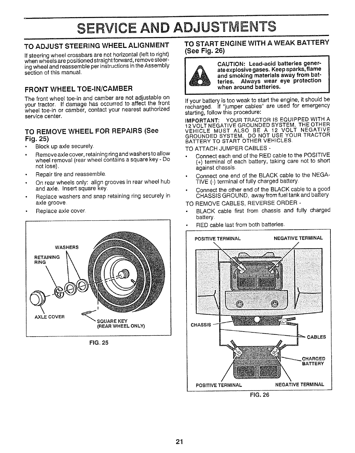
TO REMOVE WHEEL FOR REPAIRS (See
Fig. 25)
• Btock up axle securely.
•Remove axte cover, retaining ring and washers to allow
wheel remova_ (rear wheel contains a square key - Do
CAUTION: Lead-acid batteries gener-
ate explosive gases. Keep sparks, flame
and smoking materials away from bat-
teries. Always wear eye protection
when around batteries.
If your battery is too weak to start the engine, it should be
recharged. If "jumper cables" are used for emergency
starting, fotlow this procedure:
IMPORTANT: YOUR TRACTOR IS EQUIPPED WITH A
12 VOLT NEGATIVE GROUNDED SYSTEM. THE OTHER
VEHICLE MUST ALSO BE A 12 VOLT NEGATIVE
GROUNDED SYSTEM. DO NOT USE YOUR TRACTOR
BATTERY TO START OTHER VEHICLES
TO ATTACH JUMPER CABLES
• Connect each end of the RED cable to the POSITIVE
not lose).
• Repair tire and reassemble
• On rear wheels only: align grooves in rear wheel hub
and axle. Insert square key,
• Replace washers and snap retaining ring securely in
axle groove
• Replace axle cover.
WASHERS
RETAINING
RING
Q
AXLE COVER
f
SQUARE KEY
(REAR WHEEL ONLY)
FIG. 25
(+) terminal of each battery, taking care not to short
against chassis
• Connect one end of the BLACK cable to the NEGA-
TtVE (_)terminal of fully charged battery
. Connect the other end of the BLACK cable to a good
CHASStS GROUND, away from fuel tank and battery
TO REMOVE CABLES, REVERSE ORDER -
• BLACK cable first from chassis and fully charged
battery
oRED cable fast from both batteries.
POSITIVE TERMINAL NEGATIVE TERMINAL
CHARGED
BATTERY
POSITIVE TERMINAL NEGATIVE TERMINAL
FIG, 26
21
.............. ill ii i ,Ill , lu i Ii nl II nlunull L,it,Jl I
SERVICE AN ADJUSTMENTS
n ,i ................................... i_,ln Ii, lUl lU, ...................................
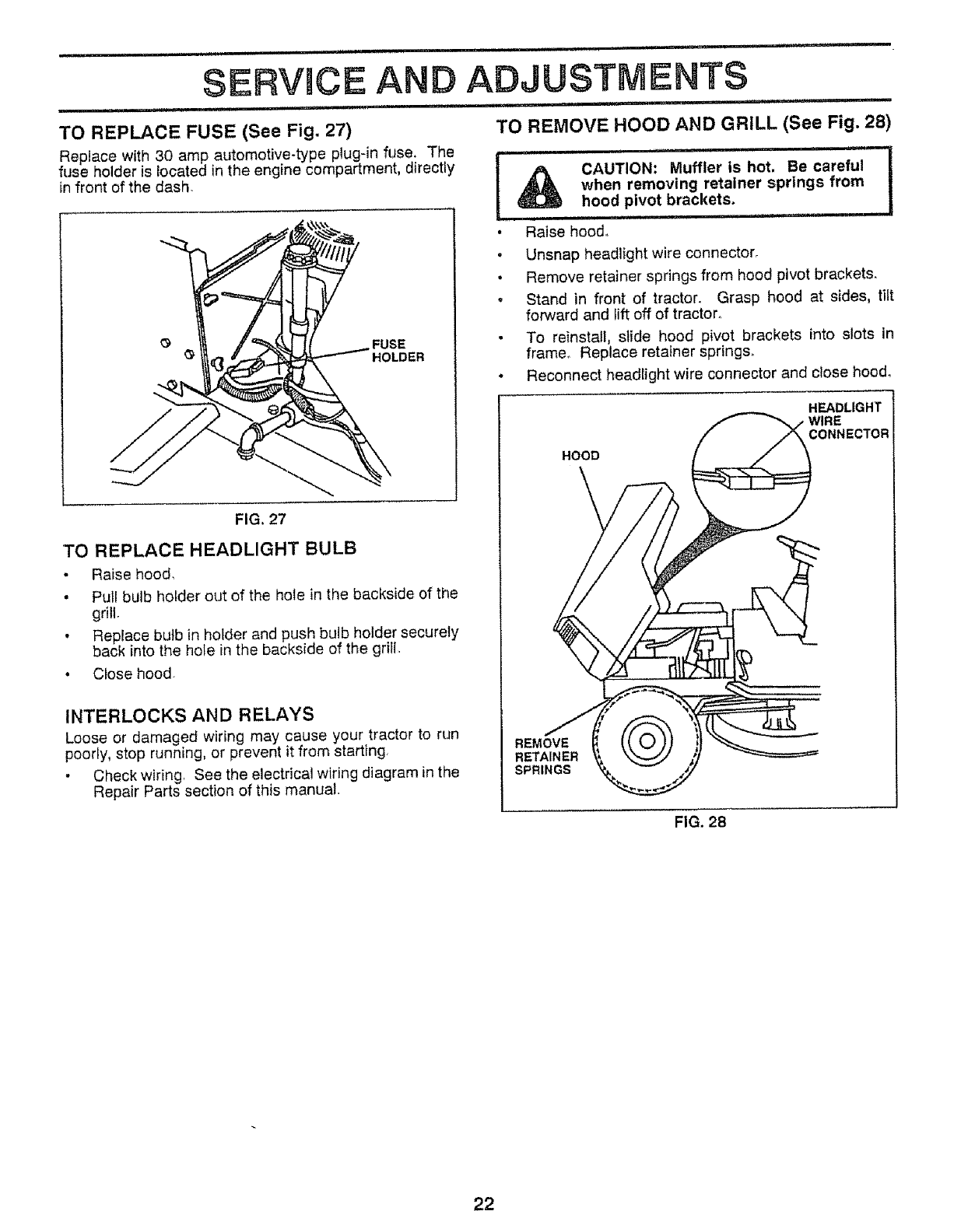
TO REPLACE FUSE (See Fig. 27) TO REMOVE HOOD AND GRILL (See Fig. 28)
fuse holder is located in the engine compartment, directly CAUTION: Muffler is hot. Be careful
in front of the dash when removing retainer springs from
hood pivot brackets,
,i i/
• Raise hood.
O FUSE
HOLDER
FIG. 27
TO REPLACE HEADLIGHT BULB
• Raise hood,
• Pull bulb holder out of the hole in the backside of the
grill,
• Replace butb in holder and push bulb holder securely
back into the hote in the backside of the grili,
• Close hood,
INTERLOCKS AND RELAYS
Loose or damaged wiring may cause your tractor to run
poorly, stop running, or prevent it from starting,
• Check wiring, See the electrical wiring diagram in the
Repair Parts section of this manual.
. Unsnap headlight wire connector.
• Remove retainer springs from hood pivot brackets.
o Stand in front of tractor. Grasp hood at sides, tilt
forward and lift off of tractor°
• To reinstall, slide hood pivot brackets into slots in
frame,, Replace retainer spring&
•Reconnect headlight wire connector and close hood.
HOOD
HEADLIGHT
CONNECTOR
REMOVE
RETAINER
SPRINGS
FIG. 28
22
,t • i,uH, ....... = == = n,m, = H,, ,H,,,,,, = = u,,,=r,,,,,,=
SERVICE AND ADJUSTMENTS
=_=,UIJil,m '' H'J" .............................. ' ' 'l =m'U 1' = 'U U'""H= 1
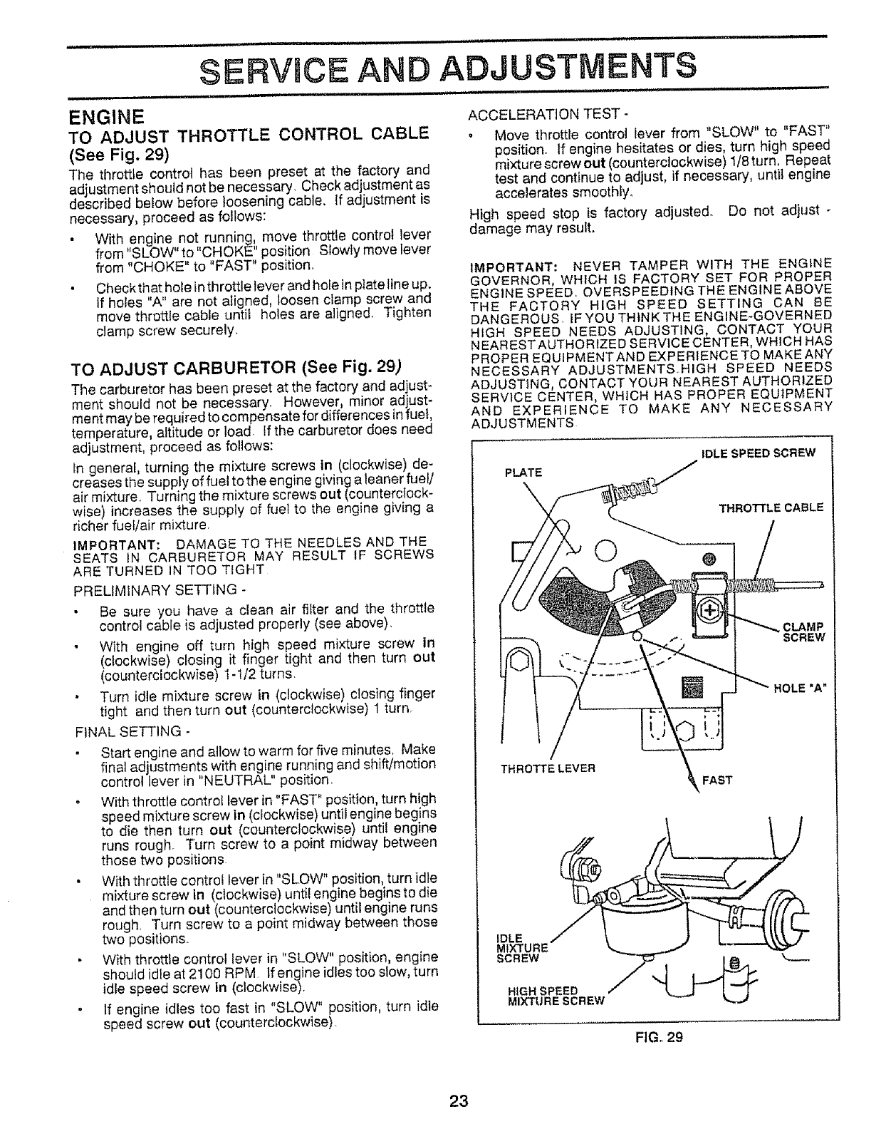
ENGINE
TO ADJUST THROTTLE CONTROL CABLE
(See Fig. 29)
The throttle control has been preset at the factory and
adjustment should not be necessary Check adjustment as
described below before loosening cable. If adjustment is
necessary, proceed as follows:
• With engine no!, runningl, move throttle control lever
from 'SLOW to CHOKE position Slowly movelever
from "CHOKE" to "FAST" position.
• Check that hole in throttle lever and hole in plate line up.
If holes "A" are not aligned, loosen clamp screw and
move throttle cable until holes are aligned Tighten
clamp screw securely
TO ADJUST CARBURETOR (See Fig. 29)
The carburetor has been preset at the factory and adjust-
ment should not be necessary However, minor adjust*
ment may be required to compensate for differences in fuel,
temperature, altitude or load If the carburetor does need
adjustment, proceed as follows:
In general, turning the mixture screws in (clockwise) de-
creases the supply of fuel to the engine giving aleaner fuel/
air mixture Turning the mixture screws out (counterclock-
wise) increases the supply of fuel to the engine giving a
richer fuel/air mixture
IMPORTANT: DAMAGE TO THE NEEDLES AND THE
SEATS IN CARBURETOR MAY RESULT IF SCREWS
ARE TURNED IN TOO TIGHT
PRELIMINARY SETTING -
Be sure you have a clean air filter and the throttle
control cable is adjusted properly (see above)
With engine off turn high speed mixture screw in
(clockwise) closing it finger tight and then turn out
(counterclockwise) 1-l/2 turns
• Turn idle mixture screw in (clockwise) closing finger
tight and then turn out (counterclockwise) 1 turn
FINAL SETTING -
Start engine and allow to warm for five minutes Make
final adjustments with engine running and shift/motion
control lever in "NEUTRAL" position
o With throttle control lever in "FAST" position, turn high
speed mixture screw in (clockwise) until engine begins
to die then turn out (counterclockwise) until engine
runs rough Turn screw to a point midway between
those two positions
• With throttle control lever in "SLOW" position, turn idle
mixture screw in (clockwise) until engine beginsto die
and then turn out (counterclockwise) until engine runs
rough. Turn screw to a point midway between those
two positions°
• With throttle control lever in "SLOW" position, engine
should idle at 2100 RPM tfengine idles too slow, turn
idle speed screw in (clockwise).
. If engine idles too fast in "SLOW" position, turn idle
speed screw out (counterclockwise).
ACCELERATION TEST -
• Move throttle control lever from "SLOW" to "FAST"
position° If engine hesitates or dies, turn high speed
mixture screw out (counterclockwise) 1/8 turn. Repeat
test and continue to adjust, if necessary, until engine
accelerates smoothly°
High speed stop is factory adjusted Do not adjust
damage may result.
IMPORTANT: NEVER TAMPER WITH THE ENGINE
GOVERNOR, WHICH IS FACTORY SET FOR PROPER
ENGINE SPEED OVERSPEEDING THE ENGINE ABOVE
THE FACTORY HIGH SPEED SETTING CAN BE
DANGEROUS. IF YOU THINK THE ENGINE-GOVERNED
HIGH SPEED NEEDS ADJUSTING, CONTACT YOUR
NEARESTAUTHORtZED SERVICE CENTER, WHICH HAS
PROPER EQUIPMENTAND EXPERIENCETO MAKE ANY
NECESSARY ADJUSTMENTS.HIGH SPEED NEEDS
ADJUSTING, CONTACT YOUR NEAREST AUTHORIZED
SERVICE CENTER, WHICH HAS PROPER EQUIPMENT
AND EXPERIENCE TO MAKE ANY NECESSARY
ADJUSTMENTS
PLATE
IDLE SPEED SCREW
THROTTLE CABLE
SCREW
HOLE"A"
/
THROTTE LEVER
_FAST
IDLE
MIXTURE
SCREW
HIGH SPEED
MIXTURE SCREW
FIGo 29
23
....................... iilll in.ln"..i I,utrl I ................................ ,.,LU, " i,ll, i ,,,,i ¸ I u lU lUI,I
STORAGE
......................... luu i,.,ul _t, i llll i i lUl i llll
Immediately prepare your tractor for storage at the end of ENGINE
the season or if the tractor witt not be used for 30 days or
more
ii, ii, ill ii i,ii. i...i
CAUTION: Never store the tractor with
gasoline in the tank inside a building
where fumes may reach an open flame
or spark. Allow the engine to cool
before storing in any enclosure.
TRACTOR
Remove mower from tractor for winter storage. When
mower is to be stored for a period of time, clean it thor-
oughly, remove all dirt, grease, leaves, etc Store in a
clean, dry area.
• Clean entire tractor (See "CLEANING" inthe Customer
Responsibilities section of this manual)
• Inspect and replace belts, if necessary (See belt re-
placement instructions in the Service and Adjustments
section of this manual).
• Lubricate as shown in the Customer Responsibilities
section of this manual
• Be sure that all nuts, bolts and screws are securely
fastened lnspect moving parts for damage, breakage
and wear Replace if necessary
• Touch up all rusted or chipped paint surfaces; sand
lightly before painting_
BATTERY
•Fu}ly charge the battery for storage
• After a period of time in storage, battery may require
recharging
• To help prevent corrosion and power leakage during
long periods of storage, battery cables should be
disconnected and battery cleaned thoroughly (see "TO
CLEAN BATTERY AND TERMINALS in the Cus-
tomer Responsibilities section of this manual)
• After cleaning, leave cables disconnected and place
cables where they cannot come in contact with battery
terminals
• Be sure battery drain tube is secureiy attached
FUEL SYSTEM
IMPORTANT: iT IS IMPORTANT TO PREVENT GUM
DEPOSITS FROM FORMING tN ESSENTIAL FUEL
SYSTEM PARTS SUCH AS CARBURETOR, FUEL FILTER,
FUEL HOSE, OR TANK DURING STORAGE. ALSO,
EXPERIENCE INDICATES THAT ALCOHOL BLENDED
FUELS (CALLED GASOHOL OR USING ETHANOL OR
METHANOL) CAN ATTRACT MOISTURE WHICH LEADS
TO SEPARATION AND FORMATION OF ACIDS DURING
STORAGE_ ACIDIC GAS CAN DAMAGE THE FUEL
SYSTEM OF AN ENGINE WHILE IN STORAGE.
o Drain the fuel tank
• Start the engine and let it run until the fuel lines and
carburetor are empty
, Never use engine or carburetor cleaner products tn the
fuel tank or permanent damage may occur
• Use fresh fuel next season
NOTE: Fuel stabilizer is an acceptable alternative in
minimizing the formation of fuel gum deposits during stor-
age Add stabilizer to gasoline in fuel tank or storage
container Always follow the mix ratio found on stabilizer
container Run engine at least 10 minutes after adding
stabilizer to allow the stabilizer to reach the carburetor Do
not drain the gas tank and carburetor if us{rig fuet stabi{izer
ENGINE OIL
Drain oil (with engine warm) and replace with clean engine
oil (See "ENGINE" in the Customer Responsibilities
section of this manual)
CYLINDERS
• Remove spark plug(s).
• Pour one ounce of oil through spark plug hole(s) into
cylinder(s)
° Turn ignition key to"START" posit{on for afew seconds
to distribute oil
• Replace with new spark plug(s)
OTHER
•Do not store gasoline from one season to another
• Replace your gasoline can if your can starts to rust.
Rust and/or dirt in your gasoline will cause problems
• If possible, store your tractor indoors and cover it to
give protection from dust and dirt.
• Cover your tractor with a suitable protective cover that
does not retain moisture. Do not use plastic. Plastic
cannot breathe which allows condensation to form and
wilt cause your tractor to rust.
IMPORTANT: NEVER COVER TRACTOR WHILE ENGINE
AND EXHAUST AREAS ARE STILL WARM.
24

TROUBLESHOOTI POINTS
CAUSE CORRECTION
,11
PROBLEM
Will not start
Hard to start
IHHH' 'H '"""'I lU
Engine will not turn over
Engine clicks but wtll not
start
Lose of power
Excessive vibration
1 Out of fuel
2 Engine not "CHOKED" properly
3Engine flooded
4 Bad spark plug
5 Dirty air filter.
6, Dirty fuel filter
7. Water tn fuel
8. Loose or damaged Wiring
9Carburetor out of adjustment.
10 Engine valves out of adjustment,
i,Hi
1 Dirty air filter
2 Bad spark plug.
3 We_k or dead battery
4D_rty fueI filter
5 Stale or dirty fuel
6 Loose or damaged wiring
7, Carburetor out of adjustment-
8 Engine valves out of adjustment,
1 Clutch/brake pedal not depressed
2, Attachment clutch ts engaged,
3Weak or dead battery
4 BIawn fuse
5Corroded battery terminals
6 Loose or damaged wiring.
7Faulty ignition switch.
8Faulty sofenoid or starter
9 Faulty operator presence switch(es)
1 Weak or dead battery.
2Corroded battery terminals
3Loose or ,damaged wiring
4 Faulty solenotd or starter
1 Cutting too much grass/too fast,
2Throttle in "CHOKE" position.
3Build-up of grass, leaves and trash under mower
4 Dirty air filter
5 Low oil level/dirty oil
6 Faulty spark pfug
7 Dirty fue_ filter
8 Stale or dirty fuel
9Water in fuel
10 Spark plug wire loose
11 Dirty engine air screen!fins
12 Dirty/c_ogged muffler.
13 Loose or damaged wiring
14 Carburetor out of adjustment
15. Engine valves out of adjustment,
1Worn, bent or loose blade,
2 Bent blade mandrel
3 Loose/damaged part(s)
1, FIll fuel tank.
2, See "TO START ENGINE" in Operation section.
3 Wait several minutes before attempting to start.
4, Replace spark ptug
5 Clean/replace air filter
6, Replace fuet filter
7. Drain fuel tank and carburetor, refill tank with fresh
gasoline and replace fuel filter.
8. Check attwirlng
9Contact Sears Service Center/Department,
10 Contact Sears Service Center/Department,
1 Clean!replace air filter
2 Replace spark p_ug
3 Recharge or replace battery
4 Replace fuel filter
5, Drain fuel tank and refitt with fresh gasonne
6 Check nil wiring
7, Contact Sears Service CentedDepartment
8 Contact Sears Service Center/Department,
1, Depress clutch/brake pedal,
2 Disengage attachment clutch,
3, Recharge or reptace battery
4 Replace fuse.
5 Clean battery terminals
6 Check at_wiring
7 Check!replace Ignition switch
8Check/replace soJenold or starter,
9 Contact Sears Service Center/Department
1 Recharge or reptace battery
2, Clean batteryterminais
3 Check al_wir;_ng
4 Check/replace solenoid or starter
1 Set in "Higher Cut" position/reduce speed.
2, Adjust throttle control
3Clean underside of mower housing
4 Cteantrep)ace air fiiter
5 Check oil leve!/change oil,
6 Clean and regap or change spark plug
7 Replace fuel filter
8 Drain fuel tank and refill with fresh gasoitne
9 Drain fuel tank and carburetor, reflt_ tank with fresh
gasotine and repiace fuel fitter
10 Connect and tighten spark pfug wire,
11 Clean engine alr screen/fins
12 Clean/replace muffler
t3 Check all Wffingr
14" Contact Sears Service Center/Department
t 5 Contact Sears Service Center/Department.
1 Replace blade Tighten blade best,
2 Replace blade mandrel.
3 Tighten loose part{s) Replace damaged parts.
25

TROUBLESHOOTING POINTS
,,N,,,,, ...................
PROBLEM
Engine continues to run
when operator leaves seat
with attachment clutch
engaged
Poor cut * uneven
CAUSE
1Faulty operator-safety presence control system
Mower blades will not
rotate
Poor grass discharge
1. Worn, bent or Ioose blade,
2Mower deck not level
3, Buiidup of grass, Ieaves, and trash under mower,
4. Bent blade mandrel
5 Clogged mower deck vent hotes from buildup of
grass, leaves, and trash around mandrels.
1. Obstruction In clutch mechanism
2Worn/damaged mower drive belt
3. Frozen Idler puttey
4 Frozen blade mandrel.
CORRECTION
1. Checkwtrlng, switches and connections If not
corrected, contact Sears Service Center/Department.
Headlight(s) not working
(if so equipped)
Battery wilt not charge
1 Engine speed too slow
2. Travefspeed too fast
3. Wet grass.
4 Mower deck not level.
5 Low/uneven tlre air pressure
6. Worn, bent or loose btade
7 Buildup of grass, leaves and trash under mower.
8 Mower drive belt worn
9Blades improperly insta_ed
10 Improper blades used
11 Clogged mower deck vent holes from buildup of
grass, leaves, and trash around mandrels.
1 Switch Is "OFF"
2. Bulb(s) burned out.
3 Faulty light switch.
4 Loose or damaged wiring
5 Blown fuse
1 Replace blade. Tighten blade bolt.
2 Level mower deck.
3 Clean underslde of mower housing
4 Replace blade mandrel-
5 Clean around mandrels to open vent holes.
1 Remove obstruction.
2Replace mower drive belto
3 Replace idler pulley
4 Replace blade mandrel
1 Place throttle control in "FAST" position.
2 Shift to s_ower speed.
3PJtow grass to dry before mowing.
4 Level mower deck
5. Check tires for proper alr pressure.
6Replace/sharpen blade. Tighten blade bo_t.
7Clean underside of mower housing
8, Replace mower drive belt.
9 Reinstall blades sharp edge down.
10 Replace with blades Hsted In this manual
11 Clean around mandrels to open vent hotes.
1 Turn switch "ON"
2 Replace bulb(s)
3 Check/replace tight switch
4 Check wiring and connections
5 Replace fuse
l Bad battery ce]!(s)
2. Poor cabie connections
3Faulty regulator (if so eqtJ_pped)
4 Faulty alternator
1 Replace battery
2. Check/clean altconnections
3 Replace regulator
4Replace alternator
26
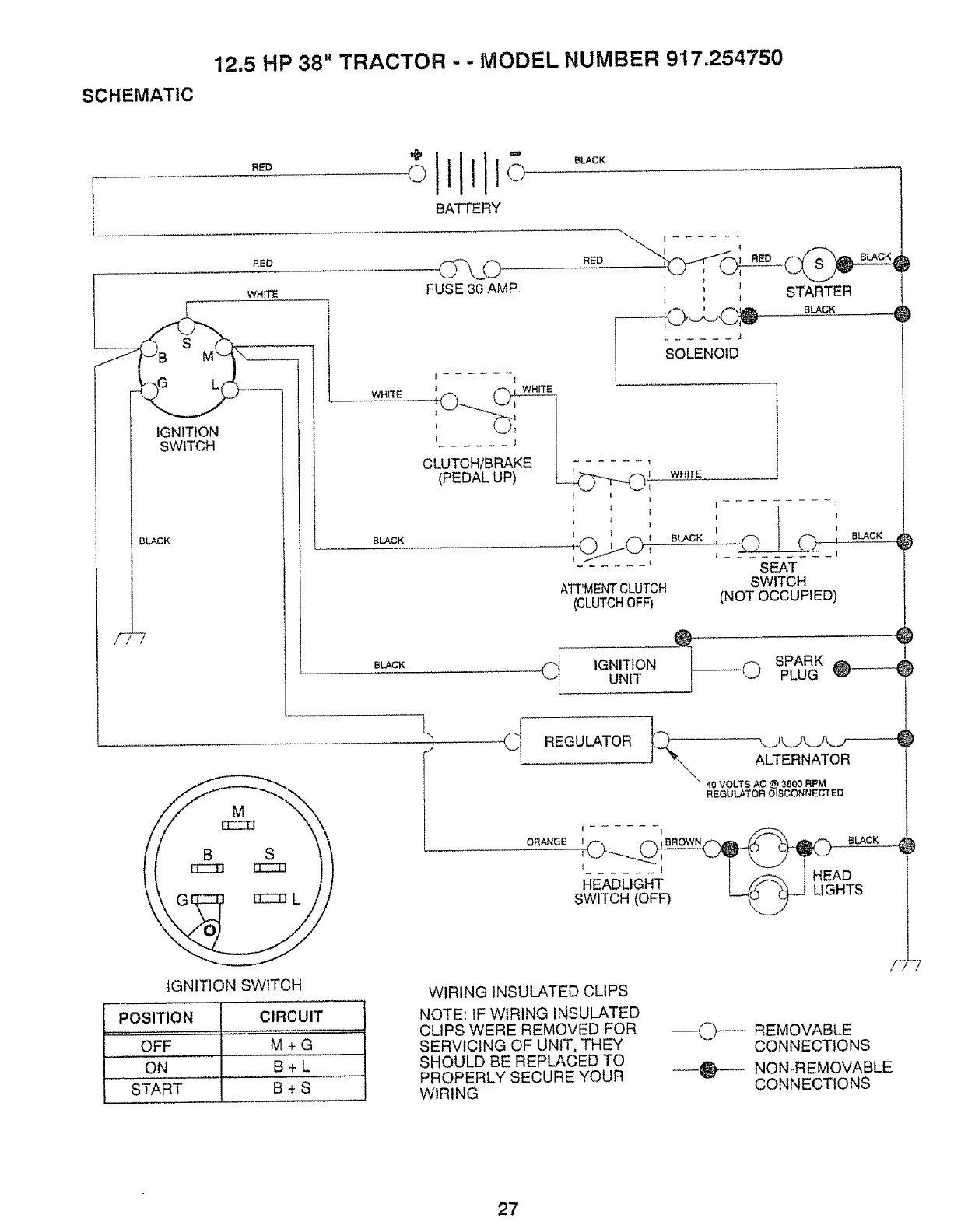
12.5 HP 38" TRACTOR - - MODEL NUMBER 917.254750
SCHEMATIC
F
RED
RED
WHITE
BATTERY
IGNITION
SWtTCH
BLACK
"7
BLACK
RED
r ......
}RED BLACK
, j STARTER
--,-tO ' O_ cLAcK
K_Jk,J _
SOLENOID
WHITE I _ = WHITE
...... 1
(PEDAL UP) _!
i I I
BLACK _ _
WHITE
BLACK
ATT'MENTCLUTCH
(CLUTCHOFF)
SEAT
SWITCH
(NOT OCCUPIED)
BLACK
Cf IGNITIONUNIT
SPARK J
PLUG F@
IGNITION SWITCH
REGULATOR
ALTERNATOR
40 VOLTS AC @ 3600 RPM
REGULATOR DISCONNECTED
ORANGE :,o.ow.@ sLAcK
tI, %
SWITCH (OFF) _-_-_ "'_
POSITION ICIRCUIT
OFF M'"+ G '
ON I B+ L
START I B + S
WIRING INSULATED CLIPS
NOTE: IF WIRING INSULATED
CLIPS WERE REMOVED FOR
SERVICING OF UNIT, THEY
SHOULD BE REPLACED TO
PROPERLY SECURE YOUR
WIRING
--0---- REMOVABLE
CONNECTIONS
--_ NON-REMOVABLE
CONNECTIONS
27
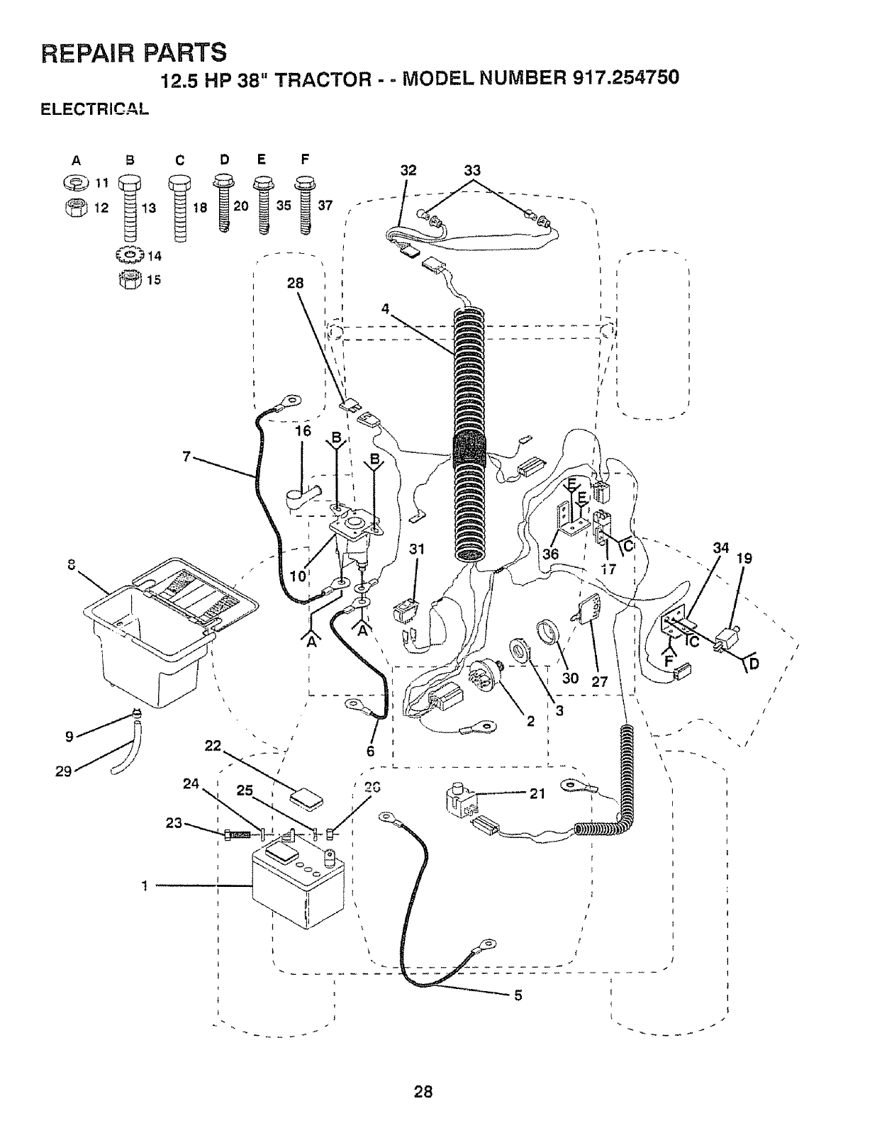
REPAIR PARTS
12.5 HP 38" TRACTOR - -MODEL NUMBER 917.254750
ELECTRICAL
A9 C D
12 13 t8 0
_15
29
22
E F 32 33
31
17
34
\
\
\
3O
\
19
!
/
28

REPAIR PARTS
12.5 HP 38" TRACTOR - - MODEL NUMBER 917.254750
ELECTRICAL
KEY PART
NO. NO, DESCRIPTION
1 t21265X
2 STD365402
3 124211X
4 133433
5 4207J
6 1322O2
7 108423X
8 129965
9 109596X
10 109081X
11 STD551125
12 73350400
13 74780408
14 STD551225
15 STD541425
16 131563
17 109553X
18 STD601005
19 104445X
20 STD601005
21 121305X
22 121264X
23 74760412
24 STD551025
25 STD551125
26 STD541025
27 109310X
28 108824X
29 105687X
30 123620X
3t 110712X
32 12744tX
33 7662J
34 I08236X
35 STD601005
36 136890
37 STD601005
Battery, 12 Volt
Switch, Starter
Nut, Ignition
Harness, ignition
Cable, Ground
Cable, Battery
Cable, Battery
Battery Box
Clamp, Hose
Solenoid
Washer, Lock
Nut, Hex, Jam 1/4-20 UNC
Bolt, Hex, Fin.
t/4-20 UNC x 1/2 Grade 5
Washer
Nut
Cover, Terminal
Switch, Interlock
Screw
Switch, Interlock
Screw
Switch, Plunger
Cap, Battery
Boft, Hex Head 1/4-20 UNC x 3/4
Washer
Washer
Nut
Key, Ignition
Fuse, 30 Amp
Tube, Battery Drain
Cover, Key Switch
Switch, Light
Harness, Light Socket
Bulb, Light
Bracket, Switch, Interlock
Screw
Bracket, Switch, Interlock
Screw
NOTE: A!l component dimensions given in U,S. inches
I inch = 25.4 mm
29
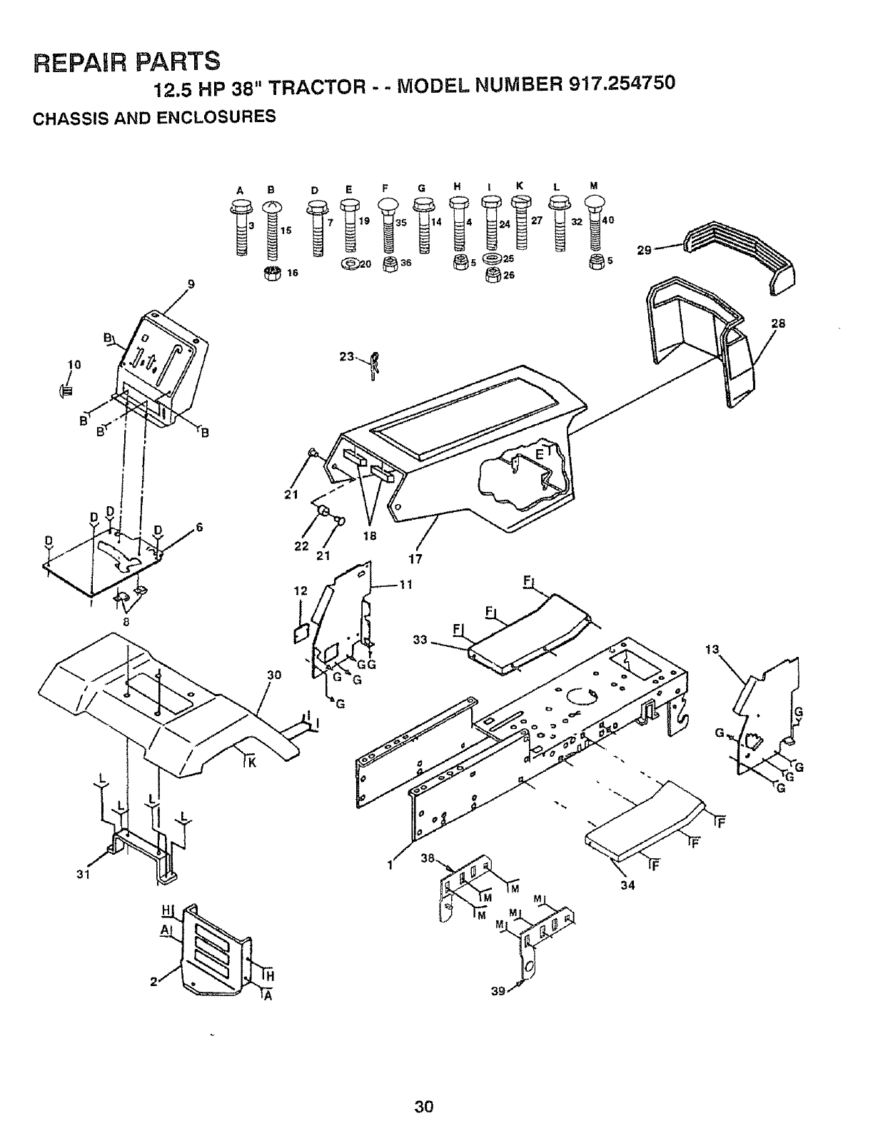
REPAIR PARTS
12,5 HP 38" TRACTOR
CHASSIS AND ENCLOSURES
.-MODEL NUMBER 917.254750
I
9
A
13
G
31 34
3O
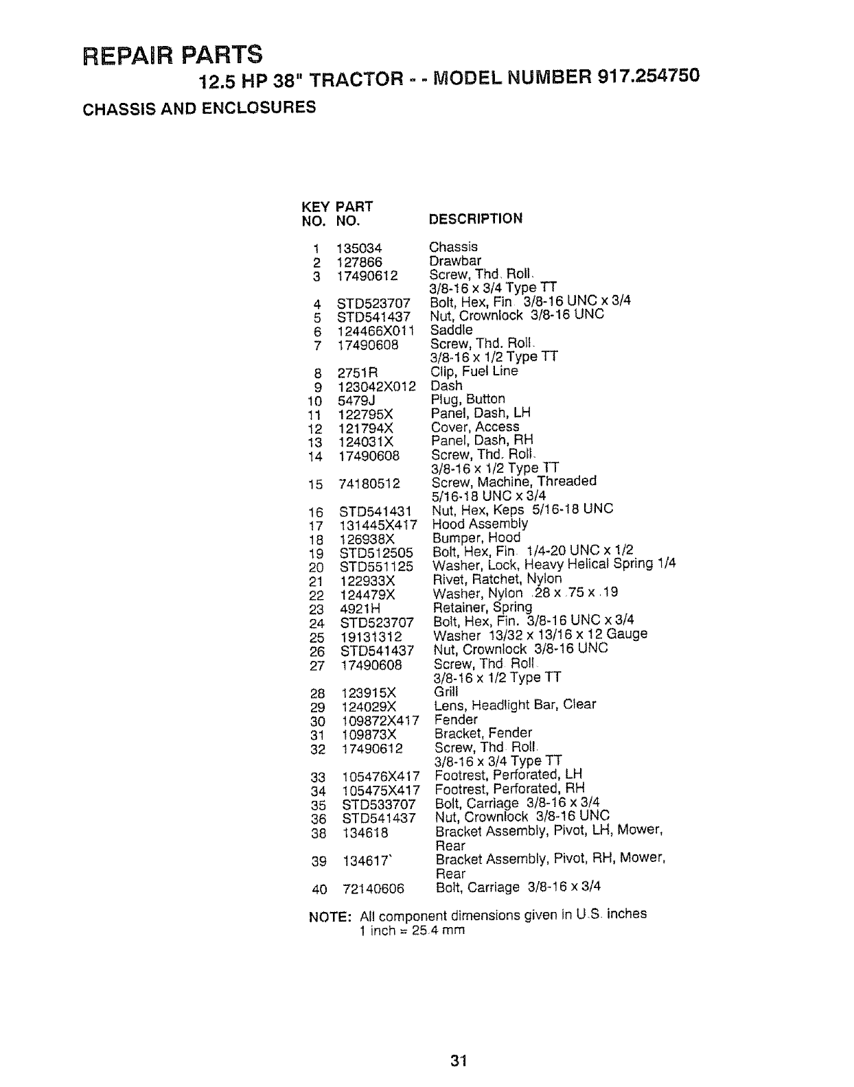
REPAIR PARTS
12.5 HP 38" TRACTOR - -MODEL NUMBER 917,254750
CHASSIS AND ENCLOSURES
KEY PART
NO. NO. DESCRIPTION
1 135034
2 127866
3 17490612
4 STD523707
5 STD541437
6 124466X011
717490608
8 2751R
9 123042X012
10 5479J
11 122795X
12 121794X
13 124031X
14 17490608
15 74180512
16 STD541431
17 13t445X417
18 126938X
19 STD512505
20 STD551125
21 122933X
22 124479X
23 4921H
24 STD523707
25 19131312
26 STD541437
27 17490608
28 123915X
29 124029X
30 109872X417
31 109873X
32 17490612
33 105476X417
34 105475X417
35 STD533707
36 STD541437
38 134618
39 134617"
40 72140606
Chassis
Drawbar
Screw, Thd, Roll.
3/8-t 6 x 3/4 Type TT
Bolt, Hex, Fin 3/8-16 UNC x 3/4
Nut, Crownlock 3/8-I6 UNC
Saddle
Screw, Thd. Roll.
3/8-16 x 1/2 Type TT
Clip, Fuel Line
Dash
Plug, Button
Panel, Dash, LH
Cover, Access
Panel, Dash, RH
Screw, Thd. Roll.
3/8-16 x 1/2 Type TT
Screw, Machine, Threaded
5/16-I8 UNC x 3/4
Nut, Hex, Keps 5/16-18 UNC
Hood Assembly
Bumper, Hood
Bolt, Hex, Fin 1/4-20 UNC x 1/2
Washer, Lock, Heavy Helical Spring 1/4
Rivet, Ratchet, Nylon
Washer, Nylon ,28 x 75 x .19
Retainer, Spring
Bolt, Hex, Fin. 3/8-16 UNC x 3/4
Washer 13/32 x 13/16 x 12 Gauge
Nut, Crownlock 3/8-16 UNC
Screw, Thd Ro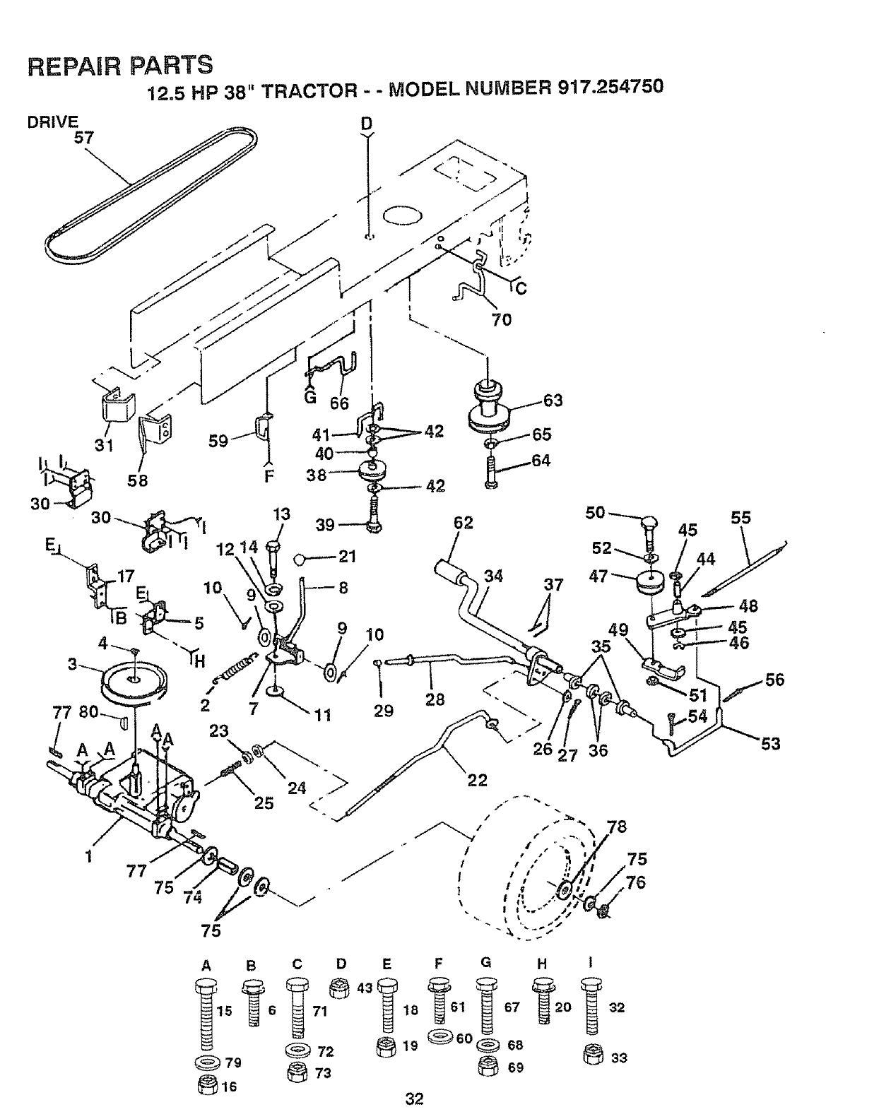
REPAIR
DRIVE57
PARTS
12.5 HP 38" TRACTOR --MODEL NUMBER 917.254750
D
F
25
77 75 74
75
A B
_79
13
_::::==-42
10
62
7O
34 37
J
C D E F G
71 18 1 67
72 _ 19_;_6o_ 68
32
7 36
78
75
76
H I
33
45
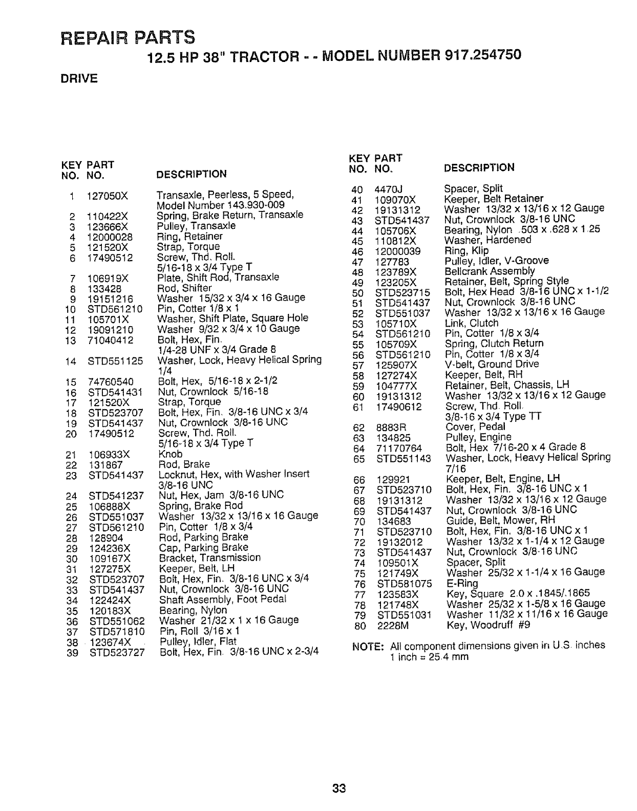
REPAIR PARTS
12.5 HP 38" TRACTOR - -MODEL NUMBER 917.254750
DRIVE
KEY PART KEY PART
NO. NO. DESCRIPTION NO. NO, DESCRIPTION
l 127050X
2 110422X
3 123666X
4 12000028
5 121520X
6 17490512
7 106919X
8 133428
9 19151216
10 STD56t210
11 105701X
12 19091210
13 71040412
14 8TD551125
15 74760540
16 STD541431
17 121520X
18 STD523707
19 STD541437
20 17490512
21 106933X
22 131867
23 STD541437
24 STD541237
25 106888X
26 STD551037
27 STD561210
28 128904
29 124236X
30 109167X
31 127275X
32 STD523707
33 STD541437
34 122424X
35 120183X
36 STD551062
37 STD571810
38 123674X
39 STD523727
Transaxfe, Peerless, 5 Speed, 40
Model Number t43.930-009 41
Spring, Brake Return, Transaxle 42
PulIey, Transaxie 43
Ring, Retainer 44
Strap, Torque 45
Screw, Thd, Roll. 46
5/16-18 x 3/4 Type T 47
Plate, Shift Rod, Transaxle 48
Rod, Shifter 49
Washer 15/32 x3/4 x 16 Gauge 50
Pin, Cotter 1/8 x 1 51
Washer, Shift Plate, Square Hole 52
Washer 9/32 x 3,/4x 10 Gauge 53
Bolt, Hex, Fin. 54
1/4-28 UNF x 3/4 Grade 8 55
Washer, Lock, Heavy Helicat Spring 56
t/4 57
Bolt, Hex, 5/t6-18 x 2-1/2 58
Nut, Crowntock 5/16.-18 59
Strap, Torque 60
Bolt, Hex, Fin. 3/8-16 UNC x 3/4 6I
Nut, Crownlock 3/8-16 UNC
Screw, Thd. Roll. 62
5/16q 8 x 3/4 Type T 63
Knob 64
Rod, Brake 65
Locknut, Hex, with Washer Insert
3/8-16 UNC 66
Nut, Hex, Jam 3/8-16 UNC 67
Spring, Brake Rod 68
Washer 13/32 x 13/t6 x 16 Gauge 69
Pin, Cotter 1/8 x 3/4 70
Rod, Parking Brake 71
72
Cap, Parking Brake
Bracket, Transmission 73
Keeper, Belt, LH 74
Boft, Hex, Fin. 3/8-16 UNC x 3/4 75
Nut, Crownlock 3/8-16 UNC 76
Shaft Assembly, Foot Pedat 77
78
Bearing, Nylon
Washer 2t/32 x t x 16 Gauge 79
Pin, RoJl 3/t6 x 1 80
Pultey, tdler, Flat
Bolt, Hex, Fin. 3/8-16 UNC x 2-3/4
447oj
10907OX
19131312
STD541437
105706X
11O812X
120o0039
127783
I23789X
t232O5X
STD523715
STD541437
STD551037
105710X
STD56t210
105709X
STD561210
125907X
127274X
104777X
19131312
17490612
8883R
134825
71170764
STD551143
129921
STD523710
19131312
STD541437
134683
STD523710
19132012
STD541437
10950lX
121749X
STD581075
123583X
121748X
STD551031
2228M
Spacer, Split
Keeper, Belt Retainer
Washer t3/32 x 13/16 x 12 Gauge
Nut, Crownlock 3/8-16 UNC
Bearing, Nylon .503 x ,628 x 1.25
Washer, Hardened
Ring, Klip
Putley, Idler, V_Groove
Belicrank Assembly
Retainer, Belt, Spring Style
Bolt, Hex Head 3/8-16 UNC x 1-1/2
Nut, Crownlock 3/8-16 UNC
Washer 13/32 x 13/16 x 16 Gauge
Link, Clutch
Pin, Cotter 1/8 x 3/4
Spring, Clutch Return
Pin, Cotter 1/8 x 3/4
V-belt, Ground Drive
Keeper, Belt, RH
Retainer, Belt, Chassis, LH
Washer 13/32 x 13/16 x 12 Gauge
Screw, Thd Roll.
3/8-16 x 3/4 Type TT
Cover, Pedal
Pulley, Engine
Bolt, Hex 7/16-20 x 4 Grade 8
Washer, Lock, Heavy Helical Spring
7116
Keeper, Belt, Engine, LH
Bolt, Hex, Fin. 3/8-16 UNC x 1
Washer 13/32 x 13/i6 x 12 Gauge
Nut, Crownlock 3/8-I6 UNC
Guide, Belt, Mower, RH
Bolt, Hex, Fin. 3/8q6 UNC x 1
Washer 13/32 x 1-1/4 x 12 Gauge
Nut, Crownlock 3/84 6 UNC
Spacer, Spfit
Washer 25/32 x 1-1/4 x 16 Gauge
E-Ring
Key, Square 2.0 x, 1845/. 1865
Washer 25/32 x 1-5/8 x 16 Gauge
Washer 11/32 x ! 1/16 x 16 Gauge
Key, Woodruff #9
NOTE: All component dimensions given in U.S inches
1 inch = 25.4 mm
33
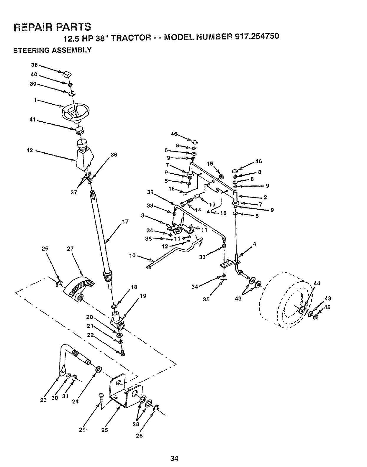
s_ _"_"__ss_L_
?.6
/
0
/
\
3t,
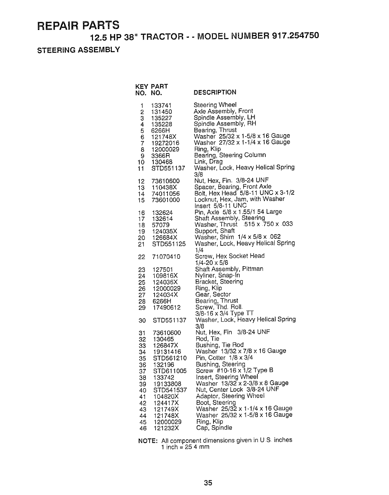
REPAIR PARTS
12.5 HP 38" TRACTOR - - MODEL NUMBER 917.254750
STEERING ASSEMBLY
KEY PART
NO. NO, DESCRIPTION
1 133741
2 131450
3 135227
4 135228
5 6266H
6 121748X
7 19272016
8 12000029
9 3366R
10 130468
11 STD551137
12 73610600
13 !10438X
14 74011056
15 73601000
16 132624
t7 132614
I8 57079
19 124035X
20 126684X
21 STD551125
22 71070410
23 127501
24 I09816X
25 124036X
26 12000029
27 124034X
28 6266H
29 17490612
30 STD551137
31 736106OO
32 130465
33 126847X
34 19131416
35 STD561210
36 132196
37 STD611005
38 133742
39 19133808
40 STD541537
41 104820X
42 124417X
43 12t749X
44 121748X
45 12000029
46 121232X
Steering Wheel
Axle Assembly, Front
Spindle Assembly, LH
Spindle Assembly, RH
Bearing, Thrust
Washer 25/32 x 1-5/8 x 16 Gauge
Washer 27/32 x 1-1/4 x I6 Gauge
Ring, Klip
Bearing, Steering Column
Link, Drag
Washer, Lock, Heavy Helical Spring
3/8
Nut, Hex, Fin. 3/8-24 UNF
Spacer, Bearing, Front Axle
Bolt, Hex Head 5/8-11 UNC x 3-1/2
Locknut, Hex, Jam, with Washer
Insert 5/8-1! UNC
Pin, Axle 5/8 x 1,55/1 54 Large
Shaft Assembly, Steering
Washer, Thrust 515 x .750 x 033
Support, Shaft
Washer, Shim 1/4 x 5/8 x 062
Washer, Lock, Heavy Helical Spring
1/4
Screw, Hex Socket Head
1/4-20 x 5/8
Shaft Assembly, Pittman
Nyliner, Snap-In
Bracket, Steering
Ring, Klip
Gear, Sector
Bearing, Thrust
Screw, Thd Roll.
3/8-16 x 3/4 Type TT
Washer, Lock, Heavy Helical Spring
3/8
Nut, Hex, Fin 3/8-24 UNF
Rod, Tie
Bushing, Tie Rod
Washer 13/32 x 7/8 x 16 Gauge
Pin, Cotter 1/8 x 3/4
Bushing, Steering
Screw #10-16 x 1/2 Type B
Insert, Steering Wheel
Washer 13/32 x 2-3/8 x 8 Gauge
Nut, Center Lock 3/8-24 UNF
Adaptor, Steering Wheel
Boot, Steering
Washer 25/32 x lq/4 x !6 Gauge
Washer 25/32 x 1-5/8 x 16 Gauge
Ring, Klip
Cap, Spindle
NOTE: All component dimensions given in U S inches
1 inch = 25 4 mm
35
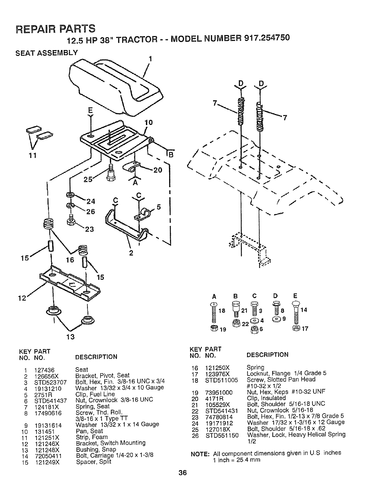
REPAnR PARTS
12,5 HP 38" TRACTOR - - MODEL NUMBER 917.254750
B
26
C
2
15
\
12
13
KEY PART
NO. NO.
1 127436
2 t26656X
3 STD523707
4 19131210
5 2751R
6 STD541437
7 124181X
8 17490616
9 19131614
10 131451
tl 121251X
12 121246X
13 121248X
14 72050411
15 121249X
DESCRIPTION
Seat
Bracket, Pivot, Seat
Bott, Hex, Fin. 3/8-16 UNCx 3/4
Washer t3/32 x 3/4 x 10 Gauge
Clip, Fuel Line
Nut, Crownlock 3/8q6 UNC
Spring, Seat
Screw, Thd, Roil,
3/8-16 x 1 Type TT
Washer 13/32 x 1 x 14 Gauge
Pan, Seat
Strip, Foam
Bracket, Switch Mounting
Bushing, Snap
Bolt, Carriage 1/4-20 x 1-3/8
Spacer, Sp_it
36
A B C D E
KEY PART
NO. NO. DESCRIPTION
16 121250X
17 123976X
t8 STD511005
19 73951000
2O 4171R
21 105529X
22 STD541431
23 74780814
24 19171912
25 127018X
26 STD551150
Spring
Locknut, Flange 1/4 Grade 5
Screw, Slotted Pan Head
#t0-32 x 1/2
Nut, Hex, Keps #10-32 UNF
Clip, Insulated
Bolt, Shoulder 5/16-18 UNC
Nut, Crownlock 5/16-18
Bolt, Hex, Fin. 1/2-13 x 7/8 Grade 5
Washer 17/32 x 1-3/16 x 12 Gauge
Bolt, Shoulder 5/16-18 x .62
Washer, Lock, Heavy Helical Spring
1/2
NOTE: All component dimensions given in U.S inches
I inch = 25.4 mm
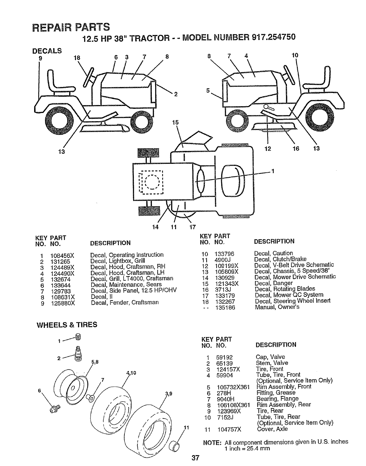
REPAnR
DECALS
9
PARTS
12.5 HP 38" TRACTOR - - MODEL NUMBER 917.254750
18
\6 3 7 8 8 7 4 10
'15
13 12 16 13
KEY PART
NO. NO.
1 108456X
2 131265
3124489X
4 124490X
5132674
6 133644
7 129783
8 108631X
9125880X
14 11 t7
DESCRIPTION
Decal, Operating Instruction
Deca!, Lightbox, Grill
Decal, Hood, Craftsman, RH
Decal, Hood, Craftsman, LH
Decal, Grill, LT4000, Craftsman
Decal, Maintenance, Sears
Decal, Side Panel, 12,5 HP/OHV
Decal, 11
Decal, Fender, Craftsman
WHEELS &TIRES
KEY PART
NO. NO.
10 133796
11 4900J
12 109199X
I3 105809X
'14 130929
15 121343X
16 3713J
17 133179
18 132267
-- 135186
DESCRIPTION
Decal, Caution
Decal, Clutch/Brake
Decal, V-Belt Drive Schematic
Decal, Chassis, 5 Speed/38"
Decat, Mower Drive Schematic
Decal, Danger
Decal, Rotating Blades
Decal, Mower QC System
Decal, Steering Wheel Insert
Manual, Owner's
37
KEY PART
NO. NO. DESCRIPTION
1 59192 Cap, Valve
2 65139 Stem, Valve
3 124157X Tire, Front
4 59904 Tube, Tire, Front
(OPtional, Service Item Only)
5 106732X361 Rim Assembly, Front
6 278H Fitting, Grease
79040H Bearing, Flange
8 106108X361 Rim Assembly, Rear
9 123969X Tire, Rear
10 7152J Tube, Tire, Rear
(Optional, Service Item Only)
t I 104757X Cover, Axle
NOTE: All component dimens{ons given in U.S. inches
1inch = 254 mm
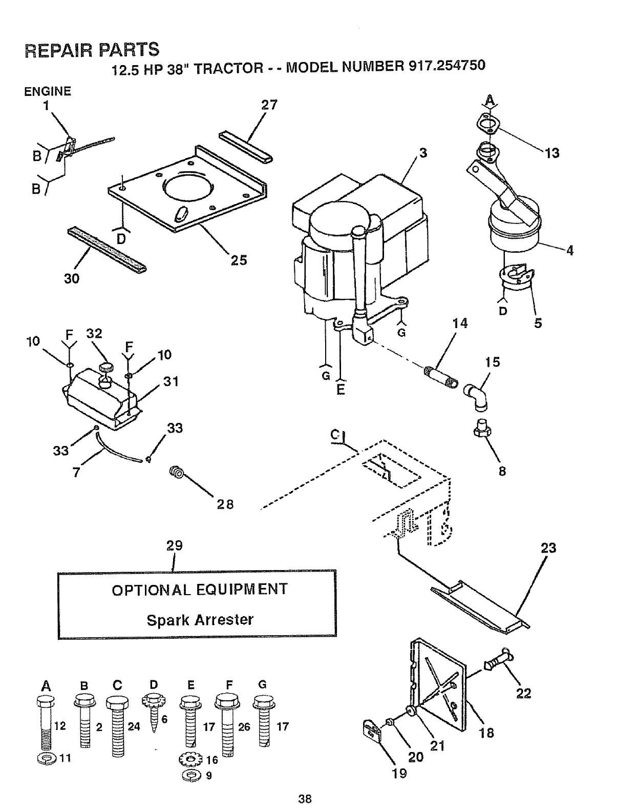
REPAIR PARTS
12.5 HP 38" TRACTOR -- MODEL NUMBER 917.254750
ENGINE
1
30
10 F!2
7
29
25
28
27
13
5
23
ABCDE G
16 _
Q9
2
19
38
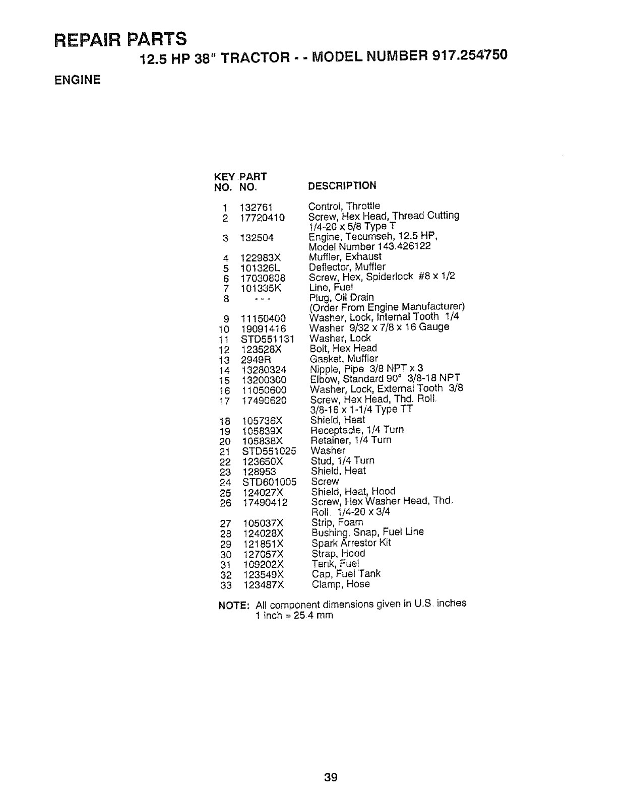
REPAIR
ENGINE
PARTS
12.5 HP 38" TRACTOR - - MODEL NUMBER 917.254750
KEY PART
NO. NO. DESCRIPTION
1 132761
2 1772O41O
3 132504
4 122983X
5 101326L
6 17030808
7 101335K
__.
9 11150400
10 19091416
11 STD551131
12 123528X
13 2949R
14 13280324
15 13200300
16 11050600
17 17490620
18 105736X
19 105839X
20 105838X
2t STD551025
22 123650X
23 128953
24 STD601005
25 124027X
26 17490412
27 105037X
28 t24028X
29 121851X
30 127057X
31 109202X
32 123549X
33 123487X
Control, Throttle
Screw, Hex Head, Thread Cutting
1/4-20 x 5/8 Type T
Engine, Tecumseh, 12,5 HP,
Model Number 143426t22
Muffler, Exhaust
Deflector, Muffler
Screw, Hex, Spidedock #8 x 1/2
Line, Fuel
Plug, Oil Drain
(Order From Engine Manufacturer)
Washer, Lock, Jnternal Tooth 1/4
Washer 9/32 x 7/8 x 16 Gauge
Washer, Lock
Bolt, Hex Head
Gasket, Muffler
Nipple, Pipe 3/8 NPT x 3
Elbow, Standard 90° 3/8-18 NPT
Washer, Lock, External Tooth 3/8
Screw, Hex Head, Thd. Roll.
3/8-16 x lq/4 Type TT
Shield, Heat
Receptacle, 1/4 Turn
Retainer, 1/4 Turn
Washer
Stud, 1/4 Turn
Shield, Heat
Screw
Shield, Heat, Hood
Screw, Hex Washer Head, Thd,
Roll_ 1/4-20 x 3/4
Strip, Foam
Bushing, Snap, Fuel Line
Spark Arrestor Kit
Strap, Hood
Tank, Fuel
Cap, Fuel Tank
Clamp, Hose
NOTE: All component dimensions given in UoS inches
1 inch = 25 4 mm
39
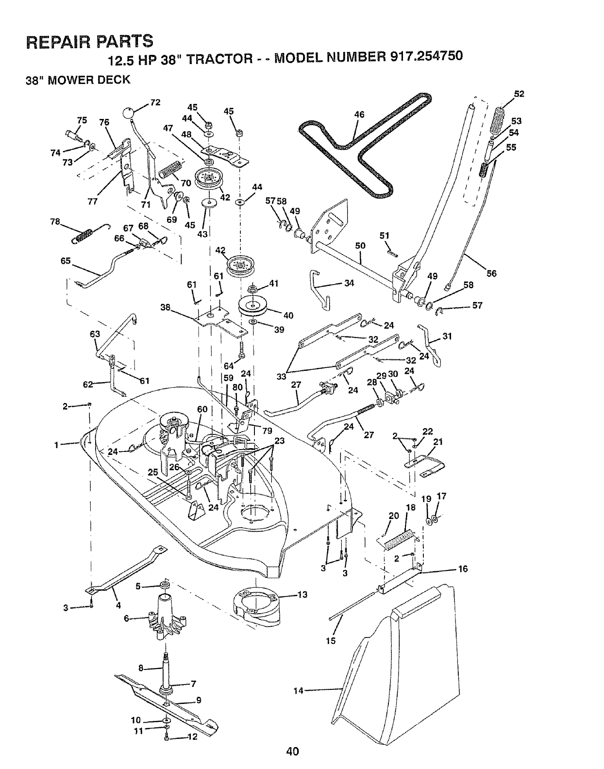
REPAIR PARTS
12.5 HP 38" TRACTOR - = MODEL NUMBER 917.254750
38" MOWER DECK
45 45
75 76 44,, \
74
23
.----7 14 ¸
46
27 2_j221
33
15
55
56
52
53
40
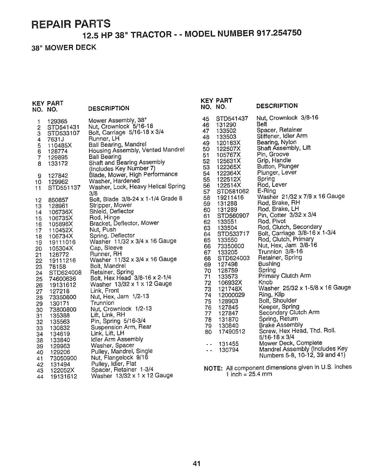
REPAIR PARTS
12.5 HP 38" TRACTOR - - MODEL NUMBER 917.254750
38" MOWER DECK
KEY PART KEY PART
NO. NO. DESCRIPTION NO. NO, DESCRIPTION
1 129365
2 STD541431
3 STD533107
4 7631J
5 t10485X
6 128774
7 129895
8 133172
9127842
10 129962
11 STD551137
12 850857
13 128961
14 t06736X
15 106735X
16 105896X
17 110452X
18 106734X
19 19111016
20 105304X
21 128772
22 19111216
23 78158
24 STD624008
25 74600636
26 19131612
27 127218
28 73350800
29 130171
30 73800800
31 135388
32 135563
33 130832
34 134619
38 133840
39 129963
40 129206
41 73050900
42 131494
43 122052X
44 19131612
Mower Assembly, 38" 45
Nut, Crownlock 5/16-18 46
Bolt, Carriage 5/16_t8 x 3/4 47
Runner, LH 48
Ball Bearing, Mandrel 49
Housing Assembly, Vented Mandrel 50
Ball Bearing 51
Shaft and Bearing Assembly 52
(lnchJdes Key Number 7) 53
Blade, Mower, High Performance 54
Washer, Hardened 55
Washer, Lock, Heavy Helical Spring 56
3/8 57
Bolt, Blade 3/8-24 x t-1/4 Grade 8 58
Stripper, Mower 59
Shield, Deflector 60
Rod, Hinge 61
Bracket, Deflector, Mower 62
Nut, Push 63
Spring, Deflector 64
Washer 11/32 x 3/4 x 16 Gauge 65
Cap, Sleeve 66
Runner, RH 67
Washer t 1/32 x 3/4 x 16 Gauge 68
Bolt, Mandrel 69
Retainer, Spring 70
Bolt, Hex Head 3/8-16 x 2-1/4 71
Washer 13/32 x 1 x 12 Gauge 72
Link, Front 73
Nut, Hex, Jam 1/2-13 74
Trunnion 75
Nut, Crownlock 1/2-13 76
Lift, Link, RH 77
Pin, Spring 5/16-3/4 78
Suspension Arm, Rear 79
Link, Lift, LH 80
Idler Arm Assembly
Washer, Spacer - -
Pulley, Mandrel, Single - -
Nut, Flangelock 9/16
Pulley, Idler, Flat
Spacer, Retainer 1-3/4
Washer 13/32 x 1 x 12 Gauge
STD541437
131290
133502
133503
120183X
122507X
105767X
125631X
122365X
122364X
122512X
122514X
STD581062
19211416
131288
131289
STD560907
133551
133504
STD533717
133550
73350600
133205
STD624003
127498
128759
133573
106932X
121748X
12000029
128903
127845
127847
131870
130840
17490512
131455
130794
Nut, Crownlock 3/8-16
Belt
Spacer, Retainer
Stiffener, idler Arm
Bearing, Nylon
Shaft Assembly, Lift
Pin, Groove
Grip, Handle
Button, Plunger
Plunger, Lever
Spring
Rod, Lever
E-Ring
Washer 21/32 x 7/8 x 16 Gauge
Rod, Brake, RH
Rod, Brake, LH
Pin, Cotter 3/32 x 3/4
Rod, Pivot
Rod, Clutch, Secondary
Bolt, Carriage 3/8-16 x 1-3/4
Rod, Clutch, Primary
Nut, Hex, Jam 3/8-16
Trunnion 3/8-16
Retainer, Spring
Bushing
Spring
Primary Clutch Arm
Knob
Washer 25/32 x 1-5/8 x 16 Gauge
Ring, Klip
Bolt, Shoulder
Keeper, Spring
Secondary Clutch Arm
Spring, Return
Brake Assembly
Screw, Hex Head, Thd. Roll.
5/16-18x3/4
Mower Deck, Complete
Mandrel Assembly (includes Key
Numbers 5-8, 10-12, 39 and 41)
NOTE; All component dimensions given in UoS. inches
1 inch = 25.4 mm
41
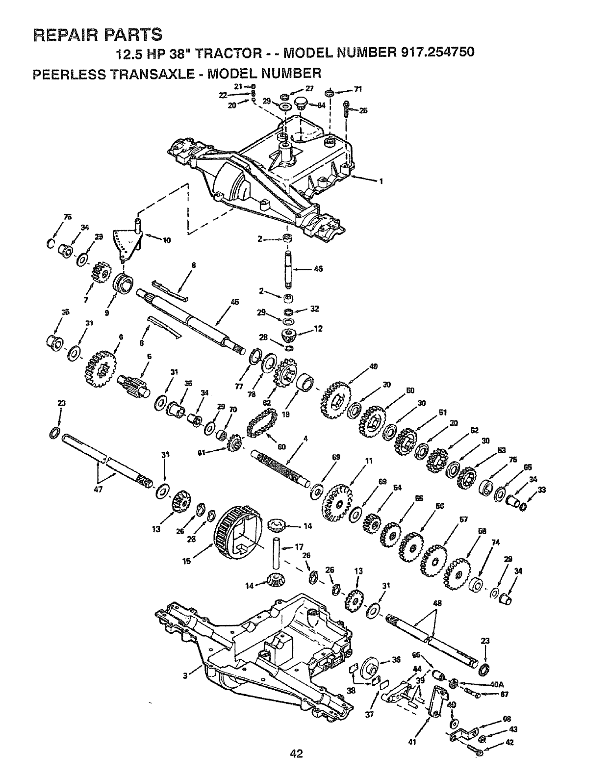
REPAIR PARTS
12.5 HP 38" TRACTOR -- MODEL NUMBER 917.254750
PEERLESS TRANSAXLE - MODEL NUMBER
21-<,-0 27 -
I
4
=/
/69 11
so
3o
57
74
48
42
37
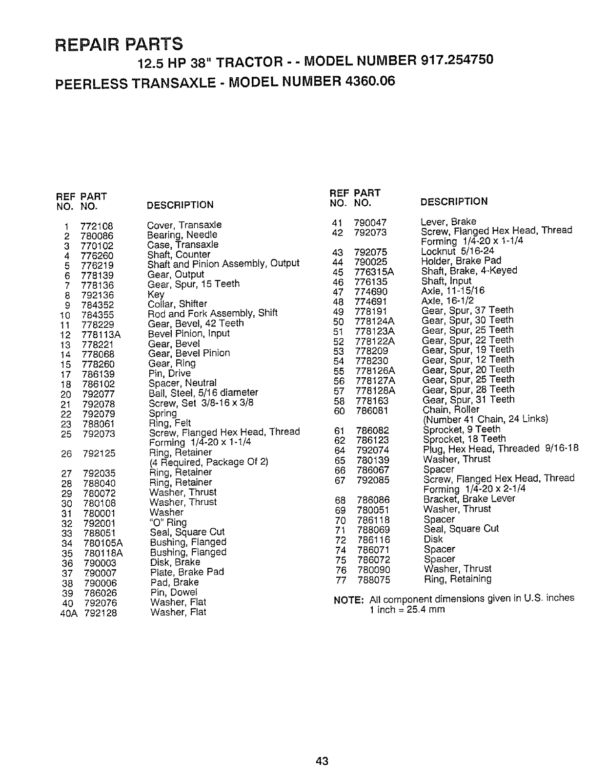
REPAmR PARTS
12.5 HP 38" TRACTOR - - MODEL NUMBER 917.254750
PEERLESS TRANSAXLE - MODEL NUMBER 4360.06
REF PART REF PART
NO. NO, DESCRIPI"ION NO. NO. DESCRIPTION
1 772108 Cover, Transax/e 41 790047
2 780086 Bearing, Needle 42 792073
3 770102 Case, Transaxle
4 776260 Shaft, Counter 43 792075
5 776219 Shaft and Pinion Assembly, Output 44 790025
6 778139 Gear, Output 45 776315A
7 778136 Gear, Spur, 15 Teeth 46 776135
8 792136 Key 47 774690
9 784352 Collar, Shifter 48 774691
10 784355 Rod and Fork Assembly, Shift 49 778191
11 778229 Gear, Bevel, 42 Teeth 50 778124A
12 778113A Bevel Pinion, Input 51 778t23A
13 778221 Gear, Bevel 52 778122A
14 778068 Gear, Bevel Pinion 53 778209
15 778260 Gear, Ring 54 778230
17 786t39 Pin, Drive 55 778126A
18 786102 Spacer, Neutral 56 778127A
20 792077 Bali, Steel, 5/16 diameter 57 778128A
21 792078 Screw, Set 3/8-16 x3/8 58 778!63
22 792079 Spring 60 786081
23 788061 Ring, Felt
25 792073 Screw, Flanged Hex Head, Thread 61 786082
Forming 1/4-20 x 1.1/4 62 786123
26 792125 Ring, Retainer 64 792074
(4 Required Package Of 2) 65 780139
27 792035 Ring, Retainer 66 786067
28 788040 Ring, Retainer 67 792085
29 780072 Washer, Thrust
30 780108 Washer, Thrust 68 786086
31 780001 Washer 69 780051
32 792001 "O" Ring 70 786118
33 788051 Seal, Square Cut 71 788069
34 780105A Bushing, Flanged 72 786116
35 7801I8A Bushing, Flanged 74 786071
36 790003 Disk, Brake 75 786072
37 790007 Plate, Brake Pad 76 780090
38 790006 Pad, Brake 77 788075
39 786026 Pin, Dowel
40 792076 Washer, FJat
40A 792128 Washer, Flat
Lever, Brake
Screw, Flanged Hex Head, Thread
Forming 1/4-20 x 1-!/4
Locknut 5/16-24
Holder, Brake Pad
Shaft, Brake, 4-Keyed
Shaft, Input
Axle 11-I5/16
Axle 16-1/2
Gear Spur, 37 Teeth
Gear Spur, 30 Teeth
Gear Spur, 25 Teeth
Gear Spur, 22 Teeth
Gear Spur, 19 Teeth
Gear Spur, t2 Teeth
Gear Spur, 20 Teeth
Gear Spur, 25 Teeth
Gear Spur, 28 Teeth
Gear, Spur, 31 Teeth
Chain, Roller
(Number 41 Chain, 24 Links)
Sprocket, 9 Teeth
Sprocket, 18 Teeth
Plug, Hex Head, Threaded 9/16-18
Washer, Thrust
Spacer
Screw, Flanged Hex Head, Thread
Forming 1/4-20 x 2-t/4
Bracket, Brake Lever
Washer, Thrust
Spacer
Seal, Square Cut
Disk
Spacer
Spacer
Washer, Thrust
Ring, Retaining
NOTE: All component dimensions given in U.S. inches
1 inch = 25.4 mm
43
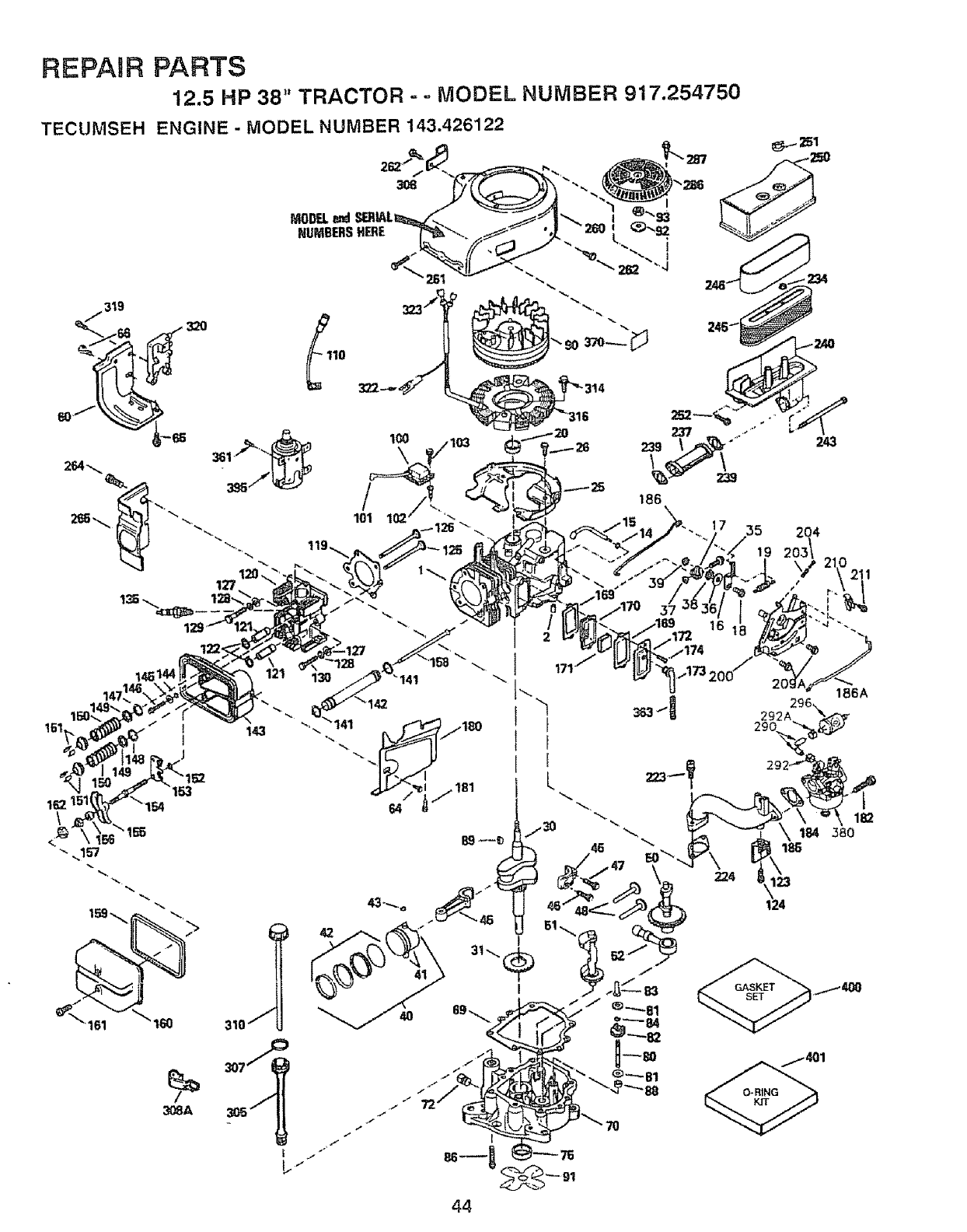
REPAIR PARTS
12.5 HP 38" TRACTOR - -MODEL NUMBER 917.254750
TECUMSEH ENGINE - MODEL NUMBER 143.426122
243
19 2
151
210211
44
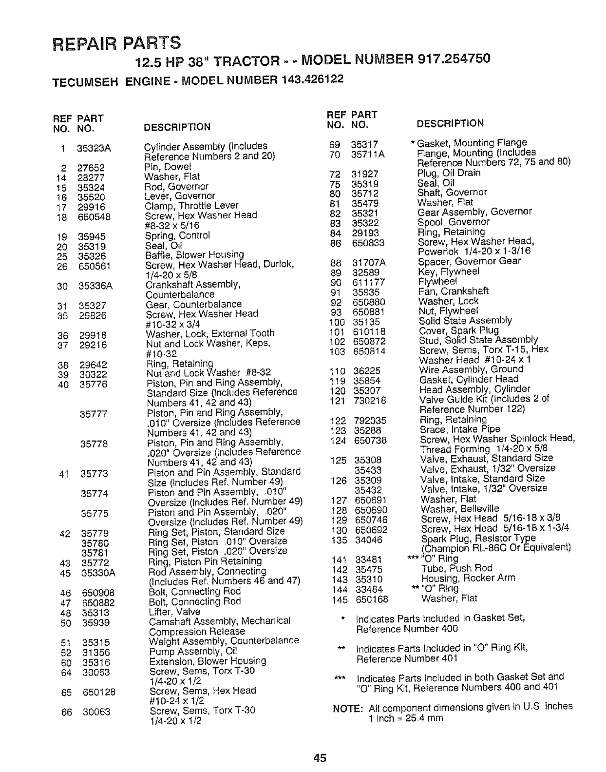
REPAIR PARTS
12.5 HP 38" TRACTOR - - MODEL NUMBER 917.254750
TECUMSEH ENGINE -MODEL NUMBER 143.426122
REF PART REF PART
NO, NO, DESCRIPTION NO. NO, DESCRIPTION
1 35323A
2 27652
14 28277
15 35324
16 35520
17 29916
t8 650548
19 35945
20 35319
25 35326
26 650561
30 35336A
31 35327
35 29826
36 29918
37 29216
38 29642
39 30322
40 35776
35777
35778
41 35773
35774
35775
42 35779
35780
35781
43 35772
45 35330A
46 650908
47 650882
48 35313
50 35939
5I 35315
52 31356
60 35316
64 30063
65 650128
66 30063
Cylinder Assembly (Includes 69 35317
Reference Numbers 2 and 20) 70 35711A
Pin, Dowel
Washer, Flat 72 31927
Rod, Governor 75 35319
Lever, Governor 80 35712
Clamp, Throttle Lever 81 35479
Screw, Hex Washer Head 82 35321
#8-32 x 5/16 83 35322
Spring, Control 84 29193
Seal, Oil 86 650833
Baffle, Blower Housing
Screw, Hex Washer Head, Durlok, 88 31707A
1/4-20 x 5/8 89 32589
Crankshaft Assembly, 90 611177
Counterbalance 91 35935
Gear, Counterbatance 92 650880
Screw, Hex Washer Head 93 650881
#I0-32 x 3/4 I00 35135
Washer, Lock, External Tooth 10t 610118
Nut and Lock Washer, Keps, 102 650872
#t0-32 103 650814
Ring, Retaining
Nut and Lock Washer #8-32 110 36225
Piston, Pin and Ring Assembly, 119 35854
Standard Size {Includes Reference 120 35307
Numbers 41,42 and 43) 121 730218
Piston, Pin and Ring Assembly,
.010" Oversize (Includes Reference 122 792035
Numbers 41,42 and 43) 123 35288
Piston, Pin and Ring Assembly, I24 650738
.020" Oversize (Includes Reference
Numbers 41, 42 and 43) 125 35308
Piston and Pin Assembly, Standard 35433
Size (Includes Ref. Number 49) 126 35309
Piston and Pin Assembly, o010" 35432
Oversize (includes Ref. Number 49) 127 650691
Piston and Pin Assembly, .020" 128 650690
Oversize (includes Ref, Number 49) 129 650746
Ring Set, Piston, Standard Size 130 650692
Ring Set, Piston .010" Oversize 135 34046
Ring Set, Piston .020" Oversize
Ring, Piston Pin Retaining 141 33481
Rod Assembly, Connecting t42 35475
(Includes Ref. Numbers 46 and 47) 143 35310
Bott, Connecting Rod 144 33484
Bolt, Connecting Rod t45 650168
Lifter, Valve
Camshaft Assembly, Mechanical
Compression Release
Weight Assembly, Counterbalance
Pump AssembLy, Oil
Extension, Btower Housing
Screw, Seres, Torx T-30
1/4-20 x 1/2
Screw, Sems, Hex Head
#10-24 x 1/2
Screw, Sems, Torx T-30
1/4-20 x I/2
* Gasket, Mounting Flange
Flange, Mounting (includes
Reference Numbers 72, 75 and 80)
Plug, Oil Drain
Seal, Oil
Shaft, Governor
Washer, Flat
Gear Assembly, Governor
Spool, Governor
Ring, Retaining
Screw, Hex Washer Head,
Powerlok 1/4-20 x 1-3/t6
Spacer, Governor Gear
Key, Flywheel
Flywheel
Fan, Crankshaft
Washer, Lock
Nut, Flywheel
Solid State Assembly
Cover, Spark Plug
Stud, Solid State Assembly
Screw, Sems, Torx T-15, Hex
Washer Head #10-24 x 1
Wire Assembly, Ground
Gasket, Cylinder Head
Head Assembly, Cyfinder
Valve Guide Kit (Includes 2 of
Reference Number 122)
Ring, Retaining
Brace, Intake Pipe
Screw, Hex Washer Spinlock Head,
Thread Forming 1/4-20 x 5/8
Valve, Exhaust, Standard Size
Valve, Exhaust, 1/32" Oversize
Valve, Intake, Standard Size
Valve, Intake, t/32" Oversize
Washer, Flat
Washer, BeHeville
Screw, Hex Head 5/16-!8 x 3/8
Screw, Hex Head 5/16-t8 x 1-3/4
ScPharkPlug, Resistor Type
ampion RL-86C Or Equivalent)
*** "O" Ring
Tube, Push Rod
Housing, Rocker Arm
** "O" Ring
Washer, Flat
*indicates Parts Included in Gasket Set,
Reference Number 400
** Indicates Parts Included in "O" Ring Kit,
Reference Number 401
*** Indicates Parts Included in both Gasket Set and
"O" Ring Kit, Reference Numbers 400 and 40!
NOTE: All component dimensions given in UoS inches
1 inch = 254 mm
45
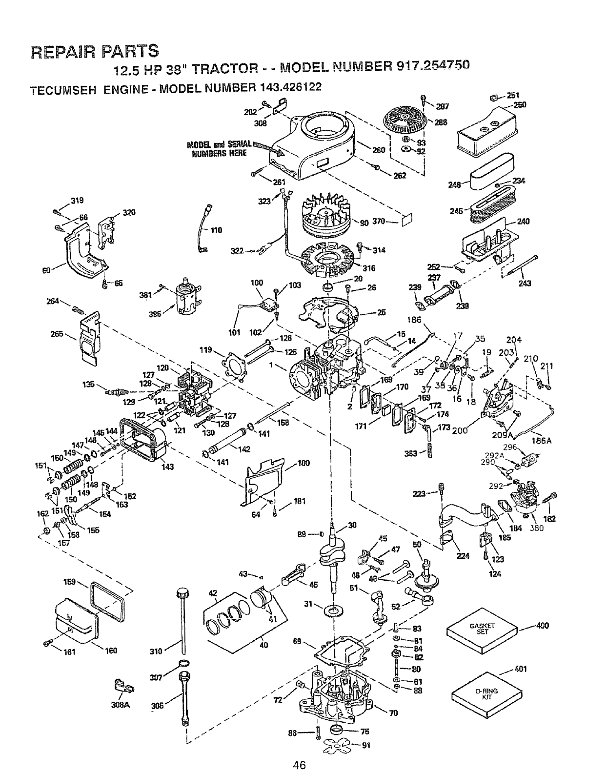
REPAHR PARTS
12.5 HP 38" TRACTOR - - MODEL NUMBER 917,254750
46
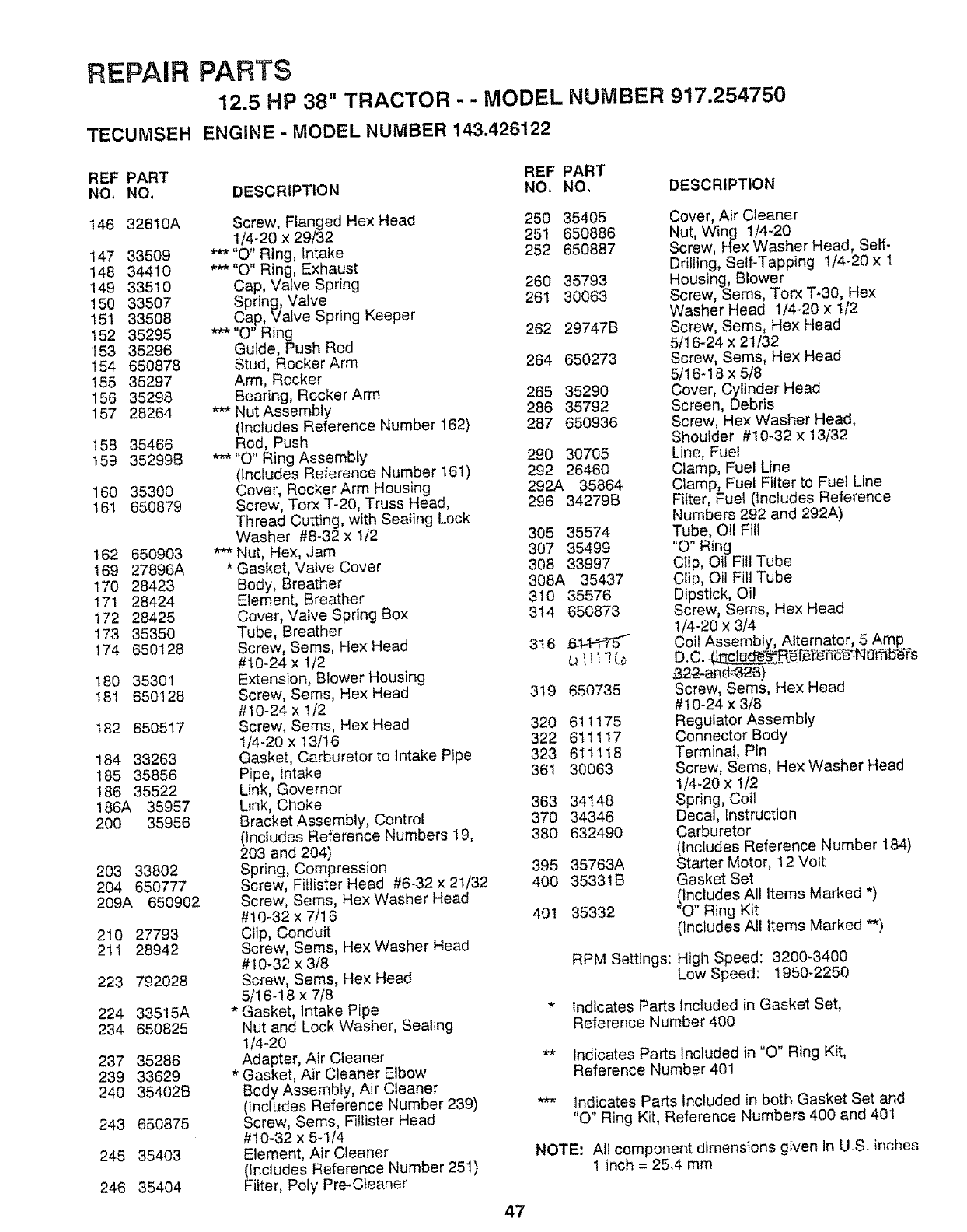
REPAaR PARTS
12.5 HP 38" TRACTOR - - MODEL NUMBER 917.254750
TECUMSEH ENGINE -MODEL NUMBER 143.426122
REF PART REF PART
NO, NO, DESCRIPTION NOo NO, DESCRIPTION
146 32610A
147 33509
148 34410
149 33510
150 33507
151 33508
152 35295
153 35296
154 650878
155 35297
156 35298
157 28264
158 35466
159 352998
160 35300
t61 650879
162 650903
169 27896A
170 28423
171 28424
172 28425
173 35350
!74 650128
180 35301
t81 650128
182 650517
184 33263
185 35856
186 35522
186A 35957
200 35956
203 33802
204 650777
209A 650902
210 27793
211 28942
223 792028
224 33515A
234 650825
237 35286
239 33629
240 35402B
243 650875
245 35403
246 35404
Screw, Flanged Hex Head 250 35405
1/4-20 x 29/32 25! 650886
*'** "O" Ring, intake 252 650887
*** "O" Ring, Exhaust
Cap, Valve Spring 260 35793
Spring, Valve 261 30063
Cap, Valve Spring Keeper
***"O" Ring 262 29747B
Guide, Push Rod
Stud, RockerArm 254 650273
Arm, Rocker
Bearing, Rocker Arm 265 35290
*** Nut Assembly 286 35792
(includes Reference Number 162) 287 650936
Rod, Push
*** "O" Ring Assembly 290 30705
(Includes Reference Number 161) 292 26460
Cover, Rocker Arm Housing 292A 35864
Screw, Torx T-20, Truss Head, 296 34279B
Thread Cutting, with Sealing Lock
Washer #8-32 x 1/2 305 35574
*** Nut, Hex, Jam 307 35499
* Gasket, Valve Cover 308 33997
Body, Breather 308A 35437
Element, Breather 310 35576
Cover, Valve Spring Box 314 650873
Tube, Breather
Screw, Seres, Hex Head 316 644_
#t0-24 x 1/2 _ 111!(._
Extension, Blower HoUsing
Screw, Sems, Hex Head 319 650735
#10-24 x 1/2
Screw, Sems, Hex Head 320 611175
1/4-20x13/16 322 611117
Gasket, Carburetor to Intake Pipe 323 6!tl 18
Pipe, Intake 361 30063
Link, Governor
Link, Choke 363 34148
Bracket Assembly, Control 370 34346
(Includes Reference Numbers 19, 380 632490
203 and 204)
Spring, Compression 395 35763A
Screw, Fi_lister Head #6-32 x 21/32 400 35331B
Screw, Sems, Hex Washer Head
#10_32 x 7/16 401 35332
Clip, Conduit
Screw, Sems, Hex Washer Head
#10-32 x 3/8
Screw, Sems, Hex Head
5/16-18 x 7/8
* Gasket, Intake Pipe
Nut and Lock Washer, Sealing
1/4-20
Adapter, Air Cleaner
* Gasket, Air Cleaner Elbow
Body Assembly, Air Cleaner
(Includes Reference Number 239)
Screw, Sems, Fillister Head
#10-32 x 5-1/4
Element, Air Cleaner
0ncludes Reference Number 251)
Filter, Poly Pre-Cteaner
Cover, Air Cleaner
Nut, Wing t/4-20
Screw, Hex Washer Head, Self-
Drilling, Self-Tapping 1/4_20 x 1
Housing, Blower
Screw, Seres, Torx T-30, Hex
Washer Head 1/4-20 x 1/2
Screw, Seres, Hex Head
5/16-24 x 21/32
Screw, Seres, Hex Head
5/16-18 x 5/8
Cover, Cyfinder Head
Screen, Debris
Screw, Hex Washer Head,
Shoulder #10-32 x 13/32
Une, Fuel
Clamp, Fuel Line
Clamp, Fuel Filter to Fuel Line
Fitter, Fuel (includes Reference
Numbers 292 and 292A)
Tube, OilFill
"0" Ring
Clip,OilFillTube
Clip,OilFillTube
Dipstick,Oil
Screw, Seres, Hex Head
1/4-20 x 3/4
Coil Assembly, Alternator, 5 Amp
D.C. __r_ e_Narfib_s
_322-ead_23)
Screw, Seres, Hex Head
#10-24 x 3/8
Regulator Assembly
Connector Body
Terminal, Pin
Screw, Sems, Hex Washer Head
1/4-20 x 1/2
Spring, Coil
Decal, Instruction
Carburetor
(Includes Reference Number 184)
Starter Motor, 12 Volt
Gasket Set
0ncfudes All Items Marked *)
"O" Ring Kit
(Includes All Items Marked **)
RPM Settings: High Speed: 3200_3400
Low Speed: 1950-2250
* Indicates Parts Included in Gasket Set,
Reference Number 400
** Indicates Parts Included in "O" Ring Kit,
Reference Number 401
*** Indicates Parts Included in both Gasket Set and
"O" Ring Kit, Reference Numbers 400 and 401
NOTE: All component dimensions given in US. inches
1 inch = 25.4 mrn
47
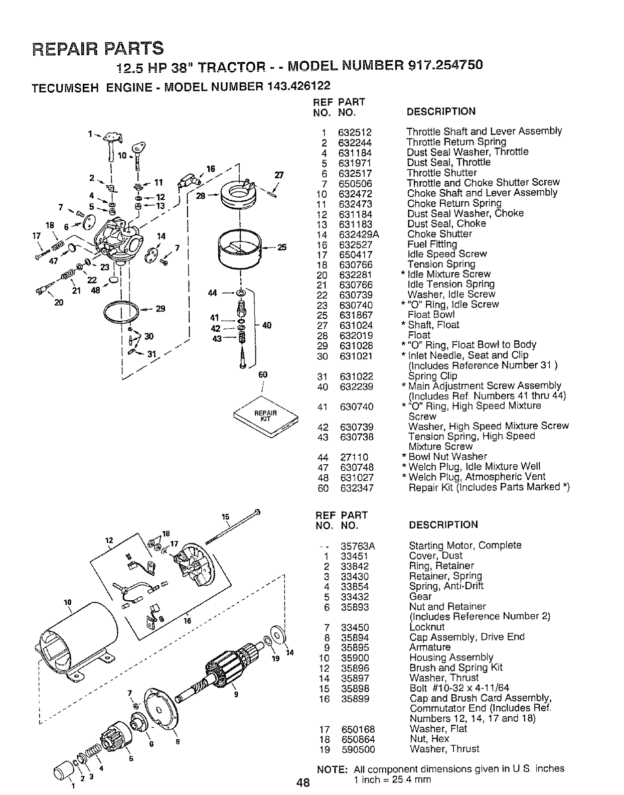
REPAUR PARTS
!2,5 HP 38" TRACTOR -- MODEL NUMBER 917.254750
TECUMSEH ENGINE - MODEL NUMBER 143.426122
REF PART
NO, NO, DESCRIPTION
2O
1
1 632512
2 632244
4 631184
5 631971
6 632517
7 650506
10 632472
11 632473
12 631184
13 631183
14 632429A
16 632527
17 650417
18 630766
20 632281
21 630766
22 630739
23 630740
25 631867
27 631024
28 632019
29 631028
30 631021
31 631022
40 632239
-_..__ 41 630740
42 630739
43 630738
44 27110
47 630748
48 631027
60 632347
Throttle Shaft and Lever Assembly
Throttle Return Spring
Dust Seal Washer, Throttle
Dust Seal, Throttle
Throttle Shutter
Throttle and Choke Shutter Screw
Choke Shaft and Lever Assembly
Choke Return Spring
Dust Seat Washer, Choke
Dust Seal, Choke
Choke Shutter
Fuel Fitting
Idle Speed Screw
Tension Spring
* Idle Mixture Screw
Idle Tension Spring
Washer, Idle Screw
* "O" Ring, Idle Screw
Float Bowl
*Shaft, Float
Float
* "O" Ring, Float Bowl to Body
*tnlet Needle, Seat and Clip
(Includes Reference Number 31 )
Spring Clip
* Main Adjustment Screw Assembly
(Includes Ref. Numbers 4I thru 44)
*"O" Ring, High Speed Mixture
Screw
Washer, High Speed Mixture Screw
Tension Spring, High Speed
Mixture Screw
* Bow! Nut Washer
* Welch Plug, Idle Mixture Welt
* Welch Plug, Atmospheric Vent
Repair Kit (includes Parts Marked *)
10
18
14
REF PART
NO, NO. DESCRIPTION
- 35763A Starting Motor, Complete
1 33451 Cover, Dust
2 33842 Ring, Retainer
3 33430 Retainer, Spring
4 33854 Spring, Anti-Drift
5 33432 Gear
6 35893 Nut and Retainer
(Includes Reference Number 2)
7 33450 Locknut
8 35894 Cap Assembly, Drive End
9 35895 Armature
10 35900 Housing Assembly
12 35896 Brush and Spring Kit
14 35897 Washer, Thrust
15 35898 Bolt #10_32 x 4-11/64
16 35899 Cap and Brush Card Assembly,
Commutator End (Includes Ref.
Numbers 12, 14, 17 and 18)
17 650168 Washer, Flat
18 650864 Nut, Hex
19 590500 Washer, Thrust
4 NOTE: All component dimensions given in US, inches
348 1 inch = 254 mm

Ul.. i ii iiiii1,1 ii i iiii iiiii iii1,111 i iiii i iii i,i ,llllllll ii ii,
SE CE OTES
iiiiii I'11111111 I1'1111 II I iiiiiiii III .111
.u
49

i illllll
SE CE NOTES
5O
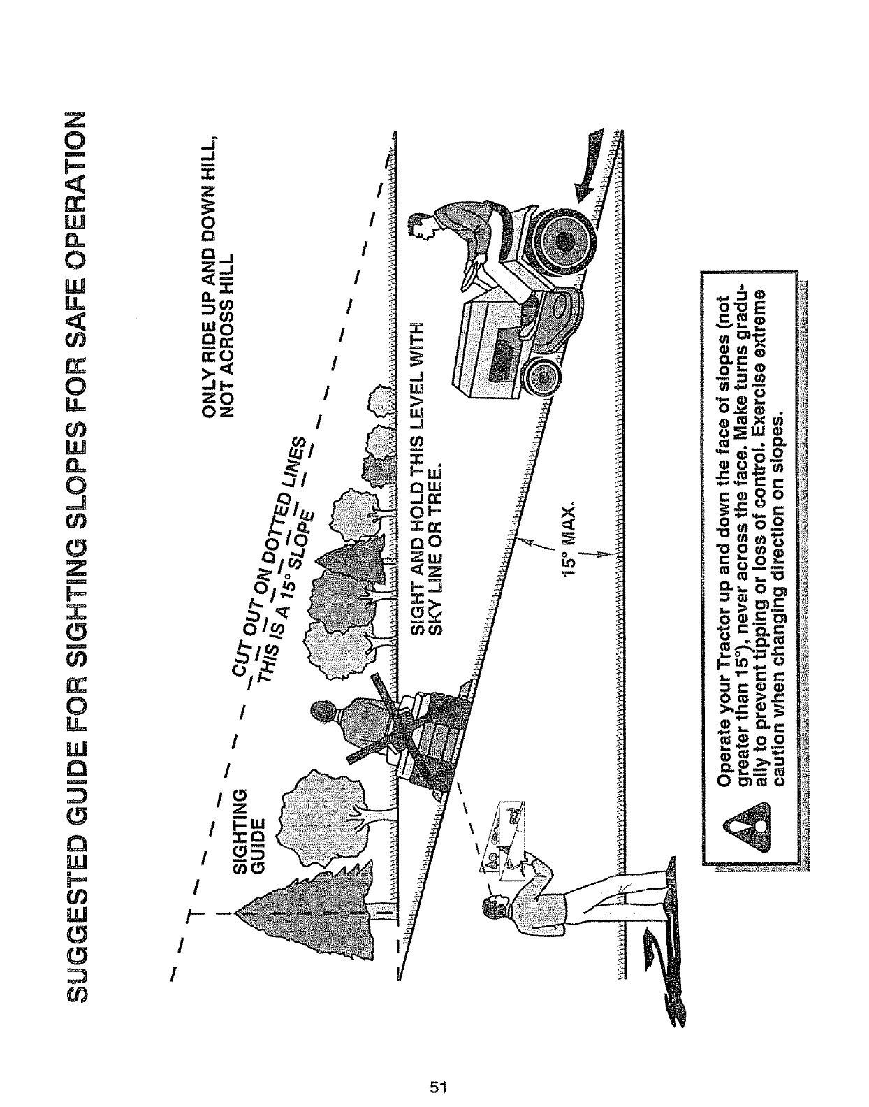
Z
0
m
LU
n
0
W
LL
¢0
0
LL
rd_
w
0
,,=J
r_
Z
m
.,,r,
r_
m
r_
rr
0
LL
W
a
m
W
LLJ
r_
rj)
/
/
/
/--
!
I
/
/
/
/
/
/
/
.4!
/o
/
/
o
51
OWNER'S
MANUAL
MODEL NO=
917.254750
HOW TO ORDER
REPAIR PARTS
®
12.5 HP OHV
ELECTRIC START
38" MOWE DECK
5 SPEED TRANSAXLE
LAWN TRACTO
Each tractor has its own model number Each engine has its own model
number
The model number for your tractor will be found on the model plate
located under the seat
The modet number for your engine will be found on the blower housing.
All parts listed herein may be ordered from any Sears, Roebuck and Co,
Service Centers and most Retail Stores
WHEN ORDERING REPAIR PARTS, ALWAYS GIVE THE FOLLOW-
ING INFORMATION:
• PRODUCT- LAWN TRACTOR
• MODEL NUMBER - 917.254750
• ENGINE MODEL NUMBER - 143,426122
•PART NUMBER
• PART DESCRIPTION
Your Sears merchandise has added value when you consider Sears has
service units nationwide staffed with Sears trained technicians.., profes-
sional technicians specifically trained to insure that we meet our pledge
to you, we service what we sell
i iiill ii Ill Illl,ll,ll
I I ,,,Irll I I I,,,I,,111 ,,I, II,,I,l,,I,I, IIIl,,ll
Sears, Roebuck and Co., Chicago, IL 60684 U.S.A.
iretail,
PRINTED IN USA.
