Craftsman 917254860 User Manual TRACTOR Manuals And Guides L0801116
CRAFTSMAN Lawn, Tractor Manual L0801116 CRAFTSMAN Lawn, Tractor Owner's Manual, CRAFTSMAN Lawn, Tractor installation guides
User Manual: Craftsman 917254860 917254860 CRAFTSMAN TRACTOR - Manuals and Guides View the owners manual for your CRAFTSMAN TRACTOR #917254860. Home:Lawn & Garden Parts:Craftsman Parts:Craftsman TRACTOR Manual
Open the PDF directly: View PDF ![]() .
.
Page Count: 56
MODEL NUMBER 917.254860 OWNER'S MANUAL
®
TM
II II IIIIIIIIIIII I II III IIIIII
Convertible
• Assembly
• Operation
• Customer
Responsibilities
• Service
• Adjustments
° Repair Parts
Caution:
Read and Follow
all Safety Rules
and Instructions
Before Operating
This Equipment
IIIIIIIIIIIIIIIIIIIIIIIHIIIIIHIIH
_L_ I IIIIIIIII IIIIIIIIII

SAFETY RULES
Safe Operation Practices for Ride-On Mowers
IMPORTANT: THIS CU'FI-tNG MACHINE tSCAPABLE OF AMPUTATING HANDS AND FEETAND THROWING OBJECTS.
FAILURE TO OBSERVE THE FOLLOWING SAFETY INSTRUCTIONS COULD RESULT IN SERIOUS INJURY OR DEATH.
1. GENERAL OPERATION
•Read, understand, and follow all instructions in the manual
and on the machine before Starting.
. Only allow responsible adults, who are famil{ar with the
instructions, to operate the machine.
• Clear the area of objects such as rocks, toys, wire, etc.,
which could be picked up and thrown by the blade.
• Be sure the area is clear of other peop/e before mowing. Stop
machine if anyone enters the area.
• Never carry passengers.
o Do not mow in reverse uniess absolutely necessary. Always
took down and behind before and while backing.
• Be aware of the mower discharge direction and do not point
it at anyone. Do not operate the mower without either the
entire grass catcher or the guard in place,
° Slow down before turning.
• Never [eave a running machine unattended; Always turn off
blades, set parking brake, stop engine, and remove keys
before dismounting.
• Turn off blades when not mowing.
• Stop engine before removing grass catcher or unc!ogging
chute.
• Mow only in daylight or good artificial light.
• Do not operate the machine while under the influence of
alcohol or drugs,
• Watch for traffic when operating near or crossing roadways.
• Use extra care when loading or unloading the machine into
a trailer or truck.
I!. SLOPE OPERATION
Slopes are a major factor related to loss-of-control and tipover
accidents, which can resuit in severe injury or death. All slopes
require extra caution. If you cannot backup the stopeor if you feet
uneasy on it, do not mow it.
DO:
° Mow up and down slopes, not across.
*Remove obstacles such as rocks, tree limbs, etc.
.Watch for holes, ruts, or bumps. Uneven terrain could
overturn the machine. Tatl grass can hide obstacles.
• Use slow speed. Choose a low gear so that you wilt not have
to stop or shift while on the slope.
• Fottow the manufacturer's recommendations for wheel
weights or counterweights to improve stability.
•Use extra care with grass catchers or other attachments.
These can change the stability of the machine,
.Keep all movement on the slopes stowand gradual Do not
make sudden changes in speed or direction.
o Avoid starting or stopping on a slope, ff tires lose traction,
disengage the blades and proceed slowly straight down the
siope.
DO NOT:
.Do not turn on slopes unless necessary, and then, turn slowly
and gradually downhill, if possible.
•Do not mow near drop-offs, ditches, or embankments. The
mower could suddenly turn over if awheet is over the edge
of a ctiff or ditch, or if an edge caves in.
.Do not mow on wet grass, Reduced traction could cause
stiding.
•Do not try to stabilize the machine by putting your foot on the
ground,
•Do not use grass catcher on steep s{opes.
III. CHILDREN
Tragic accidents can occur if the operator is not alert to the
presence of children. Children are often attracted to the machine
and the mowing activity. Neverassume that children will remain
where you last saw them.
• Keep children out of the mowing area and under the watchful
care of another responsible adult.
• Be alert and turn machine off if children enter the area.
• Before and when backing, look behind and down for small
children.
• Never carry children. They may fall off and be seriously
injured or interfere with safe machine operation.
• Never allow chiidren to operate the machine.
• Use extra care when approaching b{ind corners, shrubs,
trees, or other objects that may obscure vision.
IV. SERVICE
• Useextracareinhandtinggasolieeandotherfuels. Theyare
flammable and vapors are explosive.
Use only an approved container.
Never remove gas cap or add fue! with the engine
running. Aliow engine to cooI before refueling. Do not
smoke.
Never refuel the machine indoors.
Never store the machine or fuel container inside where
there is an open flame, such as a water heater.
• Never run a machine inside a closed area.
•Keep nuts and botts, especially blade attachment bolts, tight
and keep equipment in good condition.
• Never tamper with safety devices. Check their proper
operation regularly,
• Keep machine free of grass, leaves, or other debris build-up, i
Clean oit or fuel spiflage. Allow machine to coot before
storing.
• Stop and inspect the equipment if you strike an object.
Repair, if necessary, before restarting, i
• Never make adjustments or repairs with the engine running.
• Grass catcher components are subject to wear, damage, and:
deterioration, which could expose moving parts or allow
objects to be thrown. Frequently check components and
rep ace with manufacturer's recommended parts, when nec- I
essary.
• Mower blades are sharp and can cut, Wrap the blade(s) or
wear gloves, and use extra caution when servicing them.
• Check brake operation kequently. Adjust and service as
required.
2
il_. LoOk for this sym bol to point out impor-
tant safety precautions. It means
CAUTION!!! BECOME ALERT!!! YOUR
SAFETY IS INVOLVED.
CAUTION" Always disconnect spark
plug wire and place wire where it cannot
contact spark plug in order to prevent
accidental starting when setting up,
transporting, adjusting or making
repairs.
iii, ii

CONGRATULATIONS on your purchase of a Sears
tractor. It has been designed, engineered and manufac-
tured to give you the best possible dependability and
performance.
Should you experience any problem you cannot easily
remedy, please contact your nearest Sears Service
Center/Department. We have competent, welFtrained
technicians and the proper tools to service or repair this
unit.
Please read and retain this manual, The instructions will
enable you to assemble and maintain your unit properly,
Atways observe the "SAFETY RULES".
MODEL
NUMBER 917.254860
SERIAL
NUMBER
DATE OF PURCHASE
THE MODEL AND SERIAL NUMBERS WILL BE FOUND
ON A PLATE UNDER THE SEAT.
YOU SHOULD RECORD BOTH SERIAL NUMBER AND
DATE OF PURCHASE AND KEEP IN A SAFE PLACE
FOR FUTURE REFERENCE.
MAINTENANCE AGREEMENT
A Scars maintenance agreement is available on this prod-
uct. Contact your nearest Scars store for details.
CUSTOMER RESPONSIBILmES
Read and observe the safety rules.
, Foflowa regular schedule in maintaining, caring for and
using your unit.
Foflow the instructions under "Customer ResponsibiD
ties" and "Storage" sections of this owner's manual.
PRODUCT SPECIFICATIONS
HORSEPOWER: ! 8.0
GASOLINE CAPACITY 3.5 GALLONS
AND TYPE: UNLEADED REGULAR
OIL TYPE (APFSG): SAE 30 (above 32°F)
SAE 5W-30 (below 32°F)
OIL CAPACITY: 3.0 PINTS j
SPARK PLUG: CHAMPION RJ-19LM
(GAP: .030") STD361458 f
I
VALVE CLEARANCE: INTAKE: .004" - .006" t
EXHAUST: .007" - .009"
GROUND SPEED (MPH): FORWARD:
1st 0.77
2nd 1.46
3rd 3.4t
4th 4.34
5th 5.57
REVERSE: 1.07
TIRE PRESSURE: FRONT: 14 PSI
REAR: t0 PSI
CHARGING SYSTEM: 5 AMPS BATTERY
3 AMPS HEADLIGHTS
BLADE BOLT TORQUE: 30-35 F-F. LBS.
WARNING: This unit is equipped with an internal combus.-
tion engine and should not be used on or near any unim-
proved forest-covered, brush-covered or grass-covered
land unless the engine's exhaust system is equipped with
a spark arrester meeting applicable local or state taws (if
any)_ if a spark arrester is used, it should be maintained in
effe,,tive working order by the operator.
_3Sn the state of CaIifornia the above is required by taw
ection 4442 of the California Public Resources Code).
ther states may have similar laws. Federal laws apply on
federal lands. A spark arrester for the muffler is available
through your nearest Sears Authorized Service Center
(See REPAIR PARTS section of this manual).
LIMITED TWO YEAR WARRANTY ON ELECTRIC START RIDING EQUIPMENT
For two (2) years from the date of purchase, if this riding equipment is maintained, lubricated and tuned up according to the
instructions Jn the owner's manual, Sears will repair or replace, free of charge, any parts found to be defective in mateda[ or
workmanship.
This Warranty does not cover:
• Expendable items which become worn during normal use, such as blades, spark plugs, air cleaners and belts.
Tire replacement or repair caused by punctures from outside objects, such as nails thorns, stumps, or glass.
Repairs necessary because of operator abuse, negligence, improper storage or accident or the failure to maintain the
equipment according to the instructions contained in the owner's manual
¢
o Riding equipment used for commercial or rental purposes.
LiMiTED 90 DAY WARRANTY ON BATTERY
For 90 days from date of purchase, if any battery included with this riding equipment proves defective in material or workmanship
and our testing determines the battery will not hotd a charge, Sears wilt replace the battery at no charge.
WARRANTY SERVICE IS AVAILABLE BY RETURNING THE RIDING EQUIPMENT TO THE NEAREST SEARS SERVICE
CENTER/DEPARTMENT tN THE UNITED STATES.
This Warranty gives you specific legal rights, and you may also have other rights which may vary from state to state.
SEARS, ROEBUCK AND CO., HOFFMAN ESTATES, IL 60179 U.S.A.
3
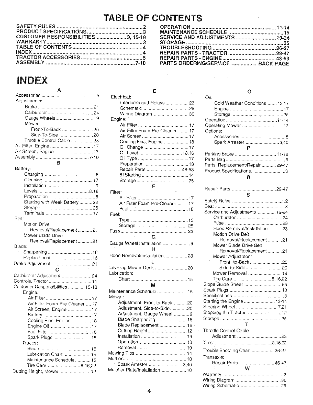
TABLE OF CONTENTS
SAFETY- RULES ............................................................ 2
PRODUCT SPECIFICATIONS ........................ ;.............. 3
CUSTOMER RESPONSIBILITIES ..................... 3, 15-18
WARRANTY ................................................................... 3
TABLE OF CONTENTS ................................................. 4
iNDEX ............................................................................. 4
TRACTOR ACCESSORIES ........................................... 5
ASSEMBLY .............................................................. 7-10
OPERATION ........................................................... 11-14
MAINTENANCE SCHEDULE ...................................... 15
SERVICE AND ADJUSTMENTS ............................ 19-24
STORAGE .................................................................... 25
TROUBLESHOOTING ............................................ 26-27
REPAIR PARTS - TRACTOR ................................. 29-47
REPAIR PARTS -ENGINE ..................................... 48-53
PARTS ORDERING/SERVICE ................... BACK PAGE
iNDEX
A
Accessories ............................................ 5
Adjustments:
Brake ........................................... 21
Carburetor ................................... 24
Gauge Wheels ............................... 9
Mower
Front-To-Back ........................ 20
Side-To-Side ............... :.......... 20
Throttle Control Cable ................. 23
Air F;Iter, Engine ......................... ........ 17
Air Screen, Engine .............................. 17
Assembly ......................................... 7-10
B
Battery:
Charging ........................................ 8
Cleaning ...................................... 17
Installation ..................................... 9
Levels ....................................... 8,!6
Preparation .................................... 8
Starting with Weak Battery .......... 22
Storage ........................................ 25
Terminals .................................... t 7
Belt:
Motion Drive
Removal/Replacement ........... 21
Mower Blade Drive
Removal/Replacement ........... 21
Brade:
Sharpening .................................. 16
Replacement ............................... 16
Brake Adjustment ............................... 21
C
Carburetor Adjustment ....................... 24
ControFs, Tractor ................................. 11
Customer Responsibilities ............. 15- ! 8
Engine:
Air FiIter ................................... 17
Air Filter Foam Pre-Cteaner .... 17
Air Screen, Engine .................. 17
Battery ..................................... 17
Cooling Fins; Engine ............... 18
Engine Oil ................................ 17
Fuel Filter ............................ :... 18
Spark Plugs ............................. 18
Tractor:
Blade ....................................... 16
Lubrication Chart ..................... 15
Maintenance Schedule ............ 15
Tire Care ...... :.................. 8,16,22
Cutting Height, Mower ........................ I2
E
Electrical:
Interlocks and Relays .................. 23
Schematic .................................... 29
Wiring Diagram ............................ 30
Engine:
Air Filter ....................................... 17
Air Filter Foam Pre-Cieaner ........ I7
Air Screen .................................... 17
Cooling Fins, Engine ................... 18
Oil Change ................................... 17
Oil Level ................................. 13,16
Oi! Type ....................................... 17
Preparation .................................. 13
Repair Parts ........................... 48-53
51Starting .................................... t4
Storage ........................................ 25
F
Filter:
Air Filter ....................................... t7
Air Filter Foam PreoOleaner ........ 17
Fuel ............................................. 18
Fuel:
Type ............................................ 13
Storage ........................................ 25
Fuse .................................................... 23
G
Gauge Wheel Installation ......... :........... 9
H
Hood RemovaVInstallation .................. 23
L
Leveling Mower Deck ......................... 20
Lubrication:
Chart ............................................ t 5
M
Maintena.noe Schedule ....................... 15
Mower:
Adjustment, Front-to-Back ........... 20
Adjustment, Side-to-Side ............. 20
Adjustment, Gauge Wheel ............ 9
Blade Sharpening ........................ 16
Blade Replacement ..................... 16
Cutting Height ............. _................ 12
Installation ................................... 19
Operation ..................................... 13
Removal ...................................... 19
Mowing Tips ....................................... 14
Muffler ................................................. 18
Spark Arrester .......................... 3,40
Mulcher Plate/Installation ................... I 0
O
Oii:
Cold Weather Conditions ....... 13,t 7
Engine ......................................... 17
Storage ...................... :................. 25
Operation ....................................... 1I-t4
Operating Mower ................................ 13
Options:
Accessories ................................... 5
Spark Arrester .......................... 3,40
P
Parking Brake ................................ 11-12
Parts Bag .............................................. 6
Parts, Replacement/Repair ........... 29-47
Product Specifications ........................... 3
R
Repair Parts .................................. 29-47
S
Safety Rules ;........................................ 2
Seat ...................................................... 8
Service and Adjustments ............... 19-24
Carburetor ................................... 24
Fuse ............................................ 23
Hood Removal/installation .......... 23
Motion Drive Belt
Removal/Replacement ........... 21
Mower Blade Drive Belt
Removal/Replacement ........... 2!
Mower Adjustment
Front- to-Back ......................... 20
Side-to_Side ............................ 20
Mower Removal .......................... 19
T!re Care ............................. 8,t6,22
Slope Guide Sheet ............................. 55
Spark Plugs ........................................ t8
Specifications ....................................... 3
Starting the Engine ........................ 13-14
Steering Wheel ................................ 7,21
Stopping the Tractor ........................... 12
Storage ............................................... 25
T
Throttle Control Cable
Adiustment .................................. 23
Tires ................................................... 8, t6,22
Trouble Shooting Chart ............... ...26-27
Transaxle:
Repair Parts ........................... 46-47
W
Warranty....: .......................................... 3
Wiring Diagram ................................... 30
Wiring Schematic ................................ 29

ACCESSORIES A ATTACHMENTS
These accessories and attachments were available when the unit was purchased. They are also available at most Sears retait outlets,
catalog and service centers. Most Sears stores Can order these items for you when you provide the model number of your tractor.
ENGINE MAmNTENANCE
AIR=FILTER GAS CAN ENGINE OIL STABiLiZER BLADES BELTS
SPARK PLUG MUFFLER
PERFOR[_ANCE
Sears offers a wide variety of attachments that fit your vehicle. Many of these are [isted below with brief explanations of hew they can
help you. This Iist was current at the time of publication; however, it may change in future years - more attachments may be added,
changes may be made in these attachments, or some may no longer be availabte or fit your model. Contact your nearest Sears store
for the accessories and attachments that are available for your unit.
Most of these attachments do not require additional hitches or conversion kits (those that do are indicated) and are designed for easy
attaching and detaching.
AERATOR promotes deep root growth for a healthy tawn.
Tapered 2.5qnch steel spikes mounted on 10-inch diameter
discs puncture holes in soi! at close intervals to let moisture soak
in, Steel weight tray for increased penetration.
BAGGER lets you collect grass clippings and teaves for a
healthier, neater _ooking lawn. Two Permanex containers hold
30_gallon plastic bags,
BUMPER protects front end of tractor from damage.
CARTS make hauling easy. Variety of sizes available, plus
_ccessories such as side panel kits, toe{ caddy, cart cover,
3rotective mat and doily.
CORING AERATOR takes small plugs out of soil to allow
noisture and nutrients to reach grass roots. 36qnch swath. 24
qardened steel coring tips. I50 lb. capacity weight tray.
EASY OiiL DRAIN VALVE makes oil changes easier, faster.
FRONT NOSE ROLLER canters in front of mower deck to
_educe chances of t'scalping" on uneven terrain,
3ANG H_TCH lets you tow 2 or 3 pull-behind attachments at
>nce, such as sweepers, dethatchers, aerators (not for use with
oilers, carts or other heavy attachments).
3AUGE WHEELS on both sides of the mowei" deck reduce
_'hances of "scalping" on uneven terrain. For mower decks not
;o equipped.
V]ULCH RAKE/DETHATCHER loosens soil and flips thatch and
hatted leaves to lawn surface for easy pickup. Twenty spring
ine teeth. Useful to prepare bare areas for seeding. Available
or front or rear mounting. HIGH PERFORm#lANCE REEL-
_,CTION SPRING TtNE DETHATCHER covers 36-inch wide
_ath and tosses thatch into large hopper, Mounts behindtracter.
_ULCH_NG KIT, once installed, lets you mulch, discharge or
_ag clippings (bagger optional) without changing blades. For
_odets not equipped as 3-in-l Convertible mowers.
:tAMP TOPS AND FEET let you toad and unload tractor from a
)ickup truck. Use with 2 x 8 or 2 x 10 lumber.
:teLLER for smoother lawn surface. 36-inch wide, 18-inch
Jiameter water-tight drum holds up to 390 Ibs. of weight. Rounded
}dges prevent harm to tuff. Adjustable scraper automatically
"leans drum.
_NOW BLADE for snow removal onty. t4qnch high, 42-inch
'videblade clears 38qnch path when angled left or right. Raises,
owers with side lever. Adjustable skids; replaceable, reversible
;craper bar. (Use with tire chains and wheel weights and/or rear
_rawbar weight.)
SNOWTH ROWER has 40-inch swath. Drum-type augerhandles
powdery and wet/heavy snow. Mounts easily with simple pin
arrangement. Discharge ehute adjusts from tractor seat. 6-inch
diameter spout discharges snow 10 to 50 feet. Lift controlled at
tractor seat. (Use with chains and wheel weights and/or rear
drawbar weight,)
SPRAYERS use 12-volt DC electric motor that connects to the
tractor battery or other 12-volt source. Includes booms for
automatic spraying and hand held wand for spot spraying. Wand
has adjustable spray pattern. For applying herbicides, insecti-
cides, fungicides and liquid fertilizers.
SPREADERlSEEDERS make seedin , fertilizin , and weed
.. g g
k_ll_ngeasy, Broadcast spreaders are also useful for granular de-
icers and sand.
SWEEPERS let you cotlect grass clippings and leaves.
T_LLER has 5 hp engine and 36-inch swath to prepare seed
beds, cultivate and compost garden residue. Tiller has its own
built-in lift and depth controJ syStem and does NOT require a
sleeve hitch, Fits any lawn, yard or garden tractor. Simply hook
up to the tractor drawbar and go! Optionali accessories convert
unit for dethatching, aerating, hitling...without tools.
TIRE CHAINS are heavy duty; closely spaced extra-large cross
links give smooth ride, outstanding traction.
TRACTOR CAB has heavy duty vinyl fabric over tubular steel
frame, ABS plastic top; clear plastic windshield offers 360
degree visibility. Hinged metal doors with catch Keeps operator
warm and dry. Remove vinyl sides and windshields for use as
sun protector in summer. Optional accessories include:
tinted/tempered solid safety glass windshield with hand oper-
ated wiper; 12-volt amber caution light for mounting on cab top.
VACS for powerfuS collection of heavy grass clippings and
{eaves, Optional wand attach merit to pick up debris ff-_hard-to-
reach places. VAC/CHIPPER includes a chipper-shredder.
WEIGHT BRACKET for drawbar for snow removal appIications.
Uses (1) 55 lb. weight.
WHEEL WEIGHTS for rear wheels provide needed traction for
snow removal or dozing heavy materials.
5
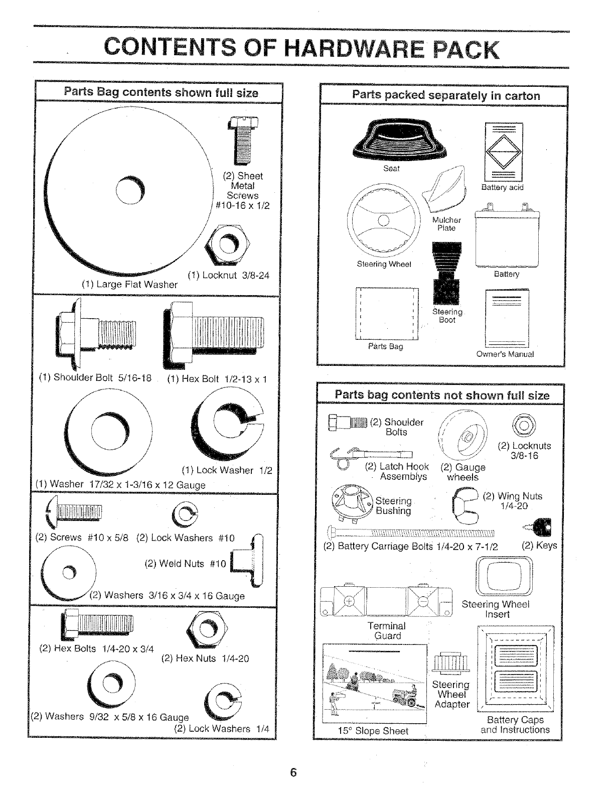
CONTENTS OF HARDWARE PACK
Parts Bag contents shown fult size
O t (2) Sheet
Metal
Screws
x I/2
(t) Locknut 3/8-24
(1) Large Fiat Washer
(l) Shoulder Bott 5/16-18 (1) HexBolt t/2-13xl
(1) Lock Washer 1/2
(1) Washer 17/32 x t-3/16 x t2 Gauge
(2) Screws #10 x 5/8 (2) Lock Washers #t0 _
(2) Weld Nuts #10
) Washers 3/16 x 3/4 x 16 Gauge
(2) Hex Bolts !/4-20 x 3/4 (2) Hex Nuts 1/4-20
(2) Washers 9/32 x 5/8 x t6 Gauge
Parts packed separately in carton
Seat
\
Steering Wheel
Parts Bag
Battery acid
Mulcher -t
Plate
Battery
Steering
Boot
Owner's Manual
Parts bag contents not shown full size
_(2) Shoulder
Bolts
_tch Hook
Assembtys
Steering
Bushing
©
(2) Locknuts
3/8 -! 6
(2) Gauge
wheels
(2) Wing Nuts
!/4-20
(2) Battery Carriage Bolts 1/4-20 x 7-1/2 (2) Keys
Steering Wheel
Insert
Guard : ................
I
Steering [ , m_---: ,
Adapter ,
I Battery Caps
!5 ° Slope Sheet and InStructions
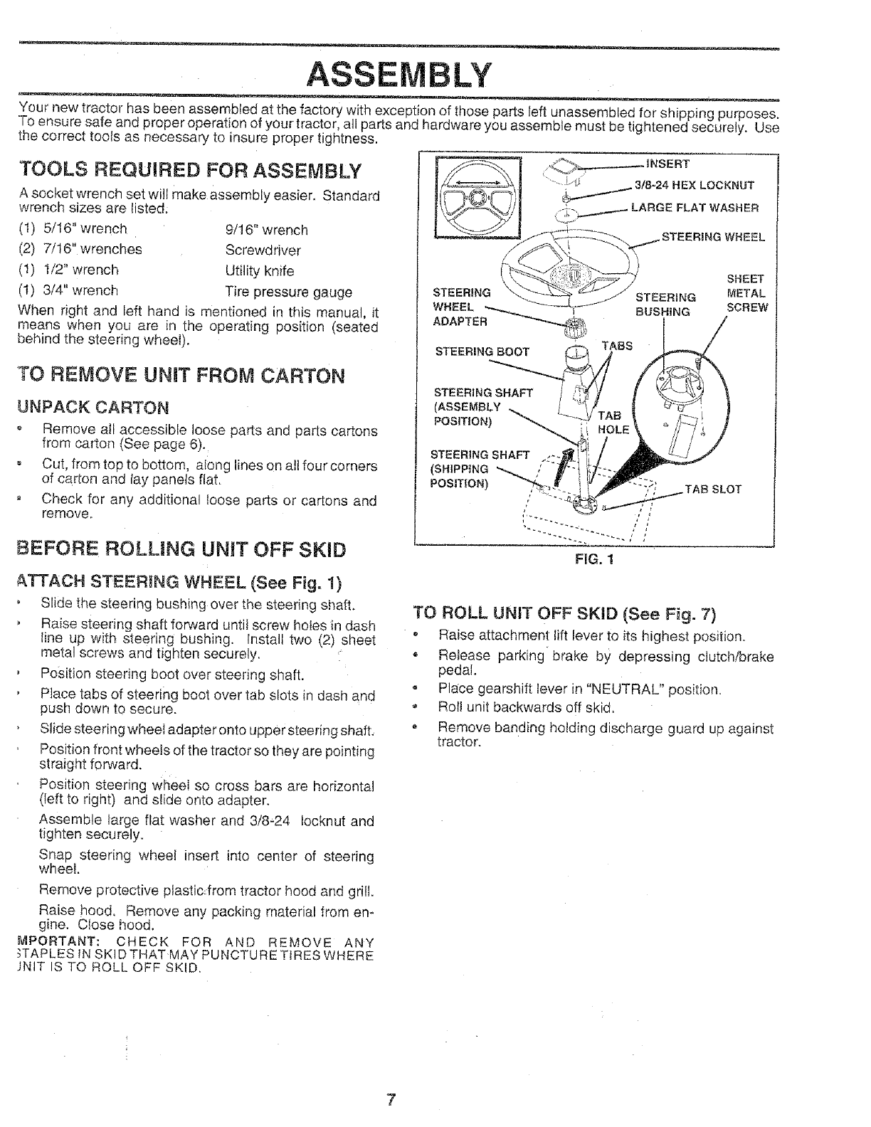
ASSE LY
Your new tractor has been assembled at the factory with exception of those parts tel unassembled for shipping purposes.
To ensure safe and proper operation of your tractor, all parts and hardware you assemble must be tightened securely. Use
the correct toots as necessary to insure proper tightness.
TOOLS REQUIRED FOR ASSEMBLY
A socket wrench set will make assembly easier, Standard
wrench sizes are listed;
(1) 5116" wrench
(2) 7/16" wrenches
(t) t/2" wrench
(I) 3/4" wrench
9/! 6" wrench
Screwdriver
Utility knife
Tire pressure gauge
When right and left hand is mentioned in this manual, it
means when you are in the operating position (seated
behind the steering wheel).
"TO REMOVE UNIT FROM CARTON
UNPACK CARTON
o' Remove all accessible loose parts and parts cartons
from carton (See page 6).
= Cut, from top to bottom, aiong lines on all four corners
of carton and lay panels flat.
, Check for any additional loose parts or cartons and
remove.
BEFORE ROLLING UNIT OFF SKiD
SCREW
&TTACH STEERmNG WHEEL (See Fig. !}
Slide the steering bushing over the steering shaft,
,Raise steering shaft forward untiI screw hotes in dash
line up with steering bushing, install two (2) sheet
metal screws and tighten securely.
Position steering boot over steering shaft.
Place tabs of steering boot over tab slots in dash and
push down to secure.
Slide steering wheel adapter onto upper steering shaft,
Position front wheels of the tractor so they are pointing
straight forward.
Position steering wheel so cross bars are horizontal
(left to right) and stide onto adapter.
Assemble large flat washer and 3/8-24 Iocknut and
tighten securely.
Snap steering wheel insert into center of steering
wheel.
TO ROLL UNIT OFF SKiD (See Fig. 7)
,Raise attachment lift lever to its highest position.
• Release parking brake by depressing clutch/brake
pedal.
= Place gearshift lever in "NEUTRAL" position.
", Roll unit backwards off skid.
Remove banding holding discharge guard up against
tractor.
Remove protective plastic from tractor hood and grill.
Raise hood, Remove any packing material from en-
gine. Close hood.
MPORTANT: CHECK FOR AND REMOVE ANY
_TAPLES tN SKIDTHATMAY PUNCTURE TIRES WHERE
JNtT IS TO ROLL OFF SKID.
7
ASSEMBLY
HOW TO SET UP YOUR TRACTOR INSTALL SEAT (See Fig, 3)
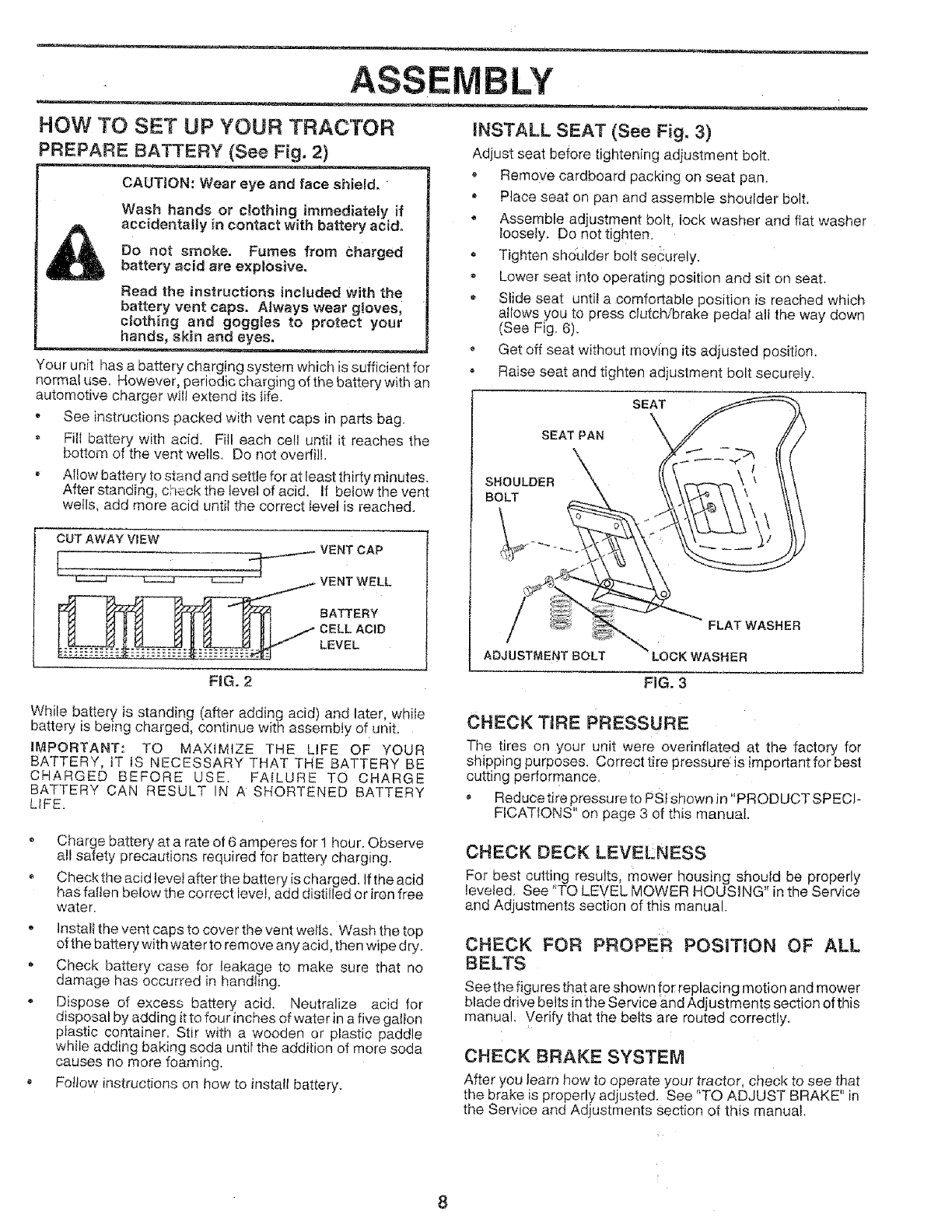
PREPARE BATTERY (See Fig. 2) Adjust seat before tightening adiustment bolt.
CAUTION: Wear eye and face shield,
Wash hands or c_othing immediately if
accidentally in contact with battery a¢ido
Do not smoke. Fumes from Charged
battery acid are explosiveo
Read the instructions included with the
battery vent caps. Always wear gloves,
clothing and goggles to protect your
hands, skin and eyes,
Your unit has a battery ch£rging system which is sufficient for
normat use. However, periodic charging of the battery with an
automotive charger will extend its life.
•See instructions packed With vent caps in parts bag.
o Fill battery with acid. Rll each cel! until it reaches the
bottom of the vent wells. Do not overfill
, Allow battery to stand and settle for at least thirty minutes.
After standing, check the level of acid. if below the vent
wells, add more acid until the correct tevel is reached.
CUT AWAY VIEW
_...... VENT CAP
VENT WELL
_ BATTERY
CELL ACID
zLEVEL
FiG. 2
o Remove cardboard packing on seat pan.
Place seat on pan and assemble shouider bolt.
, Assemble adjustment bolt, lock washer and fiat washer
loosely. Do not tighten.
Tighten shoulder bolt securely.
* Lower seat into operating position and sit on seat.
Stide seat until a comfortable position is reached which
altows you to press clutch/brake pedal all the way down
(See Fig 6).
Get off seat without moving itSadjusted posit}on.
o Raise seat and tighten adjustment bolt securely.
SEAT
SEAT PAN
SHOULDER
BOLT
ADJUSTMENTBOLT
FLAT WASHER
FIG. 3
While battery is standing (after adding acid) and later, while
battery is being charged, continue with assembly of unit,
IMPORTANT: TO MAXIMIZE THE LIFE OF YOUR
BATTERY, IT [S NECESSARY THAT THE BATTERY BE
CHARGED BEFORE USE. FAILURE TO CHARGE
BATTERY CAN RESULT IN A SHORTENED BATTERY
LIFE_
•Charge battery at a rate of 6 amperes for 1 hour. Observe
all safety precautions required for battery charging.
Check the acid level after the battery is charged. If the acid
has fallen below the correct level, add distilled or iron free
water.
,Install the vent caps to cover the vent welts, Wash the top
of the battery with water to remove any acid, then wipe dry.
Check battery case for leakage to make sure that no
damage has occurred in handling.
o Dispose of excess battery acid. Neutralize acid for
disposal by adding it to four inches of water in a five gatton
plastic container. Stir with a wooden or plastic paddle
while adding baking soda until the addition of more soda
causes no more foaming.
Follow instructions on how to instatl battery.
CHECK TIRE PRESSURE
The tires on your unit were o.verinfiated at the factory for
shipping purposes, Correct tire pressure is important for best
cutting performance,
Reduce tire pressure to PS! shown Jn "PRODUCT SPECP
FICAT[ONS" on page 3 of this manual
CHECK DECK LEVELNESS
For best cutting results, mower housing should be properly
leveled, See "TO LEVEL MOWER HOUSING" in the Service
and Adjustments section of this manual.
Z
CHECK FOR PROPER POSITION OF ALL
BELTS
See the figures that are shown for replacing motion and mower
blade drive belts in the Service and Adjustments section of this
manual. Verify that the betts are routed correctly.
CHECK BRAKE SYSTEM
After you learn how to operate your tractor, check to see that
the brake is properly adjusted. See "TO ADJUST BRAKE" in
the Service and Adjustments section of this manual
BLY
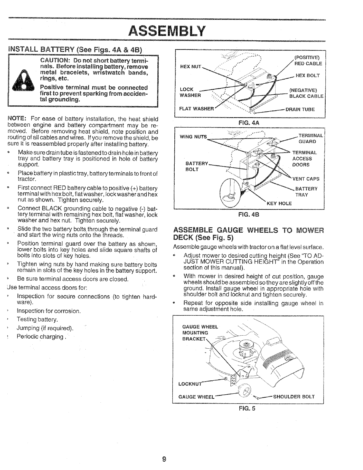
INSTALL BATTERY (See Figs. 4A & 41B)
CAUTION: Do not short battery terml-
naiso Before instaling battery, remove
rect!! bracelets, wristwatch bands,
rings, etc.
Positive termina_ must be connected
first to prevent sparking from acciden-
tal grounding°
NOTE: For ease of battery installation, the heat shiefd
between engine and battery compartrnent may be re-
moved. Before removing heat shield, note position and
routing of att cables and wires. If you remove the shield, be
sure it is reassembled properly after installing battery.
Make sure drain tube is fastened to drain hoe n battery
tray and battery tray is positioned in hole of battery
support.
Place battery in plastic tray, battery terminals to front of
tractor.
First connect RED battery cable to positive (+) battery
terminal with hex bolt, flat washer, Iock washer and hex
nut as shown. Tighten securely.
,Connect BLACK grounding cable to negative (-) bat-
tery terminaf with remaining hex bolt, flat washer, lock
washer and hex nut. Tighten securely.
o Slide the two battery bo ts through the terminal guard
and start the wing nuts onto the threads,
• Position terminal guard over the battery as shown,
lower bolts into key holes and slide square shafts of
bolts into slots of key holes.
, Tighten wing nuts by hand making sure battery bolts
remain in slots of the key hotes in the battery support.
Be sure terminal access doors are closed.
dse terminal access doors for:
o Inspection for secure connections (to tighten hard-
ware).
Inspection for corrosion.
Testing battery.
Jumping (if required).
Periodic charging.
HEX NUT.
LOCK
WASHER
(POSIT_VE}
FLAT WASHER
WiNG NUTS . , _ _TER_tNAL
I G=A=o
TERIINAL
=OLT
k .__ --KEy HOL!
FIG. 4B
ASSEMBLE GAUGE WHEELS TO MOWER
DECK (See Fig, 5)
Assemble gauge wheels with tractor on a flat level surface.
o Adjust mower to desired cutting height (See "TO AD-
JUST MOWER CUTTING HEIGHT" in the Operation
section of this manual).
, With mower in desired height of cut position, gauge
wheels should be assembled so they are slightly off the
ground. Install gauge wheel in appropriate hole with
shoulder bolt and locknut and tighten securely.
,Repeat for opposite side installing gauge wheel in
same adjustment hole.
GAUGE WHEEL
MOUNTING
NG. 5
9
ASSEMBLY
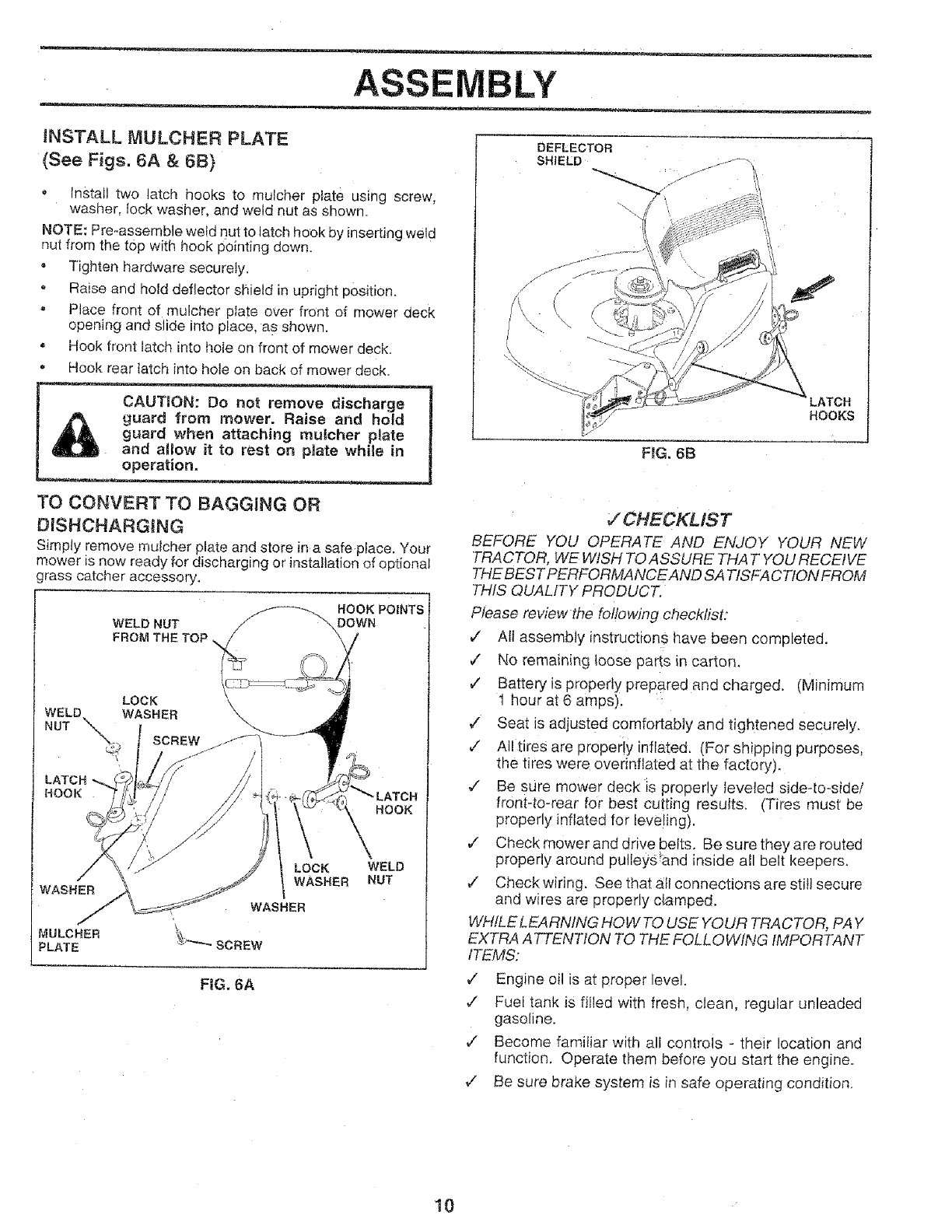
iNSTALL lVlULCHER PLATE
(See Figs. 6A &6B)
Install two latch hooks to mulcher plate using screw,
washer, lock washer, and weld nut as shown.
NOTE:: Pre-assemble wetd nut to latch hook by inserting weld
nut from the top with hook pointing down.
oTighten hardware securely.
Raise and hold deflector shield in upright position.
, Place front of mulcher plate over front of mower deck
opening and sJide into place, as shown.
Hook front latch into hole on front of mower deck.
,Hook rear {arch into hole on back of mower deck.
CAUTION: Do not remove discharge
guard from mower. Raise and hold
guard when attaching mulcher plate
and a_low it to rest on pJate while in
operation.
TO CONVERT TO BAGGING OR
DISHCHARGtNG
Simply remove muicher plate and store ina safe place. Your
mower is now ready for discharging or installation of optional
grass catcher accessory.
WELD NUT
FROM THE TOP
HOOKPOZNTS
DOWN
LATCH "-_
!-tOOK
WASHER
MULCHER
PLATE
LOCK
WASHER
WELD
NUT
FIG, 6A
DEFLECTOR
SHIELD
FIG. 6B
LATCH
HOOKS
,/CHECKLIST
BEFORE YOU OPERATE AND ENJOY YOUR NEW
TRACTOR, WE WISH TO ASSURE THAT YOU RECEIVE
THE BEST PERFORMANCEAND SATISFACTION FROM
THIS QUALITY PRODUCT.
Please review the fo/lowing checklist:
,/ All assembly instructions have been completed.
¢No remaining loose parts in carton,
v' Battery is properly prepared and charged, (Minimum
I hour at 6 amps).
,/ Seat is adjusted comfortably and tightened securely,
¢" All tires are properly inflated. (For shipping purposes,
the tires were overinflated at the factory).
,/ Be sure mower deck is properly _eveled side-to-side/
frontqO-rear for best cutting resutts. (Tires must be
properly inflated for leve!ing).
¢" Check mower and drive belts. Be sure they are routed
properly around pulleys!and inside all belt keepers,
v" Check wiring, See that _I_connections are sti}l secure
and wires are properly clamped.
WHILE LEA RNtNG HOW TO USE YOUR TRACTOR, PAY
EXTRA A TTENT!ON TO THE FOLLOWING IMPORTANT
ITEMS:
¢" Engine oil is at proper level.
,/ Fuel tank iS fiIled with fresh, clean, regular unleaded
gasoline.
7" Become famitiar with all controls - their location and
function. Operate them before you start the engine.
v" Be sure brake system is in safe operating condition.
10

O ERATION
KNOW YOUR TRACTOR
READ THiS OWNER'S MANUAL AND SAFETY RULES BEFORE OPERATING YOUR TRACTOR
C0mparethe illustrationswith your tractor to familiarize yourself with the locations of vadouscontrols and adjustments. Save
this manual for future reference.
ATTACHMENT CLUTCH LEVER IGNiTiON SWITCH LIFT LEVER
\ _ _----_ PLUNGER
%:
%
CHOKE _
\
\
LIGHT SWITCH
ATTACHMENT
LIFT LEVER
CLUTCH_RAKE
PEDAL
THROTTLE
CONTROL
HEIGHT
ADJUSTMENT
KNOB
PARKING
BRAKE LEVER
FiG. 7
Sears tractors conform to the safety standards of the American National Standards institute.
THROTTLE CONTROL: Used for starting and controlling
_ngine speed.
DHOKE CONTROL: Used for starting a cold engine.
DLUTCH/BRAKE PEDAL: Used for clutching and braking
:he tractor and starting the engine.
"{EIGHT ADJUSTMENT KNOB: Used to adjust the mower
;utting height,
GNITION SWITCH: Used for starting and stopping tile
.=ngine.
JGHT SWITCH: Turns the headlights on and off.
ATTACHMENT CLUTCH LEVER: Used to engage the
mower blades, or other attachments mounted to your
tractor.
LiFT LEVER PLUNGER: Used to release attachment lift
lever when changing its position.
ATTACHMENT LiFT LEVER: Used to raise and Iower the
mower deck or other attachments mounted to your tractor.
PARKING BRAKE LEVER: Locks Clutch/Brake Pedal into
the brake position.
GEARSHIFT LEVER: Selects the speed and direction of
tractor.
tl
OPERATION
The operation of any tractor can result in foreign objects thrown into the eyes, which
can result in severe eye damage, Always wear safety glasses or eye shields while
operating your tractor or performing any adjustments or repairS. We recommend wide
vision safety mask for over the spectacles or standard safety glasses, available at Sears
Retail or Catalog stores.
HOW TO USE YOUR TRACTOR
TO SET PARKING BRAKE (See Fig. 8)
• Depress clutch/brake pedal into fuli "BRAKE" position
and hotd.
Place parking brake lever in "ENGAGED" position and
release pressure from clutch/brake pedat. Pedal should
remain in "BRAKE" position. Make sure parking brake
will hotd vehicle secure.
STOPPING (See Fig. 8)
MOWER BLADES -
- Move attachment clutch lever to "DISENGAGED" po-
sition.
GROUND DRIVE-
Depress clutch/brake pedal into full "BRAKE" position.
, Move gearshift lever to "NEUTRAL" position.
ENGINE -
•Move throttle control to "SLOW" position.
NOTE: Failure to move throttle control to "SLOW" position
and allowing engine to idle before stopping may cause
engine to "backfire".
. Turn ignition key to "OFF" position and remove key.
Always remove key when leaving vehicle to prevent
unauthorized use.
Never use choke to stop engine.
NOTE: Undercertain conditions when unit is standing idle
with the engine running, hot engine exhaust gases may
cause "browning _' of grass. To eliminate this possibi;ity,
always stop engine when stopping unit on grass areas.
TO USE THROTTLE CONTROL (See Fig. 8)
Always operate engine at full throttle.
• Operating engine at less than full throttle reduces the
battery charging rate.
, Full throttle offers the best bagging and mower per-
formance.
TO USE CHOKE CONTROL (See Fig; 8)
Usechokecontroiwheneveryou are starting acotd engine.
Do not use to start a warm engine.
o To engage choke control, pull knob out, Slowly push
knob in to disengage.
12
TO MOVE FORWARD AND BACKWARD
(See Fig. 8)
The direction and speed of movement is controlled by the
gearshift lever.
• Start tractor with clutch!brake pedal depressed and
gearshift lever in "NEUTRAL" position.
, Move gearshift lever tO desired position.
Slowly release clutch/brake pedal to start movement.
IMPORTANT: BRING TRACTOR TO A COMPLETE STOP
BEFORESHIFTtNG OR CHANGING GEARS. FAILURE
TO DO SO WILL SHORTEN THE USEFUL LIFE OF YOUR
TRANSAXLE,
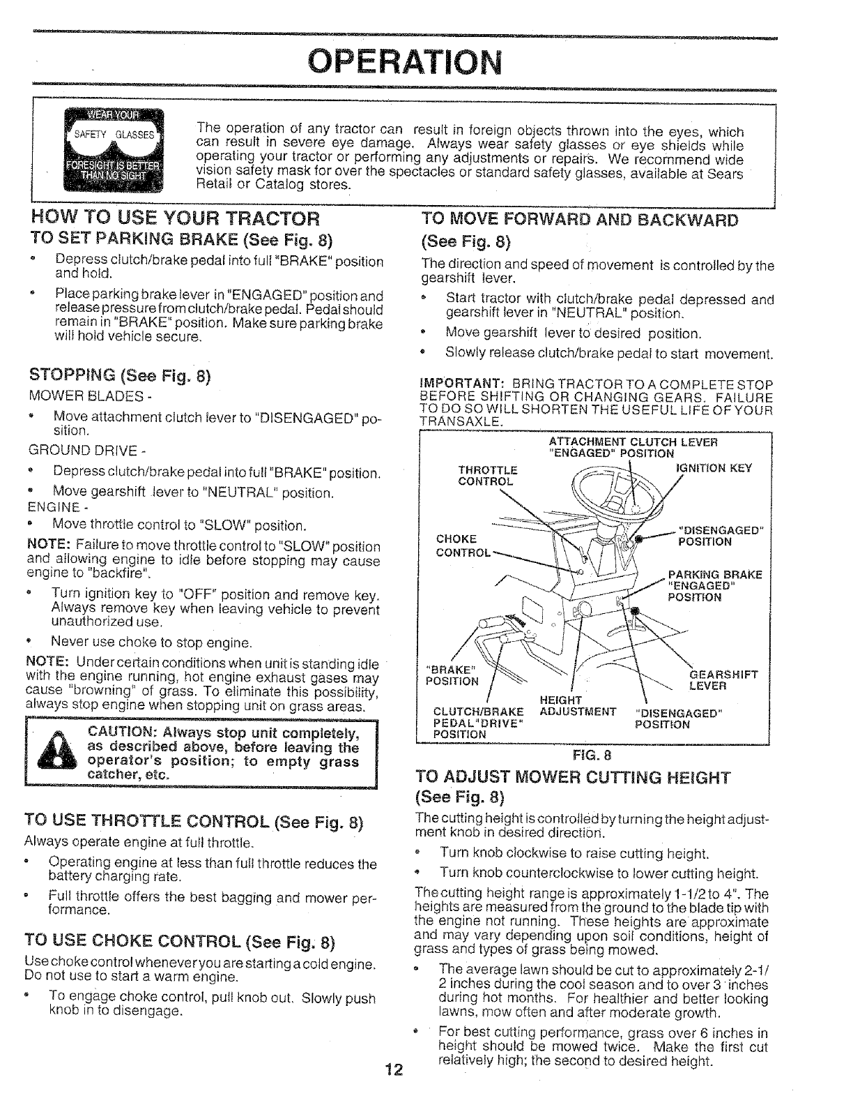
THROTTLE
CONTROL
ATTACHMENT CLUTCH LEVER
"ENGAGED" POSITION
IGNITION KEY
NGAGED"
CHOKE POSITION
PARKING BRAKE
_NGAGED"
POSITION
FIG. 8
TO ADJUST MOWER CUTTING HEIGHT
(See Fig. 8)
The cutting height is controlled byturning the height adjust-
ment knob in desired directiori.
Turn knob clockwise to raise cutting height,
Turn knob counterclockwise to lower cutting height.
Thecutting height range is approximately 1-t/2to 4". The
heights are measured from the ground to the blade tip with
the engine not running. These heights are approximate
and may vary depending upon soil conditions, height of
grass and types of grass belng mowed.
, The average lawn should be cut to approximately 2-t/
2 inches during the cool season and to over 3 inches
during hot months. For healthier and better looking
lawns, mow often and after moderate growth.
* For best cutting performance, grass over 6 inches in
height should be mowed twice. Make the first cut
relatively high; the second to desired height.

OPERATION
TO OPERATE MOWER (See Fig. 9)
Your unit is equipped with an operator presence sensing
switch, Any attempt by the operator to leave the seat with
the engine running and the attachment clutch engaged will
shut off the engine.
o Select desired height of cut.
Lower mower with attachment lift control
o Start mower blades by engaging attachment clutch
control.
TO STOP MOWER BLADES - disengage attachment
clutch control.
_ AUT|ON: Do not operate the mower
without either the entire grass catcher _on
mowers so equipped, or the discharge
guard inplace.
Move gearshift Iever to 1st gear and be sure you have
altowed room for tractor to roll slightly as you restart
movement.
To restart movement, slowly release parking brake and
clutch/brake pedal.
Make all turns slowIy.
TO TRANSPORT
, Raise attachment lift control to highest position_
oWhen pushing or towing your unit, be sure gearsilift
lever is in "NEUTRAL" position.
Do not push or tow unit at more than five (5) MPH.
NOTE: To protect hood from damage when transporting
yourtractor on atruck or atrailer, be sure hood is closed and
secured to tractor. Use an appropriate means of tying hood
to tractor (rope, cord, etc,).
ATTACHMENT
CLUTCH LEVER
"DISENGAGED"
POSiTiON
ATTACHMENT CLUTCH LEVER
"ENGAGED" POSITION
LiFT LEVER
"HIGHEST"
LOWEST
POSITION
FgG:9
rO OPERATE ON H_LLS
with slopes greater than 15° and do not l
Choose the slowest speed before starting up or down
hills.
Avoid stopping or changing speed on hills.
If slowing is necessary, move throttle control lever to
slower position.
If stopping is absolutely necessary, push clutch/brake
pedal quickly to brake position and engage parking
brake.
BEFORE STARTING THE ENGINE
CHECK ENGINE OIL LEVEL (See Fig. t5)
o The engine in your unit has been shipped, from the
factory, already filled with summer weight oil.
Check engine oil with unit on level ground.
• Remove o{! fill dipstick and wipe clean, replace and
screw cap tight, wait for a few seconds, remove and
read oil level. If necessary, add oil unti! "FULL" mark
on dipstick is reached. Do not overfill.
o For cold weather operation you should change oil for
easier starting (see "OtL VISCOSITY CHART" in the
Customer Responsibilities section of t:his manual).
,, To change engine oi!, see the Customer Responsibifio
ties section in this manual.
ADD GASOUNE
Fill fuel tank. Use fresh, clean, regular unleaded
gasoline. (Use of leaded gasoline wit! increase carbon
and lead oxide deposits and reduce valve life).
IMPORTANT: WHEN OPERATING INREI_APERATURE_
BELOW o,pop_,_or "',
.__ __,_,_,j,USE FRESH, CLEAN WINTER GRADE
GASOLINE TO HELP INSURE GOOD COLD WEATHER
STARTING.
WARNING: Experience indicates that alcohol blended
fuels (called gasohol or using ethanol or methanol) can
attract moisture which leads to separation and formation of
acids during storage. Acidic gas can damage the fuel
system of an engine while in storage. To avoid engine
problems, the fuel system should be emptied before stor-
age of 30 days or longer, Drain the gas tank, star_ the
engine and let it run until the fuel lines and carburetor are
empty. Use fresh fuel next season. See Storage Instruc-
tions for additional information. Never use engine or
carburetor cleaner products in the fuel tank or permanent
damage may occur.
CAUTION: Fil! to bottom of gas tank fH_er
neck. Do not overfill W_pe off any spilled
oil or fuel Do not store, spill or use
gasoline near an open flame°
13

OPERATION
TO START ENGINE (See Fig. 8)
When starting engine for the first time or if engine has
run out of fuel, it wil! take extra cranking time to move
fuel from the tank to the engine.
Depress the clutch/brake pedal and set the parking
brake.
• Place gearshift lever in "NEUTRAL" position.
Move attachment clutch to "DISENGAGED" position.
Pull choke control out to "CHOKE" position for cold
engine start. For warm engine start do not use choke
control.
Move throttle control to midway between "FAST" and
"SLOW" positions.
Turn ignition key clockwise to "START" position and
refease key as soon as engine starts. Do not run
starter continuously for more than fifteen seconds
per minute. If engine does not start after several
attempts, move throttle control to "FAST" position,
wait a few minutes and try again.
When engine starts, slowly push choke control in.
,, Move throttle control to "FAST" position.
Allow engine to warm up for a few minutes before
engaging drive or attachment clutch.
NOTE: tf at a high altitude (above 3000 feet) or in cold
temperatures (below 32 ° F), the carburetor fuel mixture
may need to be adjusted for best engine performance.
See "TO ADJUST CARBURETOR" in the Service and
Adjustments section of this manual.
MOWING TiPS
• Tire chains cannot be used when the mower hous-
ing is attached to unit.
o Mower should be properly leveled for best mowing
performance. See TO LEVEL MOWER HOUSING
in the Service and Adjustments section of this
manual.
• The left hand side of mower should be used for trim-
ming.
• Drive so that clippings are discharged onto the area
that has been cut. Have the cut area to the right of
the machine. This will result in a more even distri-
bution of clippings and more uniform cutting.
•When mowing large areas, start by turningto the
right so that clippings will discharge away from
shrubs, fences, driveways, etc. After one or two
rounds, mow in the opposite direction making left
hand turns until finished (See Fig. 10).
• If grass is extremely tall, it should be mowed twice
to reduce load and possible fire hazard from dried
clippings. Make first cut relatively high; the second
to the desired height.
Do not mow grass when it is wet. Wet grass will
plug mower and leave undesirable clumps. Allow
grass to dry before mowing.
• Always operate engine at ful! throttle when mowing
to assure better mowing performance and proper dis-
charge of material. Regulate ground speed by se-
lecting a tow enough speed to give the mower cut-
ting performance as well as the quality of cut de-
sired. 14
When operating attachments, select a ground speed
that will suit the terrain and give best performance of
the attachment being used.
FIG. 10
MULCHtNG MOWING T|PS
_MPORTANT: FOR BEST PERFORMANCE, KEEP
MOWER HOUSING FREE OF BUILT-UP GRASS AND
TRASH. CLEAN AFTER EACH USE.
The special mulching blade will recut the grass clip-
pings many times and reduce them in size so that as
they fall onto the lawn they will disperse into the grass
and not be noticed. Also, the mulched grass will
biodegrade quickly to provide nutrients for the lawn,
Always mulch with your highest engine (blade) speed
as this will provide the best recutting action of the
blades.
Avoid cutting your lawn when it is wet. Wet grass tends
to form clumps and interferes with the mulching action.
The best time to mow your lawn is the early afternoon.
At this time the grass has dried and the newly cut area
wil! not be exposed to the direct sun.
For best results, adjust the mower cutting height so that
the mower cuts offonly the top one-third of the grass
blades (See Fig. 1I). For extremely heavy mulching,
reduce your width of cut on each pass and mow slowly.
MA×I_
FiG. 11
Certain types of grass and grass conditions may re-
quire that an area be mulched a second time to com-
pletely hide the clippings. When doing a second cut,
mow across or perpendicular to the first cut path.
Change your cutting pattern from week to week. Mow
north to south one week then change to east to west the
next week. This will help prevent matting and graining
of the lawn.

OUSTO ESPONSIBmLmES
T
R
A
C
T
0
R
E
N
GI
MAINTENANCE SCHEDULE
FtLL IN DATES
AS YOU COMPLETE
REGULAR SERVICE
Check Brake Operation
Check Tire Pressure
Check for Loose Fasteners
Sharpen/Replace Mower Biades
Lubrication Chart
Check Battery Level!Recharge
Clean Battery and Terminals
Chock Transmission Cooling
Adjust Blade Belt(s) Tension
Adjust Motion Drive Bett(s) TenSion
Check Engine Oil Level
Change Engine Oil
Clean Air Filter
Clean Air Screen
inspect Muffler!Spark Attester
Replace Oil Filter (If equipped)
Clean Engine Cooling Fins
Replace Spark Plug
Replace Air Fi_terPaper Cartridge
Replace Fuel FiIter
- Change more often when operating under a heavy load or in high arr_bient temperatures,
2-Service more often when operating in dirty or dusty conditions.
GENERAL RECO[ MENDATIONS
The warranty on:this vehicle does not cover items that have
been subjected to operator abuse or negligence. To
receive ful! value from the warranty, operator must main-
tain unit as instructed in this manual.
Some adjustments will need to be made periodically to
propedy maintain your unit.
All adjustments in the Service and Adjustments section of
this manual should be checked at least once each season.
o Once a year you should replace the spark plug, clean
or replace air filter, and check blades and belts for
wear. A new spark plug and clean air filter assure
proper air-rue! mixture and help your engine run better
and last longer.
BEFORE EACH USE
o Check engine oil level.
o Check brake operation.
, Check tire pressure.
o Check for loose fasteners.
SERVICE DATES
3-If equipped with oil fitter, change oil ever,/50 hours.
4 - Reptace blades more often when mowing in sandy soil,
5 - If equipped with adjustable system.
ENGINE Q
Q SAE 30 OR 10W30 MOTOR OiL API - SG
(_ GENERAL PURPOSE GREASE
(_) REFER TO CUSTOMER RESPONSIBtLR1ES "ENGINE _' SECTION
tMPORTANTr DO NOT OIL OR GREASE THE PIVOT POINTS
WHICH HAVE SPECIAL NYLON BEARINGS, VISCOUS L.UBRt-
CANTS WILL ATTRACT DUST AND DiRT THAT WILL SHORTEN
THE UFE OF THE SELF-LUBRICATING BEARINGS. if: YOU
FEE[. THEY MUST BE LUBRICATED, USE ONLY A DRY, Pew-
15 DERED GRAPHITE TYPE LUBRICANT SPARINGLY,
t_ ATTACHMENT"
CLUTCH
PivoT(s)
LUBRRCATtON CHART
BEARING ZERK I_-J] "_,.,JL-'_- BEARING ZERK

CUSTOMER ESPONSIBILITiES
TRACTOR
Always observe safety rules when pedorming any mainte-
nance.
BRAKE OPERATION
If unit require s more than six (6) feet stopping distance at
high speed in highest gear, then brake must be adiusted.
(See "TO ADJUST BRAKE" in Service and Adjustments
section of this manual).
TIRES
, Maintain proper air pressure in all tires (See "PROD-
UCT SPECIFICATIONS" on page 3 of this manual).
- Keep tires free of gasoline, oil, or insect control chemi-
cals which can harm rubber.
Avoid stumps, stones, deep ruts, sharp objects and
other hazards that may cause tire damage.
BLADE CARE
For best resutts mower blades must be kept sharp, Re-
place bent or damaged blades.
BLADE REMOVAL (See Fig. 12}
, Raise mower to highest position to allow access to
btades.
- Remove hex bolt, !ock washer and flat washer securing
blade,
oInstall new or resharpened blade with trailing edge up
towards deck as shown.
• Reassemble hex boIt, lock washer and fiat washer in
exact order as shown.
•Tighten bolt securely (30-35 Ft. Lbs. torque).
IMPORTANT: BLADE BOLT IS GRADE 8 HEAT
TREATED.
NOTE: We do not _commend sharpening blade- but ifyou
do, be sure the blade is balanced.
MANDREL
ASSEMBLY
FLAT WASHER
LOCK WASHER
BLADE
TRAILING EDGE
HEX BOLT
(GRADE 8 *
•A GRADE 8 HEAT TREATED BOLT CAN BE IDENTIFIED
BY SIX LINES ON THE BOLT HEAD.
F1G° 12
TO SHARPEN BLADE (See Fig, 13}
Care should be taken to keep the b:lade balanced, An
unbalanced blade wilt cause excessive vibration and even-
tual damage to mower and engine.
•The blade can be sharpened with a file or on a grinding
wheel. Do not attempt to sharpen white on the mower.
,, To check b_ade balance; you will need a 5/8" diameter
steel bolt, pin, or cone balancer. (When using a cone
balancer, follow the instructions supplied with the bat-
ancer).
• Slide blade on to an unthreaded portion of the steet bolt
or pin parallel with ground. If blade is balanced, it
should remain in a hodzontal position. If either end of
the blade moves downward, sharpen the heavy end
until the blade is balanced.
NOTE: Do not use a nail for balancing blade. The lobes of
the center hole mm_vappear to be centered, but are not.
/
J
OR PIN
FIG, 13
BATTERY (See Fig. 14)
Your unit has a battery charging system which is sufficient
for normal use. However, periodic charging of the battery
with an automotive charger wiil extend it's life.
• Acid solution level in each battery cell should be even
with bottoms of vent wells. Add only distilled or iron free
water if necessary. Do not overfill.
, Keep battery and terminals clean.
-Keep battery bolts tight.
= Keep vent caps tight and smalt vent holes in caps open.
, Recharge at 6 ampere_ for 1 hour.
CUT AWAY VIEW VENTCAP
_ VENT
WELL
BATTERY
CELL ACID
LEVEL
F G.14
16

CUSTO RESPONSIBILITIES
TO CLEAN BATTERY AND TERMINALS -
Corrosion and dirt on the battery and terminals can cause
the battery to "leak" power.
Remove terminal guard.
Disconnect BLACK battery cable first then RED
battery cable and remove battery from tractor.
Wash battery with solution of four tablespoons of
baking soda to one gallon of water. Be careful not to
get the soda solution into the ceils.
Rinse the battery with plain water and dry.
o Clean terminals and battery cable ends with wire brush
until bright.
° Coat terminals with grease or petroleum jelly.
o Reinstall battery (See "INSTALL BATTERY" in As-
sembly section of this manual).
V-BELTS
Check V-belts for deterioration and wear after 100 hours
and replace if necessary. The belts are not adjustable.
Replace belts if they begin to slip from wear.
TRANSAXLE COOLING
Keep transaxle free from build-up of dirt and chaff which
(;an restrict cooling_
ENGINE
LUBRICATION
Only use high quality detergent oil rated with API service
classification SG. Select the oi!'s SAE viscosity grade
according to your expected operating temperature.
SAE VISCOSITY GRADES
OC 30"
1 EMPL-RA 1URn] RANG_: ANTtCfPA] _:O BEFORE NEXT OIL CHANGE
NOTE: Although multi-viscosity oils (5W30, 10W30 etc.)
improve starting in cold weather, these multi-viscosity oils
will result in increased oil consumption when used above
32'>F. Check you r engine oil level more frequently to avoid
possible engine damage from running tow on oil.
Change the oit after the first two hours of operation and
every 25 hours thereafter or at least once a year if the
tractor is not used for 25 hours in one year.
Check the crankcase oil level before starting the engine
and after each eight (8) hours of continuous use. Tighten
oil fill Capidipstic_ securely each time you check the oil
level
TO CHANGE ENGINE OIL (See Fig. t5)
o Be sure vehicle is on level sudace.
o Oil wiii drain more freeiy when warm.
.Catch oil in a suitable container.
Remove oii till dipstick. Be careful not to allow dirt to
enter the engine when changing oil.
,, Remove drain plug.
o After oi! has drained completely, replace oil drain plug
and tighten securely.
- Refill engine with oil through oil fill dipstick tube. Pour
slowly. Do not overfill. For approximate capacity see
Product Specifications on page 3 of this manual.
- Use gauge on oil fill dipstick for checking level Be sure
dipstick cap,is tigh,!ened securely for accurate reading.
Keep oil at FULL line on dipstick.
OIL
DRAIN
PLUG
ENGINE O|L
DIPSTICK AND
17
FIG. 15
AIR SCREEN (See Fig, t5)
The engine air screen must be kept free of dirt and chaff to
prevent engine damage from overheating. Clean with a
wire bnJsh or compressed air to removed dirt and stubborn
dried gum fibers.
AIR FILTER (See Fig, 16)
Your engine wilt not run properly using a dirty air filter.
Clean the foam pre-cleaner element after every 25 hours of
operation or every season. Service paper cartridge every
100 hours or every season, whichever occurs first.
Service air cleaner more often under dusty conditions.
- Remove knob(s) and cover.
TO SERVICE PRE-.CLEANER
Slide foam pre-cteaner off cartridge.
Wash it in liquid detergent and water.
o Squeeze it dry in a clean cloth.
• Saturate it in engine oil. Wrap it in clean, absorbent
cloth and squeeze to remove excess oil.
o Reinstall pre-cleaner over cartridge.
o Reinstall cover and secure with knob(s).
TO SERVICE CARTRIDGE
Remove wing n_ts and cartridge plate.
', Remove cartridge and clean by tapping gently on flat
surface.
ttvery dirty, replace or wash in a nonsudsing detergent
and warm water solution. Rinse thoroughly with water
from inside out until water runs ctear. Let cartridge dry
thorot_ghty before using.
. Reinstall cartridge plate, wing nuts, precleaner, cover
and secure with knob(s).
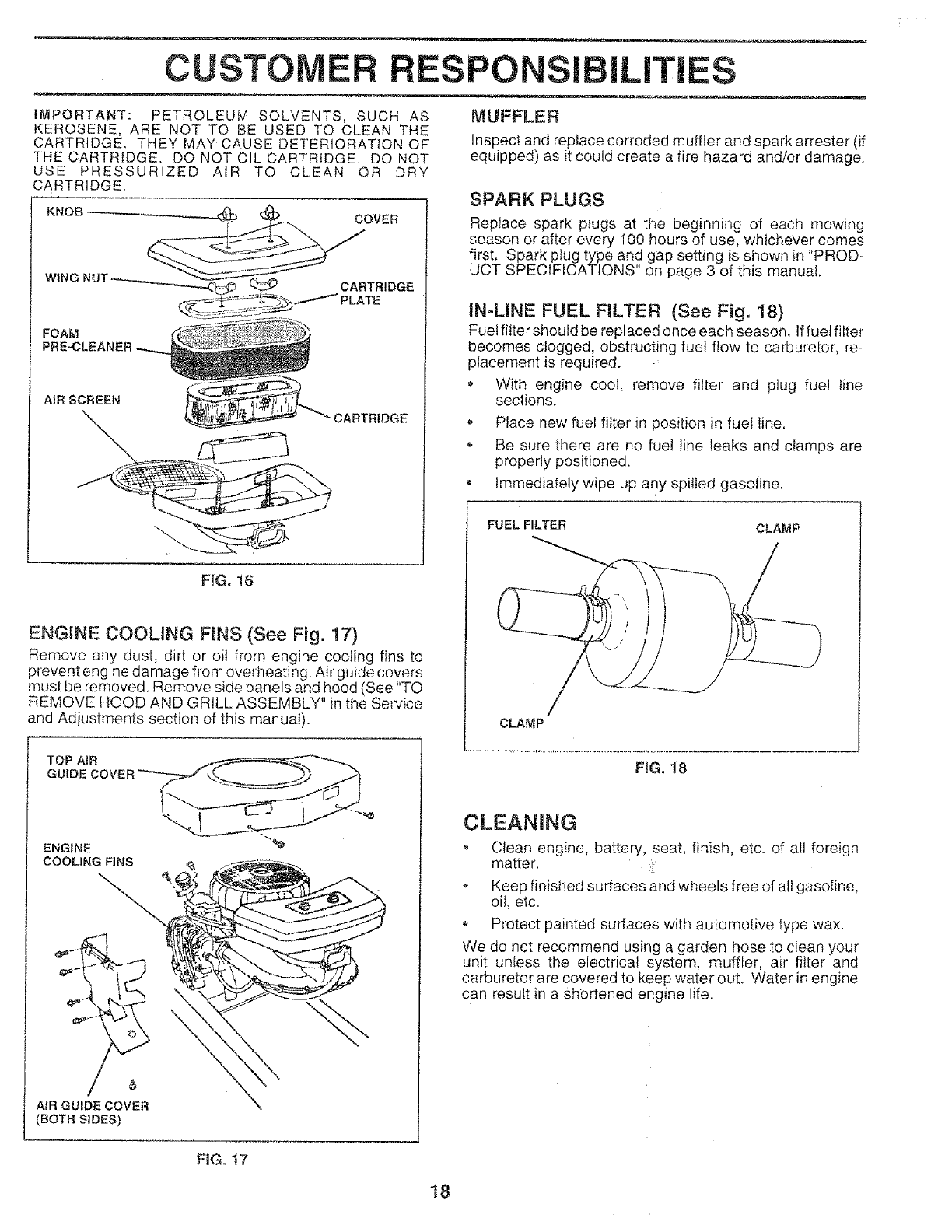
CUSTOMER RESPONSIBILiTiES
IMPORTANT: PETROLEUM SOLVENTS, SUCH AS
KEROSENE, ARE NOT TO BE USED TO CLEAN THE
CARTRIDGE. THEY MAY CAUSE DETERIORATION OF
THECARTRtDGE. DO NOTOIL CARTRIDGE. DO NOT
USE PRESSURIZED AIR TO CLEAN OR DRY
CARTRIDGE.
KNOB COVER
CARTRIDGE
/'PLATE
AiR SCREEN
FiG. 16
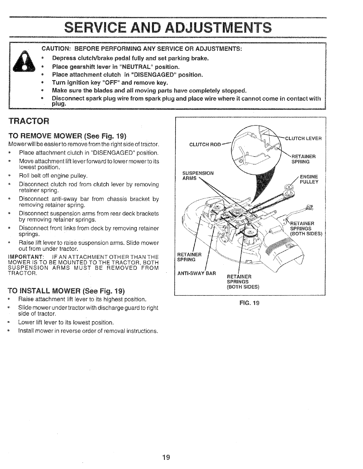
ENGINE COOLING FiNS (See Fig. 17)
Remove any dust, dirt or oil from engine cooling fins to
prevent engine damage from overheating. Air guide covers
must be removed. Remove side panels and hood (See "TO
REMOVE HOOD AND GRILL ASSEMBLY" in the Service
and Adjustments section of this manual).
MUFFLER
Inspect and replace corroded muffler and spark arrester (if
equipped) as it could create a fire hazard and/or damage,
SPARK PLUGS
Replace spark plugs at the beginning of each mowing
season or after every 100 hours of use, whichever comes
first. Spark plug type and gap setting is shown in "PROD-
UCT SPECIFICATIONS" on page 3 of this manual.
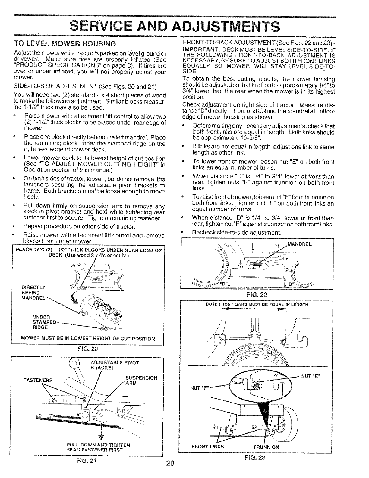
IN-LINE FUEL FILTER (See Fig. 18)
Fuetfittershouldbereplacedonceeachseason. If fuetfilter
becomes clogged, obstructing fuel flow to carburetor, re-
placement is required.
With engine coot, remove filter and plug fuel line
sections.
• Place new fuel filter in position in fuel line.
- Be sure there are no fuel line leaks and clamps are
properly positioned.
• Immediately wipe up any spitled gasoline.
FUEL FILTER CLAMP
/
/
CLAMP
TOP AiR
GUIDE
ENGINE
COOLING FINS
AIR GUIDE COVER
(BOTH SIDES)
=¢)
FiG. 18
CLEANING
Clean engine, battery, seat, finish, etc. of all foreign
matter.
,, Keep finished surfaces and wheels free of all gasoline,
oil, etc.
Protect painted surfaces with automotive type wax.
We do not recommend using a garden hose to clean your
unit unless the electdca! system, muffler, air filter and
carburetor are covered to keep water out. Water in engine
can result in a ShOrtened engine life.
FiG. t7
18
SERVICE AND ADJUSTMENTS
CAUT|ON: BEFORE PERFORMING ANY SERVICE OR ADJUSTMENTS:
Depress clutch/brake pedal fully and set parking brake.
Place gearshift lever in "NEUTRAL" position,
= Place attachment clutch in "DISENGAGED" position.
® Turn ignition key "OFF" and remove key.
- Make sure the blades and at! moving parts have completely stopped.
• Disconnect spark plug wire from spark pNugand place wire where it cannot come in contact with
plug,
TRACTOR
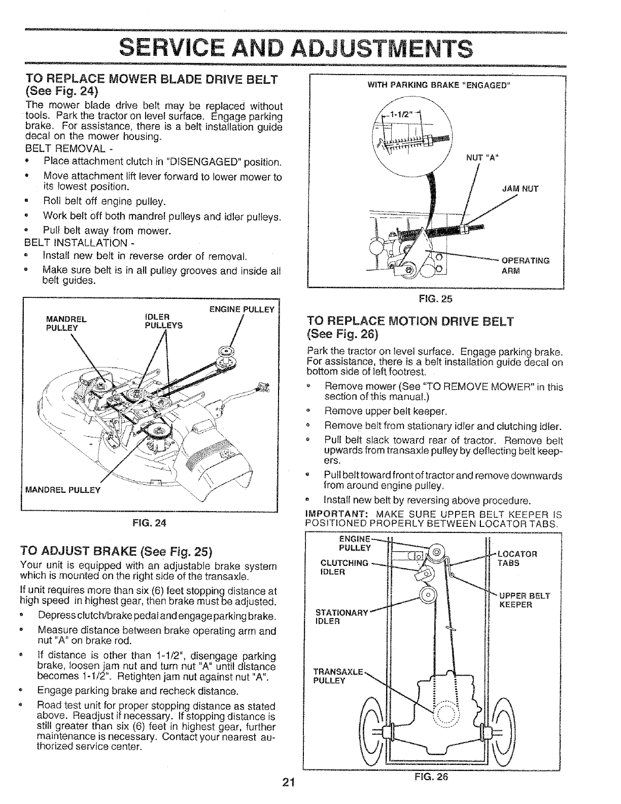
TO REMOVE MOWER (See Fig, 19}
Mower will be easier to remove from the right side of tractor.
Place attachment ctutch in "DISENGAGED" position.
o Move attachment tift lever forward to lower mower to its
lowest position.
o Roll belt off engine pulley.
Disconnect clutch rod from dutch lever by removing
retainer spring.
Disconnect anti-sway bar from chassis bracket by
removing retainer spring,
Disconnect suspension arms from rear deck brackets
by removing retainer springs,
Disconnect front links from deck by removing retainer
springs,
o Raise Jiltlever to raise suspension arms. Slide mower
out from under tractor.
_MPORTANT: IF AN ATTACHMENT OTHER THAN THE
MOWER IS TO BE MOUNTED TO THE TRACTOR, BOTH
SUSPENSION ARMS MUST BE REMOVED FROM
TRACTOR.
TO iNSTALL MOWER (See Fig. 19}
Raise attachment lift lever to its highest position.
oSlide mower under tractor with discharge guard to right
side of tractor,
Lower lift lever to its lowest position.
Install mower in reverse order of removal instructions,
SUSPENSION
ARMS PULLEY
SPRINGS
(BOTH SIDES}
RETA|NER
SPRING
ANTI-SWAY BAR RETAINER
SPRINGS
(BOT_ S_DES)
FtG, 19
19
SERVICE AND ADJUSTMENTS
TO LEVEL MOWER HOUSING FRONT-TO-BACK ADJUSTMENT(See Figs. 22 and23) -
Adjust the mower while tractor is parked on level ground or
driveway. Make sure tires are properly inflated (See
"PRODUCT SPECIFICATIONS" on page 3). If tires are
over or under inflated, you wilt not properly adjust your
mower.
SIDE-TO-SIDE ADJUSTMENT (See Figs. 20 and 2!)
You wilt need two (2) standard 2 x 4 short pieces of wood
to make the following adjustment. Similar blocks measur-
ing 1-112" thick may also be used.
- Raise mower with attachment lift control to allow two
(2) t -t/2" thick blocks to be placed under rear edge of
mower.
- Place one block directly behind the left mandrel. Place
the remaining block under the stamped ridge on the
right rear edge of mower deck.
Lower mower deck to its lowest height of cut position
(See "TO ADJUST MOWER CUTTING HEIGHT" in
Operation section of this manual).
On both sides of tractor, loosen, but do not remove, the
fasteners securing the adjustable pivot brackets to
frame. Both brackets must be loose enough to move
freely.
• Pull down firmly on suspension arm to remove any
slack in pivot bracket and hold while tightening rear
fastener first to-secure. Tighten remaining fastener.
- Repeat procedure on other side of tractor.
Raise mower with attachment lift control and remove
blocks from under rnower.
PLACE TWO (2) 1-112" THICK BLOCKS UNDER REAR EDGE OF
DECK (Use wood 2 x 4's or equiv.)
DIRECTLY
BEHIND f ._,
STA MPED.-,._,,.,._,.,_ t, " ::._;,::7
MOWER MUST BE tN LOWEST HEIGHT OF CUT POSITION
FIG. 20
FASTEN__
ADJUSTABLE PIVOT
BRACKET
PULL DOWN AND TIGHTEN
REAR FASTENER FIRST
F_G.2t
iMPORTANT: DECK MUST BE LEVEL SIDE-TO-SIDE. tF
THE FOLLOWING FRONT-TO-BACK ADJUSTMENT IS
NECESSARY, BE SURE TO ADJUST BOTH FRONT LINKS
EQUALLY SO MOWER WILL STAY LEVEL SIDE-TO-
SIDE,
TO obtain the best cutting results, the mower housing
should be adjusted so that the front is approximately 1/4" to
3/4" lower than the rear when the mower is in its highest
position.
Check adjustment on right side of tractor. Measure dis-
ta ce D d_recttytn front and behind the mandretat bottom
edge of mower housing as shown.
Before making any necessary adjustments, checkthat
both front links are equal in length. Both links should
be approximately 10-3/8".
If links are not equal in length, adjust one link to same
length as other link.
* To lower front of mower loosen nut "E" on both front
links an equal number of turns.
When distance "D" is 1/4" to 3/4" lower at front than
rear, tighten nuts "F" against trunnion on both front
links.
e To raise front of mower, loosen nut "F" from trunnion on
both front links. Tighten nut "E" on both front links an
equal number of turns.
- When distance "D" is 1/4" to 3/4" lower at front than
rear, tighten nut"F" against trun niGh on both front links.
Recheck side-to-side adjustment.
FIG. 22
BOTH FRONT LINKS MUST BE EQUAL IN LENGTH
.... ____ NUT
FRONT LINKS TRUNNION
FIG. 23
2O
SERVICE AND ADJUSTMENTS
TO REPLACE MOWER BLADE DRIVE BELT
(See Fig. 24}
The mower blade drive belt may be replaced without
tools. Park the tractor on level surface. Engage parking
brake. For assistance, there is a belt installation guide
decal on the mower housing.
BELT REMOVAL -
, Place attachment dutch in "DISENGAGED" position.
, Move attachment lift lever forward to lower mower to
its _owest position.
, Ro!t belt off engine puitey.
o Work belt off both mandrel pulleys and idler pulleys.
® Pull belt away from mower.
BELT INSTALLATION -
Install new belt in reverse order of removal.
= Make sure belt is in ail purJey grooves and inside atl
belt guides.
WiTH PARKING BRAKE "ENGAGED"
NUT "A"
JAM NUT
OPERATING
ARM
MANDREL IDLER
PULLEY PULLEYS
ENGINE PULLEY
I\
FIGo24
FIG. 25
TO REPLACE MOTION DRIVE BELT
(See Fig. 26)
Park the tractor on leve] surface. Engage parking brake.
For assistance, there is a belt instaJiationguide decal on
bottom side of left footrest.
• Remove mower (See "TO REMOVE MOWER" in this
section of this manual.)
Remove upper belt keeper.
o Remove belt from stationary idler and clutching idler.
o Pull bett slack toward rear of tractor. Remove belt
upwards from transa×le pu!ley by deflecting belt keep-
ers.
Pu!l belt toward front of tractor and remove downwards
from around engine pulley.
. Install new be!t by reversing above procedure.
iMPORTANT: MAKE SURE UPPER BELT KEEPER IS
POSITIONED PROPERLY BETWEEN LOCATOR TABS.
TO ADJUST BRAKE (See Fig. 25)
Your unit is equipped with an adjustable brake system
which is mounted on the right side of the transaxle.
If unit requires more than six (6) feet stopping distance at
high speed in highest gear, then brake must be adjusted.
. Depress clutch/brake pedal and engage parking brake.
Measure distance between brake operating arm and
nut "A" on brake rod.
o If distance is other than 1-1/2 '', disengage parking
brake, loosen jam nut and turn nut "A" until distance
becomes t-1/2". Retighten jam nut against nut "A".
• Engage parking brake and recheck distance.
® Road test unit for proper stopping distance as stated
above. Readjust if necessary. If stopping distance is
still greater than six (6) feet in highest gear, further
maintenance is necessary. Contact your nearest au-
thorized service center.
PULLEY
IDLER
STATIC
IDLER
PULLEY
TABS
BELT
KEEPER
21 FIG. 26

SERVICE AND ADJUSTMENTS
TO ADJUST STEERING WHEEL ALIGNMENT
if steering wheel crossbars are not horizontal (left to right)
when wheels are positioned straight forward, remove
steering wheel and reassemble per instructions in the
Assembly section of this manual.
FRONT WHEEL TOE=iN/CAMBER
The front wheel toe-in and camber are not adjustable on
your unit. If damage has occurred to affect the front wheel
toe-in or camber, contact your nearest authorized service
center.
TO REMOVE WHEEL FOR REPAIRS
(See Fig, 27)
Block up axle securely.
Remove axtecover, retaining ring and washersto allow
wheet removal (rear wheel contains a square key- Do
not bose).
Repair tire and reassemble.
• On rear wheels only: align grooves in rear wheel hub
and axle. insert square key.
•Replace washers and snap retaining ring securely in
axle groove.
o Replace axle cover.
WASHERS
RETAiNiNG
RiNG
AXLE COVER
I
_tSQU ARE KEY
(REAR WHEEL ONLY}
FIG, 27
TO START ENGINE WiTH A WEAK BAT-
TERY (See Figs. 28.& 2£_.) ....
CAUTION: Lead-acid batteries gener-
ate explosive gases. Keep sparks, flame
and smoking materials away from bat-
teries. Always wear eye protection
when around batteries.
If your batten/is too weak to start the engine, it should be
recharged. If "jumper cables" are used for emergency
starting, follow this procedure:
iMPORTANT: YOUR UNIT IS EQUIPPED WITH A 12
VOLT NEGATIVE GROUNDED SYSTEM. THE OTHER
VEHICLE MUST ALSO BE A 12 VOLT NEGATIVE
GROUNDED SYSTEM. DO NOT USE YOUR TRACTOR
BATTERY TO START OTHER VEHICLES,
TO ATTACH JUMPER CABLES -
Connect each end of the RED cable to the POSITIVE
(+) terminal of each battery, taking care not to short
against chassis,
Connect one end of the BLACK cable to the NEGA-
TIVE (-) terminal of fully charged battery.
Connect the other end of the BLACK cable to a panel
bolt on the left side of the chassis, away from fuel tank
and battery.
To remove cables, reverse order -
BLACK cable first from left side of chassis and then
from the fully charged battery.
* RED cable last from both batteries.
"POSmVE"
(+)
FiG. 28
PANEL
BOLT
\
FIG, 29
22
SERVICE AND ADJUSTMENTS
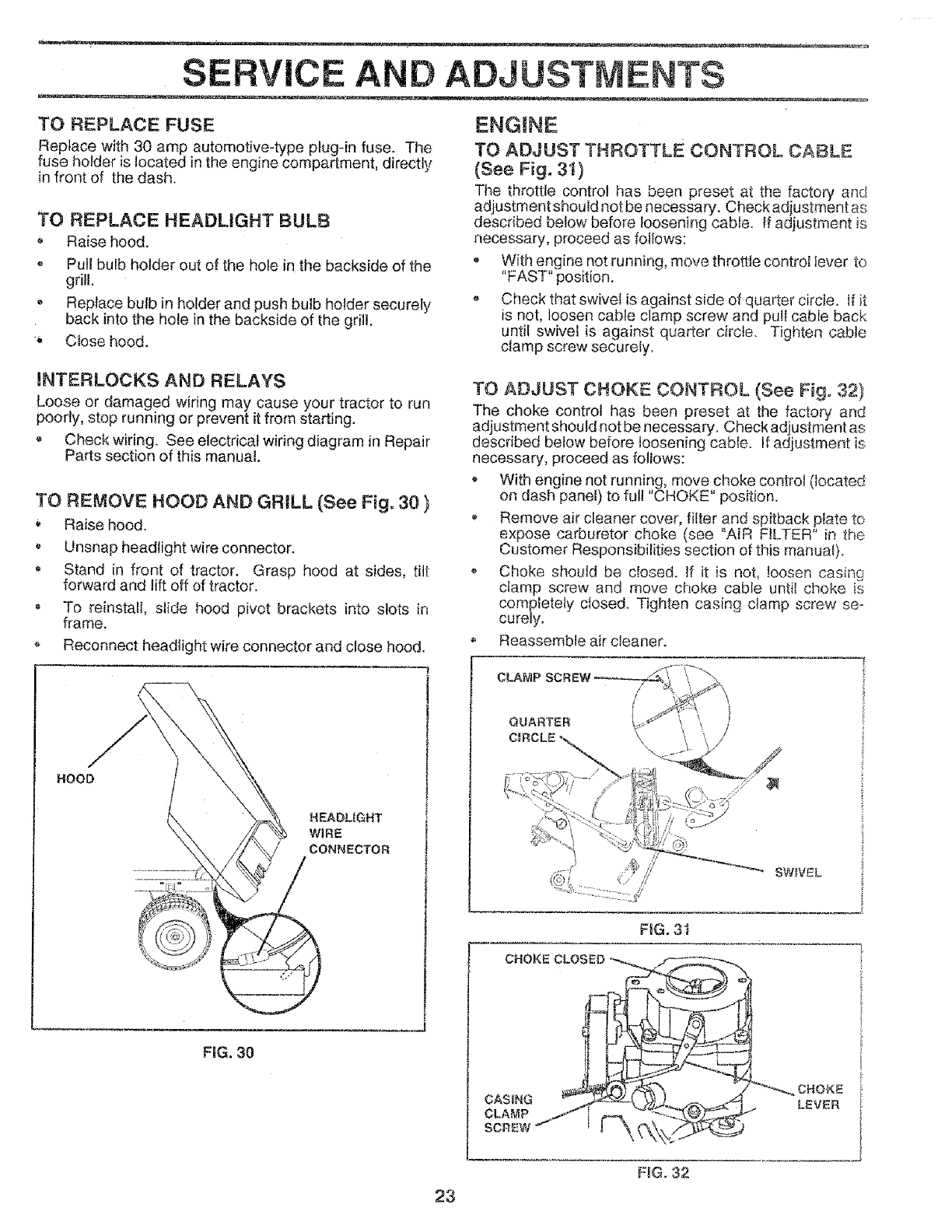
TO REPLACE FUSE
Replace with 30 amp automotive-type ptug4n fuse. The
fuse holder is located in the engine compartment, directly
in front of the dash.
TO REPLACE HEADLIGHT BULB
Raisehood.
• Pullbulbholderoutoftheholeinthebacksideofthe
grill.
Replacebulbinholderand push bulbholdersecurety
back into the hole in the backside of the grill,
Close hood,
mNTERLOCKS AND RELAYS
Loose or damaged wiring may cause your tractor to run
poorly, stop running or prevent it from starting.
o Check wiring. See electrical wiring diagram in Repair
Parts section of this manual.
TO REMOVE HOOD AND GRILL (See Fig. 30 }
Raise hood.
,Unsnap headlight wire connector.
Stand in front of tractor. Grasp hood at sides, tilt
forward and lift off of tractor.
, To reinstall, slide hood pivot brackets into slots in
frame.
Reconnect headlight wire connector and close hood.
ENGINE
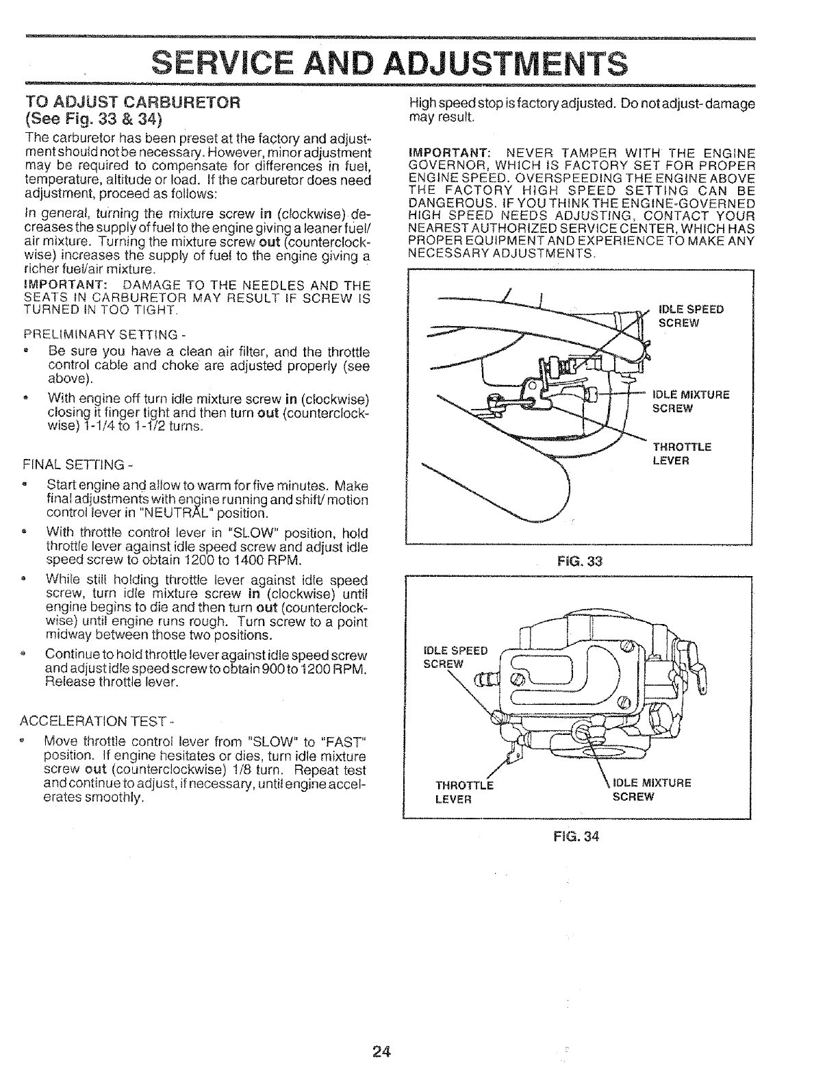
TO ADJUST THROTTLE CONTROL CABLE
(See Fig. 31)
The throttle control has been preset at the factory and
adjustment shouid notbe necessary. Checkadjustment as
described below before loosening cable. IFadjustment is
necessary, proceed as foltows:
With engine not running, move throttle control lever to
"FAST" position.
Check that swivel is against side of quarter circle, tf it
is not, loosen cable clamp screw and putl cable back
until swivel is against quarter circle. Tighten cable
clamp screw securely.
TO ADJUST CHOKE CONTROL (See Fig. 32)
The choke control has been preset at the factory and
adjustment should not be necessary. Check adjustment as
described below before loosening cable. If adjustment is
necessary, proceed as follows:
With engine not running, move choke control (located
on dash panel) to ful! "CHOKE" position.
Remove air cleaner cover, filter and spitback plate to
expose carburetor choke (see "AiR FILTER" in the
Customer Responsibilities section of this manual).
Choke should be closed. If it is not, loosen casing
clamp screw and move choke cable until choke is
completely ctosed. Tighten casing clamp screw se*
curely.
Reassemble air cleaner.
HOOD
HEADLIGHT
WiRE
CONNECTOR
FiG. 30
SWWEL
RG. 3t
CHOKE CLOSED
CHOKE
LEVER
23
F_G.32
SEFIVICE AND ADJUSTMENTS
TO ADJUST CARBURETOR
(See Fig. 33 &34)
The carburetor has been preset at the factory and adjust-
ment should not be necessary. However, minor adjustment
may be required to compensate for differences in fuel,
temperature, altitude or lead. If the carburetor does need
adjustment, proceed as follows:
In general, turning the mixture screw in (clockwise) de-
creases the supply of fuel to the engine giving a leaner fuel/
air mixture. Turning the mixture screw out (counterclock-
wise) increases the supply of fuel to the engine giving a
richer fuel/air mixture.
_MPORTANT: DAMAGE TO THE NEEDLES AND THE
SEATS IN CARBURETOR MAY RESULT IF SCREW IS
TURNED iN TOO TIGHT.
PRELIMINARY SETTING -
-Be sure you have a clean air filter, and the throttle
control cabte and choke are adjusted properly (see
above).
- With engine off turn idle mixture screw in (clockwise)
closing it finger tight and then turn out (counterclock-
wise) 1-1/4 to 1-1/2 turns.
FINAL SE-t-FtNG -
° Start engine and allow to warm for five minutes. Make
final adjustments with engine running and shift! motion
control lever in "NEUTRAL" position.
= With throttle control lever in "SLOW" position, hold
throttle lever against idle speed screw and adjust idle
speed screw to obtain 1200 to !400 RPM.
Whife still holding throttle lever against idle speed
screw, turn idle mixture screw in (clockwise) until
engine begins to die and then turn out (counterclock-
wise) until engine runs rough. Turn screw to a point
midway between those two positions.
o Continue to hotd throttle lever against idle speed screw
and adjust idle speed screw to obtain 900 to 1200 RPM.
Release throttle lever.
ACCELERATION TEST
o Move throttle control lever from "SLOW" to "FAST"
position. If engine hesitates or dies, turn idle mixture
screw out (counterclockwise) 1/8 turn. Repeat test
and continue to adjust, if necessan], untit engineaccel-
erates smoothly.
High speed stop is factory adjusted. Do not adjust- damage
may result.
IMPORTANT: NEVER TAMPER WITH THE ENGINE
GOVERNOR, WHICH tS FACTORY SET FOR PROPER
ENGINE SPEED. OVERSPEEDING THE ENGtNE ABOVE
THE FACTORY HIGH SPEED SETTING CAN BE
DANGEROUS. IF YOU THfNKTHE ENGINE_GOVERNED
HIGH SPEED NEEDS ADJUSTING, CONTACT YOUR
NEAREST AUTHORIZED SERVICE CENTER, WHtCH HAS
PROPER EQUIPMENT AND EXPERIENCE TO MAKE ANY
NECESSARY ADJUSTMENTS.
IDLE SPEED
SCREW
IDLE MIXTURE
SCREW
F_G.33
IDLE SPEED
SCREW
/
THROTTLE
LEVER
_E MIXTURE
SCREW
FiG. 34
24
STORAG
Immediately prepare your tractor for storage at the end of
the season or if the unit will not be used for 30 days Or mere.
TRACTOR
Remove mower from tractor for winter storage. When
mower is to be stored for a period of time, clean it thor-
oughly, remove atl dirt, grease, leaves, etc. Store in a
clean, dry area.
" Clean entire tractor (See"CLEANING" inthe Customer
Responsibilities section of this manual).
- Inspect and replace belts, if necessary (See belt re-
placement instructions in the Service and Adjustments
section of this manual).
* Lubricate as shown in the Customer Responsibilities
section of this manual.
Be sure that all nuts, bolts and screws are securely
fastened. Inspect moving parts for damage, breakage
and wear. Replace if necessary.
,Touch up all rusted or chipped paint surfaces; sand
lightly before painting.
BATTERY
Fully charge the battery for storage.
After a period of time in storage, battery may require
recharging.
To help prevent corrosion and power leakage during
long periods of storage, battery cables should be
disconnected and batterycleaned thoroughly (see"TO
CLEAN BATTERY AND TERMINALS in the Cus-
tomer Responsibilities section of:this manual).
• After cleaning, leave cabbs disconnected and place
cables where they cannot come in contact with battery
terminals.
• Be sure battery drain tube is securely attached.
ENGINE
FUEL SYSTEM
iMPORTANT: IT tS IMPORTANT TO PREVENT GUM
DEPOSITS FROM FORMING IN ESSENTIAL FUEL
SYSTEM PARTS SUCH AS CARBURETOR, FUEL FILTER,
FUEL HOSE, OR TANK DURtNG STORAGE. ALSO,
EXPERIENCE INDICATES THAT ALCOHOL BLENDED
FUELS (CALLED GASOHOL OR USING ETHANOL OR
METHANOL) CAN ATTRACT MOISTURE WHICH LEADS
TO SEPARATION AND FORMATION OF ACIDS DURING
STORAGE. ACIDtC GAS CAN DAMAGE THE FUEL
SYSTEM OF AN ENGINE WHILE IN STORAGE.
,, Drain the fuel tank,
Start the engine and let it run until the fuet lines and
carburetor are empty.
Never use engine or carburetor cleaner products in the
fuel tank or permanent damage may occur.
o Use fresh fuel next season.
NOTE; Fuel stabilizer is an acceptable alternative in
minimizing the formation of fuel gum deposits during stor u
age. Add stabilizer to gasofine in fuel tank or storage
container+ Always follow the mix ratio found on stabilizer
container. Run engine at least t0 minutes after adding
stabilizer to allow the stabilizer to reach the carburetor. Do
not drain the gas tank and carburetor if using fuei stabilize r.
ENGMNE O|L
Drain oil (with engine warm) and replace with ctean engine
oiI. (See "ENGINE" in the Customer Responsibilities
section of this manual).
CYLINDERS
Remove spark plug(s).
Pour one ounce of oil through spark plug hob(s) into
cylinder(s).
o Turn ignition key to"START' position for afew seconds
to distribute oil.
o Replace with new spark plug(s).
OTHER
Do not store gasoline from one season to another.
, Replace your gasoline can if your can starts to rust.
Rust and/or dirt in your gasoline will cause problems.
If possible, store your unit indoors and cover it to give
protection from dust and dirt.
Cover your unit with a suitable protective cover that
does not retain moisture. Do not use plastic° Plastic
cannot breathe which at!ows condensation to form and
will cause your unit to rust.
iMPORTANT: NEVER COVER TRACTOR WHILE ENGINE
AND EXHAUST AREAS ARE STILL WARM.
25

TROUBLESHOOTING POINTS
PROBLEM
Will not start
Hard to start
Engine will not turn over
_
Engine cticks but wit! not
start
Loss of power
Excessive vibration
CAUSE
1. Out of fuel,
2. Engine not "CHOKED" properly,
3. Engine flooded.
4. Bad spark plug.
5, Dirty air filter.
6, Dirty fuel filter.
7, Water in fuet,
8. Loose or damaged wiring.
9, Carburetor out of adiustment.
t0, Engine valves out of adjustment.
1, Dirty air filter.
2. Bad spark plug.
3, Weakor dead battery.
4. Dirty fuel fitter.
5, Stale or dirty fuel.
6. Loose or damaged wiring.
7. Carburetor out of adjustment,
8_ Engine valves out of adjustment.
I. CIutchh}rake pedal not depressed.
2, Attachment clutch is engaged.
3. Weak or dead battery.
4, Blown fuse,
5. Corroded battery terminals.
6. Loose or damaged wiring.
7. Faulty ignition switch.
8, Faulty solenoid or starter.
9. Faulty operator presence swifch(es).
1. Weak or dead battery.
2. Corroded battery terminals,
3. Loose or damaged wiring,
4, Faulty solenoid or starter.
I. Cutting too much grass/too fast.
2, Throttle in "CHOKE" position.
3. Build-up of grass, leaves and trash under mower.
4, Dirty air filter.
5, Low oil level/dirty oil.
6, Faulty spark plug
7, Dirty fuel fitter,
8. Stale or dirty fue!.
9, Water in fuel
10. Spark plug wire loose.
11. Dirty engine air screenifins_
12. Dirty/clogged muffler.
t3. Loose or damaged wfring.
14, Carburetor out of adjustment.
15. Engiee vatves out of adjustment,
1, Worn, bent ot loose btade.
2. Bent blade mandrel.
3. Loose/damaged part(s).
CORRECTION
1, Fill fuel tank.
2. See "TO START ENGINE" in Operation section,
3. Wait several minutes before attempting to start.
4. Replace spark plug,
5. Clear_'replace air filter.
6, Replace fuel filter.
7. Drain fuel tank and carburetor, refill tank with fresh
gasoline and replace fuel filter.
8. Check allwiring.
9, Contact an authorized service center/department.
!0, Contact an authorized service center/department.
1. Cfear,Jreplace air filter.
2, Replace spark p_ug,
3. Recharge or replace battery,
4, Replace fuel filter.
5, Drain fuel tank and refill with fresh gasoline.
6. Check all wiring.
7, Contact an authorized service center/department,
8. Contact an authorized service center/department,
1, Depress ctutchforake pedal.
2, Disengage attachment clutch.
3. Recharge or replace battery.
4, Replace fuse.
5. Clean battery terminals,
6. Check all wiring.
7, Check/replace ignition switch,
8. ChecWrep_ace solenoid or starter.
9. Contact an authorized service center/department,
!, Recharge or replace battery,
2. Clean battery terminals.
3, Check allwiring.
4, CheckJreplace solenoid or starter.
1. Set in "Higher Cut" position/reduce speed.
2, Adjust throttle control.
3. C_ean underside of mower housing,
4. Clean/replace air tilter.
5, Check oit level/change oil
6. Clean and regap or change spark plug,
7, Replace fuel filter.
8, Drain fuel tank and refill with fresh gasoline.
9, Drain fuel tank and carburetor, refill tank with fresh
gasotine and replace fuel tilter.
10. Connect and tighten spark ptug wire.
11. Clean engine air screen/fins,
t2. Clean/replace muffler.
t3. Check ait wiring,
14. Contact an authorized service centeddepartment,
15. Contact an authorized service center/department.
1. Replace blade. Tighten blade bolt.
2, Replace blade mandrel.
3. Tighten loose part(s). Replace damaged parts.
26

TROUBLESHOOTING POINTS
PROBLEM
Engine continues to run
when operator leaves seat
with attachment clutch
engaged
Poor cut -uneven
Mower blades witl not
rotate
Poor grass discharge
Headlight(s) not working
(if so equipped)
-- H
Battery wilt not charge
Engine "backfires"
when turning engine
"OFP
1. Faulty operator-safety presence control system.
1. Worn, bent or loose blade.
2. Mower deck not tevel.
3, Buildup of grass, leaves, and trash under mower.
4. Bent blade mandrel.
5. Clogged mower deck vent holes from buildup of
grass, leaves, and trash around mandrels.
1. Obstruction in clutch mechanism.
2. Worn/damaged mower drive belt.
3. Frozen idler pulley.
4, Frozen blade mandrel.
1. Engine speed too slow.
2, Travel speed too fast,
3. Wet grass.
4. Mower deck not level.
5. Low/uneven tire air pressure.
6. Worn, bent or loose blade.
7. Buildup of grass, leaves and trash under mower.
8. Mower drive belt worn.
9, Blades improperly installed.
10. Improper blades used.
t, Clogged mower deck vent holes from buildup of
grass, Ieaves, and trash around mandrels,
!. Switch is "OFF".
2. Bulb(s) burned out.
3. Faulty light switch,
4. Loose or damaged wiring.
5. Blown fuse,
I. Bad battery cell(s),
2. Poor cable connections.
3, Faulty regulator (if so equipped),
4, Faulty alternator,
1. Engine throttle contro not set at"SLOW"
position for 30 seconds before stopping engine.
CORRECTION
1,, Check wiring, switches and connections, If not
corrected, contact an authorized service center/
department,
t, Replace biade_ Tighten blade bolt,
2, Level mower deck.
3, Clean underside of mower housing,
4. Replace blade mandrel.
5. Clean around mandrels to open vent holes,
1. Remove obstruction.
2. Replace mower drive belt.
3, Replace idler pulley.
4, Replace blade mandrel.
1, P]ace throttle control in "FAST" position,
2. Shift to slower speed,
3. Allow grass to dry before mowing,
4, Level mower deck.
5. Check tires for proper air pressure,
6. Replace/sharpen blade, Tighten blade bolt,
7. Clean underside of mower housing,
8, Replace mower drive belt.
9. Reinstallblades sharp edge down.
t0. Replace with blades listed in this manual,
11, Clean around mandrels to open vent holes,
1, Turn switch "ON".
2. Replace bulb(s),
3, Checldreplace light switch,
4. Check wiring and connections.
5. Replace fuse,
1. Reptace battery,
2. Check/clean all connections,
3. Replace regulator,
4, Replace alternator.
t, Move throttle control to "SLOW" position and attow
to idle for 30 seconds before stopping engine,
27

SERVICE NOTES
28
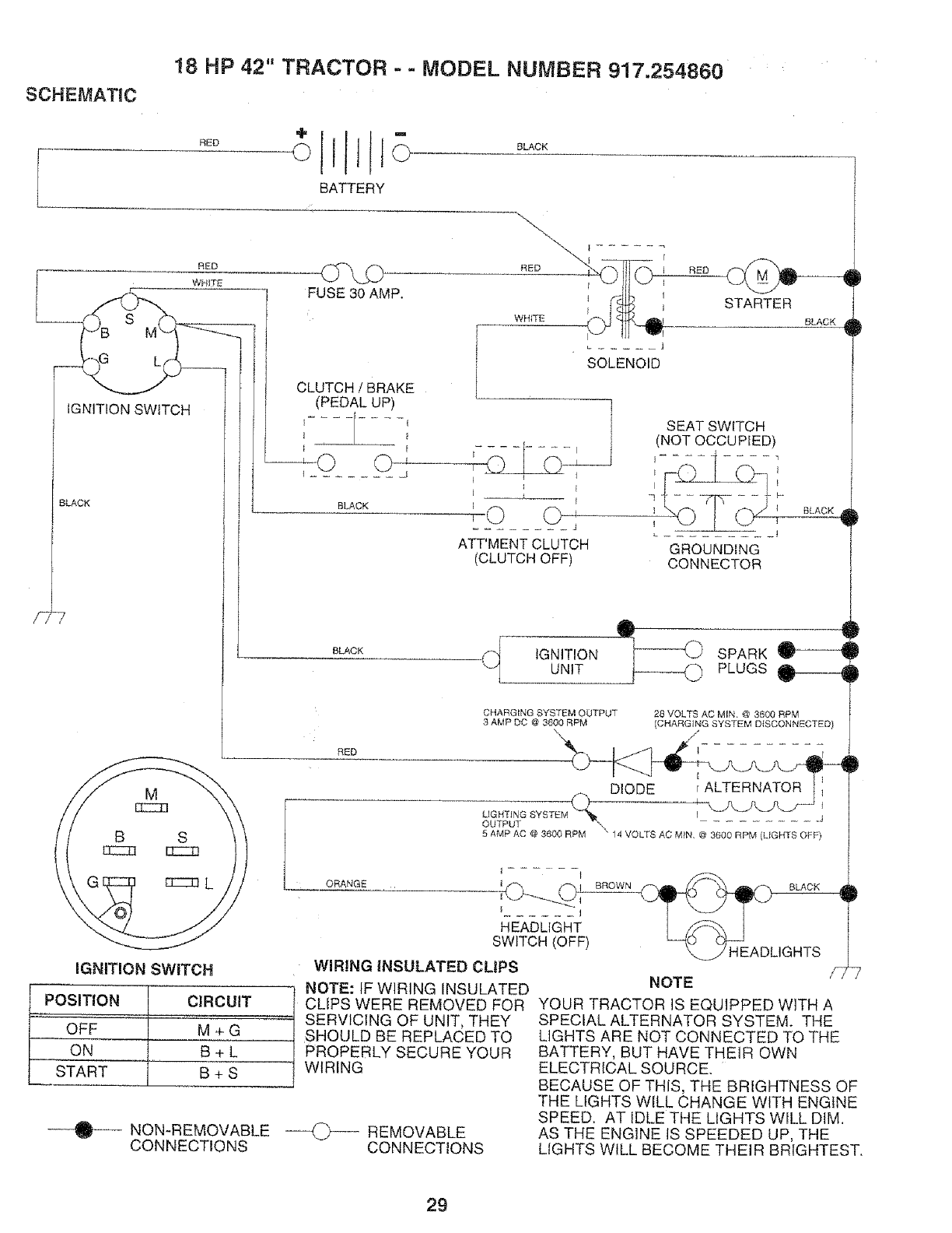
!8 HP 42" TRACTOR --MODEL NUMBER 917.254860
SCHEMATIC
RED
RED
WHITE
L
IGNITION SWtTCH
BLACK
BATTERY
BLACK
CLUTCH /BRAKE
(PEDAL UP)
I ........ I
BLACK
i ......
RED _,T_I,
WHITE _K_
J
SOLENOID
STARTER
BLACK
F
Ij
........ J
ATT'MENT CLUTCH
(CLUTCH OFF)
SEAT SWITCH
(NOT OCCUPIED)
I .... 1
GROUND{NG
CONNECTOR
BLACK ,_
BLACK
•" 4
'qm_'
,_ IGNITION _ SPARK _---'-4
UNIT PLUGS ______
CHARG{NG SYSTEM OUTPUT
3 AMP DC @ 3600 RPM 28 VOLTS AC MfN, @ 3600 RPM
CHARGING SYSTEM DISCONNECTED)
RED
DIODE r ALTERNATOR
LIGHTING SYSTEM I .j
OUTPUT "\_ ............
5 AMP AC @ 3600 RPM "" 14 VOLTS AC MfN, @ 3600 RPM (LIGHTS OFF)
16NffION SWITCH
POSITION CIRCUIT
OFF M + G
ON B+L
START I B + S
I
----_-- NON-REMOVABLE
CONNECTIONS
ORANGE i • I
HEADLIGHT
SWITCH (OFF)
WIRING INSULATED CLIPS
NOTE: IF WIRING INSULATED
CLIPS WERE REMOVED FOR
SERVICING OF UNIT, THEY
SHOULD BE REPLACED TO
PROPERLY SECURE YOUR
WIRING
O REMOVABLE
CONNECTIONS
'V' HEADLIGHTS i_TL7
NOTE
YOUR TRACTOR IS EQU1PPED WITH A
SPECIAL ALTERNATOR SYSTEM. THE
LIGHTS ARE NOT CONNECTED TO THE
BATTERY, BUT HAVE THEIR OWN
ELECTRICAL SOURCE.
BECAUSE OF THIS, THE BRIGHTNESS OF
THE LIGHTS WILL CHANGE WITH ENGINE
SPEED. AT IDLE THE LIGHTS WILL DIM.
AS THE ENGINE tS SPEEDED UP, THE
LIGHTS WILL BECOME THEIR BRIGHTEST.
29
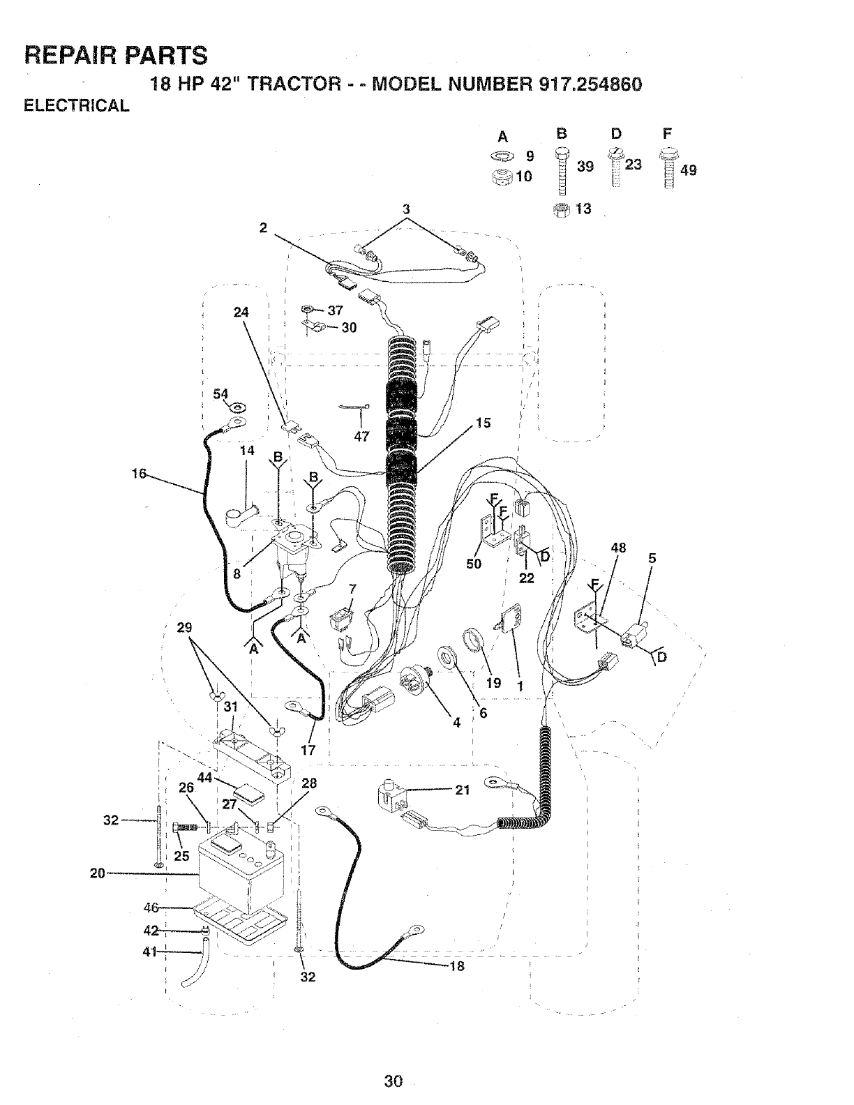
REPAIR PARTS
18 HP 42" TRACTOR - oMODEL NUMBER 917.254860
ELECTRICAL
47
7
29
A
_9
BD
39 ]: 23
5O 22
48
32
2O
17
28
\
32
F
\
/
/
/
3O
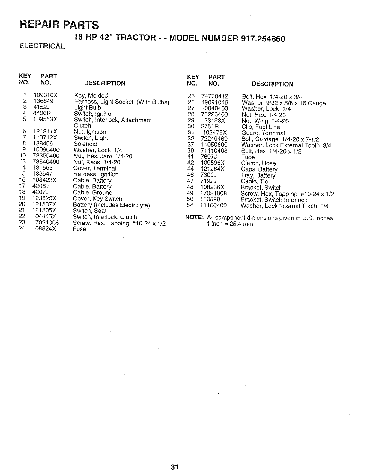
REPAIR PARTS
18 HP 42" TRACTOR --MODEL NUMBER 917.254860
ELECTRICAL
KEY PART KEY PART
NO. NO, DESCRIPTION NO, NO. DESCRIPTION
t 109310X Key, Molded 25 74760412
2 136849 Harness, Light Socket (With Bulbs) 26 19091016
3 4152J Light Bulb 27 10040400
4 4406R Switch, Ignition 28 73220400
5 109553X Switch, interlock, Attachment 29 123198X
Clutch 30 2751R
6 124211X Nut, Ignition 31 102476X
7 110712X Switch, Light 32 72240460
8 138406 Solenoid 37 11050600
9 10090400 Washer, Lock 1/4 39 71110408
10 73350400 Nut, Hex, Jam 1/4-20 41 7697J
13 73640400 Nut, Keps 1/4-20 42 109596X
14 131563 Cover, Terminal 44 121264X
15 138547 Harness, Ignition 46 7603J
I6 108423X Cable, Battery 47 7192J
t7 4206J Cable, Battery 48 108236X
!8 4207J Cable, Ground 49 17021008
19 123620X Cover, Key Switch 50 130890
20 121537X Battery (Includes Electrolyte) 54 1!150400
21 121305X Switch, Seat
22 104445X Switch, Interlock, Clutch
23 17021008 Screw, Hex, Tapping #10-24x t/2
24 108824X Fuse
Bolt, Hex 1/4-20 x 3/4
Washer 9/32 x 5/8 x 16 Gauge
Washer, Lock 1/4
Nut, Hex 1/4-20
Nut, Wing t/4-20
Clip, Fuel Line
Guard, Terminal
Bolt, Carriage 1/4-20 x 7-t/2
Washer, Lock External Tooth 3/4
Bolt, Hex 1/4-20 x 1/2
Tube
Clamp, Hose
Caps, Battery
Tray, Battery
Cable, Tie
Bracket, Switch
Screw, Hex, Tapping #10-24 x t/2
Bracket, Switch Interlock
Washer, Lock Internal Tooth 1/4
NOTE: Allcomponent dimensions given in U.S. inches
1 inch = 25.4 mm
31
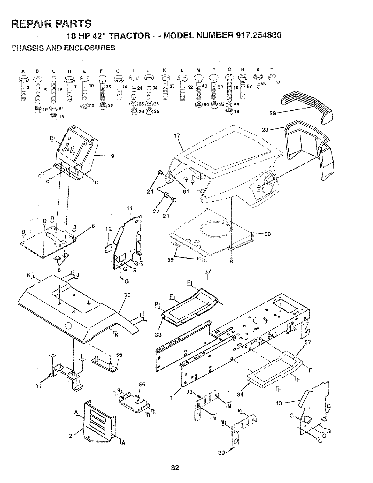
REPAIR PARTS
18 HP 42" TRACTOR - - MODEL NUMBER 917.254860
CHASSIS AND ENCLOSURES
A
D :/
y-
BCDEF
J
M P Q R S
11 2
G
17 z_
s
37
3"
@IB
29
©
33
56
2 RR__ R
37
S
32

REPAIR PARTS
18 HP 42" TRACTOR - - MODEL NUMBER 917.254860
CHASSBS AND ENCLOSURES
KEY PART KEY PART
NO. NO. DESCRIPTION NO, NO. DESCRIPTION
1 t35034
2 137275
3 174906"_2
6 137136X013
7 17490608
8 126471X
9 137411X018
11 122795X
12 121794X
!3 126276X
!4 t7490608
15 74180512
t6 STD541431
17 137386X417
18 108067X
19 STD512505
20 STD551125
21 122933X
22 !24479X
24 STD523707
25 19131312
26 STD541437
27 17490608
28 123915X
Chassis Weldment 12ga38/42 29 124029X
Drawbar, Stretch 30 t21642X4!7
Screw Thdrol 3/8-16x3/4 Ty-tt 3I 137113
Saddle Silkscreen 5 Sp 32 17490612
ScrewThdrol 3/8-16xl/2 Ty-tt 33 105465X417
Clip Line Fuel 13/32 Mtg Hole 34 105464X417
Dash Silkscreened 35 STD533707
Panel Pnt Dash Lh 36 STD541437
Cover Access Black Square 37 105466X
Pane_ Dash Rh Weldment 38 134774
Screw Thdrol 3/8-16xl/2 Ty-tt
Screw Mach Trhd 5i16-18uncx3i4 39 134775
Nut Keps 5/t6-t8 Unc
Hood Asm Pnt Weldment GT Slope 40
Nut Pal 50
Bolt Fin Hex 1/4-20unc X 1/2 51
Washer Lock Hvy Helical 1/4 53
Rivet Ratchet Nylon 54
Washer Nylon BIk 28x 75x 19 55
Bolt Fin Hex 3/8-16unc X 3/4 56
Washer 13/32 X 13/16 X 12 Ga 57
Nut Crownlock 3/8-16 Unc 58
Screw Thdrol 3/8-16xl/2 Ty-tt 59
Grille Grey 60
STD533710
STD541437
STD551025
STD533710
STD523708
1055!1X
I08171X
17490512
137357
109227X
17030808
61 126938X
Lens Headlight Bar Clear
Fender Pnt
Bracket Pnt Fender
Screw Thdro! 3/8-16x3/4 Ty4t
Footrest Pnt Lh (silver)
Footrest Pnt Rh (silver)
Bolt Rdhd Sht Sqnk 3/8-16 X3/4
Nut Crownlock 3/8q6 Unc
Pad Footrest Rbr Sq Craftsman
Bracket, Asm. Pivot, L.H., Mower
Rear
Bracket, Asm. Pivot, R.H., Mower
Rear
Bolt, Carriage 3/8-16 x 1
Locknut Hex W/Washer 3/8-16
Washer 13/32 x 3/4 x t6 Ga.
Bolt Carriage 3/8-16 x 1
Bolt Fin Hex 3/8-16 x 7/8
Strap Asm. Fender
Support Battery
Screw ThdroL 5/16-18 x 3/4
Shield Heat Hood GT
Pad Idler
Screw Spiderloc Hex Hd.
#8 x 1/2 AB
Hood Bumpers
NOTE: All component dimensions given in U.S. inches.
1 inch = 25.4 mm
33
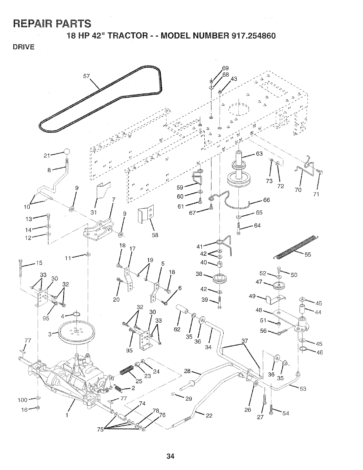
REPAIR PARTS
!8 HP 42" TRACTOR - -MODEL NUMBER 917,254860
DRIVE
77
2O
!8 17 41
4
32 30
33
62
35 36 34
71
5I
1
75
25
26 i} 54
27
34

REPAIR
DRBVE
PARTS
18 HP 42" TRACTOR- -MODEL NUMBER 917.254860
KEY PART
NO. NO.
137371
2 t10422X
3 123667X
4 12000028
5 121520X
6 17490512
7 130802
8 131679
9 19151216
t0 STD56t210
11 105701X
12 19091210
13 71040412
14, STD551125
15 74760540
16 STD541431
17 121520X
18 STD523707
19 STD541437
20 17490512
21 106933X
22 130804
23 STD541437
24 STD541237
25 106888X
26 STD551037
27 STD561210
28 128904
29 124236X
30 130807
31 127289
32 STD523107
33 STD541431
34 122424X
35 120183X
36 STD551062
37 STD571810
38 123674X
39 STD523727
40 4470J
KEY PART
DESCRIPTION NO. NO. DESCRIPTION
Transaxle 5sp Std Dana, 4l 109070X
Model No. 4360_56 42 19131312
Spring Return Brake T/a Zinc 43 STD541437
Pulley Transaxle Alum 44 105706X
Ring Retainer # 5100-62 45 110812X
Strap Pnt Torque 30 Deg Blk 46 12000039
Screw Thdrol 5/16-I8 X 3/4 Tyt 47 127783
Plate Pnt Rod Shift Tia (btk) 48 123789X
Rod Shifter Blk (dana) 49 !23205X
Washer 15/32 X 3/4 X 16ga 50 STD523715
Pin Cotter 1/8 X 1 Cad 5l STD541437
Washer Plate Shf 388 Sq Hole 52 STD551037
Washer 9/32 X 3/4 X 10 Ga 53 105710X
Bolt Fin Hex 1i4-28unfx3/4 Gr8 54 STD561210
Washer Lock Hvy Helical 1/4 55 105709X
Bolt Fin Hex 5/t6_t8 X 2-1/2 56 STD561210
Nut Crownlock 5/!6-18 57 131006
Strap Pnt Torque 30 Deg Btk 58 127290
Bolt Fin Hex 3/8-t6unc X 3/4 59 136715
Nut Crownlock 3/8-16 Unc 60 19131312
Screw Thdrot 5116-18 X 3/4 Tyt 6t 17490612
Knob Rd 1/2-13 Plstc Thds Blk 62 8883R
Rod Brake Lt 63 140186
Nut Lock Hex Wiwsh 3/8-16unc 64 71170764
Nut Hex Jam 3/8-16 Unc 65 STD551143
Spring Rod Brake 2 00 Zff_c 66 129921
Washer 13/32 X 13/16 X 16 Ga 67 STD523710
Pin Cotter 1/8 X 3/4 Cad 68 19t31312
Rod Brake Parking Lt 69 STD541437
Cap Parking Brake Red 70 134683
Bracket Transmission 71 STD523710
Keeper Belt Lh 72 t9!32012
Bolt Fin Hex 5/16-18 X 3/4 73 STD541437
Nut Crownlock 3/8-18 74 109502X
Shaft Asm Pedal Foot 1 930 75 121749X
Bearing NylonBlk 629 Id 76 STD581075
Washer 21/32 X 1 X16 Ga 77 123583X
Pin Rol_ 3/16 X 1" 78 121748X
Pulley Idler Flat 83 17490612
Bolt Fin Hex 3/8-I6unc X 2-3/4
Spacer Split 395 X 59 Bzp
Keeper Belt Retainer
Washer 13/32 X 13/16 X 12 Ga
Nut Crownlock 3/8-16 Unc
Bearing Nyl 503 X 628 X 1 25
Washer Hardened
Ring Klip #t5304-50
Pulley Idler V Groove Plastic
Berlcrank Asm
Retainer Belt Style Spring
Bolt Hex Hd 3/8-16unc X I-1/2
Nut Crowntock 3/8-16 Unc
Washer 13/32 X 13/16 X 16 Ga
Link Clutch 7 66
Pin Cotter 1/8 X 3/4 Cad
Spring Return Clutch 6 75
Pin Cotter 1/8 X 3/4 Cad
V-belt Ground Drive 98 25
Keeper Belt Rh
Retainer Belt Chassis Lh Zinc
Washer 13/32 X 13/16 X 12 Ga
Screw Thdrol 3/8-16x3/4 Ty-tt
Cover Pedal Blk Std
Pulley Engine
Bolt Finhex 7/16-20 x 4 g5
Washer Lock Hvy Hlcl Spr 7/16
Keeper Belt Engine Lh Lt
Bolt Fin Hex 3/8-16unc X 1
Washer 13/32 X 13/16 X 12 Ga
Nut Crowntock 3/8-I6 Uric
Guide Belt Dr Mower Rh
Bolt Fin Hex 3/8-!6unc X 1
Washer 13/32 X 1-1/4 X 12 Ga
Nut Crowntock 3/8-16 Unc
Spacer Split ,80xl.94
Washer 25/32 X 1 1/4 X 16 Ga
Ring E #5133-75
Key Square 2 0 X 1845/1865
Washer 25/32 X 1 5/8 X 16go
Screw Thdrol 3/8-16 x 3/4
NOTE: All component dimensions given in U.S, inches.
1 inch = 25.4 mm
35
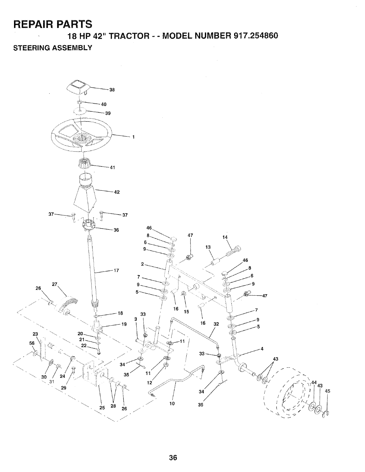
REPAIR PARTS
18 HP 42" TRACTOR - -MODEL NUMBER 917.254860
STEERING ASSEMBLY
38
_37
36
14
46
25 26 ./:"
12
34
// !o 35
43
/i
: i 45
\/
\ I 11
36
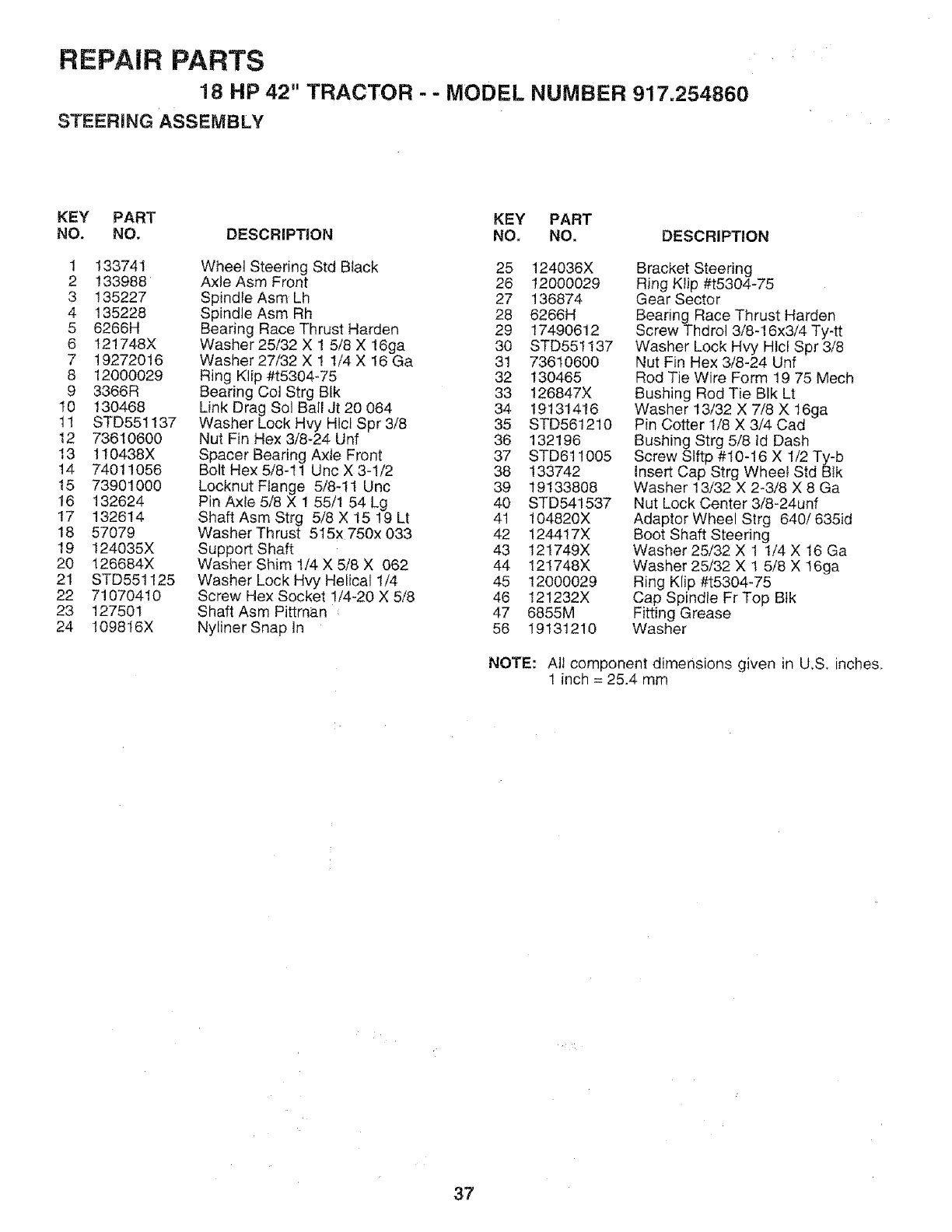
REPAIR PARTS
18 HP 42" TRACTOR - - MODEL NUMBER 917.254860
STEERING ASSEMBLY
KEY PART KEY PART
NO, NO, DESCRIPTION NO, NO. DESCRIPTION
1 133741
2 133988
3 ! 35227
4 135228
5 6266H
6 121748X
7 19272016
8 12000029
9 3366R
I0 130468
t! STD551137
12 73610600
13 110438X
14 74011056
15 73901000
16 132624
t7 132614
18 57079
19 124035X
20 126684X
21 STD551125
22 71070410
23 127501
24 1098t6X
Wheel Steering Std Black
Axle Asm Front
Spindle Asm Lh
Spindle Asm Rh
Bearing Race Thrust Harden
Washer 25/32 X ! 5/8 X 16ga
Washer 27/32 X 1 I/4 X 16 Ga
Ring Klip #t5304-75
Bearing Col Strg BIk
Link Drag Sol Bail Jt 20 064
Washer Lock Hvy Htcl Spr 3/8
Nut Fin Hex 3/8-24 Unf
Spacer Bearing Axle Front
Bolt Hex 5/8-I1 Unc X 3-1/2
Locknut Flange 5/8-11 Unc
Pin Axle 5/8 X 1 55/1 54 Lg
Shaft Asm Strg 5/8 X 15 19 Lt
Washer Thrust 515x 750x 033
Support Shaft
Washer Shim 1/4 X 5/8 X 062
Washer Lock Hvy Helical 1/4
Screw Hex Socket 1/4-20 X 5/8
Shaft Asm Pittman
Nyliner Snap In
25 124036X
26 12000029
27 136874
28 6266H
29 17490612
30 STD55t137
31 73610600
32 130465
33 126847X
34 19131416
35 STD561210
36 132196
37 STD6t1005
38 133742
39 19133808
40 STD541537
41 104820X
42 124417X
43 121749X
44 121748X
45 12000029
46 121232X
47 6855M
56 19131210
Bracket Steering
Ring KlJp #t5304-75
Gear Sector
Bearing Race Thrust Harden
Screw Thdrol 3/8-16x3/4 Ty-tt
Washer Lock Hvy Hlcl Spr 3/8
Nut Fin Hex 3/8-24 Unf
Rod Tie Wire Form 19 75 Mech
Bushing Rod Tie BIk Lt
Washer 13/32 X 7/8 X 16ga
Pin Cotter 1/8 X 3/4 Cad
Bushing Strg 5/8 Id Dash
Screw Slftp #10-16 X 1/2 Ty-b
insert Cap Strg Wheel Std Blk
Washer 13/32 X 2-3/8 X 8 Ga
Nut Lock Center 3i8-24unf
Adaptor Wheel Strg 640/635id
Boot Shaft Steering
Washer 25/32 X 1 1/4 X 16 Ga
Washer 25/32 X 1 5/8 X 16ga
Ring K[ip #t5304-75
Cap Spindle Fr Top Bik
Fitting Grease
Washer
NOTE: All component dimensions given in U.S. inches.
1 inch = 25.4 mm
37
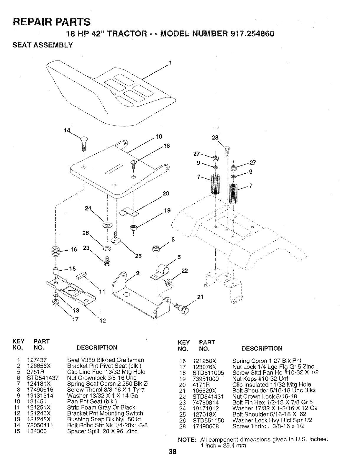
REPAIR PARTS
18 HP 42" TRACTOR --MODEL NUMBER 917,254860
SEAT ASSEMBLY
KEY
NO.
1
2
5
6
7
8
9
!0
11
12
13
14
15
PART
NO.
127437
126656X
2751R
STD541437
124181X
17490616
19131614
131451
121251X
t21246X
121248X
72050411
134300
KEY PART
DESCRIPTION NO. NO. DESCRIPTION
Seat V350 BIWred Craftsman
Bracket Pnt Pivot Seat (blk)
Clip Line Fue! 13/32 Mtg Hole
Nut Crownlock 3/8-16 Uric
Spring Seat Cprsn 2 250 BIk Zi
Screw Thdrol 3/8-16 X 1 Ty-tt
Washer 13/32 X t X 14 Ga
Pan Pnt Seat (blk)
Strip Foam Gray Or Black
Bracket Pnt Mounting Switch
Bushing Snap Btk Nyt 50 ld
Bolt Rdhd Sht Nk 1/4-20x1-.3/8
Spacer Split 28 X 96 Zinc
16 121250X
17 123976X
18 STD511005
19 73951000
20 4!71R
21 105529X
22 STD541431
23 74780814
24 19171912
25 127018X
26 STD551150
28 17490608
Spring Cprsn 1 27 Bik Pnt
Nut Lock 1/4 Lge Fig Gr 5 Zinc
Screw Sltd Pan Hd #10-32 X 1/2
Nut Keps #10-32 Unf
Clip Insulated 11/32 Mtg Hole
Bolt Shoulder 5/16-18 Unc BlkZ
Nut Crown Lock 5/16-18
Bolt Fin Hex 1/2-13 X 7/8 Gr 5
Washer 17/32 X 1-3/16 X 12 Ga
Bolt Shoulder 5/16-18 X 62
Washer Lock Hvy Hlct Spr 1/2
Screw Thdro!. 3/8-!6 x 1/2
NOTE: All component dimensions given in U.S, inches;
1 inch = 25,4 mm
38
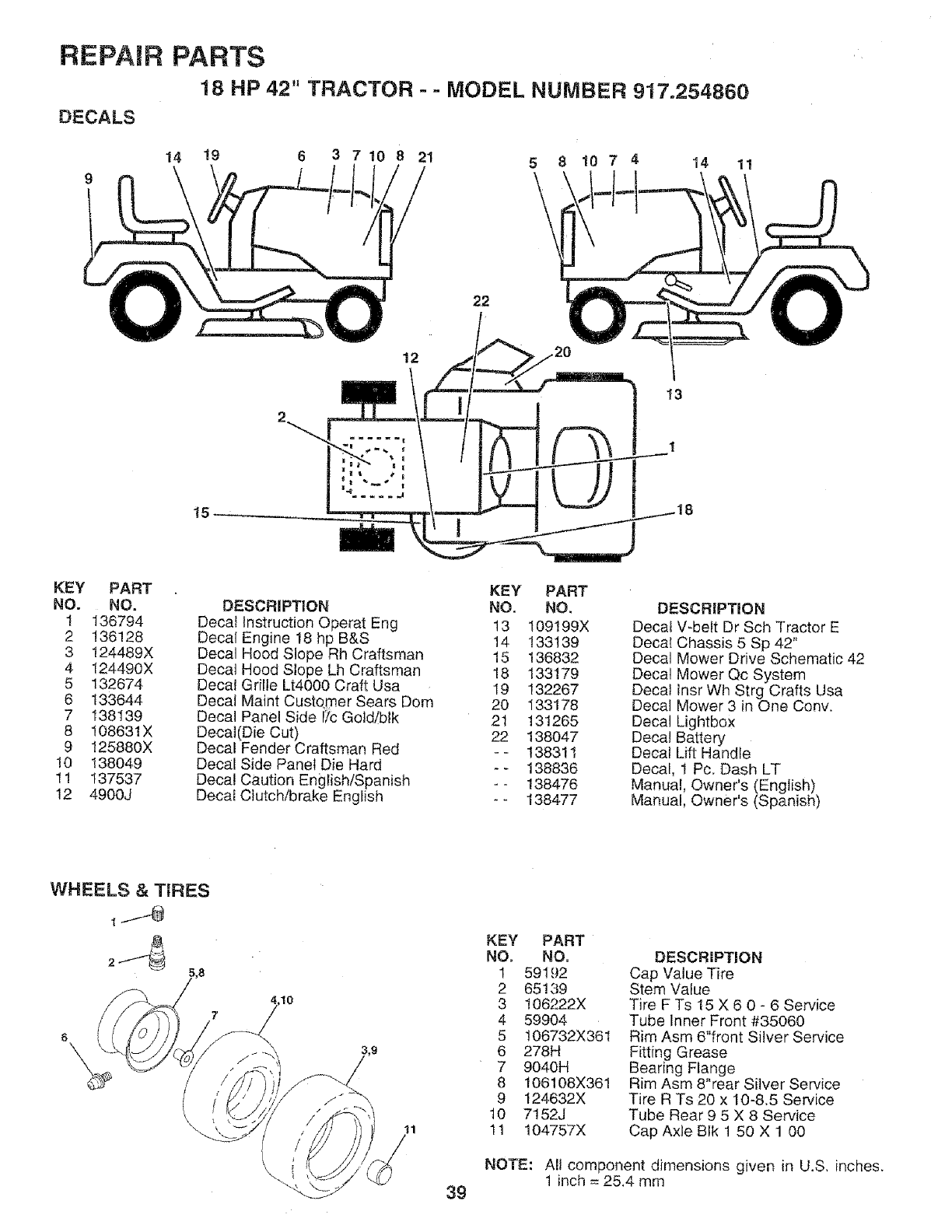
REPAIR PARTS
18 HP 42" TRACTOR - -MODEL NUMBER 917.254860
DECALS
14 !9 6 3 7 10 8 21 5 8 10 74 14 11
22
12
13
15
KEY PART
NO. NO.
1 136794
2 136128
3 124489X
4 124490X
5 132674
6 133644
7 138139
8 108631X
9 125880X
10 138049
1! 137537
12 4900J
KEY PART
DESCRIPTION NO. NO.
Deca! Instruction Operat Eng t3 109199X
Decal Engine 18 hp B&S 14 133139
Decal Hood Slope Rh Craftsman 15 136832
Decal Hood Slope Lh Craftsman 18 133179
Decal Grille Lt4000 Craft Usa 19 132267
Decal Maint Customer Sears Dom 20 133178
Decal Panel Side !_CGold/blk 21 131265
Decal(Die Cut) 22 138047
Decal Fender Craftsman Red - - 13831!
Decal Side Panel Die Hard -- 138836
Decal Caution English/Spanish -- 138476
Decal Clutch/brake English -- 138477
DESCRiPTiON
Decat V-bett Dr Sch Tractor E
Decal Chassis 5 Sp 42"
Decal Mower Drive Schematic 42
Decal Mower Qc System
Deca! insr Wh Strg Crafts Usa
Decal Mower 3 in One Conv.
Decal Lightbox
Deca! Battery
Decal Lift Handle
Decal, 1 Pc. Dash LT
Manua!, Owner's (English)
Manual, Owner's (Spanish)
WHEELS & TIRES
7
6
,,10
11
KEY PART
NO. NO.
1 59192
2 65139
3 106222X
4 59904
5 106732X361
8 278H
7 9040H
8 106108X361
9 124632X
10 7152J
11 104757X
DESCRIPTION
Cap Value Tire
Stem Value
Tire F Ts 15 X 6 0 - 6 Service
Tube Inner Front #35060
Rim Asm 6"front Silver Service
Fitting Grease
Bearing Flange
Rim Asm 8"rear Silver Service
Tire R Ts 20 x 10-8.5 Service
Tube Rear 9 5 X 8 Service
Cap Axle Blk 1 50 X 1 00
NOTE: All component dimensions given in U,S. inches.
1 inch = 25,4 mm
39
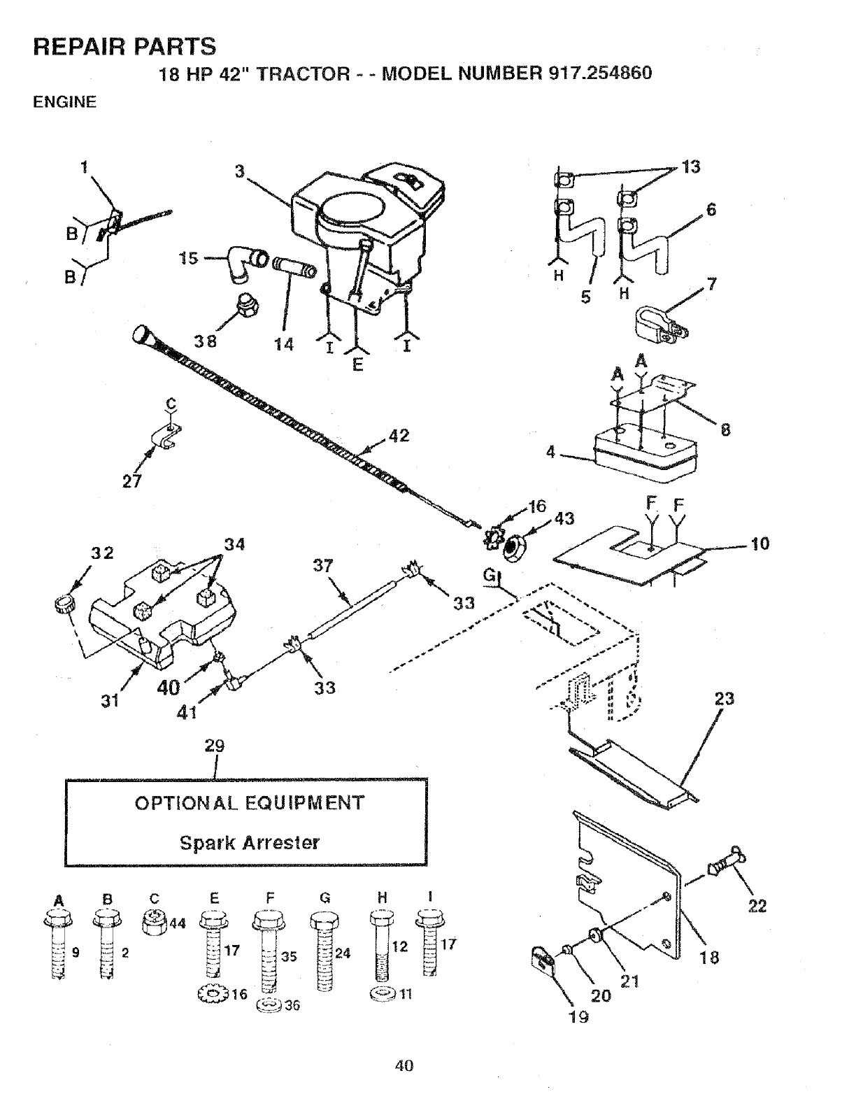
REPAIR PARTS
18 HP 42" TRACTOR - - MODEL NUMBER 917.254860
ENGINE
A
OPTIONAL EQUIPMENT
Spark Arrester
B C E F G H I
18
21
20
19
10
22
4O
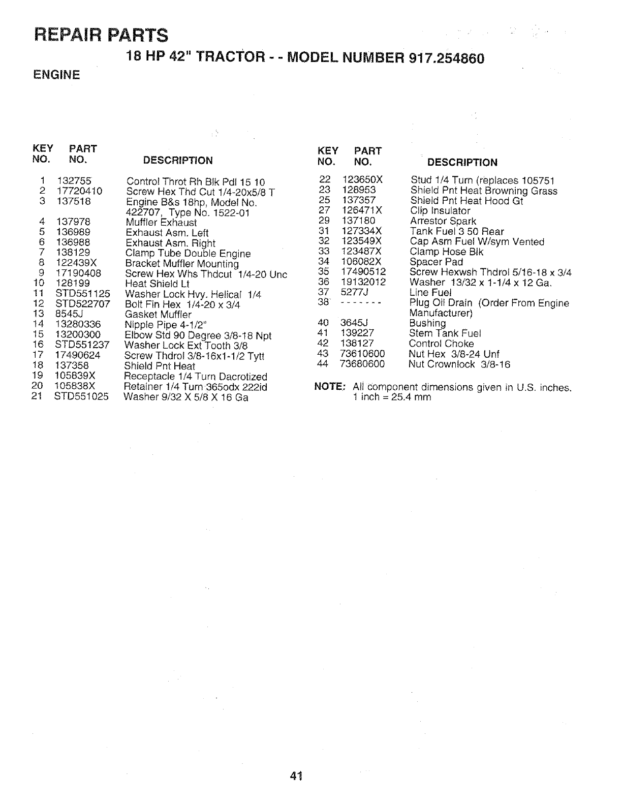
REPAIR PARTS
18 HP 42" TRACTOR - - MODEL NUMBER 917.254860
ENGINE
KEY PART KEY PART
NO. NO, DESCRIPTION NO, NO, DESCRIPTION
1
2
3
132755
17720410
137518
4 137978
5 136989
6 136988
7 138129
8 t22439X
9 17190408
10 128199
11 STD551125
12 STD522707
13 8545J
t4 13280336
15 13200300
16 STD551237
17 17490624
18 137358
19 105839X
20 105838X
21 STD551025
Control Throt Rh Blk Pd115 10 22
Screw Hex Thd Cut 1/4-20x5/8 T 23
Engine B&s 18hp, Model No. 25
422707, Type No. 1522-01 27
Muffler Exhaust 29
Exhaust Asm. Left 31
Exhaust Asm. Right 32
Clamp Tube Double Engine 33
Bracket Muffler Mounting 34
Screw Hex Whs Thdcut 1/4-20 Unc 35
Heat Shield Lt 36
Washer Lock Hvy. Helical 1/4 37
Bolt Fin Hex 1/4-20 x 3/4 38
Gasket Muffler
Nipple Pipe 4-1/2" 40
Elbow Std 90 Degree 3/8-I8 Npt 41
Washer Lock Ext Tooth 3/8 42
Screw Thdrol 3/8-16x1-1/2 Tytt 43
Shield Pnt Heat 44
Receptacle 1/4 Turn Dacrotized
Retainer !/4 Turn 365odx 222id
Washer 9/32 X 5/8 X 16 Ga
123650X
128953
137357
126471X
137180
127334X
123549X
t23487X
106082X
17490512
19132012
5277J
3645J
139227
138127
73610600
73680600
Stud 1/4 Turn (replaces 105751
Shield Pnt Heat Browning Grass
Shietd Pnt Heat Hood Gt
Clip Insulator
Arrestor Spark
Tank Fuel 3 50 Rear
Cap Asm Fuel Wisym Vented
Clamp Hose Blk
Spacer Pad
Screw Hexwsh Thdrof 5/16-18 x 3/4
Washer 13/32 x 1-1/4 x 12 Ga.
Line Fue!
Plug Oil Drain (Order From Engine
Manufacturer)
Bushing
Stem Tank Fuel
Control Choke
Nut Hex 3/8-24 Unf
Nut Crowntock 3/8-16
NOTE: All Component dimensions given in U.S. inches.
1 inch = 25.4 mm
41
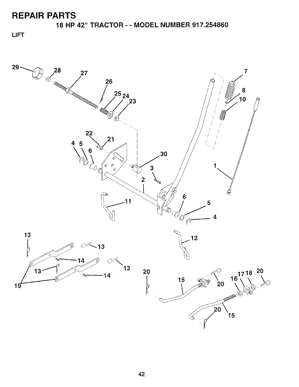
REPAIR PARTS
18 HP 42" TRACTOR - - MODEL NUMBER 917.254860
LIFT
13
28 27
22
4 5
\°
26
25 24 '
23
21
_,__13
20
3O
7
8
i to /
// /
,/ /
/ /
,t /
! /
5
161718 20
42
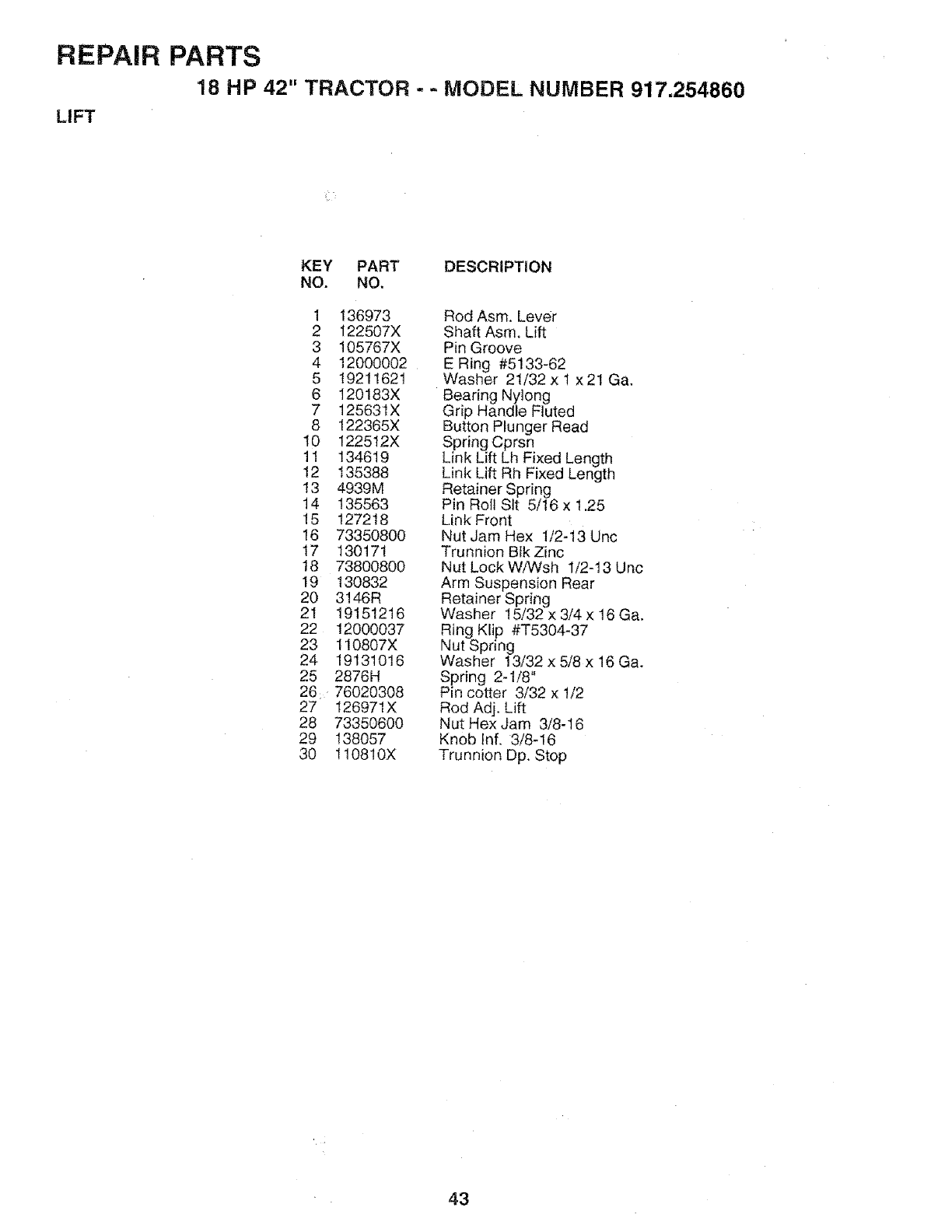
REPAIR
LIFT
PARTS
18 HP 42" TRACTOR --MODEL NUMBER 917.254860
KEY PART DESCRIPTION
NO. NO.
1 136973
2 I22507X
3 105767X
4 12O00002
5 19211621
6 120183X
7 12563tX
8 122365X
I0 122512X
11 134619
12 135388
13 4939M
14 135563
15 127218
16 73350800
17 130171
18 73800800
19 130832
20 3!46R
21 19151216
22 12000037
23 110807X
24 19131016
25 2876H
26;76020308
27 126971X
28 73350600
29 138057
30 t10810X
Rod Asm. Lever
Shaft Asm, Lift
Pin Groove
E Ring #5133-62
Washer 21/32 x I x 21 Ga.
Bearing Nylong
Grip Handle FJuted
Button Plunger Read
Spring Cprsn
Link Lift Lh Fixed Length
Link Lift Rh Fixed Length
Retainer Spring
Pin Roll Sit 5/16 x 1.25
Link Front
Nut Jam Hex 1/2-13 Unc
Trunnion Bik Zinc
Nut Lock WiWsh 1/2-t3 Unc
Arm Suspension Rear
Retainer Spring
Washer 15/32 x 3/4 x 16 Ga,
Ring Klip #T5304-37
Nut Spring
Washer 13/32 x 5/8 x 16 Ga.
Spring 2-1/8"
Pin cotter 3/32 x 1/2
Rod Adj. Lift
Nut Hex Jam 3/8-16
Knob Inf. 3/8-16
Trunnion Dp. Stop
43

REPAIR PARTS
18 HP 42" TRACTOR - - MODEL NUMBER 917.254860
42" MOWER DECK
62
61
60 :_-J
,_:::. 45
57
53
47
84
81
37 40
38
_137
O!7
32
3"t
76
17
I 18
20
21 22
24
27
44
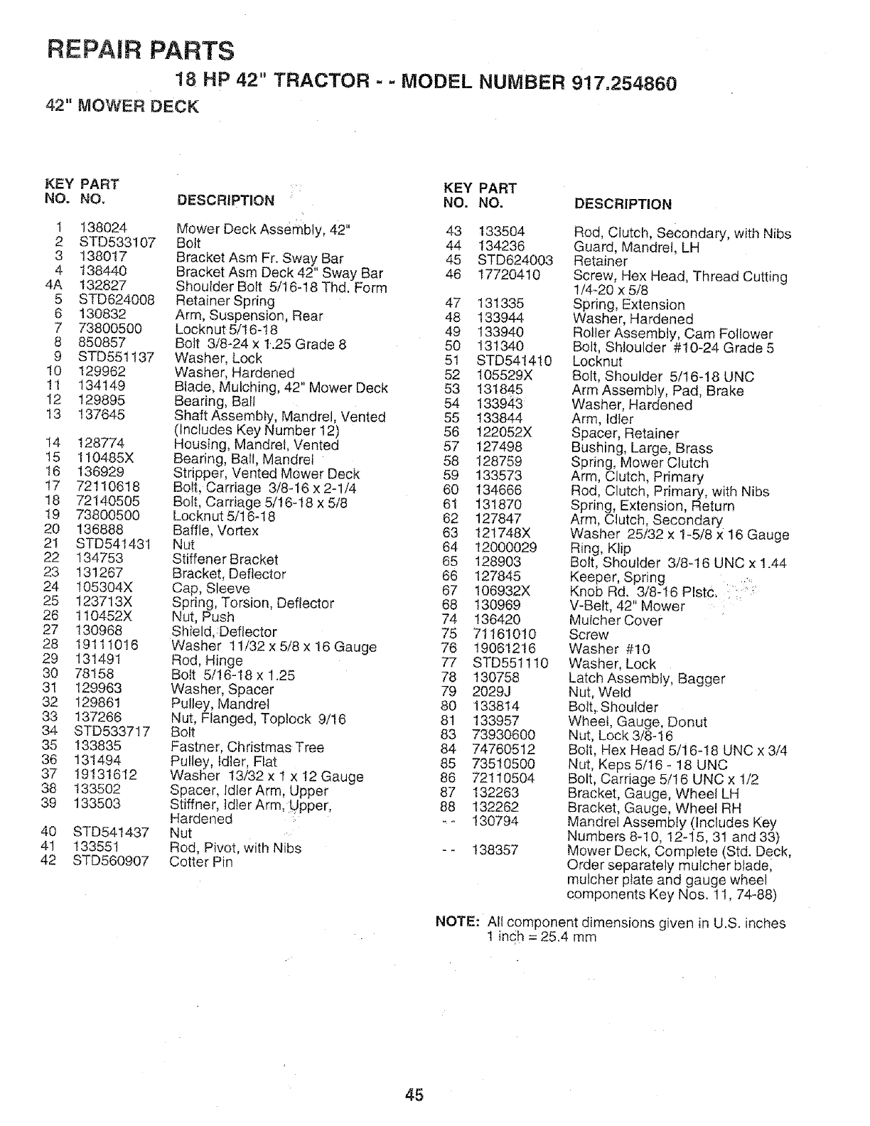
REPAIR PARTS
18 HP 42" TRACTOR - - MODEL NUMBER 917.254860
42" tVIOWER DECK
KEY PART KEY PART
NO. NO. DESCRiPTmON NO. NO.
1 t38024 Mower Deck Assembly, 42" 43 133504
2 STD533107 Bolt 44 134236
3138017 Bracket Asm Fr. Sway Bar 45 STD624003
4 138440 Bracket Asm Deck 42" Sway Bar 46 17720410
4A 132827 Shoulder Boft 5/16-!8 Thd. Form
5 STD624008 Retainer Spring 47 131335
6 130832 Arm, Suspension, Rear 48 133944
7 73800500 Locknut 5/16-!8 49 133940
8 850857 Bolt 3/8-24 x 1.25 Grade 8 50 131340
9 STD55t137 Washer, Lock 5t STD54t4t0
10 129962 Washer, Hardened 52 105529X
!1 134149 Blade, Mulching, 42" Mower Deck 53 131845
12 129895 Bearing, Bal! 54 133943
13 !37645 Shaft Assembly, Mandrel, Vented 55 133844
(Includes Key Number 12) 56 122052X
14 128774 Housing, Mandrel, Vented 57 127498
t5 110485X Bearing, Ball, Mandrel 58 I28759
16 136929 Stripper, Vented Mower Deck 59 t33573
!7 72110618 Bolt, Carriage 3/8-16x2-1/4 60 134666
18 72140505 Bolt, Carriage 5/16-18 x 5/8 61 131870
t9 73800500 Locknut 5/16-18 62 127847
20 !36888 Baffle, Vortex 63 121748X
21 STD541431 Nut 64 12000029
22 134753 Stiffener Bracket 65 128903
23 131267 Bracket, Deflector 66 127845
24 t05304X Cap, Sleeve 67 106932X
25 123713X Spring, Torsion, Deflector 68 130969
26 110452X Nut, Push 74 136420
27 130968 Shield, Deflector 75 71161010
28 1911 t016 Washer t 1/32 x 5/8 x 16 Gauge 76 t9061216
29 131491 Rod, Hinge 77 STD551110
30 78158 Bolt 5/16-18 x 1.25 78 130758
31 129963 Washer, Spacer 79 2029J
32 129861 Pulley, Mandrel 80 133814
33 137266 Nut, Flanged, Toptock 9/16 8t 133957
34 STD5337!7 Bolt 83 73930600
35 133835 Fastner, Christmas Tree 84 74760512
36 131494 Pulley, Idler, Flat 85 73510500
37 19131612 Washer 13/32 x t x 12 Gauge 86 72110504
38 t33502 Spacer, Idler Arm, Upper 87 132263
39 133503 Stiffner, ldlerArm, Upper, 88 132262
Hardened .- _ 130794
40 STD541437 Nut
41 133551 Rod, Pivot, with Nibs -- 138357
42 STD560907 Cotter Pin
DESCRIPTION
Rod, Clutch, Secondary, with Nibs
Guard, Mandrel, LH
Retainer
Screw, Hex Head, Thread Cutting
1/4-20 x 5/8
Spring, Extension
Washer, Hardened
Roller Assembly, Cam Follower
Bolt, SHoulder #10-24 Grade 5
Locknut
Bolt, Shoulder 5/16-18 UNC
Arm Assembly, Pad, Brake
Washer, Hardened
Arm, Idler
Spacer, Retainer
Bushing, Large, Brass
Spring, Mower Clutch
Arm, Clutch, Primary
Rod, Clutch, Primary, with Nibs
Spring, Extension, Return
Arm, Clutch, Secondary
Washer 25/32 x 1-5/8 x 16 Gauge
Ring, Klip
Bolt, Shoulder 3/8q 6 UNC x 1.44
Keeper, Spring ........
Knob Rd. 3/8-16 Plstc, :':':
V-Belt, 42" Mower
Mutcher Cover
Screw
Washer #10
Washer, Lock
Latch Assembly, Bagger
Nut, Weld
Bolt, Shoulder
Wheel, Gauge, Donut
Nut, Lock 3/8-16
Bolt, Hex Head 5/16-18 UNC x 3/4
Nut. Keps 5/16 - 18 UNC
Bolt, Carriage 5/t6 UNC x 1/2
Bracket, Gauge, Wheel LH
Bracket, Gauge, Wheel RH
Mandrel Assembly (Includes Key
Numbers 8-!0, 12-15, 31 and 33)
Mower Deck, Complete (Std. Deck,
Order separately mulcher blade,
mulcher plate and gauge wheel
components Key Nos. t 1, 74-88)
NOTE: All component dimensions given in U.S. inches
1 inqh = 25.4 mm
45

REPAIR PARTS
18 HP 42" TRACTOR -MODEL NUMBER 917.254860
DANA TRANSAXLE - MODEL NUMBER 4360-56
19
22
11,_ 20 24
35
37
52
/53
/
26 27
38
tt,=
3g
/
54
31
32
34 35
19 40
55 56
41
57
42
45*
/
59
56 55
/
44
46
14
12
47
48
/
15
t7
49
5051 19
/
62 63
/
/
59
64
/65
7O
68 69 67
60
/
71
/
52
/
46
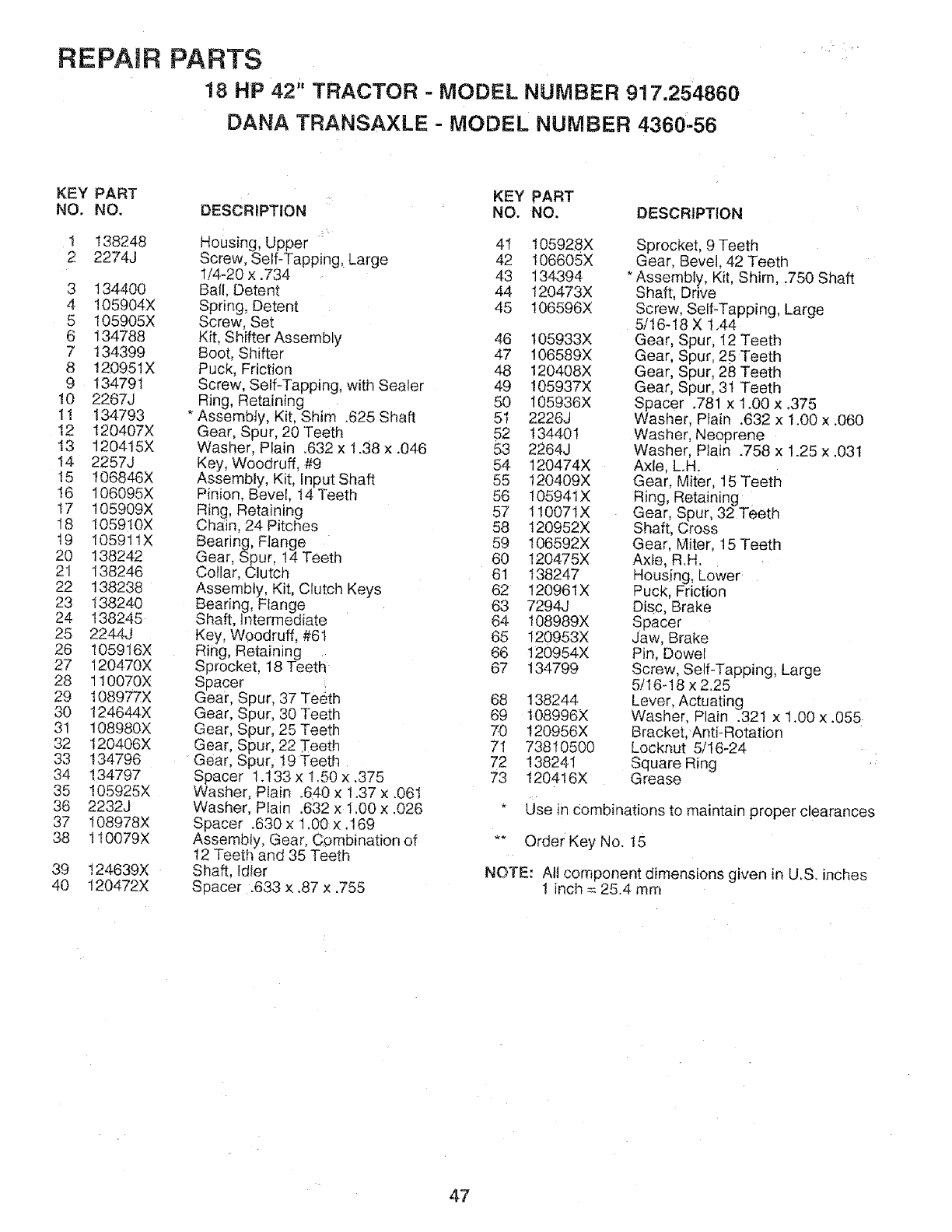
REPAIR PARTS
18 HP 42" TRACTOR - MODEL NUMBER 9!7,254860
DANA TRANSAXLE - MODEL NUMBER 4360'56
KEY PART :: KEY PART
NO. NO. DESCRIPTION NO. NO. DESCRIPTION
1 t38248 Housing, Upper 4I t05928X
2 2274J Screw, Self-Tapping, Large 42 106605X
1/4-20x.734 43 134394
3 134400 Bali, Detent 44 120473X
4 105904X Spring, Detent 45 106596X
5 t05905X Screw, Set
6 134788 Kit, Shifter Assembly 46
7 !34399 Boot, Shifter 47
8 120951X Puck, Friction 48
9 134791 Screw, Self-Tapping, with Sealer 49
!0 2267J Ring, Retaining 50
11 134793 * AssembJy, Kit, Shim .625 Shaft 5t
12 I20407X Gear, Spur, 20 Teeth 52
13 120415X Washer, Plain _632x 1.38 x .046 53
14 2257J Key, Woodruff, #9 54
15 106846X Assembly, Kit, Input Shaft 55
t6 !06095X Pinion, Bevel, 14 Teeth 56
t7 !05909X Ring, Retaining 57
18 105910X Chain, 24 Pitches 58
t9 10591tX Bearing, Flange 59
20 138242 Gear, Spur, 14 Teeth 60
21 138246 Collar, Clutch 61
22 138238 Assembly, Kit, Clutch Keys 62
23 138240 Bearing, Flange 63
24 138245 Shaft, Intermediate 64
25 2244j Key, Woodruff, #61 65
26 I05916X Ring, Retaining 66
27 120470X Sprocket, t8 Teeth 67
28 110070X Spacer
29 108977X Gear, Spur, 37 Teeth 68
30 124644X Gear, Spur, 30 Teeth 69
31 108980X Gear, Spur, 25 Teeth 70
32 t20406X Gear, Spur, 22 Teeth 71
33 134796 Gear, Spur, 119Teeth 72
34 !34797 Spacer 1.I33 x 1.50 x .375 73
35 105925X Washer, Plain .640 x 1.37 x .06t
36 2232J Washer, Plain .632 x t.00 x .026 *
37 t08978X Spacer .630 x 1.00×.169
38 1t0079X Assembly, Gear, C_mbination of
12 Teeth and 35 Teeth
Shaft, Idler
Spacer .633 x .87 x.755
39 t24639X
40 t20472X
I05933X
106589X
120408X
105937X
105936X
2226J
134401
2264J
120474X
!20409X
10594tX
110071X
120952X
106592X
t20475X
138247
I20961X
7294J
t08989X
I20953X
t20954X
134799
138244
108996X
120956X
73810500
138241
120416X
Sprocket, 9 Teeth
Gear, Bevel, 42 Teeth
* Assembly, Kit, Shim, .750 Shaft
Shaft, Drive
Screw, SelFTapping, Large
5/16-18 X 1.44
Gear, Spur, 12 Teeth
Gear, Spur, 25 Teeth
Gear, Spur, 28 Teeth
Gear, Spur, 31 Teeth
Spacer .781 x 1.00 x .375
Washer, Plain .632 x 1.00 x .060
Washer, Neoprene
Washer, Plain .758 x 1.25 x .031
Axle, LH.
Gear, Miter, 15 Teeth
Ring, Retaining
Gear, Spur, 32 Teeth
Shaft, Cross
Gear, Miter, 15 Teeth
Axfe, R.H.
Housing, Lower
Puck, Friction
Disc, Brake
Spacer
Jaw, Brake
Pin, Dowel
Screw, Self-Tapping, Large
5f16-18 x 2.25
Lever, Actuating
Washer, Plain .32! x 1.00 x .055
Bracket, Anti-Rotation
Locknut 5/16-24
Square Ring
Grease
Use in Combinations to maintain proper clearances
** Order Key No. 15
NOTE: All component dimensions given in U,S. inches
1 inch = 25.4 mm
47
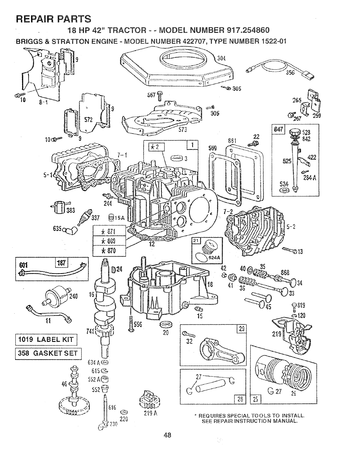
REPAIR PARTS
18 HP 42" TRACTOR - - MODEL NUMBER 917,254860
BRIGGS & STRATTON ENGINE - MODEL NUMBER 422707, TYPE NUMBER 1522_01
J
304
881
74I
1019 LABEL KIT l
358 GASKET SET ]
Q
22O _1£A
48
32
* REQUIRES SPECIAL TOOLS TO iNSTALL,
SEE REPAIR tNSTRUCTIO N MANUAL.
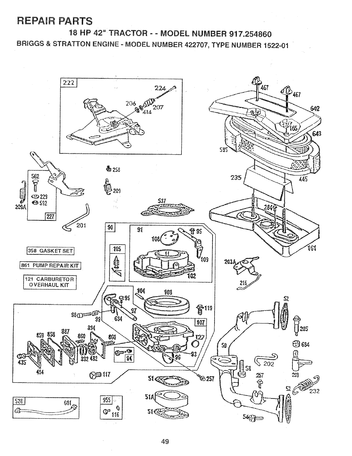
REPAIR PARTS
t8 HP 42" TRACTOR --MODEL NUMBER 917.254860
BRtGGS & STRATTON ENGINE - MODEL NUMBER 422707, TYPE NUMBER 1522..01
e s_2
35;8 GASKET SE_
t861 PUMP REPAiR KIT_
['_2' CARBURETOR tOVERHAUL KiT
'_ 238
537
49

REPAIR PARTS
18 HP 42" TRACTOR - - MODEL NUMBER 917=254860
BRIGGS & STRATTON ENGINE - MODEL NUMBER 422707, TYPE NUMBER ! 522-0t
5O
468
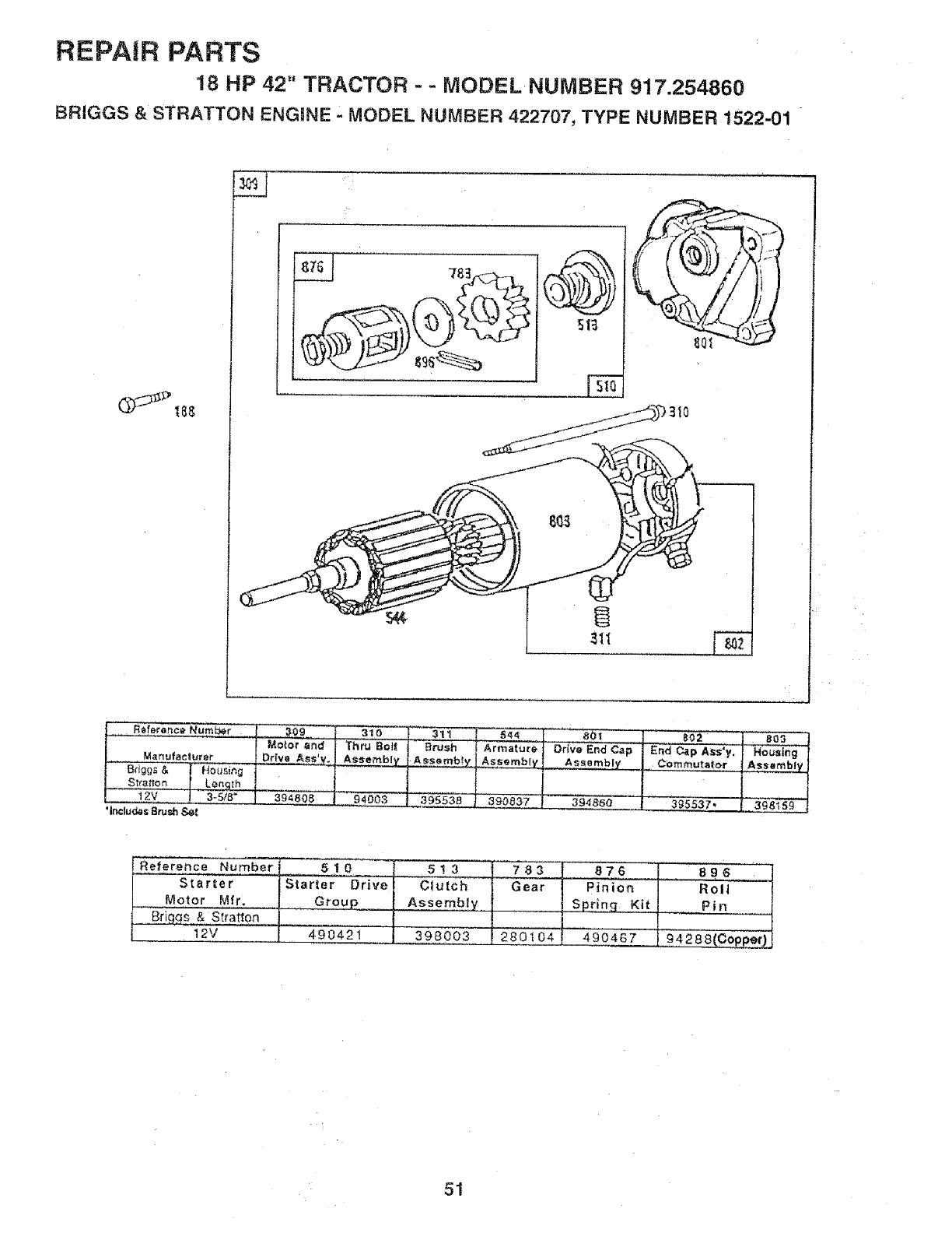
REPAIR PARTS
18 HP 42" TRACTOR - - MODEL NUMBER 917.254860
BRIGGS &STRATTON ENGINE MODEL NUMBER 422707, TYPE NUMBER 1522-01
R_ferer_ce_umb_r __ 309 _310
................... !Mo_';T'an_| T.%'_o_t
Manufacturer |Drive Ass'v. J AsseMblv
'Includes Brush S_I
311
Brush
39553B
544
Armature!
Assemb_
390837
aol
Dr{re End C=p
Assembly
394860
j002 I 8o_ l
..... I Housing ]
End Cap Ass'y, ] AssemblY4
Commutaio_"
I
3gss3z. ! 3_8_s_ I
Reference _ 5!0 ] 5!3
tVIotor Mfr, O r ou__....__ Assembly_
_" Bd _s & Svatton
L _2v L4.9042i .[ 398oo3
7;83
Gear
280104
_6 I 8_6
,Sprin_ .Ki t| Pin
' ' I
490467 94288(COpper_
51
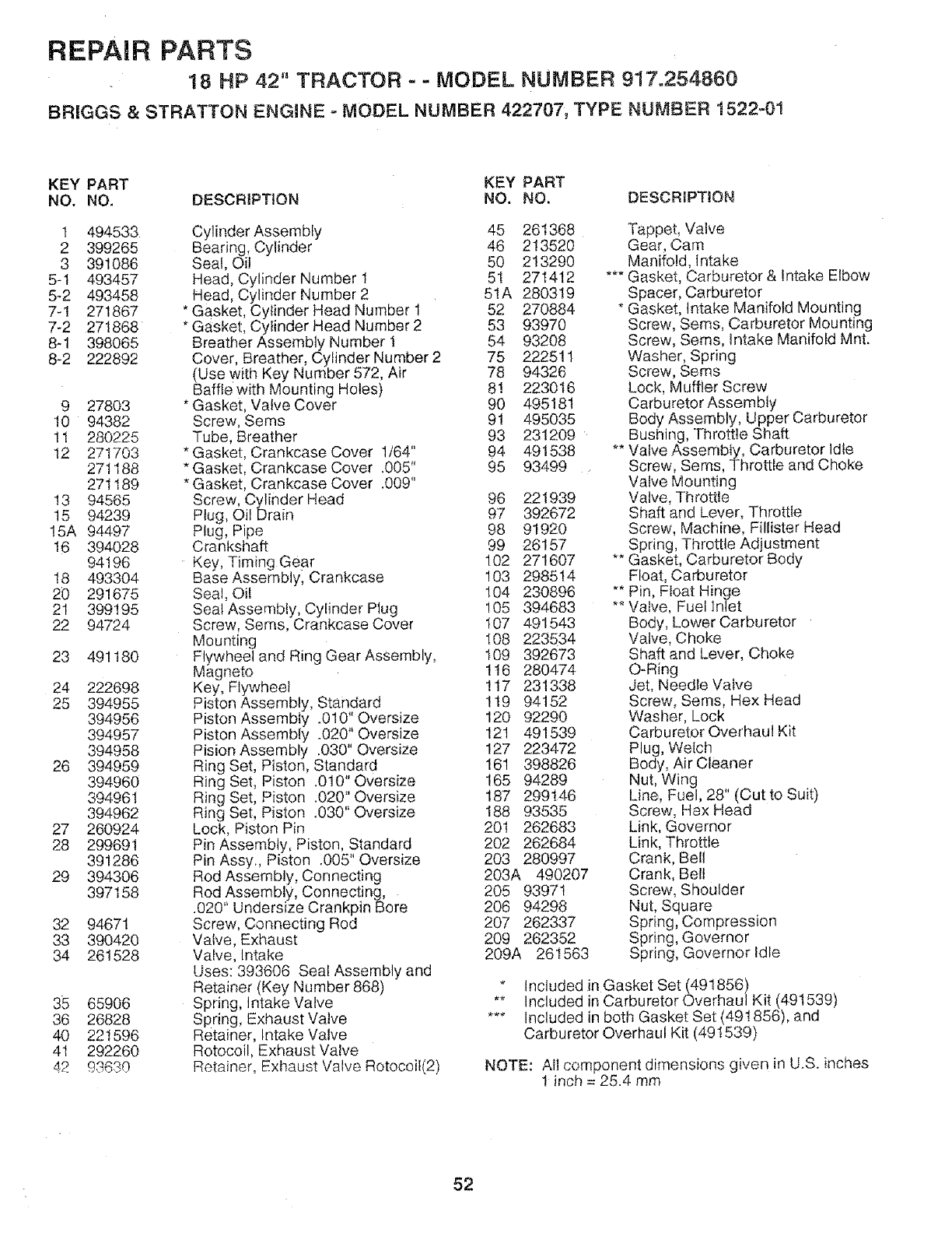
REPAIR PARTS
18 HP 42" TRACTOR - - MODEL NUMBER 917.254860
BRIGGS &STRATTON ENGINE - MODEL NUMBER 422707, TYPE NUMBER 1522=01
KEY PART KEY PART
NO. NO, DESCR_PT!ON NO. NO. DESCRIPT!ON
t 494533
2 399265
3 391086
5-t 493457
5-2 493458
7-1 271867
7-2 271868
8-1 398065
8-2 222892
9 27803
10 94382
11 280225
12 271703
271188
271189
13 94565
15 94239
15A 94497
16 394028
94196
!8 493304
20 291675
21 399195
22 94724
23 491180
24 222698
25 394955
394956
394957
394958
26 394959
394960
394961
394962
27 260924
28 299691
391286
29 394306
397158
32 94671
33 390420
34 261528
35 65906
36 26828
40 221596
41 292260
42 93630
Cylinder Assembly 45 261368
Bearing, Cylinder 46 213520
Seat, Oil 50 2!3290
Head, Cylinder Number 1 5! 271412
Head, Cylinder Number 2 51A 280319
* Gasket, Cylinder Head Number 1 52 270884
* Gasket, Cylinder Head Number 2 53 93970
Breather Assembly Number 1 54 93208
Cover, Breather, Cylinder Number 2 75 222511
(Use with Key Number 572, Air 78 94326
Bafftewith Mounting Holes) 81 223016
* Gasket, ValveCover 90 495181
Screw, Sems 91 495035
Tube, Breather 93 231209
* Gasket, Crankcase Cover 1/64" 94 491538
*Gasket, Crankcase Cover .005" 95 93499 •
* Gasket, Crankcase Cover .009"
Screw, Cylinder Head 96 221939
Plug, Oil Drain 97 392672
Plug, Pipe 98 91920
Crankshaft 99 26157
Key, Timing Gear 102 271607
Base Assembly, Crankcase !03 298514
Seal, Oil 104 230896
Seal Assembly, Cylinder Plug 105 394683
Screw, Sems, Crankcase Cover t07 491543
Mounting I08 223534
Flywheel and Ring Gear Assembly, 109 392673
Magneto 1I6 280474
Key, Flywheel !!7 231338
Piston Assembly, Standard 1t9 94152
Piston Assembly .010" Oversize 120 92290
Piston Assembly .020" Oversize 12t 491539
Pision Assembly .030" Oversize 127 223472
Ring Set, Piston, Standard 161 398826
Ring Set, Piston .010" Oversize 165 94289
Ring Set, Piston .020" Oversize 187 299146
Ring Set, Piston 4030" Oversize 188 93535
Lock, Piston Pin 20t 262683
Pin Assembly, Piston, Standard 202 262684
Pin Assy., Piston .005" Oversize 203 280997
Rod Assembly, Connecting 203A 490207
Rod,,Assembly, Connecting," 205 93971
.020 Undersize Crankpin Bore 206 94298
Screw, Connecting Rod 207 262337
Valve, Exhaust 209 262352
Valve, Intake 209A 261563
Uses: 393606 Seal Assembly and
Retainer (Key Number 868)
Spring, Intake Valve
Spring, Exhaust Valve
Retainer, Intake Valve
Rotocoil, Exhaust Valve
Retainer, Exhaust Valve Rotocoif(2)
_r'e
Tappet, Valve
Gear, Cam
Manifold, intake
Gasket, Carburetor & Intake Elbow
Spacer, Carburetor
Gasket, Intake Manifold Mounting
Screw, Sems, Carburetor Mounting
Screw, Sems, tntake Manifold Mnt.
Washer, Spring
Screw, Sems
Lock, Muffler Screw
Carburetor Assembly
Body Assembly, Upper Carburetor
Bushing, Throttle Shaft
Valve Assembly, Carburetor Idle
Screw, Seres, Throttle and Choke
Valve Mounting
Valve, Tllrottle
Shaft and Lever, Throttle
Screw, Machine, Fillister Head
Spring, Throttle Adjustment
Gasket, Carburetor Body
Float, Carburetor
Pin, Float Hinge
Valve, Fuel Inlet
Body, Lower Carburetor
Valve, Choke
Shaft and Lever, Choke
O-Ring
Jet, Needle Valve
Screw, Sems, Hex Head
Washer, Lock
Carburetor Overhaul Kit
Plug, Welch
Body, Air Cleaner
Nut, Wing
Line, Fuel, 28" (Cut to Suit)
Screw, Hax Head
Link, Governor
Link, Throttle
Crank, Bell
Crank, Belt
Screw, Shoulder
Nut, Square
Spring, Compression
Spring, Governor
Spring, Governor Idle
* Included in Gasket Set (49t856)
** Included in Carburetor Overhaul Kit (491539)
*** Included in both Gasket Set (49!856), and
Carburetor Overhaul Kit (49t 539)
NOTE: All component dimensions given in U.S. inches
! inch = 25.4 mm
52
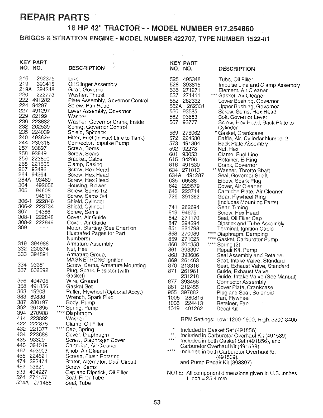
REPAIR PARTS
18 HP 42" TRACTOR- - MODEL NUMBER 917.254860
BRtGGS & STRATTON ENGINE _ MODEL NUMBER 422707, TYPE NUMBER 1522-01
KEY PART KEY PART
NO. NO. DESCRiPTiON NO, NO. DESCRIPTION
216 262375
219 393415
219A 394348
220 222773
222 491282
224 94297
227 491297
229 62199
230 223882
232 262539
235 224039
240 493629
244 230318
257 93897
258 93949
259 223890
265 221535
267 93496
284 94264
284A 93469
304 492656
305 94608
94513
306-1 222846
306-2 223734
307 94386
308-I 222848
308-2 222849
309 -_-
319 394988
332 230674
333 394891
334 93381
337 802592
356 494705
358 491856
363 19203
383 89838
387 280197
392 261395
394 270988
414 223882
422 222875
432 221377
434 223688
435 93829
445 394019
467 493903
468 224521
474 393474
482 93621
523 494927
524 271157
524A 271485
Link 525 495348
Oil Slinger Assembly 528 3938t5
Gear, Governor 535 271271
Washer, Thrust 537 271411
Plate Assembly, Governor Control 552 262332
Screw, Pan Head 552A 262331
Lever Assembly, Governor 556 93585
Washer 562 93853
Washer, Governor Crank, inside 567 93777
Spring, Governor Control
Shield, Spitback 569 276062
Fiiter, Fuel (tn Fuel Line to Tank) 572 224580
Connector, Impulse Pump 573 491304
Screw, Sems 592 92278
Screw, Seres 601 93053
Bracket, Cable 615 94296
Clamp, Casing 616 491530
Screw, Hex Head 634 2710!3
Screw, Hex Head 634A 491287
Screw, Hex Head 635 66538
Housing, Blower 642 223579
Screw, Seres 1/2 643 223714
Screw, Sems 3/4 726 39t362
Shield, Cylinder
Shield, Cylinder 741 262694
Screw, Sems 819 94675
Cover, Air Guide 842 271170
Cover, Air Guide 847 394394
Motor, Starting (See Chart on 851 221798
tItustrated Pages for Part 858 270989
Numbers) 859 271025
Armature Assembly 860 261358
Nut, Hex 86t 393397
Armature Group, 868 393606
MAGNETRON®Ignkion 869 261463
Screw, Seres, Armature Mounting 870 213316
Plug, Spark, Resistor (with 871 261961
Gasket) 231218
Wire, Ground 877 393456
Gasket Set 881 212455
Puller, Flywheel (OptionalAccy.) 955 397882
Wrench, Spark Plug !005 280815
Body, Pump 1006 224413
Spring, Pump 1019 491262
Diaphragm
Washer
Clamp, Oil Filler
Cap, Spring
Cover, Diaphragm
Screw, Diaphragm Cover
Cartridge, Air Cleaner
Knob, Air Cleaner
Screen, FIush Rotating
Stator, Alternator, Dual Circuit
Screw, Sems
Cap and Dipstick, Oif Filler
Seal, Filler Tube
Seal, Tube
Tube, Oil Filler
Impulse Line and Clamp Assembly
Element, Air Cleaner
*** Gasket, Air Cleaner
Lower Bushing, Governor
Upper Bushing, Governor
Screw, Seres, Hex Head
Bolt, Governor Lever
Screw, Hex Head, Back Plate to
Cylinder
* Gasket, Crankcase
Baffle, Air, Cylinder Number 2
Back Plate Assembly
Nut, Hex
Clamp, Fuel Line
Retainer, E_Ring
Crank, Governor
** Washer, Throtte Shaft
Seal, Governor Shaft
Elbow, Spark Plug
Cover, Air Cleaner
Cartridge Plate, Air Cleaner
Gear', Flywheel Ring
(tncludes Mounting Parts)
Gear, Timing
Screw, Hex Head
Sea!, Oil Filter Cap
Dipstick and Tube Assembly
Terminal, Ignition Cable
.... Diaphragm, Damping
.... Gasket, Carburetor Pump
.... Spring (2)
Repair Kit, Pump
Seal Assembly and Retainer
Sea[, Intake Valve, Standard
Seat, Exhaust Valve, Standard
Guide, Exhaust Valve
Guide, Intake Valve (See Manuai)
Connector Assembly
Cover Plate, Crankcase
Plug and Seal, Solenoid
Fan, Flywheel
Retainer, Fan
Decat Kit
R PM Settings: Low: I200-1600, High: 3200-3400
* Included in Gasket Set (491856)
** Included in Carburetor Overhaul Kit (491539)
*** Included in both Gasket Set (491856), and
Carburetor Overhaul Kit (491539)
.... included in both Carburetor Overhaul Kit
(491539),
and Pump Repair Kit (393397)
NOTE: All component dimensions given in U.S. inches
1 inch = 25.4 mm
53

SERVICE OTES
54

SUGGESTED GUIDE FOR SIGHTING SLOPES FOR SAFE OPERATION
U_
U1
SIGHTING
GUIDE
ONLY RIDE UP AND DOWN HILL,
NOT ACROSS HILL
SIGHT AND HOLD THIS LEVEL WITH
SKY LINE OR TREE.
/
15°MAX.
iii i IIIHIIIIIIIII • IIIIII IIIIII II I I I
_i /_ Operate your Tractor up and down the face of slopes (not
!_t AA greater than 15°), never across the face. Make turns gradu-
!1 _ ally to prevent tipping or loss of control, Exercise extreme
caution when changing direction on slopes,
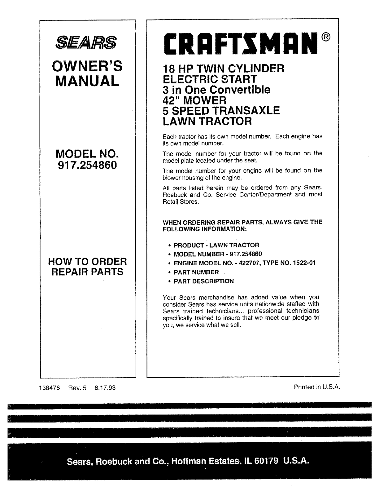
S_F/A/RS
OWNER'S
MANUAL
MODEL NO.
917.254860
HOW TO ORDER
REPAIR PARTS
£RI:IFTZMIIN®
18 HP TWIN CYLINDER
ELECTRIC START
3 in One Convertible
42" MOWER
5 SPEED TRANSAXLE
LAWN TRACTOR
Each tractor has its own model number. Each engine has
its own model number.
The model number for your tractor witl be found on the
model plate located under the seat.
The model number for your engine will be found on the
blower housing of the engine.
All parts listed herein may be ordered from any Sears,
Roebuck and Co. Service Center/Department and most
Retail Stores.
WHEN ORDERING REPAIR PARTS, ALWAYS GIVE THE
FOLLOWING INFORMATION:
"PRODUCT -LAWN TRACTOR
*MODEL NUMBER- 917.254860
, ENGINE MODEL NO. - 422707, TYPE NO. 1522-01
- PART NUMBER
* PART DESCRIPTION
Your Sears merchandise has added value when you
consider Sears has service units nationwide staffed with
Sears trained technicians.,, professional technicians
specifically trained to insure that we meet our pledge to
you, we service what we sell.
138476 Rev, 5 8,17.93 Printed in U.S.A.
II III IIIII
IIIIIIIIIHlU IIIIIIIH IIIII_IIIII
