Craftsman 917255275 User Manual SEARS 10H.P. 36 IN. RIDING LAWN TRACTOR Manuals And Guides L0810381
CRAFTSMAN Lawn, Tractor Manual L0810381 CRAFTSMAN Lawn, Tractor Owner's Manual, CRAFTSMAN Lawn, Tractor installation guides
User Manual: Craftsman 917255275 917255275 CRAFTSMAN SEARS 10H.P. 36 IN. RIDING LAWN TRACTOR - Manuals and Guides View the owners manual for your CRAFTSMAN SEARS 10H.P. 36 IN. RIDING LAWN TRACTOR #917255275. Home:Lawn & Garden Parts:Craftsman Parts:Craftsman SEARS 10H.P. 36 IN. RIDING LAWN TRACTOR Manual
Open the PDF directly: View PDF ![]() .
.
Page Count: 44
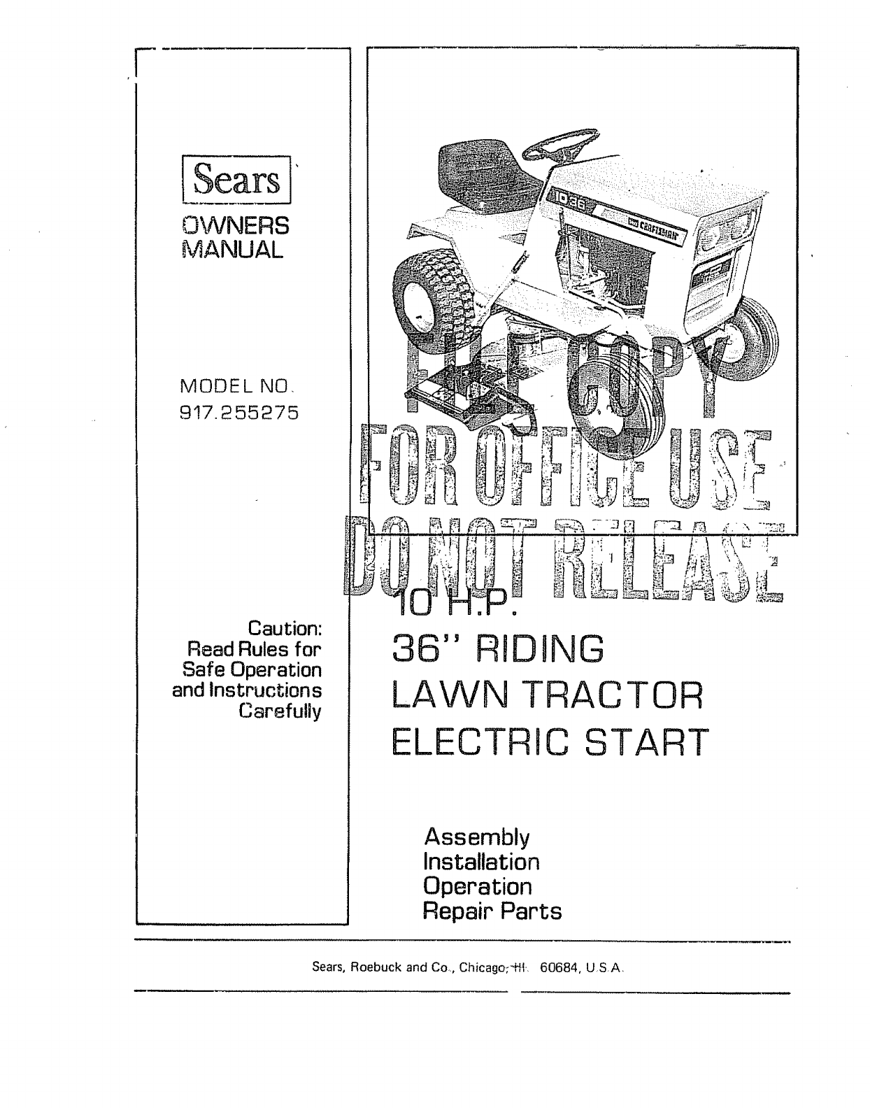
ISears ]
OWNERS
MANUAL
MODEL NO,
917.255275
Caution:
Read Rules for
Safe Operation
and Instruction s
Carefully
36" RIDING
LAWN TRACTOR
ELECTRIC START
Assembly
Installation
Operation
Repair Parts
Sears, Roebuck and Co., Chicagor-ffL 60684, USA.
MODEL
NUMBER
SERIAL
NUMBER
THE MODEL AND SERIAL NUMBERS
WILL BE FOUND ON THE MODEL
PLATE ATTACHED TO THE CHASSIS
ASSEMBLY_ (REFER TO PAGE 18L
YOU SHOULD RECORD BOTH MODEL
AND SERIAL NUMBERS AND KEEP
IN A SAFE PLACE FOR FUTURE
REFERENCE_
CONGRATULATIONS on your purchase of a Sears Lawn
Tractor. It has been designed, engineered and manufactured '
to give you the best possib{e dependability and performance_
Should you experience any problem you cannot easily reme-
dy. please contact your nearest Sears, Roebuck and Co. Store_
They have competent, we_-trained technicians and the proper
tools to service or repair this unit.
Please read and retain this manual. The instructions wilt enable
you to assemble, operate and maintain your Tractor properly.
Always observe the "RULES FOR SAFE OPERATION".
_> FULL ONE YEAR WARRANTY
'=_ ON ELECTRBC START LAWN TRACTOR c_
For one year from the date of purchase,when this Lawn Tractor is usedfor persona]household
purposes, Searswill repair any defect in material or workmanship in this Lawn Tractor, except €;_
the battery, at no charge°
If this Lawn Tractor is usedfor commercial or rental purposes,this warranty applies for only 30
days from the date of purchase.
FULL 90=DAY WARRANTY Ot=_ BATTERY
For 90 days from the date of purchase,if any battery included with the Lawn Tractor proves
defective in material or workmanship and will not hold a charge, Searswilt replace the battery,
at no charge.
UMBTED WARRANTY ON BATTERY
From the 91st day until one year from the date of purchase,if any battery included with the
Lawn Tractor proves defective in material or' workmanship andwilt not hold a charge,;Searswill
replace the battery, charging1/12th of the price of the new battery for each full month from the
date of purchase°
Warranty service is available at your home, at no charge, by simply contacting the nearest Sears
store €.r Service Center throughout the United States,,
This warranty gives you specific legal rights, and you may alsohave other'rights which vary from
state to state.
Sears,Roebuck and Co.
SearsTower
BSC 41-3
Chicago,I L 60684
TABLE OF CONTENTS
RULES FOR SAFE OPERATION ........................ 1 TROUBLE SHOOTING ........................ 11
ASSEMBLY INSTRUCTIONS ................................ 2 OPERATION INSTRUCTIONS -MOWER ............. 14
OPERATION INSTRUCTIONS - TRACTOR ............... 5 MAINTENANCE INSTRUCTIONS -MOWER ......... 15
MAINTENANCE INSTRUCTIONS - TRACTOR ............ 7 REPAI R PARTS .................................. 17
RUILES FOB SAFE OPERATnoN
WARNING: This unit is equipped with an internal combustion engine and should not be used on or near any unimproved forest-
covered, brush-covered or grass-covered land unless the engme s exhaust system is equipped with a spark arrester meeting applicable
local or state laws (if any), tf a spark arrester is used, it should be maintained in effective working order by the operator°
in the State of California the above is required by law (Section 4442 of the California Public Resources Code), Other states may
have similar laws, Federal laws apply on federal lands See your Sears Authorized Service Center for spark arrester muffler part
number 673A223.
1, Know the controls and how to stop quickly,, READ THE
OWNER'S MANUAL.
2,. Do not allow children to operate the vehicle. Do not allow
adults to operate it without proper instruction.,
3, Do not carry passengers Keep children and pets a safe dis-
tance away,
4, Always wear substantial footwear. Do not wear loose fitting
clothing that could get caught in moving parts,
5, Keep your eyes and mind on your tractor, mower and the
area being cut Don't let other interests distract you..
6. Do not attempt to operate your tractor or mower when
not in drivers seat,,
Z. Always get on or off your tractor from the operators left
hand side,
8, Clear the work area of objects which might be picked up
and thrown.
9, Disengage all attachment clutches and shift into neutral be-
fore attempting to start the engine.
10, Disengage power to attachments and stop the engine be-
fore leaving the operator's position.
11_ Disengage power to mower, stop the engine and disconnect
spark plug wire(s) from spark plug(s) before cleaning, mak-
ing an adjustment or repairs.
12. Disengage power to attachments when transporting or not
in use.,
13., Take all possible precautions when leaving the vehicle un-
attended, such as disengaging the power-take-off, lowering
the attachments, shifting into neutral, setting the parking
brake, stopping the engine, and removing the key.
14., Do not stop or start suddenly when going uphill or down-
hill. Mow up and down the face of slopes (not greater than
15°); never across the face°
t5_ Reduce speed on slopes and make turns gradually to pre-
vent tipping or loss of control, Exercise extreme caution
when changing direction on slopes..
t6 Do not shift gears while going up or down slopes. Choose
a gear low enough to negotiate the slope without stopping
and shifting gears To reduce speed, move throttle lever
to slow,
17 Never mow in wet or slippery grass, when traction is um
sure or at a speed which could cause a skid.
18o Stay alert for holes in the terrain and other hidden hazards,
19o Do not drive too close to creeks, ditches and public high-
ways_
20, Exercise special care when mowing around fixed objects
in order to prevent the blades from striking them, Never
deliberately run tractor or mower into or over any foreign
object.,
21,, Never shift gears until tractor comes to astop,.
22, Never place hands or feet under the mower, in the deflector
(discharge chute) or near any moving parts while tractor or
mower are running. Always keep clear of discharge chute,
23, Use care when pulling loads or using heavy equipment_
a, Use only approved drawbar hitch points.
b, Limit loads to those you can safely control,
c. Do not turn sharply,, Use care when backing.,
d Use counterweight or wheel weights when suggested in
this owner's manual,
24. Watch out for traffic when crossing or near roadways_
25 When using any attachments, never direct discharge of
material toward bystanders nor allow anyone near the ve-
hicle while in operation.
26_ Handle gasoline with care -it is highly flammable°
a, Use approved gasoline containers,,
b, Never remove the cap of the fuel tank or add gasoline to
arunning or hot engine, or fill the fuel tank indoors.
Wipe up spilled gasoline,
c, Open doors if the engine is run in the garage., exhaust
fumes are dangerous, Do not run the engine indoors_
27, Keep the vehicle and attachments in good operating con-
dition, and keep safety devices in place.
28., Keep all nuts, bolts and screws tight to be sure the equip-
ment is in safe working condition,
29., Never store the equipment with gasoline in the tank inside
a building where fumes may reach an open flame or spark,,
Allow the engine to cool before storing in any enclosure°
30, To reduce fire hazard, keep the engine free of grass, leaves
or excessive grease,
31, Except for adjustment; DO NOT operate Engine if air
cleaner or cover directly over carburetor air intake is re-
moved. Removal of such part could create a fire hazard_
32., DO NOT OPERATE WITHOUT A MUFFLER OR TAM-
PER WITH THE EXHAUST SYSTEM°, Damaged mufflers
or spark arresters could create a fire hazard. Inspect period-
ically and replace if necessary
33, The vehicle and attachments should be stopped and inspect-
ed for damage after striking a foreign object, and the dam-
age should be repaired before restarting and operating the
equipment,
34, Do not change the engine governor settings or overspeed
the engine,
35,, When using the vehicle with mower, proceed as follows:
a,, Mow only in daylight or in good artificial light°
b, Never make a cutting height adjustment while the engine
is running if the operator must dismount to do so.
c Shut the engine off when removing the grass catcher or
unclogging chute,
d. Check the blade mounting bolts for proper tightness at
frequent intervals,
36. Check the grass catcher bags frequently for wear or deterio-
ration Replace with new bags for safety protection,
37 Do not operate the Mower without either the entire grass
catcher, on mowers so equipped, or the deflector shield in
place,
38. Disengage power to mower before backing up, Do not mow
in reverse unless absolutely necessary and then only after
careful observation of the entire area behind the mower,
LOOK FOR THIS SYMBOL TO POINT OUT IMPORTANT
SAFETY PRECAUTIONS,, IT MEANS - ATTENTION!
BECOME ALERT! YOUR SAFETY IS INVOLVED,,
-I-
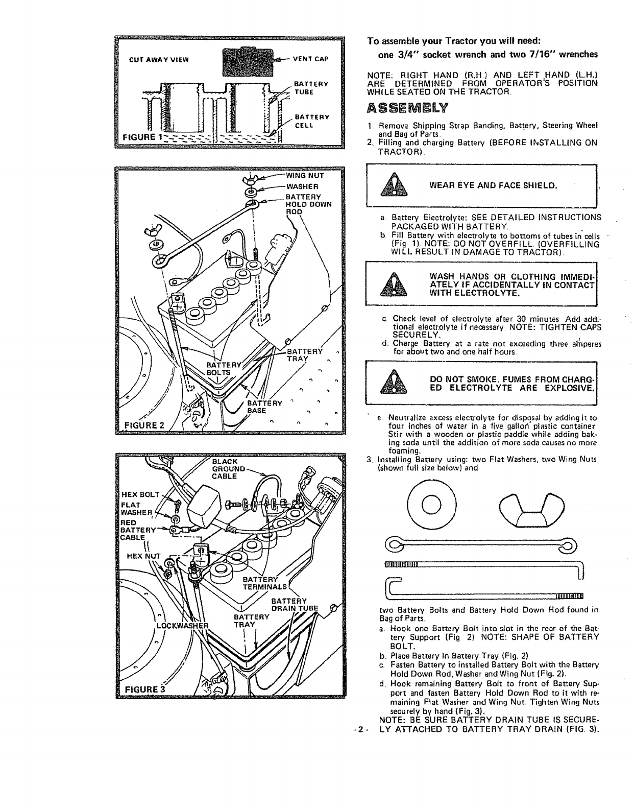
CUT AWAY VIEW VENT CAP
BATTERY
TUBE
FIGURE 2
FIGURE 3
To assembleyour Tractor you will need:
one 3/4" socket wrench and two 7/16" wrenches
NOTE: RIGHT HAND (R,H) AND LEFT HAND (L,.H,)
ARE DETERMINED FROM OPERATORS POSITION
WHILE SEATED ON THE TRACTOR.
ASSEMBLY
1_ Remove Shipping Strap Banding, B_ttery, Steering Wheel
and Bag of Parts,
2, Filling and charging Batter,/ (BEFORE I_STALLING ON
TRACTOR),
WEAR EYE AND FACE SHIELD, 1'
a, Battery Electrolyte: SEE DETAILED iNSTRUCTIONS
PACKAGED WITH BATTERY
bFill Battery with electrolyte to bottoms of tubes incells "
(Fig 1)NOTE: DO NOT OVERFILL, (OVERFILLING
WILL RESULT IN DAMAGE TO TRACTOR),
ATELY IF ACCIDENTALLY tN CONTACT|
WITH ELECTROLYTE. /
c, Check level of electrolyte after 30 mlnutes. Add addi-
tional electrolyte if necessary. NOTE: TIGHTEN CAPS
SECURELY,
d. Charge Battery at a rate not exceeding three a_peres
for' about two and one half hours,
DO NOT SMOKE, FUMES FROM CHARG-L'!
ED ELECTROLYTE ARE EXPLOSlVE.J
e, Neutralize excess electrolyte for disposal by adding [t to
four inches of water in a five gatlod plastic container
Stir with a wooden or plastic paddle while adding bak-
ing soda until the addition of mo_e soda causes no more
foaming,.
3. Installing Battery using: two Flat Washers, two Wing Nuts
(shown futl size below) and
-2-
lii_ligil|{|ltHg .............. L_
two Battery Bolts and Battery Ho_d Down Rod found in
Bag of Parts,.
a, Hook one Battery Bolt into stot in the rear of the Bat-
tery Support (Fig 2) NOTE: SHAPE OF BATI'ERY
BOLT.
b. Place Battery in Battery Tray {Fig_ 2)
c_ Fasten Battery to installed Battery Bolt with the Battery
Hold Down Rod. Washer and Wing Nut (Fig,. 2),.
d_ Hook remaining Battery Bolt to front of Battery Sup-
port and fasten Battery Hold Down Rod to it with re-
maining Fiat Washer and W_ng Nut,, Tighten Wing Nuts
securely by hand {Fig. 3).
NOTE: BE SURE BATTERY DRAIN TUBE iS SECURE-
LY ATTACHED TO BATTERY TRAY DRAIN (FIG, 3),
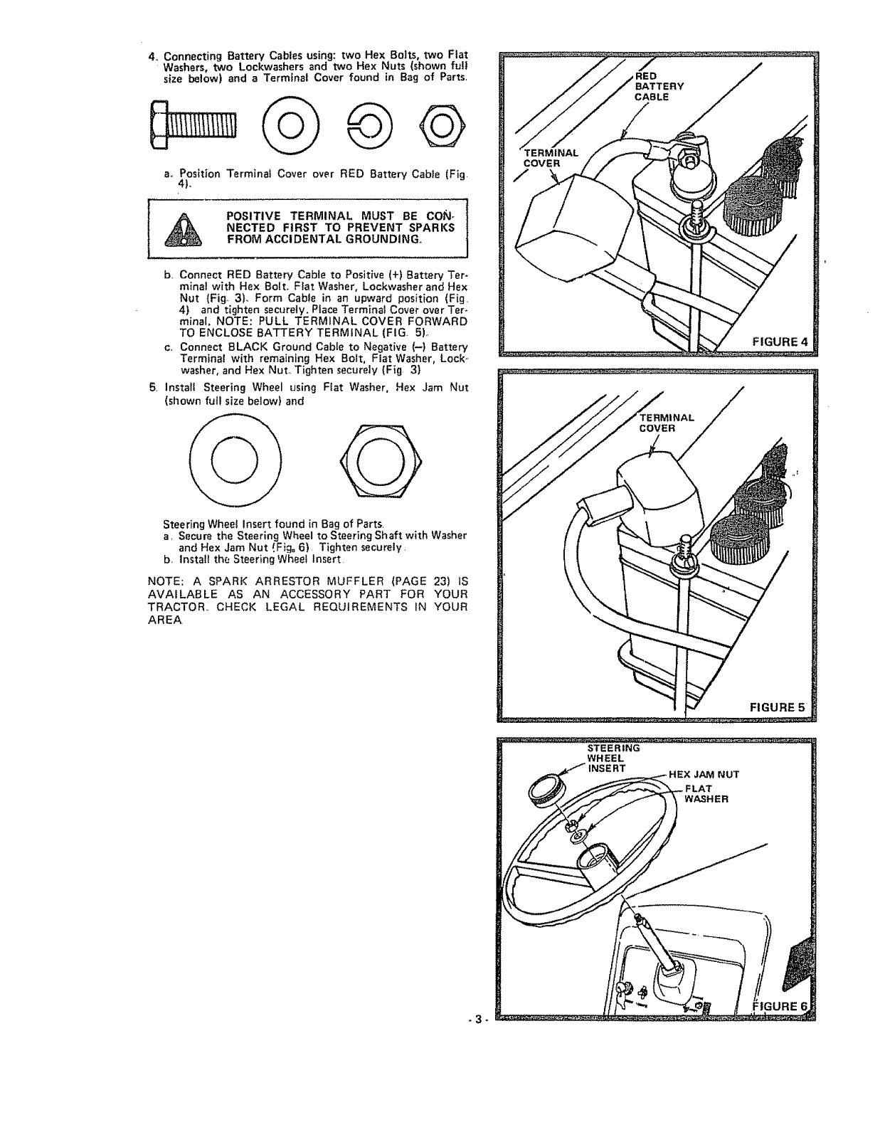
4. Connecting Battery Cables using: two Hex Bolts, two Flat
Washers, two Lockwashers and two He× Nuts (shown full
size below) and a Terminal Cover found in Bag of Parts.
@©
ao Position Terminal Cover over RED Battery Cable (Fig.
4),
POSITIVE TERMINAL MUST BE CON-
NECTED FIRST TO PREVENT SPARKS
FROM ACCIDENTAL GROUNDING°
b, Connect RED Battery Cable to Positive (+) Battery Ter-
minal with Hex Bolt. Flat Washer, Lockwasher and Hex
Nut {Fig_ 3). Form Cable in an upward position (Fig_
4) and tighten securely, Place Terminal Cover over Ter-
minal. NOTE: PULL TERMINAL COVER FORWARD
TO ENCLOSE BATTERY TERMINAL (FIG. 5),
c, Connect BLACK Ground Cable to Negative (-) Battery
Terminal with remaining Hex Bolt, Flat Washer, Lock-,
washer, and Hex Nut° Tighten securely (Fig 3)
5, Install Steering Wheel using Flat Washer, Hex Jam Nut
(shown full size below) and
@
Steering Wheel Insert found in Bag of Parts,
a, Secure the Steering Wheel to Steering Shaft with Washer
and Hex Jam Nut i.Fig=6) Tighten securely,
b, Install the Steering Wheel Insert
NOTE: A SPARK ARRESTOR MUFFLER (PAGE 23) tS
AVAILABLE AS AN ACCESSORY PART FOR YOUR
TRACTOR,, CHECK LEGAL REQUIREMENTS IN YOUR
AREA,
TERMINAL
COVER
FIGURE
FIGURE7
SEAT SPRING
s_
SEAT BOLT
8NITBAL ADaUSTMENTS
1, REDUCE TIRE PRESSURE TO 14 POUNDS IN FRONT
AND 12 POUNDS IN REAR TIRES. (Tires were overin*
flared for shipping purposes)_
2Seat position should be adiusted forward or backward so
that operator can comfortably reach Ctutch,.Brake Pedal
(Fig 8).
a, Loosen the Bolt beneath the Seat Spring (Fig. 7), Slide
the seat forward or backward Tighten Bolt securely,
3 Check mower alignment page 13 and a'djust if r_ecessary
IINgTOAL SERVllCE
NOTE: BE CAREFUL NOT TO ALLOW DIRT TO ENTER
THE ENGINE WHEN CHECKING OR ADDING OIL OR
FUEL
t Pu$t Hood Latches away from Latching Pins (Fig 8)+ Raise
Hood.
2 Check Engine Oil Love] with Tractor on tevel ground+ Re-
move and wipe Dipstick (Fig° 9} clean, screw it in tight for'
afew seconds remove and read Oil Level. If necessary, add
Oil untii "FULL mark is reached. In summer use S.A.E+
30 (SC, SO, SE or SF) Oil. tn winter (below 32°F+} use
S,A,E, t0W30 (SC, SD, SE or SF}. in extreme cotd (below
0+F.) use S.A E. 5W20 (SC, SD, SE or SF} DO NOT USE
10W40 OIL. NOTE: DO NOT OVERFILL
3, Flit Fuel Tank (Fig. 9) with fresh, clean regular grade fead-
ed or low-lead automotive gasoline ' only, Cap_acity is 3
quar_s. NOTE: DO NOT SWITCH FROM LEADED TO
LEAD.FREE GASOLINE
WARNING: DO NOT USE GASOHOL. Gasehot type al-
cohols react with water content in the fuel and tend to
form strong acids which can corrode metal parts, even eat
rubber and plastics
FILL 'to BOTTOM OF GAS TANK FILL,
ER NECK. DO NOT OVERFILL, WIPE
OFF ANY SPILLED OIL OR FUEL.
-4+
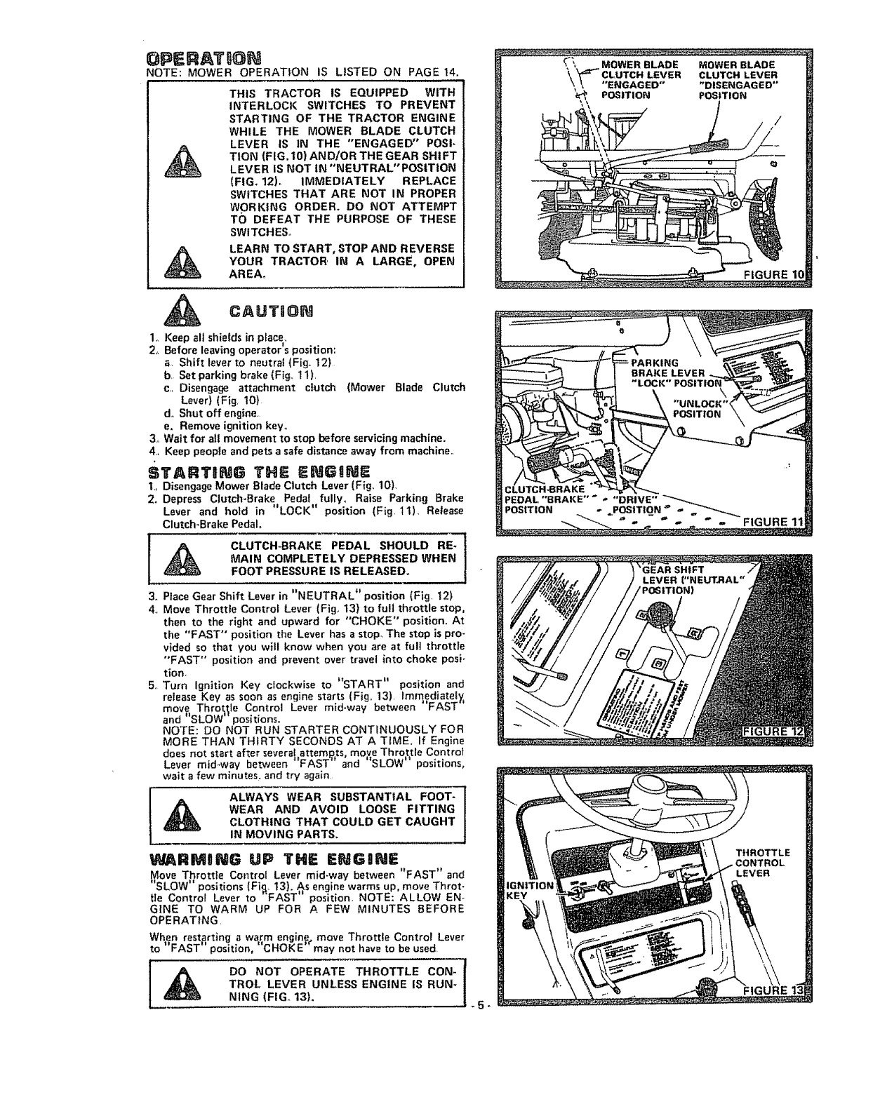
OPERATBON
NOTE: MOWER OPERATION IS LISTED ON PAGE 14,
THIS TRACTOR IS EQUIPPED WITH
INTERLOCK SWITCHES TO PREVENT
STARTING OF THE TRACTOR ENGINE
WHILE THE MOWER BLADE CLUTCH
LEVER IS IN THE "ENGAGED" POSI-
TION (FIG. 10) AND/OR THE GEAR SH! FT
LEVER IS NOT IN "NEUTRAL" POSITION
(FIG. 12), IMMEDIATELY REPLACE
SWITCHES THAT ARE NOT IN PROPER
WORKING ORDER. DO NOT ATTEMPT
TO DEFEAT THE PURPOSE OF THESE
SWITCHES,,
LEARN TO START, STOP AND REVERSE
YOUR TRACTOR' IN A LARGE, OPEN
AREA.
CAUTSON
1o Keep eli shields in place,.
2,, Before leaving operator's position:
aShift lever to neutra{ (Fig° 12)
bSet parking brake (Fig, 11),
c., Disengage attachment clutch (Mower Blade Clutch
Lever) (Fig 10)
do Shut off engine.
e. Remove ignition key.
3o Wait for all movement to stop before servicing machine.
4., Keep people and pets a safe distance away from machine°
STARTgNG THE ENGINE
1., Disengage Mower Blade Clutch Lever {Fig. 10),
2. Depress Clutch-Brake Pedal fully,, Raise Parking Brake
Lever and hold in "LOCK" position (Fig 11) Release
Clutch-Brake Pedal.
[_CLUTCH-BRAKE PEDAL SHOULD RE-
MAIN COMPLETELY DEPRESSED WHEN
FOOT PRESSURE IS RELEASED_
3. Place Gear Shift Lever in "NEUTRAL" position (Fig 12)
4, Move Throttle Control Lever (Fig. 13) to full throttle stop,
then to the right and upward for "CHOKE" position,, At
the "FAST" position the Lever has astop. The stop is pro_
vided so that you will know when you are at full throttle
"FAST" position and prevent over travel into choke posi-
tion,
5, Turn Ignition Key clockwise to "START" position and
release Key as soon as engine starts (Fig,, 13). immediately,
move Throt,_le Control Lever mid-way between "FAST-
and "'SLOW" positions.
NOTE: DO NOT RUN STARTER CONTINUOUSLY FOR
MORE THAN THIRTY SECONDS AT A TIME. If Engine
does not start after severel,attem_,ts, mo_e Throttle Control
Lever mid,,way between FAST and "SLOW' positions,
wait a few minutes, and try again,
ALWAYSWEARSUBSTANT,ALFOOT-
WEARANDAVO,DLOOSEF,TT,NG
CLOTHING THAT COULD GET CAUGHT
IN MOVING PARTS.
WARMONG UP THE ENGnNE
Move Throttle Control Lever mid-way between FAST and
,t iI ....
SLOW positions (Fig,. 13). As engine warms up, move Throt-
tle Control Lever to -FAST" position NOTE: ALLOW EN-
GINE TO WARM UP FOR AFEW MINUTES BEFORE
OPERATING
When restarting a warm engine_ move Throttle Control Lever
to "FAST" position, "'CHOKE-may not have to be used,
DO NOT OPERATE THROTTLE CON- {
TROL LEVER UNLESS ENGINE IS RUN*
NING (FIG. 13). 5-
FIGURE
FIGURE
:tGURE
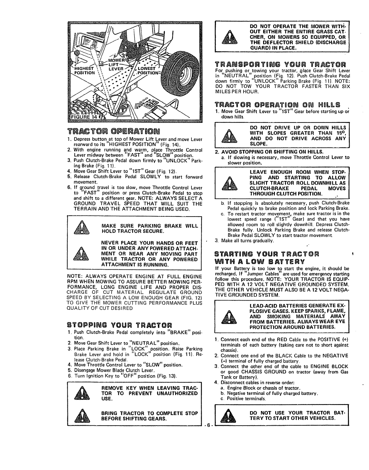
@PERATB@N
1,, Depress button at top of Mower Lift Lever and move Lever
rearward to its "HIGHEST POSITION" (Fig° 14).
DO NOT OPERATE THE MOWER WITI_-
OUT EITHER THE ENTIRE GRASS CATo
CriER, ON MOWERS SO EQUIPPED, OR
THE DEFLECTOR SHIELD (DISCHARGE
GUARD) IN PLACE.
Z With engine running and warm, place Throttle Control
Lever m_dway between FAST and SLOW pos=tlon,
3_ Push Clutch-Brake Pedal down firmly to "UNLOCK" Park-
ing Brake (Fig, t t),
4_ Move Gear Shift Lever to "1ST" Gear (Fig_ 12),,
5o Release Clutch-Brake Pedal SLOWLY to start forward
movement_
6_ If ground travel is too slow, move Throttle Control Lever
_tl II ,,
to FAST posnt=on or press Clutch-Brake Pedal to stop
and shift to a different gear, NOTE: ALWAYS SELECT A
GROUND TRAVEL SPEED THAT WILL SUIT THE
TERRAIN AND 'THE ATTACHMENT BEING USED,
MAKE SURE PARKING BRAKE WILL
HOLD TRACTOR SECURE.
NEVER PLACE YOUR HANDS OR FEET
IN OR UNDER ANY POWERED ATTACH-
MENT OR NEAR ANY MOVING PART
WHILE TRACTOR OR ANY POWERED
ATTACHMENT IS RUNNING°
NOTE: ALWAYS OPERATE ENGINE AT FULL ENGINE
RPM WHEN MOWING TO ASSURE BETTER MOWING PER-
FORMANCE, LONG ENGINE LIFE AND PROPER DIS-
CHARGE OF CUT MATERIAL REGULATE GROUND
SPEED BY SELECTING A LOW ENOUGH GEAR (FIG. 12)
TO GIVE THE MOWER CUTTING PERFORMANCE PLUS
QUALITY OF CUT DESIRED
STOPPING YOUR TRACTOR
1, Push Clutch-Brake Pedal completely into "BRAKE" posi-
tiono
2, Move Gear Shift Lever to '*NEUTRAL" position.
3, Place Parking Brake in "LOCK" position., Raise Parking
Brake Lever and hoed in "LOCK'* position (Fig.. 11L Re-
lease Clutch-Brake Pedal,
4o Move Throttle Control Lever to "SLOW" positiom
5. Disengage Mower Blade Clutch Lever.
6, Turn ignition Key to "OFF" position (Fig,, 13}.
REMOVE KEY WHEN LEAVING TRAC-
TOR TO PREVENT UNAUTHORIZED
USEo
BRING TRACTOR TO COMPLETE S3[OP
BEFORE SHIFTING GEARS.
TRANSPORTING YOUR T_ACTOR
For pushing or towing your tractor, _l_ce Gear Shift Lever
in "NEUTRAL" ,position (Fig. 12}, Push Clutch-Brake Peda!
down firmly to UNLOCK Parking Brake (Fig, 11} NOTE:
DO NOT TOW YOUR TRACTOR FASTER THAN SIX
MILES PER HOUR,,
TRACTOR OPERATgON ON HgLILS
1,. Move Gear Shift Lever to "IST" Gear before starting up o;
down hills.
DO NOT DRIVE UP OR DOWN HILLS
WITH SLOPES GREATER THAN 15 ° ,
AND DO NOT DRIVE ACROSS ANY
SLOPE.
2. AVOID STOPPING OR SHIFTING ON HILLS_
a,. tf slowing is necessary, move Throttle Control Lever to
slower position.
LEAVE ENOUGH ROOM WHEN STOP-
PING AND STARTING 3['O ALLOW
SLIGHT TRACTOR ROLL DOWNHILL AS
CLUTCH-BRAKE PEDAL MOVES
THROUGH CLUTCH POSITION.
b, If stopping is absolutely necessary, push Clutch-Brake
Pedal quickly to brake position and lock Parking Brake_
c_ To restart tractor movement, make sure tractor is in the
tl tl
lowest speed range ( 1ST Gear) and that you have
allowed room to rolt slightly downhill. Depress Clutch-
Brake fully, Unlock Parking Brake and release Clutch-
Brake Pedal SLOWLY to start tractor movement.
3. Make all turns gradually,,
STARTING YOUR TRACTOR
'dVItTH ALOW BATTERY
If your Battery is too tow to start the engine, it should be
1| II .
recharged. If Jumper Cables are used for emergency starting
follow this procedure. NOTE: YOUR TRACTOR IS EQUIP-
PED WITH A 12 VOLT NEGATIVE GROUNDED SYSTEM.
THE OTHER VEHICLE MUST ALSO BE A 12 VOLT NEGA-
TIVE GROUNDED SYSTEM.
LEAD*ACID BATTERIES GENERi_TE EX-
PLOSIVE GASES. KEEP SPARKS, FLAME,
AND SMOKING MATERIALS AWAY
FROM BATTERIES. ALWAYS WEAR EYE
PROTECTION AROUND BATTERIES°
-6-
1, Connect each end of the RED Cable to the POSITIVE (+)
terminals of each battery (taking care not to short against
chassis)_
2, Connect one end of the BLACK Cable to the NEGATIVE
(-) terminal of fully charged battery.
3, Connect the other end of the cable to ENGINE BLOCK
or good CHASSIS GROUND on tractor (away from Gas
Tank or Battery),
4., Disconnect cables in reverse order:
a. Engine Block or chassis of tractor_
bo Negative terminal of fully charged battery.
c, Positive terminals_
II
DO NOT USE YOUR TRACTOR BAT-I
TERY TO START OTHER VEHICLES, 1
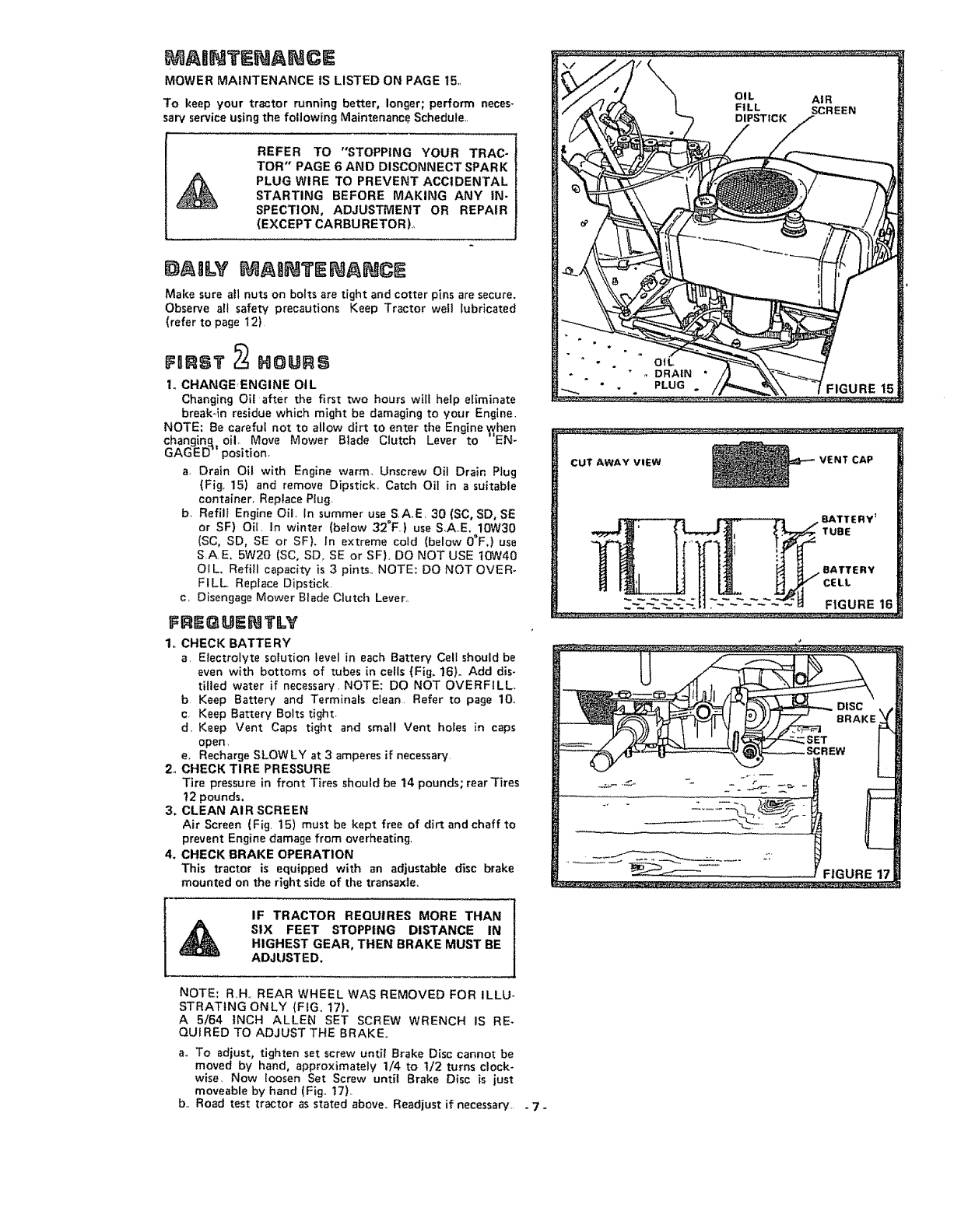
MAIINTENANCE
MOWER MAINTENANCE tS LISTED ON PAGE t5.,
To keep your tractor running better, longer; perform neces-
saw service using the following Maintenanc_ Schedule..
REFER TO "STOPPING YOUR TRAC-
TOR" PAGE 6 AND DISCONNECT SPARK
PLUG WIRE TO PREVENT ACCIDENTAL
STARTING BEFORE MAKING ANY IN-
SPECTION, ADJUSTMENT OR REPAIR
(EXCEPT CARBURETOR)..
D gLV t ABNTENANCE
Make sure all nuts on bolts are tight and cotter pins are secure.
Observe all safety precautions Keep Tractor well lubricated
(refer to page 12)
FIIRST _HOURS
1. CHANGE,ENGINE OIL
Changing Oil after the first two hours wilt help e{iminate
break4n residue which might be damaging to your Engine.
NOTE: Be careful not to allow dirt to enter the Enginewhen
changing,, oil. Move Mower Blade Clutch Lever to--EN-
GAGED" position.
a. Drain Oil with Engine warm. Unscrew Oil Drain Plug
(Fig. 15) and remove Dipstick. Catch Oit in a suitable
container. Replace Ptug
b. Refill Engine Oil. tn summer use S,A.E, 30 (SC, SD, SE
or SF) Oil, In winter (below 32°F.) use S.AE. 10W30
(SC, SD, SE or SF). In extreme cold {below O°F.} use
SAE. 5W20 (SC. SD. SE or SFL DO NOT USE 10W40
Of L. Refill capacity is 3 pints., NOTE: DO NOT OVER-
FILL Replace Dipstick.
c, Disengage Mower Blade Clutch Lever.,
FREQUENTILY
1_ CHECK BATTERY
a. Electrolyte solut{on level in each Battery Cell should be
even with bottoms of tubes in cells (Fig, !6). Add dis-
ti{led water if necessary. NOTE: DO NOT OVERFILL.
b. Keep Battery and Terminals ctean. Refer to page 10.
c Keep Battery Bolts tight_
d, Keep Vent Caps tight and smatl Vent holes in caps
open.
e. Recharge SLOWLY at 3 amperes if necessary.
2o CHECK TIRE PRESSURE
Tire pressure in front Tires should be 14 pounds; rear'Fires
t2 pounds.
3. CLEAN AIR SCREEN
Air Screen (Fig. 15) must be kept free of dirt andchaff to
prevent Engine damage from overheating.
4. CHECK BRAKE OPERATION
This tractor is equipped with an adjustable disc brake
mounted on the right side of the transaxle..
CUT AWAY VIEW VENT CAP
_/BATTERY'
i BATTERY
.'t'
FIGURE 17
IF TRACTOR REQUIRES MORE THAN
SIX FEET STOPPING DISTANCE INHIGHEST GEAR, THEN BRAKE MUST BE
ADJUSTED,
NOTE; R,H, REAR WHEEL WAS REMOVED FOR ILLU-
STRATING ONLY (FIG., 17).
A 5/64 INCH ALLEN SET SCREW WRENCH IS RE-
QUI RED TO ADJUST THE BRAKE.,
a. To adjust, tighten set screw until Brake Disc cannot be
moved by hand, approximately 1/4 to t/2 turns clock-
wise, Now loosen Set Screw until Brake Disc is just
moveable by hand (Fig,, 17).
b., Road test tractor as stated above. Readjust if necessary... 7-
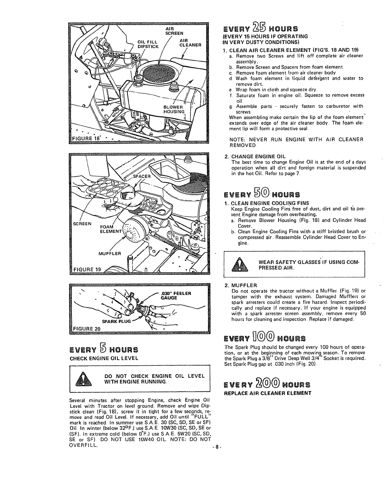
FIGURE 19
HOUSING
.ou.s
(EVERY 15 HOURS IF OPERATING
IN VERY DUSTY CONDITIONS)
1. CLEAN AIR CLEANER ELEMENT (FIG'S. 18 AND 19)
a, Remove two Screws and lift off complete air cteaner
assembly.
b. Remove Screen and Spacers from foam element
c, Remove foam element from air cleaner bqdy
d Wash foam element in liquid de_'er_ent and water to
remove dirt,
e. Wrap foam in cloth and squeeze dry,
f. Saturate foam in engine oiL. Squeeze to remove excess
g, Assemble parts -securely fasten to carburetor with
screws_
When assembling make certain the lip of the foam element'
extends over edge of the air cleaner body. The foam ele-
ment lip will form a protective seal
NOTE', NEVER RUN ENGINE WITH AIR CLEANER
REMOVED.
2,_ CHANGE ENGINE OIL
The best time to change Engine Oil is at the end of adays
operation when all dirt and foreign material is suspended
in the hot Oit_ Refer to page 7,
=vE.v .ou.s
1,. CLEAN ENGINE COOLING FINS
Keep Engine Cooling Fins free of dust, d_rt and oil t_ pre-
vent Engine damage from overheating,
a. Remove Blower Housing (Fig,, 18) and Cylinder Head
Cover_
b,_ Clean Engine Cooling Fins with a stiff brisded brush or
compressed air, Reassemble Cylinder Head Cover to En-
gine,
WEARSAFETYGLASSESUSINGCOM-
PRESSED AIR.
EVERY HOURS
CHECK ENGINE OIL LEVEL
DO NOT CHECK ENGINE OIL LEVEL
WITH ENGINE RUNNING,.
Several minutes after stopping Engine, check Engine Oit
Level with Tractor on tevel ground. Remove and wipe Dip-
stick ctean (Fig. 18), screw it in tight for afew seconds re-
move and read Oil Level. If necessary, add Oil until _ FULL
mark is reached, In summer use SA.E, 30 (SC, SD, SE or SF)
Oil In winter (below 32°F,) use S,A,E. t0W30 (SC, SD, SE or
(SF),. In extreme cold (below O=F,) use S.A.E, 5W20 (SC, SD,
SE or SF) DO NOT USE 10W40 OIL NOTE: DO NOT
OVERFILL,. -8-
2, MUFFLER
Do not operate the tractor without a Muffter (Fig, 19) or
tamper with the exhaust system., Damaged Mufflers or
spark arrestors could create afire hazard, Inspect periodi-
cally and replace if necessary_ if your engine is equipped
with aspark arrestor screen assembly, remove every 50
hours for cleaning and inspection, Replace if damaged,,
The Spark Plug should be changed every 100 hours of opera-
tion or at the beginning of each mowing season,.To remove
It /!
the Spark Plug a 3/8 Drive Deep Well 3/4 Socket is required,,
Set Spark Plug gap at 030 inch {Fig. 20)
=v=.v
REPLACE AIR CLEANER ELEMENT
A+S NEEDED:
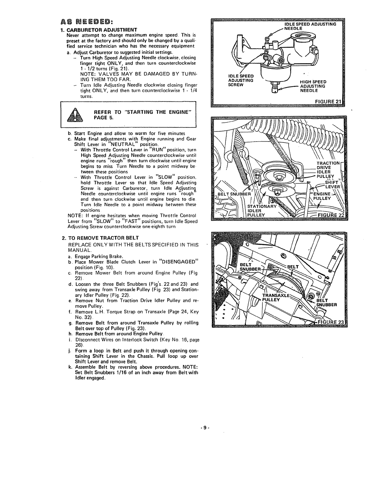
1+ CARBURETOR ADJUSTMENT
Never attempt to change maximum engine speed This is
preset at the factory and should only be changed by a quali-
fied service technician who has the necessary equipment
a. Adjust Carburetor to suggested initial Settings+
-- Turn High Speed Adjusting Needle clockwise, closing
finger tight ONLY, and then turn counterclockwise
I..1/2 turns (Fig. 21}_
NOTE: VALVES MAY BE DAMAGED BY TURN-
ING THEM TOO FAR,
-+ Turn Idle Adiusting Needle clockwise closing finger
tight ONLY, and then turn counterclockwise !+1/4
turns,,
REFER TO "STARTING THE ENGINE"
PAGE 5_
b. Start Engine and aliow to warm for five minutes
c. Make final adjustments with Engine running and Gear
Shift Lever in "NEUTRAL" position..
-- With Throttle Control Lever in ++RUN" position, turn
High Speed Adjusting Needle counterclockwise until
+ ii t! , , .
engine runs rough then turn clockwise unt+l end+no
begins to miss Turn Needle to a point midway be
tween these positions
With Throttle Control Lever in "SLOW ++position.
hold Throttle Lever so that Idle Speed Adiusting
Screw is against Carburetor, turn Idle Adjusting
Needle counterclockwise until engine runs "rough"
and then turn clockwise until engine begins to die
Turn Idle Needle to a point midway between these
positions
NOTE: tf engine hesitates when moving Throttle Control
Lever from "SLOW" to "FAST H positions, turn Idle Speed
Adjusting Screw counterclockwise one-eighth turn
2. TO REMOVE TRACTOR BELT
REPLACE ONLY WITH THE BELTS SPECIFIED IN THIS
MANUAL.
a,, Engage Parking Brake,
b, Place Mower Blade Clutch Lever in "DISENGAGED"
position (Fig,, 10)+
c, Remove Mower Belt from around Engine Pulley (Fig
22)
d+ Loosen the three Belt Snubbers (Fig's, 22 and 23) and
swing away from Transaxle Pulley (Fig, 23) and Station-
ary Idler Pulley (Fig, 22}+
e, Remove Nut from Traction Drive Idler Pulley and re,.
move Pulley,
f., Remove LH, Torque Strap on Transaxte (Page 24, Key
No, 32).
g+ Remove Belt from around Transaxle Pulley by rolling
Belt over top of Pulley (Fig. 23),,
h, Remove Belt from around Engine Pulley,
i, Disconnect Wires on Interlock Switch (Key No+ 16, page
26),
j+ Form aloop in Belt and push it through opening con+,
raining Shift Lever in the Chassis° Pull loop up over
Shift Lever and remove Belt.
k. Assemble Belt by reversing above procedures. NOTE:
Set Belt Snubbers 1/16 of an inch away from Belt with
Idler engaged+
IDLE SPEED ADJUSTING
•FIGURE 21
-9+
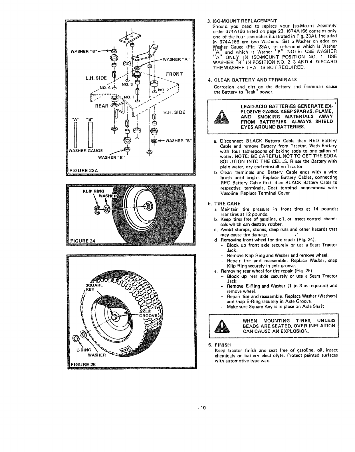
FIGURE 23A
SQUARE
E.RING
WASHER
FIGURE 25
3. ISO-MOUNT REPLACEMENT
Should you need to replace your Iso-Mount Assembly
order 674A166 listed on page 23, (674A166 contains only,,
one of the four assemblies illustrated in Fig,. 23AL Included
in 674A166 are two Washers,. Set a Washer on edge on
Washer Gauge (Fig 23A), to determine which is Washer
"A" and which is Washer "B". NOTE: USE WASHER
"A" ONLY IN tSO-MOUNT POSITION NO. 1. USE
WASHER "B" iN POSITION NO, 2,3 AND4 DISCARD
THE WASHER THAT IS NOT REQUIRED
4. CLEAN BATTERY AND TERMINALS
Corrosion and dirt on the Battery and Terminals cause
the Battery to "leak" power,,
LEAD-ACID BATTERIES GENERATE EX-
PLOSIVE GASES. KEEP SPARKS, FLAME,
AND SMOKING MATERIALS AWAY
FROM BATTERIES. ALWAYS SHIELD
EYES AROUND BATTERIES.
a Disconnect BLACK Battery Cable then RED Battery
Cable and remove Battery from Tractor. Wash Battery
with four tablespoons of baking soda to one gallon of
water, NOTE: BE CAREFUL NOT TO GET THE SODA
SOLUTION INTO THE CELLS. Rinse the Battery with
plain water, dry and reinstall on Tractor
b, Clean terminals and Battery Cable ends with a wire
brush until bright,. Replace Battery Cables. connecting
RED Battery Cable first, then BLACK Battery Cabte to
respective terminals° Coat terminal connections with
Vasofine, Replace Terminal Cover
5. TIRE CARE
aMaintain tire pressure in front tires at 14 pounds;
rear tires at 12 pounds,
bKeep tires free of gaso{ine, o11, or insect controt chemi-
cals which can destroy rubber
cAvoid stumps, stones, deep ruts and other hazards that
may cause tire damage, ,"
d. Removing front wheel for tire repair (Fig,. 24),
,.-Block up front axle securely or use aSears Tractor
Jack.
-,. Remove Klip Ring and Washer and remove wheel.
-- Repair tire and reassemble_ Replace Washer, snap
Klip Ring securely in axle groove.
e, Removing rear wheel for tire repair (Fig 25)
.,. Block up rear axle securely or use a Sears Tractor
Jack.
- Remove E, Ring and Washer (1 to 3as required} and
remove wheel,.
-- Repair tire and reassemble., Replace Washer (Washers)
and snap E,,Ring securely in Axle Groove,
-- Make sure Square Key is in place on Axle Shaft,
WHEN MOUNTING TIRES, UNLESS
BEADS ARE SEATED, OVER INFLATION
CAN CAUSE AN EXPLOSION.
6., FINISH
Keep tractor finish and seat free of gasoline, oit, insect
chemicals or battery e}ectrolvte Protect painted surfaces
with automotive type wax
-10-
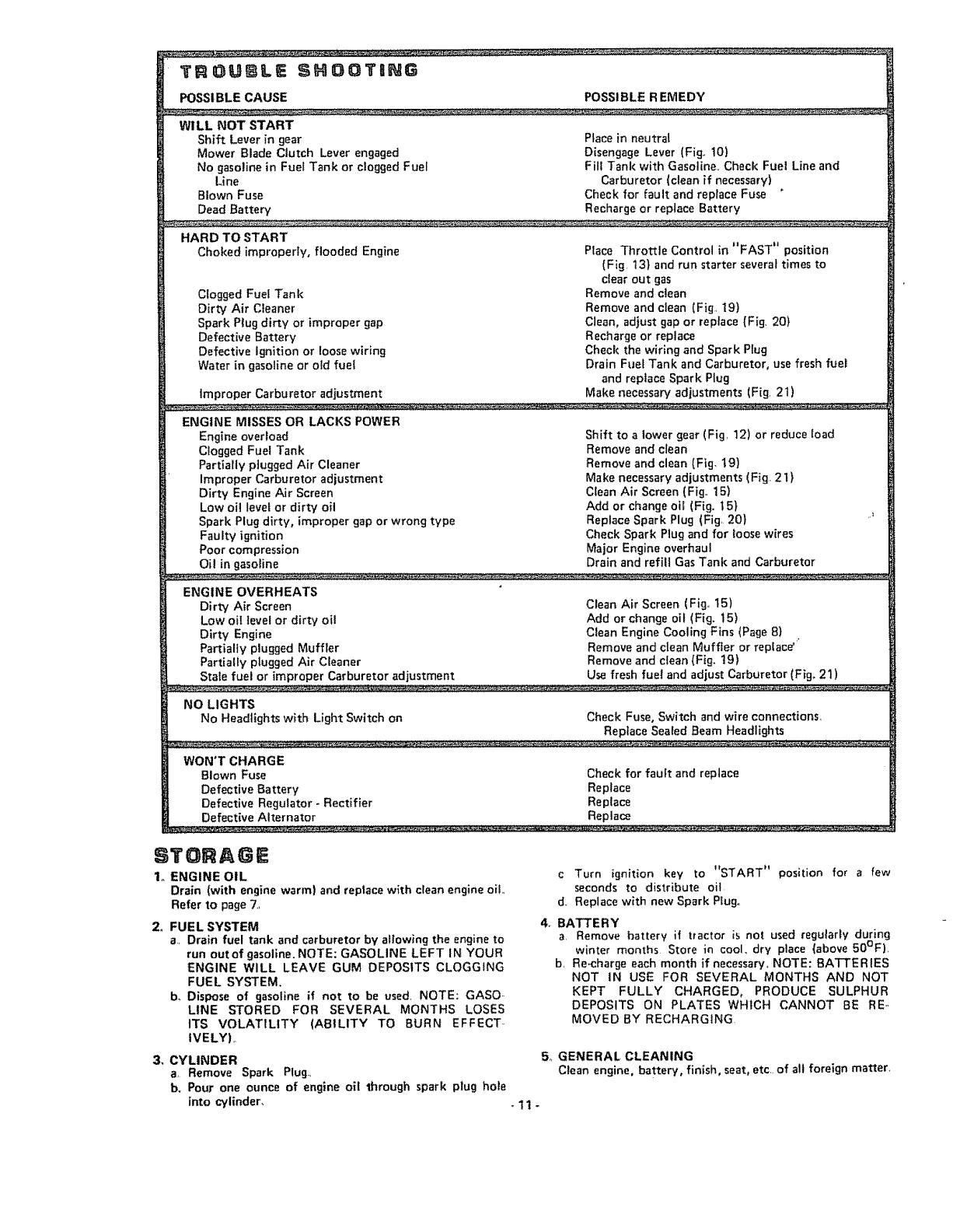
TROUBLE SHOOTaNG
POSSI BLE CAUSE POSSIBLE R EMEDY
WILL NOT START
Shift Lever in gear
Mower Blade Clutch Lever engaged
No gasoline in Fuel Tank or clogged Fuel
Line
Blown Fuse
Dead Battery
Place in neutral
Disengage Lever {Fig t0)
Fill Tank with Gasoline. Check Fuet Line and
Carburetor (clean if necessary1
Check for fault and replace Fuse
Recharge or replace Battery
HARD TO START
Choked improperly, flooded Engine
Clogged Fuel Tank
Dirty Air Cleaner
Spark P|ug dirty or improper gap
Defective Battery
Defective ignition or loose wiring
Water in gasoline or old fuel
improper Carburetor adjustment
Place Throttle Control in "FAST" position
(Fig 131 and run starter several times to
clear out gas
Remove and clean
Remove and clean (Fig 19)
Clean, adjust gap or replace (Fig, 20}
Recharge or replace
Check the wiring and Spark Plug
Drain Fuel Tank and Carburetor, use fresh fuet
and replace Spark Plug
Make necessary adjustments (Fig 21)
ENGINE MISSES OR LACKS POWER
Engine overload
Clogged Fuel Tank
Partially plugged Air Cleaner
Improper Carburetor adjustment
Dirty Engine Air Screen
Low oil level or dirty oil
Spark Plug dirty, improper gap or wrong type
Faulty ignition
Poor compression
Oil in gasoline
Shift to a lower gear (Fig 12) or reduce load
Remove and clean
Remove and clean (Fig, t9}
Make necessary adjustments (Fig 21)
Clean Air Screen (Fig 15)
Add or change oil (Fig. t51
Replace Spark Plug (Fig 201
Check Spark Ptug and for loose wires
Major Engine overhaul
Drain and refill Gas Tank and Carburetor
ENGINE OVERHEATS
Dirty Air Screen
Low oil level or dirty oil
Dirty Engine
Partially plugged Muffler
Partially plugged Air Cleaner
Stale fuel or improper Carburetor adjustment
Clean Air Screen (Fig, 15)
Add or change oil (Fig. 15)
Clean Engine Cooling Fins (Page 81
Remove and clean Muffler or replace'
Remove and clean (Fig_ 19)
Use fresh fuel and adjust Carburetor (Fig. 21)
NO LIGHTS
No Headlights with Light Switch on Check Fuse, Switch and wire connections
Replace Sealed Beam Headlights
WON'T CHARGE
Blown Fuse Check for fault and replace
Defective Battery Replace
Defective Regulator _Rectifier Replace
Defective Alternator Replace
ETORAGE
1. ENGINE OIL
Drain (with engine warm) and replace with clean engine oi!.,
Refer to page 7,
2. FUEL SYSTEM
a. Drain fuel tank and carburetor by allowing the engine to
run outof gasoline. NOTE: GASOLINE LEFT IN YOUR
ENGINE WILL LEAVE GUM DEPOSITS CLOGGING
FUEL SYSTEM,
b. Dispose of gasoline if not to be used. NOTE: GASO..
LINE STORED FOR SEVERAL MONTHS LOSES
ITS VOLATILITY (AStLITY TO BURN EFFECT..
tVELYI,.
3, CYLINDER
a, Remove Spark Plug.,
b. Pour one ounce of engine oil through spark plug hole
into cylinder,
cTurn ignition key to "START" position fo_ a few
seconds to distribute oil
d. Replace with new Spark Plugo
4, BATTERY
a, Remove battery if tractor is not used regularly during
winter months Store in cool. dry place (above 50°F),
b, Re-charge each month if necessary, NOTE: BATTERIES
NOT IN USE FOR SEVERAL MONTHS AND NOT
KEPT FULLY CHARGED, PRODUCE SULPHUR
DEPOSITS ON PLATES WHICH CANNOT BE RE-,
MOVED BY RECHARGING
5. GENERAL CLEANING
Clean engine, battery, finish, seat, etc, of all foreign matter,
-!1-
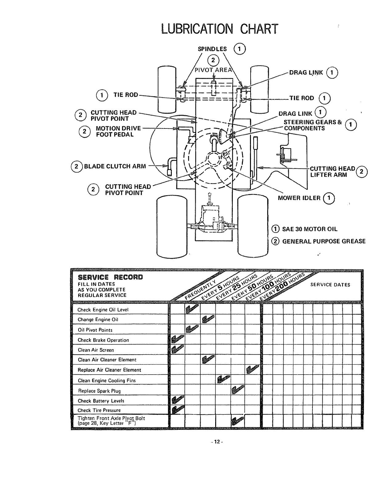
LUBRICATIONCHART
SPINDLES @
(_ TIE
(_ CUTTING HEAD --_--..._
PIVOT POINT
@ MOTION DRIVE .
v
't \ t"
TIE ROD @
DRAG LINK @
STEERING GEARS 8= 1/'_1
COMPONENTS
_"_ MOWER IDLER @ I
@SAE 30 MOTOR OIL
@GENERAL PURPOSE GREASE
SERVICE RECORD
FILL tN DATES
AS YOU COMPLETE
REGULAR SERVICE
SERVICE DATES
Check Engine OIlLevel ,
Change Engine Oil
OIl Pivot Points
.... ,,, , _ . _ ,,,
Check Brake Operation _iP
Clean Air Screen .......... _ ...........
Clean Air Cleaner Element _ ....
Replace Air Cleaner Element
Clean Engine Cooling Fins
Replace Spark Plug _!_
Check Battery Levels
Check '[ire Pres,_ure _l_ ]
Tighten Front Axle Pjyo_Bolt _ _ _i_I
o(pane28,KeyLe_e,'F") ......
12-
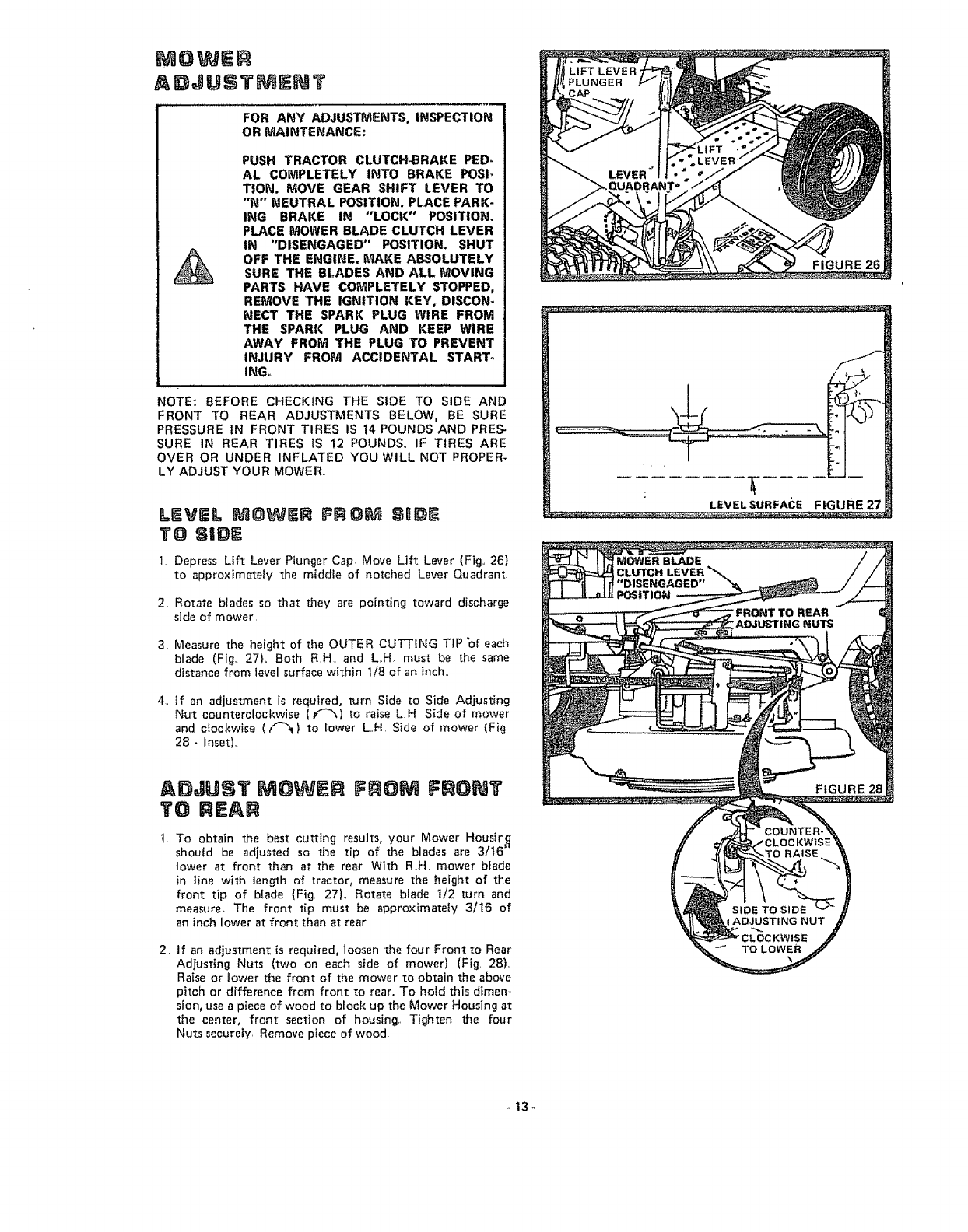
MOWER
AE)JUSTMENT
FOR AHY ADJUSTMENTS, INSPECTION
OR MAINTENANCE:
PUSH TRACTOR CLUTCH_RAKE PED_
AL COMPLETELY INTO BRAKE POSI-
TION. MOVE GEAR SHIFT LEVER TO
"N" NEUTRAL POSITIOtM, PLACE PARK-
ING BRAKE IN "LOCK" POSITION.
PLACE MOWER BLADE CLUTCH LEVER
IN "DISENGAGED" POSITION. SHUT
OFF THE ENGINE. MAKE ABSOLUTELY
SURE THE BLADES AND ALL MOVING
PARTS HAVE COMPLETELY STOPPED,
REMOVE THE IGNITION KEY, DISCON-
NECT THE SPARK PLUG WIRE FROM
THE SPAR|( PLUG AND KEEP WIRE
AWAY FROM THE PLUG TO PREVENT
INJURY FROM ACCIDENTAL STARTs
ING,,
NOTE: BEFORE CHECKING THE SIDE TO SIDE AND
FRONT TO REAR ADJUSTMENTS BELOW, BE SURE
PRESSURE IN FRONT TIRES IS 14 POUNDS AND PRES.
SURE IN REAR TIRES iS 12 POUNDS.. IF TIRES ARE
OVER OR UNDER INFLATED YOU WILL NOT PROPER-
LY ADJUST YOUR MOWER.
LEVEL MOWER FROM SBDE
TO SID
I Depress Lift Lever Plunger Cap Move Lift Lever (Fig. 26)
to approximate{y the middle of notched Lever Quadrant.
2 Rotate b{ades so that they are pointing toward discharge
side of mower.
3 Measure the height of the OUTER CUTTING TiP "of each
blade (Fig.. 27)° Both R.H and L,H. must be the same
distance from level surface within t/8 of an inch..
4. if an adjustment is required, turn Side to Side Adjusting
Nut counterclockwise ((-_) to raise LH. S_de of mower
and clockwise ( Y_} to Iower L.H Side of mower (Fig
28- Inset)..
AD,JUST MOWER FROM FRONT
TO REAR
t. To obtain the best cutting results, your Mower Housing
shouid be adjusted so the tip of the blades are 3/16"
lower at front than at the rear With R.H mower blade
in t{ne with tength of tractor, measure the height of the
front tip of blade (Fig. 27L Rotate blade t/2 turn and
measure, The front tip must be appro×imate{y 3/16 of
an inch lower at front than at rear
2 If an adjustment {s required, loosen the four Front to Rear
Adjusting Nuts (two on each side of mower) (Fig. 28}.
Raise or lower the front of the mower to obtain the above
pitch or difference from front to rear. To hold this d_men-
sion, use a piece of wood to block up the Mower Housing at
the center, front section of housing.. Tighten the four
Nuts securely. Remove piece of wood
-13-
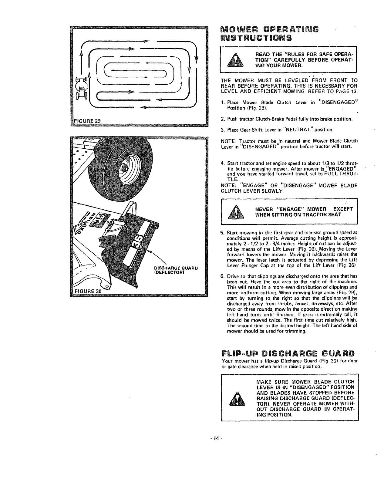
FIGURE 29
14÷
MOWER OPERATaNG
INSTRUCTmO S
READ THE "RULES FOR SAFE OPERA-
TION" CAREFULLY BEFORE OPERAT-
ING YOUR MOWER.
THE MOWER MUST BE LEVELED" FROM FRONT TO
REAR BEFORE OPERATING. THIS IS NECESSARY FOR
LEVEL AND EFFICIENT MOWING REFER TO PAGE 13,.
t,. Place Mower Blade Clutch Lever in "DISENGAGED '_
Position (Fig, 28)
2, Push tractor Clutch-Brake Pedal fully into brake position_
3, Place Gear Shift Lever in "NEUTRAL" position,,
NOTE: Tractor must be in neutra] and Mower Blade Clutch
Lever in "DISENGAGED" position before tractor will start,
4_ Start tractor and set engine speed to about 1/3 to 1/2 throt*
tie before engaging mower, After mower' is "ENGAGED"
and you have started forward travel, set to FULL THROT-
TLE
NOTE: '_ENGAGE" OR "DISENGAGE" MOWER BLADE
CLUTCH LEVER SLOWLY,
NEVER "ENGAGE" MOWER EXCEPTWHEN SITTING ON TRACTOR SEAT,
5_
6_
Start mowing in the first gear and increase ground speed as
conditions will permit. Average cutting height is appro×i _
mately 2,. 1/2 to 2 - 3/4 inches, Height of cut can be adjust-
ed by means of the Lift Lever (Fig 26), Moving the Lever
forward lowers the mower_ Moving it bdckwards raises the
mower. The lever latch is actuated by depressing the Lift
Lever Plunger Cap at the top of the Lift Lever (Fig, 26}_
Drive so that clippings are discharged onto the area that has
been cut,1 Have the cut area to the right of the machine.
This will result in amore even distribution of clippings and
more uniform cutting,, When mowing large areas _Fig. 29),
start by turning to the right so that the clippings witl .be
discharged away from shrubs, fences, driveways, etc, After
two or three rounds, mow in the opposite direction making
left hand turns until finished° If grass is extremely tall, it
should be mowed twice,, The first time cut relatively high,
The second time to the desired height= The left hand side of
mower should be used for trimming_
FLIP=UP D SCHARGE GUARD
Your mower has a flip-up Discharge Guard (Fig 30) for door
or gate clearance when held in raised position,,
MAKE SURE MOWER BLADE CLUTCH
LEVER IS IN "DISENGAGED" POSITION
AND BLADES HAVE STOPPED BEFORE
RAISING DISCHARGE GUARD (DEFLEC=
TORL NEVER OPERATE MOWER WITH-
OUT DISCHARGE GUARD IN OPERAT-
iNG POSITION,.
MOWER MAUNTENANCE
QNSTRUCTg@NS
FOR ANY ADJUSTMENTS, INSPECTION
OR MAINTENANCE:
PUSH TRACTOR CLUTCH-BRAKE PED-
AL COMPLETELY INTO BRAKE POSI-
TION. PLACE PARKING BRAKE IN
"LOCK" POSITION. MOVE GEAR SHIFT
LEVER TO "NEUTRAL" POSITION,
PLACE MOWER BLADE CLUTCH LEVER
IN "DISENGAGED" POSITION. TURN
IGNITION KEY TO "OFF" POSITION,
MAKE ABSOLUTELY SURE THE
BLADES AND ALL MOVING PARTS
HAVE COMPLETELY STOPPED,_ RE-
MOVE THE IGNITION KEY, DISCON-
NECT THE SPARK PLUG WIRE FROM
THE SPARK PLUG AND KEEP WIRE
AWAY FROM THE PLUG TO PREVENT
INJURY FROM ACCIDENTAL START-
ING°
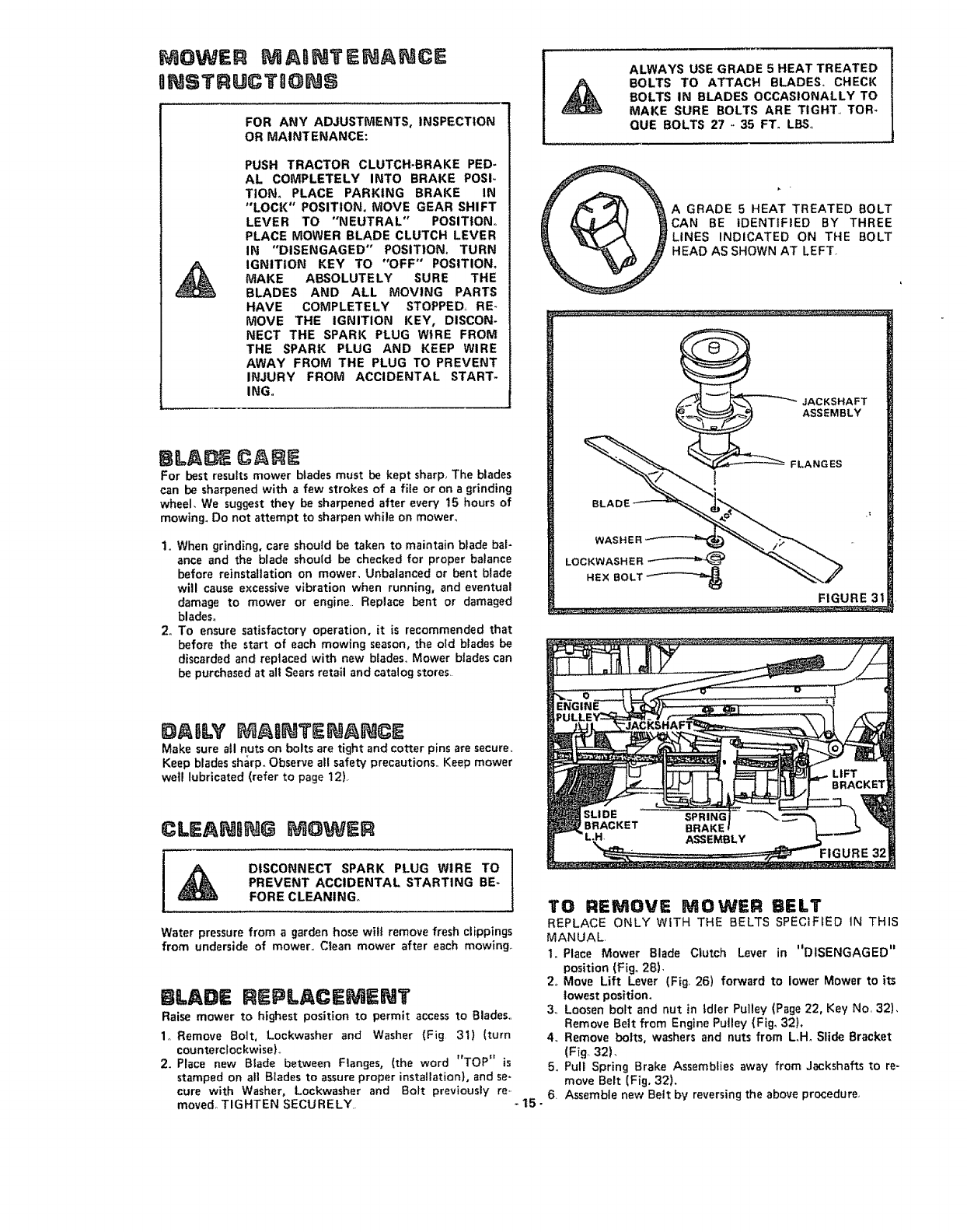
BLA CALVE
For best results mower blades must be kept sharp. The blades
can be sharpened with afew strokes of a file or on a grinding
wheel, We suggest they be sharpened after every t5 hours of
mowing. Do not attempt to sharpen while on mower,
1o When grinding, care should be taken to maintain blade bal-
ance and the blade should be checked for proper balance
before reinstaltation on mower_ Unbalanced or bent blade
will cause excessive vibration when running, and eventual
damage to mower or engine_ Replace bent or damaged
blades°
2. To ensure satisfactory operation, it is recommended that
before the start of each mowing season, the old blades be
discarded and replaced with new blades, Mower blades can
be purchased at all Sears retail and catalog stores
ALWAYS USE GRADE 5 HEAT TREATED
BOLTS TO ATTACH BLADES, CHECK
BOLTS IN BLADES OCCASIONALLY TO
MAKE SURE BOLTS ARE TIGHT TOR-
QUE BOLTS 27 ,. 35 FT. LBS,
A GRADE 5 HEAT TREATED BOLT
CAN BE IDENTIFIED BY THREE
LINES INDICATED ON THE BOLT
HEAD AS SHOWN AT LEFT.
DABI.Y I&BNTENANCE
Make sure all nuts on bolts are tight and cotter pins are secure,
Keep blades sharpoObserve all safety precautions Keep mower
well lubricated (refer to page 12)
CLEANI; G MC)WER
IDISCONNECT SPARK PLUG WIRE TO
PREVENT ACCIDENTAL STARTING BE-
FORE CLEANING_
Water pressure from a garden hose wilt remove fresh clippings
from underside of mower, Clean mower after each mowing_
BLAI E REPLACEMENT
Raise mower to highest position to permit access to Blades,
1o Remove Bolt, Lockwasher and Washer (Fig 31) (turn
counterclockwise),
2. Place new Blade between Flanges, (the word "TOP" is
stamped on atl Blades to assure proper installation), and se-
cure with Washer, Lockwasher and Bolt previously re..
moved, TIGHTEN SECURELY. -15-
TO REMOVE MOWER BELT
REPLACE ONLY WITH THE BELTS SPECIFIED tN THIS
MANUAL
1, Place Mower Blade Clutch Lever in '=DISENGAGED"
position (Fig, 28),
2, Move Lift Lever (Fig_ 26) forward to lower Mower to its
lowest positiom
3_ Loosen bolt and nut in tdler Pulley (Page 22, Key No 32),
Remove Bett from Engine Putley (Fig. 32),
4_ Remove bolts, washers and nuts from LoHoSlide Bracket
(Fig, 32).
5,, Pull Spring Brake Assemblies away from Jackshafts to re-
move Belt (Fig. 32),
6 Assemble new Belt by reversing the above procedure,
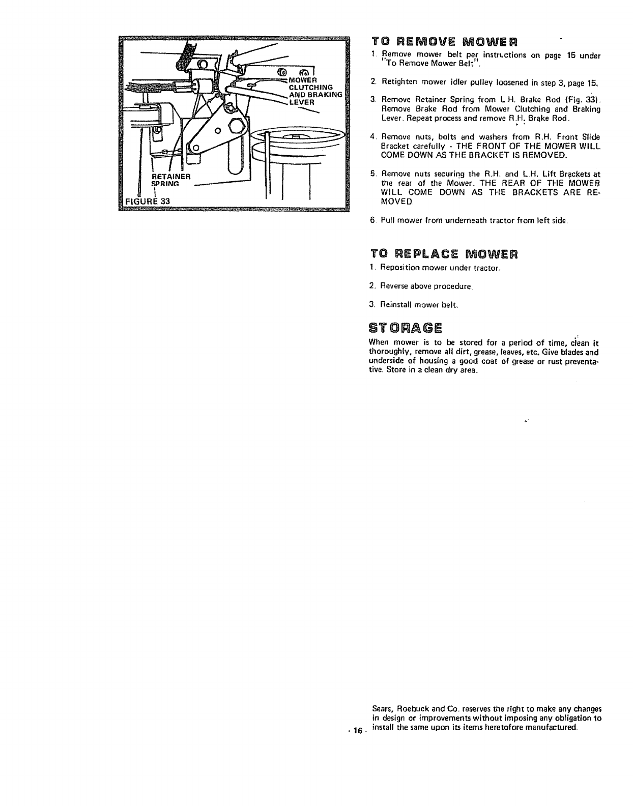
TO REMOVE MOWER
1. Remove mower belt per instructions on page 15 under
"To Remove Mower Belt",,
2, Retighten mower idler pulley loosened in step 3, page 15,,
3, Remove Retainer Spring from LH, Brake Rod {Fig, 33),,
Remove Brake Rod from Mower Clutching and Braking
Lever, Repeat process and remove R,H. Brake Rod,,
4,
5,
Remove nuts, bolts and washers from R,H, Front Slide
Bracket carefully -THE FRONT OF THE MOWER WILL
COME DOWN AS THE BRACKET IS REMOVED_
Remove nuts securing the R,,H, and L H, Lift Brackets at
the rear of the Mower_ THE REAR OF THE MOWEI_I
WILL COME DOWN AS THE BRACKETS ARE RE-
MOVED,
6 Pull mower from underneath tractor from left side,
TO REPLACE MOWER
t, Reposition mower under tractor,,
2, Reverse above procedure_
3_ Reinstall mower belt.,
STORAGE
When mower is to be stored for a period of time, clean it
thoroughly, remove all dirt. grease, leaves, etc, Give bladesand
underside of housing agood coat of grease or rust preventa-
tive, Store in a clean dry area.
Sears, Roebuck and Co,. reserves the right to make any changes
in design or improvements without imposing any obligation to
-16 -install the same upon its items heretofore manufactured,,
EP Sn PA TS
SEARS LAWN TRACTOR--MODEL NUMBER 917o255275
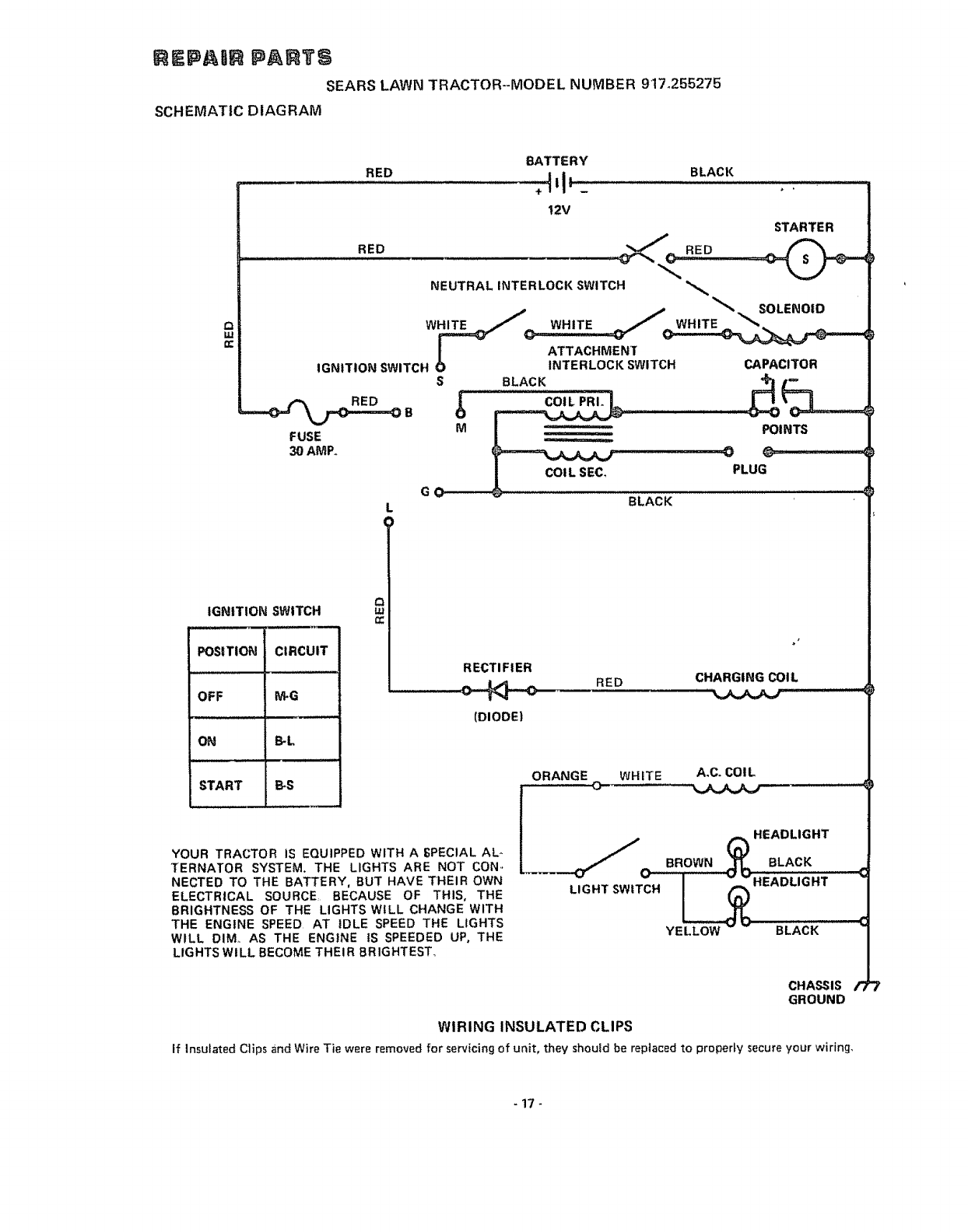
SCHEMATIC DIAGRAM
==
RED BATTERY
÷:tl"
t2V
RED
BLACK
RED
STARTER
NEUTRAL INTERLOCK SWITCH
IGNITION SWITCH O
FUSE
30 AMP.
SOLENOID
WHITE
ATTACHMENT
INTERLOCK SWITCH
G
M
BLACK
COIL PRI.
COIL SEC,
BLACK
CAPACITOR
POINTS
PLUG
IGNITION SWITCH
POSITION CIRCUIT
OFF _G
ON B-L
START B*S
n,,
RECTIFIER
(DIODE)
RED CHARGING COIL
',,.=.j_,,,_,AJ
ORANGE WHITE A,C. COIL
O
YOUR TRACTOR IS EQUIPPED WITH A _PECIAL AL-
TERNATOR SYSTEM, THE LIGHTS ARE NOT CON,
NECTED TO THE BATTERY, BUT HAVE THEIR OWN
ELECTRICAL SOURCE, BECAUSE OF THIS, THE
BRIGHTNESS OF THE LIGHTS WILL CHANGE WITH
THE ENGINE SPEED AT IDLE SPEED THE LIGHTS
WILL DIM, AS THE ENGINE tS SPEEDED UP, THE
LIGHTSWlLL BECOME THEIR BRIGHTEST_
LIGHT SWITCH _HEADLIGHT
YELLOW - -
CHASSIS /')
GROUND
WIRING INSULATED CLIPS
If Insulated Clips andWire Tie were removedfor servicing of unit, they should be replaced to properly secureyour wiring,
-17_
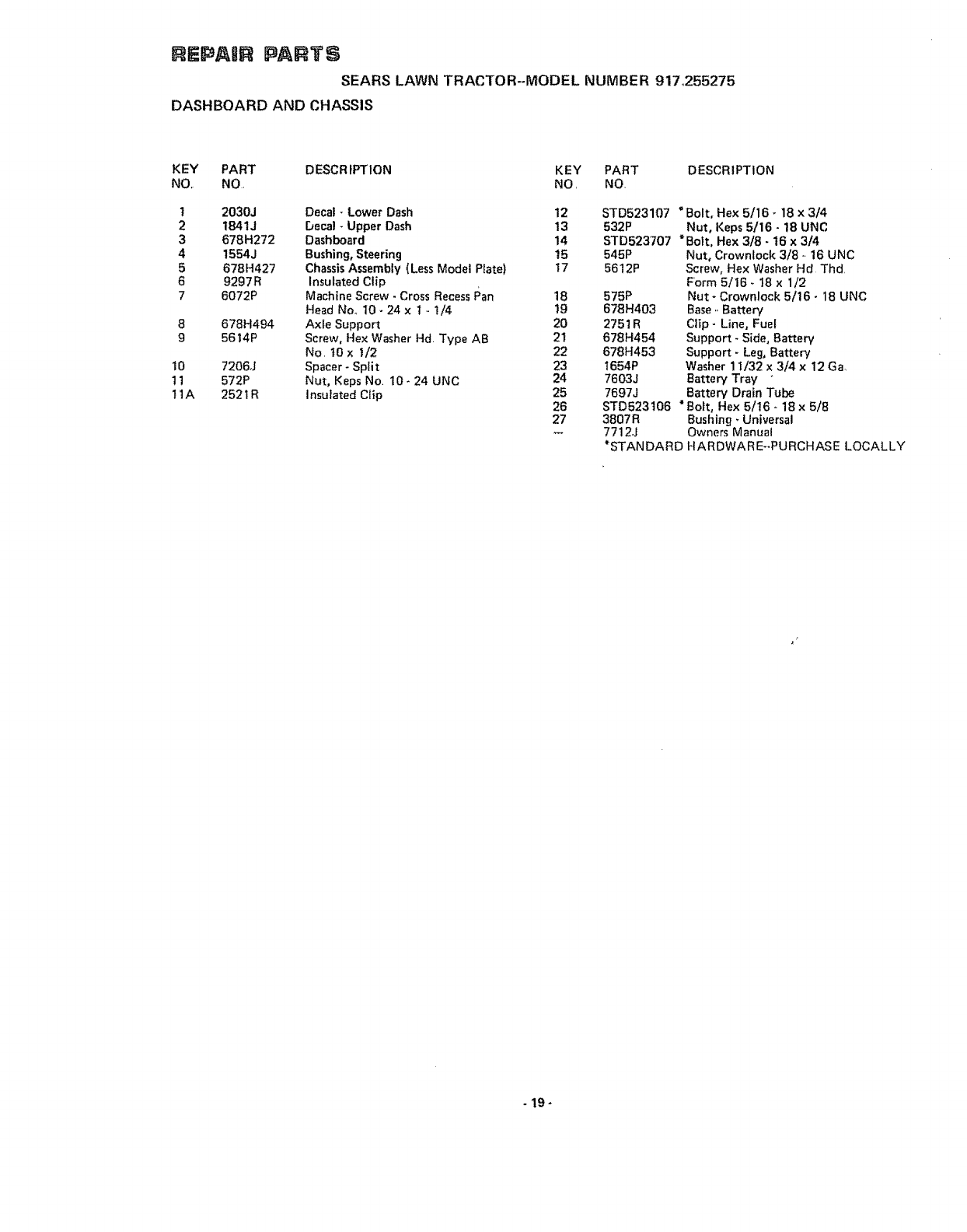
nEPASR PAIffTS
SEARS LAWN TRACTOR--MODEL NUMBER 917:255275
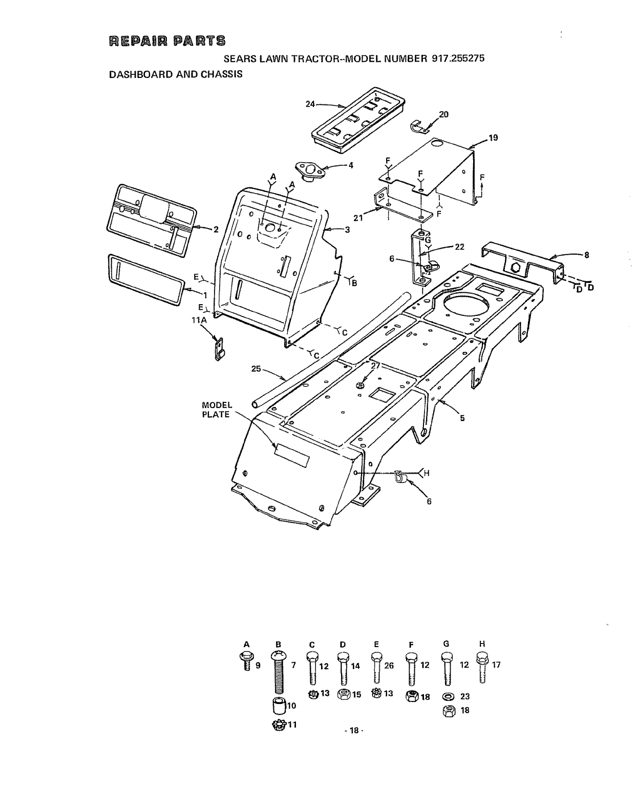
DASHBOARD AND CHASSIS
A
21
o
11A
MODEL
PLATE
A B C D E F G H
i_12 _{_14 t_26 _12 _ 12 _
_13 ®is @13 _18 _23
-18-
17
REPASR PARTS
SEARS LAWN TRACTOR--MODEL NUMBER 917_255275
DASHBOARD AND CHASSIS
KEY PART DESCRIPTION KEY PART DESCRIPTION
NO, NO NO NO
t
2
3
4
5
6
7
8
9
10
11
11A
2030J Decal -Lower Dash 12
t841J be_l - Upper Dash 13
678H272 Dashboard 14
1554J Bushing, Steering 15
678H427 ChassisAssembly (Less Model Plate) 17
9297R Insulated Clip
6072P Machine Screw- Cross RecessPan 18
Head Noo 10- 24 x 1 - 1/4 19
678H494 Axle Support 20
5614P Screw, Hex Washer Hd Type AB 21
No t0 x t/2 22
7206J Spacer- Split 23
572P Nut, Keps No 10- 24 UNC 24
2521R Insulated Clip 25
26
27
STD523107 "Bolt, Hex 5/16- 18 x 3/4
532P Nut, Keps 5116- 18 UNC
STD523707 "Bolt, Hex 3/8 - 16 x 3/4
545P Nut, Crowntock 3/8 - 16 UNC
5612P Screw, Hex Washer Hd Thd
Form 5/16 - 18 x 1/2
575P Nut - Crownlock 5/16- 18 UNC
678H403 Base,,Battery
2751R Clip- Line, Fuel
678H454 Support - Side, Battery
678H453 Support- Leg, Battery
1654P Washer 11/32 x 3/4 x 12 Ga,
7603J Battery Tray
7697J Battery Drain Tube
STD523t06 "Boil, Hex 5/16- 18x 5/8
3807R Bushing, Universal
7712J Owners Manual
*STANDARD HARDWARE-PURCHASE LOCALLY
-19-
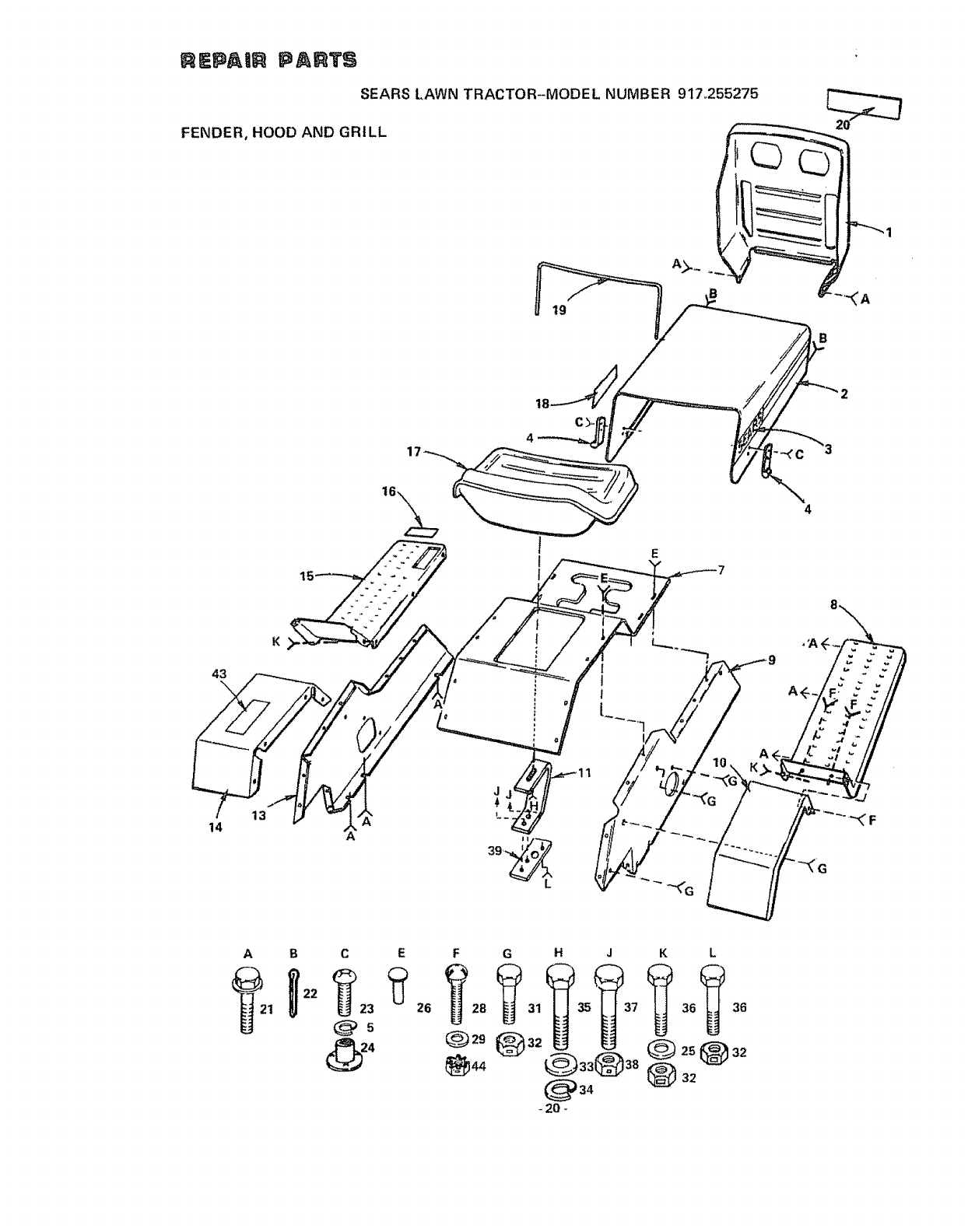
_EPAi_ PARTS
SEARS LAWN TRACTOR--MODEL NUMBER 917o255275
FENDER, HOOD AND GRILL r _...JLj
t9
B
A B C E
_g_5
@,
26
F G H J K L
@_o@=, @_=@==
- 20 -
RKPA R nTS
SEARS LAWN TRACTOR--MODEL NUMBER 91"7.255275
FENDER, HOOD AND GRILL
KEY PART DESCRIPTION KEY PART DESCRIPTION
NO NO NO NO
I 67BH149 Grill 23
2 677H83 Hood Assembty
3 4500J Decal -.Hood, R H 24
4 8889R Rubber Hood Latch 25
5 STD5511 t0 "Lockwasher No 10 Heavy 26
7 677A605 Top Panel with Silk Screen 28
8 677H94 Foot Rest- RH
9 678H275 Side Panel -R H 29
10 677H704 Fender- R.H 3t
11 677H950 Spring Sea_ 32
t3 678H276 Side Panel -LH. 33
14 677H705 Fender- LH 34
15 678H47t Foot Rest. L H.. 35
16 9596R Decal -Brake, Clutch 36
17 t496J Seat 37
t8 450tj Decal -Hood, L H 38
t9 8937R Hood Strip 39
20 2893J Decal .. Grill 43
21 5612P Screw, Hex Washer Hd Thrd Form 44
5/16- 18 x !/2
22 STD560907 *Cotter Pin 3/32 x 3/4
STD511005
2029J
1599P
2015P
66P
1507P
3008P
575P
1661P
STD551t50
*Screw, Machine Cross Recess Pan Hd
No. 10 - 24 x 1/2
Nut, Weld
Washer 11/32 x 3/4 x t6 Ga
Pop Rivet
Bolt, Carriage Short Shoutder 1/4 - 28
x t/2 Gr 5
Washer 9/32 x 3/4 x 16 Ga
Bolt, Hex 5/16 o 18 x 1/2
Nut, Crownlock 5/16 -t8 UNC
Washer 17/32 x I .. 3/16 x 12 Ga.
" Lockwasher, Spring 1/2
STD525010 "Bolt, Hex 1/2 .. t3 x 1
STD523107 "Bolt, Hex 5/16 -.18 x 3/4
STD523710 "Bolt, Hex 3/6 .. _6 x 1
545P Nut, Crownlock 3/8 - 16 UNC
678H456 Washer - Seat
664 tJ Label - Fact, Warranty
531P Nut- Keps t/4 - 20 UNC
*STANDARD HARDWARE--PURCHASE LOCALLY
-21 o
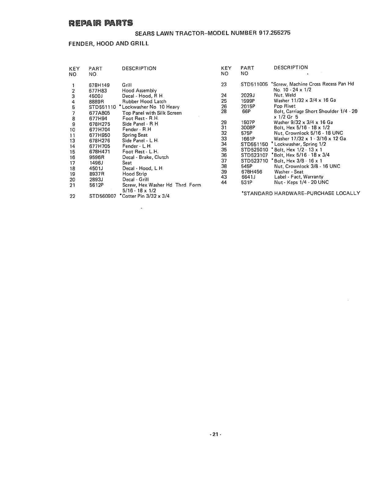
REPAIR PANTS
SEARS LAWN TRACTOR-MODEL NUMBER 917.255275
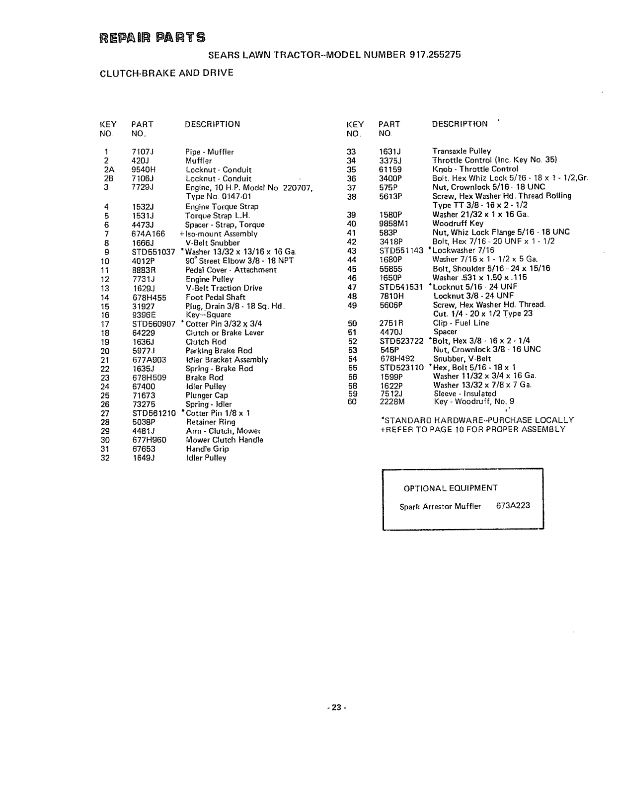
CLUTCH-BRAKE AND DRIVE
59
25
27 29
30 27
'° 7
40
A B D E F G
36 38 42 45 49
_41 @43 _46
J K
_52 I 55
_'_ 53 _) 56
_'_ 37
-22 -
mEPAUm PARTS
SEARS LAWN TRACTOR--MODEL NUMBER 917,255275
CLUTCH-BRAKE AND DRIVE
KEY PART DESCRIPTION KEY PART
NO NO., NO, NO
1
2
2A
2B
3
4
5
6
7
8
9
10
11
12
13
t4
I5
16
17
18
19
2O
21
22
23
24
25
26
27
28
29
30
31
32
7t07J Pipe - Muffler 33 1631J
420J Muffler 34 3375J
9540H Locknut - Conduit 35 61159
7106J Locknut - Conduit 36 3400P
7729J Engine, t0 HP+ Model No+ 220707, 37 575P
Type No. 0147-O1 38 5613P
1532J Engine Torque Strap
1531J Torque Strap L+H.+ 39 1580P
4473J Spacer - Strap, Torque 40 9858M1
674AI66 +tso+mount Assembly 4t 583P
1666J V+gelt Snubber 42 3418P
STD551037 *Washer 13/32 x 13/16 x 16 Ga 43
4012P 90 ° Street Elbow 3/8- 18 NPT 44
8883R Pedal Cover- Attachment 45
7731J Engine Pulley 46
t 629J V+Belt Traction Drive 47
678H455 Foot Pedal Shaft 48
31927 Plug,,Drain 3/8 + 18 Sq_ Hd+ 49
9396E Key_Square
STD560907 "Cotter Pin 3/32 _; 3/4
64229 Clutch or Brake Lever
1636J Clutch Rod
5977J Parking Brake Rod
677A903 Idler Bracket Assembly
1635J Spring +Brake Rod
678H509 Brake Rod
67400 ldter Pulley
71673 Plunger Cap
73275 Spring- Idler
STD561210 *Cotter Pin 1/8 x t
5038P Retainer Ring
4481J Arm - Clutch, Mower
677H960 Mower Clutch Handle
67653 Handle Grip
1649J Idler Pulley
5O
51
52
53
54
55
56
58
59
60
DESCRIPTION
Transaxle Pulley
Throttle Control {lnc. Key No, 35)
Knob +Throttle Control
Bolt. Hex Whiz Lock 5/16 +18 x t - ti2.Gr+
Nut, Crownlock 5/16., 18 UNC
Screw, Hex Washer Hd., Thread Rolling
Type TT 3/8 - 16 x 2 + 1/2
Washer 21/32 x 1 x 16 Ga,
Woodruff Key
Nut, Whiz Lock Flange 5/16 +18 UNC
Bolt, Hex 7/16 + 20 UNF x 1 - 1/2
STD55t143 *Lockwasher 7/16
t680P Washer 7/16 x 1 + 1/2 x 5 Ga.
55855 Bolt, Shoulder 5/16 .. 24 x 15/16
t650P Washer .531 x 1.50 x +115
STD54153t *Loeknut 5/16- 24 UNF
7810H Locknut 3/8+ 24 UNF
5606P Screw, Hex Washer Hd.,Thread+
CuL 1/4+ 20 x 1/2 Type 23
2751R Clip +Fuel Line
4470J Spacer
STD523722 *Bolt, Hex 3/8 .+16 x 2 +1/4
545P Nut, Crownlock 3/8- 16 UNC
678H492 Snubber, V-Belt
STD5231t0 *Hex, Bolt 5/16 +18 x i
1599P Washer 11/32 x 3/4 x 16 Ga,
t622P Washer 13/32 x 7/8 x 7 Ga.
75 t2J Sleeve - Insulated
2228M Key -Woodruff, No, 9
*STANDARD HARDWARE-PURCHASE LOCALLY
+REFER TO PAGE 10 FOR PROPER ASSEMBLY
OPTIONAL EQUIPMENT
Spark Arrestor Muffler 673A223
+23 +
_KPAU R PAn T S
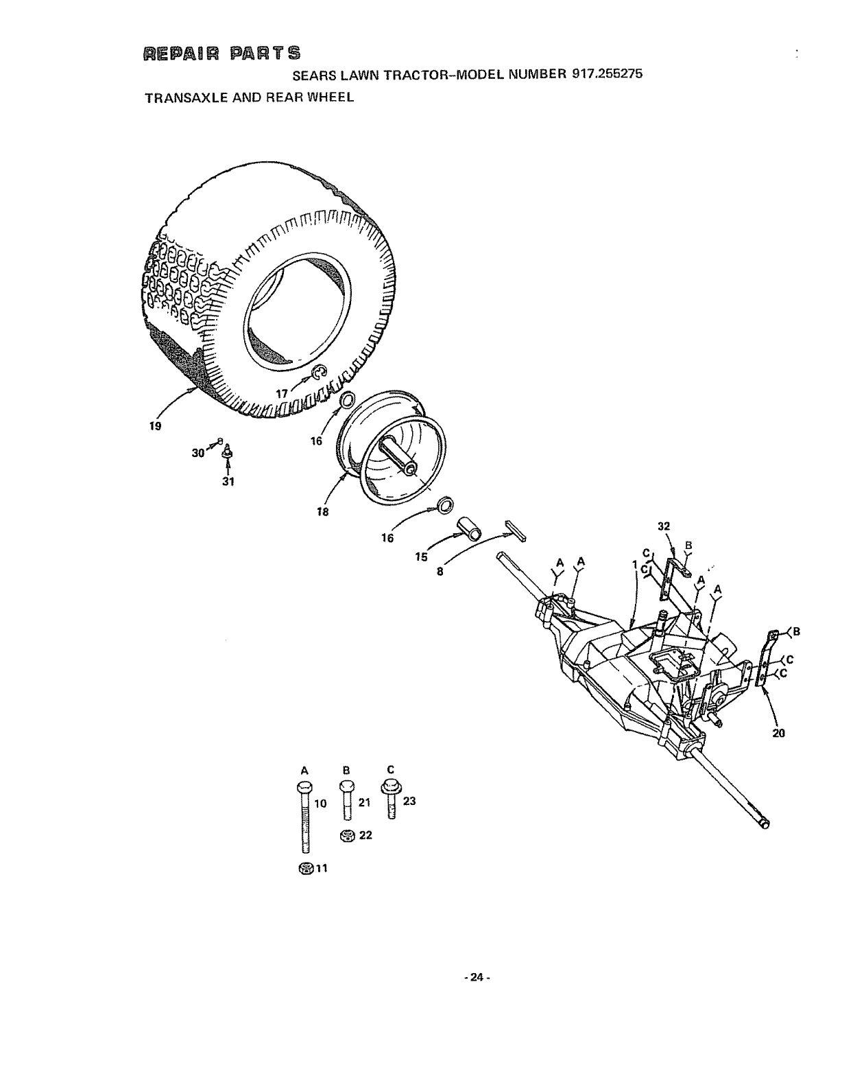
SEARS LAWN TRACTOR-MODEL NUMBER 917,255275
TRANSAXLE AND REAR WHEEL
/
19
31
16
18
16
B C
22
8
32
-24_
EPAUR PARTS
SEARS LAWN TRACTOR--MODEL NUMBER
TRANSAXLE AND REAR WHEEL,
917.255275
KEY PART DESCRIPTION KEY PART
NQ NO, NO_ NO.
8
10
11
15
16
17
18
677A302 Transaxle Assembfy Model No 4010,6 19
(See Pages 32 & 33 for Breakdown of 20
Parts) 21
2703J Key, Square 3/t6 x 2 22
STD523727 *Bolt, Hex 3/8 _ 16 x 2 _.3/4 23
545P Nut, Crownfock 3/8- 16 UNC
29353 Wheel Spacer 30
1552P Washer 25/32 x t ,. 1/4 x 16 Ga.. 3t
(2 to 6 as required) 32
5000P E-Ring
71652 Rim Assembly - Rear 8"
DESCRIPTION
3716J Tire., Soft Trac 18 x 9,50 -8
678H505 Strap, Torque -R,,H,
STD523107 "Bolt, Hex 5/16 - 18 x 3/4
575P Nut, Crownlock 5/16 _ t8 UNC
5620P Screw, Hex Washer Hd Thread Form
5/16- 18 x 3/4
59192 Valve Cap
65139 Valve Stem
678H504 Strap, Torque - LH
"STANDARD HARDWARE-PURCHASE LOCALLY
_25 -
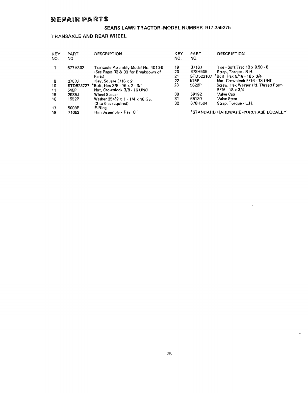
REPAmR PARTE
SEARS LAWN TRACTOR--MODEL NUMBER 917,255275
ELECTRICAL !..A 1
2p
F
47
25
25
41,,
11
35
15
16
A
29
3O
B C D E F G H
31 32 33 _36
,1_22
-26 -
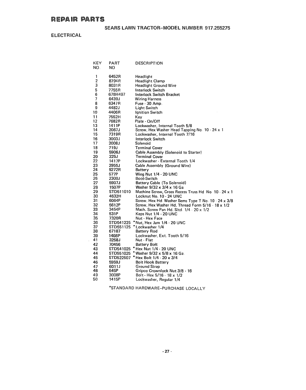
EPABR PARTS
SEARS LAWN TRACTOR-MODEL NUMBER 917o255275
ELECTRICAL
KEY PART DESCRIPTION
NO, NO
1 6452R
2 8794R
3 8031R
5 7755R
6 678H497
7 6439J
8 6347 R
94482J
10 4406R
11 7552H
12 7682R
13 t411P
14 2067J
15 7319R
t6 3003J
17 2008J
18 7t9J
19 5906J
20 225J
22 1417P
23 2955J
24 9272R
25 577P
26 2300J
27 5907J
28 t507P
29 STD511010
30 4632H
31 6064P
32 5612P
33 3454P
34 531P
35 7320R
36 STD541225
37 STD551t25
38 67187
39 1408P
4t 3258J
42 70456
43
44
45
46
47
48
49
5O
Headlight
Headlight Clamp
Headlight Ground Wire
Inter!ock Switch
Interlock Switch Bracket
Wiring Harness
Fuse - 30 Amp,
Light Switch
Ignition Switch
Key
Plate - On/Off
Lockwasher, Internal Tooth 5/8
Screw, Hex Washer Head Tapping No. 10- 24 x t
Lockwasher, Internal Tooth 7/16
Interlock Switch
Solenoid
Terminal Cover
Cable Assembly (Solenoid to Starter)
Terminal Cover
Lockwasher - External Tooth 1/4
Cable Assembly (Ground Wire)
Battery
Wing Nut 1/4 - 20 UNC
Boot-Switch
Battery Cable (To Solenoid)
Washer 9/32 x 3/4 x 16 Ga
Machine Screw, Cross Recess Truss Hd No 10.124 x 1
Locknut No., 10 - 24 UNC
Screw. Hex Hd Washer Seres Type T No, 10 -24 x 3/8
Screw, Hex Washer Hd. Thread Form 5/16 ,, I8 x 1/2
Mach, Screw Pan Hd., Sltd, 1/4., 20 x 1/2
Keps Nut 1/4 - 20 UNC
Nut - Hex Face
* Nut, Hex ,Jam 1/4 -,20 UNC
"Lockwasher 1/4
Battery Rod
Lockwasher, Ext., Tooth 5/16
Nut- Flat
Battery Bo-It
STD541025 * Hex Nut 1/4 -20 UNC
STD551025 * Washer 9/32 x 5/8 x 16 Ga,
STD522507 * Hex Bolt 1/4 - 20 x 3/4
5959J Bolt Hook Battery
601 tJ Ground Strap
545P G ripco Crownlock Nut 3/8 - 16
3008P Bolt - Hex 5/16 - 18 x t/2
!415P Lockwasher, Regular 1/4
*STANDARD HARDWAREs-PURCHASE LOCALLY
- 27
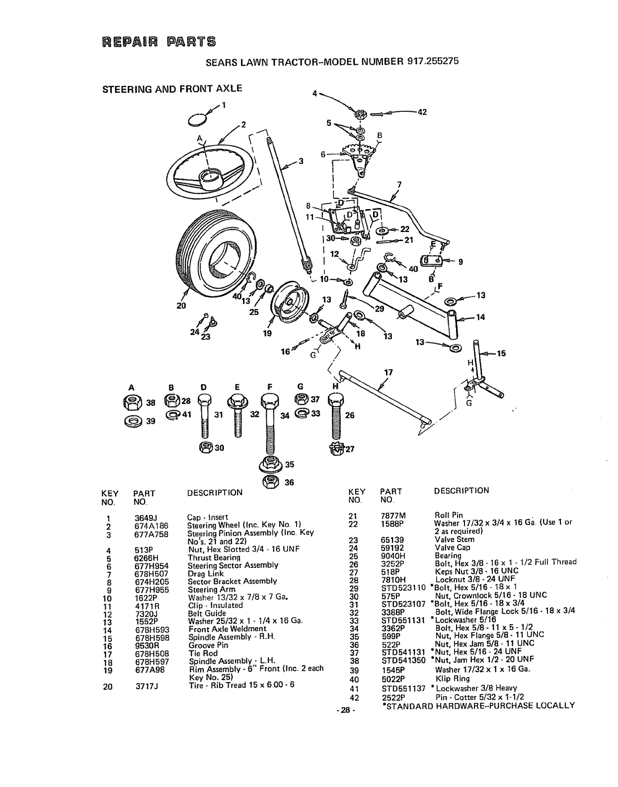
REPAI PARTS
SEARS LAWN TRACTOR-MODEL NUMBER 917o255275
STEERING AND FRONT AXLE
A
_42
A
Q 3g
KEY
NO,
1
2
3
4
5
6
7
8
9
10
11
12
13
t4
t5
16
17
18
19
20
PART
NO
3649J
674A186
677A758
513P
6266H
677H954
678H507
674H205
677H955
1622P
4171R
7320J
1552P
678H593
678H 598
9530R
678H508
678H597
677A98
3717J
2O 25
24_2€ 19
B O E
(_p 41 31
DESCR IPTtON
Cap -insert
Steering Wheel (Inc, Key No, 1}
Steering Pinion Assembly (lnc, Key
No'so 21 and 22)
Nut. Hex Slotted 3/4 - 16 UNF
Thrust Bearing
Steering Sector Assembly
Drag Link
Sector Bracket Assembly
Steering Arm
Washer 13/32 x 7/8 x 7 Ga.
Clip - Insulated
Belt Guide
Washer 25/32 x I .. I/4 x 16 Ga,,
Front Axle Weldment
Spindle Assembly - R.H,
Groove Pin
Tie Rod
Spindle Assembly -LH.
Rim Assembly -B" Front (_nc,_2each
Key No. 25)
Tire -Rib Tread 15 x 600 -6
21
22
23
24
25
26
27
28
29
30
31
32
33
34
35
36
37
38
39
40
4t
42
-2B=
7877M Roll Pin
1588P Washer 17/32 x 3/4 xt6 Ga (Use t or
2as required)
65139 Valve Stem
59192 Valve Cap
9040H Bearing
3252P Bolt, Hex 3/8- 16 x 1 - 1/2 Full Thread
518P Keps Nut 3/8- 16 UNC
7810H Locknut 3/8.24 UNF
STD523110 *Bolt, Hex 5/16 - 18 x t
575P Nut, Crowntock 5116- 18 UNC
STD523107 "Bolt, He)( 5/16 - 18 x 3/4
3388P Bolt, Wide Flange Lock 5/16- 18 x 3/4
STD551131 "Lockwasher 5/16
3362P Bott. Hex 5/8- II x 5- 1/2
599P Nut, Hex Flange 5/8- 1t UNC
522P Nut, Hex Jam 5/8. 11 UNC
STD541t31 "Nut, Hex 5/16 .. 24 UNF
STD541350 *Nut, Jam Hex 1/2- 20 UNF
1545P Washer 17/32 x I x t6 Ga_
5022P Klip Ring
STD551137 * Lockwasher 3/8 Heavy
2522P Pin -Cotter 5/32 x 1,.1/2
"STANDARD HARDWARE-PURCHASE LOCALLY
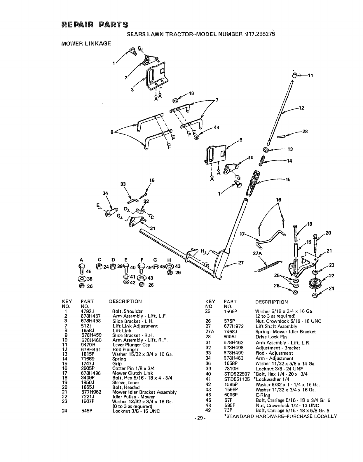
REPAUn PARTS
SEARS LAWN TRACTOR--MODEL NUMBER 917.255275
MOWER LINKAGE
12
28
KEY
NQ
1
2
3
7
8
9
10
11
12
13
14
15
16
17
18
19
20
21
22
23
24
A
26
C D E F G H
Uu_26
@41Q43
_42 _ 26
PART
NO,
4792J
678H457
678H458
512J
1658J
678H459
678H460
9479R
678H46
1615P
71669
1747J
2505P
678H496
3409P
1850J
t665J
677H962
7221J
1507P
545P
DESCRIPTION
Bolt, Shoulder
Arm Assembly - Lift, LoF,
Slide Bracket ,, L H,
Lift Link Adjustment
Lift Link
Slide Bracket -R,H.
Arm Assembly - Lift, RF
Lever Plunger Cap
Rod Plunger
Washer 15/32 x 3/4 x 16 Ga,
Spring
Grip
Cotter Pin 1/8 x3/4
Mower Clutch Link
Bolt, Hex 5/16 -18 x 4 - 3/4
Sleeve, Inner
Bolt, Headed
Mower Idler Bracket Assembly
Idler Pulley - Mower
Washer !3/32 x 3/4 x 16 Ga
(0 to 3 as required)
Locknut 3/8 -16 UNC
KEY
NO,
25
26
27
27A
28
31
32
33
34
36
39
4O
41
42
43
45
46
46
49
-29 -
PART
NO_
1509P
575P
677H972
7458J
5005J
678H462
678H498
678H499
678H463
t658P
7810H
STD522507
STD551125
1585P
1599P
5006P
67P
595P
73P
DESCRIPTION
Washer 5/16 × 3/4 x 16 Ga.
(2 to 3as required)
Nut, Crowniock 5t16 .. 16 UNC
Lift Shaft Assembly
Spring -Mower Idler Bracket
Drive Lock Pin
Arm Assembly -Lift, L,R,,
Adjustment ,. Bracket
Rod - Adjustment
Arm -.Adjustment
Washer 11/32 x 5/8 x 14 Ga
Locknut 3/8 -24 UNF
*Bolt, Hex 1/4 - 20 x 3/4
*Lockwasher 1/4
Washer 9/32 x 1 -1/4 x16 Ga,,
Washer 11/32 x 3/4 x 16 Ga,,
E.,Ring
Bolt, Carriage 5/16 •18 x 3/4 Gr 5
Nut, Crownlock 1/2 - 13 UNC
Bolt, Carriage 5/16 -t8 x 5/8 Gr. 5
*STANDARD H/kRDWARE-PURCHASE LOCALLY
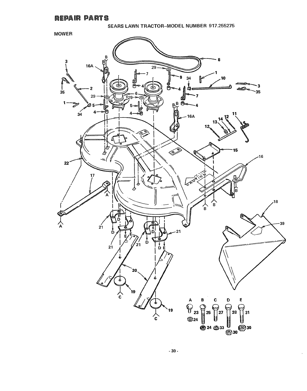
n_pAmR
MOWER
PAATS
SEARS LAWN TRACTOR-MODEL NUMBER 917o255275
3
35
16A
34
B
21
19
C
A
t_24
18
B C
24 _)33
D E
- 30
E$ ABR
MOWER
PA RT S
SEARS LAWN TRACTOR-MODEL NUMBER 9't7,255275
KEY
NO,,
1
2
3
4
5
6
7
8
9
t0
tl
12
13
14
15
16
t6A
PART
NO,, DESCRIPTION KEY PART DESCRIPTION
NO, NO,.
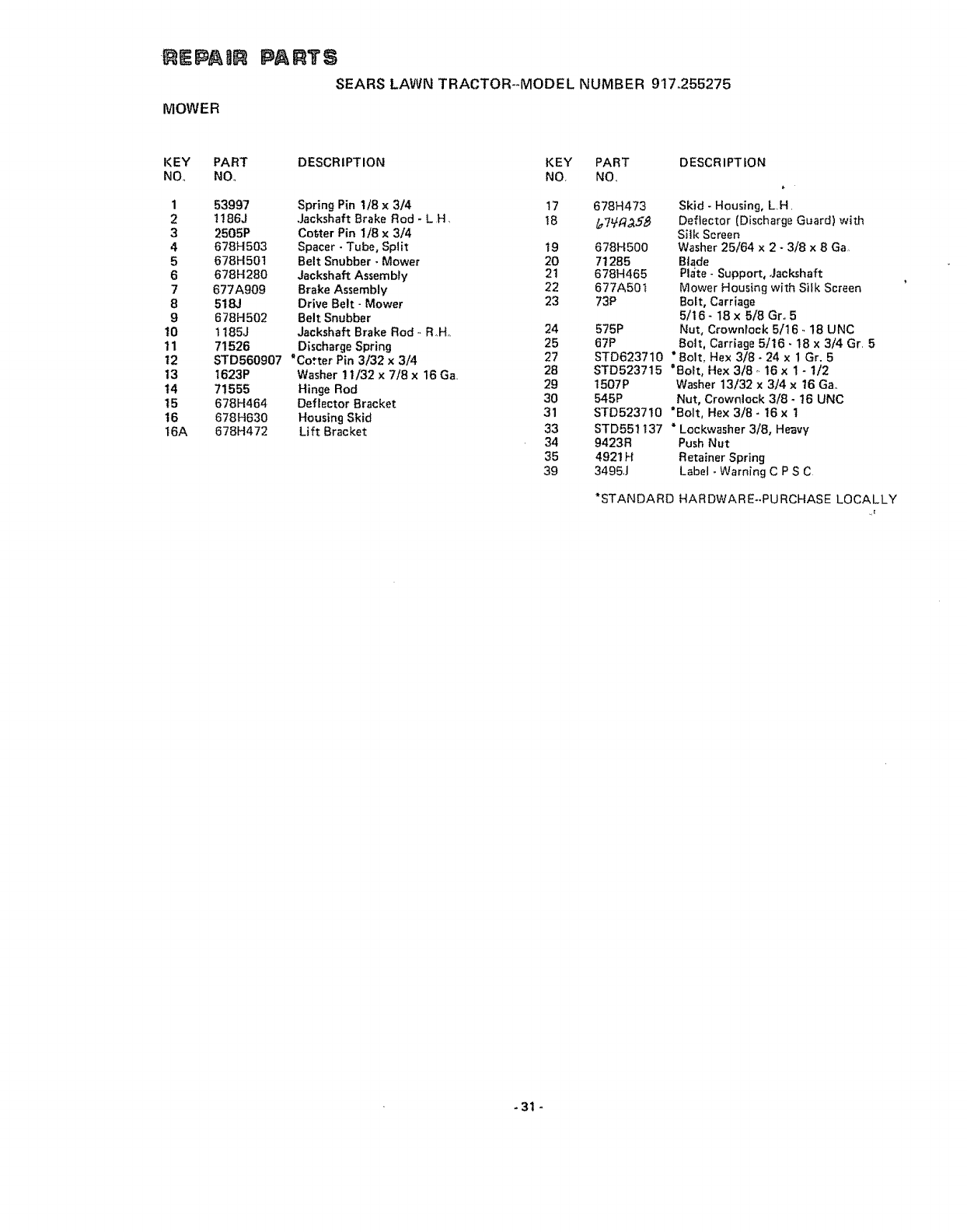
53997
! ! 86J
2505P
678H503
678H501
678H280
677A909
518J
678H502
1185J
71526
Spring Pin t/8 x 3/4 17 678H473
Jackshaft Brake Rod - LH t8 /_7_f7_5_
Cotter Pin 1/8 × 3/4
Spacer - Tube, Split 19 678H500
Belt Snubber • Mower 20 71285
Jackshaft Assembly 21 678H465
Brake Assembly 22 677A50t
Drive Belt- Mower 23 73P
Belt Snubber
Jackshaft Brake Rod- R_Ho 24 575P
Discharge Spring 25 67P
STD560907 "Cotter Pin 3/32 x 3/4 27
1623P Washer 1t/32 x 7/8 x 16 Ga 28
71555 Hinge Rod 29
678H464 Deflector Bracket 30
678H630 Housing Skid 31
678H472 Lift Bracket 33
34
35
39
Skid - Housing, L.H.
Deflector [Discharge Guard) with
S_]k Screen
Washer 25/64 x 2 - 3/8 x 8 Ga
Blade
Pla'te -Support, Jackshaft
Mower Housing with Silk Screen
Bolt, Carriage
5/16- 18x 5/8 Gr., 5
Nut, Crownrock 5/16 .. 18 UNC
Bolt, Carriage 5/16 • 18 x 3/4 Gr 5
STD623710 "Bolt, Hex 3/8- 24 x 1 Gr. 5
STD523715 "Bolt, Hex 3/8 ,. 16 x 1 - t/2
1507P Washer 13/32 x 3/4 x 16 Ga°
545P Nut, Crownlock 3/8 - t6 UNC
STD523710 "Bolt, Hex 3/8 - 16 x 1
STD55t 137 * Loekwasher 3/8, Heavy
9423R Push Nut
4921FI Retainer Spring
3495J Label - Warning C P S C
*STANDARD HARDWARE-PURCHASE LOCALLY
-31 -
REPAtR PARTS
SEARS LAWN TRACTOR-MODEL NUMBER 917.255275
TRANSAXLE--MODEL NUMBER 4010-6
'_76
74
255"<
61 _63 65
t _ J
47
41
REPAaR PARTS
SEARS LAWN TRACTOR--MODEL NUMBER 917.255275
TRANSAXLE-MODEL NUMBER 4010-6
KEY PART DESCRIPTION
NO. NO,
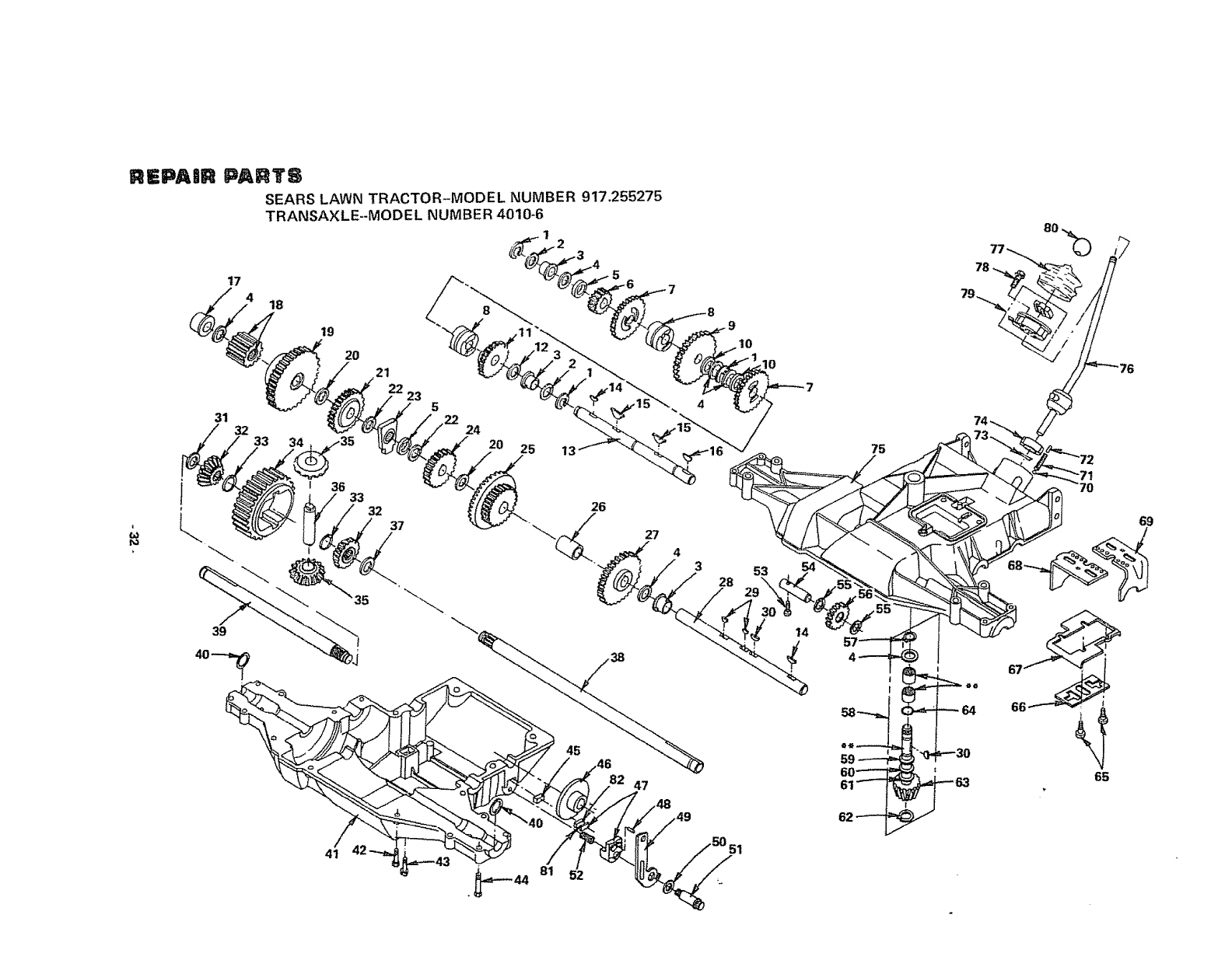
! 2225J
2 2229J
3 2234J
4 2226J
4 2227J
4 2228J
4 2229J
42230J
4 2231J
4 2232J
4 2233J
5 2235J
6 2236J
? 556tj
8 2238J
9 4174J
10 3412J
11 5562J
12 3413J
13 3414J
14 2242J
t5 3415J
16 2244J
17 2246J
18 3416J
t9 2248J
20 2228J
21 2249J
22 2232J
23 2250J
24 2251J
25 2252J
26 2253J
27 2254J
28 2255J
29 2256J
30 2228M
31 2263J
31 2264J
31 2265J
31 3417J
32 2266J
33 3418J
34 2268J
35 2269J
36 2270J
37 2264J
38 3419J
39 3420J
40 2272J
Ring, RetaEning
Washer, Plato, 1.00 x .630 x .040
Bearing, Flange
Washer, Plato, 1.00 x .630 x .060
Washer, Plain, 1.00 x .630 _.050
Washer, Plam, 1.00 x .630 x .045
Washer, Plain, 1.00 x .630 x .040
Washer; Piain, 1,00 x .630 x .035
Washer, Plaln_ ! .OOx.630 x.031
Washer, Plain, ! .00 x .630 x ,025
Washer. Plato, 1.00 x .630 x.020
Spacer, 1.00 x .630 x .110
Gear, Spur, 13T.
Gear, Spur, 25T.
Cotlar, Clutch
Gear, Spur, 33T.
Spacer, 1.00 x .630 x.260
Gear, Spur, 20T..
Washer, P_aln. 1.00 x .630 x .010
Shaft, Intermediate
Key, Wdrf, No. 3 Allov
Key, Hi-Pro, Special
Key, Wdrf. No. 61 Alloy
Bearing, Flange
Assembly, Gear, 12T.
Gear, Spur, 37T.
Washer. Plain, 1.00 x .630 x .045
Gear, Spur, 25T.
Washer, Plain, t,00 x .630 x .025
Assembly, Support, Shaft
Gear, Spur, 17T.
Gear, Spur, 20T & Revel, 42T.
Spacer (.875 x .630 x 1.375)
Gear, Spur, 30T.
Shaft, Drive
Key, Wdrf., No. 3 Alloy, Special
Key, Wdrf., No. 9 Alloy
Washer, Plato, 1.25 x .755 x .062
Washer, Plato, t .25 x .755 x .031
Washer, Plam, 1.25 x .765 x .040
Washer. Plain, 1.25 x .755 x .020
Gear, Miter. 15T., Splined
Ring, Retaining, Sptrolox R
Gear, Spur, 32T.
Gear. Miter, 15T.
Shaft, Cross
Washer, Plain, _.25 x .755 x .031
Axle, R,H.
Axte. L.H.
Seal, Felt
KEY
NO.
41
42
43
44
45
46
47
48
49
50
5t
52
53
54
55
56
57
58
59
60
61
61
61
61
61
62
63
64
65
66
67
68
69
70
7I
72
73
74
75
76
77
78
79
80
81
82
PART
NO.
2273J
2274J
2275J
2276J
4175J
2278J
2279J
2281J
2282J
2284J
2285J
2280J
2258J
2259J
2260J
2261J
2267J
3331J
2229J
2228J
3422J
2233J
2232J
223tj
2230J
2286J
2287J
3423J
2289J
2290J
2291J
2292J
2293J
2294J
2295J
2296J
2019J
2061J
2297J
3002J
2300J
2067J
3003J
4591J
4169J
4170J
DESCRIPTION
Housing, Lower
Bolt, Hex Hd,, S.T. I/4 - 20 x .875
Screw, Machine, No. 12 - 24 x .625
Bolt, Hex Hd, S.T. 1/4 -20x 1 - 5/16
Puck, Friction
Disc. Brake
Assembly, Brake Jaw (tnc, Item 48)
Screw, Set (No. 8 -32)
Assembly, Lever. Actuating
Washer. Plain, .750 x .505 x .006
Boil Shoulder
Spring, Compression
Screw. Tapping, No. 10 * 24 x 1.00
Shaft, idler
Washer, Plain. t.00 x .505 x .020
Assembly, Gear, idler
Ring, Retaining
Assembly, Kit, Input Shaft
Washer, Plain, 1.00 x ,630 x .040
Washer, Plain, 1.00 x .630 x .045
Washer, Plain, 1_00 x .630 x.015
Washer, PIam, 1.00 x .630 x .020
Washer, Piain, ! .00 x.630 x .025
Washer, Plain, 1.O0 x.630 x.030
Washer, Ptam, t .00 x.630 x.035
Ring, Retaining
Pinion, Bevel, 16T.
O-Ring
Screw, Pozi-Dnv
Plate. Lock-out
Plate, Fork, Support
Fork, Shifter
Fork, Shifter
Ball, Detent
Spring, Detent
Screw, Set. 1/4 - 20 x 1/2
Washer, Wave
insert, Nylon
Housing, Upper
Assembly, Lever, Shift
Boot, Switch
Screw, Hex Hd., S.T. No. 10 -24 x-l.0O
Assembly, Kit, Switch
Knob
Spacer (.045)
Puck, Friction
**ORDER KEY NO. 58
REPAan PANTS
SEARS LAWN TRACTOR-MODEL NUMBER 917,255275
ENGINE-MODEL NUMBER 220707, TYPE NUMBER 0147-01
AIR CLEANER AND CARBURETOR
62 66 65
10
15
='5
t3
_34_
REPAeR PARTS
SEARS LAWN TRACTOR-MODEL NUMBER 917o255275
ENGINE_MODEL NUMBER 220707, TYPE NUMBER 0147_01
AIR CLEANER AND CARBURETOR
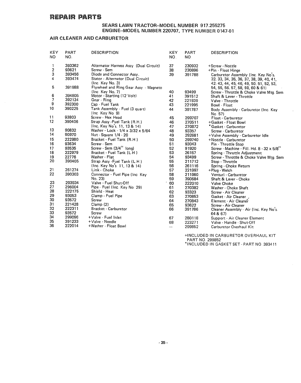
KEY PART DESCRIPTION KEY PART DESCRIPTION
NO NO, NO_ NO
t
2
3
4
6
7
9
t0
1I
12
13
14
15
t6
17
18
t9
20
21
22
23
27
28
29
30
31
32
33
34
35
36
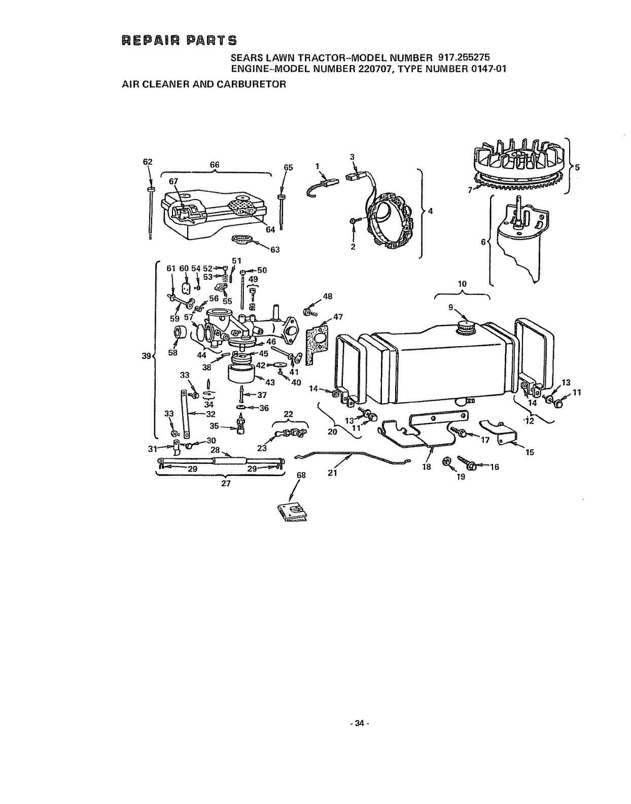
393362 Alternator Harness Assy (Dual Circuit) 37 230932
93621 Screw ..Sem 38 230896
393456 Diode and Connector Assy. 39 391788
393474 Stator- Alternator (Dual Circuit)
(lnc. Key No. 3)
39t988 Flywheel and Ring Gear Assy ,, Magneto
(Inc Key No. 7) 40 93499
394805 Motor - Starting (12 Volt) 41 391512
392134 Gear - Ring 42 221939
392300 Cap. Fuel Tank 43 221995
390225 Tank Assembly -FueI (3 quart) 44 391787
(fnc Key No 9}
93803 Screw- Hex Head 45 299707
390406 Strap Assy -Fuel Tank (Roll,,) 46 270511
(lnc. Key No's.. tt, 13 & 14) 47 270872
90832 Washer - Lock .. 1/4 x 3/32 x 5/64 48 93357
90970 Nut ,.Square 1/4_ 20 49 292681
222980 Bracket - Fuel Tank (R°H) 50 299740
93634 Screw ._Sem 51 93043
93535 Screw - Sere (3/4" tong) 52 91920
222979 Bracket -FueI Tank (LH) 53 26157
22776 Washer- Flat 54 93499
390405 Strap Assy ..Fuet Tank (L.H) 55 211712
(lnc. Key No_s 11, 13 & 14) 56 261116
261274 Link- Choke 57 221997
390303 Connector - Fuel Pipe (lnc Key 58 211960
No. 23) 59 390684
293934 Valve - Fuel Shut-Off "60 222010
296004 Pipe .. Fue! (tnc. Key No 29) 61 270382
222175 Shield *Heat 62 93323
93053 Clamp - Fuel Pipe 63 270853
93572 Screw 64 270843
221428 Clamp (2) 65 93622
222311 Bracket - Carburetor 66 391786
93572 Screw
299096 +Valve- Fuel Inlet 67 280t 18
391233 +Valve • Needle 68 223271
222014 +Washer --Float Bowl --- 299852
+Screw - Nozzle
+Pin o Float Hinge
Carburetor Assembfy {lnc Key Nots.
32. 33, 34, 35, 36, 37, 38, 39, 40, 41,
42; 43, 44, 45, 46, 49, 50. 51, 52,: 53,
54, 55, 56. 57, 58, 59, 60& 6t}
Screw - Throttle & Choke Vatve Mtg, Sem
Shaft & Lever - Throttle
Valve - Throttle
Bowl ,, Float
Body Assembly * Carburetor (tnc Key
No. 57)
Float -Carbu rotor
+Gasket •Ftoat Bowl
"Gasket * Carburetor
Screw .-Carburetor
+Valve Assembly -Carburetor idfe
+ Nozzle., Carburetor
Pin- Throttle Stop
Screw ,,Machine * Fill, Hd, 8 -32 X 5/8"
Spring - Throttle Adj_ustment
Screw- Throttle & Choke Valve Mtg. Sere
Stop -Throttle
Spring - Choke Return
+Plug -Welch
Venturi - Carburetor
Shaft & Lever - Choke
Valve Choke
Washer ,. Choke Shaft
Screw - Air Cleaner
Gasket ..Air Cleaner ,
Element - Air Cleaner
Screw - Air Cleaner
C_eaner Assembly .. Air (lnc.. Key No_s.
64 & 67)
Support _ Air Cleaner Element
Valve •Handle ,. Shut*Off
Carburetor Overhaul Kit
+INCLUDED tN CARBURETOR OVERHAUL KIT
PART NO, 299852
*{NCLUDEDIN GASKET SET-PARTNO 393411
_35_
_EPAI_ pAR'rs SEARS LAWN TRACTOR-MODEL NUMBER 917.255275
ENGINE-MODEL NUMBER 220707, TYPE NUMBER 0147-01
CYLINDER, CRANKSHAFT AND ENGI_E BASE GROUP
1___ 97
93 6
94 85
99
92 s9%
_91
69
70 66
67165_
73 77
74
65 62 59
64
61
78
60
57
57
81 36
80
_l 33 /
_J 40 30
41
46 °
44
45
36 -

EPAgR $ An3"S
SEARS LAWN TRACTOR-MODEL NUMBER 917o255275
ENGINE--MODEL NUMBER 220707, TYPE NUMBER 0147-01
CYLINDER, CRANKSHAFT AND ENGINE BASE GROUP
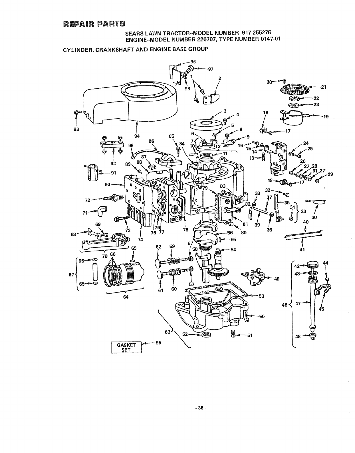
KEY PART DESCRIPTION KEY PART DESCRIPTION
NQ NO, NO, NO,
t 93572 Screw 54 212296
2 222971 Bracket., Fue! Tank Support 55 61760
3 222309 Cover - Breaker Point 56 261187
4 930!4 Screw - Sere 57 221596
5 93226 Screw - Breaker Adjusting Sem 58 261183
6 26018 Spring- Breaker Arm 59 65906
7 391284 Breaker Ass'y -Ignition (lnc Key No 6) 60 26828
8 93042 Screw -_Sem 61 261503
9 29861 Condenser 62 261462
10 65704 Plunger -Breaker Point 63 391784
t t 391086 Seal -Oil 64 39t 285
t2 393863 Cylinder Assembly (lnc-Key No tt)
13 261306 Spring o Governor 64 391287
14 390662 Plate ,,Gov. Control 64 391288
15 231039 Spacer, Control Bracket Mounting 64 391289
t6 93686 Screw -,Control Bracket Mounting 65 260924
17 93496 Screw, Sem 66 391780
t8 221535 Clamp - Casing 66 391781
19 222561 Cup ,.Screen Mounting 66 391782
20 93805 Screw ,,Sere 66 391783
2t 222562 Screen., Flush Rotating 67 299691
22 92284 Nut -Hex
23 220865 Washer - Spring 67 391286
24 26157 Spring ,,Throttle Adjustment 68 222299
25 91920 Screw - Machine, Fill, Hd, 8 - 32 x 5/8 69 92909
26 93735 Screw - Terminal 70 393860
27 92791 Washer ,. Insulating
28 66554 Collar ,, Insulating
29 90576 Nut ,, Hex - 8 - 32 (2)
30 391602 Wire _Ground 71 66538
31 66068 Washer - insulating 72 293918
32 93572 Screw 73 93723
33 391733 Lever Ass y .,Governor (1/4 Die Crank) 74 212366
(lnc, Key No's, 34 & 35) 75 261463
34 231082 Nut. Hex, 10 - 24 76 271075
35 92613 Bolt -Governor Link 77 211661
36 222450 Washer - Gov, Crank (1/4 I,,D,) 78 231218
37 93306 Cotter _,Hairpin 79 27803
38 93307 Retainer _E,Ring 80 93394
39 231058 Crank • Governor (1/4 Die,) 8t 391406
40 261198 Link Governor 82 280100
41 261197 Spring Governor 83 231055
42 391841 Cap and Dipstick 84 23513
43 270920 Seal - Oil Fi_ter Cap 85 93381
44 93804 Screw - Clamp Mtg, 86 298968
45 222502 Clamp - Oil Filter Tube 87 221907
46 392067 Fill Group, Oil (Inc Key No's, 42, 43, 88 222744
44,,45, 47 & 48) 89 93163
47 280134 Tube., Oil Filter 90 222725
48 68838 Seat ,, Filler Tube 91 89838
49 391764 Oil Slinger, Gov, Gear & Bracket 92 19203
Assembly 93 93158
50 93585 Screw - Sump Mounting Sem 94 391556
51 91084 Plug ,, Oil Drain 95 393411
52 291675 Seal oOil 96 223157
53 270808 *Gasket - Crankcase Cover - 1/64 Thick 97 93294
53 270915 * Gasket - Crankcase Cover - ,,005 Thick 98 90832
53 270916 *Gasket - Crankcase Cover - ,.009 Thick 99 221798
Gear - Cam
Key - Flywheel
Crankshaft
Retainer - Intake Valve
Tappet- Valve
Spring - Intake Valve
Spring - Exhaust Vaive
Valve - Exhaust
Valve -Intake
Sump- Oi! (lnc Key No's, 52 & 53)
Piston Ass'y-Standard (Inc Key No's
65 & 66)
Piston Ass'y _010 O S,
Piston Assry - 020 O S
Piston Asstyo-030 O ,S,
Lock - Piston Pin
Ring Set _ Piston -Standard
Ring Set- Piston -,010 O,S.
Ring Set - Piston •,020 O ,S,
Ring Set- Piston - ,030 O,S
Pin Assembly - Piston ..Standard (Iqc.
Key No, 65}
Pin Assembly - Piston -.,005 O,S,
Lock -Conn Rod Screw
Screw- Conn Rod
Rod Assty Connecting (tnc, Key No's,
68 & 69}
NOTE: For Connecting Rod with ,020
undersize Crankpin ,, Order No,, 39386 t
Elbow -Spark Plug ,
Plug -Spark (Resistor*TylSe)
Screw- Cylinder Head (3 '_ Long)
+Head - Cylinder
Seat - Intake Valve (Standard}
• Gasket - Cylinder Head
+Seat - Exhaust Valve
+Guide _,Exhaust Valve
• Gasket -Vafve Cover
Screw - Sem
Breather Assembly
Tube - Breather
Bushing- Gov Crank (1/4 LD,}
+Bushing - Plunger
Screw., Armature Mounting Sem
Armature Assembly
Clip - Wire
Shield - Cylinder
Screw - Cylinder Shield Mtgo Sem
Cover., Cylinder Head
Wrench - Spark Plug
Puller -Flywheel
Screw - Blower Housing Mounting Sere
Housing Blower
Gasket Set
Fuel Tank Support Bracket
Screw
Lockwash er
Terminal - ignition Cable
+SPECIAL TOOLS REQUIRED TO INSTALL
*INCLUDED IN GASKET SET PART NO. 39341t
_37.
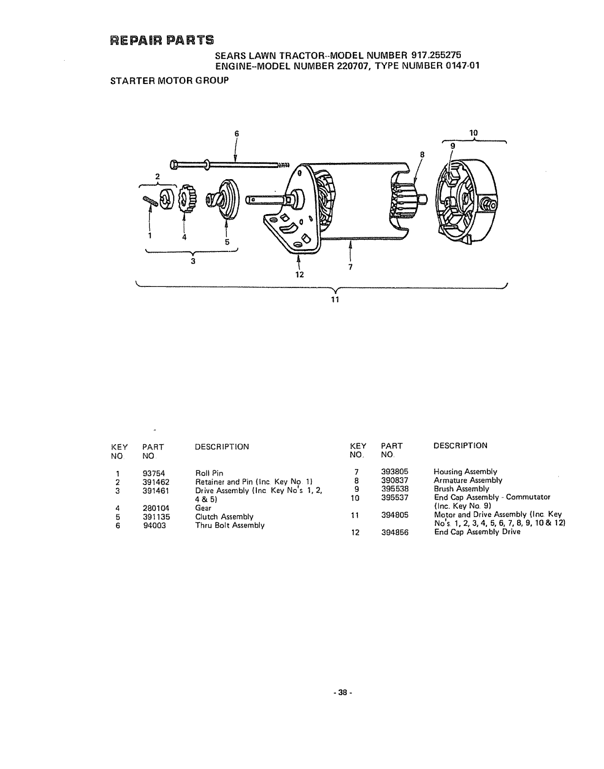
REPAIR PARTS
SEARS LAWN TRACTOR.MODEL NUMBER 917_255275
ENGINE--MODEL NUMBER 220707, TYPE NUMBER 0147-01
STARTER MOTOR GROUP
2
1 4 5
3
12
Y
11
7
lO
9
8
J
KEY
NO
1
2
3
4
5
6
PART DESCRIPTION
NO
93754 Rol! Pin
391462 Retainer and Pin (Inc Key No 1)
* !
391461 Drwe Assembly (Inc Key No s 1, 2,
4&5)
280t 04 Gear
391 t35 Ctutch Assembly
94003 Thru Bolt Assembly
KEY
NO,
7
8
9
t0
1t
12
PART
NO,
393805
390837
395538
395537
394805
394856
DESCRIPTION
Housing Assembly
Armature Assembly
Brush Assembly
End Cap Assembly - Commutator
(inc, Key No, 9)
Motor and Drive Assembly {Inc Key
No's 1,2,3,4, 5,6, 7,8,9, lO& 12)
End Cap Assembly Drive
-38-

SERVICE NOTES
39

SERVICE NOTES
40

SERVnCE NOTES
7712.J-t2 tl,8t Rev 1
-41 - Printed in USA.
[Searst
OWNERS
MANUAL
MODEL NOr
9!7,255275
HOW TO ORDER
REPAIR PARTS
10 H.P°
36" RIDING
LAWN TRACTOR
ELECTRIC START
The Model Number will be found on a piate attached tothe
Chassis Assembly, Always mention the Model Number.when re-
questing service or repair parts for your' Rid{ng Lawn Tractor? _
All parts listed herein may be ordered from any Seam Service
Center' and most Sears stores,
WHEN ORDERING REPAIR PARTS, ALWAYS GIVE THE
FOLLOWING INFORMATIONo
@THE PART NUMBER
@THE PART DESCRIPTION
@THE MODEL NUMBER
@THE NAME OF MERCHANDISE
If the par_s ycu need are not stocked locally, your order will be
electronically transmitted to a Sears Repair' Parts Distribution
Center for "expedited handling"°
i
Sears, Roebuck and Co, Chicago, Iit, 60684, U S,A_
