Craftsman 917255440 User Manual TRACTOR Manuals And Guides L0709142
CRAFTSMAN Lawn, Tractor Manual L0709142 CRAFTSMAN Lawn, Tractor Owner's Manual, CRAFTSMAN Lawn, Tractor installation guides
User Manual: Craftsman 917255440 917255440 CRAFTSMAN TRACTOR - Manuals and Guides View the owners manual for your CRAFTSMAN TRACTOR #917255440. Home:Lawn & Garden Parts:Craftsman Parts:Craftsman TRACTOR Manual
Open the PDF directly: View PDF ![]() .
.
Page Count: 56

SEA/_S
CRnFTSMnN
MODEL NUMBER 917.255440 OWNER'SMANUAL
• Assembly
•Operation
• Customer
Responsibilities
rm
Se. vice91
!AdjuStments
Repair _arf_
Caution:
Read and Follow
all Safety Rules
and Instructions
Before Operating
This Equipment
lit....
SAFETY RULES
Safe Operation Practices for Ride-On Mowers
IMPO RTANT: THIS CUTTIN G MAC HINE IS CAPABLE OFA MPUTATI NG HAN DS AN D FEET AN D TH ROWING OBJECTS.
FAILURE TO OBSERVE THE FOLLOWING SAFETY INSTRUCTIONS COULD RESULT IN SERIOUS INJU RY OR DEATH.
! GENERAL OPERATION
, Read, understand, and follow all instructions in the manual
and on the machine before starting.
, Only allow responsible adults, who are familiar with the
instructions, to operate the machine.
,Clear the area of objects such as rocks, toys, Wire, etc.,
which could be picked up and thrown by the blade.
, Be sure the area isclear of other people before mowing. Stop
machine ifanyone enters the area.
° Never carry passengers.
• Do not mow in reverse unless absolutely necessary. Always
look down and behind before and while backing.
• Be awar_of the mower discharge direction and do not point
it at anyone. Do not operate the mowe[.wthout either the
entire grass catcher orthe guard in place.
,Slow down before turning.
•Never leave a running machine unattended. Always turn off
blades, set parking brake, stop engine, and remove keys
before dismounting.
• TLa'n off blades when not mowing.
; Stopengine b#fore removing grass catcher or unclogg_hg
chute,
•' _W
oMO oniyin daylight orgood artificial4ig_t. '
• Do not operate the machin e white Under the influence of
. _ alCel_01or drugs. : -
._ _W_tch fortraffiC when operatihg nea,r o¢_rossing roadways.
•:Use extra care when loading.o€ unloading the machine into
•a_a!le.r or tr(__,_.
II. SLOPE oPERATIONZ
Slopes _.re .a major factor related to loss-of-centre! and t=pover
accidents, which can respltjr_ severe injury or death. All slopes
require extra caution. Ify0u cannot backup the slope orifyou feel
uneasy on it, _o not mow it. ....
DO:
• Mow up_anu uovyp_pes, nor across.
• Remove obstaC!_s such as rocks, tree limbs, etc.
• Watch for boles, ruts, or bumps. Uneven terrain could
overturnth_,machine. Tall grass can hide obstacleg; :.-
• Use slowspeed. Choosea Iowgear so that you will nct have
to stop or shi_ while on the slope.
• Follow the roanufacturer's recommendations for._'_ne_l
weights or counterweights to improve stability. ..,
• Use extra care with grass catchers or other attachments.
These can change the stability of the machine.
• Keepallmovementontheslopess/owandgradual. Donot
make sudden changes in speed or direction.
• Avoid starting or stopping on a slope. If tires lose traction,
disengage the blades and proceed slowly straight down the
slope.
DO NOT:
•Do not turn on slopes unless necessary, and then, turn slowly
and gradually downhill, if possible.
•Do not mow near drop-offs, ditches, or embankments• The
mower could suddenly tum over if awheel is over the edge
of a cliff or ditch, or if an edge caves in.
•Do not mow on wet grass. Reduced traction could cause
sliding.
•Donot try to stabilize the machine by putting your foot on the
ground.
•Do not use grass catcher on steep slopes•
Ill. CHILDREN
Tragic accidents can occur if the operator is not alert to the
presence of children. Children are often attracted to the machine
and the mowing activity. Neverassume that children will remain
where you last saw them.
• Keep children out ofthe mowing area and under the watchful
care of another responsible adult.
• Be alert and turn machine off if children enter the area.
• Before and when backing, look behind and down for small
children.
•Never carry children. They may fall off and be seriously
injured or interfere with safe machine operation.
=Never allow_childrent_ operate the machine.. •
• Use extra care when approaching blind corners, s_ubs,
trees, or other objects that may obscure vision.
IV. SERVICE
•Use extra care inhandling gasoline and other fuels _hey are
flammable and vapors are explosive.
Use on!y an approved container.
Never remove gas cap or add fuel with the engine
running. Allow engine _ocool before refueling. DOn0!
smoke. ..
Never refuel the machine indoors.
Never store_the machine or fuel conta_iner inside where
•t[te_ i_ an Open flame such as a water heat_,.
• Never _ru#a machin_ inside a closed area,
•Keep huts and boffs, especially blade attachment belts,.tight
._ . and keep equipment in good €ondition_._
• NeVer tamper with safety device_. ' Check their propel"
oper_t on regularly.. : ......
_,, KeepmachinefreeOfgrass leaves 0rotherdebrisbuild-up.
Clean oil or fuel spjl!_ge. Allow machine to cool before
storing. , _"
• Stop and inspect the °_quipment if you strike an object.
Repair, f necessary, before r_ta_ing.
• Ne_,er make adjustmpnts or rePair_ with the engine running.
• Grass catcher componen:ts°are subject to wear, damage and
deterioration, which ¢o_ldexpose moving parts or allow
objects to be thrown.. Frequently check components and
replace with manufacturer's recommended parts, when nec-
essary.
• Mower blades are sha_p_can cut. Wrap the blade(s) or
wear gloves, and use extra caution when servicing them.
• Check brake operation frequently. Adjust and service as
required.
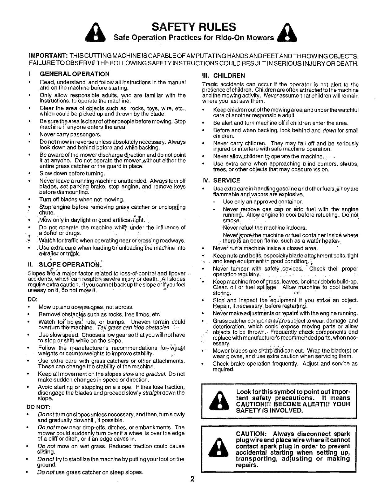
Look for this symbol to point out impor-
tant safety precautions. It means
CAUTION!!! BECOME ALERT!_! YOUR
SAFETY IS INVOLVED.
&CAUTION: Always disconnect spark
plug wire and place wire where it cannot
contact spark plug in order to prevent
accidental starting when setting up,
transporting, adjusting or making
repairs.
2

CONGRATULATIONS on your purchase of a Sears
Tractor. It has been designed, engineered and manufac-
tured to give you the best possible dependability and
performance.
Should you experience any problem you cannot easily
remedy, please contact your nearest Sears Authorized
Service Center/Department. We have competent, well-
trained technicians and the proper tools to service or repair
this unit.
Please read and retain this manual. The instructions will
enable you to assemble and maintain your unit properly.
Always observe the "SAFETY RULES",
MODEL
NUMBER 917.255440
SERIAL
NUMBER
DATEOFPURCHASE
THE MODELANDSERIALNUMBERSWlLLBEFOUND
ON A PLATE UNDER THE SEAT.
YOU SHOULD RECORD BOTH SERIAL NUMBER AND
DATE OF PURCHASE AND KEEP lN A SAFE PLACE
FOR FUTURE REFERENCE.
MAINTENANCE AGREEMENT
A Sears Maintenance Agreement is available on this prod-
uct. Contact your nearest Sears store for details.
CUSTOMER RESPONSIBILITIES
• Read and observe the safety rules.
= Follow a regular schedule in maintaining, caring for and
using your unit.
•Follow the instructions under "Customer Responsibili-
ties" and "Storage" sections of this owner's manual.
PRODUCT SPECIFICATIONS
HORSEPOWER: 12.5
GASOLINE CAPACITY 5 QUARTS
AND TYPE: UNLEADED REGULAR
OIL TYPE (API-SG): SAE 30 (above 32°F)
SAE 5W-30 (below 32°F)
OIL CAPACITY: W/O FILTER: 3.0 PINTS
SPARK PLUG: CHAMPION RJ-19LM
(GAP: .0XX") STD361458
VALVE CLEARANCE: INTAKE: .005" - .007"
EXHAUST: .009" - .011"
GROUND SPEED (MPH): FORWARD:
1st 1.00
2nd 1.50
3rd 2.00
4th 3.00
5th 4.20
6th 5.00
REVERSE: 1.50
TIRE PRESSURE: FRONT: 14PSI
REAR: 12 PSI
CHARGING SYSTEM: 3 AMPS BATTERY
5 AMPS HEADLIGHTS
BLADE BOLT TORQUE: 30-35 FT. LBS.
WARNING: This unit is equipped with an internal combus-
tion engine and should not be used on or near any unim-
proved forest-covered, brush-covered or grass-covered
land unless the engine's exhaust system is equipped with
a spark arrestor meeting applicable local or state laws (if
any): If a spark arrestor is used, it should be maintained in
effective working order by the operator.
In the State of California the above is required by law
(Section 4442 of the California Public Resources Code).
Other states may have similar !aws. Federal laws apply on
federal lands. A spar k arrestor for the muffler is available
through your nearest Sears Authorized Service Center/
Department (See REPAIR PARTS section of this manual).
LIMITED TWO YEAR WARRANTY ON ELECTRIC START RIDING EQUIPMENT
For two (2) years from the date of purchase, if this riding equipment is maintained, lubricated and tuned up according to the
instructions in the owner's manual, Sears will repair or replace, free of charge, any parts found to be defective in material or
workmanship.
This Warranty does not cover:
• Expendable items which become worn during normal use, such as blades, spark plugs, air cleaners and belts.
', Tire replacement or repair caused by punctures from outside objects, such as nails, thorns, stumps, or glass.
• Repairs necessary because of operator abuse, negligence, improper storage or accident or the failure to maintain the
equipment according to the instructions contained in the owner's manual.
• Riding equipment used for commercial or rental purposes.
LIMITED 90 DAY WARRANTY ON BATTERY
For ninety (90) days from date of purchase, if any battery included with this riding equipment proves defective in material or
workmanship and our testing determines the battery will not hold a charge, Sears will replace the battery at no charge.
WARRANTY SERVICE iS AVAILABLE BY RETURNING THE RIDING EQUIPMENT TO THE NEAREST SEARS SERVICE
CENTER/DEPARTMENT IN THE UNITED STATES.
This Warranty gives you specific legal rights, and you may also have other rights which may vary from state to state.
SEARS, ROEBUCK AND CO., D/817 WA, HOFFMAN ESTATES, ILLINOIS 60179
3
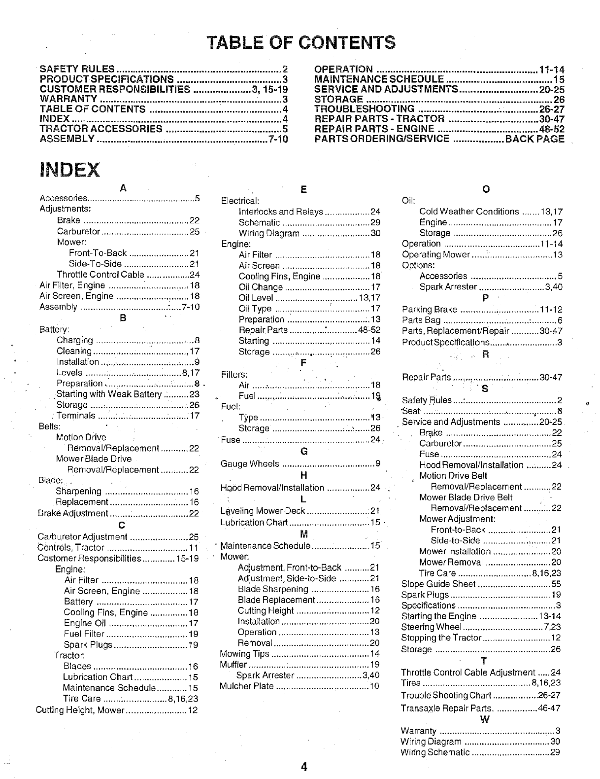
TABLE OF CONTENTS
SAFETY RULES ............................................................ 2
PRODUCT SPECIFICATIONS ...................................... 3
CUSTOMER RESPONSIBILITIES ..................... 3, 15-19
WARRANTY .................................................................. 3
TABLE OF CONTENTS ......................... ....................... 4
INDEX ............................................................................ 4
TRACTOR ACCESSORIES .......................................... 5
ASSEMBLY .............................................................. 7-10
OPERATION .......................................................... 11-14
MAINTENANCE SCHEDULE ...................................... 15
SERVICE AND ADJUSTMENTS ............................ 20-25
STO RAG E ................................................................... 26
TROUBLESHOOTING .;........................... . ............. 26-27
REPAIR PARTS - TRACTOR ................................ 30-47
REPAIR PARTS ENGINE .................................... 48-52
PARTS ORDERI _G/SERVICE .................. BACK PAGE
INDEX
A
Accessories ............................................ 5
Adjustments:
Brake .......................................... 22
Carburetor ................................... 25
Mower:
Front-To-Back ........................ 21
Side-To-Side .......................... 21
Throttle Control Cable ................. 24
Air Filter Engine .............. _................. 18
Air Screer. Engine ............................. 18
Assembly ................................... :....7-10
B
Battery:
Charging ....................................... 8
Cleaning ...................................... 17
Installation ...... _................................ 9
Levels .............................. _....... 8,17
Preparation ........................... _....:...8
Starting with Weak Battery .:........ 23
Storage ....................................... 26
Terminals ....... :................... :........ 17
Belts:
Motion Drive
Removal!Replacement ........... 22
Mower Blade Drive
Removal/Replacement ........... 22
Blade:
Shan3ening ................................. 16
Replacement ............................... 16
B rake Adjustment .............................. 22
C
E
Electrical:
interlocks and Relays .................. 24
Schematic ................................... 29
Wiring Diagram ........................... 30
Engine:
Air Filter ...................................... 18
Air Screen ................................... 18
Cooling Fins, Engine ................... 18
Oil Change .................................. 17
Oil Level ................................. 13.17
Oil Type ...................................... 17
Preparation ............................... :. 13
Repair Parts ............ _............ 48-52
Starting ..................................... 14
Storage ................ o....................... 26
F
=liters:
Air ............................. _................. 18
Fuel ................................ :............. 1
Fuel:
Type ........... i................................ '13
Storage ................................ _....... 26
Fuse ................................................... 24
G
Gauge Wheels ..................................... 9
H
I-I_od Removal/Installation ................. 24
L
Leveling Mower Deck ......................... 21
Lubrication Chart ................................ 15
CarburetorAdjustment ....................... 25 M
Controls• Tractor ................................ 11 Maintenance Schedule ..................... i. 15
Castomer Responsibilities ............. 15-19
Engine:
Air Filter .................................. 18
Air Screen, Engine .................. 18
Battery .................................... 17
Cooling Fins, Engine ............... 18
Engine Oil ............................... 17
Fuel Filter ................................ 19
Spark Plugs ............................. 19
Tractor:
Blades ..................................... i 6
Lubrication Chart ..................... 15
Maintenance Schedule ............ 15
Tire Care ......................... 8,16,23
Cutting Height, Mower ......................... 12
Mower:
Adjustment, Front-to-Back .......... 21
Adjustment, Side-to-Side ............ 21
Blade Sharpening ....................... 16
Blade Replacement ..................... 16
Cutting Height ............................. 12
Installation ................................... 20
Operation .................................... 13
Removal ...................................... 20
Mowing Tips ....................................... 14
Muffler ................................................ 19
Spark Arrester .......................... 3,40
Mulcher Plate ..................................... 10
4
O
Oil:
Cold Weather Conditions ....... 13,17
Engine ......................................... 17
Storage ....................................... 26
Operation ...................................... 11-14
Operating Mower ............................... 13
Options:
Accessories .................................. 5
Spark Arrester .......................... 3.40
P
Parking Brake ............................... 11-12
Parts Bag .................................. :.......... 6
Parts Replacement/Repair ........... 30-47
Product Specifications ........................... 3
R
Repair Parts ...... _.......................... 30-47
S
Safety Rules ....: .................................... 2
'Seat ............................................ ,........ 8
Service and Adjustments ............. 20-25
Brake .......................................... 22
Carburetor ................................... 25
Fuse ............................................ 24
Hood Removal/InstalFation .......... 24
Motion Drive Belt
Removal!Replacement ........... 22
Mower Blade Drive Belt
Removal/Replacement ........... 22
Mower Adjustment:
Front-to-Back ......................... 21
Side-to-Side ........................... 21
Mower Installation ....................... 20
Mower Remova! .......................... 20
Tire Care ............................. 8,16,23
Slope Guide Sheet ............................. 55
Spark Plugs ........................................ 19
Specifications ....................................... 3
Starting the Engine ....................... 13-14
Steering Wheel ................................ 7,23
Stopping the Tractor ........................... 12
Storage .............................................. 26
T
Throttle Control Cable Adjustment ..... 24
Tires ........................................... 8,16,23
Trouble Shooting Chart .................. 26-27
Transaxle Repair Parts ................. 46-47
W
Warranty .......................................... _...3
Wiring Diagram .................................. 30
Wiring Schematic ............................... 29
J
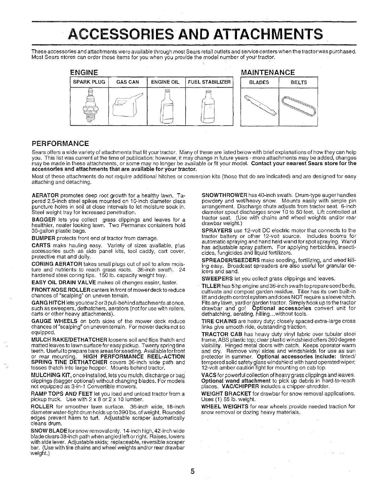
ACCESSORIES AN ATTACHMENTS
These accessories and attachments were available throug h most Sears retail outlets and service Centers when the tractor was purchased.
Most Sears stores can order these items for you when you provide the model number of your tractor.
ENGINE
f SPARK PLUG GAS CAN ENGINE OIL FUEL STABILIZER
MAINTENANCE
BLADES BELTS
PERFORMANCE
Sears offers a wide variety of attachments that fit your tractor. Many of these are listed below with brief explanations of how they can help
you. This list was current at the time of publication; however, it may change in future years - more attachments may be added, changes
may be made in these attachments, or some may no longer be available or fit your model. Contact your nearest Sears store for the
accessories and attachments that are available for your tractor.
Most of these attachments do not require additional hitches or conversion kits (those that do are indicated) and are designed for easy
attaching and detaching.
AERATOR promotes deep root growth for a healthy lawn. Ta-
pered 2.5-inch steel spikes mounted on 10-inch diameter discs
puncture holes in soil at close intervals to let moisture soak in.
Steel weight tray for increased penetration.
BAGGER lets you collect grass clippings and leaves for a
healthier, heater looking lawn. Two Permanex containers hold
30-gal!on plastic bags.
BUMPER protects front end of tractor from damage.
CARTS make hauling easy. Variety of sizes available, p!us
accessories such as side panel kits, tool caddy, cart cover,
protective mat and dolly.
CORING AERATOR takes small plugs out of soil to allow mois-
ture and nutrients to reach grass roots. 36-inch swath. 24
hardened steel coring tips. 150 lb. capacity weight tray.
EASY OIL DRAIN VALVE makes oil changes easier, faster.
FRONT NOSE ROLLER canters in front of mower deck to reduce
chanoes of "scalping" on uneven terrain.
GANG HITCH lets you tow 2 or 3pull-behind attachments at once,
such as sweepers, dethatchers, aerators (not for use with rollers,
carts or other heavy attachments).
GAUGE WHEELS on both sides of the mower deck reduce
chances of "scalping" on uneven terrain. For mower decks not so
equipped.
MULCH RAKF_.JDETHATCHER loosens soil and flips thatch and
matted leaves to lawn surface for easy pickup. Twenty spring tine
teeth. Usefuitoprepare bareareasforseeding. Availableforfront
or rear mounting. HiGH PERFORMANCE REEL-ACTION
SPRING TINE DETHATCHER covers 36-inch wide path and
tosses thatch into large hopper. Mounts behind tractor.
MULCHING KiT, once installed, lets you mulch, discharge or bag
clippings (bagger optional) without changing blades. For models
not equipped as 3-in-1 Convertible mowers.
RAMP TOPS AND FEET let you load and unload tractor from a
pickup truck. Use with 2 x 8 or 2 x 10 lumber.
ROLLER for smoother lawn surface. 36-inch wide, 18-inch
diameter water-rig ht drum holds up to 3901be. of weight. Rounded
edges prevent harm to turf. Adjustable scraper automatically
cleans drum.
SNOW BLADE forsnow removal only. 14-inch high, 42-inch wide
blade clears 38-inch path when angled left or right, Raises, lowers
with side lever. Adjustable skids; replaceable, reversible scraper
bar. (Use with tire chains and wheel weights and/or rear drawbar
weight.)
SNOWTHROWER has 40-inch swath. Drum-type auger handles
powdery and wet/heavy snow. Mounts easily with simple pin
arrangement, Discharge chute adjusts from tractor seat. 6-inch
diameter spout discharges snow 10 to 50 feet. Lift controlled at
tractor seat. (Use with chains and wheel weights an_'or rear
drawbar weight.)
SPRAYERS use 12-volt DC electric motor that connects to the
tractor battery or other 12-volt source. Includes booms for
automatic spraying and hand held wand for spot spraying. Wand
has adjustable spray pattern. For applying herbicides, insecti-
cides, fungicides and liquid fertilizers.
SPREADERISEEDERS make seeding, fertilizing, and weed kill-
ing easy. Broadcast spreaders are also useful for granular de-
icers and sand.
SWEEPERS let you collect grass clippings and leaves.
TILLER has 5 hp engine and 36-inch swath to prepare seed beds,
cultivate and compost garden residue. Tiller has its own built-in
lift and depth control system and does NOT require a sleeve hitch.
Fits any lawn, yard or garden tractor. Simply hook up to the tractor
drawbar and go[ Optional accessories convert unit for
dethatching, aerating, hilling...without tools.
TIRE CHAINS are heavy duty; closely spaced extra-large cross
links give smooth ride, outstanding traction.
TRACTOR CAB has heavy duty vinyl fabric over tubular steel
frame, ABe plastic top; clear plastic windshield offers 360 degree
visibility. Hinged meta[ doors with catch. Keeps operator warm
and dry. Remove vinyl sides and windshields for use as sun
protector in summer. Optional accessories include: tinted/
tempered solid safety glass windshield with hand operated wiper;
12-volt amber caution light for mounting on cab top.
VACS for powerful collection of heavygrass clippings and leaves.
Optional wand attachment to pick up debris in hard-to-reach
places. VAC/CHIPPER includes a chipper-shredder.
WEIGHT BRACKET for drawbar for snow removal applications.
Uses (1) 55 lb. weight.
WHEEL WEIGHTS for rear wheels provide needed traction for
snow removal or dozing heavy materials.
5
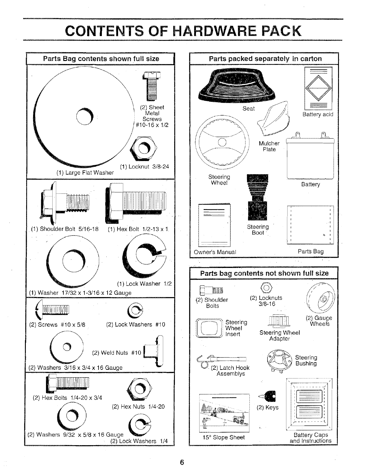
CONTENTS OF HARDWARE PACK
Parts Bag contents shown full size
\
I (2) Sheet
Metal
Screws
#10-16 x 1/2
(1) Locknut 3/8-24
(1) Large Flat Washer
(1) Shoulder Bolt 5/16-18
(_@
(1) Hex Bolt 1/2-13 x 1.
(1) Lock Washer 1/2
(1) Washer 17/32 x 1-3/16x 12 Gauge
@
(2) Screws #10 x 5/8 (2) Lock Washers #10
(2) Weld Nuts #10 <
(2) Washers 3/16 x 3/4 x 16 Gauge
(2) Hex Bolts 1/4.20 x 3/4 @
(2) Hex Nuts 1/4-20
(2) Washers 9/32 x 5/8 x 16 Gauge
(2) Lock Washers 1/4
Parts packed separately in carton
Seat
Mulcher
/Plate
O
Battery acid
Steering
Wt-eel Battery
Steering
Boot
Owner's Manual Parts Bag
Parts bag contents not shown full size
(2) Shoulder (2) Locknuts
Bolts 3/8-16
_i s Steering
_ Wheel
Insert Steering Wheel
Adapter
(2) Gauge
Wheels
Latch Hook
Assemblys
_ teering
Bushing
I-_ '.......I
15° Slope Sheet
€
(2) Keys
h .... /
I
=[
1 ,
[I
.......... h
/ \
Battery Caps
and Instructions
ASSEMBLY
Your new tractor has been assembled at the factory with exception Ofthose parts left unassembled for shipping purposes.
To ensure safe and proper operation of your tractor all parts and hardware you assemble must be tightened securely. Use
the correct tools as necessary to insure proper tightness.
TOOLS REQUIRED FOR ASSEMBLY
A socket wrench set will make assembly easier. Standard
wrench sizes are listed.
(1) 5/16" wrench
(2) 7/16" wrenches
(1) 3/4" wrench
(1) 9/16" wrench
Tire pressure gauge
Phillips Screwdriver
Utility knife
(1) 1/2" wrench
When right and left hand are mentioned in this manual, it
means when you are in the operating position (seated
behind the steering wheel).
TO REMOVE TRACTOR FROM CARTON
UNPACK CARTON
• Remove all accessible loose parts and parts cartons
from carton (See page 6).
• Cut along lines on carton, from top to bottom, all four
corners of carton and lay panels flat.
*Check for any additional loose parts or cartons and
remove.
BEFORE ROLLING TRACTOR OFF SKID
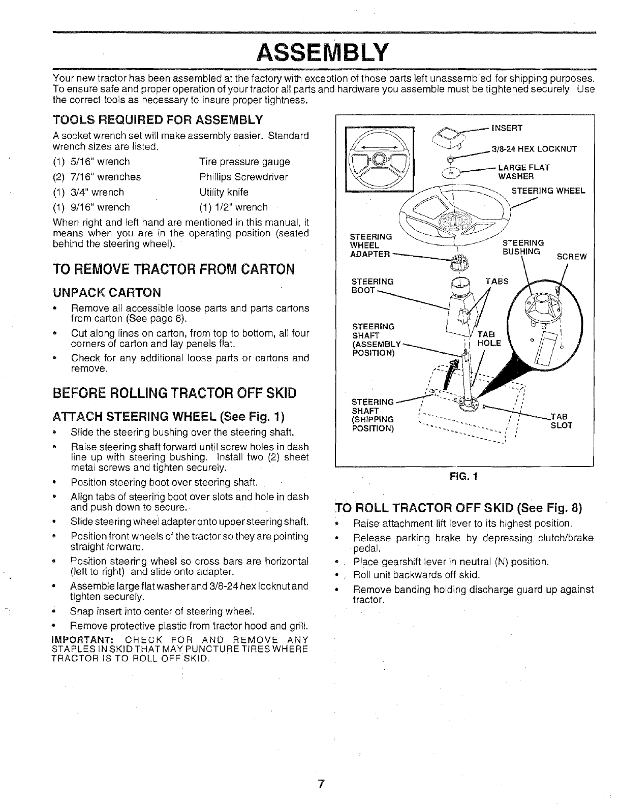
ATTACH STEERING WHEEL (See Fig. 1)
• Slide the steering bushing over the steering shaft.
• Raise steering shaft forward until screw holes in dash
line up with steering bushing. Install two (2) sheet
metal screws and tighten securely.
• Position steering boot over steering shaft.
,, Align tabs of steerifig boot over slots and hole in dash
and push down to secure.
• Slide steering wheel adapter onto upper steering shaft.
• Position front wheels of the tractor so they are pointing
straight forward.
• Position steering wheel so cross bars are horizontal
(left to right) and slide onto adapter.
• Assemble large flat washer and 3/8-24 hex Iocknut and
tighten securely.
=Snap insert into center of steering wheel.
• Remove protective plastic from tractor hood and grill.
IMPORTANT: CHECK FOR AND REMOVE ANY
STAPLES IN SKIDTHAT MAY PUNCTURE TIRES WHERE
TRACTOR IS TO ROLL OFF SKID.
INSERT
.._._3/8-24 HEX LOCKNUT
f._. _ LARGE FLAT
L_.J"'- WASHER
STEERING WHEEL
sTEERING STEERING
WHEEL I
ADAPTER __ BUSHING
STEERING TABS
BOOT
STEERING /
SHAFT _-_ 3
(, 'i HOLE
POSITION)
STEERING ,'/,"
SHAFT " ,, ;_-_._.TAB
(SHIPPING " ......
POSITION) ---. "'" ' ,' SLOT
~~.
SCREW
FIG. 1
TO ROLL TRACTOR OFF SKID (See Fig. 8)
,, Raise attachment lift lever to its highest position.
• Release parking brake by depressing clutch/brake
pedal
* 1 Place gearshift lever in neutral (N) position.
•Roll unit backwards off skid.
• Remove banding holding discharge guard up against
tractor.
7
ASSEMBLY
HOW TO SET UP YOUR TRACTOR
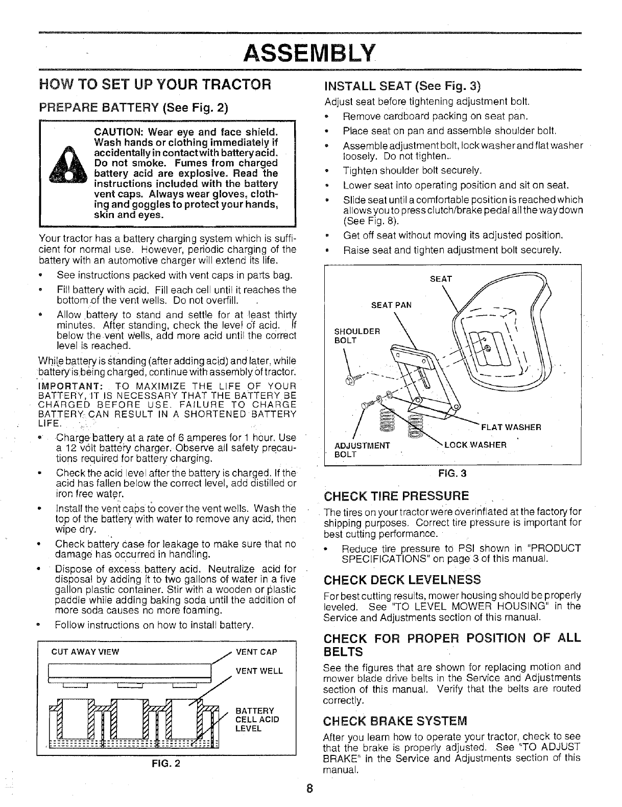
PREPARE BATTERY (See Fig. 2)
CAUTION: Wear eye and face shield.
Wash hands or clothing immediately if
accidentally in contact with batteryacido
Do not smoke. Fumes from charged
battery acid are explosive. Read the
instructions included with the battery
vent caps. Always wear gloves, cloth-
ing and goggles to protect your hands,
skin and eyes.
Your tractor has a battery charging system which is suffi-
cient for normal use. However, periodic charging of the
battery with an automotive charger will extend its life.
•See instructions packed with vent caps in oarts bag.
•Fill battery with acid. Fill each ce unti it reaches the
bottom .of the vent wells. Do not overfill.
Allow battery to stand ana settle for at east thirty
minutes. After standing, check the eve! df acid. If
below the vent Wells, add more acid until the correct
level is reached.
While battery is standing (after adding acid) and later, while
battery isbeing charged, continue with assembly of tractor.
IMPORTANT: TO MAXIMIZE THE LIFE OF YOUR
BATTERY, IT IS NECESSARY THAT THE BATTERY BE
CHARGED BEFORE USE. FAILURE TO CHARGE
BATTERY., CAN RESULT IN A SHORTEI_ED BATTERY
LIFE.
" Chargebattery at a rate of 6 amperes for 1 hour. Use
a 12 volt batteb' charger. Observe all safety orecau-
tions required for battery charging.
• Check the acid eve after the battery is charged If tne
acid has fallen below the correct evel, add distilled or
iron free water.
• install the veni caps to cover the vent wells. Wash the
top of the battery with water to remove any acid. then
wipe dry.
• Check batte_' Case for leakage to maKe sure that no
damage has occurred in handling.
° Dispose of excess battery acid. Neutralize acid for
disposal by adding it to two gallons of water in a five
gallon plastic container. Stir with a wooaen or plastic
paddle while adding baking soda until the addition of
more soda causes no more foaming.
Follow instructions on how to install battery,
CUT AWAY VIEW /VENT CAP
VENT WELL
BATTERY
CELL ACID
LEVEL
FIG. 2
INSTALL SEAT (See Fig. 3)
Adjust seat before tightening adjustment bolt.
. Remove cardboard packing on seat pan.
• Place seat on pan and assemble shoulder bolt.
• Assemble adjustment bolt, Iockwasher and fiat washer
loosely. Do not tighten.,
• Tighten shoulder bolt securely.
Lower seat into operating position and sit on seat,
Slide seat until a comfortable position is reached which
allows you to press clutch/brake pedal all the way down
(See Fig. 8).
, Get off seat without moving its adjusted Position.
• Raise seat and tighten adjustment bolt securely.
SEAT PAN
\
SHOULDER
BOLT
SEAT
\
I
I
ADJUSTMENT
BOLT LOCKWASHER
4ER
FIG. 3
CHECK TIRE PRESSURE
The tires on yoL rtractor were overinflated at the factory for
shipping purposes, Correct tire pressure is important for
best cutting performance.
o Reduce tire pressure to PSI shown n "PRODUCT
SPECIFICATIONS" on page 3 of this manual
CHECK DECK LEVELNESS
For best cutting results, mower housing should be properly
leveled. See "TO LEVEL MOWER HOUSING" in the
Service and Adjustments section of this manual.
CHECK FOR PROPER POSITION OF ALL
BELTS
See the figures that are shown for replacing motion and
mower blade drive belts in the Service and Adjustments
section of this manual, Verify that the belts are routed
correctly.
CHECK BRAKE SYSTEM
After you learn how to operate your tractor, check to see
that the brake is properly adjusted. See "TO ADJUST
BRAKE" in the Service and Adjustments section of this
manual.
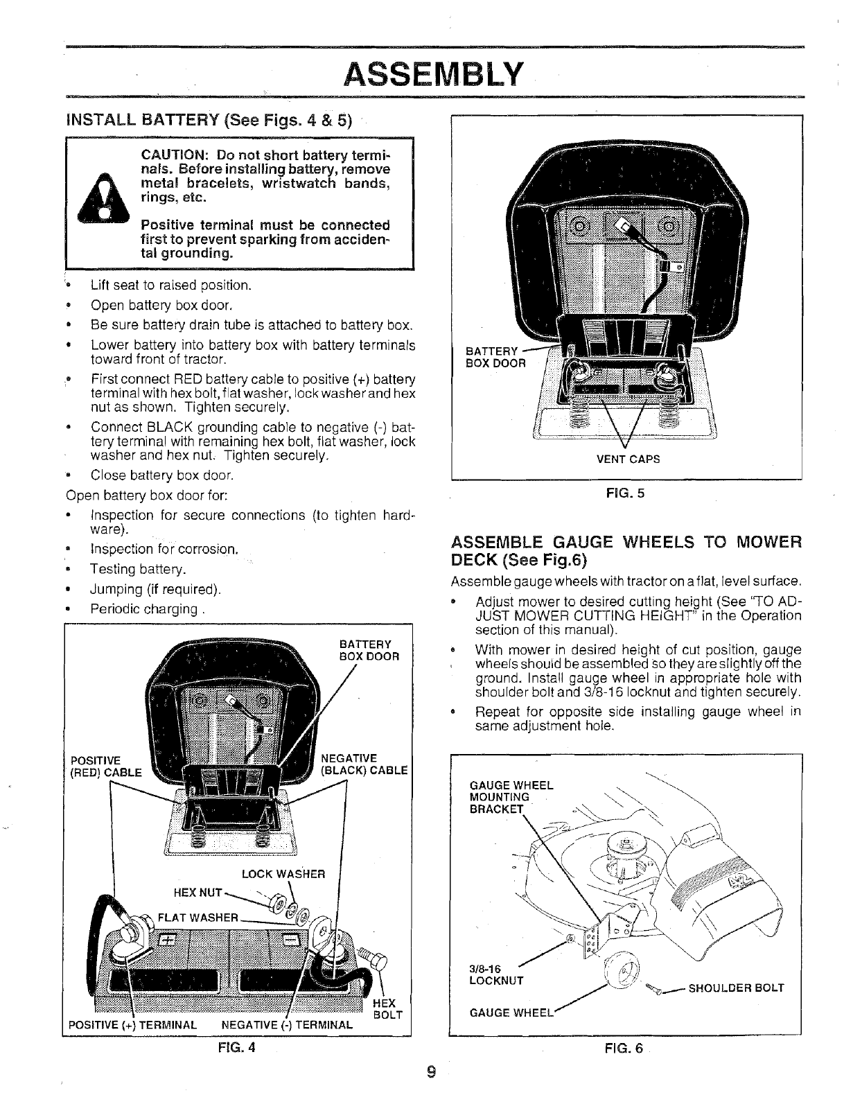
INSTALL BATTERY (See Figs. 4 & 5)
CAUTION: Do not short battery termi-
nals. Before installing battery, remove
metal bracelets; wristwatch bands,
rings, etc.
Positive terminal must be connected
first to prevent sparking from acciden-
tal grounding.
Lift seat to raised position.
Open battery box door.
• Be sure battery drain tube is attached to battery box.
° Lower battery into battery box with battery terminals
toward front of tractor.
_- First connect RED battery cable to positive (+) battery
terminal with hex bolt, flat washer, lock washer and hex
nut as shown. Tighten securely.
•Connect BLACK grounding cable to negative (-) bat-
tery terminal with remaining hex bolt, flat washer, lock
washer and hex nut, Tighten securely.
• Close battery box door.
Open battery box door for:
• inspection for secure connections (to tighten hard-
ware).
• Inspection for corrosion.
•Testing battery.
• Jumping (if required).
° Periodic charging.
BATTERY
BOXDOOR
POSITIVE NEGATIVE
(RED) CABLE (BLACK) CABLE
LOCK WASHER
POSITIVE (+) TERMINAL NEGATIVE (-) TERMINAL
FIG.4
BOX DOOR
VENT CAPS
FiG. 5
ASSEMBLE GAUGE WHEELS TO MOWER
DECK (See Fig.6)
Assemble gauge wheels with tractor on aflat, level surface.
•Adjust mower to desired cutting height (See 'q-O AD-
JUST MOWER CUTTING HEIGHT" in the Operation
section of this manual).
• With mower in desired height of cut position, gauge
wheels shoutd be assembled Sothey are slightly off the
ground. Install gauge wheel in appropriate hole with
shoulder bolt and 3/8-16 Iocknut and tighten securely.
• Repeat for opposite side installing gauge wheel in
same adjustment hote.
GAUGE WHEEL _._\ "_-_MOUNTING
BRACKET \
\
9
FIG. 6
ASSEMBLY
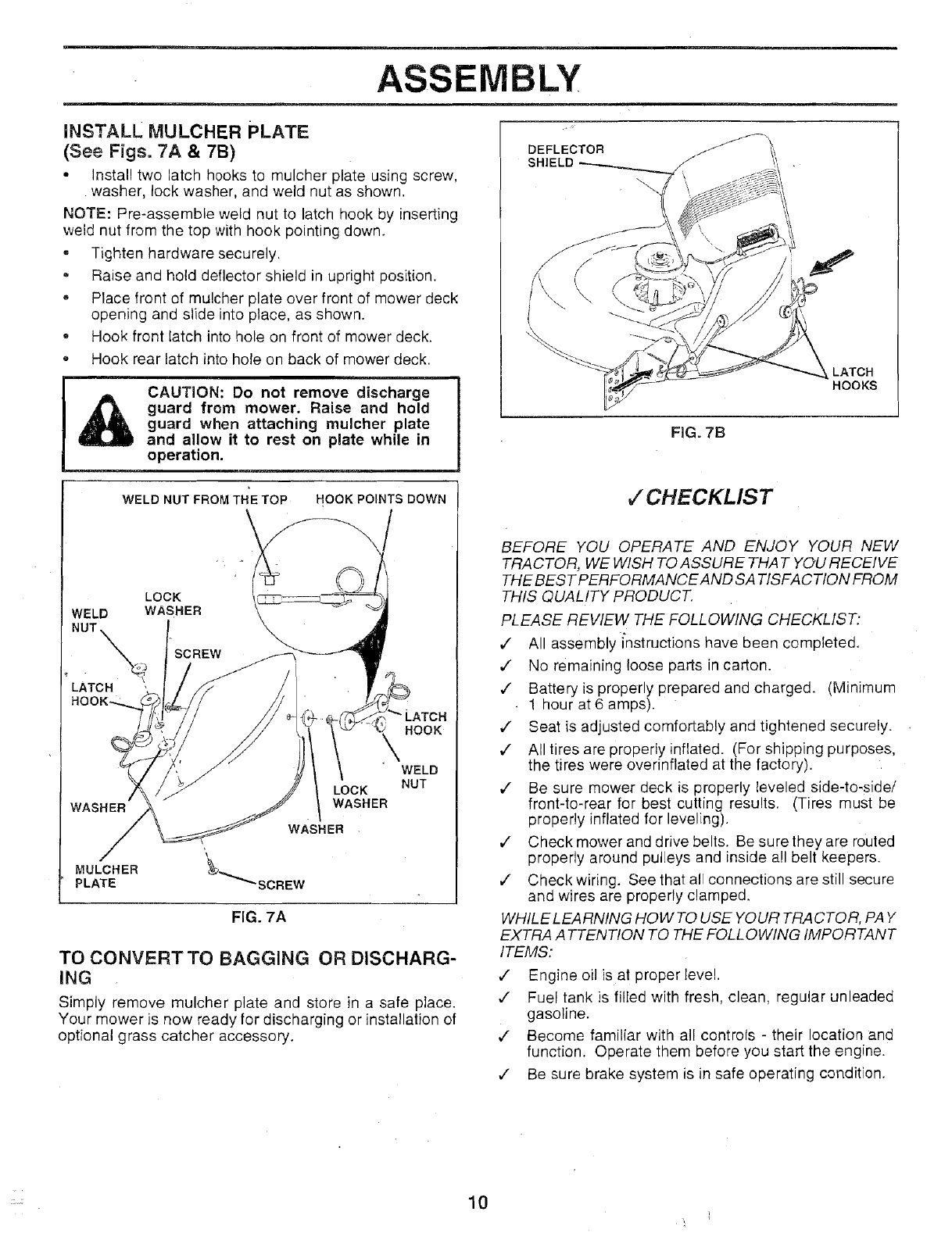
iNSTALL MULCHER PLATE
(See Figs. 7A &7B)
• Install two latch hooks to mulcher plate using screw,
washer, lock washer, and weld nut as shown.
NOTE: Pre-assemble weld nut to latch hook by inserting
weld nut from the top with hook pointing down.
,Tighten hardware securely.
• Raise and hold deflector shield in upright position.
o Place front of mulcher plate over front of mower deck
opening and slide into place, as shown.
- Hook front latch into hole on front of mower deck.
, Hook rear latch into hole on back of mower deck.
CAUTION: Do not remove discharge
guard from mower. Raise and hold
guard when attaching mulcher plate
and allow it to rest on plate while in
operation.
WELD NUT FROM THE TOP HOOK POINTS DOWN
DEFLECTOR ,.///'_
SHIELD
FIG. 7B
LATCH
HOOKS
LOCK
WELD WASHER
SCREW
HOOK
WASHER
MULCHER
PLATE
LOCK
WASHER
WASHER
SCREW
FIG. 7A
WELD
NUT
TO CONVERT TO BAGGING OR DISCHARG-
ING
Simply remove mulcher plate and store in a safe place.
Your mower is now ready for discharging or installation of
optional grass catcher accessory.
v"CHECKLIST
BEFORE YOU OPERATE AND ENJOY YOUR NEW
TRACTOR, WE WISH TO ASSURE THAT YOU RECEIVE
THE BEST PERFORMANCEAND SATISFACTION FROM
THIS QUALITY PRODUCT.
PLEASE REVIEW THE FOLLOWING CHECKLIST:
,/ All assemblyi_nstructions have been completed.
,/ No remaining loose parts in carton.
,/ Battery is properly prepared and charged. (Minimum
• 1 hour at 6 amps).
,/ Seat is adjusted comfortably and tightened securely.
,/ All tires are properly inflated. (For shipping purposes,
the tires were overinflated at the factory).
,/ Be sure mower deck is properly leveled side-to.side/
front-to-rear for best cutting results. (Tires must be
properly inflated for leveling).
,/ Check mower and drive belts. Be sure they are routed
properly around pulleys and inside all belt keepers•
,/ Check wiring. See that all connections are still secure
and wires are properly clamped.
WHILE LEARNING HOW TO USE YOUR TRACTOR, PAY
EXTRA A TTENT!ON TO THE FOLLOWING IMPORTANT
ITEMS:
,/ Engine oil is at proper level.
v" Fuel tank is filled with fresh, clean, regular unleaded
gasoline.
,/ Become familiar with all controls - their location and
function. Operate them before you start the engine.
¢" Be sure brake system is in safe operating condition.
10
OPERATION
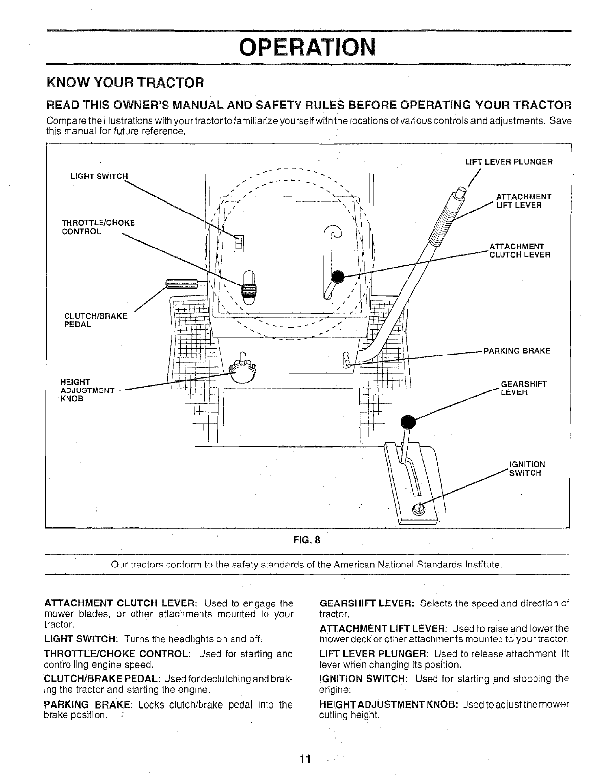
KNOW YOUR TRACTOR
READ THIS OWNER'S MANUAL AND SAFETY RULES BEFORE OPERATING YOUR TRACTOR
Compare the illustrations with your tractor to familiarize yourself with the locations of various controls and adjustments. Save
this manual for future reference.
LIGHT SWITCH
THROTTLE/CHOKE
CONTROL
CLUTCH/BRAKE
PEDAL
LIFT LEVER PLUNGER
T
LUTCH EVER
BRAKE
HEIGHT
ADJUSTMENT
KNOB
GEARSHIFT
ER
IGNITION
TCN
FIG. 8
Our tractors conform to the safety standards of the American National Standards Institute.
ATTACHMENT CLUTCH LEVER: Used to engage the
mower b ades, or other attachments mounted to your
tractor.
LIGHT SWITCH: Turns the headlights on and off.
THROTTLE!CHOKE CONTROL: Used for starting and
controlling engine speed.
CLUTCH/BRAKE PEDAL: Used fordectutching and brak-
ing the tractor and starting the engine.
PARKING BRAKE: Locks clutch/brake pedal into the
brake position.
GEARSHIFT LEVER: Selects the speed and direction of
tractor.
ATTACHMENT LIFT LEVER: Used to raise and lower the
mower deck or other attachments mounted to your tractor.
LIFT LEVER PLUNGER: Used to release attachment lift
lever when changing its position.
IGNITION SWITCH: Used for starting and stopping the
engine.
HEIGHTADJUSTMENT KNOB: Used to adjust the mower
cutting height.
OPERATION
The operation of any tractor can result in foreign objects thrown into the eyes, which can result
in severe eye damage. Always wear safety glasses or eye shields while operating your tractor
or performing any adjustments or repairs. We recommend wide vision safety mask-for over
the spectacles or standard safety glasses, available at Sears Retail or Catalog stores.
HOW TO USE YOUR TRACTOR
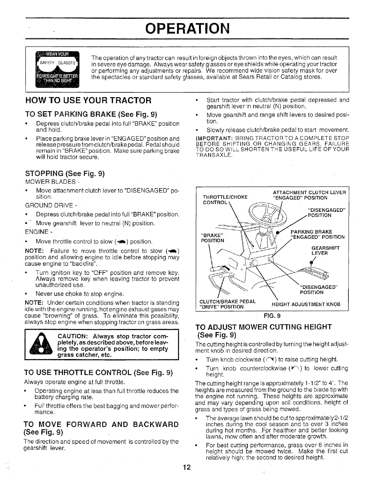
TO SET PARKING BRAKE (See Fig. 9)
= Depress clutch/brake pedal into ful! "BRAKE" position
and hold.
PIace parking brake lever in "ENGAGED" position and
release pressure from clutch/brake pedal. Pedal should
remain in "BRAKE" position. Make sure parking brake
will hoid tractor secure.
° Start tractor with clutch/brake pedal depressed and
gearshift lever in neutra! (N) position.
° Move gearshift and range shift levers to desired posi-
tion.
* Slowly release clutch/brake pedal to start movement.
IMPORTANT: BRING TRACTOR TO A COMPLETE STOP
BEFORE SHIFTING OR CHANGING GEARS. FAILURE
TO DO SO WILL SHORTEN THE USEFUL LIFE OF YOUR
TRANSAXLE.
STOPPING (See Fig. 9)
MOWER BLADES -
• Move attachment clutch lever to "DISENGAGED" po-
sition.
GROUND DRIVE -
- Depress clutch/brake pedal into full "BRAKE" position.
•'Move gearshift lever to neutral (N) position.
ENGINE -
, Move throttle control to slow (_) position.
NOTE: Failure to move throttle control to slow (,_)
position and allowing engine to idle before stopping may
cause engine to "backfire".
• Turn ignition key to "OFF" position and remove key.
Always remove key when leaving tractor to prevent
unauthorized use.
* Never use choke to stop engine.
NOTE: Under certain conditions when tractor is standing
idle with the engine running, hot engine exhaust gases may
cause "browning" of grass. To eliminate this possibility,
always stop engine when stopping tractor on grass areas.
CAUTION: Always stop tractor com-
pletely; as described above, before leav-
ing the operator's position; to empty
grass catcher, etc. , =
TO USE THROTTLE CONTROL (See Fig. 9)
Always operate engine at ful! throttle.
° Operating engine at less than full throttle reduces the
battery charging rate.
• Full throttle offers the best bagging and mower perfor-
mance.
TO MOVE FORWARD AND BACKWARD
(See Fig. 9)
The direction and speed of movement is controlled by the
gearshift lever.
THROTTL_CHOKE ATTACHMENT CLUTCHLEVER
"ENGAGED"POSITION
"DISENGAGED"
)SITION
PARKING BRAKE
"BRAKE" 'ENGAGED" POSIThON
POSITION
GEARSHIFT
LEVER
12
"DISENGAGED"
PosmoN
CLUTCH/BRAKE PEDAL
"DRIVE" POSITION HEIGHT ADJUSTMENT KNOB
FIG. 9
TO ADJUST MOWER CUTTING HEIGHT
(See Fig. 9)
l-he cutting height is controlled by turning the height adjust-
ment knob in desired direction.
° Tdrn knob clockwise (_) to raise cutting height.
• Turn knob counterclockwise (_) to lower cutting
height.
The cutting height range is approximately 1-1/2" to 4". The
heights are measured from the ground to the blade tip with
the engine not running. These heights are approximate
and may vary depending upon soil conditions, height of
grass and types of grass being mowed.
° The average lawn should be cutto approximately2-1/2
inches during the coot season and to over 3 inches
during hot months. Fpr hea!thier and better looking
lawns, mow often and after moderate growth.
° For best cutting performance, grass over 6 inches in
height should be mowed twice. Make the first cut
relatively high; the second to desired height.
OPERATION
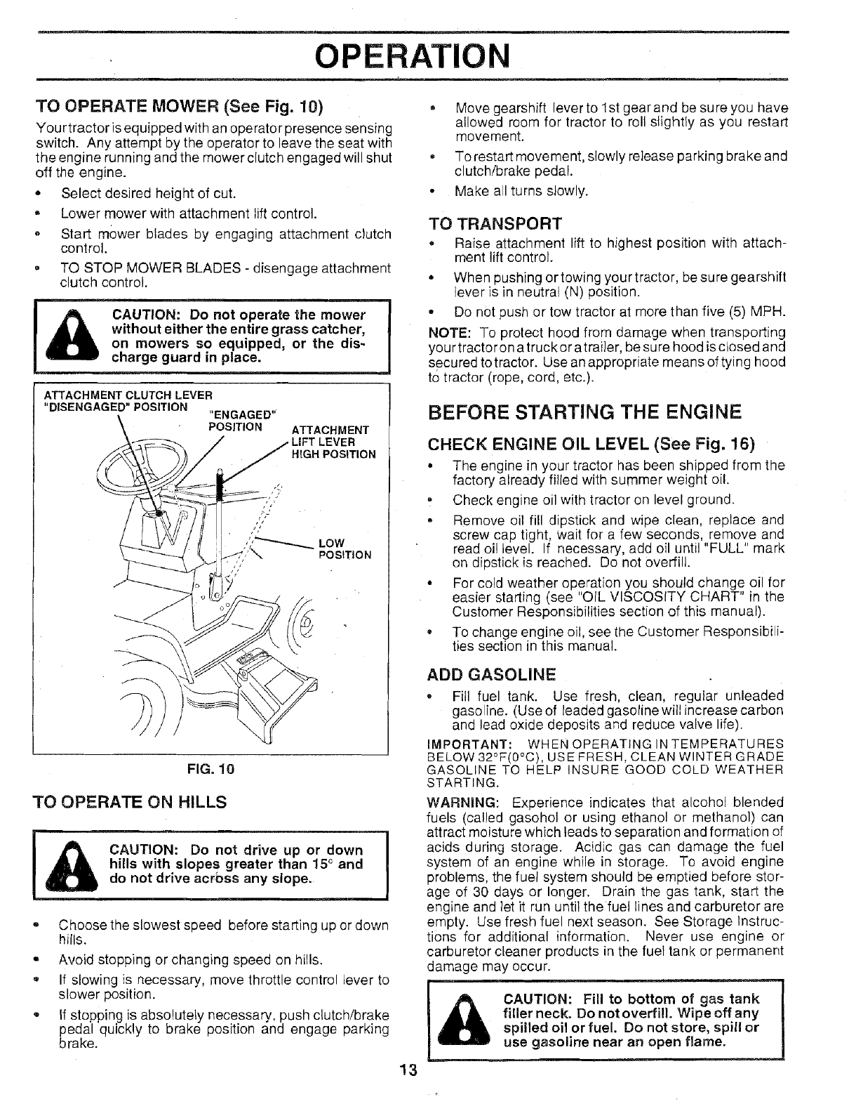
TO OPERATE MOWER (See Fig. 10)
You rtractor is equipped with an operator presence sensing
switch. Any attempt by the operator to leave the seat with
the engine running and the mower dutch engaged will shut
off the engine.
= Select desired height of cut.
Lower mower with attachment lift control.
,, Start mower blades by engaging attachment clutch
control.
•TO STOP MOWER BLADES - disengage attachment
clutch control.
&CAUTION: Do not operate the mower
without either the entire grass catcher,
on mowers so equipped, or the dis-
charge guard in place.
ATTACHMENT CLUTCH LEVER
"DISENGAGED" POSITION "ENGAGED"
POSITION ATTACHMENT
ER
HIGH POSITION
"'_ LOW
POSITION
FIG. 10
TO OPERATE ON HILLS 7
CAUTION: Do not drive up or down
hills with slopes greater than 15° and
do not drive acrbss any slope.
o
Q
®
Choose the slowest speed before starting up or down
hills.
Avoid stopping or changing speed on hills.
If slowing is necessary, move throttle control lever to
slower position.
If stopping is absolutely necessary, push clutch/brake
pedal quickly to brake position and engage parking
brake.
o
Move gearshift lever to 1st gear and be su re you have
allowed room for tractor to roll slightly as you restart
movement.
To restart movement, slowly release parking brake and
clutch/brake pedal.
Make all turns slowly.
TO TRANSPORT
• Raise attachment lift to highest position with attach-
ment lift control.
• When pushing or towing your tractor, be sure gearshift
lever is in neutral (N) position.
• Do not push or tow tractor at more than five (5) MPH.
NOTE: To protect hood from damage when transporting
your tractor on a truck or atrai]er, be sure hood is closed and
secured to tractor. Use an appropriate means of tying hood
to tractor (rope, cord, etc.).
BEFORE STARTING THE ENGINE
CHECK ENGINE OIL LEVEL (See Fig. 16)
• The engine in your tractor has been shipped from the
factory already filled with summer weight oil.
•Check engine oil with tractor on level ground.
•Remove oil fill dipstick and wipe clean, replace and
screw cap tight, wait for a few seconds, remove and
read oi! level. If necessary, add eil until "FULL" mark
on dipstick is reached. Do not overfill.
• For cold weather operation you should change oil for
easier starting (see "OIL VISCOSITY CHART" in the
Customer Responsibilities section of this manual).
• To change engine oil, see the Customer Responsibili-
ties section in this manual.
ADD GASOLINE
• Fill fuel tank. Use fresh, clean, regular unleaded
gasoline. (Use of leaded gasolinewill increase carbon
and lead oxide deposits and reduce valve life).
IMPORTANT: WHENQPERATINGINTEMPERATURES
BELOW 32°F(0°C), USE FRESH, CLEAN WINTER GRADE
GASOLINE TO HELP INSURE GOOD COLD WEATHER
STARTING.
WARNING: Experience indicates that alcohol blended
fuels (called gasohol or using ethanol or methanol) can
attract moisture which leads to separation and formation of
acids during storage. Acidic gas can damage the fuel
system of an engine while in storage. To avoid engine
problems, the fuel system should be emptied before stor-
age of 30 days or longer. Drain the gas tank, start the
engine and let it run until the fuel lines and carburetor are
empty. Use fresh fuel next season. See Storage Instruc-
tions for additional information. Never use engine or
carburetor cleaner products in the fuel tank or permanent
damage may occur.
CAUTION: Fill to bottom of gas tank
filler neck. Do not overfill. Wipe off any
spilled oil or fuel. Do not store, spill or
use gasoline near an open flame.
13
OPERATIO
TO START ENGINE (See Fig. 9)
When starting engine for the first time or if engine has run
out of fuel, it will take extra cranking time to move fuel from
the tank to the engine.
• Depress clutch/brake pedal and set parking brake.
• Place gearshift lever in neutral (N) position.
• Move attachment clutch to "DISENGAGED" position.
• Move throttle control lever to choke (I\1) position for
cold engine start. For warm engine start, move throttle
control to fast (,t_) position.
• Insert key into ignition and turn keyclockwise to"START"
position and release key as soon as engine starts. Do
not run starter continuously for more than fifteen
seconds per minute. If engine does not start after
several attempts, move throttle control to fast (._)
position, wait a few minutes and try again.
- When engine starts, move throttle control to desired
position.
• Allow engine to warm up for a few minutes before
engaging drive or attachments.
NOTE: If at a high altitude (above 3000 feet) or in cold
temperatures (below 32°F), the carburetor fuel mixture
may need to be adjusted for best engine performance. See
"TO ADJUST CARBURETOR" in the Service and Adjust-
ments section of this manual.
MOWING TIPS
• Tire chains cannot be used when the mower housing
is attached to tractor.
. Mower should be properly leveled for best mowing
performance. See "TO LEVEL MOWER HOUSING" in
the Service and Adjustments section of this manual.
• The left hand side of mower should be used for trim-
ming.
• Drive so that clippings are discharged onto the area
that has been cut. Have the cut area to the right of the
tractor. This will result in a more even distribution of
clippings and more uniform cutting.
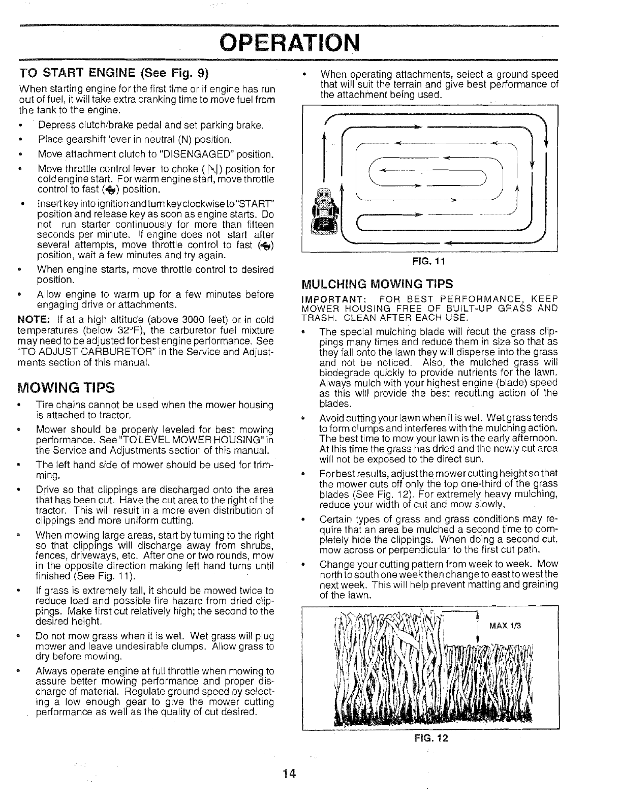
, When mowing large areas, start by turning to the right
so that clippings will discharge away from shrubs,
fences, driveways, etc. After one or two rounds, mow
in the opposite direction making left hand turns until
finished (See Fig. 11).
. If grass is extremely tall, it should be mowed twice to
reduce load and possible fire hazard from dried clip-
pings. Make first cut reratively high; the second to the
desired height.
= Do not mow grass when it is wet. Wet grass will plug
mower and leave undesirable clumps. Allow grass to
dry before mewing.
• Always operate engine at full throttle when mowing to
assure better mowing performance and proper dis-
charge of material. Regulate ground speed by select-
ing a low enough gear to give the mower cutting
performance as well as the quality of cut desired.
• When operating attachments, select a ground speed
that will suit the terrain and give best performance of
the attachment being used.
f
w _ -J
FIG. 11
MULCHING MOWING TIPS
IMPORTANT: FOR BEST PERFORMANCE, KEEP
MOWER HOUSING FREE OF BUILT-UP GRASS AND
TRASH. CLEAN AFTER EACH USE.
• The special mulching blade will recut the grass clip-
pings many times and reduce them in size so that as
they fall onto the lawn they will disperse into the grass
and not be noticed. Also, the mulched grass will
biodegrade quickly to provide nutrients for the lawn.
Always mulch with your highest engine (blade) speed
as this will provide the best recUtting action of the
blades.
, Avoid cutting your lawn when it is wet. Wet grass tends
to form clumps and interferes with the mulching action.
The best time to mow your lawn is the early afternoon.
At this time the grass has dried and the newly cut area
will not be exposed to the direct sun.
• For best results, adjust the mower cutting height so that
the mower cuts off only the top one-third of the grass
blades (See Fig. 12), For extremely heavy mulching,
reduce your width of cut and mow slowly.
. Certain types of grass and grass conditions may re-
quire that an area be mulched a second time to com-
pletely hide the clippings. When doing a second cut,
mow across or perpendicular to the first cut path.
• Change your cutting pattern from week to week. Mow
north to south one week then change to east to west the
next week. This will help prevent matting and graining
of the lawn.
IMAX 1/3
I
F|G. 12
14
CUSTOMER RESPONSIBILITIES
i'
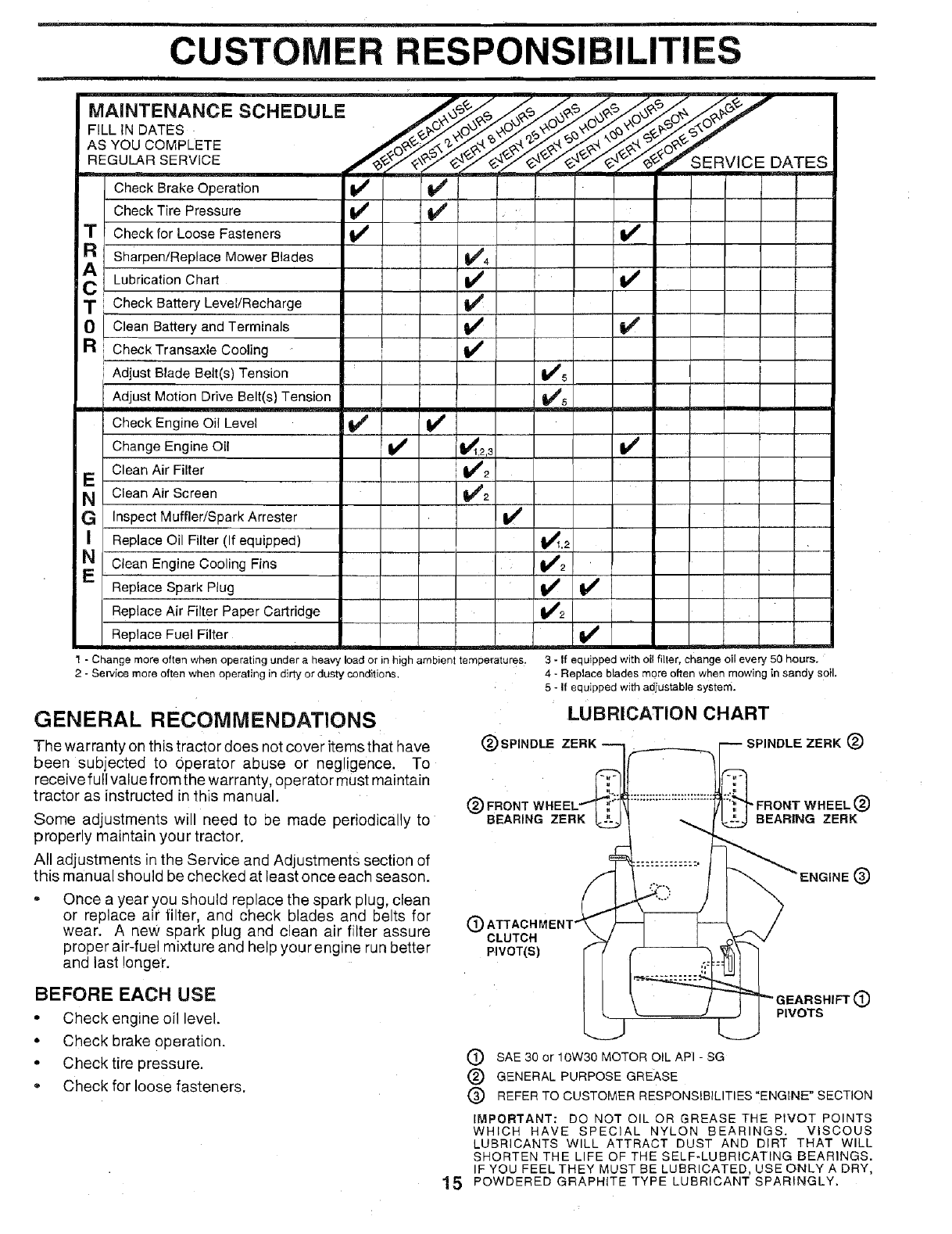
MAINTENANCE SCHEDULE
FiLL iN DATES
AS YOU COMPLETE
REGULAR SERVICE
T
R
Check Brake Operation
Check Tire Pressure
Check for Loose Fasteners
sharpen!Replace Mower Blades
v' v' ! [
v',
Lubrication Chart _ V'
TCheck Battery Level!Recharge I
0 Clean Battery and Terminals
a CheckTransaxle Cooling
Adjust Blade Belt(s) Tension
Adjust Motion Drive Belt(s) Tension
Check Engine Oil Level
Change Engine Oil
Clean Air Filter
E
NClean Air Screen
G InspectMuffler/Spark Arrester
Replace Oil Filter (If equipped)
N Clean Engine Cooling Fins
ReplaceSpark Plug
ReplaceAir Filter Paper Cartridge
Replace Fuel Filter
v' v'
v'
v' v'
v'2v'
1 - Change more often when operating under a heavy load or in high ambient temperatures.
2- Service more often when operating in dirty or dusty conditions,
GENERAL RECOMMENDATIONS
V='5
v'
SERVICE DATES
The warranty on this tractor does not cover items that have
been subjected to Operator abuse or negligence. To
receive full value from the warranty, operator must maintain
tractor as instructed in this manual.
Some adjustments will need to be made periodically to
properly maintain your tractor.
All adjustments in the Service and Adjustments section of
this manual should be checked at least once each season.
V_1_2
v'2 !
l¸
3 - If equipped with oil filter, change oil every 50 hours.
4 - Replace blades more often when mowing in sandy soil.
5 - If equipped with adiustable system.
LUBRICATION CHART
(_ SPINDLE ZERK
Once a year you should replace the spark plug, clean
or replace air filter, and check blades and belts for
wear. A new spark plug and clean air filter assure
proper air-fuel mixture and help yourengine run better
and last longer.
(_ FRONT
BEARING ZERK
SPINDLE ZERK(_
"FRONT WHEEL(_
BEARING ZERK
®
®CLUTCH
PIVOT(S)
BEFORE EACH USE
•Check engine oil level.
•Check brake operation.
•Check tire pressure.
* Check for loose fasteners.
_=ARSHIFT O
PIVOTS
(_) SAE 30 or 10W30 MOTOR OIL API - SG
® GENERAL PURPOSE GREASE
(_) REFER TO CUSTOMER RESPONSIBILITIES"ENGINE' SECTION
IMPORTANT: DO NOT OIL OR GREASE THE PIVOT POINTS
WHICH HAVE SPECIAL NYLON BEARINGS. VISCOUS
LUBRICANTS WILL ATTRACT DUST AND DIRT THAT WILL
SHORTEN THE LIFE OF THE SELF-LUBRICATING BEARINGS.
IF YOU FEEL THEY MUST BE LUBRICATED, USE ONLY A DRY,
15 POWDERED GRAPHITE TYPE LUBRICANT SPARINGLY.
CUSTOMER RESPONSIBILITIES
TRACTOR
Always observe safety rules when performing any mainte-
nance.
BRAKE OPERATION
If tractor requires more than six (6) feet stopping distance
at high speed in highest gear, then brake must be adjusted.
(See "TO ADJUST BRAKE" in the Service and Adjust-
ments section of this manual).
TIRES
- Maintain proper air pressure in all tires (See "PROD-
UCT SPECIFICATIONS" on page 3 of this manual).
• Keep tires free of gasoline, oil, or insect control chemi-
cals which can harm rubber:
• Avoid stumps, stones, deep ruts, sharp objects and
other hazards that may cause tire damage.
BLADE CARE
For best results mower blades must be kept sharp. Re-
place bent or damaged blades.
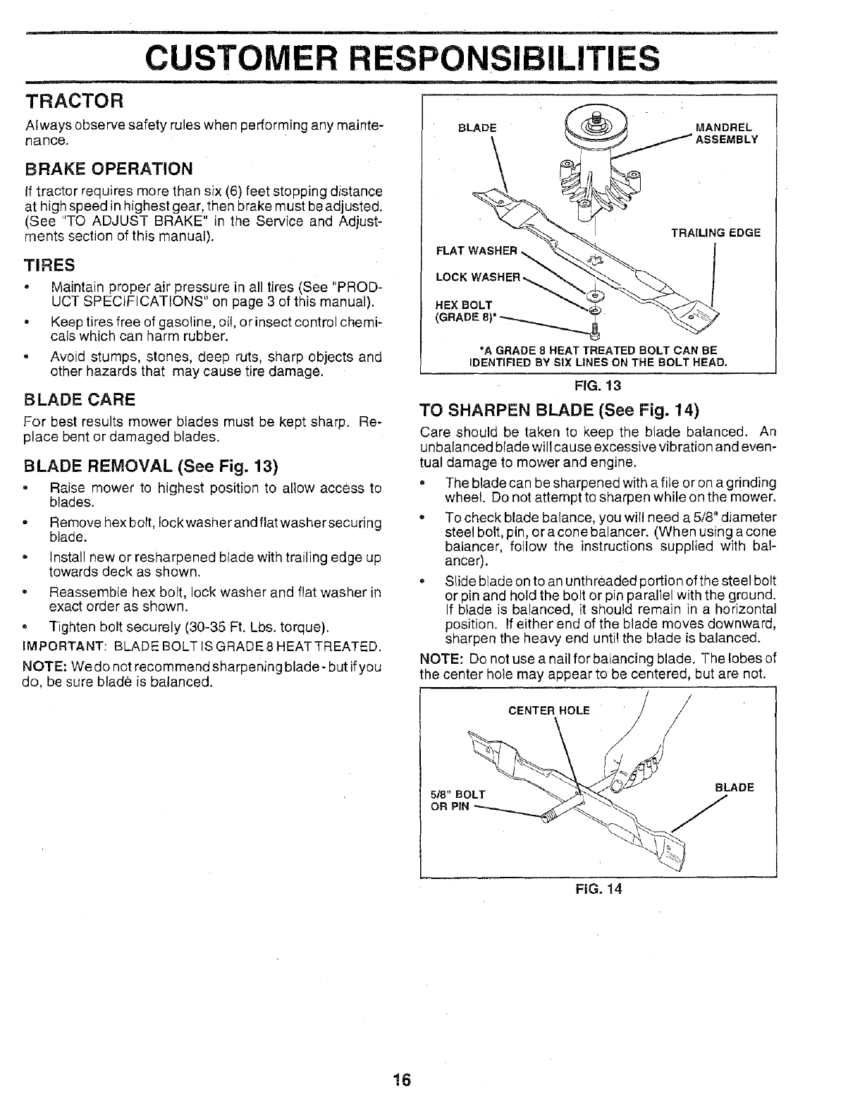
BLADE REMOVAL (See Fig. 13)
, Raise mower to highest position to allow access to
blades.
• Remove hex bolt, Iockwasher and flat washer securing
blade.
• install new or resharpened blade with trailing edge up
towards deck as shown.
, Reassemble hex bolt, lock washer and flat washer in
exact order as shown.
° Tighten bolt securely (30-35 Ft. Lbs. torque).
IMPORTANT: BLADE BOLT IS GRADE 8 HEAT TREATED.
NOTE: We do not recommend sharpening blade- but ifyou
do, be sure blade is balanced.
BLADE
FIG, 13
TO SHARPEN BLADE (See Fig. 14)
Care should be taken to keep the blade balanced. An
unbalanced blade will cause excessive vibration and even-
tual damage to mower and engine.
• The blade can be sharpened with a file or on a grinding
wheel. Do not attempt to sharpen while on the mower.
,, To check blade balance, you will need a 5/8" diameter
steel bolt, pin, or a cone balancer. (When using a cone
balancer, follow the instructions supplied with bal-
anCer).
', Slide blade on to an unthreaded portion of the steel bolt
or pin and hold the bolt or pin paraliel with the ground.
If blade is balanced, it should remain in a horizontal
position. If either end of the blade moves downward,
sharpen the heavy end until the blade is balanced.
NOTE: Do not use a nail for balancing blade. The lobes of
the center hole may appear to be centered, but are not.
CENTERHOLE / /
518" BOLT BLADE
OR PIN
FiG. 14
16
CUSTOMER RESPONSIBILITIES
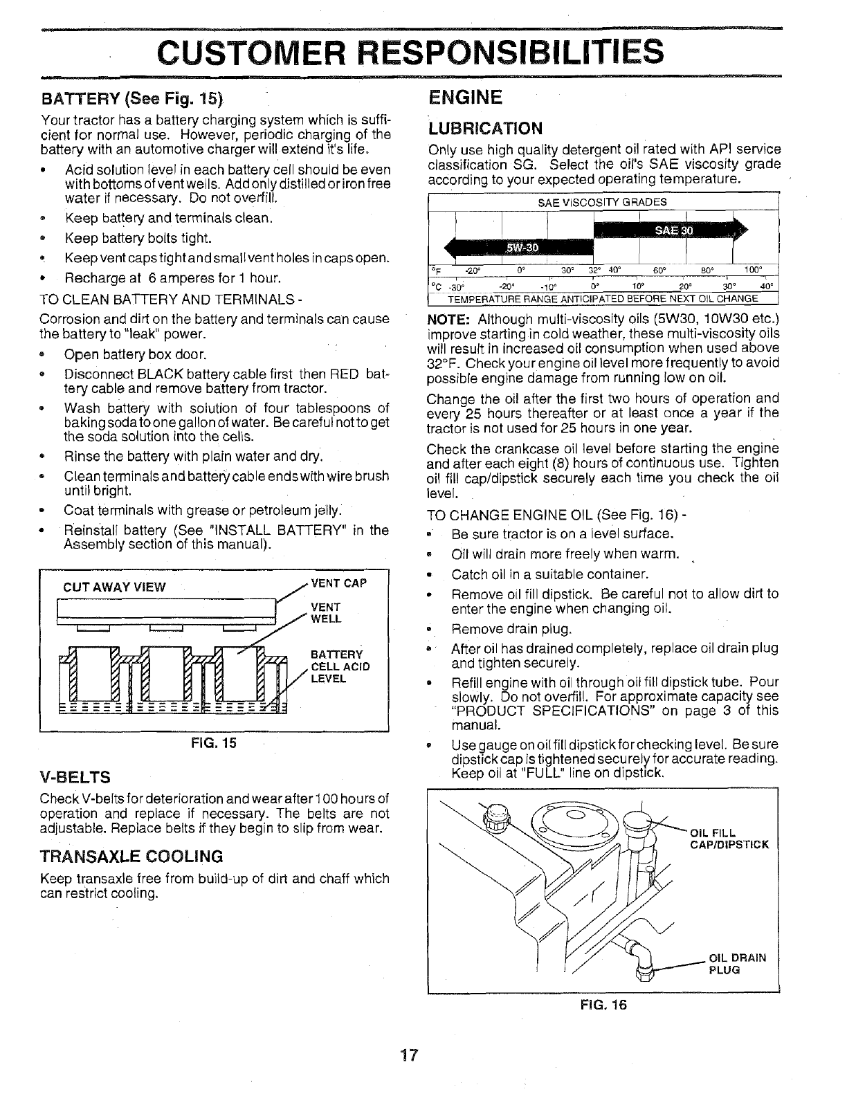
BATTERY (See Fig. 15)
Your tractor has a battery charging system which is suffi-
cient for normal use. However, periodic charging of the
battery with an automotive charger will extend it's life.
• Acid solution level in each battery Cell should be even
with bottoms of vent wells. Add only distilled or iron free
water if necessary. Do not overfill.
, Keep bat!ery and terminals clean.
•Keep battery bolts tight.
, Keep vent caps tight and smallvent holes in caps open,
•Recharge at 6 amperes for 1 hour.
TO CLEAN BATTERY AND TERMINALS -
Corrosion and dirt on the battery and terminals can cause
the battery to "leak" power.
• Open battery box door.
= Disconnect BLACK battery cable first then RED bat-
tery cable and remove battery from tractor.
• Wash battery with solution of four tablespoons of
baking soda to one gallon of water. Be careful not to get
the soda solution into the cells.
= Rinse the battery with plain water and dry.
Clean terminals and battery cable endswith wire brush
until bright.
= Coat terminals with grease or petroleum jelly.
• Reinstall battery (See "INSTALL BATTERY" in the
Assembly section of this manual).
CUT AWAY VIEW
VENT
BATTERY
CELL ACID
FIG. 15
V-BELTS
Check V-belts for deterioration and wear after 100 hours of
operation and replace if necessary. The belts are not
adjustable. Replace belts if they begin to slip from wear.
TRANSAXLE COOLING
Keep transaxle free from build-up of dirt and chaff which
can restrict cooling.
i ii,. i1_
ENGINE
:LUBRICATION
Only use high quality detergent oil rated with API service
classification SG. Select the oil's SAE viscosity grade
according to your expected operating temperature.
SAEVlSCOSlWGRADES
°F-20 _ 0 °30 ° 32° 40 ° 60_ 80* 100 °
°C -30; "20° "10 °10° 20 _ 30° 40°
TEMPERATURE RANGE ANTICIPATED BEFORE NEXT OIL CHANGE
NOTE: Although multi-viscosity oils (5W30, 10W30 etc.)
improve starting in cold weather, these multi-viscosity oils
will result in increased oil consumption when used above
32°F. Check your engine oil level more frequently to avoid
possible engine damage from running low on oil.
Change the oi! after the first two hours of operation and
every 25 hours thereafter or at least once a year if the
tractor is not used for 25 hours in one year.
Check the crankcase oil level before starting the engine
and after each eight (8) hours of continuous use. Tighten
oil fill cap/dipstick securely each time you check the oil
level.
TO CHANGE ENGINE OIL (See Fig. 16) -
• Be sure tractor is on a level surface.
,Oil will drain more freely when warm.
• Catch oil in a suitable container.
• Remove oil fill dipstick. Be careful not to allow dirt to
enter the engine when changing oil.
• Remove drain plug.
• After oil has drained completely, replace oil drain plug
and tighten securely.
. Refill engine with oil through oil fitl dipstick tube. Pour
slowly. Do not overfill. For approximate capacity see
"PRODUCT SPECIFICATIONS" on page 3 of this
manual.
•Use gauge on oil ill[ dipstick for checking level. Be sure
dipstick cap is tightened secu rely for accu rate reading.
Keep oil at "FULL" line on dipstick.
FiLL
CAP/DIPSTICK
OIL DRAIN
PLUG
FIG. 16
17
CUSTOM
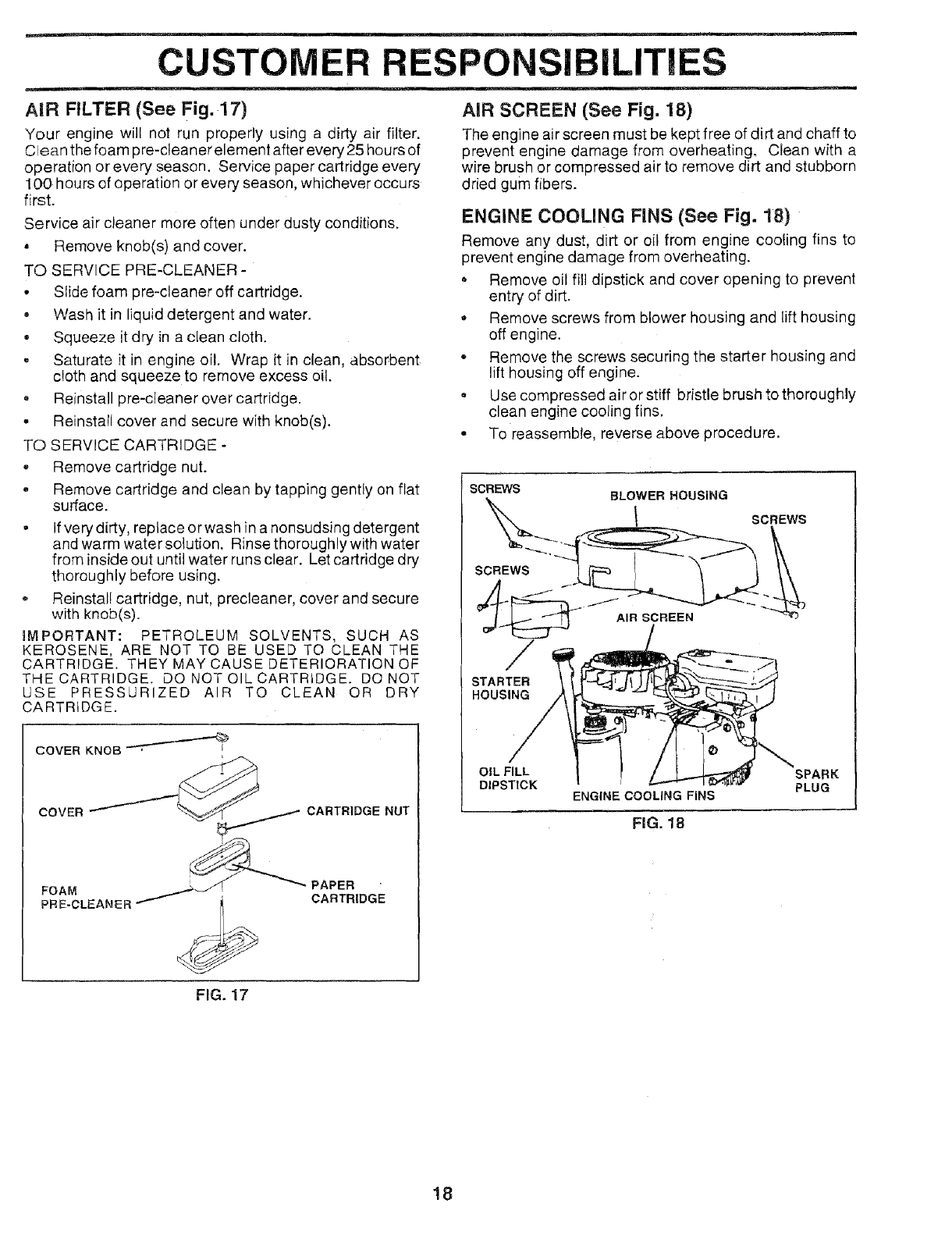
AiR FILTER (See Fig.-17)
Your engine will not run properly using a dirty air filter.
Clean the foam pre-cleaner element after every 25 hours of
operation or every season. Service paper cartridge every
100 hours of operation or every season, whichever occurs
first.
Service air cleaner more often under dusty conditions.
= Remove knob(s) and cover.
TO SERVICE PRE-CLEANER -
° Slide foam pre-cleaner off cartridge.
• Wash it in liquid detergent and water.
• Squeeze it dry in a clean cloth.
•Saturate it in engine oil. Wrap it in clean, absorbent
cloth and squeeze to remove excess oil.
• Reinstall pre-deaner over cartridge.
• Reinstall cover and secure with knob(s).
TO SERVICE CARTRIDGE -
= Remove cartridge nut.
, Remove cartridge and clean by tapping gently on flat
surface.
• If very dirty, replace or wash in a nonsudsing detergent
and warm water solution. Rinse thoroughly with water
from inside out until water runs clear. Let cartridge dry
thoroughly before using.
Reinstal! cartridge, nut, precleaner, cover and secure
with knob(s).
iMPORTANT: PETROLEUM SOLVENTS, SUCH AS
KEROSENE, ARE NOT TO BE USED TO CLEAN THE
CARTRIDGE. THEY MAY CAUSE DETERIORATION OF
THE CARTRIDGE. DO NOT OIL CARTRIDGE. DO NOT
USE PRESSURIZED AIR TO CLEAN OR DRY
CARTRIDGE.
COVER KNOB '-'_'''-
COVER
ER RESPONSIBi
CARTRIDGE NUT
PAPER
FOAM ; CARTRIDGE
AIR SCREEN (See Fig. 18)
The engine air screen must be kept free of dirt and chaff to
prevent engine damage from overheating. Clean with a
wire brush or compressed air to remove dirt and stubborn
dried gum fibers.
ENGINE COOLING FiNS (See Fig. 18)
Remove any dust, dirt or oil from engine cooling fins to
prevent engine damage from overheating.
• Remove oil fill dipstick and cover opening to prevent
entry of dirt.
•Remove screws from blower housing and lift housing
off engine.
• Remove the screws securing the starter housing and
lift housing off engine.
° Use compressed air or stiff bristle brush to thoroughly
clean engine cooling fins.
° To reassemble, reverse above procedure.
SCREWS SLOWER HOUSING
SCREWS
SCREWS
ENGINE COOLING FINS
FIG. 18
FIG. 17
18
CUSTOMER RESPONSIBILITIES
MUFFLER
Inspect and replace corroded muffler and spark arrester (if
equipped) as it could create a fire hazard and/or damage.
SPARK PLUGS
Replace spark plugs at the beginning of each mowing
season or after every 100 hours of operation, whichever
comes first. Spark plug type and gad setting are shown in
'_PRODUCT SPECIFICATIONS" on page 3 of this manual.
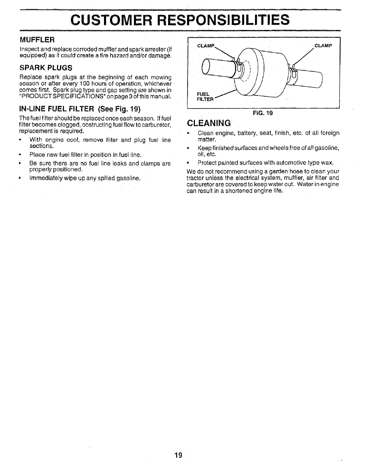
IN-LINE FUEL FILTER (See Fig. 19)
The fuel filter should be replaced once each season. If fuel
filter becomes clogged, obstructing fuel flow to carburetor,
replacement is required.
• With engine cool, remove filter and plug fuel line
sections.
•Place new fuel filter in position in fuel ine.
• Be sure there are no fue line leaks and clamps are
properly positioned.
• Immediately wipe up any spilled gasoline.
CLAMP_ _CLAMP
FIG. 19
CLEANING
Clear engine, battery, seat, finish etc. of all foreign
matter.
•Keep finished surfaces and wheels free of al! gasoline,
oil, etc.
- Protect painted surfaces with automotive type wax.
We do not recommend using a garder hose to clean your
tractor unless the electrical system, muffler, air filter and
carburetor are covered to keepwater out. Water in engine
can result in a shortened engine life.
19
m
SERVICE AND ADJUSTMENTS
e==_m
m m
CAUTION: BEFORE PERFORMING ANY SERVICE QR ADJUSTMENTS:
®
®
Depress clutch/brake pedal fully and set parking brake, ....
Place gearshift lever in "NEUTRAL" position.
Place attachment clutch in "DISENGAGED" position.
Turn ignition key "OFF" and remove key.
Make sure the blades and all moving parts have completely stopped.
Disconnect spark plug wire from spark plug and place wire where it cannot come in contact with
plug.
TRACTOR
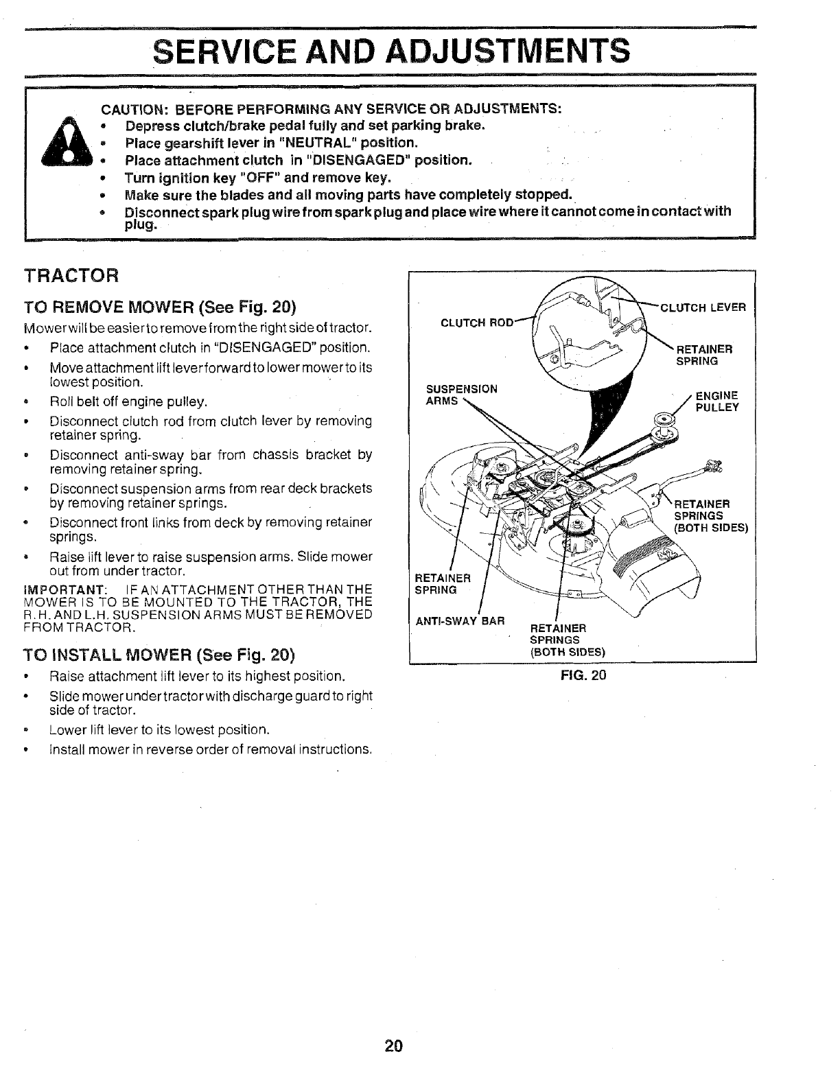
TO REMOVE MOWER (See Fig. 20)
Mower will be easier to remove from the right side ot tractor.
• Place attachment clutch in "DISENGAGED" position.
• Move attachment lift lever forward to lower mower to its
lowest position.
• Roll belt off engine pulley.
• Disconnect clutch rod from clutch lever by removing
retainer spring.
, Disconnect anti-sway bar from chassis bracket by
removing retainer spring.
• Disconnect suspension arms from rear deck brackets
by removing retainer springs.
• Disconnect front links from deck by removing retainer
springs.
• Raise tilt lever to raise suspension arms. Slide mower
out from under tractor.
IMPORTANT: IF AJ\JATTACHMENT OTHER THAN THE
MOWER IS TO BE MOUNTED TO THE TRACTOR, THE
R.H.AND L.H. SUSPENSION ARMS MUST BE REMOVED
FROM TRACTOR.
TO INSTALL MOWER (See Fig. 20)
• Raise attachment lift lever to its highest position.
• Slide mower under tractor with discharge guard to right
side of tractor.
• Lower lift lever to its lowest position.
•Install mower in reverse order of removal instructions.
LEVER
SPRING
SUSPENSION ENGINE
ARMS PULLEY
SPRINGS
(BOTH SIDES)
RETAINER
SPRING
ANTI-SWAY BAR RETAINER
SPRINGS
(BOTH SLOES)
FIG, 20
2O
SERVICE AND ADJUSTMENTS
TO LEVEL MOWER HOUSING
Adjust the mower wHle tractor is parked on level ground or
driveway. Make sure tires are properly inflated (See
"PRODUCT SPECIFICATIONS'on page3 of this manual).
If tires are over Dr unde rinflated, you will not properly adjust
your mower.
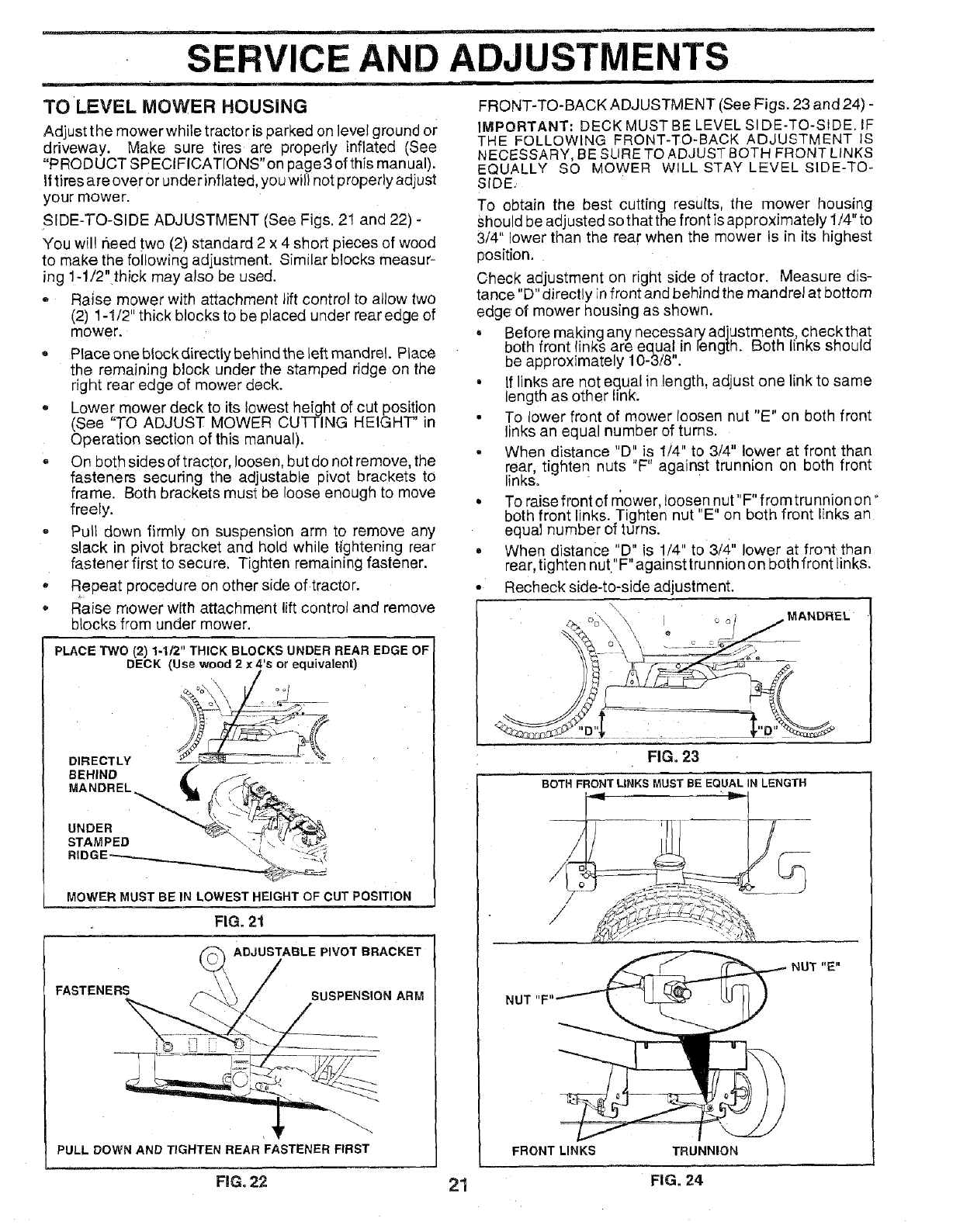
SIDE-TO-SIDE ADJUSTMENT (See Figs. 2! and 22) -
You win need two (2) standard 2 x 4 short pieces of wood
to make the following adjustment. Similar blocks measur-
ing 1-1/2" thick may also be used.
= Raise mower with attachment lift control to allow two
(2) 1-1/2" thick blocks to be placed under rear edge of
mower.
• Place one block directly behind the left mandrel Place
the remaining block under the stamped ridge on the
right rear edge of mower deck.
,, Lower mower deck to its lowest height of cut position
(See "TO ADJUST MOWER CUTTING HEIGHT' in
Operation section of this manual).
,, On bothsidesoftractor, loosen, but do not remove, the
fasteners securing the adjustable pivot brackets to
frame. Both brackets must be loose enough to move
freely.
,, Pull down firmly on suspension arm to remove any
slack in pivot bracket and hold while tightening rear
fastener first to secure. Tighten remaining fastener.
• Repeat procedure on other side of tractor.
Raise mower with attachment lift control and remove
blocks from under mower.
PLACE TWO (2) 1-1/2" THICK BLOCKS UNDER REAR EDGE OF
DECK (Use wood 2x4's or equivalent)
DIRECTLY J__('_
MOWER MUST BE IN LOWEST HEIGHT OF CUT POSITION
FIG. 21
PULL DOWN AND TIGHTEN REAR FASTENER FIRST
FIG. 22
FRONT-TO-BACK ADJUSTMENT (See Figs. 23 and 24) -
IMPORTANT: DECK MUST BE LEVEL SIDE-TO-SiDE. IF
THE FOLLOWING FRONT-TO-BACK ADJUSTMENT IS
NECESSARY, BE SURE TO ADJUST BOTH FRONT LINKS
EQUALLY SO MOWER WILL STAY LEVEL SIDE-TO-
SIDE_
TO obtain the best cutting results, the mower housing
Should be adjusted so that the front is approximately 1/4" to
3/4" lower than the rear when the mower is in its highest
position.
Check adjustment on right side of tractor. Measure dis-
tance "D" directly in front and behind the mandrel at bottom
edge of mower housing as shown.
• Before making any necessary adjustments, checktha!
both front links are equal in length. Both links snouma
be approximately 10-3/8".
• If links are not equal in length, adjust one link to same
length as other link.
• To lower front of mower loosen nut "E" on both front
links an equal number of turns.
- When distance "D" is 1/4" to 3/4" lower at front than
rear, tighten nuts "F" against trunnion on both front
links.
° To raise front of mower, loosen nut"F" fromtrunnion on"
both front links. Tighten nut "E" on both front links an
equal number of turns.
. When distance "D" is !/4" to 3/4" lower at froqt than
rear, tighten nut"F"againsttrunnion on both front links.
• Recheck side-to-side adjustment.
_ oo,,i"X i o o i=MANDREL
FIG. 23
BOTH FRONT LINKS MUST BE EQUAL IN LENGTH
/
NUT "1""
FRONT LINKS TRUNNION
NUT "E"
21 FIG. 24
SERVICE
IIIIMI !r
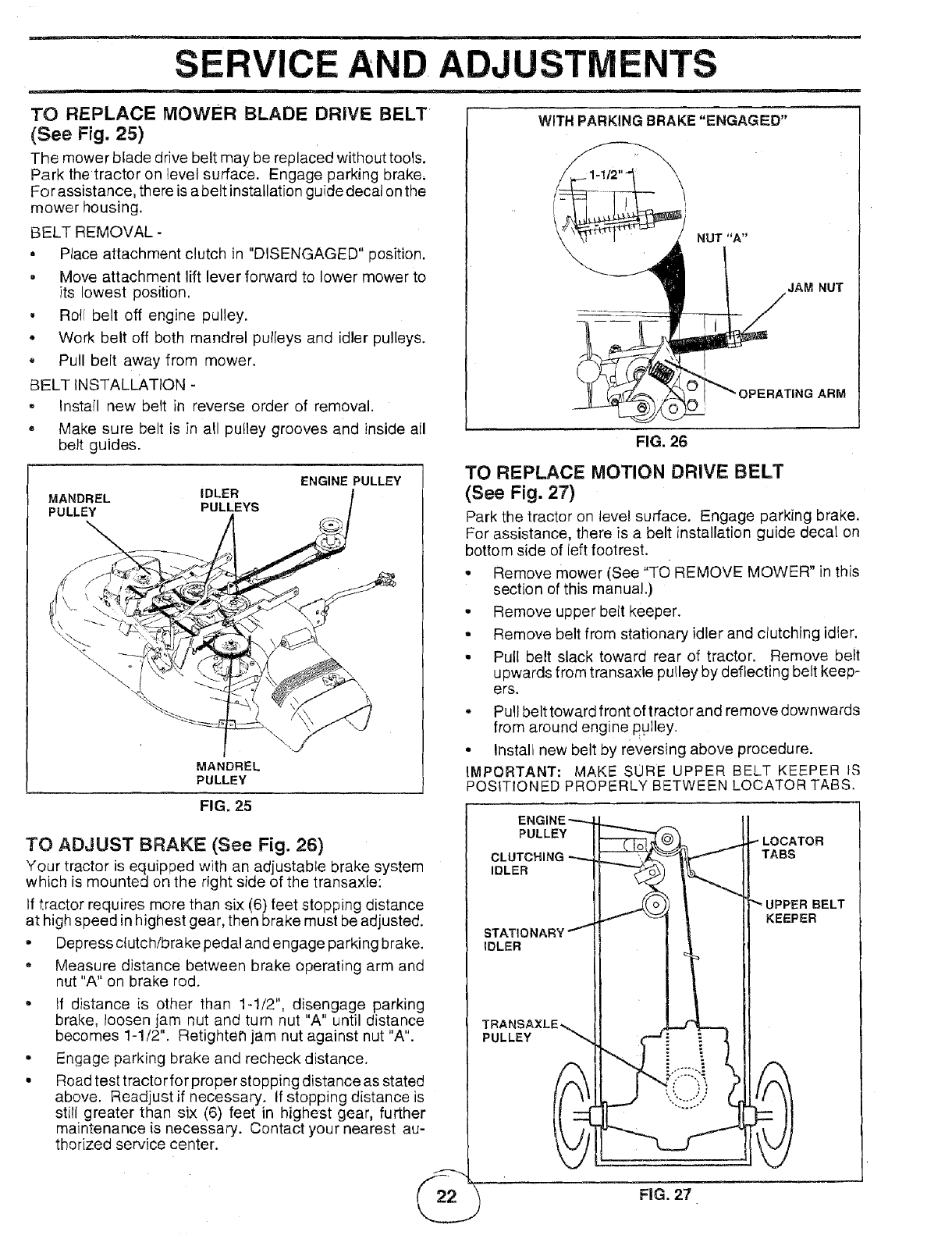
TO REPLACE MOWER BLADE DRIVE BELT
(See Fig. 25)
The mower blade drive belt may be replaced without tools.
Park the tractor on level surface. Engage parking brake,
For assistance, there is a belt installation guide decal onthe
mower housing.
BELT REMOVAL -
• Place attachment clutch in "DISENGAGED" position.
• Move attachment lift lever forward to lower mower to
its lowest position.
• Roll belt off engine pulley.
• Work belt off both mandrel pulleys and idler pulleys.
, Pull belt away from mower.
BELT INSTALLATION -
, Install new belt in reverse order of removal.
• Make sure belt is in all pu!ley grooves and inside all
belt guides.
ENGINE PULLEY
MANDREL IDLER
PULLEY PULLEYS
MANDREL
PULLEY
FIG. 25
TO ADJUST BRAKE (See Fig. 26)
Your tractor is equipped with an adjustable brake system
which is mounted on the right side of the transaxle:
If tractor requires more than six (6) feet stopping distance
at high speed in highest gear, then brake must be adjusted.
•Depress clutch/brake pedal and engage parking brake.
-Measure distance between brake operating arm and
nut "A" on brake rod.
• If distance is other than 1-1/2", disengage parking
brake, loosen jam nut and turn nut "A" until distance
becomes 1-1/2". Retighten jam nut against nut "A".
• Engage parking brake and recheck distance.
• Road test tractor for proper stopping distance as stated
above. Readjust if necessary. If stopping distance is
still greater than six (6) feet in highest gear, further
maintenance is necessary. Contact your nearest au-
thorized service center.
AND. ADJUSTMENTS
WITH PARKING BRAKE "ENGAGED"
NUT "A"
AM NUT
FIG. 26
TO REPLACE MOTION DRIVE BELT
(See Fig. 27)
Park the tractor on level surface. Engage parking brake.
For assistance, there is a belt installation guide decal on
bottom side of left footrest.
-Remove mower (See "TO REMOVE MOWER" in this
section of this manual.)
- Remove upper belt keeper.
= Remove belt from stationary idler and clutching idler.
• Pull belt slack toward rear of tractor. Remove belt
upwards from transaxle pulley by deflecting belt keep-
ers.
o Pull belt toward front of tractor and remove downwards
from around engine pulley.
• Install new belt by reversing above procedure.
iMPORTANT: MAKE SORE UPPER BELT KEEPER tS
POSITIONED PROPERLY BETWEEN LOCATOR TABS.
PULLEY LOCATOR
CLUTCHING TABS
IDLER
IDLER
UPPER BELT
KEEPER
PULLEY
FIG. 27
SERVICE AND ADJUSTMENTS
TO ADJUST STEERING WHEEL ALIGNMENT
If steering wheel crossbars are not horizontal (left to right)
when wheels are positioned straight forward, remove steer-
ing wheel and reassemble per instructions in the Assembly
section of this manual.
FRONT WHEEL TOE=IN/CAMBER
The front wheel toe-in and camber are not adjustable on
your tractor. If damage has occurred to affect the front
wheel toe-in or camber, contact your nearest authorized
service center.
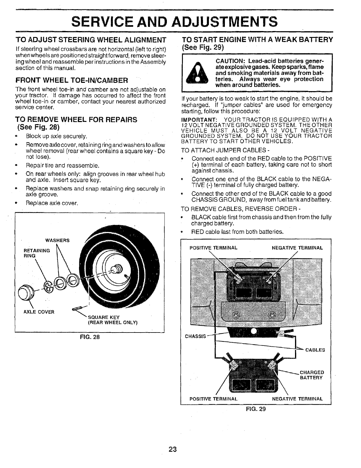
TO REMOVE WHEEL FOR REPAIRS
(See Fig. 28)
-Block up axle securely.
*Remove axle cover, retaining ring and washers to allow
wheel removal (rear wheel contains a square key - Do
not lose).
° Repair tire and reassemble.
On rear wheels only: align grooves in rear wheel hub
and axle. Insert square key.
*Replace washers and snap retaining ring securely in
axle groove.
*Replace axle cover.
WASHERS
RETAINING
RING
I
'_ SQUARE KEY
(REAR WHEEL ONLY)
FIG. 28
Q
AXLE coVER
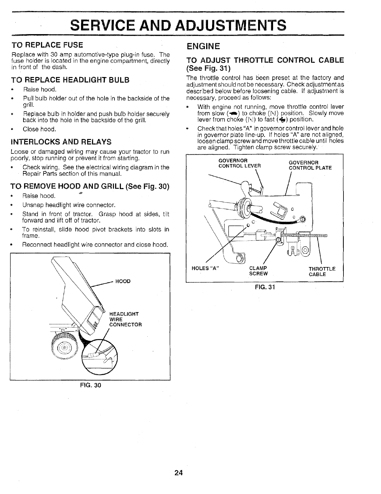
TO START ENGINE WRTHA WEAK BA'I-i'ERY
See Fig. 29)
CAUTION: Lead-acid batteries gener-
ate explosive gases. Keep sparks, flame
and smoking materials away from bat-
teries, Always wear eye protection
when around batteries.
If your battery is too weak to start the engine, it should be
recharged. If "jumper cables" are used for emergency
starting, follow this procedure:
IMPORTANT_ YOUR TRACTOR IS EQUIPPED WITHA
12 VOLT NEGATIVE GROUNDED SYSTEM. THE OTHER
VEHICLE MUST ALSO BE A 12 VOLT NEGATIVE
GROUNDED SYSTEM. DO NOT USE YOUR TRACTOR
BATTERY TO START OTHER VEHICLES.
TO ATTACH JUMPER CABLES -
,, Connect each end of the RED cable to the POSITIVE
(+) terminal of each battery, taking care not to short
against chassis.
*Connect one end of the BLACK cable to the NEGA-
TIVE (-) terminal of fully charged battery.
- Connect the other end of the BLACK cable to a good
CHASSIS GROUN D, away from fuel tank and battery.
TO REMOVE CABLES, REVERSE ORDER -
, BLACK cable first from chassis and then from the fully
charged battery.
-RED cable last from both batteries.
POSITIVE TERMINAL NEGATIVE TERMINAL
CHASSIS
CABLES
CHARGED
BATTERY
POSITIVE TERMINAL NEGATIVE TERMINAL
FiG. 29
23
S
TO REPLACE FUSE
CE AN ADJUSTMENTS
Replace with 30 amp automotive-type plug-in fuse, The
fuse holder is located in the engine compartment, directly
in front of the dash.
TO REPLACE HEADLIGHT BULB
o Raise hood.
o Pull bulb holder out of the hole in the backside of the
grill.
, Replace bulb in holder and push bulb holder securely
back into the hole in the backside of the grill.
* Close hood.
INTERLOCKS AND RELAYS
Loose or damaged wiring may cause your tractor to run
poorly, stop running or prevent it from starting.
- Check wiring. See the electrical wiring diagram in the
Repair Parts section of this manual.
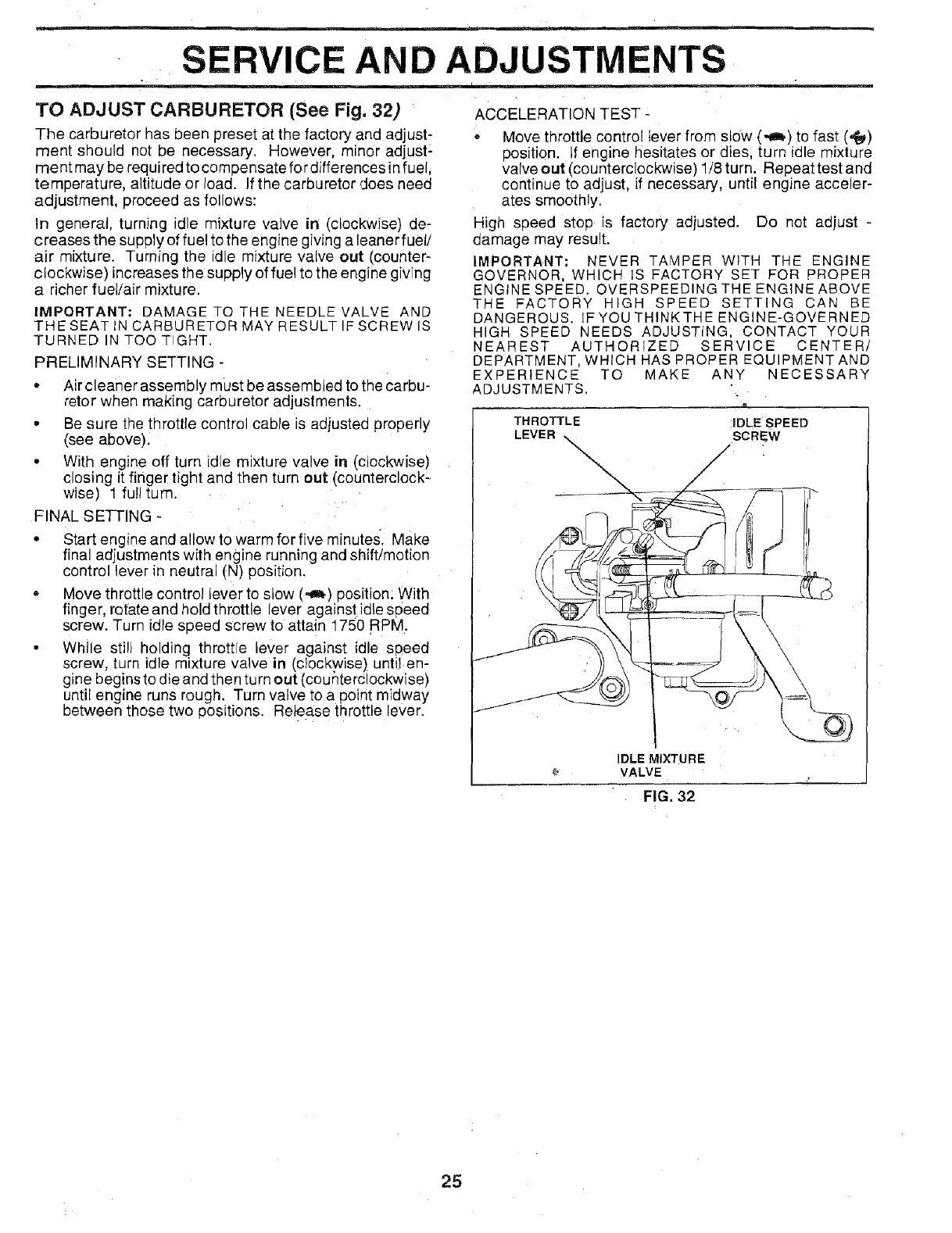
TO REMOVE HOOD AND GRILL (See Fig. 30)
,, Raise hood. _
• Unsnap headlight wire connector.
• Stand in front of tractor. Grasp hood at sides, tilt
forward and Liftoff of tractor.
• To reinstall, slide hood pivot brackets into slots in
frame.
• Reconnect headlight wire connector and close hood.
HOOD
HEADLIGHT
WIRE
CONNECTOR
ENGINE
TO ADJUST THROTTLE CONTROL CABLE
(See Fig. 31)
The throttle control has 1seen preset at the factory and
adjustment should not be necessary. Check adjustment as
described below before loosening cable. If adjustment is
necessary, proceed as follows:
= With engine not running, move throttle control lever
from slow (,,am,)to choke (N) position. Slowly move
lever from choke (1\1)to fast (,1_) position.
Check that holes"A" in governor control lever and hole
in governor plate line-up. If holes "A" are not aligned,
loosen clamp screw and move throttle cable until holes
are aligned. Tighten clamp screw securely.
GOVERNOR
CONTROLLEVER GOVERNOR
CONTROLPLATE
O
o
HOLES"A" CLAMP
SCREW THROTTLE
CABLE
FIG. 31
FiG. 30
24
. SERVICE AND ADJUSTMENTS
TO ADJUST CARBURETOR (See Fig. 32)
The carburetor has been preset at the factory and adjust-
ment should not be necessary. However, minor adjust:
ment may be required to compensate fo rdifferences in fuel,
temperature, altitude or load. If the carburetor does need
adjustment, proceed as follows:
In general, turning idle mixture valve in (clockwise) de-
creases the supply of fuel to the engine giving a leaner fuel!
air mixture. Turning the idle mixture valve out (counter-
clockwise) increases the supply of fue! to the engine giving
a richer fuel/air mixture.
IMPORTANT: DAMAGE TO THE NEEDLE VALVE AND
THE SEAT IN CARBURETOR MAY RESULT IF SCREW IS
TURNED IN TOO TIGHT.
PRELIMINARY SETTING -
• Air cleaner assembly must be assembled to the Carbu-
retor when making carburetor adjustments.
• Be sure the throttle control cable is adjusted properly
(see above).
• With engine off turn idle mixture valve in (clockwise)
closing it finger tight and then turn out (counterclock-
wise) 1 full turn.
FINAL SETTING -
• Start engine and allow to warm for five minute& Make
final adjustments with engine running and shift/motion
control lever in neutral (N) position.
+ Move throttle control lever to slow (._) position: With
finger, rotate and hold throttle lever agains t idle speed
screw. Turn idle speed Screw to attain 1750 RPM.
• While still holding throttle lever against idle speed
screw, turn idle mixture valve in (clockwise) until en-
gine begins to die and then turn out (counterclockwise)
until engine runs rough. Turn valVe toa point midway
between those two positions. Re}ease throttle lever.
ACCELERATION TEST-
, Move throttle control lever from slow (,.a_) to fast (,_)
position, if engine hesitates or dies, turn idle mixture
valve out (counterclockwise) 1/8 turn. Repeat test and
continue to adjust, if necessary, until engine acceler-
ates smoothly.
High speed stop is factory adjusted. Do not adjust -
damage may result.
IMPORTANT: NEVER TAMPER WITH THE ENGINE
GOVERNOR, WHICH IS FACTORY SET FOR PROPER
ENGINE SPEED. OVERSPEEDINGTHEENGINEABOVE
THE FACTORY HIGH SPEED SETTING CAN BE
DANGEROUS. IF YOU THINK THEENGINE-GOVERNED
HIGH SPEED NEEDS ADJUSTING, CONTACT YOUR
NEAREST AUTHORIZED SERVICE CENTER/
DEPARTMENT, WHICH HAS PROPER EQUIPMENT AND
EXPERIENCE TO MAKE ANY NECESSARY
ADJUSTMENTS.
THROTTLE iDLE SPEED
LEVER SCRE_W
VALVE
FiG, 32
25
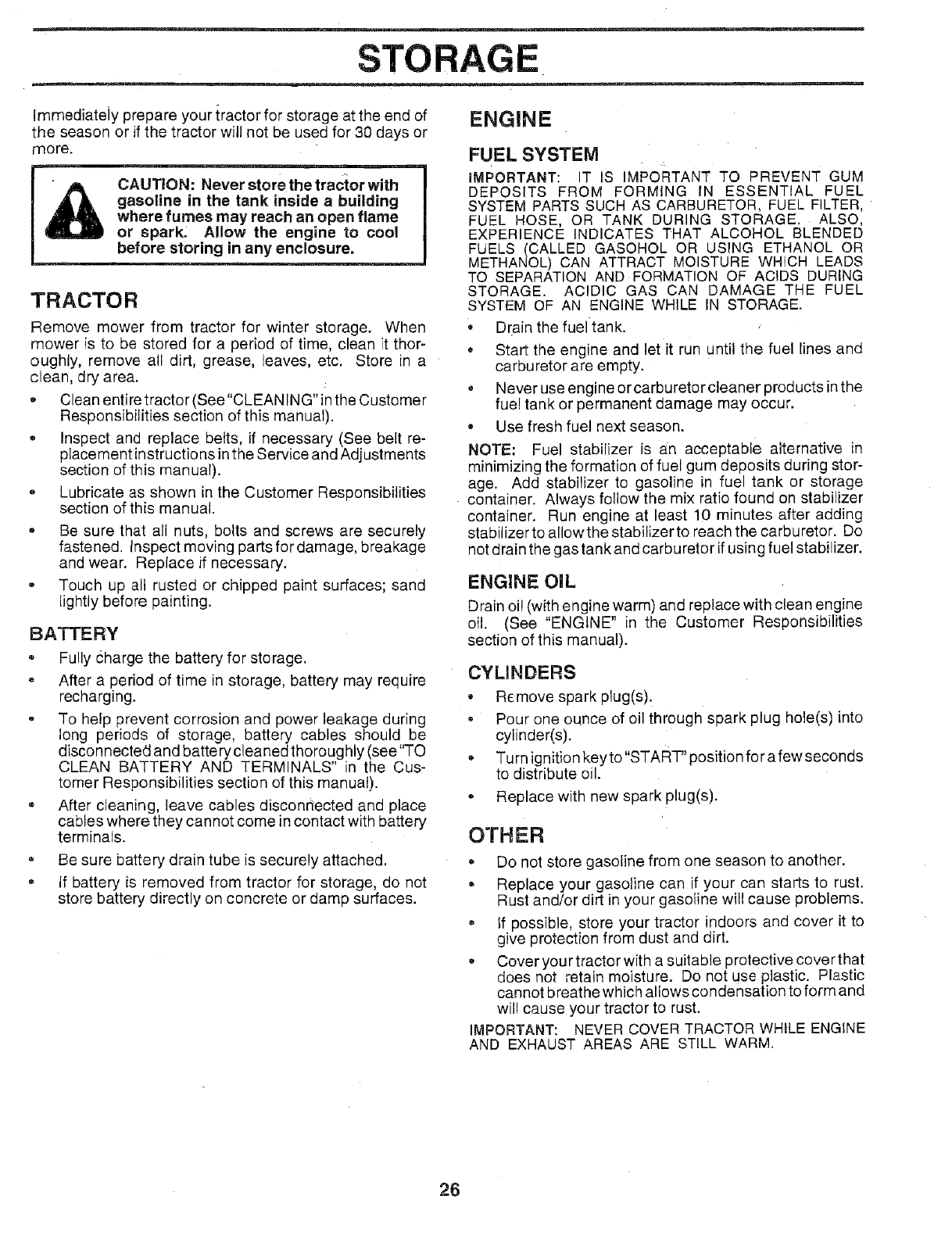
STO
Immediately prepare your iractor for storage at the end of
the season or if the tractor will not be used for 30 days or
more.
CAUTION: Never storethe tractor with
gasoline in the tank inside a building
where fumes may reach an open flame
or spark: Allow the engine to cool
before storing in any enclosure.
TRACTOR
Remove mower from tractor for winter storage. When
mower is to be stored for a period of time, clean ;tthor-
oughly, remove all dirt, grease, leaves, etc. Store in a
clean, dry area.
-Clean entiretractor (See"CLEANING"in the Customer
Responsibilities section of this manual).
e Inspect and replace belts, if necessary (See be[t re-
placement instructions in the Service and Adjustments
section of this manual).
-Lubricate as shown in the Customer Responsibilities
section of this manual.
-Be sure that all nuts, bolts and screws are securely
fastened. Inspect moving partsfordamage, breakage
and wear. Replace if necessary.
-Touch up all rusted or chipped paint surfaces; sand
[ightly before painting.
BATTERY
= Fully charge the battery for storage.
=After a period of time in storage, battery may require
recharging.
= To help prevent corrosion and power leakage during
long periods of storage, battery cables should be
disconnected and battery cleaned thoroughly (see"TO
CLEAN BATTERY AND TERMINALS" in the Cus-
tomer Responsibilities section of this manual).
.After cleaning, leave cables disconnected and place
cables where they cannot come in contact with battery
terminals.
*Be sure battery drain tube is securely attached.
*If battery is removed from tractor for storage, do not
store battery directly on concrete or damp surfaces.
ENGINE
FUEL SYSTEM
IMPORTANT: IT IS IMPORTANT TO PREVENT GUM
DEPOSITS FROM FORMING IN ESSENTIAL FUEL
SYSTEM PARTS SUCH AS CARBURETOR, FUEL FILTER,
FUEL HOSE, OR TANK DURING STORAGE. ALSO,
EXPERIENCE INDICATES THAT ALCOHOL BLENDED
FUELS (CALLED GASOHOL OR USING ETHANOL OR
METHANOL) CAN ATTRACT MOISTURE WHICH LEADS
TO SEPARATION AND FORMATION OF ACIDS DURING
STORAGE. ACIDIC GAS CAN DAMAGE THE FUEL
SYSTEM OF AN ENGINE WHILE IN STORAGE.
*Drain the fuel tank.
*Start the engine and let it run until the fuel lines and
carburetor are empty.
o Never use engine or carburetor cleaner products in the
fue! tank or permanent damage may occur.
.Use fresh fuel next season.
NOTE: Fuel stabilizer is an acceptable alternative in
minimizing the formation of fuel gum deposits during stor-
age. Add stabilizer to gasoline in fuel tank or storage
container. Always follow the mix ratio found on stabilizer
container. Run engine at least 10 minutes after adding
stabilizer to allowthe stabilizer to reach the carburetor. Do
not drain the gas tank and carburetor if using fuel stabilizer.
ENGINE OiL
Drain oi! (with engine warm) and replace with clean engine
oil. (See "ENGINE" in the Customer Responsibilities
section of this manual).
CYLINDERS
•Remove spark plug(s).
•Pour one ounce of oil through spark plug hole(s) into
cylinder(s).
.Turn ignition keyto"START" position for afew seconds
to distribute oil.
•Replace with new spark plug(s).
OTH ER
•Do not store gasoline from one season to another.
= Replace your gasoline can if your can starts to rust.
Rust and/or dirt in your gasoline wil! cause problems.
.If possible, store your tractor indoors and cover it to
give protection from dust and dirt.
•Cover your tractor with a suitable protective cover that
does not retain moisture. Do not use plastic. Plastic
cannot breathe which allows condensation to form and
will cause your tractor to rust.
IMPORTANT: NEVER COVER TRACTOR WHILE ENGINE
AND EXHAUST AREAS ARE STILL WARM.
26

TROUBLESHOOTING POINTS
PROBLEM
Will not start
CAUSE
Hard to start
!. Out of fuel.
2. Engine not "CHOKED" properly.
3. Engine flooded.
4. Bad spark plug,
5. Dirty air filter.
6. Dirty fuel filter,
7. Water in fuel+
8, Loose or damaged wiring.
9. Carburetor out of adjustment.
10. Engine valves out of adjustment.
1. Dirty air filter,
2+ Bad spark plug,
3. Weak or dead battery,
4. Dirty fuel filter.
5. Stale or dirty fuel.
6. Loose or damaged widng.
7. Carburetor out of adjustment.
8. Engine valves out of adjustment.
CORRECTION
t. Fitlfuel tank.
2. See "TO START ENGINE" in Operation section.
3. Wait several minutes before attempting to start.
4. Replace spark plug.
5. Clean/replace air filter.
6. Replace fuel filter.
7, Drain fuel tank and carburetor, refill tank with fresh
gasoline and replace fuel filter,
8+ Check all wiring.
9. Contact an authorized service facility.
10. Contact an authorized service facility.
1. Cleanireulace air filter,
2. Replace sl_rk plug.
3, Recharge or replace battery.
4. Replace fuel filter.
5+ Drain fuel tank and refill with fresh gasoline.
6, Check all wiring.
7. Contact an authorized service facility.
8. Contact an authorized service facility.
Engine will not turn over 1. Clutch!brake pedal not depressed.
2. Attachment clutch is engaged.
3. Weak or dead battery.
4. Blown fuse.
5. Corroded battery terminals.
6. Loose or damaged wiring.
7, Faulty ignition switch.
8. Faulty solenoid or starter.
9. Faulty operator presence switch(ee).
Engine clicks but will not
start
mi,,,
Loss of power
Excessive vibration
1. weak or dead battery.
2. Corroded battery terminals.
3+ Loose ordamaged wiring.
4. Faulty solenoid or starter.
i. Cutting too much grass/too fast.
2. Throttle in "CHOKE" position.
3. Build-up of grass, leaves and trash under mower,
4. Dirty air filter.
5. Low oil level/dirty oil.
6. Faulty spark plug.
7. Dirty fuel filter.
8. Stale or dirty fuel.
9. Water in fuel.
10. Spark plug wire loose,
11. Dirty engine air screen/fins.
12. Dirty/c!ogged muffler.
13. Loose or damaged wiring.
14. Carburetor out of adjustment.
15. Engine valves out of adjustment.
4. Depress clutch/brake pedal.
2+ Disengage attachment clutch.
3. Recharge or reelaee battery.
4. ,Replace fuse,
5. Clean battery terminals.
6. Check all wiring.
7L Cheek/replace ignition switch.
8. Check/replace solenoid or starter.
9. Contact an authodzed service facility.
1. Wom, bent or loose blade.
2. Bent blade mandrel.
3. Loose/damaged part(s).
1. Recharge or reolace battery.
2. Clean battery terminals.
3. Check al wiring,
4. Check!reptace solenoid or starter.
1. Set in "Higher Cut" oosition/reduce seeed,
2. Adjust throtfie centre
3. Clean underside of mower housing.
4. Clean/replace air filter,
5, Check oil level/change oil.
6. Clean and regap or change spark plug.
7. Replace fuel filter.
8+ Drain fuel tank and refi!l with fresh gaSOline.
9. Drain fuel tank and carburetor, refill tank with fresh
gasoline and replace fuel filter,
10. Connect and tighten spark plug wire.
11. Clean engine air screen/fins.
12. Clean/replace muffler.
13. Check all wiring,
14, Contact an authorized service facility.
15. Contact an authorized service facility,
1. Replace blade. Tighten blade bolt.
2. Replace blade mandrel.
3, Tighten loose part(s). Replace damaged parts.
27

PROBLEM
Engine continues to run
when operator leaves seat
with attachment clutch
engaged
Poor cut - uneven
Mower blades will not
rotate
Poor grass discharge
Headlight(e) not working
(if so equipped)
Battery will not charge
Engine "backfires"
when turning engine
"OFF"
TROU
CAUSE
1. Faulty operator-safety presence control system.
LESHOOTING POINTS
CORRECTION
1. Worn, bent or loose blade.
2. Mower deck not level.
3+ Buildup of grass, leaves, and trash under mower.
4. Bent blade mandrel.
5. Clogged mower deck vent holes from buildup of
grass, leaves, and trash around mandrels.
1. Obstruction in clutch mechanism.
2. Wor!!damaged mower drive belt,
3. Frozen idler pulley.
4. Frozen blade mandrel.
1. Engine speed too slow.
2. Travel speed too fast.
3. Wet grass, +
4. Mower deck not level.
5. Low/uneven tire air pressure.
6. Worn, bent or loose blade.
7. Buildup of grass, leaves and trash under mower,
8. Mower drive belt worn.
9. Blades impropedy installed.
10. Improper blades used.
11. Clogged mower deck vent holes from buildup of
grass, leaves, and trash around mandrels.
t. Switch is "OFF".
2, Bulb(s) burned out.
3. Faulty light switch.
4. Loose or damaged wiring.
5. Blown fuse.
1. Bad battery cell(s).
2. Poor cable connections.
3. Faulty regulator (if so equipped).
4. Faulty alternator.
1. Engine throttle control not set at "SLOW"
position for 30 seconds before stopping engine.
1. Check wiring, switches and connections. If not
corrected, contact an authorized service facility.
1. Replace blade. Tighten blade bolt.
2. Level mower deck.
3. Clean underside of mower housing.
4. Replace blade mandrel.
5. Clean around mandrels to open vent holes.
1. Remove obstruction.
2, Replace mower drive belt,
3. Replace idler pulley.
4. Replace blade mandrel.
!. Place throttle control in "FAST" position.
2. Shift to slower speed.
3. Allow grass to dry before mowing.
4. Level mower deck.
5. Check tires for proper air pressure.
6. Replace/sharpen blade. Tighten blade bolt.
7. Clean underside of mower housing.
8. Replace mower drive belt.
9. Reinstall blades sharp edge down.
10. Replace with blades listed in this manual.
11. Clean around mandrels to open vent holes.
1. Turn switch "ON".
2. Replace bulb(s).
3. Check/replace light switch.
4. Check wiring and connections.
5. Replace fuse.
!, Replace bakery.
2. Check!clean all connections.
3, Replace regulator.
4. Replace alternator.
1, Move throttle conti'ol to "SLOW" position and allow
to idle for 30 seconds before stopping engine
28
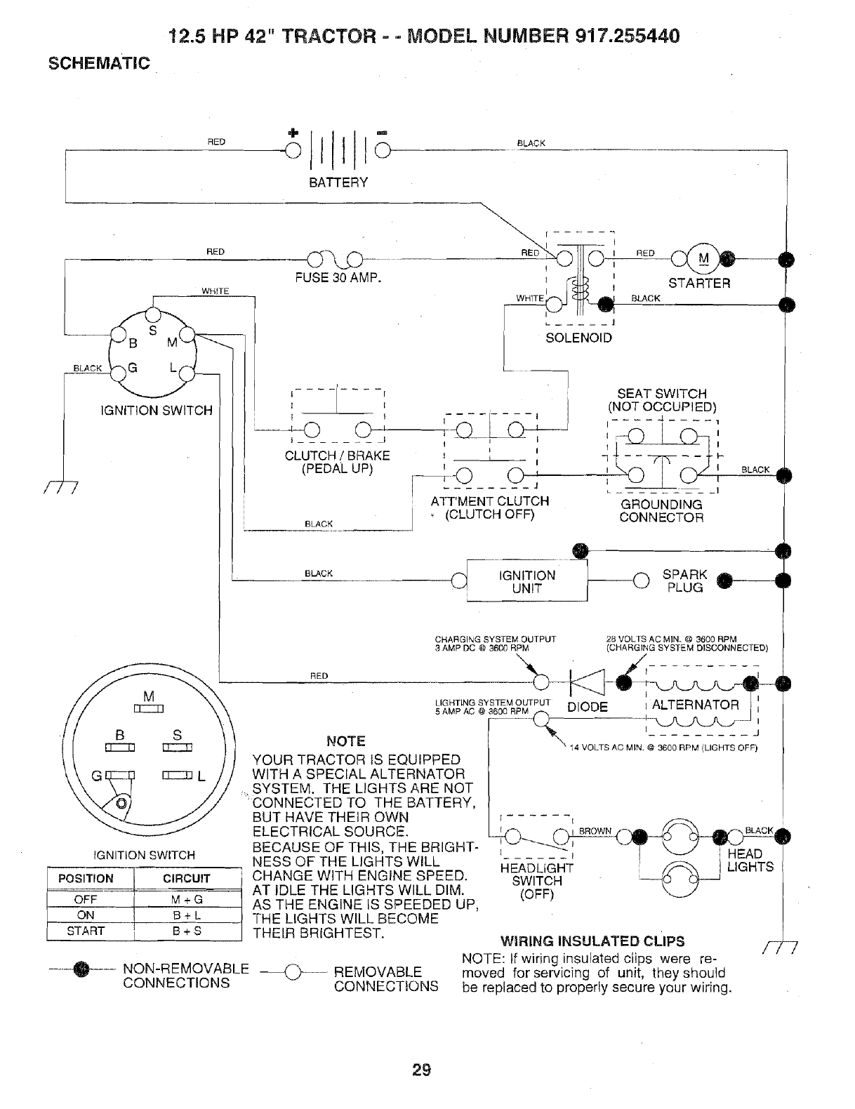
!2.5 HP 42" TRACTOR --MODEL NUMBER 917.255440
SCHEMATIC
BLACK
/27
POSITION
OFF
ON
START
.... ____
÷JII--
RED otllo o ACK
BATTERY
RED (_X._
FUSE 30 AMP.
WHITE
L(
IGNITION SWITCH
I I
t I
II
I I
CLUTCH /BRAKE
(PEDAL UP)
BLACK
L BLACK
RED
I i
RED , I
1
SOLENOID
STARTER
BLACK
SEAT SWITCH
(NOT OCCUPIED)
I- -I .... .J, ....
t --
, I__ __
ATT'MENT CLUTCH GROUNDING
(CLUTCH OFF) CONNECTOR
BLACK d
I
81L
tF
_)F iGNITiON sPARK _HI
UNIT PLUG
CHARGING SYSTEM OUTPUT
3 AMP DC @ 3600 RPM 2B VOLTS AC MIN, @ 3600 RPM
(CHARGING SYSTEM DISCONNECTED)
IGNITION SWITCH
CIRCUIT
M+G
B+L
B+S
NOTE
YOUR TRACTOR IS EQUIPPED
WITH A SPECIAL ALTERNATOR
SYSTEM. THE LIGHTS ARE NOT
'CONNECTED TO THE BATTERY,
BUT HAVE THEIR OWN
ELECTRICAL SOURCE.
BECAUSE OF THIS, THE BRIGHT-
NESS OF THE LIGHTS WILL
CHANGE WITH ENGINE SPEED.
AT IDLE THE LIGHTS WILL DIM.
AS THE ENGINE iS SPEEDED UP,
-[-HE LIGHTS WILL BECOME
THEIR BRIGHTEST.
NON-REMOVABLE ---O--
CONNECTIONS REMOVABLE
CONNECTIONS
LIGHTINGSYSTEMOUTPUTDIODE i ALTERNATOR
5 AMP AC @ 3600 RPM f-_
I j
14 VOLTS AC MIN. @ 3600 RPM (LIGHTS OFF)
i*
l I BROWN. --4 BLACK
i _ ! / _ HEAD
HEADLiGHTswITCH _@_.j LIGHTS
(OFF)
WIRING INSULATED CLIPS
NOTE: If wiring insulated clips were re-
moved for servicing of unit, they should
be replaced to properly secure your wiring.
/-7-7
29
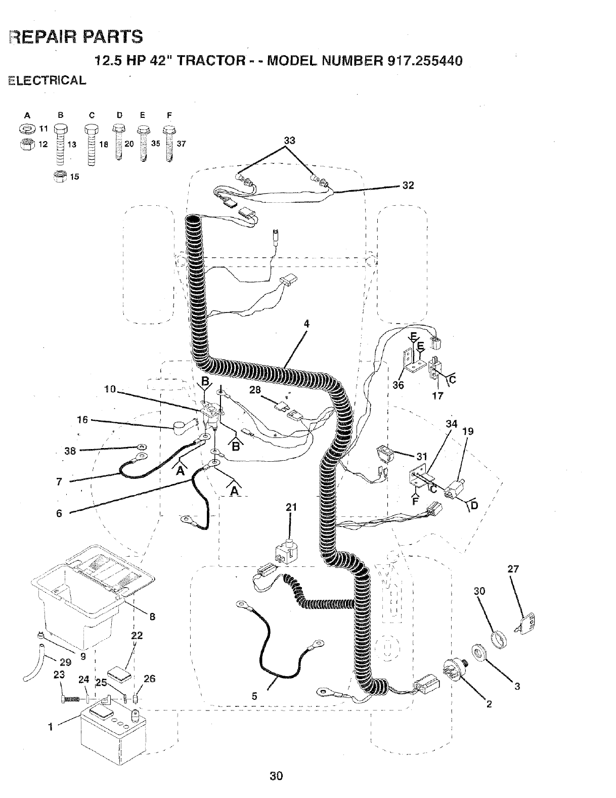
r EPAIR PARTS
12.5 HP 42" TRACTOR - -MODEL NUMBER 917,255440
ELECTRICAL
ABCD E
18 20 i_
16
•38 '
f
28 17
3'4 19
7i
t
L -I
/
/
21
5
3O
I
/
/
/
/
I
/
/
i
3O
27
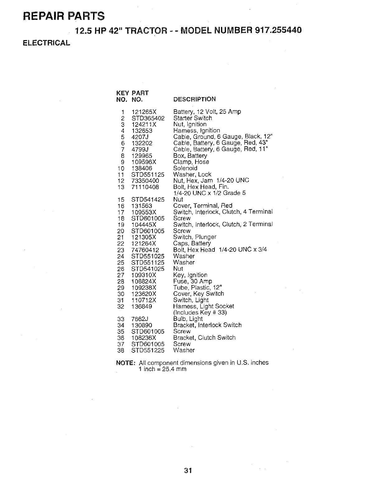
REPAIR PARTS
12,5 HP 42" TRACTOR -- MODEL NUMBER 917.255440
ELECTRICAL
KEY PART
NO. NO. DESCRIPTION
1 121265X
2 STD365402
3 124211X
4 132653
5 4207J
6 132202
7 4799J
8 129965
9 109596X
10 138406
11 STD551125
12 73350400
13 71110408
15 STD541425
16 131563
17 109553X
18 STD601005
19 104445X
20 STD601005
21 121305X
22 121264X
23 74760412
24 STD551025
25 STD551125
26 STD541025
27 109310X
28 108824X
29 109238X
30 123620X
31 110712X
32 136849
33 7662J
34 130890
35 STD601005
36 108236X
37 STD601005
38 STD551225
Battery, 12 Volt, 25 Amp
Sta_er Switch
Nut, Ignition
Harness, Ignition
Cable, Ground, 6 Gauge, Black, 12"
Cable, Battery, 6 Gauge, Red, 43"
Cable, Battery, 6 Gauge, Red, 11"
Box, Battery
Clamp, Hose
SoLenoid
Washer, Lock
Nut, Hex, Jam 1/4-20 UNC
Bolt, Hex Head, Fin.
1/4-20 UNC x 1/2 Grade 5
Nut
Cover, Terminal, Red
Switch, Interlock, C_utch, 4 Terminal
Screw
Switch, Interlock, Clutch, 2 Terminal
Screw
Switch, Plunger
Caps, Battery
Bolt, Hex Head 1/4-20 UNC x 3/4
Washer
Washer
Nut
Key, Ignition
Fuse, 30 Amp
Tube, Plastic, 12"
Cover, Key Switch
Switch, Light
Harness, Light Socket
(IncLudes Key # 33)
Bulb, Light
Bracket, Interlock Switch
Screw
Bracket, Clutch Switch
Screw
Washer
NOTE: All component dimensions given in U.S. inches
1 inch = 25,4 mm
31
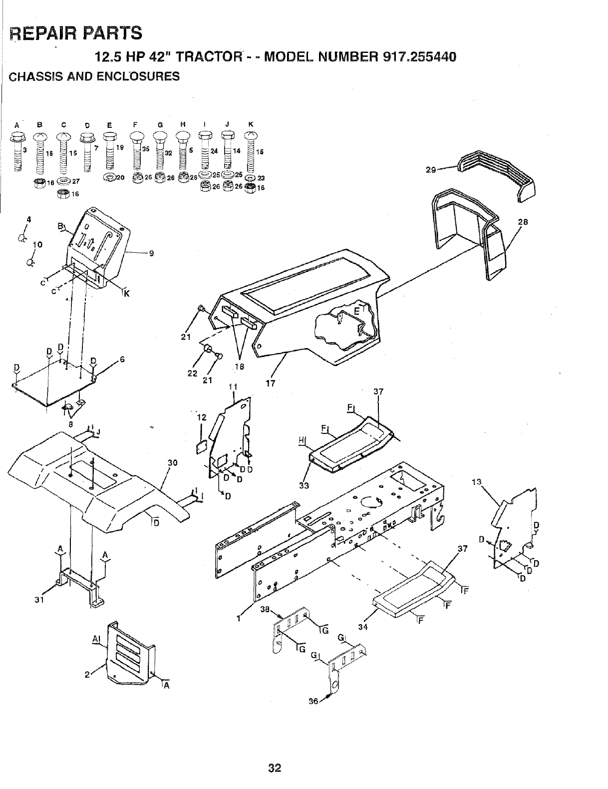
REPAIR PARTS
12.5 HP 42" TRACTOR- -MODEL NUMBER 917.255440
CHASSIS AND ENCLOSURES
c_.. i
f
8
31
9
_K
17 37
F
33
28
D
37
3
34
G
3
32
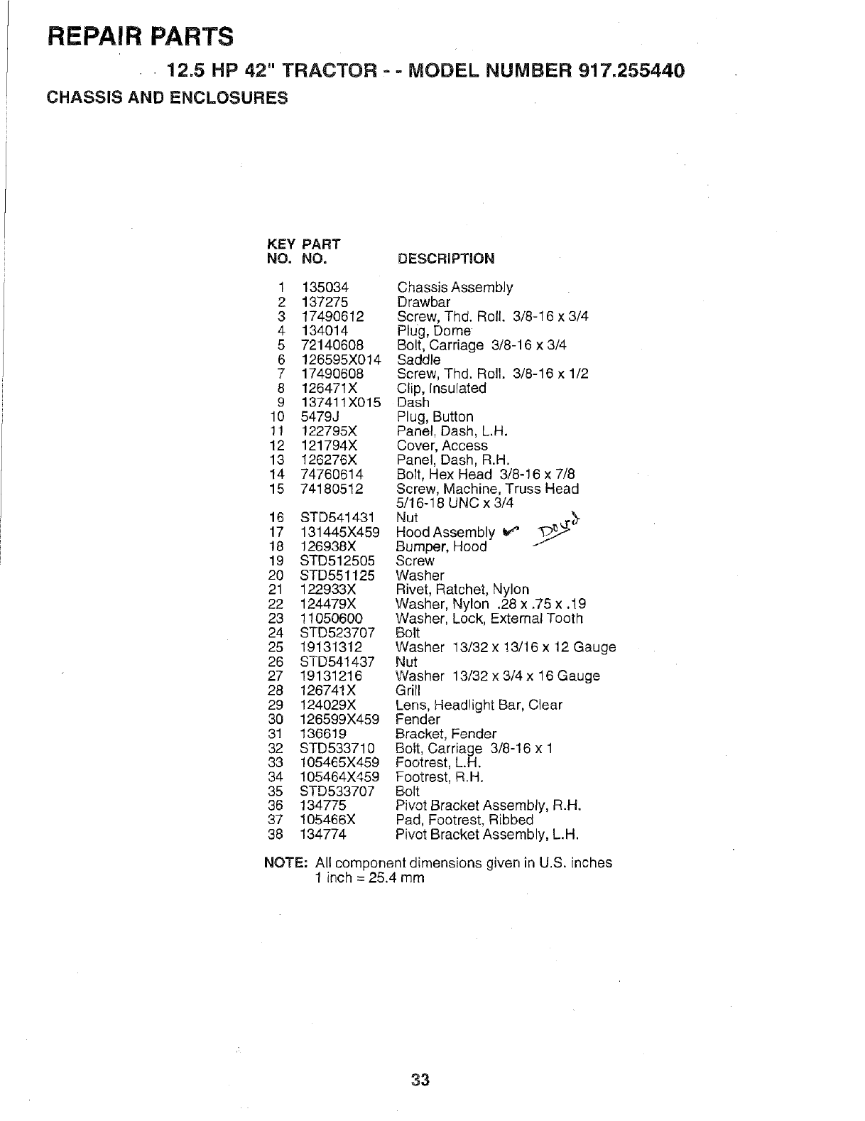
REPAIR PARTS
• • 12.5 HP 42" TRACTOR =-MODEL NUMBER 917=255440
CHASSIS AND ENCLOSURES
KEY PART
NO. NO. DESCRIPI"|ON
1 135034
2 137275
3 17490612
4 134014
5 72140608
6 126595X014
7 17490608
8 126471X
9 137411X015
10 5479J
11 122795X
12 121794X
13 126276X
14 74760614
15 74180512
16 STD541431
17 131445X459
18 126938X
19 STD512505
20 STD551125
21 122933X
22 124479X
23 11050600
24 STD523707
25 19131312
26 STD541437
27 19131216
28 126741X
29 124029X
30 126599X459
31 136619
32 STD533710
33 105465X459
34 105464X459
35 STD533707
36 134775
37 105466X
38 134774
Chassis Assembly
Drawbar
Screw, Thd. Roll. 3/8-16 x 3/4
Plug, Dome
Bolt, Carriage 3/8-16 x 3/4
Saddle
Screw, Thd. Roll. 3/8-16 x 1/2
Clip, Insulated
Dash
Plug, Button
Panel, Dash, L.H.
Cover, Access
Panel, Dash, R.H.
Bolt, Hex Head 3/8-16 x 7/8
Screw, Machine, Truss Head
5/16-18 UNC x 3/4
Nut _,r_"
Hood Assembly _ 1_._"_
Bumper, Hood
Screw
Washer
Rivet, Ratchet, Nylon
Washer, Nylon .28 x .75 x.19
Washer, Lock, External Tooth
Bolt
Washer 13/32 x !3/16 x 12 Gauge
Nut
Washer 13/32 x 3/4 x 16 Gauge
Grill
Lens, Headlight Bar, Clear
Fender
Bracket, Fender
Bolt, Carriage 3/8-16 x 1
Footrest, L.H.
Footrest, R.H.
Bolt
Pivot Bracket Assembly, R.H.
Pad, Footrest, Ribbed
Pivot Bracket Assembly, L.H.
NOTE: All component dimensions given in U.S. inches
1 inch = 25.4 mm
33
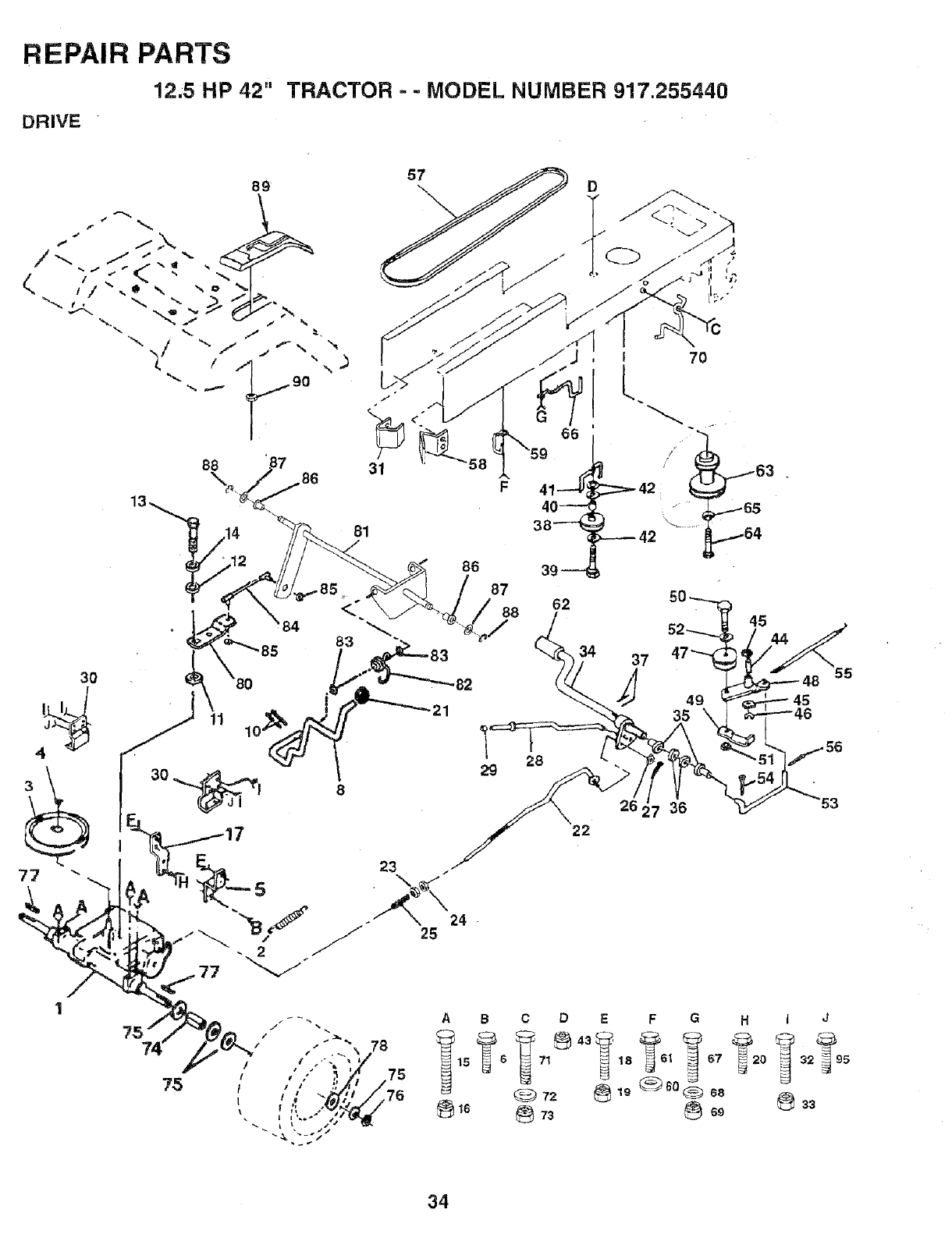
REPAIR PARTS
12,5 HP 42"
DRIVE
TRACTOR =- MODEL NUMBER 917.255440
89 ¸
_f "---- "
",,. -,/ ,,
!_.. " )x
""-- 9O
/
31
81
86
87
88
29
D
I70
L
45 44
37
J
26, 7 36
22
CD
71_
72
73
34
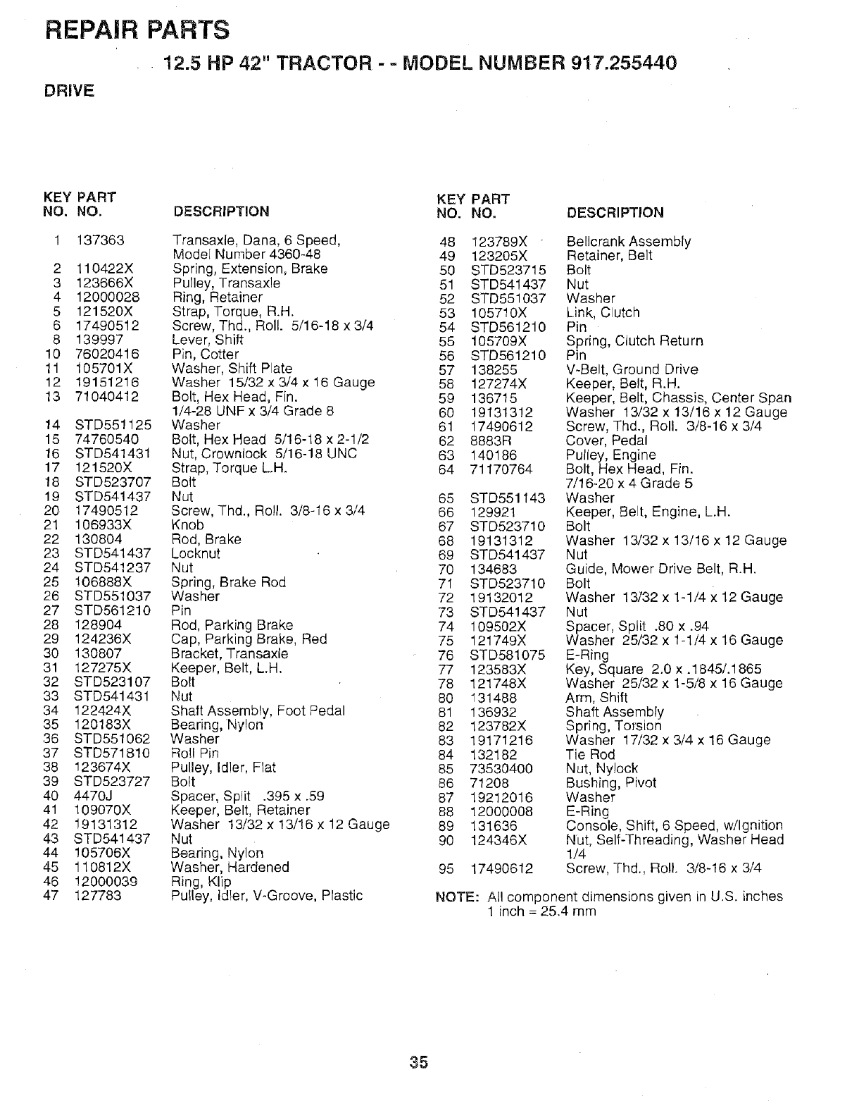
REPAIR PARTS
12.5 HP 42" TRACTOR - - MODEL NUMBER 917.255440
DRIVE
KEY PART KEY PART
NO. NO. DESCRIPTION NO. NO. DESCRIPTION
1 137363 Transaxle, Dana, 6 Speed, 48 123789X Bellcrank Assembly
Mode[ Number 4360-48 49 123205X Retainer, Belt
2 110422X Spring, Extension, Brake 50 STD523715 Bolt
3 123666X Pulley, Transaxle 51 STD541437 Nut
4 12000028 Ring, Retainer 52 STD551037 Washer
5 121520X Strap, Torque, R.H. 53 105710X Link, Clutch
6 17490512 Screw, Thd., Roll. 5/16-18 x 3/4 54 STD561210 Pin
8 139997 Lever, Shift 55 105709X Spring, Clutch Return
10 76020416 Pin, Cotter 58 STD561210 Pin
11 105701X Washer, Shift Plate 57 138255 V-Belt, Ground Drive
12 19151216 Washer 15/32 x 3/4 x 16 Gauge 58 127274X Keeper, Belt, R.H.
13 71040412 Bolt, Hex Head, Fin. 59 136715 Keeper, Belt, Chassis, Center Span
1/4-28 UNF x 3/4 Grade 8 60 19131312 Washer 13/32 x 13/16 x 12 Gauge
14 STD551125 Washer 61 17490612 Screw, Thd., Roll. 3/8-16 x 3/4
15 74760540 Bolt, Hex Head 5/16-18 x 2-1/2 62 8883R Cover, Pedal
16 STD541431 Nut, Crownlock 5/16-18 UNC 63 140186 Pulley, Engine
17 121520X Strap, Torque L.H. 64 71170764 Bolt, Hex Head, Fin.
18 STD523707 Bolt 7/16-20 x 4 Grade 5
19 STD541437 Nut 65 STD551143 Washer
20 17490512 Screw, Thd., Roll. 3/8-16 x 3/4 66 129921 Keeper, Belt, Engine, L.H.
21 106933X Knob 67 STD523710 Bolt
22 130804 Rod, Brake 68 19131312 Washer 13/32 x 13/16 x 12 Gauge
23 STD541437 Locknut 69 STD541437 Nut
24 STD541237 Nut 70 134683 Guide, Mower Drive Belt, R.H.
25 !06888X Spring, Brake Rod 71 STD523710 Bolt
26 STD551037 Washer 72 19132012 Washer 13/32 x 1-1/4 x 12 Gauge
27 STD561210 Pin 73 STD541437 Nut
28 128904 Rod, Parking Brake 74 109502X Spacer, Split .80 x.94
29 124236X Cap, Parking Brake, Red 75 121749X Washer 25/32 x 1-1/4 x 16 Gauge
30 130807 Bracket, Transaxle 76 STD581075 E-Ring
31 127275X Keeper, Belt, L.H. 77 123583X Key, Square 2.0 x .1845/.1865
32 STD523107 Bolt 78 121748X Washer 25/32 x 1-5/8 x 16 Gauge
33 STD541431 Nut 80 131488 Arm, Shift
34 122424X Shaft Assembly, Foot Pedal 81 136932 Shaft Assembly
35 120183X Bearing,Nylon 82 123782X Spring, ToTsion
36 STD551062 Washer 83 19171216 Washer 17/32 x 3/4 x 16 Gauge
37 STD571810 Roll Pin 84 132182 Tie Rod
38 123674X Pulley, Idler, Flat 85 73530400 Nut, Ny!ock
39 STD523727 Bolt 86 71208 Bushing, Pivot
40 4470J Spacer, Spilt .395 x .59 87 19212016 Washer
41 109070X Keeper, Belt, Retainer 88 12000008 E-Ring
42 19131312 Washer 13/32 x 13/16 × 12 Gauge 89 131636 Console, Shift, 6 Speed, w/Ignition
43 STD541437 Nut 90 124346X Nut, Self-Threading, Washer Head
44 105706X Bearing, Nylon 1/4
45 110812X Washer, Hardened 95 17490612 Screw, Thd., Roll. 3/8-16 x 3/4
46 !2000039 Ring, Klip
47 127783 PuIley, Idler, V-Groove, Plastic NOTE: AN component dimensions given in U.S. inches
1 inch = 25.4 mm
35
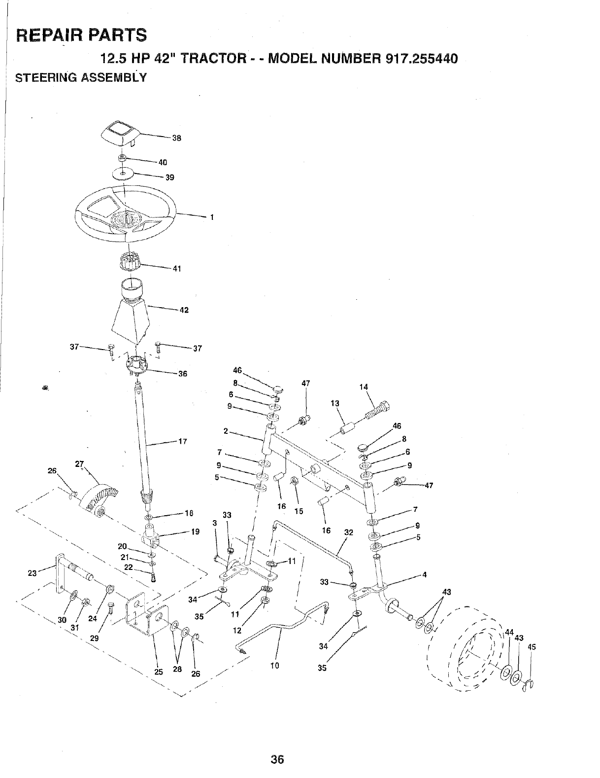
REPAIR PARTS
12.5 HP 42" TRACTOR - - MODEL NUMBER 917.255440
STEERING ASSEtVlBLY
_38
36
29
25 26
12
10
34
35
43
36
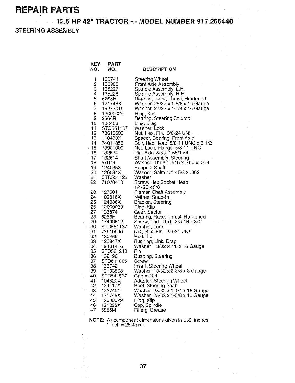
REPAIR PARTS
12.5 HP 42" TRACTOR == MODEL NUMBER 917.255440
STEERING ASSEiVlBLY
KEY PART
NO. NO. DESCRIPTION
1 133741
2 133988
3 135227
4 135228
5 6266H
6 121748X
7 19272016
8 12000029
9 3366R
10 130468
11 STD551137
12 73610600
13 110438X
14 74011056
15 73901000
16 132624
17 132614
18 57079
19 124035X
20 126684X
2! STD551125
22 71070410
23 127501
24 109816X
25 124036X
26 12000029
27 136874
28 6266H
29 17490612
30 STD551137
31 73610600
32 130465
33 126847X
34 19131416
35 STD561210
36 132196
37 STD611005
38 133742
39 19133808
40 STD541537
41 104820X
42 124417X
43 121749X
44 121748X
45 12000029
46 121232X
47 6855M
Steering Wheel
Front Axle Assembly
Spindle Assembly, L.H.
Spindle Assembly, R.H.
Bearing, Race, Thrust, Hardened
Washer 25/32 x 1-5/8 x 16 Gauge
Washer 27/32 x 1-1/4 x !6 Gauge
Ring, Klip
Bearing, Steering Column
Link, Drag
Washer, Lock
Nut, Hex, Fin. 3/8-24 UNF
Spacer, Bearing, Front Axle
Bolt, Hex Head 5/8-11 UNC x 3-1/2
Nut, Lock, Flange 5/8-11 UNC
Pin, Axle 5/8 x 1.55/1.54
Shaft Assembly, Steering
Washer, Thrust .515 x .750 x .033
Support, Shaft
Washer, Shim 1/4 x 5/8 x .062
Washer
Screw, Hex Socket Head
1/4-20 x 5/8
Pittman Shaft Assembly
Nyliner, Snapqn
Bracket, Steering
Ring, Klip
Gear, Sector
Bearing, Race, Thrust, Hardened
Screw, Thd., Roll. 3/8-16 x 3/4
Washer, Lock
Nut, Hex, Fin. 3/8-24 UNF
Rod, Tie
Bushing, Link, Drag
Washer 13/32 x 7/8 x 16 Gauge
Pin
Bushing, Steering
Screw
Insert, Steering Wheel
Washer 13/32 x 2-3/8 x 8 Gauge
Gripco Nut
Adaptor, Steering Wheel
Boot, Steering Shaft
Washer 25/32 x 1-1/4 x 16 Gauge
Washer 25/32 x 1-5/8 x 16 Gauge
Ring, Klip
Cap, Spindle
Fitting, Grease
NOTE: All component dimensions given in U.S. inches
1 inch = 25.4 mm
37
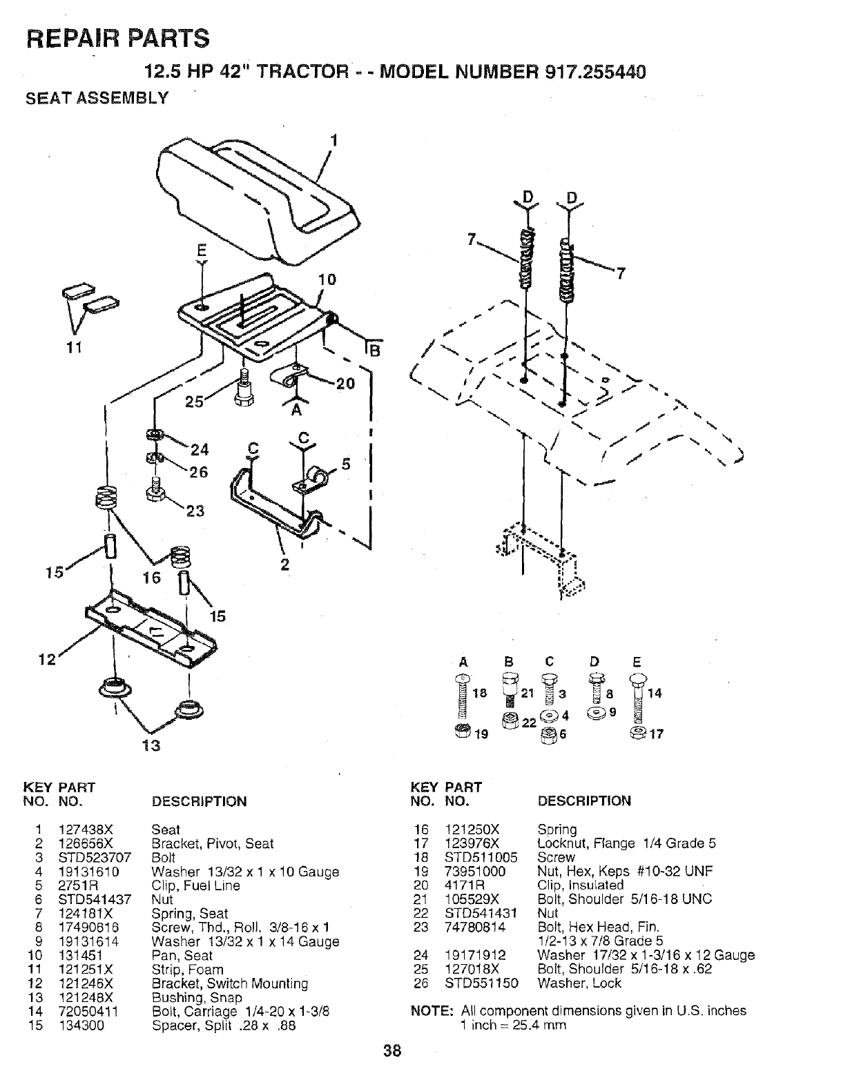
REPAIR PARTS
12.5 HP 42" TRACTOR - - MODEL NUMBER 917.255440
SEAT ASSEMBLY
11
10
15
C
!
2
D
-y
b
,.v _" 7 "_,,
J f
•-,, j
"-.t"
!J!
\
\
12
13
A B C D E
18 21 3 814
_22Q4 ®9
KEY PART
NO. NO.
1 127438X
2 126656X
3 STD523707
4 19131610
5 2751R
6 STD541437
7 124181X
8 17490616
9 19131614
10 131451
11 121251X
12 121246X
13 121248X
14 72050411
15 134300
DESCRIPTION
Seat
Bracket, Pivot, Seat
Bolt
Washer 13/32 x 1 x 10 Gauge
Clip, Fuel Line
Nut
Spring, Seat
Screw, Thd., Roll. 3/8-16 x 1
Washer !3/32 x 1 x 14 Gauge
Pan, Seat
Strip, Foam
Bracket, Switch Mounting
Bushing, Snap
Bolt, Carriage 1/4-20 x 1-3/8
Spacer, Split .28 x .88
KEY PART
NO. NO. DESCRIPTION
16 121250X
17 123976X
18 STD511005
19 73951000
20 4171R
21 105529X
22 STD541431
23 74780814
24 19171912
25 127018X
26 STD551150
Spring
Locknut, Flange 1/4 Grade 5
Screw
Nut, Hex, Keps #10-32 UNF
Clip, Insulated
Bolt, Shoulder 5/16-18 UNC
Nut
Bolt, Hex Head, Fin.
1/2-13 x 7/8 Grade 5
Washer 17/32 x 1-3/16 x 12 Gauge
Bolt, Shoulder 5/16-18 x .62
Washer, Lock
NOTE: All component dimensions given in U.S. inches
1 inch = 25.4 mm
38
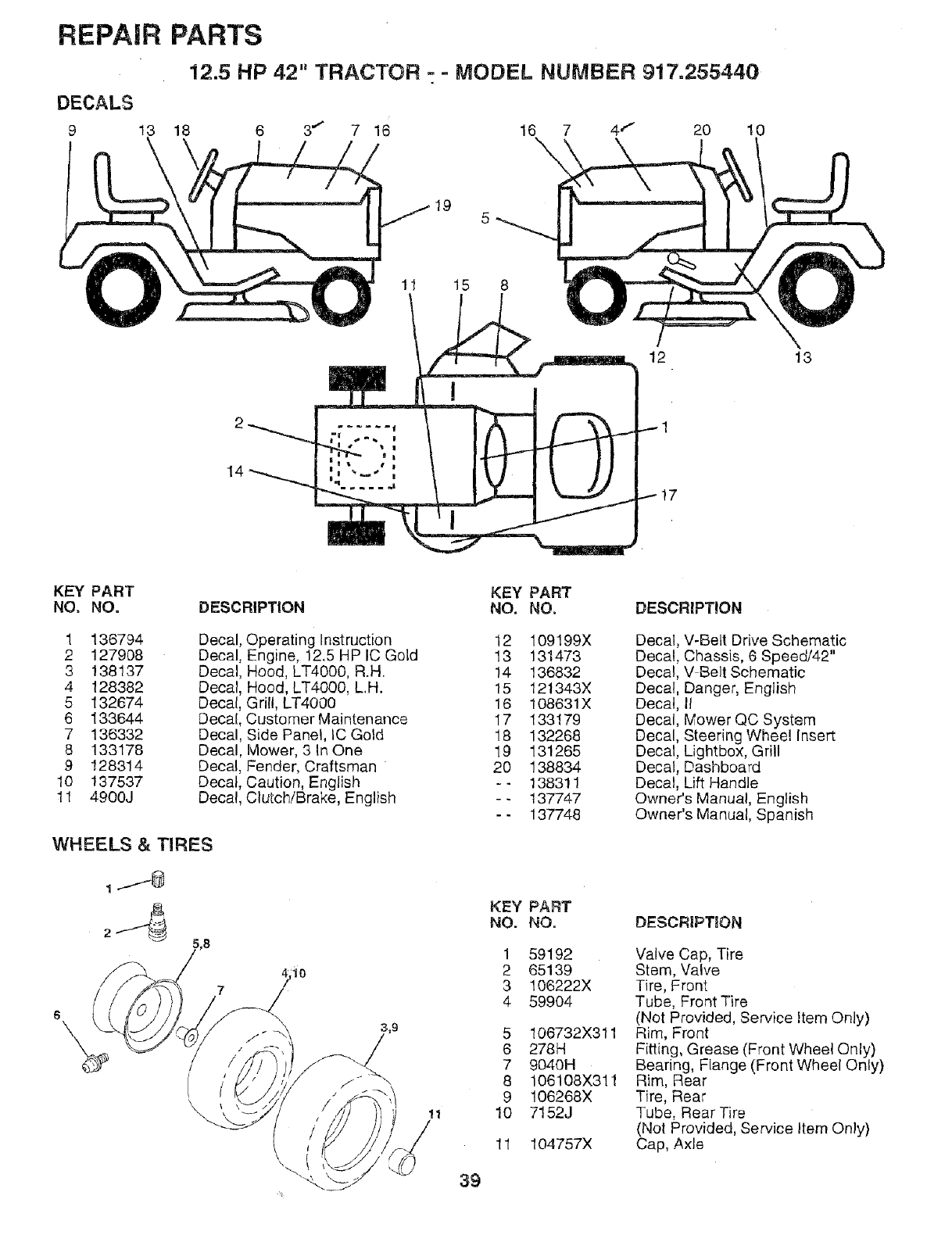
REPAIR PARTS
12.5 HP 42" TRACTOR - = MODEL NUMBER 917.255440
20 10
95
1! 15 8
1
14
12 13
KEY PART KEY PART
NO. NO. DESCRIPTION NO. NO. DESCRIPTION
1 136794 Decal
2 127908 Decal
3 138137 Decal
4 128382 Decal
5 132674 Decal
6 133644 Decal
7 136332 Decal
8 133178 Decal
9 !28314 Decal
10 137537 Decal,
11 4900J Decal,
Operating Instruction
Engine, 12.5 HP IC Gold
Hood, LT4000, R.H.
Hood, LT4000, LH.
Grill, LT4000
Customer Maintenance
Side Panel, IC Gold
Mower, 3 In One
Fender, Craftsman
Caution, English
Clutch/Brake, English
WHEELS & TIRES
11
12 109199X
13 131473
14 136832
15 121343X
16 108631X
17 133179
18 132268
19 131265
20 138834
-- 138311
-- 137747
-- 137748
KEY PART
NO. NO.
1
2
3
4
5
6
7
8
9
10
11
39
59192
65139
106222X
599O4
106732X311
278H
9040H
106108X311
106268X
7152J
104757X
Decal, V-BeLt Drive Schematic
Decal, Chassis, 6 Speed/42"
Decal, V Belt Schematic
Decal, Danger, English
Decal, II
Decal, Mower QC System
Decal, Steering Wheel Insert
Decal, Lightbox, Grill
Decal, Dashboard
Decal, Lift Handle
Owner's Manual, English
Owner's Manual, Spanish
DESCRIPTION
Valve Cap, Tire
Stem, Valve
Tire, Front
Tube, Front Tire
(Not Provided, Service Item Only)
Rim, Front
Fitting, Grease (Front Wheel Only)
Bearing, Flange (Front Wheel Only)
Rim, Rear
Tire, Rear
Tube, Rear Tire
(Not Provided, Service Item Only)
Cap, Axle
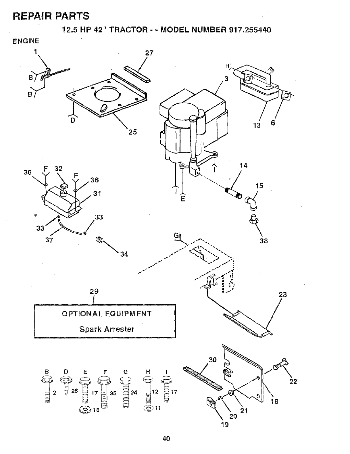
REPAIR
ENGINE
1
PARTS
12.5 HP 42" TRACTOR - - MODEL NUMBER 917.255440
27
36 F 32
3?
D
25
31
33
/
34
29
OPTIONAL EQUIPM ENT
H
3
==_, =
!
Spark Arrester
38
23
BDEFGH I
I '
2! 5 _ 24 12 7
@16 _ _11
3O
20
Ig
21
18
22
4O
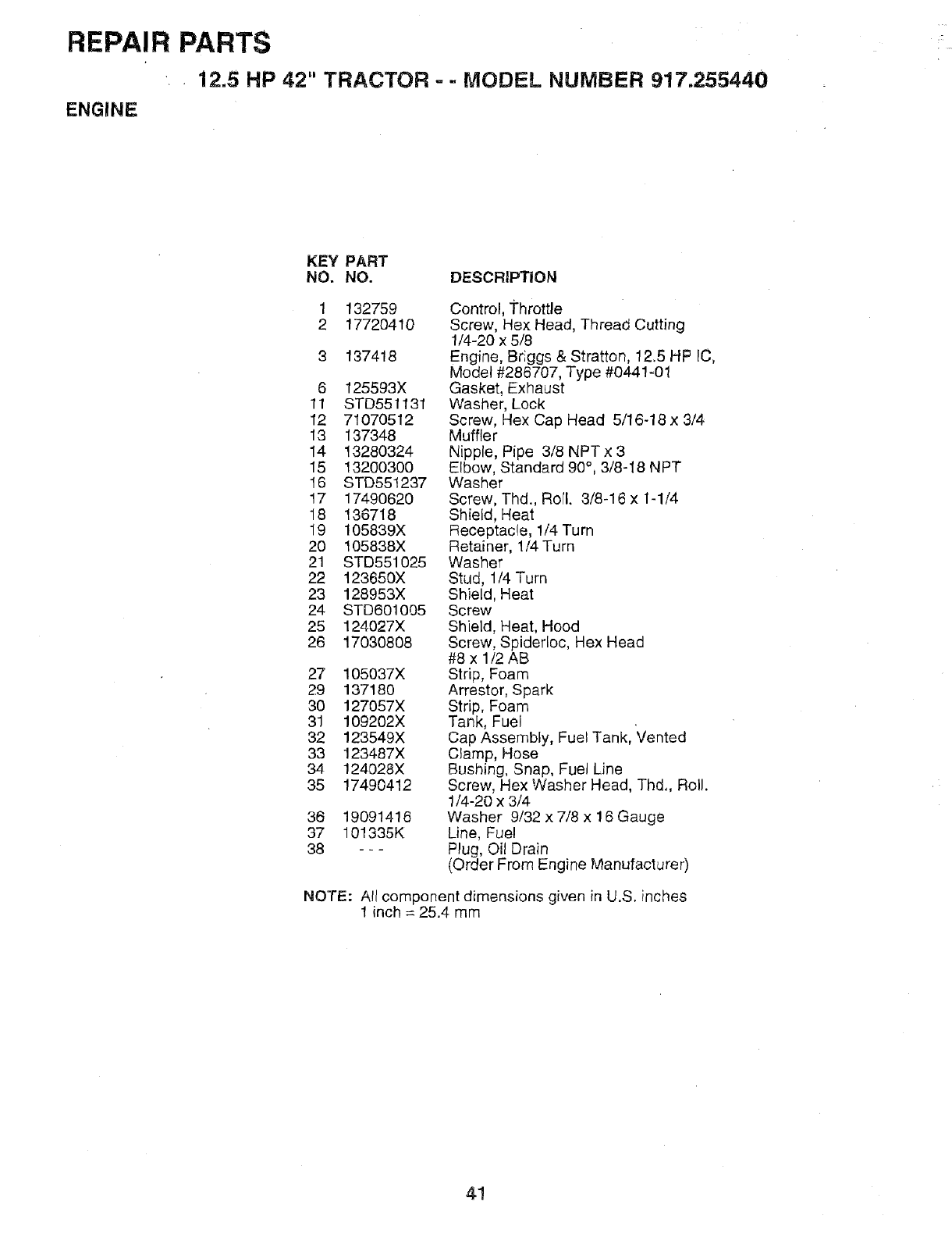
REPAIR PARTS
• i2.5 HP 42" TRACTOR =-MODEL NUMBER 917,255440
ENGINE
KEY PART
NO. NO. DESCRiPTiON
1
2132759
17720410
137418
6 125593X
11 STD551131
12 71070512
13 137348
14 1328O324
15 13200300
16 STD551237
17 17490620
18 136718
19 105839X
20 105838X
21 STD551025
22 123650X
23 128953X
24 STD601005
25 124027X
26 17030808
27 105037X
29 137180
3O 127057X
31 109202X
32 123549X
33 123487X
34 124028X
35 17490412
36 19091416
37 101335K
38 ---
Control, Throttle
Screw, Hex Head, Thread Cutting
1/4-20 x 5/8
Engine, Briggs & Stratton, 12.5 HP IC,
Model #286707, Type #0441-01
Gasket, Exhaust
Washer, Lock
Screw, Hex Cap Head 5/16-18 x 3/4
Muffler
Nipple, Pipe 3/8 NPT x3
Elbow, Standard 90°, 3/8-18 NPT
Washer
Screw, Thd., Rorl. 3/8-16 x 1-1/4
Shield, Heat
Receptacle, 1/4 Turn
Retainer, 1/4 Turn
Washer
Stud, 1/4 Turn
Shield, Heat
Screw
Shield, Heat, Hood
Screw, Spiderloc, Hex Head
#8 x 1/2 AB
Strip, Foam
Arrestor, Spark
Strip, Foam
Tank, Fuel
Cap Assembly, Fuel Tank, Vented
Clamp, Hose
Bushing, Snap, Fuel Line
Screw, Hex Washer Head, Thd,, Roll.
1/4-20 x 3/4
Washer 9/32 x 7/8 x 16 Gauge
Line, Fuel
Plug, Oil Drain
(Order From Engine Manufacturer)
NOTE: A!l component dimensions given in U.S. inches
1inch = 25.4 mm
41
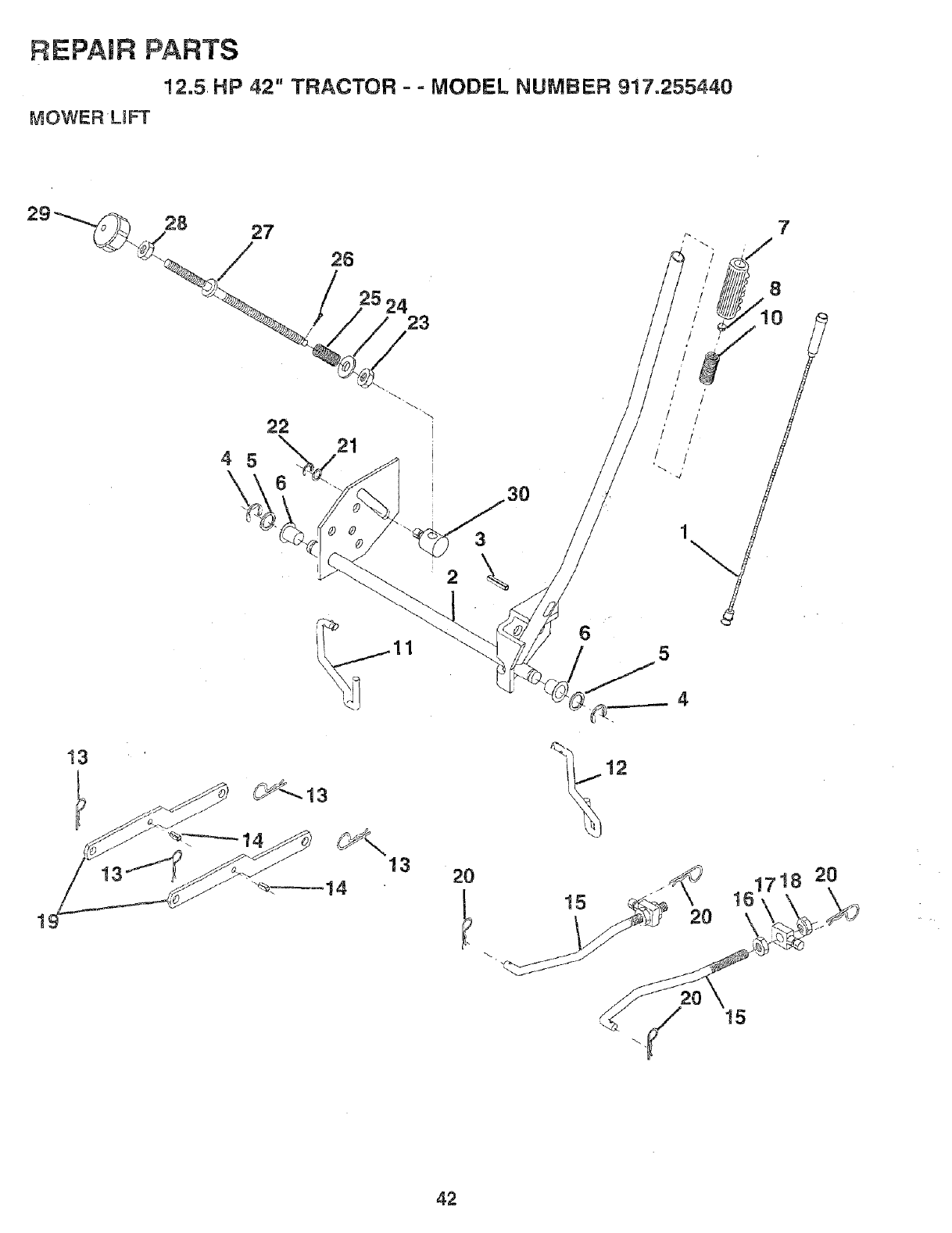
REPAIR PARTS
12.5 HP 42" TRACTOR - - MODEL NUMBER 917.255440
MOWERLJFT
22
4 5
\°
21
13
30
3
\
2O
7
161718 20
42
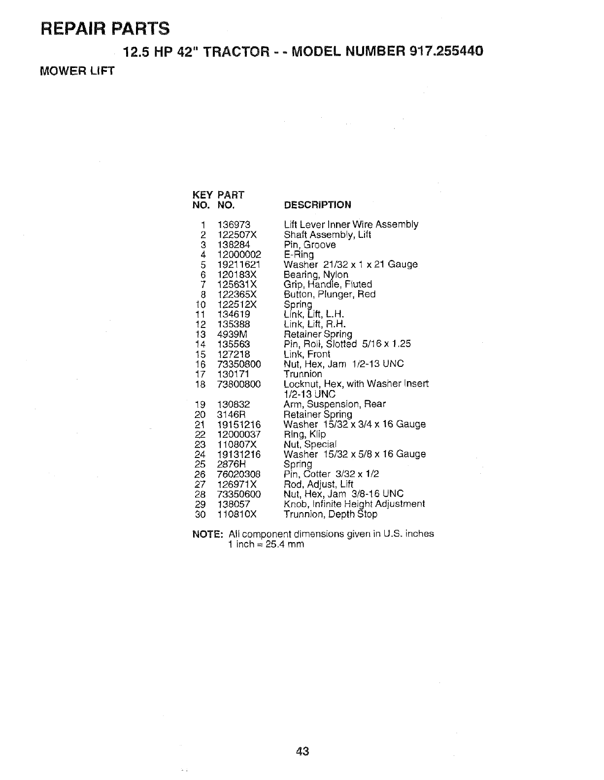
REPAIR PARTS
12.5 HP 42" TRACTOR - - MODEL NUMBER 917.255440
MOWER LIFT
KEY PART
NO. NO. DESCRIPTION
1 136973
2 122507X
3 138284
4 12000002
5 19211621
6 120183X
7 125631X
8 122365X
10 122512X
11 134619
12 135388
13 4939M
14 135563
15 127218
16 73350800
17 130171
18 73800800
19 130832
20 3146R
21 19151216
22 12000037
23 110807X
24 19131216
25 2876H
26 76020308
27 126971X
28 73350600
29 138057
30 110810X
Lift Lever Inner Wire Assembly
Shaft Assembly, Lift
Pin, Groove
E-Ring
Washer 21/32 x 1 x 21 Gauge
Bearing, Nylon
Grip, Handle, Fluted
Button, Plunger, Red
Spring
Link, Lift, L.H.
Link, Lift, R.H.
Retainer Spring
Pin, Roll, Slotted 5/16 x 1.25
Link, Front
Nut, Hex, Jam 1/2-13 UNC
Trunnion
Locknut, Hex, with Washer Insert
1/2-13 UNC
Arm, Suspension, Rear
Retainer Spring
Washer 15/32 x 3/4 x 16 Gauge
Ring, Klip
Nut, Special
Washer 15/32 x 5/8 x 16 Gauge
Spring
Pin, Cotter 3/32 x 1/2
Red, Adjust, Lift
Nut, Hex, Jam 3/8-16 UNC
Knob, Infinite Height Adjustment
Trunnion, Depth Stop
NOTE: All component dimensions given in U.S. inohes
1 inch = 25.4 mm
43
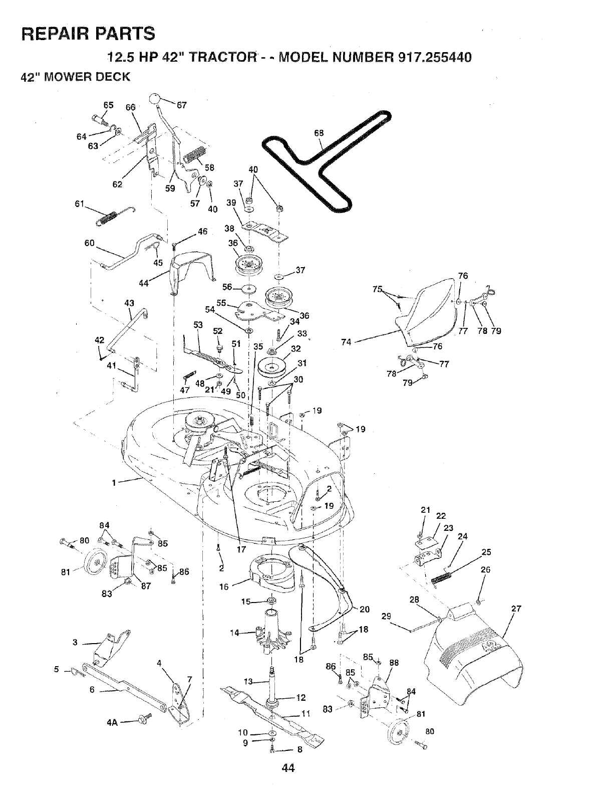
REPAIR PARTS
12.5 HP 42" TRACTOR=- MODEL NUMBER 917.255440
42" MOWER DECK
62
6O
i 59
q57
' \
I
I46
44 .,
54
53
84
81
37 40_
o3_
33 74
32
31
76
77 78 79
21
17
22
23 24
25
26
/27
44
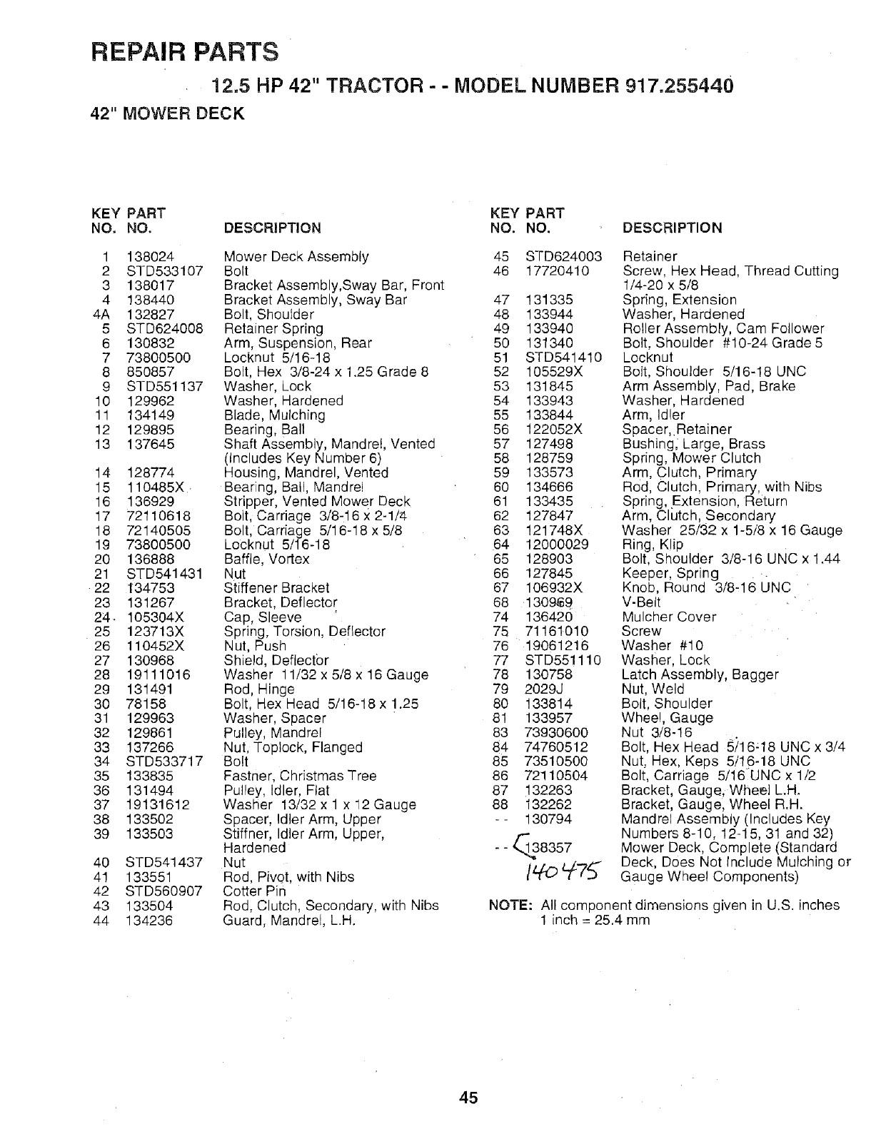
REPAIR PARTS
12.5 HP 42" TRACTOR - - MODEL NUMBER 917.255440
42" MOWER DECK
KEY PART KEY PART
NO. NO. DESCRIPTION NO. NO. DESCRIPTION
1 138024
2 STD533107
3 138017
4 138440
4A 132827
5 STD624008
6 130832
7 73800500
8 850857
9 STD551137
10 129962
11 134149
12 129895
13 137645
14 128774
15 110485X.
16 136929
17 72110618
18 72140505
19 73800500
20 136888
21 STD541431
22 134753
23 131267
24_ 105304X
25 123713X
26 110452X
27 130968
28 19111016
29 131491
30 78158
31 129963
32 129861
33 137266
34 STD533717
35 133835
36 131494
37 19131612
38 133502
39 133503
40 STD541437
41 133551
42 STD560907
43 133504
44 134236
Mower Deck Assembly
Bolt
Bracket Assembly,Sway Bar, Front
Bracket Assembly, Sway Bar
Bolt, Shoulder
Retainer Spring
Arm, Suspension, Rear
Locknut 5/16-18
Bolt, Hex 3/8-24 x 1.25 Grade 8
Washer, Lock
Washer, Hardened
Blade, Mulching
Bearing, Ball
Shaft Assembly, Mandrel, Vented
(Includes Key Number 6)
Housing, Mandrel, Vented
Bearing, Ball, Mandrel
Stripper, Vented Mower Deck
Bolt, Carriage 3/8-16 x 2-1/4
Bolt, Carriage 5/16-18 x 5/8
Locknut 5/16-18
Baffle, Vortex
Nut
Stiffener Bracket
Bracket, Deflector
Cap, Sleeve
Spring, Torsion, Deflector
Nut, Push
Shield, Deflector
Washer 11/32 x 5/8 x 16 Gauge
Rod, Hinge
Bolt, Hex Head 5/16-18 x 1.25
Washer, Spacer
Pulley, Mandrel
Nut, Toplock, Flanged
Bolt
Fastner, Christmas Tree
Pulley, Idler, Flat
Washer 13/32 x 1 x 12 Gauge
Spacer, Idler Arm, Upper
Stiffner, Idler Arm, Upper,
Hardened
Nut
Rod, Pivot, with Nibs
Cotter Pin
Rod, Clutch, Secondary, with Nibs
Guard, Mandrel, L.H.
45 STD624003
46 17720410
47 131335
48 133944
49 133940
5O 13134O
51 STD541410
52 105529X
53 131845
54 133943
55 133844
56 122052X
57 127498
58 128759
59 133573
60 134666
61 133435
62 127847
63 121748X
64 12000029
65 128903
66 127845
67 106932X
68 1309_9
74 13642O
75 71161010
76 19061216
77 STD551110
78 130758
79 2029J
80 133814
81 133957
83 73930600
84 7476O512
85 7351O50O
86 72110504
87 132263
88 132262
-- 130794
--_@8357
Retainer
Screw, Hex Head, Thread Cutting
1/4-20 x 5/8
Spring, Extension
Washer, Hardened
Roller Assembly, Cam Follower
Bolt, Shoulder #10-24 Grade 5
Locknut
Bolt, Shoulder 5/16-18 UNC
Arm Assembly, Pad, Brake
Washer, Hardened
Arm, Idler
Spacer, Retainer
Bushing_ Large, Brass
Spring, Mower Clutch
Arm, Clutch, Primary
Rod, Clutch, Primary, with Nibs
Spring, Extension, Return
Arm, Clutch, Secondary
Washer 25/32 x 1-5/8 x 16 Gauge
Ring, Klip
Bolt, Shoulder 3/8-16 UNC x 1.44
Keeper, Spring
Knob, Round 3/8,16 UNC
V-Belt
Mulcher Cover
Screw
Washer #10
Washer, Lock
Latch Assembly, Bagger
Nut, Weld
Bolt, Shoulder
Wheel, Gauge
Nut 3/8-16
Bolt, Hex Head 5/16,18 UNC x 3/4
Nut, Hex, Keps 5/16-18 UNC
Bolt, Carriage 5/16UNC x 1/2
Bracket, Gauge, Wheel L.H.
Bracket, Gaugel Wheel R.H.
Mandrel Assembly (Includes Key
Numbers 8-10, 12.-15, 31 and 32)
Mower Deck, Complete (Standard
Deck, Does Not include Mulching or
Gauge Wheel Components)
NOTE: All component dimensions given in U.S. inches
1 inch = 25.4 mm
45
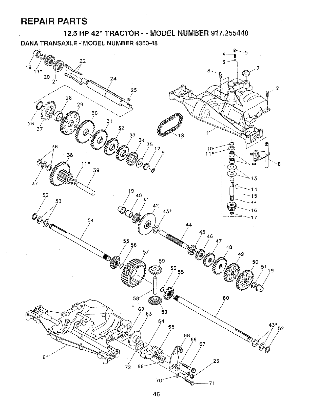
REPAIR PARTS
12.5 HP 42" TRACTOR - -MODEL NUMBER 917.255440
DANA TRANSAXLE -MODEL NUMBER 4360-48
26
22
27
24
39
35 12 9
37
52 53
54
/55
19 40
56
57
41 42
59
56 55
/
44
45
14
46 47
48
49
50 51 19
62
''63 59
6O
43_52
46
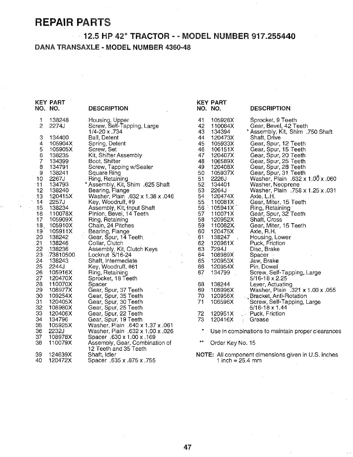
REPAIR PARTS
• 12.5 HP 42" TRACTOR - - MODEL NUMBER 917.255440
DANA TRANSAXLE - MODEL NUMBER 4360=48
KEY PART KEY PART
NO. NO. DESCRIPTION NO. NO. DESCRIPTION
138248
2274J
3 134400
4 105904X
5 105905X
6 138235
7 134399
8 134791
9 138241
10 2267J
'11 134793
12 138240
13 120415X
• 14 2257J
15 138234
16 110078X
17 i05909X
18_ 105910X
19 105911X
20 138242
21 138246
22 _138236
23 .73810500
24 138243
25 2244J
26 105916X
27 120470X
28 110070X
29 108977X
30 109254X
31 120405X
32 108980X
33 120406X
34 134796
35 105925X
36 2232J
37 108978X
38 110079X
39 124639X
40 120472X
Housing, Upper
Screw, Self-Tapping, Large
1/4-20 x .734
Ball, Detent
Spring, Detent
Screw, Set
Kit, Shifter Assembly
Boot, Shifter
Screw, Tapping w/Sealer
Square Ring
Ring, Retaining
Assembly, Kit, Shim .625 Shaft
Bearing, Flange
Washer, Plain .632 x 1.38 x .046
Key, Woodruff, #9
Assembly, Kit; tnput Shaft
Pinion, Bevet, 14 Teeth
Ring, Retaining
Chain, 24 Pitches
Bearing, Flange
Gear, Spur, 14 Teeth:
Collar, Clutch
Assembly, Kit, Clutctq Keys
Locknut 5/16-24
Shaft, Intermediate
Key, Woodruff, #61
Ring, Retaining
Sprocket, 18 Teeth
Spacer
Gear, S_ur, 37 Teeth
Gear, S3ur, 35 Teeth
Gear, S 3ur, 30 Teeth
Gear, S 3ur, 25 Teeth
Gear, S bur, 22 Teeth
Gear, S bur, 19 Teeth
Washer Plain .640 x 1.37 x .061
Washer Plain .632 x 1.00 x .026
Spacer .630 x 1.00 x .169
Assembly, Gear, Combination of
12 Teeth and 35 Teeth
Shaft, Idler
Spacer .635 x.875 x .755
41 105928X
42 110084X
43 134394
44 120473X
45 105933X
46 106151X
47 120407X
48 106589X
49 120408X
50 105937X
51 2226J
52 1344O1
53 2264J
54 120474X
55 110081X
56 ;105941X
57 110071X
58 120952X
59 110082X
60 120475X
61 138247
62 120961X
63 7294J
64 108989X
65 120953X
66 120954X
67 134799
68 138244
69 108996X
70 120956X
71 106596X
72 120951X
73 120416X
Sprocket, 9 Teeth
Gear, Bevel, 42 Teeth
* Assembly, Kit, Shim .750 Shaft
Shaft, Drive
Gear, Spur, 12 Teeth
Gear, Spur, 15 Teeth
Gear, Spur, 20 Teeth
Gear, Spur, 25 Teeth
Gear, Spur, 28 Teeth
Gear, Spur, 3! Teeth o
Washer, Piain .632 x 1.00x .060
Washer, Neoprene
Washer, Plain .758 x 1,25 x .031
Axle, LH.
Gear, Miter, 15 Teeth
Ring, Retaining
Gear, Spur, 32 Teeth
Shaft, Cross
Gear, Miter, 15 Teeth
Axle, R.H.
Housing, Lower
Puck, Friction
Disc, Brake
Spacer
Jaw, Brake
Pin, Dowel
Screw, Self-Tapping, Large
5/16-18 x 2.25
Lever, Actuating
Washer, Plain .321 x 1.00 x .055
, Bracket, Anti-Rotation
Screw, Self-Tapping, Large
5/16-18 x 1.44
Puck, Friction
Grease
* Use in combinations to maintain proper clearances
** Order Key No. 15
NOTE: All component dimensions given in U.S. inches
I inch = 25.4 mm
47
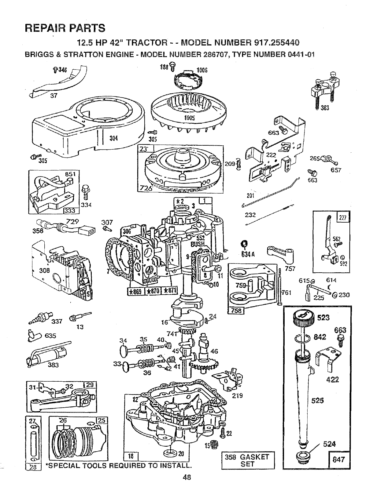
REPAIR PARTS
12.5 HP 42" TRACTOR- - MODEL NUMBER 917,255440
BRIGGS &STRATTON ENGINE - MODEL NUMBER 286707, TYPE NUMBER 0441 =01
3O7
q
757
Y337 13
*SPECIAL TOOLS REQUIRED TO iNSTALL.
48
219
358 GASKET
SET
657
563
6t5_ 614
524
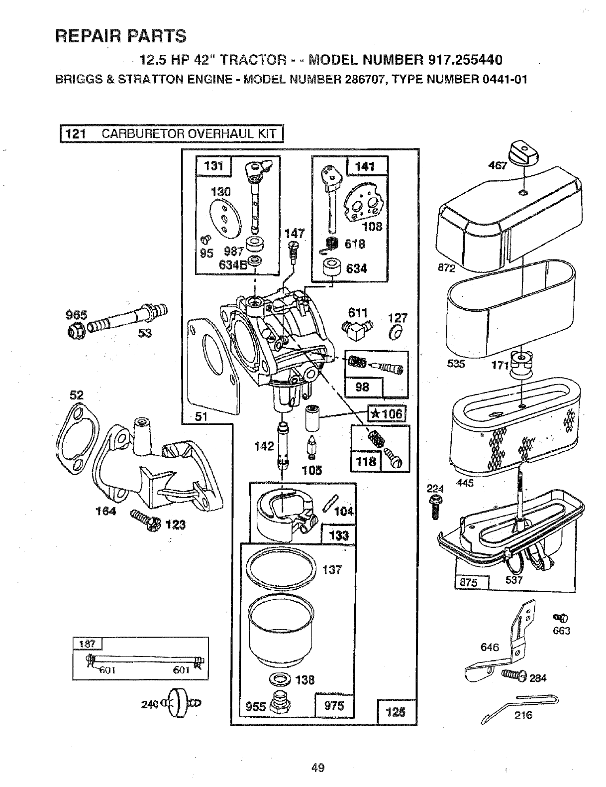
REPAIR PARTS
-12.5 HP 42" TRACTOR - = MODEL NUMBER 917.255440
BRIGGS & STRATTON ENGINE = MODEL NUMBER 286707, TYPE NUMBER 0441-01
147
137
(_ 138
224 445 .
537
663
49 _
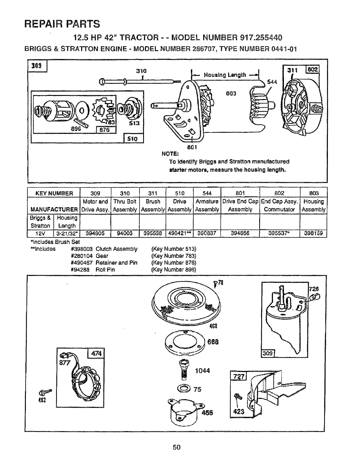
REPAIR PARTS
12.5 HP 42" TRACTOR- = MODEL NUMBER 917.255440
BRIGGS &STRATTON ENGINE - MODEL NUMBER 286707, TYPE NUMBER 0441-01
3Q_
801
NOTE:
To Identify Brlgga and Stratton manufactured
=tarter motor==,measure the housing length.
KEYNUMBER
MANUFACTURER
Briggs &Housing
Stratton Length
! 2V 3-21/32"
309
Motor and
Drive Assy.
394805
*lncluclesBrush Set
**includes
4_2
310
!Thru Bolt
Assembly
94003
#398003 Clutch Assembly
#280104 Gear
#490467 Retainer and Pin
#94288 Roll Pin
3tl
Brush
Assembly
395538
510
Drive
Assembly
490421_*
544 801
Armature Drive End Ca
Assembly Assembly
3908,37 _rl,394856
802
End Cap ASsy.
Commutator
395537*
8O3
Housing
Assembly
398159
(Key Number 513)
(Key Number 783)
(Key Number 878)
(Key Numbar 896)
ce8
1044
(_) 75
50
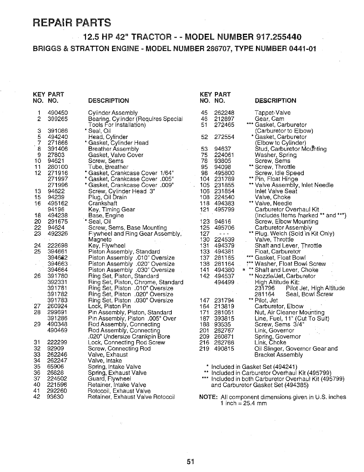
REPAIR PARTS
12.5 HP 42" TRACTOR - - MODEL NUMBER 917.255440
BRIGGS & STRATTON ENGINE = MODEL NUMBER 286707, TYPE NUMBER 0441-01
KEY PART KEY PART
NO, NO. DESCRIPTION NO, NO. DESCRIPTION
1 490450
2 399265
3 391O86
5 494240
• 7 271866
8 391406
9 27803
10 94621
11 280100
12 271916
271997
271996
13 94622
15 94239
t6 495162
94196
18 494238
20 291675
22 94624
23 492326
24 222698
25 394661
3948,62
394663
394664
26 391780
392331
391781
391782
391783
27 260924
28 299691
391286
29 490348
490469
31 222299
32 92909
33 262246
34 262247
35 65906
36 26828
37 224502
40 221596
41 292260
42 93630
Cylinder Assembly 45 262248
Bearing, Cylinder (Requires Special 46 212897
Tools For installation) 51 272465
* Seal, Oil
Head, Cylinder 52 272554
* Gasket, Cylinder Head
Breather Assembly 53 94637
Gasket, Valve Cover 75 224061
Screw, Sems 78 93805
Tube, Breather 95 94098
*Gasket, Crankcase Cover 1/64" 98 495800
* Gasket, Crankcase Cover .005" 104 231789
* Gasket, Crankcase Cover .009" 105 231855
Screw, Cylinder Head 3" 106 231854
Plug, Oil Drain 108 224540
Crankshaft 118 494383
Key, Timing Gear 121 495799
Base, Engine
*Seal, Oil 123 94616
Screw, Sems, Base Mounting 125 495706
Flywheel and Ring Gear Assembly, 127 - - -
Magneto 130 224539
Key, Flywheel 131 494379
Piston Assembly, Standard 133 494381
Piston Assembly .010" Oversize 137 281'165
Piston Assembly .020" Oversize 138 281164
Piston Assembly .030" Oversize 141 494380
Ring Set, Piston, Standard 142 494537
Ring Set, Piston, Chrome, Standard 494499
Ring Set, Piston .010" Oversize
Ring Set, Piston .020" Oversize
Ring Set, Piston .030" Oversize 147 231794
Lock, Piston Pin 164 213819
Pin Assembly, Piston, Standard 171 281051
Pin Assembly, Piston .005" Over 187 393815
Rod Assembly, Connecting 188 93535
Rod Assembly, Connecting 20t 1262767
.020" Undersize Crankpin Bore 209 260871
Lock, Connecting Rod Screw 216 262766
Screw, Connecting Rod 219 490815
Valve, Exhaust
Valve, Intake
Spring, Intake Valve
Spring, Exhaust Valve
Guard, Flywheel
Retainer, Intake Valve
Rotocoil, Exhaust Valve
Retainer, Exhaust Valve Rotocoil
Tappet-Valve
Gear, Cam
*** Gasket, Carburetor
(Carburetor to Elbow)
* Gasket, Carburetor
(Elbowto Cylinder) ..
Stud, Carburetor MoLTnting
Washer, Spring
Screw, Sems
** Screw, Throttle
Screw, Idle Speed
** Pin, Float Hinge
** Valve Assembly, Inlet Needle
Inlet Valve Seat
Valve, Choke
** Valve, Needle
Carburetor Overhaul Kit
(Includes Items Pnarked ** and ***)
Screw, Elbow Mounting
Carburetor Assembly
Plug, We ch (So d in K t On y)
Valve, Throttle
Shaft and Lever, Throttle
Float, Carbureto_
*** Gasket, Float Bowl
.***Washer, Float Bowl Screw
_, ** Shaft and Lever, Choke
** Nozzle/Jet, Carburetor
High Altitude Kit:
231796 Pilot Jet, High Altitude
281164 Seal, Bowl Screw
** Pilot, Jet
Carburetor, Elbow
Nut, Air Cleaner MOL_nting
Line, Fuel, 11" (Cut To Suit)
Screw, Sems 3/4"
Link, Governor
Spring, Governor
Link, Choke
Oil Slinger, Governor Gear and
Bracket Assembly
* Included in Gasket Set (494241)
** Included in Carburetor Overhaul Kit (495799)
*** Included in both Carburetor Overhaul Kit (495799)
and Carburetor Gasket Set (494385)
NOTE: All component dimensions given in U_S. inches
1 inch = 25.4 mm
51
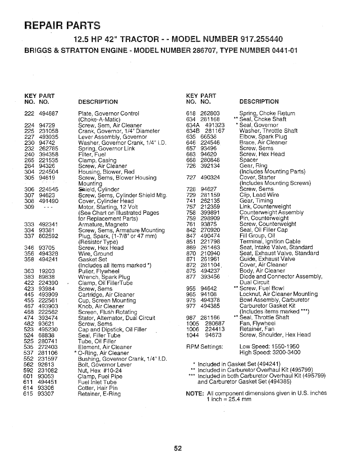
REPAIR PARTS
12.5 HP 42" TRACTOR - -MODEL NUMBER 917.255440
BRIGGS & STRATTON ENGINE - MODEL NUMBER 286707, TYPE NUMBER 0441-01
KEY PART KEY PART
NO. NO. DESCRIPTION NO. NO. DESCRIPTION
222 494887
224 94729
225 231O58
227 493935
230 94742
232 262785
240 394358
265 221535
284 94326
304 224504
305 94619
306 224545
307 94623
308 491490
309 ---
333 492341
334 93381
337 802592
346 93705
356 494328
358 494241
363 19203
383 89838
422 224390
423 93984
445 493909
455 222561
467 493903
468 222562
474 393474
482 93621
523 495230
524 68838
525 280741
535 272403
537 281106
552 231597
562 92613
592 231082
601 93053
611 494451
614 93306
615 93307
Plate, Governor Control 618 262803
(Choke-A-Matic) 634 281168
Screw, Sere, Air Cleaner 634A 491323
Crank, Governor, 1/4" Diameter 634B 281167
Lever Assembly, Governor 635 66538
Washer, Governor Crank, 1/4" I.D. 646 224546
Spring, Governor Link 657 934.96
Filter, Fuel 663 94620
Clamp, Casing 668 280848
Screw, Air Cleaner 726 392134
Housing, Blower, Red
Screw, Seres, Blower Housing 727 490324
Mounting
$_ield, Cylinder 728 94627
Screw, Sems, Cylinder Shield Mtg. 729 281159
Cover, Cylinder Head 741 262135
Motor, Starting, 12 Volt 757 212359
(See Chart on Illustrated Pages 758 399891
for Replacement Parts) 759 298909
Armature, Magneto 761 93875
Screw, Seres, Armature Mounting 842 270920
Plug, Spark, (1-7/8" or 47 ram) 847 490474
(Resistor Type) 851 221798
Screw, Hex Head 869 261463
Wire, Ground 870 210940
Gasket Set 871 261961
(Includes all items marked *) 872 281104,
PulLer, Flywheel 875 494237
Wrench, Spark Plug 877 393456
Clamp, Oil FillerTube
Screw, Seres 955 94642
Cartridge, Air Cleaner 965 94108
Cup, Screen Mounting 975 494378
Knob, Air Cleaner 977 494385
Screen, Flush Rotating
Stator, Alternator, Dual Circuit 987 281166
Screw, Sems 1005 280687
Cap and Dipstick, Oil Filler 1006 224413
Seal, FillerTube 1044 94673
Tube, Oil Filler
Element, Air Cleaner
* O-Ring, Air Cleaner
Bushing, Governor Crank, 1/4" I.D.
Bolt, Governor Lever
Nut, Hex #10-24
Clamp, Fuel Pipe
Fue! Inlet Tube
Cotter, Hair Pin
Retainer, E-Ring
Spring, Choke Return
** Seal, Choke Shaft
* Sea!, Governor
Washer, Throttle Shaft
Elbow, Spark Plug
Brace, Air Cleaner
Screw, Sems
Screw, Hex Head
Spacer
Gear, Ring
(Includes Mounting Parts)
Cover, Starter
(Includes Mounting Screws)
Screw, Sems
Clip, Lead Wire
Gear, Timing
Link, Counterweight
Counterweight Assembly
Pin, Counterweight
Screw, Counterweight
Seal, Oil Filler Cap
Fill Group, Oil
Terminal, Ignition Cable
Seat, Intake Valve, Standard
Seat, Exhaust Valve, Standard
Guide, Exhaust Valve
Cover, Air Cleaner
Body, Air Cleaner
Diode and Connector Assembly,
Dual Circuit
** Screw, Fuel Bowl
Locknut, Air Cleaner Mounting
Bowl Assembly, Carburetor
Carburetor Gasket Kit
(Includes items marked ***)
** Seal, Throttle Shaft
Fan, Flywheel
Retainer, Fan
Screw, Shoulder, Hex Head
RPM Settings: Low Speed: 1550-1950
High Speed: 3200-3400
* Included in Gasket Set (494241)
** Included in Carburetor Overhaul Kit (495799)
*** Included in both Carburetor Overhaul Kit (495799)
and Carburetor Gasket Set (494385)
NOTE: All component dimensions given in U.S. inches
1 inch = 25.4 mm
52

SERVICE NOTES
53

..... [
SERVICE NOTES
54

SUGGESTED GUIDE FOR SIGHTING SLOPES FOR SAFE OPERATION
ol
ONLY RIDE UP AND DOWN HILL,
NOT ACROSS HILL
SIGHT AND HOLD TH1SLEVEL WITH
SKY LINE ORTREE.
Ar"OP_te yqu; Tractor up and down,the face of slopes (not
M _ greater t_n_iS_),,never across the face. Make turns gradu-
J _ ally to prevent, tipping or loss of control. Exercise extreme
Ncaution when cha_ging_direction on slopes.
S A/RS
OWNER'S
MANUAL
MODEL NO.
917°255440
HOW iTO ORDER
REPAIR PARTS
137747 Rev. 3 7.08.93
CRAFTgMIIN®
12.5 HP IC
ELECTRIC START
3 IN One Convertible
42" MOWER
6 SPEED TRANSAXLE
LAWN TRACTOR
Each tractor has its own model number. Each engine has
its own model number.
The model number for your. tractor will be found on the
model p!ate located under the seat.
The._bde_ number for your engine will be found on the
blower h_sin_ _oft_heengine.
All parts s{_d t_re_?_a_ be ordered from any Sears,
Roebuck and Co _i'_,Center/Department and most
Retail Stores.
WHEN ORDERING REPAIR PARTS, ALWAYS GIVE THE
FOLLOWING INFORMATION:
•PRODUCT- LAWN TRACTOR
• MODEL NUMBER - 917.255440
-ENGINE MODEL NO. -286707, TYPE NO. 0441-01
-PART NUMBER
•PART DESCRIPTION
Your Sears merchandise has added value when you
consider Sears has service units nationwide staffed with
Sears trained technicians.., professional technicians
specifically trained to insure that we meet our pledge to
you, we service what we sell.
Printed in U.S.A.
