Craftsman 917255470 User Manual Lawn, Tractor Manuals And Guides LR708038
CRAFTSMAN Lawn, Tractor Manual LR708038 CRAFTSMAN Lawn, Tractor Owner's Manual, CRAFTSMAN Lawn, Tractor installation guides
8EAIRS LR708038
User Manual: Craftsman 917255470 917255470 CRAFTSMAN Lawn, Tractor - Manuals and Guides View the owners manual for your CRAFTSMAN Lawn, Tractor #917255470. Home:Lawn & Garden Parts:Craftsman Parts:Craftsman Lawn, Tractor Manual
Open the PDF directly: View PDF ![]() .
.
Page Count: 56
8EAIRS
®
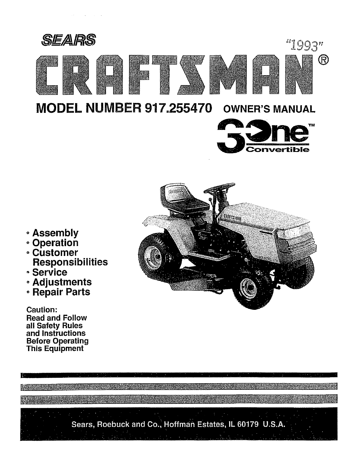
MODEL NUIMBER 917.255470 OWNER'S MANUAL
IIII I I I IIII 'll'llll'l
oAssembly
oOperation
oCustomer
Responsibilities
oService
oAdjustments
oRepair Parts
Caution:
Read and Follow
all Safety Rules
and Instructions
Before Operating
This Equipment
|1 I I I II1'1111111
SAFETY RULES
Safe Operation Practices for Ride-On Mowers
IMPORTANT: THIS CUTTING MACHIN EIS CAPABLE OFAMPUTATtNG HANDS AND FEETAND'THROWING OBJECTS,
FAILURE TO OBSERVE THE FOLLOWING SAFETY INSTRUCTIONS COULD RESULT INSERIOUS INJURY OR DEATH,
I. GENERAL OPERATION
-Read, understand, and follow all instructions in the manual
and on the machine before starting..
• Only allow responsible adults, who are familiar with the
instructions, to operate the machine,.
• Clear the area of objects such as rocks, toys wire, etc.,,
which could be pcked up and thrown by the blade
= Besure the area is clear of other people before mowing. Stop
machine if anyone enters the area,
• Never carry passengers
• Do not mowin reverse unless absolutely necessary Always
took down and behlnd before and while backing.
• Be aware of the mower discharge direction and do not point
it at anyone,. Do not operate the mower without either the
entire grass catcher or the guard in place,
• Slow down before turning.,
• Never leave a running machine unattended. Always turn off
blades, set partdng brake, stop engine, and remove keys
before dismounting,
" Turn off blades when not mowing.
,, Stop engine before removing grass catcher or unclogging
chute°
• Mow only in dayiight or good artificial tight.
° Do not operate the machine while under the influence of
alcohol or drugs
•Watch for traffic when operating near or crossing roadways.
,, Use extra care when ioading or unloading the machine into
a trailer or truck.
IL SLOPE OPERATION
Slopes are a major factor related to Ioss-of-control and ttpover
accidents, which can result in severe injuryor deathr. A!f s_opes
require extracaution, Ifyou cannot backup the slope orif you feet
uneasy on it, do not mow it.
DO:
= Mow up and down slopes, not across.
° Remove obstacles such as rocks, tree iimbs, etc.
• Watch for holes, ruts, or bumps, Uneven terrain could
overturn the machine., Tatl grass can hide obstacles.,
• Use slow speed. Choose a low gear so that you will not have
to stop or shift while on the slope.
• Follow the manufacturer's recommendations for wheel
weights or counterweights to improve stability.
• Use extra care with grass catchers or other attachments,
These can change the stability of the machine.
• Keep all movement on the slopes slowand gradual, Do not
make sudden changes in speed or direction,
• Avoid starting or stopping on a slope. If tires iose traction,
disengage the b_adesand proceed slowly straightdown the
slope.,
DO NOT:
•Donor turn on slopes unless necessary, and then turn slowly
and gradual y downhill, ifpossible.
•Do not mow near drop-offs ditches, or embankments The
mower could suddenly turn over if a wheel is over the edge
of a cliff or ditch, or if an edge caves in,
•Do not mow on wet grass_ Reduced traction could cause
sliding,,
•Do not try to stabilize the machine by putting yourfoot onthe
ground.
•Do not use grass catcher on steep slopes
II1. CHILDREN
Tragic accidents can occur if the operator is not alert to the
presence ofchildren° Children are often attracted to the machine
and the mowing acfivity. Neverassume that children will remain
where you Iast saw them,
• Keep children out of the mowing area and under the watchful
care of another responsible adult,
•Be alert and turn machine off if children enter the area.
= Before and when backing, look behind and down for small
children,
= Never carry children. They may fall off and be seriously
injuredor interfere with safe machine operation.
• Never allowchildren to operate the machine.
• Use extra care when approaching blind corners, shrubs,
trees, or other objects that may obscure vision.
IV. SERVICE
• Use extracare in handling gasoline and other fuels, Theyare
flammable and vapors are explosive,
Use only an approved container,,
Never remove gas cap or add fuel with the engine
running. Allow englne to cool before refueling. Do not
smoke,
Never refuel the machine indoors.
Never store the machine or fuel container insidewhere
there is an open flame, such as a water heater.
.Never run a machine inside a closed area.,
•Keep nutsand bolts, especially blade attachment bo_ts tight
and keep equ pment in good condition.
o Never tamper with safety dev]ces_ Check their proper
operation regulady,
• Keep machine free of grass, feaves orotherdebflsbuild-up
Clean oil or fuel spillage. Allow machine to cool before
storing
•Stop and inspect the equipment if you strike an object.,
Repair, if necessary, before restarting°
• Never make adjustments or repairs with the engine running°
-Grass catcher components are subject towear, damage, and
deterioration, which could expose moving parts or allow
objects fo be thrown. Frequently check components and
replace with manufacturer's recommended parts,when nec-
essary.
• Mower blades are sharpand can cUt.rWrap the biade(s) or
wear gloves, and use extra caution when sen/icing them.
o Check brake operation frequently. Adjust and service as
required,
I A L°0k';o;'this sYmbo| to point out impor- i
_!IA tent safety precautions. It means
_1_ CAUTIONH! _ECOMEALERT!I! YOUR
SAFETY IS INVOLVED.
ml imllu ii ii i i
!,, I
CAUTION: Always disconnect spark
plug wire and place wire where it ca nn ot
contact spark plug in order to prevent
accidental startin 9when setting up,
transporting, adlusting or making
repairs.

CONGRATULATIONS on your purchase of a Soars
Tractor. It has been designed, engineered and manu*
factured to give you the best possible dependability and
performance°
Should you experience any problem you cannot easily
remedy, please contact your nearest Sears Service
Department. We have competent, well-trained techni-
cians and the proper tools to service or repair this unit°
Please read and retain this manual. The instructions will
enable you to assemble and maintain your unit properly_
Always observe the "SAFETY RULES",
MODEL
NUMBER 917.255470
SERIAL
NUMBER
:)ATEOF PURCHASE
THE MODELAND SERIAL NUMBERS WILL BE FOUND
ON A PLATE UNDER THE SEAT°
YOU SHOULD RECORD BOTH SERIAL NUMBER AND
_)ATEOF PURCHASE AND KEEP IN A SAFE PLACE
-'OR FUTURE REFERENCE°
MAINTENANCE AGREEMENT
ASears Maintenance Agreement is available on this prod-
ucL Contact your nearest Sears store for details.
CUSTOMER RESPONSIB UTIES
= Read and observe the safety rules.
•Follow a regular schedule in maintai ni ng, caring for and
using your unit.
. FOlslOWthe_r_StrrUgCtiOsnSc_indneroCt_SstOornwenreF_r,eSmPOnsiabi'i-
PRODUCT SPECnFnCATDONS
HORSEPOWER; :I4o0
GASOLINE CAPACITY: 5 QUARTS
UNLEADED REGULAR
OIL (3_0PINTS): SAE 30 (Above 32°F)
5W-30 (Below 32°F)
SPARK PLUG.(GAP,0301No); CHAMPION RC12YC
VALVE CLEARANCE: INTAKE .003 - .005 IN.
EXHAUST .003 - .005 IN.
GROUND SPEED: FORWARD
1st 1.0I MPH
2rid 2.08 MPH
3rd 3_12 MPH
4th 3.98 MPH
5th 5.10 MPH
REVERSE: to50 MPH
TIRE PRESSURE: FRONT: 14 PSI
REAR: 12 PSI
CHARGING SYSTEM: 3 AMPS BATTERY
5AMPS HEADLIGHTS
BLADE BOLT TORQUE: 30-35 FT, LBS.
WARNING= This unit is equipped withan internalcombus-
tion engine and should not be used on or near any unim-
proved forest-covered, brush-covered or grass-covered
land unless the engine*s exhaust system is equipped with
a spark arrestor rnoeting applicable local or state laws (if
any). If a spark arresteris used, it should be maintained in
effective working order by the operator°
In the state of California the above is required by law
(Section 4442 of the California Public Resources Coda)_
Other states may have similar laws. Federal laws apply on
federal lands_ A spark arrestor for the muffler is available
through your nearest Sears Authodzed Service Center
(See REPAIR PARTS section of this manual).
i=i
LIMITED TWO YEAR WARRANTY ON ELECTRIC START RIDIING EQUliPMENT
For two (2) years from the date of purchase, if this tiding equipment is maintained, lubricated and tuned up according to the
instructionsin the owner's manual, Sears will repair or replace, free of charge, any parts found to be defective in material or
workmanship°
This Warranty does not cover:
. Expendable items which become worn during normal use, such as blades, spark plugs, air cleaners and belts.
o Tire replacement or repair caused by punctures from outside objects, such as nails, thorns, stumps, or glass°
• Repairs necessary becauee of operator abuse, negligence, improper storage or accident or the failure to maintain the
equipment according to the instructionscontained in the owner's manual.
° Riding equipment used for commercial or rental purposes
UMITED 90 DAY WARRANTY ON BATTERY
For 90 days from date of purchase, if any battery Included with this riding equipment proves defective in material or workmanship
and ourtesting determines the battery wiil not hold a charge, Sears will replace the battery at no charge°
WARRANTY SERVICE IS AVAILABLE BY RETURNING THE RIDING EQUIPMENT TO THE NEAREST SEARS SERVICE
CENTER/DEPARTMENT IN THE UNITED STATES.
This Warranty gives you specific legal rights, and you may also have other tights which may vary from state to state.
TABLE OF CONTENTS
SAFETY RULES ......................................................... _..2
PRODUCT SPECIFICATIO NS ....................................... 3
CUSTOMER RESPONSIBILITIES ..................... 3, 15-19
WARRANTY ................................................................... 3
TABLE OF CONTENTS ................................................. 4
INDEX ............................................................................. 4
TRACTOR ACCESSORIES ........................................... 5
ASSEMBLY .............................................................. 7-10
OPERATION ........................................................... 11-14
MAINTENANCE SCHEDULE ...................................... 15
SERVICE AND ADJUSTMENTS ............................ 20-25
STORAGE .................................................................... 26
TROUBLESHOOTING ............................................ 27-28
REPAIR PARTS -TRACTOR ................................. 30-47
REPAIR PARTS -ENGINE ..................................... 48-52
PARTS ORDERING/SERVICE ................... BACK PAGE
iNDEX
A
Accessodes .................................................5
Adjustments;
Brake ................................................22
Carburetor ..............................................25
Mower:.
Front-To,Back ...............................21
Side-To-Side ............................_.....21
Throttle Control Cable ................. 24
Air Filter, Engine ................................... 18
Air Screen, Engine ...........................................18
Assembly ................................................7-10
B
Batlery:
Charging ............................................ 8
Cleaning ............................................1g
Installation ..........................................9
Levels ..........................................8,17
Preparation ..................................... 8
Starling wilh Weak Battery ...........23
Storage .............................................26
Terminals .........................................17
Belts:
Motion Drive
RemovaVRepfacement .............22
Mower Blade Drive
Remova!/Replace ment ........... 22
Blade:
Sharpening o.o_...................................16
Replacement .....................................16
Brake Adjustment ...................................22
C
Carburetor Adjustment ....................... 25
Contrqls, Tractor ....................................t 1
Customer Responsibilities ...............15-t9
Engine:
Air Filter ........................................18
Air Screen, Engine .................. t8
Battery ...................................... 17
Cooling Fins, Engine ...................18
Engine Oll .......................................t7
FueI Filter .......................................19
Spark Plugs ......................................19
Tractor:
Blades ............................................16
Lubrication Chart ...................... 15
Maintenance Schedule ............ 15
Tire Care ..............................8,!6,23
Cutting Height, Mower ............................12
E
Electrical:
Interlocks and Relays .....................24
Schematic .......................................29
Wiring Diagram ...............................30
Engine:
Air Filter ................................................18
Air Screen .........................................18
Cooling Fins, Englne .......................18
Oil Change ....................................... 17
Of! Level .....................................13,17
Oil Type ..........................................17
Preparation .................................... 13
Repair Pads ............................... 48-52
Starting ...................................................14
Storage .................................................26
F
Fifters:
Air ........................................................18
Fuel ......................................................19
Fuel:
Type .......................................................... 1 3
Storage .............................................. 26
Fuse ..........................................................24
H
Hood RemovaVtnetailation ...................24
L
Leveling Mower Deck ................................21
Lubrication Chart ......................................15
M
Maintenance Schedule ....................... 15
Mower:
Adjustment, Front-to-Back ...............21
Adjustment, Side-to-Side ............ 21
Blade Sharpening ........................ 16
Blade Replacement ............................16
Cutting Height .............................. 12
Installation ............................................20
Operation .........................................13
Removal ................................................... 20
Mowing Tips ......................................... 14
Muffler ................................................. 19
Spark Arrester ..............................3,40
Mulcher Plate ............................................10
0
Oil:
Cold Weather Conditions ....... 13,17
Engine ......................................................17
Storage ............................................................ 26
Operation ....................................................11-14
Operating Mower ................................ 13
Options:
Accessodes ..................................... 5
Spari_ An'ester .................................3,40
P
Parking Brake ................................ 11-12
Pads Bag ................................................. 6
Pads, Replacement/Repair ............30-47
Product Specifications...............................3
R
Repair Parts .......................................30-47
S
Safety Rules ................................................2
Seat .................................................................8
Service and Adjustments ...............20-25
Brake ...........................................................22
Carburetor ............................................25
Fuse ......................................................24
Hood Removal!Installation .......... 24
Motion Drive Sell
Removal/Replacement ........... 22
Mower Blade Drive Beff
Removal/Replacement .................22
Mower Adjustment:
Front-to-Back ................................21
Side-to-Side ......._.......................21
Mower Installation ........................ 20
Mower Removal ..........................._..,.20
Tire Care .................................8,16,23
Slope Guide Sheet..................................55
Spark Plugs .......................................................19
Specifications ..........................................3
Starting the Engine ...............................13-14
Steering Wheel .....................................7,23
Stopping the Tractor ...............................12
Storage .................................................. 26
T
Throttle Control Cable Adjustment .....24
Tires ............................................ 8,16,23
Trouble Shooting Chart .................. 27-28
Transaxle Repair Pads ....................46-47
W
Warranty .........................................................3
Wiring Diagram .........................................3D
Wiring Schematic ............................... 29
4
These accessories and atlaohmenls were aval]ai3te when _ne tractor was puronaseo, i nay are also available a_meal: c_eers {e[u_ uu_{_,
catalog and service centers,, Most Sears steres can order these items for you when you provide the model number ef your tractor,,
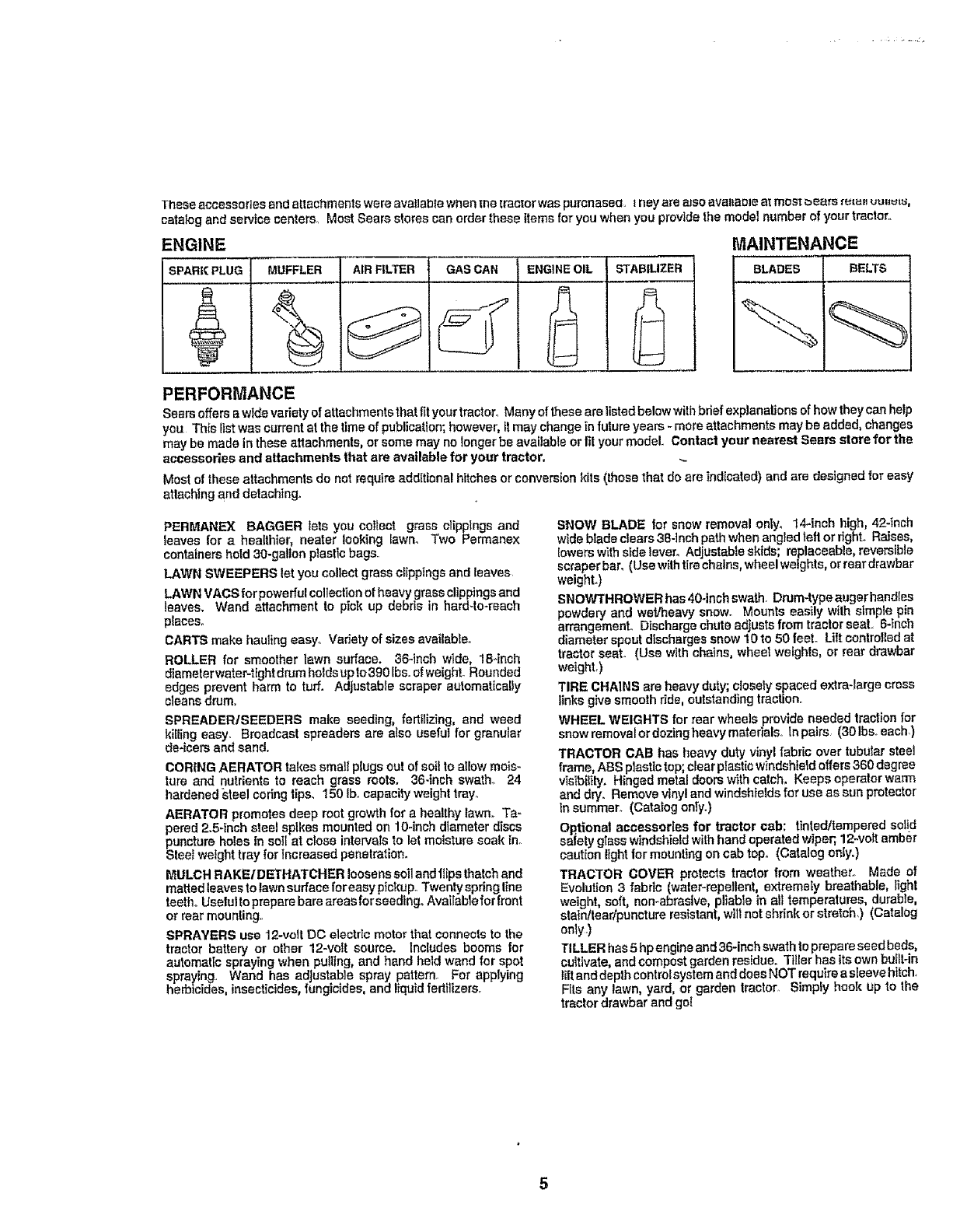
ENGINE
SPARK PLUG MUFFLER GAS CAN ENGINEOIL STABtUZER
MAINTENANCE
BLADES I BELTS
I
PERFORMANCE
Sears offers a wldevariety ofattachments thatfit yourtraotoro Manyof these are listedbelow withbdef explanations of howtheycan help
you This listwas currentat the timeof publication;however, itmay changein future years - more attachments may be added, changes
may be made intheseattachments,or some may no longer be available orfit yourmodel. Contact your nearest Sears store for the
accessories and attachments that are available for your tractor,
Most of these attachments do not requireadd{tiona! hitches or conversionkits (thosethat de are indicated) and are designed for easy
attaching and detaching.
PERMANEX BAGGER lets you coltect grass clippings and
leaves for ahealthier, neater looking {awm Two Permanex
containershotd 30-gallon plasticbags.
LAWN SWEEPERS let you collect grass clippings and leaves
LAWN VACSforpowerful collectionof heavy grass clippings and
leaves, Wand attachment to pick up debris in hard-to-reach
plaeeSo
CARTS make hauling easy° Variety ofsizes available°
ROLLER for smoother lawn surface. 36-inch wide, 18cinch
diameterwater-tight drum holdsupto390 Ibs.of weight. Rounded
edges prevent harm to turf. Adjustable scraper automatically
cleansdrum.
SPREADER/SEEDERS make seeding, fertilizing, and weed
killing easy. Broadcast spreaders are also usefuI for granular
de-icers and sand.
CORING AERATOR takes small plugsout of soil to allow mois-
ture and nutrients to reach grass roots. 36-inch swath, 24
hardened steel coringtips. 150 tb. capacityweight tray°
AERATOR promotes deep root growth for a healthy lawn_ Ta-
pered 2.5-inch steel spikes mounted on 10-inch diameter discs
puncture holes in soil at close intervals to let moisture soak in,
Steel weight tray forIncreased penetration.
MULCH RAKE/D ETHATCHER loosens soil and ftipsthatch and
matted leavesto lawnsurface fereaey pickup° Twenty spring line
teetheUselulto preparebare areasforseedtngo Available for front
or rear mounting.
SPRAYERS use 12-volt DO electricmotor that connectsto the
tractor battery or other 12-volt source. Includes booms for
automaticspraying when pulling, and hand held wand for spot
spraying. Wand has adjustable spray pattamo For applying
herbicides,insecticides,fungicides, and liquidferlilizerS.r
SNOW BLADE for snow removal ontyo 14-inch high, 42-inch
wide blade clears 38-Inch path whenangted tell or right, Raises,
Eowerswith side lever° Adjustabte skids; replaceable, reversible
scraper bar, (Use withtire chains,wheel weights, or reardrawbar
weight.)
SNOWTHROWER has40-inch swath. Drum-typeaugerhand[es
powdery and wet/heavy snow° Mounts easily with simple pin
arrangemenL Discharge chute adjusts from tractorseat. 6-inch
diameter spout discharges snow 10te 50 feel Lift controlledat
tractor seat. (Use wlth chains, wheat weights, or rear drawbar
weight,)
TIRE CHAINS are heavy duly; closety spaced extra-largecross
linksgive smooth ride, outstanding traction_
WHEEL WEIGHTS for rear wheels provide needed traction for
snowremovalerdozingheavymaferials, thpairs. (301be.each)
TRACTOR CAB has heavy duty vinyl fabric ever tubularsteel
frame ABS plastictop;clear plasticwindshieldoffers360 degree
visibility.Hingedmeta! doors withcatch, Keeps operatorwarm
and dry. Remove vinyl and windshieldsfor use as sun protector
tn summer_ (Catalog oniy.)
Optional accesserles for tractor cab: tinted/tampered solid
safety glass windshield wilh handoperated wiper;, 12welt amber
caution light for mounting on cab top. (Catalog only.)
TRACTOR COVER protects tractor from weather.. Made of
Evolution3 fabdc (waler-repetlant, extremely breathable, light
weight, soft, non-abrasive, pliable in all temperatures,durabte,
slaintlear/puncture resistant, will net shrink or stretch,) (Catalog
only.)
TILLER has5hp engineand 36-inch swathto prepareseed beds,
cultivate, and compostgarden residue. Tiller has ttsown buflt-in
lift and depthcontrolsystem and does NOT require a sleevehitch,
Fits any lawn, yard, or garden tractor. Simply hook up te the
tractor drawbar and go!
,i i1,1
Parts Bag contents shown full size
i...........
©(2) Sheet
Metal
Screws
#10-I6 x 1/2
(1) 2-3/8" Diameter Washe_ 1) Locknut 3/8-24
(1) Shoulder Bolt 5/!6-18 (1) Hex Bolt 1/2-13 x 1
(t) Lock Washer 1/2
(1) Washer 17/32 x 1-3/16 x 12 Gauge
(1) Wing Nut 3/8
(I) Washer __ (1) Lock
13/32 x 1-I/4x 16 Gauge _ Washer 3/8
i
(2) Hex Bolts I/4-20 x 3/4 @
(2) Hex Nuts t/4-20
G
(2) Washers 9/32 x 5/8 x 16 Gauge
(2) Lock Washers 1/4
.....i,,, ..........
Ill I I I I I '"1 "1 '1
Parts packed separately in carton
Steering
Boot
Seat
_ Mulcher Plate
Battery
Owner's Manual
Steering
Wheel ! U
Parts Bag
Parts bag contents not shown full size
Steering Wheel
Adapter
IIWheel
,jJ Insert
Steering (2) Keys
Bushing
........ .j"
Battery Caps
15° Slope Sheet and Instructions
our new _rac[or nas Dean assemDleo at lne "leo'tory WlIR except|on o1" _FIOSe paris lS"K urtassemDteQ lot Snlpptng purpo_e_
To ensure safe andproper operation of your tractor all parts and hardwareyou assemble must betightened securely. Use
the correct tools as necessary to Insure proper tightness.
TOOLS REQUIIRED FOR ASSEMBLY
A socket wrench set will make assembly easier° Standard
wrench sizes are listed.
(t) 5/16" wrench
(2) 7/16" wrenches
(1) 3/4" wrench
(1) 9/16" wrench
When right and left hand are mentioned in this manual, it
means when you are in the operating position (seated
behind the steering wheel).
Tire pressure gauge
Phillips Screwdriver
Utility knife
TO REMOVE TRACTOR FROM CARTON
UNPACK CARTON
o Remove all accessible loose parts and parts cartons
from carton (See page 6),
• Cut along lines on carton, from topto bottom, all four
comers of carton and lay panels fiat.
•Check for any additional loose parts or cartons and
remove_
BEFORE ROLLING TRACTOR OFF SKiD
ATTACH STEERING WHEEL (See Fig. 1)
-Slide the steering bushing over the steering shaft,,
. Raise steering shaft forward until screwholes in dash
tine up with steering bushing° Install two (2) sheet
metal screws and tighten securely.
•Position steering boot over steering shaft.
= Align tabs of steering boot over slots and hole indash
and push down to secure.
• Slidesteering wheel adapter onto uppersteering shaft.
= Position front wheels of the tractorso they are pointing
straight forward.
° Position steering wheel so cross bars are horizontal
(left to right) and slide onto adapter,
o Assembletarge flatwasher and 3/8-24 hexIoclmut and
tighten securelyo
o Snap insert into center of steering wheel
o Remove protective plastic from tractor hood and grill.
IMPORTANT.* CHECK FOR AND REMOVE ANY
STAPLES IN SKID THAT MAY PUNCTURE TIRES WHERE
TRACTOR IS TO ROLL OFF SKID.,
SLOT
FIG. 1
TO ROLL TRACTOR OFF SKID (See Fig. 8)
o Raise attachment lift lever to its highest position.
-Release parking brake by depressing clutch/brake
pedal.
• Place gearshift lever in "NEUTRAL" position.
= Roll tractor backwards off skid.
- Remove banding holding discharge guard up against
tractor,
HOW TO SET UP YOUR TRACTOR
PREPARE BATTERY (See Fig. 2) .....
, i,i i
CAUTION: Wear eye and face shield.
Wash hands or clothing Immediately if
_acciden_allyin contact with batlery acid.
Do not smoke. Fumes from charged
battery acid are explosive. Read the
instructions included with the battery
vent caps. Always wear gloves, cloth-
ing andgoggles to protect your hands,
skin and eyes.
Your tractor has a battery charging system whichis suffi-
cient for normaluser However, periodic charging of the
battery with an automotive charger will extend its life.
= See instructions packed with vent caps in parts bag,
•Fitl battery with acid. Fill each ceil until it reaches the
bottom of the vent welIs, Do not overfill,
° Altow battery to stand and settle for at least thirty
minutes_ After standing check the level of acid. If
below the vent wells, add more acid unti the correct
level is reached°
While battery isstanding (afteradding acid)andlater, while
battery Isbeing charged,continue withassembly oftractor.
IMPORTANT: TO MAXIMIZE THE LIFE OF YOUR
BATTERY, tT IS NECESSARY THAT THE BATTERY BE
CHARGED BEFORE USE,, FAILURE TO CHARGE
BATTERY CAN RESULT IN A SHORTENED BATTERY
LIFE,,
." Charge battery at a rate of 6 amperes for1 hour. Use
a 12 volt battery charger. Observe all saTetyprecau-
tions required for battery charging,
•Check the acid level after the battery is charged. Ifthe
acid has fallen below the correct level, add distilled or
ironfree water.
o Installthe vent caps to cover the vent wells, Wash the
top of the battery with water to remove any acid, then
wipe dry.
o Check battery case for leakage to make sure that no
damage has occurred in handling.
•Dispose of excess battery acid,, Neutralize acid for
disposal by adding it to four inches of water in a five
gallon plasticcontainer, Stir with a wooden or plastic
paddle while adding baking soda until the addition of
more soda causes no more foaming,
oFollow instructions on how to install battery.
CUT AWAY VIEW jVENTCAP
I, _ _ L____j ]J VENTWELL
BATTERY
CELL ACID
LEVEL
FIG. 2
INSTALL SEAT (See Fig. 3)
Adjust seat before tighteningadjustment bolto
-Remove cardboard packing on seat pan,
o Place seat on pan and assemble shoulder bolt,
•Assemble adjustment bolt, Iockwasher andflatwasher
toosely Do not tighten.
= Tighten shoulder bolt securely,,
.Lower seat intooperating position and sit on seat.
•Slideseat until acomfodabie position is reachedwhich
allows youto pressclutch/brake pedalallthe waydown
(See Fig.,8).
• Get off seat without moving its adjusted position.
o Raise seat and tighten adjustment bolt securely,
SEAT
SEAT PAN
SHOULDER
BOLT
FLATWASHER
ADJUSTMENT
BOLT
FtG, 3
CHECK TIRE PRESSURE
The tireson your tractor wereoverinflated at tha factoryfor
shipping purposes. Correct tire pressure is important for
best cutting performance.
•Reduce tire pressure to PSI shown in "PRODUCT
SPECIFICATIONS"on page 3 of this manual
CHECK DECK LEVELNESS
For bestcutting results, mower housing should be properly
leveled. See "TO LEVEL MOWER HOUSING" in the
Service and Adjustments section of this manual
CHECK FOR PROPER POSITION OF ALL
BELTS
See the figures that are shown for replacing motion and
mower blade drive belts in the Service and Adjustments
section of this manual Verify that the belts are routed
correctiyo
CHECK BRAKE SYSTEM
After you learn howto operate your tractor, check to see
that the brake is properly adjusted. See =TO ADJUST
BRAKE" in the Service and Adjustments section of this
manual
INSTALL BATTERY (See Figs. 4 & 5)
....CAUTION: Do not short battery termi-
nals. Before installing battery, remove
metal bracelets, wristwatch bands,
rings, etc,
Positive terminal must be connected
first to prevent sparking from acciden-
tal grounding.
° Lift seat to raised position..
,Open battery box door
o Lower battery into battery box with battery terminals
toward front of tractor.
. Be sure battery drain tube is attached to battery box_
= First connect REDbattery cable to positive (+) battery
terminal with hex bolt, fiatwasher, lock washerand hex
nut as_shown. Tighten securely_
° Connect BLACK grounding cable to negative (-) bat-
tery terminal with remaining hex bolt, flat washer, lock
washer and hex nut. Tighten securely_
•Close battery box door.
Open battery box door for.-
Inspection for secure connections (to tighten hard-
ware).
o Inspection for corrosion.
o Testing battery,
°Jumping (if required)°
•Periodic charging,
BATTERY
BOX DOOR
POSEIVE
(RED) CABLE (BLACK) CABLE
POSITIVE(4-)TERMINAL NEGATWE(-)TERMINAL
FIG. 4
BOX DOOR
VENT CAPS
FIG. 5
9
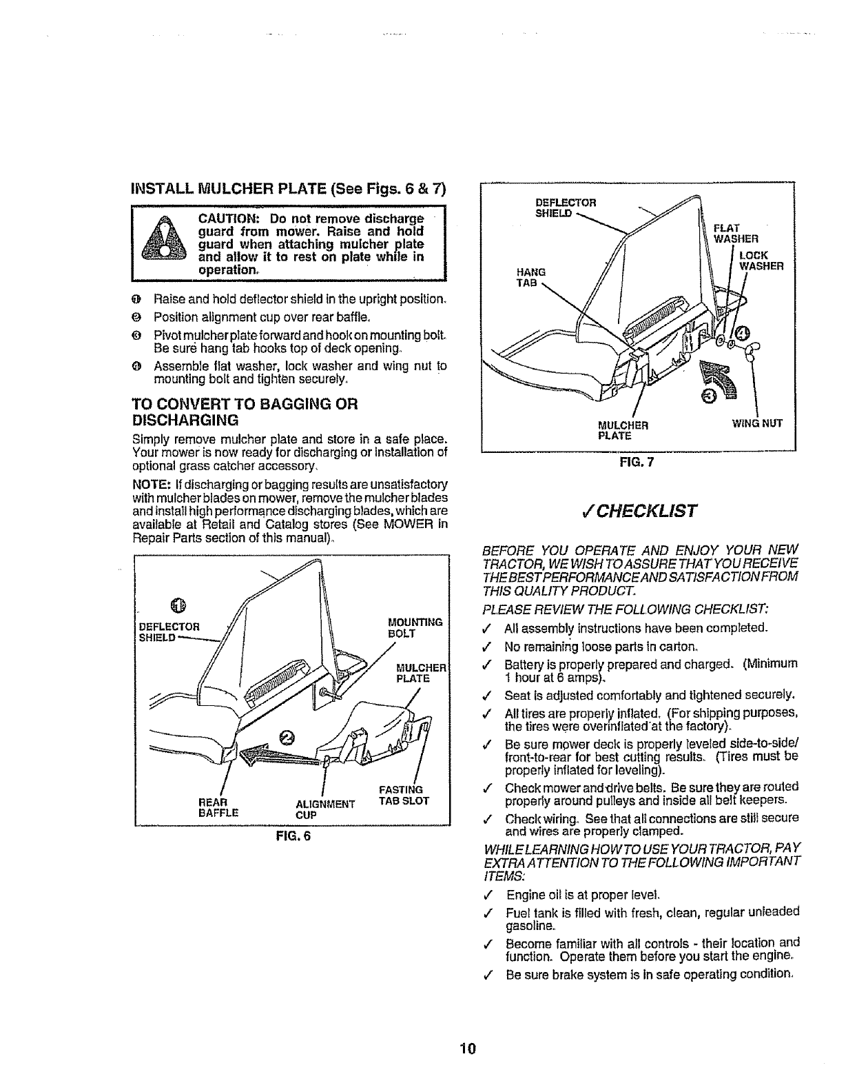
INSTALL IVtULCHER PLATE (See Figs. 6 &7)
CAUTION: Do not remove discharge
guard from mower. Raise and hold
guard when attaching muicher plate
and allow it to rest on plate whde in
operation_
iill ll,ll.,i .i,i i,i iIHH "
O Raiseand hold deflector shieldinthe upright position.
OPosition alignment cup over rear baffle°
O Pivotmulcher plateforward and hookon mounting boll
Be sure hang tab hooks top of deck opening,.
O Assemble Slatwasher, loci( washer and wing nut to
mounting bott and tighten securely,
TO CONVERT TO BAGGING OR
DISCHARGING
Simplyremove mulcher plate and stere in a safe place.
Your mower is now readyfor discharging or installationof
optionalgrass catcher accessory,
NOTE: Ifdischarging orbagging results ars unsatisfactory
withmulcher blades on mower, removethe mulcher blades
andinstall highperformance discharging blades,which are
available at Retail and Catalog stores (See MOWER in
Repair Parts section of this manual)°
DEFLEC_TOR MOUNTING
BOLT
MULCHER
pLATE
REAR ALIGNMENT
BAFFLE CUP
FIG. 6
FASTING
TAB SLOT
DEFLECTOR
SHIELD
HANG
TAB
WASHER
LOCK
WASHER
MULCHER
PLATE
FIG. 7
WiNG NUT
v"CHECKLIST
BEFORE YOU OPERATE AND ENJOY YOUR NEW
TRACTOR, WE WISH TOASSURE THAT YOURECEIVE
THEBEST PERFORMANCEAND SATISFACTION FROM
THIS QUALITY PRODUCT.
PLEASE REVIEW THE FOLLOWING CHECKLIST:
,/ All assembly Instructions have been completed.
,7 No remainirig loose parts incarton_
,/ Battery is properly prepared and charged. (Minimum
I hour at 6 amps).
•/Seat {sadjustedcomfortably andtightened securely,
•/Alltires are properi7inflated, (For shipping purposes,
the tires were ovennffated'at the factory).
/Be sure mower deck is properly leveled side-to-side/
front-to-rear for best cutting results. (Tires must be
properlyinflatedfor leveling).
,/ Checkmcweranddrivebelts. Besuretheyarerouted
properly around putleys and inside all belt keepers.
/Checkwiringo See that altconnections are stil_secure
and wires are properly clamped.
WHtLELEARNING HOWTO USE YOUR TRACTOR, PAY
EXTRAATTENTtON TO THE FOLLOWING IMPORTANT
ITEMS:
/Engine oil ts at proper level.
,/ FueI tank is filled with fresh, clean, regular unleaded
gasoline,.
v" Become familiar with all controls - their location and
function. Operate them before you start the engine.
,/ Be sure brake system is in safe operating condition..
10
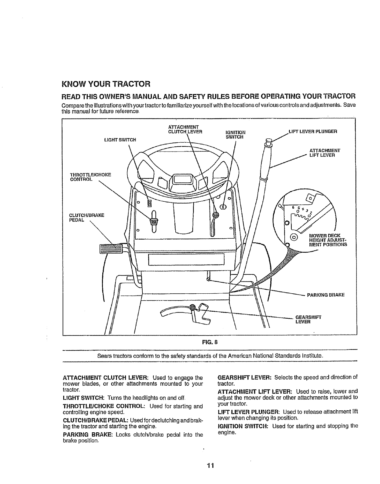
KNOW YOUR TRACTOR
READ THIS OWNER'S MANUAL AND SAFETY RULES BEFORE OPERATING YOUR TRACTOR
Comparethe illustrationswithyour tractorto familiarize yourself withthe !ocationsof various controls and adjustments. Save
this manual for future reference,
LIGHT SWITCH
ATTACHMENT
LEVER IGNITION
SWITCH
LIFT LEVER PLUNGER
ATTACHMENT
LIFT LEVER
THROTTLF-JCHOKE
CONTROL
CLUTCH/BRAKE
PEDAL
l I
MOWER DECK
HEIGHT ADJUST-
MENT POSITIONS
PARKfNG BRAKE
LEVER
FIG. 8
Sears tractorsconformto the safety standards of the American National Standards Institute,,
ATTACHMENT CLUTCH LEVER: Used to engage the
mower blades, or other attachments mounted to your
tractor.
LIGHT SWITCH: Turnsthe headlightsonand off,
THROTTLE/CHOKE CONTROL: Used for start{ng and
controlling engine speed.
CLUTCH/BRAKE PEDAL: Usedfor declutching andbrak-
ing the tractor and starting the engine.
PARKING BRAKE: Locks clutch/brake pedal into the
brake position.
GEARSHIFT LEVER: Selects the speed and direction of
tractor.
ATTACHMENT LIFT LEVER: Used to raise, _owerand
adjust the mower deck or other attachments mounted to
your tractor.
LIFT LEVER PLUNGER: Used to release attachment tilt
lever when changing its position.
IGNITION SWITCH: Used for starting and stopping the
engine.
11
The operation of any tractor can resultinforeign objects thrown into the eyes, which can result
in severe eye damage. Always.wearsafety glasses oreye shields while operating your tractor
or performing any adjustments or repalrs_ We recommend wide vision safety mask for over
the spectacles or standard safety glasses, available at Sears Retail or Catalog stores.
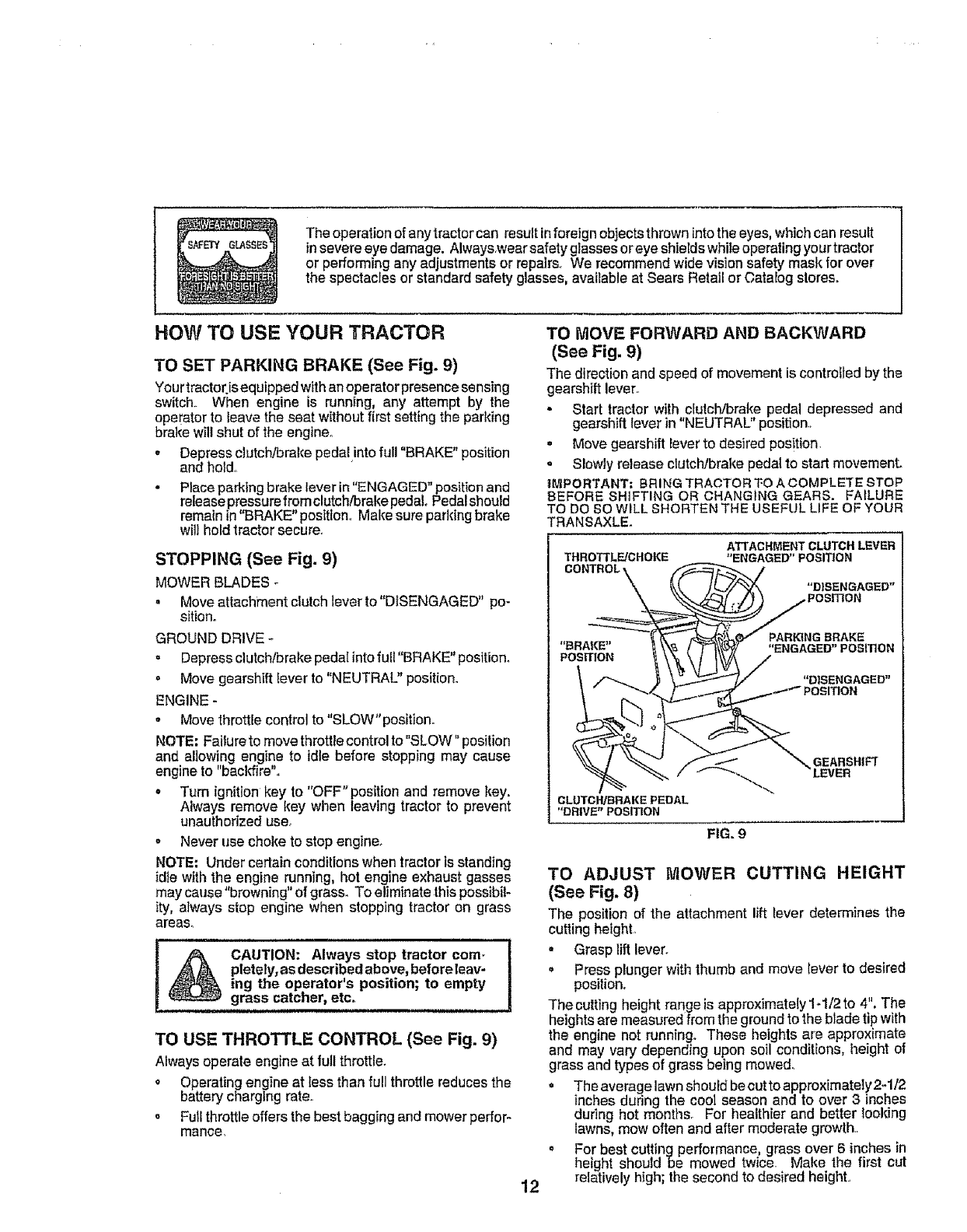
HOW TO USE YOUR TRACTOR
TO SET PARKING BRAKE (See Fig. 9)
Yourtractorjs equipped with anoperator presencesensing
switch.. When engine is running, any attempt by the
operator to leave the seat without first setting the parking
brake wilt shut of the engine°
• Depress clutch/brake pedaUntofull "BRAKE" position
and hold,,
.Place parking brake lever in"ENGAGED" position and
release pressurefrom clutch/brakepedal. Pedalshould
remain in"BRAKE"position,, Make sure parking brake
will hold tractorsecure.
STOPPING (See Fig. 9)
MOWER BLADES
. Moveattachment clutch lever to"DISENGAGED" po-
sition.
GROUND DRIVE *
= Depress clutch/brake pedal into fuil "BRAKE" position_
. Move gearshift [ever to "NEUTRAL" position.
ENGINE -
- Move throttlecontrol to "SLOW"position°
NOTE: Failureto move throttle control to"SLOW" position
and allowing engine to idle before stopping may cause
engine to "backfire",,
• Turn ignition key to "OFF" position and remove key.
Always remove key when leavingtractor to prevent
unauthorized use°
= Never use choke to stop engine.
NOTE: Under certain conditions when tractor is standing
idte with the engine running,hot engine exhaust gasses
may cause "browning" of grass. To eliminate thispossibil-
ity, always stop engine when stopping tractor on grass
areas°
! !
_k CAUTION: Always stop tractor corn.
_pletely,asdescribedabove, beforeleav-
ing the operator's position; to empty
grass catcher, etco
TO USE THROTTLE CONTROL (See Fig. 9)
Always operate engine at full throttle.
o Operating engine at less than full throttle reduces the
battery charging rate,.
o Full throttle offers the best bagging and mowerperfor-
mance.
TO MOVE FORWARD AND BACKWARD
(See Fig. 9)
The direction and speed of movement is controlled by the
gearshift lever,,
- Start tractor with clutch/brake pedal depressed and
gearshift lever in "NEUTRAL" position.,
° Move gearshift lever to desired pos!tion,
o Slowly release clutch/brake pedal to start movement.
IMPORTANT: BRING TRACTOR TO A COMPLETE STOP
BEFORE SHIFTING OR CHANGING GEARS. FAILURE
TO DO SO WILL SHORTEN THE USEFUL LIFE OF YOUR
TRANSAXLE.
THROTI'LFJCHOKE
CONTROL,
ATTACHMENT CLUTCH LEVER
"ENGAGED" POSITION
"DISENGAGED"
POSITION
_NG BRAKE
"ENGAGED" POSITION
"DISENGAGED"
,,...,_ _'*_ POSITION
12
GEARSHIFT
LEVER
CLUTCH/BRAKE PEDAL
"DRIVE" POSITION
FIG. 9
TO ADJUST MOWER CUTTING HEIGHT
(See Fig. 8)
The positionof the attachment lift lever determines the
cuttingheight,.
•Grasp lift lever.
.Press plungerwith thumb and move {everto desired
position°
The cutting height range is approximately 1-1/2 to 4", The
heightsare measured from the ground to the blade tip with
the engine not running. These heights are approximate
and may vary depending upon soil conditions, height of
grass and types of grass being mowed.
• The average lawn should becutto approximately 2-1/2
inchesduring the cool season and to over 3 inches
dudng hot months. For healthier and better tooldng
lawns, mow often and after moderate growth.,
= For best cutting performance, grass over 6 inches in
height should be mowed twice. Make the first cut
relatively high; the second to desired height.,
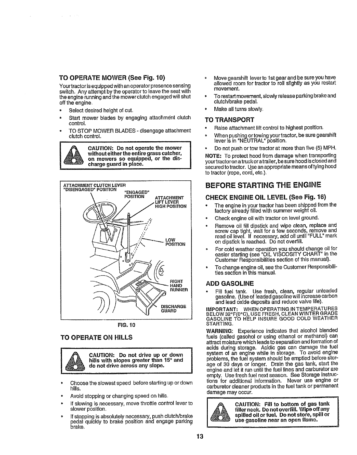
TO OPERATE MOWER (See Fig. 10)
Yourtractor isequipped withanoperatorpresencesensing
switch° Any attempt by the operator to leavethe seatwith
the engine runningand the mowerclutch engagedwill shut
offthe engine,
. Select desired height of cut.
o Start mower blades by engaging attachment clutch
control°
o TO STOP MOWER BLADES - disengage attachment
clutch control
........................ i
CAUTION: Do not operate the mower
without either the entire grasscatcher,
on mowers so equipped, or the dis-
charge guard in place.
i, i i1,1,1,i1,111,,H
FIG. f 0
TO OPERATE ON HILLS
I&CAUTION: Do notdriveupordown ..... t
hills with slopes greater than 15°and
.........d° n°tdr! ve acr°ss any sl°pe' I
•Choose the slowest speed before stading up or down
hills,
•Avoid stopping or changing speed on hills,
o if slowing is necessary, move throttle control lever to
slower position.
.If stopping is absolutely necessary, push clutch/brake
pedal quickly to brake position and engage parking
brake.
= Move gearshift lever to 1st gear and be sure you have
allowed room for tractor to roll slightly as you restart
movement.
-To restartmovement, slowly release pafldng brake and
clutch/brake peda!.
• Make all turns slowly.
TO TRANSPORT
• Raise attachment lift controlto highest position°
When pushing ortowing your tractor, be sure gearshift
lever is in "NEUTRAL" position,
o Do not push or tow tractor at more than five (5) MPH.
NOTE" To protect hood from damage when transporting
your tractor onatruck or at railer,besure hoodis closedand
securedto tractor, Useanappropriate means oftying hood
to tractor (rope, cord, etc,).
BEFORE STARTING THE ENGINE
CHECK ENGINE OIL LEVEL (See Fig, 16)
- The engine in yourtractorhas been shipped from the
factory already filled withsummer weightoil.
= Check engineoilwithtractoron level ground.
°Remove oil fii! dipstickand wipe clean, replace and
screw cap tight,wattfor a few seconds, remove and
read oil level If necessary, add oil until' FULL" mark
on dipstick ts reached. Do not oveffiIL
• For cold weather operation you should change oil for
easier starling (see "OIL VISCOSITY CHART" in the
Customer Responsibilities section of this manual).
• To change engine el!,see the Customer ResponsibllF
ties section inthis manual
ADD GASOLINE
oFill fuet tank. Use fresh clean, regular unleaded
gaseline_ (Use of teaded gasoline willincrease carbon
and lead oxide deposits and reduce valve life),
IMPORTANT; WHEN OPERATINGINTEMPERATURES
BELOW32"F(0°C), USE FRESH, CLEAN WINTER GRADE
GASOLINE TO HELP INSURE GOOD COLD WEATHER
STARTING,,
WARNING: Experience indicates that alcohol blended
fuels (called gasohol or using ethanol or methanol) can
attract moisture which leads to separation and formation of
acids during storage. Acidic gas can damage the fuel
system of an engine while in storage. To avoid engine
problems, the fuel system should be emptied before stor-
age of 30 days or longer. Drain the gas tank, start the
engine and let it run untilthe fuel lines and carburetor are
empty. Use fresh fuel next season. See Storage lnstn_c-
tions for additional information° Never use engine or
carburetor cleaner products in the fuel tank or permanent
damage may occur.
=m
filler neck. Do notoverfill. Wipe off any
spilled oil or fuel, Donot store, spill or R
use gasoline near an open flame. J
13
TO START ENGINE (See Fig. 9)
When starting engine for the first time orif engine has run
out of fuel, itwill take extra cranking time to movefuel from
the tank to the engine.
-Depress the clutchlbrake pedal and set the parking
brake..
o Place gearshift lever in "NEUTRAL" position.
,, Move attachment clutch to "DISENGAGED" position°
• Move throttle control lever to "CHOKE" posilion for
cold engine start. Forwarm engine start, move throttle
control to "FAST" position.
o Turn ignition key c!oclcwiseto "START" position and
release key as soon as engine starts. De not run
starter continuously for'more than fifteen seconds per
minute, If englnedoes not start afterseveralattempts,
move throttle control to "FAST" position, wait a few
minutes and try again°
• When engine starts, move throttle control to desired
position,
•Allow engine to warm up for a few minutes before
engaging drive or attachment clutch.
NOTE: If at a high altitude (above 3000 feet) or incold
temperatures (below 32° F), the carburetor fuel mixture
mayneedto be adjustedfor best engine performance. See
"TOADJUST CARBURETOR" inthe Service and Adjust-
ments section of this manual
MOWING TiPS
. Tire chains cannotbe used when the mower housing
is attached to tractor.
° Mower should be properly leveled for best mowing
performance. See"TOLEVEL MOWER HOUSING"in
the Service and Adjustments section of this manual,.
= The left hand side of mower should be used fortrim-
ming.
° Drive so that clippings are discharged onto the area
that has been cut. Havethe cut area to the rightof the
tractor. This will result in a more even distdbution of
clippings and more uniform cutting,.
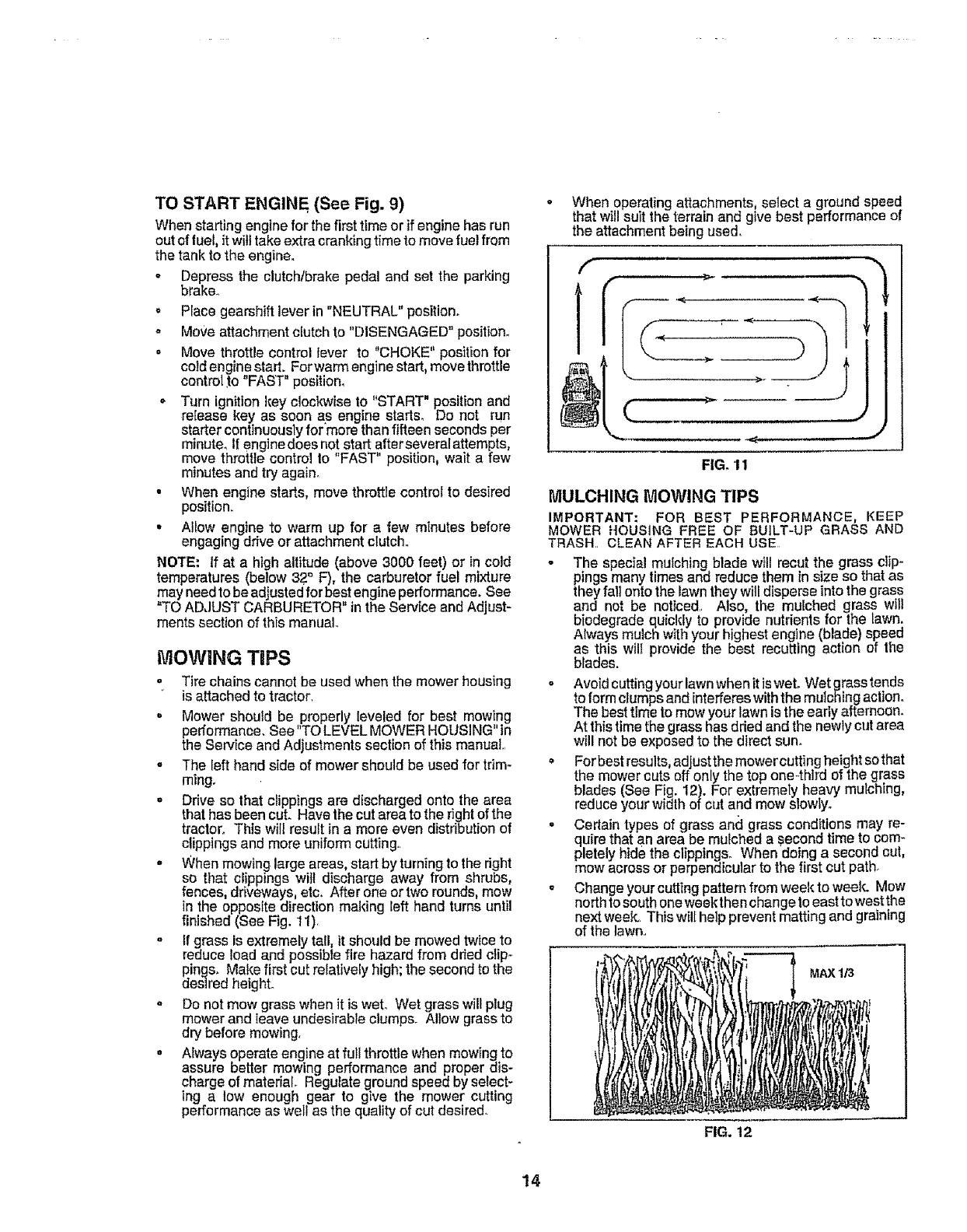
• When mowing large areas, start by turning to the dght
so that clippings wilt discharge away from shrubs,
fences, driveways, etc. After one ortwo rounds, mow
in the opposite direction making left hand turns until
finished (See Fig. 11),
°tf grass is extremely tall, it should be mowed twice to
reduce load and possibte fire hazard from dded clip-
pings. Make first cut relatively high; the second to the
desired height°
° Do not mow grass when it is weL Wet grass will plug
mower and leave undesirable clumps. Allow grassto
dry before mowing.
,Always operate engine at full throttle when mowing to
assure better mowing performance and proper dis-
charge of material. Regulateground speed by select-
ing a low enough gear to give the mower cutting
performance as well as the quality of cut desired.
° When operatingattachments, select a ground speed
that will suit the terrain and give best performance of
the attachment being used.
FIG. 11
MULCHING MOWING TIPS
IMPORTANT: FOR BEST PERFORMANCE, KEEP
MOWER HOUSING FREE OF BUILT-UP GRASS AND
TRASH,, CLEAN AFTER EACH USE
-The special mulching blade will recut the grass clip-
pings many times and reduce them in size so that as
they fall onto the lawnthey will disperse intothe grass
and not be noticed.. Also, the mulched grass wtll
biedegrade quickly to provide nutrients for the lawn.
Always mulch with your highest engine (blade) speed
as this will provide the best recutting action of the
blades.
oAvoid cutting your lawn when it is wet. Wet grass tends
to formclumps and interferes withthe mulching action.
The best time to mow your lawn is the early afternoon.
At thistime the grass has ddedand the newly cut area
will not be exposed to the direct sun.
° For bestresults,adjust the mower cutting height so that
the mower cuts off only the top one-.thirdof the grass
blades (See Fig. 12). For extremely heavy mulching,
reduce your width of cut and mow slowly.
° Certain types of grass and grass conditions may re-
quire that an area be muched a second time to com-
pletelyhide the clippings. When'doing a second cut,
mow across or perpendicular to the firstcut path
o Change your cutting pattern from week to week. Mow
north tosouthoneweek then change to easttowest the
next week..This will help prevent matting and graining
of the lawn..
FIG. 12
MAX 1/3
14
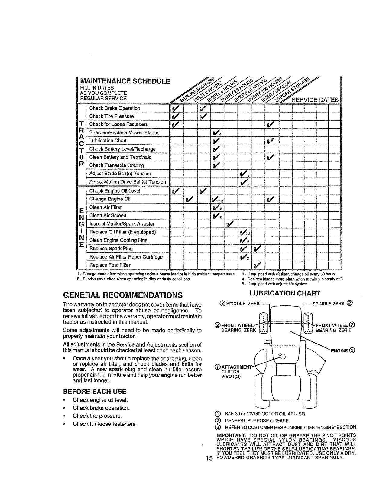
MAINTENANCE SCHEDULE
FILL IN DATES
AS YOU COMPLETE
REGU_RSERVICE
Check Brake Op"rai]on ''_ _/
Check Tire Pressure _
TCheck for Loose Fasteners
AR '""_he,per,JRepl.eeMo,_;Blaae_R 1 I IV'.
C,,i,Lub;'oa'ionOho",i, I Ii IV, ,
TCheck Battery Leve!lRecharge _*
0Clean Battery and Terminals
RCheckTransaxle Cooling
Adjust Blade Bait(s) Tension
AdJust,_Motion ,DF1v_ Belt(s)rm_n_ioR
Check Englna Oti Level
Change Engine Oil
Clean Air Filter
Clean Air Screen
GInspect Mut'fledSpark Arrester
Replace Oil Filter (If equipped)
E Clean Engine Cooling Fins
Replace Spad_ Plug
Replace Air Filter Paper Cadddge
Replace Fuel Filter
...............................L,_"
v'
Jv'
J _._
IV"_
.... i
SERVICE DATES
v'
_5 .......... .]
v"
t- Chen_e more often when operatingunder a heavy"load or in high ambient temperatures
:2-Semite more often when opetaffngin dirty or dusty condilior',s
v"
3.-If equippedwllhoi!filter,changeoi!every50 hours
4-Replaceb_adesmoreoftenwSenmov_n9 insandy sog
5- If equtppodwilhadjustablesystem
GENERAL RECOMIViENDATIONS
The warranty onthis tractor does notcover items that have
been subjected to operator abuse or negligence. To
receive full value from the warranty, operator must maintain
tractor as instructed in this manual.
Some adjustments wilt need to be made periodically to
properly maintain your tractor.
All adjustments in the Service and Adjustments section of
this manual should be checked at least once each season.
= Once a year you should replace the spark plug. clean
or replace air filter, and check blades and belts for
wear. A new spark plug and clean air filter assure
proper air-fuel mixture and help your engine run better
and last longer,
LUBRICATION CHART
(_) SPINDt,E SPINDLE ZERK (_
(_ _FRONT WHEEL (_)
BEARING ZERK BEARING ZERK
®CLUTCH
PIVOT(S)
®
BEFORE EACH USE
o Check engineoil level.
*Check brake operation.
* Check tire pressure..
* Check for loose fasteners.
SAE 30 or 10W30 MOTOR OIL API - SG
(_ GENERAL PURPOSE GREASE
(_ REFER TO CUSTOMER RESPONStBIL|TIES =ENGINE" SECTION
IMPORTANT." DO NOT OiL OR GREASE THE PIVOT POINTS
WHICH HAVE SPECIAL NYLON BEARINGS. VISCOUS
LUBRICANTS WILL ATTRACT DUST AND DIRT THAT WILL
SHORTEN THE LIFE OF THE SELF*LUBRICATING BEARINGS.
IF YOU FEEL THEY MUST BE LUBRICATED, USE ONLY A DRY,
15 POWDERED GRAPHITE TYPE LUBRICANT SPARINGLY.
IIHAfJT{3R
Always observe safety rules when performing any mainte-
nance,
BRAKE OPERATION
ff tractor requires more than six (6) feet stopping distance
athigh speed tn highest gear, then brake must beadjusted°
(See "TO ADJUST BRAKE" in the Service and Adjust-
ments section of this manual).
TIRES
o Maintain proper air pressure in all tires {See "PROD-
UCT SPECIFICATIONS" on page 3 ef this manual).
. Keeptires free of gasoline, oil, or insect control chemi-
cals which can harm rubber.
. Avoid stumps, stones, deep ruts, sharp objects and
other hazards that may cause tire damage.
BLADE CARE
For best results mower blades must be kept sharp. Re-
p]ace bent er damaged blades°
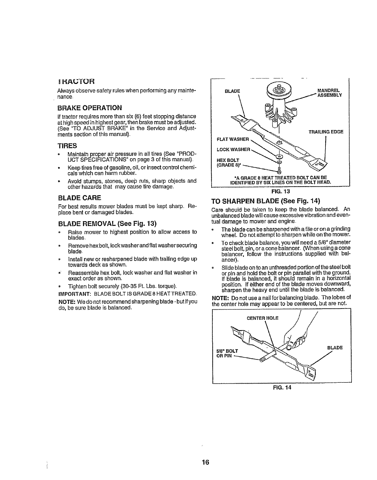
BLADE REMOVAL (See Fig. 13)
o Raise mower to highest position to allow access to
blades,
,Remove hex bolt, lockwasher and flat washersecuring
blade
o Installnew orresharpenedbladewithtrailingedge up
towards deck as shown.
, Reassemble hex bolt, lock washer and flat washer in
exact order as shewn.
o Tighten bolt securely (30-35 FroLbs. torque).
IMPORTANT: BLADE BOLT IS GRADE 8 HEAT TREATED
NOTE: We do netrecommend sharpening blade*-but ifyou
do, be sure blade is balanced.
BLADE MANDREL
FLATWASHEB
LOCK WASHER.._
HEXBOLT
TRAILING EDGE
"A GRADE B HEAT TREATED BOLT CAN BE
IDENTIFIED BY SIX LINES ON THE BOLT HEAD.
FIG. 13
TO SHARPEN BLADE (See Fig. 14)
Care should be taken to keep the blade balanced,. An
unbalanced bladewill cause excessive vibration andeven-
tual damage to mower and engine.
o The blade can be sharpened with af_leor ona grinding
wheel. Do not attemptto sharpen while en the mower.
o"[e check blade balance, yeu wtll need a 5/8 dlamete
steel bolt,pin or acone balancer. (When using a cone
baIancer, follow the instructions supplied with bal-
ancer).
• S!Idebladeon to an unthreaded poflion of the steelbolt
or pin and hold the bolt or pin parallel with the ground.
If blade is balanced, it shouId remain in a horizontal
position. If either end of the blade moves downward,
sharpen the heavy end until the blade is balanced.
NOTE= Do not use a nail for balancing blade,.The lobes of
the center hole may appear to be centered, but are not,
CENTER HOLE / /
518"BO_ BLADE
FIG. 14
16
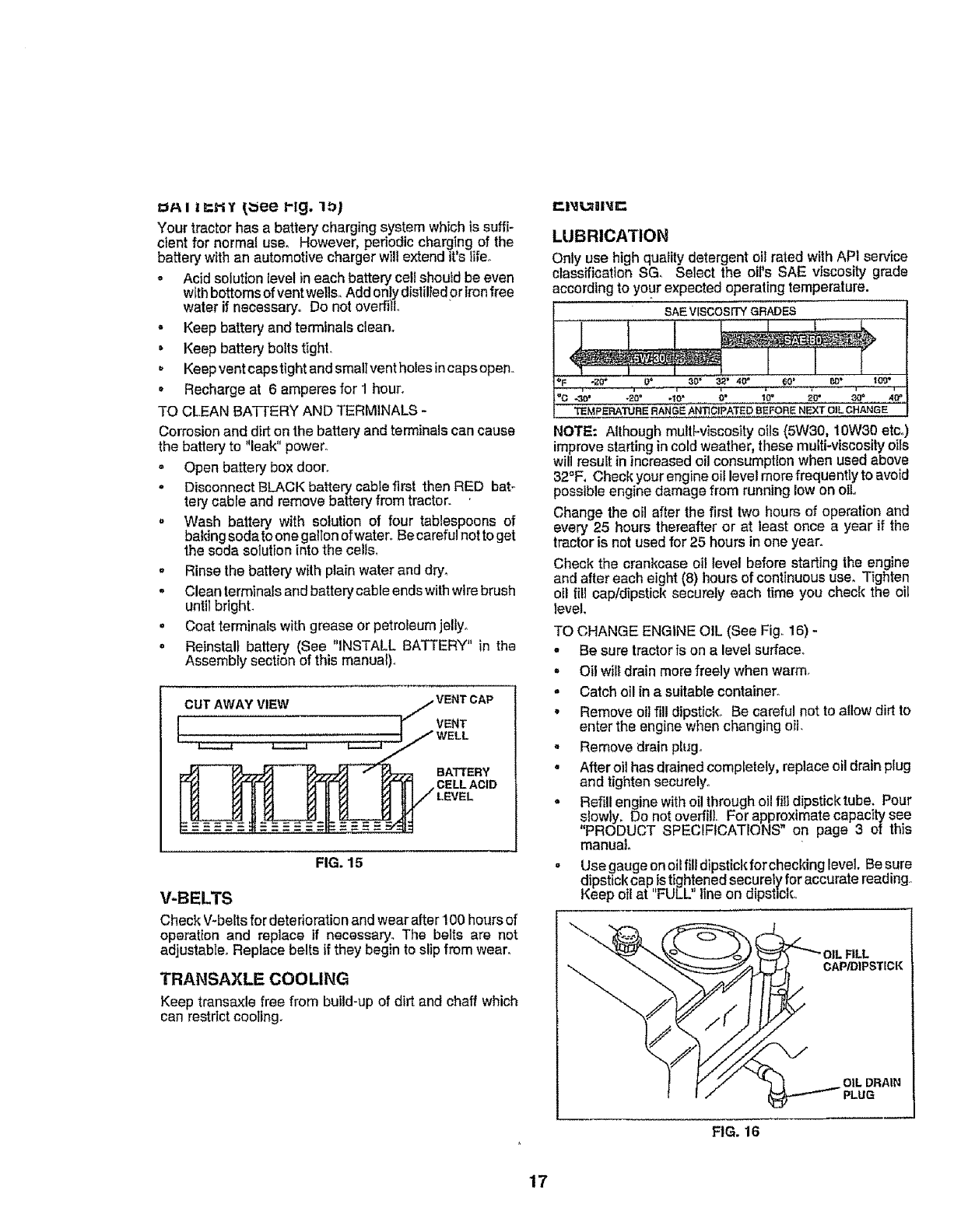
Your tractor has a battery charging system which is suffi-
cient for norma{ use. However, periodiccharging of the
battery with an automotive charger will extend it'slife_
o Acid solution level ineach battery cell should be even
withbottoms ofvent wells. Addon!ydistilledor ironfree
water if necessary. Do not overfill°
o Keep battery and terminals clean°
= Keep battery bolts tight.
, Keepventcapstight and smallvent holes incapsopen.
= Recharge at 6 amperes for 1 hour.
TO CLEAN BATTERY AND TERMINALS -
Corrosion and dirt on the battery and terminals can cause
the battery to "leak" power.
= Open battery box door.
-Disconnect BLACK battery cable first then RED bat-
tery cable and remove battery from tractor.
,Wash battery with solution of four tablespoons of
baking soda to one gallonof water°Becarefulnot to get
the soda solution into the cells.
= Rinse the battery with plain water and dry.
-Clean terminals and battery cable ends with wire brush
until bright.
= Coat terminals with grease or petroleum jelly°
• Reinstall battery (See "INSTALL BATTERY" in the
Assembly section of this manual)_
CUTAWAYVIEW ./VENT CAP
_VENT
I,,,,,_ _ L__J_ WELL
/
_ _ __7_ BATTERY
_]_J-_{-'_ r_., CELL ACID
FIG. 15
V-BELTS
Check V-belts for deterioration and wear after 100 hours of
operation and replace if necessary. The belts are not
adjustable. Replace belts if they begin to slip fromwear.
TRANSAXLE COOLING
Keep transaxle free from build-up of dirt and chaff which
can restrictcooling.
LUBRICATION
Only use high quality detergent oil rated with API service
classification SG. Select the eli's SAE viscosity grade
according to your expected operating temperature.
SAE V[SCOSFFY GRADES
_'F , -;tO* 9* _0" _2 _ 40" _0' P_" 10_
TEMPERATURE RANGE ANTICIPATED BEFORE NF._T OIL CHANGE
NOTE: Although mult[oviscosityoils (5W30, 10W30 etco
improvestarting incoldweather, thesemulti_viscosityoils
willresult in increased oil consumptionwhen usedabove
32_F, Checkyour engineoil levelmore frequently to avoid
possible engine damage from running low on oil
Change the oi! after the first two hours of operation and
every 25 hours thereafter er at least once a year if the
tractor is not used for 25 hours in one year.
Check the crankcase oil level before starting the engine
and after each eight (8) hours of continuous use. Tighten
otl fill cap/dipstick securely each time you check the oil
level.
TO CHANGE ENGINE OIL (See Fig. 16) -
•Be sure tractor is on a lever surface.
• Oil willdrain more freely when warm.
= Catch oil in a suitable container.
, Remove oil filldipstick.. Be careful not to allow dirt to
enter the engine when changing oil.
° Remove drain phJgo
, After oil has drained completely, replace oildrain plug
and tighten securely°
• Refill engine with oil through oil fill dipstick tube. Pour
slowly. Do not overfill. For approximate capacity see
"PRODUCT SPECIFICATIONS" on page 3 of this
manual°
= Usegauge onoil fili dipstick for checking level. Be sure
dipstick cap istigh!ened securely for accurate reading..
Keep oil at FULL line on dipstick°
FILL
CAP/D|PSTICK
OIL DRAIN
PLUG
FIG. 16
17
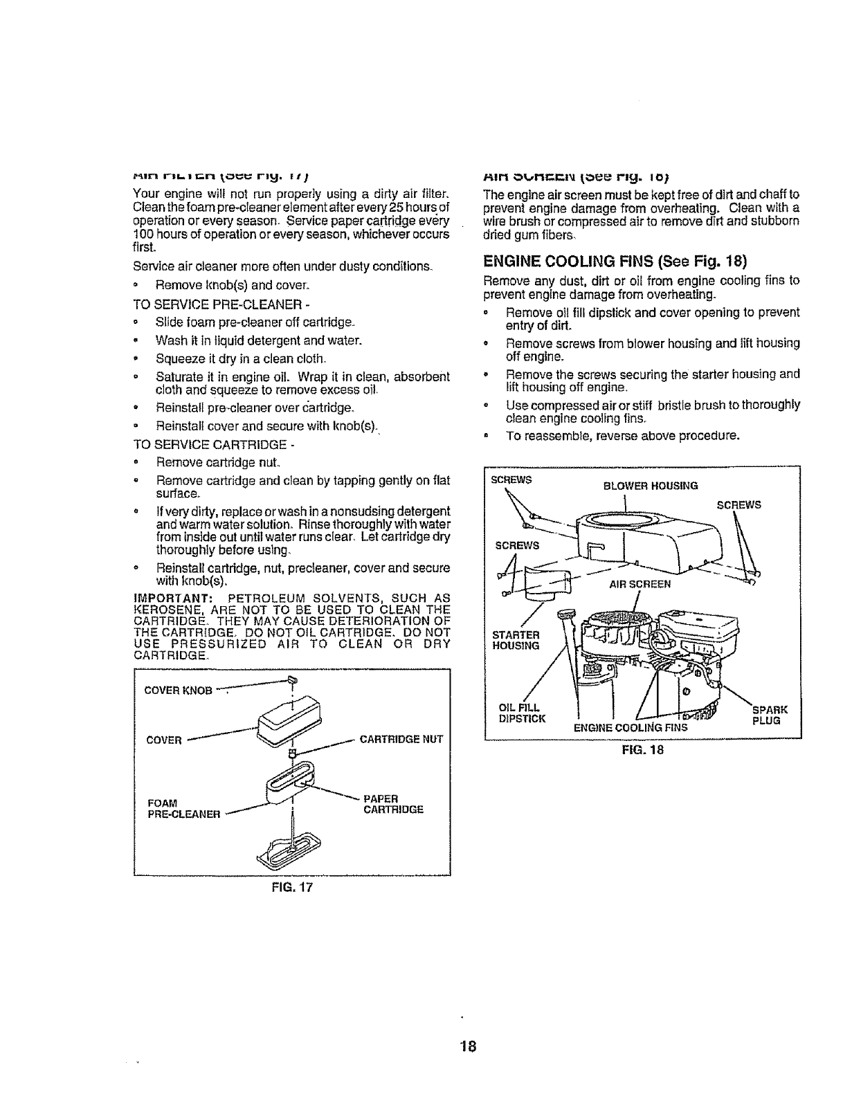
Your engine will not run properly using a dirty air filter.
Clean the foam pre-cleanar element after every 25 hours of
operation or every season. Service paperca#ridge every
100 hours of operation or every season, whichever occurs
first.
Service air cleaner more often under dusty conditions.
o Remove knob(s) and cove_:
TO SERVICE PRE-CLEANER -
o Slide foam pre-cleaner off cartridge.,
.Wash it in liquid detergent and water.
•Squeeze it dry in a clean cloth.
. Saturate it in engine oil. Wrap it in clean, absorbent
cloth and squeeze to remove excess oi!.
• Reinstall pro-cleaner over cartridge.
° Reinstall cover and secure with knob(s).
TO SERVICE CARTRiDGE-
. Remove cartridge nut°
o Remove cartridge and clean by tapping gently on flat
surface.
° If very dirty, replace or wash ina nonsudsing detergent
andwarm watersolution. Rinsethoroughlywithwater
from inside out until water runs clear. Let cartridge dry
thoroughly before using,
= Reinstall cartridge, nut, precteaner, cover and secure
with knob(s).
IMPORTANT: PETROLEUM SOLVENTS, SUCH AS
KEROSENE, ARE NOT TO BE USED TO CLEAN THE
CARTRIDGE. THEY MAY CAUSE DETERIORATION OF
THE CARTRIDGE. DO NOT OIL CARTRIDGE. DO NOT
USE PRESSURIZED AIR TO CLEAN OR DRY
CARTRIDGE.
COVER KNOB ..._/.-4_
COVER /"_¢_,..._ ., CARTRIDGE NUT
FIG. 17
P,irt Ot.,,Mc;r-=M IOUr_ r'l,_. IO)
The engine air screen must be kept free of dirt and chaff to
prevent engine damage from overheating. Clean with a
wire brush or compressed air to remove dirt and stubborn
dried gum fibers.
ENGINE COOLING FINS (See Fig. 18)
Remove any dust, dirt or oiEfrom engine cooling fins to
prevent engine damage from overheating.
,Remove oil fill dipslick and cover opening to prevent
entry of dirt.
o Remove screws from blower housfng and tilt housing
off engine.
oRemove the screws securing the starter housing and
lilt housing off engine.
o Use compressed air or stiff bristle brush to thoroughly
clean engfne cooling tins.
° To reassemble, reverse above procedure.
SCREWS BLOWER HOUSING
SCREWS
SCREWS
AIR SCREEN
STARTER
HOUSING
OIL RLL
DIPSTICK ENGINECOOLINGRNS
FIG. 18
PLUG
18
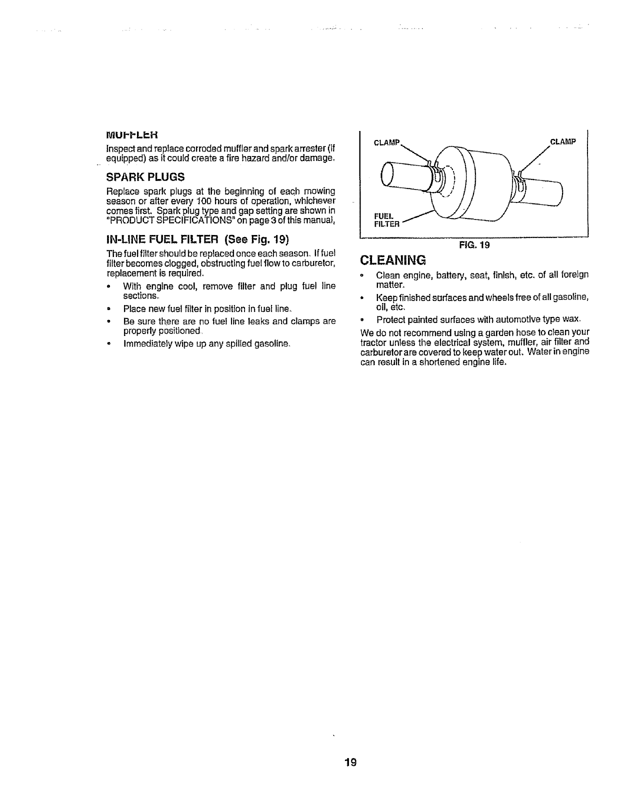
MUI-_.L_,,H
Inspect and replace corroded muffler and spark attester (if
equipped) as it could create a fire hazard and/or damage,
SPARK PLUGS
Replace spark plugs at the beginning of eac.h mowing
season or after every 100 hours of operation, whichever
comes first. Spark plug type and gap setting are shown in
"PRODUCT SPECIFICATIONS" on page 3of this manual,
IN-LINE FUEL FILTER (See Fig. 19)
The fuel _ter should be replaced onceeach season. Iffuel
filter becomes clogged, obstructing fuel flowto carburetor,
replacement is required.
•With engine cool, remove filter and plug fue! line
sections.
= Place new fuel filter inpositioninfuel lineo
.Be sure there are no fuel line leaks and clamps are
properly positioned,
o Immediately wipe up any spilled gasoline.
CLAMP CLAMP
i=ILTER""- --_-'-'--_
FIG. 19
CLEANING
.Clean engine, battery, seat, finlsh, etc. of all foreign
matter.,
• Keepfinished surfaces and wheelsfree of allgasoline,
oil, etc.
• Protect painted surfaces with automotive type wax.
We do not recommend using a garden hose to clean your
tractor unless the electrical system, muffler, air filter and
carburetor are covered to keep water out. Water in engine
can result ina shortened engine life.
19
o
o
u
CAUTION: BEFORE PERFORMING ANY SERVICE OR ADJUSTMENTS:
Depress clutch/brake pedal fully and set parking brake.
Place gearshift lever in "NEUTRAL" position,
Place attachment clutch in "DISENGAGED" position.
Turn ignition key "OFF" and remove key°
Make sure the blades and all moving parts have completely stopped°
Disconnect sparkplug wire from sparkplug and placewire where it cannot comein contactwith
plug.
...................................... ,_ , ,,,,,,, ,,,, ,,,,,,,, i iii,
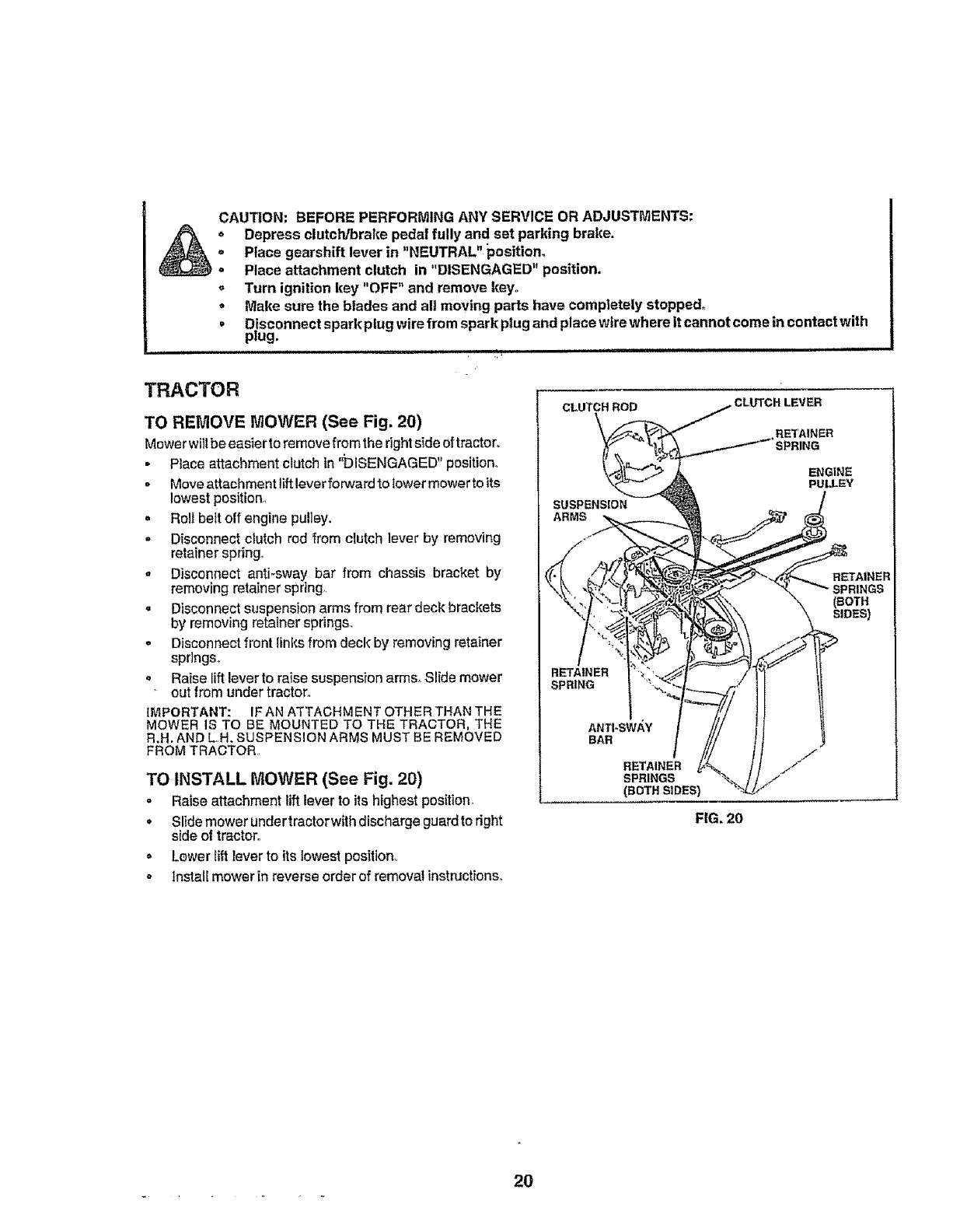
TRACTOR
TO REMOVE MOWER (See Fig. 20)
Mowerwill beeasierto removefrom therightside of tractor,
•Place attachment clutch in ';DISENGAGED" position,
=Moveattachment lift leverforward to iowermowerto its
lowestposition,,
. Roll beit off engine pulley.
= Disconnect clutch red from clutch lever by removing
retainer spring.
,Disconnect anti-sway bar from chassis bracket by
removing retainer spring..
,Disconnect suspension arms from rear deck brackets
by removing retainer springs..
oDisconnect front links from deck by removing retainer
spr]ngs,
oRaise lift leverto raise suspension arms. Slide mower
out from under tractor,,
IMPORTANT: IF AN ATTADHM ENT OTHER THAN THE
MOWER IS TO BE MOUNTED TO THE TRACTOR, THE
R.H. AND L.,H. SUSPENSION ARMS MUST BE REMOVED
FROM TRACTOR
TO INSTALL MOWER (See Fig. 20)
= Raise attachment lift lever to its highest position,
oSlidemower undertractorwith discharge guardto right
side of tractor,
o Lewer lift leverto its lowest position,,
,, Install mower in reverse order of removal instructions°
CLUTCH ROD CLUTCH LEVER
RETAINER
SUSPENSION
ARMS
ENGINE
PULLEY
RETAINER
(BOTH
S_DES)
RETAINER
SPRING
ANTI-SWAY
BAR
RETAINER
SPRINGS
(BOTH SIDES)
FIG. 20
2O
SIERV CE A DADJUSTMENTS
, ,i.., ,............................................
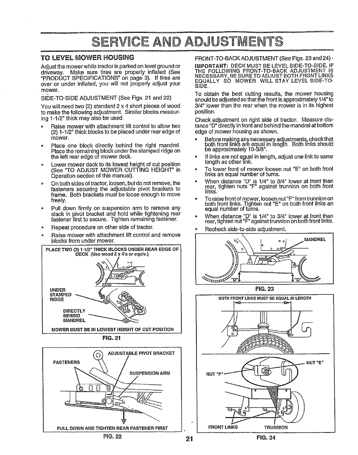
TO LEVEL MOWER HOUSING
Adjust the mower while tractor isparked on level ground or
driveway. Make sure tires are properly inflated (See
"PRODUCT SPECIFICATIONS" on page 3). If tires are
over or under inflated, you will not propedy adjust your
mower.
si[)E..TO*SIDE ADJUSTMENT (See Figs. 21 and 22)
You will need two (2) standard 2 x 4 short pieces of wood
to make the following adjustmenL Similar blocks measur-
ing 1-1/2" thick may also be used,
o Raise mower with attachment lift control to allow two
(2) 1-1/2" thick blocks to be placed under rear edge of
mower,
°Place one block directly beh|nd the right mandrel,,
Place the remaining block under the stamped ridge on
the left rear edge of mower deck.
•Lower mower deck to its lowest height of cut position
(See "TO ADJUST MOWER CUTTING HEIGHT" in
Operation section of this manual),
o On both sides of tractor, loosen, but do not remove, the
fasteners securing the adjustable pivot brackets to
frame. Both brackets must be {oose enough to move
freely.
oPull down firmly on suspension arm to remove any
slack in pivot bracket and hold while tightening rear
fastener first to secure. Tighten remalnHngfastener.
o Repeat procedure on other side of tractor.
•Raise mower with attachment li_ control and remove
blocks from under mower,
PLACE TWO {2) t-1/2" THICK BLOCKS UNDER REAR EDGE OF
DECK (Use wood 2 x4*s or equ_w)
¢
STAMPED
RIDGE
DIRECTLY
BEHIND _"
MANDREL
MOWER MUST BE IN LOWEST HEIGHT OF CUT POSITION
FIG. 21
ADJUSTABLE PWOT BRACKET
FASTENERS
SUSPENSION ARM
PULL DOWNANDTIGHTEN REAR FASTENERFIRST
F6G, 22
FRONT-TO-BACK ADJUSTMENT (See Figs. 23 and 24) -
IMPORTANT: DECK MUST BE LEVEL SIDE-TO-SIDE. IF
THE FOLLOWING FRONT-TO-BACK ADJUSTMENT IS
NECESSARY, BE SURETO ADJUST BOTH FRONTLINKS
EQUALLY SO MOWER WILL STAY LEVEL SIDE-TO o
SIDEo
"[o obtain the best cutting results, the mower housing
should be adjusted so that the front is approximately 1/4"to
3/4" lower than the rear when the mower is in its highest
position.
Check adjustment on right side of tractor'. Measure dis-
tance "D" directly in front and behind the mandrel at bottom
edge of mower housing as shown.
o Bef0re ma!dng any necessar7adjustments_ chec,kthat
DmnTron[links are equal in leng[n. #o_n i_nlcssnoula
be approximately I0-3/8".
• If links are not _qual in length, adjust one link to same
length as other }ink_
o To lower front of mower loosen nut "E" on both front
links an equal number of turns,
. When distance "D" is 1/4" to 3/4" lower at front than
rear, tighten nuts "F" against trunnion on both front
links.
•To raise front of mower, loosen nut"F" from trunnion on
both front I!nks. Tighten nut "E" on both front links an
equal number of turnso
o When distance "D" is 1/4" to 3/4" lower at front than
rear, tighten nut"F" against trunnion on both front links.
o Recheck side4o*side adjustment.
MANDREL
FIG, 23
BOTH FRONT LINKS MUST BE EQUAL IN LENGTH
21
FRONTLINKS
FIG. 24
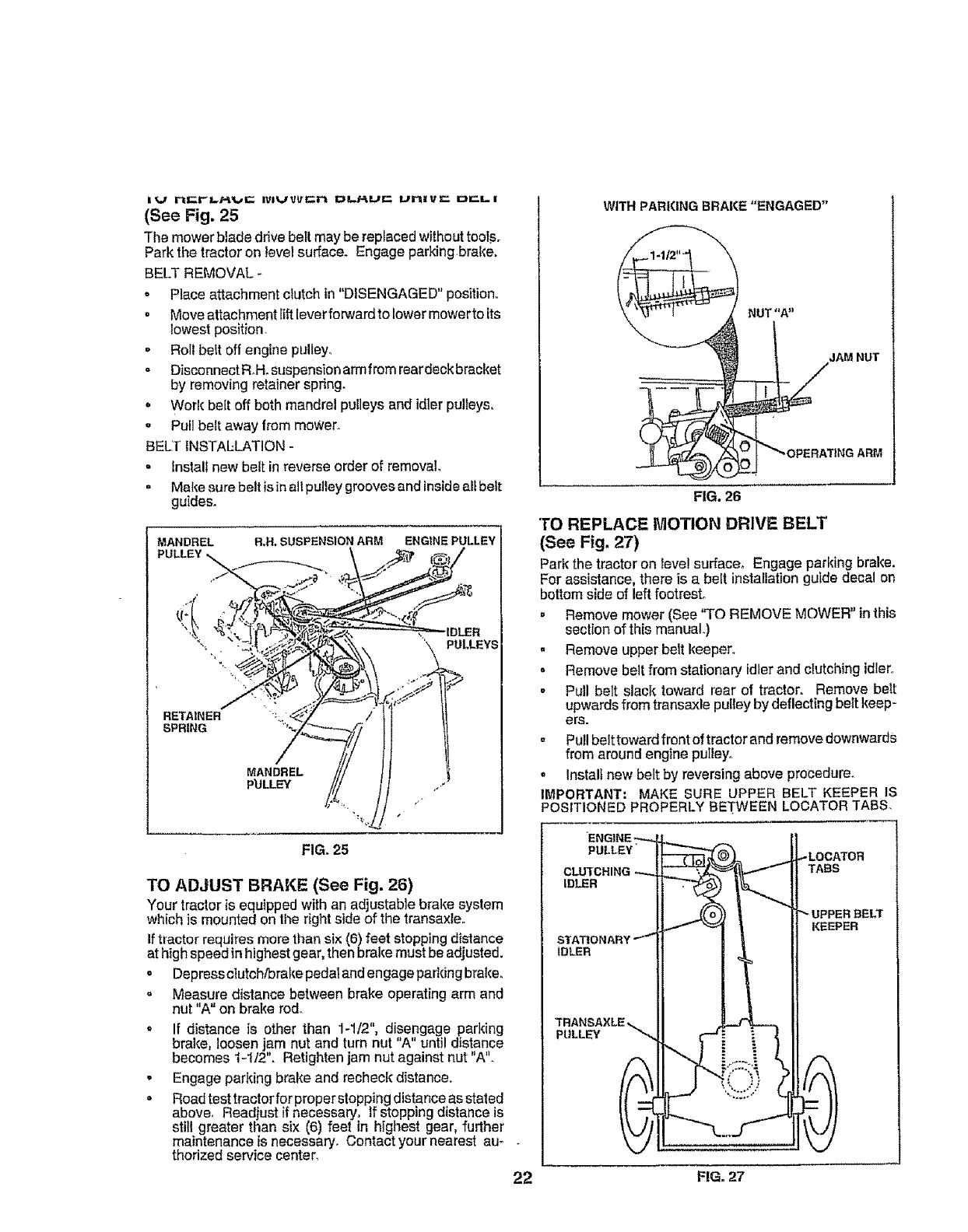
i {_/ rI=t'I-Rt_,/E IVlU_=n I_LRL/t'- l_rliVl: i:li:l, i
(See Fig. 25
The mower blade ddve belt may be replacedwithouttoof,s.
Parkthe tractoron levelsurface. Engage parking.brake,
BELT REMOVAL -
o Place attachment clutch in "DISENGAGED" position,,
o Move attachment tiltleverforward to lower mcwerto its
lowest position.
o Roll belt off engine pulley.
. DisconnectRoll. suspensionarmfrom reardeckbracket
by removing retainer spring.
, Work bait off both mandrel pulleys and idler pulleys,
,Pull belt away from mower..
BELT INSTAELATION-
• Install new belt in reverse order of removal,,
o Makesure belt is inall pulley grooves and insideall belt
guides.
MANDREL R,H, SUSPENSION ARM ENGINE PULLEY
PULLEYS
RETAINER
SPRING "'*
MANDREL
P'ULLE_
FIG. 25
TO ADJUST BRAKE (See Fig. 26)
Your tractor is equipped withan adjustable brake system
which is mounted on the right side of the transaxle°
Iftractor requires more than six (6)feet stopping distance
at high speed inhighest gear,then brake must beadjusted.
oDepressclutch/brake pedalandengage parking brake°
= Measure distance between brake operating arm and
nut "A" on brake rod,
* If distance is other than 1-1/2", disengage parking
brake, loosen jam nut and turn nut "A" until distance
becomes t-112". Retightenjam nut against nut "A".
- Engage parking brake and recheck distance.
° Road test tractor for properstopping distance asstated
above, Readjust if necessary. If stopping distance is
still greater than six (6) feet in highest gear, further
maintenance is necessary, Contact your nearest au-
thorized service center.
22
WITHPARKINGBRAKE "ENGAGED"
FIG, 26
NUT "A"
JAM NUT
S
"_'OPERATING ARM
TO REPLACE MOTION DRIVE BELT
(See Fig. 27)
Park the tractor on lave!surfacer Engage parking brake.
For assistance, there is a belt installation guide decal on
bottom side of left footrest.
= Remove mower (See "TO REMOVE MOWER" in this
section of this manuaL)
° Remove upper belt keeper°
• Remove belt from stationary idler and clutcl_ingidler.,
. Pull belt slack toward rear of tractor. Remove belt
upwards from transaxle pulley bydeflecting belt keep-
ers.
Pull belttoward front oftractor and remove downwards
from around engine puIley.
° Install new belt by reversing above procedure.
IMPORTANT; MAKE SURE UPPER BELT KEEPER IS
POSITIONED PROPERLYBETWEEN LOCATER TABS.
ENGINE ------H I!
PULLEY" [_ J_LOCATOR
II TABS
II _((o)) _ [_ UPPERBELT
_J_" _ tII KEEPER
STATIONARY"'-I1 I I I1
TRANSAXLE.._ II _ II
FiG. 27
TO ADJUST STEERING WHEEL ALIGNMENT
Ifsteering wheelcrossbars are not horizontal (leftto right)
when wheelsare positionedstraightforward, removesteer-
ingwheel and reassemble per instructionsintheAssembly
section of this manual
FRONT WHEEL TOE-IN/CAIVIBER
The front wheel toe-in and camber are not adjustable on
your tractor° if damage has occurred to affect the front
wheal toe-in or camber, contact your nearest authorized
service center,
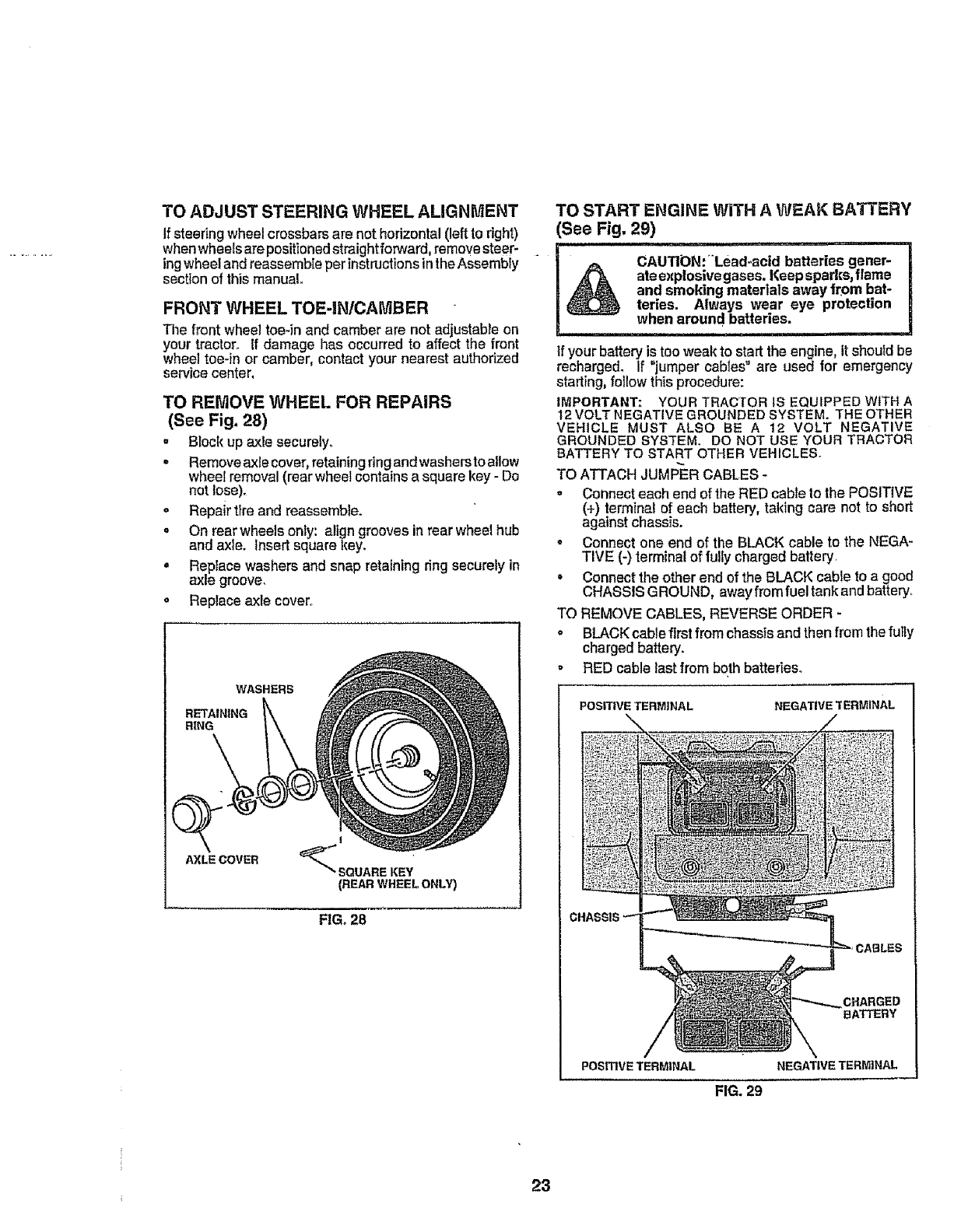
TO REMOVE WHEEL FOR REPAIRS
(See Fig. 28)
. Block up axle securely.
.Remove axle cover, retaining ringandwashersto allow
wheel removal (rear wheel contains a square key - Do
not lose).
o Repair tire and reassemble.
o On rear wheels only: align grooves in rear wheel hub
and axle. Insert square key.
• Replace washers and snap retaining ring securety in
axle groove,
oReplace axle cover,
WASHERS
RETAINING
RiNG
AXLE COVER
I
(REAR WHEEL ONLY)
FIG. 28
TO START ENGINE WiTH A WEAK BATTERY
See Fig, 29)
CAUTION:-Lead.acid batteries gener-
ateexplosivegases, Keepsparks,flame
and smoking materials away from bat-
teries. Always wear eye protection
when around batteries.
, =, _,l
If your battery istooweak to startthe engine, itshoufd be
recharge& If "jumper cables"are used for emergency
starting, follow thisprocedure:
IMPORTANT: YOUR TRACTORiS EQUIPPED WITH A
12 VOLTNEGATIVEGROUNDEDSYSTEM. THE OTHER
VEHICLE MUST ALSO BE A 12 VOLT NEGATIVE
GROUNDED SYSTEM. DO NOT USE YOUR TRACTOR
BATTERY TO STARTOTHER VEHICLES.
TO ATTACH JUMPER CABLES-
-Connect each end of the RED cable to the POSITIVE
(4-)terminalof each battery, taking care not to short
against chassis.
o Connect one end of the BLACK cable to the NEGA-
TIVE (-) termina!of fully charged battery.
Connect the other end of the BLACK cable to a good
CHASS1SGROUND, awayfrom fuel tank andbattery.
TO REMOVE CABLES, REVERSE ORDER -
o BLACK cablefirst fromchassfsand then from thefutly
charged battery.
RED cable last from both batteries.
POSITIVE TERMINAL NEGATIVE 'TERMINAL
/
CHARGED
BATTERY
POSITIVETERMINAL NEGATIVETERMINAL
FIG. 29
23
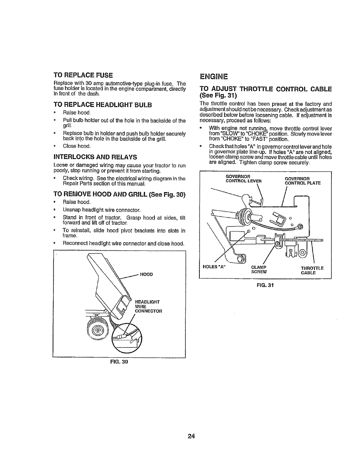
TO REPLACE FUSE
Replace with 30 amp automotive-type plugqn fuse. The
fuse holder is located in the engine compartment, directly
in front of the dash_
TO REPLACE HEADLIGHT BULB
- Raise hood.
° Pull bulb holder out of the hole in the backside of the
gdll_
o Replace bulb in holder.and push bulb holder securely
back into the hole in the backside of the grill.
o Close hoed.
INTERLOCKS AND RELAYS
Loose or damaged wiring may ,causeyour tractor to run
poorly, stop running or prevent it from starting°
o Check wiring., See the electrical wtdng diagram In the
Repair Parts section of this manual..
TO REMOVE HOOD AND GRILL (See Fig, 30)
_' Raise hood,
,Unsnap headlight wire connector_
= Stand in front of tractor. Grasp hood at sides, tilt
forward and liftoff of tractor,
o To reinstall, slide hood pivot brackets into slots in
frame.
•Reconnect headlight wire connector and close hood.
HEADLIGHT
WIRE
CONNECTOR
ENGtINE
TO ADJUST THROTTLE CONTROL CABLE
(See Fig. 31)
The throttle control has been preset at the factoryand
adjustment should not benecessary,,Check adjustment as
described below before loosening cable. If adjustment is
necessary, proceedas follows:
o With engine not running move throttle control ]ever
from "SLOW" to "CHOKE"position.. Slowly movelever
from "CHOKE" to "FAST" position.
GOVERNOR GOVERNOR
CONTROL LEVER CONTROL PLATE
HOLES "A" CLAMP THROTTLE
SCREW CABLE
FIG. 31
FIG. 3O
24
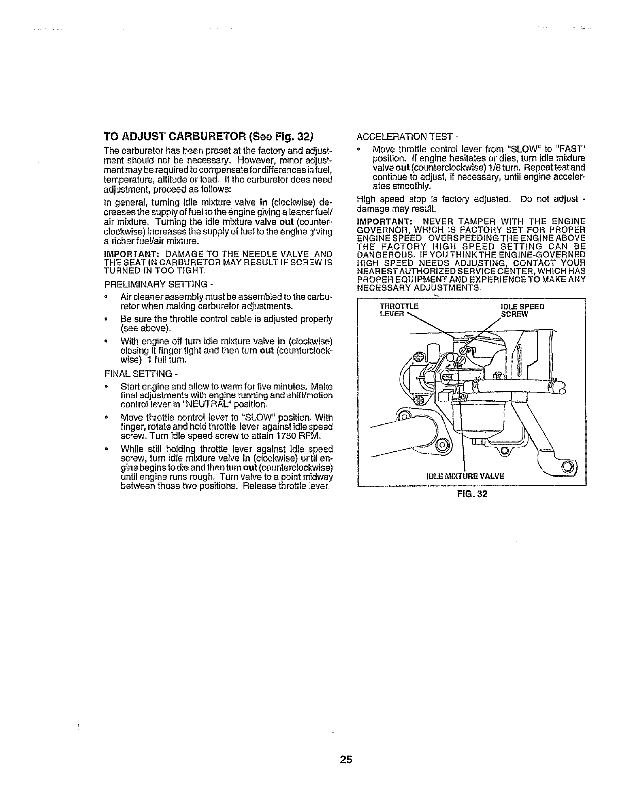
TO ADJUST CARBURETOR (See Fig. 32)
The carburetor has been preset at the factory and adjust_
ment should not be necessary_ However, minor adjust-
ment may berequiredto compensatefor differences infuel,
temperature, altitude or Ioad_ Ifthe carburetor does need
adjustment, proceed as follows:
In general, turning idle mixture valve in (ctocl_ise) de-
creases the supply of fuel to the engine giving aleanerfuel/
air mixture, Turning the idle mixture valve out (counter.-
clockwise) increases the supplyof fuel to the enginegiving
a richer fuel/air mixture,
IMPORTANT: DAMAGE TO THE NEEDLE VALVE AND
THE SEAT IN CARBURETOR MAY RESULT IF SCREW IS
TURNED IN TOO TIGHT.,
PRELIMINARY SETTING -
o Air cleaner assembly must be assembled to the carbu-
retor when making carburetor adjustments..
o Be sure the throttle control cable is adjusted properly
(see above).
oWith engineoff turn idle mixture vafve in (clocl_ise)
closing it finger tight and then turn out (counterclock-
wise) 1 full turn.
FINAL SETTING -
• Start engineand allow to warm for five minutes. Make
final adjustments with engine runningand shift/motion
control lever in "NEUTRAL" position.
o Move throttle control leverto "SLOW" position° With
finger, rotate and holdthrottle lever against idle speed
screw. Turn idle speed screw to attain 1750 RPM_
• While stiII holding throttle lever against idle speed
screw, turn idle mixture valve in (cloclo,vise) until en-
ginebegins to die and then turn out (counterclockwise)
until engine runs rough. Turn valve to a point midway
between those two positions. Release throttle lever..
ACCELERATION TEST -
, Move throttle control lever from "SLOW" to "FAST"
position. If engine hesitates or dies, turn idlemixture
valve out (counterclockwise) 1/8 turn. Repeatrostand
continue to adjust, tfnecessary, until engine acceler-
ates smoothlyo
High speed Stop is factory adjusted Do not adjust -
damage may resutL
IMPORTANT: NEVER TAMPER WITH THE ENGINE
GOVERNOR. WHICH IS FACTORY SET FOR PROPER
ENGINE SPEED,.OVERSPEEDINGTHE ENGINEABOVE
THE FACTORY HIGH SPEED SETTING CAN BE
DANGEROUS. IFYOU THINK THE ENGINE-GOVERNED
H|GH SPEED NEEDS ADJUSTING, CONTACT YOUR
NEARESTAUTHORIZED SERVICE CENTER, WHICH HAS
PROPEREQUIPMENTAND EXPERIENCETO MAKEANY
NECESSARY ADJUSTMENTS.
THROTTLE IDLE SPEED
SCREW
IDLE MIXTURE VALVE
FIG. 32
25
tmmediatefy prepare your tractor for storage at the end of
the season or if the tractor will not be used for 30 days or
more,
I CAU.,ON=.evers,eretho
i ._ _k gasoline in the tank inside a building I
| _ where fumes may reach an open flame |
]_or sparl¢, Allow the engine to cool ]
before storing in any enclosure. ]
I........................ '
TRACTOR
Remove mower from tractor for winter storage. When
mower is to be stored for a period of time, clean it thor-
oughly, remove all dirt, grease, leaves, etc., Store in a
clean, dry area.
° Clean entire tractor (See"CLEANING"in the Customer
Responsibilities section of this manual),
.Inspect and replace belts, if necessary (See be t re-
placement instructions inthe Service andAdjustments
section of this manual),
• Lubricate as shown in the Customer Responsibilities
section of this manual,,
•Be sure that all nuts, bolts and screws are securely
fastened. Inspect movingparts for damage, breakage
and wear. Replace if necessary.
o Touch up all rusted or chipped paint surfaces; sand
lightly before painting.
BATTERY
• Fully charge the battery for storage.,
-After a periodof time in storage, battery may require
recharging.
oTo help prevent corrosion and power leakage during
Iong periods of storage, battery cables should be
disconnected andbattery cleaned thoroughly (see'q'O
CLEAN BATTERY AND TERMINALS in the Cus-
tomer Responsibilities section of this manual)
• After cleaning, [nave cables disconnected and place
cableswhere they cannot come in contact with battery
terminals.
o Be sure battery drain tube is securely attached.
• If battery is removed from tractor for storage, do not
store battery directly on concrete or damp surfaces.
ENGINE
FUEL SYSTEM
IMPORTANT: IT iS iMPORTANT TO PREVENT GUM
DEPOSITS FROM FORMING IN ESSENTIAL FUEL
SYSTEMPARTSSUCHASCARBURETOR,FUEL FILTER,
FUEL HOSE, OR TANK DURING STORAGE. ALSO,
EXPERIENCE INDICATES THAT ALCOHOL BLENDED
FUELS (CALLED GASOHOL OR USING ETHANOL OR
METHANOL) CAN ATTRACT MOISTURE WHICH LEADS
TO SEPARATIONAND FORMATIONOF ACIDS DURING
STORAGE. ACIDIC GAS CAN DAMAGE THE FUEL
SYSTEM OF AN ENGINE WHILE IN STORAGE.
• Drain the fuel tank°
o Start the engine and let it run until the fuel lines and
carburetor are empty.
oNeveruse engine or carburetor cleaner productsin the
fuel tank or permanent damage may occur.
• Use fresh fuel next season°
NO't'E: Fuel stabilizer is an acceptable alternative in
minimizing the formation of fuel gum deposits during stor-
age. Add stabilizer to gasoline in fuel tank or storage
container. Always follow the mix ratio found on stabilizer
container. Run engine at least 10 minutes alter adding
stabilizer to allow the stabitizerto reach the carburetor.Do
not drainthe gastank andcarburetor if using fuel stabilizer,
ENGINE OIL
Drainoil (withenginewarm)andreplacewithcleanengine
oil,, (See "ENGINE" in the Customer Responsibilities
section of this manual).
CYLINDERS
o Remove spad(plug(s).
.Pour one ounce of oil through spark plug hole(s) into
cyllnder(s).
= Turn ignition keyto"START" positionfora fewseconds
to distribute oil
= Replace with new spark plug(s).,
OTHER
-Do not store gasoline from one season to another,,
. Replace your gasoline can tf your can starts to rust°
Rust and/or dirt in your gasoline will cause problems.
o If possible, store your tractor Indoorsand cover it to
give protectionfrom dust and dirt.
Cover yourtractor with a suitable protective cover that
does not retain moisture, Do not use plastic. Plastic
cannot breathe which allowscondensation to form and
will cause your tractor to rust
IMPORTANT: NEVER COVER TRACTOR WHILE ENGINE
AND EXHAUST AREAS ARE STILL WARM.
26

PROBLEM
Willnot start
Hard to start
Engine will not turn over
Engine clicks but will not
start
Less of power
Excessive vibration
i i...... : .................. ,...................... , ...........
TFIOIJEILISII OOTING POINTS
CAUSE CORRECTION
1. Out of fuel,
2, Engine net"CHOKED" propedy
3, Engine flooded
4, Bad spari{ plug
5. Dirty air filler
6, Dirty fuel filter
7. Water in fuel,,
& Loose or damaged widng.
9, Carburetor out of adjustment.
10, Engine valves out of adjustment,
1. Fill fuel tank.,
2, See "TO START ENGINE" in Operation secfion
3, Wait several minutes before attempting to start.
4. Replace spark plug.
5. Clean/replace alrfifler
6, Replace fuel filter.
7o Drain fuel lank and carburetor, refill tank wth fresh
gasoltne and replace fuel filler
8Check all wiring.
g. Contact an aulhorized service canler/departmenL
10, Contact an aulborized service center/department
1, Dirty air ftten
2. Bad spark plug
3, Weak or dead battery
4. Dirtyfuel filler,,
5. Stale or didy fuel
6. Loose or damaged wiring "
7. Carburetor out of adjustment,
8. Engine valves out of adjustment
1o Clutch/brake pedal not depressed.
2. Attachment clutch is engaged.
3, Weak or dead battery,
4. B_own fuse,
5. Corroded battery terminate.
6. Loose or damaged wiring,
7o Faulty Ignlfion switch
8o Faulty solenoid or starter,
9. Faulty operator presence switch(es),
1. Clean/replace air filter.
2. Replace spark plug
3. Recharg'e or replace battery.
4. Replace fuel niter.
5o Drain fuel tank and relll wIL.hfresh gasofne°
6. Check all wiring.
7o Contact an authorized service center/department
& Contact an authorized service center/department
1 Depress clutch/brake pedal
2. Disengage attachment clutch.
3- Recharge or replace battery,
4. Replace fuse,,
5. Clean battery terminals
6, Check allwiring
7, Checidreplaee _gnilien_switch,
8. Checfdraplace solenoid or starter
9, Contact an authorized service cenlerldapartment.
1,, Weak or dead battery
2. Corroded battery termlnaiso
& Loose or damaged Mring_
4, Faulty solenoid or starter.
1, Cutting too much grass/too fast,
2Throttle in "CHOKE" position.
3. Build-up of grass, leaves and trash under mower.
4 Dirty air filter.
5. Low oil level/dirty oil
6o Faulty spark plug
7, Dirty fuel filter.
8. Stale or dirty fuel.
& Water in fuel
10. Spari_ plug wire loose,
11 Dirty engine air screen/fins.
t2 Dirtylclogged muffler,
13, Loose or damaged wiring.
14. Carburetor out of adjustment,
I5. Engine valves out of adjustment
to Worn, bent or loose blade.
2- Bent blade mandrel
3 Loose/damaged part(s).
1o Recharge or replace battery
2 Clean battery terminals
3 Check all wiring,
4, Checldraplace solenoid or starter,
1, Set in "Higher Cut" poslfiontreduce speed,
2, Adjust throttle control
&Clean underside of mower housing
4. Clean/replace air filter.
5, Check ofi laveVchange el,
6,, Clean and regap or change spari( plug.
7o Replace fuel filter.
8. Drain fuel tank and rafifi with fresh gasoline,
9. Drain fuel tank and carburetor, refill tank with fresh
gasotne and replace fuel filter,
10 Connect and tighten spark plug wire.
f 1,, Clean engine air screen/fins
12 Clean/replace muffler
13, Check all wiring,,
14,. Contact an authorized service centerldepartment.,
15. Contact an authorized service centar/dspartmento
1Replace blade, Tighten blade bolt.
2. Replace blade mandrel.
& Tighten loose part{s)o Replace damaged parts.
27

m-, i,, J ..... i
i ,1111_,llll II,,,
PROBLEM
Engine continues to run
when operator leaves seat
with attachment clutch
engaged
jii.............
Poor cut _ uneven
iii ii
Mower blades will not
rotate
Poor grass discharge
Headlight(a) not working
(if so equipped)
Jil_ , i i
Battery will not charge
Engine "bacl_res"
when turning engine
"OFF"
.... IHI'I '_1= ' ! '1 ........ .Jmlll
TROUBLESHOOTING POINTS
.... _ _[1_1 ill, ii I ill
CAUSE
,i i.i iii
1,, Faulty operator-safety presence control system,
1Worn, bent or loose blade.,
2, Mower deck not level,
3_ Buildup of grass, teaves, and trash under mower.
4, Bent blade mandrel,
5 Clogged mower deck vent holes from buildup of
grass, ieavss, and trash around mandre_s_
iiil,llNllHll
10bstrucfJon in clutch mechanism
2, Worry'damaged mower drive belt
3. FrozentdterpUlleyr
4. Frozenblademandrel
1. Engine speed leo slow.
2, Travel speed too fast
3r Wet grass..
4. Mower deck not level
5. Lowtuneven tire air pressure.
6 Wom, bentorIGoseb_ade.
7. Buildup el grass, leaves and trash under mower,
&Mower drive belt worn.
9, Blades improperly installed.
I0., Improper bfedes used
11,, Clogged mower deck vent holes from buildup of
grass, leaves, and trash around mandrefs
1. Switch is "OFF".,
2., Bulb(s) bumed out
3. Faulty ltght switch.
4Loose or damaged Winng,r
5, Blawn {use,
1., Bed battery celI{s)
2, Poor cable connections,
3, Faulty regulalor (if so equipped).
4. Faulty alternator
1 Engine throttle control not set at "SLOW"
position for 30 seconds before stopping engine,
CORRECTION
.i1.1.........................,11
1. Check wiring, switches and conneclions It not
corrected, contact an authorfzed service canter/
department,
1. Replace blade, "13ghtenblade bolt
2_ Level mower deck,,
BClean underside of mower housing
4_ Replace blade rnandrel_
5Clean around mandrels to open vent holes,
't Remove obstruction
2, Replace mower dri,Jabell
3Replace idiot pulley..
4Replace blade mandrel
! Place thretfle control in "FAST" position,
2 Shift to slower speed.
3 A!iow grass to dry before mowing.,
4. Levet mower deck.
5 Check tires for proper air pressure,
B, Replecstsharpen blade. Tighten blade bolt.
7. Cleon underside el mower housing
B. Replace mawer ddve belt
9_ Reinstall bfades sharp edge down
10. Replace with blades listed in this manual
11. Clean around mandrels to open vent holes
1. Turn sw._leh"ON".
2Re_lace bulb(s}
3,, Cheek/replace light swLtch,
4. Cheek wiring and connections
5, Replace fuse
1, Replace battery
2o Check/clean an conneclione
3 Replace regulator.
4, Replace aJtemater.
1, Move throttle control to "SLOW" positionand allow
to idle for 30 seconds hot'ore stopping engine
28
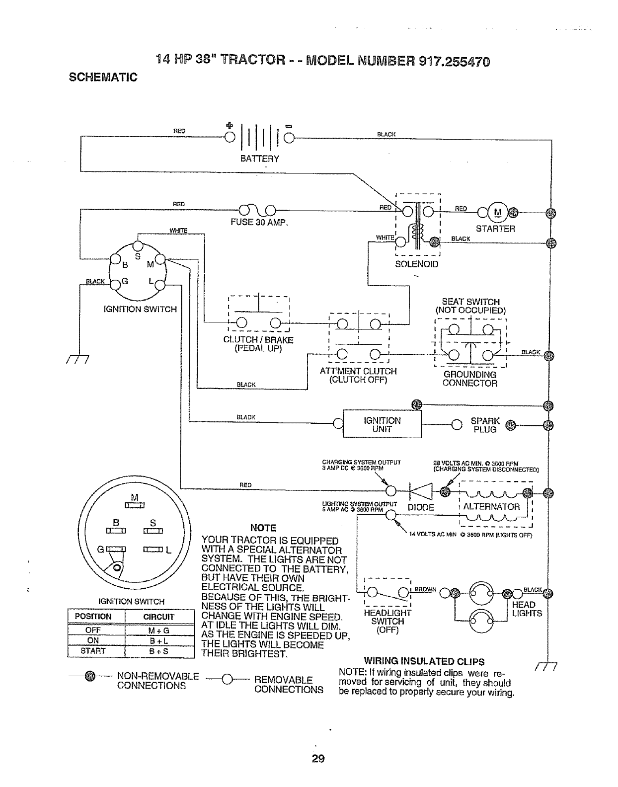
14 HP 38" TRACTOR .- = MODEL NUMBER 917,255470
SCHEMATIC
/-7-7
ill °
o111o
BATTERY
FUSE30 AMP,
WHITE
I I
I I 1
CLUTCH/BRAKE J !
_PEDALUP) _ ....
ATT'MENTCLUTCH
(CLUTCH OFF)
BLACK
RED
STARTER
IGNITION SWITCH
IGNITION SWITCH
_ITION I .CIRCUIT
L oFF":':'[ "_
[_l _ B*L
[START i B +S
RLA_K
RED
(NOT OCCUPIED)
711_tl..... II'-I
L .......... i
GROUNDING
CONNECTOR
BLACK
SOLENOID
_.__j SEAT SWITCH
NOTE
YOUR TRACTOR IS EQUIPPED
WITH A SPECIAL ALTERNATOR
SYSTEM. THE LIGHTS ARE NOT
CONNECTED TO THE BATTERY,
BUT HAVE THEIR OWN
ELECTRICAL SOURCE,
BECAUSE OF THIS, THE BRIGHT-
NESS OF THE LIGHTS WILL
CHANGE WITH ENGINE SPEED,
AT' IDLE THE LIGHTS WILL DIM.
AS THE ENGINE IS SPEEDED UP,
THE LIGHTS WILL BECOME
THEIR BRIGHTEST.
__ IGNITION _ SPARK ______
UNIT PLUG
CHARGING SYSTEM OUTPUT 28 VOLTS AC MIN. @3500 RPM
3 AMP I_0 (_ 360r_ RPf_ {CHAF_G_NG SY_'_M R_SCONtlEC'I3_R}
_L'_,_g_'_OMtnP,_UTDIODE , ALTERNATOR I;
J ...... I
(OFF)
WIRING INSULATED CLIPS
NOTE: If wiring insulated clips were re-
NON-REMOVABLE ---_---, REMOVABLE moved for servicing of unit, they should
CONNECTIONS CONNECTIONS be replaced to properly secure your wiring,
29
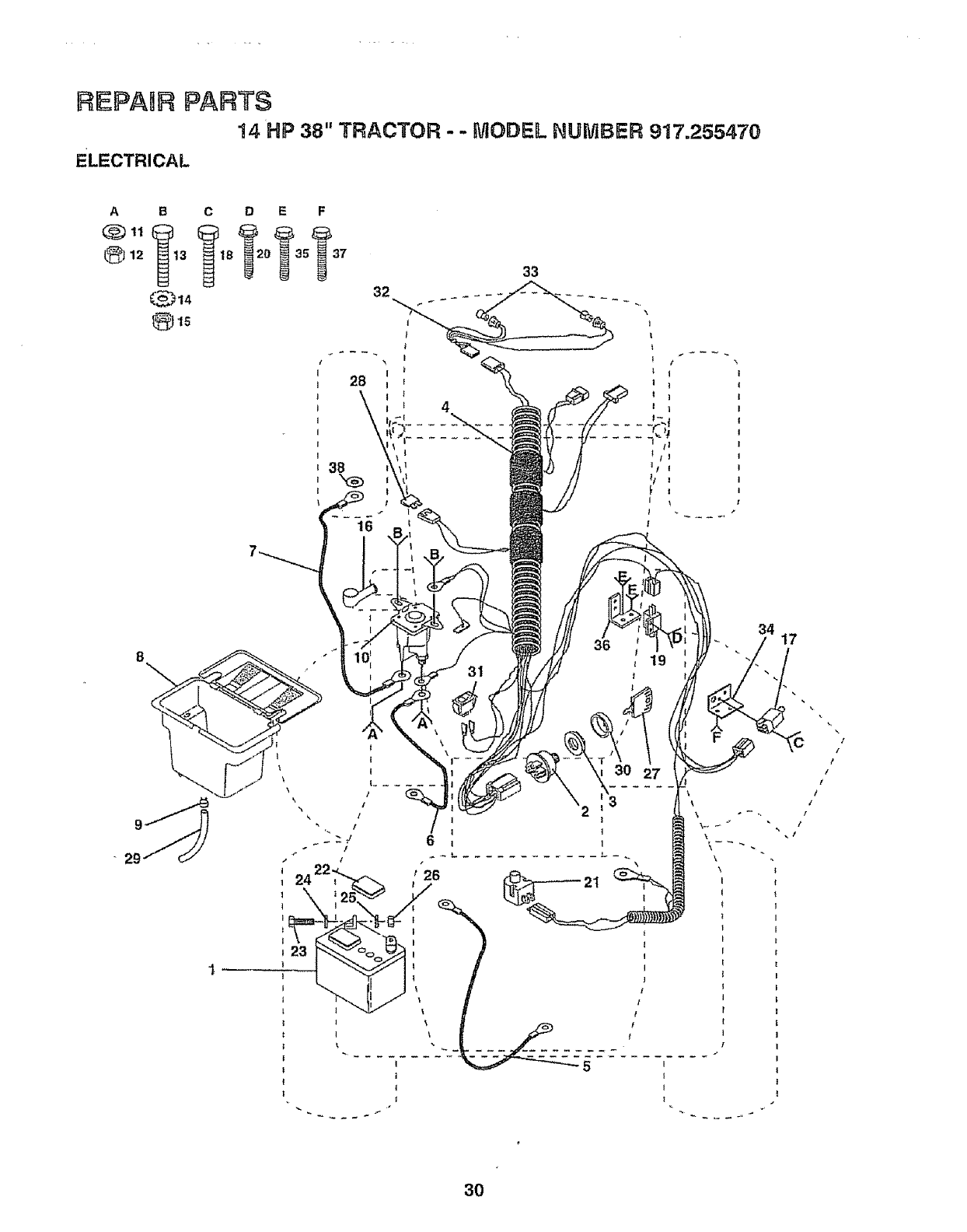
REPAIR PARTS
I4 HP 38" TRACTOR - - MODEL NUMBER 917.255470
ELECTRICAL
ABC D E F
33
32
I
38
t
I
4
34 17
3O
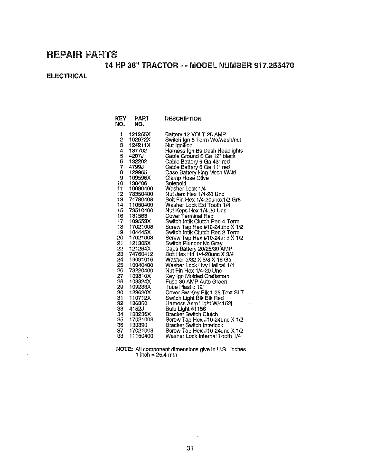
REPAgRPARTS
14 HP 38" TRACTOR --MODEL NUMBER 917.255470
ELECTRICAL
KEY PART DESCRIP_ON
NO. NO.
I 121265X
2 102972X
3 1242ttX
4 137702
54207J
6 132202
7 4799J
8 129965
9 109596X
10 138406
11 1OO9O4OO
12 73350400
13 74780408
14 11O5O4OO
15 73510400
16 131563
17 109553X
18 17021008
!9 104445X
20 17021008
21 121305X
22 121264X
23 74760412
24 19091016
25 10040400
26 73220400
27 109310X
28 108824X
29 109238X
30 123620X
31 110712X
32 136850
33 4152J
34 108236X
35 17021008
36 13089O
37 17021008
38 11150400
Battery 12 VOLT 25 AMP
Switch Ign 5Term Wo/wash/nut
Nut Ignition
Harness Ign Bs Dash Headlights
Cable Ground 6 Ga 12" black
Cable Battery 6 Ga 43_ red
Cable Battery 6 Ga 1I red
Case Battery Hng Mech W/fid
Clamp Hose Olive
Solenoid
Washer Lock 1/4
Nut Jam Hex '1/4-20Unc
Bolt Fin Hex 1/4-20uncx1/2 Gr5
Washer Lock Ext Tooth 1/4
Nut Keps Hex 1/4-20 Unc
Cover Terminal Red
Switch Intlk CIutch Red 4 "Term
Screw Tap He× #10-24unc X 1t2
Switch InUkClutch Red 2 Term
Screw Tap Hex #10-24unc X 1t2
Switch Plunger Nc Gray
Caps Battery 20/25130AMP
Bolt Hex Hd 1t4-20unc X 3t4
Washer 9/32 X 5/8 X 16 Ga
Washer Lock Hvy Helical I/4
Nut Fin Hex 1/4-20 Unc
Key lgn Molded Craftsman
Fuse 30 AMP Auto Green
Tube Plastic 12"
Cover Sw Key BIk I 25 Text SLT
Switch Light Blk BIk Red
Harness Asm Light W/4152j
Bulb Light #1156
Bracket Switch Clutch
Screw Tap Hex #10-24unc X 1/2
Bracket Switch interlock
Screw Tap Hex #10-24unc X 1/2
Washer Lock Internal Tooth 1t4
NOTE; All component dimensions give in U,.Soinches
1 inch = 25.4 mm
31
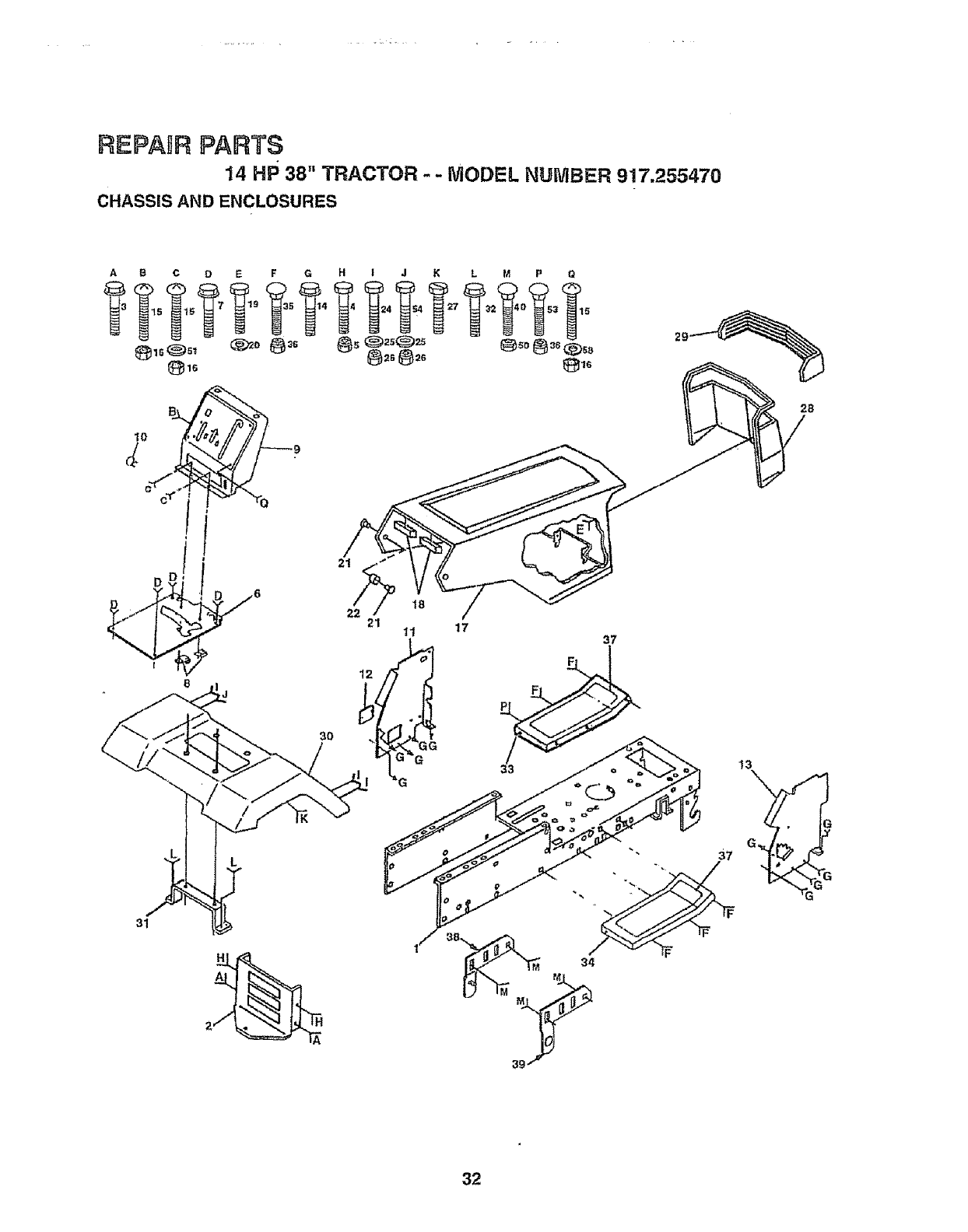
REPAIR PARTS
14 HP 38" TRACTOR - -MODEL NUMBER 917.255470
CHASSIS AND ENCLOSURES
A B C D E F G H !JKL M P Q
31
30
21 "11 17 37
13
32
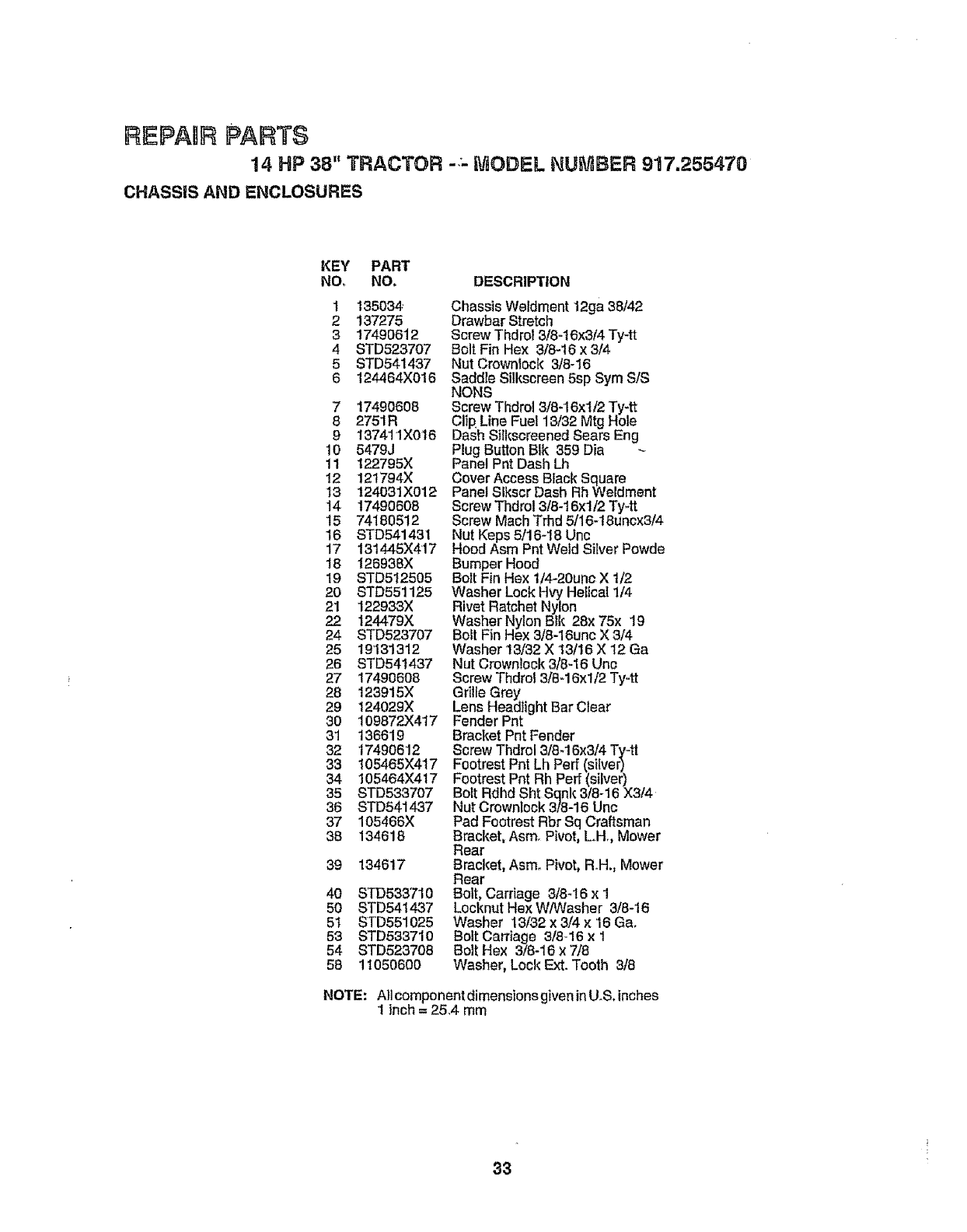
REPAIR PARTS
14 HP 38" TRACTOR -,- MODEL NUIVtBER 917.255479
CHASSIS AND ENCLOSURES
KEY PART
NO, NO,
1
2
3
4
5
6
135034
137275
17490612
STD523707
STD541437
124464X016
7 17490608
8 2751R
9137411X016
10 5479J
11 t22795X
12 12t794X
t3 124031X012
14 t7490608
15 74180512
16 STD541431
17 131445X417
18 126938X
19 STD512505
2O STD551125
21 122933X
22 124479X
24 STD523707
25 19'131312
26 STD541437
27 17490608
28 123915X
29 124029X
3O 109872X417
31 136619
32 17490612
33 105465X417
34 105464X4t7
35 STD633707
36 STD541437
37 105466)(
38 134618
39 134617
40 S'fD533710
50 STD541437
5t STD551025
53 STD533710
54 STD523708
58 1t050600
DESCRIPTION
Chassis Weldment 12ga 38/42
Drawbar Stretch
Screw Thdrol 3/8-16x314Ty-tt
Bolt Fin Hex 3/8-16 x 3/4
Nut Crownlock 3/8-16
Saddle Silkscreen 5sp Sym S/S
NONS
Screw Thdrol 3/8-16xt/2 Ty-tt
Clip,Line Fuel 13/32 Mtg Hole
Dash Silkscreened Sears Eng
Plug Button BIk 359 Dia
Panel Pnt Dash Lh
Cover Access Black Square
Panel Slkscr Dash Rh Weldment
Screw Thdrol 3/8-16xt/2 Ty-tt
Screw Math Trhd 5/16-18uncx3/4
Nut Keps 5/16-18 Unc
Hood Asm Pnt Weld Silver Powde
Bumper Hood
Boit Fin Hex 1/4-20unc X t/2
Washer Lock Hvy Heiical 1/4
Rivet Ratchet Nylon
Washer Nylon Btk 28x 75x t9
Bolt Fin Hex 3/8-16unc X 3/4
Washer !3/32 X 13/16 X 12 Ga
Nut Crownlock 3/8-16 Unc
Screw Thdrol 3/8-16xl/2 Ty-tt
Grille Grey
Lens Headlight Bar Clear
Fender Pnt
Bracket Pnt Fender
ScrewThdrol 3/8-16x3/4Ty*tt
Footrest Pnt Lh Perf (silver)
Footrest Pnt Rh Peff (silver)
Bolt Rdhd Sht Sqnk 3/8-16 X3/4
Nut Crowntock 3/8-16 Unc
Pad Footrest Rbr Sq Craftsman
Bracket, Asm_Pivot, Loll,, Mower
Rear
Bracket, Asm. Pivot, R.H., Mower
Rear
Bolt, Carriage 3/8-16 x 1
Locknut Hex W/Washer 3/8-16
Washer 13/32 x 3/4 × 16 Ga,
Bolt Carriage 8/8-16 x t
Bolt Hex 3/8-16 x 7/8
Washer, Lock Ext. Tooth 3/8
NOTE: Allcomponentdimensions given inU.S. inches
1 inch = 25,4 mm
33
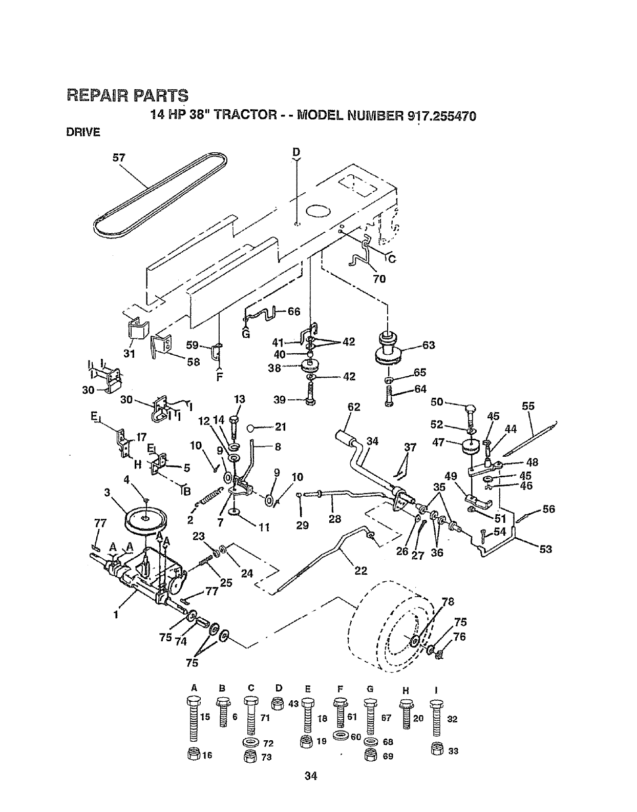
REPAIR PARTS
14 HP 38" TRACTOR - - MODEL NUMBER 9'17.255470
DRIVE
D
t:::::==-42
34 37
78
A B C D
(_ 72
_lS (_ 73
E F G H i
18 1 67 0 32
34
75
76
45
44
55
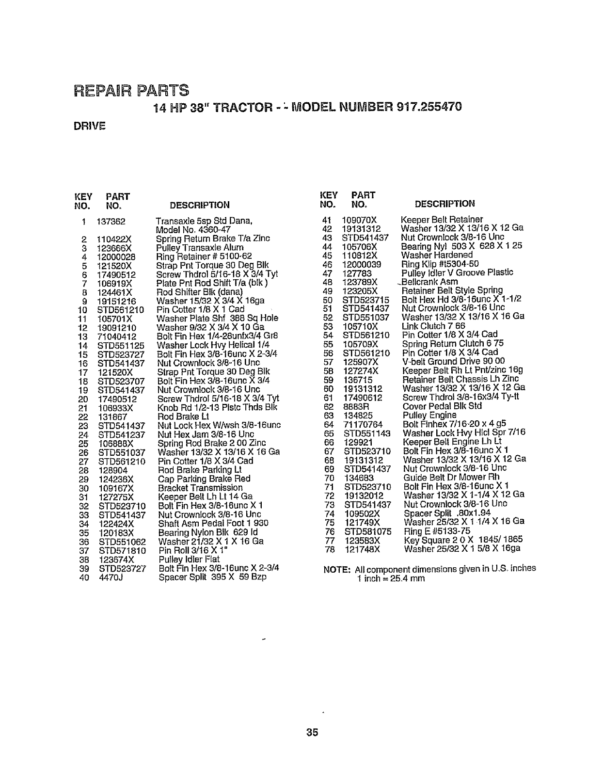
REPABRPARTS
14 HP 38" TRACTOR -:.MODEL NUMBER 917.255470
DRIVE
KEY' PART KEY PART
NO, NO. DESCRIPTION NO. NO. DESCRIPTION
1 137362 Transaxle 5sp Std Dana, 4t 109070X
Model No, 4360-47 42 19131312
2 110422X Spring Return Brake T/a Zinc 43 STD54t437
3 123666X Pulley Transax_e Alum 44 105706X
4 12000028 Ring Retainer # 5100-62 45 110812X
5 12t520X Strap Pnt Torque 30 Deg BIk 46 12000039
6 17490512 Screw Thdrol 5/16-18 X 3/4 Tyt 47 127783
7 106919X Plate Pnt Rod Shift Tie (bfk) 48 123789X
B 124461X Rod Shifter Btk (dana) 49 t23205X
9 19151216 Washer 15132 X 3/4X 16ga 50 STD523715
10 STD561210 Pin Cotter 1/8 X 1 Cad 51 STD541437
11 105701X Washer Plate Shf 388 Sq Hole 52 STD551037
12 19091210 Washer 9/32 X 3/4 X 10 Ga 53 10571OX
13 71040412 Bolt Fin Hex 1/4-28unfx3/4 Gr8 54 8TD561210
14 STD551125 Washer Lock Hvy Helical 1/4 55 I05709X
15 STD523727 Bolt Fin Hex 3/8-16uno X 2-3/4 56 STD561210
16 STD541437 Nut Crownlock 3/6-16 Unc 57 125907X
17 121520X Strap Pnt Torque 30 Deg Blk 58 127274X
18 8TD523707 Bolt Fin Hex 3/6-t6uno X 314 59 136715
19 STD541437 NutCrowntock3/8-t6 Unc 60 19131312
20 17490512 Screw Thdrot 5/16-'18 X 3/4 "Tyt 61 17490612
21 106933X Knob Rd 112-13 PlstcThds BIk 62 8883R
22 131867 Rod Brake LI 63 134825
23 STD541437 Nut Lock Hex W/wsh 3/8-16unc 64 '71170764
24 STD541237 Nut HexJam 3/8q6 Unc 65 STD551143
25 I06868X Spring Rod Brake 2 oo Zinc 66 129921
26 STD551037 Washer 13/32 X 13/16 X t6 Ga 67 8TD523710
27 8TD561210 Pin Cotter 1/8 X 3/4 Cad 68 19131312
28 128904 Rod Brake Pafldng Lt 69 STD541437
29 124236X Cap Parking Brake Red 70 134683
30 109167X Bracket Transmission 71 8TD523710
31 127275X KeeperBalt Lh Lt 14Ga 72 19132012
32 STD5237t0 Bolt Fin Hex 3/8-16unc X 1 73 STD541437
33 STD541437 Nut Crown!ock 3/8-16 Unc 74 109502X
34 122424X Shaft Asm Pedal Foot I 930 75 121749X
35 120183X Bearing Nylon Btk 629 Id 76 STD58t075
36 STD551062 Washer 21/32 X 1 X 16 Ga 77 123583X
37 STD57t810 Pin Roll 3/t6 X 1" 78 121748X
38 t23674X Pulley Idler Fiat
39 STD523727 Bolt Fin Hex 3/8-16unc X 2-314
40 4470J Spacer Split 395 X 59 Bzp
Keeper Belt Retainer
Washer 13/32 X13116X 12 Ga
Nut Crownlock 3/8-16 Uno
Bearing Nyl 503 X 628 X 125
Washer Hardened
Ring Klip #t5304_50
PulleyIdler V Groove Plastic
.Bell{rank Asm
Retainer Belt Style Spring
Bolt Hex Hd 3/8-16unc X 1-1/2
Nut Crownlock 3/8-16 Unc
Washer 13/32 X 13/!6 X 16 Ga
Link Crutch 7 86
Pin Cotter 1/8 X 3/4 Cad
Spring Retum Clutch 6 75
Pin Cotter 118X 3/4 Cad
V-belt Ground Drive 90 00
Keeper Belt Rh Lt PnUzinc 16g
Retainer Belt Chassis Lh Zinc
Washer 13/32 X 13116X 12 Ga
Screw Thdrol 3/8-16x8/4 Ty-tt
Cover Pedal BIk Std
Pulley Engine
Bott Finhex 7/16-20 x 4 g5
Washer Lock Hvy HIcl Spr 7/16
Keeper Belt Engine Lh Lt
Bolt Fin Hex 3/8-16unc X 1
Washer 13/32 X 13116X 12 Ga
Nut Crownlock 3/8-16 Unc
Guide Belt Dr Mower Rh
Bolt Fin Hex 3/8-,16unc X 1
Washer 13/32 X 1-1/4 X t2 Ga
Nut Crownlock 3/8-16 Unc
Spacer Split ,80xl.94
Washer 25/32 X t 114X t8 Ga
Ring E#5133-75
Key Square 2 0 X 1845/1865
Washer 25/32 X 1 5/8 X 16ga
NOTE: All component dimensions given in U.,& inches
1 inch = 25.4 mm
35
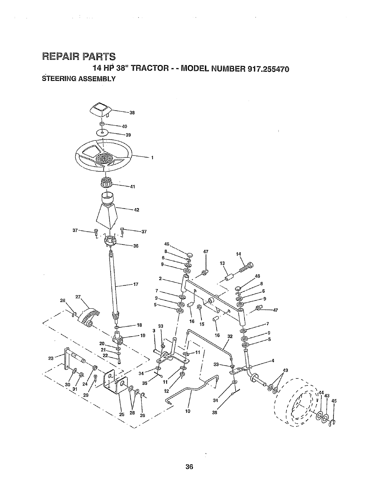
REPAIR PARTS
14 HP 38" TRACTOR - - MODEL NUMBER 917.255470
STEERING ASSEMBLY
_"_'_ 38
39
_41
11 /
12
47
/
14
16 32
43
36

REPAUR PARTS
'14 HP 38" TRACTOR - .: MODEL NUMBER 917.255479
STEERING ASSEMBLY
KEY PART
NO. NO. DESCRIPTION
1 133741
2133988
3 135227
4 135228
5 6266H
6 121748X
7 19272016
8 12000029
9 3366R
10 130466
11 STD551137
12 73610600
13 1t0438X
14 74011056
15 73901000
16 132624
17 132614
t8 57079
19 124035X
20 126684X
21 STD551125
22 71070410
23 127501
24 109816X
25 I24036X
26 12000029
27 136874
28 6266H
29 17490612
30 STD551137
31 7361060O
32 130465
33 126847X
34 19131416
35 8TD561210
36 132196
37 8TD61'1005
38 133742
39 19133808
40 8TD54t537
4! 104820X
42 124417X
43 121749X
44 121748X
45 12000029
46 121232X
47 6855M
Wheel Steering Std Black
Axle Asm Front
Spindle Asm Lh
Spindle Asm Rh
Bearing Race Thrust Harden
Washer 25t32 X 1 5/8 X 16ga
Washer 27/32 X 1 1/4 X 16 Ga
Ring Klip#t5304-75
Beating Col Strg Btk
Link Drag 8ot Bal! Jt 20 064
Washer Lock{Hvy Htcl Spr 3/8
Nut Fin Hex 3/8-24 Unf
SpacerBearing Axle Front
BoLtHex 5/8-11 Unc X 3-1/2
Locknut Flange 5/84 1 Unc
Pin Axte 5/8 X t 55/1 54 Lg
Shaft Asm Strg 5/8 X 15 19 Lt
WasherThrust 515x750x 033
Support Shaft
Washer Shim 1/4 X 5/8 X 062
Washer Lock Hvy Helical 1/4
Screw Hex Socket 1/4-20 X 5/8
Shaft Asm Pittman
Nyliner Snap In
Bracket Steering
Ring Klip #15304-75
Gear Sector
Bearing Race Thrust Harden
Screw Thdrol 3/8-16x3/4 Ty4t
Washer Lock Hvy HIclSpr 3/8
Nut Fin Hex 3/8-24 Unf
Rod Tie Wire Form 19 75 Mech
Bushing Rod 3qeBlk Lt
Washer 13132X 7/8 X 16ga
Pin Cotter 1t8 X 3/4 Cad
Bushing Strg 5/8 Id Dash
Screw Siftp #10-t6 X 1/2 Ty-b
Insert Cap Strg Wheel Std BIk
Washer 13/32 X 2_3/8X 8 Ga
Nut Lock Center 3/8-24unf
Adaptor Wheet Strg 640/635id
Boot Shaft Steering
Washer 25/32 X t 1/4X 16 Ga
Washer 25/32 X 1 5/8 X 16ga
Ring Klip #t5304-75
Cap Spindle FrTop Bik
Fittlng Grease
NOTE: All component dimensions given in U.S, inches
1 inch = 25,4 mm
37
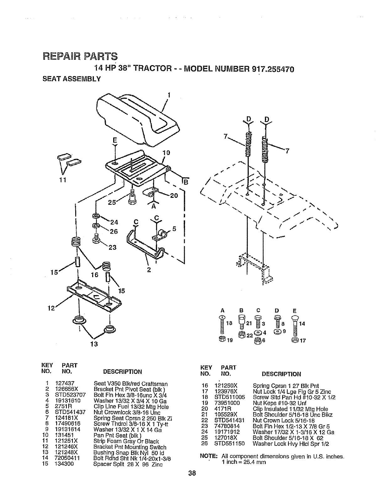
REPAIR PARTS
14 HP 38" TRACTOR --MODEl. NU1VtBF_.R917.255470
SEAT ASSEMBLY
11
2
10
\
12
I3
A B C D E
_19 _22_64 (_9 _17
KEY
NO,
1
2
3
4
5
6
7
8
9
10
11
12
13
14
15
PART
NO. DESCR|P'[ION
12"7437
I26656X
STD523707
1913161O
2751 R
STD541437
124181X
17490616
19131614
13"145!
121251X
12!246X
121248X
7205041 t
134300
Seat V350 Blldred Craftsman
Bracket Pnt PivotSeat (blk)
Bolt Fin Hex 3/8.,I6unc X 3/4
Washer 13/32 X 3/4X 10 Ga
Clip Ltne Fuel 13/32 Mtg Hole
Nut Crownlock 3/8-16 Unc
Spring Seat Cprsn 2 250 Blk Zi
Screw Thdrof 3/8-16 X tTy-tt
Washer 13/32 X t X 14 Ga
Pan Pnt Seat (blk)
Strip Foam Gray Or Black
Bracket Pnt Mounting Switch
Bushing Snap BIk Nyl 50 Id
Bolt RdhdSht Nk 1/4-20xl-3/8
Spacer Split 28 X 96 Zinc 38
KEY PART
NO. NO.
16 121250X
17 123976X
18 STD511005
19 73951OO0
20 4171R
21 105529X
22 STD541431
23 74780814
24 19171912
25 !27018X
26 STD551150
DESCRIPTION
Spring Cprsn I 27 B1}{Pnt
Nut Lock 1/4 Lge Fig Gr 5 Zinc
Screw Sltd Pan Hd #10-32 X I/2
Nut Keps #10-32 Unf
Clip Insulated 11/32 Mtg Hole
Bolt Shoulder 5/16-18 Unc BliP.
Nut Crown Loci(5/t6-t 8
Bolt F_nHex 1/2-13 X 7/8 Gr5
Washer 1'7/32X t-3/16 X 12 Ga
Bolt Shoulder 5t16-18 X 62
Washer Loci{ Hvy Hlc! Spr 1/2
NOTE: All component dimensions given in U.S. inches,,
' 1 inch = 25.4 mm
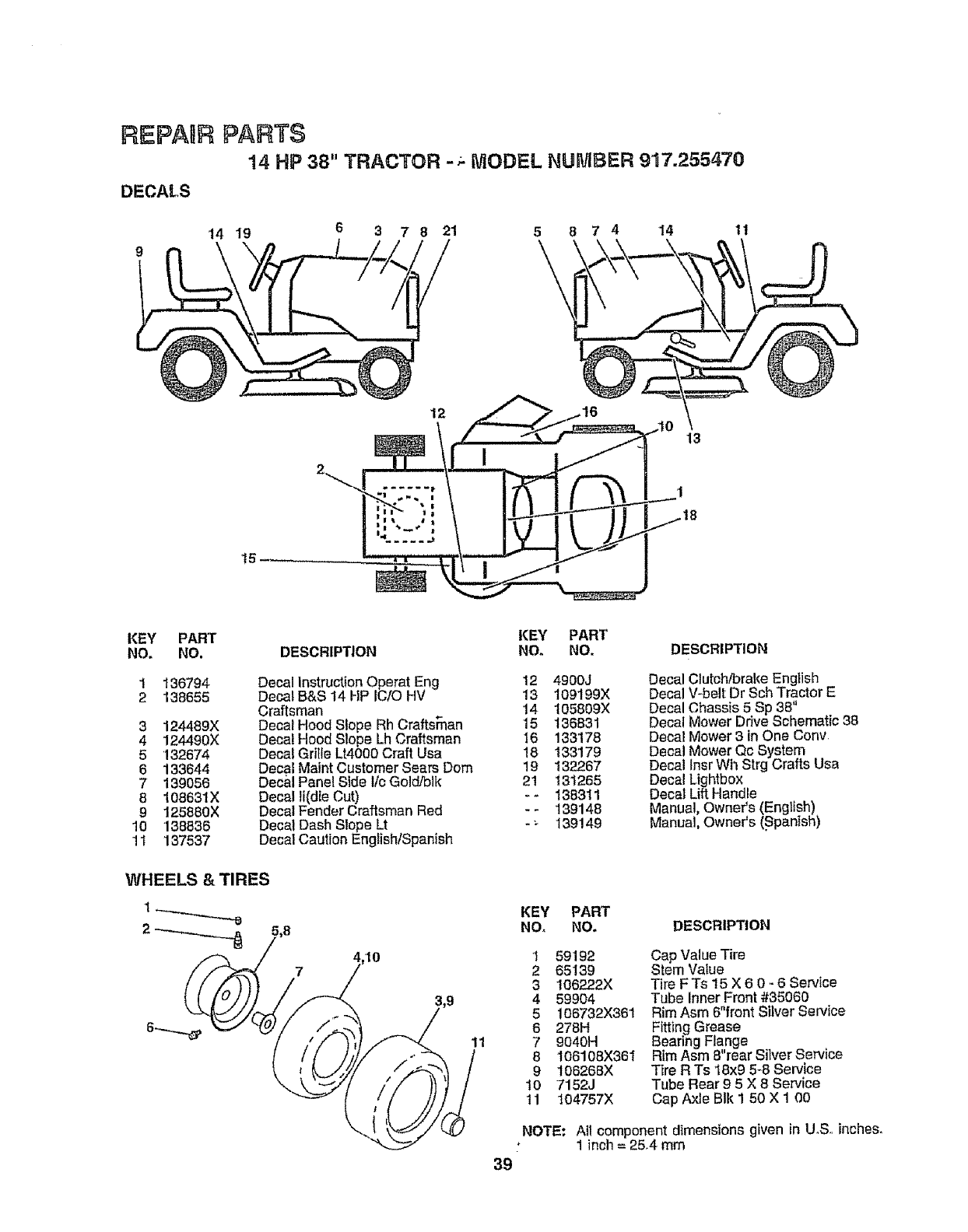
REPAUR PARTS
14 HP 38" TRACTOR -;- MODEL NUMBER 917.255470
DECALS
14 19 6 3 7 8 21 5 8 7 414 11
'f5
12
13
KEY PART
NOr NO.
1 136794
2 138655
3 124489X
4 124490X
5'132674
6133644
7139056
8 108631X
9125880X
10 "138836
!t 137537
WHEELS &TIRES
KEY PART
DESCRIPTION NO. NO. DESCRIPTION
Decal Instruction Operat Eng 12 4900J
Decal B&S 14 HP IC!O HV 13 109199X
Craftsman 14 105809X
Decal Hood Slope Rh CraftsTnan 15 136831
Decal Hood Slope Lh Craftsman 16 133178
Decal Grille LN000 Craft Usa 18 133'179
Decal Maint Customer Sears Dora 19 132267
Decal Panel Side llc Gold/blk 21 131265
Decal li(die Cut) - - 138311
Decal Fender Craftsman Red - -139148
Decal Dash Slope Lt - _ 139149
Decal Caution EnglishtSpanish
11
39
Decal Clutch/brake English
Decal V-belt Dr Sch Tractor E
Decal Chassis 5 Sp 38"
Decal Mower Drive Schematic 38
Decal Mower 3 in One Cony.
Decal Mower Qc System
Decal lnsr Wh Strg Crafts Usa
Decal Lightbox
Decal Lift Handle
Manual, Owner's (English)
Manual, Owner's (.Spanish)
KEY PART
NOr NO. DESCRIPTION
1 59192
2 65139
3 106222X
4 59904
5 106732X36t
6 278H
7 9040H
8 106108X361
9 106268X
10 7152J
tl 104757X
Cap Value Tire
Stem Value
Tire FTs 15 X 6 0 _-6 Service
Tube Inner Front #35060
Rim Asm 6"front Silver Service
Fitting Grease
Bearing Flange
Rim Asm 8"rear Silver Service
Tire R Ts 18x9 5-8 Service
Tube Rear 9 5X 8 Service
Cap Axle BIk 1 50 X 1 00
NOTE: All componentdimensions given in U_S..inches,
1 inch = 25.4 mm
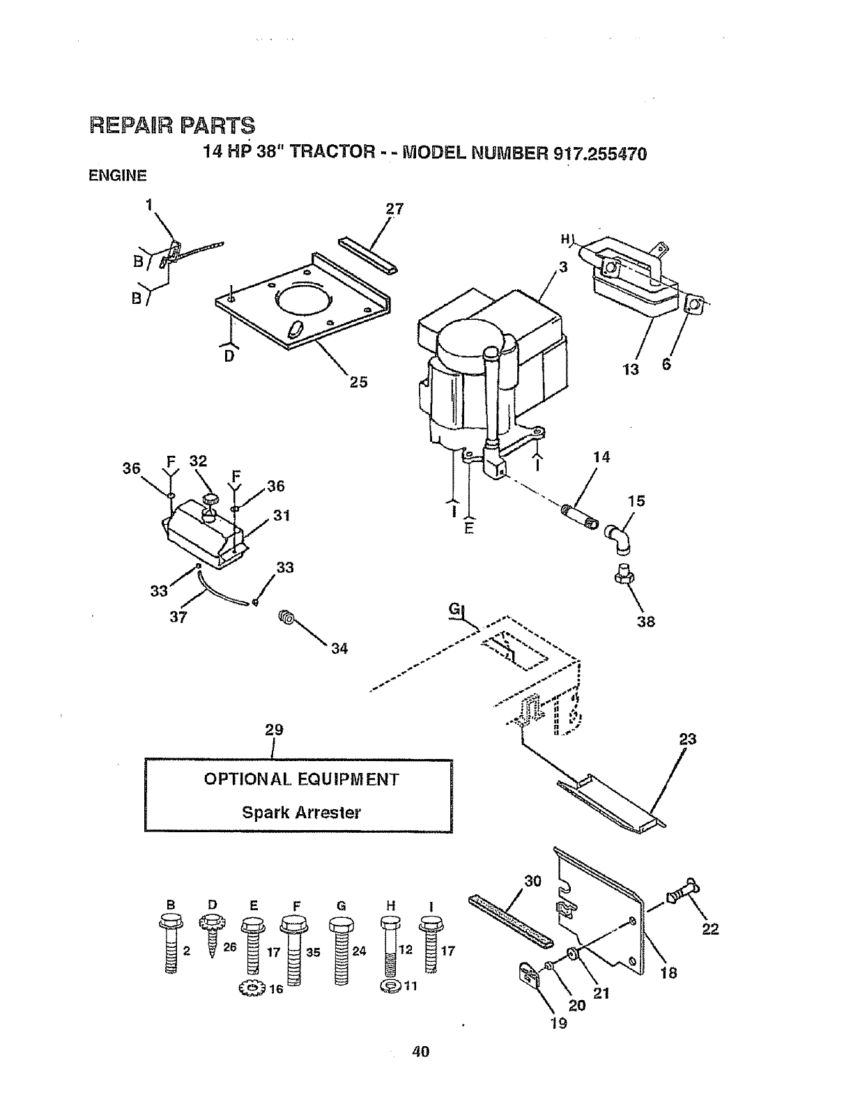
REPARR PARTS
14 HP 38" TRACTOR - - MODEL NUMBER 917.25547(}
ENGINE
127
D
25
36\
F32
31
37
H
3
38
29
!
OPTIONAL EQUIPMENT !
Spark Attester
23
B D E F G H I
@16 @tl
3O
2O
19
21
18
22
4O
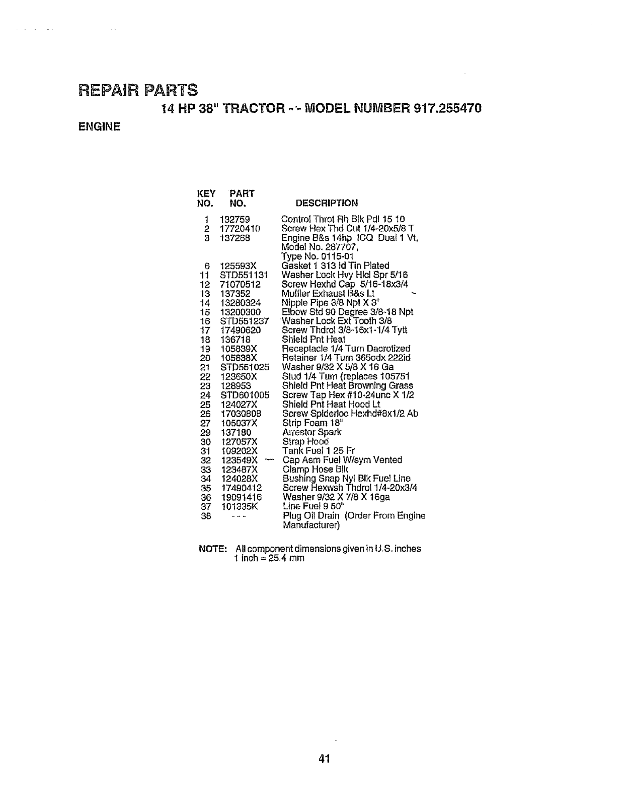
REPAIR PARTS
14 HP 38" TRACTOR -'- MODEL NUMBER 917.255470
ENGINE
KEY PART
NO. NO. DESCRIPTION
1 132759 Control Throt Rh Blk Pdl 15 10
2 17720410 Screw Hex Thd Cut I/4-20x5/8 T
3 137268 Engine B&s 14hp ICQ Dual I Vt,
Model No. 287707,
6 125593X
11 STD551131
12 71070512
13 137352
14 13280324
!5 13200300
16 STD55t237
17 17490620
18 136718
lg 105839X
20 105838X
21 STD55t025
22 123650X
23 128953
24 8TD601005
25 124027X
26 17030808
27 105037X
29 137180
30 127057X
31 t09202X
32 123549X
33 123487X
34 124028X
35 17490412
36 19091416
37 I01335K
38 ---
Type Nor 0115-01
Gasket t 313 ld Tin Plated
Washer Pock HW Hlcl Spr 5/1B
Screw Hexhd Cap 5116-18x3/4
Muffler Exhaust B&s Lt
Nipple Pipe 3/8 Npt X 3"
Elbow Std 90 Degree 3/8,-18Npt
Washer Lock Ext Tooth 3/8
Screw Thdrol 3/8-16xlq/4 Tytt
Shield Pnt Heat
Receptacle 1/4 Turn Dacrotfzed
Retainer 1/4 Turn 365od× 222id
Washer 9/32 X 5/8 X 16 Ga
Stud 1/4 Turn (replaces 105751
Shield Pnt Heat Browning Grass
Screw Tap Hex #10-24unc X 1/2
Shield Pnt Heat Hood Lt
Screw SpIder!oc Hexhd#Sxl/2 Ab
Strip Foam 18"
Arrestor Spark
Strap Hood
Tank Fuel 1 25 Fr
Cap Asm Fuel W/sym Vented
Clamp Hose BIk
Bushing Snap Nyt BIk Fuel Line
ScrewHexwsh Thdrol 1t4-20x3/4
Washer 9132X 7!8 X 16ga
Line Fuel 9 50"
Plug OiI Drain (Order From Engine
Manufacturer)
NOTE; All component dimensions given inU,S rinches
1 inch = 25,4 mm
41
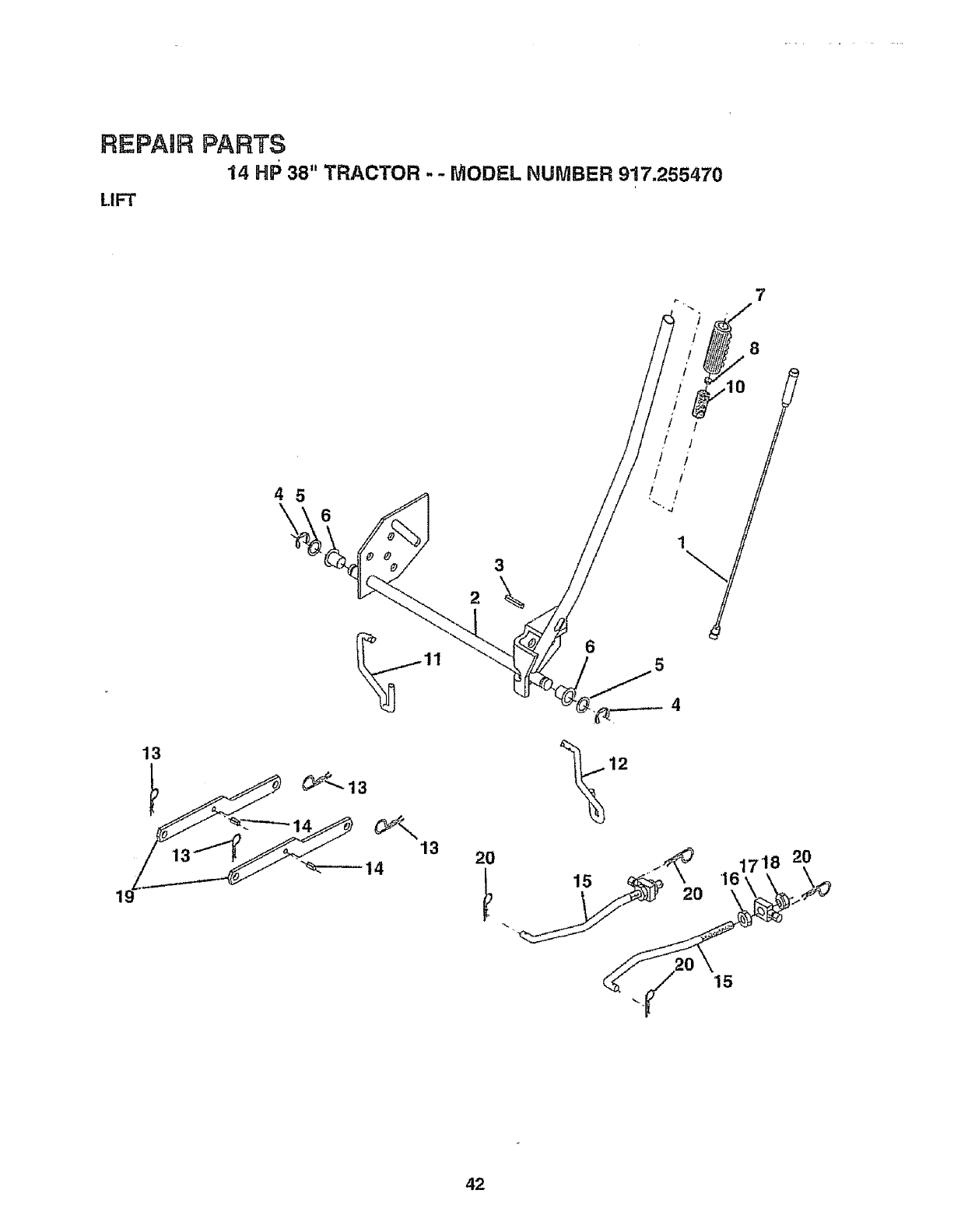
REPAIR PARTS
14 HP 38" TRACTOR - -MODEL NUMBER 9!7.255470
LIFT
7
13
3
2
2O 15 ....
2O
8
10
,161718 20
\
42
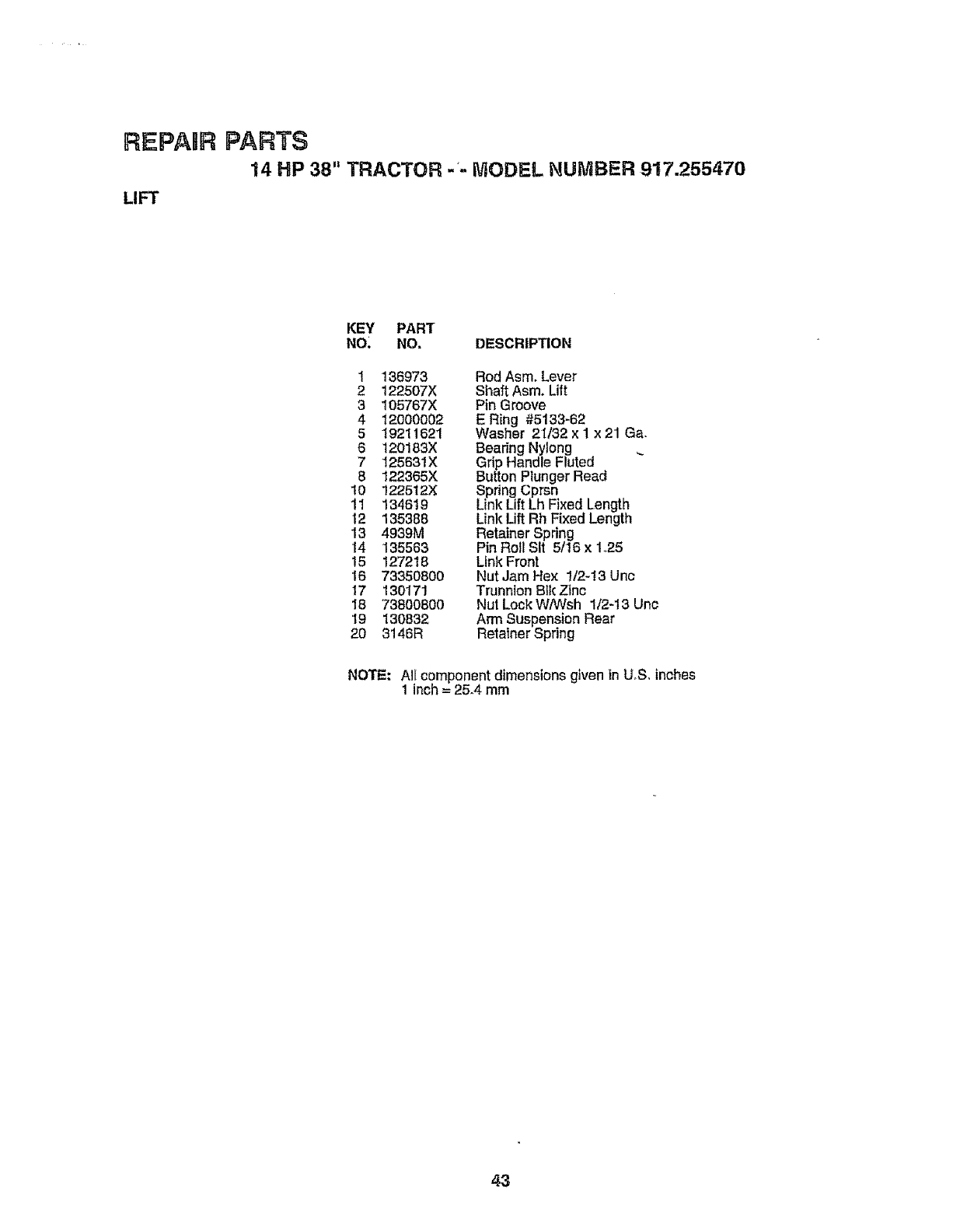
REPAUR PARTS
14 HP 38" TRACTOR -_-MODEL NUMBER 917.255470
LIFT
KEY PART
NO_ NO. DESCRIPTION
1 136973 Rod Asm. Lever
2 122507X Shaft Asm, Lift
3 105767X Pin Groove
4 12000002 E Ring #5133-62
5 19211621 Washer 21/32 x I x 21 Ga,
6 120183X Bearing Nyleng
7 125631X Grip Handle Fluted
8 122365X Button Ptunger Read
10 122512X Spring Cprsn
11 134619 Link Lift Lh Fixed Length
12 135388 Link Lift Rh Fixed Length
13 4939M Retainer Spring
14 135563 Pin Roll Sit 5/16 x 1.25
15 127218 Link Front
16 73350800 Nut Jam Hex 1/2-13 Unc
17 13017! Trunnion BIk Zinc
I8 73800800 Nut Lock W/Wsh 1/2-13 Unc
19 130832 Ann Suspension Rear
20 3146R Retainer Spring
NOTE: Ali component dimensions given inU_S,inches
1 inch = 25_4mm
43
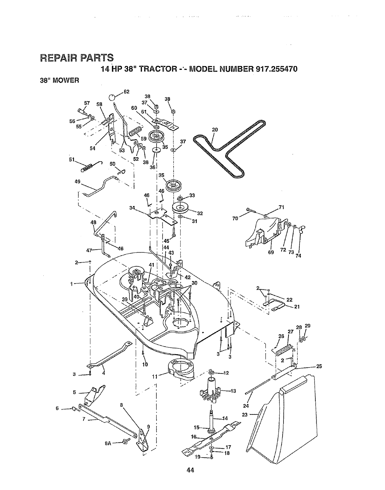
F_EPAnRPARTS
14 HP 38" TRACTOR -'- MODEL NUMBER 917.255470
38" MOWER
55
38
46
ii
i
i
I
i
I
24
44
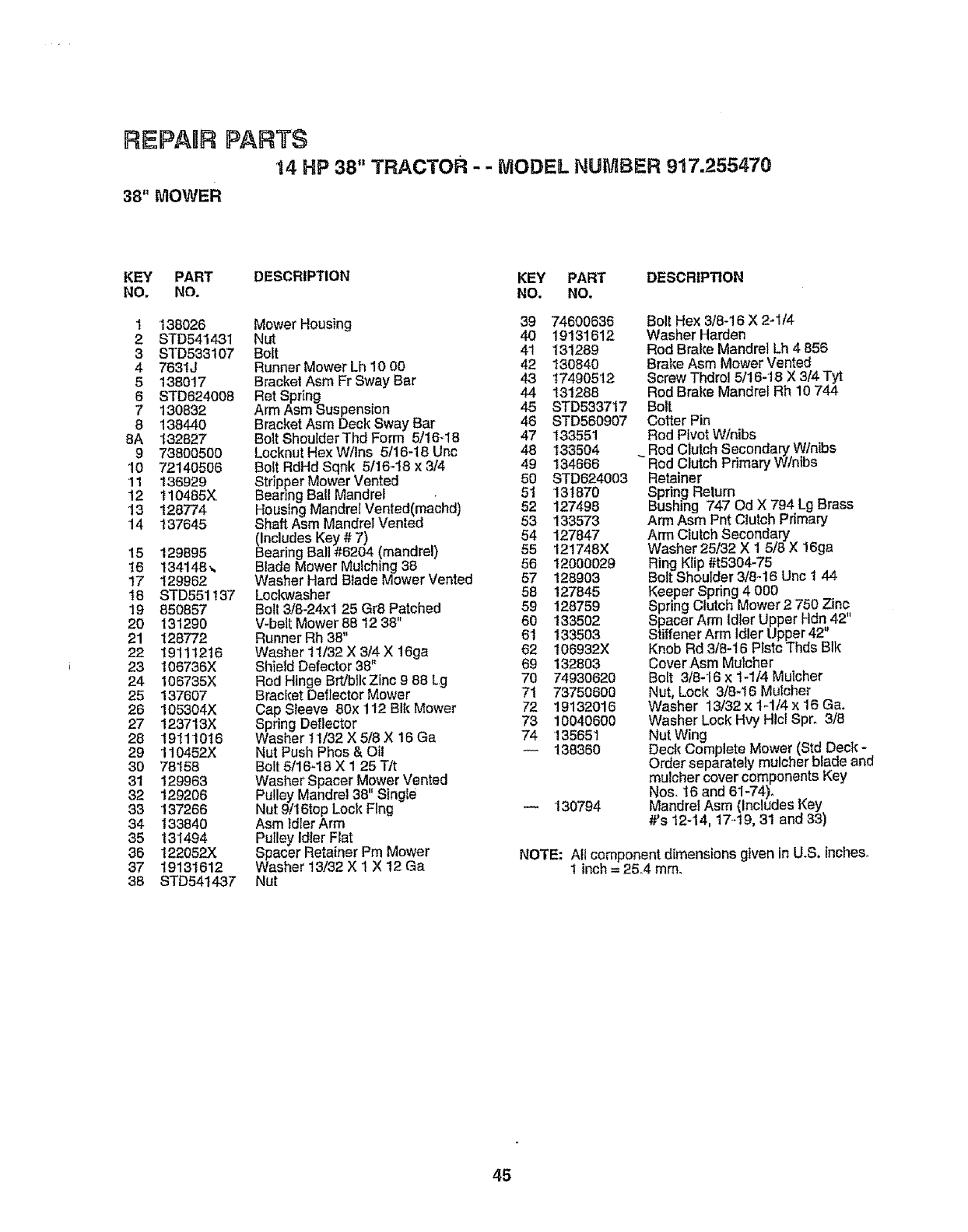
REPAIR PARTS
14 HP 38" TRACTOR - - MODEL NUMBER 9!7,255470
38"MOWER
KEY PART DESCRIPTION KEY PART DESCRIPTION
NO. NO. NO. NO.
1'138026
2 STD541431
3 STD533107
4 7631J
5138017
6 STD624008
7 130832
8 t38440
8A 132827
9 73800500
10 72140506
11 136929
12 t10485X
13 t28774
14 137645
15 129895
16 134148_
!7 129962
18 STD551!37
19 850857
20 131290
21 128772
22 19111216
23 t06736X
24 106735X
25 137607
26 105304X
27 123713X
28 19111016
29 110452X
30 78158
31 129963
32 129206
33 137266
34 133840
35 131494
36 122052X
37 19131612
38 STD541437
Mower Housing 39 74600636
Nut 40 19131612
Bolt 41 131289
Runner Mower Lh 10 00 42 130840
Bracket Asm Fr Sway Bar 43 17490512
Ret Spring 44 131288
Arm Asm Suspension 45 STD533717
Bracket Asm Deck Sway Bar 46 STD560907
Bolt ShoulderThd Form 5/16-48 47 133551
Locknut Hex W/Ins 5/16-18 Unc 48 133504
Bolt RdHd Sqnk 5116-I8 x 3/4 49 134666
Stripper Mower Vented 50 STD624003
Bearing BalI Mandrel • 51 131870
Housing Mandrel Vented(machd) 52 127498
Shaft Asm Mandrel Vented 53 133573
(Includes Key #7) 54 127847
Bearing Ball #6204 (mandrel) 55 121748X
Blade Mower Mulching 38 56 12000029
Washer Hard Btade Mower Vented 57 128903
Loci{washer 58 127845
Bolt 3/8-24xt 25 Gr8 Patched 59 128759
V-belt Mower 88 12 38" 60 133502
Runner Rh 38" 61 133503
Washer 11/32 X 3/4 X 16ga 62 106932X
Shield Defector 38" 69 132803
Rod Hinge Brt/b}k Zinc 988 Lg 70 74930620
Bracket Deflector Mower 71 73750600
Cap Sleeve 80x 112 BIk Mower 72 19132016
Spring Deflector 73 10040600
Washer t 1/32 X 5/8 X 16Ga 74 135651
Nut Push Phos & Oil -- 138360
Bolt 5/1648 X 1 25 T/t
Washer Spacer Mower Vented
Pulley Mandrel 38" Singie
Nut 9/16top Lock Flng -- 130794
Asm ldlerArm
Pulley Idler Flat
Spacer Retainer Pm Mower
Washer 13/32 X 1 X 12 Ga
Nut
Bolt Hex 3/8-16 X 2-1/4
Washer Harden
Rod Brake Mandrel Lh 4 856
Brake Asm Mower Vented
Screw Thdrol 5116-18X 3/4 Tyt
Rod Brake MandreFRh 10 744
Bolt
Cotter Pin
Rod Pivot Winibs
Rod Clutch Secondary W/nibs
Rod Clutch Primary W/ntbs
Retainer
Spring Relum
Bushing 747 Od X 794 Lg Brass
Arm Asm Pnt Clutch Primary
Arm Clutch Secondary
Washer 25/32 X 1 5/8 X 16ga
Ring Klip #t5304-75
Bolt Shoulder3/8-16 Unc 1 44
Keeper Spring 4 000
Spring Clutch Mower 2 750 Zinc
Spacer Arm IdlerUpper Hdn,42"
Stiffener Arm Idler Upper 42
Knob Rd 318-16Ptstc Thds Blk
Cover Asm Mulcher
Bolt 3/8-16 x 14/4 Mulcher
Nut, Lock 3/8-16 Mulcher
Washer 13/32 x t-1/4 x 16 Ga.
Washer Lock Hvy Htci Spr. 3/8
Nut Wing
Deck Complete Mower (Std Deck -
Order separately mulcher blade and
mulcher cover components Key
N,os. t6 and 61-74)o
Manaret Asm (includes Key
#'s 12-14, 17-.19,31 and 33)
NOTE: Aft component dimensions given in U.S. inches.
1inch= 254 mine
45
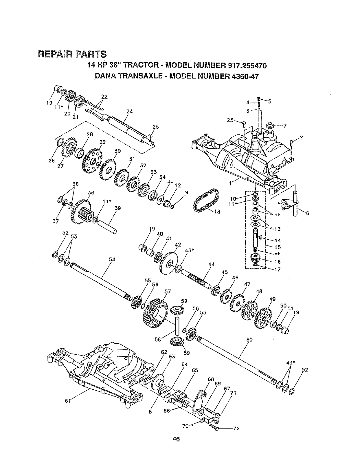
REPAgR PARTS
14 HP 38" TRACTOR - MODEL NUMBER 917.2554.70
DANA TRANSAXLE - MODEL NUMBER 4360-47
31
27 32 33 54,
36 35
37
52 53
54
19 40
55 6
41
44
57
59
55
49
6O
46
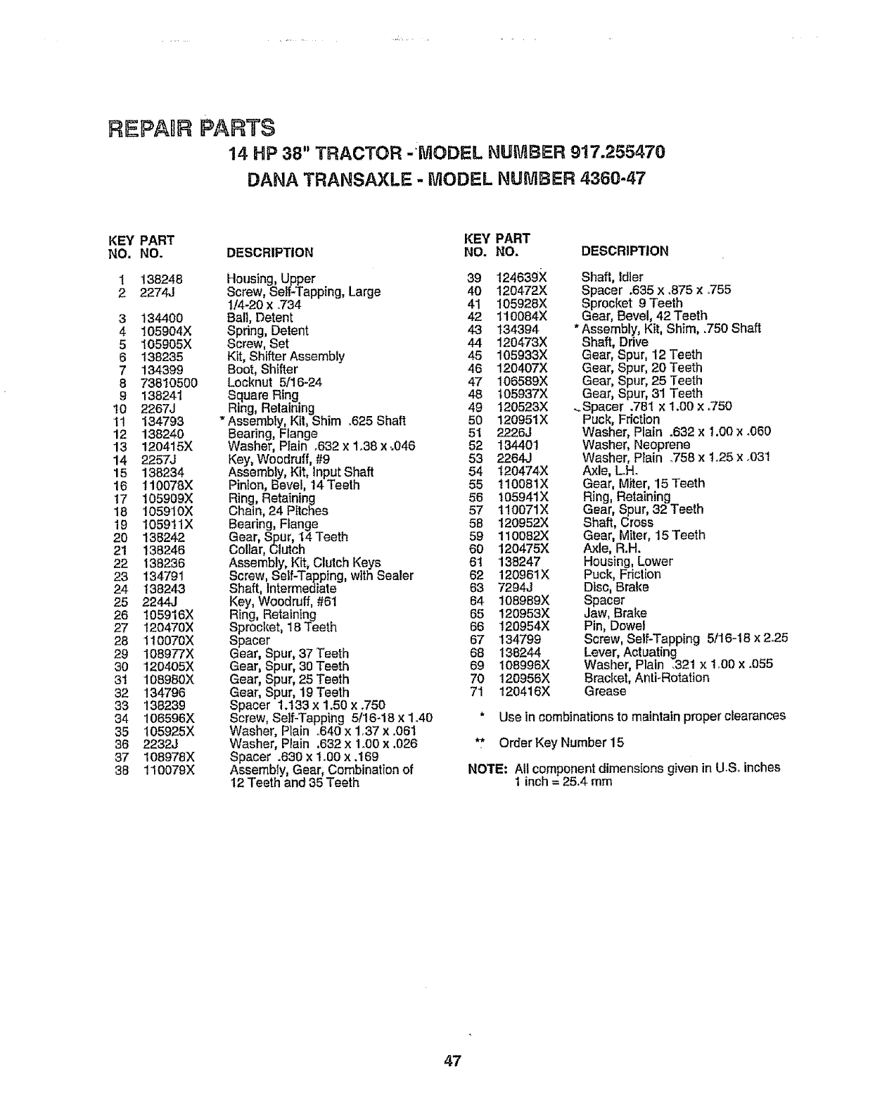
REPAnRPARTS
14 HP 38" TRACTOR -tVIODEL NUMBER 917.255470
DANA TRANSAXLE - MODEL NUMBER 436{}-47
KEY PART KEY PART
NO. NO. DESCRIPTION NO. NO. DESCRIPTION
1"138248
2 2274J
3 134400
4 105904X
5 I05905X
6 138235
7134399
8 73810500
9 138241
10 2267J
!1 134793
12 138240
13 120415X
14 2257J
15 138234
16 110078X
t7 105909X
18 105910X
19 t059tlX
20 138242
21 138246
22 138236
23 134791
24 138243
25 2244J
26 105916X
27 120470X
28 110070X
29 108977X
30 120405X
31 108980X
32 134796
33 138239
34 !06598X
35 105925X
36 2232J
37 108978X
38 110079)(
Housing, Upper 39 124639X
Screw, Self*Tapping, Large 40 120472X
1/4-20 x .734 41 105928X
Ball, Detent 42 110084X
Spdng, Detent 43 134394
Screw, Set 44 120473X
Kit, Shifter Assembly 45 105933X
Boot, Shifter 46 120407X
Locknut 5/16-24 47 108589X
Square Ring 48 105937X
Ring, Retaining 49 120523X
*Assembly, Kit, Shim °625Shaft 50 120951X
Bearing, Flange 51 2226J
Washer, Plain °632x 1.38 x ..046 52 134401
Key, Woodruff, #9 53 2264J
Assembly, Kit, Input Shaft 54 t20474X
Pinion, Bevel, 14Teeth 55 t10081X
Ring, Retaining 56 105941X
Chain, 24 Pitches 57 110071X
Bearing, Flange 58 120952X
Gear, Spur, 14Teeth 59 110082X
Collar, Clutch 60 120475X
Assembly, Kit, Clutch Keys 61 138247
Screw,Self-Tapping, with Sealer 62 120961X
Shaft, Intermediate 63 7294J
Key, Woodruff, #61 64 108989X
Ring, Retaining 65 120953X
Sprocket, 18Teeth 58 120954X
Spacer 67 !34799
Gear, Spur, 37'Teeth 68 !38244
Gear, Spur, 30 Teeth 69 108996X
Gear, Spur, 25 Teeth 70 120956X
Gear, Spur, 19Teeth 71 120416X
Spacer 1.t33 x 1.50 x .750
Screw, Self-Tapping 5116-18x 1.40
Washer, Plain .640 x 1.37 x .061
Washer, Plain ,632 x 1_0Ox .026
Spacer .630 x 1.00 x .169
Assembly, Gear, Combination of
12Teeth and 35 Teeth
Shaft, fdler
Spacer .635 x.875 x.755
Sprocket 9 Teeth
Gear, Bevel, 42 Teeth
* Assembly, Kit, Shim, .750 Shaft
Shaft, Ddve
Gear, Spur, 12 Teeth
Gear, Spur, 20 Teeth
Gear, Spur, 25 Teeth
Gear, Spur, 31 Teeth
_Spacer .781 x 1.00 x .750
Puck, Fdctton
Washer, Plain .632 x 1.00 x .060
Washer, Neoprene
Washer, Plain .758 x Io25 x .03t
Axle, L.H.
Gear, Miter, 15Teeth
Ring, Retaining
Gear, Spur, 32 Teeth
Shaft, Cross
Gear, Miter, 15 'Teeth
Axle, R.H.
Housing, Lower
Puck, Friction
Disc, Brake
Spacer
Jaw, Brake
Pin, Dowel
Screw,Self-Tapping 5/16-18 x2.25
Lever, Actuating
Washer, Plain _321x tO0 x .o55
Bracket, Anti-Rotation
Grease
*Use in combinations to maintain proper clearances
** Order Key Number 15
NOTE: All component dimensions given in US° inches
1 inch = 25.4 mm
47
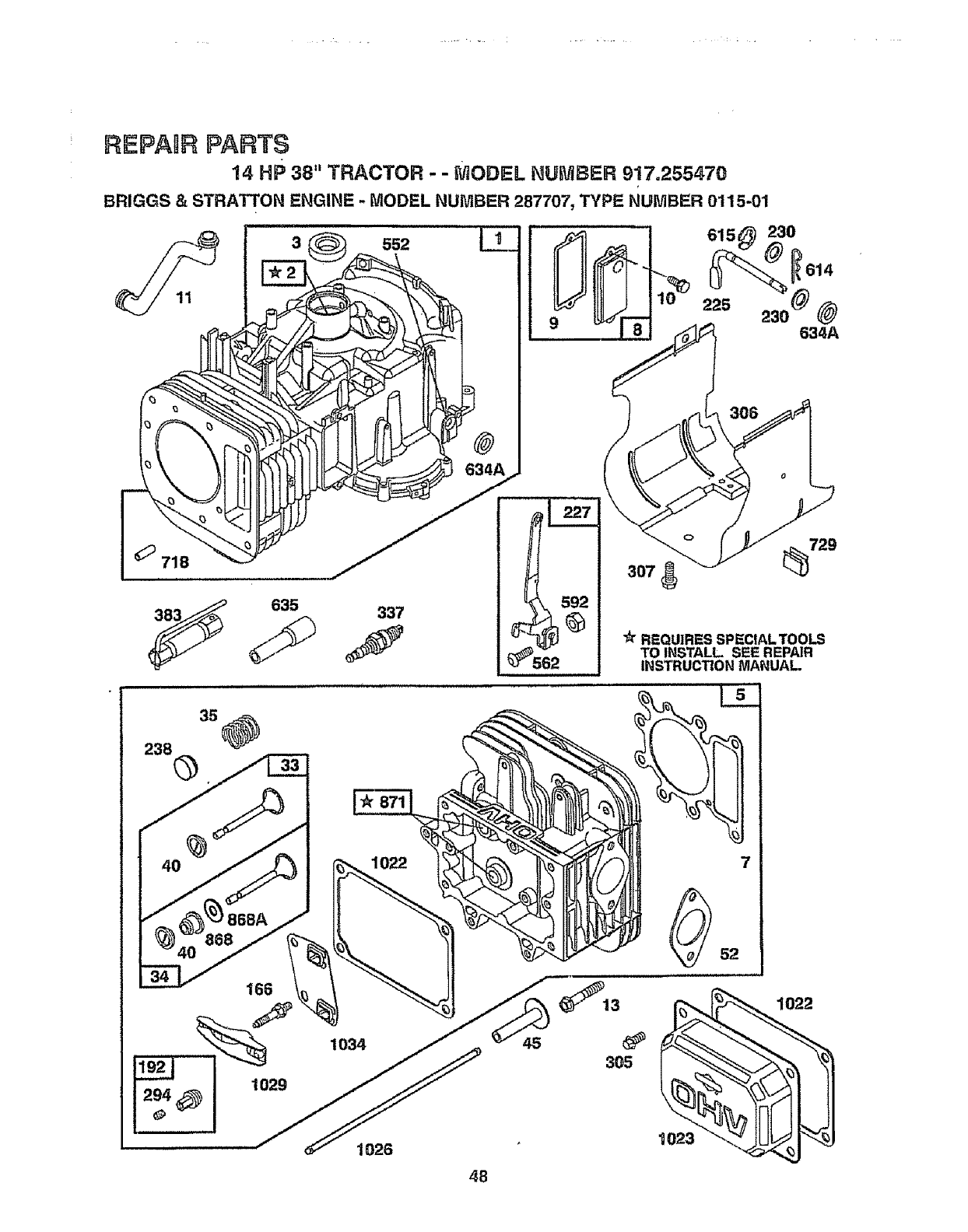
REPARR PARTS
14 HP 38" TRACTOR --MODEL NUMBER 917.255470
BRIGGS & STRATTON ENGINE - MODEL NUMBER 287707, TYPE NUMBER 0115-01
718
635 337
307 729
"A"REQUIRES SPECIAL TOOLS
TO INSTALL SEE REPAIR
INSTRUCTION MANUAL
4O 868
1029
1034
1022 7
1026
45
48
_'_13
305
9023
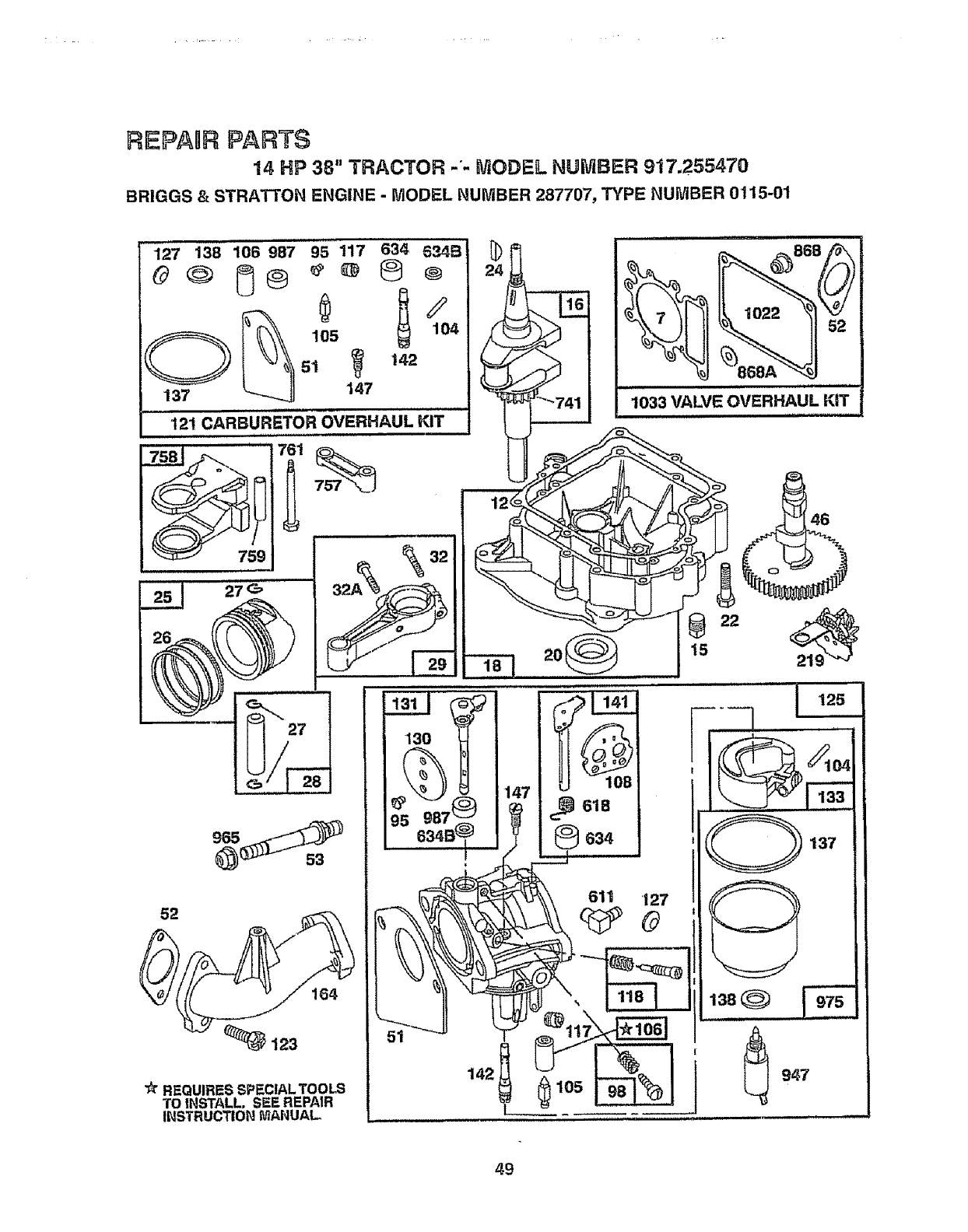
REPAaR PARTS
14 HP 38" TRACTOR -'- MODEL NUMBER 917.255470
BRIGGS & STRATTON ENGINE - MODEL NUMBER 287707, TYPE NUMBER 0115-01
127 138 106 987 95 117 634 6_,?,4B
O_ 105 104
5t _t42
137 147
12! CARBURETOR OVERHAUL KIT
= i
7s__Jz'_."
52
_!23
REQUIRES SPECIAL TOOLS
TO INSTALL. SEE REPAIR
INSTRUCTION. MANUAL
H H....................
_22 _ 52
1033 VALVE OVERHAUL KiT
€
130
9_56_7B_ 147
22
15
105
49
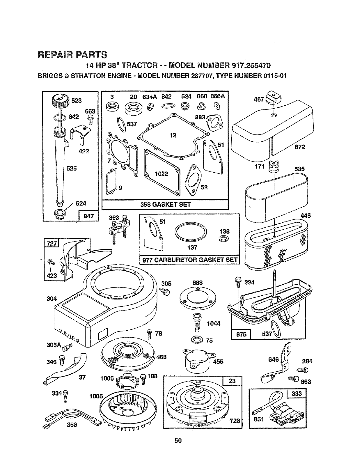
REPANR PARTS
14 HP 38" TRACTOR --MODEL NUMBER 917.255470
BR|GGS &STRATTON ENGINE -MODEL NUMBER 287707, TYPE NUMBER 01t5-01
525
524
,i,iu,,,H 3 20 634A 842 524 868 868A
_--_'J A 883 ''''_
358 GASKET SET
1 13B
@
137
i u
977 CARBURETOR GASKET SET
305 668
78
305A_
)468
37 1006
1044
O7s
_224
5O
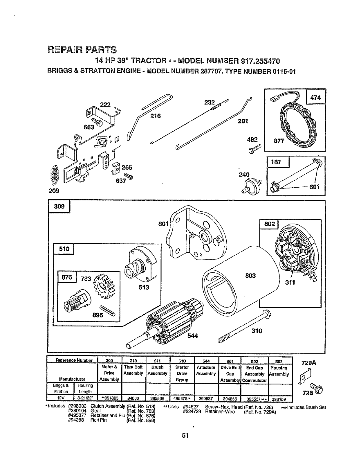
REPAHR PARTS
14 HP 38" TRACTOR • -MODEL NUMBER 917.255470
BRIGGS & STRATTON ENGINE -MODEL NUMBER 287707, TYPE NUMBER 0115-01
265 240
209
i,,i, i ,,,,,,
783
601
801
513
310
i,lllll, i,,,, ,ll
R_f,_renceNumber 309 310
Motor& ThruBolt
Drive Assembly
_ ManufactUrer _,,Ass_mb|y
Brtggs& Housing
Stratton Length
311
Brush
As,,embly
, , , , , ,ll i i ,"
51o , s_ , eo3 729/),
Starter Armature Housing J_
Drive Assembly Assembly _t_.J
Group .......
801 8B2..
Drive E_d End Cop
Cap Aesombly
Assembly Commutator
12V 3-21/32 _**394805 94003 .... 395,53 B 495B78 _ 390837 394856 395537*** 398159
*|nclud_s ._/398003 C_utchAssembly(Ref.No_513) _Uses #94627 Screw-Hex. He_d (Re|. No,728) ,_tnctudes BrushSet
#280104 Gear (RefoNo.783) #224723 Retainer-Wire (Ref. No.729A)
#495877 Retainerand Pin (Ref_No, 876)
//94288 Ro_IPin (Ref. Nee896)
51
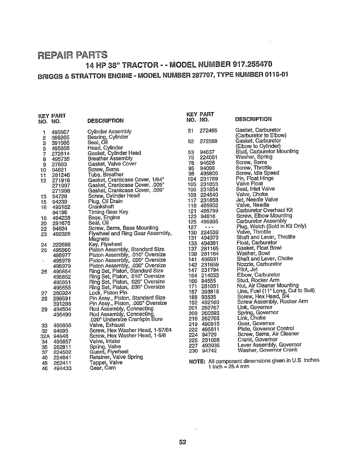
REPABR PARTS
14 HP 38" TRACTOR - -I ODEL NUMBER 917.255470
BRIGGS & STRA'I-_ON ENGINE - N1ODEL NUMBER 287707, TYPE NUMBER 01t5-01
KEY PART KEY PART
NO. NO. DESCRIPTION NO. NO. DESCRIPTION
1 495867
2399265
3 391086
5 495858
7 272614
8 495735
9 27803
10 94621
11 281246
12 271916
271997
271996
13 94728
15 94239
'16 495162
94196
18 494238
20 291675
22 94624
23 492326
24 222698
25 495860
495977
495978
495979
26 495854
495852
495851
495855
27 260924
28 299691
391286
29 4945O4
495490
33 995856
32 94695
32A 94648
34 495857
35 262811
37 224502
40 224641
45 262411
46 494433
Cylinder Assembly 51 272465
Bearing, Cylinder
Seal, Oil 52 272569
Head, Cylinder
Gasket, Cylinder Head 53 94637
Breather Assembly 75 224061
Gasket, Valve Cover 78 94626
Screw, Sems 95 94098
Tube, Breather 98 495800
Gasket, Crankcase Cover, 1/6#' 104 231789
Gasket, Crankcase Cover, .005" 105 231855
Gasket, Crankcase Cover, °009" i08 231854
Screw, CyIinder Head 108 224540
Plug, Oil Drain 117 231858
Crankshaft 118 495932
Timing Gear Key 121 495799
Base, Engine 123 94616
Be&l, Oii 125 495935
Screw, Barns, Base Mounting 127 -- -
Flywheel and Ring Gear Assembly, 130 224539
Magneto 131 494379
Key, Flywheel 133 494381
Piston Assemb(y, Standard Size 137 261165
Piston Assembly, ,010" Oversize 138 281164
Piston Assembly, ,020" Oversize 141 495931
Piston Assembly, .030" Oversize 142 231859
Ring Set, Piston, Standard Size 147 231794
Ring Set, Piston, .010" Oversize 164 214053
Ring Set, Piston, 020" Oversize 166 94555
Ring Set Piston, .030" Oversize 171 281051
Lock, P ston Pin 187 393816
Pin Assy..,Piston Standard Size I88 93535
Pin Assy., P ston, .005 Overs ze 192 492160
Rod Assembly, Connecting 201 262767
Red Assembly, Connecting, 209 260695
.020" Undersize Crankpin Bore 2t6 262766
Valve, Exhausf[ 2t9 490815
Screw, Hex Washer Head, 1-57164 222 495611
Screw, Rex Washer Head, 1-5/8 224 94729
Valve, Intake 225 231058
Spring, Valve 227 493935
Guard, Flywheel 230 94742
Retainer, Valve Spring
Tappet, Valve
Gear, Cam
Gasket° Carburetor
(Carburetor to Elbow)
Gasket, Carburetor
(EIbow to Cylinder)
Stud, Carburetor Mounting
Washer, Spring
Screw, Seres
Screw, Throttle
Screw, Idle Speed
Pin, Float Hinge
Vafve Roar
Seat, Inlet Valve
Valve, Choke
Jet, Needte Valve
Valve, Needle
Carburetor Overhaul Kit
Screw, Elbow Mounting
Carburetor Assembly
Plug, Welch (Sold in Kit Only)
Valve, Throttle
Shaft and Lever, Throttle
Float, Carburetor
Gasket, Ftoat Bowl
Washer, Bowl
Shaft and Lever, Choke
Nozzle, Carburetor
Pilot, Jet
EIbow, Carburetor
Stud, Rocker Arm
Nut, Air Cleaner Mounting
Line, Fuel (11" Long, Cut to Suit)
Screw, Hex Head, 8/4
Screw Assembly, Rocker Arm
Link, Governor
Spdng, Governor
Link, Choke
Gear, Governor
Plate, Governor Control
Screw, Seres, Air Cleaner
Crank, Governor
Lever Assembly, Governor
Washer, Governor Crank
NOTE: All component dimensions given in UoS..inches
1 inch = 25..4mm
52
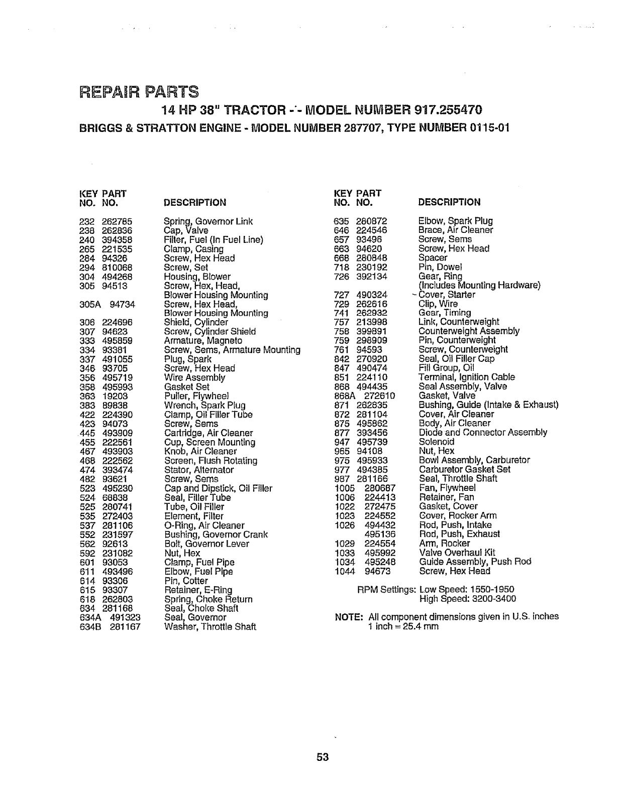
REPAIR PARTS
14 HP 38" TRACTOR -'- MODEL NUMBER 917.255479
BRIGGS & STRATTON ENGINE -MODEL NUMBER 287707, TYPE NUMBER 01'15-01
KEY PART KEY PART
NO. NO. DESCRIPTION NO. NO. DESCRIPTION
232 262785 Spring, Governor Link 635 280872
238 262836 Cap, Valve 646 224546
240 394358 Filter, Fuel (in Fuel Line) 657 93496
265 221535 Clamp, Casing 663 94620
284 94326 Screw, Hex Head 668 280848
294 810068 Screw, Set 718 230192
304 494268 Housing, Blower 726 392134
305 94513 Screw, Hex, Head,
Blower Housing Mounting 727 490324
305A 94734 Screw, Hex Head, 729 262616
Blower Housing Mounting 741 262932
308 224696 Shield, Cylinder 757 213998
307 94623 Screw, Cylinder Shield 758 399891
333 495859 Armature, Magneto 759 298909
334 93381 Screw, Sems, Armature Mounting 761 94593
337 491055 Plug, Spark 842 270920
346 93705 Screw, Hex Head 847 490474
356 495719 Wire Assembly 851 224110
358 495993 Gasket Set 868 494435
363 19203 Pulter, Flywheel 868A 272610
383 89838 Wrench, Spark Ptug 871 282835
422 224390 Clamp, Oil FillerTube 872 281104
423 94073 Screw, Seres 875 495862
445 493909 Cartridge, Air Cleaner 877 393456
455 222561 Cup, Screen Mounting 947 495739
467 493903 Knob, Air Cleaner 965 94108
468 222562 Screen, Flush Rotating 975 495933
474 393474 Stator, Alternator 977 494385
482 93621 Screw, Seres 987 281166
523 495230 Cap and Dipstick, Oil Filler 1005 280687
524 68838 Seal, FillerTube I006 224413
525 280741 Tube, el! Filler 1022 272475
535 272403 Element, Filter 1023 224552
537 281 t06 O-Ring, Air Cleaner 1026 494432
552 231597 Bushing, Governer Crank 495136
562 92613 Bolt, Governor Lever 1029 224554
592 231082 Nut, Hex 1033 495992
601 93053 Clamp, Fuel Pipe t034 495248
611 493496 Elbow, Fuel Pipe 1044 94673
614 93306 Pin, Cotter
615 93307 Retainer, E-Ring
618 262803 Spdng Choice Return
634 281168 Sea, Cho _eShaft
634A 491323 Seal, Governor
634B 281167 Washer, Throttle Shaft
Elbow, Spark Plug
Brace, Air Cleaner
Screw, Seres
Screw, Hex Head
Spacer
Pin, Dowel
Gear, Ring
(Includes Mounting Hardware)
Cover, Starter
CIip, Wire
Gear, Timing
Link, Counterweight
Counterweight Assembly
Pin, Counterweight
Screw, Counterweight
Seal, O1tFiller Cap
Fill Group, Oti
Terminal, ignitionCable
Seal Assembly, Valve
Gasket, Valve
Bushing, Guide (Intake & E×haust)
Cover, Air Cleaner
Body, Air Cleaner
Diode and Connector Assembly
Solenoid
Nut, Hex
Bowl Assembly, Carburetor
Carburetor Gasket Set
Seal, Throttle Shaft
Fan, Flywheel
Retainer, Fan
Gasket, Cover
Cover,Rocker Arm
Rod, Push, Intake
Rod, Push, Exhaust
Arm, Rocker
Valve Overhaul Kit
Guide Assembly, Push Rod
Screw, Hex Head
RPM Settings: Low Speed: 1550-1950
High Speed: 3200-3400
NOTE: All component dimensions given in U.S. inches
1 inch -- 25.4 mm
53

• . . ................. SERVICE NOTES
,,, ,,,, ,, ,,,,,,,,,,,,,, ,Hi i,ill i i llll,i ll,,l,.l,
54
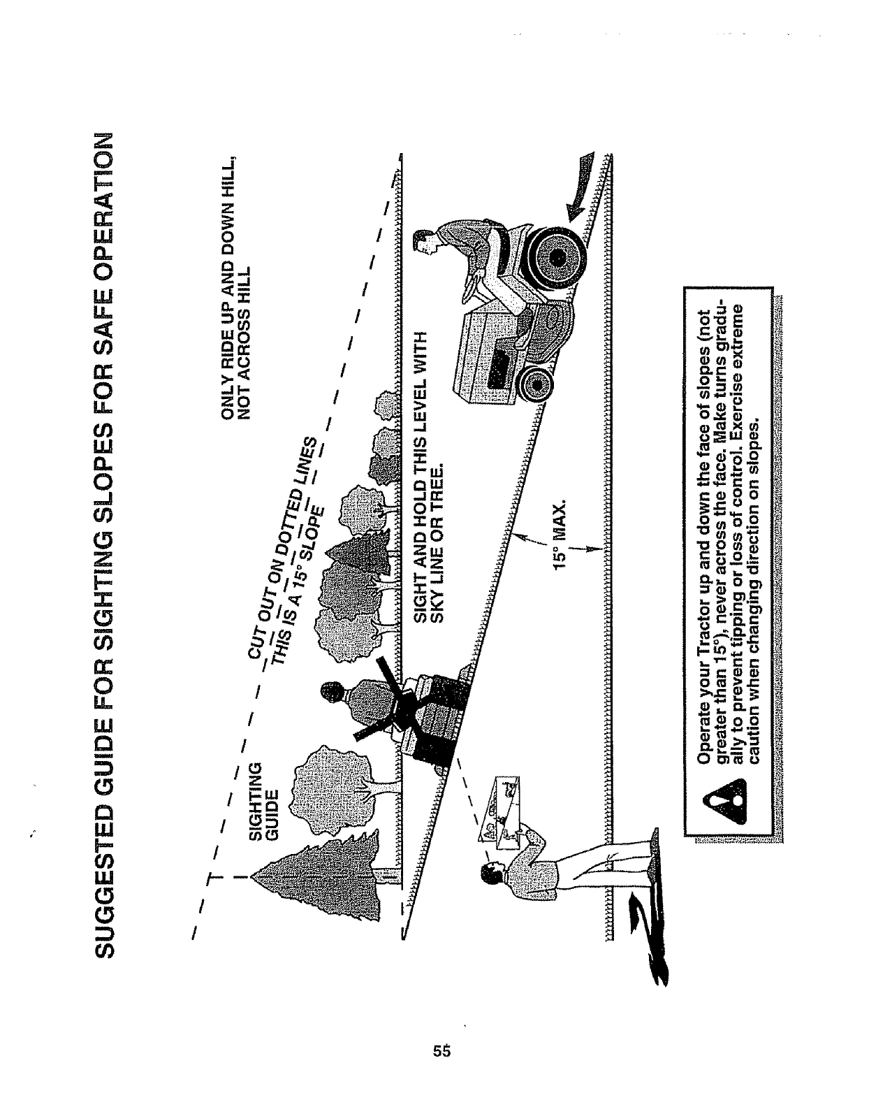
Z
0
m
F=
i.U
W
u=
U)
!.8=
o3
ILl
0
L_
Z
M
F-,
u
03
0
U=
U.!
(9
Q
LU
O3
LLI
0
0
/
t
/-
/
/
/
/
/
I
/
!
/
/
o
LO
sS
SEA/RS
OWNER'S
IANUAL
MODEL NO.
917.255470
HOW TO ORDER
REPAIR PARTS
w_
14.0 HP OHV
ELECTRIC START
38" MOWER
3 in One Convertible
5 SPEED TRANSAXLE
LAWN TRACTOR
Each tractor has its own model number. Each engine has
its own model number.
The model' number for your tractor will be found on the
model plate located under the seat,,
The model number for your engine will be found on the
blower housing of the engine.
Atl parts Jisted hereth may be ordered from any Sears,
Roebuck and Co, Service Center/Department and most
,Retail Stores.
WHEN ORDERING REPAIR PARTS, ALWAYS GIVE THE
FOLLOWING INFORMATION:
• PRODUCT -LAWN TRACTOR
•MODEL NUMBER - 917.255470
,, ENGINE MODEL NO. -287707, TYPE NO. 0115-01
. PART NUMBER
PART DESCRIPTION
Your Sears merchandise has added value when you
consider Sears has service units nationwide staffed with
Sears trained technicians.., professional technicians
specifically trained to insure that we meet our pledge to
you, we service what we sell.
®
139148 t .26o93 Printed in U.S.A.
